Space Instrumentation: Measuring Magnetic Fields in Space ...

EMV/EMC ∙ 211
7 EMV
EMC

Abb. 1 – EMV-Kabelverschraubung blueglobe TRIFig. 1 – EMC cable gland blueglobe TRI
212 ∙ EMV/EMC
1
EMV-Kabelverschraubungen
EMC cable glands
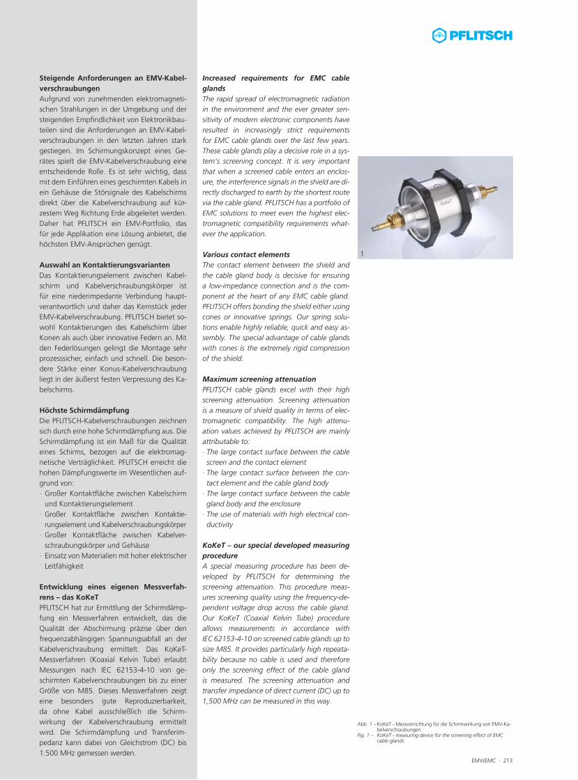
Abb. 1 – KoKeT - Messvorrichtung für die Schirmwirkung von EMV-Ka-belverschraubungen
Fig. 1 – KoKeT - measuring device for the screening effect of EMC cable glands
EMV/EMC ∙ 213
1
Steigende Anforderungen an EMV-Kabel-verschraubungenAufgrund von zunehmenden elektromagneti-schen Strahlungen in der Umgebung und der steigenden Empfindlichkeit von Elektronikbau-teilen sind die Anforderungen an EMV-Kabel-verschraubungen in den letzten Jahren stark gestiegen. Im Schirmungskonzept eines Ge-rätes spielt die EMV-Kabelverschraubung eine entscheidende Rolle. Es ist sehr wichtig, dass mit dem Einführen eines geschirmten Kabels in ein Gehäuse die Störsignale des Kabelschirms direkt über die Kabelverschraubung auf kür-zestem Weg Richtung Erde abgeleitet werden. Daher hat PFLITSCH ein EMV-Portfolio, das für jede Applikation eine Lösung anbietet, die höchsten EMV-Ansprüchen genügt. Auswahl an KontaktierungsvariantenDas Kontaktierungselement zwischen Kabel-schirm und Kabelverschraubungskörper ist für eine niederimpedante Verbindung haupt-verantwortlich und daher das Kernstück jeder EMV-Kabelverschraubung. PFLITSCH bietet so-wohl Kontaktierungen des Kabelschirm über Konen als auch über innovative Federn an. Mit den Federlösungen gelingt die Montage sehr prozesssicher, einfach und schnell. Die beson-dere Stärke einer Konus-Kabelverschraubung liegt in der äußerst festen Verpressung des Ka-belschirms. Höchste Schirmdämpfung Die PFLITSCH-Kabelverschraubungen zeichnen sich durch eine hohe Schirmdämpfung aus. Die Schirmdämpfung ist ein Maß für die Qualität eines Schirms, bezogen auf die elektromag-netische Verträglichkeit. PFLITSCH erreicht die hohen Dämpfungswerte im Wesentlichen auf-grund von:∙ Großer Kontaktfläche zwischen Kabelschirm
und Kontaktierungselement∙ Großer Kontaktfläche zwischen Kontaktie-
rungselement und Kabelverschraubungskörper ∙ Großer Kontaktfläche zwischen Kabelver-
schraubungskörper und Gehäuse∙ Einsatz von Materialien mit hoher elektrischer
Leitfähigkeit Entwicklung eines eigenen Messverfah-rens – das KoKeTPFLITSCH hat zur Ermittlung der Schirmdämp-fung ein Messverfahren entwickelt, das die Qualität der Abschirmung präzise über den frequenzabhängigen Spannungsabfall an der Kabelverschraubung ermittelt. Das KoKeT- Messverfahren (Koaxial Kelvin Tube) erlaubt Messungen nach IEC 62153-4-10 von ge-schirmten Kabelverschraubungen bis zu einer Größe von M85. Dieses Messverfahren zeigt eine besonders gute Reproduzierbarkeit, da ohne Kabel ausschließlich die Schirm-wirkung der Kabelverschraubung ermittelt wird. Die Schirmdämpfung und Transferim-pedanz kann dabei von Gleichstrom (DC) bis 1.500 MHz gemessen werden.
Increased requirements for EMC cable glandsThe rapid spread of electromagnetic radiation in the environment and the ever greater sen-sitivity of modern electronic components have resulted in increasingly strict requirements for EMC cable glands over the last few years. These cable glands play a decisive role in a sys-tem’s screening concept. It is very important that when a screened cable enters an enclos- ure, the interference signals in the shield are di-rectly discharged to earth by the shortest route via the cable gland. PFLITSCH has a portfolio of EMC solutions to meet even the highest elec-tromagnetic compatibility requirements what-ever the application. Various contact elements The contact element between the shield and the cable gland body is decisive for ensuring a low-impedance connection and is the com-ponent at the heart of any EMC cable gland. PFLITSCH offers bonding the shield either using cones or innovative springs. Our spring solu-tions enable highly reliable, quick and easy as-sembly. The special advantage of cable glands with cones is the extremely rigid compression of the shield. Maximum screening attenuation PFLITSCH cable glands excel with their high screening attenuation. Screening attenuation is a measure of shield quality in terms of elec-tromagnetic compatibility. The high attenu-ation values achieved by PFLITSCH are mainly attributable to:∙ The large contact surface between the cable screen and the contact element
∙ The large contact surface between the con-tact element and the cable gland body
∙ The large contact surface between the cable gland body and the enclosure
∙ The use of materials with high electrical con-ductivity
KoKeT – our special developed measuring procedureA special measuring procedure has been de-veloped by PFLITSCH for determining the screening attenuation. This procedure meas-ures screening quality using the frequency-de-pendent voltage drop across the cable gland. Our KoKeT (Coaxial Kelvin Tube) procedure allows measurements in accordance with IEC 62153-4-10 on screened cable glands up to size M85. It provides particularly high repeata-bility because no cable is used and therefore only the screening effect of the cable gland is measured. The screening attenuation and transfer impedance of direct current (DC) up to 1,500 MHz can be measured in this way.

214 ∙ EMV/EMC
blueglobe TRIblueglobe TRI
blueglobe TRI CLEAN Plus
blueglobe TRI CLEAN Plus
blueglobe ACblueglobe AC
blueglobe EMVblueglobe EMC
UNI Entstör DichtUNI Interference Suppres-
sion Dicht
UNI HF DichtUNI HF Dicht
UNI IRIS EMV DichtUNI IRIS EMC Dicht
UNI EMV DichtUNI EMC Dicht
Kontaktierung KabelschirmContact cable screen
TRI-FederTRI spring
TRI-FederTRI spring
KlemmringClamping ring
Kontaktelement für Gesamtschirm und bis zu zwei zusätzliche Einzel-
schirmeContact with one full cable screen and up to two add- itional individual screens
KonusCone
UNI IRIS-Feder mit zwei Konenscheiben
UNI IRIS spring with two cones
UNI IRIS-Feder mit zwei Konenscheiben
UNI IRIS spring with two cones
DoppelkonusDouble cone
SchirmdämpfungScreening attenuation +++ +++ +++ + ++ + + ++StromtragfähigkeitCurrent-carrying capacity ++ ++ +++ + + + + ++MontagefreundlichkeitSimple installation +++ +++ + + + ++ ++ +Schirm endet in der Verschraubung.Cable screen ends in the cable gland. P P P P P P P P
Schirm kann weitergeführt werden.Cable screen can be pursued. P P P P P P
Für armierte Kabel (hoher mechanischer Schutz)For armoured cables (high mechanic protection) P
Variante für hohe TemperaturenVariant for high temperatures P P P P P P P P
Gute Reinigbarkeit (Hygienic Design, EHEDG-zertifiziertEasy to clean (hygienic design, EHEDG-certificated
P
Zertifiziert für Bahnanwendungen nach Bran -schutznorm EN 45545Certified for railway applications according to firprotection standard EN 45545
P P
Verwendung des UNI Dicht-BaukastensystemsUsage of the UNI Dicht modular system P P
Variante mit Pg-GewindePg thread variant P P P P
Weiterführende Informationen auf SeiteFuther information on page 222 339 260 256 250 230 238 244
Eigenschaften der PFLITSCH- EMV-Kabelverschraubungen
Characteristics of the PFLITSCH EMC cable glands
Gut +Good
Sehr gut ++Very good
Ausgezeichnet +++Excellent
Zutreffend PApplicable
blueglobe TRIblueglobe TRI
blueglobe TRI CLEAN Plus
blueglobe TRI CLEAN Plus
blueglobe ACblueglobe AC
blueglobe EMVblueglobe EMC
UNI Entstör DichtUNI Interference Suppres-
sion Dicht
UNI HF DichtUNI HF Dicht
UNI IRIS EMV DichtUNI IRIS EMC Dicht
UNI EMV DichtUNI EMC Dicht
Kontaktierung KabelschirmContact cable screen
TRI-FederTRI spring
TRI-FederTRI spring
KlemmringClamping ring
Kontaktelement für Gesamtschirm und bis zu zwei zusätzliche Einzel-
schirmeContact with one full cable screen and up to two add- itional individual screens
KonusCone
UNI IRIS-Feder mit zwei Konenscheiben
UNI IRIS spring with two cones
UNI IRIS-Feder mit zwei Konenscheiben
UNI IRIS spring with two cones
DoppelkonusDouble cone
SchirmdämpfungScreening attenuation +++ +++ +++ + ++ + + ++StromtragfähigkeitCurrent-carrying capacity ++ ++ +++ + + + + ++MontagefreundlichkeitSimple installation +++ +++ + + + ++ ++ +Schirm endet in der Verschraubung.Cable screen ends in the cable gland. P P P P P P P P
Schirm kann weitergeführt werden.Cable screen can be pursued. P P P P P P
Für armierte Kabel (hoher mechanischer Schutz)For armoured cables (high mechanic protection) P
Variante für hohe TemperaturenVariant for high temperatures P P P P P P P P
Gute Reinigbarkeit (Hygienic Design, EHEDG-zertifiziertEasy to clean (hygienic design, EHEDG-certificated
P
Zertifiziert für Bahnanwendungen nach Bran -schutznorm EN 45545Certified for railway applications according to firprotection standard EN 45545
P P
Verwendung des UNI Dicht-BaukastensystemsUsage of the UNI Dicht modular system P P
Variante mit Pg-GewindePg thread variant P P P P
Weiterführende Informationen auf SeiteFuther information on page 222 339 260 256 250 230 238 244
EMV/EMC ∙ 215

Abb. 1 – KoKeT - Messvorrichtung für die Schirmwirkung von EMV-Ka-belverschraubungen
Fig. 1 – KoKeT - measuring device for the screening effect of EMC cable glands
Abb. 2 – KoKeT – Messvorrichtung für die Schirmwirkung von EMV- Kabelverschraubungen
Fig. 2 – KoKeT – measuring device for the screening effect of EMC cable glands
216 ∙ EMV/EMC
1
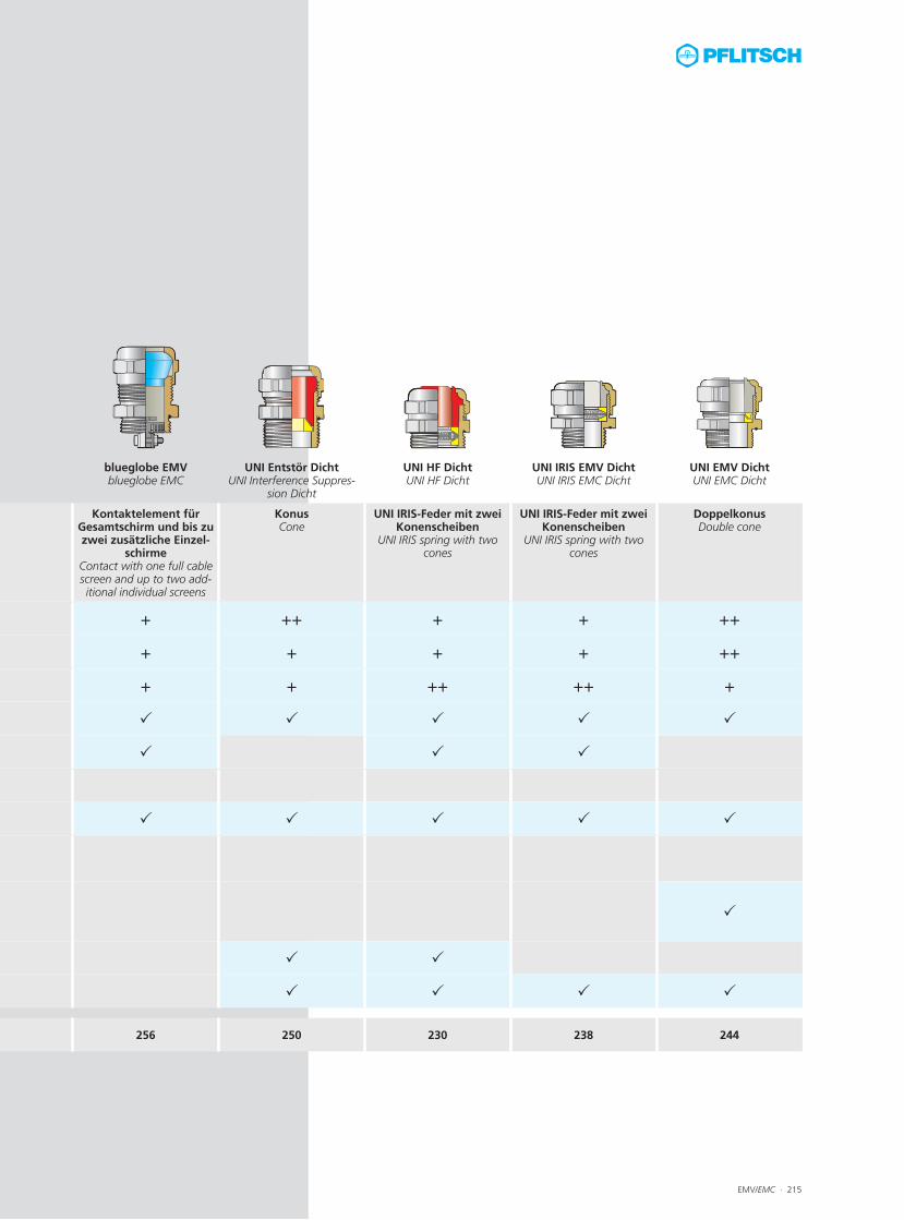
Schirmdämpfungsvergleich mit KoKeT
Screening attenuation comparison with KoKeT
2
SchirmdämpfungScreen attenuation
Däm
pfu
ng
[d
B]
Att
entu
atio
n [d
B]
Frequenz [MHz]Frequency [MHz]
blueglobe TRI
UNI IRIS
UNI EntstörUNI Interference Suppression
Mandrel: medium Ø brass, blank Cable shield: RG 213Measurement principle: KoKeT matched/matchedConnection thread: M20Conditioning: 96 hours/80 °C
Dorn: mittlerer Ø Messing blank Kabelschirm: RG 213Messprinzip: KoKeT matched/matchedAnschlussgewinde: M20Konditionierung: 96 Stunden/80 °C
EMV/EMC ∙ 217
PFLITSCH-Schirmdämpfungsvergleich PFLITSCH screening attenuation comparison
UNI IRIS EMV DichtMessing vernickeltMetrisches Anschlussgewinde EN 60423Mit O-Ring HNBRSchutzart IP 68 bis 10 barZugentlastung bis Klasse A, EN 62444UNI IRIS EMC DichtBrass, nickel-platedMetric connection thread EN 60423With o-ring HNBRType of protection IP 68 up to 10 barStrain relief up to class A, EN 62444
UNI Entstör DichtMessing vernickeltMetrisches Anschlussgewinde EN 60423Mit O-RingSchutzart IP 68 bis 10 bar, Type 4XZugentlastung bis Klasse AUNI Interference Suppression DichtBrass, nickel-platedMetric connection thread EN 60423With o-ringType of protection IP 68 up to 10 bar, Type 4XStrain relief up to class A
blueglobe TRIMessing vernickeltMetrisches Gewinde EN 60423Mit O-Ring HNBRSchutzart IP 68 bis 15 bar, IP 69, Type 4XZugentlastung bis Klasse B, EN 62444blueglobe TRIBrass, nickel-platedMetric thread EN 60423With o-ring HNBRType of protection IP 68 up to 15 bar, IP 69, Type 4XStrain relief up to class B, EN 62444

Abb. 1 – blueglobe TRI – Kabel mit freigelegtem Schirmgeflecht Fig. 1 – blueglobe TRI – cable with stripped shielding
218 ∙ EMV/EMC
blueglobe TRI
1
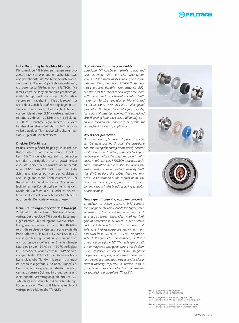
Abb. 1 – blueglobe TRI HT-EinzelteileFig. 1 – blueglobe TRI HT components
Abb. 2 – blueglobe TRI NM aus Messing verchromtFig. 2 – blueglobe TRI NM made of brass, chrome-plated
Abb. 3 – blueglobe TRI kontaktiert unrunde Kabel sicher.Fig. 3 – blueglobe TRI contacts non-round cables safely.
EMV/EMC ∙ 219
3
1
2
Hohe Dämpfung bei leichter MontageDie blueglobe TRI bietet zum einen eine pro-zesssichere, schnelle und einfache Montage und gewährleistet des Weiteren höchste Dämp-fungswerte. Dies ermöglicht das Kernelement, die patentierte TRI-Feder von PFLITSCH. Mit ihrer Geometrie sorgt sie für eine großflächige, niederohmige und langlebige 360°-Kontak-tierung zum Kabelschirm. Dies gilt sowohl für unrunde als auch für außermittig liegende Lei-tungen. In industriellen Datentechnik-Anwen-dungen bietet diese EMV-Kabelverschraubung mit über 80 dB bei 100 MHz und mit 65 db bei 1.000 MHz höchste Signalsicherheit. Zudem hat das akkreditierte Prüflabor GHMT die inno-vative blueglobe TRI-Kabelverschraubung nach Cat. 7A geprüft und zertifiziert. Direkter EMV-SchutzIst das Schirmgeflecht freigelegt, lässt sich das Kabel einfach durch die blueglobe TRI schie-ben. Die Triangelfeder legt sich sofort sicher um das Schirmgeflecht und gewährleistet ohne das Anziehen der Druckschraube bereits einen EMV-Schutz. PFLITSCH trennt damit die Schirmung mechanisch von der Abdichtung und sorgt für mehr Kontaktsicherheit. Der Kabelmantel braucht bei dieser EMV-Variante lediglich an der Kontaktstelle entfernt werden. Durch die Bauform der TRI-Feder ist ein Ver-haken im Geflecht sowohl bei der Montage als auch bei der Demontage ausgeschlossen. Neue Schirmung mit bewährtem KonzeptZusätzlich zu der sicheren EMV-Kontaktierung verfügt die blueglobe TRI über die bekannten Eigenschaften der blueglobe-Kabelverschrau-bung, wie beispielsweise den großen Dichtbe-reich, die eindeutige Kennzeichnung sowie die hohe Schutzart (IP 68 bis 15 bar bzw. IP 69) und Zugentlastung. Sie ist darüber hinaus auch als Hochtemperatur-Variante für einen Tempe-raturbereich von -55 °C bis +180 °C verfügbar. Für besonders anspruchsvolle EMV-Anwen-dungen bietet PFLITSCH die Kabelverschrau-bung blueglobe TRI NM mit einer nicht mag-netischen Triangelfeder aus CuSn6 (Bronze) an. Dank der nicht magnetischen Ausführung wer-den noch bessere Schirmdämpfungswerte und eine höhere Stromtragfähigkeit erreicht. Zu-sätzlich ist eine Variante mit Verschraubungs-körper aus dem Werkstoff Messing verchromt verfügbar: die blueglobe TRI NM/Cr.
High attenuation – easy assemblyblueglobe TRI combines reliable, quick and easy assembly with very high attenuation values. At the heart of this cable gland is the patented TRI spring from PFLITSCH. Its geo- metry ensures durable, low-resistance 360° contact with the shield over a large area, even with non-round or off-centre cables. With more than 80 dB attenuation at 100 MHz and 65 dB at 1,000 MHz, this EMC cable gland guarantees the highest level of signal reliability for industrial data technology. The accredited GHMT testing laboratory has additionally test-ed and certified the innovative blueglobe TRI cable gland for Cat. 7A applications. Direct EMC protectionOnce the braiding has been stripped, the cable can be easily pushed through the blueglobe TRI. The triangular spring immediately secures itself around the braiding, ensuring EMC pro-tection even before the pressure screw is tight-ened. In this manner, PFLITSCH provides mech- anical separation between the shield and the seal as well as greater contact reliability. With this EMC version, the cable sheathing only needs to be stripped at the contact point. The design of the TRI spring prevents it from be-coming caught in the braiding during assembly or disassembly. New type of screening – proven conceptIn addition to ensuring secure EMC contact, the blueglobe TRI also exhibits the typical char-acteristics of the blueglobe cable gland such as a large sealing range, clear marking, high type of protection (IP 68 up to 15 bar or IP 69) and good strain relief. It is furthermore avail-able as a high-temperature version for tem- peratures from –55 °C to +180 °C. For particu-larly challenging EMC applications, PFLITSCH offers the blueglobe TRI NM cable gland with a non-magnetic triangular spring made from CuSn6 (bronze). Owing to its non-magnetic properties, this spring contributes to even bet-ter screening attenuation values and a higher current-carrying capacity. A version with a gland body in chrome-plated brass can likewise be supplied: the blueglobe TRI NM/Cr.
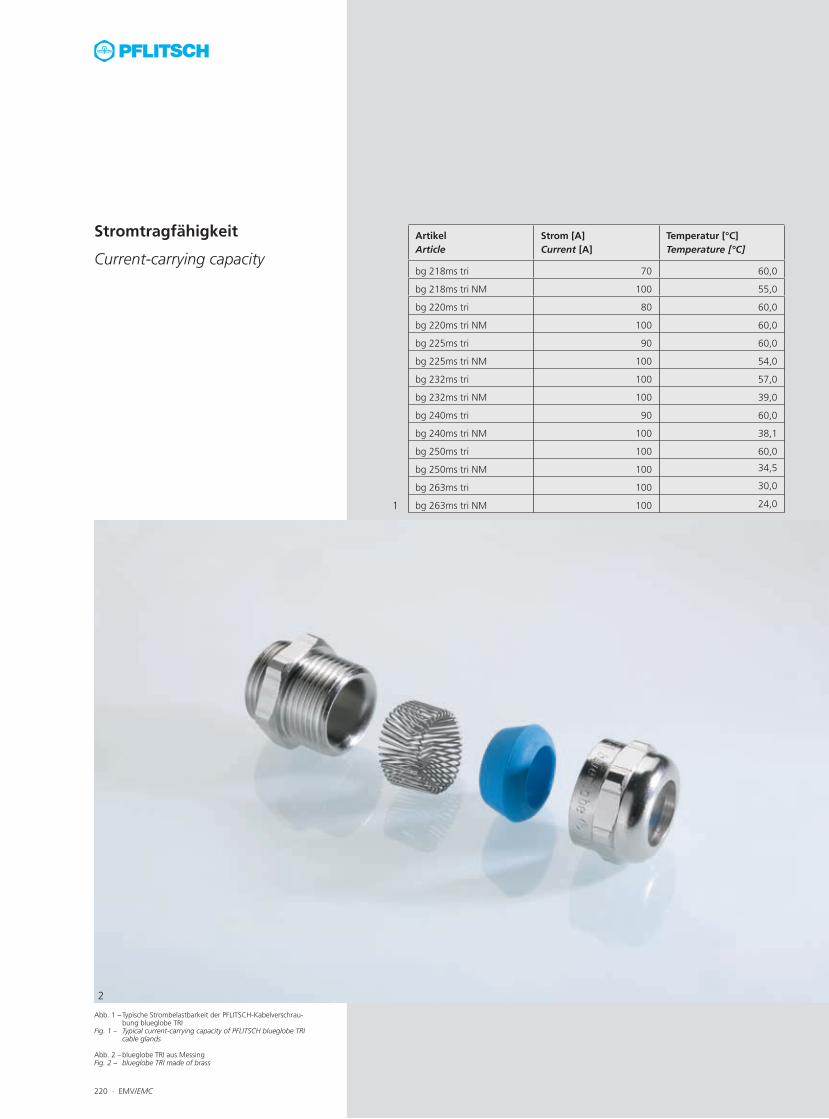
Abb. 1 – Typische Strombelastbarkeit der PFLITSCH-Kabelverschrau-bung blueglobe TRI
Fig. 1 – Typical current-carrying capacity of PFLITSCH blueglobe TRI cable glands
Abb. 2 – blueglobe TRI aus MessingFig. 2 – blueglobe TRI made of brass
220 ∙ EMV/EMC
ArtikelArticle
Strom [A]Current [A]
Temperatur [°C]Temperature [°C]
bg 218ms tri 70 60,0
bg 218ms tri NM 100 55,0
bg 220ms tri 80 60,0
bg 220ms tri NM 100 60,0
bg 225ms tri 90 60,0
bg 225ms tri NM 100 54,0
bg 232ms tri 100 57,0
bg 232ms tri NM 100 39,0
bg 240ms tri 90 60,0
bg 240ms tri NM 100 38,1
bg 250ms tri 100 60,0
bg 250ms tri NM 100 34,5
bg 263ms tri 100 30,0
bg 263ms tri NM 100 24,01
2
Stromtragfähigkeit
Current-carrying capacity

EMV/EMC ∙ 221
Beste Stromtragfähigkeit
Excellent current-carrying capacity
Neben der Schirmdämpfung ist die Strom-tragfähigkeit, also die Fähigkeit eines Bauteils, einen bestimmten Dauerstrom zu führen, ein wichtiges Kriterium bei einer EMV-Kabelver-schraubung.
Bei Fehlfunktionen, falscher Montage oder Blitzeinschlag können über den Kabelschirm und die Kabelverschraubung hohe Ströme fließen. Der Spannungsabfall an den Über-gangswiderständen einer Kabelverschraubung erzeugt aufgrund des durchfließenden Stroms auf dem Kabelschirm eine gewisse Verlust-leistung. Die dabei entstehende Wärme führt zu einem Anstieg der Temperatur der Kabel-verschraubung, die aus Berührschutzgründen +60 °C nicht übersteigen sollte. Da es für diesen Fall keine Prüfnorm gibt, hat PFLITSCH einen praxisnahen Prüfaufbau realisiert, bei dem ein ansteigender Strom bis maximal 100 Ampere auf den Kabelschirm ge-geben und die Erhöhung der Temperatur in der Kabelverschraubung bis +60 °C ermittelt wird.
Die blueglobe TRI erreicht z. B. mit einem An-schlussgewinde von M25 eine Stromtragfähig-keit von 90 A.
In addition to screening attenuation, another important criterion for any EMC cable gland is its current-carrying capacity – the ability of a component to conduct a specific continuous current.
In the event of malfunctions, incorrect assem-bly or lightning strikes, high currents can flowthrough the shield and the cable gland. The voltage drop due to the transfer resistances of a cable gland leads to power loss based on the current flowing in the shield. The heat generated from this results in a temperature in-crease at the cable gland, which should not be allowed to exceed +60 °C owing to the danger of burns on contact with the skin. In the absence of a test standard for this situ-ation, PFLITSCH has developed a practical test set-up which allows a rising current of up to 100 amperes to be applied to the shield and the temperature increase in the cable gland measured up to +60 °C.
For example, the blueglobe TRI achieves a cur-rent-carrying capacity of 90 A with an M25 connection thread.
Prüfdaten (Diagramm links)Prüfungsart: StromtragfähigkeitPrüflinge: blueglobe TRI M16 bis M63Prüfdorne: Kupfer ohne KreuzrändelungStromversorgung: EA-PS 8040-120 0 ... 40 V/0 ... 120 ATemperaturmessung: Testo 176T4
Test data (chart on the left)Test type: Current-carrying capacitySpecimens: blueglobe TRI M16 to M63Mandrel: Copper with no cross knurlingPower supply: EA-PS 8040-120
0 ... 40 V/0 ... 120 ATemperature measuring: Testo 176T4
222 ∙ EMV/EMC Technische Details und Informationen zu Zulassungen ab Seite 477For technical details and information of certifications, see f om page 477
Anschlussgewinde/ -länge
Art.-Nr. Dichtbereich Dichtbereich ohne Inlet
Dichtbereich mit Inlet
Schirm-Ø Bauhöhe Schlüssel-weite
Connection thread/length Art. no. Sealing range Sealing range without inlet
Sealing range with inlet
Shield Ø Mounting height
Spanner width
A D max./min. ø max./min. ø max./min. ø max./min. ø C SW x E
mm mm mm mm mm mm mm
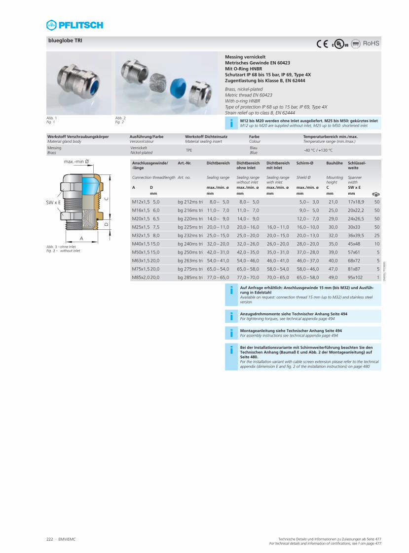
M12x1,5 5,0 bg 212ms tri 8,0 – 5,0 8,0 – 5,0 5,0 – 3,0 21,0 17x18,9 50
M16x1,5 6,0 bg 216ms tri 11,0 – 7,0 11,0 – 7,0 9,0 – 5,0 25,0 20x22,2 50
M20x1,5 6,5 bg 220ms tri 14,0 – 9,0 14,0 – 9,0 12,0 – 7,0 29,0 24x26,5 50
M25x1,5 7,5 bg 225ms tri 20,0 – 11,0 20,0 – 16,0 16,0 – 11,0 16,0 – 10,0 30,0 30x33 50
M32x1,5 8,0 bg 232ms tri 25,0 – 15,0 25,0 – 20,0 20,0 – 15,0 20,0 – 13,0 32,0 36x39,5 25
M40x1,5 15,0 bg 240ms tri 32,0 – 20,0 32,0 – 26,0 26,0 – 20,0 28,0 – 20,0 35,0 45x48 10
M50x1,5 15,0 bg 250ms tri 42,0 – 31,0 42,0 – 35,0 35,0 – 31,0 37,0 – 28,0 39,0 57x61 5
M63x1,5 20,0 bg 263ms tri 54,0 – 41,0 54,0 – 46,0 46,0 – 41,0 46,0 – 37,0 40,0 68x72 5
M75x1,5 20,0 bg 275ms tri 65,0 – 54,0 65,0 – 58,0 58,0 – 54,0 58,0 – 46,0 47,0 81x87 5
M85x2,0 20,0 bg 285ms tri 77,0 – 65,0 77,0 – 70,0 70,0 – 65,0 65,0 – 58,0 49,0 95x102 1
blueglobe TRI
Abb. 1Fig. 1
Abb. 3 – ohne InletFig. 3 – without inlet
Messing vernickeltMetrisches Gewinde EN 60423Mit O-Ring HNBRSchutzart IP 68 bis 15 bar, IP 69, Type 4XZugentlastung bis Klasse B, EN 62444 Brass, nickel-platedMetric thread EN 60423With o-ring HNBRType of protection IP 68 up to 15 bar, IP 69, Type 4XStrain relief up to class B, EN 62444
Abb. 2Fig. 2 i M12 bis M20 werden ohne Inlet ausgeliefert. M25 bis M50: gekürztes Inlet
M12 up to M20 are supplied without inlet, M25 up to M50: shortened inlet
i Auf Anfrage erhältlich: Anschlussgewinde 15 mm (bis M32) und Ausfüh-rung in EdelstahlAvailable on request: connection thread 15 mm (up to M32) and stainless steel version
i Anzugsdrehmomente siehe Technischer Anhang Seite 494For tightening torques, see technical appendix page 494
i Montageanleitung siehe Technischer Anhang Seite 494For assembly instructions see technical appendix page 494
i Bei der Installationsvariante mit Schirmweiterführung beachten Sie den Technischen Anhang (Baumaß E und Abb. 2 der Montageanleitung) auf Seite 480.For the installation variant with cable screen extension please refer to the technical appendix (dimension E and fig. 2 of the installation instructions) on page 480
Werkstoff VerschraubungskörperMaterial gland body
Ausführung/FarbeVersion/colour
Werkstoff DichteinsatzMaterial sealing insert
FarbeColour
Temperaturbereich min./max.Temperature range (min./max.)
MessingBrass
VernickeltNickel-plated
TPEBlauBlue
-40 °C / +130 °C
2660
0 | T
T038
00
RoHS
EMV/EMC ∙ 223Technische Details und Informationen zu Zulassungen ab Seite 477For technical details and information of certifications, see f om page 477
Anschlussgewinde/ -länge
Art.-Nr. Dichtbereich Dichtbereich ohne Inlet
Dichtbereich mit Inlet
Schirm-Ø Bauhöhe Schlüssel-weite
Connection thread/length
Art. no. Sealing range Sealing range without inlet
Sealing range with inlet
Shield Ø Mounting height
Spanner width
A D max./min. ø max./min. ø max./min. ø max./min. ø C SW x E
mm mm mm mm mm mm mm
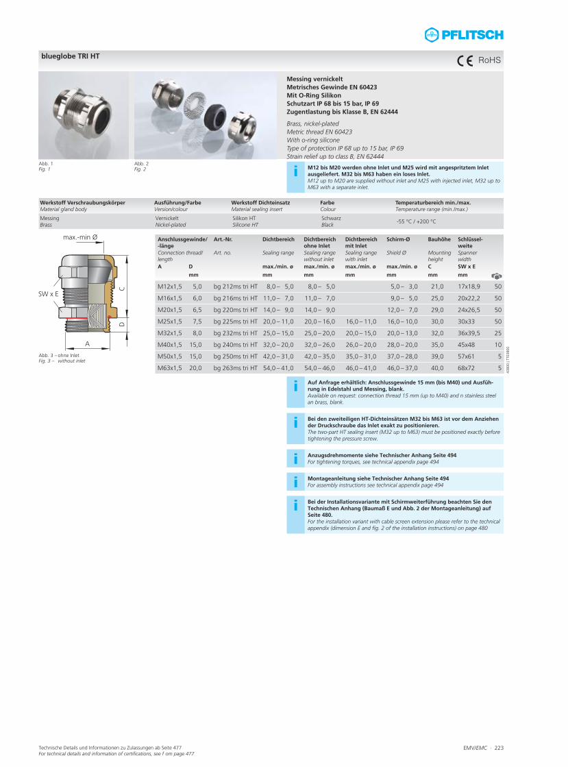
M12x1,5 5,0 bg 212ms tri HT 8,0 – 5,0 8,0 – 5,0 5,0 – 3,0 21,0 17x18,9 50
M16x1,5 6,0 bg 216ms tri HT 11,0 – 7,0 11,0 – 7,0 9,0 – 5,0 25,0 20x22,2 50
M20x1,5 6,5 bg 220ms tri HT 14,0 – 9,0 14,0 – 9,0 12,0 – 7,0 29,0 24x26,5 50
M25x1,5 7,5 bg 225ms tri HT 20,0 – 11,0 20,0 – 16,0 16,0 – 11,0 16,0 – 10,0 30,0 30x33 50
M32x1,5 8,0 bg 232ms tri HT 25,0 – 15,0 25,0 – 20,0 20,0 – 15,0 20,0 – 13,0 32,0 36x39,5 25
M40x1,5 15,0 bg 240ms tri HT 32,0 – 20,0 32,0 – 26,0 26,0 – 20,0 28,0 – 20,0 35,0 45x48 10
M50x1,5 15,0 bg 250ms tri HT 42,0 – 31,0 42,0 – 35,0 35,0 – 31,0 37,0 – 28,0 39,0 57x61 5
M63x1,5 20,0 bg 263ms tri HT 54,0 – 41,0 54,0 – 46,0 46,0 – 41,0 46,0 – 37,0 40,0 68x72 5
blueglobe TRI HT
Abb. 1Fig. 1
Abb. 3 – ohne InletFig. 3 – without inlet
Messing vernickeltMetrisches Gewinde EN 60423Mit O-Ring SilikonSchutzart IP 68 bis 15 bar, IP 69Zugentlastung bis Klasse B, EN 62444 Brass, nickel-platedMetric thread EN 60423With o-ring siliconeType of protection IP 68 up to 15 bar, IP 69Strain relief up to class B, EN 62444
Abb. 2Fig. 2 i M12 bis M20 werden ohne Inlet und M25 wird mit angespritztem Inlet
ausgeliefert. M32 bis M63 haben ein loses Inlet.M12 up to M20 are supplied without inlet and M25 with injected inlet, M32 up to M63 with a separate inlet.
i Auf Anfrage erhältlich: Anschlussgewinde 15 mm (bis M40) und Ausfüh-rung in Edelstahl und Messing, blank. Available on request: connection thread 15 mm (up to M40) and n stainless steel an brass, blank.
i Bei den zweiteiligen HT-Dichteinsätzen M32 bis M63 ist vor dem Anziehen der Druckschraube das Inlet exakt zu positionieren. The two-part HT sealing insert (M32 up to M63) must be positioned exactly before tightening the pressure screw.
i Anzugsdrehmomente siehe Technischer Anhang Seite 494For tightening torques, see technical appendix page 494
i Montageanleitung siehe Technischer Anhang Seite 494For assembly instructions see technical appendix page 494
i Bei der Installationsvariante mit Schirmweiterführung beachten Sie den Technischen Anhang (Baumaß E und Abb. 2 der Montageanleitung) auf Seite 480.For the installation variant with cable screen extension please refer to the technical appendix (dimension E and fig. 2 of the installation instructions) on page 480
Werkstoff VerschraubungskörperMaterial gland body
Ausführung/FarbeVersion/colour
Werkstoff DichteinsatzMaterial sealing insert
FarbeColour
Temperaturbereich min./max.Temperature range (min./max.)
MessingBrass
VernickeltNickel-plated
Silikon HTSilicone HT
Schwarz Black
-55 °C / +200 °C
4380
0 | T
T038
00
RoHS

224 ∙ EMV/EMC Technische Details und Informationen zu Zulassungen ab Seite 477For technical details and information of certifications, see f om page 477
Anschlussgewinde/ -länge
Art.-Nr. Dichtbereich Dichtbereich ohne Inlet
Dichtbereich mit Inlet
Schirm-Ø Bauhöhe Schlüssel-weite
Connection thread/length
Art. no. Sealing range Sealing range without inlet
Sealing range with inlet
Shield Ø Mounting height
Spanner width
A D max./min. ø max./min. ø max./min. ø max./min. ø C SW x E
mm mm mm mm mm mm mm
M12x1,5 5,0 bg 212ms triNM 8,0 – 5,0 8,0 – 5,0 5,0 – 3,0 21,0 17x18,9 50
M16x1,5 6,0 bg 216ms triNM 11,0 – 7,0 11,0 – 7,0 9,0 – 5,0 25,0 20x22,2 50
M20x1,5 6,5 bg 220ms triNM 14,0 – 9,0 14,0 – 9,0 12,0 – 7,0 29,0 24x26,5 50
M25x1,5 7,5 bg 225ms triNM 20,0 – 11,0 20,0 – 16,0 16,0 – 11,0 16,0 – 10,0 30,0 30x33 50
M32x1,5 8,0 bg 232ms triNM 25,0 – 15,0 25,0 – 20,0 20,0 – 15,0 20,0 – 13,0 32,0 36x39,5 25
M40x1,5 15,0 bg 240ms triNM 32,0 – 20,0 32,0 – 26,0 26,0 – 20,0 28,0 – 20,0 35,0 45x48 10
M50x1,5 15,0 bg 250ms triNM 42,0 – 31,0 42,0 – 35,0 35,0 – 31,0 37,0 – 28,0 39,0 57x61 5
M63x1,5 20,0 bg 263ms triNM 54,0 – 41,0 54,0 – 46,0 46,0 – 41,0 46,0 – 37,0 40,0 68x72 5
M75x1,5 20,0 bg 275ms triNM 65,0 – 54,0 65,0 – 58,0 58,0 – 54,0 58,0 – 46,0 47,0 81x87 5
M85x2,0 20,0 bg 285ms triNM 77,0 – 65,0 77,0 – 70,0 70,0 – 65,0 65,0 – 58,0 49,0 95x102 1
blueglobe TRI NM
Abb. 1Fig. 1
Abb. 3 – ohne InletFig. 3 – without inlet
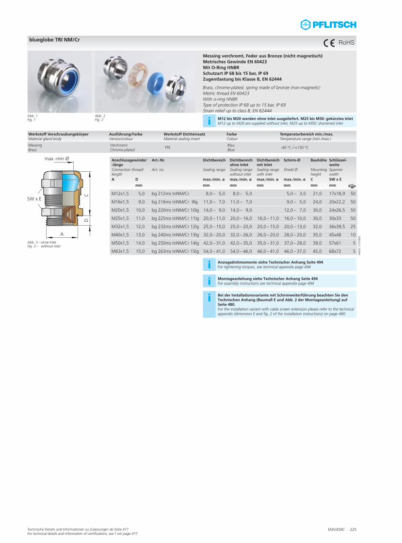
Messing vernickelt, Feder aus Bronze (nicht magnetisch)Metrisches Gewinde EN 60423Mit O-Ring HNBRSchutzart IP 68 bis 15 bar, IP 69, Type 4XZugentlastung bis Klasse B, EN 62444 Brass, nickel-plated, spring made of bronze (non-magnetic)Metric thread EN 60423With o-ring HNBRType of protection IP 68 up to 15 bar, IP 69, Type 4XStrain relief up to class B, EN 62444
Abb. 2Fig. 2 i M12 bis M20 werden ohne Inlet ausgeliefert. M25 bis M50: gekürztes Inlet
M12 up to M20 are supplied without inlet, M25 up to M50: shortened inlet
i Auf Anfrage erhältlich: Anschlussgewinde 15 mm (bis M40) und Ausfüh-rung in Edelstahl und Messing, blank. Available on request: connection thread 15 mm (up to M40) and n stainless steel an brass, blank.
i Anzugsdrehmomente siehe Technischer Anhang Seite 494For tightening torques, see technical appendix page 494
i Montageanleitung siehe Technischer Anhang Seite 494For assembly instructions see technical appendix page 494
i Bei der Installationsvariante mit Schirmweiterführung beachten Sie den Technischen Anhang (Baumaß E und Abb. 2 der Montageanleitung) auf Seite 480.For the installation variant with cable screen extension please refer to the technical appendix (dimension E and fig. 2 of the installation instructions) on page 480
Werkstoff VerschraubungskörperMaterial gland body
Ausführung/FarbeVersion/colour
Werkstoff DichteinsatzMaterial sealing insert
FarbeColour
Temperaturbereich min./max.Temperature range (min./max.)
MessingBrass
VernickeltNickel-plated
TPEBlauBlue
-40 °C / +130 °C
4550
0 | T
T038
00
RoHS
EMV/EMC ∙ 225Technische Details und Informationen zu Zulassungen ab Seite 477For technical details and information of certifications, see f om page 477
Anschlussgewinde/ -länge
Art.-Nr. Dichtbereich Dichtbereich ohne Inlet
Dichtbereich mit Inlet
Schirm-Ø Bauhöhe Schlüssel-weite
Connection thread/length
Art. no. Sealing range Sealing range without inlet
Sealing range with inlet
Shield Ø Mounting height
Spanner width
A D max./min. ø max./min. ø max./min. ø max./min. ø C SW x E
mm mm mm mm mm mm mm
M12x1,5 5,0 bg 212ms triNM/Cr 8,0 – 5,0 8,0 – 5,0 5,0 – 3,0 21,0 17x18,9 50
M16x1,5 9,0 bg 216ms triNM/Cr 9lg 11,0 – 7,0 11,0 – 7,0 9,0 – 5,0 24,0 20x22,2 50
M20x1,5 10,0 bg 220ms triNM/Cr 10lg 14,0 – 9,0 14,0 – 9,0 12,0 – 7,0 30,0 24x26,5 50
M25x1,5 11,0 bg 225ms triNM/Cr 11lg 20,0 – 11,0 20,0 – 16,0 16,0 – 11,0 16,0 – 10,0 30,0 30x33 50
M32x1,5 12,0 bg 232ms triNM/Cr 12lg 25,0 – 15,0 25,0 – 20,0 20,0 – 15,0 20,0 – 13,0 32,0 36x39,5 25
M40x1,5 13,0 bg 240ms triNM/Cr 13lg 32,0 – 20,0 32,0 – 26,0 26,0 – 20,0 28,0 – 20,0 35,0 45x48 10
M50x1,5 14,0 bg 250ms triNM/Cr 14lg 42,0 – 31,0 42,0 – 35,0 35,0 – 31,0 37,0 – 28,0 39,0 57x61 5
M63x1,5 15,0 bg 263ms triNM/Cr 15lg 54,0 – 41,0 54,0 – 46,0 46,0 – 41,0 46,0 – 37,0 45,0 68x72 5
blueglobe TRI NM/Cr
Abb. 1Fig. 1
Abb. 3 – ohne InletFig. 3 – without inlet
Messing verchromt, Feder aus Bronze (nicht magnetisch)Metrisches Gewinde EN 60423Mit O-Ring HNBRSchutzart IP 68 bis 15 bar, IP 69Zugentlastung bis Klasse B, EN 62444 Brass, chrome-plated, spring made of bronze (non-magnetic)Metric thread EN 60423With o-ring HNBRType of protection IP 68 up to 15 bar, IP 69Strain relief up to class B, EN 62444
Abb. 2Fig. 2 i M12 bis M20 werden ohne Inlet ausgeliefert. M25 bis M50: gekürztes Inlet
M12 up to M20 are supplied without inlet, M25 up to M50: shortened inlet
i Anzugsdrehmomente siehe Technischer Anhang Seite 494For tightening torques, see technical appendix page 494
i Montageanleitung siehe Technischer Anhang Seite 494For assembly instructions see technical appendix page 494
i Bei der Installationsvariante mit Schirmweiterführung beachten Sie den Technischen Anhang (Baumaß E und Abb. 2 der Montageanleitung) auf Seite 480.For the installation variant with cable screen extension please refer to the technical appendix (dimension E and fig. 2 of the installation instructions) on page 480
Werkstoff VerschraubungskörperMaterial gland body
Ausführung/FarbeVersion/colour
Werkstoff DichteinsatzMaterial sealing insert
FarbeColour
Temperaturbereich min./max.Temperature range (min./max.)
MessingBrass
VerchromtChrome-plated
TPEBlauBlue
-40 °C / +130 °C
4960
0 | T
T038
00
RoHS

226 ∙ EMV/EMC Technische Details und Informationen zu Zulassungen ab Seite 477For technical details and information of certifications, see f om page 477
Anschlussgewinde/ -länge
Art.-Nr. Dichtbereich Dichtbereich ohne Inlet
Dichtbereich mit Inlet
Schirm-Ø Bauhöhe Schlüssel-weite
Connection thread/length
Art. no. Sealing range Sealing range without inlet
Sealing range with inlet
Shield Ø Mounting height
Spanner width
A D max./min. ø max./min. ø max./min. ø max./min. ø C SW x E
mm mm mm mm mm mm mm
M18x1,5 10,0 bg 21822ms triNM/Cr 10lg 14,0 – 9,0 14,0 – 9,0 12,0 – 7,0 37,0 24x26,5 50
M24x1,5 11,0 bg 22428ms triNM/Cr 11lg 20,0 – 11,0 20,0 – 16,0 16,0 – 11,0 15,0 – 9,0 29,0 30x33 50
M30x2,0 12,0 bg 23034ms triNM/Cr 12lg 25,0 – 15,0 25,0 – 20,0 20,0 – 15,0 20,0 – 13,0 32,0 36x39,5 25
M36x2,0 13,0 bg 23642ms triNM/Cr 13lg 32,0 – 20,0 32,0 – 26,0 26,0 – 20,0 20,0 – 13,0 35,0 45x48 10
M45x2,0 14,0 bg 24542ms triNM/Cr 14lg 32,0 – 20,0 32,0 – 26,0 26,0 – 20,0 28,0 – 20,0 35,0 50x54 5
M56x2,0 15,0 bg 25652ms triNM/Cr 15lg 42,0 – 31,0 42,0 – 35,0 35,0 – 31,0 37,0 – 28,0 39,0 60x65 5
M72x2,0 16,0 bg 27265ms triNM/Cr 16lg 54,0 – 41,0 54,0 – 46,0 46,0 – 41,0 49,0 – 40,0 40,0 81x87 5
blueglobe TRI NM/Cr, Marinegewindeblueglobe TRI NM/Cr, marine thread
Abb. 1Fig. 1
Abb. 3 – ohne InletFig. 3 – without inlet
Messing verchromt, Feder aus Bronze (nicht magnetisch)Metrisches Gewinde DIN 89280 (Marine)Mit O-Ring HNBRSchutzart IP 68 bis 15 bar, IP 69Zugentlastung bis Klasse B, EN 62444 Brass, chrome-plated, spring made of bronze (non-magnetic)Metric thread DIN 89280 (marine)With o-ring HNBRType of protection IP 68 up to 15 bar, IP 69Strain relief up to class B, EN 62444
Abb. 2Fig. 2 i M18 wird ohne Inlet ausgeliefert. M24 bis M72 gekürztes Inlet
M18 is supplied without inlet, M24 up to M72: shorted inlet
i Montageanleitung siehe Technischer Anhang Seite 494For assembly instructions see technical appendix page 494
i Bei der Installationsvariante mit Schirmweiterführung beachten Sie den Technischen Anhang (Baumaß E und Abb. 2 der Montageanleitung) auf Seite 480.For the installation variant with cable screen extension please refer to the technical appendix (dimension E and fig. 2 of the installation instructions) on page 480
Werkstoff VerschraubungskörperMaterial gland body
Ausführung/FarbeVersion/colour
Werkstoff DichteinsatzMaterial sealing insert
FarbeColour
Temperaturbereich min./max.Temperature range (min./max.)
MessingBrass
VerchromtChrome-plated
TPEBlauBlue
-40 °C / +130 °C
4950
0 | T
T038
00
RoHS

EMV/EMC ∙ 227
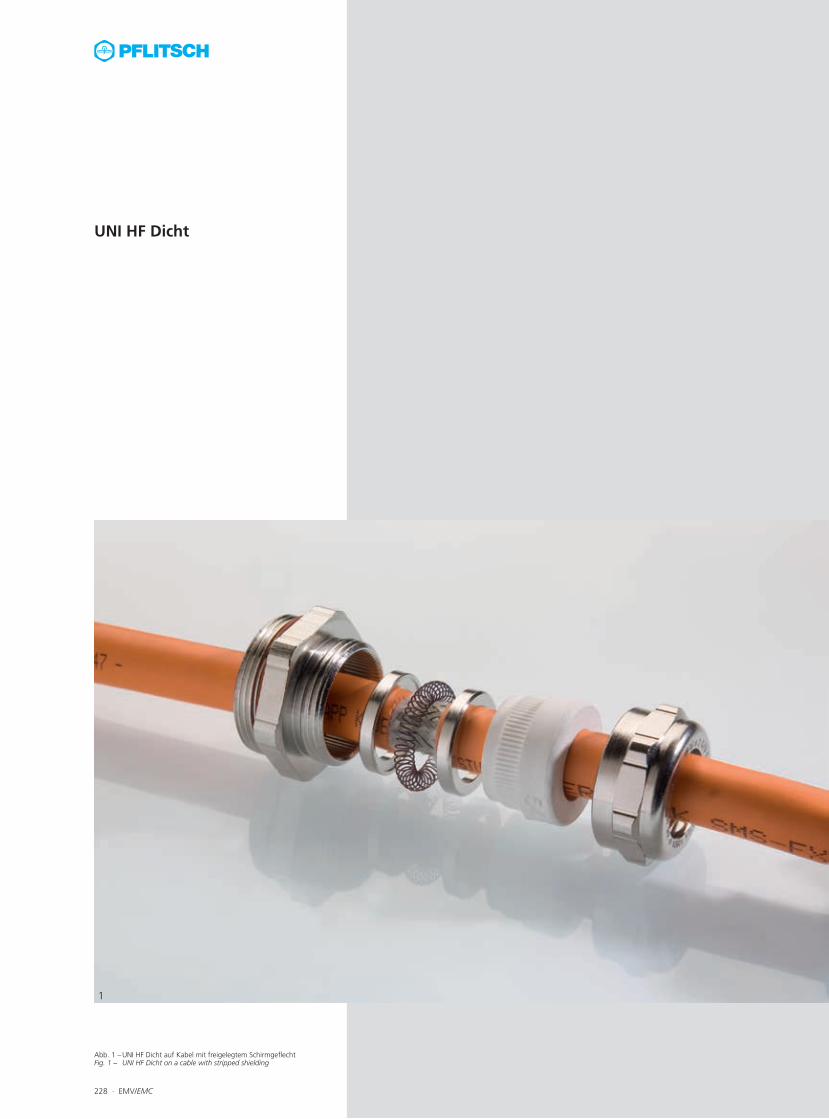
Abb. 1 – UNI HF Dicht auf Kabel mit freigelegtem Schirmgeflecht Fig. 1 – UNI HF Dicht on a cable with stripped shielding
1
UNI HF Dicht
228 ∙ EMV/EMC

Abb. 1 – UNI HF Dicht-Einzelteile Fig. 1 – UNI HF Dicht individual components
Abb. 2 – Variante AFig. 2 – Variant A
Abb. 3 – Variante BFig. 3 – Variant B
EMV/EMC ∙ 229
1
2
3
Maximale Schirmung – minimaler Platz-bedarfDie UNI HF Dicht mit innenliegender IRIS-Fe-der ist eine der kompaktesten EMV-Kabelver-schraubungen im Portfolio. Aus diesem Grund wird diese EMV-Kabelverschraubung häufig in elektromagnetischen Umgebungen mit gerin-gen Platzverhältnissen eingesetzt. Die nieder-ohmige Verbindung wird durch die 360°-Kon-taktierung der IRIS-Feder mit dem Kabelschirm gewährleistet. Umfangreiches BaukastensystemDa diese Kabelverschraubung auf Basis der UNI Dicht-Serie entwickelt wurde, kann der komplette Baukasten verwendet werden. Dies ermöglicht dem Anwender z. B. bei einem gro-ßen Anschlussgewinde auch ein kleines Kabel sicher zu kontaktieren. Sämtliche Möglichkei-ten sind im Kapitel 5 „UNI Dicht“ zu finden. FunktionsprinzipBeim Festdrehen der Druckschraube drückt der Dichteinsatz auf zwei Konenscheiben, zwischen denen die ringförmige Spiralfeder (UNI IRIS-Feder) liegt. Dieser Federring verjüngt dadurch seinen Durchmesser und wird an den vorher abisolierten blanken Leitungsschirm gepresst. Das Schirmgeflecht wird auf seinem ganzen Umfang (360°) kontaktiert (Montage-anleitung siehe Technischer Anhang). Es ent-steht eine niederohmige und niederimpedante Verbindung zwischen Schirm, UNI IRIS-Feder und Verschraubungskörper. In Abhängigkeit vom Außendurchmesser der Leitung und des Schirmes kommen zwei verschiedene Monta-gevarianten zur Anwendung:
Variante A: abgesetzter AußenmantelDer Außenmantel der Leitung muss vom Lei-tungsende her so weit entfernt werden, dass die UNI IRIS-Feder auf dem blanken Schirm aufliegt. Der Dichteinsatz soll bei seiner end-gültigen Lage noch in voller Länge auf dem Außenmantel liegen.
Variante B: durchgängiger AußenmantelDer Außenmantel wird in Form eines Ringes nur an der Stelle entfernt, wo sich die endgül-tige Lage der UNI IRIS-Feder in der Kabelver-schraubung befindet. Der Außenmantel kann hinter der Kontaktstelle weitergeführt werden.
Maximum shielding – minimum space re-quirementsThe UNI HF Dicht with an internal IRIS spring is one of the most compact EMC cable glands in the portfolio. For this reason, it is often used in electromagnetic environments when condi-tions are cramped. A low-resistance connec-tion is ensured by the 360° contact between the IRIS spring and the cable shield. Comprehensive modular systemSince this cable gland was developed based on the UNI Dicht series, the complete modular system can be used. Even small cables can thus be reliably bonded, for instance, with a large connection thread. For a detailed description of the options which are available, see chapter 5 “UNI Dicht”. Functional principleWhen the pressure screw is tightened, the sealing insert presses onto two cones, between which the annular spiral spring (UNI IRIS spring) is located. This spring washer tapers as a re-sult and is reliably pressed against the stripped cable shield. The shield is bonded around its entire circumference (360°) (see technical ap-pendix for assembly instructions). A low-resist-ance and low-impedance connection is made between the shield, the UNI IRIS spring and the gland body. Two different assembly methods are used depending on the outer diameter of the cable and the shield:
Variant A: Offset outer sheathThe outer sheath must be stripped from the end of the cable sufficiently far for the UNI IRIS spring to rest on the non-insulated shield. In its final position, the whole length of the sealing insert should still be lying on the outer sheath.
Variant B: Continuous outer sheathA narrow ring of the outer sheath is removed precisely where the UNI IRIS spring will ultim- ately be located on the cable gland. The outer sheath can continue after this contact point.

230 ∙ EMV/EMC Technische Details und Informationen zu Zulassungen ab Seite 477For technical details and information of certifications, see f om page 477
Anschlussgewinde/-län-ge
Art.-Nr. Dichtbereich Schirm-Ø Variante Bauhöhe Schlüsselweite
Connection thread/length Art. no. Sealing range Shield Ø Variant Mounting height
Spanner width
Ausführung bitte ergänzen Please complete product details
TPE =A D TPE-V = p max./min. ø max./min. ø C SW1 x E1/SW2 x E2
mm Silikon HT/Silicone HT = H mm mm mm mm
M16x1,5 6,0 21650 07S00 6,5 – 4,0 4,0 – 1,5 A 20,0 18x20/17x18,9 50
21650 07S01 6,5 – 4,0 6,0 – 2,5 B 20,0 18x20/17x18,9 50
21650 08S01 8,0 – 5,0 6,0 – 2,5 A 20,0 18x20/17x18,9 50
21650 09S01 9,5 – 6,5 6,0 – 2,5 A 20,0 18x20/17x18,9 50
M20x1,5 6,5 22051 07S01 6,5 – 4,0 6,0 – 2,5 B 20,0 22x24,4/20x22,2 50
22051 08S03 8,0 – 5,0 8,0 – 3,0 B 20,0 22x24,4/20x22,2 50
22051 09S03 9,5 – 6,5 8,5 – 3,5 A 20,0 22x24,4/20x22,2 50
22051 11S03 10,5 – 7,0 8,5 – 3,5 A 20,0 22x24,4/20x22,2 50
22052 08S04 8,0 – 5,0 8,0 – 3,5 B 21,0 22x24,4 50
22052 09S02 9,5 – 6,5 6,5 – 3,5 A 21,0 22x24,4 50
22052 09S04 9,5 – 6,5 8,0 – 3,5 A 21,0 22x24,4 50
22052 11S04 10,5 – 7,0 8,0 – 3,5 A 21,0 22x24,4 50
22052 11S05 10,5 – 7,0 10,5 – 6,5 B 21,0 22x24,4 50
22052 13S05 13,0 – 9,0 10,5 – 6,5 A 21,0 22x24,4 50
M25x1,5 7,5 22553 07S03 6,5 – 4,0 8,0 – 3,0 B 21,0 28x31,2/24x26,7 50
22553 09S03 9,5 – 6,5 8,0 – 3,0 A 21,0 28x31,2/24x26,7 50
22553 09S05 9,5 – 6,5 10,5 – 6,5 B 21,0 28x31,2/24x26,7 50
22553 11S04 10,5 – 7,0 8,0 – 5,0 A 21,0 28x31,2/24x26,7 50
22553 11S05 10,5 – 7,0 10,5 – 6,5 B 21,0 28x31,2/24x26,7 50
22553 13S04 13,0 – 9,0 8,0 – 5,0 A 21,0 28x31,2/24x26,7 50
22553 13S05 13,0 – 9,0 10,5 – 6,5 A 21,0 28x31,2/24x26,7 50
M32x1,5 8,0 23254 13S05 13,0 – 9,0 9,5 – 4,5 A 25,0 35x38,5/30x33,5 25
23254 13S07 13,0 – 9,0 12,0 – 7,0 B 25,0 35x38,5/30x33,5 25
23254 13S08 13,0 – 9,0 13,5 – 8,0 B 25,0 35x38,5/30x33,5 25
23254 16S08 15,5 – 11,5 13,5 – 8,0 A 25,0 35x38,5/30x33,5 25
23254 16S09 15,5 – 11,5 14,5 – 9,0 B 25,0 35x38,5/30x33,5 25
23254 18S09 18,0 – 14,0 14,5 – 9,0 A 25,0 35x38,5/30x33,5 25
M40x1,5 8,0 24055 16S10 15,5 – 11,5 17,0 – 13,0 B 27,0 43x47,3/40x43,5 10
24055 18S10 18,0 – 14,0 17,0 – 13,0 A 27,0 43x47,3/40x43,5 10
24055 18S18 18,0 – 14,0 18,0 – 13,0 B 27,0 43x47,3/40x43,5 10
24055 20S18 20,5 – 17,0 18,0 – 13,0 A 27,0 43x47,3/40x43,5 10
24055 20S19 20,5 – 17,0 20,0 – 15,0 B 27,0 43x47,3/40x43,5 10
24055 25S19 25,0 – 20,0 20,0 – 15,0 A 27,0 43x47,3/40x43,5 10
UNI HF Dicht
Abb. 1Fig. 1
Abb. 3 – Variante A: abgesetzter AußenmantelFig. 3 – Variant A: offset outer sheath
Abb. 4 – Variante B: durchgängiger AußenmantelFig. 4 – Variant B: continuous outer sheath
Messing vernickeltMetrisches Anschlussgewinde EN 60423Mit O-Ring HNBRSchutzart IP 68 bis 10 bar, Type 4XZugentlastung bis Klasse A, EN 62444 Brass, nickel-platedMetric connection thread EN 60423With o-ring HNBRType of protection IP 68 up to 10 bar, Type 4XStrain relief up to class A, EN 62444
Abb. 2Fig. 2 i Gewinde-Varianten: Standard-Maß D = Art.-Nr. 22052...
15 mm Länge = Art.-Nr. 82052...Thread variants: Standard size D = art. no. 22052... 15 mm length = art. no. 82052...
Fortsetzung auf der nächsten Seite Continued on next page ►
Werkstoff VerschraubungskörperMaterial gland body
Ausführung/FarbeVersion/colour
Werkstoff DichteinsatzMaterial sealing insert
FarbeColour
BestellschlüsselArt. no. supplement
Temperaturbereich min./max.Temperature range (min./max.)
MessingBrass
VernickeltNickel-plated
TPEs. FCs. CC
-40 °C / +130 °C
MessingBrass
VernickeltNickel-plated
TPE-VNaturNatural
p -40 °C / +135 °C
MessingBrass
VernickeltNickel-plated
Silikon HTSilicone HT
Schwarz Black
H -55 °C / +200 °C
2400
0 | T
T029
00
RoHS

EMV/EMC ∙ 231Technische Details und Informationen zu Zulassungen ab Seite 477For technical details and information of certifications, see f om page 477
Anschlussgewin-de/-länge
Art.-Nr. Dichtbereich Schirm-Ø Variante Bauhöhe Schlüsselweite
Connection thread/length
Art. no. Sealing range Shield Ø Variant Mounting height
Spanner width
Ausführung bitte ergänzen Please complete product details
TPE =A D TPE-V = p max./min. ø max./min. ø C SW1 x E1/SW2 x E2
mm Silikon HT/Silicone HT = H mm mm mm mm
M50x1,5 10,0 25056 28S13 28,0 – 24,0 25,0 – 18,5 A 28,0 54x58/50x54 5
25056 32S15 32,0 – 27,0 30,5 – 24,0 B 28,0 54x58/50x54 5
25056 34S15 34,0 – 29,0 30,5 – 24,0 A 28,0 54x58/50x54 5
25056 36S15 36,0 – 32,0 30,5 – 24,0 A 28,0 54x58/50x54 5
25057 38S20 * 38,0 – 33,0 39,0 – 34,0 B 30,0 57x61 5
25057 40S20 * 40,0 – 36,0 39,0 – 34,0 A 30,0 57x61 5
M63x1,5 10,0 26358 44S21 * 44,0 – 39,0 38,0 – 33,0 A 30,0 68x74/64x69 5
M75x1,5 15,0 275212 47S22 * 47,0 – 42,0 48,0 – 39,0 B 47,0 81x87 1
275212 252S22 * 52,0 – 45,0 48,0 – 39,0 A 47,0 81x87 1
275212 55S22 * 55,0 – 51,0 48,5 – 42,0 A 47,0 81x87 1
275212 58S23 * 58,0 – 54,0 54,0 – 47,0 A 47,0 81x87 1
275300 64S23 * 64,0 – 58,0 54,0 – 47,0 A 60,0 95x102 1
M80x2,0 15,0 280300 64S23 * 64,0 – 58,0 54,0 – 47,0 A 60,0 95x102 1
280300 70S23 * 70,0 – 63,0 54,0 – 47,0 A 60,0 95x102 1
* Sealing insert silicone HT not available * Dichteinsatz aus Silikon HT nicht lieferbar
UNI HF Dicht
i UL-Zulassung nur in Verbindung mit TPE-V-DichteinsätzenUL certification only in combination with sealing inserts made of TPE-
i Ausführung in Edelstahl auf Anfrage Stainless steel version on request
i Montageanleitung siehe Technischer Anhang Seite 495For assembly instructions see technical appendix page 495
Fortsetzung von vorheriger Seite Continued from previous page ◄
2400
0 | T
T029
00
232 ∙ EMV/EMC Technische Details und Informationen zu Zulassungen ab Seite 477For technical details and information of certifications, see f om page 477
Anschlussgewinde/-länge Art.-Nr. Dichtbereich Schirm-Ø Variante Bauhöhe SchlüsselweiteConnection thread/length Art. no. Sealing range Shield Ø Variant Mounting height Spanner width
Ausführung bitte ergänzen Please complete product details
TPE =A D TPE-V = p max./min. ø max./min. ø C SW x E
mm Silikon HT/Silicone HT = H mm mm mm mm
M12x1,5 5,0 21250 07S01 6,5 – 4,0 6,0 – 2,5 B 27,0 17x18,9 50
21250 08S01 8,0 – 5,0 6,0 – 2,5 A 27,0 17x18,9 50
21250 09S01 9,5 – 6,5 6,0 – 2,5 A 27,0 17x18,9 50
M16x1,5 6,0 21651 07S01 6,5 – 4,0 6,5 – 2,5 B 27,0 20x22,2 50
21651 09S03 9,5 – 6,5 8,5 – 3,5 A 28,0 20x22,2 50
21651 11S03 10,5 – 7,0 8,5 – 3,5 A 28,0 20x22,2 50
21652 11S05 10,5 – 7,0 10,5 – 6,5 B 29,0 22x24,4 50
21652 13S05 13,0 – 9,0 10,5 – 6,5 A 29,0 22x24,4 50
M20x1,5 6,5 22053 13S05 13,0 – 9,0 10,5 – 6,5 A 29,0 24x26,7 50
22054 13S07 13,0 – 9,0 12,0 – 7,0 B 35,0 30x33,5 25
M25x1,5 6,5 22554 13S07 13,0 – 9,0 12,0 – 7,0 A 35,0 30x33,5 25
22554 13S08 13,0 – 9,0 13,5 – 8,0 B 35,0 30x33,5 25
22554 16S08 15,5 – 11,5 13,5 – 8,0 A 35,0 30x33,5 25
22554 16S09 15,5 – 11,5 14,5 – 9,5 A/B 35,0 30x33,5 25
22554 18S09 18,0 – 14,0 14,5 – 9,0 A 35,0 30x33,5 25
M32x1,5 8,0 23255 18S10 18,0 – 14,0 17,0 – 13,0 B 38,0 40x43,5 10
23255 20S18 20,5 – 17,0 18,0 – 13,0 A 38,0 40x43,5 10
23255 25S19 25,0 – 20,0 20,0 – 15,0 A 38,0 40x43,5 10
M40x1,5 8,0 24056 25S13 25,0 – 20,0 25,5 – 18,5 B 39,0 50x54 10
24056 28S13 28,0 – 24,0 25,5 – 18,5 A 39,0 50x54 10
24056 28S15 28,0 – 24,0 30,5 – 24,0 B 39,0 50x54 10
24056 32S15 32,0 – 27,0 30,5 – 24,0 B 39,0 50x54 10
24056 34S15 34,0 – 29,0 30,5 – 24,0 A 39,0 50x54 10
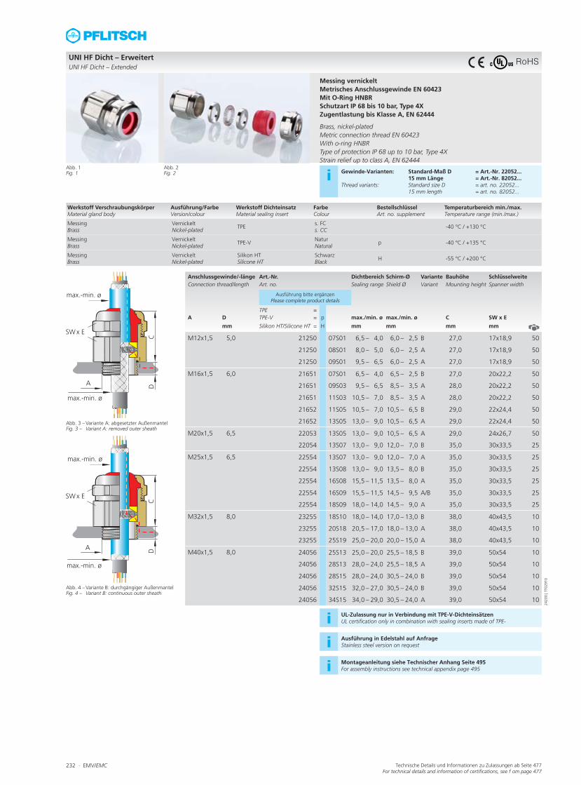
UNI HF Dicht – ErweitertUNI HF Dicht – Extended
Abb. 1Fig. 1
Abb. 3 – Variante A: abgesetzter AußenmantelFig. 3 – Variant A: removed outer sheath
Abb. 4 – Variante B: durchgängiger AußenmantelFig. 4 – Variant B: continuous outer sheath
Messing vernickeltMetrisches Anschlussgewinde EN 60423Mit O-Ring HNBRSchutzart IP 68 bis 10 bar, Type 4XZugentlastung bis Klasse A, EN 62444 Brass, nickel-platedMetric connection thread EN 60423With o-ring HNBRType of protection IP 68 up to 10 bar, Type 4XStrain relief up to class A, EN 62444
Abb. 2Fig. 2 i Gewinde-Varianten: Standard-Maß D = Art.-Nr. 22052...
15 mm Länge = Art.-Nr. 82052...Thread variants: Standard size D = art. no. 22052... 15 mm length = art. no. 82052...
i UL-Zulassung nur in Verbindung mit TPE-V-DichteinsätzenUL certification only in combination with sealing inserts made of TPE-
i Ausführung in Edelstahl auf Anfrage Stainless steel version on request
i Montageanleitung siehe Technischer Anhang Seite 495For assembly instructions see technical appendix page 495
Werkstoff VerschraubungskörperMaterial gland body
Ausführung/FarbeVersion/colour
Werkstoff DichteinsatzMaterial sealing insert
FarbeColour
BestellschlüsselArt. no. supplement
Temperaturbereich min./max.Temperature range (min./max.)
MessingBrass
VernickeltNickel-plated
TPEs. FCs. CC
-40 °C / +130 °C
MessingBrass
VernickeltNickel-plated
TPE-VNaturNatural
p -40 °C / +135 °C
MessingBrass
VernickeltNickel-plated
Silikon HTSilicone HT
Schwarz Black
H -55 °C / +200 °C
2420
0 | T
T029
10
RoHS

EMV/EMC ∙ 233Technische Details und Informationen zu Zulassungen ab Seite 477For technical details and information of certifications, see f om page 477
Anschlussgewinde/-länge Art.-Nr. Dichtbereich Schirm-Ø Variante Bauhöhe SchlüsselweiteConnection thread/length Art. no. Sealing range Shield Ø Variant Mounting height Spanner width
Ausführung bitte ergänzen Please complete product details
TPE =A D TPE-V = p max./min. ø max./min. ø C SW x E
mm Silikon HT/Silicone HT = H mm mm mm mm
Pg 9 6,0 150 07S00 6,5 – 4,0 4,0 – 1,5 A 20,0 17x18,9 50
150 07S01 6,5 – 4,0 6,0 – 2,5 B 20,0 17x18,9 50
150 08S01 8,0 – 5,0 6,0 – 2,5 A 20,0 17x18,9 50
150 09S01 9,5 – 6,5 6,0 – 2,5 A 20,0 17x18,9 50
Pg 11 6,0 151 07S01 6,5 – 4,0 6,0 – 2,5 B 20,0 20x22,2 50
151 07S03 6,5 – 4,0 8,5 – 3,5 B 20,0 20x22,2 50
151 08S01 8,0 – 5,0 6,0 – 2,5 A 20,0 20x22,2 50
151 08S03 8,0 – 5,0 8,5 – 3,5 B 20,0 20x22,2 50
151 09S01 9,5 – 6,5 6,0 – 2,5 A 20,0 20x22,2 50
151 09S03 9,5 – 6,5 8,5 – 3,5 A 20,0 20x22,2 50
151 11S03 10,5 – 7,0 8,5 – 3,5 A 20,0 20x22,2 50
Pg 13,5 6,5 152 07S02 6,5 – 4,0 6,5 – 3,5 B 21,0 22x24,4 50
152 08S04 8,0 – 5,0 8,0 – 3,5 B 21,0 22x24,4 50
152 09S02 9,5 – 6,5 6,5 – 3,5 A 21,0 22x24,4 50
152 09S04 9,5 – 6,5 8,0 – 3,5 A 21,0 22x24,4 50
152 09S05 9,5 – 6,5 8,0 – 3,5 B 21,0 22x24,4 50
152 11S04 10,5 – 7,0 8,0 – 3,5 A 21,0 22x24,4 50
152 11S05 10,5 – 7,0 10,5 – 6,5 B 21,0 22x24,4 50
152 13S05 13,0 – 9,0 10,5 – 6,5 A 21,0 22x24,4 50
Pg 16 6,5 153 09S03 9,5 – 6,5 8,0 – 3,0 A 25,0 24x26,7 50
153 11S04 10,5 – 7,0 8,0 – 5,0 A 25,0 24x26,7 50
153 11S05 10,5 – 7,0 10,5 – 6,5 B 25,0 24x26,7 50
153 13S04 13,0 – 9,0 8,0 – 5,0 A 25,0 24x26,7 50
153 13S05 13,0 – 9,0 10,5 – 6,5 A 25,0 24x26,7 50
Pg 21 7,0 154 11S05 10,5 – 7,0 9,5 – 4,5 A 25,0 30x33,5 25
154 11S07 10,5 – 7,0 12,0 – 5,5 B 25,0 30x33,5 25
154 13S05 13,0 – 9,0 9,5 – 4,5 A 25,0 30x33,5 25
154 13S07 13,0 – 9,0 12,0 – 7,0 A 25,0 30x33,5 25
154 13S08 13,0 – 9,0 13,5 – 8,0 B 25,0 30x33,5 25
154 16S08 15,5 – 11,5 13,5 – 8,0 A 25,0 30x33,5 25
154 16S09 15,5 – 11,5 14,5 – 9,0 B 25,0 30x33,5 25
154 18S09 18,0 – 14,0 14,5 – 9,0 A 25,0 30x33,5 25
UNI HF Dicht, Pg UNI HF Dicht, Pg
Abb. 1Fig. 1
Abb. 3 – Variante A: abgesetzter AußenmantelFig. 3 – Variant A: removed outer sheath
Abb. 4 – Variante B: durchgängiger AußenmantelFig. 4 – Variant B: continuous outer sheath
Messing vernickeltPg-AnschlussgewindeMit O-Ring HNBRSchutzart IP 68 bis 10 barZugentlastung bis Klasse A, EN 62444 Brass, nickel-platedPg connection threadWith o-ring HNBRType of protection IP 68 up to 10 barStrain relief up to class A, EN 62444
Abb. 2Fig. 2 i Gewinde-Varianten: Standard-Maß D = Art.-Nr. 15...
15 mm Länge = Art.-Nr. 18...Thread variants: Standard size D = art. no. 15... 15 mm length = art. no. 18...
Fortsetzung auf der nächsten Seite Continued on next page ►
Werkstoff VerschraubungskörperMaterial gland body
Ausführung/FarbeVersion/colour
Werkstoff DichteinsatzMaterial sealing insert
FarbeColour
BestellschlüsselArt. no. supplement
Temperaturbereich min./max.Temperature range (min./max.)
MessingBrass
VernickeltNickel-plated
TPEs. FCs. CC
-40 °C / +130 °C
MessingBrass
VernickeltNickel-plated
TPE-VNaturNatural
p -40 °C / +135 °C
MessingBrass
VernickeltNickel-plated
Silikon HTSilicone HT
Schwarz Black
H -55 °C / +200 °C
2430
0 | T
T029
10
RoHS
Anschlussgewinde/-länge Art.-Nr. Dichtbereich Schirm-Ø Variante Bauhöhe SchlüsselweiteConnection thread/length Art. no. Sealing range Shield Ø Variant Mounting
heightSpanner width
Ausführung bitte ergänzen Please complete product details
TPE =A D TPE-V = p max./min. ø max./min. ø C SW x E
mm Silikon HT/Silicone HT = H mm mm mm mm
Pg 29 8,0 155 18S10 18,0 – 14,0 17,0 – 13,0 A 27,0 40x43,5 10
155 18S18 18,0 – 14,0 18,0 – 13,0 B 27,0 40x43,5 10
155 20S18 20,5 – 17,0 18,0 – 13,0 A 27,0 40x43,5 10
155 20S19 20,5 – 17,0 20,0 – 15,0 B 27,0 40x43,5 10
155 25S18 25,0 – 20,0 18,0 – 13,0 A 27,0 40x43,5 10
155 25S19 25,0 – 20,0 20,0 – 15,0 A 27,0 40x43,5 10
Pg 36 9,0 156 28S13 28,0 – 24,0 25,5 – 18,5 A 28,0 50x54 10
156 32S15 32,0 – 27,0 30,5 – 24,0 B 28,0 50x54 10
156 34S15 34,0 – 29,0 30,5 – 24,0 A 28,0 50x54 10
Pg 42 10,0 157 38S20 * 38,0 – 34,0 39,0 – 34,0 B 30,0 57x61 5
157 40S20 * 40,0 – 36,0 39,0 – 34,0 A 30,0 57x61 5
Pg 48 10,0 158 44S21 * 44,0 – 39,0 38,0 – 33,0 A 30,0 64x69 5
* Sealing insert silicone HT not available * Dichteinsatz aus Silikon HT nicht lieferbar
UNI HF Dicht, Pg UNI HF Dicht, Pg
i Ausführung in Edelstahl auf Anfrage Stainless steel version on request
i Montageanleitung siehe Technischer Anhang Seite 495For assembly instructions see technical appendix page 495
Fortsetzung von vorheriger Seite Continued from previous page ◄
2430
0 | T
T029
10
234 ∙ EMV/EMC Technische Details und Informationen zu Zulassungen ab Seite 477For technical details and information of certifications, see f om page 477
EMV/EMC ∙ 235Technische Details und Informationen zu Zulassungen ab Seite 477For technical details and information of certifications, see f om page 477
Anschlussgewinde/-länge Art.-Nr. Dichtbereich Schirm-Ø Variante Bauhöhe SchlüsselweiteConnection thread/length Art. no. Sealing range Shield Ø Variant Mounting
heightSpanner width
Ausführung bitte ergänzen Please complete product details
TPE =A D TPE-V = p max./min. ø max./min. ø C SW x E
mm Silikon HT/Silicone HT = H mm mm mm mm
Pg 7 5,0 14950 07S00 6,5 – 4,0 4,0 – 1,5 A 27,0 17x18,9 50
14950 07S01 6,5 – 4,0 6,0 – 2,5 B 27,0 17x18,9 50
14950 08S01 8,0 – 5,0 6,0 – 2,5 A 27,0 17x18,9 50
14950 09S01 9,5 – 6,5 6,0 – 2,5 A 27,0 17x18,9 50
Pg 9 6,0 15051 09S01 9,5 – 6,5 6,0 – 2,5 A 28,0 20x22,2 50
15051 09S03 9,5 – 6,5 8,5 – 3,5 A 28,0 20x22,2 50
15051 11S03 10,5 – 7,0 8,5 – 3,5 A 28,0 20x22,2 50
Pg 11 6,0 15152 11S03 10,5 – 7,0 8,5 – 4,5 B 29,0 22x24,4 50
15152 11S05 10,5 – 7,0 10,5 – 6,5 B 29,0 22x24,4 50
15152 13S05 13,0 – 9,0 10,5 – 6,5 A 29,0 22x24,4 50
Pg 16 6,5 15354 13S07 13,0 – 9,0 12,0 – 7,0 A 35,0 30x33,5 25
15354 16S08 15,5 – 11,5 13,5 – 8,0 A 35,0 30x33,5 25
15354 16S09 15,5 – 11,5 14,5 – 9,0 A/B 35,0 30x33,5 25
15354 18S09 18,0 – 14,0 14,5 – 9,0 A 35,0 30x33,5 25
Pg 21 7,0 15455 18S10 18,0 – 14,0 17,0 – 13,0 A/B 38,0 40x43,5 10
15455 18S18 18,0 – 14,0 18,0 – 13,0 B 38,0 40x43,5 10
15455 20S10 20,5 – 17,0 17,0 – 13,0 A 38,0 40x43,5 10
15455 20S18 20,5 – 17,0 18,0 – 13,0 A 38,0 40x43,5 10
15455 20S19 20,5 – 17,0 20,0 – 15,0 B 38,0 40x43,5 10
15455 25S19 25,0 – 20,0 20,0 – 15,0 A 38,0 40x43,5 10
Pg 29 8,0 15556 25S13 25,0 – 20,0 25,5 – 18,5 B 39,0 50x54 10
15556 28S13 28,0 – 24,0 25,5 – 18,5 A 39,0 50x54 10
15556 32S15 32,0 – 27,0 30,5 – 24,0 A 39,0 50x54 10
15556 34S15 34,0 – 29,0 30,5 – 24,0 A 39,0 50x54 10
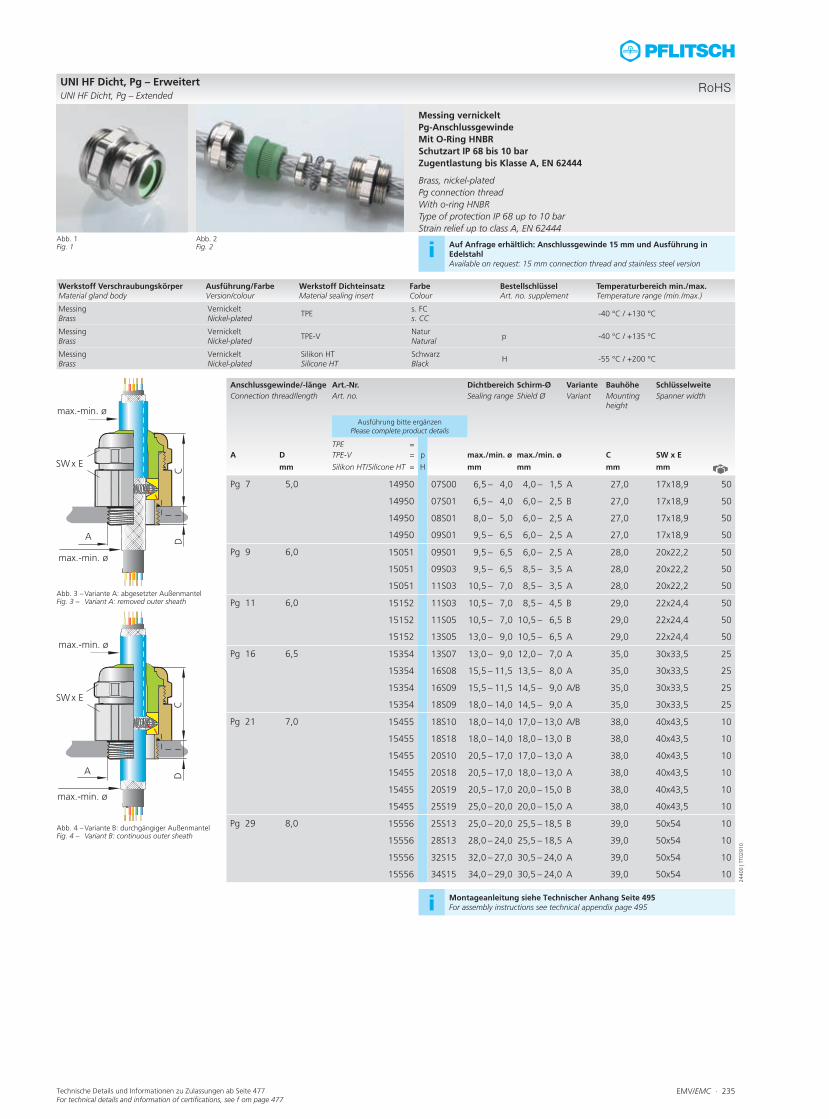
UNI HF Dicht, Pg – ErweitertUNI HF Dicht, Pg – Extended
Abb. 1Fig. 1
Abb. 3 – Variante A: abgesetzter AußenmantelFig. 3 – Variant A: removed outer sheath
Abb. 4 – Variante B: durchgängiger AußenmantelFig. 4 – Variant B: continuous outer sheath
Messing vernickeltPg-AnschlussgewindeMit O-Ring HNBRSchutzart IP 68 bis 10 barZugentlastung bis Klasse A, EN 62444 Brass, nickel-platedPg connection threadWith o-ring HNBRType of protection IP 68 up to 10 barStrain relief up to class A, EN 62444
Abb. 2Fig. 2 i Auf Anfrage erhältlich: Anschlussgewinde 15 mm und Ausführung in
EdelstahlAvailable on request: 15 mm connection thread and stainless steel version
i Montageanleitung siehe Technischer Anhang Seite 495For assembly instructions see technical appendix page 495
Werkstoff VerschraubungskörperMaterial gland body
Ausführung/FarbeVersion/colour
Werkstoff DichteinsatzMaterial sealing insert
FarbeColour
BestellschlüsselArt. no. supplement
Temperaturbereich min./max.Temperature range (min./max.)
MessingBrass
VernickeltNickel-plated
TPEs. FCs. CC
-40 °C / +130 °C
MessingBrass
VernickeltNickel-plated
TPE-VNaturNatural
p -40 °C / +135 °C
MessingBrass
VernickeltNickel-plated
Silikon HTSilicone HT
Schwarz Black
H -55 °C / +200 °C
2440
0 | T
T029
10
RoHS

Abb. 1 – UNI IRIS EMV Dicht auf Kabel mit freigelegtem SchirmgeflechtFig. 1 – UNI IRIS EMC Dicht on a cable with stripped shielding
1
UNI IRIS EMV Dicht
UNI IRIS EMC Dicht
236 ∙ EMV/EMC
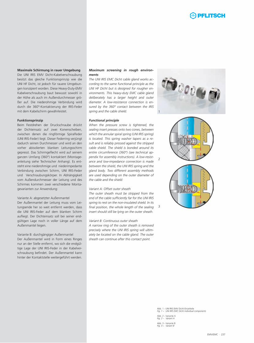
Abb. 1 – UNI IRIS EMV Dicht-Einzelteile Fig. 1 – UNI IRIS EMC Dicht individual components
Abb. 2 – Variante AFig. 2 – Variant A
Abb. 3 – Variante BFig. 3 – Variant B
EMV/EMC ∙ 237
1
2
3
Maximale Schirmung in rauer Umgebung Die UNI IRIS EMV Dicht-Kabelverschraubung besitzt das gleiche Funktionsprinzip wie die UNI HF Dicht, ist jedoch für rauere Umgebun-gen konzipiert worden. Diese Heavy-Duty-EMV Kabelverschraubung baut bewusst sowohl in der Höhe als auch im Außendurchmesser grö-ßer auf. Die niederohmige Verbindung wird durch die 360°-Kontaktierung der IRIS-Feder mit dem Kabelschirm gewährleistet. FunktionsprinzipBeim Festdrehen der Druckschraube drückt der Dichteinsatz auf zwei Konenscheiben, zwischen denen die ringförmige Spiralfeder (UNI IRIS-Feder) liegt. Dieser Federring verjüngt dadurch seinen Durchmesser und wird an den vorher abisolierten blanken Leitungsschirm gepresst. Das Schirmgeflecht wird auf seinem ganzen Umfang (360°) kontaktiert (Montage-anleitung siehe Technischer Anhang). Es ent-steht eine niederohmige und niederimpedante Verbindung zwischen Schirm, UNI IRIS-Feder und Verschraubungskörper. In Abhängigkeit vom Außendurchmesser der Leitung und des Schirmes kommen zwei verschiedene Monta-gevarianten zur Anwendung:
Variante A: abgesetzter AußenmantelDer Außenmantel der Leitung muss vom Lei-tungsende her so weit entfernt werden, dass die UNI IRIS-Feder auf dem blanken Schirm aufliegt. Der Dichteinsatz soll bei seiner end-gültigen Lage noch in voller Länge auf dem Außenmantel liegen.
Variante B: durchgängiger AußenmantelDer Außenmantel wird in Form eines Ringes nur an der Stelle entfernt, wo sich die endgül-tige Lage der UNI IRIS-Feder in der Kabelver-schraubung befindet. Der Außenmantel kann hinter der Kontaktstelle weitergeführt werden.
Maximum screening in rough environ-ments The UNI IRIS EMC Dicht cable gland works ac-cording to the same functional principle as the UNI HF Dicht but is designed for rougher en-vironments. This heavy-duty EMC cable gland deliberately has a larger height and outer diameter. A low-resistance connection is en-sured by the 360° contact between the IRIS spring and the cable shield. Functional principleWhen the pressure screw is tightened, the sealing insert presses onto two cones, between which the annular spiral spring (UNI IRIS spring) is located. This spring washer tapers as a re-sult and is reliably pressed against the stripped cable shield. The shield is bonded around its entire circumference (360°) (see technical ap-pendix for assembly instructions). A low-resist-ance and low-impedance connection is made between the shield, the UNI IRIS spring and the gland body. Two different assembly methods are used depending on the outer diameter of the cable and the shield:
Variant A: Offset outer sheathThe outer sheath must be stripped from the end of the cable sufficiently far for the UNI IRIS spring to rest on the non-insulated shield. In its final position, the whole length of the sealing insert should still be lying on the outer sheath.
Variant B: Continuous outer sheathA narrow ring of the outer sheath is removed precisely where the UNI IRIS spring will ultim- ately be located on the cable gland. The outer sheath can continue after this contact point.

238 ∙ EMV/EMC Technische Details und Informationen zu Zulassungen ab Seite 477For technical details and information of certifications, see f om page 477
Anschlussgewin-de/-länge
Art.-Nr. Dichtbereich Schirm-Ø Variante Bauhöhe Schlüsselweite
Connection thread/length
Art. no. Sealing range Shield Ø Variant Mounting height Spanner width
A1 A2 D max./min. ø max./min. ø C SW x E
mm mm mm mm mm
M16x1,5 M22x1,5 10,0 2162207S01 6,5 – 4,0 6,0 – 3,0 B 31,0 24x26,7 50
10,0 2162209S03 9,0 – 6,5 7,5 – 3,5 A 31,0 24x26,7 50
10,0 2162209S04 9,0 – 6,5 8,5 – 4,0 B 31,0 24x26,7 50
10,0 2162211S04 11,0 – 8,0 8,5 – 4,0 A 31,0 24x26,7 50
M20x1,5 M22x1,5 10,0 2202207S01 6,5 – 4,0 6,0 – 3,0 B 31,0 24x26,7 50
10,0 2202209S03 9,0 – 6,5 7,5 – 3,5 A 31,0 24x26,7 50
10,0 2202209S04 9,0 – 6,5 8,5 – 4,0 B 31,0 24x26,7 50
10,0 2202211S04 11,0 – 8,0 8,5 – 4,0 A 31,0 24x26,7 50
M25x1,5 M28x1,5 11,0 2252809S05 9,5 – 6,5 8,5 – 4,0 A 32,0 30x33,5 25
11,0 2252811S05 11,0 – 8,0 8,5 – 4,0 A 32,0 30x33,5 25
11,0 2252811S06 11,0 – 8,0 8,5 – 4,0 B 32,0 30x33,5 25
11,0 2252814S07 14,0 – 10,0 11,5 – 6,5 A 32,0 30x33,5 25
11,0 2252814S08 14,0 – 10,0 11,5 – 6,5 B 32,0 30x33,5 25
11,0 2252818S07 18,0 – 14,0 17,5 – 12,5 A 32,0 30x33,5 25
11,0 2252818S08 18,0 – 14,0 17,5 – 12,5 A/B 32,0 30x33,5 25
M25x1,5 M32x1,5 11,0 2253218S09 18,0 – 14,0 17,5 – 12,5 A 34,0 35x38,5 25
11,0 2253218S10 18,0 – 14,0 17,5 – 12,5 B 34,0 35x38,5 25
11,0 2253220S10 20,0 – 17,0 20,0 – 13,0 A 34,0 35x38,5 25
M32x1,5 M38x1,5 13,0 2323823S11 23,0 – 19,0 21,0 – 15,0 A/B 39,0 40x43,5 10
13,0 2323826S11 26,0 – 22,0 21,0 – 15,0 A 39,0 40x43,5 10
M40x1,5 M48x1,5 14,0 2404830S12 29,0 – 25,0 25,0 – 19,0 A 45,0 50x54 5
14,0 2404830S13 29,0 – 25,0 25,0 – 22,0 A 45,0 50x54 5
14,0 2404830S14 29,0 – 25,0 27,0 – 21,0 B 45,0 50x54 5
14,0 2404830S15 29,0 – 25,0 30,5 – 24,0 B 45,0 50x54 5
14,0 2404832S14 32,0 – 29,0 27,0 – 21,0 A 45,0 50x54 5
14,0 2404832S15 32,0 – 29,0 30,5 – 24,0 B 45,0 50x54 5
14,0 2404835S15 35,0 – 30,0 30,5 – 24,0 A 45,0 50x54 5
M50x1,5 M58x1,5 15,0 2505837S16 37,0 – 32,0 33,0 – 29,0 A 50,0 60x65 5
15,0 2505841S16 41,0 – 37,0 33,0 – 29,0 A 50,0 60x65 5
M63x1,5 M75x1,5 16,0 2637545S21 45,0 – 40,0 42,0 – 34,0 A 58,0 81x87 1
16,0 2637545S22 45,0 – 40,0 48,0 – 40,0 B 58,0 81x87 1
16,0 2637551S21 51,0 – 45,0 42,0 – 36,0 A 58,0 81x87 1
16,0 2637551S22 51,0 – 45,0 48,5 – 42,0 A 58,0 81x87 1
16,0 2637556S22 56,0 – 51,0 48,5 – 42,0 A 58,0 81x87 1
16,0 2637556S23 56,0 – 51,0 54,0 – 47,0 A 58,0 81x87 1
UNI IRIS EMV DichtUNI IRIS EMC Dicht
Abb. 1Fig. 1
Abb. 3 – Variante A: abgesetzter Außen mantelFig. 3 – Variant A: removed outer sheath
Abb. 4 – Variante B: durchgängiger AußenmantelFig. 4 – Variant B: continuous outer sheath
Messing vernickeltMetrisches Anschlussgewinde EN 60423Mit O-Ring HNBRSchutzart IP 68 bis 10 barZugentlastung bis Klasse A, EN 62444 Brass, nickel-platedMetric connection thread EN 60423With o-ring HNBRType of protection IP 68 up to 10 barStrain relief up to class A, EN 62444
Abb. 2Fig. 2 i Auf Anfrage erhältlich: Anschlussgewinde 15 mm (bis M40) und Ausfüh-
rung EdelstahlAvailable on request: connection thread 15 mm (up to M40) and stainless steel version
i Montageanleitung siehe Technischer Anhang Seite 495For assembly instructions see technical appendix page 495
Werkstoff VerschraubungskörperMaterial gland body
Ausführung/FarbeVersion/colour
Werkstoff DichteinsatzMaterial sealing insert
FarbeColour
Temperaturbereich min./max.Temperature range (min./max.)
MessingBrass
VernickeltNickel-plated
TPE-VNaturNatural
-40 °C / +135 °C
2370
0 | T
T028
00
RoHS
EMV/EMC ∙ 239Technische Details und Informationen zu Zulassungen ab Seite 477For technical details and information of certifications, see f om page 477
Anschlussgewin-de/-länge
Art.-Nr. Dichtbereich Schirm-Ø Variante Bauhöhe Schlüsselweite
Connection thread/length
Art. no. Sealing range Shield Ø Variant Mounting height Spanner width
A1 A2 D max./min. ø max./min. ø C SW x E
mm mm mm mm mm
M18x1,5 M22x1,5 10,0 2182207S01 6,5 – 4,0 6,0 – 3,0 B 31,0 24x26,7 50
10,0 2182209S03 9,0 – 6,5 7,5 – 3,5 A 31,0 24x26,7 50
10,0 2182209S04 9,0 – 6,5 8,5 – 4,0 B 31,0 24x26,7 50
10,0 2182211S04 11,0 – 8,0 8,5 – 4,0 A 31,0 24x26,7 50
M24x1,5 M28x1,5 11,0 2242811S05 11,0 – 8,0 8,5 – 4,0 A 32,0 30x33,5 50
11,0 2242811S06 11,0 – 8,0 8,5 – 4,0 B 32,0 30x33,5 50
11,0 2242814S07 14,0 – 10,0 11,5 – 6,5 A 32,0 30x33,5 50
11,0 2242818S08 18,0 – 14,0 17,5 – 12,5 A 32,0 30x33,5 50
M30x2,0 M32x1,5 12,0 2303218S10 18,0 – 14,0 17,5 – 12,5 B 34,0 35x38,5 25
12,0 2303220S10 20,0 – 17,0 20,0 – 13,0 A 34,0 35x38,5 25
12,0 2303220S18 20,0 – 17,0 20,0 – 13,0 B 34,0 35x38,5 25
M36x2,0 M38x1,5 13,0 2363823S11 23,0 – 19,0 21,0 – 15,0 A/B 39,0 40x43,5 10
13,0 2363826S11 26,0 – 21,0 21,0 – 15,0 A 39,0 40x43,5 10
M45x2,0 M48x1,5 14,0 2454830S12 30,0 – 25,0 25,0 – 19,0 A 45,0 50x54 5
14,0 2454830S13 29,0 – 25,0 25,0 – 22,0 A 45,0 50x54 5
14,0 2454832S15 32,0 – 30,0 30,5 – 24,0 A 45,0 50x54 5
M56x2,0 M58x1,5 15,0 2565837S16 37,0 – 32,0 33,0 – 29,0 A 50,0 60x65 5
15,0 2565841S16 41,0 – 37,0 33,0 – 29,0 A 50,0 60x65 5
15,0 2565841S21 41,0 – 37,0 42,0 – 34,0 B 50,0 60x65 5
M72x2,0 M75x1,5 16,0 2727545S21 45,0 – 40,0 42,0 – 34,0 A 58,0 81x87 1
16,0 2727551S21 51,0 – 45,0 42,0 – 34,0 A 58,0 81x87 1
16,0 2727551S22 51,0 – 45,0 48,0 – 40,0 A 58,0 81x87 1
16,0 2727556S23 56,0 – 51,0 54,0 – 47,0 B 58,0 81x87 1
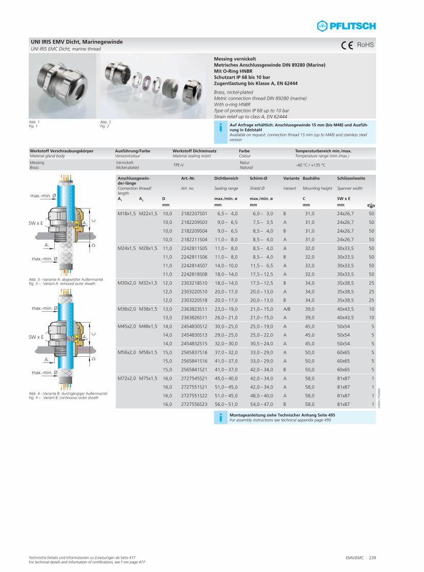
UNI IRIS EMV Dicht, MarinegewindeUNI IRIS EMC Dicht, marine thread
Abb. 1Fig. 1
Abb. 3 – Variante A: abgesetzter Außen mantelFig. 3 – Variant A: removed outer sheath
Abb. 4 – Variante B: durchgängiger AußenmantelFig. 4 – Variant B: continuous outer sheath
Messing vernickeltMetrisches Anschlussgewinde DIN 89280 (Marine)Mit O-Ring HNBRSchutzart IP 68 bis 10 barZugentlastung bis Klasse A, EN 62444 Brass, nickel-platedMetric connection thread DIN 89280 (marine)With o-ring HNBRType of protection IP 68 up to 10 barStrain relief up to class A, EN 62444
Abb. 2Fig. 2 i Auf Anfrage erhältlich: Anschlussgewinde 15 mm (bis M48) und Ausfüh-
rung in EdelstahlAvailable on request: connection thread 15 mm (up to M48) and stainless steel version
i Montageanleitung siehe Technischer Anhang Seite 495For assembly instructions see technical appendix page 495
Werkstoff VerschraubungskörperMaterial gland body
Ausführung/FarbeVersion/colour
Werkstoff DichteinsatzMaterial sealing insert
FarbeColour
Temperaturbereich min./max.Temperature range (min./max.)
MessingBrass
VernickeltNickel-plated
TPE-VNaturNatural
-40 °C / +135 °C
2390
0 | T
T028
00
RoHS
240 ∙ EMV/EMC Technische Details und Informationen zu Zulassungen ab Seite 477For technical details and information of certifications, see f om page 477
Anschlussgewin-de/-länge
Art.-Nr. Dichtbereich Schirm-Ø Variante Bauhöhe Schlüsselweite
Connection thread/length
Art. no. Sealing range Shield Ø Variant Mounting height Spanner width
A1 A2 D max./min. ø max./min. ø C SW x E
mm mm mm mm mm
Pg 9 M22x1,5 10,0 2502207S01 6,5 – 4,0 6,0 – 3,0 B 31,0 24x26,7 50
10,0 2502209S03 9,0 – 6,5 7,5 – 3,5 A 31,0 24x26,7 50
10,0 2502209S04 9,0 – 6,5 8,5 – 4,0 B 31,0 24x26,7 50
10,0 2502211S04 11,0 – 8,0 8,5 – 4,0 A 31,0 24x26,7 50
Pg 11 M22x1,5 10,0 2512207S01 6,5 – 4,0 6,0 – 3,0 B 31,0 24x26,7 50
10,0 2512209S03 9,0 – 6,5 7,5 – 3,5 A 31,0 24x26,7 50
10,0 2512209S04 9,0 – 6,5 8,5 – 4,0 B 31,0 24x26,7 50
10,0 2512211S04 11,0 – 8,0 8,5 – 4,0 A 31,0 24x26,7 50
Pg 13,5 M22x1,5 10,0 2522207S01 6,5 – 4,0 6,0 – 3,0 B 31,0 24x26,7 50
10,0 2522209S03 9,0 – 6,5 7,5 – 3,5 A 31,0 24x26,7 50
10,0 2522209S04 9,0 – 6,5 8,5 – 4,0 B 31,0 24x26,7 50
10,0 2522211S04 11,0 – 8,0 8,5 – 4,0 A 31,0 24x26,7 50
Pg 13,5 M28x1,5 6,5 2522814S07 14,0 – 10,0 11,5 – 6,5 B 32,0 30x33,5 25
Pg 16 M28x1,5 11,0 2532811S05 11,0 – 8,0 9,0 – 6,0 A 32,0 30x33,5 25
11,0 2532811S06 11,0 – 8,0 10,5 – 6,0 B 32,0 30x33,5 25
11,0 2532814S07 14,0 – 10,0 11,5 – 6,5 A 32,0 30x33,5 25
11,0 2532814S08 14,0 – 10,0 13,0 – 9,0 B 32,0 30x33,5 25
11,0 2532818S07 18,0 – 14,0 11,5 – 6,5 A 32,0 30x33,5 25
11,0 2532818S08 18,0 – 14,0 16,5 – 9,5 A 32,0 30x33,5 25
Pg 21 M28x1,5 11,0 2542811S06 11,0 – 8,0 10,5 – 6,0 B 32,0 30x33,5 25
11,0 2542814S07 14,0 – 10,0 11,5 – 7,0 B 32,0 30x33,5 25
11,0 2542818S08 18,0 – 14,0 16,5 – 9,5 A 32,0 30x33,5 25
Pg 21 M32x1,5 11,0 2543218S09 18,0 – 14,0 15,0 – 10,0 A 32,0 35x38,5 25
11,0 2543218S10 18,0 – 14,0 17,5 – 12,5 B 32,0 35x38,5 25
11,0 2543220S10 20,0 – 17,0 17,5 – 12,5 A 34,0 35x38,5 10
11,0 2543220S18 20,0 – 17,0 20,0 – 13,0 B 34,0 35x38,5 10
Pg 29 M38x1,5 13,0 2553823S11 23,0 – 19,0 21,0 – 15,0 B 39,0 40x43,5 10
13,0 2553826S11 26,0 – 22,0 21,0 – 15,0 A 39,0 40x43,5 10
Pg 29 M48x1,5 13,0 2554830S13 29,0 – 25,0 25,0 – 22,0 A 45,0 50x54 5
Pg 36 M48x1,5 14,0 2564830S12 29,0 – 25,0 25,0 – 19,0 A 45,0 50x54 5
14,0 2564830S13 30,0 – 25,0 25,0 – 22,0 A 45,0 50x54 5
14,0 2564832S14 32,0 – 29,0 27,0 – 21,0 A 45,0 50x54 5
14,0 2564832S15 32,0 – 29,0 30,5 – 24,0 A 45,0 50x54 5
Pg 42 M58x1,5 15,0 2575837S16 37,0 – 32,0 33,0 – 29,0 A 50,0 60x65 5
15,0 2575841S16 41,0 – 37,0 33,0 – 29,0 A 50,0 60x65 5
15,0 2575841S21 41,0 – 37,0 42,0 – 34,0 B 50,0 60x65 5
Pg 48 M75x1,5 16,0 2587545S21 45,0 – 40,0 42,0 – 34,0 A 58,0 81x87 2
16,0 2587551S21 51,0 – 45,0 48,0 – 40,0 A 58,0 81x87 2
16,0 2587551S22 51,0 – 45,0 48,0 – 40,0 A 58,0 81x87 2
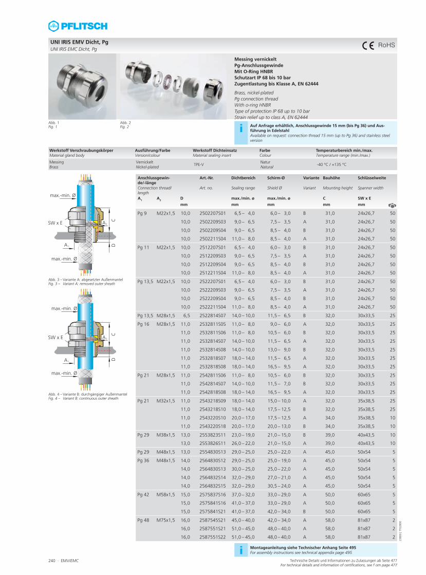
UNI IRIS EMV Dicht, Pg UNI IRIS EMC Dicht, Pg
Abb. 1Fig. 1
Abb. 3 – Variante A: abgesetzter Außen mantelFig. 3 – Variant A: removed outer sheath
Abb. 4 – Variante B: durchgängiger AußenmantelFig. 4 – Variant B: continuous outer sheath
Messing vernickeltPg-AnschlussgewindeMit O-Ring HNBR Schutzart IP 68 bis 10 barZugentlastung bis Klasse A, EN 62444 Brass, nickel-platedPg connection thread With o-ring HNBR Type of protection IP 68 up to 10 barStrain relief up to class A, EN 62444
Abb. 2Fig. 2 i Auf Anfrage erhältlich, Anschlussgewinde 15 mm (bis Pg 36) und Aus-
führung in EdelstahlAvailable on request: connection thread 15 mm (up to Pg 36) and stainless steel version
i Montageanleitung siehe Technischer Anhang Seite 495For assembly instructions see technical appendix page 495
Werkstoff VerschraubungskörperMaterial gland body
Ausführung/FarbeVersion/colour
Werkstoff DichteinsatzMaterial sealing insert
FarbeColour
Temperaturbereich min./max.Temperature range (min./max.)
MessingBrass
VernickeltNickel-plated
TPE-VNaturNatural
-40 °C / +135 °C
2380
0 | T
T028
00
RoHS

EMV/EMC ∙ 241
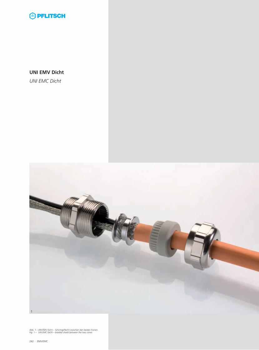
Abb. 1 – UNI EMV Dicht – Schirmgeflecht zwischen den beiden Konen.Fig. 1 – UNI EMC Dicht – braided shield between the two cones
242 ∙ EMV/EMC
1
UNI EMV Dicht
UNI EMC Dicht
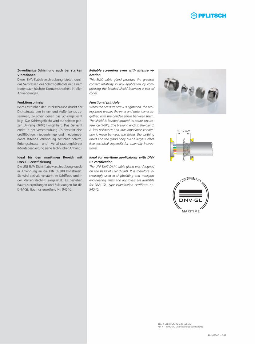
Abb. 1 – UNI EMV Dicht-EinzelteileFig. 1 – UNI EMC Dicht individual components
EMV/EMC ∙ 243
9 - 12 mm
1
Zuverlässige Schirmung auch bei starken VibrationenDiese EMV-Kabelverschraubung bietet durch das Verpressen des Schirmgeflechts mit einem Konenpaar höchste Kontaktsicherheit in allen Anwendungen. FunktionsprinzipBeim Festdrehen der Druckschraube drückt der Dichteinsatz den Innen- und Außenkonus zu-sammen, zwischen denen das Schirmgeflecht liegt. Das Schirmgeflecht wird auf seinem gan-zen Umfang (360°) kontaktiert. Das Geflecht endet in der Verschraubung. Es entsteht eine großflächige, niederohmige und niederimpe-dante leitende Verbindung zwischen Schirm, Erdungseinsatz und Verschraubungskörper (Montageanleitung siehe Technischer Anhang).
Ideal für den maritimen Bereich mit DNV-GL-ZertifizierungDie UNI EMV Dicht-Kabelverschraubung wurde in Anlehnung an die DIN 89280 konstruiert. Sie wird deshalb verstärkt im Schiffbau und in der Verkehrstechnik eingesetzt. Es bestehen Baumusterprüfungen und Zulassungen für die DNV-GL, Baumusterprüfung Nr. 94546.
Reliable screening even with intense vi-brationThis EMC cable gland provides the greatest contact reliability in any application by com-pressing the braided shield between a pair of cones.
Functional principleWhen the pressure screw is tightened, the seal-ing insert presses the inner and outer cones to-gether, with the braided shield between them. The shield is bonded around its entire circum-ference (360°). The braiding ends in the gland. A low-resistance and low-impedance connec-tion is made between the shield, the earthing insert and the gland body over a large surface (see technical appendix for assembly instruc-tions). Ideal for maritime applications with DNV GL certification The UNI EMC Dicht cable gland was designed on the basis of DIN 89280. It is therefore in-creasingly used in shipbuilding and transport engineering. Tests and approvals are available for DNV GL, type examination certificate no. 94546.
244 ∙ EMV/EMC Technische Details und Informationen zu Zulassungen ab Seite 477For technical details and information of certifications, see f om page 477
Anschlussgewinde/ -länge Art.-Nr. Dichtbereich Schirm-Ø Konus Konenpaar Bauhöhe Schlüssel-weite
Connection thread/length Art. no. Sealing range Shield Ø Cone Pair of cones
Mounting height
Spanner width
A D max./min. ø max. ø E1 min. ø E2 C SW x E
mm mm mm mm Art.-Nr. mm mm
M16x1,5 10,0 216220700 6,5 – 4,0 6,5 3,3 EEA 0 31,0 24x26,7 50
216220901 9,0 – 6,5 8,2 6,0 EEA 1 31,0 24x26,7 50
216221102 11,0 – 8,0 9,2 7,0 EEA 2 31,0 24x26,7 50
M20x1,5 10,0 220220700 6,5 – 4,0 6,5 3,3 EEA 0 31,0 24x26,7 50
220220901 9,0 – 6,5 8,2 6,0 EEA 1 31,0 24x26,7 50
220221102 11,0 – 8,0 9,2 7,0 EEA 2 31,0 24x26,7 50
M25x1,5 11,0 225280903 9,5 – 6,5 8,2 6,0 EEA 3 32,0 30x33,5 25
225281104 11,0 – 8,0 9,2 7,0 EEA 4 32,0 30x33,5 25
225281205 14,0 – 10,0 10,2 8,0 EEA 5 32,0 30x33,5 25
225281406 14,0 – 10,0 12,7 10,5 EEA 6 32,0 30x33,5 25
225281607 16,5 – 14,0 15,2 13,0 EEA 7 32,0 30x33,5 25
225281808 18,0 – 14,0 16,3 14,5 EEA 8 32,0 30x33,5 25
225321809 18,0 – 14,0 18,0 16,0 EEA 9 34,0 35x38,5 25
225322010 20,0 – 17,0 20,0 18,0 EEA 10 34,0 35x38,5 25
M32x1,5 13,0 232382311 23,0 – 19,0 22,0 20,0 EEA 11 39,0 40x43,5 10
232382312 23,0 – 19,0 24,0 22,0 EEA 12 39,0 40x43,5 10
232382611 26,0 – 22,0 22,0 20,0 EEA 11 39,0 40x43,5 10
232382613 26,0 – 22,0 26,0 24,0 EEA 13 39,0 40x43,5 10
M40x1,5 14,0 240483014 30,0 – 25,0 29,0 27,0 EEA 14 45,0 50x54 5
240483215 32,0 – 29,0 32,0 30,0 EEA 15 45,0 50x54 5
240483515 35,0 – 30,0 32,0 30,0 EEA 15 45,0 50x54 5
M50x1,5 15,0 250583716 37,0 – 32,0 37,0 35,0 EEA 16 50,0 60x65 5
250584117 41,0 – 37,0 41,0 39,0 EEA 17 50,0 60x65 5
M63x1,5 16,0 263754518 45,0 – 40,0 46,0 44,0 EEA 18 58,0 81x87 1
263755119 51,0 – 45,0 51,0 49,0 EEA 19 58,0 81x87 1
263755619 56,0 – 51,0 51,0 49,0 EEA 19 58,0 81x87 1
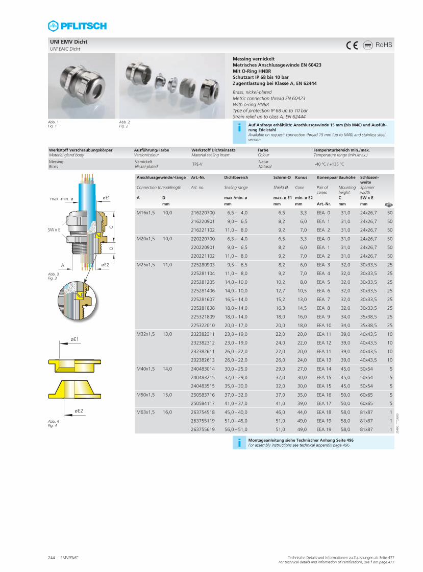
UNI EMV DichtUNI EMC Dicht
Abb. 1Fig. 1
Abb. 3 Fig. 3
Abb. 4 Fig. 4
Messing vernickeltMetrisches Anschlussgewinde EN 60423Mit O-Ring HNBRSchutzart IP 68 bis 10 barZugentlastung bei Klasse A, EN 62444 Brass, nickel-platedMetric connection thread EN 60423With o-ring HNBRType of protection IP 68 up to 10 barStrain relief up to class A, EN 62444
Abb. 2Fig. 2 i Auf Anfrage erhältlich: Anschlussgewinde 15 mm (bis M40) und Ausfüh-
rung EdelstahlAvailable on request: connection thread 15 mm (up to M40) and stainless steel version
i Montageanleitung siehe Technischer Anhang Seite 496For assembly instructions see technical appendix page 496
Werkstoff VerschraubungskörperMaterial gland body
Ausführung/FarbeVersion/colour
Werkstoff DichteinsatzMaterial sealing insert
FarbeColour
Temperaturbereich min./max.Temperature range (min./max.)
MessingBrass
VernickeltNickel-plated
TPE-VNaturNatural
-40 °C / +135 °C
2540
0 | T
T032
00
RoHS
EMV/EMC ∙ 245Technische Details und Informationen zu Zulassungen ab Seite 477For technical details and information of certifications, see f om page 477
Anschlussgewinde/ -länge Art.-Nr. Dichtbereich Schirm-Ø Konus Konenpaar Bauhöhe Schlüssel-weite
Connection thread/length Art. no. Sealing range Shield Ø Cone Pair of cones
Mounting height
Spanner width
A D max./min. ø max. ø E1 min. ø E2 C SW x E
mm mm mm mm Art.-Nr. mm mm
M18x1,5 10,0 218220700 6,5 – 4,0 5,5 3,3 EEA 0 31,0 24x26,7 50
218220901 9,0 – 6,5 8,2 6,0 EEA 1 31,0 24x26,7 50
218221102 11,0 – 8,0 9,2 7,0 EEA 2 31,0 24x26,7 50
M24x1,5 11,0 224280903 9,5 – 6,5 8,2 6,0 EEA 3 32,0 30x33,5 25
224281104 10,5 – 8,0 9,2 7,0 EEA 4 32,0 30x33,5 25
224281205 11,5 – 10,0 10,2 8,0 EEA 5 32,0 30x33,5 25
224281406 14,0 – 10,0 12,7 10,5 EEA 6 32,0 30x33,5 25
224281607 16,5 – 14,0 15,2 13,0 EEA 7 32,0 30x33,5 25
224281808 18,0 – 14,0 16,3 14,5 EEA 8 32,0 30x33,5 25
M30x2,0 12,0 230321809 18,0 – 14,0 18,0 16,0 EEA 9 34,0 35x38,5 25
230322010 20,0 – 17,0 20,0 18,0 EEA 10 34,0 35x38,5 25
M36x2,0 13,0 236382312 23,0 – 19,0 24,0 22,0 EEA 12 39,0 40x43,5 10
236382613 27,0 – 22,0 26,0 24,0 EEA 13 39,0 40x43,5 10
M45x2,0 14,0 245483014 30,0 – 25,0 29,0 27,0 EEA 14 45,0 50x54 5
245483215 32,0 – 29,0 32,0 30,0 EEA 15 45,0 50x54 5
M56x2,0 15,0 256583716 37,0 – 32,0 37,0 35,0 EEA 16 50,0 60x65 5
256584117 41,0 – 37,0 41,0 39,0 EEA 17 50,0 60x65 5
M72x2,0 16,0 272754518 45,0 – 40,0 46,0 44,0 EEA 18 58,0 81x87 1
272755119 51,0 – 45,0 51,0 49,0 EEA 19 58,0 81x87 1
272755619 56,0 – 51,0 51,0 49,0 EEA 19 58,0 81x87 1
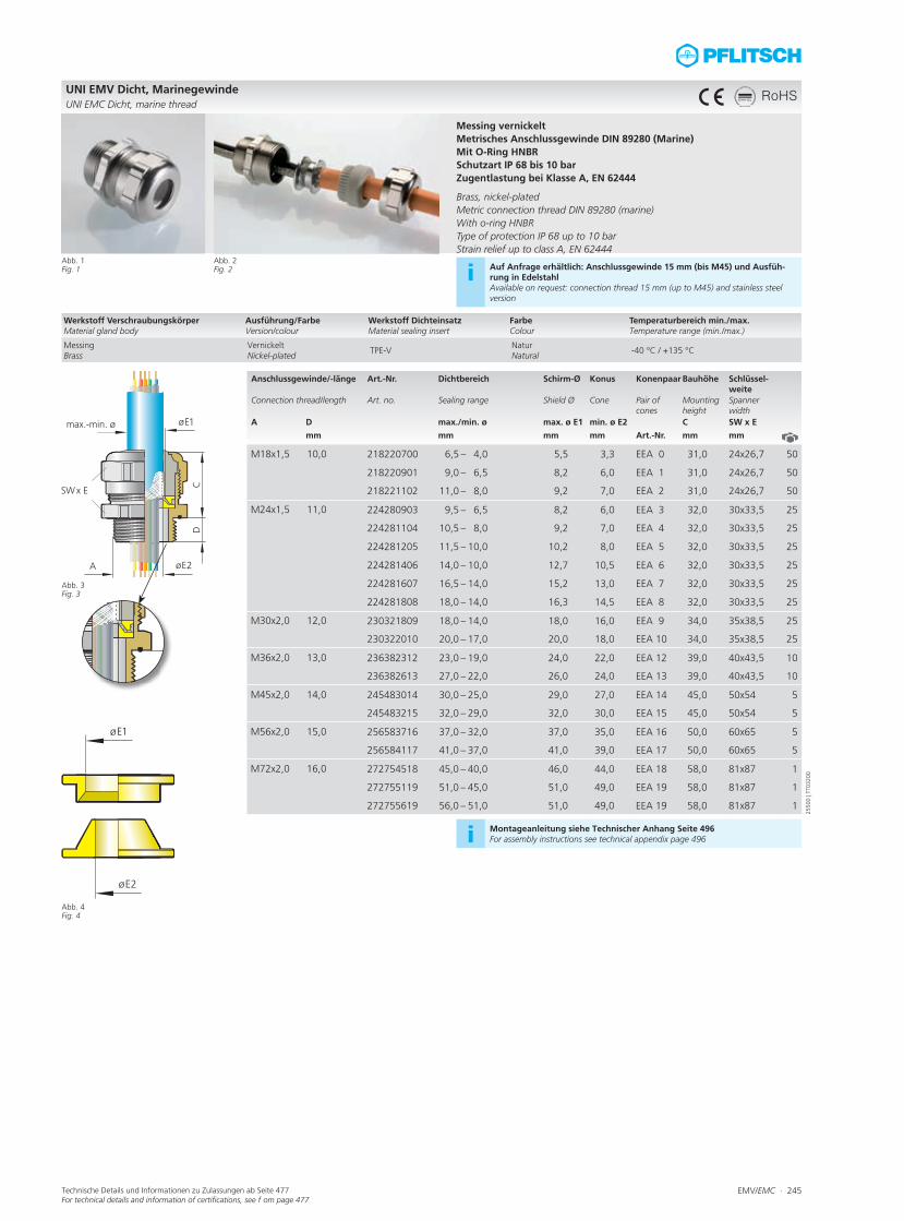
UNI EMV Dicht, MarinegewindeUNI EMC Dicht, marine thread
Abb. 1Fig. 1
Abb. 3 Fig. 3
Abb. 4 Fig. 4
Messing vernickeltMetrisches Anschlussgewinde DIN 89280 (Marine)Mit O-Ring HNBRSchutzart IP 68 bis 10 barZugentlastung bei Klasse A, EN 62444 Brass, nickel-platedMetric connection thread DIN 89280 (marine)With o-ring HNBRType of protection IP 68 up to 10 barStrain relief up to class A, EN 62444
Abb. 2Fig. 2 i Auf Anfrage erhältlich: Anschlussgewinde 15 mm (bis M45) und Ausfüh-
rung in EdelstahlAvailable on request: connection thread 15 mm (up to M45) and stainless steel version
i Montageanleitung siehe Technischer Anhang Seite 496For assembly instructions see technical appendix page 496
Werkstoff VerschraubungskörperMaterial gland body
Ausführung/FarbeVersion/colour
Werkstoff DichteinsatzMaterial sealing insert
FarbeColour
Temperaturbereich min./max.Temperature range (min./max.)
MessingBrass
VernickeltNickel-plated
TPE-VNaturNatural
-40 °C / +135 °C
2550
0 | T
T032
00
RoHS
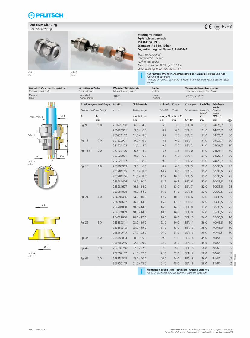
246 ∙ EMV/EMC Technische Details und Informationen zu Zulassungen ab Seite 477For technical details and information of certifications, see f om page 477
Anschlussgewinde/ -länge Art.-Nr. Dichtbereich Schirm-Ø Konus Konenpaar Bauhöhe Schlüssel-weite
Connection thread/length Art. no. Sealing range Shield Ø Cone Pair of cones Mounting height
Spanner width
A D max./min. ø max. ø E1 min. ø E2 C SW x E
mm mm mm mm Art.-Nr. mm mm
Pg 9 10,0 250220700 6,5 – 4,0 5,5 3,3 EEA 0 31,0 24x26,7 50
250220901 9,0 – 6,5 8,2 6,0 EEA 1 31,0 24x26,7 50
250221102 11,0 – 8,0 9,2 7,0 EEA 2 31,0 24x26,7 50
Pg 11 10,0 251220901 9,0 – 6,5 8,2 6,0 EEA 1 31,0 24x26,7 50
251221102 11,0 – 8,0 9,2 7,0 EEA 2 31,0 24x26,7 50
Pg 13,5 10,0 252220700 6,5 – 4,0 5,5 3,3 EEA 0 31,0 24x26,7 50
252220901 9,0 – 6,5 8,2 6,0 EEA 1 31,0 24x26,7 50
252221102 11,0 – 8,0 9,2 7,0 EEA 2 31,0 24x26,7 50
Pg 16 11,0 253280903 9,5 – 6,5 8,2 6,0 EEA 3 32,0 30x33,5 25
253281105 11,0 – 8,0 10,2 8,0 EEA 4 32,0 30x33,5 25
253281106 11,0 – 8,0 12,7 10,5 EEA 5 32,0 30x33,5 25
253281406 14,0 – 10,0 12,7 10,5 EEA 6 32,0 30x33,5 25
253281607 16,5 – 14,0 15,2 13,0 EEA 7 32,0 30x33,5 25
253281808 18,0 – 14,0 16,3 14,5 EEA 8 32,0 30x33,5 25
Pg 21 11,0 254281406 14,0 – 10,0 12,7 10,5 EEA 6 32,0 30x33,5 25
254281607 16,5 – 14,0 15,2 13,0 EEA 7 32,0 30x33,5 25
254281808 18,0 – 14,0 16,3 14,5 EEA 8 32,0 30x33,5 25
254321809 18,0 – 14,0 18,0 16,0 EEA 9 34,0 35x38,5 25
254322010 20,0 – 17,0 20,0 18,0 EEA 10 34,0 35x38,5 10
Pg 29 13,0 255382311 23,0 – 19,0 22,0 20,0 EEA 11 39,0 40x43,5 10
255382312 23,0 – 19,0 24,0 22,0 EEA 12 39,0 40x43,5 10
255382613 27,0 – 22,0 26,0 24,0 EEA 13 39,0 40x43,5 10
Pg 36 14,0 256483014 30,0 – 25,0 29,0 27,0 EEA 14 45,0 50x54 5
256483215 32,0 – 29,0 32,0 30,0 EEA 15 45,0 50x54 5
Pg 42 15,0 257583716 37,0 – 32,0 37,0 35,0 EEA 16 50,0 60x65 5
257584117 41,0 – 37,0 41,0 39,0 EEA 17 50,0 60x65 5
Pg 48 16,0 258754518 45,0 – 40,0 46,0 44,0 EEA 18 56,0 81x87 2
258755119 51,0 – 45,0 51,0 49,0 EEA 19 56,0 81x87 2
UNI EMV Dicht, PgUNI EMC Dicht, Pg
Abb. 1Fig. 1
Abb. 3 Fig. 3
Abb. 4 Fig. 4
Messing vernickeltPg-Anschlussgewinde Mit O-Ring HNBRSchutzart IP 68 bis 10 barZugentlastung bei Klasse A, EN 62444 Brass, nickel-platedPg connection threadWith o-ring HNBRType of protection IP 68 up to 10 barStrain relief up to class A, EN 62444
Abb. 2Fig. 2 i Auf Anfrage erhältlich, Anschlussgewinde 15 mm (bis Pg 96) und Aus-
führung in EdelstahlAvailable on request: connection thread 15 mm (up to Pg 96) and stainless steel version
i Montageanleitung siehe Technischer Anhang Seite 496For assembly instructions see technical appendix page 496
Werkstoff VerschraubungskörperMaterial gland body
Ausführung/FarbeVersion/colour
Werkstoff DichteinsatzMaterial sealing insert
FarbeColour
Temperaturbereich min./max.Temperature range (min./max.)
MessingBrass
VernickeltNickel-plated
TPE-VNaturNatural
-40 °C / +135 °C
2560
0 | T
T032
00
RoHS

EMV/EMC ∙ 247
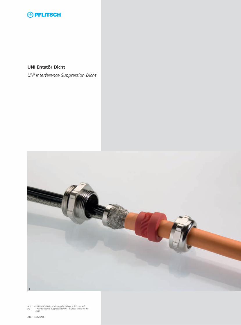
Abb. 1 – UNI Entstör Dicht – Schirmgeflecht liegt auf Konus auf.Fig. 1 – UNI Interference Suppression Dicht – braided shield on the
cone
1
UNI Entstör Dicht
UNI Interference Suppression Dicht
248 ∙ EMV/EMC

Abb. 1 – UNI Entstör Dicht-Einzelteile Fig. 1 – UNI Interference Suppression Dicht individual components
Abb. 2 – UNI Entstör Dicht mit erhöhter Zugentlastung Fig. 2 – UNI Interference Suppression Dicht strain relief
Abb. 3 – UNI Entstör Dicht mit erhöhter Zugentlastung, Einzelteile Fig. 3 – UNI Interference Suppression Dicht strain relief individual
components
EMV/EMC ∙ 249
1
2
3
Gute Schirmung zum kleinen PreisDie UNI Entstör Dicht ist die preisgünstigste EMV-Kabelverschraubung von PFLITSCH. Mit dem Fokus auf das Wesentliche erreicht sie hervorragende Schirmdämpfungswerte. Kompaktes Design für geringe Platzver-hältnisseDieses Produkt besticht außerdem durch seine sehr geringen Außenmaße. Es ist daher beson-ders für die Roboter- und Automatisierungsin-dustrie geeignet. Umfangreiches BaukastensystemDa diese Kabelverschraubung auf Basis der UNI Dicht-Serie entwickelt wurde, kann der komplette Baukasten verwendet werden. Dies ermöglicht dem Anwender z. B. bei einem gro-ßen Anschlussgewinde auch ein kleines Kabel sicher zu kontaktieren. UNI Entstör Dicht-Ka-belverschraubungen gibt es nicht nur mit der standardmäßigen Zugentlastung, sondern auch mit erhöhter Zugentlastung. Erreicht wird diese durch einen in den Dichteinsatz einge-spritzten Verstärkungsring aus Polyamid. Sämt-liche Möglichkeiten des Baukastensystems sind im Kapitel 5 „UNI Dicht“ zu finden. FunktionsprinzipBeim Festdrehen der Druckschraube drückt der Dichteinsatz das Schirmgeflecht auf den Konus des Erdungseinsatzes. Das Schirmgeflecht wird auf seinem ganzen Umfang (360°) kontaktiert. Das Geflecht endet in der Verschraubung. Es entsteht eine niederohmige und niederimpe-dante leitende Verbindung zwischen Schirm, Erdungseinsatz und Verschraubungskörper (Montageanleitung siehe Technischer Anhang).
Good shielding at a low priceThe UNI Interference Suppression Dicht is the lowest-priced EMC cable gland available from PFLITSCH. It achieves excellent screening at- tenuation values by focusing on the essentials. Compact design for cramped conditionsThis product also impresses with very small outer dimensions, making it ideal for the ro-botics and automation industries. Comprehensive modular systemSince this cable gland was developed based on the UNI Dicht series, the complete modu-lar system can be used. Even small cables can thus be reliably bonded, for instance, with a large connection thread. In addition to stand-ard strain relief, UNI Interference Suppression Dicht cable glands can also be supplied with increased strain relief. This is attained by a polyamide reinforcement ring moulded in the sealing insert. For a detailed description of the options which are available with the modular system, see Chapter 5 “UNI Dicht”. Functional principleWhen the pressure screw is tightened, the sealing insert presses the braided shield onto the cone of the earthing insert. The shield is bonded around its entire circumference (360°). The braiding ends in the gland. A low-resist-ance and low-impedance connection is made between the shield, the earthing insert and the gland body (see technical appendix for assem-bly instructions).
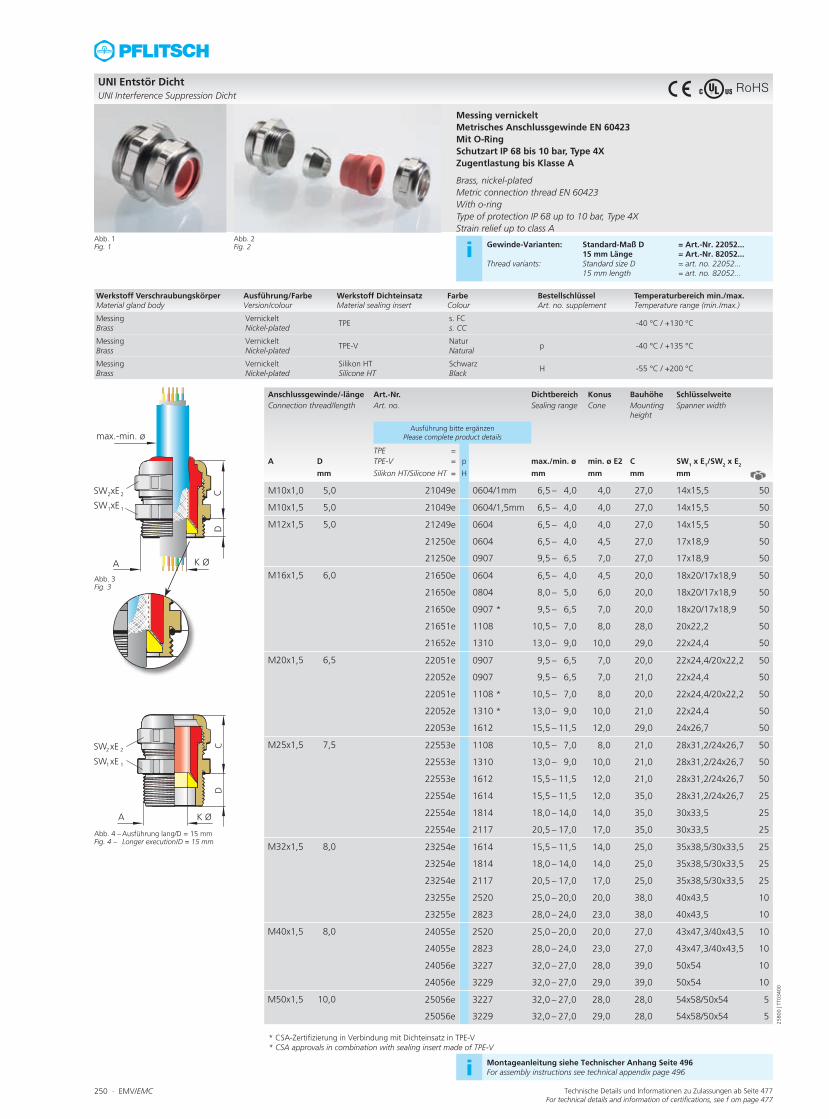
250 ∙ EMV/EMC Technische Details und Informationen zu Zulassungen ab Seite 477For technical details and information of certifications, see f om page 477
Anschlussgewinde/-länge Art.-Nr. Dichtbereich Konus Bauhöhe SchlüsselweiteConnection thread/length Art. no. Sealing range Cone Mounting
heightSpanner width
Ausführung bitte ergänzen Please complete product details
TPE =A D TPE-V = p max./min. ø min. ø E2 C SW1 x E1/SW2 x E2
mm Silikon HT/Silicone HT = H mm mm mm mm
M10x1,0 5,0 21049e 0604/1mm 6,5 – 4,0 4,0 27,0 14x15,5 50
M10x1,5 5,0 21049e 0604/1,5mm 6,5 – 4,0 4,0 27,0 14x15,5 50
M12x1,5 5,0 21249e 0604 6,5 – 4,0 4,0 27,0 14x15,5 50
21250e 0604 6,5 – 4,0 4,5 27,0 17x18,9 50
21250e 0907 9,5 – 6,5 7,0 27,0 17x18,9 50
M16x1,5 6,0 21650e 0604 6,5 – 4,0 4,5 20,0 18x20/17x18,9 50
21650e 0804 8,0 – 5,0 6,0 20,0 18x20/17x18,9 50
21650e 0907 * 9,5 – 6,5 7,0 20,0 18x20/17x18,9 50
21651e 1108 10,5 – 7,0 8,0 28,0 20x22,2 50
21652e 1310 13,0 – 9,0 10,0 29,0 22x24,4 50
M20x1,5 6,5 22051e 0907 9,5 – 6,5 7,0 20,0 22x24,4/20x22,2 50
22052e 0907 9,5 – 6,5 7,0 21,0 22x24,4 50
22051e 1108 * 10,5 – 7,0 8,0 20,0 22x24,4/20x22,2 50
22052e 1310 * 13,0 – 9,0 10,0 21,0 22x24,4 50
22053e 1612 15,5 – 11,5 12,0 29,0 24x26,7 50
M25x1,5 7,5 22553e 1108 10,5 – 7,0 8,0 21,0 28x31,2/24x26,7 50
22553e 1310 13,0 – 9,0 10,0 21,0 28x31,2/24x26,7 50
22553e 1612 15,5 – 11,5 12,0 21,0 28x31,2/24x26,7 50
22554e 1614 15,5 – 11,5 12,0 35,0 28x31,2/24x26,7 25
22554e 1814 18,0 – 14,0 14,0 35,0 30x33,5 25
22554e 2117 20,5 – 17,0 17,0 35,0 30x33,5 25
M32x1,5 8,0 23254e 1614 15,5 – 11,5 14,0 25,0 35x38,5/30x33,5 25
23254e 1814 18,0 – 14,0 14,0 25,0 35x38,5/30x33,5 25
23254e 2117 20,5 – 17,0 17,0 25,0 35x38,5/30x33,5 25
23255e 2520 25,0 – 20,0 20,0 38,0 40x43,5 10
23255e 2823 28,0 – 24,0 23,0 38,0 40x43,5 10
M40x1,5 8,0 24055e 2520 25,0 – 20,0 20,0 27,0 43x47,3/40x43,5 10
24055e 2823 28,0 – 24,0 23,0 27,0 43x47,3/40x43,5 10
24056e 3227 32,0 – 27,0 28,0 39,0 50x54 10
24056e 3229 32,0 – 27,0 29,0 39,0 50x54 10
M50x1,5 10,0 25056e 3227 32,0 – 27,0 28,0 28,0 54x58/50x54 5
25056e 3229 32,0 – 27,0 29,0 28,0 54x58/50x54 5
* CSA approvals in combination with sealing insert made of TPE-V * CSA-Zertifizierung in Verbindung mit Dichteinsatz in TPE-V
UNI Entstör DichtUNI Interference Suppression Dicht
Abb. 1Fig. 1
Abb. 3 Fig. 3
Abb. 4 – Ausführung lang/D = 15 mmFig. 4 – Longer execution/D = 15 mm
Messing vernickeltMetrisches Anschlussgewinde EN 60423Mit O-RingSchutzart IP 68 bis 10 bar, Type 4XZugentlastung bis Klasse A Brass, nickel-platedMetric connection thread EN 60423With o-ringType of protection IP 68 up to 10 bar, Type 4XStrain relief up to class A
Abb. 2Fig. 2 i Gewinde-Varianten: Standard-Maß D = Art.-Nr. 22052...
15 mm Länge = Art.-Nr. 82052...Thread variants: Standard size D = art. no. 22052... 15 mm length = art. no. 82052...
i Montageanleitung siehe Technischer Anhang Seite 496For assembly instructions see technical appendix page 496
Werkstoff VerschraubungskörperMaterial gland body
Ausführung/FarbeVersion/colour
Werkstoff DichteinsatzMaterial sealing insert
FarbeColour
BestellschlüsselArt. no. supplement
Temperaturbereich min./max.Temperature range (min./max.)
MessingBrass
VernickeltNickel-plated
TPEs. FCs. CC
-40 °C / +130 °C
MessingBrass
VernickeltNickel-plated
TPE-VNaturNatural
p -40 °C / +135 °C
MessingBrass
VernickeltNickel-plated
Silikon HTSilicone HT
Schwarz Black
H -55 °C / +200 °C
2580
0 | T
T034
00
RoHS

EMV/EMC ∙ 251Technische Details und Informationen zu Zulassungen ab Seite 477For technical details and information of certifications, see f om page 477
Anschlussgewinde/-länge Art.-Nr. Dichtbereich Konus Bauhöhe SchlüsselweiteConnection thread/length Art. no. Sealing range Cone Mounting height Spanner width
Ausführung bitte ergänzen Please complete product details
A D TPE = max./min. ø min. ø E2 C SW1 x E1/SW2 x E2
mm TPE-V = p mm mm mm mm
M10x1,0 5,0 21049e z0604/1mm 6,5 – 4,0 4,0 27,0 14x15,5 50
M10x1,5 5,0 21049e z0604/1,5mm 6,5 – 4,0 4,0 27,0 14x15,5 50
M12x1,5 5,0 21249e z0604 6,5 – 4,0 4,0 27,0 14x15,5 50
21250e z0907 9,0 – 5,5 7,0 27,0 17x18,9 50
M16x1,5 6,0 21650e z0604 6,5 – 4,0 4,5 20,0 18x20/17x18,9 50
21650e z0907 9,0 – 5,5 7,0 20,0 18x20/17x18,9 50
21651e z1108 10,0 – 6,0 8,0 28,0 20x22,2 50
21652e z1310 12,0 – 8,0 10,0 29,0 22x24,4 50
M20x1,5 6,5 22051e z0907 9,0 – 5,5 7,0 20,0 22x24,4/20x22,2 50
22052e z0907 9,0 – 5,5 7,0 21,0 22x24,4 50
22051e z1108 10,0 – 6,0 8,0 20,0 22x24,4/20x22,2 50
22052e z1310 13,0 – 9,0 10,0 21,0 22x24,4 50
22053e z1612 15,0 – 12,0 12,0 29,0 24x26,7 50
M25x1,5 7,5 22553e z1108 10,0 – 6,0 8,0 21,0 28x31,2/24x26,7 50
22553e z1310 12,0 – 8,0 10,0 21,0 28x31,2/24x26,7 50
22553e z1612 15,0 – 12,0 12,0 21,0 28x31,2/24x26,7 50
22554e z1814 17,0 – 14,0 14,0 35,0 30x33,5 25
22554e z2117 20,0 – 16,0 17,0 35,0 30x33,5 25
M32x1,5 8,0 23254e z1814 17,0 – 14,0 14,0 25,0 35x38,5/30x33,5 25
23254e z2117 20,0 – 16,0 17,0 25,0 35x38,5/30x33,5 25
23255e z2520 24,0 – 20,0 20,0 38,0 40x43,5 10
23255e z2823 28,0 – 24,0 23,0 38,0 40x43,5 10
M40x1,5 8,0 24055e z2520 24,0 – 20,0 20,0 27,0 43x47,3/40x43,5 10
24055e z2823 28,0 – 24,0 23,0 27,0 43x47,3/40x43,5 10
24056e z3227 32,0 – 27,0 28,0 39,0 50x54 5
24056e z3229 32,0 – 27,0 29,0 39,0 50x54 5
M50x1,5 10,0 25056e z3227 32,0 – 27,0 28,0 28,0 54x58/50x54 5
25056e z3229 32,0 – 27,0 29,0 28,0 54x58/50x54 5
UNI Entstör Dicht mit erhöhter ZugentlastungUNI Interference Suppression Dicht with increased strain relief
Abb. 1Fig. 1
Abb. 3 Fig. 3
Abb. 4 Fig. 4
Messing vernickelt, mit erhöhter ZugentlastungMetrisches Anschlussgewinde EN 60423Mit O-Ring HNBR Schutzart IP 54Zugentlastung bis Klasse B Brass, nickel-plated, with increased strain reliefMetric connection thread EN 60423With o-ring HNBR Type of protection IP 54Strain relief up to class B
Abb. 2Fig. 2 i Gewinde-Varianten: Standard-Maß D = Art.-Nr. 22052...
15 mm Länge = Art.-Nr. 82052...Thread variants: Standard size D = art. no. 22052... 15 mm length = art. no. 82052...
i Ausführung in Edelstahl auf Anfrage Stainless steel version on request
i Montageanleitung siehe Technischer Anhang Seite 496For assembly instructions see technical appendix page 496
Werkstoff VerschraubungskörperMaterial gland body
Ausführung/FarbeVersion/colour
Werkstoff DichteinsatzMaterial sealing insert
FarbeColour
BestellschlüsselArt. no. supplement
Temperaturbereich min./max.Temperature range (min./max.)
MessingBrass
VernickeltNickel-plated
TPEs. FCs. CC
-20 °C / +100 °C
MessingBrass
VernickeltNickel-plated
TPE-VNaturNatural
p -20 °C / +100 °C
2590
0 | T
T034
00
RoHS

252 ∙ EMV/EMC Technische Details und Informationen zu Zulassungen ab Seite 477For technical details and information of certifications, see f om page 477
Anschlussgewinde/-länge Art.-Nr. Dichtbereich Konus Bauhöhe SchlüsselweiteConnection thread/length Art. no. Sealing range Cone Mounting height Spanner width
Ausführung bitte ergänzen Please complete product details
TPE =A D TPE-V = p max./min. ø min. ø E2 C SW x E
mm Silikon HT/Silicone HT = H mm mm mm mm
Pg 7 5,0 149e 0604 6,5 – 4,0 4,0 18,0 14x15,5 50
14950e 0907 9,5 – 6,5 7,0 27,0 17x18,9 50
Pg 9 6,0 150e 0604 6,5 – 4,0 4,5 20,0 17x18,9 50
150e 0907 * 9,5 – 6,5 7,0 20,0 17x18,9 50
15051e 1108 10,5 – 7,0 8,0 28,0 20x22,2 50
Pg 11 6,0 151e 0907 9,5 – 6,5 7,0 20,0 20x22,2 50
151e 1108 * 10,5 – 7,0 8,0 20,0 20x22,2 50
15152e 1310 * 13,0 – 9,0 10,0 29,0 22x24,4 50
Pg 13,5 6,5 152e 0907 9,5 – 6,5 7,0 21,0 22x24,4 50
152e 1310 13,0 – 9,0 10,0 21,0 22x24,4 50
15253e 1612 15,5 – 11,5 12,0 29,0 24x26,7 50
Pg 16 6,5 153e 1108 10,5 – 7,0 8,0 21,0 24x26,7 50
153e 1310 13,0 – 9,0 10,0 21,0 24x26,7 50
153e 1612 15,5 – 11,5 12,0 21,0 24x26,7 50
15354e 1814 18,0 – 14,0 14,0 35,0 30x33,5 25
15354e 2117 20,5 – 17,0 17,0 35,0 30x33,5 25
Pg 21 7,0 154e 1614 15,5 – 11,5 14,0 25,0 30x33,5 25
154e 1814 18,0 – 14,0 14,0 25,0 30x33,5 25
154e 2117 20,5 – 17,0 17,0 25,0 30x33,5 25
15455e 2520 25,0 – 20,0 20,0 38,0 40x43,5 10
15455e 2823 28,0 – 24,0 23,0 38,0 40x43,5 10
Pg 29 8,0 155e 2520 25,0 – 20,0 20,0 28,0 40x43,5 10
155e 2823 28,0 – 24,0 23,0 28,0 40x43,5 10
15556e 3227 32,0 – 27,0 28,0 39,0 50x54 10
Pg 36 9,0 156e 3227 32,0 – 27,0 28,0 28,0 50x54 5
* UL and CSA approvals in combination with sealing insert made of TPE-V * UL- und CSA-Zertifizierung in Verbindung mit Dichteinsatz in TPE-V
UNI Entstör Dicht, PgUNI Interference Suppression Dicht, Pg
Abb. 1Fig. 1
Abb. 3 Fig. 3
Abb. 4 – Ausführung lang/D = 15 mmFig. 4 – Longer execution/D = 15 mm
Messing vernickeltPg-AnschlussgewindeMit O-RingSchutzart IP 68 bis 10 barZugentlastung bis Klasse A Brass, nickel-platedPg connection threadWith o-ringType of protection IP 68 up to 10 barStrain relief up to class A
Abb. 2Fig. 2 i Gewinde-Varianten: Standard-Maß D = Art.-Nr. 15...
15 mm Länge = Art.-Nr. 18...Thread variants: Standard size D = art. no. 15... 15 mm length = art. no. 18...
i Ausführung in Edelstahl auf Anfrage Stainless steel version on request
i Montageanleitung siehe Technischer Anhang Seite 496For assembly instructions see technical appendix page 496
Werkstoff VerschraubungskörperMaterial gland body
Ausführung/FarbeVersion/colour
Werkstoff DichteinsatzMaterial sealing insert
FarbeColour
BestellschlüsselArt. no. supplement
Temperaturbereich min./max.Temperature range (min./max.)
MessingBrass
VernickeltNickel-plated
TPEs. FCs. CC
-40 °C / +130 °C
MessingBrass
VernickeltNickel-plated
TPE-VNaturNatural
p -40 °C / +135 °C
MessingBrass
VernickeltNickel-plated
Silikon HTSilicone HT
Schwarz Black
H -55 °C / +200 °C
2600
0 | T
T035
00
RoHS

EMV/EMC ∙ 253Technische Details und Informationen zu Zulassungen ab Seite 477For technical details and information of certifications, see f om page 477
Anschlussgewinde/-länge Art.-Nr. Dichtbereich Konus Bauhöhe SchlüsselweiteConnection thread/length Art. no. Sealing range Cone Mounting height Spanner width
Ausführung bitte ergänzen Please complete product details
A D TPE = max./min. ø min. ø E2 C SW x E
mm TPE-V = p mm mm mm mm
Pg 7 5,0 149e z0604 6,5 – 4,0 4,0 18,0 14x15,5 50
14950e z0907 9,0 – 5,5 7,0 27,0 17x18,9 50
Pg 9 6,0 150e z0604 6,5 – 4,0 4,5 20,0 17x18,9 50
150e z0907 9,0 – 5,5 7,0 20,0 17x18,9 50
15051e z1108 10,0 – 6,0 8,0 28,0 20x22,2 50
Pg 11 6,0 151e z0907 9,0 – 5,5 7,0 20,0 20x22,2 50
151e z1108 10,0 – 6,0 8,0 20,0 20x22,2 50
15152e z1310 12,0 – 8,0 10,0 29,0 22x24,4 50
Pg 13,5 6,5 152e z0907 9,0 – 5,5 7,0 21,0 22x24,4 50
152e z1310 12,0 – 8,0 10,0 21,0 22x24,4 50
15253e z1612 15,0 – 12,0 12,0 29,0 24x26,7 50
Pg 16 6,5 153e z1108 10,0 – 6,0 8,0 21,0 24x26,7 50
153e z1310 12,0 – 8,0 10,0 21,0 24x26,7 50
153e z1612 15,0 – 12,0 12,0 21,0 24x26,7 50
15354e z1814 17,0 – 14,0 14,0 35,0 30x33,5 25
15354e z2117 20,0 – 16,0 17,0 35,0 30x33,5 25
Pg 21 7,0 154e z1814 17,0 – 14,0 14,0 25,0 30x33,5 25
154e z2117 20,0 – 16,0 17,0 25,0 30x33,5 25
15455e z2520 24,0 – 20,0 20,0 38,0 40x43,5 10
15455e z2823 28,0 – 24,0 23,0 38,0 40x43,5 10
Pg 29 8,0 155e z2520 24,0 – 20,0 20,0 28,0 40x43,5 10
155e z2823 28,0 – 24,0 23,0 28,0 40x43,5 10
15556e z3227 32,0 – 27,0 28,0 29,0 50x54 10
Pg 36 9,0 156e z3227 32,0 – 27,0 28,0 28,0 50x54 10
UNI Entstör Dicht, Pg mit erhöhter ZugentlastungUNI Interference Suppression Dicht, Pg with increased strain relief
Abb. 1Fig. 1
Abb. 3 Fig. 3
Abb. 4 Fig. 4
Messing vernickelt, mit erhöhter ZugentlastungPg-AnschlussgewindeMit O-Ring HNBRSchutzart IP 54Zugentlastung bis Klasse B Brass, nickel-plated, with increased strain reliefPg connection threadWith o-ring HNBRType of protection IP 54Strain relief up to class B
Abb. 2Fig. 2 i Gewinde-Varianten: Standard-Maß D = Art.-Nr. 15...
15 mm Länge = Art.-Nr. 18...Thread variants: Standard size D = art. no. 15... 15 mm length = art. no. 18...
i Ausführung in Edelstahl auf Anfrage Stainless steel version on request
i Montageanleitung siehe Technischer Anhang Seite 496For assembly instructions see technical appendix page 496
Werkstoff VerschraubungskörperMaterial gland body
Ausführung/FarbeVersion/colour
Werkstoff DichteinsatzMaterial sealing insert
FarbeColour
BestellschlüsselArt. no. supplement
Temperaturbereich min./max.Temperature range (min./max.)
MessingBrass
VernickeltNickel-plated
TPEs. FCs. CC
-20 °C / +100 °C
MessingBrass
VernickeltNickel-plated
TPE-VNaturNatural
p -20 °C / +100 °C
2610
0 | T
T035
00
RoHS
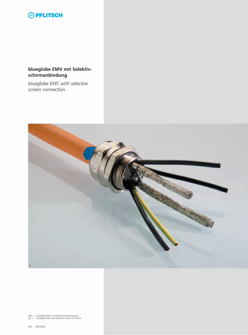
Abb. 1 – blueglobe EMV mit SelektivschirmanbindungFig. 1 – blueglobe EMC with selective screen connection
254 ∙ EMV/EMC
1
blueglobe EMV mit Selektiv-schirmanbindung
blueglobe EMC with selective screen connection

Abb. 1 – blueglobe EMV mit Selektivschirmanbindung Fig. 1 – blueglobe EMC with selective screen connection
EMV/EMC ∙ 255
1
Beste EMV-Kontaktierung von Hybridlei-tungenDie blueglobe EMV mit Selektivschirmanbin-dung ist die Lösung für die sichere EMV-Kon-taktierung von Hybridkabeln. Mit einem Schirmkontaktelement kann der äußere Ge-samtschirm großflächig angebunden werden und bis zu zwei innenliegende geschirmte Adern werden über eine Schraubklemme auf-gelegt. Einsatz in der E-MobilitätIn allen Branchen, in denen Hybridleitungen eingesetzt werden, ist diese EMV-Kabelver-schraubung zu finden. Neben der Robotik und der Automatisierungstechnik ist dies im Beson-deren die E-Mobilität. Bewährte blueglobe-EigenschaftenZusätzlich zu der sicheren EMV-Kontaktie-rung verfügt die blueglobe EMV mit Selektiv-schirm auch über die starken Eigenschaften der blueglobe-Kabelverschraubung, wie beispiels-weise den großen Dichtbereich, die eindeuti-ge Kennzeichnung sowie die hohe Schutzart (IP 68 bis 15 bar bzw. IP 69) und Zugentlas-tung.
Optimal EMC contact for hybrid cablesThe blueglobe EMC with a selective screen connection is the ideal solution to achieve reliable EMC contact with hybrid cables. The complete outer shield can be connected over a large area by means of a contact element; up to two screened, inner conductors are at-tached using a screw terminal. E-mobility applicationsThis EMC cable gland can be found in all indus-tries where hybrid cables are employed. Apart from robotics and automation, this particularly includes e-mobility. Proven blueglobe characteristics In addition to ensuring secure EMC contact, the blueglobe EMC with selective screen con-nection also exhibits the impressive character-istics of the blueglobe cable gland such as a large sealing range, clear marking, high type of protection (IP 68 up to 15 bar or IP 69) and good strain relief.
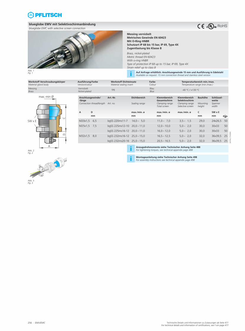
256 ∙ EMV/EMC Technische Details und Informationen zu Zulassungen ab Seite 477For technical details and information of certifications, see f om page 477
Anschlussgewinde/ -länge
Art.-Nr. Dichtbereich Klemmbereich Gesamtschirm
Klemmbereich Selektivschirm
Bauhöhe Schlüssel-weite
Connection thread/length Art. no. Sealing range Clamping range Total screen
Clamping range Selective screen
Mounting height
Spanner width
A D max./min. ø max./min. ø max./min. ø C SW x E
mm mm mm mm mm
M20x1,5 6,5 bgSS 220ms11-7 14,0 – 5,0 11,0 – 7,0 3,5 – 1,5 29,0 24x26,5 50
M25x1,5 7,5 bgSS 225ms12-10 20,0 – 11,0 12,0 – 10,0 5,0 – 2,0 30,0 30x33 50
bgSS 225ms16-12 20,0 – 11,0 16,0 – 12,0 5,0 – 2,0 30,0 30x33 50
M32x1,5 8,0 bgSS 232ms16-12 25,0 – 15,0 16,5 – 12,5 5,0 – 2,0 32,0 36x39,5 25
bgSS 232ms20-16 25,0 – 15,0 20,5 – 16,5 5,0 – 2,0 32,0 36x39,5 25
blueglobe EMV mit Selektivschirmanbindungblueglobe EMC with selective screen connection
Abb. 1Fig. 1
Abb. 2 Fig. 2
Abb. 3 Fig. 3
Messing vernickeltMetrisches Gewinde EN 60423Mit O-Ring HNBRSchutzart IP 68 bis 15 bar, IP 69, Type 4XZugentlastung bis Klasse B Brass, nickel-platedMetric thread EN 60423With o-ring HNBRType of protection IP 68 up to 15 bar, IP 69, Type 4XStrain relief up to class B
i Auf Anfrage erhältlich: Anschlussgewinde 15 mm und Ausführung in EdelstahlAvailable on request: 15 mm connection thread and stainless steel version
i Anzugsdrehmomente siehe Technischer Anhang Seite 488For tightening torques, see technical appendix page 488
i Montageanleitung siehe Technischer Anhang Seite 498For assembly instructions see technical appendix page 498
Werkstoff VerschraubungskörperMaterial gland body
Ausführung/FarbeVersion/colour
Werkstoff DichteinsatzMaterial sealing insert
FarbeColour
Temperaturbereich min./max.Temperature range (min./max.)
MessingBrass
VernickeltNickel-plated
TPEBlauBlue
-40 °C / +130 °C
2670
0 | T
T039
00
RoHS

EMV/EMC ∙ 257
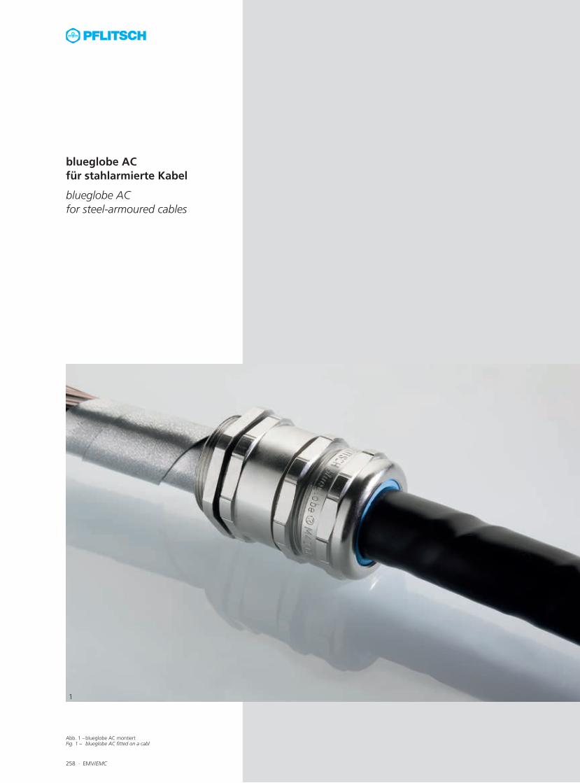
Abb. 1 – blueglobe AC montiertFig. 1 – blueglobe AC fitted on a cabl
258 ∙ EMV/EMC
1
blueglobe ACfür stahlarmierte Kabel
blueglobe ACfor steel-armoured cables
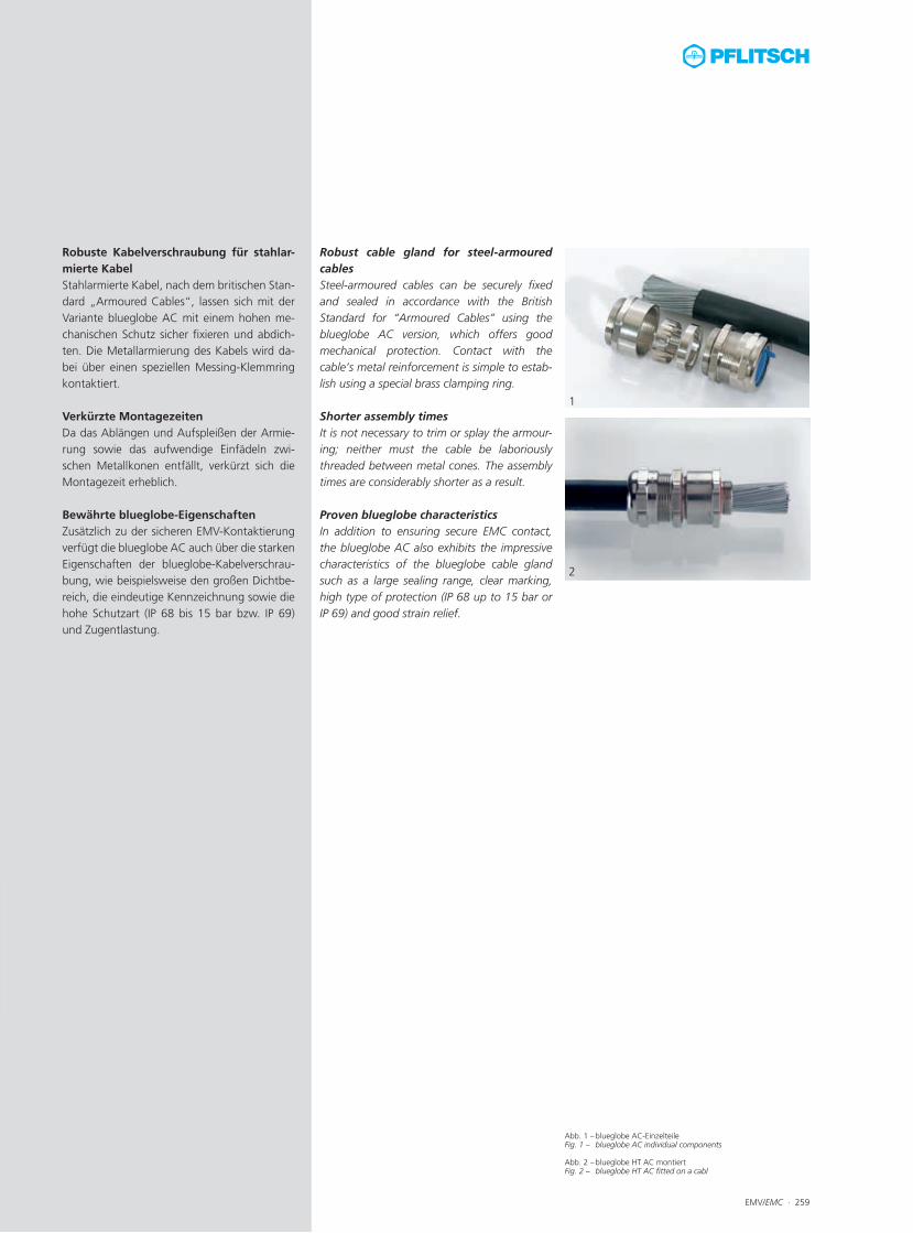
Abb. 1 – blueglobe AC-EinzelteileFig. 1 – blueglobe AC individual components
Abb. 2 – blueglobe HT AC montiertFig. 2 – blueglobe HT AC fitted on a cabl
EMV/EMC ∙ 259
1
2
Robuste Kabelverschraubung für stahlar-mierte KabelStahlarmierte Kabel, nach dem britischen Stan-dard „Armoured Cables“, lassen sich mit der Variante blueglobe AC mit einem hohen me-chanischen Schutz sicher fixieren und abdich-ten. Die Metallarmierung des Kabels wird da-bei über einen speziellen Messing-Klemmring kontaktiert. Verkürzte MontagezeitenDa das Ablängen und Aufspleißen der Armie-rung sowie das aufwendige Einfädeln zwi-schen Metallkonen entfällt, verkürzt sich die Montagezeit erheblich. Bewährte blueglobe-EigenschaftenZusätzlich zu der sicheren EMV-Kontaktierung verfügt die blueglobe AC auch über die starken Eigenschaften der blueglobe-Kabelverschrau-bung, wie beispielsweise den großen Dichtbe-reich, die eindeutige Kennzeichnung sowie die hohe Schutzart (IP 68 bis 15 bar bzw. IP 69) und Zugentlastung.
Robust cable gland for steel-armoured cablesSteel-armoured cables can be securely fixedand sealed in accordance with the British Standard for “Armoured Cables” using the blueglobe AC version, which offers good mechanical protection. Contact with the cable’s metal reinforcement is simple to estab-lish using a special brass clamping ring. Shorter assembly timesIt is not necessary to trim or splay the armour-ing; neither must the cable be laboriously threaded between metal cones. The assembly times are considerably shorter as a result. Proven blueglobe characteristics In addition to ensuring secure EMC contact, the blueglobe AC also exhibits the impressive characteristics of the blueglobe cable gland such as a large sealing range, clear marking, high type of protection (IP 68 up to 15 bar or IP 69) and good strain relief.
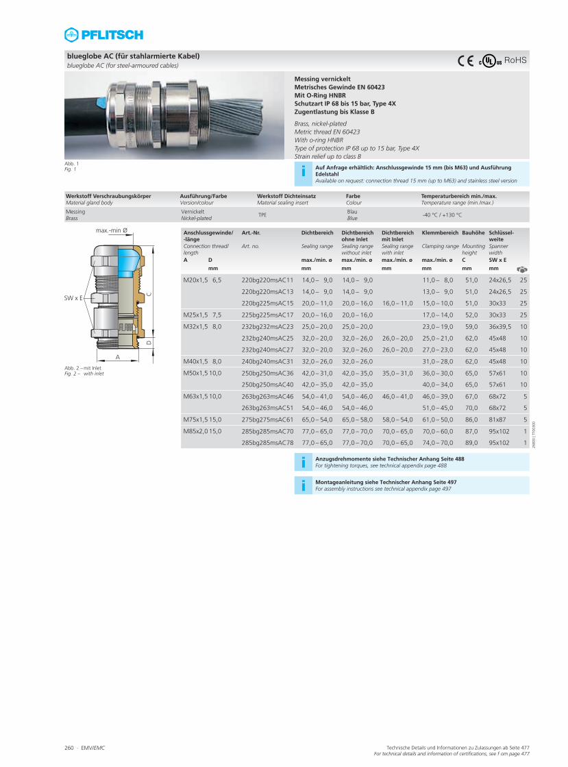
260 ∙ EMV/EMC Technische Details und Informationen zu Zulassungen ab Seite 477For technical details and information of certifications, see f om page 477
Anschlussgewinde/ -länge
Art.-Nr. Dichtbereich Dichtbereich ohne Inlet
Dichtbereich mit Inlet
Klemmbereich Bauhöhe Schlüssel-weite
Connection thread/length
Art. no. Sealing range Sealing range without inlet
Sealing range with inlet
Clamping range Mounting height
Spanner width
A D max./min. ø max./min. ø max./min. ø max./min. ø C SW x E
mm mm mm mm mm mm mm
M20x1,5 6,5 220bg220msAC11 14,0 – 9,0 14,0 – 9,0 11,0 – 8,0 51,0 24x26,5 25
220bg220msAC13 14,0 – 9,0 14,0 – 9,0 13,0 – 9,0 51,0 24x26,5 25
220bg225msAC15 20,0 – 11,0 20,0 – 16,0 16,0 – 11,0 15,0 – 10,0 51,0 30x33 25
M25x1,5 7,5 225bg225msAC17 20,0 – 16,0 20,0 – 16,0 17,0 – 14,0 52,0 30x33 25
M32x1,5 8,0 232bg232msAC23 25,0 – 20,0 25,0 – 20,0 23,0 – 19,0 59,0 36x39,5 10
232bg240msAC25 32,0 – 20,0 32,0 – 26,0 26,0 – 20,0 25,0 – 21,0 62,0 45x48 10
232bg240msAC27 32,0 – 20,0 32,0 – 26,0 26,0 – 20,0 27,0 – 23,0 62,0 45x48 10
M40x1,5 8,0 240bg240msAC31 32,0 – 26,0 32,0 – 26,0 31,0 – 28,0 62,0 45x48 10
M50x1,5 10,0 250bg250msAC36 42,0 – 31,0 42,0 – 35,0 35,0 – 31,0 36,0 – 30,0 65,0 57x61 10
250bg250msAC40 42,0 – 35,0 42,0 – 35,0 40,0 – 34,0 65,0 57x61 10
M63x1,5 10,0 263bg263msAC46 54,0 – 41,0 54,0 – 46,0 46,0 – 41,0 46,0 – 39,0 67,0 68x72 5
263bg263msAC51 54,0 – 46,0 54,0 – 46,0 51,0 – 45,0 70,0 68x72 5
M75x1,5 15,0 275bg275msAC61 65,0 – 54,0 65,0 – 58,0 58,0 – 54,0 61,0 – 50,0 86,0 81x87 5
M85x2,0 15,0 285bg285msAC70 77,0 – 65,0 77,0 – 70,0 70,0 – 65,0 70,0 – 60,0 87,0 95x102 1
285bg285msAC78 77,0 – 65,0 77,0 – 70,0 70,0 – 65,0 74,0 – 70,0 89,0 95x102 1
blueglobe AC (für stahlarmierte Kabel) blueglobe AC (for steel-armoured cables)
C
Abb. 1Fig. 1
Abb. 2 – mit Inlet Fig. 2 – with inlet
Messing vernickeltMetrisches Gewinde EN 60423Mit O-Ring HNBRSchutzart IP 68 bis 15 bar, Type 4XZugentlastung bis Klasse B Brass, nickel-platedMetric thread EN 60423With o-ring HNBRType of protection IP 68 up to 15 bar, Type 4XStrain relief up to class B
i Auf Anfrage erhältlich: Anschlussgewinde 15 mm (bis M63) und Ausführung EdelstahlAvailable on request: connection thread 15 mm (up to M63) and stainless steel version
i Anzugsdrehmomente siehe Technischer Anhang Seite 488For tightening torques, see technical appendix page 488
i Montageanleitung siehe Technischer Anhang Seite 497For assembly instructions see technical appendix page 497
Werkstoff VerschraubungskörperMaterial gland body
Ausführung/FarbeVersion/colour
Werkstoff DichteinsatzMaterial sealing insert
FarbeColour
Temperaturbereich min./max.Temperature range (min./max.)
MessingBrass
VernickeltNickel-plated
TPEBlauBlue
-40 °C / +130 °C
2680
0 | T
T003
00
RoHS
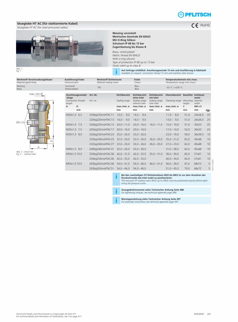
EMV/EMC ∙ 261Technische Details und Informationen zu Zulassungen ab Seite 477For technical details and information of certifications, see f om page 477
Anschlussgewinde/ -länge
Art.-Nr. Dichtbereich Dichtbereich ohne Inlet
Dichtbereich mit Inlet
Klemmbereich Bauhöhe Schlüssel-weite
Connection thread/length
Art. no. Sealing range Sealing range without inlet
Sealing range with inlet
Clamping range Mounting height
Spanner width
A D max./min. ø max./min. ø max./min. ø max./min. ø C SW x E
mm mm mm mm mm mm mm
M20x1,5 6,5 220bg220msHTAC11 14,0 – 9,0 14,0 – 9,0 11,0 – 8,0 51,0 24x26,5 25
220bg220msHTAC13 14,0 – 9,0 14,0 – 9,0 13,0 – 9,0 51,0 24x26,5 25
M20x1,5 7,5 220bg225msHTAC15 20,0 – 11,0 20,0 – 16,0 16,0 – 11,0 15,0 – 10,0 51,0 30x33 25
M25x1,5 7,5 225bg225msHTAC17 20,0 – 16,0 20,0 – 16,0 17,0 – 14,0 52,0 30x33 25
M32x1,5 8,0 232bg232msHTAC23 25,0 – 20,0 25,0 – 20,0 23,0 – 19,0 59,0 36x39,5 10
232bg240msHTAC25 32,0 – 20,0 32,0 – 26,0 26,0 – 20,0 25,0 – 21,0 62,0 45x48 10
232bg240msHTAC27 32,0 – 20,0 32,0 – 26,0 26,0 – 20,0 27,0 – 23,0 62,0 45x48 10
M40x1,5 8,0 240bg240msHTAC31 32,0 – 26,0 32,0 – 26,0 31,0 – 28,0 62,0 45x48 10
M50x1,5 10,0 250bg250msHTAC36 42,0 – 31,0 42,0 – 35,0 35,0 – 31,0 36,0 – 30,0 65,0 57x61 10
250bg250msHTAC40 42,0 – 35,0 42,0 – 35,0 40,0 – 34,0 65,0 57x61 10
M63x1,5 10,0 263bg263msHTAC46 54,0 – 41,0 54,0 – 46,0 46,0 – 41,0 46,0 – 39,0 67,0 68x72 5
263bg263msHTAC51 54,0 – 46,0 54,0 – 46,0 51,0 – 45,0 70,0 68x72 5
blueglobe HT AC (für stahlarmierte Kabel) blueglobe HT AC (for steel-armoured cables)
Abb. 1Fig. 1
Abb. 2 – ohne InletFig. 2 – without inlet
Messing vernickeltMetrisches Gewinde EN 60423Mit O-Ring SilikonSchutzart IP 68 bis 15 barZugentlastung bis Klasse B Brass, nickel-platedMetric thread EN 60423With o-ring siliconeType of protection IP 68 up to 15 barStrain relief up to class B
i Auf Anfrage erhältlich: Anschlussgewinde 15 mm und Ausführung in EdelstahlAvailable on request: connection thread 15 mm and stainless steel version
i Bei den zweiteiligen HT-Dichteinsätzen M32 bis M63 ist vor dem Anziehen der Druckschraube das Inlet exakt zu positionieren. The two-part HT sealing insert (M32 up to M63) must be positioned exactly before tight-ening the pressure screw.
i Anzugsdrehmomente siehe Technischer Anhang Seite 488For tightening torques, see technical appendix page 488
i Montageanleitung siehe Technischer Anhang Seite 497For assembly instructions see technical appendix page 497
Werkstoff VerschraubungskörperMaterial gland body
Ausführung/FarbeVersion/colour
Werkstoff DichteinsatzMaterial sealing insert
FarbeColour
Temperaturbereich min./max.Temperature range (min./max.)
MessingBrass
VernickeltNickel-plated
TPEBlauBlue
-55 °C / +200 °C
4301
0 | T
T003
00
RoHS
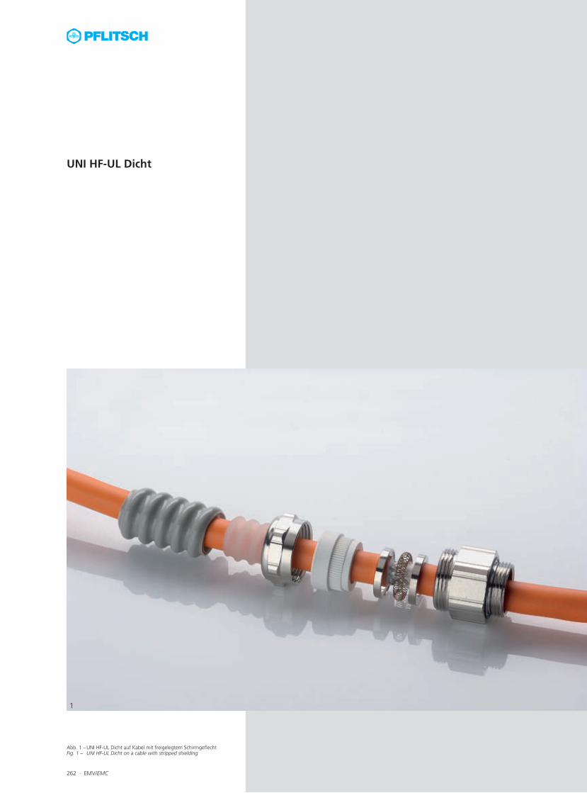
Abb. 1 – UNI HF-UL Dicht auf Kabel mit freigelegtem Schirmgeflecht Fig. 1 – UNI HF-UL Dicht on a cable with stripped shielding
262 ∙ EMV/EMC
1
UNI HF-UL Dicht

Abb. 1 – UNI HF-UL Dicht auf KabelFig. 1 – UNI HF-UL Dicht on a cable
Abb. 2 – Querschnitt UNI HF-UL DichtFig. 2 – Cross section UNI HF-UL Dicht
EMV/EMC ∙ 263
1
2
Schnelle EMV-Kontaktierung und SchlauchanbindungDie UNI HF-UL Dicht-Kabelverschraubung basiert auf der kompakten UNI HF Dicht mit innenliegender IRIS-Feder. Für den Schlauch-anschluss wird die Druckschraube mit entspre-chendem Stutzen aus dem umfangreichen UNI Dicht-Baukasten (siehe Seite 74.) verwendet. Die IRIS-Feder ermöglicht dabei eine schnelle und einfache Kontaktierung zum Kabelschirm, da das Kabelgeflecht nicht abgelängt werden muss. Funktionsprinzip der EMV-KontaktierungBeim Festdrehen der Druckschraube drückt der Dichteinsatz auf zwei Konenscheiben, zwischen denen die ringförmige Spiralfeder (UNI IRIS-Feder) liegt. Dieser Federring verjüngt dadurch seinen Durchmesser und wird an den vorher abisolierten blanken Leitungsschirm gepresst. Das Schirmgeflecht wird auf seinem ganzen Umfang (360°) kontaktiert (Montage-anleitung siehe Technischer Anhang). Es ent-steht eine niederohmige und niederimpedante Verbindung zwischen Schirm, UNI IRIS-Feder und Verschraubungskörper. In Abhängigkeit vom Außendurchmesser der Leitung und des Schirmes kommen zwei verschiedene Monta-gevarianten zur Anwendung:
Variante A: abgesetzter AußenmantelDer Außenmantel der Leitung muss vom Lei-tungsende her so weit entfernt werden, dass die UNI IRIS-Feder auf dem blanken Schirm aufliegt. Der Dichteinsatz soll bei seiner end-gültigen Lage noch in voller Länge auf dem Außenmantel liegen.
Variante B: durchgängiger AußenmantelDer Außenmantel wird in Form eines Ringes nur an der Stelle entfernt, wo sich die endgül-tige Lage der UNI IRIS-Feder in der Kabelver-schraubung befindet. Der Außenmantel kann hinter der Kontaktstelle weitergeführt werden.
Quick EMC contact and hose connectionThe UNI HF-UL Dicht cable gland is based on the compact UNI HF Dicht with an internal IRIS spring. The hose is connected using the pres-sure screw with special nozzle in the compre-hensive UNI Dicht modular system (see page 74). The IRIS spring enables quick and easy bonding with the cable shield because it is not necessary to trim the braiding. Functional principle of EMC contact When the pressure screw is tightened, the sealing insert presses onto two cones, between which the annular spiral spring (UNI IRIS spring) is located. This spring washer tapers as a re-sult and is reliably pressed against the stripped cable shield. The shield is bonded around its entire circumference (360°) (see technical ap-pendix for assembly instructions). A low-resist-ance and low-impedance connection is made between the shield, the UNI IRIS spring and the gland body. Two different assembly methods are used depending on the outer diameter of the cable and the shield:
Variant A: Offset outer sheathThe outer sheath must be stripped from the end of the cable sufficiently far for the UNI IRIS spring to rest on the non-insulated shield. In its final position, the whole length of the sealing insert should still be lying on the outer sheath.
Variant B: Continuous outer sheathA narrow ring of the outer sheath is removed precisely where the UNI IRIS spring will ultim- ately be located on the cable gland. The outer sheath can continue after this contact point.
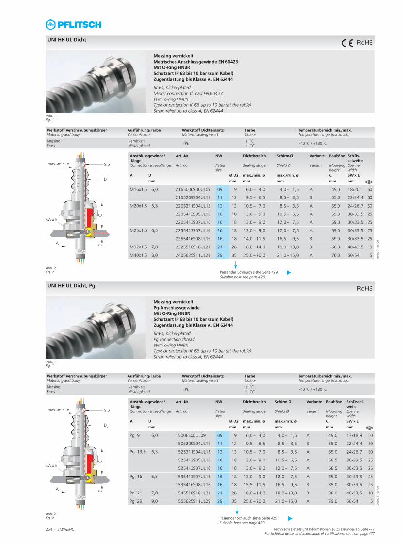
264 ∙ EMV/EMC Technische Details und Informationen zu Zulassungen ab Seite 477For technical details and information of certifications, see f om page 477
Anschlussgewinde/ -länge
Art.-Nr. NW Dichtbereich Schirm-Ø Variante Bauhöhe Schlüs-selweite
Connection thread/length Art. no. Rated size
Sealing range Shield Ø Variant Mounting height
Spanner width
A D Ø D2 max./min. ø max./min. ø C SW x E
mm mm mm mm mm mm
M16x1,5 6,0 2165006S00UL09 09 9 6,0 – 4,0 4,0 – 1,5 A 49,0 18x20 50
2165209S04UL11 11 12 9,5 – 6,5 8,5 – 3,5 B 55,0 22x24,4 50
M20x1,5 6,5 2205311S04UL13 13 13 10,5 – 7,0 8,5 – 3,5 A 55,0 24x26,7 50
2205413S05UL16 16 18 13,0 – 9,0 10,5 – 6,5 A 59,0 30x33,5 25
2205413S07UL16 16 18 13,0 – 9,0 12,0 – 7,5 A 59,0 30x33,5 25
M25x1,5 6,5 2255413S07UL16 16 18 13,0 – 9,0 12,0 – 7,5 A 59,0 30x33,5 25
2255416S08UL16 16 18 14,0 – 11,5 16,5 – 9,5 B 59,0 30x33,5 25
M32x1,5 7,0 2325518S18UL21 21 26 18,0 – 14,0 18,0 – 13,0 B 68,0 40x43,5 10
M40x1,5 8,0 2405625S11UL29 29 35 25,0 – 20,0 21,0 – 15,0 A 76,0 50x54 5
UNI HF-UL Dicht
Abb. 1Fig. 1
Abb. 2 Fig. 2
Messing vernickeltMetrisches Anschlussgewinde EN 60423Mit O-Ring HNBRSchutzart IP 68 bis 10 bar (zum Kabel)Zugentlastung bis Klasse A, EN 62444 Brass, nickel-platedMetric connection thread EN 60423 With o-ring HNBRType of protection IP 68 up to 10 bar (at the cable)Strain relief up to class A, EN 62444
Werkstoff VerschraubungskörperMaterial gland body
Ausführung/FarbeVersion/colour
Werkstoff DichteinsatzMaterial sealing insert
FarbeColour
Temperaturbereich min./max.Temperature range (min./max.)
MessingBrass
VernickeltNickel-plated
TPEs. FCs. CC
-40 °C / +130 °C
2640
0 | T
T037
00
Passender Schlauch siehe Seite 429 Suitable hose see page 429
►
RoHS
Anschlussgewinde/ -länge
Art.-Nr. NW Dichtbereich Schirm-Ø Variante Bauhöhe Schlüssel-weite
Connection thread/length Art. no. Rated size
Sealing range Shield Ø Variant Mounting height
Spanner width
A D Ø D2 max./min. ø max./min. ø C SW x E
mm mm mm mm mm mm
Pg 9 6,0 15006S00UL09 09 9 6,0 – 4,0 4,0 – 1,5 A 49,0 17x18,9 50
1505209S04UL11 11 12 9,5 – 6,5 8,5 – 3,5 B 55,0 22x24,4 50
Pg 13,5 6,5 1525311S04UL13 13 13 10,5 – 7,0 8,5 – 3,5 A 55,0 24x26,7 50
1525413S05UL16 16 18 13,0 – 9,0 10,5 – 6,5 A 58,5 30x33,5 25
1525413S07UL16 16 18 13,0 – 9,0 12,0 – 7,5 A 58,5 30x33,5 25
Pg 16 6,5 1535413S07UL16 16 18 13,0 – 9,0 12,0 – 7,5 A 35,0 30x33,5 25
1535416S08UL16 16 18 15,5 – 11,5 16,5 – 9,5 B 35,0 30x33,5 25
Pg 21 7,0 1545518S18UL21 21 26 18,0 – 14,0 18,0 – 13,0 B 38,0 40x43,5 10
Pg 29 9,0 1555625S11UL29 29 35 25,0 – 20,0 21,0 – 15,0 A 79,0 50x54 5
UNI HF-UL Dicht, Pg
Abb. 1Fig. 1
Abb. 2 Fig. 2
Messing vernickeltPg-AnschlussgewindeMit O-Ring HNBRSchutzart IP 68 bis 10 bar (zum Kabel)Zugentlastung bis Klasse A, EN 62444 Brass, nickel-platedPg connection threadWith o-ring HNBRType of protection IP 68 up to 10 bar (at the cable)Strain relief up to class A, EN 62444
Werkstoff VerschraubungskörperMaterial gland body
Ausführung/FarbeVersion/colour
Werkstoff DichteinsatzMaterial sealing insert
FarbeColour
Temperaturbereich min./max.Temperature range (min./max.)
MessingBrass
VernickeltNickel-plated
TPEs. FCs. CC
-40 °C / +130 °C
2650
0 | T
T037
00
Passender Schlauch siehe Seite 429 Suitable hose see page 429
►
RoHS

EMV/EMC ∙ 265
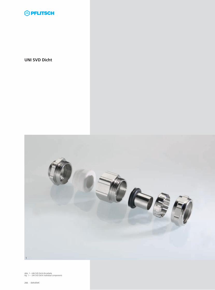
Abb. 1 – UNI SVD Dicht-Einzelteile Fig. 1 – UNI SVD Dicht individual components
266 ∙ EMV/EMC
1
UNI SVD Dicht

Abb. 1 – Montierte UNI SVD Schlauch-KabelverschraubungFig. 1 – Assembled UNI SVD hose cable gland
Abb. 2 – UNI SVD Schlauch-KabelverschraubungFig. 2 – UNI SVD hose cable gland
EMV/EMC ∙ 267
1
2
EMV-Schutz plus mechanische Sicherheit Die UNI SVD Dicht-Kabelverschraubung dichtet ein innenliegendes Kabel ab und kontaktiert sicher einen Elektro-Schutzschlauch (z. B. PVC Buna) mit außenliegendem Stahlgeflecht.
FunktionsprinzipDurch Verschrauben des Zwischenstückes mit dem Doppelnippel wird der Dichteinsatz fest an den Außenmantel der Leitung gepresst und stellt die Schutzart IP 68 sicher. Beim Festdre-hen der Druckschraube drückt ein spezieller Klemmring aus Messing auf das Stahlgeflecht des Schutzschlauches, unter den vorher eine Schlauchtülle geschoben wurde. Die Schutzart der Schlauchabdichtung durch Druckschraube und Klemmring ist IP 44.
Das Schirmgeflecht wird durch den Klemmring auf seinem ganzen Umfang (360°) kontaktiert. Es entsteht eine niederohmige leitende Ver-bindung zwischen dem Schirmgeflecht des Schlauches und dem Verschraubungskörper.
Die Kabelverschraubung steht in zwei An-schlussgewinden mit Standardlänge und mit 15 mm Gewindelänge (auf Anfrage) zur Ver-fügung.
Artikel-NummernDie Artikel-Nummern zu diesem Verschrau-bungstyp entnehmen Sie bitte den Tabellen auf den Seiten 408 und 419 im Kapitel „Ka-belschutz – Wellrohrsystem und Schlauchlö-sungen“.
EMC protection plus mechanical safetyThe UNI SVD Dicht cable gland seals internal cables and provides reliable contact to an elec-trical protective hose (e.g. PVC Buna) with ex-ternal steel braiding.
Functional principleScrewing the intermediary piece with the double nipple causes the sealing insert to be firmly pressed to the line’s outer sheath, guar-anteeing the type of protection IP 68. When the pressure screw is tightened up, a special clamping ring made of brass is pressed onto the steel braid of the protective hose, under which a hose clip was previously positioned. The type of protective of the hose sealing caused by the pressure screw and clamping ring is IP 44.
The braided shield is bonded along its entire circumference (360°) by the clamping ring. A low-resistance connection is made between the hose’s braid and gland body.
This cable gland is available in two connection threads with the standard length and with 15 mm length (on request).
Article numbersThe article numbers of these cable glands can be found in the tables in the chapter “Cable protection – Corrugated conduit system and hose solutions” on pages 408 and 419.

Abb. 1 – UNI Dicht Mehrfach TRI kontaktiert mehrere geschirmte Kabel sicher.
Fig. 1 – UNI Dicht multiple TRI contacts several cables safely
Abb. 2 – EMV-Speziallösung von PFLITSCH: UNI Dicht Mehrfach TRIFig. 2 – EMC special solutions made by PFLITSCH: UNI Dicht multiple TRI
268 ∙ EMV/EMC
1
2
EMV-Speziallösungen:UNI Dicht Mehrfach TRI
EMV special solutions:UNI Dicht Multiple TRI

In your enquiry please indicate the size of the connection thread, the number of screened cables, the number of unscreened cables and the cable and shield diameters. Feel free to combine different spring sizes if you wish.
Bitte nennen Sie uns bei Ihrer Anfrage die Anschlussgewindegröße, die Anzahl an Kabeln mit Schirm, die Anzahl an Kabeln ohne Schirm und den Kabel- sowie den Schirmdurchmesser. Es können auch unterschiedliche Federgrößen miteinander kombiniert werden.
Größe Feder/Anschlussgewinde Spring size/Connection thread
M20 M25 M32 M40 M50 M63
Fbg 212/4 tri, Schirmbereich 5,0 – 3,0 (in mm) Fbg 212/4 tri, shield range 5.0 – 3.0 (in mm)
1 3 5 8 13 21
Fbg 216/5 tri, Schirmbereich 9,0 – 5,0 (in mm) Fbg 216/5 tri, shield range 9.0 – 5.0 (in mm)
1 1 2 4 7 –
Fbg 220/5,5 tri, Schirmbereich 12,0 – 7,0 (in mm) Fbg 220/5,5 tri, shield range 12.0 – 7.0 (in mm)
1 1 1 2 4 7
Fbg 225/6,5 tri, Schirmbereich 16,0 – 10,0 (in mm) Fbg 225/6,5 tri, shield range 16.0 – 10.0 (in mm)
– 1 1 1 – 4
UNI Dicht Mehrfach TRI – auf kleinstem Raum mehrere geschirmte Kabel kontak-tierenDie Anzahl der geschirmten Leitungen nimmt branchenübergreifend in den verschiedensten Applikationen stetig zu. Damit die Störsignale der EMV-Kabel auch weiterhin fachgerecht mit dem Gehäuseeintritt abgeleitet werden kön-nen, bietet PFLITSCH als einziger Hersteller eine EMV-Kabelverschraubung an, mit der mehrere Kabelschirme kontaktiert werden können. Vorteile von UNI Dicht und blueglobe TRI vereintMit dem Dichteinsatz der UNI Dicht-Serie und der bekannten Triangelfeder aus der blueglobe Reihe vereint PFLITSCH die jeweiligen Vorteile:∙ Hohe Schirmdämpfung ∙ Hohe Stromtragfähigkeit∙ Schnelle, einfache und prozesssichere Kon-
taktierung∙ Demontage möglich, ohne Kabelschirm oder
Feder zu beschädigen∙ Auf kleinstem Raum werden mehrere Kabel
einzeln EMV-kontaktiert∙ Verdrehschutz für das Kabel beim Anziehen
der Druckschraube∙ Hohe Zugentlastung bis Klasse A∙ IP 68 bis 10 bar∙ Große Variantenvielfalt Die EMV-Mehrfach-Kabelverschraubungen werden nach Kundenwunsch ausgelegt und gefertigt. In der folgenden Tabelle ist darge-stellt, bei welcher Kabelverschraubungsgröße wie viele Schirme einzeln kontaktiert werden können.
Die nachfolgende Tabelle zeigt die Anzahl möglicher Federn bei gleicher Federgröße in einem Doppelnippel. Je nach Kabelabmessung ist eine Erhöhung der Federanzahl möglich.
UNI Dicht Multiple TRI – bonding with mul-tiple screened cables in a very small spaceThe number of screened cables is steadily in-creasing in all kinds of applications regardless of the industry. To ensure that the interference signals in the EMC cables can still be properly discharged at the point of entry into the en-closure, PFLITSCH offers an EMC cable gland which is suitable for bonding with multiple shields – the only manufacturer to do so. Advantages of UNI Dicht and blueglobe TRI combinedThanks to the UNI Dicht series sealing insert and the familiar triangular spring from the blueglobe series, PFLITSCH combines the fol-lowing advantages:∙ High screening attenuation∙ High current-carrying capacity∙ Quick, easy and reliable contact∙ Disassembly without damaging the cable
shield or the spring∙ Individual EMC contact with multiple cables
in a very small space∙ Cable protected against twisting when the
pressure screw is tightened∙ High strain relief up to class A∙ IP 68 up to 10 bar∙ Many different versions These EMC multiple cable glands are designed and manufactured to suit each customer’s in-dividual wishes. The table below shows how many shields can be individually bonded per cable gland size.
The following table shows the number of possible springs with the same spring size in a double nipple. Depending on the cable di-mensions, it is possible to increase the number of springs.
EMV/EMC ∙ 269

Abb. 1 – Geteilter EMV-Adapter mit TRI-FederFig. 1 – Splittable EMC adapter with TRI spring
Abb. 2 – EMV-Adapter mit ausgezeichneter SchirmdämpfungFig. 2 – EMC adapter with exceptional screening attenuation
Abb. 3 – Montagebeispiel des EMV-AdaptersFig. 3 – Assembly example for EMV adapter
270 ∙ EMV/EMC
1
EMV-Speziallösungen:EMV-Adapter, geteilter EMV-Adapter und EMV-Anschluss-Bock
EMC special solutions:EMC adapter, spittable EMC adapter and EMC connection bracket
2 3
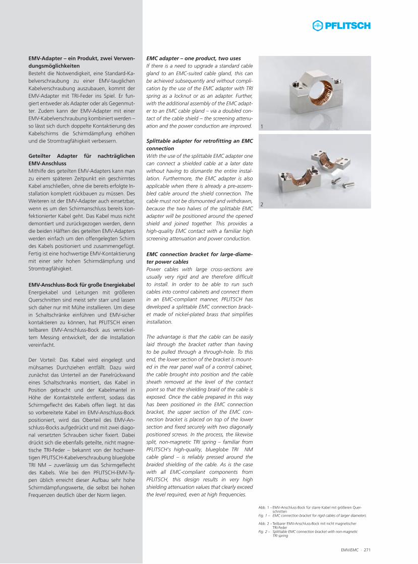
Abb. 1 – EMV-Anschluss-Bock für starre Kabel mit größeren Quer-schnitten
Fig. 1 – EMC connection bracket for rigid cables of larger diameters
Abb. 2 – Teilbarer EMV-Anschluss-Bock mit nicht magnetischer TRI-Feder
Fig. 2 – Splittable EMC connection bracket with non-magnetic TRI spring
EMV-Adapter – ein Produkt, zwei Verwen-dungsmöglichkeitenBesteht die Notwendigkeit, eine Standard-Ka-belverschraubung zu einer EMV-tauglichen Kabelverschraubung auszubauen, kommt der EMV-Adapter mit TRI-Feder ins Spiel. Er fun-giert entweder als Adapter oder als Gegenmut-ter. Zudem kann der EMV-Adapter mit einer EMV-Kabelverschraubung kombiniert werden – so lässt sich durch doppelte Kontaktierung des Kabelschirms die Schirmdämpfung erhöhen und die Stromtragfähigkeit verbessern.
Geteilter Adapter für nachträglichen EMV-AnschlussMithilfe des geteilten EMV-Adapters kann man zu einem späteren Zeitpunkt ein geschirmtes Kabel anschließen, ohne die bereits erfolgte In-stallation komplett rückbauen zu müssen. Des Weiteren ist der EMV-Adapter auch einsetzbar, wenn es um den Schirmanschluss bereits kon-fektionierter Kabel geht. Das Kabel muss nicht demontiert und zurückgezogen werden, denn die beiden Hälften des geteilten EMV-Adapters werden einfach um den offengelegten Schirm des Kabels positioniert und zusammengefügt. Fertig ist eine hochwertige EMV-Kontaktierung mit einer sehr hohen Schirmdämpfung und Stromtragfähigkeit.
EMC adapter – one product, two usesIf there is a need to upgrade a standard cable gland to an EMC-suited cable gland, this can be achieved subsequently and without compli-cation by the use of the EMC adapter with TRI spring as a locknut or as an adapter. Further, with the additional assembly of the EMC adapt-er to an EMC cable gland – via a doubled con-tact of the cable shield – the screening attenu-ation and the power conduction are improved.
Splittable adapter for retrofitting an EMC connectionWith the use of the splittable EMC adapter one can connect a shielded cable at a later date without having to dismantle the entire instal-lation. Furthermore, the EMC adapter is also applicable when there is already a pre-assem-bled cable around the shield connection. The cable must not be dismounted and withdrawn, because the two halves of the splittable EMC adapter will be positioned around the opened shield and joined together. This provides a high-quality EMC contact with a familiar high screening attenuation and power conduction.
EMV/EMC ∙ 271
1
2
EMV-Anschluss-Bock für große EnergiekabelEnergiekabel und Leitungen mit größeren Querschnitten sind meist sehr starr und lassen sich daher nur mit Mühe installieren. Um diese in Schaltschränke einführen und EMV-sicher kontaktieren zu können, hat PFLITSCH einen teilbaren EMV-Anschluss-Bock aus vernickel-tem Messing entwickelt, der die Installation vereinfacht.
Der Vorteil: Das Kabel wird eingelegt und mühsames Durchziehen entfällt. Dazu wird zunächst das Unterteil an der Panelrückwand eines Schaltschranks montiert, das Kabel in Position gebracht und der Kabelmantel in Höhe der Kontaktstelle entfernt, sodass das Schirmgeflecht des Kabels offen liegt. Ist das so vorbereitete Kabel im EMV-Anschluss-Bock positioniert, wird das Oberteil des EMV-An-schluss-Bocks aufgedrückt und mit zwei diago-nal versetzten Schrauben sicher fixiert. Dabei drückt sich die ebenfalls geteilte, nicht magne-tische TRI-Feder – bekannt von der hochwer-tigen PFLITSCH-Kabelverschraubung blueglobe TRI NM – zuverlässig um das Schirmgeflecht des Kabels. Wie bei den PFLITSCH-EMV-Ty-pen üblich erreicht dieser Aufbau sehr hohe Schirmdämpfungswerte, die selbst bei hohen Frequenzen deutlich über der Norm liegen.
EMC connection bracket for large-diame-ter power cablesPower cables with large cross-sections are usually very rigid and are therefore difficultto install. In order to be able to run such cables into control cabinets and connect them in an EMC-compliant manner, PFLITSCH has developed a splittable EMC connection brack-et made of nickel-plated brass that simplifiesinstallation.
The advantage is that the cable can be easily laid through the bracket rather than having to be pulled through a through-hole. To this end, the lower section of the bracket is mount-ed in the rear panel wall of a control cabinet, the cable brought into position and the cable sheath removed at the level of the contact point so that the shielding braid of the cable is exposed. Once the cable prepared in this way has been positioned in the EMC connection bracket, the upper section of the EMC con-nection bracket is placed on top of the lower section and fixed securely with two diagonally positioned screws. In the process, the likewise split, non-magnetic TRI spring – familiar from PFLITSCH’s high-quality, blueglobe TRI NM cable gland – is reliably pressed around the braided shielding of the cable. As is the case with all EMC-compliant components from PFLITSCH, this design results in very high shielding attenuation values that clearly exceed the level required, even at high frequencies.

272 ∙ EMV/EMC Technische Details und Informationen zu Zulassungen ab Seite 477For technical details and information of certifications, see f om page 477
Anschlussgewinde/-länge Art.-Nr. Schirm-Ø Bauhöhe SchlüsselweiteConnection thread/length Art. no. Shield Ø Mounting height Spanner widthA D A2 max./min. ø C SW x E
A mm A2 mm mm mm
M12x1,5 7,8 M12x1,5 AD 212ms tri 5,0 – 3,0 11,2 17x18,9 50
M16x1,5 8,7 M16x1,5 AD 216ms tri 9,0 – 5,0 12,2 20x22,2 50
M20x1,5 8,8 M20x1,5 AD 220ms tri 12,0 – 7,0 14,2 24x26,5 50
M25x1,5 8,8 M25x1,5 AD 225ms tri 16,0 – 10,0 14,2 30x33 50
M32x1,5 11,0 M32x1,5 AD 232ms tri 20,0 – 13,0 14,6 36x39,5 25
M40x1,5 12,0 M40x1,5 AD 240ms tri 28,0 – 20,0 23,0 45x48 10
M50x1,5 15,0 M50x1,5 AD 250ms tri 37,0 – 28,0 23,8 57x61 10
M63x1,5 15,0 M63x1,5 AD 263ms tri 46,0 – 37,0 23,8 68x72 10
Abb. 1Fig. 1
Messing vernickeltMetrisches Gewinde EN 60423Schutzart IP 68 bis 10 bar zum GehäuseMit O-Ring HNBR Brass, nickel platedMetric thread EN 60423Type of protection IP 68 up to 10 bar to the housingWith o-ring HNBR
i Edelstahl auf AnfrageStainless steel on request
i Optional ist die Feder aus Bronze (nicht magnetisch) erhältlich.The spring made of bronze (non-magnetic) is also available.
4610
0 | T
T105
00
EMV-AdapterEMC adapter
Abb. 2 Fig. 2
RoHS
Anschlussgewinde/-länge Art.-Nr. Schirm-Ø Bauhöhe SchlüsselweiteConnection thread/length Art. no. Shield Ø Mounting height Spanner widthA D A2 max./min. ø C SW x E
A mm A2 mm mm mm
M 20 9,0 M20 AD 220ms tri geteilt 12,0 – 7,0 16,0 30x33 1
M 25 9,0 M25 AD 225ms tri geteilt 16,0 – 10,0 16,0 36x39,5 1
M 32 10,0 M32 AD 232ms tri geteilt 20,0 – 13,0 16,0 45x48 1
Abb. 1Fig. 1
Geteilter EMV-AdapterSplittable EMC adapter
Messing vernickeltMetrisches Gewinde EN 60423Ohne O-Ring Brass, nickel platedMetric thread EN 60423Without o-ring
Abb. 2Fig. 2
4850
0 | T
T105
00
Abb. 3 Fig. 3
RoHS
Inner threadInnengewinde
Inner threadInnengewinde

EMV/EMC ∙ 273Technische Details und Informationen zu Zulassungen ab Seite 477For technical details and information of certifications, see f om page 477
Art.-Nr. Schirm-ØArt. no. Shield Ø
max./min. ø A B C Ø d E F
mm mm mm mm mm mm mm
GEA-B 225 triNM 16,0 – 10,0 54 24,0 15 16,0 4,0 42 1
GEA-B 232 triNM 20,0 – 13,0 61 30,0 15 21,0 7,0 49 1
GEA-B 240 triNM 28,0 – 20,0 63 40,0 28 28,0 10,0 49 1
GEA-B 250 triNM 37,0 – 28,0 72 50,0 28 37,0 10,0 58 1
GEA-B 263 triNM 46,0 – 37,0 87 62,0 28 47,0 10,0 73 1
GEA-B 275 triNM 58,0 – 46,0 100 74,0 28 59,0 10,0 86 1
GEA-B 285 triNM 65,0 – 58,0 110 82,0 28 67,5 10,0 96 1
Geteilter EMV-Anschluss-BockSplittable EMC connection bracket
Abb. 1Fig. 1
Abb. 3 Fig. 3
Messing vernickeltFeder aus Bronze, nicht magnetisch Brass, nickel platedSpring made of bronze, non-magnetic
Abb. 2Fig. 2 i Schrauben und Stifte aus Messing
Screws and pins made of brass
i Messing blank auf AnfrageBrass blank on request
i Schrauben zur Befestigung des EMV-Anschluss-Bocks an einer Gehäuse-wand sind nicht im Lieferumfang enthalten. Wir empfehlen folgende Größen der Befestigungsschrauben: M25–M32: M5 M40–M85: M6Screws for fastening the EMC connection bracket to an enclosure wall are not included with the articles. We recommend the following screw sizes:M25–M32: M5M40–M85: M6
4840
0 | T
T106
00
RoHS

274 ∙ EMV/EMC