
Engineering Framework for Service- oriented Automation Systems · font l’objet d’une grande...
208
F ACULDADE DE ENGENHARIA DA UNIVERSIDADE DO PORTO Engineering Framework for Service- oriented Automation Systems João Marco de Melo Pereira Mendes Doctoral Dissertation Programa de Doutoramento em Engenharia Informática Supervisor: Francisco José de Oliveira Restivo (Prof. Doutor) Second supervisor: Paulo Jorge Pinto Leitão (Prof. Doutor) Industrial co-supervisor: Armando Walter Colombo (Prof. Dr.-Ing.) Final Version: March 2011 (Submitted on September 2010)
Transcript of Engineering Framework for Service- oriented Automation Systems · font l’objet d’une grande...
FACULDADE DE ENGENHARIA DA UNIVERSIDADE DO PORTO
Engineering Framework for Service-oriented Automation Systems
João Marco de Melo Pereira Mendes
Doctoral Dissertation
Programa de Doutoramento em Engenharia Informática
Supervisor: Francisco José de Oliveira Restivo (Prof. Doutor)
Second supervisor: Paulo Jorge Pinto Leitão (Prof. Doutor)
Industrial co-supervisor: Armando Walter Colombo (Prof. Dr.-Ing.)
Final Version: March 2011(Submitted on September 2010)


© João Marco de Melo Pereira Mendes, 2011
Departamento de Engenharia Informática
Faculdade de Engenharia da Universidade do Porto
Rua Dr. Roberto Frias s/n, 4200-465 Porto, Portugal
URL: http://paginas.fe.up.pt/~pro06002/wikie-mail: [email protected]


Abstract
Decentralized, autonomous and collaborative automation is becoming an emergent paradigm,
not only when flexibility and reconfigurability are required, but also when the maintenance of the
overall quality is considered. Multi-agent, holonic and service-oriented systems have been subject of
great attention, fitting well with the idea of collaborative automation. Important questions are still
related to the definition of complex processes, its management and integration, especially in service-
oriented automation and production systems.
This dissertation introduces a new engineering framework for service-oriented automation
system. It covers the specification of the architecture, the extensible basis for multiple applications
using Petri nets and the full engineering approach including the necessary software. Most of the
resulting characteristics came from the open methodology for Petri nets, used as a unified tool for
the specification, modeling, analysis and execution of service-based automation systems. Petri nets
were chosen and identified as being part of the solution by presenting a set of useful characteristics.
For this, the open and extensible basis permits the expansion and adaptation to several requirements.
In consequence, with the collaboration of other methodologies that addresses e.g. decision
mechanisms, automatic reconfiguration and service aggregation, the solution may contribute to the
reduction of the design, operation and reconfiguration.
Based on the validation and evaluation of the engineering framework, it is possible to highlight
its contributions, namely the support of several phases in the engineering and the development of
customized Petri net applications based on the formal definition. Moreover, the same Petri net
models can be used for analysis, simulation, operation and support information for decision makers.
Additionally, the composition strategy permits the development of orchestration models without
knowing the final control and displacement layout. Reusable models and well structured engineering
process are towards the enhancements in design and configuration, and consequent operation.
i

ii
Resumo
Automação descentralizada, autónoma e colaborativa está a tornar-se num paradigma emergente,
não só quando a flexibilidade e a reconfiguração são obrigatórias, mas também quando a manutenção
da qualidade em geral é considerada. Sistemas multi-agente, holónicos e orientados a serviços têm
sido objecto de grande atenção, integrando-se bem com a ideia de automação colaborativa. No
entanto, questões importantes ainda estão relacionadas com a definição de processos complexos, a
gestão e integração de sistemas, especialmente considerando sistemas de automação e produção
orientados a serviços.
Esta dissertação apresenta um novo engineering framework para sistemas de automação orientados a
serviços. O conteúdo abrange as especificações da arquitectura, a base extensível para aplicações
múltiplas utilizando redes de Petri e uma abordagem completa de engenharia, incluindo o software
necessário. A maioria das características resultam da metodologia aberta para redes de Petri, utilizada
como um instrumento unificado para a especificação, modelagem, análise e execução de sistemas de
automação baseados em serviços. As redes de Petri foram escolhidas e identificadas como sendo
parte da solução, devido ao seu conjunto de características úteis. Para isso, a base aberta e extensível
permite a expansão e adaptação às diversas exigências. Em consequência, com a colaboração de
outras metodologias que abordam, por exemplo mecanismos de decisão, reconfiguração automática e
agregação de serviços, a solução pode contribuir para a redução do design, operação e
reconfiguração.
Com base na validação e avaliação do engineering framework, é possível destacar as suas
contribuições, ou seja, o apoio às várias fases de engenharia e desenvolvimento de aplicações
personalizáveis de rede de Petri baseadas na definição formal. Além disso, os mesmos modelos de
rede de Petri podem ser usados para a análise, simulação, operação e suporte de informações para os
sistemas de decisão. A estratégia de composição permite também o desenvolvimento de modelos de
orquestração sem saber a disposição final do controlo. Modelos reutilizáveis e processo de engenharia
bem estruturado são importantes na melhoria no design, configuração, e consequente operação.
iii

iv
Resumé
L’automatisme décentralisé, autonome et collaboratif devient un paradigme émergent, non
seulement lorsque flexibilité et reconfiguration sont exigées, mais aussi lorsque le maintien de la
qualité globale est pris en considération. Des systèmes multi-agents, holoniques et orientés services
font l’objet d’une grande attention, qui s’harmonise parfaitement avec l’idée d’un automatisme
collaboratif. Des questions importantes sont toujours liées à la définition de processus complexes, à
leur gestion et intégration, en particulier dans l’automatisme orienté services et dans les systèmes de
production.
Cette thèse présente un nouveau framework d’ingénierie pour les systèmes automatiques orientés
services. Elle introduit la spécification de l’architecture - la base extensible pour des multiples
applications, en utilisant des réseaux de Petri et une approche d’ingénierie complète, y compris le
logiciel nécessaire. La plupart des caractéristiques résultantes viennent de la méthodologie des réseaux
de Petri, utilisés comme un outil unifié pour la spécification, la modélisation, l’analyse et l’exécution
des systèmes automatiques orientés services. Les réseaux de Petri ont été choisis et identifiés comme
étant partie de la solution en présentant un ensemble de caractéristiques utiles. Pour cela, une base
ouverte et extensible permet l’expansion et l’adaptation de nombreuses exigences. En conséquence,
en collaboration avec d’autres méthodologies qui adressent par exemple des mécanismes de décision,
la reconfiguration automatique et l’agrégation des services, la solution proposée peut contribuer à
réduire le temps de conception, d’exploitation et de reconfiguration.
En se basant sur la validation et l’évaluation du framework d’ingénierie, il est possible de mettre
en évidence ses contributions, à savoir le soutien dans plusieurs phases de l’ingénierie et dans le
développement des applications de réseaux de Petri personnalisés basées sur la définition formelle.
En outre, les mêmes modèles de réseaux de Petri peuvent être utilisés pour l’analyse, la simulation,
l’exploitation et le soutien d’information pour les décideurs. En plus, la stratégie de composition
permet de développer de modèles d’orchestration sans savoir la régulation finale et l’agencement de
déplacement. Des modèles réutilisables et des processus d’ingénierie bien structurés s’orientent vers
une réduction des efforts de conception et de configuration.
v

vi
Zusammenfassung
Dezentrale, autonome und kollaborative Automatisierungssysteme gelten zur Zeit als
aufstrebendes Paradigma, nicht nur wenn Flexibilität und Rekonfigurierbarkeit erforderlich sind,
sondern auch wenn die Aufrechterhaltung der Qualität insgesamt betrachtet wird. Multi-Agenten,
holonischen und serviceorientierten Systemen wird heutzutage große Betrachtung geschenkt, auch
im Bezug auf die Eigenschaften der kollaborativen Automatisierung. Jedoch stehen immer noch
wichtige Fragen im Zusammenhang auf die Definition von komplexen Prozessen, die Verwaltung
und Integration von Systemen, vor allem im Bereich von serviceorientierten Automatisierungs-und
Produktionssystemen offen.
Diese Dissertation stellt eine neue Engineering Framework für serviceorientierte
Automatisierungssysteme vor. Es umfasst die Spezifikation der Architektur, die erweiterbare
Grundlage für mehrere Anwendungen die Petri-Netze benutzen und ein vollständiger Engineering-
Ansatz, einschließlich die erforderlichen Software. Die meisten der daraus resultierenden Merkmale
stammen aus der flexiblen Methode der Petri-Netze, die als ein einheitliches Werkzeug zur
Spezifikation, Modellierung, Analyse und Durchführung von servicebasierten
Automatisierungssystemen benutzt wird. Aufgrund der mathematischen Vorteile die Petri-Netze
bieten, wurde diese zur Grundlage der These. Ein weiterer Vorteil ist die leichte Erweiterung der
Netze. Im Zusammenarbeit mit anderen Methoden, sollte diese Engineering Framework zur
Reduzierung der Planung, Betrieb und Rekonfiguration beitragen.
Aufgrund der durchgeführten Testreihe wurde festgestellt, dass die Engineering Framework
verschiedene Unterstützungsmerkmale für die Engineeringsphasen aufweist. Zum ersten können die
Petri-Netz Modelle für die Analyse, Simulation, Betrieb und als Informationsunterstützung von
Entscheidungssystemen dienen. Zum zweiten ermöglicht es die Kompositionsstrategie der
Entwicklung von Orchestrierungsmodelle, ohne dass das Controllayout vorliegen muss.
Wiederverwendbare Prozesse verbessern das Design und die Konfiguration der serviceorientierten
Automatisierungssysteme.
vii

viii

Acknowledgments
First and foremost I offer my sincerest gratitude to my supervisors, Prof. Francisco Restivo and
Prof. Paulo Leitão, who have supported me throughout my thesis with their patience and knowledge
whilst allowing me the room to work in my own way. I attribute the level of my degree to their
encouragement and effort and without them this thesis, too, would not have been completed or
written.
My sincerely greetings goes to Prof. Armando W. Colombo, for all the dedication effort and
humanism. Despite of his busy occupation with the management of projects (and now teaching), he
always gave me motivation and orientation in the right moments.
I am grateful to all the people of Schneider Electric Automation in Seligenstadt, where I did the
most part of my research work. A big thank you goes to Axel, Daniel, Dorian, Javier, Nataliya, Nuno,
Ralf, Ronald, Rudi, and many others.
Of course, I do not forget the several students that were at Schneider: Alexandre, João, Joel, José,
Mohammed, Pedro, Than, Viktor, ... (sorry for the ones I forgot to put here).
I would like to show my gratitude to many international researchers and industrial experts that I
met in conferences. This goes also for the people of the SOCRADES project, were I could
demonstrate and evaluate part of my work.
I want to express my gratitude to my family for all the support and motivation given during my
life, as much as in the easy moments as in the difficult ones. Without them I would not be here.
Finally, I dedicate this work to the sweetest person: Christina. Her love, affection, trust and
support were indispensable for the conclusion of this thesis.
The Author.
ix

x

““No intelligent idea can gain general acceptance unless some stupidity is mixed in with it.”
Fernando Pessoa (1888 – 1935)
xi

xii
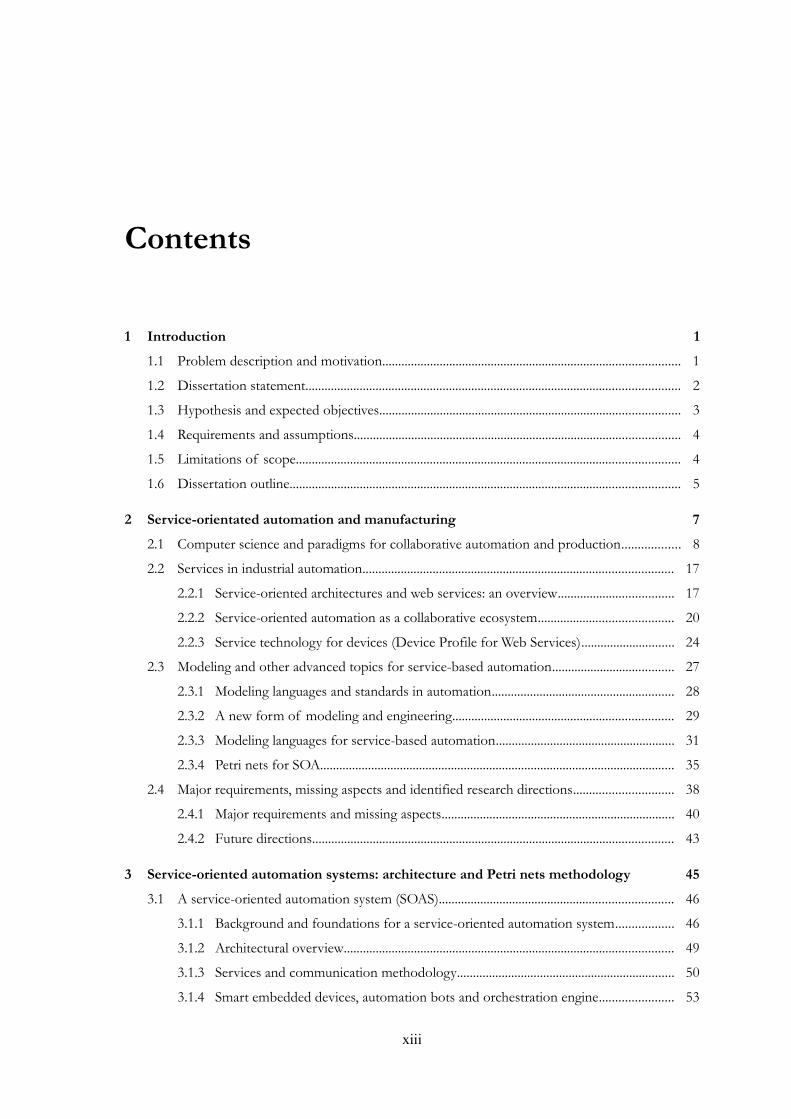
Contents
1 Introduction 11.1 Problem description and motivation............................................................................................. 1
1.2 Dissertation statement..................................................................................................................... 2
1.3 Hypothesis and expected objectives.............................................................................................. 3
1.4 Requirements and assumptions...................................................................................................... 4
1.5 Limitations of scope........................................................................................................................ 4
1.6 Dissertation outline.......................................................................................................................... 5
2 Service-orientated automation and manufacturing 72.1 Computer science and paradigms for collaborative automation and production.................. 8
2.2 Services in industrial automation................................................................................................. 17
2.2.1 Service-oriented architectures and web services: an overview.................................... 17
2.2.2 Service-oriented automation as a collaborative ecosystem.......................................... 20
2.2.3 Service technology for devices (Device Profile for Web Services)............................. 24
2.3 Modeling and other advanced topics for service-based automation...................................... 27
2.3.1 Modeling languages and standards in automation......................................................... 28
2.3.2 A new form of modeling and engineering..................................................................... 29
2.3.3 Modeling languages for service-based automation........................................................ 31
2.3.4 Petri nets for SOA............................................................................................................... 35
2.4 Major requirements, missing aspects and identified research directions............................... 38
2.4.1 Major requirements and missing aspects......................................................................... 40
2.4.2 Future directions................................................................................................................. 43
3 Service-oriented automation systems: architecture and Petri nets methodology 453.1 A service-oriented automation system (SOAS)......................................................................... 46
3.1.1 Background and foundations for a service-oriented automation system.................. 46
3.1.2 Architectural overview....................................................................................................... 49
3.1.3 Services and communication methodology.................................................................... 50
3.1.4 Smart embedded devices, automation bots and orchestration engine....................... 53
xiii

xiv
3.2 Open methodology for Petri nets in the modeling, analysis and execution of SOAS........ 54
3.2.1 Petri nets formalism............................................................................................................ 56
3.2.2 Analysis................................................................................................................................. 57
3.2.3 Conflicts............................................................................................................................... 58
3.2.4 Property system................................................................................................................... 59
3.2.5 Timed Petri nets.................................................................................................................. 60
3.2.6 Petri nets dynamics: a template for token games........................................................... 62
3.2.7 User-developed Petri nets applications............................................................................ 66
3.3 Features and extensions for Petri nets based on the open methodology.............................. 66
3.3.1 Petri net models and ports................................................................................................. 67
3.3.2 Service association to Petri nets........................................................................................ 70
3.3.3 Description of Petri nets in XML.................................................................................... 72
3.3.4 Composition of Petri nets................................................................................................. 73
3.3.5 Decision support system.................................................................................................... 77
4 Service-oriented automation systems: tools, implementation and engineering 814.1 Continuum Development Tools................................................................................................... 83
4.1.1 Bot framework..................................................................................................................... 86
4.1.2 Automation bot with the Petri nets kernel module....................................................... 89
4.1.3 Development studio for engineers................................................................................... 95
4.2 Engineering process....................................................................................................................... 98
4.2.1 Hardware setup and definition of atomic services..................................................... 100
4.2.2 Design and analysis of orchestration models............................................................... 100
4.2.3 Orchestration strategy and composition of models................................................... 106
4.2.4 Configuration and deployment....................................................................................... 108
4.2.5 Operation........................................................................................................................... 111
5 Application and Evaluation 1175.1 Assembly automation in manufacturing: Seligenstadt demonstrator................................... 117
5.1.1 Hardware setup and definition of atomic services..................................................... 121
5.1.2 Design and analysis of orchestration models............................................................... 126
5.1.3 Orchestration strategy and composition of models................................................... 132
5.1.4 Configuration and deployment....................................................................................... 134
5.1.5 Use-cases and features..................................................................................................... 134
5.2 Mechatronic trials: Aachen Demonstrator............................................................................... 135
5.2.1 The trial scenario concept............................................................................................... 135
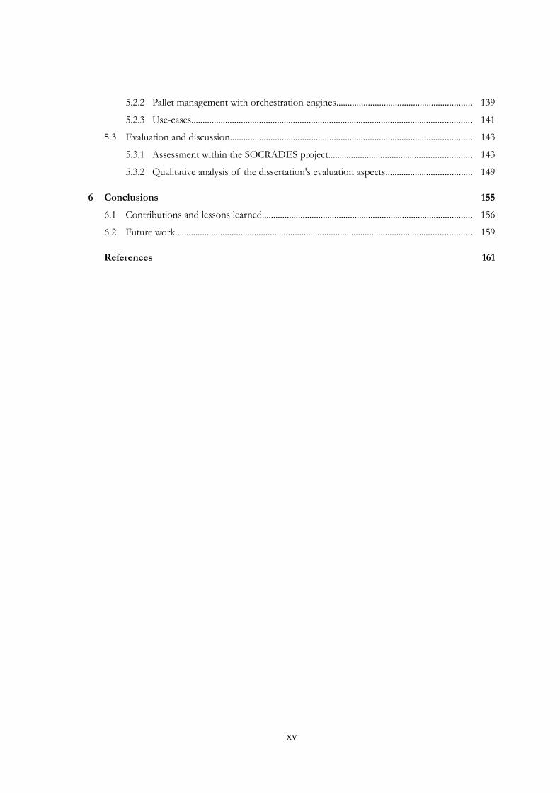
5.2.2 Pallet management with orchestration engines............................................................ 139
5.2.3 Use-cases............................................................................................................................ 141
5.3 Evaluation and discussion........................................................................................................... 143
5.3.1 Assessment within the SOCRADES project............................................................... 143
5.3.2 Qualitative analysis of the dissertation's evaluation aspects...................................... 149
6 Conclusions 1556.1 Contributions and lessons learned............................................................................................. 156
6.2 Future work................................................................................................................................... 159
References 161
xv

xvi

List of figures
Figure 1: Main clusters of this dissertation .................................................................................................. 5
Figure 2: Economic goals for various manufacturing paradigms ........................................................... 11
Figure 3: ARC's collaborative management model (left) and collaborative industrial automation ... 12
Figure 4: Modern IT-enterprise for manufacturing .................................................................................. 14
Figure 5: “Magic” SOA triangle with core web services protocols ........................................................ 18
Figure 6: Modern IT-enterprise for manufacturing using service-orientation ..................................... 22
Figure 7: SOCRADES infrastructure views .............................................................................................. 24
Figure 8: DPWS protocol stack (left) and device architecture (right) .................................................... 26
Figure 9: Web service platform and engineering levels with some common topics ........................... 27
Figure 10: Most common interaction methods in SOA .......................................................................... 32
Figure 11: The SOCRADES device and surrounding topics/requirements ........................................ 39
Figure 12: Service-oriented industrial automation ecosystem integrated to the CMM model .......... 47
Figure 13: Service-oriented automation bot and its environment .......................................................... 48
Figure 14: Most important elements of the architecture of SOAS ....................................................... 49
Figure 15: Interaction between provider and requester (A) and types of services (B) ....................... 51
Figure 16: Sequence diagram of the message exchange patterns ........................................................... 52
Figure 17: Smart embedded device with internal automation bot ......................................................... 53
Figure 18: Modeling, analysis and execution of Petri nets in service-oriented automation systems 55
Figure 19: Approach for the open methodology for applied Petri nets ................................................ 56
Figure 20: Life-cycle of a transition ............................................................................................................ 61
Figure 21: State diagram of a Petri net transition ..................................................................................... 64
Figure 22: Dependency graph for features and extensions of Petri nets .............................................. 67
Figure 23: Basic control flow patterns for Petri nets used in this work ................................................ 68
Figure 24: Example Petri net model associated to the behavior of a conveyor .................................. 70
Figure 25: Two types of service message association to transitions ...................................................... 71
Figure 26: Example of Figure 24 associated to services ......................................................................... 72
Figure 27: Composition of Petri net models and their execution in orchestration engines .............. 74
Figure 28: Offline composition of Petri nets PN1 and PN2 resulting in PN1∪2 .............................. 74
xvii
xviii
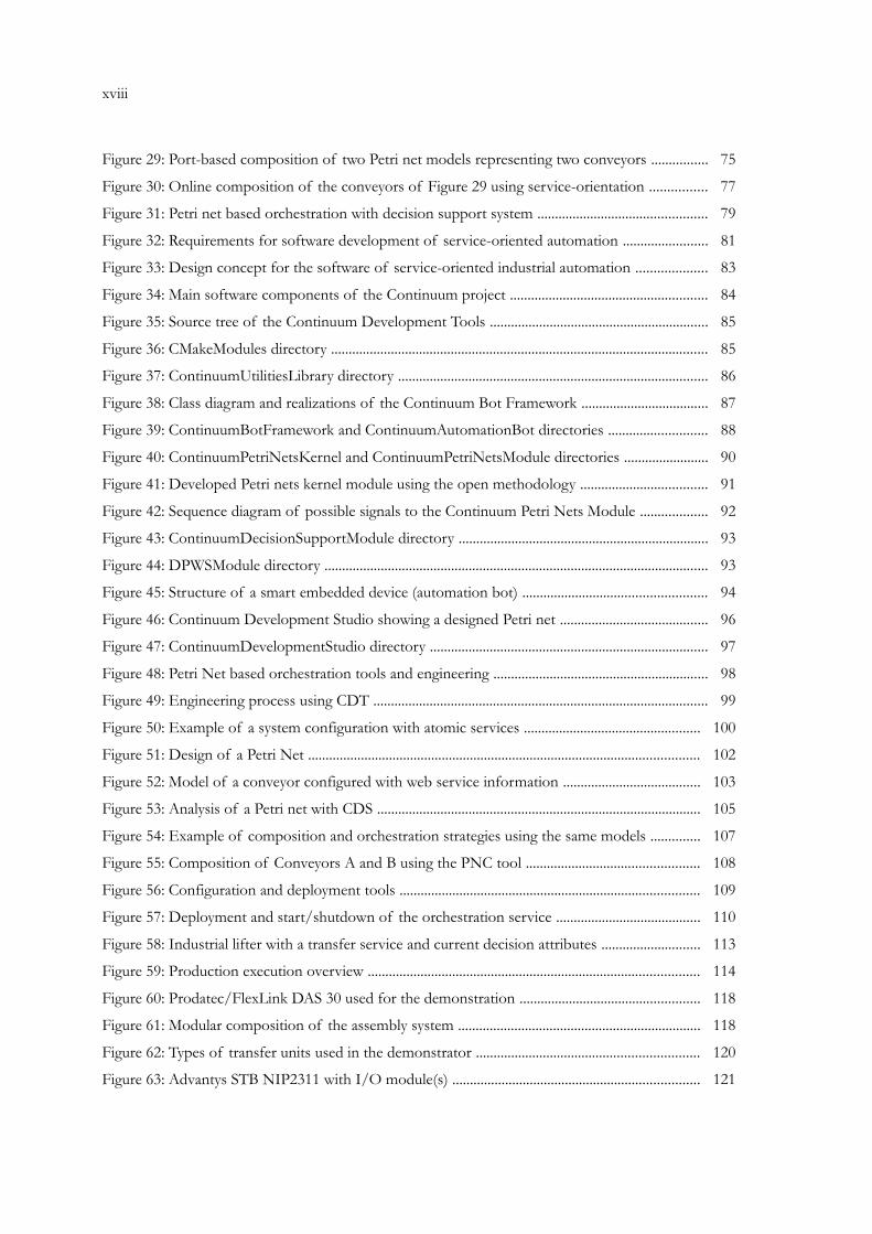
Figure 29: Port-based composition of two Petri net models representing two conveyors ................ 75
Figure 30: Online composition of the conveyors of Figure 29 using service-orientation ................ 77
Figure 31: Petri net based orchestration with decision support system ................................................ 79
Figure 32: Requirements for software development of service-oriented automation ........................ 81
Figure 33: Design concept for the software of service-oriented industrial automation .................... 83
Figure 34: Main software components of the Continuum project ........................................................ 84
Figure 35: Source tree of the Continuum Development Tools .............................................................. 85
Figure 36: CMakeModules directory ........................................................................................................... 85
Figure 37: ContinuumUtilitiesLibrary directory ........................................................................................ 86
Figure 38: Class diagram and realizations of the Continuum Bot Framework .................................... 87
Figure 39: ContinuumBotFramework and ContinuumAutomationBot directories ............................ 88
Figure 40: ContinuumPetriNetsKernel and ContinuumPetriNetsModule directories ........................ 90
Figure 41: Developed Petri nets kernel module using the open methodology .................................... 91
Figure 42: Sequence diagram of possible signals to the Continuum Petri Nets Module ................... 92
Figure 43: ContinuumDecisionSupportModule directory ....................................................................... 93
Figure 44: DPWSModule directory ............................................................................................................. 93
Figure 45: Structure of a smart embedded device (automation bot) .................................................... 94
Figure 46: Continuum Development Studio showing a designed Petri net .......................................... 96
Figure 47: ContinuumDevelopmentStudio directory ............................................................................... 97
Figure 48: Petri Net based orchestration tools and engineering ............................................................. 98
Figure 49: Engineering process using CDT ............................................................................................... 99
Figure 50: Example of a system configuration with atomic services .................................................. 100
Figure 51: Design of a Petri Net ............................................................................................................... 102
Figure 52: Model of a conveyor configured with web service information ....................................... 103
Figure 53: Analysis of a Petri net with CDS ............................................................................................ 105
Figure 54: Example of composition and orchestration strategies using the same models .............. 107
Figure 55: Composition of Conveyors A and B using the PNC tool ................................................. 108
Figure 56: Configuration and deployment tools ..................................................................................... 109
Figure 57: Deployment and start/shutdown of the orchestration service ......................................... 110
Figure 58: Industrial lifter with a transfer service and current decision attributes ............................ 113
Figure 59: Production execution overview .............................................................................................. 114
Figure 60: Prodatec/FlexLink DAS 30 used for the demonstration ................................................... 118
Figure 61: Modular composition of the assembly system ..................................................................... 118
Figure 62: Types of transfer units used in the demonstrator ............................................................... 120
Figure 63: Advantys STB NIP2311 with I/O module(s) ...................................................................... 121

Figure 64: Connection of mechanics, automation devices and network ............................................ 123
Figure 65: Message sequence for the operations of the transfer units (left) and lifters (right) ....... 125
Figure 66: Service landscape of the system ............................................................................................. 125
Figure 67: Identification of the global behavior with a Petri net structure ........................................ 126
Figure 68: Device connection approach based on distributed orchestration ..................................... 127
Figure 69: Orchestration of transfer units ............................................................................................... 127
Figure 70: Orchestration of lifters ............................................................................................................ 128
Figure 71: Conflict and resource sharing modeling for the cross units L4 and L6 ........................... 129
Figure 72: Modeling decisions on workstations ...................................................................................... 130
Figure 73: Analysis of the transfer unit model of Figure 69 ................................................................ 130
Figure 74: Analysis of the lifter model of Figure 70 ............................................................................. 131
Figure 75: Connection of behavior models and generation of orchestration services .................... 133
Figure 76: Realistic background of the trial scenario concept ............................................................. 136
Figure 77: Gantry robot system in the Mechatronic Centre of Aachen, Germany .......................... 137
Figure 78: Layout of the application scenario represented by the trial site ........................................ 138
Figure 79: Orchestration sequence diagram ............................................................................................ 141
Figure 80: Trial enterprise integration sequence diagram ...................................................................... 142
xix

xx
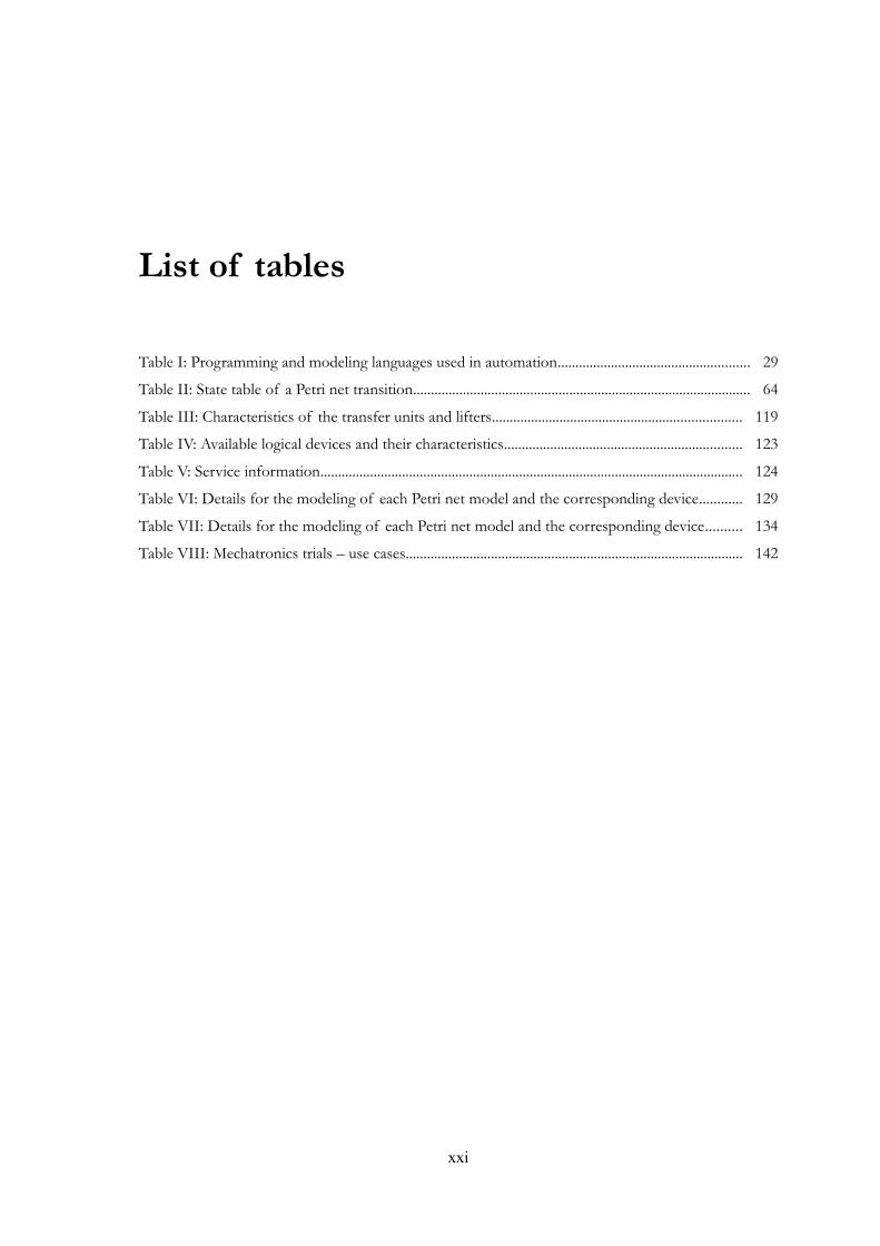
List of tables
Table I: Programming and modeling languages used in automation...................................................... 29
Table II: State table of a Petri net transition............................................................................................... 64
Table III: Characteristics of the transfer units and lifters...................................................................... 119
Table IV: Available logical devices and their characteristics................................................................... 123
Table V: Service information....................................................................................................................... 124
Table VI: Details for the modeling of each Petri net model and the corresponding device............ 129
Table VII: Details for the modeling of each Petri net model and the corresponding device.......... 134
Table VIII: Mechatronics trials – use cases............................................................................................... 142
xxi

xxii

Abbreviations
B2B Business-to-business
CA Collaborative automation
CBF Continuum Bot Framework
CDT Continuum Development Tools
CDS Continuum Development Studio
CIM Computer-integrated manufacturing
CMM Collaborative management model / collaborative manufacturing management
CPS Cyber-physical system
CWSL Composite Web Service Language
DCOM Distributed Component Object Model
DCS Distributed control system
DPWS Device Profile for Web Services
DSS Decision support system
ERP Enterprise resource planning
FBD Function block diagram
FMS Flexible manufacturing system
FTP File Transfer Protocol
GUI Graphical user interface
HLPN High-level Petri net
HMI Human-machine interface
HMS Holonic manufacturing systems
HTTP HyperText Transfer Protocol
xxiii
xxiv
IAMC Intelligent autonomous mechatronics component
ID Identification
IDE Integrated development environment
IL Instruction list
IMS Intelligent manufacturing system
I/O Input/output
IT Information technology
LD Ladder diagram
LDU Local discover unit
MAS Multi-agent system
MES Manufacturing execution system
OOC Object-oriented computing
OPC-UA OLE for Process Control - Unified Architecture
PC Personal computer
PndK Petri nets development toolKit
PLC Programmable logic controller
PN Petri net
PNC Petri Net Composer
PES Production execution system
QoS Quality of service
RFID Radio-Frequency IDentification
RMI Java Remote Method Invocation
RMS Reconfigurable manufacturing system
SFC Sequential function chart
SIA Server Intelligence Agent
SOA Service-oriented architecture
SOAP Originally stood for Simple Object Access Protocol, and lately also Service Oriented Architecture Protocol, but is now simply SOAP
SOAS Service-oriented automation system
SOC Service-oriented computing
SOM Service-oriented modeling
SOSE Service-oriented system engineering
ST Structured text
STB Small Terminal Box
TNCES Timed net conditions event system
UDDI Universal Description, Discovery and Integration
UML Unified Modeling Language
WS Web services
WS-BPEL Web Services Business Process Execution Language
WS-CDL Web Services Choreography Description Language
WSCL Web Service Conversation Language
WSDL Web Services Description Language, formally Web Services Definition Language
WSFL Web Services Flow Language
XML eXtensible Markup Language
xxv

xxvi

Chapter 1:Introduction
Tomorrow's industrial automation will confront the increase of complexity and growth of
information to be processed and therefore the ability to automate tasks as efficient as possible. The
number of different available options are a consequent challenge for the system developers.
Furthermore, traditional centralized and sequential systems are insufficiently flexible for the required
dynamism to handle different situations, requirements and changing markets. Conventional
automation approaches require too much design and reconfiguration effort and don't deploy as much
as possible the collaborative and distributed “intelligence”.
In opposition to the availability of bleeding edge technology, a significant inroad in industrial
automation and manufacturing plants is missing. The reasons for this situation are various, such as
the missing answers to several basic questions in terms of development and performance of these
systems, efficient methodologies for control software and modular verification before the final
implementation together with methods of reuse and/or reconfiguration of control solutions. Any
new concept requires also a new way of designing and thinking to automation engineers, as well as
the correct identification of requirements by the software engineers to develop powerful software for
computer systems and embedded devices.
1.1 Problem description and motivation
Service-oriented architecture (SOA) is a new model for automation that has proven results in
different areas of computer science (documented, for example, by the book series “Service Oriented
Computing and Applications”). In service-oriented automation systems, the research on coordination
models and composition (service-oriented engineering in general) is a relative a new area (since the
proven concepts of service-oriented architecture at the device level by the SIRENA project
[Jammes2005]). In the center of such solution are the services, but less important are the service
providers and consumers in general, such as embedded devices providing not only services, but
1
2 Introduction
acting as a source of multitask features. In this context, service computing and orientation is not only
a form of communication but instead a philosophy that software entities should adopt by sharing
resources and representing their needs. An assimilation of this direction can be done with
collaborative automation [Mick2003], in terms of autonomous, reusable and loosely-coupled
distributed resources. These characteristics are also part of a SOA and in the end it favors the
proactive control of the shop-floor devices.
The engineering of these systems has to adopt a new development process that is naturally
different to the traditional controller-centric design. The options are to use the already applied
service standards in business and e-commerce fields or the adaption of industrial standards to the
emergent requirements. Of course, a mixed approach could also be beneficial. Nevertheless, in
service-oriented architectures for industrial automation several research directions and solutions have
been presented, but overwhelmingly directed to a specific part of the whole engineering problem.
Thus, a road map is required for integrated solutions of engineering, respecting users, developers,
available hardware and software. Moreover, a formal method is also required to provide design
facilities, with the ability to validate models and to be used as an integration middleware to connect
loosely-coupled services together that are provided by automation components of the shop-floor. In
addition, it should also handle other details that could be beneficial in just using one common
solution. SOA principles such as loose coupling, reusability and the design paradigm of service-
orientation should be as well validated in industrial automation.
The mathematical modeling language of Petri nets [Petri1962] is one of the possible candidates
for the purpose of engineering SOA automation systems and to validate service-orientation and the
reusability of information and resources. Nevertheless, there are missing applications of Petri nets in
service-oriented industrial automation environment, especially a methodology for the development
of custom based and extensible Petri nets software to fit the SOA approach in automation.
1.2 Dissertation statement
This dissertation focus on the specification of a formal, open and unified methodology and
resulting engineering framework that addresses the modeling, analysis, operation and integration of
service-oriented automation systems based on distributed automation devices. The “formality” of
the methodology means that is grounded on proven mathematical theory; “openness” in sense of
being prepared for methodological and implementation extensions and “unity” as one reusable
solution for most of the possible applications.
The fundamental architecture is around the design paradigm of service-orientation and for this
purpose several concepts were introduced in terms of architectural elements and behavior. The
methodology itself is founded in Petri nets and their mathematical characteristics, extended to permit
a flexible basis for service-based automation applications. Therefore, this open methodology is used
within the engineering framework to cover the principles of service-orientation and to permit multi-
featured service-based automation systems. The service-orientation design paradigm and principles
of SOA are validated within this thesis.
Moreover, in terms of implementation, the concepts are translated into a software suite
consisting of engineering tools for PC, as well as software for automation devices providing features
such as web service communication, orchestration engine in the Petri net formalism, distributed
orchestration, online composition and decision support. The service technology of choice is web
services, more concretely Device Profile for Web Services (consisting of a set of web service
protocols specially chosen for low profile devices).
With the choice of a Petri net based formalism, the research question of this work follows as:
“How does a formal, extensible and open methodology contribute to an engineering framework to the design and
management of service-oriented automation components?”. From the viewpoint of the life-cycle, the question
is: “How to contribute to the reduction of the design and operational phases in service-oriented automation systems
using an engineering framework based on formal methods?”. Both of them are connected in such a way that
the answer of one complements the other (depending only on the viewpoint).
1.3 Hypothesis and expected objectives
The hypothesis of this dissertation is formulated in the following way: Design paradigm of
service-orientation and SOA principles can be validated in industrial automation by using a formal,
open and unified methodology based on Petri nets for an engineering framework. Moreover, the
design and operation efforts can therefore be reduced by introducing an engineering framework
respecting SOA principles and formal methods.
The proposed objectives can be resumed by the following lists, both scientific and
implementation objectives.
Scientific objectives – Specification and evaluation of engineering methodology for service-oriented
automation systems using a formal foundation:
• Background and requirements analysis;
• Specification of the architectural elements;
• Formal description and validation of the methodology;
• Integration with the service specification;
• Uncover of most of the methodology features for the engineering of service-oriented
automation systems;
3

4 Introduction
• Validate service-orientation design principles and proof of SOA in automation (at the device
level, but for the orchestration of atomic services and composition).
Implementation objectives – Development of engineering tools and orchestration engine for
automation components:
• Software packages based on the unified methodology;
• Service-oriented automation components (structure) integrated with the used web service
profile for devices and orchestration engine;
• Orchestration engine for automation components (i.e. devices) with several features such as
composition, distributed orchestration (via collaboration with other entities) and decision
support;
• PC-tools for the design and configuration of automation components.
The proposed approach and resulting software package should be evaluated and validated in real
industrial scenarios.
1.4 Requirements and assumptions
The main requirements for this dissertation are the usage of service-oriented architectures for
industrial automation. In terms of technology, Device Profile for Web Services (DPWS) is
considered as the web service specification to be used, as well as implemented frameworks according
to the standard. In terms of architectural elements, besides the required services, automation
components (designated here as automation bots) running on embedded industrial devices are the
main requesters and providers of services, and also participants in distributed orchestration activities
with other entities on the system.
Petri nets were chosen and identified as being part of the solution by presenting a set of useful
characteristics supporting the life-cycle of service-oriented systems. For this, an open basis permits
the expansion and adaptation to several requirements. These nets are applied to the modeling,
analysis, service management, embedded software controllers, decision support system and
monitoring, to improve the fundamentals in the engineering of service-oriented automation systems.
1.5 Limitations of scope
The considered research domain is part of the computer science vain, supporting the application
in industrial automation. The following topics are not included in this research and thus limit its
boundaries:
• Performance aspects with web service device and the technical integration itself;
• Decisions mechanisms (should only detect decision points/conflicts, provide necessary
information from the analysis and ask for its resolution);
• Service composition directed by web semantics and ontologies;
• Multi-agent systems (can be considered only as part of the integration for decisions);
• Automatic reconfiguration (but may provide some patterns such as alternative paths, that
enhance towards automatic reconfiguration);
• Applicability in other domains, such as e-commerce.
1.6 Dissertation outline
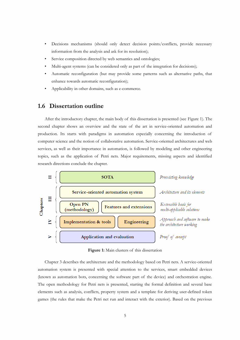
After the introductory chapter, the main body of this dissertation is presented (see Figure 1). The
second chapter shows an overview and the state of the art in service-oriented automation and
production. Its starts with paradigms in automation especially concerning the introduction of
computer science and the notion of collaborative automation. Service-oriented architectures and web
services, as well as their importance in automation, is followed by modeling and other engineering
topics, such as the application of Petri nets. Major requirements, missing aspects and identified
research directions conclude the chapter.
Figure 1: Main clusters of this dissertation
Chapter 3 describes the architecture and the methodology based on Petri nets. A service-oriented
automation system is presented with special attention to the services, smart embedded devices
(known as automation bots, concerning the software part of the device) and orchestration engine.
The open methodology for Petri nets is presented, starting the formal definition and several base
elements such as analysis, conflicts, property system and a template for deriving user-defined token
games (the rules that make the Petri net run and interact with the exterior). Based on the previous
5
6 Introduction
foundation, features and extensions are given, concerning mostly the application in service-oriented
automation systems. These include Petri net models and service association, composition of models
and decision support system.
Tools, implementation and engineering are broached in chapter 4. The Continuum Development
Tools are presented as a software package for the engineering of service-oriented automation
systems. Part of it, the bot framework permits the development of service-oriented entities to be
embedded into automation devices. In addition, this chapter also reports the engineering process that
is expected to be done in conjunction with the software.
Chapter 5 discusses the application of the methodology and software in two industrial
demonstrators: the first one deals with assembly automation in manufacturing and the second one
serves the purpose of integrating different technologies and solutions. The evaluation and discussion
is done afterwards.
Finally, the conclusions are given in the last chapter, including future work that can be done
based on the results of this dissertation.
Chapter 2:Service-orientated automation and manufacturing
The meaning of doing things automatically without our personal intervention is a common
thought, supporting everybody's laziness, quality and comfort against repeated, boring and
sometimes heavy operations. Slavery, animal labor and the utilization of natural forces are some of
the historical documented aspects in this sense. The last one and also revealing the enormous human
creativity towards commodity, permitted the exploration of new forms that are less independent on
the efforts of others. One example is the use of watermills to break wheat grain into flour for baking
breads – one of the oldest prepared food.
Advancements in technology (such as the steam engine and the safe control of electricity)
permitted unprecedented forms of automatic operations and machinery in the industry. Known as
the industrial revolution – new methods and organizations for producing goods – the
industrialization has altered where people live, how they play and how they define political issues.
Innovation is central to most concepts of industrial revolution [Stearns1989]. This is often associated
with the advent of capital intensive plant and equipment, steam power and factories [Hudson2009].
A central nominee of industry is automation. Automation (or specifically industrial automation) is the
use of scientific and technological principles in the manufacture of machines that take over work
normally done by humans [ScienceEncyclopedia2010]. This definition has been disputed by
professional scientists and engineers, but in any case, the term is derived from the longer term
“automatization” or from the phrase “automatic operation”. Delmar S. Harder, a plant manager of
General Motors, is credited with first having used the term in 1935, as “the automatic transfer of
auto parts from one metalworking machine to the next” [TIME1956]. But its meaning has broadened
as fast as its application.
Industrial automation is applied in manufacturing , which in its comprehensive sense, is the process
of converting raw material into products that have value in the market. Manufacturing also involves
7

8 Service-orientated automation and manufacturing
activities in which the manufactured product, itself, is used to make other products [Kalpakjian2005].
Another perspective sees the manufacturing as an internal function that is buffered from the
customer in order to maximize efficiency [Chase1992]. Note that manufacturing and the term
production are used here synonymously. More information about automation and production can be
found, for example, in [Groover2007].
One of the most significant facts is the emergence of decentralized systems capable of dealing
with the rapid changes in the production environment better than the traditional centralized
architectures [Harrison2007]. Different approaches had been developed and analyzed to cover the
requirements of novel automation and production systems. Furthermore, the introduction of
computer science and information technology in automation reflects an obvious convergence in
terms of computation and resolution of problems, including optimization of automation processes
and enhancing manufacturing quality. Solutions can be found from the agent-based systems (as an
example, the ARCHON industrial applications [Horwood1992]) to service-oriented architectures
(diffused with the SIRENA project [Jammes2005]).
The current chapter reports the state-of-the-art and definitions in terms of service-oriented
automation and manufacturing, preceded by models and solutions for distributed and collaborative
automation and the importance of computer science in automation. The kernel is focused on the
engineering topics of such service systems, namely orchestration and composition of services, as well
technological and integration aspects. Current research directions and missing aspects are highlighted
and serve as important background for this dissertation.
2.1 Computer science and paradigms for collaborative automation and production
Computer systems are a constant presence in today's business, technology and services. Behind
the systems relies the science and technology, and in this case, computer science is the basis for the
computation processes translated into software and hardware applications. Closely related, information
technology (IT) deals with several life-cycle elements of information systems that can be computer
based. Moreover, software engineering is related to the methods for the development and maintenance
of software to improve its efficiency in the field where it is applied. Whenever it is information or the
computation to process it, these aspects are common in today's industrial automation, and therefore
the knowledge and experience should be brought together. After decades of parallel development,
the paths of information systems tools and manufacturing systems are converging to provide the
impetus that will allow the integration of the total business enterprise [Fitzgerald1992].
One of the main concerns is the distribution and heterogeneity of resources, and particularly if a
deliberated dispersion makes sense or brings any benefit. In computing, distributed systems are a
natural evolution of isolated computing, not only for extending the limitations in terms of
processing power and consequent drawbacks, but also to assimilate software to the real nature of
things. Examples of dispersions and their relations with the environment can be found in natural
systems (such as ecosystems [Clapham1990]) and also in human-made ones, like theme parks.
Whatever the extent is, the distribution should also be handled with some kind of arrangement and
obey to imposed laws, else the behavior would be chaotic and non-sense. Therefore, distribution and
heterogeneity is often discussed as a beneficial feature or an obstacle for a particular system. The
question in the context of informatics to the previous reference is: How can computer science
contribute and resolve these problems?
Particularly, distribution of equipment, operators, products and information can be found in
modern industrial production systems. Many industrial applications are physically dispersed within a
widely area to be controlled by a single program running on a single computing platform. Years ago,
the method used to deal with these large systems was to decompose the system into smaller, more
manageable subsystems and machines, program the control for each one separately, and then write
custom “glue” code to knit the smaller components into the complete system [Hall2007]. A large
number of factors are critical in the effective operation of such flexible production lines, including
the number of product options, manufacturing operation of each one, product type, workstation
capacity, processing time of the operations at each station, material handling capacity at each work
station, and overall material handling capacity [Ali2005]. Therefore, the resulting data to be
processed, besides being enormous, may also be constantly in change [Mendes2009].
Distribution is only one of the characteristics that is part of modern computer science and also
of automation. Attending to the ACM Computing Classification System [ACM2010], it is possible to
see how diverse the subjects and applications are, in order to reflect the vast and changing world of
computer oriented writing [Mirkin2008]. Looking to the list, the reader can find several topics of the
classification systems that have direct reference to automation and manufacturing: (I.2.1) Artificial
Intelligence – Applications and Expert Systems: Industrial automation, (J.1) – Computer Applications
– Administrative data processing: Manufacturing, (J.7) – Computer Applications – Computers in
other systems: Industrial control, etc. Nevertheless the application is not limited to those references,
as it can be identified by the use of distributed artificial intelligence, data communication devices and
models of computation (just to name a few). Observing the huge number of applications, projects
and publications, computer science has an effective impact in industrial automation as an application
domain, therefore the boundaries should be lowered to permit a greater synergy between them.
One target for computer science in the automation world is the processing of information and
functions of programmable logic controllers (PLC). Traditionally, these systems are used in the control,
9
10 Service-orientated automation and manufacturing
which communicates and synchronizes the operation of individual devices via I/O, providing limited
reconfiguration capabilities. PLCs are at the forefront of manufacturing automation and many
factories use PLCs to cut production costs and or increase quality [Erickson1996]. PLCs still remains
the key of industrial automation, presenting nowadays advanced features, such as networking and
high-level programming environments, to support the development of distributed systems. However,
last years have witnessed a demand for reconfigurable, modular and cost-effective solutions for
industrial automation. In fact, cost, quality and responsiveness are the three main foundations on
which every manufacturing company stands on, to be competitive in the current global economy
[ElMaraghy2006].
In current practice, the control program which runs on the PLC is designed manually, and the
control program together with the time-driven, sequential operating system of the PLC determines
the behavior of the PLC [Hanisch1997]. They are programmed using the IEC 61131-3 standard
[IEC2003], which provides the specification for several languages used in the control (see
[Erickson1996] for a good introduction on these topics). But with the emergence of soft-
programmable hardware and advanced communication techniques, e.g. field-buses, complex
distributed systems consisting of heterogeneous controller devices are becoming quite common
[Hussain2005]. On the other side, the resulting engineering tools used in the development and
deployment processes usually do not address other characteristics, such as modularity, flexibility,
extensibility, reusability, and interoperability [Thramboulidis2003].
In opposite to what happen in terms of evolution of products that become easily old-fashion
after a short period of time, automation and manufacturing systems have been in a peaceful and calm
situation, concerning to the adoption of new research and technology results. An exception may be
the introduction of the IEC 61499 [IEC2005] standard that according to [Hussain2005] marks the
beginning of a new era in the field of software engineering for industrial control systems. The IEC
61499 standard (an event-based function blocks specification) was introduced to extend the
limitations of the previous standards in terms of modularity and distribution. However, its adoption
by the major control system equipment vendors has been slow to nonexistent [Hall2007].
Over the years different models have been introduced and discussed to enhance current
automation and manufacturing systems, including concepts from other domains such as computer
science. Early was identified that automation systems need to follow the changing demands, by
introducing concepts of flexibility and reconfigurability, beside others. This idea is reinforced by
several studies, e.g. the one elaborated by the US Committee on Visionary Manufacturing [CVM1998]
and another one sponsored by High-level Group of the European Commission [EC2004], which
have identified reconfigurable manufacturing as the highest priority for future research in
manufacturing. The NSF Engineering Research Center for reconfigurable manufacturing systems (RMS)
defines reconfigurability as the ability to adjust the production capacity and functionality of a
manufacturing system to new circumstances through the rearrangement or change of the system's
components [Harrison2007]. The aptitude of a system to reconfigure automatically in several
circumstances can be considered as the ultimate dream in production systems, and may affect all
enterprise levels, ranging from the strategic level to the shop floor level comprising physical
automation devices.
RMS extended the concept previously introduced by flexible manufacturing systems (FMS). Where
FMS make possible the manufacture of a variety of products (flexibility) on the same system, RMS
provide the functionality and capacity that is needed, in the sense of increasing the speed of
responsiveness to markets and customers (see [Mehrabi2000]). Thus, a given RMS configuration can
be dedicated or flexible, or in between, and can change as needed. In fact, reconfigurable systems,
instead of incorporating all the flexibility once at the beginning of their life cycle, incorporate basic
process models that can be rearranged or replaced quickly and reliably [Mehrabi2000a].
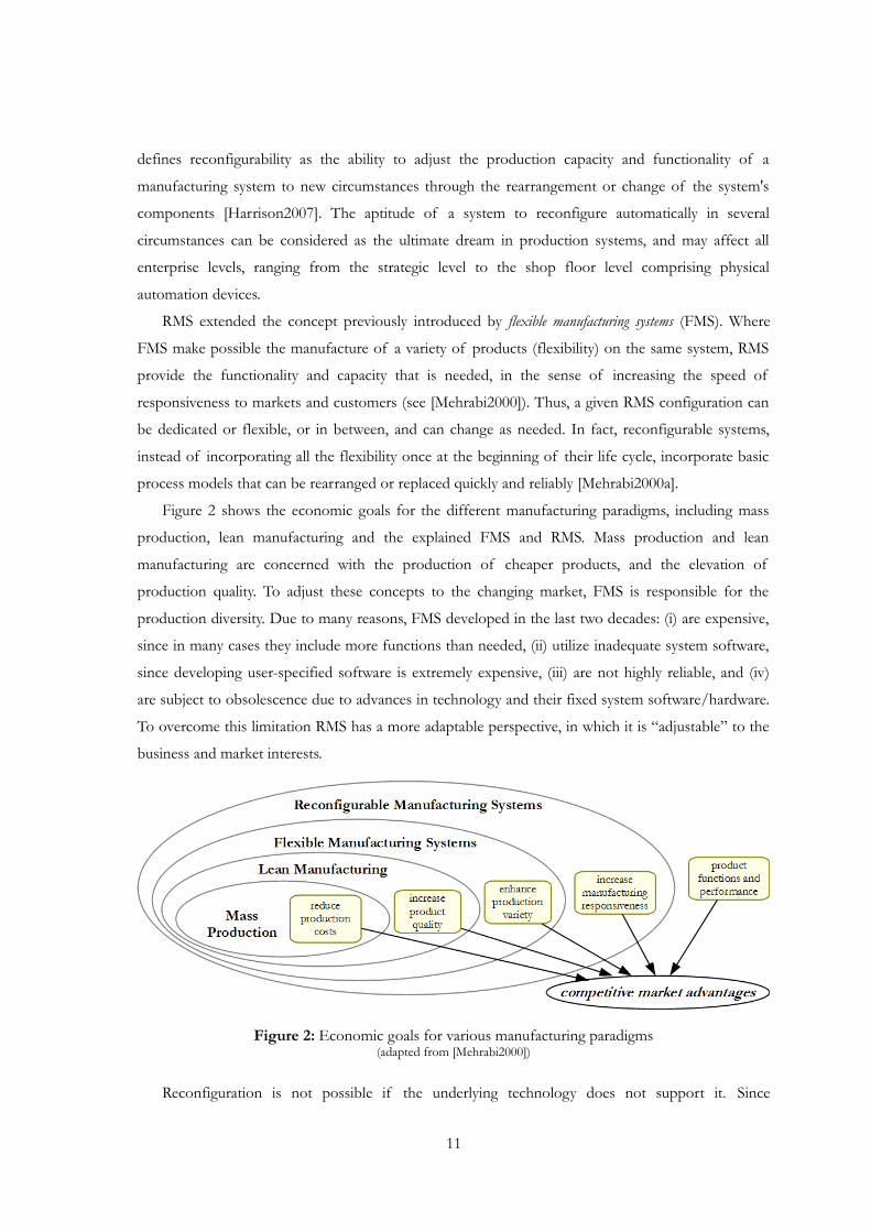
Figure 2 shows the economic goals for the different manufacturing paradigms, including mass
production, lean manufacturing and the explained FMS and RMS. Mass production and lean
manufacturing are concerned with the production of cheaper products, and the elevation of
production quality. To adjust these concepts to the changing market, FMS is responsible for the
production diversity. Due to many reasons, FMS developed in the last two decades: (i) are expensive,
since in many cases they include more functions than needed, (ii) utilize inadequate system software,
since developing user-specified software is extremely expensive, (iii) are not highly reliable, and (iv)
are subject to obsolescence due to advances in technology and their fixed system software/hardware.
To overcome this limitation RMS has a more adaptable perspective, in which it is “adjustable” to the
business and market interests.
Figure 2: Economic goals for various manufacturing paradigms(adapted from [Mehrabi2000])
Reconfiguration is not possible if the underlying technology does not support it. Since
11
12 Service-orientated automation and manufacturing
automation is under the hood of manufacturing, changes have to occur in the automatic processing
of machines and services. Furthermore, the growth in the complexity involving production, process
control, communication, etc. creates numerous problems for their developers [Zhou1999].
Computational control and production strategies have to be adopted to solve the different issues and
to permit that a certain paradigm be feasible. The consequently reduced human intervention also
means a more rigorous attention and responsibility when designing such systems. It was identified
that the use of emergent computer solutions and information technologies is a fundamental engine
to promote the new vision of these systems in the industrial automation. Different from the high-
level concept of the RMS model, several others provide a close inspection to the use of intelligent
and distributed automation and manufacturing to support reconfiguration and other aspects.
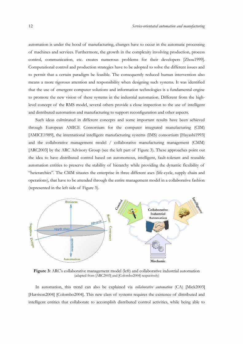
Such ideas culminated in different concepts and some important results have been achieved
through European AMICE Consortium for the computer integrated manufacturing (CIM)
[AMICE1989], the international intelligent manufacturing systems (IMS) consortium [Hayashi1993]
and the collaborative management model / collaborative manufacturing management (CMM)
[ARC2003] by the ARC Advisory Group (see the left part of Figure 3). These approaches point out
the idea to have distributed control based on autonomous, intelligent, fault-tolerant and reusable
automation entities to preserve the stability of hierarchy while providing the dynamic flexibility of
“heterarchies”. The CMM situates the enterprise in three different axes (life-cycle, supply chain and
operations), that have to be attended through the entire management model in a collaborative fashion
(represented in the left side of Figure 3).
Figure 3: ARC's collaborative management model (left) and collaborative industrial automation(adapted from [ARC2003] and [Colombo2004] respectively)
In automation, this trend can also be explained via collaborative automation (CA) [Mick2003]
[Harrison2004] [Colombo2004]. This new class of systems requires the existence of distributed and
intelligent entities that collaborate to accomplish distributed control activities, while being able to
self-organize and evolve organization structures and mechanical devices. The rationale paradigm of
collaborative automation is explained by three main emerging technologies that are integrated
respectively (see the right side of Figure 3 from [Colombo2004]): mechanic, control and intelligence.
These methods are to be used effectively in order to achieve a system with flexibility, reconfigurability
as well as robustness [Colombo2008]. From the computer science side, the control (in parallel with
the traditional control theory) and intelligence are fundamental aspects and demonstrate were
computational theory and practice can be applied.
Applying the collaborative automation paradigm typically means that all the participating groups
such as control vendors, machine builders and system integrators will be confronted with the subject
to migrate from legacy manufacturing systems to new systems composed of building blocks. The
modularization of the production system requires the decomposition of the present “controller-
oriented structure” into functional modules with a “manufacturing-task-oriented structure”.
Furthermore, in order to be able to use the modularized function entities they have to be described
and the functional dependencies of the latter need to be described. The functional/dependency
description also has to respect the mechanical flexibility of the collaborating devices which is a
crucial factor when designing a variable production process. Based on those descriptions the
functional modules are aggregated again to obtain a higher level of autonomy [Colombo2008].
Collaboration can be understood in the three layer IT-enterprise pyramid of Figure 4,
representing the composition of the enterprise resource planning (ERP), manufacturing execution system
(MES) and the shop-floor (in this case, made of the distributed control system, DCS). Information flow
is required between these layers: planning and business data have to be translated so that
manufacturing and control strategies can be defined and, from the other side, feedback should be
returned to be analyzed for future planning. A more collaborative initiative (and not just information
passing procedures) could be beneficial in the sense of offering and using services that represent
integration and support resources from the layers.
ERPs are an alternative approach to the traditional software development methods. ERPs are
integrated and enterprise wide systems which automate core corporate activities such as
manufacturing, human resources, finance and supply chain management. From a business
perspective, the software and the business processes need to be aligned which involves a mixture of
business process design and software configuration [Gibson1999]. These front ends normally
includes all office planning, scheduling, sales, and services systems, whereas the back end includes the
supportive logistics, MESs, and shop floor controls that oversee the real value-added manufacturing
activities [Qiu2004].
13
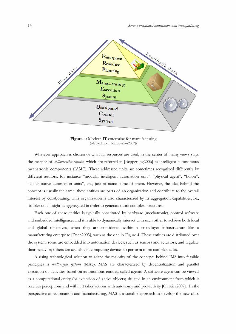
14 Service-orientated automation and manufacturing
Figure 4: Modern IT-enterprise for manufacturing(adapted from [Karnouskos2007])
Whatever approach is chosen or what IT resources are used, in the center of many views stays
the essence of collaborative entities, which are referred in [Bepperling2006] as intelligent autonomous
mechatronic components (IAMC). These addressed units are sometimes recognized differently by
different authors, for instance “modular intelligent automation unit”, “physical agent”, “holon”,
“collaborative automation units”, etc., just to name some of them. However, the idea behind the
concept is usually the same: these entities are parts of an organization and contribute to the overall
interest by collaborating. This organization is also characterized by its aggregation capabilities, i.e.,
simpler units might be aggregated in order to generate more complex structures.
Each one of these entities is typically constituted by hardware (mechatronic), control software
and embedded intelligence, and it is able to dynamically interact with each other to achieve both local
and global objectives, when they are considered within a cross-layer infrastructure like a
manufacturing enterprise [Deen2003], such as the one in Figure 4. These entities are distributed over
the system: some are embedded into automation devices, such as sensors and actuators, and regulate
their behavior; others are available in computing devices to perform more complex tasks.
A rising technological solution to adapt the majority of the concepts behind IMS into feasible
principles is multi-agent systems (MAS). MAS are characterized by decentralization and parallel
execution of activities based on autonomous entities, called agents. A software agent can be viewed
as a computational entity (or extension of active objects) situated in an environment from which it
receives perceptions and within it takes actions with autonomy and pro-activity [Oliveira2007]. In the
perspective of automation and manufacturing, MAS is a suitable approach to develop the new class
of reconfigurable production systems since they already supports the idea of interaction within a
society of individual agents, fitting well with the idea of a community of collaborative entities.
Additionally, emergence can be mapped into the evolution of the society of agents when identifying
reconfiguration opportunities and defining new complex functionality and behavior.
According to Giret et al. [Giret2005] MAS are good candidates for modeling holonic manufacturing
systems (HMS). In an HMS, key elements such as machines, work centers, plants, parts, products,
persons, departments, or divisions have autonomous and cooperative properties [Gou1998]. These
elements are called “holons”. In an HMS, each holon's activities are determined through the
cooperation with other holons, as opposed to being determined by a centralized mechanism. An
HMS could therefore enjoy high agility, which is an important characteristic for future manufacturing
systems. From the outset, the prevalent software technology to implement the concepts of holonic
manufacturing appeared to be intelligent co-operating agents, also called multi-agent systems
[Bongaerts1998]
Industrial applications of multi-agent and holonic systems are diverse and well documented in
different publications. By enabling networks of autonomous yet interacting reasoning elements, this
technology provides an alternative to the centralized systems prevailing in industry [Marik2005]. One
of the most known MAS architecture for industrial application is ARCHON [Horwood1992],
developed during the ARCHON project – ESPRIT project P-2256 – until 1994. The consortium has
developed a general purpose architecture which can be used to facilitate cooperative problem solving
in industrial applications [Wittig1994]. Another example is the agent-based control system developed
in the project P2000+, able to meet the challenges of flexible and robust manufacturing in the
automotive industry [Bussmann2001] [Schild2007]. ADACOR (ADAptive holonic COntrol
aRchitecture for distributed manufacturing systems) [Leitão2006] is a successful example of the
application of MAS and holonic manufacturing system. ADACOR deals with the frequent
occurrence of unexpected disturbances in a very decentralized way, relying in simple scheduling and
control algorithms and using local information available in the functional blocks.
The topic of cyber-physical systems (CPS) is recently discussed in industrial automation. CPS are
engineered systems that require tight conjoining of and coordination between the computational
(discrete) and the physical (continuous) [Wing2008]. They have a computational core that interacts
with the physical world. The trend in cyber-physical systems is to rely less and less on human
intervention and decision-making and more and more on the intelligence as embodied in the
computational core. Computational components may be distributed, and thus need some sort of
interaction to complete objectives of both cyber and physical parts. Such components can be seen as
collaborative entities with tight integration of the continuous world. Indicators of missing
foundations, such as lack of compositionality and predictability in the engineering process and lack
15
16 Service-orientated automation and manufacturing
of comprehensive design automation tools, are experienced by industry while developing and
operating real-life CPS.
In distributed manufacturing environments, using MAS, HMS, CPS, or other approach, it is
important to guarantee the interoperability between the distributed entities or applications and to
verify that the semantic content is preserved during the exchange of messages between them. In fact,
a study commissioned by NIST (National Institute of Standards and Technology) reported that the
US automotive sector alone expends one billion dollars per year to solve interoperability problems
[Brunnermeier1999]. The solution to those problems requires the use of standard platforms that
support transparent communication between distributed smart control components or applications.
In spite of the promising perspective of agent-based and holonic approaches, the industrial
applications developed in the context of evolvable and reconfigurable manufacturing systems are
extremely rare, and the implemented functionality are normally restrict [Marik2005]. Some other
reasons to sustain this fact can be pointed out, namely i) a new way of thinking, ii) industry want to
use proven technology and is afraid to use emergent terminology usually associated to these new
technologies, like ontologies, self-organization, emergence and learning, iii) the integration with
business levels, and iv) a set of more technical related problems, namely in terms of granularity,
scalability, interoperability, flexibility, modularity and complexity of self-organization mechanisms to
support the reconfigurability and evolution [Leitão2009]. Additionally, the investment required to
implement these approaches is much larger than that required to implement the traditional ones. In
fact, as stated by Schild and Bussmann, flexibility is a future advantage that requires an immediate
investment, while the flexibility advantages are only potential benefits [Schild2007].
The integration of collaborative entities in mechatronic devices still presents some problems,
mainly due to the heterogeneity of these devices. In fact, the majority of agent-based laboratorial
control applications use software agents without the need to integrate physical devices (for example
in the supply chain case) or emulators when they are needed (for example, in manufacturing control
systems). But in the real situations, industrial applications require the integration of physical
mechatronic devices, normally tens or hundreds. Methodologies to support an easy, fast, transparent
and re-usable integration of mechatronic devices is then required.
One of the most recently adopted and with promising applicability for distributed collaborative
automation are service-oriented architectures. The present dissertation's reference architecture is
based on service-orientation and therefore the following sections detail its applicability in automation
and manufacturing domains.

2.2 Services in industrial automation
Distributed software components are being used in the form of distributed objects, function
blocks and services, beside others. The last one, as part of the main element in service-oriented
architectures, is hitting right now the domain of industrial automation systems. The idea of “service-
oriented computing to provide a way to create a new architecture that reflects components' trends
toward autonomy and heterogeneity” [Huhns2005] dominates the view of the future trend. Also its
growing maturity in the business and e-commerce ground, are seen as step forwards for a seamless
integration [Jammes2005c] of resources from different levels.
The root of service-oriented architectures fits well with collaborative automation, in sense of
autonomous, reusable and loosely-coupled distributed components. The use of the service-
orientation paradigm enables the adoption of a unifying technology for all levels of the enterprise,
from sensors and actuators to enterprise business processes [Bepperling2006]. In automation
domain, the vision of using service-orientation is to support the life-cycle in the context of agile and
flexible process control. Therefore, methodologies and technologies for service-oriented
architectures must be sufficient and efficient for the many features and issues that exist in modern
industrial automation.
2.2.1 Service-oriented architectures and web services: an overview
The proliferation of the Internet in the '90s, due to the possibility of sharing information to
other people and organizations, guided to discover of common interests and to search for new
market possibilities. In order to survive the massive competition created by the new on-line economy,
many organizations are rushing to put their core business competencies on the Internet
[Hamadi2003]. In consequence, the emergence of service-oriented architecture and one of its
technological standard, web services (WS), became notorious. Moreover, service-oriented computing (SOC) is
the most promising approach to face the increasing demand for business-aligned applications that
provide the ability to react quickly on new requirements of continuously changing business
environments [Belter2008]. SOC is the computing paradigm that utilizes services as fundamental
elements for developing applications and solutions. To build the service model, SOC relies on the
SOA, which is a way of reorganizing software applications and infrastructure into a set of interacting
services [Papazoglou2003]. The ability to efficiently and effectively share services on the web is a
critical step towards the development of the new on-line economy driven by the business-to-business
(B2B) e-commerce [Hamadi2003]. In parallel, SOA represents also a form of interoperability not
only for Internet environments, but also used for closed networks, inter-application communication,
etc.
17
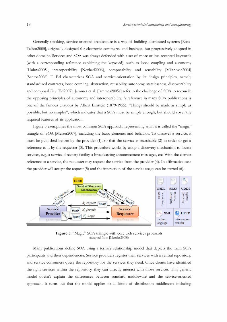
18 Service-orientated automation and manufacturing
Generally speaking, service-oriented architecture is a way of building distributed systems [Ross-
Talbot2005], originally designed for electronic commerce and business, but progressively adopted in
other domains. Services and SOA was always defended with a set of more or less accepted keywords
(with a corresponding reference explaining the keyword), such as loose coupling and autonomy
[Huhns2005], interoperability [Nezhad2006], composability and reusability [Milanovic2004]
[Santos2006]. T. Erl characterizes SOA and service-orientation by its design principles, namely
standardized contracts, loose coupling, abstraction, reusability, autonomy, statelessness, discoverability
and composability [Erl2007]. Jammes et al. [Jammes2005a] refer to the challenge of SOA to reconcile
the opposing principles of autonomy and interoperability. A reference in many SOA publications is
one of the famous citations by Albert Einstein (1879-1955): “Things should be made as simple as
possible, but no simpler”, which indicates that a SOA must be simple enough, but should cover the
required features of its application.
Figure 5 exemplifies the most common SOA approach, representing what it is called the “magic”
triangle of SOA [Melzer2007], including the basic elements and behavior. To discover a service, it
must be published before by the provider (1), so that the service is searchable (2) in order to get a
reference to it by the requester (3). This procedure works by using a discovery mechanism to locate
services, e.g., a service directory facility, a broadcasting announcement messages, etc. With the correct
reference to a service, the requester may request the service from the provider (4). In affirmative case
the provider will accept the request (5) and the interaction of the service usage can be started (6).
Figure 5: “Magic” SOA triangle with core web services protocols(adapted from [Mendes2008])
Many publications define SOA using a ternary relationship model that depicts the main SOA
participants and their dependencies. Service providers register their services with a central repository,
and service consumers query the repository for the services they need. Once clients have identified
the right services within the repository, they can directly interact with those services. This generic
model doesn't explain the differences between standard middleware and the service-oriented
approach. It turns out that the model applies to all kinds of distribution middleware including
CORBA (see comparison in [Lagerberg2002]), a Distributed Component Object Model (DCOM),
Java Remote Method Invocation (RMI), and .NET Remoting.
Although many vendors view SOA as a unique paradigm, SOA functionality can be implemented
in many ways. Information is a commodity. For decades, techniques have been refined for acquiring
and parsing information. Gathering data over the Internet has evolved quite a bit, from basic file
retrieval via the FTP, to the dynamically generated content and the personalized GUI of web pages
today [Ma2005]. Today, the preferable realization of SOA is web services, which provide a language-
neutral, loosely-coupled, and platform independent way for linking applications over the network (Fu
et al. [Fu2006]). Formal definition of WS and additional algebra is given by Hamadi and Benatallah
[Hamadi2003] and Bing and Huaping [Bing2005]. From the practical standpoint, WS offer a
technology that is rich and flexible enough to make SOA a reality [Ma2005].
The underlying structure of the web service platform is made of XML (eXtensible Markup
Language) + HTTP (HyperText Transfer Protocol). The HTTP is one of the most used Internet
protocols, and the XML provides a mark-up language which can be used between different platforms
and programming languages for interchanging information in a standard way. A web service itself is
software that can process a received XML document through some combination of transport and
application protocols [Vogels2003]. These services are made available from a web server for web
users or other web-connected programs. Besides the standardization and wide availability of the
Internet itself, web services are also enabled by the ubiquitous use of XML as a means of
standardizing data formats and exchanging data [Jammes2005b].
One of the major protocols used in web services is WSDL (Web Services Description Language,
formally Web Services Definition Language) [W3C2007], which is a W3C specification that provides
an abstract, technology neutral language for the definition of published operations of a service
[Brenner2007]. In a simple manner, services are a set of operations, which in turn can be one of
different message exchange patterns, for instance request/response or events. The exchange of
information of the operations is via the network using SOAP (originally stood for Simple Object
Access Protocol, and lately also Service Oriented Architecture Protocol, but is now simply SOAP)
formatted messages (which is another web service standard). SOAP is a platform and language
independent communication protocol used between applications, using a simple and extensible XML
based format for sending messages over the Internet. UDDI (Universal Description, Discovery and
Integration) manages a service directory where applications can register and search for web services
in form of interfaces described by WSDL. These protocols are known as the core web services
technologies [Roy2001]. Figure 5 represents the interaction schema using the common core web
service protocols. More information and details about these and other protocols related to web
services can be found in [Ma2005].
19
20 Service-orientated automation and manufacturing
In fact, there are many possible views of SOA, most of which focus on technologies and
implementations for service orientation rather than the architecture. SOA in its fundamental core
doesn't simply define an implementation technology but an architectural solution for a specific design
problem in a given context, with XML web services being just one possible implementation
technology [Stal2006]. Furthermore, the main difference to the other technologies does not only rely
on the implementation of the basic resources, but in the way that they are used and composed into
complex applications. Thus, for the real applicability of WS, advanced topics of engineering have to
exist. Service-oriented System Engineering (SOSE) and Service-oriented Modeling (SOM) are some
examples of emerging areas that involves engineering SOC/SOA applications and associated
techniques include modeling, specifications, analysis, automated code generation, simulation, testing,
monitoring, and policy governing and enforcement [Tsai2006].
2.2.2 Service-oriented automation as a collaborative ecosystem
The SOA paradigm was originally applied in electronic commerce and business systems, using
web services technology, but is being progressively adopted by other fields. SOA was seen as a new
ground for experimentation in industrial automation since its relative success in the business chapter
from the beginning of the 21st century. Since industrial automation and production systems domains
present distinct technical requirements from the original application in business levels, SOA must be
proved not only at its most basic form, but also to permit complex engineering steps that are
required in modern distributed systems.
In the automation domain, the vision of using service-oriented architectures is to support the
life-cycle needs in the context of agile and flexible manufacturing, addressing distributed, modular
and reconfigurable automation systems whose behavior is regulated by the coordination of services.
Service-orientation principles are pointed out as a promising solution to address the current
challenges in industrial automation and production systems, namely the modularity, flexibility and
reconfigurability. Standardized services and advanced separation of interfaces and implementation
enhance the abstraction of component-based development and thereby paving the way for non-
technical software engineers to develop complex, process-oriented software systems [Zeeb2007].
Some services can be composed by other services, creating a leveled structure of services. In these
systems, the behavior is regulated by the coordination of services.
The use of services was already a long discussion in factory automation long before formally
presented in SOC and SOA. From one side, service-based manufacturing and service factory was
discussed in [Chase1992]; from the other side, component services have been part of multi-agent
systems, such as in [Lin1994]. The main difference to SOA/SOC is that there was no main focuses
on service-orientation, interoperability and autonomy concerning services, formal approaches, and
the consideration as a new form of engineering. Another aspect is related to the fact that the service-
oriented systems were adopted from other domains, namely e-commerce and business, which create a
greater challenge in their application in industrial automation. Indeed, Tsai et al. sustain that “the goal
of the industry is no longer manufacturing hardware and software products. Instead, it provides
services that people need” [Tsai2006], which represents this tendency.
Collaboration should be a central topic in SOA, and therefore SOA principles fit well with
collaborative automation, in the sense of autonomous, reusable and loosely-coupled distributed
components. According to [Huhns2002], “A service-oriented architecture is a set of architectural
tenets for building autonomous yet interoperable systems.” and this proposal is facing one of the
challenges of collaborative automation, namely providing interoperability between autonomous
systems. SOA provides a communication platform in which underlying structures and processes can
be encapsulated in one interface, represented by services that may be used externally [Jammes2005].
Contributions have been made about the integration of service-oriented components from the
factory's shop-floor into the IT-enterprise, in order to provide vertical information and control
sharing. One possible solution is that these components provide the required services to the upper
levels of the enterprise and thus are controlled by them. This fits with the service-oriented paradigm,
but the traditional master-slave hierarchy from the top-down perspective is not favorable when
speaking about collaborative and proactive devices. A partial solution is a mix of autonomous devices
from the shop-floor level that may provide services, but also may request services provided by the
other levels, such as decision making systems and the typical MES and ERP. Figure 6 represents the
enhancement of the model of Figure 4 with horizontal and cross-layer service-orientation.
To simplify the service integration into large-scale enterprise software, many large vendors have
announced architectures and products for an enterprise service bus designed to facilitate the
integration of enterprise software components [Bichier2006]. With the advent of web services and
service-oriented architectures, realizing enterprise integration, accelerating enterprise responsiveness
to customers, automating inter-enterprise interactions and optimizing the business processes of the
whole supply chain, become feasible. The service-oriented paradigm and the web services
technologies are rapidly emerging as the most practical approaches for integrating a wide array of
manufacturing resources in the manufacturing grid environment. Efforts in the semantic web
standards and technologies present an opportunity for automating the integration process
[Zhao2005].
SOA have proved to be a suitable approach in e-commerce and IT-enterprise, but considering the
root of many production and automation companies, their ground made of electronic devices is still
a major task for SOA. Service providers and requesters also include also industrial devices,
manufacturing equipment and products (besides the typical software agents that run on normal
21
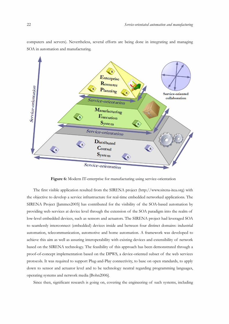
22 Service-orientated automation and manufacturing
computers and servers). Nevertheless, several efforts are being done in integrating and managing
SOA in automation and manufacturing.
Figure 6: Modern IT-enterprise for manufacturing using service-orientation
The first visible application resulted from the SIRENA project (http://www.sirena-itea.org) with
the objective to develop a service infrastructure for real-time embedded networked applications. The
SIRENA Project [Jammes2005] has contributed for the visibility of the SOA-based automation by
providing web services at device level through the extension of the SOA paradigm into the realm of
low-level embedded devices, such as sensors and actuators. The SIRENA project had leveraged SOA
to seamlessly interconnect (embedded) devices inside and between four distinct domains: industrial
automation, telecommunication, automotive and home automation. A framework was developed to
achieve this aim as well as assuring interoperability with existing devices and extensibility of network
based on the SIRENA technology. The feasibility of this approach has been demonstrated through a
proof-of-concept implementation based on the DPWS, a device-oriented subset of the web services
protocols. It was required to support Plug-and-Play connectivity, to base on open standards, to apply
down to sensor and actuator level and to be technology neutral regarding programming languages,
operating systems and network media [Bohn2006].
Since then, significant research is going on, covering the engineering of such systems, including
the modeling, semantic description and collaboration. Based on the achieved success of SIRENA,
several other projects have followed. SODA (Service Oriented Device and Delivery Architecture)
[SODA2007] is one of such examples which goal was to create a service-oriented ecosystem built on
top of the foundations laid by the groundbreaking SIRENA framework for the high-level
communications between devices based on the SOA paradigm.
Nevertheless, the major representative in the area of service based systems for automation is the
SOCRADES project (Service-Oriented Cross-layer infRAstructure for Distributed smart Embedded
Systems). Its primary objective is to develop a design, execution and management platform for the
next-generation industrial automation systems [Cassina2009]. Since the emergence of service-
oriented architecture in industrial automation, smaller applications were shown, but fully functional
demonstrations close to the reality were minimal. Moreover, integrated solutions to validate the
configuration and operation of service-oriented automation systems, from embedded devices until
business applications need to be demonstrated. With these motivations and also as part of the results
of the SOCRADES project, efforts were done in developing a full engineering approach for an
industrial demonstrator. The used methodologies are based on the project's requirements, but
sufficiently flexible to adapt novel approaches by the researchers and developers. The new solution
for automation system brings a different way to configure and operate the system, but in the near
future is expected a wide acceptance, based on the integration, reconfiguration, ease of use and
performance of service-based systems (see the project's road-map of [Gerosa2008]).
The SOCRADES project integrates two complementary technological approaches: one that
focuses on device-centric functionality at the lowest level and the other one that adopts a service-
oriented view in order to cut across, not only all levels of the embedded device hierarchy, but also the
higher-level business processes of which the device level processes are a constituent part. As‐
illustrated by Figure 7, these two orthogonal approaches meet at the sensor/actuator level. At this
level, the emergence of wireless sensor/actuator networks poses new challenges with respect to the
robustness and reliability of communications links. Such issues are addressed by a device level‐
middleware. The device level application platform layer above this middleware makes use of the‐
services offered by the latter. Enterprise level middleware provides functionality like service‐
orchestration and choreography, knowledge-based service discovery, agent based service interactions‐
and service repository management. The enterprise level application platform is situated at the level‐
of enterprise information systems. This platform is intended to be an extended version of an existing
business process management system [SOCRADES2006].
23

24 Service-orientated automation and manufacturing
Figure 7: SOCRADES infrastructure views(adapted from [SOCRADES2006])
Currently, the SOCRADES project and other related works have already demonstrated new
methodologies, technologies and tools for the modeling, design, implementation and operation of
networked systems made up of smart embedded devices. Most of the results of service-oriented
devices and automation systems can be found in disseminated works (see some examples in the
reference section). Several international conferences in the area of automation already have a great
support of service applications and also there are dedicated sessions for these topics (for example the
Annual Conference of the IEEE Industrial Electronics Society). It is shown that the adoption of
web services principles in an automated production system satisfies some requirements, namely the
interoperability between equipments and the basis for flexibility and reconfigurability. Moreover, in
the center of service-oriented automation stays the service technology that is already available for
industrial devices.
2.2.3 Service technology for devices (Device Profile for Web Services)
Standard web technologies and increasing computational power are becoming ever more available
even on the smallest devices and also different platforms [Bepperling2006]. Some devices have
already natively integrated web servers, supporting standard protocols or even allow user-defined
enhancements. The interoperability of SOA and the concept of creating a service interface for hiding
the service implementation becomes an important feature. This will enable radically new device
networking architectures and pave the way for application of a uniform communication paradigm
down from the shop floor up to the top floor, thus breaking down current technological barriers
[Smit2006]. In turn, these evolutions hold the promise of greatly increasing the agility of future
industrial enterprises.
The benefits of service-orientation are conveyed all the way to the device level, facilitating the
discovery and composition of applications by re-configuration rather than re-programming. Dynamic
self-configuration of smart embedded devices using loosely-coupled services provides significant
advantages for highly dynamic and ad hoc distributed applications, as opposed to the use of more
rigid technologies such as those based on distributed objects (see [Jammes2005] and [Jammes2005a]).
From the other hand, the fundamental production operations are closely related to device-level and
their service representation can be considered as the glue between the traditional automation area
and the service-driven area. Those services do a translation of the service's input, output and event
variables to process values and vice verse. Those implementations do not underlie such dynamic
modifications as aggregate services do and could be implemented with less flexible constraints.
WS and SOA would be difficult to be practicable in industrial automation if there were not some
trade-offs considering the domain and available resources. In the home and industrial automation
domain, one technological specification that is used in the research of service-based devices is the
Device Profile for Web Services [OASIS2009a]. DPWS was specified considering some specific web
service protocols but also restricting the usage of web services to keep aspects of the limitations in
embedded systems [Pruter2008]. DPWS defines the extensions required for using web services in
electronic devices [Jammes2005b]:
• Taking into account their specific constraints: footprint, performances, etc.;
• Fulfilling the most common needs: security, plug & play, asynchronous and event-driven
exchanges.
DPWS defines a profile over a specific set of web services protocols to enable secure web
service capabilities on resource-constraint devices [Bobek2008]. Therefore, simple or complex
services can be called directly by other devices or enterprise information systems [Li2008]. DPWS
allows sending secure messages to and from web services, dynamically discovering a web service,
describing a web service, subscribing to, and receiving events from a web service [Zeeb2007].
The DPWS protocol stack comprehends the following protocols (see Figure 8 (for more details
see [Jammes2005b] and [Zeeb2007]):
• SOAP: domain-independent protocol for message exchange, used to invoke actions and to
retrieve information;
• WSDL: formalize the way to specify service interfaces;
25
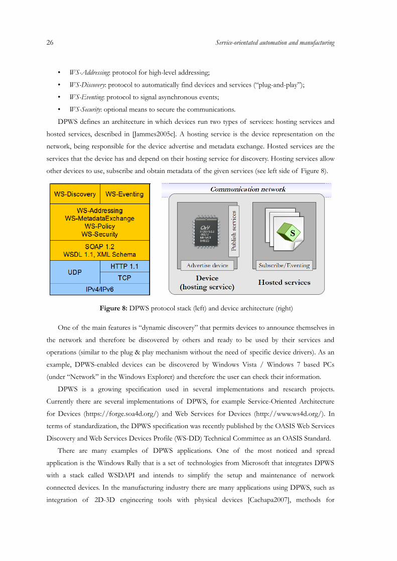
26 Service-orientated automation and manufacturing
• WS-Addressing: protocol for high-level addressing;
• WS-Discovery: protocol to automatically find devices and services (“plug-and-play”);
• WS-Eventing: protocol to signal asynchronous events;
• WS-Security: optional means to secure the communications.
DPWS defines an architecture in which devices run two types of services: hosting services and
hosted services, described in [Jammes2005c]. A hosting service is the device representation on the
network, being responsible for the device advertise and metadata exchange. Hosted services are the
services that the device has and depend on their hosting service for discovery. Hosting services allow
other devices to use, subscribe and obtain metadata of the given services (see left side of Figure 8).
Figure 8: DPWS protocol stack (left) and device architecture (right)
One of the main features is “dynamic discovery” that permits devices to announce themselves in
the network and therefore be discovered by others and ready to be used by their services and
operations (similar to the plug & play mechanism without the need of specific device drivers). As an
example, DPWS-enabled devices can be discovered by Windows Vista / Windows 7 based PCs
(under “Network” in the Windows Explorer) and therefore the user can check their information.
DPWS is a growing specification used in several implementations and research projects.
Currently there are several implementations of DPWS, for example Service-Oriented Architecture
for Devices (https://forge.soa4d.org/) and Web Services for Devices (http://www.ws4d.org/). In
terms of standardization, the DPWS specification was recently published by the OASIS Web Services
Discovery and Web Services Devices Profile (WS-DD) Technical Committee as an OASIS Standard.
There are many examples of DPWS applications. One of the most noticed and spread
application is the Windows Rally that is a set of technologies from Microsoft that integrates DPWS
with a stack called WSDAPI and intends to simplify the setup and maintenance of network
connected devices. In the manufacturing industry there are many applications using DPWS, such as
integration of 2D-3D engineering tools with physical devices [Cachapa2007], methods for

developing efficient diagnosis mechanisms in devices [Barata2007] and systems for adding
transparently security properties to service orchestration [Chollet2008]. On home service
development using web services for devices, companies are successfully creating products that allow
the integrations of many devices at home promoting a new degree in home interaction
[Bottaro2008].
Several projects used and use DPWS as the main foundation for web services and web service-
enabled devices. DPWS was used as a basis for the SIRENA project with the objective to develop a
service infrastructure for real time embedded networked applications. The feasibility of the project
has been demonstrated through a proof-of-concept implementation based on the DPWS. Several
others, such as SOCRADES and SODA, continued the expansible demonstration of DPWS in their
devices.
2.3 Modeling and other advanced topics for service-based automation
In an architecture that is being specified and developed with web services technologies and
making available different kinds of distributed services, it is clear that the basic structure is not
enough to automate the interactions and to permit the application of diverse functionality. For
example, we need to describe a transaction that should depend on a well established sequence of
services and also a way to validate the transaction model to discover possible deadlocks or conflicts.
Thus, there are distinct tools that offer particular features for web services. Aoyama et al.
[Aoyama2002] has classified web service technologies in two layers: web services platforms to describe,
discover and execute web services, and web service engineering to develop applications with web services
(see Figure 9).
Figure 9: Web service platform and engineering levels with some common topics
The platform technologies of web services are generally related to the core protocols (see section
2.2.1 “Service-oriented architectures and web services: an overview”). As a new domain of software
engineering, web services engineering concerns every aspect from development, deployment, use, to
evolution of web services, such as analysis, architectures, development methodologies, descriptions,
27
28 Service-orientated automation and manufacturing
testing, development environments, management, and applications [Aoyama2002]. The topics in
Figure 9 are collected from different research works present in publications. It does not represent all
existing areas and many of them overlap (or have dependencies).
Important subjects are still related to engineering solutions of service-oriented systems from the
software/hardware and user point of view, and also to stimulate the industrial adoption. In service-
oriented automation systems, a formal and unified method is required to provide design facilities,
with the ability to validate models and to be also used as an integration middleware at run-time with
enough flexibility and features. Previous works in the domain report some advances with engineering
methodologies. Main research directions are related to SOA device integration and DPWS
[Jammes2005b] [Bobek2008] [Li2008], orchestration and semantics of devices and systems
[Jammes2005b] [Delamer2006a], the use of Business Process Execution Language (BPEL) and other
formalisms [Puttonen2008] [Lobov2008], process optimization [Rahman2008], business integration
[Nguyen2008], integration of SOA and MAS [Ribeiro2008] and virtual SOA enabled production
environments [Cachapa2007].
The following sections represent a description of a sub-area of the engineering of services,
namely modeling and adjacent topics, related but not only limited to industrial automation.
2.3.1 Modeling languages and standards in automation
Programmable logic controllers are widely used for automating a variety of industrial plants.
Important applications are material handling and warehousing systems, weight lifting systems,
transportation lines, packaging systems. A PLC is a general-purpose microprocessor system
connected to sensors and actuators: the former provide information on the state of the controlled
plant while the latter perform the actions prescribed by the controller. Mapping input information
into output commands is the basic task of PLC software [Bonfatti1995].
Equipment manufacturers provide different devices and machinery, and the request for a
common way to configure them begun to grow; standards were defined to overcome these problems.
Therefore, the IEC 61131 standard was defined for PLCs. Due to the real-time, cyclic nature of the
PLC software, specific languages have been studied for supporting the design and coding phases.
According to the IEC 61131-3 standard (the third part of the IEC 61131), five basic languages are
identified at different levels of abstraction: Instruction List, Structured Text, Ladder Diagram,
Function Block Diagram, Sequential Function Chart (Grafcet) [Bonfatti1995].
From the other hand, the primary purpose of the IEC 61499 standard is not as a programming
methodology, rather as an architecture and a model for distributed systems. This standard defines a
number of models conducive for designing distributed systems. These models are defined in terms
of Function Blocks (FB) and allow describing distributed control systems (DCS) in an unambiguous
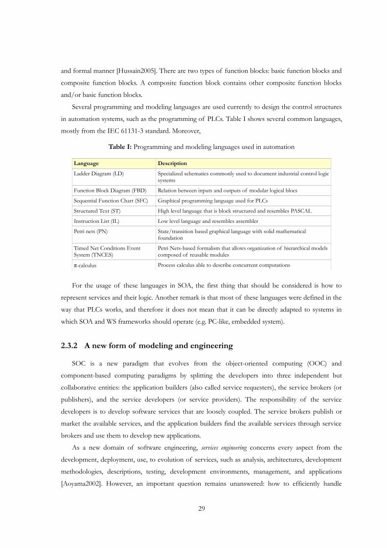
and formal manner [Hussain2005]. There are two types of function blocks: basic function blocks and
composite function blocks. A composite function block contains other composite function blocks
and/or basic function blocks.
Several programming and modeling languages are used currently to design the control structures
in automation systems, such as the programming of PLCs. Table I shows several common languages,
mostly from the IEC 61131-3 standard. Moreover,
Table I: Programming and modeling languages used in automation
Language Description
Ladder Diagram (LD) Specialized schematics commonly used to document industrial control logic systems
Function Block Diagram (FBD) Relation between inputs and outputs of modular logical blocs
Sequential Function Chart (SFC) Graphical programming language used for PLCs
Structured Text (ST) High level language that is block structured and resembles PASCAL
Instruction List (IL) Low level language and resembles assembler
Petri nets (PN) State/transition based graphical language with solid mathematical foundation
Timed Net Conditions Event System (TNCES)
Petri Nets-based formalism that allows organization of hierarchical models composed of reusable modules
π-calculus Process calculus able to describe concurrent computations
For the usage of these languages in SOA, the first thing that should be considered is how to
represent services and their logic. Another remark is that most of these languages were defined in the
way that PLCs works, and therefore it does not mean that it can be directly adapted to systems in
which SOA and WS frameworks should operate (e.g. PC-like, embedded system).
2.3.2 A new form of modeling and engineering
SOC is a new paradigm that evolves from the object-oriented computing (OOC) and
component-based computing paradigms by splitting the developers into three independent but
collaborative entities: the application builders (also called service requesters), the service brokers (or
publishers), and the service developers (or service providers). The responsibility of the service
developers is to develop software services that are loosely coupled. The service brokers publish or
market the available services, and the application builders find the available services through service
brokers and use them to develop new applications.
As a new domain of software engineering, services engineering concerns every aspect from the
development, deployment, use, to evolution of services, such as analysis, architectures, development
methodologies, descriptions, testing, development environments, management, and applications
[Aoyama2002]. However, an important question remains unanswered: how to efficiently handle
29

30 Service-orientated automation and manufacturing
distributed systems based on services and consequently their processes [Leitão2010]? In other words,
the challenge is how to describe the processes that regulates the system behavior and how to
synchronize and coordinate the execution of the services offered by distributed entities to achieve
the desired behavior. Besides the individual control, interaction must occur along individual
components of the system. This can be done by defining processes between them that agglomerates
together pieces of single process models controlled by the components. Whatever is the strategy
chosen by the system engineer, i.e. a centralized control by gluing control models together or peer-to-
peer synchronization between components' control models, it should be possible to design the
control with a minimal effort.
The main basis for the specification and use of services is their description. At the factory floor,
manufacturing equipments can be abstracted as the web services described in a WSDL file. Each
device or a piece of equipment ranging from a sensor to the entire production cell may be controlled
at run-time to perform required operations stipulated by the business or product needs. The vendor
of the equipments can deliver the WSDL file along with the supplied equipments for the production
line [Lobov2008].
Besides the description, an emerging area of research is also the investigation of technologies
that will enable the discovery and composition of web services [Bansal2008]. This paradigm shift is
changing the way software and hardware is being developed [Tsai2005]. Both automatic discovery
and composition are seen as the way of building more complex software from simple elements. One
way to accomplish web service composition is to define the composite services as workflows
containing a set of atomic web services with control and data flow among them. Proposed industry
standards for the service composition, such as the BPEL and the BPML, use this approach
[Bichier2006]. Service discovery and composition are fundamentally based on the syntactical
matching using the WSDL.
For the automation world, this way of constructing applications from elementary pieces can be
somehow compared with the IEC 61499 standard, where elements are basic function blocks and the
higher level engineering is related to wire these blocks. However, for the IEC 61499 standard little or
none was done in terms of discovery and automatic association of these blocks. Furthermore,
service-based systems are not static “wired” as in IEC 61499, providing a balanced view between
information sharing, modularity, integration aspects and collaboration, based on the natural idea of
services that are present in the daily life.
Therefore, a set of engineering tools is required for supporting a successful migration to the new
automation approach. Among other tasks, the engineering tool should provide methods for the
following items: identification of modular components, description of the architecture of the
automation system, modeling languages for service composition and other forms, methods to model
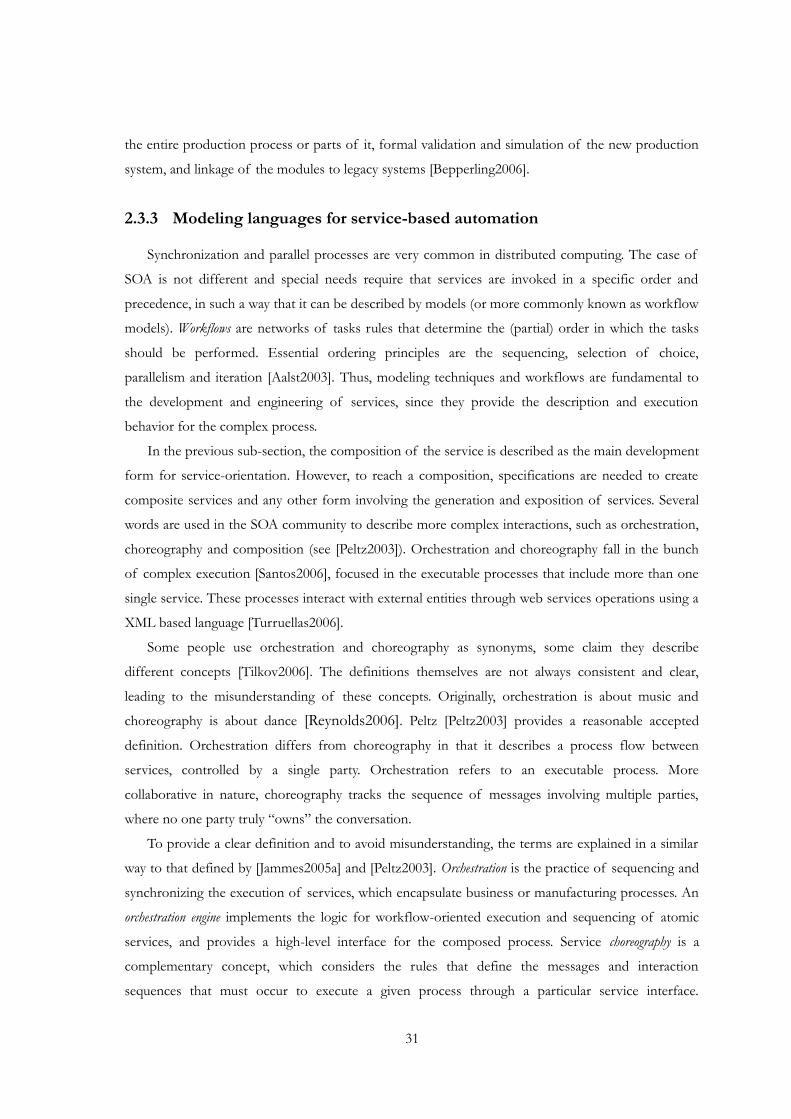
the entire production process or parts of it, formal validation and simulation of the new production
system, and linkage of the modules to legacy systems [Bepperling2006].
2.3.3 Modeling languages for service-based automation
Synchronization and parallel processes are very common in distributed computing. The case of
SOA is not different and special needs require that services are invoked in a specific order and
precedence, in such a way that it can be described by models (or more commonly known as workflow
models). Workflows are networks of tasks rules that determine the (partial) order in which the tasks
should be performed. Essential ordering principles are the sequencing, selection of choice,
parallelism and iteration [Aalst2003]. Thus, modeling techniques and workflows are fundamental to
the development and engineering of services, since they provide the description and execution
behavior for the complex process.
In the previous sub-section, the composition of the service is described as the main development
form for service-orientation. However, to reach a composition, specifications are needed to create
composite services and any other form involving the generation and exposition of services. Several
words are used in the SOA community to describe more complex interactions, such as orchestration,
choreography and composition (see [Peltz2003]). Orchestration and choreography fall in the bunch
of complex execution [Santos2006], focused in the executable processes that include more than one
single service. These processes interact with external entities through web services operations using a
XML based language [Turruellas2006].
Some people use orchestration and choreography as synonyms, some claim they describe
different concepts [Tilkov2006]. The definitions themselves are not always consistent and clear,
leading to the misunderstanding of these concepts. Originally, orchestration is about music and
choreography is about dance [Reynolds2006]. Peltz [Peltz2003] provides a reasonable accepted
definition. Orchestration differs from choreography in that it describes a process flow between
services, controlled by a single party. Orchestration refers to an executable process. More
collaborative in nature, choreography tracks the sequence of messages involving multiple parties,
where no one party truly “owns” the conversation.
To provide a clear definition and to avoid misunderstanding, the terms are explained in a similar
way to that defined by [Jammes2005a] and [Peltz2003]. Orchestration is the practice of sequencing and
synchronizing the execution of services, which encapsulate business or manufacturing processes. An
orchestration engine implements the logic for workflow-oriented execution and sequencing of atomic
services, and provides a high-level interface for the composed process. Service choreography is a
complementary concept, which considers the rules that define the messages and interaction
sequences that must occur to execute a given process through a particular service interface.
31
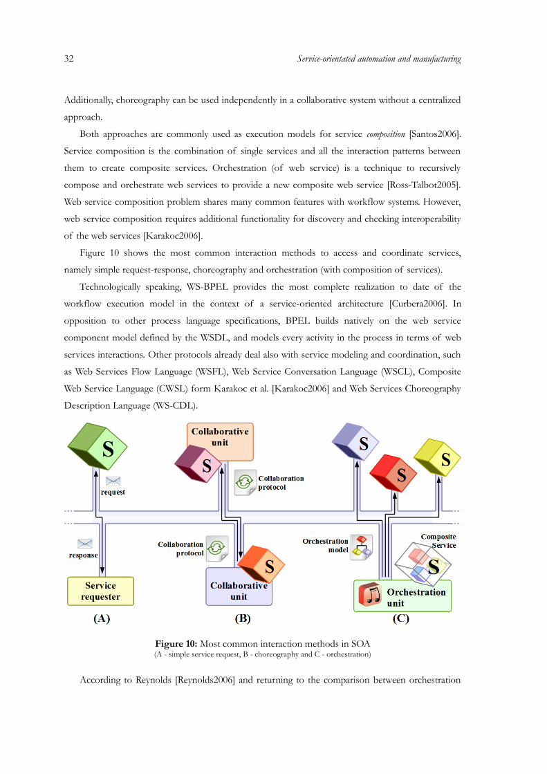
32 Service-orientated automation and manufacturing
Additionally, choreography can be used independently in a collaborative system without a centralized
approach.
Both approaches are commonly used as execution models for service composition [Santos2006].
Service composition is the combination of single services and all the interaction patterns between
them to create composite services. Orchestration (of web service) is a technique to recursively
compose and orchestrate web services to provide a new composite web service [Ross-Talbot2005].
Web service composition problem shares many common features with workflow systems. However,
web service composition requires additional functionality for discovery and checking interoperability
of the web services [Karakoc2006].
Figure 10 shows the most common interaction methods to access and coordinate services,
namely simple request-response, choreography and orchestration (with composition of services).
Technologically speaking, WS-BPEL provides the most complete realization to date of the
workflow execution model in the context of a service-oriented architecture [Curbera2006]. In
opposition to other process language specifications, BPEL builds natively on the web service
component model defined by the WSDL, and models every activity in the process in terms of web
services interactions. Other protocols already deal also with service modeling and coordination, such
as Web Services Flow Language (WSFL), Web Service Conversation Language (WSCL), Composite
Web Service Language (CWSL) form Karakoc et al. [Karakoc2006] and Web Services Choreography
Description Language (WS-CDL).
Figure 10: Most common interaction methods in SOA(A - simple service request, B - choreography and C - orchestration)
According to Reynolds [Reynolds2006] and returning to the comparison between orchestration
and choreography, the real distinction lies not in the dictionary, but in the differences between WS-
BPEL and the WS-CDL. Web service orchestration relates to the execution of specific business
processes. WS-BPEL is a language for defining processes that can be executed on an orchestration
engine. Web service choreography relates to describing externally observable interactions between
web services. WS-CDL is a language for describing multi-party contracts and is somewhat like an
extension of WSDL: WSDL describes web services interfaces, WS-CDL describes collaborations
between web services. Both approaches have been separately developed by industrial consortia and
international organizations as W3C and OASIS. In particular, WS-CDL (W3C standard) and WS-
BPEL (OASIS standard) specifications represent the most credited languages for the web services
technology which deal with choreography and orchestration respectively [Busi2006].
Most research works have been concerned with the co-ordination of services, specially the
automatic way of creating new orchestrations based on the available services and some rules on how
to compose them and to generate new forms of services. There are several methodologies for that
purpose, since the use of semantic services [Medjahed2003] [Lastra2006] [Thramboulidis2007] to the
application of intelligent systems (such as multi-agent systems [Maamar2004]) to support the
construction of workflows from services (e.g. using BPEL [Pasley2005]). Evaluation of services and
the use of quality of service (QoS) is also used when generating orchestrations and selecting the best
possible service [Day2004] [Chaari2008].
Web service composition is today a very active topic of research. It involves the combination of
a number of existing web services to produce a more complex and useful service [Tang2004].
Semantic enriched web services (semantic web services) provide the possibility to enhance the
automatic tying and corresponding composition of web services. Composition can be viewed as a
modeling technique, but the emphasis on creating new services from old ones and the problem of
efficiency and effectiveness of the process, may have different motivations and methods behind. A
central challenge is the development of modeling techniques and tools for enabling the semi-
automatic composition and analysis of these services, taking into account their semantic and
behavioral properties [Hull2005]. In [Bhiri2006] is given an approach to specify and orchestrate
flexible and reliable web services compositions based on the concept of transactional patterns.
Hamadi and Benatallah [Hamadi2003] describe a Petri net-based algebra, used to model control
flows, as a necessary constituent of reliable web service composition process. An agent-based and
context-oriented approach is used in [Maamar2005] to support the composition of web services.
According to Moldt and Ortmann [Moldt2004], web services might be composed to accomplish
arbitrary complex tasks. Agents can compose these web services as long as they know their
semantics. Here process ontology offers a way to give agents an understanding of the services
offered. Elfatatry and Layzell [Elfatatry2005] write about complex forms of interaction, such as
33
34 Service-orientated automation and manufacturing
negotiation, that will become dominant towards a service-oriented model of development. More
research work on service composition is given in [Chafle2004], [Hull2005] and [Karakoc2006].
The authors of [Fu2006] present an executable web service architecture model (SO-SAM) that
incorporates predicate transition nets with the style and understandability of component-based
concepts. To overcome the centralized nature of these processes, in [Nanda2004] is given a technique
to partition a composite web service written as a single BPEL program into an equivalent set of
decentralized processes. In [Santos2006] a semantic-based binding is illustrated. An engine receives
the composition description (i.e. the code), starts to run it and for each abstract service (described
with semantic information), a service repository (or a service broker) is contacted in order to
discover which service will be the responsible for executing that activity, always considering the
associated ontology.
Other approaches are based on the well known UML (Unified Modeling Language) [Amir2004].
The authors of [Baresi2003] present the proposal for modeling SO-architectural styles with UML
diagrams and graph transformation rules and exemplifies it for SOA.
The previous works show that there is a lot of research in the area of modeling and processes
based on services, mainly applied to business and e-commerce. In industrial automation, namely at
the device level, services are used for diversified tasks, mostly monitoring, diagnosis and basic
operations. Standard protocols should handle the basis for these issues and thus specify technology
rules that should be followed by all involved partners to successfully permit the conversation. From
the technology point of view, web services are the main force to implement these concepts using
well established web protocols, but also other types of implementations are possible. From the
service modeling perspective, the associated complexity of modeling and its execution should also be
available to industrial controllers, so that they can be more independent from business applications
and therefore, have a local domain of autonomy over equipment, such as robots, conveyors, and
other shop-floor mechatronics.
Embedded systems usually consist of some transformed parts dedicated to calculate and transfer
values through the system (data flow) and some reactive part that curbs the type and order of such
transformed operations (control flow). The result of a data flow operation can reside within the data
flow or be part of the control flow – the latter one is called condition. Similarly, a subset of the
control flow interacts with the data flow, and constitutes the set of control signals. These
control/data-flow interactions are not a trivial matter and have been long neglected in behavioral
models for embedded systems – for the sake of simplicity [Varea2006].
However, it is not expected that such devices be only able to provide services representing their
resources, but also a source of multi-functional actions concerning service-orientation. Particularly,
composition and orchestration have been seen as the form of engineering of service-oriented

architectures, and the inclusion of these features in industrial devices is still a major effort. The
representation of the work-plan associated to services, to be interpreted and executed by
orchestration engines, can be defined using different methods [Milanovic2004]. In automation and
manufacturing, the service composition and collaboration have been studied with web semantics
[Delamer2006], service classification [Zhao2005], service binding [Pohl2008] and the
collaboration/integration of multi-agent systems [Shen2005].
A possible solution is to use WS-BPEL, but it only specifies interactions among web services and
does not consider the internal logic of software components and services. Other solutions that have
been applied are based on 61131-3 languages and IEC 61499 function blocks [Bangemann2009]
[Candido2010] with the objective of adapting industrial standards to SOA. Similar to Petri nets,
TNCES (Timed Net Condition/Event Systems) are used for modeling interaction-aware services
[Popescu2008].
2.3.4 Petri nets for SOA
Petri nets formalism is a graphical oriented language for design, specification, simulation and
verification of systems, created by Carl Adam Petri in his dissertation (see [Petri1962]). It is in
particular well-suited for systems in which communication, synchronization and resource sharing are
important. On one hand, as a graphical tool, Petri nets can be used as a visual-communication aid
similar to flow charts, block diagrams, and networks. On the other, as a mathematical tool, it is
possible to set up state equations, algebraic equations, and other mathematical models governing the
behavior of systems [Murata1989]. According to R. Zurawski [Zurawski1994] the Petri nets
formalism, based on a well-founded mathematical theory, has a very good capacity to graphically and
formally represent and validate certain typical relationships, such as concurrency and parallelism,
synchronization, resource sharing, mutual exclusion, monitoring and supervision, which are typical
specifications of manufacturing systems.
Since the formal Petri nets are very basic in the application point of view, numerous extensions
nets have been introduced over the years. It is important to keep in mind, that as the complexity of
the net increases in terms of extended features, the harder it is to use standard tools to evaluate
certain properties of the net. Commonly, extended Petri nets are appointed as high-level Petri nets
(HLPN). An ISO draft for the HLPN standard is also available (see the ISO15909-1 specification).
Some important extensions include: stochastic Petri nets [Ciardo1987] and colored Petri nets (CPN)
[Jensen1987].
Automation systems are a common target for the application of Petri nets and their higher-level
deviated structures (e.g. colored Petri nets), preferable in analysis and modeling. Another question is
the real-time interpreters or engines of Petri nets for logic controllers. They are not common, and
35
36 Service-orientated automation and manufacturing
normally Petri nets are converted into other formalisms (such as the IEC 61131-3 languages) that can
be understand by devices (see [Uzam1996]). Anyway, one of the first documented implementations
of Petri nets based sequence controllers were developed in the early 80's by Hitachi Ltd.
[Murata1986]. It was successfully used in real applications to control parts on an assembly system and
to control an industrial robot. Also fuzzy Petri nets and colored Petri nets have been studied for the
application in logic controllers, compiling them afterwards to PLC understandable language (see
[Gomes1995] and [Colombo1998], respectively). A tutorial on Petri nets in industrial applications can
be found in [Zurawski1994].
The powerful analysis and modeling features provides also the ability to control complex
manufacturing systems. Due to their capability in modeling the systems' dynamics, Petri nets have
been combined with fault tree analysis techniques to determine the average rate of occurrence of
system failures (Adamyan and He [Adamyan2004]). A novel approach to the development life-cycle
of agent-based production control applications, from the design to the operation, based in a catalog
of high-level Petri nets is given by Leitão et al. [Leitão2005]. The high-level Petri net-based approach
facilitates the conception, definition and formal specification of an “encapsulation process” in
industrial production systems.
In service-oriented systems, the use of visual modeling techniques such as Petri nets in the design
of complex services is justified by many reasons. For example, visual representations provide a high-
level yet precise language which allows expressing and reasoning about concepts at their natural level
of abstraction. From the application point of view, a service behavior is basically a partially ordered
set of operations. Therefore, it is straight-forward to map it into a Petri net and vice-versa.
Operations are modeled by transitions and the state of the service is modeled by places. The arrows
between places and transitions are used to specify causal relations [Hamadi2003].
Petri nets describe process models, i.e. workflow models, and can also be used as a tool for
design and validation of the modeled system. The simulation capabilities and coordination among
individual transitions (that can represent real services), may indicate that it is also possible to use for
orchestration of web services. A control component with a build-in orchestration engine can
interpret such nets and execute it. In real-time execution, the enabled transition must be detected,
services associated with the enabled transition must be called and, after that, the workflow model has
to be updated to reflect the actual state of the system. The task of orchestration engines is to
synchronize and to control the whole process until it reaches the goal, based on the elaborated
model, i.e. they have to orchestrate the production system.
Diversified research has been done by using Petri nets in web service environment. The
traditional application of Petri nets in SOA environments seems to be orchestration and
choreography, to define sequences, conditions, interactions and compositions of services. Hamadi
and Benatallah [Hamadi2003] propose a Petri net-based algebra for modeling web services control
flows, and Zhai et al. [Zhai2005] integrate agents and web services into grid service workflow system
based on colored Petri nets. The combination of agents and web services enhances the adaptability
and dynamics of the framework. The verification of web services composition by using colored Petri
nets is presented by Yang et al. [Yang2005]. In Bing and Huaping [Bing2005], a Petri net-based
algebra is used to capture the semantics of complex web service combinations. Chatain and Jard
[Chatain2005] reveal the interest in the questions of supervision and diagnosis, by explaining how to
use unfolding of dynamic nets for the diagnosis application. To facilitating web services integration
and verification, Zhang et al. [Zhang2004] introduces WS-Net as an executable architectural
description language incorporating the semantics of colored Petri net with the style of object-
oriented concepts.
Compositional aspects and coordination of Petri nets and workflows in general have been
studied, such as described by Anisimov et al. [Anisimov2001] and Pankratius and Stucky
[Pankratius2005], to provide an approach to distributed systems. The workflow management system
can be orchestrated in a centralized viewpoint (master/slave) in which the workflow model should be
interpreted and coordinated by the corresponding manager. In other hand, distributed management
requires additional care because the global execution and state identification is not synchronized and
supervised by one element.
The question of using Petri nets for SOA-automation has been less researched and documented.
The behavior of service-based automation systems can be modeled by Petri nets, described by the
differential and algebraic equation associated with the bipartite graph. However, the resolvability of
these equations is somewhat limited, partly because of the non-deterministic nature inherent in
service-oriented systems and also because of the constraints that solutions must be found as non-
negative integers. Nevertheless, Petri nets must respond to the basic requirements of modeling (i.e.
representing the system dynamics), being user-friendly, consider performance issues, interoperability,
portability and acceptability.
Moreover, the missing key aspects are related to more complex engineering, coordination and
aggregation methods, especially tailored for the system's requirements. The suggestion over Petri nets
is to provide a balance between the typical SOA methodologies and the programming languages of
the IEC 61131 standard. However, practical usage of Petri nets is limited by the lack of computer
tools which would allow handling large and complex nets in a comfortable way [Suraj2006]. From the
other hand and considering also the use of Petri nets in the run-time of SOA, methods are missing
for the development of customized Petri nets libraries for software applications and devices of
multitasked usage.
37
38 Service-orientated automation and manufacturing
2.4 Major requirements, missing aspects and identified research directions
Multi-agent systems and more recently service-oriented systems were considered by the research
community to face some of the major challenges in industrial automation and production systems. A
major motivation started to grow in the field of service-orientation and complementary topics with
visible results in several research works and international projects. Service-oriented computing
represents a novel research domain, based on the principles of services and surrounding engineering.
Besides the advantage of bringing the IT closer to the automation world, most SOC research is based
on the topics of communication and derivative activities, such as integration and standardization.
Other questions such as the meaning of service-oriented devices, energy-efficiency (a highly
appreciated topic nowadays), control solutions and industrial adoption, should also be a main interest
in service-oriented automation systems.
The emergence of SOA in the automation domain and the use of web services standards became
notorious after the successful application in automation devices and as a new form of engineering.
However, a major industrial acceptance, besides the research projects scope, is needed, due to the
lack of demonstrated features of both automation devices and supporting applications. A major
challenge in this type of service-oriented systems is related to how individual entities may interact,
coordinating their activities by synchronizing the execution of services they provide. The aggregation
of single services and all the interaction patterns between them is also a complex issue. Specifically
for service-oriented based collaborative automation systems, there is a gap on mechanisms and
engineering tools that provide interaction schemes, protocols and patterns applied for services and
corresponding providers and requesters.
As reported before, one of the major propulsion in this direction was the EU research project
SOCRADES. An important result of SOCRADES is the smart embedded devices (or SOCRADES
devices) that are service-enabled industrial controllers with several functionality that were extended
during the project. It is represented in the central hexagon of Figure 11.
Surrounding the device, there are several other hexagons in Figure 11, representing important
topics and requirements of the project [Mendes2010b] (more detailed information can be found in
[Gerosa2008] as well as the project's public deliverables and its homepage http://www.socrades.eu):
• Service-oriented industrial automation: The application domain and also the source of knowledge.
For this there are several techniques to describe the available information (e.g. the use of
semantics, ontology), besides the intrinsic capabilities provided by web service technologies.
• Plug & play: A selling point is the ability to connect devices and others to the network and
with minimal need of configuration they are able to integrate and ready to work. This is
eased by features such as dynamic discovery, dynamic configuration, uniform description, use
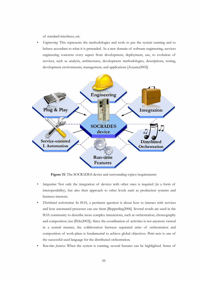
of standard interfaces, etc.
• Engineering: This represents the methodologies and tools to put the system running and to
behave accordant to what it is pretended. As a new domain of software engineering, services
engineering concerns every aspect from development, deployment, use, to evolution of
services, such as analysis, architectures, development methodologies, descriptions, testing,
development environments, management, and applications [Aoyama2002].
Figure 11: The SOCRADES device and surrounding topics/requirements
• Integration: Not only the integration of devices with other ones is required (in a form of
interoperability), but also their approach to other levels such as production systems and
business interests.
• Distributed orchestration: In SOA, a pertinent question is about how to interact with services
and how automated processes can use them [Bepperling2006]. Several words are used in the
SOA community to describe more complex interactions, such as orchestration, choreography
and composition (see [Peltz2003]). Since the coordination of activities is not anymore viewed
in a central manner, the collaboration between separated units of orchestration and
composition of work-plans is fundamental to achieve global objectives. Petri nets is one of
the successful used language for the distributed orchestration.
• Run-time features: When the system is running, several features can be highlighted. Some of
39
40 Service-orientated automation and manufacturing
them are inherited by the nature of service-oriented architecture; others were introduced by
the motivation of the requirements. Most high-level features are considered to be
reconfigurability, adaptability, intelligence, auto-sustainability, besides others.
There are many works discussing the benefits and innovations when using SOC as the main way
of engineering systems, especially when dealing with business models, but just a few tell the other
side of the story (see e.g. [Dias-Patel2006]). As in other domains, the research of SOC in industrial
automation has faced some difficulties, mostly due to the insufficient study of the SOC concepts and
also on relaying on the confidential results of SOC in the business world.
2.4.1 Major requirements and missing aspects
Web services and their performance issues
Several automation control vendors decided to work on the topics of service-orientation in form
of web services, with distributed engines integrated at the device-level, in opposite to the
conventional IT system that run heavy-weight engines in central computers. However, the complex
description patterns and the verbosity of XML web services protocols create a whole new set of
design tradeoffs and issues for developing web services applications for embedded systems.
Embedded systems rarely have enough memory and processing power to run a HTTP Web server,
SOAP engine and XML parser. The verbosity of XML and HTTP increases the RAM usage,
bandwidth requirements, and operating costs [Engelen2004].
Decomposing applications and hardware into services
“How to effective decompose a given application into services? Should the decomposition be
guided by the set of available services, i.e., should the decomposition be different depending on the
set of available services?” [Tsai2006]. These are several questions that affect the development and
integration of services and until know there is no clear answer; at least at the device level.
Increasing complexity but also functional simplicity
Current service applications are already complex due to dynamic composition and uniform
handling of various software and hardware resources as services. But future services applications will
be even more challenging [Tsai2006]. This can evolve to a situation called “Gas Factory”, an anti-
pattern that identifies overgrown complexity for what it is for. Therefore, for service-enabled devices
a balance must be reached between functionality and simplicity.
To overcome SOAP limitations, DPWS specifies limited constraints functionality, so that it can
be implemented on small devices to restrict the traffic. DPWS specification is a set of very general
standards based on SOAP. While protocol generality can be considered as an advantage that can lead
to acceptability and even interoperability, it brings also complexity in the design of a concrete
framework [Zeeb2007]. The functional simplicity also means that other technologies must be added
to build complex distributed applications.
BPEL or not BPEL?
The application of BPEL has also been studied in industrial automation (see [Puttonen2008]),
but is a high-end computational and centralized control approach for orchestration and far away
from novel industrial objectives. BPEL seems to be a solution for creating composition of individual
services and their rules, but in many ways comparable of what non-visual programming already is
doing since the beginning: encapsulation of several function calls and their order and rules of calling
into a single function. Obviously, BPEL has the advantage of allowing visual representation and
description of concurrent processes, but not different from what was already studied within other
languages. The main disadvantage is its interpretative nature, but it can be overcome with code
generation techniques.
The application of BPEL in automation environment can be discussed. From one side, it has
already a well defined syntax in XML, development tools and can be used directly with web services,
providing a way of orchestration. From the other side, BPEL is a specification mainly targeting
business requirements for both intra-corporate and business-to-business spaces. Therefore, it is
unknown to automation system engineers that are used to the IEC 61131 languages.
Other aspects are that the application of BPEL is probably too complex and descriptive to be
interpreted by the resource constrained devices (typically used in automation) and that it is not
suitable for internal service process description based on device/software capabilities. The
orchestration of existing web services to workflows is a challenging task which is complicated by the
fact that manufacturing processes have time constraints, especially real-time constraints (see
[Mathes2008] for the use of orchestration based on BPEL in automation and production
environments). BPEL depends on web services and therefore it is technology dependent that is
affordable to adapt to non-web services based SOA. Last but not least, BPEL is missing analysis and
validation support that is in fact an active research topic in the SOA business community. However,
some efforts have been done in terms of the application of BPEL and orchestration in general for
industrial automation with results (see [Puttonen2008], [Mathes2008] and [Jammes2005a]).
Solutions can be described by a decentralized option. Because performance and throughput are
major concerns in enterprise applications, it is important to remove the inefficiencies introduced by
the centralized control. In the work of [Nanda2004], the BPEL program is partitioned into
independent sub-programs that interact with each other without any centralized control.
Decentralization can increase parallelism and reduce the amount of network traffic required for an
application. Another possibility is the use of the IEC 61131 languages (adapted to services) and also
41
42 Service-orientated automation and manufacturing
Petri nets (see [Mendes2008]).
Most services are used as objects
Given the strong similarities between (web) services and distributed objects, it is understandable
that many people believe they are the same [Vogels2003]. The main problem seems to be that (web)
services are widely implemented in the same way as distributed objects are. As an example, we define
an interface with a set of operations, we implement the operations of the service and, from the client
side, we define the rules and the logic to call the operations of the service. Isn't it familiar with the
common object-oriented approach?
To overcome this idea, the main difference when comparing with object-based methodologies
seems to be the automatic use, discovery and binding of services, and also the high level
programming (creation of new services based on atomic ones). However, these features can also be
easily adapted to the object-oriented approach, for example using some design patterns dealing with
distribution and concurrency.
The same happens at the device level. It seems to be missing a deeper meaning of service-
oriented components, their autonomous development and also the study of the conditions that a
component has on providing services and the needs on requesting others' services. Reasoning in this
direction, a more clear separation with the object-oriented concept can be defined.
The question of autonomy
If services become mobile and adaptive, there will be an enormous number of services that will
be available. These services may not know each other before, yet they may need to communicate and
to collaborate with each other to complete a trade or perform a joint mission [Tsai2006]. Having well
known interfaces, functionality and the orchestration between means the same as using the traditional
modular approach that was already defined in the IEC 61499 standard. In the other edge, too much
autonomy of services providers and requesters, increased loose-coupling and introduction of
unknown components and services requires the use of enhanced semantics and artificial intelligence
mechanisms.
Lack of service education and adoption
Currently, an important problem in SOC/SOA is the lack of education related to the service-
oriented principles [Tsai2006], namely due to the missing of enough documentation and reports,
high quality applications and reduced availability in workshops.
The other question is related to the industrial adoption of SOA principles, since most of the
factories are heavily based on the centralized IEC 61131 standard for PLCs. There were taken efforts
on modernizing some aspects of the automation and production levels, such as the IEC 61499

standard for distributed control and automation based on function blocks. Even considering this
relatively recent acceptance as a standard, adoption by the major control system equipment vendors
has been slow to nonexistent (see [Hall2007] for the challenges to industry adoption of IEC 61499).
The difficult adoption can also be explained by the fact that several trends are considered as
“fashionable”. Consequently, the industry relies on technology that has proven work and engineers
are used to, even if antiquated, inflexible and does have not parallel advance with other scientific
fields.
2.4.2 Future directions
A global consideration to be faced in the near future is to co-relate the use and advantages of
SOC approach with the important topics of flexibility, adaptability and re-configuration. Solutions
used in the past, such as multi-agent systems, have always concentrated in particular problems, but
automation and production systems have to be considered as a whole to respond adequately to
business models. With SOC, and since it already provides sufficient integration mechanisms, new
research work has to flow in this direction. Therefore, qualitative industrial demonstrations, especially
the ones that connect business entropy with factory shop-floor are required to convince the industry
market.
Even if loose-coupling and autonomy are key issues in service-oriented systems, in automation it
is important that the collaborative processes should be done under the umbrella of particular
requirements. Although web services, and particularly DPWS, already complies many requirements, a
real heterarchical service-oriented “architecture” is missing, where services and their
requester/providers may be easily integrated and functionally operate.
For a SOA based collaborative automation systems, there is a gap on mechanisms and
engineering tools that provide interaction schemes, protocols and patterns applied for services and
corresponding providers and requesters. It is not a technological issue, since web services are already
there and demonstrated by practical use, but merely taking in account the viewpoint of collaborative
automation, the strong requirements request further research and applicability of high level methods.
Under this context, questions such as formal and flexible control solutions with analysis and
validation capabilities, decision support systems, scheduling mechanisms, high-level programming
through association/composition, consideration of real-time constraints, and energy efficiency are
highly appreciated and must be demonstrated in service-oriented systems.
43

44 Service-orientated automation and manufacturing
Chapter 3:Service-oriented automation systems: architecture and Petri nets methodology
Service ecosystems are well known in the field of business and electronic commerce (see
[Barros2006] and [Sawatani2007]) but in industrial automation and production systems (especially
concerning distributed devices) it is a relatively new research area with promising results. An
important issue for these systems is where the control is located and how its granularity and
distribution are affected. Since the introduction of the common PLC, significant effort has been
done in research and development to overcome the PLC's limitations in terms of centralized usage.
Architectures for devices and control software have been focus of research, commonly dealing
with the IEC61131-3 languages [Bonfatti1995] [Erickson1996] [Aramaki1997] [Huang2003], the IEC
61499 function blocks for distributed control and automation [Thramboulidis2006] [Hall2007]
[Hirsch2007] and other control techniques such as Petri nets [Murata1986] [Nascimento2004]. For
service-oriented distributed devices, the control method is partially open to any control approach, but
should also consider specific requirements of service-orientation. Serving different functionality, a
single service-oriented control device should be ready for multiple activities, and thus requires a
special adapted internal framework that handles differentiate and concurrent processes.
Especially for service-oriented industrial automation, the application of Petri nets must be open
to several specifications, requirements and methodologies for engineering that will possibly come in
future. Considering these aspects, an approach was specified to permit feasible and customized Petri
net based applications (particular for service-oriented industrial automation). The choice over Petri
net was due to the convincement based on previous experience that it could be used in this sense and
to “do the most possible with the methodology”, i.e. to uncover its features for the engineering of
service-oriented automation systems. Of course, the excellent properties of Petri nets should be
maintained.
The resulting open methodology for the definition of Petri net based applications is using a
45

46 Service-oriented automation systems: architecture and Petri nets methodology
ground basis made of several elementary packages. This includes the Petri net formalism (according
to [Murata1989]), analysis routines and conflict management. Besides the required openness, another
requirement is the introduction of the time factor when evolving the Petri net. Consequently, the
basis of the Petri nets is guaranteed and the doors are open (in terms of time delays) that can be used
for customized operations. On top of this, a modular property system was specified and a novel
approach for the creation of token games (an “engine” that runs a Petri net) based on a customized
template.
3.1 A service-oriented automation system (SOAS)
In distributed automation and especially in the domain of production systems, the set of
equipment and other components in the system may be comparable under some circumstances to a
society of living beings. Taken a closer look into a component itself, its internal mechatronical
organization may correspond to functional organs that are responsible for specific tasks, providing
the “vital” properties to be able to fulfill its requirements. Service-oriented systems are one approach
to specify the environments for heterogeneous “organisms” that require interaction. The following
sub-section describes the approach in terms of architecture and composing elements.
3.1.1 Background and foundations for a service-oriented automation system
It is likely that in the future, all computing units, both hardware and software, both small (such as
embedded systems) and large (such as mainframes) will be organized as services, i.e., systems will be
service-enabled [Tsai2006]. Adapting the service-orientation concepts to shop floor “ecosystems”, a
“society” of service-oriented entities is designed, composing the reference model for
automation/production system. Each participant in the system is referred as service-oriented
automation bot that may have different roles (e.g. production, transportation and monitoring). A
“bot” is a general term given to any service-oriented automation component in the architecture, from
simple representatives of equipment to complex entities that have orchestration and decision duties.
The adoption of the designation “bot” in this work is easy to comprehend: from one side the
question of representing someone or something, from the other side the connotation to robots that
are widely used in industrial automation. Bots are a common term used in computer games to
designate non-human players in a virtual world that should behave as similar as possible as the ones
made of flesh and bone. Therefore, methodologies of artificial intelligence and nowadays scripting
are used to specify their behavior, whatever it is based on known information or on completely new
input. Bots are also used in other fields with similar meaning and/or extending it also for the use of
repetitive software tasks, such as chatbots, web bots and tutor bots for e-learning (as industrial robots

for physical tasks). In a general way, it is correct to say that a bot is the software part of a robot or
simulated being.
Since services are the main guide, bots should have the need of requesting services and also the
desire in providing services to the community. Services itself are a form of providing resources and
actions that are shared in some circumstances, much similar to the real-life services. As an example,
industrial sensors are not simply supplier of Internet pages to browsers but they become servers of
measurement functions and so they can play a more complex role in the monitoring system or in the
integration of different measurement networks. This solution offers great possibility in terms of fast
and easy access to measured data, of integration of large complex web sensor network, of realization
of flexible custom applications, and of service reusability [Ciancetta2007].
The service-orientation reference model provides support over the three axes of the CMM
model [ARC2003], as illustrated in Figure 12. This means that it addresses the vertical enterprise
integration by covering from the shop-floor level to the business level, the supply chain integration
by supporting the interaction with suppliers and customers, and the life-cycle of a collaborative
manufacturing system.
Figure 12: Service-oriented industrial automation ecosystem integrated to the CMM model
47
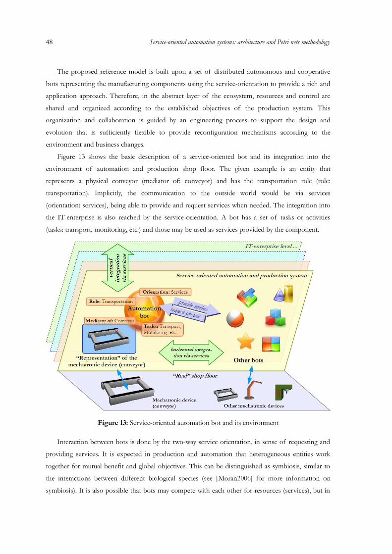
48 Service-oriented automation systems: architecture and Petri nets methodology
The proposed reference model is built upon a set of distributed autonomous and cooperative
bots representing the manufacturing components using the service-orientation to provide a rich and
application approach. Therefore, in the abstract layer of the ecosystem, resources and control are
shared and organized according to the established objectives of the production system. This
organization and collaboration is guided by an engineering process to support the design and
evolution that is sufficiently flexible to provide reconfiguration mechanisms according to the
environment and business changes.
Figure 13 shows the basic description of a service-oriented bot and its integration into the
environment of automation and production shop floor. The given example is an entity that
represents a physical conveyor (mediator of: conveyor) and has the transportation role (role:
transportation). Implicitly, the communication to the outside world would be via services
(orientation: services), being able to provide and request services when needed. The integration into
the IT-enterprise is also reached by the service-orientation. A bot has a set of tasks or activities
(tasks: transport, monitoring, etc.) and those may be used as services provided by the component.
Figure 13: Service-oriented automation bot and its environment
Interaction between bots is done by the two-way service orientation, in sense of requesting and
providing services. It is expected in production and automation that heterogeneous entities work
together for mutual benefit and global objectives. This can be distinguished as symbiosis, similar to
the interactions between different biological species (see [Moran2006] for more information on
symbiosis). It is also possible that bots may compete with each other for resources (services), but in

the end the global goal must be respected.
3.1.2 Architectural overview
The architecture is based on a society of collaborative automation bots working under service-
oriented principles, permitting an easy configuration, operation and communication between the
system's entities based on service provider/requester (see Definition 1 and Figure 14).
Figure 14: Most important elements of the architecture of SOAS
Definition 1. Service-oriented automation system (SOAS) is a set of bots providing and requesting
services under the service-orientation principle, responsible to resolve automation problems,
concerning the representation of services, orchestration of services and additional topics.
The following presents a resume of the architecture principles:
• Organization: Bots have one or more functions and resources, visible via services;
• Interaction of entities and environment: All the interaction is via requesting and providing services,
representing bots' resources. These services are described via interfaces and have one or
several access ports with several operations. Interaction protocols are required to guide the
communication;
• Design and evolution: The development is concerned with the definition of bots and hosted
49
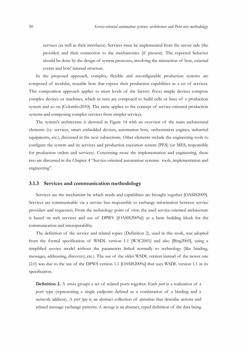
50 Service-oriented automation systems: architecture and Petri nets methodology
services (as well as their interfaces). Services must be implemented from the server side (the
provider) and their connection to the mechatronics (if present). The expected behavior
should be done by the design of system processes, involving the interaction of bots, external
events and bots' internal structure.
In the proposed approach, complex, flexible and reconfigurable production systems are
composed of modular, reusable bots that expose their production capabilities as a set of services.
This composition approach applies to most levels of the factory floor; simple devices compose
complex devices or machines, which in turn are composed to build cells or lines of a production
system and so on [Colombo2010]. The same applies to the concept of service-oriented production
systems and composing complex services from simpler services.
The system's architecture is denoted in Figure 14 with an overview of the main architectural
elements (i.e. services, smart embedded devices, automation bots, orchestration engines, industrial
equipments, etc.), discussed in the next subsections. Other elements include the engineering tools to
configure the system and its services and production execution system (PES) (or MES, responsible
for production orders and services). Concerning more the implementation and engineering, these
two are discussed in the Chapter 4 “Service-oriented automation systems: tools, implementation and
engineering”.
3.1.3 Services and communication methodology
Services are the mechanism by which needs and capabilities are brought together [OASIS2009].
Services are communicable via a service bus responsible to exchange information between service
providers and requesters. From the technology point of view, the used service-oriented architecture
is based on web services and use of DPWS ([OASIS2009a]) as a basic building block for the
communication and interoperability.
The definition of the service and related topics (Definition 2), used in this work, was adopted
from the formal specification of WSDL version 1.1 [W3C2001] and also [Bing2005], using a
simplified service model without the parameters linked normally to technology (like binding,
messages, addressing, discovery, etc.). The use of the older WSDL version instead of the newer one
(2.0) was due to the use of the DPWS version 1.1 [OASIS2009a] that uses WSDL version 1.1 in its
specification.
Definition 2. A service groups a set of related ports together. Each port is a realization of a
port type (representing a single endpoint defined as a combination of a binding and a
network address). A port type is an abstract collection of operations that describe actions and
related message exchange patterns. A message is an abstract, typed definition of the data being
communicated. A service port is represented by a set of operations Sp = {s1, s2, …, sn} and
can be used as the synonym of the service if the service is just defined by one port.
What really makes the kernel of the service is the use of these operations and their management
by the provider (see Figure 15.A). For a service requester to use a service, it must know its interface,
which describes the service (e.g. its operations, messages, types). However, implementation aspects
are not included in the interface (must be handled by the provider), as well as more complex
coordination of the operations and services (this is arranged e.g. within the orchestration). Of
course, service providers can also be requesters and “vice versa”.
Figure 15: Interaction between provider and requester (A) and types of services (B)
There are different types of services in the system and even if their origin is transparent to the
outside (requesters), some essential types are explained here (see Figure 15.B). Device service (hosting
service) is directly associated to a device, and play an important part in the device discovery process
[Jammes2005c]. Atomic services are considered the ones provided by elementary equipments and
entities, such as the smart embedded device (controlling the conveyor) that would expose a “transfer”
service. They cannot be divisible into other services and serve as the basis of service composition
(and service modeling in general). Complex services may aggregate the functionality provided by
simpler ones. This is referred to as service composition and the aggregated service becomes a
composite service [Chafle2004] (e.g. a service resulting from an orchestration). The deployment service is
itself a built-in service, which allows the integrator to deploy its own resources [Candido2009],
configure other services and other aspects of the server. Services are available and can be requested
via the service bus which is a network.
51
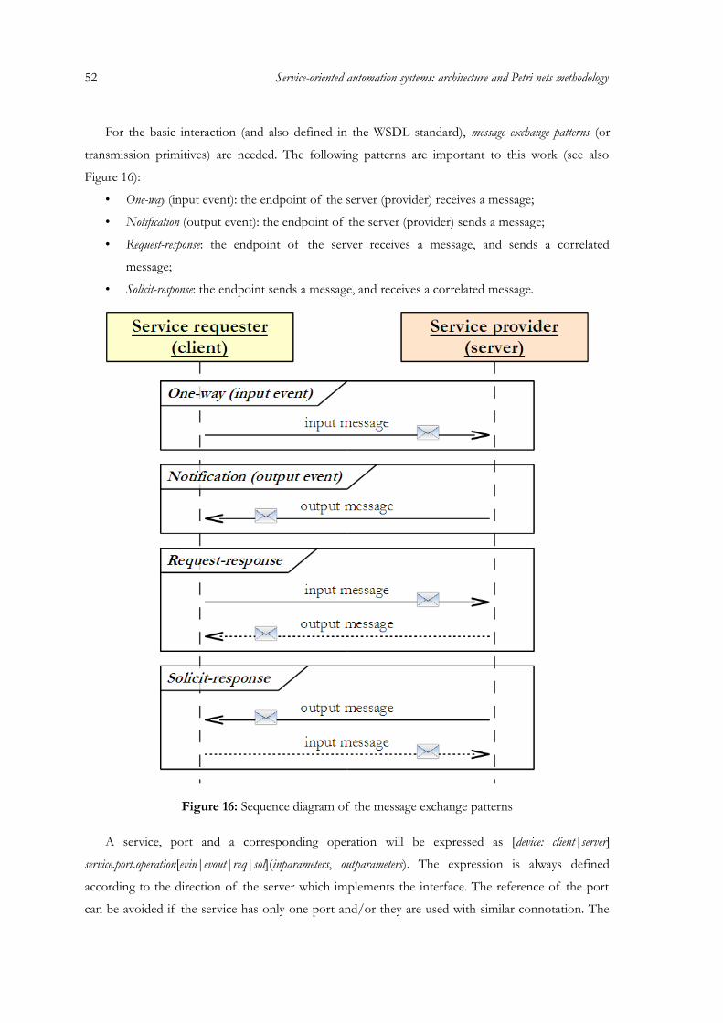
52 Service-oriented automation systems: architecture and Petri nets methodology
For the basic interaction (and also defined in the WSDL standard), message exchange patterns (or
transmission primitives) are needed. The following patterns are important to this work (see also
Figure 16):
• One-way (input event): the endpoint of the server (provider) receives a message;
• Notification (output event): the endpoint of the server (provider) sends a message;
• Request-response: the endpoint of the server receives a message, and sends a correlated
message;
• Solicit-response: the endpoint sends a message, and receives a correlated message.
Figure 16: Sequence diagram of the message exchange patterns
A service, port and a corresponding operation will be expressed as [device: client|server]
service.port.operation[evin|evout|req|sol](inparameters, outparameters). The expression is always defined
according to the direction of the server which implements the interface. The reference of the port
can be avoided if the service has only one port and/or they are used with similar connotation. The
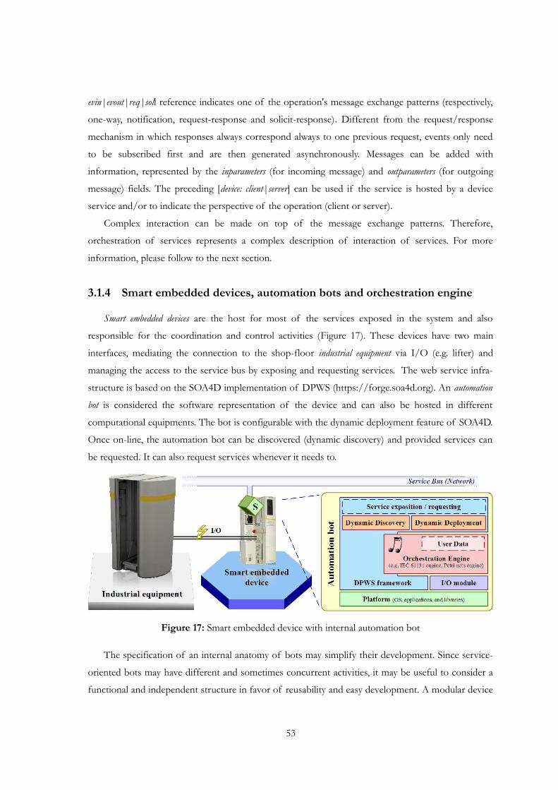
evin|evout|req|soll reference indicates one of the operation's message exchange patterns (respectively,
one-way, notification, request-response and solicit-response). Different from the request/response
mechanism in which responses always correspond always to one previous request, events only need
to be subscribed first and are then generated asynchronously. Messages can be added with
information, represented by the inparameters (for incoming message) and outparameters (for outgoing
message) fields. The preceding [device: client|server] can be used if the service is hosted by a device
service and/or to indicate the perspective of the operation (client or server).
Complex interaction can be made on top of the message exchange patterns. Therefore,
orchestration of services represents a complex description of interaction of services. For more
information, please follow to the next section.
3.1.4 Smart embedded devices, automation bots and orchestration engine
Smart embedded devices are the host for most of the services exposed in the system and also
responsible for the coordination and control activities (Figure 17). These devices have two main
interfaces, mediating the connection to the shop-floor industrial equipment via I/O (e.g. lifter) and
managing the access to the service bus by exposing and requesting services. The web service infra-
structure is based on the SOA4D implementation of DPWS (https://forge.soa4d.org). An automation
bot is considered the software representation of the device and can also be hosted in different
computational equipments. The bot is configurable with the dynamic deployment feature of SOA4D.
Once on-line, the automation bot can be discovered (dynamic discovery) and provided services can
be requested. It can also request services whenever it needs to.
Figure 17: Smart embedded device with internal automation bot
The specification of an internal anatomy of bots may simplify their development. Since service-
oriented bots may have different and sometimes concurrent activities, it may be useful to consider a
functional and independent structure in favor of reusability and easy development. A modular device
53
54 Service-oriented automation systems: architecture and Petri nets methodology
architecture with asynchronous and synchronous event mechanism between modules and
independent thread routine for each module should be considered. For example, the DPWS
framework and the I/O module are two modules of an automation bot, providing different features
(communication via services and synchronization of the industrial equipment, respectively) and
interoperable via event passing. Both have their own scheduling unit to avoid that, e.g. the I/O
module has to stop each time the DPWS framework is waiting for the response of a service, thus
blocking the execution of parallel processes by the I/O.
Since services aren't isolated entities exposed by the intervenient software components, there
should be some kind of logic that is responsible for the interaction. Therefore, some of them may
include an orchestration engine to “link” services into higher ones. The model-based orchestration engine is
able to interpret a given work-plan made of services (an orchestration) and execute it. The work-plan
can be defined in several orchestration languages, for example, BPEL [OASIS2007], Petri nets formalism
(see for example the work of R. Hamadi and B. Benatallah [Hamadi2003] and L. Bing and C.
Huaping [Bing2005]) or even adapted IEC 61131-3 languages. Another feature is to compose
services, i.e. the work-plan itself represents an exposed service. In this dissertation it was adopted the
orchestration (and additional features) based on the Petri net formalism. Besides the language
specification and the development of the interpreter (i.e. the orchestration engine), a complete
extensible methodology was created to permit the multi-featured application of Petri nets.
3.2 Open methodology for Petri nets in the modeling, analysis and execution of SOAS
The kind of automation and production systems addressed in this dissertation is characterized by
having a flexible material flow with several different flow specifications that can be offered by a
defined layout. Therefore, high-degree of concurrency, competency relationships among components
and non-deterministic sequences are presented. In addition, the introduction of service-orientation
makes possible to represent needs and conditions of the system's components in form of services
that can be accessed by others. The formal specification and modeling of physical systems that have
the characteristics addressed above can only be performed by using a mathematical tool able to
represent all the characteristics without exceptions.
Especially for service-oriented industrial automation, the application of Petri nets must also be
open to several specifications, requirements and methodologies for engineering that will possibly
come in future. Besides this, it also has the necessary flexibility to develop higher-level structures
based on the foundation, such as colored Petri nets. Since services, modeling, analysis, synthesis,
integration and flexibility are used as the synonym of SOA, Petri nets based structures are strong
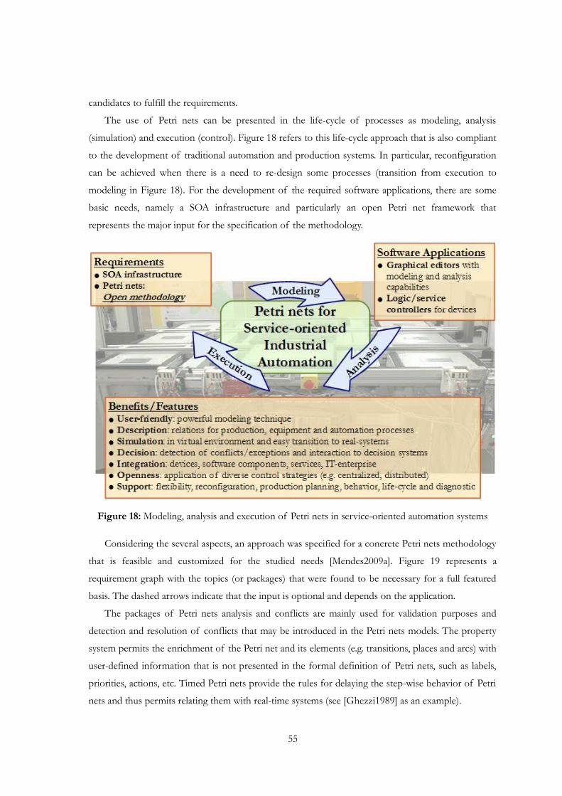
candidates to fulfill the requirements.
The use of Petri nets can be presented in the life-cycle of processes as modeling, analysis
(simulation) and execution (control). Figure 18 refers to this life-cycle approach that is also compliant
to the development of traditional automation and production systems. In particular, reconfiguration
can be achieved when there is a need to re-design some processes (transition from execution to
modeling in Figure 18). For the development of the required software applications, there are some
basic needs, namely a SOA infrastructure and particularly an open Petri net framework that
represents the major input for the specification of the methodology.
Figure 18: Modeling, analysis and execution of Petri nets in service-oriented automation systems
Considering the several aspects, an approach was specified for a concrete Petri nets methodology
that is feasible and customized for the studied needs [Mendes2009a]. Figure 19 represents a
requirement graph with the topics (or packages) that were found to be necessary for a full featured
basis. The dashed arrows indicate that the input is optional and depends on the application.
The packages of Petri nets analysis and conflicts are mainly used for validation purposes and
detection and resolution of conflicts that may be introduced in the Petri nets models. The property
system permits the enrichment of the Petri net and its elements (e.g. transitions, places and arcs) with
user-defined information that is not presented in the formal definition of Petri nets, such as labels,
priorities, actions, etc. Timed Petri nets provide the rules for delaying the step-wise behavior of Petri
nets and thus permits relating them with real-time systems (see [Ghezzi1989] as an example).
55
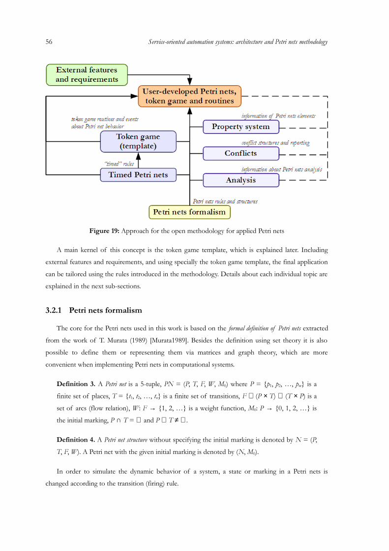
56 Service-oriented automation systems: architecture and Petri nets methodology
Figure 19: Approach for the open methodology for applied Petri nets
A main kernel of this concept is the token game template, which is explained later. Including
external features and requirements, and using specially the token game template, the final application
can be tailored using the rules introduced in the methodology. Details about each individual topic are
explained in the next sub-sections.
3.2.1 Petri nets formalism
The core for the Petri nets used in this work is based on the formal definition of Petri nets extracted
from the work of T. Murata (1989) [Murata1989]. Besides the definition using set theory it is also
possible to define them or representing them via matrices and graph theory, which are more
convenient when implementing Petri nets in computational systems.
Definition 3. A Petri net is a 5-tuple, PN = (P, T, F, W, M0) where P = {p1, p2, …, pm} is a
finite set of places, T = {t1, t2, …, tn} is a finite set of transitions, F ⊆ (P × T) ∪ (T × P) is a
set of arcs (flow relation), W: F → {1, 2, …} is a weight function, M0: P → {0, 1, 2, …} is
the initial marking, P ∩ T = ∅ and P ∪ T ≠ ∅.
Definition 4. A Petri net structure without specifying the initial marking is denoted by N = (P,
T, F, W). A Petri net with the given initial marking is denoted by (N, M0).
In order to simulate the dynamic behavior of a system, a state or marking in a Petri nets is
changed according to the transition (firing) rule.
Definition 5. A transition t is said to be enabled if each input place p of transition t is marked
with at least w(p, t) tokens, where w(p, t) is the weight of the arc from place p to transition t.
Definition 6. A firing of an enabled transition t, corresponding to the firing rule, removes w(p,
t) tokens from each input place p of transition t, and adds w(t, p) tokens to each output place
p of transition t, where w(t, p) is the weight of the arc from transition t to place p. Note: An
enabled transition may or may not fire (depending on whether or not the event actually takes
place).
In a Petri net each node is either a place or a transition. Tokens occupy places representing
resources or states of the system. The dynamic evolution of the Petri net, i.e. the change of a state or
marking in the model, is described through the enabling and firing rules, stated in the following
definitions.
Graphically, Petri nets can be represented by a bipartite graph structure. Nodes of the graph are
places (represented usually as a cycle) and transitions (normally described by a bar). Arcs are responsible
of connecting places to transitions and “vice versa”. The dynamic of Petri nets is regulated by the
flow of tokens (pictured by corresponding number of dots) that are resident inside places and as a
whole (all tokens existent in the Petri net) represent the marking of the Petri net, translated in the
system's actual state.
3.2.2 Analysis
The Petri nets formalism is widely used by researchers due to their mathematical foundation and
consequently “proof of concepts” and specification of new theorems. Analysis and validation of
systems is crucial, not only to prove that they are free of errors, but also to test if they do what the
engineer wants that they should do. Also and not less important, is to obtain statistical information
of the system performance, allowing the future enhancements of the system.
Generally speaking, two types of analysis can be done over a Petri net: the analysis considering
both the Petri net structure and the initial marking is called behavioral analysis and the analysis based
solely on the structure of the Petri net is designated structural analysis.
The first analysis is heavily based on reachability, described by the general behavior of a Petri net
and concerns with the reaching from one marking to another. Starting from initial system condition
or state (initial marking), it is desired to derive all the possible states the system can reach, as well as
their relationship. The resulting representation is a reachability tree or reachability graph. To
construct this tree, the algorithm found in [Zhou1999] can be used. Some properties like the
existence of dead markings, firing sequences that transform one marking into another, boundness,
safeness, reversibility and many other properties can be obtained.
57
58 Service-oriented automation systems: architecture and Petri nets methodology
From the computational point of view, creating the reachability tree (i.e. all possible sequence of
markings from firing transitions) can be quite expensive, depending on the complexity of the Petri
net model. Therefore, structural properties are more suitable to obtain when only the topological
structures of Petri nets are considered. They are independent of the initial marking M0 in the sense
that these properties refer to the existence of certain firing sequences patterns and possible places of
mutual exclusion. These properties can often be characterized in terms of the incidence matrix and
its associated homogeneous equations or inequalities [Murata1989]. The resulting invariants can then
be used to obtain some structural properties (independent of the initial marking).
Definition 7. For a Petri net structure N with m places and n transitions, the incidence matrix
A= [aij] is a m × n matrix of integers and its typical entry is given by aij = aij+ - aij
-, where aij+ is
the weight of the arc from a transition j to its output place i and aij- is the weight of the arc to
transition j from its input place i. Note: The transpose of A is represented by At = [aji].
Definition 8. An integer solution x of the homogeneous equation Ax = 0 is called transition-
invariant. The set of non-zero entries of this solution is called transition-support.
Definition 9. An integer solution y of the homogeneous equation Aty = 0 is called place-
invariant. The set of non-zero entries of this solution is called place-support.
To obtain the invariants, some matrix reduction algorithms can be used to discover the set of x
and y vectors of the Ax = 0 and Aty = 0 equations (see [Amer-Yahia1999] and [Martinez1980]).
Generally speaking, the meaning of the analysis of place-support constitution allows confirming
mutual exclusion relationships among places and functions and resources involved in the model
structure. The analysis of the transition-support allows the identification of work cycles.
3.2.3 Conflicts
There is the possibility to model Petri nets without conflicts, but the existence of such properties
creates a new dimension in terms of flexibility of Petri nets. Besides static models that only specify a
predefined work-plan, some models can be enriched with the possibility of choices that permit the
intervention of decision handlers (often borrowing concepts from artificial intelligence). In more
complex systems represented by their Petri nets, they may contain intersections of conflicts. This
happen when a transition t has more that one input place that is in conflict. In these cases the
resolution of one conflict implies also considering the other conflicts that are in intersection.
Therefore, conflicts sets (set of intersecting conflicts) should be considered, instead of single conflicts.
Definition 10. A place p has a structural conflict, SC(p), if there are at least 2 transitions t ∈ T
where w(p, t) > 0. The set of all structural conflicts is denoted by SC.
Definition 11. A place p is in conflict, C(p) if it has a structural conflict SC(p) and the current
number of tokens of place p, M(p), enables at least two transitions t which place p is inputs.
Structural conflicts are quite suitable because they represent the candidates for the real conflicts
that happen at run-time. In fact, the set of real conflicts C is always a subset (or equal) of the
structural conflicts SC, S ⊆ SC. These candidates can be obtained by the structural information of
the Petri net and if calculated before running the net, performance is increased afterwards (avoiding
the analysis of each place).
In more complex systems represented by their Petri nets models, they may contain intersections
of conflicts. This happen when a transition t has more that one input place that is in conflict. In
these cases the resolution of one conflict implies also considering the other conflicts that are in
intersection. Therefore, conflicts sets (set of intersecting conflicts) should be considered, instead of
single conflicts.
3.2.4 Property system
The formal definition of Petri nets does only define the structure and behavior of the net, in
which their elements (e.g. transitions and places) do not contain any information or are associated to
anything. Enhancements have been done to Petri nets to make them more usable and applicable to
real systems (e.g. colored Petri nets [Jensen1987]). A common point in all these types of nets is that
the elements are associated to some kind of information (e.g. time, capacity and priority). The idea is
always to maintain the strong foundation of Petri nets, but enhancing it with structural and
behavioral characteristics. One approach to permit a flexible and customized definition of control
structures based on Petri nets is to define a property system that works on top of the standard
structure and behavior. In the end, the advantage is to provide the facility to customize higher-level
types of nets, based on the formal Petri nets definition and the developed property system.
The following definition (Definition 12) describes a property system to be used for Petri nets and
its elements, such as places, transitions and arcs. It was inspired by the Qt's Property System for
classifying their QObjects (see [Blanchette2006]).
Definition 12. A property system (for Petri nets), Π = {π1, π2, …, πl}, is a set of properties that
classify one or several elements of the system (in this case represented by Petri nets). Each
property π ∈ Π is defined by property parameters, ψ(π) = (ψname, ψscope, ψreference, ψinformation, ψdata-type,
ψdefault- value, ψvalue, ψaccess, ψpersistence, ψdesignable).
59
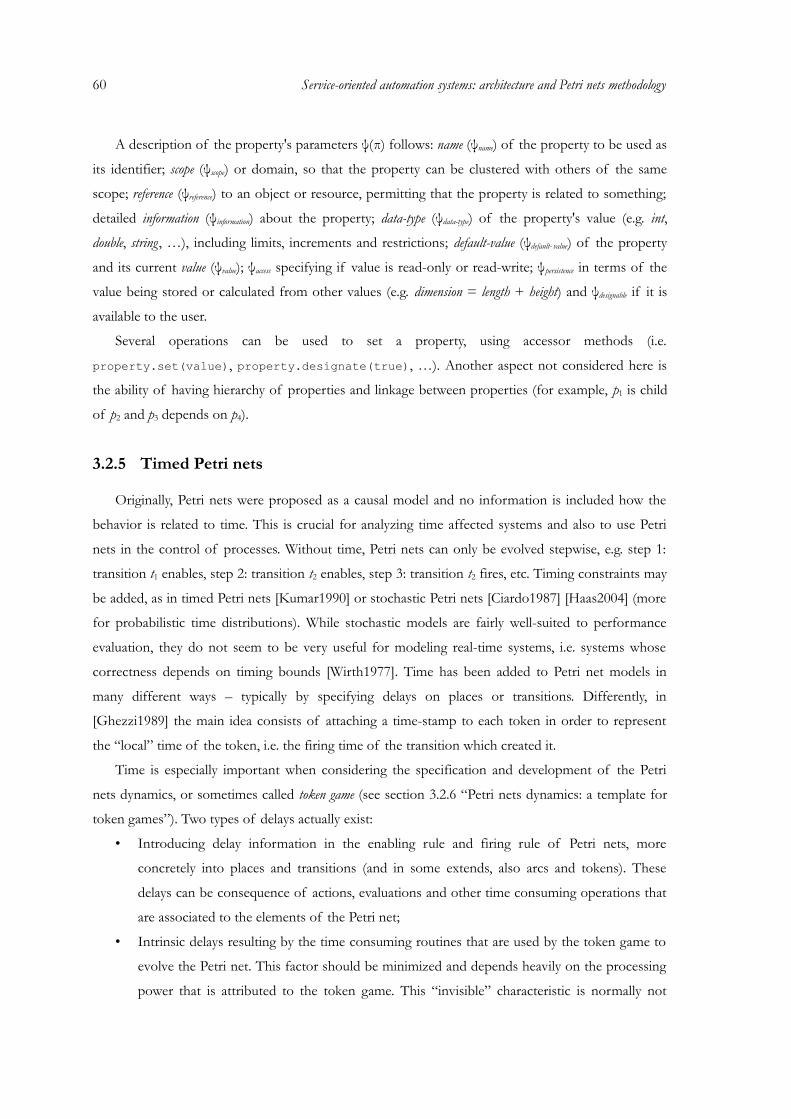
60 Service-oriented automation systems: architecture and Petri nets methodology
A description of the property's parameters ψ(π) follows: name (ψname) of the property to be used as
its identifier; scope (ψscope) or domain, so that the property can be clustered with others of the same
scope; reference (ψreference) to an object or resource, permitting that the property is related to something;
detailed information (ψinformation) about the property; data-type (ψdata-type) of the property's value (e.g. int,
double, string , …), including limits, increments and restrictions; default-value (ψdefault- value) of the property
and its current value (ψvalue); ψaccess specifying if value is read-only or read-write; ψpersistence in terms of the
value being stored or calculated from other values (e.g. dimension = length + height) and ψdesignable if it is
available to the user.
Several operations can be used to set a property, using accessor methods (i.e.
property.set(value), property.designate(true), …). Another aspect not considered here is
the ability of having hierarchy of properties and linkage between properties (for example, p1 is child
of p2 and p3 depends on p4).
3.2.5 Timed Petri nets
Originally, Petri nets were proposed as a causal model and no information is included how the
behavior is related to time. This is crucial for analyzing time affected systems and also to use Petri
nets in the control of processes. Without time, Petri nets can only be evolved stepwise, e.g. step 1:
transition t1 enables, step 2: transition t2 enables, step 3: transition t2 fires, etc. Timing constraints may
be added, as in timed Petri nets [Kumar1990] or stochastic Petri nets [Ciardo1987] [Haas2004] (more
for probabilistic time distributions). While stochastic models are fairly well-suited to performance
evaluation, they do not seem to be very useful for modeling real-time systems, i.e. systems whose
correctness depends on timing bounds [Wirth1977]. Time has been added to Petri net models in
many different ways – typically by specifying delays on places or transitions. Differently, in
[Ghezzi1989] the main idea consists of attaching a time-stamp to each token in order to represent
the “local” time of the token, i.e. the firing time of the transition which created it.
Time is especially important when considering the specification and development of the Petri
nets dynamics, or sometimes called token game (see section 3.2.6 “Petri nets dynamics: a template for
token games”). Two types of delays actually exist:
• Introducing delay information in the enabling rule and firing rule of Petri nets, more
concretely into places and transitions (and in some extends, also arcs and tokens). These
delays can be consequence of actions, evaluations and other time consuming operations that
are associated to the elements of the Petri net;
• Intrinsic delays resulting by the time consuming routines that are used by the token game to
evolve the Petri net. This factor should be minimized and depends heavily on the processing
power that is attributed to the token game. This “invisible” characteristic is normally not
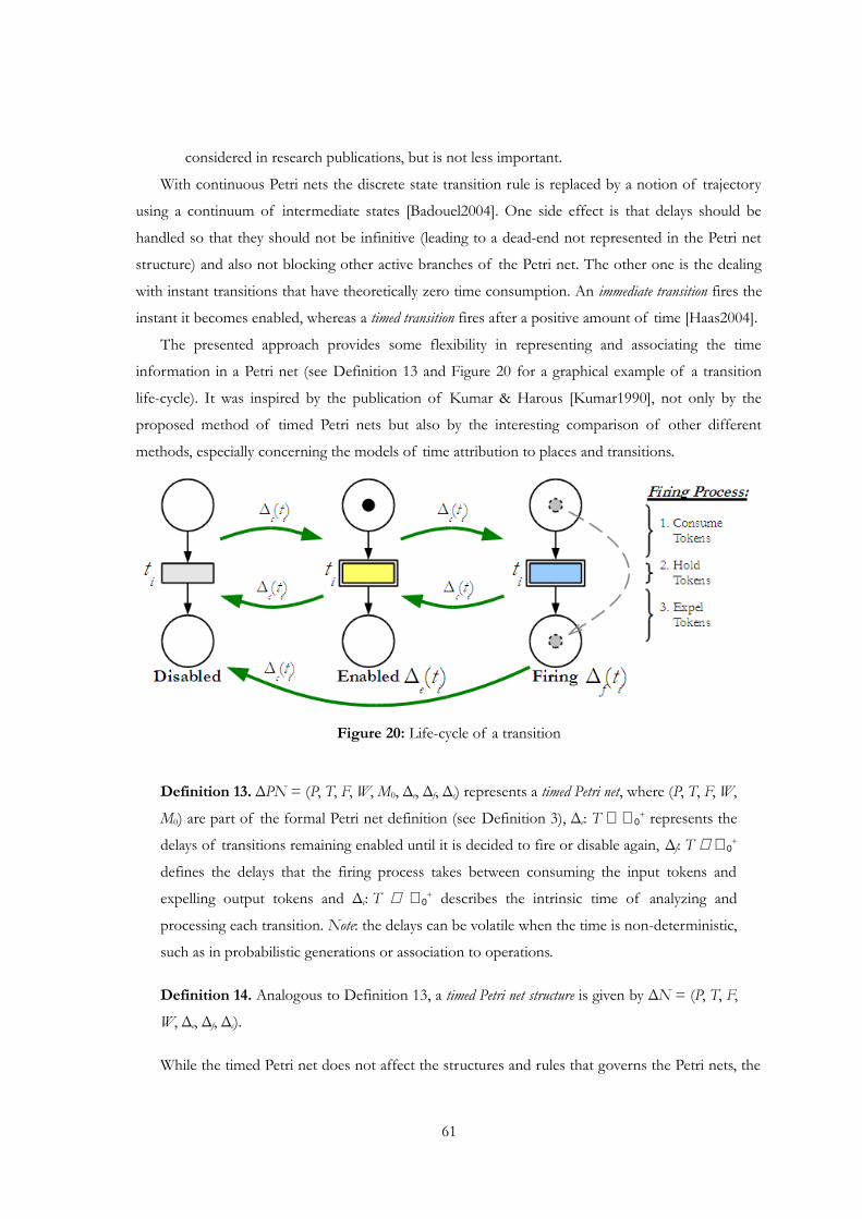
considered in research publications, but is not less important.
With continuous Petri nets the discrete state transition rule is replaced by a notion of trajectory
using a continuum of intermediate states [Badouel2004]. One side effect is that delays should be
handled so that they should not be infinitive (leading to a dead-end not represented in the Petri net
structure) and also not blocking other active branches of the Petri net. The other one is the dealing
with instant transitions that have theoretically zero time consumption. An immediate transition fires the
instant it becomes enabled, whereas a timed transition fires after a positive amount of time [Haas2004].
The presented approach provides some flexibility in representing and associating the time
information in a Petri net (see Definition 13 and Figure 20 for a graphical example of a transition
life-cycle). It was inspired by the publication of Kumar & Harous [Kumar1990], not only by the
proposed method of timed Petri nets but also by the interesting comparison of other different
methods, especially concerning the models of time attribution to places and transitions.
Figure 20: Life-cycle of a transition
Definition 13. ΔPN = (P, T, F, W, M0, Δe, Δf, Δc) represents a timed Petri net, where (P, T, F, W,
M0) are part of the formal Petri net definition (see Definition 3), Δe: T ∈ ℜ0+ represents the
delays of transitions remaining enabled until it is decided to fire or disable again, Δf: T ∈ ℜ0+
defines the delays that the firing process takes between consuming the input tokens and
expelling output tokens and Δc: T ∈ ℜ0+ describes the intrinsic time of analyzing and
processing each transition. Note: the delays can be volatile when the time is non-deterministic,
such as in probabilistic generations or association to operations.
Definition 14. Analogous to Definition 13, a timed Petri net structure is given by ΔN = (P, T, F,
W, Δe, Δf, Δc).
While the timed Petri net does not affect the structures and rules that governs the Petri nets, the
61
62 Service-oriented automation systems: architecture and Petri nets methodology
influence of time affects how (and when) the rules should be applied. Important are the two first
delays Δe and Δf that can be used or represent external time-consuming functions and operations.
While the disabled and enabled states are intrinsic of the logical process of Petri nets, the firing
process can be extended to be the interface to the system by calling specific functions that make the
evolution of the firing process. This characteristic makes possible to associate the Petri net to the real
systems: the marking of the Petri net corresponds to the state of the system, and the firing of a
transition corresponds to the occurrence of an event [Haas2004]. The last one, Δc, represents
intrinsic delays that are associated with time consuming routines to evolve the Petri net (analyzing
and processing each transition). This “invisible” characteristic is normally not considered in the
research publications, but is not less important.
One side effect is that delays should not be infinitive (leading to a dead-end not represented in
the Petri net structure) and also not blocking other active branches of the Petri net. The other one is
the dealing with immediate transitions that have theoretically zero time consumption. An immediate
transition fires the instant it becomes enabled, whereas a timed transition fires after a positive amount of
time [Haas2004]. A special remark to be considered is when a transition is on firing process and it
does enable again. More detailed discussion can be found in the section 3.2.6 “Petri nets dynamics: a
template for token games” about the definition of a prototype token game that regulates the state
changing of transitions and considers the already specified Petri net features in the previous sections.
3.2.6 Petri nets dynamics: a template for token games
The goal of this template is to provide a basis for Petri nets token games (an “engine” that runs a
Petri net), based on the standard Petri nets formalism and extensible to permit the inclusion
customized features. In its core and to maintain an asynchronous (independent) operation of the
transitions, the template is a state machine specification for each transition and consequently
responsible for managing the transition's state and evolution. The template itself is not a fully
functional token game because it only defines a set of basic operations for analyzing and evolving
transitions of the Petri net. Concrete token games can then be customized from this template.
The choice of having a state machine representation for the life-cycle of transitions is mainly due
to implementation concerns on computational systems. The different „states“ and „edges“ that are
part of the life-cycle, invites the adoption of a state changing mechanism for processing the
transitions. A state machine is a safe way to represent and implement those possibilities. The state
machine is specified by checking what is possible and valid for the Petri net formalism and, at the
same time, concerning possible external interactions.
The state machine is formally given in Definition 15, Table II presents its state table and Figure
21 the state diagram.
Definition 15. The Petri nets transition state machine for a transition t ∈ T (where T represents a
finite set of transitions of a Petri net) is defined by a 5-tuple TSMt = (Σ, Φ, Ω, Γ, σ0), where
Σ = {σ1, σ2, …, σ16} is a set of 16 states, Φ: Σ → {φ1, φ2, …, φ16} is a set of flags for each
state, Ω = {ω1, ω2, …, ωn} defines a finite set of input/output symbols, Γ: Σ × Ω → Σ
defines edges between two states as caused by the input/output and σ0 ∈ Σ defines the initial
state (σ0 = σ1 = 1). Note: transitions in the state machine are referred as edges, not to be
confused with the transitions of the Petri net.
The state machine related to each transition is made of several states representing the different
combination of flags and the change between states is made by occurrence of events and execution
of operations. Besides the enabled and firing flags that indicate if a transition is enabled or firing,
sleeping and jump parameters were added to permit a more flexible management for the external
time consuming functions (see definition below). “In summa”, there are four flags, and their
combination result in 16 different states for the transition. The state of a transition is evolved by two
main situations:
• Implicitly, by calling the evolve function over the transition. This function analyzes the actual
state of the transition and proceeds according to the state machine in Table II (it
corresponds to the white background rows);
• Explicitly, by 1) the enabling/disabling of the transition during previous processing of other
transitions and their evolution and also 2) by calling the wake-up function over a transition due
to occurrence of events (it disables then the sleeping flag). These situations are marked in
darker background rows in Table II.
The previous definition of TSMt has several remarks that are discussed. The flags for a state
σ ∈ Σ are defined by φσ = (φE, φF, φJ, φS). The meaning of a flag when it is true is:
• Enabled (φE): the transition is automatically enabled depending on the actual marking of the
Petri net;
• Firing (φF): the transition is on firing process. A particular note considered here is that if a
transition is during firing process and enabled again, the enabling is ignored until the firing
process is concluded;
• Jump (φJ): the handler functions (see below) are not called in the next analyzing iteration of
the transition;
• Sleeping (φS): the transition is waiting for external signal and consequently is blocked.
Note: The additional flags (sleeping and jumping) do not interfere on the basic mechanism to
evolve the Petri net (in sense of consuming and expelling tokens by the transitions), but moreover
when the net should evolve and how external events influence it. Note that the Petri nets that are
used in this work are not isolated, but connected to external events outside the net via the transitions.
63
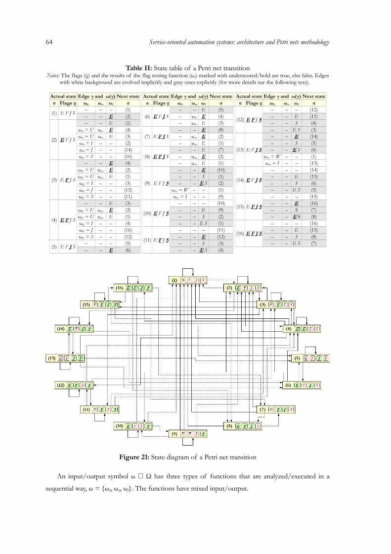
64 Service-oriented automation systems: architecture and Petri nets methodology
Table II: State table of a Petri net transitionNotes: The flags (φ) and the results of the flag testing function (ωf) marked with underscored/bold are true, else false. Edges
with white background are evolved implicitly and gray ones explicitly (for more details see the following text).
Actual state Edge γ and ω(γ) Next state Actual state Edge γ and ω(γ) Next state Actual state Edge γ and ω(γ) Next stateσ Flags φ ωk ωu ωf σ σ Flags φ ωk ωu ωf σ σ Flags φ ωk ωu ωf σ
(1) E F J S – – – (1)(6) E F J S
– – E (5)
(12) E F J S
– – – (12)– – E (2) – ωui E (4) – – E (11)
(2) E F J S
– – E (1) – ωui E (3) – – S (4)ωhe = U ωui E (4)
(7) E F J S– – E (8) – – E S (3)
ωhe = U ωui E (3) – ωuo E (2)
(13) E F J S
– – E (14)ωhe = I – – (2) – ωuo E (1) – – S (5)ωhe = J – – (14)
(8) E F J S– – E (7) – – E S (6)
ωhe = S – – (10) – ωuo E (2) ωhx = W – – (1)
(3) E F J S
– – E (4) – ωuo E (1) ωhx = I – – (13)ωhf = U ωuo E (2)
(9) E F J S
– – E (10)
(14) E F J S
– – – (14)ωhf = U ωuo E (1) – – S (1) – – E (13)ωhf = I – – (3) – – E S (2) – – S (6)ωhf = J – – (15) ωhx = W – – (1) – – E S (5)ωhf = S – – (11) ωhx = I – – (9)
(15) E F J S
– – – (15)
(4) E F J S
– – E (3)
(10) E F J S
– – – (10) – – E (16)ωhf = U ωuo E (2) – – E (9) – – S (7)ωhf = U ωuo E (1) – – S (2) – – E S (8)ωhf = I – – (4) – – E S (1)
(16) E F J S
– – – (16)ωhf = J – – (16)
(11) E F J S
– – – (11) – – E (15)ωhf = S – – (12) – – E (12) – – S (8)
(5) E F J S – – – (5) – – S (3) – – E S (7)– – E (6) – – E S (4)
Figure 21: State diagram of a Petri net transition
An input/output symbol ω ∈ Ω has three types of functions that are analyzed/executed in a
sequential way, ω = {ωh, ωu, ωf}. The functions have mixed input/output.
Handler functions ωh ∈ {ωhe, ωhf, ωhx} (generate both input and output) are used for the external
communication (and thus must be defined). Their return values contribute to the definition of the
next steps in the state machine. In practice, the main distinction between enabled and firing functions
is that the first one does not guarantee the number of tokens, not even if the transition will
effectively enter the firing process (e.g. it may disable again):
• Enabled function (ωhe): called when a transition is enabled and thus permitting it to enter the
firing process (and consuming tokens). It may return {U, S, I, J} (for testing as input),
meaning update (if still enabled, the transition then enters effectively the firing process by
calling consequently one of the update functions), sleep (puts the transition in sleeping,
awaiting an call of the wake-up function), ignore (does nothing and does not change the
status of the transition) and jump (does the same as returning S, but next time, the enabled
function is not called);
• Firing function (ωhf): called when a transition is on firing and thus permitting it to leave this
process (and expel tokens). The return status is similar to the enabled function, but for
leaving the firing process;
• Exception function (ωhx): called on exceptions when a transition is disabled during sleeping (see
state 9 and 13 of Table II). Returning W (wake-up), the sleeping mode (and jump mode if
active) is disabled. Returning I (ignore) the actual state is not changed.
Update functions ωu ∈ {ωui, ωuo}, (only generate output) are responsible for evolving the
transition according to the actual state of flags, i.e. they are used to effectively consume and expel
tokens. The update input ωui updates the input of a transition, i.e. consuming tokens and the update
output ωuo is responsible for updating the output of a transition (expelling tokens). Last, the flag
testing function ωf (only input) tests the status of a state, namely its flags (φE, φF, φJ, φS) if they are
true or false.
When relating the transition state machine with the timed Petri nets, it is easy to verify where the
intersections are. For a transition t, the time between the calling of the enabled function ωhe(t) and 1)
returning update (U), 2) calling corresponding wake-up function when sleeping or 3) disabling of the
transition, represents the Δe(t) delay. Similar, the time between the calling of the firing function and 1)
returning update (U) or 2) calling corresponding wake-up function when sleeping, describes the Δf(t).
The processing of the wake-up function and the evolve function (that encapsulates the application
of the three types of functions that are analyzed/executed in a sequential way, ω = {ωh, ωu, ωf}) are
mapped to the Δc(t) delay. To compare the association, please see the previous Figure 20 of the
transition's life-cycle.
65
66 Service-oriented automation systems: architecture and Petri nets methodology
3.2.7 User-developed Petri nets applications
The open methodology and the token game template do not define a concrete Petri nets
application and leaves to the engineer and/or developers the possibility to customize their Petri nets
application. Therefore, when defining a concrete application based on the previous methodology
(especially a token game), several aspects must be considered:
• Create the necessary Petri nets structures based on the open methodology;
• Define the handler functions of the token game and the call of the wake-up function;
• Consider a specification of properties and their association to the elements of the Petri net
and the evolution of the net;
• Decide about how conflicts are managed and reported;
• Define the life-cycle of the whole Petri net based on the ones from the transitions. A special
attention must be taken in the order of analyzing transitions, when to begin/finish the token
game and also deadlock detection.
In service-oriented automation, the resulting Petri nets applications must also consider their
environment and what features should be handled. Additionally, the necessary service infra-structure
must be available and also, when targeting devices, hardware access must be considered. From the
Petri net side, one obvious conclusion is that services should somehow be related to Petri nets,
whatever it should represent the logic of a service, work-flow between services or other situations.
Other thoughts have to be done if the final structure should help in the modeling, analysis and/or be
used in the control of a service environment.
3.3 Features and extensions for Petri nets based on the open methodology
The proposed approach to develop Petri net-based application for embedded devices and PC
tools, is to use the open methodology described in section 3.2 “Open methodology for Petri nets in
the modeling, analysis and execution of SOAS” tailored for service-oriented systems, taking the
advantage of their powerful mathematical foundation. Having the basis for Petri nets applications
and engineering, the next step would be identify what are the characteristics that can be extracted
from them to be used in service-oriented automation systems.
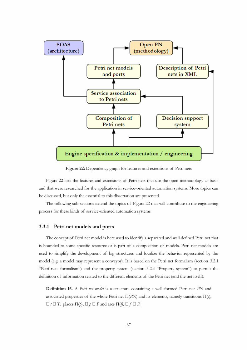
Figure 22: Dependency graph for features and extensions of Petri nets
Figure 22 lists the features and extensions of Petri nets that use the open methodology as basis
and that were researched for the application in service-oriented automation systems. More topics can
be discussed, but only the essential to this dissertation are presented.
The following sub-sections extend the topics of Figure 22 that will contribute to the engineering
process for these kinds of service-oriented automation systems.
3.3.1 Petri net models and ports
The concept of Petri net model is here used to identify a separated and well defined Petri net that
is bounded to some specific resource or is part of a composition of models. Petri net models are
used to simplify the development of big structures and localize the behavior represented by the
model (e.g. a model may represent a conveyor). It is based on the Petri net formalism (section 3.2.1
“Petri nets formalism”) and the property system (section 3.2.4 “Property system”) to permit the
definition of information related to the different elements of the Petri net (and the net itself).
Definition 16. A Petri net model is a structure containing a well formed Petri net PN and
associated properties of the whole Petri net Π(PN) and its elements, namely transitions Π(t),
∀ t ∈ T, places Π(p), ∀ p ∈ P and arcs Π(f), ∀ f ∈ F.
67

68 Service-oriented automation systems: architecture and Petri nets methodology
Common properties of the Petri net can be the name of the Petri net πname(PN), the resource it
represents πresource(PN) and the address(reference) of the net πreference(PN).
Since Petri nets can be used to describe process activities in different ways, some association rules
of processes are necessary to be explained. The following basic control flow patterns are considered
for this work (Figure 23)1:
• Sequence: An activity in a process is enabled after the completion of another activity in the
same process;
• Parallel split: A point in the process where a single thread of control splits into multiple
threads of control which can be executed in parallel, thus allowing activities to be executed
simultaneously or in any order;
• Synchronization: A point in the process where multiple parallel sub-processes/activities
converge into one single thread of control, thus synchronizing multiple threads;
• Exclusive choice: A point in the process where, based on a decision or work data, one of several
branches is chosen;
• Simple merge: A point in the process where two or more alternative branches come together
without synchronization. It is an assumption of this pattern that none of the alternative
branches is ever executed in parallel.
• Figure 23: Basic control flow patterns for Petri nets used in this work• (A) sequence, (B) parallel split, (C) synchronization, (D) exclusive choice, (E) simple merge
More complex patterns can be obtained with the intrinsic properties of Petri nets (see the
examples of [Aalst2003]), which are dependent of the designer's choice of how to define the
associated resource's behavior. The introduction of tokens in the Petri net creates an increased
flexibility to represent complex systems, where states are not limited to a mark at a given place, but a
1 Note that activity actions represented in the Petri net are associated to transitions. Places define occurrences that are triggered by transitions (e.g. calling an action, receiving an event).
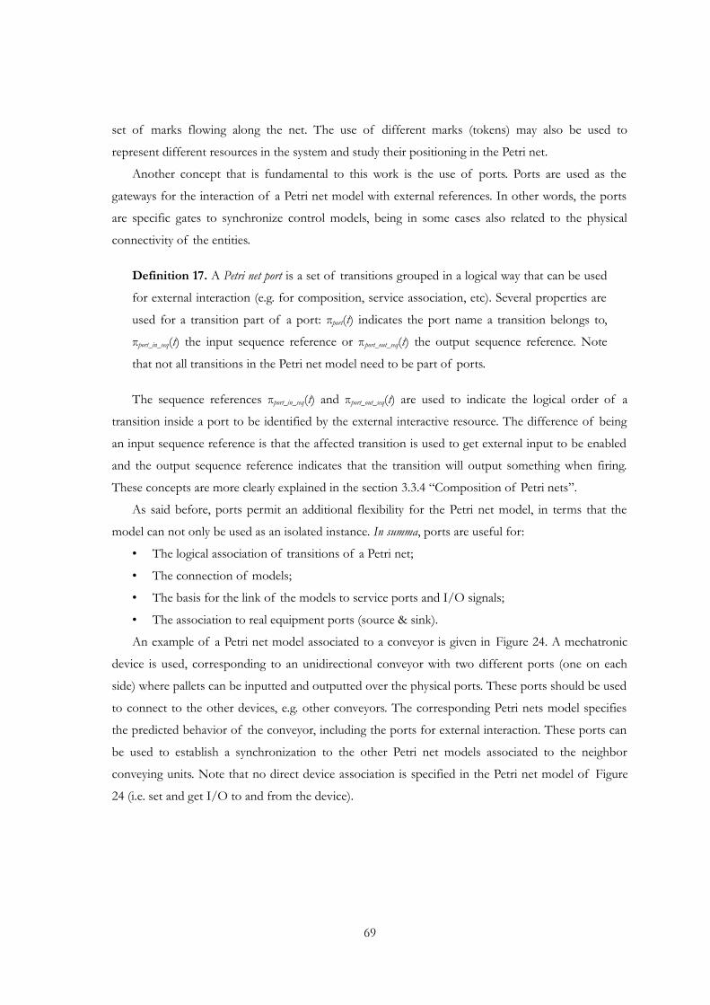
set of marks flowing along the net. The use of different marks (tokens) may also be used to
represent different resources in the system and study their positioning in the Petri net.
Another concept that is fundamental to this work is the use of ports. Ports are used as the
gateways for the interaction of a Petri net model with external references. In other words, the ports
are specific gates to synchronize control models, being in some cases also related to the physical
connectivity of the entities.
Definition 17. A Petri net port is a set of transitions grouped in a logical way that can be used
for external interaction (e.g. for composition, service association, etc). Several properties are
used for a transition part of a port: πport(t) indicates the port name a transition belongs to,
πport_in_seq(t) the input sequence reference or πport_out_seq(t) the output sequence reference. Note
that not all transitions in the Petri net model need to be part of ports.
The sequence references πport_in_seq(t) and πport_out_seq(t) are used to indicate the logical order of a
transition inside a port to be identified by the external interactive resource. The difference of being
an input sequence reference is that the affected transition is used to get external input to be enabled
and the output sequence reference indicates that the transition will output something when firing.
These concepts are more clearly explained in the section 3.3.4 “Composition of Petri nets”.
As said before, ports permit an additional flexibility for the Petri net model, in terms that the
model can not only be used as an isolated instance. In summa, ports are useful for:
• The logical association of transitions of a Petri net;
• The connection of models;
• The basis for the link of the models to service ports and I/O signals;
• The association to real equipment ports (source & sink).
An example of a Petri net model associated to a conveyor is given in Figure 24. A mechatronic
device is used, corresponding to an unidirectional conveyor with two different ports (one on each
side) where pallets can be inputted and outputted over the physical ports. These ports should be used
to connect to the other devices, e.g. other conveyors. The corresponding Petri nets model specifies
the predicted behavior of the conveyor, including the ports for external interaction. These ports can
be used to establish a synchronization to the other Petri net models associated to the neighbor
conveying units. Note that no direct device association is specified in the Petri net model of Figure
24 (i.e. set and get I/O to and from the device).
69
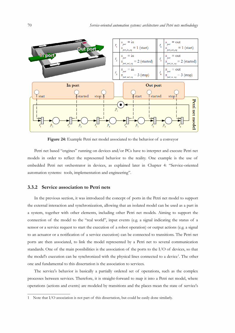
70 Service-oriented automation systems: architecture and Petri nets methodology
Figure 24: Example Petri net model associated to the behavior of a conveyor
Petri net based “engines” running on devices and/or PCs have to interpret and execute Petri net
models in order to reflect the represented behavior to the reality. One example is the use of
embedded Petri net orchestrator in devices, as explained later in Chapter 4: “Service-oriented
automation systems: tools, implementation and engineering”.
3.3.2 Service association to Petri nets
In the previous section, it was introduced the concept of ports in the Petri net model to support
the external interaction and synchronization, allowing that an isolated model can be used as a part in
a system, together with other elements, including other Petri net models. Aiming to support the
connection of the model to the “real world”, input events (e.g. a signal indicating the status of a
sensor or a service request to start the execution of a robot operation) or output actions (e.g. a signal
to an actuator or a notification of a service execution) can be connected to transitions. The Petri net
ports are then associated, to link the model represented by a Petri net to several communication
standards. One of the main possibilities is the association of the ports to the I/O of devices, so that
the model's execution can be synchronized with the physical lines connected to a device1. The other
one and fundamental to this dissertation is the association to services.
The service's behavior is basically a partially ordered set of operations, such as the complex
processes between services. Therefore, it is straight-forward to map it into a Petri net model, where
operations (actions and events) are modeled by transitions and the places mean the state of service's
1 Note that I/O association is not part of this dissertation, but could be easily done similarly.
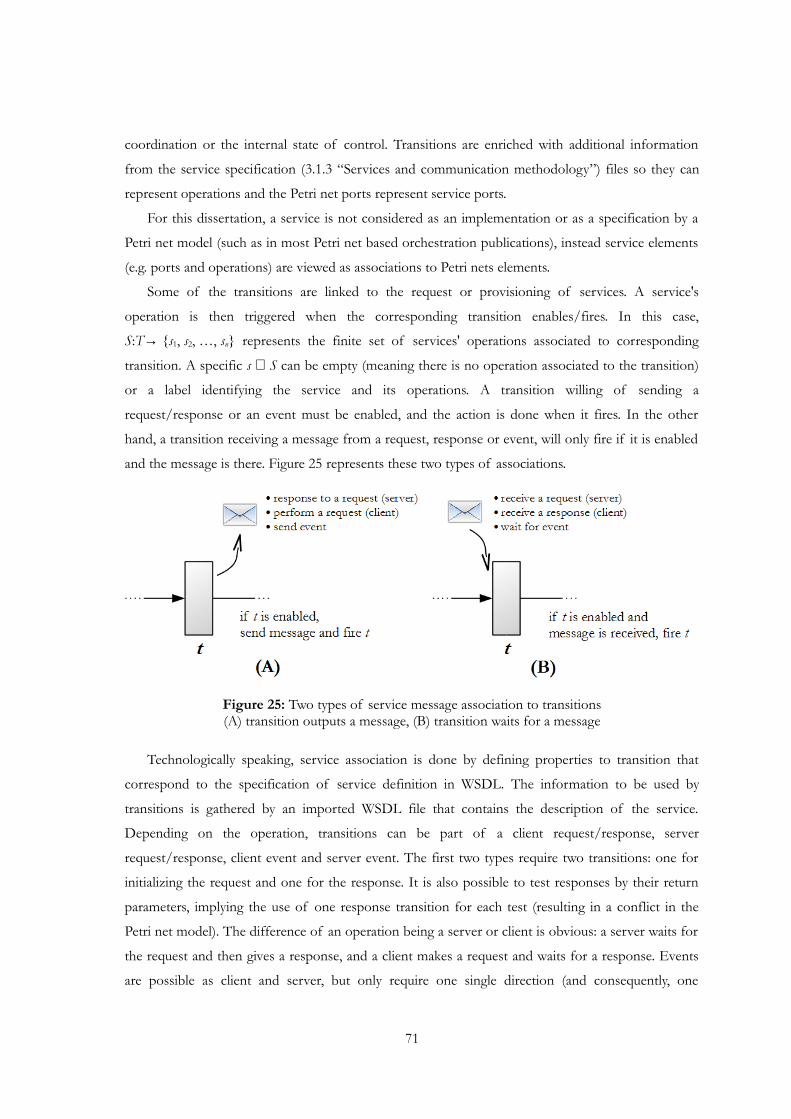
coordination or the internal state of control. Transitions are enriched with additional information
from the service specification (3.1.3 “Services and communication methodology”) files so they can
represent operations and the Petri net ports represent service ports.
For this dissertation, a service is not considered as an implementation or as a specification by a
Petri net model (such as in most Petri net based orchestration publications), instead service elements
(e.g. ports and operations) are viewed as associations to Petri nets elements.
Some of the transitions are linked to the request or provisioning of services. A service's
operation is then triggered when the corresponding transition enables/fires. In this case,
S:T→ {s1, s2, …, sn} represents the finite set of services' operations associated to corresponding
transition. A specific s ∈ S can be empty (meaning there is no operation associated to the transition)
or a label identifying the service and its operations. A transition willing of sending a
request/response or an event must be enabled, and the action is done when it fires. In the other
hand, a transition receiving a message from a request, response or event, will only fire if it is enabled
and the message is there. Figure 25 represents these two types of associations.
Figure 25: Two types of service message association to transitions(A) transition outputs a message, (B) transition waits for a message
Technologically speaking, service association is done by defining properties to transition that
correspond to the specification of service definition in WSDL. The information to be used by
transitions is gathered by an imported WSDL file that contains the description of the service.
Depending on the operation, transitions can be part of a client request/response, server
request/response, client event and server event. The first two types require two transitions: one for
initializing the request and one for the response. It is also possible to test responses by their return
parameters, implying the use of one response transition for each test (resulting in a conflict in the
Petri net model). The difference of an operation being a server or client is obvious: a server waits for
the request and then gives a response, and a client makes a request and waits for a response. Events
are possible as client and server, but only require one single direction (and consequently, one
71
72 Service-oriented automation systems: architecture and Petri nets methodology
transition).
Figure 26: Example of Figure 24 associated to services
The example of Figure 24 is extended in Figure 26 with the service association. The conveyor
provides one service that handles the necessary operations to make transfer movements over the two
logical ports (corresponding to the physical ones). This service must be requested in order to behave
in the corresponding way. Requesters can be other conveyors connected to this one over the ports.
The ports have several operations that are used to synchronize the operation and message exchange.
3.3.3 Description of Petri nets in XML
Since SOA implementations are frequently based on web services, their descriptive nature based
on XML hints to the adoption of similar procedure for the description of Petri nets. In fact, several
efforts where already done for representing Petri nets (and High-level based structures) in XML
format, such as the Petri Net Markup Language (see http://www2.informatik.hu-
berlin.de/top/pnml) and the International Standard ISO/IEC 15909 draft on a Transfer Format for
High-level Petri nets. This has several advantages inherited from the nature of XML, serving as a
portable interchange format towards interoperability and also the human/machine
“understandability” of the resulting representations. Considering automation systems (nowadays
growing in terms of information and engineers/machines that require to interpret it), the usefulness
can be easily understand.
In terms of information, all that is needed to represent a Petri net is its formal structure (see

3.2.1 “Petri nets formalism”) and a property system (3.2.4 “Property system”) that contains all the
additional information that may be necessary. Therefore, a XML based file format was defined for
the definition of Petri nets and associated information, such as analysis information, property system
and layout information. This specification was developed to provide a common file format for
exchanging Petri nets and related information. One of the goals is to permit a certain flexibility in
order to be adaptable to several kinds of Petri nets, especially high-level Petri nets, and also different
types of applications (simulation, control, analysis, etc.). The proposed file format is based on XML
and extension is xpn (Extensible Petri Net File Format).
The xpn file format is based around three main elements that express the container for the whole
information of the Petri net: <structure> sets up the structure of the Petri nets, i.e. the transitions,
places and arcs; <marking> defines the initial marking (if any) of the Petri net and the property
system is constructed in the <property_system> element, where properties can be assigned to each
element of the Petri net.
3.3.4 Composition of Petri nets
In the first place, the composition of services can be implemented in a hard-wired manner by
implementing the internal logic directly, or by utilization of an intermediate process modeling
language, for instance, Petri nets.
The composition of Petri nets is viewed as additional logic to synchronize the process of two or
more models. As illustrated in the left side of Figure 27, three Petri net models are composed and
their intersection is defined as composition logic. This can be done offline by using a composition
tool to generate a new Petri net model that is the composition of several individual ones, and also
online where individual models are maintained in their distributional units and synchronized together
on the fly via the network [Mendes2010]. The online composition can also be designated as virtual
composition, because no new model is generated, but individual models have to be linked together as
they were part of one. The online composition is done by using service-oriented architecture as
means of information exchange and service representation (i.e. to identify the synchronization points
of the Petri nets model). In both cases, at run-time an orchestration engine will get the Petri nets
model and run it.
There is an important note to the topic of composing Petri nets: Petri net composition is not the
same as composition of services. In the first case (and the one used in this dissertation), the
composition of Petri nets is used to generate larger Petri net models or to synchronize the activity
between models. Only if a composition of Petri nets which accesses exiting services and exposes
new services based on a Petri net logic it is possible to say that the composition of Petri nets also
supports the composition of services, generating composite services.
73
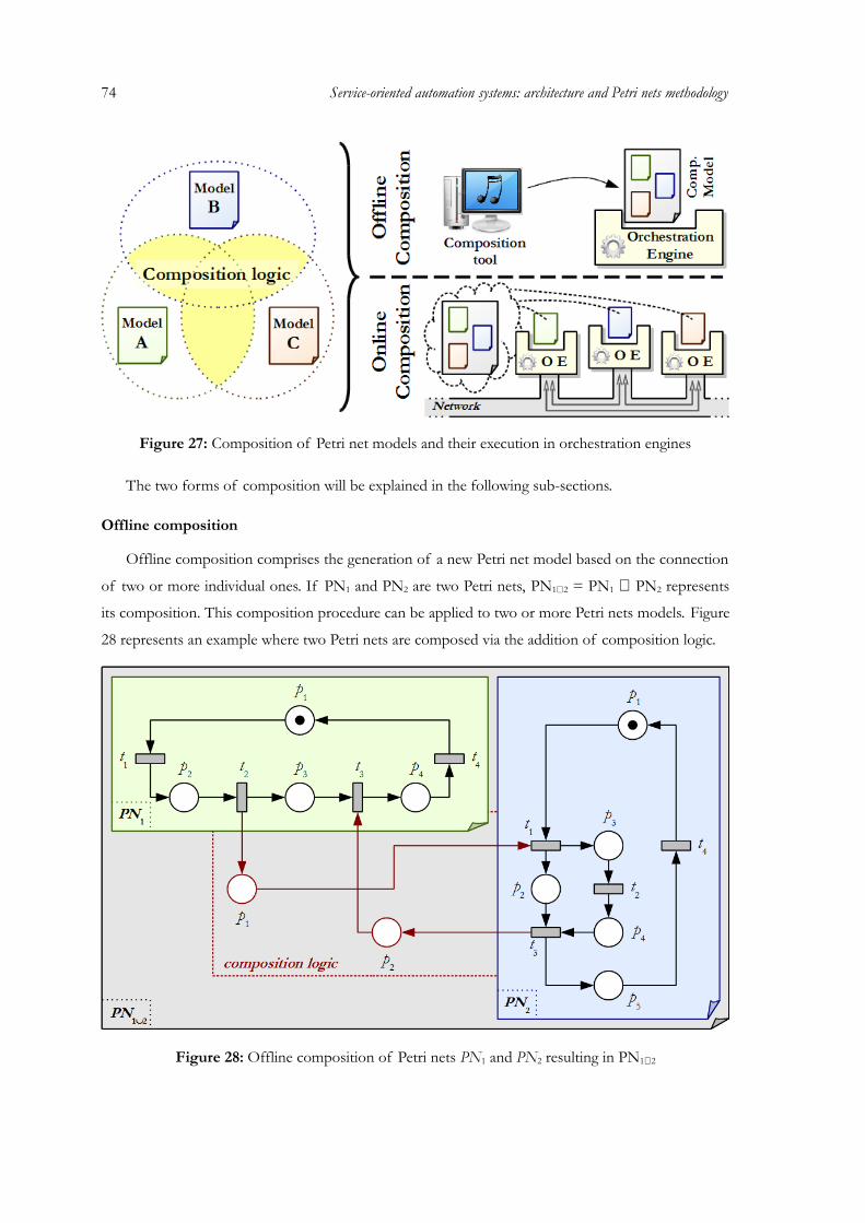
74 Service-oriented automation systems: architecture and Petri nets methodology
Figure 27: Composition of Petri net models and their execution in orchestration engines
The two forms of composition will be explained in the following sub-sections.
Offline composition
Offline composition comprises the generation of a new Petri net model based on the connection
of two or more individual ones. If PN1 and PN2 are two Petri nets, PN1∪2 = PN1 ∪ PN2 represents
its composition. This composition procedure can be applied to two or more Petri nets models. Figure
28 represents an example where two Petri nets are composed via the addition of composition logic.
Figure 28: Offline composition of Petri nets PN1 and PN2 resulting in PN1∪2

When the composition is completed, new inter-logic is generated. The basic idea is to match two
transitions from different models by connecting them via a place (and corresponding arcs).
Additionally, the specification of the direction should be considered (e.g. the transition t2 from PN1 is
the input of the transition t1 from PN2). This approach, besides to simplify the development of
bigger and more complex models, also facilitates the synchronization of models viewed as individual
entities.
For the composition, Petri net ports are used (see section 3.3.1 “Petri net models and ports”) An
example is given in Figure 29 where the conveyor A is the client and the conveyor B is the server.
The transition t1 represents a start order of the conveyor B, the transition t2 represents that it has
started and the transition t3 notifies when it is completed. All these three transitions are part of the
same port (port=in of the conveyor B) and are input or output transitions in contrast to their
counterparts in the other model of the conveyor A. Additionally, they have a sequence reference to
indicate the order of connection of the transitions (e.g. the output transition t4 of port=out from the
conveyor A will be connected to the input transition t1 of port=in from the conveyor B, because they
have the same sequence reference, port_out_seq=port_in_seq=1). In a few words, for two
interconnected ports from different models, input transitions will be connected to output transitions
with the same sequence reference. This can be seen in the connection table of Figure 29, where
transitions have two properties, {port, port_in_seq|port_out_seq}, which indicate, respectively, the
port they belong and also the input/output sequence reference.
Figure 29: Port-based composition of two Petri net models representing two conveyors
75
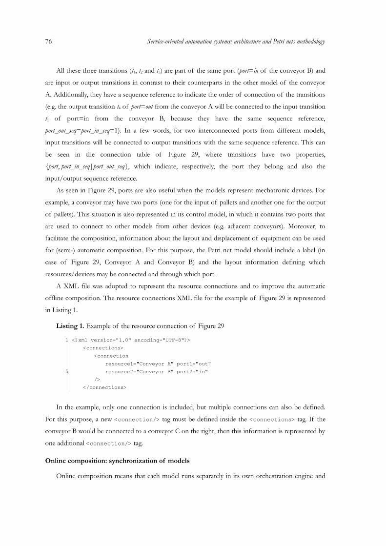
76 Service-oriented automation systems: architecture and Petri nets methodology
All these three transitions (t1, t2 and t3) are part of the same port (port=in of the conveyor B) and
are input or output transitions in contrast to their counterparts in the other model of the conveyor
A. Additionally, they have a sequence reference to indicate the order of connection of the transitions
(e.g. the output transition t4 of port=out from the conveyor A will be connected to the input transition
t1 of port=in from the conveyor B, because they have the same sequence reference,
port_out_seq=port_in_seq=1). In a few words, for two interconnected ports from different models,
input transitions will be connected to output transitions with the same sequence reference. This can
be seen in the connection table of Figure 29, where transitions have two properties,
{port, port_in_seq|port_out_seq}, which indicate, respectively, the port they belong and also the
input/output sequence reference.
As seen in Figure 29, ports are also useful when the models represent mechatronic devices. For
example, a conveyor may have two ports (one for the input of pallets and another one for the output
of pallets). This situation is also represented in its control model, in which it contains two ports that
are used to connect to other models from other devices (e.g. adjacent conveyors). Moreover, to
facilitate the composition, information about the layout and displacement of equipment can be used
for (semi-) automatic composition. For this purpose, the Petri net model should include a label (in
case of Figure 29, Conveyor A and Conveyor B) and the layout information defining which
resources/devices may be connected and through which port.
A XML file was adopted to represent the resource connections and to improve the automatic
offline composition. The resource connections XML file for the example of Figure 29 is represented
in Listing 1.
Listing 1. Example of the resource connection of Figure 29
1 <?xml version="1.0" encoding="UTF-8"?><connections>
<connectionresource1="Conveyor A" port1="out"
5 resource2="Conveyor B" port2="in"/>
</connections>
In the example, only one connection is included, but multiple connections can also be defined.
For this purpose, a new <connection/> tag must be defined inside the <connections> tag. If the
conveyor B would be connected to a conveyor C on the right, then this information is represented by
one additional <connection/> tag.
Online composition: synchronization of models
Online composition means that each model runs separately in its own orchestration engine and

they are synchronized via a composition logic. In this case, the composition logic represents a
service-based communication act, where services and their operations are described in Petri net
models.
Online composition requires that Petri nets have information on how to invoke and represent
services to synchronize with the other models. This is done by describing transitions in the Petri net
model (see section 3.3.2 “Service association to Petri nets”).
Figure 30 represents the connection of the two conveyors illustrated in Figure 29 with the
connection logic based on the service infrastructure. In the example, the conveyor A is the client and
the conveyor B is the server. Both use the transfer interface (transfer.wsdl) to express the service in
the model. The sequence start, started and completed will be transformed into a
TransferIn(request), TransferIn(response) and TransferStatus(“completed”) sequence,
to be compliant with the WSDL file.
Figure 30: Online composition of the conveyors of Figure 29 using service-orientation
Note that the correct division and use of the composition types depends always on the available
resources, the optimization strategies and the layout of the system, but orchestration models can be
individually developed without knowing this information.
3.3.5 Decision support system
Decision points, alternative ways and other conflicts are characteristics that can be modeled in
Petri nets, the same way that web services related functions are able to figure out as transitions and
places in Petri nets. A conflict can be viewed as a resource or state that is to be taken by more entities
than its capacity or transitions that activate from the same state leading to different paths. Both of
77
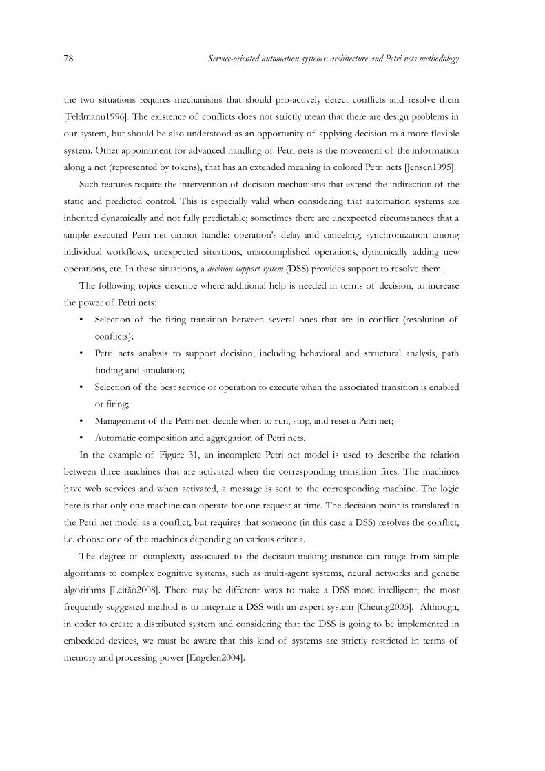
78 Service-oriented automation systems: architecture and Petri nets methodology
the two situations requires mechanisms that should pro-actively detect conflicts and resolve them
[Feldmann1996]. The existence of conflicts does not strictly mean that there are design problems in
our system, but should be also understood as an opportunity of applying decision to a more flexible
system. Other appointment for advanced handling of Petri nets is the movement of the information
along a net (represented by tokens), that has an extended meaning in colored Petri nets [Jensen1995].
Such features require the intervention of decision mechanisms that extend the indirection of the
static and predicted control. This is especially valid when considering that automation systems are
inherited dynamically and not fully predictable; sometimes there are unexpected circumstances that a
simple executed Petri net cannot handle: operation's delay and canceling, synchronization among
individual workflows, unexpected situations, unaccomplished operations, dynamically adding new
operations, etc. In these situations, a decision support system (DSS) provides support to resolve them.
The following topics describe where additional help is needed in terms of decision, to increase
the power of Petri nets:
• Selection of the firing transition between several ones that are in conflict (resolution of
conflicts);
• Petri nets analysis to support decision, including behavioral and structural analysis, path
finding and simulation;
• Selection of the best service or operation to execute when the associated transition is enabled
or firing;
• Management of the Petri net: decide when to run, stop, and reset a Petri net;
• Automatic composition and aggregation of Petri nets.
In the example of Figure 31, an incomplete Petri net model is used to describe the relation
between three machines that are activated when the corresponding transition fires. The machines
have web services and when activated, a message is sent to the corresponding machine. The logic
here is that only one machine can operate for one request at time. The decision point is translated in
the Petri net model as a conflict, but requires that someone (in this case a DSS) resolves the conflict,
i.e. choose one of the machines depending on various criteria.
The degree of complexity associated to the decision-making instance can range from simple
algorithms to complex cognitive systems, such as multi-agent systems, neural networks and genetic
algorithms [Leitão2008]. There may be different ways to make a DSS more intelligent; the most
frequently suggested method is to integrate a DSS with an expert system [Cheung2005]. Although,
in order to create a distributed system and considering that the DSS is going to be implemented in
embedded devices, we must be aware that this kind of systems are strictly restricted in terms of
memory and processing power [Engelen2004].
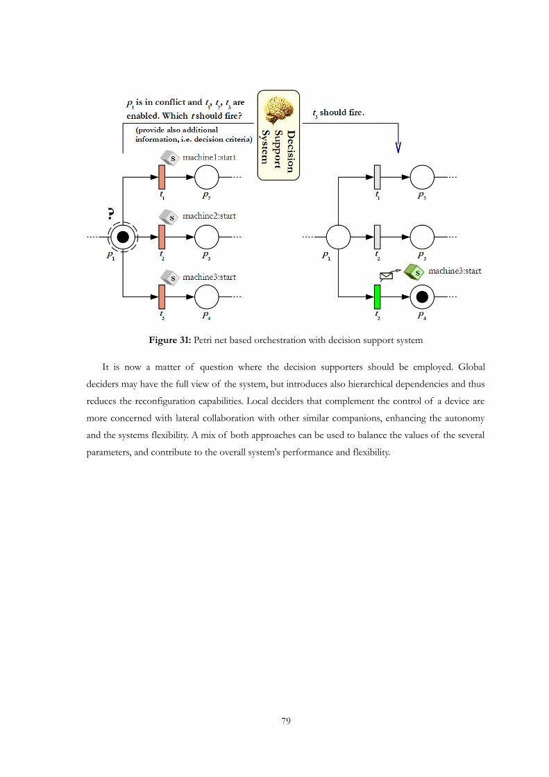
Figure 31: Petri net based orchestration with decision support system
It is now a matter of question where the decision supporters should be employed. Global
deciders may have the full view of the system, but introduces also hierarchical dependencies and thus
reduces the reconfiguration capabilities. Local deciders that complement the control of a device are
more concerned with lateral collaboration with other similar companions, enhancing the autonomy
and the systems flexibility. A mix of both approaches can be used to balance the values of the several
parameters, and contribute to the overall system's performance and flexibility.
79

80 Service-oriented automation systems: architecture and Petri nets methodology

Chapter 4:Service-oriented automation systems: tools, implementation and engineering
The initiative in service-based systems replies its echo in the concept of collaborative automation
[Colombo2008] in the sense of autonomous, reusable and loosely-coupled distributed components.
Service computing and orientation is here viewed not only as a form of communication, but more a
philosophy that software entities (bots) should adopt by sharing resources and representing their
needs. As said before, this also stands for a new way of design and thinking for automation
engineers, supported business managers, and software engineers that have to develop the necessary
tools and methodologies. Figure 32 represents this view based on the requirements flow from the
automation and business “worlds” for the specification of the necessary software.
Figure 32: Requirements for software development of service-oriented automation
81
82 Service-oriented automation systems: tools, implementation and engineering
For the success of a company, the marked must be correctly analyzed and business strategies
have to be planned, which can maximize the usage of external suppliers and clients, and
consequently produce the most favorable outcome (more details on this subject can be obtained
from game theory, particularly the best response strategy and the Nash equilibrium [Nash1950]). Of
course, since the environment is not static, flexibility and adaptability are keywords of enormous
importance. The same is valid for efficient planning and management of industrial shop-floors by the
automation engineers. A perfect balance between mass-production and mass-customization is
essential in the new markets of ever changing demands.
Even if not seen at the first sight, both worlds are service-enabled, and this does not always
mean from the technology point of view. In fact, the technology side of services is nowadays more
and more close related to web services. Therefore, software engineers have the task to provide the
right tools to facilitate the life of both “communities” for service-oriented environments, from the
concept to the technology. Business managers may used, for example, to get statistical information
of production and consequently plan new strategies. But the main usage is for the automation
“people” so that they can easily plan and configure factory cells.
There are numerous requirements for the development of such systems and tools that can be
found in the requirement tables of several projects (see for example the SOCRADES and SODA
projects and several related publications [SODA2007] [Spiess2007] [Phaithoonbuathong2008]). In
this context it is important to discuss the requirements that software engineers have to attend to
specify configurable software entities (bots) and engineering tools. The major requirements are:
• Service-oriented architectures as a reference model for the specification, operation and
integration of automation systems;
• Maintenance of some compatibility to traditional standards, such as IEC 61131 and IEC
61499;
• Easy development environment for automation engineers and integration capabilities in
business levels;
• Device considerations such as use of low-cost embedded devices with plug-and-play
capabilities, energy efficient, performance restrictions, security, reliability and portability of
code;
• Reuse, composition, aggregation, extension and simplification of services and software
entities;
• High-level process description for component behavior and inter component relations,
supported by handling of undocumented and exceptional events;
• Preparation for decentralization, autonomy of entities, automatic reconfiguration and/or
simple manual reconfiguration.
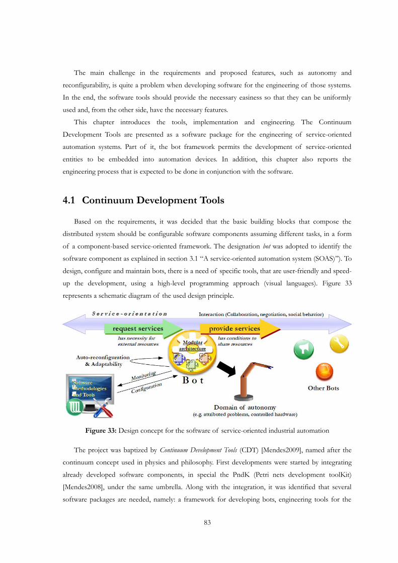
The main challenge in the requirements and proposed features, such as autonomy and
reconfigurability, is quite a problem when developing software for the engineering of those systems.
In the end, the software tools should provide the necessary easiness so that they can be uniformly
used and, from the other side, have the necessary features.
This chapter introduces the tools, implementation and engineering. The Continuum
Development Tools are presented as a software package for the engineering of service-oriented
automation systems. Part of it, the bot framework permits the development of service-oriented
entities to be embedded into automation devices. In addition, this chapter also reports the
engineering process that is expected to be done in conjunction with the software.
4.1 Continuum Development Tools
Based on the requirements, it was decided that the basic building blocks that compose the
distributed system should be configurable software components assuming different tasks, in a form
of a component-based service-oriented framework. The designation bot was adopted to identify the
software component as explained in section 3.1 “A service-oriented automation system (SOAS)”). To
design, configure and maintain bots, there is a need of specific tools, that are user-friendly and speed-
up the development, using a high-level programming approach (visual languages). Figure 33
represents a schematic diagram of the used design principle.
Figure 33: Design concept for the software of service-oriented industrial automation
The project was baptized by Continuum Development Tools (CDT) [Mendes2009], named after the
continuum concept used in physics and philosophy. First developments were started by integrating
already developed software components, in special the PndK (Petri nets development toolKit)
[Mendes2008], under the same umbrella. Along with the integration, it was identified that several
software packages are needed, namely: a framework for developing bots, engineering tools for the
83
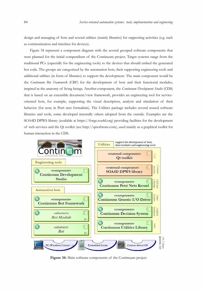
84 Service-oriented automation systems: tools, implementation and engineering
design and managing of bots and several utilities (mainly libraries) for supporting activities (e.g. such
as communication and interface for devices).
Figure 34 represent a component diagram with the several grouped software components that
were planned for the initial compendium of the Continuum project. Target systems range from the
traditional PCs (especially for the engineering tools) to the devices that should embed the generated
bot code. The groups are categorized by the automation bots, their supporting engineering tools and
additional utilities (in form of libraries) to support the development. The main component would be
the Continuum Bot Framework (CBF) for the development of bots and their functional modules,
inspired in the anatomy of living beings. Another component, the Continuum Development Studio (CDS)
that is based on an extensible document/view framework, provides an engineering tool for service-
oriented bots, for example, supporting the visual description, analysis and simulation of their
behavior (for now, in Petri nets formalism). The Utilities package includes several reused software
libraries and tools, some developed internally others adopted from the outside. Examples are the
SOA4D DPWS library (available at https://forge.soa4d.org) providing facilities for the development
of web services and the Qt toolkit (see http://qtsoftware.com), used mainly as a graphical toolkit for
human interaction in the CDS.
Figure 34: Main software components of the Continuum project
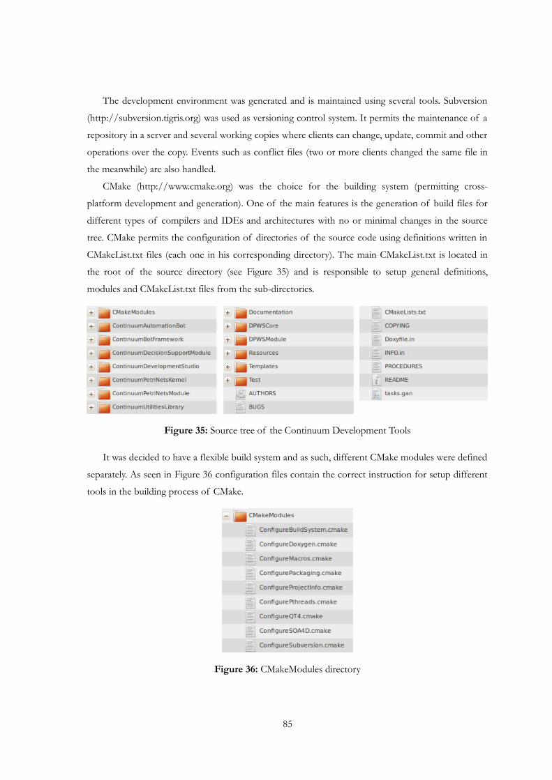
The development environment was generated and is maintained using several tools. Subversion
(http://subversion.tigris.org) was used as versioning control system. It permits the maintenance of a
repository in a server and several working copies where clients can change, update, commit and other
operations over the copy. Events such as conflict files (two or more clients changed the same file in
the meanwhile) are also handled.
CMake (http://www.cmake.org) was the choice for the building system (permitting cross-
platform development and generation). One of the main features is the generation of build files for
different types of compilers and IDEs and architectures with no or minimal changes in the source
tree. CMake permits the configuration of directories of the source code using definitions written in
CMakeList.txt files (each one in his corresponding directory). The main CMakeList.txt is located in
the root of the source directory (see Figure 35) and is responsible to setup general definitions,
modules and CMakeList.txt files from the sub-directories.
Figure 35: Source tree of the Continuum Development Tools
It was decided to have a flexible build system and as such, different CMake modules were defined
separately. As seen in Figure 36 configuration files contain the correct instruction for setup different
tools in the building process of CMake.
Figure 36: CMakeModules directory
85
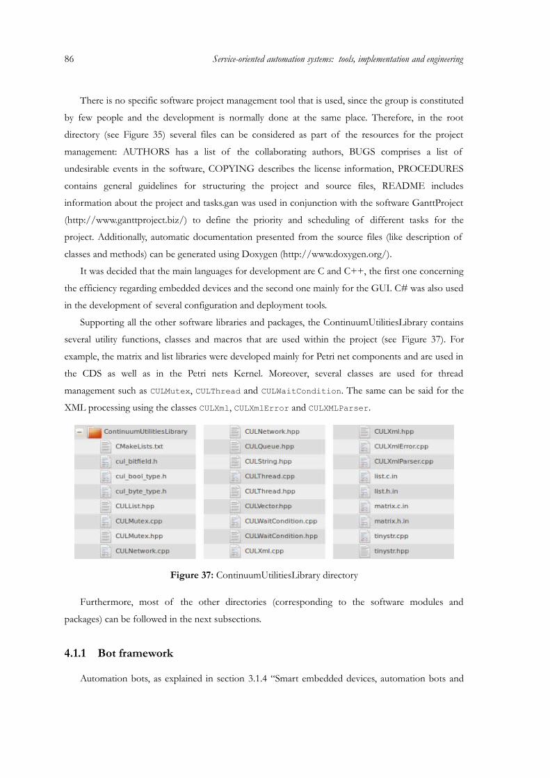
86 Service-oriented automation systems: tools, implementation and engineering
There is no specific software project management tool that is used, since the group is constituted
by few people and the development is normally done at the same place. Therefore, in the root
directory (see Figure 35) several files can be considered as part of the resources for the project
management: AUTHORS has a list of the collaborating authors, BUGS comprises a list of
undesirable events in the software, COPYING describes the license information, PROCEDURES
contains general guidelines for structuring the project and source files, README includes
information about the project and tasks.gan was used in conjunction with the software GanttProject
(http://www.ganttproject.biz/) to define the priority and scheduling of different tasks for the
project. Additionally, automatic documentation presented from the source files (like description of
classes and methods) can be generated using Doxygen (http://www.doxygen.org/).
It was decided that the main languages for development are C and C++, the first one concerning
the efficiency regarding embedded devices and the second one mainly for the GUI. C# was also used
in the development of several configuration and deployment tools.
Supporting all the other software libraries and packages, the ContinuumUtilitiesLibrary contains
several utility functions, classes and macros that are used within the project (see Figure 37). For
example, the matrix and list libraries were developed mainly for Petri net components and are used in
the CDS as well as in the Petri nets Kernel. Moreover, several classes are used for thread
management such as CULMutex, CULThread and CULWaitCondition. The same can be said for the
XML processing using the classes CULXml, CULXmlError and CULXMLParser.
Figure 37: ContinuumUtilitiesLibrary directory
Furthermore, most of the other directories (corresponding to the software modules and
packages) can be followed in the next subsections.
4.1.1 Bot framework
Automation bots, as explained in section 3.1.4 “Smart embedded devices, automation bots and
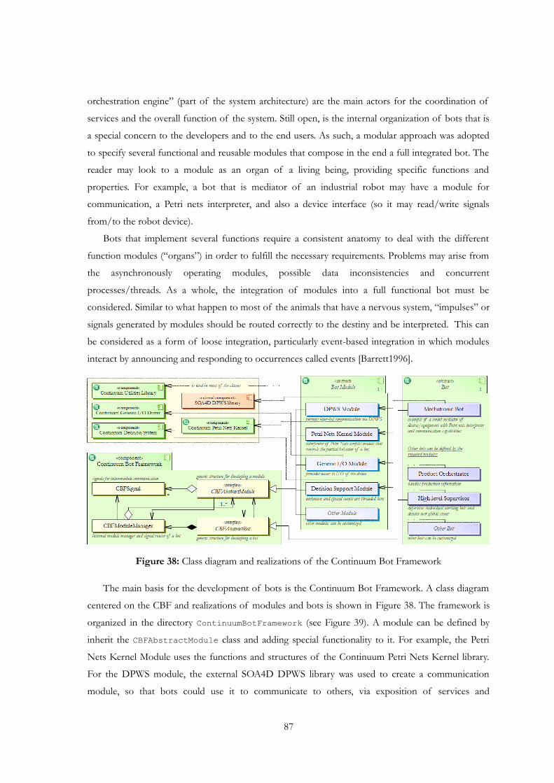
orchestration engine” (part of the system architecture) are the main actors for the coordination of
services and the overall function of the system. Still open, is the internal organization of bots that is
a special concern to the developers and to the end users. As such, a modular approach was adopted
to specify several functional and reusable modules that compose in the end a full integrated bot. The
reader may look to a module as an organ of a living being, providing specific functions and
properties. For example, a bot that is mediator of an industrial robot may have a module for
communication, a Petri nets interpreter, and also a device interface (so it may read/write signals
from/to the robot device).
Bots that implement several functions require a consistent anatomy to deal with the different
function modules (“organs”) in order to fulfill the necessary requirements. Problems may arise from
the asynchronously operating modules, possible data inconsistencies and concurrent
processes/threads. As a whole, the integration of modules into a full functional bot must be
considered. Similar to what happen to most of the animals that have a nervous system, “impulses” or
signals generated by modules should be routed correctly to the destiny and be interpreted. This can
be considered as a form of loose integration, particularly event-based integration in which modules
interact by announcing and responding to occurrences called events [Barrett1996].
Figure 38: Class diagram and realizations of the Continuum Bot Framework
The main basis for the development of bots is the Continuum Bot Framework. A class diagram
centered on the CBF and realizations of modules and bots is shown in Figure 38. The framework is
organized in the directory ContinuumBotFramework (see Figure 39). A module can be defined by
inherit the CBFAbstractModule class and adding special functionality to it. For example, the Petri
Nets Kernel Module uses the functions and structures of the Continuum Petri Nets Kernel library.
For the DPWS module, the external SOA4D DPWS library was used to create a communication
module, so that bots could use it to communicate to others, via exposition of services and
87
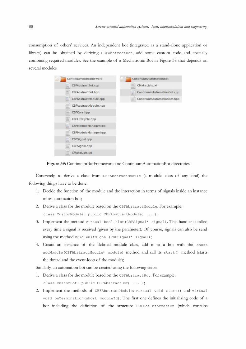
88 Service-oriented automation systems: tools, implementation and engineering
consumption of others' services. An independent bot (integrated as a stand-alone application or
library) can be obtained by deriving CBFAbstractBot, add some custom code and specially
combining required modules. See the example of a Mechatronic Bot in Figure 38 that depends on
several modules.
Figure 39: ContinuumBotFramework and ContinuumAutomationBot directories
Concretely, to derive a class from CBFAbstractModule (a module class of any kind) the
following things have to be done:
1. Decide the function of the module and the interaction in terms of signals inside an instance
of an automation bot;
2. Derive a class for the module based on the CBFAbstractModule. For example:
class CustomModule: public CBFAbstractModule{ ... };
3. Implement the method virtual bool slot(CBFSignal* signal). This handler is called
every time a signal is received (given by the parameter). Of course, signals can also be send
using the method void emitSignal(CBFSignal* signal);
4. Create an instance of the defined module class, add it to a bot with the short addModule(CBFAbstractModule* module) method and call its start() method (starts
the thread and the event-loop of the module);
Similarly, an automation bot can be created using the following steps:
1. Derive a class for the module based on the CBFAbstractBot. For example:
class CustomBot: public CBFAbstractBot{ ... };
2. Implement the methods of CBFAbstractModule: virtual void start() and virtual void onTermination(short moduleId). The first one defines the initializing code of a
bot including the definition of the structure CBFBotInformation (which contains

information such as the name and type of bot) and which modules it should be composed
(using the short addModule(CBFAbstractModule* module) method). The last one
(onTermination()) is called by the last terminating module and must therefore be
implemented to define the termination code of a bot;
3. Create an instance of the defined bot class and call its start() method.
Signals are used for intra-specific communication of a bot, i.e. event-based interaction between
its modules. A signal is created from the CBFSignal class and several parameters and user-data can
be set in the signal's instance. Signals are sent by a module and routed via the intermediate
CBFModuleManager that has a reference to each module. The receiving of signals and their analysis is
done asynchronously by each module. When a signal is received, it is saved in the local queue of the
module. Internally, a module represents a threaded close-loop that analyzes the local queue of
received signals. Whenever a signal is popped out from the queue, a code corresponding to this event
is executed. The used signals mechanism can be compared in the functional way to the Signal/Slot
approach from the Qt toolkit [Blanchette2006] and to active objects design pattern for concurrent
programming [Lavender1996].
4.1.2 Automation bot with the Petri nets kernel module
The signal system is heavily centered around the Petri net kernel (or engine) and the way it works,
since it is the main implementation structure concerning the output of this dissertation as well as it is
based on the open methodology explained in Chapter 3: “Service-oriented automation systems:
architecture and Petri nets methodology”. The modeling language of choice used along this thesis
derives from the Petri net specifications, including time considerations, property system and
customizable token game engine. The developed Petri net orchestration engine based on the
specifications has several features, including:
• Lightweight alternative to BPEL and similar to what automation engineers are used to;
• Service invocation and exposition;
• Design time and run-time composition;
• Analysis possibilities of models at design time;
• Integrated decision support for conflict situations on the PN models;
• Interpretation of XML-based configurations (used in dynamic deployment).
The following application library defines the Petri Nets Kernel library that is used as
orchestration engine in the automation bots, but also in other applications, including the Petri net
library in the CDS (see Figure 40). In terms of services, needs and requests are used in the
description of predicted device behavior and also in the definition of service-workflows (as in the
traditional orchestration). The purpose of the library is to provide Petri nets definition capabilities,
89
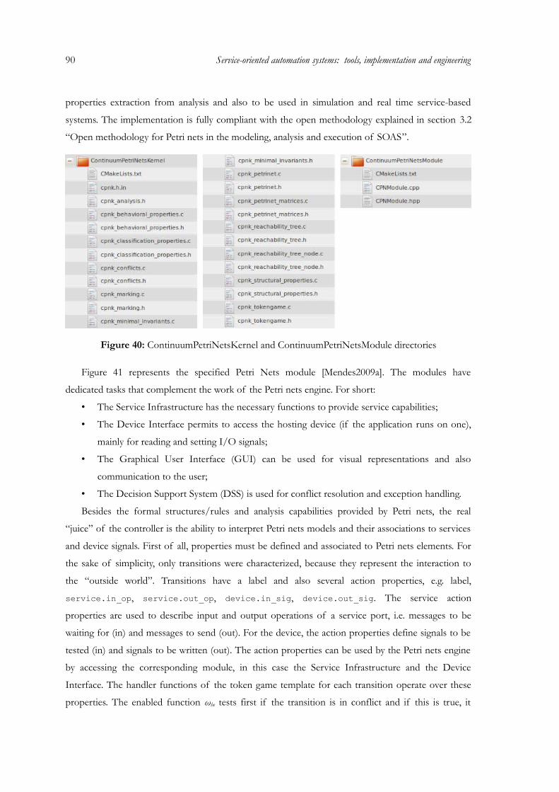
90 Service-oriented automation systems: tools, implementation and engineering
properties extraction from analysis and also to be used in simulation and real time service-based
systems. The implementation is fully compliant with the open methodology explained in section 3.2
“Open methodology for Petri nets in the modeling, analysis and execution of SOAS”.
Figure 40: ContinuumPetriNetsKernel and ContinuumPetriNetsModule directories
Figure 41 represents the specified Petri Nets module [Mendes2009a]. The modules have
dedicated tasks that complement the work of the Petri nets engine. For short:
• The Service Infrastructure has the necessary functions to provide service capabilities;
• The Device Interface permits to access the hosting device (if the application runs on one),
mainly for reading and setting I/O signals;
• The Graphical User Interface (GUI) can be used for visual representations and also
communication to the user;
• The Decision Support System (DSS) is used for conflict resolution and exception handling.
Besides the formal structures/rules and analysis capabilities provided by Petri nets, the real
“juice” of the controller is the ability to interpret Petri nets models and their associations to services
and device signals. First of all, properties must be defined and associated to Petri nets elements. For
the sake of simplicity, only transitions were characterized, because they represent the interaction to
the “outside world”. Transitions have a label and also several action properties, e.g. label,
service.in_op, service.out_op, device.in_sig, device.out_sig. The service action
properties are used to describe input and output operations of a service port, i.e. messages to be
waiting for (in) and messages to send (out). For the device, the action properties define signals to be
tested (in) and signals to be written (out). The action properties can be used by the Petri nets engine
by accessing the corresponding module, in this case the Service Infrastructure and the Device
Interface. The handler functions of the token game template for each transition operate over these
properties. The enabled function ωhe tests first if the transition is in conflict and if this is true, it
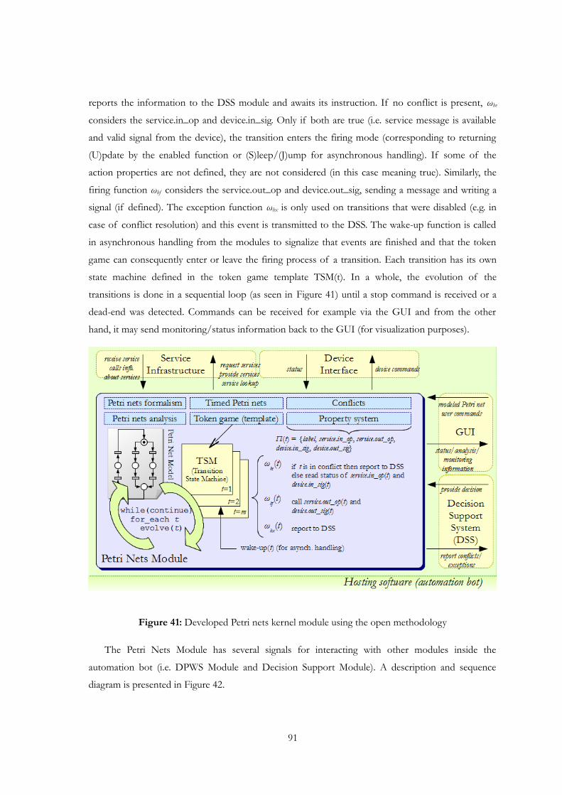
reports the information to the DSS module and awaits its instruction. If no conflict is present, ωhe
considers the service.in_op and device.in_sig. Only if both are true (i.e. service message is available
and valid signal from the device), the transition enters the firing mode (corresponding to returning
(U)pdate by the enabled function or (S)leep/(J)ump for asynchronous handling). If some of the
action properties are not defined, they are not considered (in this case meaning true). Similarly, the
firing function ωhf considers the service.out_op and device.out_sig, sending a message and writing a
signal (if defined). The exception function ωhx is only used on transitions that were disabled (e.g. in
case of conflict resolution) and this event is transmitted to the DSS. The wake-up function is called
in asynchronous handling from the modules to signalize that events are finished and that the token
game can consequently enter or leave the firing process of a transition. Each transition has its own
state machine defined in the token game template TSM(t). In a whole, the evolution of the
transitions is done in a sequential loop (as seen in Figure 41) until a stop command is received or a
dead-end was detected. Commands can be received for example via the GUI and from the other
hand, it may send monitoring/status information back to the GUI (for visualization purposes).
Figure 41: Developed Petri nets kernel module using the open methodology
The Petri Nets Module has several signals for interacting with other modules inside the
automation bot (i.e. DPWS Module and Decision Support Module). A description and sequence
diagram is presented in Figure 42.
91
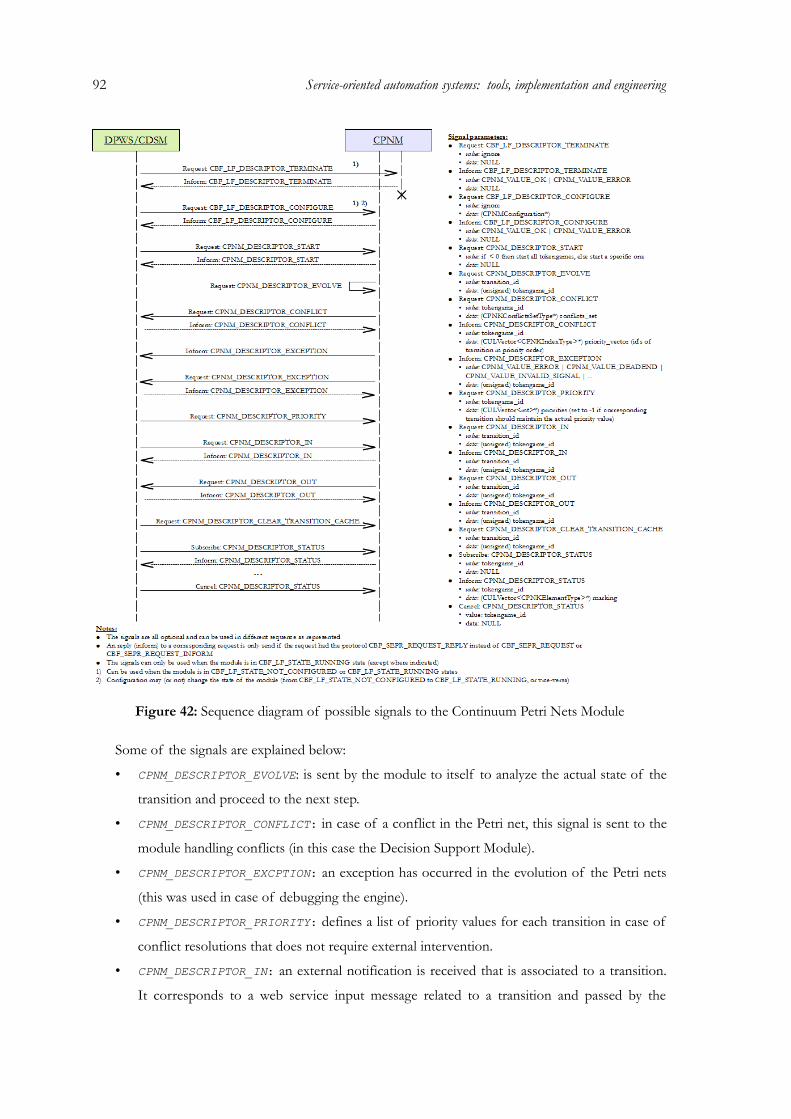
92 Service-oriented automation systems: tools, implementation and engineering
Figure 42: Sequence diagram of possible signals to the Continuum Petri Nets Module
Some of the signals are explained below:
• CPNM_DESCRIPTOR_EVOLVE: is sent by the module to itself to analyze the actual state of the
transition and proceed to the next step.
• CPNM_DESCRIPTOR_CONFLICT: in case of a conflict in the Petri net, this signal is sent to the
module handling conflicts (in this case the Decision Support Module).
• CPNM_DESCRIPTOR_EXCPTION: an exception has occurred in the evolution of the Petri nets
(this was used in case of debugging the engine).
• CPNM_DESCRIPTOR_PRIORITY: defines a list of priority values for each transition in case of
conflict resolutions that does not require external intervention.
• CPNM_DESCRIPTOR_IN: an external notification is received that is associated to a transition.
It corresponds to a web service input message related to a transition and passed by the
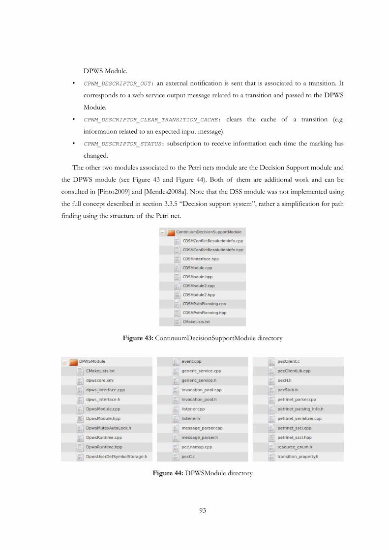
DPWS Module.
• CPNM_DESCRIPTOR_OUT: an external notification is sent that is associated to a transition. It
corresponds to a web service output message related to a transition and passed to the DPWS
Module.
• CPNM_DESCRIPTOR_CLEAR_TRANSITION_CACHE: clears the cache of a transition (e.g.
information related to an expected input message).
• CPNM_DESCRIPTOR_STATUS: subscription to receive information each time the marking has
changed.
The other two modules associated to the Petri nets module are the Decision Support module and
the DPWS module (see Figure 43 and Figure 44). Both of them are additional work and can be
consulted in [Pinto2009] and [Mendes2008a]. Note that the DSS module was not implemented using
the full concept described in section 3.3.5 “Decision support system”, rather a simplification for path
finding using the structure of the Petri net.
Figure 43: ContinuumDecisionSupportModule directory
Figure 44: DPWSModule directory
93
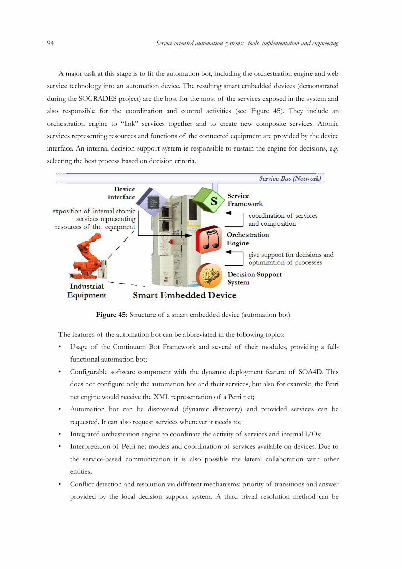
94 Service-oriented automation systems: tools, implementation and engineering
A major task at this stage is to fit the automation bot, including the orchestration engine and web
service technology into an automation device. The resulting smart embedded devices (demonstrated
during the SOCRADES project) are the host for the most of the services exposed in the system and
also responsible for the coordination and control activities (see Figure 45). They include an
orchestration engine to “link” services together and to create new composite services. Atomic
services representing resources and functions of the connected equipment are provided by the device
interface. An internal decision support system is responsible to sustain the engine for decisions, e.g.
selecting the best process based on decision criteria.
Figure 45: Structure of a smart embedded device (automation bot)
The features of the automation bot can be abbreviated in the following topics:
• Usage of the Continuum Bot Framework and several of their modules, providing a full-
functional automation bot;
• Configurable software component with the dynamic deployment feature of SOA4D. This
does not configure only the automation bot and their services, but also for example, the Petri
net engine would receive the XML representation of a Petri net;
• Automation bot can be discovered (dynamic discovery) and provided services can be
requested. It can also request services whenever it needs to;
• Integrated orchestration engine to coordinate the activity of services and internal I/Os;
• Interpretation of Petri net models and coordination of services available on devices. Due to
the service-based communication it is also possible the lateral collaboration with other
entities;
• Conflict detection and resolution via different mechanisms: priority of transitions and answer
provided by the local decision support system. A third trivial resolution method can be
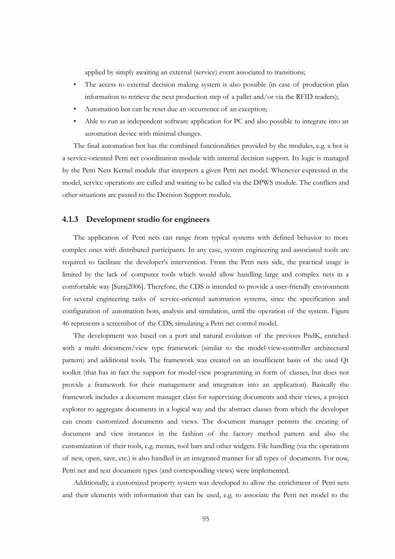
applied by simply awaiting an external (service) event associated to transitions;
• The access to external decision making system is also possible (in case of production plan
information to retrieve the next production step of a pallet and/or via the RFID readers);
• Automation bot can be reset due an occurrence of an exception;
• Able to run as independent software application for PC and also possible to integrate into an
automation device with minimal changes.
The final automation bot has the combined functionalities provided by the modules, e.g. a bot is
a service-oriented Petri net coordination module with internal decision support. Its logic is managed
by the Petri Nets Kernel module that interprets a given Petri net model. Whenever expressed in the
model, service operations are called and waiting to be called via the DPWS module. The conflicts and
other situations are passed to the Decision Support module.
4.1.3 Development studio for engineers
The application of Petri nets can range from typical systems with defined behavior to more
complex ones with distributed participants. In any case, system engineering and associated tools are
required to facilitate the developer's intervention. From the Petri nets side, the practical usage is
limited by the lack of computer tools which would allow handling large and complex nets in a
comfortable way [Suraj2006]. Therefore, the CDS is intended to provide a user-friendly environment
for several engineering tasks of service-oriented automation systems, since the specification and
configuration of automation bots, analysis and simulation, until the operation of the system. Figure
46 represents a screenshot of the CDS, simulating a Petri net control model.
The development was based on a port and natural evolution of the previous PndK, enriched
with a multi document/view type framework (similar to the model-view-controller architectural
pattern) and additional tools. The framework was created on an insufficient basis of the used Qt
toolkit (that has in fact the support for model-view programming in form of classes, but does not
provide a framework for their management and integration into an application). Basically the
framework includes a document manager class for supervising documents and their views, a project
explorer to aggregate documents in a logical way and the abstract classes from which the developer
can create customized documents and views. The document manager permits the creating of
document and view instances in the fashion of the factory method pattern and also the
customization of their tools, e.g. menus, tool bars and other widgets. File handling (via the operations
of new, open, save, etc.) is also handled in an integrated manner for all types of documents. For now,
Petri net and text document types (and corresponding views) were implemented.
Additionally, a customized property system was developed to allow the enrichment of Petri nets
and their elements with information that can be used, e.g. to associate the Petri net model to the
95
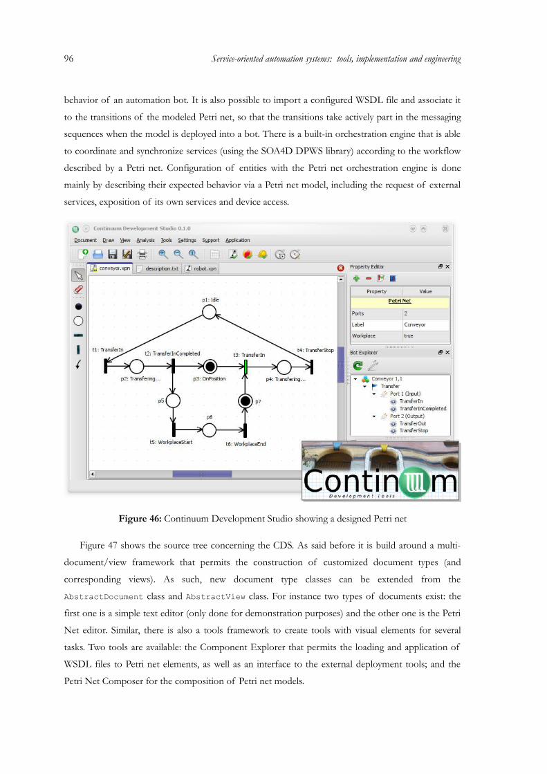
96 Service-oriented automation systems: tools, implementation and engineering
behavior of an automation bot. It is also possible to import a configured WSDL file and associate it
to the transitions of the modeled Petri net, so that the transitions take actively part in the messaging
sequences when the model is deployed into a bot. There is a built-in orchestration engine that is able
to coordinate and synchronize services (using the SOA4D DPWS library) according to the workflow
described by a Petri net. Configuration of entities with the Petri net orchestration engine is done
mainly by describing their expected behavior via a Petri net model, including the request of external
services, exposition of its own services and device access.
Figure 46: Continuum Development Studio showing a designed Petri net
Figure 47 shows the source tree concerning the CDS. As said before it is build around a multi-
document/view framework that permits the construction of customized document types (and
corresponding views). As such, new document type classes can be extended from the
AbstractDocument class and AbstractView class. For instance two types of documents exist: the
first one is a simple text editor (only done for demonstration purposes) and the other one is the Petri
Net editor. Similar, there is also a tools framework to create tools with visual elements for several
tasks. Two tools are available: the Component Explorer that permits the loading and application of
WSDL files to Petri net elements, as well as an interface to the external deployment tools; and the
Petri Net Composer for the composition of Petri net models.

For the configuration of devices and deployment of services, CDS is linked to additional tools
that are responsible for the respective tasks. The tools are needed to transform the modeled
information into device-interpretable XML language (previous defined semantically) and to upload
this information via the dynamic deployment feature of DPWS. The information on the deployment
files ranges from the Petri net model (to configure the orchestration engine) until service information
(what services are to be called and which new services should the device generate). More description
about these tools can be found in the subsequent engineering process.
Figure 47: ContinuumDevelopmentStudio directory
It is worth mentioning that the previous version of CDS had automation bot included with a
Petri net engine which operation could be visualized in the editor, but in the new incarnation this was
not ported due time constrains.
97
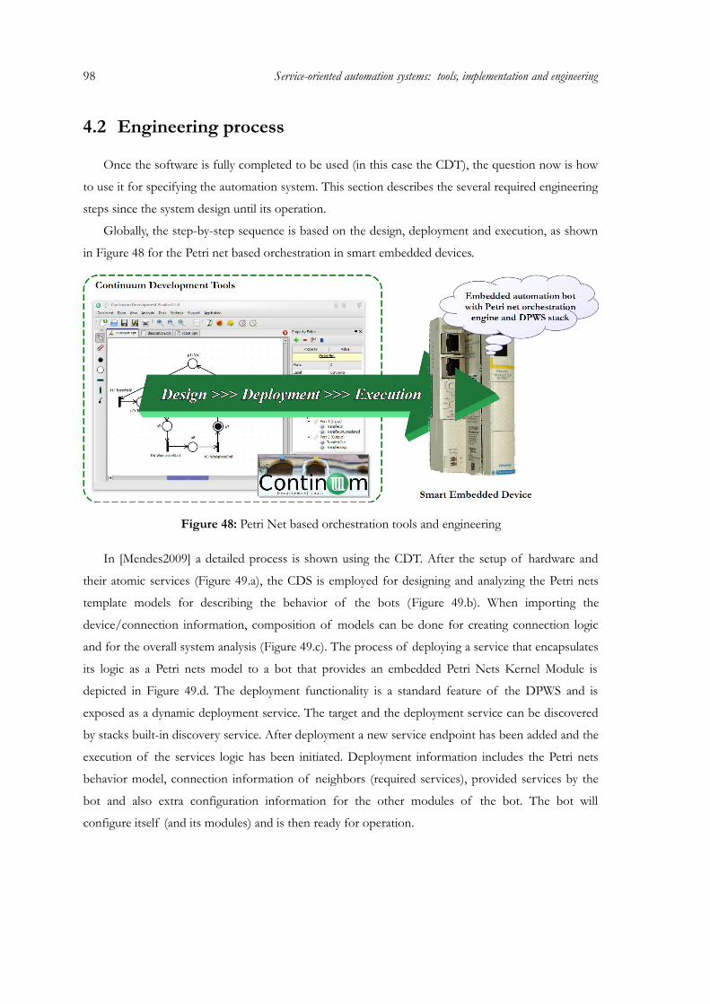
98 Service-oriented automation systems: tools, implementation and engineering
4.2 Engineering process
Once the software is fully completed to be used (in this case the CDT), the question now is how
to use it for specifying the automation system. This section describes the several required engineering
steps since the system design until its operation.
Globally, the step-by-step sequence is based on the design, deployment and execution, as shown
in Figure 48 for the Petri net based orchestration in smart embedded devices.
Figure 48: Petri Net based orchestration tools and engineering
In [Mendes2009] a detailed process is shown using the CDT. After the setup of hardware and
their atomic services (Figure 49.a), the CDS is employed for designing and analyzing the Petri nets
template models for describing the behavior of the bots (Figure 49.b). When importing the
device/connection information, composition of models can be done for creating connection logic
and for the overall system analysis (Figure 49.c). The process of deploying a service that encapsulates
its logic as a Petri nets model to a bot that provides an embedded Petri Nets Kernel Module is
depicted in Figure 49.d. The deployment functionality is a standard feature of the DPWS and is
exposed as a dynamic deployment service. The target and the deployment service can be discovered
by stacks built-in discovery service. After deployment a new service endpoint has been added and the
execution of the services logic has been initiated. Deployment information includes the Petri nets
behavior model, connection information of neighbors (required services), provided services by the
bot and also extra configuration information for the other modules of the bot. The bot will
configure itself (and its modules) and is then ready for operation.

Figure 49: Engineering process using CDT
Operation means the behavior of bots according to their defined model, plus exposition and
requesting of services by the different bots and other software components that are on the system
(Figure 49.e). Higher level features in the service approach includes also the aggregation of services
into one (simplifying the outside view), lateral collaboration between bots (offering services),
decentralization versus hierarchical control approach and also business considerations. Business
integration (and in general, higher-level integration) of the factory cell is done via service-orientation.
Business needs are expressed by the production planning and management of the factory cells by
monitoring their work status (via specific series), disabling/enabling several routing paths of
production, etc.
During operation, reconfiguration may also be needed. For example, a control model for a bot is
not anymore valid or production strategies have changed. In these cases, affected bots should be
stopped (without paralyzing all the system) and consequently their services would no longer available.
During this time, new models can be designed to define the new expected behavior, uploaded to the
bots and restart their operation.
The next sub-sections provide details of the individual engineering steps.
99
100 Service-oriented automation systems: tools, implementation and engineering
4.2.1 Hardware setup and definition of atomic services
The most important issue in this case, besides configuring correctly the hardware, is the
availability of atomic services in the network as well as their description in WSDLs. Hardware
mounting and configuration is vendor-specific and thus requires dedicated knowledge to build the
physical system. In addition, control and embedded devices need to be connected to a network
system in order to be communicable. Of course, these embedded systems must contain a framework
for web service management, beside others. For orchestration purposes, some embedded systems
should contain an orchestration engine (in this case, a Petri net based).
Figure 50: Example of a system configuration with atomic services
Figure 50 represents a configuration with two conveyors and two machines. The objective is to
convey pallets through the system and one of the machines (or none) should operate over the pallet.
Atomic services, available in the network, are the basic building blocks to orchestrate the system.
They represent the operations provided by each equipment. These services are provided and
managed by industrial embedded controllers that make the interface between the equipment and the
service applications.
4.2.2 Design and analysis of orchestration models
The Petri net models are designed in a bottom-up manner according to the process behavior that
is intended to describe and orchestrate, such as robots and conveyors. Each model represents all
possible discrete states of such a resource and also all the functions that this resource is able to
expose as services, for instance move-piece, pick-part and transfer-pallet. The Petri net model is
dependent on the physical resource it represents (e.g. the behavior associated to a conveyor is
certainly different from the behavior associated to a robot), and the type of operation the physical

resource performs (e.g. an industrial robot can perform different operations, such as handling,
welding or painting). The identification of the patterns associated to usual operations allows building
a library of Petri net models that can be re-used latter, simplifying the development of modular
solutions.
This phase can be resumed into the following sequence, all possible with the CDS1:
1. Study the selected device class and its behavior (must be done externally to CDS);
2. Design the orchestration model in Petri net formalism (note that the same model can be used
for other devices with the same behavior);
3. If services are represented in the model: import the WSDL of the atomic service that the
device represent (if needed, WSDL of the composition can also be imported) and associate
services to the transitions;
4. If composition will be later used, define connection ports in the model;
5. Define additional properties using the property editor;
6. Analyze and simulate the model.
In parallel and if the full modular system is known from the beginning, the global objectives and
system behavior should also be known in order to facilitate the development, especially the
composition.
Some of the topics in the previous numerated list are expanded subsequently concerning the
usage of CDS.
Design of Orchestration models in Petri net formalism
The design of the Petri nets and the association to services can be done with the CDS tool. The
specification of the used Petri nets is based on the one from section 3.2 “Open methodology for
Petri nets in the modeling, analysis and execution of SOAS” and the features and extension in section
3.3. After opening the Continuum Development Studio, the workspace is shown. It contains a multi-
document framework, so several documents can be handled inside the editor. For the handling of
documents, there are several operations that can be performed: New, Open, Save, Export, Print, etc. The
Petri Net file (.xpn) is an XML definition for Petri nets and can also be easily viewed and edited with
text editors, as well as post-processed by tools, able to import XML.
Creating and editing a Petri net is done using the special toolbox that provides several action
buttons: Select, Erase, Token, Place, Vertical Transition, Horizontal Transition and Arc.
When selecting a particular element on the document, the Property Editor on the right shows the
corresponding properties. Some of them can be edited. A common property is the id of the element.
There are also properties that are only associated to specific type of elements. For example, a place
has a Tokens field that defines the number of tokens that a place has. New properties can be created
1 Except otherwise indicated.
101

102 Service-oriented automation systems: tools, implementation and engineering
for both Petri net elements (selecting the corresponding element) and for the whole Petri net (when
no element is selected). At the top of the Property Editor there are the buttons for the management
of properties. When adding a new property to an element, the user must first introduce its name, the
type of the property and the initial value. Property sets defined for an element can be saved into a
template. Templates can then be applied to other elements.
Figure 51: Design of a Petri Net
As an example, the Petri net in Figure 51 was designed. It is constituted of a sequential part and a
mutual-exclusive branch. The state of a Petri net is defined by the number of tokens present on each
place. In the example, the initial state is defined by having one token (black dot) in place p1 and all
others are empty. Transitions (black bars) describe the possible modification of state, consuming
tokens from the connected places that input the transition and expelling tokens to the connected
output places. For example, transition t1 has one input place (p1) and one output place (p2). Transitions
may also have multiple connections to places. Connected arcs may have different weight value. The
weight value is only drawn if it is greater than one. The weight value influences also the behavior of
Petri nets.
Conflicts are modeled by places that have one or more “output” transitions that depend on the
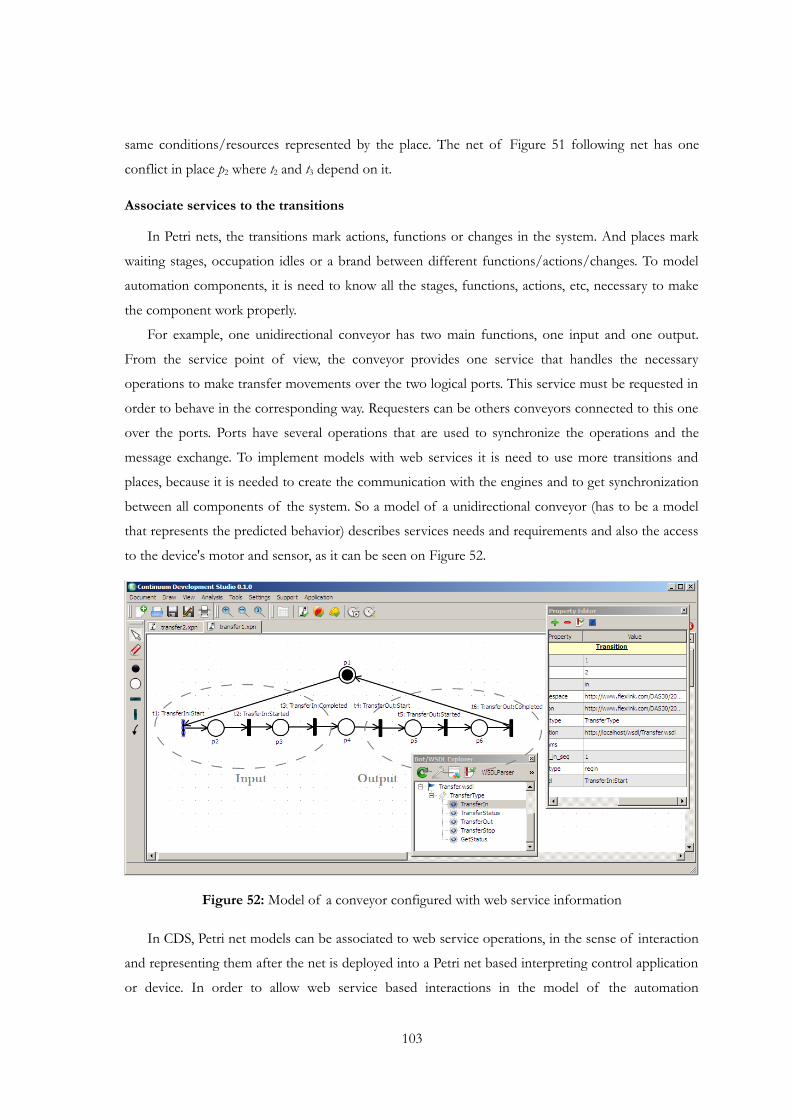
same conditions/resources represented by the place. The net of Figure 51 following net has one
conflict in place p2 where t2 and t3 depend on it.
Associate services to the transitions
In Petri nets, the transitions mark actions, functions or changes in the system. And places mark
waiting stages, occupation idles or a brand between different functions/actions/changes. To model
automation components, it is need to know all the stages, functions, actions, etc, necessary to make
the component work properly.
For example, one unidirectional conveyor has two main functions, one input and one output.
From the service point of view, the conveyor provides one service that handles the necessary
operations to make transfer movements over the two logical ports. This service must be requested in
order to behave in the corresponding way. Requesters can be others conveyors connected to this one
over the ports. Ports have several operations that are used to synchronize the operations and the
message exchange. To implement models with web services it is need to use more transitions and
places, because it is needed to create the communication with the engines and to get synchronization
between all components of the system. So a model of a unidirectional conveyor (has to be a model
that represents the predicted behavior) describes services needs and requirements and also the access
to the device's motor and sensor, as it can be seen on Figure 52.
Figure 52: Model of a conveyor configured with web service information
In CDS, Petri net models can be associated to web service operations, in the sense of interaction
and representing them after the net is deployed into a Petri net based interpreting control application
or device. In order to allow web service based interactions in the model of the automation
103
104 Service-oriented automation systems: tools, implementation and engineering
component, transitions (which are responsible for requesting actions and receiving events) can be
configured with parameters allowing the discovery, exposure and consumption of services, sending
and reception of messages and event notifications.
In the CDS tool, WSDL files can be imported (see the lower window of Figure 52) and their
service operations listed. Service operations can be applied over a selected transition. If the operation
is a request/response, then the user has to select one of them (request or response) and if it is a
client or a server operation (i.e. the direction of the message). A request must also be defined with
the device class reference and transition(s) that will receive the response. In case of events, the server
or client viewpoint is selected, as well as the device class reference. The properties are automatically
applied to the transition (this can be seen in the Property editor, in the right side of Figure 52), and
can be edited, including the addition of parameters to the message fired by the transition (or to be
tested by incoming message).
After the successful configuration of the Petri nets and the service operations, the nets can be
analyzed, composed, configured and deployed into Petri net interpreters (orchestration devices,
automation bots).
Analyze and simulate the model
An important feature of Petri nets is the background definition based in mathematics, more
concretely in Set/Graph Theory and Linear Algebra. This enables them to be analyzed and to extract
several properties. The CDS allows the user to do several analysis, tests and simulation. This is one
important function because it is possible to search for errors on the model, see if the model is well
constructed, etc. The analysis toolbox includes several analysis options. In terms of analysis, the first
one is a simple classification that tells if the structure of the designed Petri net is valid for further
analysis. More qualified analysis is used to generate behavioral properties and structural properties
(see Figure 53).
The analysis toolbox verifies the following properties:
• Bounded - A Petri net is bounded when each place may have a finite number of marks
(tokens);
• Safe - Is a particular case of bounded property, a Petri net is tell as safe if the number of
marks possible in each place is equal to 1;
• Live - A Petri net is live if each transition is able to be fired at least one time;
• Reversible - A Petri net is reversible if the first marking is able to be obtained from all other
marking;
• Conservative - A Petri net is bounded when each place has always a specific number of tokens.
Additional analysis can be performed by obtaining the t- and p-invariants. The p-invariants vector
of places indicates a set of places which total number of tokens is always the same independent of

the actual marking of the net. The analysis of p-invariants constitution allows confirming mutual
exclusion relationships among places and functions and resources involved in the model structure.
The t-invariants vector of transitions that indicate the set of transition of a specific path of the Petri
net. The analysis of the t-invariants allows the identification of work cycles.
Figure 53: Analysis of a Petri net with CDS
The qualitative analysis of the incidence matrix and t- and p-invariants allows validating several
aspects of a conveying system for pallets with workstations:
• Mutual exclusion is presented in each control model of the transfer units, in the sense of
only one pallet may occupy it;
• The t-invariants of the synthesize model for the transfer system describe possible sets of
operations. Translated into the topology it may refer to all possible routing sequences of
pallets along this system;
• It is possible to have deadlock situations due to the presence of circular paths if all transfer
units of these paths are occupied by pallets. The overlapping conflicts of these paths support
the resolution of these issues by activating alternative ways to route some pallets.
The quantitative analysis allows simulating the system behavior, therewith checking the system
compliance with specified performance indexes, such as the lead time to produce a product, the
105
106 Service-oriented automation systems: tools, implementation and engineering
throughput of the system and the percentage use of the resources. With the tool, it is possible to
simulate the designed Petri net (also called token game). The simulation begins with the initial state
and analysis the possible transitions. The user may stop the simulation or it is automatically stopped
when a dead-end is reached. In between, the user may decide in case of conflicts which transition(s)
should fire.
The analysis of Petri net models, both quantitative and qualitative, allows validating the
specifications of the system's behavior, verifying the correctness of the models and verifying if the
models fulfill the desired specifications. It is also possible to refine strategies or specifications of the
system, detecting errors and mistakes before to implement the real production system. Only if the
model verifies all necessary properties (structural and behavioral), it is possible to be sure that the
model is correct from the functional point of view and it can be seen as a virtual representation of
the system.
4.2.3 Orchestration strategy and composition of models
The development of modular service-oriented manufacturing systems requires the composition
of individual Petri nets models into a coordination model, and consequently the composition of
services. This task follows the same rules of configuring a required resource's layout, i.e. taking into
account, among others, the competition, concurrency and shared resources behavioral relationships.
The specified approach is flexible enough to support different solutions: from a more centralized
manner by using one automation bot with an orchestration engine to a more distributed manner by
using several ones working together to coordinate their services.
In case of using a more centralized orchestration, the models representing the orchestration of
individual equipment are glued together into one model that should run in an automation bot. It
implements the logic for the process-oriented execution and sequencing of atomic services (from its
point of view), and provides a high-level interface for the aggregated process, creating higher value
services based on individual ones. In the distributed approach, several automation bots are
responsible for the coordination and take care of their own domain of autonomy. This means that
the orchestration is distributed and does not require central supervision. The individual coordination
has to collaborate with each other in order to reach the same level of synchronization as one
automation bot should provide.
The composition of Petri net models used in the engineering process is based on the approach
described in section 3.3.4 “Composition of Petri nets”. As an example, Figure 54 shows the
specification of models for three conveyors and two possible strategies, depending on how many
orchestration engines are used. As such, offline composition is needed for selected models that
should run in the same orchestration engine.
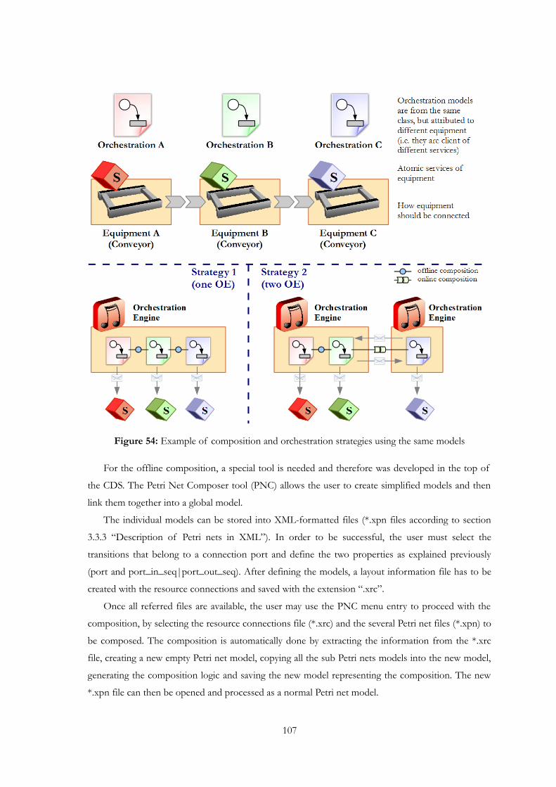
Figure 54: Example of composition and orchestration strategies using the same models
For the offline composition, a special tool is needed and therefore was developed in the top of
the CDS. The Petri Net Composer tool (PNC) allows the user to create simplified models and then
link them together into a global model.
The individual models can be stored into XML-formatted files (*.xpn files according to section
3.3.3 “Description of Petri nets in XML”). In order to be successful, the user must select the
transitions that belong to a connection port and define the two properties as explained previously
(port and port_in_seq|port_out_seq). After defining the models, a layout information file has to be
created with the resource connections and saved with the extension “.xrc”.
Once all referred files are available, the user may use the PNC menu entry to proceed with the
composition, by selecting the resource connections file (*.xrc) and the several Petri net files (*.xpn) to
be composed. The composition is automatically done by extracting the information from the *.xrc
file, creating a new empty Petri net model, copying all the sub Petri nets models into the new model,
generating the composition logic and saving the new model representing the composition. The new
*.xpn file can then be opened and processed as a normal Petri net model.
107
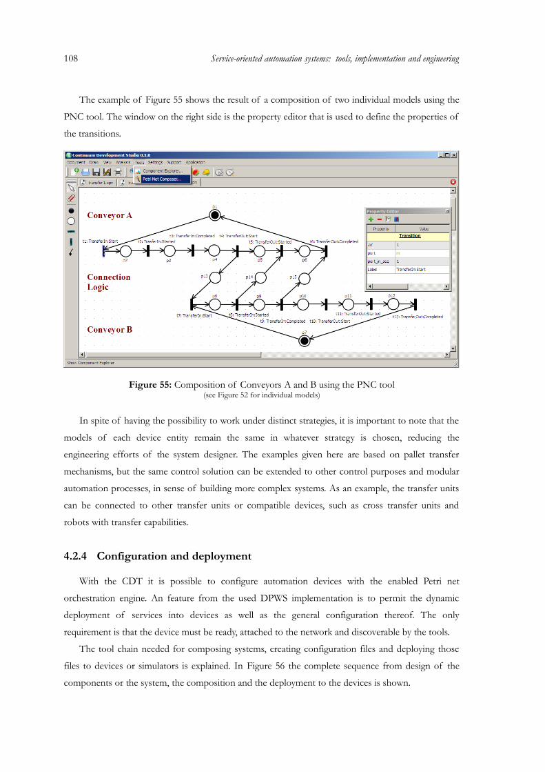
108 Service-oriented automation systems: tools, implementation and engineering
The example of Figure 55 shows the result of a composition of two individual models using the
PNC tool. The window on the right side is the property editor that is used to define the properties of
the transitions.
Figure 55: Composition of Conveyors A and B using the PNC tool(see Figure 52 for individual models)
In spite of having the possibility to work under distinct strategies, it is important to note that the
models of each device entity remain the same in whatever strategy is chosen, reducing the
engineering efforts of the system designer. The examples given here are based on pallet transfer
mechanisms, but the same control solution can be extended to other control purposes and modular
automation processes, in sense of building more complex systems. As an example, the transfer units
can be connected to other transfer units or compatible devices, such as cross transfer units and
robots with transfer capabilities.
4.2.4 Configuration and deployment
With the CDT it is possible to configure automation devices with the enabled Petri net
orchestration engine. An feature from the used DPWS implementation is to permit the dynamic
deployment of services into devices as well as the general configuration thereof. The only
requirement is that the device must be ready, attached to the network and discoverable by the tools.
The tool chain needed for composing systems, creating configuration files and deploying those
files to devices or simulators is explained. In Figure 56 the complete sequence from design of the
components or the system, the composition and the deployment to the devices is shown.
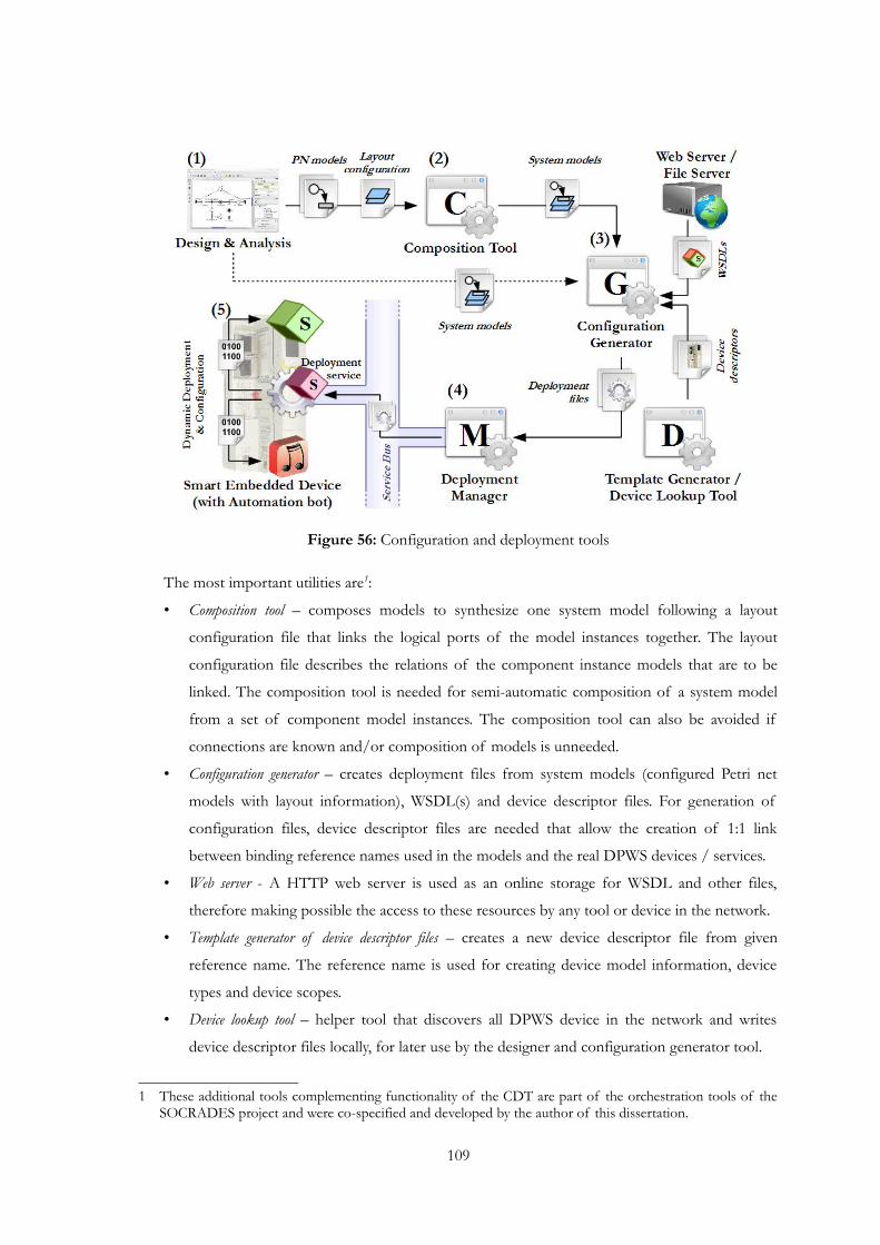
Figure 56: Configuration and deployment tools
The most important utilities are1:
• Composition tool – composes models to synthesize one system model following a layout
configuration file that links the logical ports of the model instances together. The layout
configuration file describes the relations of the component instance models that are to be
linked. The composition tool is needed for semi-automatic composition of a system model
from a set of component model instances. The composition tool can also be avoided if
connections are known and/or composition of models is unneeded.
• Configuration generator – creates deployment files from system models (configured Petri net
models with layout information), WSDL(s) and device descriptor files. For generation of
configuration files, device descriptor files are needed that allow the creation of 1:1 link
between binding reference names used in the models and the real DPWS devices / services.
• Web server - A HTTP web server is used as an online storage for WSDL and other files,
therefore making possible the access to these resources by any tool or device in the network.
• Template generator of device descriptor files – creates a new device descriptor file from given
reference name. The reference name is used for creating device model information, device
types and device scopes.
• Device lookup tool – helper tool that discovers all DPWS device in the network and writes
device descriptor files locally, for later use by the designer and configuration generator tool.
1 These additional tools complementing functionality of the CDT are part of the orchestration tools of the SOCRADES project and were co-specified and developed by the author of this dissertation.
109
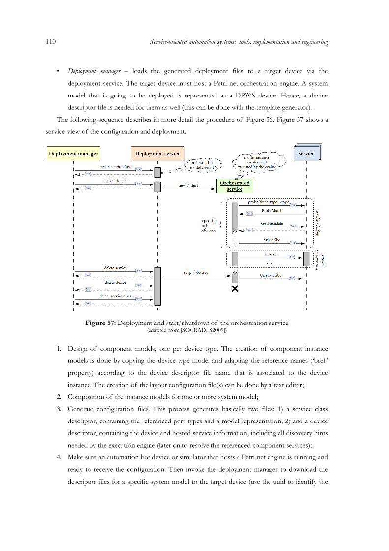
110 Service-oriented automation systems: tools, implementation and engineering
• Deployment manager – loads the generated deployment files to a target device via the
deployment service. The target device must host a Petri net orchestration engine. A system
model that is going to be deployed is represented as a DPWS device. Hence, a device
descriptor file is needed for them as well (this can be done with the template generator).
The following sequence describes in more detail the procedure of Figure 56. Figure 57 shows a
service-view of the configuration and deployment.
Figure 57: Deployment and start/shutdown of the orchestration service(adapted from [SOCRADES2009])
1. Design of component models, one per device type. The creation of component instance
models is done by copying the device type model and adapting the reference names (‘bref ’
property) according to the device descriptor file name that is associated to the device
instance. The creation of the layout configuration file(s) can be done by a text editor;
2. Composition of the instance models for one or more system model;
3. Generate configuration files. This process generates basically two files: 1) a service class
descriptor, containing the referenced port types and a model representation; 2) and a device
descriptor, containing the device and hosted service information, including all discovery hints
needed by the execution engine (later on to resolve the referenced component services);
4. Make sure an automation bot device or simulator that hosts a Petri net engine is running and
ready to receive the configuration. Then invoke the deployment manager to download the
descriptor files for a specific system model to the target device (use the uuid to identify the
target). Repeat this step until all models are deployed. A new device is generated if there is
server information in the deployment files (previously modeled in the Petri net). The new
device can then be used by any client;
5. Once a target has received the configuration and configured correctly, the execution start
automatically.
4.2.5 Operation
The real-time execution of Petri nets models for service-oriented systems is done by the previous
configured automation bots that run on smart embedded devices or also on the PC. The engine is
able to detect the enabled transitions, which may only be activated according to the enabling rule of
Petri nets, and especially considering all input events connected to the transition (e. g. waiting for a
service call). The transition firing corresponds to the firing rule of the Petri nets and the setting of
the actions associated with the fired transition (e.g. notifying the execution of a service). After that,
the model has to be updated to reflect the current state of the system.
Based on if the service exposed by the orchestration engine service (namely a transfer service)
the execution of the model is started. Normally the execution starts immediately after the
deployment and the shutdown of the orchestration service is done after the orchestration (see Figure
57).
Other capabilities at run-time is the ability of managing conflicts with a decision support system
based on decision criteria and the connection to a production execution system that provides
production information, i.e. the workstation that pallets should follow next (consequently resolving
the conflict).
Decision criteria & conflicts
Once workflows are available to be executed and since they describe mostly all possible
combinations of available processes (modi operandi), there are still decisions required in selecting the
best process (modus operandi) in a specific circumstance. The coordination of processes and
services, depending on the flexibility that the system reveals, requires the decision-making and
conflict resolution at run-time, because a system model does not describe a fixed sequence of
actions, but rather all possible combinations thereof. On the other hand, it may also be necessary to
choose from different available services that result from a filtered discovery. For instance, a pallet has
the option to be conveyed straight ahead or to the right (requesting the corresponding service from
the transport system). The answer can be given based on required manufacturing services, energy
consumption, speed, and other quality parameters. Consequently, the decision of the best modus
operandi is a key issue to improve the system performance that depends always on current situation
111
112 Service-oriented automation systems: tools, implementation and engineering
of the automation system.
Detection of decision points can be done when they actually happen during the execution of the
workflow or analyzed previously when the model is about to be executed. In any case, the decision
points represent situations where there is a need of the decision support system to provide a
concrete answer to the execution system of the workflow. In terms of Petri nets, decision points are
identified by conflicts in the Petri net (see section 3.2.3 “Conflicts”) and therefore need an extension
to handle such situations (see section 3.3.5 “Decision support system”). There is the possibility to
model Petri nets without conflicts, but the existence of such properties creates a new dimension in
terms of flexibility of Petri nets. Besides static models that only specify a predefined work-plan,
some models can be enriched with the possibility of choices that permit the intervention of decision
systems.
Therefore, [Mendes2010a] describes a solution for the decision-making over Petri net conflicts
using a set of criteria. Some prerequisites are needed before they are configured in the design and
analysis phases. Decision criteria can be defined for each service s ∈ S using several attributes As =
{a1, a2, …, ak}. Since attributes are possibly of different units of measurement, normalization has to
be done. In this case, the adopted procedure is to convert each attribute a ∈ A to a fuzzy interval of
[0, 1] where the maximization of this value is considered.
In this case, the linear normalization is given as an example. Other normalization approaches can
be used as well such as the exponential and logarithmical. For the normalization of a value v into n
(n∈ [0, 1]), the desired maximum and minimum of the attribute must be known (vmax and vmin,
vmax >vmin). If the quantity is directly proportional to the normalization interval [0, 1], i.e. the quantity
is considered better the higher the value is, then linear normalization can be achieved by n = (v -
vmin)/(vmax - vmin) , vmin ≤ v ≤ vmax. From the other hand, in case of inverse proportionality, the
normalization must be done using n = 1 - (v - vmin)/(vmax - vmin) , vmin ≤ v ≤ vmax.
Figure 58 shows and industrial lifter to lift pallets via the two ports (that may be connected to
conveyors). The lifter has a transfer service with two operations responsible to transport a pallet
from port A to port B and vice-verse. Each one of the operation has defined attributes to be used as
decision criteria. In the example, energy efficiency, quickness of operation and reliability are defined.
They have different values for each operation that may be gathered from previous experiences,
defined initially using vendor specific information, or just defined for example purposes (as in this
case).
In Fig. 3, the mean quickness of the operation from port A to port B (.transfer_A_B) was defined
as 11 seconds and from port B to port A (.transfer_B_A) is 12 seconds. Considering that maximum
and minimum values for this attribute are, respectively, 18 and 8 seconds, and that the quickness is
inversely proportional to the normalization quantity (less time means better value), the quickness

values for .transfer_A_B and .transfer_B_A will be 0.7 and 0.6. This means that from the speed point
of view, .transfer_A_B would be the selected operation because of the higher value (0.7).
Figure 58: Industrial lifter with a transfer service and current decision attributes
Decision criteria should also be changed at run-time to provide an update to the current situation
of the system, especially when involving a learning system that can balance the attributes according
to the past situations. For example, the energy efficiency of an equipment will probably be reduced
with its increasing age.
At run-time, decision points (conflicts) have to be detected. For a given decision point, the
decision support system will now combine the pre-calculated t-invariants of the workflow with the
current decision criteria.
For a given transition t ∈ T associated to a service operation s ∈ S, the combined attribute value
for t is given by A(t) = [a1(t) + a2(t) + … + ak(t)]/k, where ai(t) is the normalized value of an
attribute of the service s associated to the transition t. There are k different attributes to be
considered for the transition t.
The decision factor of a t-invariant (modus operandi) x extracted from a Petri net workflow is
given by F(x) = b[∑(CxAx)/∑(Cx)], where Cx represents the set of non-null coefficients of all t ∈ x,
Ax is the set of combined attribute values of all non-null coefficient t ∈ x. The value of b ∈ [0, 1]
indicates how much of the decision factor of x is to be considered (0 means not to be considered
and 1 fully considered). Similarly, the values of attributes ai and combined attributes A(t) can also be
weighted by a w = [0, 1] before each operation. This represents the weight the attribute’s value has in
the final decision.
Once the decision factors are calculated for each t-invariant, the selected modus operandi would
113
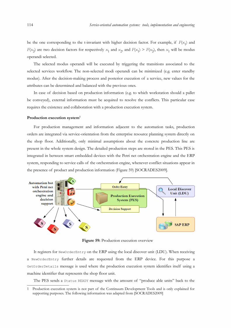
114 Service-oriented automation systems: tools, implementation and engineering
be the one corresponding to the t-invariant with higher decision factor. For example, if F(x1) and
F(x2) are two decision factors for respectively x1 and x2, and F(x1) > F(x2), then x1 will be modus
operandi selected.
The selected modus operandi will be executed by triggering the transitions associated to the
selected services workflow. The non-selected modi operandi can be minimized (e.g. enter standby
modus). After the decision-making process and posterior execution of a service, new values for the
attributes can be determined and balanced with the previous ones.
In case of decision based on production information (e.g. to which workstation should a pallet
be conveyed), external information must be acquired to resolve the conflicts. This particular case
requires the existence and collaboration with a production execution system.
Production execution system1
For production management and information adjacent to the automation tasks, production
orders are integrated via service-orientation from the enterprise resource planning system directly on
the shop floor. Additionally, only minimal assumptions about the concrete production line are
present in the whole system design. The detailed production steps are stored in the PES. This PES is
integrated in between smart embedded devices with the Petri net orchestration engine and the ERP
system, responding to service calls of the orchestration engine, whenever conflict situations appear in
the presence of product and production information (Figure 59) [SOCRADES2009].
Figure 59: Production execution overview
It registers for NewOrderEntry on the ERP using the local discover unit (LDU). When receiving
a NewOrderEntry further details are requested from the ERP device. For this purpose a
GetOrderDetails message is used where the production execution system identifies itself using a
machine identifier that represents the shop floor unit.
The PES sends a Status READY message with the amount of “produce able units” back to the
1 Production execution system is not part of the Continuum Development Tools and is only explained for supporting purposes. The following information was adapted from [SOCRADES2009]
ERP device. This answer is based on internally stored data about the required time to produce a
single product. The production starts after receiving the Start message. The PES will be send each
change of the status of the orders to the ERP device until the complete order is fulfilled.
The example is for a product where the process description is defined as follows:
1. A new pallet is inserted into the production workflow on workstation 1;
2. The single production step is performed at workstation 2;
3. Finally the product is phased out on workstation 1 again.
The workflow starts within a Petri net engine that requires a decision to proceed further. To
identify the pallet to be handled, the engine gets the RFID number of the associated RFID reader
using the matching service. This association is modeled into the Petri net based on the concrete
physical topology.
This pallet ID is used to get the next service from the PES. The returned service allows the Petri
net engine to proceed. In turn, the pallet is moved on to the determined facility, e.g. workstation 2.
Reaching the destination, the accompanied Production Unit is called to ExecuteService for the
given pallet ID. Then the production unit is performing the service.
A PC based HMI is used as production unit. It is a program that displays a text message with the
required production step to the operator. The displayed text is provided by the PES. In a real system
the PES may provide other information used to perform the production step, e.g. a program to
operate a manipulator.
The used production unit is acknowledged by the operator after finishing the production step by
pressing a button. This button can either be part of the HMI or later on a physically provided
button. For example the PES is notified that the service “ws1” (workstation 1) is completed for
PalletID=10721. With this message the result of the production step is also provided, e.g. for a
successful service the Result=”OK” is used. For the next time a service is requested for this pallet ID
another service is returned. This way the pallet is moved to the next service. The time to complete
each production step and to manufacture the whole product is measured and stored into the
database.
To demonstrate the workflow over a longer period of time, the production unit can be
configured to operate automatically. In this case the service is completed after a fixed period of time.
This way it is possible to let the system produce the units automatically and allow completing an
order without human interaction.
115

116 Service-oriented automation systems: tools, implementation and engineering
Chapter 5:Application and Evaluation
This chapter serves to prove the application of the specified methodology, including the
developed software and engineering process. The two successfully appreciated demonstrations where
part of the SOCRADES project and are based on the methodology proposed in this dissertation.1
5.1 Assembly automation in manufacturing: Seligenstadt demonstrator
The application scenario used to demonstrate the SOA approach is based on a customized
Prodatec/FlexLink DAS 30 – Dynamic Assembly System. The DAS 30 system is a modular factory
concept platform for light assembly, inspection, test, repairing and packing applications. The DAS 30
system combines flow-oriented dynamic production control and modular automation for increased
production efficiency with ergonomic solutions for manual assembly. This modular automation
platform includes a range of standardized modules as workstations, robot cells, conveyors and
flexible buffers.
The used system comprises a flexible production system with two work stations (that can be used
by operators and robots), several conveyors that route production pallets into/out of the system and
to the workstations, and also two lifters that make the interface between the upper and lower levels
of conveyors. The system exists physically (Figure 60.a) and was also 3D modeled in DELMIA
(Digital Enterprise Lean Manufacturing Interactive Application), used for simulation, monitoring and
to provide the connection of virtual devices. Prototype devices were connected to the several
equipment units (conveyors and lifters) for hosting the developed automation bots (initially un-
configured). The used tools and engineering methodology were applied to this scenario with the goal
of transferring pallets to the workstations and introduce some flexibility in the design and
1 Part of the description of the two demonstrators from the SOCRADES project were adapted from [SOCRADES2009], co-written by the author of this dissertation.
117
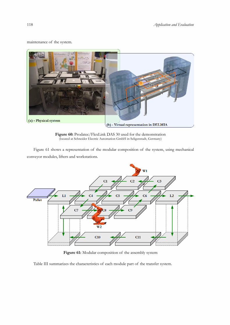
118 Application and Evaluation
maintenance of the system.
Figure 60: Prodatec/FlexLink DAS 30 used for the demonstration(located at Schneider Electric Automation GmbH in Seligenstadt, Germany)
Figure 61 shows a representation of the modular composition of the system, using mechanical
conveyor modules, lifters and workstations.
Figure 61: Modular composition of the assembly system
Table III summarizes the characteristics of each module part of the transfer system.
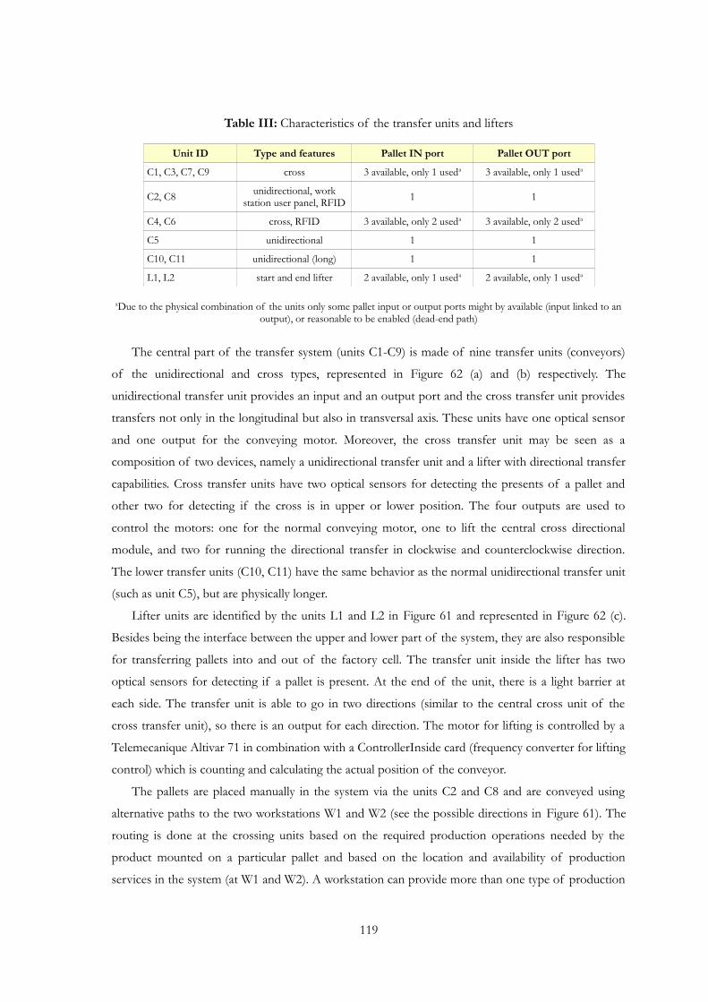
Table III: Characteristics of the transfer units and lifters
Unit ID Type and features Pallet IN port Pallet OUT port
C1, C3, C7, C9 cross 3 available, only 1 useda 3 available, only 1 useda
C2, C8 unidirectional, work station user panel, RFID 1 1
C4, C6 cross, RFID 3 available, only 2 useda 3 available, only 2 useda
C5 unidirectional 1 1
C10, C11 unidirectional (long) 1 1
L1, L2 start and end lifter 2 available, only 1 useda 2 available, only 1 useda
aDue to the physical combination of the units only some pallet input or output ports might by available (input linked to an output), or reasonable to be enabled (dead-end path)
The central part of the transfer system (units C1-C9) is made of nine transfer units (conveyors)
of the unidirectional and cross types, represented in Figure 62 (a) and (b) respectively. The
unidirectional transfer unit provides an input and an output port and the cross transfer unit provides
transfers not only in the longitudinal but also in transversal axis. These units have one optical sensor
and one output for the conveying motor. Moreover, the cross transfer unit may be seen as a
composition of two devices, namely a unidirectional transfer unit and a lifter with directional transfer
capabilities. Cross transfer units have two optical sensors for detecting the presents of a pallet and
other two for detecting if the cross is in upper or lower position. The four outputs are used to
control the motors: one for the normal conveying motor, one to lift the central cross directional
module, and two for running the directional transfer in clockwise and counterclockwise direction.
The lower transfer units (C10, C11) have the same behavior as the normal unidirectional transfer unit
(such as unit C5), but are physically longer.
Lifter units are identified by the units L1 and L2 in Figure 61 and represented in Figure 62 (c).
Besides being the interface between the upper and lower part of the system, they are also responsible
for transferring pallets into and out of the factory cell. The transfer unit inside the lifter has two
optical sensors for detecting if a pallet is present. At the end of the unit, there is a light barrier at
each side. The transfer unit is able to go in two directions (similar to the central cross unit of the
cross transfer unit), so there is an output for each direction. The motor for lifting is controlled by a
Telemecanique Altivar 71 in combination with a ControllerInside card (frequency converter for lifting
control) which is counting and calculating the actual position of the conveyor.
The pallets are placed manually in the system via the units C2 and C8 and are conveyed using
alternative paths to the two workstations W1 and W2 (see the possible directions in Figure 61). The
routing is done at the crossing units based on the required production operations needed by the
product mounted on a particular pallet and based on the location and availability of production
services in the system (at W1 and W2). A workstation can provide more than one type of production
119
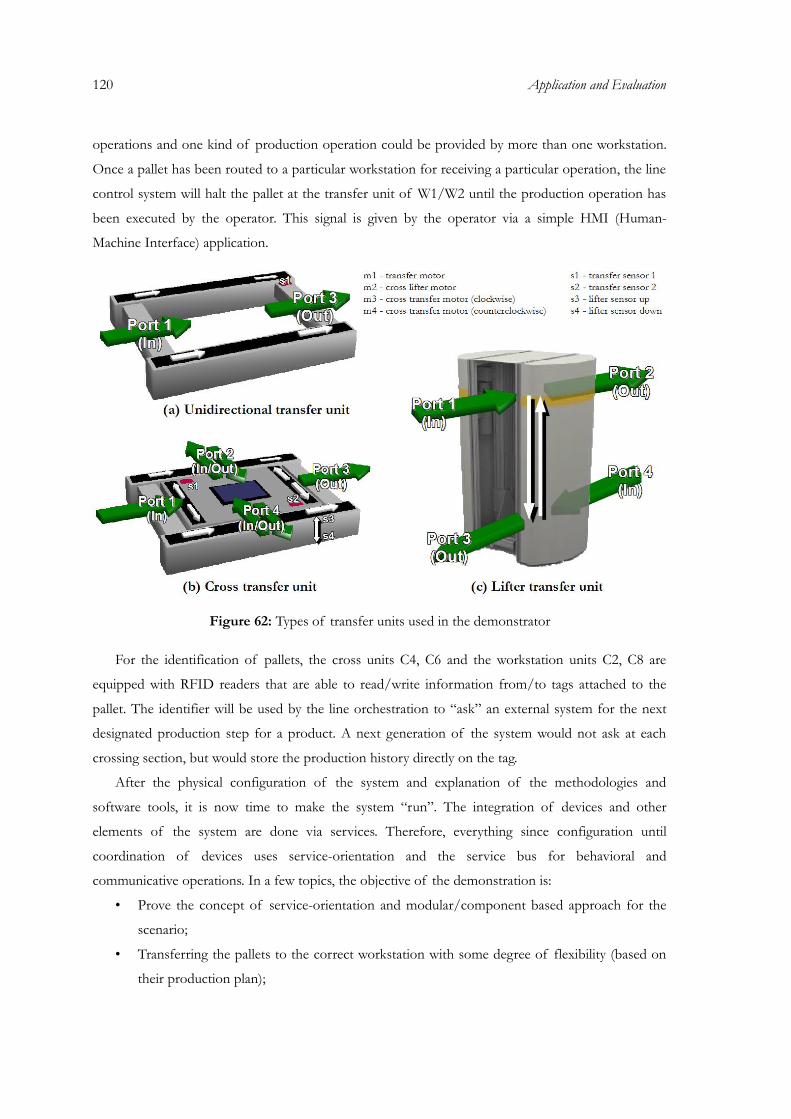
120 Application and Evaluation
operations and one kind of production operation could be provided by more than one workstation.
Once a pallet has been routed to a particular workstation for receiving a particular operation, the line
control system will halt the pallet at the transfer unit of W1/W2 until the production operation has
been executed by the operator. This signal is given by the operator via a simple HMI (Human-
Machine Interface) application.
Figure 62: Types of transfer units used in the demonstrator
For the identification of pallets, the cross units C4, C6 and the workstation units C2, C8 are
equipped with RFID readers that are able to read/write information from/to tags attached to the
pallet. The identifier will be used by the line orchestration to “ask” an external system for the next
designated production step for a product. A next generation of the system would not ask at each
crossing section, but would store the production history directly on the tag.
After the physical configuration of the system and explanation of the methodologies and
software tools, it is now time to make the system “run”. The integration of devices and other
elements of the system are done via services. Therefore, everything since configuration until
coordination of devices uses service-orientation and the service bus for behavioral and
communicative operations. In a few topics, the objective of the demonstration is:
• Prove the concept of service-orientation and modular/component based approach for the
scenario;
• Transferring the pallets to the correct workstation with some degree of flexibility (based on
their production plan);

• Use of high-level programming (e.g. Petri net based structures) to compose the exposed
atomic services offered by the system;
• Respond to some events that may happen in industrial manufacturing systems;
• Development of additional software to ease the engineering of such systems;
• Definition of several engineering steps for the design, analysis, operation and maintenance of
the scenario.
The following sub-sections describe step-by-step the application procedures, following the one
defined in section 4.2 “Engineering process”.
5.1.1 Hardware setup and definition of atomic services
Several automation devices are used to control the mechanical parts of the demonstrator and
make the interface to higher level system via the exposition and requisition of services. The modules
of the system (C1-C11, L1, L2) are controlled by Telemecanique Advantys STB (Small Terminal Box)
NIP2311 prototype devices (Figure 63). The STB contains an Ethernet network interface module
and can be assembled by the user from different input/output modules according to the process
image requirements.
Figure 63: Advantys STB NIP2311 with I/O module(s)
For this prototype implementation, the controller of the Ethernet module is used to host the
service infrastructure allowing the deployment of user-defined applications as DPWS-compliant
service components. STB devices were configured and programmed to be the smart embedded
devices, as explained in section 3.4, therefore STB will be mostly used as a synonym for smart
embedded device and vice-versa. The STB is used for the implementation of the different units as
mechatronic components, meaning each unit is controlled by its own STB and its functions are
exposed as web service. The services are implemented by the STB with an embedded IEC-61131
121

122 Application and Evaluation
engine. The ControlBuild prototype developed by Geensys (www.geensys.com) is used to specify the
logic and services offline and then to deploy those into STBs. Currently, several IEC 61131-3
languages are supported: Function block diagram, ladder diagram and sequential function chart.
Another STB prototype has been implemented that provides an embedded service orchestration
engine based on the Continuum Bot Framework with Petri nets kernel (see section 4.1.1 “Bot
framework”) and the DPWS stack with the same deployment mechanisms as for the STB with IEC-
61131 engine. The current implementation does not allow the integration of both IEC-61131 and
Petri net engines in the same physical device (due to device restrictions, consequent required
optimizations and parallel access to I/O and messaging subsystem). The CDS is used to engineer
system models and deploy those models to the STBs.
For the RFID reader/writer, the OSITrack RFID identification system is used. The OSITrack
devices are connected using Modbus Serial to a TSX ETG 100 (RS485 to Ethernet converter) which
is talking via ModbusTCP to the network. These antennas are placed on the modules C2, C4, C6 and
C8. Each of the pallets is identifiable by a 112 Kbyte tag on the bottom side. Each pallet has a unique
tag id. Information about the workflow of a specific pallet is deposited in a database. The OSITrack
RFID system checks automatically the presence of a pallet and transmits the data of its tag to the
TSX ETG 100. Every time a new tag is detected by an antenna, the corresponding data is refreshed.
The connection between the mechanical system, automation devices and network is represented
in Figure 64.
The ControlBuild application was used to define the atomic services for the connected STBs to
the modules C1-C11, L1 and L2. The TSX ETG 100 connected to the RFID antennas use a DPWS-
to-ModbusTCP Gateway, which is a PC-based application where the logic is hard-coded for RFID-
related services. The orchestration engines run on their own STBs and provide composed services to
the system. Remark: due to the loss of 7 STB prototypes short before demonstration started,
modules C1-C3, C7-C9 and C10-C11 share 3 STBs; this also proves that the same STB can
coordinate several modules and expose their respective services.
Physical devices (e.g. conveyors and lifters) are represented as logical devices to the network.
These logical devices and their services run on the STB controllers (also some of them where
defined on the PC Gateway such as the RFID ones). The specification of the services of logical
devices and their control logic is done using several procedures:
• Logic and services are specified offline using the ControlBuild tool and then deployed into
the STB;
• Logic and services are hard-coded in PC Gateway application (e.g. services from the RFID
antennas).
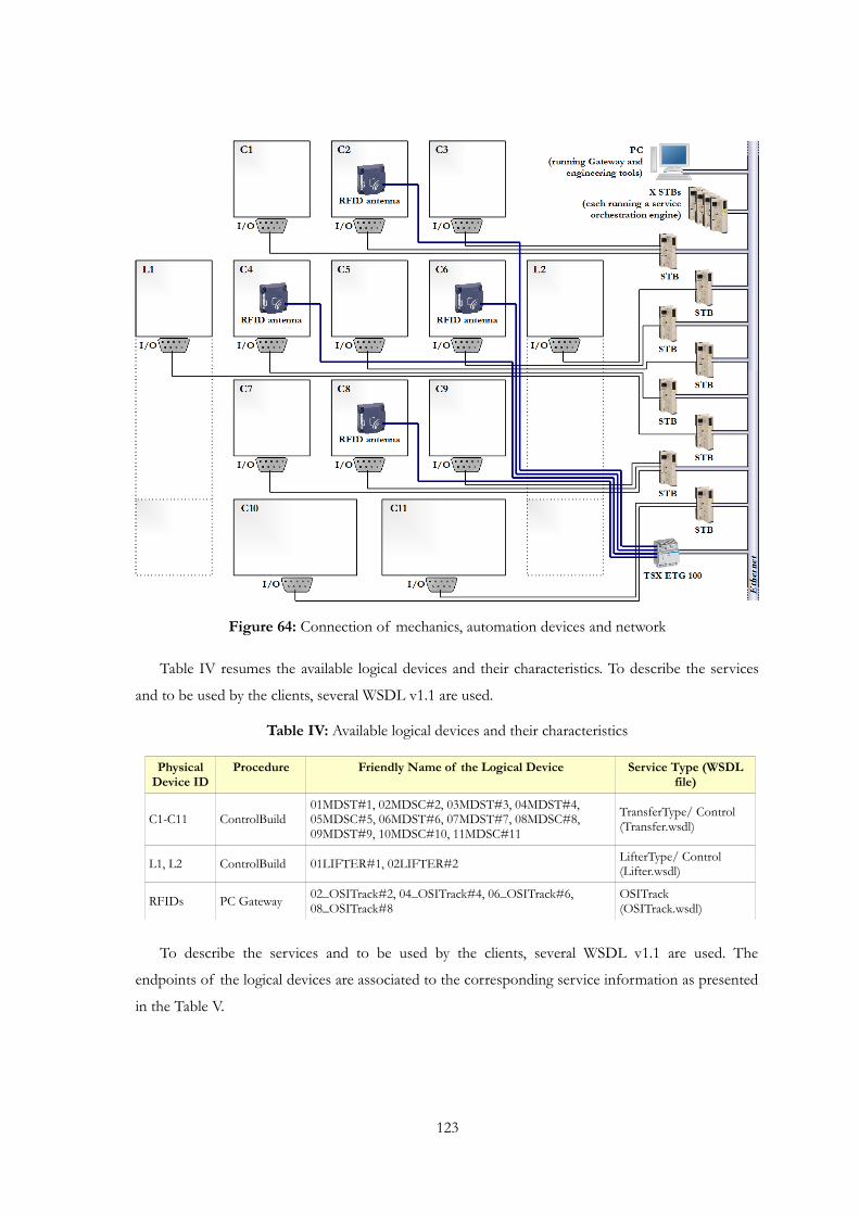
Figure 64: Connection of mechanics, automation devices and network
Table IV resumes the available logical devices and their characteristics. To describe the services
and to be used by the clients, several WSDL v1.1 are used.
Table IV: Available logical devices and their characteristics
Physical Device ID
Procedure Friendly Name of the Logical Device Service Type (WSDL file)
C1-C11 ControlBuild01MDST#1, 02MDSC#2, 03MDST#3, 04MDST#4, 05MDSC#5, 06MDST#6, 07MDST#7, 08MDSC#8, 09MDST#9, 10MDSC#10, 11MDSC#11
TransferType/ Control (Transfer.wsdl)
L1, L2 ControlBuild 01LIFTER#1, 02LIFTER#2 LifterType/ Control (Lifter.wsdl)
RFIDs PC Gateway 02_OSITrack#2, 04_OSITrack#4, 06_OSITrack#6, 08_OSITrack#8
OSITrack (OSITrack.wsdl)
To describe the services and to be used by the clients, several WSDL v1.1 are used. The
endpoints of the logical devices are associated to the corresponding service information as presented
in the Table V.
123
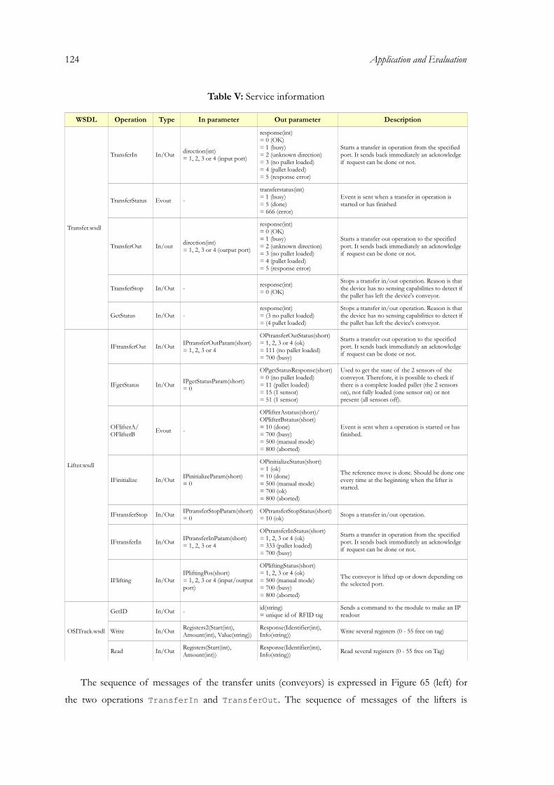
124 Application and Evaluation
Table V: Service information
WSDL Operation Type In parameter Out parameter Description
Transfer.wsdl
TransferIn In/Out direction(int)= 1, 2, 3 or 4 (input port)
response(int)= 0 (OK)= 1 (busy)= 2 (unknown direction)= 3 (no pallet loaded)= 4 (pallet loaded)= 5 (response error)
Starts a transfer in operation from the specified port. It sends back immediately an acknowledge if request can be done or not.
TransferStatus Evout -
transferstatus(int)= 1 (busy)= 5 (done)= 666 (error)
Event is sent when a transfer in operation is started or has finished
TransferOut In/out direction(int)= 1, 2, 3 or 4 (output port)
response(int)= 0 (OK)= 1 (busy)= 2 (unknown direction)= 3 (no pallet loaded)= 4 (pallet loaded)= 5 (response error)
Starts a transfer out operation to the specified port. It sends back immediately an acknowledge if request can be done or not.
TransferStop In/Out - response(int)= 0 (OK)
Stops a transfer in/out operation. Reason is that the device has no sensing capabilities to detect if the pallet has left the device's conveyor.
GetStatus In/Out -response(int)= (3 no pallet loaded)= (4 pallet loaded)
Stops a transfer in/out operation. Reason is that the device has no sensing capabilities to detect if the pallet has left the device's conveyor.
Lifter.wsdl
IFtransferOut In/Out IPtransferOutParam(short)= 1, 2, 3 or 4
OPtransferOutStatus(short)= 1, 2, 3 or 4 (ok)= 111 (no pallet loaded)= 700 (busy)
Starts a transfer out operation to the specified port. It sends back immediately an acknowledge if request can be done or not.
IFgetStatus In/Out IPgetStatusParam(short)= 0
OPgetStatusResponse(short)= 0 (no pallet loaded)= 11 (pallet loaded)= 15 (1 sensor)= 51 (1 sensor)
Used to get the state of the 2 sensors of the conveyor. Therefore, it is possible to check if there is a complete loaded pallet (the 2 sensors on), not fully loaded (one sensor on) or not present (all sensors off).
OFlifterA/OFlifterB Evout -
OPlifterAstatus(short)/OPlifterBstatus(short)= 10 (done)= 700 (busy)= 500 (manual mode)= 800 (aborted)
Event is sent when a operation is started or has finished.
IFinitialize In/Out IPinitializeParam(short)= 0
OPinitializeStatus(short)= 1 (ok)= 10 (done)= 500 (manual mode)= 700 (ok)= 800 (aborted)
The reference move is done. Should be done one every time at the beginning when the lifter is started.
IFtransferStop In/Out IPtransferStopParam(short)= 0
OPtransferStopStatus(short)= 10 (ok) Stops a transfer in/out operation.
IFtransferIn In/Out IPtransferInParam(short)= 1, 2, 3 or 4
OPtransferInStatus(short)= 1, 2, 3 or 4 (ok)= 333 (pallet loaded)= 700 (busy)
Starts a transfer in operation from the specified port. It sends back immediately an acknowledge if request can be done or not.
IFlifting In/OutIPliftingPos(short)= 1, 2, 3 or 4 (input/output port)
OPliftingStatus(short)= 1, 2, 3 or 4 (ok)= 500 (manual mode)= 700 (busy)= 800 (aborted)
The conveyor is lifted up or down depending on the selected port.
OSITrack.wsdl
GetID In/Out - id(string)= unique id of RFID tag
Sends a command to the module to make an IP readout
Write In/Out Registers2(Start(int), Amount(int), Value(string))
Response(Identifier(int), Info(string)) Write several registers (0 - 55 free on tag)
Read In/Out Registers(Start(int), Amount(int))
Response(Identifier(int), Info(string)) Read several registers (0 - 55 free on Tag)
The sequence of messages of the transfer units (conveyors) is expressed in Figure 65 (left) for
the two operations TransferIn and TransferOut. The sequence of messages of the lifters is
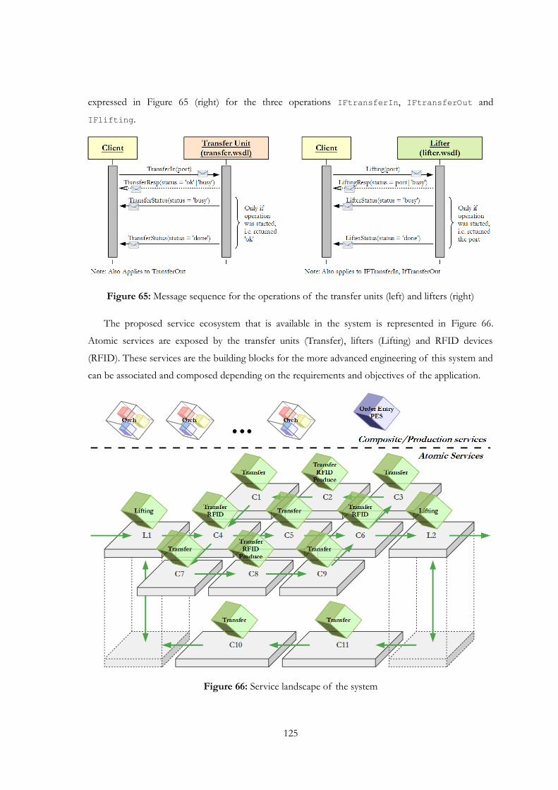
expressed in Figure 65 (right) for the three operations IFtransferIn, IFtransferOut and
IFlifting.
Figure 65: Message sequence for the operations of the transfer units (left) and lifters (right)
The proposed service ecosystem that is available in the system is represented in Figure 66.
Atomic services are exposed by the transfer units (Transfer), lifters (Lifting) and RFID devices
(RFID). These services are the building blocks for the more advanced engineering of this system and
can be associated and composed depending on the requirements and objectives of the application.
Figure 66: Service landscape of the system
125

126 Application and Evaluation
Besides the “atomic” services explained previously, the “heart” of the demonstration are the
orchestration engines distributed into the STB devices, and the production execution system (PES,
integrated into a PC) that coordinate and interface the activity of automation and production
processes, and also external orders. In the case of the orchestration engines, the question is how
many are available and how they should be used. This step is done after the definition of the
orchestration models and shows that some flexibility is introduced in which models can be defined
without knowing the exact number of orchestration engines that will run them.
5.1.2 Design and analysis of orchestration models
Before entering into details of individual models for the case study scenario, a global scratch
behavior model can be defined for the system. Figure 67 shows the scenario with a general behavior
in Petri net formalism. The states represent the different units of the system (transfers and lifters)
and the transitions plus arcs the possible connections between the units. Besides the global overview
concerning the behavior, it can be easily seen that actually the behavior represented in Figure 67
corresponds also to the paths that pallets can take. In this case, it is shown that one solution has
already several functions, namely modularization, connections between modules, general system
operation and paths for pallets. In addition, it also represents some sites where decision is needed to
enhance the flexibility.
Figure 67: Identification of the global behavior with a Petri net structure
Behavior models of the individual modules are designed according to the available atomic
services (and their operations) and the pretended behavior of the devices. The editing of the control
models can be done using the Continuum Development Studio.
The orchestration approach concerning orchestration engines and interaction for each unit is
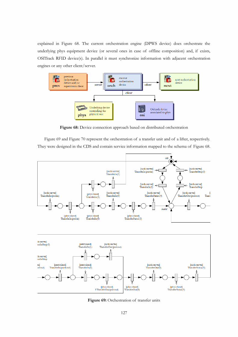
explained in Figure 68. The current orchestration engine (DPWS device) does orchestrate the
underlying phys equipment device (or several ones in case of offline composition) and, if exists,
OSITrack RFID device(s). In parallel it must synchronize information with adjacent orchestration
engines or any other client/server.
Figure 68: Device connection approach based on distributed orchestration
Figure 69 and Figure 70 represent the orchestration of a transfer unit and of a lifter, respectively.
They were designed in the CDS and contain service information mapped to the schema of Figure 68.
Figure 69: Orchestration of transfer units
127
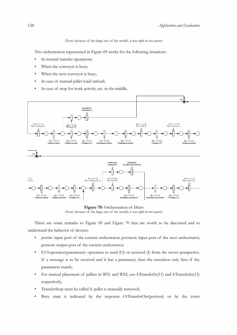
128 Application and Evaluation
(Note: because of the large size of the model, it was split in two parts)
The orchestration represented in Figure 69 works for the following situations:
• In normal transfer operations;
• When the conveyor is busy;
• When the next conveyor is busy;
• In case of manual pallet load/unload;
• In case of stop for work activity, etc. in the middle.
Figure 70: Orchestration of lifters(Note: because of the large size of the model, it was split in two parts)
There are some remarks to Figure 69 and Figure 70 that are worth to be discussed and to
understand the behavior of devices:
• portin: input port of the current orchestrator; portnext: input port of the next orchestrator;
portout: output port of the current orchestrator;
• I|O:operation(parameter): operation to send (O) or received (I) from the server perspective.
If a message is to be received and it has a parameter, then the transition only fires if the
parameters match;
• For manual placement of pallets in WS1 and WS2, use I:TransferIn(11) and I:TransferIn(12)
respectively;
• TransferStop must be called if pallet is manually removed;
• Busy state is indicated by the response O:TransferOut(portout) or by the event

O:TransferStatus(portout), in which portout = 101-111 (for the conveyors), 112 and 113 (for
the lifters).
Table VI: Details for the modeling of each Petri net model and the corresponding device
Model Model type Workstation(Including manual replace/remove of
pallets)
Multiple I/O Conflicts
C1, C3, C5, C7, C9, C10, C11 Transfer unit No No No
C2, C8 Transfer unit Yes No Yes
C4, C6 (For several input and output ports do branches like the one in Figure 71)
Transfer unit No Yes Yes
L1, L2 (The lifter model of Figure 70 represents lifter L1 (OFlifterA) and therefore, when L2 is the represented lifter, change OFlifterA to OFlifterB in the model)
Lifter No No No
These represent general models for all equipment shown in Figure 69 and Figure 70. Since it is
difficult and in expensive in terms of size to represent the models for all the equipment units, some
changes have to be introduced in the models of Figure 69 and Figure 70. Table VI resumes the
changes that have to be done by adapting the models of Figure 69 and Figure 70.
Figure 71: Conflict and resource sharing modeling for the cross units L4 and L6
For decisions on workstations (pallet should pass-through or be operated) and on the conflict
points in C4/C6 (which path to take), changes have to be done in the central part where he conflict is
located. Here an example for the workstation 1 in Figure 72. Basically to call the decision handler in
some point of the net, information of the pallet ID has to be obtained first using the OSITrack
service operation GetID. The parameter of the request (id>p”loaded”.conflict_id) the “loaded” part
has to be replaced with the place id of the conflict (in the example labeled as loaded). After that, the
first places of each branch resulting from the conflict should have a property called services with
coma-separated-values of services that this branch leads to. In the example there is the “ws1” service
129
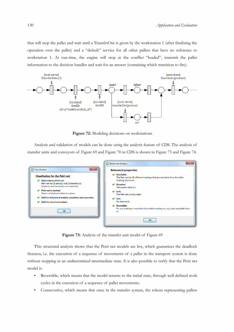
130 Application and Evaluation
that will stop the pallet and wait until a TransferOut is given by the workstation 1 (after finalizing the
operation over the pallet) and a “default” service for all other pallets that have no reference to
workstation 1. At run-time, the engine will stop at the conflict “loaded”, transmit the pallet
information to the decision handler and wait for an answer (containing which transition to fire).
Figure 72: Modeling decisions on workstations
Analysis and validation of models can be done using the analysis feature of CDS. The analysis of
transfer units and conveyors of Figure 69 and Figure 70 in CDS is shown in Figure 73 and Figure 74.
Figure 73: Analysis of the transfer unit model of Figure 69
This structural analysis shows that the Petri net models are live, which guarantees the deadlock
freeness, i.e. the execution of a sequence of movements of a pallet in the transport system is done
without stopping in an undetermined intermediate state. It is also possible to verify that the Petri net
model is:
• Reversible, which means that the model returns to the initial state, through well defined work
cycles in the execution of a sequence of pallet movements;
• Conservative, which means that once in the transfer system, the tokens representing pallets
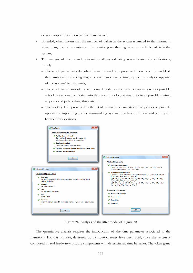
do not disappear neither new tokens are created;
• Bounded, which means that the number of pallets in the system is limited to the maximum
value of m, due to the existence of a monitor place that regulates the available pallets in the
system;
• The analysis of the t- and p-invariants allows validating several systems' specifications,
namely:
– The set of p-invariants describes the mutual exclusion presented in each control model of
the transfer units, showing that, in a certain moment of time, a pallet can only occupy one
of the systems' transfer units;
– The set of t-invariants of the synthesized model for the transfer system describes possible
sets of operations. Translated into the system topology it may refer to all possible routing
sequences of pallets along this system;
– The work cycles represented by the set of t-invariants illustrates the sequences of possible
operations, supporting the decision-making system to achieve the best and short path
between two locations.
Figure 74: Analysis of the lifter model of Figure 70
The quantitative analysis requires the introduction of the time parameter associated to the
transitions. For this purpose, deterministic distribution times have been used, since the system is
composed of real hardware/software components with deterministic time behavior. The token game
131
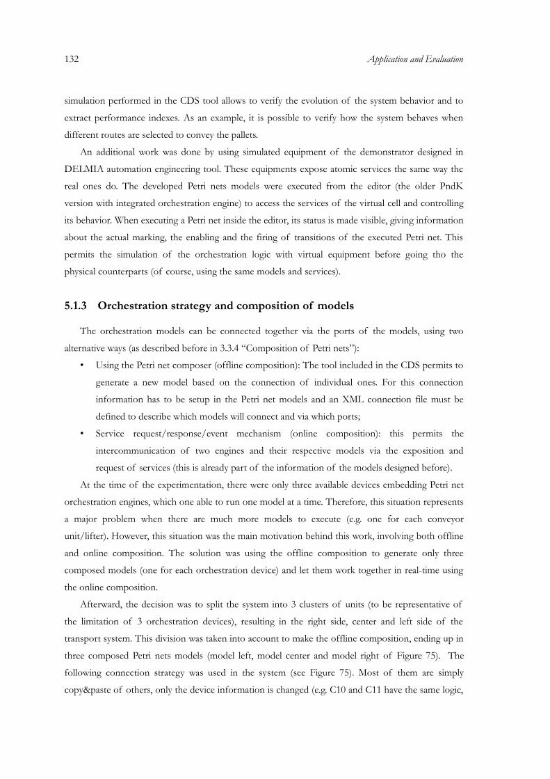
132 Application and Evaluation
simulation performed in the CDS tool allows to verify the evolution of the system behavior and to
extract performance indexes. As an example, it is possible to verify how the system behaves when
different routes are selected to convey the pallets.
An additional work was done by using simulated equipment of the demonstrator designed in
DELMIA automation engineering tool. These equipments expose atomic services the same way the
real ones do. The developed Petri nets models were executed from the editor (the older PndK
version with integrated orchestration engine) to access the services of the virtual cell and controlling
its behavior. When executing a Petri net inside the editor, its status is made visible, giving information
about the actual marking, the enabling and the firing of transitions of the executed Petri net. This
permits the simulation of the orchestration logic with virtual equipment before going tho the
physical counterparts (of course, using the same models and services).
5.1.3 Orchestration strategy and composition of models
The orchestration models can be connected together via the ports of the models, using two
alternative ways (as described before in 3.3.4 “Composition of Petri nets”):
• Using the Petri net composer (offline composition): The tool included in the CDS permits to
generate a new model based on the connection of individual ones. For this connection
information has to be setup in the Petri net models and an XML connection file must be
defined to describe which models will connect and via which ports;
• Service request/response/event mechanism (online composition): this permits the
intercommunication of two engines and their respective models via the exposition and
request of services (this is already part of the information of the models designed before).
At the time of the experimentation, there were only three available devices embedding Petri net
orchestration engines, which one able to run one model at a time. Therefore, this situation represents
a major problem when there are much more models to execute (e.g. one for each conveyor
unit/lifter). However, this situation was the main motivation behind this work, involving both offline
and online composition. The solution was using the offline composition to generate only three
composed models (one for each orchestration device) and let them work together in real-time using
the online composition.
Afterward, the decision was to split the system into 3 clusters of units (to be representative of
the limitation of 3 orchestration devices), resulting in the right side, center and left side of the
transport system. This division was taken into account to make the offline composition, ending up in
three composed Petri nets models (model left, model center and model right of Figure 75). The
following connection strategy was used in the system (see Figure 75). Most of them are simply
copy&paste of others, only the device information is changed (e.g. C10 and C11 have the same logic,
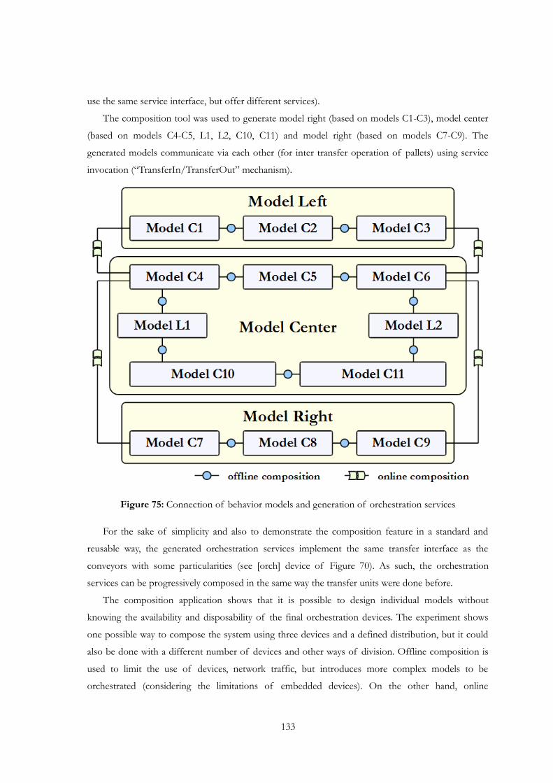
use the same service interface, but offer different services).
The composition tool was used to generate model right (based on models C1-C3), model center
(based on models C4-C5, L1, L2, C10, C11) and model right (based on models C7-C9). The
generated models communicate via each other (for inter transfer operation of pallets) using service
invocation (“TransferIn/TransferOut” mechanism).
Figure 75: Connection of behavior models and generation of orchestration services
For the sake of simplicity and also to demonstrate the composition feature in a standard and
reusable way, the generated orchestration services implement the same transfer interface as the
conveyors with some particularities (see [orch] device of Figure 70). As such, the orchestration
services can be progressively composed in the same way the transfer units were done before.
The composition application shows that it is possible to design individual models without
knowing the availability and disposability of the final orchestration devices. The experiment shows
one possible way to compose the system using three devices and a defined distribution, but it could
also be done with a different number of devices and other ways of division. Offline composition is
used to limit the use of devices, network traffic, but introduces more complex models to be
orchestrated (considering the limitations of embedded devices). On the other hand, online
133
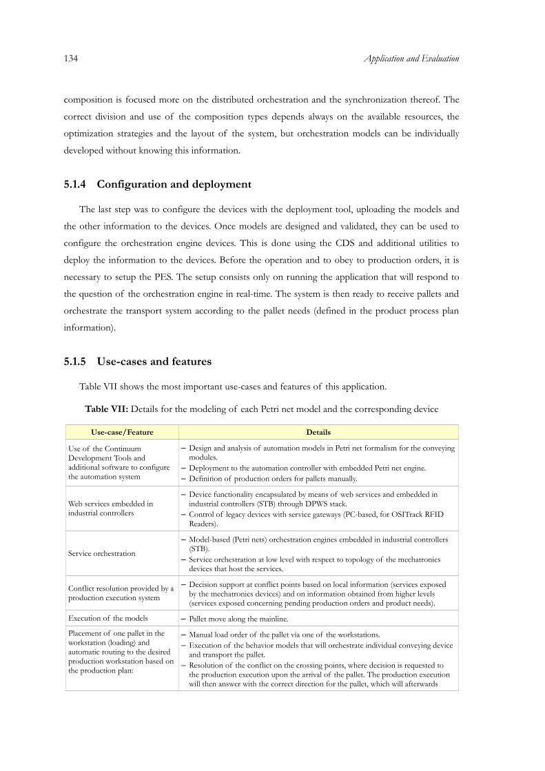
134 Application and Evaluation
composition is focused more on the distributed orchestration and the synchronization thereof. The
correct division and use of the composition types depends always on the available resources, the
optimization strategies and the layout of the system, but orchestration models can be individually
developed without knowing this information.
5.1.4 Configuration and deployment
The last step was to configure the devices with the deployment tool, uploading the models and
the other information to the devices. Once models are designed and validated, they can be used to
configure the orchestration engine devices. This is done using the CDS and additional utilities to
deploy the information to the devices. Before the operation and to obey to production orders, it is
necessary to setup the PES. The setup consists only on running the application that will respond to
the question of the orchestration engine in real-time. The system is then ready to receive pallets and
orchestrate the transport system according to the pallet needs (defined in the product process plan
information).
5.1.5 Use-cases and features
Table VII shows the most important use-cases and features of this application.
Table VII: Details for the modeling of each Petri net model and the corresponding device
Use-case/Feature Details
Use of the Continuum Development Tools and additional software to configure the automation system
– Design and analysis of automation models in Petri net formalism for the conveying modules.
– Deployment to the automation controller with embedded Petri net engine.– Definition of production orders for pallets manually.
Web services embedded in industrial controllers
– Device functionality encapsulated by means of web services and embedded in industrial controllers (STB) through DPWS stack.
– Control of legacy devices with service gateways (PC-based, for OSITrack RFID Readers).
Service orchestration
– Model-based (Petri nets) orchestration engines embedded in industrial controllers (STB).
– Service orchestration at low level with respect to topology of the mechatronics devices that host the services.
Conflict resolution provided by a production execution system
– Decision support at conflict points based on local information (services exposed by the mechatronics devices) and on information obtained from higher levels (services exposed concerning pending production orders and product needs).
Execution of the models – Pallet move along the mainline.
Placement of one pallet in the workstation (loading) and automatic routing to the desired production workstation based on the production plan:
– Manual load order of the pallet via one of the workstations.– Execution of the behavior models that will orchestrate individual conveying device
and transport the pallet.– Resolution of the conflict on the crossing points, where decision is requested to
the production execution upon the arrival of the pallet. The production execution will then answer with the correct direction for the pallet, which will afterwards
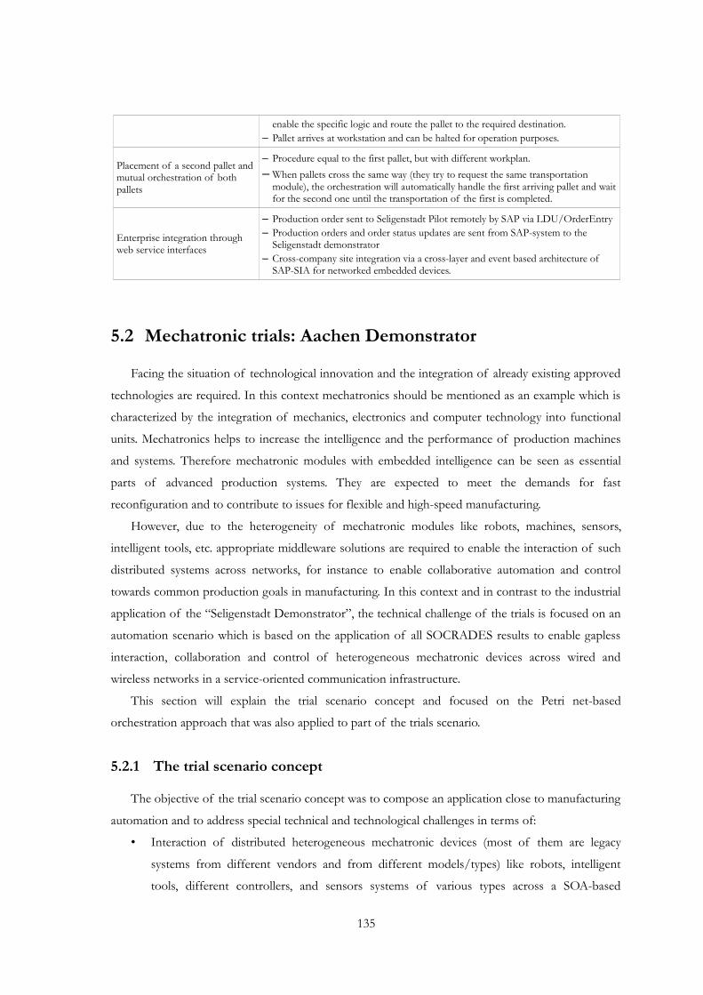
enable the specific logic and route the pallet to the required destination.– Pallet arrives at workstation and can be halted for operation purposes.
Placement of a second pallet and mutual orchestration of both pallets
– Procedure equal to the first pallet, but with different workplan.– When pallets cross the same way (they try to request the same transportation
module), the orchestration will automatically handle the first arriving pallet and wait for the second one until the transportation of the first is completed.
Enterprise integration through web service interfaces
– Production order sent to Seligenstadt Pilot remotely by SAP via LDU/OrderEntry– Production orders and order status updates are sent from SAP-system to the
Seligenstadt demonstrator– Cross-company site integration via a cross-layer and event based architecture of
SAP-SIA for networked embedded devices.
5.2 Mechatronic trials: Aachen Demonstrator
Facing the situation of technological innovation and the integration of already existing approved
technologies are required. In this context mechatronics should be mentioned as an example which is
characterized by the integration of mechanics, electronics and computer technology into functional
units. Mechatronics helps to increase the intelligence and the performance of production machines
and systems. Therefore mechatronic modules with embedded intelligence can be seen as essential
parts of advanced production systems. They are expected to meet the demands for fast
reconfiguration and to contribute to issues for flexible and high-speed manufacturing.
However, due to the heterogeneity of mechatronic modules like robots, machines, sensors,
intelligent tools, etc. appropriate middleware solutions are required to enable the interaction of such
distributed systems across networks, for instance to enable collaborative automation and control
towards common production goals in manufacturing. In this context and in contrast to the industrial
application of the “Seligenstadt Demonstrator”, the technical challenge of the trials is focused on an
automation scenario which is based on the application of all SOCRADES results to enable gapless
interaction, collaboration and control of heterogeneous mechatronic devices across wired and
wireless networks in a service-oriented communication infrastructure.
This section will explain the trial scenario concept and focused on the Petri net-based
orchestration approach that was also applied to part of the trials scenario.
5.2.1 The trial scenario concept
The objective of the trial scenario concept was to compose an application close to manufacturing
automation and to address special technical and technological challenges in terms of:
• Interaction of distributed heterogeneous mechatronic devices (most of them are legacy
systems from different vendors and from different models/types) like robots, intelligent
tools, different controllers, and sensors systems of various types across a SOA-based
135
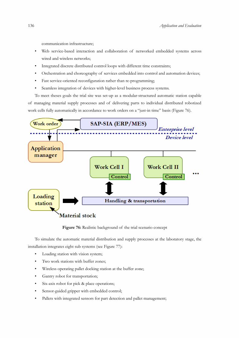
136 Application and Evaluation
communication infrastructure;
• Web service-based interaction and collaboration of networked embedded systems across
wired and wireless networks;
• Integrated discrete distributed control loops with different time constraints;
• Orchestration and choreography of services embedded into control and automation devices;
• Fast service-oriented reconfiguration rather than re-programming;
• Seamless integration of devices with higher-level business process systems.
To meet theses goals the trial site was set-up as a modular-structured automatic station capable
of managing material supply processes and of delivering parts to individual distributed robotized
work cells fully automatically in accordance to work orders on a “just-in time” basis (Figure 76).
Figure 76: Realistic background of the trial scenario concept
To simulate the automatic material distribution and supply processes at the laboratory stage, the
installation integrates eight sub systems (see Figure 77):
• Loading station with vision system;
• Two work stations with buffer zones;
• Wireless operating pallet docking station at the buffer zone;
• Gantry robot for transportation;
• Six-axis robot for pick & place operations;
• Sensor-guided gripper with embedded control;
• Pallets with integrated sensors for part detection and pallet management;
• Safety guards for surveillance of the gantry workspace.
As platform to provide parts of different size and color for supplying the robotized work cells
with material the loading station will select requested parts from a material stock and generates data
from a vision system to command the pick & place and transportation operations. For this purpose a
set of data containing information about color, quantity, and location of the requested parts is
supplied and forwarded for use in the hybrid robot system (robot + gantry) which is responsible for
the handling and transportation tasks. Driven by the exchange of services inside the automatic
station, the robot and gantry are automatically controlled to move to successive work stations and to
deliver parts (here: colored cylindrical objects as test samples) in accordance to predetermined work
orders or in response to special events or requests from the robotized work stations.
Figure 77: Gantry robot system in the Mechatronic Centre of Aachen, Germany
Figure 78 shows the layout of the installation. The automation system is configured to apply
sorting, processing, and storing of machined material and parts. But it can also be utilized for
packaging automation or similar processes.
The laboratory prototype system includes a gantry robot system combined with a six-axis
industrial robot and associated controller units, gripper tools with embedded control, a safety guard
system for surveillance of the working area under the gantry, a loading station with integrated vision
sensor for object identification and position detection, as well as two individual partly robotized work
stations surrounding the gantry, each with a material buffer station. The buffer station is equipped
with small mobile pallets. Each of them consists of integrated sensors for object detection and a
137
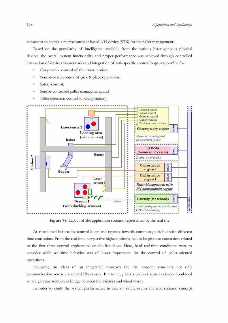
138 Application and Evaluation
connector to couple a microcontroller-based I/O device (STB) for the pallet management.
Based on the granularity of intelligence available from the various heterogeneous physical
devices, the overall system functionality and proper performance was achieved through controlled
interaction of devices via networks and integration of task-specific control loops responsible for:
• Cooperative control of the robot motion;
• Sensor-based control of pick & place operations;
• Safety control;
• Sensor-controlled pallet management; and
• Pallet detection control (docking station).
Figure 78: Layout of the application scenario represented by the trial site
As mentioned before the control loops will operate towards common goals but with different
time constraints. From the real-time perspective highest priority had to be given to constraints related
to the first three control applications on the list above. Here, hard real-time conditions were to
consider while real-time behavior was of lower importance for the control of pallet-oriented
operations.
Following the ideas of an integrated approach the trial concept considers not only
communication across a standard IP-network. It also integrates a wireless sensor network combined
with a gateway solution as bridge between the wireless and wired world.
In order to study the system performance in case of safety events the trial scenario concept
includes also two scanner sensors for workspace surveillance. The safety system provides services
related to situations where the workspace under the gantry is entered by a human operator. Through
event management functionality the robot systems are forced to stop immediately until the safety
area is free again. Then via a restart function the robot systems will continue to finalize the service-
driven activities.
Besides device-centric aspects in the application of the used technology the trial scenario
concept, as shown in Figure 78, also considers the integration of device-level services with business
processes and engineering aspects. For this purpose the SAP-SIA approach was implemented to test
and demonstrate “enterprise-to-shopfloor” communication in terms of:
• Device discovery,
• Work order handling,
• Service discovery,
• Device and production status monitoring,
• Monitoring of critical events with impact on business processes like down,
• Times of machinery, safety events, pauses, breakdown of communication lines via web
services.
Moreover, the overall architecture of the prototype installation for the mechatronics trials has
been developed and implemented as shown in Figure 78. It integrates in a very modular way:
• A cluster of embedded service-enabled mechatronic devices for automatic handling and
transportation processes able to communicate and interact in accordance to the real-time
constraints that are to consider for the different control loops involved;
• Web service enabled controller devices for sensor data acquisition and pallet management at
the buffer zone of each individual the work cell;
• A multi-hop sensor network for pallet docking control integrated via an OPC-UA gateway
and a translator to DPWS; and
• An interface for the enterprise integration by means of the SAP-SIA to collect information
from device level for the control of selected business processes.
The collaboration of the systems is implemented by coordination of the state behavior of each
component. Interlocks and conditions are used to provide a proper event-based synchronization
during operation.
5.2.2 Pallet management with orchestration engines
At the buffer zones of the integrated work stations, pallet devices are installed to carry material
and to care for the material supply. The pallets are connected to WS-enabled I/O devices (i.e. STBs)
which are responsible for the pallet management at each work station. The management functions
139
140 Application and Evaluation
include
• The supervision of the material available on the pallet;
• The administration of the material supply services;
• The registration of occupied and free pallet slots through interaction with object detectors;
• The administration of work-orders;
• The management of alarm services;
• The pallet presence function ( presence of pallet);
• The pallet lock/unlock function controlled through input of the wireless docking sensors.
There are two workstations within the trials system, as shown in the schema of Figure 78. A
material handling system, composed of gantry and a gripper tool, is able to move colored pieces
between the stations. The stations are positioned on the shop-floor at fixed, known coordinates. The
stations are exposed as a pallet management service.
The workstation is a mechatronic component that is positioned at known position in the shop
floor. It is composed of two compartments, a basis device (immobile) and a removable pallet. The
pallet is equipped with 8 proximity sensors for the slots and a pallet presence sensor. The presence
sensor allows detection if the pallet is mounted on the station. The proximity sensors are sued for
the slots to detect if a work piece is present in a slot or not. The respective I/O interface is linked
with a controller, the STB with embedded IEC engine and web services. A 16-bit digital input
module is used for linking the sensors to the pallet control function implemented in the STB.
The basic functions of the pallet controller are to manage the slots, to detect if the pallet is
installed and to manage how the information can be accessed from external nodes. Another feature
that the pallet controller has to manage the absolute coordinates of the station and the slots in the
global Trials reference system. This has to be done in case that the choreography engine is not able to
transform logical position information of slots to absolute coordinates of the mechatronics trial
system.
The PN-based orchestration engine part of the automation bot is able to interact with the station
service by reception of station status messages which are used to trigger high-level actions at the
choreography engine, e.g. “bring red object from station 2 to 1”, which is then managing the complex
interactions with the gantry, gripper, security sensors etc. The PN engine in combination with the
production execution system is used to link shop floor processes with business processes in terms
that actions on the shop floor are performed according to production plans.
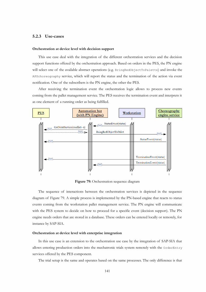
5.2.3 Use-cases
Orchestration at device level with decision support
This use case deal with the integration of the different orchestration services and the decision
support functions offered by the orchestration approach. Based on orders in the PES, the PN engine
will select one of the available abstract operations (e.g. BringRedObjectToPalette) and invoke the
APSchoreography service, which will report the status and the termination of the action via event
notification. One of the subscribers is the PN engine, the other the PES.
After receiving the termination event the orchestration logic allows to process new events
coming from the pallet management service. The PES receives the termination event and interprets it
as one element of a running order as being fulfilled.
Figure 79: Orchestration sequence diagram
The sequence of interactions between the orchestration services is depicted in the sequence
diagram of Figure 79. A simple process is implemented by the PN-based engine that reacts to status
events coming from the workstation pallet management service. The PN engine will communicate
with the PES system to decide on how to proceed for a specific event (decision support). The PN
engine needs orders that are stored in a database. These orders can be entered locally or remotely, for
instance by SAP-SIA.
Orchestration at device level with enterprise integration
In this use case is an extension to the orchestration use case by the integration of SAP-SIA that
allows entering production orders into the mechatronic trials system remotely with the OrderEntry services offered by the PES component.
The trial setup is the same and operates based on the same processes. The only difference is that
141
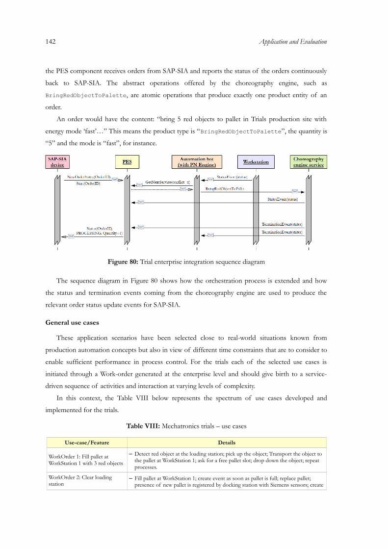
142 Application and Evaluation
the PES component receives orders from SAP-SIA and reports the status of the orders continuously
back to SAP-SIA. The abstract operations offered by the choreography engine, such as
BringRedObjectToPalette, are atomic operations that produce exactly one product entity of an
order.
An order would have the content: “bring 5 red objects to pallet in Trials production site with
energy mode ‘fast’…” This means the product type is “BringRedObjectToPalette”, the quantity is
“5” and the mode is “fast”, for instance.
Figure 80: Trial enterprise integration sequence diagram
The sequence diagram in Figure 80 shows how the orchestration process is extended and how
the status and termination events coming from the choreography engine are used to produce the
relevant order status update events for SAP-SIA.
General use cases
These application scenarios have been selected close to real-world situations known from
production automation concepts but also in view of different time constraints that are to consider to
enable sufficient performance in process control. For the trials each of the selected use cases is
initiated through a Work-order generated at the enterprise level and should give birth to a service-
driven sequence of activities and interaction at varying levels of complexity.
In this context, the Table VIII below represents the spectrum of use cases developed and
implemented for the trials.
Table VIII: Mechatronics trials – use cases
Use-case/Feature Details
WorkOrder 1: Fill pallet at WorkStation 1 with 3 red objects
– Detect red object at the loading station; pick up the object; Transport the object to the pallet at WorkStation 1; ask for a free pallet slot; drop down the object; repeat processes.
WorkOrder 2: Clear loading station
– Fill pallet at WorkStation 1; create event as soon as pallet is full; replace pallet; presence of new pallet is registered by docking station with Siemens sensors; create
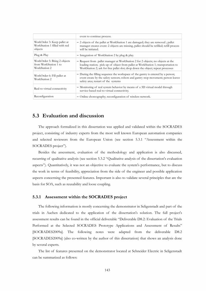
event to continue process.
WorkOrder 3: Keep pallet at WorkStation 1 filled with red objects
– 2 objects of the pallet at WorkStation 1 are damaged; they are removed ; pallet manager creates event: 2 objects are missing, pallet should be refilled; refill process will be initiated.
Plug & Play – Integration of WorkStation 2 by plug & play.
WorkOrder 5: Bring 2 objects from WorkStation 1 to WorkStation 2
– Request from pallet manager at WorkStation 2 for 2 objects; no objects at the loading station; pick-up of object from pallet at WorkStation 1; transportation to WorkStation 2; ask for free pallet slot; drop down the object; repeat processes
WorkOrder 6: Fill pallet at WorkStation 2
– During the filling sequence the workspace of the gantry is entered by a person; event create by the safety sensors; robots and gantry stop movement; person leaves safety area; restart of the systems
Real-to-virtual connectivity – Monitoring of real system behavior by means of a 3D virtual model through service-based real-to-virtual connectivity.
Reconfiguration – Online choreography; reconfiguration of wireless network.
5.3 Evaluation and discussion
The approach formalized in this dissertation was applied and validated within the SOCRADES
project, consisting of industry experts from the most well known European automation companies
and selected reviewers from the European Union (see section 5.3.1 “Assessment within the
SOCRADES project”).
Besides the assessment, evaluation of the methodology and application is also discussed,
recurring of qualitative analysis (see section 5.3.2 “Qualitative analysis of the dissertation's evaluation
aspects”). Quantitatively, it was not an objective to evaluate the system's performance, but to discuss
the work in terms of feasibility, appreciation from the side of the engineer and possible application
aspects concerning the presented features. Important is also to validate several principles that are the
basis for SOA, such as reusability and loose coupling.
5.3.1 Assessment within the SOCRADES project
The following information is mostly concerning the demonstrator in Seligenstadt and part of the
trials in Aachen dedicated to the application of the dissertation's solution. The full project's
assessment results can be found in the official deliverable “Deliverable D8.2: Evaluation of the Trials
Performed at the Selected SOCRADES Prototype Applications and Assessment of Results”
[SOCRADES2009a]. The following notes were adapted from the deliverable D8.2
[SOCRADES2009a] (also co-written by the author of this dissertation) that shows an analysis done
by several experts.
The list of features presented on the demonstrator located at Schneider Electric in Seligenstadt
can be summarized as follows:
143

144 Application and Evaluation
• Web services embedded in industrial control devices and modularization of the system (each
module has own hardware + control device + services);
• Dynamic deployment and dynamic discovery of devices/services;
• Service orchestration embedded in industrial control devices using Petri net formalism;
• Modular device architecture (DPWS framework, Petri net kernel, DSS, custom applications);
• Complete engineering approach with custom designed supporting software;
• Service orchestration using Petri net formalism, including modeling, composition, analysis,
simulation and execution in service enabled control devices;‐• Interoperability between different hardware/software technologies, connected together by
one framework using DPWS;
• Conflict resolution provided internally by the control device and supported externally by a
production execution system (which can communicate to ERP from SAP);
• Device to enterprise integration through web service interfaces;
• Proactive pallet management in a SOA-based material flow control system, with multiple
pallet support at run-time via web services.
The following list describes the link between features, the requirements from where they were
originated, and the assessment criteria utilized for its evaluation (only the ones that include input and
contribution from this dissertation):
• Engineering of SOCRADES components SHOULD support composition of application task related services [fulfilled? YES] – Two main device level components‐
have been developed that allow the composition of task related services, (a) the embedded
IEC engine which allows composition in a Russian doll manner with a single high level‐ ‐
interface of the composite and composition in peer to peer manner, where logic is‐ ‐
distributed to several logical components. Apart from that, (b) the (embedded) model based‐
orchestration engine component allows also composition of services by composing
component models of the devices and services. The DSS supports the selection of services
on the Seligenstadt demonstrator according to product needs at run-time. At design time,
composition of services is supported for both components. The CDS tool allows design of
complete automation applications based on distributed service based components.‐
Distribution, deployment and dynamic interaction between the components/services are
completely managed by CDS. The CDS used for the model based orchestration does the‐
composition of tasks by linking models (of services) into one system model by using a port
connection logic and layout information of the devices and services present and used in the
factory floor.
• The system MUST allow high level functionality (e.g. control) to be distributed (i.e.
embedded, deployed) into devices [fulfilled? YES] – Control in terms of having direct
link to process interfaces (actuators and sensors) is embedded in devices and is downloaded
to devices via deployment services. Control in terms of workflow logic is covered by the
orchestration engine embedded in STB device (Remote IO device now serving as
orchestration engine). The configuration of the engine takes place via the same service
deployment mechanisms. An embedded version of the decision component that supports the
embedded orchestration engine has been integrated into the device. Configuration is done by
service deployment.
• The system MUST allow peer to peer communication between devices [fulfilled? YES]
– Peer to peer communication is possible and supported by the embedded IEC control and‐ ‐
orchestration components. Each service and composite service can act in a server role, but
can also include references to other services acting as a client. In the Seligenstadt
demonstrator, the orchestration logic was distributed and executed on 3 separate devices. The
synchronization among the engines was done by peer to peer, meaning there was no superior‐ ‐
instance supervising the distributed engines. However, the interaction between the
orchestration services and the web services exposed by the devices was not mixed with peer‐to peer interaction between the devices at lowest level, because the reconfiguration of the‐
system is done at the orchestration model only.
• The service centric infrastructure MUST enable devices to expose their‐ functionalities as web services [fulfilled? YES] – This is provided by the implementation
of the DPWS stack and the IEC engine in the STBs and also in the middleware components.
Moreover, the embedded orchestration is also able to generate non-atomic services.
• The system MUST provide the ability to dynamically assemble services to provide higher level functional capabilities [fulfilled? PARTLY] – The dynamic assembly or
composition of services has been achieved by using a Petri net based workflow language.
The dynamicity lies in that the assembly of services is done at design time with service
models that are enriched with logical interfaces. With those interfaces the models are
compiled automatically to a system model, creating the correct and allowed service
invocation sequences. Service binding to production services is done dynamically at run-time,
where the selection of services is supported by a decision making system. Dynamic assembly‐
of services at run-time and at device level is not possible with the embedded orchestration
approach today, there is always an engineering step needed before that.
• The service centric infrastructure MUST allow service assembly to be embedded into‐ devices [fulfilled? YES] – The service assembly can be deployed as orchestration service
with the embedded Petri net based orchestration engine and it can be deployed as service
145
146 Application and Evaluation
component with the embedded IEC engine.
• The service centric infrastructure MUST support a procedure driven interaction‐ ‐ mechanism [fulfilled? PARTLY] – With the model based orchestration approach based on‐
Petri net formalism, procedure driven interaction mechanisms are supported with limited‐
features. Modeling of sequential service invocations with client and server roles is supported
and similar to BPEL. However, handling of complex message content with functions for
calculation, compare, aggregation etc is not implemented yet in the orchestration engine. The
approach allows the designer to choose between modeling a system supported by automated
model composition, or modeling systems by defining the set of allowed service sequences for
a given production system.
• The service centric infrastructure MUST support the management of deployed‐ (hosted) services on device [fulfilled? YES] – Basic management for application services are
provided as operations exposed by the same web services. Each service in the Seligenstadt
demonstrator supports at least a GetStatus operation and Status event notification. The
operations read status information from the programming logic used for controlling those
devices. The dynamic deployment management service is the generic interface to manage
hosted services, in terms of creating, deleting and updating their metadata.
• Devices and IT applications SHOULD be able to interact together without intermediaries and no protocols translation [fulfilled? YES] – All the web services hosted
on STBs in the EAD are visible to the SOCRADES SIA developed by SAP. The software
component LDU implementing the DPWS stack is in charge of discovering local web
services hosted on STBs and also exposes a Virtual enterprise web service hosted on a
remote server. In this way the interaction between IT applications and the factory floor is
completely transparent.
• Support an Event Driven Architecture [fulfilled? YES] – Event driven architecture is
supported and has been applied in the Seligenstadt demonstrator for the interaction patterns
between application services at device level and orchestration services, between orchestration‐
services and MES and SAP SIA enterprise services. Status information is propagated to
upper levels via event notifications. The classical synchronous request response interaction‐
pattern for operations that take a considerable amount of time has been replaced by a
pattern using an asynchronous event notification as response.
The main focus in Seligenstadt scenario was the application of the approach of model based‐
orchestration of services and decision making processes at device level. Together with‐ ‐
demonstrations done in the past, the demonstrator shows the missing phases of the complete life-
cycle of the engineering approach (2D/3D modeling and simulation, design, simulation, analysis and
validation based on formal methodologies, configuration, deployment and production execution).
The demonstrator puts strong emphasis and efforts on integrating components of the service‐centric infrastructure at device level. The implementation and fulfillment of the scientific and‐
technological aspects in the demonstrator has been covered in a satisfactory way:
• Application web service and device control based on an embedded IEC engine;
• Embedded orchestration services and engine;
• Embedded and external decision supporting components;‐• Service and device management services;
• Logic deployment services;
• Integration with enterprise systems and business processes.
The production cell offered all basic components that would also be needed by a larger
production line, such as loading, unloading, workstations offering different production services and
equipment layout that allows testing of flexible material flow concepts. It was possible to evaluate the
expected characteristics of the approach explained previously in section 5.1 “Assembly automation in
manufacturing: Seligenstadt demonstrator”.
It is worth of mentioning some of the highlights that are present in the developed middleware:
• Composition of services by linking models according to layout knowledge rather than
designing individual processes from scratch (“configuration rather than programming”);
• Concurrent processes and sequences are easy to model with the PN formalism and thus,
appropriate for the design of modular systems;
• Separation between orchestration engine, embedded DSS and external DSS allows to
implement decision algorithms where most appropriate, e.g. embedded DSS deals with
simple path finding calculation, external DSS deals with high level production scheduling.‐However, the small size of the cell had some disadvantages that were not considered as
significant in the beginning. The Seligenstadt cell has only 2 workstations, so that multiple services
had to be hosted on same devices (workstations), e.g. workstation 1, hosted 2 production services
and the loading an unloading service. Hence, the production scenarios that could be investigated
were only of simple nature. The system performed stable with 2 3 pallets, critical situations usually‐
occurred due to loss of synchronization of the engine with the real state of the devices.
Due to the resource limitations given by the embedded orchestration engines, only simplified
versions of the logic models could be executed, which meant that most logic that was responsible for
the dynamicity and reactivity of the models had to be removed. For example, the detection of pallets
at run-time at any place in the system did not work as expected any more. Workaround was to
introduce pallets only at designated devices.
Because of the relatively small size of the manufacturing cell, scenarios with multiple
147
148 Application and Evaluation
simultaneous production processes (>2) of products with different production plans (>4 production
steps) could not be satisfactorily tested with the existing equipment.
A strong synchronization between the orchestration engines and between each orchestration
engine with the device level services is required. It was observed that, otherwise, unexpected‐
situations will disturb the operation of the system too easy. In the current version of the engine,
synchronization takes place via user defined service interfaces. This decision was made in order to‐
hide the technology behind the interface. The conclusion of today is to have dedicated
synchronization interfaces, specialized for the synchronization of distributed models.
More efforts in the future need to focus on really combine results around BPEL based
orchestration and the presented embedded orchestration approach. Petri net was chosen because of
the existing tools for validation and analysis, which were objectives in the project. Both languages
describe workflows, but BPEL language was too powerful to be able to develop an embedded
version out of the specification for such an engine in C. Most engines available are based on Java for
executing large scale business processes. Anyway, a subset of the BPEL elements is implemented in
the PN engine.
The user has the choice of using the orchestration engine as shown in the demonstrator, by using
model composition and distribution of logic to multiple engines, but he can use the engine also in‐
the classical service orchestration manner, where as many orchestration instances are present as
processes are running. As a reminder, the approach was to have one logical model to handle all
processes (though done with distributed engines). Weaknesses in the Petri net approach are the lack
of semantic descriptions of exposed interfaces and discovery using semantic annotations of service
endpoints. Another weakness compared to BPEL is the lack of sophisticated message handling and
implementing algorithms for more complex data processing.
The design of behavioral models is quite intuitive and quickly done in Petri net. However, it is
evident that the current language derived from Petri nets provides only the basic language primitives
and that more complex component models or models enhanced with security features or exception
handling will result in very complex models which are hard to maintain and understand.
For example, a standard call to a device operation needs at least 3 elements (request response +‐
sync event as operation finished notification), and much more if the model must reflect different
responses. Moreover, at this moment, SOAP exceptions cannot be handled at application level. The
health of a device/service is not monitored, only if respective calls are modeled. Hence, introducing
more capabilities into the engine and offering the designer more properties allows significantly
reducing the complexity of models and ease the design of complex systems.
5.3.2 Qualitative analysis of the dissertation's evaluation aspects
Besides the evaluation within the SOCRADES project concerning the aspects in this dissertation,
several other parameters can be discussed. The objective of the validation is the proof of service-
orientation in automation concerning the principles of SOA. There are several design principles for
SOA depending on the authors who defines them, but the ones considered here are, according to T.
Earl [Erl2007], the ones that realize the goals and benefits of service-oriented computing in the real
world: standardization, loose coupling, abstraction, reusability, autonomy, statelessness, discoverability
and composability. “Becoming proficient with the concepts and principles of service-orientation equips you with an
understanding of what is and is not considered "service-oriented" within the world of solution design!” (T. Erl). Note
that the considered principles are not only directed to the services itself, but in general to the
engineering as a whole. In addition, other principles and aspects were considered concerning the
methodology and engineering framework described in this work. In conjunction, these build the
qualitative metrics used to proof the research work.
Contracts & Standardization
Services obey to standards that are defined to provide means of interoperability. The use of the
DPWS introduces the basic profile for this need and, since this work integrates DPWS, the principle
of contracts and standardization is to some extend valid. Nevertheless, DPWS does not provide any
standard for orchestration neither for complex description using semantics. This question was
addressed by using a specification for the orchestration language based on XML description of Petri
nets that is also possible to enrich with additional information due to the property system. Semantics
was not an objective of this work, but semantic descriptions could benefit and complement the
orchestration and decision mechanisms.
Loose coupling and autonomy
Services are to be specified, permitting some flexibility in their usage and minimizing their
dependency. The approach in this work is to allow that models are independently designed and
loosely coupled to services and other models. Models can be therefore composed and orchestrated
differently. Their instantiation permits the association to services and the orchestration engines they
will run on. Orchestration engines work afterwards independently from each other, until they need
interaction from other services. It was demonstrated that if one orchestration engine fails, the other
ones do not stop until they requires a service from the failed one.
Abstraction
Services are implemented in such a way that they should hide their internal logic. In the
engineering framework this is valid in the sense that orchestration models do not need to know
149

150 Application and Evaluation
details about atomic services they use (besides the interface). The development of orchestration
models can be done without knowing the final control and displacement layout, making it possible to
construct models for individual equipments (such as conveyors and lifters) instead of considering the
full scenario. This is possible due the composition approach introduced in this dissertation as well as
the abstraction from automation control devices. The methodology is flexible enough to permit
different control strategies based on the same models and adapted to the proposed service-oriented
control architecture.
Reusability
Reusability is promoted by SOA: not only the ability of services being reused during their life-
cycle, but also information and mechanisms during the engineering should be “recycled”.
Information contained in the extended Petri nets can be (re)used for different means during the
life-cycle. Thus, the same Petri net models are used for analysis, simulation, operation and support
information of decision makers (using decision criteria). The composition strategy permits also the
reuse of service interfaces (composition does not add complexity to the interface, but complexity to
their implementation).
Reduced transition from the design (including analysis and simulation) to the operation is also
achieved. The same orchestration models are used in both the simulated environment and for the real
automation scenario. The only thing that changes are the provider of atomic services (instead of
simulated equipment, there are real devices) and the orchestration (not on PC, but on embedded
devices).
Statelessness
State information is not managed by the serves directly, but associated to their implementation
(whatever the service is atomic or a composite based on a Petri net orchestration).
Discoverability
Discoverability depends on what communication standard is used and in this case DPWS (and
the used implementation framework SOA4D) provides the necessary primitives to make services
discoverable, by including, besides others, meta-data description associated to services and network
mechanisms to broadcast/multicast information. Services are announced in the network and can be
located using the dynamic discovery feature of SOA4D.
Composability
Services can be composed to form complex structures based on some sort of logic. This logic
may also result in new services (composite services). The logic for composite services is defined here
by the Petri net formalism with service association. A composition may also introduce enhanced
features to an existing service by wrapping its interface. For example, the service for the pallet
management in the Aachen demonstrator can be used as it is or composed with the pallet detection
system, generating a composed one that has the same interface of the first one.
The composition of services allows creating new and more complex services; each individual
service behavior being modeled using Petri nets, the composed model is by sure more complex. The
proposed approach for the composition of Petri nets models considers two forms, namely the off-
line composition and the on-line composition. Both compositions can be used depending on the
design choices and available resources, but in both cases they maintain the original behavior planned
for the individual equipment. At the end, the whole composition represents the specification of the
system made of several well specified elementary models.
Offline composition is used to limit the use of devices, network traffic, but introduces more
complex models to be orchestrated (considering the limitations of embedded devices). Online
composition is focused more on the distributed orchestration and the synchronization thereof.
Formality, openness and unity
The methodology is formally specified in this dissertation and is proved by its implementation
and application in the two industrial demonstrators. The choice over Petri net was due to the
convincement based on previous experience that it could be used in this sense. Therefore, it was
pretended to “do the most possible with the methodology” based on Petri nets, i.e. uncover its
features for the engineering of service-oriented automation systems. Of course there are several
types of high-level Petri nets that could be used, however the basis for the dissertation was to permit
user customization over the core Petri net formalism, so that requirements and objectives could be
considered. Besides the required openness, another requirement is the introduction of the time factor
when evolving the Petri net. Consequently, the basis of the Petri nets is guaranteed, except that the
doors are open in terms of delays that can be used for customized operations.
Other important aspects include:
• Token game template – Part of the open methodology, the token game template permits the
definition of concrete token games affecting the life-cycle of transitions (that are used as
inputs and outputs of interactivity for custom applications). In its core and to maintain an
asynchronous (independent) operation of the transitions, the template is a state machine
specification for each transition and consequently responsible for managing the transition's
state and evolution.
• Property system for Petri nets – Part of the open methodology, the property system gives the
possibility of enrichment of the several elements of the Petri net (e.g. transitions and places)
with custom information that can be for example changed during the evolution of the Petri
151
152 Application and Evaluation
net by the token game.
• Active conflict management – Part of the open methodology, conflicts are viewed as choice
possibilities and reported to the outside (as an output) by the mechanism of the token game.
The result (choice) can be replied afterwards back to the token game. The decision maker
responsible to solve the conflicts can be anything choosing the firing transition from the
candidates, for example a rule-based reasoning system.
• Association of service ports to model ports and device ports – Another concept that is fundamental to
this work is the use of ports. Ports are used as the gateways for the interaction of a Petri net
model with external references. In other words, the ports are specific gates to synchronize
control models, being in some cases also related to the physical connectivity of the entities.
Engineering and implementation
• Requirements for the engineering – One requirement is the previous knowledge about Petri nets,
SOA and the engineering approach. This information has to be transmitted to the users and
developers that are normally used to the traditional automation systems. Petri nets are not
much different from what automation engineers are used to (e.g. IEC 61131-3 languages).
SOA can easily taught and understood if more education and trainings are done in services
for automation, especially to understood why services simplifies the representation of
resources and how topics of engineering such as orchestration and composition are used to
create complete automation applications.
• Elementary architecture for service-based automation – Indeed, it is based on SOA and therefore it is
centered on the notion of services, but a more focus is given to providers and requesters.
This perspective permits to identify why and how system entities request and provide
services.
• Automation bots (smart embedded devices) – Service-oriented automation components (structure)
integrated with the used web service profile for devices and orchestration engine.
• Modular and event-based internal architecture for automation bots (components) – Based on the
foundation from the token game template part of the open methodology, the event system is
reused for the whole component. Modules of the component may be integrated and
programmed with diverse functions. Modules have their own thread of execution to permit
parallel processing and non-mutual blocking.
• Continuum Development Tools – These tools are a full featured software package that includes a
PC engineering application and the framework for automation bots.
• Engineering tools for PC (i.e. CDS) – The CDS provides a GUI to facilitate the engineering
process described in this dissertation. The CDS has as well some limitations and bugs, but
not concerning the methodology exposed in this dissertation, but rather some
implementation aspects mostly related to the GUI and the handling of XML information.
Other improvements, such as an Undo/Redo could be implemented, but due time
restrictions and seen as features of a “final product” (and not as a experimental software
which objectives are not the user-friendliness of the software) were drawn into the
background.
• Distributed orchestration on automation devices using Petri nets and web services – Orchestration engine
for automation components (i.e. devices) with several features such as composition,
distributed orchestration (via collaboration with other entities) and decision support. This
also proves the application of SOA in general to industrial automation devices, specially
high-level functions at the device level, such as orchestration.
• Centralized vs Distributed – Automation resources are in nature distributed but what is
important here is the question of orchestration engines. If more than one is used, than it is
possible to talk about their distribution and needed collaboration between them. The
composition approach introduced in this dissertation can be applied to both types (one or
more orchestration engines), using the same basic models (before the composition) in any of
the situation.
• Implementation possibilities – The Petri net methodology is in a such way specified that until
now its implementation works the same way in PC and embedded systems. The token game
template is compatible with typical state machines in the sense that the the life-cycle of each
transition is a state machine with shared information (that are the places and tokens).
Moreover, the event-based nature of it makes it possible to integrate the nets in event-based
systems.
• Use of Petri nets for SOA in automation – Macro-programming for service definition and logic
to plan service interactions using a tool grounded on formal specification of Petri nets with
an extensible based directed to SOA and related subjects. The same Petri net models are used
for analysis, simulation, operation and support information of decision makers (using
decision criteria).
• Expected behavior of the system – In both demonstrations, the planned behavior was observed,
even considering the more complex final solution and distribution of resources. In the
Seligenstadt demonstrator it was shown the proactive management of a pallet conveying
system using SOA concepts in automation and the Aachen demonstrator highlights the
integration approach of different technologies with SOA in a cross-layer infrastructure for
industrial companies.
• Towards the reduction of the design and configuration efforts – Orchestration model classes can be
reused for other similar equipment. The composition approach also reduces the efforts in
153
154 Application and Evaluation
the specification of the final orchestration by using several smaller models. Reusability of
information and mechanisms, as well as the adoption of the other principles in automation
contribute to the reduction of efforts.
Performance
No performance evaluation was done (not an objective of the dissertation and not really
conclusive in the project), but should be considered in the future in how deep SOA can be located in
the automation comparing with traditional control logic. The problem of real-time control and
processing is because the use of a distributed control system (several devices) and because of web
services for communication (that need time for communication and processing). Technologically
speaking, it is not possible (for the moment) to bring SOA to the direct I/O control and/or inside
fast control loops. This are the parts that should be improved in the future, so that there may be as
little as possible of delays (all the delays sum together can that result in minutes of delay). The
orchestration itself with Petri nets is fast as normal PLC control systems as long as it only involves
the coordination of internal function of the device. If there is coordination of external services, than
it includes also the delays that are associated to web service communication, processing, etc.
Integration
One initial concern was that service-oriented automation devices should be more capable besides
just providing services. With this dissertation, these devices have embedded orchestration engine that
can access services from any server and also create new ones based on composition. Moreover, the
devices include a decision support system that only will request information from high-level systems
(such as the production execution system) in case it has no clue on what to do (e.g. a pallet needs to
go to machine A, so the orchestration engine request production information for the next step). Pro-
activity and a higher autonomy has been demonstrated, favoring the bottom-up approach and
reducing the power of MES and ERPs Sure, for automation vendors, pro-activity and more
functions in automation devices make them more indispensable and generates a stronger business
opportunity.
Manufacturing is set one level higher than the output of this dissertation (see for example the
production execution system). Since the idea was a more proactive concept (also in the direction of
collaborative automation), production orders are not given, but proactively requested by the internal
decision support system of devices to the PES. This can be a change in direction, were traditionally
MES gives orders to the DCS (i.e. MES controls the DCS).
Chapter 6:Conclusions
SOA was identified of being a key chapter in several domains of information technology. The
emergence of this discipline is done in a limited scale due to the traditions of automation and its well
founded roots. SOA and other paradigms have been demonstrated in industrial automation mostly
for academical use, contrasting to what is happening in the industrial world. This means also that
solutions must not only tackle a limited scale of problems, but a wider and complete spectrum of
what is known to automation and manufacturing.
This research work was started from the missing aspects in the engineering of service-oriented
industrial automation environment, especially a methodology for the development of custom based
features to permit a successful framework for this ambient and obeying to the principles of service-
orientation. First, a service-oriented automation system was presented with special attention to the
services, smart embedded devices, automation bots and orchestration engines. The open
methodology for Petri nets followed, including the formal definition and several base elements, as
well as features and extensions, concerning mostly the application in service-oriented automation
systems. The Continuum Development Tools are the result in terms of software, enabling the
process of engineering given in this dissertation. The framework was tested and evaluated in two
industrial demonstrators, as part of the EU SOCRADES project.
The engineering framework is the center of the proposed research and also the main
contribution for service-oriented automation systems. This thesis proves that the design paradigm of
service-orientation and SOA principles are validated and applicable in industrial automation by using
a formal, open and unified methodology for the engineering. The framework is based on the
principles of Petri nets that are extended for applicability. This is an important reference because it
demonstrates the application of SOA in automation beyond the typical “communication” property,
but effectively as a design paradigm. Moreover, the design and operation efforts can therefore be
reduced by introducing this engineering framework based on SOA principles and formal methods.
The open methodology contributes as an engineering framework to the design and management
155

156 Conclusions
of service-oriented automation components. It covers manly the design principles of service-
orientation, but also additional concerns are threaded in terms of engineering. This is possible due to
the intrinsic features of Petri nets and the open specification developed in this dissertation, to permit
a full-featured engineering process. The formal attributes of Petri nets are mathematically grounded
and are reused in the extensions introduced here. These extensions only affect the time variable of
Petri nets and not its reachability (i.e. the possible states and how to reach them). The unity of the
method permits the reuse of mechanisms and information during the life-cycle of service-oriented
automation systems, contributing also to the reduction of design and operational efforts. The
methodology has the necessary foundations to build software and strategies that cover most phases
of the life-cycle of service-based automation. Numerous features and extensions are demonstrated in
this dissertation as well shown through real industrial scenarios.
The application of the engineering framework was done in two different demonstrators under
the SOCRADES project and, together with other solutions, evaluated by industrial experts of the
European Union. The engineering methodology, the CDT environment and the ability of distributed
orchestration for industrial devices were welcomed by the experts. Therefore is was shown that SOA
is possible in industrial automation, as a pro-active and feature-rich platform that serves also the
purpose of a cross-layer framework in the integration of modern enterprises. Other evaluations
include the disseminated work, discussions with experts and patent applications that are based on this
work. Summarizing, this work was judged in research, legal and industrial communities.
6.1 Contributions and lessons learned
The dissertation's contributions should fulfill the proposed objectives. Scientific and
implementation objectives were reached, namely a specification and evaluation of engineering
methodology for service-oriented automation systems using a formal foundation and the
development of engineering tools and orchestration engine for automation components. The
highlight of this work is the engineering framework itself to validate the principles and the paradigm
of service-orientation in automation, recurring to a formal, open and unified solution based on Petri
nets.
In terms of Petri nets, the methodology was defined to permit extensibility, but maintaining its
formality. This is mainly possible due to 1) property system that is used for the enrichment of the
elements of the Petri net with information and 2) specification of the template for token games that
represent the mechanisms to make a Petri net run and to associate external primitives to its evolution.
The state machine representation for the transitions of the Petri net was a design choice considering
implementation aspects (event-driven, non-blocking, resource sharing, conflicts and parallel

execution) that make possible to develop it for multiple platforms. The unified property of the
methodology demonstrates that Petri nets are used as much as possible during the life-cycle of
automation systems (not requiring other formalisms for design, analysis and operation). Petri nets are
also exploited as the form of orchestration and composition in service-oriented automation systems.
The architecture is fully defined, not only in terms of services, but also concerning service-
providers and requesters, which are seen necessary for a modern service-oriented automation system.
A gateway is left open to the integration of production elements as well as other domains such as
ERP systems. It was demonstrated the pro-active nature of the resulting system, in which it is able to
request information to the levels above whenever a conflictual situation is present. This kind of
activity is fundamental to the “bottom-up” type of integration.
The output is also complemented with the integration of service orchestrations based on the
proposed Petri net formalism, expanded to permit the association to services. This milestone is a step
forward, presenting a model-based distributed orchestration based on Petri nets to reveal the
different engineering features that are possible with it:
• Formal analysis of orchestration models due to the maintenance of these properties in the
Petri net methodology and its extensions.
• Reusability of models during all the engineering process since the design until its operation.
• Flexible description of orchestration modes using the property system: In the present work
it was used to include descriptions in the Petri nets concerning services and decision
support, but it is also prepared for other kind of descriptions and semantic usages.
• Intrinsic conflict detection and reporting are present in the models: Basic decisions can be
made by introducing criteria to transitions (in form of priorities) that are then evaluated
when a conflict happens. Another solution is the use of external decision support system to
resolve these conflicts.
• Flexible composition of models: This permits different control strategies, depending on
available control resources on time of deployment. A centralized or distributed orchestration
strategy can be realized based on the same initial individual model classes. The device
distribution abstraction is fundamental in the engineering process, because design can be
partially abstracted from the final hardware layout.
• Orchestration independence: A orchestration engines continues the operation, even on the
failure of other engines and can also operate when decision systems are not responding
(using default ways described in the models).
The engineering process introduced in this research describes a sequence of steps to design,
configure and operate these kind of systems, intended to reduce efforts as indicted by the several
contributions explained previously. In terms of implementation, the efforts resulted in the
157
158 Conclusions
Continuum Development Tools, that includes a rich-featured chain of PC applications for service-
oriented industrial applications, as well as the framework for implementing automation bots. This
framework is based on a modular approach and handled in a event-driven way. One of the modules
is the orchestration engine for Petri nets based on the open methodology and the extensions to
permit the association to a web service framework (such as the one used in the demonstrators,
namely the SOA4D DPWS implementation). The orchestration engine for automation bots have
several features such as composition, distributed orchestration (via collaboration with other entities)
and decision support and are configurable with orchestration models.
The main lesson that was learned is the importance of reusing information. Generally it does not
only apply to SOA, but to any kind of systems. The manipulation of information is vital and many
of it can be directly found in sets that someone already has in its disposition. With Petri nets and the
introduced extensions, reusabilty is a key element during the engineering process by providing
necessary information that are contained in the models since its specification. As said before
“Reusable models and well structured engineering process are towards the reduction in the design
and configuration efforts.”
Nevertheless, some very high demanding subjects by the industrial community were not analyzed
in this work. Performance and security are out of the scope, but during the research they
demonstrated how crucial they are, concerning the degrees of acceptance of SOA in automation.
The bottleneck in terms of performance in this work is due the processing of web services by the
used SOA framework for devices. Performance restrictions were not visible during the
demonstrations by the human eyes, but are a real concern in describing how far it is possible to apply
technically SOA and web services in automation.
Debatable is also the question of using Petri nets instead of other well known formalisms. If
SOA is considered, WS-BPEL is the first answer that would be logical for the orchestration.
Standards have limits and the scientific research work was not to be limited by the business-driven
orchestration that WS-BPEL is based on, including its quite complex specification that would
penalize the implementation in industrial controllers. This work was not concerning with the
application of a specific orchestration standard in automation, but to prove SOA principles in
automation concerning model-based orchestration and beyond. Petri nets are simple and flexible
enough, therefore they were considered as the basis for the methodology. The methodology and
resulting engineering framework is not directed to one particular piece of the puzzle that is SOA in
automation, but moreover is the frame that support the puzzle.

6.2 Future work
This dissertation does not by any mean represent a completely finished work. Therefore, it leaves
open several research directions that could be expanded in the future. SOA in automation is not a
closed chapter, indeed it needs more research and especially, stable and powerful applications to
convince industrial adoptions. What was reached with this dissertation is that such applications are
possible, using a single grounded methodology for the development and operation life-cycle.
Nevertheless it was also demonstrated that a lot of topics can be expanded in the future, directly or
indirectly derived by this work.
From the methodology and engineering itself, some details can be explored, for example, the
features of composition, including automatic composition using semantics and the use of direct
information from announced devices. In terms of analysis of Petri nets, a study can be taken on how
the properties of individual models are reflected in the composition. Since the focus is a distributed
environment, it is also important to research the way of distributed or collaborative intelligence to
support the manual planning by automation engineers. Further specifications should be around the
decision-making mechanisms and their implementation using a proper decision technique. This
would contribute to current active topics such as energy efficiency and reduction of costs. Moreover,
since the idea was to create a methodology that is open and for sure not all possibilities were
discovered in this dissertation, it could be used as well for research activities in the future.
Concerning SOA devices, more experimentation with the real hardware is needed to ensure a
qualified evaluation. In practical terms, evaluation has to be done in SOA automation systems by the
parameters of performance, security, error handling, design and maintenance efforts, flexibility, and
capacity, besides others. This was not possible because of the restricted use of hardware and the
limited demonstrative purpose of the scenarios in which the exposed methodology was used. A
qualification with good quantity metrics would be very beneficial for objective conclusions.
Tradition in automation cannot be avoided, and as such, adoption of these techniques is and will
be a major challenge and possible research topic by itself. Thus compatibility to the standards of
automation (such as IEC 61131, IEC 61499, AutomationML, PLCopen, Modbus, CANopen, etc.)
must be reached to provide smooth transitions to new approaches. This is also true concerning the
migration to/from legacy systems, because it requires enormous efforts in all levels to change the
core of what is already working perfectly. A wise integration of these systems would here be a
“temporary” bypass. “Service education” is the keyword and needs to be disseminated from business
managers to automation technicians. Furthermore, implementations or conversions could be tested
using WS-BPEL and automation standards, or being handled by an embedded scripting engine that
acts as a gateway between these languages and standards.
The CDT software is still a prototype and was used successfully in two demonstrations. As such,
159
160 Conclusions
more testing and development are needed, including the addition of new features, to make it a
“commercial” product. The commercial possibilities and potential impact in the future of several
aspects of this dissertation have been backed-up with international patent applications.
The engineering framework is not only limited to the demonstrations where it was applied,
neither constricted to the domain of automation. Close to automation is manufacturing and
therefore it would be interesting to analyze complex manufacturing processes and integrate some
fundamentals used in this work. Validation of SOA principles is a fascinating subject that should have
no boundaries considering the different types of systems and disciplines that exist. The reuse of the
service-orientation design paradigm and its principles is toward a multidimensional space of
applications and new possibilities in computer science.
References
[Aalst2003] W. M. P. Aalst, A. H. M. Hofstede, B. Kiepuszewski & A. P. Barros, “Workflow
Patterns”, Distributed and Parallel Databases, vol. 14, pp. 5-51, 2003.
[ACM2010] The 1998 ACM Computing Classification System, Association for Computing
Machinery (ACM), http://www.acm.org/about/class/1998, Last seen: May 2010.
[Adamyan2004] A. Adamyan & D. He, “System Failure Analysis Through Counters of Petri Net
Models”, Quality and Reliability Engineering International, vol. 20, no. 4, pp. 317-335, 2004.
[Ali2005] S. A. Ali, H. Seifoddini & H. Sun, “Intelligent modeling and simulation of flexible
assembly systems”, Proceedings of the 37th conference on Winter simulation, Orlando, Florida, pp. 1350-
1358, 2005.
[Amer-Yahia1999] C. Amer-Yahia, N. Zerhouni, A. E. Moudni & M. Ferney, “Some subclasses of
Petri nets and the analysis of their structural properties: a new approach”, IEEE Transactions on
Systems, Man and Cybernetics, Part A: Systems and Humans, vol. 29, no. 2, pp. 164-172, March 1999.
[AMICE1989] Open System Architecture for CIM, Research Report of ESPRIT Project 688,
AMICE Consortium, vol. 1, Springer-Verlag, 1989.
[Amir2004] R. Amir & A. Zeid, “A UML profile for service oriented architectures”, Companion to the
19th annual ACM SIGPLAN conference on Object-oriented programming systems, languages, and applications,
ACM Press, New York, NY, USA, pp. 192-193, 2004.
[Anisimov2001] N. A. Anisimov, E. A. Golenkov & D. I. Kharitonov, “Compositional Petri Net
Approach to the Development of Concurrent and Distributed Systems”, Program. Comput. Softw.,
vol. 27, no. 6, pp. 309-319, 2001.
[Aoyama2002] M. Aoyama, S. Weerawarana, H. Maruyama, C. Szyperski, K. Sullivan & D. Lea,
“Web services engineering: promises and challenges”, Proceedings of the 24th International Conference
on Software Engineering , ACM Press, New York, NY, USA, pp. 647-648, 2002.
161
162 References
[Aramaki1997] N. Aramaki, Y. Shimokawa, S. Kuno, T. Saitoh & H. Hashimoto, “A new architecture
for high-performance programmable logic controller”, 23rd International Conference on Industrial
Electronics, Control and Instrumentation (IECON 97), vol. 1, pp. 187-190, 1997.
[ARC2003] “Collaborative Automation: The Platform for Operational Excellence”, ARC Advisory
Group, May 2003.
[Badouel2004] E. Badouel, J. Chenou & G. Guillou, “Petri Algebras”, Research report, Insitut
National de Recherche en Informatique et en Automatique, November 2004.
[Bangemann2009] T. Bangemann, M. Riedl, C. Diedrich, R. Harrison, R. Monfared & Wuwer,
“Integration of Automation Devices in Web Service supporting Systems”, 30th IFAC Workshop on
Real-Time Programming and 4th International Workshop on Real-Time Software, 2009.
[Bansal2008] A. Bansal, M. B. Blake, S. Kona, S. Bleul, T. Weise, M. C. Jaeger, “Continuing the Web
Services Challenge”, Proceedings of the 10th IEEE Conference on E-Commerce Technology and the Fifth
IEEE Conference on Enterprise Computing, E-Commerce and E-Services, pp. 351-354, 2008.
[Barata2007] J. Barata, L. Ribeiro & A. Colombo, “Diagnosis using Service Oriented Architectures
(SOA)”, Proceedings of the 5th IEEE International Conference on Industrial Informatics, vol. 2, pp. 1203-
1208, 2007.
[Baresi2003] L. Baresi, R. Heckel and S. Thöne & D. Varró, “Modeling and validation of service-
oriented architectures: application vs. style”, Proceedings of the 9th European software engineering
conference held jointly with 11th ACM SIGSOFT international symposium on Foundations of software
engineering, ACM Press, New York, NY, USA, pp. 68-77, 2003.
[Barrett1996] D. J. Barrett, L. A. Clarke, P. L. Tarr & A. E. Wise, “A framework for event-based
software integration”, ACM Trans. Softw. Eng. Methodol., vol. 5, no. 4, pp. 378-421, 1996.
[Barros2006] A. P. Barros & M. Dumas, “The Rise of Web Service Ecosystems”, IT Professional, vol.
8, no. 5, pp. 31-37, September/October 2006.
[Belter2008] R. Belter & R. Kluge, “Towards Distributed Management of Service-Oriented
Computing Infrastructures”, Proceedings of the 32nd Annual IEEE International Computer Software and
Applications (COMPSAC '08), pp. 1029-1034, 008.
[Bepperling2006] A. Bepperling, J. M. Mendes, A. W. Colombo, R. Schoop & A. Aspragathos, “A
Framework for Development and Implementation of Web service-Based Intelligent
Autonomous Mechatronics Components”, Proceedings of the 2006 IEEE International Conference on
Industrial Informatics, Singapore, pp. 341-347, August 2006.

[Bhiri2006] S. Bhiri, O. Perrin & C. Godart, “Extending workflow patterns with transactional
dependencies to define reliable composite Web services”, Proceedings of the International Conference
on Internet and Web Applications and Services, 2006.
[Bichier2006] M. Bichier & K. J. Lin, “Service-oriented computing”, Computer, vol. 39, no. 3, pp. 99-
101, March 2006.
[Bing2005] L. Bing & C. Huaping, “Web Service Composition and Analysis: A Petri-net Based
Approach”, First International Conference on Semantics, Knowledge and Grid (SKG '05), November 2005.
[Blanchette2006] J. Blanchette & M. Summerfield, C++ GUI Programming with Qt 4, Prentice Hall (in
association with Trolltech Press), 2006.
[Bobek2008] A. Bobek, E. Zeeb, H. Bohn, F. Golatowski & D. Timmermann, “Device and service
templates for the Devices Profile for Web Services”, Proceedings of the 6th IEEE International
Conference on Industrial Informatics (INDIN 2008), pp. 797-801, July 2008.
[Bohn2006] H. Bohn, A. Bobek & F. Golatowski, “SIRENA - Service Infrastructure for Real-time
Embedded Networked Devices: A service oriented framework for different domains”,
International Conference on Networking, International Conference on Systems and International Conference on
Mobile Communications and Learning Technologies (ICN/ICONS/MCL 2006), pp. 43-43, April 2006.
[Bonfatti1995] F. Bonfatti, G. Gianni & P. D. Monari, “Re-usable software design for programmable
logic controllers”, Proceedings of the ACM SIGPLAN 1995 workshop on Languages, compilers, & tools
for real-time systems, ACM, New York, NY, USA, pp. 31-40, 1995.
[Bongaerts1998] L. Bongaerts, “Integration of Scheduling and Control in Holonic Manufacturing
Systems”, Ph.D. dissertation PMA/K.U.Leuven, 1998.
[Bottaro2008] A. Bottaro, E. Simon, S. Seyvoz & A. Gerodolle, “Dynamic Web Services on a Home
Service Platform”, 22nd International Conference on Advanced Information Networking and Applications
(AINA 2008), pp. 378-385, March 2008.
[Brenner2007] M. R. Brenner & M. R. Unmehopa, “Service-oriented architecture and Web services
penetration in next-generation networks”, Bell Labs Technical Journal, vol. 12, no. 2, pp. 147-159,
2007.
[Brunnermeier1999] S. B. Brunnermeier & S. A. Martin, “Interoperability Cost Analysis of the U.S.
Automotive Supply Chain” (Planning Report #99-1), Technical report, NIST, 1999.
[Busi2006] N. Busi, R. Gorrieri, C. Guidi, R. Lucchi & G. Zavattaro, “Choreography and
163
164 References
Orchestration Conformance for System Design”, Coordination Models and Languages (Lecture Notes
in Computer Science), vol. 4038, Springer Berlin / Heidelberg, pp.63-81, 2006.
[Bussmann2001] S. Bussmann & K. Schild, “An agent-based approach to the control of flexible
production systems”, Proceedings of the 8th IEEE International Conference onEmerging Technologies and
Factory Automation, vol. 2, pp. 481-488, October 2001.
[Cachapa2007] D. Cachapa, A. Colombo, M. Feike & A. Bepperling, “An approach for integrating
real and virtual production automation devices applying the service-oriented architecture
paradigm”, Proceedings of the IEEE Conference on Emerging Technologies & Factory Automation , pp. 309-
314, 2007.
[Candido2009] G. Cândido, F. Jammes, J. Barata, A. W. Colombo, “Generic Management Services
for DPWS-enabled devices”, Proceedings of the 35th Annual Conference of the IEEE Industrial
Electronics Society (IECON 2009), 2009.
[Candido2010] G. Candido, J. Barata, F. Jammes & A. W. Colombo, “Applications of Dynamic
Deployment of Services in Industrial Automation”, Emerging Trends in Technological Innovation (IFIP
Advances in Information and Communication Technology), vol. 314, Springer Boston, pp. 151-158, 2010.
[Cassina2009] J. Cassina, A. Cannata & M. Taisch, “Development of an Extended Product Lifecycle
Management through Service Oriented”, Proceedings of the Industrial Product-Service Systems (CIRP
IPS2), 2009.
[Chaari2008] S. Chaari, Y. Badr & F. Biennier, “Enhancing web service selection by QoS-based
ontology and WS-policy”, Proceedings of the 2008 ACM symposium on Applied computing , ACM, New
York, NY, USA, pp. 2426-2431, 2008.
[Chafle2004] G. B. Chafle, S. Chandra, V. Mann & M. G. Nanda, “Decentralized orchestration of
composite web services”, Proceedings of the 13th international World Wide Web conference on Alternate
track papers & posters, ACM Press, New York, NY, USA, pp. 134-143, 2004.
[Chatain2005] T. Chatain & C. Jard, “Models for the supervision of Web services orchestration with
dynamic changes”, Advanced Industrial Conference on Telecommunications/Service Assurance with Partial
and Intermittent Resources Conference/ E-Learning on Telecommunications Workshop, pp. 446-451, July
2005.
[Chase1992] R. Chase, K. Kumar & W. Youngdahl, “Service-based manufacturing: A service
factory”, Production and Operations Management, vol. 1, no. 2, pp. 175-184, 1992.
[Cheung2005] W. Cheung, L. C. Leung & P. C. F. Tam, “An intelligent decision support system for
service network planning”, Decision Support Systems, vol. 39, no. 3, Elsevier Science Publishers B. V.
Amsterdam, The Netherlands, pp. 415-428, May 2005.
[Chollet2008] S. Chollet, P. Lalanda & A. Bottaro, “Transparently Adding Security Properties to
Service Orchestration”, 22nd International Conference on Advanced Information Networking and
Applications - Workshops (AINAW 2008), pp. 1363-1368, March 2008.
[Ciancetta2007] F. Ciancetta, B. D'Apice, D. Gallo & C. Landi, “Plug-n-Play Smart Sensor Based on
Web Service”, IEEE Sensors Journal, vol. 7, no. 5, pp. 882-889, May2007.
[Ciardo1987] G. Ciardo, “Toward a Definition of Modeling Power for Stochastic Petri Net Models”,
The Proceedings of the Second International Workshop on Petri Nets and Performance Models, IEEE
Computer Society, Washington, DC, USA, pp. 54-62, 1987.
[Clapham1990] A. R. Clapham, T. G. Tutin, & D. M. Moore, Flora of the British Isles, Edition 3,
Cambridge University Press Archive, 1990.
[Colombo1998] A. W. Colombo, “Development and implementation of hierarchical control
structures of flexible production systems using high-level Petri nets”, Ph.D. dissertation,
Fertigungstechnik, Erlangen, Nuernberg, 1998.
[Colombo2004] A. W. Colombo, R. Schoop, P. Leitão & F. Restivo, “A collaborative automation
approach to distributed production systems”, Proceedings of the 2nd IEEE International Conference on
Industrial Informatics (INDIN'04), pp. 27-32, June 2004.
[Colombo2008] A. W. Colombo & R. Harrison, “Modular and collaborative automation: achieving
manufacturing flexibility and reconfigurability”, International Journal of Manufacturing Technology and
Management, vol. 14, no. 3-4, pp. 249-265, 2008.
[Colombo2010] A. W. Colombo, S. Karnouskos & J. M. Mendes, “Factory of the Future: A
Service-oriented System of Modular, Dynamic Reconfigurable and Collaborative Systems”,
Artificial Intelligence Techniques for Networked Manufacturing Enterprises Management , Springer Series in
Advanced Manufacturing, Springer London, pp. 459-481, 2010.
[Curbera2006] F. Curbera, R. Khalaf, W. A. Nagy & S. Weerawarana, “Implementing BPEL4WS: the
architecture of a BPEL4WS implementation”, Concurrency and Computation: Practice and Experience,
vol. 18, no. 10, pp. 1219-1228, 2006.
[CVM1998] “Visionary Manufacturing Challenges for 2020”, Committee on Visionary
Manufacturing, National Academic Press: Washington DC, USA, 1998.
165
166 References
[Day2004] J. Day & R. Deters, “Selecting the best web service”, Proceedings of the 2004 conference of the
Centre for Advanced Studies on Collaborative research, IBM Press, pp. 293-307, 2004.
[Deen2003] S. Deen, Agent-based manufacturing: advances in the holonic approach, Springer Verlag Berlin-
Heidelberg, 2003.
[Delamer2006] I. M. Delamer & J. L. M. Lastra, “Ontology Modeling of Assembly Processes and
Systems using Semantic Web Services”, Proceedings of the IEEE International Conference on Industrial
Informatics, pp. 611-617, 2006.
[Delamer2006a] I. M. Delamer, & J. L. M. Lastra, “Self-orchestration and choreography: towards
architecture-agnostic manufacturing systems”, Proceedings of the 20th International Conference on
Advanced Information Networking and Applications (AINA 2006), vol. 2, 5 pp., April 2006.
[Dias-Patel2006] J. Dias-Patel, “The problem with SOAs”, ITNOW, vol. 48, no. 4, pp. 31, 2006.
[Erl2007] T. Erl, SOA: Principles of Service Design, Prentice Hall, 2007.
[EC2004] “Manufuture, A Vision for 2020, Assuring the Future of Manufacturing in Europe”,
Report of the High-level Group, European Commission, 2004.
[Elfatatry2005] A. Elfatatry & P. Layzell, “A negotiation description language”, Software: Practice and
Experience, vol. 35, no. 4, pp. 323-343, 2005.
[ElMaraghy2006] H. ElMaraghy, “Flexible and Reconfigurable Manufacturing Systems Paradigms”,
International Journal of Flexible Manufacturing Systems, vol. 17, no. 4, Springer Netherlands, pp. 261-
271, October 2006.
[Engelen2004] R. Engelen, “Code generation techniques for developing light-weight XML Web
services for embedded devices”, Proceedings of the 2004 ACM symposium on Applied computing , ACM
Press, New York, NY, USA, pp. 854-861, 22004.
[Erickson1996] K. T. Erickson, “Programmable logic controllers”, IEEE Potentials, vol. 15, no. 1,
pp. 14-17, 1996.
[Feldmann1996] K. Feldmann, C. Schnur & A. W. Colombo, “Modularized, distributed real-time
control of flexible production cells, using Petri nets Control Engineering Practice”, Int. Journal of
IFAC, pp. 1067-1078, 1996.
[Fitzgerald1992] A. Fitzgerald, “Enterprise resource planning (ERP)-breakthrough or buzzword?”,
Third International Conference on Factory 2000, pp. 291-297, July 1992.
[Fu2006] Y. Fu, Z. Dong & X. He, “An approach to web services oriented modeling and
validation”, Proceedings of the 2006 international workshop on Service-oriented software engineering , ACM
Press, New York, NY, USA, pp. 81-87, 2006.
[Gerosa2008] M. Gerosa, A. Cannata & M. Taisch, “A Technology Roadmap on Service-Oriented
Cross-layer Infrastructure for Distributed smart Embedded devices”, Proceedings of the I*PROMS
Conference, 2008.
[Ghezzi1989] C. Ghezzi, D. Mandrioli, S. Morasca & M. Pezze, “A general way to put time in Petri
nets”, ACM SIGSOFT Software Engineering Notes, vol. 14, no. 3, ACM New York, NY, USA, pp.
60-67, May 1989.
[Giarratano1998] J. Giarratano & G. Riley, Expert Systems: Principles and Programming , 3rd edition, PWS
Publishing Company, 1998.
[Gibson1999] N. Gibson, C. P. Holland & B. Light, “Enterprise resource planning: a business
approach to systems development”, Proceedings of the 32nd Annual Hawaii International Conference on
System Sciences, Maui, Hawaii, pp. 785-787, January 1999.
[Giret2005] A. Giret, V. Botti & S. Valero, “MAS Methodology for HMS”, Holonic and multi-agent
systems for manufacturing, Lecture Notes in Computer Science, vol. 3593, pp. 39-49, 2005.
[Gomes1995] L. Gomes & A. Steiger-Garção, “Petri net based programmable fuzzy controller
targeted for distributed control environments”, Proceedings of the International Joint Conference of the
4th IEEE International Conference on Fuzzy Systems and the 2nd International Fuzzy Engineering Symposium
1995, Yokohama, vol. 3, pp. 1427-1434, March 1995.
[Gou1998] L. Gou, P. B. Luh & Y. Kyoya, “Holonic manufacturing scheduling: architecture,
cooperation mechanism and implementation”, Computers in Industry, Special issue on manufacturing
systems, vol. 37, no. 3, Elsevier Science Publishers B. V. Amsterdam, pp. 213-231, November 1998.
[Groover2007] M. P. Groover, Automation, Production Systems, and Computer-Integrated Manufacturing , 3rd
edition, Prentice Hall, 2007.
[Haas2004] P. J. Haas, “Stochastic Petri Nets for modelling and simulation”, Proceedings of the 36th
Conference on Winter Simulation (WSC'04), Washington, D.C., pp. 101-112, 2004.
[Hall2007] K. Hall, R. Staron & A. Zoitl, “Challenges to Industry Adoption of the IEC 61499
Standard on Event-based Function Blocks”, Proceedings of the 5th IEEE International Conference on
Industrial Informatics 2007, Vienna, vol. 2, pp. 823-828, June 2007.
167

168 References
[Hamadi2003] R. Hamadi & B. Benatallah, “A Petri net-based model for web service composition”,
Proceedings of the 14th Australasian database conference, Darlinghurst, Australia, pp. 191-200, 2003.
[Hanisch1997] H. M. Hanisch, J. Thieme, A. Luder & O. Wienhold, “Modeling of PLC behavior by
means of timed net condition/event systems”, Proceedings of the IEEE Conference on Emerging
Technologies and Factory Automation 1997 (ETFA'97), pp. 391-396, September 1997.
[Harrison2004] R. Harrison & A. W. Colombo, “Collaborative automation: from rigid coupling
towards dynamic reconfigurable production systems”, Proceedings of the 16th IFAC World Congress,
Prague, July 2004.
[Harrison2007] R. Harrison, A. W. Colombo, A. A. West & S. M. Lee, “Reconfigurable modular
automation systems for automotive power-train manufacture”, International Journal of Flexible
Manufacturing Systems, vol. 18, no. 3, Springer Netherlands, pp. 175-190, 2007.
[Hayashi1993] H. Hayashi, “The IMS International Collaborative Program”, Proceedings of the 24th
ISIR, Japan Industrial Robot Association, 1993.
[Hirsch2007] M. Hirsch, C. Gerber, H. M. Hanisch & V. Vyatkin, “Design and Implementation of
Heterogeneous Distributed Controllers According to the IEC 61499 Standard - A Case Study”,
Proceedings of the 5th IEEE International Conference on Industrial Informatics, vol. 2, pp. 829-834, 2007.
[Horwood1992] E. Horwood, ARCHON: an architecture for multi-agent systems, Thies Wittig, Atlas
Elektronik, Bremen, Germany, 1992.
[Huang2003] J. H. Huang, Y. C. Li, Z. Luo, X. X. Liu & K. F. Nan, “The design of a new-type PLC
based on IEC61131-3”, Proceedings of the International Conference on Machine Learning and Cybernetics,
vol. 2, pp. 809-813, 2003.
[Hudson2009] P. Hudson, The Industrial Revolution, Bloomsbury USA, September 2009.
[Huhns2002] M. N Huhns, “Agents as Web services”, IEEE Internet Computing , vol. 6, no. 4, pp. 93-
95, July/August 2002.
[Huhns2005] M. N. Huhns & M. P. Singh, “Service-oriented computing: key concepts and
principles”, IEEE Internet Computing , vol. 9, no. 1, pp. 75-81, 2005.
[Hull2005] R. Hull and J. Su, “Tools for composite web services: a short overview”, ACM
SIGMOD Record, vol. 34, no. 2, ACM New York, NY, USA, pp. 86-95, 2005.
[Hussain2005] T. Hussain & G. Frey, “Migration of a PLC Controller to an IEC 61499 Compliant
Distributed Control System: Hands-on Experiences”, Proceedings of the 21st IEEE International
Conference on Robotics and Automation (ICRA'05), Barcelona, Spain, pp. 3995-4000, April 2005.
[IEC2003] “IEC 61131-1, Programmable controllers – Part 1: General information”, Second
edition, International Electrotechnical Commission (IEC), May 2003.
[IEC2005] “IEC 61499-1, Function blocks – Part 1: Architecture”, First edition, International
Electrotechnical Commission (IEC), January 2005.
[Jammes2005] F. Jammes & H. Smit, “Service-oriented architectures for devices - the SIRENA
view”, Proceedings of the 3rd IEEE International Conference on Industrial Informatics 2008 (INDIN'05),
pp. 140-147, 2008.
[Jammes2005a] F. Jammes, H. Smit, J. L. M. Lastra & I. M. Delamer, “Orchestration of service-
oriented manufacturing processes”, Proceedings of the 10th IEEE Conference on Emerging Technologies
and Factory Automation (ETFA 2005), vol 1., pp. 617-624, 2005.
[Jammes2005b] F. Jammes & H. Smit, “Service-oriented paradigms in industrial automation”, IEEE
Transactions on Industrial Informatics, vol. 1, no. 1, pp. 62-70, February 2005.
[Jammes2005c] F. Jammes, A. Mensch & H. Smit, “Service-oriented device communications using
the devices profile for web services”, Proceedings of the 3rd international workshop on Middleware for
pervasive and ad-hoc computing , ACM Press, New York, NY, USA, pp. 1-8, 2005.
[Jensen1987] K. Jensen, “Coloured Petri Nets”, W. Brauer, W. Reisig & G. Rozenberg (eds.): Petri
Nets: Central Models and Their Properties, Advances in Petri Nets, Part I , Lecture Notes in Computer
Science, vol. 254, Springer-Verlag, pp. 248-299, 1987.
[Jensen1995] K. Jensen, Coloured Petri Nets: Basic Concepts, Analysis Methods and Practical Use, vol. 1,
Springer-Verlag, 1995.
[Kalpakjian2005] S. Kalpakjian & S. R. Schmid, Manufacturing, Engineering and Technology, 5th edition,
Prentice Hall, August 2005.
[Karakoc2006] E. Karakoc, K. Kardas & P. Senkul, “A Workflow-Based Web Service Composition
System”, Proceedings of the 2006 IEEE/WIC/ACM International Conference on Web Intelligence and
Intelligent Agent Technology, IEEE Computer Society, Washington, DC, USA, pp. 113-116, 2006.
[Karnouskos2007] S. Karnouskos, “Towards a Service-Oriented Cross-layer Infrastructure for
Distributed Smart Embedded Devices”, WASP Industrial Workshop on Wirelessly Accessible Sensor
Populations, Darmstadt, Germany, September 2007.
[Kumar1990] D. Kumar & S. Harous, “An approach towards distributed simulation of timed Petri
169
170 References
nets”, Proceedings of the 22nd Conference on Winter Simulation (WSC'90), IEEE Press, Piscataway, NJ,
USA, pp. 428-435, 1990.
[Lagerberg2002] K. Lagerberg, D. Plas & M. Wegdam, “Web services in third-generation service
platforms”, Bell Labs Technical Journal, vol. 7, no. 2, pp. 167-183, 2002.
[Lastra2006] J. L. M. Lastra & M. Delamer, “Semantic web services in factory automation:
fundamental insights and research roadmap”, IEEE Transactions on Industrial Informatics, vol. 2, no.
1, pp. 1-11, 2006.
[Lavender1996] R. G. Lavender & D. C. Schmidt, “Active object: an object behavioral pattern for
concurrent programming”, Pattern languages of program design 2, Addison-Wesley Longman
Publishing Co., Inc., Boston, MA, USA, pp. 483-499, 1996.
[Leitão2005] P. Leitão & A. W. Colombo, “An approach towards the development life-cycle of
agent-based production control applications”, Proceedings of the 10th IEEE Conference on Emerging
Technologies and Factory Automation, 2005.
[Leitão2006] P. Leitão & F. Restivo, “ADACOR: A Holonic Architecture for Agile and Adaptive
Manufacturing Control”, Computers in Industry, vol. 57, no. 2, Elsevier, pp. 121-130, 2006.
[Leitão2008] P. Leitão, J. M. Mendes & A. W. Colombo, “Decision Support System in a Service-
oriented Control Architecture for Industrial Automation”, Proceedings of the 13th IEEE International
Conference on Emerging Technologies and Factory Automation, pp. 1228-1235, 2008.
[Leitão2009] P. Leitão, J. Marco Mendes, F. Restivo & Armando W. Colombo, “Service-oriented
ecosystems in modular and reconfigurable production systems”, Submitted to Computers in
Industry, Elsevier, 2009.
[Leitão2010] P. Leitão, J. Marco Mendes, F. Restivo & Armando W. Colombo, “High-Level Petri
Nets for the Process Description and Control in Service-oriented Manufacturing Systems”,
Submitted to the IEEE Transactions on Automation Science and Engineering, 2010.
[Li2008] Q. Li, Y. Shu, C. Tao, X. Peng & H. Shi, “Service-Oriented Embedded Device Model in
Industrial Automation”, Second International Symposium on Intelligent Information Technology Application
(IITA '08), vol. 1, pp. 525-529, December 2008.
[Lin1994] G. Y. Lin & J. J. Solberg, “An agent-based flexible routing manufacturing control
simulation system”, Proceedings of the 26th conference on Winter simulation, International Society for
Computer Simulation, San Diego, CA, USA, pp. 970-977, 1994.
[Lobov2008] A. Lobov, J. Puttonen, V. V. Herrera, R. Andiappan & J. L. M. Lastra, “Service oriented
architecture in developing of loosely-coupled manufacturing systems”, Proceedings of the 6th IEEE
International Conference on Industrial Informatics (INDIN 2008), pp. 791-796, 2008.
[Ma2005] K. J. Ma, “Web services: what's real and what's not?”, IT Professional, vol. 7, no. 2, pp. 4-21,
2005.
[Maamar2004] Z. Maamar, S. Kouadri & H. Yahyaoui, “A Web services composition approach based
on software agents and context”, Proceedings of the 2004 ACM symposium on Applied computing , ACM
Press, New York, NY, USA, pp. 1619-1623, 2004.
[Maamar2005] Z. Maamar, S. K. Mostefaoui & H. Yahyaoui, “Toward an agent-based and context-
oriented approach for Web services composition”, IEEE Transactions on Knowledge and Data
Engineering, vol. 17, no. 5, May 2005.
[Marik2005] V. Marik & D. McFarlane, “Industrial adoption of agent-based technologies”, IEEE
Intelligent Systems, vol. 20, no. 1, pp. 27-35, 2005.
[Martinez1980] J. Martinez & M. Silva, “A Simple and Fast Algorithm to Obtain All Invariants of a
Generalized Petri Net”, Selected Papers from the First and the Second European Workshop on Application
and Theory of Petri Nets, Informatik-Fachberichte, vol. 52, Springer-Verlag London, UK, pp. 301-
310, 1980.
[Mathes2008] M. Mathes, R. Schwarzkopf, T. Dornemann, S. Heinzl & B. Freisleben,
“Orchestration of Time-Constrained BPEL4WS workflows”, Proceedings of the 13th IEEE
International Conference on Emerging Technologies and Factory Automation, pp. 1-4, September 2008.
[Medjahed2003] B. Medjahed, A. Bouguettaya & A. K. Elmagarmid, “Composing Web services on
the Semantic Web”, The VLDB Journal - The International Journal on Very Large Data Bases, vol. 12,
no. 4, Springer-Verlag New York, Inc., Secaucus, NJ, USA, pp. 333-351, 2003.
[Mehrabi2000] M. Mehrabi, A. Ulsoy & Y. Koren, “Reconfigurable manufacturing systems: Key to
future manufacturing”, Journal of Intelligent Manufacturing , vol. 11, no. 4, Springer Netherlands, pp.
403-419, August 2000.
[Mehrabi2000a] M. Mehrabi, A. Ulsoy & Y. Koren, “Reconfigurable manufacturing systems and
their enabling technologies”, International Journal of Manufacturing Technology and Management, vol. 1,
no.1, pp. 114-131, 2000.
[Melzer2007] I. Melzer, Service-orientierte Architekturen mit Web Services. Konzepte - Standards - Praxis ,
Spektrum Akademischer Verlag, 2007.
171
172 References
[Mendes2008] J. M. Mendes, P. Leitão, A. W. Colombo & F. Restivo, “High-Level Petri Nets control
modules for service-oriented devices: A case study”, Proceedings of the 34th Annual Conference of
IEEE Industrial Electronics (IECON 2008), pp. 1487-1492, November 2008.
[Mendes2008a] J. M. Mendes, A. Rodrigues, P. Leitão, A. W. Colombo & F. Restivo, “Distributed
Control Patterns using Device Profile for Web Services”, Proceedings of the 12th International IEEE
EDOC Conference Workshop, 2008.
[Mendes2009] J. M. Mendes, A. Bepperling, J. Pinto, P. Leitão, F. Restivo & A. W. Colombo,
“Software Methodologies for the Engineering of Service-Oriented Industrial Automation: The
Continuum Project”, Proceedings of the 33rd Annual IEEE International Computer Software and
Applications Conference, vol. 1, pp. 452-459, 2009.
[Mendes2009a] J. M. Mendes, F. Restivo, P. Leitão & A. W. Colombo, “Customizable Service-
oriented Petri Net Controllers”, Proceedings of the 35th Annual Conference of the IEEE Industrial
Electronics Society, pp. 4341-4346, 2009.
[Mendes2010] J. M. Mendes, P. Leitão, F. Restivo & A. W. Colombo, “Composition of Petri nets
Models in Service-oriented Industrial Automation”, Proceedings of the 8th IEEE International
Conference on Industrial Informatics, pp. 578 - 583, 2010.
[Mendes2010a] J. M. Mendes, P. Leitão, F. Restivo & A. W. Colombo, “Process Optimization of
Service-Oriented Automation Devices Based on Petri Nets”, Proceedings of the 8th IEEE
International Conference on Industrial Informatics, pp. 274 - 279, 2010.
[Mendes2010b] J. M. Mendes, A. W. Colombo, A. Bepperling, P. Leitão & F. Restivo, “Engineering
and practice of distributed orchestration in service-oriented automation systems: The
SOCRADES experience”, to be submitted to the IFAC Journal of Control Engineering Practice,
Elsevier, 2010.
[Mick2003] R. Mick & C. Polsonetti, “Collaborative Automation: The Platform for Operational
Excellence”, White paper, ARC Advisory Group, 2003.
[Milanovic2004] N. Milanovic & M. Malek, “Current solutions for Web service composition”,
IEEE Internet Computing , vol. 8, no. 6, pp. 51-59, November/December 2004.
[Mirkin2008] B. Mirkin, S. Nascimento & L. M. Pereira, “Representing a Computer Science
Research Organization on the ACM Computing Classification System”, Supplementary proceedings
of the 16th International Conference on Conceptual Structures (ICCS 2008), vol. 354, pp. 57-65, 2008.
[Moldt2004] D. Moldt and J. Ortmann, “A Conceptual and Practical Framework for Web-Based

Processes in Multi-Agent Systems”, Proceedings of the Third International Joint Conference on
Autonomous Agents and Multiagent Systems (AAMAS '04), IEEE Computer Society, Washington,
DC, USA, pp. 1464-1465, 2004.
[Moran2006] N. A. Moran, “Symbiosis”, Current Biology, vol. 16, no. 20, Cell Press, Elsevier Inc., pp.
866-871, 2006.
[Murata1986] T. Murata, N. Komoda, K. Matsumoto, K. Haruna, “A Petri Net-Based Controller for
Flexible and Maintainable Sequence Control and its Applications in Factory Automation”, IEEE
Transactions on Industrial Electronics, vol. 33, no. 1, pp. 1-8, 1986.
[Murata1989] T. Murata, “Petri nets: Properties, analysis and applications”, Proceedings of the IEEE,
vol. 77, pp. 541-580, April 1989.
[Nascimento2004] P. S. B. Nascimento, P. R. M. Maciel, M. E. Lima, R. E. Santana & A. G. S. Filho,
“A partial reconfigurable architecture for controllers based on Petri nets”, Proceedings of the 17th
symposium on Integrated circuits and system design, pp. 16-21, 2004.
[Nanda2004] M. G. Nanda, S. Chandra & V. Sarkar, “Decentralizing execution of composite web
services”, Proceedings of the 19th annual ACM SIGPLAN conference on Object-oriented programming,
systems, languages, and applications, ACM Press, New York, NY, USA, pp. 170-187, 2004.
[Nash1950] J. Nash, “Equilibrium points in n-person games”, Proceedings of the National Academy of
Sciences, vol. 36, no. 1, pp. 48-49, 1950.
[Nezhad2006] H. R. M. Nezhad, B. Benatallah, F. Casati & F. Toumani, “Web services
interoperability specifications”, Computer, vol. 39, no. 5, pp. 24-32, May 2006.
[Nguyen2008] D. K. Nguyen & D. Savio, “Exploiting SOA for adaptive and distributed
manufacturing with cross enterprise shop floor commerce”, Proceedings of the 10th International
Conference on Information Integration and Web-based Applications & Services, pp. 318-323, 2008.
[OASIS2007] “Web Services Business Process Execution Language Version 2.0”, OASIS Standard,
April 2007.
[OASIS2009] “OASIS Reference Architecture Foundation for Service Oriented Architecture 1.0”,
Committee Draft 2, OASIS SOA Reference Model TC, October 2009.
[OASIS2009a] “Devices Profile for Web Services Version 1.1”, OASIS Web Services Discovery and
Web Services Devices Profile (WS-DD) TC, July 2009.
[Oliveira2007] E. Oliveira & A. P. Rocha, “Tecnologias de Negócio Electrónico”, Faculty of
173
174 References
Engineering, University of Porto, 2007.
[Pankratius2005] V. Pankratius & W. Stucky, “A formal foundation for workflow composition,
workflow view definition, and workflow normalization based on Petri nets”, Proceedings of the 2nd
Asia-Pacific conference on Conceptual modelling , Australian Computer Society, Inc., pp. 79-88, 2005.
[Papazoglou2003] M. P. Papazoglou, “Service-oriented computing: concepts, characteristics and
directions”, Proceedings of the 4th International Conference on Web Information Systems Engineering (WISE
2003), pp. 3-12, December 2003.
[Pasley2005] J. Pasley, How BPEL and SOA are changing Web services development, IEEE Internet
Computing , vol. 9, no. 3, pp. 60-67, May/June 2005.
[Peltz2003] C. Peltz, “Web services orchestration and choreography”, Computer, vol. 36, no. 10, pp.
46-52, October 2003.
[Petri1962] C.A. Petri, “Kommunikation mit Automaten”, Ph.D. dissertation, Bonn Institut fuer
lnstrumentelle Mathematik, Schriften des IIM, Nr. 3, 1962.
[Phaithoonbuathong2008] P. Phaithoonbuathong, T. Kirkham, C. S. Mcleod, M. Capers, R.
Harrison, & R. P. Monfared, “Adding Factory Floor Automation to Digital Ecosystems: Tools,
Technology and Transformation”, Proceedings of the 2nd IEEE International Conference on Digital
Ecosystems and Technologies, pp. 288-293, February 2008.
[Pinto2009] J. Pinto, J. M. Mendes, P. Leitão, A. W. Colombo, A. Bepperling & F. Restivo, “Decision
Support System for Petri Nets Enabled Automation Components”, Proceedings of the 7th IEEE
International Conference on Industrial Informatics, pp. 289-294, 2009.
[Pohl2008] A. Pohl, H. Krumm, F. Holland, I. Luck & F. J. Stewing, “Service-Orientation and
Flexible Service Binding in Distributed Automation and Control Systems”, Proceedings of the 22nd
International Conference on Advanced Information Networking and Applications - Workshops, pp. 1393-
1398, March 2008.
[Popescu2008] C. Popescu & J. Lastra, “Modelling Interaction-aware Services from an
Orchestration Viewpoint”, Proceedings of the 6th IEEE International Conference on Industrial Informatics
2008 (INDIN'08), pp. 780-785, 2008.
[Pruter2008] S. Pruter, G. Moritz, E. Zeeb, R. Salomon, D. Timmermann & F. Golatowski,
“Applicability of Web Service Technologies to Reach Real Time Capabilities”, Proceedings of the
11th IEEE Symposium on Object Oriented Real-Time Distributed Computing (ISORC), pp. 229-233, May
2008.
[Puttonen2008] J. Puttonen, A. Lobov & J. L. M. Martinez Lastra, “An application of BPEL for
service orchestration in an industrial environment”, Proceedings of the IEEE International Conference
on Emerging Technologies and Factory Automation (ETFA 2008), pp. 530-537, 2008.
[Qiu2004] R. G. Qiu & M. Zhou, “Mighty MESs; state-of-the-art and future manufacturing
execution systems”, IEEE Robotics & Automation Magazine, vol. 11, no. 1, pp. 19-25, 2004.
[Rahman2008] M. A. Rahman, H. F. Ahmad, H. Suguri, S. Sadik, H. O. D. Longe & A. K. Ojo,
“Supply chain optimization towards personalizing web services”, Proceedings of the 4th International
IEEE Conference on Intelligent Systems, vol. 3, pp. 17-22, 2008.
[Reynolds2006] J. Reynolds, “Service Orchestration vs. Service Choreography”, See
http://weblogs.java.net/blog/johnreynolds/archive/2006/01/service_orchest.html, Last seen:
January 2006.
[Ribeiro2008] L. Ribeiro, J. Barata & P. Mendes, “MAS and SOA: Complementary Automation
Paradigms”, Innovation in Manufacturing Networks, Springer Boston, pp. 259-268, 2008.
[Ross-Talbot2005] S. Ross-Talbot, “Orchestration and Choreography: Standards, Tools and
Technologies for Distributed Workflows”, Pi4 Technology, London, UK and W3C, Geneva,
Switzerland, 2005.
[Roy2001] J. Roy & A. Ramanujan, “Understanding Web services”, IT Professional, vol. 3, no. 6, pp.
69-73, November/December 2001.
[Santos2006] I. J. G. Santos, M. Fluegge, N. P. Tizzo & E. R. M. Madeira, “Challenges and
techniques on the road to dynamically compose web services”, Proceedings of the 6th international
conference on Web engineering , ACM Press, New York, NY, USA, pp. 40-47, 2006.
[Sawatani2007] Y. Sawatani, “Research in Service Ecosystems”, International Center for
Management of Engineering and Technology, Portland, pp. 2763-2768, 2007.
[Schild2007] K. Schild & S. Bussmann, “Self-organization in Manufacturing Operations”,
Communications of the ACM, vol. 50, no. 12, ACM, New York, NY, USA, pp. 74-79, December
2007.
[ScienceEncyclopedia2010] “Automation - History, Types Of Automation, The Role Of Computers
In Automation, Applications, The Human Impact Of Automation - In the home”, Science
Encyclopedia, http://science.jrank.org/pages/679/Automation.html, 2010.
[Shen2005] W. Shen, Y. Li, Q. Hao, S. Wang & H. Ghenniwa, “Implementing collaborative
175
176 References
manufacturing with intelligent Web services”, The Fifth International Conference on Computer and
Information Technology (CIT 2005), pp. 1063-1069, 2005.
[Smit2006] H. Smit & I. M. Delamer, “Service-oriented Architectures in Industrial Automation”,
2006 IEEE International Conference on Industrial Informatics, pp. xxxii-xxxiii, 2006.
[SOCRADES2006] “Service Oriented Cross layer infRAstructure for Distributed smart Embedded‐ ‐
deviceS: Annex I – Description of Work”, April 2006.ʺ
[SOCRADES2009] “Service Oriented Cross layer infRAstructure for Distributed smart Embedded‐ ‐
deviceS: Deliverable D8.1 – Implementation of the SOCRADES Framework in selected
Application Pilots and Trials”, September 2009.
[SOCRADES2009a] “Service Oriented Cross layer infRAstructure for Distributed smart‐ ‐
Embedded deviceS: Deliverable D8.2 – Evaluation of the Trials Performed at the Selected
SOCRADES Prototype Applications and Assessment of Results”, November 2009.
[SODA2007] “Requirements Specification for SODA”, Final Version, http://www.soda-itea.org,
March 2007.
[Spiess2007] P. Spiess & S. Karnouskos, “Maximizing the Business Value of Networked Embedded
Systems through Process-Level Integration into Enterprise Software”, Proceedings of the Second
International Conference on Pervasive Computing and Applications, pp. 536-541, July 2007.
[Stal2006] M. Stal, “Using architectural patterns and blueprints for service-oriented architecture”,
IEEE Software, vol. 23, no. 2, pp. 54-61, March/April 2006.
[Stearns1989] P. Stearns, The Industrial Revolution in World History, 2nd edition, Westview Press, 1998.
[Suraj2006] Z. Suraj, B. Fryc, Z. Matusiewicz & K. Pancerz, “A Petri Net System - an Overview”,
Fundam. Inf., vol. 71. no. 1, pp. 101-120, 2006.
[Tang2004] Y. Tang, L. Chen, K. He & N. Jing, “SRN: an extended Petri-net-based workflow model
for Web service composition”, IEEE International Conference on Web Services, pp. 591-599, July
2004.
[Thramboulidis2003] K. Thramboulidis, “Towards an engineering tool for implementing reusable
distributed control systems”, Proceedings of the 9th European software engineering conference held jointly
with 11th ACM SIGSOFT international symposium on Foundations of software engineering , ACM, New
York, NY, USA, pp. 351-354, 2003.
[Thramboulidis2006] K. Thramboulidis, G. Koumoutsos & G. Doukas, “Towards a Service-

Oriented IEC 61499 compliant Engineering Support Environment”, Proceedings of the IEEE
Conference on Emerging Technologies and Factory Automation (ETFA '06), pp. 758-765, 2006.
[Thramboulidis2007] K. C. Thramboulidis, G. V. Koumoutsos & G. S. Doukas, “Semantic Web
Services in the Development of Distributed Control and Automation Systems”, Proceedings of the
IEEE International Conference on Robotics and Automation, pp. 2940-2945, April 2007.
[Tilkov2006] S. Tilkov, “Choreography vs. Orchestration, Stefan Tilkov's Weblog”, Consulted at
http://www.innoq.com/blog/st/2005/02/16/choreography_vs_orchestration.html, December
2006.
[TIME1956] “Automation”, Time, Issue: March 19, 1956.
[Tsai2005] W. T. Tsai, “Service-oriented system engineering: a new paradigm”, IEEE International
Workshop on Service-Oriented System Engineering (SOSE 2005), pp. 3-6, October 2005.
[Tsai2006] W. T. Tsai, M. Malek, C. Yinong & F. Bastani, “Perspectives on Service-Oriented
Computing and Service-Oriented System Engineering”, Proceedings of the Second IEEE International
Workshop Service-Oriented System Engineering (SOSE '06), pp. 3-10, October 2006.
[Turruellas2006] J. C. O. Turruellas, “Talking about choreography and orchestration in Web
Services”, http://geekswithblogs.net/johnx_olam/archive/2006/10/18/94430.aspx, Last seen:
October 2006.
[Uzam1996] M. Uzam, A. H. Jones & N. Ajlouni, “Conversion of Petri net controllers for
manufacturing systems into ladder logic diagrams”, Proceedings of the IEEE Conference on Emerging
Technologies and Factory Automation (EFTA '96), vol. 2, pp. 649-655, November 1996.
[Varea2006] M. Varea, B. M. Al-Hashimi, L. A. Cortés, P. Eles & Z. Peng, “Dual Flow Nets:
Modeling the control/data-flow relation in embedded systems”, Transactions on Embedded
Computing Systems, vol. 5, no. 1, pp. 54-81, 2006.
[Vogels2003] W. Vogels, “Web services are not distributed objects”, IEEE Internet Computing , vol. 7,
no. 6, pp. 59-66, 2003.
[W3C2001] “Web Services Description Language (WSDL) 1.1”, W3C, March 2001.
[W3C2007] “Web Services Description Language (WSDL) 2.0”, W3C, June 2007.
[Wing2008] J. M. Wing, “Cyber-Physical Systems”, Computing Research News, vol. 20, no. 1, January
2008.
177
178 References
[Wirth1977] N. Wirth, “Toward a discipline of real-time programming”, Communications of the ACM,
vol. 20, no. 8, ACM New York, NY, USA, pp. 577-583, August 1977.
[Wittig1994] T. Wittig, N. R. Jennings & E. H. Mamdani, “ARCHON: A Framework for Intelligent
Cooperation”, IEE-BCS Journal of Intelligent Systems Engineering - Special issue on Real-time Intelligent
Systems in ESPRIT, vol. 3, no. 3. pp. 168-179, 1994.
[Yang2005] Y. Yang, Q. Tan & Y. Xiao, “Verifying web services composition based on hierarchical
colored Petri nets”, Proceedings of the first international workshop on Interoperability of heterogeneous
information systems, ACM Press, New York, NY, USA, pp. 47-54, 2005.
[Zeeb2007] E. Zeeb, A. Bobek, H. Bohn & F. Golatowski, “Lessons learned from implementing the
Devices Profile for Web Services”, IEEE International Conference on Digital Ecosystems and
Technologies, 2007.
[Zhai2005] Z. Zhai, Y. Yang, W. Guo & Z. Tian, “Integrating Agent and Web Service into Grid
Service Workflow System”, Sixth International Conference on Parallel and Distributed Computing,
Applications and Technologies, pp. 407-410, December 2005.
[Zhang2004] J. Zhang, J. Chung, C. K. Chang & S. W. Kim, “WS-Net: A Petri-net Based
Specification Model for Web Services”, Proceedings of the IEEE International Conference on Web
Services (ICWS'04), IEEE Computer Society, Washington, DC, USA, 2004.
[Zhao2005] Y. Z. Zhao, J. B. Zhang, L. Zhuang & D. H. Zhang, “Service-oriented architecture and
technologies for automating integration of manufacturing systems and services”, Proceedings of the
10th IEEE Conference on Emerging Technologies and Factory Automation (ETFA 2005) , vol. 1, pp. 349-
355, September 2005.
[Zhou1999] M. Zhou & K. Venkatesh, Modeling, Simulation, and Control of Flexible Manufacturing
Systems: A Petri Net Approach, Series in Intelligent Control and Intelligent Automation, vol. 6,
World Scientific Publishing Company, May 1999.
[Zurawski1994] R. Zurawski & M. Zhou, “Petri nets and industrial applications: A tutorial”, IEEE
Transactions on Industrial Electronics, vol. 41, no. 6, pp. 567-583, December 2006.