
Environmental Management System - · PDF fileEnvironmental Management System —...
48
Environmental Management System AP9320 Installation and Quick Start
Transcript of Environmental Management System - · PDF fileEnvironmental Management System —...

EnvironmentalManagement System
AP9320
Installation andQuick Start

This manual is available in English on the enclosed CD.Dieses Handbuch ist in Deutsch auf der beiliegenden CD-ROM verfügbar.Este manual está disponible en español en el CD-ROM adjunto.Ce manuel est disponible en français sur le CD-ROM ci-inclus.Questo manuale è disponibile in italiano nel CD-ROM allegato.
Instrukcja Obslugi w języku polskim jest dostępna na CD.
Contents
Preliminary Information. . . . . . . . . . . . . . . . . . . . . . . . . . . . . . . 1Overview . . . . . . . . . . . . . . . . . . . . . . . . . . . . . . . . . . . . . 1
Product inventory . . . . . . . . . . . . . . . . . . . . . . . . . . . . . . . 1
Additional options . . . . . . . . . . . . . . . . . . . . . . . . . . . . . . . 1
Additional documentation . . . . . . . . . . . . . . . . . . . . . . . . . 2
Receiving inspection . . . . . . . . . . . . . . . . . . . . . . . . . . . . . 2
Please recycle . . . . . . . . . . . . . . . . . . . . . . . . . . . . . . . . . . 2
InfraStruXure-certified . . . . . . . . . . . . . . . . . . . . . . . . . . . . 2
Overview . . . . . . . . . . . . . . . . . . . . . . . . . . . . . . . . . . . . . . . . . 3Environmental Management System — front panel . . . . . . . . . 3
Environmental Management System —rear panel . . . . . . . . . . 4
Connector pinout descriptions . . . . . . . . . . . . . . . . . . . . . . . 6
Install the Environmental Management System . . . . . . . . . . . . . 7Installation guidelines . . . . . . . . . . . . . . . . . . . . . . . . . . . . 7
Installation methods . . . . . . . . . . . . . . . . . . . . . . . . . . . . . 7
A-Link Connection . . . . . . . . . . . . . . . . . . . . . . . . . . . . . . . . . . . 9Connection guidelines . . . . . . . . . . . . . . . . . . . . . . . . . . . . 9
DIP switch addresses . . . . . . . . . . . . . . . . . . . . . . . . . . . . . 9
Connect to the devices . . . . . . . . . . . . . . . . . . . . . . . . . . . 10
Accessories . . . . . . . . . . . . . . . . . . . . . . . . . . . . . . . . . . . . . . . 12Temperature and humidity probe . . . . . . . . . . . . . . . . . . . . 12
Temperature and humidity A-Link probe . . . . . . . . . . . . . . . 13
Alarm beacon . . . . . . . . . . . . . . . . . . . . . . . . . . . . . . . . . 14
Door sensors . . . . . . . . . . . . . . . . . . . . . . . . . . . . . . . . . 15
Vibration sensor . . . . . . . . . . . . . . . . . . . . . . . . . . . . . . . 17
Smoke sensor (optional) . . . . . . . . . . . . . . . . . . . . . . . . . . 17
Motion sensor (optional) . . . . . . . . . . . . . . . . . . . . . . . . . . 17
Leak sensor cable and leak extension cable (optional) . . . . . . 18
Environmental Management System — Installation and Quick Start i
Alarm Overview. . . . . . . . . . . . . . . . . . . . . . . . . . . . . . . . . . . . 19Alarm messages . . . . . . . . . . . . . . . . . . . . . . . . . . . . . . . 19
A-Link Alarms . . . . . . . . . . . . . . . . . . . . . . . . . . . . . . . . . 19
Sensor hardware alarms . . . . . . . . . . . . . . . . . . . . . . . . . . 19
Clearing the hardware alarms . . . . . . . . . . . . . . . . . . . . . . 20
Quick Configuration . . . . . . . . . . . . . . . . . . . . . . . . . . . . . . . . 21Overview . . . . . . . . . . . . . . . . . . . . . . . . . . . . . . . . . . . . 21
TCP/IP configuration methods . . . . . . . . . . . . . . . . . . . . . . 21
Device IP Configuration Wizard . . . . . . . . . . . . . . . . . . . . . . 22
BOOTP & DHCP configuration . . . . . . . . . . . . . . . . . . . . . . 22
Local access to the control console . . . . . . . . . . . . . . . . . . 25
Remote access to the control console . . . . . . . . . . . . . . . . . 25
Control console . . . . . . . . . . . . . . . . . . . . . . . . . . . . . . . 26
Display interface . . . . . . . . . . . . . . . . . . . . . . . . . . . . . . . 26
Using the Display . . . . . . . . . . . . . . . . . . . . . . . . . . . . . . . . . . 27Main menu screen . . . . . . . . . . . . . . . . . . . . . . . . . . . . . . 27
Navigate the interface . . . . . . . . . . . . . . . . . . . . . . . . . . . 27
Change settings . . . . . . . . . . . . . . . . . . . . . . . . . . . . . . . 27
Alarm mapping . . . . . . . . . . . . . . . . . . . . . . . . . . . . . . . . 28
Alarm mapping screen . . . . . . . . . . . . . . . . . . . . . . . . . . . 29
Network setup from the display interface . . . . . . . . . . . . . . 30
How to Access a Configured Unit. . . . . . . . . . . . . . . . . . . . . . . 31Overview . . . . . . . . . . . . . . . . . . . . . . . . . . . . . . . . . . . . 31
Web interface . . . . . . . . . . . . . . . . . . . . . . . . . . . . . . . . . 31
Telnet and SSH . . . . . . . . . . . . . . . . . . . . . . . . . . . . . . . . 32
SNMP . . . . . . . . . . . . . . . . . . . . . . . . . . . . . . . . . . . . . . 32
FTP and SCP . . . . . . . . . . . . . . . . . . . . . . . . . . . . . . . . . . 33
How to Recover From a Lost Password. . . . . . . . . . . . . . . . . . . 34
How to Download Firmware Updates . . . . . . . . . . . . . . . . . . . 36
Warranty and Service . . . . . . . . . . . . . . . . . . . . . . . . . . . . . . . 37Limited warranty . . . . . . . . . . . . . . . . . . . . . . . . . . . . . . 37
Warranty limitations . . . . . . . . . . . . . . . . . . . . . . . . . . . . 37
Obtaining service . . . . . . . . . . . . . . . . . . . . . . . . . . . . . . 37
ii Environmental Management System — Installation and Quick Start

Life-Support Policy. . . . . . . . . . . . . . . . . . . . . . . . . . . . . . . . . . 39General policy . . . . . . . . . . . . . . . . . . . . . . . . . . . . . . . . . 39
Examples of life-support devices . . . . . . . . . . . . . . . . . . . . 39
Specifications . . . . . . . . . . . . . . . . . . . . . . . . . . . . . . . . . . . . . 40Environmental Management System . . . . . . . . . . . . . . . . . . 40
Sensors . . . . . . . . . . . . . . . . . . . . . . . . . . . . . . . . . . . . . 41
Environmental Management System — Installation and Quick Start iii
Preliminary Information
Overview The APC® Environmental Management System is a 1U rack-mountable device that monitors and controls the essential functions needed to ensure the availability of a rack.
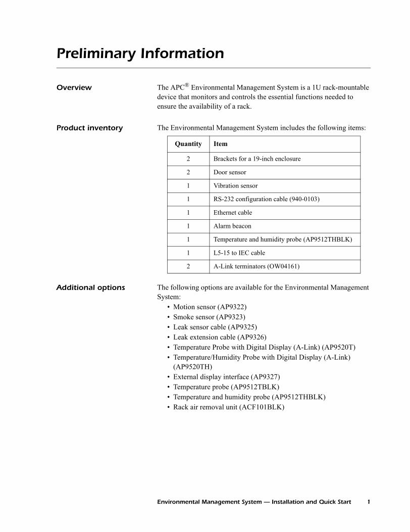
Product inventory The Environmental Management System includes the following items:
Additional options The following options are available for the Environmental Management System:
• Motion sensor (AP9322)• Smoke sensor (AP9323)• Leak sensor cable (AP9325)• Leak extension cable (AP9326)• Temperature Probe with Digital Display (A-Link) (AP9520T)• Temperature/Humidity Probe with Digital Display (A-Link)
(AP9520TH)• External display interface (AP9327)• Temperature probe (AP9512TBLK)• Temperature and humidity probe (AP9512THBLK)• Rack air removal unit (ACF101BLK)
Quantity Item
2 Brackets for a 19-inch enclosure
2 Door sensor
1 Vibration sensor
1 RS-232 configuration cable (940-0103)
1 Ethernet cable
1 Alarm beacon
1 Temperature and humidity probe (AP9512THBLK)
1 L5-15 to IEC cable
2 A-Link terminators (OW04161)
Environmental Management System — Installation and Quick Start 1
Preliminary Information
Additional documentation
The Environmental Management System User’s Guide is available on the supplied CD or on the APC Web site: www.apc.com.
The online user’s guide (.\doc\en\usrguide.pdf) contains additional information about the following topics related to the Environmental Management System:
• Management interfaces• User accounts• Customizing setup• Security• The Device IP Configuration Wizard• Configuration utilities• File transfers
Receiving inspection Inspect the package and contents for shipping damage, and make sure that all parts were sent. Report any damage immediately to the shipping agent, and report missing contents, damage, or other problems immediately to APC or your APC reseller.
Please recycle
InfraStruXure-certified This product is certified for use in APC InfraStruXure systems. If you have InfraStruXure Manager as part of your system, the Quick Configuration instructions in this document do not apply. See instead the InfraStruXure Manager’s documentation for more information.
The shipping materials are recyclable. Please save them for later use, or dispose of them appropriately.
2 Environmental Management System — Installation and Quick Start
Overview
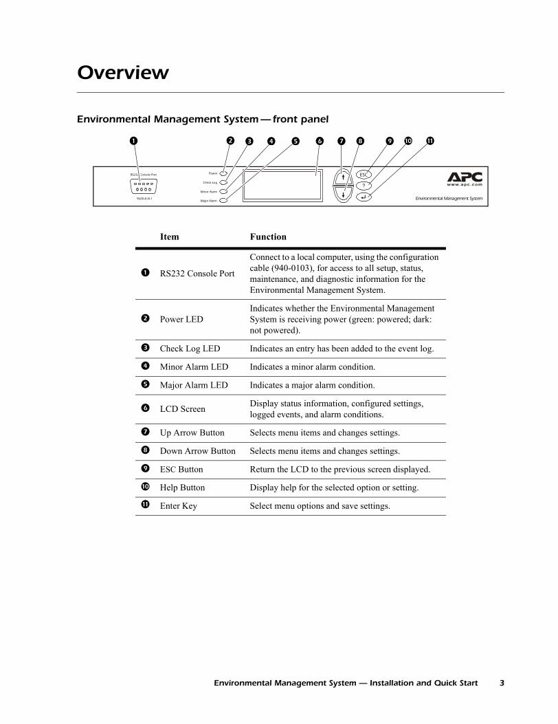
Environmental Management System — front panel
Power
Check Log
Major Alarm
Minor Alarm
ESC
?
RS232 Console Port
9600-8-N-1 Environmental Management System
Item Function
RS232 Console Port
Connect to a local computer, using the configuration cable (940-0103), for access to all setup, status, maintenance, and diagnostic information for the Environmental Management System.
Power LEDIndicates whether the Environmental Management System is receiving power (green: powered; dark: not powered).
Check Log LED Indicates an entry has been added to the event log.
Minor Alarm LED Indicates a minor alarm condition.
Major Alarm LED Indicates a major alarm condition.
LCD Screen Display status information, configured settings, logged events, and alarm conditions.
Up Arrow Button Selects menu items and changes settings.
Down Arrow Button Selects menu items and changes settings.
ESC Button Return the LCD to the previous screen displayed.
Help Button Display help for the selected option or setting.
Enter Key Select menu options and save settings.
Environmental Management System — Installation and Quick Start 3
Overview
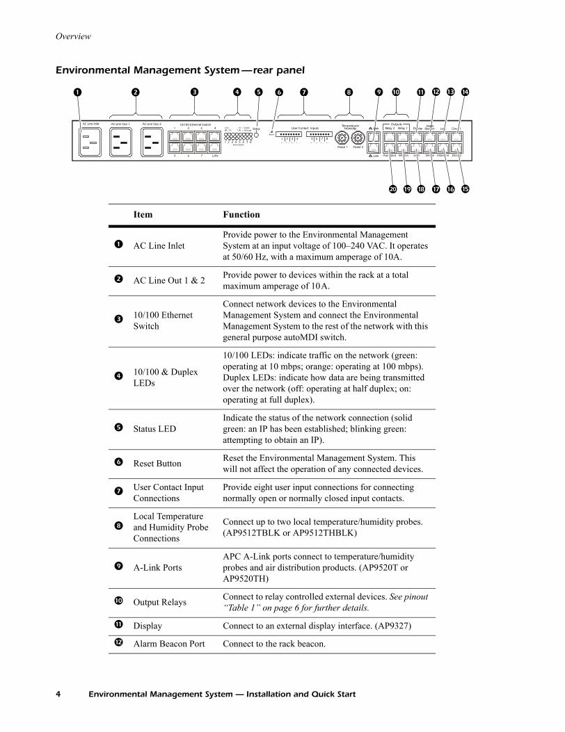
Environmental Management System —rear panel
Door 1
Door 2
Lock
Vibration
Beacon
SmokeLeak
DisplayRelay 1Outputs
Motion
Relay 2
Aux Input
Probe 2Probe 1
Temperature/HumidityUser Contact Inputs
1 2 3 4 5 6 7 8
–+–+–+–+–+–+–+–+1 2 3 4 5 6 7 8
Reset
Status100 = Orange
Full Duplex
10/100 Ethernet SwitchAC Line Out 2AC Line Out 1AC Line Inlet
1 2 3 4
5 6 7 LAN
-Link
-Link
10 = G reenLinkRX / TX
Alarm
Item Function
AC Line InletProvide power to the Environmental Management System at an input voltage of 100–240 VAC. It operates at 50/60 Hz, with a maximum amperage of 10A.
AC Line Out 1 & 2 Provide power to devices within the rack at a total maximum amperage of 10A.
10/100 Ethernet Switch
Connect network devices to the Environmental Management System and connect the Environmental Management System to the rest of the network with this general purpose autoMDI switch.
10/100 & Duplex LEDs
10/100 LEDs: indicate traffic on the network (green: operating at 10 mbps; orange: operating at 100 mbps). Duplex LEDs: indicate how data are being transmitted over the network (off: operating at half duplex; on: operating at full duplex).
Status LEDIndicate the status of the network connection (solid green: an IP has been established; blinking green: attempting to obtain an IP).
Reset Button Reset the Environmental Management System. This will not affect the operation of any connected devices.
User Contact Input Connections
Provide eight user input connections for connecting normally open or normally closed input contacts.
Local Temperature and Humidity Probe Connections
Connect up to two local temperature/humidity probes. (AP9512TBLK or AP9512THBLK)
A-Link PortsAPC A-Link ports connect to temperature/humidity probes and air distribution products. (AP9520T or AP9520TH)
Output Relays Connect to relay controlled external devices. See pinout “Table 1” on page 6 for further details.
Display Connect to an external display interface. (AP9327)
Alarm Beacon Port Connect to the rack beacon.
4 Environmental Management System — Installation and Quick Start
Overview
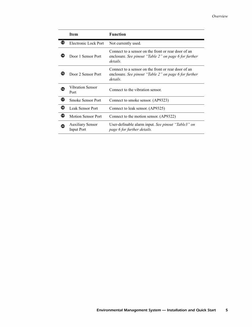
Electronic Lock Port Not currently used.
Door 1 Sensor PortConnect to a sensor on the front or rear door of an enclosure. See pinout “Table 2” on page 6 for further details.
Door 2 Sensor PortConnect to a sensor on the front or rear door of an enclosure. See pinout “Table 2” on page 6 for further details.
Vibration Sensor Port Connect to the vibration sensor.
Smoke Sensor Port Connect to smoke sensor. (AP9323)
Leak Sensor Port Connect to leak sensor. (AP9325)
Motion Sensor Port Connect to the motion sensor. (AP9322)
Auxiliary Sensor Input Port
User-definable alarm input. See pinout “Table3” on page 6 for further details.
Item Function
Environmental Management System — Installation and Quick Start 5
Overview
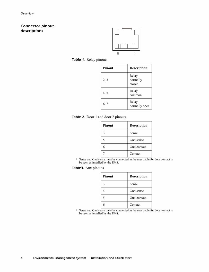
Connector pinout descriptions
Table 1. Relay pinouts
Table 2. Door 1 and door 2 pinouts
† Sense and Gnd sense must be connected in the user cable for door contact to be seen as installed by the EMS.
Table3. Aux pinouts
† Sense and Gnd sense must be connected in the user cable for door contact to be seen as installed by the EMS.
Pinout Description
2, 3Relay normally closed
4, 5 Relay common
6, 7 Relay normally open
Pinout Description
3 Sense
5 Gnd sense
6 Gnd contact
7 Contact
Pinout Description
3 Sense
4 Gnd sense
5 Gnd contact
6 Contact
8 1
6 Environmental Management System — Installation and Quick Start

Install the Environmental Management System
Installation guidelines • If the Environmental Management System is installed in an enclosed communications rack, the recommended maximum ambient temperature should be no greater than 45° C.
• Install the Environmental Management System and the included sensors so that the amount of air flow required for safe operation of the equipment is not compromised.
• Install the Environmental Management System and the included sensors so that there is not an uneven mechanical load.
• Follow the nameplate ratings when connecting equipment to the supply circuit. Consider the effect that overloading the circuits might have on over-current protection and supply wiring.
• Maintain reliable earth grounding of the Environmental Management System. Give particular consideration to supply-connections that do not directly connect to the branch circuit.
Installation methods Install the Environmental Management System using either the rubber feet or the brackets for a 19-inch enclosure or rack. Install it so that the power plug may be disconnected for service.
Install using the rubber feet.
1. Attach the rubber feet (provided) to the bottom of the Environmental Management System, placing one in each corner.
2. Place the Environmental Management System on an even surface, where it will be accessible for connection procedures.
Install in a NetShelter enclosure or rack. To install the Environmental Management System in a NetShelter® enclosure:
1. Attach the brackets (provided) to the Environmental Management System, using four screws.
Environmental Management System — Installation and Quick Start 7
Install the Environmental Management System
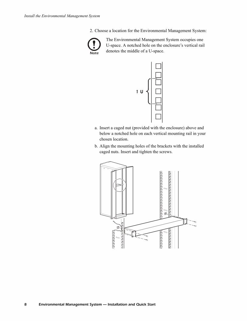
2. Choose a location for the Environmental Management System:
a. Insert a caged nut (provided with the enclosure) above and below a notched hole on each vertical mounting rail in your chosen location.
b. Align the mounting holes of the brackets with the installed caged nuts. Insert and tighten the screws.
Note
The Environmental Management System occupies one U-space. A notched hole on the enclosure’s vertical rail denotes the middle of a U-space.
1 U
8 Environmental Management System — Installation and Quick Start
A-Link Connection
The Environmental Management System can link to a variety of A-Link compatible devices, including temperature and humidity probes and Rack Air Removal Units (ARU). The Environmental Management System can support a maximum of eight A-Link Temperature and Humidity probes and eight A-Link ARUs.
Connection guidelines When connecting devices to the Environmental Management System in a cascading configuration, follow these guidelines:
• The total length of all cables used should not exceed 100 meters. • The connection must include two APC terminators, connected to
the unused A-Link port on each device at the end of the connection.
• Use CAT5 (or equivalent) cables for linking devices. Do not use a crossover cable for connection.
DIP switch addresses To connect to A-Link compatible devices, set the DIP switch addresses on the individually monitored devices. Refer to the user’s manual included with the individual products for specific configuration information. However, here are some general address guidelines:
• Two identical devices cannot share the same address. For example, if you are connecting two Temperature/Humidity Probes, assign each probe a different address.
• Two different devices can share the same address. For example, you can assign address #1 to a Temperature/Humidity Probe and an ARU.
Note
A-Link is an APC proprietary CAN (Controller Area Network) bus. A-Link compatible devices are not Ethernet devices and cannot coexist on an Ethernet bus with other networking devices, such as hubs and switches.
Caution
When you apply power, the Environmental Management System will not exceed 500 milliamps for more than one second.
The total device current draw during normal operation of the Environmental Management System will not exceed 400 milliamps.
Environmental Management System — Installation and Quick Start 9
A-Link Connection
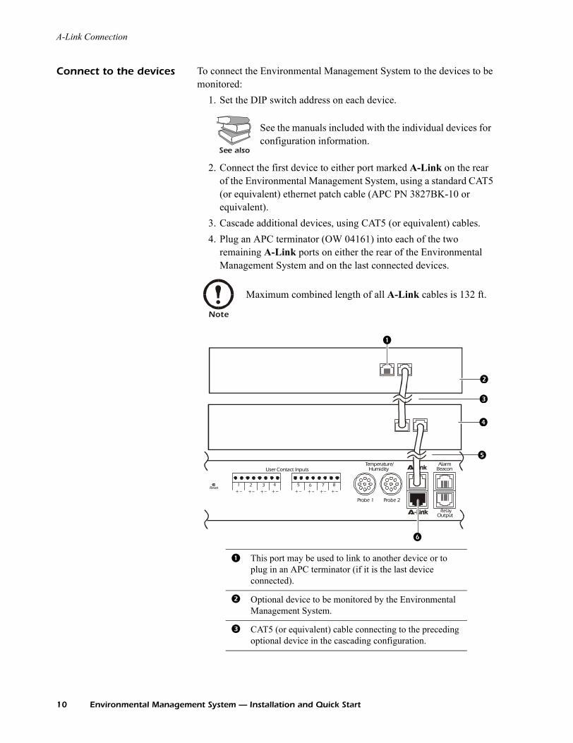
Connect to the devices To connect the Environmental Management System to the devices to be monitored:
1. Set the DIP switch address on each device.
2. Connect the first device to either port marked A-Link on the rear of the Environmental Management System, using a standard CAT5 (or equivalent) ethernet patch cable (APC PN 3827BK-10 or equivalent).
3. Cascade additional devices, using CAT5 (or equivalent) cables.4. Plug an APC terminator (OW 04161) into each of the two
remaining A-Link ports on either the rear of the Environmental Management System and on the last connected devices.
See also
See the manuals included with the individual devices for configuration information.
Note
Maximum combined length of all A-Link cables is 132 ft.
This port may be used to link to another device or to plug in an APC terminator (if it is the last device connected).
Optional device to be monitored by the Environmental Management System.
CAT5 (or equivalent) cable connecting to the preceding optional device in the cascading configuration.
Alarm
Beacon
Output
Probe 2Probe 1
Temperature/HumidityUser Contact Inputs
51 62 73 84
–– ++ –– ++ –– ++ –– ++Reset
10 Environmental Management System — Installation and Quick Start

A-Link Connection
Optional device to be monitored by the Environmental Management System.
CAT5 (or equivalent) cable connecting to the Environmental Management System.
This port may be used to link to another device or to plug in an APC terminator.
Environmental Management System — Installation and Quick Start 11
Accessories
Temperature and humidity probe
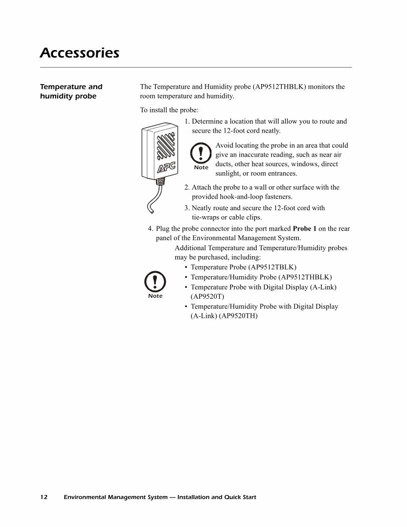
The Temperature and Humidity probe (AP9512THBLK) monitors the room temperature and humidity.
To install the probe:1. Determine a location that will allow you to route and
secure the 12-foot cord neatly..
2. Attach the probe to a wall or other surface with the provided hook-and-loop fasteners.
3. Neatly route and secure the 12-foot cord with tie-wraps or cable clips.
4. Plug the probe connector into the port marked Probe 1 on the rear panel of the Environmental Management System.
Note
Avoid locating the probe in an area that could give an inaccurate reading, such as near air ducts, other heat sources, windows, direct sunlight, or room entrances.
Note
Additional Temperature and Temperature/Humidity probes may be purchased, including:
• Temperature Probe (AP9512TBLK)• Temperature/Humidity Probe (AP9512THBLK)• Temperature Probe with Digital Display (A-Link)
(AP9520T)• Temperature/Humidity Probe with Digital Display
(A-Link) (AP9520TH)
12 Environmental Management System — Installation and Quick Start
Accessories
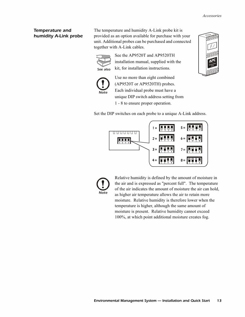
Temperature and humidity A-Link probe
The temperature and humidity A-Link probe kit is provided as an option available for purchase with your unit. Additional probes can be purchased and connected together with A-Link cables.
Set the DIP switches on each probe to a unique A-Link address.
See also
See the AP9520T and AP9520TH installation manual, supplied with the kit, for installation instructions.
Note
Use no more than eight combined (AP9520T or AP9520TH) probes. Each individual probe must have a unique DIP switch address setting from 1 - 8 to ensure proper operation.
Note
Relative humidity is defined by the amount of moisture in the air and is expressed as "percent full". The temperature of the air indicates the amount of moisture the air can hold, as higher air temperature allows the air to retain more moisture. Relative humidity is therefore lower when the temperature is higher, although the same amount of moisture is present. Relative humidity cannot exceed 100%, at which point additional moisture creates fog.
1 2 3 4
1=
2=
1 2 3 4
1 2 3 4
3=
1 2 3 4
1 2 3 4
4=
1 2 3 4
5=
1 2 3 4
1 2 3 4
1 2 3 4
6=
7=
8=
Environmental Management System — Installation and Quick Start 13
Accessories
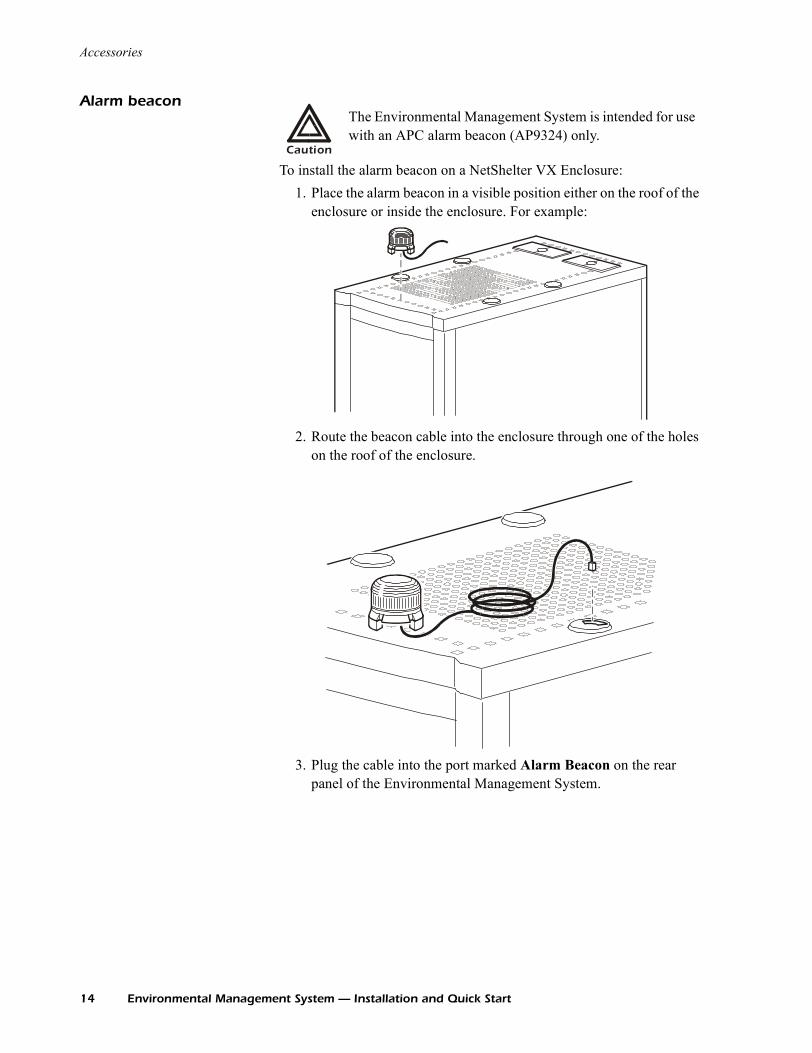
Alarm beacon
To install the alarm beacon on a NetShelter VX Enclosure:1. Place the alarm beacon in a visible position either on the roof of the
enclosure or inside the enclosure. For example:
2. Route the beacon cable into the enclosure through one of the holes on the roof of the enclosure.
3. Plug the cable into the port marked Alarm Beacon on the rear panel of the Environmental Management System.
Caution
The Environmental Management System is intended for use with an APC alarm beacon (AP9324) only.
14 Environmental Management System — Installation and Quick Start
Accessories
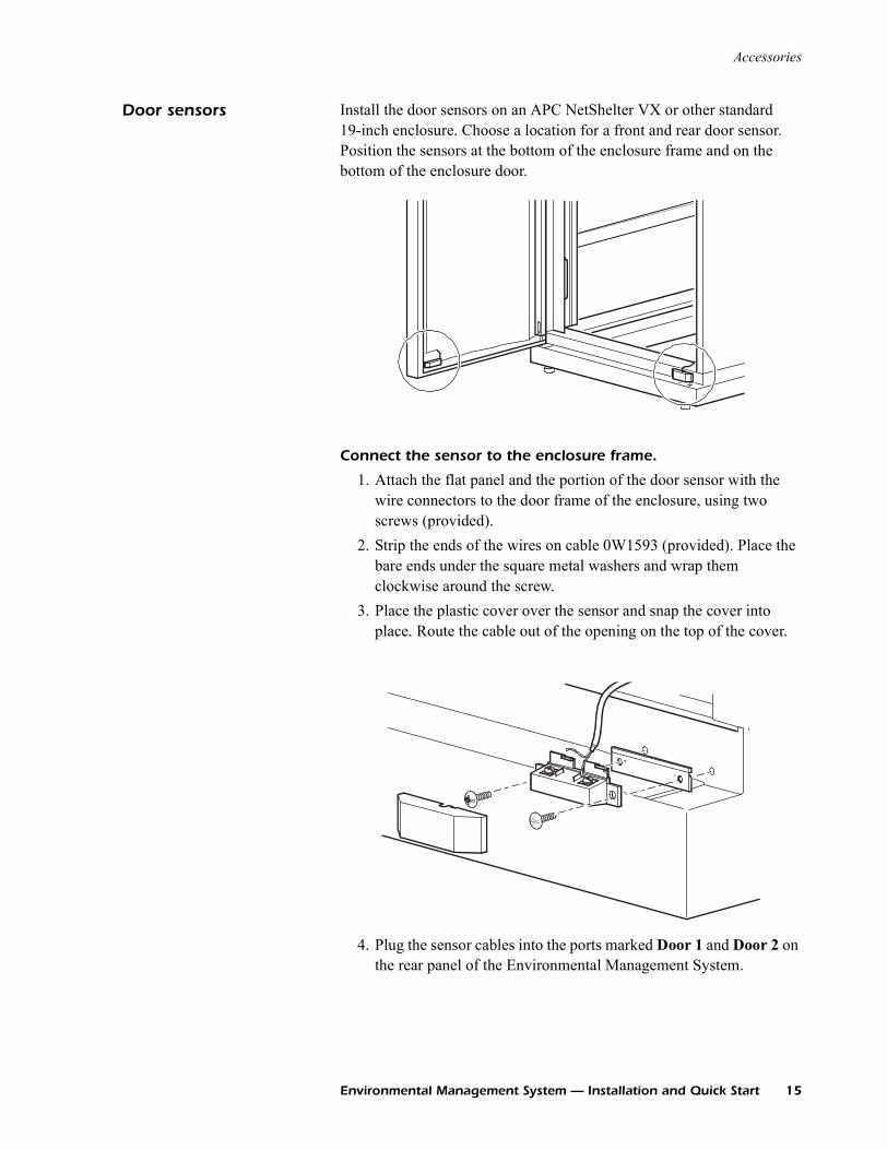
Door sensors Install the door sensors on an APC NetShelter VX or other standard 19-inch enclosure. Choose a location for a front and rear door sensor. Position the sensors at the bottom of the enclosure frame and on the bottom of the enclosure door.
Connect the sensor to the enclosure frame.
1. Attach the flat panel and the portion of the door sensor with the wire connectors to the door frame of the enclosure, using two screws (provided).
2. Strip the ends of the wires on cable 0W1593 (provided). Place the bare ends under the square metal washers and wrap them clockwise around the screw.
3. Place the plastic cover over the sensor and snap the cover into place. Route the cable out of the opening on the top of the cover.
4. Plug the sensor cables into the ports marked Door 1 and Door 2 on the rear panel of the Environmental Management System.
Environmental Management System — Installation and Quick Start 15
Accessories
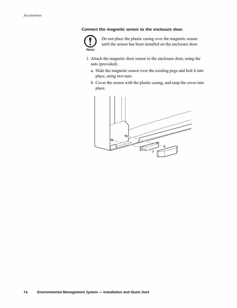
Connect the magnetic sensor to the enclosure door.
1. Attach the magnetic door sensor to the enclosure door, using the nuts (provided).a. Slide the magnetic sensor over the existing pegs and bolt it into
place, using two nuts.b. Cover the sensor with the plastic casing, and snap the cover into
place.
Note
Do not place the plastic casing over the magnetic sensor until the sensor has been installed on the enclosure door.
16 Environmental Management System — Installation and Quick Start
Accessories
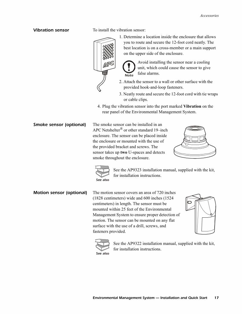
Vibration sensor To install the vibration sensor:1. Determine a location inside the enclosure that allows
you to route and secure the 12-foot cord neatly. The best location is on a cross-member or a main support on the upper side of the enclosure.
.
2. Attach the sensor to a wall or other surface with the provided hook-and-loop fasteners.
3. Neatly route and secure the 12-foot cord with tie wraps or cable clips.
4. Plug the vibration sensor into the port marked Vibration on the rear panel of the Environmental Management System.
Smoke sensor (optional) The smoke sensor can be installed in an APC Netshelter® or other standard 19–inch enclosure. The sensor can be placed inside the enclosure or mounted with the use of the provided bracket and screws. The sensor takes up two U-spaces and detects smoke throughout the enclosure.
Motion sensor (optional) The motion sensor covers an area of 720 inches (1828 centimeters) wide and 600 inches (1524 centimeters) in length. The sensor must be mounted within 25 feet of the Environmental Management System to ensure proper detection of motion. The sensor can be mounted on any flat surface with the use of a drill, screws, and fasteners provided.
Note
Avoid installing the sensor near a cooling unit, which could cause the sensor to give false alarms.
See also
See the AP9323 installation manual, supplied with the kit, for installation instructions.
See also
See the AP9322 installation manual, supplied with the kit, for installation instructions.
Environmental Management System — Installation and Quick Start 17
Accessories
Leak sensor cable and leak extension cable (optional)
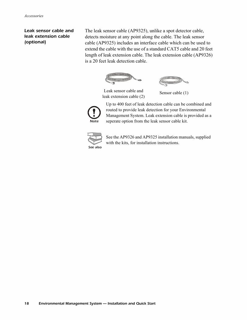
The leak sensor cable (AP9325), unlike a spot detector cable, detects moisture at any point along the cable. The leak sensor cable (AP9325) includes an interface cable which can be used to extend the cable with the use of a standard CAT5 cable and 20 feet length of leak extension cable. The leak extension cable (AP9326) is a 20 feet leak detection cable.
Leak sensor cable and leak extension cable (2)
Sensor cable (1)
Note
Up to 400 feet of leak detection cable can be combined and routed to provide leak detection for your Environmental Management System. Leak extension cable is provided as a seperate option from the leak sensor cable kit.
See also
See the AP9326 and AP9325 installation manuals, supplied with the kits, for installation instructions.
18 Environmental Management System — Installation and Quick Start
Alarm Overview
Alarm messages An audible alarm sounds when there is a hardware problem with the Environmental Management System. The problem could be caused by an improper A-Link or sensor connection, or by damaged hardware.
A-Link Alarms The audible alarm is accompanied by the following messages:
The A-Link messages indicate one of the following problems:• An improper A-Link connector in one of the A-Link ports• Too much equipment connected to one of the A-Link ports• An internal A-Link hardware problem
Sensor hardware alarms The audible alarm is accompanied by the following messages:
The sensor hardware messages indicate one of the following problems:• An improper connector in one of the sensor ports• An internal sensor port hardware problem
A-Link Interface Message
Control Console or Web (front status display)
ALINK
Event Log Alink Power Overload
Powerview (status display) ALINK:Curr Lim Alarm
Sensor Interface Message
Control Console or Web (front status display)
SenHdw
Event Log Sensor Connection Error
Powerview (status display) Hdw Err
Environmental Management System — Installation and Quick Start 19
Alarm Overview
Clearing the hardware alarms
To clear an A-Link or sensor alarm, disconnect the appropriate connectors to the Environmental Management System.
If the alarm stops, reconnect the devices one at a time to determine what caused the alarm condition.
If everything is properly connected and the alarm persists, contact APC Worldwide Customer Support.
If the alarm sounds and nothing is plugged into either the A-Link or sensor ports, turn off the Environmental Management System and return the unit to APC.
For information on sensor and A-Link connections, see “Accessories” on page 12.
20 Environmental Management System — Installation and Quick Start
Quick Configuration
Overview You must configure the following TCP/IP settings before the Environmental Management System can operate on a network:
• IP address of the Environmental Management System• Subnet mask• Default gateway
TCP/IP configuration methods
Use one of the following methods to define the TCP/IP settings needed by the Environmental Management System:
• Device IP Configuration Wizard (See “Device IP Configuration Wizard” on page 22.)
• BOOTP or DHCP server (See “BOOTP & DHCP configuration” on page 22.)
• Local computer (See “Local access to the control console” on page 25.)
• Networked computer (See “Remote access to the control console” on page 25.)
• Network setup using display interface (See “Network setup from the display interface” on page 30.)
Warning
Disregard the procedures in this section if you have APC InfraStruXure Manager as part of your system. See the InfraStruXure Manager’s documentation for more information.
Note
If a default gateway is unavailable, use the IP address of a computer that is located on the same subnet as the Environmental Management System and that is usually running. The Environmental Management System uses the default gateway to test the network when traffic is very light. See “Watchdog Features” in the “Introduction” of the Environmental Management System User’s Guide for more information about the watchdog role of the default gateway.
Environmental Management System — Installation and Quick Start 21
Quick Configuration
Device IP Configuration Wizard
You can use the Device IP Configuration Wizard on a Windows NT® 4.0, Windows 2000, or Windows XP computer to discover unconfigured Environmental Management Systems and configure their basic TCP/IP settings.
1. Insert the Environmental Management System Utility CD into a computer on your network.
2. Launch the Wizard, when prompted, or, if prompted to restart the computer, access the Wizard from the Start menu after the computer has restarted.
3. Wait for the Wizard to discover the first unconfigured Environmental Management System, then follow the on-screen instructions.
BOOTP & DHCP configuration
The Boot Mode Setting, a TCP/IP option in the Environmental Management System’s Network menu, identifies how the TCP/IP settings will be defined. The possible settings are Manual, DHCP only, BOOTP only, and DHCP & BOOTP (the default setting).
With Boot Mode set to DHCP & BOOTP, the Environmental Management System attempts to discover a properly configured server. It first searches for a BOOTP server, then a DHCP server, and repeats this pattern until it discovers a BOOTP or DHCP server.
See also
To configure one or more Environmental Management Systems, by exporting configuration settings from a configured Environmental System, see “How to Export Configuration Settings” in the User’s Guide on the Utility CD.
Note
If you leave the Start a Web browser when finished option enabled, you can use apc for both the User Name and Password to access the Environmental Management System through your browser.
Note
The DHCP & BOOTP setting assumes that a properly configured DHCP or BOOTP server is available to provide TCP/IP settings to Environmental Management Systems. If these servers are unavailable, see “Device IP Configuration Wizard” on this page, “Local access to the control console” on page 25, or “Remote access to the control console” on page 25 to configure the needed TCP/IP settings.
Note
For more information, see “BOOTP” on page 23 or “DHCP” on page 24.
22 Environmental Management System — Installation and Quick Start
Quick Configuration
BOOTP. You can use an RFC951-compliant BOOTP server to configure the TCP/IP settings for the Environmental Management System.
1. Make sure that the BOOTP setting, a TCP/IP option in the Environmental Management System’s Network menu, is enabled.
2. Enter the Environmental Management System’s MAC and IP addresses, the subnet mask and default gateway settings, and an optional Bootup file name in the BOOTPTAB file of the BOOTP server.
3. When the Environmental Management System reboots, the BOOTP server provides it with the TCP/IP settings. – If you specified a bootup file name, the Environmental
Management System attempts to transfer that file from the BOOTP server using TFTP or FTP. The Environmental Management System assumes all settings specified in the bootup file.
– If you did not specify a bootup file name, the Environmental Management System can be configured remotely by using Telnet or by using the Web interface: User Name and Password are both apc, by default.
Note
The BOOTP setting assumes that a properly configured BOOTP server is available to provide TCP/IP settings to APC Environmental Management Systems. If a BOOTP server is unavailable, see “Device IP Configuration Wizard” on page 22, “Local access to the control console” on page 25, or “Remote access to the control console” on page 25 to configure the TCP/IP settings.
See also
For the MAC address, look on the bottom of the Environmental Management System or on the Quality Assurance slip included in the package.
See also
To create the bootup file, see your BOOTP server documentation.
Environmental Management System — Installation and Quick Start 23
Quick Configuration
DHCP. You can use a RFC2131/RFC2132-compliant DHCP server to configure the TCP/IP settings for the Environmental Management System.
1. An Environmental Management System sends out a DHCP request that uses the following to identify itself:– A Vendor Class Identifier (APC by default)– A Client Identifier (by default, the Environmental Management
System’s MAC address value)– A User Class Identifier (by default, the identification of the
Environmental Management System’s application firmware)2. A properly configured DHCP server responds with a DHCP offer
that includes all of the settings that the Environmental Management System needs for network communication. The DHCP offer also includes the Vendor Specific Information option (DHCP option 43). By default, the Environmental Management System will ignore DHCP offers that do not encapsulate the APC cookie in the Vendor Specific Information option using the following hexidecimal format:Option 43 = 01 04 31 41 50 43
where – the first byte (01) is the code– the second byte (04) is the length– the remaining bytes (31 41 50 43) are the APC cookies
See also
This section briefly summarizes the Environmental Management System communication with a DHCP server. For more detail about how a DHCP server is used to configure the network settings for a Environmental Management System, see “DHCP Configuration” in the Environmental Management System Users’ Guide.
See your DHCP server documentation to add code to the Vendor Specific Information option. To disable the APC cookie requirement, see “Local access to the control console” on page 25.To change the control console’s DHCP Cookie Is setting, use the Advanced option in the TCP/IP menu. See “Remote access to the control console” on page 25.
24 Environmental Management System — Installation and Quick Start

Quick Configuration
Local access to the control console
You can use a local computer that connects to the Environmental Management System through the serial port on the front of the Environmental Management System to access the control console.
1. Select a serial port at the local computer, and disable any service that uses that port.
2. Use the configuration cable (940-0103) to connect the selected port to the serial port on the front panel of the Environmental Management System.
3. Run a terminal program (such as HyperTerminal) on your computer and configure the selected port for 9600 bps, 8 data bits, no parity, 1 stop bit, and no flow control, and save the changes.
4. Press ENTER to display the User Name prompt.5. Use apc for the User Name and Password.6. See “Control console” on page 26 to finish the configuration.
Remote access to the control console
From any computer on the same subnet as the Environmental Management System, you can use ARP and Ping to assign an IP address to a Environmental Management System, and then use Telnet to access that Environmental Management System’s control console and configure the needed TCP/IP settings.
1. Use ARP to define an IP address for the Environmental Management System, and use the Environmental Management System’s MAC address in the ARP command. For example, to define an IP address of 156.205.14.141 for a Environmental Management System that has a MAC address of 00 c0 b7 63 9f 67, use one of the following commands:– Windows command format:
arp -s 156.205.14.141 00-c0-b7-63-9f-67
– LINUX command format:arp -s 156.205.14.141 00:c0:b7:63:9f:67
Note
Modbus and the control console share a common serial port. You can use either one or the other, one at a time, to access the Environmental Management System.
Note
Modbus runs at 9600 or 19200 bps. To use the control console when Modbus is enabled, your computer’s serial port must communicate at the same serial protocol rate as Modbus.
Note
After a Environmental Management System has its IP address configured, you can use Telnet, without first using ARP and Ping, to access that Environmental Management System.
Environmental Management System — Installation and Quick Start 25
Quick Configuration
2. Use Ping with a size of 113 bytes to assign the IP address defined by the ARP command. For the IP address defined in step 1, use one of the following Ping commands: – Windows command format:
ping 156.205.14.141 -l 113
– LINUX command format:ping 156.205.14.141 -s 113
3. Use Telnet to access the Environmental Management System at its newly assigned IP address. For example:telnet 156.205.14.141
4. Use apc for both User Name and Password.5. See “Control console” on this page to finish the configuration.
Control console After you log on at the control console, as described in “Local access to the control console” on page 25 or “Remote access to the control console” on page 25:
1. Choose Network from the Control Console menu.2. Choose TCP/IP from the Network menu.3. If you are not using a BOOTP or DHCP server to configure the
TCP/IP settings, select the Boot Mode menu. Select Manual boot mode, and then press ESC to return to the TCP/IP menu. (Changes will take effect when you log out.)
4. Set the System IP, Subnet Mask, and Default Gateway address values.
5. Press CTRL-C to exit to the Control Console menu.6. Log out (option 4 in the Control Console menu).
Display interface See “Using the Display” on page 27 to map alarms, change settings, and navigate the Environmental Management System using the display interface.
See also
For the MAC address, look on the bottom of the Environmental Management System or on the Quality Assurance slip included in the package.
Note
If you disconnected a cable during the procedure described in “Local access to the control console” on page 25, reconnect that cable and restart the associated service.
26 Environmental Management System — Installation and Quick Start
Using the Display
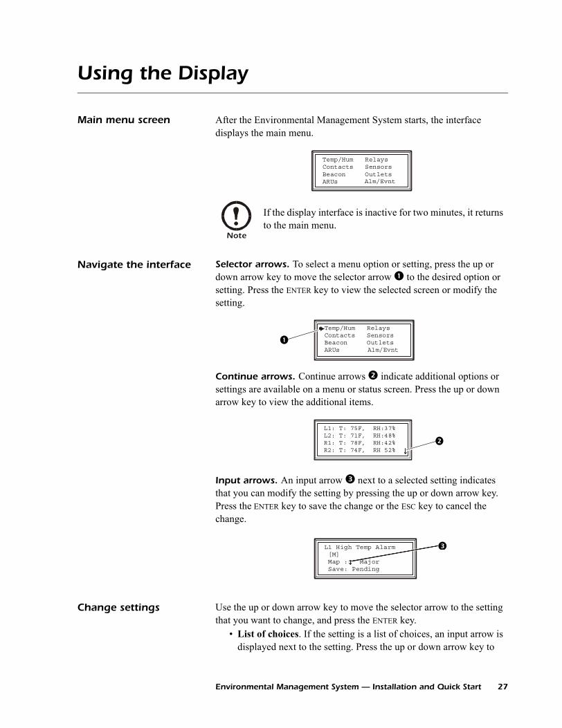
Main menu screen After the Environmental Management System starts, the interface displays the main menu.
Navigate the interface Selector arrows. To select a menu option or setting, press the up or down arrow key to move the selector arrow to the desired option or setting. Press the ENTER key to view the selected screen or modify the setting.
Continue arrows. Continue arrows indicate additional options or settings are available on a menu or status screen. Press the up or down arrow key to view the additional items.
Input arrows. An input arrow next to a selected setting indicates that you can modify the setting by pressing the up or down arrow key. Press the ENTER key to save the change or the ESC key to cancel the change.
Change settings Use the up or down arrow key to move the selector arrow to the setting that you want to change, and press the ENTER key.
• List of choices. If the setting is a list of choices, an input arrow is displayed next to the setting. Press the up or down arrow key to
Note
If the display interface is inactive for two minutes, it returns to the main menu.
Temp/Hum RelaysContacts SensorsBeacon OutletsARUs Alm/Evnt
Temp/Hum RelaysContacts SensorsBeacon OutletsARUs Alm/Evnt
L1: T: 75F, RH:37%L2: T: 71F, RH:48%R1: T: 78F, RH:42%R2: T: 74F, RH 52%
L1 High Temp Alarm [M] Map : Major Save: Pending
Environmental Management System — Installation and Quick Start 27
Using the Display
select the choice you want, and then press the ENTER key to exit the input mode and save the setting. (Press the ESC key to exit without saving.)
• Numbers or text fields. If the setting is a number or text field, use the arrow keys to select the value of the first character, and press the ENTER key to move to the next. Press the ENTER key after the last character is set to exit the input mode and save the setting. (Press the ESC key to exit without saving.)
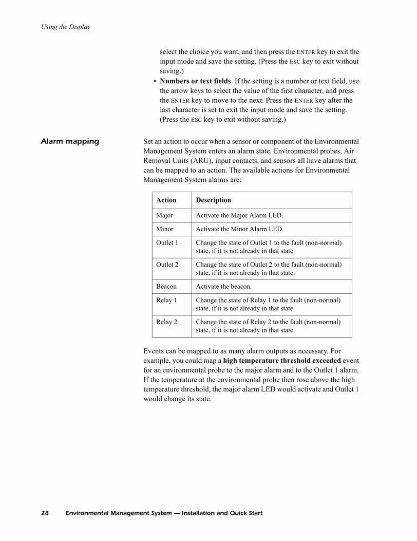
Alarm mapping Set an action to occur when a sensor or component of the Environmental Management System enters an alarm state. Environmental probes, Air Removal Units (ARU), input contacts, and sensors all have alarms that can be mapped to an action. The available actions for Environmental Management System alarms are:
Events can be mapped to as many alarm outputs as necessary. For example, you could map a high temperature threshold exceeded event for an environmental probe to the major alarm and to the Outlet 1 alarm. If the temperature at the environmental probe then rose above the high temperature threshold, the major alarm LED would activate and Outlet 1 would change its state.
Action Description
Major Activate the Major Alarm LED.
Minor Activate the Minor Alarm LED.
Outlet 1 Change the state of Outlet 1 to the fault (non-normal) state, if it is not already in that state.
Outlet 2 Change the state of Outlet 2 to the fault (non-normal) state, if it is not already in that state.
Beacon Activate the beacon.
Relay 1 Change the state of Relay 1 to the fault (non-normal) state, if it is not already in that state.
Relay 2 Change the state of Relay 2 to the fault (non-normal) state, if it is not already in that state.
28 Environmental Management System — Installation and Quick Start

Using the Display
Alarm mapping screen The alarm mapping screen is displayed under the alarm map options of the Temp/Hum, Contacts, ARUs, and Sensors screens.
The first line of the screen displays the event to be mapped to alarm outputs. In the preceding screen, it is the high temperature alarm from the local temperature and humidity probe (L1).
The second line displays the alarm outputs to which this event is mapped. The following table explains the abbreviations.
Map. Select an option from the Map list. Press the ENTER key to add an option to the list on line 2. An x will appear next to each selected option in the list.
Save. When you change the mapping of an alarm output select the Save option and press the ENTER key to save the changes.
Alarm Output Code Description
M Major Alarm
m Minor Alarm
O1 Outlet 1
O2 Outlet 2
R1 Relay 1
R2 Relay 2
See also
For more information on configuring the Environmental Management System, see the user’s guide on the Environmental Management System Utility CD.
L1 High Temp Alarm [None] Map: Major Save:
L1 High Temp Alarm [M] Map : x Major Save: Pending
Environmental Management System — Installation and Quick Start 29
Using the Display
30 Environmental Management System — Installation and Quick Start
Network setup from the display interface
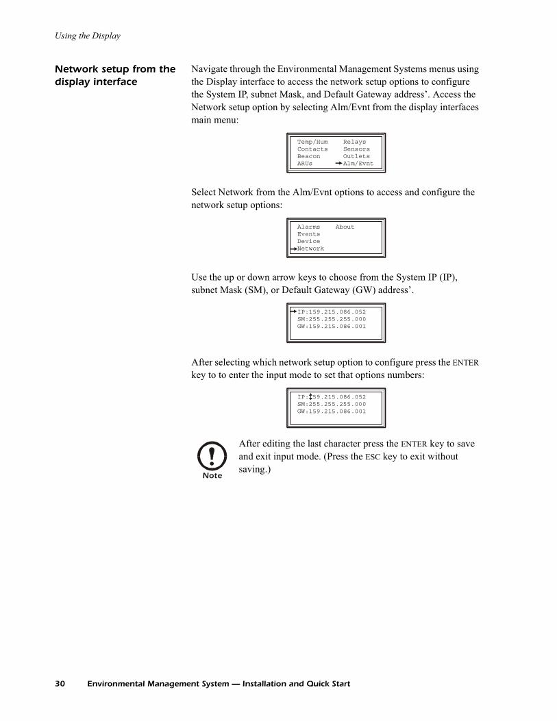
Navigate through the Environmental Management Systems menus using the Display interface to access the network setup options to configure the System IP, subnet Mask, and Default Gateway address’. Access the Network setup option by selecting Alm/Evnt from the display interfaces main menu:
Select Network from the Alm/Evnt options to access and configure the network setup options:
Use the up or down arrow keys to choose from the System IP (IP), subnet Mask (SM), or Default Gateway (GW) address’.
After selecting which network setup option to configure press the ENTER key to to enter the input mode to set that options numbers:
Note
After editing the last character press the ENTER key to save and exit input mode. (Press the ESC key to exit without saving.)
Temp/Hum RelaysContacts SensorsBeacon OutletsARUs Alm/Evnt
Alarms AboutEvents Device Network
IP:159.215.086.052 SM:255.255.255.000 GW:159.215.086.001
IP:159.215.086.052 SM: GW:159.215.086.001
255.255.255.000
How to Access a Configured Unit
Overview After the Environmental Monitoring Unit is running on your network, you can use the interfaces summarized here to access the unit.
Web interface As your browser, you can use Microsoft® Internet Explorer 5.0 (and higher) or Netscape® 4.0.8 (and higher, except Netscape 6.x) to access the Management Card through its Web interface. Other commonly available browsers also may work but have not been fully tested by APC.
To use the Web browser to configure and monitor Environmental Monitoring Unit options or to view the event log, you can use either of the following:
• The HTTP protocol (enabled by default), which provides authentication by user name and password but no encryption.
• The more secure HTTPS protocol, which provides extra security through Secure Socket Layer (SSL) and encrypts user names, passwords, and data being transmitted. It also provides authentication of Network Management Cards by means of digital certificates.
To access the Web interface and configure the security of your device on the network:
1. Address the Environmental Monitoring Unit by its IP address or DNS name (if configured).
2. Enter the user name and password (by default, apc and apc for an Administrator, or device and apc for a Device Manager).
3. Select and configure the type of security you want. (This option is available only for Administrators.)
See also
For more information on the interfaces, see the User’s Guide.
See also
See the chapter entitled “Security” in the User’s Guide for information on choosing and setting up your network security. Use the Web/SSL option of the Network menu to enable or disable the HTTP or HTTPS protocols.
Environmental Management System — Installation and Quick Start 31
How to Access a Configured Unit
Telnet and SSH You can access the control console through Telnet or Secure SHell (SSH), depending on which is enabled. (An Administrator can enable these access methods through the Telnet/SSH option of the Network menu.) By default, Telnet is enabled. Enabling SSH automatically disables Telnet.
Telnet for basic access. Telnet provides the basic security of authentication by user name and password, but not the high-security benefits of encryption. To use Telnet to access an Environmental Monitoring Unit’s control console from any computer on the same subnet:
1. At a command prompt, use the following command line, and press ENTER:telnet address
As address, use the Environmental Monitoring Unit’s IP address or DNS name (if configured).
2. Enter the user name and password (by default, apc and apc for an Administrator, or device and apc for a Device Manager).
SSH for high-security access. If you use the high security of SSL for the Web interface, use Secure SHell (SSH) for access to the control console. SSH encrypts user names, passwords, and transmitted data.
The interface, user accounts, and user access rights are the same whether you access the control console through SSH or Telnet, but to use SSH, you must first configure SSH and have an SSH client program installed on your computer.
SNMP After you add the PowerNet MIB to a standard SNMP MIB browser, you can use that browser for SNMP access to the Environmental Monitoring Unit. The default read community name is public; the default read/write community name is private.
See also
See the User’s Guide for more information on configuring and using SSH.
Note
If you enable SSL and SSH for their high-security authentication and encryption, disable SNMP. Allowing SNMP access to the Environmental Monitoring Unit compromises the high security you implement by choosing SSL and SSH. To disable SNMP, you must be an Administrator; use the SNMP option of the Network menu.
32 Environmental Management System — Installation and Quick Start
How to Access a Configured Unit
FTP and SCP You can use FTP (enabled by default) or Secure CoPy (SCP) to transfer new firmware to the Environmental Monitoring Unit, or to access a copy of the Environmental Monitoring Unit’s event logs. SCP provides the higher security of encrypted data transmission and is enabled automatically when you enable SSH.
To access the Environmental Monitoring Unit through FTP or SCP, the default user name and password are apc and apc for an Administrator, or device and apc for a Device Manager. In the command line, use the IP address of the unit.
Note
If you enable SSL and SSH for their high-security authentication and encryption, disable FTP. Allowing file transfer to the Environmental Monitoring Unit through FTP compromises the high security you implement by choosing SSL and SSH. To disable FTP, you must be an Administrator; use the FTP Server option of the Network menu.
See also
See the User’s Guide to use FTP or SCP to retrieve log files from the Network Management Card or to transfer firmware files to the Network Management Card.
Environmental Management System — Installation and Quick Start 33

How to Recover From a Lost Password
You can use a local computer, a computer that connects to the Environmental Management System or other device through the serial port to access the control console.
1. Select a serial port at the local computer, and disable any service that uses that port.
2. Connect the serial cable (940-0103) to the selected port on the computer and to the configuration port at the Environmental Management System:
3. Run a terminal program (such as HyperTerminal®) on your computer and configure the selected port as follows:– 9600 bps– 8 data bits– no parity– 1 stop bit– no flow control.
4. Press ENTER, repeatedly if necessary, to display the User Name prompt. If you are unable to display the User Name prompt, verify the following:– The serial port is not in use by another application.– The terminal settings are correct as specified in step 3.– The correct cable is being used as specified in step 2.
5. Press the Reset button. The Status LED will flash alternately orange and green. Press the Reset button a second time immediately while the LED is flashing to reset the user name and password to their defaults temporarily.
6. Press ENTER as many times as necessary to redisplay the User Name prompt, then use the default, apc, for the user name and password. (If you take longer than 30 seconds to log on after the User Name prompt is redisplayed, you must repeat step 5 and log on again.)
Note
Modbus and the control console share a common serial port. You can use either one or the other, one at a time, to access the Environmental Management System.
Note
Modbus runs at 9600 or 19200 bps. To use the control console when Modbus is enabled, your computer’s serial port must communicate at the same serial protocol rate as Modbus.
34 Environmental Management System — Installation and Quick Start

How to Recover From a Lost Password
7. From the Control Console menu, select System, then User Manager.
8. Select Administrator, and change the User Name and Password settings, both of which are now defined as apc.
9. Press CTRL-C, log off, reconnect any serial cable you disconnected, and restart any service you disabled.
Environmental Management System — Installation and Quick Start 35

How to Download Firmware Updates
To use a local computer that connects to the Environmental Management System through the serial port on the front of the unit to transfer a downloaded firmware upgrade:
1. Select a serial port at the local computer, and disable any service that uses that port.
2. Use the configuration cable to connect the selected port to the RS-232 serial port on the front panel of the Environmental Management System.
3. Run a terminal program (such as HyperTerminal) and configure the selected port for 9600 bps, 8 data bits, no parity, 1 stop bit, and no flow control. Save the changes.
4. Press ENTER repeatedly if necessary to display the User Name prompt.
5. Enter your User Name and Password (both apc, for administrators only) and press the ENTER key.
6. From the Control Console menu, select System, then Tools, then File Transfer, then XMODEM.
7. The system will prompt you with Perform transfer with XMODEM -CRC? Type Yes and press ENTER.
8. The system will then prompt you to choose a transfer rate and to change your terminal settings to match the transfer rate. Press ENTER to set the Environmental Management System to accept the download.
9. In the terminal program, send the file using the XMODEM protocol. Upon completion of the transfer, the console will prompt you to restore the baud rate to normal.
The Environmental Management System will reboot when the download is complete.
See also
To download a firmware upgrade and transfer it to your Environmental Management System, see “File Transfers” in the User’s Guide on the Environmental Management System Utility CD.
Caution
Do not interrupt the download.
Note
Upgrading the firmware will not interfere with the operation of the outlets.
36 Environmental Management System — Installation and Quick Start
Warranty and Service
Limited warranty APC warrants the Environmental Management System to be free from defects in materials and workmanship for a period of two years from the date of purchase. Its obligation under this warranty is limited to repairing or replacing, at its own sole option, any such defective products. This warranty does not apply to equipment that has been damaged by accident, negligence, or misapplication or has been altered or modified in any way. This warranty applies only to the original purchaser.
Warranty limitations Except as provided herein, APC makes no warranties, expressed or implied, including warranties of merchantability and fitness for a particular purpose. Some jurisdictions do not permit limitation or exclusion of implied warranties; therefore, the aforesaid limitation(s) or exclusion(s) may not apply to the purchaser.
Except as provided above, in no event will APC be liable for direct, indirect, special, incidental, or consequential damages arising out of the use of this product, even if advised of the possibility of such damage.
Specifically, APC is not liable for any costs, such as lost profits or revenue, loss of equipment, loss of use of equipment, loss of software, loss of data, costs of substitutes, claims by third parties, or otherwise. This warranty gives you specific legal rights and you may also have other rights, which vary according to jurisdiction.
Obtaining service To obtain support for problems with your Environmental Management System:
0
1. Note the serial number and date of purchase. The serial number appears on the bottom of the Environmental Management System.
2. Contact Customer Support at a phone number located on the back cover of this document. A technician will try to help you solve the problem by phone.
3. If you must return the product, the technician will give you a return material authorization (RMA) number. If the warranty expired, you will be charged for repair or replacement.
Environmental Management System — Installation and Quick Start 37

Warranty and Service
4. Pack the unit carefully. The warranty does not cover damage sustained in transit. Enclose a letter with your name, address, RMA number and daytime phone number; a copy of the sales receipt; and a check as payment, if applicable.
5. Mark the RMA number clearly on the outside of the shipping carton.
6. Ship by insured, prepaid carrier to the address provided by the Customer Support technician.
38 Environmental Management System — Installation and Quick Start
Life-Support Policy
General policy American Power Conversion (APC) does not recommend the use of any of its products in the following situations:
• In life-support applications where failure or malfunction of the APC product can be reasonably expected to cause failure of the life-support device or to affect significantly its safety or effectiveness.
• In direct patient care.
APC will not knowingly sell its products for use in such applications unless it receives in writing assurances satisfactory to APC that (a) the risks of injury or damage have been minimized, (b) the customer assumes all such risks, and (c) the liability of American Power Conversion is adequately protected under the circumstances.
Examples of life-support devices
The term life-support device includes but is not limited to neonatal oxygen analyzers, nerve stimulators (whether used for anesthesia, pain relief, or other purposes), autotransfusion devices, blood pumps, defibrillators, arrhythmia detectors and alarms, pacemakers, hemodialysis systems, peritoneal dialysis systems, neonatal ventilator incubators, ventilators (for adults and infants), anesthesia ventilators, infusion pumps, and any other devices designated as “critical” by the U.S. FDA.
Hospital-grade wiring devices and leakage current protection may be ordered as options on many APC UPS systems. APC does not claim that units with these modifications are certified or listed as hospital-grade by APC or any other organization. Therefore these units do not meet the requirements for use in direct patient care.
Environmental Management System — Installation and Quick Start 39
Specifications
Environmental Management System
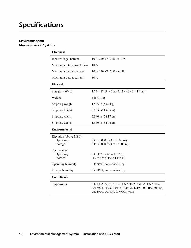
Electrical
Input voltage, nominal 100 - 240 VAC; 50 -60 Hz
Maximum total current draw 10 A
Maximum output voltage 100 - 240 VAC; 50 - 60 Hz
Maximum output current 10 A
Physical
Size (H × W× D) 1.74 × 17.10 × 7 in (4.42 × 43.43 × 18 cm)
Weight 6 lb (3 kg)
Shipping weight 12.85 lb (5.84 kg)
Shipping height 8.30 in (21.08 cm)
Shipping width 22.90 in (58.17 cm)
Shipping depth 13.40 in (34.04 cm)
Environmental
Elevation (above MSL)OperatingStorage
0 to 10 000 ft (0 to 3000 m)0 to 50 000 ft (0 to 15 000 m)
TemperatureOperatingStorage
0 to 45° C (32 to 113° F) -15 to 65° C (5 to 149° F)
Operating humidity 0 to 95%, non-condensing
Storage humidity 0 to 95%, non-condensing
Compliance
Approvals CE, CSA 22.2 No. 950, EN 55022 Class A, EN 55024, EN 60950, FCC Part 15 Class A, ICES-003, IEC 60950, UL 1950, UL 60950, VCCI, VDE
40 Environmental Management System — Installation and Quick Start
Specifications
Sensors
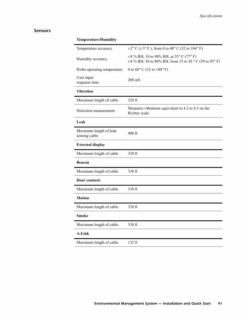
Temperature/Humidity
Temperature accuracy ±2º C (±3º F ), from 0 to 40º C (32 to 104º F)
Humidity accuracy ±8 % RH, 10 to 90% RH, at 25º C (77º F)±8 % RH, 30 to 80% RH, from 15 to 30 º C (59 to 95º F)
Probe operating temperature 0 to 60º C (32 to 140º F)
User input response time 200 mS
Vibration
Maximum length of cable 330 ft
Detection measurement Measures vibrations equivalent to 4.2 to 4.5 on the Richter scale.
Leak
Maximum length of leak sensing cable 400 ft
External display
Maximum length of cable 330 ft
Beacon
Maximum length of cable 330 ft
Door contacts
Maximum length of cable 330 ft
Motion
Maximum length of cable 330 ft
Smoke
Maximum length of cable 330 ft
A-Link
Maximum length of cable 132 ft
Environmental Management System — Installation and Quick Start 41
Radio Frequency Interference
USA—FCC This equipment has been tested and found to comply with the limits for a Class A digital device, pursuant to part 15 of the FCC Rules. These limits are designed to provide reasonable protection against harmful interference when the equipment is operated in a commercial environment. This equipment generates, uses, and can radiate radio frequency energy and, if not installed and used in accordance with this user manual, may cause harmful interference to radio communications. Operation of this equipment in a residential area is likely to cause harmful interference. The user will bear sole responsibility for correcting such interference.
Canada—ICES This Class A digital apparatus complies with Canadian ICES-003.
Cet appareil numérique de la classe A est conforme à la norme NMB-003 du Canada.
Japan—VCCI This is a Class A product based on the standard of the Voluntary Control Council for Interference by Information Technology Equipment (VCCI). If this equipment is used in a domestic environment, radio disturbance may occur, in which case, the user may be required to take corrective actions.
この装置は、情報処理装置等電波障害自主規制協議会(VCCI)の基
準に基づくクラス A 情報技術装置です。この装置を家庭環境で使用
すると、電波妨害を引き起こすことがあります。この場合には、使
用者が適切な対策を講ずるように要求されることがあります。a
Warning
Changes or modifications to this unit not expressly approved by the party responsible for compliance could void the user’s authority to operate this equipment.

*990-1285A-001*
APC Worldwide Customer Support
Customer support for this or any other APC product is available at no charge in any of the following ways:• Visit the APC Web site to access documents in the APC Knowledge Base and to submit customer
support requests.– www.apc.com (Corporate Headquarters)
Connect to localized APC Web sites for specific countries, each of which provides customer support information.
– www.apc.com/support/Global support searching APC Knowledge Base and using e-support.
• Contact an APC Customer Support center by telephone or e-mail.– Regional centers:
– Local, country-specific centers: go to www.apc.com/support/contact for contact information.
Contact the APC representative or other distributor from whom you purchased your APC product for information on how to obtain local customer support.
Direct InfraStruXure Customer Support Line (1)(877)537-0607 (toll free)
APC headquarters U.S., Canada (1)(800)800-4272 (toll free)
Latin America (1)(401)789-5735 (USA)
Europe, Middle East, Africa (353)(91)702000 (Ireland)
Japan (0) 35434-2021
Australia, New Zealand, South Pacific area (61) (2) 9955 9366 (Australia)
Entire contents copyright © 2004 American Power Conversion. All rights reserved. Reproduction in whole or in part without permission is prohibited. APC, the APC logo,
InfraStruXure, and NetShelter are trademarks of American Power Conversion Corporation and may be registered in some jurisdictions. All other trademarks, product names, and
corporate names are the property of their respective owners and are used for informational purposes only.
990-1285A-001 09/2004