farmaceutica - Verlag Dr. Felix Wüst Fachzeitschriften · Swiss Journal for the Pharmaceutical...
36
Swiss Journal for the Pharmaceutical Industry Schweizerische Zeitschrift für die pharmazeutische Industrie Revue suisse pour l’industrie pharmaceutique Rivista svizzera per l’industria farmaceutica 1978–2008 40 years SKAN AG 30 years Isolator Technology 6/09 SKAN AG - Postfach - CH-4009 Basel Phone +41 (0)61 485 44 44 - [email protected] - www.skan.ch SAFETY BY CONTAINMENT
Transcript of farmaceutica - Verlag Dr. Felix Wüst Fachzeitschriften · Swiss Journal for the Pharmaceutical...
Swiss Journal for the Pharmaceutical Industry
SchweizerischeZeitschrift für diepharmazeutischeIndustrie
Revue suissepour l’industriepharmaceutique
Rivista svizzeraper l’industriafarmaceutica
1978–2008
40 years SKAN AG
30 years Isolator Technology
6/09SKAN AG - Postfach - CH-4009 Basel
Phone +41 (0)61 485 44 44 - [email protected] - www.skan.ch
SAFETY BY CONTAINMENT

SWISS PHARMA 31 (2009) Nr. 6 1
Swiss Journal for SWISS PHARMA 31 (2009) Nr. 6 the Pharmaceutical IndustrySchweizerische Zeitschrift für die pharmazeutische IndustrieRevue suisse pour l’industrie pharmaceutiqueRivista svizzera per l’industria farmaceutica 6/09
Special issue “Isolator Technology” 1978–2008: 40 years SKAN AG – 30 years Isolator Technology Guest Editor: Dr. sc. nat. Paul Ruffieux Vice President SKAN AG P.O. Box CH-4009 Basel
Impressum 2
edItorIal 3
40 years SKAN AG – 30 years Isolator TechnologyProduction of sterile forms in the pharma-ceutical industry:From the ancient times of the clean rooms to today’s appropriate solutions for the production of the product and the opera-tor at optimal conditions considering the investments and the running costs– Dr. Paul Ruffieux, Vice President,
SKAN AG, Allschwil (CH)
ContrIbutIons 4
Setting the Scene – Thirty Years of Isolator Technology– Dr. Paul Ruffieux, Vice President,
SKAN AG, Allschwil (CH) 4
Isolator Quest – Perseverance necessary to find the right fit– Robert F. Guardino, Wilmington, NC
(USA) 10
Nested Syringe Filling in Isolators with E-Beam Tub Decontamination– James Spolyar, SKAN US, Inc. (USA), with
major contribution from Volker Sigwarth, Andre Boesiger, and Frank Lehmann, SKAN AG, (CH) 13
Convenient filter changing with the FIBO – the “safe change” filter box– Martin Glättli, SKAN AG, Allschwil (CH)
17
Launch of Aukamm Pharma in Wiesbaden – APV is responsible for project planning, process development and the SOP system– Dr. Frank Stieneker,
International Association for Pharmaceutical Technology (APV), Mainz (D) 23
FK Petrovax Pharma, MoscowIsolator Seminar in Moscow, June 24th, 2009 (in English)– Elena Kondrasheva, Head of Microbio
logical Lab, FK Petrovax Pharma, Moscow (Russian Federation) 25
FK Petrovax Pharma, MoscowIsolator Seminar in Moscow, June 24th, 2009 (in Russian)– Elena Kondrasheva, Head of Microbio
logical Lab, FK Petrovax Pharma, Moscow (Russian Federation) 29
COVERCONTENTS
Pharmaceutical isolator systems
for aseptic processes in laboratory and production
An isolator is a process We take on responsibility
for the entire process.
SKAN AG - Postfach CH-4009 Basel
Phone +41 (0)61 485 44 44 [email protected] - www.skan.ch

2 SWISS PHARMA 31 (2009) Nr. 6
ImpressumVerlag, Abonnemente, Anzeigen:Verlag Dr. Felix Wüst agIn der Hinterzelg 4 • CH-8700 Küsnacht ZHTelefon 0041 (0)44 918 27 27 • Telefax 0041 (0)44 918 29 70E-Mail: [email protected]
Redaktion: a) Allgemeiner Teil: Dr. rer. publ. Felix Wüst b) Wissenschaftlicher Teil:
Schweizerische Gesellschaft der Pharmazeutischen Wissenschaften (SGPhW) Prof. Dr. Dr. h.c. mult. Hans Leuenberger, Institut für industrielle Pharmazie, Ifiip GmbH, Birsigstrasse 79, Postfach, CH-4054 Basel
© by Verlag Dr. Felix Wüst ag • CH-8700 Küsnacht ZHAlle Rechte, insbesondere das der Übersetzung in fremde Sprachen, beim Verlag.Nachdruck, Vervielfältigung und Verbreitung, auch auszugsweise, in allen Formen wie Mikrofilm, Xerografie, Mikrofiche, Mikrocard, Offsetdruck usw. sowie durch Film, Funk und Fernsehen, fotomechanische Wiedergabe, Tonträger jeder Art. Einspeiche-rung und Rück gewinnung in Datenverarbeitungsanlagen aller Art sind verboten.Nachdruck von Beiträgen, auch auszugsweise, nur mit schriftlicher Genehmigung des Verlages. Mit Autorennamen gekennzeichnete Beiträge stehen ausserhalb der Verantwortung der Redaktion. Sie geben nicht unbedingt die Meinung der Redaktion wieder.
Im Verlag Dr. FelIx Wüst ag erscheinende Zeitschriften
Bestellung von EinzelheftenPreis pro Exemplar in der Regel CHF 50.– exkl. MwSt. und zuzügliche Versandkosten.Bei grösseren Ausgaben gilt der Preis auf Anfrage bzw. gemäss Angebot.
Als abonnierte Zeitschrift erscheinender Titel Auch als Sonderheft (für Firmen, Verbände, Institutionen usw.) möglich
sWIss pharma Schweizerische Zeitschrift für die pharmazeutische IndustrieISSN 0251-1673 Revue suisse pour l’industrie pharmaceutique Rivista svizzera per l’industria farmaceutica
Abonnemente für SWISS PHARMA
CHF 290.– + Versandkosten Schweiz: CHF 40.– Europa: CHF 60.– Airmail: CHF 200.–
In unregelmässigen Abständen als Sonderhefte (für Firmen, Verbände usw.) aufgelegte Titel (keine Abonnemente)
Die hiernach aufgeführten Zeitschriften sind keine Periodika; sie können demnach nicht abonniert werden. Die einzelnen Ausgaben erscheinen in unregelmässigen Abständen im Auftrag von Firmen, Verbänden, Institutionen («Corporate Publishing») oder als Spezialausgaben des Verlags im Vorfeld besonderer Veranstaltungen.
sWIss BIotech Schweizerische Zeitschrift für BiotechnologieISSN 0253-9675 Revue suisse de biotechnologie Rivista svizzera di biotecnologia
sWIss meD Schweizerische Zeitschrift für Medizin und medizinische TechnikISSN 0251-1665 Revue suisse de médecine et de technique médicale Rivista svizzera di medicina e tecnica medica
sWIss Dent Schweizerische Zeitschrift für orale Präventiv- und KurativmedizinISSN 0251-1657 Revue suisse d’Odontostomatologie préventive et thérapeutique Rivista svizzera di Odontologia e Stomatologia preventiva terapeutica
sWIss Vet Schweizerische Zeitschrift für VeterinärmedizinISSN 0254-6337 Revue suisse de médecine vétérinaire Rivista svizzera di medicina veterinaria
sWIss FooD Schweizerische Zeitschrift für die NahrungsmittelindustrieISSN 0251-1687 Revue suisse pour l’industrie alimentaire Rivista svizzera per l’industria alimentare
sWIss chem Schweizerische Zeitschrift für die chemische IndustrieISSN 0251-1703 Revue suisse pour l’industrie chimique Rivista svizzera per l’industria chimica
sWIss Schweizerische Zeitschrift für ReinraumtechnikcontamInatIon Revue suisse pour la prévention de la contaminationcontrol Rivista svizzera per il controllo della contaminazione ISSN 1011-6710 ambientale
sWIss materIals Schweizerische Zeitschrift für MaterialtechnikISSN 1013-4476 Revue suisse pour la technique des matériaux Rivista svizzera per la tecnica dei materiali
Prepress und Druck
Bubenberg Druck- und Verlags-AG • Monbijoustrasse 61 • Postfach • CH-3001 BernE-Mail: [email protected]
SWISS PHARMA 31 (2009) Nr. 6 3
Editorial
40 years SKAN AG – 30 years Isolator TechnologyProduction of sterile forms in the pharmaceutical industry: From the ancient times of the clean rooms to today’s appropriate solutions for the production of the product and the operator at optimal conditions considering the investments and the running costs
For the production of sterile forms, mostly injectables, in the Pharmaceutical Industry, a new step forward into incre-ased product safety began at the end of the sixties and the beginning of the seventies of the last century. The magic word of this step was “clean rooms”. Clean rooms were intended to solve all the problems of the old way of produ-cing sterile products with unsterile pro-ducts and unclean production areas, as
yet unstable steam sterilization cycles including problems in micro-biological labs, etc. This was the time of full laminar flow ceilings in production rooms, with specially gowned operators entering the critical areas through double step pass-throughs. These rooms took up significant space within the buildings.After some years of experience with this technology one critical point became more and more important in working in these clean rooms – the operator!Incorrect or inappropriate handling in the clean rooms and errors during gowning led to contaminated batches that were ultimately unusable. In almost all the cases the human element was responsi-ble. Similar findings were made in microbiological labs testing bat-ches for sterility. From time to time the labs had to be closed for cleaning and disinfection of the internal contamination that had led to the wrong results.The industry became increasingly active in searching for an improve-ment of the critical factors, in particular to separate the operator and the product during the critical steps of the production process, i. e. as long the sterile product is not yet finally in a closed container.Just over 30 years ago the idea to separate the critical production area completely from the surroundings, including the operator, arose. The final idea to build isolated systems – “isolators” – was born.In 1987/88 SKAN was in contact with hospitals looking for a total separation from the environment for transplantation patients, to give them a chance to survive bone marrow transplantations for a better life.
SKAN has built and installed various isolators in hospitals. The iso-lators have had a rigid construction, gloves, unidirectional air flow and the possibility to decontaminate the total inner room with per-acetic acid. The ability to decontaminate the isolator and to have a clear separation of the patient and the medical personnel was the important advantage over clean room technology.The same design of these isolators was then used more and more for pharmaceutical needs in sterile production.SKAN has influenced the progress of isolation technology with a large number of improvements, realization of new ideas and devel-opments in the last thirty years. Highlights include the integrated H2O2 decontamination system SIS 700, standardization of the de-velopment of decontamination cycles and bioindicators, including a large material study to show the influence of the material on D-values and introduction of the GAMP philosophy for all projects in-cluding documentation. Modular, standardized, and fully validated software that provides a wide range of advantages for the user. A series of scientific studies on the question of low H2O2 residu-als after a decontamination cycle and the influence on products. Last but not least the new development of pass-throughs with a 15-minute full H2O2 decontamination cycle, validated with bio-indicators.Additional activities are under way in the field of solid forms, in particular highly active products that demand additional safety for the operator.SKAN can provide you here and now with its first guarantee – that of being the real specialist in all aspects of “Safety by Contain-ment”.
SKAN AG
Dr. sc. nat. Paul RuffieuxVice President

4 SWISS PHARMA 31 (2009) Nr. 6
Thirty years of Isolator Technology? A number of people still believe today that Isolator Technology is a new technology with which little experience has been made and which is not very well established in the industry, by authorities and around the world.
Rick Friedman from the FDA said in the summary of his presenta-tion about “Aseptic Processing Isolators” at the ISPE conference in Washington, – 5–8 June 2006, that Isolator Technology – meets 21st century objectives for process consistency,– is a modern technology – is well-established – provides significantly increased sterility assurance
A clear statement about a technology developed over a consider-able period into a technology that is accepted worldwide in the field of sterile/sterile-toxic production and for the safety of prod-ucts and people.
The milestones of SKAN Isolator Technology provide a very good picture of the important steps forward in the development of the technology over the last 30 years.The first installation, e.g. on filling lines, was in 1985 with soft-wall isolators. The greatest progress began in the early 90’s and continues today. According to the latest survey by Jack Lysfjord and Michael Porter on the use of barrier isolators for fill/finish op-erations, there are over 400 filling barrier isolators installed world-wide.
Parallel to this progress, “powder” applications were built and op-erator safety became increasingly important for isolator technol-ogy.
30 YEars of isolator tEchnologY
1978–2008: 40 years SKAN AG – 30 years Isolator Technology
Setting the Scene – Thirty Years of Isolator TechnologyDr. Paul Ruffieux, SKAN AG, CH-4123 Allschwil
2www.skan.ch
30 Years SKAN Isolator
Technology / 1978–2008
• Important Milestones
• 1978 First isolator for hospitals, including decontamination
• 1993 Development of the first rigid wall isolator for a syringe line for Cilag
• 1995 Approval at the Cilag site for production, all in isolator technology
• 1997 First isolator with fully integrated decontamination system SIS 700
• 1998 Installation of the microbiological lab
3www.skan.ch
30 Years SKAN Isolator
Technology / 1978–2008
• Important Milestones cont.
• 1999 Five filling lines for ampoules
• 2000 Publication in PDA Journal Vol. 54
“Development and Qualification of
H202 Decontamination Cycles”
(Sigwarth/Moirandat)
• 2001/02 GSK, four prefilled syringe lines with
e-beam
• 2002 GSK, four freeze dryers
• 2003 PDA Journal Vol. 57 “Effect of
Carrier Materials of Spores of Bac.
Stearothermophilius to Gaseous H202
(Sigwarth/Stärk)
4www.skan.ch
30 Years SKAN Isolator
Technology / 1978–2008
• Important Milestones cont.
• 1995–2008 Approx. 100 filling lines, sterile, sterile/toxic, freeze dryer connections, syringe lines with e-beam,140 sterility test isolators
• New developments during this period:
– Cytotoxic safe isolators (CSI)
– Safety isolators
– Risk free exchangeable toxic return filters
– Quick cycle time (15 Min. full cycle)
– Low H202 residuals after deco < 0,1 ppm
5www.skan.ch
1987 / Hospital Isolator for
Transplantation Patients
SWISS PHARMA 31 (2009) Nr. 6 5
30 YEars of isolator tEchnologY
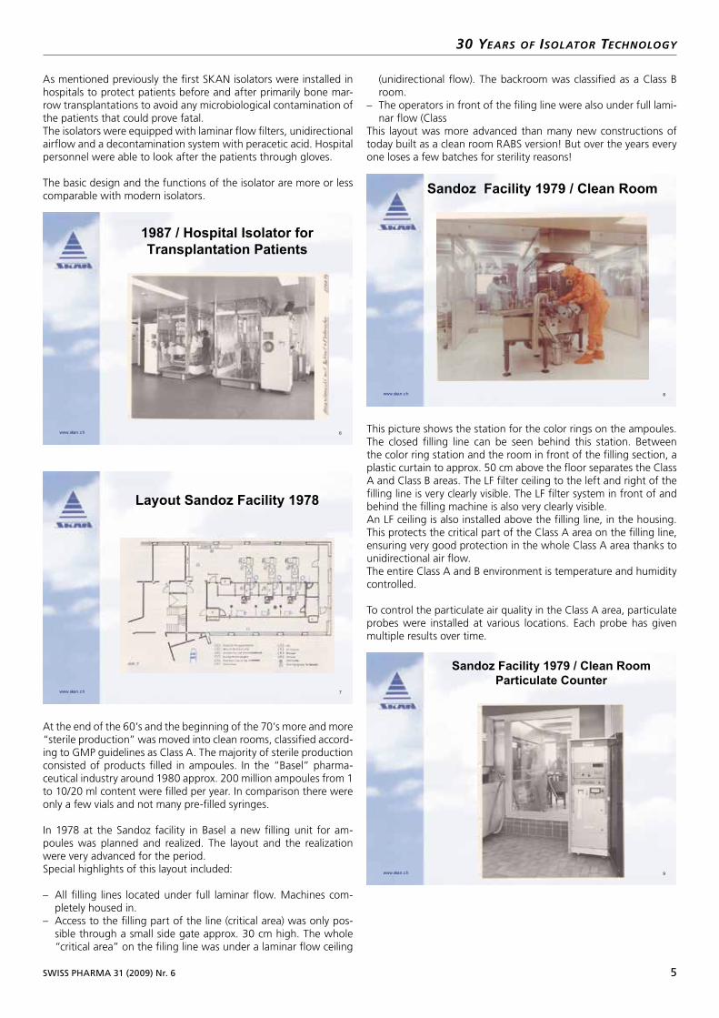
As mentioned previously the first SKAN isolators were installed in hospitals to protect patients before and after primarily bone mar-row transplantations to avoid any microbiological contamination of the patients that could prove fatal.The isolators were equipped with laminar flow filters, unidirectional airflow and a decontamination system with peracetic acid. Hospital personnel were able to look after the patients through gloves.
The basic design and the functions of the isolator are more or less comparable with modern isolators.
At the end of the 60’s and the beginning of the 70’s more and more “sterile production” was moved into clean rooms, classified accord-ing to GMP guidelines as Class A. The majority of sterile production consisted of products filled in ampoules. In the “Basel” pharma-ceutical industry around 1980 approx. 200 million ampoules from 1 to 10/20 ml content were filled per year. In comparison there were only a few vials and not many pre-filled syringes.
In 1978 at the Sandoz facility in Basel a new filling unit for am-poules was planned and realized. The layout and the realization were very advanced for the period.Special highlights of this layout included: – All filling lines located under full laminar flow. Machines com-
pletely housed in.– Access to the filling part of the line (critical area) was only pos-
sible through a small side gate approx. 30 cm high. The whole “critical area” on the filing line was under a laminar flow ceiling
(unidirectional flow). The backroom was classified as a Class B room.
– The operators in front of the filing line were also under full lami-nar flow (Class
This layout was more advanced than many new constructions of today built as a clean room RABS version! But over the years every one loses a few batches for sterility reasons!
This picture shows the station for the color rings on the ampoules. The closed filling line can be seen behind this station. Between the color ring station and the room in front of the filling section, a plastic curtain to approx. 50 cm above the floor separates the Class A and Class B areas. The LF filter ceiling to the left and right of the filling line is very clearly visible. The LF filter system in front of and behind the filling machine is also very clearly visible.An LF ceiling is also installed above the filling line, in the housing. This protects the critical part of the Class A area on the filling line, ensuring very good protection in the whole Class A area thanks to unidirectional air flow.The entire Class A and B environment is temperature and humidity controlled.
To control the particulate air quality in the Class A area, particulate probes were installed at various locations. Each probe has given multiple results over time.
6www.skan.ch
1987 / Hospital Isolator for
Transplantation Patients
7www.skan.ch
Layout Sandoz Facility 1978
8www.skan.ch
Sandoz Facility 1979 / Clean Room
9www.skan.ch
Sandoz Facility 1979 / Clean Room
Particulate Counter
6 SWISS PHARMA 31 (2009) Nr. 6
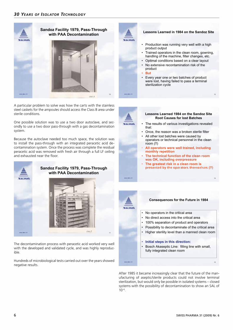
A particular problem to solve was how the carts with the stainless steel caskets for the ampoules should access the Class B area under sterile conditions.
One possible solution was to use a two door autoclave, and sec-ondly to use a two door pass-through with a gas decontamination system.
Because the autoclave needed too much space, the solution was to install the pass-through with an integrated peracetic acid de-contamination system. Once the process was complete the residual peracetic acid was removed with fresh air through a full LF ceiling and exhausted near the floor.
The decontamination process with peracetic acid worked very well with the developed and validated cycle, and was highly reproduc-ible.
Hundreds of microbiological tests carried out over the years showed negative results.
After 1985 it became increasingly clear that the future of the man-ufacturing of aseptic/sterile products could not involve terminal sterilization, but would only be possible in isolated systems – closed systems with the possibility of decontamination to show an SAL of 10-6.
30 YEars of isolator tEchnologY
10www.skan.ch
Sandoz Facility 1979, Pass-Through
with PAA Decontamination
11www.skan.ch
Sandoz Facility 1979, Pass-Through
with PAA Decontamination
12www.skan.ch
Lessons Learned in 1984 on the Sandoz Site
• Production was running very well with a highproduct output
• Trained operators in the clean room, gowning,handling of the machine, filter changes, etc.
• Optimal conditions based on a clear layout
• No extensive recontamination risk of theproduct
• But
• Every year one or two batches of productwere lost, having failed to pass a terminalsterilization cycle
13www.skan.ch
Lessons Learned 1984 on the Sandoz Site
Root Causes for lost Batches
• The results of various investigations revealedthat:
• Once, the reason was a broken sterile filter
• All other lost batches were caused byoperators or technical personnel in the cleanroom (!!)
All operators were well trained, includingmonthly repetition
• The technical function of the clean roomwas OK, including overpressure
The greatest risk in a clean room is
14www.skan.ch
Consequences for the Future in 1984
• No operators in the critical area
• No direct access into the critical area
• 100% separation of product and operators
• Possibility to decontaminate of the critical area
• Higher sterility level than a manned clean room
• Initial steps in this direction:
• Bosch Akaseptic Line: filling line with small,
fully integrated clean room
SWISS PHARMA 31 (2009) Nr. 6 7
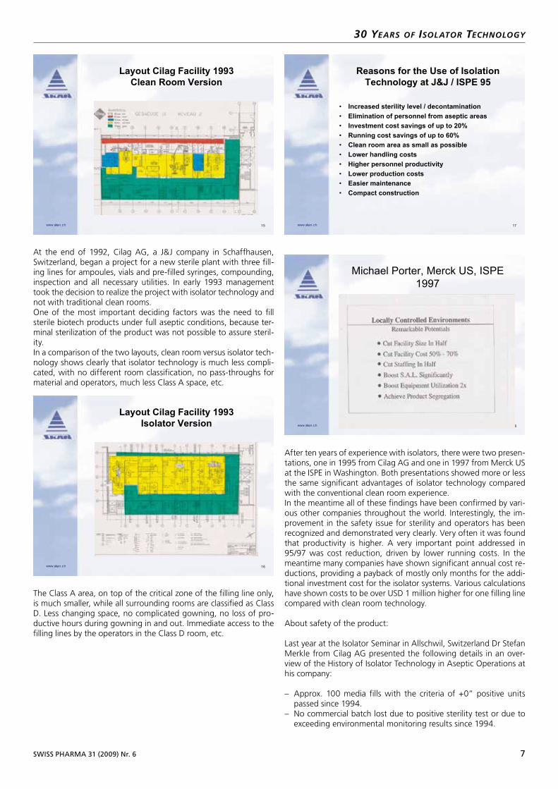
At the end of 1992, Cilag AG, a J&J company in Schaffhausen, Switzerland, began a project for a new sterile plant with three fill-ing lines for ampoules, vials and pre-filled syringes, compounding, inspection and all necessary utilities. In early 1993 management took the decision to realize the project with isolator technology and not with traditional clean rooms.One of the most important deciding factors was the need to fill sterile biotech products under full aseptic conditions, because ter-minal sterilization of the product was not possible to assure steril-ity.In a comparison of the two layouts, clean room versus isolator tech-nology shows clearly that isolator technology is much less compli-cated, with no different room classification, no pass-throughs for material and operators, much less Class A space, etc.
The Class A area, on top of the critical zone of the filling line only, is much smaller, while all surrounding rooms are classified as Class D. Less changing space, no complicated gowning, no loss of pro-ductive hours during gowning in and out. Immediate access to the filling lines by the operators in the Class D room, etc.
After ten years of experience with isolators, there were two presen-tations, one in 1995 from Cilag AG and one in 1997 from Merck US at the ISPE in Washington. Both presentations showed more or less the same significant advantages of isolator technology compared with the conventional clean room experience.In the meantime all of these findings have been confirmed by vari-ous other companies throughout the world. Interestingly, the im-provement in the safety issue for sterility and operators has been recognized and demonstrated very clearly. Very often it was found that productivity is higher. A very important point addressed in 95/97 was cost reduction, driven by lower running costs. In the meantime many companies have shown significant annual cost re-ductions, providing a payback of mostly only months for the addi-tional investment cost for the isolator systems. Various calculations have shown costs to be over USD 1 million higher for one filling line compared with clean room technology.
About safety of the product:
Last year at the Isolator Seminar in Allschwil, Switzerland Dr Stefan Merkle from Cilag AG presented the following details in an over-view of the History of Isolator Technology in Aseptic Operations at his company:
– Approx. 100 media fills with the criteria of +0” positive units passed since 1994.
– No commercial batch lost due to positive sterility test or due to exceeding environmental monitoring results since 1994.
30 YEars of isolator tEchnologY
15www.skan.ch
Layout Cilag Facility 1993
Clean Room Version
16www.skan.ch
Layout Cilag Facility 1993
Isolator Version
17www.skan.ch
Reasons for the Use of Isolation
Technology at J&J / ISPE 95
• Increased sterility level / decontamination
• Elimination of personnel from aseptic areas
• Investment cost savings of up to 20%
• Running cost savings of up to 60%
• Clean room area as small as possible
• Lower handling costs
• Higher personnel productivity
• Lower production costs
• Easier maintenance
• Compact construction
www.skan.ch
Michael Porter, Merck US, ISPE
1997
8 SWISS PHARMA 31 (2009) Nr. 6
– Approx. 20 compliance inspections (Swissmedic, FDA, Health Canada and others) with excellent records since 1994.
– Actual deviation rate approx. 0.1 deviation/batch.
At Cilag over the years there have been various filling lines including pre-filled syringes in isolation technology running, including sterility testing.
Today more and more companies are demanding dual safety, meaning product safety (sterility) and operator safety during the process (toxicity).This need for dual safety can only be met by isolator technology.
To conclude, isolator technology is today more than 30 years old and in operation on nearly 400 filling lines for sterile aseptic prod-ucts. Most of the companies have accepted in the meantime, based on real results, that:
The only way to fulfill all the objectives (GMP, security, costs, pro-ductivity and safety) for aseptic production of sterile medicinal products is to go into Isolator Technology with all the benefits it has to offer.
In addition, the high zone in an isolator “in operation” is control-lable, while a manned clean room is not!Validation of an isolator system has been carried out hundreds of times and is fast to perform, and ultimately there is great potential for significant cost reductions compared with traditional technolo-gies, showing only one way into the future:
Isolator Technology!
The next few pictures will show different applications with isolator technology in pharmaceutical production from the active ingredi-ent through aseptic to aseptic/toxic processing.
30 YEars of isolator tEchnologY
19www.skan.ch
Additional Advantages of Isolator
Technology over the Years
• Operator safety when handling toxic products
• Increasing numbers of biotech products
• Validation of the decontamination process in
an isolator, clean room not possible
• Running costs, environmental testing, energy
costs.
• Special products, like viruses etc.
• Humidity and temperature controlled
environment.
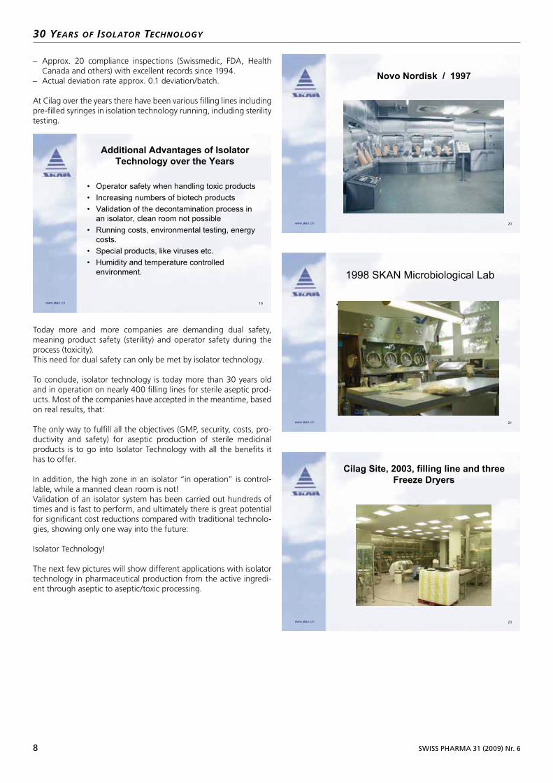
20www.skan.ch
Novo Nordisk / 1997
21www.skan.ch
1998 SKAN Microbiological Lab
23www.skan.ch
Cilag Site, 2003, filling line and three
Freeze Dryers

SWISS PHARMA 31 (2009) Nr. 6 9
30 YEars of isolator tEchnologY
24www.skan.ch
Pierre Fabre / 2006 at SKAN
25www.skan.ch
Pierre Fabre Site / 2006
Details of Cleaning in Place System
26www.skan.ch
Isolators for Aseptic ProductionAseptic Working Isolator “ARIS”
27www.skan.ch
Isolators for Operator - Product
ProtectionPowder process plant (milling, sieving, dosing, weighing, packaging)
28www.skan.ch
My Summary as VP Pharma
Operations of Cilag presented at
ISPE/PDA 1995
• The only way to fulfill all the objectives (GMP,
security, costs, productivity, safety) for a
production of sterile medicinal products, is to
go into Isolation Technology.
• The high risk zone in an isolator “in operation”
is controllable, a clean room not!
• Validation of an isolator system is possible
• Potential in Cost Reductions especially
Running Costs
Contact:Dr. Paul RuffieuxSKAN AGP.O. BoxCH4009 BaselPhone ++41 61 485 44 64Fax ++41 61 485 44 45EMail: [email protected]@skan.ch www.skan.ch
10 SWISS PHARMA 31 (2009) Nr. 6
isolator QuEst / Pursuit of a good stErilitY tEst isolator
The risks cannot be completely eliminated. Removing the operator/analyst from the environment and ensuring that exposure of prod-uct and test material only occurs within a sealed, decontaminated environment greatly enhance the process, however. Aside from the obvious regulatory expectations and interests, other issues, such as analyst comfort and the cost of disposables for clean room opera-tion (e. g., gowning, preparation time, sanitization, and clean room monitoring) make the use of isolators enticing.Isolators with automated decontamination cycles allow for unat-tended preparation of the working space and test materials. Once all test items are loaded, the cycle can be initiated and decontami-nation and aeration accomplished without further human interven-tion. This is a clear advantage over clean room sanitization and rinsing, which involve the manual decontamination of materials required during sterility testing in a clean room. Isolators with an automatic decontamination cycle allow you to prepare the cham-bers for use, run the cycle overnight, and commence testing the following morning. This functionality saves both time and money.
The Equipment
When deciding which vendor to work with, you must choose either glove box or half suit and either hard wall or soft wall isolators. Height restrictions and the taller profile of half suit isolators led us to pick glove box isolators. To shorten the decontamination/aera-tion cycle, we chose the hard wall models.In considering which vaporized hydrogen peroxide (VHP) vendor to use, you will immediately get caught up in the wet versus dry process dispute. Both processes work, but they have different cycle times; the dry process requires higher peroxide levels and a longer aeration period. We strongly recommend that you visit sites using the equipment under consideration and talk with users before de-ciding on the isolator and VHP generator. Of particular importance are the challenges inherent to validation, routine maintenance of the equipment, and associated down time. This research is the best investment of time and resources that you can make during the decision-making process. After evaluating vendors of both the iso-lator and VHP generator equipment, we became aware of an isola-tor system manufactured by SKAN AG (Basel, Switzerland) with a
fully integrated VHP generation system. This product offers several advantages:• Each isolator has its own generator, providing redundancy (if more
than one isolator is purchased) that can minimize down time;• It costs about 25% as much as the stand-alone models;• The design is simple;• The generator is validated as an integral part of the system; and• There is no need to regenerate desiccant because the process is
wet and desiccant is not used.After additional discussions with SKAN AG isolator customers, we decided to purchase their unit.
The Justification
Sterility isolator technology is a significant investment for any com-pany. If you’re a project manager or owner, you must be prepared to justify the purchase.The benefits of sterility test isolator technology can be tangible (ef-ficiency, greater throughput for samples, and use of fewer con-sumables) or intangible (reduced fatigue and employee burnout).Key criteria to focus on when preparing the operational justification include:• Significant reduction in the risk of false-positive results and the cor-
responding savings for investigations and product release delays;• Increased capacity for sample analysis;• Enhancement of compliance with domestic and international
guidelines and expectations;• Reduced employee fatigue and attrition due to harsh conditions
in clean room technology environment;• Decreased expenditures for consumables (about $20,000 per
year, including reduced cost for gowning supplies, disinfectants, and related supplies); and
• Portability (sterility test isolators can be relocated).In our example, isolators can save 745 work hours, which can be used for other activities such as batch release or testing. You can do more with the same number of employees – or fewer. There will also be greater flexibility in scheduling personnel, which will increase capacity.Clean room technology may require two employees to work in tan-dem to pass through needed materials or for safety purposes. The isolator equipment allows the analyst to leave the lab for supplies or other reasons. Carefully planned decontamination cycles in a steril-ity test isolator can allow for faster turnaround on test scheduling when compared with that required for a clean room environment. Planning allows for greater sample throughput, expedited product release, and greater capacity.Clean room technology frequently requires annual shutdowns for maintenance, such as repairing epoxy paint and disinfectant-induced corrosion.Sanitizing and monitoring to recommission the clean room can add two weeks to the down time. Isolators minimize this time, ensuring more efficiency and sample volume for the lab.Though it is difficult to calculate because it varies with time and conditions, there will be a reduction in the organism isolate iden-
1978–2008: 40 years SKAN AG – 30 years Isolator Technology
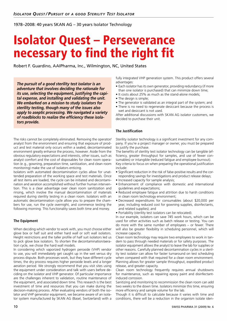
Isolator Quest – Perseverance necessary to find the right fitRobert F. Guardino, AAIPharma, Inc., Wilmington, NC, United States
The pursuit of a good sterility test isolator is an adventure that involves deciding the rationale for its use, selecting the equipment, justifying the capi-tal expense, and installing and validating the unit.We embarked on a mission to study isolators for sterility testing, though many of the issues also apply to aseptic processing. We navigated a variety of roadblocks to realize the efficiency these isola-tors provide.

SWISS PHARMA 31 (2009) Nr. 6 11
isolator QuEst / Pursuit of a good stErilitY tEst isolator
tification related to environmental excursions and positive sterility test investigations. Additionally, the costs associated with subcon-tracted DNA-sequence identification of isolates will be reduced be-cause the isolator technology should reduce or eliminate the envi-ronmental effects of clean room technology.Financial decision-making criteria are weighted differently from company to company and industry to industry, but key indicators for any investment are net present value, internal rate of return, and return on investment. These will factor into any company’s decision to buy sterility test isolators.
The Installation
Perhaps the next biggest hurdle is deciding where to install the iso-lators. This is especially problematic if you have an older laboratory space that was not designed with isolators in mind.An isolator may be the largest piece of equipment purchased for a microbiology lab. The footprint must allow ample space on all sides for work and maintenance. When height restrictions are an issue, choose a unit with maintenance access on the front of the unit rather than on the top.To meet height requirements, we constructed a lab. We installed dedicated HVAC to meet the requirements of an ISO Class 8 clean room. FDA advises that an aseptic processing isolator should not be located in an unclassified room. While no such requirement exists for sterility test isolators, it is prudent to plan for ISO 8 even if the environment is not classified. Providing a clean, controlled-access environment helps to ensure safety.Isolators are typically custom-built, even when a standard unit is available. Knowing how the isolators will be used and documenting user requirements are vital parts of the process. At AAIPharma, a supplier of product development and support services to the phar-maceutical, biotechnology, and medical device industries, we pur-chased two SKAN ARIS isolators, which are a standard design for sterility testing purposes.For our use, we determined that we wanted the isolators directly linked with pass-through doors. As a contract lab, we see many product formats, ranging from aqueous injectables and ophthalmic and otic solutions to sterile powders and implantable combination products and devices, to name a few. Each format has unique test parameters. Our worst-case scenario, from a material-needs point of view, requires in excess of 80 one-liter bottles of media plus samples, as well as all associated testing materials and controls. To set up one test requires the space available in both isolators; thus, we needed the units to be joined in some fashion. For simplicity, we opted for a pass-through setup rather than a rapid transfer port. The isolators may be used as a single-test environment or as inde-pendent clean zones for testing. We have essentially doubled our capacity from a single ISO Class 5 clean room to two side-by-side isolator units.Other design considerations include the isolator’s working height, which affects analyst comfort, and the accommodation of an in-tegral membrane filtration unit. The choice of vendors for the fil-tration unit was important because a design modification became necessary for the unit chosen. The two most widely marketed de-vices are the Millipore Steritest Equinox (Millipore, Billerica, Mass.) and the Sartorius Sterisart (Sartorius Stedim Biotech, Aubagne, France). The Equinox has a higher profile inside the isolator, while the Sterisart has a greater profile beneath the isolator chamber, requiring the door to the electrical panel beneath the work surface to be redesigned to accommodate the pump unit.Once we established our design requirements, we scheduled the manufacture of the isolators. With the exception of the review of design documents, the build process was rather seamless. Most of the lab’s preparation during this time was focused on facilities and utilities issues. This required diligence from all parties involved, including company engineering and facilities maintenance depart-
ments, contractors, equipment vendors, and the isolator company. The HVAC system components required perhaps the longest lead times. Each isolator/VHP generator has particular temperature and relative humidity (RH) range requirements.It’s important to ensure that the HVAC unit can deliver the ap-propriate environment consistently. Ensuring proper ventilation and isolator exhaust required continued discussions. The exhaust component was particularly troublesome. To decrease the aeration time, which is the key to a shorter decontamination cycle, unre-stricted exhaust is critical. The ARIS isolators have unidirectional airflow.No fans are required to disperse the VHP. Exhaust is accomplished through an air return in the back of the unit that is driven, by a blower, through a HEPA filter and up the exhaust flume.An additional consideration for the location of the isolators is their exhaust needs. A short, straight, unrestricted exhaust flume greatly enhances the aeration rate. No auxiliary exhaust blower is neces-sary as long as the length of the exhaust duct is less than 10 me-ters, there are no right angle bends, and the diameter of the HVAC ducts is as large as the exhaust coupling on the isolator.Because cycle time is critical to turnaround time between testing, we sought to maximize the efficiency of this component of the sys-tem. We achieved all parameters necessary to minimize the aera-tion times by carefully selecting the location of the isolator lab, the location of the isolators within the lab, and the components of the exhaust system, and by ensuring proper installation. The exhaust system was made of surgical welded stainless steel and run straight through the roof.Prior to construction, we planned the location of the isolators in the room. During construction, lighting fixtures were installed that we later found to be directly in line with the exhaust couplings of the isolators. Once the isolators were installed in the optimal location in the room, we decided that it would be wiser to relocate the lighting fixtures rather than to bend the exhaust system around the light-ing fixtures. Though it seems like a simple item – and something that could have been avoided during the lab design phase – it was not obvious, until the isolators were installed, precisely where the exhaust ducts would need to go. The exact location of the isola-tor exhaust coupling, the angle at which the isolator chamber was mounted on the stand, and the location of the ceiling joists were all important considerations in deciding the final exhaust location.
A diversified isolator system for critical process steps in laboratory and pro-duction applications, very often used for sterility testing. (Photo: SKAN AG, Basel).
12 SWISS PHARMA 31 (2009) Nr. 6
isolator QuEst / Pursuit of a good stErilitY tEst isolator
While installing the isolators in new construction, we became aware that the final electrical inspection was going to be performed after the isolators were installed. The isolators were labeled with Euro-pean electrical certification rather than a UL-listed one as required in the U.S. This was discovered during the electrical inspection and further delayed implementation of the isolators. The equipment had to be retrofitted on site before the in-field UL labeling could be accomplished. While waiting for the retrofit and UL labeling – roughly a two-month process – we proceeded with installation and operational qualification (IO/Q), some of which had to be repeated after UL labeling.
The Validation
Because we had no experience validating isolators, we contracted with a third party for validation services.In our travels to visit the users of various isolators, we had learned how time-consuming and difficult validation can be. We spoke to individuals who had been trying to validate their isolators for more than a year. This problem has a lot to do with isolator design and features, but it’s also related to the level of experience of those performing the validation. Hiring individuals with a proven track record is money well spent. Though they are few, they are easy to find: Just ask an isolator vendor or most users. Aside from the IO/Q mentioned above, the steps involved include D-value testing of bio-logical indicators in the isolators, decontamination/aeration cycle development, the formal load-dependent performance qualifica-tion (PQ) studies, and sterilant intrusion and residue effects (false-negative studies).Document preparation alone justifies the cost of validation services; the nuances of isolator validation, together with the tricks of the trade, will truly make you glad that you did not “try this at home.”Also, the advice given by validation vendors regarding the materi-als and supplies needed up front, as well as applicable vendors of the same, may save a great deal of time. Speaking of materials, one critical parameter for validation is the proper selection of test samples for cycle development and PQ loads and for sterilant intru-sion studies. Those companies who have one or more products
to test with the same format, such as sealed glass vials, have the advantage of simply including all products in validation studies. We already mentioned the variety of product formats that we test as a contract lab. These come in all sizes and shapes – not to mention the various construction materials used for containers and closures. Add to that the particular seal strengths used during processing, and you are left with quite a selection.Now imagine that you don’t have samples available because they all belong to other companies. Careful planning and a good rela-tionship with your clients are both critical to sourcing the samples needed for validation. Fortunately, the benefits for the client com-panies during sterility testing in an isolator should make most of them willing participants in your validation activities.
1. Fisher J, Caputo RA. Comparing and contrasting barrier isolator decontamination systems. Pharm Technol. 2004;28:68-82.
2. Food and Drug Administration. Guidance for industry: ste-rile drug products produced by aseptic processing – current good manufacturing practice. Food and Drug Administration. Rockville, Maryland. 2004. Available at www.fda.gov/cber/gdlns/steraseptic.pdf. Accessed July 23, 2007
Contact:Robert F. GuardinoDirector of MicrobiologyAAIPharma, Inc.2320 Scientific Park DriveUSAWilmington, NC 28405United States(P) 910.254.7635(C) 910.200.5758Fax 910.254.7416EMail: [email protected]
RESOURCES
SWISS PHARMA 31 (2009) Nr. 6 13
isolator tEchnologY / nEstEd sYringE filling / E-BEam tunnEls
1978–2008: 40 years SKAN AG – 30 years Isolator Technology
Nested Syringe Filling in Isolators with E-Beam Tub DecontaminationJames Spolyar, SKAN US, Inc., with major contribution from Volker Sigwarth, Andre Boesiger, and Frank Lehman, SKAN AG, Switzerland
• HISTORY OF USE (SKAN ORDERS)➢ ORDER YEAR # OF LINES REGION BEAM SUPPLIER
{LINAC (L) AEB (A)}➢ 2002 4 EUROPE L➢ 2004 1 EUROPE L➢ 2005 2 EUROPE L➢ 2006 3 EUROPE L➢ 2007 3 EUROPE (3) L➢ 2008 TO
SEPT8 EUROPE (5) US (3) L (5) A (3)
➢ HISTORY OF USE (NON-SKAN ORDERS {ESTIMATED})➢ 2005–
MAY 20088 EUROPE (3) US (5) L(1) A (7)
The utilization of isolator technology places very high demands on surface de-contamination. Whereby today, de-contamination of isolator chambers is performed with vaporized hydrogen peroxide, the de-contamination process for continuously working fill systems with e-beam is being utilized.
A Continuous Fill System
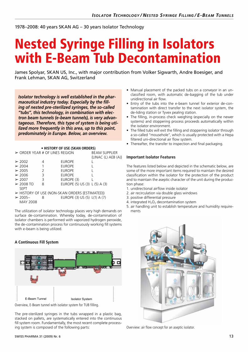
The pre-sterilized syringes in the tubs wrapped in a plastic bag, stacked on pallets, are systematically entered into the continuous fill system room. Fundamentally, the most recent complete process-ing system is composed of the following parts:
• Manual placement of the packed tubs on a conveyor in an un-classified room, with automatic de-bagging of the tub under unidirectional air flow.
• Entry of the tubs into the e-beam tunnel for exterior de-con-tamination with direct transfer to the next isolator system, the de-liding station or Tyvex pealing station.
• The filling, in-process check weighing (especially on the newer systems) and stoppering process proceeds automatically within the isolator environment.
• The filled tubs will exit the filling and stoppering isolator through a so-called “mousehole”, which is usually protected with a Hepa filtered uni-directional air flow system.
• Thereafter, the transfer to inspection and final packaging.
Important Isolator Features
The features listed below and depicted in the schematic below, are some of the more important items required to maintain the desired classification within the isolator for the protection of the product and to maintain the aseptic character of the unit during the produc-tion phase:1. unidirectional airflow inside isolator2. air recirculation via double glass windows3. positive differential pressure4. integrated H2O2 decontamination system5. air handling unit to establish temperature and humidity require-
ments
Isolator technology is well established in the phar-maceutical industry today. Especially by the fill-ing of nested pre-sterilized syringes, the so-called “tubs”, this technology, in combination with elec-tron beam tunnels (e-beam tunnels), is very advan-tageous. Therefore, this type of system is being uti-lized more frequently in this area, up to this point, predominately in Europe. Below, an overview.
Position Abbildung [1]:
Manuskript Seite: 1 von 4
Abschnitt: links unten
Abbildung [1] Overview, E-Beam tunnel with isolator system for TUB filling
E-Beam Tunnel Isolator System
Overview, E-Beam tunnel with isolator system for TUB filling.
Overview: air flow concept for an aseptic isolator.

14 SWISS PHARMA 31 (2009) Nr. 6
isolator tEchnologY / nEstEd sYringE filling / E-BEam tunnEls
Cleanroom Classification, Zone Concept and Differential Pressure Cascade (Picture 2)The separation of the critical zone of the isolator systems (ISO 5, Grade A, Class 100) from the surrounding room-normally ISO 7 or ISO 8-is assured through the use of a pressure cascade. This dynamic barrier, using directional air flow for the protection of the product, is positive to the external room. In the entry zone of the e-beam tunnel, there is a negative pressure to the environment, in order to protect the atmosphere from the bi-products of the e-beam, such as Ozone. For the rest of the e-beam tunnel, generally the typical clean room zones are defined.
Integrated Decontamination and Sterilization ProcessesBefore any production is started, all interior surfaces of the e-beam tunnel, as well as the filling line and isolator system, including air handling pipes, filters and plenums, will be de-contaminated with vaporized hydrogen peroxide. The delivered syringe tubs will be totally decontaminated with ethylene oxide (ETO). With the trans-fer through the e-beam tunnel, the external surfaces of the tubs will once again be decontaminated with electron beams. Product contact surfaces, especially for the filling machine, are sterilized normally using a CIP/SIP system. The syringe stoppers are entered into the isolator either Gamma sterilized as “ready to use”, utiliz-ing special transfer flanges, or stopper processing units, also using special transfer flanges.
Regulatory Demands for Surface DecontaminationIn the actual practice of isolator technology you will find various de-mands on the process results of exterior surface decontamination. These demands reflect the normal practice and methodology of the industry. In the PIC/S recommendations, exterior decontamination is discussed in the concept of “sporicidal process”. Even though it is not totally defined, clearly the concept of log reduction, often of 6 logs is the process goal. The FDA, in it’s Aseptic Guidelines, based on a specific process, suggests a 4–6 log reduction on the exterior surfaces, can be justified. For example, materials which are only marginally exposed to the controlled environment in the isolator system, with only a minor “bio-burden”, could justify a 4 log reduc-tion as the process goal.
Why Use E-beam Technology With Nested Fillers➢ 1. Validatable method to reach a 6 log reduction of spores on all
exterior surfaces of the tubs.➢ 2. Repeatable➢ 3. Eliminate operator interface with the tubs, including de-bag-
ging before infeed➢ 4. High speed infeed of tubs to match new high speed fillers➢ 5. Robust system with measurable killing energy system param-
eters
Hydrogen Peroxide Decontamination of Isolator Systems
In today’s isolator technology, decontamination with vaporized hy-drogen peroxide is the norm. The surface decontamination of the surfaces of isolator systems with vaporized hydrogen peroxide is con-sidered a pharmaceutical process, which must first withstand valida-tion. This process rests on the following three partial systems:• The isolator and decontamination system• The process parameters utilized• The biological indicators as the microbiological test system
These systems can fundamentally be considered independent for one another. But, only the detailed co-ordination of these systems with the process expectations and boundaries, can produce the process results and finally the successful process validation. Regard-less of the manufacturer of the de-contamination system, decon-tamination with vaporized hydrogen peroxide systems for isolators are generally as follows:
Liquid hydrogen peroxide solution, in a concentration between 35 and 50 percent, is delivered by a pump and dropped onto a vapor-izing system. (See picture below) The amount of the solution to be vaporized is generally controlled by a scale. Since hydrogen perox-ide has a slightly high vapor point than water, the vaporization of individual drops reduces the separation of peroxide and water in the vaporizer system. The resulting vaporized hydrogen peroxide is mixed with the air as the carrier gas and directed into the system, through the existing HEPA filter system.
Position Abbildung [3]
Manuskript Seite: 2 von 4
Abschnitt: links oben
Abbildung [3] Cleanroom class, zone concept and pressure cascade
Tub Inlet
∆p = Neg. - ∆p = Pos. + ∆p = Pos. ++ ∆p = Ref.
Grade B to A ISO 7 to 5
Grade A ISO 5
Grade C / D ISO 8
Exhaust
Position Abbildung [4]:
Manuskript Seite: 2 von 4
Abschnitt: rechts unten
Abbildung [4] H2O2 decontamination process
H2O2 Solution
Carrier gas
HEPA Filter
Vaporizer
H2O2 / Water Vapor
Cleanroom class, zone concept and pressure cascade.
H2O2 decontamination process.
SWISS PHARMA 31 (2009) Nr. 6 15
isolator tEchnologY / nEstEd sYringE filling / E-BEam tunnEls
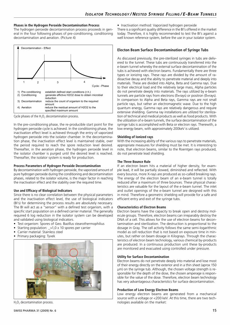
Phases in the Hydrogen Peroxide Decontamination ProcessThe hydrogen peroxide decontamination process proceeds in gen-eral in the four following phases of pre-conditioning, conditioning decontamination and aeration. (Picture 4)
In the pre-conditioning phase, the re-producible start point for the hydrogen peroxide cycle is achieved. In the conditioning phase, the inactivation effect level is achieved through the entry of vaporized hydrogen peroxide into the isolator chamber. In the decontamina-tion phase, the inactivation effect level is maintained stable, over the period required to reach the spore reduction level desired. Thereafter, in the aeration phase, the hydrogen peroxide level in the isolator chamber is purged until the desired level is reached. Thereafter, the isolator system is ready for production.
Process Parameters of Hydrogen Peroxide DecontaminationBy decontamination with hydrogen peroxide, the vaporized amount of pure hydrogen peroxide during the conditioning and decontamination phases, related to the isolator volume, is the major factor in reaching the inactivation effect and the stability over the required time.
Use and Efficacy of Biological IndicatorsSince there is no clear correlation between the physical parameters and the inactivation effect level, the use of biological indicators (BI’s) for determining the process results are absolutely necessary. The BI will act as a “sensor” with a defined test organism, with a specific start population on a defined carrier material. The generally required 6 log reduction in the isolator system can be developed and validated using biological indicators.• Test organism: Spores of Geo. Bazillus stearothermophilius• Starting population: _>1,0 x 10 spores per carrier• Carrier material: Stainless steel• Primary packaging: Tyvek
• Inactivation method: Vaporized hydrogen peroxideThere is a significant quality difference in the BI’s offered in the market today. Therefore, it is highly recommended to test the BI’s against a well known reference system, before the use in your isolator system.
Electon Beam Surface Decontamination of Syringe Tubs
As discussed previously, the pre-sterilized syringes in tubs are deliv-ered to the tunnel. These tubs are continuously transferred into the e-beam tunnel whereby the external surface decontamination of the tubs is achieved with electron beams. Fundamentally there are three types or ionizing rays. These rays are divided by the amount of ra-dioactive decay and the ability to penetrate material and deeply into materials. These are divided into Alpha, Beta and Gamma rays. Due to their electrical load and the relatively large mass, Alpha particles do not penetrate deeply into materials. The rays utilized by e-beam tunnels are particle rays from electrons (ß+rays) or positron (ß+rays). In comparison to Alpha and Beta rays, Gamma rays are not small particle rays, but rather an electromagnetic wave. Due to the high quantum energy, Gamma rays are relatively dangerous and require extensive shielding. Gamma ray installations are utilized for steriliza-tion of technical and medical products as well as food products. With the utilization of e-beam tunnels, the surface decontamination of the syringe tubs is accomplished with Beta or electron rays. Therewith, a low energy beam, with approximately 200keV is utilized.
Shielding of Ionized raysWith the increasing ability of the various rays to penetrate materials, appropriate measures for shielding must be met. It is interesting to note, that electron beams, similar to the Roentgen rays produced, do not penetrate lead shielding.
The Three Bounce RuleIf an electron beam hits a material of higher density, for exam-ple lead, it will be partially slowed, diminished and reflected. With every bounce, more X-rays are produced as so-called breaking rays. The energy of the electron beam of an e-beam tunnel is totally reduced after a maximum of three bounces. These physical charac-teristics are valuable for the layout of the e-beam tunnel. The inlet and outlet openings of the e-beam tunnel are designed with this in mind. Therefore a geometric shielding will provide for a safe and efficient entry and exit of the syringe tubs.
Characteristics of Electron BeamsElectron beams have the capacity to break open and destroy mol-ecule groups. Therefore, electron beams can irreparably destroy the DNA of a cell. This allows for the use of electron beams for decon-tamination and sterilization. The destruction is proportional to the dosage in Gray. The cell activity follows the same semi-logarithmic model as cell reduction that is not based on exposure time in min-utes, but rather on beam dosage in Kilograys. Through the charac-teristics of electron beam technology, various chemical by-products are produced. In a continuous production unit these by-products are monitored and evacuated using controlled under pressure.
Utility for Surface DecontaminationElectron beams do not penetrate deeply into material and lose most of their energy directly on the exterior and in a thin sheet (aprox 150 µm) on the syringe tub. Although, the chosen voltage strength is re-sponsible for the depth of the dose, the chosen amperage is respon-sible for the value of the dose. Therefore, electron beam technology has very advantageous characteristics for surface decontamination.
Production of Low Energy Electron BeamsLow energy electron beams are generated from a mechanical source with a voltage or <200 keV. At this time, there are two tech-nologies available on the market:
Position Abbildung [5]:
Manuskript Seite: 3 von 4
Abschnitt: links oben
Abbildung [5] Cycle phases of the H2O2 decontamination process
Cycle - Phase
Decontamination - Effect
1 3 4 2
1) Pre conditioning establish defined start conditions (r.h.) 2) Conditioning generate effictive H2O2 dose to obtain microbial reduction 3) Decontamination reduce the count of organism to the required amount 4) Aeration reduce the residual amount of H2O2 to the specified maximum amount
Position Abbildung [6]:
Manuskript Seite: 3 von 4
Abschnitt: links unten
Abbildung [6] Isolator for aseptic production: H2O2 decontamination system
H2O2 decontamination process.
Cycle phases of the H2O2 decontamination process.
16 SWISS PHARMA 31 (2009) Nr. 6
isolator tEchnologY / nEstEd sYringE filling / E-BEam tunnEls
• Beam emitter with vacuum pumps and magnetic beam scanning• Hermetically sealed beam emitter without beam scanningIn both technologies, the electron beams are only generated when the emitter is turn on. That means, the shut-off of the beam emitter stops the production of electron beams immediately. Since after the shut down of the electron beam emitter, no latent rays are present in the tunnel, immediate access to the tunnel for maintenance and service is possible without issues. The advantage of beam scanning is the ability to confine the dose to the desired exterior surface geometric dimen-sion. An unnecessary raising or lowering of the dose can be reduced. The disadvantage of the beam scanning system is the integrated com-plex technology (permanent production of vacuum) with the attendant increase in validation activity. It also has some influence on the process time for the throughput of the syringe tubs. In Europe, there are already many such e-beam emitters in production applications. A hermetically sealed electron beam emitter without beam scanning compares to the basic principal of a light bulb and therefore presents a simpler technol-ogy. The vacuum in the emitter is maintained by a very thin titanium foil, over which the generated rays escape. The beam dosage reached as well as the homogeneity and reproducibility of the dose, depends on the individual quality of the beam emitter. Since there is no beam scanning, geometric factors must be exactly considered and potentially larger dosage raises might need to be considered.
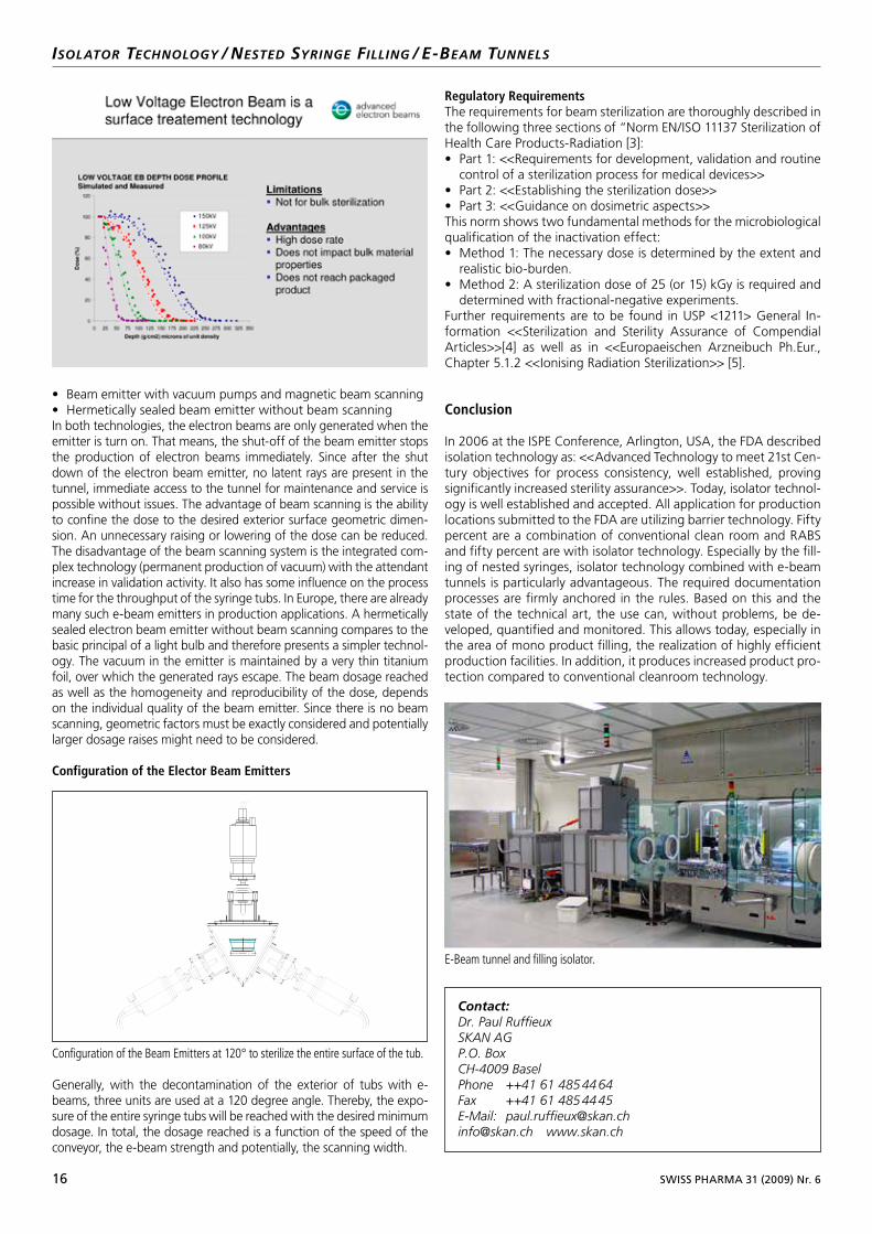
Configuration of the Elector Beam Emitters
Generally, with the decontamination of the exterior of tubs with e-beams, three units are used at a 120 degree angle. Thereby, the expo-sure of the entire syringe tubs will be reached with the desired minimum dosage. In total, the dosage reached is a function of the speed of the conveyor, the e-beam strength and potentially, the scanning width.
Regulatory RequirementsThe requirements for beam sterilization are thoroughly described in the following three sections of “Norm EN/ISO 11137 Sterilization of Health Care Products-Radiation [3]:• Part 1: <<Requirements for development, validation and routine
control of a sterilization process for medical devices>>• Part 2: <<Establishing the sterilization dose>>• Part 3: <<Guidance on dosimetric aspects>>This norm shows two fundamental methods for the microbiological qualification of the inactivation effect:• Method 1: The necessary dose is determined by the extent and
realistic bio-burden.• Method 2: A sterilization dose of 25 (or 15) kGy is required and
determined with fractional-negative experiments.Further requirements are to be found in USP <1211> General In-formation <<Sterilization and Sterility Assurance of Compendial Articles>>[4] as well as in <<Europaeischen Arzneibuch Ph.Eur., Chapter 5.1.2 <<Ionising Radiation Sterilization>> [5].
Conclusion
In 2006 at the ISPE Conference, Arlington, USA, the FDA described isolation technology as: <<Advanced Technology to meet 21st Cen-tury objectives for process consistency, well established, proving significantly increased sterility assurance>>. Today, isolator technol-ogy is well established and accepted. All application for production locations submitted to the FDA are utilizing barrier technology. Fifty percent are a combination of conventional clean room and RABS and fifty percent are with isolator technology. Especially by the fill-ing of nested syringes, isolator technology combined with e-beam tunnels is particularly advantageous. The required documentation processes are firmly anchored in the rules. Based on this and the state of the technical art, the use can, without problems, be de-veloped, quantified and monitored. This allows today, especially in the area of mono product filling, the realization of highly efficient production facilities. In addition, it produces increased product pro-tection compared to conventional cleanroom technology.
Position Abbildung [7]:
Manuskript Seite: 4 von 4
Abschnitt: links unten
Abbildung [7] Configuration of the Beam Emitters at 120° to sterilize the entire
surface of the tub.
Contact:Dr. Paul RuffieuxSKAN AGP.O. BoxCH4009 BaselPhone ++41 61 485 44 64Fax ++41 61 485 44 45EMail: [email protected]@skan.ch www.skan.ch
Configuration of the Beam Emitters at 120° to sterilize the entire surface of the tub.
E-Beam tunnel and filling isolator.
SWISS PHARMA 31 (2009) Nr. 6 17
General measures when handling highly active/toxic pharmaceutical products:
Work with open pharmaceutical substances and products must be carried out at specially designed workstations, for reasons relating to the purity, sterility or toxicity of the product. Combinations of these three are usual. The corresponding regulatory requirements have become increasingly strict in recent years, and now clearly dictate how such products are to be handled. It is clearly defined whether work has to be carried out in areas with controlled air flow such as laminar flow facilities and safety cabinets, up to isolators, in order to maintain the required level of protection for personnel, environment and product.In addition to the validated operation of a safety facility, with con-siderable importance being attached to the filters used and the air quality they provide, straightforward and reliable cleaning is of course also important. This factor must not be neglected in the planning process. Often, however, too little attention is paid to en-suring that maintenance work can be carried out easily and above all safely.After all, no one wants to change a filter without being 100% cer-tain about what work has been carried out and which substances used in the facility, even if it has been cleaned correctly in ad-vance.In the designing of safety facilities, as much attention should be paid to maintenance as to ergonomics, operational safety and eco-nomic viability or operation and cleaning. If a facility is intended to protect personnel and the environment during work with toxic products, this should also be the case during the maintenance process.
Problem: Changing contaminated filters
Once a safety facility has been used and cleaned, routine mainte-nance work must be carried out. While this work is usually plan-nable with regard to time and cost, it is in effect unproductive and must therefore be carried out with the minimum influence on the day-to-day work process. Day-to-day work with small quantities of concentrated toxic material in the laboratory or in pharmacies con-tinues to be carried out primarily in safety cabinets. The process of changing the return air filter of such safety cabinets, which must be carried out regularly during routine maintenance, is defined by an SOP. This is followed by a hazard assessment concerning the poten-tial presence of substances in the filter harmful to individuals and the environment, using the logbook. Maintenance personnel are required to ensure that the work is carried out correctly and that the appropriate protective measures are taken, starting with the interruption of all work in the surrounding room and followed by the provision of all protective equipment. Naturally, it is important here that time and costs are kept to a minimum.
1978–2008: 40 years SKAN AG – 30 years Isolator Technology
Convenient filter changing with the FIBO – the “safe change” filter boxMartin Glättli, SKAN AG, CH-4123 Allschwil
isolators / glovEBoxEs / contamination frEE, safE changE filtEr Box
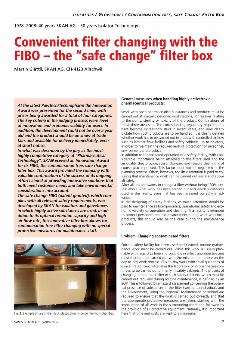
At the latest Powtech/Technopharm the Innovation Award was presented for the second time, with prizes being awarded for a total of four categories. The key criteria in the judging process were level of innovation and economic viability for users. In addition, the development could not be over a year old and the product should be on show at trade fairs and available for delivery immediately, even at short notice.In what was described by the jury as the most highly competitive category of “Pharmaceutical Technology”, SKAN eceived an Innovation Award for its FIBO, the contamination free, safe change filter box. This award provided the company with valuable confirmation of the success of its ongoing efforts aimed at providing innovative solutions that both meet customer needs and take environmental considerations into account.The safe change FIBO (patent granted), which com-plies with all relevant safety requirements, was developed by SKAN for isolators and gloveboxes in which highly active substances are used. In ad-dition to its optimal retention capacity and high air flow rate, this innovative filter box allows for contamination free filter changing with no special protective measures for maintenance staff.
Fig. 1: Example of use of the FIBO, placed directly below the work chamber.
18 SWISS PHARMA 31 (2009) Nr. 6
The level of toxicity of new pharmaceutical substances has been increasing significantly for some years now, calling for systems that are able to comply with the evolving safety requirements. These requirements are met by closed systems that also offer increased product protection with regard to sterility – i. e. sterile isolators fit-ted with return air filters. These return air filters must meet all re-quirements for use in hospital and community pharmacies in which, for example, highly toxic pharmaceuticals such as cytostatics and other CMR substances for parenteral administration are prepared. The return air filters for a sterile isolator of this kind should there-fore comply with the standards EN 12980 and EN 12469 for safety cabinets. They should also meet the requirements of ISO 5 (Class 100 / Grade A) applied in the pharmaceutical industry for use in parenteralia production.In order to maintain the integrity of the overall protection concept of isolators for maintenance work, the return air filters should be designed to enable the filter change process to be carried out as a closed system. There are currently two main systems in use for this purpose – the push-push filter system and the bag-in/bag-out system. However, neither is without its problems when it comes to changing filters with regard to contamination of the environment and, as a result, also of the individual carrying out the work, calling for additional protective measures and time. This is what inspired SKAN to work on developing its FIBO, the contamination free, safe change filter box. A detailed comparison of the three systems can be found below.
isolators / glovEBoxEs / contamination frEE, safE changE filtEr Box
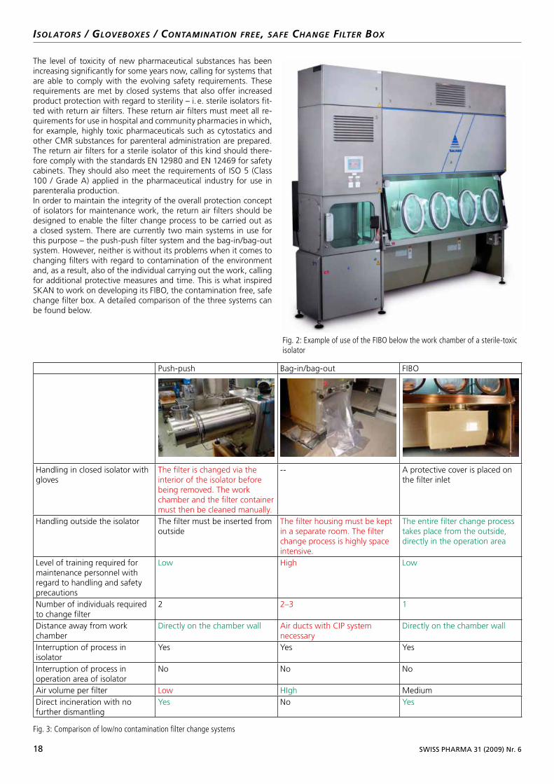
Fig. 2: Example of use of the FIBO below the work chamber of a sterile-toxic isolator
Push-push Bag-in/bag-out FIBO
Handling in closed isolator with gloves
The filter is changed via the interior of the isolator before being removed. The work chamber and the filter container must then be cleaned manually.
-- A protective cover is placed on the filter inlet
Handling outside the isolator The filter must be inserted from outside
The filter housing must be kept in a separate room. The filter change process is highly space intensive.
The entire filter change process takes place from the outside, directly in the operation area
Level of training required for maintenance personnel with regard to handling and safety precautions
Low High Low
Number of individuals required to change filter
2 2–3 1
Distance away from work chamber
Directly on the chamber wall Air ducts with CIP system necessary
Directly on the chamber wall
Interruption of process in isolator
Yes Yes Yes
Interruption of process in operation area of isolator
No No No
Air volume per filter Low HIgh MediumDirect incineration with no further dismantling
Yes No Yes
Fig. 3: Comparison of low/no contamination filter change systems
SWISS PHARMA 31 (2009) Nr. 6 19
A detailed overview of the FIBO – the contamination free, safe change filter box
Process application:The FIBO is designed to capture highly active airborne particulate substances (cytostatics and other CMR substances) and live viral or bacterial vaccines. It is particularly suitable for use in isolator sys-tems with hydrogen peroxide decontamination.
Process safety:Thanks to the clamp connection, the filter can be changed quickly and easily by a single individual. As the process chamber and the FIBO remain closed at all times during removal and no contami-nated surfaces are exposed, no special protective clothing is re-quired, saving time and providing greater comfort for personnel. The air inlet, and therefore the FIBO, is connected directly to the process chamber, avoiding the need for return air ducts and costly CIP systems for the obligatory cleaning of contaminated return air ducts between the process chamber and the filter barrier.
Disposal:The filter box can be changed safely and with no risk of contamination at the work location itself, i. e. in the same room as the process chamber. This is not possible with bagin/bagout systems, which for reasons of space as well as safety can only be accommodated in a specially separated zone of the technical floor. For easy disposal, the FIBO can be incinerated completely without being opened, and it fits through the opening of incineration ovens for hazardous waste.Given that no wet cleaning is required, no operating costs for the incineration of contaminated cleaning water are generated.
Technical application:The FIBO facilitates considerably higher air volumes in compari-son with conventional push-push filter cartridges (for H14 up to 1100m3/h, i. e. up to 5.5 times higher, and for H13 up to 2000m3/h, i. e. up to 10 times higher). See also Fig. 5: Separation efficiency.The small pressure drop at high air volumes and high separation efficiency (170Pa @ 1100m3/h) enables costs to be reduced as it allows for lower ventilator efficiency than would be required at this air volume for push-push filters, for example.
The high separation efficiency HEPA H14 can be qualified via fil-ter scanning – not only is integral measurement possible as with conventional filter cartridges, but the design of the FIBO allows for scanning of the entire filter face. Thanks to a special clamp connec-tion, the fit of the filter box flange does not have to be tested after installation.The change interval depends primarily on the level of clogging of the filter medium. With lower levels of clogging, a lifetime of up to 5 years is possible, while with extensive clogging – due for example to the weighing of micronized powder from 100 litre drums – paral-lel systems can be used.
isolators / glovEBoxEs / contamination frEE, safE changE filtEr Box
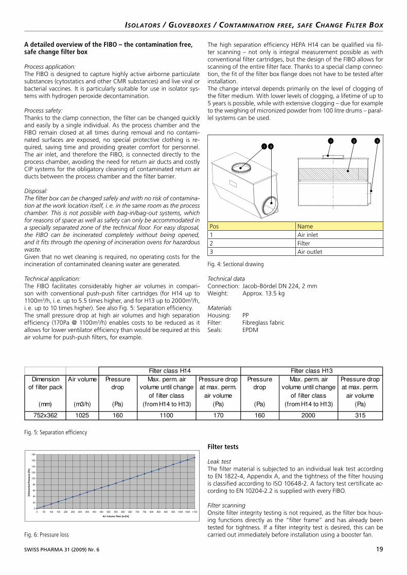
Pos Name1 Air inlet2 Filter3 Air outlet
Fig. 4: Sectional drawing
Technical dataConnection: Jacob-Bördel DN 224, 2 mmWeight: Approx. 13.5 kg
Materials Housing: PPFilter: Fibreglass fabricSeals: EPDM
SWISS PHARMA 31 (2009) Nr. 6 19
A detailed overview of the FIBO – the contamination free, safe change filter box
Process application:The FIBO is designed to capture highly active airborne particulate substances (cytostatics and other CMR substances) and live viral or bacterial vaccines. It is particularly suitable for use in isolator sys-tems with hydrogen peroxide decontamination.
Process safety:Thanks to the clamp connection, the filter can be changed quickly and easily by a single individual. As the process chamber and the FIBO remain closed at all times during removal and no contami-nated surfaces are exposed, no special protective clothing is re-quired, saving time and providing greater comfort for personnel. The air inlet, and therefore the FIBO, is connected directly to the process chamber, avoiding the need for return air ducts and costly CIP systems for the obligatory cleaning of contaminated return air ducts between the process chamber and the filter barrier.
Disposal:The filter box can be changed safely and with no risk of contamination at the work location itself, i. e. in the same room as the process chamber. This is not possible with bagin/bagout systems, which for reasons of space as well as safety can only be accommodated in a specially separated zone of the technical floor. For easy disposal, the FIBO can be incinerated completely without being opened, and it fits through the opening of incineration ovens for hazardous waste.Given that no wet cleaning is required, no operating costs for the incineration of contaminated cleaning water are generated.
Technical application:The FIBO facilitates considerably higher air volumes in compari-son with conventional push-push filter cartridges (for H14 up to 1100m3/h, i. e. up to 5.5 times higher, and for H13 up to 2000m3/h,i. e. up to 10 times higher). See also Fig. 5: Separation efficiency.The small pressure drop at high air volumes and high separation efficiency (170Pa @ 1100m3/h) enables costs to be reduced as it allows for lower ventilator efficiency than would be required at this air volume for push-push filters, for example.
The high separation efficiency HEPA H14 can be qualified via fil-ter scanning – not only is integral measurement possible as with conventional filter cartridges, but the design of the FIBO allows for scanning of the entire filter face. Thanks to a special clamp connec-tion, the fit of the filter box flange does not have to be tested after installation.The change interval depends primarily on the level of clogging of the filter medium. With lower levels of clogging, a lifetime of up to 5 years is possible, while with extensive clogging – due for example to the weighing of micronized powder from 100 litre drums – paral-lel systems can be used.
isolators / glovEBoxEs / contamination frEE, safE changE filtEr Box
Pos Name1 Air inlet2 Filter3 Air outlet
Fig. 4: Sectional drawing
Technical dataConnection: Jacob-Bördel DN 224, 2 mmWeight: Approx. 13.5 kg
Materials Housing: PPFilter: Fibreglass fabricSeals: EPDM
1 2 3
1 3
Dimension
of filter pack
(mm)
Air volume
(m3/h)
Pressure
drop
(Pa)
Max. perm. air
volume until change
of filter class
(fromH14 to H13)
Pressure drop
at max. perm.
air volume
(Pa)
Pressure
drop
(Pa)
Max. perm. air
volume until change
of filter class
(from H14 to H13)
Pressure drop
at max. perm.
air volume
(Pa)
752x362 1025 160 1100 170 160 2000 315
Filter class H14 Filter class H13
Fig. 5: Separation efficiency
0
20
40
60
80
100
120
140
160
180
0 50 100 150 200 250 300 350 400 450 500 550 600 650 700 750 800 850 900 950 1000 1050 1100
Air Volume Flow [m3/h]
DifferentialPressure[Pa]
Fig. 6: Pressure loss
Filter tests
Leak testThe filter material is subjected to an individual leak test according to EN 1822-4, Appendix A, and the tightness of the filter housing is classified according to ISO 10648-2. A factory test certificate ac-cording to EN 10204-2.2 is supplied with every FIBO.
Filter scanningOnsite filter integrity testing is not required, as the filter box hous-ing functions directly as the “filter frame” and has already been tested for tightness. If a filter integrity test is desired, this can be carried out immediately before installation using a booster fan.
9_23013_PH6_09.indd 19 2.9.2009 11:06:25 Uhr
Fig. 5: Separation efficiency
SWISS PHARMA 31 (2009) Nr. 6 19
A detailed overview of the FIBO – the contamination free, safe change filter box
Process application:The FIBO is designed to capture highly active airborne particulate substances (cytostatics and other CMR substances) and live viral or bacterial vaccines. It is particularly suitable for use in isolator sys-tems with hydrogen peroxide decontamination.
Process safety:Thanks to the clamp connection, the filter can be changed quickly and easily by a single individual. As the process chamber and the FIBO remain closed at all times during removal and no contami-nated surfaces are exposed, no special protective clothing is re-quired, saving time and providing greater comfort for personnel. The air inlet, and therefore the FIBO, is connected directly to the process chamber, avoiding the need for return air ducts and costly CIP systems for the obligatory cleaning of contaminated return air ducts between the process chamber and the filter barrier.
Disposal:The filter box can be changed safely and with no risk of contamination at the work location itself, i. e. in the same room as the process chamber. This is not possible with bagin/bagout systems, which for reasons of space as well as safety can only be accommodated in a specially separated zone of the technical floor. For easy disposal, the FIBO can be incinerated completely without being opened, and it fits through the opening of incineration ovens for hazardous waste.Given that no wet cleaning is required, no operating costs for the incineration of contaminated cleaning water are generated.
Technical application:The FIBO facilitates considerably higher air volumes in compari-son with conventional push-push filter cartridges (for H14 up to 1100m3/h, i. e. up to 5.5 times higher, and for H13 up to 2000m3/h,i. e. up to 10 times higher). See also Fig. 5: Separation efficiency.The small pressure drop at high air volumes and high separation efficiency (170Pa @ 1100m3/h) enables costs to be reduced as it allows for lower ventilator efficiency than would be required at this air volume for push-push filters, for example.
The high separation efficiency HEPA H14 can be qualified via fil-ter scanning – not only is integral measurement possible as with conventional filter cartridges, but the design of the FIBO allows for scanning of the entire filter face. Thanks to a special clamp connec-tion, the fit of the filter box flange does not have to be tested after installation.The change interval depends primarily on the level of clogging of the filter medium. With lower levels of clogging, a lifetime of up to 5 years is possible, while with extensive clogging – due for example to the weighing of micronized powder from 100 litre drums – paral-lel systems can be used.
isolators / glovEBoxEs / contamination frEE, safE changE filtEr Box
Pos Name1 Air inlet2 Filter3 Air outlet
Fig. 4: Sectional drawing
Technical dataConnection: Jacob-Bördel DN 224, 2 mmWeight: Approx. 13.5 kg
Materials Housing: PPFilter: Fibreglass fabricSeals: EPDM
1 2 3
1 3
Dimension
of filter pack
(mm)
Air volume
(m3/h)
Pressure
drop
(Pa)
Max. perm. air
volume until change
of filter class
(fromH14 to H13)
Pressure drop
at max. perm.
air volume
(Pa)
Pressure
drop
(Pa)
Max. perm. air
volume until change
of filter class
(from H14 to H13)
Pressure drop
at max. perm.
air volume
(Pa)
752x362 1025 160 1100 170 160 2000 315
Filter class H14 Filter class H13
Fig. 5: Separation efficiency
0
20
40
60
80
100
120
140
160
180
0 50 100 150 200 250 300 350 400 450 500 550 600 650 700 750 800 850 900 950 1000 1050 1100
Air Volume Flow [m3/h]
DifferentialPressure[Pa]
Fig. 6: Pressure loss
Filter tests
Leak testThe filter material is subjected to an individual leak test according to EN 1822-4, Appendix A, and the tightness of the filter housing is classified according to ISO 10648-2. A factory test certificate ac-cording to EN 10204-2.2 is supplied with every FIBO.
Filter scanningOnsite filter integrity testing is not required, as the filter box hous-ing functions directly as the “filter frame” and has already been tested for tightness. If a filter integrity test is desired, this can be carried out immediately before installation using a booster fan.
9_23013_PH6_09.indd 19 2.9.2009 11:06:25 Uhr
Fig. 6: Pressure loss
Filter tests
Leak testThe filter material is subjected to an individual leak test according to EN 1822-4, Appendix A, and the tightness of the filter housing is classified according to ISO 10648-2. A factory test certificate ac-cording to EN 10204-2.2 is supplied with every FIBO.
Filter scanningOnsite filter integrity testing is not required, as the filter box hous-ing functions directly as the “filter frame” and has already been tested for tightness. If a filter integrity test is desired, this can be carried out immediately before installation using a booster fan.
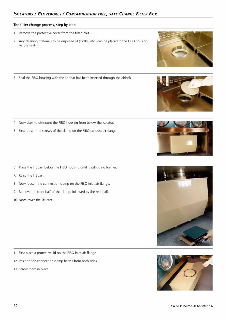
20 SWISS PHARMA 31 (2009) Nr. 6
isolators / glovEBoxEs / contamination frEE, safE changE filtEr Box
The filter change process, step by step
1. Remove the protective cover from the filter inlet.
2. Any cleaning materials to be disposed of (cloths, etc.) can be placed in the FIBO housing before sealing.
3. Seal the FIBO housing with the lid that has been inserted through the airlock.
4. Now start to dismount the FIBO housing from below the isolator.
5. First loosen the screws of the clamp on the FIBO exhaust air flange.
6. Place the lift cart below the FIBO housing until it will go no further.
7. Raise the lift cart.
8. Now loosen the connection clamp on the FIBO inlet air flange.
9. Remove the front half of the clamp, followed by the rear half.
10. Now lower the lift cart.
11. First place a protective lid on the FIBO inlet air flange.
12. Position the connection clamp halves from both sides.
13. Screw them in place.
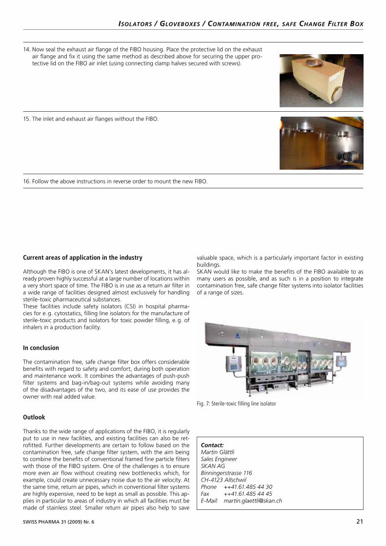
SWISS PHARMA 31 (2009) Nr. 6 21
isolators / glovEBoxEs / contamination frEE, safE changE filtEr Box
14. Now seal the exhaust air flange of the FIBO housing. Place the protective lid on the exhaust air flange and fix it using the same method as described above for securing the upper pro-tective lid on the FIBO air inlet (using connecting clamp halves secured with screws).
15. The inlet and exhaust air flanges without the FIBO.
16. Follow the above instructions in reverse order to mount the new FIBO.
Current areas of application in the industry
Although the FIBO is one of SKAN’s latest developments, it has al-ready proven highly successful at a large number of locations within a very short space of time. The FIBO is in use as a return air filter in a wide range of facilities designed almost exclusively for handling sterile-toxic pharmaceutical substances.These facilities include safety isolators (CSI) in hospital pharma-cies for e. g. cytostatics, filling line isolators for the manufacture of sterile-toxic products and isolators for toxic powder filling, e. g. of inhalers in a production facility.
In conclusion
The contamination free, safe change filter box offers considerable benefits with regard to safety and comfort, during both operation and maintenance work. It combines the advantages of push-push filter systems and bag-in/bag-out systems while avoiding many of the disadvantages of the two, and its ease of use provides the owner with real added value.
Outlook
Thanks to the wide range of applications of the FIBO, it is regularly put to use in new facilities, and existing facilities can also be ret-rofitted. Further developments are certain to follow based on the contamination free, safe change filter system, with the aim being to combine the benefits of conventional framed fine particle filters with those of the FIBO system. One of the challenges is to ensure more even air flow without creating new bottlenecks which, for example, could create unnecessary noise due to the air velocity. At the same time, return air pipes, which in conventional filter systems are highly expensive, need to be kept as small as possible. This ap-plies in particular to areas of industry in which all facilities must be made of stainless steel. Smaller return air pipes also help to save
valuable space, which is a particularly important factor in existing buildings.SKAN would like to make the benefits of the FIBO available to as many users as possible, and as such is in a position to integrate contamination free, safe change filter systems into isolator facilities of a range of sizes.
Contact:Martin GlättliSales EngineerSKAN AGBinningerstrasse 116CH4123 AllschwilPhone ++41.61.485 44 30Fax ++41.61.485 44 45EMail: [email protected]
Fig. 7: Sterile-toxic filling line isolator

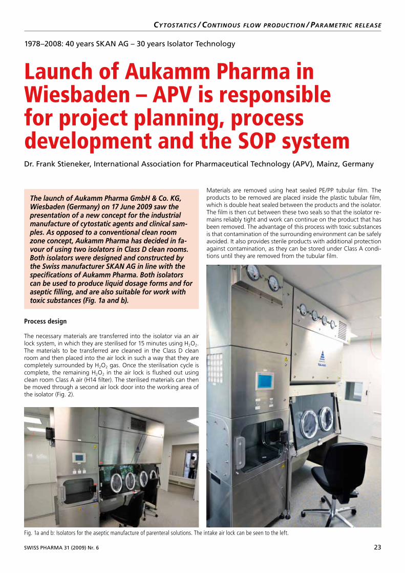
SWISS PHARMA 31 (2009) Nr. 6 23
cYtostatics / continous flow Production / ParamEtric rElEasE
Process design
The necessary materials are transferred into the isolator via an air lock system, in which they are sterilised for 15 minutes using H2O2. The materials to be transferred are cleaned in the Class D clean room and then placed into the air lock in such a way that they are completely surrounded by H2O2 gas. Once the sterilisation cycle is complete, the remaining H2O2 in the air lock is flushed out using clean room Class A air (H14 filter). The sterilised materials can then be moved through a second air lock door into the working area of the isolator (Fig. 2).
Materials are removed using heat sealed PE/PP tubular film. The products to be removed are placed inside the plastic tubular film, which is double heat sealed between the products and the isolator. The film is then cut between these two seals so that the isolator re-mains reliably tight and work can continue on the product that has been removed. The advantage of this process with toxic substances is that contamination of the surrounding environment can be safely avoided. It also provides sterile products with additional protection against contamination, as they can be stored under Class A condi-tions until they are removed from the tubular film.
1978–2008: 40 years SKAN AG – 30 years Isolator Technology
Launch of Aukamm Pharma in Wiesbaden – APV is responsible for project planning, process development and the SOP systemDr. Frank Stieneker, International Association for Pharmaceutical Technology (APV), Mainz, Germany
The launch of Aukamm Pharma GmbH & Co. KG, Wiesbaden (Germany) on 17 June 2009 saw the presentation of a new concept for the industrial manufacture of cytostatic agents and clinical sam-ples. As opposed to a conventional clean room zone concept, Aukamm Pharma has decided in fa-vour of using two isolators in Class D clean rooms.Both isolators were designed and constructed by the Swiss manufacturer SKAN AG in line with the specifications of Aukamm Pharma. Both isolators can be used to produce liquid dosage forms and for aseptic filling, and are also suitable for work with toxic substances (Fig. 1a and b).
Fig. 1a and b: Isolators for the aseptic manufacture of parenteral solutions. The intake air lock can be seen to the left.
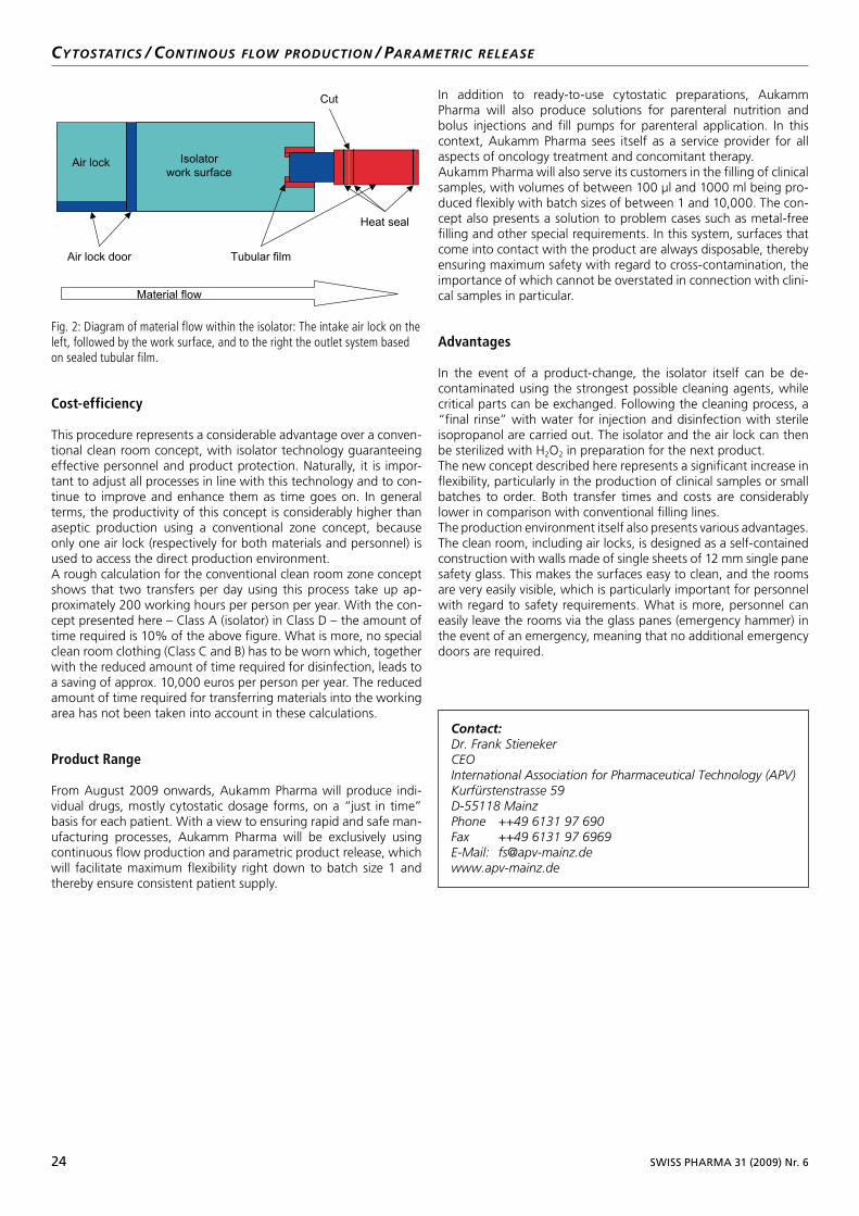
24 SWISS PHARMA 31 (2009) Nr. 6
cYtostatics / continous flow Production / ParamEtric rElEasE
Cost-efficiency
This procedure represents a considerable advantage over a conven-tional clean room concept, with isolator technology guaranteeing effective personnel and product protection. Naturally, it is impor-tant to adjust all processes in line with this technology and to con-tinue to improve and enhance them as time goes on. In general terms, the productivity of this concept is considerably higher than aseptic production using a conventional zone concept, because only one air lock (respectively for both materials and personnel) is used to access the direct production environment. A rough calculation for the conventional clean room zone concept shows that two transfers per day using this process take up ap-proximately 200 working hours per person per year. With the con-cept presented here – Class A (isolator) in Class D – the amount of time required is 10% of the above figure. What is more, no special clean room clothing (Class C and B) has to be worn which, together with the reduced amount of time required for disinfection, leads to a saving of approx. 10,000 euros per person per year. The reduced amount of time required for transferring materials into the working area has not been taken into account in these calculations.
Product Range
From August 2009 onwards, Aukamm Pharma will produce indi-vidual drugs, mostly cytostatic dosage forms, on a “just in time” basis for each patient. With a view to ensuring rapid and safe man-ufacturing processes, Aukamm Pharma will be exclusively using continuous flow production and parametric product release, which will facilitate maximum flexibility right down to batch size 1 and thereby ensure consistent patient supply.
In addition to ready-to-use cytostatic preparations, Aukamm Pharma will also produce solutions for parenteral nutrition and bolus injections and fill pumps for parenteral application. In this context, Aukamm Pharma sees itself as a service provider for all aspects of oncology treatment and concomitant therapy.Aukamm Pharma will also serve its customers in the filling of clinical samples, with volumes of between 100 µl and 1000 ml being pro-duced flexibly with batch sizes of between 1 and 10,000. The con-cept also presents a solution to problem cases such as metal-free filling and other special requirements. In this system, surfaces that come into contact with the product are always disposable, thereby ensuring maximum safety with regard to cross-contamination, the importance of which cannot be overstated in connection with clini-cal samples in particular.
Advantages
In the event of a product-change, the isolator itself can be de-contaminated using the strongest possible cleaning agents, while critical parts can be exchanged. Following the cleaning process, a “final rinse” with water for injection and disinfection with sterile isopropanol are carried out. The isolator and the air lock can then be sterilized with H2O2 in preparation for the next product.The new concept described here represents a significant increase in flexibility, particularly in the production of clinical samples or small batches to order. Both transfer times and costs are considerably lower in comparison with conventional filling lines.The production environment itself also presents various advantages. The clean room, including air locks, is designed as a self-contained construction with walls made of single sheets of 12 mm single pane safety glass. This makes the surfaces easy to clean, and the rooms are very easily visible, which is particularly important for personnel with regard to safety requirements. What is more, personnel can easily leave the rooms via the glass panes (emergency hammer) in the event of an emergency, meaning that no additional emergency doors are required.
Fig. 2: Diagram of material flow within the isolator: The intake air lock on the left, followed by the work surface, and to the right the outlet system based on sealed tubular film.
Air lock
Air lock door
Isolator
work surface
Heat seal
Cut
Tubular film
Fig. 2: Diagram of material flow within the isolator: The intake air lock on the left, followed by the work surface, and to the right the outlet system based on sealed tubular film.
Material flow
Contact:Dr. Frank StienekerCEOInternational Association for Pharmaceutical Technology (APV)Kurfürstenstrasse 59D55118 MainzPhone ++49 6131 97 690Fax ++49 6131 97 6969EMail: fs@apvmainz.dewww.apvmainz.de
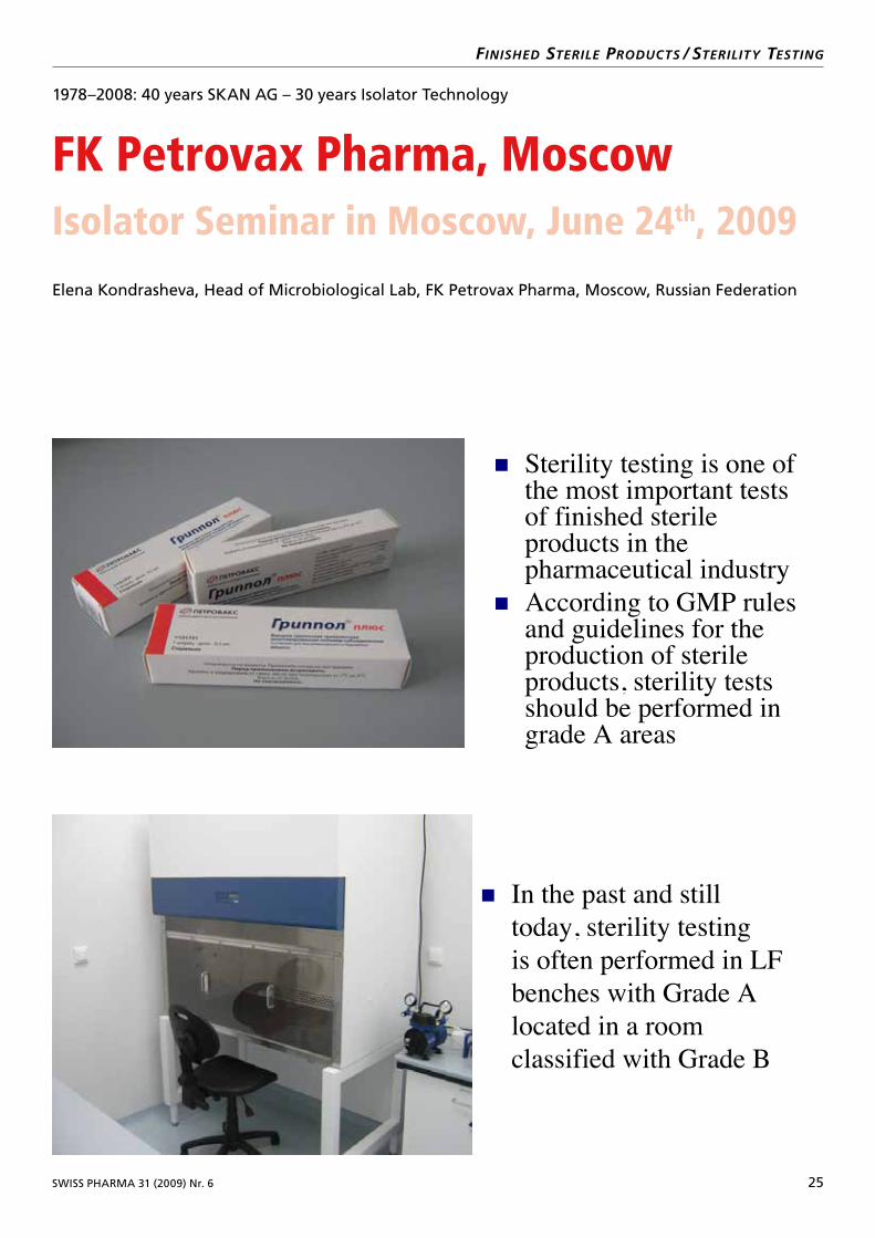
SWISS PHARMA 31 (2009) Nr. 6 25
finishEd stErilE Products / stErilitY tEsting
1978–2008: 40 years SKAN AG – 30 years Isolator Technology
FK Petrovax Pharma, MoscowIsolator Seminar in Moscow, June 24th, 2009
Elena Kondrasheva, Head of Microbiological Lab, FK Petrovax Pharma, Moscow, Russian Federation
FK Petrovax PharmaKondrasheva Elena, Head of Microbiological Lab
Isolator Seminar in Moscow , June 24th 2009
Sterility testing is one of the most important tests of finished sterile products in the
According to GMP rules and guidelines for the production of sterile products, sterility tests should be performed in grade A areas
pharmaceutical industry
In the past and still
is often performed in LF
located in a room classified with Grade B
FK Petrovax PharmaKondrasheva Elena, Head of Microbiological Lab
Isolator Seminar in Moscow , June 24th 2009
today, sterility testing
benches with Grade A
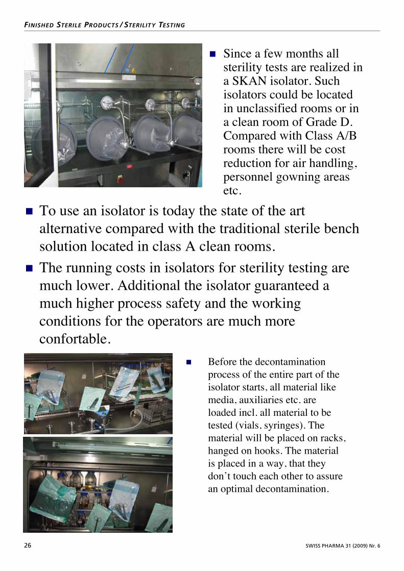
26 SWISS PHARMA 31 (2009) Nr. 6
finishEd stErilE Products / stErilitY tEsting
FK Petrovax PharmaKondrasheva Elena, Head of Microbiological Lab
Isolator Seminar in Moscow , June 24th 2009
Since a few months all
a SKAN isolator. Such
in unclassified rooms or in
Compared with Class A/B rooms there will be cost reduction for air handling, personnel gowning areas etc.
sterility tests are realized in
isolators could be located
a clean room of Grade D.
FK Petrovax PharmaKondrasheva Elena, Head of Microbiological Lab
Isolator Seminar in Moscow , June 24th 2009
To use an isolator is today the state of the art alternative compared with the traditional sterile bench solution located in class A clean rooms.The running costs in isolators for sterility testing are much lower. Additional the isolator guaranteed a much higher process safety and the working conditions for the operators are much more confortable.
FK Petrovax PharmaKondrasheva Elena, Head of Microbiological Lab
Isolator Seminar in Moscow , June 24th 2009
Before the decontamination process of the entire part of the isolator starts, all material like media, auxiliaries etc. are loaded incl. all material to be
material will be placed on racks, hanged on hooks. The material is placed in a way, that they don’t touch each other to assure an optimal decontamination.
tested (vials, syringes). The
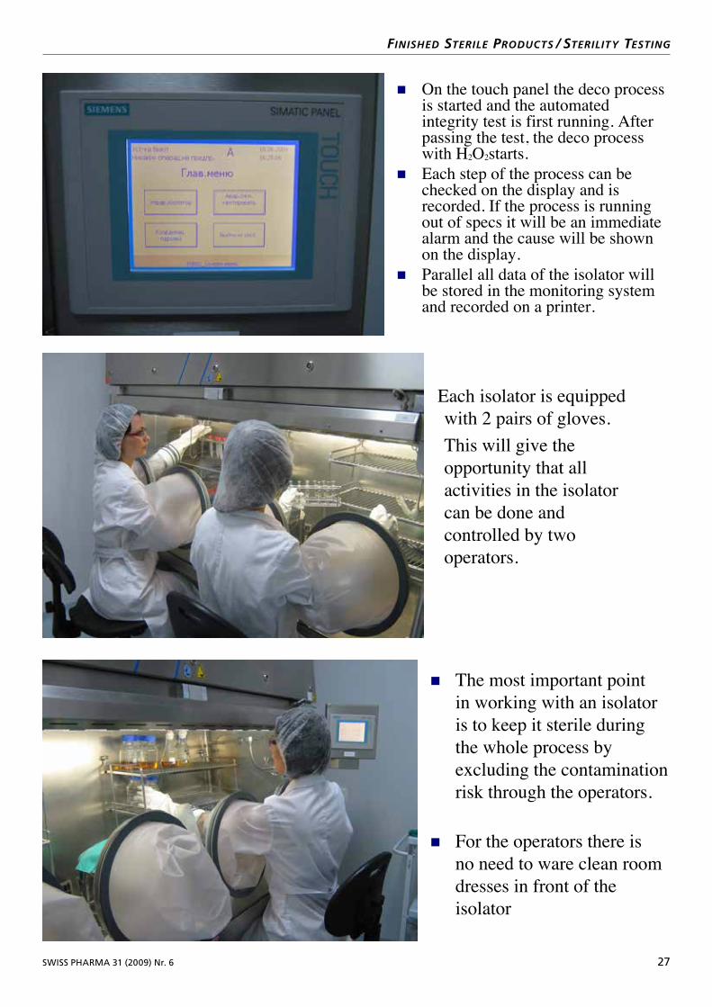
SWISS PHARMA 31 (2009) Nr. 6 27
finishEd stErilE Products / stErilitY tEsting
FK Petrovax PharmaKondrasheva Elena, Head of Microbiological Lab
Isolator Seminar in Moscow , June 24th 2009
On the touch panel the deco process is started and the automated integrity test is first running. After passing the test, the deco process
Each step of the process can be checked on the display and is recorded. If the process is running out of specs it will be an immediate alarm and the cause will be shown on the display.Parallel all data of the isolator will be stored in the monitoring system and recorded on a printer.
with H2O2starts.
FK Petrovax PharmaKondrasheva Elena, Head of Microbiological Lab
Isolator Seminar in Moscow , June 24th 2009
Each isolator is equipped with 2 pairs of gloves.This will give the opportunity that all activities in the isolator can be done and controlled by two operators.
FK Petrovax PharmaKondrasheva Elena, Head of Microbiological Lab
Isolator Seminar in Moscow , June 24th 2009
The most important point in working with an isolator is to keep it sterile during the whole process by
dresses in front of the isolator
For the operators there is no need to ware clean room
excluding the contamination risk through the operators.
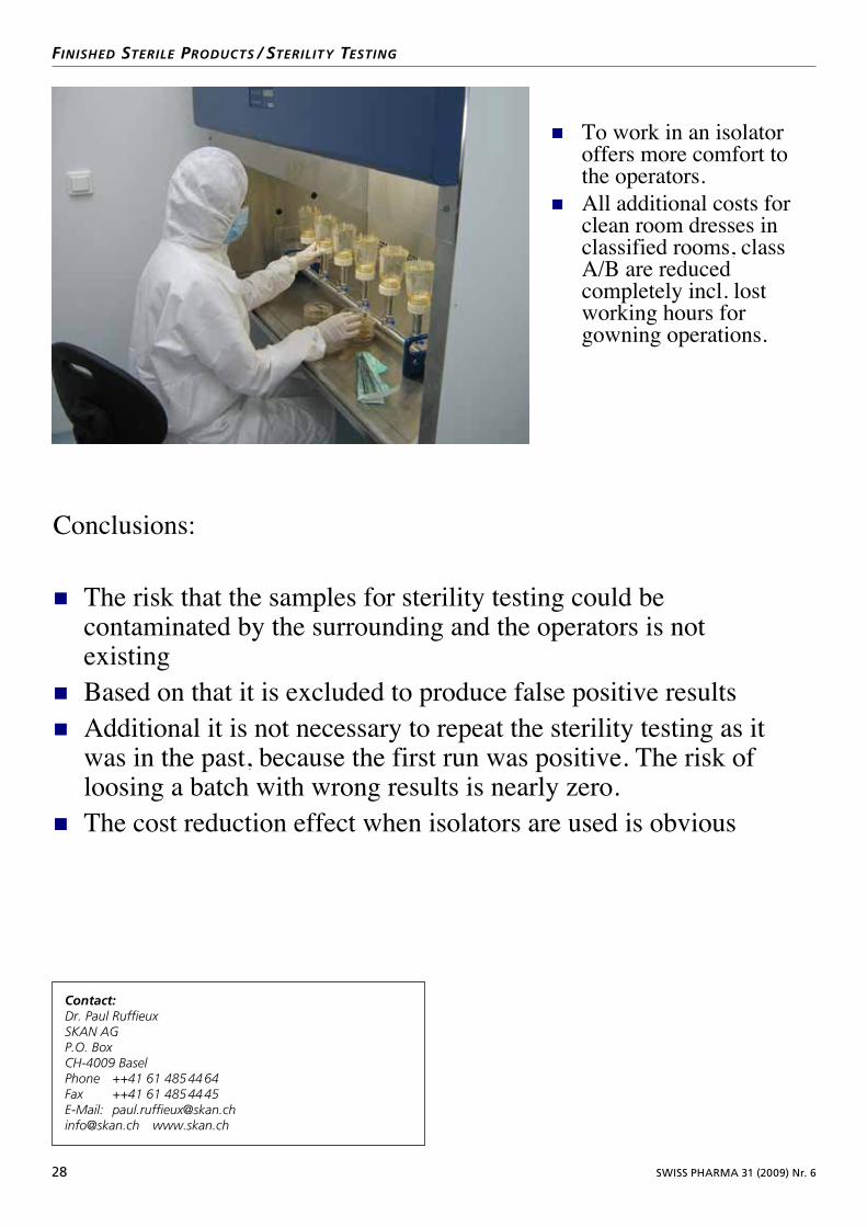
28 SWISS PHARMA 31 (2009) Nr. 6
finishEd stErilE Products / stErilitY tEsting
FK Petrovax PharmaKondrasheva Elena, Head of Microbiological Lab
Isolator Seminar in Moscow , June 24th 2009
To work in an isolator offers more comfort to the operators.All additional costs for clean room dresses in classified rooms, class A/B are reduced completely incl. lost working hours for gowning operations.
Contact:Dr. Paul RuffieuxSKAN AGP.O. BoxCH4009 BaselPhone ++41 61 485 44 64Fax ++41 61 485 44 45EMail: [email protected]@skan.ch www.skan.ch
FK Petrovax PharmaKondrasheva Elena, Head of Microbiological Lab
Isolator Seminar in Moscow , June 24th 2009
Conclusions:
The risk that the samples for sterility testing could be contaminated by the surrounding and the operators is not existingBased on that it is excluded to produce false positive resultsAdditional it is not necessary to repeat the sterility testing as it was in the past, because the first run was positive. The risk ofloosing a batch with wrong results is nearly zero.The cost reduction effect when isolators are used is obvious
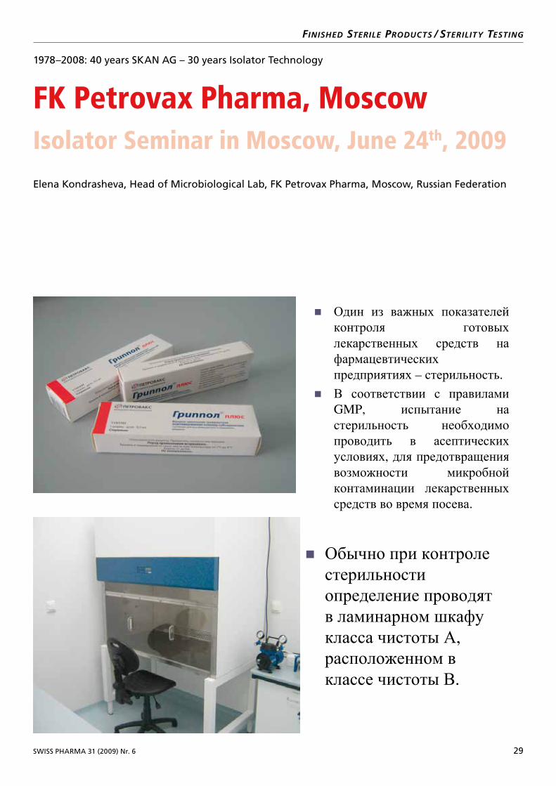
SWISS PHARMA 31 (2009) Nr. 6 29
finishEd stErilE Products / stErilitY tEsting
1978–2008: 40 years SKAN AG – 30 years Isolator Technology
FK Petrovax Pharma, MoscowIsolator Seminar in Moscow, June 24th, 2009
Elena Kondrasheva, Head of Microbiological Lab, FK Petrovax Pharma, Moscow, Russian Federation
ООО ФК «ПЕТРОВАКС»
Один из важных показателейконтроля готовыхлекарственных средств нафармацевтическихпредприятиях – стерильность.
В соответствии с правиламиGMP, испытание настерильность необходимопроводить в асептическихусловиях, для предотвращениявозможности микробнойконтаминации лекарственныхсредств во время посева.
Обычно при контролестерильностиопределение проводятв ламинарном шкафукласса чистоты А,
расположенном вклассе чистоты В.
ООО ФК «ПЕТРОВАКС»
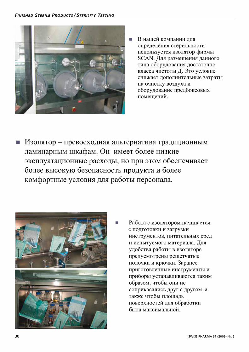
30 SWISS PHARMA 31 (2009) Nr. 6
finishEd stErilE Products / stErilitY tEsting
ООО ФК «ПЕТРОВАКС»
В нашей компании дляопределения стерильностииспользуется изолятор фирмыSCAN. Для размещения данноготипа оборудования достаточнокласса чистоты Д. Это условиеснижает дополнительные затратына очистку воздуха иоборудование предбоксовыхпомещений.
ООО ФК «ПЕТРОВАКС»
Изолятор – превосходная альтернатива традиционнымламинарным шкафам. Он имеет более низкиеэксплуатационные расходы, но при этом обеспечиваетболее высокую безопасность продукта и болеекомфортные условия для работы персонала.
ООО ФК «ПЕТРОВАКС»
Работа с изолятором начинаетсяс подготовки и загрузкиинструментов, питательных среди испытуемого материала. Дляудобства работы в изоляторепредусмотрены решетчатыеполочки и крючки. Заранееприготовленные инструменты иприборы устанавливаются такимобразом, чтобы они несоприкасались друг с другом, атакже чтобы площадьповерхностей для обработкибыла максимальной.

SWISS PHARMA 31 (2009) Nr. 6 31
finishEd stErilE Products / stErilitY tEsting
ООО ФК «ПЕТРОВАКС»
Далее проводится автоматическаяпроверка изолятора на герметичностьи стерилизация загруженногоматериала и рабочих поверхностейпарами перекиси водорода. Управление процессомосуществляется с помощьюкомпьютера со встроеннымсенсорным монитором.
Каждый этап работы изолятораотображается на дисплее. Принарушении условий работы изолятора(разгерметизация, нехватка перекисии др.), включается аварийнаясигнализация, на дисплееотображается причина проблемы.
Параллельно происходит распечаткаинформации о работе оборудованияна принтере.
ООО ФК «ПЕТРОВАКС»
Работа в изолятореможет проводиться какодним оператором, таки одновременно двумя. Для этогопредусмотрены 2 парывстроенных перчаток.
ООО ФК «ПЕТРОВАКС»
Самое важное, чторабота в изоляторепозволяет избежать, такназываемый, человеческий фактор.
При проведениииспытания в изоляторелекарственных средствна стерильность, персоналу нетнеобходимости работатьв стерильной одежде.
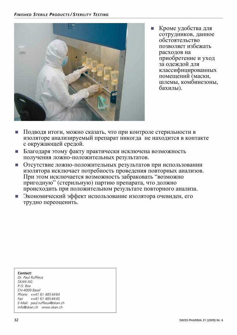
32 SWISS PHARMA 31 (2009) Nr. 6
finishEd stErilE Products / stErilitY tEsting
ООО ФК «ПЕТРОВАКС»
Кроме удобства длясотрудников, данноеобстоятельствопозволяет избежатьрасходов наприобретение и уходза одеждой дляклассифицированныхпомещений (маски, шлемы, комбинезоны, бахилы).
ООО ФК «ПЕТРОВАКС»
Подводя итоги, можно сказать, что при контроле стерильности визоляторе анализируемый препарат никогда не находится в контактес окружающей средой.
Благодаря этому факту практически исключена возможностьполучения ложно-положительных результатов.
Отсутствие ложно-положительных результатов при использованииизолятора исключает потребность проведения повторных анализов. При этом исключается возможность забраковать “возможнопригодную” (стерильную) партию препарата, что должнопроисходить при положительном результате повторного анализа.
Экономический эффект использование изолятора очевиден, еготрудно переоценить.
Contact:Dr. Paul RuffieuxSKAN AGP.O. BoxCH4009 BaselPhone ++41 61 485 44 64Fax ++41 61 485 44 45EMail: [email protected]@skan.ch www.skan.ch

SKAN AG - Postfach - CH-4009 Basel Phone +41 (0)61 485 44 44 - [email protected] - www.skan.ch
SAFETY BY CONTAINMENT