Feldbus-Kommunikation Fieldbus...
24
Feldbus-Kommunikation Fieldbus communication e2c 20 – easy to connect closer contacts
Transcript of Feldbus-Kommunikation Fieldbus...

Feldbus-Kommunikation
Fieldbus communication
e2c 20 – easy to connect
c l o s e r c o n t a c t s
9.2
e2c 20 – das IP 20 Verteilersystem fürden Schaltschrank
Nach wie vor werden für Schaltschränke und VerteilerkästenVerdrahtungssysteme eingesetzt, die den einfachen Anschlussvon Sensoren und Aktoren ermöglichen und zudem über einengängigen Feldbus angesteuert werden können.
e2c 20 ist eine kompakte, modulare Feldbusstation in IP 20 mit flexiblen und vielseitigen Einsatzmöglichkeiten.Über den Buskoppler gibt es Schnittstellen zu denFeldbussystemen Profibus, CanOpen und DeviceNet.
Bewährt und wirtschaftlich bei übersichtlichenAnwendungen
Der Einsatz von IP 20-Verdrahtungssystemen macht beispielsweisebei kleineren Montage-/ und Handling-Automaten Sinn, in denenkeine größeren Entfernungen zwischen Schaltschrank und denwenigen I/O-Signalen liegen.
Beispielsweise durch die praxis-nahe Anschlussleisten-Verriegelung von e2c 20 lassensich solche Anlagen undMaschinen wirtschaftlich ver-drahten und instandhalten.
Switch cabinets and distribution boxes continue to rely on wiringsystems that can be controlled using standard fieldbus compo-nents, while enabling easy connection to sensors and actuators.
e2c 20 is a compact, IP20 rated, modular fieldbus stationthat enables a wide range of flexible applications.Interfaces to Profibus, CanOpen, and DeviceNet fieldbussystems are made available over the bus coupler.
A proven, cost-effective solution for simple applications
IP 20 wiring systems are ideal for applications involving smallassembly and handling machines where no long distances existbetween the switch cabinet and a small number of I/O signals.
e2c 20 provides special featuressuch as practical, removableterminal blocks, making it pos-sible to wire and maintain sys-tems and machines of this typecost-effectively.
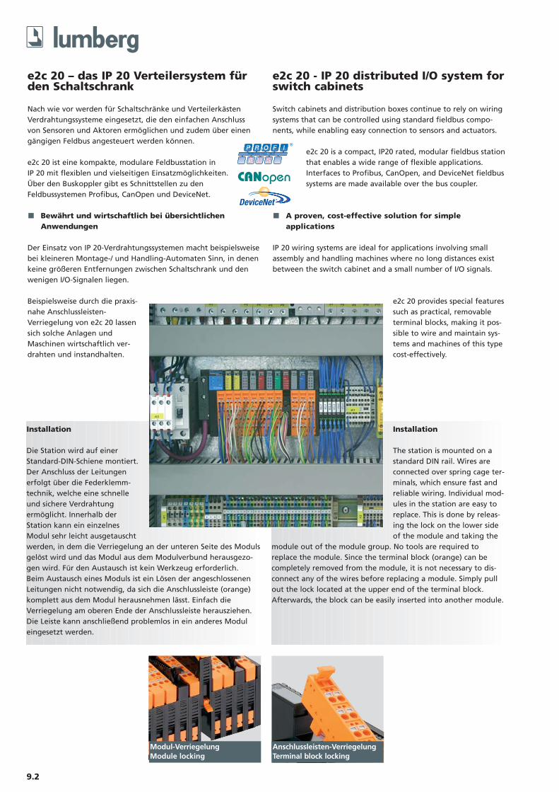
Installation
Die Station wird auf einerStandard-DIN-Schiene montiert.Der Anschluss der Leitungenerfolgt über die Federklemm-technik, welche eine schnelleund sichere Verdrahtungermöglicht. Innerhalb derStation kann ein einzelnesModul sehr leicht ausgetauschtwerden, in dem die Verriegelung an der unteren Seite des Modulsgelöst wird und das Modul aus dem Modulverbund herausgezo-gen wird. Für den Austausch ist kein Werkzeug erforderlich.Beim Austausch eines Moduls ist ein Lösen der angeschlossenenLeitungen nicht notwendig, da sich die Anschlussleiste (orange)komplett aus dem Modul herausnehmen lässt. Einfach dieVerriegelung am oberen Ende der Anschlussleiste herausziehen.Die Leiste kann anschließend problemlos in ein anderes Moduleingesetzt werden.
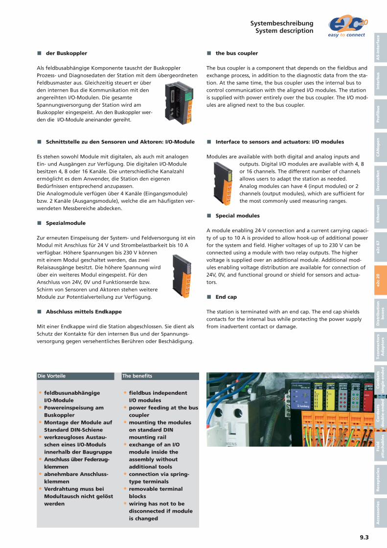
Modul-VerriegelungModule locking
Anschlussleisten-VerriegelungTerminal block locking
e2c 20 - IP 20 distributed I/O system forswitch cabinets
Installation
The station is mounted on astandard DIN rail. Wires areconnected over spring cage ter-minals, which ensure fast andreliable wiring. Individual mod-ules in the station are easy toreplace. This is done by releas-ing the lock on the lower sideof the module and taking the
module out of the module group. No tools are required toreplace the module. Since the terminal block (orange) can becompletely removed from the module, it is not necessary to dis-connect any of the wires before replacing a module. Simply pullout the lock located at the upper end of the terminal block.Afterwards, the block can be easily inserted into another module.
• feldbusunabhängigeI/O-Module
• Powereinspeisung am Buskoppler
• Montage der Module auf Standard DIN-Schiene
• werkzeugloses Austau-schen eines I/O-Moduls innerhalb der Baugruppe
• Anschluss über Federzug-klemmen
• abnehmbare Anschluss-klemmen
• Verdrahtung muss beiModultausch nicht gelöstwerden
• fieldbus independent I/O modules
• power feeding at the bus coupler
• mounting the modules on standard DIN mounting rail
• exchange of an I/O module inside the assembly without additional tools
• connection via spring-type terminals
• removable terminal blocks
• wiring has not to be disconnected if module is changed
der Buskoppler
Als feldbusabhängige Komponente tauscht der BuskopplerProzess- und Diagnosedaten der Station mit dem übergeordnetenFeldbusmaster aus. Gleichzeitig steuert er überden internen Bus die Kommunikation mit denangereihten I/O-Modulen. Die gesamteSpannungsversorgung der Station wird amBuskoppler eingespeist. An den Buskoppler wer-den die I/O-Module aneinander gereiht.
Schnittstelle zu den Sensoren und Aktoren: I/O-Module
Es stehen sowohl Module mit digitalen, als auch mit analogenEin- und Ausgängen zur Verfügung. Die digitalen I/O-Modulebesitzen 4, 8 oder 16 Kanäle. Die unterschiedliche Kanalzahlermöglicht es dem Anwender, die Station den eigenenBedürfnissen entsprechend anzupassen. Die Analogmodule verfügen über 4 Kanäle (Eingangsmodule)bzw. 2 Kanäle (Ausgangsmodule), welche die am häufigsten ver-wendeten Messbereiche abdecken.
Spezialmodule
Zur erneuten Einspeisung der System- und Feldversorgung ist einModul mit Anschluss für 24 V und Strombelastbarkeit bis 10 Averfügbar. Höhere Spannungen bis 230 V könnenmit einem Modul geschaltet werden, das zweiRelaisausgänge besitzt. Die höhere Spannung wirdüber ein weiteres Modul eingespeist. Für denAnschluss von 24V, 0V und Funktionserde bzw.Schirm von Sensoren und Aktoren stehen weitereModule zur Potentialverteilung zur Verfügung.
Abschluss mittels Endkappe
Mit einer Endkappe wird die Station abgeschlossen. Sie dient alsSchutz der Kontakte für den internen Bus und der Spannungs-versorgung gegen versehentliches Berühren oder Beschädigung.
the bus coupler
The bus coupler is a component that depends on the fieldbus andexchange process, in addition to the diagnostic data from the sta-tion. At the same time, the bus coupler uses the internal bus tocontrol communication with the aligned I/O modules. The stationis supplied with power entirely over the bus coupler. The I/O mod-ules are aligned next to the bus coupler.
Interface to sensors and actuators: I/O modules
Modules are available with both digital and analog inputs andoutputs. Digital I/O modules are available with 4, 8or 16 channels. The different number of channelsallows users to adapt the station as needed. Analog modules can have 4 (input modules) or 2channels (output modules), which are sufficient forthe most commonly used measuring ranges.
Special modules
A module enabling 24-V connection and a current carrying capaci-ty of up to 10 A is provided to allow hook-up of additional powerfor the system and field. Higher voltages of up to 230 V can beconnected using a module with two relay outputs. The highervoltage is supplied over an additional module. Additional mod-ules enabling voltage distribution are available for connection of24V, 0V, and functional ground or shield for sensors and actua-tors.
End cap
The station is terminated with an end cap. The end cap shieldscontacts for the internal bus while protecting the power supplyfrom inadvertent contact or damage.
Die Vorteile The benefits
9.3
AS-I
nte
rface
Inte
rbu
sPro
fib
us
CA
No
pen
Devic
eN
et
Eth
ern
et
e2c
67
e2c
20
Dis
trib
uti
on
bo
xes
T-co
nn
ect
ors
Ad
ap
tors
Co
rdse
ts
sin
gle
-en
ded
Co
rdse
ts
do
ub
le-e
nd
ed
Field
att
ach
ab
les
Rece
pta
cles
Acc
ess
ori
es
SystembeschreibungSystem description
9.4
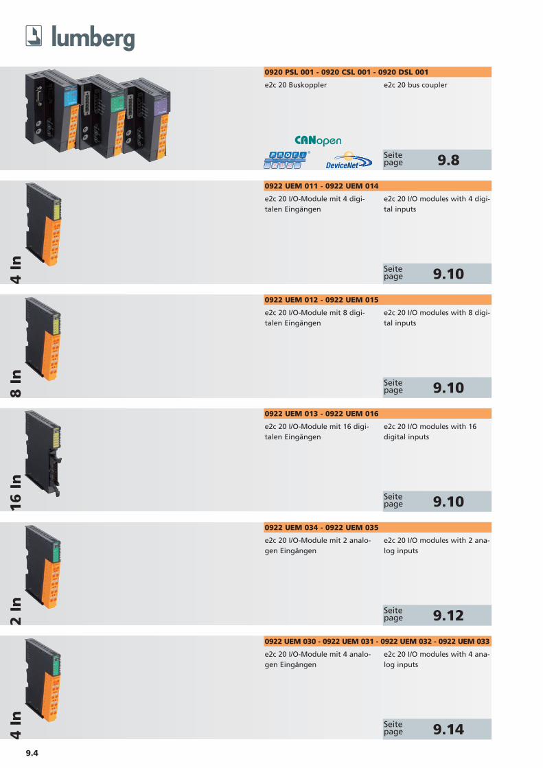
e2c 20 Buskoppler e2c 20 bus coupler
Seitepage 9.8
e2c 20 I/O-Module mit 4 digi-talen Eingängen
e2c 20 I/O modules with 4 digi-tal inputs
Seitepage 9.10
e2c 20 I/O-Module mit 8 digi-talen Eingängen
e2c 20 I/O modules with 8 digi-tal inputs
Seitepage 9.10
e2c 20 I/O-Module mit 16 digi-talen Eingängen
e2c 20 I/O modules with 16digital inputs
Seitepage 9.10
e2c 20 I/O-Module mit 2 analo-gen Eingängen
e2c 20 I/O modules with 2 ana-log inputs
Seitepage 9.12
e2c 20 I/O-Module mit 4 analo-gen Eingängen
e2c 20 I/O modules with 4 ana-log inputs
Seitepage 9.14
8 I
n4 I
n16 I
n2 I
n
0920 PSL 001 - 0920 CSL 001 - 0920 DSL 001
0922 UEM 011 - 0922 UEM 014
0922 UEM 012 - 0922 UEM 015
0922 UEM 013 - 0922 UEM 016
0922 UEM 034 - 0922 UEM 035
0922 UEM 030 - 0922 UEM 031 - 0922 UEM 032 - 0922 UEM 033
4 I
n
9.5
ÜbersichtOverview
AS-I
nte
rface
Inte
rbu
sPro
fib
us
CA
No
pen
Devic
eN
et
Eth
ern
et
e2c
67
e2c
20
Dis
trib
uti
on
bo
xes
T-co
nn
ect
ors
Ad
ap
tors
Co
rdse
ts
sin
gle
-en
ded
Co
rdse
ts
do
ub
le-e
nd
ed
Field
att
ach
ab
les
Rece
pta
cles
Acc
ess
ori
es
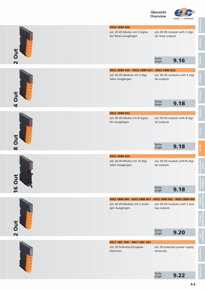
e2c 20 I/O-Module mit 4 digi-talen Ausgängen
e2c 20 I/O modules with 4 digi-tal outputs
Seitepage 9.18
e2c 20 I/O-Modul mit 8 digita-len Ausgängen
e2c 20 I/O module with 8 digi-tal outputs
Seitepage 9.18
e2c 20 I/O-Modul mit 16 digi-talen Ausgängen
e2c 20 I/O module with16 digi-tal outputs
Seitepage 9.18
e2c 20 I/O-Module mit 2 analo-gen Ausgängen
e2c 20 I/O modules with 2 ana-log outputs
Seitepage 9.20
e2c 20 Potential-Einspeise-klemmen
e2c 20 potential power supplyterminals
Seitepage 9.22
16 O
ut
4 O
ut
8 O
ut
2 O
ut
0922 UEM 020 - 0922 UEM 021 - 0922 UEM 022
0922 UEM 023
0922 UEM 024
e2c 20 I/O-Modul mit 2 digita-len Relais-Ausgängen
e2c 20 I/O module with 2 digi-tal relay outputs
Seitepage 9.162
Ou
t
0922 UEM 050
0922 UEM 040 - 0922 UEM 041 - 0922 UEM 042 - 0922 UEM 043
0921 UEC 500 - 0921 UEC 501
9.6
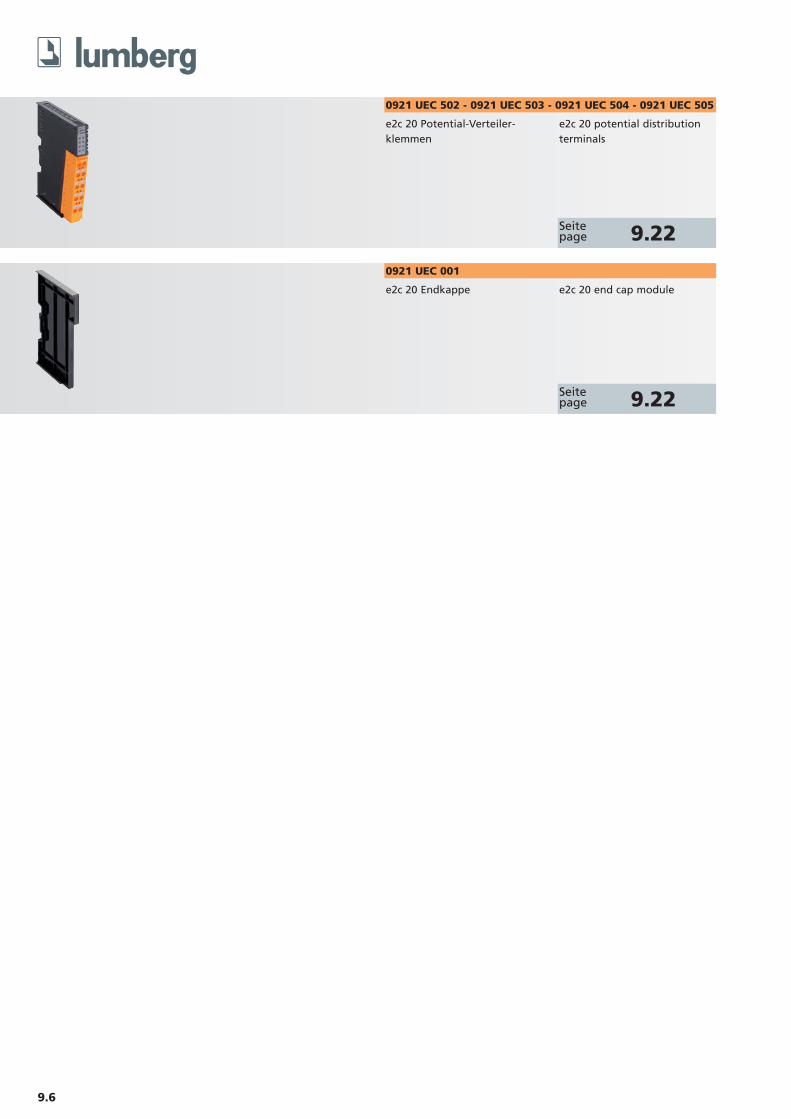
e2c 20 Potential-Verteiler-klemmen
e2c 20 potential distributionterminals
Seitepage 9.22
0921 UEC 502 - 0921 UEC 503 - 0921 UEC 504 - 0921 UEC 505
e2c 20 Endkappe e2c 20 end cap module
Seitepage 9.22
0921 UEC 001
9.7
AS-I
nte
rface
Inte
rbu
sPro
fib
us
CA
No
pen
Devic
eN
et
Eth
ern
et
e2c
67
e2c
20
Dis
trib
uti
on
bo
xes
T-co
nn
ect
ors
Ad
ap
tors
Co
rdse
ts
sin
gle
-en
ded
Co
rdse
ts
do
ub
le-e
nd
ed
Field
att
ach
ab
les
Rece
pta
cles
Acc
ess
ori
es
9.8
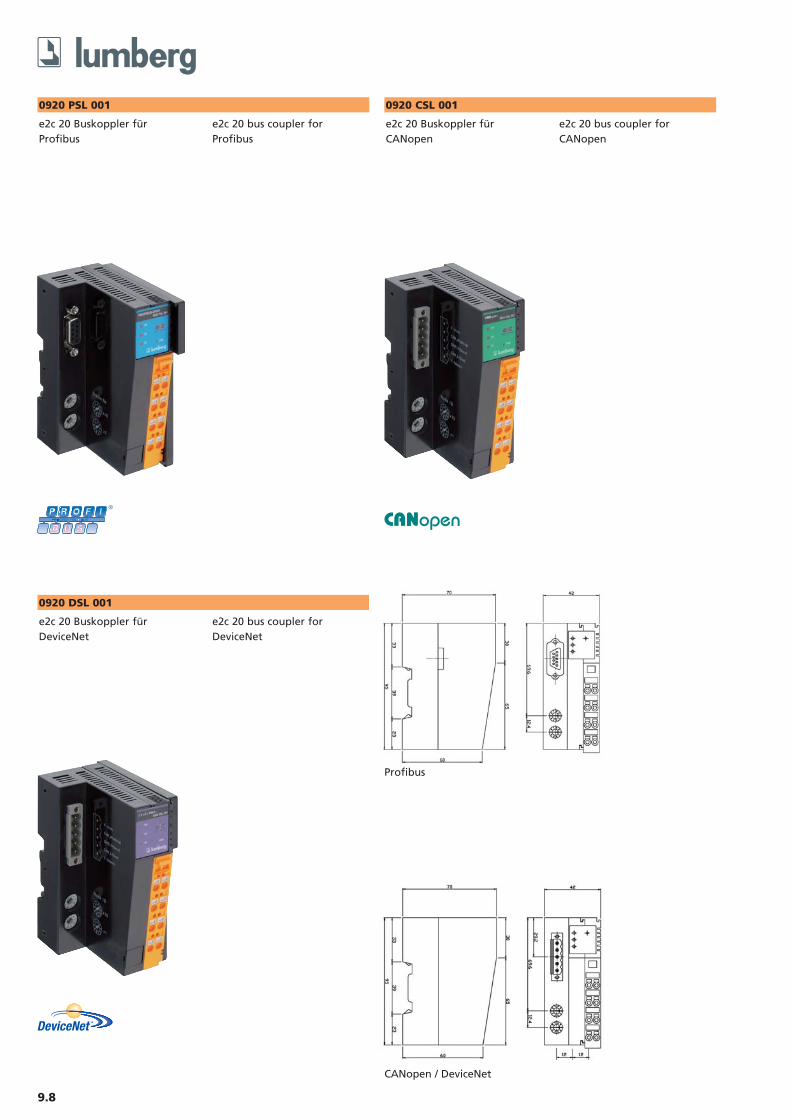
0920 PSL 001
e2c 20 Buskoppler für Profibus
e2c 20 bus coupler forProfibus
0920 CSL 001
e2c 20 Buskoppler fürCANopen
e2c 20 bus coupler forCANopen
0920 DSL 001
e2c 20 Buskoppler fürDeviceNet
e2c 20 bus coupler forDeviceNet
Profibus
CANopen / DeviceNet
9.9Ein Einsatz der Produkte in aggressiven Medienist im Einzelfall zu überprüfen.
The application of these products in harsh environments should always be checked before use
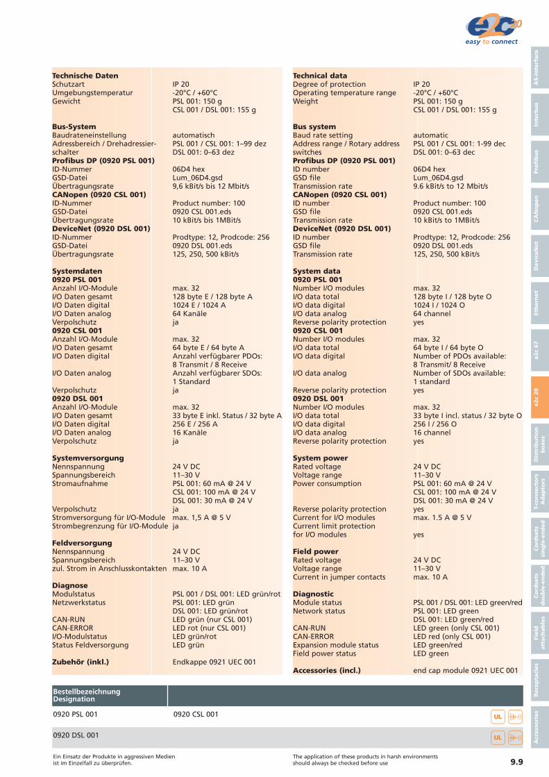
Technische DatenSchutzart IP 20Umgebungstemperatur -20°C / +60°CGewicht PSL 001: 150 g
CSL 001 / DSL 001: 155 g
Bus-SystemBaudrateneinstellung automatischAdressbereich / Drehadressier- PSL 001 / CSL 001: 1–99 dezschalter DSL 001: 0–63 dezProfibus DP (0920 PSL 001)ID-Nummer 06D4 hexGSD-Datei Lum_06D4.gsdÜbertragungsrate 9,6 kBit/s bis 12 Mbit/sCANopen (0920 CSL 001)ID-Nummer Product number: 100GSD-Datei 0920 CSL 001.edsÜbertragungsrate 10 kBit/s bis 1MBit/sDeviceNet (0920 DSL 001)ID-Nummer Prodtype: 12, Prodcode: 256GSD-Datei 0920 DSL 001.edsÜbertragungsrate 125, 250, 500 kBit/s
Systemdaten0920 PSL 001Anzahl I/O-Module max. 32I/O Daten gesamt 128 byte E / 128 byte AI/O Daten digital 1024 E / 1024 AI/O Daten analog 64 KanäleVerpolschutz ja0920 CSL 001Anzahl I/O-Module max. 32I/O Daten gesamt 64 byte E / 64 byte AI/O Daten digital Anzahl verfügbarer PDOs:
8 Transmit / 8 ReceiveI/O Daten analog Anzahl verfügbarer SDOs:
1 StandardVerpolschutz ja0920 DSL 001Anzahl I/O-Module max. 32I/O Daten gesamt 33 byte E inkl. Status / 32 byte AI/O Daten digital 256 E / 256 AI/O Daten analog 16 KanäleVerpolschutz ja
SystemversorgungNennspannung 24 V DCSpannungsbereich 11–30 VStromaufnahme PSL 001: 60 mA @ 24 V
CSL 001: 100 mA @ 24 VDSL 001: 30 mA @ 24 V
Verpolschutz jaStromversorgung für I/O-Module max. 1,5 A @ 5 VStrombegrenzung für I/O-Module ja
FeldversorgungNennspannung 24 V DCSpannungsbereich 11–30 Vzul. Strom in Anschlusskontakten max. 10 A
DiagnoseModulstatus PSL 001 / DSL 001: LED grün/rotNetzwerkstatus PSL 001: LED grün
DSL 001: LED grün/rotCAN-RUN LED grün (nur CSL 001)CAN-ERROR LED rot (nur CSL 001)I/O-Modulstatus LED grün/rotStatus Feldversorgung LED grün
Zubehör (inkl.) Endkappe 0921 UEC 001
Technical dataDegree of protection IP 20Operating temperature range -20°C / +60°CWeight PSL 001: 150 g
CSL 001 / DSL 001: 155 g
Bus systemBaud rate setting automaticAddress range / Rotary address PSL 001 / CSL 001: 1-99 decswitches DSL 001: 0–63 decProfibus DP (0920 PSL 001)ID number 06D4 hexGSD file Lum_06D4.gsdTransmission rate 9.6 kBit/s to 12 Mbit/sCANopen (0920 CSL 001)ID number Product number: 100GSD file 0920 CSL 001.edsTransmission rate 10 kBit/s to 1MBit/sDeviceNet (0920 DSL 001)ID number Prodtype: 12, Prodcode: 256GSD file 0920 DSL 001.edsTransmission rate 125, 250, 500 kBit/s
System data0920 PSL 001Number I/O modules max. 32I/O data total 128 byte I / 128 byte OI/O data digital 1024 I / 1024 OI/O data analog 64 channelReverse polarity protection yes0920 CSL 001Number I/O modules max. 32I/O data total 64 byte I / 64 byte OI/O data digital Number of PDOs available:
8 Transmit/ 8 ReceiveI/O data analog Number of SDOs available:
1 standardReverse polarity protection yes0920 DSL 001Number I/O modules max. 32I/O data total 33 byte I incl. status / 32 byte OI/O data digital 256 I / 256 OI/O data analog 16 channelReverse polarity protection yes
System powerRated voltage 24 V DCVoltage range 11–30 VPower consumption PSL 001: 60 mA @ 24 V
CSL 001: 100 mA @ 24 VDSL 001: 30 mA @ 24 V
Reverse polarity protection yesCurrent for I/O modules max. 1.5 A @ 5 VCurrent limit protection for I/O modules yes
Field powerRated voltage 24 V DCVoltage range 11–30 VCurrent in jumper contacts max. 10 A
DiagnosticModule status PSL 001 / DSL 001: LED green/redNetwork status PSL 001: LED green
DSL 001: LED green/redCAN-RUN LED green (only CSL 001)CAN-ERROR LED red (only CSL 001)Expansion module status LED green/redField power status LED green
Accessories (incl.) end cap module 0921 UEC 001
AS-I
nte
rface
Inte
rbu
sPro
fib
us
CA
No
pen
Devic
eN
et
Eth
ern
et
e2c
67
e2c
20
Dis
trib
uti
on
bo
xes
T-co
nn
ect
ors
Ad
ap
tors
Co
rdse
ts
sin
gle
-en
ded
Co
rdse
ts
do
ub
le-e
nd
ed
Field
att
ach
ab
les
Rece
pta
cles
Acc
ess
ori
es0920 PSL 001 0920 CSL 001
0920 DSL 001
BestellbezeichnungDesignation
��
��
9.10
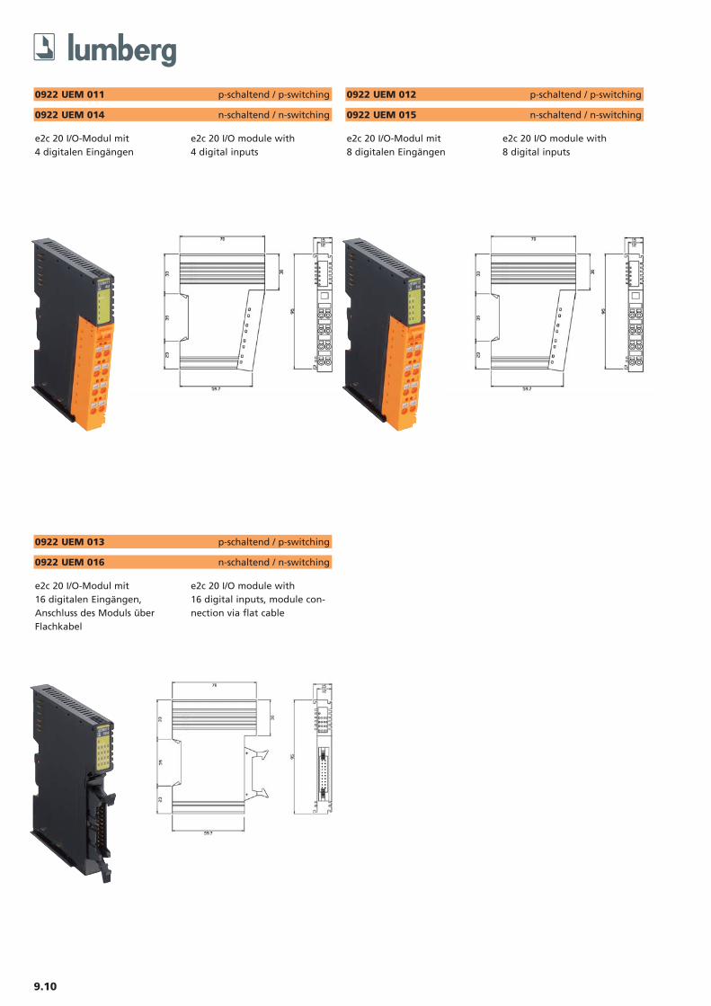
0922 UEM 011 p-schaltend / p-switching
e2c 20 I/O-Modul mit 4 digitalen Eingängen
e2c 20 I/O module with 4 digital inputs
0922 UEM 014 n-schaltend / n-switching
0922 UEM 012 p-schaltend / p-switching
e2c 20 I/O-Modul mit 8 digitalen Eingängen
e2c 20 I/O module with 8 digital inputs
0922 UEM 015 n-schaltend / n-switching
0922 UEM 013 p-schaltend / p-switching
e2c 20 I/O-Modul mit 16 digitalen Eingängen,Anschluss des Moduls überFlachkabel
e2c 20 I/O module with 16 digital inputs, module con-nection via flat cable
0922 UEM 016 n-schaltend / n-switching
9.11Ein Einsatz der Produkte in aggressiven Medienist im Einzelfall zu überprüfen.
The application of these products in harsh environments should always be checked before use
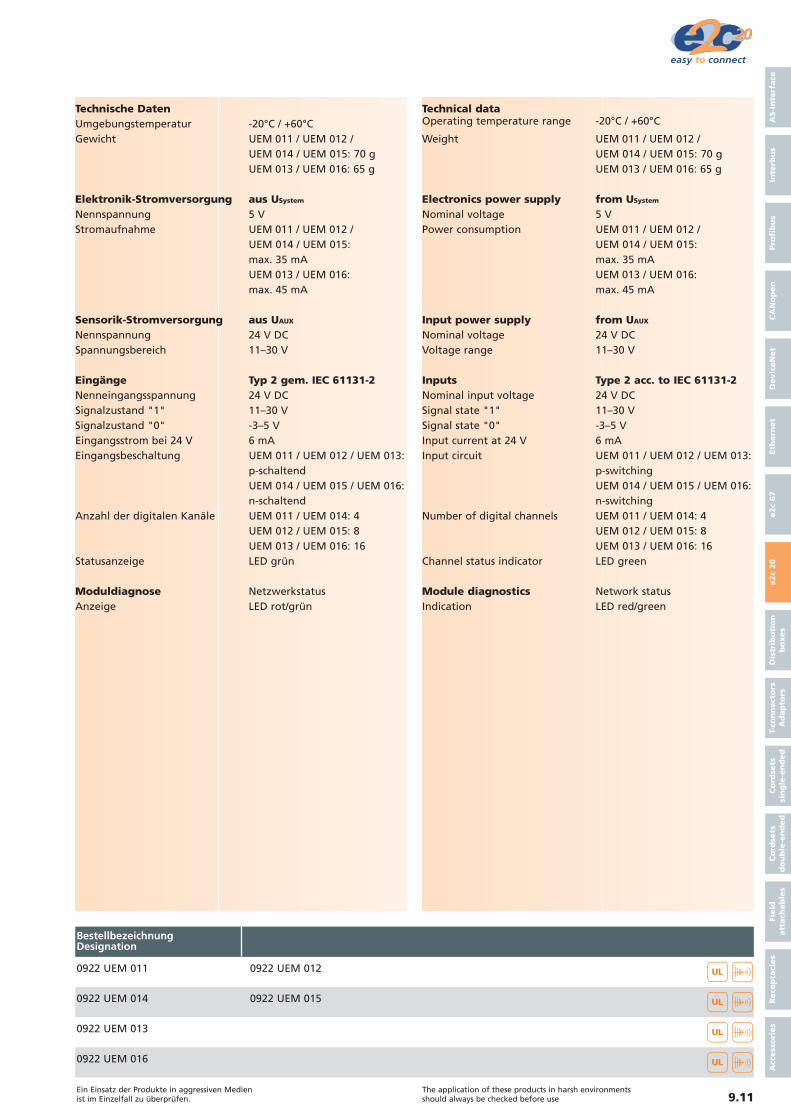
Technische DatenUmgebungstemperatur -20°C / +60°CGewicht UEM 011 / UEM 012 /
UEM 014 / UEM 015: 70 gUEM 013 / UEM 016: 65 g
Elektronik-Stromversorgung aus USystem
Nennspannung 5 VStromaufnahme UEM 011 / UEM 012 /
UEM 014 / UEM 015:max. 35 mAUEM 013 / UEM 016:max. 45 mA
Sensorik-Stromversorgung aus UAUX
Nennspannung 24 V DCSpannungsbereich 11–30 V
Eingänge Typ 2 gem. IEC 61131-2Nenneingangsspannung 24 V DCSignalzustand "1" 11–30 VSignalzustand "0" -3–5 VEingangsstrom bei 24 V 6 mAEingangsbeschaltung UEM 011 / UEM 012 / UEM 013:
p-schaltendUEM 014 / UEM 015 / UEM 016: n-schaltend
Anzahl der digitalen Kanäle UEM 011 / UEM 014: 4UEM 012 / UEM 015: 8UEM 013 / UEM 016: 16
Statusanzeige LED grün
Moduldiagnose NetzwerkstatusAnzeige LED rot/grün
Technical dataOperating temperature range -20°C / +60°C
Weight UEM 011 / UEM 012 / UEM 014 / UEM 015: 70 gUEM 013 / UEM 016: 65 g
Electronics power supply from USystem
Nominal voltage 5 VPower consumption UEM 011 / UEM 012 /
UEM 014 / UEM 015:max. 35 mAUEM 013 / UEM 016:max. 45 mA
Input power supply from UAUX
Nominal voltage 24 V DCVoltage range 11–30 V
Inputs Type 2 acc. to IEC 61131-2Nominal input voltage 24 V DCSignal state "1" 11–30 VSignal state "0" -3–5 VInput current at 24 V 6 mAInput circuit UEM 011 / UEM 012 / UEM 013:
p-switchingUEM 014 / UEM 015 / UEM 016: n-switching
Number of digital channels UEM 011 / UEM 014: 4UEM 012 / UEM 015: 8UEM 013 / UEM 016: 16
Channel status indicator LED green
Module diagnostics Network statusIndication LED red/green
AS-I
nte
rface
Inte
rbu
sPro
fib
us
CA
No
pen
Devic
eN
et
Eth
ern
et
e2c
67
e2c
20
Dis
trib
uti
on
bo
xes
T-co
nn
ect
ors
Ad
ap
tors
Co
rdse
ts
sin
gle
-en
ded
Co
rdse
ts
do
ub
le-e
nd
ed
Field
att
ach
ab
les
Rece
pta
cles
Acc
ess
ori
es
0922 UEM 011 0922 UEM 012
0922 UEM 0150922 UEM 014
BestellbezeichnungDesignation
��
0922 UEM 013 ��
��
0922 UEM 016 ��
9.12
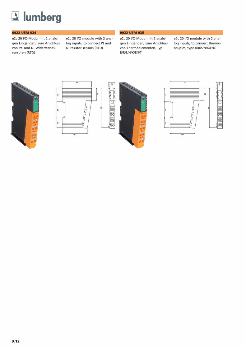
0922 UEM 034
e2c 20 I/O-Modul mit 2 analo-gen Eingängen, zum Anschlussvon Pt- und Ni-Widerstands-sensoren (RTD)
e2c 20 I/O module with 2 ana-log inputs, to connect Pt andNi resistor sensors (RTD)
0922 UEM 035
e2c 20 I/O-Modul mit 2 analo-gen Eingängen, zum Anschlussvon Thermoelementen, TypB/R/S/N/K/E/J/T
e2c 20 I/O module with 2 ana-log inputs, to connect thermo-couples, type B/R/S/N/K/E/J/T

9.13Ein Einsatz der Produkte in aggressiven Medienist im Einzelfall zu überprüfen.
The application of these products in harsh environments should always be checked before use
Technische DatenSchutzart IP 20Umgebungstemperatur 0°C / +60°CGewicht 70 g
Elektronik-Stromversorgung aus USystem
Nennspannung 5 VStromaufnahme max. 120 mA
EingängeSensorarten UEM 034:
PT100, PT200, PT 500, PT1000, PT50, Ni100, Ni120, Ni200, Ni500, Ni1000, Widerstands-messung (10,20,100 mOhm)UEM 035: B, R, S, N, K, E, J, T, 30 mV (1uV/bit)
Anschlusstechnik UEM 034: 2- oder 3-LeiterUEM 035: 2-Leiter
Auflösung UEM 034: 0,1°C / 10 mOhmUEM 035: 0,1°C / 1uV
Wandlungszeit 200 ms / alle KanäleMessfehler ± 0,1 % vom Skalenendwert
@ 25°CDatenformat 16 bit Integer (2er Komplement)Anzahl der analogen Kanäle 2Diagnose MessbereichsüberlaufStatusanzeige LED grün/rot
Diagnose NetzwerkstatusAnzeige LED rot/grün
Technical dataDegree of protection IP 20Operating temperature range 0°C / +60°CWeight 70 g
Electronics power supply from USytem
Rated voltage 5 VPower consumption max. 120 mA
InputsSensor types UEM 034:
PT100, PT200, PT 500, PT1000, PT50, Ni100, Ni120, Ni200, Ni500, Ni1000, resistor measu-rement (10,20,100 mOhm)UEM 035: B, R, S, N, K, E, J, T, 30 mV (1uV/bit)
Connection technology UEM 034:2 or 3-wireUEM 035: 2-wire
Resolution UEM 034: 0.1°C / 10 mOhmUEM 035: 0.1°C / 1uV
Conversion time 200 ms / all channelMeasuring fault ± 0,1 % full range @ 25°CData format 16 bit integer (2's complement)Number of analog channels 2Diagnostic Over rangeChannel status indicator LED green/red
Diagnostic Network statusIndication LED red/green
AS-I
nte
rface
Inte
rbu
sPro
fib
us
CA
No
pen
Devic
eN
et
Eth
ern
et
e2c
67
e2c
20
Dis
trib
uti
on
bo
xes
T-co
nn
ect
ors
Ad
ap
tors
Co
rdse
ts
sin
gle
-en
ded
Co
rdse
ts
do
ub
le-e
nd
ed
Field
att
ach
ab
les
Rece
pta
cles
Acc
ess
ori
es
0922 UEM 034 0922 UEM 035
BestellbezeichnungDesignation
��
9.14
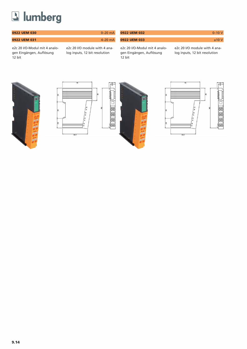
0922 UEM 030 0–20 mA
e2c 20 I/O-Modul mit 4 analo-gen Eingängen, Auflösung 12 bit
e2c 20 I/O module with 4 ana-log inputs, 12 bit resolution
0922 UEM 031 4–20 mA
0922 UEM 032 0–10 V
e2c 20 I/O-Modul mit 4 analo-gen Eingängen, Auflösung 12 bit
e2c 20 I/O module with 4 ana-log inputs, 12 bit resolution
0922 UEM 033 ±10 V
9.15Ein Einsatz der Produkte in aggressiven Medienist im Einzelfall zu überprüfen.
The application of these products in harsh environments should always be checked before use
Technische DatenSchutzart IP 20Umgebungstemperatur 0°C / +60°CGewicht 70 g
Elektronik-Stromversorgung aus USystem
Nennspannung 5 VStromaufnahme max. 200 mA
EingängeMess-Signal UEM 030: 0–20 mA
UEM 031: 4–20 mAUEM 032: 0–10 VUEM 033: -10–10 V
Auflösung 12 bitMessfehler ± 0,1 % @ 25°CEingangsimpedanz UEM 030 / UEM 031: 120 Ohm
UEM 032 / UEM 033: 500 kOhmWandlungszeit 4 ms pro ModulAnzahl der analogen Kanäle 4Diagnose UEM 030 / UEM 032 / UEM 033:
keineUEM 031: Unterspannung
Statusanzeige LED grün/rot
Diagnose NetzwerkstatusAnzeige LED rot/grün
Technical dataDegree of protection IP 20Operating temperature range 0°C / +60°CWeight 70 g
Electronics power supply from USystem
Rated voltage 5 VPower consumption max. 200 mA
InputsMeasurement signal UEM 030: 0–20 mA
UEM 031: 4–20 mAUEM 032: 0–10 VUEM 033: -10–10 V
Resolution 12 bitMeasuring fault ± 0,1 % @ 25°CInput impedance UEM 030 / UEM 031: 120 Ohm
UEM 032 / UEM 033: 500 kOhmConversion time 4 ms per moduleNumber of analog channels 4Diagnostic UEM 030 / UEM 032 / UEM 033:
noUEM 031: Low voltage
Channel status indicator LED green/red
Diagnostic Network statusIndication LED red/green
AS-I
nte
rface
Inte
rbu
sPro
fib
us
CA
No
pen
Devic
eN
et
Eth
ern
et
e2c
67
e2c
20
Dis
trib
uti
on
bo
xes
T-co
nn
ect
ors
Ad
ap
tors
Co
rdse
ts
sin
gle
-en
ded
Co
rdse
ts
do
ub
le-e
nd
ed
Field
att
ach
ab
les
Rece
pta
cles
Acc
ess
ori
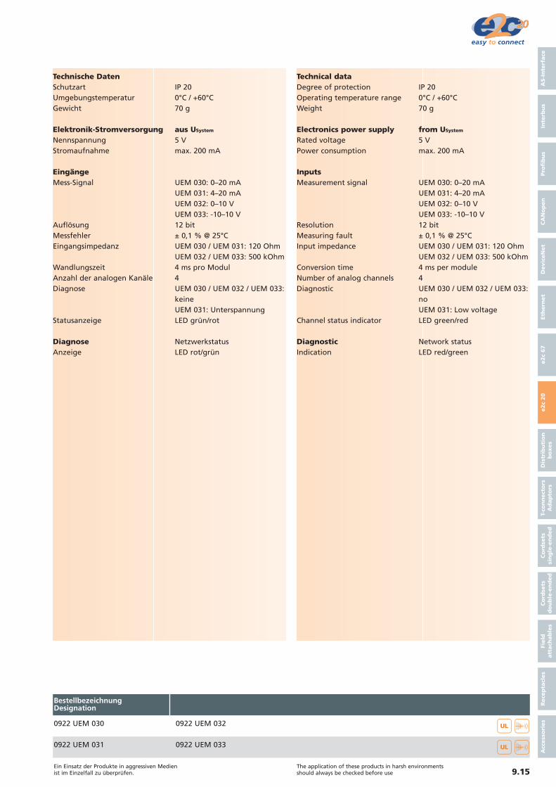
es0922 UEM 030 0922 UEM 032
0922 UEM 0330922 UEM 031
BestellbezeichnungDesignation
��
��
9.16
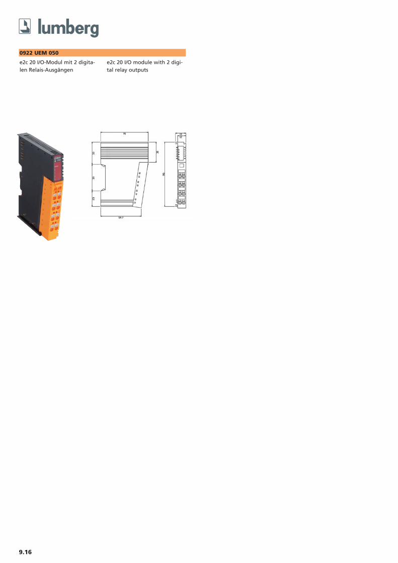
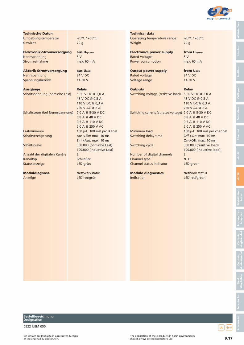
0922 UEM 050
e2c 20 I/O-Modul mit 2 digita-len Relais-Ausgängen
e2c 20 I/O module with 2 digi-tal relay outputs
9.17Ein Einsatz der Produkte in aggressiven Medienist im Einzelfall zu überprüfen.
The application of these products in harsh environments should always be checked before use
Technische DatenUmgebungstemperatur -20°C / +60°CGewicht 70 g
Elektronik-Stromversorgung aus USystem
Nennspannung 5 VStromaufnahme max. 65 mA
Aktorik-Stromversorgung aus UAUX
Nennspannung 24 V DCSpannungsbereich 11-30 V
Ausgänge RelaisSchaltspannung (ohmsche Last) 5-30 V DC @ 2,0 A
48 V DC @ 0,8 A110 V DC @ 0,3 A250 V AC @ 2 A
Schaltstrom (bei Nennspannung) 2,0 A @ 5-30 V DC0,8 A @ 48 V DC0,5 A @ 110 V DC2,0 A @ 250 V AC
Lastminimum 100 µA, 100 mV pro KanalSchaltverzögerung Aus->Ein: max. 10 ms
Ein->Aus: max. 10 msSchaltspiele 300.000 (ohmsche Last)
100.000 (induktive Last)Anzahl der digitalen Kanäle 2Kanaltyp SchließerStatusanzeige LED grün
Moduldiagnose NetzwerkstatusAnzeige LED rot/grün
Technical dataOperating temperature range -20°C / +60°CWeight 70 g
Electronics power supply from USystem
Rated voltage 5 VPower consumption max. 65 mA
Output power supply from UAUX
Rated voltage 24 V DCVoltage range 11-30 V
Outputs RelaySwitching voltage (resistive load) 5-30 V DC @ 2.0 A
48 V DC @ 0.8 A110 V DC @ 0.3 A250 V AC @ 2 A
Switching current (at rated voltage) 2.0 A @ 5-30 V DC0.8 A @ 48 V DC0.5 A @ 110 V DC2.0 A @ 250 V AC
Minimum load 100 µA, 100 mV per channelSwitching delay time Off->On: max. 10 ms
On->Off: max. 10 msSwitching cycle 300.000 (resistive load)
100.000 (inductive load)Number of digital channels 2Channel type N. O.Channel status indicator LED green
Module diagnostics Network statusIndication LED red/green
AS-I
nte
rface
Inte
rbu
sPro
fib
us
CA
No
pen
Devic
eN
et
Eth
ern
et
e2c
67
e2c
20
Dis
trib
uti
on
bo
xes
T-co
nn
ect
ors
Ad
ap
tors
Co
rdse
ts
sin
gle
-en
ded
Co
rdse
ts
do
ub
le-e
nd
ed
Field
att
ach
ab
les
Rece
pta
cles
Acc
ess
ori
es
0922 UEM 050
BestellbezeichnungDesignation
��
9.18
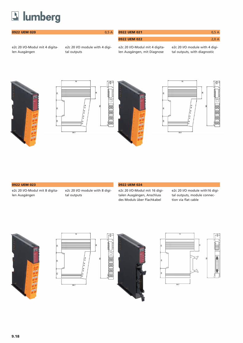
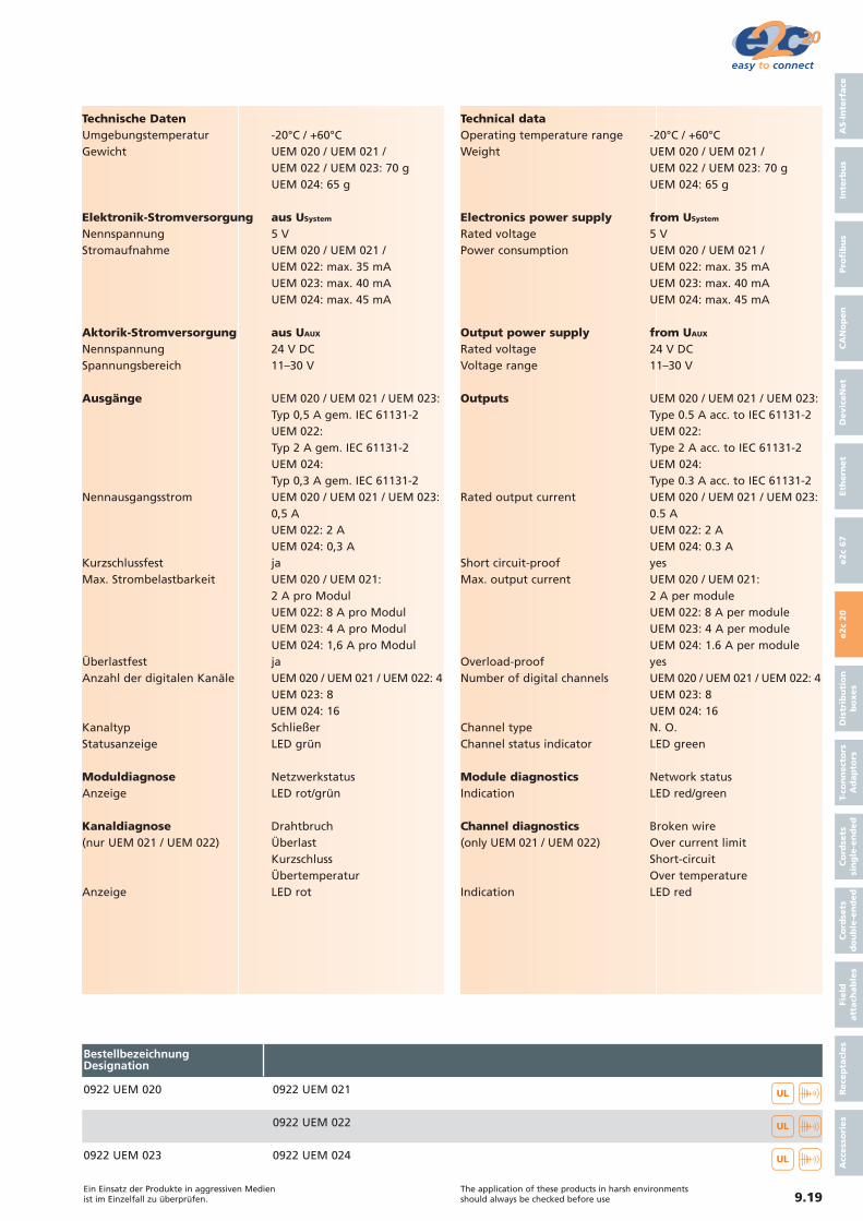
0922 UEM 020 0,5 A
e2c 20 I/O-Modul mit 4 digita-len Ausgängen
e2c 20 I/O module with 4 digi-tal outputs
0922 UEM 021 0,5 A
e2c 20 I/O-Modul mit 4 digita-len Ausgängen, mit Diagnose
e2c 20 I/O module with 4 digi-tal outputs, with diagnostic
0922 UEM 022 2,0 A
0922 UEM 023
e2c 20 I/O-Modul mit 8 digita-len Ausgängen
e2c 20 I/O module with 8 digi-tal outputs
0922 UEM 024
e2c 20 I/O-Modul mit 16 digi-talen Ausgängen, Anschlussdes Moduls über Flachkabel
e2c 20 I/O module with16 digi-tal outputs, module connec-tion via flat cable
9.19Ein Einsatz der Produkte in aggressiven Medienist im Einzelfall zu überprüfen.
The application of these products in harsh environments should always be checked before use
Technische DatenUmgebungstemperatur -20°C / +60°CGewicht UEM 020 / UEM 021 /
UEM 022 / UEM 023: 70 gUEM 024: 65 g
Elektronik-Stromversorgung aus USystem
Nennspannung 5 VStromaufnahme UEM 020 / UEM 021 /
UEM 022: max. 35 mAUEM 023: max. 40 mAUEM 024: max. 45 mA
Aktorik-Stromversorgung aus UAUX
Nennspannung 24 V DCSpannungsbereich 11–30 V
Ausgänge UEM 020 / UEM 021 / UEM 023: Typ 0,5 A gem. IEC 61131-2UEM 022: Typ 2 A gem. IEC 61131-2UEM 024: Typ 0,3 A gem. IEC 61131-2
Nennausgangsstrom UEM 020 / UEM 021 / UEM 023:0,5 AUEM 022: 2 AUEM 024: 0,3 A
Kurzschlussfest jaMax. Strombelastbarkeit UEM 020 / UEM 021:
2 A pro ModulUEM 022: 8 A pro ModulUEM 023: 4 A pro ModulUEM 024: 1,6 A pro Modul
Überlastfest jaAnzahl der digitalen Kanäle UEM 020 / UEM 021 / UEM 022: 4
UEM 023: 8UEM 024: 16
Kanaltyp SchließerStatusanzeige LED grün
Moduldiagnose NetzwerkstatusAnzeige LED rot/grün
Kanaldiagnose Drahtbruch(nur UEM 021 / UEM 022) Überlast
KurzschlussÜbertemperatur
Anzeige LED rot
Technical dataOperating temperature range -20°C / +60°CWeight UEM 020 / UEM 021 /
UEM 022 / UEM 023: 70 gUEM 024: 65 g
Electronics power supply from USystem
Rated voltage 5 VPower consumption UEM 020 / UEM 021 /
UEM 022: max. 35 mAUEM 023: max. 40 mAUEM 024: max. 45 mA
Output power supply from UAUX
Rated voltage 24 V DCVoltage range 11–30 V
Outputs UEM 020 / UEM 021 / UEM 023: Type 0.5 A acc. to IEC 61131-2UEM 022: Type 2 A acc. to IEC 61131-2UEM 024: Type 0.3 A acc. to IEC 61131-2
Rated output current UEM 020 / UEM 021 / UEM 023:0.5 AUEM 022: 2 AUEM 024: 0.3 A
Short circuit-proof yesMax. output current UEM 020 / UEM 021:
2 A per moduleUEM 022: 8 A per moduleUEM 023: 4 A per moduleUEM 024: 1.6 A per module
Overload-proof yesNumber of digital channels UEM 020 / UEM 021 / UEM 022: 4
UEM 023: 8UEM 024: 16
Channel type N. O.Channel status indicator LED green
Module diagnostics Network statusIndication LED red/green
Channel diagnostics Broken wire(only UEM 021 / UEM 022) Over current limit
Short-circuitOver temperature
Indication LED red
AS-I
nte
rface
Inte
rbu
sPro
fib
us
CA
No
pen
Devic
eN
et
Eth
ern
et
e2c
67
e2c
20
Dis
trib
uti
on
bo
xes
T-co
nn
ect
ors
Ad
ap
tors
Co
rdse
ts
sin
gle
-en
ded
Co
rdse
ts
do
ub
le-e
nd
ed
Field
att
ach
ab
les
Rece
pta
cles
Acc
ess
ori
es
0922 UEM 020 0922 UEM 021
0922 UEM 022
BestellbezeichnungDesignation
��
��
0922 UEM 023 0922 UEM 024 ��
9.20
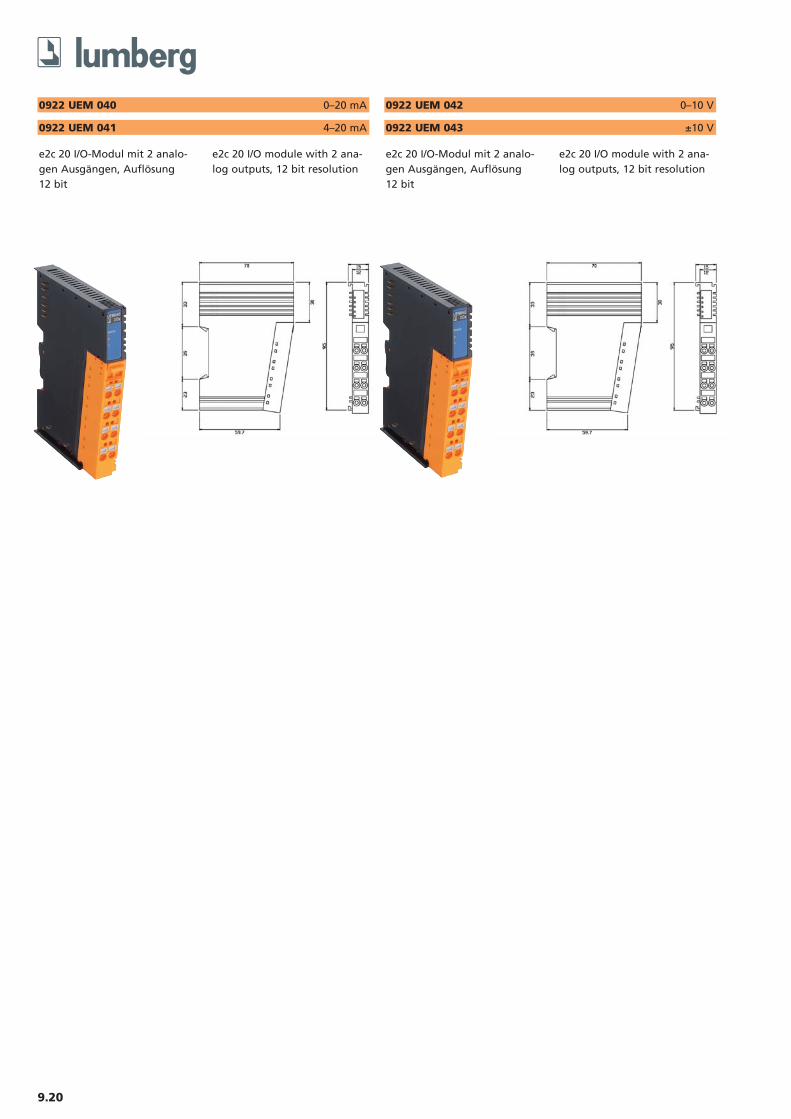
0922 UEM 040 0–20 mA
e2c 20 I/O-Modul mit 2 analo-gen Ausgängen, Auflösung 12 bit
e2c 20 I/O module with 2 ana-log outputs, 12 bit resolution
0922 UEM 041 4–20 mA
0922 UEM 042 0–10 V
e2c 20 I/O-Modul mit 2 analo-gen Ausgängen, Auflösung 12 bit
e2c 20 I/O module with 2 ana-log outputs, 12 bit resolution
0922 UEM 043 ±10 V

9.21Ein Einsatz der Produkte in aggressiven Medienist im Einzelfall zu überprüfen.
The application of these products in harsh environments should always be checked before use
Technische DatenSchutzart IP 20Umgebungstemperatur 0°C / +60°CGewicht 70 g
Elektronik-Stromversorgung aus USystem
Nennspannung 5 VStromaufnahme UEM 040 / UEM 041: max. 65 mA
UEM 042: max. 120 mAUEM 043: max. 250 mA
Aktorik-Stromversorgung aus UAUX
Nennspannung 24 V (nur UEM 040 / UEM 041)Spannungsbereich 15–30 V (nur UEM 040 / UEM 041)
AusgängeAusgangssignal UEM 040: 0–20 mA
UEM 041: 4–20 mAUEM 042: 0–10 VUEM 043: -10–10 V
Auflösung 12 bitMessfehler ± 0,1 % vom Endwert @ 25 °COhmsche Last UEM 040 / UEM 041:
max. 500 OhmUEM 042 / UEM 043: min. 5 kOhm
Wandlungszeit UEM 040 / UEM 041: 2 msUEM 042: 2 ms pro KanalUEM 043: 2 ms pro Modul
Anzahl der analogen Kanäle 2Diagnose keineStatusanzeige LED grün/rot
Diagnose NetzwerkstatusAnzeige LED rot/grün
Technical dataDegree of protection IP 20Operating temperature range 0°C / +60°CWeight 70 g
Electronics power supply from USystem
Rated voltage 5 VPower consumption UEM 040 / UEM 041: max. 65 mA
UEM 042: max. 120 mAUEM 043: max. 250 mA
Output power supply from UAUX
Rated voltage 24 V (only UEM 040 / UEM 041)Voltage range 15–30 V (only UEM 040 / UEM 041)
OutputsOutput signal UEM 040: 0–20 mA
UEM 041: 4–20 mAUEM 042: 0–10 VUEM 043: -10–10 V
Resolution 12 bitMeasuring fault ± 0,1 % Full scale @ 25 °CResistive load UEM 040 / UEM 041:
max. 500 OhmUEM 042 / UEM 043: min. 5 kOhm
Conversion time UEM 040 / UEM 041: 2 msUEM 042: 2 ms per channelUEM 043: 2 ms per module
Number of analog channels 2Diagnostic noChannel status indicator LED green/red
Diagnostic Network statusIndication LED red/green
AS-I
nte
rface
Inte
rbu
sPro
fib
us
CA
No
pen
Devic
eN
et
Eth
ern
et
e2c
67
e2c
20
Dis
trib
uti
on
bo
xes
T-co
nn
ect
ors
Ad
ap
tors
Co
rdse
ts
sin
gle
-en
ded
Co
rdse
ts
do
ub
le-e
nd
ed
Field
att
ach
ab
les
Rece
pta
cles
Acc
ess
ori
es0922 UEM 040 0922 UEM 042
0922 UEM 0430922 UEM 041
BestellbezeichnungDesignation
��
��
9.22
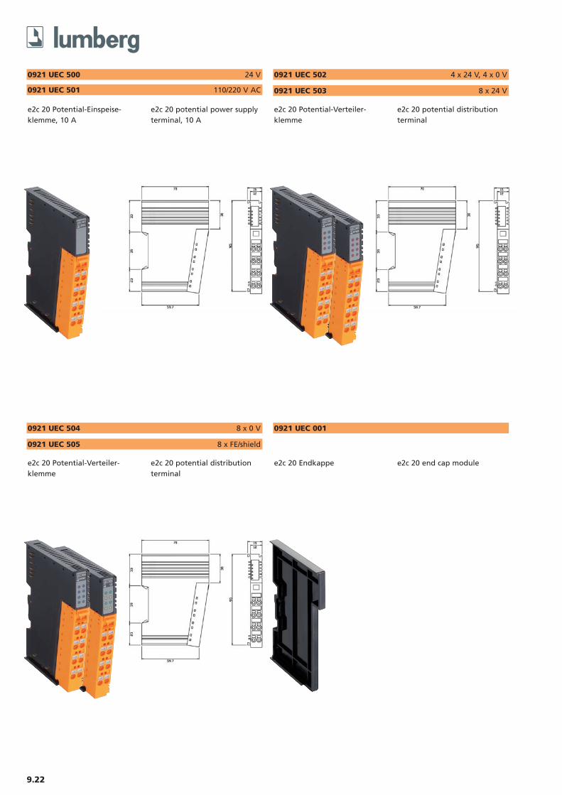
0921 UEC 500 24 V
e2c 20 Potential-Einspeise-klemme, 10 A
e2c 20 potential power supplyterminal, 10 A
0921 UEC 501 110/220 V AC
0921 UEC 502 4 x 24 V, 4 x 0 V
e2c 20 Potential-Verteiler-klemme
e2c 20 potential distributionterminal
0921 UEC 503 8 x 24 V
0921 UEC 504 8 x 0 V
e2c 20 Potential-Verteiler-klemme
e2c 20 potential distributionterminal
0921 UEC 505 8 x FE/shield
0921 UEC 001
e2c 20 Endkappe e2c 20 end cap module
9.23Ein Einsatz der Produkte in aggressiven Medienist im Einzelfall zu überprüfen.
The application of these products in harsh environments should always be checked before use
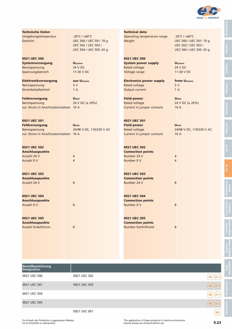
Technische DatenUmgebungstemperatur -20°C / +60°CGewicht UEC 500 / UEC 501: 70 g
UEC 502 / UEC 503 / UEC 504 / UEC 505: 65 g
0921 UEC 500Systemversorgung USystem
Nennspannung 24 V DCSpannungsbereich 11-30 V DC
Elektronikversorgung aus USystem
Nennspannung 5 VStrombelastbarkeit 1 A
Feldversorgung UAUX
Nennspannung 24 V DC (± 20%)zul. Strom in Anschlusskontakten 10 A
0921 UEC 501Feldversorgung UAUX
Nennspannung 24/48 V DC, 110/220 V ACzul. Strom in Anschlusskontakten 10 A
0921 UEC 502AnschlusspunkteAnzahl 24 V 4Anzahl 0 V 4
0921 UEC 503AnschlusspunkteAnzahl 24 V 8
0921 UEC 504AnschlusspunkteAnzahl 0 V 8
0921 UEC 505AnschlusspunkteAnzahl Erde/Schirm 8
Technical dataOperating temperature range -20°C / +60°CWeight UEC 500 / UEC 501: 70 g
UEC 502 / UEC 503 / UEC 504 / UEC 505: 65 g
0921 UEC 500System power supply USystem
Rated voltage 24 V DCVoltage range 11-30 V DC
Electronics power supply from USystem
Rated voltage 5 VOutput current 1 A
Field power UAUX
Rated voltage 24 V DC (± 20%)Current in jumper contacts 10 A
0921 UEC 501Field power UAUX
Rated voltage 24/48 V DC, 110/220 V ACCurrent in jumper contacts 10 A
0921 UEC 502Connection pointsNumber 24 V 4Number 0 V 4
0921 UEC 503Connection pointsNumber 24 V 8
0921 UEC 504Connection pointsNumber 0 V 8
0921 UEC 505Connection pointsNumber Earth/Shield 8
AS-I
nte
rface
Inte
rbu
sPro
fib
us
CA
No
pen
Devic
eN
et
Eth
ern
et
e2c
67
e2c
20
Dis
trib
uti
on
bo
xes
T-co
nn
ect
ors
Ad
ap
tors
Co
rdse
ts
sin
gle
-en
ded
Co
rdse
ts
do
ub
le-e
nd
ed
Field
att
ach
ab
les
Rece
pta
cles
Acc
ess
ori
es
0921 UEC 500 0921 UEC 502
0921 UEC 5030921 UEC 501
BestellbezeichnungDesignation
��
��
0921 UEC 504
0921 UEC 001
0921 UEC 505
��
��
��

9.24