FT-Katalog engl.qxd 17.03.2005 14:06 Uhr Seite 1...
60
SICHERHEITSSCHLÖSSER ESCAPE ROUTE SYSTEM Rettungswegtechnik Escape door systems Verrouillage des issues de secours Tecnica delle uscite di sivurezza Sistemas para salida de emergencia
Transcript of FT-Katalog engl.qxd 17.03.2005 14:06 Uhr Seite 1...

S I C H E R H E I T S S C H L Ö S S E R
E S C A P E R O U T E S Y S T E M
RettungswegtechnikE s c a p e d o o r s y s t e m s
Verroui l lage des issues de secoursT e c n i c a d e l l e u s c i t e d i s i v u r e z z a
Sistemas para sal ida de emergencia
FT-Katalog engl.qxd 17.03.2005 14:06 Uhr Seite 1

Airport Hamburg Old Opera, Frankfurt
2
Breaking new grounds, making use of new technologies, developing new ideas.
Founded in 1936, the company effeff from Albstadt became the market leader in the field of
door control systems by following a consistent strategy.
After starting the electric strike production in 1947, a comprehensive product range has been
gradually developed, which enables effeff to offer suitable solutions for every door.
February 1st, 2000, effeff joined the ASSA ALBOY Group based in Stockholm, Sweden.
ASSA ABLOY is the leading manufacturer and supplier of mechanical and electromechanical
locks and related products worldwide.
FT-Katalog engl.qxd 17.03.2005 14:07 Uhr Seite 2

British embassy, Berlin Lake Constance thermae, Überlingen
3
effeff‘s customers now profit from the group’s wide know-how, offering everything for total
security and comfort throughout the world.
With worldwide sales activities in more than 75 countries and with high experience make
effeff – the expert for electromechanical security – a reliable and competent partner in all
areas.The company attaches great importance to customer orientation and service.
Whatever you want to safeguard, protect, preserve – effeff offers the right solution!
FT-Katalog engl.qxd 17.03.2005 14:07 Uhr Seite 3
4
FT-Katalog engl.qxd 17.03.2005 14:07 Uhr Seite 4

5
S E E K A N D F I N D !
TABLE OF CONTENTS
ABOUT US . . . . . . . . . . . . . . . . . . . . . . . . . . . . . . . . . . . . . . . . 2
CONTENTS . . . . . . . . . . . . . . . . . . . . . . . . . . . . . . . . . . . . . . . . 5
INTRODUCTION TO ESCAPE ROUTE SYSTEMS . . . . . . . . . . . . . . . 7
OVERVIEW OF OPTIONS. . . . . . . . . . . . . . . . . . . . . . . . . . . . . 8-9
CONTROL MODULE . . . . . . . . . . . . . . . . . . . . . . . . . . . . . . . . . 10Design . . . . . . . . . . . . . . . . . . . . . . . . . . . . . . . . . 10Control module 1370 . . . . . . . . . . . . . . . . . . . . . . . 11-13EAC 1 Integra. . . . . . . . . . . . . . . . . . . . . . . . . . . 14-15
CONTROL TERMINAL . . . . . . . . . . . . . . . . . . . . . . . . . . . . . . . . 16Control terminal 1338/1340 . . . . . . . . . . . . . . . . . . . 16-17
CONTROL DEVICES . . . . . . . . . . . . . . . . . . . . . . . . . . . . . . . . . 18Control device 720 . . . . . . . . . . . . . . . . . . . . . . . . 18-19
OPERATING ELEMENT 20Model 1370-10/1370-11 . . . . . . . . . . . . . . . . . . . . . 20-21Model 1332 . . . . . . . . . . . . . . . . . . . . . . . . . . . . . . 22
COMBINATION MATRIX . . . . . . . . . . . . . . . . . . . . . . . . . . . . . . 23
LOCKING ELEMENTS . . . . . . . . . . . . . . . . . . . . . . . . . . . . . . . . 24Introduction . . . . . . . . . . . . . . . . . . . . . . . . . . . . . . 25Escape door strike Model 331U . . . . . . . . . . . . . . . . . 26-27Surface mounted housing. . . . . . . . . . . . . . . . . . . . . 28-29Holding magnets Model 828 . . . . . . . . . . . . . . . . . . . 30-31Holding magnets Model 827 . . . . . . . . . . . . . . . . . . . . . 32Strike for swing doors Model 351 . . . . . . . . . . . . . . . . . . 33
CENTRAL CONTROL. . . . . . . . . . . . . . . . . . . . . . . . . . . . . . . . . 34BUS control panel 925 . . . . . . . . . . . . . . . . . . . . . . 34-35Model overview . . . . . . . . . . . . . . . . . . . . . . . . . . 36-37Escape route visualization WinFT . . . . . . . . . . . . . . . . 38-39
APPLICATIONS . . . . . . . . . . . . . . . . . . . . . . . . . . . . . . . . . . . . 40Kindergarten solution . . . . . . . . . . . . . . . . . . . . . . . 40-41Central release . . . . . . . . . . . . . . . . . . . . . . . . . . 42-43Security and safety of escape routes for high security zones . 44-45
ACCESSORIES . . . . . . . . . . . . . . . . . . . . . . . . . . . . . . . . . . . 46-49
ESCAPE DOOR MONITORING . . . . . . . . . . . . . . . . . . . . . . . . . . 50Day alarm. . . . . . . . . . . . . . . . . . . . . . . . . . . . . 50-51
REGULATIONS AND GUIDELINES . . . . . . . . . . . . . . . . . . . . . . . 52
PRODUCT OVERVIEW . . . . . . . . . . . . . . . . . . . . . . . . . . . . . 54-55
ORDER FORMS . . . . . . . . . . . . . . . . . . . . . . . . . . . . . . . . . . . . 59
FT-Katalog engl.qxd 17.03.2005 14:07 Uhr Seite 5

6
To meet this requirement, the product “Electrical locking systemsfor doors in escape routes” has been defined in the Building RulesList. This enables safe and secure escape in case of emergencyand simultaneously prevents misuse of emergency exits.
All effeff escape door systems comply with the “Guideline onelectrical locking system of doors in escape routes (EltVTR)”defined as the relevant technical regulation for this product in the Building Rules List A, Part 1, No. 6.19 and bear the corresponding compliance mark.
Workers, hotel guests or visitors to public buildings must beassured that they can escape from the building in case of danger.Escape routes do just that. Doors that are located in escape routes must open easily in the direction of escape and withoutany additional assistance. This, however, often contradicts thesecurity requirements of the building operator as emergency exitsare virtually open to misuse. For example, in supermarkets wherethe emergency exits that are located at the back of the buildingprovide the perfect opportunity to avoid the cash desks.
FT-Katalog engl.qxd 17.03.2005 14:07 Uhr Seite 6

7
I N T R O D U C T I O N
ESCAPE ROUTE SYSTEMS
The systems and its components
To ensure that doors in escape routes equipped with an effeffescape door system conform with the required regulations, onlythree components are required as the control electronics arealready integrated in the terminal.
Central systems, e. g. building control system, hazard detectionsystems etc. can be connected to the control electronics. Thepanel for central monitoring and control is in BUS technology.
Fail-unlocked principle
Systems for locking escape routes operate according to the fail-unlocked principle. In case of release, emergency unlocking or current failure, the door is released without immediately.
The locking elements
The actual electrical locking mechanism is selected according touse and the local conditions. effeff provides both electromechanical(form locked) and electromagnetic (frictionally locked) lockingelements. The former are only used when flush mounting isnecessary for optical or security reasons. A surface mounting version is also available.
The electromagnetic door locking mechanisms are used whendoors in fire barriers are upgraded with escape door systems or when subsequent installation of an escape door system doesnot require any structural changes to the door leaf and frame.Surface holding magnets are also advantageous for doors thatare frequently entered and exited thanks to their virtually silentoperation.
The hall sensor integrated in surface holding magnets activates a status check to the control device and thus ensures protectionagainst tamper and manipulation. A microswitch is responsible forthis function in escape doors and panic strikes.
effeff – The leader in escape route technology
No other manufacturer offers a greater choice of locking elements for escape routes than effeff. effeff has long since pointed the way to the future as far as escape route technologyis concerned, in fact effeff was the first manufacturer in Germanyto integrate the power supply in the terminal. The compact terminal is space-saving but nevertheless fulfils all technicalrequirements.
Evidence that effeff is not only a pioneer in technical matters,is the new terminal 1370. effeff was successful in engaging therenowned industrial designer Professor Rido Busse for designingthis terminal. Busse is keen to express the individuality of theproduct through its design. The optical shape of the terminalenhances its appearance and clearly underlines its reliable technical function. Simple and logic in its operation, it gains the confidence and acceptance of the user for the technologybehind the facade.
effeff is well prepared for the future: the effeff FT products arenetwork-capable and can be integrated in building managementsystems.
Our catalogue
effeff products are state-of-the-art. Illustrations in this catalogueare product models that may deviate in certain details fromstandard products. effeff reserves the right to make alterationsthat serve technical progress.
Dimensions, technical data etc. are non-binding and are intendedto serve as a guide.
This catalogue contains just a small section of the extensive effeffrange. We will be glad to provide you with further non-bindinginformation and special catalogues, e. g. on electric door strikes,arrester systems, access control systems, electric bolts and securitylocks as well as the currently valid price list and main catalogue.
FT-Katalog engl.qxd 17.03.2005 14:07 Uhr Seite 7

8
O V E R V I E W O F O P T I O N S
ESCAPE ROUTE SYSTEMS
Systems with integrated control
Locking elements
Modular system with external power supply
Compact systemwith integratedpower supply
Additional alarmsignalling
Surface holding magnet828 -44
Escape door strike 331U331U RR /AKRR + 807-10
Control terminal1338 -20 surface mounted1338-21 flush mounted
Control module1370 -20
Control terminal1340 -20 surface mounted1340 -21 flush mounted
Flashing beacon1055-24
Multi-tone siren1200 -10
Power supply module1370 -40
Surface holding magnet827-44
FT-Katalog engl.qxd 17.03.2005 14:07 Uhr Seite 8

9
O V E R V I E W O F O P T I O N S
ESCAPE ROUTE SYSTEMS
Operating elements
Central control andmonitoring
Control unit720 -30
Operating element1332-10/11
Strike for swing doors351U AKRR
Terminal module1370 -10
Terminal1337-10 surface mounted1337-11 flush mounted
Control unit720 -32
Panel for 4 doors in the wall/table housing
Escape route visualization WinFT
Optical smoke detector60030
Optical smoke detector60030
Panel for 4 doors and central emergencyopen button in the wall/table housing
Systems with external controlwith on-site emergency button with central emergency button provided on site
Control panel for all systems
Panel for 4 doors and central emergency open button in thewall / table housing
FT-Katalog engl.qxd 17.03.2005 14:08 Uhr Seite 9
10
C O L O U R O P T I O N S
DESIGN
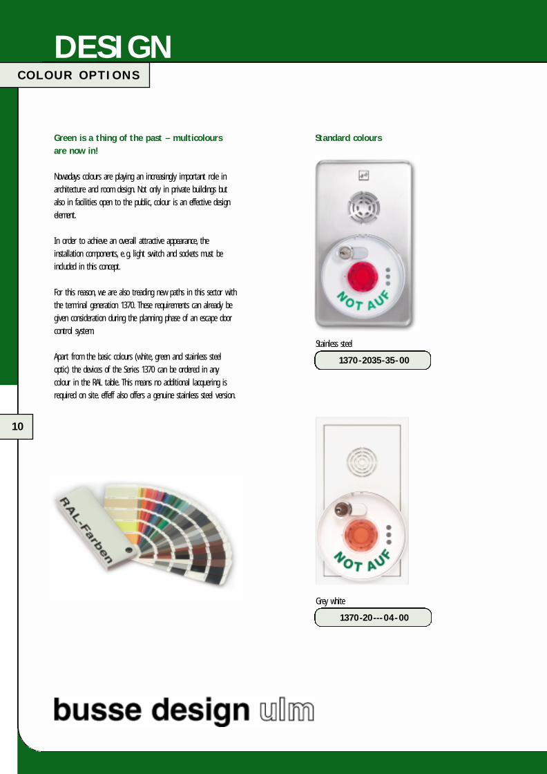
Green is a thing of the past – multicoloursare now in!
Nowadays colours are playing an increasingly important role inarchitecture and room design. Not only in private buildings butalso in facilities open to the public, colour is an effective designelement.
In order to achieve an overall attractive appearance, the installation components, e. g. light switch and sockets must be included in this concept.
For this reason, we are also treading new paths in this sector withthe terminal generation 1370. These requirements can already begiven consideration during the planning phase of an escape doorcontrol system.
Apart from the basic colours (white, green and stainless steel optic) the devices of the Series 1370 can be ordered in any colour in the RAL table. This means no additional lacquering isrequired on site. effeff also offers a genuine stainless steel version.
Standard colours
Grey white
1370-20---04-00
Stainless steel
1370-2035-35-00
FT-Katalog engl.qxd 17.03.2005 14:08 Uhr Seite 10

11
CONTROL MODULESC O N T R O L M O D U L E 1 3 7 0
Standard colours
Stainless steel optic
1370-20---35-00
Green
1370-20---97-00
Special colours
If you require a special colour from the RAL colour range,simply add the corresponding RAL No. on the colour cards tothe effeff no.
e. g. the module in ultramarine blue
Enter RAL-No. 5002
Ultramarine blue
1370-20-5002-00
1370-20- x x x x -00
FT-Katalog engl.qxd 17.03.2005 14:08 Uhr Seite 11

12
C O N T R O L M O D U L E 1 3 7 0
CONTROL MODULES
The escape door power supply module 1370-40
Specially designed power supply for the voltage supply of thecontrol module 1370-20. 24 V output voltage and 0.7 A outputcurrent.
Accessories required for the mechanical connection to the controlmodule are included in the scope of delivery of the power supply module.
Technical data
Connection voltage 230 V AC +6 %/-10 % /50 Hz
Max. current consumption at 230 V input voltage 0.4 A
Output voltage 24 V DC
Max. overall output currentat Tu = 40 °C 1 A
Protection class as per DIN VDE 0470-1:1992-11 IP 40
Operating temperature range 0 °C to +40 °C
Storage temperature range -20 °C to +60 °C
Dimensions Approx. 170 x 85 x 80 mm
Frame dimensions for flush andcavity wall mounting Approx. 190 x 105 x 12 mm
Housing material Plastic Bayblend FR90
Standard surfaces Pure white (similar to RAL 9010)Stainless steel opticGreen (similar to RAL 6032)
Included in scope of delivery Frame for flush and cavity wallmounting; 2 pce. clip and connector for connection toModel 1370-20
Stainless steel
1370-1035-35-00 1370- 40---97-00
The escape door control module 1370-20
All the control and monitoring functions as well as the interfacefor connecting to the effeff TS bus (WinFT and control panel 925)that are required for the security and safety of escape routesare already integrated in this module. The module can be operated with stabilized voltages between 12 V and 24 V.
The power supply module 1370-40 matches the control unit inappearance. Both modules can be installed above one another ornext to one another as well as horizontally or vertically.
Technical data
Rated operating voltage 12 V DC -15% to 24 V DC +15%stabilized DC voltage (low voltage wiring)
Max. internal current consumption at 12 V DC Approx. 140 mA
Max. internal current consumption at 24 V DC Approx. 85 mA
Max. output current for locking components 2 A
Contact load capacity of potential-free 24 V/2 Arelay contacts
Protection class as per DIN VDE 0470-1:1992-11 with integrated locking cylinder IP 40
Operating temperature range 0 °C to +40 °C
Storage temperature range -20 °C to +60 °C
Profile semi-cylinder as per DIN 18252 Locking bit position 90° leftLength 27 - 32 mm
Dimensions Approx. 175 x 100 x 95 mm
Frame for flush and cavity wall mounting Approx. 190 x 105 x 12 mm
Housing material Plastic Bayblend FR90
Standard surfaces Pure white (similar to RAL 9010)Stainless steel opticGreen (similar to RAL 6032)
Included in scope of delivery Frame for flush andcavity wall mounting
The sign “Emergency button” is enclosed with the terminal.
FT-Katalog engl.qxd 17.03.2005 14:08 Uhr Seite 12
13
F U N C T I O N A L D I A G R A M
CONTROL MODULES
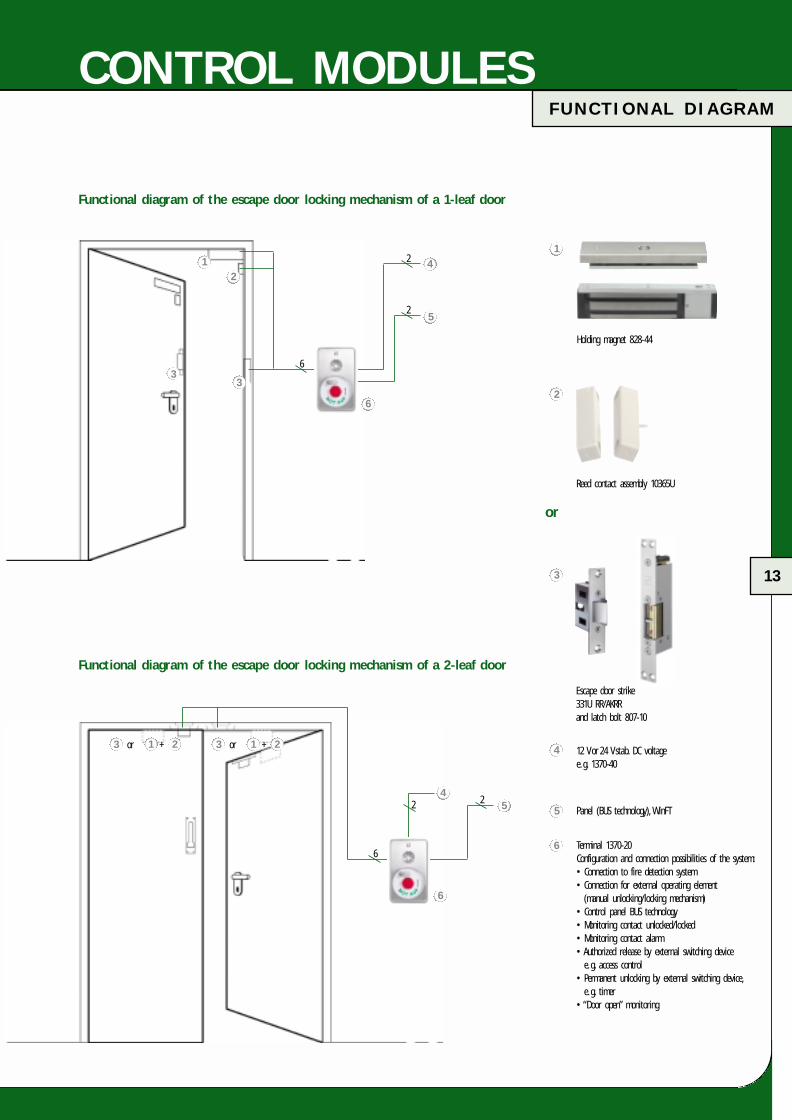
Holding magnet 828-44
12 V or 24 V stab. DC voltagee. g. 1370-40
Terminal 1370-20Configuration and connection possibilities of the system:• Connection to fire detection system• Connection for external operating element
(manual unlocking/locking mechanism)• Control panel BUS technology• Monitoring contact unlocked/locked• Monitoring contact alarm• Authorized release by external switching device
e. g. access control• Permanent unlocking by external switching device,
e. g. timer• “Door open” monitoring
Escape door strike331U RR/AKRRand latch bolt 807-10
or
Panel (BUS technology), WinFT
1
2
3
4
5
6
Reed contact assembly 10365U
Functional diagram of the escape door locking mechanism of a 1-leaf door
Functional diagram of the escape door locking mechanism of a 2-leaf door
2
6
2
2
6
12
3
4
5
6
3 1 2or + 3 1 2or +
5
6
4
3
2
FT-Katalog engl.qxd 17.03.2005 14:08 Uhr Seite 13

14
E A C 1 I N T E G R A
CONTROL UNIT
Access control forescape door terminal Series 1370
The advantages of Integra:� Compatible with other contactless effeff access control systems� Simple retrofitting� Easy to handle� Reliable monitoring and maximum security for escape routes� No compatibility problems� No wear thanks to contactless data transmission� Meets high demands on design� No additional access control required� Two devices in one
Technical data
Connection voltage 12 to 24 V DC
Rated current consumption Approx. 70 mA (typ.) approx. 150 mA (max.)
Inputs Possible connection for additionalreading antenna
Reading distance Approx. 60 mm
Operating temperature range 0 °C to +40 °C
Protection class IP 40
Dimensions L x W x H Approx. 93.6 x 95.2 x 7.7 mm
Access control with integrated reader
2 in 1 – access control for integration in escape door systems
The effeff EAC l Integra combines both access control and escapedoor systems in one device. This means that you can effectivelycontrol access and simultaneously comply with all statutory regulations for escape doors.
EAC l Integra is a complete stand-alone access control systemthat can be installed in the effeff escape door controls of theSeries 1370.The access control is simply placed over the “EMERGENCY-OFF”button under the plexiglass cover. The device is supplied withvoltage from the escape door terminal and switched to the input“Temporary release”. In other words it is simple to mount andrequires no additional voltage supply. An additional readingantenna (e. g. for outdoors) can be connected to the controlunit. The set comprises a control unit, master card, user cardand connecting cable.
• Contactless system• Single card clearing of lost cards via digital display• 199 cards programmable• Only one master card required for programming• Control unit with integrated reader for use indoors• Extendible with reading antenna• Programming directly at control unit• Settable unlocking time
Scope of delivery� EAC l Integra access control for integration in
escape door terminals of the Series 1370� 1 user card� 1 master card� Connecting cable
Note!The device was optimized specially for integration in theeffeff escape door terminals of the Series 1370. The escapedoor terminal is not included in the scope of delivery.
Type 481-10-FT Order no.
481-10-FT----00
FT-Katalog engl.qxd 17.03.2005 14:08 Uhr Seite 14

15
E A C 1 I N T E G R A
CONTROL UNIT
Protection class IP 65Operating temperature range: -20 °C to +60 °CDimensions approx. 80 x 80 mm
Preformed with connector and screwing terminal
User cardType 481-10-4, Order no.
481-10-4 -----00
Key fobType 481-10-5, Order no.
481-10-5----00
Master cardType 481-10-3, Order no.
481-10-3 ----- 00 EAC l reading antennaType 481-10-1 Order no.
481-10-1----- 00
Connecting cablefor connecting the EAC l antenna 481-10-1Type 481-FT-KAB03, Order no.
481-FT-KAB03-00
Connecting cableFor retrofitting FT control devices of theSeries 1370-20 manufactured before 2004Type 481, Order no.
481-FT-KAB01-00
Our leaflet “Access controls systems”contains further information and a detailed product overview.
FT-Katalog engl.qxd 17.03.2005 14:08 Uhr Seite 15

16
C O N T R O L T E R M I N A L 1 3 3 8 / 1 3 4 0
CONTROL TERMINAL
Control terminal 1338-2xfor 230 V mains voltage
The control terminal combines both the control device and thedoor terminal in one housing.
Control terminal 1340-2xfor 12 V/24 V stab. DC voltage
Same as Model 1338-2x however without integrated power supply.
Technical data
Connection voltage 230 V AC (+10%/-15%)
Rated operating voltage 12 V/24 V DC
Current consumption 200 mA
Max. load current 1 A at 12 V/640 mA at 24 V
Housing Sturdy plastic housing withtransparent, non-splintering coverof emergency button (re-usable),incl. profile semi-cylinder
Housing colour Green (similar to RAL 6032) orgrey white (similar to RAL 9002)other RAL colours on request
Housing dimensions See dimension drawings, Page 21
Profile semi cylinder Locking bit position 90° left,length 30-35 mm
Emergency button lighting Multi-LED
Protection class DIN 40050 IP 30
Humidity class DIN 40040 Class F
Operating temperature range 0 °C to +40 °C
1320 Surface mounted
Technical data
Connection voltage 230 V AC (+10%/-15%)
Rated operating voltage 24 V DC
Internal current consumption 300 mA
Max. load current Max. 320 mA
Housing Sturdy plastic housing withtransparent, non-splitter cover for emergency button (re-usable),incl. profile semi-cylinder
Housing colour Green (similar to RAL 6032) orgrey white (similar to RAL 9002),other RAL colours on request
Housing dimensions See dimension drawings, Page 21
Profile semi cylinder Locking bit position 90° left,length 30-35 mm
Emergency button lighting Multi-LED
Protection class DIN 40050 IP 30
Humidity class DIN 40040 Class F
Operating temperature range 0 °C to +40 °C
1350 set
comprising 1338-20/21 and an already pre-formed escape door strike 331U with connection lead and mortise latch bolt lock 807-10.
1321 Flush mounted
Surface mounted version
Flush mounted version
The sign “Emergency button” is enclosed with the control terminals.1338-20-----F90 1338-21-----F90
1350-21------04
1350-20------04
FT-Katalog engl.qxd 17.03.2005 14:08 Uhr Seite 16
17
F U N C T I O N A L D R A W I N G
CONTROL TERMINAL
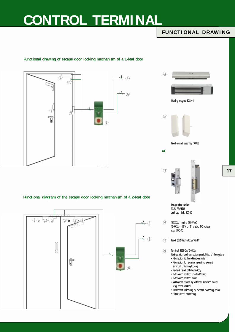
Holding magnet 828-44
1338-2x - mains 230 V AC1340-2x - 12 V or 24 V stab. DC voltagee. g. 1370-40
Terminal 1338-2x/1340-2xConfiguration and connection possibilities of the system:• Connection to fire detection system• Connection for external operating element
(manual unlocking/locking)• Control panel BUS technology• Monitoring contact unlocked/locked• Monitoring contact alarm• Authorized release by external switching device
e. g. access control• Permanent unlocking by external switching device• “Door open” monitoring
Escape door strike331U RR/AKRRand latch bolt 807-10
or
Panel (BUS technology), WinFT
1
2
3
4
5
6
Reed contact assembly 10365
2
2
Functional drawing of escape door locking mechanism of a 1-leaf door
Functional diagram of the escape door locking mechanism of a 2-leaf door
2
6
2
2
6
12
33
4
5
6
3 1 2or + 3 1 2or +4
5
6
FT-Katalog engl.qxd 17.03.2005 14:08 Uhr Seite 17
18
C O N T R O L D E V I C E 7 2 0 - 3 0
CONTROL DEVICE
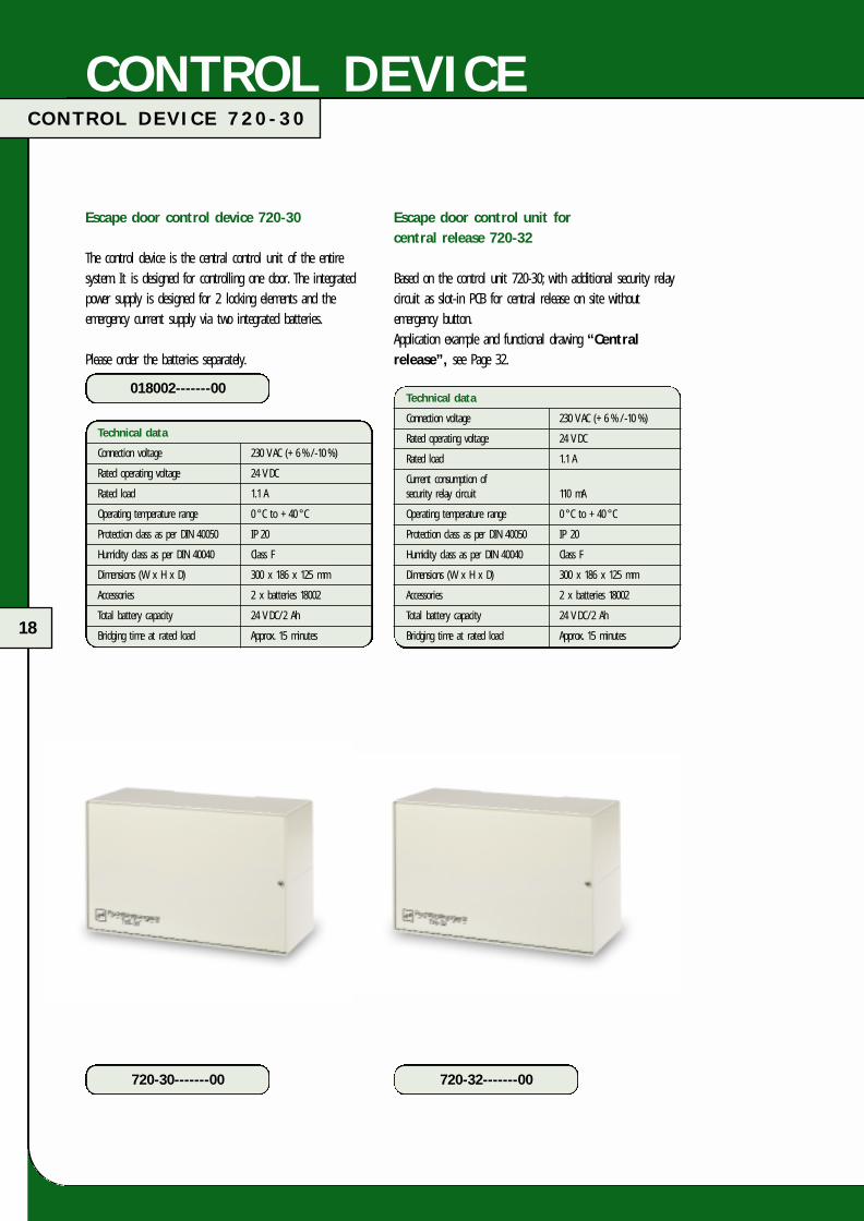
Technical data
Connection voltage 230 V AC (+6 % /-10 %)
Rated operating voltage 24 V DC
Rated load 1.1 A
Operating temperature range 0 °C to +40 °C
Protection class as per DIN 40050 IP 20
Humidity class as per DIN 40040 Class F
Dimensions (W x H x D) 300 x 186 x 125 mm
Accessories 2 x batteries 18002
Total battery capacity 24 V DC/2 Ah
Bridging time at rated load Approx. 15 minutes
Technical data
Connection voltage 230 V AC (+6 % / -10 %)
Rated operating voltage 24 V DC
Rated load 1.1 A
Current consumption of security relay circuit 110 mA
Operating temperature range 0 °C to +40 °C
Protection class as per DIN 40050 IP 20
Humidity class as per DIN 40040 Class F
Dimensions (W x H x D) 300 x 186 x 125 mm
Accessories 2 x batteries 18002
Total battery capacity 24 V DC/2 Ah
Bridging time at rated load Approx. 15 minutes
Escape door control unit for central release 720-32
Based on the control unit 720-30; with additional security relaycircuit as slot-in PCB for central release on site withoutemergency button.Application example and functional drawing “Centralrelease”, see Page 32.
Escape door control device 720-30
The control device is the central control unit of the entiresystem. It is designed for controlling one door. The integratedpower supply is designed for 2 locking elements and theemergency current supply via two integrated batteries.
Please order the batteries separately.
720-30-------00
018002-------00
720-32-------00
FT-Katalog engl.qxd 17.03.2005 14:08 Uhr Seite 18
19
F U N C T I O N A L D R A W I N G
CONTROL DEVICE
Haftmagnet 828-44
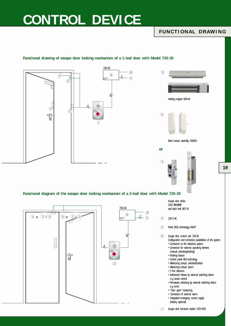
Holding magnet 828-44
1
Functional drawing of escape door locking mechanism of a 1-leaf door with Model 720-30
Functional diagram of the escape door locking mechanism of a 2-leaf door with Model 720-30
6
2
16
720-30
6
24
5
16
720-30
12
33
4
56
7
230 V AC
Escape door control unit 720-30 Configuration and connection possibilities of the system:• Connection to fire detection system• Connection for external operating element(manual unlocking/locking)
• Flashing beacon• Control panel BUS technology• Monitoring contact unlocked/locked• Monitoring contact alarm• 5 fire detectors• Authorized release by external switching devicee. g. access control
• Permanent unlocking by external switching devicee. g. timer
• “Door open” monitoring• Connection of external alarm• Integrated emergency current supply(battery optional)
Escape door strike331U RR/AKRRand latch bolt 807-10
or
Panel (BUS technology), WinFT
Escape door terminal module 1370-1035
2
3
4
5
6
Reed contact assembly 10365U
63 1 2or + 3 1 2or +
7
7
FT-Katalog engl.qxd 17.03.2005 14:09 Uhr Seite 19

20
M O D E L 1 3 7 0 - 1 0 / 1 3 3 7 - 1 x
OPERATING ELEMENT
The terminal module 1370-10
Door terminal without control electronics matching appearance of control module. It can be combined with the control module1370-20 (e. g. for applications with an escape route on bothsides) and is compatible with the familiar escape door controlunit 720-30.
Technical data
Rated operating voltage 12 V DC -15 % to 24 V DC +15 %
Max. internal current consumption at 12 V DC Approx. 55 mA
Max. internal current consumption at 24 V DC Approx. 55 mA
Protection class as per DIN VDE 0470-1:1992-11 with integrated locking cylinder IP 40
Operating temperature range 0 °C to +40 °C
Storage temperature range -20 °C to +60 °C
Profile semi-cylinder Same as 1370-20
Dimensions Same as 1370-20
Housing material Plastic Bayblend FR90
Standard surfaces Pure white (similar to RAL 9010)Stainless steel opticGreen (similar to RAL 6032)
Included in scope of delivery Frame for flush and cavity wall mounting
The sign “Emergency button” is enclosed with the terminal.
1337-10 Surface mounting
Technical data
Rated operating voltage 24 V DC ( ±15 % )
Housing Sturdy plastic housing withtransparent, non-splitter cover ofemergency button (re-usable),incl. profile semi-cylinder
Housing colour Green (similar to RAL 6032) orgrey white (similar to RAL 9002)other RAL colours on request
Profile semi cylinder Locking bit position 90° left,length 30-35 mm
Emergency button lighting Multi-LED
Protection class DIN 40050 IP 30
Humidity class DIN 40040 Class F
Operating temperature range 0 °C to +40 °C
The sign “Emergency button” is enclosed with the door terminal.
1337-10------00
1337-11 Flush mounting
1337-11------00
1370-1035-35-00
Further housing colours, see Page 11.
Terminal for indoor use 1337-lX
The door terminal 1337-lX is a combination of an emergencybutton and control and monitoring elements and is compatiblewith the escape door control unit 720-3X.
The special shape is suitable for surface mounting as well asflush mounting with housing.
The following functions are integrated:Emergency button with cover (is not destroyed when operated)for releasing the doors in case of panic.Key switch for the functions:Door locking On/Off - alarm reset - temporary release.Light diodes for displaying:Door locked - unlocked - alarmCover contact for tamper monitoring and siren.
FT-Katalog engl.qxd 17.03.2005 14:09 Uhr Seite 20

D I M E N S I O N S 1 3 7 0 - 1 0 / 1 3 3 7 - 1 x
21
OPERATING ELEMENT
Kabeldurchmessermax. 10 mm
99
14,5
4585
51
122
279
242
3
213,4
6132
12,1 21,5
102,2
2025
3,6
6
52,5
97
20
15,5
45102
Dimensions for control terminal 1337-10, 1338-20 and 1340-20
Dimensions for control modules, Series 1370
Sheet metal thickness 1 mm
Cable entry
Dimensions for control terminals 1337-11, 1338-21 and 1340-21
Flush mounted housing 13xx-x1 flush mounted version(Included in scope of delivery of Model 1337-11, 1338-21 and 1340-21)
FT-Katalog engl.qxd 17.03.2005 14:09 Uhr Seite 21

22
M O D E L 1 3 3 2
OPERATING ELEMENT
1332-10Zy surface mounted
Housing depth 52 mm
1332-11Zy flush mounted
100
155
350
170
149
94115
Operating element 1332
The operating element in the metal housing is available forsurface or flush mounting. It is used for controlling escape doorlocking mechanisms in the direction opposite that of escape.It is also used in systems with central release instead of doorterminals.
The following functions are integrated:Key switch for the functions:Door locking On/Off - alarm reset - temporary release.Light diodes for displaying:Door locked - unlocked - alarmCover contact for tamper monitoring and buzzer.
The standard operating element is supplied without a cylinder.
Without cylinder – surface mounted
1332-10------00
Without cylinder – flush mounted
1332-11------00
Matching profile semi-cylinder
2.0507-0030000
FT-Katalog engl.qxd 17.03.2005 14:09 Uhr Seite 22

M AT R I X
23
COMBINATION MATRIX
Connectable locking elements
Connectionvoltage
Control unit/control terminal Locking element (max. number)
Rated operatingvoltage
Type
720-30
720-32
1338-20
1338-21
1340-20
1340-21
1340-20
1340-21
•
•
•
•
•
•
•
•
2
2
2
2
2
2
2
2
2
2
2
2
2
2
2
2
2
2
2
2
2
2
2
2
2
2
1
1
2
2
1
1
Type of mounting
surface flush 828 827
Escape door strikeType 331U
Holding magnetStrike for swing doorsType 351
230 V AC 24 V DC
24 V DC 24 V DC
12 V DC 12 V DC
Voltage supply
Control module 1370 Locking element (max. number)
Connectionvoltage
Ratedoperatingvoltage
12 V
24 V
24 V
Type
1370-20 • •
6
12
4
6
12
4
3
6
2
4
8
3
Type of mounting
surface flush Type 828 Type 827
Escape door strikeType 331U
Holding magnetStrike for swing doorsType 351
External supply
12V–24V DC(2 A)
Power supplyModule 1370-40
230 V AC
FT-Katalog engl.qxd 17.03.2005 14:09 Uhr Seite 23

24
FT-Katalog engl.qxd 17.03.2005 14:09 Uhr Seite 24

25
I N T R O D U C T I O N
LOCKING ELEMENTS
The special advantages...... of the escape door strike
The outstanding features of the effeff escape door strike are itsconcealed mounting and the integrated monitoring contacts (doorposition and locking indication) that ensure extensive protectionagainst manipulation. An additional door contact is not required.
The clear door height and width of the escape door is notaffected. Due to the low current consumption, several escape door strikes can be used for e. g. for the security and safety ofdouble-leaf doors.
In addition to the normal panic lock, the escape door strike isinstalled in the door frame and the latch bolt 807-10 as themating part in the door leaf. The escape door strike is similarin shape to a commercially available security strike. This meanssimple, uncomplicated and quick installation in the differentprofiles, irrespective of the integrated panic lock as well as highstability and resulting additional fire safeguard against break-in.An important point that underlines the functionality of thisescape door strike, is the secure unlocking even when thecurrent is switched off and when counter pressure of up to5000 N is applied to the door.
Note: When installing in fire-rated doors, observe the approvalregulations for fire-rated doors. See also information provided bythe Institute for Building Technology.
The special advantages ...... of the surface holding magnet
Surface holding magnets are particularly suitable for retrofitting(surface mounting). No alterations or recesses are required in thedoor frames. They can also be installed in doors in escape routesthat simultaneously act as fire-rated doors (see Page 30, 52).Please observe the approval of the relevant door element. Due toits silent operation, this locking element is predestined for use,for example in living areas.
The surface holding magnet and the counter holding plate formthe complete locking unit. The holding power of the magnetcombined with the counter plate provide additional break-openprotection. A monitoring contact in the device ensures extensiveprotection against manipulation. The surface holding magnet ismounted on the door frame or in the door passage and thecounter holding plate on the door leaf. An additional doorcontact is required.
Note: A clear height of min. 2 m is stipulated in the WorkshopGuidelines (§ 10 WG 10/1 Doors, Gates). The escape door strikeis a recommended alternative to mounting in the door passage.
The special advantages ...... of the strike for swing doors
The strike for swing doors is flush mounted (concealed) in thesame manner as the escape door strike. When the door isclosed, the element installed in addition to the panic lockremains concealed.
The swing door strike provides additional break-open protection.The integrated monitoring contact (locking signal) ensuresextensive protection against manipulation. An additional doorcontact is required.
FT-Katalog engl.qxd 17.03.2005 14:09 Uhr Seite 25

26
E S C A P E D O O R S T R I K E M O D E L 3 3 1U
LOCKING ELEMENTS
Electrical data
At 20 °C Rated operating Rated resistance Rated current Model Series: 331U voltage in ohm consumption
Tolerance range DC in mA
12 V ±1 V 37.5 320
24 V ±2 V 150.0 160
Escape door strike Model 331U
The escape door strike 331U is specially designed for lockingdoors in escape routes. The situation as far as building codes isconcerned as well as the application in fire-rated doors isexplained on Page 52. Due to secure unlocking under side load(max. 5000 N) it is used above all in doors without escaperoute requirements. In interlocking systems, sound-insulated doorsand doors where pressure is to be expected on the door keeper,the 331U Series functions reliably.
331U80F11635F94
331U80F09035F94
FT-Katalog engl.qxd 17.03.2005 14:09 Uhr Seite 26

27
E S C A P E D O O R S T R I K E M O D E L 8 0 7 - 1 0
LOCKING ELEMENTS
Technical data
Strength against break-open – standard 7500 N
Material: Housing/ latch – standard High grade cast steel/steel
Material: Housing/ latch/surface mounted attachment FaFix High grade cast steel/high grade cast steel/steel
Operating temperature range -15 °C to +40 °C
Installation – irrespective of position Yes
Latch side load max. in N 5000 N
Important!The escape door strike is intended exclusively as anadditional locking mechanism of the fire-rated doorirrespective of the main lock. It should never be used as a mating part to the main lock as otherwise thefunction of the fire-rated door is no longer ensured.The escape door strike and the corresponding mating part 807-10 are tested according to the valid regulationsand approved as suitable for the electrical locking ofdoors in escape routes.
Mating part for escape door strike Model
807-12-------00
807-12-------00
807-10-------00
FT-Katalog engl.qxd 17.03.2005 14:09 Uhr Seite 27
28
S U R F A C E M O U N T E D H O U S I N G
LOCKING ELEMENTS
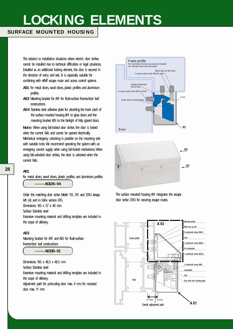
Frame profile
Mounting bracket
Blind rivet nut M5
8 countersunk screws M5x18
Cover
2 countersunk screws M5x30
Fix counterplate
2 countersunk screws M2.5x6
2 countersunk screws M3x5
Counterplate
Cover
Door strike with mounting plate
Overall adjustment path
Door
A03
A01
�
�
The surface mounted housing A01 integrates the escape door strike 331U for securing escape routes.
Blind rivet nut M5 steelCounter-sunk screw M5x25 steel
mating component(hook unit)
Counter-sunk screw M5x15 steel
Strike with mounting plateCover
Frame profile
Door
For steel doors: Screws accessories includedFor wooden doors: Wood screws
The solution to installation situations where electric door strikescannot be installed due to technical difficulties or legal provisions.Installed as an additional locking element, the door is secured inthe direction of entry and exit. It is especially suitable forcombining with effeff escape route and access control systems.
A01 for metal doors, wood doors, plastic profiles and aluminiumprofiles
A03 Mounting bracket for A01 for flush-surface frames/door leafconstructions
A04 Stainless steel adhesive plate for attaching the hook catch ofthe surface mounted housing A01 to glass doors and themounting bracket A03 to the fanlight of fully glazed doors.
Note: When using fail-locked door strikes the door is lockedwhen the current fails and cannot be opened electrically.Mechanical emergency unlocking is possible on the mounting sidewith suitable tools. We recommend operating the system with an emergency current supply when using fail-locked mechanisms. Whenusing fail-unlocked door strikes, the door is unlocked when thecurrent fails.
A01for metal doors, wood doors, plastic profiles and aluminium profiles
-------AO135-04
Order the matching door strike Model 131, 141 and 331U alwaysleft (4) and in FaFix version (FF).Dimensions: 165 x 57 x 40 mmSurface: Stainless steelExtensive mounting material and drilling template are included inthe scope of delivery.
A03Mounting bracket for A01 and A02 for flush-surface frames/door leaf constructions
-------A0335-01
Dimensions: 165 x 46.5 x 46.5 mmSurface: Stainless steelExtensive mounting material and drilling template are included inthe scope of delivery.Adjustment path for protruding door max. 4 mm, for recessed door max. 11 mm
�
A01
FT-Katalog engl.qxd 17.03.2005 14:09 Uhr Seite 28
29
S U R F A C E M O U N T E D H O U S I N G
LOCKING ELEMENTS
adhesive plate�
concealing plate�
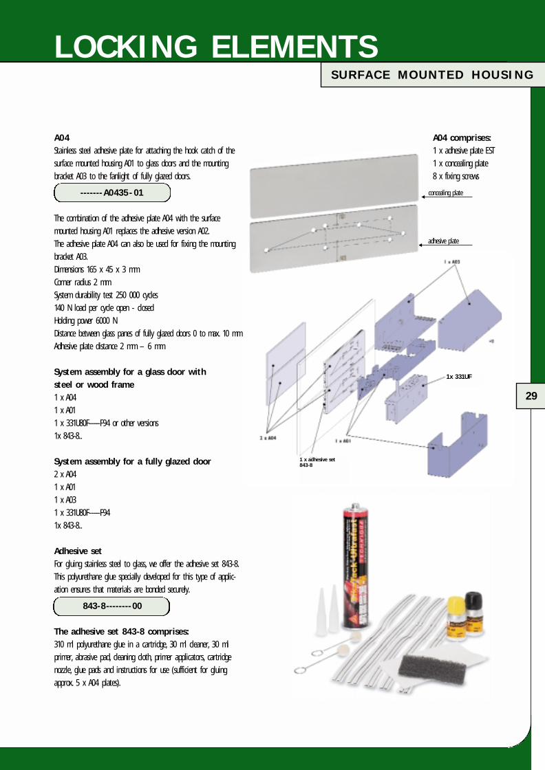
A04Stainless steel adhesive plate for attaching the hook catch of thesurface mounted housing A01 to glass doors and the mountingbracket A03 to the fanlight of fully glazed doors.
-------A0435- 01
The combination of the adhesive plate A04 with the surfacemounted housing A01 replaces the adhesive version A02.The adhesive plate A04 can also be used for fixing the mountingbracket A03.Dimensions 165 x 45 x 3 mmCorner radius 2 mmSystem durability test 250 000 cycles140 N load per cycle open - closedHolding power 6000 NDistance between glass panes of fully glazed doors 0 to max. 10 mmAdhesive plate distance 2 mm – 6 mm
System assembly for a glass door with steel or wood frame1 x A041 x A011 x 331U80F-----F94 or other versions1x 843-8..
System assembly for a fully glazed door2 x A041 x A011 x A031 x 331U80F-----F941x 843-8..
Adhesive setFor gluing stainless steel to glass, we offer the adhesive set 843-8.This polyurethane glue specially developed for this type of applic-ation ensures that materials are bonded securely.
843-8--------00
The adhesive set 843-8 comprises:310 ml polyurethane glue in a cartridge, 30 ml cleaner, 30 mlprimer, abrasive pad, cleaning cloth, primer applicators, cartridgenozzle, glue pads and instructions for use (sufficient for gluingapprox. 5 x A04 plates).
A04 comprises:1 x adhesive plate EST1 x concealing plate8 x fixing screws
1x 331UF
1 x adhesive set843-8
FT-Katalog engl.qxd 17.03.2005 14:09 Uhr Seite 29

30
H O L D I N G M A G N E T M O D E L 8 2 8
LOCKING ELEMENTS
Countersunk screwM 6x50 DIN 965
Fixing plate 828-5 for through screwingwood doors.For achieving higher stability when fixingthe counter holding plate to wood doors(not suitable for fire-rated doors).
Accessories
Mounting set 828-6 for mounting surface holding magnet 828 to surface mounted door elements. The set comprises: Adjustablemounting bracket, mounting bracket 828-4 and plastic cover.
Fixing plate 828-5 for counter holding plate 828-2. Deliverycomplete with mounting screws (countersunk screws M 6x50 DIN 965). Dimensions 150x70 mm. Threaded sleeve length 31 mm.
Mounting bracket 828-7 for mounting the surface holding magnet828 to surface mounted door elements. Complete with spacerplates and Fix mating part.
Technical data
Rated operating voltage 24 V DC /12 V DC
Rated current consumption 315 mA /630 mA
Rated output 7.5 W
Duty cycle 100 % ED
Holding power 5000 N
Residual holding power 0 N
Switching contact Potential-free relay change-over contact, max. switching current 2 A resistive load
Surface holding magnet 828
Surface holding magnets are suitable for locking doorselectromagnetically and are easy to mount. No alterations orrecesses are required in the door frames. According to theinformation dated 24 March 1991 issued by the Institute forBuilding Technology, Berlin, electric magnets can also be attachedto fire-rated doors. The electric surface holding magnet 828 has an integrated contact for the locking signal (Hall sensor).The magnet has a sturdy aluminium housing and is available innatural colour as well as in dark bronze, anodized.
The rated voltage can be set on the magnet at either 24 V DCor 12 V DC. The counter holding plate 828-2 is included in thescope of delivery.
Note:In addition to the integrated locking signal, an additionaldoor contact must also be ordered.
Order numbersSurface holding magnet 828natural colour, anodized
828-------44F90
Surface holding magnet 828dark bronze, anodized
828-------47F90
Corresponding magnetic contact (see Page 46)
10365-6------00
FT-Katalog engl.qxd 17.03.2005 14:09 Uhr Seite 30

31
H O L D I N G M A G N E T M O D E L 8 2 8
LOCKING ELEMENTS
Mounting set 828-6
Installation diagram
16 34,5
1820
40
37,5 2663,5
3868
One rivet
(providedon site)
nut M6
Wood screws(provided on site)
Bracket 828-7
40
Model828-7
Door
Door frame
L bracket
Adjustment -5 +10Fix mating part
Space plate
Holding magnet
Counter holding plate
Fixing screws (provided on site), depending onconditions and structural requirements
Model 828 with set 828-6Version A: Door opens inwards
Model 828 with set 828-6Version B: Door opens outwards
Surface holding magnet 828,profile cross-section
91.5 - 105 mm
9.5 10.5 mm
828-
4.
Mounting bracket
Plasticcover
Counterholding plate
Mounting bracketAdjustment
Surface holding magnetModel 828...
Masonry
Door frame
Mounting range
Door leaf
Su
MoA
Counhold
Mounti
Pc
5 mm63.5- 82 mm
828-4
4.5 15.5 mm
Masonry
me
ange
Surface holding magnet Model 828..
Mounting bracketAdjustment
Counterholding plate
Mounting bracket
Plasticcover
Door frame
Mounting range
Door leaf
Model 828 with bracket 828-7
FT-Katalog engl.qxd 17.03.2005 14:42 Uhr Seite 31

32
H O L D I N G M A G N E T S M O D E L 8 2 7
LOCKING ELEMENTS
Technical data
Rated operating voltage 24 V DC/12 V DC
Rated current consumption 250 mA/500 mA
Rated output 6 W
Duty cycle 100 % ED
Holding power 2500 N
Residual holding power 0 N
Connection lead - length 4 m
Compact surface holding magnet 827
For concealed mounting of doors in escape routesCompact surface holding magnet. Without monitoring contactswith narrow counter holding plate for installing in door frames,sturdy aluminium housing for flush mounting.
Order numbersSurface holding magnet 827, natural colour anodized
827-------44F90
Corresponding magnetic contact (Page 26)
10365-6------00
Compact surface holding magnet 827
Compact surface holding magnet 827,surface mounted
In the surface mounted housing e. g. for sliding doorsComplete with counter holding plate in the surface mountedhousing, sturdy version in surface mounted sheet steel housing.
Order numbersIn the surface mounted housing, grey white
827AP-----93F90
Corresponding reed contact (Page 26)
10365-6------00
FT-Katalog engl.qxd 17.03.2005 14:42 Uhr Seite 32

33
S T R I K E F O R S W I N G D O O R S M O D E L 3 5 1
LOCKING ELEMENTS
Fail-unlocked door strike for swing doors
• Adapted to effeff escape door systems with system approval and test certificate
• The locking prism is held in the locking position by springforce.When the door is closed the prism engages in the striking plate.
• When the door strike is energized, the prism is arrested and the door locked.
• For models with integrated door contact, the activation of the locking mechanism that is controlled via the door contact can be limited to the state “Door closed”.
• The integrated armature contact (25 V/l A) can be used for electronically monitoring the locking state.
• System prerequisite: Swing door closer with adjustable lockingforce and locking speed for securely positioning the door leafready for locking.
• Door contact 10405.ll with terminals. Mounting distance betweenface plate and striking plate 3 mm (min. 2 mm, max. 4.5 mm)
Adjustment range approx. 8 mm
351U66-A0535F91
Technical data
Rated operating voltage 24 V DC/12 V DC
Rated current consumption 160 mA/320 mA
Installation position Universal
Door gap 2 – 4.5 mm; 3 mm recommended
Dead bolt throw 10 mm
Secure unlocking withcounter pressure of up to 5000 N
Pressure resistance to attempted intrusion 5000 N
Operation Fail-unlocked principle
Max. load of armature contact 25 V/1 A
351U66-80135F91
Surface mounting set A05
FT-Katalog engl.qxd 17.03.2005 14:42 Uhr Seite 33

34
B U S C O N T R O L PA N E L 9 2 5
CENTRAL CONTROL
BUS control panel 925
The BUS control panel 925 for central control and monitoring of maximum 70 effeff escape door locking mechanisms.
Simple wiring thanks to 2-wire data line between escape doorcontrol units/escape door control terminals and the BUS controlpanel 925.
The following versions of the frame components are available:
• Combined wall/door housing• Frame component for installing switchboard panel
(closed version)• Frame component for 19” cabinet (open version)• Frame component for 19” cabinet (closed version)
In addition to the models mentioned on Page 14 and 15,we can design the control panel specially for your application.In order to ideally coordinate the specifications to make a project-specific quotation, we require information on the functionand number of doors.
Modules of project-specific control panels(the modules are equipped at the factory)
• BUS control module (BSM)The BUS control module is the central unit of the panel.It contains the processor functions that are required for BUScommunication and the general display and operating elementsfor the panel, as well as a button for testing the LED displaysand a key switch for releasing/blocking the operating keys.Also 3 LEDs each for 4 doors for the status display and twobuttons for locking/unlocking.
There are two versions of control module: The BSM-01 is used inthe control panel, the BSM-02 in the parallel panel.
• BUS door module (BTM)Extension of the BUS control module with operating and displayelements for 3 doors with 3 LEDs each for displaying the stateof door and two buttons for locking/unlocking per door.
• BUS controller (BCM)The BUS controller has a serial RS 232 interface that enables thevisualization and control of escape door controls at a PC whenused with the corresponding software. All the processor functionsrequired for BUS communication are already integrated in theBUS controller. Further modules are not required.
In case the connected escape door controls should beadditionally displayed on one or several panels, they should beconfigured as parallel panels.
• Emergency open module with emergency button
For central (indirect) release of effeff escape door lockingmechanisms via the security relay circuit in the control unit 720-32 (additional wiring required).
• Blind modulesAs a cover for partly equipped frame components.
FT-Katalog engl.qxd 17.03.2005 14:42 Uhr Seite 34

35
B U S C O N T R O L PA N E L 9 2 5
CENTRAL CONTROL
24 V DC e. g. (1001-241)
Thanks to bus technology, wiring is even simpler and more efficient
720-30 925
1338-20 /21 1338-20 /21
720-30
1370-2035
720-30925
9252
TS-BUS
1370-2035
1370-2035
Corresponding accessories, see Page 49
FT-Katalog engl.qxd 17.03.2005 14:42 Uhr Seite 35

36
M O D E L O V E R V I E W
CENTRAL CONTROL
Control panel versions
Installation in switchboard panel
External dimensions (H xWxD), mm Recess (H xW), mm Order No.
4 doors 170 x 270 x 176 134 x 231 925-111-000-000
7 doors 170 x 376 x 176 134 x 338 925-121-100-000
10 doors 170 x 483 x 176 134 x 444 925-131-200-000
16 doors 303 x 376 x 176 267 x 338 925-141-400-000
22 doors 303 x 483 x 176 267 x 444 925-151-600-000
Corresponding power supply for BUS control panel
Order No.
Rectifier unit/transformer 1001-241-000000
Emergency power supply including two batteries 18003 1006-24020-0000
Combined wall/table housing
External dimensions (H xWxD), mm Order No.
4 doors 152 x 259 x 269 925-311- 000-000
7 doors 152 x 366 x 269 925-321-100-000
10 doors 152 x 473 x 269 925-331-200-000
16 doors 285 x 366 x 269 925-341- 400-000
22 doors 285 x 473 x 269 925-351-600-000
19” frame components – open
External dimensions (H xWxD), mm Order No.
4 doors 133 x 270 x 176 925-411-000-000
7 doors 133 x 376 x 176 925-421-100-000
10 doors 133 x 483 x 176 925-431-200-000
16 doors 266 x 376 x 176 925-441-400-000
22 doors 266 x 483 x 176 925-451-600-000
Panel for 10 doors in the housing for installation in switchboard panel
925-131-200-000
Panel for 4 doors in wall/table housing
925-311-000-000
FT-Katalog engl.qxd 17.03.2005 14:42 Uhr Seite 36

37
M O D E L O V E R V I E W
CENTRAL CONTROL
Further models and configurations on request.Panels can have special modular configuration dependingon the requirements.
Control panel versions with emergency open module
Installation in switchboard panel
External dimensions (H xWxD), mm Recess (H xW), mm Order No.
4 doors 170 x 376 x 176 134 x 338 925-121-010-100
7 doors 170 x 483 x 176 134 x 444 925-131-110-100
13 doors 303 x 376 x 176 267 x 338 925-141-310 -100
19 doors 303 x 483 x 176 267 x 444 925-151-510 -100
Combined wall/table housing
External dimensions (H xWxD), mm Order No.
4 doors 152 x 366 x 269 925-321- 010 -100
7 doors 152 x 473 x 269 925-331-110 -100
13 doors 285 x 366 x 269 925-341-310-100
19 doors 285 x 473 x 269 925-351-510 -100
19” frame components – open
External dimensions (H xWxD), mm Order No.
4 doors 133 x 376 x 176 925-421-010 -100
7 doors 133 x 483 x 176 925-431-110 -100
13 doors 266 x 376 x 176 925-441-310 -100
19 doors 266 x 483 x 176 925-451-510 -100
Corresponding power supply for BUS control panel 925 with emergency open module
On request
Panel for 7 doors with emergency open module in wall/table housing
925-331-110-100
FT-Katalog engl.qxd 17.03.2005 14:42 Uhr Seite 37

38
E S C A P E R O U T E V I S U A L I Z A T I O N
CENTRAL CONTROL
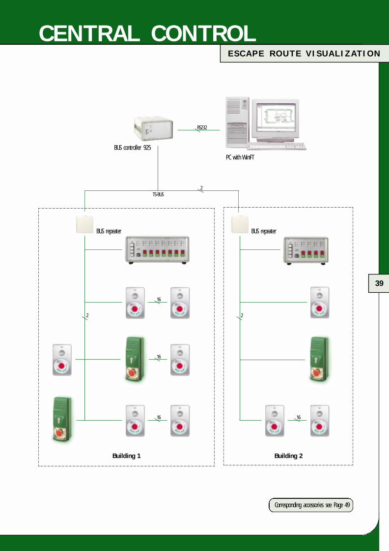
Escape route visualization WinFT
WinFT is a visualization software for WINDOWSTM PCs.Its functions are basically equivalent to those of the familiar BUScontrol panel 925 so that combinations of WinFT with up to 10parallel panels and 110 escape door systems of the model series925 are easy to realize.
The basis is a building floor plan on which the door symbolsare arranged.
After installation, three authorization levels are available: For dailyoperation, a choice can be made between the authorization levels“Supervision” and “Control”. The locking status and the doorposition of every individual door is displayed via symbols.The authorization level “Control” enables the individual doors to be unlocked/locked and alarm states to be reset.
The user authorization level “Edit” also enables specific systemsettings e. g. changing floor plans and shifting, reinserting ordeleting of door symbols.
All procedures are fully logged by the software.
The BUS controller 925-BCM acts as an interface between theeffeff TS bus and WinFT and is supplied already installed in thecombined wall/table housing (19” technology).
As the costs for the central control unit technology with thismodern and innovative solution do not depend on the numberof the connected doors, WinFT is an extremely attractivealternative to the control panel 925, especially for largebuildings.
Scope of delivery
The WinFT set Model 970-10 comprises:
• Basic software and building-specific data on CD-ROM• Manual• BUS controller Model 925 310 000 001 000
(925-BCM in wall/table housing; incl. PC cable)External dimensions: (H x W x D) = 152 x 259 x 269 mm
• Power supply 1001-241• Editing and insertion of up to 3 building floor plans in
Bitmap format (.bmp)• Placement of up to 30 door symbols.
It is also possible to read in additional floor plans as well as toinsert further door symbols.
Data processing
For processing building-specific data, we require the followinginformation:
• Building floor plans in Bitmap format (.bmp)• Position of doors that require visualizing• The bus addresses of the escape door systems
(if already exist or defined)
FT-Katalog engl.qxd 17.03.2005 14:42 Uhr Seite 38
39
E S C A P E R O U T E V I S U A L I Z A T I O N
CENTRAL CONTROL
BUS controller 925
PC with WinFT
BUS repeater
Building 1 Building 2
BUS repeater
RS232
TS-BUS2
16
16
16 16
2 2
Corresponding accessories see Page 49
FT-Katalog engl.qxd 17.03.2005 14:43 Uhr Seite 39
40
K I N D E R G A R T E N S O L U T I O N
More security for kindergartens
In kindergartens children are not allowed to exit the buildingunaccompanied. At the same time, the exit route out of thebuilding must be free in case of danger.
The following requirements for main entry doors tokindergartens/day care centres are therefore compulsory:
• It must be possible to enter the door from the outside duringopening hours but the door must be locked at all times forthe children from the inside.
• It must be possible for adults to open the door easily fromthe inside at all times.
• In case of danger, e. g. fire or other panic situations,the door must also function as an escape route.
In addition to these functions, the statutory “Federal GermanBuilding Regulations pertaining to the electrical locking of doorsin escape routes”, must be complied with. effeff offers a testedand approved door locking mechanism for this application.
Mechanical door requirements
The door must be equipped with a latch bolt or a latch boltpanic lock and front door furniture (inside: Panic bar, outside:Door knob). The lock can always be opened in the escapedirection by the panic bar.
The door is locked and controlled via an additional escape doorlocking mechanism that is attached separately from the mainlock.
In order for the door to be pulled open from outside when it isreleased, a door strike is also installed opposite the main lock.
Function
In its basic state the door is closed and additionally locked bythe escape door locking mechanism.
A button is mounted on the outside that is only activatedduring certain periods as desired via a timer or a switch.The door can be unlocked and thus opened via this button by everyone during the defined period. After closing, the door is immediately relocked automatically. In order for the door tobe unlocked outside the operating times (button) by authorizedpersons (e. g. in the morning before opening hours) a key switchis also required outside.
A button is also mounted on the inside for unlocking the door.To prevent children from reaching the button, it should bemounted at a height of e. g. 1.80 m. The functioning of thisbutton is usually not affected by the operating times, i. e.the door can be unlocked at all times by adults.
In addition to the door, a door terminal or control terminal is also installed. The terminal has an emergency button with aplexiglass cover for securely unlocking the escape door lockingmechanism in case of panic. The emergency button should notbe mounted higher than 1.05 m so that it can also be activatedby children. When the emergency button is activated, the acoust-ical signal transmitter integrated in the terminal is actuated andtriggers an alarm signal. A potential-free monitoring contact(closer) is available for further alarm evaluations.After releasing via the emergency button, the door can beopened from the inside via the panic bar . Relocking is onlypossible via the key switch integrated in the control terminal.
For a detailed description, request the corresponding applicationsheet.
APPLICATIONS
FT-Katalog engl.qxd 17.03.2005 14:43 Uhr Seite 40

S I C H E R H E I T S S C H L Ö S S E R
41
F U N C T I O N A L D I A G R A M
10:54
Digital timer
Release button Mounting height:1.80 m
Escape door terminalMounting height 1.05 m
Distributor
FDS (optional)
Outside:Waterproof button(provided on site)
Outside:Key switch
230 V
Indoors Outdoors
APPLICATIONS
2
2 2 2
23
511
FT-Katalog engl.qxd 17.03.2005 14:43 Uhr Seite 41

42
C E N T R A L R E L E A S E
APPLICATIONS
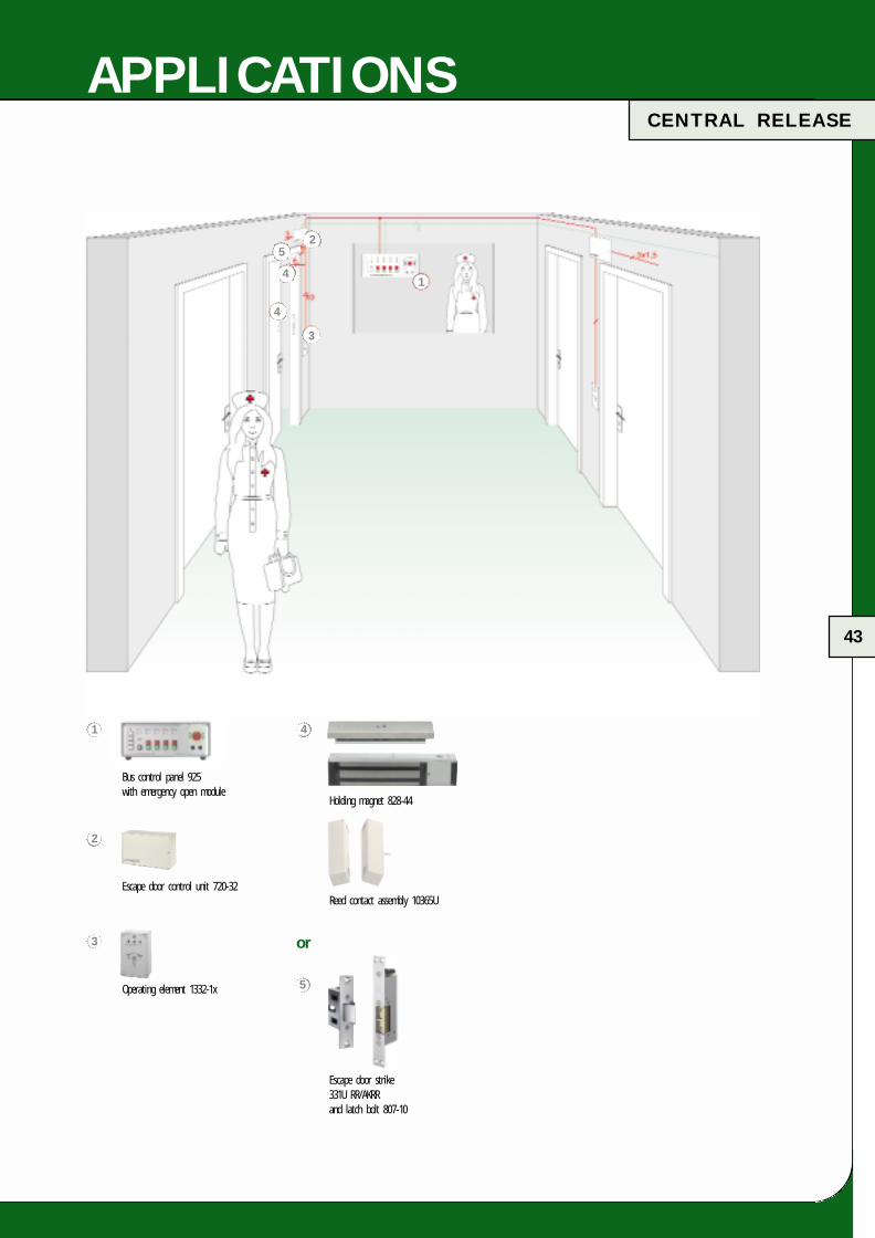
Central release without emergency button on site
For the safety of humans, doors in escape routes must be easyto open from the inside and without additional assistance acc-ording to the regulations in the special building directives.Basically, these requirements mean that these exits are open tomisuse. In certain applications the misuse of emergency exits canhave disastrous consequences. For example, an emergency buttoncannot be installed for obvious reasons in closed departments sothat indirect release from a permanently occupied central pointis the only possibility. If this type of release is required for alldoors, the circuit must be state-of-the-art and provide maximumsecurity.
As specialists for escape door locking mechanisms, we naturallyoffer solutions for this type of application. effeff has developed a self-monitoring security relay circuit that is directly connectedto the electric circuit of the electrical locking mechanism as isthe emergency button (in the standard application) and releasesit when activated.
We would like to mention however, that renouncing on theemergency button at the door, in other words renouncing on the most important link in the escape door locking mechanism,must be clarified with the relevant inspection authorities andapproved accordingly. This special concept of the escape doorcontrol system is used everywhere where the local emergencybutton at the door cannot be used, e. g. in
• Closed departments in hospitals• Psychiatric institutes • Sheltered workshops
The requirements for secure accommodation must be fulfilled andunintentional or unwanted operation prevented.
Features of the escape door control unit 720-32• Central release• Connection to fire detection system• Connection for external operating element
(manual unlocking/locking)• Flash lamp• Control panel BUS technology• Monitoring contact unlocked/locked• Monitoring contact alarm• 5 fire detectors• Authorized temporary release by external switching element,
e. g. access control• Permanent unlocking by external switching element, e. g. timer• “Door open” monitoring• Connection of external alarm elements• Integrated emergency current supply (battery optional)
FT-Katalog engl.qxd 17.03.2005 14:43 Uhr Seite 42
43
APPLICATIONS
Holding magnet 828-44
Escape door strike331U RR/AKRRand latch bolt 807-10
Reed contact assembly 10365U
or
Bus control panel 925with emergency open module
1
Escape door control unit 720-32
2
Operating element 1332-1x
3
4
5
4
4
5
1
2
3
C E N T R A L R E L E A S E
FT-Katalog engl.qxd 17.03.2005 14:43 Uhr Seite 43

44
E S C A P E R O U T E S E C U R I T Y F O R M A X I M U M S E C U R I T Y Z O N E
APPLICATIONS
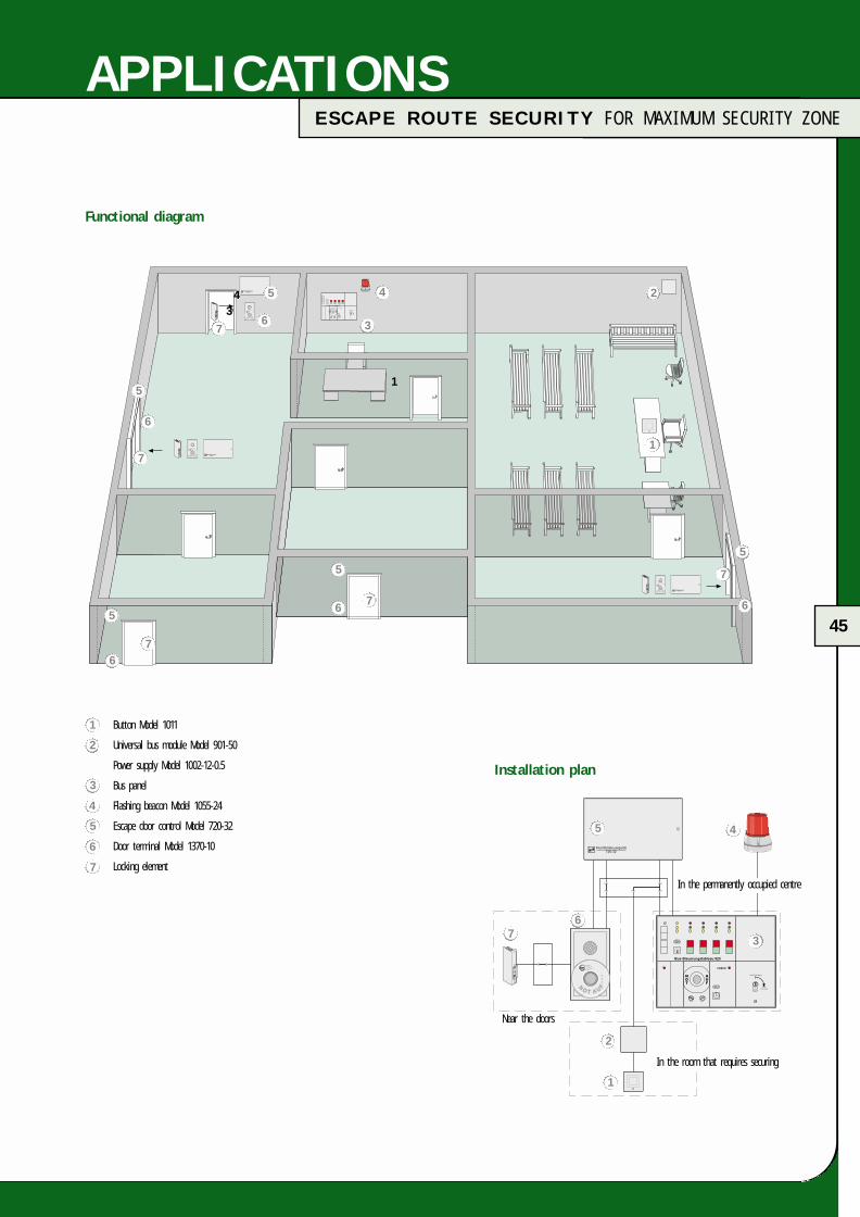
Misuse of escape doors
In order to prevent the misuse of escape doors, effeff offers asolution for deactivating the emergency open button at the doorfor a specific period of time and transferring the possibility toopen the door to a central control centre.
If a critical situation occurs in a room that requires securing,the person responsible on site presses a request button.The security personnel at the control centre switch the systemand thus deactivate the emergency open button at the door.The escape doors can then only be unlocked centrally from thecontrol centre or via the key switch at the door terminals.If a person then presses the emergency open switch at the sitein question, the escape door remains locked. At the same time,an alarm is triggered at the security control centre. The securitypersonnel decide whether there is an emergency and reacts acc-ordingly. This central releasing process is limited in time.If it is not manually extended or terminated when it hasexpired, the system switches automatically and the doors can be opened by the emergency open button.
The described “locking system for central locking with direct and indirect release” complies with the “Guideline on electricallocking systems of doors in escape routes”. This was confirmedby the Certificate R 60003659 issued by TÜV Rhineland (German Technical Incorporate).
A system of this type must always be approved by the relevantinspection authorities. A condition for this is usually a central,permanently occupied centre where the relevant escape routedoors can be monitored.
Application areas
• Police station• Museum• Justice building (e. g. court)• Banks• Laboratories• Transport companies (transport of valuables)
For a detailed description, please request the correspondingapplication sheet.
FT-Katalog engl.qxd 17.03.2005 14:43 Uhr Seite 44
45
S I C H E R H E I T S S C H L Ö S S E RE S C A P E R O U T E S E C U R I T Y F O R M A X I M U M S E C U R I T Y Z O N E
APPLICATIONS
Button Model 1011
Universal bus module Model 901-50
Power supply Model 1002-12-0.5
Bus panel
Flashing beacon Model 1055-24
Escape door control Model 720-32
Door terminal Model 1370-10
Locking element
Installation plan
Functional diagram
In the room that requires securing
Near the doors
In the permanently occupied centre
34
15
5
5
5
5
6
6
6
6 6
7
7
7
7
7
24
1
3
1
2
3
45
67
1
2
3
4
5
6
7
FT-Katalog engl.qxd 17.03.2005 14:43 Uhr Seite 45

46
A C C E S S O R I E S
ACCESSORIES
10360
10366
10371
10365
10370
10405
10361
Technical data
Electromechanical contact
Response distance Approx. 2 mm
Switching current 2 A
Switching voltage 25 V ≈
Connection leads Approx. 10 cm
Magnetic contacts
Switching current max. 0.5 A
Switching voltage 25 V ≈
Connection lead length 6 m
Door contacts
Electromechanical contactThe door contact is installed in the door frame and enables thedoor position to be evaluated by the escape door control.
Magnetic contacts (reed contacts)are melted into a glass tube and are both dust and water-proof.A reed contact is activated by a permanent magnet and is thuscontactless. The reed contact is recessed e. g. in a door frame on the opposite side of the hinge and the corresponding magneton the opposite side in the door leaf. When installing in steelprofiles (magnetic materials) only use block reed assemblies(Order no. 10365) with surface mounted base (Order no. 10366).The available surface mounted bases and fixings are intended tofacilitate flat fitting and aid in mounting the magnetic contacts.
Order numbers
Flat reed contact assembly Switching interval approx. 10 mm 10360-6-----00
Accessories 1fixation 10361-------00
Block reed assembly Approx. 20 mm 10365-6-----00
Accessories 1 set, surface mounted base, 6 pce. 10366-------00
Circular reed contact with flange approx. 5 mm 10370-6-----00
Accessories 1 fixation 10371-------00
Model Connection Face platetechnology
10405.10-----00 Cable (4 m) With square face plate
10405.11-----00 Terminals With square face plate
10405.10R----00 Cable (4 m) With radiused face plate
10405.11R----00 Terminals With radiused face plate
Note:Magnetic materials affect the magnetic fields required for theswitching operation. This reduces the defined switching interval.The reed contact cannot be switched if it is fully surrounded by magnetic materials. Use non-magnetic screws for fixing themagnetic contacts. If installation in magnetic materials cannot beavoided, a test should be carried out to determine the resultingswitching interval. Further information can be obtained from ourTechnical Sales Dept.
FT-Katalog engl.qxd 17.03.2005 14:43 Uhr Seite 46

47
A C C E S S O R I E S
ACCESSORIES
Technical data
Rated operating voltage 12 V DC
Operating temperature range 0 °C to +50 °C
Housing colour White
Fire detector
Optical smoke detectorOptical smoke detector with base and LED display for connectingto escape door control unit 720-30/32
60030--------00
Technical data
Indicator Macralon, transparent, red
Dimensions Ø 114 mm, height 173 mm
Rated operating voltage 24 V DC
Rated current consumption 250 mA
Flashing frequency 1 to 1.5 Hz =̂60 to 90 flashes/minute
Protection class IP 54
Multi-tone siren Model 1200-10In plastic housing for mounting indoors.
1200-10------00
Technical data
Rated operating voltage 12 – 24 V DC stabilized DC voltage
Rated current consumption at 12 V 90mA/24 V 80 mA
Audio frequency and Settablepulsating alarm signalling
Protection class IP 33
Loudness level (at 1 m distance) 100 dB (A) at 24 V (±10 %)
Colour Grey
Dimensions H 80 x W 70 x D 78 mm
Duty cycle 100 % ED
Temperature range -20 °C to +50 °C
Additional alarm transmitter
Flashing beaconOptical signal transmitter in plastic housing for mounting on the wall. Thanks to its high light efficiency, this flashing beaconis also easily visible in well lit rooms. It is also suitable formounting in dry and moist rooms and outdoors.
1055-24------00
FT-Katalog engl.qxd 17.03.2005 14:43 Uhr Seite 47

48
A C C E S S O R I E S
ACCESSORIES
Nur bei Gefahr betätigen
NOTTASTE
Nur bei Gefahr betätigen
NOTTASTE
Nur bei Gefahr betätigen
NOTTASTE
Replacement coverfor terminal 1337, 1338, 1340Art. No. Z1337-10-1---6
Plastic sign EMERGENCY OFFfor terminal 1337, 1338, 1340Art. No. 2.1504-00131800
Test badgefor all terminalsArt. No. 2.1502-00030000
Plastic sign EMERGENCY BUT-TONArrow pointing downwards, greenArt. No. 2.1504-00091800
Plastic sign EMERGENCY BUTTONArrow pointing to the right, greenArt. No. 2.1504-00071800
Plastic sign EMERGENCY BUTTONArrow pointing to the left, greenArt. No. 2.1504-00061800
Replacement coverfor terminal 1370Art. No. 1370-20-02---00
Flush mounted housing for 1370whiteArt. No. 01370.202001
Cavity wall mounting set 1370Art. No. 1370-00-01---00
Replacement seal for power supply module 1370e. g. stainless steel opticArt. No. 1370-40-0104-00
Replacement emergency button cover, 2 pce.for terminal 1370Art. No. 1370-20-01---00
Insertion label EMERGENCYOPEN for terminal 1370with European profile cylinderArt. No. 1370-20-03---00Swiss circular profile cylinderArt. No. 1370-70-03---00
FT-Katalog engl.qxd 17.03.2005 14:43 Uhr Seite 48

49
A C C E S S O R I E S
ACCESSORIES
Universal BUS module
In addition to the visualization of escape door systems, electricdoor strikes and electric security locks can be controlled anddoor and bolt switch contacts monitored via the universal busmodule 901-50. The number of 110 connectable escape doorsystems is thus reduced accordingly.
BUS repeater escape door control
When installing an escape door system, the overall length of thelines soon amounts to several hundred meters. For larger systemsa BUS repeater must be installed for lengths longer than 1000m (per bus phase). With this BUS repeater, the BUS signal isamplified and the escape door BUS systems can thus be realizedwith lines several kilometres in length. A further advantage ofthe BUS repeater is the galvanic insulation of the BUS line.This means that the installation of large systems can be dividedamongst e. g. floors. In case of a fault, only the relevant phasefails due to the galvanic insulation, the remaining section of theBUS system continues to function fully.Technical data
Connection voltage 12 V AC/DC ± 10 % uncontrolledor12 V DC controlled +15/-10 %
Rated operating voltage 12 V
Rated current consumption max. 100 mA
Power consumption 1.2 W
Contact load capacity of relay 24 V /3A
Capacity of output max. 50 mA at 2.5 V “acoustical alarm” (terminal 25) voltage drop
(inside device 0.5 V drop per 10 mA load current)
Protection class as per DIN 40050 IP 40
Operating temperature range 0 °C to +40 °C
Storage temperature range -25 °C to +60 °C
Dimensions 120 x 120 x 30 mm
Weight 200 g
Colour RAL 9002
Technical data
Connection voltage 12 V AC/DC ±10 % uncontrolledor12 V DC controlled
Rated operating voltage 12 V
Rated current consumption max. 60 mA
Power consumption 720 mW
Protection class as per DIN 40050 IP 40
Operating temperature range 0 °C to +40 °C
Storage temperature range -25 °C to +60 °C
Dimensions 120 x 120 x 30 mm
Weight 200 g
Colour RAL 9002
901-50-------00 901-35-------00
FT-Katalog engl.qxd 17.03.2005 14:43 Uhr Seite 49

50
D AY A L A R M
ESCAPE DOOR MONITORING
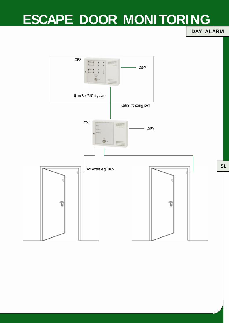
Day alarm Model 7450
Two emergency exit doors can be monitored with the day alarm that according to validregulations should not be closed. The device is easy to mount on site. Only 230 V AC/50Hz are required as a supply voltage thanks to the integrated power supply. The doorsare monitored via door contacts. If the door is opened, the door contacts trigger analarm. The day alarm device can be switched on/off via an integrated key switch.
Equipped with:• Key switch on/off• Operating state display via green LED• Special display for alarm triggering (2 red LEDs)• 2 door contact connections (fail-unlocked loop)• Integrated acoustical alarm transmitter (buzzer)• Output for external buzzer;• Semi-conductor outputs for “Alarm” and “Operating state OFF”• Potential-free relay changeover contacts for “Alarm”
Application areas:The day alarm is used to monitor escape doors, e. g. with a reed contact. The day alarmis used preferably in escape route doors that should not be additionally locked with aconventional escape door locking mechanism as per the Guidelines on Electrical LockingSystems. As only one contact is attached to the door, the function of the escape doorsis not affected. This means that these devices present a cost-favourable alternative toconventional escape door systems as per the Guidelines on Electrical Locking Systems.
Technical data
Rated operating voltage 230 V AC;+10 % to -15 %, 50 Hz
Rated current consumption Fail-unlocked approx. 10 mAAlarm approx. 20 mA
Output for operating state OFF Max. 12 V DC /40 mA
Relay contact load capacity: 2 A/30 V DC0.5 A/125 V AC
Relay contact load capacity: 2 A /30 V DC0.5 A /125 V AC
Operating temperature range -5 °C to +50 °C
Storage temperature range -25 °C to +70 °C
Protection class as per DIN 40 050 IP 30
Output for operating state OFF: 12 V DC /max. 40 mA
Output for alarm: 12 V DC /max. 80 mA
Output for “external buzzer”: 12 V DC /max. 50 mA
Contact version: Soldered connections
Dimensions (W x H x D): 200 x 146 x 55 mm
Technical data
Rated operating voltage: 12 V DC, 10 V to 15 V DC
Rated current consumption: Per LED approx. 10 mABuzzer approx. 20 mA
Operating temperature range -5 °C to +45 °C
Storage temperature range -20 °C to +70 °C
Contact version: Soldered connections
Protection class As per DIN 40 050 IP 30
Dimensions (W x H x D): 200 x 146 x 55 mm
Parallel panel Model 7452
The parallel panel Model 7452 is used for remote individualindication of one to 8 day alarm systems. It has a display (2LEDs) for each connected door contact as well as an acousticalcollective alarm (buzzer).
Equipped with:• Operating state and alarm display of each individual
detector by green and red LED• Alarm indication of each individual detector• Acoustical collective alarm by integrated buzzer• Key switch for buzzer control “On/Off”
Application areasFor the central indication of several day alarm devices (escape doors). Examples:• Gate• Monitoring room• Nurse’s staff room
7450---------00 7452---------00
FT-Katalog engl.qxd 17.03.2005 14:43 Uhr Seite 50
51
D AY A L A R M
ESCAPE DOOR MONITORING
7452
7450
Central monitoring room
230 V
Up to 8 x 7450 day alarm
230 V
Door contact e. g. 10365
FT-Katalog engl.qxd 17.03.2005 14:43 Uhr Seite 51

52
I N F O R M AT I O N O N B U I L D I N G C O D E S
GUIDELINES
Locking of emergency exits
All effeff escape door locking mechanisms comply with the“Guideline on electrical locking systems of doors in escaperoutes”. The certificates are filed in the collection of testcertificates D00070 that we can send to you on request.These certificates are proof of the suitability of all the systemscontained in this catalogue for securing escape routes. They canbe used throughout the Federal Republic of Germany.
With the “C” sign and the corresponding declaration ofcompliance, effeff guarantees a continuous high standard ofquality.
The use and thus the installation, acceptance and recurring testsof escape door locking mechanisms are subject to the regionalbuilding laws. The regional building regulations and the technicaltest regulations of the different states are applicable and areusually based on the sample decree “Federal German BuildingRequirements for the electrical locking of doors in escape routes”dated June 1988.
Should you have any questions on the “Guidelines on electricallocking systems of doors in escape routes” relating to the applic-ation of effeff escape door locking mechanisms, just call our specialists at:
Escape route hotline: 07431 123-381
Additional locking of doors with surface holding magnets
As the locking element of an escape door locking mechanism isalways installed in the fire-rated door in addition to the mainlock, this means that the door is kept securely closed even incase of fire.
The materials testing office of Nordrhein-Westfalen refers explicitlyin test certificate No. 120418792-01 to the non-objection of theuse of the combined escape door strike 331U and latch bolt807-10 in fire-rated doors.
As regards the installation in fire-rated doors, observe theinformation issued by the German Institute for BuildingTechnology, Berlin “Modifications to fire barriers”.
According to the German Institute for Building Technology, surfaceholding magnets may also be installed in already manufacturedfire barriers in addition to the existing lock system.
“In addition to the existing lock system, installation of holdingplates for holding magnets of electromagnetic locking equipment.The holding plate must be fixed to the door leaf using min.four screws of max. 6 mm Ø; for sheet steel doors these screwsshould be replaced by rivet nuts. Do not drill through the fire-rated doors!”.
FT-Katalog engl.qxd 17.03.2005 14:43 Uhr Seite 52

53
S E M I N A R
ADVANCED TRAINING
Depending on the target group, effeff offers different seminarsreferring to specific areas of escape route technology.
Should you wish to deepen your knowledge of “Locking of escape routes”, please contact our training department:
Tel. 07431 123-870Fax 07431 123-333E-Mail: [email protected]
FT-Katalog engl.qxd 17.03.2005 14:43 Uhr Seite 53

e f f e f f P r o d u c t O v e r v i e w
P r o d u c t O v e r v i e w
O V E R V I E W
ES C A P E D O O R S Y S T E M S
When danger is imminent have confidence in effeff ’s know-how and
reliability. Our rescue path systems ensure secure operation of the escape
route door irrespective of whether the door requires locking or may only
be used by authorized persons. Absolute secure use of escape routes in
case of danger is ensured at all times.
effeff escape door control systems ensure protection and security e. g. in
hospitals, schools, kindergarten, office buildings, airports and exhibition halls.
For your special applications too, we have the fitting solutions e. g. closed
departments in clinics.
54
S E C U R I T Y L O C K S
First and foremost security: The effeff electric security locks with anti-panic
function and self-locking mechanism ensure maximum mechanical security in
conjunction with high operating comfort for the user. The effeff range of
locks is suitable for use both in fire doors and escape and rescue
routes.
E L E C T R I C D O O R S T R I K E
effeff door strikes offer a high degree of security and are easy to use.
Our wide range fulfils all requirements and includes models for all types
of installation.
This applies worldwide as effeff products comply with both national and
international regulations. effeff ’s convincing solutions for smoke protec-
tion doors, fire rated doors and doors in escape routes.
E L E C T R I C B O L T S
effeff electric bolts reliably complement locks and door strikes and are
used for special applications e.g. swing doors or sliding doors where they
act as an additional locking mechanism. For door bolts with integrated
monitoring contact, the locking state can be monitored so that e. g. a
system can only start when the corresponding door is also securely
locked.
Application possibilities range from the simple drawer to elevator doors
and high security zones.
FT-Katalog engl.qxd 17.03.2005 14:43 Uhr Seite 54
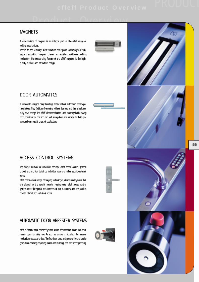
e f f e f f P r o d u c t O v e r v i e w
P r o d u c t O v e r v i e w
P R O D U C T
55
D O O R A U TO M A T I C S
It is hard to imagine many buildings today without automatic power-ope-
rated doors. They facilitate free entry without barriers and thus simultane-
ously save energy. The effeff electromechanical and electrohydraulic swing
door operators for one and two leaf swing doors are suitable for both pri-
vate and commercial areas of application.
AUTOMAT IC DOOR ARRESTER SYSTEMS
effeff automatic door arrester systems secure fire-retardant doors that must
remain open for daily use. As soon as smoke is signalled, the arrester
mechanism releases the door. The fire doors close and prevent fire and smoke
gases from reaching adjoining rooms and buildings and fire from spreading.
M A G N E T S
A wide variety of magnets is an integral part of the effeff range of
locking mechanisms.
Thanks to the virtually silent function and special advantages of sub-
sequent mounting, magnets present an excellent additional locking
mechanism. The outstanding feature of the effeff magnets is the high-
quality surface and attractive design.
A C C E S S C O N T R O L S Y S T E M S
The simple solution for maximum security! effeff access control systems
protect and monitor buildings, individual rooms or other security-relevant
zones.
effeff offers a wide range of varying technologies, devices and systems that
are aligned to the special security requirements. effeff access control
systems meet the special requirements of our customers and are used in
private, official and industrial zones.
FT-Katalog engl.qxd 17.03.2005 14:44 Uhr Seite 55

N O T E S
56
FT-Katalog engl.qxd 17.03.2005 14:44 Uhr Seite 56

N O T E S
57
FT-Katalog engl.qxd 17.03.2005 14:44 Uhr Seite 57

58
N O T E S
FT-Katalog engl.qxd 17.03.2005 14:44 Uhr Seite 58
59
O R D E R - F A X
Company Branch E-mail
Contact Telephone Fax
Street/POB Customer No.
Postal code/Town Order date
Order No. Pce.
An ASSA ABLOY Group company
FT-Katalog engl.qxd 17.03.2005 14:44 Uhr Seite 59
S I C H E R H E I T S S C H L Ö S S E R
2.190
1-07
40G0
01
RettungswegtechnikE s c a p e d o o r s y s t e m s
Verroui l lage des issues de secoursT e c n i c a d e l l e u s c i t e d i s i v u r e z z a
Sistemas para sal ida de emergencia
An ASSA ABLOY Group company
effeff Fritz Fuss GmbH & Co.Kommanditgesellschaft auf AktienBildstockstraße 20 72458 AlbstadtGERMANYTel. +49 7431 123-0 Fax +49 7431 123-240 [email protected]
FT-Katalog engl.qxd 17.03.2005 15:01 Uhr Seite 60