
Functional Safety in KNX
105
Functional Safety in KNX DIPLOMARBEIT zur Erlangung des akademischen Grades Diplom-Ingenieur im Rahmen des Studiums Technische Informatik eingereicht von Marco Steffan Matrikelnummer 0215884 an der Fakultät für Informatik der Technischen Universität Wien Betreuung Betreuer: Ao.Univ.Prof.Dr. Wolfgang Kastner Mitwirkung: Dr. Wolfgang Granzer Wien, 24.11.2011 (Unterschrift Verfasser) (Unterschrift Betreuer) Technische Universität Wien A-1040 Wien Karlsplatz 13 Tel. +43-1-58801-0 www.tuwien.ac.at Die approbierte Originalversion dieser Diplom-/Masterarbeit ist an der Hauptbibliothek der Technischen Universität Wien aufgestellt (http://www.ub.tuwien.ac.at). The approved original version of this diploma or master thesis is available at the main library of the Vienna University of Technology (http://www.ub.tuwien.ac.at/englweb/).
Transcript of Functional Safety in KNX

Functional Safety in KNX
DIPLOMARBEIT
zur Erlangung des akademischen Grades
Diplom-Ingenieur
im Rahmen des Studiums
Technische Informatik
eingereicht von
Marco SteffanMatrikelnummer 0215884
an derFakultät für Informatik der Technischen Universität Wien
BetreuungBetreuer: Ao.Univ.Prof.Dr. Wolfgang KastnerMitwirkung: Dr. Wolfgang Granzer
Wien, 24.11.2011(Unterschrift Verfasser) (Unterschrift Betreuer)
Technische Universität WienA-1040 Wien � Karlsplatz 13 � Tel. +43-1-58801-0 � www.tuwien.ac.at
Die approbierte Originalversion dieser Diplom-/Masterarbeit ist an der Hauptbibliothek der Technischen Universität Wien aufgestellt (http://www.ub.tuwien.ac.at). The approved original version of this diploma or master thesis is available at the main library of the Vienna University of Technology (http://www.ub.tuwien.ac.at/englweb/).


Erklärung zur Verfassung der Arbeit
Marco SteffanWiesenweg 13, 6170 Zirl
Hiermit erkläre ich, dass ich diese Arbeit selbständig verfasst habe, dass ich die verwende-ten Quellen und Hilfsmittel vollständig angegeben habe unddass ich die Stellen der Arbeit -einschließlich Tabellen, Karten und Abbildungen -, die anderen Werken oder dem Internet imWortlaut oder dem Sinn nach entnommen sind, auf jeden Fall unter Angabe der Quelle als Ent-lehnung kenntlich gemacht habe.
(Ort, Datum) (Unterschrift Verfasser)
i

Abstract
Building automation systems aim at providing a comfortableenvironment while savingavailable resources. In case of using fire alarm systems (functional safety) or access-controlsystems (security) those systems are realized as separate,closed systems interacting with anexisting building automation system via dedicated points of interaction. Integrated systemsproviding functional safety natively are currently hardlyavailable.
This thesis targets an approach to extend the building automation technology KNXwith functional safety. In compliance with IEC 61508 (Functional safety of electrical/elec-tronic/programmable electronic safety-related systems)and ISO 13849 (Safety of machin-ery - Safety-related parts of control systems) an architecture satisfying safety integrity level3 (SIL3) as defined by IEC 61508 is presented. Security is thereby left unconsidered.SIL3 compliance implies sufficient support on hardware level (fault-tolerance), a standard-conform documentation of all development steps as well as adequate software to detecterrors in the hardware and the communication system.
The intention of the thesis is not the provision of a completeimplementation of allrequirements according to IEC 61508 but rather elaborationof an extension to existing ap-proaches within this field. On that score and in compliance with IEC 61784-3 (IndustrielleKommunikationsnetze - Profile - Teil 3-1: Funktional sichere Übertragung bei Feldbussen)measures to detect errors in the communication system are discussed, architectures for aSIL3 compliant KNX-system are presented and resulting impacts on hard- and software areshown.
Kurzfassung
Gebäudeautomationssysteme dienen in erster Linie der Erzeugung eines komfortablenRaumklimas bei gleichzeitiger, ressourcenschonender Nutzung der zur Verfügung stehen-den Energie. Geht man davon aus, dass funktionale Sicherheit (Safety) etwa für Brand-meldeanlagen oder Systemsicherheit (Security) für Zutrittskontrollen erforderlich sind, wer-den diese Anforderungen durch eigenständige Systeme realisiert, die (im besten Fall) überausgewählte Schnittstellen mit einem vorhanden Gebäudeautomationssystem kommunizieren.Integrierte Systeme, die bereits "nativ" funktionale Sicherheit zur Verfügung stellen, sindderzeit kaum verfügbar.
Diese Arbeit versucht einen Ansatz zu schaffen, die GebäudeautomationstechnologieKNX um funktionale Sicherheit zu erweitern. In Übereinstimmung mit den StandardsIEC 61508 (Funktionale Sicherheit sicherheits-bezogenerelektrischer / elektronischer /programmierbarer elektronischer Systeme) und ISO 13849 (Sicherheit von Maschinen -Sicherheitsbezogene Teile von Steuerungen) wird eine mögliche Architektur erarbeitet, umeinen Sicherheitsintegritäts-Level 3 (SIL3) laut IEC 61508 zu erreichen. Systemsicher-heit bleibt dabei unberücksichtigt. SIL3 impliziert eine ausreichende Unterstützung der zu-grunde liegenden Hardware (Fehlertoleranz), eine Standard-konforme Dokumentation allerEntwicklungsschritte sowie Software, um Fehler in der Hardware und dem Kommunika-tionssystem zu erkennen.
Ziel dieser Arbeit ist nicht eine vollständige Ausarbeitung aller Erfordernisse gemäßIEC 61508, sondern eine Erweiterung zu bereits bestehendenAnsätzen in diesem Umfeldzu schaffen. Im Zuge dieser Arbeit werden Mechanismen, die Fehler im Kommunikations-system erkennen, in Abstimmung mit IEC 61784-3 (Industrielle Kommunikationsnetze -Profile - Teil 3-1: Funktional sichere Übertragung bei Feldbussen) diskutiert, Architekturenfür ein SIL3 konformes KNX-System vorgestellt und sich daraus ergebende Anforderungenan die Hard- und Software erarbeitet.


Contents
Abstract ii
Kurzfassung iii
Contents v
List of Figures vi
List of Tables viii
1 Introduction 31.1 Motivation . . . . . . . . . . . . . . . . . . . . . . . . . . . . . . . . . . . . . 31.2 Guide through this Thesis . . . . . . . . . . . . . . . . . . . . . . . . . .. . . 4
2 Building Automation Systems 52.1 Introduction . . . . . . . . . . . . . . . . . . . . . . . . . . . . . . . . . . . . 52.2 KNX . . . . . . . . . . . . . . . . . . . . . . . . . . . . . . . . . . . . . . . . 8
3 State-of-the-art Standards 133.1 ISO 13849 - Safety of machinery - Safety-related parts ofcontrol systems . . . 153.2 IEC 61508 - Functional safety of E/E/PE safety-related systems . . . . . . . . 183.3 Conclusions of ISO 13849 and IEC 61508 . . . . . . . . . . . . . . . .. . . . 28
4 Existing Safety Solutions in HBA Systems 314.1 IEC61784-3 - Functional safety fieldbuses . . . . . . . . . . . .. . . . . . . . 324.2 Industrial Automation solutions . . . . . . . . . . . . . . . . . . .. . . . . . 364.3 OpenSafety . . . . . . . . . . . . . . . . . . . . . . . . . . . . . . . . . . . . 404.4 SafetyLON . . . . . . . . . . . . . . . . . . . . . . . . . . . . . . . . . . . . 43
5 KNX Safety 475.1 Hardware Architectures for Safe KNX Nodes . . . . . . . . . . . .. . . . . . 485.2 Synchronizing Safety Nodes . . . . . . . . . . . . . . . . . . . . . . . .. . . 535.3 Intercommunication - KNX Safety Protocol Extension . . .. . . . . . . . . . 595.4 Software Architecture for a Safety Node . . . . . . . . . . . . . .. . . . . . . 64
v

5.5 Intracommunication - Communication between Safe Controllers . . . . . . . . 675.6 KNX Safety Application . . . . . . . . . . . . . . . . . . . . . . . . . . . .. 725.7 Hardware self tests . . . . . . . . . . . . . . . . . . . . . . . . . . . . . . .. 735.8 Scheduling tasks on a Microprocessor . . . . . . . . . . . . . . . .. . . . . . 815.9 Building Safe Hardware . . . . . . . . . . . . . . . . . . . . . . . . . . . .. 84
6 Conclusion 916.1 Outlook and further work . . . . . . . . . . . . . . . . . . . . . . . . . . .. . 92
Bibliography 93
List of Figures
2.1 Three-tier architecture . . . . . . . . . . . . . . . . . . . . . . . . . .. . . . . . 72.2 Two-tier architecture . . . . . . . . . . . . . . . . . . . . . . . . . . . .. . . . . 72.3 KNX model [2] . . . . . . . . . . . . . . . . . . . . . . . . . . . . . . . . . . . . 92.4 KNX topology [2] . . . . . . . . . . . . . . . . . . . . . . . . . . . . . . . . . .. 102.5 KNX LPDU TP1 standard frame structure . . . . . . . . . . . . . . . .. . . . . . 12
3.1 Fault chain defined by [21] . . . . . . . . . . . . . . . . . . . . . . . . . .. . . . 133.2 One-out-of-two architecture (1oo2) . . . . . . . . . . . . . . . .. . . . . . . . . . 143.3 Simplified V-Model of the software lifecycle proposed byISO 13849-1 . . . . . . 173.4 Requirements map for parts 1 to 7 of IEC 61508 [13] . . . . . . .. . . . . . . . . 193.5 Entire safety lifecycle as defined by [3] . . . . . . . . . . . . . .. . . . . . . . . 203.6 E/E/PES safety lifecycle in the realization phase defined by [4] . . . . . . . . . . . 223.7 Relation between hardware and software architectures of PE [5] . . . . . . . . . . 23
4.1 C-model for safety-relevant communication networks [17] . . . . . . . . . . . . . 364.2 Example for SRVT timing [17] . . . . . . . . . . . . . . . . . . . . . . . .. . . . 374.3 Example for SCT timing [17] . . . . . . . . . . . . . . . . . . . . . . . . .. . . . 374.4 Basic FSCP 12/1-System [14] . . . . . . . . . . . . . . . . . . . . . . . .. . . . 394.5 Safety PDU for CPF 12 embedded in Type 12 PDU [14] . . . . . . . .. . . . . . 394.6 FSoE Cycle [14] . . . . . . . . . . . . . . . . . . . . . . . . . . . . . . . . . . .404.7 OpenSafety safety frame structure . . . . . . . . . . . . . . . . . .. . . . . . . . 424.8 Possible hardware architecture for an OpenSafety-Node. . . . . . . . . . . . . . . 424.9 SafetyLON protocol Extension . . . . . . . . . . . . . . . . . . . . . .. . . . . . 44
5.1 System chain - From the sensor to the actuator . . . . . . . . . .. . . . . . . . . . 47
vi

5.2 One channel architecture . . . . . . . . . . . . . . . . . . . . . . . . . .. . . . . 495.3 Replicated Safe Controllers on a single bus-coupler . . .. . . . . . . . . . . . . . 505.4 Replicated Safe Controllers on a single bus-coupler - Alternative . . . . . . . . . . 505.5 Replicated Safe Controllers with replicated bus-couplers . . . . . . . . . . . . . . 515.6 Redundant Safe Nodes on a redundant Bus . . . . . . . . . . . . . . .. . . . . . . 525.7 Triple modular redundancy - TMR . . . . . . . . . . . . . . . . . . . . .. . . . . 535.8 Synchronization condition . . . . . . . . . . . . . . . . . . . . . . . .. . . . . . 555.9 Basic synchronization message exchange [15] . . . . . . . . .. . . . . . . . . . . 575.10 Example execution of vector clocks . . . . . . . . . . . . . . . . .. . . . . . . . 595.11 Safety providing protocol extension for KNX . . . . . . . . .. . . . . . . . . . . 605.12 Schematic addressing in KNX Safety . . . . . . . . . . . . . . . . .. . . . . . . . 625.13 Timing diagram of message exchange between KNX nodes . .. . . . . . . . . . . 655.14 Software architecture of a safe KNX node . . . . . . . . . . . . .. . . . . . . . . 665.15 Simple acknowledge transmission protocol . . . . . . . . . .. . . . . . . . . . . 675.16 Sequence diagram of a successful Two-Phase-Commit Protocol . . . . . . . . . . . 685.17 Sequence diagram of a failed Two-Phase-Commit Protocol . . . . . . . . . . . . . 685.18 State diagram of the coordinator in the Two-Phase-Commit Protocol . . . . . . . . 685.19 State diagram of a participant in the Two-Phase-CommitProtocol . . . . . . . . . 695.20 Sequence diagram of the Three-Phase-Commit Protocol .. . . . . . . . . . . . . 705.21 State diagram of the coordinator in the Three-Phase-Commit Protocol . . . . . . . 715.22 State diagram of a participant in the Three-Phase-Commit Protocol . . . . . . . . 725.23 Online and Offline test intervals. Slightly modified illustration from [28] . . . . . 735.24 State diagram of a correct working memory cell . . . . . . . .. . . . . . . . . . . 745.25 State diagram of a stuck-at zero error in a memory cell . .. . . . . . . . . . . . . 755.26 State diagram of a stuck-at one error in a memory cell . . .. . . . . . . . . . . . . 755.27 State diagram of a state transition error of memory cell. . . . . . . . . . . . . . . 755.28 Potential errors in a memory block . . . . . . . . . . . . . . . . . .. . . . . . . . 765.29 Sample execution of Galpat-Pattern-Test . . . . . . . . . . .. . . . . . . . . . . . 775.30 Sample calculation of CRC . . . . . . . . . . . . . . . . . . . . . . . . .. . . . . 785.31 Structure of stack memory . . . . . . . . . . . . . . . . . . . . . . . . .. . . . . 805.32 Single sensor on replicated input stages . . . . . . . . . . . .. . . . . . . . . . . 855.33 Replicated sensors on replicated input stages . . . . . . .. . . . . . . . . . . . . . 855.34 Example of connecting two switches in line . . . . . . . . . . .. . . . . . . . . . 865.35 Example of connecting two switches parallel . . . . . . . . .. . . . . . . . . . . 865.36 Monitoring sensors using pulsed voltage . . . . . . . . . . . .. . . . . . . . . . . 865.37 Test in a closed circuit . . . . . . . . . . . . . . . . . . . . . . . . . . .. . . . . 875.38 Testable input stage in a closed circuit . . . . . . . . . . . . .. . . . . . . . . . . 875.39 Serially connected switches with read-back switch state . . . . . . . . . . . . . . . 875.40 Two-channel output using semiconductors . . . . . . . . . . .. . . . . . . . . . . 885.41 Fail-safe unit . . . . . . . . . . . . . . . . . . . . . . . . . . . . . . . . . .. . . 89
List of Tables
3.1 Performance Levels (PL) . . . . . . . . . . . . . . . . . . . . . . . . . . .. . . . 153.2 Mean time to failure for a channelMTTFd . . . . . . . . . . . . . . . . . . . . . 163.3 Diagnostic coverage (DC) . . . . . . . . . . . . . . . . . . . . . . . . . .. . . . 163.4 Safety integrity levels for devices with high performance rate [3] . . . . . . . . . . 213.5 Safety integrity of hardware: Constraints to architectures for safety-related type A
subsystems [4] . . . . . . . . . . . . . . . . . . . . . . . . . . . . . . . . . . . . 243.6 Safety integrity of hardware: Constraints to architectures for safety-related type B
subsystems [4] . . . . . . . . . . . . . . . . . . . . . . . . . . . . . . . . . . . . 253.7 Relation between Performance Levels (PL) and Safety Integrity Levels (SIL) as de-
fined by [10] . . . . . . . . . . . . . . . . . . . . . . . . . . . . . . . . . . . . . . 28
4.1 Communication errors and detection measures by [9] . . . .. . . . . . . . . . . . 354.2 Relation between residual error rate and safety integrity level . . . . . . . . . . . . 354.3 Communication errors and detection measures used by CANopen Safety . . . . . . 384.4 Communication errors and detection measures used by Safety over EtherCAT . . . 414.5 Communication errors and detection measures by OpenSafety . . . . . . . . . . . 434.6 Communication errors and detection measures used by Safety LON . . . . . . . . 45
5.1 Communication errors and detection measures used in KNXsafety . . . . . . . . . 615.2 Message types for KNX Safety . . . . . . . . . . . . . . . . . . . . . . . .. . . . 645.3 RAM test methods and resulting DC . . . . . . . . . . . . . . . . . . . .. . . . . 775.4 ROM test methods and resulting DC . . . . . . . . . . . . . . . . . . . .. . . . . 795.5 Example round-robin scheduling . . . . . . . . . . . . . . . . . . . .. . . . . . . 84
viii

FSoE Failsafe over CPF 12CPF Communication Profile FamilySFF Safe Failure FractionSIL Safety Integrity LevelPL Performance LevelPLr Required Performance LevelE/E/PES Electric/Electronic/Programmable Electronic SystemSRP Safety-Related PartEUC Equipment under ControlMTTR Mean Time To RepairDC Diagnostic CoverageCCF Common Cause FailureSCL Safety Communication LayerPTP Precision Time ProtocolCRC Cyclic Redundancy CheckFCS Frame Checking SequenceSRDO Safe Communication ObjectSRVT Safety-relevant Object Validation TimeSA Safe AddressSPDU Safety Process Data UnitAPDU Application Process Data UnitGSPN Generalized Stochastic Petri NetsANubis Advanced Network for Unified Building Integration & ServicesCPU Central Processing UnitOSSD Output Silicon Switched DeviceWCET Worst Case Execution TimePES Programmable Electronic SystemMTTF Mean Time To FailureFMEA Failure Mode and Effects AnalysisSCL Safety Communication LayerCRC Cyclical Redundancy CheckCS Control SystemSRESW Safety-Related Embedded SoftwareSRASW Safety-Related Application SoftwareHVAC Heating Ventilation Air ConditioningROM Read Only MemoryRAM Random Access MemoryEPROM Electrical Erasable Read Only MemoryTMR Triple Modular RedundancyBCI BatiBus Club InternationalEIBA European Installation Bus AssociationEHSA European Home System AssociationHBA Home and Building Automation
1

CSMA Carrier Sense Multiple AccessTPCI Transport Layer Protocol Control InformationAPCI Application Layer Protocol Control InformationPDU Process Data UnitCAFMS Computer Aided Facility Management SystemFSCP Functional Safety Communication ProfileSCM Safety Configuration ManagerCiA CAN in AutomationSCT Safeguard Cycle Time
2

CHAPTER 1Introduction
1.1 Motivation
Traditionally, Building Automation Systems (BAS) providebasic services like Heating, Ven-tilation and Air Conditioning (HVAC), lighting and shading. Safety critical applications likefire detection and alarm systems are usually stand-alone units which interact with BAS usingdedicated gateways. Increasing requests for BAS in safety-critical environments ask for ad-vanced mechanisms to integrate safety-critical technology into BAS. Therefore, it is necessaryto define what safety-critical properties are and what theirmeaning is - to detect hazardousevents in an automation system. These can be failures in hardware, software or the underlyingcommunication-system like a "wrong message" in any way. Such a message can be wrong ina sense of its value-domain or in its time-domain. Detectionof the afore mentioned failuresrequires implementation of certain mechanisms in hardwareand software.
The requirements for safety-critical systems are specifiedin two common standards - ISO13849 (Safety of machinery - Safety-related parts of control systems) and IEC 61508 (Functionalsafety of electrical/electronic/programmable electronic safety-related systems). Especially, IEC61508 presents a very general view on requirements and guidelines for the complete lifecycle ofa safety-related device. Requirements to communication systems are presended in detail in IEC61784-3 (Functional safety fieldbuses).
The thesis follows the approach presented in [20] and tries to extend the KNX protocolto fulfill requirements of SIL 3 as defined by IEC 61508. To achieve this, certain measuresregarding hardware and software are required. From a hardware point of view a higher levelof safety can be achieved by application of redundancy approaches. Furthermore, software isrequired which is capable of detecting failures in hardwareand the communication system. Onthat score, the following chapters will give discussions onhow to achieve functional safety inthe KNX protocol in terms of hardware requirements and involved software.
3

1.2 Guide through this Thesis
Chapter 2 will give an overview about automation systems andrelated terms and definitions.Furthermore, the target technology KNX will be described.
Chapter 3 will cover state-of-the-art standards IEC 61508 and ISO 13849 and show the maindifferences between them. Following IEC 61508, the achievement of specific Safety-Integrity-Levels (SIL) is of importance. SILs define requirements concerning electrical and programming-standards implying the failure rate of a safety-providing device depending on its frequency ofuse. In the context of this thesis, high demanding devices which allow a maximum of onehazardous failure in107 hours will be of special interest (SIL3).
Existing solutions in BAS and industrial automation will bepresented and compared inChapter 4. Here, special attention is put on potential communication errors as defined by IEC61784-3.
In Chapter 5, special aspects relevant for this thesis regarding safety will be presented indetail. This will include a discussion on possible hardwarearchitectures, communication issues,clock synchronization, scheduling and hardware self tests.
The closing Chapter 6 will conclude gained knowledge and provides an outlook on furtherwork.
4

CHAPTER 2Building Automation Systems
Progress in technology mostly aims at making things more convenient for the user. Focusingon electronic devices, additionally energy efficiency comes into mind. That trend also affectsbuildings or their building automation systems. When talking about automation, mainly indus-trial automation comes into mind. Characterized by short reaction times, fast control loops, highprecision and occasionally high dependability, an industrial automation system handles taskswhere human power is not sufficient, too slow, or not possibledue to dangerous environments.Building Automation Systems (BAS) are a special category ofindustrial automation. In contrast,timings are more relaxed due to long response times from the building. Additionally, a BAS hasto take care of energy efficient house keeping and to do that ina most comfortable way.
2.1 Introduction
BAS start at small homes with just a handful of devices and endat large, public buildings likeairports or office buildings automatized by some thousand devices. Especially for large build-ings the advantage of BAS is clear: A BAS provides central knowledge and control about allprocesses involved in a building which is also known as Computer Aided Facility ManagementSystem (CAFMS). In case of an error, the operator is enabled to gain information about the errorand can initiate measures to maintain the system at a very early stage. Another advantage ofBAS is the ability to dynamically reconfigure the behaviour of the system. If for example a lightswitch should control more than the initially installed lamps, it was necessary to re-wire certainparts of the installation in traditional electrical installations. Using a BAS, simply re-binding theswitch to more lamps can be done from a PC in far less time. Having knowledge of multiplesensors also enables construction of intelligent buildings. For example, opening a window willturn off the heating or ventilation. Likewise, increasing temperatures in a room will activate sunshadings and climate control. Since the properties of a comfortable room climate are differentfor each person, smart room controllers in combination withknowledge about who is in theroom could control HVAC according to the person’s preferences (smart buildings). Against all
5

advantages, the main disadvantage is the tremendous cost for initial installation. Additionally,operators have to be trained thoroughly.
According to [19], typically the running costs of a buildingover its lifetime are seven timesthe initial cost for construction. Considering the whole life cycle of a building, the amount ofsaved energy during its lifetime makes the use of a BAS economically feasible.
Another topics in BAS are security and safety. These are two completely different concepts,although described by the same word in German language (“Sicherheit”).
Security describes protection of a system against malicious attacks. For instance, consid-ering a network, insertion of a malicious message or listening to the contents sent through thenetwork have to be detected or prevented by certain securitymeasures. At the beginning, BASwere designed and implemented as closed systems and missingknowledge of potential intruderson how to break the BAS was protection enough. Advances in wireless technology, networkedautomation devices in every room in combination with open standards give motivation for de-velopment of appropriate measures to close those vulnerabilities.
Safety describes the failure free operation of a system or atleast the detection of an error andtransferring the system to a safe state. Safety in automation is currently just available for indus-trial automation solutions (with some minor exceptions). That can be divided into requirementsfor operator safety and requirements for process safety. For example, an emergency stop in-formation transferred through an automation network is required to be delivered and performedwithin predefined deadlines. If that requirement cannot be met, the operator working on the ma-chine could sustain injury or the machine could take damage.That means, the information has tobe transmitted correctly and in time - no matter what happens, the machine has to be transferredto a safe state. Safety in HBA has been an isolated topic so far, addressing primarily fire alarmsystems. Until now, safety providing systems have been mainly constructed as closed systemscommunicating via dedicated gateways with other systems. The only HBA solution providingfunctional safety found so far is an extension to LON called SafetyLON.
Automation Networks
Communication in a traditional automation system can be visualized by the three-levelarchitectureas depicted in Figure 2.1.
The field levelis responsible for direct interaction with the physical environment and col-lects data from simple sensors and activates actuators. Usually that level is equipped with low-bandwidth networks. The collected data is transferred to the automation levelwhich processesand passes data to the management level (vertical communication) or issues other devices atfield level to take action (horizontal communication). The topmostmanagement levelprovidesa global view of all data across the BAS. Therefore, control terminals and logging systems areplaced on that level. Operators are enabled to (re-)configure the BAS through a control centerand perform diagnostic measures on the BAS in case of an error. Typically, the managementlevel is equipped with a high-bandwidth network caused by high amount of data collected bythe lower levels. If communication with other automation systems is required, the managementlevel networks are connected via gateways or routers.
As described, the previous approach assumes simple sensorswith small processing powerto prepare raw data in a very basic way. Development in the microprocessor sector increased
6

Figure 2.1: Three-tier architecture
processing power to admit advanced techniques to pre-process and transmit sensor values [18].That simplifies the diagram in Figure 2.1 to the enhanced two-tier architecture depicted in Figure2.2 by making use ofintelligent devices.
Figure 2.2: Two-tier architecture
Increased intelligence on sensor/actuator level enables integration of communication pro-tocols for direct communication between sensors and actuators through acontrol networkwhatmakes a separate automation level obsolete. Communicationbetween different control networksis established via gateways throughbackbone networksproviding sufficient bandwidth for inter-
7
control network communication as well as for management- and logging tasks.
2.2 KNX
In 1996,BatiBus Club International(BCI), European Installation Bus Association(EIBA) andEuropean Home System Association(EHSA) started to develop a common standard for homeand building automation. In 1999, leading manufacturers ofelectrical building equipment suchas Siemens, Bosch and Merten, along with some more, founded Konnex Association (alsoknown as KNX Association). The first KNX specification was published in 2002 which wasadopted EN 50090 in 2005 and accepted as an international standard ISO/IEC 14543-3 later in2006.
Basically, KNX defines runtime-characteristics, a toolkitof services as well as mechanismsto manage a network. The building automation system is defined by a distributed applicationimplemented through standardized data-point types and “functional block” objects modellinglogical device channels. KNX is platform independent enabling usage of any kind of micropro-cessor to implement a network device.
Elements of KNX
The KNX framework consists of the following parts:
• An inter-working and (distributed) application model which performs the actual HBAapplication (lighting, shading, HVAC,. . . ).
• Configuration and management schemes for logical linking orbinding of KNX devices.These schemes are structured in a set of configuration modes.
• A communication system which defines communication media, amessage protocol and acommunication stack. The communication system has to implement required mechanismsfor configuration and management and hosts the distributed application. This is typifiedby the KNX Common Kernel [2].
• A set of device models is summarized in profiles.
An illustration of the afore mentioned components of KNX is depicted in Figure 2.3.
Supported communication media by KNX
KNX offers a wide variety of possible communication media suited to customer’s needs anddevices to enable interaction between different media.
• Twisted pair is the basic medium in KNX. Main characteristics are: energy and informa-tion are transported over the same pair of wires, an asynchronous, character oriented datatransfer, half duplex, bi-directional communication. TP1(9,6 kBit/s) is the basic mediuminherited from EIB and allows free choice of topology. On topof TP1 the CSMA/CAprotocol is implemented.
8
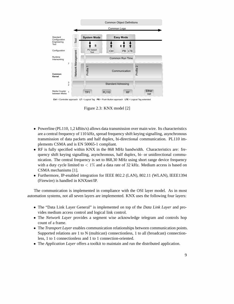
Figure 2.3: KNX model [2]
• Powerline (PL110, 1,2 kBits/s) allows data transmission over main wire. Its characteristicsare a central frequency of 110 kHz, spread frequency shift keying signalling, asynchronoustransmission of data packets and half duplex, bi-directional communication. PL110 im-plements CSMA and is EN 50065-1 compliant.
• RF is fully specified within KNX in the 868 MHz bandwidth. Characteristics are: fre-quency shift keying signalling, asynchronous, half duplex, bi- or unidirectional commu-nication. The central frequency is set to 868,30 MHz using short range device frequencywith a duty cycle limited to< 1% and a data rate of 32 kHz. Medium access is based onCSMA mechanisms [1].
• Furthermore, IP-enabled integration for IEEE 802.2 (LAN),802.11 (WLAN), IEEE1394(Firewire) is handled in KNXnet/IP.
The communication is implemented in compliance with the OSIlayer model. As in mostautomation systems, not all seven layers are implemented. KNX uses the following four layers:
• The “Data Link Layer General” is implemented on top of theData Link Layerand pro-vides medium access control and logical link control.
• The Network Layerprovides a segment wise acknowledge telegram and controls hopcount of a frame.
• TheTransport Layerenables communication relationships between communication points.Supported relations are 1 to N (multicast) connectionless,1 to all (broadcast) connection-less, 1 to 1 connectionless and 1 to 1 connection-oriented.
• TheApplication Layeroffers a toolkit to maintain and run the distributed application.
9

Topologies
As shown later, a KNX frame supports 16-bit space for individual source and destination ad-dresses. That results in a total of 65535 possible devices ona KNX network. The network canbe grouped physically intolinesof 256 devices each. These lines can be formed by amain lineinto anarea. A domainis a combination of up to 15 areas connected through abackbone line.Figure 2.4 gives an illustration of the resulting topology.
Figure 2.4: KNX topology [2]
Addressing schemes
Central functionality of a network is to enable communication between nodes. Therefore, nodesneed to be identified uniquely. In most cases, an installation will be wired and configured af-terwards. KNX offers device identification by a unique device serial number or by the device’sindividual address. Unique serial device numbering is achieved through controlled allocation ofnumber ranges to manufacturers by KNX Association. By knowledge of a devices identifica-tion (unique serial number or individual address) it is possible to communicate with that device.
10

KNX distinguishes system resources keeping configuration information (address-, lookup tablesand parameters) and parameters which control the application.
Communication is distinguished between network resource management and run-time com-munication. Configuration and management tasks usually require direct communication withthe related node (point-to-point connection) or require communication with all nodes (broad-cast) nodes. In contrast, run-time communication mainly uses multicast communication withother nodes interested in changed values.
In order to achieve inter-working, the data-points have to implement “Standardized Data-point Types”, grouped into “Functional Blocks”. Communication between nodes is establishedafter “binding” or linking data-points located on different devices to common multicast groupaddresses. Binding of devices happens either through looseor strict binding rules or dependingon semantic information contained in the address. Upon a successful binding process the dis-tributed application is enabled. That is, if a local application on a node writes a data-point valuethe change notification will be sent across the network with the corresponding address of thesending node. Any node interested in the changed value from that node will receive that valueand inform its local application about the new value. The local application on the receivingnode will now react depending on its internal state machine and update its own data-points. Thecommunication between nodes transferes multiple local applications into a single, distributedapplication.
KNX supports the following three binding schemes: free, structured or tagged. Basically,free and structured binding assume free addressing which means that the numerical value ofaddresses do not contain application semantics. The only assumption is, that all data-pointscommunicating with each other are assigned to the same address. Contrarily, tagged binding as-sumes the numerical value of an address to contain a semantic(data-point) identifier. Therefore,the logical tag or zoningpart of the address identifies a device’s communication partners on adevice level. By assigning data-points to the same zone, they form a group communicating viamulticast.
To configure a KNX network, two main configuration modes are specified as depicted inFigure 2.3. Depending on the user’s preferences and application environment these modes pro-vide functionality to configure a device remotely from ETS tool or locally using the push buttonapproach:
• E(asy)-Mode is applied for simple manipulations where devices are configured accordingto a structured binding without need for separate configuration tools.Controller mode (Ctrl) supports installation of a limited number of devices on one logicalsegment of a physical medium. Such an installation will contain one dedicated noderesponsible for the configuration process.Logical Tag (LT) and Logical Tag Extended (LTE) modes basically enable device config-uration using DIP-switches or selectors.Push Button mode (PB) is almost equal to Ctrl-mode configuration but without the needfor a dedicated configuration device.
• S(ystem)-Mode enables central, free binding and configuration of the installation, typi-cally carried out with the ETS tool.
11

KNX Frame
The frame of a KNX TP1 telegram is depicted in Figure 2.5. Depending on the communicationmedium, different preambles might be appended which will beleft unconsidered here.
Figure 2.5: KNX LPDU TP1 standard frame structure
The control field determines the priority and distinguishesbetween standard and extendedframe format. The individual source address determines theaddress of the sending node. Theindividual (unicast) or group (multicast) destination address determines the address of the re-ceiving node(s). The following byte contains hop-count andaddress-type-information. TheTransport Layer Protocol Control Information (TPCI) controls the transport layer to manageend-to-end connection. The Application Layer Protocol Control Information (APCI) accessesapplication layer primitives (read, write, response,. . . ). The standard frame ensures compatibil-ity with KNX messages (up to 14 octets of data). Extended frames can contain up to 248 octetsof data. The enclosing frame check sequence ensures data consistency.
KNX line access
To access contents sent on the KNX line, special hardware in form of a transceiver is required.Therefore, Siemens provides the TP-UART-IC (Twisted Pair -Universal Asynchronous ReceiveTransmit - IC).
This module supports every transmit- and receive - functionand also the high ohmicdecoupling of energy from bus line. It generates further a stabilized 3.3V or 5Vsupply to use by a host controller. Up to 256 subscribers can be connected to onebus line [25]
The TP-UART-IC consists of an analog part responsible for level converting on the KNX-lineand a digital part providing serial access for communication with connected microcontrollers.
12

CHAPTER 3State-of-the-art Standards
This section gives an overview of applicable standards for safety-related systems. First, ISO13849 for a general approach regarding safety of machinery is presented. A more detailed de-scription of safety-related development is specified by IEC61508, a standard defining a completelifecycle model for every development phase of an Electric/Electronic/Programmable ElectronicSystem (E/E/PES). Here, a degree of safety is described by safety integrity levels (SIL) whichare assigned depending to the probability of one hazardous failure per hour. In contrast, perfor-mance levels (PL) are defined by ISO 13849.
Prior to focusing on the standards, some important terms such as fault, error, failure, risk,hazard, dangerous failure and hazardous event are introduced:
[21] describes faults, errors and failures as a chain depicted in Figure 3.1. Afault is thecause of an error and, thus, the indirect cause of failure. In[6], a fault is defined as an unusualcondition which leads to loss of ability to perform a desiredfunctionality. Anerror is both, thedeviation of an expected result ([6]) or an incorrect internal state, like a corrupted element in thememory ([21]), whereas afailure is an event that denotes the deviation between the actual andthe intended service, or the loss of ability to perform a demanded functionality, respectively.
Figure 3.1: Fault chain defined by [21]
Riskis defined as the combination of probability of error and the resulting harm [6].
13

A hazardis a potential source of harm and is specified to define the source (mechanical orelectrical harm) or type (fire, cut or electrical shock) of harm [6]. Thus, ahazardous eventis asituation where a hazard leads to a harm [6].
A dangerous failuredescribes a failure that potentially leads the safety-related system to adangerous or non-functioning state [6].
In safety-related systems, redundancy is common practice which introduced multiple-channelarchitectures. Such an architecture can be, for example, a1oo2 architecture(one out-of two) de-scribing an approach where one output is chosen among two possible candidates (see Figure3.2). The expression 1oo2 gives no information about the chosen criteria for either of the twoinput channels. It is clear, that such an architecture is optionally extendable by more inputs likea 1oo3 or 1oo4 architecture.
Figure 3.2: One-out-of-two architecture (1oo2)
A clear distinction has to be drawn between safety and security, although it is not alwayspossible in every aspect. Security describes the protection of a system against malicious attacks.Contrarily, safety is defined as the ability of a system to perform its intended behaviour even incase of failure under predefined conditions.
The structure of standards in the domain of safety-related machinery as defined by ISO12100-1 is as follows:
• Type-A-Standards cover definitions, design guidelines, and general aspects applicable tomachinery.
• Type-B-Standards cover a specific safety-aspect or a type ofsafety equipment that is ap-plicable for a wide range of machinery:
– Type-B1-Standards for specific safety-aspects like safetymargins and temperaturelevels.
– Type-B2-Standards for safety equipment.
• Type-C-Standards cover detailed safety requirements for aspecific machine or a group ofmachines.
In case different standards have to be applied, like a Type-Aand a Type-C standard, thehigher level standard (Type-C in that case) will have to be favoured. By means of that catego-rization, ISO 13849 is a Type-B1 standard.
14

3.1 ISO 13849 - Safety of machinery - Safety-related parts ofcontrol systems
This section explains some of the basic principles on how to achieve a certain level of safetyas defined by ISO 13849-1 [10]. Performance levels (PL) are the base for the following devel-opment process. This standard specifies methods to fulfill the requirements for a PL throughthe terms diagnostic coverage, mean time to failure, commoncause failure, and some more keywords explained briefly in the following. Furthermore, ISO 13849 defines requirements to thelifecycle of safety-related software. The second part of the standard (ISO 13849-2 [11]) presentsguidelines and techniques for the validation of the afore defined safety concept.
All parts of a machine control supplying safety functionality are called “safety-related partsof the control system” (SRP/CS). These parts may be realizedin hard- or software. Additionally,such a machine may supply operational functionality. The ability of a device to provide safety-related functionality under predictable conditions is divided into five PLs as shown in Table 3.1.These PLs are defined in terms of probability of a dangerous failure per hour.
Performance Level (PL) Average probability ofa hazardous failure per hour[1/h]
a ≥ 10−5 until < 10−4
b ≥ 3 ∗ 10−6 until < 10−5
c ≥ 10−6 until < 3 ∗ 10−6
d ≥ 10−7 until < 10−6
e ≥ 10−8 until < 10−7
Table 3.1: Performance Levels (PL)
Probability of a dangerous failure depends on certain parameters. ISO 13849 defines thefollowing criteria which have to be considered:
• Hard- and software structure• Fault detection mechanisms• Degree of diagnostic coverage (DC)• Dependability of used devices (MTTFd)• Common cause failures (CCF)• Behaviour at systematic failures• Behaviour at faults• Development process• Load under operational conditions• Environmental conditions
With regard to the evaluation process of PLs those aspects are grouped into quantifiable (MTTF,DC, CCF, structure) and non-quantifiable, qualitative (allothers) principles. Quantifiable aspectsof PLs can be estimated by usage of Markov models, generalized stochastic Petri Nets (GSPN)
15
or reliability block diagrams. In ISO 13849, the determination of PLs under quantifiable aspectsis proposed by five different architectures fulfilling predefined characteristics in case of fault. Ifother architectures are used, detailed calculations on theachieved PLs need to be given. For adescription of predefined architectures, please refer to [10].
To achieve a required PL, measures have to be taken to lower risk. These measures are thereduction of the probability of a fault on device level by usage of more reliable devices andby improvement of the structure of the SRP/CS to lower the effect of the fault. Depending onexpectable faults, these measures can be applied separately or together, where common causefailures have to be taken into account.
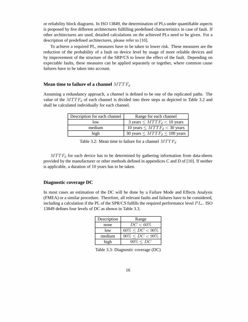
Mean time to failure of a channelMTTFd
Assuming a redundancy approach, achannelis defined to be one of the replicated paths. Thevalue of theMTTFd of each channel is divided into three steps as depicted in Table 3.2 andshall be calculated individually for each channel.
Description for each channel Range for each channellow 3 years≤ MTTFd < 10 years
medium 10 years≤ MTTFd < 30 yearshigh 30 years≤ MTTFd ≤ 100 years
Table 3.2: Mean time to failure for a channelMTTFd
MTTFd for each device has to be determined by gathering information from data-sheetsprovided by the manufacturer or other methods defined in appendices C and D of [10]. If neitheris applicable, a duration of 10 years has to be taken.
Diagnostic coverage DC
In most cases an estimation of the DC will be done by a Failure Mode and Effects Analysis(FMEA) or a similar procedure. Therefore, all relevant faults and failures have to be considered,including a calculation if the PL of the SPR/CS fulfills the required performance levelPLr. ISO13849 defines four levels of DC as shown in Table 3.3.
Description Rangenone DC < 60%
low 60% ≤ DC < 90%
medium 90% ≤ DC < 99%
high 99% ≤ DC
Table 3.3: Diagnostic coverage (DC)
16
Requirements to safety-related software
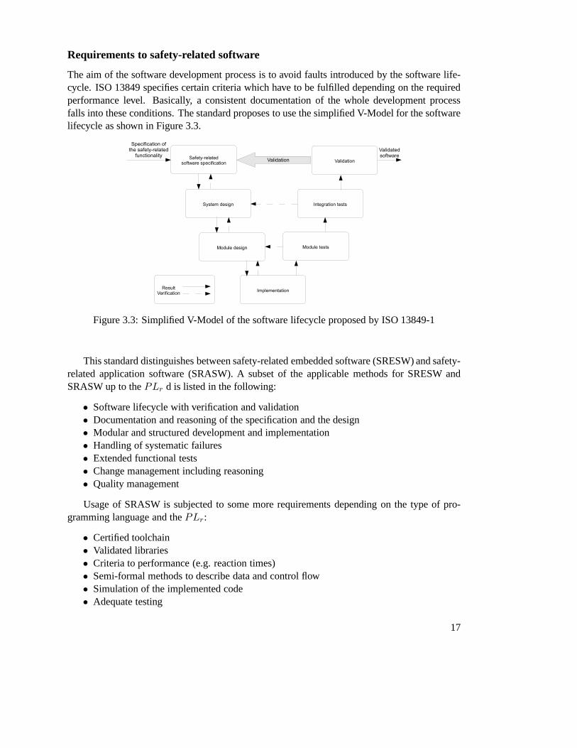
The aim of the software development process is to avoid faults introduced by the software life-cycle. ISO 13849 specifies certain criteria which have to be fulfilled depending on the requiredperformance level. Basically, a consistent documentationof the whole development processfalls into these conditions. The standard proposes to use the simplified V-Model for the softwarelifecycle as shown in Figure 3.3.
Figure 3.3: Simplified V-Model of the software lifecycle proposed by ISO 13849-1
This standard distinguishes between safety-related embedded software (SRESW) and safety-related application software (SRASW). A subset of the applicable methods for SRESW andSRASW up to thePLr d is listed in the following:
• Software lifecycle with verification and validation• Documentation and reasoning of the specification and the design• Modular and structured development and implementation• Handling of systematic failures• Extended functional tests• Change management including reasoning• Quality management
Usage of SRASW is subjected to some more requirements depending on the type of pro-gramming language and thePLr:
• Certified toolchain• Validated libraries• Criteria to performance (e.g. reaction times)• Semi-formal methods to describe data and control flow• Simulation of the implemented code• Adequate testing
17

• A complete, consistent, readable, available and understandable documentation• Verification• Change management
For detailed requirements, please refer to points 4.6.2 and4.6.3 in [10].ISO 13849-1 proposes the parametrization of safety-related software as well. According to
this, the inserted parameters need to be examined with respect to their validity. Further, safedata transmission from a configuration tool to the device hasto be ensured and the effects ofincomplete or incorrect transmitted parameters have to be known in advance. Additionally, theconfiguration tool needs to comply with the same requirements of SRP/CS as the configureddevice. Once again, for a detailed description of applicable criteria to parametrize safety-relateddevices, please refer to point 4.6.4. in [10].
ISO 13849-2 Validation
The standard’s second part addresses validation of mechanical, pneumatical, hydraulic and elec-tronic systems. The validation process assumes error listscontaining all considered faults. Theselists are processed by a predefined validation process and a validation plan. Furthermore, thewhole validation process needs to be documented.
Finally, the most important part is the validation of safety-related functionality. In that stepvalidation has to ensure correct operation of the device under different configurations and itsreaction to different inputs. Additionally, where applicable, a combination of safety-relateddevices needs to be validated by analysis or by testing if required.
3.2 IEC 61508 - Functional safety of E/E/PE safety-related systems
IEC 61508 is the de-facto standard for anything concerning safety-related electric/electronic/pro-grammable electronic (E/E/PE) systems. It covers every single step of the development processof safety-related systems starting from the very first concept up to the decommission of the sys-tem and provides requirements and methods in order to achieve a specified safety integrity level(SIL).
IEC 61508 is divided into seven technical parts and an additional guide part. The docu-ment structure and relation between them are shown in Figure3.4. Part one covers basic terms,conditions and requirements for the entire safety lifecycle of the development process. Thesecond part addresses special requirements for E/E/PE systems. In the third part, the develop-ment of safety-related software is examined in terms of lifecycle, parametrization, extension andupgrading, whereas definitions and abbreviations are defined in the fourth part. Methods for de-termining the achieved safety integrity level are laid downin part five. The sixth part presentsguidelines for the application of parts two and three. Finally, the seventh part gives an overviewof techniques and measures for the implementation and validation.
Before details regarding the development of a safety-related system are described, basicdefinitions of safety and functional safety need to be given.According to IEC 61508-0 [13] thedefinition of safety is as follows:
18
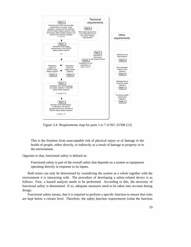
Figure 3.4: Requirements map for parts 1 to 7 of IEC 61508 [13]
This is the freedom from unacceptable risk of physical injury or of damage to thehealth of people, either directly, or indirectly as a resultof damage to property or tothe environment.
Opposite to that, functional safety is defined as:
Functional safety is part of the overall safety that dependson a system or equipmentoperating directly in response to its inputs.
Both terms can only be determined by considering the system as a whole together with theenvironment it is interacting with. The procedure of developing a safety-related device is asfollows: First, a hazard analysis needs to be performed. According to this, the necessity offunctional safety is determined. If so, adequate measures need to be taken into account duringdesign.
Functional safety means, that it is required to perform a specific function to ensure that risksare kept below a certain level. Therefore, thesafety function requirements(what the function
19

does) deriving from the hazard analysis and thesafety integrity requirements(the probabilitythat the safety function performs as defined) which again derive from the risk assessment needto be determined. The hazard analysis points out what needs to be done to prevent hazardousfailures, whereas risk assessment defines the degree of certainty that the safety function will beperformed.
The entire safety lifecycle
In order to achieve the required safety integrity, the standard defines a lifecycle model (see Figure3.5) which covers every step of the lifetime of a safety-related device starting at the first conceptand ending by the decommission of the device.
Figure 3.5: Entire safety lifecycle as defined by [3]
To achieve and keep a defined SIL during the design and throughout the further operation,each step must to be documented scrupulously. Additionally, the generated documentation hasto be versioned, revisioned and approved. Further, the standard requires defined authorities forthe technical and management phases of each cycle in the model, referred to asmanagement offunctional safety.
A brief description of the single steps of the entire safety lifecycle seems to be helpful:The concept phase is intended to get knowledge about the equipment under control (EUC)
and its environment. This is the base for the consecutive steps, for which reason all possible
20

sources of hazards and information about them as well as any information from applicable stan-dards have to be pointed out.
The aim of defining the complete area of application is to showthe limits of the EUC and theapplication area for the following hazard and risk analysis, requiring specification of physicaldevices, external events and subsystems.
The hazard and risk analysis point out hazards, hazardous events and sequences leading tohazardous events. Probability of a hazardous event, its impact and necessary measures to reducethe risk have to be considered. Furthermore, any assumptions during the analysis have to bestated.
The entire safety requirements target the development of safety-related E/E/PES, focussedon the safety functionality and the safety integrity. Therefore, safety functions and necessaryrisk reduction for every hazardous event have to be defined. Requirements for safety integrityhave to be determined for every safety function.
Assignment of safety requirements is intended to map the previously defined safety functionsto the safety-related systems and E/E/PES and to assign a SILto each of these functions. Incase the assignment of the safety requirements shows that the required SIL cannot be achieved,the architecture has to be changed and the assignment needs to be re-done. Requirements tosafety integrity have to be adequate in order to show that themean probability of failure or theprobability of a hazardous failure per hour is satisfied. Furthermore, common cause failures(CCF) have to be taken into account, unless the single subsystems can be shown to operateindependently. Independence is given if
• the subsystems are functionally different,• they are based on different technologies,• they do not use common parts, services or supply systems,• they have no common operational, maintenance or test measures, or• they are physically separated.
In case one of these requirements cannot be satisfied the subsystems cannot be considered asindependent in terms of safety integrity.
Once the mapping has been done, the safety integrity levels have to be assigned accordingto Table 3.4.
Safety Integrity Level Operational mode with continuous operation(Probability of a hazardous fault per hour)
4 ≥ 10−9 until < 10−8
3 ≥ 10−8 until < 10−7
2 ≥ 10−7 until < 10−6
1 ≥ 10−6 until < 10−5
Table 3.4: Safety integrity levels for devices with high performance rate [3]
For systems containing of multiple subsystems with different SILs, the whole system willhave to be regarded as a system with the lowest SIL among its subsystems, unless it can beshown that sufficient independence between them is present.
21

The E/E/PES lifecycle model defined by IEC 61508-2
This section describes the lifecycle model for a E/E/PES as apart of the overall IEC 61508-1 lifecycle model in Figure 3.5. Therefore, the component 9 of the model is extracted intofurther steps as shown in Figure 3.6. The model is kept very general and can be used unchangedfor hard- and software development. The sub-lifecycle is organized in six tasks which will beexplained in the following.
Figure 3.6: E/E/PES safety lifecycle in the realization phase defined by [4]
Specification of the E/E/PES safety requirements
The specification of the requirements to the safety functionality needs to contain the following:
• A description of the provided safety functionality• Performance requirements like throughput and response times• Interfaces between the E/E/PES and user interfaces• Any safety relevant information• Operational modes like parametrization, automatic, semi-automatic, manual, shut down,
maintenance• All kinds of failure performance, i.e. the reaction of the system in case of failure (e.g.
alarm or shut-down)• The meaning of the hardware/software interaction• Constraints and limits of the E/E/PE subsystems• Requirements to the commission and restart of the E/E/PES
22

Furthermore, the specification of the E/E/PES safety integrity requires to define the SIL forevery safety function, the operational mode for every safety function, limits to the environmentalconditions and limits to electromagnetic compatibility.
Planning the validation of the safety-related E/E/PES regarding safety
E/E/PES design and implementation
This step presents the most complex part in the development process of a safety related device.For better understanding, it is subdivided into several smaller items:
General requirements The main requirement is that the design needs to fulfill the speci-fication in all points. The design of a safety-related E/E/PES including hard- and software-architecture, sensors, actuators, programmable electronics, embedded- and application softwareas shown in Figure 3.7 has to be accomplished in order to satisfy all of the following conditions:
• Safety integrity requirements to hardware consisting of the requirements due to the prob-ability of dangerous hardware failures and the constraintsof the safety integrity caused byhardware architecture.
• Requirements to the systematic safety integrity consisting of the certificate of approveddevices and the requirements to avoidance and handling of systematic failures.
• Requirements to the system behavior when detecting a fault.
Figure 3.7: Relation between hardware and software architectures of PE [5]
In case a safety-related E/E/PES supplies safety-relevantand non-safety-relevant function-ality, the complete hardware and software have to be considered safety-relevant except a prooffor the independence of safety and non-safety-related parts of the system can be provided. Thearising SIL that has to be satisfied is the highest among all affected devices. That means, a sys-tem requiring SIL2 has to contain systems satisfying at least SIL2. If one subsystem just fulfillsSIL1, the whole system is considered to have SIL1.
If independence between safety and non-safety functionality is required the methods forachieving the separation and the reasons therefore have to be disclosed.
23

The developer has to ensure the adequateness of the requirements for the safety-relatedE/E/PES hardware and software with focus on the safety-functionality, safety-integrity require-ments, electrical equipment and user interfaces.
A further step requires documentation and reasoning of the applied procedures and measuresin design as well as of hardware-software interaction.
The whole system has to be partitioned into subsystems whereby each of them requires aseparate design and verification process. In case a subsystem has multiple outputs it is requiredto show that no possible combination of states leads to a hazardous failure of the E/E/PES. Ifpossible, all components should be dimensioned for underload.
Constraints to the hardware safety integrity due to architecture The highest achievableSIL in the context of hardware is limited through the fault tolerance of the hardware and thefraction of safe failures in the subsystems. A fault tolerance of N means that the safety func-tionality will get lost by N+1 faults with the constraint that fault detection mechanisms likediagnosis must not be taken into consideration. Where a fault leads to another fault, these twofaults are considered to be a single fault. If certain improbable faults can be excluded from thefault tolerance calculation it has to be reasoned and documented. The fraction of non-hazardousfailures (SFF) of a subsystem is defined as the mean rate of non-hazardous faults plus hazardousdetected faults divided by the overall failure rate of the subsystem:
SFF=Safe Faults+ Detected Faults
Overall Failure Rate of the Subsystem(3.1)
The standard defines subsystems of types A and B. Type A is required to be completelyspecified by means of fault performance of the components, the subsystem itself under a faultand reliable information about process experience. Even ifonly one requirement is not fulfilled,a subsystem is classified as type B. Depending on the subsystem type either Table 3.5 for type Aor Table 3.6 for a type B subsystem have to be taken into consideration. These tables describe theachievable SIL depending on the fault tolerance of the hardware and the fraction of nonhazardousfailures. For example, a subsystem of type A with more than 99% of non-hazardous failures canreach SIL4 with a fault tolerance of 1.
Fraction of nonhazardous failuresFault tolerance of the hardware
0 1 2< 60% SIL1 SIL2 SIL3
60% - <90% SIL2 SIL3 SIL490% - <99% SIL3 SIL4 SIL4
≥99% SIL3 SIL4 SIL4
Table 3.5: Safety integrity of hardware: Constraints to architectures for safety-related type Asubsystems [4]
Requirements for the estimation of the failure probability of a safety function due to ran-dom hardware faults The probability of loss of the safety functionality due to random hard-
24
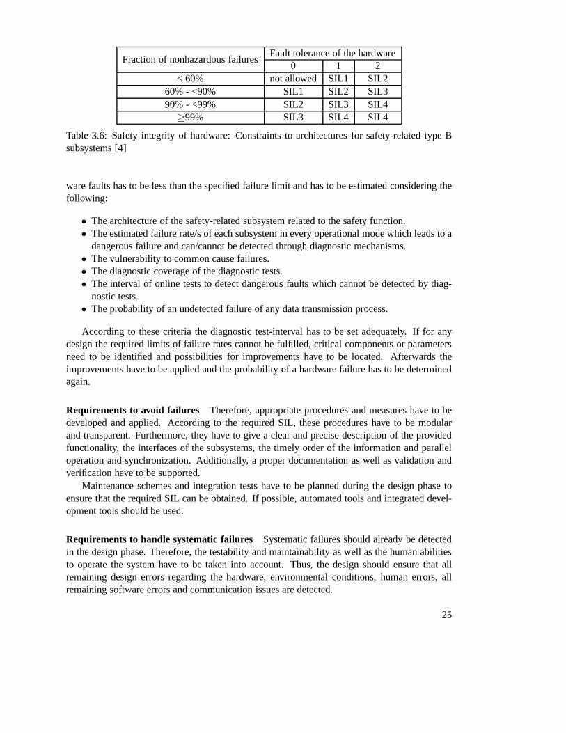
Fraction of nonhazardous failuresFault tolerance of the hardware
0 1 2< 60% not allowed SIL1 SIL2
60% - <90% SIL1 SIL2 SIL390% - <99% SIL2 SIL3 SIL4
≥99% SIL3 SIL4 SIL4
Table 3.6: Safety integrity of hardware: Constraints to architectures for safety-related type Bsubsystems [4]
ware faults has to be less than the specified failure limit andhas to be estimated considering thefollowing:
• The architecture of the safety-related subsystem related to the safety function.• The estimated failure rate/s of each subsystem in every operational mode which leads to a
dangerous failure and can/cannot be detected through diagnostic mechanisms.• The vulnerability to common cause failures.• The diagnostic coverage of the diagnostic tests.• The interval of online tests to detect dangerous faults which cannot be detected by diag-
nostic tests.• The probability of an undetected failure of any data transmission process.
According to these criteria the diagnostic test-interval has to be set adequately. If for anydesign the required limits of failure rates cannot be fulfilled, critical components or parametersneed to be identified and possibilities for improvements have to be located. Afterwards theimprovements have to be applied and the probability of a hardware failure has to be determinedagain.
Requirements to avoid failures Therefore, appropriate procedures and measures have to bedeveloped and applied. According to the required SIL, theseprocedures have to be modularand transparent. Furthermore, they have to give a clear and precise description of the providedfunctionality, the interfaces of the subsystems, the timely order of the information and paralleloperation and synchronization. Additionally, a proper documentation as well as validation andverification have to be supported.
Maintenance schemes and integration tests have to be planned during the design phase toensure that the required SIL can be obtained. If possible, automated tools and integrated devel-opment tools should be used.
Requirements to handle systematic failures Systematic failures should already be detectedin the design phase. Therefore, the testability and maintainability as well as the human abilitiesto operate the system have to be taken into account. Thus, thedesign should ensure that allremaining design errors regarding the hardware, environmental conditions, human errors, allremaining software errors and communication issues are detected.
25

Requirements to the system behavior at fault detection If a fault has been detected thesystem either has to go into a safe state and inform the operator about it or, if that is not possible,the fault has to be isolated. If the fault cannot be fixed within the MTTR a predefined action hasto take place.
Requirements to E/E/PES implementation The implementation of the safety-related E/E/PEShas to be in agreement with the design of the E/E/PES. Every subsystem that is used by a safetyfunction has to be identified and described as a safety-related subsystem. To every safety-relatedsubsystem the following information has to be provided:
• The functional specification of functions and interfaces used by the safety-related subsys-tem.
• The estimated failure rate/s caused by random hardware errors in every mode leading to adangerous failure and being detected or not by diagnostic measures.
• The environmental limits of the subsystem.• The lifetime of the subsystem.• Maintenance requirements and intervals.• The diagnostic coverage and test interval.• Any required information to determine the MTTR.• Any information to determine the fraction of safe failures.• Fault tolerance of the hardware.• All remaining limits applicable to the subsystem to avoid systematic failures.• The highest SIL that can be consumed by a safety function.• Any information regarding configuration of the subsystem.• A confirmation about the verification of the subsystem.
Estimated failure rates for a subsystem caused by random hardware errors can be determined bya failure mode and effects analysis (FMEA) or, if available,by performance information aboutthe subsystem under similar conditions.
Requirements to data communication In case of data communication influencing the safetyfunctionality, the probability of an undetected fault of the communication system has to be es-timated. Therefore, transmission errors, repetition, loss, insertion, wrong sequence, corruption,delay and masquerade have to be taken into account. Especially the parameters residual er-ror rate, rate of residual information loss, bitrate and message delay have to be considered forthe estimation. The topic of data communication will be discussed in detail in the Section 4.1describing the IEC 61784-3.
E/E/PES integration
The integration tests of an E/E/PES have to ensure that all modules interact in the specified wayand fulfill the intended behaviour. For the execution of the tests, appropriate procedures andmeasures have to be applied. Furthermore, every modification needs to be evaluated and thetests themselves must be properly documented.
26
E/E/PES operation and maintenance procedures
That point addresses the routinely procedures for maintenance purposes. It has to be ensured thatan unsafe state does not occur during these tasks. Moreover,it requires that irregularities fromthe normal operation and online test results are documented. Procedures for maintenance haveto be defined which are applied in case of failure including procedures for diagnosis, repair,logging and analysis of failures and revalidation. Routinely maintenance procedures have tofulfill systematic methods which have to detect non-detected failures resulting in reduction ofthe required safety integrity.
Validation of the E/E/PES regarding safety
Validation of the E/E/PES has to be performed according to the previously defined validationplan. Each used measurement device has to be calibrated and verified for its correct functionality.During tests every safety function has to be evaluated according to its intended behaviour andresults have to be documented in an adequate way.
E/E/PES modification
If an existing E/E/PES has to be modified the following requirements have to be complied:
• An exact and complete specification of the modification.• An analysis of the impact on the whole system.• Approval for all modifications.• Test-cases of the modified components including data gainedby the revalidation process.• Deviations from the normal operation.• Required changes to the system behaviour and the documentation.
Once the system has been modified it has to be re-verified and re-validated.
E/E/PES verification
The goal of the verification is to ensure the correctness and consistency of the device with thespecification. Therefore, the verification already has to beplanned during the development phaseof the E/E/PES. That plan has to include strategies and procedures for verification, usage ofmeasurement devices, documentation and analysis of the gained results. For each stage of thedesign phase it has to be shown that the safety integrity requirements are fulfilled.
SIL 3 in detail
In the previous sections some of the basic requirements for the development of a safety-relatedE/E/PES have been presented. Basically, these requirements are applicable from SIL 1 to SIL 4.Part 3 of IEC 61508 [5] presents guidelines for every SIL witha special focus on the softwareof an E/E/PES.
As already mentioned the development of safety-related software has to be executed accord-ing to the lifecycle model in Figure 3.6. Besides, some more guidelines for the implementation
27

of each step are given in Appendix A and B of [5]. For the software specification and design,computer-based specification tools and semi-formal methods are recommended. Appropriate, ifpossible certified, programming languages, toolchains, compilers, libraries and integrated devel-opment environments should be used. As this thesis does not target a fully developed device, notall of the recommendations can be met. For instance, the usage of interrupts and pointers shouldbe avoided although they are some of the basic concepts in microcontroller programming.
According to Table 3.6, a SIL can be achieved by increasing the SFF or the fault toleranceof hardware. For SIL3 that is to detect more than 99% of hazards with a fault tolerance of 0 orto detect 90% to 99% of hazards with a fault tolerance of 1 or todetect 60% to 90% of hazardswith a fault tolerance of 2. As shown later, a high SFF can onlybe gained through extensiveonline tests and thus high diagnostic coverage. The consequence is to increase hardware faulttolerance. A discussion on different hardware architectures will be given in Section 5.1.
3.3 Conclusions of ISO 13849 and IEC 61508
So far, terms and definitions regarding safety-related systems and the two most important stan-dards in the area of safety-related systems have been presented. Summing up, ISO 13849-1 iskept very generic in some parts of the definition of safety-related devices. There are no mecha-nisms or methods given on how to realize specific functionality in order to accomplish a certainperformance level. Also the second part, ISO 13849-2 is keptgeneric to be applicable for a widerange of devices.
Contrary, IEC 61508 provides detailed information about the whole development lifecycleof safety-related devices and depicts generic requirements for concept, design, implementation,testing, validation and verification.
Both standards address the development of safety-related systems as a whole and do notprovide guidelines on how to implement specific safety-functionality. A more “implementation-oriented” standard is IEC 61784, outlined in the following chapter where measures for safetransmission of data over a network will be presented.
Especially interesting for this thesis is the relation of PLs to SILs which is outlined in Table3.7.
PL SIL (high usage)a no correspondentb 1c 1d 2e 3
Table 3.7: Relation between Performance Levels (PL) and Safety Integrity Levels (SIL) as de-fined by [10]
PL a has no corresponding SIL level and is intended to reduce the risk of slight, usuallyreversible injury. IEC 61508 defines SIL 4 for possible hazardous accidents in process industry
28

and is not relevant for the application at machinery. Thus, the highest relevant PL ise which isassigned SIL 3.
29


CHAPTER 4Existing Safety Solutions in HBA
Systems
Building automation systems have initially been designed for simple applications like lighting,shading and climate control without any safety relevance. If safety was required, separate, closedsystems have been installed which were interacting via gateways with the non-safe parts of theautomation system.
Increasing demands regarding safety resulted in extensions of existing automation systemswith safety functionality. A further requirement has been to enable coexistence of safe and non-safe nodes on the same network. Since also the existing communication media should have beenreused, the solution was to implement protocols which were built on top of the existing non-safeones. Thus, to gain safety requirements, the underlying communication channel is considered as“black channel”. That means, theoretically any communication medium, wired or wireless, canbe used as long as timing requirements are met which are of major importance. If no guaranteescan be given whether a message has arrived or not, timeouts have to be introduced to determineloss of messages. Discussion of these issues will be presented in the following.
However, safety in home and building systems does not mean high dependability. Instead,each safe automation system is assumed to have a safe state. Thus, safety can be gained bydetecting faults and transferring the system into a safe state.
In the following four automation solutions will be presented, namely Safety over Ether-CAT (SoE), CANopen Safety, SafetyLON and OpenSafety. Although Safety over EtherCATand CANopen Safety have their origins in industrial automation, they are covered too, sinceespecially SoE becomes more interesting for building automation. However, this thesis doesnot focus solely on building automation systems. Instead, the communication and hardwaretechnology used is of special interest which brings in SoE and CANopen Safety for comparison.
Preliminary to presenting existing safety solutions in home and building automation systems,a standard defining communication measures for safety-related systems will be presented - IEC61784-3. The standard describes common communication errors and measures to detect them.
31
4.1 IEC61784-3 - Functional safety fieldbuses
The IEC 61784-3 standard outlines the general principles for safe message transmission in net-works which are conform with afore described IEC 61508. Therefore, communication profilesfor different fieldbus networks are specified in parts IEC 61784-3-x and an additional communi-cation/protocol service is extended by a safety layer.
Before the standard will be described in depth some important terms have to be defined.Since all communication profiles defined here base on it, theblack channel principlewill begiven special attention:
Black Channel Principle
As defined by [9], that principle states:
. . . the chosen communications technology does not matter, except for a few basicconstraints. . .
. . . none of the error detection mechanisms of the chosen communication technologyare taken into account to guarantee the integrity of the transferred process data.
. . . Basically, there are no restrictions with respect to transmission rate, number ofbus devices, or transmission technology as long as the parameters are tolerated bythe required reaction times of a given safety application.[29]
The black channel principle gives no guarantee whether a sent message has been delivered cor-rectly, in time, or received at all by the receiver. Message transmission is thus just a best effortapproach. Any data integrity or safety measures have to be done by the safety layer.
Another term is thesafety communication layer (SCL). That is a separate layer in the com-munication stack which provides measures to ensure safe transmission of messages accordingto IEC 61508.
Communication Errors
To achieve a certain level of safety in message transmission, all kinds of communication er-rors have to be taken into account. In the following, IEC 61784-3 defined errors and possiblebehaviour under black channel conditions will be explainedbriefly:
Corruption
A message may be corrupted by errors in the communication subsystem or on a node. Sucherrors are common in networks and usually end up in bit errors(flipped bits).
Unintended repetition
By errors or malfunction, old and out-of-date messages are repeated at wrong time instants.Repetition by sender is common in case an acknowledgement ofthe receiver is absent.
32
Incorrect sequence
By errors or malfunction, a sink receives messages in incorrect sequence by means of wrongsequence numbers or timestamps. It is likely that such errors occur in networks with storingelements like routers or gateways where messages are delayed caused by higher prioritized mes-sages.
Loss
By errors or malfunction, a message was not delivered or acknowledged.
Unacceptable delay
Messages are intended to be delivered within a predefined time instant. If a message is delayeddue to congestion or errors on the bus, FIFOs in switches, bridges or routers, the message willbe delayed.
Insertion
By errors or malfunction, a message from an unintended or unknown source was inserted. Sincethese messages do not have a valid source they cannot be classified as correct.
Masquerade
Maquerade is similar to insertion, except that the receivedmessage comes from a valid source.That means, a non-safety message will be accepted as safety relevant message.
Addressing
Through errors on the communication system a safety relevant message has been received by awrong node which handles the message as correct.
Deterministic Countermeasures
So far, possible errors on the communication system have been pointed out. They have to bedetected by at least one mechanism in the safety communications layer. In the following, coun-termeasures for deterministic errors as defined by IEC 61784-3 are presented:
Sequence number
Each message is tagged with a continuous increasing number.
Timestamp
Usually, data is only valid for an amount of time. Therefore,each message is tagged with arelative or absolute timestamp. That requires synchronization of clocks across the participatingnodes.
33
Timing expectation
Messages are expected to be received during predefined timeslots. If a message arrives outsidea timeslot, an error can be assumed. That requires synchronization, since each participant has toknow the time instant of its bus access.
Connection authenticity
Each message contains a unique sender or receiver identifierdescribing the logical address ofthe safety relevant participant.
Acknowledge
The message sink replies the reception to the source. Depending on the protocol, that can be asimple acknowledge message, or the message itself to ensurecorrect reception of data.
Redundancy with crosschecking
Safety relevant data can be packed twice or more times into the same or different messages. Onreceiver side, the message contents are cross checked to their correctness.
Different data integrity assurance systems
If safety relevant and non-safety relevant messages are transmitted over the same communicationsystem, different data integrity measures like CRC-polynomials or hash functions can be applied.Thus, non-safety messages should not be accepted as safety relevant data.
Relation between errors and safety measures
Table 4.1 shows already described errors on the communication subsystem and possible coun-termeasures against such errors. It is clear, that any type of error has to be detected by at leastone countermeasure. Depending on the implementation of theoverall system, the table is am-biguous, since for example incorrect sequence errors can bedetected by sequence numbers andtimestamps. Thus, not both measures are required to be implemented.
Data integrity and Data security
To ensure integrity of received data, hash functions, parity bits, CRC checks or redundant mes-sage sending have to be performed. It has to be mentioned, that the underlying communicationchannel must not use the same data integrity and data safety mechanisms as the implementedsafety communication layer, except special measures against mix up have been met. To re-late the degree of safety in the SCL with the required SIL, theresidual error rate of the SCLΛSL(Pe), which is a function of the bit error ratePe, the residual error rate of the safety mes-sageRSL(Pe), the maximum number of safety messages per hourv and the maximum numberof safety message sinksm, is introduced by IEC 61784-3:
34

Communicationerror
Safety Measures
Seq
uenc
enu
mbe
r
Tim
esta
mp
Tim
eex
pect
atio
n
Con
nect
ion
auth
entic
atio
n
Fee
dbac
km
essa
ge
Dat
ain
tegr
ityas
sura
nce
Red
unda
ncy
with
cros
s-ch
ecki
ng
Diff
eren
tdat
ain
tegr
ityas
sura
nce
syst
ems
Corruption XN1) XUnintended repetition X X XN1)
Incorrect sequence X X XN1)
Loss X XN1) XN1)
Unacceptable delay X Xc)
Insertion X Xa)b) Xa) XN1)
Masquerade Xa) Xa) XAddressing Xa) Application dependentb) Shows only insertion of an invalid sourcec) In any case requiredd) Just in case that the residual error rateΛSL can be shown to meet specified requirementsN1) Under certain conditions
Table 4.1: Communication errors and detection measures by [9]
ΛSL(Pe) = RSL(Pe) ∗ v ∗m (4.1)
The residual error rate also depends on the maximum number ofsafety messages per hourwhich implies bounded reaction times of safety functionality. Regardless of the operationalmode (continuous, or low performance, see Table 3.4), relations between the residual error rateof the functional safe communication system and applicableSILs are depicted in Table 4.2.
SIL Probability of a hazardousfailure per hour of the functionalsafe communication system
Max. allowed residual error rate of thefunctional safe communication system
4 < 10−10/h Λ < 10−10/h
3 < 10−9/h Λ < 10−9/h
2 < 10−8/h Λ < 10−8/h
1 < 10−7/h Λ < 10−7/h
Table 4.2: Relation between residual error rate and safety integrity level
Thus, to fulfill SIL 3 the residual error rate per hour has to beless than10−9.Additionally to safe transmission of data, security has to be considered as well. According to
IEC 61784-3 Point 5.7, security measures have to be implemented in the black channel. Furtherinformation will be provided in the upcoming IEC 62443.
35

The remaining information provided by the standard addresses different communicationprofiles for fieldbus systems such as Profibus, CIP, EtherCAT and much more which will beexplained partially in the following. For further information, refer to [9].
4.2 Industrial Automation solutions
CANopen Safety
This automation solution builds on the well known CAN bus which was originally developedfor in-vehicle networks. There are several standardized protocols that make use of the CAN datalink protocol which are, for example, CANopen for embedded control systems1, DeviceNet forfactory automation, J1939 based solutions (J1939-71 Isobus, ISO 11992) for trucks and othervehicles and, ISO 15765 for passenger car diagnostics.
CANopen can be extended to be safe by either applying the safety-relevant communicationprotocol defined in CiA 304 [17] or by using the CANopen safetychip 02 (CSC02) which hasbeen certified by TÜV according to SIL3. Application of CiA 304 describes safety as a prop-erty of a device: A device uses all features defined by a communication profile and additionallyspecial safety communication objects. All other, non-safecommunication objects remain un-changed. A CSC02 chip contains a complete implementation ofstandard CiA 301 CANopenapplication layer [16] and CiA 304 CANopen safety protocol on top of two CAN modules on-chip.
CiA 304 also defines required hardware architecture for SIL3compliance (see Figure 4.1).
Figure 4.1: C-model for safety-relevant communication networks [17]
CANopen Safety distinguishes sources of safe information (safety switches, light barri-ers, emergency stops) and consumers of information (relay,valve drives, safety PLCs). Since
1http://www.can-cia.org/index.php?id=4
36

CANopen Safety does not provide request-response communication pattern, it is left up to thedata consumers to check data integrity and transfer to safe state in case of incorrect data. Thenumber of information sources (safe inputs) is limited to 64, whereas an unlimited number ofinformation consumers (safe outputs) may listen to the produced safety-relevant data objects(SRDOs).
To increase data safety, an SRDO consists of two standard CANdata frames, where thesecond data frame transfers the same data as the first one, butin a different bit-ordering, likereverse ordering (Redundancy with cross-checking). Such consecutive CAN frames from thesame SRDO have to arrive within the safety-relevant object validation time (SRVT). An exampleis given in Figure 4.2. Additionally, that mechanisms checkwhether sufficient network capacityis available. If the second frame is delivered after the SRVTexpired, the safety controller shallgo into safe state. Likewise, if one of the frames does not satisfy data integrity or data contentsof the two frames do not match, the safety controller also hasto switch to safe state.
Figure 4.2: Example for SRVT timing [17]
Further, SRDOs are transmitted periodically. The intervalbetween consecutive SRDOs isreferred to as Safeguard Cycle Time (SCT). If a message is delivered after the SCT expired, thesafety controller shall go into a safe state. Figure 4.3 illustrates an example. Timing expecta-tions require synchronization among safe nodes. Unlike most other safety extensions, CANopenprovides synchronization by default.
Figure 4.3: Example for SCT timing [17]
CiA 304 also gives a mathematical analysis of the protocol performance: Assuming a max-imum of 64 safety relevant devices and an error rate of less than10−9 for SIL3 compliance, 44SRDOs per second are possible. The calculation is as follows:
The worst case residual error probability of CAN is defined by[8]:
37
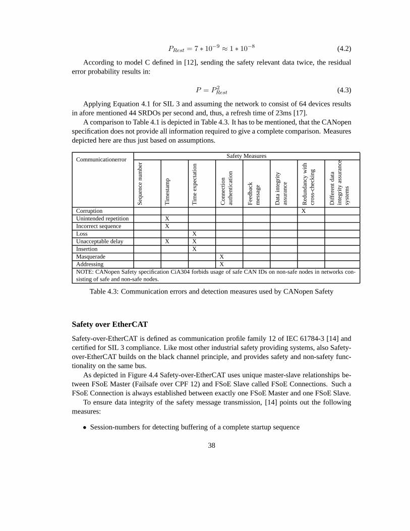
PRest = 7 ∗ 10−9 ≈ 1 ∗ 10−8 (4.2)
According to model C defined in [12], sending the safety relevant data twice, the residualerror probability results in:
P = P 2Rest (4.3)
Applying Equation 4.1 for SIL 3 and assuming the network to consist of 64 devices resultsin afore mentioned 44 SRDOs per second and, thus, a refresh time of 23ms [17].
A comparison to Table 4.1 is depicted in Table 4.3. It has to bementioned, that the CANopenspecification does not provide all information required to give a complete comparison. Measuresdepicted here are thus just based on assumptions.
CommunicationerrorSafety Measures
Seq
uenc
enu
mbe
r
Tim
esta
mp
Tim
eex
pect
atio
n
Con
nect
ion
auth
entic
atio
n
Fee
dbac
km
essa
ge
Dat
ain
tegr
ityas
sura
nce
Red
unda
ncy
with
cros
s-ch
ecki
ng
Diff
eren
tdat
ain
tegr
ityas
sura
nce
syst
ems
Corruption XUnintended repetition XIncorrect sequence XLoss XUnacceptable delay X XInsertion XMasquerade XAddressing XNOTE: CANopen Safety specification CiA304 forbids usage of safe CAN IDs on non-safe nodes in networks con-sisting of safe and non-safe nodes.
Table 4.3: Communication errors and detection measures used by CANopen Safety
Safety over EtherCAT
Safety-over-EtherCAT is defined as communication profile family 12 of IEC 61784-3 [14] andcertified for SIL 3 compliance. Like most other industrial safety providing systems, also Safety-over-EtherCAT builds on the black channel principle, and provides safety and non-safety func-tionality on the same bus.
As depicted in Figure 4.4 Safety-over-EtherCAT uses uniquemaster-slave relationships be-tween FSoE Master (Failsafe over CPF 12) and FSoE Slave called FSoE Connections. Such aFSoE Connection is always established between exactly one FSoE Master and one FSoE Slave.
To ensure data integrity of the safety message transmission, [14] points out the followingmeasures:
• Session-numbers for detecting buffering of a complete startup sequence
38
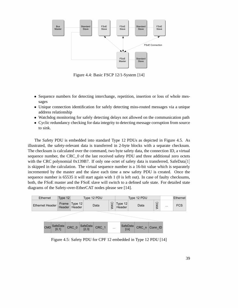
Figure 4.4: Basic FSCP 12/1-System [14]
• Sequence numbers for detecting interchange, repetition, insertion or loss of whole mes-sages
• Unique connection identification for safely detecting miss-routed messages via a uniqueaddress relationship
• Watchdog monitoring for safely detecting delays not allowed on the communication path• Cyclic redundancy checking for data integrity to detectingmessage corruption from source
to sink.
The Safety PDU is embedded into standard Type 12 PDUs as depicted in Figure 4.5. Asillustrated, the safety-relevant data is transferred in 2-byte blocks with a separate checksum.The checksum is calculated over the command, two byte safetydata, the connection ID, a virtualsequence number, the CRC_0 of the last received safety PDU and three additional zero octetswith the CRC polynomial 0x139B7. If only one octet of safety data is transferred, SafeData[1]is skipped in the calculation. The virtual sequence number is a 16-bit value which is separatelyincremented by the master and the slave each time a new safetyPDU is created. Once thesequence number is 65535 it will start again with 1 (0 is left out). In case of faulty checksums,both, the FSoE master and the FSoE slave will switch to a defined safe state. For detailed statediagrams of the Safety-over-EtherCAT nodes please see [14].
Figure 4.5: Safety PDU for CPF 12 embedded in Type 12 PDU [14]
39
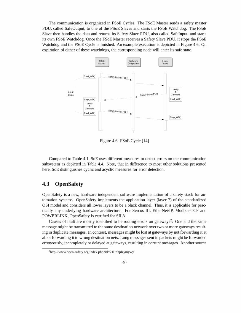
The communication is organized in FSoE Cycles. The FSoE Master sends a safety masterPDU, called SafeOutput, to one of the FSoE Slaves and starts the FSoE Watchdog. The FSoESlave then handles the data and returns its Safety Slave PDU,also called SafeInput, and startsits own FSoE Watchdog. Once the FSoE Master receives a SafetySlave PDU, it stops the FSoEWatchdog and the FSoE Cycle is finished. An example executionis depicted in Figure 4.6. Onexpiration of either of these watchdogs, the correspondingnode will enter its safe state.
Figure 4.6: FSoE Cycle [14]
Compared to Table 4.1, SoE uses different measures to detecterrors on the communicationsubsystem as depicted in Table 4.4. Note, that in differenceto most other solutions presentedhere, SoE distinguishes cyclic and acyclic measures for error detection.
4.3 OpenSafety
OpenSafety is a new, hardware independent software implementation of a safety stack for au-tomation systems. OpenSafety implements the application layer (layer 7) of the standardizedOSI model and considers all lower layers to be a black channel. Thus, it is applicable for prac-tically any underlying hardware architecture. For Sercos III, EtherNet/IP, Modbus-TCP andPOWERLINK, OpenSafety is certified for SIL3.
Causes of fault are mostly identified to be routing errors on gateways2: One and the samemessage might be transmitted to the same destination network over two or more gateways result-ing in duplicate messages. In contrast, messages might be lost at gateways by not forwarding it atall or forwarding it to wrong destination nets. Long messages sent in packets might be forwardederroneously, incompletely or delayed at gateways, resulting in corrupt messages. Another source
2http://www.open-safety.org/index.php?id=21L=hplzymywy
40

CommunicationerrorSafety Measures
Seq
uenc
enu
mbe
r
Tim
esta
mp
Tim
eex
pect
atio
n
Con
nect
ion
auth
entic
atio
n
Fee
dbac
km
essa
ge
Dat
ain
tegr
ityas
sura
nce
Red
unda
ncy
with
cros
s-ch
ecki
ng
Diff
eren
tdat
ain
tegr
ityas
sura
nce
syst
ems
Corruption Xa Xa Xc Xa XcUnintended repetition Xa XcIncorrect sequence Xa XcLoss Xa Xca) XaUnacceptable delay Xc XcInsertion Xa Xcb) XaMasquerade Xc Xa Xc Xa Xc Xa XcAddressing Xa Xca) Missing PDUs shall be detected within maximum reaction time.b) Only one message shall be accepted during a defined time frame.Xc) Errors detected by cyclic measuresXa) Errors detected by A-cyclic measures
Table 4.4: Communication errors and detection measures used by Safety over EtherCAT
of error is identified to message corruption caused by electro-magnetical interference resultingin flipping bits. Finally, as safe and non-safe nodes may coexist on the same network, non-safemessages might be erroneously identified as safe messages (masquerading or message mix-up).
To detect these identified errors, OpenSafety introduces timestamps as a basic concept. Eachsent message is tagged with a timestamp resulting in detection of duplication, delay and mix-up. Each safe receiver is required to reply to a message reception to the sender to indicatethat the data link remains established. Additionally, timemonitoring detects delayed and lostmessages. The latter two mechanisms are referred to as watchdog and are part of the OpenSafetysoftware stack. Message corruption is avoided by tagging each message with a unique 8 or 16 bitidentification tag which encodes parts of the messages’ address field, telegram type and frametype. Furthermore, CRCs are calculated over every frame andattached to it including the key thecalculation was done with. Upon reception, the receiver will recalculate the CRC of the messagewith the attached key. In case of different checksums, the message will be dropped. As finalmeasurement, each frame is packed twice into one OpenSafetyframe as illustrated in Figure 4.7.This increases the probability to detect corrupt messages,since an error would have to occur inboth frames at the exactly same position. Also, masquerading is now very unlikely to occur.
Unfortunately, OpenSafety does not provide more detailed information about the exact time-synchronization protocol implemented, but according to the EPSG website (see3), a resolutionin microsecond range is achievable.
An implementation of OpenSafety on top of the POWERLINK protocol is available underBSD-license at IXXAT4.
3http://www.ethernet-powerlink.org/index.php?id=414http://www.ixxat.de/ethernet_powerlink_safety_intro_de.html
41

Figure 4.7: OpenSafety safety frame structure
Since OpenSafety just provides a software stack, it is left up to the hardware designer whicharchitecture to use. But to be SIL3 compliant, an architecture similar to the one presented inFigure 4.8 has to be applied.
Figure 4.8: Possible hardware architecture for an OpenSafety-Node
An OpenSafety network can handle up to 1023 domains, where each domain may includeup to 1023 nodes, whereat safe nodes in a safety domain do not have to operate within thesame network. Communication between safety domains is handled through gateways. SinceOpenSafety builds on the black channel principle, safe and non-safe nodes are allowed to operatein the same network. Each domain has to contain a Safety Configuration Manager (SCM) tomonitor safe nodes. That SCM cyclically sends lifeguard signals to test safe nodes in its domain.If a lifeguard signal is absent, the safe node shall go into safe state.
Compared to safety measures defined by IEC 61784-3 in Table 4.1, OpenSafety uses mea-
42

sures depicted in Table 4.5.
FaultsPreventive/Corrective measures
Tim
eS
tam
p
Tim
eM
onito
ring
Iden
tifier
CR
Cpr
otec
tion
Red
unda
ncy
with
cros
s-ch
ecks
Dis
tinct
fram
est
ruct
ure
Duplication XLoss XInsertion XIncorrect Sequence XDelay X XDistortion X XMix-up of standardand safety frames
X
Table 4.5: Communication errors and detection measures by OpenSafety
Summing up, OpenSafety is a good option to extend any bus-system with safety functionalitysince an available software stack is already SIL3 certified.The provided documentation includedin the downloadable software stack is a good entry point on how to integrate OpenSafety withinan existing implementation. For SIL3 certification, the OpenSafety homepage5 recommends tocontact the EPSG (Ethernet PowerLink Safety Group) for help.
4.4 SafetyLON
SafetyLON is an extension to the building automation systemLON developed in the 1990s byEchelon. Since 2008 LON is approved ISO and IEC standard and documented in EN 14908series. Due to its open and inter-operable specification it is widely used, especially in publicbuildings. LON nodes base on Neuron Chips, including MAC-, network- and application-CPU.The MAC CPU handles physical access to medium, the network CPU de- and encodes messagesto proper format and the application CPU implements the userprogram. Each neuron chip isidentified by a worldwide, unique 48 bit Neuron ID, assigned by the chip manufacturer. TheNeuron ID is used for identifying chips in the fieldbus network. The communication betweenLON nodes is performed according to the LonTalk protocol which is applicable to a wide rangeof communication media.
Just like other building automation protocols, LON does notprovide safety by default. Incourse of the SafetyLON project, LON has been extended to fulfill safety requirements up toSIL 3. Therefore, the hardware architecture has been extended as similar depicted in Figure 4.8.To access LON networks, the bus transceiver will be replacedby a Neuron chip. Since safeand non-safe nodes shall coexist among the same network, theLonTalk protocol must not bechanged which results in application of the black channel principle. Thus, safety relevant datais packed into payload data area of standard LonTalk messages.
5http://www.open-safety.com/index.php?id=25&L=wqdrevmxcexvyln
43

The format of the safe message is depicted in Figure 4.9. To ensure high amount of dataintegrity and low risk of corruption, the data part of the safe message is sent twice. The mes-sage starts with an ID field keeping information about message type followed by a three bytesafe address field. The timestamp is divided in two parts which results in a 4 byte timestampconsisting of MSWord (Most Significant Word) for the higher two bytes and LSWord (LeastSignificant Word) for the lower. SafetyLON uses timestamps for detection of delay, repetition,wrong sequence and in conjunction with safe address, insertion [23]. Finally, two different CRCpolynomials are applied and results placed in field CRC 1 and 2. Depending on the messagelength, either one or two bytes of CRC sums are appended.
Figure 4.9: SafetyLON protocol Extension
Communication among nodes is performed according to producer-consumer model: Eachproducer and consumer is assigned a safe address. Additionally, consumers keep a list of safeaddresses of producers, from which they are allowed to receive safe messages. When sendinga safe message, the producer attaches its own safe address tothe message. Upon receiving asafe message, the receiver will only do further processing,if the safe address in the message iscontained in its list of valid producers.
Additionally, producers cyclically send heartbeat messages. Consumers check timing inter-vals between heartbeats and in case of expired timeout, the consumer will enter a defined safestate.
In comparison to Table 4.1, applied measures in SafetyLON are depicted in Table 4.6. It hasto be mentioned, that connection authentication is implemented by means of a safe addressingmodel.
Unfortunately, information about application of SafetyLON can hardly be found. For thetime this thesis was written, it was not even possible to examine if SafetyLON was used at all.
44

Communicationerror
Safety Measures
Seq
uenc
enu
mbe
r
Tim
esta
mp
Tim
eex
pect
atio
n
Con
nect
ion
auth
entic
atio
nS
afe
Add
ress
es
Fee
dbac
km
essa
ge
Dat
ain
tegr
ityas
sura
nce
Red
unda
ncy
with
cros
s-ch
ecki
ng
Diff
eren
tdat
ain
tegr
ityas
sura
nce
syst
ems
Corruption XUnintended repetition XIncorrect sequence XLoss XUnacceptable delay X XInsertion Xa) Xa)
Masquerade XAddressing XNOTE: Connection authentication is implemented by usage ofa safe addressing model. Messages are just processedif the source address in a delivered message is in the list of known source addresses.a) In conjunction of timestamps with safe addresses.
Table 4.6: Communication errors and detection measures used by Safety LON
45


CHAPTER 5KNX Safety
The development of a safety-related device requires to consider every aspect of a device startingfrom a sensor up to the actuator. The chain is visualized in Figure 5.1. For the further safetyconsiderations, only the red marked units will be taken intoaccount.
Figure 5.1: System chain - From the sensor to the actuator
First, all possible hazards have to be determined in a hazardand risk analysis. For fieldbussystems, [24] has identified them to:
• Crosstalk due to a coupling fault• Broken cabling• Wrong wiring• Stochastic failures• Extensive bandwidth allocation• Transmission of unauthorized messages
These hazards can cause further hazardous events which are:
• Data corruption• Loss of messages• Insertion of messages• Delay, repetition, wrong sequence of messages• Masquerade: Unsafe messages look like safe messages
47

Hence, hazards can occur on every component of the microcontroller such as CPU, memory,inputs and outputs. Since it is assumed that not all used components are fully specified withregard to their safety properties, Table 3.6 will be applied. As already stated, a SIL can beachieved by increasing the SFF or fault tolerance of hardware. For SIL 3 that is, according toTable 3.6, to detect more than 99% of hazards with a fault tolerance of 0 or, to detect 90% to 99%of hazards with a fault tolerance of 1 or to detect 60% to 90% ofhazards with a fault toleranceof 2. As shown later, a high SFF can only be gained through extensive online tests and thus highdiagnostic coverage. The consequence is to increase hardware fault tolerance. Hardware faulttolerance of 1 can be achieved with a 1oo2 architecture as presented in [7].
Up to now, hazards on a microprocessor level have been considered. Failures in the commu-nication subsystem have been discussed in Section 4.1. Safein- and outputs will be covered inSection 5.9.
In the following sections requirements to extend KNX with functional safety will be pre-sented. This will start with a discussion on possible hardware architectures. After a selection ofthe best suited hardware architecture, consequences for software will be discussed.
5.1 Hardware Architectures for Safe KNX Nodes
This section discusses possible architectures for safe nodes. We will start with a simple onechannel architecture and, by replicating the safe controllers and bus access hardware, end witha triple modular redundancy (TMR) approach. Since most automation systems are assumed tohave a safe state, it is sufficient to detect errors and switchto the safe state. This measure lowersrequirements to the whole system enormously since complexity of hardware and software offail-safe and fail-operational systems is magnitudes higher.
Most of the architectures in existing solutions make use of the black channel principle asalready described in Section 4.1 which will be assumed here,too. A further requirement for thechoice of hardware is reuse of existing wiring-scheme of KNXnetworks. Thus, full redundantapproaches using replicated bus wiring could be left unconsidered.
One Channel Architecture
The one channel architecture is the most simple architecture with just a single controller. Theimplementation of a SIL 3 compliant device requires a certain degree of safe failures as alreadypresented in previous sections. Since that kind of hardwarearchitecture has a fault tolerance of 0it is necessary to have a safe failure fraction (SFF) of more than 99% to be SIL 3 compliant (seeTable 3.6). This can be achieved by extensive online self tests resulting in a high diagnostic cov-erage, but it is very resource intensive. To lower the required safe failure fraction it is necessaryto increase the fault tolerance of the hardware. Such an approach is presented in the following.
Replicated Safe Controllers on a single TP-UART Chip
The first presented architecture (see Figure 5.3) is a typical master-slave model. The safe con-troller 1 (SC1) receives messages from the bus and forwards them to the safe controller 2 (SC2).
48

Figure 5.2: One channel architecture
On top of the safe controllers a safe I/O unit decides on the in- and outputs. Referring to Fig-ure 5.14, only the SC1 has to run the complete stack (KNX and TP-UART) whereas the SC2will only run the KNX Safety stack. This architecture has a fault tolerance of 1 and thus a SFFbetween 90% and <99% is required. It has to be considered herethat in case the SC1 fails,SC2 may still work but has no possibility to continue the further operation since it gets no moremessages and cannot send messages.
Thus, the consequence is an architecture shown in Figure 5.4where SC2 also has bus access.The bus access for SC2 is intended to operate in a cold standbymode which means that it willonly be used if SC1 fails. Then SC2 takes over control and performs the communication. Thesingle point of failure SC1 has now moved downwards to the TP-UART which is in the blackchannel and thus not relevant for the further safety considerations. The problem that arises hereis that in case SC1 fails SC2 has to continue the operation where SC1 ended. Thus, the safecontrollers have to be synchronized. Additionally, the communication lines between the TP-UART chip and SC1 will have to be physically disconnected since SC1 may fail with a stuck-aterror on the bus lines and thus SC2 cannot communicate either. The problem is that everythingin the black channel is out of the controlled area of the safe controllers which affects the TP-UART-safe controller connection, too.
Replicated Safe Nodes
A further consequence is to duplicate the TP-UART-Safe Controller line as depicted in Figure5.5. That approach looks very similar to the afore presentedarchitectures but is very different
49

Figure 5.3: Replicated Safe Controllers on a single bus-coupler
Figure 5.4: Replicated Safe Controllers on a single bus-coupler - Alternative
50
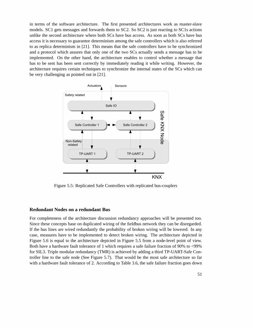
in terms of the software architecture. The first presented architectures work as master-slavemodels. SC1 gets messages and forwards them to SC2. So SC2 is just reacting to SC1s actionsunlike the second architecture where both SCs have bus access. As soon as both SCs have busaccess it is necessary to guarantee determinism among the safe controllers which is also referredto as replica determinism in [21]. This means that the safe controllers have to be synchronizedand a protocol which assures that only one of the two SCs actually sends a message has to beimplemented. On the other hand, the architecture enables tocontrol whether a message thathas to be sent has been sent correctly by immediately readingit while writing. However, thearchitecture requires certain techniques to synchronize the internal states of the SCs which canbe very challenging as pointed out in [21].
Figure 5.5: Replicated Safe Controllers with replicated bus-couplers
Redundant Nodes on a redundant Bus
For completeness of the architecture discussion redundancy approaches will be presented too.Since these concepts base on duplicated wiring of the fieldbus network they can be disregarded.If the bus lines are wired redundantly the probability of broken wiring will be lowered. In anycase, measures have to be implemented to detect broken wiring. The architecture depicted inFigure 5.6 is equal to the architecture depicted in Figure 5.5 from a node-level point of view.Both have a hardware fault tolerance of 1 which requires a safe failure fraction of 90% to <99%for SIL3. Triple modular redundancy (TMR) is achieved by adding a third TP-UART-Safe Con-troller line to the safe node (See Figure 5.7). That would be the most safe architecture so farwith a hardware fault tolerance of 2. According to Table 3.6,the safe failure fraction goes down
51

to 60% to <90%. The extension brings advantages in the safe I/O unit since now a simple 2oo3voter can be implemented. On the other hand the hardware costis significantly higher and for afieldbus system inapplicable.
Figure 5.6: Redundant Safe Nodes on a redundant Bus
Conclusion
So far all relevant architectures have been presented with their advantages and disadvantages.The one channel architecture is not useful due to high computation complexity for the requiredonline-tests and the redundancy approaches due to the bus wiring. Thus, the remaining archi-tectures are the replicated SCs with single and replicated bus access depicted in Figures 5.3,5.4 and 5.5. Since the black channel has to be left unchanged the remaining architecture is theone depicted in Figure 5.3. Additionally, the architectureis advantageous since no synchroniza-tion between the single SCs is required. It leaves the black channel completely unchanged andrequires no further knowledge about mechanisms working in the black channel.
Depending on the chosen hardware architecture several requirements arise for the softwarearchitecture. As the black channel gives no guarantees on the completeness, correctness or time-liness of a sent message, just to name a few, these controls have to be covered by the software.Therefore, the following sections will present approachesto overcome these issues.
52
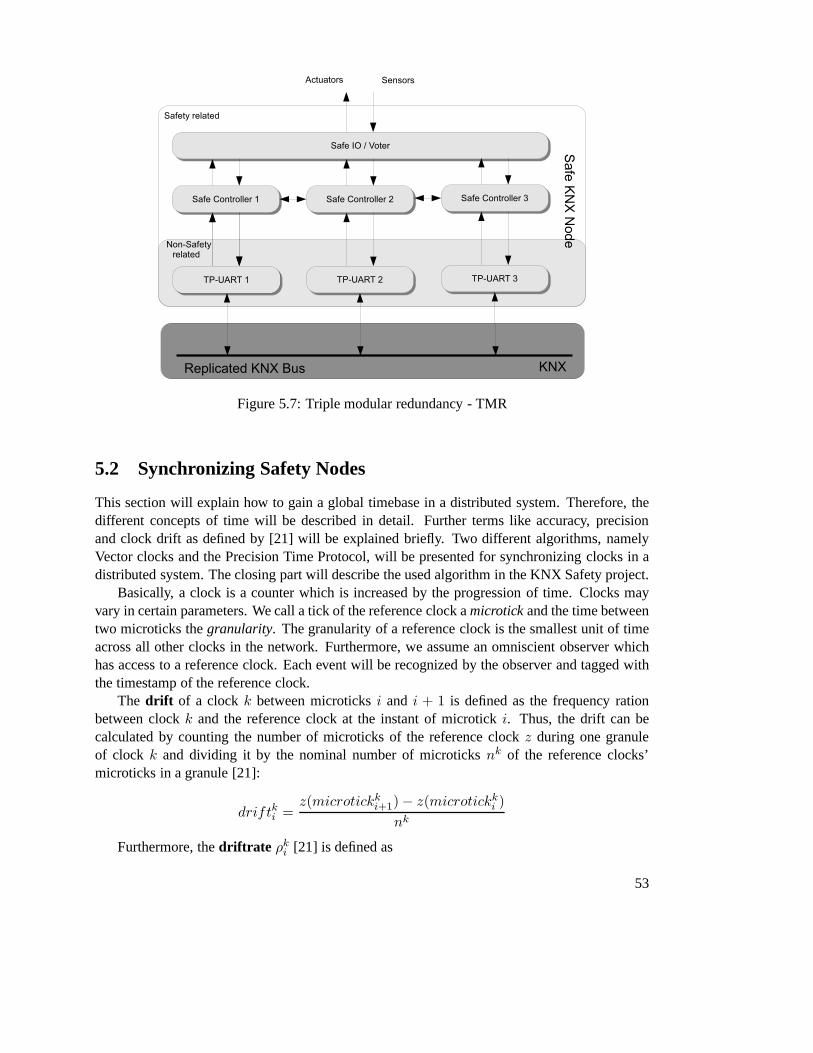
Figure 5.7: Triple modular redundancy - TMR
5.2 Synchronizing Safety Nodes
This section will explain how to gain a global timebase in a distributed system. Therefore, thedifferent concepts of time will be described in detail. Further terms like accuracy, precisionand clock drift as defined by [21] will be explained briefly. Two different algorithms, namelyVector clocks and the Precision Time Protocol, will be presented for synchronizing clocks in adistributed system. The closing part will describe the usedalgorithm in the KNX Safety project.
Basically, a clock is a counter which is increased by the progression of time. Clocks mayvary in certain parameters. We call a tick of the reference clock amicrotickand the time betweentwo microticks thegranularity. The granularity of a reference clock is the smallest unit oftimeacross all other clocks in the network. Furthermore, we assume an omniscient observer whichhas access to a reference clock. Each event will be recognized by the observer and tagged withthe timestamp of the reference clock.
The drift of a clockk between microticksi and i + 1 is defined as the frequency rationbetween clockk and the reference clock at the instant of microticki. Thus, the drift can becalculated by counting the number of microticks of the reference clockz during one granuleof clock k and dividing it by the nominal number of microticksnk of the reference clocks’microticks in a granule [21]:
driftki =z(microtickki+1)− z(microtickki )
nk
Furthermore, thedriftrate ρki [21] is defined as
53

ρki =
∣
∣
∣
∣
∣
z(microtickki+1)− z(microtickki )
nk− 1
∣
∣
∣
∣
∣
which tends to get zero for perfect clocks.The offset error of two clocksj and k with the same granularity is defined as the time
difference between two consecutive microticks of these clocks measured in microticks of thereference clock [21].
offsetjki = |z(microtickji )− z(microtickki )|
TheprecisionΠi at microticki of a given ensemble of clocks{1, 2, . . . , n} is defined as themaximum offset between any of these clocks [21]:
Πi = max∀1≤j,k≤n
{offsetjki }
The maximum offset between any two clocks in an interval of interest is called the precisionΠ of the ensemble and is measured in microticks of the reference clock.
The accuracy is defined as the offset of clockk against the reference clock at microtickiof the reference clock. The maximum offset of clockk in an interval of interest is denoted byaccuracyk.
For now the most important terms for clocks are defined. In thefollowing the basic conceptsof internal clock synchronization will be explained.
The idea behind clock synchronization is that all correct nodes work within a specified preci-sionΦ regardless of the driftrates of the single clocks. Since every clock works slightly differentthey need to be synchronized after an interval calledresynchronization intervalRint. An exam-ple is shown in Figure 5.8. Here one can see that clocks drift apart (grey shaded areas) and afterthe durationRint they are resynchronized and the process starts again. Theconvergence functionΦ denotes the offset values immediately after resynchronization. Thedrift offsetΓ denotes themaximum difference between any two good clocks during a resynchronization interval. As thedrift offset depends onRint andρ it can be calculated by
Γ = 2ρRint
By looking at Figure 5.8 one can see thesynchronization conditionfor an ensemble ofclocks:
Φ+ Γ ≤ Π
This means that starting immediately after a resynchronization, the convergence functioncorrects the clocks to a specified precisionΦ. After that the clocks drift apart byΓ. As theclocks need to stay within a defined interval of precisionΠ the synchronization condition resultsin Φ+ Γ ≤ Π.
54

Figure 5.8: Synchronization condition
Now assume we have a central master which periodically sendsits current time to all othernodes. The time it takes for the master to read its local clockvalue, to put into a message and tosend it as well as the time it takes for the receiver to unpack the message and to read the sent timeis called thejitter ε. The jitter is most affected through the communication subsystem and thusa non-deterministic function. However, adding the jitter to the precision of the central mastersynchronization results in
Πcentral = ε+ Γ
Precision Time Protocol IEEE1588
The Precision Time Protocol (PTP) is an IEEE standardized protocol for high precise clock syn-chronization [15]. It is applicable to any communication system supporting multicast communi-cation. The protocol supports a system wide synchronization accuracy to a grandmaster clock inthe sub-microsecond range with minimal network and clock computing resources. This sectiongives a short overview about the terms, constraints, exchanged messages and the communicationscheme of the PTP.
Terms of PTP
Grandmaster clock: The grandmaster clock is the source of synchronization within a domain.It is comparable with a reference clock.
55

PTP Port: A logical access point of a clock for PTP communication to the communicationsnetwork.
Ordinary clock : A clock that has a single PTP Port. The clock can act as masterclock oras a slave clock which synchronizes to a master clock.
Boundary clock: A clock that has multiple PTP Ports in a domain and maintainsthetimescale used in that domain. That clock may be a master or a slave clock.
Constraints to the network and the implementation
• The network eliminates cyclic forwarding of PTP messages.• PTP assumes a multicast network model.• The time accuracy is degraded by asymmetry in the communication paths. This means
that it takes different times for messages to be passed to thesynchronization source andback.
• PTP tolerates duplicated, missed or out-of-order messagesas long as they happen seldom.• The network should be optimized to forward PTP messages at high priorities to prevent
the introduction of jitter.
Exchanged messages
The PTP distinguishes between event messages which containa timestamp and general messageswhich do not require accurate timestamps. An event message can be one of:
• Sync• Delay_Req• PDelay_Req• PDelay_Resp
General messages are defined by:
• Announce• Follow_Up• Delay_Resp• PDelay_Resp_Follow_Up• Management• Signaling
The PTP defines two ways to measure the propagation delay between PTP ports, namelythe delay request-response method for the synchronizationof ordinary and boundary clocksand the peer delay mechanism for measuring the link delays. Sync, Delay_Req, Follow_Upand Delay_Resp messages are used in the request-response method whereas PDelay_Req, PDe-lay_Resp and PDelay_Resp_Follow_Up messages are used to implement the peer delay mech-anism. The Announce messages are used to establish a hierarchy between master and slaveclocks. Management messages are intended to query and update PTP data sets as well as tocustomize the PTP system. Signaling messages are defined forcommunication between clocksregarding all other purposes.
56

Synchronization Process
The execution of the PTP works in two phases:
• Building a master-slave hierarchy through Announce messages, and• Synchronization of the clocks
The hierarchy is established by a best master-clock algorithm. The properties of the clocksreceived in the Announce messages are compared to the already known clocks and the bestamong them is chosen as master.
Next, the clocks are synchronized according to the message exchange sequence shown inFigure 5.9.
Figure 5.9: Basic synchronization message exchange [15]
• The master initiates the sync-process by sending a Sync message to all its slaves and notesthe timet1 it was sent.
• The slave receives the Sync message and notes the timet2 it was received.• The master tells its slaves about the timet1 when the Sync message has been sent. This can
be done either by packingt1 into the Sync message or by sending a Follow_Up messagecontainingt1.
• The slave sends a Delay_Req message to the master and notes the timet3 it was sent.• The master receives the Delay_Req and notes the time of its receptiont4.• The master replies with a Delay_Resp containingt4.
After the synchronization process a slave knows all four times t1, t2, t3 and t4. First, anoffset correction can be applied:
offset = t2 − t1 − delay
57

where theDelay is not known yet. For the correction of the delay the timestms (delay masterto slave) andtsm (delay slave to master) are assumed to be equal. Otherwise, small errors in thecalculation of the link delay will occur.
tms = t2 − t1
tsm = t4 − t3
delay =tms + tsm
2
It is absolutely essential to have the exact times of the sending and receiving instants of themessages. That means that a timestamp is best drawn as late aspossible before sending it. Dueto the execution of the protocol stack this is not easily possible. Thus, Follow_Up messages areused which contain the sending instant of the previously sent Sync message. The same appliesfor the receiving times. The timestamp of a received messageis best drawn immediately whenit is read from the bus. As this is not always possible too, further errors in the offset and linkdelay calculations will arise.
Vector Clocks
So far the term clock was assumed to be a counter which increases by the progression of time. Inthe following, we will assume that a clock progresses by the occurrence of events. This meansthat whenever an event happens the local counter is increased by one. This concept is beingreferred to as logical clock [22].
Now assume that each node in a network has its own view of the logical timesCi of eachother node kept in a vector of lengthn, wheren is the number of processes in the network. Atthe beginning the vector is initialized with the zero vector. Whenever an event occurs the clockticks immediately before the event by incrementing the value of its own component:
Ci[i] := Ci[i] + 1
Each message which is sent across the network contains the timestamp vector of its sender.By receiving a message the timestampst of the remote vector and the local vectorCi are adaptedby the following function:
Ci := sup(Ci, t)
wheresupdenotes the component-wise maximum operation. The timestamp C(e) of an evente at processPi is the value of the clockCi at the moment of the execution ofe. An exampleexecution is depicted in Figure 5.10. The vector timestampC(e) of an evente contains thecomplete knowledge about previously happened events from which e is potentially dependent.
58

Figure 5.10: Example execution of vector clocks
Conclusion
Summing up, the vector clocks protocol is well applicable for environments where the numberof nodes participating the communication is limited since occurance of an event will require toexchange the vector time. Thus, increasing the number of nodes implies increasing the lengthof messages and increasing the utilization on the bus. However, the vector clocks method isnot applicable to KNX Safety due to a simple reason: The protocol extension only allows sixbytes of user data. As described, a node has to keep track of all events happening at other nodeswhich requires to store an array with the length of the numberof participating nodes. Assumingthat 255 events (1 byte) might happen before the local counters are resetted, only 6 nodes couldparticipate the synchronization which is not sufficient forthe requirements of the KNX Safetyproject.
The Precision Time Protocol is intended for use in environments where highly accurateclock synchronization is required. Therefore, a wide variety of different message types, datatypes and settings are defined in the IEEE 1588 standard. As one can see later, our approachdoes neither require nor give the possibility in the implementation of such a high accuracy. Thus,not all properties of the PTP will be implemented. It is sufficient to achieve an accuracy in themillisecond range. Therefore, the basic synchronization algorithm depicted in Figure 5.9 couldbe implemented.
5.3 Intercommunication - KNX Safety Protocol Extension
To gain functional safety it is not sufficient to just build safe hardware. Instead, also softwarehas to be designed to fulfill safety requirements which involves safety of application softwareand an applied communication protocol. By employing the mentioned architecture depicted inFigure 5.3 and taking into account requirements of SIL3, a safe failure fraction of 90% to 99%is necessary. That is, more than 90% of all dangerous failures shall be detected. That involvesfailures in the safety-related part or failures in the blackchannel which is the standard KNXnetwork.
Safety devices developed from scratch will have no constraints for protocol design. Sincethis thesis builds on an existing KNX protocol which shall not be altered, protocol safety has
59

to be gained differently. A widely accepted approach to extend non-safe protocols by safety, isto embed a separate protocol enabling safety requirements into the payload area of the non-safeunderlying protocol. Such existing solutions have alreadybeen presented in the previous chap-ter. These solutions make use of the black channel principlestating that the non-safe protocolresides in the black channel and therefore needs not to be taken into account for safety con-siderations. Instead, the embedded safety-providing protocol has to take care of all mentionedcommunication errors as specified in Table 4.1. Therefore, the protocol extension as proposedby [20] will be applied (see Figure 5.11).
Figure 5.11: Safety providing protocol extension for KNX
• The ID field contains information about the protocol versionand the length of the follow-ing safety-related data.
• The safety address of the source is encapsulated in every sent message. During com-missioning phase, each safety data-point is assigned a safety address. Additionally, eachsafety data-point receives a list of safety addresses whichit is allowed to receive messagesfrom. Thus, a received message will only be processed if the safety address contained inthe message is on the list of known safety addresses. Using two bytes for safety addresses,a total of216 = 65535 safety data-points is possible.
• Since KNX is purely event-driven and sends messages solely upon changed values, thelast received value is assumed to be the most current one which gives no possibility todetect loss or delay of messages. For safety considerations, each message is tagged witha timestamp generated at the time-instant of the causally connected event. To be able tocompare timestamps across a network, clock synchronization is required.
• The message type defines the type of the following safety-related data.• Safety-related data carries the current values captured from the environment.
60
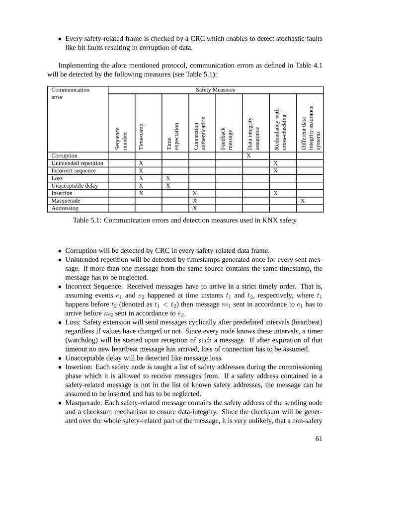
• Every safety-related frame is checked by a CRC which enablesto detect stochastic faultslike bit faults resulting in corruption of data.
Implementing the afore mentioned protocol, communicationerrors as defined in Table 4.1will be detected by the following measures (see Table 5.1):
Communicationerror
Safety Measures
Seq
uenc
enu
mbe
r
Tim
esta
mp
Tim
eex
pect
atio
n
Con
nect
ion
auth
entic
atio
n
Fee
dbac
km
essa
ge
Dat
ain
tegr
ityas
sura
nce
Red
unda
ncy
with
cros
s-ch
ecki
ng
Diff
eren
tdat
ain
tegr
ityas
sura
nce
syst
ems
Corruption XUnintended repetition X XIncorrect sequence X XLoss X XUnacceptable delay X XInsertion X X XMasquerade X XAddressing X
Table 5.1: Communication errors and detection measures used in KNX safety
• Corruption will be detected by CRC in every safety-related data frame.• Unintended repetition will be detected by timestamps generated once for every sent mes-
sage. If more than one message from the same source contains the same timestamp, themessage has to be neglected.
• Incorrect Sequence: Received messages have to arrive in a strict timely order. That is,assuming eventse1 and e2 happened at time instantst1 and t2, respectively, wheret1happens beforet2 (denoted ast1 < t2) then messagem1 sent in accordance toe1 has toarrive beforem2 sent in accordance toe2.
• Loss: Safety extension will send messages cyclically afterpredefined intervals (heartbeat)regardless if values have changed or not. Since every node knows these intervals, a timer(watchdog) will be started upon reception of such a message.If after expiration of thattimeout no new heartbeat message has arrived, loss of connection has to be assumed.
• Unacceptable delay will be detected like message loss.• Insertion: Each safety node is taught a list of safety addresses during the commissioning
phase which it is allowed to receive messages from. If a safety address contained in asafety-related message is not in the list of known safety addresses, the message can beassumed to be inserted and has to be neglected.
• Masquerade: Each safety-related message contains the safety address of the sending nodeand a checksum mechanism to ensure data-integrity. Since the checksum will be gener-ated over the whole safety-related part of the message, it isvery unlikely, that a non-safety
61

message contains information which would represent a validsafety address accepted bythe receiving node and, additionally, also the checksum is valid. Thus, it is almost impos-sible that a non-safety message is interpreted as a safety-related message.
• Addressing will be detected like insertion.• Additionally, each safety-related message will be received and checked by both safety
controllers. Only if both safety controllers agree on the same correct result, the mes-sage will be accepted (redundancy with cross-checking). Otherwise, the message will beneglected.
Communication between safety data-points
Addressing of safety nodes cannot be done directly since thesafety extension is built on top of anexisting KNX protocol. Thus, a safety-relevant message is packed into the payload of a standardKNX message and will have a usual KNX address, too. An addressing scheme is depicted inFigure 5.12.
Figure 5.12: Schematic addressing in KNX Safety
Referring to Figure 5.12, if a safety relevant message should be sent from a data-point withsafety address 1 (SA) to SA 2, the safety-relevant message will be packed into a standard KNXmessage with a particular KNX address. Since non-safety devices in the KNX network, suchas routers, switches and gateways, do not care about the datacontent of a message, the safetyaddress cannot be used for addressing. The most simple solution therefore is to define one KNXgroup where all KNX nodes containing safety data-points areconnected. If a message is sentto that group, every node in the same group will receive and accept that message. Thus, alsoall safety data-points will receive that message. As depicted in Firgure 5.12, if the data-pointwith safety address 1 tries so send a message, the safety-relevant message will be packed intoa standard KNX message containing the KNX group address 1. That message will be receivedand accepted by any standard KNX node in that particular group with address 1. Any KNXmessage with a different group address should be neglected by the KNX stack. If a messagewith an unacceptable group address passes the KNX stack anyway, the safety-related part of themessage should not be accepted by the SCL since safety-relevant messages are only accepted ifthe safety address is in the list of known safety data-points.
As mentioned afore, timing expectation is required to detect loss or delay of messages. Todetermine a realistic timeout, it is required to know the worst case time it takes for a messageto be received by another node. The timeout consists of the processing times required for han-dling the safety and non-safety protocol, the transfer timefrom the microcontroller to the TP-UART-chip and from the TP-UART-chip to the KNX-line. Transfer times from microcontroller
62
to TP-UART and following KNX-line additionally are dependent on KNX-specific retransmitmeasures. Likewise, handling and transfer times on the receiving node have to be calculated.
• Data sent from the microcontroller to the TP-UART will be transferred at a transmissionrate of 19200 bit/s. As soon as the last byte has been transferred to the TP-UART, achecksum will be calculated at the TP-UART and the message will be transmitted to theKNX-line [25]. The time required for checksum calculation will be neglected here. Thetransfer rate of 19200 bit/s yields in a bit-time of52, 083µs. One data-packet transferredto the TP-UART consists of one start-bit, eight data-bits, one parity-bit and one stop-bit(11 bits). Between consecutive bytes, the bus will be idle for 2 bit-times. Additionally,each data byte sent from the microcontroller to the TP-UART is preceeded by a controlbyte. To indicate start and end of data-content, special data start and data end octets aretransmitted. Assuming the extended KNX frame format, a maximum of 263 bytes of datamight be transmitted. Attaching start and end bytes as well as control bytes to each of thetransmitted data bytes, this results in 265 * 2 = 530 bytes which is a worst case time of358,75ms required to transfer data from the microcontroller to the TP-UART.
• Transmission from the TP-UART to the KNX-line: At maximum, 265 bytes (1 controlbyte, 263 data bytes and 1 checksum byte) will be transferredat a transmission rate of9600 bit/s which yields in a bit-time of 104µs. Between consecutive bytes, the bus willbe idle for 2 bit-times. Before transmission, the sender will wait for 53 bit-times (5,52ms)to ensure that no other sender is currently active. The transmission might fail if a higherprioritized frame is currently in transfer. In that case, the frame will be retransmitted fora maximum of three times. Between retransmit attempts, the sender will wait for 50 bit-times (5,512ms). One data-byte transferred will be enclosed by one start-bit, one parity-bitand one stop-bit which yields in 1,146ms for one data-byte tobe transferred. The worstcase time for one complete data frame to be transferred wouldbe to initially wait foran empty bus-line (53 bit-times) and failing to send due to higher prioritized frame with amaximum length of 265 bytes. After that, the sender will waitfor another 50 bit-times andmight fail again. There will be one initial try to transmit followed by 3 retries. Summingup, the overall worst case transfer time results in: 53 bit-times (5,521ms) followed by 265bytes data (358,07ms), 50 bit-times idle (5,512ms) and 265 bytes data. That is, 5,521ms+ 358,07ms +3*(5,512ms + 358,07ms) = 1,454s worst case transmission time from theTP-UART to the KNX-line.
• Transmission from the KNX-line to the TP-UART and the microcontroller: In contrast tothe transmission from the microcontroller to the TP-UART and further to the KNX-line,data received by the TP-UART from the KNX-line will be immediately forwarded to themicrocontroller after receiving the control-byte from theKNX-line.
• Repeaters, routers, etc. on the KNX-line: KNX supports transmission over a maximum of5 lines. That means, summing up transmission times from microcontroller to TP-UART(358,75ms) and TP-UART to KNX-line (1,454s) a controller will receive the message atlatest after 1812,75ms. Each time a controller forwards a message, that time has to becalculated yielding in 5*1812,75ms = 9,06s until a node in 5 lines distance receives a
63

message. A complete transmission cycle between two KNX nodes is illustrated in Figure5.13.
Data exchange between safety data points
To exchange data between safety data points it is required todefine the meaning of the exchangeddata. Therefore, the KNX safety protocol contains the message type field which indicates howto interpret the following data.
So far identified message types could be encoded as depicted in Table 5.2:
Octet 8 Message type7 6 5 4 3 2 1 0General messages0 0 0 0 0 0 0 1 SKNX_A_heartbeat0 0 0 0 0 0 1 0 SKNX_A_safestateTime synchronization messages0 0 0 0 0 0 1 1 SKNX_A_timesync_sync0 0 0 0 0 1 0 0 SKNX_A_timesync_follow_up0 0 0 0 0 1 0 1 SKNX_A_timesync_delay_req0 0 0 0 0 1 1 0 SKNX_A_timesync_delay_respProcess data messages0 0 0 0 0 1 1 1 SKNX_A_pd_value_read0 0 0 0 1 0 0 0 SKNX_A_pd_value_write
Table 5.2: Message types for KNX Safety
As mentioned afore, each safety node is required to cyclically send heartbeat messages(SKNX_A_heartbeat) to indicate that it is still working. Depending on the intervals requiredfor heartbeat messages and time synchronization processes, the time synchronization processcould be used as heartbeat mechanism too.
The SKNX_A_safestate message is intended to indicate a global error on a networklevel. Upon receiving that message, all safety nodes have totransfer into their safe state.
The time synchronization messages have already been presented in the previous Section 5.2.To indicate process data exchangeSKNX_A_pd_value_read andSKNX_A_pd_value_writemessages are defined.
5.4 Software Architecture for a Safety Node
To apply the afore discussed architecture depicted in Figure 5.3, certain requirements arise forthe software. Since the chosen architecture consists of twomicrocontrollers, a communicationprotocol to exchange messages between them has to be found. To detect errors in the commu-nication system, time synchronization is required. Furthermore, to gain a SFF of more than90% test mechanisms have to be provided as well. Finally, as stated in [5] if safety-relatedand non-safety-related software are executed on the same device, it has to be ensured, that thenon-safety-related part does not have any influence on the safety-related part of the software.
64
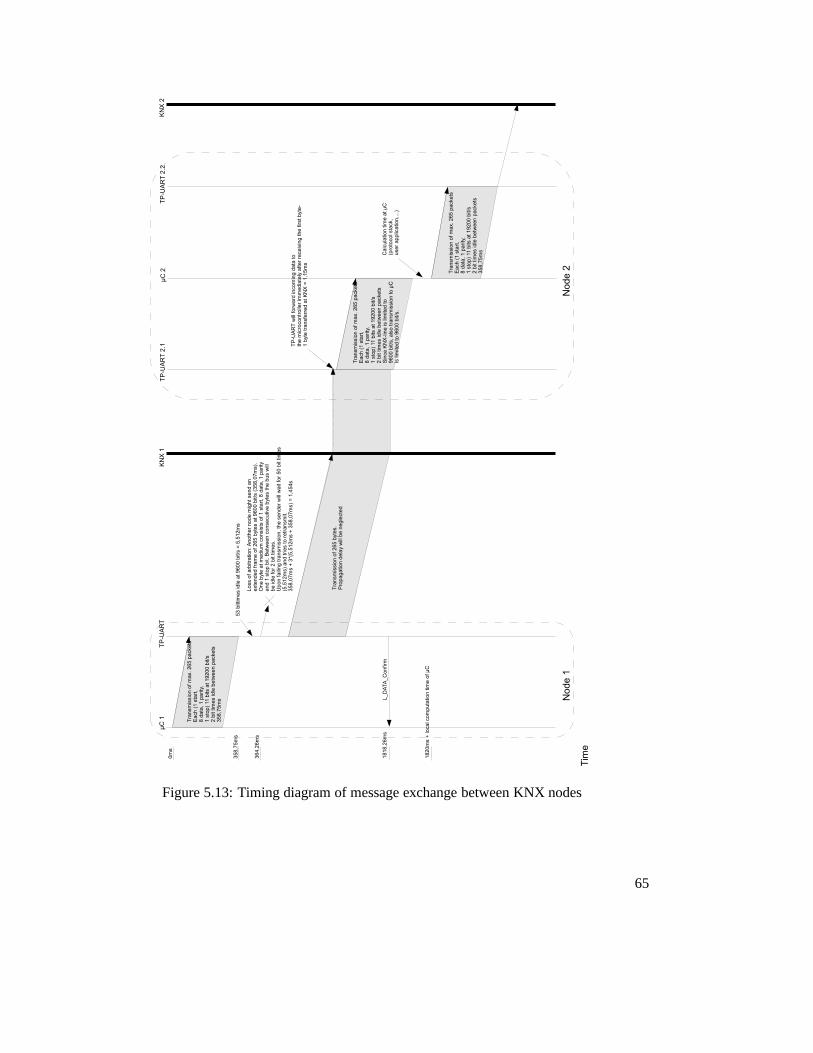
Figure 5.13: Timing diagram of message exchange between KNXnodes
65
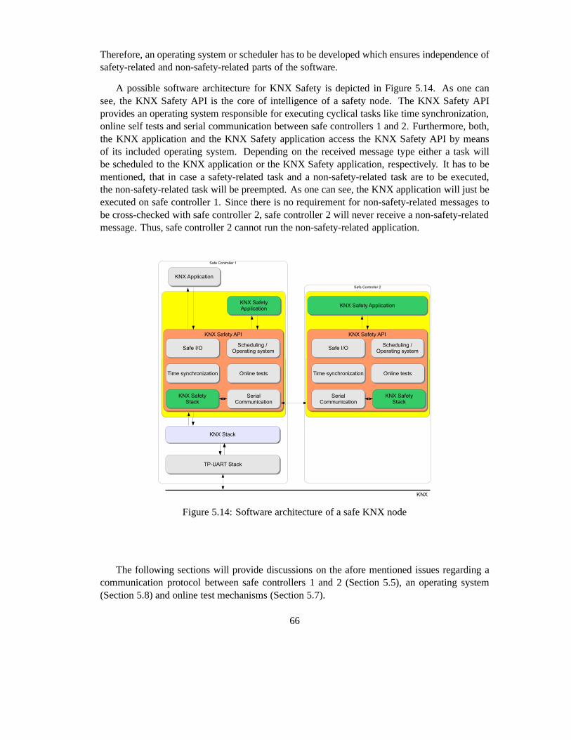
Therefore, an operating system or scheduler has to be developed which ensures independence ofsafety-related and non-safety-related parts of the software.
A possible software architecture for KNX Safety is depictedin Figure 5.14. As one cansee, the KNX Safety API is the core of intelligence of a safetynode. The KNX Safety APIprovides an operating system responsible for executing cyclical tasks like time synchronization,online self tests and serial communication between safe controllers 1 and 2. Furthermore, both,the KNX application and the KNX Safety application access the KNX Safety API by meansof its included operating system. Depending on the receivedmessage type either a task willbe scheduled to the KNX application or the KNX Safety application, respectively. It has to bementioned, that in case a safety-related task and a non-safety-related task are to be executed,the non-safety-related task will be preempted. As one can see, the KNX application will just beexecuted on safe controller 1. Since there is no requirementfor non-safety-related messages tobe cross-checked with safe controller 2, safe controller 2 will never receive a non-safety-relatedmessage. Thus, safe controller 2 cannot run the non-safety-related application.
Figure 5.14: Software architecture of a safe KNX node
The following sections will provide discussions on the afore mentioned issues regarding acommunication protocol between safe controllers 1 and 2 (Section 5.5), an operating system(Section 5.8) and online test mechanisms (Section 5.7).
66
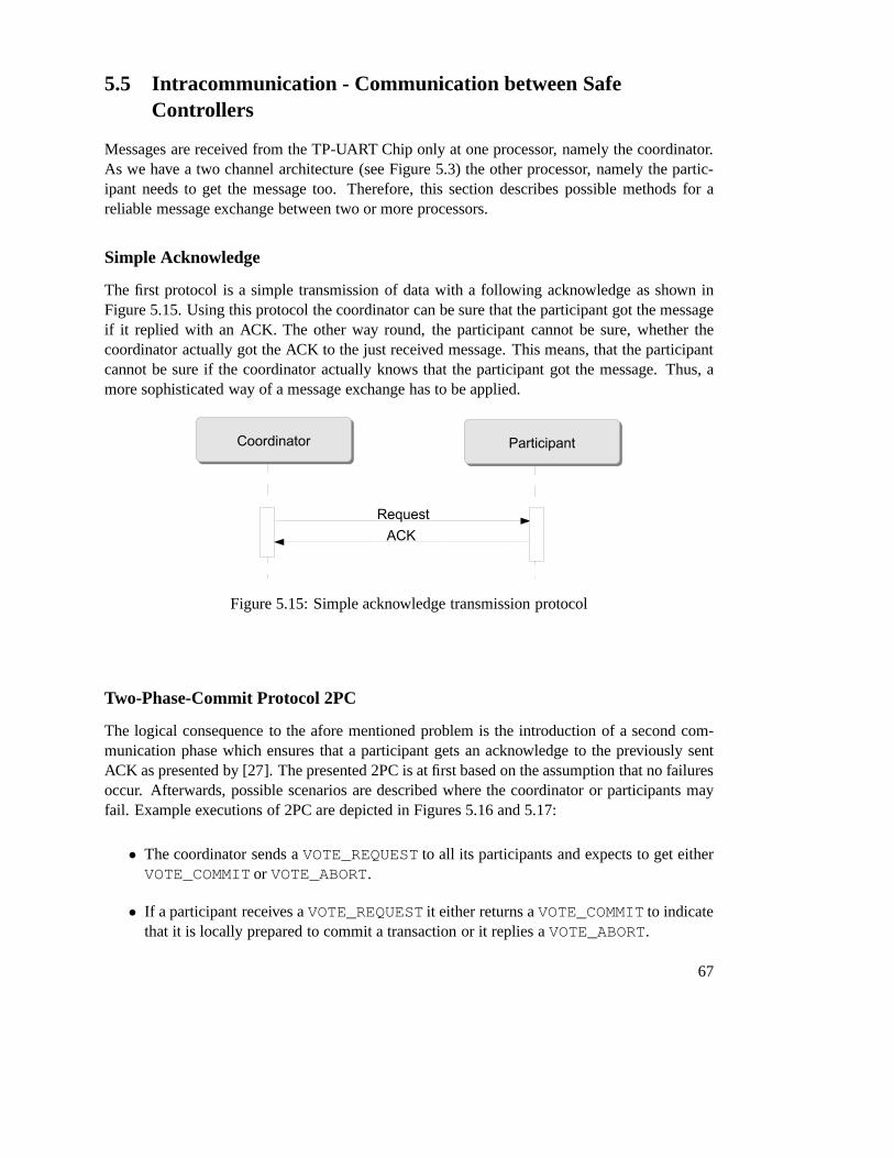
5.5 Intracommunication - Communication between SafeControllers
Messages are received from the TP-UART Chip only at one processor, namely the coordinator.As we have a two channel architecture (see Figure 5.3) the other processor, namely the partic-ipant needs to get the message too. Therefore, this section describes possible methods for areliable message exchange between two or more processors.
Simple Acknowledge
The first protocol is a simple transmission of data with a following acknowledge as shown inFigure 5.15. Using this protocol the coordinator can be surethat the participant got the messageif it replied with an ACK. The other way round, the participant cannot be sure, whether thecoordinator actually got the ACK to the just received message. This means, that the participantcannot be sure if the coordinator actually knows that the participant got the message. Thus, amore sophisticated way of a message exchange has to be applied.
Figure 5.15: Simple acknowledge transmission protocol
Two-Phase-Commit Protocol 2PC
The logical consequence to the afore mentioned problem is the introduction of a second com-munication phase which ensures that a participant gets an acknowledge to the previously sentACK as presented by [27]. The presented 2PC is at first based onthe assumption that no failuresoccur. Afterwards, possible scenarios are described wherethe coordinator or participants mayfail. Example executions of 2PC are depicted in Figures 5.16and 5.17:
• The coordinator sends aVOTE_REQUEST to all its participants and expects to get eitherVOTE_COMMIT or VOTE_ABORT.
• If a participant receives aVOTE_REQUEST it either returns aVOTE_COMMIT to indicatethat it is locally prepared to commit a transaction or it replies aVOTE_ABORT.
67

Figure 5.16: Sequence diagram of a successfulTwo-Phase-Commit Protocol
Figure 5.17: Sequence diagram of a failed Two-Phase-Commit Protocol
• Upon receiving aVOTE_COMMIT from all its participants the coordinator will reply withaGLOBAL_COMMIT to notify the participants to commit the transaction.
• If one of the participants replies with aVOTE_ABORT the coordinator will broadcast aGLOBAL_ABORT to indicate that the transaction has failed.
In a failure free scenario the 2PC-protocol can ensure that aparticipant got a previously sentmessage, and the coordinator will know that the participantactually got the message. As theassumption of a failure free environment is not sufficient for this thesis, we assume that fail-stopfailures may occur. This can be explained best using the state diagrams depicted in Figures 5.18for the coordinator and 5.19 for the participants.
Figure 5.18: State diagram of the coordinator in the Two-Phase-Commit Protocol
First, assume all participants are inINIT state and the coordinator crashes. The participantswill wait for a VOTE_REQUEST. Since the coordinator has crashed such a message will neverbe received and thus the participants will be blocked inINIT state. To detect such a caseparticipants will wait until a timeout happens and send aVOTE_ABORT to the coordinator andcancel the current transaction locally.
68

Figure 5.19: State diagram of a participant in the Two-Phase-Commit Protocol
A similar case can be observed if the coordinator is in stateWAIT, and waits for votesfrom its participants. If not all participants replied within a certain time, the coordinator has todistribute aGLOBAL_ABORT to all of them.
Finally, assume a participant in stateREADY waiting for a GLOBAL_COMMIT or aGLOBAL_ABORT from the coordinator. Furthermore, assume the coordinatorhas crashed. Thismeans that the coordinator may have sent aVOTE_REQUESTor a GLOBAL_COMMIT, whereas either of those messages has not been delivered to all par-ticipants. In such a case the participant may not simply abort the transaction. Instead, it has tofind out in which state the other participants are and decide according to their states to eitherabort or commit the transaction.
In any case this model assumes that faulty processes recoverwithin a finite time. To enablelocal recovery the current state of the process needs to be written to a persistent memory. Forinstance a participant which has crashed in statesCOMMIT or ABORT without having returnedan ACK to the coordinator, can recover to its last logged state and inform the coordinator aboutits decision.
Problems arise if a participant crashes in stateREADY. After recovery it can not safely decideto abort or commit the transaction without checking the decisions of other participants.
If the coordinator crashes in stateWAIT it has to ensure, that it has not missed anyCOMMIT-messages. Therefore, a safe solution is to retransmit theVOTE_REQUEST. Likewise, if a deci-sion has already been taken it is sufficient to retransmit it when recovering.
Here one can observe that a participant may block until the coordinator has recovered. Sucha scenario is present if all participants have received theVOTE_REQUEST and the coordinatorcrashes. If so, the participants cannot cooperatively decide on a final result. A possible solutionto avoid the blocking issue is resolved in the Three-Phase-Commit protocol described in thefollowing section.
69

Three-Phase-Commit Protocol 3PC
As described before if the coordinator crashes, the participants may not be able to reach a finaldecision. Therefore, [26] has extended 2PC to avoid blocking processes in crash-stop scenarios.To achieve this, the following two constraints have to be fulfilled:
• There is no single state from which it is possible to directlyreach one of the statesCOMMITor ABORT.
• From each state it is possible to reach a final decision and from which a transition toCOMMIT can be made.
The execution of the 3PC is quite similar to 2PC but with the difference that an addi-tional pre-commit phase is now introduced. The coordinatorstarts again by multicasting aVOTE_REQUEST to its participants and expects to receiveVOTE_COMMIT messages. Oncethe coordinator got allVOTE_COMMIT messages it broadcasts aPREPARE_COMMIT. Afterreceiving all acknowledges the coordinator will now send the GLOBAL_COMMIT message toactually commit the transaction.
Figure 5.20: Sequence diagram of the Three-Phase-Commit Protocol
Once again, there are possible scenarios where processors may block waiting for incomingmessages. Therefore, state diagrams for the coordinator and the participant in Figures 5.21 and5.22 illustrate that behaviour.
70

Like in the 2PC, a participant may wait for aVOTE_REQUEST until it times out and even-tually aborts the transaction. Analogously, the coordinator may stay inWAIT state waiting forvotes from the participants. On a timeout the coordinator will assume that one or more partici-pants have crashed, abort the transaction and broadcast aGLOBAL_ABORT.
Now assume that the coordinator is blocked in statePRECOMMIT. Since all participantsmust have voted for committing the transaction before - otherwise the coordinator would nothave reached thePRECOMMIT state - the coordinator can now safely commit the transaction bymulticasting aGLOBAL_COMMITmessage.
A participant may block in one of the statesREADY or PRECOMMIT. On a timeout theparticipant has to ask its neighbours for their states. If all of them are in stateCOMMIT orABORT the participant should move to one of those states, too. If all neighbours are in statePRECOMMIT the transaction can safely be commited.
Figure 5.21: State diagram of the coordinator in the Three-Phase-Commit Protocol
Conclusion
This section has described possible methods for the exchange of messages between safe con-trollers on a single node - hence the name intracommunication. The simple acknowledge pro-tocol has been shown to not supply the required level of safety. The applied architecture asdepicted in Figure 5.3 makes use of just two safe controllers. The three-phase commit protocolis assumed to rely on a majority of correct working controllers, which can not be guaranteed withonly two processors. Hence, the 3PC can be taken out of consideration. Thus, the two-phase
71

Figure 5.22: State diagram of a participant in the Three-Phase-Commit Protocol
commit protocol is the only remaining protocol which might be applied for communication be-tween safe controllers 1 and 2 in KNX Safety.
5.6 KNX Safety Application
The actual user application is carried out in the KNX Safety Application. The application pro-grammer defines how KNX Safety messagesSKNX_A_pd_value_read andSKNX_A_pd_value_write as defined in Table 5.2 have to be interpreted. Therefore, theprogrammer has access to the KNX Safety stack to fetch the content of a safety message and tocreate safety messages. To enable interaction with the environment, the programmer has accessto the interface of the safe I/O unit. It has to be mentioned, that it is up to the underlying oper-ating system to run cyclical processes like time synchronization and intracommunication. TheKNX Safety application is solely responsible for reading and writing output values according tothe user application.
Similar to KNX, the concept of data points will be applied here too. Here, aKNX Safety DataPoint can be read using aSKNX_A_pd_value_read message while writing a safety datapoint will be handled by anSKNX_A_pd_value_writemessage. If KNX-mechanisms likeA_GroupValue_Read-PDU andA_GroupValue_Write-PDU are required too, Table 5.2 has to be extended by the requiredmessage types.
72

5.7 Hardware self tests
As already stated, a certain SIL can be gained through increasing fault tolerance of hardware orincreasing detection of failures which is mainly gathered by software. While hardware architec-tures have already been discussed thoroughly in previous chapters, test mechanisms in softwarewill be covered in this section.
Basically, there are two ways of test executions: First, to run the system for a predefinedtime and fully test it afterwards (offline test). A second possibility is to test the system cyclicallyin running mode (online test). Figure 5.23 illustrates the required test intervals of on- and offlinetests.
Figure 5.23: Online and Offline test intervals. Slightly modified illustration from [28]
During operation the number of errors will increase linear.If no error detection measures areperformed, the system will run until a maximum number of faults is reached where the systemcannot be assumed to work safely any further. At that time instant, the system has to be fullytested. After that test the system is in a theoretical new state which means that theoretically everyerror has been detected and repaired. In practice not every error will be detected nor repaired.
If cyclical tests are performed, a fraction of errors can be detected and repaired. Since notevery error can be detected or repaired by online tests (for instance mechanical wear problems)some errors will remain what requires to perform a full test additionally.
It is clear, that only combination of online and offline testsyield in an optimal solution.Eventually, information about best test strategies gives an FMEA analysis.
73

Errors in memory
Any CPU requires various memory elements to process data. Therefore, data is stored in mem-ory elements and retrieved later to be processed. During that time, information in memory mightbe corrupted through hardware defects. Basically, memory can be divided into two categories:Read Only Memory (ROM)andRandom Access Memory (RAM). ROM keeps the operating sys-tem, bootstrap loader and application code while RAM contains working information like reg-isters. Thus, errors in memory may occur in various ways resulting in marginal deviated storedvalues or in hazardous program execution. Therefore, it is of importance to ensure a correctworking behaviour of memory. This can only be achieved through repetitive memory tests. Thetest intervals will depend on manufacturer specific MTTF of the memory.
Memory elements are organized in units of bytes (8 bit) or words (16 bit) and can be accessedby addressing the memory element followed by a write or read command. Memory elements areaddressed by an address decoder controlled by the CPU. The contents of the addressed memorycell are then made accessible by an I/O driver which is controlled by an access logic deciding ifthe cell has to be read or written. An illustration of a memorystructure including possible errorsis given in Figure 5.28.
An error is present if the memory access deviates from the intended behaviour. An error freememory element will behave like depicted in Figure 5.24.
Figure 5.24: State diagram of a correct working memory cell
If the current value of the cell is 0, and the next value written will be 0 too, the resultingvalue of the cell will be 0. If the current value is 0 and the written value is 1, the resulting valuewill be 1. The same applies for an initial value of 1. Any deviation of the afore depicted statediagram is an error.
Such an error might be astuck-at-erroras depicted in Figures 5.25 and 5.26 resulting in anunchanged memory cell. If the current value of the cell is 0 itwill remain 0 regardless of thewritten value. The same applies to a cell value of 1 and a written value of 0.
Similarly, a memory cell can be in a dominant state resultingin an unchangeable state oncethe cell resides in that dominant state (see Figure 5.27).
74

Figure 5.25: State diagram of a stuck-at zero er-ror in a memory cell
Figure 5.26: State diagram of a stuck-at one er-ror in a memory cell
Figure 5.27: State diagram of a state transition error of memory cell
So far, errors in memory have been considered to occur in the memory cell only. Sincememory cells are accessed via addresses, the address decoder or access logic might behaveerroneous, too. Potential errors are depicted in Figure 5.28.
• A short circuit between address lines will result in replicated data in memory since ad-dresses will occur twice. The replicated cells will depend on either a logical 0 or 1 in theaddress decoder will become dominant.
• Likewise, a stuck-at to ground will result in replicated data in memory.• A short after the decoder will result in replicated memory, too.• A short in the data area will result in identical bytes in a word. If the short resides on the
output side, any data will be affected. There is also the possibility that the short resides inthe memory cell itself which can be detected by direct addressing the cell.
• Timing errors can be assumed to occur sporadically. But if they occur, a total failure ofthe device can be assumed.
• Defects in the memory cell can be caused by manufacturing process or occur during op-eration.
• Open circuits might result in no access at all or might affectneighbor cells.
RAM tests
As described so far, errors in memory may occur in the memory cell or in the access logicfor the cell. Thus, memory testing should cover all parts of the memory element to ensure ahigh diagnostic coverage. Basically, memory tests work by writing test patterns to memory and
75

Figure 5.28: Potential errors in a memory block
reading them back afterwards. If the written value differs from the read one, the memory cellhas to be assumed erroneous. It is clear, that this kind of tests can only be performed on writablememories.
TheMarching-Bit-Testassumes an empty memory (all cells set to 0) and writes sequentially,beginning by the first memory address ones to each bit of the memory. Before writing the newvalue, each bit is checked to be 0. In a second run, the test will be performed with inverted databeginning from the last memory cell.
Similarly, theCheckerboard-Pattern-Testinitially writes alternating 0/1 bits to memory. Af-terwards, all bits are read back and checked for their correct value. A second run is performedwith inverted data.
TheWalkpat-Pattern-Testassumes a memory initialized with defined bit-patterns. Thefirststep will be to invert the first bit and test all other bits for their validity. After that, the first bitwill be set to its initial value again and the procedure will be performed for the second bit. In asecond run, the whole memory will be inverted and tested again.
Finally, theGalpat-Pattern-Test(galloping patterns) is a variation of Walkpat-Pattern-Testwhere a single 1 passes an initially empty (all bits set to 0) memory. After inverting a singlebit, all (including the currently set bit) bits are read and tested for validity. Additionally, afterreading a (0-) bit-cell also the inverted (1-) bit-cell willbe checked for validity. Thus, the Galpat-Pattern-Test also detects errors yielding from unexpectedwriting after reading a bit-cell. Afterevery bit-cell has been inverted, a second run will be performed starting with a 1-initialized
76

memory where a single bit is set to 0. Figure 5.29 illustratesa sample test execution.
Figure 5.29: Sample execution of Galpat-Pattern-Test
Memory Test Performance and Test Strategies
Depending on the chosen test pattern, memory tests can be very time consuming. For example,simply setting all bits to 0, reading the memory, writing allbits to 1 and reading the completememory again already results in test length of4∗2N where N is the number of address bits wherediagnostic coverage (DC) is less than50% since neither the decoder errors nor short circuits aredetected. The more exhaustive Galpat-Pattern-Test provides very high diagnostic coverage butyields in test length of2∗ (2N +2∗n2) where N is the number of address bits and n the numberof memory cells (bits). Table 5.3 gives an overview of tests and the resulting DC.
Test / Diagnostic method Diagnostic CoverageCheckerboard-Pattern-Test lowMarching-Bit-Test lowWalkpat-Pattern-Test mediumGalpat-Pattern-Test high
Parity Bit lowMirrored memory with constant bitcomparison on every read- and write access
high
Table 5.3: RAM test methods and resulting DC
Since processing time can be assumed to be limited, it is almost impossible to test the wholememory with a high DC in a single test execution. Instead, memory has to be divided intoseveral smaller segments and a test manager has to take care of running memory tests part-wise.Since all presented memory test algorithms are data destroying, the values before test executionhave to be mirrored and written back again. Additionally, the currently in use memory has to betested, too. To ensure correctness of mirrored data, it is required to calculate a checksum over
77

the mirrored memory area before the test starts, recalculate the checksum after writing back thememory segment and finally compare the checksums.
Read Only Memory Tests
Contents of read only memory are usually written only once bythe manufacturer to ROM orduring activation or maintenance to EEPROM (Electrical Erasable Programmable Read OnlyMemory). Possible errors can therefore be reduced to randomerrors occurring at putting onsupply voltage. Thus, ROM checks should be performed immediately at startup of the system.Since errors can occur during operation of the system, online-tests are necessary.
The simplest test for ROMs are calculation of parity bits (even of odd) and store the parityinformation in a separate word. Alternatively, checksums of ROM can be taken and stored.Additionally, overflow bits might be considered or not.
A more safe method is to calculate a CRC where the complete memory is assumed to bea polynomial. Therefore, every byte of the memory is attached to a chain. Using that chaina CRC is calculated where the remainder is kept in memory. It is clear, that CRC calculationrequires check polynomials guaranteeing Hamming-distance and complete coding. Figure 5.30illustrates a simple example assuming two bytes of memory and additionally, one byte for theCRC checksum. To increase data integrity, an appropriate check polynomial has to be chosen.As depicted in Figure 5.30, combining 16 bits differently results in 65536 possible combinationsof data. Including 8 bits for checksum, 24 bits of information resulting in 16777216 possibledata combinations are available. That is, 16777216 possible combinations against 65535 validcombinations. Probability to not detect an error is thus65535/16777216 = 1/256 which yieldsin DC of more than99%.
Figure 5.30: Sample calculation of CRC
Summing up, ROM error detection mechanisms differ in simplicity and thus error detectioncoverage. Parity checks will fail even on even numbers of flipped bits, where for failing CRC at
78

least 4 bits have to flip. Table 5.4 gives an overview of ROM test measures and resulting DC.
Test / Diagnostic method Diagnostic CoverageParity bit lowDouble word checksum mediumCRC with guaranteed Hamming-distance high
Table 5.4: ROM test methods and resulting DC
Errors in the CPU
A CPU (Central Processing Unit) is the core of any processor or microcontroller and is respon-sible for executing software. Usually, CPU consists of an ALU (Arithmetic Logic Unit), instruc-tion counter, registers and instruction decoder. Microcontrollers are microprocessors extendedby peripheral components like I/O ports, clock generator, watchdog or communication ports. Tothoroughly test a microcontroller implementations have tobe provided to test every componentseparately. It is clear, that only those components have to be tested which are required for thesafety functionality.
There is still doubt about the effectiveness of online CPU tests since the question ariseswhich errors in a processor could be detected by an erroneousprocessor and if there is a possi-bility to transfer it to a safe state upon detecting an error.Therefore, the following conditionshave been defined [28]:
• A test should detect random errors.• A test should detect errors in production lots.• The DC is derived from error models and not from error combinations.• Errors are limited in their effects. Even in case of an error,there is still possibility to
transfer the system into a safe state.
[4] presents requirements for error models in single components of microcontrollers anddefines according DC upon detecting an error. An example would be an emergency-stop signalwhich is fired only rarely. Software is implemented to execute the according handler whichworks on different registers. Caused by rare usage of those methods and switching to associatedregisters, it might be the case that the handler method is notexecuted correctly.
Therefore, every seldom used method or hardware component has to be tested dynamically.Furthermore, test results have to be compared with a predefined expectancy value. It is clear,that self tests consume a lot of time, but components do not have to be tested concurrently.Test routines can be executed serially, where overall consuming time to test the whole deviceshould be between one and two hours [28]. For systems which are restarted regularly it mightbe sufficient to execute self-tests at startup.
79

Execution of tests are coordinated by a test manager. The manager has to take care, thatnone of the test routines consumes more time than provided. Therefore tests have to be designedto be short enough to fit that constraint. If a test routine takes more time it has to be divided intoseveral smaller jobs.
Checking the Stack
The stack memory size is assigned at development time. Depending on the usage of interruptsstack memory can reserve some bytes up to some kilobytes. Theexact size can be determinedafter extensive tests. Monitoring stack memory can be done as illustrated in Figure 5.31: Themaximum stack memory element is allocated a fixed value. Following stack memory entries arefilled top-down. Thus, a stack underflow can only occur if more“pop”-commands are executedthan “push”-commands. A stack overflow might occur if (nested) interrupt routines are executedmultiple times. Therefore, a buffer area in the stack memoryis reserved. Stack memory isinitialized on startup and has to be tested during runtime like other memory.
Figure 5.31: Structure of stack memory
Implementing test routines
For different test routines it might be required to temporarily disable interrupts. It has to beverified, that enabling and disabling interrupts has been executed successfully. If componentsare required constantly it might not be necessary to test them separately since deviations mightalready be detected during regular operation. For example,sending and receiving registers of aserial communications port which cyclically sends and receives data do not have to be tested.Especially if protocols containing checksums are used, anyerror in the communication systemwill be detected by higher level software.
80

5.8 Scheduling tasks on a Microprocessor
So far, most required tasks for safety-related nodes have been identified and discussed thor-oughly:
• (Cyclical) Message exchange between safety data-points (intercommunication)• (Cyclical) Message exchange between safety controllers (intracommunication)• (Cyclical) Clock synchronization between safety nodes• Running the safety-related application software• Running the non-safety-related application software• Running hardware self tests
To ensure in time execution of each of these tasks, scheduling strategies are of major interest.On personal computers, scheduling is implemented by the operating system. On most micro-controllers, scheduling is not available by default. Sincethe application programmer should nottake care about the execution of the afore mentioned tasks, an operating system or at least asimple scheduling mechanism should be provided which takescare of executing the basic tasksrequired for running the safety-related and non-safety-related software.
In the following, some available operating systems have been evaluated for possible reuseand will be described briefly1 . The criteria for the choice of an existing product has been theexistence of a port to the MSP430f149 since an implementation of the hardware drivers, theTP-UART stack and the KNX stack is already available.
• MicroC/OSII
MicroC/OSII has been developed by Micriµm and advertises its safety-capability, espe-cially with its SIL3 and even SIL4 compliance:
“. . . it is successfully implemented in some of the highest level safety-criticaldevices, including those certified for avionics DO-178B Level A, and EURO-CAE ED-12B, medical FDA pre-market notification (510(k)), and pre-marketapproval (PMA), and SIL 3/SIL4 IEC for transportation and nuclear systems.2
“
Micriµm offers a 45 day trial license for evaluation after which theproduct needs to bepurchased. There exists a port to the MSP430x5xx processor series, but unfortunately notfor the used MSP430f149.
1http://processors.wiki.ti.com/index.php/MSP430_Real_Time_Operating_Systems_Overview2http://micrium.com/page/products/rtos/os-ii
81

• TinyOS
TinyOS3 is an open-source embedded operating system mainly developed for sensor nodes(motes). The extension SafeTinyOS4 adds further functionality regarding datatype andmemory safety at runtime. The communication protocol is predefined. Thus, the onlything to do for the programmer is to handle the inputs and outputs. This is done in themodule based language NCC. Reuse of existing C-code is not provided thus the completeKNX stack and the TPUART driver would have to be recoded. However, TinyOS supportsthe MSP430f149 in the Telos mote, but recoding KNX would go beyond the scope of thisthesis.
• FreeRTOS
The RTOS5 family is available in three different versions:
– FreeRTOS is open source and royalty free.
– OpenRTOS is the commercially licensed and supported version or FreeRTOS. Itsupplies further functionality such as USB and TCP/IP components.
– SafeRTOS is a SIL3 certified version with a complete development/safety lifecycledocumentation for compliance with IEC 61508.
There exists a FreeRTOS port for the MSP430f149 in combination with the MSPGCCtoolchain. However, the last supported version of MSPGCC isdated back in 2004 whichis quite too old.
• Other remaining operating systems either do not offer an active support, are not freelyavailable (embOS, IAR PowerPAC) or do not support the MSPGCCtoolchain (Salvo,CMX-Tiny+).
So far, operating systems for the MSP430 family have been evaluated for reuse in the KNXsafety project. Since no OS met all requirements, scheduling needs to be developed from scratch.In the following, an approach for a simple scheduling of safety and non-safety-related tasks willbe presented.
Simple Scheduling for KNX Safety
Scheduling is a very wide area of research and development. Since a detailed discussion ondifferent scheduling mechanisms would go far beyond the scope of that thesis, basic appropriatescheduling mechanisms will be presented only. For choice ofa scheduler in KNX Safety, thefollowing tasks and issues have to be taken into consideration:
3http://tinyos.net/4http://docs.tinyos.net/index.php/Safe_TinyOS5http://www.freertos.org/
82
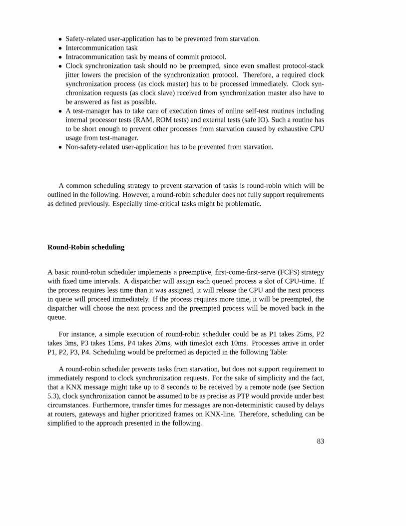
• Safety-related user-application has to be prevented from starvation.• Intercommunication task• Intracommunication task by means of commit protocol.• Clock synchronization task should no be preempted, since even smallest protocol-stack
jitter lowers the precision of the synchronization protocol. Therefore, a required clocksynchronization process (as clock master) has to be processed immediately. Clock syn-chronization requests (as clock slave) received from synchronization master also have tobe answered as fast as possible.
• A test-manager has to take care of execution times of online self-test routines includinginternal processor tests (RAM, ROM tests) and external tests (safe IO). Such a routine hasto be short enough to prevent other processes from starvation caused by exhaustive CPUusage from test-manager.
• Non-safety-related user-application has to be prevented from starvation.
A common scheduling strategy to prevent starvation of tasksis round-robin which will beoutlined in the following. However, a round-robin scheduler does not fully support requirementsas defined previously. Especially time-critical tasks might be problematic.
Round-Robin scheduling
A basic round-robin scheduler implements a preemptive, first-come-first-serve (FCFS) strategywith fixed time intervals. A dispatcher will assign each queued process a slot of CPU-time. Ifthe process requires less time than it was assigned, it will release the CPU and the next processin queue will proceed immediately. If the process requires more time, it will be preempted, thedispatcher will choose the next process and the preempted process will be moved back in thequeue.
For instance, a simple execution of round-robin scheduler could be as P1 takes 25ms, P2takes 3ms, P3 takes 15ms, P4 takes 20ms, with timeslot each 10ms. Processes arrive in orderP1, P2, P3, P4. Scheduling would be preformed as depicted in the following Table:
A round-robin scheduler prevents tasks from starvation, but does not support requirement toimmediately respond to clock synchronization requests. For the sake of simplicity and the fact,that a KNX message might take up to 8 seconds to be received by aremote node (see Section5.3), clock synchronization cannot be assumed to be as precise as PTP would provide under bestcircumstances. Furthermore, transfer times for messages are non-deterministic caused by delaysat routers, gateways and higher prioritized frames on KNX-line. Therefore, scheduling can besimplified to the approach presented in the following.
83
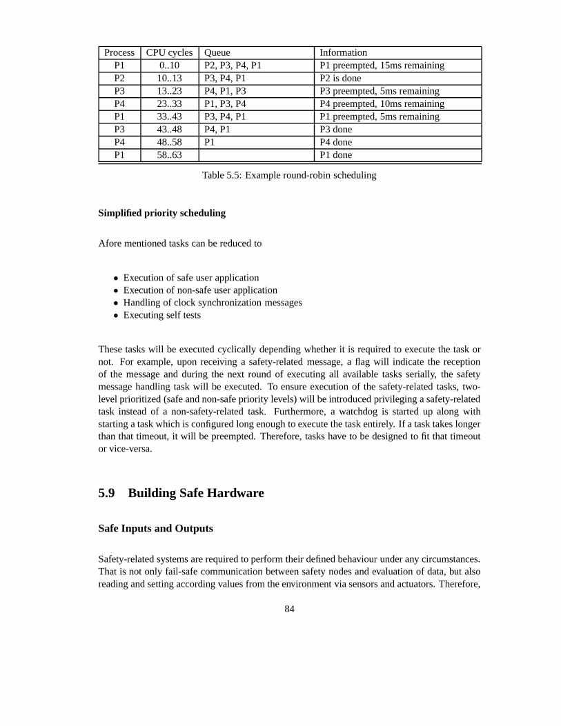
Process CPU cycles Queue InformationP1 0..10 P2, P3, P4, P1 P1 preempted, 15ms remainingP2 10..13 P3, P4, P1 P2 is doneP3 13..23 P4, P1, P3 P3 preempted, 5ms remainingP4 23..33 P1, P3, P4 P4 preempted, 10ms remainingP1 33..43 P3, P4, P1 P1 preempted, 5ms remainingP3 43..48 P4, P1 P3 doneP4 48..58 P1 P4 doneP1 58..63 P1 done
Table 5.5: Example round-robin scheduling
Simplified priority scheduling
Afore mentioned tasks can be reduced to
• Execution of safe user application• Execution of non-safe user application• Handling of clock synchronization messages• Executing self tests
These tasks will be executed cyclically depending whether it is required to execute the task ornot. For example, upon receiving a safety-related message,a flag will indicate the receptionof the message and during the next round of executing all available tasks serially, the safetymessage handling task will be executed. To ensure executionof the safety-related tasks, two-level prioritized (safe and non-safe priority levels) willbe introduced privileging a safety-relatedtask instead of a non-safety-related task. Furthermore, a watchdog is started up along withstarting a task which is configured long enough to execute thetask entirely. If a task takes longerthan that timeout, it will be preempted. Therefore, tasks have to be designed to fit that timeoutor vice-versa.
5.9 Building Safe Hardware
Safe Inputs and Outputs
Safety-related systems are required to perform their defined behaviour under any circumstances.That is not only fail-safe communication between safety nodes and evaluation of data, but alsoreading and setting according values from the environment via sensors and actuators. Therefore,
84
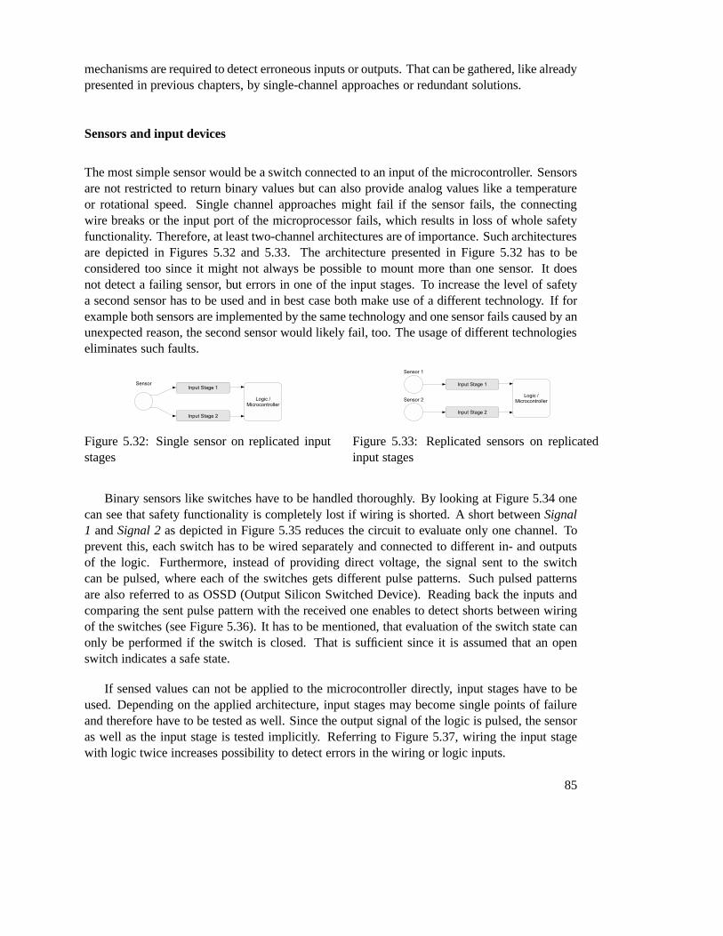
mechanisms are required to detect erroneous inputs or outputs. That can be gathered, like alreadypresented in previous chapters, by single-channel approaches or redundant solutions.
Sensors and input devices
The most simple sensor would be a switch connected to an inputof the microcontroller. Sensorsare not restricted to return binary values but can also provide analog values like a temperatureor rotational speed. Single channel approaches might fail if the sensor fails, the connectingwire breaks or the input port of the microprocessor fails, which results in loss of whole safetyfunctionality. Therefore, at least two-channel architectures are of importance. Such architecturesare depicted in Figures 5.32 and 5.33. The architecture presented in Figure 5.32 has to beconsidered too since it might not always be possible to mountmore than one sensor. It doesnot detect a failing sensor, but errors in one of the input stages. To increase the level of safetya second sensor has to be used and in best case both make use of adifferent technology. If forexample both sensors are implemented by the same technologyand one sensor fails caused by anunexpected reason, the second sensor would likely fail, too. The usage of different technologieseliminates such faults.
Figure 5.32: Single sensor on replicated inputstages
Figure 5.33: Replicated sensors on replicatedinput stages
Binary sensors like switches have to be handled thoroughly.By looking at Figure 5.34 onecan see that safety functionality is completely lost if wiring is shorted. A short betweenSignal1 andSignal 2as depicted in Figure 5.35 reduces the circuit to evaluate only one channel. Toprevent this, each switch has to be wired separately and connected to different in- and outputsof the logic. Furthermore, instead of providing direct voltage, the signal sent to the switchcan be pulsed, where each of the switches gets different pulse patterns. Such pulsed patternsare also referred to as OSSD (Output Silicon Switched Device). Reading back the inputs andcomparing the sent pulse pattern with the received one enables to detect shorts between wiringof the switches (see Figure 5.36). It has to be mentioned, that evaluation of the switch state canonly be performed if the switch is closed. That is sufficient since it is assumed that an openswitch indicates a safe state.
If sensed values can not be applied to the microcontroller directly, input stages have to beused. Depending on the applied architecture, input stages may become single points of failureand therefore have to be tested as well. Since the output signal of the logic is pulsed, the sensoras well as the input stage is tested implicitly. Referring toFigure 5.37, wiring the input stagewith logic twice increases possibility to detect errors in the wiring or logic inputs.
85

Figure 5.34: Example of connecting twoswitches in line
Figure 5.35: Example of connecting twoswitches parallel
Figure 5.36: Monitoring sensors using pulsed voltage
Since not every sensor provides potential free contacts, itmight not be possible to use aforementioned pulsed pattern technique to ensure correctness of operation. That might be the casefor sensors with separate power supply providing an active signal themselves like proximitysensors (see Figure 5.38). Here one can see that the input stage receives a pulsed signal from thelogic which cyclically tests if the input stage still reactsby forwarding the pulses to the logic. Itis clear, that such an approach assumes correctness of the sensor itself. It can only be tested ifthe input stage behaves according to its specification.
Safe outputs
In safety-relevant automation systems it is often requiredto safely turn off a device like a motorfor example. Here it is not sufficient to use a simple switch toexecute a safety function since incase of a stuck-at error, it might not be possible to disconnect the device and transfer the systeminto a safe state. Therefore, multiple switches connected serially as depicted in Figure 5.39 areapplied. If one of the switches fails to disconnect, there isstill another one to execute the safety
86

Figure 5.37: Test in a closed circuit
Figure 5.38: Testable input stage in a closed circuit
function and transfer the system to a safe state. To ensure ifthe switch is actually disconnected,reading back values gives information about successful execution of the switch-command.
Figure 5.39: Serially connected switches with read-back switch state
A more sophisticated circuit fulfilling even highest level safety requirements is depicted inFigure 5.40. Just like in the afore presented circuit two switching elements are used to safelydisconnect the device. To ensure correctness of the operation, both semiconductors (T2, T3)
87
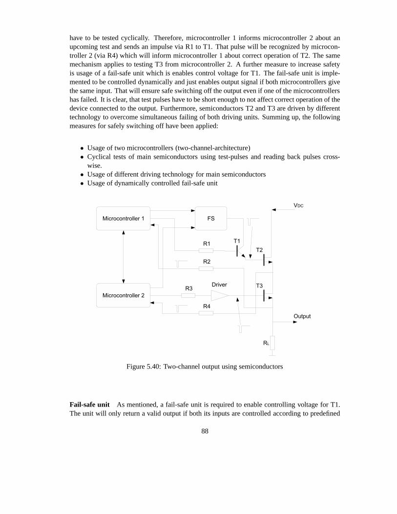
have to be tested cyclically. Therefore, microcontroller 1informs microcontroller 2 about anupcoming test and sends an impulse via R1 to T1. That pulse will be recognized by microcon-troller 2 (via R4) which will inform microcontroller 1 aboutcorrect operation of T2. The samemechanism applies to testing T3 from microcontroller 2. A further measure to increase safetyis usage of a fail-safe unit which is enables control voltagefor T1. The fail-safe unit is imple-mented to be controlled dynamically and just enables outputsignal if both microcontrollers givethe same input. That will ensure safe switching off the output even if one of the microcontrollershas failed. It is clear, that test pulses have to be short enough to not affect correct operation of thedevice connected to the output. Furthermore, semiconductors T2 and T3 are driven by differenttechnology to overcome simultaneous failing of both driving units. Summing up, the followingmeasures for safely switching off have been applied:
• Usage of two microcontrollers (two-channel-architecture)• Cyclical tests of main semiconductors using test-pulses and reading back pulses cross-
wise.• Usage of different driving technology for main semiconductors• Usage of dynamically controlled fail-safe unit
Figure 5.40: Two-channel output using semiconductors
Fail-safe unit As mentioned, a fail-safe unit is required to enable controlling voltage for T1.The unit will only return a valid output if both its inputs arecontrolled according to predefined
88

dynamic signals. Otherwise, an output indicating safe state will be provided. An example ofa fail-safe output unit is depicted in Figure 5.41. Microcontroller 1 provides constant voltagevia high-side driver 1 while microcontroller 2 provides pulsed voltage to drive the transformervia low-side driver 2. Additionally, both microcontrollers provide alternating test pulses. Thetransformer including filter D1, C1 are dimensioned that microcontrollers are enabled to readback test pulses via R1 or R2, respectively. Following D2 andC2 are dimensioned that output ofthe fail-safe unit is pulse-free direct voltage. If either of the microcontrollers fails, the output ofthe fail-safe unit turns to zero since valid outputs of both microcontrollers are required to drivethe transformer.
Figure 5.41: Fail-safe unit
89


CHAPTER 6Conclusion
The thesis started by explaining basic terms and definitionsrequired for building automationsystems and KNX protocol in depth. Chapter 3 gave an outline on state-of-the-art standardsIEC 61508 and ISO 13849 concerning functional safety in electrical systems and pointed outrequirements for functional safe devices from a development lifecycle as well as hard- and soft-ware point of view. Basically, IEC 61508 states that higher safety integrity levels can either begained by increasing fault tolerance of hardware or by increasing fraction of errors which can bedetected by system itself through extensive self tests.
In Chapter 4, a selection of existing solutions for industrial and home and building automa-tion providing functional safety has been presented and compared in terms of their protocolsafety. Possible errors in communication systems and measures to detect and prevent them aredefined in IEC 61784-3. Communication errors have been identified in case of corruption, unin-tended repetition, incorrect sequence, loss, unacceptable delay, insertion, masquerade and wrongaddressing. Detection of timing-related errors requires implementation of clock synchronizationmechanisms to ensure global notion of time and therefore ability to order messages by their oc-currences. Due to limited bandwidth of the KNX bus line, existing synchronization protocols,namely vector clocks and precision time protocol, have beenevaluated with a focus on reuse inthe thesis.
To gain safety integrity level 3 as specified by IEC 61508, application of extensive hardwareself tests or hardware redundancy is required. Due to limited processing power of microcon-trollers, a hardware redundancy approach using two microcontrollers and a single TP-UART-ICfor KNX-line access has been chosen. Even implementation ofhardware redundancy requireshardware self tests, but to gain SIL 3 a safe failure fractionof more than 90% is sufficient whichcan be gained by memory tests as presented in Chapter 5.7. To enable application of redun-dant controllers, a reliable communication protocol between safe controllers had to be applied.
91

Furthermore, safe hardware also includes safe in- and outputs for interaction with environmentwhich has been outlined in Section 5.9. Since non-safety andsafety-related applications shouldoperate on the same node, IEC 61508 requires to show sufficient independence of safety-relatedand non-safety-related application which requires implementation of scheduling mechanisms.
Summing up, developing a safety-capable device requires much more than just building re-dundant hardware. Instead, especially protocol safety is of major concern, which even gets moreimportant if existing wiring has to be kept and safety and non-safety nodes should coexist on thesame network. To solve this problem, almost any existing solution for safety-related automationsystems relies on the black-channel-principle stating, that the safety-related protocol itself has totake care about correct transmission, reception and detection of errors of a message without rely-ing on potentially implemented error detection mechanismsof the underlying non-safety-relatedprotocol. Further issues become safety of hardware itself which includes implementation of safeinteraction with the environment via safe inputs and outputs as well as communication betweenredundant safe controllers on a safe node itself. Finally, the hardware has to be checked cycli-cally for correctness of operation where especially errorsin memory have to be detected usingdifferent memory-check algorithms.
6.1 Outlook and further work
Process data exchange has been explained only very briefly. KNX supports a variety of mech-anisms to exchange data between nodes and how nodes are seen from their data-point-of-viewby means of their functional block description. To allow a simpler implementation of a KNXSafety network, KNX Safety should be extended to support functional blocks as well as moresophisticated methods to work with safety data points.
Rapid spreading of wireless devices with potential safety-related functionality entails an-other topic which has to be considered too i.e. security. A safety-related device might operatesafely in closed circuits, but if an unauthorized person gains access to a safety-related system, thesystem itself cannot be considered to safely operate anymore. Therefore, integration of securitymeasures into safety-related devices and vice-versa has tobe a major concern.
92

Bibliography
[1] Konnex Association.KNX Handbook, Version 2.0. Konnex Association, 2009.
[2] Konnex Association.KNX System Specifications, Architecture, v3.0. Konnex Association,2009.
[3] CENELEC Europäisches Komitee für Elektrotechnische Normung. DIN EN 61508-1 (VDE 0803 Teil 1) Funktionale Sicherheit sicherheitsbezogener elektrischer/elek-tronischer/programmierbarer elektronischer Systeme - Teil 1: Allgemeine Anforderungen(IEC 61508-1:1996 + Corrigendum 1999); Deutsche Fassung EN61508-1:2001. IEC,2001.
[4] CENELEC Europäisches Komitee für Elektrotechnische Normung. DIN EN61508-2 (VDE 0803 Teil 2) Funktionale Sicherheit sicherheitsbezogener elek-trischer/elektronischer/programmierbarer elektronischer Systeme - Teil 2: Anforderungenan sicherheitsbezogene elektrische/elektronische/programmierbare elektronische Systeme(IEC 61508-2:2000); Deutsche Fassung EN 61508-2:2001.IEC, 2001.
[5] CENELEC Europäisches Komitee für Elektrotechnische Normung. DIN EN61508-3 (VDE 0803 Teil 3) Funktionale Sicherheit sicherheitsbezogener elek-trischer/elektronischer/programmierbarer elektronischer Systeme - Teil 3: Anforderungenan Software (IEC 61508-3:1998 + Corrigendum 1999); Deutsche Fassung EN 61508-3:2001.IEC, 2001.
[6] CENELEC Europäisches Komitee für Elektrotechnische Normung. DIN EN61508-4 (VDE 0803 Teil 4) Funktionale Sicherheit sicherheitsbezogener elek-trischer/elektronischer/programmierbarer elektronischer Systeme - Teil 4: Begriffe undAbkürzungen (IEC 61508-4:1998 + Corrigendum 1999); Deutsche Fassung EN 61508-4:2001.IEC, 2001.
[7] CENELEC Europäisches Komitee für Elektrotechnische Normung. DIN EN61508-6 (VDE 0803 Teil 6) Funktionale Sicherheit sicherheitsbezogener elek-trischer/elektronischer/programmierbarer elektronischer Systeme - Teil 6: Anwen-dungsrichtlinie für IEC 61508-2 und IEC 61508-3 (IEC 61508-6:2000); Deutsche FassungEN 61508-6:2001.IEC, 2001.
93

[8] Charzinsiki. Bewertung der Fehlersicherungsverfahren im CAN Protokoll. UniversitätStuttgart, 1991.
[9] DEK Deutsche Kommission Elektrotechnik Elektronik Informationstechnik im DIN undVDE. DIN IEC 61784-3 (VDE 0803-500) Industrielle Kommunikationsnetze - Profile -Teil 3: Funktional sichere Übertragung bei Feldbussen (IEC65C/500/CD:2008.IEC, 2008.
[10] DIN Deutsches Institut für Normung e.V. DIN EN 13849-1 Sicherheit von Maschinen -Sicherheitsbezogene Teile von Steuerungen - Teil 1: Allgemeine Gestaltungsleitsätze (ISO13849-1:2006); Deutsche Fassung EN ISO 13849-1:2008.DIN, 2008.
[11] DIN Deutsches Institut für Normung e.V. DIN EN 13849-2 Sicherheit von Maschinen- Sicherheitsbezogene Teile von Steuerungen - Teil 2: Validierung (ISO 13849-2:2003);Deutsche Fassung EN ISO 13849-2:2008.DIN, 2008.
[12] Fachausschuss Elektrotechnik. Grundsatz für die Prüfung und Zertifizierung von Bussys-temen für die Übertragung sicherheitsrelevanter Nachrichten, 2002.
[13] IEC International Electrotechnical Commission. IEC 61508-0 Part 0: Functional safetyand IEC 61508.IEC, 2005.
[14] IEC International Electrotechnical Commission. IEC 61784-3-12 Industrial communica-tion networks - Profiles - Part 3-12: Functional safety fieldbuses - Additional specificationsfor CPF 12 (Safety-over-EtherCAT).IEC, 2010.
[15] IEEE Instrumentation and Measurement Society. IEEE 1588 Standard for a PrecisionClock Synchronization Protocol for Networked Measurementand Control Systems.IEEE,Revision of IEEE Std 1588-2002.
[16] CAN in Automation e.V. CANopen - Application Layer and Communication Profile - CiADraft Standard 301.CAN in Automation e.V., 2002.
[17] CAN in Automation e.V. CANopen - Framework for safety-relevant communication - CiADraft Standard 304.CAN in Automation e.V., 2005.
[18] Wolfgang Kastner and Georg Neugschwandtner. Datenkommunikation in der verteiltengebäudeautomation.Bulletin SEV/VSE, 2006.
[19] Wolfgang Kastner, Georg Neugschwandtner, Stefan Soucek, and H. Michael Newman.Communication systems for building automation and control. In Proceedings of the IEEE,volume 93, pages 1178–1203, 2005.
[20] Wolfgang Kastner and Thomas Novak. Functional safety in building automation. InInProc. of 14th IEEE Conference on Emerging Technologies and Factory Automation (ETFA’09), pages 1–8, September 2009.
[21] Hermann Kopetz.Real-Time Systems - Design Principles for Distributed Embedded Ap-plications. Kluwer Academic Publichers, 2003.
94
[22] Friedemann Mattern. On the relativistic structure of logical time in distributed systems. InElsevier Science Publishers B.V in Parallel and Distributed Algorithms, pages 215–226,1992.
[23] Thomas Novak and Thomas Tamandl. Architecture of a safenode for a fieldbus system.In 5th IEEE International Conference on Industrial Informatics, pages 101–106, 2007.
[24] Dietmar Reinert and Dietmar Schaefer.Sichere Bussysteme für die Automation. Hüthig,2001.
[25] Siemens.Technical data EIB-TP-UART-IC, 2001.
[26] Dale Skeen and Michael Stonebraker. A formal model of crash recovery in a distributedsystems.IEEE Transactions on Software Engineering, pages 219–228, 1983.
[27] Andrew S. Tanenbaum and Maarten van Steen.Distributed Systems - Principles andParadigms. Prentice Hall, 2002.
[28] Peter Wratil and Michael Kieviet. Sicherheitstechnik für Komponenten und Systeme.Hüthig, 2007.
[29] Richard Zurawski.The industrial communication technology handbook. CRC Press, 2005.
95