FUNCTIONALIZED OLIGOTHIOPHENES FOR APPLICATION IN ORGANIC ...
218
FUNCTIONALIZED OLIGOTHIOPHENES FOR APPLICATION IN ORGANIC SOLAR CELLS Dissertation zur Erlangung des akademischen Grades „Doktor der Naturwissenschaften“ (Dr. rer. nat.) der Fakultät der Naturwissenschaften der Universität Ulm vorgelegt von Roland Fitzner geboren in Ludwigshafen am Rhein Ulm, 2015
Transcript of FUNCTIONALIZED OLIGOTHIOPHENES FOR APPLICATION IN ORGANIC ...
FUNCTIONALIZED OLIGOTHIOPHENES FOR APPLICATION IN ORGANIC SOLAR CELLS
Dissertation
zur Erlangung des akademischen Grades
„Doktor der Naturwissenschaften“ (Dr. rer. nat.)
der Fakultät der Naturwissenschaften
der Universität Ulm
vorgelegt von
Roland Fitzner
geboren in Ludwigshafen am Rhein
Ulm, 2015
Amtierender Dekan: Prof. Dr. Joachim Ankerhold
Erstgutachter: Prof. Dr. Peter Bäuerle
Zweitgutachter: Prof. Dr. Mika Lindén
Drittgutachterin: Prof. Dr. Sabine Ludwigs
Tag der Promotionsprüfung: 15. Juli 2015

This work has been elaborated between April 2009 and September 2013 at the
Institute of Organic Chemistry II and Advanced Materials, University of Ulm, Germany.
DANKSAGUNG / ACKNOWLEGEMENT
Zunächst möchte ich mich bei Prof. Dr. Peter Bäuerle für die interessante Themenstellung im
aufregenden Forschungsbereich der Organischen Elektronik, die hervorragende Betreuung und
die Möglichkeit an internationalen Konferenzen teilzunehmen bedanken.
Prof. Dr. Mika Lindén und Prof. Dr. Sabine Ludwigs danke ich für die freundliche Übernahme
der Gutachten, sowie Prof. Dr. Tanja Weil, Prof. Dr. Sven Rau und Prof. Dr. Gerhard Taubmann
für ihre Teilnahme am Dissertationskolloquium.
Mein besonderer Dank gilt außerdem Dr. Elena Mena-Osteritz für die Hilfestellung bei
spektroskopischen, quantenchemischen und röntgenstrukturanalytischen Fragen, Astrid Vogt für
die unzähligen praktischen Tipps, Dr. Gisela Schulz für die Hilfe bei der Herstellung löslich-
keitsprozessierter Solarzellen, Dr. Egon Reinold für die fachliche Betreuung besonders in der
Anfangszeit, Dr. Amaresh Mishra für die Unterstützung beim Schreiben der ersten Publikation,
Dr. Günther Götz für die Einführung in Cyclovoltammetrie und Vakuumsublimation, Dr.
Markus Wunderlin für die Messung der MALDIs und Prof. Dr. Fan Zhang für die Hilfe bei der
Suche nach Einkristallen.
Bei allen Mitarbeitern der OCII und besonders bei meinen Laborkolleginnen Astrid, Gisela und
Hanne möchte ich mich für die angenehme und freundschaftliche Arbeitsatmosphäre bedanken.
Herzlich bedanken möchte ich mich bei meinen Kooperationspartnern Prof. Dr. Karl Leo, Dr.
Moritz Riede, Dr. Christian Körner, Dr. Hannah Ziehlke, Dr. Chris Elschner vom Institut für
Angewandte Photophysik an der TU Dresden; bei Dr. Martin Pfeiffer, Dr. Christian Uhrich und
Dr. Karsten Walzer von der Heliatek GmbH; bei Dr. Denis Andrienko und Dr. Manuel Schrader
vom Max Planck Institut für Polymerforschung in Mainz; bei Prof. Dr. Andrew Holmes, Dr.
Wallace W. H. Wong und Dr. Jegadesan Subbiah von der University of Melbourne und bei Prof.
Dr. José I. Pascual von der Freien Universität Berlin.
Nicolas Trinks, Matthias Arzt, Philipp Kratzer, Patrick Nagl, Janina Belka und Vitali
Weißbecker danke ich für den Einsatz während ihrer Praktika bzw. Bachelorarbeiten.
Dr. Maria Heuschmid und Ingrid Bopp danke ich für die hervorragende organisatorisch-
administrative Betreuung.
Zu guter Letzt möchte ich mich ganz herzlich bei meinen Freunden und meiner Familie für ihre
Geduld und ihre unverzichtbare moralische Unterstützung bedanken.
i
TABLE OF CONTENTS
TABLE OF CONTENTS .............................................................................................................. i
ABBREVEATIONS ..................................................................................................................... v
PREFACE .................................................................................................................................... ix
I. INTRODUCTION .................................................................................................................... 1
1. Solar Energy .......................................................................................................................... 1
2. Basic Materials and Working Principle of Organic Solar Cells....................................... 2
3. Device Architecture and Fabrication .................................................................................. 5
3.1 Photoactive Layer ............................................................................................................. 5
3.2 Device Stack ..................................................................................................................... 7
4. Solar Cell Performance Characteristics ............................................................................. 8
3.1 Open Circuit Voltage ....................................................................................................... 9
3.2 Short Circuit Current ...................................................................................................... 10
4.3 Fill Factor ........................................................................................................................ 10
4.4 Power Conversion Efficiency ......................................................................................... 10
4.5 External Quantum Efficiency ......................................................................................... 11
5. Material Requirements ...................................................................................................... 11
6. Applied Materials ............................................................................................................... 13
6.1 Polymeric Donor Materials ............................................................................................ 13
6.2 Molecular Donor Materials for Solution-Processing ..................................................... 15
6.3 Molecular Donor Materials for Vacuum-Processing ..................................................... 19
References ................................................................................................................................ 23
II. OVERVIEW OFT THE THESIS ........................................................................................ 29
Chapter III .............................................................................................................................. 29
Chapter IV ............................................................................................................................... 32
Chapter V ................................................................................................................................ 34
Chapter VI ............................................................................................................................... 37
Chapter VII ............................................................................................................................. 40
Personal Contributions to the Joined Publications ............................................................. 42
References ................................................................................................................................ 44
ii
III. DICYANOVINYL-SUBSTITUTED OLIGOTHIOPHENES:
STRUCTURE-PROPERTY RELATIONSHIPS AND APPLICATION IN VACUUM-
PROCESSED SMALL MOLECULE ORGANIC SOLAR CELLS ..................................... 47
Abstract ................................................................................................................................... 48
1. Introduction ........................................................................................................................ 49
2. Synthesis of Dicyanovinyl-Functionalized Oligothiophenes DCVnT ............................ 50
2.1 Linear Syntheses ............................................................................................................. 50
2.2 Convergent Syntheses..................................................................................................... 51
3. Thermal Properties ............................................................................................................ 51
4. Structure Analysis .............................................................................................................. 53
5. Optical and Redox Properties ........................................................................................... 58
5.1 Steady-State Spectroscopy ............................................................................................. 58
5.2 Electrochemical Characterization ................................................................................... 61
5.3 Quantum Chemical Calculations .................................................................................... 63
6. Fabrication and Characterization of DCVnTs in Organic Solar Cells ......................... 64
6.1 Planar Heterojunction Solar Cells .................................................................................. 64
6.2 Bulk Heterojunction Solar Cells ..................................................................................... 67
7. Conclusion ........................................................................................................................... 70
8. Experimental ....................................................................................................................... 71
Instruments and Spectroscopic Measurements ..................................................................... 71
Thin Film and Device Fabrication ........................................................................................ 72
Photovoltaic Characterization ............................................................................................... 73
Reagents and Chemicals ....................................................................................................... 73
Synthesis and Characterization ............................................................................................. 74
Acknowledgements ................................................................................................................. 76
References ............................................................................................................................... 77
IV. INTERRELATION BETWEEN CRYSTAL PACKING AND SMALL MOLECULE
ORGANIC SOLAR CELL PERFORMANCE ...................................................................... 81
Abstract ................................................................................................................................... 82
Acknowledgements ................................................................................................................. 93
References ............................................................................................................................... 94
Supporting Information ......................................................................................................... 95
Instruments, Spectroscopic Measurements, and Methods .................................................... 95
Synthesis and Characterization ............................................................................................. 96
X-Ray Diffraction Analysis .................................................................................................. 98
Differential Scanning Calorimetry (DSC) .......................................................................... 101
Thermogravimetric Analysis (TGA) .................................................................................. 102
Cyclic Voltammetry (CV) .................................................................................................. 102
References .......................................................................................................................... 103
Table of Contents iii
V. CORRELATION OF Π-CONJUGATED OLIGOMER STRUCTURE WITH FILM
MORPHOLOGY AND ORGANIC SOLAR CELL PERFORMANCE ............................ 105
Abstract ................................................................................................................................. 106
Acknowledgements ............................................................................................................... 115
References .............................................................................................................................. 116
Supporting Information ....................................................................................................... 117
Materials and Methods........................................................................................................ 117
Synthesis and Characterization ........................................................................................... 117
Optical and Electrochemical Measurements....................................................................... 123
X-ray Single Crystal Analysis ............................................................................................ 123
Thin Film and Device Fabrication ...................................................................................... 124
Thermal Analysis ................................................................................................................ 126
Cyclic Voltammetry (CV) .................................................................................................. 127
Solar Cell Device Stacks..................................................................................................... 127
Photovoltaic Characteristics of optimized Solar Cells (Stack B) ....................................... 128
Comparison of EQE of initial (A) and optimized stack (B) ............................................... 128
Thin Film X-ray Diffraction Measurement ........................................................................ 129
Statistics for Several Stack 3(B) Solar Cell Parameters ..................................................... 130
X-ray Reflection (XRR)...................................................................................................... 131
References ........................................................................................................................... 132
VI. A-D-A-TYPE OLIGOTHIOPHENES FOR SMALL MOLECULE ORGANIC
SOLAR CELLS: EXTENDING THE Π-SYSTEM BY INTRODUCTION OF RING-
LOCKED DOUBLE BONDS ................................................................................................. 133
Abstract ................................................................................................................................. 134
1. Introduction ...................................................................................................................... 135
2. Results and Discussion ..................................................................................................... 136
2.1 Synthesis ....................................................................................................................... 136
2.2 Thermal Properties and Solubility ................................................................................ 137
2.3 X-ray Structure Analysis .............................................................................................. 140
2.4 Optoelectronic Properties ............................................................................................. 143
2.5 Photovoltaic Properties ................................................................................................. 150
3. Conclusion ......................................................................................................................... 153
4. Experimental Section........................................................................................................ 153
Instruments and Measurements .......................................................................................... 153
Quantum Chemical Calculations ........................................................................................ 155
Thin Film and Device Fabrication ...................................................................................... 155
Photovoltaic Characterization ............................................................................................. 155
Reagents and Chemicals ..................................................................................................... 155
Synthesis and Characterization ........................................................................................... 156
Acknowledgements ............................................................................................................... 159
iv
References ............................................................................................................................. 160
Supporting Information ....................................................................................................... 162
Single Crystal X-ray Analysis ............................................................................................ 164
Theoretical Calculations ..................................................................................................... 164
VII. STRUCTURAL MODIFICATION OF THE TERMINAL GROUPS IN
A-D-A OLIGOTHIOPHENES FOR SOLUTION-PROCESSED SOLAR CELLS.......... 165
Abstract ................................................................................................................................. 166
1. Introduction ...................................................................................................................... 167
2. Results and Discussion ..................................................................................................... 168
3. Conclusion ......................................................................................................................... 178
4. Experimental ..................................................................................................................... 179
Materials and Methods ....................................................................................................... 179
Device Fabrication .............................................................................................................. 180
Synthesis and Characterization ........................................................................................... 180
Acknowledgements ............................................................................................................... 183
References ............................................................................................................................. 184
SUMMARY .............................................................................................................................. 187
ZUSAMMENFASSUNG ......................................................................................................... 191
PUBLICATIONS AND PRESENTATIONS ......................................................................... 195
CURRICULUM VITAE .......................................................................................................... 200
v
ABBREVEATIONS
A Acceptor
abs Absorption
AM1.5 Air Mass 1.5 global
BHJ Bulk heterojunction
BPAPF 9,9-Bis[4-(N,N-bis-biphenyl-4-yl-amino)phenyl]-9H-fluorene
Bu Butyl
calc. Calculated
CI Chemical ionization
CN Chloronaphthalene
CT Charge transfer
CV Cyclic voltammetry
D Donor
d Doublet
DCC Dicyanocyclohexenone
DCM Dichloromethane
DCV Dicyanovinyl
DIO 1,8-Diiodooctane
DMF N,N-Dimethylformamide
DMSO Dimethyl sulfoxide
DPV Differential pulse voltammetry
DSC Differential scanning calorimetry
Eg Band gap
EI Electron impact
em Emission
eq. Equivalent
EQE External quantum efficiency
Et Ethyl
Fc/Fc+ Ferrocene/ferrocenium couple
FF Fill factor
vi
FHJ Flat heterojunction
HOMO Highest occupied molecular orbital
HTL Hole transporting layer
ISC Short-circuit current
ITO Indium tin oxide
J Coupling constant
JSC Short-circuit current density
LUMO Lowest unoccupied molecular orbital
m Multiplet
M.p. Melting point
MALDI Matrix assisted laser desorption/ionization
Me Methyl
NBS N-Bromo succinimide
n-BuLi n-Butyllithium
NIR Near infrared
NMR Nuclear magnetic resonance
OFET Organic field effect transistor
opt Optical
OSC Organic solar cell
Ox Oxidation
P3HT Poly(3-hexylthiophene)
PCBM Phenyl fullerene butyric acid methyl ester
PCE Power conversion efficiency
PEDOT Poly(3,4-ethylenedioxythiophene)
PHJ Planar heterojunction
ppm Parts per million
r.t. Room temperature
Red Reduction
s Singlet
t Triplet
TBAPF6 tetrabutylammonium hexafluorophosphate
TCE 1,1,2,2-Tetrachloroethane
TD Decomposition temperature
TGA thermogravimetric analysis
Abbreveations vii
Th Thiophene
THF Tetrahydrofurane
TOF Time of flight
UV Ultra-violet
V Voltage
vis Visible
VOC Open-circuit voltage
w/w Weight-to-weight
XRD X-Ray diffraction

viii
ix
PREFACE
The central goal of this work was to elucidate relationships between the molecular structure of
acceptor-substituted oligothiophenes and their unique material properties, with special regard to
the application in organic solar cells (OSC, Chapter I). To this end, various series of acceptor-
donor-acceptor (A-D-A)-type oligothiophene compounds (Chart 1) with systematic variation of
specific structural parameters were designed. Chapters III thru VII deal with one of these
oligomer series, respectively, describing synthesis, thermal and optoelectronic properties as well
as crystal packing behavior or thin film morphology. These characteristics are used to
rationalize the photovoltaic properties of the compounds in organic solar cells, emphasizing a
different aspect in each contribution.
This thesis comprises five publications which are presented in the chronological order of their
completion. The first four reports are published, and the last one is intended for submission. The
central findings of the individual publications are summarized and correlated to each other in
Chapter II. A more detailed description of synthesis and material characteristics is found in the
respective Chapters III thru VII.
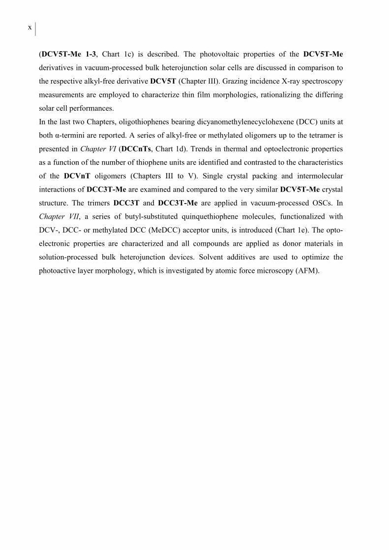
The first three publications describe dicyanovinyl (DCV)-substituted oligothiophenes. In
Chapter III, alkyl-free terminally DCV-capped oligothiophenes (DCVnTs, Chart 1a) up to the
sexithiophene (n = 6) are presented. Optical, electrochemical, and thermal properties of all
compounds are discussed in detail, identifying the longer homologues DCV4T to DCV6T as
suitable candidates for use as donor materials in organic solar cells in combination with C60
fullerene as the acceptor material. The optoelectronic properties of these three compounds are
then related to their photovoltaic properties in vacuum-processed planar heterojunction devices.
DCV5T is additionally tested in bulk heterojunction solar cells. In the following two Chapters,
the influence of alkyl substituents in DCV-capped quarter- and quinquethiophenes is
investigated with a focus on crystal structures and morphological properties. In Chapter IV,
thermal, optoelectronic, and photovoltaic properties of methyl- and ethyl-substituted tetramers
DCV4T-Me and DCV4T-Et (Chart 1b) are compared to alkyl-free parent derivative DCV4T
introduced in the previous chapter. Differences in single crystal packing are analyzed
extensively and correlated to the photovoltaic performance of the three compounds in bulk
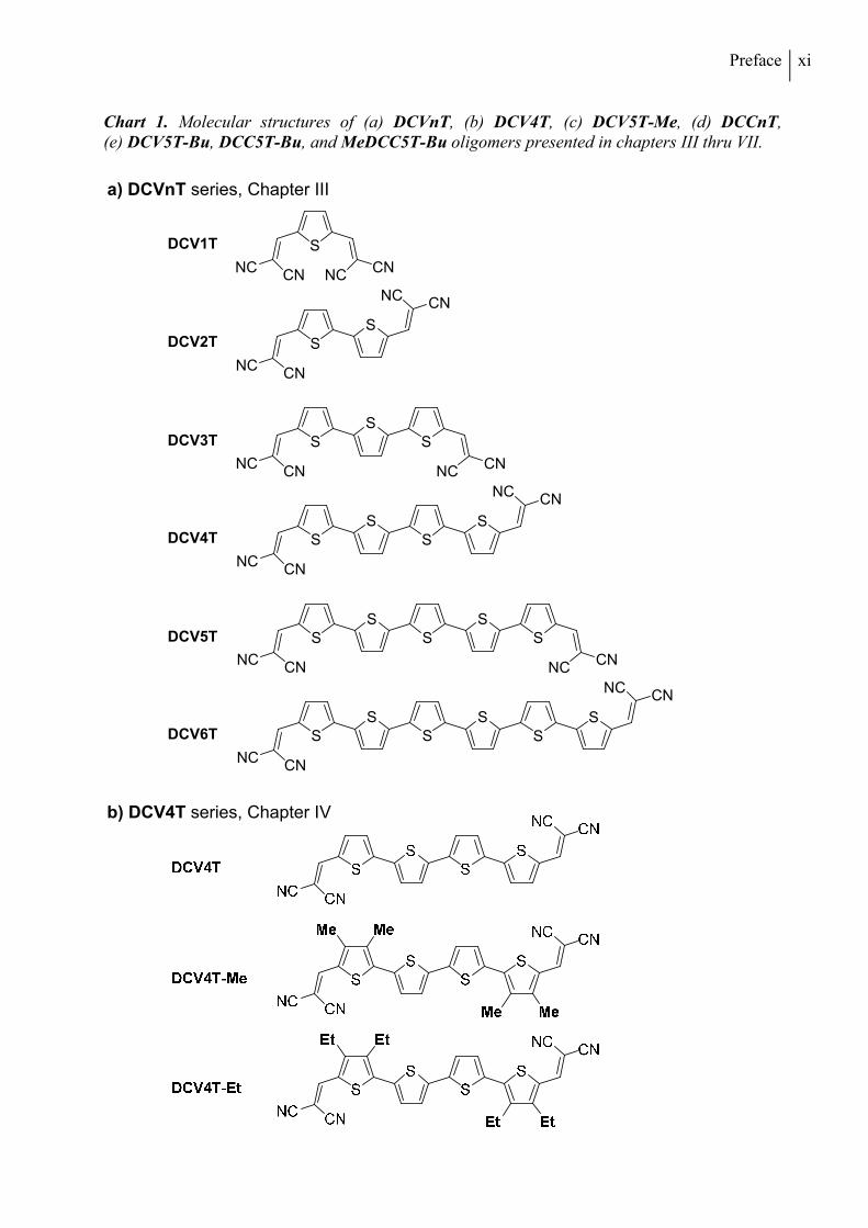
heterojunction solar cells made by vacuum-processing. In Chapter V, a series of three
methylated DCV-substituted quinquethiophenes with varied alkyl-substitution patterns
x
(DCV5T-Me 1-3, Chart 1c) is described. The photovoltaic properties of the DCV5T-Me
derivatives in vacuum-processed bulk heterojunction solar cells are discussed in comparison to
the respective alkyl-free derivative DCV5T (Chapter III). Grazing incidence X-ray spectroscopy
measurements are employed to characterize thin film morphologies, rationalizing the differing
solar cell performances.
In the last two Chapters, oligothiophenes bearing dicyanomethylenecyclohexene (DCC) units at
both α-termini are reported. A series of alkyl-free or methylated oligomers up to the tetramer is
presented in Chapter VI (DCCnTs, Chart 1d). Trends in thermal and optoelectronic properties
as a function of the number of thiophene units are identified and contrasted to the characteristics
of the DCVnT oligomers (Chapters III to V). Single crystal packing and intermolecular
interactions of DCC3T-Me are examined and compared to the very similar DCV5T-Me crystal
structure. The trimers DCC3T and DCC3T-Me are applied in vacuum-processed OSCs. In
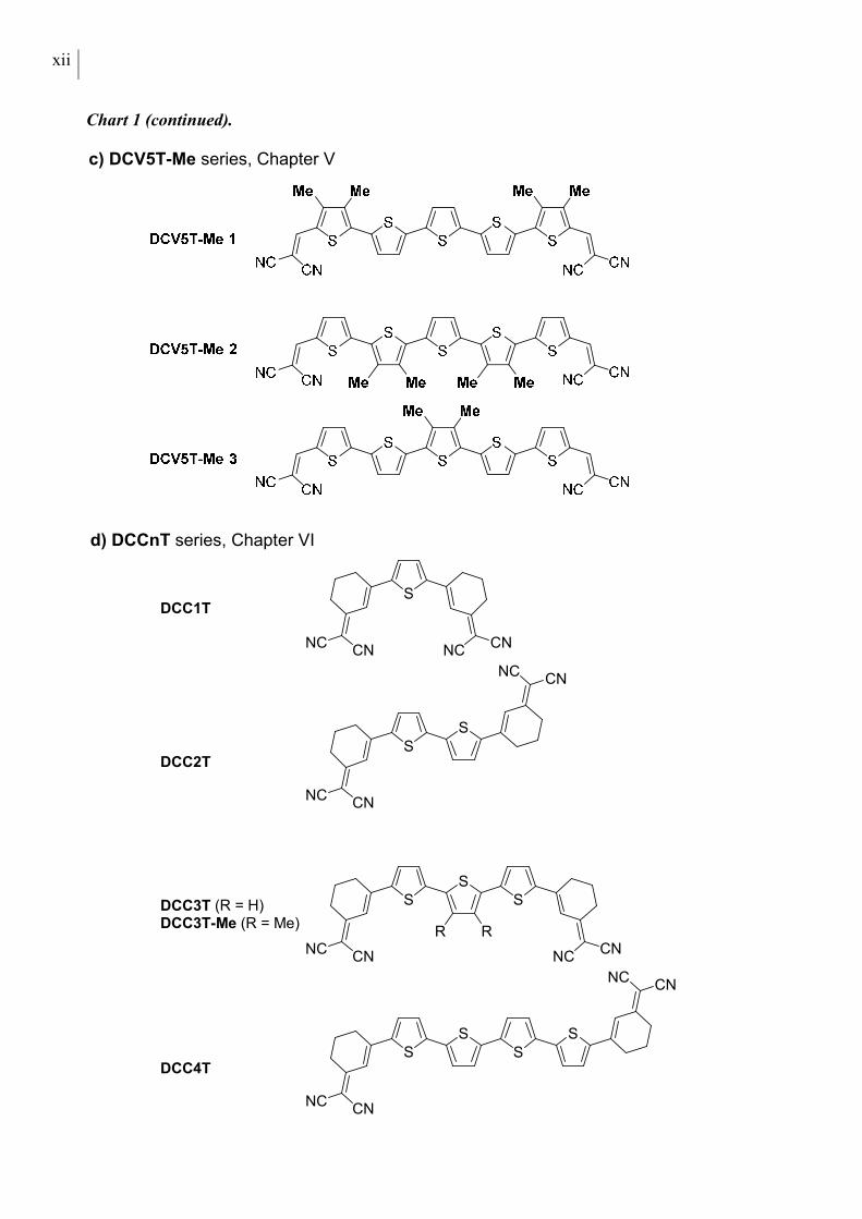
Chapter VII, a series of butyl-substituted quinquethiophene molecules, functionalized with
DCV-, DCC- or methylated DCC (MeDCC) acceptor units, is introduced (Chart 1e). The opto-
electronic properties are characterized and all compounds are applied as donor materials in
solution-processed bulk heterojunction devices. Solvent additives are used to optimize the
photoactive layer morphology, which is investigated by atomic force microscopy (AFM).
Preface xi
Chart 1. Molecular structures of (a) DCVnT, (b) DCV4T, (c) DCV5T-Me, (d) DCCnT, (e) DCV5T-Bu, DCC5T-Bu, and MeDCC5T-Bu oligomers presented in chapters III thru VII.
S
NCCN
DCV1T
SS
NCCN
DCV2T
SSS
NCCN
CNNC
DCV3T
SSS
CNNC
DCV4T
SSS
CNNC
DCV5T
SSS
CNNC
DCV6T
CNNC
CNNC
S
NCCN
SS
NCCN
SS
S
NCCN
a) DCVnT series, Chapter III
b) DCV4T series, Chapter IV
xii
Chart 1 (continued).
S
NCCN
CNNC
S
NCCN
S
NCCN
DCC1T
DCC2T
S
CNNC
S
DCC3T (R = H)DCC3T-Me (R = Me)
S
NCCN
RR
S
NCCN
SS
S
CNNC
DCC4T
c) DCV5T-Me series, Chapter V
d) DCCnT series, Chapter VI
Preface xiii
Chart 1 (continued).
e) Chapter VII

xiv
1
CHAPTER I
INTRODUCTION
1. SOLAR ENERGY
Solar radiation represents by far the largest source of renewable energy exceeding the global
energy demand by several thousand times.[1] Direct conversion of the radiative energy of
sunlight into electricity may be accomplished using photovoltaic devices also referred to as solar
cells. The photovoltaic effect was first observed by A. E. Becquerel in 1839, when he detected a
current flow between illuminated and dark platinum electrodes placed in an electrolyte bath.[2]
The first solid state solar cell device, demonstrated by Fritts in 1883, consisted of a thin layer of
selenium sandwiched between different work-function metal electrodes and showed a power
conversion efficiency (PCE) of about 1%.[3] In 1905, Einstein published a comprehensive
theoretical description of the photoelectric effect, for which he received the Noble price in
physics in 1921.[4]
The great variety of modern photovoltaic technologies is usually categorized into three groups
corresponding to three generations of solar cells. In 1953, Chapin, Fuller and Pearson at Bell
laboratories reported the first photocell incorporating a silicon p-n junction with an efficiency of
6%.[5] Based on this finding, first generation silicon wafer-based solar cells have been
continuously enhanced over the last decades reaching PCE values of 25% for laboratory devices
and 16-21% in commercial panels.[6,7] Despite the energy intensive production process of highly
pure electronic grade crystalline silicon, first generation photovoltaic solar cells are dominating
today’s commercial market. Second-generation thin film technologies incorporate very thin
layers of semiconductor materials like amorphous silicon, cadmium telluride (CdTe), or copper
indium gallium diselenide (CIGS). Lower material consumption and less costly manufacturing
processes lead to reduced production costs for thin-film devices compared to first generation
crystalline silicon technology. CIGS and CdTe solar cells reach record laboratory efficiencies of
about 20% and up to 15% in commercial products.[7] The greatest challenges for second
generation concepts are the still relatively high energy costs in the production and the usage of
limited and toxic elements. Third generation photovoltaics covers more recent developments
including organic-inorganic hybrid technologies like dye-sensitized solar cells or methyl-
2 Chapter I
ammonium lead halide-based perovskite devices as well as organic donor/acceptor (D/A)
heterojunction solar cells. These approaches offer the potential for a clean and inexpensive
large-scale production using continuous roll-to-roll coating processes onto flexible substrates.
Special features such as transparency, light weight, and flexibility may be implemented into
commercial products opening new application areas such as the integration into building
façades, cars, or low weight structures. Third generation photovoltaic technologies are on the
verge of commercialization, reaching laboratory performance levels of approximately 12% for
dye-sensitized and organic solar cells.[8,9] Maximum PCE values of perovskite-based devices
have increased at an unprecedented rate over the recent years to a current record value of about
20%.[6]
2. BASIC MATERIALS AND WORKING PRINCIPLE OF ORGANIC SOLAR
CELLS
The first organic solar cell devices were based on a single layer of one molecular p-type material
sandwiched between metal or conducting glass electrodes of different work functions.[10-12]
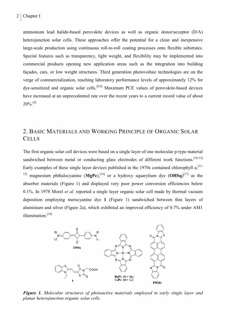
Early examples of these single layer devices published in the 1970s contained chlorophyll a,[13-
15] magnesium phthalocyanine (MgPc),[16] or a hydroxy squarylium dye (OHSq)[17] as the
absorber materials (Figure 1) and displayed very poor power conversion efficiencies below
0.1%. In 1978 Morel et al. reported a single layer organic solar cell made by thermal vacuum
deposition employing merocyanine dye 1 (Figure 1) sandwiched between thin layers of
aluminium and silver (Figure 2a), which exhibited an improved efficiency of 0.7% under AM1
illumination.[18]
Figure 1. Molecular structures of photoactive materials employed in early single layer and planar heterojunction organic solar cells.
Organic Solar Cells 3
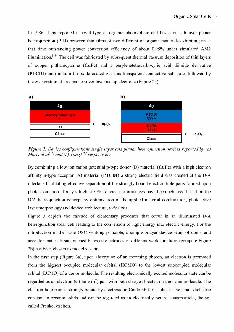
In 1986, Tang reported a novel type of organic photovoltaic cell based on a bilayer planar
heterojunction (PHJ) between thin films of two different of organic materials exhibiting an at
that time outstanding power conversion efficiency of about 0.95% under simulated AM2
illumination.[19] The cell was fabricated by subsequent thermal vacuum deposition of thin layers
of copper phthalocyanine (CuPc) and a perylenetetracarboxylic acid diimide derivative
(PTCDI) onto indium tin oxide coated glass as transparent conductive substrate, followed by
the evaporation of an opaque silver layer as top electrode (Figure 2b).
Figure 2. Device configurations single layer and planar heterojunction devices reported by (a) Morel et al[18] and (b) Tang,[19] respectively.
By combining a low ionization potential p-type donor (D) material (CuPc) with a high electron
affinity n-type acceptor (A) material (PTCDI) a strong electric field was created at the D/A
interface facilitating effective separation of the strongly bound electron-hole-pairs formed upon
photo-excitation. Today’s highest OSC device performances have been achieved based on the
D/A hetreojunction concept by optimization of the applied material combination, photoactive
layer morphology and device architecture, vide infra.
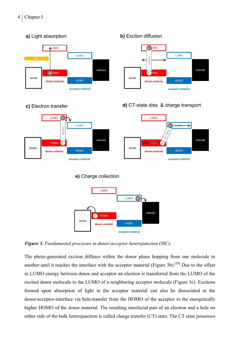
Figure 3 depicts the cascade of elementary processes that occur in an illuminated D/A
heterojunction solar cell leading to the conversion of light energy into electric energy. For the
introduction of the basic OSC working principle, a simple bilayer device setup of donor and
acceptor materials sandwiched between electrodes of different work functions (compare Figure
2b) has been chosen as model system.
In the first step (Figure 3a), upon absorption of an incoming photon, an electron is promoted
from the highest occupied molecular orbital (HOMO) to the lowest unoccupied molecular
orbital (LUMO) of a donor molecule. The resulting electronically excited molecular state can be
regarded as an electron (e-)-hole (h+) pair with both charges located on the same molecule. The
electron-hole pair is strongly bound by electrostatic Coulomb forces due to the small dielectric
constant in organic solids and can be regarded as an electrically neutral quasiparticle, the so-
called Frenkel exciton.
a) b)
4 Chapter I
Figure 3. Fundamental processes in donor/acceptor heterojunction OSCs.
The photo-generated exciton diffuses within the donor phase hopping from one molecule to
another until it reaches the interface with the acceptor material (Figure 3b).[20] Due to the offset
in LUMO energy between donor and acceptor an electron is transferred from the LUMO of the
excited donor molecule to the LUMO of a neighboring acceptor molecule (Figure 3c). Excitons
formed upon absorption of light in the acceptor material can also be dissociated at the
donor/acceptor-interface via hole-transfer from the HOMO of the acceptor to the energetically
higher HOMO of the donor material. The resulting interfacial pair of an electron and a hole on
either side of the bulk heterojunction is called charge transfer (CT) state. The CT state possesses
a) Light absorption b) Exciton diffusion
c) Electron transfer d) CT-state diss. & charge transport
e) Charge collection
Organic Solar Cells 5
only a small Coulomb binding energy due to the spatial separation of the charges on two
different molecules. The CT-state dissociates into free charge carriers in the next step (Figure
3d). The nature of the driving force for this process is still not completely clear. The discussed
explanations are ionization by the internal electric field,[21] thermal,[22] or assisted thermal
ionization.[23] The free charge carriers are subsequently transported away from the D/A interface
along the in-build potential of the solar cell to the electrodes. In the last step, the positive and
negative charge carriers are finally collected at the respective electrodes (Figure 3e).
3. DEVICE ARCHITECTURE AND FABRICATION
3.1 PHOTOACTIVE LAYER
As the formation of free charge carriers occurs at the interface between donor and acceptor, the
way how both material phases are arranged in the photoactive zone of the device is of crucial
importance for the functioning and the performance of an organic solar cell.
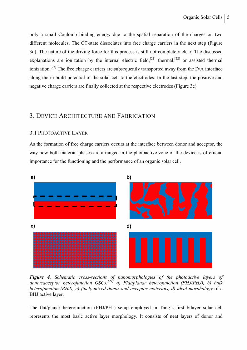
Figure 4. Schematic cross-sections of nanomorphologies of the photoactive layers of donor/acceptor heterojunction OSCs:[24] a) Flat/planar heterojunction (FHJ/PHJ), b) bulk heterojunction (BHJ), c) finely mixed donor and acceptor materials, d) ideal morphology of a BHJ active layer.
The flat/planar heterojunction (FHJ/PHJ) setup employed in Tang’s first bilayer solar cell
represents the most basic active layer morphology. It consists of neat layers of donor and
a) b)
c) d)
6 Chapter I
acceptor material stacked on top of each other forming a planar interface (Figure 4a). Using
vacuum-processing, the PHJ layout is efficiently realized by subsequent vacuum-deposition of
both photoactive compounds in separate thin layers. The fabrication of PHJ morphologies by
solution-processing is limited to orthogonally soluble material combinations to avoid the
destruction of the first neat layer during the coating of the second layer.[24]
Whereas the PHJ setup guarantees efficient charge carrier transport, its performance is usually
limited by incomplete charge generation caused by the typically short exciton diffusion length
LD in organic materials of about 5-10 nm.[25] Excitons created upon photo-excitation in the bulk
material further away from the D/A interface than LD are not separated into free charge carriers
and decay without contributing to the photo-current. Thus, the effective photoactive area where
the absorption of incident photons contributes to the photocurrent is limited to a thin zone close
to the D/A interface (dashed box in Figure 4a). Although organic absorber materials show very
high extinction coefficients, a donor layer thickness in the range of the exciton diffusion length
is usually not enough to absorb all incoming photons.
To circumvent the drawbacks of the PHJ setup with respect to insufficient charge carrier
generation, the bulk heterojunction (BHJ) active layer architecture has been introduced (Figure
4b).[26] The highest power conversion efficiencies reported today for organic solar cells are
achieved using this active layer design. In the BHJ setup, the planar bilayer junction is replaced
by a phase-separated blend layer of donor and acceptor materials significantly enlarging the
donor/acceptor interface compared to the PHJ design. The theoretically ideal bulk
heterojunction morphology depicted in Figure 4d is a bi-continuous interpenetrating network of
donor- and acceptor-phases, which are twice the exciton diffusion length in diameter.[27] This
arrangement is a compromise between a maximized interfacial area, corresponding to a finely
mixed D/A blend (Figure 4c) and the bilayer PHJ design, which offers optimal perculation
pathways for the transport of the generated charge carriers. The ideal BHJ morphology is very
hard to prepare and in general not achieved. Figure 4b shows a sketch of the cross-section of a
typical BHJ layer in a real device.
Using solution-processing, D/A blend films are usually fabricated by spin-coating of solutions
containing both, donor, and acceptor materials. The resulting blend morphology may be
beneficially influenced by the proper selection of the solvent, the use of solvent additives or
post-deposition thermal treatment as well as solvent vapor annealing.[25] The preparation of BHJ
layers is also possible for vacuum-processed molecular materials by simultaneous co-
evaporation of both photoactive components. Here, the choice of substrate temperature during
the deposition is crucial for the morphology and crystallinity of the bulk heterojunction layer.
Organic Solar Cells 7
3.2 DEVICE STACK
Organic solar cells are usually prepared by subsequent deposition of the different layers onto
substrates pre-coated with a transparent conductive electrode material. Owing to its outstanding
properties with respect to transparency and conductivity, indium tin oxide (ITO) sputtered on
glass substrates is commonly used as bottom electrode. Materials like silver nano wires,[28]
carbon nano tubes,[29] or graphene[30] are investigated as possible alternatives, as the high price
and low abundance of indium might become a limiting factor for the large scale production of
ITO-based organic solar cells.
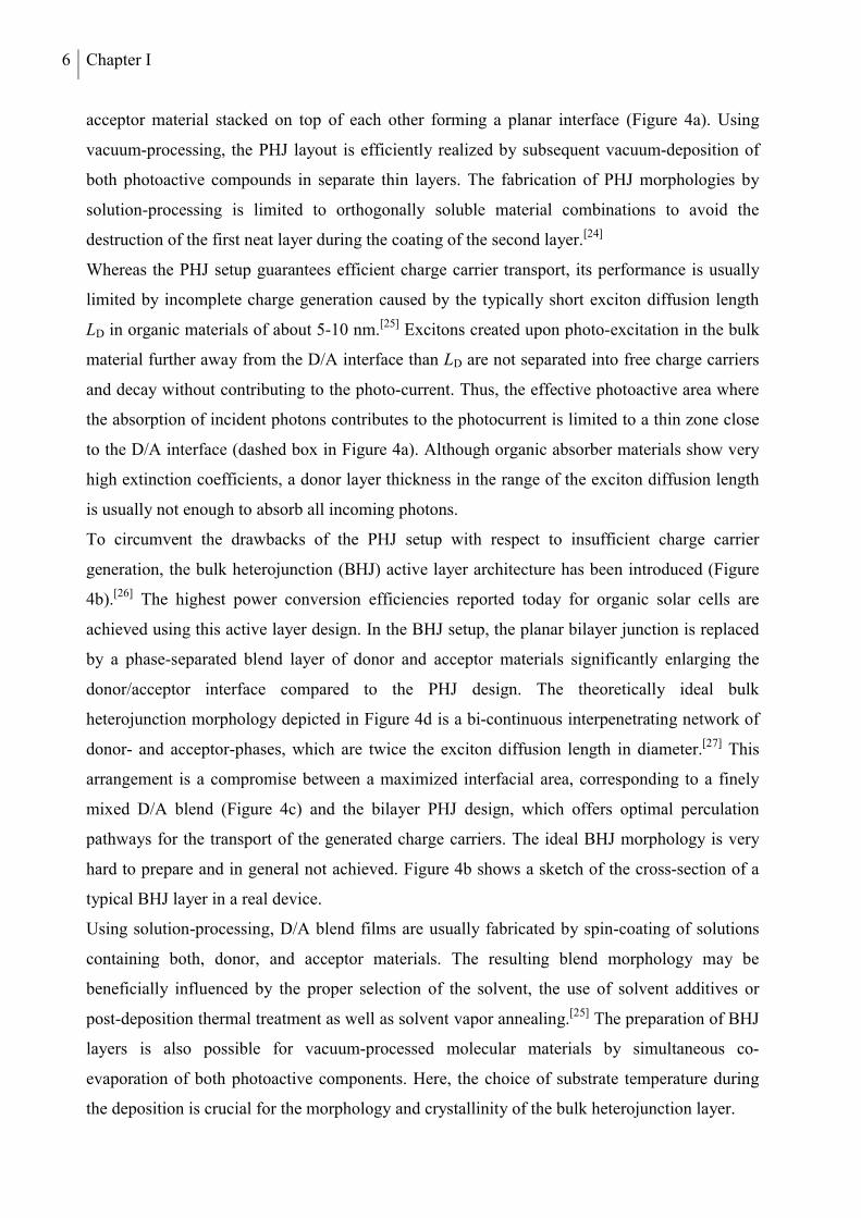
Figure 5. Schematic representation of the layer structure of bulk heterojunction solar cells with (a) standard and (b) inverted device design;[24] (c) p-i-n and (d) m-i-p configuration.
Figures 5a and b depict the layer structure of the typical device architecture used for organic
solar cells with the photoactive layer sandwiched between a hole transport layer (HTL) and an
a) b)
c) d)
8 Chapter I
electron transport layer (ETL). In the standard configuration (Figure 5a), the HTL is deposited
onto the transparent electrode and the electrons are injected from the ETL into the low work
function metal top electrode, which acts as the cathode. In the inverted design (Figure 5b), the
HTL is deposited on top of the active layer and a high work function metal is used for the top
electrode (anode). This improves the device stability under ambient conditions. Using solution-
processing, the transport layers are typically fabricated by spin-coating of aqueous dispersions.
For the HTLs, poly(3,4-ethylenedioxythiophene) (PEDOT) blended with poly(styrenesulfonate)
(PSS) (Chapter VII) as p-dopant or transition metal oxides like MoO3 or V2O5 are frequently
used.[31] The optional electron transport layers are usually made from aqueous solutions of ZnO
or TiO2 nanoparticles.[32] For the coating of the photoactive blend layers organic solvent systems
are employed. Using vacuum-processing, doped transport layers may be fabricated by co-
evaporation of hole or electron transport materials together with molecular dopants.[33] Solar
cells incorporating an undoped intrinsic photoactive layer sandwiched between p- and n-doped
transport layers (p-i-n configuration, Figure 5c) may be prepared by this technique. Due to the
high conductivity of the doped transport layers their thicknesses may be varied over a large
range in order to put the photoactive layer into the interference maximum of the incoming light
optimizing the device performance (Chapter V).[34,35] In a simplified design, the p-doped ETL is
omitted and the intrinsic layer is directly deposited onto the conductive metal (m) oxide (m-i-p
configuration, Figure 5d). This is possible due to the already good conductivity of the fullerene
acceptor material.
4. PHOTOVOLTAIC PERFORMANCE CHARACTERISTICS
The precise characterization of the photovoltaic device performance is of fundamental
importance as it provides the basis for the evaluation of the employed donor/acceptor material
combination. Standard test conditions have been established to guarantee the comparability of
the results obtained for different device setups in different laboratories.[36,37] For the
determination of current-voltage characteristics, the Air Mass 1.5 Global (AM 1.5) light
spectrum is used to illuminate the solar cells devices during the measurement. In radiation
intensity (100 mW cm-2) and spectral composition, the AM 1.5 spectrum corresponds to sun
light at a zenith angle of 48.2°. This is equivalent to the yearly average of solar radiation in
temperate climate zones, where most of the world’s population is located. The standard
measuring temperature is 25 °C.
Organic Solar Cells 9
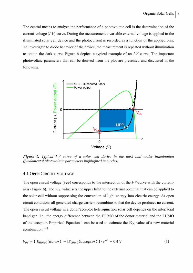
The central means to analyze the performance of a photovoltaic cell is the determination of the
current-voltage (I-V) curve. During the measurement a variable external voltage is applied to the
illuminated solar cell device and the photocurrent is recorded as a function of the applied bias.
To investigate to diode behavior of the device, the measurement is repeated without illumination
to obtain the dark curve. Figure 6 depicts a typical example of an I-V curve. The important
photovoltaic parameters that can be derived from the plot are presented and discussed in the
following.
Figure 6. Typical I-V curve of a solar cell device in the dark and under illumination (fundamental photovoltaic parameters highlighted in circles).
4.1 OPEN CIRCUIT VOLTAGE
The open circuit voltage (VOC) corresponds to the intersection of the I-V-curve with the current-
axis (Figure 6). The VOC value sets the upper limit to the external potential that can be applied to
the solar cell without suppressing the conversion of light energy into electric energy. At open
circuit conditions all generated charge carriers recombine so that the device produces no current.
The open circuit voltage in a donor/acceptor heterojunction solar cell depends on the interfacial
band gap, i.e., the energy difference between the HOMO of the donor material and the LUMO
of the acceptor. Empirical Equation 1 can be used to estimate the VOC value of a new material
combination.[38]
≈ |()| − |()| ∙ − 0.4 V (1)
10 Chapter I
4.2 SHORT CIRCUIT CURRENT
The short circuit current (ISC) is the intersection of the I-V-curve with the voltage-axis (Figure
6). It represents the photocurrent generated by the solar cell at short-circuit conditions with no
external voltage applied. The short circuit current density (JSC) is calculated by dividing the
short circuit current by the active device area (Equation 2). As it is independent of the size of the
solar cell, the JSC value is generally used in literature facilitating the comparison of different
devices.
=
(2)
4.3 FILL FACTOR
The fill factor (FF) is defined as the ratio between the maximum power output of a solar cell and
the theoretical power output calculated as the product of ISC and VOC (Equation 3). The device
generates maximum power at the maximum power point (MPP, Figure 6), where the product of
current and voltage reaches its largest value. Graphically, the fill factor corresponds to the area
ratio of the blue rectangles depicted in Figure 6. The FF provides a measure for the quality of
the solar cell device with respect to charge transport and charge carrier collection. The best
devices in literature show FF values in the range of 0.7-0.75.
= ∙
∙ (3)
4.4 POWER CONVERSION EFFICIENCY
The power conversion efficiency (PCE, η) is defined as the ratio between the electric power
output of a solar cell at the maximum power point and the power input of the incident light
given by the AM 1.5 spectrum. As the central characteristic of a device, it represents a measure
for its ability to convert the energy of solar light into electrical energy. According to Equation 4,
the PCE is proportional to the open circuit voltage, short circuit current, and fill factor, which
means that all three values need to be maximized at the same time in order to optimize the
overall device performance.
=
=
∙
=
∙ ∙
(4)
Organic Solar Cells 11
4.5 EXTERNAL QUANTUM EFFICIENCY
The external quantum efficiency (EQE), also denoted as incident photon to current efficiency
(IPCE), is defined as the ratio between the number of charge carrier pairs generated by the
device and the number of incoming photons at a certain wavelength (Equation 5). Usually, the
EQE is determined at short circuit conditions and plotted versus the wavelength in the form of a
spectrum.
() = ()
()
(5)
As the injection of charge carriers into the electrodes is the final result of the linear chain of
elementary processes, which occur in an illuminated D/A heterojunction solar cell (Chapter I.2),
the EQE represents a measure for the combined efficiency of all these steps. According to
Equation 6, it can be regarded as the product of the efficiencies of light absorption ηAbs, exciton
diffusion ηDiff, charge carrier dissociation ηDiss, charge transport ηTrans, and collection ηCC.[39]
() = () ∙ ∙ ∙ ∙ (6)
5. MATERIAL REQUIREMENTS
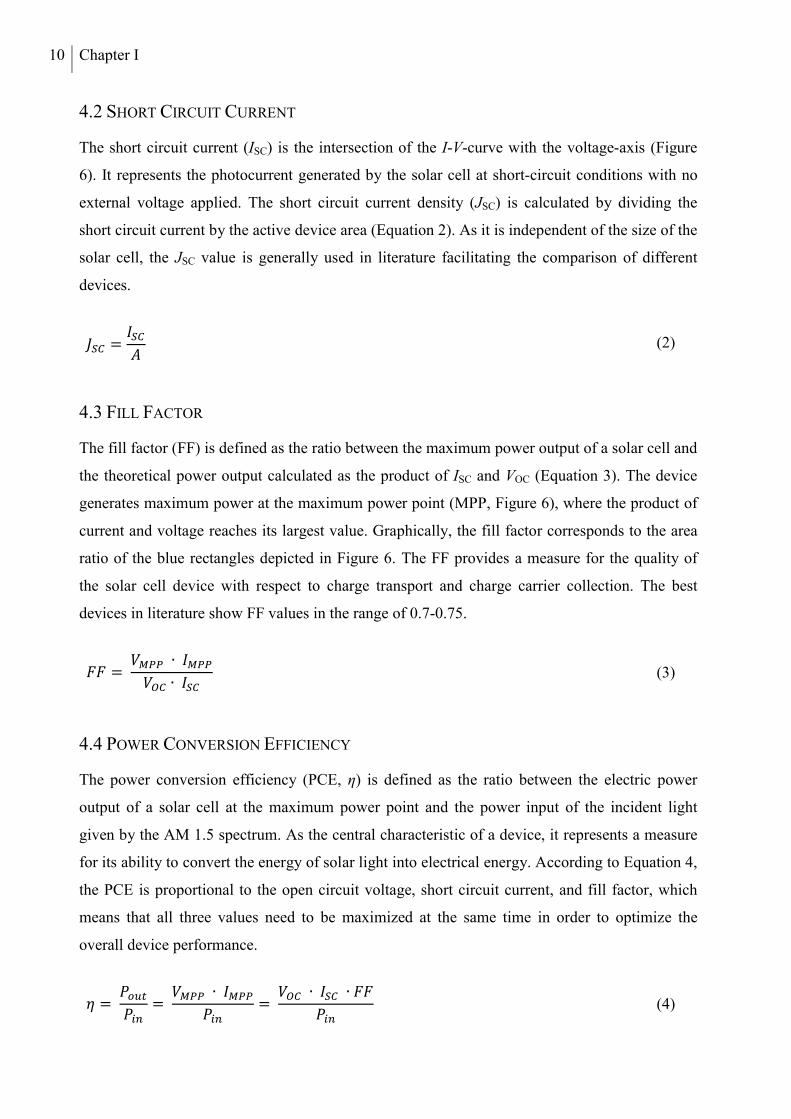
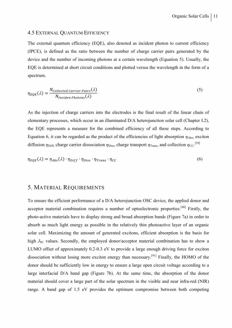
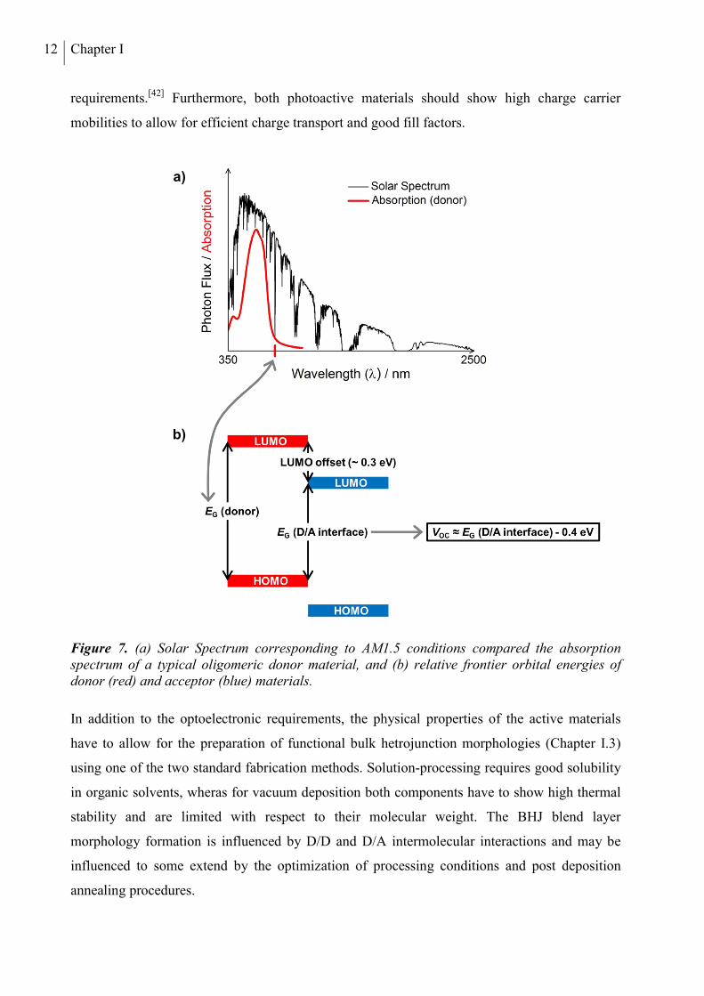
To ensure the efficient performance of a D/A heterojunction OSC device, the applied donor and
acceptor material combination requires a number of optoelectronic properties.[40] Firstly, the
photo-active materials have to display strong and broad absorption bands (Figure 7a) in order to
absorb as much light energy as possible in the relatively thin photoactive layer of an organic
solar cell. Maximizing the amount of generated excitons, efficient absorption is the basis for
high JSC values. Secondly, the employed donor/acceptor material combination has to show a
LUMO offset of approximately 0.2-0.3 eV to provide a large enough driving force for exciton
dissociation without losing more exciton energy than necessary.[41] Finally, the HOMO of the
donor should be sufficiently low in energy to ensure a large open circuit voltage according to a
large interfacial D/A band gap (Figure 7b). At the same time, the absorption of the donor
material should cover a large part of the solar spectrum in the visible and near infra-red (NIR)
range. A band gap of 1.5 eV provides the optimum compromise between both competing
12 Chapter I
requirements.[42] Furthermore, both photoactive materials should show high charge carrier
mobilities to allow for efficient charge transport and good fill factors.
Figure 7. (a) Solar Spectrum corresponding to AM1.5 conditions compared the absorption spectrum of a typical oligomeric donor material, and (b) relative frontier orbital energies of donor (red) and acceptor (blue) materials.
In addition to the optoelectronic requirements, the physical properties of the active materials
have to allow for the preparation of functional bulk hetrojunction morphologies (Chapter I.3)
using one of the two standard fabrication methods. Solution-processing requires good solubility
in organic solvents, wheras for vacuum deposition both components have to show high thermal
stability and are limited with respect to their molecular weight. The BHJ blend layer
morphology formation is influenced by D/D and D/A intermolecular interactions and may be
influenced to some extend by the optimization of processing conditions and post deposition
annealing procedures.
a)
b)
Organic Solar Cells 13
6. APPLIED MATERIALS
OSC devices may be categorized with respect to the applied material system and fabrication
method. Two classes of donor materials are typically applied as photoactive material in organic
solar cells: π-conjugated polymers and π-conjugated molecular materials. While polymers can
only be processed from solution, the structure of molecularly defined materials may be
optimized for solution- or vacuum-processing. Due to their outstanding n-type charge transport
properties, fullerenes C60 or C70 as well as soluble derivatives [6,6]-phenyl-C61-butyric acid
methyl ester (PC61BM)[26] or [6,6]-phenyl-C71-butyric acid methyl ester (PC71BM)[43] are by far
the most commonly used electron acceptor materials.
6.1 POLYMERIC DONOR MATERIALS
Among the large variety of π-conjugated polymers applied in organic solar cells, poly(3-
alkylthiophenes) (P3AT) are a prominent and extensively investigated class of materials.
Regioregular poly(3-hexylthiophene) (P3HT, Figure 8) is the most commonly used derivative,
as it combines the advantages of good solubility induced by the hexyl substituents and a high
charge carrier mobility. The material is efficiently synthesized via Grignard metathesis
polymerization of 2,5-dibromo-3-hexylthiophene, developed by McCullough et al. in 1999.[44]
This method provides great side-chain regioregularity and high molecular weight. Both
parameters are of crucial importance for the charge transport properties of the material.[45,46] By
optimization of the acceptor material and morphological modifications, the highest power
conversion efficiencies, reported for P3HT-based bulk heterojunction solar cells, have been
increased over the last decade from 4-5%[47] to values over 7%.[48,49]
Inspite of these great results, the frontier energy levels of P3HT are not optimal. Due to the
relatively high HOMO level of P3HT, solar cells made from it in combination with the
commonly used fullerene acceptors exhibit rather low open circuit voltages. The polymer has a
quite large band gap of about 1.9 eV, which results in an absorption onset at about 650 nm in
thin films. Thus, a large part of the solar spectrum in the red and NIR region is not absorbed and
cannot contribute to the photo-current. To circumvent these problems, research has focused on
donor-acceptor π-conjugated polymers over the recent years. Due to inter-chain charge transfer
from electron-rich (donor) to electron-poor (acceptor) repeating units in the conjugated chain,
these low band gap polymers show strong absorption in the red and NIR region.[50] A selection
of successfully applied polymer donor materials containing the most important building blocks
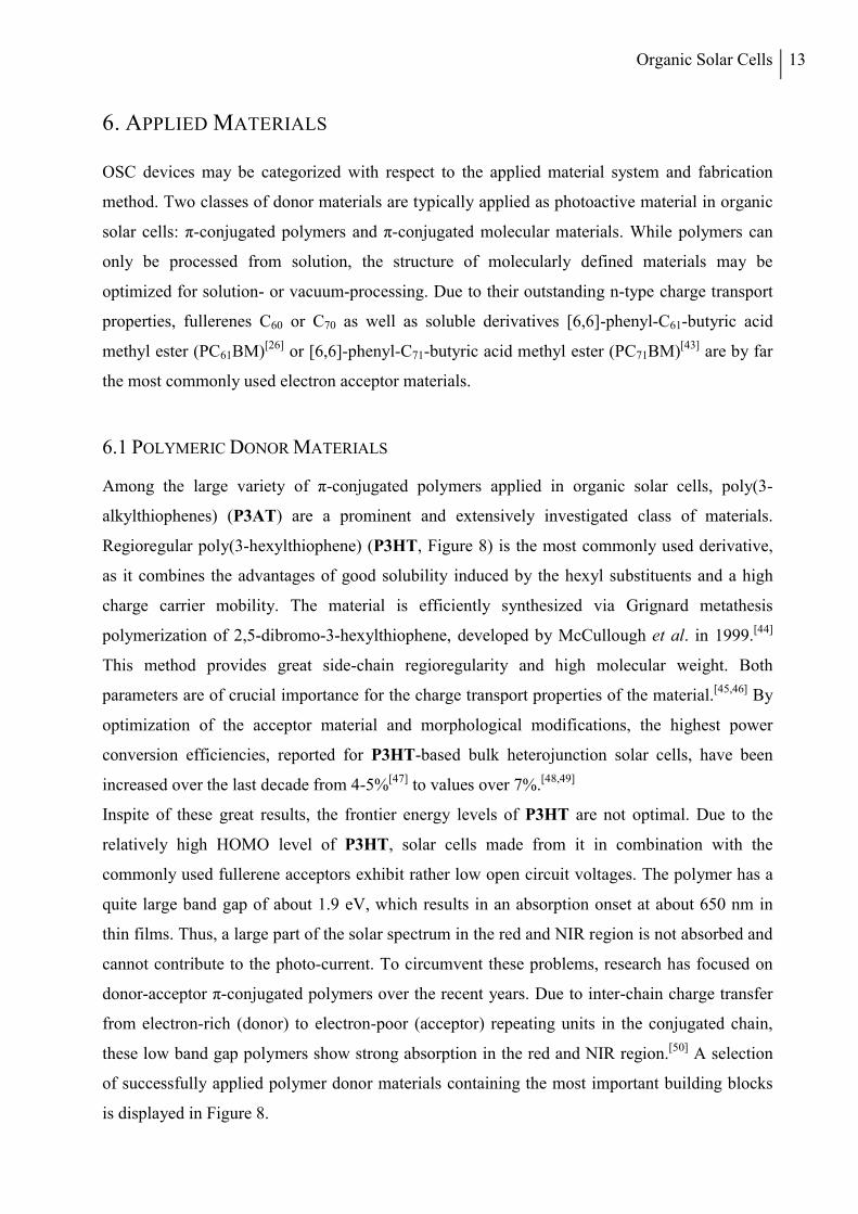
is displayed in Figure 8.
14 Chapter I
Figure 8. Molecular structures of high performance polymeric donor materials.
In 2007, Leclerc et al. reported an efficiency of 3.6% for a D-A-co-polymer containig carbazole
and benzothiadiazole units (PCDTBT)[51] which could be improved to 6.1% by introduction of a
solution-processed titanium oxide electron transport layer to the stack of a BHJ device with
PC71BM as acceotor.[52] In 2009, Janssen et al. presented the low band gap polymer PDPP3T
combining diketopyrrolopyrrole with terthiophene units which showed photo-response up to 930
nm.[53] By increasing the molecular weight of the polymer and due to optimization of the
PDPP3T:PC71BM BHJ morphology, the initial PCE value of 4.7% could be improved to
6.7%.[54] In 2010, Frechet et al. published a series of N-alkylthieno[3,4-c]pyrrole-4,6-dione
(TPD)-based polmers PBDT-TPD with variation of the alkyl-substituents on the TPD unit.[55]
The octyl-substituted polymer yielded the highest efficiencies of up to 6.8% in BHJ devices
with PC61BM due to an enhaced crystallinity of the donor phase determined by grazing inciden
X-ray scattering (GIXRD). Recently, power conversion efficiencies over 7% have been realized
using highly sophisticated polymeric donor materials using PC71BM as acceptor. In 2010, Yu et
al. reported a PCE of 7.4% for co-polymer PTB7, combining benzo[1,2-b:4,5-b’]dithiophene
units with fluorinated thieno[3,4-b]thiophene, which stabilizes the quinoid structure, thus
reducing the bandgap.[56] In 2012, an impressive efficiency of 9.2% was achieved by Cao et al.
Organic Solar Cells 15
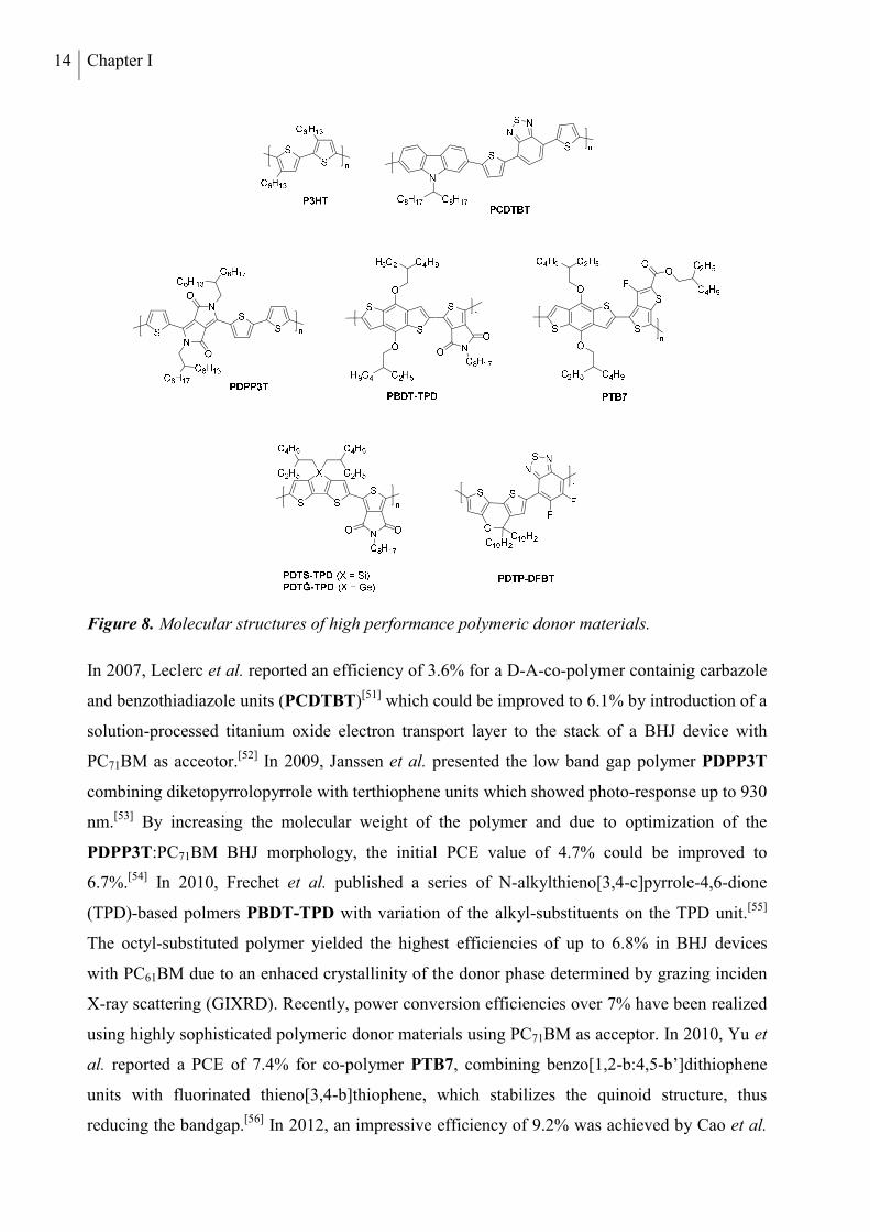
applying the PTB7 donor material in an inverted device structure.[57] Reynolds et al. prepared
two conjugated polymers by polycondensation of thieno-pyrrolodione with dithienogermole or
dithienosilole and obtained an enhanced PCE value of 7.3% for germanium-containing PDTG-
TPD compared to 6.6% for PDTS-TPD.[58] Yang et. al. reported an efficiency of 8.0% for
regiorandom D-A-polymer PDTP-DFBT, prepared by polymerization of electron-rich 5H-
dithieno[3,2-b:2’,3’-d]pyran with the strongly electron-deficient difluorobenzothiadiazole
unit.[59] A certified PCE value of 10.6% was obtained, when PDTP-DFBT was incorporated
with PC61BM in a tandem solar cell setup using P3HT and indene-C60 bisadduct ICBA in the
second subcell.[60]
6.2 MOLECULAR DONOR MATERIALS FOR SOLUTION-PROCESSING
Early examples of solution-processed bulk heterojunction devices using so-called small
molecules did not exceed performance levels of 3% limited by poor fill factors or low
photocurrents.[61] In 2009, a report of Nguyen et al. created great attention presenting a power
conversion efficiency of 4.4% obtained for a solution-processed BHJ solar cell using D-A-D
type benzofuran-substituted thienyl-diketopyrrolopyrrole DPP(TBFu)2 (Figure 9) as donor in
combination with PC71BM as acceptor material.[62] The publication showed, that the morpholo-
gy of the photoactive blend layer and thus the device performance is highly sensitive to the do-
nor/acceptor ratio and post-deposition thermal treatment. It was found, that the as-cast blend
layers were very smooth and showed very little phase separation, which led to poor device
performances. Thermal annealing at 110 °C lead to favorable blend layer morphology, boosting
the short circuit current density from 1.5 to 10.0 mA/cm2 and improving the fill factor from 24
to 48% for the optimized D/A blend ratio.
Figure 9. Molecular structures of oligomeric donor materials for solution-processing.
In 2011, Forrest et al. reported a power conversion efficiency of 5.2% applying squaraine SQ
(Figure 9) in a BHJ device with PC71BM.[63] The squaraine dye was used in a very dilute D:A
16 Chapter I
mixture of 6:1 to account for the very limited exciton diffusion length and large extinction
coefficient of the donor material. Nakamura et al. published a PCE value of 5.2% for a BHJ
solar cell containing tetrabenzoporphyrin BP (Figure 9) as donor and bis(dimethyl-
phenylsilylmethyl)[60]fullerenes (SIMEF).[64] The active layer was processed by spin-coating of
a solution containing soluble precursor derivative tetraethanotetrabenzoporphyrin and was
subsequently converted into the desired insoluble BP donor material by thermal treatment.
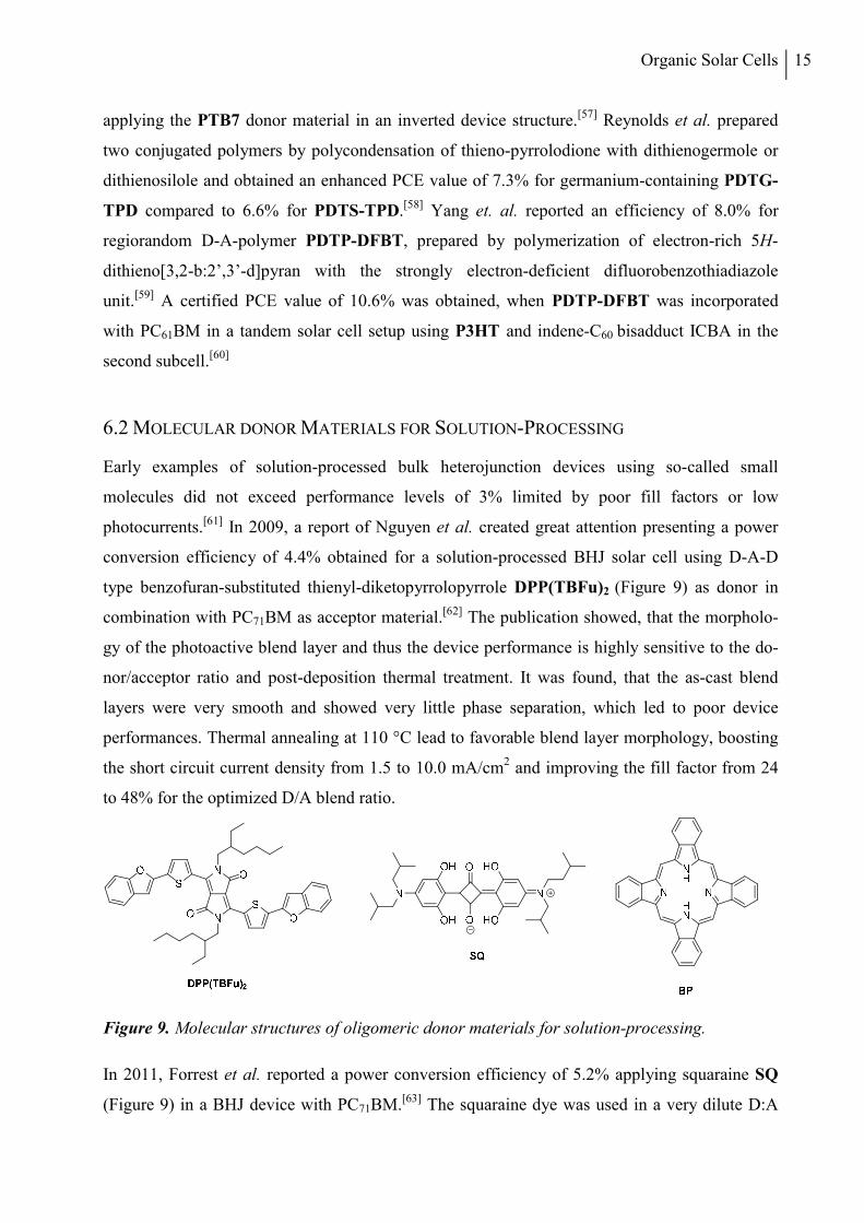
Bazan and his group systematically developed highly efficient, soluble D1-A-D2-A-D1-type
oligomers (Figure 10).[65] In 2011, an efficiency of 6.7% was achieved for the DTS(PTTh2)2
donor material incorporating electron-rich dithienosilole as central and bithiophene as terminal
units in combination with thiadiazolopyridine electron-withdrawing moieties.[66] A small
percentage of diiodooctane was used as solvent additive during solution-processing to optimize
the domain sizes of the DTS(PTTh2)2:PC71BM blend.
Figure 10. Molecular structures of D1-A-D2-A-D1-type donor materials developed by Bazan et al.
A subtle structural modification of the molecular donor material by replacing the
thiadiazolopyridine unit by fluorobenzothiadiazole in DTS(FBTTh2)2 resulted in an increased
device performance of 7.0%.[67] By use of a modified ZnO electron transport layer in an inverted
device structure an improved efficiency of 7.9% with an impressive JSC value of 15.2 mA/cm2
was achieved.[68] The introduction of a thin barium interlayer between the aluminium top
electrode and the DTS(FBTTh2)2:PC71BM layer using the standard device structure resulted in
an further enhanced PCE value of 8.6% due to an impressive fill factor of 75%.[69]
Chen and his group systematically investigated high molecular weight oligothiophene-based A-
D-A donor materials for application in solution-processed small molecule organic solar cells
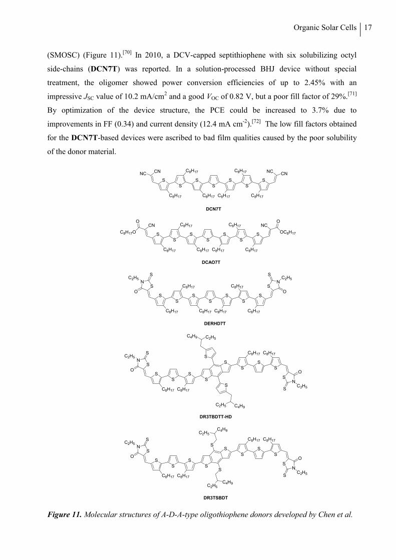
Organic Solar Cells 17
(SMOSC) (Figure 11).[70] In 2010, a DCV-capped septithiophene with six solubilizing octyl
side-chains (DCN7T) was reported. In a solution-processed BHJ device without special
treatment, the oligomer showed power conversion efficiencies of up to 2.45% with an
impressive JSC value of 10.2 mA/cm2 and a good VOC of 0.82 V, but a poor fill factor of 29%.[71]
By optimization of the device structure, the PCE could be increased to 3.7% due to
improvements in FF (0.34) and current density (12.4 mA cm-2).[72] The low fill factors obtained
for the DCN7T-based devices were ascribed to bad film qualities caused by the poor solubility
of the donor material.
Figure 11. Molecular structures of A-D-A-type oligothiophene donors developed by Chen et al.
SS
C8H17
C8H17
SS
NCCN
C8H17
SS
S
CNNC
C8H17C8H17
C8H17
DCN7T
SS
C8H17
C8H17
SS
NC
C8H17
SS
S
CN
C8H17C8H17
C8H17
DCAO7T
OC8H17
O
C8H17O
O
SS
C8H17
C8H17
SS
C8H17
SS
S
C8H17C8H17
C8H17
DERHD7T
SN N
SO
SC2H5
S
O
C2H5
SS
S
C8H17
SS
S
C8H17
SN
NS
O
SC2H5
S
O
C2H5
S
S
S
S
C2H5 C4H9
C2H5C4H9
C8H17
C8H17
DR3TBDTT-HD
SS
S
C8H17
SS
S
C8H17
SN
NS
O
SC2H5
S
O
C2H5
S
S
S
C8H17
C8H17
DR3TSBDT
S
C4H9C2H5
C2H5
C4H9
18 Chapter I
Replacing the dicyanovinyl units in DCN7T by alkyl cyano acetate groups the solubility in
chloroform significantly increased to values of up to 204 mg mL-1 determined for octyl
derivative DCAO7T.[73] BHJ solar cells made by spin-coating of DCAO7T and PC61BM from
chloroform solution exhibited similar JSC and VOC values of up to 10.7 mA cm-2 and 0.86 V,
respectively, compared to the previously reported DCN7T-based devices. Due to a strongly
increased fill factor of 55%, a PCE of 5.1% could be obtained.
In 2012, Chen et al. attached the ethylrhodanine acceptor unit to the conjugated septithiophene
backbone by reaction of the corresponding oligothiophene dialdehyde with 3-ethylrhodanine.[74]
The new material (DERHD7T) showed a very high molar extinction coefficient of 90’000
L mol-1 cm-1 exceeding the values determined for DCN7T and DCAO7T. In the solar cell
device, the strong absorption of the new donor material resulted in a remarkable short circuit
current density of almost 14 mA cm-2 pushing the device performance to 6.1%. In a recent
contribution, a series of novel optimized A-D-A-type donor materials based on the DERHD7T
structure is presented.[75] By replacement of the central thiophene unit of DERHD7T with a
thienyl-substituted benzodithiophene block, structural planarization and extension of the
conjugated π-system is achieved. Under optimized solution-processing conditions using
polydimethylsiloxane (PDMS) as solvent additive, an excellent power conversion efficiency of
8.1% has been measured for the best-performing derivative DR3TBDTT-HD in combination
with PC71BM as the acceptor material. Yang et al. reported a PCE of 10.1% for a solution
processed homo-tandem device incorporating very similar octyl-rhodanine derivative SMPV1
in both subcells.[76] In late 2014, a record PCE value of 9.95% was published for a single BHJ
device using PC71BM and the further optimized donor material DR3TSBDT with dialkylthiol-
substituted benzodithiophene as the central building block.[77] A combination of thermal and
subsequent solvent vapor annealing was appled to improve the morpology of the photoactive
layer, resulting in an outstanding fill factor of 0.74 (VOC = 0.92 V, JSC = 14.6 mA cm−2) for the
most efficient solar cell.
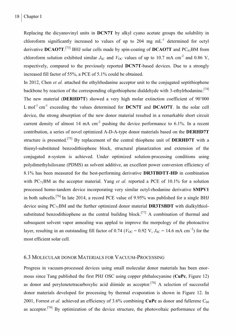
6.3 MOLECULAR DONOR MATERIALS FOR VACUUM-PROCESSING
Progress in vacuum-processed devices using small molecular donor materials has been enor-
mous since Tang published the first PHJ OSC using copper phthalocyanine (CuPc, Figure 12)
as donor and perylenetetracarboxylic acid diimide as acceptor.[78] A selection of successful
donor materials developed for processing by thermal evaporation is shown in Figure 12. In
2001, Forrest et al. achieved an efficiency of 3.6% combining CuPc as donor and fullerene C60
as acceptor.[79] By optimization of the device structure, the photovoltaic performance of the
Organic Solar Cells 19
CuPc:C60-based solar cells could be improved to 4.2%[80] in 2004 and 5.0%[81] in 2005. Leo and
his work group developed efficient OSC device architectures thoroughly investigating the zink
phthalocyanine (ZnPc):C60 donor/acceptor combination. In 2003, p-i-n-type solar cells incur-
porating a co-evaporated intrinsic BHJ layer sandwiched between p- or n-doped charge transport
layers were reported showing efficiencies of up to 1.04% (VOC = 0.50 V, JSC = 6.3 mA cm−2)
under AM1.5 illumination.[82] By optimization of the applied charge transport layers an im-
proved PCE value of 1.9% was achieved.[83] In 2004, a power conversion efficiency of 1.44%
was published for a m-i-p-type ZnPc:C60-based BHJ device using a p-doped hole transport layer
below the gold top contact.[84]
Figure 12. Molecular structures of selected molecular donor materials designed for vacuum-processing.
Over the recent years, Wong and co-workers systematically studied very low molecular weight
D-A-A-type donor materials bearing dicyanovinyl (DCV) electron-withdrawing groups. In
2011, a PCE value of 5.8% was achieved using fullerene C70 as acceptor in combination with
DTDCTB as donor, in which an electron-donating ditolylaminothienyl moiety and the electron-
withdrawing DCV unit are bridged by another electron-accepting benzothiadiazole block.[85] A
slight structural variation, replacing the central thiophene moiety by a phenylene unit in
DTDCPB allowed for an increased device performance of 6.6% for a hybrid planar-mixed
heterojunction device with C70.[86] Recently, Holmes et al. achieved a further improved average
PCE value of 7.9% for a DTDCPB:C70-based solar cell, using a uniform BHJ active layer.[87] In
2011, Würthner et al. reported an efficiency of 6.1% for a vacuum-processed BHJ-SMOSC
incorporating merocyanine donor HB194,[88] which had initially been implemented in solution-
processed solar cells.[89]
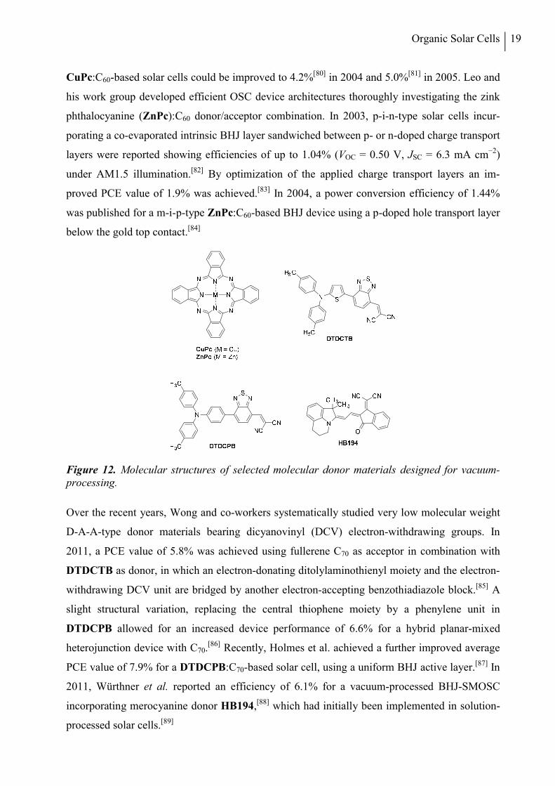
20 Chapter I
In 2014, Heremans et al. published a PCE value of 6.0% for a fullerene-free PHJ device
incorporating α-sexithiophene (α-6T, Figure 13) as donor and boron subnaphthalocyanine
chloride (SubNc) as acceptor.[90] Combination of SubNc with its subphthalocyanine (SubPc)
homologue as second acceptor material in a three-layer device structure with α-6T resulted in an
improved efficiency of 8.4% due to an increased photocurrent of 14.6 mA cm-2.
Figure 13. Molecular structures of photoactive materials used in a three-layer OSC device re-ported by Heremans et al.
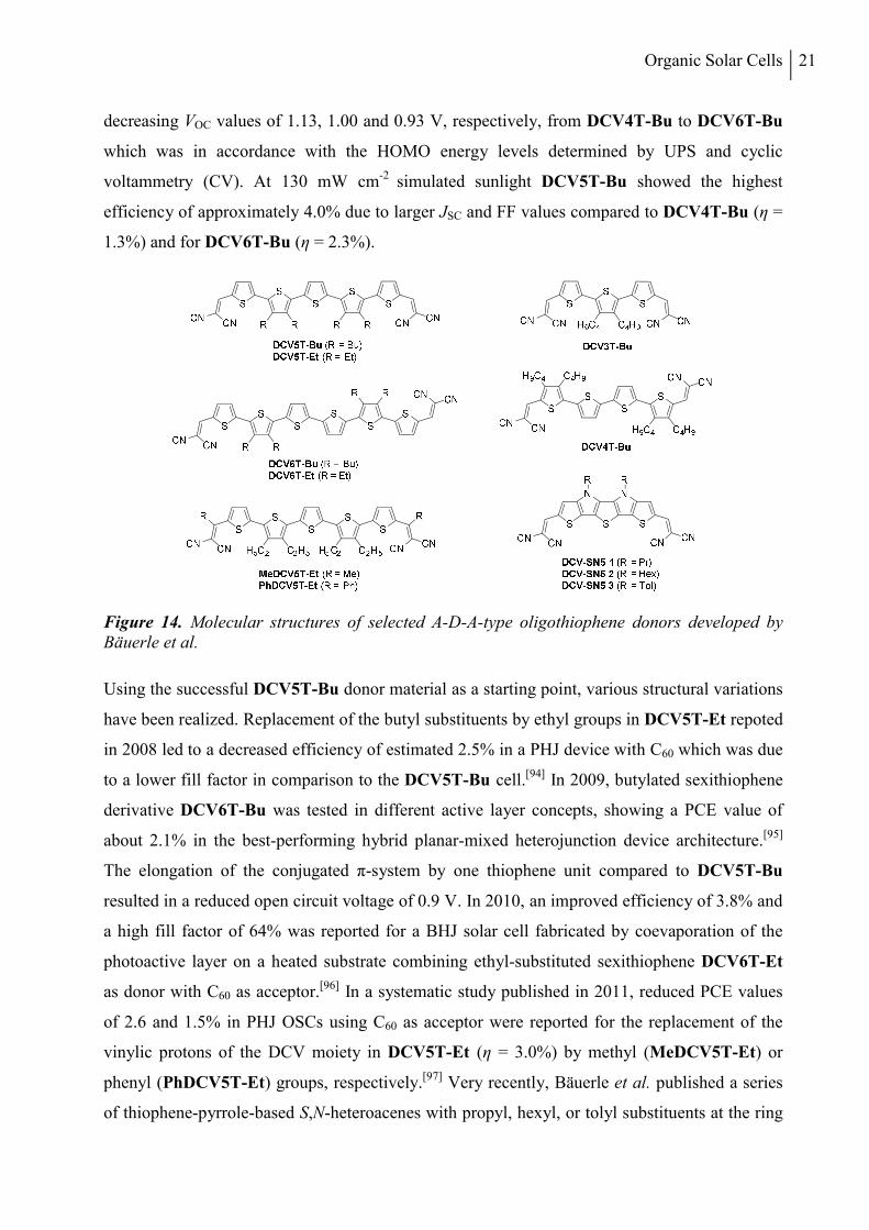
The Bäuerle group in collaboration with the physics research group of Leo thoroughly inves-
tigated alkylated acceptor-substituted oligothiophene donor materials (Figure 14). In 2006, a
PCE value of 3.4% under simulated sun light illumination of 118 mW cm-2 was published for a
vacuum-processed OSC incorporating a PHJ of butyl-substituted DCV-capped quinquethio-
phene DCV5T-Bu and fullerene C60 sandwiched between a highly p-doped hole transport layer
and a wide-bandgap exciton blocking layer.[91] The device showed a high VOC of 0.98 V as a
result of the low lying HOMO energy level corresponding to the large ionization energy of 5.6
eV determined by ultraviolet photoelectron spectroscopy (UPS). In 2007, butylated terthiophene
derivative DCV3T-Bu was applied as acceptor material in combination with 4,4’-bis-(N,N-
diphenylamino)quaterphenyl (4P-TPD) as donor in a m-i-p-type PHJ device structure, reaching
a high open circuit voltage of 1.04 V and a moderate power conversion efficiency of 1.6% due
to a low JSC value of 3.8 mA cm-2.[92] The admixture of fullerene C60 as second acceptor material
to the DCV3T-Bu layer was shown to lead to an enhanced generation of long-lived triplet
excitons on DCV3T-Bu caused by an excitonic ping-pong effect with inter-system-crossing on
C60. In a study published in 2008, photoinduced absorption (PIA) spectroscopy in combination
with quantum-chemical calculations was used to investigate the electron and energy transfer
processes at the donor/C60 interface for a homologous series of butylated DCV-capped
oligothiophene donors from the trimer DCV3T-Bu to the hexamer derivative DCV6T-Bu.[93]
Planar heterojunction solar cells prepared for DCV4T-Bu, DCV5T-Bu and DCV6T-Bu yielded
Organic Solar Cells 21
decreasing VOC values of 1.13, 1.00 and 0.93 V, respectively, from DCV4T-Bu to DCV6T-Bu
which was in accordance with the HOMO energy levels determined by UPS and cyclic
voltammetry (CV). At 130 mW cm-2 simulated sunlight DCV5T-Bu showed the highest
efficiency of approximately 4.0% due to larger JSC and FF values compared to DCV4T-Bu (η =
1.3%) and for DCV6T-Bu (η = 2.3%).
Figure 14. Molecular structures of selected A-D-A-type oligothiophene donors developed by Bäuerle et al.
Using the successful DCV5T-Bu donor material as a starting point, various structural variations
have been realized. Replacement of the butyl substituents by ethyl groups in DCV5T-Et repoted
in 2008 led to a decreased efficiency of estimated 2.5% in a PHJ device with C60 which was due
to a lower fill factor in comparison to the DCV5T-Bu cell.[94] In 2009, butylated sexithiophene
derivative DCV6T-Bu was tested in different active layer concepts, showing a PCE value of
about 2.1% in the best-performing hybrid planar-mixed heterojunction device architecture.[95]
The elongation of the conjugated π-system by one thiophene unit compared to DCV5T-Bu
resulted in a reduced open circuit voltage of 0.9 V. In 2010, an improved efficiency of 3.8% and
a high fill factor of 64% was reported for a BHJ solar cell fabricated by coevaporation of the
photoactive layer on a heated substrate combining ethyl-substituted sexithiophene DCV6T-Et
as donor with C60 as acceptor.[96] In a systematic study published in 2011, reduced PCE values
of 2.6 and 1.5% in PHJ OSCs using C60 as acceptor were reported for the replacement of the
vinylic protons of the DCV moiety in DCV5T-Et (η = 3.0%) by methyl (MeDCV5T-Et) or
phenyl (PhDCV5T-Et) groups, respectively.[97] Very recently, Bäuerle et al. published a series
of thiophene-pyrrole-based S,N-heteroacenes with propyl, hexyl, or tolyl substituents at the ring
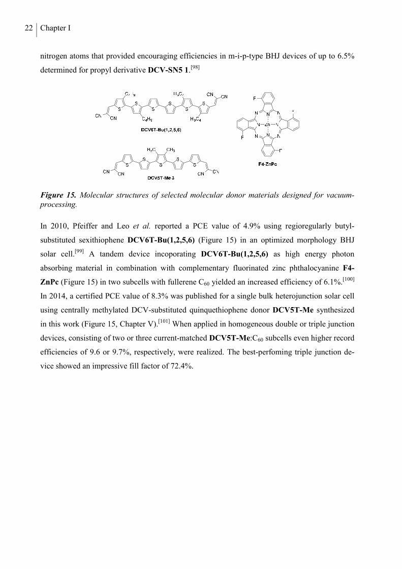
22 Chapter I
nitrogen atoms that provided encouraging efficiencies in m-i-p-type BHJ devices of up to 6.5%
determined for propyl derivative DCV-SN5 1.[98]
Figure 15. Molecular structures of selected molecular donor materials designed for vacuum-processing.
In 2010, Pfeiffer and Leo et al. reported a PCE value of 4.9% using regioregularly butyl-
substituted sexithiophene DCV6T-Bu(1,2,5,6) (Figure 15) in an optimized morphology BHJ
solar cell.[99] A tandem device incoporating DCV6T-Bu(1,2,5,6) as high energy photon
absorbing material in combination with complementary fluorinated zinc phthalocyanine F4-
ZnPc (Figure 15) in two subcells with fullerene C60 yielded an increased efficiency of 6.1%.[100]
In 2014, a certified PCE value of 8.3% was published for a single bulk heterojunction solar cell
using centrally methylated DCV-substituted quinquethiophene donor DCV5T-Me synthesized
in this work (Figure 15, Chapter V).[101] When applied in homogeneous double or triple junction
devices, consisting of two or three current-matched DCV5T-Me:C60 subcells even higher record
efficiencies of 9.6 or 9.7%, respectively, were realized. The best-perfoming triple junction de-
vice showed an impressive fill factor of 72.4%.
Organic Solar Cells 23
REFERENCES
[1] D. Wöhrle, D. Meissner, Adv. Mater. 1991, 3, 129-138.
[2] A. E. Becquerel, Comptes Rendus 1839, 9, 145-149.
[3] C. Fritts, Van Nostrands Engineering Magazine 1885, 32, 388–395.
[4] A. Einstein, Ann. der Physik 1905, 17, 132-148.
[5] D. M. Chapin, C. S. Fuller, G. L. Pearson, J. Appl. Phys. 1954, 25, 676-677.
[6] http://www.nrel.gov/ncpv/images/efficiency_chart.jpg; accessed 11/29/2014.
[7] http://www.ise.fraunhofer.de/de/downloads/pdf-files/aktuelles/photovoltaics-report-in-englischer-sprache.pdf; accessed 11/29/2014.
[8] A. Yella, H.-W. Lee, H. N. Tsao, C. Yi, A. K. Chandiran, M. K. Nazeeruddin, E. W.-G. Diau, C.-Y. Yeh, S. M. Zakeeruddin, M. Grätzel, Science 2011, 334, 629-634.
[9] http://www.heliatek.com/newscenter/latest_news/neuer-weltrekord-fur-organische-solarzellen-heliatek-behauptet-sich-mit-12-zelleffizienz-als-technologiefuhrer/; accessed 11/29/2014.
[10] G. A. Chamberlain, Solar Cells 1983, 8, 47-83.
[11] G. Horowitz, Adv. Mater. 1990, 2, 287-292.
[12] D. Wöhrle, D. Meissner, Adv. Mater. 1991, 3, 129-138.
[13] C. W. Tang, A. C. Albrecht, Nature 1975, 254, 507-509.
[14] C. W. Tang, A. C. Albrecht, J. Chem. Phys. 1975, 62, 2139-2149.
[15] C. W. Tang, A. C. Albrecht, J. Chem. Phys. 1975, 63, 953-961.
[16] A. K. Ghosh, D. L. Morel, T. Feng, R. F. Shaw, J. Charles A. Rowe, J. Appl. Phys. 1974, 45, 230-236.
[17] V. Y. Merritt, H. J. Hovel, Appl. Phys. Lett. 1976, 29, 414-415.
[18] D. L. Morel, A. K. Ghosh, T. Feng, E. L. Stogryn, P. E. Purwin, R. F. Shaw, C. Fishman, Appl. Phys. Lett. 1978, 32, 495-497.
[19] C. W. Tang, Appl. Phys. Lett. 1986, 48, 183-185.
[20] P. Peumans, A. Yakimov, S. R. Forrest, J. Appl. Phys. 2003, 93, 3693-3723.
[21] M. Wojcik, M. Tachiya, J. Chem. Phys. 2009, 130, 104107.
[22] R. A. Street, M. Schoendorf, A. Roy, J. H. Lee, Phys. Rev. B 2010, 81, 205307.
24 Chapter I
[23] J. A. Bartelt, Z. M. Beiley, E. T. Hoke, W. R. Mateker, J. D. Douglas, B. A. Collins, J. R. Tumbleston, K. R. Graham, A. Amassian, H. Ade, J. M. J. Fréchet, M. F. Toney, M. D. McGehee, Adv. Energy Mater. 2013, 3, 364–374.
[24] S. A. Jenekhe, S. Yi, Appl. Phys. Lett. 2000, 77, 2635-2637.
[25] M. C. Scharber, N. S. Sariciftci, Prog. Polym. Sci. 2013, 38, 1929-1940.
[26] G. Yu, J. Gao, J. C. Hummelen, F. Wudl, A. J. Heeger, Science 1995, 270, 1789-1791.
[27] P. K. Watkins, A. B. Walker, G. L. B. Verschoor, Nano Lett. 2005, 5, 1814-1818.
[28] C. Sachse, L. Müller-Meskamp, L. Bormann, Y. H. Kim, F. Lehnert, A. Philipp, B. Beyer, K. Leo, Org. Electron. 2013, 14, 143-148.
[29] A. Kaskela, A. G. Nasibulin, M. Y. Timmermans, B. Aitchison, A. Papadimitratos, Y. Tian, Z. Zhu, H. Jiang, D. P. Brown, A. Zakhidov, E. I. Kauppinen, Nano Lett. 2010, 10, 4349-4355.
[30] S. Bae, H. Kim, Y. Lee, X. Xu, J.-S. Park, Y. Zheng, J. Balakrishnan, T. Lei, H. Ri Kim, Y. I. Song, Y.-J. Kim, K. S. Kim, B. Ozyilmaz, J.-H. Ahn, B. H. Hong, S. Iijima, Nat. Nanotechnol. 2010, 5, 574-578.
[31] S. Murase, Y. Yang, Adv. Mater. 2012, 24, 2459–2462.
[32] J. Huang, Z. Yin, Q. Zheng, Energy Environ. Sci. 2011, 4, 3861–3877.
[33] K. Walzer, B. Männig, M. Pfeiffer, K. Leo, Chem. Rev. 2007, 107, 1233-1271.
[34] M. Riede, C. Uhrich, J. Widmer, R. Timmreck, D. Wynands, G. Schwartz, W.-M. Gnehr, D. Hildebrandt, A. Weiss, J. Hwang, S. Sudharka, P. Erk, M. Pfeiffer, K. Leo, Adv. Funct. Mater. 2011, 21, 3019-3028.
[35] C. Falkenberg, K. Leo, M. K. Riede, J. Appl. Phys. 2011, 110, 124509.
[36] K. A. Emery, C. R. Osterwald, Solar Cells 1986, 17, 253-274.
[37] V. Shrotriya, G. Li, Y. Yao, T. Moriarty, K. Emery, Y. Yang, Adv. Funct. Mater. 2006, 16, 2016-2023.
[38] J. C. Bijleveld, M. Shahid, J. Gilot, M. M. Wienk, R. A. J. Janssen, Adv. Funct. Mater. 2009, 19, 3262-3270.
[39] B. P. Rand, J. Genoe, P. Heremans, J. Poortmans, Prog. Photovoltaics 2007, 15, 659.
[40] Y. Li, Acc. Chem. Res. 2012, 45, 723–733.
[41] M. C. Scharber, D. Mühlbacher, M. Koppe, P. Denk, C. Waldauf, A. J. Heeger, C. J. Brabec, Adv. Mater. 2006, 18, 789-794.
[42] C. Soci, I. W. Hwang, D. Moses, Z. Zhu, D. Waller, R. Gaudiana, C. J. Brabec, A. J. Heeger, Adv. Funct. Mater. 2007, 17, 632-636.
Organic Solar Cells 25
[43] a) M. M. Wienk, J. M. Kroon, W. J. H. Verhees, J. Knol, J. C. Hummelen, P. A. van Hal, R. A. J. Janssen Angew. Chem. 2003, 115, 3493–3497; b) M. M. Wienk, J. M. Kroon, W. J. H. Verhees, J. Knol, J. C. Hummelen, P. A. van Hal, R. A. J. Janssen, Angew. Chem. Int. Ed. 2003, 42, 3371-3375.
[44] R. S. Loewe, S. M. Khersonsky, R. D. McCullough, Adv. Mater. 1999, 11, 250-253.
[45] M. C. Iovu, E. E. Sheina, R. R. Gil, R. D. McCullough, Macromolecules 2005, 38, 8649-8656.
[46] P. Schilinsky, U. Asawapirom, U. Scherf, M. Biele, C. J. Brabec, Chem. Mater. 2005, 17, 2175-2180.
[47] W. Ma, C. Yang, X. Gong, K. Lee, A. J. Heeger, Adv. Funct. Mater. 2005, 15, 1617-1622.
[48] S.-H. Liao, Y.-L. Li, T.-H. Jen, Y.-S. Cheng, S.-A. Chen, J. Am. Chem. Soc. 2012, 134, 14271–14274.
[49] X. Guo, C. Cui, M. Zhang, L. Huo, Y. Huang, J. Hou, Y. Li, Energy Environ. Sci. 2012, 5, 7943-7949.
[50] J. Roncali, Chem. Rev. 1997, 97, 173-206.
[51] N. Blouin, A. Michaud, M. Leclerc, Adv. Mater. 2007, 19, 2295-2300.
[52] S. H. Park, A. Roy, S. Beaupre, S. Cho, N. Coates, J. S. Moon, D. Moses, M. Leclerc, K. Lee, A. J. Heeger, Nat. Photon. 2009, 3, 297-302.
[53] J. C. Bijleveld, A. P. Zoombelt, S. G. J. Mathijssen, M. M. Wienk, M. Turbiez, D. M. de Leeuw, R. A. J. Janssen, J. Am. Chem. Soc. 2009, 131, 16616-16617.
[54] L. Ye, S. Zhang, W. Ma, B. Fan, X. Guo, Y. Huang, H. Ade, J. Hou, Adv. Mater. 2012, 24, 6335–6341.
[55] C. Piliego, T. W. Holcombe, J. D. Douglas, C. H. Woo, P. M. Beaujuge, J. M. J. Fréchet, J. Am. Chem. Soc. 2010, 132, 7595-7597.
[56] Y. Liang, Z. Xu, J. Xia, S.-T. Tsai, Y. Wu, G. Li, C. Ray, L. Yu, Adv. Mater. 2010, 22, E135-E138.
[57] Z. C. He, C. M. Zhong, S. J. Su, M. Xu, H. B. Wu, Y. Cao, Nat. Photon. 2012, 6, 591-595.
[58] C. M. Amb, S. Chen, K. R. Graham, J. Subbiah, C. E. Small, F. So, J. R. Reynolds, J. Am. Chem. Soc. 2011, 133, 10062–10065.
[59] L. Dou, C.-C. Chen, K. Yoshimura, K. Ohya, W.-H. Chang, J. Gao, Y. Liu, E. Richard, Y. Yang, Macromolecules 2013, 46, 3384-3390.
[60] J. You, L. Dou, K. Yoshimura, T. Kato, K. Ohya, T. Moriarty, K. Emery, C.-C. Chen, J. Gao, G. Li, Y. Yang, Nat. Commun. 2013, 4, 1446.
26 Chapter I
[61] A. B. Tamayo, X.-D. Dang, B. Walker, J. Seo, T. Kent, T.-Q. Nguyen, Appl. Phys. Lett. 2009, 94, 103301-103303.
[62] B. Walker, A. B. Tamayo, X.-D. Dang, P. Zalar, J. H. Seo, A. Garcia, M. Tantiwiwat, T.-Q. Nguyen, Adv. Funct. Mater. 2009, 19, 3063-3069.
[63] G. Wei, S. Wang, K. Sun, M. E. Thompson, S. R. Forrest, Adv. Energy Mater. 2011, 1, 184-187.
[64] Y. Matsuo, Y. Sato, T. Niinomi, I. Soga, H. Tanaka, E. Nakamura, J. Am. Chem. Soc. 2009, 131, 16048-16050.
[65] J. E. Coughlin, Z. B. Henson, G. C. Welch, G. C. Bazan, Acc. Chem. Res. 2013, 47, 257-270.
[66] Y. Sun, G. C. Welch, W. L. Leong, C. J. Takacs, G. C. Bazan, A. J. Heeger, Nat. Mater. 2012, 11, 44–48.
[67] T. S. van der Poll, J. A. Love, T.-Q. Nguyen, G. C. Bazan, Adv. Mater. 2012, 24, 3646–3649.
[68] A. K. K. Kyaw, D. H. Wang, V. Gupta, J. Zhang, S. Chand, G. C. Bazan, A. J. Heeger, Adv. Mater. 2013, 25, 2397–2402.
[69] V. Gupta, A. K. K. Kyaw, D. H. Wang, S. Chand, G. C. Bazan , A. J. Heeger, Sci. Rep. 2013, 3, 1965.
[70] Y. Chen, X. Wan, G. Long, Acc. Chem. Res. 2013, 46, 2645-2655.
[71] Y. Liu, X. Wan, B. Yin, J. Zhou, G. Long, S. Yin, Y. Chen, J. Mater. Chem. 2010, 20, 2464-2468.
[72] B. Yin, L. Yang, Y. Liu, Y. Chen, Q. Qi, F. Zhang, S. Yin, Appl. Phys. Lett. 2010, 97, 023303.
[73] Y. Liu, X. Wan, F. Wang, J. Zhou, G. Long, J. Tian, J. You, Y. Yang, Y. Chen, Adv. Energy Mater. 2011, 1, 771-775.
[74] Z. Li, G. He, X. Wan, Y. Liu, J. Zhou, G. Long, Y. Zuo, M. Zhang, Y. Chen, Adv. Energy Mater. 2012, 2, 74–77.
[75] J. Zhou, Y. Zuo, X. Wan, G. Long, Q. Zhang, W. Ni, Y. Liu, Z. Li, G. He, C. Li, B. Kan, M. Li, Y. Chen, J. Am. Chem. Soc. 2013, 135, 8484–8487.
[76] Y. Liu, C.-C. Chen, Z. Hong, J. Gao, Y. Yang, H. Zhou, L. Dou, G. Li, Y. Yang, Sci. Rep. 2013, 3, 3356.
[77] B. Kan, Q. Zhang, M. Li, X. Wan, W. Ni, G. Long, Y. Wang, X. Yang, H. Feng, Y. Chen, J. Am. Chem. Soc. 2014, 136, 15529.
[78] A. Mishra, P. Bäuerle, Angew. Chem. Int. Ed. 2012, 51, 2020-2067.
[79] P. Peumans, S. R. Forrest, Appl. Phys. Lett. 2001, 79, 126-128.
Organic Solar Cells 27
[80] J. Xue, S. Uchida, B. P. Rand, S. R. Forrest, Appl. Phys. Lett. 2004, 84, 3013-3015.
[81] J. Xue, B. P. Rand, S. Uchida, S. R. Forrest, Adv. Mater. 2005, 17, 66-71.
[82] D. Gebeyehu, B. Männig, J. Drechsel, K. Leo, M. Pfeiffer, Sol. Energy Mater. Sol. Cells 2003, 79, 81-92.
[83] J. Drechsel, B. Männig, F. Kozlowski, D. Gebeyehu, A. Werner, M. Koch, K. Leo, M. Pfeiffer, Thin Solid Films 2004, 451-452, 515-517.
[84] J. Drechsel, B. Männig, D. Gebeyehu, M. Pfeiffer, K. Leo, H. Hoppe, Org. Electron. 2004, 5, 175-186.
[85] L.-Y. Lin, Y.-H. Chen, Z.-Y. Huang, H.-W. Lin, S.-H. Chou, F. Lin, C.-W. Chen, Y.-H. Liu, K.-T. Wong, J. Am. Chem. Soc. 2011, 133, 15822–15825.
[86] Y.-H. Chen, L.-Y. Lin, C.-W. Lu, Z.-Y. Huang, H.-W. Lin, F. Lin, P.-H. Wang, Y.-H. Liu, K.-T. Wong, J. Wen, D. J. Miller, S. B. Darling, J. Am. Chem. Soc. 2012, 134, 13616–13623.
[87] Y. Zou, J. Holst, Y. Zhang, R. J. Holmes, J. Mater. Chem. A 2014, 2, 12397-12402.
[88] V. Steinmann, N. M. Kronenberg, M. R. Lenze, S. M. Graf, D. Hertel, K. Meerholz, H. Bürckstümmer, E. V. Tulyakova, F. Würthner, Adv. Energy Mater. 2011, 1, 888-893.
[89] H. Burckstummer, N. M. Kronenberg, M. Gsanger, M. Stolte, K. Meerholz, F. Wurthner, J. Mater. Chem. 2010, 20, 240-243.
[90] K. Cnops, B. P. Rand, D. Cheyns, B. Verreet, M. A. Empl, P. Heremans, Nat. Commun.
2014, 5, 3406.
[91] K. Schulze, C. Uhrich, R. Schüppel, K. Leo, M. Pfeiffer, E. Brier, E. Reinold, P. Bäuerle, Adv. Mater. 2006, 18, 2872–2875.
[92] C. Uhrich, R. Schueppel, A. Petrich, M. Pfeiffer, K. Leo, E. Brier, P. Kilickiran, P. Bäuerle, Adv. Funct. Mater. 2007, 17, 2991.
[93] R. Schueppel, K. Schmidt, C. Uhrich, K. Schulze, D. Wynands, J. L. Brédas, E. Brier, E. Reinold, H.-B. Bu, P. Bäuerle, B. Männig, M. Pfeiffer, K. Leo Phys. Rev. B, 2008, 77, 085311.
[94] K. Schulze, M. Riede, E. Brier, E. Reinold, P. Bäuerle, K. Leo, J. Appl. Phys. 2008, 104, 074511.
[95] D. Wynands, B. Männig, M. Riede, K. Leo, E. Brier, E. Reinold, P. Bäuerle, J. Appl. Phys. 2009, 106, 054509.
[96] D. Wynands, M. Levichkova, M. Riede, M. Pfeiffer, P. Bäuerle, R. Rentenberger, P. Denner, K. Leo, J. Appl. Phys. 2010, 107, 014517.
[97] A. Mishra, C. Uhrich, E. Reinold, M. Pfeiffer, P. Bäuerle, Adv. Energy Mater. 2011, 1, 265-273.

28 Chapter I
[98] A. Mishra, D. Popovic, A. Vogt, H. Kast, T. Leitner, K. Walzer, M. Pfeiffer, E. Mena-Osteritz, P. Bäuerle, Adv. Mater. 2014, 26, 7217-7223.
[99] D. Wynands, M. Levichkova, K. Leo, C. Uhrich, G. Schwartz, D. Hildebrandt, M. Pfeiffer, M. Riede, Appl. Phys. Lett. 2010, 97, 073503.
[100] M. Riede, C. Uhrich, J. Widmer, R. Timmreck, D. Wynands, G. Schwartz, W.-M. Gnehr, D. Hildebrandt, A. Weiss, J. Hwang, S. Sundarraj, P. Erk, M. Pfeiffer, K. Leo, Adv. Funct. Mater. 2011, 21, 3019–3028.
[101] R. Meerheim, C. Körner, K. Leo, Appl. Phys. Lett. 2014, 105, 253508.
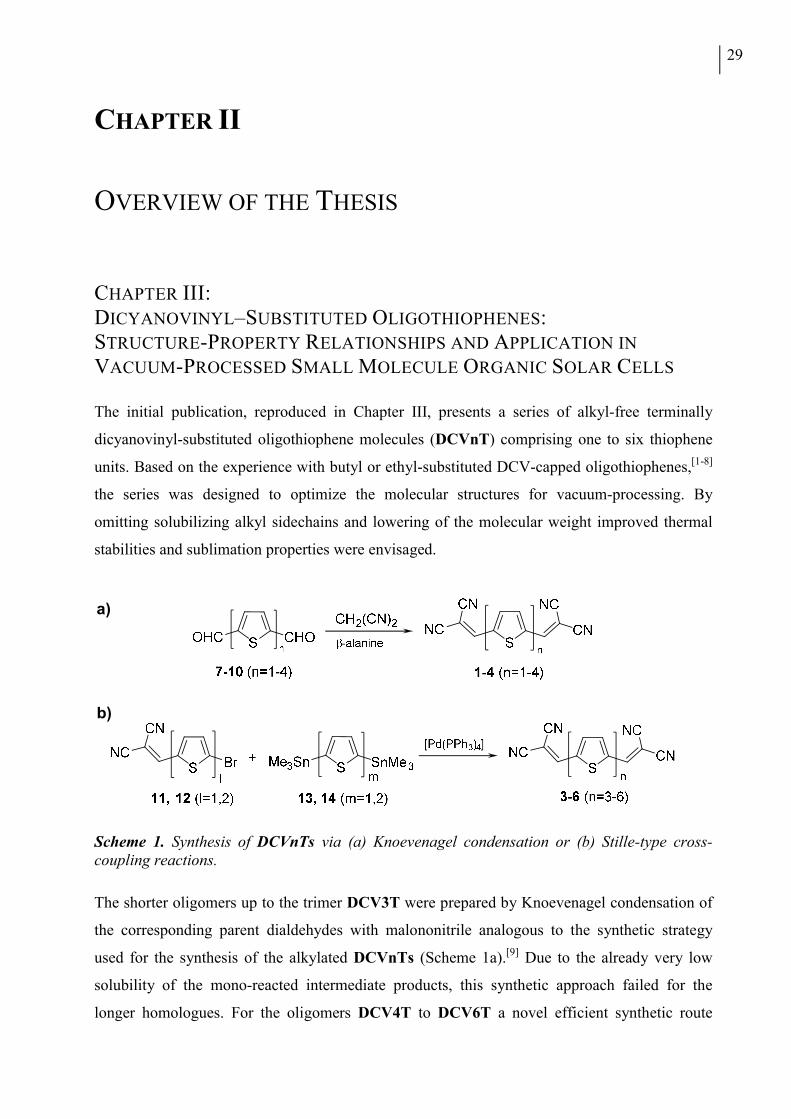
29
CHAPTER II
OVERVIEW OF THE THESIS
CHAPTER III: DICYANOVINYL–SUBSTITUTED OLIGOTHIOPHENES: STRUCTURE-PROPERTY RELATIONSHIPS AND APPLICATION IN
VACUUM-PROCESSED SMALL MOLECULE ORGANIC SOLAR CELLS
The initial publication, reproduced in Chapter III, presents a series of alkyl-free terminally
dicyanovinyl-substituted oligothiophene molecules (DCVnT) comprising one to six thiophene
units. Based on the experience with butyl or ethyl-substituted DCV-capped oligothiophenes,[1-8]
the series was designed to optimize the molecular structures for vacuum-processing. By
omitting solubilizing alkyl sidechains and lowering of the molecular weight improved thermal
stabilities and sublimation properties were envisaged.
Scheme 1. Synthesis of DCVnTs via (a) Knoevenagel condensation or (b) Stille-type cross-coupling reactions.
The shorter oligomers up to the trimer DCV3T were prepared by Knoevenagel condensation of
the corresponding parent dialdehydes with malononitrile analogous to the synthetic strategy
used for the synthesis of the alkylated DCVnTs (Scheme 1a).[9] Due to the already very low
solubility of the mono-reacted intermediate products, this synthetic approach failed for the
longer homologues. For the oligomers DCV4T to DCV6T a novel efficient synthetic route
b)
a)
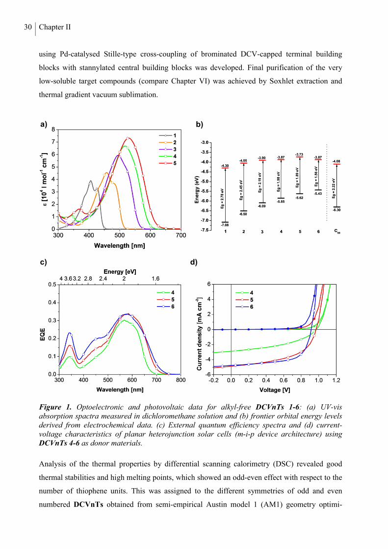
30 Chapter II
using Pd-catalysed Stille-type cross-coupling of brominated DCV-capped terminal building
blocks with stannylated central building blocks was developed. Final purification of the very
low-soluble target compounds (compare Chapter VI) was achieved by Soxhlet extraction and
thermal gradient vacuum sublimation.
Figure 1. Optoelectronic and photovoltaic data for alkyl-free DCVnTs 1-6: (a) UV-vis absorption spactra measured in dichloromethane solution and (b) frontier orbital energy levels derived from electrochemical data. (c) External quantum efficiency spectra and (d) current-voltage characteristics of planar heterojunction solar cells (m-i-p device architecture) using DCVnTs 4-6 as donor materials.
Analysis of the thermal properties by differential scanning calorimetry (DSC) revealed good
thermal stabilities and high melting points, which showed an odd-even effect with respect to the
number of thiophene units. This was assigned to the different symmetries of odd and even
numbered DCVnTs obtained from semi-empirical Austin model 1 (AM1) geometry optimi-
a) b)
c) d)
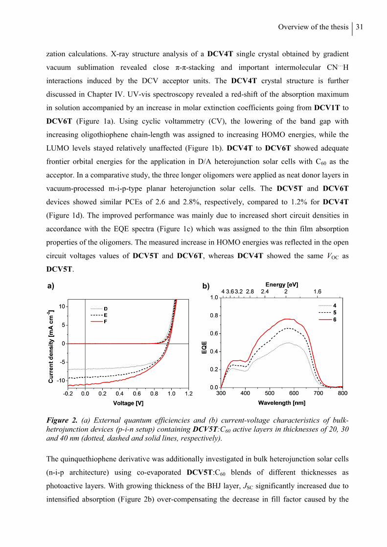
Overview of the thesis 31
zation calculations. X-ray structure analysis of a DCV4T single crystal obtained by gradient
vacuum sublimation revealed close π-π-stacking and important intermolecular CN…H
interactions induced by the DCV acceptor units. The DCV4T crystal structure is further
discussed in Chapter IV. UV-vis spectroscopy revealed a red-shift of the absorption maximum
in solution accompanied by an increase in molar extinction coefficients going from DCV1T to
DCV6T (Figure 1a). Using cyclic voltammetry (CV), the lowering of the band gap with
increasing oligothiophene chain-length was assigned to increasing HOMO energies, while the
LUMO levels stayed relatively unaffected (Figure 1b). DCV4T to DCV6T showed adequate
frontier orbital energies for the application in D/A heterojunction solar cells with C60 as the
acceptor. In a comparative study, the three longer oligomers were applied as neat donor layers in
vacuum-processed m-i-p-type planar heterojunction solar cells. The DCV5T and DCV6T
devices showed similar PCEs of 2.6 and 2.8%, respectively, compared to 1.2% for DCV4T
(Figure 1d). The improved performance was mainly due to increased short circuit densities in
accordance with the EQE spectra (Figure 1c) which was assigned to the thin film absorption
properties of the oligomers. The measured increase in HOMO energies was reflected in the open
circuit voltages values of DCV5T and DCV6T, whereas DCV4T showed the same VOC as
DCV5T.
Figure 2. (a) External quantum efficiencies and (b) current-voltage characteristics of bulk-hetrojunction devices (p-i-n setup) containing DCV5T:C60 active layers in thicknesses of 20, 30 and 40 nm (dotted, dashed and solid lines, respectively).
The quinquethiophene derivative was additionally investigated in bulk heterojunction solar cells
(n-i-p architecture) using co-evaporated DCV5T:C60 blends of different thicknesses as
photoactive layers. With growing thickness of the BHJ layer, JSC significantly increased due to
intensified absorption (Figure 2b) over-compensating the decrease in fill factor caused by the
a) b)
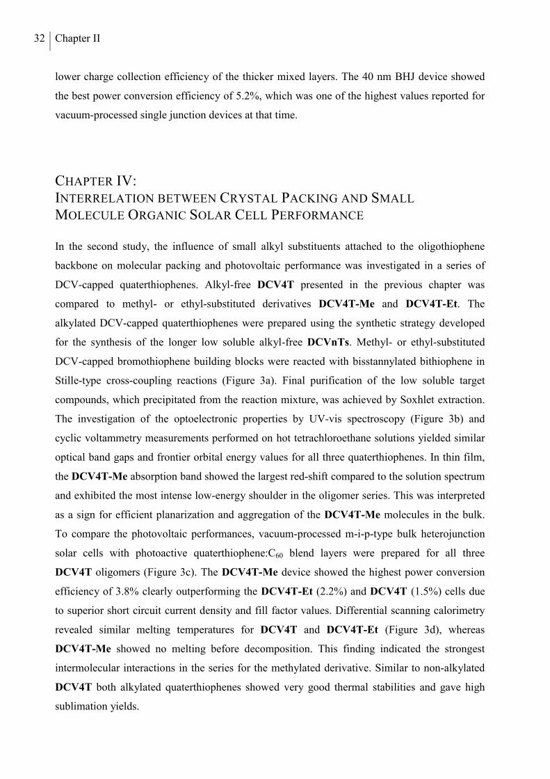
32 Chapter II
lower charge collection efficiency of the thicker mixed layers. The 40 nm BHJ device showed
the best power conversion efficiency of 5.2%, which was one of the highest values reported for
vacuum-processed single junction devices at that time.
CHAPTER IV: INTERRELATION BETWEEN CRYSTAL PACKING AND SMALL
MOLECULE ORGANIC SOLAR CELL PERFORMANCE
In the second study, the influence of small alkyl substituents attached to the oligothiophene
backbone on molecular packing and photovoltaic performance was investigated in a series of
DCV-capped quaterthiophenes. Alkyl-free DCV4T presented in the previous chapter was
compared to methyl- or ethyl-substituted derivatives DCV4T-Me and DCV4T-Et. The
alkylated DCV-capped quaterthiophenes were prepared using the synthetic strategy developed
for the synthesis of the longer low soluble alkyl-free DCVnTs. Methyl- or ethyl-substituted
DCV-capped bromothiophene building blocks were reacted with bisstannylated bithiophene in
Stille-type cross-coupling reactions (Figure 3a). Final purification of the low soluble target
compounds, which precipitated from the reaction mixture, was achieved by Soxhlet extraction.
The investigation of the optoelectronic properties by UV-vis spectroscopy (Figure 3b) and
cyclic voltammetry measurements performed on hot tetrachloroethane solutions yielded similar
optical band gaps and frontier orbital energy values for all three quaterthiophenes. In thin film,
the DCV4T-Me absorption band showed the largest red-shift compared to the solution spectrum
and exhibited the most intense low-energy shoulder in the oligomer series. This was interpreted
as a sign for efficient planarization and aggregation of the DCV4T-Me molecules in the bulk.
To compare the photovoltaic performances, vacuum-processed m-i-p-type bulk heterojunction
solar cells with photoactive quaterthiophene:C60 blend layers were prepared for all three
DCV4T oligomers (Figure 3c). The DCV4T-Me device showed the highest power conversion
efficiency of 3.8% clearly outperforming the DCV4T-Et (2.2%) and DCV4T (1.5%) cells due
to superior short circuit current density and fill factor values. Differential scanning calorimetry
revealed similar melting temperatures for DCV4T and DCV4T-Et (Figure 3d), whereas
DCV4T-Me showed no melting before decomposition. This finding indicated the strongest
intermolecular interactions in the series for the methylated derivative. Similar to non-alkylated
DCV4T both alkylated quaterthiophenes showed very good thermal stabilities and gave high
sublimation yields.
Overview of the thesis 33
Figure 3. (a) Synthesis of DCV4T-Me 2 and DCV4T-Et 3. Reagents: i) CH2(CN)2, β-alanine, ethanol/dichloroethane, reflux; ii) Pd(PPh3)4, DMF, 80 °C. (b) Solution and thin film absorption profiles and (d) differential scanning calorymetry traces of DCV4Ts 1-3. (c) Current-voltage characteristics of bulk-hetrojunction devices (m-i-p setup) containing DCV4T 1-3:C60 active layers.
Single crystals of suitable size for structure analysis by XRD could be obtained for all DCV4Ts
by thermal gradient sublimation. The analysis of intermolecular close contacts shorter than the
van-der-Waals distance, corresponding to non-bonding interactions, revealed the highest number
of short distances for DCV4T-Me, which formed a perfect layer structure and displayed
effective π-π-stacking (Figure 4). Grazing incidence X-ray diffraction (GIXRD) measurements
on a vacuum-processed mixed layer with C60 suggested the formation of crystalline DCV4T-Me
domains within the blend, which exhibited similar molecular packing as observed in the single
crystal structure. The superior device performance of methylated DCV4T-Me within the series
a) b)
c) d)
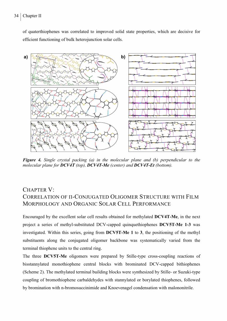
34 Chapter II
of quaterthiophenes was correlated to improved solid state properties, which are decisive for
efficient functioning of bulk heterojunction solar cells.
Figure 4. Single crystal packing (a) in the molecular plane and (b) perpendicular to the molecular plane for DCV4T (top), DCV4T-Me (center) and DCV4T-Et (bottom).
CHAPTER V: CORRELATION OF Π-CONJUGATED OLIGOMER STRUCTURE WITH FILM
MORPHOLOGY AND ORGANIC SOLAR CELL PERFORMANCE
Encouraged by the excellent solar cell results obtained for methylated DCV4T-Me, in the next
project a series of methyl-substituted DCV-capped quinquethiophenes DCV5T-Me 1-3 was
investigated. Within this series, going from DCV5T-Me 1 to 3, the positioning of the methyl
substituents along the conjugated oligomer backbone was systematically varied from the
terminal thiophene units to the central ring.
The three DCV5T-Me oligomers were prepared by Stille-type cross-coupling reactions of
bisstannylated monothiophene central blocks with brominated DCV-capped bithiophenes
(Scheme 2). The methylated terminal building blocks were synthesized by Stille- or Suzuki-type
coupling of bromothiophene carbaldehydes with stannylated or borylated thiophenes, followed
by bromination with n-bromosuccinimide and Knoevenagel condensation with malononitrile.
a) b)
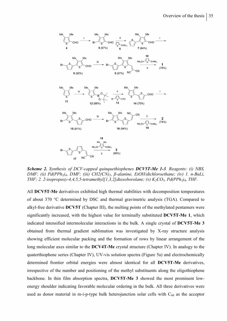
Overview of the thesis 35
Scheme 2. Synthesis of DCV-capped quinquethiophenes DCV5T-Me 1-3. Reagents: (i) NBS, DMF; (ii) Pd(PPh3)4, DMF; (iii) CH2(CN)2, β-alanine, EtOH/dichloroethane; (iv) 1. n-BuLi, THF; 2. 2-isopropoxy-4,4,5,5-tetramethyl[1,3,2]dioxoborolane; (v) K2CO3, Pd(PPh3)4, THF.
All DCV5T-Me derivatives exhibited high thermal stabilities with decomposition temperatures
of about 370 °C determined by DSC and thermal gravimetric analysis (TGA). Compared to
alkyl-free derivative DCV5T (Chapter III), the melting points of the methylated pentamers were
significantly increased, with the highest value for terminally substituted DCV5T-Me 1, which
indicated intensified intermolecular interactions in the bulk. A single crystal of DCV5T-Me 3
obtained from thermal gradient sublimation was investigated by X-ray structure analysis
showing efficient molecular packing and the formation of rows by linear arrangement of the
long molecular axes similar to the DCV4T-Me crystal structure (Chapter IV). In analogy to the
quaterthiophene series (Chapter IV), UV-vis solution spectra (Figure 5a) and electrochemically
determined frontier orbital energies were almost identical for all DCV5T-Me derivatives,
irrespective of the number and positioning of the methyl substituents along the oligothiophene
backbone. In thin film absorption spectra, DCV5T-Me 3 showed the most prominent low-
energy shoulder indicating favorable molecular ordering in the bulk. All three derivatives were
used as donor material in m-i-p-type bulk heterojunction solar cells with C60 as the acceptor
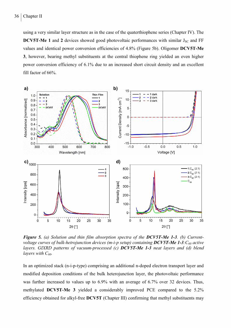
36 Chapter II
using a very similar layer structure as in the case of the quaterthiophene series (Chapter IV). The
DCV5T-Me 1 and 2 devices showed good photovoltaic performances with similar JSC and FF
values and identical power conversion efficiencies of 4.8% (Figure 5b). Oligomer DCV5T-Me
3, however, bearing methyl substituents at the central thiophene ring yielded an even higher
power conversion efficiency of 6.1% due to an increased short circuit density and an excellent
fill factor of 66%.
Figure 5. (a) Solution and thin film absorption spectra of the DCV5T-Me 1-3. (b) Current-voltage curves of bulk-hetrojunction devices (m-i-p setup) containing DCV5T-Me 1-3:C60 active layers. GIXRD patterns of vacuum-processed (c) DCV5T-Me 1-3 neat layers and (d) blend layers with C60.
In an optimized stack (n-i-p-type) comprising an additional n-doped electron transport layer and
modified deposition conditions of the bulk heterojunction layer, the photovoltaic performance
was further increased to values up to 6.9% with an average of 6.7% over 32 devices. Thus,
methylated DCV5T-Me 3 yielded a considerably improved PCE compared to the 5.2%
efficiency obtained for alkyl-free DCV5T (Chapter III) confirming that methyl substituents may
a) b)
d) c)
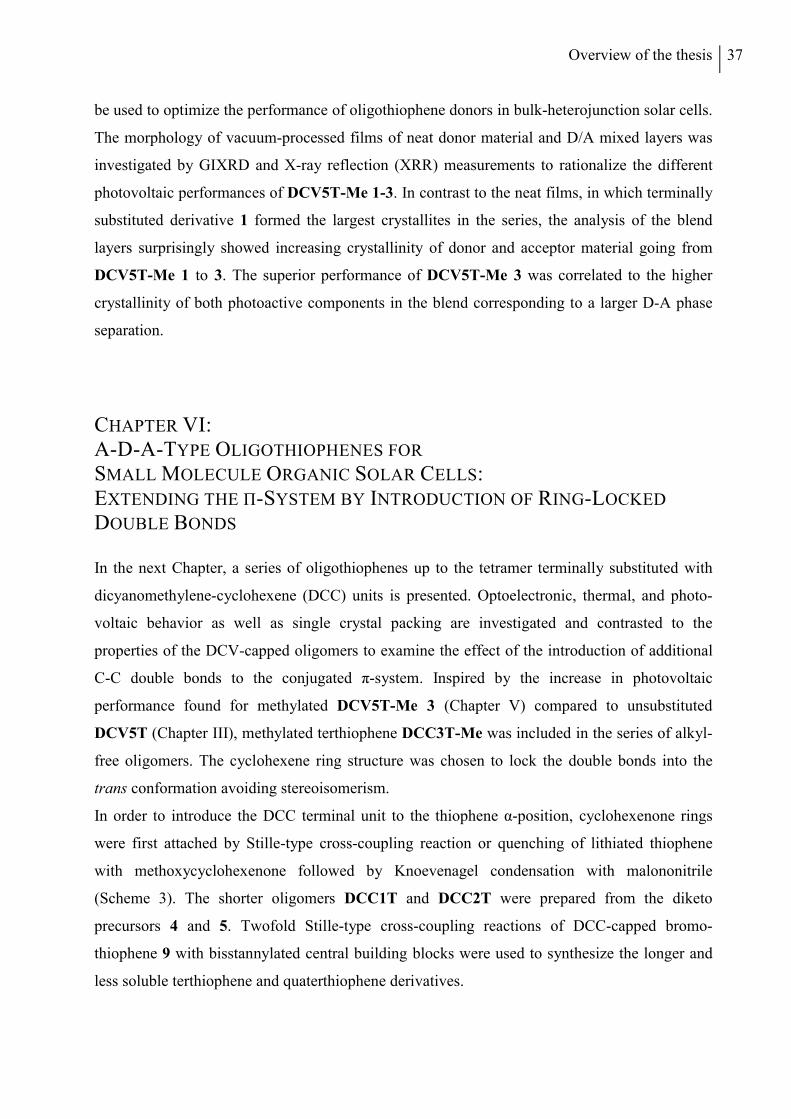
Overview of the thesis 37
be used to optimize the performance of oligothiophene donors in bulk-heterojunction solar cells.
The morphology of vacuum-processed films of neat donor material and D/A mixed layers was
investigated by GIXRD and X-ray reflection (XRR) measurements to rationalize the different
photovoltaic performances of DCV5T-Me 1-3. In contrast to the neat films, in which terminally
substituted derivative 1 formed the largest crystallites in the series, the analysis of the blend
layers surprisingly showed increasing crystallinity of donor and acceptor material going from
DCV5T-Me 1 to 3. The superior performance of DCV5T-Me 3 was correlated to the higher
crystallinity of both photoactive components in the blend corresponding to a larger D-A phase
separation.
CHAPTER VI: A-D-A-TYPE OLIGOTHIOPHENES FOR SMALL MOLECULE ORGANIC SOLAR CELLS: EXTENDING THE Π-SYSTEM BY INTRODUCTION OF RING-LOCKED
DOUBLE BONDS
In the next Chapter, a series of oligothiophenes up to the tetramer terminally substituted with
dicyanomethylene-cyclohexene (DCC) units is presented. Optoelectronic, thermal, and photo-
voltaic behavior as well as single crystal packing are investigated and contrasted to the
properties of the DCV-capped oligomers to examine the effect of the introduction of additional
C-C double bonds to the conjugated π-system. Inspired by the increase in photovoltaic
performance found for methylated DCV5T-Me 3 (Chapter V) compared to unsubstituted
DCV5T (Chapter III), methylated terthiophene DCC3T-Me was included in the series of alkyl-
free oligomers. The cyclohexene ring structure was chosen to lock the double bonds into the
trans conformation avoiding stereoisomerism.
In order to introduce the DCC terminal unit to the thiophene α-position, cyclohexenone rings
were first attached by Stille-type cross-coupling reaction or quenching of lithiated thiophene
with methoxycyclohexenone followed by Knoevenagel condensation with malononitrile
(Scheme 3). The shorter oligomers DCC1T and DCC2T were prepared from the diketo
precursors 4 and 5. Twofold Stille-type cross-coupling reactions of DCC-capped bromo-
thiophene 9 with bisstannylated central building blocks were used to synthesize the longer and
less soluble terthiophene and quaterthiophene derivatives.
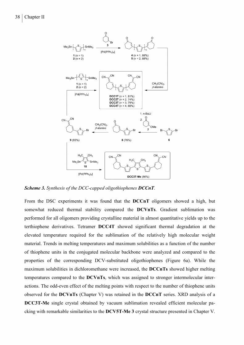
38 Chapter II
Scheme 3. Synthesis of the DCC-capped oligothiophenes DCCnT.
From the DSC experiments it was found that the DCCnT oligomers showed a high, but
somewhat reduced thermal stability compared the DCVnTs. Gradient sublimation was
performed for all oligomers providing crystalline material in almost quantitative yields up to the
terthiophene derivatives. Tetramer DCC4T showed significant thermal degradation at the
elevated temperature required for the sublimation of the relatively high molecular weight
material. Trends in melting temperatures and maximum solubilities as a function of the number
of thiophene units in the conjugated molecular backbone were analyzed and compared to the
properties of the corresponding DCV-substituted oligothiophenes (Figure 6a). While the
maximum solubilities in dichloromethane were increased, the DCCnTs showed higher melting
temperatures compared to the DCVnTs, which was assigned to stronger intermolecular inter-
actions. The odd-even effect of the melting points with respect to the number of thiophene units
observed for the DCVnTs (Chapter V) was retained in the DCCnT series. XRD analysis of a
DCC3T-Me single crystal obtained by vacuum sublimation revealed efficient molecular pa-
cking with remarkable similarities to the DCV5T-Me 3 crystal structure presented in Chapter V.
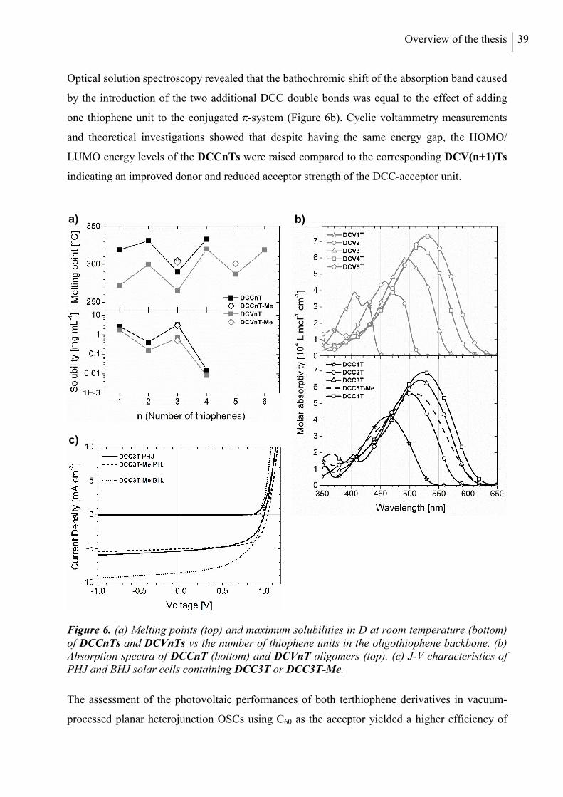
Overview of the thesis 39
Optical solution spectroscopy revealed that the bathochromic shift of the absorption band caused
by the introduction of the two additional DCC double bonds was equal to the effect of adding
one thiophene unit to the conjugated π-system (Figure 6b). Cyclic voltammetry measurements
and theoretical investigations showed that despite having the same energy gap, the HOMO/
LUMO energy levels of the DCCnTs were raised compared to the corresponding DCV(n+1)Ts
indicating an improved donor and reduced acceptor strength of the DCC-acceptor unit.
Figure 6. (a) Melting points (top) and maximum solubilities in D at room temperature (bottom) of DCCnTs and DCVnTs vs the number of thiophene units in the oligothiophene backbone. (b) Absorption spectra of DCCnT (bottom) and DCVnT oligomers (top). (c) J-V characteristics of PHJ and BHJ solar cells containing DCC3T or DCC3T-Me.
The assessment of the photovoltaic performances of both terthiophene derivatives in vacuum-
processed planar heterojunction OSCs using C60 as the acceptor yielded a higher efficiency of
a) b)
c)
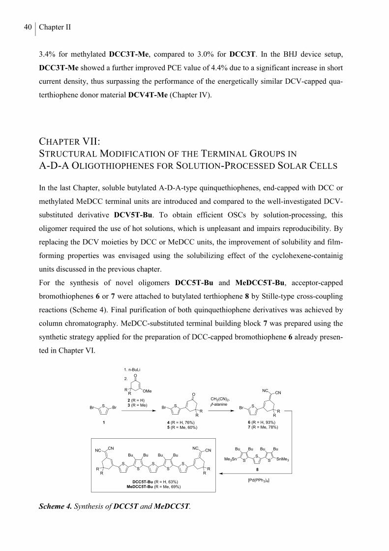
40 Chapter II
3.4% for methylated DCC3T-Me, compared to 3.0% for DCC3T. In the BHJ device setup,
DCC3T-Me showed a further improved PCE value of 4.4% due to a significant increase in short
current density, thus surpassing the performance of the energetically similar DCV-capped qua-
terthiophene donor material DCV4T-Me (Chapter IV).
CHAPTER VII: STRUCTURAL MODIFICATION OF THE TERMINAL GROUPS IN
A-D-A OLIGOTHIOPHENES FOR SOLUTION-PROCESSED SOLAR CELLS
In the last Chapter, soluble butylated A-D-A-type quinquethiophenes, end-capped with DCC or
methylated MeDCC terminal units are introduced and compared to the well-investigated DCV-
substituted derivative DCV5T-Bu. To obtain efficient OSCs by solution-processing, this
oligomer required the use of hot solutions, which is unpleasant and impairs reproducibility. By
replacing the DCV moieties by DCC or MeDCC units, the improvement of solubility and film-
forming properties was envisaged using the solubilizing effect of the cyclohexene-containig
units discussed in the previous chapter.
For the synthesis of novel oligomers DCC5T-Bu and MeDCC5T-Bu, acceptor-capped
bromothiophenes 6 or 7 were attached to butylated terthiophene 8 by Stille-type cross-coupling
reactions (Scheme 4). Final purification of both quinquethiophene derivatives was achieved by
column chromatography. MeDCC-substituted terminal building block 7 was prepared using the
synthetic strategy applied for the preparation of DCC-capped bromothiophene 6 already presen-
ted in Chapter VI.
Scheme 4. Synthesis of DCC5T and MeDCC5T.
S Br
1. n-BuLi
2.
SBr
OCH2(CN)2,
-alanine SBr
SSS
1 4 (R = H, 76%)5 (R = Me, 60%)
2 (R = H)3 (R = Me)
6 (R = H, 93%)7 (R = Me, 78%)
DCC5T-Bu (R = H, 63%)MeDCC5T-Bu (R = Me, 69%)
8
[Pd(PPh3)4]
Br
O
OMeRR
NCCN
RR
RR
SS
Bu Bu Bu Bu
RRR
R
NCCN
CNNC
SSSMe3Sn
Bu Bu Bu Bu
SnMe3
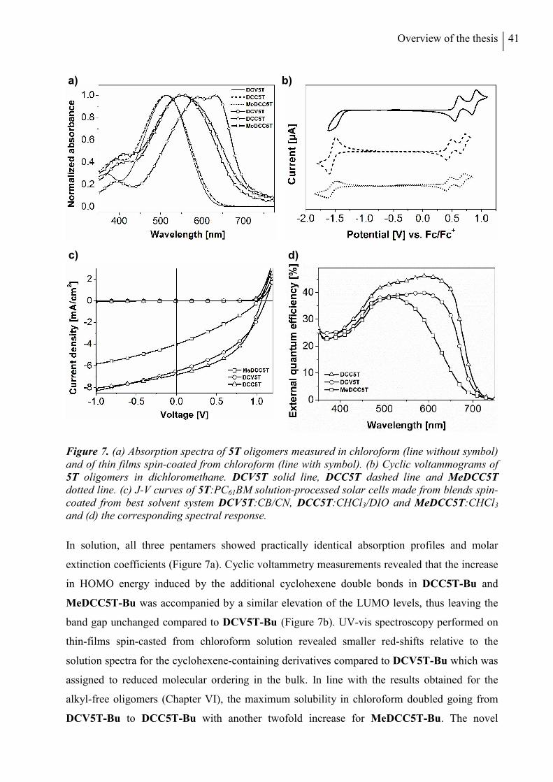
Overview of the thesis 41
Figure 7. (a) Absorption spectra of 5T oligomers measured in chloroform (line without symbol) and of thin films spin-coated from chloroform (line with symbol). (b) Cyclic voltammograms of 5T oligomers in dichloromethane. DCV5T solid line, DCC5T dashed line and MeDCC5T dotted line. (c) J-V curves of 5T:PC61BM solution-processed solar cells made from blends spin-coated from best solvent system DCV5T:CB/CN, DCC5T:CHCl3/DIO and MeDCC5T:CHCl3 and (d) the corresponding spectral response.
In solution, all three pentamers showed practically identical absorption profiles and molar
extinction coefficients (Figure 7a). Cyclic voltammetry measurements revealed that the increase
in HOMO energy induced by the additional cyclohexene double bonds in DCC5T-Bu and
MeDCC5T-Bu was accompanied by a similar elevation of the LUMO levels, thus leaving the
band gap unchanged compared to DCV5T-Bu (Figure 7b). UV-vis spectroscopy performed on
thin-films spin-casted from chloroform solution revealed smaller red-shifts relative to the
solution spectra for the cyclohexene-containing derivatives compared to DCV5T-Bu which was
assigned to reduced molecular ordering in the bulk. In line with the results obtained for the
alkyl-free oligomers (Chapter VI), the maximum solubility in chloroform doubled going from
DCV5T-Bu to DCC5T-Bu with another twofold increase for MeDCC5T-Bu. The novel
a) b)
d) c)
42 Chapter II
quinquethiophene derivatives DCC5T-Bu and MeDCC5T-Bu were incorporated into solution-
processed bulk-heterojunction solar cells using phenyl-C61-butyric acid methyl ester (PC61BM)
as acceptor. Both oligomers yielded high open circuit voltages of about 1 V. Using DCC5T-Bu
as donor material a maximum PCE value of 3.4% was obtained by adding diiodooctane (DIO) to
the chloroform solution of the photoactive materials, compared to 1.4% without solvent
additive. This improvement was due to an enhanced short circuit density according to a red-shift
and the appearance of a low-energy shoulder in EQE spectra, that could also be tracked in the
absorption spectra of solution-processed D:A blend films. MeDCC5T-Bu showed a
significantly lower BHJ device performance of 1.3% using an optimized D:A blend ratio which
may be due the additional methyl groups on the cyclohexene ring hindering efficient molecular
packing. Atomic force microscopy (AFM) measurements on DCC5T-Bu:PC61BM mixed layers
fabricated with solvent additive showed the formation of fibrilar features with finely interdigi-
tated bright and dark regions. MeDCC5T-Bu blend layers displayed a finer phase separation. In
summary, by replacement of the DCV units in DCV5T-Bu with DCC moieties, a small increase
in optimized BHJ device performance from 3.0% to 3.4% could be achieved.
PERSONAL CONTRIBUTIONS TO THE JOINED PUBLICATIONS
CHAPTER III
This manuscript is published in Advanced Functional Materials (2011, 21, 897-910) under the
title:
“Dicyanovinyl–Substituted Oligothiophenes: Structure-Property Relationships and Application
in Vacuum-Processed Small Molecule Organic Solar Cells”
by Roland Fitzner, Egon Reinold, Amaresh Mishra, Elena Mena-Osteritz, Hannah Ziehlke,
Christian Körner, Karl Leo, Moritz Riede, Matthias Weil, Olga Tsaryova, André Weiß,
Christian Uhrich, Martin Pfeiffer and Peter Bäuerle.
I synthesized and characterized all oligomers except DCV1T and DCV2T, performed thermal
gradient sublimation as well as DSC, UV-vis (solution), and CV measurements. Furthermore, I
wrote the first draft of the paper in collaboration with Dr. Amaresh Mishra and was involved in
the scientific discussion and correction of the manuscript.
Overview of the thesis 43
CHAPTER IV
This manuscript is published in Advanced Materials (2012, 24, 675-680) under the title:
“Interrelation between Crystal Packing and Small Molecule Organic Solar Cell Performance”
by Roland Fitzner, Chris Elschner, Matthias Weil, Christian Uhrich, Christian Körner, Moritz
Riede, Karl Leo, Martin Pfeiffer, Egon Reinold, Elena Mena-Osteritz, and Peter Bäuerle.
I synthesized and characterized all oligomers and performed thermal gradient sublimation as
well as DSC, UV-vis (solution), and CV measurements. I wrote the first draft of the paper and
was involved in the scientific discussion and correction of the manuscript.
CHAPTER V
This manuscript is published in the Journal of the American Chemical Society (2012, 134,
11064−11067) under the title:
“Correlation of π-Conjugated Oligomer Structure with Film Morphology and Organic Solar Cell
Performance”
by Roland Fitzner, Elena Mena-Osteritz, Amaresh Mishra, Gisela Schulz, Egon Reinold,
Matthias Weil, Christian Körner, Hannah Ziehlke, Chris Elschner, Karl Leo, Moritz Riede,
Martin Pfeiffer, Christian Uhrich, and Peter Bäuerle.
I synthesized and characterized all oligomers and performed thermal gradient sublimation as
well as DSC, UV-vis (solution), and CV measurements. Additionally, I wrote the first draft of
the paper in collaboration with Dr. Amaresh Mishra and was involved in the scientific
discussion and correction of the manuscript.
CHAPTER VI
This manuscript is published in Advanced Functional Materials (2015, online. DOI: 10.1002/
adfm.201404210) under the title:
“A-D-A-Type Oligothiophenes for Small Molecule Organic Solar Cells: Extending the π-
System by Introduction of Ring-Locked Double Bonds”
by Roland Fitzner, Elena Mena-Osteritz, Karsten Walzer, Martin Pfeiffer, and Peter Bäuerle.
44 Chapter II
I synthesized and characterized all oligomers. I performed thermal gradient sublimation as well
as DSC, UV-vis (solution), CV and solubility measurements. Further, I wrote the paper and was
involved in the scientific discussion and the correction of the manuscript.
CHAPTER VII
This manuscript is intended for submission under the title:
“Structural Modification of the Terminal Groups in A-D-A Oligothiophenes for Solution-
Processed Solar Cells”
by Roland Fitzner, Gisela L. Schulz, Florian Henne, Marta Urdanpilleta, Peter Bäuerle.
I synthesized and characterized all oligomers, performed DSC, UV-vis (solution) and CV
measurements and prepared the first solar-cell devices under supervision of Dr. Gisela Schulz
and Dr. Jegadesan Subbiah. I wrote the paper in collaboration with Dr. Gisela Schulz and was
involved in the scientific discussion and the correction of the manuscript.
Overview of the thesis 45
REFERENCES
[1] K. Schulze, C. Uhrich, R. Schüppel, K. Leo, M. Pfeiffer, E. Brier, E. Reinold, P. Bäuerle, Proc. SPIE Int. Soc. Opt. Eng. 2006, 6192, 61920C(61921-61926).
[2] K. Schulze, C. Uhrich, R. Schüppel, K. Leo, M. Pfeiffer, E. Brier, E. Reinold, P. Bäuerle, Adv. Mater. 2006, 18, 2872–2875.
[3] R. Schueppel, K. Schmidt, C. Uhrich, K. Schulze, D. Wynands, J. L. Bredas, B. Männig, M. Pfeiffer, K. Leo, E. Brier, E. Reinold, H.-B. Bu, P. Bäuerle, Proc. SPIE Int. Soc. Opt. Eng. 2007, 6656, 66560G(66561-66511).
[4] K. Schulze, B. Männig, K. Leo, Y. Tomita, C. May, J. Hupkes, E. Brier, E. Reinold, P. Bäuerle, Appl. Phys. Lett. 2007, 91, 073521-073523.
[5] M. K. Riede, R. Schueppel, K. Schulze, D. Wynands, R. Timmreck, C. Uhrich, A. Petrich, M. Pfeiffer, E. Brier, E. Reinold, P. Bäuerle, K. Leo, Proc. SPIE Int. Soc. Opt. Eng. 2008, 7002, 70020G(70021-70028).
[6] R. Schueppel, K. Schmidt, C. Uhrich, K. Schulze, D. Wynands, J. L. Bredas, E. Brier, E. Reinold, H. B. Bu, P. Bäuerle, B. Männig, M. Pfeiffer, K. Leo, Phys. Rev. B 2008, 77, 085311.
[7] K. Schulze, M. Riede, E. Brier, E. Reinold, P. Bäuerle, K. Leo, J. Appl. Phys. 2008, 104, 074511.
[8] D. Wynands, B. Männig, M. Riede, K. Leo, E. Brier, E. Reinold, P. Bäuerle, J. Appl. Phys. 2009, 106, 054509.
[9] G. L. Schulz, M. Urdanpilleta, R. Fitzner, E. Brier, E. Mena-Osteritz, E. Reinold, P. Bäuerle, Beilstein J. Nanotechnol. 2013, 4, 680-689.

46
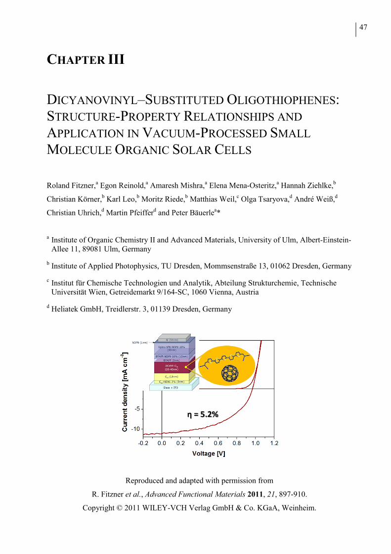
47
CHAPTER III
DICYANOVINYL–SUBSTITUTED OLIGOTHIOPHENES: STRUCTURE-PROPERTY RELATIONSHIPS AND
APPLICATION IN VACUUM-PROCESSED SMALL
MOLECULE ORGANIC SOLAR CELLS
Roland Fitzner,a Egon Reinold,a Amaresh Mishra,a Elena Mena-Osteritz,a Hannah Ziehlke,b
Christian Körner,b Karl Leo,b Moritz Riede,b Matthias Weil,c Olga Tsaryova,d André Weiß,d
Christian Uhrich,d Martin Pfeifferd and Peter Bäuerlea*
a Institute of Organic Chemistry II and Advanced Materials, University of Ulm, Albert-Einstein-
Allee 11, 89081 Ulm, Germany
b Institute of Applied Photophysics, TU Dresden, Mommsenstraße 13, 01062 Dresden, Germany
c Institut für Chemische Technologien und Analytik, Abteilung Strukturchemie, Technische Universität Wien, Getreidemarkt 9/164-SC, 1060 Vienna, Austria
d Heliatek GmbH, Treidlerstr. 3, 01139 Dresden, Germany
Reproduced and adapted with permission from
R. Fitzner et al., Advanced Functional Materials 2011, 21, 897-910.
Copyright © 2011 WILEY-VCH Verlag GmbH & Co. KGaA, Weinheim.
48 Chapter III
ABSTRACT
Efficient synthesis of a series of terminally dicyanovinyl (DCV)-substituted oligothiophenes,
DCVnT 1-6, without solubilizing side chains synthesized via a novel convergent approach and
their application as electron donors in vacuum-processed m-i-p-type planar and p-i-n-type bulk
heterojunction organic solar cells is described. Purification of the products via gradient
sublimation yielded thermally highly stable organic semiconducting materials in single
crystalline quality which allowed for X-ray structure analysis. Important insight in the packing
features and intermolecular interactions of these promising solar cell materials are provided.
Optical absorption spectra and electrochemical properties of the oligomers were investigated
and valuable structure-property relationships deduced. Photovoltaic devices incorporating
DCVnTs 4-6 showed power conversion efficiencies up to 2.8% for planar and 5.2% for bulk
heterojunction organic solar cells under full sun illumination (mismatch corrected simulated AM
1.5G sunlight). The 5.2% efficiency shown here represents one of the highest values ever
reported for organic vacuum-deposited single heterojunction solar cells.
DCVnT series – Variation of the oligothiophene chain length 49
1. INTRODUCTION
Organic solar cells (OSC) have attracted enormous interest in recent years, because of their
potential towards low-cost production on flexible substrates.[1-9] The field started by utilization
of organic small molecules[2,10-14] and later on by using functional semiconducting polymers,[5,15-
20] resulting in remarkable improvement in power conversion efficiencies over the decade from
about 1% to over 7%. To date, functionalized oligo- and polythiophenes are among the best ma-
terials for application in organic photovoltaics.[16,21]
The most frequently used material for small molecule organic solar cells (SMOSC) prepared by
vacuum-evaporation processes are represented by metal phthalocyanines (Pc) as electron donor
(D) and fullerene C60 as acceptor (A) with reported efficiencies of 5% for a single cell.[22] How-
ever, for outdoor applications, the performance of these solar cells should be improved in terms
of efficiency along with stability and costs. One aspect of improving efficiency is the use of
suitable electron donors and acceptors with optimized energy levels to minimize energetic losses
during exciton separation. In this respect, various D-A and A-A substituted oligothiophenes
have been prepared and tested in SMOSCs.[23-30]
We have demonstrated that a photovoltage (VOC) of as high as 1.0 V can be obtained by repla-
cing the frequently used metal Pcs by terminally dicyanovinyl (DCV)-substituted oligothio-
phenes bearing butyl side chains (DCV5T-Bu) for solubility reasons as donor when using
fullerene C60 as acceptor. These solar cells reached power conversion efficiencies of up to
3.4%.[24,25,31-35] The high VOC obtained is due to a high ionization potential (IP) of DCV5T-Bu
(IP = -5.6 eV). The effect of the alkyl chain length, attached at the β-position of the conjugated
backbone on device performance within the series of DCV-functionalized quinquethiophenes
was also established. Solar cells prepared from these derivatives revealed that the butyl-
substituted oligomers showed higher efficiencies (η = 3.4%) than the ethyl substituted DCVnT-
Et (η = 2.5-3.0%).[33] The reduced efficiency was mainly due to the reduced fill factor (FF). The
difference in performance was explained by the difference in packing, by differences in hole-
injection between the hole-transport layer and the oligothiophene as well as a difference in hole
mobility of the oligothiophene derivatives.
Photovoltaic properties of DCVnT-Bu (n = 4, 5 and 6) with various lengths of the oligothiophe-
ne unit were also investigated. The VOC decreased from 1.13V for DCV4T-Bu to 1.0V for
DCV5T-Bu and to 0.93V for DCV6T-Bu, which is ascribed to the decrease in their IP, respecti-
vely increase in energy of the highest occupied molecular orbital (HOMO). On the other hand,
no clear trend was observed for short-circuit current density (JSC) and fill factor (FF) values.
50 Chapter III
The power conversion efficiency of DCV4T-Bu was lower compared to DCV5T-Bu because of
its lower JSC and FF, while the small differences in JSC and FF values between DCV5T-Bu and
DCV6T-Bu do not represent a general trend.[34]
One advantage of the vacuum-processable SMOSCs is that tandem cells can easily be fabrica-
ted. Very recently, by combining in a tandem device two bulk heterojunctions of C60 in blend
layers with an optimized DCVnT-derivative and a novel pigment with absorption range
between 600 and 750 nm developed by BASF, respectively, a certified efficiency of 6.1% on 2
cm2 active area[36] and shortly after a certified record efficiency of 7.7% on 1.1 cm2 device have
been released.[37]
Herein, we investigate structure-property relationships in a series of DCVnTs with conjugated
chain lengths of one to six thiophene units (n=1-6) and without solubilizing alkyl side chains,
well being aware that synthesis and characterization of longer derivatives might be problematic
due to low solubility. However, we expect that these oligomers may show good packing and
thermal stability which might influence the solar cell performance.
2. SYNTHESIS OF DICYANOVINYL-FUNCTIONALIZED
OLIGOTHIOPHENES DCVnT
2.1. LINEAR SYNTHESES
Synthesis of the smaller members of the series, DCV1T-DCV3T 1-3, were already described in
literature and were prepared for non-linear optical properties.[38,39] Based on our experience with
alkylated DCVnTs, we firstly synthesized DCV1T-DCV4T 1-4 by a linear approach (Scheme
1). Thus, bi-, ter-, and quaterthiophene dialdehydes 8-10,[40-43] which were prepared by Vils-
meier-Haack formylation of the parent oligothiophenes[44-46] were reacted with malononitrile
and ß-alanine as catalyst to form target DCVnTs 2 and 3 (n=2, 3) in nearly quantitative yield
and in high purity. DCV1T 1 was obtained from commercially available thiophene-2,5-di-
carbaldehyde 7 and malononitrile without the use of catalyst. However, due to a dramatic de-
crease in solubility, reaction of quaterthiophene-dialdehyde 10 resulted in an inseparable mixtu-
re of target DCV4T 4 and the singly reacted intermediate with a DCV-group at one chain end
and an unreacted formyl group at the other.
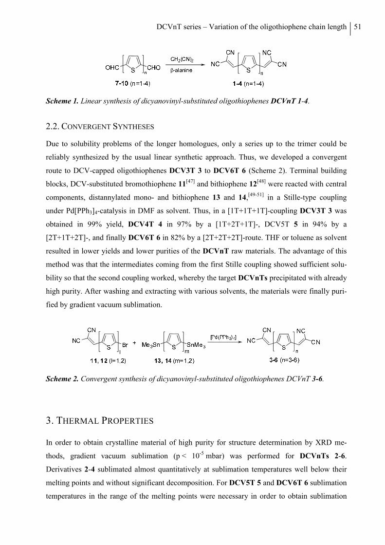
DCVnT series – Variation of the oligothiophene chain length 51
Scheme 1. Linear synthesis of dicyanovinyl-substituted oligothiophenes DCVnT 1-4.
2.2. CONVERGENT SYNTHESES
Due to solubility problems of the longer homologues, only a series up to the trimer could be
reliably synthesized by the usual linear synthetic approach. Thus, we developed a convergent
route to DCV-capped oligothiophenes DCV3T 3 to DCV6T 6 (Scheme 2). Terminal building
blocks, DCV-substituted bromothiophene 11[47] and bithiophene 12[48] were reacted with central
components, distannylated mono- and bithiophene 13 and 14,[49-51] in a Stille-type coupling
under Pd[PPh3]4-catalysis in DMF as solvent. Thus, in a [1T+1T+1T]-coupling DCV3T 3 was
obtained in 99% yield, DCV4T 4 in 97% by a [1T+2T+1T]-, DCV5T 5 in 94% by a
[2T+1T+2T]-, and finally DCV6T 6 in 82% by a [2T+2T+2T]-route. THF or toluene as solvent
resulted in lower yields and lower purities of the DCVnT raw materials. The advantage of this
method was that the intermediates coming from the first Stille coupling showed sufficient solu-
bility so that the second coupling worked, whereby the target DCVnTs precipitated with already
high purity. After washing and extracting with various solvents, the materials were finally puri-
fied by gradient vacuum sublimation.
Scheme 2. Convergent synthesis of dicyanovinyl-substituted oligothiophenes DCVnT 3-6.
3. THERMAL PROPERTIES
In order to obtain crystalline material of high purity for structure determination by XRD me-
thods, gradient vacuum sublimation (p < 10-5 mbar) was performed for DCVnTs 2-6.
Derivatives 2-4 sublimated almost quantitatively at sublimation temperatures well below their
melting points and without significant decomposition. For DCV5T 5 and DCV6T 6 sublimation
temperatures in the range of the melting points were necessary in order to obtain sublimation
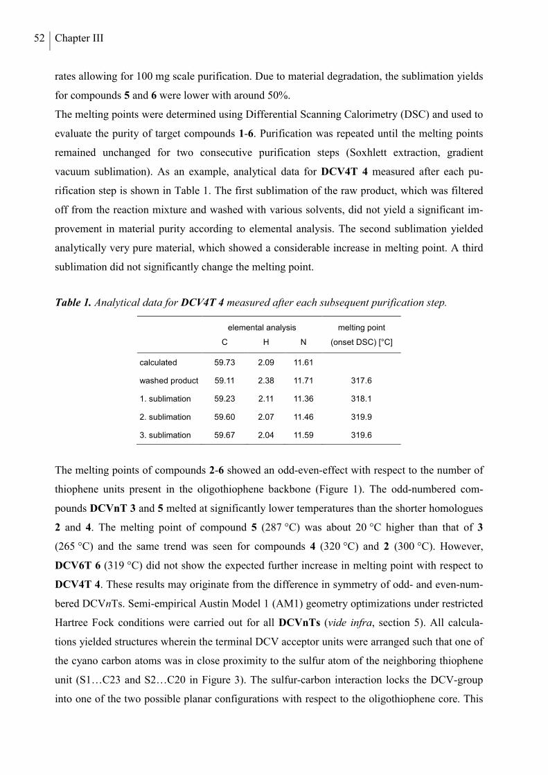
52 Chapter III
rates allowing for 100 mg scale purification. Due to material degradation, the sublimation yields
for compounds 5 and 6 were lower with around 50%.
The melting points were determined using Differential Scanning Calorimetry (DSC) and used to
evaluate the purity of target compounds 1-6. Purification was repeated until the melting points
remained unchanged for two consecutive purification steps (Soxhlett extraction, gradient
vacuum sublimation). As an example, analytical data for DCV4T 4 measured after each pu-
rification step is shown in Table 1. The first sublimation of the raw product, which was filtered
off from the reaction mixture and washed with various solvents, did not yield a significant im-
provement in material purity according to elemental analysis. The second sublimation yielded
analytically very pure material, which showed a considerable increase in melting point. A third
sublimation did not significantly change the melting point.
Table 1. Analytical data for DCV4T 4 measured after each subsequent purification step.
elemental analysis melting point
C H N (onset DSC) [°C]
calculated 59.73 2.09 11.61
washed product 59.11 2.38 11.71 317.6
1. sublimation 59.23 2.11 11.36 318.1
2. sublimation 59.60 2.07 11.46 319.9
3. sublimation 59.67 2.04 11.59 319.6
The melting points of compounds 2-6 showed an odd-even-effect with respect to the number of
thiophene units present in the oligothiophene backbone (Figure 1). The odd-numbered com-
pounds DCVnT 3 and 5 melted at significantly lower temperatures than the shorter homologues
2 and 4. The melting point of compound 5 (287 °C) was about 20 °C higher than that of 3
(265 °C) and the same trend was seen for compounds 4 (320 °C) and 2 (300 °C). However,
DCV6T 6 (319 °C) did not show the expected further increase in melting point with respect to
DCV4T 4. These results may originate from the difference in symmetry of odd- and even-num-
bered DCVnTs. Semi-empirical Austin Model 1 (AM1) geometry optimizations under restricted
Hartree Fock conditions were carried out for all DCVnTs (vide infra, section 5). All calcula-
tions yielded structures wherein the terminal DCV acceptor units were arranged such that one of
the cyano carbon atoms was in close proximity to the sulfur atom of the neighboring thiophene
unit (S1…C23 and S2…C20 in Figure 3). The sulfur-carbon interaction locks the DCV-group
into one of the two possible planar configurations with respect to the oligothiophene core. This
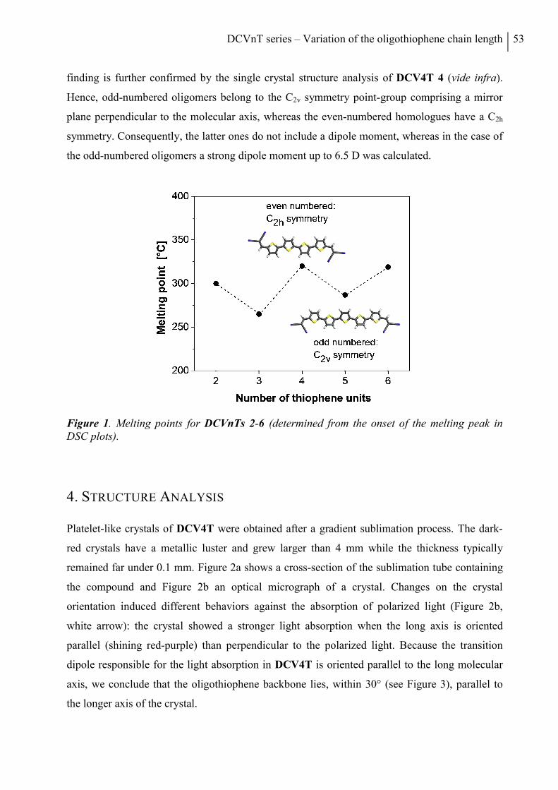
DCVnT series – Variation of the oligothiophene chain length 53
finding is further confirmed by the single crystal structure analysis of DCV4T 4 (vide infra).
Hence, odd-numbered oligomers belong to the C2v symmetry point-group comprising a mirror
plane perpendicular to the molecular axis, whereas the even-numbered homologues have a C2h
symmetry. Consequently, the latter ones do not include a dipole moment, whereas in the case of
the odd-numbered oligomers a strong dipole moment up to 6.5 D was calculated.
Figure 1. Melting points for DCVnTs 2-6 (determined from the onset of the melting peak in DSC plots).
4. STRUCTURE ANALYSIS
Platelet-like crystals of DCV4T were obtained after a gradient sublimation process. The dark-
red crystals have a metallic luster and grew larger than 4 mm while the thickness typically
remained far under 0.1 mm. Figure 2a shows a cross-section of the sublimation tube containing
the compound and Figure 2b an optical micrograph of a crystal. Changes on the crystal
orientation induced different behaviors against the absorption of polarized light (Figure 2b,
white arrow): the crystal showed a stronger light absorption when the long axis is oriented
parallel (shining red-purple) than perpendicular to the polarized light. Because the transition
dipole responsible for the light absorption in DCV4T is oriented parallel to the long molecular
axis, we conclude that the oligothiophene backbone lies, within 30° (see Figure 3), parallel to
the longer axis of the crystal.
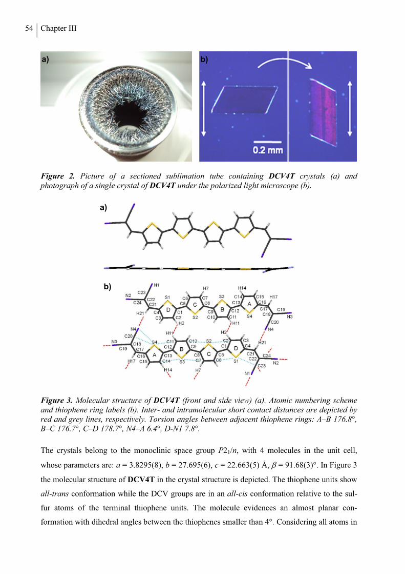
54 Chapter III
Figure 2. Picture of a sectioned sublimation tube containing DCV4T crystals (a) and photograph of a single crystal of DCV4T under the polarized light microscope (b).
Figure 3. Molecular structure of DCV4T (front and side view) (a). Atomic numbering scheme and thiophene ring labels (b). Inter- and intramolecular short contact distances are depicted by red and grey lines, respectively. Torsion angles between adjacent thiophene rings: A–B 176.8°, B–C 176.7°, C–D 178.7°, N4–A 6.4°, D-N1 7.8°.
The crystals belong to the monoclinic space group P21/n, with 4 molecules in the unit cell,
whose parameters are: a = 3.8295(8), b = 27.695(6), c = 22.663(5) Å, = 91.68(3)°. In Figure 3
the molecular structure of DCV4T in the crystal structure is depicted. The thiophene units show
all-trans conformation while the DCV groups are in an all-cis conformation relative to the sul-
fur atoms of the terminal thiophene units. The molecule evidences an almost planar con-
formation with dihedral angles between the thiophenes smaller than 4°. Considering all atoms in
b)
a)
b)
a)
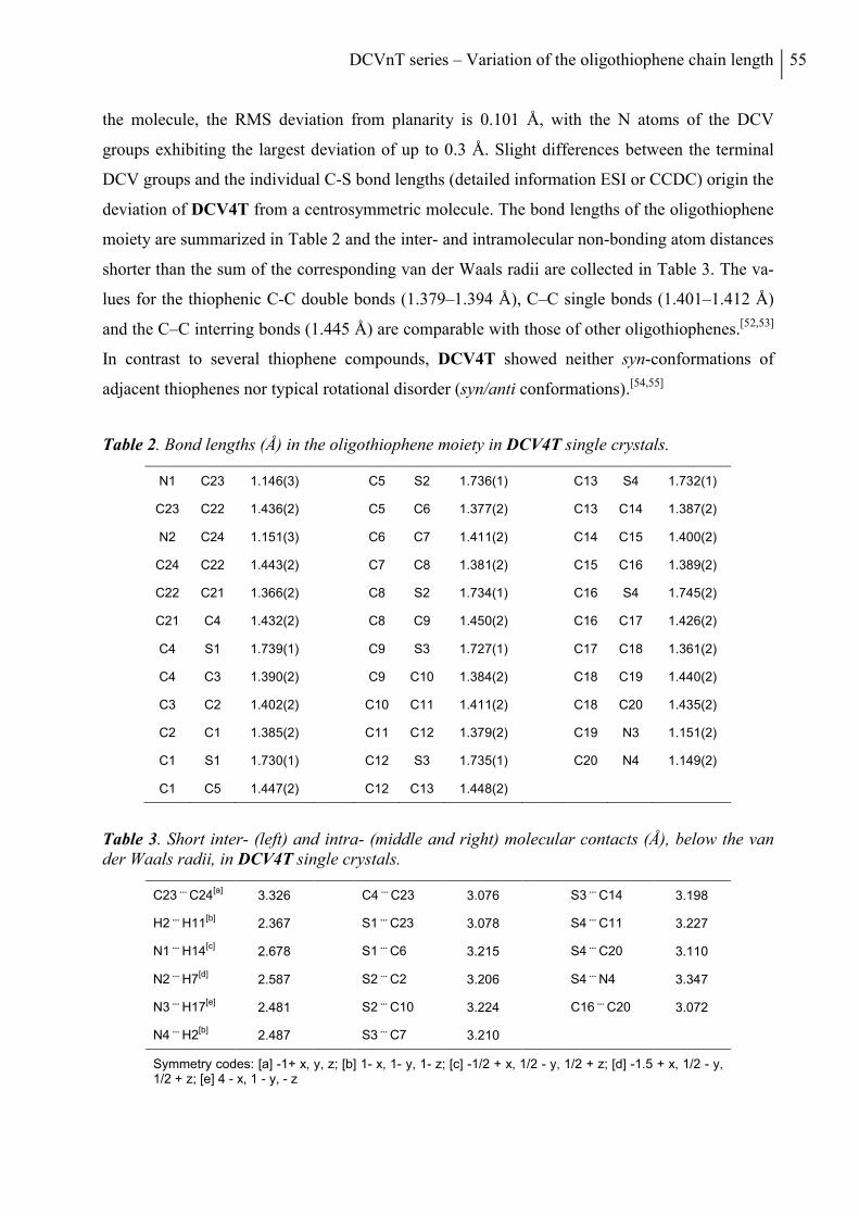
DCVnT series – Variation of the oligothiophene chain length 55
the molecule, the RMS deviation from planarity is 0.101 Å, with the N atoms of the DCV
groups exhibiting the largest deviation of up to 0.3 Å. Slight differences between the terminal
DCV groups and the individual C-S bond lengths (detailed information ESI or CCDC) origin the
deviation of DCV4T from a centrosymmetric molecule. The bond lengths of the oligothiophene
moiety are summarized in Table 2 and the inter- and intramolecular non-bonding atom distances
shorter than the sum of the corresponding van der Waals radii are collected in Table 3. The va-
lues for the thiophenic C-C double bonds (1.379–1.394 Å), C–C single bonds (1.401–1.412 Å)
and the C–C interring bonds (1.445 Å) are comparable with those of other oligothiophenes.[52,53]
In contrast to several thiophene compounds, DCV4T showed neither syn-conformations of
adjacent thiophenes nor typical rotational disorder (syn/anti conformations).[54,55]
Table 2. Bond lengths (Å) in the oligothiophene moiety in DCV4T single crystals.
N1 C23 1.146(3) C5 S2 1.736(1) C13 S4 1.732(1)
C23 C22 1.436(2) C5 C6 1.377(2) C13 C14 1.387(2)
N2 C24 1.151(3) C6 C7 1.411(2) C14 C15 1.400(2)
C24 C22 1.443(2) C7 C8 1.381(2) C15 C16 1.389(2)
C22 C21 1.366(2) C8 S2 1.734(1) C16 S4 1.745(2)
C21 C4 1.432(2) C8 C9 1.450(2) C16 C17 1.426(2)
C4 S1 1.739(1) C9 S3 1.727(1) C17 C18 1.361(2)
C4 C3 1.390(2) C9 C10 1.384(2) C18 C19 1.440(2)
C3 C2 1.402(2) C10 C11 1.411(2) C18 C20 1.435(2)
C2 C1 1.385(2) C11 C12 1.379(2) C19 N3 1.151(2)
C1 S1 1.730(1) C12 S3 1.735(1) C20 N4 1.149(2)
C1 C5 1.447(2) C12 C13 1.448(2)
Table 3. Short inter- (left) and intra- (middle and right) molecular contacts (Å), below the van der Waals radii, in DCV4T single crystals.
C23 ...
C24[a]
3.326 C4 ...
C23 3.076 S3 ...
C14 3.198
H2 ...
H11[b]
2.367 S1 ...
C23 3.078 S4 ...
C11 3.227
N1 ...
H14[c]
2.678 S1 ...
C6 3.215 S4 ...
C20 3.110
N2 ...
H7[d]
2.587 S2 ...
C2 3.206 S4 ...
N4 3.347
N3 ...
H17[e]
2.481 S2 ...
C10 3.224 C16 ...
C20 3.072
N4 ...
H2[b]
2.487 S3 ...
C7 3.210
Symmetry codes: [a] -1+ x, y, z; [b] 1- x, 1- y, 1- z; [c] -1/2 + x, 1/2 - y, 1/2 + z; [d] -1.5 + x, 1/2 - y, 1/2 + z; [e] 4 - x, 1 - y, - z
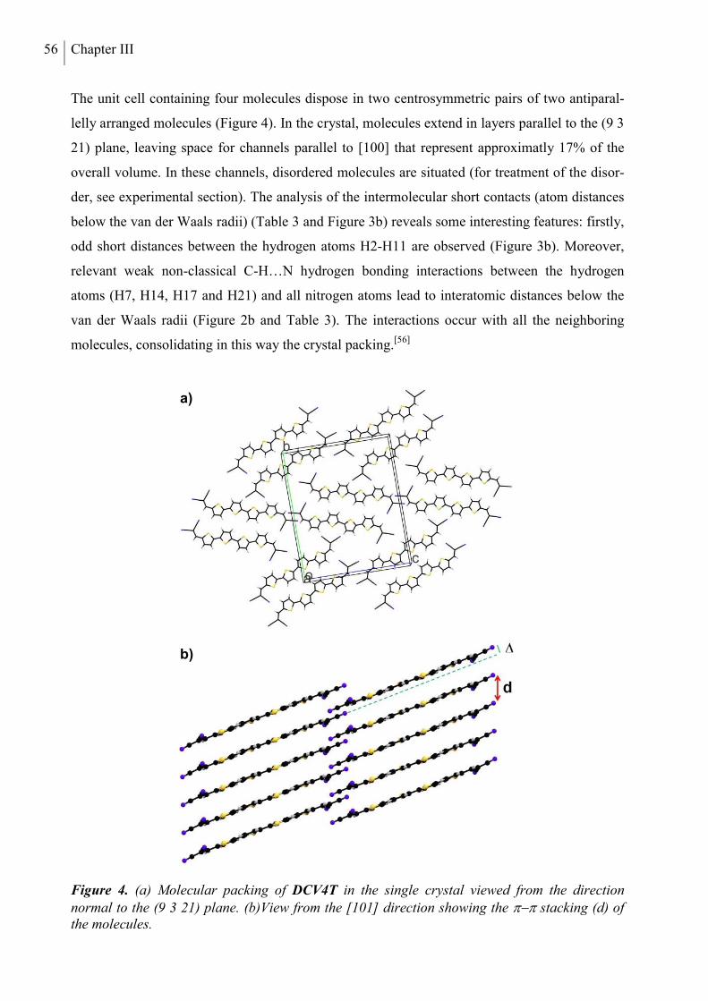
56 Chapter III
The unit cell containing four molecules dispose in two centrosymmetric pairs of two antiparal-
lelly arranged molecules (Figure 4). In the crystal, molecules extend in layers parallel to the (9 3
21) plane, leaving space for channels parallel to [100] that represent approximatly 17% of the
overall volume. In these channels, disordered molecules are situated (for treatment of the disor-
der, see experimental section). The analysis of the intermolecular short contacts (atom distances
below the van der Waals radii) (Table 3 and Figure 3b) reveals some interesting features: firstly,
odd short distances between the hydrogen atoms H2-H11 are observed (Figure 3b). Moreover,
relevant weak non-classical C-H…N hydrogen bonding interactions between the hydrogen
atoms (H7, H14, H17 and H21) and all nitrogen atoms lead to interatomic distances below the
van der Waals radii (Figure 2b and Table 3). The interactions occur with all the neighboring
molecules, consolidating in this way the crystal packing.[56]
Figure 4. (a) Molecular packing of DCV4T in the single crystal viewed from the direction normal to the (9 3 21) plane. (b)View from the [101] direction showing the stacking (d) of the molecules.
a)
b)
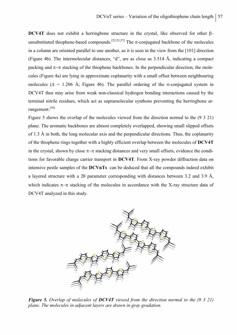
DCVnT series – Variation of the oligothiophene chain length 57
DCV4T does not exhibit a herringbone structure in the crystal, like observed for other -
unsubstituted thiophene-based compounds.[52,53,57] The -conjugated backbone of the molecules
in a column are oriented parallel to one another, as it is seen in the view from the [101] direction
(Figure 4b). The intermolecular distances, “d”, are as close as 3.514 Å, indicating a compact
packing and stacking of the thiophene backbones. In the perpendicular direction, the mole-
cules (Figure 4a) are lying in approximate coplanarity with a small offset between neighbouring
molecules ( = 1.206 Å; Figure 4b). The parallel ordering of the -conjugated system in
DCV4T thus may arise from weak non-classical hydrogen bonding interactions caused by the
terminal nitrile residues, which act as supramolecular synthons preventing the herringbone ar-
rangement.[56]
Figure 5 shows the overlap of the molecules viewed from the direction normal to the (9 3 21)
plane. The aromatic backbones are almost completely overlapped, showing small slipped offsets
of 1.3 Å in both, the long molecular axis and the perpendicular directions. Thus, the coplanarity
of the thiophene rings together with a highly efficient overlap between the molecules of DCV4T
in the crystal, shown by close stacking distances and very small offsets, evidence the condi-
tions for favorable charge carrier transport in DCV4T. From X-ray powder diffraction data on
intensive pestle samples of the DCVnTs can be deduced that all the compounds indeed exhibit
a layered structure with a 2 parameter corresponding with distances between 3.2 and 3.9 Å,
which indicates stacking of the molecules in accordance with the X-ray structure data of
DCV4T analyzed in this study.
Figure 5. Overlap of molecules of DCV4T viewed from the direction normal to the (9 3 21) plane. The molecules in adjacent layers are drawn in gray gradation.
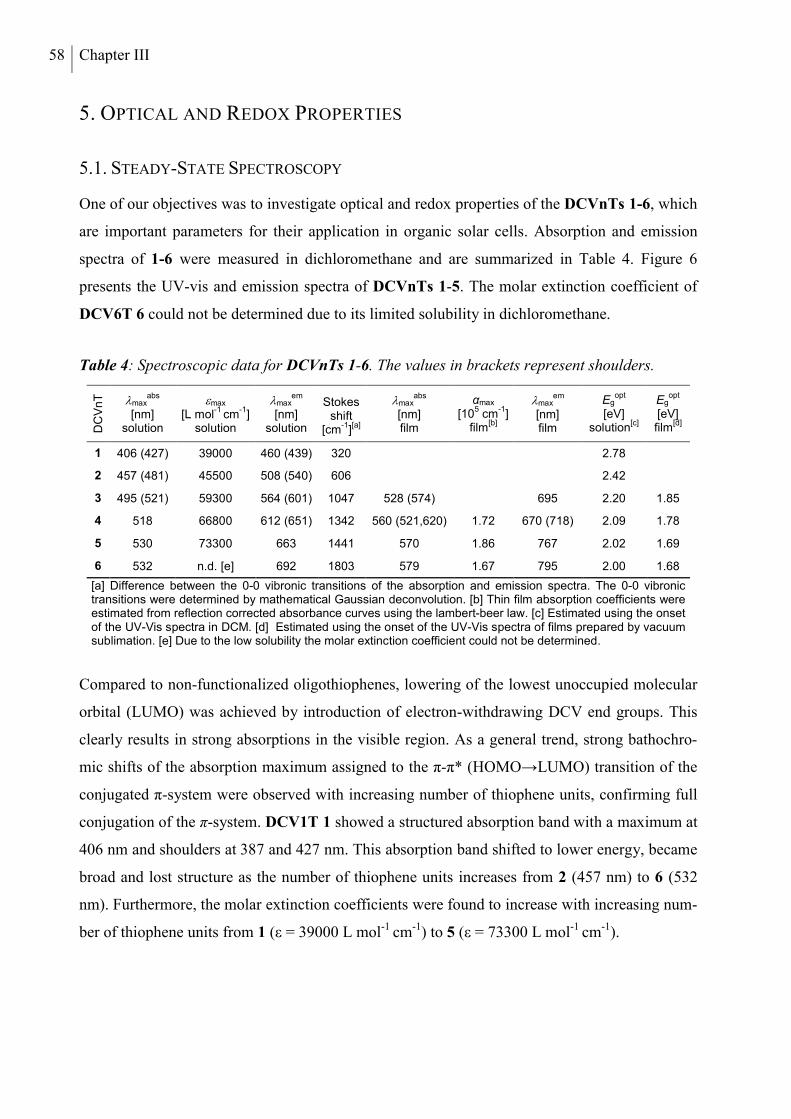
58 Chapter III
5. OPTICAL AND REDOX PROPERTIES
5.1. STEADY-STATE SPECTROSCOPY
One of our objectives was to investigate optical and redox properties of the DCVnTs 1-6, which
are important parameters for their application in organic solar cells. Absorption and emission
spectra of 1-6 were measured in dichloromethane and are summarized in Table 4. Figure 6
presents the UV-vis and emission spectra of DCVnTs 1-5. The molar extinction coefficient of
DCV6T 6 could not be determined due to its limited solubility in dichloromethane.
Table 4: Spectroscopic data for DCVnTs 1-6. The values in brackets represent shoulders.
DC
Vn
T
maxabs
[nm]
solution
max [L mol
-1 cm
-1]
solution
maxem
[nm]
solution
Stokes shift
[cm-1][a]
maxabs
[nm] film
αmax [10
5 cm
-1]
film[b]
maxem
[nm] film
Egopt
[eV]
solution[c]
Egopt
[eV] film
[d]
1 406 (427) 39000 460 (439) 320 2.78
2 457 (481) 45500 508 (540) 606 2.42
3 495 (521) 59300 564 (601) 1047 528 (574) 695 2.20 1.85
4 518 66800 612 (651) 1342 560 (521,620) 1.72 670 (718) 2.09 1.78
5 530 73300 663 1441 570 1.86 767 2.02 1.69
6
532 n.d. [e] 692 1803 579 1.67 795 2.00 1.68
[a] Difference between the 0-0 vibronic transitions of the absorption and emission spectra. The 0-0 vibronic transitions were determined by mathematical Gaussian deconvolution. [b] Thin film absorption coefficients were estimated from reflection corrected absorbance curves using the lambert-beer law. [c] Estimated using the onset of the UV-Vis spectra in DCM. [d] Estimated using the onset of the UV-Vis spectra of films prepared by vacuum sublimation. [e] Due to the low solubility the molar extinction coefficient could not be determined.
Compared to non-functionalized oligothiophenes, lowering of the lowest unoccupied molecular
orbital (LUMO) was achieved by introduction of electron-withdrawing DCV end groups. This
clearly results in strong absorptions in the visible region. As a general trend, strong bathochro-
mic shifts of the absorption maximum assigned to the π-π* (HOMO→LUMO) transition of the
conjugated π-system were observed with increasing number of thiophene units, confirming full
conjugation of the π-system. DCV1T 1 showed a structured absorption band with a maximum at
406 nm and shoulders at 387 and 427 nm. This absorption band shifted to lower energy, became
broad and lost structure as the number of thiophene units increases from 2 (457 nm) to 6 (532
nm). Furthermore, the molar extinction coefficients were found to increase with increasing num-
ber of thiophene units from 1 (ε = 39000 L mol-1 cm-1) to 5 (ε = 73300 L mol-1 cm-1).
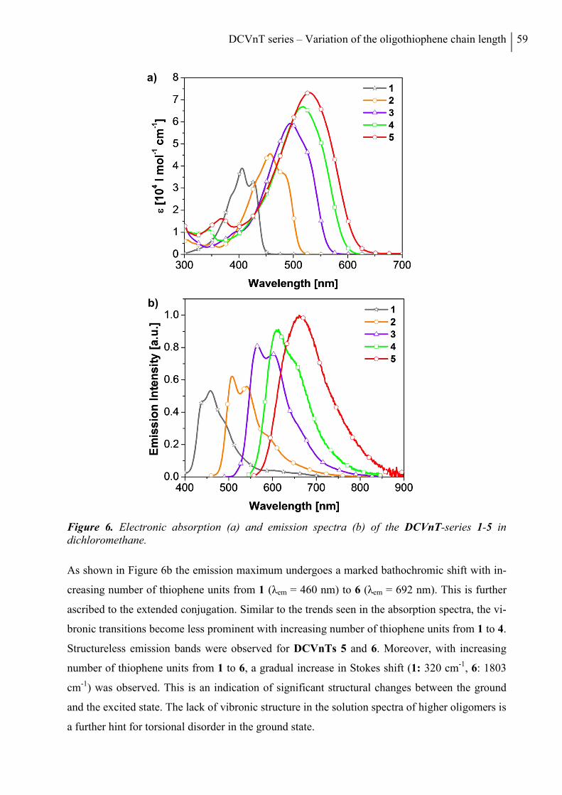
DCVnT series – Variation of the oligothiophene chain length 59
Figure 6. Electronic absorption (a) and emission spectra (b) of the DCVnT-series 1-5 in dichloromethane.
As shown in Figure 6b the emission maximum undergoes a marked bathochromic shift with in-
creasing number of thiophene units from 1 (λem = 460 nm) to 6 (λem = 692 nm). This is further
ascribed to the extended conjugation. Similar to the trends seen in the absorption spectra, the vi-
bronic transitions become less prominent with increasing number of thiophene units from 1 to 4.
Structureless emission bands were observed for DCVnTs 5 and 6. Moreover, with increasing
number of thiophene units from 1 to 6, a gradual increase in Stokes shift (1: 320 cm-1, 6: 1803
cm-1) was observed. This is an indication of significant structural changes between the ground
and the excited state. The lack of vibronic structure in the solution spectra of higher oligomers is
a further hint for torsional disorder in the ground state.
a)
b)
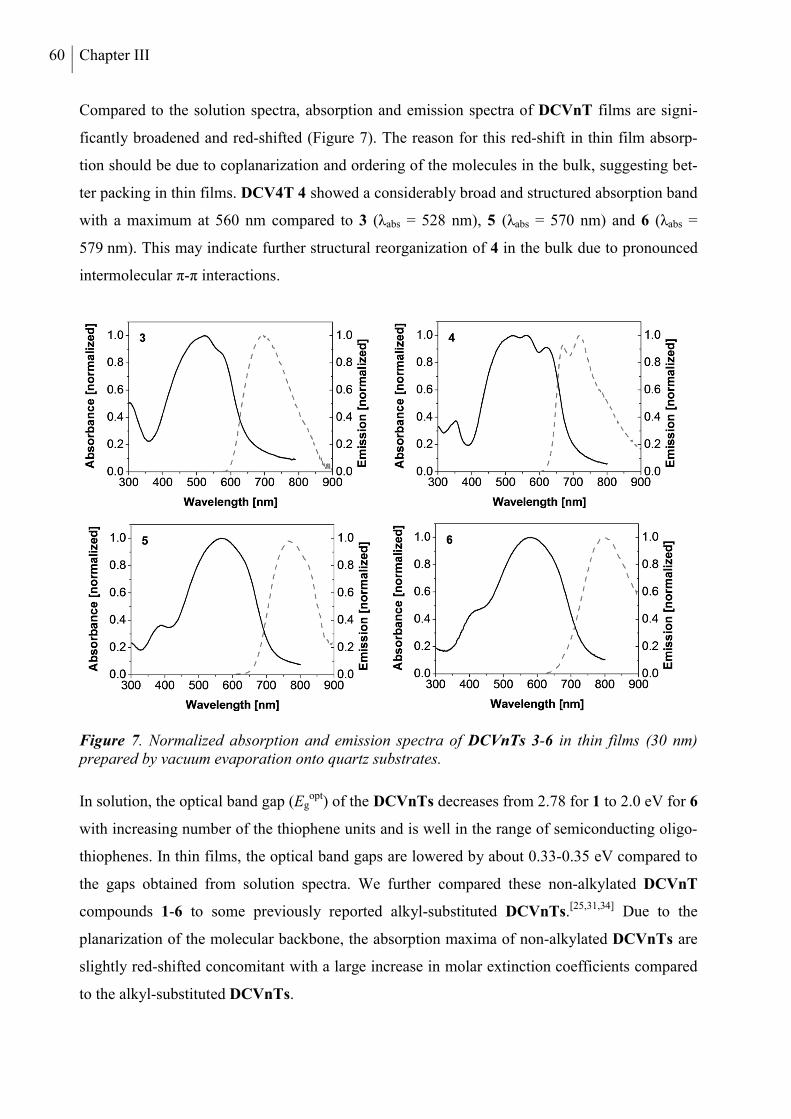
60 Chapter III
Compared to the solution spectra, absorption and emission spectra of DCVnT films are signi-
ficantly broadened and red-shifted (Figure 7). The reason for this red-shift in thin film absorp-
tion should be due to coplanarization and ordering of the molecules in the bulk, suggesting bet-
ter packing in thin films. DCV4T 4 showed a considerably broad and structured absorption band
with a maximum at 560 nm compared to 3 (λabs = 528 nm), 5 (λabs = 570 nm) and 6 (λabs =
579 nm). This may indicate further structural reorganization of 4 in the bulk due to pronounced
intermolecular π-π interactions.
Figure 7. Normalized absorption and emission spectra of DCVnTs 3-6 in thin films (30 nm) prepared by vacuum evaporation onto quartz substrates.
In solution, the optical band gap (Egopt) of the DCVnTs decreases from 2.78 for 1 to 2.0 eV for 6
with increasing number of the thiophene units and is well in the range of semiconducting oligo-
thiophenes. In thin films, the optical band gaps are lowered by about 0.33-0.35 eV compared to
the gaps obtained from solution spectra. We further compared these non-alkylated DCVnT
compounds 1-6 to some previously reported alkyl-substituted DCVnTs.[25,31,34] Due to the
planarization of the molecular backbone, the absorption maxima of non-alkylated DCVnTs are
slightly red-shifted concomitant with a large increase in molar extinction coefficients compared
to the alkyl-substituted DCVnTs.
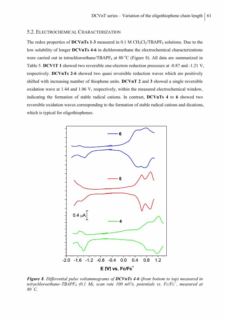
DCVnT series – Variation of the oligothiophene chain length 61
5.2. ELECTROCHEMICAL CHARACTERIZATION
The redox properties of DCVnTs 1-3 measured in 0.1 M CH2Cl2/TBAPF6 solutions. Due to the
low solubility of longer DCVnTs 4-6 in dichloromethane the electrochemical characterizations
were carried out in tetrachloroethane/TBAPF6 at 80 oC (Figure 8). All data are summarized in
Table 5. DCV1T 1 showed two reversible one-electron reduction processes at -0.87 and -1.21 V,
respectively. DCVnTs 2-6 showed two quasi reversible reduction waves which are positively
shifted with increasing number of thiophene units. DCVnT 2 and 3 showed a single reversible
oxidation wave at 1.44 and 1.06 V, respectively, within the measured electrochemical window,
indicating the formation of stable radical cations. In contrast, DCVnTs 4 to 6 showed two
reversible oxidation waves corresponding to the formation of stable radical cations and dications,
which is typical for oligothiophenes.
Figure 8. Differential pulse voltammograms of DCVnTs 4-6 (from bottom to top) measured in tetrachloroethane–TBAPF6 (0.1 M), scan rate 100 mV/s, potentials vs. Fc/Fc+, measured at 80 °C.
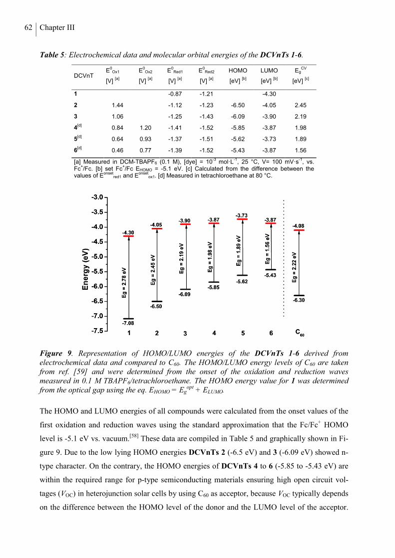
62 Chapter III
Table 5: Electrochemical data and molecular orbital energies of the DCVnTs 1-6.
DCVnT E
0Ox1
[V] [a]
E0
Ox2
[V] [a]
E0
Red1
[V] [a]
E0
Red2
[V] [a]
HOMO
[eV] [b]
LUMO
[eV] [b]
EgCV
[eV] [c]
1 -0.87 -1.21
-4.30
2 1.44 -1.12 -1.23 -6.50 -4.05 2.45
3 1.06 -1.25 -1.43 -6.09 -3.90 2.19
4[d]
0.84 1.20 -1.41 -1.52 -5.85 -3.87 1.98
5[d]
0.64 0.93 -1.37 -1.51 -5.62 -3.73 1.89
6[d]
0.46 0.77 -1.39 -1.52 -5.43 -3.87 1.56
[a] Measured in DCM-TBAPF6 (0.1 M), [dye] = 10-3
mol·L-1
, 25 °C, V= 100 mV·s-1
, vs. Fc
+/Fc. [b] set Fc
+/Fc EHOMO = -5.1 eV. [c] Calculated from the difference between the
values of Eonset
red1 and Eonset
ox1. [d] Measured in tetrachloroethane at 80 °C.
Figure 9. Representation of HOMO/LUMO energies of the DCVnTs 1-6 derived from electrochemical data and compared to C60. The HOMO/LUMO energy levels of C60 are taken from ref. [59] and were determined from the onset of the oxidation and reduction waves measured in 0.1 M TBAPF6/tetrachloroethane. The HOMO energy value for 1 was determined from the optical gap using the eq. EHOMO = Eg
opt + ELUMO.
The HOMO and LUMO energies of all compounds were calculated from the onset values of the
first oxidation and reduction waves using the standard approximation that the Fc/Fc+ HOMO
level is -5.1 eV vs. vacuum.[58] These data are compiled in Table 5 and graphically shown in Fi-
gure 9. Due to the low lying HOMO energies DCVnTs 2 (-6.5 eV) and 3 (-6.09 eV) showed n-
type character. On the contrary, the HOMO energies of DCVnTs 4 to 6 (-5.85 to -5.43 eV) are
within the required range for p-type semiconducting materials ensuring high open circuit vol-
tages (VOC) in heterojunction solar cells by using C60 as acceptor, because VOC typically depends
on the difference between the HOMO level of the donor and the LUMO level of the acceptor.
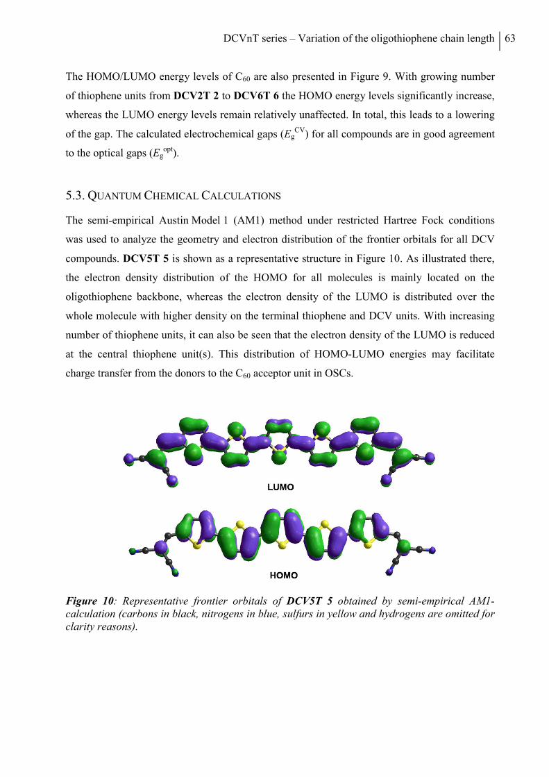
DCVnT series – Variation of the oligothiophene chain length 63
The HOMO/LUMO energy levels of C60 are also presented in Figure 9. With growing number
of thiophene units from DCV2T 2 to DCV6T 6 the HOMO energy levels significantly increase,
whereas the LUMO energy levels remain relatively unaffected. In total, this leads to a lowering
of the gap. The calculated electrochemical gaps (EgCV) for all compounds are in good agreement
to the optical gaps (Egopt).
5.3. QUANTUM CHEMICAL CALCULATIONS
The semi-empirical Austin Model 1 (AM1) method under restricted Hartree Fock conditions
was used to analyze the geometry and electron distribution of the frontier orbitals for all DCV
compounds. DCV5T 5 is shown as a representative structure in Figure 10. As illustrated there,
the electron density distribution of the HOMO for all molecules is mainly located on the
oligothiophene backbone, whereas the electron density of the LUMO is distributed over the
whole molecule with higher density on the terminal thiophene and DCV units. With increasing
number of thiophene units, it can also be seen that the electron density of the LUMO is reduced
at the central thiophene unit(s). This distribution of HOMO-LUMO energies may facilitate
charge transfer from the donors to the C60 acceptor unit in OSCs.
Figure 10: Representative frontier orbitals of DCV5T 5 obtained by semi-empirical AM1-calculation (carbons in black, nitrogens in blue, sulfurs in yellow and hydrogens are omitted for clarity reasons).
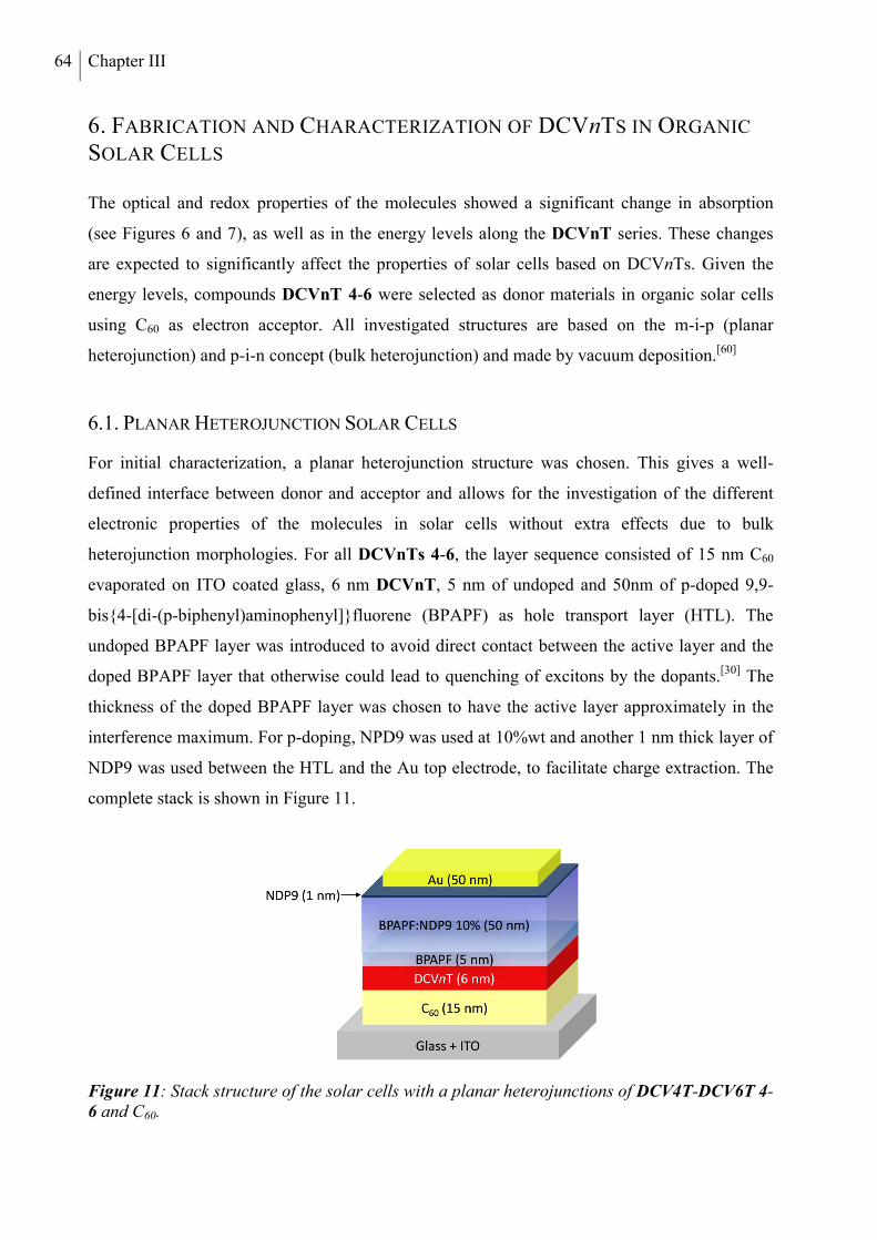
64 Chapter III
6. FABRICATION AND CHARACTERIZATION OF DCVnTS IN ORGANIC
SOLAR CELLS
The optical and redox properties of the molecules showed a significant change in absorption
(see Figures 6 and 7), as well as in the energy levels along the DCVnT series. These changes
are expected to significantly affect the properties of solar cells based on DCVnTs. Given the
energy levels, compounds DCVnT 4-6 were selected as donor materials in organic solar cells
using C60 as electron acceptor. All investigated structures are based on the m-i-p (planar
heterojunction) and p-i-n concept (bulk heterojunction) and made by vacuum deposition.[60]
6.1. PLANAR HETEROJUNCTION SOLAR CELLS
For initial characterization, a planar heterojunction structure was chosen. This gives a well-
defined interface between donor and acceptor and allows for the investigation of the different
electronic properties of the molecules in solar cells without extra effects due to bulk
heterojunction morphologies. For all DCVnTs 4-6, the layer sequence consisted of 15 nm C60
evaporated on ITO coated glass, 6 nm DCVnT, 5 nm of undoped and 50nm of p-doped 9,9-
bis4-[di-(p-biphenyl)aminophenyl]fluorene (BPAPF) as hole transport layer (HTL). The
undoped BPAPF layer was introduced to avoid direct contact between the active layer and the
doped BPAPF layer that otherwise could lead to quenching of excitons by the dopants.[30] The
thickness of the doped BPAPF layer was chosen to have the active layer approximately in the
interference maximum. For p-doping, NPD9 was used at 10%wt and another 1 nm thick layer of
NDP9 was used between the HTL and the Au top electrode, to facilitate charge extraction. The
complete stack is shown in Figure 11.
Figure 11: Stack structure of the solar cells with a planar heterojunctions of DCV4T-DCV6T 4-6 and C60.
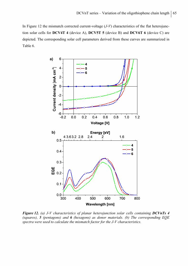
DCVnT series – Variation of the oligothiophene chain length 65
In Figure 12 the mismatch corrected current-voltage (J-V) characteristics of the flat heterojunc-
tion solar cells for DCV4T 4 (device A), DCV5T 5 (device B) and DCV6T 6 (device C) are
depicted. The corresponding solar cell parameters derived from these curves are summarized in
Table 6.
Figure 12. (a) J-V characteristics of planar heterojunction solar cells containing DCVnTs 4 (squares), 5 (pentagons) and 6 (hexagons) as donor materials. (b) The corresponding EQE spectra were used to calculate the mismatch factor for the J-V characteristics.
a)
b)
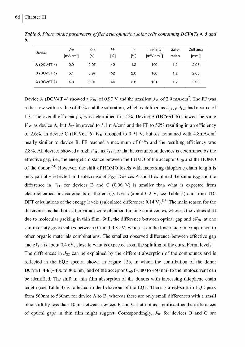
66 Chapter III
Table 6. Photovoltaic parameters of flat heterojunction solar cells containing DCVnTs 4, 5 and 6.
Device JSC
[mA cm²]
VOC
[V]
FF
[%]
η
[%]
Intensity
[mW cm-2]
Satu-
ration
Cell area
[mm²]
A (DCV4T 4) 2.9 0.97 42 1.2 100 1.3 2.96
B (DCV5T 5) 5.1 0.97 52 2.6 106 1.2 2.83
C (DCV6T 6) 4.8 0.91 64 2.8 101 1.2 2.96
Device A (DCV4T 4) showed a VOC of 0.97 V and the smallest JSC of 2.9 mA/cm2. The FF was
rather low with a value of 42% and the saturation, which is defined as J(-1V)/ JSC, had a value of
1.3. The overall efficiency was determined to 1.2%. Device B (DCV5T 5) showed the same
VOC as device A, but JSC improved to 5.1 mA/cm2 and the FF to 52% resulting in an efficiency
of 2.6%. In device C (DCV6T 6) VOC dropped to 0.91 V, but JSC remained with 4.8mA/cm2
nearly similar to device B. FF reached a maximum of 64% and the resulting efficiency was
2.8%. All devices showed a high VOC, as VOC for flat heterojunction devices is determined by the
effective gap, i.e., the energetic distance between the LUMO of the acceptor C60 and the HOMO
of the donor.[61] However, the shift of HOMO levels with increasing thiophene chain length is
only partially reflected in the decrease of VOC. Devices A and B exhibited the same VOC and the
difference in VOC for devices B and C (0.06 V) is smaller than what is expected from
electrochemical measurements of the energy levels (about 0.2 V, see Table 6) and from TD-
DFT calculations of the energy levels (calculated difference: 0.14 V).[34] The main reason for the
differences is that both latter values were obtained for single molecules, whereas the values shift
due to molecular packing in thin film. Still, the difference between optical gap and eVOC at one
sun intensity gives values between 0.7 and 0.8 eV, which is on the lower side in comparison to
other organic materials combinations. The smallest observed difference between effective gap
and eVOC is about 0.4 eV, close to what is expected from the splitting of the quasi Fermi levels.
The differences in JSC can be explained by the different absorption of the compounds and is
reflected in the EQE spectra shown in Figure 12b, in which the contribution of the donor
DCVnT 4-6 (~400 to 800 nm) and of the acceptor C60 (~300 to 450 nm) to the photocurrent can
be identified. The shift in thin film absorption of the donors with increasing thiophene chain
length (see Table 4) is reflected in the behaviour of the EQE. There is a red-shift in EQE peak
from 560nm to 580nm for device A to B, whereas there are only small differences with a small
blue-shift by less than 10nm between devices B and C, but not as significant as the differences
of optical gaps in thin film might suggest. Correspondingly, JSC for devices B and C are
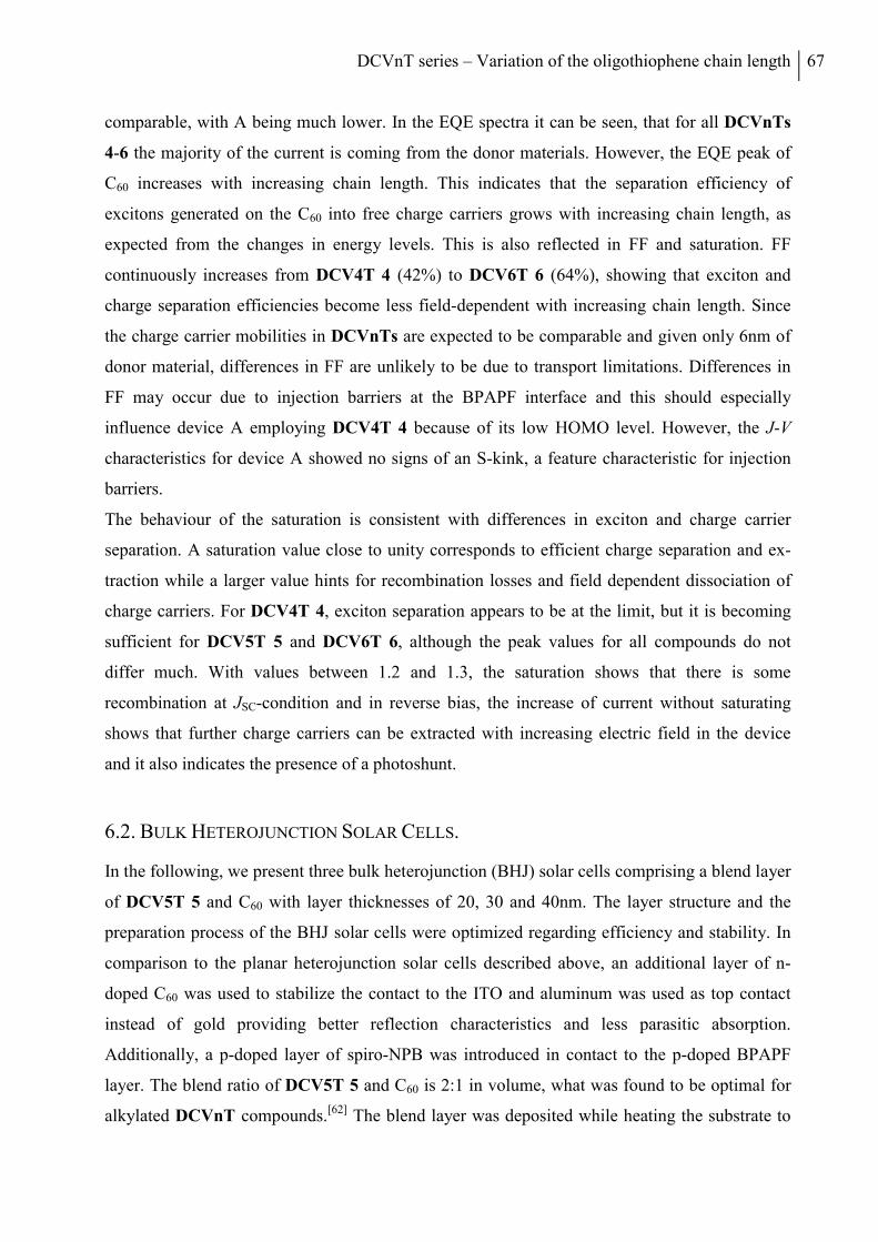
DCVnT series – Variation of the oligothiophene chain length 67
comparable, with A being much lower. In the EQE spectra it can be seen, that for all DCVnTs
4-6 the majority of the current is coming from the donor materials. However, the EQE peak of
C60 increases with increasing chain length. This indicates that the separation efficiency of
excitons generated on the C60 into free charge carriers grows with increasing chain length, as
expected from the changes in energy levels. This is also reflected in FF and saturation. FF
continuously increases from DCV4T 4 (42%) to DCV6T 6 (64%), showing that exciton and
charge separation efficiencies become less field-dependent with increasing chain length. Since
the charge carrier mobilities in DCVnTs are expected to be comparable and given only 6nm of
donor material, differences in FF are unlikely to be due to transport limitations. Differences in
FF may occur due to injection barriers at the BPAPF interface and this should especially
influence device A employing DCV4T 4 because of its low HOMO level. However, the J-V
characteristics for device A showed no signs of an S-kink, a feature characteristic for injection
barriers.
The behaviour of the saturation is consistent with differences in exciton and charge carrier
separation. A saturation value close to unity corresponds to efficient charge separation and ex-
traction while a larger value hints for recombination losses and field dependent dissociation of
charge carriers. For DCV4T 4, exciton separation appears to be at the limit, but it is becoming
sufficient for DCV5T 5 and DCV6T 6, although the peak values for all compounds do not
differ much. With values between 1.2 and 1.3, the saturation shows that there is some
recombination at JSC-condition and in reverse bias, the increase of current without saturating
shows that further charge carriers can be extracted with increasing electric field in the device
and it also indicates the presence of a photoshunt.
6.2. BULK HETEROJUNCTION SOLAR CELLS.
In the following, we present three bulk heterojunction (BHJ) solar cells comprising a blend layer
of DCV5T 5 and C60 with layer thicknesses of 20, 30 and 40nm. The layer structure and the
preparation process of the BHJ solar cells were optimized regarding efficiency and stability. In
comparison to the planar heterojunction solar cells described above, an additional layer of n-
doped C60 was used to stabilize the contact to the ITO and aluminum was used as top contact
instead of gold providing better reflection characteristics and less parasitic absorption.
Additionally, a p-doped layer of spiro-NPB was introduced in contact to the p-doped BPAPF
layer. The blend ratio of DCV5T 5 and C60 is 2:1 in volume, what was found to be optimal for
alkylated DCVnT compounds.[62] The blend layer was deposited while heating the substrate to
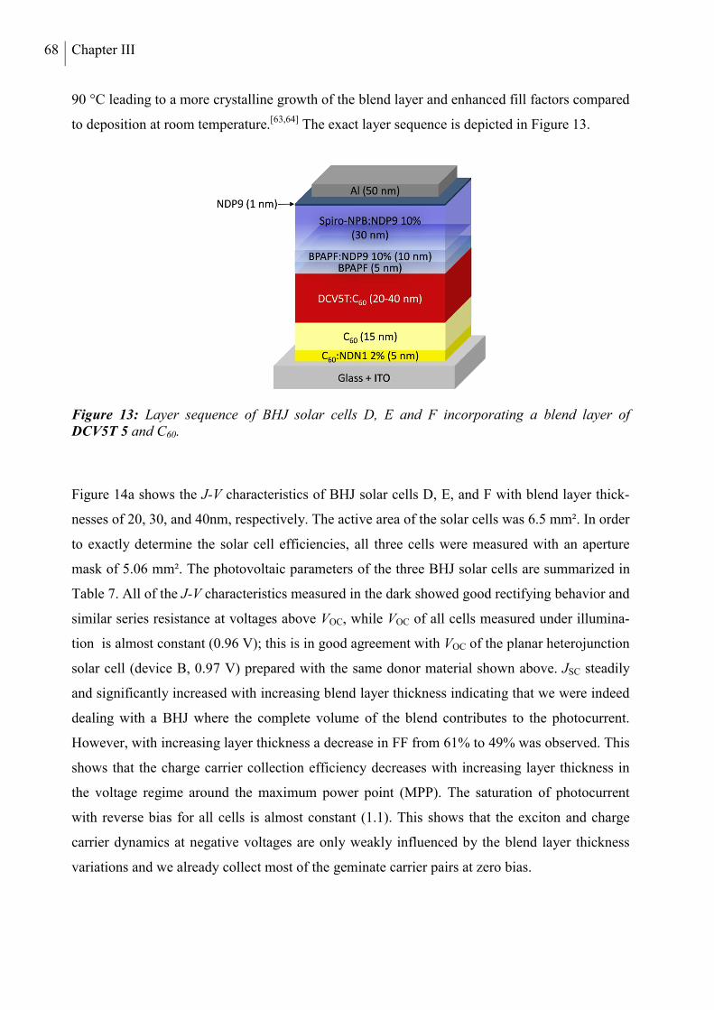
68 Chapter III
90 °C leading to a more crystalline growth of the blend layer and enhanced fill factors compared
to deposition at room temperature.[63,64] The exact layer sequence is depicted in Figure 13.
Figure 13: Layer sequence of BHJ solar cells D, E and F incorporating a blend layer of DCV5T 5 and C60.
Figure 14a shows the J-V characteristics of BHJ solar cells D, E, and F with blend layer thick-
nesses of 20, 30, and 40nm, respectively. The active area of the solar cells was 6.5 mm². In order
to exactly determine the solar cell efficiencies, all three cells were measured with an aperture
mask of 5.06 mm². The photovoltaic parameters of the three BHJ solar cells are summarized in
Table 7. All of the J-V characteristics measured in the dark showed good rectifying behavior and
similar series resistance at voltages above VOC, while VOC of all cells measured under illumina-
tion is almost constant (0.96 V); this is in good agreement with VOC of the planar heterojunction
solar cell (device B, 0.97 V) prepared with the same donor material shown above. JSC steadily
and significantly increased with increasing blend layer thickness indicating that we were indeed
dealing with a BHJ where the complete volume of the blend contributes to the photocurrent.
However, with increasing layer thickness a decrease in FF from 61% to 49% was observed. This
shows that the charge carrier collection efficiency decreases with increasing layer thickness in
the voltage regime around the maximum power point (MPP). The saturation of photocurrent
with reverse bias for all cells is almost constant (1.1). This shows that the exciton and charge
carrier dynamics at negative voltages are only weakly influenced by the blend layer thickness
variations and we already collect most of the geminate carrier pairs at zero bias.
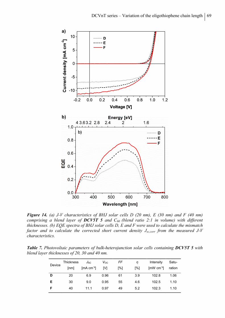
DCVnT series – Variation of the oligothiophene chain length 69
Figure 14. (a) J-V characteristics of BHJ solar cells D (20 nm), E (30 nm) and F (40 nm) comprising a blend layer of DCV5T 5 and C60 (blend ratio 2:1 in volume) with different thicknesses. (b) EQE spectra of BHJ solar cells D, E and F were used to calculate the mismatch factor and to calculate the corrected short current density Jsc,corr from the measured J-V characteristics.
Table 7. Photovoltaic parameters of bulk-heterojunction solar cells containing DCV5T 5 with blend layer thicknesses of 20, 30 and 40 nm.
Device Thickness
[nm]
JSC
[mA cm-²]
VOC
[V]
FF
[%]
η
[%]
Intensity
[mW cm-²]
Satu-
ration
D 20 6.9 0.96 61 3.9 102.8 1.06
E 30 9.0 0.95 55 4.6 102.5 1.10
F 40 11.1 0.97 49 5.2 102.3 1.10
a)
b)
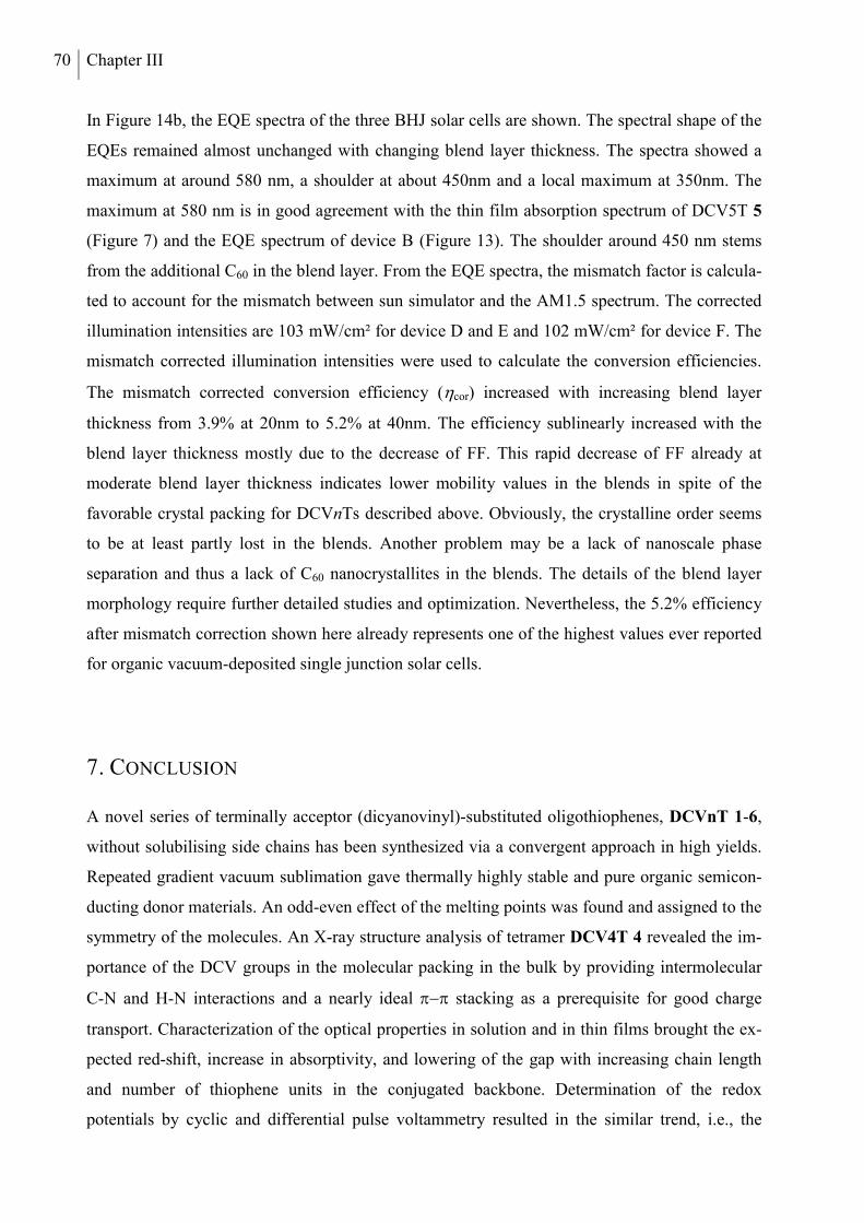
70 Chapter III
In Figure 14b, the EQE spectra of the three BHJ solar cells are shown. The spectral shape of the
EQEs remained almost unchanged with changing blend layer thickness. The spectra showed a
maximum at around 580 nm, a shoulder at about 450nm and a local maximum at 350nm. The
maximum at 580 nm is in good agreement with the thin film absorption spectrum of DCV5T 5
(Figure 7) and the EQE spectrum of device B (Figure 13). The shoulder around 450 nm stems
from the additional C60 in the blend layer. From the EQE spectra, the mismatch factor is calcula-
ted to account for the mismatch between sun simulator and the AM1.5 spectrum. The corrected
illumination intensities are 103 mW/cm² for device D and E and 102 mW/cm² for device F. The
mismatch corrected illumination intensities were used to calculate the conversion efficiencies.
The mismatch corrected conversion efficiency (cor) increased with increasing blend layer
thickness from 3.9% at 20nm to 5.2% at 40nm. The efficiency sublinearly increased with the
blend layer thickness mostly due to the decrease of FF. This rapid decrease of FF already at
moderate blend layer thickness indicates lower mobility values in the blends in spite of the
favorable crystal packing for DCVnTs described above. Obviously, the crystalline order seems
to be at least partly lost in the blends. Another problem may be a lack of nanoscale phase
separation and thus a lack of C60 nanocrystallites in the blends. The details of the blend layer
morphology require further detailed studies and optimization. Nevertheless, the 5.2% efficiency
after mismatch correction shown here already represents one of the highest values ever reported
for organic vacuum-deposited single junction solar cells.
7. CONCLUSION
A novel series of terminally acceptor (dicyanovinyl)-substituted oligothiophenes, DCVnT 1-6,
without solubilising side chains has been synthesized via a convergent approach in high yields.
Repeated gradient vacuum sublimation gave thermally highly stable and pure organic semicon-
ducting donor materials. An odd-even effect of the melting points was found and assigned to the
symmetry of the molecules. An X-ray structure analysis of tetramer DCV4T 4 revealed the im-
portance of the DCV groups in the molecular packing in the bulk by providing intermolecular
C-N and H-N interactions and a nearly ideal stacking as a prerequisite for good charge
transport. Characterization of the optical properties in solution and in thin films brought the ex-
pected red-shift, increase in absorptivity, and lowering of the gap with increasing chain length
and number of thiophene units in the conjugated backbone. Determination of the redox
potentials by cyclic and differential pulse voltammetry resulted in the similar trend, i.e., the
DCVnT series – Variation of the oligothiophene chain length 71
HOMO energies increase with increasing chain length, whereas the LUMO values stay nearly
unaffected. The longer oligomers DCVnT 4-6 were implemented in vacuum-processed planar
heterojunction organic solar cells and mismatch-corrected efficiencies of 1.2-2.8% have been
achieved under full sun illumination. The optimization of bulk heterojunction solar cells using a
40 nm active layer of DCV5T 5 and C60 in a 2:1-ratio resulted in a mismatch-corrected value of
5.2% for a 5.06 mm2-sized and masked device. The 5.2% efficiency reported here represents
one of the highest values ever reported for organic vacuum-deposited single junction solar cells
and clearly shows the advantage of a higher internal interface in bulk heterojunctions compared
to planar heterojunctions. Thus, the structural fine-tuning of these A-D-A-type oligothiophenes
led to highly efficient materials with sufficiently good electronic and charge transport properties,
which are crucial prerequisites in bulk heterojunction devices.
8. EXPERIMENTAL
INSTRUMENTS AND SPECTROSCOPIC MEASUREMENTS
NMR spectra were recorded on a Bruker AMX 500 (1H NMR: 500 MHz, 13C NMR: 125 MHz)
or an Avance 400 spectrometer (1H NMR: 400 MHz), at 25 °C or 100 °C. Chemical shift values
() are expressed in parts per million using residual solvent protons (1H NMR, H = 2.50 for
DMSO-d6 and H = 5.93 for tetrachloroethane-d2; 13C NMR, C = 74.20 tetrachloroethane-d2) as
internal standard. The splitting patterns are designated as follows: s (singlet), d (doublet) and m
(multiplet). The assignments are ThH (thiophene protons) and DCVH (dicyanovinyl protons).
Melting points were determined using a Mettler Toledo DSC 823e and were not corrected. Ele-
mental analyses were performed on an Elementar Vario EL. CI mass spectra were recorded on a
Finnigan MAT SSQ-7000.
X-ray diffraction data of DCV4T were collected on a Bruker APEX-II CCD area detector
diffractometer using graphite-monochromated Mo Kα radiation. Correction for absorption
(multi-scan method) was applied. The structure was solved by direct methods and refined on F2
with the SHELXTL program package.[65] All non-H atoms were refined anisotropically. The
thiophene H-atoms were placed in calculated positions and refined as riding. The structure
contains accessible voids with a volume of ca. 400 Å3. These voids represent approximately
17% of the overall volume and are filled with heavily disordered molecules, discernible from the
smeared electron density (maximum electron density within the voids 4.2 e-Å-3). This disorder
72 Chapter III
could not be resolved during refinement; electron density associated with peaks in these voids
was eventually omitted by applying the SQUEEZE option in PLATON.[66] DCV4T:
C24H10N4S4, Mr = 482.60, dark-red needle with metallic lustre, 0.55x0.12x0.06 mm3, mono-
clinic, P21/n, a = 3.8295(8) Å, b = 27.695(6) Å, c = 22.663(5) Å, = 91.68(3)°, V = 2402.5(8)
Å3, Z = 4, = 0.414 mm-1, dx = 1.334 g∙cm-3, T = 100 K. 36948 reflections collected (θmax =
35.0°) and merged to 10230 independent data (Rint = 0.046); final R indices (I > 2σ(I)): R1 =
0.0488, wR2 = 0.1176. Detailed crystallographic data for structure DCV4T has been deposited
with the Cambridge Crystallographic Data Centre as supplementary publication CCDC 786021.
Optical measurements in solution were carried out in 1 cm cuvettes with Merck Uvasol grade
solvents. Absorption spectra were recorded on a Perkin Elmer Lambda 19 spectrometer and
corrected fluorescence spectra were recorded on a Perkin Elmer LS 55 fluorescence
spectrometer. Cyclic voltammetry experiments were performed with a computer-controlled
Autolab PGSTAT30 potentiostat in a three-electrode single-compartment cell with a platinum
working electrode, a platinum wire counter electrode, and an Ag/AgCl reference electrode. All
potentials were internally referenced to the ferrocene/ferrocenium couple.
THIN FILM AND DEVICE FABRICATION
Thin films and heterojunction solar cell devices were prepared by thermal vapor deposition in
ultra-high vacuum at a base pressure of 10-8 mbar onto the substrate at room temperature. Thin
films for absorption and emission measurements were prepared on quartz substrates, solar cells
on tin-doped indium oxide (ITO) coated glass (Thin Film Devices, USA, sheet resistance of
30 Ω/sq.). Layer thicknesses were determined during evaporation by using quartz crystal
monitors calibrated for the respective material. The thin films prepared for absorption and
emission measurements are approximately 30 nm thick. . Thin film absorption spectra were
recorded on a Shimadzu UV-2101/3101 UV-Vis spectrometer. The thin film emission spectra
were recorded with a Edinburgh Instruments FSP920 fluoresence spectrometer. The flat hetero-
junction solar cells were prepared layer by layer without breaking the vacuum and were
encapsulated after processing using a glass cover under nitrogen atmosphere. The layer structure
of the flat heterojunction solar cells is as follows: ITO; 15 nm C60 (Bucky, USA); 6 nm DCVnT
4-6; 5 nm 9,9-bis[4-(N,N-bis-biphenyl-4-yl-amino)phenyl]-9H-fluorene (BPAPF, Lumtec,
Taiwan; ionization potential (IP) measured -5.6 eV); 50 nm BPAPF doped with p-dopant NDP9
(Novaled AG, Germany) with a doping concentration of 10 weight per cent (wt%); 1 nm NDP9;
50 nm Au. BPAPF and C60 were purified at least twice by vacuum gradient sublimation prior to
DCVnT series – Variation of the oligothiophene chain length 73
sample preparation; the dopant was used as received. NDP9 is used because of better
processability, but doping of materials with low lying HOMO can be achieved in a comparable
way using WO3.
The layer structure of the bulk heterojunction solar cells: ITO; 5nm C60 (Bucky, USA) n-doped
by coevaporation with NDN1 (Novaled AG, Germany) (2wt%); 15nm C60; 20 to 40nm blend
layer of DCV5T 5 and C60 (ratio 2:1 in volume) prepared by coevaporation deposited on heated
substrate (90 °C); 5nm BPAPF; 10 nm BPAPF doped with NDP9 (10wt%); 30 nm N,N'-bis-
(naphthalen-1-yl)-N,N'-bis(phenyl)-9,9-spirobifluorene (spiro-NPB, Lumtec, Taiwan) doped
with NDP9 (10wt%); 1 nm NDP9; 100nm aluminium. Instead of acridine orange base (AOB) as
n-dopant for C60, NDN1 is used because of better processability, but a comparable doping per-
formance.
PHOTOVOLTAIC CHARACTERIZATION
EQE measurements for the heterojunction solar cell devices were conducted at a custom-made
setup utilizing a xenon arc lamp, a monochromator (Newport Cornerstone) and a lock-in
amplifier (Signal Recovery 7265 DSP). A silicon reference diode (Hamamatsu S1337) was used
to calibrate the setup. J-V characteristics were measured using an automated setup consisting of
a source-measure unit (Keithley SMU 2400) and an AM 1.5G sun simulator (KHS Technical
Lighting SC1200). The intensity was monitored with a silicon photodiode (Hamamatsu S1337)
which was calibrated at Fraunhofer ISE. The mismatch between the spectrum of the sun
simulator and the AM 1.5G spectrum was determined by taking these spectra as well as the
spectral responses of the reference diode and the sample (from EQE measurements) into
account. For well-defined active solar cell areas, aperture masks were used.
REAGENTS AND CHEMICALS
Dimethylformamide (Merck) was first refluxed over P4O10 and distilled, then refluxed over BaO
and distilled again. All synthetic steps were carried out under argon atmosphere. n-butyl lithium
(1.6 N in n-hexane) and CuCl2 were purchased from Merck. Malononitrile, trimethyltin chloride,
2-isopropoxy-4,4,5,5-tetramethyl[1,3,2]dioxaborolane, 2,5-dibromothiophene, 5-bromothio-
phene-2-carboxaldehyde and thiophene-2,5-dicarbaldehyde 7 were purchased from Aldrich.
2,2’-Bithiophene was synthesized from lithiated thiophene by oxidative coupling with CuCl2 in
80% yield.[47] Ter-and quaterthiophene were prepared from 2,5-dibromothiophene and 5,5’-di-
bromo-2,2'-bithiophene[67] using Suzuki-type coupling with 2-(thien-2-yl)-4,4,5,5-tetramethyl-
74 Chapter III
[1,3,2]dioxaborolane[68] in yields of 96% and 85%, respectively. The oligothiophenes gave dial-
dehydes 8-10 by Vilsmeier-Haack formylation.[40-43] Compounds 11 and 12 were synthesized
from 5-bromothiophene-2-carboxaldehyde and 5-bromo-5'-formyl-2,2'-bithiophene[43] by reac-
tion with malononitrile in yields of 70% and 93%, respectively.[47,48] Distannylated compounds
13 and 14 were synthesized according to literature.[49-51] and recrystallized before use.
SYNTHESIS AND CHARACTERIZATION
Synthesis of 2,2'-[thien-2,5-diylbis(methane-1-yl-1-ylidene)]dimalononitrile 1: A solution of
thiophene-2,5-dicarbaldehyde 7 (400 mg, 2.85 mmol) and malononitrile (766 mg, 11.6 mmol) in
ethanol (35 mL) was stirred at room temperature for 10 min. The precipitate was filtered off and
recrystallized from methanol to give 1 (654 mg, 2.77 mmol, 97%) as yellow needles. M.p.
272 oC (DSC). 1H NMR (tetrachloroethane-d2, 100 °C, δ ppm) 7.87 (s, 2H, DCVH), 7.79 (s, 2H,
ThH). 13C NMR (tetrachloroethane-d2, 100 °C, δ ppm) 148.52, 142.05, 136.49, 112.83, 112.25,
84.58. CI mass 237 [M+H+] (calcd. for C12H4N4S 236.02). Elemental analysis for C12H4N4S:
calcd. C, 61.01; H, 1.71; N, 23.71%; found: C, 61.10; H, 1.80; N, 23.58%.
Synthesis of 2,2'-[2,2'-bithien-5,5'-diylbis(methane-1-yl-1-ylidene)]dimalononitrile 2: A solution
of 2,2'-bithiophene-5,5'-dicarbaldehyde 8 (1.00 g, 4.50 mmol), malononitrile (891 mg,
13.5 mmol) and β-alanine (25 mg, 0.062 mmol) in a mixture of dichloroethane (110 mL) and
ethanol (110 mL) was stirred at 60 °C for 22 hours. The reaction mixture was allowed to cool to
room temperature, the precipitate filtered off and washed with ethanol. The crude product was
washed with hot dichloromethane to provide DCV2T 2 (1.42 g, 4.45 mmol, 99 %) as red solid.
The compound was further purified by gradient vacuum sublimation. M.p. 300 oC (DSC). 1H
NMR (DMSO-d6, δ ppm) 8.71 (s, 2H, DCVH), 7.95 (d, 2H, J = 4.09 Hz, ThH), 7.89 (d, 2H, J =
4.07 Hz, ThH). CI mass 319 [M+H+] (calcd. for C16H6N4S2 318.00). Elemental analysis for
C16H6N4S2: calcd. C, 60.36; H, 1.90; N, 17.60%; found: C, 60.46; H, 1.96; N, 17.43%.
Synthesis of 2,2'-[2,2':5',2"-terthien-5,5"-diylbis(methane-1-yl-1-ylidine)]dimalononitrile 3 by
linear synthesis: A solution of 2,2’:5',2''-terthiophene-5,5''-dicarbaldehyde 9 (500 mg,
1.64 mmol), malononitrile (651 mg, 9.9 mmol) and β-alanine (18 mg, 0.2 mmol) in a mixture of
dichloroethane (80 mL) and ethanol (80 mL) were stirred under reflux overnight. The reaction
mixture was allowed to cool to room temperature, the precipitate filtered off and washed tho-
roughly with ethanol to provide compound 3 (652 mg, 1.63 mmol, 99 %) as deep red solid.
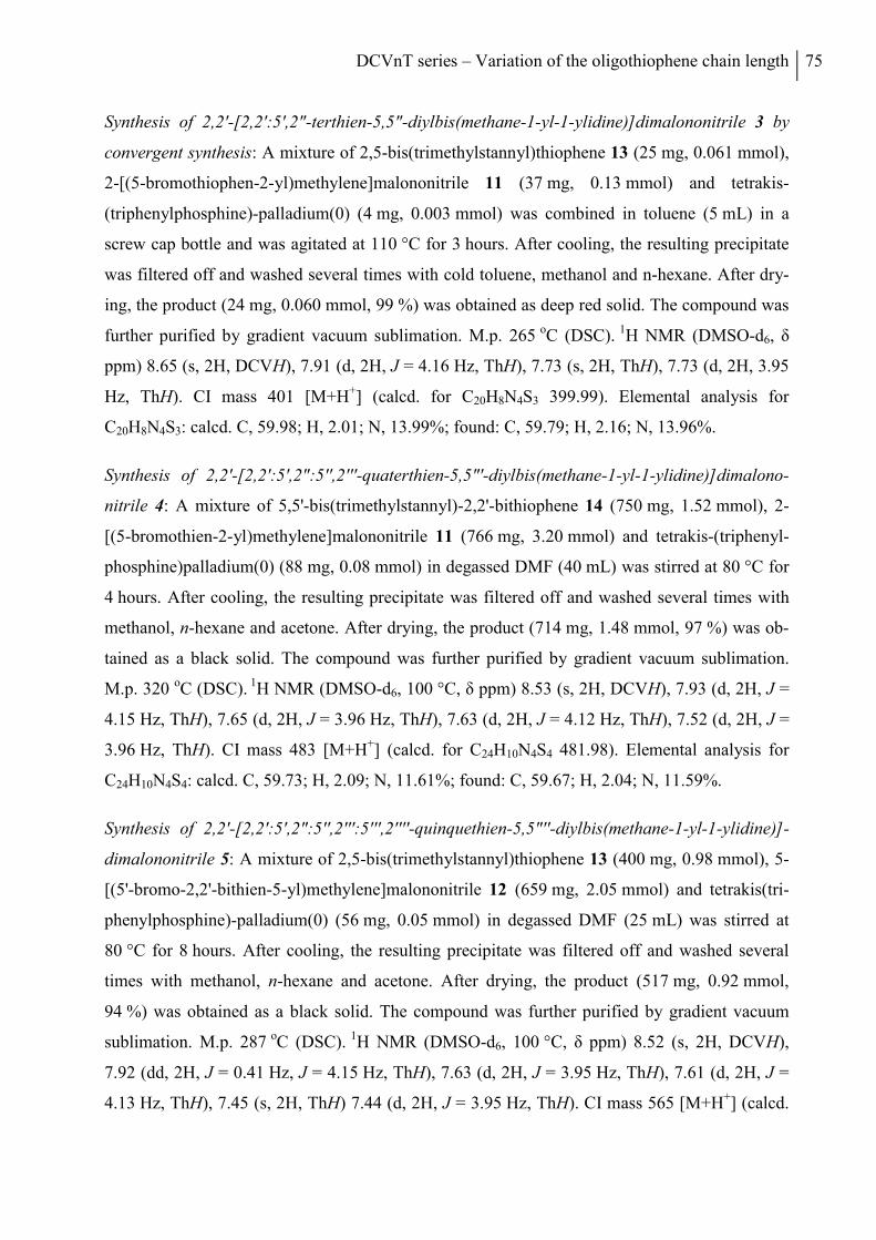
DCVnT series – Variation of the oligothiophene chain length 75
Synthesis of 2,2'-[2,2':5',2"-terthien-5,5"-diylbis(methane-1-yl-1-ylidine)]dimalononitrile 3 by
convergent synthesis: A mixture of 2,5-bis(trimethylstannyl)thiophene 13 (25 mg, 0.061 mmol),
2-[(5-bromothiophen-2-yl)methylene]malononitrile 11 (37 mg, 0.13 mmol) and tetrakis-
(triphenylphosphine)-palladium(0) (4 mg, 0.003 mmol) was combined in toluene (5 mL) in a
screw cap bottle and was agitated at 110 °C for 3 hours. After cooling, the resulting precipitate
was filtered off and washed several times with cold toluene, methanol and n-hexane. After dry-
ing, the product (24 mg, 0.060 mmol, 99 %) was obtained as deep red solid. The compound was
further purified by gradient vacuum sublimation. M.p. 265 oC (DSC). 1H NMR (DMSO-d6, δ
ppm) 8.65 (s, 2H, DCVH), 7.91 (d, 2H, J = 4.16 Hz, ThH), 7.73 (s, 2H, ThH), 7.73 (d, 2H, 3.95
Hz, ThH). CI mass 401 [M+H+] (calcd. for C20H8N4S3 399.99). Elemental analysis for
C20H8N4S3: calcd. C, 59.98; H, 2.01; N, 13.99%; found: C, 59.79; H, 2.16; N, 13.96%.
Synthesis of 2,2'-[2,2':5',2":5'',2'''-quaterthien-5,5"'-diylbis(methane-1-yl-1-ylidine)]dimalono-
nitrile 4: A mixture of 5,5'-bis(trimethylstannyl)-2,2'-bithiophene 14 (750 mg, 1.52 mmol), 2-
[(5-bromothien-2-yl)methylene]malononitrile 11 (766 mg, 3.20 mmol) and tetrakis-(triphenyl-
phosphine)palladium(0) (88 mg, 0.08 mmol) in degassed DMF (40 mL) was stirred at 80 °C for
4 hours. After cooling, the resulting precipitate was filtered off and washed several times with
methanol, n-hexane and acetone. After drying, the product (714 mg, 1.48 mmol, 97 %) was ob-
tained as a black solid. The compound was further purified by gradient vacuum sublimation.
M.p. 320 oC (DSC). 1H NMR (DMSO-d6, 100 °C, δ ppm) 8.53 (s, 2H, DCVH), 7.93 (d, 2H, J =
4.15 Hz, ThH), 7.65 (d, 2H, J = 3.96 Hz, ThH), 7.63 (d, 2H, J = 4.12 Hz, ThH), 7.52 (d, 2H, J =
3.96 Hz, ThH). CI mass 483 [M+H+] (calcd. for C24H10N4S4 481.98). Elemental analysis for
C24H10N4S4: calcd. C, 59.73; H, 2.09; N, 11.61%; found: C, 59.67; H, 2.04; N, 11.59%.
Synthesis of 2,2'-[2,2':5',2":5'',2''':5''',2''''-quinquethien-5,5"''-diylbis(methane-1-yl-1-ylidine)]-
dimalononitrile 5: A mixture of 2,5-bis(trimethylstannyl)thiophene 13 (400 mg, 0.98 mmol), 5-
[(5'-bromo-2,2'-bithien-5-yl)methylene]malononitrile 12 (659 mg, 2.05 mmol) and tetrakis(tri-
phenylphosphine)-palladium(0) (56 mg, 0.05 mmol) in degassed DMF (25 mL) was stirred at
80 °C for 8 hours. After cooling, the resulting precipitate was filtered off and washed several
times with methanol, n-hexane and acetone. After drying, the product (517 mg, 0.92 mmol,
94 %) was obtained as a black solid. The compound was further purified by gradient vacuum
sublimation. M.p. 287 oC (DSC). 1H NMR (DMSO-d6, 100 °C, δ ppm) 8.52 (s, 2H, DCVH),
7.92 (dd, 2H, J = 0.41 Hz, J = 4.15 Hz, ThH), 7.63 (d, 2H, J = 3.95 Hz, ThH), 7.61 (d, 2H, J =
4.13 Hz, ThH), 7.45 (s, 2H, ThH) 7.44 (d, 2H, J = 3.95 Hz, ThH). CI mass 565 [M+H+] (calcd.
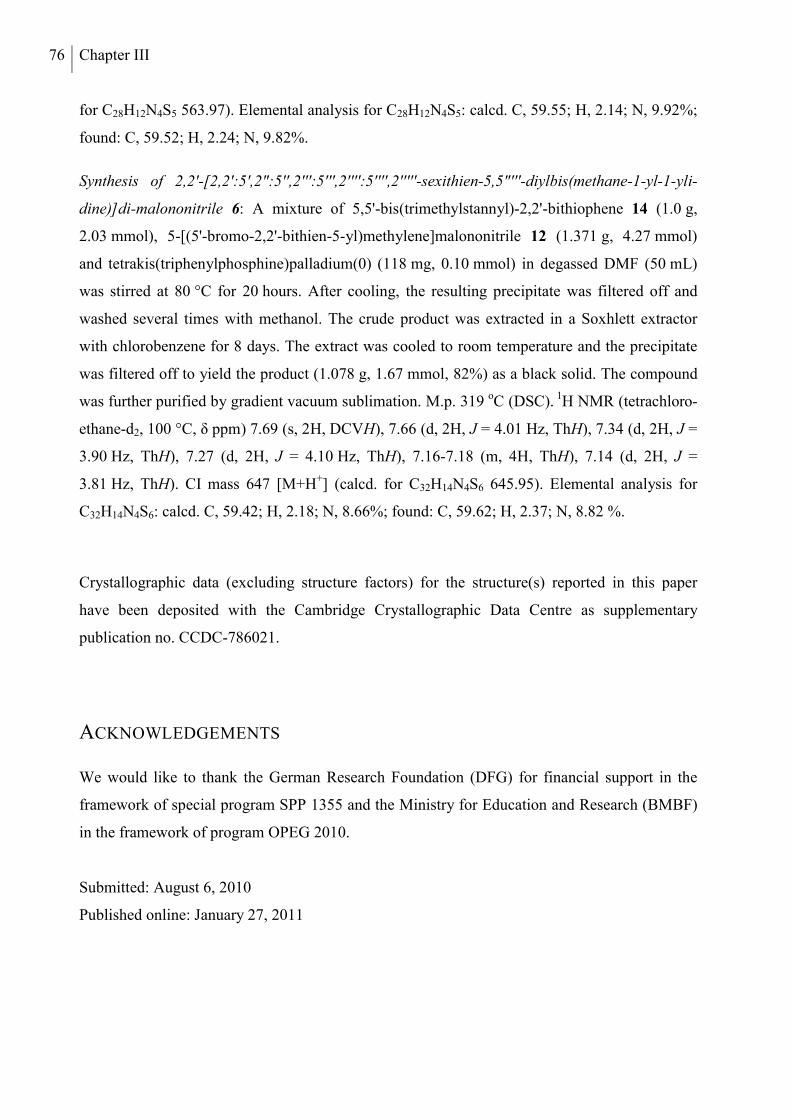
76 Chapter III
for C28H12N4S5 563.97). Elemental analysis for C28H12N4S5: calcd. C, 59.55; H, 2.14; N, 9.92%;
found: C, 59.52; H, 2.24; N, 9.82%.
Synthesis of 2,2'-[2,2':5',2":5'',2''':5''',2'''':5'''',2'''''-sexithien-5,5"'''-diylbis(methane-1-yl-1-yli-
dine)]di-malononitrile 6: A mixture of 5,5'-bis(trimethylstannyl)-2,2'-bithiophene 14 (1.0 g,
2.03 mmol), 5-[(5'-bromo-2,2'-bithien-5-yl)methylene]malononitrile 12 (1.371 g, 4.27 mmol)
and tetrakis(triphenylphosphine)palladium(0) (118 mg, 0.10 mmol) in degassed DMF (50 mL)
was stirred at 80 °C for 20 hours. After cooling, the resulting precipitate was filtered off and
washed several times with methanol. The crude product was extracted in a Soxhlett extractor
with chlorobenzene for 8 days. The extract was cooled to room temperature and the precipitate
was filtered off to yield the product (1.078 g, 1.67 mmol, 82%) as a black solid. The compound
was further purified by gradient vacuum sublimation. M.p. 319 oC (DSC). 1H NMR (tetrachloro-
ethane-d2, 100 °C, δ ppm) 7.69 (s, 2H, DCVH), 7.66 (d, 2H, J = 4.01 Hz, ThH), 7.34 (d, 2H, J =
3.90 Hz, ThH), 7.27 (d, 2H, J = 4.10 Hz, ThH), 7.16-7.18 (m, 4H, ThH), 7.14 (d, 2H, J =
3.81 Hz, ThH). CI mass 647 [M+H+] (calcd. for C32H14N4S6 645.95). Elemental analysis for
C32H14N4S6: calcd. C, 59.42; H, 2.18; N, 8.66%; found: C, 59.62; H, 2.37; N, 8.82 %.
Crystallographic data (excluding structure factors) for the structure(s) reported in this paper
have been deposited with the Cambridge Crystallographic Data Centre as supplementary
publication no. CCDC-786021.
ACKNOWLEDGEMENTS
We would like to thank the German Research Foundation (DFG) for financial support in the
framework of special program SPP 1355 and the Ministry for Education and Research (BMBF)
in the framework of program OPEG 2010.
Submitted: August 6, 2010
Published online: January 27, 2011
DCVnT series – Variation of the oligothiophene chain length 77
REFERENCES
[1] G. A. Chamberlain, Solar Cells 1983, 8, 47.
[2] D. Wöhrle, D. Meissner, Adv. Mater. 1991, 3, 129.
[3] C. J. Brabec, N. S. Sariciftci, J. C. Hummelen, Adv. Funct. Mater. 2001, 11, 15.
[4] J.-M. Nunzi, C. R. Physique 2002, 3, 523.
[5] C. Brabec, V. Dyakonov, U. Scherf (Eds.), Organic Photovoltaics: Materials, Device Physics, and Manufacturing Technologies, Wiley-VCH verlag, Weinheim, 2008.
[6] P. Peumans, A. Yakimov, S. R. Forrest, J. Appl. Phys. 2003, 93, 3693.
[7] B. C. Thompson, J. M. J. Fréchet, Angew. Chem. Int. Ed. 2007, 47, 58.
[8] M. Pagliaro, G. Palmisano, R. Ciriminna (Eds.), Flexible Solar Cells, Wiley-VCH, Weinheim, 2008.
[9] O. Inganäs, F. Zhang, K. Tvingstedt, L. M. Andersson, S. Hellström, M. R. Andersson, Adv. Mater. 2010, 22, E100.
[10] C. W. Tang, Appl. Phys. Lett. 1986, 48, 183.
[11] P. Peumans, S. Uchida, S. R. Forrest, Nature 2003, 425, 158.
[12] J. Xue, S. Uchida, B. P. Rand, S. R. Forrest, Appl. Phys. Lett. 2004, 85, 5757.
[13] B. P. Rand, J. Genoe, P. Heremans, J. Poortmans, Prog. Photovoltaics 2007, 15, 659.
[14] J. Y. Kim, K. Lee, N. E. Coates, D. Moses, T.-Q. Nguyen, M. Dante, A. J. Heeger, Science 2007, 317, 222.
[15] S. Günes, H. Neugebauer, N. S. Sariciftci, Chem. Rev. 2007, 107, 1324.
[16] Y.-J. Cheng, S.-H. Yang, C.-S. Hsu, Chem. Rev. 2009, 109, 5868.
[17] G. Li, V. Shrotriya, J. Huang, Y. Yao, T. Moriarty, K. Emery, Y. Yang, Nat. Mater. 2009, 4, 864.
[18] H.-Y. Chen, J. Hou, S. Zhang, Y. Liang, G. Yang, Y. Yang, L. Yu, Y. Wu, G. Li, Nat. Photon. 2009, 3, 649.
[19] L. Huo, J. Hou, S. Zhang, H.-Y. Chen, Y. Yang, Angew. Chem. Int. Ed. 2010, 49, 1500.
[20] Y. Liang, Z. Xu, J. Xia, S.-T. Tsai, Y. Wu, G. Li, C. Ray, L. Yu, Adv. Mater. 2010, 22, E135.
[21] A. Mishra, C.-Q. Ma, P. Bäuerle, Chem. Rev. 2009, 109, 1141.
[22] J. Xue, B. P. Rand, S. Uchida, S. R. Forrest, Adv. Mater. 2005, 17, 66.
78 Chapter III
[23] A. Yassar, C. Videlot, A. Jaafari, Sol. Energy Mater. Sol. Cells 2006, 90, 916.
[24] K. Schulze, C. Uhrich, R. Schüppel, K. Leo, M. Pfeiffer, E. Brier, E. Reinold, P. Bäuerle, Proc. SPIE Int. Soc. Opt. Eng. 2006, 6192, 61920C.
[25] K. Schulze, C. Uhrich, R. Schüppel, K. Leo, M. Pfeiffer, E. Brier, E. Reinold, P. Bäuerle, Adv. Mater. 2006, 18, 2872.
[26] K. Schulze, B. Maennig, K. Leo, Y. Tomita, C. May, J. Hupkes, E. Brier, E. Reinold, P. Bäuerle, Appl. Phys. Lett. 2007, 91, 073521.
[27] P. F. Xia, X. J. Feng, J. Lu, R. Movileanu, Y. Tao, J.-M. Baribeau, M. S. Wong, J. Phys. Chem. C 2008, 112, 16714.
[28] P. F. Xia, X. J. Feng, J. Lu, S.-W. Tsang, R. Movileanu, Y. Tao, M. S. Wong, Adv. Mater. 2008, 20, 4810.
[29] D. Wynands, B. Mannig, M. Riede, K. Leo, E. Brier, E. Reinold, P. Bäuerle, J. Appl. Phys. 2009, 106, 054509.
[30] D. Wynands, M. Levichkova, M. Riede, M. Pfeiffer, P. Bäuerle, R. Rentenberger, P. Denner, K. Leo, J. Appl. Phys. 2010, 107, 014517.
[31] C. Uhrich, R. Schueppel, A. Petrich, M. Pfeiffer, K. Leo, E. Brier, P. Kilickiran, P. Bäuerle, Adv. Funct. Mater. 2007, 17, 2991.
[32] R. Schueppel, K. Schmidt, C. Uhrich, K. Schulze, D. Wynands, J. L. Bredas, B. Maennig, M. Pfeiffer, K. Leo, E. Brier, E. Reinold, H.-B. Bu, P. Bäuerle, Proc. SPIE Int. Soc. Opt. Eng. 2007, 6656, 66560G.
[33] K. Schulze, M. Riede, E. Brier, E. Reinold, P. Bäuerle, K. Leo, J. Appl. Phys. 2008, 104, 074511.
[34] R. Schueppel, K. Schmidt, C. Uhrich, K. Schulze, D. Wynands, J. L. Bredas, E. Brier, E. Reinold, H. B. Bu, P. Bäuerle, B. Maennig, M. Pfeiffer, K. Leo, Phys. Rev. B 2008, 77, 085311.
[35] M. K. Riede, R. Schueppel, K. Schulze, D. Wynands, R. Timmreck, C. Uhrich, A. Petrich, M. Pfeiffer, E. Brier, E. Reinold, P. Bäuerle, K. Leo, Proc. SPIE Int. Soc. Opt. Eng. 2008, 7002, 70020G.
[36] Heliatek GmbH, press release, 20th August 2009.
[37] Heliatek GmbH, press release, 6th April 2010.
[38] T. Sone, Bull. Chem. Soc. Jpn. 1964, 37, 1197.
[39] M. V. Joshi, M. P. Cava, M. V. Lakshmikantham, R. M. Metzger, H. Abdeldayem, M. Henry, P. Venkateswarlu, Synth. Met. 1993, 57, 3974.
[40] Y. Wei, B. Wang, W. Wang, J. Tian, Tetrahedron Lett. 1995, 36, 665.
[41] Y. Wei, Y. Yang, J.-M. Yeh, Chem. Mater. 1996, 8, 2659.

DCVnT series – Variation of the oligothiophene chain length 79
[42] R. F. Curtis, G. T. Phillips, Tetrahedron 1967, 23, 4419.
[43] R. Chen, X. Yang, H. Tian, X. Wang, A. Hagfeldt, L. Sun, Chem. Mater. 2007, 19, 4007.
[44] K. Tamao, S. Komada, I. Nakajinma, M. Kumada, A. Minato, K. Suzuki, Tetrahedron 1982, 38, 3347.
[45] C. van Pham, A. Burkhardt, R. Shabana, D. D. Cunningham, H. B. Mark, H. Zimmer, Phosph. Sulf. Silic. Rel. Elem. 1989, 46, 153
[46] A. Srinivasan, V. M. Reddy, S. J. Narayanan, B. Sridevi, S. K. Pushpan, M. Ravikumar, T. K. Chandrashekar, Angew. Chem. Int. Ed. 1997, 36, 2598.
[47] T. Qi, Y. Liu, W. Qiu, H. Zhang, X. Gao, Y. Liu, K. Lu, C. Du, G. Yu, D. Zhu, J. Mater. Chem. 2008, 18, 1131.
[48] M. M. M. Raposo, A. M. C. Fonseca, G. Kirsch, Tetrahedron 2004, 60, 4071.
[49] C. van Pham, R. S. Macomber, H. B. Mark Jr., H. Zimmer, J. Org. Chem. 1984, 49, 5250.
[50] S. Kotani, K. Shiina, K. Sonogashira, J. Organomet. Chem. 1992, 429, 403.
[51] U. Asawapirom, R. Guentner, M. Forster, T. Farrell, U. Scherf, Synthesis 2002, 1136.
[52] D. Fichou, J. Mater. Chem. 2000, 10, 571.
[53] R. Azumi, M. Goto, K. Honda, M. Matsumoto, Bull. Chem. Soc. Jpn. 2003, 76, 1561.
[54] T. Kirschbaum, R. Azumi, E. Mena-Osteritz, P. Bäuerle, New J. Chem. 1999, 23, 241.
[55] R. Azumi, E. Mena-Osteritz, R. Boese, J. Benet-Buchholz, P. Bäuerle, J. Mater. Chem. 2006, 16, 728.
[56] T. M. Barclay, A. W. Cordes, C. D. MacKinnon, R. T. Oakley, R. W. Reed, Chem. Mater. 1997, 9, 981.
[57] J. Chisaka, M. Lu, S. Nagamatsu, M. Chikamatsu, Y. Yoshida, M. Goto, R. Azumi, M. Yamashita, K. Yase, Chem. Mater. 2007, 19, 2694.
[58] T. Johansson, W. Mammo, M. Svensson, M. R. Andersson, O. Inganäs, J. Mater. Chem. 2003, 13, 1316.
[59] Q. Xie, F. Arias, L. Echegoyen, J. Am. Chem. Soc. 1993, 115, 9818.
[60] M. Riede, T. Mueller, W. Tress, R. Schueppel, K. Leo, Nanotechnology 2008, 19, 424001 (12pp).
[61] D. Cheyns, J. Poortmans, P. Heremans, C. Deibel, S. Verlaak, B. P. Rand, J. Genoe, Phys. Rev. B 2008, 77, 165332.
80 Chapter III
[62] D. Wynands, M. Levichkova, C. Uhrich, D. Hildebrandt, G. Schwartz, M. Pfeiffer, K. Leo, M. Riede, Appl. Phys. Lett. 2010, in print.
[63] A. Opitz, M. Bronner, W. Brutting, J. Appl. Phys. 2007, 101, 063709.
[64] M. Y. Chan, S. L. Lai, M. K. Fung, C. S. Lee, S. T. Lee, Appl. Phys. Lett. 2007, 90, 023504.
[65] G. M. Sheldrick, Acta Crystallogr.2008, A64, 112.
[66] A. L. Spek, Acta Crystallogr. 2009, D65, 148.
[67] P. Bäuerle, F. Würthner, G. Goetz, F. Effenberger, Synthesis 1993, 1099.
[68] Y. Dienes, S. Durben, T. Kárpáti, T. Neumann, U. Englert, L. Nyulászi, T. Baumgartner, Chem. Eur. J. 2007, 13, 7487.
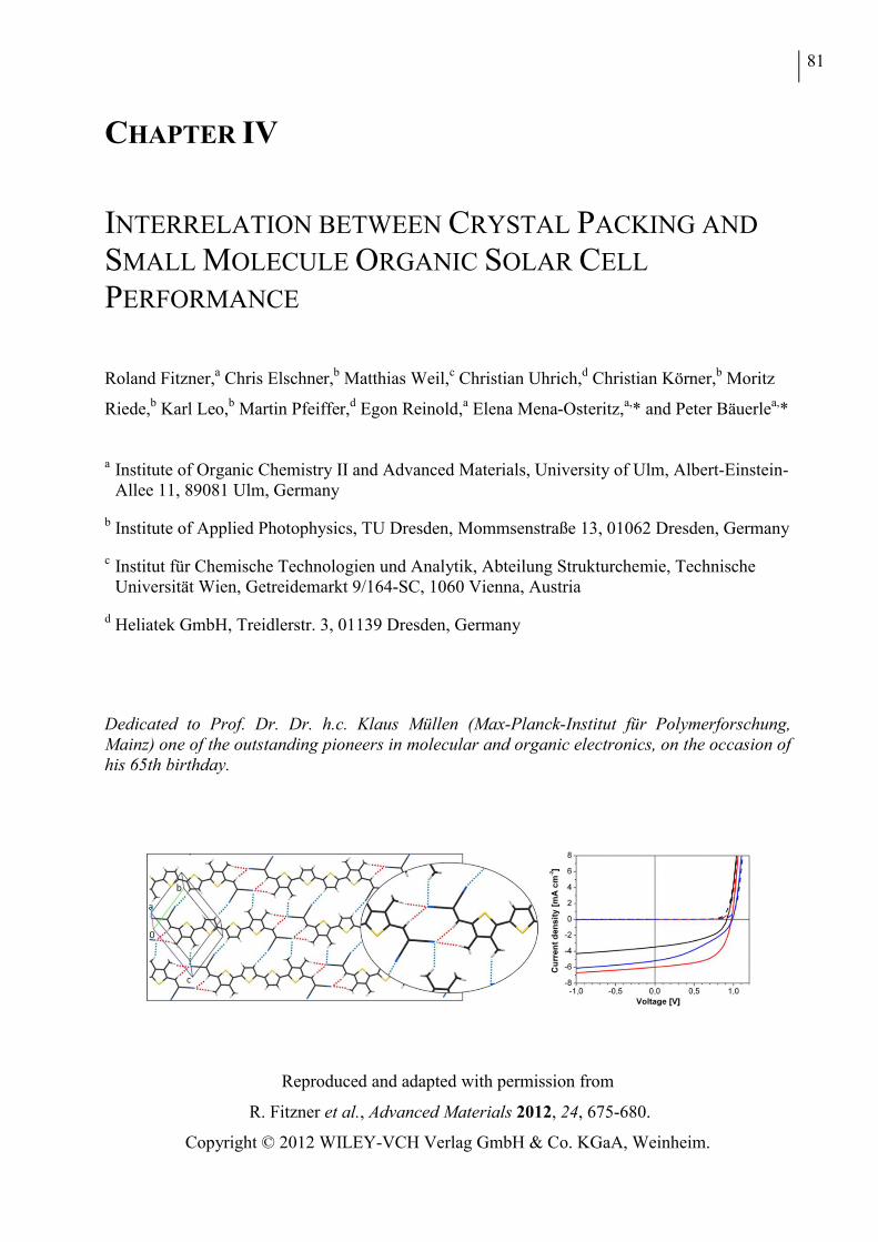
81
CHAPTER IV
INTERRELATION BETWEEN CRYSTAL PACKING AND
SMALL MOLECULE ORGANIC SOLAR CELL
PERFORMANCE
Roland Fitzner,a Chris Elschner,b Matthias Weil,c Christian Uhrich,d Christian Körner,b Moritz
Riede,b Karl Leo,b Martin Pfeiffer,d Egon Reinold,a Elena Mena-Osteritz,a,* and Peter Bäuerlea,*
a Institute of Organic Chemistry II and Advanced Materials, University of Ulm, Albert-Einstein-
Allee 11, 89081 Ulm, Germany
b Institute of Applied Photophysics, TU Dresden, Mommsenstraße 13, 01062 Dresden, Germany
c Institut für Chemische Technologien und Analytik, Abteilung Strukturchemie, Technische Universität Wien, Getreidemarkt 9/164-SC, 1060 Vienna, Austria
d Heliatek GmbH, Treidlerstr. 3, 01139 Dresden, Germany
Dedicated to Prof. Dr. Dr. h.c. Klaus Müllen (Max-Planck-Institut für Polymerforschung, Mainz) one of the outstanding pioneers in molecular and organic electronics, on the occasion of his 65th birthday.
Reproduced and adapted with permission from
R. Fitzner et al., Advanced Materials 2012, 24, 675-680.
Copyright © 2012 WILEY-VCH Verlag GmbH & Co. KGaA, Weinheim.

82 Chapter IV
ABSTRACT
X-ray investigation on single crystals of a series of terminally DCV-substituted
quaterthiophenes and co-evaporated blend layers with C60 give insight into molecular packing
behavior and morphology, which are crucial parameters in organic electronics. Structural
characteristics on various levels and length scales are correlated with the photovoltaic
performance of bulk heterojunction small molecule organic solar cells.
DCV4T series – Interrelation between crystal packing and SMOSC performance 83
The dynamic development in small molecule organic solar cells (SMOSC) has recently led to
high power conversion efficiencies (PCE) of >8% approaching those of polymer-based devi-
ces.[1] Structurally well-defined oligomeric materials avoid the inherent batch-to-batch
variations of physical properties for corresponding polymers and therefore provide higher repro-
ducibility. Various types of donor/acceptor-based π-conjugated oligomeric systems with tailored
optoelectronic and transport properties have been straightforwardly synthesized leading to
record PCEs of 6.7% for solution-processed bulk-heterojunction (BHJ)[2] and 8.3% for vacuum-
processed tandem SMOSCs.[3]
The photovoltaic performance of organic solar cells in general depends on various parameters
and besides the optimization of molecular properties, such as optical and redox, the rational
improvement of bulk properties responsible for the charge carrier mobility, processability, and
thermal stability still remains mostly empirical. The bulk characteristics in turn depend on non-
bonding intermolecular interactions, which lead to specific molecular order, packing, and
morphology in the solid state.[4-6] A good performance of BHJ SMOSCs is only guaranteed if an
interpenetrating network of the oligomeric donor (D) and an electron-acceptor (A), typically a
fullerene derivative, is formed at the nanoscale as the photoactive layer.[7-9] Moreover, the size
of the D and A homophases is crucially important for the diffusion of excitons to the D-A
interface, subsequent charge separation, and effective charge transport to the electrodes.[2,9-11]
Investigation of the morphology of the phase-separated blend layers by transmission electron
microscopy (TEM)[12] or X-ray diffraction (XRD)[13] have shed light into this complex puzzle.
The use of small molecules in OSCs provides in contrast to polymeric materials another
advantage: single crystals suitable for X-ray structure analysis become available providing
detailed insight into intermolecular interactions and non-bonding atomic contacts responsible for
the observed packing motifs.[14]
In this contribution, synthesis, thermal, and optoelectronic properties of a series of terminally
acceptor-substituted quaterthiophenes will be presented. A correlation between X-ray data and
photovoltaic performance of corresponding BHJ-SMOSCs will be established.
We have synthesized a series of dicyanovinyl (DCV)-substituted quaterthiophenes DCV4T 1,[14]
DCV4T-Me 2, and DCV4T-Et 3 by systematical variation of substituents at the terminal
thiophene units from hydrogen to methyl and ethyl (Scheme 1). As in the case of parent com-
pound DCV4T 1,[14] for the synthesis of quaterthiophenes DCV4T-Me 2 and DCV4T-Et 3 a
convergent route was chosen. Both compounds were synthesized in good yields by Stille-type
cross-coupling reactions of dicyanovinyl (DCV)-substituted bromothiophenes 6 or 7, bearing
methyl or ethyl side groups in the β-positions, and bisstannylated bithiophene 8 as central buil-
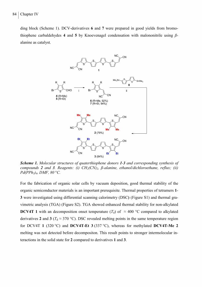
84 Chapter IV
ding block (Scheme 1). DCV-derivatives 6 and 7 were prepared in good yields from bromo-
thiophene carbaldehydes 4 and 5 by Knoevenagel condensation with malononitrile using β-
alanine as catalyst.
Scheme 1. Molecular structures of quaterthiophene donors 1-3 and corresponding synthesis of compounds 2 and 3. Reagents: (i) CH2(CN)2, β-alanine, ethanol/dichloroethane, reflux; (ii) Pd(PPh3)4, DMF, 80 °C.
For the fabrication of organic solar cells by vacuum deposition, good thermal stability of the
organic semiconductor materials is an important prerequisite. Thermal properties of tetramers 1-
3 were investigated using differential scanning calorimetry (DSC) (Figure S1) and thermal gra-
vimetric analysis (TGA) (Figure S2). TGA showed enhanced thermal stability for non-alkylated
DCV4T 1 with an decomposition onset temperature (Td) of ≈ 400 °C compared to alkylated
derivatives 2 and 3 (Td ≈ 370 °C). DSC revealed melting points in the same temperature region
for DCV4T 1 (320 °C) and DCV4T-Et 3 (337 °C), whereas for methylated DCV4T-Me 2
melting was not detected before decompositon. This result points to stronger intermolecular in-
teractions in the solid state for 2 compared to derivatives 1 and 3.
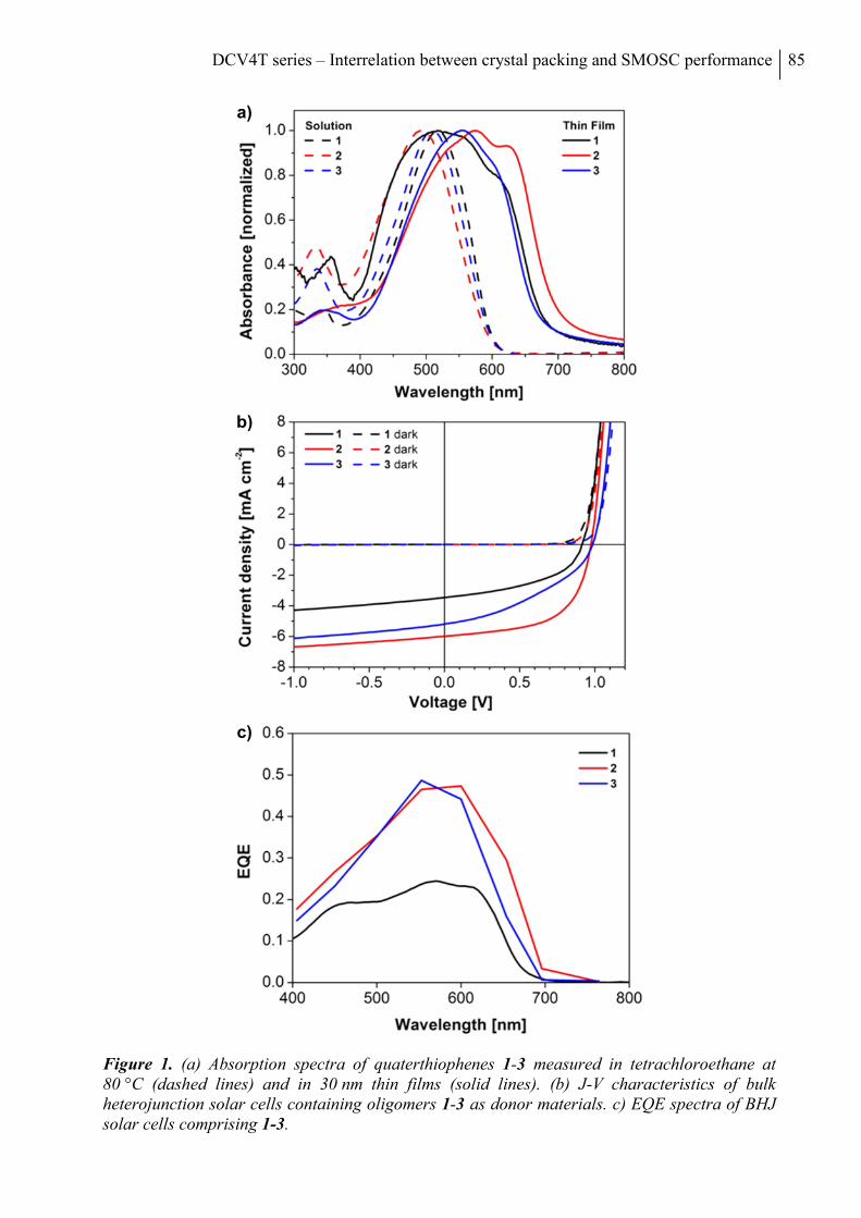
DCV4T series – Interrelation between crystal packing and SMOSC performance 85
Figure 1. (a) Absorption spectra of quaterthiophenes 1-3 measured in tetrachloroethane at 80 °C (dashed lines) and in 30 nm thin films (solid lines). (b) J-V characteristics of bulk heterojunction solar cells containing oligomers 1-3 as donor materials. c) EQE spectra of BHJ solar cells comprising 1-3.
a)
b)
c)
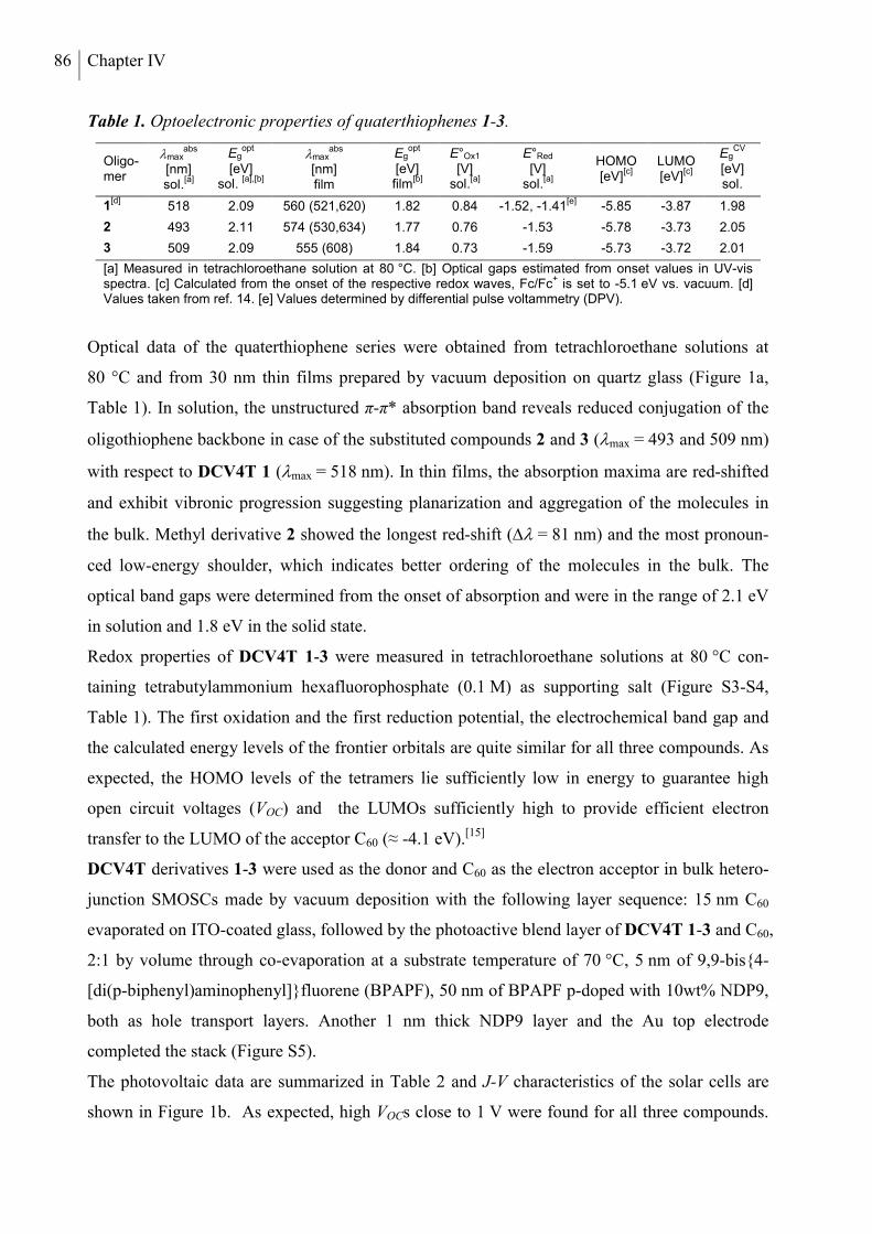
86 Chapter IV
Table 1. Optoelectronic properties of quaterthiophenes 1-3.
Oligo-mer
maxabs
[nm] sol.
[a]
Egopt
[eV]
sol. [a],[b]
maxabs
[nm] film
Egopt
[eV] film
[b]
E°Ox1 [V]
sol.[a]
E°Red [V]
sol.[a]
HOMO [eV]
[c] LUMO [eV]
[c]
EgCV
[eV] sol.
1[d]
518 2.09 560 (521,620) 1.82 0.84 -1.52, -1.41[e]
-5.85 -3.87 1.98
2 493 2.11 574 (530,634) 1.77 0.76 -1.53 -5.78 -3.73 2.05
3 509 2.09 555 (608) 1.84 0.73 -1.59 -5.73 -3.72 2.01
[a] Measured in tetrachloroethane solution at 80 °C. [b] Optical gaps estimated from onset values in UV-vis spectra. [c] Calculated from the onset of the respective redox waves, Fc/Fc
+ is set to -5.1 eV vs. vacuum. [d]
Values taken from ref. 14. [e] Values determined by differential pulse voltammetry (DPV).
Optical data of the quaterthiophene series were obtained from tetrachloroethane solutions at
80 °C and from 30 nm thin films prepared by vacuum deposition on quartz glass (Figure 1a,
Table 1). In solution, the unstructured π-π* absorption band reveals reduced conjugation of the
oligothiophene backbone in case of the substituted compounds 2 and 3 (max = 493 and 509 nm)
with respect to DCV4T 1 (max = 518 nm). In thin films, the absorption maxima are red-shifted
and exhibit vibronic progression suggesting planarization and aggregation of the molecules in
the bulk. Methyl derivative 2 showed the longest red-shift ( = 81 nm) and the most pronoun-
ced low-energy shoulder, which indicates better ordering of the molecules in the bulk. The
optical band gaps were determined from the onset of absorption and were in the range of 2.1 eV
in solution and 1.8 eV in the solid state.
Redox properties of DCV4T 1-3 were measured in tetrachloroethane solutions at 80 °C con-
taining tetrabutylammonium hexafluorophosphate (0.1 M) as supporting salt (Figure S3-S4,
Table 1). The first oxidation and the first reduction potential, the electrochemical band gap and
the calculated energy levels of the frontier orbitals are quite similar for all three compounds. As
expected, the HOMO levels of the tetramers lie sufficiently low in energy to guarantee high
open circuit voltages (VOC) and the LUMOs sufficiently high to provide efficient electron
transfer to the LUMO of the acceptor C60 (≈ -4.1 eV).[15]
DCV4T derivatives 1-3 were used as the donor and C60 as the electron acceptor in bulk hetero-
junction SMOSCs made by vacuum deposition with the following layer sequence: 15 nm C60
evaporated on ITO-coated glass, followed by the photoactive blend layer of DCV4T 1-3 and C60,
2:1 by volume through co-evaporation at a substrate temperature of 70 °C, 5 nm of 9,9-bis4-
[di(p-biphenyl)aminophenyl]fluorene (BPAPF), 50 nm of BPAPF p-doped with 10wt% NDP9,
both as hole transport layers. Another 1 nm thick NDP9 layer and the Au top electrode
completed the stack (Figure S5).
The photovoltaic data are summarized in Table 2 and J-V characteristics of the solar cells are
shown in Figure 1b. As expected, high VOCs close to 1 V were found for all three compounds.
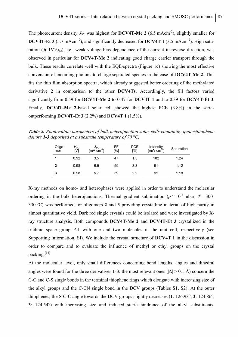
DCV4T series – Interrelation between crystal packing and SMOSC performance 87
The photocurrent density JSC was highest for DCV4T-Me 2 (6.5 mAcm-2), slightly smaller for
DCV4T-Et 3 (5.7 mAcm-2), and significantly decreased for DCV4T 1 (3.5 mAcm-2). High satu-
ration (J(-1V)/Jsc), i.e., weak voltage bias dependence of the current in reverse direction, was
observed in particular for DCV4T-Me 2 indicating good charge carrier transport through the
bulk. These results correlate well with the EQE-spectra (Figure 1c) showing the most effective
conversion of incoming photons to charge separated species in the case of DCV4T-Me 2. This
fits the thin film absorption spectra, which already suggested better ordering of the methylated
derivative 2 in comparison to the other DCV4Ts. Accordingly, the fill factors varied
significantly from 0.59 for DCV4T-Me 2 to 0.47 for DCV4T 1 and to 0.39 for DCV4T-Et 3.
Finally, DCV4T-Me 2-based solar cell showed the highest PCE (3.8%) in the series
outperforming DCV4T-Et 3 (2.2%) and DCV4T 1 (1.5%).
Table 2. Photovoltaic parameters of bulk heterojunction solar cells containing quaterthiophene donors 1-3 deposited at a substrate temperature of 70 °C.
Oligo-mer
VOC [V]
JSC [mA cm
-2]
FF [%]
PCE [%]
Intensity [mW cm
-2]
Saturation
1 0.92 3.5 47 1.5 102 1.24
2 0.98 6.5 59 3.8 91 1.12
3 0.98 5.7 39 2.2 91 1.18
X-ray methods on homo- and heterophases were applied in order to understand the molecular
ordering in the bulk heterojunctions. Thermal gradient sublimation (p ≈ 10-6 mbar, T = 300-
330 °C) was performed for oligomers 2 and 3 providing crystalline material of high purity in
almost quantitative yield. Dark red single crystals could be isolated and were investigated by X-
ray structure analysis. Both compounds DCV4T-Me 2 and DCV4T-Et 3 crystallized in the
triclinic space group P-1 with one and two molecules in the unit cell, respectively (see
Supporting Information, SI). We include the crystal structure of DCV4T 1 in the discussion in
order to compare and to evaluate the influence of methyl or ethyl groups on the crystal
packing.[14]
At the molecular level, only small differences concerning bond lengths, angles and dihedral
angles were found for the three derivatives 1-3: the most relevant ones (|| > 0.1 Å) concern the
C-C and C-S single bonds in the terminal thiophene rings which elongate with increasing size of
the alkyl groups and the C-CN single bond in the DCV groups (Tables S1, S2). At the outer
thiophenes, the S-C-C angle towards the DCV groups slightly decreases (1: 126.93°, 2: 124.86°,
3: 124.54°) with increasing size and induced steric hindrance of the alkyl substituents.
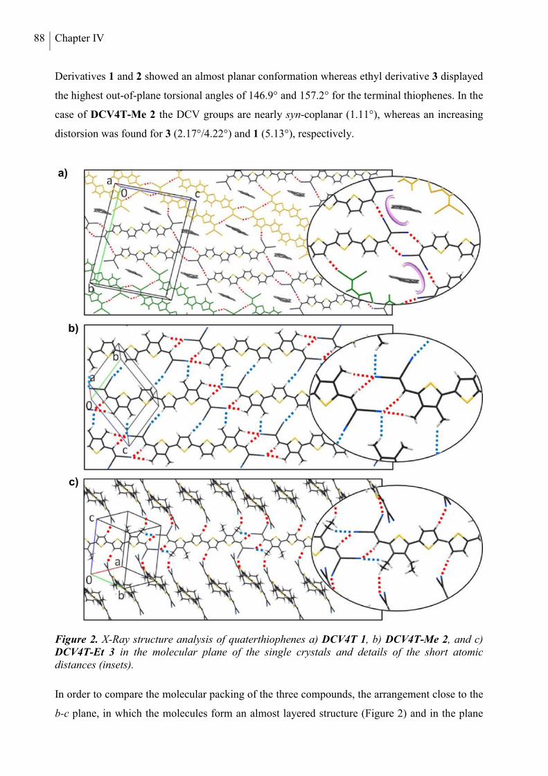
88 Chapter IV
Derivatives 1 and 2 showed an almost planar conformation whereas ethyl derivative 3 displayed
the highest out-of-plane torsional angles of 146.9° and 157.2° for the terminal thiophenes. In the
case of DCV4T-Me 2 the DCV groups are nearly syn-coplanar (1.11°), whereas an increasing
distorsion was found for 3 (2.17°/4.22°) and 1 (5.13°), respectively.
Figure 2. X-Ray structure analysis of quaterthiophenes a) DCV4T 1, b) DCV4T-Me 2, and c) DCV4T-Et 3 in the molecular plane of the single crystals and details of the short atomic distances (insets).
In order to compare the molecular packing of the three compounds, the arrangement close to the
b-c plane, in which the molecules form an almost layered structure (Figure 2) and in the plane
a)
b)
c)
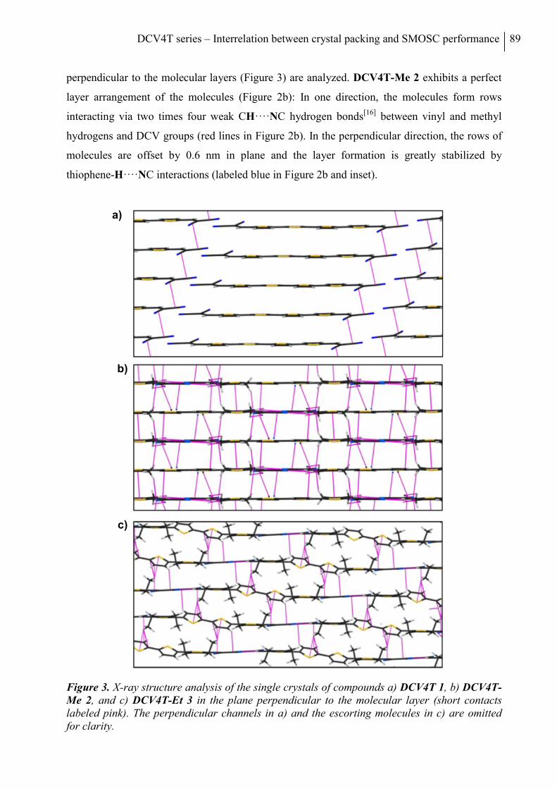
DCV4T series – Interrelation between crystal packing and SMOSC performance 89
perpendicular to the molecular layers (Figure 3) are analyzed. DCV4T-Me 2 exhibits a perfect
layer arrangement of the molecules (Figure 2b): In one direction, the molecules form rows
interacting via two times four weak CH····NC hydrogen bonds[16] between vinyl and methyl
hydrogens and DCV groups (red lines in Figure 2b). In the perpendicular direction, the rows of
molecules are offset by 0.6 nm in plane and the layer formation is greatly stabilized by
thiophene-H····NC interactions (labeled blue in Figure 2b and inset).
Figure 3. X-ray structure analysis of the single crystals of compounds a) DCV4T 1, b) DCV4T-Me 2, and c) DCV4T-Et 3 in the plane perpendicular to the molecular layer (short contacts labeled pink). The perpendicular channels in a) and the escorting molecules in c) are omitted for clarity.
a)
b)
c)
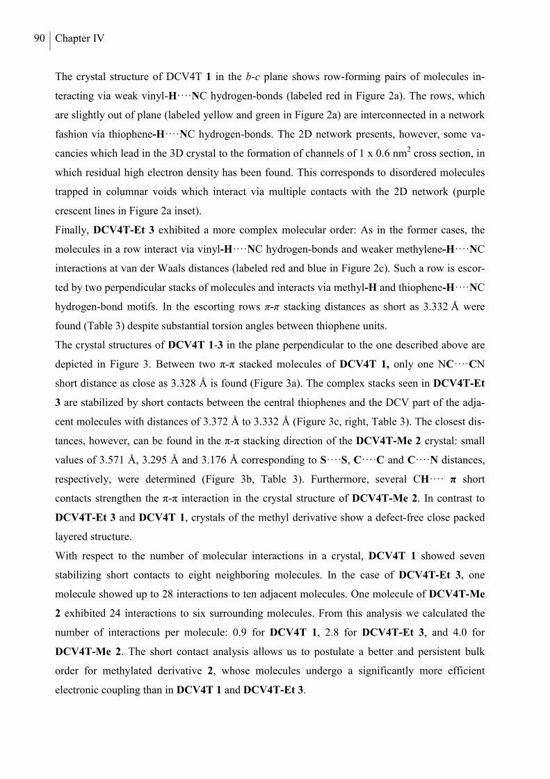
90 Chapter IV
The crystal structure of DCV4T 1 in the b-c plane shows row-forming pairs of molecules in-
teracting via weak vinyl-H····NC hydrogen-bonds (labeled red in Figure 2a). The rows, which
are slightly out of plane (labeled yellow and green in Figure 2a) are interconnected in a network
fashion via thiophene-H····NC hydrogen-bonds. The 2D network presents, however, some va-
cancies which lead in the 3D crystal to the formation of channels of 1 x 0.6 nm2 cross section, in
which residual high electron density has been found. This corresponds to disordered molecules
trapped in columnar voids which interact via multiple contacts with the 2D network (purple
crescent lines in Figure 2a inset).
Finally, DCV4T-Et 3 exhibited a more complex molecular order: As in the former cases, the
molecules in a row interact via vinyl-H····NC hydrogen-bonds and weaker methylene-H····NC
interactions at van der Waals distances (labeled red and blue in Figure 2c). Such a row is escor-
ted by two perpendicular stacks of molecules and interacts via methyl-H and thiophene-H····NC
hydrogen-bond motifs. In the escorting rows π-π stacking distances as short as 3.332 Å were
found (Table 3) despite substantial torsion angles between thiophene units.
The crystal structures of DCV4T 1-3 in the plane perpendicular to the one described above are
depicted in Figure 3. Between two π-π stacked molecules of DCV4T 1, only one NC····CN
short distance as close as 3.328 Å is found (Figure 3a). The complex stacks seen in DCV4T-Et
3 are stabilized by short contacts between the central thiophenes and the DCV part of the adja-
cent molecules with distances of 3.372 Å to 3.332 Å (Figure 3c, right, Table 3). The closest dis-
tances, however, can be found in the π-π stacking direction of the DCV4T-Me 2 crystal: small
values of 3.571 Å, 3.295 Å and 3.176 Å corresponding to S····S, C····C and C····N distances,
respectively, were determined (Figure 3b, Table 3). Furthermore, several CH···· π short
contacts strengthen the π-π interaction in the crystal structure of DCV4T-Me 2. In contrast to
DCV4T-Et 3 and DCV4T 1, crystals of the methyl derivative show a defect-free close packed
layered structure.
With respect to the number of molecular interactions in a crystal, DCV4T 1 showed seven
stabilizing short contacts to eight neighboring molecules. In the case of DCV4T-Et 3, one
molecule showed up to 28 interactions to ten adjacent molecules. One molecule of DCV4T-Me
2 exhibited 24 interactions to six surrounding molecules. From this analysis we calculated the
number of interactions per molecule: 0.9 for DCV4T 1, 2.8 for DCV4T-Et 3, and 4.0 for
DCV4T-Me 2. The short contact analysis allows us to postulate a better and persistent bulk
order for methylated derivative 2, whose molecules undergo a significantly more efficient
electronic coupling than in DCV4T 1 and DCV4T-Et 3.
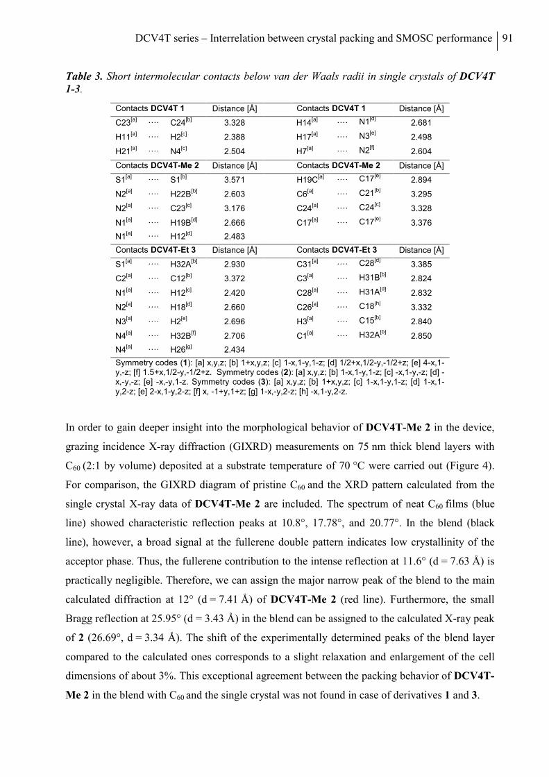
DCV4T series – Interrelation between crystal packing and SMOSC performance 91
Table 3. Short intermolecular contacts below van der Waals radii in single crystals of DCV4T 1-3.
Contacts DCV4T 1 Distance [Å] Contacts DCV4T 1 Distance [Å]
C23[a]
···· C24[b]
3.328 H14[a]
···· N1[d]
2.681
H11[a]
···· H2[c]
2.388 H17[a]
···· N3[e]
2.498
H21[a]
···· N4[c]
2.504 H7[a]
···· N2[f]
2.604
Contacts DCV4T-Me 2 Distance [Å] Contacts DCV4T-Me 2 Distance [Å]
S1[a]
···· S1[b]
3.571 H19C[a]
···· C17[e]
2.894
N2[a]
···· H22B[b]
2.603 C6[a]
···· C21[b]
3.295
N2[a]
···· C23[c]
3.176 C24[a]
···· C24[c]
3.328
N1[a]
···· H19B[d]
2.666 C17[a]
···· C17[e]
3.376
N1[a]
···· H12[d]
2.483
Contacts DCV4T-Et 3 Distance [Å] Contacts DCV4T-Et 3 Distance [Å]
S1[a]
···· H32A[b]
2.930 C31[a]
···· C28[d]
3.385
C2[a]
···· C12[b]
3.372 C3[a]
···· H31B[b]
2.824
N1[a]
···· H12[c]
2.420 C28[a]
···· H31A[d]
2.832
N2[a]
···· H18[d]
2.660 C26[a]
···· C18[h]
3.332
N3[a]
···· H2[e]
2.696 H3[a]
···· C15[b]
2.840
N4[a]
···· H32B[f] 2.706 C1
[a] ···· H32A
[b] 2.850
N4[a]
···· H26[g]
2.434
Symmetry codes (1): [a] x,y,z; [b] 1+x,y,z; [c] 1-x,1-y,1-z; [d] 1/2+x,1/2-y,-1/2+z; [e] 4-x,1-y,-z; [f] 1.5+x,1/2-y,-1/2+z. Symmetry codes (2): [a] x,y,z; [b] 1-x,1-y,1-z; [c] -x,1-y,-z; [d] -x,-y,-z; [e] -x,-y,1-z. Symmetry codes (3): [a] x,y,z; [b] 1+x,y,z; [c] 1-x,1-y,1-z; [d] 1-x,1-y,2-z; [e] 2-x,1-y,2-z; [f] x, -1+y,1+z; [g] 1-x,-y,2-z; [h] -x,1-y,2-z.
In order to gain deeper insight into the morphological behavior of DCV4T-Me 2 in the device,
grazing incidence X-ray diffraction (GIXRD) measurements on 75 nm thick blend layers with
C60 (2:1 by volume) deposited at a substrate temperature of 70 °C were carried out (Figure 4).
For comparison, the GIXRD diagram of pristine C60 and the XRD pattern calculated from the
single crystal X-ray data of DCV4T-Me 2 are included. The spectrum of neat C60 films (blue
line) showed characteristic reflection peaks at 10.8°, 17.78°, and 20.77°. In the blend (black
line), however, a broad signal at the fullerene double pattern indicates low crystallinity of the
acceptor phase. Thus, the fullerene contribution to the intense reflection at 11.6° (d = 7.63 Å) is
practically negligible. Therefore, we can assign the major narrow peak of the blend to the main
calculated diffraction at 12° (d = 7.41 Å) of DCV4T-Me 2 (red line). Furthermore, the small
Bragg reflection at 25.95° (d = 3.43 Å) in the blend can be assigned to the calculated X-ray peak
of 2 (26.69°, d = 3.34 Å). The shift of the experimentally determined peaks of the blend layer
compared to the calculated ones corresponds to a slight relaxation and enlargement of the cell
dimensions of about 3%. This exceptional agreement between the packing behavior of DCV4T-
Me 2 in the blend with C60 and the single crystal was not found in case of derivatives 1 and 3.
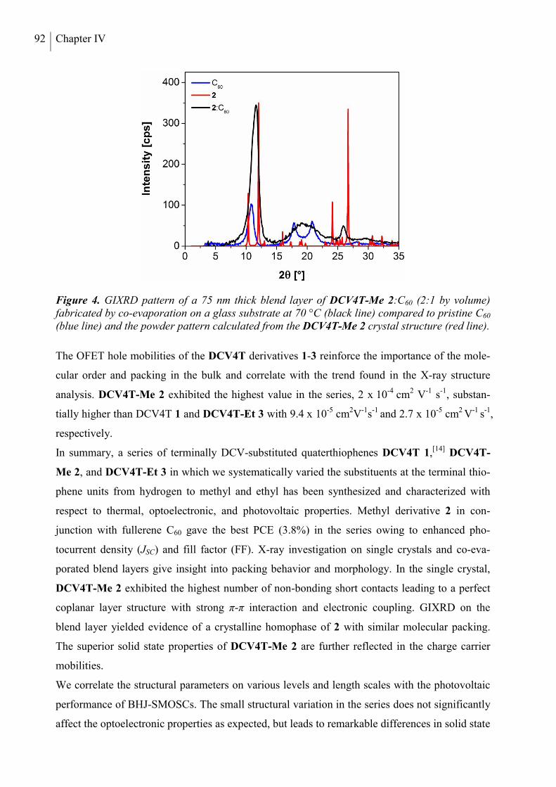
92 Chapter IV
Figure 4. GIXRD pattern of a 75 nm thick blend layer of DCV4T-Me 2:C60 (2:1 by volume) fabricated by co-evaporation on a glass substrate at 70 °C (black line) compared to pristine C60 (blue line) and the powder pattern calculated from the DCV4T-Me 2 crystal structure (red line).
The OFET hole mobilities of the DCV4T derivatives 1-3 reinforce the importance of the mole-
cular order and packing in the bulk and correlate with the trend found in the X-ray structure
analysis. DCV4T-Me 2 exhibited the highest value in the series, 2 x 10⁻⁴ cm2 V-1 s-1, substan-
tially higher than DCV4T 1 and DCV4T-Et 3 with 9.4 x 10⁻⁵ cm2V-1s-1 and 2.7 x 10⁻⁵ cm2 V-1 s-1,
respectively.
In summary, a series of terminally DCV-substituted quaterthiophenes DCV4T 1,[14] DCV4T-
Me 2, and DCV4T-Et 3 in which we systematically varied the substituents at the terminal thio-
phene units from hydrogen to methyl and ethyl has been synthesized and characterized with
respect to thermal, optoelectronic, and photovoltaic properties. Methyl derivative 2 in con-
junction with fullerene C60 gave the best PCE (3.8%) in the series owing to enhanced pho-
tocurrent density (JSC) and fill factor (FF). X-ray investigation on single crystals and co-eva-
porated blend layers give insight into packing behavior and morphology. In the single crystal,
DCV4T-Me 2 exhibited the highest number of non-bonding short contacts leading to a perfect
coplanar layer structure with strong π-π interaction and electronic coupling. GIXRD on the
blend layer yielded evidence of a crystalline homophase of 2 with similar molecular packing.
The superior solid state properties of DCV4T-Me 2 are further reflected in the charge carrier
mobilities.
We correlate the structural parameters on various levels and length scales with the photovoltaic
performance of BHJ-SMOSCs. The small structural variation in the series does not significantly
affect the optoelectronic properties as expected, but leads to remarkable differences in solid state
DCV4T series – Interrelation between crystal packing and SMOSC performance 93
properties that are crucial for exciton diffusion and charge transport and consequently for the
photovoltaic performance.
EXPERIMENTAL SECTION
Experimental details, synthesis, and analytical data of the oligomers, device preparation and
characterization, plots of DSC, TGA and cyclic voltammetry are available in the Supporting
Information. CCDC 816600 and 846475 contain the supplementary crystallographic data for this
paper. These data can be obtained free of charge from The Cambridge Crystallographic Data
Centre via www.ccdc.cam.ac.uk/data_request/cif.
SUPPORTING INFORMATION
Supporting Information is available from the Wiley Online Library or from the author.
ACKNOWLEDGEMENTS
The work was supported by the German Research Foundation (DFG, priority program SPP
1355) and the Ministry for Education and Research (BMBF, programs OPEG 13N9720 and
OPA 13N98872). We thank Dr. L. Wilde (Fraunhofer CNT) for the X-ray measurements,
Moritz Hein and Jens Jankowski (IAPP Dresden) for the OFET mobility measurements and
Novaled AG for providing NDP9.
Submitted: November 21, 2011
Published online: January 5, 2012
94 Chapter IV
REFERENCES
[1] (a) K. Walzer, B. Männig, M. Pfeiffer, K. Leo, Chem. Rev. 2007, 107, 1233; b) M. A. Green, K. Emery, Y. Hishikawa, W. Warta, Prog. Photovolt: Res. Appl. 2011, 19, 84; c) A. Mishra, P. Bäuerle, Angew. Chem. in print.
[2] Y. Sun, G. C. Welch, W. L. Leong, C. J. Takacs, G. C. Bazan, A. J. Heeger, Nat. Mater. 2011, asap, doi:10.1038/nmat3160.
[3] Heliatek GmbH, press release, October 11, 2010 (http:// www.heliatek.com).
[4] S. Wang, L. Hall, V. V. Diev, R. Haiges, G. Wei, X. Xiao, P. I. Djurovich, S. R. Forrest, M. E. Thompson, Chem. Mater. 2011, 23, 4789.
[5] H. Bürckstümmer, E. V. Tulyakova, M. Deppisch, M. R. Lenze, N. M. Kronenberg, M. Gsänger, M. Stolte, K. Meerholz, F. Würthner, Angew. Chem. Int. Ed. 2011, doi: 10.1002/anie.201105133.
[6] A. Ojala, A. Petersen, A. Fuchs, R. Lovrincic, C. Pölking, J. Trollmann, J. Hwang, C. Lennartz, H. Reichelt, H. W. Höffken, A. Pucci, P. Erk, T. Kirchartz, F. Würthner, Adv. Funct. Mater. 2011, doi: 10.1002/adfm.201101697.
[7] F. Yang, S. R. Forrest, ACS Nano 2008, 2, 1022.
[8] B. Walker, A. B. Tamayo, X.-D. Dang, P. Zalar, J. H. Seo, A. Garcia, M. Tantiwiwat, T.-Q. Nguyen, Adv. Funct. Mater. 2009, 19, 3063.
[9] G. Wei, R. R. Lunt, K. Sun, S. Wang, M. E. Thompson, S. R. Forrest, Nano Lett. 2010, 10, 3555.
[10] F. Yang, M. Shtein, S. R. Forrest, Nat. Mater. 2005, 4, 37.
[11] F. Yang, K. Sun, S. Forrest, Adv. Mater. 2007, 19, 4166.
[12] S. D. Oosterhout, M. M. Wienk, S. S. van Bavel, R. Thiedmann, L. J. A. Koster, J. Gilot, J. Loos, V. Schmidt, R. A. J. Janssen, Nat. Materials 2009, 8, 818-824.
[13] Z. M. Beiley, E. T. Hoke, R. Noriega, J. Dacuña, G. F. Burkhard, J. A. Bartelt, A. Salleo, M. F. Toney, M. D. McGehee, Adv. Energy Mater. 2011, 1, 954.
[14] R. Fitzner, E. Reinold, A. Mishra, E. Mena-Osteritz, H. Ziehlke, C. Körner, K. Leo, M. Riede, M. Weil, O. Tsaryova, A. Weiß, C. Uhrich, M. Pfeiffer, P. Bäuerle, Adv. Funct. Mater. 2011, 21, 897.
[15] Q. Xie, F. Arias, L. Echegoyen, J. Am. Chem. Soc. 1993, 115, 9818.
[16] a) M. Mazik, D. Bläser, R. Boese Tetrahedron 2001, 57, 5791-5797; b) M. Mazik, D. Bläser, R. Boese Tetrahedron Lett. 2000, 41, 5827-5831.
DCV4T series – Interrelation between crystal packing and SMOSC performance 95
SUPPORTING INFORMATION
INSTRUMENTS, SPECTROSCOPIC MEASUREMENTS, AND METHODS
NMR spectra were recorded on a Bruker AMX 500 (1H NMR: 500 MHz, 13C NMR: 125 MHz)
or an Avance 400 spectrometer (1H NMR: 400 MHz, 13C NMR: 100 MHz), at 25 °C or 100 °C.
Chemical shift values () are expressed in parts per million using residual solvent protons (1H
NMR, H = 7.26 for CDCl3, H = 2.50 for DMSO-d6 and H = 5.93 for tetrachloroethane-d2; 13C
NMR, C = 77.0 for CDCl3 and C = 39.43 for DMSO-d6) as internal standard. The splitting pat-
terns are designated as follows: s (singlet), d (doublet), t (triplet) and q (quartet). The assign-
ments are ThH (thiophene protons), MeH (methyl protons) and DCVH (dicyanovinyl protons).
GC-MS (EI) mass spectra were recorded on a Varian Saturn 2000 and MALDI-TOF mass spec-
tra on a Bruker Daltonic Reflex III. Thermogravimetric analysis (TGA) was conducted on a
Mettler Toledo TGA/SDTA851e instrument with a heating rate of 10 °Cmin-1 under nitrogen
atmosphere at a flow rate of 50 cm3 min-1. Differential scanning calorimetric measurements
(DSC) were performed on a Mettler Toledo DSC823e under argon atmosphere at a heating rate
of 10 °Cmin-1. Melting points were determined using a Büchi B-545 apparatus and were not cor-
rected. Elemental analyses were performed on an Elementar Vario EL.
Optical solution measurements were carried out in 1 cm cuvettes with Merck Uvasol grade sol-
vents, absorption spectra were recorded on a Perkin Elmer Lambda 19 spectrometer. Cyclic vol-
tammetry experiments were performed with a computer-controlled Metrohm Autolab PGSTAT
30 potentiostat in a three-electrode single-compartment cell with a platinum working electrode,
a platinum wire counter electrode, and an Ag/AgCl reference electrode. All potentials were
internally referenced to the ferrocene/ferrocenium couple.
Thin film samples were prepared by thermal vapor deposition in ultra-high vacuum at a base
pressure of lower than 10-7 mbar. The layer thicknesses were determined during evaporation
using quartz crystal monitors calibrated for the respective material prior to evaporation. The de-
position rates for the organic were between 0.2 and 0.4 Ås-1. For UV-vis characterization nomi-
nally 30 nm of the pristine material was deposited on quartz glass substrates (Quarzglass QCS).
Evaporation rates were around 0.2 Ås-1. The thin film absorbance spectra were recorded on a
Perkin Elmer lambda900 spectrometer.
The solar cells were prepared on tin-doped indium oxide (ITO) coated glass (Thin Film Devices,
USA, sheet resistance of 30 Ωsq.-1) layer by layer without breaking the vacuum. The layer
structure of the bulk heterojunction solar cells was as follows: ITO; 15 nm C60 (Bucky USA,
96 Chapter IV
used density 1.54 gcm-³); 20nm blend layer of respective DCV4T 1-3 (used density 1.3 gcm-³,
confirmed by XRR) and C60 (ratio 2:1 in volume) prepared by co-evaporation deposited on
heated substrates (70 °C); 5 nm 9,9-bis4-[di(p-biphenyl)aminophenyl] fluorene (BPAPF,
Lumtec, Taiwan; used density 1.2 gcm-³); 50 nm BPAPF doped with NDP9 (10wt%, purchased
from Novaled AG, Germany); 1 nm NDP9; 50 nm Au. The completed solar cells were
encapsulated with a transparent encapsulation glass, fixed by UV-hardened epoxy glue, in a
nitrogen glovebox. Particular care was taken for the active device area: it was individually
determined for each solar cell by comparing the short circuit current without and with an
aperture of well-defined size. The average device area was about 6 mm².
The solar cells were characterized by external quantum efficiency (EQE) and current voltage
characteristics (J-V). The EQE measurements were carried out on a custom-made setup utilizing
chopped monochromatic light produced by a xenon arc lamp, a monochromator (Newport
Cornerstone) and a chopper wheel. Data acquisition is accomplished with a lock-in amplifier
(Signal Recovery 7265 DSP). A silicon reference diode (Hamamatsu S1337) was used to cali-
brate the setup. From EQE spectra the spectral response of each individual solar cell device was
determined and a spectral mismatch factor calculated. The corresponding J-V characteristics
were recorded on a setup consisting of a source-measure unit (Keithley SMU 2400) and an AM
1.5G sun simulator (KHS Technical Lighting SC1200). The illumination intensity was
monitored with a silicon photodiode (Hamamatsu S1337) and the J-V measurements were
conducted under mismatch corrected intensities.
SYNTHESIS AND CHARACTERIZATION
Dimethylformamide (DMF, Merck) was refluxed over P4O10 (Merck) and distilled. 5-Bromo-
3,4-diethylthiophene-2-carboxaldehyde 5[1] was prepared according to the published literature
procedure. Malononitrile and β-alanine were purchased from Merck. All synthetic steps were
carried out under argon atmosphere.
Synthesis of 2,2'-[3,4,3"',4"'-tetramethyl-2,2':5',2":5'',2'''-quaterthien-5,5"'-diylbis(methane-1-
yl-1-ylidine)]dimalononitrile 2: A mixture of 5,5'-bis(trimethylstannyl)-2,2'-bithiophene 8
(800 mg, 1.63 mmol), 2-[(5-bromo-3,4-dimethylthien-2-yl)methylene]malononitrile 6 (912 mg,
3.42 mmol) and tetrakis(triphenylphosphine)palladium(0) (94 mg, 0.081 mmol) in degassed
DMF (50 mL) was stirred at 80 °C for 16 hours. The reaction mixture was allowed to cool to
room temperature, the precipitate was filtered off and washed thoroughly with methanol. The
crude product was extracted in a Soxhlet extractor with 1,2-dichloroethane for 1 day to remove
DCV4T series – Interrelation between crystal packing and SMOSC performance 97
the most soluble reaction by-products. Subsequently, Soxhlet extraction was continued for 10
days using chlorobenzene as solvent. After cooling the resulting extract down to room tempera-
ture, the precipitate was filtered off to yield quaterthiophene 2 (692 mg, 1.28 mmol, 79%) as a
black solid. 1H NMR (tetrachloroethane-d2, 100 °C, δ ppm) 7.83 (s, 2H, DCVH), 7.32 (d, 2H, J
= 3.98 Hz, ThH), 7.29 (d, 2H, J = 3.98 Hz, ThH), 2.38 (s, 6H, MeH), 2.33 (s, 6H, MeH). MS
(MALDI, m/z) 538 [M+] (calcd. for C28H18N4S4 538.04). Elemental analysis for C28H18N4S4:
calcd. C, 62.43; H, 3.37; N, 10.40; S, 23.81%; found: C, 62.55; H, 3.36; N, 10.58; S, 23.67%.
Synthesis of 2,2'-[3,4,3"',4"'-tetraethyl-2,2':5',2":5'',2'''-quaterthien-5,5"'-diylbis(methane-1-yl-
1-ylidine)]dimalononitrile 3: A mixture of 5,5'-bis(trimethylstannyl)-2,2'-bithiophene 8
(1.00 mg, 2.03 mmol), 2-[(5-bromo-3,4-diethylthien-2-yl)methylene]malononitrile 7 (1.26 mg,
4.27 mmol) and tetrakis(triphenylphosphine)palladium(0) (117 mg, 0.102 mmol) in degassed
DMF (30 mL) was stirred at 80 °C for 16 hours. The reaction mixture was allowed to cool to
room temperature, the precipitate was filtered off and washed thoroughly with methanol. The
crude product was extracted in a Soxhlet extractor with chlorobenzene for 4 days. After cooling
the resulting extract down to room temperature, the precipitate was filtered off to yield
quaterthiophene 3 (1.014 mg, 1.70 mmol, 84%) as a black solid. M.p. 337 oC (DSC). 1H NMR
(tetrachloroethane-d2, 100 °C, δ ppm) 7.81 (s, 2H, DCVH), 7.31 (d, 2H, J = 3.93 Hz, ThH), 7.26
(d, 2H, J = 3.91 Hz, ThH), 2.84 (q, 4H, J = 7.54 Hz), 2.77 (q, 4H, J = 7.64 Hz), 1.26-1.22 (m,
12H). MS (MALDI, m/z) 595 [M+] (calcd. for C32H26N4S4 594.10). Elemental analysis for
C32H26N4S4: calcd. C, 64.61; H, 4.41; N, 9.42; S, 21.56%; found: C, 64.79; H, 4.31; N, 9.55; S,
21.56%.
Synthesis of 2-[(5-bromo-3,4-dimethylthien-2-yl)methylene]malononitrile 6: A solution consis-
ting of 5-bromo-3,4-dimethylthiophene-2-carboxaldehyde 4 (6.00 g, 27.4 mmol), malononitrile
(5.43 g, 82.2 mmol) and β-alanine (146 mg, 1.64 mmol) in a mixture of dichloroethane
(150 mL) and ethanol (150 mL) was stirred under reflux for 2 days. The reaction mixture was
allowed to cool to room temperature, the precipitate was filtered off and washed thoroughly
with ethanol to provide compound 6 (6.73 g, 25.2 mmol, 92 %) as yellow needles. M.p. 204-
205 oC. 1H NMR (DMSO-d6, 100 °C, δ ppm) 8.50 (s, 1H, DCVH), 2.41 (s, 3H, MeH), 2.17 (s,
3H, MeH). 13C NMR (DMSO-d6, 100 °C, δ ppm) 151.4, 150.5, 140.3, 130.7, 122.2, 114.9,
114.4, 75.7, 14.7, 14.1. MS (EI, m/z) 269 [M+H+] (calcd. for C10H7BrN2S 267.95). Elemental
analysis for C10H7BrN2S: calcd. C, 44.96; H, 2.64; N, 10.49%; found: C, 44.82; H, 2.69; N,
10.46%.
98 Chapter IV
Synthesis of 2-[(5-bromo-3,4-diethylthien-2-yl)methylene]malononitrile 7: A solution consisting
of 5-bromo-3,4-diethylthiophene-2-carboxaldehyde 5 (4.94 g, 20.0 mmol), malononitrile (3.96 g,
60.0 mmol) and β-alanine (107 mg, 1.20 mmol) in a mixture of dichloroethane (100 mL) and
ethanol (100 mL) was stirred under reflux for 20 hours. The reaction mixture was allowed to
cool to room temperature, the precipitate was filtered off and washed thoroughly with ethanol to
provide compound 7 (5.57 g, 19.5 mmol, 94 %) as yellow needles. M.p. 163-164 oC. 1H NMR
(CDCl3, δ ppm) 7.82 (s, 1H, DCVH), 2.74 (q, 2H, J = 7.66 Hz), 2.64 (q, 2H, J = 7.59 Hz), 1.19
(t, 3H, J = 7.63 Hz), 1.15 (t, 3H, J = 7.56 Hz). 13C NMR (CDCl3, δ ppm) 155.1, 149.6, 147.7,
144.48, 130.5, 124.6, 114.5, 113.4, 75.9, 21.5, 21.4, 16.6, 13.8. MS (EI, m/z) 297 [M+H+] (calcd.
for C12H11BrN2S 295.98). Elemental analysis for C12H11BrN2S: calcd. C, 48.82; H, 3.76; N,
9.49%; found: C, 48.72; H, 3.74; N, 9.46%.
X-RAY DIFFRACTION ANALYSIS
Single crystal X-ray diffraction data of DCV4T-Me 2 and DCV4T-Et 3 were collected at 100(2)
K on a Bruker APEX-II CCD area detector diffractometer using graphite-monochromated Mo
Kα radiation. Absorption effects were corrected based on a semi-empirical method with the
SADABS algorithm.[2] Structure solution by direct methods with SHELXS-97 revealed all
atoms of the oligothiophene backbone; additional atoms were assigned from difference Fourier
maps during refinement on F2 with SHELXL-97.[3] For the final model, all non-H atoms were
refined anisotropically. H atoms were placed in calculated positions riding the parent C atom
with C-H distance constraints of 0.93 Å for aromatic H atoms, 0.96 Å for methyl H atoms and
0.99 Å for methylene H atoms, and with Uiso(H) = 1.2Ueq(C) for aromatic and 1.5Ueq(C) for
aliphatic H atoms.
DCV4T-Me 2: C28H18N4S4, M r = 538.74, dark-red rod, 0.50 × 0.40 × 0.20 mm3, triclinic, P-1, a
= 7.3460(8) Å, b = 8.8290(10) Å, c = 10.2702(12) Å, α = 103.727(5)°, β = 109.371(5)°, γ =
91.203(6)°, V = 606.82(12) Å3 , Z = 1, μ = 0.419 mm−1 , dx = 1.474 g cm−3, T = 100 K. 11867
reflections collected (θmax = 32.5°) and merged to 4292 independent data (Rint = 0.035); final R
indices: R1(I >2σ(I)) = 0.0396, wR2 (all) = 0.1092.
DCV4T-Et 3: C32H26N4S4, M r = 594.80, dark-red block, 0.20 × 0.20 × 0.15 mm3, triclinic, P-1,
a = 8.1500(10) Å, b = 11.7401(14) Å, c = 15.8219(19) Å, α = 77.658(6)°, β = 86.996(6)°, γ =
73.908(6)°, V = 1420.9(3) Å3 , Z = 2, μ = 0.365 mm−1 , dx = 1.390 g cm−3, T = 100 K. 25541
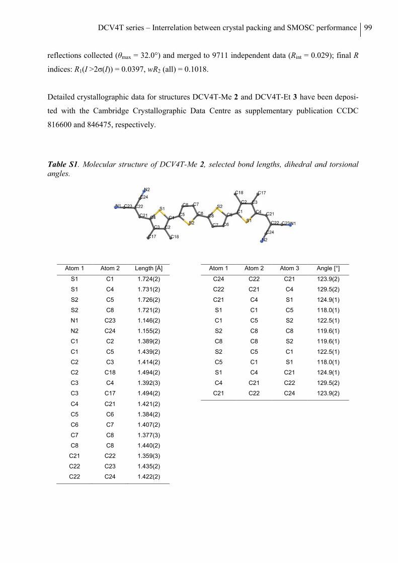
DCV4T series – Interrelation between crystal packing and SMOSC performance 99
reflections collected (θmax = 32.0°) and merged to 9711 independent data (Rint = 0.029); final R
indices: R1(I >2σ(I)) = 0.0397, wR2 (all) = 0.1018.
Detailed crystallographic data for structures DCV4T-Me 2 and DCV4T-Et 3 have been deposi-
ted with the Cambridge Crystallographic Data Centre as supplementary publication CCDC
816600 and 846475, respectively.
Table S1. Molecular structure of DCV4T-Me 2, selected bond lengths, dihedral and torsional angles.
Atom 1 Atom 2 Length [Å] Atom 1 Atom 2 Atom 3 Angle [°]
S1 C1 1.724(2) C24 C22 C21 123.9(2)
S1 C4 1.731(2) C22 C21 C4 129.5(2)
S2 C5 1.726(2) C21 C4 S1 124.9(1)
S2 C8 1.721(2) S1 C1 C5 118.0(1)
N1 C23 1.146(2) C1 C5 S2 122.5(1)
N2 C24 1.155(2) S2 C8 C8 119.6(1)
C1 C2 1.389(2) C8 C8 S2 119.6(1)
C1 C5 1.439(2) S2 C5 C1 122.5(1)
C2 C3 1.414(2) C5 C1 S1 118.0(1)
C2 C18 1.494(2) S1 C4 C21 124.9(1)
C3 C4 1.392(3) C4 C21 C22 129.5(2)
C3 C17 1.494(2) C21 C22 C24 123.9(2)
C4 C21 1.421(2)
C5 C6 1.384(2)
C6 C7 1.407(2)
C7 C8 1.377(3)
C8 C8 1.440(2)
C21 C22 1.359(3)
C22 C23 1.435(2)
C22 C24 1.422(2)
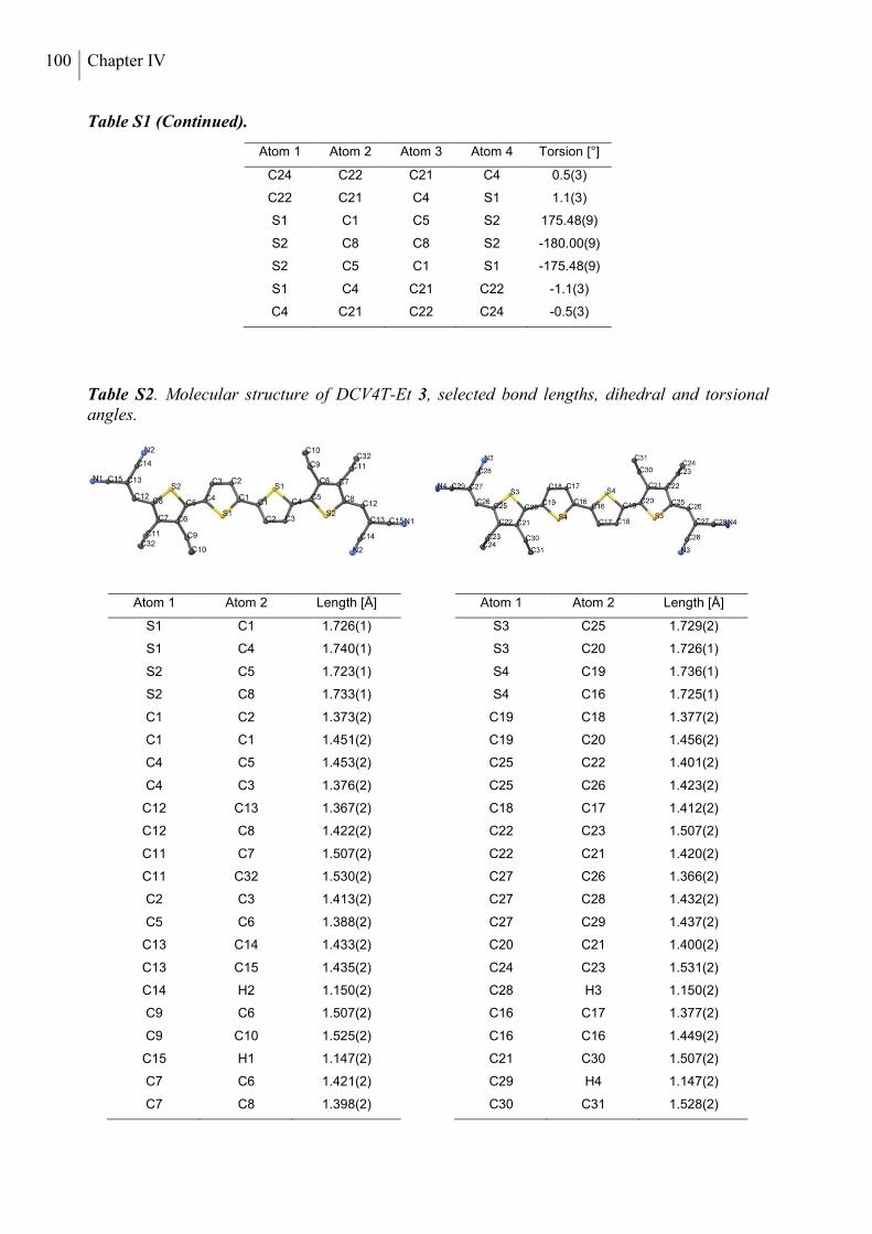
100 Chapter IV
Table S1 (Continued).
Atom 1 Atom 2 Atom 3 Atom 4 Torsion [°]
C24 C22 C21 C4 0.5(3)
C22 C21 C4 S1 1.1(3)
S1 C1 C5 S2 175.48(9)
S2 C8 C8 S2 -180.00(9)
S2 C5 C1 S1 -175.48(9)
S1 C4 C21 C22 -1.1(3)
C4 C21 C22 C24 -0.5(3)
Table S2. Molecular structure of DCV4T-Et 3, selected bond lengths, dihedral and torsional angles.
Atom 1 Atom 2 Length [Å] Atom 1 Atom 2 Length [Å]
S1 C1 1.726(1) S3 C25 1.729(2)
S1 C4 1.740(1) S3 C20 1.726(1)
S2 C5 1.723(1) S4 C19 1.736(1)
S2 C8 1.733(1) S4 C16 1.725(1)
C1 C2 1.373(2) C19 C18 1.377(2)
C1 C1 1.451(2) C19 C20 1.456(2)
C4 C5 1.453(2) C25 C22 1.401(2)
C4 C3 1.376(2) C25 C26 1.423(2)
C12 C13 1.367(2) C18 C17 1.412(2)
C12 C8 1.422(2) C22 C23 1.507(2)
C11 C7 1.507(2) C22 C21 1.420(2)
C11 C32 1.530(2) C27 C26 1.366(2)
C2 C3 1.413(2) C27 C28 1.432(2)
C5 C6 1.388(2) C27 C29 1.437(2)
C13 C14 1.433(2) C20 C21 1.400(2)
C13 C15 1.435(2) C24 C23 1.531(2)
C14 H2 1.150(2) C28 H3 1.150(2)
C9 C6 1.507(2) C16 C17 1.377(2)
C9 C10 1.525(2) C16 C16 1.449(2)
C15 H1 1.147(2) C21 C30 1.507(2)
C7 C6 1.421(2) C29 H4 1.147(2)
C7 C8 1.398(2) C30 C31 1.528(2)
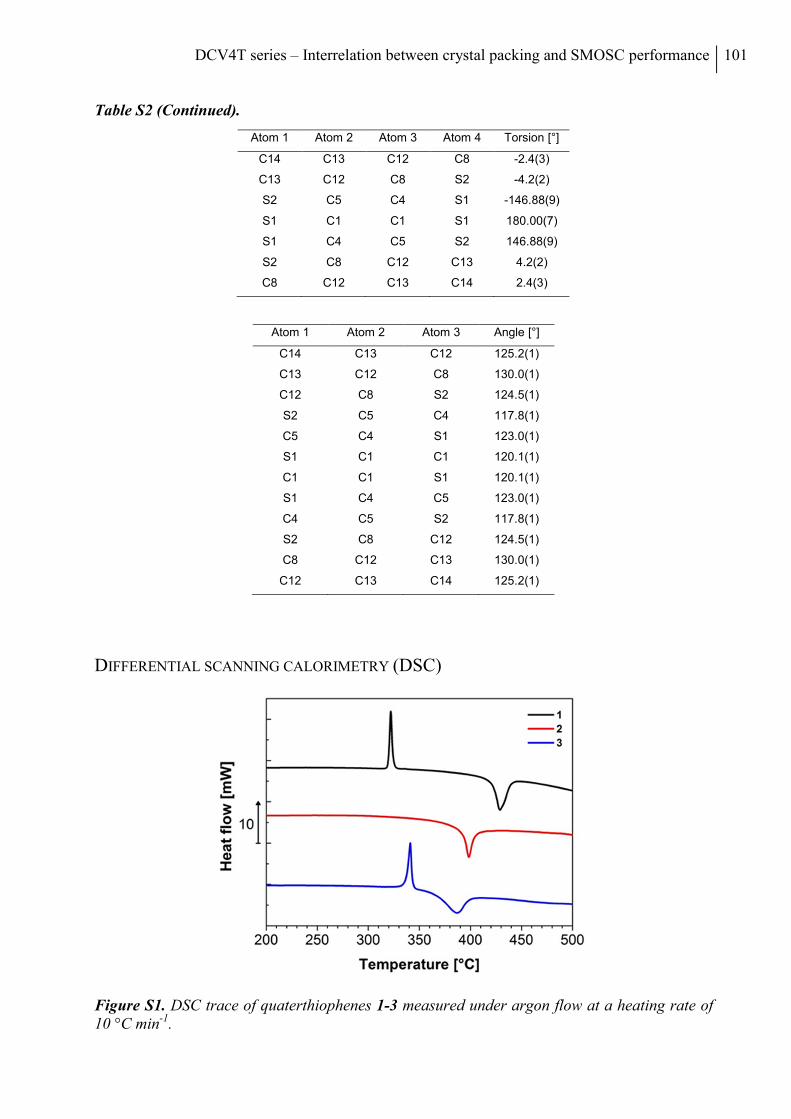
DCV4T series – Interrelation between crystal packing and SMOSC performance 101
Table S2 (Continued).
Atom 1 Atom 2 Atom 3 Atom 4 Torsion [°]
C14 C13 C12 C8 -2.4(3)
C13 C12 C8 S2 -4.2(2)
S2 C5 C4 S1 -146.88(9)
S1 C1 C1 S1 180.00(7)
S1 C4 C5 S2 146.88(9)
S2 C8 C12 C13 4.2(2)
C8 C12 C13 C14 2.4(3)
Atom 1 Atom 2 Atom 3 Angle [°]
C14 C13 C12 125.2(1)
C13 C12 C8 130.0(1)
C12 C8 S2 124.5(1)
S2 C5 C4 117.8(1)
C5 C4 S1 123.0(1)
S1 C1 C1 120.1(1)
C1 C1 S1 120.1(1)
S1 C4 C5 123.0(1)
C4 C5 S2 117.8(1)
S2 C8 C12 124.5(1)
C8 C12 C13 130.0(1)
C12 C13 C14 125.2(1)
DIFFERENTIAL SCANNING CALORIMETRY (DSC)
Figure S1. DSC trace of quaterthiophenes 1-3 measured under argon flow at a heating rate of 10 °C min-1.
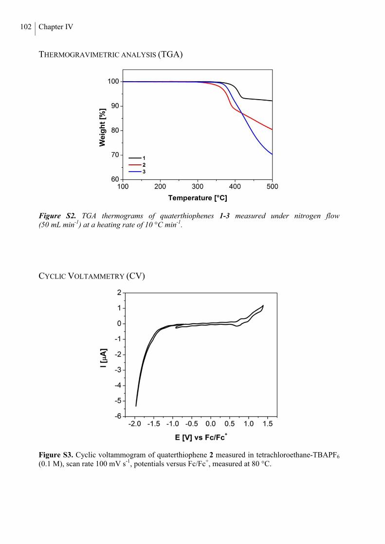
102 Chapter IV
THERMOGRAVIMETRIC ANALYSIS (TGA)
Figure S2. TGA thermograms of quaterthiophenes 1-3 measured under nitrogen flow (50 mL min-1) at a heating rate of 10 °C min-1.
CYCLIC VOLTAMMETRY (CV)
Figure S3. Cyclic voltammogram of quaterthiophene 2 measured in tetrachloroethane-TBAPF6 (0.1 M), scan rate 100 mV s-1, potentials versus Fc/Fc+, measured at 80 °C.
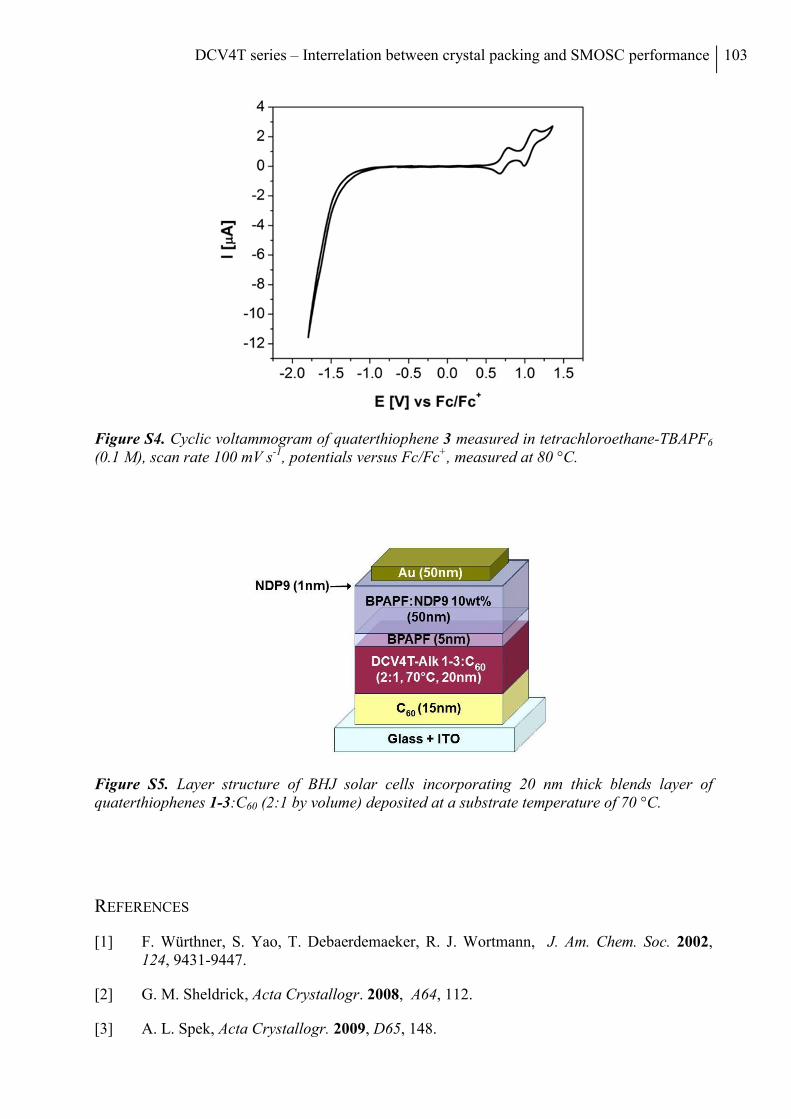
DCV4T series – Interrelation between crystal packing and SMOSC performance 103
Figure S4. Cyclic voltammogram of quaterthiophene 3 measured in tetrachloroethane-TBAPF6 (0.1 M), scan rate 100 mV s-1, potentials versus Fc/Fc+, measured at 80 °C.
Figure S5. Layer structure of BHJ solar cells incorporating 20 nm thick blends layer of quaterthiophenes 1-3:C60 (2:1 by volume) deposited at a substrate temperature of 70 °C.
REFERENCES
[1] F. Würthner, S. Yao, T. Debaerdemaeker, R. J. Wortmann, J. Am. Chem. Soc. 2002, 124, 9431-9447.
[2] G. M. Sheldrick, Acta Crystallogr. 2008, A64, 112.
[3] A. L. Spek, Acta Crystallogr. 2009, D65, 148.

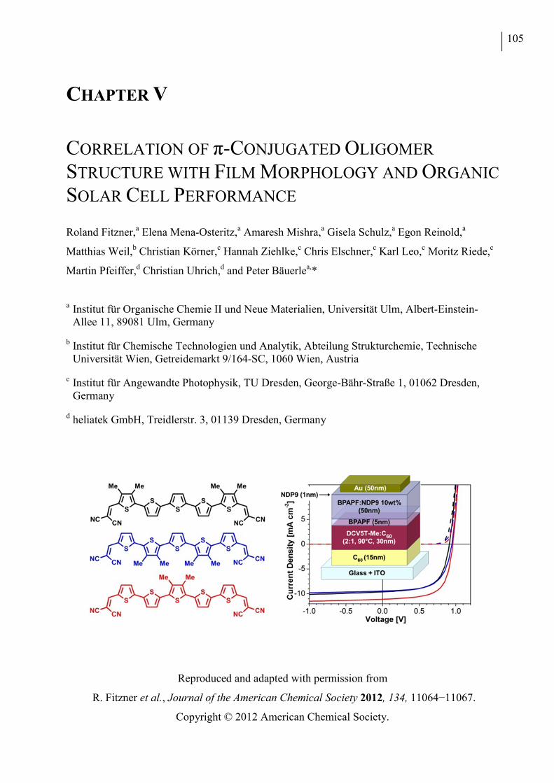
105
CHAPTER V
CORRELATION OF π-CONJUGATED OLIGOMER
STRUCTURE WITH FILM MORPHOLOGY AND ORGANIC
SOLAR CELL PERFORMANCE
Roland Fitzner,a Elena Mena-Osteritz,a Amaresh Mishra,a Gisela Schulz,a Egon Reinold,a
Matthias Weil,b Christian Körner,c Hannah Ziehlke,c Chris Elschner,c Karl Leo,c Moritz Riede,c
Martin Pfeiffer,d Christian Uhrich,d and Peter Bäuerlea,*
a Institut für Organische Chemie II und Neue Materialien, Universität Ulm, Albert-Einstein-Allee 11, 89081 Ulm, Germany
b Institut für Chemische Technologien und Analytik, Abteilung Strukturchemie, Technische Universität Wien, Getreidemarkt 9/164-SC, 1060 Wien, Austria
c Institut für Angewandte Photophysik, TU Dresden, George-Bähr-Straße 1, 01062 Dresden, Germany
d heliatek GmbH, Treidlerstr. 3, 01139 Dresden, Germany
Reproduced and adapted with permission from
R. Fitzner et al., Journal of the American Chemical Society 2012, 134, 11064−11067.
Copyright © 2012 American Chemical Society.

106 Chapter V
ABSTRACT
The novel methyl-substituted dicyanovinyl-capped quinquethiophenes 1−3 led to highly
efficient organic solar cells with power conversion efficiencies of 4.8−6.9%. X-ray analysis of
single crystals and evaporated neat and blend films gave insights into the packing and
morphological behavior of the novel compounds that rationalized their improved photovoltaic
performance.
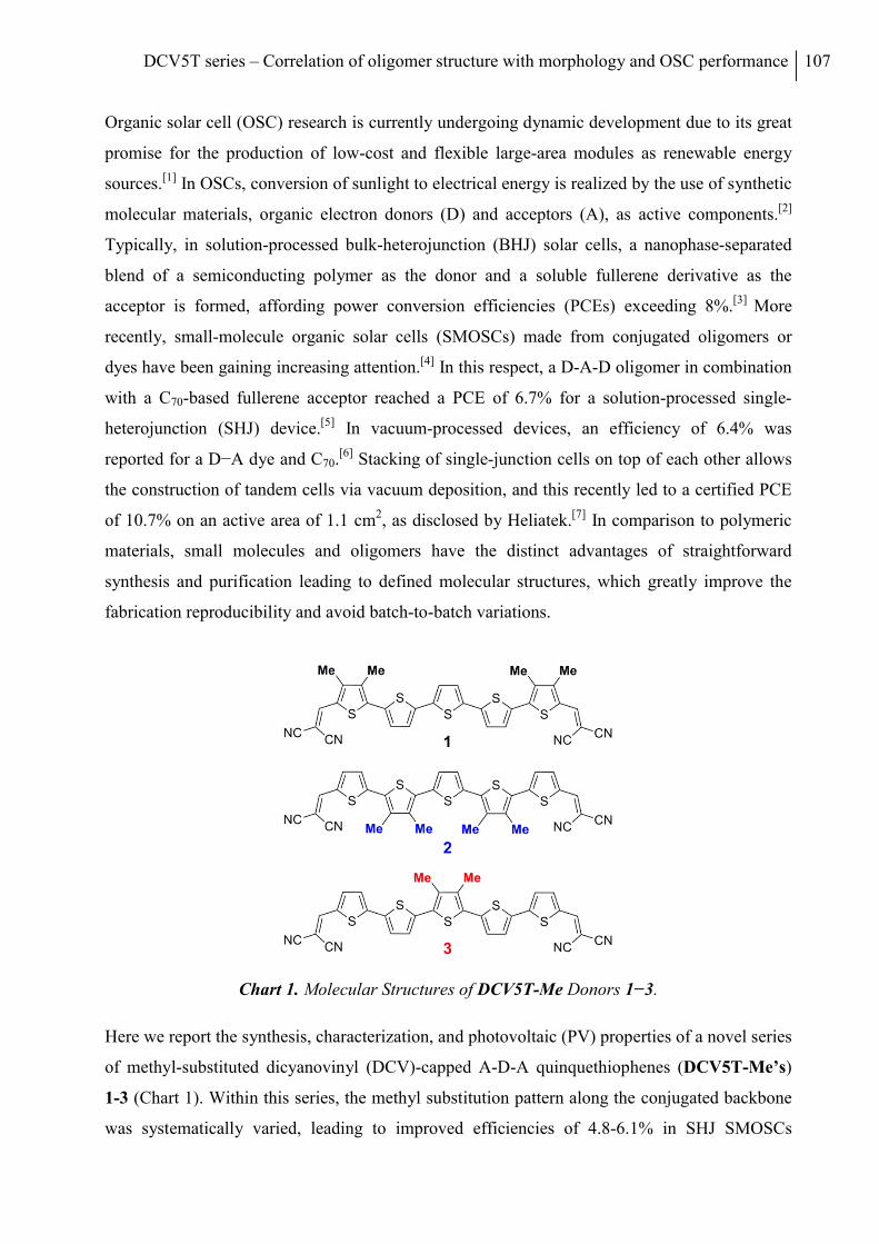
DCV5T series – Correlation of oligomer structure with morphology and OSC performance 107
Organic solar cell (OSC) research is currently undergoing dynamic development due to its great
promise for the production of low-cost and flexible large-area modules as renewable energy
sources.[1] In OSCs, conversion of sunlight to electrical energy is realized by the use of synthetic
molecular materials, organic electron donors (D) and acceptors (A), as active components.[2]
Typically, in solution-processed bulk-heterojunction (BHJ) solar cells, a nanophase-separated
blend of a semiconducting polymer as the donor and a soluble fullerene derivative as the
acceptor is formed, affording power conversion efficiencies (PCEs) exceeding 8%.[3] More
recently, small-molecule organic solar cells (SMOSCs) made from conjugated oligomers or
dyes have been gaining increasing attention.[4] In this respect, a D-A-D oligomer in combination
with a C70-based fullerene acceptor reached a PCE of 6.7% for a solution-processed single-
heterojunction (SHJ) device.[5] In vacuum-processed devices, an efficiency of 6.4% was
reported for a D−A dye and C70.[6] Stacking of single-junction cells on top of each other allows
the construction of tandem cells via vacuum deposition, and this recently led to a certified PCE
of 10.7% on an active area of 1.1 cm2, as disclosed by Heliatek.[7] In comparison to polymeric
materials, small molecules and oligomers have the distinct advantages of straightforward
synthesis and purification leading to defined molecular structures, which greatly improve the
fabrication reproducibility and avoid batch-to-batch variations.
Chart 1. Molecular Structures of DCV5T-Me Donors 1−3.
Here we report the synthesis, characterization, and photovoltaic (PV) properties of a novel series
of methyl-substituted dicyanovinyl (DCV)-capped A-D-A quinquethiophenes (DCV5T-Me’s)
1-3 (Chart 1). Within this series, the methyl substitution pattern along the conjugated backbone
was systematically varied, leading to improved efficiencies of 4.8-6.1% in SHJ SMOSCs
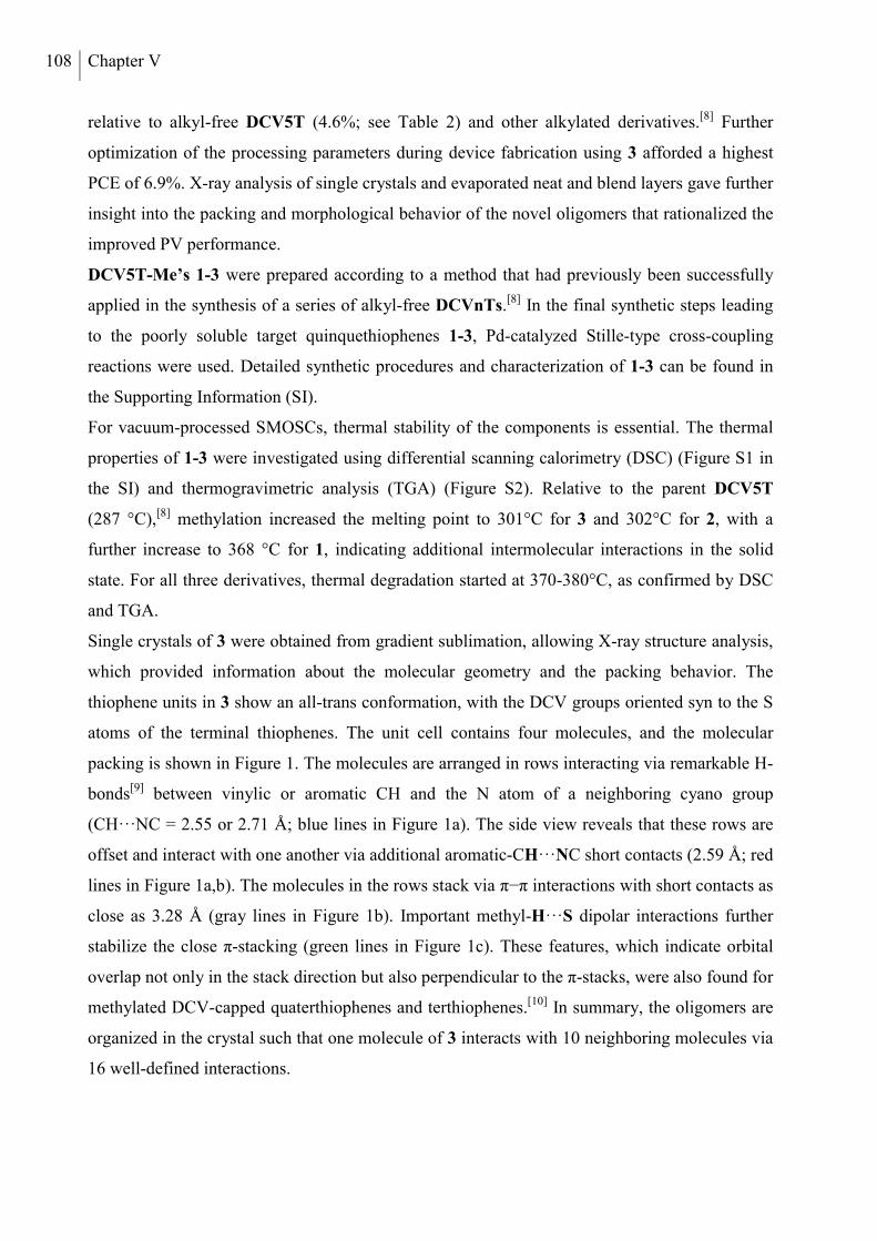
108 Chapter V
relative to alkyl-free DCV5T (4.6%; see Table 2) and other alkylated derivatives.[8] Further
optimization of the processing parameters during device fabrication using 3 afforded a highest
PCE of 6.9%. X-ray analysis of single crystals and evaporated neat and blend layers gave further
insight into the packing and morphological behavior of the novel oligomers that rationalized the
improved PV performance.
DCV5T-Me’s 1-3 were prepared according to a method that had previously been successfully
applied in the synthesis of a series of alkyl-free DCVnTs.[8] In the final synthetic steps leading
to the poorly soluble target quinquethiophenes 1-3, Pd-catalyzed Stille-type cross-coupling
reactions were used. Detailed synthetic procedures and characterization of 1-3 can be found in
the Supporting Information (SI).
For vacuum-processed SMOSCs, thermal stability of the components is essential. The thermal
properties of 1-3 were investigated using differential scanning calorimetry (DSC) (Figure S1 in
the SI) and thermogravimetric analysis (TGA) (Figure S2). Relative to the parent DCV5T
(287 °C),[8] methylation increased the melting point to 301°C for 3 and 302°C for 2, with a
further increase to 368 °C for 1, indicating additional intermolecular interactions in the solid
state. For all three derivatives, thermal degradation started at 370-380°C, as confirmed by DSC
and TGA.
Single crystals of 3 were obtained from gradient sublimation, allowing X-ray structure analysis,
which provided information about the molecular geometry and the packing behavior. The
thiophene units in 3 show an all-trans conformation, with the DCV groups oriented syn to the S
atoms of the terminal thiophenes. The unit cell contains four molecules, and the molecular
packing is shown in Figure 1. The molecules are arranged in rows interacting via remarkable H-
bonds[9] between vinylic or aromatic CH and the N atom of a neighboring cyano group
(CH···NC = 2.55 or 2.71 Å; blue lines in Figure 1a). The side view reveals that these rows are
offset and interact with one another via additional aromatic-CH···NC short contacts (2.59 Å; red
lines in Figure 1a,b). The molecules in the rows stack via π−π interactions with short contacts as
close as 3.28 Å (gray lines in Figure 1b). Important methyl-H···S dipolar interactions further
stabilize the close π-stacking (green lines in Figure 1c). These features, which indicate orbital
overlap not only in the stack direction but also perpendicular to the π-stacks, were also found for
methylated DCV-capped quaterthiophenes and terthiophenes.[10] In summary, the oligomers are
organized in the crystal such that one molecule of 3 interacts with 10 neighboring molecules via
16 well-defined interactions.
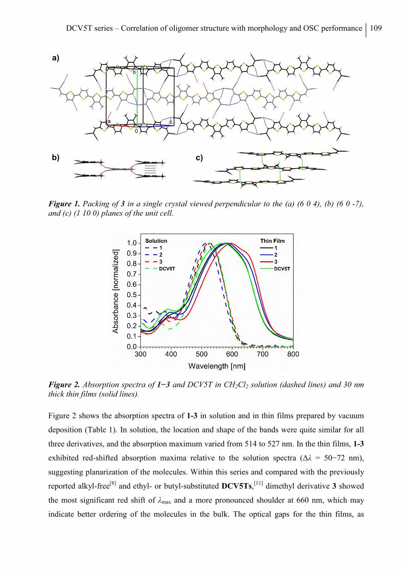
DCV5T series – Correlation of oligomer structure with morphology and OSC performance 109
Figure 1. Packing of 3 in a single crystal viewed perpendicular to the (a) (6 0 4), (b) (6 0 -7), and (c) (1 10 0) planes of the unit cell.
Figure 2. Absorption spectra of 1−3 and DCV5T in CH2Cl2 solution (dashed lines) and 30 nm thick thin films (solid lines).
Figure 2 shows the absorption spectra of 1-3 in solution and in thin films prepared by vacuum
deposition (Table 1). In solution, the location and shape of the bands were quite similar for all
three derivatives, and the absorption maximum varied from 514 to 527 nm. In the thin films, 1-3
exhibited red-shifted absorption maxima relative to the solution spectra (Δλ = 50−72 nm),
suggesting planarization of the molecules. Within this series and compared with the previously
reported alkyl-free[8] and ethyl- or butyl-substituted DCV5Ts,[11] dimethyl derivative 3 showed
the most significant red shift of λmax and a more pronounced shoulder at 660 nm, which may
indicate better ordering of the molecules in the bulk. The optical gaps for the thin films, as
a)
b) c)
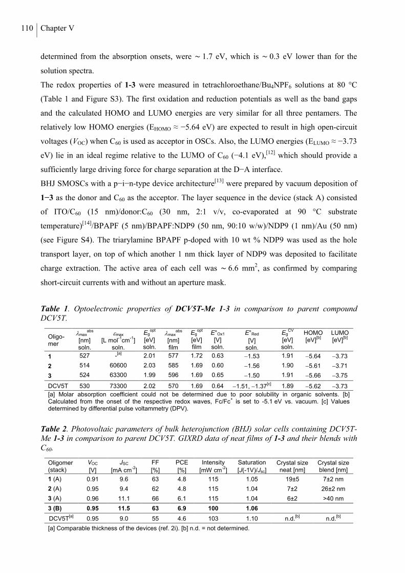
110 Chapter V
determined from the absorption onsets, were ∼ 1.7 eV, which is ∼ 0.3 eV lower than for the
solution spectra.
The redox properties of 1-3 were measured in tetrachloroethane/Bu4NPF6 solutions at 80 °C
(Table 1 and Figure S3). The first oxidation and reduction potentials as well as the band gaps
and the calculated HOMO and LUMO energies are very similar for all three pentamers. The
relatively low HOMO energies (EHOMO ≈ −5.64 eV) are expected to result in high open-circuit
voltages (VOC) when C60 is used as acceptor in OSCs. Also, the LUMO energies (ELUMO ≈ −3.73
eV) lie in an ideal regime relative to the LUMO of C60 (−4.1 eV),[12] which should provide a
sufficiently large driving force for charge separation at the D−A interface.
BHJ SMOSCs with a p−i−n-type device architecture[13] were prepared by vacuum deposition of
1−3 as the donor and C60 as the acceptor. The layer sequence in the device (stack A) consisted
of ITO/C60 (15 nm)/donor:C60 (30 nm, 2:1 v/v, co-evaporated at 90 °C substrate
temperature)[14]/BPAPF (5 nm)/BPAPF:NDP9 (50 nm, 90:10 w/w)/NDP9 (1 nm)/Au (50 nm)
(see Figure S4). The triarylamine BPAPF p-doped with 10 wt % NDP9 was used as the hole
transport layer, on top of which another 1 nm thick layer of NDP9 was deposited to facilitate
charge extraction. The active area of each cell was ∼ 6.6 mm2, as confirmed by comparing
short-circuit currents with and without an aperture mask.
Table 1. Optoelectronic properties of DCV5T-Me 1-3 in comparison to parent compound DCV5T.
Oligo-mer
maxabs
[nm] soln.
max [L mol
-1cm
-1]
soln.
Egopt
[eV] soln.
maxabs
[nm] film
Egopt
[eV] film
E°Ox1 [V]
soln.
E°Red
[V] soln.
EgCV
[eV] soln.
HOMO [eV]
[b] LUMO [eV]
[b]
1 527 -[a]
2.01 577 1.72 0.63 1.53 1.91 5.64 3.73
2 514 60600 2.03 585 1.69 0.60 1.56 1.90 5.61 3.71
3 524 63300 1.99 596 1.69 0.65 1.50 1.91 5.66 3.75
DCV5T
530 73300 2.02 570 1.69 0.64 1.51, 1.37[c] 1.89 5.62 3.73
[a] Molar absorption coefficient could not be determined due to poor solubility in organic solvents. [b] Calculated from the onset of the respective redox waves, Fc/Fc
+ is set to -5.1 eV vs. vacuum. [c] Values
determined by differential pulse voltammetry (DPV).
Table 2. Photovoltaic parameters of bulk heterojunction (BHJ) solar cells containing DCV5T-Me 1-3 in comparison to parent DCV5T. GIXRD data of neat films of 1-3 and their blends with C60.
Oligomer (stack)
VOC
[V]
JSC
[mA cm-2
]
FF
[%]
PCE
[%]
Intensity
[mW cm-2
]
Saturation
[J(-1V)/Jsc] Crystal size neat [nm]
Crystal size blend [nm]
1 (A) 0.91 9.6 63 4.8 115 1.05 19±5 7±2 nm
2 (A) 0.95 9.4 62 4.8 115 1.04 7±2 26±2 nm
3 (A) 0.96 11.1 66 6.1 115 1.04 6±2 >40 nm
3 (B) 0.95 11.5 63 6.9 100 1.06
DCV5T[a]
0.95 9.0 55 4.6 103 1.10 n.d.[b]
n.d.[b]
[a] Comparable thickness of the devices (ref. 2i). [b] n.d. = not determined.
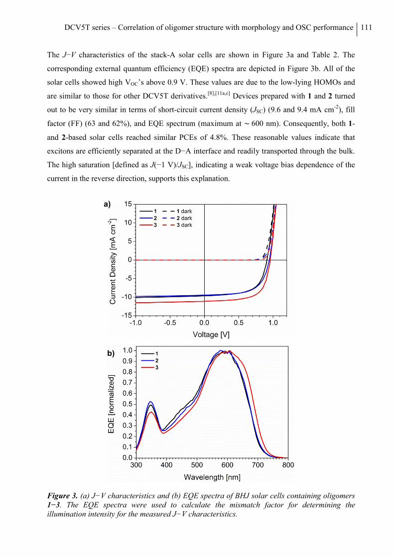
DCV5T series – Correlation of oligomer structure with morphology and OSC performance 111
The J−V characteristics of the stack-A solar cells are shown in Figure 3a and Table 2. The
corresponding external quantum efficiency (EQE) spectra are depicted in Figure 3b. All of the
solar cells showed high VOC’s above 0.9 V. These values are due to the low-lying HOMOs and
are similar to those for other DCV5T derivatives.[8],[11a,c] Devices prepared with 1 and 2 turned
out to be very similar in terms of short-circuit current density (JSC) (9.6 and 9.4 mA cm-2), fill
factor (FF) (63 and 62%), and EQE spectrum (maximum at ∼ 600 nm). Consequently, both 1-
and 2-based solar cells reached similar PCEs of 4.8%. These reasonable values indicate that
excitons are efficiently separated at the D−A interface and readily transported through the bulk.
The high saturation [defined as J(−1 V)/JSC], indicating a weak voltage bias dependence of the
current in the reverse direction, supports this explanation.
Figure 3. (a) J−V characteristics and (b) EQE spectra of BHJ solar cells containing oligomers 1−3. The EQE spectra were used to calculate the mismatch factor for determining the illumination intensity for the measured J−V characteristics.
a)
b)
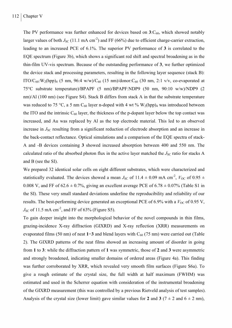
112 Chapter V
The PV performance was further enhanced for devices based on 3:C60, which showed notably
larger values of both JSC (11.1 mA cm-2) and FF (66%) due to efficient charge-carrier extraction,
leading to an increased PCE of 6.1%. The superior PV performance of 3 is correlated to the
EQE spectrum (Figure 3b), which shows a significant red shift and spectral broadening as in the
thin-film UV-vis spectrum. Because of the outstanding performance of 3, we further optimized
the device stack and processing parameters, resulting in the following layer sequence (stack B):
ITO/C60:W2(hpp)4 (5 nm, 96:4 w/w)/C60 (15 nm)/donor:C60 (30 nm, 2:1 v/v, co-evaporated at
75°C substrate temperature)/BPAPF (5 nm)/BPAPF:NDP9 (50 nm, 90:10 w/w)/NDP9 (2
nm)/Al (100 nm) (see Figure S4). Stack B differs from stack A in that the substrate temperature
was reduced to 75 °C, a 5 nm C60 layer n-doped with 4 wt % W2(hpp)4 was introduced between
the ITO and the intrinsic C60 layer, the thickness of the p-dopant layer below the top contact was
increased, and Au was replaced by Al as the top electrode material. This led to an observed
increase in JSC resulting from a significant reduction of electrode absorption and an increase in
the back-contact reflectance. Optical simulations and a comparison of the EQE spectra of stack-
A and -B devices containing 3 showed increased absorption between 400 and 550 nm. The
calculated ratio of the absorbed photon flux in the active layer matched the JSC ratio for stacks A
and B (see the SI).
We prepared 32 identical solar cells on eight different substrates, which were characterized and
statistically evaluated. The devices showed a mean JSC of 11.4 ± 0.09 mA cm-2, VOC of 0.95 ±
0.008 V, and FF of 62.6 ± 0.7%, giving an excellent average PCE of 6.78 ± 0.07% (Table S1 in
the SI). These very small standard deviations underline the reproducibility and reliability of our
results. The best-performing device generated an exceptional PCE of 6.9% with a VOC of 0.95 V,
JSC of 11.5 mA cm-2, and FF of 63% (Figure S5).
To gain deeper insight into the morphological behavior of the novel compounds in thin films,
grazing-incidence X-ray diffraction (GIXRD) and X-ray reflection (XRR) measurements on
evaporated films (50 nm) of neat 1−3 and blend layers with C60 (75 nm) were carried out (Table
2). The GIXRD patterns of the neat films showed an increasing amount of disorder in going
from 1 to 3: while the diffraction pattern of 1 was symmetric, those of 2 and 3 were asymmetric
and strongly broadened, indicating smaller domains of ordered areas (Figure 4a). This finding
was further corroborated by XRR, which revealed very smooth film surfaces (Figure S6a). To
give a rough estimate of the crystal size, the full width at half maximum (FWHM) was
estimated and used in the Scherrer equation with consideration of the instrumental broadening
of the GIXRD measurement (this was controlled by a previous Rietveld analysis of test samples).
Analysis of the crystal size (lower limit) gave similar values for 2 and 3 (7 ± 2 and 6 ± 2 nm),
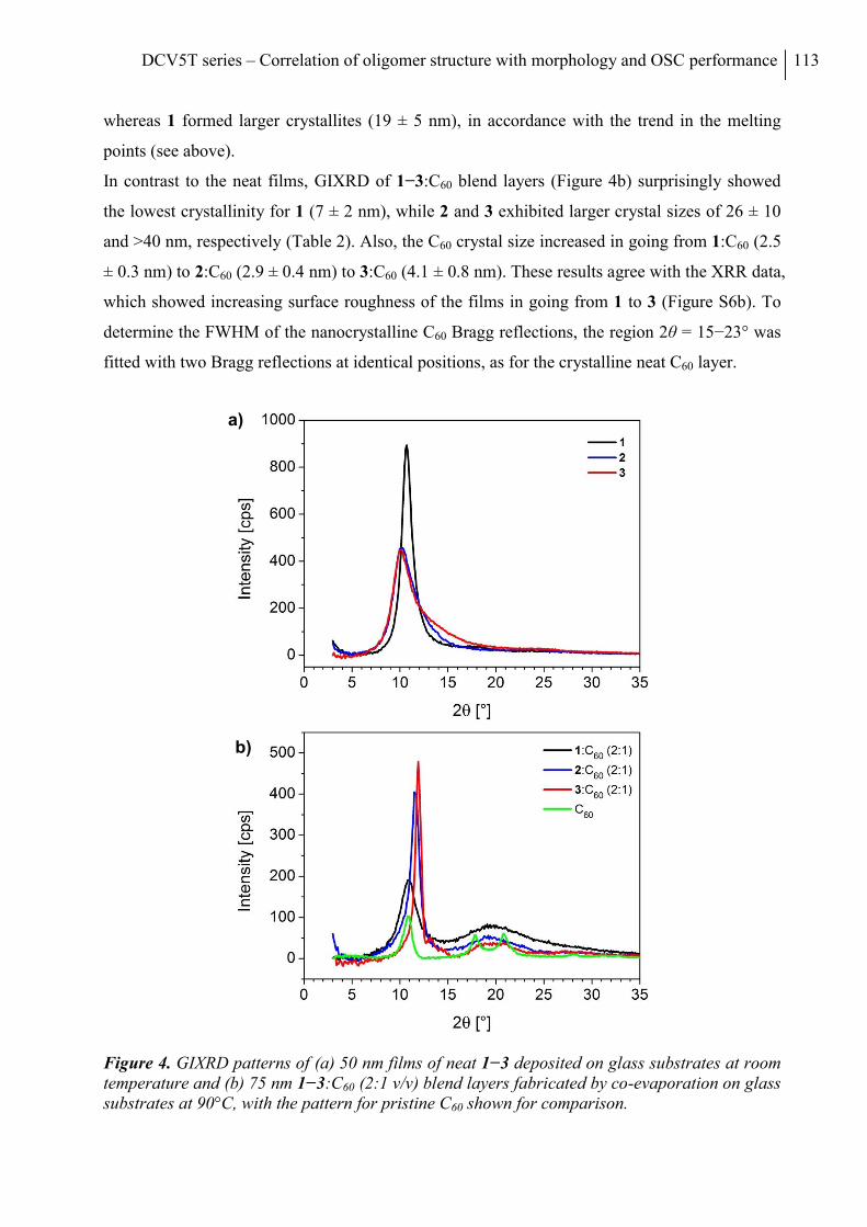
DCV5T series – Correlation of oligomer structure with morphology and OSC performance 113
whereas 1 formed larger crystallites (19 ± 5 nm), in accordance with the trend in the melting
points (see above).
In contrast to the neat films, GIXRD of 1−3:C60 blend layers (Figure 4b) surprisingly showed
the lowest crystallinity for 1 (7 ± 2 nm), while 2 and 3 exhibited larger crystal sizes of 26 ± 10
and >40 nm, respectively (Table 2). Also, the C60 crystal size increased in going from 1:C60 (2.5
± 0.3 nm) to 2:C60 (2.9 ± 0.4 nm) to 3:C60 (4.1 ± 0.8 nm). These results agree with the XRR data,
which showed increasing surface roughness of the films in going from 1 to 3 (Figure S6b). To
determine the FWHM of the nanocrystalline C60 Bragg reflections, the region 2θ = 15−23° was
fitted with two Bragg reflections at identical positions, as for the crystalline neat C60 layer.
Figure 4. GIXRD patterns of (a) 50 nm films of neat 1−3 deposited on glass substrates at room temperature and (b) 75 nm 1−3:C60 (2:1 v/v) blend layers fabricated by co-evaporation on glass substrates at 90°C, with the pattern for pristine C60 shown for comparison.
a)
b)
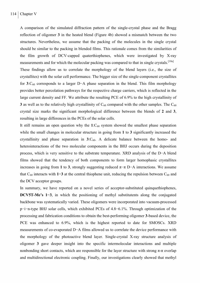
114 Chapter V
A comparison of the simulated diffraction pattern of the single-crystal phase and the Bragg
reflection of oligomer 3 in the heated blend (Figure 4b) showed a mismatch between the two
structures. Nevertheless, we assume that the packing of the molecules in the single crystal
should be similar to the packing in blended films. This rationale comes from the similarities of
the film growth of DCV-capped quaterthiophenes, which were investigated by X-ray
measurements and for which the molecular packing was compared to that in single crystals.[10a]
These findings allow us to correlate the morphology of the blend layers (i.e., the size of
crystallites) with the solar cell performance. The bigger size of the single-component crystallites
for 3:C60 corresponds to a larger D−A phase separation in the blend. This film morphology
provides better percolation pathways for the respective charge carriers, which is reflected in the
large current density and FF. We attribute the resulting PCE of 6.9% to the high crystallinity of
3 as well as to the relatively high crystallinity of C60 compared with the other samples. The C60
crystal size marks the significant morphological difference between the blends of 2 and 3,
resulting in large differences in the PCEs of the solar cells.
It still remains an open question why the 1:C60 system showed the smallest phase separation
while the small changes in molecular structure in going from 1 to 3 significantly increased the
crystallinity and phase separation in 3:C60. A delicate balance between the homo- and
heterointeractions of the two molecular components in the BHJ occurs during the deposition
process, which is very sensitive to the substrate temperature. XRD analysis of the D−A blend
films showed that the tendency of both components to form larger homophasic crystallites
increases in going from 1 to 3, strongly suggesting reduced π−π D−A interactions. We assume
that C60 interacts with 1−3 at the central thiophene unit, reducing the repulsion between C60 and
the DCV acceptor groups.
In summary, we have reported on a novel series of acceptor-substituted quinquethiophenes,
DCV5T-Me’s 1−3, in which the positioning of methyl substitutents along the conjugated
backbone was systematically varied. These oligomers were incorporated into vacuum-processed
p−i−n-type BHJ solar cells, which exhibited PCEs of 4.8−6.1%. Through optimization of the
processing and fabrication conditions to obtain the best-performing oligomer 3-based device, the
PCE was enhanced to 6.9%, which is the highest reported to date for SMOSCs. XRD
measurements of co-evaporated D−A films allowed us to correlate the device performance with
the morphology of the photoactive blend layer. Single-crystal X-ray structure analysis of
oligomer 3 gave deeper insight into the specific intermolecular interactions and multiple
nonbonding short contacts, which are responsible for the layer structure with strong π-π overlap
and multidirectional electronic coupling. Finally, our investigations clearly showed that methyl
DCV5T series – Correlation of oligomer structure with morphology and OSC performance 115
substitution in oligothiophenes can be used to provide a beneficial influence on the morphology
of D−A blends and consequently the device performance. This work emphasizes the advantages
of structurally defined oligomers, which provide structure−property relationships (molecular
level) as well as information on favorable molecular organization in the bulk (supramolecular
level) and pronounced phase separation of the donor and acceptor materials in BHJs (systems
level).[15]
SUPPORTING INFORMATION
Experimental procedures, additional results, and a CIF file. This material is available free of
charge via the Internet at http://pubs.acs.org. The X-ray data were also deposited with the
CCDC (entry 850004).
ACKNOWLEDGEMENTS
This work was supported by the DFG (Priority Program SPP 1355) and BMBF (Programs
OPEG 13N9720 and OPA 13N98872). We thank Dr. L. Wilde (Fraunhofer CNT) for the X-ray
measurements and Novaled AG for providing NDP9.
116 Chapter V
REFERENCES
[1] Brabec, C.; Gowrisanker, S.; Halls, J. M. M.; Laird, D.; Jia, S. J.; Williams, S. P. Adv. Mater. 2010, 22, 3839.
[2] Organic Photovoltaics: Materials, Device Physics, and Manufacturing Technologies; Brabec, C., Dyakonov, V., Scherf, U., Eds.; Wiley-VCH: Weinheim, Germany, 2008.
[3] Dou, L.; You, J.; Yang, J.; Chen, C.-C.; He, Y.; Murase, S.; Moriarty, T.; Emery, K.; Li, G.; Yang, Y. Nat. Photonics 2012, 6, 180.
[4] Mishra, A.; Bäuerle, P. Angew. Chem., Int. Ed. 2012, 51, 2020.
[5] Sun, Y.; Welch, G. C.; Leong, W. L.; Takacs, C. T.; Bazan, G. C.; Heeger, A. J. Nat. Mater. 2012, 11, 44.
[6] Chiu, S.-W.; Lin, L.-Y.; Lin, H.-W.; Liu, Y.-H.; Huang, Z.-Y.; Lin, Y.-T.; Lin, F.; Chen, Y.-H.; Wong, K.-T. Chem. Commun. 2012, 48, 1857.
[7] Heliatek GmbH, press release of April 27, 2012 (http://www.heliatek.com).
[8] Fitzner, R.; Reinold, E.; Mishra, A.; Mena-Osteritz, E.; Ziehlke, H.; Körner, C.; Leo, K.; Riede, M.; Weil, M.; Tsaryova, O.; Weiß, A.; Uhrich, C.; Pfeiffer, M.; Bäuerle, P. Adv. Funct. Mater. 2011, 21, 897.
[9] Desiraju, G. R.; Steiner, T. The Weak Hydrogen Bond; Oxford University Press: New York, 1999.
[10] (a) Fitzner, R.; Elschner, C.; Weil, M.; Uhrich, C.; Körner, C.; Riede, M.; Leo, K.; Pfeiffer, M.; Reinold, E.; Mena-Osteritz, E.; Bäuerle, P. Adv. Mater. 2012, 24, 675. (b) Schrader, M.; Fitzner, R.; Hein, M.; Elschner, C.; Baumeier, B.; Riede, M.; Leo, K.; Bäuerle, P.; Andrienko, D. J. Am. Chem. Soc. 2012, 134, 6052−6056.
[11] (a) Schulze, K.; Uhrich, C.; Schüppel, R.; Leo, K.; Pfeiffer, M.; Brier, E.; Reinold, E.; Bäuerle, P. Adv. Mater. 2006, 18, 2872. (b) Schulze, K.; Riede, M.; Brier, E.; Reinold, E.; Bäuerle, P.; Leo, K. J. Appl. Phys. 2008, 104, No. 074511. (c) Mishra, A.; Uhrich, C.; Reinold, E.; Pfeiffer, M.; Bäuerle, P. Adv. Energy Mater. 2011, 1, 265.
[12] Xie, Q.; Arias, F.; Echegoyen, L. J. Am. Chem. Soc. 1993, 115, 9818.
[13] Riede, M.; Mueller, T.; Tress, W.; Schueppel, R.; Leo, K. Nanotechnology 2008, 19, No. 424001.
[14] Wynands, D.; Levichkova, M.; Leo, K.; Uhrich, C.; Schwartz, G.; Hildebrandt, D.; Pfeiffer, M.; Riede, M. Appl. Phys. Lett. 2010, 97, No. 073503.
[15] Würthner, F.; Meerholz, K. Chem. - Eur. J. 2010, 16, 9366.
DCV5T series – Correlation of oligomer structure with morphology and OSC performance 117
SUPPORTING INFORMATION
MATERIALS AND METHODS
NMR spectra were recorded on a Bruker AMX 500 (1H NMR: 500 MHz, 13C NMR: 125 MHz)
or an Avance 400 spectrometer (1H NMR: 400 MHz, 13C NMR: 100 MHz), at 25 °C or 100 °C.
Chemical shift values () are expressed in parts per million using residual solvent protons (1H
NMR, H = 7.26 for CDCl3, H = 2.50 for DMSO-d6 and H = 5.93 for tetrachloroethane-d2; 13C
NMR, C = 77.0 for CDCl3, C = 39.43 for DMSO-d6 and C = 74.20 tetrachloroethane-d2) as
internal standard. The splitting patterns are designated as follows: s (singlet), d (doublet) and dd
(doublet of doublets). The assignments are ThH (thiophene protons), MeH (methyl protons)
CHO (aldehyde protons) and DCVH (dicyanovinyl protons). GC-MS (EI) mass spectra were
recorded on a Varian Saturn 2000, CI mass spectra on a Finnigan MAT SSQ-7000 and MALDI-
TOF mass spectra on a Bruker Daltonic Reflex III. Melting points were determined using a
Büchi B-545 apparatus and were not corrected. Elemental analyses were performed on an
Elementar Vario EL. Preparative column chromatography was performed on glass columns
packed with silica gel (Merck Silica 60, particle size 40-43 µm).
Tetrahydrofurane (THF, Merck) was dried under reflux over sodium/benzophenone (Merck) and
distilled. Dimethylformamide (DMF, Merck) was refluxed over P4O10 (Merck) and distilled.
The potassium carbonate (Riedel-de Haën) solution was prepared by dissolving in deionised
water and was degassed prior to use. 3,4-Dimethylthiophene-2-carboxaldehyde 4,[1] 2,5-bis(tri-
methylstannyl)thiophene 10,[2] 3,4-dimethylthiophene 11,[3] 2-[(5-bromo-thiophen-2-
yl)methylene]-malononitrile 17[4] and 2,5-bis(trimethylstannyl)-3,4-dimethylthiophen 18[5] were
prepared according to published literature procedures. n-Butyl lithium (2.5 M solution in
hexanes), 2-isopropoxy-4,4,5,5-tetramethyl[1,3,2]dioxoborolane, 5-bromothiophene-
2-carbaldehyde 13, 2-(tributylstannyl)thiophene 6 and trimethyltinchloride were purchased from
Aldrich. n-Butyl lithium (1.6 M solution in hexanes) was purchased from Acros. N-
bromosuccinimide (NBS), malononitrile and β-alanine were purchased from Merck. All
synthetic steps were carried out under argon atmosphere.
SYNTHESIS AND CHARACTERIZATION
Target compounds 1-3 were obtained in good yields by reacting DCV-capped bromobithiophe-
nes 9, 16, 17 and bisstannylated thiophene 10 or 3,4-dimethylthiophene 18 in Pd-catalyzed
Stille-type cross-coupling reactions (Scheme S1). Bromobithiophenes 9 and 16 were prepared
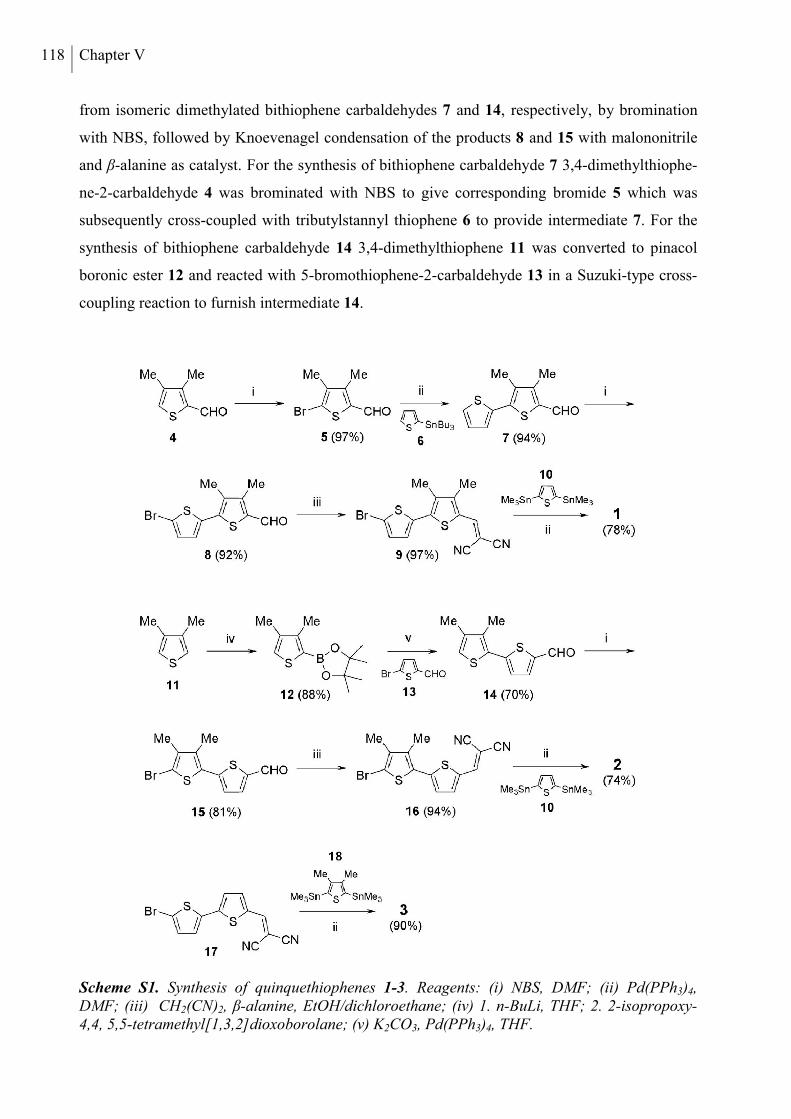
118 Chapter V
from isomeric dimethylated bithiophene carbaldehydes 7 and 14, respectively, by bromination
with NBS, followed by Knoevenagel condensation of the products 8 and 15 with malononitrile
and β-alanine as catalyst. For the synthesis of bithiophene carbaldehyde 7 3,4-dimethylthiophe-
ne-2-carbaldehyde 4 was brominated with NBS to give corresponding bromide 5 which was
subsequently cross-coupled with tributylstannyl thiophene 6 to provide intermediate 7. For the
synthesis of bithiophene carbaldehyde 14 3,4-dimethylthiophene 11 was converted to pinacol
boronic ester 12 and reacted with 5-bromothiophene-2-carbaldehyde 13 in a Suzuki-type cross-
coupling reaction to furnish intermediate 14.
Scheme S1. Synthesis of quinquethiophenes 1-3. Reagents: (i) NBS, DMF; (ii) Pd(PPh3)4, DMF; (iii) CH2(CN)2, β-alanine, EtOH/dichloroethane; (iv) 1. n-BuLi, THF; 2. 2-isopropoxy-4,4, 5,5-tetramethyl[1,3,2]dioxoborolane; (v) K2CO3, Pd(PPh3)4, THF.
DCV5T series – Correlation of oligomer structure with morphology and OSC performance 119
Synthesis of 2,2'-[3,4,3'''',4''''-tetramethyl-2,2':5',2'':5'',2''':5''',2''''-quinquethien-5,5''''-diylbis-
(methane-1-yl-1-ylidine)]dimalononitrile 1: A mixture of 2,5-bis(trimethylstannyl)thiophene 10
(2.50 g, 6.10 mmol), 5-[(5'-bromo-3,4-dimethyl-2,2'-bithien-5-yl)methylene]malononitrile 9
(4.69 g, 13.4 mmol) and tetrakis(triphenylphosphine)palladium(0) (352 mg, 0.31 mmol) in de-
gassed DMF (200 mL) was stirred at 80 °C for 8 hours. The reaction mixture was allowed to
cool to room temperature and the precipitate was filtered off. The obtained solid was further
refluxed in methanol for 30 min and collected by filtration. The crude product was extracted in a
Soxhlet extractor with acetone for 16 hours to remove the most soluble reaction by-products.
Subsequently, Soxhlet extraction was continued for 8 days using chlorobenzene. Upon cooling
the resulting extract to room temperature, the precipitate was filtered off to yield 1 (2.95 g,
4.76 mmol, 78%) as a black solid. M.p. 368 oC (DSC). 1H NMR (TCE-d2, 100 °C, δ ppm) 7.83
(s, 2H, DCVH), 7.31 (d, 2H, J = 3.82 Hz, ThH), 7.22 (d, 2H, J = 3.82 Hz, ThH), 7.19 (s, 2H,
ThH), 2.38 (s, 6H, MeH), 2.33 (s, 6H, MeH). MALDI-TOF mass 620 [M+] (calcd. for
C32H20N4S5 620). Elemental analysis for C32H20N4S5: calcd. C, 61.91; H, 3.25; N, 9.02; S,
25.82%; found: C, 62.02; H, 3.35; N, 8.83; S, 25.69%.
Synthesis of 2,2'-[3',4',3''',4'''-tetramethyl-2,2':5',2'':5'',2''':5''',2''''-quinquethien-5,5''''-diylbis-
(methane-1-yl-1-ylidine)]dimalononitrile 2: A mixture of 2,5-bis(trimethylstannyl)thiophene 10
(150 mg, 0.37 mmol), 5-[(5'-bromo-3',4'-dimethyl-2,2'-bithien-5-yl)methylene]malononitrile 16
(269 mg, 0.77 mmol) and tetrakis(triphenylphosphine)palladium(0) (21 mg, 0.012 mmol) was
combined in degassed DMF (6.5 mL) in a screw cap vial, and was agitated at 80 °C for 20 hours.
After cooling, the resulting precipitate was filtered off and washed several times with methanol
and n-hexane. Column chromatography (silica gel, DCM) yielded compound 2 (168 mg,
0.27 mmol, 74%) as a black solid. M.p. 302 oC (DSC). 1H NMR (DMSO-d6, 100 °C, δ ppm)
8.52 (s, 2H, DCVH), 7.96 (d, 2H, J = 4.17 Hz, ThH), 7.51 (d, 2H, J = 4.13 Hz, ThH), 7.35 (s, 2H,
ThH), 2.40 (s, 6H, MeH), 2.37 (s, 6H, MeH). MALDI-TOF mass 621 [M+H+] (calcd. for
C32H20N4S5 620). Elemental analysis for C32H20N4S5: calcd. C, 61.91; H, 3.25; N, 9.02; S,
25.82%; found: C, 62.03; H, 3.30; N, 8.90; S, 25.95%.
Synthesis of 2,2'-[3'',4''-dimethyl-2,2':5',2'':5'',2''':5''',2''''-quinquethien-5,5''''-diylbis(methane -
1-yl-1-ylidine)]dimalononitrile 3: A mixture of 2,5-bis(trimethylstannyl)-3,4-dimethyl-thiophe-
ne 18 (100 mg, 0.23 mmol), 5-[(5'-bromo-3,4-dimethyl-2,2'-bithien-5-yl)methylene]malono-
nitrile 17 (269 mg, 0.77 mmol) and tetrakis(triphenylphosphine)palladium(0) (13 mg,
0.012 mmol) was combined in degassed DMF (4 mL) in a screw cap vial, and was agitated at
80 °C for 8 hours. Upon cooling, the resulting precipitate was filtered off and washed several
120 Chapter V
times with methanol and n-hexane. After drying, product 3 (122 mg, 0.20 mmol, 90%) was
obtained as a black crystalline solid. M.p. 301 oC (DSC). 1H NMR (DMSO-d6, 100 °C, δ ppm)
8.53 (s, 2H, DCVH), 7.93 (d, 2H, J = 4.22 Hz, ThH), 7.67 (d, 2H, J = 3.95 Hz, ThH), 7.63 (s, 2H,
J = 3.95, ThH), 7.35 (s, 2H, J = 3.93, ThH), 2.38 (s, 6H, MeH). MALDI-TOF mass 593 [M+H+]
(calcd. for C30H16N4S5 592). Elemental analysis for C30H16N4S5: calcd. C, 60.78; H, 2.72; N,
9.45; S, 27.04%; found: C, 60.62; H, 2.85; N, 9.75; S, 27.32%.
Synthesis of 5-bromo-3,4-dimethylthiophene-2-carboxaldehyde 5: Solutions of 3,4-dimethylthio-
phene-2-carboxaldehyde 4 (20.0 g, 143 mmol) in dimethylformamide (DMF, 150 mL) and NBS
(30.5 g, 172 mmol) in DMF (150 mL) were cooled to -18 °C and combined. The reaction
mixture was allowed to stand at room temperature for 2 days and then poured onto ice (1 kg).
The precipitate was filtered off, washed with water (2 L) and dried under reduced pressure in a
desiccator. Recrystallisation of the crude product from n-hexane (70 mL) provided compound 5
(30.2 g, 138 mmol, 97%) as a colourless crystalline solid. M.p. 79-81 oC. 1H NMR (chloroform-
d1, δ ppm) 9.93 (s, 1H, CHO), 2.48 (s, 3H, MeH), 2.14 (s, 3H, MeH). 13C NMR (chloroform-d1,
δ ppm) 181.23, 146.38, 139.57, 138.04, 122.08, 13.70, 13.67. CI mass 219 [M+H+] (calcd. for
C7H7BrOS 218). Elemental analysis for C7H7BrOS: calcd. C, 38.37; H, 3.22; S, 14.63%; found:
C, 38.58; H, 3.22; S, 14.53%.
Synthesis of 3,4-dimethyl-2,2'-bithiophene-5-carbaldehyde 7: A degassed solution of 2-tributyl-
stannylthiophene 6 (16.60 g, 44.5 mmol), 5-bromo-3,4-dimethylthiophene-2-carboxaldehyde 5
(8.12 g, 37.1 mmol) and tetrakis(triphenylphosphine)palladium(0) (857 mg, 0.74 mmol) in DMF
(200 mL) was stirred at 60 °C for 16 hours. The reaction mixture was poured on ice (500 g), ex-
tracted with dichloromethane (3 100 mL), filtered over silica gel and concentrated under redu-
ced pressure. Column chromatography (silica gel, DCM) and subsequent recrystallization from
n-hexane/dichloromethane afforded compound 7 (7.74 g, 34.8 mmol, 94%) as a yellow
crystalline solid. M.p. 100-102.5 oC. 1H NMR (chloroform-d1, δ ppm) 10.03 (s, 1H, CHO), 7.41
(dd, 1H, J = 5.09 Hz, J = 0.99 Hz, ThH), 7.28 (dd, 1H, J = 3.61 Hz, J = 0.97 Hz, ThH), 7.11 (dd,
1H, J = 5.14 Hz, J = 3.80 Hz, ThH), 2.49 (s, 3H, MeH), 2.31 (s, 3H, MeH). 13C NMR
(chloroform-d1, δ ppm) 182.00, 147.94, 140.81, 135.80, 135.50, 127.76, 127.44, 127.12, 13.41,
13.36. CI mass 222 [M+] (calcd. for C11H10OS2 222). Elemental analysis for C11H10OS2: calcd.
C, 59.43; H, 4.53; S, 28.84%; found: C, 59.58; H, 4.77; S, 28.64%.
Synthesis of 2'-bromo-3,4-dimethyl-2,2'-bithiophene-5-carbaldehyde 8: Solutions of 3,4-dime-
thyl-2,2'-bithiophene-5-carbaldehyde 7 (7.50 g, 33.7 mmol) in DMF (50 mL) and NBS (6.90 g,
DCV5T series – Correlation of oligomer structure with morphology and OSC performance 121
38.8 mmol) in DMF (50 mL) were cooled to -18 °C and combined. The reaction mixture was al-
lowed to stand for 2 days at -18 °C, followed by 10 hours at 7 °C and then poured on ice (500 g).
The precipitate was filtered off, washed with water and dried under reduced pressure in a desic-
cator. Recrystallization of the crude product from n-hexane/dichloromethane provided
compound 8 (9.31 g, 30.9 mmol, 92%) as yellow needles. M.p. 138-139 oC. 1H NMR (DMSO-d6,
100 °C, δ ppm) 10.06 (s, 1H, CHO), 7.29 (d, 1H, J = 3.97 Hz, ThH), 7.21 (d, 1H, J = 3.92 Hz,
ThH), 2.50 (s, 3H, MeH), 2.27 (s, 3H, MeH). 13C NMR (chloroform-d1, δ ppm) 182.34, 147.65,
136.96, 135.99, 135.92, 135.46, 130.91, 127.84, 112.48, 12.38, 12.36. EI mass 302 [M+H+]
(calcd. for C11H9BrOS2 301). Elemental analysis for C11H9BrOS2: calcd. C, 43.86; H, 3.01; S,
21.29%; found: C, 43.88; H, 3.12; S, 21.18%.
Synthesis of 5-[(5'-bromo-3,4-dimethyl-2,2'-bithien-5-yl)methylene]malononitrile 9: A solution
consisting of 2'-bromo-3,4-dimethyl-2,2'-bithiophene-5-carbaldehyde 8 (8.50 g, 28.2 mmol),
malononitrile (5.59 g, 84.7 mmol) and β-alanine (151 mg, 1.7 mmol) in a mixture of dichloro-
ethane (250 mL) and ethanol (250 mL) was stirred under reflux for 16 hours. The reaction mix-
ture was allowed to cool to room temperature, the precipitate was filtered off and washed
thoroughly with water and methanol. Recrystallization of the crude product from dichlo-
romethane/n-hexane provided compound 9 (9.51 g, 27.2 mmol, 97%) as red needles. M.p.
231.5-233 oC. 1H NMR (DMSO-d6, 100 °C, δ ppm) 8.50 (s, 1H, CHO), 7.33 (d, 1H, J = 3.90 Hz,
ThH), 7.28 (d, 1H, J = 4.03 Hz, ThH), 2.40 (s, 3H, MeH), 2.31 (s, 3H, MeH). 13C NMR
(DMSO-d6, 100 °C, δ ppm) 152.15, 149.39, 138.58, 135.56, 135.04, 131.20, 128.72, 127.95,
114.06, 113.73, 113.31, 73.91, 13.25, 12.83. CI mass 350 [M+H+] (calcd. for C14H9BrN2S2 349).
Elemental analysis for C14H9BrN2S2: calcd. C, 48.14; H, 2.60; N, 8.02; S, 18.36%; found: C,
48.20; H, 2.81; N, 8.29; S, 18.49%.
Synthesis of 2-(3,4-dimethylthien-2-yl)-4,4,5,5-tetramethyl[1,3,2]dioxoborolane 12: To a solu-
tion of 3,4-dimethylthiophene 11 (10.07 g, 89.9 mmol) in THF (100 mL), stirred at -10 °C,
n-butyl lithium (1.6 M solution in hexanes, 56.2 mL, 89.9 mmol) was added dropwise over
45 minutes. The solution was stirred at -10 °C for 30 minutes, allowed to warm to ambient tem-
perature and stirred an additional hour. After cooling to -10 °C again, a solution of 2-iso-
propoxy-4,4,5,5-tetramethyl[1,3,2]dioxoborolane (16.62 g, 89.9 mmol) in THF (30 mL) was
added and stirring was continued for 30 minutes. The reaction was quenched with an aqueous
NaHCO3 solution (200 mL) and the product was extracted with diethyl ether (3 × 200 mL). The
combined organic extracts were dried over MgSO4, filtered and the solvents were removed in
vacuo. Recrystallization from n-hexane yielded boronic ester 12 (18.6 g, 78.1 mmol, 88%) as a
122 Chapter V
colorless crystalline solid. M.p. 61-62.5 oC. 1H NMR (chloroform-d1, δ ppm) 7.16 (s, 1H, ThH),
2.37 (s, 3H, ThH), 2.17 (s, 3H, MeH), 1.34 (s, 12 H). 13C NMR (chloroform-d1, δ ppm) 148.36,
139.26, 127.37, 83.46, 24.79, 14.57, 14.48. EI mass 239 [M+H+] (calcd. for C12H19BO2S 238).
Elemental analysis for C12H19BO2S: calcd. C, 60.52; H, 8.04; S, 13.46%; found: C, 60.27; H,
7.97; S, 13.42%.
Synthesis of 3',4'-dimethyl-2,2'-bithiophene-5-carbaldehyde 14: A degassed aqueous potassium
carbonate solution (35 mL, 70 mmol) was added to a degassed solution containing boronic ester
12 (4.91 g, 20.6 mmol), 5-bromothiophene-2-carbaldehyde 13 (3.28 g, 17.2 mmol) and tetrakis-
(triphenylphosphine)palladium(0) (992 mg, 0.86 mmol) in THF (150 mL). The reaction mixture
was stirred under reflux for seven days, whereas after two days another portion of tetrakis(tri-
phenylphosphine)palladium(0) (992 mg, 0.86 mmol) was added. After this, the mixture was
poured on water (200 mL), extracted with dichloromethane (3 100 mL), washed with water
(2 100 mL), dried over MgSO4, filtered and concentrated under reduced pressure. Column
chromatography (silica gel, DCM) yielded compound 14 (2.67 g, 12.0 mmol, 70%) as yellow
needles. M.p. 58-59.5 oC. 1H NMR (chloroform-d1, δ ppm) 9.87 (s, 1H, CHO), 7.70 (d, 1H, J =
3.97 Hz, ThH), 7.21 (d, 1H, J = 4.00 Hz, ThH), 6.96 (s, 1H, ThH), 2.34 (s, 3H, MeH), 2.20 (s,
3H, MeH). 13C NMR (chloroform-d1, δ ppm) 182.58, 147.43, 142.07, 139.52, 136.72, 136.26,
130.15, 125.77, 121.54, 15.39, 14.02. EI mass 222 [M +] (calcd. for C11H10OS2 222). Elemental
analysis for C11H10OS2: calcd. C, 59.43; H, 4.53; S, 28.84%; found: C, 59.18; H, 4.31; S,
28.82%.
Synthesis of 2'-bromo-3',4'-dimethyl-2,2'-bithiophene-5-carbaldehyde 15: Solutions of 3',4'-di-
methyl-2,2'-bithiophene-5-carbaldehyde 14 (1.36 g, 6.12 mmol) in DMF (20 mL) and NBS
(1.09 g, 6.12 mmol) in DMF (10 mL) were cooled to -18 °C and combined. The reaction mixtu-
re was allowed to stand for 3 days at -18°C and then poured on ice (200 g). The precipitate was
filtered off, washed with water and dried under reduced pressure in a desiccator. Recrystal-
lization of the crude product from n-hexane/dichloromethane provided compound 15 (1.49 g,
4.96 mmol, 81%) as yellow needles. M.p. 119-120 oC. 1H NMR (DMSO-d6, δ ppm) 9.91 (s, 1H,
CHO), 8.02 (d, 1H, J = 3.99 Hz, ThH), 7.40 (d, 1H, J = 3.99 Hz, ThH), 2.33 (s, 3H, MeH), 2.12
(s, 3H, MeH). 13C NMR (DMSO-d6, δ ppm) 183.84, 143.61, 142.14, 139.22, 138.37, 136.30,
129.04, 127.13, 109.47, 14.64, 14.22. EI mass 302 [M+H+] (calcd. for C11H9BrOS2 301).
Elemental analysis for C11H9BrOS2: calcd. C, 43.86; H, 3.01; S, 21.29%; found: C, 43.79; H,
2.84; S, 21.37%.
DCV5T series – Correlation of oligomer structure with morphology and OSC performance 123
Synthesis of 5-[(5'-bromo-3',4'-dimethyl-2,2'-bithien-5-yl)methylene]malononitrile 16: A solu-
tion consisting of 2'-bromo-3',4'-dimethyl-2,2'-bithiophene-5-carbaldehyde 15 (1.43 g,
4.73 mmol), malononitrile (938 mg, 14.8 mmol) and β-alanine (26 mg, 0.28 mmol) in a mixture
of dichloroethane (150 mL) and ethanol (150 mL) was stirred under reflux for 24 hours. The
reaction mixture was allowed to cool to room temperature, the precipitate was filtered off and
washed thoroughly with ethanol to provide compound 16 (1.56 g, 4.47 mmol, 94 %) as red
needles. M.p. 203-204 oC. 1H NMR (DMSO-d6, 100 °C, δ ppm) 8.53 (s, 1H, DCVH), 7.94 (d,
1H, J = 4.10 Hz, ThH), 7.44 (d, 1H, J = 4.11 Hz, ThH), 2.37 (s, 3H, MeH), 2.15 (s, 3H, MeH).
13C NMR (DMSO-d6, 100 °C, δ ppm) 151.47, 145.46, 139.98, 139.07, 136.70, 133.83, 128.41,
126.76, 113.70, 113.09, 110.13, 74.88, 14.20, 13.58. EI mass 350 [M+H+] (calcd. for
C14H9BrN2S2 349). Elemental analysis for C14H9BrN2S2: calcd. C, 48.14; H, 2.60; N, 8.02; S,
18.36%; found: C, 48.42; H, 2.69; N, 8.21; S, 18.46%.
OPTICAL AND ELECTROCHEMICAL MEASUREMENTS
Optical solution measurements were carried out in 1 cm cuvettes with Merck Uvasol grade sol-
vents, absorption spectra were recorded on a Perkin Elmer Lambda 19 spectrometer. For thin
film UV-vis characterization, nominally 30 nm of the pristine material was deposited on quartz
glass substrates (Quarzglas QCS). Evaporation rates were around 0.2 Å/s. The thin film
absorbance spectra were recorded on a Perkin Elmer lambda 900 spectrometer. Cyclic voltam-
metry experiments were performed with a computer-controlled Metrohm Autolab PGSTAT30
potentiostat in a three-electrode single-compartment cell with a platinum working electrode, a
platinum wire counter electrode, and an Ag/AgCl reference electrode. All potentials were
internally referenced to the ferrocene/ferrocenium couple.
X-RAY SINGLE CRYSTAL ANALYSIS
X-ray diffraction data of a greenish to black DCV5T-Me 3 single crystal were collected in a
stream of nitrogen at 100(2) K on a Bruker APEX-II CCD area detector diffractometer using
graphite-monochromated Mo Kα radiation. Absorption correction based on a semi-empirical
method was performed with the SADABS algorithm.[6] The structure was solved by direct
methods with SHELXS-97,[7] revealing all atoms of the oligothiophene backbone. Additional
atoms were discernible from difference Fourier maps during refinement on F2 with SHELXL-
97.[7] For the final model, all non-H atoms were refined anisotropically. H atoms were placed in
calculated positions riding the parent C atom with C-H distance constraints of 0.93 Å for
124 Chapter V
aromatic H atoms, 0.96 Å for methyl H atoms (allowing for free rotation) and 0.99 Å for
methylene H atoms, and with Uiso(H) = 1.2Ueq(C) for aromatic and 1.5Ueq(C) for aliphatic H
atoms.
DCV5T-Me 3: C30H16N4S5, Mr = 592.77, greenish to black fragment, 0.18 × 0.18 × 0.07 mm3,
monoclinic, C2/c, a = 13.5670(12) Å, b = 15.9004(13) Å, c = 12.8460(10) Å, β = 98.956(5)°, V
= 2737.4(4) Å3, Z = 4, μ = 0.452 mm−1, dx = 1.438 g cm−3, T = 100(2) K. 24684 reflections
collected (θmax = 27.0°) and merged to 2983 independent data (Rint = 0.079); final R indices: R1(I
>2σ(I)) = 0.0574, wR2 (all) = 0.1527. Detailed crystallographic data for the structure of
DCV5T-Me 3 have been deposited with the Cambridge Crystallographic Data Centre as
supplementary publication CCDC 850004.Details on measurement and refinement are given as
below:
THIN FILM AND DEVICE FABRICATION
Thin film samples were prepared by thermal vapor deposition in ultra-high vacuum at a base
pressure of lower than 10-7 mbar. The layer thicknesses were determined during evaporation
using quartz crystal monitors calibrated for the respective material prior to evaporation. The de-
position rates for the organic materials were between 0.1 and 0.4 Å s-1. The solar cells were
Average Bond Precision: C-C = 0.0051 Å
Wavelength: 0.71073 Å
Measurement temperature: 100(2) K
Cell: a = 13.5670(12) Å b = 15.9004(13) Å c = 12.846(1) Å
α = 90° β = 98.956(5)° γ = 90°
Volume 2737.4(4) Å3 h,k,l max 17,20,16
Space group C2/c Nref 2996
Hall group -C 2yc Tmin, Tmax 0.922,0.969
Moiety formula C30H16N4S5 Tmin’ 0.922
Sum formula C30H16N4S5 Correction method MULTI-SCAN
Mr 592.82 Data completeness 0.996
Density 1.439 g/cm-3 Theta(max) 27.000
Z 4 R(reflections) 0.0574( 2281)
Mu 0.452 mm-1 wR2(reflections) 0.1527( 2983)
F000 1216.0 S 1.081
F000’ 1218.80 Npar 178
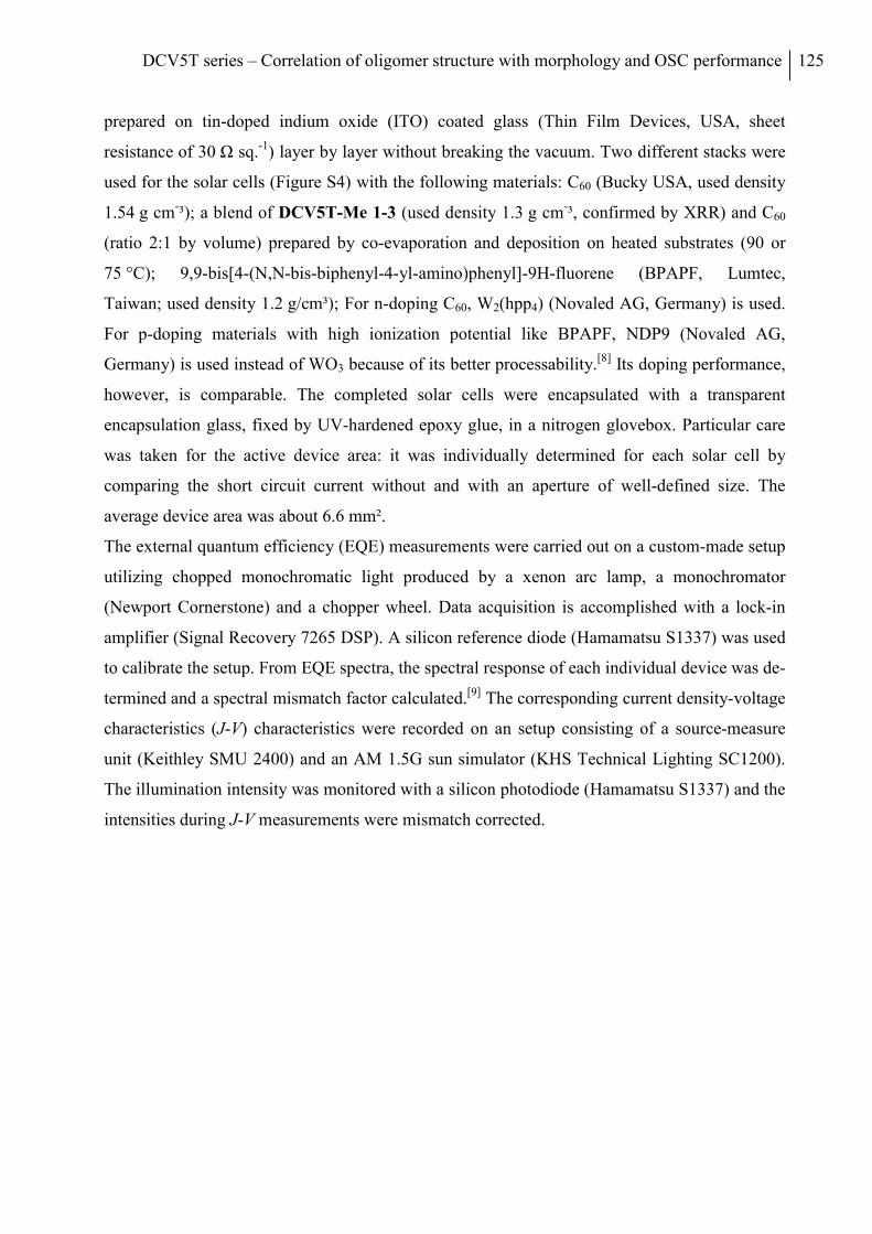
DCV5T series – Correlation of oligomer structure with morphology and OSC performance 125
prepared on tin-doped indium oxide (ITO) coated glass (Thin Film Devices, USA, sheet
resistance of 30 Ω sq.-1) layer by layer without breaking the vacuum. Two different stacks were
used for the solar cells (Figure S4) with the following materials: C60 (Bucky USA, used density
1.54 g cm-³); a blend of DCV5T-Me 1-3 (used density 1.3 g cm-³, confirmed by XRR) and C60
(ratio 2:1 by volume) prepared by co-evaporation and deposition on heated substrates (90 or
75 °C); 9,9-bis[4-(N,N-bis-biphenyl-4-yl-amino)phenyl]-9H-fluorene (BPAPF, Lumtec,
Taiwan; used density 1.2 g/cm³); For n-doping C60, W2(hpp4) (Novaled AG, Germany) is used.
For p-doping materials with high ionization potential like BPAPF, NDP9 (Novaled AG,
Germany) is used instead of WO3 because of its better processability.[8] Its doping performance,
however, is comparable. The completed solar cells were encapsulated with a transparent
encapsulation glass, fixed by UV-hardened epoxy glue, in a nitrogen glovebox. Particular care
was taken for the active device area: it was individually determined for each solar cell by
comparing the short circuit current without and with an aperture of well-defined size. The
average device area was about 6.6 mm².
The external quantum efficiency (EQE) measurements were carried out on a custom-made setup
utilizing chopped monochromatic light produced by a xenon arc lamp, a monochromator
(Newport Cornerstone) and a chopper wheel. Data acquisition is accomplished with a lock-in
amplifier (Signal Recovery 7265 DSP). A silicon reference diode (Hamamatsu S1337) was used
to calibrate the setup. From EQE spectra, the spectral response of each individual device was de-
termined and a spectral mismatch factor calculated.[9] The corresponding current density-voltage
characteristics (J-V) characteristics were recorded on an setup consisting of a source-measure
unit (Keithley SMU 2400) and an AM 1.5G sun simulator (KHS Technical Lighting SC1200).
The illumination intensity was monitored with a silicon photodiode (Hamamatsu S1337) and the
intensities during J-V measurements were mismatch corrected.
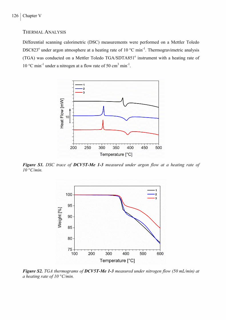
126 Chapter V
THERMAL ANALYSIS
Differential scanning calorimetric (DSC) measurements were performed on a Mettler Toledo
DSC823e under argon atmosphere at a heating rate of 10 °C min-1. Thermogravimetric analysis
(TGA) was conducted on a Mettler Toledo TGA/SDTA851e instrument with a heating rate of
10 °C min-1 under a nitrogen at a flow rate of 50 cm3 min-1.
Figure S1. DSC trace of DCV5T-Me 1-3 measured under argon flow at a heating rate of 10 °C/min.
Figure S2. TGA thermograms of DCV5T-Me 1-3 measured under nitrogen flow (50 mL/min) at a heating rate of 10 °C/min.
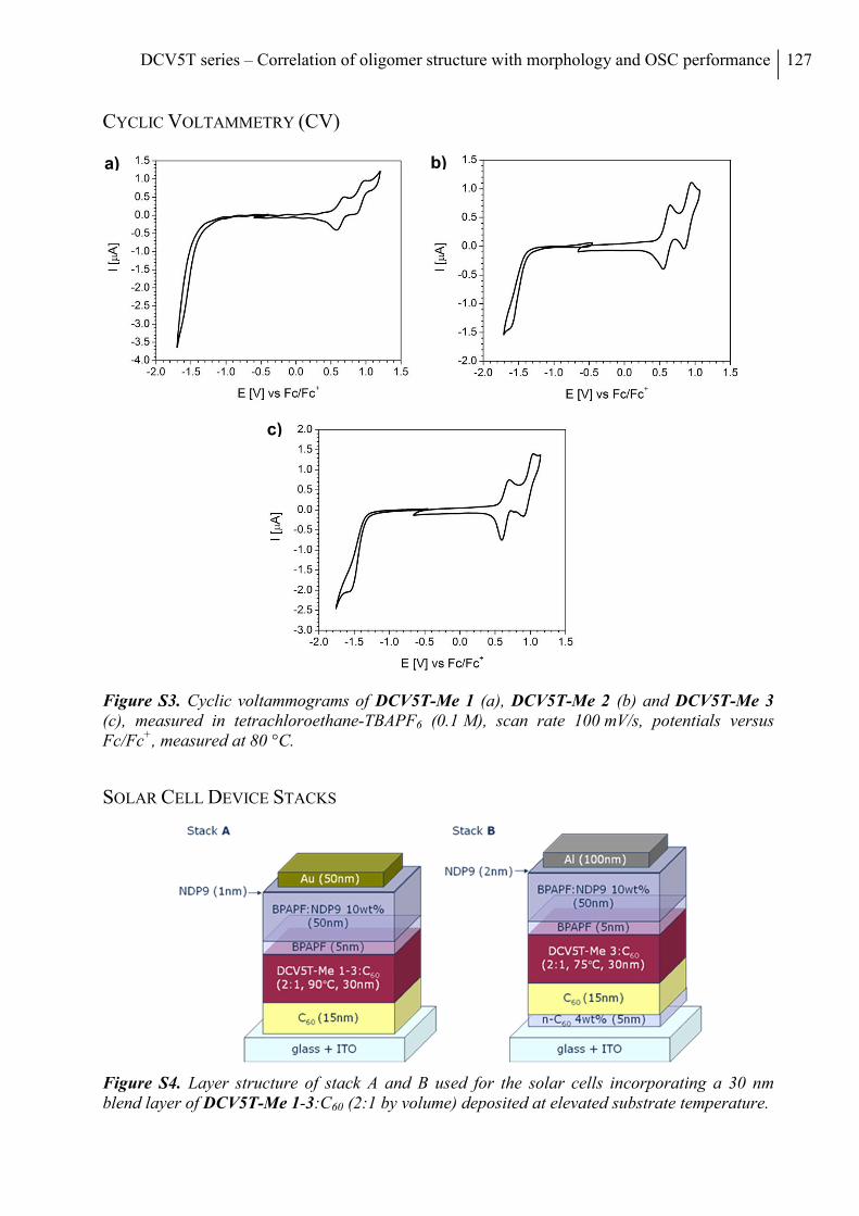
DCV5T series – Correlation of oligomer structure with morphology and OSC performance 127
CYCLIC VOLTAMMETRY (CV)
Figure S3. Cyclic voltammograms of DCV5T-Me 1 (a), DCV5T-Me 2 (b) and DCV5T-Me 3 (c), measured in tetrachloroethane-TBAPF6 (0.1 M), scan rate 100 mV/s, potentials versus Fc/Fc+, measured at 80 °C.
SOLAR CELL DEVICE STACKS
Figure S4. Layer structure of stack A and B used for the solar cells incorporating a 30 nm blend layer of DCV5T-Me 1-3:C60 (2:1 by volume) deposited at elevated substrate temperature.
a) b)
c)
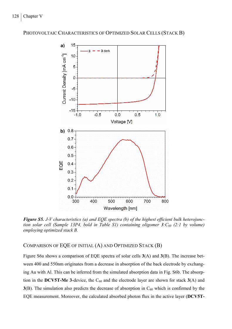
128 Chapter V
PHOTOVOLTAIC CHARACTERISTICS OF OPTIMIZED SOLAR CELLS (STACK B)
Figure S5. J-V characteristics (a) and EQE spectra (b) of the highest efficient bulk heterojunc-tion solar cell (Sample 13P4, bold in Table S1) containing oligomer 3:C60 (2:1 by volume) employing optimized stack B.
COMPARISON OF EQE OF INITIAL (A) AND OPTIMIZED STACK (B)
Figure S6a shows a comparison of EQE spectra of solar cells 3(A) and 3(B). The increase bet-
ween 400 and 550nm originates from a decrease in absorption of the back electrode by exchang-
ing Au with Al. This can be inferred from the simulated absorption data in Fig. S6b. The absorp-
tion in the DCV5T-Me 3-device, the C60 and the electrode layer are shown for stack 3(A) and
3(B). The simulation also predicts the decrease of absorption in C60 which is confirmed by the
EQE measurement. Moreover, the calculated absorbed photon flux in the active layer (DCV5T-
a)
b)
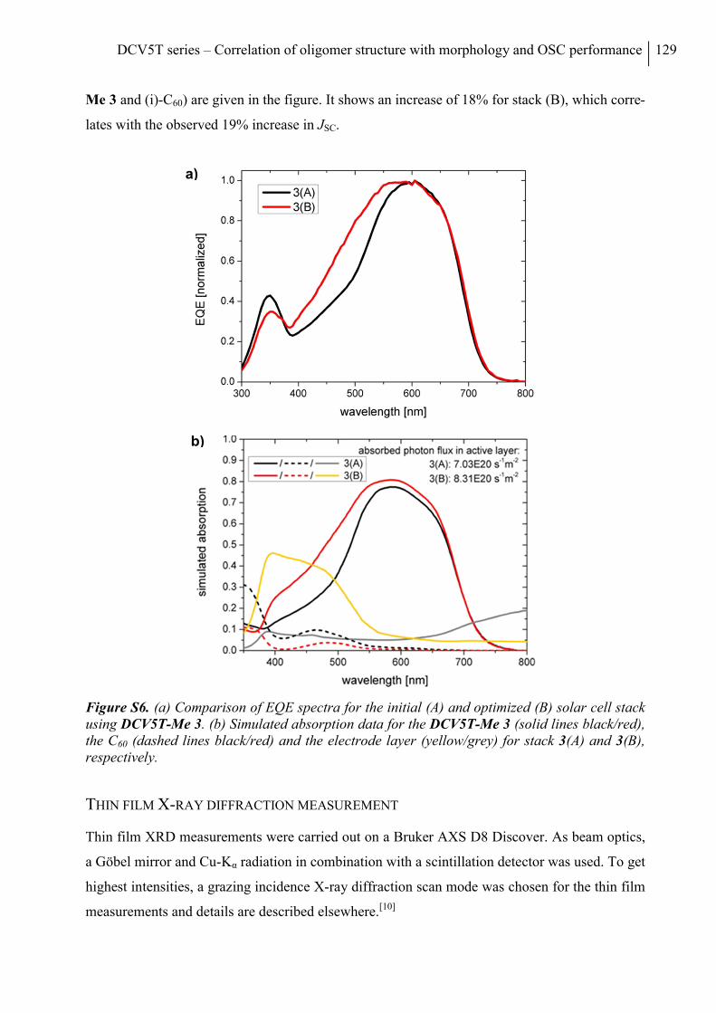
DCV5T series – Correlation of oligomer structure with morphology and OSC performance 129
Me 3 and (i)-C60) are given in the figure. It shows an increase of 18% for stack (B), which corre-
lates with the observed 19% increase in JSC.
Figure S6. (a) Comparison of EQE spectra for the initial (A) and optimized (B) solar cell stack using DCV5T-Me 3. (b) Simulated absorption data for the DCV5T-Me 3 (solid lines black/red), the C60 (dashed lines black/red) and the electrode layer (yellow/grey) for stack 3(A) and 3(B), respectively.
THIN FILM X-RAY DIFFRACTION MEASUREMENT
Thin film XRD measurements were carried out on a Bruker AXS D8 Discover. As beam optics,
a Göbel mirror and Cu-Kα radiation in combination with a scintillation detector was used. To get
highest intensities, a grazing incidence X-ray diffraction scan mode was chosen for the thin film
measurements and details are described elsewhere.[10]
a)
b)
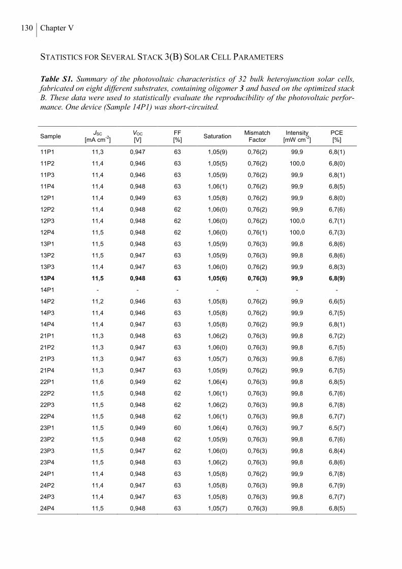
130 Chapter V
STATISTICS FOR SEVERAL STACK 3(B) SOLAR CELL PARAMETERS
Table S1. Summary of the photovoltaic characteristics of 32 bulk heterojunction solar cells, fabricated on eight different substrates, containing oligomer 3 and based on the optimized stack B. These data were used to statistically evaluate the reproducibility of the photovoltaic perfor-mance. One device (Sample 14P1) was short-circuited.
Sample JSC
[mA cm-2
] VOC
[V] FF [%]
Saturation Mismatch
Factor Intensity
[mW cm-2
] PCE [%]
11P1 11,3 0,947 63 1,05(9) 0,76(2) 99,9 6,8(1)
11P2 11,4 0,946 63 1,05(5) 0,76(2) 100,0 6,8(0)
11P3 11,4 0,946 63 1,05(9) 0,76(2) 99,9 6,8(1)
11P4 11,4 0,948 63 1,06(1) 0,76(2) 99,9 6,8(5)
12P1 11,4 0,949 63 1,05(8) 0,76(2) 99,9 6,8(0)
12P2 11,4 0,948 62 1,06(0) 0,76(2) 99,9 6,7(6)
12P3 11,4 0,948 62 1,06(0) 0,76(2) 100,0 6,7(1)
12P4 11,5 0,948 62 1,06(0) 0,76(1) 100,0 6,7(3)
13P1 11,5 0,948 63 1,05(9) 0,76(3) 99,8 6,8(6)
13P2 11,5 0,947 63 1,05(9) 0,76(3) 99,8 6,8(6)
13P3 11,4 0,947 63 1,06(0) 0,76(2) 99,9 6,8(3)
13P4 11,5 0,948 63 1,05(6) 0,76(3) 99,9 6,8(9)
14P1 - - - - - - -
14P2 11,2 0,946 63 1,05(8) 0,76(2) 99,9 6,6(5)
14P3 11,4 0,946 63 1,05(8) 0,76(2) 99,9 6,7(5)
14P4 11,4 0,947 63 1,05(8) 0,76(2) 99,9 6,8(1)
21P1 11,3 0,948 63 1,06(2) 0,76(3) 99,8 6,7(2)
21P2 11,3 0,947 63 1,06(0) 0,76(3) 99,8 6,7(5)
21P3 11,3 0,947 63 1,05(7) 0,76(3) 99,8 6,7(6)
21P4 11,3 0,947 63 1,05(9) 0,76(2) 99,9 6,7(5)
22P1 11,6 0,949 62 1,06(4) 0,76(3) 99,8 6,8(5)
22P2 11,5 0,948 62 1,06(1) 0,76(3) 99,8 6,7(6)
22P3 11,5 0,948 62 1,06(2) 0,76(3) 99,8 6,7(8)
22P4 11,5 0,948 62 1,06(1) 0,76(3) 99,8 6,7(7)
23P1 11,5 0,949 60 1,06(4) 0,76(3) 99,7 6,5(7)
23P2 11,5 0,948 62 1,05(9) 0,76(3) 99,8 6,7(6)
23P3 11,5 0,947 62 1,06(0) 0,76(3) 99,8 6,8(4)
23P4 11,5 0,948 63 1,06(2) 0,76(3) 99,8 6,8(6)
24P1 11,4 0,948 63 1,05(8) 0,76(2) 99,9 6,7(8)
24P2 11,4 0,947 63 1,05(8) 0,76(3) 99,8 6,7(9)
24P3 11,4 0,947 63 1,05(8) 0,76(3) 99,8 6,7(7)
24P4 11,5 0,948 63 1,05(7) 0,76(3) 99,8 6,8(5)
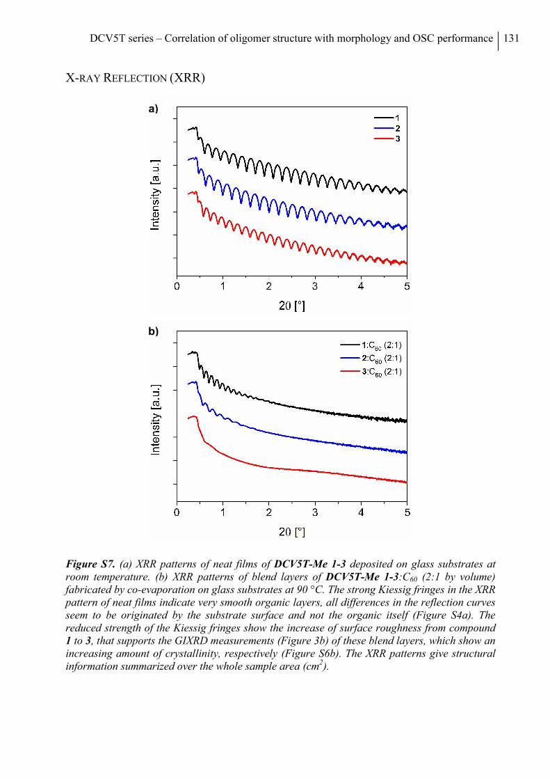
DCV5T series – Correlation of oligomer structure with morphology and OSC performance 131
X-RAY REFLECTION (XRR)
Figure S7. (a) XRR patterns of neat films of DCV5T-Me 1-3 deposited on glass substrates at room temperature. (b) XRR patterns of blend layers of DCV5T-Me 1-3:C60 (2:1 by volume) fabricated by co-evaporation on glass substrates at 90 °C. The strong Kiessig fringes in the XRR pattern of neat films indicate very smooth organic layers, all differences in the reflection curves seem to be originated by the substrate surface and not the organic itself (Figure S4a). The reduced strength of the Kiessig fringes show the increase of surface roughness from compound 1 to 3, that supports the GIXRD measurements (Figure 3b) of these blend layers, which show an increasing amount of crystallinity, respectively (Figure S6b). The XRR patterns give structural information summarized over the whole sample area (cm2).
b)
a)
132 Chapter V
REFERENCES
[1] (a) Crowe, B. F.; Nord, F. F. J. Org. Chem. 1950, 15, 1177; (b) King, W. J.; Nord, F. F. J. Org. Chem. 1948, 13, 635.
[2] Pham, C. V.; Macomber, R. S.; Mark Jr., H. B.; Zimmer, H. J. Org. Chem. 1984, 49, 5250.
[3] Deng, S.-R.; Wu, T.; Hu, G.-Q.; Li, D.; Zhou, Y.-H.; Li, Z.-Y. Synth. Commun. 2007, 37, 71.
[4] Fitzner, R.; Reinold, E.; Mishra, A.; Mena-Osteritz, E.; Ziehlke, H.; Körner, C.; Leo, K.; Riede, M.; Weil, M.; Tsaryova, O.; Weiß, A.; Uhrich, C.; Pfeiffer, M.; Bäuerle, P. Adv. Funct. Mater. 2011, 21, 897.
[5] Ziehlke, H.; Fitzner, R.; Koerner, C.; Gresser, R.; Reinold, E.; Baeuerle, P.; Leo, K.; Riede, M. J. Phys. Chem. A 2011, 30, 8437.
[6] Sheldrick, G.M. (2008). SADABS. University of Göttingen, Germany.
[7] Sheldrick, G. M. Acta Cryst. 2008, A64, 112-122.
[8] Meyer, J.; Hamwi, S.; Schmale, S.; Winkler, T.; Johannes, H.-H.; Riedl, T.; Kowalsky, W. J. Mater. Chem.. 2009, 19, 702.
[9] Shrotriya, V.; Li, G.; Yao, Y.; Moriarty, T.; Emery, K.; Yang, Y. Adv. Funct. Mater. 2006, 16, 2016.
[10] Elschner, C.; Levin, A.; Wilde, L.; Grenzer, J.; Schroer, C.; Leo, K.; Riede, M. J. Appl. Cryst. 2011, 44, 983.
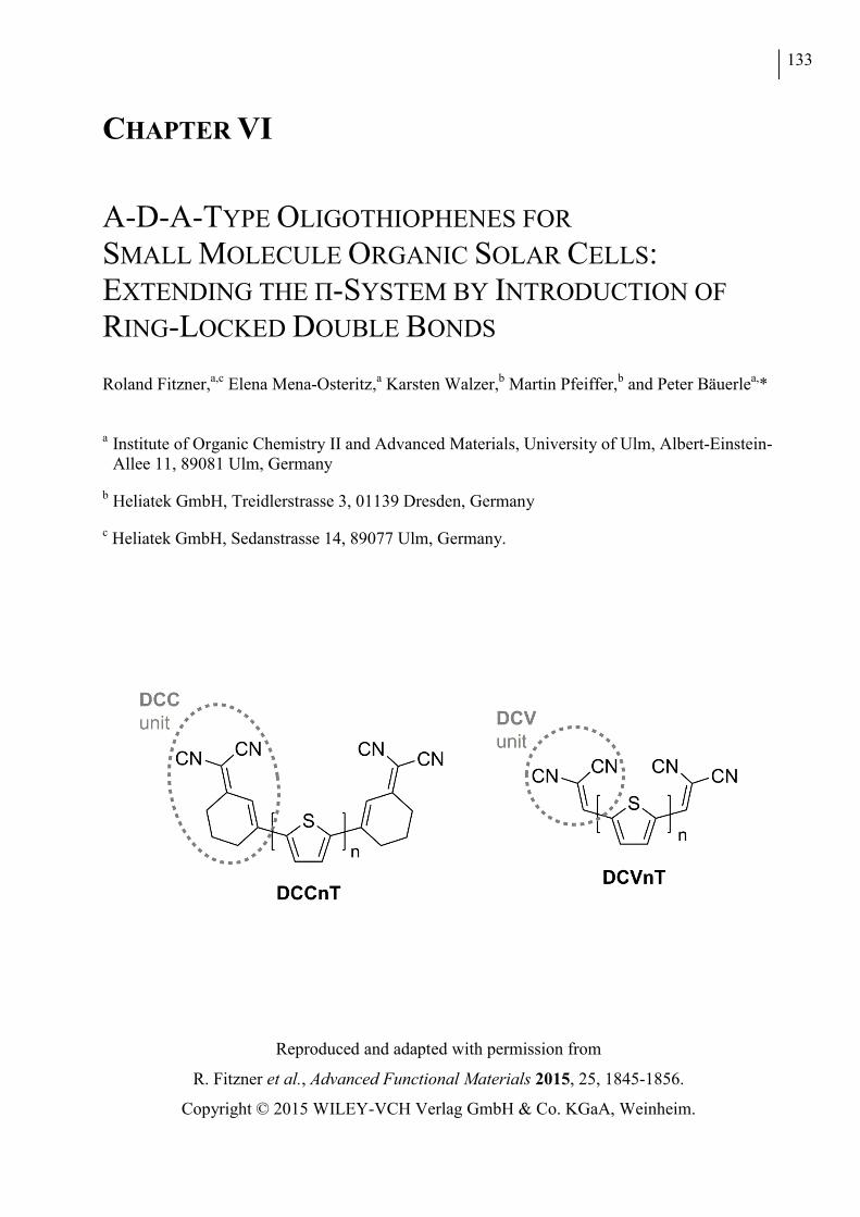
133
CHAPTER VI
A-D-A-TYPE OLIGOTHIOPHENES FOR
SMALL MOLECULE ORGANIC SOLAR CELLS: EXTENDING THE Π-SYSTEM BY INTRODUCTION OF
RING-LOCKED DOUBLE BONDS
Roland Fitzner,a,c Elena Mena-Osteritz,a Karsten Walzer,b Martin Pfeiffer,b and Peter Bäuerlea,*
a Institute of Organic Chemistry II and Advanced Materials, University of Ulm, Albert-Einstein-
Allee 11, 89081 Ulm, Germany
b Heliatek GmbH, Treidlerstrasse 3, 01139 Dresden, Germany
c Heliatek GmbH, Sedanstrasse 14, 89077 Ulm, Germany.
Reproduced and adapted with permission from
R. Fitzner et al., Advanced Functional Materials 2015, 25, 1845-1856.
Copyright © 2015 WILEY-VCH Verlag GmbH & Co. KGaA, Weinheim.
134 Chapter VI
ABSTRACT
A series of novel acceptor-donor-acceptor oligothiophenes terminally substituted with the 1-
(1,1-dicyanomethylene)-cyclohex-2-ene (DCC) acceptor has been synthesized. Structural,
thermal, optoelectronic, and photovoltaic properties of the π-extended DCCnTs (n = 1-4) are
characterized and contrasted to the trends found for the series of parent dicyanovinyl (DCV)-
substituted oligothiophenes DCVnT. The optoelectronic properties reveal the influence of the
additional exocyclic, sterically fixed double bonds in trans-configuration in the novel DCCnT
derivatives. A close correspondence for derivatives with equal number of double bonds, that is,
DCCnTs and DCV(n + 1)Ts, is identified. Despite having the same energy gap, the energy
levels of the frontier orbitals, HOMO and LUMO, for the DCC - derivatives are raised and more
destabilized due to the aromatization energy of a thiophene ring versus two exocyclic double
bonds indicating improved donor and reduced acceptor strength. DCC-terthiophenes give good
photovoltaic performance as donor materials in vacuum-processed solar cells (power conversion
efficiencies ≤ 4.4%) clearly outperforming all comparable DCV4T derivatives.
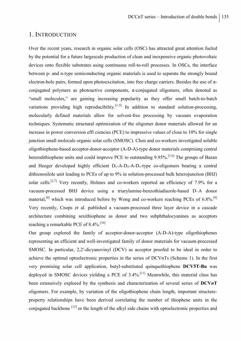
DCCnT series – Introduction of double bonds 135
1. INTRODUCTION
Over the recent years, research in organic solar cells (OSC) has attracted great attention fueled
by the potential for a future largescale production of clean and inexpensive organic photovoltaic
devices onto flexible substrates using continuous roll-to-roll processes. In OSCs, the interface
between p- and n-type semiconducting organic materials is used to separate the strongly bound
electron-hole pairs, formed upon photoexcitation, into free charge carriers. Besides the use of π-
conjugated polymers as photoactive components, π-conjugated oligomers, often denoted as
“small molecules,” are gaining increasing popularity as they offer small batch-to-batch
variations providing high reproducibility.[1-5] In addition to standard solution-processing,
molecularly defined materials allow for solvent-free processing by vacuum evaporation
techniques. Systematic structural optimization of the oligomer donor materials allowed for an
increase in power conversion effi ciencies (PCE) to impressive values of close to 10% for single
junction small molecule organic solar cells (SMOSC). Chen and co-workers investigated soluble
oligothiophene-based acceptor-donor-acceptor (A-D-A)-type donor materials comprising central
benzodithiophene units and could improve PCE to outstanding 9.95%.[1,6] The groups of Bazan
and Heeger developed highly efficient D1-A-D2-A-D1-type co-oligomers bearing a central
dithienosilole unit leading to PCEs of up to 9% in solution-processed bulk heterojunction (BHJ)
solar cells.[2,7] Very recently, Holmes and co-workers reported an efficiency of 7.9% for a
vacuum-processed BHJ device using a triarylamine-benzothiadiazole-based D–A donor
material,[8] which was introduced before by Wong and co-workers reaching PCEs of 6.8%.[9]
Very recently, Cnops et al. published a vacuum-processed three layer device in a cascade
architecture combining sexithiophene as donor and two subphthalocyanines as acceptors
reaching a remarkable PCE of 8.4%.[10]
Our group explored the family of acceptor-donor-acceptor (A-D-A)-type oligothiophenes
representing an efficient and well-investigated family of donor materials for vacuum-processed
SMOSC. In particular, 2,2′-dicyanovinyl (DCV) as acceptor proofed to be ideal in order to
achieve the optimal optoelectronic properties in the series of DCVnTs (Scheme 1). In the first
very promising solar cell application, butyl-substituted quinquethiophene DCV5T-Bu was
deployed in SMOSC devices yielding a PCE of 3.4%.[11] Meanwhile, this material class has
been extensively explored by the synthesis and characterization of several series of DCVnT
oligomers. For example, by variation of the oligothiophene chain length, important structure-
property relationships have been derived correlating the number of thiophene units in the
conjugated backbone [12] or the length of the alkyl side chains with optoelectronic properties and
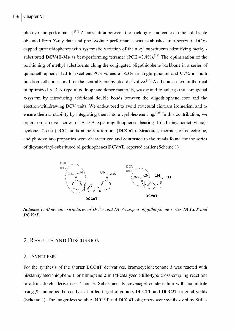
136 Chapter VI
photovoltaic performance.[13] A correlation between the packing of molecules in the solid state
obtained from X-ray data and photovoltaic performance was established in a series of DCV-
capped quaterthiophenes with systematic variation of the alkyl substituents identifying methyl-
substituted DCV4T-Me as best-performing tetramer (PCE =3.8%).[14] The optimization of the
positioning of methyl substituents along the conjugated oligothiophene backbone in a series of
quinquethiophenes led to excellent PCE values of 8.3% in single junction and 9.7% in multi
junction cells, measured for the centrally methylated derivative.[15] As the next step on the road
to optimized A-D-A-type oligothiophene donor materials, we aspired to enlarge the conjugated
π-system by introducing additional double bonds between the oligothiophene core and the
electron-withdrawing DCV units. We endeavored to avoid structural cis/trans isomerism and to
ensure thermal stability by integrating them into a cyclohexene ring.[16] In this contribution, we
report on a novel series of A-D-A-type oligothiophenes bearing 1-(1,1-dicyanomethylene)-
cyclohex-2-ene (DCC) units at both α-termini (DCCnT). Structural, thermal, optoelectronic,
and photovoltaic properties were characterized and contrasted to the trends found for the series
of dicyanovinyl-substituted oligothiophenes DCVnT, reported earlier (Scheme 1).
Scheme 1. Molecular structures of DCC- and DCV-capped oligothiophene series DCCnT and DCVnT.
2. RESULTS AND DISCUSSION
2.1 SYNTHESIS
For the synthesis of the shorter DCCnT derivatives, bromocyclohexenone 3 was reacted with
bisstannylated thiophene 1 or bithiopene 2 in Pd-catalyzed Stille-type cross-coupling reactions
to afford diketo derivatives 4 and 5. Subsequent Knoevenagel condensation with malonitrile
using β-alanine as the catalyst afforded target oligomers DCC1T and DCC2T in good yields
(Scheme 2). The longer less soluble DCC3T and DCC4T oligomers were synthesized by Stille-
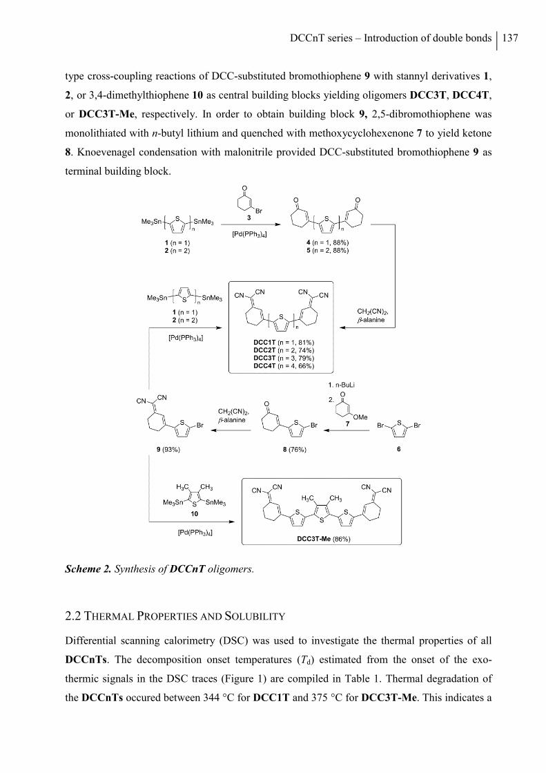
DCCnT series – Introduction of double bonds 137
type cross-coupling reactions of DCC-substituted bromothiophene 9 with stannyl derivatives 1,
2, or 3,4-dimethylthiophene 10 as central building blocks yielding oligomers DCC3T, DCC4T,
or DCC3T-Me, respectively. In order to obtain building block 9, 2,5-dibromothiophene was
monolithiated with n-butyl lithium and quenched with methoxycyclohexenone 7 to yield ketone
8. Knoevenagel condensation with malonitrile provided DCC-substituted bromothiophene 9 as
terminal building block.
Scheme 2. Synthesis of DCCnT oligomers.
2.2 THERMAL PROPERTIES AND SOLUBILITY
Differential scanning calorimetry (DSC) was used to investigate the thermal properties of all
DCCnTs. The decomposition onset temperatures (Td) estimated from the onset of the exo-
thermic signals in the DSC traces (Figure 1) are compiled in Table 1. Thermal degradation of
the DCCnTs occured between 344 °C for DCC1T and 375 °C for DCC3T-Me. This indicates a
138 Chapter VI
high, but somewhat reduced thermal stability in comparison to the alkyl free DCVnTs, which
exhibited decomposition onset temperatures of about 400 °C.[12c] The DCCnT derivatives up to
the trimers sublimed at temperatures between 250 and 280 °C (p ≈ 10-6 mbar) yielding
crystalline material of high purity in almost quantitative yield. The sublimation of DCC4T
occurred at significantly higher temperatures around the melting point and led to poor yields due
to material decomposition.
Figure 1. DSC traces of DCCnTs measured under argon flow at a heating rate of 10 °C/min.
Melting temperatures (Tm) of the DCCnTs (Table 1) were determined from the onset of the en-
dothermic signals in the DSC traces. All DCCnT derivatives exhibited high melting points bet-
ween 290 and 333 °C which is an important requirement for efficient sublimation of the
materials from the solid phase. In order to compare and to illustrate trends in the melting
behavior of both oligothiophene series, in Figure 2 the melting temperatures of the DCCnTs
and DCVnTs are plotted vs the number of thiophene rings in the respective oligomer.
Comparing oligomers with identical oligothiophene cores, the DCC-substituted derivatives mel-
ted at higher temperatures than their DCV-capped analogues. This indicates that the two additio-
nal cyclohexene rings in the molecular structure of the DCCnTs, which increase the molecular
weight by 132 g mol-1 compared to the DCVnTs, induce additional intermolecular interactions.
The differences in melting points between DCCnTs and DCVnTs (Tm in Table 1) diminished
with increasing oligomer length from Tm = 47 °C for the 1T to 13 °C for the 4T derivatives. As
the number of thiophene units increases, the oligothiophene core dominates the molecular struc-
ture and the intermolecular forces. As we have shown previously for the DCVnT series, the
DCCnT oligomers as well exhibited an odd-even effect of the melting points with respect to the
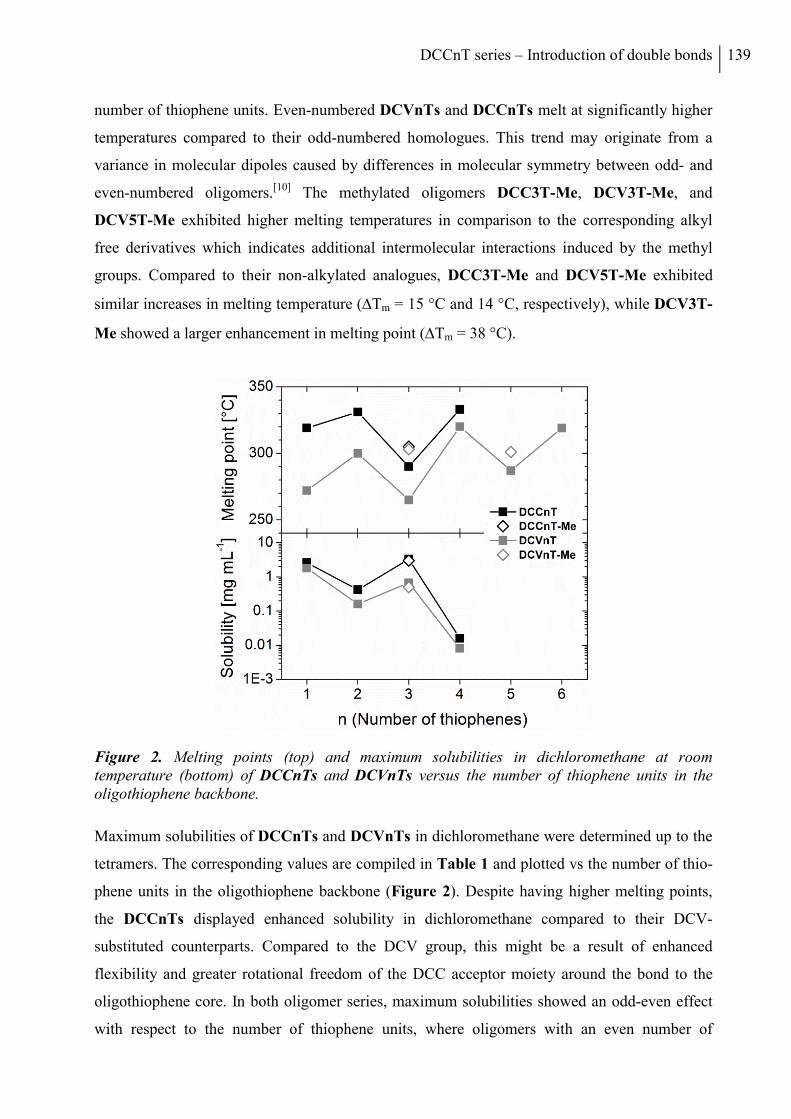
DCCnT series – Introduction of double bonds 139
number of thiophene units. Even-numbered DCVnTs and DCCnTs melt at significantly higher
temperatures compared to their odd-numbered homologues. This trend may originate from a
variance in molecular dipoles caused by differences in molecular symmetry between odd- and
even-numbered oligomers.[10] The methylated oligomers DCC3T-Me, DCV3T-Me, and
DCV5T-Me exhibited higher melting temperatures in comparison to the corresponding alkyl
free derivatives which indicates additional intermolecular interactions induced by the methyl
groups. Compared to their non-alkylated analogues, DCC3T-Me and DCV5T-Me exhibited
similar increases in melting temperature (Tm = 15 °C and 14 °C, respectively), while DCV3T-
Me showed a larger enhancement in melting point (Tm = 38 °C).
Figure 2. Melting points (top) and maximum solubilities in dichloromethane at room temperature (bottom) of DCCnTs and DCVnTs versus the number of thiophene units in the oligothiophene backbone.
Maximum solubilities of DCCnTs and DCVnTs in dichloromethane were determined up to the
tetramers. The corresponding values are compiled in Table 1 and plotted vs the number of thio-
phene units in the oligothiophene backbone (Figure 2). Despite having higher melting points,
the DCCnTs displayed enhanced solubility in dichloromethane compared to their DCV-
substituted counterparts. Compared to the DCV group, this might be a result of enhanced
flexibility and greater rotational freedom of the DCC acceptor moiety around the bond to the
oligothiophene core. In both oligomer series, maximum solubilities showed an odd-even effect
with respect to the number of thiophene units, where oligomers with an even number of
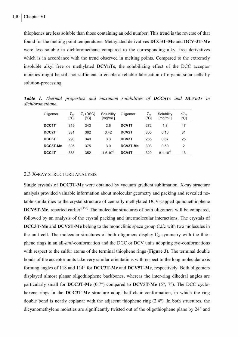
140 Chapter VI
thiophenes are less soluble than those containing an odd number. This trend is the reverse of that
found for the melting point temperatures. Methylated derivatives DCC3T-Me and DCV-3T-Me
were less soluble in dichloromethane compared to the corresponding alkyl free derivatives
which is in accordance with the trend observed in melting points. Compared to the extremely
insoluble alkyl free or methylated DCVnTs, the solubilizing effect of the DCC acceptor
moieties might be still not sufficient to enable a reliable fabrication of organic solar cells by
solution-processing.
Table 1. Thermal properties and maximum solubilities of DCCnTs and DCVnTs in dichloromethane.
Oligomer Tm [°C]
Td (DSC) [°C]
Solubility [mg/mL]
Oligomer Tm [°C]
Solubility [mg/mL]
Tm [°C]
DCC1T 319 343 2.6 DCV1T 272 1.8 47
DCC2T 331 362 0.42 DCV2T 300 0.16 31
DCC3T 290 340 3.3 DCV3T 265 0.67 25
DCC3T-Me 305 375 3.0 DCV3T-Me 303 0.50 2
DCC4T 333 352 1.610-2
DCV4T 320 8.110-3
13
2.3 X-RAY STRUCTURE ANALYSIS
Single crystals of DCC3T-Me were obtained by vacuum gradient sublimation. X-ray structure
analysis provided valuable information about molecular geometry and packing and revealed no-
table similarities to the crystal structure of centrally methylated DCV-capped quinquethiophene
DCV5T-Me, reported earlier.[15a] The molecular structures of both oligomers will be compared,
followed by an analysis of the crystal packing and intermolecular interactions. The crystals of
DCC3T-Me and DCV5T-Me belong to the monoclinic space group C2/c with two molecules in
the unit cell. The molecular structures of both oligomers display C2 symmetry with the thio-
phene rings in an all-anti-conformation and the DCC or DCV units adopting syn-conformations
with respect to the sulfur atoms of the terminal thiophene rings (Figure 3). The terminal double
bonds of the acceptor units take very similar orientations with respect to the long molecular axis
forming angles of 118 and 114° for DCC3T-Me and DCV5T-Me, respectively. Both oligomers
displayed almost planar oligothiophene backbones, whereas the inter-ring dihedral angles are
particularly small for DCC3T-Me (0.7°) compared to DCV5T-Me (5°, 7°). The DCC cyclo-
hexene rings in the DCC3T-Me structure adopt half-chair conformation, in which the ring
double bond is nearly coplanar with the adjacent thiophene ring (2.4°). In both structures, the
dicyanomethylene moieties are significantly twisted out of the oligothiophene plane by 24° and
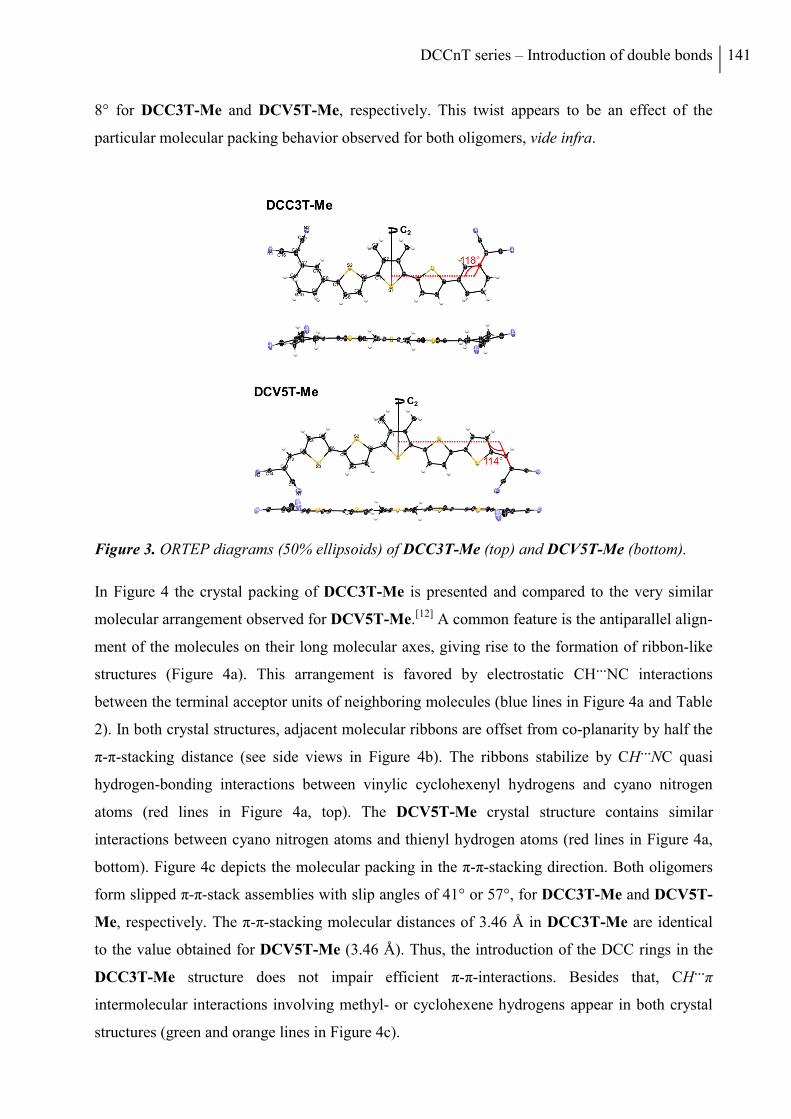
DCCnT series – Introduction of double bonds 141
8° for DCC3T-Me and DCV5T-Me, respectively. This twist appears to be an effect of the
particular molecular packing behavior observed for both oligomers, vide infra.
Figure 3. ORTEP diagrams (50% ellipsoids) of DCC3T-Me (top) and DCV5T-Me (bottom).
In Figure 4 the crystal packing of DCC3T-Me is presented and compared to the very similar
molecular arrangement observed for DCV5T-Me.[12] A common feature is the antiparallel align-
ment of the molecules on their long molecular axes, giving rise to the formation of ribbon-like
structures (Figure 4a). This arrangement is favored by electrostatic CH…NC interactions
between the terminal acceptor units of neighboring molecules (blue lines in Figure 4a and Table
2). In both crystal structures, adjacent molecular ribbons are offset from co-planarity by half the
π-π-stacking distance (see side views in Figure 4b). The ribbons stabilize by CH…NC quasi
hydrogen-bonding interactions between vinylic cyclohexenyl hydrogens and cyano nitrogen
atoms (red lines in Figure 4a, top). The DCV5T-Me crystal structure contains similar
interactions between cyano nitrogen atoms and thienyl hydrogen atoms (red lines in Figure 4a,
bottom). Figure 4c depicts the molecular packing in the π-π-stacking direction. Both oligomers
form slipped π-π-stack assemblies with slip angles of 41° or 57°, for DCC3T-Me and DCV5T-
Me, respectively. The π-π-stacking molecular distances of 3.46 Å in DCC3T-Me are identical
to the value obtained for DCV5T-Me (3.46 Å). Thus, the introduction of the DCC rings in the
DCC3T-Me structure does not impair efficient π-π-interactions. Besides that, CH…π
intermolecular interactions involving methyl- or cyclohexene hydrogens appear in both crystal
structures (green and orange lines in Figure 4c).
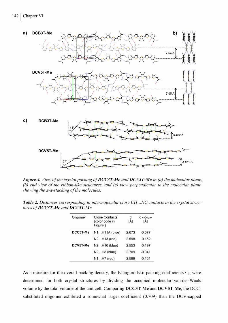
142 Chapter VI
Figure 4. View of the crystal packing of DCC3T-Me and DCV5T-Me in (a) the molecular plane, (b) end view of the ribbon-like structures, and (c) view perpendicular to the molecular plane showing the π-π-stacking of the molecules.
Table 2. Distances corresponding to intermolecular close CH…NC contacts in the crystal struc-tures of DCC3T-Me and DCV5T-Me.
Oligomer Close Contacts (color code in Figure )
d [Å]
d - dVDW [Å]
DCC3T-Me N1…H11A (blue) 2.673 -0.077
N2…H13 (red) 2.598 -0.152
DCV5T-Me N2…H10 (blue) 2.553 -0.197
N2…H8 (blue) 2.709 -0.041
N1…H7 (red) 2.589 -0.161
As a measure for the overall packing density, the Kitaigorodskii packing coefficients CK were
determined for both crystal structures by dividing the occupied molecular van-der-Waals
volume by the total volume of the unit cell. Comparing DCC3T-Me and DCV5T-Me, the DCC-
substituted oligomer exhibited a somewhat larger coefficient (0.709) than the DCV-capped
a)
c)
b)
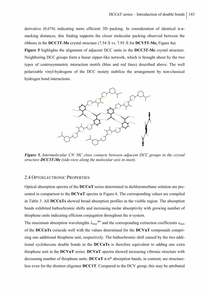
DCCnT series – Introduction of double bonds 143
derivative (0.674) indicating more efficient 3D packing. In consideration of identical π-π-
stacking distances, this finding supports the closer molecular packing observed between the
ribbons in the DCC3T-Me crystal structure (7.54 Å vs. 7.95 Å for DCV5T-Me, Figure 4a).
Figure 5 highlights the alignment of adjacent DCC units in the DCC3T-Me crystal structure.
Neighboring DCC groups form a linear zipper-like network, which is brought about by the two
types of centrosymmetric interaction motifs (blue and red lines) described above. The well
polarizable vinyl-hydrogens of the DCC moiety stabilize the arrangement by non-classical
hydrogen bond interactions.
Figure 5. Intermolecular CN…HC close contacts between adjacent DCC groups in the crystal structure DCC3T-Me (side-view along the molecular axis in inset).
2.4 OPTOELECTRONIC PROPERTIES
Optical absorption spectra of the DCCnT series determined in dichloromethane solution are pre-
sented in comparison to the DCVnT spectra in Figure 6. The corresponding values are compiled
in Table 3. All DCCnTs showed broad absorption profiles in the visible region. The absorption
bands exhibited bathochromic shifts and increasing molar absorptivity with growing number of
thiophene units indicating efficient conjugation throughout the π-system.
The maximum absorption wavelengths maxabs and the corresponding extinction coefficients max
of the DCCnTs coincide well with the values determined for the DCVnT compounds compri-
sing one additional thiophene unit, respectively. The bathochromic shift caused by the two addi-
tional cyclohexene double bonds in the DCCnTs is therefore equivalent to adding one extra
thiophene unit in the DCVnT series. DCVnT spectra showed increasing vibronic structure with
decreasing number of thiophene units. DCCnT π-π* absorption bands, in contrast, are structure-
less even for the shortest oligomer DCC1T. Compared to the DCV group, this may be attributed
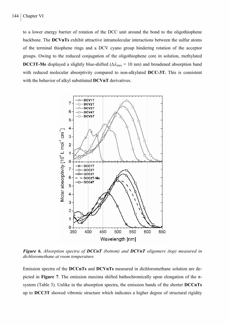
144 Chapter VI
to a lower energy barrier of rotation of the DCC unit around the bond to the oligothiophene
backbone. The DCVnTs exhibit attractive intramolecular interactions between the sulfur atoms
of the terminal thiophene rings and a DCV cyano group hindering rotation of the acceptor
groups. Owing to the reduced conjugation of the oligothiophene core in solution, methylated
DCC3T-Me displayed a slightly blue-shifted (max = 10 nm) and broadened absorption band
with reduced molecular absorptivity compared to non-alkylated DCC-3T. This is consistent
with the behavior of alkyl substituted DCVnT derivatives.
Figure 6. Absorption spectra of DCCnT (bottom) and DCVnT oligomers (top) measured in dichloromethane at room temperature.
Emission spectra of the DCCnTs and DCVnTs measured in dichloromethane solution are de-
picted in Figure 7. The emission maxima shifted bathochromically upon elongation of the π-
system (Table 3). Unlike in the absorption spectra, the emission bands of the shorter DCCnTs
up to DCC3T showed vibronic structure which indicates a higher degree of structural rigidity
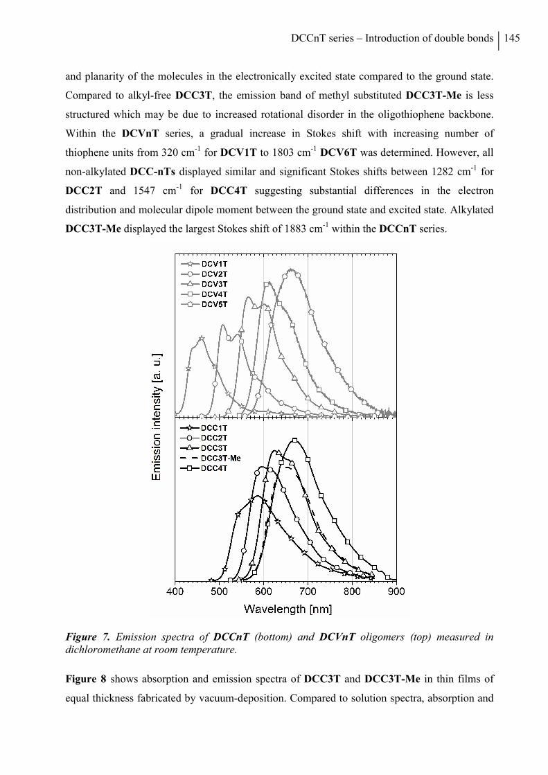
DCCnT series – Introduction of double bonds 145
and planarity of the molecules in the electronically excited state compared to the ground state.
Compared to alkyl-free DCC3T, the emission band of methyl substituted DCC3T-Me is less
structured which may be due to increased rotational disorder in the oligothiophene backbone.
Within the DCVnT series, a gradual increase in Stokes shift with increasing number of
thiophene units from 320 cm-1 for DCV1T to 1803 cm-1 DCV6T was determined. However, all
non-alkylated DCC-nTs displayed similar and significant Stokes shifts between 1282 cm-1 for
DCC2T and 1547 cm-1 for DCC4T suggesting substantial differences in the electron
distribution and molecular dipole moment between the ground state and excited state. Alkylated
DCC3T-Me displayed the largest Stokes shift of 1883 cm-1 within the DCCnT series.
Figure 7. Emission spectra of DCCnT (bottom) and DCVnT oligomers (top) measured in dichloromethane at room temperature.
Figure 8 shows absorption and emission spectra of DCC3T and DCC3T-Me in thin films of
equal thickness fabricated by vacuum-deposition. Compared to solution spectra, absorption and
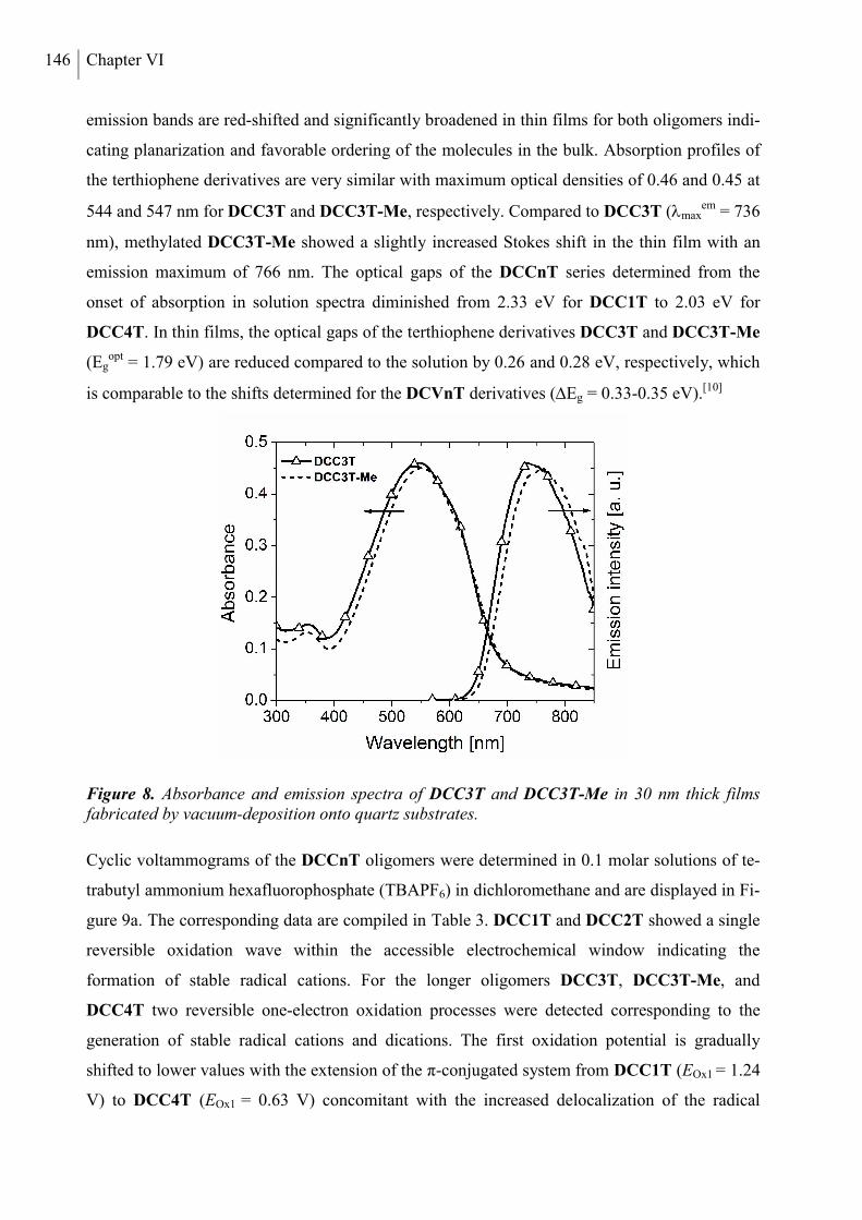
146 Chapter VI
emission bands are red-shifted and significantly broadened in thin films for both oligomers indi-
cating planarization and favorable ordering of the molecules in the bulk. Absorption profiles of
the terthiophene derivatives are very similar with maximum optical densities of 0.46 and 0.45 at
544 and 547 nm for DCC3T and DCC3T-Me, respectively. Compared to DCC3T (maxem = 736
nm), methylated DCC3T-Me showed a slightly increased Stokes shift in the thin film with an
emission maximum of 766 nm. The optical gaps of the DCCnT series determined from the
onset of absorption in solution spectra diminished from 2.33 eV for DCC1T to 2.03 eV for
DCC4T. In thin films, the optical gaps of the terthiophene derivatives DCC3T and DCC3T-Me
(Egopt = 1.79 eV) are reduced compared to the solution by 0.26 and 0.28 eV, respectively, which
is comparable to the shifts determined for the DCVnT derivatives (Eg = 0.33-0.35 eV).[10]
Figure 8. Absorbance and emission spectra of DCC3T and DCC3T-Me in 30 nm thick films fabricated by vacuum-deposition onto quartz substrates.
Cyclic voltammograms of the DCCnT oligomers were determined in 0.1 molar solutions of te-
trabutyl ammonium hexafluorophosphate (TBAPF6) in dichloromethane and are displayed in Fi-
gure 9a. The corresponding data are compiled in Table 3. DCC1T and DCC2T showed a single
reversible oxidation wave within the accessible electrochemical window indicating the
formation of stable radical cations. For the longer oligomers DCC3T, DCC3T-Me, and
DCC4T two reversible one-electron oxidation processes were detected corresponding to the
generation of stable radical cations and dications. The first oxidation potential is gradually
shifted to lower values with the extension of the π-conjugated system from DCC1T (EOx1 = 1.24
V) to DCC4T (EOx1 = 0.63 V) concomitant with the increased delocalization of the radical
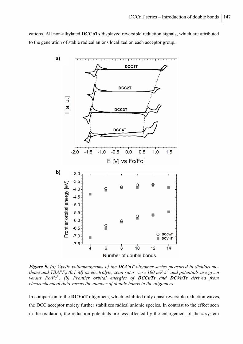
DCCnT series – Introduction of double bonds 147
cations. All non-alkylated DCCnTs displayed reversible reduction signals, which are attributed
to the generation of stable radical anions localized on each acceptor group.
Figure 9. (a) Cyclic voltammograms of the DCCnT oligomer series measured in dichlorome-thane and TBAPF6 (0.1 M) as electrolyte, scan rates were 100 mV s-1 and potentials are given versus Fc/Fc+. (b) Frontier orbital energies of DCCnTs and DCVnTs derived from electrochemical data versus the number of double bonds in the oligomers.
In comparison to the DCVnT oligomers, which exhibited only quasi-reversible reduction waves,
the DCC acceptor moiety further stabilizes radical anionic species. In contrast to the effect seen
in the oxidation, the reduction potentials are less affected by the enlargement of the π-system
a)
b)
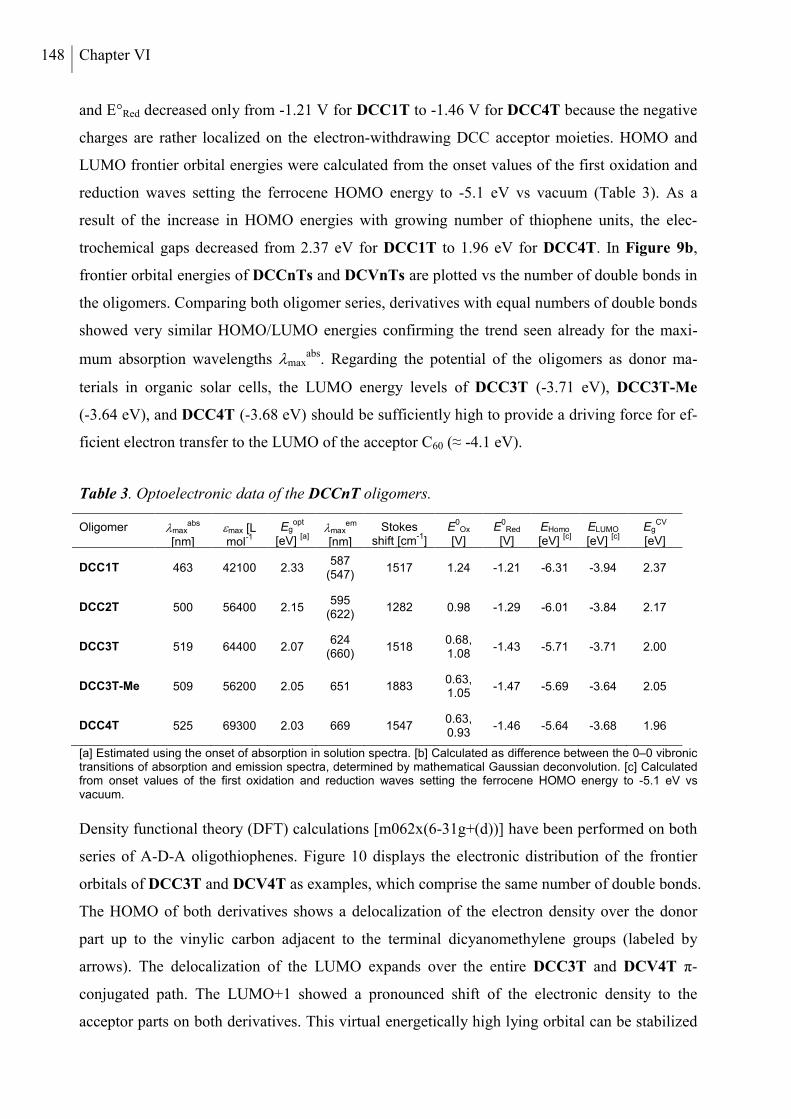
148 Chapter VI
and E°Red decreased only from -1.21 V for DCC1T to -1.46 V for DCC4T because the negative
charges are rather localized on the electron-withdrawing DCC acceptor moieties. HOMO and
LUMO frontier orbital energies were calculated from the onset values of the first oxidation and
reduction waves setting the ferrocene HOMO energy to -5.1 eV vs vacuum (Table 3). As a
result of the increase in HOMO energies with growing number of thiophene units, the elec-
trochemical gaps decreased from 2.37 eV for DCC1T to 1.96 eV for DCC4T. In Figure 9b,
frontier orbital energies of DCCnTs and DCVnTs are plotted vs the number of double bonds in
the oligomers. Comparing both oligomer series, derivatives with equal numbers of double bonds
showed very similar HOMO/LUMO energies confirming the trend seen already for the maxi-
mum absorption wavelengths maxabs. Regarding the potential of the oligomers as donor ma-
terials in organic solar cells, the LUMO energy levels of DCC3T (-3.71 eV), DCC3T-Me
(-3.64 eV), and DCC4T (-3.68 eV) should be sufficiently high to provide a driving force for ef-
ficient electron transfer to the LUMO of the acceptor C60 (≈ -4.1 eV).
Table 3. Optoelectronic data of the DCCnT oligomers.
Oligomer maxabs
[nm]
max [L mol
-1
-1
Egopt
[eV]
[a]
maxem
[nm]
Stokes shift [cm
-1]
[b]
E0
Ox [V]
E0
Red [V]
EHomo [eV]
[c]
ELUMO [eV]
[c]
EgCV
[eV]
DCC1T 463 42100 2.33 587
(547) 1517 1.24 -1.21 -6.31 -3.94 2.37
DCC2T 500 56400 2.15 595
(622) 1282 0.98 -1.29 -6.01 -3.84 2.17
DCC3T 519 64400 2.07 624
(660) 1518
0.68, 1.08
-1.43 -5.71 -3.71 2.00
DCC3T-Me 509 56200 2.05 651 1883 0.63, 1.05
-1.47 -5.69 -3.64 2.05
DCC4T 525 69300 2.03 669 1547 0.63, 0.93
-1.46 -5.64 -3.68 1.96
[a] Estimated using the onset of absorption in solution spectra. [b] Calculated as difference between the 0–0 vibronic transitions of absorption and emission spectra, determined by mathematical Gaussian deconvolution. [c] Calculated from onset values of the first oxidation and reduction waves setting the ferrocene HOMO energy to -5.1 eV vs vacuum.
Density functional theory (DFT) calculations [m062x(6-31g+(d))] have been performed on both
series of A-D-A oligothiophenes. Figure 10 displays the electronic distribution of the frontier
orbitals of DCC3T and DCV4T as examples, which comprise the same number of double bonds.
The HOMO of both derivatives shows a delocalization of the electron density over the donor
part up to the vinylic carbon adjacent to the terminal dicyanomethylene groups (labeled by
arrows). The delocalization of the LUMO expands over the entire DCC3T and DCV4T π-
conjugated path. The LUMO+1 showed a pronounced shift of the electronic density to the
acceptor parts on both derivatives. This virtual energetically high lying orbital can be stabilized
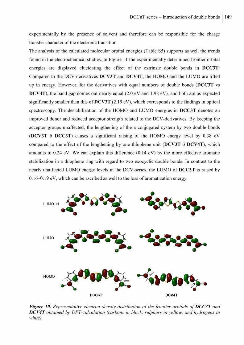
DCCnT series – Introduction of double bonds 149
experimentally by the presence of solvent and therefore can be responsible for the charge
transfer character of the electronic transition.
The analysis of the calculated molecular orbital energies (Table S5) supports as well the trends
found in the electrochemical studies. In Figure 11 the experimentally determined frontier orbital
energies are displayed elucidating the effect of the extrinsic double bonds in DCC3T:
Compared to the DCV-derivatives DCV3T and DCV4T, the HOMO and the LUMO are lifted
up in energy. However, for the derivatives with equal numbers of double bonds (DCC3T vs
DCV4T), the band gap comes out nearly equal (2.0 eV and 1.98 eV), and both are as expected
significantly smaller than this of DCV3T (2.19 eV), which corresponds to the findings in optical
spectroscopy. The destabilization of the HOMO and LUMO energies in DCC3T denotes an
improved donor and reduced acceptor strength related to the DCV-derivatives. By keeping the
acceptor groups unaffected, the lengthening of the π-conjugated system by two double bonds
(DCV3T ð DCC3T) causes a significant raising of the HOMO energy level by 0.38 eV
compared to the effect of the lengthening by one thiophene unit (DCV3T ð DCV4T), which
amounts to 0.24 eV. We can explain this difference (0.14 eV) by the more effective aromatic
stabilization in a thiophene ring with regard to two exocyclic double bonds. In contrast to the
nearly unaffected LUMO energy levels in the DCV-series, the LUMO of DCC3T is raised by
0.16–0.19 eV, which can be ascribed as well to the loss of aromatization energy.
Figure 10. Representative electron density distribution of the frontier orbitals of DCC3T and DCV4T obtained by DFT-calculation (carbons in black, sulphurs in yellow, and hydrogens in white).
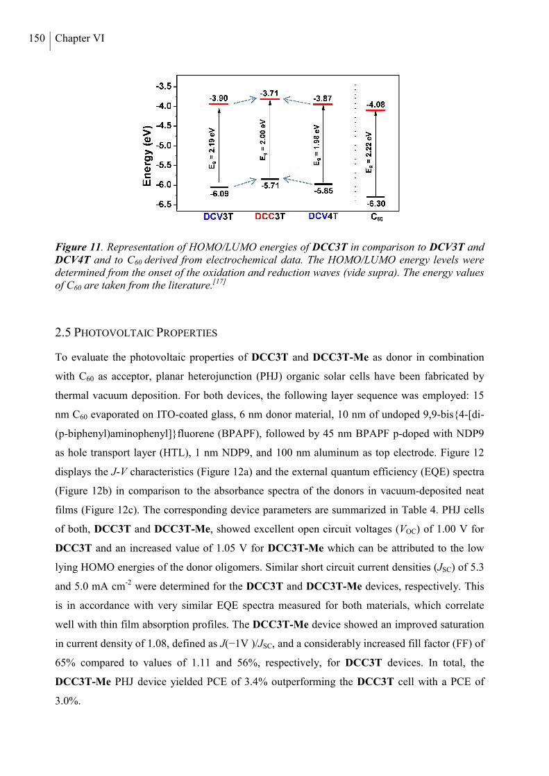
150 Chapter VI
Figure 11. Representation of HOMO/LUMO energies of DCC3T in comparison to DCV3T and DCV4T and to C60 derived from electrochemical data. The HOMO/LUMO energy levels were determined from the onset of the oxidation and reduction waves (vide supra). The energy values of C60 are taken from the literature.[17]
2.5 PHOTOVOLTAIC PROPERTIES
To evaluate the photovoltaic properties of DCC3T and DCC3T-Me as donor in combination
with C60 as acceptor, planar heterojunction (PHJ) organic solar cells have been fabricated by
thermal vacuum deposition. For both devices, the following layer sequence was employed: 15
nm C60 evaporated on ITO-coated glass, 6 nm donor material, 10 nm of undoped 9,9-bis4-[di-
(p-biphenyl)aminophenyl]fluorene (BPAPF), followed by 45 nm BPAPF p-doped with NDP9
as hole transport layer (HTL), 1 nm NDP9, and 100 nm aluminum as top electrode. Figure 12
displays the J-V characteristics (Figure 12a) and the external quantum efficiency (EQE) spectra
(Figure 12b) in comparison to the absorbance spectra of the donors in vacuum-deposited neat
films (Figure 12c). The corresponding device parameters are summarized in Table 4. PHJ cells
of both, DCC3T and DCC3T-Me, showed excellent open circuit voltages (VOC) of 1.00 V for
DCC3T and an increased value of 1.05 V for DCC3T-Me which can be attributed to the low
lying HOMO energies of the donor oligomers. Similar short circuit current densities (JSC) of 5.3
and 5.0 mA cm-2 were determined for the DCC3T and DCC3T-Me devices, respectively. This
is in accordance with very similar EQE spectra measured for both materials, which correlate
well with thin film absorption profiles. The DCC3T-Me device showed an improved saturation
in current density of 1.08, defined as J(−1V )/JSC, and a considerably increased fill factor (FF) of
65% compared to values of 1.11 and 56%, respectively, for DCC3T devices. In total, the
DCC3T-Me PHJ device yielded PCE of 3.4% outperforming the DCC3T cell with a PCE of
3.0%.
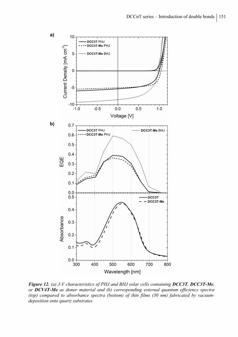
DCCnT series – Introduction of double bonds 151
Figure 12. (a) J-V characteristics of PHJ and BHJ solar cells containing DCC3T, DCC3T-Me, or DCV4T-Me as donor material and (b) corresponding external quantum efficiency spectra (top) compared to absorbance spectra (bottom) of thin films (30 nm) fabricated by vacuum-deposition onto quartz substrates.
a)
b)
152 Chapter VI
We have as well seen this trend for methylated A-D-A quinquethiophenes, which gave an
improved performance compared to all other substituted derivatives coming from special
intermolecular interactions and thus optimal packing of the oligomers in the solid state.[15a] If we
compare these results with PHJ solar cells made from DCV4T, which comprises the same
number of double bonds and conjugation length as the novel DCC3T-derivatives, the DCC-
terthiophenes clearly surpass the quaterthiophene DCV4T in all photovoltaic parameters, which
showed a PCE of only 1.2% under comparable conditions (Table 4). At that point it is
noteworthy, that typically terthiophenes such as DCV3T and C60 did not lead to an efficient
exciton separation into charge carrier pairs at the interface, because of the low HOMO offset
between the two materials which leads to poor solar cell performance.[12a]
DCC3T-Me as the best performing A-D-A oligomer in PHJs was additionally tested in BHJ
solar cells. In the BHJ device stack, the neat donor layer employed in the PHJ setup was
replaced by a 20 nm thick blend layer of donor and acceptor fabricated by co-evaporation of
DCC3T-Me and C60 in a ratio of 2:1 by volume. During the deposition of the photoactive layer
the substrate was heated to 90 °C. Despite the VOC of the BHJ solar cells was slightly reduced
0.99 V and the fill factor dropped to 53% compared to the PHJ device, a strongly enhanced JSC
of 8.5 mA cm-2 was found and led to a further improved PCE of 4.4% (Table 4).This is as well
represented in the EQE data of DCC3T-Me:C60-BHJ devices achieving maximum values of
60% @ 500 nm compared to 35% in the PHJ devices, which can be assigned to the stronger thin
film absorption (Figure 12c). Interestingly, this device performance of DCC-substituted
terthiophene DCC3T-Me excels those of all 4T derivatives even the best one, which is
methylated DCV4T-Me giving a PCE of 3.8% at a VOC of 0.98 V, a JSC of 6.5 mA cm-2, and a
fill factor of 59%.[14]
Table 4. Photovoltaic characteristics of planar (PHJ) solar cell devices containing DCC3T and DCC3T-Me as donor component and C60 as acceptor in comparison to DCV4T and of bulk heterojunction (BHJ) cells with DCC3T-Me.
Donor oligomer
Device type
VOC [V]
JSC [mA cm
-2]
FF [%]
PCE [%]
Satura-tion
[a]
Intensity [mW cm
-2]
DCC3T PHJ 1.00 5.3 56 3.0 1.11 93
DCC3T-Me PHJ 1.05 5.0 65 3.4 1.08 92
DCV4T[b]
PHJ 0.97 2.9 42 1.2 1.3 100
DCC3T-Me BHJ 0.99 8.5 53 4.4 1.09 87
[a] Saturation defined as J(-1V)/JSC, i.e., voltage bias dependence of the current in reverse direction; [b] Data taken from the literature.
[12c]
DCCnT series – Introduction of double bonds 153
3. CONCLUSION
In summary, a series of novel A-D-A oligothiophenes, from the mono- to the quarterthiophene,
terminally substituted with the DCC acceptor has been synthesized. Structural, thermal,
optoelectronic, and photovoltaic properties of the π-extended DCCnTs were characterized and
contrasted to the trends found for the series of dicyanovinyl (DCV)-substituted oligothiophenes
DCVnT. We were able to bring out the influence of additional exocyclic, sterically fixed in
trans-configuration, located between the acceptor and donor units in such A-D-A
oligothiophenes. The direct comparison of the two series showed that (1) the DCCnTs had
increased melting temperatures and signifi cantly enhanced solubilities including an odd–even
effect as a function of the number of thiophene units due to molecular symmetry, whereas the
thermal stability is somewhat smaller. (2) Great similarities in crystal packing were observed for
DCC3T-Me and DCV5T-Me, which have the same substitution pattern and the same number of
rings including efficient π–π-stacking of the oligothiophene cores. Both acceptor units, DCC and
DCV, govern the 2D-arrangement in the molecular plane by multiple nonclassical hydrogen
bonding. (3) The comparison of the optical properties of DCC- and DCV-capped oligomers
resulted in a close correspondence of the absorption profiles for derivatives with equal number
of double bonds, i.e., DCCnTs and DCV(n + 1)Ts. (4) Electrochemical and theoretical inves-
tigations showed that despite having the same energy gap, the HOMO/LUMO energy levels for
the DCC-derivatives are raised and more destabilized due to the aromatization energy of a
thiophene ring versus two exocyclic double bonds. This result indicates that implementation of
DCC-acceptor units lead to improved donor and reduced acceptor strength in the oligomers. (5)
The incorporation of the DCC-terthiophenes DCC3T and DCC3T-Me as donor materials in
vacuum-processed planar and bulk heterojunction solar cells resulted in a good photovoltaic
performance (PCE ≤ 4.4%), which clearly outperformed all comparable DCV4T derivatives.
4. EXPERIMENTAL SECTION
INSTRUMENTS AND MEASUREMENTS
NMR spectra were recorded on an Avance 400 spectrometer (1H NMR: 400 MHz, 13C NMR:
100 MHz) or a Bruker AMX 500 (1H NMR: 500 MHz, 13C NMR: 125 MHz), at 25 °C or
100 °C, respectively. Chemical shift values () are expressed in parts per million using residual
154 Chapter VI
solvent protons (1H NMR, H = 7.26 for CDCl3, H = 2.50 for DMSO-d6 and H = 5.93 for tetra-
chloroethane-d2; 13C NMR, C = 77.0 for CDCl3, C = 39.43 for DMSO-d6 and C = 74.20 tetra-
chloroethane-d2) as internal standard. The splitting patterns are designated as follows: s (singlet),
d (doublet) and m (multiplet). The assignments are ThH (thiophene protons), MeH (methyl
protons) and VH (vinyl protons).
GC-MS (EI) mass spectra were recorded on a Varian Saturn 2000, CI mass spectra on a
Finnigan MAT SSQ-7000 and MALDI-TOF mass spectra on a Bruker Daltonic Reflex III.
Differential scanning calorimetric measurements (DSC) were performed on a Mettler Toledo
DSC823e under argon atmosphere at a heating rate of 10 °C min-1. Melting points were
determined using a Büchi B-545 apparatus and were not corrected. Elemental analyses were
performed on an Elementar Vario EL. Preparative column chromatography was performed on
glass columns packed with silica gel (Merck Silica 60, particle size 40-43 µm).
Optical solution measurements were carried out in 1 cm cuvettes with Merck Uvasol grade sol-
vents; absorption spectra were recorded on a Perkin Elmer Lambda 19 spectrometer and cor-
rected fluorescence spectra were recorded on a Perkin ElmerLS 55 fluorescence spectrometer.
Thin film absorption spectra were recorded on a Shimadzu UV-2101/3101 UV–Vis
spectrometer. The thin film emission spectra were recorded with an Edinburgh Instruments
FSP920 fluorescence spectrometer. Cyclic voltammetry experiments were performed with a
computer-controlled Metrohm Autolab PGSTAT30 potentiostat in a three-electrode single-
compartment cell with a platinum working electrode, a platinum wire counter electrode, and an
Ag/AgCl reference electrode. All potentials were internally referenced to the
ferrocene/ferrocenium couple.
X-ray diffraction data of DCC3T-Me were collected on a Agilent SuperNova, Cu at zero, Atlas
CCD using graphite-monochromated Cu Kα radiation. Data collection strategy was perfor-
med with the APEX2 software, data reduction and cell refinement with SAINT. DCC3T-Me:
C32H24N4S3, Mr = 560.73, dark-green platelet, 0.39x0.10x0.06 mm3, monoclinic, C2/c, a =
21.3166(12) Å, b = 15.0156(7) Å, c = 9.1933(5) Å, = 118.089(8)°, V = 2596.0(3) Å3, Z = 4,
= 2.850 mm-1, dx = 1.435 g/cm3, T = 150 K. 4754 reflections collected (θmax = 73.723°) and
merged to 2541 independent data (Rint = 0.023); final R indices (I > 2σ(I)): R1 = 0.0402, wR2 =
0.0457. Detailed crystallographic data for structure DCC3T-Me has been deposited with the
Cambridge Crystallographic Data Centre as supplementary publication CCDC 1025975. Details
on measurement and refinement are given in the Supporting Information.
DCCnT series – Introduction of double bonds 155
QUANTUM CHEMICAL CALCULATIONS
Density functional theory was employed with the hybrid functionals B3LYP and the basis set 6-
31G* from the NWChem package.[18]
THIN FILM AND DEVICE FABRICATION
Thin films and planar heterojunction solar cell devices were prepared by thermal vapor
deposition in ultra-high vacuum at a base pressure of 10-7 mbar onto the substrate at room
temperature. Thin films for absorption and emission measurements were prepared on quartz
substrates; solar cells on tin-doped indium oxide (ITO) coated glass (Thin Film Devices, USA,
sheet resistance of 30 Ω/sq.). Layer thicknesses were determined during evaporation by using
quartz crystal monitors calibrated for the respective material. The thin films prepared for
absorption and emission measurements are approximately 30 nm thick. The bulk-heterojunction
solar cell was prepared layer by layer without breaking the vacuum using the following layer
structure: ITO; 15 nm C60; 20 nm blend layer of DCC3T-Me and C60 (ratio 2:1 by volume)
prepared by co-evaporation on the heated substrate (90 °C), 10 nm 9,9-bis4-[di-(p-biphenyl)-
aminophenyl]fluorene (BPAPF), 50 nm BPAPF p-doped with NDP9 (purchased from Novaled
AG Germany, 10 wt%); 1 nm NDP9; 100 nm aluminum.
PHOTOVOLTAIC CHARACTERIZATION
J–V and EQE measurements were carried out in a glove box with nitrogen atmosphere. J–V
characteristics were measured using a source-measure unit (Keithley SMU 2400) and an AM
1.5G sun simulator (KHS Technical Lighting SC1200). The intensity was monitored with a
silicon photodiode (Hamamatsu S1337), which was calibrated at Fraunhofer ISE, Freiburg,
Germany. The mismatch between the spectrum of the sun simulator and the solar AM 1.5G
spectrum was taken into account for the calculation of current density. For well-defined active
solar cell areas, aperture masks (2.76 mm²) were used. Simple EQE measurements were carried
out using the sun simulator in combination with color filters for monochromatic illumination.
The illumination intensities were measured with a silicon reference diode (Hamamatsu S1337).
REAGENTS AND CHEMICALS
2,5-Bis(trimethylstannyl)thiophene 1,[19] 5,5'-bis(trimethylstannyl)-2,2'-bithiophene 2,[20,21] 3-
bromocyclohex-2-enone 3,[22-24] 3-methoxy-2-cyclohex-2-enon 7,[25] and 2,5-bis(trimethyl-
156 Chapter VI
stannyl)-3,4-dimethylthiophen 10[26] were prepared according to published literature procedures.
2,5-Dibromothiophene 6 was purchased from Aldrich. Malonitrile and β-alanine were purchased
from Merck. n-Butyl lithium (1.6 M solution in hexanes) was purchased from Acros. All synthe-
tic steps were carried out under argon atmosphere.
SYNTHESIS AND CHARACTERIZATION
Synthesis of 3,3'-(Thien-2,5-diyl)bis(cyclohex-2-enone) 4: A mixture of 2,5-bis(trimethyl-
stannyl)thiophene 1 (200 mg, 488 μmol), 3-bromocyclohex-2-enone 3 (179 mg, 1.03 mmol) and
tetrakis(triphenylphosphine)palladium(0) (28 mg, 24 μmol) in degassed DMF (3 mL) was
stirred at 80 °C for 3 hours. Upon cooling to -20 °C, the resulting precipitate was filtered off and
washed thoroughly with water. The filtrate was poured into dichloromethane (50 mL), washed
with water (3 x 50 mL), dried over MgSO4, filtered, and concentrated under reduced pressure.
Recrystallization of the combined solids from n-hexane/dichloromethane provided compound 4
(117 mg, 430 μmol, 88% yield) as yellow needles. Mp 149 oC (DSC); 1H NMR (DMSO-d6, δ
ppm) 7.69 (s, 2H, ThH), 6.34 (s, 2H, VH), 2.78 (t, 4H, J = 5.7 Hz), 2.38 (t, 4H, J = 6.6 Hz),
2.06-2.00 (m, 4H). 13C NMR (DMSO-d6, δ ppm) 198.12, 151.56, 144.28, 129.56, 122.70, 36.75,
27.02, 21.87. MS (EI) m/z: 272 [M+]; Elemental analysis for C16H16O2S: calcd. C, 70.56; H,
5.92; S, 11.77%; found: C, 70.41; H, 5.75; S, 11.58%.
Synthesis of 3,3'-[(2,2'-Bithien)-5,5'-diyl]bis(cyclohex-2-enone) 5: A mixture of 5,5'-
bis(trimethylstannyl)-2,2'-bithiophene 2 (200 mg, 406 μmol), 3-bromocyclohex-2-enone 3
(156 mg, 894 μmol), and tetrakis(triphenylphosphine)palladium(0) (24 mg, 20 μmol) in degas-
sed DMF (5 mL) was stirred at 80 °C for 3 hours. Upon cooling to -20 °C, the resulting
precipitate was filtered off and thoroughly washed with methanol. The filtrate was poured into
dichloromethane (50 mL), washed with water (3 x 50 mL), dried over MgSO4, filtered, and
concentrated under reduced pressure. Recrystallization of the combined solids from n-hexane/
dichloromethane provided diketone 5 (127 mg, 358 μmol, 88% yield) as orange needles. Mp
214 oC (DSC); 1H NMR (DMSO-d6, 100 °C, δ ppm) 7.57 (d, 2H, J = 4.0 Hz, ThH), 7.44 (d, 2H,
J = 4.0 Hz, ThH), 6.27 (s, 2H, VH), 2.79 (t, 4H, J = 5.5 Hz), 2.39 (t, 4H, J = 6.6 Hz), 2.10-2.05
(m, 4H). 13C NMR (DMSO-d6, 100 °C, δ ppm) 196.91, 150.88, 141,34, 137,87, 128,77, 125.71,
121,66, 36.27, 26.80, 21.43. MS (CI) m/z: 355 [M+H+]; Elemental analysis for C20H18O2S2:
calcd. C, 67.77; H, 5.12; S, 18.09%; found: C, 67.73; H, 5.28; S, 18.25%.
DCCnT series – Introduction of double bonds 157
Synthesis of 3-(5-Bromothien-2-yl)cyclohex-2-enone 8: To a solution of 2,5-dibromothiophene 6
(10.07 g, 25.0 mmol) in diethyl ether (75 mL), stirred at -78 °C, n-butyl lithium (1.6 M solution
in hexanes, 15.6 mL, 25.0 mmol) was added dropwise over 15 minutes. After stirring at -78 °C
for 10 minutes, a solution of 3-methoxy-2-cyclohex-2-enon 7 (3.16 g, 25.0 mmol) in diethyl
ether (30 mL) was added and stirring was continued for 15 minutes. The solution was warmed
to 0 °C, stirred for 3 hours, and subsequently allowed to warm to room temperature and stirred
for 16 hours. The reaction was quenched with brine (300 mL) and the product was extracted
with diethyl ether (3 × 150 mL). The combined organic extracts were dried over MgSO4, filtered,
and the solvents were removed in vacuo. Column chromatography (silica gel, DCM) and subse-
quent recrystallization from n-hexane yielded ketone 8 (4.91 g, 19.1 mmol, 76% yield) as a
colourless crystalline solid. Mp 90.5-92 oC; 1H NMR (CDCl3, δ ppm) 7.12 (d, 1H, J = 4.0 Hz,
ThH), 7.05 (d, 1H, J = 3.9 Hz, ThH), 6.29 (s, 1H, VH), 2.70 (t, 2H, J = 6.0 Hz), 2.45 (t, 2H, J =
6.6 Hz), 2.16-2.09 (m, 2H). 13C NMR (CDCl3, δ ppm) 199.08, 151.19, 143.97, 131.20, 127.57,
122.80, 116.38, 37.18, 27.35, 22.29. MS (EI) m/z: 258 [M+H+]; Elemental analysis for
C10H9BrOS: calcd. C, 46.71; H, 3.53; S, 12.47%; found: C, 46.97; H, 3.59; S, 12.48%.
Synthesis of 2-[3-(5-Bromothien-2-yl)cyclohex-2-en-1-ylidene]malonitrile 9: A solution con-
sisting of 3-(5-bromothien-2-yl)cyclohex-2-enone 8 (4.00 g, 15.6 mmol), malonitrile (3.08 g,
46.7 mmol), and β-alanine (83 mg, 0.93 mmol) in a mixture of dichloroethane (100 mL) and
ethanol (100 mL) was stirred under reflux for 6 days. The reaction mixture was allowed to cool
to room temperature, the precipitate was filtered off and washed thoroughly with water. After
concentration of the filtrate in vacuo to about half the volume and cooling to room temperature,
the resulting precipitate was collected by filtration and washed with water to afford a second
crop of 9 (overall: 4.40 g, 14.4 mmol, 93% yield) as an orange crystalline solid. M.p. 195.5-
197 oC; 1H NMR (CDCl3, δ ppm) 7.23 (d, 1H, J = 3.9 Hz, ThH), 7.10 (d, 1H, J = 3.9 Hz, ThH),
7.01 (s, 1H, VH), 2.80 (t, 2H, J = 6.4 Hz), 2.74 (t, 1H, J = 5.9 Hz), 2.00 (p, 1H, J = 6.1 Hz). 13C
NMR (CDCl3, δ ppm) 168.85, 149.24, 143.88, 131.71, 128.64, 118.57, 118.25, 113.28, 112.46,
78.34, 29.06, 27.73, 21.11. MS (EI) m/z: 306 [M+H+]; Elemental analysis for C13H9BrN2S:
calcd. C, 51.16; H, 2.97; N, 9.18; S, 10.51%; found: C, 51.38; H, 3.04; N, 9.15; S, 10.54%.
Synthesis of 2,2'-[(Thien-2,5-diyl)bis(cyclohex-2-en-3-yl-1-ylidene)]dimalonitrile DCC1T: A
solution consisting of 3,3'-(thien-2,5-diyl)bis(cyclohex-2-enone) 4 (390 mg, 1.43 mmol), malo-
nitrile (570 mg, 8.59 mmol), and β-alanine (7 mg, 0.08 mmol) in a mixture of dichloroethane
(5 mL) and ethanol (5 mL) was stirred under reflux for 7 days. The reaction mixture cooled to -
18 °C, the precipitate was filtered off and recrystallized from dichloromethane to yield DCC1T
158 Chapter VI
(427 mg, 1.16 mmol, 81% yield) as an red crystalline solid. M.p. 319 oC (DSC); 1H NMR (tetra-
chloroethane-d2, 100 °C, δ ppm) 7.45 (s, 2H, ThH), 7.16 (s, 2H, VH), 2.80-2.74 (m, 8H), 1.01-
1.96 (m, 4H). 13C NMR (tetrachloroethane-d2, 100 °C, δ ppm) 168.29, 149.26, 146.40, 129.18,
120.56, 113.18, 112.48, 80.02, 29.34, 28.69, 21.51. MS (CI) m/z: 369 [M+H+]; Elemental
analysis for C22H16N4S: calcd. C, 71.72; H, 4.38; N, 15.21; S, 8.70%; found: C, 71.98; H, 4.43;
N, 15.26; S, 8.83%.
Synthesis of 2,2'-[(2,2'-Bithien-5,5'-diyl)bis(cyclohex-2-en-3-yl-1-ylidene)]dimalononitrile
DCC2T: A suspension consisting of 3,3'-(2,2'-bithien-5,5'-diyl)bis(cyclohex-2-enone) 5 (730 mg,
2.06 mmol), malonitrile (680 mg, 10.3 mmol), and β-alanine (10 mg, 0.11 mmol) in a mixture of
dichloroethane (10 mL) and ethanol (10 mL) was stirred under reflux for 21 days. The reaction
mixture was allowed to cool to room temperature, the precipitate was filtered off and
recrystallized from dichloroethane to yield DCC2T (691 mg, 1.53 mmol, 74% yield) as an dark
red solid. M.p. 331 oC (DSC); 1H NMR (tetrachloroethane-d2, 100 °C, δ ppm) 7.40 (d, 2H, J =
4.0 Hz, ThH), 7.10 (s, 2H, VH), 2.79-2.75 (m, 8H), 2.01-1.96 (m, 4H). 13C NMR was not
possible due to low solubility. MS (CI) m/z: 451 [M+H+]; Elemental analysis for C26H18N4S2:
calcd. C, 69.31; H, 4.03; N, 12.43; S, 14.23%; found: C, 69.50; H, 3.96; N, 12.38; S, 14.22%.
Synthesis of 2,2'-[(2,2':5',2''-Terthien-5,5''-diyl)bis(cyclohex-2-en-3-yl-1-ylidene)]dimalonitrile
DCC3T: A mixture of 2,5-bis(trimethylstannyl)thiophene 1 (767 mg, 1.87 mmol), 2-[3-(5-bro-
mothien-2-yl)-cyclohex-2-en-1-ylidene]malonitrile 9 (1.20 g, 3.93 mmol), and tetrakis(triphe-
nylphosphine)palladium(0) (108 mg, 94 μmol) in degassed DMF (30 mL) was stirred at 80 °C
for 30 hours. Upon cooling, the resulting precipitate was filtered off and washed several times
with methanol and n-hexane. After drying, DCC3T (783 mg, 1.47 mmol, 79% yield) was obtai-
ned as a dark purple solid. M.p. 290 oC; 1H NMR (tetrachloroethane-d2, 100 °C, δ ppm) 7.36 (d,
2H, J = 4.0 Hz, ThH), 7.20 (s, 2H, ThH), 7.16 (d, 2H, J = 4.0 Hz, ThH), 6.99 (s, 2H, VH), 2.74-
2.71 (m, 8H), 1.96-1.90 (m, 4H). 13C NMR (tetrachloroethane-d2, 100 °C, δ ppm) 168.99,
150.23, 141.91, 141.66, 137.17, 130.06, 126.73, 125.75, 118.90, 113.76, 113.04, 77.88, 29.41,
28.33, 21.58. MALDI-TOF MS m/z: 532 [M+]; Elemental analysis for C30H20N4S3: calcd. C,
67.64; H, 3.78; N, 10.52; S, 18.06%; found: C, 67.70; H, 3.79; N, 10.30; S, 17.89%.
Synthesis of 2,2'-[(2,2':5',2'':5'',2'''-Quaterthien-5,5'''-diyl)bis(cyclohex-2-en-3-yl-1-ylidene)]di-
malonitrile DCC4T: A mixture of 5,5'-bis(trimethylstannyl)-2,2'-bithiophene (1.00 mg, 2.03
mmol), 2-[3-(5-bromothien-2-yl)cyclohex-2-en-1-ylidene]malonitrile 9 (1.30 g, 4.27 mmol), and
tetrakis(triphenylphosphine)palladium(0) (117 mg, 10 μmol) in degassed DMF (40 mL) was
stirred at 80 °C for 16 hours. Upon cooling, the resulting precipitate was filtered off and washed
DCCnT series – Introduction of double bonds 159
several times with methanol and n-hexane. The crude product was extracted in a Soxhlet ex-
tractor with chlorobenzene for 6 days. The extract was cooled to room temperature and the
precipitate was filtered off to yield DCC4T (819 mg, 1.33 mmol, 66% yield) as a black solid.
M.p. 333 oC (DSC); 1H NMR (tetrachloroethane-d2, 100 °C, δ ppm) 7.39 (d, 2H, J = 4.0 Hz,
ThH), 7.21 (d, 2H, J = 3.9 Hz, ThH), 7.18 (d, 2H, J = 4.0 Hz, ThH), 7.15 (d, 2H, J = 3.9 Hz,
ThH), 7.07 (s, 2H, VH), 2.78-2.75 (m, 8H), 2.00-1.95 (m, 4H). 13C NMR was not possible due
to low solubility. MALDI-TOF MS m/z: 614 [M+]; Elemental analysis for C34H22N4S4: calcd. C,
66.42; H, 3.61; N, 9.11; S, 20.86%; found: C, 66.59; H, 3.51; N, 8.92; S, 20.60%.
Synthesis of 2,2'-[3',4'-Dimethyl-(2,2':5',2''-terthien-5,5''-diyl)]bis(cyclohex-2-en-3-yl-1-yli-
dene)dimalonitrile DCC3T-Me: A mixture of 2,5-bis(trimethylstannyl)-3,4-dimethylthiophene
10 (400 mg, 913 μmol), 2-[3-(5-bromothien-2-yl)cyclohex-2-en-1-ylidene]malonitrile 9
(586 mg, 1.92 mmol), and tetrakis(triphenylphosphine)palladium(0) (46 mg, 40 μmol) in
degassed DMF (15 mL) was stirred at 80 °C for 16 hours. Upon cooling, the resulting
precipitate was filtered off and washed several times with methanol and n-hexane. After drying,
DCC3T-Me (443 mg, 787 μmol, 86% yield) was obtained as a dark purple crystalline solid.
M.p. 305 oC (DSC); 1H NMR (tetrachloroethane-d2, 100 °C, δ ppm) 7.42 (d, 2H, J = 4.0 Hz,
ThH), 7.17 (d, 2H, J = 4.1 Hz, ThH), 7.02 (s, 2H, VH), 2.78-2.72 (m, 8H), 2.33 (s, 6H, MeH),
1.97-1.91 (m, 4H). 13C NMR (tetrachloroethane-d2, 100 °C, δ ppm) 169.75, 150.91, 141.96,
141.68, 137.91, 130.67, 130.16, 127.56, 118.38, 114.23, 113.47, 76.95, 29.51, 28.29, 21.56,
15.30. MALDI-TOF MS m/z: 560 [M+]; Elemental analysis for C32H24N4S3: calcd. C, 68.54; H,
4.31; N, 9.99; S, 17.15%; found: C, 68.51; H, 4.18; N, 9.98; S, 16.99%.
ACKNOWLEDGEMENTS
The authors would like to thank the German Research Foundation (DFG) for financial support
in the framework of special program SPP 1355. The authors thank Novaled GmbH for providing
NDP9.
Submitted: November 27, 2014
Revised: January 17, 2015
Published online: February 16, 2015
160 Chapter VI
REFERENCES
[1] Y. Chen, X. Wan, G. Long, Acc. Chem. Res. 2013, 46, 2645.
[2] J. E. Coughlin, Z. B. Henson, G. C. Welch, G. C. Bazan, Acc. Chem. Res. 2013, 47, 257.
[3] L. Dou, J. You, Z. Hong, Z. Xu, G. Li, R. A. Street, Y. Yang, Adv. Mater. 2013, 25, 6642.
[4] a) A. Mishra, P. Bäuerle, Angew. Chem. 2012, 124, 2060; b) A. Mishra, P. Bäuerle, Angew. Chem. Int. Ed. 2012, 51, 2020.
[5] M. C. Scharber, N. S. Sariciftci, Prog. Polym. Sci. 2013, 38, 1929.
[6] a) J. Zhou, Y. Zuo, X. Wan, G. Long, Q. Zhang, W. Ni, Y. Liu, Z. Li, G. He, C. Li, B. Kan, M. Li, Y. Chen, J. Am. Chem. Soc. 2013, 135, 8484; b) B. Kan, Q. Zhang, M. Li, W. Ni, G. Long, Y. Wang, X. Yang, H. Feng, Y. Chen, J. Am. Chem. Soc. 2014, 136, 15529.
[7] a) T. S. van der Poll, J. A. Love, T.-Q. Nguyen, G. C. Bazan, Adv. Mater. 2012, 24, 3646; b) A. K. K. Kyaw, D. H. Wang, V. Gupta, J. Zhang, S. Chand, G. C. Bazan, A. J. Heeger, Adv. Mater. 2013, 25, 2397; c) V. Gupta, A. K. K. Kyaw, D. H. Wang, S. Chand, G. C. Bazan , A. J. Heeger, Sci. Rep. 2013, 3, 1965.
[8] Y. Zou, J. Holst, Y. Zhang, R. J. Holmes, J. Mater. Chem. A 2014, 2, 12397.
[9] Y.-H. Chen, L.-Y. Lin, C.-W. Lu, Z.-Y. Huang, H.-W. Lin, F. Lin, P.-H. Wang, Y.-H. Liu, K.-T. Wong, J. Wen, D. J. Miller, S. B. Darling, J. Am. Chem. Soc. 2012, 134, 13616.
[10] K. Cnops, B. P. Rand, D. Cheyns, B. Verreet, M. A. Empl, P. Heremans, Nat. Commun. 2014, 5, 3406.
[11] K. Schulze, C. Uhrich, R. Schüppel, K. Leo, M. Pfeiffer, E. Brier, E. Reinold, P. Bäuerle, Adv. Mater. 2006, 18, 2872.
[12] a) C. Uhrich, R. Schüppel, A. Petrich, M. Pfeiffer, K. Leo, E. Brier, P. Kilickiran, P. Bäuerle, Adv. Funct. Mater. 2007, 1, 2991; b) R. Schüppel, K. Schmidt, C. Uhrich, K. Schulze, D. Wynands, J. L. Bredas, E. Brier, E. Reinold, H. B. Bu, P. Bäuerle, B. Maennig, M. Pfeiffer, K. Leo, Phys. Rev. B 2008, 77, 085311; c) R. Fitzner, E. Reinold, A. Mishra, E. Mena-Osteritz, H. Ziehlke, C. Körner, K. Leo, M. Riede, M. Weil, O. Tsaryova, A. Weiß, C. Uhrich, M. Pfeiffer, P. Bäuerle, Adv. Funct. Mater. 2011, 21, 897.
[13] K. Schulze, M. Riede, E. Brier, E. Reinold, P. Bäuerle, K. Leo, J. Appl. Phys. 2008, 104, 074511.
[14] R. Fitzner, C. Elschner, M. Weil, C. Uhrich, C. Körner, M. Riede, K. Leo, M. Pfeiffer, E. Reinold, E. Mena-Osteritz, P. Bäuerle, Adv. Mater. 2012, 24, 675.
[15] a) R. Fitzner, E. Mena-Osteritz, A. Mishra, G. Schulz, E. Reinold, M. Weil, C. Körner, H. Ziehlke, C. Elschner, K. Leo, M. Riede, M. Pfeiffer, C. Uhrich, P. Bäuerle, J. Am. Chem. Soc. 2012, 134, 11064; b) R. Meerheim, C. Körner, K. Leo, Appl. Phys. Lett. 2014, 105,
DCCnT series – Introduction of double bonds 161
063306.
[16] K. Staub, G. A. Levina, S. Barlow, T. C. Kowalczyk, H. Lackritz, M. Barzoukas, A. Fort, S. R. Marder, J. Mater. Chem. 2003, 13, 825.
[17] Q. Xie, F. Arias, L. Echegoyen, J. Am. Chem. Soc. 1993, 115, 9818.
[18] M. Valiev, E. J. Bylaska, N. Govind, K. Kowalski, T. P. Straatsma, H. J. J. Van Dam, D. Wang, J. Nieplocha, E. Apra, T. L. Windus, W. A. de Jong, Comput. Phys. Commun. 2010, 181, 1477-1489.
[19] C. van Pham, R. S. Macomber, H. B. Mark Jr., H. Zimmer, J. Org. Chem. 1984, 49, 5250.
[20] S. Kotani, K. Shiina, K. Sonogashira, J. Organomet. Chem. 1992, 429, 403.
[21] U. Asawapirom, R. Guentner, M. Forster, T. Farrell, U. Scherf, Synthesis 2002, 9, 1136.
[22] E. Piers, I. Nagakura, Synth. Commun. 1975, 5, 193.
[23] C. Shih, J. S. Swenton, J. Org. Chem. 1982, 47, 2825.
[24] M. E. Jimenez, K. Bush, J. Pawlik, L. Sower, J. W. Peterson, S. R. Gilbertson, Org. Biomol. Chem. 2007, 5, 3778.
[25] C.-F. Shu, Y.-C. Shu, Z.-H. Gong, Chem. Mater. 1998, 10, 3284.
[26] H. Ziehlke, R. Fitzner, C. Koerner, R. Gresser, E. Reinold, P. Bäuerle, K. Leo, M. K. Riede J. Phys. Chem. A 2011, 115, 8437.
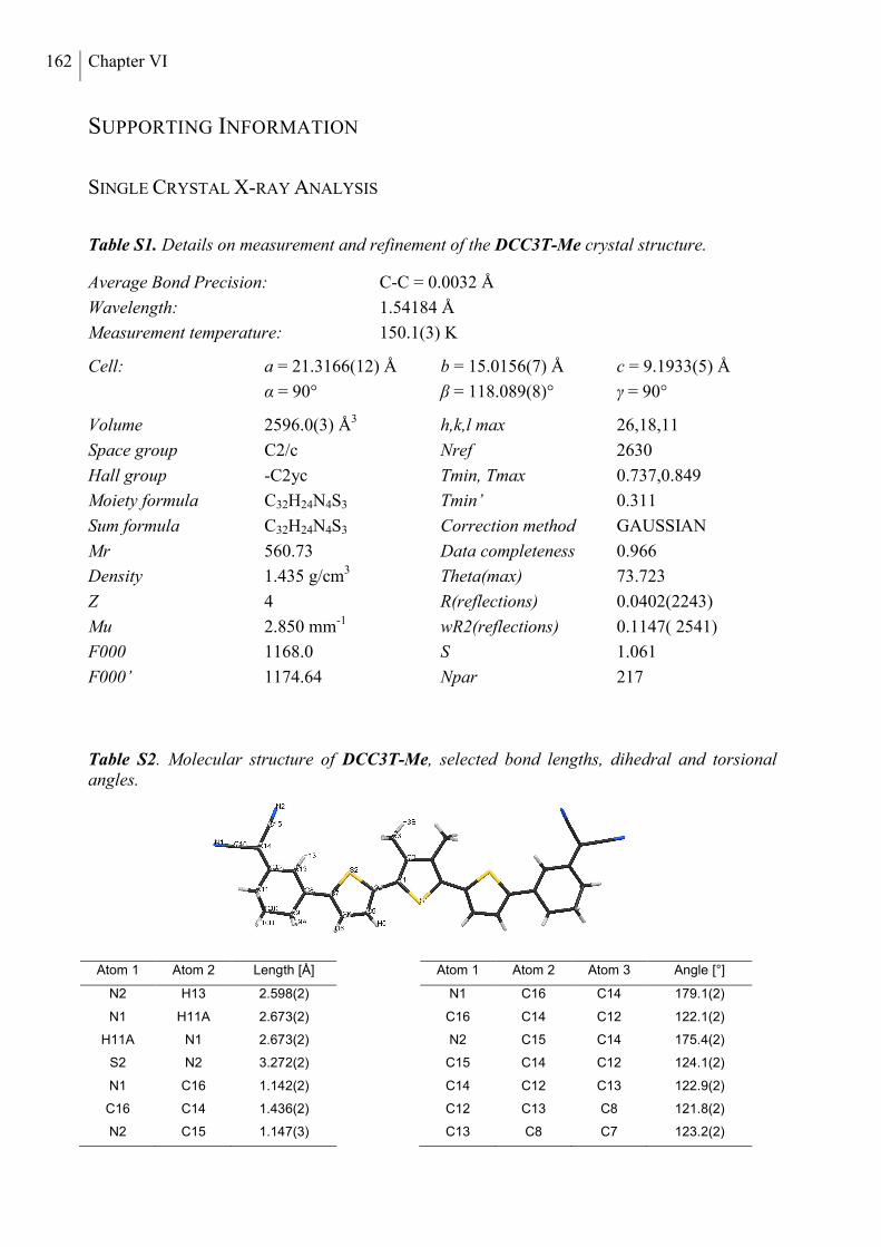
162 Chapter VI
SUPPORTING INFORMATION
SINGLE CRYSTAL X-RAY ANALYSIS
Table S1. Details on measurement and refinement of the DCC3T-Me crystal structure.
Table S2. Molecular structure of DCC3T-Me, selected bond lengths, dihedral and torsional angles.
Atom 1 Atom 2 Length [Å] Atom 1 Atom 2 Atom 3 Angle [°]
N2 H13 2.598(2) N1 C16 C14 179.1(2)
N1 H11A 2.673(2) C16 C14 C12 122.1(2)
H11A N1 2.673(2) N2 C15 C14 175.4(2)
S2 N2 3.272(2) C15 C14 C12 124.1(2)
N1 C16 1.142(2) C14 C12 C13 122.9(2)
C16 C14 1.436(2) C12 C13 C8 121.8(2)
N2 C15 1.147(3) C13 C8 C7 123.2(2)
Average Bond Precision: C-C = 0.0032 Å
Wavelength: 1.54184 Å
Measurement temperature: 150.1(3) K
Cell: a = 21.3166(12) Å b = 15.0156(7) Å c = 9.1933(5) Å
α = 90° β = 118.089(8)° γ = 90°
Volume 2596.0(3) Å3 h,k,l max 26,18,11
Space group C2/c Nref 2630
Hall group -C2yc Tmin, Tmax 0.737,0.849
Moiety formula C32H24N4S3 Tmin’ 0.311
Sum formula C32H24N4S3 Correction method GAUSSIAN
Mr 560.73 Data completeness 0.966
Density 1.435 g/cm3 Theta(max) 73.723
Z 4 R(reflections) 0.0402(2243)
Mu 2.850 mm-1 wR2(reflections) 0.1147( 2541)
F000 1168.0 S 1.061
F000’ 1174.64 Npar 217
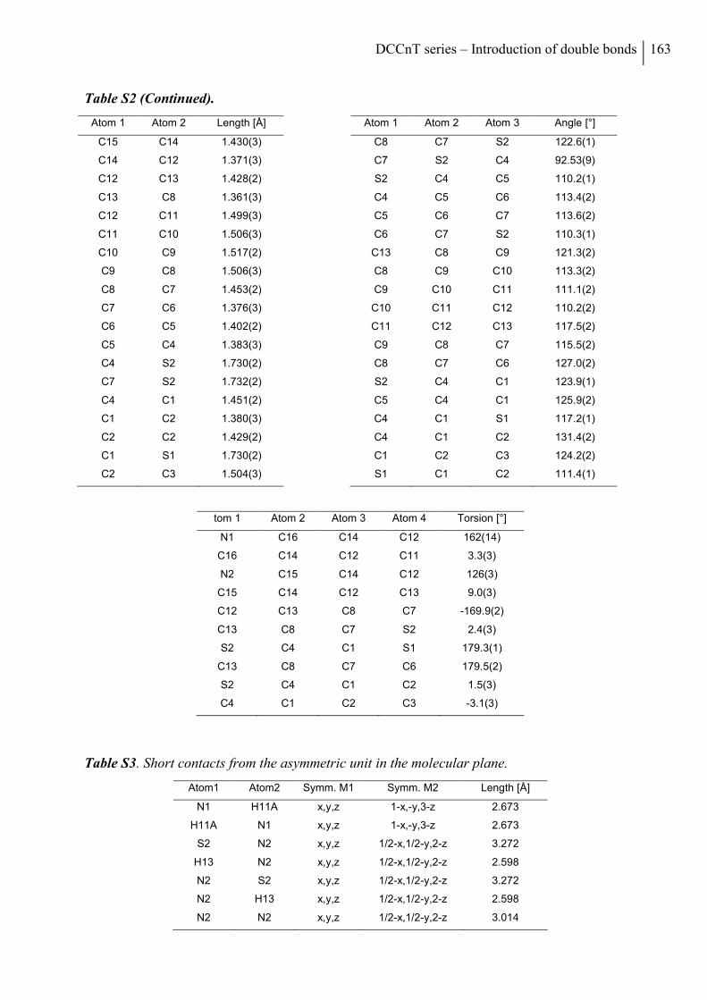
DCCnT series – Introduction of double bonds 163
Table S2 (Continued).
Atom 1 Atom 2 Length [Å] Atom 1 Atom 2 Atom 3 Angle [°]
C15 C14 1.430(3) C8 C7 S2 122.6(1)
C14 C12 1.371(3) C7 S2 C4 92.53(9)
C12 C13 1.428(2) S2 C4 C5 110.2(1)
C13 C8 1.361(3) C4 C5 C6 113.4(2)
C12 C11 1.499(3) C5 C6 C7 113.6(2)
C11 C10 1.506(3) C6 C7 S2 110.3(1)
C10 C9 1.517(2) C13 C8 C9 121.3(2)
C9 C8 1.506(3) C8 C9 C10 113.3(2)
C8 C7 1.453(2) C9 C10 C11 111.1(2)
C7 C6 1.376(3) C10 C11 C12 110.2(2)
C6 C5 1.402(2) C11 C12 C13 117.5(2)
C5 C4 1.383(3) C9 C8 C7 115.5(2)
C4 S2 1.730(2) C8 C7 C6 127.0(2)
C7 S2 1.732(2) S2 C4 C1 123.9(1)
C4 C1 1.451(2) C5 C4 C1 125.9(2)
C1 C2 1.380(3) C4 C1 S1 117.2(1)
C2 C2 1.429(2) C4 C1 C2 131.4(2)
C1 S1 1.730(2) C1 C2 C3 124.2(2)
C2 C3 1.504(3) S1 C1 C2 111.4(1)
tom 1 Atom 2 Atom 3 Atom 4 Torsion [°]
N1 C16 C14 C12 162(14)
C16 C14 C12 C11 3.3(3)
N2 C15 C14 C12 126(3)
C15 C14 C12 C13 9.0(3)
C12 C13 C8 C7 -169.9(2)
C13 C8 C7 S2 2.4(3)
S2 C4 C1 S1 179.3(1)
C13 C8 C7 C6 179.5(2)
S2 C4 C1 C2 1.5(3)
C4 C1 C2 C3 -3.1(3)
Table S3. Short contacts from the asymmetric unit in the molecular plane.
Atom1 Atom2 Symm. M1 Symm. M2 Length [Å]
N1 H11A x,y,z 1-x,-y,3-z 2.673
H11A N1 x,y,z 1-x,-y,3-z 2.673
S2 N2 x,y,z 1/2-x,1/2-y,2-z 3.272
H13 N2 x,y,z 1/2-x,1/2-y,2-z 2.598
N2 S2 x,y,z 1/2-x,1/2-y,2-z 3.272
N2 H13 x,y,z 1/2-x,1/2-y,2-z 2.598
N2 N2 x,y,z 1/2-x,1/2-y,2-z 3.014
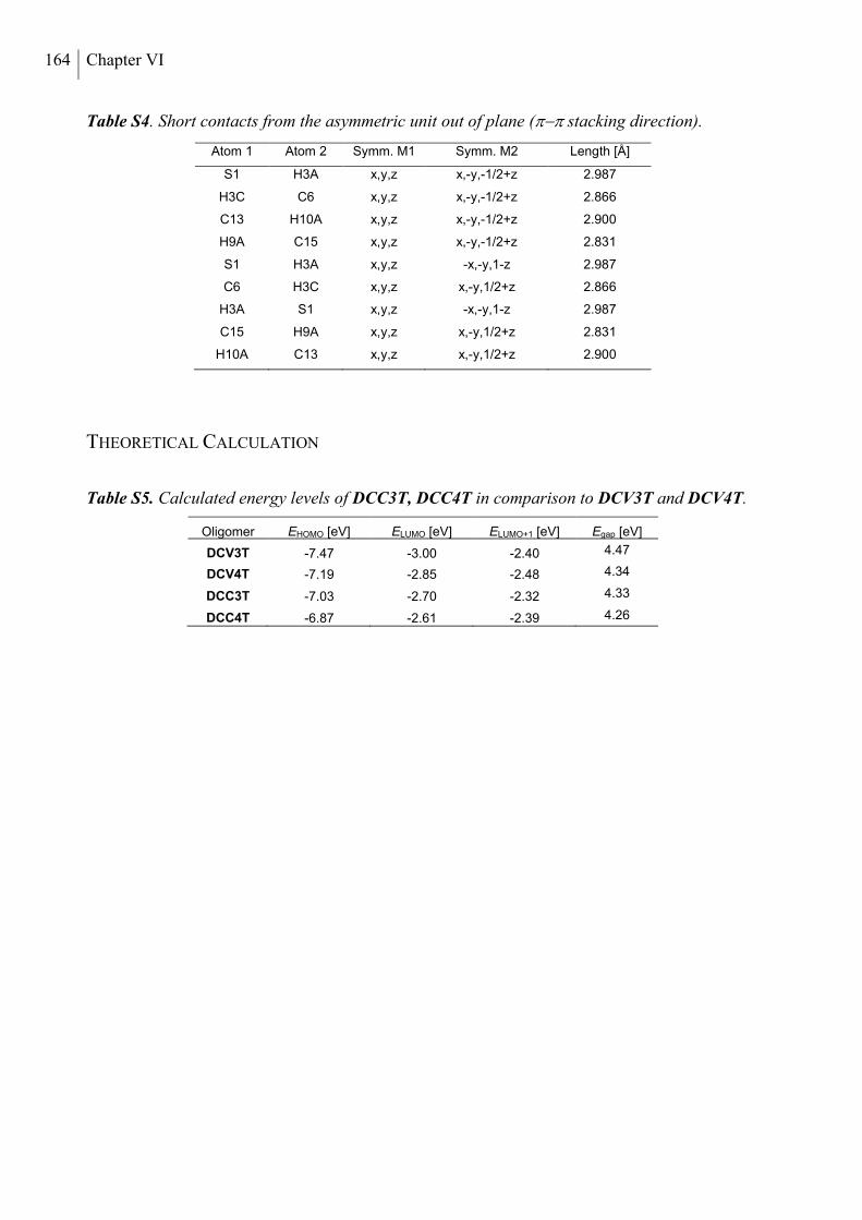
164 Chapter VI
Table S4. Short contacts from the asymmetric unit out of plane ( stacking direction).
Atom 1 Atom 2 Symm. M1 Symm. M2 Length [Å]
S1 H3A x,y,z x,-y,-1/2+z 2.987
H3C C6 x,y,z x,-y,-1/2+z 2.866
C13 H10A x,y,z x,-y,-1/2+z 2.900
H9A C15 x,y,z x,-y,-1/2+z 2.831
S1 H3A x,y,z -x,-y,1-z 2.987
C6 H3C x,y,z x,-y,1/2+z 2.866
H3A S1 x,y,z -x,-y,1-z 2.987
C15 H9A x,y,z x,-y,1/2+z 2.831
H10A C13 x,y,z x,-y,1/2+z 2.900
THEORETICAL CALCULATION
Table S5. Calculated energy levels of DCC3T, DCC4T in comparison to DCV3T and DCV4T.
Oligomer EHOMO [eV] ELUMO [eV] ELUMO+1 [eV] Egap [eV]
DCV3T -7.47 -3.00 -2.40 4.47
DCV4T -7.19 -2.85 -2.48 4.34
DCC3T -7.03 -2.70 -2.32 4.33
DCC4T -6.87 -2.61 -2.39 4.26
165
CHAPTER VII
STRUCTURAL MODIFICATION OF THE TERMINAL
GROUPS IN A-D-A OLIGOTHIOPHENES FOR
SOLUTION-PROCESSED SOLAR CELLS
Roland Fitzner,a Gisela L. Schulz,a Florian Henne,a Marta Urdanpilleta,b Peter Bäuerlea*
a Institute of Organic Chemistry II and Advanced Materials, University of Ulm, Albert-Einstein-Allee 11, 89081 Ulm, Germany
b Department of Applied Physics, University of the Basque Country (UPV/EHU), Plaza de Europa, 1, 20018 Donostia - San Sebastián, Spain
Intended for submission.
166 Chapter VII
ABSTRACT
Herein, we present the synthesis of two structurally new electron donor materials for organic
solar cells. The first molecule in the series, DCV5T-Bu, contains the long-standing
dicyanovinyl (DCV) acceptor unit. Solubility and film forming properties of the oligomers
could be tuned through insertion of a cyclohexene ring and additional methyl groups. The three
target compounds are characterized using optical spectroscopy and cyclic voltammetry. After
processing each oligomer in various solvent systems together with PC61BM as electron
accepting material, the solar cell parameters of the three oligomers are compared. Structure-
property relationships with respect to the modification of the acceptor units and its impact on the
photovoltaic performance are discussed. It was found that UV-vis absorption spectroscopy could
be used as a predictive tool to determine the optimal amount of solvent additive for the
fabrication DCC5T-Bu:PC61BM based solar cells. Finally, power conversion efficiencies up to
3.4% were measured.
DCV5T-Bu, DCC5T-Bu, MeDCC5T-Bu – Solution-processed OSCs 167
1. INTRODUCTION
The demand for the development of new materials for applications in solution-processed organic
bulk heterojunction solar cells (BHJSC) has been increasing. In the last year alone, dozens of
new molecules have been synthesized and tested in photovoltaic devices. Due to their defined
structure, reproducible synthesis and verifiable purity, oligomeric structures, also referred to as
small molecules, are of particular interest. Most of the research in the small molecule solar cell
field focusses on developing new electron donors;[1] however there has been significant progress
with respect to new electron acceptor materials as well.[2-4]
To date, several different molecular architectures for electron donors have been investigated,
including dendrimers, star shaped molecules, and most frequently, linear oligomers.[1,5] In the
following overview, we will focus on linear oligomeric acceptor-donor-acceptor (A-D-A)-type
compounds that have been applied in solution-processed BHJSCs. Chen et al. have published
more than 10 different donor materials containing oligothiophenes,[6-8] dithienosiloles,[9]
benzodithiophenes[10-12] as electron rich moieties and dicyanovinyl,[7] alkyl cyanoacetate,[6,11]
dimethylpyrimidine-trione[13] and rhodanine[12,14] as terminal electron withdrawing groups. In
these reports, power conversion efficiencies (PCE) range between 3.7 and 8.1%. Yang et al.
have recently described the effect of incorporating selenophene into the oligomer backbone of
an A-D-A structure and measured PCEs up to 6.15%.[15] The chemical structure of electron-rich
and electron-poor components, incorporated into the molecules, not only influences the
absorption and electrochemical behavior of the materials but also its physical properties such as
solubility, mixing and film forming abilities. During the fabrication of the solar cell, these
physical properties play an important role, influencing the active layer morphology and thus the
performance of the devices. In an ideal situation, pathways that will allow for hole and electron
transport to the respective electrodes will be formed. They will be approximately the size of the
exciton diffusion length in order to minimize recombination losses.
A technique that has developed into a routine method to influence the photoactive layer
morphology, is the use of solvent additives. This was initially employed with the conjugated
polymer based BHJSCs but more recently has also been shown to be very effective with small
molecules systems.[16] The presence of the typically high boiling point additive in the solution
used to deposit the BHJ active layer, can strongly influence the D:A morphology by either
increasing or decreasing the size of the phase separated domains.[17]
In this paper, we report on a series of quinquethiophene-based A-D-A-type electron donors,
describing the effect of the structural variation of the terminal groups on physical,
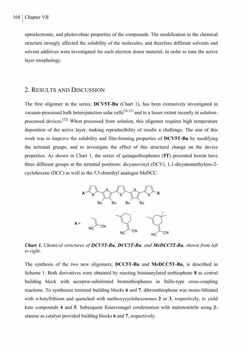
168 Chapter VII
optoelectronic, and photovoltaic properties of the compounds. The modification to the chemical
structure strongly affected the solubility of the molecules, and therefore different solvents and
solvent additives were investigated for each electron donor material, in order to tune the active
layer morphology.
2. RESULTS AND DISCUSSION
The first oligomer in the series, DCV5T-Bu (Chart 1), has been extensively investigated in
vacuum-processed bulk heterojunction solar cells[18-21] and to a lesser extent recently in solution-
processed devices.[22] When processed from solution, this oligomer requires high temperature
deposition of the active layer, making reproducibility of results a challenge. The aim of this
work was to improve the solubility and film-forming properties of DCV5T-Bu by modifying
the terminal groups, and to investigate the effect of this structural change on the device
properties. As shown in Chart 1, the series of quinquethiophenes (5T) presented herein have
three different groups at the terminal positions: dicyanovinyl (DCV), 1,1-dicyanomethylene-2-
cyclohexene (DCC) as well as the 5,5-dimethyl analogue MeDCC.
Chart 1. Chemical structures of DCV5T-Bu, DCC5T-Bu, and MeDCC5T-Bu, shown from left to right.
The synthesis of the two new oligomers, DCC5T-Bu and MeDCC5T-Bu, is described in
Scheme 1. Both derivatives were obtained by reacting bisstannylated terthiophene 8 as central
building block with acceptor-substituted bromothiophenes in Stille-type cross-coupling
reactions. To synthesize terminal building blocks 6 and 7, dibromthiophene was mono-lithiated
with n-butyllithium and quenched with methoxycyclohexenones 2 or 3, respectively, to yield
keto compounds 4 and 5. Subsequent Knoevenagel condensation with malononitrile using β-
alanine as catalyst provided building blocks 6 and 7, respectively.
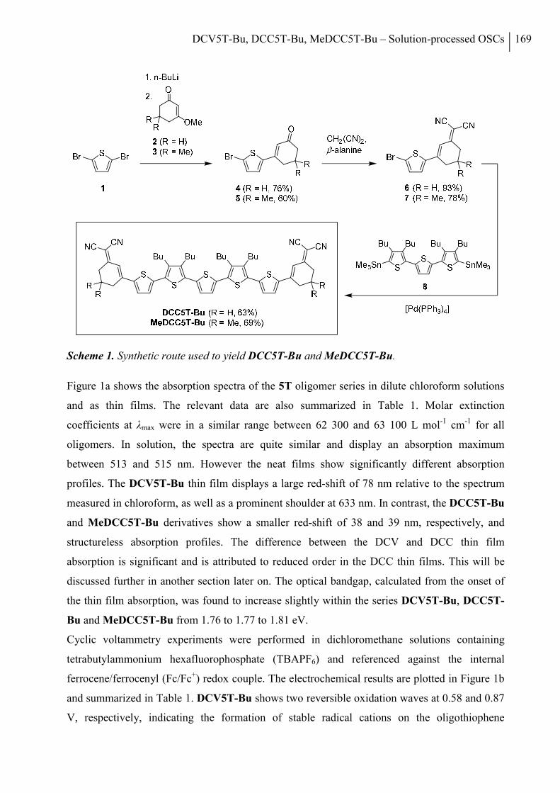
DCV5T-Bu, DCC5T-Bu, MeDCC5T-Bu – Solution-processed OSCs 169
Scheme 1. Synthetic route used to yield DCC5T-Bu and MeDCC5T-Bu.
Figure 1a shows the absorption spectra of the 5T oligomer series in dilute chloroform solutions
and as thin films. The relevant data are also summarized in Table 1. Molar extinction
coefficients at λmax were in a similar range between 62 300 and 63 100 L mol-1 cm-1 for all
oligomers. In solution, the spectra are quite similar and display an absorption maximum
between 513 and 515 nm. However the neat films show significantly different absorption
profiles. The DCV5T-Bu thin film displays a large red-shift of 78 nm relative to the spectrum
measured in chloroform, as well as a prominent shoulder at 633 nm. In contrast, the DCC5T-Bu
and MeDCC5T-Bu derivatives show a smaller red-shift of 38 and 39 nm, respectively, and
structureless absorption profiles. The difference between the DCV and DCC thin film
absorption is significant and is attributed to reduced order in the DCC thin films. This will be
discussed further in another section later on. The optical bandgap, calculated from the onset of
the thin film absorption, was found to increase slightly within the series DCV5T-Bu, DCC5T-
Bu and MeDCC5T-Bu from 1.76 to 1.77 to 1.81 eV.
Cyclic voltammetry experiments were performed in dichloromethane solutions containing
tetrabutylammonium hexafluorophosphate (TBAPF6) and referenced against the internal
ferrocene/ferrocenyl (Fc/Fc+) redox couple. The electrochemical results are plotted in Figure 1b
and summarized in Table 1. DCV5T-Bu shows two reversible oxidation waves at 0.58 and 0.87
V, respectively, indicating the formation of stable radical cations on the oligothiophene
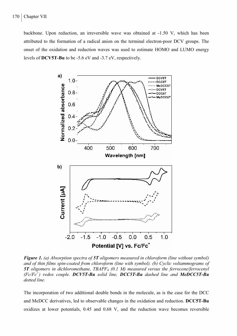
170 Chapter VII
backbone. Upon reduction, an irreversible wave was obtained at -1.50 V, which has been
attributed to the formation of a radical anion on the terminal electron-poor DCV groups. The
onset of the oxidation and reduction waves was used to estimate HOMO and LUMO energy
levels of DCV5T-Bu to be -5.6 eV and -3.7 eV, respectively.
Figure 1. (a) Absorption spectra of 5T oligomers measured in chloroform (line without symbol) and of thin films spin-coated from chloroform (line with symbol). (b) Cyclic voltammograms of 5T oligomers in dichloromethane, TBAPF6 (0.1 M) measured versus the ferrocene/ferrocenyl (Fc/Fc+) redox couple. DCV5T-Bu solid line, DCC5T-Bu dashed line and MeDCC5T-Bu dotted line.
The incorporation of two additional double bonds in the molecule, as is the case for the DCC
and MeDCC derivatives, led to observable changes in the oxidation and reduction. DCC5T-Bu
oxidizes at lower potentials, 0.45 and 0.68 V, and the reduction wave becomes reversible
b)
a)
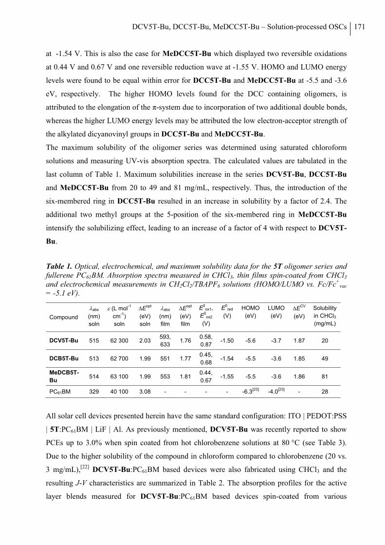
DCV5T-Bu, DCC5T-Bu, MeDCC5T-Bu – Solution-processed OSCs 171
at -1.54 V. This is also the case for MeDCC5T-Bu which displayed two reversible oxidations
at 0.44 V and 0.67 V and one reversible reduction wave at -1.55 V. HOMO and LUMO energy
levels were found to be equal within error for DCC5T-Bu and MeDCC5T-Bu at -5.5 and -3.6
eV, respectively. The higher HOMO levels found for the DCC containing oligomers, is
attributed to the elongation of the π-system due to incorporation of two additional double bonds,
whereas the higher LUMO energy levels may be attributed the low electron-acceptor strength of
the alkylated dicyanovinyl groups in DCC5T-Bu and MeDCC5T-Bu.
The maximum solubility of the oligomer series was determined using saturated chloroform
solutions and measuring UV-vis absorption spectra. The calculated values are tabulated in the
last column of Table 1. Maximum solubilities increase in the series DCV5T-Bu, DCC5T-Bu
and MeDCC5T-Bu from 20 to 49 and 81 mg/mL, respectively. Thus, the introduction of the
six-membered ring in DCC5T-Bu resulted in an increase in solubility by a factor of 2.4. The
additional two methyl groups at the 5-position of the six-membered ring in MeDCC5T-Bu
intensify the solubilizing effect, leading to an increase of a factor of 4 with respect to DCV5T-
Bu.
Table 1. Optical, electrochemical, and maximum solubility data for the 5T oligomer series and fullerene PC61BM. Absorption spectra measured in CHCl3, thin films spin-coated from CHCl3 and electrochemical measurements in CH2Cl2/TBAPF6 solutions (HOMO/LUMO vs. Fc/Fc+
vac = -5.1 eV).
Compound
abs
(nm)
soln
(L mol-1
cm-1
)
soln
Eopt
(eV)
soln
abs
(nm)
film
Eopt
(eV)
film
E0
ox1,
E0
ox2
(V)
E0
red
(V)
HOMO
(eV)
LUMO
(eV)
ECV
(eV)
Solubility
in CHCl3
(mg/mL)
DCV5T-Bu 515 62 300 2.03 593,
633 1.76
0.58,
0.87 -1.50 -5.6 -3.7 1.87 20
DCB5T-Bu 513 62 700 1.99 551 1.77 0.45,
0.68 -1.54 -5.5 -3.6 1.85 49
MeDCB5T-
Bu 514 63 100 1.99 553 1.81
0.44,
0.67 -1.55 -5.5 -3.6 1.86 81
PC61BM 329 40 100 3.08 - - - - -6.3[23]
-4.0[23]
- 28
All solar cell devices presented herein have the same standard configuration: ITO | PEDOT:PSS
| 5T:PC61BM | LiF | Al. As previously mentioned, DCV5T-Bu was recently reported to show
PCEs up to 3.0% when spin coated from hot chlorobenzene solutions at 80 °C (see Table 3).
Due to the higher solubility of the compound in chloroform compared to chlorobenzene (20 vs.
3 mg/mL),[22] DCV5T-Bu:PC61BM based devices were also fabricated using CHCl3 and the
resulting J-V characteristics are summarized in Table 2. The absorption profiles for the active
layer blends measured for DCV5T-Bu:PC61BM based devices spin-coated from various
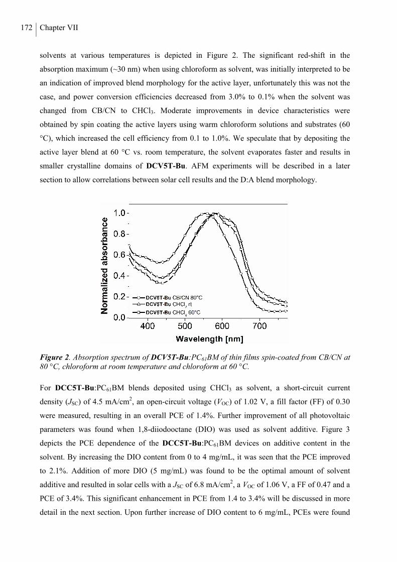
172 Chapter VII
solvents at various temperatures is depicted in Figure 2. The significant red-shift in the
absorption maximum (~30 nm) when using chloroform as solvent, was initially interpreted to be
an indication of improved blend morphology for the active layer, unfortunately this was not the
case, and power conversion efficiencies decreased from 3.0% to 0.1% when the solvent was
changed from CB/CN to CHCl3. Moderate improvements in device characteristics were
obtained by spin coating the active layers using warm chloroform solutions and substrates (60
°C), which increased the cell efficiency from 0.1 to 1.0%. We speculate that by depositing the
active layer blend at 60 °C vs. room temperature, the solvent evaporates faster and results in
smaller crystalline domains of DCV5T-Bu. AFM experiments will be described in a later
section to allow correlations between solar cell results and the D:A blend morphology.
Figure 2. Absorption spectrum of DCV5T-Bu:PC61BM of thin films spin-coated from CB/CN at 80 °C, chloroform at room temperature and chloroform at 60 °C.
For DCC5T-Bu:PC61BM blends deposited using CHCl3 as solvent, a short-circuit current
density (JSC) of 4.5 mA/cm2, an open-circuit voltage (VOC) of 1.02 V, a fill factor (FF) of 0.30
were measured, resulting in an overall PCE of 1.4%. Further improvement of all photovoltaic
parameters was found when 1,8-diiodooctane (DIO) was used as solvent additive. Figure 3
depicts the PCE dependence of the DCC5T-Bu:PC61BM devices on additive content in the
solvent. By increasing the DIO content from 0 to 4 mg/mL, it was seen that the PCE improved
to 2.1%. Addition of more DIO (5 mg/mL) was found to be the optimal amount of solvent
additive and resulted in solar cells with a JSC of 6.8 mA/cm2, a VOC of 1.06 V, a FF of 0.47 and a
PCE of 3.4%. This significant enhancement in PCE from 1.4 to 3.4% will be discussed in more
detail in the next section. Upon further increase of DIO content to 6 mg/mL, PCEs were found
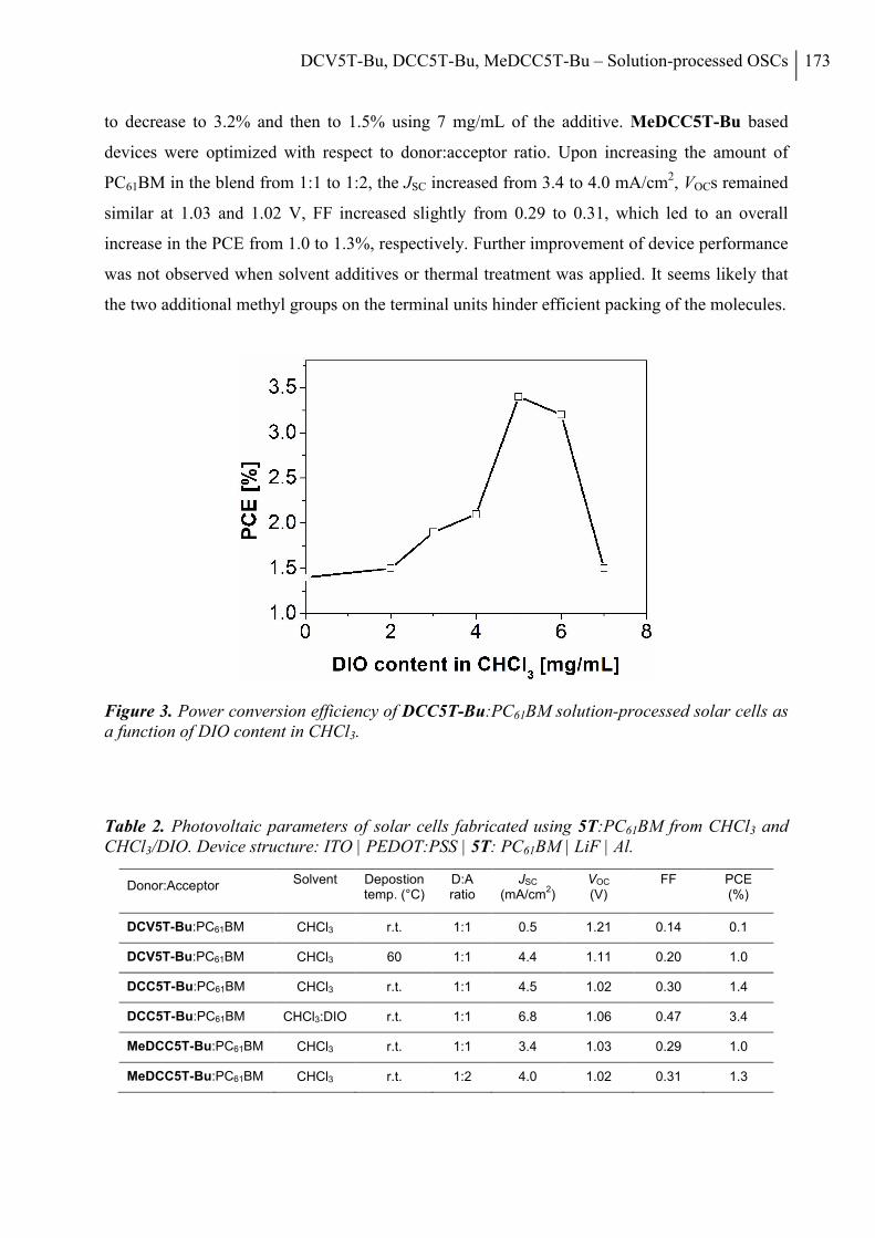
DCV5T-Bu, DCC5T-Bu, MeDCC5T-Bu – Solution-processed OSCs 173
to decrease to 3.2% and then to 1.5% using 7 mg/mL of the additive. MeDCC5T-Bu based
devices were optimized with respect to donor:acceptor ratio. Upon increasing the amount of
PC61BM in the blend from 1:1 to 1:2, the JSC increased from 3.4 to 4.0 mA/cm2, VOCs remained
similar at 1.03 and 1.02 V, FF increased slightly from 0.29 to 0.31, which led to an overall
increase in the PCE from 1.0 to 1.3%, respectively. Further improvement of device performance
was not observed when solvent additives or thermal treatment was applied. It seems likely that
the two additional methyl groups on the terminal units hinder efficient packing of the molecules.
Figure 3. Power conversion efficiency of DCC5T-Bu:PC61BM solution-processed solar cells as a function of DIO content in CHCl3.
Table 2. Photovoltaic parameters of solar cells fabricated using 5T:PC61BM from CHCl3 and CHCl3/DIO. Device structure: ITO | PEDOT:PSS | 5T: PC61BM | LiF | Al.
Donor:Acceptor Solvent Depostion temp. (°C)
D:A ratio
JSC (mA/cm
2)
VOC (V)
FF PCE (%)
DCV5T-Bu:PC61BM CHCl3 r.t. 1:1 0.5 1.21 0.14 0.1
DCV5T-Bu:PC61BM CHCl3 60 1:1 4.4 1.11 0.20 1.0
DCC5T-Bu:PC61BM CHCl3 r.t. 1:1 4.5 1.02 0.30 1.4
DCC5T-Bu:PC61BM CHCl3:DIO r.t. 1:1 6.8 1.06 0.47 3.4
MeDCC5T-Bu:PC61BM CHCl3 r.t. 1:1 3.4 1.03 0.29 1.0
MeDCC5T-Bu:PC61BM CHCl3 r.t. 1:2 4.0 1.02 0.31 1.3
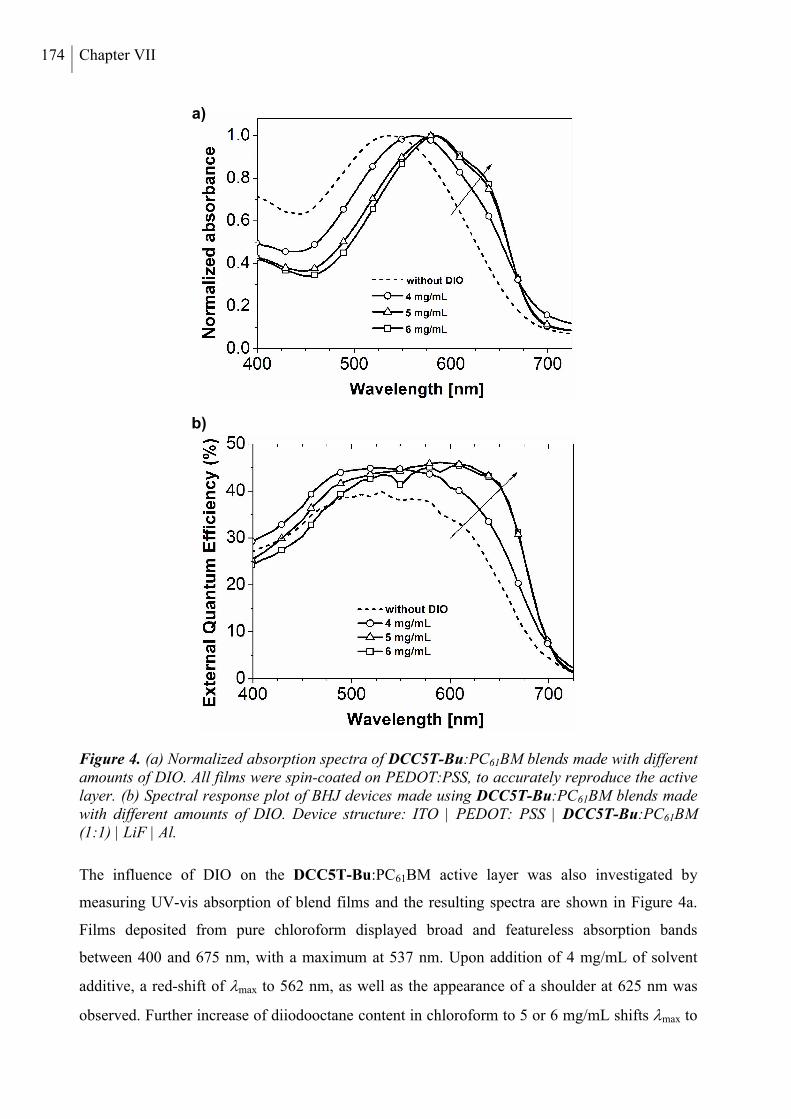
174 Chapter VII
Figure 4. (a) Normalized absorption spectra of DCC5T-Bu:PC61BM blends made with different amounts of DIO. All films were spin-coated on PEDOT:PSS, to accurately reproduce the active layer. (b) Spectral response plot of BHJ devices made using DCC5T-Bu:PC61BM blends made with different amounts of DIO. Device structure: ITO | PEDOT: PSS | DCC5T-Bu:PC61BM (1:1) | LiF | Al.
The influence of DIO on the DCC5T-Bu:PC61BM active layer was also investigated by
measuring UV-vis absorption of blend films and the resulting spectra are shown in Figure 4a.
Films deposited from pure chloroform displayed broad and featureless absorption bands
between 400 and 675 nm, with a maximum at 537 nm. Upon addition of 4 mg/mL of solvent
additive, a red-shift of max to 562 nm, as well as the appearance of a shoulder at 625 nm was
observed. Further increase of diiodooctane content in chloroform to 5 or 6 mg/mL shifts max to
b)
a)
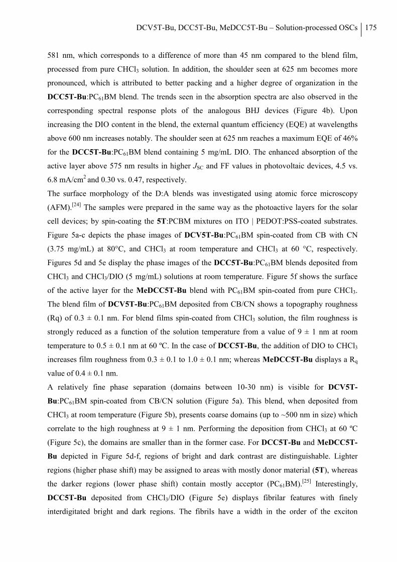
DCV5T-Bu, DCC5T-Bu, MeDCC5T-Bu – Solution-processed OSCs 175
581 nm, which corresponds to a difference of more than 45 nm compared to the blend film,
processed from pure CHCl3 solution. In addition, the shoulder seen at 625 nm becomes more
pronounced, which is attributed to better packing and a higher degree of organization in the
DCC5T-Bu:PC61BM blend. The trends seen in the absorption spectra are also observed in the
corresponding spectral response plots of the analogous BHJ devices (Figure 4b). Upon
increasing the DIO content in the blend, the external quantum efficiency (EQE) at wavelengths
above 600 nm increases notably. The shoulder seen at 625 nm reaches a maximum EQE of 46%
for the DCC5T-Bu:PC61BM blend containing 5 mg/mL DIO. The enhanced absorption of the
active layer above 575 nm results in higher JSC and FF values in photovoltaic devices, 4.5 vs.
6.8 mA/cm2 and 0.30 vs. 0.47, respectively.
The surface morphology of the D:A blends was investigated using atomic force microscopy
(AFM).[24] The samples were prepared in the same way as the photoactive layers for the solar
cell devices; by spin-coating the 5T:PCBM mixtures on ITO | PEDOT:PSS-coated substrates.
Figure 5a-c depicts the phase images of DCV5T-Bu:PC61BM spin-coated from CB with CN
(3.75 mg/mL) at 80°C, and CHCl3 at room temperature and CHCl3 at 60 °C, respectively.
Figures 5d and 5e display the phase images of the DCC5T-Bu:PC61BM blends deposited from
CHCl3 and CHCl3/DIO (5 mg/mL) solutions at room temperature. Figure 5f shows the surface
of the active layer for the MeDCC5T-Bu blend with PC61BM spin-coated from pure CHCl3.
The blend film of DCV5T-Bu:PC61BM deposited from CB/CN shows a topography roughness
(Rq) of 0.3 ± 0.1 nm. For blend films spin-coated from CHCl3 solution, the film roughness is
strongly reduced as a function of the solution temperature from a value of 9 ± 1 nm at room
temperature to 0.5 ± 0.1 nm at 60 ºC. In the case of DCC5T-Bu, the addition of DIO to CHCl3
increases film roughness from 0.3 ± 0.1 to 1.0 ± 0.1 nm; whereas MeDCC5T-Bu displays a Rq
value of 0.4 ± 0.1 nm.
A relatively fine phase separation (domains between 10-30 nm) is visible for DCV5T-
Bu:PC61BM spin-coated from CB/CN solution (Figure 5a). This blend, when deposited from
CHCl3 at room temperature (Figure 5b), presents coarse domains (up to ~500 nm in size) which
correlate to the high roughness at 9 ± 1 nm. Performing the deposition from CHCl3 at 60 ºC
(Figure 5c), the domains are smaller than in the former case. For DCC5T-Bu and MeDCC5T-
Bu depicted in Figure 5d-f, regions of bright and dark contrast are distinguishable. Lighter
regions (higher phase shift) may be assigned to areas with mostly donor material (5T), whereas
the darker regions (lower phase shift) contain mostly acceptor (PC61BM).[25] Interestingly,
DCC5T-Bu deposited from CHCl3/DIO (Figure 5e) displays fibrilar features with finely
interdigitated bright and dark regions. The fibrils have a width in the order of the exciton
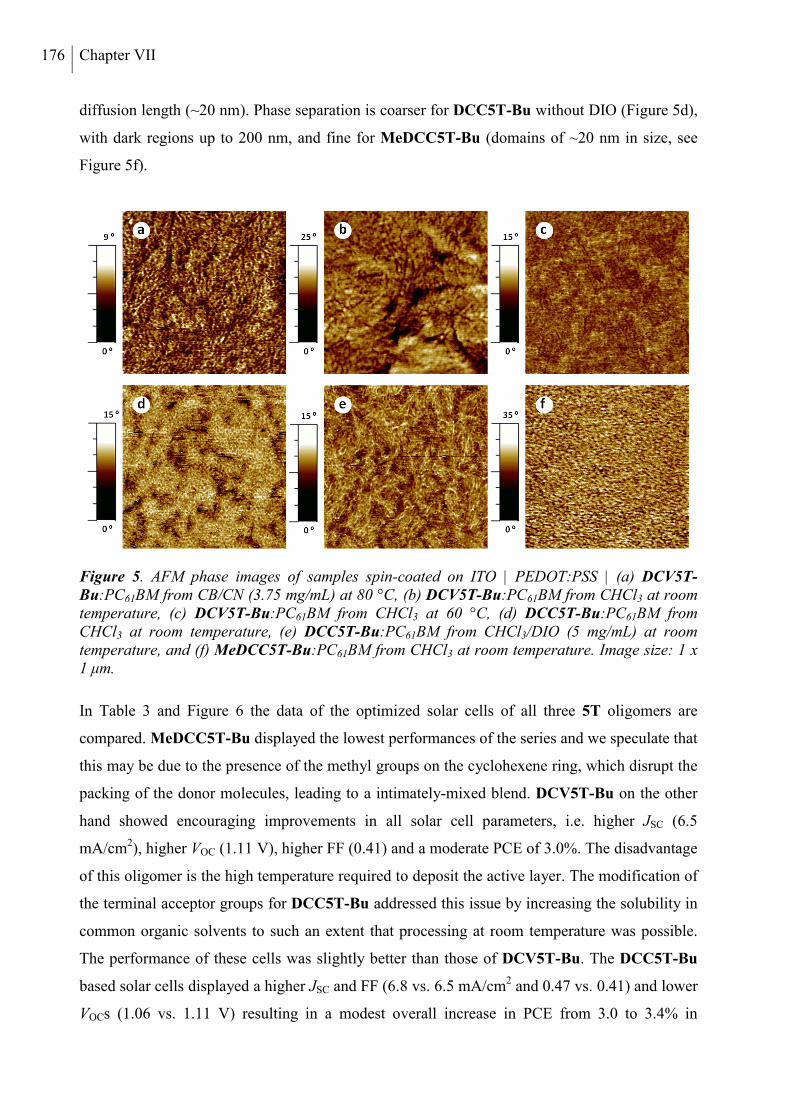
176 Chapter VII
diffusion length (~20 nm). Phase separation is coarser for DCC5T-Bu without DIO (Figure 5d),
with dark regions up to 200 nm, and fine for MeDCC5T-Bu (domains of ~20 nm in size, see
Figure 5f).
Figure 5. AFM phase images of samples spin-coated on ITO | PEDOT:PSS | (a) DCV5T-Bu:PC61BM from CB/CN (3.75 mg/mL) at 80 °C, (b) DCV5T-Bu:PC61BM from CHCl3 at room temperature, (c) DCV5T-Bu:PC61BM from CHCl3 at 60 °C, (d) DCC5T-Bu:PC61BM from CHCl3 at room temperature, (e) DCC5T-Bu:PC61BM from CHCl3/DIO (5 mg/mL) at room temperature, and (f) MeDCC5T-Bu:PC61BM from CHCl3 at room temperature. Image size: 1 x 1 μm.
In Table 3 and Figure 6 the data of the optimized solar cells of all three 5T oligomers are
compared. MeDCC5T-Bu displayed the lowest performances of the series and we speculate that
this may be due to the presence of the methyl groups on the cyclohexene ring, which disrupt the
packing of the donor molecules, leading to a intimately-mixed blend. DCV5T-Bu on the other
hand showed encouraging improvements in all solar cell parameters, i.e. higher JSC (6.5
mA/cm2), higher VOC (1.11 V), higher FF (0.41) and a moderate PCE of 3.0%. The disadvantage
of this oligomer is the high temperature required to deposit the active layer. The modification of
the terminal acceptor groups for DCC5T-Bu addressed this issue by increasing the solubility in
common organic solvents to such an extent that processing at room temperature was possible.
The performance of these cells was slightly better than those of DCV5T-Bu. The DCC5T-Bu
based solar cells displayed a higher JSC and FF (6.8 vs. 6.5 mA/cm2 and 0.47 vs. 0.41) and lower
VOCs (1.06 vs. 1.11 V) resulting in a modest overall increase in PCE from 3.0 to 3.4% in
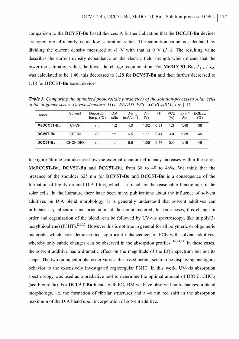
DCV5T-Bu, DCC5T-Bu, MeDCC5T-Bu – Solution-processed OSCs 177
comparison to the DCV5T-Bu based devices. A further indication that the DCC5T-Bu devices
are operating efficiently is its low saturation value. The saturation value is calculated by
dividing the current density measured at -1 V with that at 0 V (JSC). The resulting value
describes the current density dependence on the electric field strength which means that the
lower the saturation value, the lower the charge recombination. For MeDCC5T-Bu, J-1 V / JSC
was calculated to be 1.46, this decreased to 1.28 for DCV5T-Bu and then further decreased to
1.18 for DCC5T-Bu based devices.
Table 3. Comparing the optimized photovoltaic parameters of the solution-processed solar cells of the oligomer series. Device structure: ITO | PEDOT:PSS | 5T:PC61BM | LiF | Al.
Donor Solvent Depostion temp. (°C)
D:A ratio
JSC (mA/cm
2)
VOC (V)
FF PCE (%)
J-1 V / JSC
EQEmax (%)
MeDCC5T-Bu CHCl3 r.t. 1:2 4.0 1.02 0.31 1.3 1.46 38
DCV5T-Bu CB:CN 80 1:1 6.5 1.11 0.41 3.0 1.28 40
DCC5T-Bu CHCl3:DIO r.t. 1:1 6.8 1.06 0.47 3.4 1.18 46
In Figure 6b one can also see how the external quantum efficiency increases within the series
MeDCC5T-Bu, DCV5T-Bu and DCC5T-Bu, from 38 to 40 to 46%. We think that the
presence of the shoulder 625 nm for DCV5T-Bu and DCC5T-Bu is a consequence of the
formation of highly ordered D:A films, which is crucial for the reasonable functioning of the
solar cells. In the literature there have been many publications about the influence of solvent
additives on D:A blend morphology. It is generally understood that solvent additives can
influence crystallization and orientation of the donor material. In some cases, this change in
order and organization of the blend, can be followed by UV-vis spectroscopy, like in poly(3-
hexylthiophene) (P3HT).[26,27] However this is not true in general for all polymeric or oligomeric
materials, which have demonstrated significant enhancement of PCE with solvent additives,
whereby only subtle changes can be observed in the absorption profiles.[16,28,29] In these cases,
the solvent additive has a dramatic effect on the magnitude of the EQE spectrum but not its
shape. The two quinquethiophene derivatives discussed herein, seem to be displaying analogous
behavior to the extensively investigated regioregular P3HT. In this work, UV-vis absorption
spectroscopy was used as a predictive tool to determine the optimal amount of DIO in CHCl3
(see Figure 4a). For DCC5T-Bu blends with PC61BM we have observed both changes in blend
morphology, i.e. the formation of fibrilar structures and a 46 nm red shift in the absorption
maximum of the D:A blend upon incorporation of solvent additive.
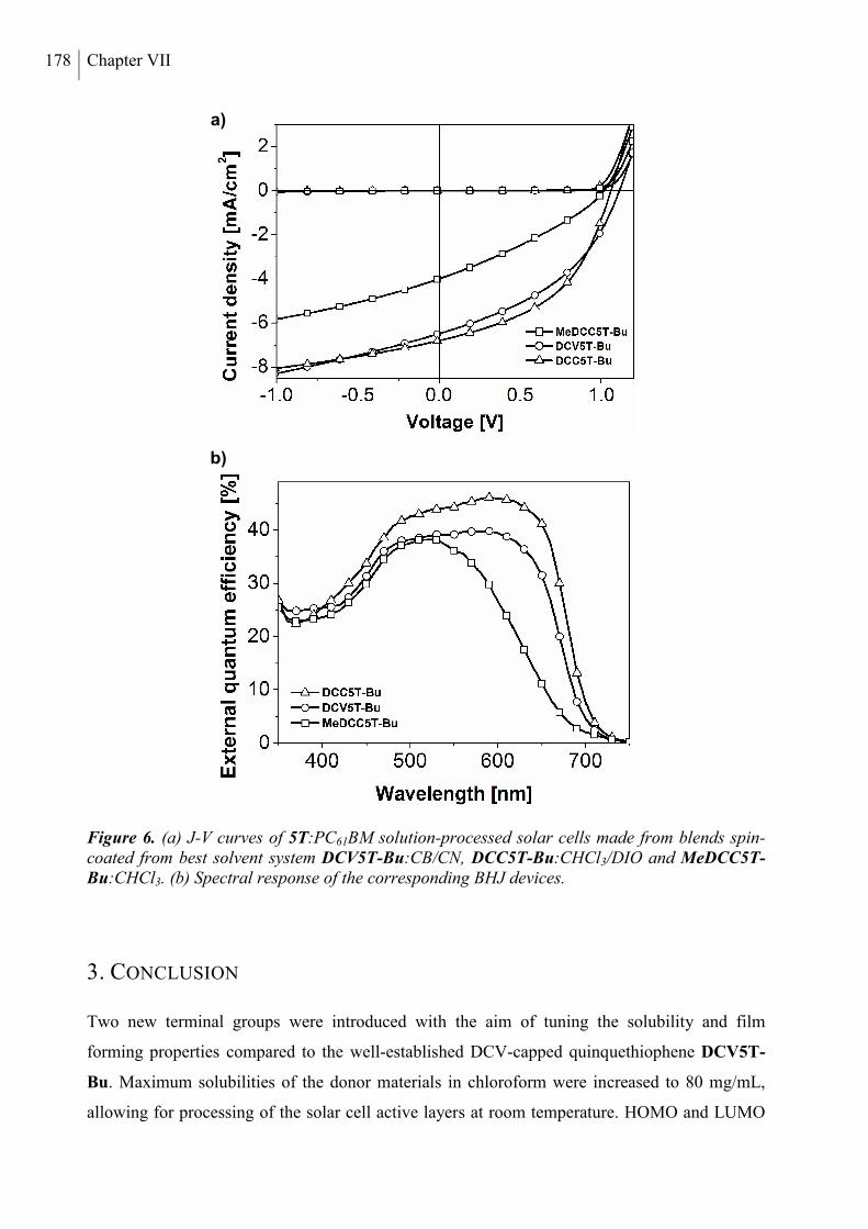
178 Chapter VII
Figure 6. (a) J-V curves of 5T:PC61BM solution-processed solar cells made from blends spin-coated from best solvent system DCV5T-Bu:CB/CN, DCC5T-Bu:CHCl3/DIO and MeDCC5T-Bu:CHCl3. (b) Spectral response of the corresponding BHJ devices.
3. CONCLUSION
Two new terminal groups were introduced with the aim of tuning the solubility and film
forming properties compared to the well-established DCV-capped quinquethiophene DCV5T-
Bu. Maximum solubilities of the donor materials in chloroform were increased to 80 mg/mL,
allowing for processing of the solar cell active layers at room temperature. HOMO and LUMO
b)
a)
DCV5T-Bu, DCC5T-Bu, MeDCC5T-Bu – Solution-processed OSCs 179
energy levels were found to be suitable for application in photovoltaic devices with PC61BM
fullerene derivatives. In the case of DCC5T-Bu, the addition of diiodooctane to the solution
strongly influenced both the absorption profile and phase separation of the D:A blend. The
power conversion efficiency could be increased from 1.4 to 3.4% through use of a solvent
additive.
4. EXPERIMENTAL SECTION
MATERIALS AND METHODS
Dimethylformamide (DMF, Merck) was first refluxed over P4O10 and distilled, then refluxed
over BaO and distilled again. 1-Chloronaphthalene (CN, Aldrich) was distilled prior to use. 3-
methoxy-5,5-dimethylcyclohex-2-enone 3 and (3,3'',4,4''-tetrabutyl-[2,2':5',2''-terthiophene]-
5,5''-diyl)bis(trimethylstannane) 8 were prepared according to published literature
procedures.[21,31] 2,5-dibromothiophene 1 was purchased from Aldrich. Malononitrile and β-
alanine were purchased from Merck. n-Butyl lithium (1.6 M solution in hexanes) was purchased
from Acros. All synthetic steps were carried out under argon atmosphere. NMR spectra were
recorded on a Bruker Avance 400 spectrometer (1H NMR: 400 MHz, 13C NMR: 100 MHz) or a
Bruker AMX 500 (13C NMR: 125 MHz) at 25 °C or 100 °C, respectively. Chemical shift values
(δ) are expressed in parts per million using residual solvent protons (1H NMR, δH = 7.26 for
CDCl3 and δH = 5.93 for tetrachloroethane-d2; 13C NMR, δC = 77.0 for CDCl3 and δC = 74.20
tetrachloroethane-d2) as internal standard. The splitting patterns are designated as follows: s
(singlet), d (doublet) and m (multiplet). EI mass spectra (GC-MS) were recorded on a Varian
Saturn 2000 and MALDI-TOF mass spectra on a Bruker Daltonic Reflex III using dithranol or
DCTB (trans-2[3-4-tert.-butylphenyl]-2-methyl-2-propenylidene)-malononitrile) as matrices.
Differential scanning calorimetric measurements (DSC) were performed on a Mettler Toledo
DSC823e under argon atmosphere at a heating rate of 10 °C min-1. Melting points were
determined using a Büchi B 545 apparatus and were not corrected. Elemental analyses were
performed on an Elementar Vario EL. Preparative column chromatography was performed on
glass columns packed with silica gel (Merck Silica 60, particle size 40-43 µm).
Optical solution measurements were carried out in 1 cm cuvettes with Merck Uvasol grade sol-
vents; absorption spectra were recorded on a Perkin Elmer Lambda 19 spectrometer. Maximum
solubility values were measured using UV-vis absorption spectroscopy. After determination of
180 Chapter VII
the molar extinction coefficient, saturated solutions were made, stirred for 60 min at 60 °C then
allowed to cool to room temperature. The saturated solutions were then filtered and diluted for
absorption spectroscopy, and the corresponding concentrations could be determined. Cyclic vol-
tammetry experiments were performed with a computer-controlled Metrohm Autolab
PGSTAT30 potentiostat in a three-electrode single-compartment cell with a platinum working
electrode, a platinum wire counter electrode, and an Ag/AgCl reference electrode. All potentials
were internally referenced to the ferrocene/ferrocenium couple (-5.1 eV). High pressure liquid
chromatography was performed on a Hitachi instrument equipped with a UV-vis detector L-
7420, columns (Nucleosil 100-5 NO2 with a pore size of 100 Å) from Machery-Nagel using a
dichlormethane/n-hexane mixture (40:60) as eluent. Surface images were recorded with the help
of a Bruker Nanoscope V AFM at ambient temperature in tapping mode.
DEVICE FABRICATION
Photovoltaic devices were made by spin-coating PEDOT:PSS (Clevios P, VP Al4083) onto pre-
cleaned, patterned indium tin oxide (ITO) substrates (15 Ω per square) (Kintec). The
photoactive layer (~ 80 nm) was deposited by spin-coating from of a mixed solution of 5T with
PC61BM (total concentration of 17.5 mg/mL in chlorobenzene or 15 mg/mL in CHCl3). PC61BM
was purchased from Solenne BV, Netherlands. The counter electrode of LiF (1 nm) and
aluminum (100 nm) was deposited by vacuum evaporation at 2 ∙ 10-6 Torr. The active areas of
the cells were 0.2 cm2. Film thicknesses were measured using a Dektak profilometer. J-V
characteristics were measured under ~ 100 mW/cm2 white light from a tungsten-halogen lamp
filtered by a Schott GG385 UV filter and a Hoya LB120 daylight filter, using a Keithley 2400
source meter. Spectral response was measured under monochromatic light from a 300 W Xenon
lamp in combination with monochromator (Oriel, Cornerstone 260), modulated with a mecha-
nical chopper. The response was recorded as the voltage over a 220 Ω resistance, using a lock-in
amplifier (Merlin 70104). A calibrated Si cell was used as reference. The devices were kept
behind a quartz window in a nitrogen filled container.
SYNTHESIS AND CHARACTERIZATION
Synthesis of 3-[5-Bromothiophen-2-yl]cyclohex-2-enone 4: To a solution of 2,5-
dibromothiophene 1 (6.05 g, 25.0 mmol) in diethyl ether (75 mL), stirred at -78 °C, n-butyl-
lithium (1.6 M solution in hexanes, 15.6 mL, 25.0 mmol) was added dropwise over 15 minutes.
After stirring at -78 °C for 10 minutes, a solution of 3-methoxy-2-cyclohex-2-enon 2 (3.16 g,
DCV5T-Bu, DCC5T-Bu, MeDCC5T-Bu – Solution-processed OSCs 181
25.0 mmol) in diethylether (30 mL) was added and stirring was continued for 15 minutes. The
solution was warmed to 0 °C, stirred for 3 hours and subsequently allowed to warm to room
temperature and stirred for 16 hours. The reaction was quenched with brine (300 mL) and the
product was extracted with diethyl ether (3 × 150 mL). The combined organic extracts were
dried over MgSO4, filtered and the solvents were removed in vacuo. Column chromatography
(silica gel, DCM) and subsequent recrystallization from n-hexane yielded compound 4 (4.91 g,
19.1 mmol, 76%) as a colourless crystalline solid. M.p. 90.5-92 oC. 1H NMR (chloroform-d1, δ
ppm) 7.12 (d, 1H, J = 4.0 Hz), 7.05 (d, 1H, J = 3.9 Hz), 6.29 (s, 1H), 2.70 (t, 2H, J = 6.0 Hz),
2.45 (t, 2H, J = 6.6 Hz), 2.16-2.09 (m, 2H). 13C NMR (chloroform-d1, δ ppm) 199.08, 151.19,
143.97, 131.20, 127.57, 122.80, 116.38, 37.18, 27.35, 22.29. EI mass 258 [M+H+] (calcd. for
C10H9BrOS 257). Elemental analysis for C10H9BrOS: calcd. C, 46.71; H, 3.53; S, 12.47%;
found: C, 46.97; H, 3.59; S, 12.48%.
Synthesis of 3-[5-Bromothiophen-2-yl]-5,5-dimethylcyclohex-2-enone 5: To a solution of 2,5-
dibromothiophene 1 (6.05 g, 25.0 mmol) in diethyl ether (75 mL), stirred at -78 °C, n-butyl-
lithium (1.6 M solution in hexanes, 15.6 mL, 25.0 mmol) was added dropwise over 15 minutes.
After stirring at -78 °C for 15 minutes, a solution of 3-methoxy-5,5-dimethylcyclohex-2-enone 3
(3.86 g, 25.0 mmol) in diethylether (15 mL) was added and stirring was continued for
30 minutes. The solution was warmed to 0 °C, stirred for 3 hours and subsequently allowed to
warm to room temperature and stirred for 16 hours. The reaction was quenched with brine
(300 mL) and the product was extracted with diethyl ether (3 × 150 mL). The combined organic
extracts were dried over MgSO4, filtered and the solvents were removed in vacuo. Column
chromatography (silica gel, DCM) yielded compound 5 (4.28 g, 15.0 mmol, 60%) as a pale
yellow crystalline solid. M.p. 81.5-83 oC. 1H NMR (chloroform-d1, δ ppm) 7.12 (d, 1H, J = 4.0
Hz), 7.05 (d, 1H, J = 3.9 Hz), 6.30-6.29 (m, 1H), 2.57-2.56 (m, 2H), 2.32-2.31 (m, 2H), 1.11 (s,
6H). 13C NMR (chloroform-d1, δ ppm) 199.24, 149.05, 144.25, 131.18, 127.52, 121.73, 116.33,
50.90, 41.33, 33.53, 28.35. EI mass 286 [M+H+] (calcd. for C12H13BrOS 285). Elemental
analysis for C12H13BrOS: calcd. C, 50.54; H, 4.59; S, 11.24%; found: C, 50.74; H, 4.62; S,
11.32%.
Synthesis of 2-[3-(5-Bromothiophen-2-yl)cyclohex-2-en-1-ylidene]malononitrile 6: A solution
consisting of 3-[5-Bromothiophen-2-yl]cyclohex-2-enone 4 (4.00 g, 15.6 mmol), malononitrile
(3.08 g, 46.7 mmol) and β-alanine (83 mg, 0.93 mmol) in a mixture of dichloroethane (100 mL)
and ethanol (100 mL) was stirred under reflux for 6 days. The reaction mixture was allowed to
cool to room temperature, the precipitate was filtered off and washed thoroughly with water.
182 Chapter VII
After concentration of the filtrate in vacuo to about half the volume and cooling to room
temperature, the resulting precipitate was collected by filtration and washed with water to afford
a second crop of 6 (overall yield: 4.40 g, 14.4 mmol, 93%) as an orange crystalline solid. M.p.
195.5-197 oC. 1H NMR (chloroform-d1, δ ppm) 7.23 (d, 1H, J = 3.9 Hz), 7.10 (d, 1H, J = 3.9
Hz), 7.01 (s, 1H), 2.80 (t, 2H, J = 6.4 Hz), 2.74 (t, 1H, J = 5.9 Hz), 2.00 (p, 1H, J = 6.1 Hz). 13C
NMR (chloroform-d1, δ ppm) 168.85, 149.24, 143.88, 131.71, 128.64, 118.57, 118.25, 113.28,
112.46, 78.34, 29.06, 27.73, 21.11. EI mass 306 [M+H+] (calcd. for C13H9BrN2S 305).
Elemental analysis for C13H9BrN2S: calcd. C, 51.16; H, 2.97; N, 9.18; S, 10.51%; found: C,
51.38; H, 3.04; N, 9.15; S, 10.54%.
Synthesis of 2-[3-(5-Bromothiophen-2-yl)-5,5-dimethylcyclohex-2-en-1-ylidene]malononitrile 7:
A solution consisting of 3-[5-Bromothiophen-2-yl]-5,5-dimethylcyclohex-2-enone 5 (2.60 g,
9.12 mmol), malononitrile (1.81 g, 27.3 mmol) and β-alanine (49 mg, 0.55 mmol) in a mixture
of dichloroethane (30 mL) and ethanol (30 mL) was stirred under reflux. After 5 days additional
portions of malononitrile (900 mg, 13.5 mmol) and β-alanine (20 mg, 0.22 mmol) were added to
the solution and stirring under reflux was continued for one day. The reaction mixture was
poured into water (250 mL), extracted with dichloromethane (3 × 150 mL), dried over MgSO4
and the solvents were removed in vacuo. The crude product was purified by column
chromatography (SiO2, dichloromethane) to obtain 7 (2.36 g, 7.08 mmol, 78%) as a yellow
crystalline solid. M.p. 135-136.5 oC. 1H NMR (chloroform-d1, δ ppm) 7.22 (d, 1H, J = 4.0 Hz),
7.10 (d, 1H, J = 4.1 Hz), 7.01 (m, 1H), 2.61-2.60 (m, 2H), 2.56-2.55 (m, 2H), 1.09 (s, 6H). 13C
NMR (chloroform-d1, δ ppm) 168.45, 147.50, 144.06, 131.68, 128.62, 118.18, 117.52, 113.31,
112.48, 79.19, 42.57, 41.72, 32.09, 27.84. EI mass 334 [M+H+] (calcd. for C15H13BrN2S 333).
Elemental analysis for C15H13BrN2S: calcd. C, 54.06; H, 3.93; N, 8.41; S, 9.62%; found: C,
54.22; H, 4.13; N, 8.48; S, 9.66%.
Synthesis of 2,2'-((3',3''',4',4'''-tetrabutyl-[2,2':5',2'':5'',2''':5''',2''''-quinquethiophene]-5,5''''-
diyl)bis(cyclohex-2-en-3-yl-1-ylidene)) DCC5T-Bu: A mixture of (3,3'',4,4''-tetrabutyl-
[2,2':5',2''-terthiophene]-5,5''-diyl)bis(trimethylstannane) 8 (650 mg, 814 μmol), 2-[3-(5-Bromo-
thiophen-2-yl)-5,5-dimethylcyclohex-2-en-1-ylidene]malononitrile 6 (547 mg, 1.79 mmol) and
tetrakis(triphenylphosphine)palladium(0) (47 mg, 41 μmol) was combined in degassed DMF
(30 mL) and stirred at 80 °C for 20 hours. The reaction mixture was poured into water, extracted
with dichloromethane, dried over MgSO4 and the solvents were removed in vacuo. Column
chromatography (silica gel, DCM) yielded compound DCC5T-Bu (472 mg, 511 μmol, 63%) as
a dark purple solid. M.p. 198 (DSC) oC. 1H NMR (tetrachloroethane-d2, δ ppm) 7.42 (d, 2H, J =
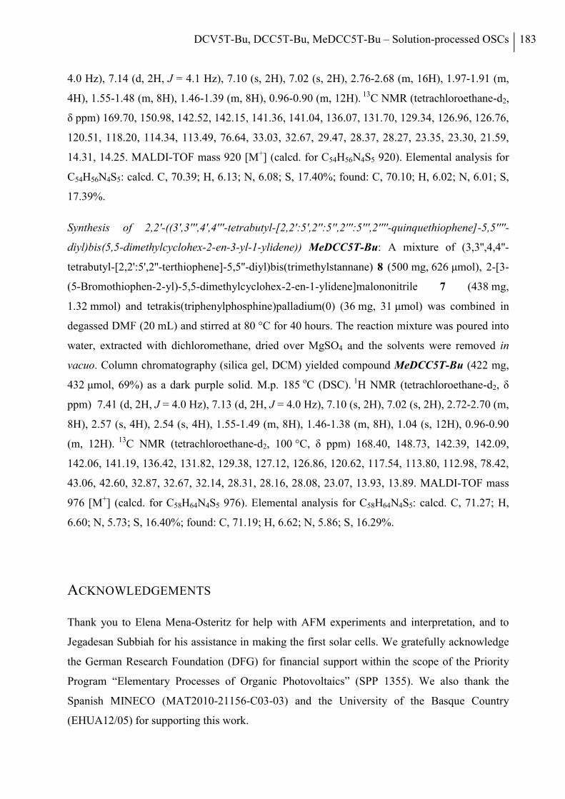
DCV5T-Bu, DCC5T-Bu, MeDCC5T-Bu – Solution-processed OSCs 183
4.0 Hz), 7.14 (d, 2H, J = 4.1 Hz), 7.10 (s, 2H), 7.02 (s, 2H), 2.76-2.68 (m, 16H), 1.97-1.91 (m,
4H), 1.55-1.48 (m, 8H), 1.46-1.39 (m, 8H), 0.96-0.90 (m, 12H). 13C NMR (tetrachloroethane-d2,
δ ppm) 169.70, 150.98, 142.52, 142.15, 141.36, 141.04, 136.07, 131.70, 129.34, 126.96, 126.76,
120.51, 118.20, 114.34, 113.49, 76.64, 33.03, 32.67, 29.47, 28.37, 28.27, 23.35, 23.30, 21.59,
14.31, 14.25. MALDI-TOF mass 920 [M+] (calcd. for C54H56N4S5 920). Elemental analysis for
C54H56N4S5: calcd. C, 70.39; H, 6.13; N, 6.08; S, 17.40%; found: C, 70.10; H, 6.02; N, 6.01; S,
17.39%.
Synthesis of 2,2'-((3',3''',4',4'''-tetrabutyl-[2,2':5',2'':5'',2''':5''',2''''-quinquethiophene]-5,5''''-
diyl)bis(5,5-dimethylcyclohex-2-en-3-yl-1-ylidene)) MeDCC5T-Bu: A mixture of (3,3'',4,4''-
tetrabutyl-[2,2':5',2''-terthiophene]-5,5''-diyl)bis(trimethylstannane) 8 (500 mg, 626 μmol), 2-[3-
(5-Bromothiophen-2-yl)-5,5-dimethylcyclohex-2-en-1-ylidene]malononitrile 7 (438 mg,
1.32 mmol) and tetrakis(triphenylphosphine)palladium(0) (36 mg, 31 μmol) was combined in
degassed DMF (20 mL) and stirred at 80 °C for 40 hours. The reaction mixture was poured into
water, extracted with dichloromethane, dried over MgSO4 and the solvents were removed in
vacuo. Column chromatography (silica gel, DCM) yielded compound MeDCC5T-Bu (422 mg,
432 μmol, 69%) as a dark purple solid. M.p. 185 oC (DSC). 1H NMR (tetrachloroethane-d2, δ
ppm) 7.41 (d, 2H, J = 4.0 Hz), 7.13 (d, 2H, J = 4.0 Hz), 7.10 (s, 2H), 7.02 (s, 2H), 2.72-2.70 (m,
8H), 2.57 (s, 4H), 2.54 (s, 4H), 1.55-1.49 (m, 8H), 1.46-1.38 (m, 8H), 1.04 (s, 12H), 0.96-0.90
(m, 12H). 13C NMR (tetrachloroethane-d2, 100 °C, δ ppm) 168.40, 148.73, 142.39, 142.09,
142.06, 141.19, 136.42, 131.82, 129.38, 127.12, 126.86, 120.62, 117.54, 113.80, 112.98, 78.42,
43.06, 42.60, 32.87, 32.67, 32.14, 28.31, 28.16, 28.08, 23.07, 13.93, 13.89. MALDI-TOF mass
976 [M+] (calcd. for C58H64N4S5 976). Elemental analysis for C58H64N4S5: calcd. C, 71.27; H,
6.60; N, 5.73; S, 16.40%; found: C, 71.19; H, 6.62; N, 5.86; S, 16.29%.
ACKNOWLEDGEMENTS
Thank you to Elena Mena-Osteritz for help with AFM experiments and interpretation, and to
Jegadesan Subbiah for his assistance in making the first solar cells. We gratefully acknowledge
the German Research Foundation (DFG) for financial support within the scope of the Priority
Program “Elementary Processes of Organic Photovoltaics” (SPP 1355). We also thank the
Spanish MINECO (MAT2010-21156-C03-03) and the University of the Basque Country
(EHUA12/05) for supporting this work.
184 Chapter VII
REFERENCES
[1] B. Walker, C. Kim, T.-Q. Nguyen, Chem. Mater. 2010, 23, 470.
[2] A. Sharenko, C. M. Proctor, T. S. van der Poll, Z. B. Henson, T.-Q. Nguyen, G. C. Bazan, Adv. Mater. 2013, 25, 4403.
[3] K. N. Winzenberg, P. Kemppinen, F. H. Scholes, G. E. Collis, Y. Shu, T. Birendra Singh, A. Bilic, C. M. Forsyth, S. E. Watkins, Chem. Comm. 2013, 49, 6307.
[4] T. V. Pho, F. M. Toma, B. J. Tremolet de Villers, S. Wang, N. D. Treat, N. D. Eisenmenger, G. M. Su, R. C. Coffin, J. D. Douglas, J. M. J. Fréchet, G. C. Bazan, F. Wudl, M. L. Chabinyc, Adv. Energy Mater. 2014, 5, n/a.
[5] A. Mishra, P. Bäuerle, Angew. Chem., Int. Ed. 2012, 51, 2020.
[6] Y. Liu, X. Wan, F. Wang, J. Zhou, G. Long, J. Tian, J. You, Y. Yang, Y. Chen, Adv. Energy Mater. 2011, 1, 771.
[7] B. Yin, L. Y. Yang, Y. S. Liu, Y. S. Chen, Q. J. Qi, F. L. Zhang, S. G. Yin, Appl. Phys. Lett. 2010, 97, 023303.
[8] G. Long, X. Wan, B. Kan, Y. Liu, G. He, Z. Li, Y. Zhang, Y. Zhang, Q. Zhang, M. Zhang, Y. Chen, Adv. Energy Mater. 2013, 3, 639.
[9] J. Zhou, X. Wan, Y. Liu, G. Long, F. Wang, Z. Li, Y. Zuo, C. Li, Y. Chen, Chem. Mater. 2011, 23, 4666.
[10] J. Zhou, X. Wan, Y. Liu, Y. Zuo, Z. Li, G. He, G. Long, W. Ni, C. Li, X. Su, Y. Chen, J. Amer. Chem. Soc. 2012, 134, 16345.
[11] Y. Liu, X. Wan, F. Wang, J. Zhou, G. Long, J. Tian, Y. Chen, Adv. Mater. 2011, 23, 5387.
[12] J. Zhou, Y. Zuo, X. Wan, G. Long, Q. Zhang, W. Ni, Y. Liu, Z. Li, G. He, C. Li, B. Kan, M. Li, Y. Chen, J. Amer. Chem. Soc. 2013, 135, 8484.
[13] G. He, Z. Li, X. Wan, Y. Liu, J. Zhou, G. Long, M. Zhang, Y. Chen, J. Mater. Chem. 2012, 22, 9173.
[14] Z. Li, G. He, X. Wan, Y. Liu, J. Zhou, G. Long, Y. Zuo, M. Zhang, Y. Chen, Adv. Energy Mater. 2012, 2, 74.
[15] Y. Liu, Y. Yang, C.-C. Chen, Q. Chen, L. Dou, Z. Hong, G. Li, Adv. Mater. 2013, 25, 4657.
[16] Y. Sun, G. C. Welch, W. L. Leong, C. J. Takacs, G. C. Bazan, A. J. Heeger, Nat. Mater. 2012, 11, 44.
[17] K. R. Graham, P. M. Wieruszewski, R. Stalder, M. J. Hartel, J. Mei, F. So, J. R. Reynolds, Adv. Func. Mater. 2012, 22, 4801.
DCV5T-Bu, DCC5T-Bu, MeDCC5T-Bu – Solution-processed OSCs 185
[18] K. Schulze, C. Uhrich, R. Schüppel, K. Leo, M. Pfeiffer, E. Brier, E. Reinold, P. Bäuerle, Adv. Mater. 2006, 18, 2872.
[19] K. Schulze, M. Riede, E. Brier, E. Reinold, P. Bäuerle, K. Leo, J. Appl. Phys. 2008, 104, 074511.
[20] H. Ziehlke, L. Burtone, C. Koerner, R. Fitzner, E. Reinold, P. Bäuerle, K. Leo, M. Riede, Org. Electron. 2011, 12, 2258.
[21] S. Haid, A. Mishra, C. Uhrich, M. Pfeiffer, P. Bäuerle, Chem. Mater. 2011, 23, 4435.
[22] G. L. Schulz, M. Urdanpilleta, R. Fitzner, E. Brier, E. Mena-Osteritz, E. Reinold, P. Bäuerle, Beilstein J. Nanotechnol. 2013, 4, 680.
[23] K. Staub, G. A. Levina, S. Barlow, T. C. Kowalczyk, H. S. Lackritz, M. Barzoukas, A. Fort, S. R. Marder, J. Mater. Chem. 2003, 13, 825.
[24] M. Lenes, G.-J. A. H. Wetzelaer, F. B. Kooistra, S. C. Veenstra, J. C. Hummelen, P. W. M. Blom, Adv. Mater. 2008, 20, 2116.
[25] I. Horcas, R. Fernández, J. M. Gómez-Rodríguez, J. Colchero, J. Gómez-Herrero, A. M. Baro, Rev. Sci. Instrum. 2007, 78, 0137051.
[26] V. Shrotriya, Y. Yao, G. Li, Y. Yang, Appl. Phys. Lett. 2006, 89, 063505.
[27] H.-Y. Chen, H. Yang, G. Yang, S. Sista, R. Zadoyan, G. Li, Y. Yang, J. Phys. Chem. C 2009, 113, 7946.
[28] T. Salim, L. H. Wong, B. Brauer, R. Kukreja, Y. L. Foo, Z. Bao, Y. M. Lam, J. Mater. Chem. 2011, 21, 242.
[29] J. K. Lee, W. L. Ma, C. J. Brabec, J. Yuen, J. S. Moon, J. Y. Kim, K. Lee, G. C. Bazan, A. J. Heeger, J. Amer. Chem. Soc. 2008, 130, 3619.
[30] J. C. Bijleveld, A. P. Zoombelt, S. G. J. Mathijssen, M. M. Wienk, M. Turbiez, D. M. de Leeuw, R. A. J. Janssen, J. Amer. Chem. Soc. 2009, 131, 16616.
[31] C.-F. Shu, Y.-C. Shu, Z.-H. Gong, S.-M. Peng, G.-H. Lee, A. K. Y. Jen, Chem. Mater. 1998, 10, 3284.

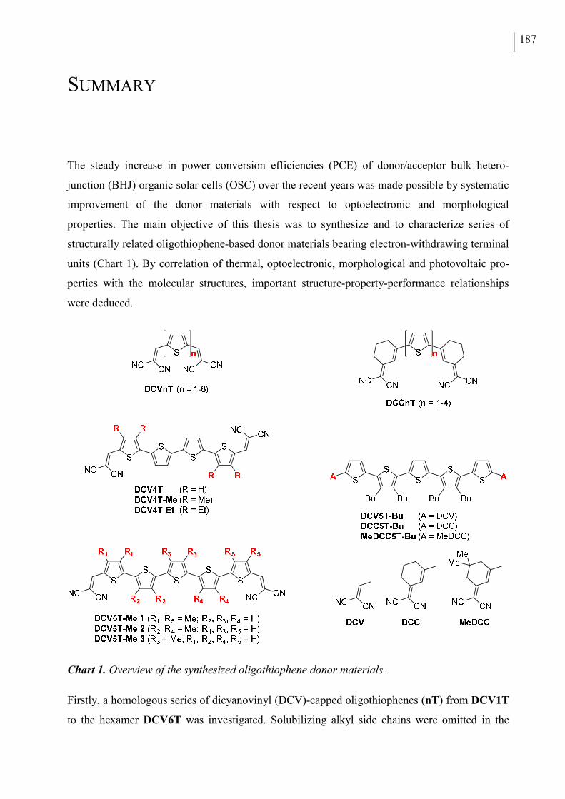
187
SUMMARY
The steady increase in power conversion efficiencies (PCE) of donor/acceptor bulk hetero-
junction (BHJ) organic solar cells (OSC) over the recent years was made possible by systematic
improvement of the donor materials with respect to optoelectronic and morphological
properties. The main objective of this thesis was to synthesize and to characterize series of
structurally related oligothiophene-based donor materials bearing electron-withdrawing terminal
units (Chart 1). By correlation of thermal, optoelectronic, morphological and photovoltaic pro-
perties with the molecular structures, important structure-property-performance relationships
were deduced.
Chart 1. Overview of the synthesized oligothiophene donor materials.
Firstly, a homologous series of dicyanovinyl (DCV)-capped oligothiophenes (nT) from DCV1T
to the hexamer DCV6T was investigated. Solubilizing alkyl side chains were omitted in the
188
molecular structures to improve thermal properties for vacuum-processing and to facilitate
efficient molecular packing in the bulk. The longer poorly soluble oligothiophene target
structures were prepared by palladium-catalyzed cross-coupling of halogenated terminal units
with stannylated central building blocks. Final purification was accomplished by extractive
recrystallization and thermal gradient sublimation. The extension of the conjugated π-system,
going from DCV1T to DCV6T resulted in a reduction of the optical and electrochemical
bandgaps, caused by increasing HOMO energy levels. Planar heterojunction (PHJ) solar cells
fabricated for DCV4T, DCV5T and DCV6T showed PCE values of up to 2.8%. A record
efficiency of 5.2% was achieved using DCV5T in an optimized device setup with a BHJ active
layer.
In the second project, a correlation between single crystal X-ray structure analysis data and
photovoltaic performance was established in a series of DCV-capped quaterthiophenes
(DCV4Ts) with systematic variation of the substituents on the terminal thiophene units from
hydrogen to methyl and ethyl. Best-performing methyl-substituted tetramer DCV4T-Me (PCE =
3.8%) exhibited the highest number of non-bonding short intermolecular contacts within the
series, leading to a perfect coplanar layer structure with strong π–π interactions.
Next, a series of methylated quinquethiophene donor materials DCV5T-Me 1-3 with different
alkyl substitution patterns along the oligothiophene backbone was synthesized by Stille-type
cross-coupling of methyl substituted building blocks. Centrally methylated DCV5T-Me 3
yielded a superior efficiency of 6.1% in vacuum-processed BHJ solar cells compared to 4.8%
for the other two oligomers. By optimization of the processing conditions and the device stack, a
record PCE value of 6.9% was achieved for DCV5T-Me 3. X-ray diffraction measurements
performed on co-evaporated blend layers of all three derivatives with the fullerene C60 acceptor
material showed the highest crystallinity of donor and acceptor phases for the best-performing
oligomer DCV5T-Me 3, thus rationalizing the improved photovoltaic performance.
The following chapter introduces the dicyanomethylenecyclohexene (DCC) terminal group as a
structural variation of the DCV unit comprising an additional double bond conformationally
locked in a cyclohexene ring. The comparison of a series of alkyl-free DCCnTs up to the
tetramer to the previously investigated DCVnTs revealed very similar optical properties and
frontier orbital energies for oligomers with equal numbers of double bonds, i.e. DCCnTs and
DCV(n+1)Ts. In both oligothiophene series, derivatives with even numbers of thiophene units
showed higher melting points and lower solubilities compared to odd-numbered oligomers
which was assigned to the different molecular symmetries. The single crystal structure obtained
for methylated DCC3T-Me displayed remarkable similarities to the molecular packing of
Summary 189
structurally related DCV-capped pentamer DCV5T-Me. In PHJ solar cells, DCC3T-Me showed
a higher fill factor and an increased efficiency of 3.4% compared to 3.0% for alkyl-free
DCC3T. Due to an improved short circuit current density (JSC), a BHJ device incorporating a
DCC3T-Me:C60 active layer displayed a PCE value of 4.4% surpassing the photovoltaic
performance of the best DCV-capped quaterthiophene donor material DCV4T-Me, which
showed similar frontier orbital energies.
Finally, a series of soluble butylated quinquethiophene compounds was investigated. Two novel
oligomers bearing DCC and methylated MeDCC terminal units were synthesized and compared
to the well-studied DCV-capped derivative DCV5T-Bu. In solution all three compounds
showed very similar optical properties as the introduction of the additional cyclohexene double
bonds caused an almost identical elevation of HOMO and LUMO levels. Absorption profiles of
spin-cast thin films were less red-shifted relative to solution measurements for DCC5T-Bu and
MeDCC5T-Bu compared to DCV5T-Bu which was ascribed to reduced molecular ordering in
the bulk. The first solution-processed BHJ solar cells using [6,6]-phenyl C61 butyric acid methyl
ester (PC61BM) as the acceptor material displayed rather low PCE values of 1.4% and 1.3% for
DCC5T-Bu and MeDCC5T-Bu, respectively. In the case of DCC5T-Bu, the use of
diiodooctane (DIO) as solvent additive during processing significantly improved the device
efficiency to 3.4%. This improvement was due to enhanced JSC values caused by the appearance
of a photoactive low-energy shoulder in the blend film absorption spectra. Atomic force
microscopy experiments indicated a favorable phase separation for the DCC5T-Bu blend layer
processed under optimized conditions, whereas the MeDCC5T-Bu:PC61BM film showed a
much finer intermixing.
In summary, an efficient protocol for the synthesis of low soluble dicyanovinyl-capped
oligothiophenes for application as donor materials in vacuum-processed organic solar cells has
been elaborated. By correlation of thermal, optoelectronic and morphological behaviour with
molecular structure and photovoltaic properties important structure-property-performance re-
lationships were deduced for different series of oligomers with variation of conjugated chain
legth and alkyl substitution pattern. The introduction of methylated thiophene units to the
oligomer backbone was identified as an effective means to improve the solid state morphology
of the photoactive layer in the solar cell device stack.


Zusammenfassung 191
ZUSAMMENFASSUNG
Die stetige Steigerung des Wirkungsgrads der Energieumwandlung (PCE, power conversion
efficiency) von organischen Solarzellen mit Donor/Akzeptor Mischheteroübergang (BHJ, bulk
heterojunction) im Laufe der letzten Jahre wurde durch systematische Weiterentwicklung der
Donormaterialien im Hinblick auf optoelektronische und morphologische Eigenschaften
ermöglicht. Das zentrale Ziel der vorliegenden Arbeit war die Synthese und Charakterisierung
von Serien strukturverwandter Oligothiophen-basierter Donormaterialien mit elektronen-
ziehenden terminalen Einheiten (Schema 1). Durch Korrelation von thermischen, optoelek-
tronischen, morphologischen und photovoltaischen Eigenschaften mit den Molekülstrukturen
konnten wichtige Struktur-Eigenschafts-Leistungsfähigkeits-Beziehungen abgeleitet werden.
Schema 1. Übersicht der synthetisierten Oligothiophen-Donormaterialien.
Zunächst wurde eine homologe Serie Dicyanovinyl (DCV)-substituierter Oligothiophene (nT)
von DCV1T bis zum Hexamer DCV6T untersucht. Dabei wurde auf löslichkeitsvermittelnde
192
Alkylseitenketten verzichtet, um die thermischen Eigenschaften für die Vakuumprozessierung
zu verbessern und um eine effiziente Molekülpackung im Festkörper ermöglichen. Die längeren
schwerlöslichen Oligothiophen-Zielverbindungen wurden durch Palladium-katalysierte
Kreuzkupplung halogenierter Außen- mit stannylierten Mittelbausteinen hergestellt. Die finale
Aufreinigung wurde durch extraktive Umkristallisation und thermische Gradientensublimation
erreicht. Die Verlängerung des konjugierten π-Systems, ausgehend vom DCV1T zum DCV6T
resultierte in einer Reduktion der optischen und elektrochemischen Bandlücken, bedingt durch
ansteigende HOMO-Energieniveaus. Solarzellen mit flachem Heteroübergang (PHJ, planar
heterojunction), die für DCV4T, DCV5T und DCV6T hergestellt wurden, wiesen
Wirkungsgrade von bis zu 2.8% auf. Unter Verwendung eines optimierten Zellaufbaus mit BHJ-
Aktivschicht wurde eine Rekordeffizienz von 5.2% erreicht.
Im zweiten Projekt wurde eine Serie DCV-substituierter Quaterthiophene (DCV4Ts), bei der
die Substituenten an den terminalen Thiopheneinheiten systematisch von Wasserstoff über
Methyl zu Ethyl variiert wurden, untersucht und ein Zusammenhang zwischen Einkristall-
Röntgenstrukturanalysedaten und photovoltaischer Leistungsfähigkeit hergestellt. Das leistungs-
fähigste methylsubstituierte Tetramer DCV4T-Me (PCE = 3.8%) wies innerhalb der Serie die
größte Anzahl nichtbindender intermolekularer Kontakte auf, was zu einer perfekten koplanaren
Schichtstruktur mit starken π-π-Wechselwirkungen führte.
Als Nächstes wurde eine Serie methylierter Quinquethiophen-Donormaterialien DCV5T-Me 1-
3 mit verschiedenen Alkylsubstitutionsmustern entlang des Oligothiophenrückgrats durch Stille-
Kreuzkupplung methylsubstituierter Bausteine synthetisiert. Das zentral methylierte DCV5T-
Me 3 zeigte in vakuumprozessierten BHJ Solarzellen eine überlegene Effizienz von 6.1%,
verglichen mit 4.8% für die beiden anderen Oligomere. Durch Optimierung der Prozessierungs-
bedingungen und des Zellaufbaus wurde ein PCE-Rekordwert von 6.9% für DCV5T-Me 3
erreicht. Röntgenbeugungsmessungen, die an koevaporierten Mischschichten aller drei Derivate
mit dem Akzeptormaterial Fulleren C60 durchgeführt wurden, zeigten die höchste Kristallinität
von Donor- und Akzeptor-Phasen für das leistungsfähigste Oligomer DCV5T-Me 3 und
lieferten somit eine Erklärung für die verbesserte photovoltaische Leistungsfähigkeit.
Im folgenden Kapitel wird die Dicyanomethylencyclohexen (DCC)-Endgruppe als strukturelle
Variation der DCV-Einheit mit einer zusätzlichen Doppelbindung, die im Cyclohexenring
konformativ fixiert ist, vorgestellt. Der Vergleich einer Serie alkylfreier DCCnTs bis zur
Tetramerverbindung mit den vorher untersuchten DCVnTs zeigt sehr ähnliche optische
Eigenschaften und Grenzorbitalenergien für Oligomere mit gleicher Anzahl an
Doppelbindungen, also für DCCnTs und DCV(n+1)Ts. In beiden Oligomerserien weisen die
Zusammenfassung 193
Derivate mit gerader Anzahl an Thiophen-Einheiten im Vergleich zu den ungeradzahligen
Oligomeren höhere Schmelzpunkte und geringere Löslichkeiten auf, was auf die
unterschiedlichen Molekülsymmetrien zurückgeführt wurde. Die Einkristallstruktur, die das
methylierte DCC3T-Me erhalten wurde, zeigte bemerkenswerte Ähnlichkeiten zu der
Molekülpackung des strukturverwandten DCV-substituierten Pentamers DCV5T-Me. In PHJ-
Solarzellen wies DCC3T-Me einen höheren Füllfaktor und eine erhöhte Effizienz von 3.4% auf,
verglichen mit 3.0% für das alkylfreie DCC3T. Aufgrund einer verbesserten Kurzschluss-
stromdichte (JSC) lieferte eine BHJ-Zelle mit DCC3T-Me:C60-Aktivschicht einen PCE-Wert
von 4.4%, was die photovoltaische Leistungsfähigkeit des besten DCV-substituierten Quater-
thiophen-Donormaterials DCV4T-Me überstieg, für das ähnliche Grenzorbitalenergien
bestimmt wurden.
Schließlich wurde eine Serie löslicher butylierter Quinquethiophene untersucht. Zwei neue
Oligomere mit terminalen DCC- und methylierten MeDCC-Einheiten wurden synthetisiert und
mit dem gut erforschten DCV-substituierten Derivat DCV5T-Bu verglichen. In Lösung zeigten
alle drei Verbindungen sehr ähnliche optische Eigenschaften, da die Einführung der zusätzlichen
Cyclohexen-Doppelbindungen zu fast gleichen Anhebungen von HOMO- und LUMO-Niveaus
führten. Die Absorptionsprofile schleuderbeschichteter Dünnfilme von DCC5T-Bu und
MeDCC5T-Bu waren verglichen zu DCV5T-Bu gegenüber den Lösungs-Messungen weniger
rotverschoben, was einer geringeren Ordnung der molekularen Packung im Festkörper
zugeschrieben wurde. Die ersten lösungsprozessierten BHJ-Solarzellen mit [6,6]-Phenyl-C61-
buttersäuremethylester (PC61BM) als Akzeptormaterial zeigten eher geringe PCE-Werte von
1.4% und 1.3% für DCC5T-Bu bzw. MeDCC5T-Bu. Im Falle von DCC5T-Bu wurde die
Zelleffizienz durch Verwendung von Diiodoktan (DIO) als Lösungsmitteladditiv während der
Prozessierung wesentlich auf 3.4% erhöht. Diese Verbesserung war auf eine Erhöhung des JSC-
Wertes zurückzuführen, die durch das Auftreten einer photoaktiven niederenergetischen
Schulter im Mischschicht-Absorptionsspektrum verursacht wurde. Rasterkraftmikroskop
(AFM)-Experimente deuteten auf eine günstige Phasentrennung bei der unter optimierten
Bedingungen prozessierten DCC5T-Bu-Mischschicht hin, während der MeDCC5T-
Bu:PC61BM-Film eine viel feinere Durchmischung aufwies.
Zusammenfassend wurde ein effizientes Syntheseprotokoll zur Darstellung von schwerlöslichen
Dicyanovinyl-substituierten Oligothiophenen für die Anwendung als Donormaterialien in
vakuumprozessierten organischen Solarzellen entwickelt. Durch die Korrelation von
thermischem, optoelektronischem und morphologischem Verhalten mit der Molekülstruktur und
den photovoltaischen Eigenschaften wurden für verschiedene Oligomer-Serien, bei denen die

194
konjugierte Kettenlänge und das Alkyl-Substitutionsmuster variiert wurde, wichtige Struktur-
Eigenschafts-Leistungsfähigkeits-Beziehungen abgeleitet. Das Einführen von methylierten
Thiopheneinheiten in das Oligomer-Rückgrat wurde als effektives Mittel zur Verbesserung der
Festkörper-Morphologie der photoaktiven Schicht in der Solarzelle identifiziert.
195
PUBLICATIONS AND PRESENTATIONS
REFEREED PUBLICATIONS
R. Fitzner, E. Mena-Osteritz, K. Walzer, M. Pfeiffer, P. Bäuerle “A-D-A-Type Oligothiophenes for Small Molecule Organic Solar Cells: Extending the π-System by Introduction of Ring-Locked Double Bonds” Adv. Funct. Mater. 2015, 25, 1845-1856. Z. Yang, M. Corso, R. Robles, C. Lotze, R. Fitzner, E. Mena-Osteritz, P. Bäuerle, K. J. Franke, J. I. Pascual “Orbital Redistribution in Molecular Nanostructures Mediated by Metal-Organic Bonds” ACS Nano 2014, 8, 10715-10722. C. Koerner, M. P. Hein, V. Kažukauskas, A. Sakavičius, V. Janonis, R. Fitzner, P. Bäuerle, K. Leo, M. Riede “Correlation between Temperature Activation of Charge-Carrier Generation Efficiency and Hole Mobility in Small-Molecule Donor Materials” ChemPhysChem 2014, 15, 1049-1055. G. L. Schulz, M. Urdanpilleta, R. Fitzner, E. Brier, E. Mena-Osteritz, E. Reinold, P. Bäuerle “Optimization of solution-processed oligothiophene:fullerene based organic solar cells by using solvent additives” Beilstein J. Nanotechnol. 2013, 4, 680–689. C. Elschner, M. Schrader, R. Fitzner, A. A. Levin, P. Bäuerle, D. Andrienko, K. Leo, M. Riede “Molecular Ordering and Charge Transport in a Dicyanovinyl-substituted Quaterthiophene Thin Film” RSC Adv. 2013, 3, 12117-12123. C. Koerner, H. Ziehlke, R. Gresser, R. Fitzner, E. Reinold, P. Bäuerle, K. Leo, M. Riede ”Temperature Activation of the Photoinduced Charge Carrier Generation Efficiency in Quaterthiophene:C60 Mixed Films” J. Phys. Chem. C 2012, 116, 25097-25105. R. Fitzner, E. Mena-Osteritz, A. Mishra, G. Schulz, E. Reinold, M. Weil, C. Körner, H. Ziehlke, C. Elschner, K. Leo, M. Riede, M. Pfeiffer, C. Uhrich, P. Bäuerle “Correlation of π-Conjugated Oligomer Structure with Film Morphology and Organic Solar Cell Performance“ J. Am. Chem. Soc. 2012, 134, 11064-11067. M. Schrader, R. Fitzner, M. Hein, C. Elschner, B. Baumeier, K. Leo, M. Riede, P. Bäuerle, D. Andrienko “Comparative study of microscopic charge dynamics in crystalline acceptor-substituted oligothiophenes” J. Am. Chem. Soc. 2012, 134, 6052-6056.
196
R. Fitzner, C. Elschner, M. Weil, C. Uhrich, C. Körner, M. Riede, K. Leo, M. Pfeiffer, E. Reinold, E. Mena-Osteritz, P. Bäuerle “Interrelation between Crystal Packing and Small-Molecule Organic Solar Cell Performance“ Adv. Mater. 2012, 24, 675-680. C. Körner, C. Elschner, N. C. Miller, R. Fitzner, F. Selzer, E. Reinold, P. Bäuerle, M. F. Toney, M. D. McGehee, K. Leo, M. Riede “Probing the effect of substrate heating during deposition of DCV4T:C60 blend layers for organic solar cells” Org. Electron. 2012, 13, 623-631. H. Ziehlke, L. Burtone, C. Körner, R. Fitzner, E. Reinold, P. Bäuerle, K. Leo, M. Riede “Increase of charge carrier lifetime in dicyanovinyl-quinquethiophene:fullerene blends upon deposition on heated substrates” Org. Electron. 2011, 12, 2258-2267. H. Ziehlke, R. Fitzner, C. Körner, R. Gresser, E. Reinold, P. Bäuerle, K. Leo, M. K. Riede “Side Chain Variations on a Series of Dicyanovinyl-Terthiophenes: A Photoinduced Absorption Study” J. Phys. Chem. A 2011, 115, 8437-8446. R. Fitzner, E. Reinold, A. Mishra, E. Mena-Osteritz, H. Ziehlke, C. Körner, K. Leo, M. K. Riede, M. Weil, O. Tsaryova, A. Weiß, C. Uhrich, M. Pfeiffer, P. Bäuerle “Dicyanovinyl-Substituted Oligothiophenes: Structure-Property Relationships and Application in Vacuum-Processed Small-Molecule Organic Solar Cells” Adv. Funct. Mater. 2011, 21, 897-910. S. Götze, R. Fitzner, H. Kunz “Gold Catalysis in Glycosylation Reactions” Synlett 2009, 20, 3346-3348.
SELECTED PRESENTATIONS
BMBF-i Final Meeting, Ulm, Germany, June 3rd-4th 2013. Oral Presentation: “Small Molecule Organic Solar Cells: Tailoring Materials for a Future Technology” Organic Chemistry Seminar Program at the Bio21 Institute, University of Melbourne, Australia, March 30th 2012. Oral Presentation: “Dicyanovinyl-Capped Oligothiophene Donor Materials for Small Molecule Organic Solar cells” ISEOFM2012, Shanghai, China, March 11th-13th 2012. Poster presentation. DFG SPP1355 Summer School, Veitshöchheim, Germany, June 20th-24th 2011. Poster presentation.

197
Fπ9, Atlanta, Georgia, USA, May 23rd-28th 2010. Poster presentation. DFG SPP1355 Spring School, Krippen, Germany, February 28th-March 3rd 2010. Poster presentation. KOPO2009, Blaubeuren, Germany, September 13th-16th 2009. Poster presentation. ISNA13, Luxembourg, July 19th-24th 2009. Poster presentation.

199
Parts of this dissertation are already published in:
R. Fitzner, E. Mena-Osteritz, K. Walzer, M. Pfeiffer, P. Bäuerle “A-D-A-Type Oligothiophenes for Small Molecule Organic Solar Cells: Extending the π-System by Introduction of Ring-Locked Double Bonds” Adv. Funct. Mater. 2015, 25, 1845-1856. DOI: 10.1002/adfm.201404210. www.onlinelibrary.wiley.com/doi/10.1002/adfm.201404210/abstract Copyright © 2015 WILEY-VCH Verlag GmbH & Co. KGaA, Weinheim. R. Fitzner, E. Mena-Osteritz, A. Mishra, G. Schulz, E. Reinold, M. Weil, C. Körner, H. Ziehlke, C. Elschner, K. Leo, M. Riede, M. Pfeiffer, C. Uhrich, P. Bäuerle “Correlation of π-Conjugated Oligomer Structure with Film Morphology and Organic Solar Cell Performance“ J. Am. Chem. Soc. 2012, 134, 11064-11067. DOI: 10.1021/ja302320c. www.pubs.acs.org/doi/abs/10.1021/ja302320c Copyright © 2012 American Chemical Society. R. Fitzner, C. Elschner, M. Weil, C. Uhrich, C. Körner, M. Riede, K. Leo, M. Pfeiffer, E. Reinold, E. Mena-Osteritz, P. Bäuerle “Interrelation between Crystal Packing and Small-Molecule Organic Solar Cell Performance“ Adv. Mater. 2012, 24, 675-680. DOI: 10.1002/adma.201104439. www.onlinelibrary.wiley.com/doi/10.1002/adma.201104439/abstract Copyright © 2012 WILEY-VCH Verlag GmbH & Co. KGaA, Weinheim. R. Fitzner, E. Reinold, A. Mishra, E. Mena-Osteritz, H. Ziehlke, C. Körner, K. Leo, M. K. Riede, M. Weil, O. Tsaryova, A. Weiß, C. Uhrich, M. Pfeiffer, P. Bäuerle “Dicyanovinyl-Substituted Oligothiophenes: Structure-Property Relationships and Application in Vacuum-Processed Small-Molecule Organic Solar Cells” Adv. Funct. Mater. 2011, 21, 897-910. DOI: 10.1002/adfm.201001639. www. onlinelibrary.wiley.com/doi/10.1002/adfm.201001639/abstract Copyright © 2011 WILEY-VCH Verlag GmbH & Co. KGaA, Weinheim.
200
CURRICULUM VITAE
Name Roland Fitzner
Date of birth 6th November 1983
Place of birth Ludwigshafen am Rhein, Germany
Citizenship German
Email [email protected]
since Oct 2013 Research scientist, Heliatek GmbH, Ulm, Germany.
Apr 2009 – Sep 2013
Postgraduate studies in the group of Prof. Peter Bäuerle, Institute of Organic Chemistry II and Advanced Materials, University of Ulm, Germany; Thesis topic: Functionalized Oligothiophenes for Application in Organic Solar Cells.
Mar 2012 – Apr 2012
Reaserch internship in the group of Prof. Andrew Holmes, Bio21 Institute, University of Melbourne, Australia.
Oct 2001 – Oct 2008
Studies of Chemistry, Johannes-Gutenberg-University, Mainz, Germany; Degree: Diploma (overall grade: 1.0).
Jan 2008 – Oct 2008
Diploma student in the group of Prof. Horst Kunz, Institute of Organic Chemistry, Johannes Gutenberg-University, Mainz, Germany; Thesis topic: Gold-catalyzed Glycosylations.
Oct 2005 – Mar 2006
Visiting student (ERASMUS program of the EU) in the group of Prof. Gérard Rousseau, Institute of Molecular Chemistry, University of Paris-Sud, France; Topic: Synthesis of Silapicenadol.
Sep 1992 – Jun 2001
Carl-Bosch-Gymnasium, Ludwigshafen am Rhein, Germany; Degree: Abitur (overall grade: 1.4).