gator 46632V001-022006-0-OCE Rev GB - Eurogate 2000 Report wurde mit Hilfe der Adobe Acrobat...
28
gator 400 Installation and Operating Instructions 1 - 31 46632V001-022006-0-OCE-Rev.
Transcript of gator 46632V001-022006-0-OCE Rev GB - Eurogate 2000 Report wurde mit Hilfe der Adobe Acrobat...
�gator 400
� Installation and Operating Instructions 1 - 31
46632V001-022006-0-OCE-Rev.
Verwendete Distiller Joboptions
Dieser Report wurde mit Hilfe der Adobe Acrobat Distiller Erweiterung "Distiller Secrets v3.0.2" der IMPRESSED GmbH erstellt.Registrierte Kunden können diese Startup-Datei für die Distiller Versionen 7.0.x kostenlos unter http://www.impressed.de/DistillerSecrets herunterladen.ALLGEMEIN ----------------------------------------Beschreibung: INTERNET: Erzeugt PDF-Dateien für Internet. Qualität: 72/300 dpi, JPEG Minimal. Die Farben werden in sRGB konvertiert! Font-Untergruppen unter 35%. Preflight: bei fehlenden Schriften wird die Konvertierung abgebrochen. Achtung: kann nur mit Distiller 7.x Professional eingesetzt werden! (050228/StJ. Benutzung auf eigenes Risiko. Weitere Informationen: www.prepress.ch)Dateioptionen: Kompatibilität: PDF 1.3 Komprimierung auf Objektebene: Aus Seiten automatisch drehen: Aus Bund: Links Auflösung: 2400 dpi Alle Seiten Piktogramme einbetten: Nein Für schnelle Web-Anzeige optimieren: JaPapierformat: Breite: 208.347 Höhe: 294.661 mmKOMPRIMIERUNG ------------------------------------Farbbilder: Neuberechnung: Bikubische Neuberechnung auf 72 ppi (Pixel pro Zoll) für Auflösung über 94 ppi (Pixel pro Zoll) Komprimierung: Automatisch (JPEG) Bildqualität: MinimalGraustufenbilder: Neuberechnung: Bikubische Neuberechnung auf 72 ppi (Pixel pro Zoll) für Auflösung über 94 ppi (Pixel pro Zoll) Komprimierung: Automatisch (JPEG) Bildqualität: MinimalSchwarzweißbilder: Neuberechnung: Bikubische Neuberechnung auf 300 ppi (Pixel pro Zoll) für Auflösung über 399 ppi (Pixel pro Zoll) Komprimierung: CCITT Gruppe 4 Mit Graustufen glätten: AusRichtlinien: Richtlinien für Farbbilder Bei Bildauflösung unter: 72 ppi (Pixel pro Zoll) Warnen und weiter Richtlinien für Graustufenbilder Bei Bildauflösung unter: 72 ppi (Pixel pro Zoll) Warnen und weiter Richtlinen für monochrome Bilder Bei Bildauflösung unter: 200 ppi (Pixel pro Zoll) Warnen und weiterFONTS --------------------------------------------Alle Schriften einbetten: JaUntergruppen aller eingebetteten Schriften: JaUntergruppen, wenn benutzte Zeichen kleiner als: 35 %Wenn Einbetten fehlschlägt: AbbrechenEinbetten: Schrift immer einbetten: [ ] Schrift nie einbetten: [ ]FARBE --------------------------------------------Farbmanagement: Einstellungsdatei: Farbmanagement: Alle Farben in sRGB konvertieren Wiedergabemethode: StandardArbeitsfarbräume: Graustufen Arbeitsfarbraum: RGB Arbeitsfarbraum: sRGB IEC61966-2.1 CMYK Arbeitsfarbraum: Europe ISO Coated FOGRA27Geräteabhängige Daten: Unterfarbreduktion und Schwarzaufbau beibehalten: Nein Transferfunktionen: Anwenden Rastereinstellungen beibehalten: NeinERWEITERT ----------------------------------------Optionen: Überschreiben der Adobe PDF-Einstellungen durch PostScript zulassen: Nein PostScript XObjects zulassen: Nein Farbverläufe in Smooth Shades konvertieren: Ja Geglättene Linien in Kurven konvertieren: Ja (Grenzwert für Glättung: 0.1) Level 2 copypage-Semantik beibehalten: Nein Einstellungen für Überdrucken beibehalten: Ja Überdruckstandard ist nicht Null: Ja Adobe PDF-Einstellungen in PDF-Datei speichern: Ja Ursprüngliche JPEG-Bilder wenn möglich in PDF speichern: Nein Portable Job Ticket in PDF-Datei speichern: Nein Prologue.ps und Epilogue.ps verwenden: Nein JDF-Datei (Job Definition Format) erstellen: Nein(DSC) Document Structuring Conventions: DSC-Kommentare verarbeiten: Ja DSC-Warnungen protokollieren: Nein EPS-Info von DSC beibehalten: Ja OPI-Kommentare beibehalten: Nein Dokumentinfo von DSC beibehalten: Ja Für EPS-Dateien Seitengröße ändern und Grafiken zentrieren: JaPDF/X --------------------------------------------Standards - Berichterstellung und Kompatibilität: Kompatibilitätsstandard: NeinANDERE -------------------------------------------Distiller-Kern Version: 7050ZIP-Komprimierung verwenden: JaASCII-Format: NeinText und Vektorgrafiken komprimieren: JaMinimale Bittiefe für Farbbild Downsampling: 1Minimale Bittiefe für Graustufenbild Downsampling: 2Farbbilder glätten: NeinGraustufenbilder glätten: NeinFarbbilder beschneiden: JaGraustufenbilder beschneiden: JaSchwarzweißbilder beschneiden: JaBilder (< 257 Farben) in indizierten Farbraum konvertieren: JaBildspeicher: 1048576 ByteOptimierungen deaktivieren: 0Transparenz zulassen: NeinICC-Profil Kommentare parsen: JasRGB Arbeitsfarbraum: sRGB IEC61966-2.1DSC-Berichtstufe: 0Flatness-Werte beibehalten: JaGrenzwert für künstlichen Halbfettstil: 1.0ENDE DES REPORTS ---------------------------------IMPRESSED GmbHBahrenfelder Chaussee 4922761 Hamburg, GermanyTel. +49 40 897189-0Fax +49 40 897189-71Email: [email protected]: www.impressed.de
Contents
1
General Tips . . . . . . . . . . . . . . . . . . . . . . . . . . . . . . . . . . . . 2
Symbols 2
Safety Instructions 2
Operation 2
Permitted Gate Dimensions 3
Technical Data 3
Dimensions 3
EU Manufacturer’s Declaration 3
Preparations of Installation . . . . . . . . . . . . . . . . . . . . . . . 4
Safety Instructions 4
Tools 4
Personal protective equipment 4
Scope of Delivery 4
Installation Tips 5
General Preparation 5
Installation . . . . . . . . . . . . . . . . . . . . . . . . . . . . . . . . . . . . . 6
Safety Instructions 6
Location of Installation 6
Foundation 6
Installation to Ground 7
Mounting of rack 8
Positioning of Stops 9
Connection to power supply 10
Commissioning . . . . . . . . . . . . . . . . . . . . . . . . . . . . . . . . 11
Safety Instructions 11
Operation . . . . . . . . . . . . . . . . . . . . . . . . . . . . . . . . . . . . . 13
Safety Instructions 13
Opening the Gate 13
Closing of Gate 13
Pulse Sequence of Door Movement 13
Reset of Control System 13
Emergency Release 14
Intermediate Stop 14
Stop forced by Obstacle 14
Functions and Connections . . . . . . . . . . . . . . . . . . . . . . 15
General Tips 15
Overview of Control System 15
DIP Switches 1 - 8 15
Radio Receiver 16
Obstacle Detection (DIP 1, 2 + 3) 17
Automatic Close Mode 17
Warning Time (DIP 5) 18
Fraba System (DIP 6) 18
Separate Signals for Closing and Opening (DIP Switch 7) 18
Partial Opening (DIP 8) 18
Terminal bar with 24 slots 19
Connection to Power Supply 19
Connection of Push-Buttons 19
Connection of Light Barrier 19
Connection of Safety contact strip 20
24 V Connection 20
Connection of Warning Lamps 20
12 V Connection 20
Connection of External Antenna 20
Accessories . . . . . . . . . . . . . . . . . . . . . . . . . . . . . . . . . . . 22
Maintenance and Servicing . . . . . . . . . . . . . . . . . . . . . . 24
Important Information 24
Regular Inspection 24
Replacement of Fuses 25
Additional Information . . . . . . . . . . . . . . . . . . . . . . . . . . 25
Disassembly 25
Disposal 25
Warranty and After-Sales Service 25
Additional Tips for Troubleshooting 26
Troubleshooting . . . . . . . . . . . . . . . . . . . . . . . . . . . . . . . 26
Spare Parts List . . . . . . . . . . . . . . . . . . . . . . . . . . . . . . . . 29
Glossary 31
2
SymbolsWarning symbol: Indicates a potential risk. Failure to follow instructions mayresult in serious injury!
Note symbol:Information, useful advice.
Refers to the relevant illustration in the document.
Safety Instructions
General• These Installation and Operating Instructions must be read, understood
and observed by all persons installing, operating or maintaining the drivemechanism.
• Installation, connection and commissioning of the drive mechanism mayonly be carried out by qualified specialists.
• The drive system may only be mounted onto properly aligned gates. Ifinstalled in incorrectly aligned gates, there is a risk of serious injury ordamage to the drive system.
• The manufacturer shall not be liable for damages or disruptions due tonon-compliance with the Installation and Operating Instructions.
• Keep this installation and operating manual near the unit for future refer-ence.
• Observe and comply with the locally applicable accident prevention regu-lations and EU standards.
• Observe and comply with the directive on “Power-driven Windows, Doorsand Gates - BGR 232” issued by the Employers’ Liability InsuranceAssociation (mandatory for operator in Germany).
• Prior to carrying out any work on the drive system, disconnect it from thepower supply and secure it against inadvertent switching on.
• Only use the manufacturer’s original spare parts, accessories and fixingmaterial.
Storage• The drive mechanism may only be stored indoors, in a dry environment
at an ambient temperature of between -20°C and +50°C.
• Store drive system as shown below.
Operation• The drive mechanism may only be operated if a risk-free force tolerance
has been set. The force tolerance must be set as low as is required toensure that the gate’s closing force does not constitute a risk (see sec-tion “Force settings”).
• Keep your hands clear of the moving gate or any other moving parts.
• Keep children, disabled persons and animals away from the gate.
• Only drive through the gate when it is fully opened.
• There is a risk of injury from being trapped or cut on the gate system’smoving parts or edges.
(1)1
for Radio Remote Control• The radio remote control may only be used for equipment and systems in
which defective remote operation of the transmitter or receiver does notconstitute a risk to people, animals or property, or in cases where this riskis eliminated by means of additional safety facilities.
• The user must be made aware of the fact that the remote control ofequipment with accident risk potential may only occur, if at all, when theequipment concerned is clearly visible.
• Radio remote control may only be used if movement of the gate can besupervised and there are no persons or objects in the area of movement.
• Store the hand-held transmitter in such a way that there is no risk of itbeing accidentally operated by, for instance, children or animals.
• The operator of this radio-controlled equipment is not in any way protect-ed against interference from other telecommunication systems and facili-ties (e.g. other radio-controlled equipment that is licensed to operate atthe same frequency range). Should serious interference be encountered,please contact your nearest telecommunications office with interferencemeasuring facilities (radio signal localisation)!
• Do not use hand-held transmitters near locations or installations that aresusceptible to radio interference (e.g. airports, hospitals).
Rating PlateThe type plate is attached to the inside of the unit at the base support/housing.
Exact type designation and date of manufacture (month/year) of the driveare to be found on the rating plate.
Normal Use• The drive is designed for the exclusive purpose of opening and closing
sliding gates (according to EN 12433-1), hereafter referred to as gates.Any other use does not constitute normal use. The manufacturer acceptsno liability for damage resulting from use other than normal use. Theuser accepts sole responsibility for any risks thereby incurred. Improperuse shall void all warranty.
• Gates operated automatically with a drive must comply with the applica-ble standards and directives as amended: e.g. EN 12604, EN 12605.
• Maintain the safety distances between the gate wing and any nearbyobject required by EN 12 604.
• The drive mechanism may only be used, if in a technically perfect condi-tion, and in compliance with these Installation and Operating Instructions,particularly regarding correct and responsible use.
• The gate may not be installed at a slope.
• The runner rail must be installed in such a way that water can drain off inorder to prevent the formation of ice in winter.
• Ensure that the gate is sliding smoothly on the rail. Otherwise, thesensors of the drive system may not detect obstacles and might fail tohalt the gate.
• The gate must be equipped with stops at both the open and closedposition, as it might otherwise be dislocated from the rail in the event ofan emergency release.
• Any defects that may impair the safe operation of the equipment shouldbe eliminated without delay.
• The gate wings must be stable and warp-proof, i.e. they should not bendor warp during opening or closing operations.
• The drive mechanism is unable to compensate for any defects in the gateor incorrect installation.
• Do not operate the drive in areas where there is a risk of explosion.
• Do not operate the drive in rooms where the air contains aggressivegases.
General Tips
General Tips
3
Permitted Gate Dimensions- Max. travel: max. 6000 mm
- Weight: max. 400 kg
- Slope: 0 %
Technical DataRated voltage: 220 - 240 AC/V
Rated frequency: 50/60 Hz
Operating temp. range: -20 - +50 °C
Protection class: IP 34
Max. traction force and pressure: 800 N
Rated traction: 240 N
Rated current consumption: 0,65 A
Rated power consumption: 120 W
Max. speed: 200 mm/s
Rated consumption in standby: ~ 2 W
Weight: 6 kg
Operating factor: 40 %
Workplace noise emission < 75 dBA - drive only
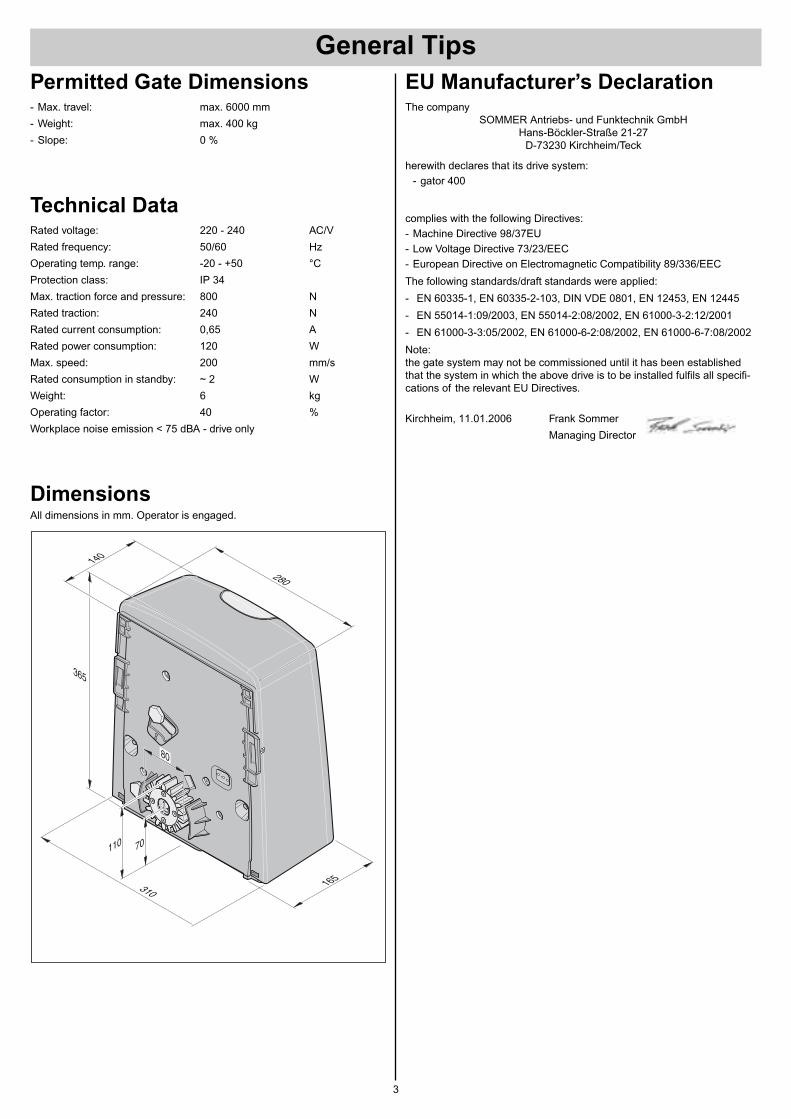
DimensionsAll dimensions in mm. Operator is engaged.
280
70110
365
310165
140
80
EU Manufacturer’s DeclarationThe company
SOMMER Antriebs- und Funktechnik GmbHHans-Böckler-Straße 21-27
D-73230 Kirchheim/Teck
herewith declares that its drive system:
- gator 400
complies with the following Directives:
- Machine Directive 98/37EU
- Low Voltage Directive 73/23/EEC
- European Directive on Electromagnetic Compatibility 89/336/EEC
The following standards/draft standards were applied:
- EN 60335-1, EN 60335-2-103, DIN VDE 0801, EN 12453, EN 12445
- EN 55014-1:09/2003, EN 55014-2:08/2002, EN 61000-3-2:12/2001
- EN 61000-3-3:05/2002, EN 61000-6-2:08/2002, EN 61000-6-7:08/2002
Note:the gate system may not be commissioned until it has been establishedthat the system in which the above drive is to be installed fulfils all specifi-cations of the relevant EU Directives.
Kirchheim, 11.01.2006 Frank Sommer
Managing Director
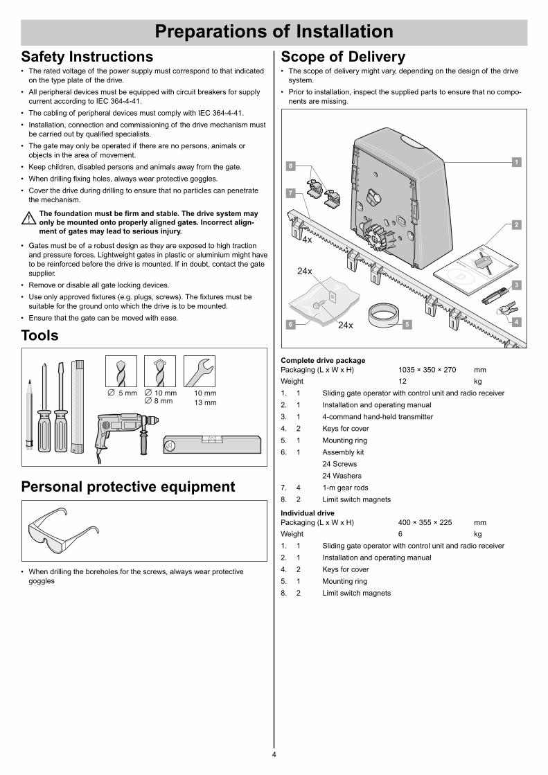
Scope of Delivery• The scope of delivery might vary, depending on the design of the drive
system.
• Prior to installation, inspect the supplied parts to ensure that no compo-nents are missing.
Complete drive package
Packaging (L x W x H) 1035 × 350 × 270 mm
Weight 12 kg
1. 1 Sliding gate operator with control unit and radio receiver
2. 1 Installation and operating manual
3. 1 4-command hand-held transmitter
4. 2 Keys for cover
5. 1 Mounting ring
6. 1 Assembly kit
24 Screws
24 Washers
7. 4 1-m gear rods
8. 2 Limit switch magnets
Individual drive
Packaging (L x W x H) 400 × 355 × 225 mm
Weight 6 kg
1. 1 Sliding gate operator with control unit and radio receiver
2. 1 Installation and operating manual
4. 2 Keys for cover
5. 1 Mounting ring
8. 2 Limit switch magnets
4x
24x
24x
SOMMERT O R A N T R I E B E
Ma
de
in
Ge
rm
an
y
D
D
4
1
2
6
7
8
5
3
Safety Instructions• The rated voltage of the power supply must correspond to that indicated
on the type plate of the drive.
• All peripheral devices must be equipped with circuit breakers for supplycurrent according to IEC 364-4-41.
• The cabling of peripheral devices must comply with IEC 364-4-41.
• Installation, connection and commissioning of the drive mechanism mustbe carried out by qualified specialists.
• The gate may only be operated if there are no persons, animals orobjects in the area of movement.
• Keep children, disabled persons and animals away from the gate.
• When drilling fixing holes, always wear protective goggles.
• Cover the drive during drilling to ensure that no particles can penetratethe mechanism.
The foundation must be firm and stable. The drive system may
only be mounted onto properly aligned gates. Incorrect align-
ment of gates may lead to serious injury.
• Gates must be of a robust design as they are exposed to high tractionand pressure forces. Lightweight gates in plastic or aluminium might haveto be reinforced before the drive is mounted. If in doubt, contact the gatesupplier.
• Remove or disable all gate locking devices.
• Use only approved fixtures (e.g. plugs, screws). The fixtures must besuitable for the ground onto which the drive is to be mounted.
• Ensure that the gate can be moved with ease.
Tools
Personal protective equipment
• When drilling the boreholes for the screws, always wear protectivegoggles
5 mm 10 mm8 mm
10 mm13 mm
Preparations of Installation
4
Preparations of Installation
5
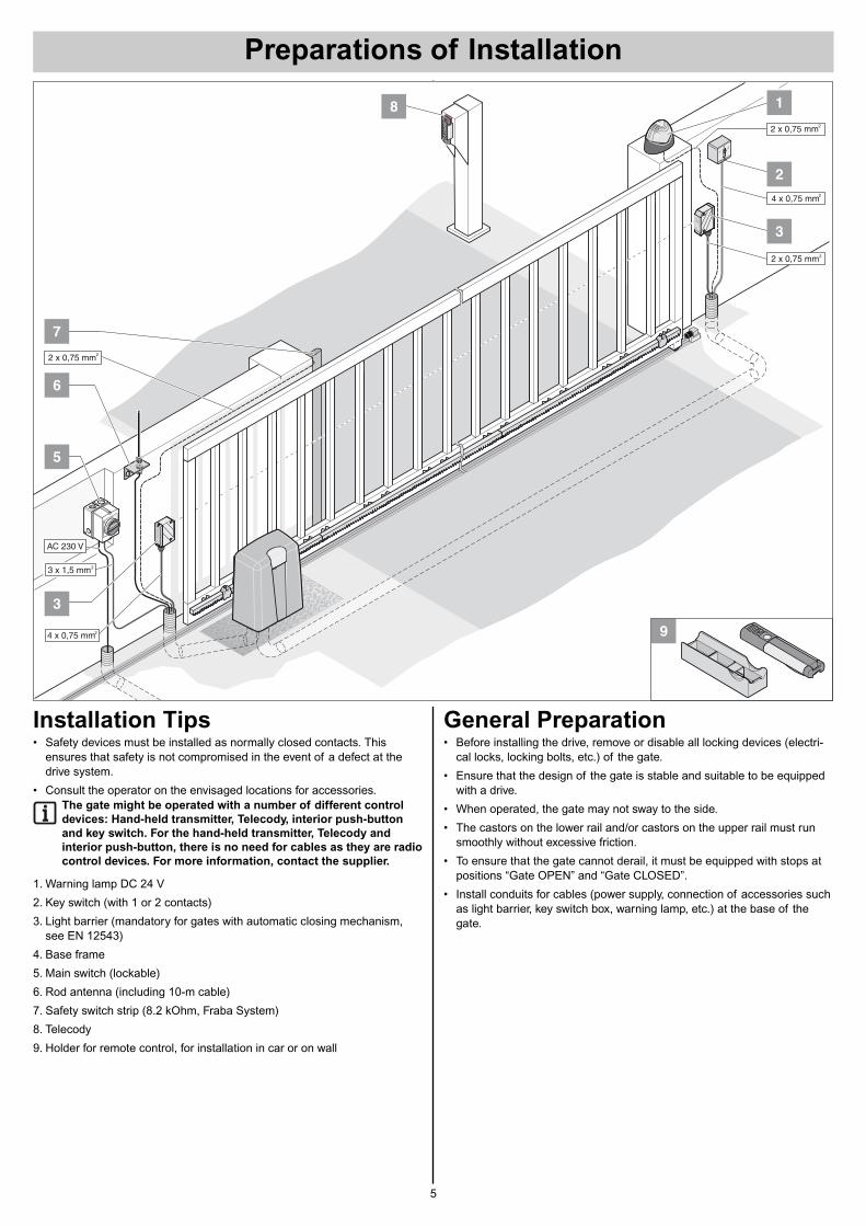
Installation Tips• Safety devices must be installed as normally closed contacts. This
ensures that safety is not compromised in the event of a defect at thedrive system.
• Consult the operator on the envisaged locations for accessories.The gate might be operated with a number of different control
devices: Hand-held transmitter, Telecody, interior push-button
and key switch. For the hand-held transmitter, Telecody and
interior push-button, there is no need for cables as they are radio
control devices. For more information, contact the supplier.
1. Warning lamp DC 24 V
2. Key switch (with 1 or 2 contacts)
3. Light barrier (mandatory for gates with automatic closing mechanism,see EN 12543)
4. Base frame
5. Main switch (lockable)
6. Rod antenna (including 10-m cable)
7. Safety switch strip (8.2 kOhm, Fraba System)
8. Telecody
9. Holder for remote control, for installation in car or on wall
General Preparation• Before installing the drive, remove or disable all locking devices (electri-
cal locks, locking bolts, etc.) of the gate.
• Ensure that the design of the gate is stable and suitable to be equippedwith a drive.
• When operated, the gate may not sway to the side.
• The castors on the lower rail and/or castors on the upper rail must runsmoothly without excessive friction.
• To ensure that the gate cannot derail, it must be equipped with stops atpositions “Gate OPEN” and “Gate CLOSED”.
• Install conduits for cables (power supply, connection of accessories suchas light barrier, key switch box, warning lamp, etc.) at the base of thegate.
2
1
2 x 0,75 mm2
4 x 0,75 mm2
3
2 x 0,75 mm2
SOMM
ERTORANTRIEBE
0
1
2
6
7
2 x 0,75 mm2
PE
MCS
PE
MCS
8
9
AC 230 V
O
5
3
4 x 0,75 mm2
3 x 1,5 mm2
6
Safety Instructions• For the connection of the control system to the power supply, contract an
electrician.
• Ensure that the drive system is firmly secured to the ground and that theracks are properly fixed to the gate, as these devices are exposed toconsiderable forces during the opening and closing of the gate.
• If the opening/closing of the gate is controlled by means of a push-but-ton, the button must be mounted at a minimum height of 1.6 m aboveground to prevent children from operating the gate.
• During operation of the gate, the rack may not be pressed onto thetoothed wheel, as this could damage the drive mechanism.
• During installation, comply with the relevant standards such as EN 12604and EN 12605.
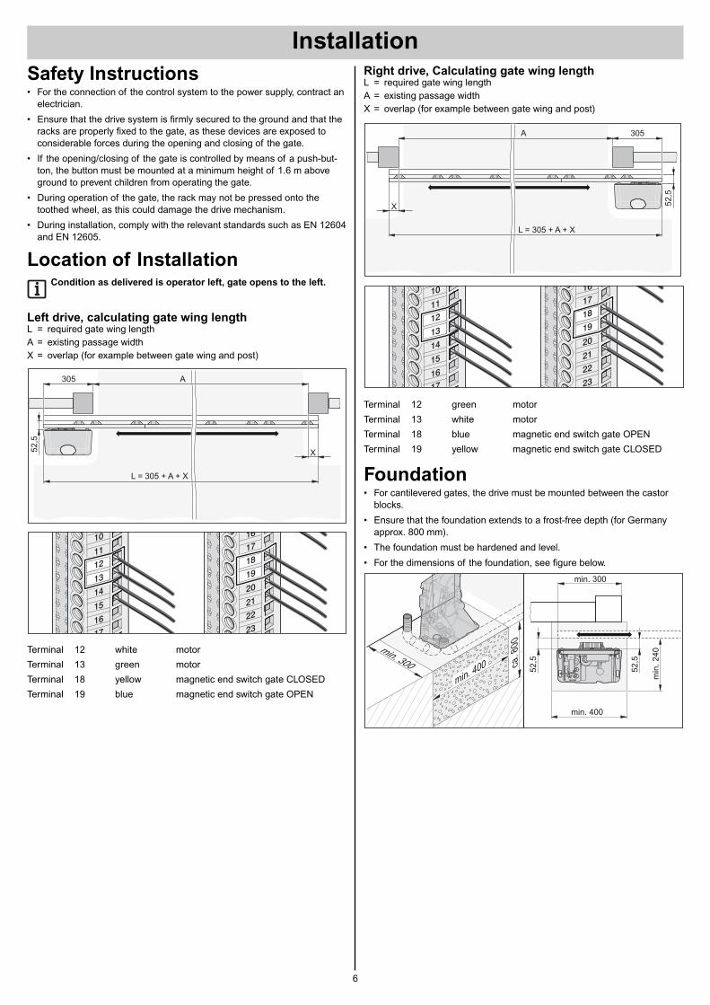
Location of InstallationCondition as delivered is operator left, gate opens to the left.
Left drive, calculating gate wing lengthL = required gate wing lengthA = existing passage widthX = overlap (for example between gate wing and post)
Terminal 12 white motor
Terminal 13 green motor
Terminal 18 yellow magnetic end switch gate CLOSED
Terminal 19 blue magnetic end switch gate OPEN
22
23
10
11
12
13
14
16
16
17
17
18
19
15
20
21
305
X
A
L = 305 + A + X
52,5
Right drive, Calculating gate wing lengthL = required gate wing lengthA = existing passage widthX = overlap (for example between gate wing and post)
Terminal 12 green motor
Terminal 13 white motor
Terminal 18 blue magnetic end switch gate OPEN
Terminal 19 yellow magnetic end switch gate CLOSED
Foundation• For cantilevered gates, the drive must be mounted between the castor
blocks.
• Ensure that the foundation extends to a frost-free depth (for Germanyapprox. 800 mm).
• The foundation must be hardened and level.
• For the dimensions of the foundation, see figure below.
min. 300 ca.
80
0
min. 400
min. 300
min. 400
min
.240
52,5
52,5
22
23
10
11
12
13
14
16
16
17
17
18
19
15
20
21
305
X
A
L = 305 + A + X
52,5
Installation
Installation
7
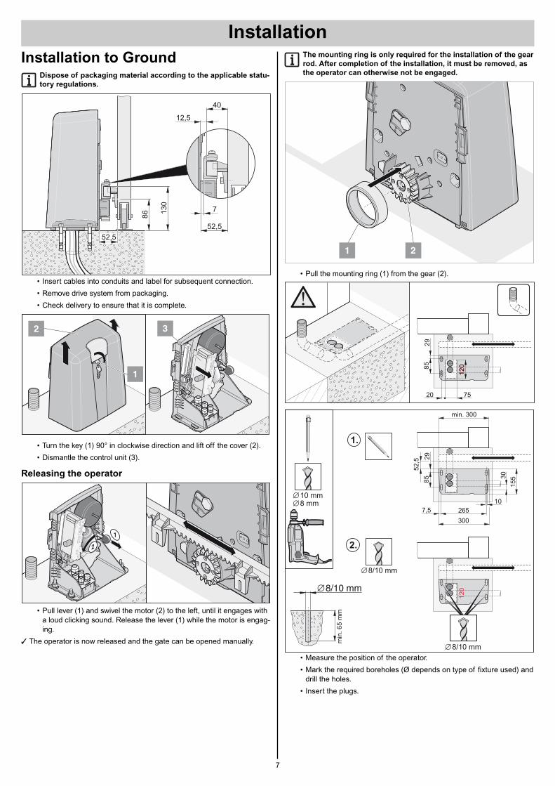
Installation to GroundDispose of packaging material according to the applicable statu-
tory regulations.
• Insert cables into conduits and label for subsequent connection.
• Remove drive system from packaging.
• Check delivery to ensure that it is complete.
• Turn the key (1) 90° in clockwise direction and lift off the cover (2).
• Dismantle the control unit (3).
Releasing the operator
• Pull lever (1) and swivel the motor (2) to the left, until it engages witha loud clicking sound. Release the lever (1) while the motor is engag-ing.
† The operator is now released and the gate can be opened manually.
1
2
1
2 3
86
52,5
52,5
130
12,5
7
40
The mounting ring is only required for the installation of the gear
rod. After completion of the installation, it must be removed, as
the operator can otherwise not be engaged.
• Pull the mounting ring (1) from the gear (2).
• Measure the position of the operator.
• Mark the required boreholes (Ø depends on type of fixture used) anddrill the holes.
• Insert the plugs.
min. 30052,5
85
29
120
30
300
265
10
7,5155
2.
8/10 mm
1.
min
.65
mm
8/10 mm
10 mm8 mm
8/10 mm
7520
85
29
120
120
21
Installation
8
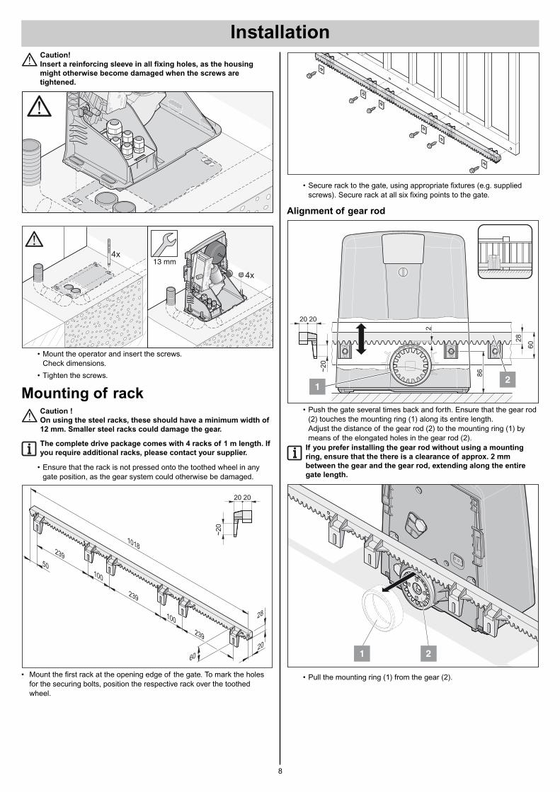
Caution!
Insert a reinforcing sleeve in all fixing holes, as the housing
might otherwise become damaged when the screws are
tightened.
• Mount the operator and insert the screws.Check dimensions.
• Tighten the screws.
Mounting of rackCaution !
On using the steel racks, these should have a minimum width of
12 mm. Smaller steel racks could damage the gear.
The complete drive package comes with 4 racks of 1 m length. If
you require additional racks, please contact your supplier.
• Ensure that the rack is not pressed onto the toothed wheel in anygate position, as the gear system could otherwise be damaged.
• Mount the first rack at the opening edge of the gate. To mark the holesfor the securing bolts, position the respective rack over the toothedwheel.
20
28
60
239
239
1018
239
100
50
100
~20
2020
4x
4x13 mm
• Secure rack to the gate, using appropriate fixtures (e.g. suppliedscrews). Secure rack at all six fixing points to the gate.
Alignment of gear rod
• Push the gate several times back and forth. Ensure that the gear rod(2) touches the mounting ring (1) along its entire length.Adjust the distance of the gear rod (2) to the mounting ring (1) bymeans of the elongated holes in the gear rod (2).
If you prefer installing the gear rod without using a mounting
ring, ensure that the there is a clearance of approx. 2 mm
between the gear and the gear rod, extending along the entire
gate length.
• Pull the mounting ring (1) from the gear (2).
21
~20
28
60
20 20
86
2
12
Installation
9
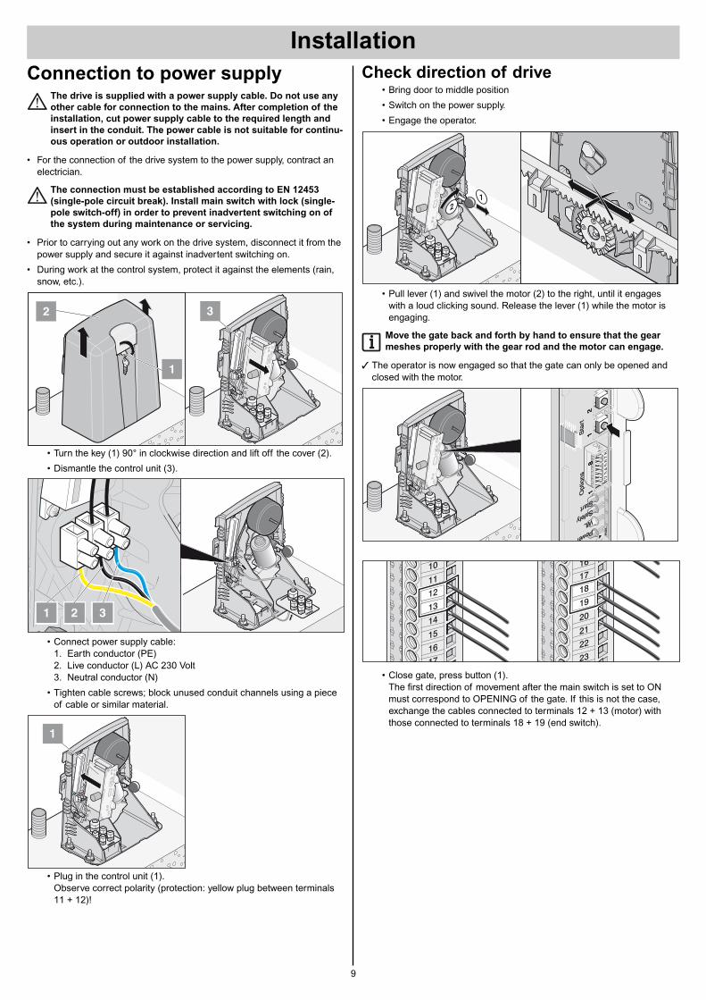
Connection to power supplyThe drive is supplied with a power supply cable. Do not use any
other cable for connection to the mains. After completion of the
installation, cut power supply cable to the required length and
insert in the conduit. The power cable is not suitable for continu-
ous operation or outdoor installation.
• For the connection of the drive system to the power supply, contract anelectrician.
The connection must be established according to EN 12453
(single-pole circuit break). Install main switch with lock (single-
pole switch-off) in order to prevent inadvertent switching on of
the system during maintenance or servicing.
• Prior to carrying out any work on the drive system, disconnect it from thepower supply and secure it against inadvertent switching on.
• During work at the control system, protect it against the elements (rain,snow, etc.).
• Turn the key (1) 90° in clockwise direction and lift off the cover (2).
• Dismantle the control unit (3).
• Connect power supply cable:1. Earth conductor (PE)2. Live conductor (L) AC 230 Volt3. Neutral conductor (N)
• Tighten cable screws; block unused conduit channels using a pieceof cable or similar material.
• Plug in the control unit (1).Observe correct polarity (protection: yellow plug between terminals11 + 12)!
1
2 31
1
2 3
Check direction of drive• Bring door to middle position
• Switch on the power supply.
• Engage the operator.
• Pull lever (1) and swivel the motor (2) to the right, until it engageswith a loud clicking sound. Release the lever (1) while the motor isengaging.
Move the gate back and forth by hand to ensure that the gear
meshes properly with the gear rod and the motor can engage.
† The operator is now engaged so that the gate can only be opened andclosed with the motor.
• Close gate, press button (1).The first direction of movement after the main switch is set to ONmust correspond to OPENING of the gate. If this is not the case,exchange the cables connected to terminals 12 + 13 (motor) withthose connected to terminals 18 + 19 (end switch).
22
23
10
11
12
13
14
16
16
17
17
18
19
15
20
21
LE
D4
LE
D3
LE
D2
LE
D1
T1
T1
T2
ON
78
65
43
21
ON
78
65
43
21
LE
D4
LE
D3
LE
D2
LE
D1
T1
T1
T2
ON
78
65
43
21
ON
78
65
43
21
FO
FF
max
.
Opt
ions
Sta
rt1
12
81
12
8
Start Safety WLPower
Fm
ax.
Opt
ions
Sta
rt1
12
81
12
8
Start Safety WLPower
1
2
10
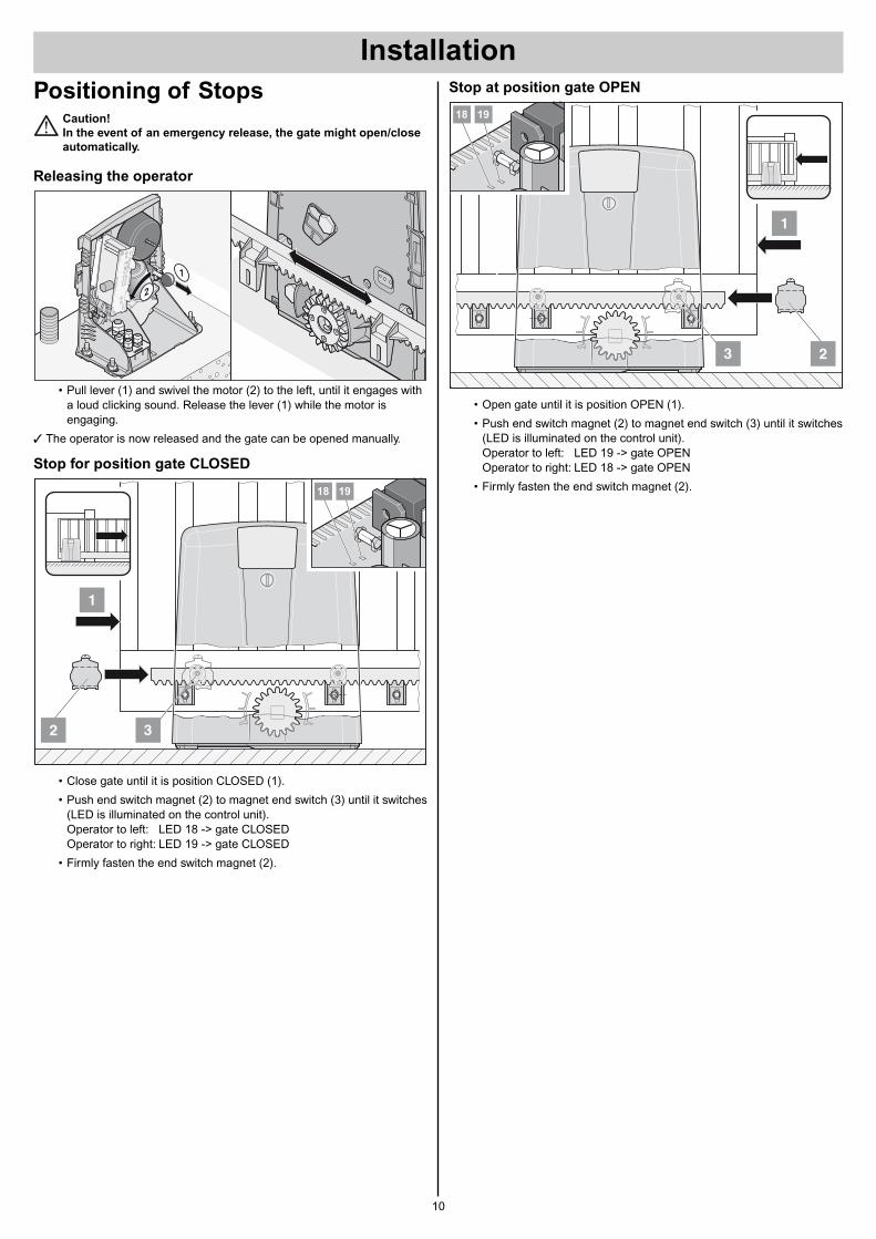
Positioning of StopsCaution!
In the event of an emergency release, the gate might open/close
automatically.
Releasing the operator
• Pull lever (1) and swivel the motor (2) to the left, until it engages witha loud clicking sound. Release the lever (1) while the motor isengaging.
† The operator is now released and the gate can be opened manually.
Stop for position gate CLOSED
• Close gate until it is position CLOSED (1).
• Push end switch magnet (2) to magnet end switch (3) until it switches(LED is illuminated on the control unit).Operator to left: LED 18 -> gate CLOSEDOperator to right: LED 19 -> gate CLOSED
• Firmly fasten the end switch magnet (2).
1
32
18 19
1
2
Stop at position gate OPEN
• Open gate until it is position OPEN (1).
• Push end switch magnet (2) to magnet end switch (3) until it switches(LED is illuminated on the control unit).Operator to left: LED 19 -> gate OPENOperator to right: LED 18 -> gate OPEN
• Firmly fasten the end switch magnet (2).
1
3 2
18 19
Installation
11
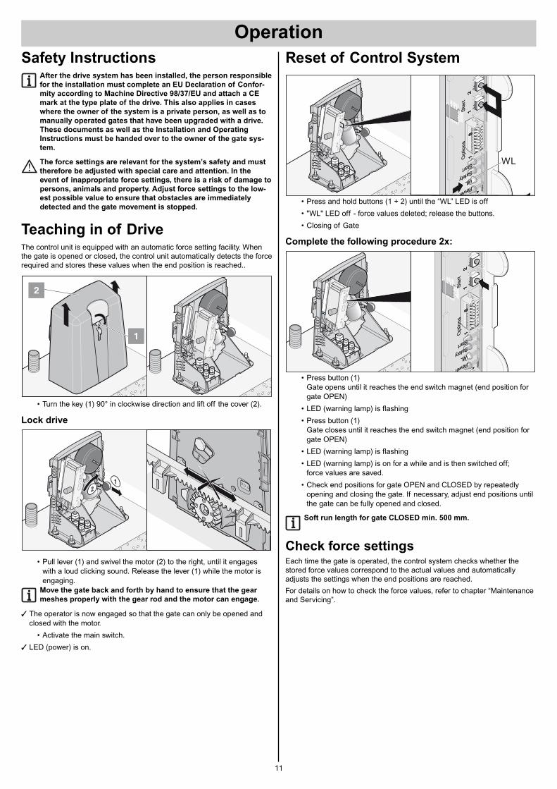
Reset of Control System
• Press and hold buttons (1 + 2) until the “WL” LED is off
• "WL" LED off - force values deleted; release the buttons.
• Closing of Gate
Complete the following procedure 2x:
• Press button (1) Gate opens until it reaches the end switch magnet (end position forgate OPEN)
• LED (warning lamp) is flashing
• Press button (1)Gate closes until it reaches the end switch magnet (end position forgate OPEN)
• LED (warning lamp) is flashing
• LED (warning lamp) is on for a while and is then switched off; force values are saved.
• Check end positions for gate OPEN and CLOSED by repeatedlyopening and closing the gate. If necessary, adjust end positions untilthe gate can be fully opened and closed.
Soft run length for gate CLOSED min. 500 mm.
Check force settingsEach time the gate is operated, the control system checks whether thestored force values correspond to the actual values and automaticallyadjusts the settings when the end positions are reached.
For details on how to check the force values, refer to chapter “Maintenanceand Servicing”.
LE
D4
LE
D3
LE
D2
LE
D1
T1
T1
T2
ON
78
65
43
21
ON
78
65
43
21
LE
D4
LE
D3
LE
D2
LE
D1
T1
T1
T2
ON
78
65
43
21
ON
78
65
43
21
FO
FF
max
.
Opt
ions
Sta
rt1
12
81
12
8
Start Safety WLPower
Fm
ax.
Opt
ions
Sta
rt1
12
81
12
8
Start Safety WLPower
LE
D4
LE
D3
LE
D2
LE
D1
T1
T1
T2
ON
78
65
43
21
ON
78
65
43
21
LE
D4
LE
D3
LE
D2
LE
D1
T1
T1
T2
ON
78
65
43
21
ON
78
65
43
21
FO
FF
max
.
Opt
ions
Sta
rt1
12
81
12
8
Start Safety WLPower
Fm
ax.
Opt
ions
Sta
rt1
12
81
12
8
Start Safety WLPower
WL
Safety InstructionsAfter the drive system has been installed, the person responsible
for the installation must complete an EU Declaration of Confor-
mity according to Machine Directive 98/37/EU and attach a CE
mark at the type plate of the drive. This also applies in cases
where the owner of the system is a private person, as well as to
manually operated gates that have been upgraded with a drive.
These documents as well as the Installation and Operating
Instructions must be handed over to the owner of the gate sys-
tem.
The force settings are relevant for the system’s safety and must
therefore be adjusted with special care and attention. In the
event of inappropriate force settings, there is a risk of damage to
persons, animals and property. Adjust force settings to the low-
est possible value to ensure that obstacles are immediately
detected and the gate movement is stopped.
Teaching in of DriveThe control unit is equipped with an automatic force setting facility. Whenthe gate is opened or closed, the control unit automatically detects the forcerequired and stores these values when the end position is reached..
• Turn the key (1) 90° in clockwise direction and lift off the cover (2).
Lock drive
• Pull lever (1) and swivel the motor (2) to the right, until it engageswith a loud clicking sound. Release the lever (1) while the motor isengaging.
Move the gate back and forth by hand to ensure that the gear
meshes properly with the gear rod and the motor can engage.
† The operator is now engaged so that the gate can only be opened andclosed with the motor.
• Activate the main switch.
† LED (power) is on.
1
2
1
2
Operation
Operation
12
Teaching in of Hand-Held
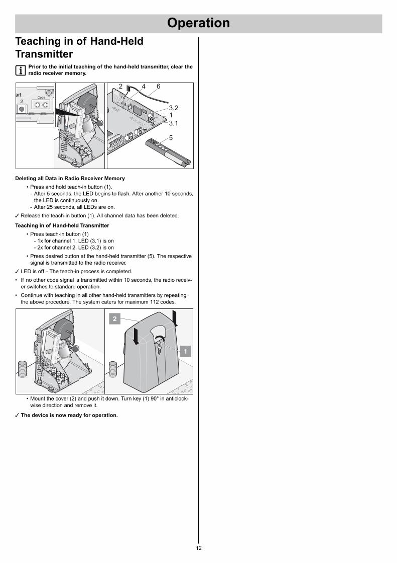
TransmitterPrior to the initial teaching of the hand-held transmitter, clear the
radio receiver memory.
Deleting all Data in Radio Receiver Memory
• Press and hold teach-in button (1).- After 5 seconds, the LED begins to flash. After another 10 seconds,
the LED is continuously on.- After 25 seconds, all LEDs are on.
† Release the teach-in button (1). All channel data has been deleted.
Teaching in of Hand-held Transmitter
• Press teach-in button (1)- 1x for channel 1, LED (3.1) is on- 2x for channel 2, LED (3.2) is on
• Press desired button at the hand-held transmitter (5). The respectivesignal is transmitted to the radio receiver.
† LED is off - The teach-in process is completed.
• If no other code signal is transmitted within 10 seconds, the radio receiv-er switches to standard operation.
• Continue with teaching in all other hand-held transmitters by repeatingthe above procedure. The system caters for maximum 112 codes.
• Mount the cover (2) and push it down. Turn key (1) 90° in anticlock-wise direction and remove it.
† The device is now ready for operation.
1
2
art Code2
art
T1
T2
5
3.1
3.2
2 4 6
1
Operation
13
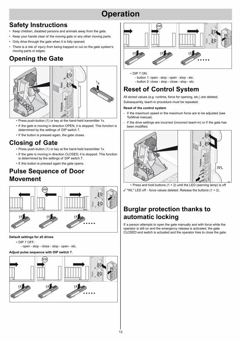
Safety Instructions• Keep children, disabled persons and animals away from the gate.
• Keep your hands clear of the moving gate or any other moving parts.
• Only drive through the gate when it is fully opened.
• There is a risk of injury from being trapped or cut on the gate system’smoving parts or edges.
Opening the Gate
• Press push-button (1) or key at the hand-held transmitter 1x.
• If the gate is moving in direction OPEN, it is stopped. This function isdetermined by the settings of DIP switch 7.
• If the button is pressed again, the gate closes.
Closing of Gate• Press push-button (1) or key at the hand-held transmitter 1x.
• If the gate is moving in direction CLOSED, it is stopped. This functionis determined by the settings of DIP switch 7.
• If this button is pressed again the gate opens.
Pulse Sequence of Door
Movement
Default settings for all drives
• DIP 7 OFF:- open - stop - close - stop - open - etc.
Adjust pulse sequence with DIP switch 7.
LE
D4
LE
D3
T1
T1
T2
ON
78
65
43
21
ON
78
65
43
21
LE
D4
LE
D3
T1
T1
T2
ON
78
65
43
21
ON
78
65
43
21
Opt
ions
Sta
rtCC
ode
11
28
11
28
Start SSafety
Opt
ions
Sta
rtC
11
28
11
28
Start S
1x
• DIP 7 ON:- button 1: open - stop - open - stop - etc.- button 2: close - stop - close - stop - etc.
Reset of Control SystemAll stored values (e.g. runtime, force for opening, etc.) are deleted.
Subsequently, teach-in procedure must be repeated.
Reset of the control system
- if the maximum speed or the maximum force are to be adjusted (seeTorMinal manual).
- if the drive settings are incorrect (incorrect teach-in) or if the gate hasbeen modified.
• Press and hold buttons (1 + 2) until the LED (warning lamp) is off
† "WL" LED off - force values deleted. Release the buttons (1 + 2).
Burglar protection thanks to
automatic lockingIf a person attempts to open the gate manually and with force while theoperator is still on and the emergency release is activated, the gateCLOSED end switch is actuated and the operator tries to close the gate.
LE
D4
LE
D3
LE
D2
LE
D1
T1
T1
T2
ON
78
65
43
21
ON
78
65
43
21
LE
D4
LE
D3
LE
D2
LE
D1
T1
T1
T2
ON
78
65
43
21
ON
78
65
43
21
FO
FF
max
.
Opt
ions
Sta
rt1
12
81
12
8
Start Safety WLPower
Fm
ax.
Opt
ions
Sta
rt1
12
81
12
8
Start Safety WLPower
WL
Operation
14
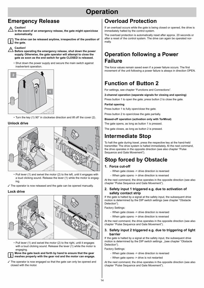
Emergency ReleaseCaution!
In the event of an emergency release, the gate might open/close
automatically.
The drive can be released anytime, irrespective of the position of
the gate.
Caution!
Before operating the emergency release, shut down the power
supply. Otherwise, the gate operator will attempt to close the
gate as soon as the end switch for gate CLOSED is released.
• Shut down the power supply and secure the main switch againstinadvertent operation.
• Turn the key (1) 90° in clockwise direction and lift off the cover (2).
Unlock drive
• Pull lever (1) and swivel the motor (2) to the left, until it engages witha loud clicking sound. Release the lever (1) while the motor is engag-ing.
† The operator is now released and the gate can be opened manually.
Lock drive
• Pull lever (1) and swivel the motor (2) to the right, until it engageswith a loud clicking sound. Release the lever (1) while the motor isengaging.
Move the gate back and forth by hand to ensure that the gear
meshes properly with the gear rod and the motor can engage.
† The operator is now engaged so that the gate can only be opened andclosed with the motor.
1
2
1
2
1
2
Overload ProtectionIf an overload occurs while the gate is being closed or opened, the drive isimmediately halted by the control system.
The overload protection is automatically reset after approx. 20 seconds orafter a reset of the control system. The drive can again be operated nor-mally.
Operation following a Power
FailureThe force values remain saved even if a power failure occurs. The firstmovement of the unit following a power failure is always in direction OPEN.
Function of Button 2For settings, see chapter “Functions and Connections”.
2-channel operation (separate signals for closing and opening)
Press button 1 to open the gate; press button 2 to close the gate.
Partial opening
Press button 1 to fully open/close the gate.
Press button 2 to open/close the gate partially.
Biased-off operation (activation only with TorMinal)
The gate opens, as long as button 1 is pressed.
The gate closes, as long as button 2 is pressed.
Intermediate StopTo halt the gate during travel, press the respective key at the hand-heldtransmitter. The drive system is halted immediately. At the next command,the drive operates in the opposite direction (see also chapter “PulseSequence and Gate Movement”).
Stop forced by Obstacle1. Force cut-off
- When gate closes -> drive direction is reversed
- When gate opens -> drive direction is reversed
At the next command, the drive operates in the opposite direction (see alsochapter “Pulse Sequence and Gate Movement”).
2. Safety input 1 triggered e.g. due to activation of
safety contact stripIf the gate is halted by a signal at the safety input, the subsequent drivemotion is determined by the DIP switch settings (see chapter “ObstacleDetection”).
Factory Settings:
- When gate closes -> drive direction is reversed
- When gate opens -> drive direction is reversed
At the next command, the drive operates in the opposite direction (see alsochapter “Pulse Sequence and Gate Movement”).
3. Safety input 2 triggered e.g. due to triggering of light
barrierIf the gate is halted by a signal at the safety input, the subsequent drivemotion is determined by the DIP switch settings _(see chapter “ObstacleDetection”).
Factory Settings:
- When gate closes -> drive direction is reversed
- When gate opens -> drive is not restarted
At the next command, the drive operates in the opposite direction (see alsochapter “Pulse Sequence and Gate Movement”).
15
General Tips• At delivery, all DIP switches are in OFF position.
• Do not apply any external voltage to the control connections, as thiswould completely destroy the system.
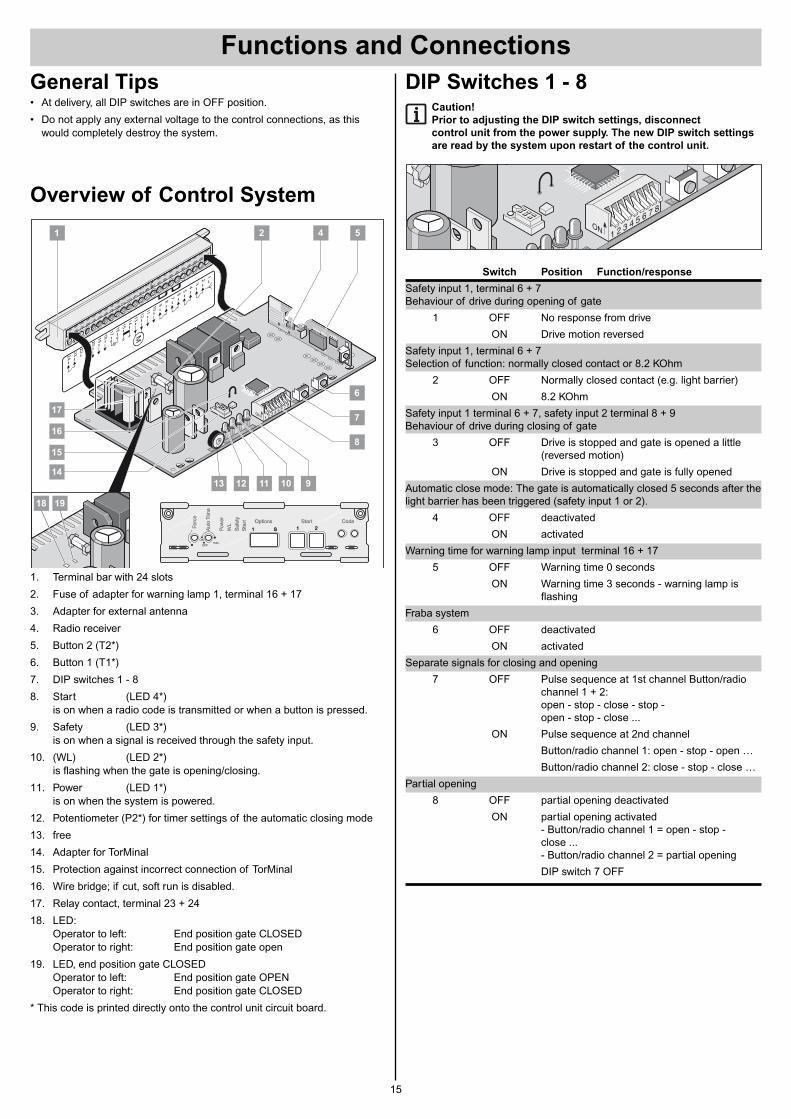
Overview of Control System
1. Terminal bar with 24 slots
2. Fuse of adapter for warning lamp 1, terminal 16 + 17
3. Adapter for external antenna
4. Radio receiver
5. Button 2 (T2*)
6. Button 1 (T1*)
7. DIP switches 1 - 8
8. Start (LED 4*)is on when a radio code is transmitted or when a button is pressed.
9. Safety (LED 3*)is on when a signal is received through the safety input.
10. (WL) (LED 2*)is flashing when the gate is opening/closing.
11. Power (LED 1*)is on when the system is powered.
12. Potentiometer (P2*) for timer settings of the automatic closing mode
13. free
14. Adapter for TorMinal
15. Protection against incorrect connection of TorMinal
16. Wire bridge; if cut, soft run is disabled.
17. Relay contact, terminal 23 + 24
18. LED:Operator to left: End position gate CLOSEDOperator to right: End position gate open
19. LED, end position gate CLOSEDOperator to left: End position gate OPENOperator to right: End position gate CLOSED
* This code is printed directly onto the control unit circuit board.
1
3
5
7
9101
112
18
20
22
14
16
13
M19
21
232
4
15
17
2
4
6
8
LED1 LED2 LED3 LED4
T1
P2
T2
1112
ON
OFFmax.
Options Start CodeOptions Start Code
1 1 281 1 28Sta
rtS
afet
y
WL
Pow
er
Aut
oT
ime
For
ce
Sta
rtS
afet
y
WL
Pow
er
Aut
oT
ime
For
ce
1 2
6
7
8
910111213
14
15
16
17
54
18 19
DIP Switches 1 - 8Caution!
Prior to adjusting the DIP switch settings, disconnect
control unit from the power supply. The new DIP switch settings
are read by the system upon restart of the control unit.
Switch Position Function/response
Safety input 1, terminal 6 + 7Behaviour of drive during opening of gate
1 OFF No response from drive
ON Drive motion reversed
Safety input 1, terminal 6 + 7Selection of function: normally closed contact or 8.2 KOhm
2 OFF Normally closed contact (e.g. light barrier)
ON 8.2 KOhm
Safety input 1 terminal 6 + 7, safety input 2 terminal 8 + 9Behaviour of drive during closing of gate
3 OFF Drive is stopped and gate is opened a little(reversed motion)
ON Drive is stopped and gate is fully opened
Automatic close mode: The gate is automatically closed 5 seconds after thelight barrier has been triggered (safety input 1 or 2).
4 OFF deactivated
ON activated
Warning time for warning lamp input terminal 16 + 17
5 OFF Warning time 0 seconds
ON Warning time 3 seconds - warning lamp isflashing
Fraba system
6 OFF deactivated
ON activated
Separate signals for closing and opening
7 OFF Pulse sequence at 1st channel Button/radiochannel 1 + 2:open - stop - close - stop - open - stop - close ...
ON Pulse sequence at 2nd channel
Button/radio channel 1: open - stop - open …
Button/radio channel 2: close - stop - close …
Partial opening
8 OFF partial opening deactivated
ON partial opening activated- Button/radio channel 1 = open - stop - close ...- Button/radio channel 2 = partial opening
DIP switch 7 OFF
T1
T2
Functions and Connections
Functions and Connections
16
Radio Receiver
Safety Instructions• Ensure that the installation and operation of the system complies with
the applicable statutory safety regulations! For more information, contactthe local electricity supplier, safety authorities and trade organisations.
• The operator of this radio-controlled equipment is not in any way protect-ed against interference from other telecommunications systems and facil-ities (e.g. other radio-controlled equipment that is licensed to operate atthe same frequency range).
• Poor reception might be eliminated by replacing the batteries of therespective hand-held transmitter.
Display and Buttons
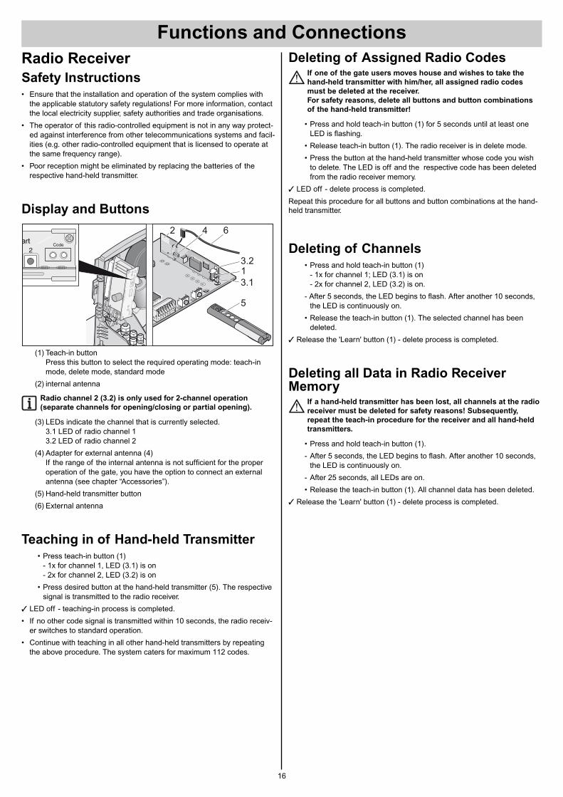
(1) Teach-in button Press this button to select the required operating mode: teach-inmode, delete mode, standard mode
(2) internal antenna
Radio channel 2 (3.2) is only used for 2-channel operation
(separate channels for opening/closing or partial opening).
(3) LEDs indicate the channel that is currently selected. 3.1 LED of radio channel 13.2 LED of radio channel 2
(4) Adapter for external antenna (4)If the range of the internal antenna is not sufficient for the properoperation of the gate, you have the option to connect an externalantenna (see chapter “Accessories”).
(5) Hand-held transmitter button
(6) External antenna
Teaching in of Hand-held Transmitter• Press teach-in button (1)
- 1x for channel 1, LED (3.1) is on- 2x for channel 2, LED (3.2) is on
• Press desired button at the hand-held transmitter (5). The respectivesignal is transmitted to the radio receiver.
† LED off - teaching-in process is completed.
• If no other code signal is transmitted within 10 seconds, the radio receiv-er switches to standard operation.
• Continue with teaching in all other hand-held transmitters by repeatingthe above procedure. The system caters for maximum 112 codes.
tart Code2
art
T1
T2
5
3.1
3.2
2 4 6
1
Deleting of Assigned Radio CodesIf one of the gate users moves house and wishes to take the
hand-held transmitter with him/her, all assigned radio codes
must be deleted at the receiver.
For safety reasons, delete all buttons and button combinations
of the hand-held transmitter!
• Press and hold teach-in button (1) for 5 seconds until at least oneLED is flashing.
• Release teach-in button (1). The radio receiver is in delete mode.
• Press the button at the hand-held transmitter whose code you wishto delete. The LED is off and the respective code has been deletedfrom the radio receiver memory.
† LED off - delete process is completed.
Repeat this procedure for all buttons and button combinations at the hand-held transmitter.
Deleting of Channels• Press and hold teach-in button (1)
- 1x for channel 1; LED (3.1) is on- 2x for channel 2, LED (3.2) is on.
- After 5 seconds, the LED begins to flash. After another 10 seconds,the LED is continuously on.
• Release the teach-in button (1). The selected channel has beendeleted.
† Release the 'Learn' button (1) - delete process is completed.
Deleting all Data in Radio ReceiverMemory
If a hand-held transmitter has been lost, all channels at the radio
receiver must be deleted for safety reasons! Subsequently,
repeat the teach-in procedure for the receiver and all hand-held
transmitters.
• Press and hold teach-in button (1).
- After 5 seconds, the LED begins to flash. After another 10 seconds,the LED is continuously on.
- After 25 seconds, all LEDs are on.
• Release the teach-in button (1). All channel data has been deleted.
† Release the 'Learn' button (1) - delete process is completed.
Obstacle Detection (DIP 1, 2 + 3)
Obstacle detected while gate is opening
Force cut-offDrive motion reversed
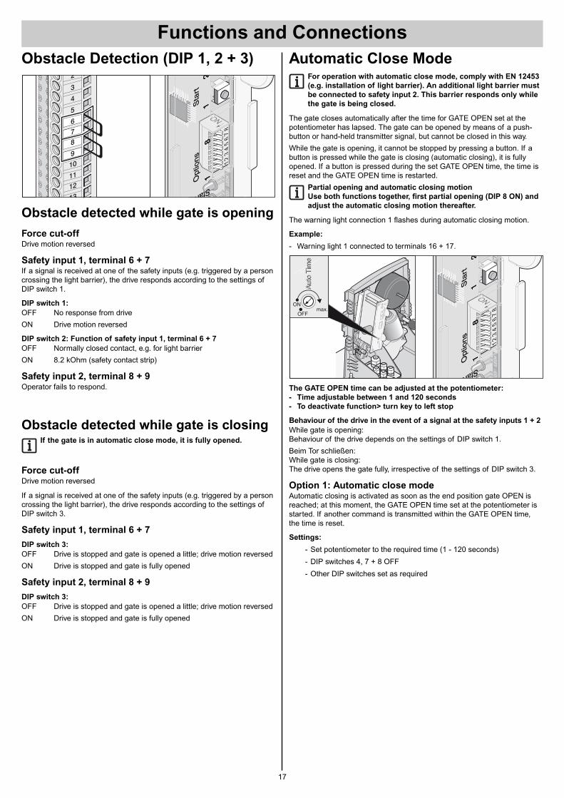
Safety input 1, terminal 6 + 7If a signal is received at one of the safety inputs (e.g. triggered by a personcrossing the light barrier), the drive responds according to the settings ofDIP switch 1.
DIP switch 1:
OFF No response from drive
ON Drive motion reversed
DIP switch 2: Function of safety input 1, terminal 6 + 7
OFF Normally closed contact, e.g. for light barrier
ON 8.2 kOhm (safety contact strip)
Safety input 2, terminal 8 + 9Operator fails to respond.
Obstacle detected while gate is closingIf the gate is in automatic close mode, it is fully opened.
Force cut-offDrive motion reversed
If a signal is received at one of the safety inputs (e.g. triggered by a personcrossing the light barrier), the drive responds according to the settings ofDIP switch 3.
Safety input 1, terminal 6 + 7
DIP switch 3:
OFF Drive is stopped and gate is opened a little; drive motion reversed
ON Drive is stopped and gate is fully opened
Safety input 2, terminal 8 + 9
DIP switch 3:
OFF Drive is stopped and gate is opened a little; drive motion reversed
ON Drive is stopped and gate is fully opened
LE
D4
ED
3T
1T
1
ON
78
65
43
21
ON
78
65
43
21
LE
D4
ED
3T
1T
1
ON
78
65
43
21
ON
78
65
43
21
Opt
ions
Sta
rt1
12
81
12
8
Start
Opt
ions
Sta
rt1
12
81
12
8
Start
678
9
10
11
2
12
13
3
4
5
Functions and Connections
17
Automatic Close ModeFor operation with automatic close mode, comply with EN 12453
(e.g. installation of light barrier). An additional light barrier must
be connected to safety input 2. This barrier responds only while
the gate is being closed.
The gate closes automatically after the time for GATE OPEN set at thepotentiometer has lapsed. The gate can be opened by means of a push-button or hand-held transmitter signal, but cannot be closed in this way.
While the gate is opening, it cannot be stopped by pressing a button. If abutton is pressed while the gate is closing (automatic closing), it is fullyopened. If a button is pressed during the set GATE OPEN time, the time isreset and the GATE OPEN time is restarted.
Partial opening and automatic closing motion
Use both functions together, first partial opening (DIP 8 ON) and
adjust the automatic closing motion thereafter.
The warning light connection 1 flashes during automatic closing motion.
Example:
- Warning light 1 connected to terminals 16 + 17.
The GATE OPEN time can be adjusted at the potentiometer:
- Time adjustable between 1 and 120 seconds
- To deactivate function> turn key to left stop
Behaviour of the drive in the event of a signal at the safety inputs 1 + 2
While gate is opening:Behaviour of the drive depends on the settings of DIP switch 1.
Beim Tor schließen:While gate is closing:The drive opens the gate fully, irrespective of the settings of DIP switch 3.
Option 1: Automatic close modeAutomatic closing is activated as soon as the end position gate OPEN isreached; at this moment, the GATE OPEN time set at the potentiometer isstarted. If another command is transmitted within the GATE OPEN time,the time is reset.
Settings:
- Set potentiometer to the required time (1 - 120 seconds)
- DIP switches 4, 7 + 8 OFF
- Other DIP switches set as required
LE
D4
ED
3T
1T
1
ON
78
65
43
21
ON
78
65
43
21
LE
D4
ED
3T
1T
1
ON
78
65
43
21
ON
78
65
43
21
Opt
ions
Sta
rt1
12
81
12
8
Start
Opt
ions
Sta
rt1
12
81
12
8
Start
ON
OFFmax.
Aut
oT
ime
Aut
oT
ime
Functions and Connections
18
Option 2: Automatic close mode + light barrier
(DIP switch 4)
This option allows for the manual interruption of the closing
motion, and for automatic closing after a set period of time after
triggering of the light barrier.
The functions of option 1 apply. In option 2, the gate is automatically closed5 seconds after the light barrier has been triggered (e.g. by vehicle passingthrough it). This option requires the connection of safety input 2, terminal 8 + 9.
Settings:
- Set potentiometer to the required time (1 - 120 seconds)
- DIP switches 7 + 8 OFF
- DIP switch 4 ON
- Other DIP switches set as required
Option 3: Automatic close mode + safety contact strip +
light barrier
This option allows for the manual interruption of the closing
motion, and for automatic closing after a set period of time after
triggering of the light barrier.
Similar to option 2, whereby the gate is automatically closed 5 secondsafter the light barrier has been triggered.
- Safety contact strip to safety connection 1 (terminal 6 + 7).
- This option requires the connection of safety input 2, terminal 8 + 9.
Settings:
- Set potentiometer to the required time (1 - 120 seconds)
- DIP switches 7 + 8 OFF
- DIP switches 2, 4 ON
- Other DIP switches set as required
Warning Time (DIP 5)A warning light connected to warning light connection 1 (terminal 16 + 17),flashes for 3 seconds after activation of the button, or activation of thehand transmitter, before the operator starts.
The drive is only activated after this period has lapsed. If another button ispressed in the meantime, the warning time is terminated.
DIP switch 5
OFF deactivated
ON activated, warning light 1 flashes for 3 seconds.
Fraba System (DIP 6)You have the option to route the function of safety input 1 (terminal 6 + 7) tothe signal interpretation of a Fraba system.
DIP switch 6
OFF deactivated
ON activated
Separate Signals for Closing and
Opening (DIP Switch 7)Button/radio channel 1: for opening, button/radio channel 2 for closing. The2-channel mode is suitable for operation with 2 push-buttons or hand-heldtransmitters.
Settings: DIP switch 8 OFF, 2 buttons connected and/or 2 hand-held trans-mitter buttons programmed.
DIP switch 7
OFF deactivated
ON activated
Partial Opening (DIP 8)This function allows for the partial opening of the gate.
Example:You wish to open the gate to give access to pedestrians only. To open thegate partially with this function, you have the option to adjust the settingsfor control with 2 push-buttons or by radio code (hand-held transmitter,Telecody, etc.).
DIP switch 8
OFF deactivated
ON activated, DIP switch 7 disabled
Partial opening by pressing 2 push-buttonsInstall additional push-button and connect it as button 2 to terminal 4 + 5.
Push-button 1 opens the gate fully.If the gate has been opened partially bypressing button 2, it can be fully opened by pressing push-button 1.
Push-button 2 opens the gate partially, provided that the gate is firstclosed.If the gate has already been opened fully (push-button 1) or partially(push-button 2), it is closed when push-button 2 is pressed again.
Procedure:
1. Close gate.
2 DIP switch 8 ON: partial opening is activated- Leave DIP switch 8 in position ON; if it is set to OFF, the set partial
opening is deleted.
3. Press push-button 2 (opening gate from position GATE CLOSED).- The gate opens until push-button 2 is pressed again or until the
gate reaches the GATE OPEN position.
4. Press push-button 2 as soon as the desired position is reached.
5. To close the gate, press push-button 2 again.
† The opening distance for partial opening has been programmed. Nexttime push-button 2 is pressed, the gate is opened partially according tothese settings.
To delete the settings for partial opening: Set DIP switch 8 to OFF.
Partial opening by means of
hand-held transmitter (2-channel operation)Teach-in 2 buttons at the hand-held transmitter: e.g. button 1 assigned toradio channel 1 and button 2 assigned to radio channel 2
Radio channel 1 is assigned the same function as button 1, terminal 2 + 3,
Radio channel 2 is assigned the same function as button 2, terminal 4 + 5.
Proceed with programming as described above.
Functions and Connections
19
Terminal bar with 24 slotsCaution! Risk of short circuit!
The reverse polarity protection (yellow plug) must always be
mounted between terminals 11 + 12. Plug in only a STA1 control
unit, as other control units will be damaged during operation
and/or might damage the operator.
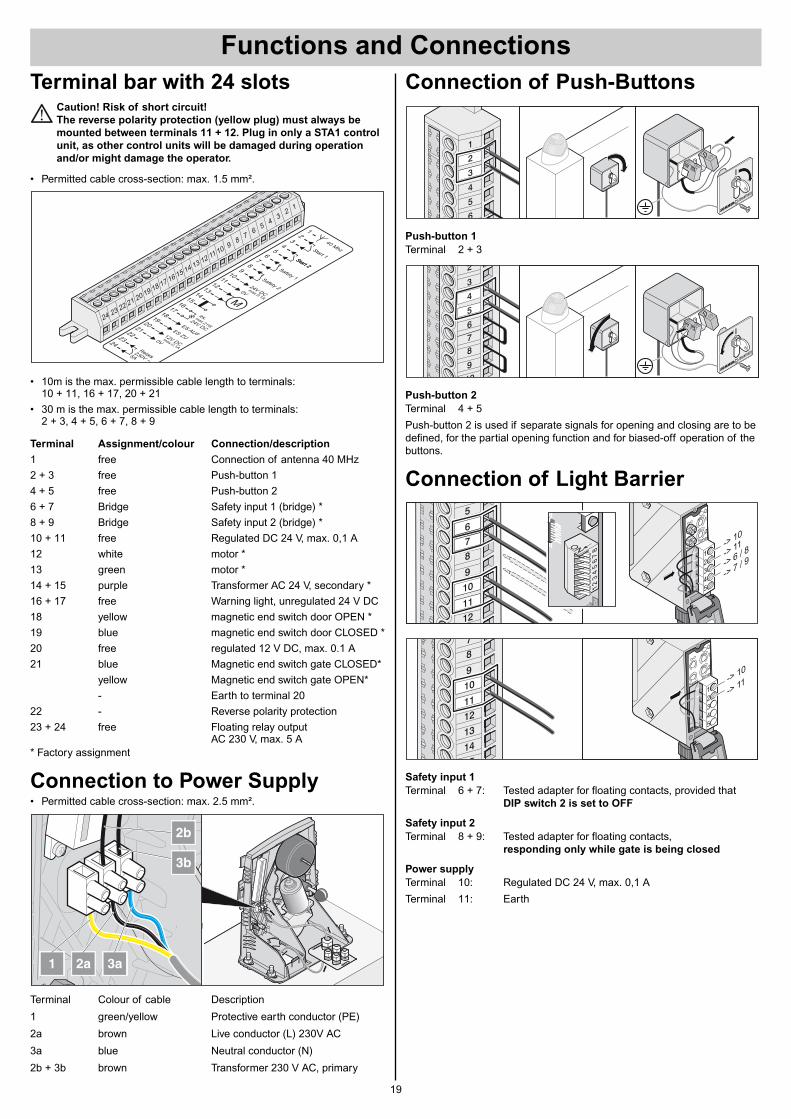
• Permitted cable cross-section: max. 1.5 mm².
• 10m is the max. permissible cable length to terminals: 10 + 11, 16 + 17, 20 + 21
• 30 m is the max. permissible cable length to terminals: 2 + 3, 4 + 5, 6 + 7, 8 + 9
Terminal Assignment/colour Connection/description
1 free Connection of antenna 40 MHz
2 + 3 free Push-button 1
4 + 5 free Push-button 2
6 + 7 Bridge Safety input 1 (bridge) *
8 + 9 Bridge Safety input 2 (bridge) *
10 + 11 free Regulated DC 24 V, max. 0,1 A
12 white motor *
13 green motor *
14 + 15 purple Transformer AC 24 V, secondary *
16 + 17 free Warning light, unregulated 24 V DC
18 yellow magnetic end switch door OPEN *
19 blue magnetic end switch door CLOSED *
20 free regulated 12 V DC, max. 0.1 A
21 blue Magnetic end switch gate CLOSED*
yellow Magnetic end switch gate OPEN*
- Earth to terminal 20
22 - Reverse polarity protection
23 + 24 free Floating relay outputAC 230 V, max. 5 A
* Factory assignment
Connection to Power Supply• Permitted cable cross-section: max. 2.5 mm².
Terminal Colour of cable Description
1 green/yellow Protective earth conductor (PE)
2a brown Live conductor (L) 230V AC
3a blue Neutral conductor (N)
2b + 3b brown Transformer 230 V AC, primary
2a 3a1
2b
3b
1
3
5
7
910
1112
18
20
22
14
16
13
M
19
21
2324
15
17
2
4
6
8
40 MhzStart 1Start 2Start 2
Safety 1Safety 224VDC
ex.24VDCES AUF
ESZU12V
DC
Relais230V
~
0V
5A
max.0,1A
max.0,1A
max.21W
0V
23 22 21 20 19 18 17 16 15 14 13 12 11 109
87
65
43
21
24
Connection of Push-Buttons
Push-button 1
Terminal 2 + 3
Push-button 2
Terminal 4 + 5
Push-button 2 is used if separate signals for opening and closing are to bedefined, for the partial opening function and for biased-off operation of thebuttons.
Connection of Light Barrier
Safety input 1
Terminal 6 + 7: Tested adapter for floating contacts, provided that DIP switch 2 is set to OFF
Safety input 2
Terminal 8 + 9: Tested adapter for floating contacts, responding only while gate is being closed
Power supply
Terminal 10: Regulated DC 24 V, max. 0,1 A
Terminal 11: Earth
SOMM
ER
SOMM
ER
678
9
10
2
3
4
5
SOMM
ER
SOMM
ER4
5
6
1
2
3
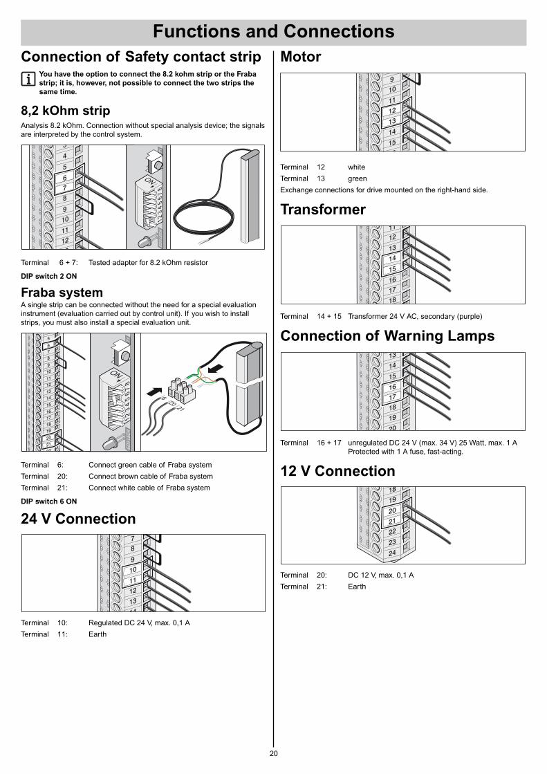
Motor
Terminal 12 white
Terminal 13 green
Exchange connections for drive mounted on the right-hand side.
Transformer
Terminal 14 + 15 Transformer 24 V AC, secondary (purple)
Connection of Warning Lamps
Terminal 16 + 17 unregulated DC 24 V (max. 34 V) 25 Watt, max. 1 AProtected with 1 A fuse, fast-acting.
12 V Connection
Terminal 20: DC 12 V, max. 0,1 A
Terminal 21: Earth
Connection of Safety contact stripYou have the option to connect the 8.2 kohm strip or the Fraba
strip; it is, however, not possible to connect the two strips the
same time.
8,2 kOhm stripAnalysis 8.2 kOhm. Connection without special analysis device; the signalsare interpreted by the control system.
Terminal 6 + 7: Tested adapter for 8.2 kOhm resistor
DIP switch 2 ON
Fraba systemA single strip can be connected without the need for a special evaluationinstrument (evaluation carried out by control unit). If you wish to installstrips, you must also install a special evaluation unit.
Terminal 6: Connect green cable of Fraba system
Terminal 20: Connect brown cable of Fraba system
Terminal 21: Connect white cable of Fraba system
DIP switch 6 ON
24 V Connection
Terminal 10: Regulated DC 24 V, max. 0,1 A
Terminal 11: Earth
620
21
ED
3LE
D4
T1
ON
78
65
43
21
4
5
78
9
10
11
16
17
18
19
20
21
22
12
13
14
15
6
Functions and Connections
20
Functions and Connections
21
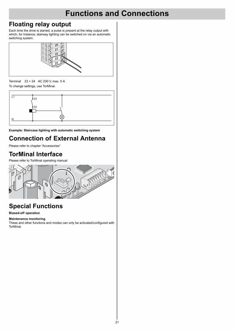
Floating relay outputEach time the drive is started, a pulse is present at the relay output withwhich, for instance, stairway lighting can be switched on via an automaticswitching system.
Terminal 23 + 24 AC 230 V, max. 5 A
To change settings, use TorMinal.
Example: Staircase lighting with automatic switching system
Connection of External AntennaPlease refer to chapter “Accessories”
TorMinal InterfacePlease refer to TorMinal operating manual
Special FunctionsBiased-off operation
Maintenance monitoring
These and other functions and modes can only be activated/configured withTorMinal.
22
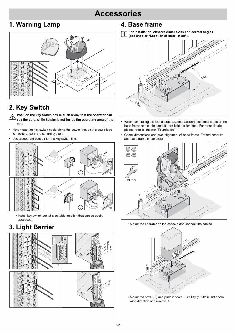
1. Warning Lamp
2. Key SwitchPosition the key switch box in such a way that the operator can
see the gate, while he/she is not inside the operating area of the
gate.
• Never lead the key switch cable along the power line, as this could leadto interference in the control system.
• Use a separate conduit for the key switch line.
• Install key switch box at a suitable location that can be easilyaccessed.
3. Light Barrier
SOMM
ER
SOMM
ER
678
9
10
2
3
4
5
SOMM
ER
SOMM
ER4
5
6
1
2
3
4. Base frameFor installation, observe dimensions and correct angles
(see chapter “Location of Installation”).
• When completing the foundation, take into account the dimensions of thebase frame and cable conduits (for light barrier, etc.). For more details,please refer to chapter “Foundation”.
• Check dimensions and level alignment of base frame. Embed conduitsand base frame in concrete.
• Mount the operator on the console and connect the cables.
• Mount the cover (2) and push it down. Turn key (1) 90° in anticlock-wise direction and remove it.
13 mm
min. 300
55
90°
Accessories
Accessories
23
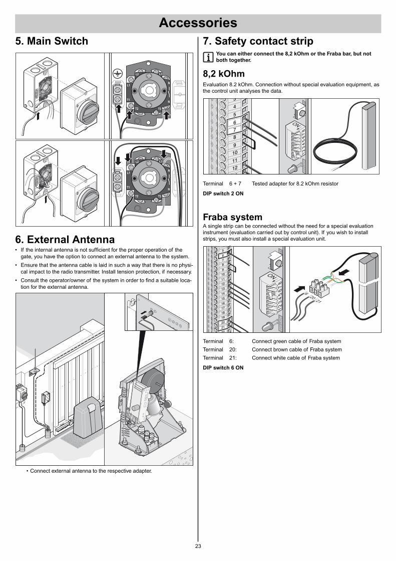
5. Main Switch
6. External Antenna• If the internal antenna is not sufficient for the proper operation of the
gate, you have the option to connect an external antenna to the system.
• Ensure that the antenna cable is laid in such a way that there is no physi-cal impact to the radio transmitter. Install tension protection, if necessary.
• Consult the operator/owner of the system in order to find a suitable loca-tion for the external antenna.
• Connect external antenna to the respective adapter.
O
L1
L2
L3
T3
T2
T1
N
N
O
L1
L2 L3
T3T2
T1
N
N
L1
L2
L3
T3
T2
T1
N
N
O
L1
L2 L3
T3T2
T1
N
N
7. Safety contact stripYou can either connect the 8,2 kOhm or the Fraba bar, but not
both together.
8,2 kOhmEvaluation 8.2 kOhm. Connection without special evaluation equipment, asthe control unit analyses the data.
Terminal 6 + 7 Tested adapter for 8.2 kOhm resistor
DIP switch 2 ON
Fraba systemA single strip can be connected without the need for a special evaluationinstrument (evaluation carried out by control unit). If you wish to installstrips, you must also install a special evaluation unit.
Terminal 6: Connect green cable of Fraba system
Terminal 20: Connect brown cable of Fraba system
Terminal 21: Connect white cable of Fraba system
DIP switch 6 ON
620
21
ED
3LE
D4
T1
ON7
86
54
32
1
4
5
78
9
10
11
16
17
18
19
20
21
22
12
13
14
15
6
24
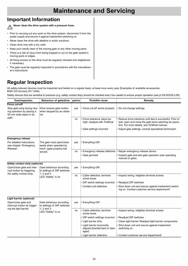
Test/inspection Behaviour of gate/drive yes/no Remedy
Stop gate wing during clos-ing operation by placing a50 mm wide object in itspath.
Drive reverse gate motionwhen stopped by an obsta-cle
yes
no
• Do not change settings.
• Reduce force tolerance until test is successful. Prior totest, open and close the gate twice watching its opera-tion. For more details, see TorMinal manual.
• Adjust gate settings, consult specialised technician!
Force cut-off
For detailed instructions,see chapter “EmergencyRelease”.
The gate must open/closeeasily when operated byhand. (gate properly bal-anced)
yes
no • Repair emergency release device
• Inspect gate and test gate operation (see operatingmanual of gate).
Emergency release
Open/close gate and inter-rupt motion by triggeringthe safety contact strip.
Gate behaviour accordingto settings of DIP switches1, 2 and 3.LED “Safety” is on
yes
no • Inspect wiring, retighten terminal screws
• Readjust DIP switches
• Shut down unit and secure against inadvertent switch-ing on. Contact customer service department!
Safety contact strip (optional)
Open/close gate andinterrupt motion by trigger-ing the light barrier.
Gate behaviour accordingto settings of DIP switches1, 2 and 3.LED “Safety” is on
yes
no • Inspect wiring, retighten terminal screws
• Readjust DIP switches
• Clean light barrier Readjust light barrier components
• Shut down unit and secure against inadvertentswitching on.
• Contact customer service department!
Light barrier (optional)
Regular InspectionAll safety-relevant devices must be inspected and tested on a regular basis, at least once every year (Examples of available accessories: BGR 232 formerly ZH 1/494).
Safety devices that are sensitive to pressure (e.g. safety contact strip) should be checked every four weeks to ensure proper operation (see pr EN 60335-2-95).
Possible cause
• Force cut-off works properly
• Force tolerance value toohigh; readjust with TorMinal
• Gate settings incorrect
• Everything OK!
• Emergency release defective
• Gate jammed
• Everything OK!
• Cable defective, terminalscrew loose
• DIP switch settings incorrect
• Contact unit defective
• Everything OK!
• Cable defective, terminalscrew loose
• DIP switch settings incorrect
• Light barrier dirty
• Light barrier incorrectlyaligned (bracket bent or dam-aged)
• Light barrier defective
Important InformationNever clean the drive system with a pressure hose.
• Prior to carrying out any work on the drive system, disconnect it from thepower supply and secure it against inadvertent switching on.
• Never clean the drive with alkaline or acidic solutions.
• Clean drive only with a dry cloth.
• Keep your hands clear of the moving gate or any other moving parts.
• There is a risk of injury from being trapped or cut on the gate system’smoving parts or edges.
• All fixing screws on the drive must be regularly checked and retightenedif necessary.
• The gate must be regularly inspected in accordance with the manufactur-er’s instructions.
Maintenance and Servicing
25
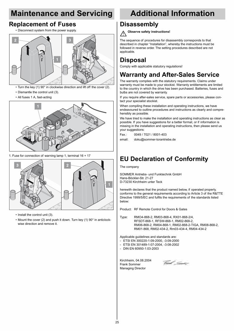
DisassemblyObserve safety instructions!
The sequence of procedures for disassembly corresponds to thatdescribed in chapter “Installation”, whereby the instructions must befollowed in reverse order. The setting procedures described are notapplicable.
DisposalComply with applicable statutory regulations!
Warranty and After-Sales ServiceThe warranty complies with the statutory requirements. Claims underwarranty must be made to your stockist. Warranty entitlements are limitedto the country in which the drive has been purchased. Batteries, fuses andbulbs are not covered by warranty.
If you require after-sales service, spare parts or accessories, please con-tact your specialist stockist.
When compiling these installation and operating instructions, we haveendeavoured to outline procedures and instructions as clearly and compre-hensibly as possible.
We have tried to make the installation and operating instructions as clear aspossible. If you have suggestions for a better format, or if information ismissing in the installation and operating instructions, then please send usyour suggestions:
Fax.: 0049 / 7021 / 8001-403
email: [email protected]
EU Declaration of ConformityThe company
SOMMER Antriebs- und Funktechnik GmbHHans-Böckler-Str. 21-27D-73230 Kirchheim unter Teck
herewith declares that the product named below, if operated properly,conforms to the general requirements according to Article 3 of the R&TTEDirective 1999/5/EC and fulfils the requirements of the standards listedbelow:
Product: RF Remote Control for Doors & Gates
Type: RMO4-868-2, RM03-868-4, RX01-868-2/4,RFSDT-868-1, RFSW-868-1, RM02-868-2,RM06-868-2, RM04-868-1, RM02-868-2-TIGA, RM08-868-2,RM01-868, RM02-434-2, Rm03-434-4, RM04-434-2
Applicable guidelines and standards are:- ETSI EN 300220-1:09-2000, -3:09-2000- ETSI EN 301489-1:07-2004, -3:08-2002- DIN EN 60950-1:03-2003
Kirchheim, 04.08.2004Frank SommerManaging Director
Maintenance and Servicing
Replacement of Fuses• Disconnect system from the power supply.
• Turn the key (1) 90° in clockwise direction and lift off the cover (2).
• Dismantle the control unit (3).
• All fuses 1 A, fast-acting
1. Fuse for connection of warning lamp 1, terminal 16 + 17
• Install the control unit (3).
• Mount the cover (2) and push it down. Turn key (1) 90° in anticlock-wise direction and remove it.
1
23
LED1 LED2 LED3 LED4
T1
P2
T2
1
1
2 3
Additional Information
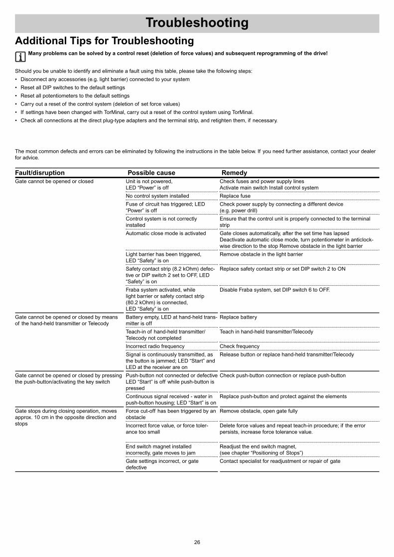
The most common defects and errors can be eliminated by following the instructions in the table below. If you need further assistance, contact your dealerfor advice.
Fault/disruption Possible cause Remedy
Troubleshooting
26
Gate cannot be opened or closed
Gate cannot be opened or closed by means of the hand-held transmitter or Telecody
Gate cannot be opened or closed by pressingthe push-button/activating the key switch
Gate stops during closing operation, movesapprox. 10 cm in the opposite direction andstops
Unit is not powered, LED “Power” is off
No control system installed
Fuse of circuit has triggered; LED“Power” is off
Control system is not correctlyinstalled
Automatic close mode is activated
Light barrier has been triggered, LED “Safety” is on
Safety contact strip (8.2 kOhm) defec-tive or DIP switch 2 set to OFF, LED“Safety” is on
Fraba system activated, while light barrier or safety contact strip (80.2 kOhm) is connected, LED “Safety” is on
Battery empty, LED at hand-held trans-mitter is off
Teach-in of hand-held transmitter/Telecody not completed
Incorrect radio frequency
Signal is continuously transmitted, asthe button is jammed; LED “Start” andLED at the receiver are on
Push-button not connected or defectiveLED “Start” is off while push-button ispressed
Continuous signal received - water inpush-button housing; LED “Start” is on
Force cut-off has been triggered by anobstacle
Incorrect force value, or force toler-ance too small
End switch magnet installedincorrectly, gate moves to jam
Gate settings incorrect, or gatedefective
Check fuses and power supply linesActivate main switch Install control system
Replace fuse
Check power supply by connecting a different device (e.g. power drill)
Ensure that the control unit is properly connected to the terminalstrip
Gate closes automatically, after the set time has lapsedDeactivate automatic close mode, turn potentiometer in anticlock-wise direction to the stop Remove obstacle in the light barrier
Remove obstacle in the light barrier
Replace safety contact strip or set DIP switch 2 to ON
Disable Fraba system, set DIP switch 6 to OFF.
Replace battery
Teach in hand-held transmitter/Telecody
Check frequency
Release button or replace hand-held transmitter/Telecody
Check push-button connection or replace push-button
Replace push-button and protect against the elements
Remove obstacle, open gate fully
Delete force values and repeat teach-in procedure; if the errorpersists, increase force tolerance value.
Readjust the end switch magnet, (see chapter “Positioning of Stops”)
Contact specialist for readjustment or repair of gate
Additional Tips for TroubleshootingMany problems can be solved by a control reset (deletion of force values) and subsequent reprogramming of the drive!
Should you be unable to identify and eliminate a fault using this table, please take the following steps:
• Disconnect any accessories (e.g. light barrier) connected to your system
• Reset all DIP switches to the default settings
• Reset all potentiometers to the default settings
• Carry out a reset of the control system (deletion of set force values)
• If settings have been changed with TorMinal, carry out a reset of the control system using TorMinal.
• Check all connections at the direct plug-type adapters and the terminal strip, and retighten them, if necessary.
Troubleshooting
27
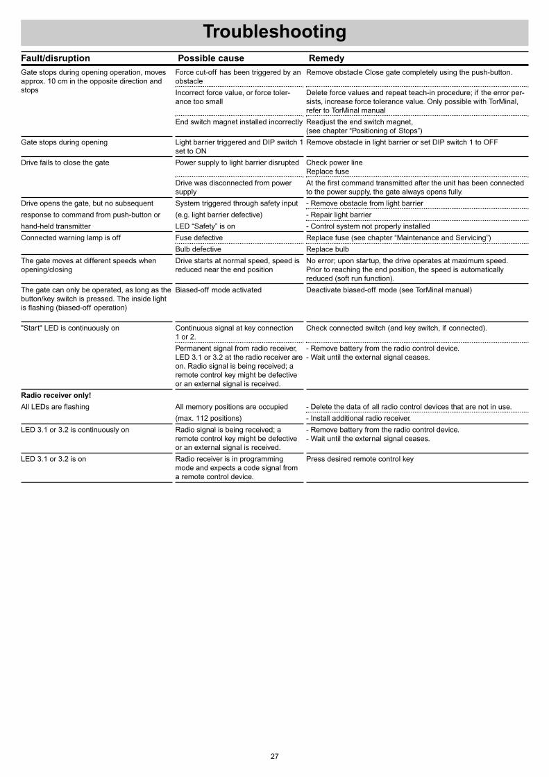
Fault/disruption Possible cause Remedy
Gate stops during opening operation, movesapprox. 10 cm in the opposite direction andstops
Gate stops during opening
Drive fails to close the gate
Drive opens the gate, but no subsequent
response to command from push-button or
hand-held transmitter
Connected warning lamp is off
The gate moves at different speeds whenopening/closing
The gate can only be operated, as long as thebutton/key switch is pressed. The inside lightis flashing (biased-off operation)
"Start" LED is continuously on
Radio receiver only!
All LEDs are flashing
LED 3.1 or 3.2 is continuously on
LED 3.1 or 3.2 is on
Force cut-off has been triggered by anobstacle
Incorrect force value, or force toler-ance too small
End switch magnet installed incorrectly
Light barrier triggered and DIP switch 1set to ON
Power supply to light barrier disrupted
Drive was disconnected from powersupply
System triggered through safety input
(e.g. light barrier defective)
LED “Safety” is on
Fuse defective
Bulb defective
Drive starts at normal speed, speed isreduced near the end position
Biased-off mode activated
Continuous signal at key connection 1 or 2.
Permanent signal from radio receiver,LED 3.1 or 3.2 at the radio receiver areon. Radio signal is being received; aremote control key might be defectiveor an external signal is received.
All memory positions are occupied
(max. 112 positions)
Radio signal is being received; aremote control key might be defectiveor an external signal is received.
Radio receiver is in programmingmode and expects a code signal froma remote control device.
Remove obstacle Close gate completely using the push-button.
Delete force values and repeat teach-in procedure; if the error per-sists, increase force tolerance value. Only possible with TorMinal,refer to TorMinal manual
Readjust the end switch magnet, (see chapter “Positioning of Stops”)
Remove obstacle in light barrier or set DIP switch 1 to OFF
Check power lineReplace fuse
At the first command transmitted after the unit has been connectedto the power supply, the gate always opens fully.
- Remove obstacle from light barrier
- Repair light barrier
- Control system not properly installed
Replace fuse (see chapter “Maintenance and Servicing”)
Replace bulb
No error; upon startup, the drive operates at maximum speed. Prior to reaching the end position, the speed is automaticallyreduced (soft run function).
Deactivate biased-off mode (see TorMinal manual)
Check connected switch (and key switch, if connected).
- Remove battery from the radio control device.- Wait until the external signal ceases.
- Delete the data of all radio control devices that are not in use.
- Install additional radio receiver.
- Remove battery from the radio control device.- Wait until the external signal ceases.
Press desired remote control key