HB triton ABB Rev01 en
132
0073-1-7621 │ Rev. 01 │ 02.2011 KNX Technical Reference Manual Busch-triton Pos: 2 /Produkthandbuch - DIN-A4/Titelblätter/Titelblatt - Busch-triton @ 11\mod_1279183665269_15.doc @ 82831 @ 6320/10 1/2-fold MF/IR 6320/30 3/6-fold MF/IR 6320/38 3/6-fold MF/IR/RTC 6320/50 5/10-fold MF/IR 6320/58 5/10-fold MF/IR/RTC excitingly different Unique in form – versatile in function: Busch-triton® sensors are redefining the role of control elements. Without frame, but with a design that is eye-catching, modern and elegant, they become an irresistible attention-getter in every room. The innovative exterior gives the impression that the switch behind it is something unique. And it is in fact a versatile multi-functional element with an almost unlimited flexibility. The individual rocker switches can be freely programmed, with each side being able to trigger different functions. This makes the sensor an independent control center with an unbeatable price-performance-ratio because three rocker switches are turned into a 6-fold control element. The bus coupler is already integrated, making additional devices unnecessary. The ultimate in comfort is the result of the interaction between the Busch-triton® and a remote control for the convenient call-up of the different functions. The sensors can also be used for controlling the room climate. They sense the actual temperature value in the room and adjust the cooling or heating accordingly. Also fan coil actuators can be controlled. Busch-triton® is available in different versions with one, three or five rocker switches, with or without room thermostat function. Each of the individual buttons can be labelled, making operation especially easy. The subdued lighting additionally provides orientation in the dark. The design with its five noble colours fits into every environment. The colours and the quality of the surfaces are also found in other Bush-Jaeger switch ranges, to ensure that entire technical facilities of the building, from the control element to the socket outlet, can be selected to match perfect visually. === Ende der Liste für Textmarke Cover ===
Transcript of HB triton ABB Rev01 en

0073-1-7621 │ Rev. 01 │ 02.2011
KNX Technical Reference Manual Busch-triton
Pos: 2 /Produkthandbuch - DIN-A4/Titelblätter/Titelblatt - Busch-triton @ 11\mod_1279183665269_15.doc @ 82831 @
6320/10 1/2-fold MF/IR 6320/30 3/6-fold MF/IR 6320/38 3/6-fold MF/IR/RTC 6320/50 5/10-fold MF/IR 6320/58 5/10-fold MF/IR/RTC
excitingly different Unique in form – versatile in function: Busch-triton® sensors are redefining the role of control elements. Without frame, but with a design that is eye-catching, modern and elegant, they become an irresistible attention-getter in every room. The innovative exterior gives the impression that the switch behind it is something unique. And it is in fact a versatile multi-functional element with an almost unlimited flexibility. The individual rocker switches can be freely programmed, with each side being able to trigger different functions. This makes the sensor an independent control center with an unbeatable price-performance-ratio because three rocker switches are turned into a 6-fold control element. The bus coupler is already integrated, making additional devices unnecessary. The ultimate in comfort is the result of the interaction between the Busch-triton® and a remote control for the convenient call-up of the different functions. The sensors can also be used for controlling the room climate. They sense the actual temperature value in the room and adjust the cooling or heating accordingly. Also fan coil actuators can be controlled.
Busch-triton® is available in different versions with one, three or five rocker switches, with or without room thermostat function. Each of the individual buttons can be labelled, making operation especially easy. The subdued lighting additionally provides orientation in the dark. The design with its five noble colours fits into every environment. The colours and the quality of the surfaces are also found in other Bush-Jaeger switch ranges, to ensure that entire technical facilities of the building, from the control element to the socket outlet, can be selected to match perfect visually.
=== Ende der Liste für Textmarke Cover ===

KNX Technical Reference Manual Busch-triton
2 | 0073-1-7621 | KNX Technical Reference Manual
Pos: 4.1 /Produkthandbuch - DIN-A4/Überschriften/1. Ebene/S - Z/Sicherheitshinweise @ 9\mod_1269243781484_15.doc @ 52309 @ 1
Safety instructions Pos: 4.2 /Spezial/Neues Layout 2010/Steuermodule_Neues_Layout_2010/++++++++++++ Wechsel von ein- auf zweispaltig ++++++++++++ @ 9\mod_1268898451593_0.doc @ 52140 @ Pos: 4.3 /Produkthandbuch - DIN-A4/Busch-priOn/Sicherheitshinweise/Sicherheitshinweise @ 9\mod_1269245364203_15.doc @ 52365 @
Work on the 230 V power supply system must only be performed by specialist staff. Disconnect the mains power supply prior to mounting and/or disassembly! Failure to observe the installation and operating instructions may result in fire or other hazards.
Pos: 4.4 /Produkthandbuch - DIN-A4/Busch-priOn/Sicherheitshinweise/Haftungsausschluss @ 16\mod_1292413036321_15.doc @ 97864 @
Disclaimer The content of this printed material has been checked for compliance with hardware and software. However, no liability can be assumed for any deviations that may still occur. Any necessary corrections will be implemented in future versions of this manual. Please advise us of any suggestions concerning the manual's improvement you may have.
Pos: 4.5 /Spezial/Neues Layout 2010/Steuermodule_Neues_Layout_2010/++++++++++++ Spaltenumbruch ++++++++++++ @ 9\mod_1268898761421_0.doc @ 52154 @

KNX Technical Reference Manual | 0073-1-7621 | 3
Pos: 4.6 /Spezial/Neues Layout 2010/Steuermodule_Neues_Layout_2010/++++++++++++ Wechsel zwei- auf einspaltig ++++++++++++ @ 9\mod_1268898591406_0.doc @ 52144 @
Pos: 5 /Spezial/Neues Layout 2010/Steuermodule_Neues_Layout_2010/++++++++++++ Seitenumbruch ++++++++++++ @ 9\mod_1268898668093_0.doc @ 52149 @ Pos: 6.1 /Produkthandbuch - DIN-A4/Überschriften/1. Ebene/S - Z/Technische Daten @ 11\mod_1279185386320_15.doc @ 83019 @ 1
Technical data Pos: 6.2 /Produkthandbuch - DIN-A4/Busch-triton/Technische Daten/Technische Daten @ 12\mod_1282831520895_15.doc @ 87813 @
Attribute Value Power supply Bus voltage 21 to 30 V DC, via bus line current consumption: Type 10 mA (= 2 bus subscribers)
Connections KNX Bus terminal Temperature sensor system Accuracy of temperature sensor +/- 0.3 K
(adjustment possible via parameter) Sensor type: NTC
Control and display elements LCD display Devices with integrated room thermostat 1, 3 or 5 rocker switches with 2 buttons each
1, 3 or 5 two-colour LEDs Red or green Backlit label areas
Protection IP 20, according to DIN EN 60529 Protection class III, acc. to DIN EN 61140
Insulation category Overvoltage category III, acc. to DIN EN 60664-1
Contamination degree 2, acc. to DIN EN 60664-1
Temperature range Use -5 °C to 45 °C
Storage -25 °C to 55 °C Transport -25 °C to 70 °C
Ambient conditions Maximum humidity 93%, no dew permissible Maximum air pressure Atmosphere up to 2000 m
Construction, housing, design Surface-mounted with integrated bus coupler Without additional supply voltage Fire characteristics V0
RoHs conformity and halogen-free Mounting Clicked onto support ring
Licence KNX According to EN 50 090-1, -2 According to EMC and low-voltage guidelines
Pos: 7 /Spezial/Neues Layout 2010/Steuermodule_Neues_Layout_2010/++++++++++++ Seitenumbruch ++++++++++++ @ 9\mod_1268898668093_0.doc @ 52149 @

KNX Technical Reference Manual Busch-triton
4 | 0073-1-7621 | KNX Technical Reference Manual
Pos: 8.1 /Produkthandbuch - DIN-A4/Überschriften/1. Ebene/A - F/Applikationsübersicht @ 14\mod_1286454537749_15.doc @ 92888 @ 1
Overview of applications Pos: 8.2 /Produkthandbuch - DIN-A4/Busch-triton/Applikationsübersicht/Tabelle @ 14\mod_1286373283580_15.doc @ 92443 @
Applications Control elements Function
1/2-fold 3/6-fold 3/6-fold RTC 5/10-fold 5/10-fold RTC IR remote control possible ● ● ● ● ●
Switching, rocker ● ● ● ● ●
Switching, button ● ● ● ● ● Dimming, rocker ● ● ● ● ●
Dimming, button ● ● ● ● ● Roller shutter, rocker ● ● ● ● ●
Roller shutter, button ● ● ● ● ● Value sender, rocker ● ● ● ● ●
Value sender, rocker ● ● ● ● ● Value dimming sensor, rocker ● ● ● ● ●
Light scene extension unit with memory function
● ● ● ● ●
Step-type switch, rocker ● ● ● ● ● Step-type switch, button ● ● ● ● ●
Short-long operation, button ● ● ● ● ● Setting RTC operation mode ● ● ● ● ●
Switching error protection ● ● ● ● ● 13 freely programmable IR channels ● ● ● ● ●
8 light scenes ● ● ● ● ● Features Write-on rockers ● ● ● ● ● Backlit labelling area ● ● ● ● ●
Removal protection ● ● ● ● ● Freely programmable control panel ● ● ● ● ●
IR remote control possible ● ● ● ● ● Freely programmable additional key ● ● ● ● ●
LCD display ● ● Heating with additional stage ● ●
Cooling with additional stage ● ● Comfort operation ● ●
Standby mode ● ● Night mode ● ●
Frost protection ● ● Heat protection ● ●
Fan control ● ●
Pos: 9 /Spezial/Neues Layout 2010/Steuermodule_Neues_Layout_2010/++++++++++++ Seitenumbruch ++++++++++++ @ 9\mod_1268898668093_0.doc @ 52149 @

KNX Technical Reference Manual | 0073-1-7621 | 5
Pos: 10.1 /Produkthandbuch - DIN-A4/Überschriften/1. Ebene/M - R/Maßzeichnungen @ 9\mod_1269243888140_15.doc @ 52313 @ 1
Dimensional drawings Pos: 10.2 /Spezial/Neues Layout 2010/Steuermodule_Neues_Layout_2010/++++++++++++ Wechsel von ein- auf zweispaltig ++++++++++++ @ 9\mod_1268898451593_0.doc @ 52140 @ Pos: 10.3 /Produkthandbuch - DIN-A4/Busch-triton/Maßzeichnungen/Maßzeichnungen @ 13\mod_1284973860036_15.doc @ 90164 @
Control element Busch-triton® 6320/10
90
84
Control element Busch-triton® 6320/30
Control element Busch-triton® 6320/38
Control element Busch-triton® 6320/50 and 6320/58
Pos: 10.4 /Spezial/Neues Layout 2010/Steuermodule_Neues_Layout_2010/++++++++++++ Wechsel zwei- auf einspaltig ++++++++++++ @ 9\mod_1268898591406_0.doc @ 52144 @
Pos: 11 /Spezial/Neues Layout 2010/Steuermodule_Neues_Layout_2010/++++++++++++ Seitenumbruch ++++++++++++ @ 9\mod_1268898668093_0.doc @ 52149 @

KNX Technical Reference Manual Busch-triton
6 | 0073-1-7621 | KNX Technical Reference Manual
Pos: 12.1 /Produkthandbuch - DIN-A4/Überschriften/1. Ebene/A - F/Einfache Montage @ 9\mod_1269243901843_15.doc @ 52338 @ 1
Easy to mount Pos: 12.2 /Produkthandbuch - DIN-A4/Busch-triton/Einfache Montage/Einfache Montage - Text @ 12\mod_1283176252903_15.doc @ 88128 @
Note For the horizontal installation of two Busch-triton® button sensors, it is recommended to keep a distance of 112 mm (by means of 2 flush-mounted box spacers, e.g. 2 x Kaiser spacing collars 91).
Screwed connection of the Busch-triton® cover with the support ring
Installation of label areas
Further information is contained in the "Installation and Operating Instructions". Pos: 13 /Spezial/Neues Layout 2010/Steuermodule_Neues_Layout_2010/++++++++++++ Seitenumbruch ++++++++++++ @ 9\mod_1268898668093_0.doc @ 52149 @

KNX Technical Reference Manual | 0073-1-7621 | 7
Pos: 14.1 /Produkthandbuch - DIN-A4/Überschriften/1. Ebene/M - R/Raumtemperaturregler @ 13\mod_1286268674432_15.doc @ 91479 @ 1
Room thermostat Pos: 14.2 /Produkthandbuch - DIN-A4/Überschriften/2. Ebene/P - R/Raumtemperaturregler-Display @ 13\mod_1286269387786_15.doc @ 91504 @ 2
Room thermostat with display Pos: 14.3 /Produkthandbuch - DIN-A4/Überschriften/3. Ebene/Standardansicht @ 13\mod_1286269449786_15.doc @ 91512 @ 3
Standard view Pos: 14.4 /Spezial/Neues Layout 2010/Steuermodule_Neues_Layout_2010/++++++++++++ Wechsel von ein- auf zweispaltig ++++++++++++ @ 9\mod_1268898451593_0.doc @ 52140 @ Pos: 14.5 /Produkthandbuch - DIN-A4/Busch-triton/Raumtemperaturregler/Standardansicht @ 13\mod_1286269136131_15.doc @ 91487 @
Operating state Operating mode
Actual or setpoint temperature
The display of the room thermostat shows either the current room temperature or the setpoint for the temperature, depending on the parameterization. The current operating state is shown in the left area of the display and the current operating mode in the right area. Pos: 14.6 /Spezial/Neues Layout 2010/Steuermodule_Neues_Layout_2010/++++++++++++ Wechsel zwei- auf einspaltig ++++++++++++ @ 9\mod_1268898591406_0.doc @ 52144 @
Pos: 14.7 /Produkthandbuch - DIN-A4/Überschriften/3. Ebene/Sollwerte @ 13\mod_1286269492130_15.doc @ 91520 @ 3
Set values Pos: 14.8 /Spezial/Neues Layout 2010/Steuermodule_Neues_Layout_2010/++++++++++++ Wechsel von ein- auf zweispaltig ++++++++++++ @ 9\mod_1268898451593_0.doc @ 52140 @ Pos: 14.9 /Produkthandbuch - DIN-A4/Busch-triton/Raumtemperaturregler/Sollwerte @ 13\mod_1286269283224_15.doc @ 91495 @
Heating setpoint Cooling setpoint
Temperature - Temperature + Next setpoint Previous setpoint
Comfort/Standby FanCoil-Steps On/Off
Short press Long press
In the setting level, which is accessed by pressing the additional key once, the setpoints for heating and/or cooling can be adjusted. The corresponding setpoints are located to the right of each respective symbol for heating or cooling. The value brightly highlighted can be changed. The adjustment is made with the upper rocker of the control element. A short press of the left side lowers the setpoint, a short press of the right side raises the setpoint. With a long press of the button the selection jumps to the next setpoint. This one can now also be adjusted with a short press of the button. After an adjustable time, the display returns to the standard view. Pos: 14.10 /Spezial/Neues Layout 2010/Steuermodule_Neues_Layout_2010/++++++++++++ Wechsel zwei- auf einspaltig ++++++++++++ @ 9\mod_1268898591406_0.doc @ 52144 @
Pos: 14.11 /Spezial/Neues Layout 2010/Steuermodule_Neues_Layout_2010/++++++++++++ Seitenumbruch ++++++++++++ @ 9\mod_1268898668093_0.doc @ 52149 @

KNX Technical Reference Manual Busch-triton
8 | 0073-1-7621 | KNX Technical Reference Manual
Pos: 14.12 /Produkthandbuch - DIN-A4/Überschriften/2. Ebene/A - F/Betriebsarten @ 13\mod_1286276050737_15.doc @ 91535 @ 2
Operating modes Pos: 14.13 /Spezial/Neues Layout 2010/Steuermodule_Neues_Layout_2010/++++++++++++ Wechsel von ein- auf zweispaltig ++++++++++++ @ 9\mod_1268898451593_0.doc @ 52140 @ Pos: 14.14 /Produkthandbuch - DIN-A4/Busch-triton/Raumtemperaturregler/Betriebsarten_zwei @ 13\mod_1286273939022_15.doc @ 91528 @
Standby: Standby mode lowers the temperature below the value of comfort mode. This saves energy and does not cool down the room even during an extended absence.
Comfort: Comfort mode regulates the temperature to suit the occupants while present. It can be called up time-controlled or via a telegram.
Dew point: If an appropriate telegram is received from a dew point sensor, the room thermostat will display the corresponding symbol and cease cooling and merely protect against the heat.
Alarm: The alarm can be freely parameterized. For example, it can occur when an external temperature sensor no longer sends values.
Night setback: The temperature can be reduced during the night. This saves energy and makes the night's rest comfortable. The heating starts again automatically the next morning to reach a comfortable temperature for rising.
Frost protection: If parameterized, frost protection will ensure that the temperature does not drop below the desired value. It is the lowest setpoint.
Heat protection: If parameterized, heat protection will ensure that the temperature does not exceed the desired value. It is the highest setpoint.
Condensate: The operation of a fan coil may cause condensate water, which is collected in a container. If the fan coil sends out a telegram when the container is full, the symbol for condensate mode is displayed. The room thermostat immediately switches into heat protection mode.
Pos: 14.15 /Spezial/Neues Layout 2010/Steuermodule_Neues_Layout_2010/++++++++++++ Wechsel zwei- auf einspaltig ++++++++++++ @ 9\mod_1268898591406_0.doc @ 52144 @
Pos: 14.16 /Spezial/Neues Layout 2010/Steuermodule_Neues_Layout_2010/++++++++++++ Seitenumbruch ++++++++++++ @ 9\mod_1268898668093_0.doc @ 52149 @

KNX Technical Reference Manual | 0073-1-7621 | 9
Pos: 14.17 /Produkthandbuch - DIN-A4/Überschriften/2. Ebene/A - F/Bedienelemente @ 13\mod_1286277412052_15.doc @ 91551 @ 2
Control elements Pos: 14.18 /Spezial/Neues Layout 2010/Steuermodule_Neues_Layout_2010/++++++++++++ Wechsel von ein- auf zweispaltig ++++++++++++ @ 9\mod_1268898451593_0.doc @ 52140 @ Pos: 14.19 /Produkthandbuch - DIN-A4/Busch-triton/Raumtemperaturregler/Bedienelement 1/2 @ 13\mod_1286277092802_15.doc @ 91544 @ 33333
1/2-fold control element with backlit label area and IR reception
The control elements have "large" freely programmable operating surfaces. They can be occupied with both rocker as well as button oriented applications. 3/6-fold control element with backlit label area, integrated room thermostat and IR reception
The control elements have two operating levels. On the first level the on-site operations are triggered, the additional key is used to access the second operating level with which the heating control can be operated. 3/6-fold control element with backlit label area and IR reception
Via the additional key there is the option of executing all the functions of a button or, on units with a room thermostat, to access the setting level.
5/10-fold control element with backlit label area and IR reception
Via the additional key there is the option of saving lighting scenes or controlling the backlighting of the label area. 5/10-fold control element with backlit label area, integrated room thermostat and IR reception
Alternative to the second operating level, also the operating surfaces can be used to control the the functions of the room thermostat. Pos: 14.20 /Spezial/Neues Layout 2010/Steuermodule_Neues_Layout_2010/++++++++++++ Wechsel zwei- auf einspaltig ++++++++++++ @ 9\mod_1268898591406_0.doc @ 52144 @
Pos: 14.21 /Spezial/Neues Layout 2010/Steuermodule_Neues_Layout_2010/++++++++++++ Seitenumbruch ++++++++++++ @ 9\mod_1268898668093_0.doc @ 52149 @

KNX Technical Reference Manual Busch-triton
10 | 0073-1-7621 | KNX Technical Reference Manual
Pos: 14.22 /Produkthandbuch - DIN-A4/Überschriften/3. Ebene/Verfügbare Farben @ 14\mod_1286352522378_15.doc @ 91714 @ 3
Available colours Pos: 14.23 /Spezial/Neues Layout 2010/Steuermodule_Neues_Layout_2010/++++++++++++ Wechsel von ein- auf zweispaltig ++++++++++++ @ 9\mod_1268898451593_0.doc @ 52140 @ Pos: 14.24 /Produkthandbuch - DIN-A4/Busch-triton/Raumtemperaturregler/Farben @ 14\mod_1286282747698_15.doc @ 91616 @
Platinum
Palladium
Champagne
Aluminium silver
Studio white
Pos: 14.25 /Spezial/Neues Layout 2010/Steuermodule_Neues_Layout_2010/++++++++++++ Wechsel zwei- auf einspaltig ++++++++++++ @ 9\mod_1268898591406_0.doc @ 52144 @
Pos: 15 /Spezial/Neues Layout 2010/Steuermodule_Neues_Layout_2010/++++++++++++ Seitenumbruch ++++++++++++ @ 9\mod_1268898668093_0.doc @ 52149 @

KNX Technical Reference Manual | 0073-1-7621 | 11
Pos: 16.1 /Produkthandbuch - DIN-A4/Überschriften/1. Ebene/M - R/Planerunterstützung RTR @ 13\mod_1286265494848_15.doc @ 91464 @ 1
Planner support for RTC Pos: 16.2 /Produkthandbuch - DIN-A4/Busch-triton/Bedienung/Betriebsarten @ 13\mod_1284551640044_15.doc @ 89965 @ 2
Operating modes
The room thermostat has four operating modes: • Frost protection mode (for heating): The room temperature control is inactive; heating is only carried out when the
temperature in the room drops to the point where the heating system could sustain damage through freezing. Heat protection mode (for cooling): The room temperature control is inactive; cooling is only carried out when the temperature has risen to the point where the heat in the room becomes unbearable.
• Comfort mode (for heating and cooling): The setpoint for the room temperature is set to a value that makes the temperature of the room comfortable during "normal use".
• Standby mode (for heating): The room temperature is reduced to the point where heating costs are saved (e.g. during temporary absence), but can be quickly raised to comfort temperature again. Standby mode (for cooling): The room temperature is only raised to the point where energy costs are saved (e.g. during temporary absence), but can be quickly increased to comfort temperature again.
• Night mode (for heating and cooling): Rooms are not used for longer periods during the night hours; the room temperature is set a comfortable night-time value and can be quickly raised again to the comfort setpoint in the morning.
A switchover between these operating modes can take place either by means of a switching telegram (parameter "Operating mode switchover": "1 bit (3x)") or with 1-byte value telegrams (parameter "Operating mode switchover": "1 byte (2x)"). Pos: 16.3 /Produkthandbuch - DIN-A4/Busch-triton/Bedienung/Betriebsartenumschaltung 1 Bit @ 13\mod_1284559347241_15.doc @ 89973 @ 3
Operating mode switchover, 1 bit
Frost/heat protection has the highest priority; i.e., switchover to a different mode cannot take place in this case. The frost/heat protection must first be deactivated; by closing an open window, for example. Night mode has the next highest priority, followed by comfort mode. If none of these three operating modes are active, the room thermostat is in standby mode. Pos: 16.4 /Produkthandbuch - DIN-A4/Busch-triton/Bedienung/Betriebsartenumschaltung 1 Byte @ 13\mod_1284559643038_15.doc @ 89981 @ 3
Operating mode switchover, 1 byte
Two 1-byte communication objects are made available with operation mode switchover via 1 byte. The two 1-byte communication objects have different behaviours for receipt of telegram. One object evaluates received telegrams as "normal". This means, for example, if a comfort telegram is received, the room thermostat switches to comfort mode. If a night telegram is received, the room thermostat switches to night mode. This object is controlled, for example, by time switches. The second object ("Operating mode switchover OMO") can "overwrite" the first. This means, for example, if a frost/heat protection telegram is received, the room thermostat switches to frost or heat protection mode. If frost or heat protection is reset after receipt of a new telegram, the room thermostat activates the mode that is pending on the "normal" object. As a result, it is capable of memorising operating modes. This object is controlled, for example, by binary inputs that record information from window contacts. The following conditions apply for both 1-byte communication objects: 0 = Auto (only for "Operating mode switchover OMO“) 1 = Comfort 2 = Standby 3 = Night 4 = Frost/Heat protection 5 – 255 = not allowed Pos: 16.5 /Produkthandbuch - DIN-A4/Busch-triton/Bedienung/Temperaturmessung @ 13\mod_1284626154763_15.doc @ 89994 @ 2
Temperature measurement
The room thermostat with display can record the temperature via an internal sensor. Additionally, values can be received from an external sensor or an external temperature sensor via communication objects. The incoming values can be monitored and, if necessary, adjusted. The functions are explained in greater detail in the following. Pos: 16.6 /Produkthandbuch - DIN-A4/Busch-triton/Bedienung/Interne Temperaturerfassung @ 13\mod_1284626329778_15.doc @ 90002 @ 3

KNX Technical Reference Manual Busch-triton
12 | 0073-1-7621 | KNX Technical Reference Manual
Internal temperature sensor
The device has an integrated temperature sensor. The measured value enters the control as actual value. The value can also be shown on the display. In addition, the measured temperature can be transferred to the bus via the 2-byte communication object "Send actual value - temperature sensor", to be shown on the display, for example. Sending takes place in dependence of parameters "Send actual value for change greater than" and "Send actual value cyclically". By default, both parameters are deactivated. This means that at least one setting must be activated if the actual temperature is to be sent. The setting "Send actual value for change greater than" has the advantage of being able to transmit the smallest change in the measured temperature, adjustable from 0.1 k to 1.0 K, to the bus. The disadvantage is, for example, that at a setting of 0.1 K and a lot of room thermostats within an installation, the load on the bus increases. The parameter "Send actual value cyclically" has the advantage that the current actual value is sent out continuously, even when the measured value does not change. The disadvantage is that rapid changes may not be registered because the cycle time selected is too large. It should also not be small because of the extreme load the bus is subjected to. Pos: 16.7 /Produkthandbuch - DIN-A4/Busch-triton/Bedienung/Externe Temperaturerfassung @ 13\mod_1284635472980_15.doc @ 90010 @ 3
External temperature sensor
In open-plan offices it can be difficult to control the temperature with only a single thermostat. That is why it would be advantageous to divide the room into zones with an additional room thermostat. To integrate the temperature value of the additional temperature sensor into the temperature control, the parameter "Room temperature measurement" must be set on "Internal and external". The the temperature measured inside and outside can then be additionally weighted. The setting for weighting depend on the local circumstances. If the room thermostat and the additional measuring sensor are positioned equal distances from the heater, in the case of panel heaters, a 50% / 50% setting should provide good control results. Pos: 16.8 /Produkthandbuch - DIN-A4/Busch-triton/Bedienung/Überwachung Temperaturmessung @ 13\mod_1284635867620_15.doc @ 90018 @ 3
Monitoring
The "Temperature measurement monitoring" parameter specifies whether the external temperature sensor and the outside temperature are to be monitored. This means that the room thermostat has to receive at least one telegram with the current temperature on the associated communication object within an adjustable time ("Monitoring time of external temperature" and "Monitoring time of outside temperature"). If no telegram is received during monitoring time, the room thermostat assumes that the measuring sensor for the outside temperature or external temperature is defective or no longer connected to the bus. The room thermostat will then terminate its control and send a predefined control value ("Control value during temperature measurement error") so that the room to be controlled does not overheat or cool down. This control value is sent out until the room thermostat again receives a temperature telegram via the bus and reactivates the control. Pos: 16.9 /Produkthandbuch - DIN-A4/Busch-triton/Bedienung/Abgleich Temperaturmessung @ 13\mod_1284636694181_15.doc @ 90026 @ 3
Adjustment
If the measured temperature is distorted, such as by the inherent heat of the bus coupler, an "Offset room temperature measurement" can be set. If additional external temperature recording has been activated and the measured value becomes distorted through the influence of cold or heat, here, too, an offset can be entered. Pos: 16.10 /Spezial/Neues Layout 2010/Steuermodule_Neues_Layout_2010/++++++++++++ Seitenumbruch ++++++++++++ @ 9\mod_1268898668093_0.doc @ 52149 @

KNX Technical Reference Manual | 0073-1-7621 | 13
Pos: 16.11 /Produkthandbuch - DIN-A4/Busch-triton/Bedienung/Regler @ 13\mod_1284636897353_15.doc @ 90034 @ 2
Controller
The room thermostat can be used exclusively for heating, exclusively for cooling or for heating and cooling. If the room thermostat is to heat or cool, the switchover from heating to cooling or cooling to heating can occur automatically by means of the room thermostat. The controller detects automatically whether a control value for heating or cooling is to be sent out. If the automatic switchover is not required, the switchover between heating and cooling can take place by means of an external, central control via the 1-bit object "Switchover heating/cooling". In this setup, the heat and cooling icons are continuously displayed in the respective mode. The object is enabled via parameter "Switchover between heating/cooling". The control value for heating and/or cooling can be sent out on a common communication object "Heating/cooling control value" or on two individual communication objects "Heating control value" and "Cooling control value". If a common object is used, it may be necessary to inform the actuator whether the control value is for heating or cooling. For this, a 1-bit communication object "Switchover heating/cooling" can be enabled via parameter "Switchover between heating and cooling" with setting "Automatic and sending". For activation of heating operating mode a "1" is sent to the bus, for activation of cooling mode a "0". A common communication object for heating and cooling is required to activate two two-pipe systems, i.e., the same pipeline is used for heating and cooling. Two single communication objects are used for four-pipe systems. Heating and cooling each have their own pipeline system. Parameter "Number of output channels" specifies whether an object ("1 channel (two-pipe system) for heating and cooling") or two objects ("2 channels (four-pipe system) for heating and cooling") are to be displayed. Separate control types can be configured each for heating and cooling. One of the following control types can be selected: • 2-point • PWM • Continuous • Fan coil The individual control types are described in greater detail in the following. Pos: 16.12 /Produkthandbuch - DIN-A4/Busch-triton/Bedienung/Zweipunktregler @ 13\mod_1284639958501_15.doc @ 90042 @ 3
2-point controller
A 2-point controller has two output states that alternate in dependence of the actual value. If the actual value is above the parameterised setpoint, control value "0" is sent on the bus. If the actual value is below the parameterised setpoint, control value "1" is sent. A 2-point controller should be used when the control value is to alternate only between the two states ON and OFF, such as an electrothermal valve that is connected to a switch actuator, for example. A 2-point controller can quickly correct control variations in case of large changes in the control variable, but never comes to rest. To avoid rapid oscillations of the output states, the 2-point controllers always have a built-in hysteresis that varies around the setpoint. The hysteresis can have different size parameters. For example, if the setpoint during heating mode is 21 °C and the hysteresis is 1.0 K, the controller switches on when the value falls below 20.5 °C and switches off again when exceeding 21.5 °C. The "Hyteresis" parameter to be set, on the one hand responds to how quickly the heating can heat the room or how quickly the air-conditioning cools the room, and on the other hand to the desired temperature of the people in the room. The hysteresis should not be set too small, otherwise the switching actuator will constantly open and close. The hysteresis should also not be set too large, otherwise the temperature fluctuations in the room will be too large. Pos: 16.13 /Spezial/Neues Layout 2010/Steuermodule_Neues_Layout_2010/++++++++++++ Seitenumbruch ++++++++++++ @ 9\mod_1268898668093_0.doc @ 52149 @

KNX Technical Reference Manual Busch-triton
14 | 0073-1-7621 | KNX Technical Reference Manual
Pos: 16.14 /Produkthandbuch - DIN-A4/Busch-triton/Bedienung/Stetigregler @ 13\mod_1284706827607_15.doc @ 90054 @ 3
Continuous controller
A continuous controller has a continuously changing control value which can accept values between 0 and 100%. For the KNX this control value signal is converted to a 1-byte value, which means that control value 0% corresponds to value "0" and control value 100% to value "255". Continuous controllers with a 1-byte control value, for example, can be used to activate electromotive actuating drives. They translate the value received directly into the valve position via an installed motor. This results in optimum control. The 1-byte control value of a continuous controller can also be sent to KNX heating actuators which convert the 1-byte signal into a PWM size. This allows electrothermal valves to be activated. Here it is practical to limit the dynamic range since electrothermal valves require time to open and close. This takes place via parameters "Minimum control value" or "Maximum control value". If, for example, a maximum control value of 80% is specified, the control will always automatically send the value 255 when the control value of 204 has been exceeded. To protect the bus from unnecessary loads the change of the control value that is permitted to be sent to the bus can be set. The setting is in percent. The control value sent, unless it has changed, is specified by means of a cycle time. The cycle time selected should not be too small (e.g. every 10 min.). Pos: 16.15 /Produkthandbuch - DIN-A4/Busch-triton/Bedienung/PWM-Regler @ 13\mod_1284713045044_15.doc @ 90062 @ 3
PWM controller
The PWM controller has the same continuous control as the continuous controller. The difference is that with a PWM controller the 1-byte control value (0...255) is converted into an On/OFF switching relationship (0 and 1). If, for example, a control value of 70% is to be issued, at a pre-set cycle time of 10 minutes the switch-on time will be 7 minutes and the switch-off time 3 minutes. This transfers the advantages of the continuous control (control at the desired setpoint, no overshooting) to drives which are designed only for On/Off switching signals, such as electrothermal drives. To optimise the controlling characteristics of the heating/cooling system, the "PWM control value cycle time" can be set. To set a practical cycle time, the type of heating or cooling as well as the actuating drive used should be taken into consideration. The following recommendations can be used: • Electrothermal actuating drive
To fully open an electrothermal control valve takes approximately 2-3 minutes. That is why a cycle time of less than 15 minutes is not practical.
• Floor heating The time constant of floor heating is rather large. That is why a cycle time of 20 minutes is sufficient.
• Hot water heating Her electrothermal drives are generally used. A cycle time of 15 minutes will produce excellent control results.
• Electro-convector heating Cycle times of between 10 and 15 minutes are recommended, depending on the electric heating system and the spatial circumstances.
Pos: 16.16 /Produkthandbuch - DIN-A4/Busch-triton/Bedienung/Fan Coil @ 13\mod_1284715124126_15.doc @ 90070 @ 3
Fan coil
With the selection of fan coil for "Control types" the control value output takes place in the same way as described under Continuous control. With 'fan coil' there is the additional option of activating fan stages via a 1-byte or three 1-bit communication objects. The added connection of the fan stages heats or cools the room correspondingly faster. Which fan stage is to be active at which control value is specified on a separate tab "Fan coil heating" or "Fan coil cooling". Here it should be ensured that threshold value stage 1 must always be smaller than threshold value stage 2, which in turn must be smaller than threshold value stage 3. Pos: 16.17 /Spezial/Neues Layout 2010/Steuermodule_Neues_Layout_2010/++++++++++++ Seitenumbruch ++++++++++++ @ 9\mod_1268898668093_0.doc @ 52149 @
KNX Technical Reference Manual | 0073-1-7621 | 15
Pos: 16.18 /Produkthandbuch - DIN-A4/Busch-triton/Bedienung/Regelparameter @ 13\mod_1284716229894_15.doc @ 90078 @ 3
Control parameter for PWM controller and continuous controller (Fan coil)
For continuous control behaviour and for a switching PWM controller, the preset control parameters can be used via the installation type of the heating or cooling system. If different control parameters are required, they should be set individually via user parameterization. User parameterization should only be used by persons with adequate experience in control technology. The setting "User parameterization" can be used to set the "Proportional range (Xp)" and the "Readjust time (Tn". The proportional range lies below and above the preset setpoint and determines the regulating speed. The readjust time amounts to three times the delay time. The delay time is determined by the reversing tangent of the heating curve of the room. In general, the more inactive the overall system, the larger the parameterization values should be. Pos: 16.19 /Produkthandbuch - DIN-A4/Busch-triton/Bedienung/Zweistufiges Heizen Kühlen @ 13\mod_1284717573439_15.doc @ 90086 @ 3
Two-stage heating / cooling
In specific instances such as when using underfloor heating, it may be necessary to install a quick additional stage for the heat control in order to warm up the room rapidly. When the room thermostat is preset to "Additional heating stage active", it has a second heating system with switching control that regulates with the 1-byte values 0% and 100%. The parameters "Distance of the additional stage" and "Hysteresis (one-sided)" enable you to specify when the additional stage switches on and off. For instance, if the setpoint for the additional stage is 18 °C and the hysteresis is 0.5 K (one-sided), the controller switches on at 18 °C and off again at 18.5 °C. The settings for the additional heating stage apply equally to the additional cooling stage, the only difference being that in the case of cooling, when a set temperature has been exceeded, an additional cooling stage is switched on to cool the room faster. Since several actuating drives close (opened de-energised) at a 1-bit value of "1" or a 1-byte value of "255" and open at "0", the mode of the control value can be changed via "Invert control value". Pos: 16.20 /Produkthandbuch - DIN-A4/Busch-triton/Bedienung/Sollwerte @ 13\mod_1284722358805_15.doc @ 90094 @ 2
Set values
The room thermostat can operate with dependent or individual set values. Both versions are explained in greater detail in the following. Pos: 16.21 /Produkthandbuch - DIN-A4/Busch-triton/Bedienung/Abhängige Sollwerte @ 13\mod_1284722436946_15.doc @ 90102 @ 3
Dependent setpoints
In case of dependent setpoints there are two basic setpoints, one for heating ("Heating setpoint comfort operation" and one for cooling ("Cooling setpoint comfort operation"). The settings "...lowering standby/night mode" or "...raising standby/night mode". This means, for example, when 21 °C has been set for "Heating setpoint comfort mode" and 2 K was specified for "Lower heating setpoint standby", the heating setpoint in standby mode is lowered by 2 K to 19 °C. If 4 K has been specified for "Lower heating setpoint standby", the setpoint for "Heating setpoint for night mode" is 17 °C. The dependence of the setpoints are also maintained after a manual setpoint shift. For example, when the user has effected a setpoint shift of 1 K upward to 22 °C for the parameterized temperature "Heating setpoint comfort mode", this value will be lowered by 2 K to 20 °C when comfort mode is activated. When night mode is called up, the value will be lowered by 4 K, resulting in a setpoint of 18 °C. The user can manually change the parameterized setpoints via the two buttons "Raise temperature" or "Lower temperature". The change between "Heating setpoint comfort mode" and Cooling setpoint comfort mode" is made via a long press (approx. 1 sec.) of button "Raise temperature" to heating setpoint and on button "Lower temperature" to cooling setpoint. The two specified setpoints for heating and cooling can also be changed as often as desired via the bus without the ETS. Here a 2-byte temperature value must be sent to the communication object "Base setpoint - control". Depending on whether heating or cooling is currently active, the value is stored as "Heating setpoint comfort mode" or "Cooling setpoint comfort mode". The values received are stored in the memory of the device and are retained in case of bus power failure and subsequent return of bus voltage. This makes it possible to send new base setpoints to the device via a visualization when the use of a room changes, for example. New parameterization is not required. In case of a manual adjustment and dependent setpoints the reference base setpoint is taken into consideration. This is used to specify whether the base setpoint refers to the comfort temperature for heating, cooling or the mid-range temperature between heating and cooling.

KNX Technical Reference Manual Busch-triton
16 | 0073-1-7621 | KNX Technical Reference Manual
"Setpoint heating" is the default setting. In regions where the cooling function is more important, it is recommended that you change this parameter to "Setpoint cooling". This makes it easier to set the room thermostat and raise the cooling setpoint (standby temperature cooling and night setback cooling). Pos: 16.22 /Produkthandbuch - DIN-A4/Busch-triton/Bedienung/Individuelle Sollwerte @ 13\mod_1284722653915_15.doc @ 90110 @ 3
Individual setpoints
When individual setpoints are used, individual setpoints are defined for each operating mode ("Heating setpoint comfort mode", Heating setpoint standby", "Heating setpoint night mode", "Cooling setpoint standby" and "Cooling setpoint night mode". Different to the dependent setpoints, the individual setpoints are also maintained after a manual setpoint shift. For example, when the user has effected a setpoint shift of the parameterized temperature "Heating setpoint comfort mode" upward or downward, the parameterized value "Heating setpoint standby" will always be called up when standby mode is activated. This means that only the fixed setpoints that are stored will be called up for the individual operating modes. The user can manually change the parameterized setpoints via the two buttons "Raise temperature" or "Lower temperature". The change between "Heating setpoint comfort mode" and "Cooling setpoint comfort mode" is made via a long press (approx. 1 sec.) of button "Raise temperature" to heating setpoint and on button "Lower temperature" to cooling setpoint. The specified setpoints can be changed as often as desired via the bus also without the ETS. For this, a 2-byte temperature value must be sent to the corresponding communication object "Setpoint heating comfort", "Setpoint heating standby", Setpoint heating night mode", "Setpoint frost protection", "Setpoint cooling comfort", "Setpoint cooling standby", "Setpoint cooling night mode" or "Setpoint heat protection". The values received are stored in the memory of the device and are retained in case of bus power failure and subsequent return of bus voltage. This makes it possible to send new setpoints to the device via a visualization when the use of a room changes, for example. New parameterization is not required. Pos: 16.23 /Produkthandbuch - DIN-A4/Busch-triton/Bedienung/Mindestabstand @ 13\mod_1284722752633_15.doc @ 90118 @ 3
Minimum distance
The adjustable parameter "Minimum distance between heating and cooling" is active both for the dependent and the individual setpoints. The minimum distance is always between "Heating setpoint comfort mode" and "Cooling setpoint comfort mode". It serves as a buffer zone to prevent the the two setpoints from interfering with each other. Example: Individual setpoints has been selected. The "Heating setpoint comfort mode" is 21 °C and the "Cooling setpoint comfort mode" is set on 26 °C. The dead zone between heating and cooling is 3 K. If a heating setpoint is now shifted upwards, the dead zone also shifts upwards. If the shift exceeds a temperature of 23 °C, the "Cooling setpoint comfort mode" will also shift upwards so that a minimum distance of 3 K is always guaranteed between heating and cooling. If a cooling setpoint is shifted downwards, the dead zone also shifts downwards. If the shift exceeds a temperature of 24 °C, the "Heating setpoint comfort mode" will also shift downwards so that a minimum distance is also guaranteed in this case. Pos: 16.24 /Spezial/Neues Layout 2010/Steuermodule_Neues_Layout_2010/++++++++++++ Seitenumbruch ++++++++++++ @ 9\mod_1268898668093_0.doc @ 52149 @

KNX Technical Reference Manual | 0073-1-7621 | 17
Pos: 16.25 /Produkthandbuch - DIN-A4/Busch-triton/Bedienung/Fan Coil Allgemein @ 13\mod_1284722830008_15.doc @ 90126 @ 2
Fan coil, general
The ventilation convectors, also called fan convectors or fan coil units, are used for decentralized heating and cooling. They are installed in the room and supplied via a central heating and cooling system. There are two-pipe and four-pipe systems. There are multi-stage ventilators within a fan coil unit that enable fast adjustment to the room temperature to be made according to individual requirements. The fan coil room thermostat with display can activate up to three fan stages either manually or automatically. The fan stages can be activated in three ways: • via 1-bit values,
i.e., a 1-bit communication object "Fan coil stage ... switching" is made available for each fan stage. This required for "normal switch actuators. ((When using KNX switch actuators and fan coil units, the connecting instructions for the fan coil unit are to be observed).
• via 1-byte object as numerical value 0-3, i.e. there is a 1-byte communication object "Fan stage manual 1 byte" which is connected with a corresponding communication object of a fan coil actuator. Here the value 0 = OFF 1 = stage 1 2 = stage 2 3 = stage 3
• via 1-byte object as constant value 0-100%, i.e. there is a 1-byte communication object "Fan stage manual 1 byte" which is connected with a corresponding communication object of a fan coil actuator. During manual stage switchover the stage threshold values that are set on tab heating or cooling are sent out. In heating mode the threshold values for heating, in cooling mode the threshold values for cooling. To ensure that the fan coil unit switches the fan stages, the parameters of the associated fan coil actuator must be set accordingly.
Via parameter "Evaluate fan stage status byte" a 1-byte communication object "Fan coil operating state", which is connected with a corresponding object of a fan coil actuator, can be enabled. This allows the fan coil room thermostat evaluate which fan stage is actually active on the fan coil actuator. The display corresponds to the value of the communication object (0 = OFF, 1 = stage 1, 2 = stage 2, 3 = stage 3). The parameter "Evaluate operation status byte" activates a 1-bit communication object "Receive during operation - actuator monitoring". Cyclical telegrams from the fan coil actuator can be received and evaluated on this object. This allows the room thermostat to check whether the fan coil actuator is still operating and can be activated. If the fan coil actuator has a problem and can no longer send cyclical telegrams, the room thermostat will indicate this on the display with the "Error" symbol. If the error on the fan coil actuator has been rectified and cyclical telegrams can be received, the "Error" on the display is removed and the room thermostat will again function as "Normal". The cycle time setting "In operation" in the fan coil actuator should be selected at least twice as large as the monitoring time in the room thermostat ("Sending cycle time of actuator in sec."). A practical cycle time for the actuator is approximately 60 seconds with a monitoring time of 120 seconds for the room thermostat. To prevent an excessive noise level in hotel rooms during the silent period in the night, a "Stage limitation for night mode" can be set. This means that during night mode only the fan stage that has been set is automatically switched to. All fan stages can be activated again when changing to a different operating mode. Parameter "Stage limitation for night mode" can be used to set a limit to "Stage 2" or "Stage 1" or the ventilation can be completely deactivated. Pos: 16.26 /Produkthandbuch - DIN-A4/Busch-triton/Bedienung/Kompensation @ 13\mod_1284723063462_15.doc @ 90134 @ 2
Compensation
The fan coil room thermostat with display has the two compensation types, summer and winter compensation. Each is explained in greater detail in the following. Pos: 16.27 /Spezial/Neues Layout 2010/Steuermodule_Neues_Layout_2010/++++++++++++ Seitenumbruch ++++++++++++ @ 9\mod_1268898668093_0.doc @ 52149 @
KNX Technical Reference Manual Busch-triton
18 | 0073-1-7621 | KNX Technical Reference Manual
Pos: 16.28 /Produkthandbuch - DIN-A4/Busch-triton/Bedienung/Sommerkompensation @ 13\mod_1284723143680_15.doc @ 90142 @ 3
Summer compensation
To save energy and to maintain a reasonable temperature difference when entering an air-conditioned building, the room temperature should be adjusted in relation to the external temperature (summer compensation according to DIN 1946). The room temperature is raised by adjusting the "Cooling setpoint comfort mode". Raising the room temperature does not, however, mean that you heat up the room. Rather the adjustment is intended to allow the room temperature without cooling to increase to a specified value. This prevents the cooling system from further reducing the room temperature to 24 °C with an external temperature of 35 °C. However, the activation of summer compensation makes an external temperature sensor necessary that sends its measured value to the KNX for evaluation by the room thermostat with display. The following parameters are available for summer compensation: • "Summer compensation lower outside temperature value" • "Summer compensation upper outside temperature value" • “Summer compensation lower setpoint offset" • “Summer compensation upper setpoint offset" The value of the lower and upper temperature is used to specify from and to which temperature value a setpoint correction is to be made. The lower and upper setpoint offset is used to specify by how many Kelvin the setpoint specified in the parameters or by the user via a manual shift is to be adjusted during summer compensation. Typical values for the summer compensation are: • 20 °C: lower outside temperature value • 32 °C: upper outside temperature value • 0 K: lower setpoint offset • 4 K: upper setpoint offset That means that a flowing setpoint increase of 0 to 4 K occurs if the outside temperature increases from 20°C to 32°C. Example: In the lower diagram 25 °C has been parameterized for "Cooling setpoint comfort". When the outside temperature rises, the parameterized setpoint is raised starting from an outside temperature of 20 °C flowing from 25 °C to 29 °C. The 29 °C are reached at an outside temperature of 32 °C. After this the setpoint is no longer raised even though the outside temperature rises. Note: When compensation is active, CO is shown on the display of the room thermostat. Pos: 16.29 /Spezial/Neues Layout 2010/Steuermodule_Neues_Layout_2010/++++++++++++ Seitenumbruch ++++++++++++ @ 9\mod_1268898668093_0.doc @ 52149 @

KNX Technical Reference Manual | 0073-1-7621 | 19
Pos: 16.30 /Produkthandbuch - DIN-A4/Busch-triton/Bedienung/Winterkompensation @ 13\mod_1284723385008_15.doc @ 90150 @ 3
Winter compensation
To improve comfort and to keep the temperature difference when entering a room with large window areas in comfortable limits, an increase of the room temperature, as a function of the outside temperature, should be performed during the winter (winter compensation). The room temperature is raised by adjusting the "Heating setpoint comfort mode". However, similar to summer compensation, winter compensation makes an external temperature sensor necessary that sends its measured value to the KNX for evaluation by the room thermostat with display. The following parameters are available for winter compensation: • "Winter compensation lower outside temperature value" • "Winter compensation upper outside temperature value" • "Winter compensation lower setpoint offset" • "Winter compensation upper setpoint offset" The value of the lower and upper temperature is used to specify from and to which temperature value a setpoint correction is to be made. The lower and upper setpoint offset is used to specify by how many Kelvin the setpoint specified in the parameters or by the user via a manual shift is to be adjusted during winter compensation. Typical values for the winter compensation are: • 0 °C: lower outside temperature value • 10 °C: upper outside temperature value • 4 K: lower setpoint offset • 0 K: upper setpoint offset That means that a flowing setpoint increase from 0 to 4 K occurs if the outside temperature falls from 10 °C to 0 °C. Example: In the lower diagram 21 °C has been parameterized for "Heating setpoint comfort". When the outside temperature falls, the parameterized setpoint is raised starting from an outside temperature of 10 °C flowing from 21 °C to 25 °C. The 25 °C are reached at an outside temperature of 0 °C. After this the setpoint is no longer raised even though the outside temperature continuous to fall. Note: When compensation is active, CO is shown on the display. Pos: 17 /Spezial/Neues Layout 2010/Steuermodule_Neues_Layout_2010/++++++++++++ Seitenumbruch ++++++++++++ @ 9\mod_1268898668093_0.doc @ 52149 @

KNX Technical Reference Manual Busch-triton
20 | 0073-1-7621 | KNX Technical Reference Manual
Pos: 18.1 /Produkthandbuch - DIN-A4/Überschriften/1. Ebene/M - R/Parameter - Allgemeine Beschreibung @ 11\mod_1279199708077_15.doc @ 83691 @ 1
Parameters - General Description Pos: 18.2 /Produkthandbuch - DIN-A4/Busch-triton/Parameter - Allgemeine Beschreibung/Inhalt @ 16\mod_1294834213926_15.doc @ 99153 @
General See page 21. Rocker Switch 1-5 See page 23. LED rocker switch 1-5 See page 70. Light Scene Actuator, General See page 73. Light Scene Actuator, Actuator Groups See page 74. Light Scene Actuator, Scene 1-8 See page 75. Infrared Receiver See page 77. Infrared Receiver Button Pair 1-5 See page 78. Infrared Receiver Memo Button 1-2, Red See page 79. Temperature Sensor, General See page 80. Temperature measurement See page 83. Controller, General See page 86. Control, Heating See page 89. Control, PWM Heating See page 93. Control, Cooling See page 95. Control, PWM Cooling See page 99. Additional Heating Stage See page 101. Additional Cooling Stage See page 103. Set Value, General See page 105. Set Value, Manual See page 107. Set Value, Heating / Cooling See page 110. Fan Coil, General See page 114. Fan Coil, Heating See page 117. Fan Coil, Cooling See page 119. Compensation See page 122. Pos: 18.3.1 /Produkthandbuch - DIN-A4/Überschriften/1. Ebene/A - F/Allgemein @ 11\mod_1279269377674_15.doc @ 84332 @ 1
KNX Technical Reference Manual | 0073-1-7621 | 21
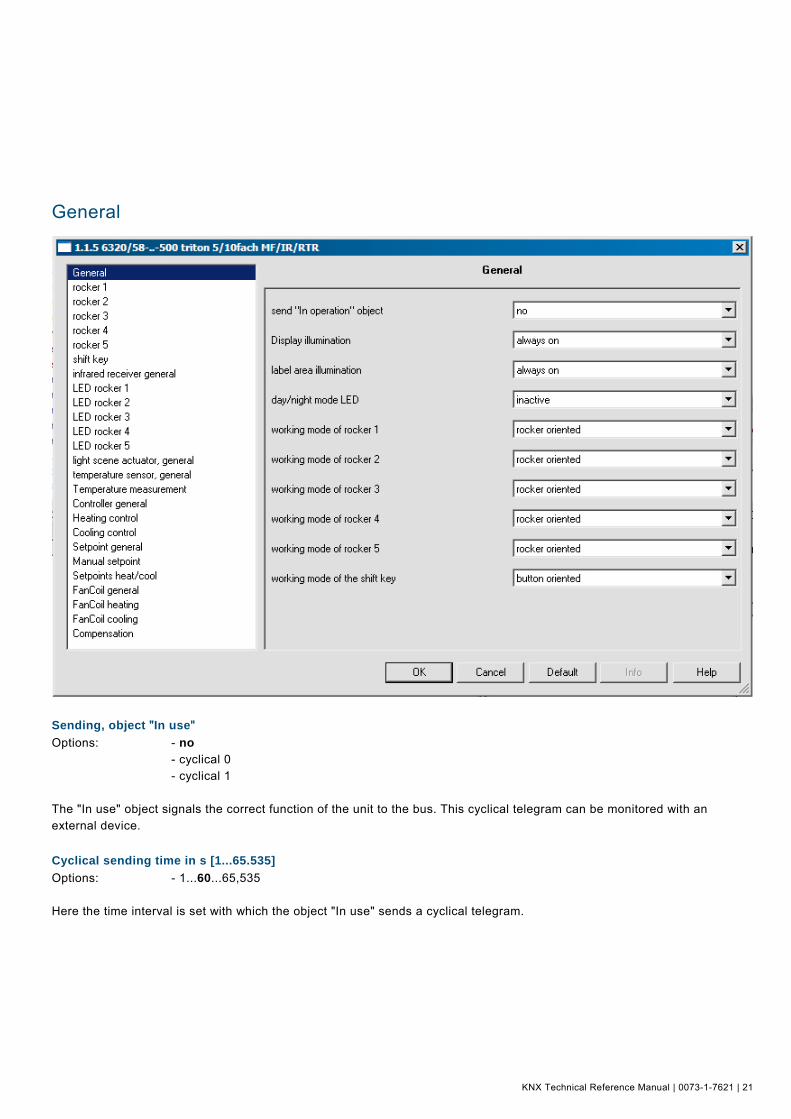
General Pos: 18.3.2 /Produkthandbuch - DIN-A4/Busch-triton/Parameter - Allgemeine Beschreibung/Allgemein/Screenshot @ 16\mod_1294825620300_15.doc @ 98953 @
Pos: 18.3.3 /Produkthandbuch - DIN-A4/Busch-triton/Parameter - Allgemeine Beschreibung/Allgemein/Objekt In Betrieb senden @ 12\mod_1283155212370_15.doc @ 87847 @ 2
Sending, object "In use"
Options: - no - cyclical 0 - cyclical 1 The "In use" object signals the correct function of the unit to the bus. This cyclical telegram can be monitored with an external device. Pos: 18.3.4 /Produkthandbuch - DIN-A4/Busch-triton/Parameter - Allgemeine Beschreibung/Allgemein/Sendezykluszeit @ 12\mod_1283155508276_15.doc @ 87855 @ 2
Cyclical sending time in s [1...65.535]
Options: - 1...60...65,535 Here the time interval is set with which the object "In use" sends a cyclical telegram. Pos: 18.3.5 /Produkthandbuch - DIN-A4/Busch-triton/Parameter - Allgemeine Beschreibung/Allgemein/Verhalten Beleuchtung Display @ 12\mod_1283154856074_15.doc @ 87823 @ 2
KNX Technical Reference Manual Busch-triton
22 | 0073-1-7621 | KNX Technical Reference Manual
Display illumination
Options: - always ON - always OFF - 5 sec. light-on time This parameter is only available on devices with integrated room thermostat. This parameter is used to set the background lighting of the LCD. It is either always switched on, always switched off, or it switches itself off automatically 5 s after being actuated. Note If an ON telegram is received on the 1-bit "Illumination" communication object, the background lighting remains on until an OFF telegram is received. Pos: 18.3.6 /Produkthandbuch - DIN-A4/Busch-triton/Parameter - Allgemeine Beschreibung/Allgemein/Verhalten Beleuchtung Schriftfeld @ 12\mod_1283154945308_15.doc @ 87831 @ 2
Label area illumination
Options: - always ON - always OFF This parameter is used to set the label area illumination of the rocker switches. They are either always switched on or always switched off. Note If an ON telegram is received on the 1-bit "Label area illumination" communication object, the label area illumination remains on until an OFF telegram is received. Pos: 18.3.7 /Produkthandbuch - DIN-A4/Busch-triton/Parameter - Allgemeine Beschreibung/Allgemein/Tag-/Nachtbetrieb LED @ 15\mod_1287391303789_15.doc @ 96193 @ 2
Day/night mode LED
Options: - disabled - active When parameter "Day/night mode LED" is activated, an additional 1-bit communication object "Day/night mode LED" is displayed. If an OFF telegram is received on the 1-bit "Day/night mode LED" communication object, all LEDs are switched off and remain switched off until they are switched on again with their former (or changed) status with the receipt of an ON telegram The LED can be temporarily deactivated via this object, e.g. in bedrooms during the night. Pos: 18.3.8 /Produkthandbuch - DIN-A4/Überschriften/2. Ebene/A - F/Arbeitsweise der Wippe @ 11\mod_1279200377944_15.doc @ 83715 @ 2
Working mode of rocker switch 1-5 Pos: 18.3.9 /Produkthandbuch - DIN-A4/Busch-triton/Parameter - Allgemeine Beschreibung/Allgemein/Arbeitsweise der Wippe - DIN-A4 @ 14\mod_1286354162520_15.doc @ 91749 @
Options: - inactive - rocker oriented - button oriented Here a rocker oriented or button oriented function can be set. Pos: 18.3.10 /Produkthandbuch - DIN-A4/Busch-triton/Parameter - Allgemeine Beschreibung/Allgemein/Arbeitsweise der Umschalttaste - DIN-A4 @ 16\mod_1295341259827_15.doc @ 99393 @ 2
Working mode of the shift key
Options: - inactive - button oriented Pos: 18.4.1 /Produkthandbuch - DIN-A4/Überschriften/1. Ebene/S - Z/Wippe 1-5 @ 11\mod_1279265325993_15.doc @ 84278 @ 1

KNX Technical Reference Manual | 0073-1-7621 | 23
Rocker Switch 1-5 Pos: 18.4.2 /Produkthandbuch - DIN-A4/Busch-triton/Parameter - Allgemeine Beschreibung/Wippe 1-5/Screenshot @ 16\mod_1294827315421_15.doc @ 98969 @
Pos: 18.4.3 /Produkthandbuch - DIN-A4/Busch-triton/Parameter - Allgemeine Beschreibung/Wippe 1-5/Funktion Wippe - DIN-A4 @ 13\mod_1286192429036_15.doc @ 91233 @ 2
Function of rocker 1-5
Options: - switching - dimming - blind - value sender value dimming sensor - step switch Additionally for control elements with integrated RTC: - setpoint adjustment of the internal RTC - operating mode/fans stage switchover of the internal RTC These channels are only visible when parameter "Function of rocker" is set on "Rocker oriented". Additional parameters (see parameter description of rockers) are displayed depending on the set function. Pos: 18.4.4 /Produkthandbuch - DIN-A4/Busch-triton/Parameter - Allgemeine Beschreibung/Wippe 1-5/Schalten - DIN-A4 @ 13\mod_1286192502348_15.doc @ 91241 @ 2
KNX Technical Reference Manual Busch-triton
24 | 0073-1-7621 | KNX Technical Reference Manual
Switching
The "Working mode of the rocker switch for switching" determines whether operation of the left or right side of the rocker will send out an ON or an OFF telegram. Alternatively, for the selection "Alternating on/off", you can switch between switching on and switching off for every operation that triggers a switching telegram. I.e. after a switch-on telegram has been sent out (or received), a switch-off telegram will be sent out for a renewed operation. After it is operated again, a switch-on telegram is sent out. If a switching telegram is triggered by operation of the rocker, this will be sent out on the 1-bit communication object "Switching". Pos: 18.4.5 /Produkthandbuch - DIN-A4/Busch-triton/Parameter - Allgemeine Beschreibung/Wippe 1-5/Arbeitsweise der Wippe für Schalten - DIN-A4 @ 13\mod_1286193048909_15.doc @ 91291 @ 2
Working mode of the rocker for switching
Options: - left on, right off - left off, right on - alternating on/off The "Working mode of the rocker for switching" determines whether operation of the left or right side of the rocker will send out an ON or an OFF telegram. Alternatively, for the selection "Alternating on/off", you can switch between switching on and switching off for every operation that triggers a switching telegram. I.e. after a switch-on telegram has been sent out (or received), a switch-off telegram will be sent out for a renewed operation. After it is operated again, a switch-on telegram is sent out. If a switching telegram is triggered by operation of the rocker, this will be sent out on the 1-bit communication object "Switching". Pos: 18.4.6 /Produkthandbuch - DIN-A4/Busch-triton/Parameter - Allgemeine Beschreibung/Wippe 1-5/Freigabeobjekt - DIN-A4 @ 13\mod_1286192563364_15.doc @ 91249 @ 2
Enable object
Options: - inactive - active If the "Enable object" parameter is set to "active", the function can temporarily be blocked via the the 1-bit communication object "Enable". The function is active if an ON telegram is received on the 1-bit communication object "Enable". The function is blocked if an OFF telegram is received on the 1-bit communication object "Enable". This means that after an actuation, a telegram is no longer sent out. Pos: 18.4.7 /Produkthandbuch - DIN-A4/Busch-triton/Parameter - Allgemeine Beschreibung/Wippe 1-5/Objektwert Freigabe - DIN-A4 @ 13\mod_1286192637644_15.doc @ 91257 @ 2
Object value enable
Options: - normal - inverse This parameter is only adjustable with activated enable object. The enable function normally functions as follows: The function is active if an ON telegram is received on the 1-bit communication object "Enable". The function is blocked if an OFF telegram is received on the 1-bit communication object "Enable". Via the "Object value enable" parameter, the behaviour described above can be inverted. I.e. the function is blocked if an ON telegram is received on the 1-bit communication object "Enable". The function is active if an OFF telegram is received on the 1-bit communication object "Enable". Pos: 18.4.8 /Produkthandbuch - DIN-A4/Busch-triton/Parameter - Allgemeine Beschreibung/Wippe 1-5/Freigabe nach Busspannungswiederkehr - DIN-A4 @ 13\mod_1286192715660_15.doc @ 91265 @ 2
Enable after return of bus voltage
Options: - blocked - enabled This parameter is only adjustable with activated enable object. The parameter "Behaviour enable after return of voltage" exists to permit a defined behaviour at the "Enable" communication object after a return of voltage. A determination is made here about whether a "1" ("enabled") or a "0" ("blocked") is present on the enable object after the return of voltage.

KNX Technical Reference Manual | 0073-1-7621 | 25
Note: If the logic of the enable function (parameter "Object value enable") is set to "inverse", the behaviour is also inverted after the return of voltage. This means that if the parameter "Behaviour enable after return of voltage" is set to "enabled", and the "Object value enable" is at the same time parameterised to "inverse", then the function will initially not be active after the return of voltage. This must first be activated via the receipt of an OFF telegram on the enable object. Pos: 18.4.9 /Produkthandbuch - DIN-A4/Busch-triton/Parameter - Allgemeine Beschreibung/Wippe 1-5/Dimmen - DIN-A4 @ 13\mod_1286192976909_15.doc @ 91283 @ 2
Dimming
These parameters are only visible when parameter "Working mode of rocker" is set on "Rocker oriented" and the "Dimming" function has been set. With the "Dimming" application, a rocker has communication objects for switching and for dimming. A distinction is made between short and long press of the button. The "Dimming" application differentiates between whether the rocker is operated on the left or right side. The "Working mode of rocker for …" parameter allows adjustment of whether the left or right side switches on or off or whether it is dimmed brighter or darker. Pos: 18.4.10 /Produkthandbuch - DIN-A4/Busch-triton/Parameter - Allgemeine Beschreibung/Wippe 1-5/Arbeitsweise der Wippe für Schalten - DIN-A4 @ 13\mod_1286193048909_15.doc @ 91291 @ 2
Working mode of the rocker for switching
Options: - left on, right off - left off, right on - alternating on/off The "Working mode of the rocker for switching" determines whether operation of the left or right side of the rocker will send out an ON or an OFF telegram. Alternatively, for the selection "Alternating on/off", you can switch between switching on and switching off for every operation that triggers a switching telegram. I.e. after a switch-on telegram has been sent out (or received), a switch-off telegram will be sent out for a renewed operation. After it is operated again, a switch-on telegram is sent out. If a switching telegram is triggered by operation of the rocker, this will be sent out on the 1-bit communication object "Switching". Pos: 18.4.11 /Produkthandbuch - DIN-A4/Busch-triton/Parameter - Allgemeine Beschreibung/Wippe 1-5/Arbeitsweise der Wippe für Dimmen - DIN-A4 @ 13\mod_1286193426969_15.doc @ 91299 @ 2
Working mode of the rocker for dimming
Options: - left brighter, right darker - left darker, right brighter The "Working mode of the rocker for dimming" determines whether operation of the left or right side of the rocker will send out a dim brighter or a dim darker telegram. If a dimming telegram is triggered by operation of the rocker, a dimming telegram will be sent out on the 4-bit communication object "Relative dimming". Pos: 18.4.12 /Produkthandbuch - DIN-A4/Busch-triton/Parameter - Allgemeine Beschreibung/Wippe 1-5/Dimmart - DIN-A4 @ 13\mod_1286193515359_15.doc @ 91347 @ 2
Manner of dimming
Options: - start-stop dimming - step-wise dimming You can switch between the two dimming versions "Start-stop dimming" and "Step-wise dimming" via this parameter. "Start-stop dimming" means that exactly two 4-bit telegrams for dimming are always sent out. For triggering of a dimming command, a telegram with the information "Dim by 100% brighter" or "Dim by 100% darker" is sent. When the rocker is released, the second telegram is sent out with the "Dimming stop" information. Hence, a connected dimming actuator can be halted at any time during the dimming phase. The second dimming procedure is step-wise dimming. For step-wise dimming, a defined value, e.g. "Dim brighter by 6.25%" is always sent out for triggering of a dimming command. This dimming procedure can be utilised if dimming sensor and actuator are installed in different lines. In this case, telegram delays can occur through a coupler and thus varying brightness values if multiple dimming actuators are to be activated in different lines. Pos: 18.4.13 /Produkthandbuch - DIN-A4/Busch-triton/Parameter - Allgemeine Beschreibung/Wippe 1-5/Schrittweite beim Schrittdimmen - DIN-A4 @ 13\mod_1286193570593_15.doc @ 91355 @ 2

KNX Technical Reference Manual Busch-triton
26 | 0073-1-7621 | KNX Technical Reference Manual
Step size for step-wise dimming
Options: - 1.56 - 3.13 - 6.25 - 12.5 - 25 - 50 This parameter is only visible if the parameter "Manner of dimming" is set on "Step-wise dimming". Via the "Step size for step-wise dimming" setting you can specify by how much brighter or darker dimming should occur. The value sent out always relates to the current brightness value. Example: A dimming actuator is currently dimmed to a brightness value of 70%. By operation of the rocker, a dimming command "Dim by 12.5 % brighter" (step size for step-wise dimming: 12.5%) is sent out. The dimming actuator will adjust its brightness value to 82.5% immediately after receiving the dimming command. Note: If the step-wise dimming is to be used to evenly dim multiple dimming actuators in different lines, a relatively low step size is to be selected, e.g. 3.13%, and a cyclical repeat activated at the same time. Dimming telegrams are thus sent out continuously as long as the rocker is being operated. Pos: 18.4.14 /Produkthandbuch - DIN-A4/Busch-triton/Parameter - Allgemeine Beschreibung/Wippe 1-5/Dimmfunktion - DIN-A4 @ 13\mod_1286193636577_15.doc @ 91363 @ 2
Dimming function
Options: short operation dimming, long operation switching - short operation switching, long operation dimming This parameter is only visible if the parameter "Manner of dimming" is set on "Step-wise dimming". The basic function of dimming can be specified via the "Dimming function" parameter. You can set whether a switching telegram will be sent out for a short operation of the rocker switch and a dimming telegram will be sent out for a long operation or whether a long operation will cause a switching telegram to be sent out and a short operation will cause a dimming telegram to be sent out. Pos: 18.4.15 /Produkthandbuch - DIN-A4/Busch-triton/Parameter - Allgemeine Beschreibung/Wippe 1-5/Zyklisches Senden der Dimm-Telegramme - DIN-A4 @ 13\mod_1286193677280_15.doc @ 91371 @ 2
Cyclical sending of dimming telegrams
Options: - inactive - active This parameter is only visible if the parameter "Dimming function" is set on "Short operation switching, long operation dimming". If the parameter "Cyclical sending of the dimming telegrams" is activated, dimming telegrams will be sent out cyclically on the 4-bit communication object "Dimming" as long as the rocker switch is operated. After releasing the rocker switch, the cyclical sending of the dimming telegrams is immediately stopped. The cycle time is specified via the "Duration of the telegram repetition" parameter. Pos: 18.4.16 /Produkthandbuch - DIN-A4/Busch-triton/Parameter - Allgemeine Beschreibung/Wippe 1-5/Zeit für die Telegrammwiederholung - DIN-A4 @ 13\mod_1286193738140_15.doc @ 91379 @ 2
Duration of telegram repetition
Options: - 0,1...0,4...5,0 If the parameter "Cyclical sending of the dimming telegrams" is activated, dimming telegrams will be sent out cyclically on the 4-bit communication object "Dimming" as long as the rocker switch is operated. After releasing the rocker switch, the cyclical sending of the dimming telegrams is immediately stopped. The cycle time is specified via the "Duration of the telegram repetition" parameter. Pos: 18.4.17 /Produkthandbuch - DIN-A4/Busch-triton/Parameter - Allgemeine Beschreibung/Wippe 1-5/Freigabeobjekt - DIN-A4 @ 13\mod_1286192563364_15.doc @ 91249 @ 2

KNX Technical Reference Manual | 0073-1-7621 | 27
Enable object
Options: - inactive - active If the "Enable object" parameter is set to "active", the function can temporarily be blocked via the the 1-bit communication object "Enable". The function is active if an ON telegram is received on the 1-bit communication object "Enable". The function is blocked if an OFF telegram is received on the 1-bit communication object "Enable". This means that after an actuation, a telegram is no longer sent out. Pos: 18.4.18 /Produkthandbuch - DIN-A4/Busch-triton/Parameter - Allgemeine Beschreibung/Wippe 1-5/Objektwert Freigabe - DIN-A4 @ 13\mod_1286192637644_15.doc @ 91257 @ 2
Object value enable
Options: - normal - inverse This parameter is only adjustable with activated enable object. The enable function normally functions as follows: The function is active if an ON telegram is received on the 1-bit communication object "Enable". The function is blocked if an OFF telegram is received on the 1-bit communication object "Enable". Via the "Object value enable" parameter, the behaviour described above can be inverted. I.e. the function is blocked if an ON telegram is received on the 1-bit communication object "Enable". The function is active if an OFF telegram is received on the 1-bit communication object "Enable". Pos: 18.4.19 /Produkthandbuch - DIN-A4/Busch-triton/Parameter - Allgemeine Beschreibung/Wippe 1-5/Freigabe nach Busspannungswiederkehr - DIN-A4 @ 13\mod_1286192715660_15.doc @ 91265 @ 2
Enable after return of bus voltage
Options: - blocked - enabled This parameter is only adjustable with activated enable object. The parameter "Behaviour enable after return of voltage" exists to permit a defined behaviour at the "Enable" communication object after a return of voltage. A determination is made here about whether a "1" ("enabled") or a "0" ("blocked") is present on the enable object after the return of voltage. Note: If the logic of the enable function (parameter "Object value enable") is set to "inverse", the behaviour is also inverted after the return of voltage. This means that if the parameter "Behaviour enable after return of voltage" is set to "enabled", and the "Object value enable" is at the same time parameterised to "inverse", then the function will initially not be active after the return of voltage. This must first be activated via the receipt of an OFF telegram on the enable object. Pos: 18.4.20 /Produkthandbuch - DIN-A4/Busch-triton/Parameter - Allgemeine Beschreibung/Wippe 1-5/Jalousie @ 14\mod_1286356546846_15.doc @ 91775 @ 2
Blind
These parameters are only visible when parameter "Working mode of rocker" is set on "rocker oriented" and the the "Blind" function has been set. Via the application "Blind", blind movement and/or slats adjustment commands can be sent to connected blind actuators with a short or long operation of the rocker. A short button press always triggers a slats adjustment or stop command and a long button press always triggers a travel command. The control always remembers the last action performed on the side of the rocker that is assigned with the "Blind" application. For example: If a blind was lowered and halted at half height via a short button contact, then a renewed long button contact will raise the blind. Pos: 18.4.21 /Produkthandbuch - DIN-A4/Busch-triton/Parameter - Allgemeine Beschreibung/Wippe 1-5/Zeit für Langbedienung @ 14\mod_1286356671299_15.doc @ 91793 @ 2
Duration of long operation (s)
Options: - 0.3...0.4...3 A short and long operation can be differentiated between for the operation of the rocker switch. Via the "Duration of long operation (s)", the time is specified after which a long button press is recognised. By default, the rocker recognises a long press of the button if the operation occurs for at least 0.4 s. Any arbitrary time from 0.3 to 3.0 seconds can be set. Pos: 18.4.22 /Produkthandbuch - DIN-A4/Busch-triton/Parameter - Allgemeine Beschreibung/Wippe 1-5/Arbeitsweise der Wippe (Jalousie) - DIN-A4 @ 14\mod_1286356847503_15.doc @ 91811 @ 2
KNX Technical Reference Manual Busch-triton
28 | 0073-1-7621 | KNX Technical Reference Manual
Working mode of the rocker switch
Options: - left up, right down - left down, right up The "Working mode of the rocker" determines whether operation of the left or right side of the rocker will send out commands for moving up or down. Pos: 18.4.23 /Produkthandbuch - DIN-A4/Busch-triton/Parameter - Allgemeine Beschreibung/Wippe 1-5/Objekttyp (Jalousie) - DIN-A4 @ 14\mod_1286356964018_15.doc @ 91819 @ 2
Object type
Options: - 1 bit - 1 byte 0...100% Parameter object type is used to specify whether the blind control occurs via two 1-bit or two 1-byte communication objects "Move" and "Adjust". If 1-byte was selected as object type, the communication objects can be connected with 1-byte position objects from blind actuators. One side of the rocker could lower the blind to 50% with slats closed 50%, while the other rocker side can lower the blind to 80% with slats closed 100%. Pos: 18.4.24 /Produkthandbuch - DIN-A4/Busch-triton/Parameter - Allgemeine Beschreibung/Wippe 1-5/Wert für Position Ab - DIN-A4 @ 14\mod_1286357114127_15.doc @ 91827 @ 2
Value for position down (%)
Options: - 0...100 This parameter can only be set if "1-byte 0..100%" has been set as object type. The position that a connected blind shall be lowered to is set via this parameter. The associated 1-byte "Move" communication object must hereby be connected with a 1-byte position object of a blind actuator. Percent values from 0% to 100% can be set in 1% steps. The value 0% means travel up completely; the value 100% means travel down completely. Pos: 18.4.25 /Produkthandbuch - DIN-A4/Busch-triton/Parameter - Allgemeine Beschreibung/Wippe 1-5/Wert für Position Auf - DIN-A4 @ 14\mod_1286357235765_15.doc @ 91835 @ 2
Value for position up (%)
Options: - 0...100 This parameter can only be set if "1-byte 0..100%" has been set as object type. The position that a connected blind shall be raised to is set via this parameter. The associated 1-byte "Move" communication object must hereby be connected with a 1-byte position object of a blind actuator. Percent values from 0% to 100% can be set in 1% steps. The value 0% means travel up completely; the value 100% means travel down completely. Pos: 18.4.26 /Produkthandbuch - DIN-A4/Busch-triton/Parameter - Allgemeine Beschreibung/Wippe 1-5/Wert für Lamellenposition Ab - DIN-A4 @ 14\mod_1286358024835_15.doc @ 91843 @ 2
Value for slats position down (%)
Options: - 0...50...100 This parameter can only be set if "1-byte 0..100%" has been set as object type. The position that a connected blind slat shall be opened to is set via this parameter. The associated 1-byte "Adjust" communication object must hereby be connected with a 1-byte slat position object of a blind actuator. Percent values from 0% to 100% can be set in 1% steps. The value 0% means travel opened completely; the value 100% means closed completely. Pos: 18.4.27 /Produkthandbuch - DIN-A4/Busch-triton/Parameter - Allgemeine Beschreibung/Wippe 1-5/Wert für Lamellenposition Auf - DIN-A4 @ 14\mod_1286358102616_15.doc @ 91851 @ 2
Value for slats position up (%)
Options: - 0...50...100 This parameter can only be set if "1-byte 0..100%" has been set as object type. The position that a connected blind slat shall be closed to is set via this parameter. The associated 1-byte "Adjust" communication object must hereby be connected with a 1-byte slat position object of a blind actuator. Percent values from 0% to 100% can be set in 1% steps. The value 0% means travel opened completely; the value 100% means closed completely.
KNX Technical Reference Manual | 0073-1-7621 | 29
Pos: 18.4.28 /Produkthandbuch - DIN-A4/Busch-triton/Parameter - Allgemeine Beschreibung/Wippe 1-5/Freigabeobjekt - DIN-A4 @ 13\mod_1286192563364_15.doc @ 91249 @ 2
Enable object
Options: - inactive - active If the "Enable object" parameter is set to "active", the function can temporarily be blocked via the the 1-bit communication object "Enable". The function is active if an ON telegram is received on the 1-bit communication object "Enable". The function is blocked if an OFF telegram is received on the 1-bit communication object "Enable". This means that after an actuation, a telegram is no longer sent out. Pos: 18.4.29 /Produkthandbuch - DIN-A4/Busch-triton/Parameter - Allgemeine Beschreibung/Wippe 1-5/Objektwert Freigabe - DIN-A4 @ 13\mod_1286192637644_15.doc @ 91257 @ 2
Object value enable
Options: - normal - inverse This parameter is only adjustable with activated enable object. The enable function normally functions as follows: The function is active if an ON telegram is received on the 1-bit communication object "Enable". The function is blocked if an OFF telegram is received on the 1-bit communication object "Enable". Via the "Object value enable" parameter, the behaviour described above can be inverted. I.e. the function is blocked if an ON telegram is received on the 1-bit communication object "Enable". The function is active if an OFF telegram is received on the 1-bit communication object "Enable". Pos: 18.4.30 /Produkthandbuch - DIN-A4/Busch-triton/Parameter - Allgemeine Beschreibung/Wippe 1-5/Freigabe nach Busspannungswiederkehr - DIN-A4 @ 13\mod_1286192715660_15.doc @ 91265 @ 2
Enable after return of bus voltage
Options: - blocked - enabled This parameter is only adjustable with activated enable object. The parameter "Behaviour enable after return of voltage" exists to permit a defined behaviour at the "Enable" communication object after a return of voltage. A determination is made here about whether a "1" ("enabled") or a "0" ("blocked") is present on the enable object after the return of voltage. Note: If the logic of the enable function (parameter "Object value enable") is set to "inverse", the behaviour is also inverted after the return of voltage. This means that if the parameter "Behaviour enable after return of voltage" is set to "enabled", and the "Object value enable" is at the same time parameterised to "inverse", then the function will initially not be active after the return of voltage. This must first be activated via the receipt of an OFF telegram on the enable object. Pos: 18.4.31 /Produkthandbuch - DIN-A4/Busch-triton/Parameter - Allgemeine Beschreibung/Wippe 1-5/Wertsender - DIN-A4 @ 14\mod_1286358384336_15.doc @ 91867 @ 2
Value sender
These parameters are only visible when parameter "Working mode of rocker" is set on "Rocker oriented" and the the "Value sender" function has been set. With the "Value sender" application, a telegram with the predefined value is sent out for an operation of the right or left side of the rocker. The "Value sender" application differentiates here between whether the rocker is operated on the left or right side. Pos: 18.4.32 /Produkthandbuch - DIN-A4/Busch-triton/Parameter - Allgemeine Beschreibung/Wippe 1-5/Objekttyp (Wertsender) - DIN-A4 @ 14\mod_1286358196492_15.doc @ 91859 @ 2
Object type
Options: - 1 bit - 1-byte 0...100% - 1-byte 0...255 - 2-byte float - 2-byte signed - 2-byte unsigned - 4-byte signed - 4-byte unsigned

KNX Technical Reference Manual Busch-triton
30 | 0073-1-7621 | KNX Technical Reference Manual
The application "Value sender, rocker orientated" makes its own communication object available to the rocker for the "Value switching". The bit size of the communication objects is specified via the "Object type" parameter. For different applications the bit size of communication objects can be adjusted from "1 bit" up to "4 byte unsigned" via the "Object type" parameter. 1 Bit: switching functions (on/off, enabled/blocked, true/untrue, …) 1 byte 0…100%: percent values (0=0%, 255=100%) 1 byte 0…255: arbitrary values from 0 to 255 2 byte float: floating point value (physical values such as temperature, brightness, …) 2 byte signed: arbitrary values from -32,768 to 32,767 2 byte unsigned: arbitrary values from 0 to 65,535 4 byte signed: arbitrary values from -2,147,483,648 to 2,147,483,647 4 byte unsigned: arbitrary values from 0 to 4,294,967,295 Pos: 18.4.33 /Produkthandbuch - DIN-A4/Busch-triton/Parameter - Allgemeine Beschreibung/Wippe 1-5/Arbeitsweise der Wippe (Wertsender) - DIN-A4 @ 14\mod_1286358454680_15.doc @ 91875 @ 2
Working mode of the rocker
Options: - left value1, right value2 - left value2, right value1 - alternating value1 / value2 The parameter "Working mode of the rocker" is used to specify whether the right or the left side of the rocker sends out "Value 1" or "Value 2". With the behaviour "Alternating value1/value2", switching always alternates between value 1 and value 2. That means, for example, if value 1 was last sent out, then a renewed operation of the rocker switch will send out value 2. When the rocker is operated again, value 1 is again sent out, etc. The rocker thus always remembers the last state and then switches over to the other value. This also applies for values that are received via the associated communication object, i.e. if value 1 was sent out for the last rocker switch operation, thereafter value 2 was received via the communication object, the next operation of the rocker switch will send out value 1 again. It must be observed here that the S-flag (writing) of the communication object is activated. Pos: 18.4.34 /Produkthandbuch - DIN-A4/Busch-triton/Parameter - Allgemeine Beschreibung/Wippe 1-5/Wert 1 - DIN-A4 @ 14\mod_1286358629633_15.doc @ 91883 @ 2
Value 1 (1-bit)
Options: - off - on This object is only adjustable if the object type parameter is set to 1 bit. Value 1 (on or off) is specified here, which is sent out for an operation of the right or left side of the rocker. This could be an ON or an OFF telegram, so that connected switching actuators can be switched. The sent out signal could, however, also call an enable or block or operate a logical function. Pos: 18.4.35 /Produkthandbuch - DIN-A4/Busch-triton/Parameter - Allgemeine Beschreibung/Wippe 1-5/Wert 2 - DIN-A4 @ 14\mod_1286358704211_15.doc @ 91891 @ 2
Value 2 (1 bit)
Options: - on - off This object is only adjustable if the object type parameter is set to 1 bit. Value 2 (on or off) is specified here, which is sent out for an operation of the right or left side of the rocker. This could be an ON or an OFF telegram, so that connected switching actuators can be switched. The sent out signal could, however, also call an enable or block or operate a logical function for example. Pos: 18.4.36 /Produkthandbuch - DIN-A4/Busch-triton/Parameter - Allgemeine Beschreibung/Wippe 1-5/Wert 1 1 Byte (0...100%) - DIN-A4 @ 14\mod_1286358867616_15.doc @ 91899 @ 2

KNX Technical Reference Manual | 0073-1-7621 | 31
Value 1, 1 byte (0..100%)
Options: - 0...100 This object is only adjustable if the object type parameter is set to 1-byte 0..100%. Value 1 is specified here, which is sent out for an operation of the right or left side of the rocker. This can be a percent value from 0% to 100% (adjustable in 1% steps). Pos: 18.4.37 /Produkthandbuch - DIN-A4/Busch-triton/Parameter - Allgemeine Beschreibung/Wippe 1-5/Wert 2 1 Byte (0...100%) - DIN-A4 @ 14\mod_1286358974084_15.doc @ 91907 @ 2
Value 2, 1 byte (0..100%)
Options: - 0...100 This object is only adjustable if the object type parameter is set to 1-byte 0..100%. Value 2 is specified here, which is sent out for an operation of the right or left side of the rocker. This can be a percent value from 0% to 100% (adjustable in 1% steps). Pos: 18.4.38 /Produkthandbuch - DIN-A4/Busch-triton/Parameter - Allgemeine Beschreibung/Wippe 1-5/Wert 1 1 Byte (0...255) - DIN-A4 @ 14\mod_1286359242754_15.doc @ 91915 @ 2
Value 1, 1 byte (0..255)
Options: - 0...255 This object is only adjustable if the object type parameter is set to 1 byte 0..255. Value 1 is specified here, which is sent out for an operation of the right or left side of the rocker. This can be any value from 0 to 255. Pos: 18.4.39 /Produkthandbuch - DIN-A4/Busch-triton/Parameter - Allgemeine Beschreibung/Wippe 1-5/Wert 2 1 Byte (0...255) - DIN-A4 @ 14\mod_1286359325269_15.doc @ 91923 @ 2
Value 2, 1 byte (0..255)
Options: - 0...255 This object is only adjustable if the object type parameter is set to 1 byte 0..255. Value 2 is specified here, which is sent out for an operation of the right or left side of the rocker. This can be any value from 0 to 255. Pos: 18.4.40 /Produkthandbuch - DIN-A4/Busch-triton/Parameter - Allgemeine Beschreibung/Wippe 1-5/Wert 1 2 Byte Float - DIN-A4 @ 14\mod_1286360119969_15.doc @ 91931 @ 2
Value 1 (2-byte float x factor 0.1)
Options: - 0...6707600 This parameter can only be set if the object type parameter is set to 2-byte float (floating point value). Value 1 is specified here, which is sent out for an operation of the right or left side of the rocker. This is a 2-byte floating point value which is used to transfer physical values. Pos: 18.4.41 /Produkthandbuch - DIN-A4/Busch-triton/Parameter - Allgemeine Beschreibung/Wippe 1-5/Wert 2 2 Byte Float - DIN-A4 @ 14\mod_1286360233312_15.doc @ 91939 @ 2
Value 2 (2-byte float x factor 0.1)
Options: - 0...6707600 This parameter can only be set if the object type parameter is set to 2-byte float. Value 2 is specified here, which is sent out for an operation of the right or left side of the rocker. This is a 2-byte floating point value which is used to transfer physical values. Pos: 18.4.42 /Produkthandbuch - DIN-A4/Busch-triton/Parameter - Allgemeine Beschreibung/Wippe 1-5/Wert 1 2 Byte Signed - DIN-A4 @ 14\mod_1286360290124_15.doc @ 91947 @ 2
Value 1 (2-byte signed)
Options: - -32,768...0...32,767 This parameter can only be set if the object type parameter is set to 2-byte signed. Value 1 is specified here, which is sent out for an operation of the right or left side of the rocker. This is a signed 2-byte value, that can assume arbitrary values from -32,768 to 32,767. Pos: 18.4.43 /Produkthandbuch - DIN-A4/Busch-triton/Parameter - Allgemeine Beschreibung/Wippe 1-5/Wert 2 2 Byte Signed - DIN-A4 @ 14\mod_1286360383593_15.doc @ 91955 @ 2

KNX Technical Reference Manual Busch-triton
32 | 0073-1-7621 | KNX Technical Reference Manual
Value 2 (2-byte signed)
Options: - -32,768...0...32,767 This parameter can only be set if the object type parameter is set to 2-byte signed. Value 2 is specified here, which is sent out for an operation of the right or left side of the rocker. This is a signed 2-byte value, that can assume arbitrary values from -32,768 to 32,767. Pos: 18.4.44 /Produkthandbuch - DIN-A4/Busch-triton/Parameter - Allgemeine Beschreibung/Wippe 1-5/Wert 1 2 Byte Unsigned - DIN-A4 @ 14\mod_1286360442842_15.doc @ 91963 @ 2
Value 1 (2-byte unsigned)
Options: - 0...65,535 This parameter can only be set if the object type parameter is set to 2-byte unsigned. Value 1 is specified here, which is sent out for an operation of the right or left side of the rocker. This is a 2-byte value, that can assume arbitrary values from 0 to 65,535. Pos: 18.4.45 /Produkthandbuch - DIN-A4/Busch-triton/Parameter - Allgemeine Beschreibung/Wippe 1-5/Wert 2 2 Byte Unsigned - DIN-A4 @ 14\mod_1286360515467_15.doc @ 91971 @ 2
Value 2 (2-byte unsigned)
Options: - 0...65,535 This parameter can only be set if the object type parameter is set to 2-byte unsigned. Value 2 is specified here, which is sent out for an operation of the right or left side of the rocker. This is a 2-byte value, that can assume arbitrary values from 0 to 65,535. Pos: 18.4.46 /Produkthandbuch - DIN-A4/Busch-triton/Parameter - Allgemeine Beschreibung/Wippe 1-5/Wert 1 4 Byte Signed - DIN-A4 @ 14\mod_1286360719982_15.doc @ 91979 @ 2
Value 1 (4-byte signed)
Options: - -2.147.483.648...0...2.147.483.647 This parameter can only be set if the object type parameter is set to 4-byte signed. Value 1 is specified here, which is sent out for an operation of the right or left side of the rocker. This is a signed 4-byte value, that can assume arbitrary values from -2,147,483,648 to 2,147,483,647. Pos: 18.4.47 /Produkthandbuch - DIN-A4/Busch-triton/Parameter - Allgemeine Beschreibung/Wippe 1-5/Wert 2 4 Byte Signed - DIN-A4 @ 14\mod_1286360804812_15.doc @ 91987 @ 2
Value 2 (4-byte signed)
Options: - -2,147,483,648...0...2,147,483,647 This parameter can only be set if the object type parameter is set to 4-byte signed. Value 2 is specified here, which is sent out for an operation of the right or left side of the rocker. This is a signed 4-byte value, that can assume arbitrary values from -2,147,483,648 to 2,147,483,647. Pos: 18.4.48 /Produkthandbuch - DIN-A4/Busch-triton/Parameter - Allgemeine Beschreibung/Wippe 1-5/Wert 1 4 Byte Unsigned - DIN-A4 @ 14\mod_1286360872407_15.doc @ 91995 @ 2
Value 1 (4-byte unsigned)
Options: - 0...4,294,967,295 This parameter can only be set if the object type parameter is set to 4-byte unsigned. Value 1 is specified here, which is sent out for an operation of the right or left side of the rocker. This is a 4-byte value, that can assume arbitrary values from 0 to 4,294,967,295. Pos: 18.4.49 /Produkthandbuch - DIN-A4/Busch-triton/Parameter - Allgemeine Beschreibung/Wippe 1-5/Wert 2 4 Byte Unsigned - DIN-A4 @ 14\mod_1286360936143_15.doc @ 92003 @ 2
Value 2 (4-byte unsigned)
Options: - 0...4,294,967,295 This parameter can only be set if the object type parameter is set to 4-byte unsigned. Value 2 is specified here, which is sent out for an operation of the right or left side of the rocker. This is a 4-byte value, that can assume arbitrary values from 0 to 4,294,967,295. Pos: 18.4.50 /Produkthandbuch - DIN-A4/Busch-triton/Parameter - Allgemeine Beschreibung/Wippe 1-5/Freigabeobjekt - DIN-A4 @ 13\mod_1286192563364_15.doc @ 91249 @ 2
KNX Technical Reference Manual | 0073-1-7621 | 33
Enable object
Options: - inactive - active If the "Enable object" parameter is set to "active", the function can temporarily be blocked via the the 1-bit communication object "Enable". The function is active if an ON telegram is received on the 1-bit communication object "Enable". The function is blocked if an OFF telegram is received on the 1-bit communication object "Enable". This means that after an actuation, a telegram is no longer sent out. Pos: 18.4.51 /Produkthandbuch - DIN-A4/Busch-triton/Parameter - Allgemeine Beschreibung/Wippe 1-5/Objektwert Freigabe - DIN-A4 @ 13\mod_1286192637644_15.doc @ 91257 @ 2
Object value enable
Options: - normal - inverse This parameter is only adjustable with activated enable object. The enable function normally functions as follows: The function is active if an ON telegram is received on the 1-bit communication object "Enable". The function is blocked if an OFF telegram is received on the 1-bit communication object "Enable". Via the "Object value enable" parameter, the behaviour described above can be inverted. I.e. the function is blocked if an ON telegram is received on the 1-bit communication object "Enable". The function is active if an OFF telegram is received on the 1-bit communication object "Enable". Pos: 18.4.52 /Produkthandbuch - DIN-A4/Busch-triton/Parameter - Allgemeine Beschreibung/Wippe 1-5/Freigabe nach Busspannungswiederkehr - DIN-A4 @ 13\mod_1286192715660_15.doc @ 91265 @ 2
Enable after return of bus voltage
Options: - blocked - enabled This parameter is only adjustable with activated enable object. The parameter "Behaviour enable after return of voltage" exists to permit a defined behaviour at the "Enable" communication object after a return of voltage. A determination is made here about whether a "1" ("enabled") or a "0" ("blocked") is present on the enable object after the return of voltage. Note: If the logic of the enable function (parameter "Object value enable") is set to "inverse", the behaviour is also inverted after the return of voltage. This means that if the parameter "Behaviour enable after return of voltage" is set to "enabled", and the "Object value enable" is at the same time parameterised to "inverse", then the function will initially not be active after the return of voltage. This must first be activated via the receipt of an OFF telegram on the enable object. Pos: 18.4.53 /Produkthandbuch - DIN-A4/Busch-triton/Parameter - Allgemeine Beschreibung/Wippe 1-5/Wertdimmsensor - DIN-A4 @ 14\mod_1286364039690_15.doc @ 92011 @ 2
Value dimming sensor
With the application "Value dimming sensor", it is possible to send 1-byte or 2-byte telegrams via an operation of the rocker. Each operation of the left or right side of the rocker will increase or reduce a 1-byte value (percent or value from 0 to 255) or a 2-byte float value. The 1-byte value can be connected with 1-byte brightness value objects from dimming actuators. This allows a dimming actuator to be dimmed brighter or darker with the rocker via value telegrams. For example, temperature setpoints can be influenced with the 2-byte float values. Pos: 18.4.54 /Produkthandbuch - DIN-A4/Busch-triton/Parameter - Allgemeine Beschreibung/Wippe 1-5/Zeit für Langbedienung @ 14\mod_1286356671299_15.doc @ 91793 @ 2
Duration of long operation (s)
Options: - 0.3...0.4...3 A short and long operation can be differentiated between for the operation of the rocker switch. Via the "Duration of long operation (s)", the time is specified after which a long button press is recognised. By default, the rocker recognises a long press of the button if the operation occurs for at least 0.4 s. Any arbitrary time from 0.3 to 3.0 seconds can be set. Pos: 18.4.55 /Produkthandbuch - DIN-A4/Busch-triton/Parameter - Allgemeine Beschreibung/Wippe 1-5/Dimmart (Wertdimmsensor) - DIN-A4 @ 14\mod_1286364172705_15.doc @ 92019 @ 2

KNX Technical Reference Manual Busch-triton
34 | 0073-1-7621 | KNX Technical Reference Manual
Manner of dimming
Optionen: - switch-type dimming - step-wise dimming You can select between the two dimming versions "Switch-type dimming" and "Step-wise dimming" via this parameter. "Switch-type dimming" means that with a short press of one rocker side the "Minimum value" and a long press of the other side the "Maximum value" is sent. A long press of the rocker side the value is raised or lowered by the "Step size". The second dimming procedure is step-wise dimming. With step-wise dimming the triggering of a dimming command with a short press of the rocker side raises or lowers the value by the "Step size". Pos: 18.4.56 /Produkthandbuch - DIN-A4/Busch-triton/Parameter - Allgemeine Beschreibung/Wippe 1-5/Arbeitsweise der Wippe für Schalten (Wertdimmsensor) - DIN-A4 @ 14\mod_1286364270079_15.doc @ 92037 @ 2
Working mode of the rocker switch for switching
Options: - left on, right off - left off, right on - alternating on/off This parameter is only adjustable if the "Manner of dimming" parameter is set to "Switch-type dimming". "Working mode of the rocker for switching" is used to specify whether the "Minimum value" or the "Maximum value" is sent out with a short press of the left or the right side of the rocker. Alternatively, when selecting "Alternating on/off", you can switch between minimum and maximum value. I.e., after a switch-on telegram has been sent out (or received), a switch-off telegram will be sent out for a renewed operation. After it is operated again, a switching-on telegram is sent out. Pos: 18.4.57 /Produkthandbuch - DIN-A4/Busch-triton/Parameter - Allgemeine Beschreibung/Wippe 1-5/Arbeitsweise der Wippe (Wertdimmsensor) - DIN-A4 @ 14\mod_1286364410595_15.doc @ 92055 @ 2
Working mode of the rocker
Options: - left darker, right brighter - left brighter, right darker If the rocker is operated left or right, the value that is sent out from the 1-byte communication object "Value" is increased or lowered. Whether the operation of the rocker increases or lowers the value depends on the setting of the "Working mode of the rocker" parameter. Pos: 18.4.58 /Produkthandbuch - DIN-A4/Busch-triton/Parameter - Allgemeine Beschreibung/Wippe 1-5/Zyklisches Senden der Wertdimm-Telegramme - DIN-A4 @ 14\mod_1286364533659_15.doc @ 92073 @ 2
Cyclical sending of the value dimming telegrams
Options: - inactive - active If the parameter "Cyclical sending of the value dimming telegrams" is activated, value dimming telegrams will be sent out cyclically on the communication object "Value" as long as the rocker is operated. After releasing the rocker, the cyclical sending of the value telegrams is immediately stopped. The cycle time is specified via the "Duration of the telegram repetition" parameter. Pos: 18.4.59 /Produkthandbuch - DIN-A4/Busch-triton/Parameter - Allgemeine Beschreibung/Wippe 1-5/Zeit für die Telegrammwiederholung (Wertdimmsensor) - DIN-A4 @ 14\mod_1286364666393_15.doc @ 92081 @ 2
Duration of the telegram repetition (s)
Options: - 0,1...0,4...5,0 If the parameter "Cyclical sending of the value dimming telegrams" is activated, value telegrams will be sent out cyclically on the communication object "Value" as long as the rocker is operated. After releasing the rocker, the cyclical sending of the value telegrams is immediately stopped. The cycle time is specified via the "Duration of the telegram repetition" parameter. Pos: 18.4.60 /Produkthandbuch - DIN-A4/Busch-triton/Parameter - Allgemeine Beschreibung/Wippe 1-5/Objekttyp (Wertdimmsensor) - DIN-A4 @ 14\mod_1286365210874_15.doc @ 92089 @ 2

KNX Technical Reference Manual | 0073-1-7621 | 35
Object type
Options: - 1-byte 0...100% - 1-byte 0...255 - 2-byte float - 2-byte signed - 2-byte unsigned - 4-byte signed - 4-byte unsigned The communication object "Value" is set via the parameter object type. With the setting "1-byte 0..100%", the current value is increased or reduced by a fixed percentage amount with every operation. With the setting "1-byte 0..255" and "2-byte float", the momentary value is increased or reduced by an absolute value with every operation. How large the percent value or the absolute value will be is determined via the "Step size" parameter. Pos: 18.4.61 /Produkthandbuch - DIN-A4/Busch-triton/Parameter - Allgemeine Beschreibung/Wippe 1-5/Minimalwert 1 Byte (0...100%) - DIN-A4 @ 14\mod_1286365372607_15.doc @ 92097 @ 2
Minimum value, 1 byte (0...100%)
Options: - 0...100 This parameter is only adjustable if the "Object type" parameter is set to "1-byte 0..100 %". If the sendable values are to be restricted to a specific value range, the smallest selectable value is specified via the "Minimum value" parameter which can be sent out via the "Value" communication object. An arbitrary specified value from 0 to 100 can be set as minimum value. Pos: 18.4.62 /Produkthandbuch - DIN-A4/Busch-triton/Parameter - Allgemeine Beschreibung/Wippe 1-5/Maximalwert 1 Byte (0...100%) - DIN-A4 @ 14\mod_1286365375451_15.doc @ 92153 @ 2
Maximum value, 1 byte (0...100%)
Options: - 0...100 This parameter is only adjustable if the "Object type" parameter is set to "1-byte 0..100%". If the sendable values are to be restricted to a specific value range, the largest selectable value is specified via the "Maximum value" parameter which can be sent out via the "Value" communication object. An arbitrary value from 0 to 100 can be set as maximum value. Pos: 18.4.63 /Produkthandbuch - DIN-A4/Busch-triton/Parameter - Allgemeine Beschreibung/Wippe 1-5/Schrittweite % - DIN-A4 @ 14\mod_1286365545700_15.doc @ 92209 @ 2
Step size %
Options: - 0...5...100 This parameter is only adjustable if the "Object type" parameter is set to "1-byte 0..100 %". The size by which the momentary value is to be increased or reduced for an operation is set via the "Step size" parameter. A percent value can be specified. Example: The current value on the 1-byte communication object "Value" amounts to 40%. For a step size of "10%", the current value is increased from 40% to 50% for an operation (for an increase). Pos: 18.4.64 /Produkthandbuch - DIN-A4/Busch-triton/Parameter - Allgemeine Beschreibung/Wippe 1-5/Minimalwert 1 Byte (0...255) - DIN-A4 @ 14\mod_1286365373060_15.doc @ 92105 @ 2
Minimum value, 1 byte (0...255)
Options: - 0...255 This parameter is only adjustable if the "Object type" parameter is set to "1-byte 0..255". If the sendable values are to be restricted to a specific value range, the smallest selectable value is specified via the "Minimum value" parameter which can be sent out via the "Value" communication object. An arbitrary value from 0 to 255 can be set as minimum value. Pos: 18.4.65 /Produkthandbuch - DIN-A4/Busch-triton/Parameter - Allgemeine Beschreibung/Wippe 1-5/Maximalwert 1 Byte (0...255) - DIN-A4 @ 14\mod_1286365375842_15.doc @ 92161 @ 2

KNX Technical Reference Manual Busch-triton
36 | 0073-1-7621 | KNX Technical Reference Manual
Maximum value, 1 byte (0...255)
Options: - 0...255 This parameter is only adjustable if the "Object type" parameter is set to "1-byte 0..255". If the sendable values are to be restricted to a specific value range, the largest selectable value is specified via the "Maximum value" parameter which can be sent out via the "Value" communication object. An arbitrary specified value from 0 to 255 can be set as maximum value. Pos: 18.4.66 /Produkthandbuch - DIN-A4/Busch-triton/Parameter - Allgemeine Beschreibung/Wippe 1-5/Schrittweite - DIN-A4 @ 14\mod_1286365784995_15.doc @ 92217 @ 2
Step size
Options: - 0...10...255 This parameter can only be adjusted if parameter "Object type" is set on "1-byte 0..255". The size by which the momentary value is to be increased or reduced for an operation is set via the "Step size" parameter. An absolute value from 1 to 255 can be specified. Example: The current value on the 1-byte communication object "Value" is 100. For a step size of "20", the current value for one operation is increased from 100 to 120 (for an increase). Pos: 18.4.67 /Produkthandbuch - DIN-A4/Busch-triton/Parameter - Allgemeine Beschreibung/Wippe 1-5/Minimalwert 2 Byte Float - DIN-A4 @ 14\mod_1286365373467_15.doc @ 92113 @ 2
Minimum value 1 (2-byte float x factor 0.1)
Options: - 0...6707600 This parameter can only be set if the "Object type" parameter is set to "2-byte float" (floating point value). If the sendable values are to be restricted to a specific value range, the smallest selectable value is specified via the "Minimum value" parameter which can be sent out via the "Value" communication object. A specified value from -671,088,6 to 670,760,9 can be set as minimum value. Pos: 18.4.68 /Produkthandbuch - DIN-A4/Busch-triton/Parameter - Allgemeine Beschreibung/Wippe 1-5/Maximalwert 2 Byte Float - DIN-A4 @ 14\mod_1286365376295_15.doc @ 92169 @ 2
Maximum value (2-byte float x factor 0.1)
Options: - 0...6707600 This parameter can only be set if the "Object type" parameter is set to "2-byte float" (floating point value). If the sendable values are to be restricted to a specific value range, the largest selectable value is specified via the "Maximum value" parameter which can be sent out via the "Value" communication object. A specified value from -671,088,6 to 670,760,9 can be set as maximum value. Pos: 18.4.69 /Produkthandbuch - DIN-A4/Busch-triton/Parameter - Allgemeine Beschreibung/Wippe 1-5/Schrittweite Float - DIN-A4 @ 14\mod_1286365995494_15.doc @ 92225 @ 2
Step size (value x factor 0.1)
Options: - 0...6707600 This parameter can only be set if the "Object type" parameter is set to "2-byte float" (floating point value). The size by which the momentary value is to be increased or reduced for an operation is set via the "Step size" parameter. An absolute value from 0 to 67076.0 can be specified. Pos: 18.4.70 /Produkthandbuch - DIN-A4/Busch-triton/Parameter - Allgemeine Beschreibung/Wippe 1-5/Minimalwert 2 Byte Signed - DIN-A4 @ 14\mod_1286365373842_15.doc @ 92121 @ 2
Minimum value (2-byte signed)
Options: - -32,768...0...32,767 This parameter can only be set if the object type parameter is set to 2-byte signed. Value 1 is specified here which, is sent out with a short operation of the rocker. This is a signed 2-byte value, that can assume arbitrary values from -32,768 to 32,767. Pos: 18.4.71 /Produkthandbuch - DIN-A4/Busch-triton/Parameter - Allgemeine Beschreibung/Wippe 1-5/Maximalwert 2 Byte Signed - DIN-A4 @ 14\mod_1286365376685_15.doc @ 92177 @ 2

KNX Technical Reference Manual | 0073-1-7621 | 37
Maximum value (2-byte signed)
Options: - -32,768...0...32,767 This parameter can only be set if the object type parameter is set to 2-byte signed. Value 2 is specified here, which is sent out with a short operation of the rocker. This is a signed 2-byte value, that can assume arbitrary values from -32,768 to 32,767. Pos: 18.4.72 /Produkthandbuch - DIN-A4/Busch-triton/Parameter - Allgemeine Beschreibung/Wippe 1-5/Schrittweite 2 Byte Signed - DIN-A4 @ 14\mod_1286366248713_15.doc @ 92233 @ 2
Step size (2-byte signed)
Options: - -32,768...0...32,767 This parameter can only be set if the object type parameter is set to 2-byte signed. Value 2 is specified here, which is sent out with a short operation of the rocker. This is a signed 2-byte value, that can assume arbitrary values from -32,768 to 32,767. Pos: 18.4.73 /Produkthandbuch - DIN-A4/Busch-triton/Parameter - Allgemeine Beschreibung/Wippe 1-5/Minimalwert 2 Byte Unsigned - DIN-A4 @ 14\mod_1286365374263_15.doc @ 92129 @ 2
Minimum value (2-byte unsigned)
Options: - 0...65,535 This parameter can only be set if the object type parameter is set to 2-byte unsigned. Value 1 is specified here, which is sent out with a short operation of the rocker. This is a 2-byte value that can assume arbitrary values from 0 to 65,535. Pos: 18.4.74 /Produkthandbuch - DIN-A4/Busch-triton/Parameter - Allgemeine Beschreibung/Wippe 1-5/Maximalwert 2 Byte Unsigned - DIN-A4 @ 14\mod_1286365377092_15.doc @ 92185 @ 2
Maximum value (2-byte unsigned)
Options: - 0...65,535 This parameter can only be set if the object type parameter is set to 2-byte unsigned. Value 2 is specified here, which is sent out for an operation of the right or left side of the rocker. This is a 2-byte value, that can assume arbitrary values from 0 to 65,535. Pos: 18.4.75 /Produkthandbuch - DIN-A4/Busch-triton/Parameter - Allgemeine Beschreibung/Wippe 1-5/Schrittweite 2 Byte Unsigned - DIN-A4 @ 14\mod_1286366429589_15.doc @ 92241 @ 2
Step size (2-byte unsigned)
Options: - 0...65,535 This parameter can only be set if the object type parameter is set to 2-byte unsigned. Value 2 is specified here, which is sent out for an operation of the right or left side of the rocker. This is a 2-byte value, that can assume arbitrary values from 0 to 65,535. Pos: 18.4.76 /Produkthandbuch - DIN-A4/Busch-triton/Parameter - Allgemeine Beschreibung/Wippe 1-5/Minimalwert 4 Byte Signed - DIN-A4 @ 14\mod_1286365374670_15.doc @ 92137 @ 2
Minimum value (4-byte signed)
Options: - -2,147,483,648...0...2,147,483,647 This parameter can only be set if the object type parameter is set to 4-byte signed. Value 1 is specified here, which is sent out with an operation of the right or left side of the rocker. This is a signed 4-byte value, that can assume arbitrary values from -2,147,483,648 to 2,147,483,647. Pos: 18.4.77 /Produkthandbuch - DIN-A4/Busch-triton/Parameter - Allgemeine Beschreibung/Wippe 1-5/Maximalwert 4 Byte Signed - DIN-A4 @ 14\mod_1286365377482_15.doc @ 92193 @ 2
Maximum value (4-byte signed)
Options: - -2,147,483,648...0...2,147,483,647 This parameter can only be set if the object type parameter is set to 4-byte signed. Value 2 is specified here, which is sent out with an operation of the right or left side of the rocker. This is a signed 4-byte value, that can assume arbitrary values from -2,147,483,648 to 2,147,483,647. Pos: 18.4.78 /Produkthandbuch - DIN-A4/Busch-triton/Parameter - Allgemeine Beschreibung/Wippe 1-5/Schrittweite 4 Byte Signed - DIN-A4 @ 14\mod_1286366549651_15.doc @ 92249 @ 2

KNX Technical Reference Manual Busch-triton
38 | 0073-1-7621 | KNX Technical Reference Manual
Step size (4-byte signed)
Options: - -2,147,483,648...0...2,147,483,647 This parameter can only be set if the object type parameter is set to 4-byte signed. Value 2 is specified here, which is sent out for an operation of the right or left side of the rocker. This is a signed 4-byte value, that can assume arbitrary values from -2,147,483,648 to 2,147,483,647. Pos: 18.4.79 /Produkthandbuch - DIN-A4/Busch-triton/Parameter - Allgemeine Beschreibung/Wippe 1-5/Minimalwert 4 Byte Unsigned - DIN-A4 @ 14\mod_1286365375060_15.doc @ 92145 @ 2
Minimum value (4-byte unsigned)
Options: - 0...4,294,967,295 This parameter can only be set if the object type parameter is set to 4-byte unsigned. Value 1 is specified here, which is sent out with an operation of the right or left side of the rocker. This is a 4-byte value, that can assume arbitrary values from 0 to 4,294,967,295. Pos: 18.4.80 /Produkthandbuch - DIN-A4/Busch-triton/Parameter - Allgemeine Beschreibung/Wippe 1-5/Maximalwert 4 Byte Unsigned - DIN-A4 @ 14\mod_1286365377920_15.doc @ 92201 @ 2
Maximum value (4-byte unsigned)
Options: - 0...4,294,967,295 This parameter can only be set if the object type parameter is set to 4-byte unsigned. Value 2 is specified here, which is sent out for an operation of the right or left side of the rocker. This is a 4-byte value, that can assume arbitrary values from 0 to 4,294,967,295. Pos: 18.4.81 /Produkthandbuch - DIN-A4/Busch-triton/Parameter - Allgemeine Beschreibung/Wippe 1-5/Schrittweite 4 Byte Unsigned - DIN-A4 @ 14\mod_1286366635261_15.doc @ 92257 @ 2
Step size (4-byte unsigned)
Options: - 0...4,294,967,295 This parameter can only be set if the object type parameter is set to 4-byte unsigned. Value 2 is specified here, which is sent out for an operation of the right or left side of the rocker. This is a 4-byte value, that can assume arbitrary values from 0 to 4,294,967,295. Pos: 18.4.82 /Produkthandbuch - DIN-A4/Busch-triton/Parameter - Allgemeine Beschreibung/Wippe 1-5/Freigabeobjekt - DIN-A4 @ 13\mod_1286192563364_15.doc @ 91249 @ 2
Enable object
Options: - inactive - active If the "Enable object" parameter is set to "active", the function can temporarily be blocked via the the 1-bit communication object "Enable". The function is active if an ON telegram is received on the 1-bit communication object "Enable". The function is blocked if an OFF telegram is received on the 1-bit communication object "Enable". This means that after an actuation, a telegram is no longer sent out. Pos: 18.4.83 /Produkthandbuch - DIN-A4/Busch-triton/Parameter - Allgemeine Beschreibung/Wippe 1-5/Objektwert Freigabe - DIN-A4 @ 13\mod_1286192637644_15.doc @ 91257 @ 2
Object value enable
Options: - normal - inverse This parameter is only adjustable with activated enable object. The enable function normally functions as follows: The function is active if an ON telegram is received on the 1-bit communication object "Enable". The function is blocked if an OFF telegram is received on the 1-bit communication object "Enable". Via the "Object value enable" parameter, the behaviour described above can be inverted. I.e. the function is blocked if an ON telegram is received on the 1-bit communication object "Enable". The function is active if an OFF telegram is received on the 1-bit communication object "Enable". Pos: 18.4.84 /Produkthandbuch - DIN-A4/Busch-triton/Parameter - Allgemeine Beschreibung/Wippe 1-5/Freigabe nach Busspannungswiederkehr - DIN-A4 @ 13\mod_1286192715660_15.doc @ 91265 @ 2

KNX Technical Reference Manual | 0073-1-7621 | 39
Enable after return of bus voltage
Options: - blocked - enabled This parameter is only adjustable with activated enable object. The parameter "Behaviour enable after return of voltage" exists to permit a defined behaviour at the "Enable" communication object after a return of voltage. A determination is made here about whether a "1" ("enabled") or a "0" ("blocked") is present on the enable object after the return of voltage. Note: If the logic of the enable function (parameter "Object value enable") is set to "inverse", the behaviour is also inverted after the return of voltage. This means that if the parameter "Behaviour enable after return of voltage" is set to "enabled", and the "Object value enable" is at the same time parameterised to "inverse", then the function will initially not be active after the return of voltage. This must first be activated via the receipt of an OFF telegram on the enable object. Pos: 18.4.85 /Produkthandbuch - DIN-A4/Busch-triton/Parameter - Allgemeine Beschreibung/Wippe 1-5/Stufenschalter @ 14\mod_1286368249446_15.doc @ 92265 @ 2
Step-type switch
The application "Step-type switch" facilitates step-type switching. This means that the user can trigger different switching processes with each new actuation of the left or right side of the rocker. The application differentiates between whether the left or right side of the rocker was operated. Depending on the setting, a stage higher or a stage lower can thus be switched to. Up to five switching levels can be activated. Pos: 18.4.86 /Produkthandbuch - DIN-A4/Busch-triton/Parameter - Allgemeine Beschreibung/Wippe 1-5/Arbeitsweise der Wippe (Stufenschalter) - DIN-A4 @ 14\mod_1286368322055_15.doc @ 92273 @ 2
Working mode of the rocker
Options: - left down, right up - left up, right down The "Working mode of the rocker" parameter specifies whether an operation of the left rocker side switches one stage up and an operation of the right rocker switch side switches one stage lower ("left up, right down") or vice versa (i.e. "left down, right up"). Pos: 18.4.87 /Produkthandbuch - DIN-A4/Busch-triton/Parameter - Allgemeine Beschreibung/Wippe 1-5/Anzahl der Objekte - DIN-A4 @ 14\mod_1286368397070_15.doc @ 92281 @ 2
Number of objects
Options: - 1...3...5 The application can switch up to five levels. The number of the levels is specified via the "Number of objects" parameter. Pos: 18.4.88 /Produkthandbuch - DIN-A4/Busch-triton/Parameter - Allgemeine Beschreibung/Wippe 1-5/Objekttyp (Stufenschalter) - DIN-A4 @ 14\mod_1286368492585_15.doc @ 92289 @ 2
Object type
Options: - 1 bit - 1-byte 0...100% - 1-byte 0...255 - 2-byte float - 2-byte signed - 2-byte unsigned - 4-byte signed - 4-byte unsigned The communication object "Value" is set via the parameter object type. With the "1 bit" setting, the steps that are set according to the values under "Number of objects" are output via 1-bit communication objects. With setting "1 byte", the steps are output via a 1-byte communication object. With setting "2-byte float", the steps are output via a 2-byte float communication object, e.g. for temperature values. Pos: 18.4.89 /Produkthandbuch - DIN-A4/Busch-triton/Parameter - Allgemeine Beschreibung/Wippe 1-5/Bitmuster der Objektwerte - DIN-A4 @ 14\mod_1286368555897_15.doc @ 92297 @ 2

KNX Technical Reference Manual Busch-triton
40 | 0073-1-7621 | KNX Technical Reference Manual
Bit pattern of the object values
Options: - x of n - 1 of n This Parameter is only visible if the "Object type" is set to 1 bit. The levels can be switched in two different bit patterns. x of n (for 5 objects, object 0 to 4): 00000 10000 11000 11100 11110 11111 1 of n (for 5 objects, object 0 to 4): 00000 10000 01000 00100 00010 00001 Pos: 18.4.90 /Produkthandbuch - DIN-A4/Busch-triton/Parameter - Allgemeine Beschreibung/Wippe 1-5/Stufe 1 Byte (0...100%) - DIN-A4 @ 14\mod_1286368795349_15.doc @ 92305 @ 2
Level 1...5, 1 byte (0...100%)
Options: - 0...10...40...70...80...100 This parameter is only adjustable if the "Object type" parameter is set to 1-byte 0..100%. The value is specified here that is sent out with a short operation of the rocker in dependence of the selected level. This can be a percent value from 0% to 100%. Pos: 18.4.91 /Produkthandbuch - DIN-A4/Busch-triton/Parameter - Allgemeine Beschreibung/Wippe 1-5/Stufe 1 Byte (0...255) - DIN-A4 @ 14\mod_1286368795771_15.doc @ 92313 @ 2
Level 1...5, 1 byte (0...255)
Options: - 0...50...100...150...200...255 This parameter is only adjustable if the "Object type" parameter is set to 1 byte 0..255. The value is specified here that is sent out with a short operation of the rocker in dependence of the selected level. This can be any value from 0 to 255. Pos: 18.4.92 /Produkthandbuch - DIN-A4/Busch-triton/Parameter - Allgemeine Beschreibung/Wippe 1-5/Stufe 2 Byte Float - DIN-A4 @ 14\mod_1286368796161_15.doc @ 92321 @ 2
Level 1 (2-byte float x factor 0.1)
Options: - 0...6707600 This parameter can only be set if the "Object type" parameter is set to 2-byte float. The value is specified here that is sent out with a short operation of the rocker in dependence of the selected level. This can be any value from -671,088,6 to 670,760,9. Pos: 18.4.93 /Produkthandbuch - DIN-A4/Busch-triton/Parameter - Allgemeine Beschreibung/Wippe 1-5/Stufe 2 Byte Signed - DIN-A4 @ 14\mod_1286368796567_15.doc @ 92329 @ 2
Level 1...5 (2-byte signed)
Options: - -32,768...0...32,767 This parameter can only be set if the object type parameter is set to 2-byte signed. Value 1 is specified here, which is sent out with a short operation of the rocker. This is a signed 2-byte value, that can assume arbitrary values from -32,768 to 32,767. Pos: 18.4.94 /Produkthandbuch - DIN-A4/Busch-triton/Parameter - Allgemeine Beschreibung/Wippe 1-5/Stufe 2 Byte Unsigned - DIN-A4 @ 14\mod_1286368796974_15.doc @ 92337 @ 2

KNX Technical Reference Manual | 0073-1-7621 | 41
Level 1...5 (2-byte unsigned)
Options: - 0...65,535 This parameter can only be set if the object type parameter is set to 2 byte unsigned. Value 1 is specified here, which is sent out with a short operation of the rocker. This is a 2-byte value, that can assume arbitrary values from 0 to 65,535. Pos: 18.4.95 /Produkthandbuch - DIN-A4/Busch-triton/Parameter - Allgemeine Beschreibung/Wippe 1-5/Stufe 4 Byte Signed - DIN-A4 @ 14\mod_1286368797364_15.doc @ 92345 @ 2
Level 1...5 (4-byte signed)
Options: - -2,147,483,648...0...2,147,483,647 This parameter can only be set if the object type parameter is set to 4 byte signed. Value 1 is specified here, which is sent out for an operation of the right or left side of the rocker. This is a signed 4-byte value, that can assume arbitrary values from -2,147,483,648 to 2,147,483,647. Pos: 18.4.96 /Produkthandbuch - DIN-A4/Busch-triton/Parameter - Allgemeine Beschreibung/Wippe 1-5/Stufe 4 Byte Unsigned - DIN-A4 @ 14\mod_1286368797786_15.doc @ 92353 @ 2
Level 1...5 (4-byte unsigned)
Options: - 0...4,294,967,295 This parameter can only be set if the object type parameter is set to 4 byte unsigned. Value 1 is specified here, which is sent out with an operation of the right or left side of the rocker. This is a 4-byte value, that can assume arbitrary values from 0 to 4,294,967,295. Pos: 18.4.97 /Produkthandbuch - DIN-A4/Busch-triton/Parameter - Allgemeine Beschreibung/Wippe 1-5/Freigabeobjekt - DIN-A4 @ 13\mod_1286192563364_15.doc @ 91249 @ 2
Enable object
Options: - inactive - active If the "Enable object" parameter is set to "active", the function can temporarily be blocked via the the 1-bit communication object "Enable". The function is active if an ON telegram is received on the 1-bit communication object "Enable". The function is blocked if an OFF telegram is received on the 1-bit communication object "Enable". This means that after an actuation, a telegram is no longer sent out. Pos: 18.4.98 /Produkthandbuch - DIN-A4/Busch-triton/Parameter - Allgemeine Beschreibung/Wippe 1-5/Objektwert Freigabe - DIN-A4 @ 13\mod_1286192637644_15.doc @ 91257 @ 2
Object value enable
Options: - normal - inverse This parameter is only adjustable with activated enable object. The enable function normally functions as follows: The function is active if an ON telegram is received on the 1-bit communication object "Enable". The function is blocked if an OFF telegram is received on the 1-bit communication object "Enable". Via the "Object value enable" parameter, the behaviour described above can be inverted. I.e. the function is blocked if an ON telegram is received on the 1-bit communication object "Enable". The function is active if an OFF telegram is received on the 1-bit communication object "Enable". Pos: 18.4.99 /Produkthandbuch - DIN-A4/Busch-triton/Parameter - Allgemeine Beschreibung/Wippe 1-5/Freigabe nach Busspannungswiederkehr - DIN-A4 @ 13\mod_1286192715660_15.doc @ 91265 @ 2
Enable after return of bus voltage
Options: - blocked - enabled This parameter is only adjustable with activated enable object. The parameter "Behaviour enable after return of voltage" exists to permit a defined behaviour at the "Enable" communication object after a return of voltage. A determination is made here about whether a "1" ("enabled") or a "0" ("blocked") is present on the enable object after the return of voltage.
KNX Technical Reference Manual Busch-triton
42 | 0073-1-7621 | KNX Technical Reference Manual
Note: If the logic of the enable function (parameter "Object value enable") is set to "inverse", the behaviour is also inverted after the return of voltage. This means that if the parameter "Behaviour enable after return of voltage" is set to "enabled", and the "Object value enable" is at the same time parameterised to "inverse", then the function will initially not be active after the return of voltage. This must first be activated via the receipt of an OFF telegram on the enable object. Pos: 18.4.100 /Produkthandbuch - DIN-A4/Busch-triton/Parameter - Allgemeine Beschreibung/Wippe 1-5/Sollwertverstellung des internen RTR @ 14\mod_1286369295832_15.doc @ 92361 @ 2
Setpoint adjustment of the internal RTC
Setting the application "Setpoint adjustment of the internal RTC" is possible only on devices with integrated RTC (3-fold, 5-fold). This selection can make the setpoint adjustment of the RTC also accessible at the operating level. However, the individual parameter settings are still made via the parameter pages of the RTC. Pos: 18.4.101 /Produkthandbuch - DIN-A4/Busch-triton/Parameter - Allgemeine Beschreibung/Wippe 1-5/Freigabeobjekt - DIN-A4 @ 13\mod_1286192563364_15.doc @ 91249 @ 2
Enable object
Options: - inactive - active If the "Enable object" parameter is set to "active", the function can temporarily be blocked via the the 1-bit communication object "Enable". The function is active if an ON telegram is received on the 1-bit communication object "Enable". The function is blocked if an OFF telegram is received on the 1-bit communication object "Enable". This means that after an actuation, a telegram is no longer sent out. Pos: 18.4.102 /Produkthandbuch - DIN-A4/Busch-triton/Parameter - Allgemeine Beschreibung/Wippe 1-5/Objektwert Freigabe - DIN-A4 @ 13\mod_1286192637644_15.doc @ 91257 @ 2
Object value enable
Options: - normal - inverse This parameter is only adjustable with activated enable object. The enable function normally functions as follows: The function is active if an ON telegram is received on the 1-bit communication object "Enable". The function is blocked if an OFF telegram is received on the 1-bit communication object "Enable". Via the "Object value enable" parameter, the behaviour described above can be inverted. I.e. the function is blocked if an ON telegram is received on the 1-bit communication object "Enable". The function is active if an OFF telegram is received on the 1-bit communication object "Enable". Pos: 18.4.103 /Produkthandbuch - DIN-A4/Busch-triton/Parameter - Allgemeine Beschreibung/Wippe 1-5/Freigabe nach Busspannungswiederkehr - DIN-A4 @ 13\mod_1286192715660_15.doc @ 91265 @ 2
Enable after return of bus voltage
Options: - blocked - enabled This parameter is only adjustable with activated enable object. The parameter "Behaviour enable after return of voltage" exists to permit a defined behaviour at the "Enable" communication object after a return of voltage. A determination is made here about whether a "1" ("enabled") or a "0" ("blocked") is present on the enable object after the return of voltage. Note: If the logic of the enable function (parameter "Object value enable") is set to "inverse", the behaviour is also inverted after the return of voltage. This means that if the parameter "Behaviour enable after return of voltage" is set to "enabled", and the "Object value enable" is at the same time parameterised to "inverse", then the function will initially not be active after the return of voltage. This must first be activated via the receipt of an OFF telegram on the enable object. Pos: 18.4.104 /Produkthandbuch - DIN-A4/Busch-triton/Parameter - Allgemeine Beschreibung/Wippe 1-5/Betriebartenumschaltung des internen RTR @ 14\mod_1286369385863_15.doc @ 92369 @ 2
Operating mode switchover/fan stage switchover of the internal RTC
Setting the application "Operating mode switchover/fan stage switchover of the internal RTC" is possible only on devices with integrated RTC (3-fold, 5-fold). This selection can make the operating mode switchover/fan stage switchover of the RTC also accessible at the operating level. However, the individual parameter settings are still made via the parameter pages of the RTC. Pos: 18.4.105 /Produkthandbuch - DIN-A4/Busch-triton/Parameter - Allgemeine Beschreibung/Wippe 1-5/Freigabeobjekt - DIN-A4 @ 13\mod_1286192563364_15.doc @ 91249 @ 2

KNX Technical Reference Manual | 0073-1-7621 | 43
Enable object
Options: - inactive - active If the "Enable object" parameter is set to "active", the function can temporarily be blocked via the the 1-bit communication object "Enable". The function is active if an ON telegram is received on the 1-bit communication object "Enable". The function is blocked if an OFF telegram is received on the 1-bit communication object "Enable". This means that after an actuation, a telegram is no longer sent out. Pos: 18.4.106 /Produkthandbuch - DIN-A4/Busch-triton/Parameter - Allgemeine Beschreibung/Wippe 1-5/Objektwert Freigabe - DIN-A4 @ 13\mod_1286192637644_15.doc @ 91257 @ 2
Object value enable
Options: - normal - inverse This parameter is only adjustable with activated enable object. The enable function normally functions as follows: The function is active if an ON telegram is received on the 1-bit communication object "Enable". The function is blocked if an OFF telegram is received on the 1-bit communication object "Enable". Via the "Object value enable" parameter, the behaviour described above can be inverted. I.e. the function is blocked if an ON telegram is received on the 1-bit communication object "Enable". The function is active if an OFF telegram is received on the 1-bit communication object "Enable". Pos: 18.4.107 /Produkthandbuch - DIN-A4/Busch-triton/Parameter - Allgemeine Beschreibung/Wippe 1-5/Freigabe nach Busspannungswiederkehr - DIN-A4 @ 13\mod_1286192715660_15.doc @ 91265 @ 2
Enable after return of bus voltage
Options: - blocked - enabled This parameter is only adjustable with activated enable object. The parameter "Behaviour enable after return of voltage" exists to permit a defined behaviour at the "Enable" communication object after a return of voltage. A determination is made here about whether a "1" ("enabled") or a "0" ("blocked") is present on the enable object after the return of voltage. Note: If the logic of the enable function (parameter "Object value enable") is set to "inverse", the behaviour is also inverted after the return of voltage. This means that if the parameter "Behaviour enable after return of voltage" is set to "enabled", and the "Object value enable" is at the same time parameterised to "inverse", then the function will initially not be active after the return of voltage. This must first be activated via the receipt of an OFF telegram on the enable object. Pos: 18.4.108 /Produkthandbuch - DIN-A4/Busch-triton/Parameter - Allgemeine Beschreibung/Wippe 1-5 links, Wippe 1-5 rechts/Funktion Wippe - DIN-A4 @ 14\mod_1286371144920_15.doc @ 92410 @ 2
Function of rocker 1-5 left, rocker 1-5 right
Options: - switching - dimming - roller shutters - value sender - value sender - light scene extension unit with memory function - step-type switch - short-long operation - setting the RTC operating mode These channels are only visible when parameter "Working mode of rocker" is set on "button-oriented". Additional parameters (see parameter description of rockers) are displayed depending on the set function. Pos: 18.4.109 /Produkthandbuch - DIN-A4/Busch-triton/Parameter - Allgemeine Beschreibung/Wippe 1-5 links, Wippe 1-5 rechts/Schalten Wippe - DIN-A4 @ 14\mod_1286371146201_15.doc @ 92434 @ 2
KNX Technical Reference Manual Busch-triton
44 | 0073-1-7621 | KNX Technical Reference Manual
Switching
With the application "Switching" a switching telegram is sent when the rocker is actuated and/or released. The application can differentiate between the operation and the releasing of the rocker switch. An operation is designated as "Rising edge" and the releasing is designated as "Falling edge". Pos: 18.4.110 /Produkthandbuch - DIN-A4/Busch-triton/Parameter - Allgemeine Beschreibung/Wippe 1-5 links, Wippe 1-5 rechts/Reaktion auf steigende Flanke - DIN-A4 @ 14\mod_1286371145795_15.doc @ 92426 @ 2
Reaction on rising edge
Options: - on - off - alternating on/off - inactive Via the parameter "Reaction on rising edge", you can set which 1-bit value is sent out for every operation. This can be an ON telegram ("Switch on"), an OFF telegram ("Switch off") or a toggle telegram ("alternating on/off"). Alternatively, no telegram can be sent out for a rocker operation using the "No reaction" setting. Pos: 18.4.111 /Produkthandbuch - DIN-A4/Busch-triton/Parameter - Allgemeine Beschreibung/Wippe 1-5 links, Wippe 1-5 rechts/Reaktion auf fallende Flanke - DIN-A4 @ 14\mod_1286371145388_15.doc @ 92418 @ 2
Reaction on falling edge
Options: - on - off - alternating on/off - inactive Via the parameter "Reaction on falling edge", the 1-bit value for every release is sent out. This can be an ON telegram ("Switch on"), an OFF telegram ("Switch off") or a toggle telegram ("alternating on/off"). Alternatively, no telegram can be sent out for a rocker switch releasing using the "No reaction" setting. Pos: 18.4.112 /Produkthandbuch - DIN-A4/Busch-triton/Parameter - Allgemeine Beschreibung/Wippe 1-5/Freigabeobjekt - DIN-A4 @ 13\mod_1286192563364_15.doc @ 91249 @ 2
Enable object
Options: - inactive - active If the "Enable object" parameter is set to "active", the function can temporarily be blocked via the the 1-bit communication object "Enable". The function is active if an ON telegram is received on the 1-bit communication object "Enable". The function is blocked if an OFF telegram is received on the 1-bit communication object "Enable". This means that after an actuation, a telegram is no longer sent out. Pos: 18.4.113 /Produkthandbuch - DIN-A4/Busch-triton/Parameter - Allgemeine Beschreibung/Wippe 1-5/Objektwert Freigabe - DIN-A4 @ 13\mod_1286192637644_15.doc @ 91257 @ 2
Object value enable
Options: - normal - inverse This parameter is only adjustable with activated enable object. The enable function normally functions as follows: The function is active if an ON telegram is received on the 1-bit communication object "Enable". The function is blocked if an OFF telegram is received on the 1-bit communication object "Enable". Via the "Object value enable" parameter, the behaviour described above can be inverted. I.e. the function is blocked if an ON telegram is received on the 1-bit communication object "Enable". The function is active if an OFF telegram is received on the 1-bit communication object "Enable". Pos: 18.4.114 /Produkthandbuch - DIN-A4/Busch-triton/Parameter - Allgemeine Beschreibung/Wippe 1-5/Freigabe nach Busspannungswiederkehr - DIN-A4 @ 13\mod_1286192715660_15.doc @ 91265 @ 2

KNX Technical Reference Manual | 0073-1-7621 | 45
Enable after return of bus voltage
Options: - blocked - enabled This parameter is only adjustable with activated enable object. The parameter "Behaviour enable after return of voltage" exists to permit a defined behaviour at the "Enable" communication object after a return of voltage. A determination is made here about whether a "1" ("enabled") or a "0" ("blocked") is present on the enable object after the return of voltage. Note: If the logic of the enable function (parameter "Object value enable") is set to "inverse", the behaviour is also inverted after the return of voltage. This means that if the parameter "Behaviour enable after return of voltage" is set to "enabled", and the "Object value enable" is at the same time parameterised to "inverse", then the function will initially not be active after the return of voltage. This must first be activated via the receipt of an OFF telegram on the enable object. Pos: 18.4.115 /Produkthandbuch - DIN-A4/Busch-triton/Parameter - Allgemeine Beschreibung/Wippe 1-5 links, Wippe 1-5 rechts/Dimmen - DIN-A4 @ 14\mod_1286446305575_15.doc @ 92595 @ 2
Dimming
With the application "Dimming", a switching telegram and or dimming telegram is sent when the rocker is actuated. A distinction is made between short (switching) and long (dimming) button presses. Pos: 18.4.116 /Produkthandbuch - DIN-A4/Busch-triton/Parameter - Allgemeine Beschreibung/Wippe 1-5 links, Wippe 1-5 rechts/Zeit für Langbedienung @ 14\mod_1286446363371_15.doc @ 92635 @ 2
Duration of long operation (s)
Options: - 0.3...0.4...3.0 A short and long operation can be differentiated between for the operation of the rocker. For a short operation of the rocker, a switching telegram is sent out on the 1-bit communication object "Switching". For a long operation of the rocker, a dimming telegram is sent out on the 4-bit communication object "Relative dimming". Via the "Duration of long operation (s)", the time is specified after which a long button press is recognised. By default, the rocker recognises a long press of the button if the operation occurs for at least 0.4 s. Any arbitrary time from 0.3 to 3.0 seconds can be set. Pos: 18.4.117 /Produkthandbuch - DIN-A4/Busch-triton/Parameter - Allgemeine Beschreibung/Wippe 1-5 links, Wippe 1-5 rechts/Arbeitsweise der Wippe für Schalten - DIN-A4 @ 14\mod_1286446304668_15.doc @ 92579 @ 2
Working mode of the rocker for switching
Options: - on - off - alternating on/off - inactive For a short operation of the rocker, a switching telegram is sent out on the 1-bit communication object "Switching". The "Working mode of the rocker for switching" is used to specify whether a short operation sends out an ON or an OFF telegram. Alternatively, when selecting "Alternating on/off", you can switch between switching on and off with each short operation. I.e., after a switch-on telegram has been sent out (or received), a switch-off telegram will be sent out for a renewed operation. After it is operated again, a switching-on telegram is sent out. Pos: 18.4.118 /Produkthandbuch - DIN-A4/Busch-triton/Parameter - Allgemeine Beschreibung/Wippe 1-5 links, Wippe 1-5 rechts/Arbeitsweise der Wippe für Dimmen - DIN-A4 @ 14\mod_1286446304278_15.doc @ 92571 @ 2
Working mode of the rocker for dimming
Options: - darker - brighter - alternating darker/brighter For a long operation of the rocker, a dimming telegram is sent out on the 4-bit communication object "Relative dimming". The "Working mode of the rocker switch for dimming" is used to specify whether a long operation sends out a dim brighter or a dim darker telegram. Alternatively, when selecting "Alternating brighter/darker", you can switch between dimming brighter and darker with each long operation. I.e., after a dim brighter telegram has been sent out (or received), a dim darker telegram will be sent out for a renewed operation. After it is operated again, a dim brighter telegram is sent out. Pos: 18.4.119 /Produkthandbuch - DIN-A4/Busch-triton/Parameter - Allgemeine Beschreibung/Wippe 1-5/Dimmart - DIN-A4 @ 13\mod_1286193515359_15.doc @ 91347 @ 2

KNX Technical Reference Manual Busch-triton
46 | 0073-1-7621 | KNX Technical Reference Manual
Manner of dimming
Options: - start-stop dimming - step-wise dimming You can switch between the two dimming versions "Start-stop dimming" and "Step-wise dimming" via this parameter. "Start-stop dimming" means that exactly two 4-bit telegrams for dimming are always sent out. For triggering of a dimming command, a telegram with the information "Dim by 100% brighter" or "Dim by 100% darker" is sent. When the rocker is released, the second telegram is sent out with the "Dimming stop" information. Hence, a connected dimming actuator can be halted at any time during the dimming phase. The second dimming procedure is step-wise dimming. For step-wise dimming, a defined value, e.g. "Dim brighter by 6.25%" is always sent out for triggering of a dimming command. This dimming procedure can be utilised if dimming sensor and actuator are installed in different lines. In this case, telegram delays can occur through a coupler and thus varying brightness values if multiple dimming actuators are to be activated in different lines. Pos: 18.4.120 /Produkthandbuch - DIN-A4/Busch-triton/Parameter - Allgemeine Beschreibung/Wippe 1-5/Schrittweite beim Schrittdimmen - DIN-A4 @ 13\mod_1286193570593_15.doc @ 91355 @ 2
Step size for step-wise dimming
Options: - 1.56 - 3.13 - 6.25 - 12.5 - 25 - 50 This parameter is only visible if the parameter "Manner of dimming" is set on "Step-wise dimming". Via the "Step size for step-wise dimming" setting you can specify by how much brighter or darker dimming should occur. The value sent out always relates to the current brightness value. Example: A dimming actuator is currently dimmed to a brightness value of 70%. By operation of the rocker, a dimming command "Dim by 12.5 % brighter" (step size for step-wise dimming: 12.5%) is sent out. The dimming actuator will adjust its brightness value to 82.5% immediately after receiving the dimming command. Note: If the step-wise dimming is to be used to evenly dim multiple dimming actuators in different lines, a relatively low step size is to be selected, e.g. 3.13%, and a cyclical repeat activated at the same time. Dimming telegrams are thus sent out continuously as long as the rocker is being operated. Pos: 18.4.121 /Produkthandbuch - DIN-A4/Busch-triton/Parameter - Allgemeine Beschreibung/Wippe 1-5/Dimmfunktion - DIN-A4 @ 13\mod_1286193636577_15.doc @ 91363 @ 2
Dimming function
Options: short operation dimming, long operation switching - short operation switching, long operation dimming This parameter is only visible if the parameter "Manner of dimming" is set on "Step-wise dimming". The basic function of dimming can be specified via the "Dimming function" parameter. You can set whether a switching telegram will be sent out for a short operation of the rocker switch and a dimming telegram will be sent out for a long operation or whether a long operation will cause a switching telegram to be sent out and a short operation will cause a dimming telegram to be sent out. Pos: 18.4.122 /Produkthandbuch - DIN-A4/Busch-triton/Parameter - Allgemeine Beschreibung/Wippe 1-5/Zyklisches Senden der Dimm-Telegramme - DIN-A4 @ 13\mod_1286193677280_15.doc @ 91371 @ 2
Cyclical sending of dimming telegrams
Options: - inactive - active
KNX Technical Reference Manual | 0073-1-7621 | 47
This parameter is only visible if the parameter "Dimming function" is set on "Short operation switching, long operation dimming". If the parameter "Cyclical sending of the dimming telegrams" is activated, dimming telegrams will be sent out cyclically on the 4-bit communication object "Dimming" as long as the rocker switch is operated. After releasing the rocker switch, the cyclical sending of the dimming telegrams is immediately stopped. The cycle time is specified via the "Duration of the telegram repetition" parameter. Pos: 18.4.123 /Produkthandbuch - DIN-A4/Busch-triton/Parameter - Allgemeine Beschreibung/Wippe 1-5 links, Wippe 1-5 rechts/Zeit für die Telegrammwiederholung - DIN-A4 @ 14\mod_1286446306871_15.doc @ 92619 @ 2
Duration of telegram repetition
Options: - 0.1...1.0...5.0 If the parameter "Cyclical sending of the dimming telegrams" is activated, dimming telegrams will be sent out cyclically on the 4-bit communication object "Dimming" as long as the rocker is operated. After releasing the rocker, the cyclical sending of the dinning telegrams is immediately stopped. The cycle time is specified via the "Duration of the telegram repetition" parameter. Pos: 18.4.124 /Produkthandbuch - DIN-A4/Busch-triton/Parameter - Allgemeine Beschreibung/Wippe 1-5/Freigabeobjekt - DIN-A4 @ 13\mod_1286192563364_15.doc @ 91249 @ 2
Enable object
Options: - inactive - active If the "Enable object" parameter is set to "active", the function can temporarily be blocked via the the 1-bit communication object "Enable". The function is active if an ON telegram is received on the 1-bit communication object "Enable". The function is blocked if an OFF telegram is received on the 1-bit communication object "Enable". This means that after an actuation, a telegram is no longer sent out. Pos: 18.4.125 /Produkthandbuch - DIN-A4/Busch-triton/Parameter - Allgemeine Beschreibung/Wippe 1-5/Objektwert Freigabe - DIN-A4 @ 13\mod_1286192637644_15.doc @ 91257 @ 2
Object value enable
Options: - normal - inverse This parameter is only adjustable with activated enable object. The enable function normally functions as follows: The function is active if an ON telegram is received on the 1-bit communication object "Enable". The function is blocked if an OFF telegram is received on the 1-bit communication object "Enable". Via the "Object value enable" parameter, the behaviour described above can be inverted. I.e. the function is blocked if an ON telegram is received on the 1-bit communication object "Enable". The function is active if an OFF telegram is received on the 1-bit communication object "Enable". Pos: 18.4.126 /Produkthandbuch - DIN-A4/Busch-triton/Parameter - Allgemeine Beschreibung/Wippe 1-5/Freigabe nach Busspannungswiederkehr - DIN-A4 @ 13\mod_1286192715660_15.doc @ 91265 @ 2
Enable after return of bus voltage
Options: - blocked - enabled This parameter is only adjustable with activated enable object. The parameter "Behaviour enable after return of voltage" exists to permit a defined behaviour at the "Enable" communication object after a return of voltage. A determination is made here about whether a "1" ("enabled") or a "0" ("blocked") is present on the enable object after the return of voltage. Note: If the logic of the enable function (parameter "Object value enable") is set to "inverse", the behaviour is also inverted after the return of voltage. This means that if the parameter "Behaviour enable after return of voltage" is set to "enabled", and the "Object value enable" is at the same time parameterised to "inverse", then the function will initially not be active after the return of voltage. This must first be activated via the receipt of an OFF telegram on the enable object. Pos: 18.4.127 /Produkthandbuch - DIN-A4/Busch-triton/Parameter - Allgemeine Beschreibung/Wippe 1-5 links, Wippe 1-5 rechts/Rolllade @ 14\mod_1286447706399_15.doc @ 92663 @ 2

KNX Technical Reference Manual Busch-triton
48 | 0073-1-7621 | KNX Technical Reference Manual
Roller blind
Via the application "Blind", blind movement and/or slats adjustment commands can be sent to connected blind actuators with a short or long operation of the rocker. A short button press always triggers a stop command and a long button press always triggers a travel command. The control always remembers the last action performed on the side of the rocker that is assigned with the "Blind" application. Example: If a Venetian blind was lowered and halted at half height via a long button contact, then a renewed short button contact will raise the Venetian blind. Pos: 18.4.128 /Produkthandbuch - DIN-A4/Busch-triton/Parameter - Allgemeine Beschreibung/Wippe 1-5 links, Wippe 1-5 rechts/Zeit für Langbedienung @ 14\mod_1286446363371_15.doc @ 92635 @ 2
Duration of long operation (s)
Options: - 0.3...0.4...3.0 A short and long operation can be differentiated between for the operation of the rocker. For a short operation of the rocker, a switching telegram is sent out on the 1-bit communication object "Switching". For a long operation of the rocker, a dimming telegram is sent out on the 4-bit communication object "Relative dimming". Via the "Duration of long operation (s)", the time is specified after which a long button press is recognised. By default, the rocker recognises a long press of the button if the operation occurs for at least 0.4 s. Any arbitrary time from 0.3 to 3.0 seconds can be set. Pos: 18.4.129 /Produkthandbuch - DIN-A4/Busch-triton/Parameter - Allgemeine Beschreibung/Wippe 1-5/Freigabeobjekt - DIN-A4 @ 13\mod_1286192563364_15.doc @ 91249 @ 2
Enable object
Options: - inactive - active If the "Enable object" parameter is set to "active", the function can temporarily be blocked via the the 1-bit communication object "Enable". The function is active if an ON telegram is received on the 1-bit communication object "Enable". The function is blocked if an OFF telegram is received on the 1-bit communication object "Enable". This means that after an actuation, a telegram is no longer sent out. Pos: 18.4.130 /Produkthandbuch - DIN-A4/Busch-triton/Parameter - Allgemeine Beschreibung/Wippe 1-5/Objektwert Freigabe - DIN-A4 @ 13\mod_1286192637644_15.doc @ 91257 @ 2
Object value enable
Options: - normal - inverse This parameter is only adjustable with activated enable object. The enable function normally functions as follows: The function is active if an ON telegram is received on the 1-bit communication object "Enable". The function is blocked if an OFF telegram is received on the 1-bit communication object "Enable". Via the "Object value enable" parameter, the behaviour described above can be inverted. I.e. the function is blocked if an ON telegram is received on the 1-bit communication object "Enable". The function is active if an OFF telegram is received on the 1-bit communication object "Enable". Pos: 18.4.131 /Produkthandbuch - DIN-A4/Busch-triton/Parameter - Allgemeine Beschreibung/Wippe 1-5/Freigabe nach Busspannungswiederkehr - DIN-A4 @ 13\mod_1286192715660_15.doc @ 91265 @ 2
Enable after return of bus voltage
Options: - blocked - enabled This parameter is only adjustable with activated enable object. The parameter "Behaviour enable after return of voltage" exists to permit a defined behaviour at the "Enable" communication object after a return of voltage. A determination is made here about whether a "1" ("enabled") or a "0" ("blocked") is present on the enable object after the return of voltage. Note: If the logic of the enable function (parameter "Object value enable") is set to "inverse", the behaviour is also inverted after the return of voltage. This means that if the parameter "Behaviour enable after return of voltage" is set to "enabled", and the "Object value enable" is at the same time parameterised to "inverse", then the function will initially not be active after the return of voltage. This must first be activated via the receipt of an OFF telegram on the enable object.

KNX Technical Reference Manual | 0073-1-7621 | 49
Pos: 18.4.132 /Produkthandbuch - DIN-A4/Busch-triton/Parameter - Allgemeine Beschreibung/Wippe 1-5 links, Wippe 1-5 rechts/Wertsender (Wippe links rechts) - DIN-A4 @ 14\mod_1286450801450_15.doc @ 92707 @ 2
Value sender
With the "Value sender" application, a telegram with the predefined value is sent out for an operation and/or upon release of the rocker. Pos: 18.4.133 /Produkthandbuch - DIN-A4/Busch-triton/Parameter - Allgemeine Beschreibung/Wippe 1-5/Objekttyp (Wertsender) - DIN-A4 @ 14\mod_1286358196492_15.doc @ 91859 @ 2
Object type
Options: - 1 bit - 1-byte 0...100% - 1-byte 0...255 - 2-byte float - 2-byte signed - 2-byte unsigned - 4-byte signed - 4-byte unsigned The application "Value sender, rocker orientated" makes its own communication object available to the rocker for the "Value switching". The bit size of the communication objects is specified via the "Object type" parameter. For different applications the bit size of communication objects can be adjusted from "1 bit" up to "4 byte unsigned" via the "Object type" parameter. 1 Bit: switching functions (on/off, enabled/blocked, true/untrue, …) 1 byte 0…100%: percent values (0=0%, 255=100%) 1 byte 0…255: arbitrary values from 0 to 255 2 byte float: floating point value (physical values such as temperature, brightness, …) 2 byte signed: arbitrary values from -32,768 to 32,767 2 byte unsigned: arbitrary values from 0 to 65,535 4 byte signed: arbitrary values from -2,147,483,648 to 2,147,483,647 4 byte unsigned: arbitrary values from 0 to 4,294,967,295 Pos: 18.4.134 /Produkthandbuch - DIN-A4/Busch-triton/Parameter - Allgemeine Beschreibung/Wippe 1-5 links, Wippe 1-5 rechts/Reaktion auf steigende Flanke (Wertsender) - DIN-A4 @ 14\mod_1286449942378_15.doc @ 92699 @ 2
Reaction on rising edge
Options: - no reaction - value 1 - value 2 - alternating value1/value2 The application can differentiate between the operation and the releasing of the rocker. An operation is designated as "Rising edge" and the releasing is designated as "Falling edge". A determination is made here about whether "Value 1" or "Value 2" is sent out for a rising edge. Alternatively, value1/value2 can also be alternately set for a rising edge; i.e., after value 1 was sent (or received), a renewed operation will send out value 2. After it is operated again, value 1 is again sent out. The values 1 and 2 are specified via the parameters "Value 1" and "Value 2". The "No reaction" setting causes no telegram to be sent out for a operation of the rocker. Pos: 18.4.135 /Produkthandbuch - DIN-A4/Busch-triton/Parameter - Allgemeine Beschreibung/Wippe 1-5 links, Wippe 1-5 rechts/Reaktion auf fallende Flanke (Wertsender) - DIN-A4 @ 14\mod_1286449941956_15.doc @ 92691 @ 2
Reaction on falling edge
Options: - no reaction - value 1 - value 2 - alternating value1/value2 The application can differentiate between the operation and the releasing of the rocker. An operation is designated as "Rising edge" and the releasing is designated as "Falling edge". A determination is made here about whether the "Value 1" or the "Value 2" is sent out for a falling edge.
KNX Technical Reference Manual Busch-triton
50 | 0073-1-7621 | KNX Technical Reference Manual
Alternatively, value1/value2 can also be alternately set for a falling edge; i.e., after value 1 was sent (or received), a renewed release will send out value 2. After it is released again, value 1 is again sent out. The values 1 and 2 are specified via the parameters "Value 1" and "Value 2". The "No reaction" setting causes no telegram to be sent out for a operation of the rocker. Pos: 18.4.136 /Produkthandbuch - DIN-A4/Busch-triton/Parameter - Allgemeine Beschreibung/Wippe 1-5/Wert 1 - DIN-A4 @ 14\mod_1286358629633_15.doc @ 91883 @ 2
Value 1 (1-bit)
Options: - off - on This object is only adjustable if the object type parameter is set to 1 bit. Value 1 (on or off) is specified here, which is sent out for an operation of the right or left side of the rocker. This could be an ON or an OFF telegram, so that connected switching actuators can be switched. The sent out signal could, however, also call an enable or block or operate a logical function. Pos: 18.4.137 /Produkthandbuch - DIN-A4/Busch-triton/Parameter - Allgemeine Beschreibung/Wippe 1-5/Wert 2 - DIN-A4 @ 14\mod_1286358704211_15.doc @ 91891 @ 2
Value 2 (1 bit)
Options: - on - off This object is only adjustable if the object type parameter is set to 1 bit. Value 2 (on or off) is specified here, which is sent out for an operation of the right or left side of the rocker. This could be an ON or an OFF telegram, so that connected switching actuators can be switched. The sent out signal could, however, also call an enable or block or operate a logical function for example. Pos: 18.4.138 /Produkthandbuch - DIN-A4/Busch-triton/Parameter - Allgemeine Beschreibung/Wippe 1-5/Wert 1 1 Byte (0...100%) - DIN-A4 @ 14\mod_1286358867616_15.doc @ 91899 @ 2
Value 1, 1 byte (0..100%)
Options: - 0...100 This object is only adjustable if the object type parameter is set to 1-byte 0..100%. Value 1 is specified here, which is sent out for an operation of the right or left side of the rocker. This can be a percent value from 0% to 100% (adjustable in 1% steps). Pos: 18.4.139 /Produkthandbuch - DIN-A4/Busch-triton/Parameter - Allgemeine Beschreibung/Wippe 1-5/Wert 2 1 Byte (0...100%) - DIN-A4 @ 14\mod_1286358974084_15.doc @ 91907 @ 2
Value 2, 1 byte (0..100%)
Options: - 0...100 This object is only adjustable if the object type parameter is set to 1-byte 0..100%. Value 2 is specified here, which is sent out for an operation of the right or left side of the rocker. This can be a percent value from 0% to 100% (adjustable in 1% steps). Pos: 18.4.140 /Produkthandbuch - DIN-A4/Busch-triton/Parameter - Allgemeine Beschreibung/Wippe 1-5/Wert 1 1 Byte (0...255) - DIN-A4 @ 14\mod_1286359242754_15.doc @ 91915 @ 2
Value 1, 1 byte (0..255)
Options: - 0...255 This object is only adjustable if the object type parameter is set to 1 byte 0..255. Value 1 is specified here, which is sent out for an operation of the right or left side of the rocker. This can be any value from 0 to 255. Pos: 18.4.141 /Produkthandbuch - DIN-A4/Busch-triton/Parameter - Allgemeine Beschreibung/Wippe 1-5/Wert 2 1 Byte (0...255) - DIN-A4 @ 14\mod_1286359325269_15.doc @ 91923 @ 2
Value 2, 1 byte (0..255)
Options: - 0...255 This object is only adjustable if the object type parameter is set to 1 byte 0..255. Value 2 is specified here, which is sent out for an operation of the right or left side of the rocker. This can be any value from 0 to 255. Pos: 18.4.142 /Produkthandbuch - DIN-A4/Busch-triton/Parameter - Allgemeine Beschreibung/Wippe 1-5/Wert 1 2 Byte Float - DIN-A4 @ 14\mod_1286360119969_15.doc @ 91931 @ 2

KNX Technical Reference Manual | 0073-1-7621 | 51
Value 1 (2-byte float x factor 0.1)
Options: - 0...6707600 This parameter can only be set if the object type parameter is set to 2-byte float (floating point value). Value 1 is specified here, which is sent out for an operation of the right or left side of the rocker. This is a 2-byte floating point value which is used to transfer physical values. Pos: 18.4.143 /Produkthandbuch - DIN-A4/Busch-triton/Parameter - Allgemeine Beschreibung/Wippe 1-5/Wert 2 2 Byte Float - DIN-A4 @ 14\mod_1286360233312_15.doc @ 91939 @ 2
Value 2 (2-byte float x factor 0.1)
Options: - 0...6707600 This parameter can only be set if the object type parameter is set to 2-byte float. Value 2 is specified here, which is sent out for an operation of the right or left side of the rocker. This is a 2-byte floating point value which is used to transfer physical values. Pos: 18.4.144 /Produkthandbuch - DIN-A4/Busch-triton/Parameter - Allgemeine Beschreibung/Wippe 1-5/Wert 1 2 Byte Signed - DIN-A4 @ 14\mod_1286360290124_15.doc @ 91947 @ 2
Value 1 (2-byte signed)
Options: - -32,768...0...32,767 This parameter can only be set if the object type parameter is set to 2-byte signed. Value 1 is specified here, which is sent out for an operation of the right or left side of the rocker. This is a signed 2-byte value, that can assume arbitrary values from -32,768 to 32,767. Pos: 18.4.145 /Produkthandbuch - DIN-A4/Busch-triton/Parameter - Allgemeine Beschreibung/Wippe 1-5/Wert 2 2 Byte Signed - DIN-A4 @ 14\mod_1286360383593_15.doc @ 91955 @ 2
Value 2 (2-byte signed)
Options: - -32,768...0...32,767 This parameter can only be set if the object type parameter is set to 2-byte signed. Value 2 is specified here, which is sent out for an operation of the right or left side of the rocker. This is a signed 2-byte value, that can assume arbitrary values from -32,768 to 32,767. Pos: 18.4.146 /Produkthandbuch - DIN-A4/Busch-triton/Parameter - Allgemeine Beschreibung/Wippe 1-5/Wert 1 2 Byte Unsigned - DIN-A4 @ 14\mod_1286360442842_15.doc @ 91963 @ 2
Value 1 (2-byte unsigned)
Options: - 0...65,535 This parameter can only be set if the object type parameter is set to 2-byte unsigned. Value 1 is specified here, which is sent out for an operation of the right or left side of the rocker. This is a 2-byte value, that can assume arbitrary values from 0 to 65,535. Pos: 18.4.147 /Produkthandbuch - DIN-A4/Busch-triton/Parameter - Allgemeine Beschreibung/Wippe 1-5/Wert 2 2 Byte Unsigned - DIN-A4 @ 14\mod_1286360515467_15.doc @ 91971 @ 2
Value 2 (2-byte unsigned)
Options: - 0...65,535 This parameter can only be set if the object type parameter is set to 2-byte unsigned. Value 2 is specified here, which is sent out for an operation of the right or left side of the rocker. This is a 2-byte value, that can assume arbitrary values from 0 to 65,535. Pos: 18.4.148 /Produkthandbuch - DIN-A4/Busch-triton/Parameter - Allgemeine Beschreibung/Wippe 1-5/Wert 1 4 Byte Signed - DIN-A4 @ 14\mod_1286360719982_15.doc @ 91979 @ 2
Value 1 (4-byte signed)
Options: - -2.147.483.648...0...2.147.483.647 This parameter can only be set if the object type parameter is set to 4-byte signed. Value 1 is specified here, which is sent out for an operation of the right or left side of the rocker. This is a signed 4-byte value, that can assume arbitrary values from -2,147,483,648 to 2,147,483,647. Pos: 18.4.149 /Produkthandbuch - DIN-A4/Busch-triton/Parameter - Allgemeine Beschreibung/Wippe 1-5/Wert 2 4 Byte Signed - DIN-A4 @ 14\mod_1286360804812_15.doc @ 91987 @ 2
KNX Technical Reference Manual Busch-triton
52 | 0073-1-7621 | KNX Technical Reference Manual
Value 2 (4-byte signed)
Options: - -2,147,483,648...0...2,147,483,647 This parameter can only be set if the object type parameter is set to 4-byte signed. Value 2 is specified here, which is sent out for an operation of the right or left side of the rocker. This is a signed 4-byte value, that can assume arbitrary values from -2,147,483,648 to 2,147,483,647. Pos: 18.4.150 /Produkthandbuch - DIN-A4/Busch-triton/Parameter - Allgemeine Beschreibung/Wippe 1-5/Wert 1 4 Byte Unsigned - DIN-A4 @ 14\mod_1286360872407_15.doc @ 91995 @ 2
Value 1 (4-byte unsigned)
Options: - 0...4,294,967,295 This parameter can only be set if the object type parameter is set to 4-byte unsigned. Value 1 is specified here, which is sent out for an operation of the right or left side of the rocker. This is a 4-byte value, that can assume arbitrary values from 0 to 4,294,967,295. Pos: 18.4.151 /Produkthandbuch - DIN-A4/Busch-triton/Parameter - Allgemeine Beschreibung/Wippe 1-5/Wert 2 4 Byte Unsigned - DIN-A4 @ 14\mod_1286360936143_15.doc @ 92003 @ 2
Value 2 (4-byte unsigned)
Options: - 0...4,294,967,295 This parameter can only be set if the object type parameter is set to 4-byte unsigned. Value 2 is specified here, which is sent out for an operation of the right or left side of the rocker. This is a 4-byte value, that can assume arbitrary values from 0 to 4,294,967,295. Pos: 18.4.152 /Produkthandbuch - DIN-A4/Busch-triton/Parameter - Allgemeine Beschreibung/Wippe 1-5/Freigabeobjekt - DIN-A4 @ 13\mod_1286192563364_15.doc @ 91249 @ 2
Enable object
Options: - inactive - active If the "Enable object" parameter is set to "active", the function can temporarily be blocked via the the 1-bit communication object "Enable". The function is active if an ON telegram is received on the 1-bit communication object "Enable". The function is blocked if an OFF telegram is received on the 1-bit communication object "Enable". This means that after an actuation, a telegram is no longer sent out. Pos: 18.4.153 /Produkthandbuch - DIN-A4/Busch-triton/Parameter - Allgemeine Beschreibung/Wippe 1-5/Objektwert Freigabe - DIN-A4 @ 13\mod_1286192637644_15.doc @ 91257 @ 2
Object value enable
Options: - normal - inverse This parameter is only adjustable with activated enable object. The enable function normally functions as follows: The function is active if an ON telegram is received on the 1-bit communication object "Enable". The function is blocked if an OFF telegram is received on the 1-bit communication object "Enable". Via the "Object value enable" parameter, the behaviour described above can be inverted. I.e. the function is blocked if an ON telegram is received on the 1-bit communication object "Enable". The function is active if an OFF telegram is received on the 1-bit communication object "Enable". Pos: 18.4.154 /Produkthandbuch - DIN-A4/Busch-triton/Parameter - Allgemeine Beschreibung/Wippe 1-5/Freigabe nach Busspannungswiederkehr - DIN-A4 @ 13\mod_1286192715660_15.doc @ 91265 @ 2
Enable after return of bus voltage
Options: - blocked - enabled This parameter is only adjustable with activated enable object. The parameter "Behaviour enable after return of voltage" exists to permit a defined behaviour at the "Enable" communication object after a return of voltage. A determination is made here about whether a "1" ("enabled") or a "0" ("blocked") is present on the enable object after the return of voltage.
KNX Technical Reference Manual | 0073-1-7621 | 53
Note: If the logic of the enable function (parameter "Object value enable") is set to "inverse", the behaviour is also inverted after the return of voltage. This means that if the parameter "Behaviour enable after return of voltage" is set to "enabled", and the "Object value enable" is at the same time parameterised to "inverse", then the function will initially not be active after the return of voltage. This must first be activated via the receipt of an OFF telegram on the enable object. Pos: 18.4.155 /Produkthandbuch - DIN-A4/Busch-triton/Parameter - Allgemeine Beschreibung/Wippe 1-5 links, Wippe 1-5 rechts/Wertsender, 2 Objekte - DIN-A4 @ 14\mod_1286451795888_15.doc @ 92725 @ 2
Value sender, 2 objects
With the "Value sender, 2 objects" application, two telegrams with predefined values from two different communication objects can be sent out for an operation and/or upon release of the rocker. Pos: 18.4.156 /Produkthandbuch - DIN-A4/Busch-triton/Parameter - Allgemeine Beschreibung/Wippe 1-5 links, Wippe 1-5 rechts/Objekttyp für Wert 1- DIN-A4 @ 14\mod_1286451898997_15.doc @ 92823 @ 2
Object type for value 1
Options: - 1 bit - 1-byte 0...100% - 1-byte 0...255 - 2-byte float - 2-byte signed - 2-byte unsigned - 4-byte signed - 4-byte unsigned The application "Value sender, 2 objects" makes two separate "Switching" communication objects available for the rocker. The bit size of the first communication object is specified via the "Object type for rising edge" parameter. For the most diverse applications, the bit size of the communication objects can be adapted from "1 bit" up to "4-byte unsigned" via "Object type for rising edge". 1 Bit: switching functions (On/off, enabled/blocked, true/untrue, …) 1-Byte 0…100%: percent values (0=0%, 255=100%) 1-Byte 0…255: arbitrary values from 0 to 255 2-Byte float: floating point value (physical values such as temperature, brightness, …) 2-Byte signed: arbitrary values from -32,768 to 32,767 2 Byte-unsigned: arbitrary values from 0 to 65,535 4-Byte signed: arbitrary values from -2,147,483,648 to 2,147,483,647 4-Byte unsigned: arbitrary values from 0 to 4,294,967,295 Pos: 18.4.157 /Produkthandbuch - DIN-A4/Busch-triton/Parameter - Allgemeine Beschreibung/Wippe 1-5 links, Wippe 1-5 rechts/Objekttyp für Wert 2- DIN-A4 @ 14\mod_1286451962982_15.doc @ 92841 @ 2
Object type for value 2
Options: - 1 bit - 1-byte 0...100% - 1-byte 0...255 - 2-byte float - 2-byte signed - 2-byte unsigned - 4-byte signed - 4-byte unsigned The application "Value sender, 2 objects" makes two separate "Switching" communication objects available for the rocker. The bit size of the second communication object is specified via the "Object type for falling edge" parameter. For the most diverse applications, the bit size of the communication objects can be adapted from "1 bit" up to "4-byte unsigned" via "Object type for falling edge". Pos: 18.4.158 /Produkthandbuch - DIN-A4/Busch-triton/Parameter - Allgemeine Beschreibung/Wippe 1-5 links, Wippe 1-5 rechts/Reaktion auf steigende Flanke (Wertsender) - DIN-A4 @ 14\mod_1286449942378_15.doc @ 92699 @ 2

KNX Technical Reference Manual Busch-triton
54 | 0073-1-7621 | KNX Technical Reference Manual
Reaction on rising edge
Options: - no reaction - value 1 - value 2 - alternating value1/value2 The application can differentiate between the operation and the releasing of the rocker. An operation is designated as "Rising edge" and the releasing is designated as "Falling edge". A determination is made here about whether "Value 1" or "Value 2" is sent out for a rising edge. Alternatively, value1/value2 can also be alternately set for a rising edge; i.e., after value 1 was sent (or received), a renewed operation will send out value 2. After it is operated again, value 1 is again sent out. The values 1 and 2 are specified via the parameters "Value 1" and "Value 2". The "No reaction" setting causes no telegram to be sent out for a operation of the rocker. Pos: 18.4.159 /Produkthandbuch - DIN-A4/Busch-triton/Parameter - Allgemeine Beschreibung/Wippe 1-5/Wert 1 - DIN-A4 @ 14\mod_1286358629633_15.doc @ 91883 @ 2
Value 1 (1-bit)
Options: - off - on This object is only adjustable if the object type parameter is set to 1 bit. Value 1 (on or off) is specified here, which is sent out for an operation of the right or left side of the rocker. This could be an ON or an OFF telegram, so that connected switching actuators can be switched. The sent out signal could, however, also call an enable or block or operate a logical function. Pos: 18.4.160 /Produkthandbuch - DIN-A4/Busch-triton/Parameter - Allgemeine Beschreibung/Wippe 1-5/Wert 2 - DIN-A4 @ 14\mod_1286358704211_15.doc @ 91891 @ 2
Value 2 (1 bit)
Options: - on - off This object is only adjustable if the object type parameter is set to 1 bit. Value 2 (on or off) is specified here, which is sent out for an operation of the right or left side of the rocker. This could be an ON or an OFF telegram, so that connected switching actuators can be switched. The sent out signal could, however, also call an enable or block or operate a logical function for example. Pos: 18.4.161 /Produkthandbuch - DIN-A4/Busch-triton/Parameter - Allgemeine Beschreibung/Wippe 1-5/Wert 1 1 Byte (0...100%) - DIN-A4 @ 14\mod_1286358867616_15.doc @ 91899 @ 2
Value 1, 1 byte (0..100%)
Options: - 0...100 This object is only adjustable if the object type parameter is set to 1-byte 0..100%. Value 1 is specified here, which is sent out for an operation of the right or left side of the rocker. This can be a percent value from 0% to 100% (adjustable in 1% steps). Pos: 18.4.162 /Produkthandbuch - DIN-A4/Busch-triton/Parameter - Allgemeine Beschreibung/Wippe 1-5/Wert 2 1 Byte (0...100%) - DIN-A4 @ 14\mod_1286358974084_15.doc @ 91907 @ 2
Value 2, 1 byte (0..100%)
Options: - 0...100 This object is only adjustable if the object type parameter is set to 1-byte 0..100%. Value 2 is specified here, which is sent out for an operation of the right or left side of the rocker. This can be a percent value from 0% to 100% (adjustable in 1% steps). Pos: 18.4.163 /Produkthandbuch - DIN-A4/Busch-triton/Parameter - Allgemeine Beschreibung/Wippe 1-5/Wert 1 1 Byte (0...255) - DIN-A4 @ 14\mod_1286359242754_15.doc @ 91915 @ 2

KNX Technical Reference Manual | 0073-1-7621 | 55
Value 1, 1 byte (0..255)
Options: - 0...255 This object is only adjustable if the object type parameter is set to 1 byte 0..255. Value 1 is specified here, which is sent out for an operation of the right or left side of the rocker. This can be any value from 0 to 255. Pos: 18.4.164 /Produkthandbuch - DIN-A4/Busch-triton/Parameter - Allgemeine Beschreibung/Wippe 1-5/Wert 2 1 Byte (0...255) - DIN-A4 @ 14\mod_1286359325269_15.doc @ 91923 @ 2
Value 2, 1 byte (0..255)
Options: - 0...255 This object is only adjustable if the object type parameter is set to 1 byte 0..255. Value 2 is specified here, which is sent out for an operation of the right or left side of the rocker. This can be any value from 0 to 255. Pos: 18.4.165 /Produkthandbuch - DIN-A4/Busch-triton/Parameter - Allgemeine Beschreibung/Wippe 1-5/Wert 1 2 Byte Float - DIN-A4 @ 14\mod_1286360119969_15.doc @ 91931 @ 2
Value 1 (2-byte float x factor 0.1)
Options: - 0...6707600 This parameter can only be set if the object type parameter is set to 2-byte float (floating point value). Value 1 is specified here, which is sent out for an operation of the right or left side of the rocker. This is a 2-byte floating point value which is used to transfer physical values. Pos: 18.4.166 /Produkthandbuch - DIN-A4/Busch-triton/Parameter - Allgemeine Beschreibung/Wippe 1-5/Wert 2 2 Byte Float - DIN-A4 @ 14\mod_1286360233312_15.doc @ 91939 @ 2
Value 2 (2-byte float x factor 0.1)
Options: - 0...6707600 This parameter can only be set if the object type parameter is set to 2-byte float. Value 2 is specified here, which is sent out for an operation of the right or left side of the rocker. This is a 2-byte floating point value which is used to transfer physical values. Pos: 18.4.167 /Produkthandbuch - DIN-A4/Busch-triton/Parameter - Allgemeine Beschreibung/Wippe 1-5/Wert 1 2 Byte Signed - DIN-A4 @ 14\mod_1286360290124_15.doc @ 91947 @ 2
Value 1 (2-byte signed)
Options: - -32,768...0...32,767 This parameter can only be set if the object type parameter is set to 2-byte signed. Value 1 is specified here, which is sent out for an operation of the right or left side of the rocker. This is a signed 2-byte value, that can assume arbitrary values from -32,768 to 32,767. Pos: 18.4.168 /Produkthandbuch - DIN-A4/Busch-triton/Parameter - Allgemeine Beschreibung/Wippe 1-5/Wert 2 2 Byte Signed - DIN-A4 @ 14\mod_1286360383593_15.doc @ 91955 @ 2
Value 2 (2-byte signed)
Options: - -32,768...0...32,767 This parameter can only be set if the object type parameter is set to 2-byte signed. Value 2 is specified here, which is sent out for an operation of the right or left side of the rocker. This is a signed 2-byte value, that can assume arbitrary values from -32,768 to 32,767. Pos: 18.4.169 /Produkthandbuch - DIN-A4/Busch-triton/Parameter - Allgemeine Beschreibung/Wippe 1-5/Wert 1 2 Byte Unsigned - DIN-A4 @ 14\mod_1286360442842_15.doc @ 91963 @ 2
Value 1 (2-byte unsigned)
Options: - 0...65,535 This parameter can only be set if the object type parameter is set to 2-byte unsigned. Value 1 is specified here, which is sent out for an operation of the right or left side of the rocker. This is a 2-byte value, that can assume arbitrary values from 0 to 65,535. Pos: 18.4.170 /Produkthandbuch - DIN-A4/Busch-triton/Parameter - Allgemeine Beschreibung/Wippe 1-5/Wert 2 2 Byte Unsigned - DIN-A4 @ 14\mod_1286360515467_15.doc @ 91971 @ 2

KNX Technical Reference Manual Busch-triton
56 | 0073-1-7621 | KNX Technical Reference Manual
Value 2 (2-byte unsigned)
Options: - 0...65,535 This parameter can only be set if the object type parameter is set to 2-byte unsigned. Value 2 is specified here, which is sent out for an operation of the right or left side of the rocker. This is a 2-byte value, that can assume arbitrary values from 0 to 65,535. Pos: 18.4.171 /Produkthandbuch - DIN-A4/Busch-triton/Parameter - Allgemeine Beschreibung/Wippe 1-5/Wert 1 4 Byte Signed - DIN-A4 @ 14\mod_1286360719982_15.doc @ 91979 @ 2
Value 1 (4-byte signed)
Options: - -2.147.483.648...0...2.147.483.647 This parameter can only be set if the object type parameter is set to 4-byte signed. Value 1 is specified here, which is sent out for an operation of the right or left side of the rocker. This is a signed 4-byte value, that can assume arbitrary values from -2,147,483,648 to 2,147,483,647. Pos: 18.4.172 /Produkthandbuch - DIN-A4/Busch-triton/Parameter - Allgemeine Beschreibung/Wippe 1-5/Wert 2 4 Byte Signed - DIN-A4 @ 14\mod_1286360804812_15.doc @ 91987 @ 2
Value 2 (4-byte signed)
Options: - -2,147,483,648...0...2,147,483,647 This parameter can only be set if the object type parameter is set to 4-byte signed. Value 2 is specified here, which is sent out for an operation of the right or left side of the rocker. This is a signed 4-byte value, that can assume arbitrary values from -2,147,483,648 to 2,147,483,647. Pos: 18.4.173 /Produkthandbuch - DIN-A4/Busch-triton/Parameter - Allgemeine Beschreibung/Wippe 1-5/Wert 1 4 Byte Unsigned - DIN-A4 @ 14\mod_1286360872407_15.doc @ 91995 @ 2
Value 1 (4-byte unsigned)
Options: - 0...4,294,967,295 This parameter can only be set if the object type parameter is set to 4-byte unsigned. Value 1 is specified here, which is sent out for an operation of the right or left side of the rocker. This is a 4-byte value, that can assume arbitrary values from 0 to 4,294,967,295. Pos: 18.4.174 /Produkthandbuch - DIN-A4/Busch-triton/Parameter - Allgemeine Beschreibung/Wippe 1-5/Wert 2 4 Byte Unsigned - DIN-A4 @ 14\mod_1286360936143_15.doc @ 92003 @ 2
Value 2 (4-byte unsigned)
Options: - 0...4,294,967,295 This parameter can only be set if the object type parameter is set to 4-byte unsigned. Value 2 is specified here, which is sent out for an operation of the right or left side of the rocker. This is a 4-byte value, that can assume arbitrary values from 0 to 4,294,967,295. Pos: 18.4.175 /Produkthandbuch - DIN-A4/Busch-triton/Parameter - Allgemeine Beschreibung/Wippe 1-5 links, Wippe 1-5 rechts/Reaktion auf fallende Flanke (Wertsender) - DIN-A4 @ 14\mod_1286449941956_15.doc @ 92691 @ 2
Reaction on falling edge
Options: - no reaction - value 1 - value 2 - alternating value1/value2 The application can differentiate between the operation and the releasing of the rocker. An operation is designated as "Rising edge" and the releasing is designated as "Falling edge". A determination is made here about whether the "Value 1" or the "Value 2" is sent out for a falling edge. Alternatively, value1/value2 can also be alternately set for a falling edge; i.e., after value 1 was sent (or received), a renewed release will send out value 2. After it is released again, value 1 is again sent out. The values 1 and 2 are specified via the parameters "Value 1" and "Value 2". The "No reaction" setting causes no telegram to be sent out for a operation of the rocker. Pos: 18.4.176 /Produkthandbuch - DIN-A4/Busch-triton/Parameter - Allgemeine Beschreibung/Wippe 1-5/Freigabeobjekt - DIN-A4 @ 13\mod_1286192563364_15.doc @ 91249 @ 2
KNX Technical Reference Manual | 0073-1-7621 | 57
Enable object
Options: - inactive - active If the "Enable object" parameter is set to "active", the function can temporarily be blocked via the the 1-bit communication object "Enable". The function is active if an ON telegram is received on the 1-bit communication object "Enable". The function is blocked if an OFF telegram is received on the 1-bit communication object "Enable". This means that after an actuation, a telegram is no longer sent out. Pos: 18.4.177 /Produkthandbuch - DIN-A4/Busch-triton/Parameter - Allgemeine Beschreibung/Wippe 1-5/Objektwert Freigabe - DIN-A4 @ 13\mod_1286192637644_15.doc @ 91257 @ 2
Object value enable
Options: - normal - inverse This parameter is only adjustable with activated enable object. The enable function normally functions as follows: The function is active if an ON telegram is received on the 1-bit communication object "Enable". The function is blocked if an OFF telegram is received on the 1-bit communication object "Enable". Via the "Object value enable" parameter, the behaviour described above can be inverted. I.e. the function is blocked if an ON telegram is received on the 1-bit communication object "Enable". The function is active if an OFF telegram is received on the 1-bit communication object "Enable". Pos: 18.4.178 /Produkthandbuch - DIN-A4/Busch-triton/Parameter - Allgemeine Beschreibung/Wippe 1-5/Freigabe nach Busspannungswiederkehr - DIN-A4 @ 13\mod_1286192715660_15.doc @ 91265 @ 2
Enable after return of bus voltage
Options: - blocked - enabled This parameter is only adjustable with activated enable object. The parameter "Behaviour enable after return of voltage" exists to permit a defined behaviour at the "Enable" communication object after a return of voltage. A determination is made here about whether a "1" ("enabled") or a "0" ("blocked") is present on the enable object after the return of voltage. Note: If the logic of the enable function (parameter "Object value enable") is set to "inverse", the behaviour is also inverted after the return of voltage. This means that if the parameter "Behaviour enable after return of voltage" is set to "enabled", and the "Object value enable" is at the same time parameterised to "inverse", then the function will initially not be active after the return of voltage. This must first be activated via the receipt of an OFF telegram on the enable object. Pos: 18.4.179 /Produkthandbuch - DIN-A4/Busch-triton/Parameter - Allgemeine Beschreibung/Wippe 1-5 links, Wippe 1-5 rechts/Lichtszenennebenstelle mit Speicherfunktion - DIN-A4 @ 14\mod_1286520837981_15.doc @ 92913 @ 2
Light scene extension unit with memory function
Via the application "Light scene extension unit with memory function", a predefined light scene number is called up when the rocker is operated. The application "Light scene extension unit with memory function" makes a separate set of parameters and communication objects available for the rocker. The user has the option to trigger a light scene memory command via a long button press. Pos: 18.4.180 /Produkthandbuch - DIN-A4/Busch-triton/Parameter - Allgemeine Beschreibung/Wippe 1-5 links, Wippe 1-5 rechts/Speicherfunktion Lichtszene - DIN-A4 @ 14\mod_1286520937434_15.doc @ 92921 @ 2
Light scene memory function
Options: - disabled - active If the "Light scene memory function" is set on "active", the user has the option of sending out a light scene memory command via a long press of the button. The same 1-byte communication object that also sends out the light scene number is used for this.

KNX Technical Reference Manual Busch-triton
58 | 0073-1-7621 | KNX Technical Reference Manual
Within the 1-byte value, a memory bit is set in addition to the light scene number. If a light scene module receives this 1-byte value, the module can identify the affected light scene and trigger a memory procedure. Read requests are sent to all connected actuators that in turn answer with their current communication object values. The answers are saved by the light scene module and are sent out again for every future receipt of the light scene number. Pos: 18.4.181 /Produkthandbuch - DIN-A4/Busch-triton/Parameter - Allgemeine Beschreibung/Wippe 1-5 links, Wippe 1-5 rechts/Zeit für Langbedienung (Lichtszene) @ 14\mod_1286521063637_15.doc @ 92929 @ 2
Duration of long operation (s)
Options: - 0.3...3.0...10.0 A short and long operation can be differentiated between for the operation of the rocker switch. For a short operation of the rocker switch, a preset light scene is called up on the 1-byte communication object "Light scene number". For a long operation, a command for storage of the preset light scene is sent out on the same communication object. Via the "Duration of long operation (s)", the time is determined after which a long press of the button is recognised and a command for the light scene storage is sent out instead of the light scene number. Any arbitrary time from 0.3 to 10.0 seconds can be set. A typical value, after which a rocker switch triggers a storage for a long press, is 3 s. Pos: 18.4.182 /Produkthandbuch - DIN-A4/Busch-triton/Parameter - Allgemeine Beschreibung/Wippe 1-5 links, Wippe 1-5 rechts/Lichtszenennummer @ 14\mod_1286521368074_15.doc @ 92937 @ 2
Light scene number
Options: - 1...64 In parameter "Light scene number" an arbitrary light scene number from 1 to 64 can be specified which will be sent out via the 1-byte communication object "Light scene number" when the rocker switch is actuated. The rocker switch only serves as light scene extension unit, i.e. the rocker switch only calls up the light scene number. The individual values for the dimming actuators or blind actuators to be adjusted are either stored in the actuator itself or in connected light scene modules. A light scene module will receive the light scene number and subsequently send the stored light scene values consecutively to the connected actuators. Pos: 18.4.183 /Produkthandbuch - DIN-A4/Busch-triton/Parameter - Allgemeine Beschreibung/Wippe 1-5/Freigabeobjekt - DIN-A4 @ 13\mod_1286192563364_15.doc @ 91249 @ 2
Enable object
Options: - inactive - active If the "Enable object" parameter is set to "active", the function can temporarily be blocked via the the 1-bit communication object "Enable". The function is active if an ON telegram is received on the 1-bit communication object "Enable". The function is blocked if an OFF telegram is received on the 1-bit communication object "Enable". This means that after an actuation, a telegram is no longer sent out. Pos: 18.4.184 /Produkthandbuch - DIN-A4/Busch-triton/Parameter - Allgemeine Beschreibung/Wippe 1-5/Objektwert Freigabe - DIN-A4 @ 13\mod_1286192637644_15.doc @ 91257 @ 2
Object value enable
Options: - normal - inverse This parameter is only adjustable with activated enable object. The enable function normally functions as follows: The function is active if an ON telegram is received on the 1-bit communication object "Enable". The function is blocked if an OFF telegram is received on the 1-bit communication object "Enable". Via the "Object value enable" parameter, the behaviour described above can be inverted. I.e. the function is blocked if an ON telegram is received on the 1-bit communication object "Enable". The function is active if an OFF telegram is received on the 1-bit communication object "Enable". Pos: 18.4.185 /Produkthandbuch - DIN-A4/Busch-triton/Parameter - Allgemeine Beschreibung/Wippe 1-5/Freigabe nach Busspannungswiederkehr - DIN-A4 @ 13\mod_1286192715660_15.doc @ 91265 @ 2

KNX Technical Reference Manual | 0073-1-7621 | 59
Enable after return of bus voltage
Options: - blocked - enabled This parameter is only adjustable with activated enable object. The parameter "Behaviour enable after return of voltage" exists to permit a defined behaviour at the "Enable" communication object after a return of voltage. A determination is made here about whether a "1" ("enabled") or a "0" ("blocked") is present on the enable object after the return of voltage. Note: If the logic of the enable function (parameter "Object value enable") is set to "inverse", the behaviour is also inverted after the return of voltage. This means that if the parameter "Behaviour enable after return of voltage" is set to "enabled", and the "Object value enable" is at the same time parameterised to "inverse", then the function will initially not be active after the return of voltage. This must first be activated via the receipt of an OFF telegram on the enable object. Pos: 18.4.186 /Produkthandbuch - DIN-A4/Busch-triton/Parameter - Allgemeine Beschreibung/Wippe 1-5 links, Wippe 1-5 rechts/Stufenschalter @ 14\mod_1286521851167_15.doc @ 92945 @ 2
Step-type switch
The application "Step-type switch" facilitates step-type switching. This means that the user can trigger different switching processes with each new actuation of the left or right side of the rocker. Depending on the setting, a stage higher or a stage lower can thus be switched to. Up to five switching levels can be activated. Pos: 18.4.187 /Produkthandbuch - DIN-A4/Busch-triton/Parameter - Allgemeine Beschreibung/Wippe 1-5 links, Wippe 1-5 rechts/Verhalten der Stufenschaltung - DIN-A4 @ 14\mod_1286521895651_15.doc @ 92953 @ 2
Behaviour of step-type switching
Options: - rolling - counting up/down The "Behaviour of step-type switching" parameter specifies the behaviour of step-type switching after the last step has been reached. With "rolling", the first step starts again after the last step is completed. With "counting up/down", the next to last step is switched back to after the last step is completed, and so on. Pos: 18.4.188 /Produkthandbuch - DIN-A4/Busch-triton/Parameter - Allgemeine Beschreibung/Wippe 1-5/Anzahl der Objekte - DIN-A4 @ 14\mod_1286368397070_15.doc @ 92281 @ 2
Number of objects
Options: - 1...3...5 The application can switch up to five levels. The number of the levels is specified via the "Number of objects" parameter. Pos: 18.4.189 /Produkthandbuch - DIN-A4/Busch-triton/Parameter - Allgemeine Beschreibung/Wippe 1-5/Objekttyp - DIN-A4 @ 11\mod_1279266693762_15.doc @ 84285 @ 2
Object type
Options: - 1 bit - 1-byte 0...100% - 1 byte 0...255 - 2-byte float - 2-byte signed --2-byte unsigned - 4-byte signed - 4-byte unsigned The 1-byte communication object "Value" is set via the parameter "Object type". With the "1-bit" setting, the steps that are set according to the values under "Number of objects" are output via 1-bit communication objects. With the "1-byte" setting, the steps are output via a 1-byte communication object. With the "2-byte float" setting, the steps are output via a '2-byte float' communication object, e.g. for temperature values. Pos: 18.4.190 /Produkthandbuch - DIN-A4/Busch-triton/Parameter - Allgemeine Beschreibung/Wippe 1-5/Bitmuster der Objektwerte - DIN-A4 @ 14\mod_1286368555897_15.doc @ 92297 @ 2

KNX Technical Reference Manual Busch-triton
60 | 0073-1-7621 | KNX Technical Reference Manual
Bit pattern of the object values
Options: - x of n - 1 of n This Parameter is only visible if the "Object type" is set to 1 bit. The levels can be switched in two different bit patterns. x of n (for 5 objects, object 0 to 4): 00000 10000 11000 11100 11110 11111 1 of n (for 5 objects, object 0 to 4): 00000 10000 01000 00100 00010 00001 Pos: 18.4.191 /Produkthandbuch - DIN-A4/Busch-triton/Parameter - Allgemeine Beschreibung/Wippe 1-5/Stufe 1 Byte (0...100%) - DIN-A4 @ 14\mod_1286368795349_15.doc @ 92305 @ 2
Level 1...5, 1 byte (0...100%)
Options: - 0...10...40...70...80...100 This parameter is only adjustable if the "Object type" parameter is set to 1-byte 0..100%. The value is specified here that is sent out with a short operation of the rocker in dependence of the selected level. This can be a percent value from 0% to 100%. Pos: 18.4.192 /Produkthandbuch - DIN-A4/Busch-triton/Parameter - Allgemeine Beschreibung/Wippe 1-5/Stufe 1 Byte (0...255) - DIN-A4 @ 14\mod_1286368795771_15.doc @ 92313 @ 2
Level 1...5, 1 byte (0...255)
Options: - 0...50...100...150...200...255 This parameter is only adjustable if the "Object type" parameter is set to 1 byte 0..255. The value is specified here that is sent out with a short operation of the rocker in dependence of the selected level. This can be any value from 0 to 255. Pos: 18.4.193 /Produkthandbuch - DIN-A4/Busch-triton/Parameter - Allgemeine Beschreibung/Wippe 1-5/Stufe 2 Byte Float - DIN-A4 @ 14\mod_1286368796161_15.doc @ 92321 @ 2
Level 1 (2-byte float x factor 0.1)
Options: - 0...6707600 This parameter can only be set if the "Object type" parameter is set to 2-byte float. The value is specified here that is sent out with a short operation of the rocker in dependence of the selected level. This can be any value from -671,088,6 to 670,760,9. Pos: 18.4.194 /Produkthandbuch - DIN-A4/Busch-triton/Parameter - Allgemeine Beschreibung/Wippe 1-5/Stufe 2 Byte Signed - DIN-A4 @ 14\mod_1286368796567_15.doc @ 92329 @ 2
Level 1...5 (2-byte signed)
Options: - -32,768...0...32,767 This parameter can only be set if the object type parameter is set to 2-byte signed. Value 1 is specified here, which is sent out with a short operation of the rocker. This is a signed 2-byte value, that can assume arbitrary values from -32,768 to 32,767. Pos: 18.4.195 /Produkthandbuch - DIN-A4/Busch-triton/Parameter - Allgemeine Beschreibung/Wippe 1-5/Stufe 2 Byte Unsigned - DIN-A4 @ 14\mod_1286368796974_15.doc @ 92337 @ 2

KNX Technical Reference Manual | 0073-1-7621 | 61
Level 1...5 (2-byte unsigned)
Options: - 0...65,535 This parameter can only be set if the object type parameter is set to 2 byte unsigned. Value 1 is specified here, which is sent out with a short operation of the rocker. This is a 2-byte value, that can assume arbitrary values from 0 to 65,535. Pos: 18.4.196 /Produkthandbuch - DIN-A4/Busch-triton/Parameter - Allgemeine Beschreibung/Wippe 1-5/Stufe 4 Byte Signed - DIN-A4 @ 14\mod_1286368797364_15.doc @ 92345 @ 2
Level 1...5 (4-byte signed)
Options: - -2,147,483,648...0...2,147,483,647 This parameter can only be set if the object type parameter is set to 4 byte signed. Value 1 is specified here, which is sent out for an operation of the right or left side of the rocker. This is a signed 4-byte value, that can assume arbitrary values from -2,147,483,648 to 2,147,483,647. Pos: 18.4.197 /Produkthandbuch - DIN-A4/Busch-triton/Parameter - Allgemeine Beschreibung/Wippe 1-5/Stufe 4 Byte Unsigned - DIN-A4 @ 14\mod_1286368797786_15.doc @ 92353 @ 2
Level 1...5 (4-byte unsigned)
Options: - 0...4,294,967,295 This parameter can only be set if the object type parameter is set to 4 byte unsigned. Value 1 is specified here, which is sent out with an operation of the right or left side of the rocker. This is a 4-byte value, that can assume arbitrary values from 0 to 4,294,967,295. Pos: 18.4.198 /Produkthandbuch - DIN-A4/Busch-triton/Parameter - Allgemeine Beschreibung/Wippe 1-5/Freigabeobjekt - DIN-A4 @ 13\mod_1286192563364_15.doc @ 91249 @ 2
Enable object
Options: - inactive - active If the "Enable object" parameter is set to "active", the function can temporarily be blocked via the the 1-bit communication object "Enable". The function is active if an ON telegram is received on the 1-bit communication object "Enable". The function is blocked if an OFF telegram is received on the 1-bit communication object "Enable". This means that after an actuation, a telegram is no longer sent out. Pos: 18.4.199 /Produkthandbuch - DIN-A4/Busch-triton/Parameter - Allgemeine Beschreibung/Wippe 1-5/Objektwert Freigabe - DIN-A4 @ 13\mod_1286192637644_15.doc @ 91257 @ 2
Object value enable
Options: - normal - inverse This parameter is only adjustable with activated enable object. The enable function normally functions as follows: The function is active if an ON telegram is received on the 1-bit communication object "Enable". The function is blocked if an OFF telegram is received on the 1-bit communication object "Enable". Via the "Object value enable" parameter, the behaviour described above can be inverted. I.e. the function is blocked if an ON telegram is received on the 1-bit communication object "Enable". The function is active if an OFF telegram is received on the 1-bit communication object "Enable". Pos: 18.4.200 /Produkthandbuch - DIN-A4/Busch-triton/Parameter - Allgemeine Beschreibung/Wippe 1-5/Freigabe nach Busspannungswiederkehr - DIN-A4 @ 13\mod_1286192715660_15.doc @ 91265 @ 2
Enable after return of bus voltage
Options: - blocked - enabled This parameter is only adjustable with activated enable object. The parameter "Behaviour enable after return of voltage" exists to permit a defined behaviour at the "Enable" communication object after a return of voltage. A determination is made here about whether a "1" ("enabled") or a "0" ("blocked") is present on the enable object after the return of voltage.

KNX Technical Reference Manual Busch-triton
62 | 0073-1-7621 | KNX Technical Reference Manual
Note: If the logic of the enable function (parameter "Object value enable") is set to "inverse", the behaviour is also inverted after the return of voltage. This means that if the parameter "Behaviour enable after return of voltage" is set to "enabled", and the "Object value enable" is at the same time parameterised to "inverse", then the function will initially not be active after the return of voltage. This must first be activated via the receipt of an OFF telegram on the enable object. Pos: 18.4.201 /Produkthandbuch - DIN-A4/Busch-triton/Parameter - Allgemeine Beschreibung/Wippe 1-5 links, Wippe 1-5 rechts/Kurz-Lang-Bedienung @ 14\mod_1286525148372_15.doc @ 92961 @ 2
Short-long operation
Via application "Short-long operation", different values can be sent out with a short and/or long operation of the rocker switch. The application "Short-long operation" makes two communication objects available: "Reaction for short operation" and "Reaction for long operation". The bit size of both communication objects is specified via the "Object type" parameter. Pos: 18.4.202 /Produkthandbuch - DIN-A4/Busch-triton/Parameter - Allgemeine Beschreibung/Wippe 1-5 links, Wippe 1-5 rechts/Zeit für Langbedienung @ 14\mod_1286446363371_15.doc @ 92635 @ 2
Duration of long operation (s)
Options: - 0.3...0.4...3.0 A short and long operation can be differentiated between for the operation of the rocker. For a short operation of the rocker, a switching telegram is sent out on the 1-bit communication object "Switching". For a long operation of the rocker, a dimming telegram is sent out on the 4-bit communication object "Relative dimming". Via the "Duration of long operation (s)", the time is specified after which a long button press is recognised. By default, the rocker recognises a long press of the button if the operation occurs for at least 0.4 s. Any arbitrary time from 0.3 to 3.0 seconds can be set. Pos: 18.4.203 /Produkthandbuch - DIN-A4/Busch-triton/Parameter - Allgemeine Beschreibung/Wippe 1-5 links, Wippe 1-5 rechts/Objekttyp Wert 1 (Kurz Lang) - DIN-A4 @ 14\mod_1286525995794_15.doc @ 92977 @ 2
Object type value 1
Options: - 1 bit - 1-byte 0...100% - 1-byte 0...255 - 2-byte float - 2-byte signed - 2-byte unsigned - 4-byte signed - 4-byte unsigned The application "Short-long operation" makes two separate "Switching" communication objects available for the rocker switch. The bit size of the first communication object is specified via the "Object type for short operation" parameter. For the most diverse applications, the bit size of the communication objects can be adjusted from "1 bit" up to "4-byte unsigned" via "Object type value 1". 1 Bit: switching functions (On/off, enabled/blocked, true/untrue, …) 1-byte 0…100 %: percent values (0=0%, 255=100%) 1-byte 0…255: arbitrary values from 0 to 255 2-byte float: floating point value (physical values such as temperature, brightness, …) 2-byte signed: arbitrary values from -32,768 to 32,767 2-byte unsigned: arbitrary values from 0 to 65,535 4-byte signed: arbitrary values from -2,147,483,648 to 2,147,483,647 4-byte unsigned: arbitrary values from 0 to 4,294,967,295 Pos: 18.4.204 /Produkthandbuch - DIN-A4/Busch-triton/Parameter - Allgemeine Beschreibung/Wippe 1-5 links, Wippe 1-5 rechts/Objekttyp Wert 2 (Kurz Lang) - DIN-A4 @ 14\mod_1286526086107_15.doc @ 92985 @ 2

KNX Technical Reference Manual | 0073-1-7621 | 63
Object type value 2
Options: - 1 bit - 1-byte 0...100% - 1-byte 0...255 - 2-byte float - 2-byte signed - 2-byte unsigned - 4-byte signed - 4-byte unsigned The application "Short-long operation" makes two separate "Switching" communication objects available for the left rocker switch. The bit size of the second communication object is specified via the "Object type for long operation" parameter. For the most diverse applications, the bit size of the communication objects can be adapted from "1 bit" up to "4-byte unsigned" via "Object type value 2". Pos: 18.4.205 /Produkthandbuch - DIN-A4/Busch-triton/Parameter - Allgemeine Beschreibung/Wippe 1-5 links, Wippe 1-5 rechts/Reaktion bei kurzer Betätigung - DIN-A4 @ 14\mod_1286526175013_15.doc @ 92993 @ 2
Reaction on short operation
Options: - no reaction - value 1 - value 2 alternating value1/value2 Here it is specified whether "Value 1" or "Value 2" is sent out for a short operation of the rocker switch. Alternatively, value 1/value 2 can also be alternately set for a short operation, i.e. after value 1 was sent (or received), a renewed operation will send out a value 2. A subsequent operation again sends out value 1. The values 1 and 2 are specified via the "Value … for short operation". With the "No reaction" setting, no telegram is sent out for a short operation of the rocker switch. Pos: 18.4.206 /Produkthandbuch - DIN-A4/Busch-triton/Parameter - Allgemeine Beschreibung/Wippe 1-5/Wert 1 - DIN-A4 @ 14\mod_1286358629633_15.doc @ 91883 @ 2
Value 1 (1-bit)
Options: - off - on This object is only adjustable if the object type parameter is set to 1 bit. Value 1 (on or off) is specified here, which is sent out for an operation of the right or left side of the rocker. This could be an ON or an OFF telegram, so that connected switching actuators can be switched. The sent out signal could, however, also call an enable or block or operate a logical function. Pos: 18.4.207 /Produkthandbuch - DIN-A4/Busch-triton/Parameter - Allgemeine Beschreibung/Wippe 1-5/Wert 2 - DIN-A4 @ 14\mod_1286358704211_15.doc @ 91891 @ 2
Value 2 (1 bit)
Options: - on - off This object is only adjustable if the object type parameter is set to 1 bit. Value 2 (on or off) is specified here, which is sent out for an operation of the right or left side of the rocker. This could be an ON or an OFF telegram, so that connected switching actuators can be switched. The sent out signal could, however, also call an enable or block or operate a logical function for example. Pos: 18.4.208 /Produkthandbuch - DIN-A4/Busch-triton/Parameter - Allgemeine Beschreibung/Wippe 1-5/Wert 1 1 Byte (0...100%) - DIN-A4 @ 14\mod_1286358867616_15.doc @ 91899 @ 2
Value 1, 1 byte (0..100%)
Options: - 0...100 This object is only adjustable if the object type parameter is set to 1-byte 0..100%. Value 1 is specified here, which is sent out for an operation of the right or left side of the rocker. This can be a percent value from 0% to 100% (adjustable in 1% steps).
KNX Technical Reference Manual Busch-triton
64 | 0073-1-7621 | KNX Technical Reference Manual
Pos: 18.4.209 /Produkthandbuch - DIN-A4/Busch-triton/Parameter - Allgemeine Beschreibung/Wippe 1-5/Wert 2 1 Byte (0...100%) - DIN-A4 @ 14\mod_1286358974084_15.doc @ 91907 @ 2
Value 2, 1 byte (0..100%)
Options: - 0...100 This object is only adjustable if the object type parameter is set to 1-byte 0..100%. Value 2 is specified here, which is sent out for an operation of the right or left side of the rocker. This can be a percent value from 0% to 100% (adjustable in 1% steps). Pos: 18.4.210 /Produkthandbuch - DIN-A4/Busch-triton/Parameter - Allgemeine Beschreibung/Wippe 1-5/Wert 1 1 Byte (0...255) - DIN-A4 @ 14\mod_1286359242754_15.doc @ 91915 @ 2
Value 1, 1 byte (0..255)
Options: - 0...255 This object is only adjustable if the object type parameter is set to 1 byte 0..255. Value 1 is specified here, which is sent out for an operation of the right or left side of the rocker. This can be any value from 0 to 255. Pos: 18.4.211 /Produkthandbuch - DIN-A4/Busch-triton/Parameter - Allgemeine Beschreibung/Wippe 1-5/Wert 2 1 Byte (0...255) - DIN-A4 @ 14\mod_1286359325269_15.doc @ 91923 @ 2
Value 2, 1 byte (0..255)
Options: - 0...255 This object is only adjustable if the object type parameter is set to 1 byte 0..255. Value 2 is specified here, which is sent out for an operation of the right or left side of the rocker. This can be any value from 0 to 255. Pos: 18.4.212 /Produkthandbuch - DIN-A4/Busch-triton/Parameter - Allgemeine Beschreibung/Wippe 1-5/Wert 1 2 Byte Float - DIN-A4 @ 14\mod_1286360119969_15.doc @ 91931 @ 2
Value 1 (2-byte float x factor 0.1)
Options: - 0...6707600 This parameter can only be set if the object type parameter is set to 2-byte float (floating point value). Value 1 is specified here, which is sent out for an operation of the right or left side of the rocker. This is a 2-byte floating point value which is used to transfer physical values. Pos: 18.4.213 /Produkthandbuch - DIN-A4/Busch-triton/Parameter - Allgemeine Beschreibung/Wippe 1-5/Wert 2 2 Byte Float - DIN-A4 @ 14\mod_1286360233312_15.doc @ 91939 @ 2
Value 2 (2-byte float x factor 0.1)
Options: - 0...6707600 This parameter can only be set if the object type parameter is set to 2-byte float. Value 2 is specified here, which is sent out for an operation of the right or left side of the rocker. This is a 2-byte floating point value which is used to transfer physical values. Pos: 18.4.214 /Produkthandbuch - DIN-A4/Busch-triton/Parameter - Allgemeine Beschreibung/Wippe 1-5/Wert 1 2 Byte Signed - DIN-A4 @ 14\mod_1286360290124_15.doc @ 91947 @ 2
Value 1 (2-byte signed)
Options: - -32,768...0...32,767 This parameter can only be set if the object type parameter is set to 2-byte signed. Value 1 is specified here, which is sent out for an operation of the right or left side of the rocker. This is a signed 2-byte value, that can assume arbitrary values from -32,768 to 32,767. Pos: 18.4.215 /Produkthandbuch - DIN-A4/Busch-triton/Parameter - Allgemeine Beschreibung/Wippe 1-5/Wert 2 2 Byte Signed - DIN-A4 @ 14\mod_1286360383593_15.doc @ 91955 @ 2
Value 2 (2-byte signed)
Options: - -32,768...0...32,767 This parameter can only be set if the object type parameter is set to 2-byte signed. Value 2 is specified here, which is sent out for an operation of the right or left side of the rocker. This is a signed 2-byte value, that can assume arbitrary values from -32,768 to 32,767. Pos: 18.4.216 /Produkthandbuch - DIN-A4/Busch-triton/Parameter - Allgemeine Beschreibung/Wippe 1-5/Wert 1 2 Byte Unsigned - DIN-A4 @ 14\mod_1286360442842_15.doc @ 91963 @ 2

KNX Technical Reference Manual | 0073-1-7621 | 65
Value 1 (2-byte unsigned)
Options: - 0...65,535 This parameter can only be set if the object type parameter is set to 2-byte unsigned. Value 1 is specified here, which is sent out for an operation of the right or left side of the rocker. This is a 2-byte value, that can assume arbitrary values from 0 to 65,535. Pos: 18.4.217 /Produkthandbuch - DIN-A4/Busch-triton/Parameter - Allgemeine Beschreibung/Wippe 1-5/Wert 2 2 Byte Unsigned - DIN-A4 @ 14\mod_1286360515467_15.doc @ 91971 @ 2
Value 2 (2-byte unsigned)
Options: - 0...65,535 This parameter can only be set if the object type parameter is set to 2-byte unsigned. Value 2 is specified here, which is sent out for an operation of the right or left side of the rocker. This is a 2-byte value, that can assume arbitrary values from 0 to 65,535. Pos: 18.4.218 /Produkthandbuch - DIN-A4/Busch-triton/Parameter - Allgemeine Beschreibung/Wippe 1-5/Wert 1 4 Byte Signed - DIN-A4 @ 14\mod_1286360719982_15.doc @ 91979 @ 2
Value 1 (4-byte signed)
Options: - -2.147.483.648...0...2.147.483.647 This parameter can only be set if the object type parameter is set to 4-byte signed. Value 1 is specified here, which is sent out for an operation of the right or left side of the rocker. This is a signed 4-byte value, that can assume arbitrary values from -2,147,483,648 to 2,147,483,647. Pos: 18.4.219 /Produkthandbuch - DIN-A4/Busch-triton/Parameter - Allgemeine Beschreibung/Wippe 1-5/Wert 2 4 Byte Signed - DIN-A4 @ 14\mod_1286360804812_15.doc @ 91987 @ 2
Value 2 (4-byte signed)
Options: - -2,147,483,648...0...2,147,483,647 This parameter can only be set if the object type parameter is set to 4-byte signed. Value 2 is specified here, which is sent out for an operation of the right or left side of the rocker. This is a signed 4-byte value, that can assume arbitrary values from -2,147,483,648 to 2,147,483,647. Pos: 18.4.220 /Produkthandbuch - DIN-A4/Busch-triton/Parameter - Allgemeine Beschreibung/Wippe 1-5/Wert 1 4 Byte Unsigned - DIN-A4 @ 14\mod_1286360872407_15.doc @ 91995 @ 2
Value 1 (4-byte unsigned)
Options: - 0...4,294,967,295 This parameter can only be set if the object type parameter is set to 4-byte unsigned. Value 1 is specified here, which is sent out for an operation of the right or left side of the rocker. This is a 4-byte value, that can assume arbitrary values from 0 to 4,294,967,295. Pos: 18.4.221 /Produkthandbuch - DIN-A4/Busch-triton/Parameter - Allgemeine Beschreibung/Wippe 1-5/Wert 2 4 Byte Unsigned - DIN-A4 @ 14\mod_1286360936143_15.doc @ 92003 @ 2
Value 2 (4-byte unsigned)
Options: - 0...4,294,967,295 This parameter can only be set if the object type parameter is set to 4-byte unsigned. Value 2 is specified here, which is sent out for an operation of the right or left side of the rocker. This is a 4-byte value, that can assume arbitrary values from 0 to 4,294,967,295. Pos: 18.4.222 /Produkthandbuch - DIN-A4/Busch-triton/Parameter - Allgemeine Beschreibung/Wippe 1-5/Freigabeobjekt - DIN-A4 @ 13\mod_1286192563364_15.doc @ 91249 @ 2
Enable object
Options: - inactive - active If the "Enable object" parameter is set to "active", the function can temporarily be blocked via the the 1-bit communication object "Enable". The function is active if an ON telegram is received on the 1-bit communication object "Enable". The function is blocked if an OFF telegram is received on the 1-bit communication object "Enable". This means that after an actuation, a telegram is no longer sent out.

KNX Technical Reference Manual Busch-triton
66 | 0073-1-7621 | KNX Technical Reference Manual
Pos: 18.4.223 /Produkthandbuch - DIN-A4/Busch-triton/Parameter - Allgemeine Beschreibung/Wippe 1-5/Objektwert Freigabe - DIN-A4 @ 13\mod_1286192637644_15.doc @ 91257 @ 2
Object value enable
Options: - normal - inverse This parameter is only adjustable with activated enable object. The enable function normally functions as follows: The function is active if an ON telegram is received on the 1-bit communication object "Enable". The function is blocked if an OFF telegram is received on the 1-bit communication object "Enable". Via the "Object value enable" parameter, the behaviour described above can be inverted. I.e. the function is blocked if an ON telegram is received on the 1-bit communication object "Enable". The function is active if an OFF telegram is received on the 1-bit communication object "Enable". Pos: 18.4.224 /Produkthandbuch - DIN-A4/Busch-triton/Parameter - Allgemeine Beschreibung/Wippe 1-5/Freigabe nach Busspannungswiederkehr - DIN-A4 @ 13\mod_1286192715660_15.doc @ 91265 @ 2
Enable after return of bus voltage
Options: - blocked - enabled This parameter is only adjustable with activated enable object. The parameter "Behaviour enable after return of voltage" exists to permit a defined behaviour at the "Enable" communication object after a return of voltage. A determination is made here about whether a "1" ("enabled") or a "0" ("blocked") is present on the enable object after the return of voltage. Note: If the logic of the enable function (parameter "Object value enable") is set to "inverse", the behaviour is also inverted after the return of voltage. This means that if the parameter "Behaviour enable after return of voltage" is set to "enabled", and the "Object value enable" is at the same time parameterised to "inverse", then the function will initially not be active after the return of voltage. This must first be activated via the receipt of an OFF telegram on the enable object. Pos: 18.4.225 /Produkthandbuch - DIN-A4/Busch-triton/Parameter - Allgemeine Beschreibung/Wippe 1-5 links, Wippe 1-5 rechts/RTR-Betriebsart einstellen @ 14\mod_1286526467648_15.doc @ 93001 @ 2
Setting RTC operation mode
With the "Setting the RTC operating mode" application, an operating mode switchover for connected room thermostats can be carried out with an operation of a rocker switch side. Pos: 18.4.226 /Produkthandbuch - DIN-A4/Busch-triton/Parameter - Allgemeine Beschreibung/Wippe 1-5 links, Wippe 1-5 rechts/Objekttyp für Ausgabe- DIN-A4 @ 14\mod_1286526567068_15.doc @ 93009 @ 2
Object type for output
Options: - 1 bit - 1 byte Depending on the setting of the "Object type for output" parameter, the application offers either three 1-bit communication objects "Operating mode comfort", "Operating mode night", and "Operating mode frost" or a 1-byte communication object "Operating mode". The "1-bit"selection is used for the control of room thermostats that have 1-bit communication objects for operation mode switchover. The "1-byte" selection is used for the control of room thermostats that have a 1-byte communication object for operation mode switchover to KNX. In this case, the values mean 0 = auto 1 = comfort 2 = standby 3 = night 4 = frost/heat protection 5 – 255 = not allowed Pos: 18.4.227 /Produkthandbuch - DIN-A4/Busch-triton/Parameter - Allgemeine Beschreibung/Wippe 1-5 links, Wippe 1-5 rechts/Betriebsart - DIN-A4 @ 14\mod_1286526668395_15.doc @ 93017 @ 2

KNX Technical Reference Manual | 0073-1-7621 | 67
Operating mode
Options: - auto - comfort - standby - night - frost protection, heat protection The "Operating mode" parameter specifies the operating mode that is sent out on the three 1-bit communication objects or on the 1-byte communication object for the KNX operating mode switchover when the button is operated. Pos: 18.4.228 /Produkthandbuch - DIN-A4/Busch-triton/Parameter - Allgemeine Beschreibung/Wippe 1-5/Freigabeobjekt - DIN-A4 @ 13\mod_1286192563364_15.doc @ 91249 @ 2
Enable object
Options: - inactive - active If the "Enable object" parameter is set to "active", the function can temporarily be blocked via the the 1-bit communication object "Enable". The function is active if an ON telegram is received on the 1-bit communication object "Enable". The function is blocked if an OFF telegram is received on the 1-bit communication object "Enable". This means that after an actuation, a telegram is no longer sent out. Pos: 18.4.229 /Produkthandbuch - DIN-A4/Busch-triton/Parameter - Allgemeine Beschreibung/Wippe 1-5/Objektwert Freigabe - DIN-A4 @ 13\mod_1286192637644_15.doc @ 91257 @ 2
Object value enable
Options: - normal - inverse This parameter is only adjustable with activated enable object. The enable function normally functions as follows: The function is active if an ON telegram is received on the 1-bit communication object "Enable". The function is blocked if an OFF telegram is received on the 1-bit communication object "Enable". Via the "Object value enable" parameter, the behaviour described above can be inverted. I.e. the function is blocked if an ON telegram is received on the 1-bit communication object "Enable". The function is active if an OFF telegram is received on the 1-bit communication object "Enable". Pos: 18.4.230 /Produkthandbuch - DIN-A4/Busch-triton/Parameter - Allgemeine Beschreibung/Wippe 1-5/Freigabe nach Busspannungswiederkehr - DIN-A4 @ 13\mod_1286192715660_15.doc @ 91265 @ 2
Enable after return of bus voltage
Options: - blocked - enabled This parameter is only adjustable with activated enable object. The parameter "Behaviour enable after return of voltage" exists to permit a defined behaviour at the "Enable" communication object after a return of voltage. A determination is made here about whether a "1" ("enabled") or a "0" ("blocked") is present on the enable object after the return of voltage. Note: If the logic of the enable function (parameter "Object value enable") is set to "inverse", the behaviour is also inverted after the return of voltage. This means that if the parameter "Behaviour enable after return of voltage" is set to "enabled", and the "Object value enable" is at the same time parameterised to "inverse", then the function will initially not be active after the return of voltage. This must first be activated via the receipt of an OFF telegram on the enable object. Pos: 18.5.1 /Produkthandbuch - DIN-A4/Überschriften/1. Ebene/G - L/LED Wippe 1-5 @ 11\mod_1279281692832_15.doc @ 84827 @ 1
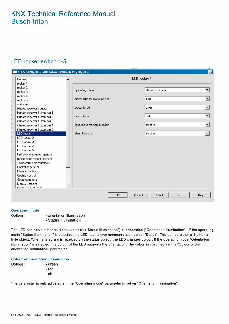
KNX Technical Reference Manual Busch-triton
68 | 0073-1-7621 | KNX Technical Reference Manual
LED rocker switch 1-5 Pos: 18.5.2 /Produkthandbuch - DIN-A4/Busch-triton/Parameter - Allgemeine Beschreibung/LED Wippe 1-5/Screenshot @ 16\mod_1294828727414_15.doc @ 98977 @
Pos: 18.5.3 /Produkthandbuch - DIN-A4/Busch-triton/Parameter - Allgemeine Beschreibung/LED Wippe 1-5/Betriebsart - DIN-A4 @ 13\mod_1286184098074_15.doc @ 91085 @ 2
Operating mode
Options: - orientation illumination - Status illumination The LED can serve either as a status display ("Status illumination") or orientation ("Orientation illumination"). If the operating mode "Status illumination" is selected, the LED has its own communication object "Status". This can be either a 1-bit or a 1-byte object. When a telegram is received on the status object, the LED changes colour. If the operating mode "Orientation illumination" is selected, the colour of the LED supports the orientation. The colour is specified via the "Colour of the orientation illumination" parameter. Pos: 18.5.4 /Produkthandbuch - DIN-A4/Busch-triton/Parameter - Allgemeine Beschreibung/LED Wippe 1-5/Farbe der Orientierungsbeleuchtung - DIN-A4 @ 13\mod_1286184164464_15.doc @ 91093 @ 2
Colour of orientation illumination
Options: - green - red - off The parameter is only adjustable if the "Operating mode" parameter is set on "Orientation illumination". Pos: 18.5.5 /Produkthandbuch - DIN-A4/Busch-triton/Parameter - Allgemeine Beschreibung/LED Wippe 1-5/Objekttyp für Status - DIN-A4 @ 13\mod_1286184417510_15.doc @ 91101 @ 2
KNX Technical Reference Manual | 0073-1-7621 | 69
Object type for status object
Options: - 1 bit - 1 byte (0...100%) - 1 byte (0...255) The parameter is only adjustable if the "Operating mode" parameter is set on "Status illumination". With the setting "1-bit", the communication object "Status" has the size "1-bit". If an ON telegram is received on the object, the LED takes on the colour that is stored in the "Colour for On" parameter. If an OFF telegram is received, the LED takes on the colour that is stored in the "Colour for Off" parameter. With the setting "1-byte 0..100%", the communication object "Status" has the size "1-byte". When a value telegram is received on the object, the LED can change colour. Whether the colour is switched and to which colour will be switched to depends on the parameter settings "Colour for zone …". The three adjustable zones have the following behaviour: Zone 1: 0% <= value < S1 Zone 2:, S1 <= value < S2 Zone 3: S2 <= value < 100%, The two threshold values S1 and S2 are determined via the parameters "Threshold 1 for intermediate level" (S1) and "Threshold 2 for intermediate level" (S2). Pos: 18.5.6 /Produkthandbuch - DIN-A4/Busch-triton/Parameter - Allgemeine Beschreibung/LED Wippe 1-5/Farbe für Aus - DIN-A4 @ 13\mod_1286184505838_15.doc @ 91109 @ 2
Colour for off
Options: - green - red - off The parameter can only be set if the "Operating mode" parameter is set on "Status illumination" and the parameter "Object type for status object" is set on "1 bit". Pos: 18.5.7 /Produkthandbuch - DIN-A4/Busch-triton/Parameter - Allgemeine Beschreibung/LED Wippe 1-5/Farbe für Ein - DIN-A4 @ 13\mod_1286184578275_15.doc @ 91117 @ 2
Colour for on
Options: - green - red - off The parameter can only be set if the "Operating mode" parameter is set on "Status illumination" and the parameter "Object type for status object" is set on "1 bit". Pos: 18.5.8 /Produkthandbuch - DIN-A4/Busch-triton/Parameter - Allgemeine Beschreibung/LED Wippe 1-5/Farbe für Bereich 1 - DIN-A4 @ 13\mod_1286184618119_15.doc @ 91125 @ 2
Colour for zone 1
Options: - green - red - off The parameter can only be set if the "Operating mode" parameter is set on "Status illumination" and the parameter "Object type for status object" is set on "1 byte". Pos: 18.5.9 /Produkthandbuch - DIN-A4/Busch-triton/Parameter - Allgemeine Beschreibung/LED Wippe 1-5/Schwelle zwischen 1 und 2 - DIN-A4 @ 13\mod_1286184666338_15.doc @ 91133 @ 2
Threshold between zone 1 and 2
Options: - 0...33...255 The parameter can only be set if the "Operating mode" parameter and is set to "Status illumination" and the parameter "Format status object" is set to "1 byte 0..255%". The value for S1 is specified via the parameter "Threshold between Zone 1 and 2". Pos: 18.5.10 /Produkthandbuch - DIN-A4/Busch-triton/Parameter - Allgemeine Beschreibung/LED Wippe 1-5/Farbe für Bereich 2 - DIN-A4 @ 13\mod_1286184740244_15.doc @ 91141 @ 2
KNX Technical Reference Manual Busch-triton
70 | 0073-1-7621 | KNX Technical Reference Manual
Colour for zone 2
Options: - green - red - off The parameter can only be set if the "Operating mode" parameter is set on "Status illumination" and the parameter "Object type for status object" is set on "1 byte". Pos: 18.5.11 /Produkthandbuch - DIN-A4/Busch-triton/Parameter - Allgemeine Beschreibung/LED Wippe 1-5/Schwelle zwischen 2 und 3 - DIN-A4 @ 13\mod_1286184808619_15.doc @ 91149 @ 2
Threshold between zone 2 and 3
Options: - 0...66...255 The parameter can only be set if the "Operating mode" parameter and is set to "Status illumination" and the parameter "Format status object" is set to "1 byte 0..255%". The value for S2 is specified via the parameter "Threshold between zone 2 and 3". Pos: 18.5.12 /Produkthandbuch - DIN-A4/Busch-triton/Parameter - Allgemeine Beschreibung/LED Wippe 1-5/Farbe für Bereich 3 - DIN-A4 @ 13\mod_1286184864993_15.doc @ 91157 @ 2
Colour for zone 3
Options: - green - red - off The parameter can only be set if the "Operating mode" parameter is set on "Status illumination" and the parameter "Object type for status object" is set on "1 byte". Pos: 18.5.13 /Produkthandbuch - DIN-A4/Busch-triton/Parameter - Allgemeine Beschreibung/LED Wippe 1-5/Speicherfunktion Lichtszene - DIN-A4 @ 13\mod_1286184895868_15.doc @ 91165 @ 2
Light scene memory function
Options: - inactive - active If the "Light scene memory function" is switched active, the LED can be made to flash (3 Hz) during the status or function display via a 1-byte communication object "Scene storage". If a scene storage telegram is received on the 1-byte communication object "Scene storage", the LED will flash for 3 s and then stop flashing automatically. The LED will always flash in green. Pos: 18.5.14 /Produkthandbuch - DIN-A4/Busch-triton/Parameter - Allgemeine Beschreibung/LED Wippe 1-5/Alarmfunktion - DIN-A4 @ 13\mod_1286184963368_15.doc @ 91173 @ 2
Alarm function
Options: - inactive - active If the alarm function is switched active, the LED can be made to flash (1 Hz) during the status or function display via a 1-bit communication object "Alarm". The LED will flash if an ON telegram is received on the 1-bit communication object "Alarm". If the object receives an OFF telegram, the LED will no longer flash. The LED will always flash in red. The alarm function could be used to display a wind alarm to the user for example so that the user knows that no blind operation is possible at that time. An additional application would be the signalling of an open door when user would like to lower a roller blind. Pos: 18.6.1 /Produkthandbuch - DIN-A4/Überschriften/1. Ebene/G - L/Lichtszenenaktor allgemein @ 11\mod_1279269720003_15.doc @ 84348 @ 1

KNX Technical Reference Manual | 0073-1-7621 | 71
Light Scene Actuator, General Pos: 18.6.2 /Produkthandbuch - DIN-A4/Busch-triton/Parameter - Allgemeine Beschreibung/Lichtszenenaktor allgemein/Screenshot @ 16\mod_1294828834508_15.doc @ 98985 @
Pos: 18.6.3 /Produkthandbuch - DIN-A4/Busch-triton/Parameter - Allgemeine Beschreibung/Lichtszenenaktor allgemein/Anzahl der Szenen - DIN-A4 @ 13\mod_1286180751085_15.doc @ 90973 @ 2
Number of scenes
Options: - inactive - 1...8 Up to eight different scenes can be called up via the device. They are defined by the "Number of scenes" parameter. Any arbitrary number from 1 to 8 scenes can be entered. The values that are sent out over the different actuator objects for the scene call-up are adjustable. But they can also be saved in the device by the user. Pos: 18.6.4 /Produkthandbuch - DIN-A4/Busch-triton/Parameter - Allgemeine Beschreibung/Lichtszenenaktor allgemein/Zeit für Telegrammverzögerung - DIN-A4 @ 13\mod_1286180849851_15.doc @ 90981 @ 2
Duration of telegram delay
Options: - 0.3...1.0...10 The parameter can only be adjusted when the "Number of scenes" is set on at least "1" and a maximum of "8". When a scene is called up, telegrams are sent out sequentially on the actuator group communication objects. The sequence is strictly specified. First the telegram of actuator group A is sent out, then the telegram of the actuator group B and then the telegram of the actuator group C, etc. The time between the telegrams can be adjusted. Pos: 18.6.5 /Produkthandbuch - DIN-A4/Busch-triton/Parameter - Allgemeine Beschreibung/Lichtszenenaktor allgemein/Szenen bei Download überschreiben - DIN-A4 @ 13\mod_1286180940038_15.doc @ 90989 @ 2

KNX Technical Reference Manual Busch-triton
72 | 0073-1-7621 | KNX Technical Reference Manual
Overwrite scenes for download
Options: - active - inactive These parameters are only adjustable if the "Number of scenes" is set to at least "1" and a maximum of "8". When reprogramming the device, the values stored by the user can be overwritten by the preset values in the parameterising software. To do this, the "Overwrite scenes for download" must be set to "active". The values stored by the user remain in the device with the "inactive" setting. Pos: 18.7.1 /Produkthandbuch - DIN-A4/Überschriften/1. Ebene/G - L/Lichtszenenaktor Aktorgruppen @ 11\mod_1279269787644_15.doc @ 84356 @ 1
Light Scene Actuator, Actuator Groups Pos: 18.7.2 /Produkthandbuch - DIN-A4/Busch-triton/Parameter - Allgemeine Beschreibung/Lichtszenenaktor Aktorgruppen/Screenshot @ 16\mod_1294829027069_15.doc @ 98993 @
When a scene is called up, telegrams are sent out consecutively on the actuator group communication objects. Pos: 18.7.3 /Produkthandbuch - DIN-A4/Busch-triton/Parameter - Allgemeine Beschreibung/Lichtszenenaktor Aktorgruppen/Objekttyp Aktorgruppe - DIN-A4 @ 13\mod_1286181112773_15.doc @ 91005 @ 2

KNX Technical Reference Manual | 0073-1-7621 | 73
Object type actuator group A-H
Options: - 1-bit switching - 1-bit blind - 1-byte 0...100% - 1-byte 0...255 - light scene number - 1-byte RTC operating mode - 2-byte float (-33.5°C...93.5°C) These parameters are only adjustable if the "Number of actuator groups" is set to at least "1" and a maximum of "8". The size of the actuator group communication object can be adjusted for different applications. Pos: 18.8.1 /Produkthandbuch - DIN-A4/Überschriften/1. Ebene/G - L/Lichtszenenaktor Szene 1-8 @ 11\mod_1279268622252_15.doc @ 84301 @ 1
Light Scene Actuator, Scene 1-8 Pos: 18.8.2 /Produkthandbuch - DIN-A4/Busch-triton/Parameter - Allgemeine Beschreibung/Lichtszenenaktor Szene 1-8/Szenennummer - DIN-A4 @ 13\mod_1286181219631_15.doc @ 91013 @ 2
Scene number
Options: - 1-64 The "Scene number" parameter specifies with which value the scene or a scene storage can be called up that is received on the 1-byte "Scene call-up" communication object. An arbitrary scene number from 1 to 64 can be set. Pos: 18.8.3 /Produkthandbuch - DIN-A4/Busch-triton/Parameter - Allgemeine Beschreibung/Lichtszenenaktor Szene 1-8/Szene kann gespeichert werden - DIN-A4 @ 13\mod_1286181969816_15.doc @ 91021 @ 2
Scene can be saved
Options: - inactive - active The user has the option of triggering a scene storage via the receipt of a corresponding scene storage command. The actuator groups communication objects in this case send read requests to the connected actuators. Provided that the L-flag is set for the communication objects of the connected actuators, these will send their current values to the device via an answer telegram. The values are stored in the memory and overwrite the previous values. These are also not lost in the event of a possibly occurring power failure. Pos: 18.8.4 /Produkthandbuch - DIN-A4/Busch-triton/Parameter - Allgemeine Beschreibung/Lichtszenenaktor Szene 1-8/Aktorgruppe A-H - DIN-A4 @ 13\mod_1286182047081_15.doc @ 91029 @ 2
Actuator group A-H
Options: - inactive - active These parameters are only adjustable if the "Number of actuator groups" is set to at least "1" and a maximum of "8". The number of parameters that were defined via the "Number of actuator groups" parameter are displayed. Via the "Actuator group A-H" parameter you can specify whether the actuator group A-H is sent out or not for a call-up of the scene. Select the "active" setting if the actuator group A-H is to trigger a telegram for a call-up of scene 1-8. Pos: 18.8.5 /Produkthandbuch - DIN-A4/Busch-triton/Parameter - Allgemeine Beschreibung/Lichtszenenaktor Szene 1-8/Lichtszenennummer - DIN-A4 @ 13\mod_1286183204873_15.doc @ 91037 @ 2
Light scene number
Options: - 1...64 This parameter can only be set if the actuator group A-H is activated and the "Object type actuator group A-H" parameter is set to "Light scene number". The parameter specifies which light scene number is to be sent out on the 1-byte communication object of the actuator group for a scene call-up. Arbitrary light scene numbers from 1 to 64 can be entered here. Pos: 18.8.6 /Produkthandbuch - DIN-A4/Busch-triton/Parameter - Allgemeine Beschreibung/Lichtszenenaktor Szene 1-8/Wert 1 Bit Schalten - DIN-A4 @ 13\mod_1286183292873_15.doc @ 91045 @ 2

KNX Technical Reference Manual Busch-triton
74 | 0073-1-7621 | KNX Technical Reference Manual
Value, 1-bit switching
Options: - off - on This parameter can only be set if the actuator group A-H is activated and the "Object type actuator group A-H" parameter is set on "1-bit switching". The "Value" parameter specifies whether an ON or an OFF telegram is to be sent out on the 1-bit communication object of the actuator group for a scene call-up. Pos: 18.8.7 /Produkthandbuch - DIN-A4/Busch-triton/Parameter - Allgemeine Beschreibung/Lichtszenenaktor Szene 1-8/Wert 1 Bit Jalousie - DIN-A4 @ 13\mod_1286183404591_15.doc @ 91053 @ 2
Value, 1-bit blind
Options: - up down This parameter can only be set if the actuator group A-H is activated and the "Object type actuator group A-H" parameter is set on "1-bit blind". The parameter specifies whether a blind up or down command is to be sent out on the 1-bit communication object of the actuator group for a scene call-up. Pos: 18.8.8 /Produkthandbuch - DIN-A4/Busch-triton/Parameter - Allgemeine Beschreibung/Lichtszenenaktor Szene 1-8/Wert 1 Byte 0...100% - DIN-A4 @ 13\mod_1286183456654_15.doc @ 91061 @ 2
Value, 1 byte 0...100%
Options: - 0...100% This parameter can only be set if the actuator group A-H is activated and the "Object type actuator group A-H" parameter is set on "1 byte 0..100 %". The "Value" parameter specifies which value is to be sent out on the 1-byte communication object of the actuator group for a scene call up. Percent values from 0 to 100 % can be entered (in 1% steps). Pos: 18.8.9 /Produkthandbuch - DIN-A4/Busch-triton/Parameter - Allgemeine Beschreibung/Lichtszenenaktor Szene 1-8/Wert 1 Byte 0...255 - DIN-A4 @ 13\mod_1286183543201_15.doc @ 91069 @ 2
Value, 1 byte 0...255
Options: - 0...255 This parameter can only be set if the actuator group A-H is activated and the "Object type actuator group A-H" parameter is set on "1 byte 0..255". The "Value" parameter specifies which value is to be sent out on the 1-byte communication object of the actuator group for a scene call up. Values from 0 to 255 can be entered here. Pos: 18.8.10 /Produkthandbuch - DIN-A4/Busch-triton/Parameter - Allgemeine Beschreibung/Lichtszenenaktor Szene 1-8/Wert Temperatur °C - DIN-A4 @ 13\mod_1286183606560_15.doc @ 91077 @ 2
Value, temperature °C
This parameter can only be set if the actuator group A-H is activated and the "Object type actuator group A-H" parameter is set on "Temperature value absolute". The parameter specifies which value is to be sent out on the 2-byte communication object of the actuator group for a scene call up. Absolute temperature values from -33.5 to +93.5°C can be entered. A set value shift for a room thermostat can be carried out here for example. Pos: 18.8.11 /Produkthandbuch - DIN-A4/Überschriften/2. Ebene/U - Z/Wert 1 Byte RTR-Betriebsart einstellen @ 11\mod_1279268851581_15.doc @ 84316 @ 2
Setting 1-byte value for RTC operation mode Pos: 18.8.12 /Produkthandbuch - DIN-A4/Busch-triton/Parameter - Allgemeine Beschreibung/Lichtszenenaktor Szene 1-8/Wert 1 Byte RTR-Betriebsart einstellen - DIN-A4 @ 11\mod_1279268744049_15.doc @ 84308 @
Options: - auto - comfort - standby - night - frost/heat protection This parameter can only be set if the actuator group A-H is activated and the "Object type actuator group A-H" parameter is set on "1-byte RTC mode".
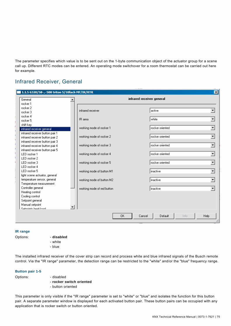
KNX Technical Reference Manual | 0073-1-7621 | 75
The parameter specifies which value is to be sent out on the 1-byte communication object of the actuator group for a scene call up. Different RTC modes can be entered. An operating mode switchover for a room thermostat can be carried out here for example. Pos: 18.9.1 /Produkthandbuch - DIN-A4/Überschriften/1. Ebene/G - L/Infrarotempfänger @ 11\mod_1279269032502_15.doc @ 84324 @ 1
Infrared Receiver, General Pos: 18.9.2 /Produkthandbuch - DIN-A4/Busch-triton/Parameter - Allgemeine Beschreibung/Infrarotempfänger/Screenshot @ 16\mod_1294829613161_15.doc @ 99001 @
Pos: 18.9.3 /Produkthandbuch - DIN-A4/Überschriften/2. Ebene/G - L/IR-Bereich @ 11\mod_1279272126670_15.doc @ 84515 @ 2
IR range Pos: 18.9.4 /Produkthandbuch - DIN-A4/Busch-triton/Parameter - Allgemeine Beschreibung/Infrarotempfänger/IR-Bereich - DIN-A4 @ 11\mod_1279272039529_15.doc @ 84507 @
Options: - disabled - white - blue The installed infrared receiver of the cover strip can record and process white and blue infrared signals of the Busch remote control. Via the "IR range" parameter, the detection range can be restricted to the "white" and/or the "blue" frequency range. Pos: 18.9.5 /Produkthandbuch - DIN-A4/Überschriften/2. Ebene/S - T/Tastenpaar 1-5 @ 11\mod_1279272612141_15.doc @ 84544 @ 2
Button pair 1-5 Pos: 18.9.6 /Produkthandbuch - DIN-A4/Busch-triton/Parameter - Allgemeine Beschreibung/Infrarotempfänger/Tastenpaar 1-5 - DIN-A4 @ 11\mod_1279272219842_15.doc @ 84522 @
Options: - disabled - rocker switch oriented - button oriented This parameter is only visible if the "IR range" parameter is set to "white" or "blue" and isolates the function for this button pair. A separate parameter window is displayed for each activated button pair. These button pairs can be occupied with any application that is rocker switch or button oriented.

KNX Technical Reference Manual Busch-triton
76 | 0073-1-7621 | KNX Technical Reference Manual
Pos: 18.9.7 /Produkthandbuch - DIN-A4/Überschriften/2. Ebene/M - O/Memotaste 1-2, Memotaste Rot @ 11\mod_1279272566406_15.doc @ 84536 @ 2
Memo button 1-2, red memo button Pos: 18.9.8 /Produkthandbuch - DIN-A4/Busch-triton/Parameter - Allgemeine Beschreibung/Infrarotempfänger/Memotaste 1-2, Memotaste Rot - DIN-A4 @ 11\mod_1279272451686_15.doc @ 84529 @
Options: - disabled - active These parameters are only visible if the "IR range" parameter is set to "white" or "blue" and isolates the function for this button pair. A separate parameter window is displayed for each activated button. These buttons can be occupied with any button oriented application. Pos: 18.10.1 /Produkthandbuch - DIN-A4/Überschriften/1. Ebene/G - L/Infrarotempfänger Tastenpaar 1-5 @ 11\mod_1279269879972_15.doc @ 84364 @ 1
Infrared Receiver Button Pair 1-5 Pos: 18.10.2 /Produkthandbuch - DIN-A4/Busch-triton/Parameter - Allgemeine Beschreibung/Infrarotempfänger Tastenpaar 1-5/Screenshot @ 16\mod_1294829675083_15.doc @ 99009 @
Pos: 18.10.3 /Produkthandbuch - DIN-A4/Busch-triton/Parameter - Allgemeine Beschreibung/Infrarotempfänger Tastenpaar 1-5/Tastenpaar 1-5 (weiß) - DIN-A4 @ 12\mod_1283159021652_15.doc @ 87871 @ 2
Button pair 1-5 (white)
Options: - switching - dimming - blind - value sender - value dimming sensor - step-type switch

KNX Technical Reference Manual | 0073-1-7621 | 77
Additionally for control elements with integrated RTC: - setpoint adjustment of the internal RTC - operating mode/fans stage switchover of the internal RTC These channels are only visible when parameter "Function of button pair" is set on "Rocker switch oriented". Additional parameters (see parameter description of rocker switches) are displayed depending on the set function. Pos: 18.10.4 /Produkthandbuch - DIN-A4/Überschriften/2. Ebene/S - T/Taste 1-5 links; Taste 1-5 rechts @ 11\mod_1279272910627_15.doc @ 84559 @ 2
Button 1-5 left; button 1-5 right Pos: 18.10.5 /Produkthandbuch - DIN-A4/Busch-triton/Parameter - Allgemeine Beschreibung/Infrarotempfänger Tastenpaar 1-5/Taste 1-5 links; Taste 1-5 rechts - DIN-A4 @ 11\mod_1279272802892_15.doc @ 84552 @
Options: - switching - dimming - roller blind - value sender - value sender, 2 objects - light scene extension unit with memory function - step-type switch - short-long operation - setting the RTC operating mode These channels are only visible when parameter "Function of button pair" is set on "button-oriented". Additional parameters (see parameter description of rocker switches) are displayed depending on the set function. Pos: 18.11.1 /Produkthandbuch - DIN-A4/Überschriften/1. Ebene/G - L/Infrarotempfänger Memotaste 1-2, rot @ 11\mod_1279270300569_15.doc @ 84372 @ 1
Infrared Receiver Memo Button 1-2, Red Pos: 18.11.2 /Produkthandbuch - DIN-A4/Überschriften/2. Ebene/M - O/Memotaste 1-2, Memotaste Rot @ 11\mod_1279272566406_15.doc @ 84536 @ 2
Memo button 1-2, red memo button Pos: 18.11.3 /Produkthandbuch - DIN-A4/Busch-triton/Parameter - Allgemeine Beschreibung/Infrarotempfänger Memotaste 1-2, rot/Memotaste 1-2, Memotaste Rot (weiß) - DIN-A4 @ 12\mod_1283160460970_15.doc @ 87879 @
Options: - switching - dimming - roller shutters - value sender - value sender, 2 objects - light scene extension unit with memory function - step-type switch - short-long operation - setting the RTC operating mode This channel is only visible if the "IR area" parameter and "Memo button 1-2, red" is set on "active". Pos: 18.12.1 /Produkthandbuch - DIN-A4/Überschriften/1. Ebene/S - Z/Temperatursensor allgemein @ 11\mod_1279270385084_15.doc @ 84380 @ 1

KNX Technical Reference Manual Busch-triton
78 | 0073-1-7621 | KNX Technical Reference Manual
Temperature Sensor, General Pos: 18.12.2 /Produkthandbuch - DIN-A4/Busch-triton/Parameter - Allgemeine Beschreibung/Temperatursensor allgemein/Screenshot @ 16\mod_1294829790084_15.doc @ 99017 @
Pos: 18.12.3 /Produkthandbuch - DIN-A4/Überschriften/2. Ebene/U - Z/Umschaltung der Temperaturanzeige °C/°F @ 11\mod_1279275052753_15.doc @ 84663 @ 2
Switchover of temperature display °C/°F Pos: 18.12.4 /Produkthandbuch - DIN-A4/Busch-triton/Parameter - Allgemeine Beschreibung/Temperatursensor allgemein/Umschaltung der Temperaturanzeige °C/°F - DIN-A4 @ 11\mod_1279273559127_15.doc @ 84567 @
Options: - °C - °F The temperature shown on the display can be changed from °C to °F. The conversion from °C to °F is always made in the room thermostat since only °C values can be sent on the KNX. A switchover of the °C/°F unit can only be made via the associated object. Pos: 18.12.5 /Produkthandbuch - DIN-A4/Überschriften/2. Ebene/A - F/Anzeige im Normalbetrieb @ 11\mod_1279274905925_15.doc @ 84631 @ 2
Display during normal operation Pos: 18.12.6 /Produkthandbuch - DIN-A4/Busch-triton/Parameter - Allgemeine Beschreibung/Temperatursensor allgemein/Anzeige im Normalbetrieb - DIN-A4 @ 11\mod_1279273698627_15.doc @ 84574 @
Options: - no temperature - absolute setpoint temperature - relative setpoint temperature (+/- K) - current actual value This parameter is used to specify the information to be displayed in the temperature sensor mode. This can include current temperature, current setpoint, relative current setpoint (adjusted setpoint) or no temperature. Pos: 18.12.7 /Produkthandbuch - DIN-A4/Überschriften/2. Ebene/A - F/Anzeige im Verstellmodus @ 11\mod_1279274940535_15.doc @ 84639 @ 2
KNX Technical Reference Manual | 0073-1-7621 | 79
Display in adjustment mode Pos: 18.12.8 /Produkthandbuch - DIN-A4/Busch-triton/Parameter - Allgemeine Beschreibung/Temperatursensor allgemein/Anzeige im Verstellmodus - DIN-A4 @ 11\mod_1279273921721_15.doc @ 84581 @
Options: - absolute setpoint temperature - relative setpoint temperature (+/- K) This parameter is used to specify the information to be displayed in adjustment mode. You can choose to display the setpoint temperature or relative current temperature (adjusted setpoint). Pos: 18.12.9 /Produkthandbuch - DIN-A4/Überschriften/2. Ebene/A - F/Anzeige Heizen / Kühlen ist aktiv @ 11\mod_1279274839956_15.doc @ 84623 @ 2
Heating / cooling display is active Pos: 18.12.10 /Produkthandbuch - DIN-A4/Busch-triton/Parameter - Allgemeine Beschreibung/Temperatursensor allgemein/Anzeige Heizen / Kühlen ist aktiv - DIN-A4 @ 11\mod_1279274016439_15.doc @ 84588 @
Options: when operating mode is active - when heating or cooling is required Depending on the parameter setting, the heating/cooling display responds either during "Heating/cooling requirement" or "when operation mode is active". The lower setting shows only heating or cooling, even when the system is actually heating or cooling. Pos: 18.12.11 /Produkthandbuch - DIN-A4/Überschriften/2. Ebene/A - F/Betriebsartenumschaltung @ 11\mod_1279275018003_15.doc @ 84655 @ 2
Operating mode switchover Pos: 18.12.12 /Produkthandbuch - DIN-A4/Busch-triton/Parameter - Allgemeine Beschreibung/Temperatursensor allgemein/Betriebsartenumschaltung - DIN-A4 @ 11\mod_1279274256908_15.doc @ 84595 @
Options: - 1 bit (3 x DPT_Switch) - 1 byte (2 x DPT_HVACMode) The operating mode switchover is used to specify whether the room thermostat has three 1-bit communication objects "Comfort/Standby", "Night mode" and "Frost/Heat protection", or two 1-byte communication objects for operating mode switchover. If an ON telegram is received on the comfort/standby object with the 1-bit operating mode switchover, the comfort operating mode is activated. If an OFF telegram is received, the standby operation is activated. If an ON telegram is received on the night mode object, the night mode is active. An OFF telegram deactivates the night mode again. The Frost/Heat protection mode is also activated with an ON telegram and deactivated with an OFF telegram. If an ON telegram has been received on multiple objects, the frost/heat protection has a higher priority than the comfort operation. Night setback has a higher priority than comfort operation. Two 1-byte communication objects are made available with operation mode switchover via 1 byte. Note: The two 1-byte communication objects have different behaviours for receipt of telegrams. One object evaluates received telegrams as "normal". This means, for example, if a comfort telegram is received, the room thermostat switches to comfort mode. If a night telegram is received, the room thermostat switches to night mode. This object is controlled, for example, by time switches. The second object can "overwrite" the first. This means, for example, if a frost/heat protection telegram is received, the room thermostat switches to frost or heat protection mode. If frost or heat protection is reset after receipt of a new telegram, the room thermostat activates the mode that is on the "normal" operating mode object. As a result, it is capable of memorising operating modes. This object is controlled, for example, by binary inputs that record information from window contacts. The following conditions apply for the 1-byte communication object: 0 = auto 1 = comfort 2 = standby 3 = night 4 = frost/Heat protection 5 – 255 = not allowed Pos: 18.12.13 /Produkthandbuch - DIN-A4/Überschriften/2. Ebene/U - Z/Umschaltung Komfort/Standby per Wippe 2 Taste links freigeben @ 11\mod_1279275085394_15.doc @ 84671 @ 2
Enable switchover of comfort/standby via left button of rocker switch 2 Pos: 18.12.14 /Produkthandbuch - DIN-A4/Busch-triton/Parameter - Allgemeine Beschreibung/Temperatursensor allgemein/Umschaltung Komfort/Standby per Wippe 2 Taste links freigeben - DIN-A4 @ 11\mod_1279274473597_15.doc @ 84602 @

KNX Technical Reference Manual Busch-triton
80 | 0073-1-7621 | KNX Technical Reference Manual
Options: - yes - no This parameter is used to enable the operating mode switchover via the left button of rocker switch 2. Pos: 18.12.15 /Produkthandbuch - DIN-A4/Überschriften/2. Ebene/U - Z/Umschaltung Regler EIN/AUS per Wippe 2 Taste links freigeben @ 11\mod_1279275119535_15.doc @ 84679 @ 2
Enable switchover of ON/OFF controller via left button of rocker switch 2 Pos: 18.12.16 /Produkthandbuch - DIN-A4/Busch-triton/Parameter - Allgemeine Beschreibung/Temperatursensor allgemein/Umschaltung Regler EIN/AUS per Wippe 2 Taste links freigeben - DIN-A4 @ 11\mod_1279274579644_15.doc @ 84609 @
Options: - yes - no This parameter is used to enable ON/OFF switching via the left button of rocker switch 2. If "yes" has been set here, the device is switched off/on with a long press of the button (> 500 ms). When the device is off, and is then switched on via the button, the comfort mode is called up. Pos: 18.12.17 /Produkthandbuch - DIN-A4/Überschriften/2. Ebene/A - F/Betriebsart nach Reset @ 11\mod_1279274988175_15.doc @ 84647 @ 2
Operating mode after reset Pos: 18.12.18 /Produkthandbuch - DIN-A4/Busch-triton/Parameter - Allgemeine Beschreibung/Temperatursensor allgemein/Betriebsart nach Reset - DIN-A4 @ 11\mod_1279274661644_15.doc @ 84616 @
Options: - comfort mode - standby - night mode - frost/heat protection This parameter specifies the mode activated after resetting the temperature sensor or after commissioning. "Comfort mode" is preset; however, also "Standby", "Night mode" or "Frost/heat protection" can be selected. Pos: 18.13.1 /Produkthandbuch - DIN-A4/Überschriften/1. Ebene/S - Z/Temperaturmessung @ 11\mod_1279270545022_15.doc @ 84388 @ 1

KNX Technical Reference Manual | 0073-1-7621 | 81
Temperature Measurement Pos: 18.13.2 /Produkthandbuch - DIN-A4/Busch-triton/Parameter - Allgemeine Beschreibung/Temperaturmessung/Screenshot @ 16\mod_1294829853021_15.doc @ 99025 @
Pos: 18.13.3 /Produkthandbuch - DIN-A4/Busch-triton/Parameter - Allgemeine Beschreibung/Temperaturmessung/Abgleichwert für Raumtemperaturmessung - DIN-A4 @ 12\mod_1283162274918_15.doc @ 87887 @ 2
Offset for room temperature measurement (measured value changed by (-128...127) x 0.1 K)
Options: - -128 - ... - 0 - ... - 127 If the current temperature is measured internally, it can possibly be distorted by an additional permanent source of heat, e.g. bus or mains coupler. The distorted value can be adjusted by the parameter "Offset for temperature measurement". Pos: 18.13.4 /Produkthandbuch - DIN-A4/Busch-triton/Parameter - Allgemeine Beschreibung/Temperaturmessung/Istwert bei Änderung senden größer - DIN-A4 @ 12\mod_1283162340074_15.doc @ 87895 @ 2

KNX Technical Reference Manual Busch-triton
82 | 0073-1-7621 | KNX Technical Reference Manual
Send actual value for change greater than
Options: - inactive - 0.1 K - 0.2 K - 0.3 K - 0.4 K - 0.5 K - 0.6 K - 0.7 K - 0.8 K - 0.9 K - 1.0 K If the parameter is set to a difference, the associated 2-byte communication object "Actual temperature" sends its current value as soon as it changes by more than the specified difference. Pos: 18.13.5 /Produkthandbuch - DIN-A4/Busch-triton/Parameter - Allgemeine Beschreibung/Temperaturmessung/Istwert zyklisch senden - DIN-A4 @ 12\mod_1283162401496_15.doc @ 87903 @ 2
Send actual value cyclically (0 – inactive, min)
Options: - 0...60 If the actual value is to be sent cyclically independent of a change, the parameter "Cyclic sending of actual value" must be set to a time. This may be necessary, for instance, with a higher-level boiler that expects to receive setpoints and current values within a certain time period. If the values are not received, a predefined supply line temperature is set that is no longer oriented on actual demand. Pos: 18.13.6 /Produkthandbuch - DIN-A4/Busch-triton/Parameter - Allgemeine Beschreibung/Temperaturmessung/Raumtemperaturmessung - DIN-A4 @ 12\mod_1283162461121_15.doc @ 87911 @ 2
Room temperature measurement
Options: - internal - external - internal and external This parameter is used to set the measurement of the current temperature. It can be measured "internally," "externally" or "internally and externally". Internal measurement means that the temperature is taken directly from the room thermostat. For external measurements, an additional temperature sensor is used and is sent to the room thermostat via 2-byte communication object. If the current temperature is measured internally and externally, the room thermostat determines a common current temperature from the combination of temperature values defined in the "Weighting internal/external" parameter. An additional sensor may need to be added for larger spaces. Pos: 18.13.7 /Produkthandbuch - DIN-A4/Busch-triton/Parameter - Allgemeine Beschreibung/Temperaturmessung/Gewichtung intern/extern - DIN-A4 @ 12\mod_1283162562058_15.doc @ 87919 @ 2
Internal/external weighting
Options: - 10% / 90% - 20% / 80% - 30% / 70% - 40% / 60% - 50% / 50% - 60% / 40% - 70% / 30% - 80% / 20% - 90% / 10% The "Weighting internal/external" parameter specifies how the internal temperature sensor for the room thermostat and the external temperature sensor are included in the control. If, for instance, the parameter is set to 60%, the current temperature is 60% of the temperature measured internally and 40% of the value obtained externally. Pos: 18.13.8 /Produkthandbuch - DIN-A4/Busch-triton/Parameter - Allgemeine Beschreibung/Temperaturmessung/Überwachung Temperaturmessung - DIN-A4 @ 12\mod_1283162611230_15.doc @ 87927 @ 2

KNX Technical Reference Manual | 0073-1-7621 | 83
Temperature measurement monitoring
Options: - yes - no The "Temperature monitoring" parameter specifies whether the internal, if connected, and the external temperature sensor are to be monitored. Pos: 18.13.9 /Produkthandbuch - DIN-A4/Überschriften/2. Ebene/S - T/Stellgröße bei Fehler Temperaturmessung @ 11\mod_1279275716607_15.doc @ 84708 @ 2
Control value during temperature measurement error Pos: 18.13.10 /Produkthandbuch - DIN-A4/Busch-triton/Parameter - Allgemeine Beschreibung/Temperaturmessung/Stellgröße bei Fehler Temperaturmessung - DIN-A4 @ 11\mod_1279275445277_15.doc @ 84687 @
Options: - last value - 0% - 10% - 20% - 30% - 40% - 50% - 60% - 70% - 80% - 90% - 100% In the event of a fault, the output of the device adjusts to the set value to execute an emergency operating function. Pos: 18.13.11 /Produkthandbuch - DIN-A4/Überschriften/2. Ebene/U - Z/Überwachungszeit externe Temperatur @ 11\mod_1279275783670_15.doc @ 84724 @ 2
External temperature monitoring time Pos: 18.13.12 /Produkthandbuch - DIN-A4/Busch-triton/Parameter - Allgemeine Beschreibung/Temperaturmessung/Überwachungszeit externe Temperatur - DIN-A4 @ 11\mod_1279275540621_15.doc @ 84694 @
Options: - 0 / 1 / ... / 10 / ... / 60 When the "Temperature measurement monitoring" parameter is set on yes, the time is set here in which the external temperature sensor must have sent a telegram on the bus. Pos: 18.13.13 /Produkthandbuch - DIN-A4/Überschriften/2. Ebene/U - Z/Überwachungszeit Außentemperatur @ 11\mod_1279275748982_15.doc @ 84716 @ 2
Outside temperature monitoring time Pos: 18.13.14 /Produkthandbuch - DIN-A4/Busch-triton/Parameter - Allgemeine Beschreibung/Temperaturmessung/Überwachungszeit Außentemperatur - DIN-A4 @ 11\mod_1279275608122_15.doc @ 84701 @
Options: - 0 / 1 / ... / 10 / .../ 60 When the "Temperature measurement monitoring" parameter is set on yes, the time is set here in which the outside temperature sensor must have sent a telegram on the bus. Pos: 18.13.15 /Produkthandbuch - DIN-A4/Busch-triton/Parameter - Allgemeine Beschreibung/Temperaturmessung/Abgleichwert für Außentemperaturmessung - DIN-A4 @ 12\mod_1283162703401_15.doc @ 87935 @ 2
Offset for outside temperature measurement
Options: - -128 - ... - 0 - ... - 127 This parameter is used to adjust the measured outside temperature. I.e., if the outside temperature value is distorted at the temperature sensor by heating and cooling factors, the measured value can be increased or decreased. Pos: 18.14.1 /Produkthandbuch - DIN-A4/Überschriften/1. Ebene/M - R/Regler allgemein @ 11\mod_1279270618960_15.doc @ 84396 @ 1

KNX Technical Reference Manual Busch-triton
84 | 0073-1-7621 | KNX Technical Reference Manual
Controller, General Pos: 18.14.2 /Produkthandbuch - DIN-A4/Busch-triton/Parameter - Allgemeine Beschreibung/Regler allgemein/Screenshot @ 16\mod_1294829909755_15.doc @ 99033 @
Pos: 18.14.3 /Produkthandbuch - DIN-A4/Überschriften/2. Ebene/A - F/Betriebsart des Geräts @ 11\mod_1279276245252_15.doc @ 84761 @ 2
Operating mode of the device Pos: 18.14.4 /Produkthandbuch - DIN-A4/Busch-triton/Parameter - Allgemeine Beschreibung/Regler allgemein/Betriebsart des Geräts - DIN-A4 @ 11\mod_1279275940765_15.doc @ 84732 @
Options: - normal operation with control function - extension unit, only control and display function For the setting "Extension unit, operating and display function only", the control function of the device is deactivated. The device then serves for operating another device, such as e.g. switching on/off, setpoint setting, fan stage setting, display of switching between C/ F. Pos: 18.14.5 /Produkthandbuch - DIN-A4/Busch-triton/Parameter - Allgemeine Beschreibung/Regler allgemein/Verwendete Reglerfunktion - DIN-A4 @ 12\mod_1283163867352_15.doc @ 87943 @ 2
Control functions used
Options: - heating - cooling - heating and cooling The parameter "Used control functions" allows you to define the functionality of the room thermostat. You can choose between "heating" or "cooling" functions, or use it for both "heating and cooling". Once you have selected a function, only the parameters and communication objects required for that function are shown. This setting is only displayed when the operating mode of the device is set on normal operation with control functions. Pos: 18.14.6 /Produkthandbuch - DIN-A4/Busch-triton/Parameter - Allgemeine Beschreibung/Regler allgemein/Umschalten zwischen Heizen und Kühlen - DIN-A4 @ 12\mod_1283163922102_15.doc @ 87951 @ 2

KNX Technical Reference Manual | 0073-1-7621 | 85
Switching between heating and cooling
Options: - automatic - automatic and sending - external You can switch between heating and cooling automatically in the room thermostat. To do so, select the "automatic" option. This ensures that the room thermostat checks the configured setpoints for heating and cooling. The option "automatic and send" also allows you to switch automatically. In addition, a toggle telegram is sent and can be analysed by other room thermostats. The "external" option allows you to switch via an associated 1-bit communication object. Pos: 18.14.7 /Produkthandbuch - DIN-A4/Busch-triton/Parameter - Allgemeine Beschreibung/Regler allgemein/Zusatzstufe Heizen aktiv - DIN-A4 @ 12\mod_1283163975837_15.doc @ 87959 @ 2
Additional heating stage active
Options: - yes - no In specific instances, such as when using underfloor heating, it may be necessary to install a quick additional stage for the heat control in order to warm up the room rapidly. With the option on "yes", the room thermostat has a second heating system with switching control (1-bit) or continuous control (1-byte). This parameter is only available if the controller function "Heating" or "Heating and cooling" is used. Pos: 18.14.8 /Produkthandbuch - DIN-A4/Busch-triton/Parameter - Allgemeine Beschreibung/Regler allgemein/Zusatzstufe Kühlen aktiv - DIN-A4 @ 12\mod_1283166460935_15.doc @ 87967 @ 2
Additional cooling stage active
Options: - yes - no In specific instances, it may be necessary to install a quick additional stage in the cooling control in order to cool off the room rapidly. With the option on "yes", the room thermostat has a second cooling system with switching control (1-bit) or continuous control (1-byte) 100%. This parameter is only available if the controller function "Cooling" or "Heating and cooling" is used. Pos: 18.14.9 /Produkthandbuch - DIN-A4/Busch-triton/Parameter - Allgemeine Beschreibung/Regler allgemein/Kondensatwasseralarm aktiv - DIN-A4 @ 12\mod_1283166526763_15.doc @ 87975 @ 2
Condensate water alarm active
Options: - yes - no If the parameter "Condensate water alarm" is activated, the room thermostat has a 1-bit communication object to which telegrams from a container for condensate water can be sent. When an ON telegram arrives, the room thermostat changes to the heat protection mode. Heat protection is deactivated when an OFF telegram is received. This prevents condensate, which can collect during cooling, from overflowing the condensate container. This parameter is only available if the controller function "Cooling" or "Heating and cooling" is used. A condensate water alarm is shown on the display (fault symbol plus text abbreviation). Once the condensate alarm is removed and no dew point alarm is active, a switchover from heat protection to the pending operating mode occurs. Pos: 18.14.10 /Produkthandbuch - DIN-A4/Busch-triton/Parameter - Allgemeine Beschreibung/Regler allgemein/Taupunktalarm aktiv - DIN-A4 @ 12\mod_1283166575763_15.doc @ 87983 @ 2
Dew point alarm active
Options: - yes - no If the parameter "Dew point alarm active" is activated, the room thermostat has a 1-bit communication object that can be used to send telegrams from a dew point sensor. When an ON telegram arrives, the room thermostat changes to the heat protection mode. Heat protection is deactivated when an OFF telegram is received. This prevents the condensate water that forms during incipient condensation when cooling is switched on from causing damage. This parameter is only available if the controller function "Cooling" or "Heating and cooling" is used. A dew point alarm is shown on the display (fault symbol plus text abbreviation).
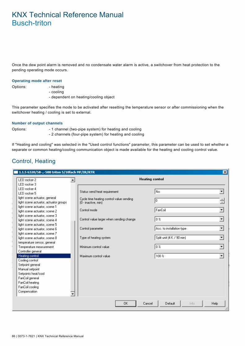
KNX Technical Reference Manual Busch-triton
86 | 0073-1-7621 | KNX Technical Reference Manual
Once the dew point alarm is removed and no condensate water alarm is active, a switchover from heat protection to the pending operating mode occurs. Pos: 18.14.11 /Produkthandbuch - DIN-A4/Überschriften/2. Ebene/A - F/Betriebsmodus nach Reset @ 11\mod_1279276278331_15.doc @ 84769 @ 2
Operating mode after reset Pos: 18.14.12 /Produkthandbuch - DIN-A4/Busch-triton/Parameter - Allgemeine Beschreibung/Regler allgemein/Betriebsmodus nach Reset - DIN-A4 @ 11\mod_1279276020796_15.doc @ 84739 @
Options: - heating - cooling - dependent on heating/cooling object This parameter specifies the mode to be activated after resetting the temperature sensor or after commissioning when the switchover heating / cooling is set to external. Pos: 18.14.13 /Produkthandbuch - DIN-A4/Überschriften/2. Ebene/A - F/Anzahl der Ausgangskanäle @ 11\mod_1279276212986_15.doc @ 84753 @ 2
Number of output channels Pos: 18.14.14 /Produkthandbuch - DIN-A4/Busch-triton/Parameter - Allgemeine Beschreibung/Regler allgemein/Anzahl der Ausgangskanäle - DIN-A4 @ 11\mod_1279276096907_15.doc @ 84746 @
Options: - 1 channel (two-pipe system) for heating and cooling - 2 channels (four-pipe system) for heating and cooling If "Heating and cooling" was selected in the "Used control functions" parameter, this parameter can be used to set whether a separate or common heating/cooling communication object is made available for the heating and cooling control value. Pos: 18.15.1 /Produkthandbuch - DIN-A4/Überschriften/1. Ebene/M - R/Regelung Heizen @ 11\mod_1279270697523_15.doc @ 84404 @ 1
Control, Heating Pos: 18.15.2 /Produkthandbuch - DIN-A4/Busch-triton/Parameter - Allgemeine Beschreibung/Regelung Heizen/Screenshot @ 16\mod_1294829975785_15.doc @ 99041 @
Pos: 18.15.3 /Produkthandbuch - DIN-A4/Überschriften/2. Ebene/S - T/Status Heizanforderung senden @ 11\mod_1279282723771_15.doc @ 84905 @ 2

KNX Technical Reference Manual | 0073-1-7621 | 87
Send heating request status Pos: 18.15.4 /Produkthandbuch - DIN-A4/Busch-triton/Parameter - Allgemeine Beschreibung/Regelung Heizen/Status Heizanforderung senden - DIN-A4 @ 11\mod_1279276962160_15.doc @ 84777 @
Options: - yes - no If you set the "Status send heating request" to "Yes", the room thermostat will send an ON telegram via the relevant 1-bit communication object once it is in heating mode. If the room thermostat is in the "dead zone" between heating and cooling or in cooling mode, the thermostat sends an OFF telegram via the status heating object. This parameter is only available if the control function "Heating" or "Heating and cooling" is set. Pos: 18.15.5 /Produkthandbuch - DIN-A4/Busch-triton/Parameter - Allgemeine Beschreibung/Regelung Heizen/Zykluszeit Stellgröße Heizen senden - DIN-A4 @ 12\mod_1283167057575_15.doc @ 87991 @ 2
Send cycle time heating control value (0 inactive, min)
Options: - 0 / 1 / ... / 60 The room thermostat can send the control value, even if the value remains unchanged. This is often required since the connected actuator otherwise assumes that the room thermostat is no longer available. This enables the actuator to activate its force-position control, which is only deactivated when a new control value is received. The cycle time for automatic sending of the control value is adjustable from 1 to 60 minutes; cyclic sending can also be disabled (setting 0). This parameter is only available if the control function "Heating" or "Heating and cooling" is set. Pos: 18.15.6 /Produkthandbuch - DIN-A4/Busch-triton/Parameter - Allgemeine Beschreibung/Regelung Heizen/Regelungstyp - DIN-A4 @ 12\mod_1283167171747_15.doc @ 87999 @ 2
Control type
Options: - 2-point - PWM - continuous - fan coil This function allows you to specify the type of control. You can choose from "2-point control", "PWM control", "Continuous control" or "Fan coil" control (see also from page 81 and the following). This parameter is only available if the control function "Heating" or "Heating and cooling" is set. Note: The fan stage adjustment is available only with fan coil. The button has no function and the fan stage is not displayed for any other control type. Pos: 18.15.7 /Produkthandbuch - DIN-A4/Busch-triton/Parameter - Allgemeine Beschreibung/Regelung Heizen/Hysterese - DIN-A4 @ 12\mod_1283167254793_15.doc @ 88007 @ 2
Hysteresis
Options: - 0.0 K - 0.1 K - 0.2 K - 0.3 K - ... - 1.0 K - ... - 2.0 K Set a hysteresis value to ensure that the valve does not constantly switch with each minor under and overshoot when using 2-point control of the actuator. The hysteresis value lies around the setpoint. For example, if the setpoint is 21 °C and the hysteresis is 1 K, the room thermostat only sends an "on" signal at 21.5 °C and an "off" signal at 20.5 °C. This parameter is only available if the "2-point control" is set as control type. Pos: 18.15.8 /Produkthandbuch - DIN-A4/Überschriften/2. Ebene/G - L/Heizen invertieren @ 11\mod_1279282514288_15.doc @ 84857 @ 2

KNX Technical Reference Manual Busch-triton
88 | 0073-1-7621 | KNX Technical Reference Manual
Invert heating Pos: 18.15.9 /Produkthandbuch - DIN-A4/Busch-triton/Parameter - Allgemeine Beschreibung/Regelung Heizen/Heizen invertieren - DIN-A4 @ 11\mod_1279277090645_15.doc @ 84784 @
Options: - yes - no Via "Invert heating", the mode of the control value can be used to adapt control value to "deenergised opened" or "deenergised closed" valves. Pos: 18.15.10 /Produkthandbuch - DIN-A4/Überschriften/2. Ebene/S - T/Stellgröße senden bei Änderung größer @ 11\mod_1279282756459_15.doc @ 84913 @ 2
Send control value for change greater than Pos: 18.15.11 /Produkthandbuch - DIN-A4/Busch-triton/Parameter - Allgemeine Beschreibung/Regelung Heizen/Stellgröße senden bei Änderung größer - DIN-A4 @ 11\mod_1279277167817_15.doc @ 84791 @
Options: - 0% - 1% - ... - 5% - ... - 15% The parameter "Send control value for change greater than" can be used to influence the bus load. This setting is configured in percentages. The higher the selected value, the fewer the control value telegrams sent by the room thermostat. However, the value should not be set too high to ensure the control works properly. The value of 5% will generally provide good control results. This parameter is only available if the "Heating" or "Heating and cooling" control function is set and the "Heating" control type is set to "continuous" or "fan coil". Pos: 18.15.12 /Produkthandbuch - DIN-A4/Überschriften/2. Ebene/P - R/Regelparameter @ 11\mod_1279282690334_15.doc @ 84897 @ 2
Control parameters Pos: 18.15.13 /Produkthandbuch - DIN-A4/Busch-triton/Parameter - Allgemeine Beschreibung/Regelung Heizen/Regelparameter - DIN-A4 @ 11\mod_1279280506182_15.doc @ 84798 @
Options: - according to installation type - free parameterisation This parameter allows you to configure the control based on the type of system in use. The "By installation type" setting displays predefined values for the different system types that most frequently provide good control results. The setting "User parameterisation" can be used to individually adjust the proportional range and readjust time. Proper knowledge in the field of control technology is required to use "User parameterization". Pos: 18.15.14 /Produkthandbuch - DIN-A4/Überschriften/2. Ebene/A - F/Art der Anlage @ 11\mod_1279282471382_15.doc @ 84849 @ 2
System type Pos: 18.15.15 /Produkthandbuch - DIN-A4/Busch-triton/Parameter - Allgemeine Beschreibung/Regelung Heizen/Art der Anlage - DIN-A4 @ 11\mod_1279280629823_15.doc @ 84805 @
Options: - hot water heating (1.5 K/ 100 min) - electric heating (1.5 K / 50 min) - floor heating (4 K / 200 min) - split unit (4 K / 90 min) The "System type" parameter enables you to select the heating/cooling system in use with predefined control parameters. Pos: 18.15.16 /Produkthandbuch - DIN-A4/Überschriften/2. Ebene/P - R/Proportionalbereich (Xp) @ 11\mod_1279282656568_15.doc @ 84889 @ 2
Proportional range (Xp) Pos: 18.15.17 /Produkthandbuch - DIN-A4/Busch-triton/Parameter - Allgemeine Beschreibung/Regelung Heizen/Proportionalbereich (Xp) - DIN-A4 @ 11\mod_1279280784012_15.doc @ 84812 @
Options: - 0.5 K - 1.0 K - 1.5 K - 2.0 K - 2.5 K - ... - 10.0 K

KNX Technical Reference Manual | 0073-1-7621 | 89
The proportional range stands for the P-component of a controller. It varies around the setpoint and can be used to influence control speed with a PI controller. The smaller the configured value, the faster it reacts to the control. This value should not be configured too low, in order to avoid risk of an overshoot. This parameter is only available if the "User parameterization" is set as control parameter. Pos: 18.15.18 /Produkthandbuch - DIN-A4/Überschriften/2. Ebene/M - O/Nachstellzeit @ 11\mod_1279282621474_15.doc @ 84881 @ 2
Readjust time Pos: 18.15.19 /Produkthandbuch - DIN-A4/Busch-triton/Parameter - Allgemeine Beschreibung/Regelung Heizen/Nachstellzeit - DIN-A4 @ 11\mod_1279280946715_15.doc @ 84819 @
Options: - 0 min – 10 min – 20 min - ... – 90 min - ... – 240 min The readjust time stands for the I-component of a controller. The integral amount has the effect of moving the room temperature slowly toward and finally to the setpoint. Depending on the system type used, the readjust time has to have different values. In general, the more inactive the overall system, the larger the readjust time. Pos: 18.15.20 /Produkthandbuch - DIN-A4/Überschriften/2. Ebene/M - O/Minimale Stellgröße @ 11\mod_1279282587756_15.doc @ 84873 @ 2
Minimum control value Pos: 18.15.21 /Produkthandbuch - DIN-A4/Busch-triton/Parameter - Allgemeine Beschreibung/Regelung Heizen/Minimale Stellgröße - DIN-A4 @ 11\mod_1279281830521_15.doc @ 84834 @
Options: - 0% - 5% - 10% - 15% - 20% - 25% - 30% This parameter is required if the room thermostat with constant control regulates a constant actuator or a fan coil. To prevent switching with control variables that are too small, the parameter "Minimum control value" can be set to a value so that the actuator switches on at larger control values. Pos: 18.15.22 /Produkthandbuch - DIN-A4/Überschriften/2. Ebene/M - O/Maximale Stellgröße @ 11\mod_1279282554194_15.doc @ 84865 @ 2
Maximum control value Pos: 18.15.23 /Produkthandbuch - DIN-A4/Busch-triton/Parameter - Allgemeine Beschreibung/Regelung Heizen/Maximale Stellgröße - DIN-A4 @ 11\mod_1279282257009_15.doc @ 84841 @
Options: - 70% - 75% - 80% - 85% - 90% - 95% - 100% This parameter is required, if the room thermostat with constant control regulates a constant actuator or a fan coil. To prevent switching with control values that are too high, the parameter "Maximum control value" can be set to a value so that the actuator switches on at slightly lower control values. Pos: 18.16.1 /Produkthandbuch - DIN-A4/Überschriften/1. Ebene/M - R/Regelung PWM Heizen @ 11\mod_1279270862603_15.doc @ 84412 @ 1

KNX Technical Reference Manual Busch-triton
90 | 0073-1-7621 | KNX Technical Reference Manual
Control, PWM Heating Pos: 18.16.2 /Produkthandbuch - DIN-A4/Busch-triton/Parameter - Allgemeine Beschreibung/Regelung PWM Heizen/Screenshot @ 16\mod_1294830045300_15.doc @ 99049 @
Pos: 18.16.3 /Produkthandbuch - DIN-A4/Überschriften/2. Ebene/G - L/Heizen invertieren @ 11\mod_1279282514288_15.doc @ 84857 @ 2
Invert heating Pos: 18.16.4 /Produkthandbuch - DIN-A4/Busch-triton/Parameter - Allgemeine Beschreibung/Regelung Heizen/Heizen invertieren - DIN-A4 @ 11\mod_1279277090645_15.doc @ 84784 @
Options: - yes - no Via "Invert heating", the mode of the control value can be used to adapt control value to "deenergised opened" or "deenergised closed" valves. Pos: 18.16.5 /Produkthandbuch - DIN-A4/Überschriften/2. Ebene/U - Z/Zykluszeit PWM-Stellgröße @ 13\mod_1285327089638_15.doc @ 90602 @ 2
Cycle time PWM control value (min) Pos: 18.16.6 /Produkthandbuch - DIN-A4/Busch-triton/Parameter - Allgemeine Beschreibung/Regelung PWM Heizen/Zykluszeit PWM-Stellgröße - DIN-A4 @ 12\mod_1283168643523_15.doc @ 88015 @
Options: - 1 / 2 / ... / 10 / ... / 60 With PWM control, the actuator switches the valve drive depending on the control value. The control thereby checks the "Cyclic time of the PWM control value". Example: For a cyclic time of 10 min. and a control value of 60%, the valve gear is switched on for 6 min. and off for 4 min. Basically, the following applies for cyclic time: the more inactive the entire system, the higher the cyclic time you can set. Pos: 18.16.7 /Produkthandbuch - DIN-A4/Überschriften/2. Ebene/P - R/PWM-Zyklus bis @ 13\mod_1285327166138_15.doc @ 90610 @ 2

KNX Technical Reference Manual | 0073-1-7621 | 91
PWM cycle is 0% to control value of Pos: 18.16.8 /Produkthandbuch - DIN-A4/Busch-triton/Parameter - Allgemeine Beschreibung/Regelung PWM Heizen/PWM-Zyklusist 0% bis Stellgröße von - DIN-A4 @ 12\mod_1283168752726_15.doc @ 88023 @
Options: - 0% - 5% - ... - 10% - ... - 30% If the control value is very small for PWM control, the switch-on period for the actuator might not be sufficient to put in motion the connected thermoelectric valve gear. A valve drive opens or closes by warming or cooling an expansion element. However, it always takes time for the element to heat up or cool off sufficiently to allow the valve to be opened or closed. As a result, the valve might not even open with very small control values. The parameter "PWM cycle is 0% to control value of" can be used to prevent switching with control values that are too small. This parameter allows you to configure the control value at which the actuator switches on. Pos: 18.16.9 /Produkthandbuch - DIN-A4/Überschriften/2. Ebene/P - R/PWM-Zyklus ab @ 13\mod_1285327221451_15.doc @ 90618 @ 2
PWM cycle is 100% from control value of Pos: 18.16.10 /Produkthandbuch - DIN-A4/Busch-triton/Parameter - Allgemeine Beschreibung/Regelung PWM Heizen/PWM-Zyklusist 100% ab Stellgröße von - DIN-A4 @ 12\mod_1283168819585_15.doc @ 88031 @
Options: - 70% - 75% - ... - 90% - ... - 100% If the control value is very large for PWM control, the switch-off period for the actuator might not be sufficient to put in motion the connected thermoelectric valve gear. A valve drive opens or closes by warming or cooling an expansion element. However, it always takes time for the element to heat up or cool off sufficiently. As a result, the valve might not even close with very large control values. The parameter "PWM cycle is 100% from control value" can be used to prevent switching with control values that are too large. This parameter allows you to configure the control value at which the actuator switches off. Pos: 18.17.1 /Produkthandbuch - DIN-A4/Überschriften/1. Ebene/M - R/Regelung Kühlen @ 11\mod_1279270932917_15.doc @ 84420 @ 1

KNX Technical Reference Manual Busch-triton
92 | 0073-1-7621 | KNX Technical Reference Manual
Control, Cooling Pos: 18.17.2 /Produkthandbuch - DIN-A4/Busch-triton/Parameter - Allgemeine Beschreibung/Regelung Kühlen/Screenshot @ 16\mod_1294830382112_15.doc @ 99057 @
Pos: 18.17.3 /Produkthandbuch - DIN-A4/Überschriften/2. Ebene/S - T/Status Kühlanforderung senden @ 13\mod_1285327338482_15.doc @ 90626 @ 2
Send cooling request status Pos: 18.17.4 /Produkthandbuch - DIN-A4/Busch-triton/Parameter - Allgemeine Beschreibung/Regelung Kühlen/Status Kühlanforderung senden - DIN-A4 @ 12\mod_1283168999491_15.doc @ 88039 @
Options: - yes - no If you set the "Status send cooling request" to "yes", the room thermostat will send an ON telegram via the relevant 1-bit communication object once it is in cooling mode. If the room thermostat is in the "insensitive range" between heating and cooling or in heating mode, the thermostat sends an OFF telegram via the status cooling object. This parameter is only available if the controller function "Cooling" or "Heating and cooling" is used. Pos: 18.17.5 /Produkthandbuch - DIN-A4/Überschriften/2. Ebene/U - Z/Zykluszeit Stellgröße Kühlen senden @ 13\mod_1285327418529_15.doc @ 90634 @ 2
Send cooling cycle time control value Pos: 18.17.6 /Produkthandbuch - DIN-A4/Busch-triton/Parameter - Allgemeine Beschreibung/Regelung Kühlen/Zykluszeit Stellgröße Kühlen senden - DIN-A4 @ 12\mod_1283169122099_15.doc @ 88047 @
Options: - 0 / 1 / 2/ ... / 60 The room thermostat can send the control value, even if the value remains unchanged. This is often required since the connected actuator otherwise assumes that the room thermostat is no longer available. This enables the actuator to activate its force-position control, which is only deactivated when a new control value is received. The cycle time for automatic sending is adjustable. Cyclic sending can also be disabled. This parameter is only available if the "Cooling" or "Heating and cooling" control functions are used and the control type heating is set to "2-point control", "Continuous" or "Fan coil". Pos: 18.17.7 /Produkthandbuch - DIN-A4/Überschriften/2. Ebene/P - R/Regelungstyp @ 13\mod_1285327486904_15.doc @ 90642 @ 2
KNX Technical Reference Manual | 0073-1-7621 | 93
Control type Pos: 18.17.8 /Produkthandbuch - DIN-A4/Busch-triton/Parameter - Allgemeine Beschreibung/Regelung Kühlen/Regelungstyp - DIN-A4 @ 12\mod_1283169212443_15.doc @ 88071 @
Options: - 2-point - PWM - continuous - fan coil This function allows you to specify the type of control. You can choose from "2-point control", "PWM control", "Continuous control" or "Fan coil" control (see also from page 81 and the following). This parameter is only available if the control function "Cooling" or "Heating and cooling" is set. Pos: 18.17.9 /Produkthandbuch - DIN-A4/Überschriften/2. Ebene/G - L/Hysterese @ 13\mod_1285327569904_15.doc @ 90650 @ 2
Hysteresis Pos: 18.17.10 /Produkthandbuch - DIN-A4/Busch-triton/Parameter - Allgemeine Beschreibung/Regelung Kühlen/Hysterese - DIN-A4 @ 12\mod_1283169212036_15.doc @ 88063 @
Options: - 0.0 K - 0.1 K - 0.2 K - 0.3 K - ... - 1.0 K - ... - 2.0 K Set a hysteresis value to ensure that the valve does not constantly switch with each minor under and overshoot when using 2-point control of the actuator. The hysteresis value lies around the setpoint. For example, if the setpoint is 26 °C and the hysteresis is 1 K, the room thermostat when cooling sends only an "on" signal at 25.5 °C and an "off" signal at 26.5 °C. This parameter is only available if the "2-point control" is set as control type. Pos: 18.17.11 /Produkthandbuch - DIN-A4/Überschriften/2. Ebene/G - L/Kühlen invertieren @ 13\mod_1285327608638_15.doc @ 90658 @ 2
Invert cooling Pos: 18.17.12 /Produkthandbuch - DIN-A4/Busch-triton/Parameter - Allgemeine Beschreibung/Regelung Kühlen/Kühlen invertieren - DIN-A4 @ 12\mod_1283169211646_15.doc @ 88055 @
Options: - yes - no Via "Invert cooling", the mode of the control value can be used to adapt control value to "deenergised opened" or "deenergised closed" valves. Pos: 18.17.13 /Produkthandbuch - DIN-A4/Überschriften/2. Ebene/S - T/Stellgröße senden bei Änderung größer @ 11\mod_1279282756459_15.doc @ 84913 @ 2
Send control value for change greater than Pos: 18.17.14 /Produkthandbuch - DIN-A4/Busch-triton/Parameter - Allgemeine Beschreibung/Regelung Kühlen/Stellgröße senden bei Änderung größer - DIN-A4 @ 12\mod_1283169994750_15.doc @ 88079 @
Options: - 0% - 1% - ... - 5% - ... - 15% The parameter "Send control value for change greater than" can be used to influence the bus load. This setting is configured in percentages. The higher the selected value, the fewer the control value telegrams sent by the room thermostat. However, the value should not be set too high to ensure the control works properly. The value of 5% will generally provide good control results. This parameter is only available if the "Cooling" or "Heating and cooling" control function is set and the "Heating" control type is set to "Continuous" or "Fan coil". Pos: 18.17.15 /Produkthandbuch - DIN-A4/Überschriften/2. Ebene/P - R/Regelparameter @ 11\mod_1279282690334_15.doc @ 84897 @ 2

KNX Technical Reference Manual Busch-triton
94 | 0073-1-7621 | KNX Technical Reference Manual
Control parameters Pos: 18.17.16 /Produkthandbuch - DIN-A4/Busch-triton/Parameter - Allgemeine Beschreibung/Regelung Kühlen/Regelparameter - DIN-A4 @ 12\mod_1283170034765_15.doc @ 88087 @
Options: - according to installation type - free parameterization This parameter allows you to configure the control based on the type of system in use. The "By installation type" setting displays predefined values for the different system types that most frequently provide good control results. The setting "User parameterisation" can be used to individually adjust the proportional range and readjust time. Proper knowledge in the field of control technology is required to use "User parameterization". Pos: 18.17.17 /Produkthandbuch - DIN-A4/Überschriften/2. Ebene/A - F/Art der Anlage @ 11\mod_1279282471382_15.doc @ 84849 @ 2
System type Pos: 18.17.18 /Produkthandbuch - DIN-A4/Busch-triton/Parameter - Allgemeine Beschreibung/Regelung Kühlen/Art der Anlage - DIN-A4 @ 14\mod_1286439178870_15.doc @ 92473 @
Options: - cooling ceiling (5 K/ 240 min) - split unit (4 K / 90 min) The "System type" parameter enables you to select the heating/cooling system in use with predefined control parameters. Pos: 18.17.19 /Produkthandbuch - DIN-A4/Überschriften/2. Ebene/P - R/Proportionalbereich (Xp) @ 11\mod_1279282656568_15.doc @ 84889 @ 2
Proportional range (Xp) Pos: 18.17.20 /Produkthandbuch - DIN-A4/Busch-triton/Parameter - Allgemeine Beschreibung/Regelung Heizen/Proportionalbereich (Xp) - DIN-A4 @ 11\mod_1279280784012_15.doc @ 84812 @
Options: - 0.5 K - 1.0 K - 1.5 K - 2.0 K - 2.5 K - ... - 10.0 K The proportional range stands for the P-component of a controller. It varies around the setpoint and can be used to influence control speed with a PI controller. The smaller the configured value, the faster it reacts to the control. This value should not be configured too low, in order to avoid risk of an overshoot. This parameter is only available if the "User parameterization" is set as control parameter. Pos: 18.17.21 /Produkthandbuch - DIN-A4/Überschriften/2. Ebene/M - O/Nachstellzeit @ 11\mod_1279282621474_15.doc @ 84881 @ 2
Readjust time Pos: 18.17.22 /Produkthandbuch - DIN-A4/Busch-triton/Parameter - Allgemeine Beschreibung/Regelung Heizen/Nachstellzeit - DIN-A4 @ 11\mod_1279280946715_15.doc @ 84819 @
Options: - 0 min – 10 min – 20 min - ... – 90 min - ... – 240 min The readjust time stands for the I-component of a controller. The integral amount has the effect of moving the room temperature slowly toward and finally to the setpoint. Depending on the system type used, the readjust time has to have different values. In general, the more inactive the overall system, the larger the readjust time. Pos: 18.17.23 /Produkthandbuch - DIN-A4/Überschriften/2. Ebene/M - O/Minimale Stellgröße @ 11\mod_1279282587756_15.doc @ 84873 @ 2

KNX Technical Reference Manual | 0073-1-7621 | 95
Minimum control value Pos: 18.17.24 /Produkthandbuch - DIN-A4/Busch-triton/Parameter - Allgemeine Beschreibung/Regelung Heizen/Minimale Stellgröße - DIN-A4 @ 11\mod_1279281830521_15.doc @ 84834 @
Options: - 0% - 5% - 10% - 15% - 20% - 25% - 30% This parameter is required if the room thermostat with constant control regulates a constant actuator or a fan coil. To prevent switching with control variables that are too small, the parameter "Minimum control value" can be set to a value so that the actuator switches on at larger control values. Pos: 18.17.25 /Produkthandbuch - DIN-A4/Überschriften/2. Ebene/M - O/Maximale Stellgröße @ 11\mod_1279282554194_15.doc @ 84865 @ 2
Maximum control value Pos: 18.17.26 /Produkthandbuch - DIN-A4/Busch-triton/Parameter - Allgemeine Beschreibung/Regelung Heizen/Maximale Stellgröße - DIN-A4 @ 11\mod_1279282257009_15.doc @ 84841 @
Options: - 70% - 75% - 80% - 85% - 90% - 95% - 100% This parameter is required, if the room thermostat with constant control regulates a constant actuator or a fan coil. To prevent switching with control values that are too high, the parameter "Maximum control value" can be set to a value so that the actuator switches on at slightly lower control values. Pos: 18.18.1 /Produkthandbuch - DIN-A4/Überschriften/1. Ebene/M - R/Regelung PWM Kühlen @ 11\mod_1279271083042_15.doc @ 84428 @ 1

KNX Technical Reference Manual Busch-triton
96 | 0073-1-7621 | KNX Technical Reference Manual
Control, PWM Cooling Pos: 18.18.2 /Produkthandbuch - DIN-A4/Busch-triton/Parameter - Allgemeine Beschreibung/Regelung PWM Kühlen/Screenshot @ 16\mod_1294830433393_15.doc @ 99065 @
Pos: 18.18.3 /Produkthandbuch - DIN-A4/Überschriften/2. Ebene/G - L/Kühlen invertieren @ 13\mod_1285327608638_15.doc @ 90658 @ 2
Invert cooling Pos: 18.18.4 /Produkthandbuch - DIN-A4/Busch-triton/Parameter - Allgemeine Beschreibung/Regelung Kühlen/Kühlen invertieren - DIN-A4 @ 12\mod_1283169211646_15.doc @ 88055 @
Options: - yes - no Via "Invert cooling", the mode of the control value can be used to adapt control value to "deenergised opened" or "deenergised closed" valves. Pos: 18.18.5 /Produkthandbuch - DIN-A4/Überschriften/2. Ebene/U - Z/Zykluszeit PWM-Stellgröße @ 13\mod_1285327089638_15.doc @ 90602 @ 2
Cycle time PWM control value (min) Pos: 18.18.6 /Produkthandbuch - DIN-A4/Busch-triton/Parameter - Allgemeine Beschreibung/Regelung PWM Heizen/Zykluszeit PWM-Stellgröße - DIN-A4 @ 12\mod_1283168643523_15.doc @ 88015 @
Options: - 1 / 2 / ... / 10 / ... / 60 With PWM control, the actuator switches the valve drive depending on the control value. The control thereby checks the "Cyclic time of the PWM control value". Example: For a cyclic time of 10 min. and a control value of 60%, the valve gear is switched on for 6 min. and off for 4 min. Basically, the following applies for cyclic time: the more inactive the entire system, the higher the cyclic time you can set. Pos: 18.18.7 /Produkthandbuch - DIN-A4/Überschriften/2. Ebene/P - R/PWM-Zyklus bis @ 13\mod_1285327166138_15.doc @ 90610 @ 2

KNX Technical Reference Manual | 0073-1-7621 | 97
PWM cycle is 0% to control value of Pos: 18.18.8 /Produkthandbuch - DIN-A4/Busch-triton/Parameter - Allgemeine Beschreibung/Regelung PWM Heizen/PWM-Zyklusist 0% bis Stellgröße von - DIN-A4 @ 12\mod_1283168752726_15.doc @ 88023 @
Options: - 0% - 5% - ... - 10% - ... - 30% If the control value is very small for PWM control, the switch-on period for the actuator might not be sufficient to put in motion the connected thermoelectric valve gear. A valve drive opens or closes by warming or cooling an expansion element. However, it always takes time for the element to heat up or cool off sufficiently to allow the valve to be opened or closed. As a result, the valve might not even open with very small control values. The parameter "PWM cycle is 0% to control value of" can be used to prevent switching with control values that are too small. This parameter allows you to configure the control value at which the actuator switches on. Pos: 18.18.9 /Produkthandbuch - DIN-A4/Überschriften/2. Ebene/P - R/PWM-Zyklus ab @ 13\mod_1285327221451_15.doc @ 90618 @ 2
PWM cycle is 100% from control value of Pos: 18.18.10 /Produkthandbuch - DIN-A4/Busch-triton/Parameter - Allgemeine Beschreibung/Regelung PWM Heizen/PWM-Zyklusist 100% ab Stellgröße von - DIN-A4 @ 12\mod_1283168819585_15.doc @ 88031 @
Options: - 70% - 75% - ... - 90% - ... - 100% If the control value is very large for PWM control, the switch-off period for the actuator might not be sufficient to put in motion the connected thermoelectric valve gear. A valve drive opens or closes by warming or cooling an expansion element. However, it always takes time for the element to heat up or cool off sufficiently. As a result, the valve might not even close with very large control values. The parameter "PWM cycle is 100% from control value" can be used to prevent switching with control values that are too large. This parameter allows you to configure the control value at which the actuator switches off. Pos: 18.19.1 /Produkthandbuch - DIN-A4/Überschriften/1. Ebene/S - Z/Zusatzstufe Heizen @ 11\mod_1279271321449_15.doc @ 84436 @ 1

KNX Technical Reference Manual Busch-triton
98 | 0073-1-7621 | KNX Technical Reference Manual
Additional Heating Stage Pos: 18.19.2 /Produkthandbuch - DIN-A4/Busch-triton/Parameter - Allgemeine Beschreibung/Zusatzstufe Heizen/Screenshot @ 16\mod_1294830478815_15.doc @ 99073 @
Pos: 18.19.3 /Produkthandbuch - DIN-A4/Überschriften/2. Ebene/A - F/Art der Stellgröße @ 13\mod_1285328604840_15.doc @ 90666 @ 2
Control value type Pos: 18.19.4 /Produkthandbuch - DIN-A4/Busch-triton/Parameter - Allgemeine Beschreibung/Zusatzstufe Heizen/Art der Stellgröße - DIN-A4 @ 12\mod_1283171712294_15.doc @ 88095 @
Options: - virtually continuous (1 byte) - switching (1 bit) The additional stage for heating/cooling can transmit a 1-bit or 1-byte sized control value. If "Switching 1-bit" is selected, the additional stage controls a switching control (1-bit) via a 1-bit communication object, e.g., a thermoelectric actuating drive that controls a switch actuator. If "Quasi-continuous 1-byte" is selected, the additional stage provides continuous control (1-byte) via a 1-byte communication object, e.g., an electrical drive or an actuator with integrated pulse width modulation. Pos: 18.19.5 /Produkthandbuch - DIN-A4/Überschriften/2. Ebene/S - T/Stellgröße invertieren @ 13\mod_1285328664996_15.doc @ 90674 @ 2
Invert control value Pos: 18.19.6 /Produkthandbuch - DIN-A4/Busch-triton/Parameter - Allgemeine Beschreibung/Zusatzstufe Heizen/Stellgröße invertieren - DIN-A4 @ 12\mod_1283171859511_15.doc @ 88103 @
Options: - yes - no Via "Invert control values", the mode of the control output can adapted to "deenergised opened" or "deenergised closed" valves. Pos: 18.19.7 /Produkthandbuch - DIN-A4/Überschriften/2. Ebene/G - L/Hysterese einseitig @ 13\mod_1285329638178_15.doc @ 90682 @ 2

KNX Technical Reference Manual | 0073-1-7621 | 99
Hysteresis one-sided Pos: 18.19.8 /Produkthandbuch - DIN-A4/Busch-triton/Parameter - Allgemeine Beschreibung/Zusatzstufe Heizen/Hysterese einseitig - DIN-A4 @ 12\mod_1283172150558_15.doc @ 88111 @
Options: - 0.0 K - 0.1 K - 0.2 K - 0.3 K - ... - 1.0 K - ... - 2.0 K The parameters "Distance of the additional stage" and "Hysteresis (one-sided)" enable you to specify when the additional stage switches on and off. For instance, if the setpoint is 18 °C and the hysteresis is 0.5 K (one-sided), the additional stage switches on at 18 °C and off at 18.5 °C. Example for the additional cooling stage: If the setpoint is 29 °C and the hysteresis is 0.5 K (one-sided), the additional stage switches on at 29 °C and off again at 28.5 °C. Pos: 18.19.9 /Produkthandbuch - DIN-A4/Busch-triton/Parameter - Allgemeine Beschreibung/Zusatzstufe Heizen/Zykluszeit zum Senden der Stellgröße - DIN-A4 @ 14\mod_1286440015428_15.doc @ 92481 @ 2
Cycle time for sending control value (0 - inactive, min)
Options: - 0 / 1 / 2 / ... / 60 The room thermostat can send the control value, even if the value remains unchanged. This is often required since the connected actuator otherwise assumes that the room thermostat is no longer available. This enables the actuator to activate its force-position control, which is only deactivated when a new control value is received. The cycle time for automatic sending is adjustable. Cyclic sending can also be disabled. Pos: 18.19.10 /Produkthandbuch - DIN-A4/Überschriften/2. Ebene/U - Z/Wertebereich entspricht @ 13\mod_1285329766320_15.doc @ 90698 @ 2
Distance of the additional stage Pos: 18.19.11 /Produkthandbuch - DIN-A4/Busch-triton/Parameter - Allgemeine Beschreibung/Zusatzstufe Heizen/Abstand der Zusatzstufe - DIN-A4 @ 12\mod_1283172888117_15.doc @ 88119 @
Options: - 0 - ... - 30 - ... - 127 This parameter allows you to specify the setpoint of the additional stage for heating. The setpoint refers to the base setpoint for heating (comfort temperature for heating) for the basic stage. Example: The basic setpoint for heating is set to 21 °C. When the temperature falls below 18 °C, additional heating should be switched on so that the room heats up again rapidly. In this event, set the parameter "Stage gap for the basic stage to additional stage" to 3 K. This may be necessary after automatic night setback, if the user wishes to use the room immediately (e.g., the bathroom early in the morning). This parameter is only available if the controller function "Heating" or "Heating and cooling" is used. Pos: 18.20.1 /Produkthandbuch - DIN-A4/Überschriften/1. Ebene/S - Z/Zusatzstufe Kühlen @ 11\mod_1279271390731_15.doc @ 84444 @ 1

KNX Technical Reference Manual Busch-triton
100 | 0073-1-7621 | KNX Technical Reference Manual
Additional Cooling Stage Pos: 18.20.2 /Produkthandbuch - DIN-A4/Busch-triton/Parameter - Allgemeine Beschreibung/Zusatzstufe Kühlen/Screenshot @ 16\mod_1294830534425_15.doc @ 99081 @
Pos: 18.20.3 /Produkthandbuch - DIN-A4/Überschriften/2. Ebene/A - F/Art der Stellgröße @ 13\mod_1285328604840_15.doc @ 90666 @ 2
Control value type Pos: 18.20.4 /Produkthandbuch - DIN-A4/Busch-triton/Parameter - Allgemeine Beschreibung/Zusatzstufe Heizen/Art der Stellgröße - DIN-A4 @ 12\mod_1283171712294_15.doc @ 88095 @
Options: - virtually continuous (1 byte) - switching (1 bit) The additional stage for heating/cooling can transmit a 1-bit or 1-byte sized control value. If "Switching 1-bit" is selected, the additional stage controls a switching control (1-bit) via a 1-bit communication object, e.g., a thermoelectric actuating drive that controls a switch actuator. If "Quasi-continuous 1-byte" is selected, the additional stage provides continuous control (1-byte) via a 1-byte communication object, e.g., an electrical drive or an actuator with integrated pulse width modulation. Pos: 18.20.5 /Produkthandbuch - DIN-A4/Überschriften/2. Ebene/S - T/Stellgröße invertieren @ 13\mod_1285328664996_15.doc @ 90674 @ 2
Invert control value Pos: 18.20.6 /Produkthandbuch - DIN-A4/Busch-triton/Parameter - Allgemeine Beschreibung/Zusatzstufe Heizen/Stellgröße invertieren - DIN-A4 @ 12\mod_1283171859511_15.doc @ 88103 @
Options: - yes - no Via "Invert control values", the mode of the control output can adapted to "deenergised opened" or "deenergised closed" valves. Pos: 18.20.7 /Produkthandbuch - DIN-A4/Überschriften/2. Ebene/G - L/Hysterese einseitig @ 13\mod_1285329638178_15.doc @ 90682 @ 2
KNX Technical Reference Manual | 0073-1-7621 | 101
Hysteresis one-sided Pos: 18.20.8 /Produkthandbuch - DIN-A4/Busch-triton/Parameter - Allgemeine Beschreibung/Zusatzstufe Heizen/Hysterese einseitig - DIN-A4 @ 12\mod_1283172150558_15.doc @ 88111 @
Options: - 0.0 K - 0.1 K - 0.2 K - 0.3 K - ... - 1.0 K - ... - 2.0 K The parameters "Distance of the additional stage" and "Hysteresis (one-sided)" enable you to specify when the additional stage switches on and off. For instance, if the setpoint is 18 °C and the hysteresis is 0.5 K (one-sided), the additional stage switches on at 18 °C and off at 18.5 °C. Example for the additional cooling stage: If the setpoint is 29 °C and the hysteresis is 0.5 K (one-sided), the additional stage switches on at 29 °C and off again at 28.5 °C. Pos: 18.20.9 /Produkthandbuch - DIN-A4/Busch-triton/Parameter - Allgemeine Beschreibung/Zusatzstufe Heizen/Zykluszeit zum Senden der Stellgröße - DIN-A4 @ 14\mod_1286440015428_15.doc @ 92481 @ 2
Cycle time for sending control value (0 - inactive, min)
Options: - 0 / 1 / 2 / ... / 60 The room thermostat can send the control value, even if the value remains unchanged. This is often required since the connected actuator otherwise assumes that the room thermostat is no longer available. This enables the actuator to activate its force-position control, which is only deactivated when a new control value is received. The cycle time for automatic sending is adjustable. Cyclic sending can also be disabled. Pos: 18.20.10 /Produkthandbuch - DIN-A4/Überschriften/2. Ebene/U - Z/Wertebereich entspricht @ 13\mod_1285329766320_15.doc @ 90698 @ 2
Distance of the additional stage Pos: 18.20.11 /Produkthandbuch - DIN-A4/Busch-triton/Parameter - Allgemeine Beschreibung/Zusatzstufe Kühlen/Abstand der Zusatzstufe - DIN-A4 @ 12\mod_1283236936040_15.doc @ 88151 @
Options: - 0 - ... - 30 - 127 This parameter allows you to specify the setpoint of the additional stage for cooling. The setpoint refers to the base setpoint for cooling (comfort temperature for cooling) for the basic stage. Example: The basic setpoint for cooling is set to 26 °C. When the temperature rises above 29 °C, additional cooling should be switched on so that the room cools off again rapidly. In this event, set the parameter "Stage gap for the basic stage to additional stage" to 3 K. Pos: 18.21.1 /Produkthandbuch - DIN-A4/Überschriften/1. Ebene/S - Z/Sollwert allgemein @ 11\mod_1279271455824_15.doc @ 84452 @ 1

KNX Technical Reference Manual Busch-triton
102 | 0073-1-7621 | KNX Technical Reference Manual
Set Value, General Pos: 18.21.2 /Produkthandbuch - DIN-A4/Busch-triton/Parameter - Allgemeine Beschreibung/Sollwert allgemein/Screenshot @ 16\mod_1294830582534_15.doc @ 99089 @
Pos: 18.21.3 /Produkthandbuch - DIN-A4/Busch-triton/Parameter - Allgemeine Beschreibung/Sollwert allgemein/Sollwert bei Änderung senden größer - DIN-A4 @ 12\mod_1283237181407_15.doc @ 88159 @ 2
Send set value for change greater than
Options: - inactive - 0.1 K - 0.2 K - 0.3 K - 0.4 K - 0.5 K - ... - 1.0 K If this parameter is set to a difference, the associated 2-byte communication object "Setpoint temperature" sends its current value as soon as this changes by more than the specified difference. Pos: 18.21.4 /Produkthandbuch - DIN-A4/Busch-triton/Parameter - Allgemeine Beschreibung/Sollwert allgemein/Zyklisches Senden des Sollwertes - DIN-A4 @ 12\mod_1283237300066_15.doc @ 88167 @ 2
Cyclical sending of set value (0 – inactive, min)
Options: - 0 / 1 / 2 / ... / 60 If the actual value is to be sent cyclically independent of a change, the parameter "Cyclic sending of set value" must be set to a time. This may be necessary, for instance, with a higher-level boiler control that expects to receive setpoints and current values within a certain time period. If the values are not received, a predefined supply line temperature is set that is no longer oriented on actual demand.

KNX Technical Reference Manual | 0073-1-7621 | 103
Pos: 18.21.5 /Produkthandbuch - DIN-A4/Busch-triton/Parameter - Allgemeine Beschreibung/Sollwert allgemein/Auswahl des Basis-Sollwertes - DIN-A4 @ 12\mod_1283239014399_15.doc @ 88175 @ 2
Selection of basic setpoint
Options: - dependent setpoints - individual setpoints The "Select basic setpoint" option defines whether the room thermostat refers to "dependent setpoints" or to "individual setpoints". Dependent setpoints mean that a comfort temperature (base setpoint) is defined and other set points such as temperature at standby or automatic night setback refer to this point. Example: The standby temperature is set 2 K lower than the comfort temperature (base setpoint). For a comfort temperature of 21 °C this means a standby temperature of 19 °C. If the comfort temperature is raised to 22 °C by manually moving the setpoint, the standby temperature also automatically changes to 20 °C. The setting "Individual setpoints" allows you to choose a separate temperature on the room thermostat for each setpoint; the room thermostat always refers to this setting in the respective operating mode. Example: The standby temperature is set permanently at 19 °C. If you raise the comfort temperature from 21 °C to 22 °C by manually moving the setpoint, the standby temperature does not change. Pos: 18.21.6 /Produkthandbuch - DIN-A4/Busch-triton/Parameter - Allgemeine Beschreibung/Sollwert allgemein/Bezug Basis-Sollwert - DIN-A4 @ 12\mod_1283239093103_15.doc @ 88183 @ 2
Reference base setpoint
Options: - heating setpoint - cooling setpoint - middle of dead zone If "Heating and cooling" was selected for the control function and "Dependent setpoints" was selected for the base setpoint selection, you can specify via this parameter whether the base setpoint refers to the comfort temperature for heating, cooling or the mid-range temperature between "Heating and cooling". "Setpoint heating" is the default setting. In regions where the cooling function is more important, it is recommended that you change this parameter to "Setpoint cooling". This makes it easier to set the room thermostat and raise the cooling setpoint (standby temperature cooling and automatic night setback). Pos: 18.21.7 /Produkthandbuch - DIN-A4/Busch-triton/Parameter - Allgemeine Beschreibung/Sollwert allgemein/Manuelle Sollwertverstellung - DIN-A4 @ 12\mod_1283241466917_15.doc @ 88191 @ 2
Resetting the manual setpoint adjustment for switching from night / to night
Options: - yes - no If this parameter is set to "Yes", the setpoint offset for the change of operating mode from night / to night can be automatically reset. If a manual setpoint adjustment was performed, the increase or lowering of the setpoint that was carried out can be reset again for a change of the operating mode, e.g. upon receipt of a telegram by a timer. I.e. provided the parameter is set to "Yes", the manually set setpoint is discarded for a change of mode and the setpoint that was preset in the parameters is accessed again. Pos: 18.22.1 /Produkthandbuch - DIN-A4/Überschriften/1. Ebene/S - Z/Sollwert manuell @ 11\mod_1279271517528_15.doc @ 84460 @ 1
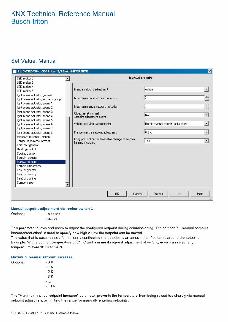
KNX Technical Reference Manual Busch-triton
104 | 0073-1-7621 | KNX Technical Reference Manual
Set Value, Manual Pos: 18.22.2 /Produkthandbuch - DIN-A4/Busch-triton/Parameter - Allgemeine Beschreibung/Sollwert manuell/Screenshot @ 16\mod_1294831002985_15.doc @ 99097 @
Pos: 18.22.3 /Produkthandbuch - DIN-A4/Busch-triton/Parameter - Allgemeine Beschreibung/Sollwert manuell/Manuelle Sollwertverstellung über Wippe - DIN-A4 @ 12\mod_1283249723690_15.doc @ 88199 @ 2
Manual setpoint adjustment via rocker switch 1
Options: - blocked - active This parameter allows end users to adjust the configured setpoint during commissioning. The settings "... manual setpoint increase/reduction" is used to specify how high or low the setpoint can be moved. The value that is parametrised for manually configuring the setpoint is an amount that fluctuates around the setpoint. Example: With a comfort temperature of 21 °C and a manual setpoint adjustment of +/- 3 K, users can select any temperature from 18 °C to 24 °C. Pos: 18.22.4 /Produkthandbuch - DIN-A4/Busch-triton/Parameter - Allgemeine Beschreibung/Sollwert manuell/Maximale manuelle Sollwerterhöhung - DIN-A4 @ 12\mod_1283249820612_15.doc @ 88207 @ 2
Maximum manual setpoint increase
Options: - 0 K - 1 K - 2 K - 3 K - ... - 10 K The "Maximum manual setpoint increase" parameter prevents the temperature from being raised too sharply via manual setpoint adjustment by limiting the range for manually entering setpoints.

KNX Technical Reference Manual | 0073-1-7621 | 105
Example: With a heating comfort temperature of 21 °C and a manual setpoint adjustment of +/- 3 K, users can select any temperature from 18 °C to 24 °C. If the comfort temperature can be increased to a maximum of 22 °C, enter "1 K" under the parameter "Maximum set point increase". Pos: 18.22.5 /Produkthandbuch - DIN-A4/Busch-triton/Parameter - Allgemeine Beschreibung/Sollwert manuell/Maximale manuelle Sollwertverringerung - DIN-A4 @ 12\mod_1283249888534_15.doc @ 88215 @ 2
Maximum manual setpoint reduction
Options: - 0 K - 1 K - 2 K - 3 K - ... - 10 K The "Maximum manual setpoint reduction" parameter prevents the temperature from being reduced too sharply via manual setpoint adjustment by limiting the range for manually entering setpoints. Example: With a cooling comfort temperature of 26 °C and a manual setpoint adjustment of +/- 3 K, users can select any temperature from 23 °C to 29 °C. If the comfort temperature can be decreased to a maximum of 25 °C, enter "1 K" under the parameter "Maximum setpoint decrease". Pos: 18.22.6 /Produkthandbuch - DIN-A4/Busch-triton/Parameter - Allgemeine Beschreibung/Sollwert manuell/Rücksetzen der manuellen Sollwertverstellung - DIN-A4 @ 12\mod_1283253574929_15.doc @ 88223 @ 2
Object resetting of the manual setpoint adjustment active
Options: - yes - no This parameter releases a 1-bit communication object that upon receipt of an ON telegram can be used manually reset the setpoint adjustment. This is required, for instance, if a central function is triggered that is intended to reset all the room thermostats to their default settings. For both "dependent" setpoints as well as "individual" setpoints, all manual setpoint adjustments are reset. Pos: 18.22.7 /Produkthandbuch - DIN-A4/Busch-triton/Parameter - Allgemeine Beschreibung/Sollwert manuell/Bei Empfang von Basissollwert - DIN-A4 @ 12\mod_1283253656476_15.doc @ 88231 @ 2
For receipt of base setpoint
Options: - retain manual setpoint adjustment - reset manual setpoint adjustment If a new base setpoint is received by the room thermostat via KNX telegram after manually adjusting the setpoint, the room thermostat can also reset the manually adjusted setpoint. The behaviour of the room thermostat when receiving a base setpoint value can be configured via this parameter. The manually configured setpoint is either reset or remains unchanged. For "dependent" setpoints, this refers to all setpoints; for "individual" setpoints, this refers to the base set point that was received, e.g. "Heating setpoint comfort operation". Pos: 18.22.8 /Produkthandbuch - DIN-A4/Busch-triton/Parameter - Allgemeine Beschreibung/Sollwert manuell/Sprungweite manuelle Sollwertverstellung - DIN-A4 @ 12\mod_1283253716522_15.doc @ 88239 @ 2
Jump size manual setpoint adjustment
Options: - 0.1 K - 0.2 K - 0.3 K - ... - 1.0 K The user can adjust the preset setpoint to their needs via the two buttons, increase or decrease. The "Jump size manual setpoint adjustment" parameter specifies by how many degrees Kelvin the preset value shall be increased or decreased for a button operation. Pos: 18.22.9 /Produkthandbuch - DIN-A4/Busch-triton/Parameter - Allgemeine Beschreibung/Sollwert manuell/Langer Tastendruck für Wechsel - DIN-A4 @ 12\mod_1283253781225_15.doc @ 88247 @ 2
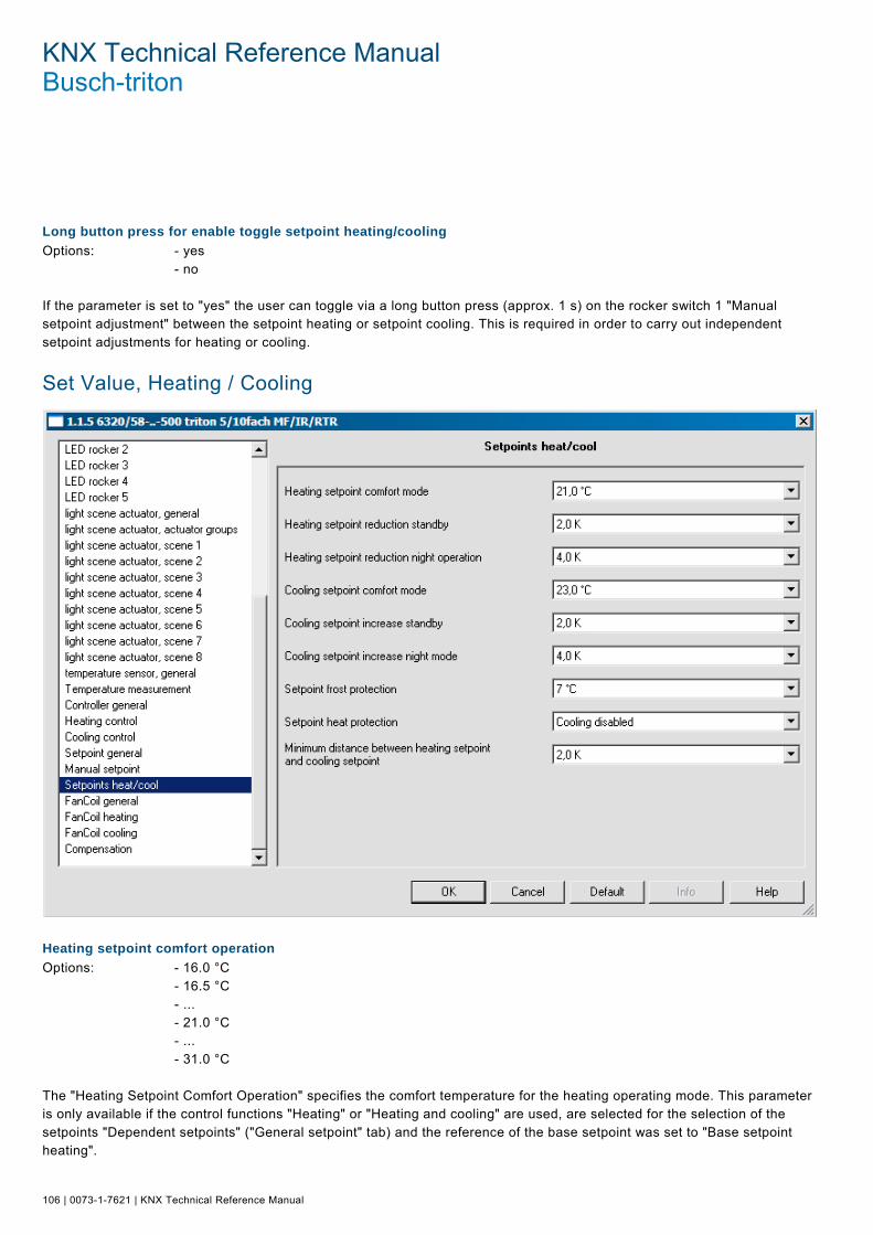
KNX Technical Reference Manual Busch-triton
106 | 0073-1-7621 | KNX Technical Reference Manual
Long button press for enable toggle setpoint heating/cooling
Options: - yes - no If the parameter is set to "yes" the user can toggle via a long button press (approx. 1 s) on the rocker switch 1 "Manual setpoint adjustment" between the setpoint heating or setpoint cooling. This is required in order to carry out independent setpoint adjustments for heating or cooling. Pos: 18.23.1 /Produkthandbuch - DIN-A4/Überschriften/1. Ebene/S - Z/Sollwert Heizen / Kühlen @ 11\mod_1279271576684_15.doc @ 84468 @ 1
Set Value, Heating / Cooling Pos: 18.23.2 /Produkthandbuch - DIN-A4/Busch-triton/Parameter - Allgemeine Beschreibung/Sollwert Heizen / Kühlen/Screenshot @ 16\mod_1294831081719_15.doc @ 99105 @
Pos: 18.23.3 /Produkthandbuch - DIN-A4/Busch-triton/Parameter - Allgemeine Beschreibung/Sollwert Heizen / Kühlen/Heizen Sollwert Komfortbetrieb - DIN-A4 @ 12\mod_1283254333315_15.doc @ 88255 @ 2
Heating setpoint comfort operation
Options: - 16.0 °C - 16.5 °C - ... - 21.0 °C - ... - 31.0 °C The "Heating Setpoint Comfort Operation" specifies the comfort temperature for the heating operating mode. This parameter is only available if the control functions "Heating" or "Heating and cooling" are used, are selected for the selection of the setpoints "Dependent setpoints" ("General setpoint" tab) and the reference of the base setpoint was set to "Base setpoint heating".

KNX Technical Reference Manual | 0073-1-7621 | 107
Pos: 18.23.4 /Produkthandbuch - DIN-A4/Busch-triton/Parameter - Allgemeine Beschreibung/Sollwert Heizen / Kühlen/Heizen Sollwert Absenkung Standby - DIN-A4 @ 12\mod_1283254795906_15.doc @ 88263 @ 2
Lower heating setpoint standby
Options: - 0.5 K - 1.0 K - ... - 2.0 K - ... - 8.0 K Via the "Lower heating setpoint standby" setting, you can specify the number of degrees Kelvin that the comfort temperature is lowered in standby operation. This parameter is only available if the "Selection of the base setpoint" parameter ("General setpoint" tab) is set to "dependent setpoints". Pos: 18.23.5 /Produkthandbuch - DIN-A4/Busch-triton/Parameter - Allgemeine Beschreibung/Sollwert Heizen / Kühlen/Heizen Sollwert Absenkung Nachtbetrieb - DIN-A4 @ 12\mod_1283254893327_15.doc @ 88271 @ 2
Lower heating setpoint in night mode
Options: - 0.5 K - 1.0 K - ... - 4.0 K - ... - 8.0 K Via the "Lower heating setpoint in night mode" setting, you can specify the number of degrees Kelvin that the comfort temperature is lowered during night operation. This parameter is only available if the "Selection of the base setpoint" parameter ("General setpoint" tab) is set to "dependent setpoints". Pos: 18.23.6 /Produkthandbuch - DIN-A4/Busch-triton/Parameter - Allgemeine Beschreibung/Sollwert Heizen / Kühlen/Heizen Sollwert Standbybetrieb - DIN-A4 @ 12\mod_1283254964000_15.doc @ 88279 @ 2
Heating setpoint standby mode
Options: - 14.0 °C - 14.5 °C - ... - 19.0 °C - ... - 29.0 °C The "Heating setpoint standby mode" parameter specifies the individual standby temperature for the heating mode. The temperature value specified does not depend on the set "Heating setpoint comfort operation". This parameter is only available if the "Selection of the base setpoint" parameter ("General setpoint" tab) is set to "individual setpoints". Pos: 18.23.7 /Produkthandbuch - DIN-A4/Busch-triton/Parameter - Allgemeine Beschreibung/Sollwert Heizen / Kühlen/Heizen Sollwert Nachtbetrieb - DIN-A4 @ 12\mod_1283255048875_15.doc @ 88287 @ 2
Heating setpoint night mode
Options: - 10.0 °C - 10.5 °C - ... - 15.0 °C - ... - 25.0 °C The "Heating setpoint night mode" specifies the individual temperature during the night for the heating operating mode. The temperature value specified does not depend on the set "Heating setpoint comfort operation".
KNX Technical Reference Manual Busch-triton
108 | 0073-1-7621 | KNX Technical Reference Manual
This parameter is only available if the "Selection of the base setpoint" parameter ("General setpoint" tab) is set to "individual setpoints". Pos: 18.23.8 /Produkthandbuch - DIN-A4/Busch-triton/Parameter - Allgemeine Beschreibung/Sollwert Heizen / Kühlen/Kühlen Sollwert Komfortbetrieb - DIN-A4 @ 14\mod_1286442761314_15.doc @ 92505 @ 2
Heating setpoint comfort operation
Options: - 16.0 °C - 16.5 °C - ... - 23.0 °C - ... - 31.0 °C The "Cooling setpoint comfort operation" parameter specifies the comfort temperature for the cooling operating mode. This parameter is only available if the control functions "Cooling" or "Heating and cooling" are used and were selected for the selection of the setpoints "Dependent setpoints" ("General setpoint" tab). Pos: 18.23.9 /Produkthandbuch - DIN-A4/Busch-triton/Parameter - Allgemeine Beschreibung/Sollwert Heizen / Kühlen/Kühlen Sollwert Anhebung Standby - DIN-A4 @ 14\mod_1286442760877_15.doc @ 92497 @ 2
Cooling setpoint increase standby
Options: - 0.5 K - 1.0 K - ... - 2.0 K - ... - 8.0 K Via the "Cooling setpoint increase standby" setting, you can specify the number of Kelvin that the comfort temperature is increased in standby operation. This parameter is only available if the "Selection of the base setpoint" parameter ("General setpoint" tab) is set to "Dependent setpoints". Pos: 18.23.10 /Produkthandbuch - DIN-A4/Busch-triton/Parameter - Allgemeine Beschreibung/Sollwert Heizen / Kühlen/Kühlen Sollwert Anhebung Nachtbetrieb - DIN-A4 @ 14\mod_1286442760314_15.doc @ 92489 @ 2
Cooling setpoint increase night mode
Options: - 0.5 K - 1.0 K - ... - 4.0 K - ... - 8.0 K The "Cooling setpoint increase night mode" setting allows you to specify the number of degrees Kelvin that the comfort temperature is raised during night operation. This parameter is only available if the "Selection of the base setpoint" parameter ("General setpoint" tab) is set to "Dependent setpoints". Pos: 18.23.11 /Produkthandbuch - DIN-A4/Busch-triton/Parameter - Allgemeine Beschreibung/Sollwert Heizen / Kühlen/Kühlen Sollwert Standbybetrieb - DIN-A4 @ 14\mod_1286442762173_15.doc @ 92521 @ 2
Cooling setpoint standby mode
Options: - 21.0 °C - 21.5 °C - ... - 25.0 °C - ... - 36.0 °C The "Cooling setpoint standby mode" parameter specifies the individual standby temperature for the cooling mode. The set temperature value specified does not depend on the set "Cooling setpoint comfort operation".

KNX Technical Reference Manual | 0073-1-7621 | 109
This parameter is only available if the "Selection of the base setpoint" parameter ("General setpoint" tab) is set to "Individual setpoints". Pos: 18.23.12 /Produkthandbuch - DIN-A4/Busch-triton/Parameter - Allgemeine Beschreibung/Sollwert Heizen / Kühlen/Kühlen Sollwert Nachtbetrieb - DIN-A4 @ 14\mod_1286442761736_15.doc @ 92513 @ 2
Cooling setpoint night mode
Options: - 23.0 °C - 23.5 °C - ... - 27.0 °C - ... - 38.0 °C The "Cooling setpoint night mode" parameter specifies the individual temperature during the night for the cooling operating mode. The set temperature value specified does not depend on the set "Cooling setpoint comfort operation". This parameter is only available if the "Selection of the base setpoint" parameter ("General setpoint" tab) is set to "Individual setpoints". Pos: 18.23.13 /Produkthandbuch - DIN-A4/Busch-triton/Parameter - Allgemeine Beschreibung/Sollwert Heizen / Kühlen/Mindestabstand zwischen Heizen / Kühlen - DIN-A4 @ 14\mod_1286443197124_15.doc @ 92529 @ 2
Minimum distance between heating / cooling
Options: - 0.0 K - 0.5 K - ... - 2.0 K - ... - 7.5 K The comfort temperature can be set for the cooling operation via the "Minimum distance between heating / cooling" setting. These values also apply to the cooling setpoint increases for standby and night mode. If, for instance, with a comfort temperature (base setpoint) of 21 °C you want to cool at 26 °C in comfort mode, you have to set an insensitive range of 5 °K. (See also page 95, Section 4.4.3 Minimum distance). This parameter is only available if the "Selection of the base setpoint" parameter ("General setpoint" tab) is set to "Dependent setpoints". Pos: 18.23.14 /Produkthandbuch - DIN-A4/Busch-triton/Parameter - Allgemeine Beschreibung/Sollwert Heizen / Kühlen/Sollwert Frostschutz - DIN-A4 @ 14\mod_1286443301451_15.doc @ 92537 @ 2
Set value frost protection
Options: - 0 °C - 1 °C - ... - 7 °C - ... - 15 °C The setpoint for frost protection is the temperature that must not be undershot during the frost protection mode. If the current temperature undershoots the configured value, the room thermostat triggers a control value telegram that causes the relevant heating actuator to heat up the room to prevent damage to the heating system from frost-related cooling. Pos: 18.23.15 /Produkthandbuch - DIN-A4/Busch-triton/Parameter - Allgemeine Beschreibung/Sollwert Heizen / Kühlen/Sollwert Hitzeschutz - DIN-A4 @ 14\mod_1286443380545_15.doc @ 92545 @ 2
Heat protection setpoint
Options: - 30.0 °C - 30.5 °C - ... - 44.0 °C - cooling switched off

KNX Technical Reference Manual Busch-triton
110 | 0073-1-7621 | KNX Technical Reference Manual
The setpoint for heat protection is the temperature that must not be overshot during heat protection mode. If the current temperature overshoots the configured value, the room thermostat triggers a control value telegram that causes the relevant cooling unit to cool the room to prevent damage from heat build-up. This parameter is only available if the controller function "Cooling" or "Heating and cooling" is used. Note: For "Cooling off", 99.9 °C is sent out as setpoint! Pos: 18.24.1 /Produkthandbuch - DIN-A4/Überschriften/1. Ebene/A - F/Fan Coil allgemein @ 11\mod_1279271646232_15.doc @ 84476 @ 1
Fan Coil, General Pos: 18.24.2 /Produkthandbuch - DIN-A4/Busch-triton/Parameter - Allgemeine Beschreibung/Fan Coil allgemein/Screenshot @ 16\mod_1294831236968_15.doc @ 99113 @
Pos: 18.24.3 /Produkthandbuch - DIN-A4/Busch-triton/Parameter - Allgemeine Beschreibung/Fan Coil allgemein/Anzahl der Lüfterstufen - DIN-A4 @ 13\mod_1285051113841_15.doc @ 90319 @ 2
Number of fan stages
Options: - 1 stage - 2 stages - 3 stages Parameter "Number of fan stages" is used to specify the number of fan stages of a fan coil actuator that should be activated. One, two or three stages can be selected. The room thermostat always provides a 1-byte communication object (see object "Send fan stage manually" has the following coding) and additionally exactly as many 1-bit communication objects as the number of fan stages selected. Most importantly, the number selected must match the actual number of fan stages. The actuator is then controlled either by the 1-byte communication object or alternatively via 1-bit communication objects. Pos: 18.24.4 /Produkthandbuch - DIN-A4/Busch-triton/Parameter - Allgemeine Beschreibung/Fan Coil allgemein/Handbedienung der Lüfterstufe freigeben - DIN-A4 @ 13\mod_1285051188202_15.doc @ 90327 @ 2

KNX Technical Reference Manual | 0073-1-7621 | 111
Enabling manual operation of the fan stage
Options: - yes - no The manual adjustment of the fan stages can be enabled or disabled with this parameter via the right button of rocker 2. Manual operation of the fan stage is displayed to the actuator via Options: object "Automatic ON/OFF...“ object "Manual ON/OFF...“ Here you can set via which object the information is sent to the actuator or whether the fan stage is currently being manually operated by the user. The objects only differ in the coding: "Automatic ON/OFF" = 1, if no manual operation is active "Manual ON/OFF" = 1, if manual operation is active Pos: 18.24.5 /Produkthandbuch - DIN-A4/Busch-triton/Parameter - Allgemeine Beschreibung/Fan Coil allgemein/Handbedienung der Lüfterstufe angezeigt - DIN-A4 @ 14\mod_1286443684170_15.doc @ 92553 @ 2
Manual operation of the fan stage is displayed to the actuator via
Options: object "Automatic ON/OFF“ -. object "Manual "ON/OFF" Here you can set via which object the information is sent to the actuator or whether the fan stage is currently being manually operated by the user. The objects only differ in the coding: "Automatic ON/OFF" = 1, if no manual operation is active "Manual ON/OFF" = 1, if manual operation is active Pos: 18.24.6 /Produkthandbuch - DIN-A4/Busch-triton/Parameter - Allgemeine Beschreibung/Fan Coil allgemein/Manuelle Lüfterstufe senden - DIN-A4 @ 13\mod_1285051398970_15.doc @ 90335 @ 2
Object "Send manual fan stage" has the following coding
Options: - 1-byte object as constant value 0-100% - 1-byte object as numerical value 0-3 - 1-bit values If the user has performed a manual fan stage change-over, this can be transmitted on the KNX. Via the parameter "Send manual fan stage has the following encoding" a 1-byte object or three 1-bit objects can be enabled. Via the 1-byte object, either the selected fan stage can be sent out as numerical value from 0 to 3 (0= no manual switchover) or the constant value from 0 to 100% can be sent out. The constant values to be output are specified via the settings in the threshold values of the respective stage. A 1-bit communication object is available with the 1-bit values selection. Provided the respective fan stage is manually switched, an ON telegram is sent out via the corresponding object. An OFF telegram is sent out for reset of the manual change-over. Pos: 18.24.7 /Produkthandbuch - DIN-A4/Busch-triton/Parameter - Allgemeine Beschreibung/Fan Coil allgemein/Manuelle Lüfterstufe senden Automatik - DIN-A4 @ 13\mod_1285053853835_15.doc @ 90343 @ 2
Also use "Send manual fan stage" in the automatic fan stage
Options: - yes - no If this option is set to "Yes", the corresponding object sends the fan stage both in manual mode as well as in automatic mode. Pos: 18.24.8 /Produkthandbuch - DIN-A4/Busch-triton/Parameter - Allgemeine Beschreibung/Fan Coil allgemein/Statusbyte Lüfterstufe auswerten - DIN-A4 @ 13\mod_1285053934866_15.doc @ 90351 @ 2

KNX Technical Reference Manual Busch-triton
112 | 0073-1-7621 | KNX Technical Reference Manual
Evaluate fan stage status byte
Options: - yes - no If this parameter is set to "Yes", the room thermostat can analyse a stage status message that is received by a fan-coil actuator. This enables a 1-byte communication object that is used to evaluate which stage the fan coil actuator has activated. This parameter is only available if the "Heating" or "Heating and cooling" control functions are used and the "Heating" control type is set to "fan coil". Pos: 18.24.9 /Produkthandbuch - DIN-A4/Busch-triton/Parameter - Allgemeine Beschreibung/Fan Coil allgemein/Statusbyte Betrieb auswerten - DIN-A4 @ 13\mod_1285056177951_15.doc @ 90359 @ 2
Evaluate operation status byte
Options: - yes - no If this parameter is set to "Yes", the room thermostat can analyse an operating status message that is received from a fan coil actuator. This enables a 1-bit communication object that is used to evaluate whether the fan coil actuator is currently in operation. Provided an operating fault is detected, this will be displayed by the fault symbol in the display. This parameter is only available if the "Heating" or "Heating and cooling" control functions are used and the "Heating" control type is set to "fan coil". Pos: 18.24.10 /Produkthandbuch - DIN-A4/Busch-triton/Parameter - Allgemeine Beschreibung/Fan Coil allgemein/Sendezykluszeit des Aktors - DIN-A4 @ 13\mod_1285056445326_15.doc @ 90367 @ 2
Transmission cycle time of the actuator in s (1...65.535)
Options: - 1 / 2 / ... / 120 / ... / 65,535 If the "Status byte operation" object is activated and connected to the corresponding communication object of the fan coil actuator, the room thermostat expects a cyclical transmission of the operating state from the linked fan coil actuator. If a message does not occur at least once within the monitoring time "Transmission cycle of the actuator in s", the room thermostat will automatically go into the fault display. That is why it would be most practical to set the actuator so that a telegram is sent at least twice during the "transmission cycle time of the actuator in s". Pos: 18.24.11 /Produkthandbuch - DIN-A4/Busch-triton/Parameter - Allgemeine Beschreibung/Fan Coil allgemein/Stufe des Lüfters - DIN-A4 @ 13\mod_1285057282732_15.doc @ 90375 @ 2
Stage of the fan after reset
Options: - off - stage 1 - stage 2 - stage 3 - automatic mode The "Stage of the fan after reset and after off" parameter is used to prevent an undefined state after a reset or after switching off the room thermostat. This specifies whether the fan activates the first, second or third stage, switches off or switches to automatic mode. Note: Automatic mode means that the fan coil actuator switches the fan stages due to the received 1-byte control value. Pos: 18.25.1 /Produkthandbuch - DIN-A4/Überschriften/1. Ebene/A - F/Fan Coil Heizen @ 11\mod_1279271722779_15.doc @ 84484 @ 1

KNX Technical Reference Manual | 0073-1-7621 | 113
Fan Coil, Heating Pos: 18.25.2 /Produkthandbuch - DIN-A4/Busch-triton/Parameter - Allgemeine Beschreibung/Fan Coil Heizen/Screenshot @ 16\mod_1294831284999_15.doc @ 99121 @
Pos: 18.25.3 /Produkthandbuch - DIN-A4/Überschriften/2. Ebene/S - T/Stufenbegrenzung bei Nachtbetrieb @ 13\mod_1285319003841_15.doc @ 90578 @ 2
Stage limitation for night mode Pos: 18.25.4 /Produkthandbuch - DIN-A4/Busch-triton/Parameter - Allgemeine Beschreibung/Fan Coil Kühlen/Stufenbegrenzung bei Nachtbetrieb - DIN-A4 @ 13\mod_1284988008364_15.doc @ 90187 @
Options: - no limit - fan off - stage 1 - stage 2 If the device is used in a hotel room, for example, it is desirable to limit the fan stages during the night due to noise disturbance. The "Stage limitation for night mode" parameter is used for this purpose. I.e. if the "Stage 1" is set then the stage of the fan is limited to the first stage if the "Night mode" is activated. This is also the case even if the control value that is sent out requires a higher fan stage. Pos: 18.25.5 /Produkthandbuch - DIN-A4/Überschriften/2. Ebene/A - F/Automatischer Rücksprung @ 13\mod_1285319152685_15.doc @ 90593 @ 2
Automatic jump-back from manual adjustment Pos: 18.25.6 /Produkthandbuch - DIN-A4/Busch-triton/Parameter - Allgemeine Beschreibung/Fan Coil Kühlen/Automatischer Rücksprung - DIN-A4 @ 13\mod_1284988110019_15.doc @ 90195 @
Options: - 0 / 1 / 2 / ... / 60 If "Manual stage switching" was performed by the user, this action can be reset via on-site operation of the room thermostat. Users can also specify the time after which the room temperature resets the "Manual stage switching" and returns to automatic mode. This parameter is only available if the "Cooling" or "Heating and cooling" control functions are used and the "Cooling" control type is set to "Fan coil". Pos: 18.25.7 /Produkthandbuch - DIN-A4/Überschriften/2. Ebene/P - R/Rücksprung inaktiv @ 13\mod_1285319077716_15.doc @ 90586 @ 2

KNX Technical Reference Manual Busch-triton
114 | 0073-1-7621 | KNX Technical Reference Manual
Jump-back inactive for fan stage off Pos: 18.25.8 /Produkthandbuch - DIN-A4/Busch-triton/Parameter - Allgemeine Beschreibung/Fan Coil Kühlen/Rücksprung inaktiv - DIN-A4 @ 13\mod_1284988182081_15.doc @ 90203 @
Options: - Yes - no If the user has manually changed the stage to "Switch off", the room thermostat can also be set so that it does not return to automatic switching at the end of the "Manual switching period" but rather remains switched off. This parameter is only available if the "Cooling" or "Heating and cooling" control functions are used and the "Cooling" control type is set to "Fan coil". Pos: 18.25.9 /Produkthandbuch - DIN-A4/Überschriften/2. Ebene/S - T/Schwellwert Stufe 1 @ 13\mod_1285318902935_15.doc @ 90554 @ 2
Threshold value stage 1 Pos: 18.25.10 /Produkthandbuch - DIN-A4/Busch-triton/Parameter - Allgemeine Beschreibung/Fan Coil Kühlen/Schwellwert Stufe 1 - DIN-A4 @ 13\mod_1284988438079_15.doc @ 90211 @
Options: - 0% - 10% - ... - 50% - ... - 100% This parameter defines how large the control value has to be for the room thermostat to switch on the fan stage. The threshold can be defined in percentages. Make sure that the threshold for stage 1 is not larger than the threshold for stage 2 (if available). This parameter is only available if the "Cooling" or "Heating and cooling" control functions are used and the "Cooling" control type is set to "Fan coil" and the number of fan stages is set to at least "1 stage". Pos: 18.25.11 /Produkthandbuch - DIN-A4/Überschriften/2. Ebene/S - T/Schwellwert Stufe 2 @ 13\mod_1285318950216_15.doc @ 90570 @ 2
Threshold value stage 2 Pos: 18.25.12 /Produkthandbuch - DIN-A4/Busch-triton/Parameter - Allgemeine Beschreibung/Fan Coil Kühlen/Schwellwert Stufe 2 - DIN-A4 @ 13\mod_1284988980200_15.doc @ 90219 @
Options: - 0% - 10% - ... - 40% - ... - 100% This parameter defines how large the control value has to be for the room thermostat to switch from fan stage 1 to fan stage 2. The threshold can be defined in percentages. Make sure that the threshold for stage 2 is not smaller than the threshold for stage 1 and not larger than the threshold for stage 3 (if available). This parameter is only available if the "Cooling" or "Heating and cooling" control functions are used and the "Cooling" control type is set to "Fan coil" and the number of fan stages is set to at least "2 stages". Pos: 18.25.13 /Produkthandbuch - DIN-A4/Überschriften/2. Ebene/S - T/Schwellwert Stufe 3 @ 13\mod_1285318947606_15.doc @ 90562 @ 2
Threshold value stage 3 Pos: 18.25.14 /Produkthandbuch - DIN-A4/Busch-triton/Parameter - Allgemeine Beschreibung/Fan Coil Kühlen/Schwellwert Stufe 3 - DIN-A4 @ 13\mod_1284990822325_15.doc @ 90227 @
Options: - 0% - 10% - ... - 70% - ... - 100% This parameter defines how large the control value has to be for the room thermostat to switch from fan stage 2 to fan stage 3. The threshold can be defined in percentages. Make sure that the threshold for stage 3 is not smaller than the threshold for stage 2 and not larger than the threshold for stage 4 (if available). This parameter is only available if the "Cooling" or "Heating and cooling" control functions are used and the "Cooling" control type is set to "Fan coil" and the number of fan stages is set to at least "3 stages".

KNX Technical Reference Manual | 0073-1-7621 | 115
Pos: 18.26.1 /Produkthandbuch - DIN-A4/Überschriften/1. Ebene/A - F/Fan Coil Kühlen @ 11\mod_1279271785560_15.doc @ 84492 @ 1
Fan Coil, Cooling Pos: 18.26.2 /Produkthandbuch - DIN-A4/Busch-triton/Parameter - Allgemeine Beschreibung/Fan Coil Kühlen/Screenshot @ 16\mod_1294831452953_15.doc @ 99129 @
Pos: 18.26.3 /Produkthandbuch - DIN-A4/Überschriften/2. Ebene/S - T/Stufenbegrenzung bei Nachtbetrieb @ 13\mod_1285319003841_15.doc @ 90578 @ 2
Stage limitation for night mode Pos: 18.26.4 /Produkthandbuch - DIN-A4/Busch-triton/Parameter - Allgemeine Beschreibung/Fan Coil Kühlen/Stufenbegrenzung bei Nachtbetrieb - DIN-A4 @ 13\mod_1284988008364_15.doc @ 90187 @
Options: - no limit - fan off - stage 1 - stage 2 If the device is used in a hotel room, for example, it is desirable to limit the fan stages during the night due to noise disturbance. The "Stage limitation for night mode" parameter is used for this purpose. I.e. if the "Stage 1" is set then the stage of the fan is limited to the first stage if the "Night mode" is activated. This is also the case even if the control value that is sent out requires a higher fan stage. Pos: 18.26.5 /Produkthandbuch - DIN-A4/Überschriften/2. Ebene/A - F/Automatischer Rücksprung @ 13\mod_1285319152685_15.doc @ 90593 @ 2
Automatic jump-back from manual adjustment Pos: 18.26.6 /Produkthandbuch - DIN-A4/Busch-triton/Parameter - Allgemeine Beschreibung/Fan Coil Kühlen/Automatischer Rücksprung - DIN-A4 @ 13\mod_1284988110019_15.doc @ 90195 @
Options: - 0 / 1 / 2 / ... / 60 If "Manual stage switching" was performed by the user, this action can be reset via on-site operation of the room thermostat. Users can also specify the time after which the room temperature resets the "Manual stage switching" and returns to automatic mode. This parameter is only available if the "Cooling" or "Heating and cooling" control functions are used and the "Cooling" control type is set to "Fan coil".

KNX Technical Reference Manual Busch-triton
116 | 0073-1-7621 | KNX Technical Reference Manual
Pos: 18.26.7 /Produkthandbuch - DIN-A4/Überschriften/2. Ebene/P - R/Rücksprung inaktiv @ 13\mod_1285319077716_15.doc @ 90586 @ 2
Jump-back inactive for fan stage off Pos: 18.26.8 /Produkthandbuch - DIN-A4/Busch-triton/Parameter - Allgemeine Beschreibung/Fan Coil Kühlen/Rücksprung inaktiv - DIN-A4 @ 13\mod_1284988182081_15.doc @ 90203 @
Options: - Yes - no If the user has manually changed the stage to "Switch off", the room thermostat can also be set so that it does not return to automatic switching at the end of the "Manual switching period" but rather remains switched off. This parameter is only available if the "Cooling" or "Heating and cooling" control functions are used and the "Cooling" control type is set to "Fan coil". Pos: 18.26.9 /Produkthandbuch - DIN-A4/Überschriften/2. Ebene/S - T/Schwellwert Stufe 1 @ 13\mod_1285318902935_15.doc @ 90554 @ 2
Threshold value stage 1 Pos: 18.26.10 /Produkthandbuch - DIN-A4/Busch-triton/Parameter - Allgemeine Beschreibung/Fan Coil Kühlen/Schwellwert Stufe 1 - DIN-A4 @ 13\mod_1284988438079_15.doc @ 90211 @
Options: - 0% - 10% - ... - 50% - ... - 100% This parameter defines how large the control value has to be for the room thermostat to switch on the fan stage. The threshold can be defined in percentages. Make sure that the threshold for stage 1 is not larger than the threshold for stage 2 (if available). This parameter is only available if the "Cooling" or "Heating and cooling" control functions are used and the "Cooling" control type is set to "Fan coil" and the number of fan stages is set to at least "1 stage". Pos: 18.26.11 /Produkthandbuch - DIN-A4/Überschriften/2. Ebene/S - T/Schwellwert Stufe 2 @ 13\mod_1285318950216_15.doc @ 90570 @ 2
Threshold value stage 2 Pos: 18.26.12 /Produkthandbuch - DIN-A4/Busch-triton/Parameter - Allgemeine Beschreibung/Fan Coil Kühlen/Schwellwert Stufe 2 - DIN-A4 @ 13\mod_1284988980200_15.doc @ 90219 @
Options: - 0% - 10% - ... - 40% - ... - 100% This parameter defines how large the control value has to be for the room thermostat to switch from fan stage 1 to fan stage 2. The threshold can be defined in percentages. Make sure that the threshold for stage 2 is not smaller than the threshold for stage 1 and not larger than the threshold for stage 3 (if available). This parameter is only available if the "Cooling" or "Heating and cooling" control functions are used and the "Cooling" control type is set to "Fan coil" and the number of fan stages is set to at least "2 stages". Pos: 18.26.13 /Produkthandbuch - DIN-A4/Überschriften/2. Ebene/S - T/Schwellwert Stufe 3 @ 13\mod_1285318947606_15.doc @ 90562 @ 2
Threshold value stage 3 Pos: 18.26.14 /Produkthandbuch - DIN-A4/Busch-triton/Parameter - Allgemeine Beschreibung/Fan Coil Kühlen/Schwellwert Stufe 3 - DIN-A4 @ 13\mod_1284990822325_15.doc @ 90227 @
Options: - 0% - 10% - ... - 70% - ... - 100% This parameter defines how large the control value has to be for the room thermostat to switch from fan stage 2 to fan stage 3. The threshold can be defined in percentages. Make sure that the threshold for stage 3 is not smaller than the threshold for stage 2 and not larger than the threshold for stage 4 (if available).
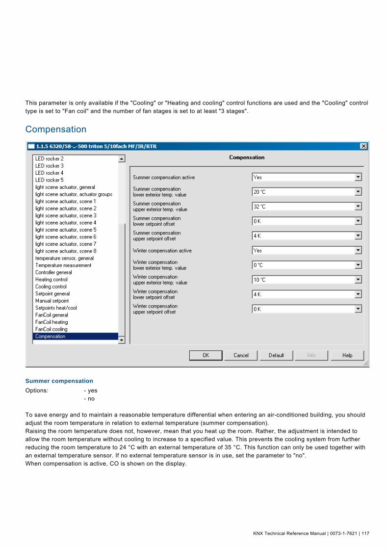
KNX Technical Reference Manual | 0073-1-7621 | 117
This parameter is only available if the "Cooling" or "Heating and cooling" control functions are used and the "Cooling" control type is set to "Fan coil" and the number of fan stages is set to at least "3 stages". Pos: 18.27.1 /Produkthandbuch - DIN-A4/Überschriften/1. Ebene/G - L/Kompensation @ 11\mod_1279271851842_15.doc @ 84500 @ 1
Compensation Pos: 18.27.2 /Produkthandbuch - DIN-A4/Busch-triton/Parameter - Allgemeine Beschreibung/Kompensation/Screenshot @ 16\mod_1294831509079_15.doc @ 99137 @
Pos: 18.27.3 /Produkthandbuch - DIN-A4/Überschriften/2. Ebene/S - T/Sommerkompensation @ 13\mod_1285318308856_15.doc @ 90474 @ 2
Summer compensation Pos: 18.27.4 /Produkthandbuch - DIN-A4/Busch-triton/Parameter - Allgemeine Beschreibung/Kompensation/Sommerkompensation - DIN-A4 @ 13\mod_1284990991324_15.doc @ 90235 @
Options: - yes - no To save energy and to maintain a reasonable temperature differential when entering an air-conditioned building, you should adjust the room temperature in relation to external temperature (summer compensation). Raising the room temperature does not, however, mean that you heat up the room. Rather, the adjustment is intended to allow the room temperature without cooling to increase to a specified value. This prevents the cooling system from further reducing the room temperature to 24 °C with an external temperature of 35 °C. This function can only be used together with an external temperature sensor. If no external temperature sensor is in use, set the parameter to "no". When compensation is active, CO is shown on the display. Pos: 18.27.5 /Produkthandbuch - DIN-A4/Überschriften/2. Ebene/S - T/Sommerkompensation unterer Außenwert @ 13\mod_1285318352622_15.doc @ 90482 @ 2

KNX Technical Reference Manual Busch-triton
118 | 0073-1-7621 | KNX Technical Reference Manual
Summer compensation of lower outside temperature value Pos: 18.27.6 /Produkthandbuch - DIN-A4/Busch-triton/Parameter - Allgemeine Beschreibung/Kompensation/Sommerkompensation unterer Außenwert - DIN-A4 @ 13\mod_1284991111698_15.doc @ 90243 @
Options: - 9 °C - 10 °C - ... - 20 °C - ... - 31 °C - 40 °C This parameter allows you to specify the lower outside temperature beyond which value a compensation is carried out due to an excessively high outside temperature. Pos: 18.27.7 /Produkthandbuch - DIN-A4/Überschriften/2. Ebene/S - T/Sommerkompensation oberer Außenwert @ 13\mod_1285318403653_15.doc @ 90490 @ 2
Summer compensation of upper outside temperature value Pos: 18.27.8 /Produkthandbuch - DIN-A4/Busch-triton/Parameter - Allgemeine Beschreibung/Kompensation/Sommerkompensation oberer Außenwert - DIN-A4 @ 13\mod_1284991173026_15.doc @ 90251 @
Options: - 9 °C - 10 °C - ... - 32 °C - ... - 31 °C - 40 °C This parameter allows you to specify the upper outside temperature up to which value a compensation is carried out due to excessively high outside temperature. Pos: 18.27.9 /Produkthandbuch - DIN-A4/Überschriften/2. Ebene/S - T/Sommerkompensation unterer Sollwertoffset @ 13\mod_1285318443638_15.doc @ 90498 @ 2
Summer compensation of lower setpoint offset Pos: 18.27.10 /Produkthandbuch - DIN-A4/Busch-triton/Parameter - Allgemeine Beschreibung/Kompensation/Sommerkompensation unterer Sollwertoffset - DIN-A4 @ 13\mod_1285049167663_15.doc @ 90263 @
Options: - 0 K - 1 K - 2 K - ... - 10 K Via the "Lower setpoint offset", you can specify by how many degrees Kelvin the setpoint shall be raised during the summer compensation when the "Lower outside temperature value" is reached. Pos: 18.27.11 /Produkthandbuch - DIN-A4/Überschriften/2. Ebene/S - T/Sommerkompensation oberer Sollwertoffset @ 13\mod_1285318489638_15.doc @ 90506 @ 2
Summer compensation of upper setpoint offset Pos: 18.27.12 /Produkthandbuch - DIN-A4/Busch-triton/Parameter - Allgemeine Beschreibung/Kompensation/Sommerkompensation oberer Sollwertoffset - DIN-A4 @ 13\mod_1285049292837_15.doc @ 90271 @
Options: - 0 K - 1 K - 2 K - ... - 4 K - ... - 10 K Via the "Upper setpoint offset", you can specify by how many degrees Kelvin the setpoint shall be raised during the summer compensation when the "Upper outside temperature value" is reached. Pos: 18.27.13 /Produkthandbuch - DIN-A4/Überschriften/2. Ebene/U - Z/Winterkompensation @ 13\mod_1285318534435_15.doc @ 90514 @ 2

KNX Technical Reference Manual | 0073-1-7621 | 119
Winter compensation Pos: 18.27.14 /Produkthandbuch - DIN-A4/Busch-triton/Parameter - Allgemeine Beschreibung/Kompensation/Winterkompensation - DIN-A4 @ 13\mod_1285049411978_15.doc @ 90279 @
Options: - Yes - no To improve comfort and to keep the temperature difference when entering a room with large window areas in comfortable limits, an increase of the room temperature, as a function of the outside temperature, should be performed during the winter (winter compensation). This function can only be used together with an external temperature sensor. If no external temperature sensor is in use, set the parameter to "NO". When compensation is active, CO is shown on the display. Pos: 18.27.15 /Produkthandbuch - DIN-A4/Überschriften/2. Ebene/U - Z/Winterkompensation unterer Außenwert @ 13\mod_1285318536560_15.doc @ 90538 @ 2
Winter compensation of lower outside temperature value Pos: 18.27.16 /Produkthandbuch - DIN-A4/Busch-triton/Parameter - Allgemeine Beschreibung/Kompensation/Winterkompensation unterer Außenwert - DIN-A4 @ 13\mod_1285049413353_15.doc @ 90303 @
Options: - -10 °C - -9 °C - ... - 0 °C - ... - 21 °C This parameter defines the lower outside temperature value up to which setpoint correction (winter compensation) is performed based on too low an external temperature. Pos: 18.27.17 /Produkthandbuch - DIN-A4/Überschriften/2. Ebene/U - Z/Winterkompensation oberer Außenwert @ 13\mod_1285318535122_15.doc @ 90522 @ 2
Winter compensation of upper outside temperature value Pos: 18.27.18 /Produkthandbuch - DIN-A4/Busch-triton/Parameter - Allgemeine Beschreibung/Kompensation/Winterkompensation oberer Außenwert - DIN-A4 @ 13\mod_1285049412432_15.doc @ 90287 @
Options: - -10 °C - -9 °C - ... - 10 °C - ... - 21 °C This parameter defines the upper outside temperature value at which setpoint correction (winter compensation) is performed based on too low an external temperature. Pos: 18.27.19 /Produkthandbuch - DIN-A4/Überschriften/2. Ebene/U - Z/Winterkompensation unterer Sollwertoffset @ 13\mod_1285318537263_15.doc @ 90546 @ 2
Winter compensation lower setpoint offset Pos: 18.27.20 /Produkthandbuch - DIN-A4/Busch-triton/Parameter - Allgemeine Beschreibung/Kompensation/Winterkompensation unterer Sollwertoffset - DIN-A4 @ 13\mod_1285049413775_15.doc @ 90311 @
Options: - 0 K - 1 K - 2 K - ... - 4 K - ... - 10 K Via the "Lower setpoint offset", you can specify by how many degrees Kelvin the setpoint shall be raised during the winter compensation when the "Lower outside temperature value" is reached. Pos: 18.27.21 /Produkthandbuch - DIN-A4/Überschriften/2. Ebene/U - Z/Winterkompensation oberer Sollwertoffset @ 13\mod_1285318535856_15.doc @ 90530 @ 2

KNX Technical Reference Manual Busch-triton
120 | 0073-1-7621 | KNX Technical Reference Manual
Winter compensation of upper setpoint offset Pos: 18.27.22 /Produkthandbuch - DIN-A4/Busch-triton/Parameter - Allgemeine Beschreibung/Kompensation/Winterkompensation oberer Sollwertoffset - DIN-A4 @ 13\mod_1285049412838_15.doc @ 90295 @
Options: - 0 K - 1 K - 2 K - ... - 10 K Via the "Upper setpoint offset", you can specify by how many degrees Kelvin the setpoint shall be raised during the winter compensation when the "Upper outside temperature value" is reached. Pos: 19 /Spezial/Neues Layout 2010/Steuermodule_Neues_Layout_2010/++++++++++++ Seitenumbruch ++++++++++++ @ 9\mod_1268898668093_0.doc @ 52149 @
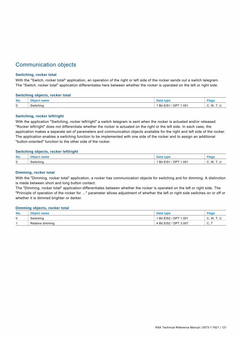
KNX Technical Reference Manual | 0073-1-7621 | 121
Pos: 20.1 /Produkthandbuch - DIN-A4/Überschriften/1. Ebene/G - L/Kommunikationsobjekte @ 16\mod_1294831725265_15.doc @ 99146 @ 1
Communication objects Pos: 20.2.1 /Produkthandbuch - DIN-A4/Überschriften/2. Ebene/S - T/Schalten, Wippe Gesamt @ 9\mod_1269245200625_15.doc @ 52356 @ 2
Switching, rocker total Pos: 20.2.2 /KNX/Applikationsbeschreibungen/Applikationen - App/Schalten_Wippe_gesamt/App. - Schalten, Wippe Gesamt - DIN-A4 @ 9\mod_1269244387750_15.doc @ 52348 @
With the "Switch, rocker total" application, an operation of the right or left side of the rocker sends out a switch telegram. The "Switch, rocker total" application differentiates here between whether the rocker is operated on the left or right side. Switching objects, rocker total No. Object name Data type Flags 0 Switching 1 Bit EIS1 / DPT 1.001 C, W, T, U
Pos: 20.2.3 /Produkthandbuch - DIN-A4/Überschriften/2. Ebene/S - T/Schalten, Wippe Links / Rechts @ 9\mod_1269245253031_15.doc @ 52360 @ 2
Switching, rocker left/right Pos: 20.2.4 /KNX/Applikationsbeschreibungen/Applikationen - App/Schalten_Taste/App. - Schalten, Wippe Links / Rechts - DIN-A4 @ 9\mod_1269420582437_15.doc @ 52553 @
With the application "Switching, rocker left/right" a switch telegram is sent when the rocker is actuated and/or released. "Rocker left/right" does not differentiate whether the rocker is actuated on the right or the left side. In each case, the application makes a separate set of parameters and communication objects available for the right and left side of the rocker. The application enables a switching function to be implemented with one side of the rocker and to assign an additional "button-oriented" function to the other side of the rocker. Switching objects, rocker left/right No. Object name Data type Flags 0 Switching 1 Bit EIS1 / DPT 1.001 C, W, T, U
Pos: 20.2.5 /Produkthandbuch - DIN-A4/Überschriften/2. Ebene/A - F/Dimmen, Wippe Gesamt @ 9\mod_1269422737250_15.doc @ 52683 @ 2
Dimming, rocker total Pos: 20.2.6 /KNX/Applikationsbeschreibungen/Applikationen - App/Dimmen_Wippe_gesamt/App. - Dimmen, Wippe Gesamt - DIN-A4 @ 9\mod_1269422368187_15.doc @ 52558 @
With the "Dimming, rocker total" application, a rocker has communication objects for switching and for dimming. A distinction is made between short and long button contact. The "Dimming, rocker total" application differentiates between whether the rocker is operated on the left or right side. The "Principle of operation of the rocker for …" parameter allows adjustment of whether the left or right side switches on or off or whether it is dimmed brighter or darker. Dimming objects, rocker total No. Object name Data type Flags 0 Switching 1 Bit EIS2 / DPT 1.001 C, W, T, U 1 Relative dimming 4 Bit EIS2 / DPT 3.007 C, T
Pos: 20.2.7 /Spezial/Neues Layout 2010/Steuermodule_Neues_Layout_2010/++++++++++++ Seitenumbruch ++++++++++++ @ 9\mod_1268898668093_0.doc @ 52149 @

KNX Technical Reference Manual Busch-triton
122 | 0073-1-7621 | KNX Technical Reference Manual
Pos: 20.2.8 /Produkthandbuch - DIN-A4/Überschriften/2. Ebene/A - F/Dimmen, Wippe Links / Rechts @ 9\mod_1269423462609_15.doc @ 52694 @ 2
Dimming, rocker left/right Pos: 20.2.9 /KNX/Applikationsbeschreibungen/Applikationen - App/Dimmen_Wippe_links_rechts/App. - Dimmen, Wippe links / rechts - DIN-A4 @ 9\mod_1269423217171_15.doc @ 52689 @
With the "Dimming, rocker left/right" application, a rocker switch has communication objects for switching and for dimming. A distinction is made between short (switching) and long (dimming) button contact. The "Dimming, rocker left/right" application does not differentiate between whether the rocker is operated on the left or right side. In each case, the application makes a separate set of parameters and communication objects available for the right and left side of the rocker. The application makes it possible to dim a light via one side of the rocker and to assign an additional "button-orientated" function to the other side. Dimming objects, rocker left/right No. Object name Data type Flags 0 Switching 1 Bit EIS2 / DPT 1.001 C, W, T, U
1 Relative dimming 4 Bit EIS2 / DPT 3.007 C, T
Pos: 20.2.10 /Produkthandbuch - DIN-A4/Überschriften/2. Ebene/G - L/Jalousie, Wippe Gesamt @ 9\mod_1269423899109_15.doc @ 52704 @ 2
Blind, rocker total Pos: 20.2.11 /KNX/Applikationsbeschreibungen/Applikationen - App/Jal_Wippe_gesamt/App. - Jalousie, Wippe Gesamt - DIN-A4 @ 9\mod_1269423548328_15.doc @ 52699 @
Via the application "Blind, rocker total", blind movement and/or slat adjustment commands can be sent to connected shutting actuators with a short or long contact of the rocker. A short button contact always triggers a slat adjustment or stop command and a long button contact always triggers a move command. The control always remembers the last action performed on the side of the rocker switch that is assigned with the "Blind, rocker total" application. If a blind was lowered and halted at half height via a short button contact, then a renewed long button contact will raise the blind. Blind objects, rocker total No. Object name Data type Flags 0 Adjusting(1 Bit) 1 Bit EIS7 / DPT 1.008 C, T
0 Adjusting (1 Byte) 1 Byte EIS6 / DPT 5.001 C, T 1 Move (1 Bit) 1 Bit EIS7 / DPT 1.007 C, T
1 Move(1 Byte) 1 Byte EIS6 / DPT 5.001 C, T
Pos: 20.2.12 /Produkthandbuch - DIN-A4/Überschriften/2. Ebene/G - L/Jalousie, Wippe Links / Rechts @ 9\mod_1269424455828_15.doc @ 52715 @ 2
Blind, rocker left/right Pos: 20.2.13 /KNX/Applikationsbeschreibungen/Applikationen - App/Jalousie_Wippe_links_rechts/App. - Jalousie, Wippe Links / Rechts - DIN-A4 @ 9\mod_1269424218921_15.doc @ 52710 @
Via the application "Blind, rocker left/right", blind movement and/or slat adjustment commands can be sent to connected shutting actuators with short or long actuation of the rocker. A short button contact always triggers a move command and a long button contact always triggers a slat adjustment or stop command. The application "Blind, rocker left/right" makes a separate set of parameters and communication objects available in each case for the right or left side of the rocker. This facilitates control of a Venetian blind with one side of the rocker and assigning an additional "Rocker, left/right" function to the other side of the rocker. The control always remembers the last action performed on the side of the rocker that is assigned with the "Blind, rocker left/right" application. If a blind was lowered and halted at half height via a long button contact, then a renewed short button contact will raise the blind. Blind objects, rocker left/right No. Object name Data type Flags 0 Adjusting (1 Bit) 1 Bit EIS7 / DPT 1.007 C, W, T, U
0 Adjusting(1 Byte) 1 Byte EIS6 / DPT 5.001 C, W, T, U
1 Moving(1 Bit) 1 Bit EIS7 / DPT 1.008 C, W, T, U 1 Moving(1 Byte) 1 Byte EIS6 / DPT 5.001 C, W, T, U
Pos: 20.2.14 /Spezial/Neues Layout 2010/Steuermodule_Neues_Layout_2010/++++++++++++ Seitenumbruch ++++++++++++ @ 9\mod_1268898668093_0.doc @ 52149 @

KNX Technical Reference Manual | 0073-1-7621 | 123
Pos: 20.2.15 /Produkthandbuch - DIN-A4/Überschriften/2. Ebene/U - Z/Wertsender, Wippe Gesamt @ 9\mod_1269425035171_15.doc @ 52725 @ 2
Value sender, rocker total Pos: 20.2.16 /KNX/Applikationsbeschreibungen/Applikationen - App/Wert Wippe/App. - Wertsender, Wippe Gesamt - DIN-A4 @ 9\mod_1269424602000_15.doc @ 52720 @
With the "Value sender, rocker total" application, a telegram with the predefined value is sent out at an actuation of the right or left side of the rocker. The "Value sender, rocker total" application differentiates here between whether the rocker is actuated on the left or right side. Value sender objects, rocker total No. Object name Data type Flags 0 Switching value(1 Bit) 1 Bit EIS1 / DPT 1.001 C, W, T, U 0 Switching value(1 Byte 0..100 %) 1 Byte EIS6 / DPT 5.001 C, W, T, U
0 Switching value(1 Byte 0..255) 1 Byte EIS14 / DPT 5.010 C, W, T, U 0 Switching value(2 Byte Float) 2 Byte EIS5 / DPT 9.xxx C, W, T, U
0 Switching value(2 Byte Signed) 2 Byte EIS10 / DPT 7.001 C, W, T, U 0 Switching value (2 Byte Unsigned) 2 Byte EIS10 / DPT 8.001 C, W, T, U
0 Switching value (4 Byte Float) 4 Byte EIS9 / DPT 14.xxx C, W, T, U 0 Switching value (4 Byte Signed) 4 Byte EIS11 / DPT 13.001 C, W, T, U
0 Switching value (4 Byte Unsigned) 4 Byte EIS11 / DPT 12.001 C, W, T, U
Pos: 20.2.17 /Produkthandbuch - DIN-A4/Überschriften/2. Ebene/U - Z/Wertsender, Wippe Links / Rechts @ 9\mod_1269425766812_15.doc @ 52735 @ 2
Value sender, rocker left/right Pos: 20.2.18 /KNX/Applikationsbeschreibungen/Applikationen - App/Wert Taste/App. - Wertsender, Wippe Links / Rechts - DIN-A4 @ 9\mod_1269425575718_15.doc @ 52730 @
With the "Value sender, rocker left/right" application, a telegram with a predefined value is sent out at an actuation or release of the rocker. The "Value sender, rocker left/right" application does not differentiate between whether the rocker is actuated on the left or right side. In each case, the application makes a separate set of parameters and communication objects available for the right and left side of the rocker. The application enables realising a switching function via one rocker side, while the other rocker side can be assigned with an additional "button-orientated" function. Value sender objects, rocker left/right No. Object name Data type Flags 0 Switching (1 Bit) 1 Bit EIS1 / DPT 1.001 C, W, T, U 0 Switching (1 Byte 0..100 %) 1 Byte EIS6 / DPT 5.001 C, W, T, U
0 Switching (1 Byte 0..255) 1 Byte EIS14 / DPT 5.010 C, W, T, U 0 Switching (2 Byte Float) 2 Byte EIS5 / DPT 9.xxx C, W, T, U
0 Switching (2 Byte Signed) 2 Byte EIS10 / DPT 8.001 C, W, T, U 0 Switching (2 Byte Unsigned) 2 Byte EIS10 / DPT 7.001 C, W, T, U
0 Switching (4 Byte Float) 4 Byte EIS9 / DPT 14.xxx C, W, T, U 0 Switching (4 Byte Signed) 4 Byte EIS11 / DPT 13.001 C, W, T, U
0 Switching (4 Byte Unsigned) 4 Byte EIS11 / DPT 12.001 C, W, T, U
Pos: 20.2.19 /Spezial/Neues Layout 2010/Steuermodule_Neues_Layout_2010/++++++++++++ Seitenumbruch ++++++++++++ @ 9\mod_1268898668093_0.doc @ 52149 @

KNX Technical Reference Manual Busch-triton
124 | 0073-1-7621 | KNX Technical Reference Manual
Pos: 20.2.20 /Produkthandbuch - DIN-A4/Überschriften/2. Ebene/U - Z/Wertsender, 2 Objekte, Wippe Links / Rechts @ 9\mod_1269431015140_15.doc @ 52763 @ 2
Value sender, 2 objects, rocker left/right Pos: 20.2.21 /KNX/Applikationsbeschreibungen/Applikationen - App/Wertsender_2_Objekte_Wippe_links_rechts/App. - Wertsender, 2 Objekte, Wippe Links / Rechts - DIN-A4 @ 9\mod_1269428977390_15.doc @ 52758 @
With the "Value sender, 2 objects, rocker left/right" application, two telegrams with predefined values from two different communication objects can be sent out by actuation and/or upon release of the rocker. The application "Value sender, 2 objects, rocker left/right" makes a separate set of parameters and communication objects available in each case for the right or left side of the rocker. For example, the application facilitates the sending out of a switching function and a floating point value with the actuation of one rocker side and assigning an additional "button orientated" function to the other side of the rocker. Value sender objects, 2 objects, rocker left/right No. Object name Data type Flags 0 Switching (rising flank) (1 Bit) 1 Bit EIS1 / DPT 1.001 C, W, T, U 0 Switching (rising flank) (1 Byte 0..100 %) 1 Byte EIS6 / DPT 5.001 C, W, T, U
0 Switching (rising flank) (1 Byte 0..255) 1 Byte EIS14 / DPT 5.010 C, W, T, U 0 Switching (rising flank) (2 Byte Float) 2 Byte EIS5 / DPT 1.xxx C, W, T, U
0 Switching (rising flank) (2 Byte Signed) 2 Byte EIS10 / DPT 8.001 C, W, T, U 0 Switching (rising flank) (2 Byte Unsigned) 2 Byte EIS10 / DPT 7.001 C, W, T, U
0 Switching (rising flank) (4 Byte Float) 4 Byte EIS9 / DPT 14.xxx C, W, T, U 0 Switching (rising flank) (4 Byte Signed) 4 Byte EIS11 / DPT 13.001 C, W, T, U
0 Switching (rising flank) (4 Byte Unsigned) 4 Byte EIS11 / DPT 12.001 C, W, T, U 1 Switching (falling flank) (1 Bit) 1 Bit EIS1 / DPT 1.001 C, W, T, U
1 Switching (falling flank) (1 Byte 0..100 %) 1 Byte EIS6 / DPT 5.001 C, W, T, U 1 Switching (falling flank) (1 Byte 0..255) 1 Byte EIS14 / DPT 5.010 C, W, T, U
1 Switching (falling flank) (2 Byte Float) 2 Byte EIS5 / DPT 9.xxx C, W, T, U 1 Switching (falling flank) (2 Byte Signed) 2 Byte EIS10 / DPT 7.001 C, W, T, U
1 Switching (falling flank) (2 Byte Unsigned) 2 Byte EIS10 / DPT 8.001 C, W, T, U 1 Switching (falling flank) (4 Byte Float) 4 Byte EIS9 / DPT 14.xxx C, W, T, U
1 Switching (falling flank) (4 Byte Signed) 4 Byte EIS11 / DPT 13.001 C, W, T, U 1 Switching (falling flank) (4 Byte Unsigned) 4 Byte EIS11 / DPT 12.001 C, W, T, U
Pos: 20.2.22 /Produkthandbuch - DIN-A4/Überschriften/2. Ebene/U - Z/Wertdimmsensor, Wippe Gesamt @ 9\mod_1269431267671_15.doc @ 52773 @ 2
Value dimming sensor, rocker total Pos: 20.2.23 /KNX/Applikationsbeschreibungen/Applikationen - App/Wertdimmsensor_Wippe_gesamt/App. - Wertdimmsensor, Wippe Gesamt - DIN-A4 @ 9\mod_1269431145656_15.doc @ 52768 @
With the application "Value dimming sensor, rocker total", it is possible to send 1-byte telegrams by actuating the rocker. Each actuation of the left or right side of the rocker will increase or reduce a 1-byte value (percent or values from 0 to 255). The 1-byte value can be connected with 1-byte brightness value objects of dimming actuators. This allows a dimming actuator to be dimmed brighter or darker with the rocker via value telegrams. Value dimming sensor objects, rocker total No. Object name Data type Flags 0 Value 1 Byte / EIS6/14 / DPT 5.001 /
DPT 5.010 C, W, T, U
Pos: 20.2.24 /Spezial/Neues Layout 2010/Steuermodule_Neues_Layout_2010/++++++++++++ Seitenumbruch ++++++++++++ @ 9\mod_1268898668093_0.doc @ 52149 @
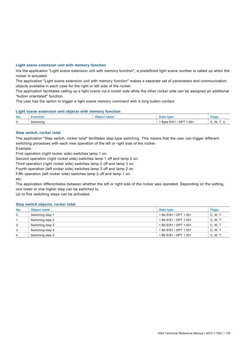
KNX Technical Reference Manual | 0073-1-7621 | 125
Pos: 20.2.25 /Produkthandbuch - DIN-A4/Überschriften/2. Ebene/G - L/Lichtszenennebenstelle mit Speicherfunktion @ 9\mod_1269436310937_15.doc @ 52783 @ 2
Light scene extension unit with memory function Pos: 20.2.26 /KNX/Applikationsbeschreibungen/Applikationen - App/Lichtszenennebenstelle_mit_Speicherfunktion/App. - Lichtszenennebenstelle mit Speicherfunktion - DIN-A4 @ 9\mod_1269435757171_15.doc @ 52778 @
Via the application "Light scene extension unit with memory function", a predefined light scene number is called up when the rocker is actuated. The application "Light scene extension unit with memory function" makes a separate set of parameters and communication objects available in each case for the right or left side of the rocker. The application facilitates calling up a light scene via a rocker side while the other rocker side can be assigned an additional "button orientated" function. The user has the option to trigger a light scene memory command with a long button contact. Light scene extension unit objects with memory function No. Function Object name Data type Flags 0 Switching 1 Byte EIS1 / DPT 1.001 C, W, T, U
Pos: 20.2.27 /Produkthandbuch - DIN-A4/Überschriften/2. Ebene/S - T/Stufenschalter, Wippe Gesamt @ 9\mod_1269437200187_15.doc @ 52793 @ 2
Step switch, rocker total Pos: 20.2.28 /KNX/Applikationsbeschreibungen/Applikationen - App/Stufenschalter_Wippe_gesamt/App. - Stufenschalter, Wippe Gesamt - DIN-A4 @ 9\mod_1269436921171_15.doc @ 52788 @
The application "Step switch, rocker total" facilitates step-type switching. This means that the user can trigger different switching processes with each new operation of the left or right side of the rocker. Example: First operation (right rocker side) switches lamp 1 on. Second operation (right rocker side) switches lamp 1 off and lamp 2 on. Third operation (right rocker side) switches lamp 2 off and lamp 3 on. Fourth operation (left rocker side) switches lamp 3 off and lamp 2 on. Fifth operation (left rocker side) switches lamp 2 off and lamp 1 on. etc. The application differentiates between whether the left or right side of the rocker was operated. Depending on the setting, one lower or one higher step can be switched to. Up to five switching steps can be activated. Step switch objects, rocker total No. Object name Data type Flags 0 Switching step 1 1 Bit EIS1 / DPT 1.001 C, W, T 1 Switching step 2 1 Bit EIS1 / DPT 1.001 C, W, T
2 Switching step 3 1 Bit EIS1 / DPT 1.001 C, W, T 3 Switching step 4 1 Bit EIS1 / DPT 1.001 C, W, T
4 Switching step 5 1 Bit EIS1 / DPT 1.001 C, W, T
Pos: 20.2.29 /Spezial/Neues Layout 2010/Steuermodule_Neues_Layout_2010/++++++++++++ Seitenumbruch ++++++++++++ @ 9\mod_1268898668093_0.doc @ 52149 @

KNX Technical Reference Manual Busch-triton
126 | 0073-1-7621 | KNX Technical Reference Manual
Pos: 20.2.30 /Produkthandbuch - DIN-A4/Überschriften/2. Ebene/S - T/Stufenschalter, Wippe Links / Rechts @ 9\mod_1269437464625_15.doc @ 52803 @ 2
Step switch, rocker left/right Pos: 20.2.31 /KNX/Applikationsbeschreibungen/Applikationen - App/Stufenschalter_Wippe_links_rechts/App. - Stufenschalter, Wippe Links / Rechts - DIN-A4 @ 9\mod_1269437349390_15.doc @ 52798 @
The application "Step switch, rocker left/right" facilitates step-type switching. This means that the user can trigger different switching processes with each new operation of the rocker switch. Example: First operation switches lamp 1 on. Second operation switches lamp 1 off and lamp 2 on. Third operation switches lamp 2 off and lamp 3 on. Fourth operation switches lamp 3 off and lamp 1 on. etc. Up to five switching steps can be activated. In each case, the application "Step switch, button oriented" makes a separate set of parameters and communication objects available for the right or left side of the rocker. The application enables realising switching functions via one rocker side while the other rocker side can be assigned with an additional "button orientated" function. Step switch objects, rocker left/right No. Object name Data type Flags 0 Switching step 1 1 Bit EIS1 / DPT 1.001 C, W, T
1 Switching step 2 1 Bit EIS1 / DPT 1.001 C, W, T 2 Switching step 3 1 Bit EIS1 / DPT 1.001 C, W, T
3 Switching step 4 1 Bit EIS1 / DPT 1.001 C, W, T 4 Switching step 5 1 Bit EIS1 / DPT 1.001 C, W, T
Pos: 20.2.32 /Produkthandbuch - DIN-A4/Überschriften/2. Ebene/M - O/Mehrfachbetätigung, Wippe Links / Rechts @ 9\mod_1269438670421_15.doc @ 52813 @ 2
Multiple operation, rocker left/right Pos: 20.2.33 /KNX/Applikationsbeschreibungen/Applikationen - App/Mehrfachbetätigung_Wippe_links_rechts/App. - Mehrfachbetätigung, Wippe Links / Rechts - DIN-A4 @ 9\mod_1269437591625_15.doc @ 52808 @
With the "Multiple operation, rocker left/right" application, a differentiation can be made between a single, double, triple, quadruple or quintuple operation of the rocker. Different values can be sent out for every operation: single, double, triple, quadruple, or quintuple. The application "Multiple operation, rocker left/right" makes a separate set of parameters and communication objects available in each case for the right or left side of the rocker. It is therefore possible to realise a multiple operation via one side of the rocker and assigning a "button-orientated" function to the other side of the rocker. Multiple operation objects, rocker left/right No. Object name Data type Flags 0 Switching 1, multiple operation (1 Bit) 1 Bit EIS1 / DPT 1.001 C, W, T 0 Switching 1, multiple operation (1 Byte 0..100 %) 1 Byte EIS6 / DPT 5.001 C, W, T
0 Switching 1, multiple operation (1 Byte 0..255) 1 Byte EIS14 / DPT 5.010 C, W, T 0 Switching 1, multiple operation (2 Byte Float) 2 Byte EIS5 / DPT 9.xxx C, W, T
0 Switching 1, multiple operation (2 Byte Signed) 2 Byte EIS10 / DPT 8.001 C, W, T 0 Switching 1, multiple operation (2 Byte Unsigned) 2 Byte EIS10 / DPT 7.001 C, W, T
0 Switching 1, multiple operation (4 Byte Float) 4 Byte EIS9 / DPT 14.xxx C, W, T 0 Switching 1, multiple operation (4 Byte Signed) 4 Byte EIS11 / DPT 13.001 C, W, T
0 Switching 1, multiple operation (4 Byte Unsigned) 4 Byte EIS11 / DPT 12.001 C, W, T

KNX Technical Reference Manual | 0073-1-7621 | 127
Multiple operation objects, rocker left/right, continued No. Object name Data type Flags 1 Switching 2, multiple operation (1 Bit) 1 Bit EIS1 / DPT 1.001 C, W, T
1 Switching 2, multiple operation (1 Byte 0..100 %) 1 Byte EIS6 / DPT 5.001 C, W, T
1 Switching 2, multiple operation (1 Byte 0..255) 1 Byte EIS14 / DPT 5.010 C, W, T 1 Switching 2, multiple operation (2 Byte Float) 2 Byte EIS5 / DPT 9.xxx C, W, T
1 Switching 2, multiple operation (2 Byte Signed) 2 Byte EIS10 / DPT 8.001 C, W, T 1 Switching 2, multiple operation (2 Byte Unsigned) 2 Byte EIS10 / DPT 7.001 C, W, T
1 Switching 2, multiple operation (4 Byte Float) 4 Byte EIS9 / DPT 14.xxx C, W, T 1 Switching 2, multiple operation (4 Byte Signed) 4 Byte EIS11 / DPT 13.001 C, W, T
1 Switching 2, multiple operation (4 Byte Unsigned) 4 Byte EIS11 / DPT 12.001 C, W, T 2 Switching 3, multiple operation (1 Bit) 1 Bit EIS1 / DPT 1.001 C, W, T
2 Switching 3, multiple operation (1 Byte 0..100 %) 1 Byte EIS6 / DPT 5.001 C, W, T 2 Switching 3, multiple operation (1 Byte 0..255) 1 Byte EIS14 / DPT 5.010 C, W, T
2 Switching 3, multiple operation (2 Byte Float) 2 Byte EIS5 / DPT 9.xxx C, W, T 2 Switching 3, multiple operation (2 Byte Signed) 2 Byte EIS10 / DPT 8.001 C, W, T
2 Switching 3, multiple operation (2 Byte Unsigned) 2 Byte EIS10 / DPT 7.001 C, W, T 2 Switching 3, multiple operation (4 Byte Float) 4 Byte EIS9 / DPT 14.xxx C, W, T
2 Switching 3, multiple operation (4 Byte Signed) 4 Byte EIS11 / DPT 13.001 C, W, T 2 Switching 3, multiple operation (4 Byte Unsigned) 4 Byte EIS11 / DPT 12.001 C, W, T
3 Switching 4, multiple operation (1 Bit) 1 Bit EIS1 / DPT 1.001 C, W, T 3 Switching 4, multiple operation (1 Byte 0..100 %) 1 Byte EIS6 / DPT 5.001 C, W, T
3 Switching 4, multiple operation (1 Byte 0..255) 1 Byte EIS14 / DPT 5.010 C, W, T 3 Switching 4, multiple operation (2 Byte Float) 2 Byte EIS5 / DPT 9.xxx C, W, T
3 Switching 4, multiple operation (2 Byte Signed) 2 Byte EIS10 / DPT 8.001 C, W, T 3 Switching 4, multiple operation (2 Byte Unsigned) 2 Byte EIS10 / DPT 7.001 C, W, T
3 Switching 4, multiple operation (4 Byte Float) 4 Byte EIS9 / DPT 14.xxx C, W, T 3 Switching 4, multiple operation (4 Byte Signed) 4 Byte EIS11 / DPT 13.001 C, W, T
3 Switching 4, multiple operation (4 Byte Unsigned) 4 Byte EIS11 / DPT 12.001 C, W, T 4 Switching 5, multiple operation (1 Bit) 1 Bit EIS1 / DPT 1.001 C, W, T
4 Switching 5, multiple operation (1 Byte 0..100 %) 1 Byte EIS6 / DPT 5.001 C, W, T 4 Switching 5, multiple operation (1 Byte 0..255) 1 Byte EIS14 / DPT 5.010 C, W, T
4 Switching 5, multiple operation (2 Byte Float) 2 Byte EIS5 / DPT 9.xxx C, W, T 4 Switching 5, multiple operation (2 Byte Signed) 2 Byte EIS10 / DPT 8.001 C, W, T
4 Switching 5, multiple operation (2 Byte Unsigned) 2 Byte EIS10 / DPT 7.001 C, W, T 4 Switching 5, multiple operation (4 Byte Float) 4 Byte EIS9 / DPT 14.xxx C, W, T
4 Switching 5, multiple operation (4 Byte Signed) 4 Byte EIS11 / DPT 13.001 C, W, T 4 Switching 5, multiple operation (4 Byte Unsigned) 4 Byte EIS11 / DPT 12.001 C, W, T
Pos: 20.2.34 /Spezial/Neues Layout 2010/Steuermodule_Neues_Layout_2010/++++++++++++ Seitenumbruch ++++++++++++ @ 9\mod_1268898668093_0.doc @ 52149 @

KNX Technical Reference Manual Busch-triton
128 | 0073-1-7621 | KNX Technical Reference Manual
Pos: 20.2.35 /Produkthandbuch - DIN-A4/Überschriften/2. Ebene/G - L/Kurz-Lang-Bedienung, Wippe Links / Rechts @ 9\mod_1269440952703_15.doc @ 52823 @ 2
Short/long operation, rocker left/right Pos: 20.2.36 /KNX/Applikationsbeschreibungen/Applikationen - App/Kurz_lang_Bedienung_Wippe_links_rechts/App. - Kurz-Lang-Bedienung, Wippe Links / Rechts - DIN-A4 @ 9\mod_1269440785765_15.doc @ 52818 @
Via the application "Short/long operation, rocker left/right", different values can be sent out with a short and/or long actuation of the rocker switch. The "Short/long operation, rocker left/right" application does not differentiate between whether the rocker is actuated on the left or right side. In each case, the application makes a separate set of parameters and communication objects available for the right and left side of the rocker. The application facilitates making two separate functions available on one side of the rocker that can be called up via a short or long button contact and assigning the other side of the rocker switch with an additional "button-orientated" function. Short/long operation objects, rocker left/right No. Object name Data type Flags 0 Adjusting(1 Bit) 1 Bit EIS7 / DPT 1.007 C, W, T, U
0 Adjusting(1 Byte) 1 Byte EIS6 / DPT 5.001 C, W, T, U 1 Moving (1 Bit) 1 Bit EIS7 / DPT 1.008 C, W, T, U
1 Moving (1 Byte) 1 Byte EIS6 / DPT 5.001 C, W, T, U
Pos: 20.2.37 /Produkthandbuch - DIN-A4/Überschriften/2. Ebene/P - R/RTR-Betriebsart einstellen @ 9\mod_1269441295921_15.doc @ 52833 @ 2
Setting RTC operation mode Pos: 20.2.38 /KNX/Applikationsbeschreibungen/Applikationen - App/RTR-Betriebsart/App. - RTR-Betriebsart einstellen - DIN-A4 @ 9\mod_1269441072468_15.doc @ 52828 @
With the "Setting the RTC operation mode" application, an operation mode switchover for connected room temperature controllers can be carried out via an actuation of a rocker side. Depending on the setting of the "Object type for output" parameter, the application offers either three 1-bit communication objects "Operation mode comfort", "Operation mode night", and "Operation mode frost" or a 1-byte communication object "Operation mode". The selection "1-bit" is used for the control of room temperature controllers that have 1-bit communication objects for operation mode switchover. The "1-byte" selection is used for the control of room temperature controllers that have a 1-byte communication object for operation mode switchover to KNX. In this case, the values mean 0 = Auto 1 = Comfort 2 = Standby 3 = Night 4 = Frost / Heat protection The function can be temporarily blocked via a 1-bit "Enable" communication object. Setting RTC operation mode objects No. Object name Data type Flags 0 Enable 1 Bit EIS1 / DPT 1.001 C, W, U
1 Operation mode Comfort(1 Bit) 1 Bit EIS1 / DPT 1.001 C, T 2 Operation mode Night(1 Bit) 1 Bit EIS1 / DPT 1.001 C, T
3 Operation mode Frost(1 Bit) 1 Bit EIS1 / DPT 1.001 C, T 4 Operation mode (1 Byte) 1 Byte / DPT 20.102 C, T
Pos: 20.3.1 /Produkthandbuch - DIN-A4/Überschriften/2. Ebene/A - F/Allgemein @ 15\mod_1289225396075_15.doc @ 97000 @ 2
General Pos: 20.3.2 /Produkthandbuch - DIN-A4/Busch-triton/Parameter - Kommunikationsobjekte/Allgemein/Kommunikationsobjekte - DIN-A4 @ 13\mod_1285136571387_15.doc @ 90383 @
Communication object(s) No. Function Object name Data type Flags 0 In operation General 1 Bit EIS1 / DPT 1.001 K, Ü
1 Device On/Off Operating mode 1 Bit EIS1 / DPT 1.001 K, S, Ü, L
2 Switching display unit °C/°F General 1 Bit EIS1 / DPT 1.001 K, S, L
3 On/Off General 1 Bit EIS1 / DPT 1.001 K, S, Ü, L
Pos: 20.4.1 /Produkthandbuch - DIN-A4/Überschriften/2. Ebene/P - R/Regler allgemein @ 15\mod_1289225464434_15.doc @ 97008 @ 2
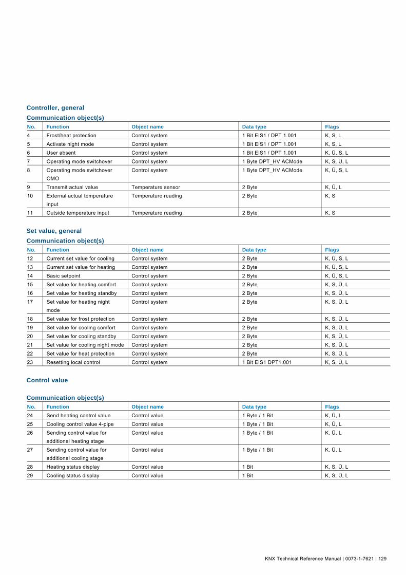
KNX Technical Reference Manual | 0073-1-7621 | 129
Controller, general Pos: 20.4.2 /Produkthandbuch - DIN-A4/Busch-triton/Parameter - Kommunikationsobjekte/Regler allgemein/Kommunikationsobjekte - DIN-A4 @ 13\mod_1285143556742_15.doc @ 90391 @
Communication object(s) No. Function Object name Data type Flags 4 Frost/heat protection Control system 1 Bit EIS1 / DPT 1.001 K, S, L
5 Activate night mode Control system 1 Bit EIS1 / DPT 1.001 K, S, L
6 User absent Control system 1 Bit EIS1 / DPT 1.001 K, Ü, S, L
7 Operating mode switchover Control system 1 Byte DPT_HV ACMode K, S, Ü, L
8 Operating mode switchover OMO
Control system 1 Byte DPT_HV ACMode K, Ü, S, L
9 Transmit actual value Temperature sensor 2 Byte K, Ü, L
10 External actual temperature input
Temperature reading 2 Byte K, S
11 Outside temperature input Temperature reading 2 Byte K, S
Pos: 20.5.1 /Produkthandbuch - DIN-A4/Überschriften/2. Ebene/S - T/Sollwert allgemein @ 15\mod_1289225510543_15.doc @ 97016 @ 2
Set value, general Pos: 20.5.2 /Produkthandbuch - DIN-A4/Busch-triton/Parameter - Kommunikationsobjekte/Sollwert allgemein/Kommunikationsobjekte - DIN-A4 @ 13\mod_1285145728814_15.doc @ 90399 @
Communication object(s) No. Function Object name Data type Flags 12 Current set value for cooling Control system 2 Byte K, Ü, S, L
13 Current set value for heating Control system 2 Byte K, Ü, S, L
14 Basic setpoint Control system 2 Byte K, Ü, S, L
15 Set value for heating comfort Control system 2 Byte K, S, Ü, L
16 Set value for heating standby Control system 2 Byte K, S, Ü, L
17 Set value for heating night mode
Control system 2 Byte K, S, Ü, L
18 Set value for frost protection Control system 2 Byte K, S, Ü, L
19 Set value for cooling comfort Control system 2 Byte K, S, Ü, L
20 Set value for cooling standby Control system 2 Byte K, S, Ü, L
21 Set value for cooling night mode Control system 2 Byte K, S, Ü, L
22 Set value for heat protection Control system 2 Byte K, S, Ü, L
23 Resetting local control Control system 1 Bit EIS1 DPT1.001 K, S, Ü, L
Pos: 20.6 /Produkthandbuch - DIN-A4/Busch-triton/Parameter - Kommunikationsobjekte/Sollwert allgemein/Kommunikationsobjekte Stellgroesse - DIN-A4 @ 13\mod_1285146595088_15.doc @ 90407 @ 2
Control value
Communication object(s) No. Function Object name Data type Flags 24 Send heating control value Control value 1 Byte / 1 Bit K, Ü, L
25 Cooling control value 4-pipe Control value 1 Byte / 1 Bit K, Ü, L
26 Sending control value for additional heating stage
Control value 1 Byte / 1 Bit K, Ü, L
27 Sending control value for additional cooling stage
Control value 1 Byte / 1 Bit K, Ü, L
28 Heating status display Control value 1 Bit K, S, Ü, L
29 Cooling status display Control value 1 Bit K, S, Ü, L
Pos: 20.7 /Produkthandbuch - DIN-A4/Busch-triton/Parameter - Kommunikationsobjekte/Regelung Heizen/Kommunikationsobjekte Heizen Kuehlen - DIN-A4 @ 13\mod_1285146905444_15.doc @ 90415 @ 2

KNX Technical Reference Manual Busch-triton
130 | 0073-1-7621 | KNX Technical Reference Manual
Heating / cooling
Communication object(s) No. Function Object name Data type Flags 24 Heating and cooling control
value Control value 1 Byte / 1 Bit K, Ü, L
30 Switchover heating/cooling Heating/cooling 1 Bit EIS1 DPT1.001 K, S, Ü, L
Pos: 20.8.1 /Produkthandbuch - DIN-A4/Überschriften/2. Ebene/A - F/Fan Coil allgemein @ 15\mod_1289225626980_15.doc @ 97024 @ 2
Fan coil, general Pos: 20.8.2 /Produkthandbuch - DIN-A4/Busch-triton/Parameter - Kommunikationsobjekte/Fan Coil allgemein/Kommunikationsobjekte - DIN-A4 @ 13\mod_1285148750528_15.doc @ 90423 @
Communication object(s) No. Function Object name Data type Flags 31 Automatic On/Off Fan, manual / automatic 1 Bit EIS1 DPT1.001 K, S, Ü, L
31 Manual On/Off Fan, manual / automatic 1 Bit K, S, Ü, L
32 Fan stage manual 1 byte Fan, manual 1 Byte K, S, Ü, L
33 Status, fan coil operating mode Status, fan coil operation 1 Byte K, S
34 Switching, fan coil stage 1 Fan, manual 1 Bit EIS1 DPT1.001 K, S, Ü, L
35 Switching, fan coil stage 2 Fan, manual 1 Bit EIS1 DPT1.001 K, S, Ü, L
36 Switching, fan coil stage 3 Fan, manual 1 Bit EIS1 DPT1.001 K, S, Ü, L
Pos: 20.9 /Produkthandbuch - DIN-A4/Busch-triton/Parameter - Kommunikationsobjekte/Allgemein/Kommunikationsobjekte Ueberwachung - DIN-A4 @ 13\mod_1285154313695_15.doc @ 90431 @ 2
Monitoring
Communication object(s) No. Function Object name Data type Flags 37 Automatic On/Off Actuator monitoring 1 Bit K, S
39 Manual On/Off Dew point monitoring 1 Bit EIS1 DPT1.001 K, S
40 Fan stage manual 1 byte Monitoring of condensate tank 1 Bit EIS1 DPT1.001 K, S
Pos: 20.10 /Produkthandbuch - DIN-A4/Busch-triton/Parameter - Kommunikationsobjekte/Allgemein/Kommunikationsobjekte Alarm Temperatur - DIN-A4 @ 13\mod_1285154468368_15.doc @ 90439 @ 2
Alarm temperature
Communication object(s) No. Function Object name Data type Flags 41 Message, failure of actual
temperature detection Alarm temperature 1 Bit EIS1 DPT1.001 K, Ü, L
42 Message, failure of exterior temperature detection
Alarm temperature 1 Bit EIS1 DPT1.001 K, Ü, L
Pos: 20.11 /Produkthandbuch - DIN-A4/Busch-triton/Parameter - Kommunikationsobjekte/Allgemein/Kommunikationsobjekte Statusbyte - DIN-A4 @ 13\mod_1285154729618_15.doc @ 90447 @ 2
Status byte
Communication object(s) No. Function Object name Data type Flags 43 Status byte, StatusRHCC Status byte 2 Byte DPT22.101 K, Ü, L
44 Status byte, HVACStatus Status byte 2 Byte DPT_HVACStatus K, Ü, L
Pos: 20.12.1 /Produkthandbuch - DIN-A4/Überschriften/2. Ebene/G - L/Kompensation @ 15\mod_1289225728151_15.doc @ 97032 @ 2
Compensation Pos: 20.12.2 /Produkthandbuch - DIN-A4/Busch-triton/Parameter - Kommunikationsobjekte/Kompensation/Kommunikationsobjekte - DIN-A4 @ 13\mod_1285154896930_15.doc @ 90455 @
Communication object(s) No. Function Object name Data type Flags 45 Summer compensation active Control system 1 Bit K, S, Ü, L
46 Winter compensation active Control system 1 Bit K, S, Ü, L
Pos: 20.13 /Produkthandbuch - DIN-A4/Busch-triton/Parameter - Kommunikationsobjekte/Fan Coil allgemein/Kommunikationsobjekte Luefterstufe Status - DIN-A4 @ 13\mod_1285154998649_15.doc @ 90463 @ 2
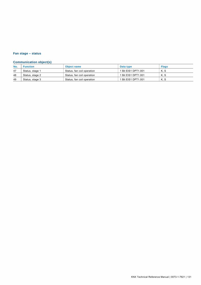
KNX Technical Reference Manual | 0073-1-7621 | 131
Fan stage – status
Communication object(s) No. Function Object name Data type Flags 47 Status, stage 1 Status, fan coil operation 1 Bit EIS1 DPT1.001 K, S
48 Status, stage 2 Status, fan coil operation 1 Bit EIS1 DPT1.001 K, S
49 Status, stage 3 Status, fan coil operation 1 Bit EIS1 DPT1.001 K, S
=== Ende der Liste für Textmarke Content ===

Contact us
0073
-1-7
621
| R
ev. 0
1 |
02.
2011
Pos: 22 /Produkthandbuch - DIN-A4/Rückseiten/Rückseite - Busch-Jaeger - Allgemein @ 9\mod_1269241585218_15.doc @ 52245 @
A member of the ABB Group Busch-Jaeger Elektro GmbH PO box 58505 Lüdenscheid Freisenbergstraße 2 58513 Lüdenscheid Germany www.BUSCH-JAEGER.com [email protected] Central sales service: Phone: +49 180 5 669900 Fax: +49 180 5 669909
Notice We reserve the right to at all times make technical changes as well as changes to the contents of this document without prior notice. The detailed specifications agreed to at the time of ordering apply to all orders. ABB accepts no responsibility for possible errors or incompleteness in this document. We reserve all rights to this document and the topics and illustrations contained therein. The document and its contents, or extracts thereof, must not be reproduced, transmitted or reused by third parties without prior written consent by ABB. Copyright© 2010 Busch-Jaeger Elektro GmbH All rights reserved
=== Ende der Liste für Textmarke Backcover ===


![Übersicht über Bibliographien und Nachschlagewerke der ... · Technik und Patente, ITP) HB 1 3. OG rechts HB 2 EG HB 3 - HB 30 2. OG links Ja A - Ja Y 3. ... [Hrsg.]. - rev. printing](https://static.fdokument.com/doc/165x107/5b1429c67f8b9a347c8b9c49/uebersicht-ueber-bibliographien-und-nachschlagewerke-der-technik-und-patente.jpg)