Hcb.03 100 Handbuch Englisch
31
GmbH a b ANTENNENTECHNIK Hermann - Petersilge - Straße 1 D-07422 Bad Blankenburg Phone: ++ 49 (0) 36 74 1 / 60 - 0 Telefax: ++ 49 (0) 36 74 1 / 60 - 100 www.blankom.de BLANKOM Antennentechnik GmbH · · · Germany Manual Headend Controller (HCB 100 “blue” (9650.03) Changes due to technical progress possible!
description
CATV Headend
Transcript of Hcb.03 100 Handbuch Englisch

GmbHab
ANTENNENTECHNIK
Hermann - Petersilge - Straße 1 D-07422 Bad Blankenburg
Phone: ++ 49 (0) 36 74 1 / 60 - 0 Telefax: ++ 49 (0) 36 74 1 / 60 - 100www.blankom.de
BLANKOM Antennentechnik GmbH�
�
� Germany
Manual Headend Controller (HCB 100 “blue” (9650.03)
Changes due to technical progress possible!

GmbHab
ANTENNENTECHNIK
CONTENT
1. Set up of the network connection
2. Set up of the Web browser
3. Working with the Headend Controller (HCB 100)
4. Diagramm for the manual operation/management of the HCB 100
5. LCD display at the HCB 100
6. Changes of the Hardware
7. Additional Network components
.............................................................................1.1 WINDOWS XP .........................................................................................................1.2 WINDOWS 2000 ......................................................................................................
........................................................................................2.1 Microsoft Internet Explorer .......................................................................................
....................................................3.1 Call up the Headend Controller ................................................................................3.2 Selection of the desired Headend overview...............................................................3.3 Selcection of Adjustments and Configurations...........................................................3.4 Basic settings of the Headend Controller ..................................................................
3.4.1 Reset of the HEADEND CONTROLLER .........................................................3.4.2 Configuration of the HEADEND CONTROLLER ..............................................3.4.3 Manual start of NIT - distribution........................................................................3.4.4 Timer / Time controlled switching ......................................................................3.4.5 Adjustment of Date/Time ..................................................................................3.4.6 Cold stard of individual/single modules................................................................3.4.7 Change of User ID, Pass word..........................................................................3.4.8 Additional NIT - Datas .......................................................................................3.4.9 Protocoll / Log book ..........................................................................................3.4.10 Update of the HEAEND CONTROLLER............................................................
...........................4.1 Configuration of the HCB 100 .....................................................................................4.2 Adjustment possibilities of IP - Numbers ...................................................................4.3 General Information for adjustments of the IP - Number ...........................................
.........................................................................................5.1 Initializing of the modules after a RESET ..................................................................285.2 Standard Display ......................................................................................................5.3 Error display, if a module can not be called up ........................................................
............................................................................................
...............................................................................
335
77
88
10121313131414202021222324
26272727
28
2828
29
30
Hermann - Petersilge - Straße 1 D-07422 Bad Blankenburg
Phone: ++ 49 (0) 36 74 1 / 60 - 0 Telefax: ++ 49 (0) 36 74 1 / 60 - 100www.blankom.de
BLANKOM Antennentechnik GmbH�
�
� Germany

GmbHab
ANTENNENTECHNIK
1. Set up of the network connection
- Entering via “Start” button of your desktop and then call up “System operation”
1.1 WINDOWS XP
Confirm LAN - connectionwith douple click(continue at page 4)
3
Hermann - Petersilge - Straße 1 D-07422 Bad Blankenburg
Phone: ++ 49 (0) 36 74 1 / 60 - 0 Telefax: ++ 49 (0) 36 74 1 / 60 - 100www.blankom.de
BLANKOM Antennentechnik GmbH�
�
� Germany

GmbHab
ANTENNENTECHNIK
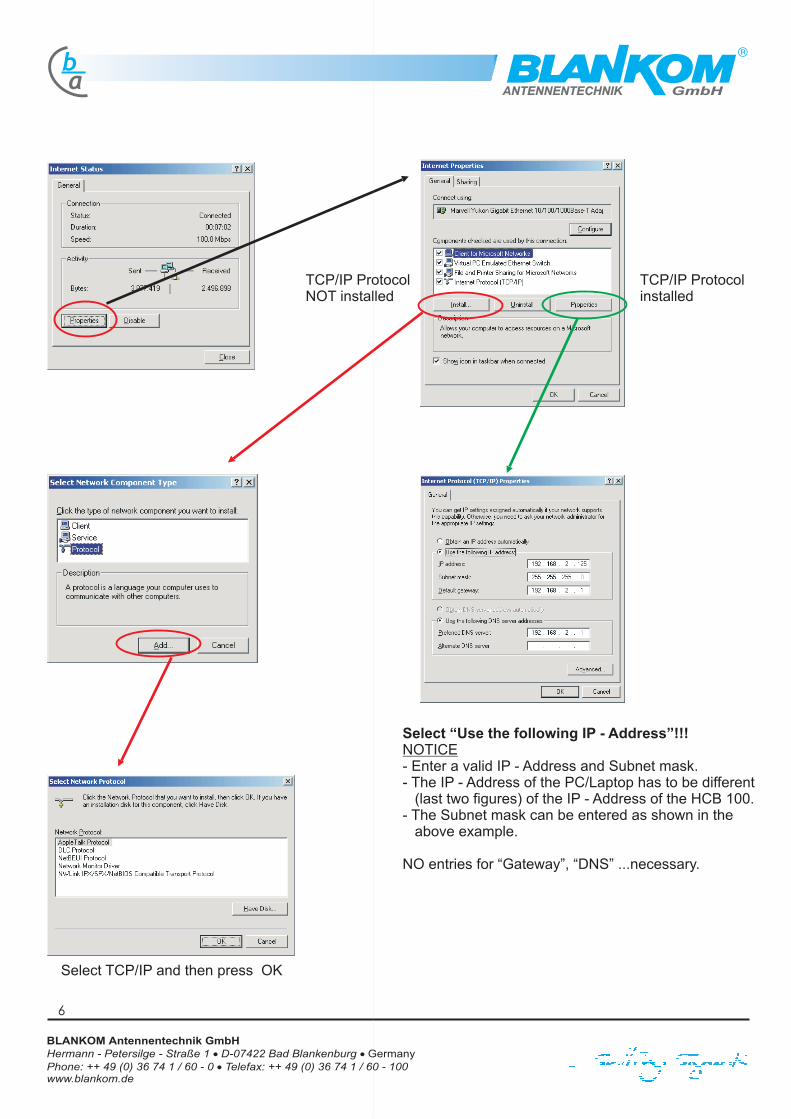
TCP/IP Protocolinstalled
TCP/IP Protocolnot installed
Select TCP/IP and then press OK
4
Select “Use the following IP - Address”!!!
- Enter a valid IP - Address and Subnet mask.- The IP - Address of the PC/Laptop has to be different
(last two figures) of the IP - Address of the HCB 100.- The Subnet mask can be entered as shown in the
above example.
NO entries for “Gateway”, “DNS” ... are necessary.
NOTICE
Hermann - Petersilge - Straße 1 D-07422 Bad Blankenburg
Phone: ++ 49 (0) 36 74 1 / 60 - 0 Telefax: ++ 49 (0) 36 74 1 / 60 - 100www.blankom.de
BLANKOM Antennentechnik GmbH�
�
� Germany

GmbHab
ANTENNENTECHNIK
1.2 WINDOWS 2000
5
- Entering via “Start” button of your desktop and then call up “System operation” via “Adjustments”
Confirm LAN - connectionwith douple click(continue at page 4)
Hermann - Petersilge - Straße 1 D-07422 Bad Blankenburg
Phone: ++ 49 (0) 36 74 1 / 60 - 0 Telefax: ++ 49 (0) 36 74 1 / 60 - 100www.blankom.de
BLANKOM Antennentechnik GmbH�
�
� Germany
GmbHab
ANTENNENTECHNIK
TCP/IP Protocolinstalled
TCP/IP ProtocolNOT installed
6
Select “Use the following IP - Address”!!!
- Enter a valid IP - Address and Subnet mask.- The IP - Address of the PC/Laptop has to be different
(last two figures) of the IP - Address of the HCB 100.- The Subnet mask can be entered as shown in the
above example.
NO entries for “Gateway”, “DNS” ...necessary.
NOTICE
Select TCP/IP and then press OK
Hermann - Petersilge - Straße 1 D-07422 Bad Blankenburg
Phone: ++ 49 (0) 36 74 1 / 60 - 0 Telefax: ++ 49 (0) 36 74 1 / 60 - 100www.blankom.de
BLANKOM Antennentechnik GmbH�
�
� Germany

GmbHab
ANTENNENTECHNIK
2. Set up of the Webbrowser
- Open the Webbrowser, select “Extras” sand then “Internet Option”
Select“Every visit to the page” !!!
NoticeTo avoid display errors please change the ,adjustments for the storing oftemporaryInternet files.
General settings Adjustments for “Connections”
Select “No connections”
Please disconnect the access to a Proxyserverfor direct connection of the HCB 100 withPC/Laptop.
2.1 Microsoft Internet Explorer
Please restart the PC/Laptop after all settings/adjustments are finished.Then the connection to the Headend Controller HCB 100 can be called up via the Webbrowser.
7
Hermann - Petersilge - Straße 1 D-07422 Bad Blankenburg
Phone: ++ 49 (0) 36 74 1 / 60 - 0 Telefax: ++ 49 (0) 36 74 1 / 60 - 100www.blankom.de
BLANKOM Antennentechnik GmbH�
�
� Germany

GmbHab
ANTENNENTECHNIK
Enter the IP - Number into the address - line.(IP - Number ex works BLANKOM is 192.168.2.80)
The Login - window of the HCB 100 will be displayed if all adjustments/settings are correct.You now can save/secure the operation via a password.Selecting the configuration “Automatic Login” allows i Login without password entry (see 3.4.2).
3. Working with the Headend Controller HCB 100
3.1 Access to the Headend Controller
8
Hermann - Petersilge - Straße 1 D-07422 Bad Blankenburg
Phone: ++ 49 (0) 36 74 1 / 60 - 0 Telefax: ++ 49 (0) 36 74 1 / 60 - 100www.blankom.de
BLANKOM Antennentechnik GmbH�
�
� Germany

GmbHab
ANTENNENTECHNIK
Enter USER ID and passwordt
User ID.......0000Passwordt....0000
USER ID and Password ex works BLANKOM:
Writing protection has been deleted.You will be automatically forwarded to the“Selcetion - Menu”.
Selection of desired Headend overview table(see 3.2)
Selection of Adjustments and Configurations(see 3.3)
9
Hermann - Petersilge - Straße 1 D-07422 Bad Blankenburg
Phone: ++ 49 (0) 36 74 1 / 60 - 0 Telefax: ++ 49 (0) 36 74 1 / 60 - 100www.blankom.de
BLANKOM Antennentechnik GmbH�
�
� Germany

GmbHab
ANTENNENTECHNIK
3.2 Selection of the desired Headend overview table
Headend overview (LIST)
The Headend overview (List) displays all the modules of theentire Headend system as a List.
Selecting the button “Edit” gets you to the operation overviewof the respective module.
The Headend overview (Matrix) displays all the modules of the entire Headend system as a Matrix
Selecting the button “Edit” gets you to the operation overview of the respective module.
.- The first line (horizontaly / here 02 and 03) displays the line-addresses of the Bus-Extender/Power supply(BEB 100).
- The fist line (verticaly / here 01 - 07) displays the addresses of the individual modules.as well as additional information like the module type, the synchronisation (SYNC) for digital converters,channel name(s), respective output band and -frequencyies...
Headend overview table (Matrix)
10
Hermann - Petersilge - Straße 1 D-07422 Bad Blankenburg
Phone: ++ 49 (0) 36 74 1 / 60 - 0 Telefax: ++ 49 (0) 36 74 1 / 60 - 100www.blankom.de
BLANKOM Antennentechnik GmbH�
�
� Germany
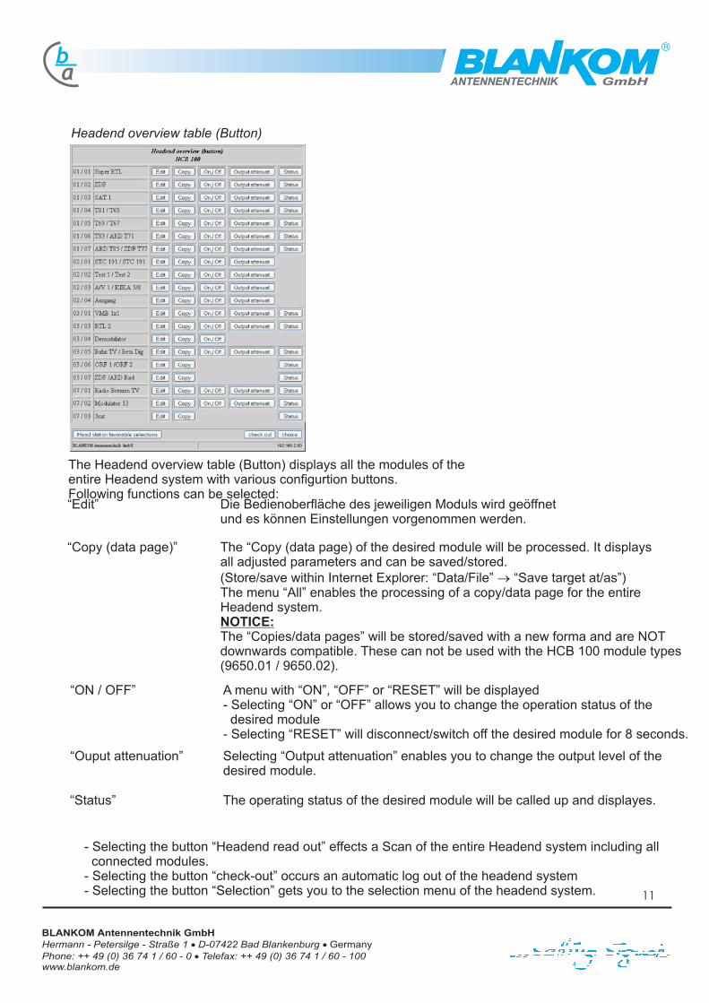
Headend overview table (Button)
“Edit” Die Bedienoberfläche des jeweiligen Moduls wird geöffnetund es können Einstellungen vorgenommen werden.
“Copy (data page)” The “Copy (data page) of the desired module will be processed. It displaysall adjusted parameters and can be saved/stored.(Store/save within Internet Explorer: “Data/File” “Save target at/as”)The menu “All” enables the processing of a copy/data page for the entireHeadend system.
The “Copies/data pages” will be stored/saved with a new forma and are NOTdownwards compatible. These can not be used with the HCB 100 module types(9650.01 / 9650.02).
�
NOTICE:
“ON / OFF”
“Status”
A menu with “ON”, “OFF” or “RESET” will be displayed- Selecting “ON” or “OFF” allows you to change the operation status of thedesired module
- Selecting “RESET” will disconnect/switch off the desired module for 8 seconds.
The operating status of the desired module will be called up and displayes.
“Ouput attenuation” Selecting “Output attenuation” enables you to change the output level of thedesired module.
The Headend overview table (Button).
Following functions can be selected:
displays all the modules of theentire Headend system with various configurtion buttons
GmbHab
ANTENNENTECHNIK
- Selecting the button “Headend read out” effects a Scan of the entire Headend system including allconnected modules.
- Selecting the button “check-out” occurs an automatic log out of the headend system- Selecting the button “Selection” gets you to the selection menu of the headend system.
11
Hermann - Petersilge - Straße 1 D-07422 Bad Blankenburg
Phone: ++ 49 (0) 36 74 1 / 60 - 0 Telefax: ++ 49 (0) 36 74 1 / 60 - 100www.blankom.de
BLANKOM Antennentechnik GmbH�
�
� Germany

GmbHab
ANTENNENTECHNIK
Module information (Matrix)
Headend Controller
3.3 Selcection of Adjustments and Configurations
Headend level settings (List)
For adjustment/setting of signal-levelfor each module of the headendEnter “Transmit” to confirm desired/selectedlevel.
The Matrix overview displays the part n°,current software and the serial n° of the respectivemodule.
- Displays all setting/adjustment opportunities of theentire headend or for individual modules.
- Displays the IP - number, the current software of theHeadend Controller HCB 100.
- Basic settings/adjustments in part 3.4
- The button “Name” allows the desired name for theheadend.
- The button “Language” allows the selection betweenGerman & Englisch.
12
Hermann - Petersilge - Straße 1 D-07422 Bad Blankenburg
Phone: ++ 49 (0) 36 74 1 / 60 - 0 Telefax: ++ 49 (0) 36 74 1 / 60 - 100www.blankom.de
BLANKOM Antennentechnik GmbH�
�
� Germany

GmbHab
ANTENNENTECHNIK
3.4 Basic settings/adjusments for the Headend Controllers
3.4.1 Reset of the HEADEND CONTROLLER
3.4.2 Konfiguration HEADEND CONTROLLER
Ente “RESET” effects a restart of the HEADEND CONTROLLER”and a software reset is done also.Afterwards a headend read out is done.
Sub-Menu for activation of additional functionsfor the Headend controller HCB 100.
“Address select.” (manual operation)ON ... Manual selection is done via Up / Down key-pads of the
HCB 100OFF ... Selection is done via direct entry of
line- and device addresses
“All characters” (manal operation)ON ... Text input for all characters possibleOFF ... Text input only for 0- 9 und A - Z possible
“NIT - Distribution”ON ... NIT - datas will be exchanged dynamicallyOF ... NIT - dats will be switched OFF
“NIT - Rack A”“NIT - Rack B”
Notice:Special adjustments have to be done when interchanging NIT - datasof two HCB 100 or one HCB 100 with additional NIT - datas
a
a
a
a
Example:*
NIT - Rack ANIT - Rack B
HCB 100 with32 x STB 606**
OFFOFF
a
HCB 100 Rack A with16 x STB 606**
EINOFF
a
HCB 100 Rack B with16 x STB 606**
OFFON
a
* Maxl 32 NIT - Datas of the B-LINE - modules can be processed. (16x Rack A + 16x Rack B) or (16x B-LINE + 16x external)**Valid for following B-LINE modules: STB 606, STB 607, STB 006, AMB 206, CTB 206
“additional NIT - datas”ON ... input of 16 external transponder information possibleOFF ...NO additional inputs possible
“Key lock”ON ... manual settings/adjustments directly at HCB 100 deactivatedOFF ... manual
“Automatic Login”ON ... Writing protection is deactivated. Access to the Menu without password entry possible.OFF ... Entry of User ID & Password necessary for access to the menu
“ ”ON ... time controlled changes/switching is possible/activatedAUS ... time controlled changes/switching deactivated
a
a
A
settings/adjustments directly at HCB 100 activated
Timer / Time controlled switching
13
Hermann - Petersilge - Straße 1 D-07422 Bad Blankenburg
Phone: ++ 49 (0) 36 74 1 / 60 - 0 Telefax: ++ 49 (0) 36 74 1 / 60 - 100www.blankom.de
BLANKOM Antennentechnik GmbH�
�
� Germany

GmbHab
ANTENNENTECHNIK
3.4.3 Manual NIT-Distribution
3.4.4 Timer / Time controlled switching
Press “Star Manual NIT - Distribution” for an one timeNIT - Distribution.Pls. see more detailed information for NIT-Distribution atour website, www.blankom.de
Timer / Time controlled switching allows a time controlledswitchover of programs.
NOTICETime-synchronization of the HCB100 is done with a reference time(see 3.4.5).
NOTICE
- Input of parameters/values into the timer has to be done in thesequence of the operator interface of the respective module(see page 17 for the sequences of the module)
- Upper and lower cases have as well as the input of thedimensions (e. G. MHz) have to be considered
Timer / Time controlled switching is OFF- NO input windows are enabled- Press “Configuration” to go to themenu “Configuration for Headend Controller”
- To enable the configuration table press Timer/Time controlledswitching to “ON”.
14
Hermann - Petersilge - Straße 1 D-07422 Bad Blankenburg
Phone: ++ 49 (0) 36 74 1 / 60 - 0 Telefax: ++ 49 (0) 36 74 1 / 60 - 100www.blankom.de
BLANKOM Antennentechnik GmbH�
�
� Germany

GmbHab
ANTENNENTECHNIK
Beispiele HCB 100 Timer
Program switchover forMPEG - modulesKIKA TV-Program switched toANTENNE Bayern Radio - Program
Example 2
(Switschtime approx. 10 sec.)
ExampleProgram switchover for analogue signalsC-LINE TWIN-Module8:00 hrs. activation for channel 120:00 hrs. activation for channel 2
3 (Special case)
The desired changes have been entered as displayedat the html - operation surface.e. g. Operating status: ON or OFF
This menu is for the configuration of time controlled switching and will only be displayed whenthe Timer-Mode is activated.
Example 1 (Special case)Switching of 2 modules viaRF - disconnection(switching itme approx. 1-2 sec.)5:00 hrs.Address 00/03 will be switched offAddresse 00/04 will be switched on7:00 hrsAddress 00/04 will be switched offAddress 00/03 will be switched on
15
Hermann - Petersilge - Straße 1 D-07422 Bad Blankenburg
Phone: ++ 49 (0) 36 74 1 / 60 - 0 Telefax: ++ 49 (0) 36 74 1 / 60 - 100www.blankom.de
BLANKOM Antennentechnik GmbH�
�
� Germany

GmbHab
ANTENNENTECHNIK
Program switchover (Example for KIKA-TV / Antenne Bayern-Radio)
special configuration for KIKA:Name = KIKA
SAT-IF = 1354ServiceID = 28008Service Type = TV
NOTICE!Please consider that only the values which are desired to be changed for switchover have to enteredwithin the configuration window.n.Also the desired switchtimes for the switchover of the desired programs have to be selected.
special configuration for Antenne Bayern:Name= Antenne BayernSAT-IF = 1548ServiceID = 170Service Type = Radio
NOTICE!If programs (e. G. KIKA) are to be switchedoverby fixed broadcasting-times, then please toNOT program the switchover time!!!
Differences
16
Hermann - Petersilge - Straße 1 D-07422 Bad Blankenburg
Phone: ++ 49 (0) 36 74 1 / 60 - 0 Telefax: ++ 49 (0) 36 74 1 / 60 - 100www.blankom.de
BLANKOM Antennentechnik GmbH�
�
� Germany

GmbHab
ANTENNENTECHNIK
Program selection for the C-LINE headend system (special case via RF - Signal)
Switching condition channel 2 “ON”:Program = Sonnenklar TV
Output frequency = 503,25 MHz (K25)
.
Example- Currently channel 1 (HSE) is activ- Output channel for timer controlled switchover is K25- As desired Sonnenklar-TV will be switched ON and HSE24 will be switche OFF at 20:00 hrs.
Switching condition channel 1”ON”:Programm = HSE
Output frequency = 503,25 MHz (K25)
Only the active channel has to be selected for this configuration. No further entries necessary
This time controlled switchover allows to change/switchover programs of different levels within one modulwithout an additional RF - switch.
activated channel
Differences
17
Hermann - Petersilge - Straße 1 D-07422 Bad Blankenburg
Phone: ++ 49 (0) 36 74 1 / 60 - 0 Telefax: ++ 49 (0) 36 74 1 / 60 - 100www.blankom.de
BLANKOM Antennentechnik GmbH�
�
� Germany

GmbHab
ANTENNENTECHNIK
Further information for timer configuration
RF - Signal: This parameter is only available at the 1. selection box.Not all modules support this configuration.This can be done only if the respective module supprt switching/selectionof the RF-signal (see page 18)
Übernahme: This function is only available at the 8. selection boxThe adjustments of the input parameters will be overtaken without a reset(see tabel page 20).
1. selection box
8. selection box
Example for an Einstellbox (Address,Switchtime, Parameter, Werte)
Parameter-List
Color bar:
TV-picture withFarbbalken ON
When color bar is ON then and datas will be sent to the module then the Farbbalkenwill be switched off
Following configurations have to be done.
18
Hermann - Petersilge - Straße 1 D-07422 Bad Blankenburg
Phone: ++ 49 (0) 36 74 1 / 60 - 0 Telefax: ++ 49 (0) 36 74 1 / 60 - 100www.blankom.de
BLANKOM Antennentechnik GmbH�
�
� Germany

Possib
lepara
mete
rsfo
rtim
er
contro
lled
sw
itchover
Para
mete
r
Channel (o
nly
Nam
eS
AT-IF
QP
SK
-Sym
bol ra
teS
ervice
IDLanguage
n°
Service
Typ
eA
dju
stem
entco
de
SA
T-S
ound
frequency
Inputfre
quency
Spectru
min
versio
nQ
AM
-Sym
bol ra
teIF
bandw
ith
Opera
ting
statu
s
RF.-sig
nal
C-L
INE
)
Farb
balke
n
Übern
ahm
e
Para
mete
r
Channel (o
nly
Nam
eS
AT-IF
QP
SK
-Sym
bol ra
teS
ervice
IDLanguage
n°
Service
Typ
eA
dju
stem
entco
de
SA
T-S
ound
frequency
Inputfre
quency
Spectru
min
versio
nQ
AM
-Sym
bol ra
teIF
bandw
ith
Opera
ting
statu
s
RF.-sig
nal
C-L
INE
)
Farb
balke
n
Übern
ahm
e
ST
B1x1
920x.xx
SD
B209
9802.0
1S
TB
2x1
ST
C291
981x.xx
9609.xx
ST
B607
9880.0
1T
TB
5x1
TT
C591
982x.xx
9601.xx
UC
B1x6
919x.0
1C
CB
1x1
TC
Bxx1
923x.xx
92xx.xx
CT
B1x1
983x.xx
VM
B1x1
922x.xx
AT
B1x1
984x.xx
AD
B109
9861.0
1
ST
C191
9616.xx
TC
C591
9617.xx
ST
C697
9619.0
2V
MC
191
9627.xx
xxxxxx
xxxxxxxxxx xxxxxxx
xxxx
xxxx xxxxxxx
xxx
xxxx
xxxx xxxxxxxx
xxxx
xxxx xxxxxxx xxxxx
xxxxxxx
xxxxxx
xxxxx
GmbHab
ANTENNENTECHNIK
19He
rma
nn
-P
ete
rsilg
e-
Stra
ße
1D
-07
42
2B
ad
Bla
nke
nb
urg
Ph
on
e:
++
49
(0)
36
74
1/
60
-0
Te
lefa
x:
++
49
(0)
36
74
1/
60
-1
00
ww
w.b
lan
ko
m.d
e
BL
AN
KO
MA
nte
nn
en
tec
hn
ikG
mb
H�
�
�G
erm
an
y

GmbHab
ANTENNENTECHNIK
3 Options for Date & Time configuration via the Headend Controller HCB 100.- Time can be configured manually, synchronised with the PC/Laptop-time or adopted from andigital converter
Manual correction of Date/Time- Press “Transmit” for acceptance/storage
Synchronization of Date/Time with connected PC/Laptop- Press “Transmit” to Confirm accept PC-Time ”
Select address of a module to adopt its time(Can be done with all headend modules)[-/- = die Adressauswahl erfolgt automatisch]- Press “Transmit” for acceptance
Offset time, for time correction of desired/selected address
Aktualization/Update of Date/Time for displayed module
Overview of all modules which provide Date & Time.The reference address can be selected directly in this window
NOTICE!Display of the date for digital Transmodulators possible only fromsofware-version V1.68 of the MPEG-Module.
3.4.5 Adjustment of Date/Time
3.4.6 Cold start of single modules
Entry of the sytstem cold start time (e.G. 03:00 hrs.)( when entering 00:00 hrs.)Cold start is deactivated
“Time alignment”*ON ... “Time aligment” will be done after restart of the moduleOFF ... No “Time aligment” after restart of the module
Matrix for all available modules- Selection of the module for restart
- Select “All” (all modules will be considered)- “Delete” module-selection will be relocated and restart configurations
- Manual restart of selected/modules
- “Transmit” for acceptance of cold start configurations
* Die Zeitaktualisierung erfolgt bei aktivierten Neustart auch wenn für kein Modul ein Neustart vereinbart wurde.20
Hermann - Petersilge - Straße 1 D-07422 Bad Blankenburg
Phone: ++ 49 (0) 36 74 1 / 60 - 0 Telefax: ++ 49 (0) 36 74 1 / 60 - 100www.blankom.de
BLANKOM Antennentechnik GmbH�
�
� Germany

GmbHab
ANTENNENTECHNIK
- Full rights for configuration/management/changesfor the headend system
- To provide and to change User Id´s and Passwordsfor the Sub-Administrators
- The Sub-Adminsitrators only have the right to do anyfor changes/configuration/management of the headend
Rights for Main-Administrator
Rights for Sub-Administrators
Access rights for 1 Main-Administrator and for up to 15 Sub-adminsitrators can be edited!!!
3.4.7 Change User ID, Password
21
Hermann - Petersilge - Straße 1 D-07422 Bad Blankenburg
Phone: ++ 49 (0) 36 74 1 / 60 - 0 Telefax: ++ 49 (0) 36 74 1 / 60 - 100www.blankom.de
BLANKOM Antennentechnik GmbH�
�
� Germany

GmbHab
ANTENNENTECHNIK
Examples for Transport stream - ID and Original Network - ID
Transponder
656769717577818385
Downlink(MHz)
117201175811798118361191411954120321207012110
Symbol rate(MSps)
27,50027,50027,50027,50027,50027,50027,50027,50027,500
SAT-IF(MHz)
112011581198123613141354143214701510
Transport stream - IDHexal Dezimal
0x0003 (3)0x0011 (17)0x0002 (2)0x044D (1101)0x0006 (6)0x0437 (1079)0x0004 (4)0x0005 (5)0x0431 (1073)
Original-Network - IDHexal Dezimal
0x0085 (133)0x0085 (133)0x0085 (133)0x0001 (1)0x0085 (133)0x0001 (1)0x0085 (133)0x0085 (133)0x0001 (1)
Entering/Using additional NIT - datas of previous BLANKOM headend systems(e.G Profi 800- or MINISAT system) or even of headend system of other suppliers allows also boththe distribution of this and of NIT - Datas of the B-/C-LINE headend systems.
This function has to be activated at the “Configuration” menu for the Headend Controller HCB 100.Then a table for 16 manual entries is available.
The values for output frequency, modulation and QAM symbol rate of the respective channels are known.The Transport stream - ID and the ORIGINAL Network-ID can be selected/seen with aQPSK-QAM Transmodulator (STB606/607 or STC696/697) or with a respective test device.
3.4.8 Additional NIT - Datas
22
Hermann - Petersilge - Straße 1 D-07422 Bad Blankenburg
Phone: ++ 49 (0) 36 74 1 / 60 - 0 Telefax: ++ 49 (0) 36 74 1 / 60 - 100www.blankom.de
BLANKOM Antennentechnik GmbH�
�
� Germany

GmbHab
ANTENNENTECHNIK
3.4.9 Protocoll / Logbook
The HCB 100 contains of a Protocoll/Logbook system
- Up to 127 events can be stored- Every entry displays date, time and information of the respective events.(The latest/last input/entry is always displayed above the green line)
The Protocoll registers/stores different accesses and its related events to the headend system:
1.2.3.4.5.6.
Logon and Logoff via the Browser (User ID / Password)Changes of the maximum- and minimum values for temperature and voltageActivatin of the TimerStart of NIT - distributionReset of the Headend controller HCB 100Changing of adjustments/configurations (Writing protecton to the module will be registered)
ALL CHANGES WILL BE STORED AND DISPLAYED WITH DATE AND TIME INFORMATION ONLY IF THECLOCK OF THE HCB 100 IS SYNCHRONIZED
23
Hermann - Petersilge - Straße 1 D-07422 Bad Blankenburg
Phone: ++ 49 (0) 36 74 1 / 60 - 0 Telefax: ++ 49 (0) 36 74 1 / 60 - 100www.blankom.de
BLANKOM Antennentechnik GmbH�
�
� Germany

GmbHab
ANTENNENTECHNIK
1. Connect PC/Laptop to the Headend Controller HCB 100 (directly connection or via network)2. Select the configuration page for the “HEADEND CONTROLLER” at the selection menu
Load Datas (values) orsoftware
Select Upload files*HCB_100_Up_V2xx.txt
Select “Upload” to start theupdate function
Upload is running!!!
Upload was successful!
Start software-update then!
Sample headend station
3.4.10 Update of the HCB 100 (internal software)
* The upload/update file has to be stored as .txt file at the PC/Laptop.NO zip - data/file can be stored with the HCB 100.
Search
Search
24
Hermann - Petersilge - Straße 1 D-07422 Bad Blankenburg
Phone: ++ 49 (0) 36 74 1 / 60 - 0 Telefax: ++ 49 (0) 36 74 1 / 60 - 100www.blankom.de
BLANKOM Antennentechnik GmbH�
�
� Germany

GmbHab
ANTENNENTECHNIK
Display for all versions availablewith this update.The connection circuit boardAnschlussleitertplatte (APL) versionswill be acualized automatically also
Updates runs automatically
Start software update
- Duration for HCB 100 update approx 2 Min.- Disconnect a possible ethernet-connectonbefore starting the update and during upd.
- Duration for the APL updateapprox. 15 sec./per module
*)
Feedback: Start Software update
- Updates runs automatically
!!! NO access to the HCB 100 duringthe update possible!!!
Update is finished whenENTER and the TIME isdisplayed at the HCB 100
� END of Update
Bootloader
BLANKOMAntennentechnik GmbH
Softwareupdate
BLANKOMAntennentechnik GmbH
ENTER 13:01
*) - Firmware-Updates for the modules can much more longer(Meldung HCB: Software update)
25
Hermann - Petersilge - Straße 1 D-07422 Bad Blankenburg
Phone: ++ 49 (0) 36 74 1 / 60 - 0 Telefax: ++ 49 (0) 36 74 1 / 60 - 100www.blankom.de
BLANKOM Antennentechnik GmbH�
�
� Germany

GmbHab
ANTENNENTECHNIK
4. Flussdiagramm for manual operation of the HCB 100
BLANKOMENTER
Modules/Cassettes
IP - Number
Type / Part N°
Change Module( )see device manual of respective module
Change configuration
Change IP - Number
System reset
NIT - Distribution
Temperature
Voltage
Contrast
Version
Back
Reset
Configuration
Select module address
Displays NIT-Verteilung execution
Displays Temperature
Displays Voltage
Displays/Selection +/-
Displays Version
Any key
OK
1
�
�
�
�
�
�
�
�
�
�
�
�
�
�
�
�
�
�
�
11
21
�
�
ENTERUpDown
Current�
�
�
Displays Current
2
Any key
Any key
Any key
Any key
26
Hermann - Petersilge - Straße 1 D-07422 Bad Blankenburg
Phone: ++ 49 (0) 36 74 1 / 60 - 0 Telefax: ++ 49 (0) 36 74 1 / 60 - 100www.blankom.de
BLANKOM Antennentechnik GmbH�
�
� Germany

GmbHab
ANTENNENTECHNIK
4.1 Configuration of the HCB 100
4.2 Adjustments for IP - Numbers 4.3 General routine for adjustmentof the IP - Numbers
Matrixview
NIT - distribution
NIT - Rack A
NIT - Rack B
End
Implement or do not implement
Module overview as list or matrix
1. HCB 100 in the NIT - Data exchange
2. HCB 100 in the NIT - Data exchange
1
1
�
�
�
�
�
�
�
�
�
�
�
�
�
�
11
Configuration change
Address selection
All signs
Direct input or selection
All or numbers and capital letters
21
4. Byte (MSB)
3. Byte
2. Byte
1. Byte (LSB)
2
Change
JA
NO
21
IP - number change 2IP - number Webserver
xx or zz(see fig. on theright side)
Subnet Mask
Gateway
DHCP - IP
VEA - IP
Trap - IP (SNMP)*21
*Option
xx or zz(see fig. on theright side)
xx or zz(see fig. on theright side)
xx or zz(see fig. on theright side)
xx or zz(see fig. on theright side)
xx or zz(see fig. on theright side)
27
Hermann - Petersilge - Straße 1 D-07422 Bad Blankenburg
Phone: ++ 49 (0) 36 74 1 / 60 - 0 Telefax: ++ 49 (0) 36 74 1 / 60 - 100www.blankom.de
BLANKOM Antennentechnik GmbH�
�
� Germany

GmbHab
ANTENNENTECHNIK
5. LCD Display at the Headend Controller HCB 100
Start of the HCB 100==> Current software version of HCB 100 is displayed
Power ON RESET occurs an additional running-time forfor the self initialization of the modules
5.1 Initialization of the modules after a RESET
Search for BUS-Extenders BEB 100 (used with of the headend system)==> Displays all found BEB 100
Search for BUS - Extendern BEB 100 is finished==> Displays the found BEB 100 with respective addresses(here 1, 2, 3, 4 und 5 = 5 BEB 100 are founded)
Search for modules of line 2==> Displays all modulesfound
Search for modules of line 2 is finished=> Displays the found BEB 100 with respective addresses
5.2 Standard Display
HCB 100 is in operation mode (works correctly)==> Green LED is on.
HCB 100 is doing a Datenaustausch between QSPK/QAM-Modules==> Yellow Led is “blinking”
5.3 Display of Errors, if a module is not supported
HCB 100 tried to detect a module which is not supported.
11111TTT TTT22222ZZZZ.ZZ
Index of the modulerecognized TypeIndex of theHCB 100 read outdrawing number
TTT TTT 11111ZZZZ . ZZ 22222
Software update!Press any key
Suche. . .BEB 100 ADDR 02BEB 100 ADDR - -NIT - Verteilung
Suche. . .BEB 100 ADDR 02BEB 100 ADDR - -Enter 15:23
Search. . .BEB 100 ADDR 02Modules ADDR - -12345 - - - - - - - - - - - -
Search. . .BEB 100 ADDR 02Module ADDR 04- - - - - - - - - - - - - - - - -
Search. . .BUS-ExtenderBEB 100 ADDR 0512345 - - - - - - - - - - - -
Search. . .BUS-ExtenderBEB 100 ADDR 05- - - - - - - - - - - - - - - - -
Start ...V2.22 / 20.04.06
Pause . . . . . . 8 s
Start ...V2.22 / 20.04.06
IP-Nummer
28
Hermann - Petersilge - Straße 1 D-07422 Bad Blankenburg
Phone: ++ 49 (0) 36 74 1 / 60 - 0 Telefax: ++ 49 (0) 36 74 1 / 60 - 100www.blankom.de
BLANKOM Antennentechnik GmbH�
�
� Germany
GmbHab
ANTENNENTECHNIK
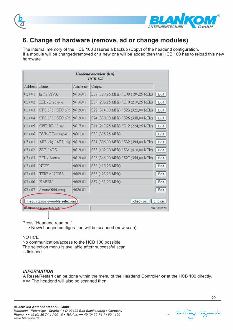
6. Change of hardware (remove, ad or change modules)The internal memory of the HCB 100 assures a backup (Copy) of the headend configuration.If a module will be changed/removed or a new one will be added then the HCB 100 has to reload this newhardware
A Reset/Restart can be done within the menu of the Headend Controller at the HCB 100 directly.==> The headend will also be scanned then
INFORMATIONor
Press “Headend read out”==> New/changed configuraiton will be scanned (new scan)
NOTICENo communication/access to the HCB 100 possibleThe selection menu is available afterr successful scanis finished
29
Hermann - Petersilge - Straße 1 D-07422 Bad Blankenburg
Phone: ++ 49 (0) 36 74 1 / 60 - 0 Telefax: ++ 49 (0) 36 74 1 / 60 - 100www.blankom.de
BLANKOM Antennentechnik GmbH�
�
� Germany
GmbHab
ANTENNENTECHNIK
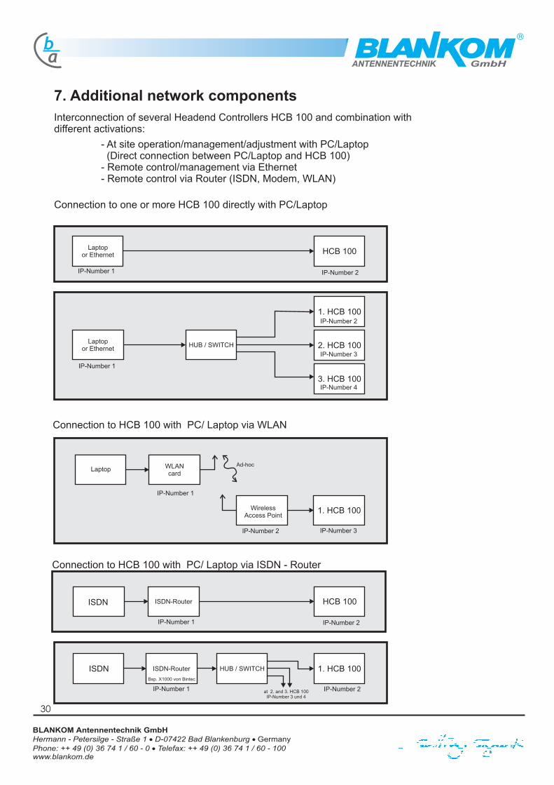
7. Additional network components
Connection to one or more HCB 100 directly with PC/Laptop
Interconnection of several Headend Controllers HCB 100 and combination withdifferent activations:
- At site operation/management/adjustment with PC/Laptop(Direct connection between PC/Laptop and HCB 100)
- Remote control/management via Ethernet- Remote control via Router (ISDN, Modem, WLAN)
Connection to HCB 100 with PC/ Laptop via ISDN - Router
HCB 100
1. HCB 100
2. HCB 100
3. HCB 100
1. HCB 100
HCB 100
1. HCB 100
HUB / SWITCH
HUB / SWITCHISDN-Router
ISDN-Router
Laptop
Laptopor Ethernet
Laptopor Ethernet
WLANcard
WirelessAccess Point
ISDN
ISDN
IP-Number 2at 2. and 3. HCB 100IP-Number 3 und 4
IP-Number 2
IP-Number 2 IP-Number 3
IP-Number 1
IP-Number 1
IP-Number 1
IP-Number 1
IP-Number 2
IP-Number 2
IP-Number 3
IP-Number 4
Ad-hoc
Bsp. X1000 von Bintec
IP-Number 1
Connection to HCB 100 with PC/ Laptop via WLAN
30
Hermann - Petersilge - Straße 1 D-07422 Bad Blankenburg
Phone: ++ 49 (0) 36 74 1 / 60 - 0 Telefax: ++ 49 (0) 36 74 1 / 60 - 100www.blankom.de
BLANKOM Antennentechnik GmbH�
�
� Germany

GmbHab
ANTENNENTECHNIK
Connection to HCB 100 via an analogue - Router
Network of several HCB 100- At site Controll/Management/Adjustments- REMOTE Controll/Management/Adjustmentsvia network connection- REMOTE Controll/Management/Adjustments via Router
HCB 100
1. HCB 100HUB / SWITCH
Router withintegrated
Modem
Router withintegratedModdem
analogueTelephoneconnection
analogueTelephoneconnection
IP-Number 2at 2. and 3. HCB 100IP-Number 3 and 4
IP-Number 2IP-Number 1
IP-Number 1Example: Prestige 100 MH from ZyXEL
1. HCB 100Laptop
ISDN-Router
2. HCB 100Ethernet
(LAN / WAN)HUB / SWITCH
with minimum6 Port´s
3. HCB 100ISDN
IP-Number 2
IP-Number 3
IP-Number 4
31
Hermann - Petersilge - Straße 1 D-07422 Bad Blankenburg
Phone: ++ 49 (0) 36 74 1 / 60 - 0 Telefax: ++ 49 (0) 36 74 1 / 60 - 100www.blankom.de
BLANKOM Antennentechnik GmbH�
�
� Germany


![842085 05 Handbuch TAV TMX Englisch[1]](https://static.fdokument.com/doc/165x107/577cc3561a28aba71195b942/842085-05-handbuch-tav-tmx-englisch1.jpg)