HY-150 ETA-05-0051_rebar-en
26
Diese Zulassung umfasst This Approval contains 26 Seiten einschließlich 17 Anhänge 26 pages including 17 annexes Diese Zulassung ersetzt This Approval replaces ETA-05/0051 mit Geltungsdauer vom 20.12.2007 bis 17.03.2010 ETA-05/0051 with validity from 20.12.2007 to 17.03.2010 Europäische Organisation für Technische Zulassungen European Organisation for Technical Approvals Deutsches Institut für Bautechnik Anstalt des öffentlichen Rechts Kolonnenstr. 30 L 10829 Berlin Germany Tel.: +49(0)30 787 30 0 Fax: +49(0)30 787 30 320 E-mail: [email protected] Internet: www.dibt.de Mitglied der EOTA Member of EOTA European Technical Appro val ETA -05/0051 English translation prepared by DIBt - Original version in German language Handelsbezeichnung Trade name Injektionssystem Hilti HIT-HY 150 Injection System Hilti HIT-HY 150 Zulassungsinhaber Holder of approval Hilti Aktiengesellschaft Business Unit Anchors 9494 Schaan FÜRSTENTUM LIECHTENSTEIN Zulassungsgegenstand und Verwendungsz weck Verbunddüb el in den Größen Ø 8 mm bis Ø 30 zur Verankerung im ungerissenen Beton Generic type and use of construction product Bonded anchor in the size of Ø 8 to Ø 30 for use in non-cracked concrete Geltungsdauer: Validity: vom from 22 October 2008 bis to 17 March 2010 Herstellwerk Manufacturing plant Hilti Werke
-
Upload
razvan-vasiluta -
Category
Documents
-
view
219 -
download
0
Transcript of HY-150 ETA-05-0051_rebar-en
8/12/2019 HY-150 ETA-05-0051_rebar-en
http://slidepdf.com/reader/full/hy-150-eta-05-0051rebar-en 1/26
Diese Zulassung umfasst
This Approval contains 26 Seiten einschließlich 17 Anhänge26 pages including 17 annexes
Diese Zulassung ersetztThis Approval replaces ETA-05/0051 mit Geltungsdauer vom 20.12.2007 bis 17.03.2010 ETA-05/0051 with validity from 20.12.2007 to 17.03.2010
E u r o p ä i s c h e O r g a n i s a t i o n f ü r T e c h n i s c h e Z u l a s s u n g e n
E u r o p e a n O r g a n i s a t i o n f o r T e c h n i c a l A p p r o v a l s
Deutsches Institut
für Bautechnik
Anstalt des öffentlichen Rechts
Kolonnenstr. 30 L10829 Berlin
GermanyTel.: +49(0)30 787 30 0Fax: +49(0)30 787 30 320E-mail: [email protected]: www.dibt.de
Mitglied der EOTA Member of EOTA
Eu r o p ean Tec h n i c al A p p r o val ETA-05/0051
English translation prepared by DIBt - Original version in German language
HandelsbezeichnungTrade name Injektionssystem Hilti HIT-HY 150 Injection System Hilti HIT-HY 150
Zulassungsinhaber Holder of approval
Hilti AktiengesellschaftBusiness Unit Anchors9494 SchaanFÜRSTENTUM LIECHTENSTEIN
Zulassungsgegenstandund Verwendungszweck
Verbunddübel in den Größen Ø 8 mm bis Ø 30 zurVerankerung im ungerissenen Beton
Generic type and use
of construction product Bonded anchor in the size of Ø 8 to Ø 30 for use in non-cracked concrete
Geltungsdauer:Validity:
vom from
22 October 2008
bisto
17 March 2010
Herstellwerk Manufacturing plant
Hilti Werke
8/12/2019 HY-150 ETA-05-0051_rebar-en
http://slidepdf.com/reader/full/hy-150-eta-05-0051rebar-en 2/26
Page 2 of ETA-05/0051, issued on 22 October 2008English translation by Deutsches Institut für Bautechnik (DIBt)
Z26092.08 De ut sc he s In s t i t ut fü r Ba ut ec hn ik 8.06.01-224/07
I LEGAL BASES AND GENERAL CONDITIONS
1 This European technical approval is issued by Deutsches Institut für Bautechnik inaccordance with:
- Council Directive 89/106/EEC of 21 December 1988 on the approximation of laws,
regulations and administrative provisions of Member States relating to constructionproducts1, modified by Council Directive 93/68/EEC2 and Regulation (EC) N° 1882/2003of the European Parliament and of the Council3;
- Gesetz über das In-Verkehr-Bringen von und den freien Warenverkehr mit Bauproduktenzur Umsetzung der Richtlinie 89/106/EWG des Rates vom 21. Dezember 1988 zurAngleichung der Rechts- und Verwaltungsvorschriften der Mitgliedstaaten überBauprodukte und anderer Rechtsakte der Europäischen Gemeinschaften(Bauproduktengesetz - BauPG) vom 28. April 19984, zuletzt geändert durch Gesetz vom06.01.20045;
- Common Procedural Rules for Requesting, Preparing and the Granting of Europeantechnical approvals set out in the Annex to Commission Decision 94/23/EC6;
- Guideline for European technical approval of "Metal anchors for use in concrete - Part 5:Bonded anchors", ETAG 001-05.
2 Deutsches Institut für Bautechnik is authorized to check whether the provisions of thisEuropean technical approval are met. Checking may take place in the manufacturing plant.Nevertheless, the responsibility for the conformity of the products to the European technicalapproval and for their fitness for the intended use remains with the holder of the Europeantechnical approval.
3 This European technical approval is not to be transferred to manufacturers or agents ofmanufacturers other than those indicated on page 1, or manufacturing plants other thanthose indicated on page 1 of this European technical approval.
4 This European technical approval may be withdrawn by Deutsches Institut für Bautechnik, in
particular pursuant to information by the Commission according to Article 5(1) of CouncilDirective 89/106/EEC.
5 Reproduction of this European technical approval including transmission by electronicmeans shall be in full. However, partial reproduction can be made with the written consent ofDeutsches Institut für Bautechnik. In this case partial reproduction has to be designated assuch. Texts and drawings of advertising brochures shall not contradict or misuse theEuropean technical approval.
6 The European technical approval is issued by the approval body in its official language. Thisversion corresponds fully to the version circulated within EOTA. Translations into otherlanguages have to be designated as such.
1 Official Journal of the European Communities L 40, 11.02.1989, p. 122 Official Journal of the European Communities L 220, 30.08.1993, p. 13 Official Journal of the European Union L 284, 31.10.2003, p. 254 Bundesgesetzblatt I, p. 8125 Bundesgesetzblatt I, p.2, 156 Official Journal of the European Communities L 17, 20.01.1994, p. 34
8/12/2019 HY-150 ETA-05-0051_rebar-en
http://slidepdf.com/reader/full/hy-150-eta-05-0051rebar-en 3/26
Page 3 of ETA-05/0051, issued on 22 October 2008English translation by Deutsches Institut für Bautechnik (DIBt)
Z26092.08 De ut sc he s In s t i t ut fü r Ba ut ec hn ik 8.06.01-224/07
II SPECIFIC CONDITIONS OF THE EUROPEAN TECHNICAL APPROVAL
1 Defini tion of product and intended use
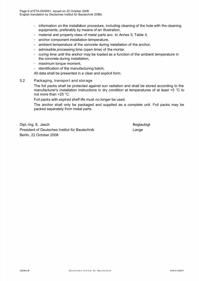
1.1 Definition of the construction productThe Injection System Hilti HIT-HY 150 for non-cracked concrete is a bonded anchorconsisting of a foil pack with injection mortar Hilti HIT-HY 150 and a steel element.
The steel elements are made of zinc coated steel (threaded rod HIT-V, HAS-(E), internalsleeve HIS-N), reinforcing bar BSt 500 S, stainless steel (threaded rod HIT-V-R, HAS-(E)R,internal sleeve HIS-RN) or high corrosion resistant steel (threaded rods HIT-V-HCR andHAS-(E)HCR).
The steel element is placed into a drilled hole filled with injection mortar and is anchored viathe bond between metal part, injection mortar and concrete.
An illustration of the product and intended use is given in Annex 1 and 2.
1.2 Intended useThe anchor is intended to be used for anchorages for which requirements for mechanicalresistance and stability and safety in use in the sense of the Essential Requirements 1 and 4of Council Directive 89/106 EEC shall be fulfilled and failure of anchorages made with theseproducts would cause risk to human life and/or lead to considerable economicconsequences. Safety in case of fire (Essential Requirement 2) is not covered in thisEuropean technical approval. The anchor is to be used only for anchorages subject to staticor quasi-static loading in reinforced or unreinforced normal weight concrete of strengthclasses C20/25 at minimum and C50/60 at most according to EN 206:2000-12.
The anchor may be used in non-cracked concrete only.
The anchor may be installed in dry or wet concrete; it must not be installed in flooded holes.
The anchor may be used in the following temperature ranges:Temperature range I: -40 °C to +40 °C (max long term temperature +24 °C and
max short term temperature +40 °C)Temperature range II: -40 °C to +80 °C (max long term temperature +50 °C and
max short term temperature +80 °C)Temperature range III: -40 °C to +120 °C (max long term temperature +72 °C and
max short term temperature +120 °C)
Elements made of zinc coated steel (threaded rods HIT-V and HAS-(E), internal sleeveHIS-N):
The element made of electroplated or hot-dipped galvanised steel may only be used in
structures subject to dry internal conditions.Elements made of stainless steel (threaded rods HIT-V-R and HAS-(E)R, internal sleeveHIS-RN):
The element made of stainless steel 1.4401, 1.4404, 1.4578, 1.4571, 1.4439 or 1.4362 maybe used in structures subject to dry internal conditions and also in structures subject toexternal atmospheric exposure (including industrial and marine environment), or exposure topermanently damp internal conditions, if no particular aggressive conditions exist. Suchparticular aggressive conditions are e.g. permanent, alternating immersion in seawater orthe splash zone of seawater, chloride atmosphere of indoor swimming pools or atmospherewith extreme chemical pollution (e.g. in desulphurization plants or road tunnels where de-icing materials are used).
8/12/2019 HY-150 ETA-05-0051_rebar-en
http://slidepdf.com/reader/full/hy-150-eta-05-0051rebar-en 4/26
Page 4 of ETA-05/0051, issued on 22 October 2008English translation by Deutsches Institut für Bautechnik (DIBt)
Z26092.08 De ut sc he s In s t i t ut fü r Ba ut ec hn ik 8.06.01-224/07
Elements made of high corrosion resistant steel (threaded rods HIT-V-HCR andHAS-(E)HCR):
The element made of high corrosion resistant steel 1.4529 or 1.4565 may be used instructures subject to dry internal conditions and also in structures subject to externalatmospheric exposure, in permanently damp internal conditions or in other particular
aggressive conditions. Such particular aggressive conditions are e. g. permanent, alternatingimmersion in seawater or the splash zone of seawater, chloride atmosphere of indoorswimming pools or atmosphere with chemical pollution (e.g. in desulphurization plants orroad tunnels where de-icing materials are used).
Elements made of reinforcing bars BSt 500 S:
Post-installed reinforcing bars may be used as anchor designed in accordance with theEOTA Technical Report TR 029 only. Such applications are e.g. concrete overlay or sheardowel connections or the connections of a wall predominantly loaded by shear andcompression forces with the foundation, where the reinforcing bars act as dowels to take upshear forces. Connections with post-installed reinforcing bars in concrete structuresdesigned in accordance with EN 1992-1-1: 2004 are not covered by this European technicalapproval.
The provisions made in this European technical approval are based on an assumed workinglife of the anchor of 50 years. The indications given on the working life cannot be interpretedas a guarantee given by the producer, but are to be regarded only as a means for choosingthe right products in relation to the expected economically reasonable working life of theworks.
2 Characteristics of the product and methods of verification
2.1 Characteristi cs of the product
The anchor corresponds to the drawings and provisions given in Annexes 3 to 5. The
characteristic material values, dimensions and tolerances of the anchor not indicated inAnnexes 3 to 5 shall correspond to the respective values laid down in the technicaldocumentation7 of this European technical approval.
The characteristic values for the design of anchorages are given in Annexes 10 to 17.
The two components of the injection mortar Hilti HIT-HY 150 are delivered in unmixedcondition in foil packs of sizes 330 ml, 500 ml or 1400 ml according to Annex 1. Each foilpack is marked with the identifying mark "HY 150", with the production date and expiry date.
Each threaded rod HIT-V is marked with the marking of steel grade and length inaccordance with Annex 3. Each threaded rod made of stainless steel is marked with theadditional letter "R". Each threaded rod made of high corrosion resistant steel is marked withthe additional letter "HCR".
Each threaded rod HAS-(E) is marked with the identifying mark – "H" and the embossingaccordance with Annex 3. Each threaded rod made of zinc coated steel is marked with theadditional embossing "1". Each threaded rod made of stainless steel is marked with theadditional embossing "=". Each threaded rod made of high corrosion resistant steel ismarked with the additional embossing "CR".
7 The technical documentation of this European technical approval is deposited at the Deutsches Institut fürBautechnik and, as far as relevant for the tasks of the approved bodies involved in the attestation of conformityprocedure, is handed over to the approved bodies.
8/12/2019 HY-150 ETA-05-0051_rebar-en
http://slidepdf.com/reader/full/hy-150-eta-05-0051rebar-en 5/26
Page 5 of ETA-05/0051, issued on 22 October 2008English translation by Deutsches Institut für Bautechnik (DIBt)
Z26092.08 De ut sc he s In s t i t ut fü r Ba ut ec hn ik 8.06.01-224/07
Each internal sleeve made of zinc coated steel is marked with "HIS-N" according to Annex 4.Each internal sleeve made of stainless steel is marked with "HIS-RN" according to Annex 4.
Explanations of the markings are given in Annexes 3 and 4.
Elements made of reinforcing bar BSt 500 S shall comply with the specifications given inAnnex 5.
The marking of embedment depth may be done on jobsite.
2.2 Methods of verification
The assessment of fitness of the anchor for the intended use in relation to the requirementsfor mechanical resistance and stability and safety in use in the sense of the EssentialRequirements 1 and 4 has been made in accordance with the "Guideline for Europeantechnical approval of Metal Anchors for Use in Concrete", Part 1 "Anchors in general" andPart 5 "Bonded anchors", on the basis of Option 7.
In addition to the specific clauses relating to dangerous substances contained in thisEuropean technical approval, there may be other requirements applicable to the productsfalling within its scope (e.g. transposed European legislation and national laws, regulations
and administrative provisions). In order to meet the provisions of the Construction ProductsDirective, these requirements need also to be complied with, when and where they apply.
3 Evaluation and attestation of conformity and CE marking
3.1 System of attestation of conformity
According to the Decision 96/582/EG of the European Commission8 system 2(i) (referred toas System 1) of the attestation of conformity applies.
This system of attestation of conformity is defined as follows:
System 1: Certification of the conformity of the product by an approved certification body onthe basis of:
(a) Tasks for the manufacturer:
(1) factory production control;
(2) further testing of samples taken at the factory by the manufacturer in accordancewith a prescribed test plan;
(b) Tasks for the approved body:
(3) initial type–testing of the product;
(4) initial inspection of factory and of factory production control;
(5) continuous surveillance, assessment and approval of factory production control.
Note: Approved bodies are also referred to as "notified bodies".
3.2 Responsibilities
3.2.1 Tasks for the manufacturer
3.2.1.1 Factory production control
The manufacturer shall exercise permanent internal control of production. All the elements,requirements and provisions adopted by the manufacturer shall be documented in asystematic manner in the form of written policies and procedures, including records of resultsperformed. This production control system shall insure that the product is in conformity withthis European technical approval.
8 Official Journal of the European Communities L 254 of 08.10.1996
8/12/2019 HY-150 ETA-05-0051_rebar-en
http://slidepdf.com/reader/full/hy-150-eta-05-0051rebar-en 6/26
Page 6 of ETA-05/0051, issued on 22 October 2008English translation by Deutsches Institut für Bautechnik (DIBt)
Z26092.08 De ut sc he s In s t i t ut fü r Ba ut ec hn ik 8.06.01-224/07
The manufacturer may only use initial/raw/constituent materials stated in the technicaldocumentation of this European technical approval.
The factory production control shall be in accordance with the control plan of November2007 which is part of the technical documentation of this European technical approval . Thecontrol plan is laid down in the context of the factory production control system operated by
the manufacturer and deposited at Deutsches Institut für Bautechnik.9
The results of factory production control shall be recorded and evaluated in accordance withthe provisions of the control plan.
3.2.1.2 Other tasks for the manufacturer
The manufacturer shall, on the basis of a contract, involve a body which is approved for thetasks referred to in section 3.1 in the field of anchors in order to undertake the actions laiddown in section 3.2.2 For this purpose, the control plan referred to in sections 3.2.1.1 and3.2.2 shall be handed over by the manufacturer to the approved body involved.
The manufacturer shall make a declaration of conformity, stating that the constructionproduct is in conformity with the provisions of this European technical approval.
3.2.2 Tasks for the approved bodies
The approved body shall perform the- initial type-testing of the product,
- initial inspection of factory and of factory production control,
- continuous surveillance, assessment and approval of factory production control,
in accordance with the provisions laid down in the control plan.
The approved body shall retain the essential points of its actions referred to above and statethe results obtained and conclusions drawn in a written report.
The approved certification body involved by the manufacturer shall issue an EC certificate ofconformity of the product stating the conformity with the provisions of this Europeantechnical approval.
In cases where the provisions of the European technical approval and its control plan are nolonger fulfilled the certification body shall withdraw the certificate of conformity and informDeutsches Institut für Bautechnik without delay.
3.3 CE marking
The CE marking shall be affixed on each packaging of the anchor. The letters ”CE” shall befollowed by the identification number of the approved certification body, where relevant, andbe accompanied by the following additional information:
- the name and address of the producer (legal entity responsible for the manufacture),
- the last two digits of the year in which the CE marking was affixed,
- the number of the EC certificate of conformity for the product,
- the number of the European technical approval,
- the number of the guideline for European technical approval,
- use category (ETAG 001-1, Option 7),
- size
9 The control plan is a confidential part of the European technical approval and only handed over to the approvedbody involved in the procedure of attestation of conformity. See section 3.2.2.
8/12/2019 HY-150 ETA-05-0051_rebar-en
http://slidepdf.com/reader/full/hy-150-eta-05-0051rebar-en 7/26
Page 7 of ETA-05/0051, issued on 22 October 2008English translation by Deutsches Institut für Bautechnik (DIBt)
Z26092.08 De ut sc he s In s t i t ut fü r Ba ut ec hn ik 8.06.01-224/07
4 Assumptions under which the fitness of the product for the intended use was
favourably assessed
4.1 Manufacturing
The European technical approval is issued for the product on the basis of agreed
data/information, deposited at Deutsches Institut für Bautechnik, which identifies the productthat has been assessed and judged. Changes to the product or production process, whichcould result in this deposited data/information being incorrect, should be notified toDeutsches Institut für Bautechnik before the changes are introduced. Deutsches Institut fürBautechnik will decide whether or not such changes affect the approval and consequentlythe validity of the CE marking on the basis of the approval and if so whether furtherassessment or alterations to the approval shall be necessary.
4.2 Installation
4.2.1 Design of anchorages
The fitness of the anchor for the intended use is given under the following conditions:
The anchorages are designed in accordance with the EOTA Technical Report TR 029"Design of bonded anchors"10 under the responsibility of an engineer experienced inanchorages and concrete work.
Post-installed reinforcing bars may be used as anchor designed in accordance with theEOTA Technical Report TR 029 only. The basic assumptions for the design according toanchor theory shall be observed. This includes the consideration of tension and shear loadsand the corresponding failure modes as well as the assumption that the base material(concrete structural element) remains essentially in the serviceability limit state (either non-cracked or cracked) when the connection is loaded to failure. Such applications are e.g.concrete overlay or shear dowel connections or the connections of a wall predominantlyloaded by shear and compression forces with the foundation, where the reinforcing bars actas dowels to take up shear forces. Connections with reinforcing bars in concrete structuresdesigned in accordance with EN1992-1-1: 2004 (e.g. connection of a wall loaded withtension forces in one layer of the reinforcement with the foundation) are not covered by thisEuropean technical approval.
For the internal sleeve only fastening screws or threaded rods made of galvanised steel withthe minimum strength class 8.8 EN ISO 898-1 shall be used. The minimum and maximumthread engagement length hs of the fastening screw or the threaded rod for installation of thefixture shall be met the requirements according to Annex 4, Table 2. The length of thefastening screw or the threaded rod shall be determined depending on thickness of fixture,admissible tolerances, available thread length and minimum and maximum threadengagement length hs.
Verifiable calculation notes and drawings are prepared taking account of the loads to beanchored.The position of the anchor is indicated on the design drawings (e.g. position of the anchorrelative to reinforcement or to supports, etc.).
4.2.2 Installation of anchors
The fitness for use of the anchor can only be assumed if the anchor is installed as follows:
- anchor installation carried out by appropriately qualified personnel and under thesupervision of the person responsible for technical matters of the site,
- anchor installation in accordance with the manufacturer’s specifications and drawingsusing the tools indicated in the technical documentation of this European technicalapproval,
10 The Techncial Report TR 029 "Design of bonded anchors" is published in English on EOTA websitewww.eota.eu.
8/12/2019 HY-150 ETA-05-0051_rebar-en
http://slidepdf.com/reader/full/hy-150-eta-05-0051rebar-en 8/26
Page 8 of ETA-05/0051, issued on 22 October 2008English translation by Deutsches Institut für Bautechnik (DIBt)
Z26092.08 De ut sc he s In s t i t ut fü r Ba ut ec hn ik 8.06.01-224/07
- use of the anchor only as supplied by the manufacturer without exchanging thecomponents of an anchor,
- commercial standard threaded rods, washers and hexagon nuts may also be used if thefollowing requirements are fulfilled:
• material, dimensions and mechanical properties of the metal parts according to the
specifications given in Annex 5, Table 4,• confirmation of material and mechanical properties of the metal parts by inspection
certificate 3.1 according to EN 10204:2004, the documents should be stored,
• marking of the threaded rod with the envisage embedment depth. This may be doneby the manufacturer of the rod or the person on jobsite.
- checks before placing the anchor to ensure that the strength class of the concrete inwhich the anchor is to be placed is in the range given and is not lower than that of theconcrete to which the characteristic loads apply,
- check of concrete being well compacted, e.g. without significant voids,- marking and keeping the effective anchorage depth,- edge distance and spacing not less than the specified values without minus tolerances,- positioning of the drill holes without damaging the reinforcement,- drilling by hammer-drilling,- in case of aborted drill hole: the drill hole shall be filled with mortar,- the anchor must not be installed in flooded holes,- cleaning the drill hole in accordance with Annexes 6 to 8,- the anchor component installation temperature shall be at least +5 °C; during curing of
the chemical mortar the temperature of the concrete must not fall below -5 °C; observingthe curing time according to Annex 8, Table 5 until the anchor may be loaded,
- fastening screws or threaded rods (including nut and washer) for the internal sleeves HIS-(R)N must be made of appropriate steel grade and property class,
- installation torque moments are not required for functioning of the anchor. However, thetorque moments given in Annexes 3 and 4 must not be exceeded.
5 Recommendations concerning packaging, transport and storage
5.1 Respons ibili ty of the manufacturer
The manufacturer is responsible to ensure that the information on the specific conditionsaccording to 1 and 2 including Annexes referred to and 4.2.1 and 4.2.2 is given to those whoare concerned. This information may be made by reproduction of the respective parts of theEuropean technical approval.
In addition all installation data shall be shown clearly on the package and/or on an enclosedinstruction sheet, preferably using illustration(s).
The minimum data required are:
- drill bit diameter,- hole depth,- diameter of anchor rod,- minimum effective anchorage depth,
8/12/2019 HY-150 ETA-05-0051_rebar-en
http://slidepdf.com/reader/full/hy-150-eta-05-0051rebar-en 9/26
Page 9 of ETA-05/0051, issued on 22 October 2008English translation by Deutsches Institut für Bautechnik (DIBt)
Z26092.08 De ut sc he s In s t i t ut fü r Ba ut ec hn ik 8.06.01-224/07
- information on the installation procedure, including cleaning of the hole with the cleaningequipments, preferably by means of an illustration,
- material and property class of metal parts acc. to Annex 5, Table 4,- anchor component installation temperature,- ambient temperature of the concrete during installation of the anchor,
- admissible processing time (open time) of the mortar,- curing time until the anchor may be loaded as a function of the ambient temperature in
the concrete during installation,- maximum torque moment,- identification of the manufacturing batch,All data shall be presented in a clear and explicit form.
5.2 Packaging, transport and storage
The foil packs shall be protected against sun radiation and shall be stored according to themanufacturer's installation instructions in dry condition at temperatures of at least +5 °C tonot more than +25 °C.
Foil packs with expired shelf life must no longer be used.The anchor shall only be packaged and supplied as a complete unit. Foil packs may bepacked separately from metal parts.
Dipl.-Ing. E. Jasch Beglaubigt
President of Deutsches Institut für Bautechnik Lange
Berlin, 22 October 2008
8/12/2019 HY-150 ETA-05-0051_rebar-en
http://slidepdf.com/reader/full/hy-150-eta-05-0051rebar-en 10/26

8/12/2019 HY-150 ETA-05-0051_rebar-en
http://slidepdf.com/reader/full/hy-150-eta-05-0051rebar-en 11/26
Page 11 of European technical approval ETA – 05/0051, issued on 22 October 2008English translation prepared by DIBt.
Injection System Hilti HIT-HY 150
of Europeantechnical approval
ETA – 05/0051
d 0
h0 = hef
h
Use category: Installation in dry or water saturated concrete, (not in flooded holes)
Temperature range I: -40°C to +40°C ( max long term temperature +24°C andmax short term temperature +40°C)
Temperature range II: -40°C to +80°C ( max long term temperature +50°C andmax short term temperature +80°C)
Temperature range III: -40°C to +120°C ( max long term temperature +72°C andmax short term temperature +120°C)
Annex 2
Installed anchor and intended use
Fixture
Thickness tfix
d 0
Marking of theembedment depth
Bore hole depth h0 = anchorage depth hef
Thickness of concrete member h
d 0
hS
d f
h0 = hef
Marking of theembedment depth
8/12/2019 HY-150 ETA-05-0051_rebar-en
http://slidepdf.com/reader/full/hy-150-eta-05-0051rebar-en 12/26
Page 12 of European technical approval ETA – 05/0051, issued on 22 October 2008English translation prepared by DIBt.
Injection System Hilti HIT-HY 150
of Europeantechnical approval
ETA – 05/0051
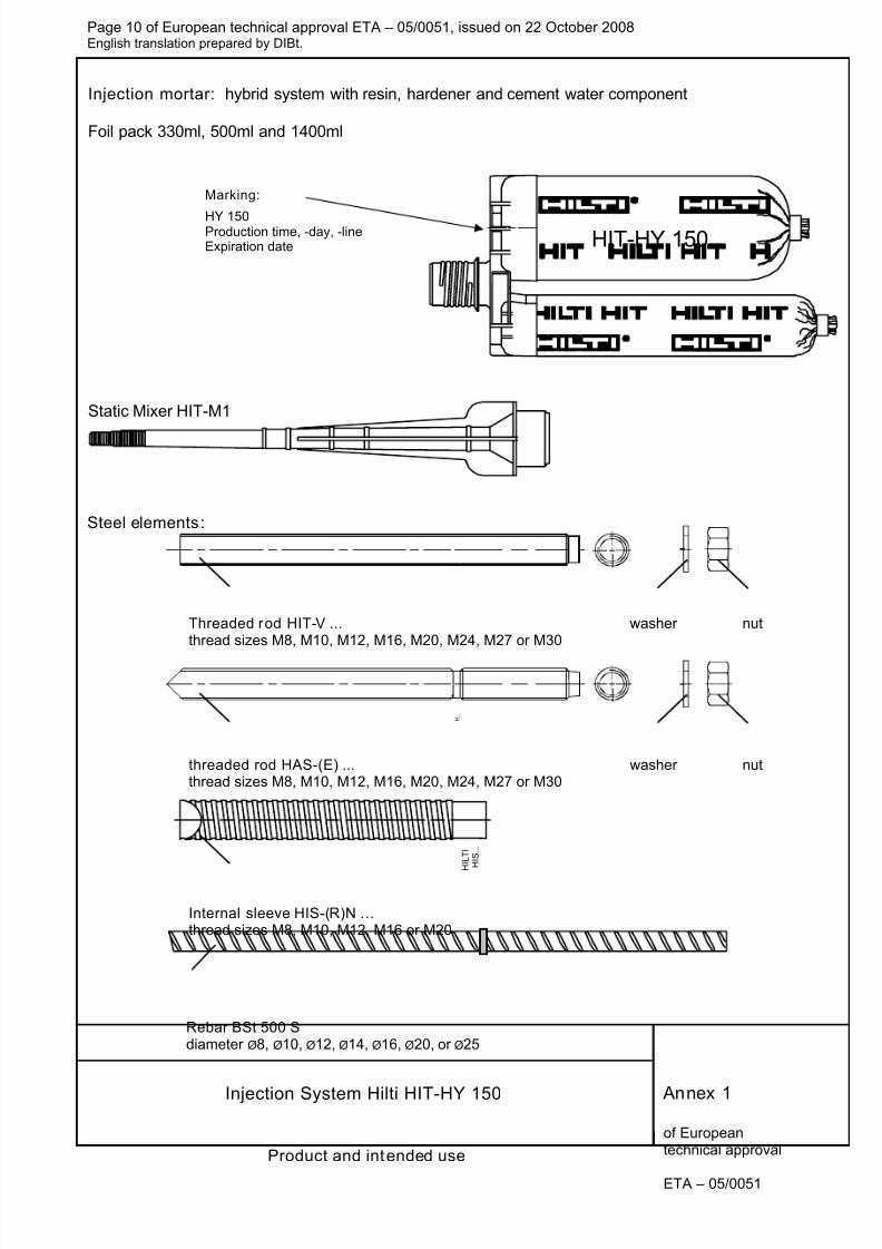
Table 1: Installation parameters of anchor rod HIT-V... and HAS-(E)...
HIT-HY 150 wi th HIT-V-… and HAS-(E)... M8 M10 M12 M16 M20 M24 M27 M30
Diameter of element d [mm] 8 10 12 16 20 24 27 30
min [mm] 60 60 70 80 90 100 110 120Range of anchorage depth hef and bore hole depth h0
HIT-V-... max [mm] 160 200 240 320 400 480 540 600Effective anchorage depthHAS-(E)...
hef [mm] 80 90 110 125 170 210 240 270
Nominal diameter of drill bit d0 [mm] 10 12 14 18 24 28 30 35
Diameter of clearance hole inthe fixture df [mm] 9 12 14 18 22 26 30 33
Maximum torque moment Tmax [Nm] 10 20 40 80 150 200 270 300
Minimum thickness of concretemember
hmin [mm]hef + 30 mm≥ 100 mm
hef + 2do
Minimum spacing smin [mm] 40 50 60 80 100 120 135 150
Minimum edge distance cmin [mm] 40 50 60 80 100 120 135 150
HIT-V…
HAS-(E)…
Annex 3
Installation parameterThreaded rod HIT-V and HAS-(E)
Head marking:5.8 - l (= HIT-V-5.8) M…x l; M8 - M245.8F - l (= HIT-V-5.8F) M…x l; M8 - M248.8 - l (= HIT-V-8.8) M…x l; M27, M308.8F - l (= HIT-V-8.8F) M…x l; M27, M30R - l (= HIT-V-R) M…x lHCR - l (= HIT-V-HCR) M…x l
d
1 2 3
l (total length of element)
d
1
H . .
Effective anchorage depth hef Embedment depth marking
2 3Marking: identifying mark - H, embossing "1" HAS-(E)identifying mark - H, embossing “=” HAS-(E)Ridentifying mark - H, embossing “CR” HAS-(E)HCR
8/12/2019 HY-150 ETA-05-0051_rebar-en
http://slidepdf.com/reader/full/hy-150-eta-05-0051rebar-en 13/26
Page 13 of European technical approval ETA – 05/0051, issued on 22 October 2008English translation prepared by DIBt.
Injection System Hilti HIT-HY 150
of Europeantechnical approval
ETA – 05/0051
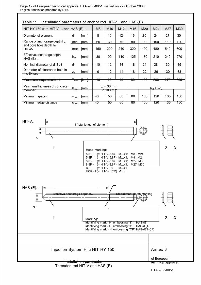
Table 2: Installation parameters of internal sleeve HIS-(R)N
HIT-HY 150 wi th HIS-(R)N M 8 M 10 M 12 M 16 M 20
Diameter of sleeve d1 [mm] 12,5 16,5 20,5 25,4 27,6
Effective anchorage depth hef [mm] 90 110 125 170 205
Nominal diameter of drill bit d0 [mm] 14 18 22 28 32
Depth of drilled hole h0 [mm] 90 110 125 170 205
Diameter of clearance holein the fixture
df [mm] 9 12 14 18 22
Maximum torque moment Tmax [Nm] 10 20 40 80 150
Thread engagement lengthmin-max
hs [mm] 8-20 10-25 12-30 16-40 20-50
Minimum thickness ofconcrete member
hmin [mm] 120 150 170 230 270
Minimum spacing smin [mm] 40 45 55 65 90
Minimum edge distance cmin [mm] 40 45 55 65 90
HIS-(R)N…
Table 3: Installation parameters of anchor element rebar
HIT-HY 150 wi th BSt 500 S Ø8 Ø10 Ø12 Ø14 Ø16 Ø20 Ø25
Diameter of element d [mm] 8 10 12 14 16 20 25
min [mm] 60 60 70 75 80 90 100Range of anchorage depth (hef )and bore hole depth (h0) max [mm] 160 200 240 280 320 400 500
Nominal diameter of drill bit d0 [mm] 10 / 12
1)12
/ 14
1)14
/ 16
1)18 20 25 32
Minimum thickness ofconcrete member
hmin [mm]hef + 30mm≥ 100 mm
hef + 2do
Minimum spacing smin [mm] 40 50 60 70 80 100 125Minimum edge distance cmin [mm] 40 50 60 70 80 100 125
1) Both given values for drill bit diameter can be used.
Rebar
Annex 4
Installation parameterInternal sleeve HIS-(R)N and rebar
Marking:Identifying mark - HILTI andembossing "HIS-N" (for C-steel)embossin "HIS-RN" for stainless steel
d 1
H I L T I
H I S . . .
Effective anchorage depth hef
Marking of the embedment depth
Effective anchorage depth hef
8/12/2019 HY-150 ETA-05-0051_rebar-en
http://slidepdf.com/reader/full/hy-150-eta-05-0051rebar-en 14/26
Page 14 of European technical approval ETA – 05/0051, issued on 22 October 2008English translation prepared by DIBt.
Injection System Hilti HIT-HY 150
of Europeantechnical approval
ETA – 05/0051
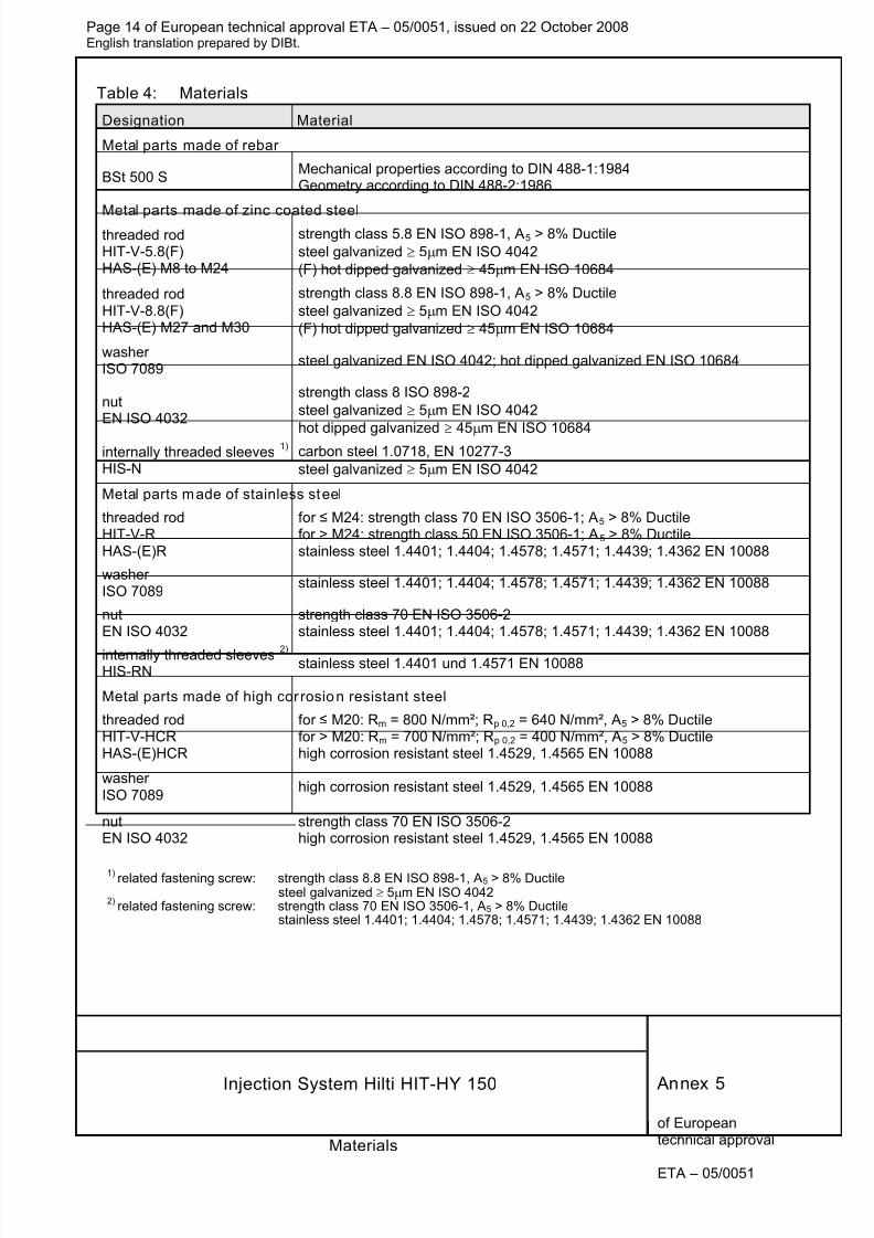
Table 4: Materials
Designation Material
Metal parts made of rebar
BSt 500 SMechanical properties according to DIN 488-1:1984Geometry according to DIN 488-2:1986
Metal parts made of zinc coated steelthreaded rodHIT-V-5.8(F)HAS-(E) M8 to M24
strength class 5.8 EN ISO 898-1, A5 > 8% Ductile
steel galvanized ≥ 5μm EN ISO 4042
(F) hot dipped galvanized ≥ 45μm EN ISO 10684
threaded rodHIT-V-8.8(F)HAS-(E) M27 and M30
strength class 8.8 EN ISO 898-1, A5 > 8% Ductile
steel galvanized ≥ 5μm EN ISO 4042
(F) hot dipped galvanized ≥ 45μm EN ISO 10684
washerISO 7089
steel galvanized EN ISO 4042; hot dipped galvanized EN ISO 10684
nutEN ISO 4032
strength class 8 ISO 898-2
steel galvanized ≥ 5μm EN ISO 4042
hot dipped galvanized ≥ 45μm EN ISO 10684internally threaded sleeves
1)
HIS-N
carbon steel 1.0718, EN 10277-3
steel galvanized ≥ 5μm EN ISO 4042
Metal parts made of stainless steel
threaded rodHIT-V-RHAS-(E)R
for ≤ M24: strength class 70 EN ISO 3506-1; A5 > 8% Ductilefor > M24: strength class 50 EN ISO 3506-1; A5 > 8% Ductilestainless steel 1.4401; 1.4404; 1.4578; 1.4571; 1.4439; 1.4362 EN 10088
washerISO 7089
stainless steel 1.4401; 1.4404; 1.4578; 1.4571; 1.4439; 1.4362 EN 10088
nutEN ISO 4032
strength class 70 EN ISO 3506-2stainless steel 1.4401; 1.4404; 1.4578; 1.4571; 1.4439; 1.4362 EN 10088
internally threaded sleeves 2)
HIS-RNstainless steel 1.4401 und 1.4571 EN 10088
Metal parts made of high cor rosion resistant steel
threaded rodHIT-V-HCRHAS-(E)HCR
for ≤ M20: Rm = 800 N/mm²; Rp 0,2 = 640 N/mm², A5 > 8% Ductilefor > M20: Rm = 700 N/mm²; Rp 0,2 = 400 N/mm², A5 > 8% Ductilehigh corrosion resistant steel 1.4529, 1.4565 EN 10088
washerISO 7089
high corrosion resistant steel 1.4529, 1.4565 EN 10088
nutEN ISO 4032
strength class 70 EN ISO 3506-2high corrosion resistant steel 1.4529, 1.4565 EN 10088
1)related fastening screw: strength class 8.8 EN ISO 898-1, A5 > 8% Ductile
steel galvanized ≥ 5μm EN ISO 40422)
related fastening screw: strength class 70 EN ISO 3506-1, A5 > 8% Ductilestainless steel 1.4401; 1.4404; 1.4578; 1.4571; 1.4439; 1.4362 EN 10088
Annex 5
Materials
8/12/2019 HY-150 ETA-05-0051_rebar-en
http://slidepdf.com/reader/full/hy-150-eta-05-0051rebar-en 15/26
Page 15 of European technical approval ETA – 05/0051, issued on 22 October 2008English translation prepared by DIBt.
Injection System Hilti HIT-HY 150
of Europeantechnical approval
ETA – 05/0051
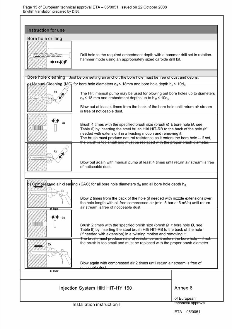
Instruction for use
Bore hole drilling
Drill hole to the required embedment depth with a hammer drill set in rotation-hammer mode using an appropriately sized carbide drill bit.
Bore hole cleaning Just before setting an anchor, the bore hole must be free of dust and debris.
a) Manual Cleaning (MC) for bore hole diameters d0 ≤ 18mm and bore hole depth h0 ≤ 10dS
The Hilti manual pump may be used for blowing out bore holes up to diametersd0 ≤ 18 mm and embedment depths up to hef ≤ 10dS.
Blow out at least 4 times from the back of the bore hole until return air streamis free of noticeable dust.
Brush 4 times with the specified brush size (brush Ø ≥ bore hole Ø, seeTable 6) by inserting the steel brush Hilti HIT-RB to the back of the hole (ifneeded with extension) in a twisting motion and removing it.The brush must produce natural resistance as it enters the bore hole -- if not,the brush is too small and must be replaced with the proper brush diameter.
Blow out again with manual pump at least 4 times until return air stream is freeof noticeable dust.
b) Compressed air cl eaning (CAC) for all bore hole diameters d0 and all bore hole depth h0
Blow 2 times from the back of the hole (if needed with nozzle extension) overthe hole length with oil-free compressed air (min. 6 bar at 6 m³/h) until returnair stream is free of noticeable dust.
Brush 2 times with the specified brush size (brush Ø ≥ bore hole Ø, see
Table 6) by inserting the steel brush Hilti HIT-RB to the back of the hole(if needed with extension) in a twisting motion and removing it.The brush must produce natural resistance as it enters the bore hole -- if not,the brush is too small and must be replaced with the proper brush diameter.
Blow again with compressed air 2 times until return air stream is free ofnoticeable dust.
Annex 6
Installation instruction I
6 bar
6 bar
8/12/2019 HY-150 ETA-05-0051_rebar-en
http://slidepdf.com/reader/full/hy-150-eta-05-0051rebar-en 16/26
Page 16 of European technical approval ETA – 05/0051, issued on 22 October 2008English translation prepared by DIBt.
Injection System Hilti HIT-HY 150
of Europeantechnical approval
ETA – 05/0051
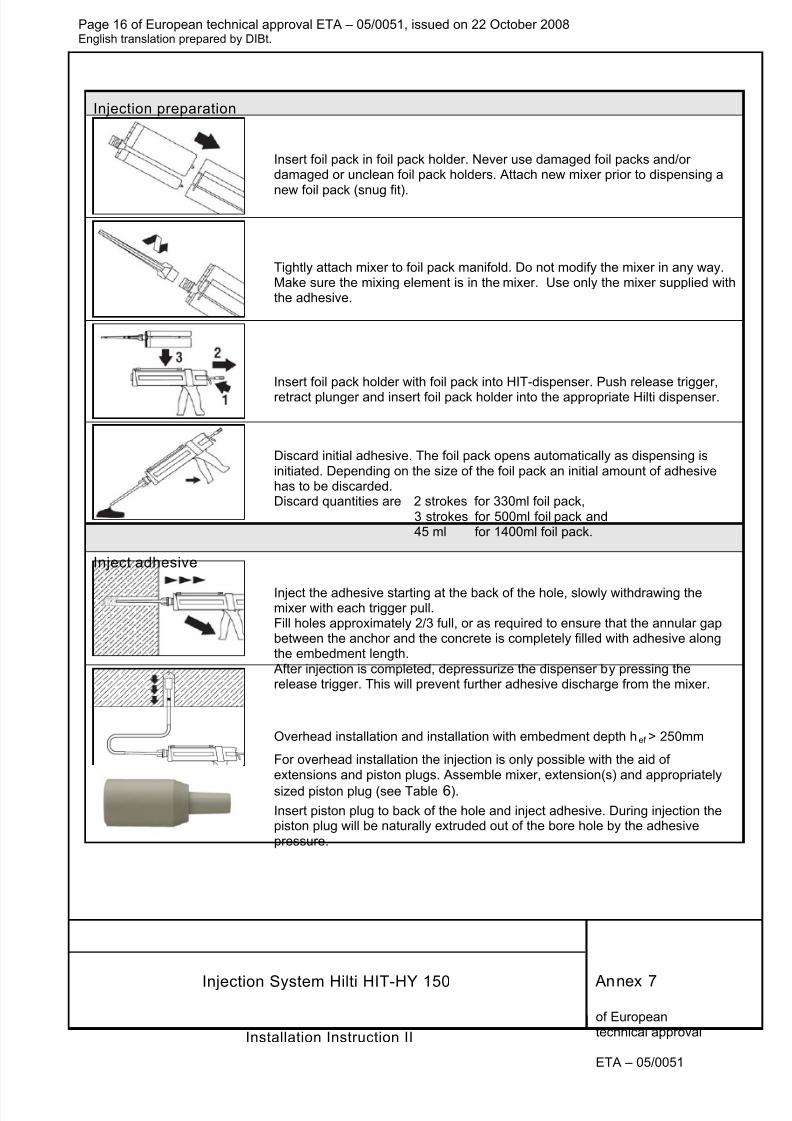
Injection preparation
Insert foil pack in foil pack holder. Never use damaged foil packs and/ordamaged or unclean foil pack holders. Attach new mixer prior to dispensing a
new foil pack (snug fit).
Tightly attach mixer to foil pack manifold. Do not modify the mixer in any way.Make sure the mixing element is in the mixer. Use only the mixer supplied withthe adhesive.
Insert foil pack holder with foil pack into HIT-dispenser. Push release trigger,
retract plunger and insert foil pack holder into the appropriate Hilti dispenser.
Discard initial adhesive. The foil pack opens automatically as dispensing isinitiated. Depending on the size of the foil pack an initial amount of adhesivehas to be discarded.Discard quantities are 2 strokes for 330ml foil pack,
3 strokes for 500ml foil pack and45 ml for 1400ml foil pack.
Inject adhesive
Inject the adhesive starting at the back of the hole, slowly withdrawing themixer with each trigger pull.Fill holes approximately 2/3 full, or as required to ensure that the annular gapbetween the anchor and the concrete is completely filled with adhesive alongthe embedment length.
After injection is completed, depressurize the dispenser by pressing therelease trigger. This will prevent further adhesive discharge from the mixer.
Overhead installation and installation with embedment depth hef > 250mm
For overhead installation the injection is only possible with the aid ofextensions and piston plugs. Assemble mixer, extension(s) and appropriately
sized piston plug (see Table 6).
Insert piston plug to back of the hole and inject adhesive. During injection thepiston plug will be naturally extruded out of the bore hole by the adhesivepressure.
Annex 7
Installation Instruction II
8/12/2019 HY-150 ETA-05-0051_rebar-en
http://slidepdf.com/reader/full/hy-150-eta-05-0051rebar-en 17/26
Page 17 of European technical approval ETA – 05/0051, issued on 22 October 2008English translation prepared by DIBt.
Injection System Hilti HIT-HY 150
of Europeantechnical approval
ETA – 05/0051
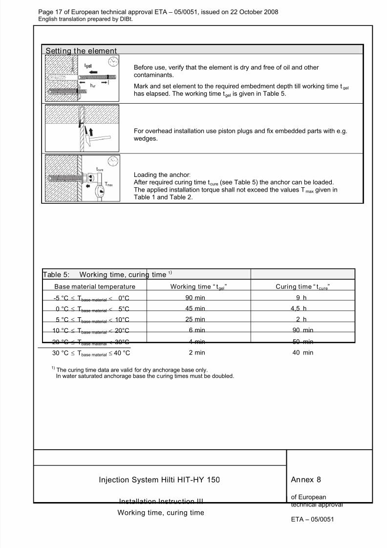
Setting the element
hef
Before use, verify that the element is dry and free of oil and othercontaminants.
Mark and set element to the required embedment depth till working time tgel
has elapsed. The working time tgel is given in Table 5.
For overhead installation use piston plugs and fix embedded parts with e.g.wedges.
Loading the anchor: After required curing time tcure (see Table 5) the anchor can be loaded.
The applied installation torque shall not exceed the values Tmax given inTable 1 and Table 2.
Table 5: Working time, curing time 1)
Base material temperature Working time “ tgel” Curing time “ tcure”-5 °C ≤ Tbase material < 0°C 90 min 9 h
0 °C ≤ Tbase material < 5°C 45 min 4,5 h
5 °C ≤ Tbase material < 10°C 25 min 2 h
10 °C ≤ Tbase material < 20°C 6 min 90 min
20 °C ≤ Tbase material < 30°C 4 min 50 min
30 °C ≤ Tbase material ≤ 40 °C 2 min 40 min
1) The curing time data are valid for dry anchorage base only.In water saturated anchorage base the curing times must be doubled.
Annex 8
Installation Instruction III
Working time, curing time
tcure
Tmax

8/12/2019 HY-150 ETA-05-0051_rebar-en
http://slidepdf.com/reader/full/hy-150-eta-05-0051rebar-en 18/26
Page 18 of European technical approval ETA – 05/0051, issued on 22 October 2008English translation prepared by DIBt.
Injection System Hilti HIT-HY 150
of Europeantechnical approval
ETA – 05/0051
Table 6: Bore hole cleaning: Steel brush – Installation with Piston Plug
Element Size
Nominaldrill bit
diameter
d0 [mm]
Steel brushHIT-RB
Piston plugHIT-SZ
Cleaning methods
Manual cleaning(MC)
Compressed aircleaning
(CAC)
M8 10 HIT-RB 10 - Yes … hef ≤ 80mm Yes
M10 12 HIT-RB 12 HIT-SZ 12 Yes … hef ≤ 100mm Yes
M12 14 HIT-RB 14 HIT-SZ 14 Yes … hef ≤ 120mm Yes
M16 18 HIT-RB 18 HIT-SZ 18 Yes … hef ≤ 160mm Yes
M20 24 HIT-RB 24 HIT-SZ 24 No Yes
M24 28 HIT-RB 28 HIT-SZ 28 No Yes
M27 30 HIT-RB 30 HIT-SZ 30 No Yes
HIT-V / HAS
M30 35 HIT-RB 35 HIT-SZ 35 No Yes
M8 14 HIT-RB 14 HIT-SZ 14 Yes Yes
M10 18 HIT-RB 18 HIT-SZ 18 Yes Yes
M12 22 HIT-RB 22 HIT-SZ 22 No Yes
M16 28 HIT-RB 28 HIT-SZ 28 No Yes
HIS-(R)N
M20 32 HIT-RB 32 HIT-SZ 32 No Yes
Ø810
12 1)
HIT-RB 10
HIT-RB 12
HIT-SZ 10
HIT-SZ 12Yes … hef ≤ 80mm Yes
Ø1012
141)
HIT-RB 12
HIT-RB 14
HIT-SZ 12
HIT-SZ 14Yes … hef ≤ 100mm Yes
Ø1214
161)
HIT-RB 14
HIT-RB 16
HIT-SZ 14
HIT-SZ 16Yes … hef ≤ 120mm Yes
Ø14 18 HIT-RB 18 HIT-SZ 18 Yes … hef ≤ 140mm Yes
Ø16 20 HIT-RB 20 HIT-SZ 20 No Yes
Ø20 25 HIT-RB 25 HIT-SZ 25 No Yes
Rebar
Ø25 32 HIT-RB 32 HIT-SZ 32 No Yes
1) Both given values for drill bit diameter can be used.
Manual Cleaning (MC):Hilti hand pump recommended for blowingout bore holes with diameters d0≤18mmand bore hole depth h0≤10dS.
Compressed air c leaning (CAC):
Air nozzle with an orifice opening ofminimum 3,5 mm in diameterrecommended for blowing out withcompressed air (min. 6 bar at 6 m³/h).
Annex 9
Bore hole cleaning
Installation with piston plug
8/12/2019 HY-150 ETA-05-0051_rebar-en
http://slidepdf.com/reader/full/hy-150-eta-05-0051rebar-en 19/26
Page 19 of European technical approval ETA – 05/0051, issued on 22 October 2008English translation prepared by DIBt.
Injection System Hilti HIT-HY 150
of Europeantechnical approval
ETA – 05/0051
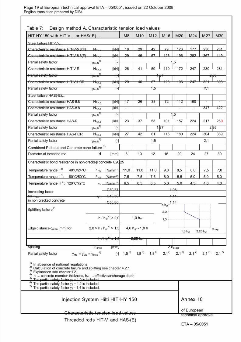
Table 7: Design method A, Characteristic tension load values
HIT-HY 150 wi th HIT-V... or HAS(-E)-… M8 M10 M12 M16 M20 M24 M27 M30
Steel failure HIT-V-…
Characteristic resistance HIT-V-5.8(F) NRk,s [kN] 18 29 42 79 123 177 230 281
Characteristic resistance HIT-V-8.8(F) NRk,s [kN] 29 46 67 126 196 282 367 449
Partial safety factor γMs,N1) [-] 1,5
Characteristic resistance HIT-V-R NRk,s [kN] 26 41 59 110 172 247 230 281
Partial safety factor γMs,N1)
[-] 1,87 2,86
Characteristic resistance HIT-V-HCR NRk,s [kN] 29 46 67 126 196 247 321 393
Partial safety factor γMs,N1) [-] 1,5 2,1
Steel failure HAS(-E)…
Characteristic resistance HAS-5.8 NRk,s [kN] 17 26 38 72 112 160 - -
Characteristic resistance HAS-8.8 NRk,s [kN] - - - - - - 347 422
Partial safety factor γMs,N1)
[-] 1,5
Characteristic resistance HAS-R NRk,s [kN] 23 37 53 101 157 224 217 263
Partial safety factor γMs,N1)
[-] 1,87 2,86
Characteristic resistance HAS-HCR NRk,s [kN] 27 42 61 115 180 224 304 369
Partial safety factor γMs,N1)
[-] 1,5 2,1
Combined Pull-out and Concrete cone failure2)
Diameter of threaded rod d [mm] 8 10 12 16 20 24 27 30
Characteristic bond resistance in non-cracked concrete C20/25
Temperature range I3)
: 40°C/24°C Rk [N/mm²] 11,0 11,0 11,0 9,0 8,5 8,0 7,5 7,0
Temperature range II 3)
: 80°C/50°C Rk [N/mm²] 7,5 7,5 7,5 6,0 5,5 5,0 5,0 5,0
Temperature range III 3)
: 120°C/72°C Rk [N/mm²] 6,5 6,5 6,5 5,0 5,0 4,5 4,0 4,0
C30/37 1,06
C40/50 1,11
Increasing factor
for τRk,p in non cracked concrete
ψc
C50/60 1,14
Splitting failure 2)
h / hef4)
≥ 2,0 1,0 hef
2,0 > h / hef 4)
> 1,3 4,6 hef - 1,8 hEdge distance ccr,sp [mm] for
h / hef
4)
≤
1,3 2,26 hef
Spacing scr,sp [mm] 2 ccr,sp
Partial safety factor γMp = γMc = γMsp 1) [-] 1,5
5) 1,8
6) 1,8
6) 2,1
7) 2,1
7) 2,1
7) 2,1
7) 2,1
7)
1)In absence of national regulations
2)Calculation of concrete failure and splitting see chapter 4.2.1
3) Explanation see chapter 1.2
4) h … concrete member thickness, hef … effective anchorage depth
5) The partial safety factor γ2 = 1,0 is included.
6) The partial safety factor γ2 = 1,2 is included.
7) The partial safety factor γ2 = 1,4 is included.
Annex 10
Characteristic tension load values
Threaded rods HIT-V and HAS-(E)
8/12/2019 HY-150 ETA-05-0051_rebar-en
http://slidepdf.com/reader/full/hy-150-eta-05-0051rebar-en 20/26
Page 20 of European technical approval ETA – 05/0051, issued on 22 October 2008English translation prepared by DIBt.
Injection System Hilti HIT-HY 150
of Europeantechnical approval
ETA – 05/0051
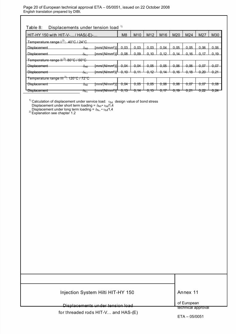
Table 8: Displacements under tension load 1)
HIT-HY 150 wi th HIT-V-… / HAS(-E)-… M8 M10 M12 M16 M20 M24 M27 M30
Temperature range I 2)
: 40°C / 24°C
Displacement δN0 [mm/(N/mm²)] 0,03 0,03 0,03 0,04 0,05 0,05 0,06 0,06
Displacement δN∞ [mm/(N/mm²)] 0,08 0,09 0,10 0,12 0,14 0,16 0,17 0,19
Temperature range II 2): 80°C / 50°C
Displacement δN0 [mm/(N/mm²)] 0,04 0,04 0,05 0,05 0,06 0,06 0,07 0,07
Displacement δN∞ [mm/(N/mm²)] 0,10 0,11 0,12 0,14 0,16 0,18 0,20 0,21
Temperature range III 2)
: 120°C / 72°C
Displacement δN0 [mm/(N/mm²)] 0,04 0,05 0,05 0,06 0,06 0,07 0,07 0,08
Displacement δN∞ [mm/(N/mm²)] 0,13 0,14 0,15 0,17 0,19 0,21 0,22 0,24
1)Calculation of displacement under service load: τSd design value of bond stressDisplacement under short term loading = δN0• τSd/1,4Displacement under long term loading = δN∞ • τSd/1,4
2)Explanation see chapter 1.2
Annex 11
Displacements under tension load
for threaded rods HIT-V… and HAS-(E)
8/12/2019 HY-150 ETA-05-0051_rebar-en
http://slidepdf.com/reader/full/hy-150-eta-05-0051rebar-en 21/26
Page 21 of European technical approval ETA – 05/0051, issued on 22 October 2008English translation prepared by DIBt.
Injection System Hilti HIT-HY 150
of Europeantechnical approval
ETA – 05/0051
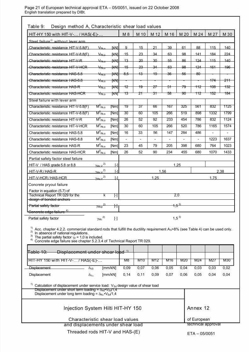
Table 9: Design method A, Characteristic shear load values
HIT-HY 150 with HIT-V-… / HAS(-E)-… M 8 M 10 M 12 M 16 M 20 M 24 M 27 M 30
Steel failure1) withou t lever arm
Characteristic resistance HIT-V-5.8(F) VRk,s [kN] 9 15 21 39 61 88 115 140
Characteristic resistance HIT-V-8.8(F) VRk,s [kN] 15 23 34 63 98 141 184 224
Characteristic resistance HIT-V-R VRk,s [kN] 13 20 30 55 86 124 115 140Characteristic resistance HIT-V-HCR VRk,s [kN] 15 23 34 63 98 124 161 196
Characteristic resistance HAS-5.8 VRk,s [kN] 8,5 13 19 36 56 80 - -
Characteristic resistance HAS-8.8 VRk,s [kN] - - - - - - 174 211
Characteristic resistance HAS-R VRk,s [kN] 12 19 27 51 79 112 108 132
Characteristic resistance HAS-HCR VRk,s [kN] 13 21 31 58 90 112 152 184
Steel failure wi th lever arm
Characteristic resistance HIT-V-5.8(F) M0Rk,s [Nm] 19 37 66 167 325 561 832 1125
Characteristic resistance HIT-V-8.8(F) M0Rk,s [Nm] 30 60 105 266 519 898 1332 1799
Characteristic resistance HIT-V-R M0Rk,s [Nm] 26 52 92 233 454 786 832 1124
Characteristic resistance HIT-V-HCR M0Rk,s [Nm] 30 60 105 266 520 786 1165 1574
Characteristic resistance HAS-5.8 M0Rk,s [Nm] 16 33 56 147 284 486 - -
Characteristic resistance HAS-8.8 M0Rk,s [Nm] - - - - - - 1223 1637
Characteristic resistance HAS-R M0Rk,s [Nm] 23 45 79 205 398 680 764 1023
Characteristic resistance HAS-HCR M0Rk,s [Nm] 26 52 90 234 455 680 1070 1433
Partial safety factor steel failure
HIT-V / HAS grade 5.8 or 8.8 γMs,V2) [-] 1,25
HIT-V-R / HAS-R γMs,V 2) [-] 1,56 2,38
HIT-V-HCR / HAS-HCR γMs,V 2) [-] 1,25 1,75
Concrete pryout failure Factor in equation (5.7) ofTechnical Report TR 029 for thedesign of bonded anchors
k [-] 2,0
Partial safety factor γMcp 2) [-] 1,5
3)
Concrete edge failure4)
Partial safety factor γMc 2) [-] 1,5
3)
1) Acc. chapter 4.2.2. commercial standard rods that fulfill the ductility requirement A5>8% (see Table 4) can be used only.
2) In absence of national regulations.
3)The partial safety factor γ2 = 1,0 is included.
4)Concrete edge failure see chapter 5.2.3.4 of Technical Report TR 029.
Table 10: Displacement under shear load 1)
HIT-HY 150 wi th HIT-V-… / HAS(-E)-… M8 M10 M12 M16 M20 M24 M27 M30
Displacement δV0 [mm/kN] 0,09 0,07 0,06 0,05 0,04 0,03 0,03 0,02
Displacement δV∞ [mm/kN] 0,14 0,11 0,09 0,07 0,06 0,05 0,04 0,04
1)Calculation of displacement under service load: VSd design value of shear loadDisplacement under short term loading = δN0•VSd/1,4Displacement under long term loading = δN∞•VSd/1,4
Annex 12
Characteristic shear load valuesand displacements under shear load
Threaded rods HIT-V and HAS-(E)
8/12/2019 HY-150 ETA-05-0051_rebar-en
http://slidepdf.com/reader/full/hy-150-eta-05-0051rebar-en 22/26
Page 22 of European technical approval ETA – 05/0051, issued on 22 October 2008English translation prepared by DIBt.
Injection System Hilti HIT-HY 150
of Europeantechnical approval
ETA – 05/0051
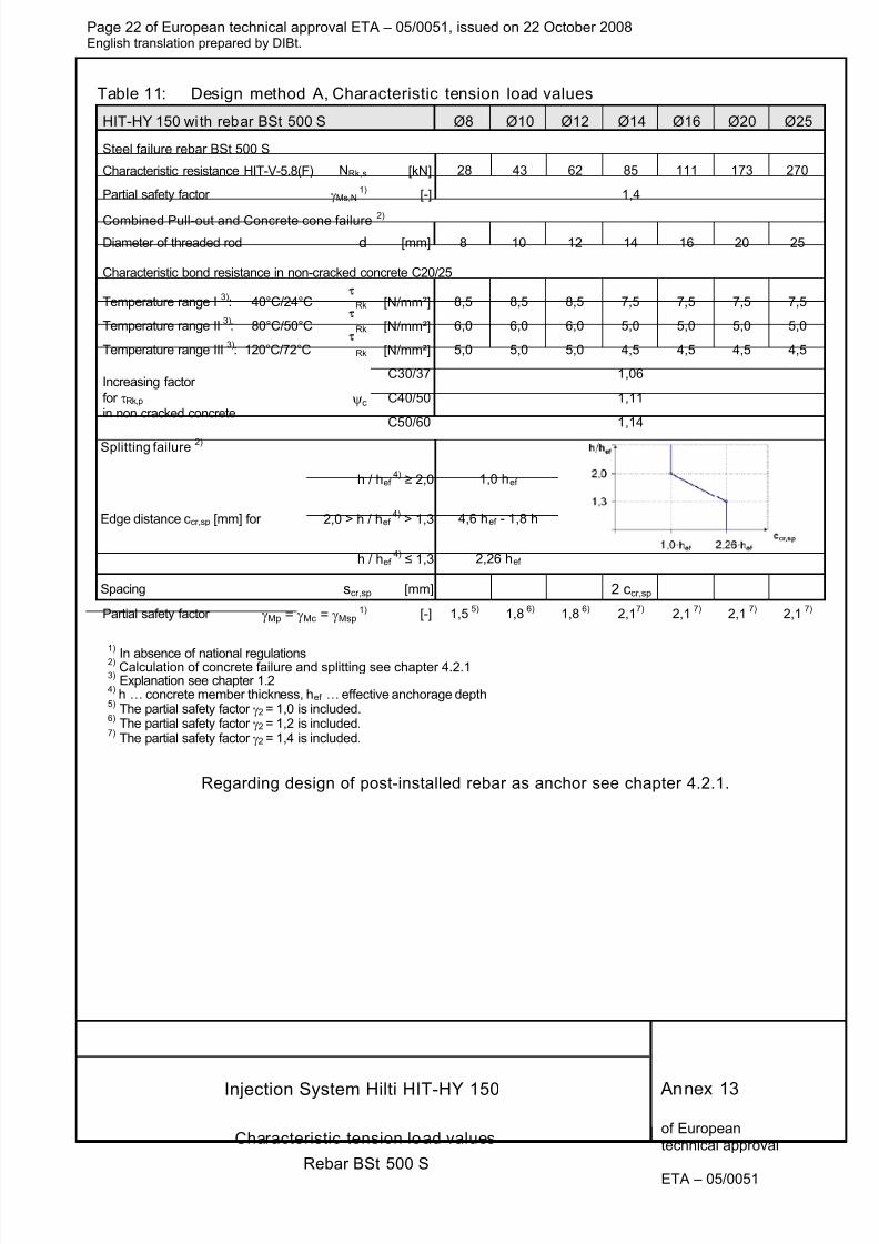
Table 11: Design method A, Characteristic tension load values
HIT-HY 150 wi th rebar BSt 500 S Ø8 Ø10 Ø12 Ø14 Ø16 Ø20 Ø25
Steel failure rebar BSt 500 S
Characteristic resistance HIT-V-5.8(F) NRk,s [kN] 28 43 62 85 111 173 270
Partial safety factor γMs,N1)
[-] 1,4
Combined Pull-out and Concrete cone failure 2)
Diameter of threaded rod d [mm] 8 10 12 14 16 20 25
Characteristic bond resistance in non-cracked concrete C20/25
Temperature range I3)
: 40°C/24°C Rk [N/mm²] 8,5 8,5 8,5 7,5 7,5 7,5 7,5
Temperature range II 3)
: 80°C/50°C Rk [N/mm²] 6,0 6,0 6,0 5,0 5,0 5,0 5,0
Temperature range III 3)
: 120°C/72°C Rk [N/mm²] 5,0 5,0 5,0 4,5 4,5 4,5 4,5
C30/37 1,06
ψc C40/50 1,11
Increasing factor
for τRk,p in non cracked concrete
C50/60 1,14
Splitting failure2)
h / hef4)
≥ 2,0 1,0 hef
2,0 > h / hef 4)
> 1,3 4,6 hef - 1,8 hEdge distance ccr,sp [mm] for
h / hef 4)
≤ 1,3 2,26 hef
Spacing scr,sp [mm] 2 ccr,sp
Partial safety factor γMp = γMc = γMsp 1) [-] 1,5
5) 1,8
6) 1,8
6) 2,1
7) 2,1
7) 2,1
7) 2,1
7)
1)
In absence of national regulations2) Calculation of concrete failure and splitting see chapter 4.2.1
3) Explanation see chapter 1.2
4) h … concrete member thickness, hef … effective anchorage depth
5) The partial safety factor γ2 = 1,0 is included.
6) The partial safety factor γ2 = 1,2 is included.
7) The partial safety factor γ2 = 1,4 is included.
Regarding design of post-installed rebar as anchor see chapter 4.2.1.
Annex 13
Characteristic tension load values
Rebar BSt 500 S
8/12/2019 HY-150 ETA-05-0051_rebar-en
http://slidepdf.com/reader/full/hy-150-eta-05-0051rebar-en 23/26
Page 23 of European technical approval ETA – 05/0051, issued on 22 October 2008English translation prepared by DIBt.
Injection System Hilti HIT-HY 150
of Europeantechnical approval
ETA – 05/0051
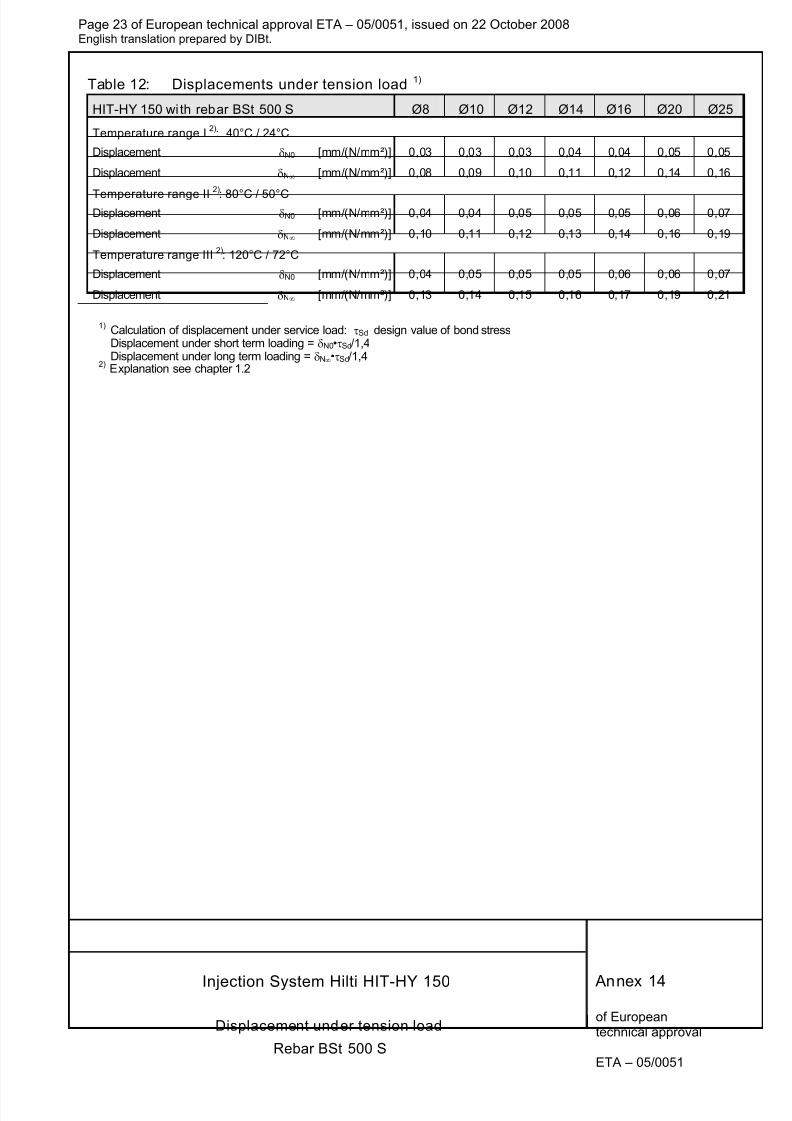
Table 12: Displacements under tension load 1)
HIT-HY 150 wi th rebar BSt 500 S Ø8 Ø10 Ø12 Ø14 Ø16 Ø20 Ø25
Temperature range I 2)
: 40°C / 24°C
Displacement δN0 [mm/(N/mm²)] 0,03 0,03 0,03 0,04 0,04 0,05 0,05
Displacement δN∞ [mm/(N/mm²)] 0,08 0,09 0,10 0,11 0,12 0,14 0,16
Temperature range II 2)
: 80°C / 50°C Displacement δN0 [mm/(N/mm²)] 0,04 0,04 0,05 0,05 0,05 0,06 0,07
Displacement δN∞ [mm/(N/mm²)] 0,10 0,11 0,12 0,13 0,14 0,16 0,19
Temperature range III 2)
: 120°C / 72°C
Displacement δN0 [mm/(N/mm²)] 0,04 0,05 0,05 0,05 0,06 0,06 0,07
Displacement δN∞ [mm/(N/mm²)] 0,13 0,14 0,15 0,16 0,17 0,19 0,21
1)Calculation of displacement under service load: τSd design value of bond stressDisplacement under short term loading = δN0•τSd/1,4Displacement under long term loading = δN∞•τSd/1,4
2) Explanation see chapter 1.2
Annex 14
Displacement under tension load
Rebar BSt 500 S
8/12/2019 HY-150 ETA-05-0051_rebar-en
http://slidepdf.com/reader/full/hy-150-eta-05-0051rebar-en 24/26
Page 24 of European technical approval ETA – 05/0051, issued on 22 October 2008English translation prepared by DIBt.
Injection System Hilti HIT-HY 150
of Europeantechnical approval
ETA – 05/0051
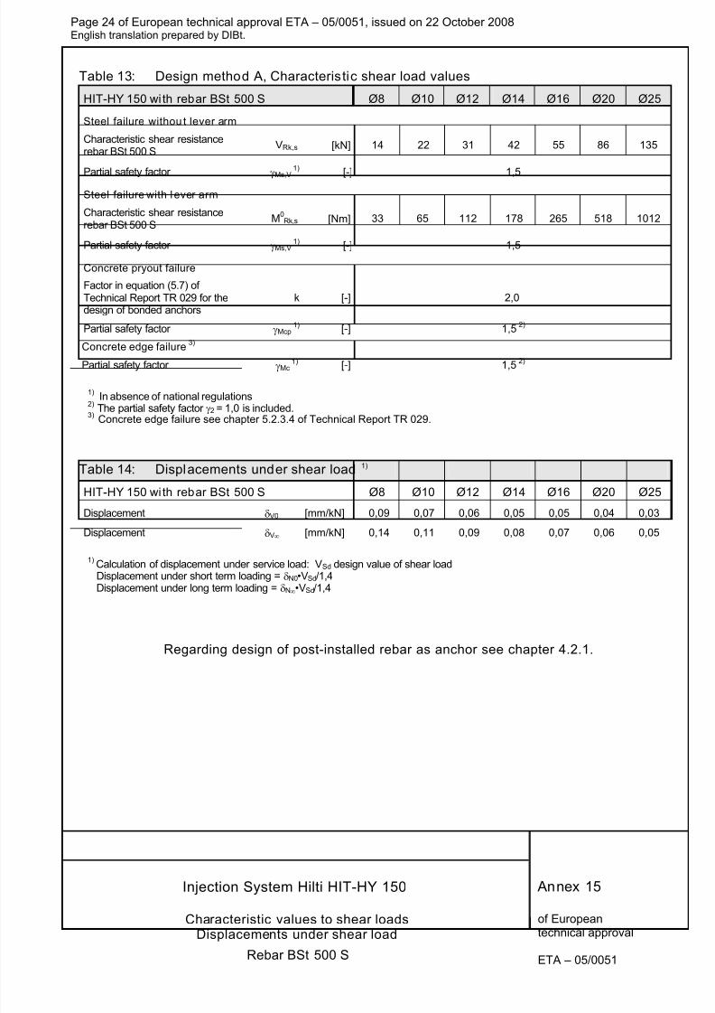
Table 13: Design method A, Characteristic shear load values
HIT-HY 150 wi th rebar BSt 500 S Ø8 Ø10 Ø12 Ø14 Ø16 Ø20 Ø25
Steel failure withou t lever arm
Characteristic shear resistancerebar BSt 500 S
VRk,s [kN] 14 22 31 42 55 86 135
Partial safety factor γMs,V
1)
[-] 1,5
Steel failure with l ever arm
Characteristic shear resistancerebar BSt 500 S
M0Rk,s [Nm] 33 65 112 178 265 518 1012
Partial safety factor γMs,V 1)
[-] 1,5
Concrete pryout failure
Factor in equation (5.7) ofTechnical Report TR 029 for thedesign of bonded anchors
k [-] 2,0
Partial safety factor γMcp 1) [-] 1,5
2)
Concrete edge failure 3)
Partial safety factor γMc 1) [-] 1,5
2)
1)In absence of national regulations
2) The partial safety factor γ2 = 1,0 is included.
3)Concrete edge failure see chapter 5.2.3.4 of Technical Report TR 029.
Table 14: Displacements under shear load 1)
HIT-HY 150 wi th rebar BSt 500 S Ø8 Ø10 Ø12 Ø14 Ø16 Ø20 Ø25
Displacement δV0 [mm/kN] 0,09 0,07 0,06 0,05 0,05 0,04 0,03
Displacement δV∞ [mm/kN] 0,14 0,11 0,09 0,08 0,07 0,06 0,05
1)Calculation of displacement under service load: VSd design value of shear loadDisplacement under short term loading = δN0•VSd/1,4Displacement under long term loading = δN∞•VSd/1,4
Regarding design of post-installed rebar as anchor see chapter 4.2.1.
Annex 15
Characteristic values to shear loadsDisplacements under shear load
Rebar BSt 500 S
8/12/2019 HY-150 ETA-05-0051_rebar-en
http://slidepdf.com/reader/full/hy-150-eta-05-0051rebar-en 25/26
Page 25 of European technical approval ETA – 05/0051, issued on 22 October 2008English translation prepared by DIBt.
Injection System Hilti HIT-HY 150
of Europeantechnical approval
ETA – 05/0051
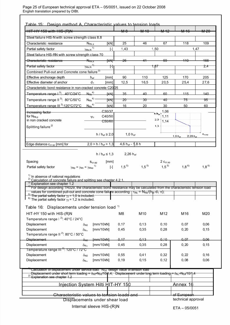
Table 15: Design method A, Characteristic values to tension loads
HIT-HY 150 wi th HIS-(R)N M 8 M 10 M 12 M 16 M 20
Steel failure HIS-N with screw strength c lass 8.8
Characteristic resistance NRk,s [kN] 25 46 67 118 109
Partial safety factor γMs,N 1)
[-] 1,43 1,50 1,47
Steel failure HIS-RN with screw strength c lass 70
Characteristic resistance NRk,s [kN] 26 41 59 110 166
Partial safety factor γMs,N 1)
[-] 1,87 2,4
Combined Pull-out and Concrete cone failure 2)
Effective anchorage depth hef [mm] 90 110 125 170 205
Effective diameter of anchor d1 [mm] 12,5 16,5 20,5 25,4 27,6
Characteristic bond resistance in non-cracked concrete C20/25
Temperature range I 3)
: 40°C/24°C NRk4)
[kN] 35 40 60 115 140
Temperature range II 3)
: 80°C/50°C NRk4)
[kN] 20 30 40 75 95
Temperature range III 3)
:120°C/72°C NRk4)
[kN] 16 20 30 50 60
C30/37 1,06
ψc C40/50 1,11Increasing factorfor NRk,p in non cracked concrete C50/60 1,14
Splitting failure 2)
h / hef ≥ 2,0 1,0 hef
2,0 > h / hef > 1,3 4,6 hef - 1,8 hEdge distance ccr,sp [mm] for
h / hef ≤ 1,3 2,26 hef
Spacing scr,sp [mm] 2 ccr,sp
Partial safety factor γMp = γMc = γMsp 1) [-] 1,5
5) 1,5
5) 1,5
5) 1,8
6)1,8
6)
1) In absence of national regulations
2) Calculation of concrete failure and splitting see chapter 4.2.1.
3) Explanation see chapter 1.2
4) For design according TR029, the characteristic bond resistance may be calculated from the characteristic tension load
values for combined pull-out and concrete cone failure according: τRk = NRk/(hef d1 π);
5) The partial safety factor γ2 = 1,0 is included.
6) The partial safety factor γ2 = 1,2 is included.
Table 16: Displacements under tension load 1)
HIT-HY 150 wi th HIS-(R)N M8 M10 M12 M16 M20
Temperature range I 2)
: 40°C / 24°C
Displacement δN0 [mm/10kN] 0,17 0,13 0,10 0,07 0,06
Displacement δN∞ [mm/10kN] 0,45 0,35 0,28 0,20 0,15
Temperature range II 2)
: 80°C / 50°C
Displacement δN0 [mm/10kN] 0,17 0,13 0,10 0,07 0,06
Displacement δN∞ [mm/10kN] 0,45 0,35 0,28 0,20 0,15
Temperature range III 2)
: 120°C / 72°C
Displacement δN0 [mm/10kN] 0,55 0,41 0,32 0,22 0,16
Displacement δN∞ [mm/10kN] 0,19 0,15 0,12 0,08 0,06
1)Calculation of displacement under service load: NSd design value of tension loadDisplacement under short term loading = δN0•NSd/10/1,4; Displacement under long term loading = δN∞•NSd/10/1,4
2) Explanation see chapter 1.2
Annex 16
Characteristic values to tension loads andDisplacements under shear load
Internal sleeve HIS-(R)N
8/12/2019 HY-150 ETA-05-0051_rebar-en
http://slidepdf.com/reader/full/hy-150-eta-05-0051rebar-en 26/26
Page 26 of European technical approval ETA – 05/0051, issued on 22 October 2008English translation prepared by DIBt.
Injection System Hilti HIT-HY 150
of Europeant h i l l
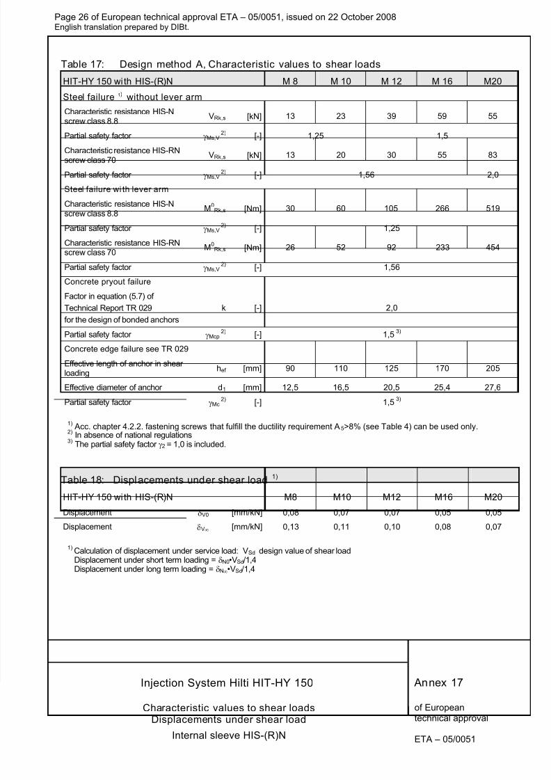
Table 17: Design method A, Characteristic values to shear loads
HIT-HY 150 wi th HIS-(R)N M 8 M 10 M 12 M 16 M20
Steel failure 1) without lever arm
Characteristic resistance HIS-Nscrew class 8.8
VRk,s [kN] 13 23 39 59 55
Partial safety factor γMs,V2)
[-] 1,25 1,5
Characteristic resistance HIS-RNscrew class 70
VRk,s [kN] 13 20 30 55 83
Partial safety factor γMs,V 2)
[-] 1,56 2,0
Steel failure wi th lever arm
Characteristic resistance HIS-Nscrew class 8.8
M0Rk,s [Nm] 30 60 105 266 519
Partial safety factor γMs,V 2)
[-] 1,25
Characteristic resistance HIS-RNscrew class 70
M0Rk,s [Nm] 26 52 92 233 454
Partial safety factor γMs,V 2)
[-] 1,56
Concrete pryout failure
Factor in equation (5.7) of
Technical Report TR 029
for the design of bonded anchors
k [-] 2,0
Partial safety factor γMcp 2)
[-] 1,5 3)
Concrete edge failure see TR 029
Effective length of anchor in shearloading
hef [mm] 90 110 125 170 205
Effective diameter of anchor d1 [mm] 12,5 16,5 20,5 25,4 27,6
Partial safety factor γMc 2)
[-] 1,5 3)
1) Acc. chapter 4.2.2. fastening screws that fulfill the ductility requirement A5>8% (see Table 4) can be used only.
2) In absence of national regulations
3) The partial safety factor γ2 = 1,0 is included.
Table 18: Displacements under shear load 1)
HIT-HY 150 wi th HIS-(R)N M8 M10 M12 M16 M20
Displacement δV0 [mm/kN] 0,08 0,07 0,07 0,05 0,05
Displacement δV∞ [mm/kN] 0,13 0,11 0,10 0,08 0,07
1) Calculation of displacement under service load: VSd design value of shear loadDisplacement under short term loading = δN0•VSd/1,4Displacement under long term loading = δN∞•VSd/1,4
Annex 17
Characteristic values to shear loads