Gedruckte Information, Netzpublikation oder beides? – Überlegungen zum Sachbuch 2.0
Inno
vatio
n Re
port
Innovation Report2012
Institute of Composite Structures andAdaptive Systems

Publication dataPublisher Deutsches Zentrum für Luft- und Raumfahrt e.V. German Aerospace Center
Institute of Composite Structures and Adaptive Systems
Adress Lilienthalplatz 7 D-38108 Braunschweig Tel. +49 531 295 2300
Editors Prof. Dr. Martin Wiedemann Prof. Dr. Michael Sinapius Prof. Dr. Jörg Melcher
Design Brigitte Zell-Walczok Jana Hoidis
Printed by Documaxx Hessler Digitaldruck GmbH Braunschweig
Published Brunswick, September 2012
Reproduction (in whole or in part) or use is subject to prior permission from the German Aerospace Center (DLR)
www.DLR.de/FA
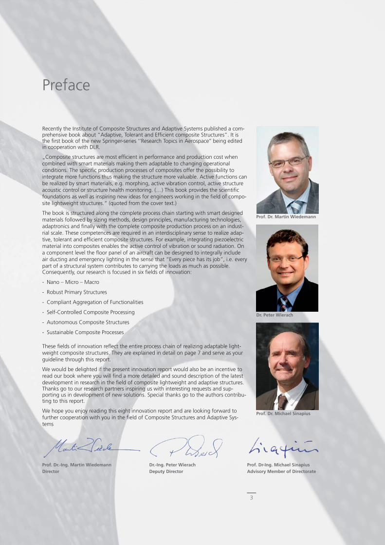
Preface
Recently the Institute of Composite Structures and Adaptive Systems published a com-prehensive book about “Adaptive, Tolerant and Effi cient composite Structures”. It is the fi rst book of the new Springer-series ‘’Research Topics in Aerospace’’ being edited in cooperation with DLR.
„Composite structures are most effi cient in performance and production cost when combined with smart materials making them adaptable to changing operational conditions. The specifi c production processes of composites offer the possibility to integrate more functions thus making the structure more valuable. Active functions can be realized by smart materials, e.g. morphing, active vibration control, active structure acoustic control or structure health monitoring. (…) This book provides the scientifi c foundations as well as inspiring new ideas for engineers working in the fi eld of compo-site lightweight structures.“ (quoted from the cover text.)
The book is structured along the complete process chain starting with smart designed materials followed by sizing methods, design principles, manufacturing technologies, adaptronics and fi nally with the complete composite production process on an indust-rial scale. These competences are required in an interdisciplinary sense to realize adap-tive, tolerant and effi cient composite structures. For example, integrating piezoelectric material into composites enables the active control of vibration or sound radiation. On a component level the fl oor panel of an aircraft can be designed to integrally include air ducting and emergency lighting in the sense that “Every piece has its job”, i.e. every part of a structural system contributes to carrying the loads as much as possible.Consequently, our research is focused in six fi elds of innovation:
- Nano – Micro – Macro
- Robust Primary Structures
- Compliant Aggregation of Functionalities
- Self-Controlled Composite Processing
- Autonomous Composite Structures
- Sustainable Composite Processes
These fi elds of innovation refl ect the entire process chain of realizing adaptable light-weight composite structures. They are explained in detail on page 7 and serve as your guideline through this report.
We would be delighted if the present innovation report would also be an incentive to read our book where you will fi nd a more detailed and sound description of the latest development in research in the fi eld of composite lightweight and adaptive structures.Thanks go to our research partners inspiring us with interesting requests and sup-porting us in development of new solutions. Special thanks go to the authors contribu-ting to this report.
We hope you enjoy reading this eight innovation report and are looking forward to further cooperation with you in the fi eld of Composite Structures and Adaptive Sys-tems
Prof. Dr. Martin Wiedemann
Dr. Peter Wierach
Prof. Dr. Michael Sinapius
Prof. Dr.-Ing. Martin WiedemannDirector
Dr.-Ing. Peter WierachDeputy Director
Prof. Dr-Ing. Michael SinapiusAdvisory Member of Directorate
3

4
Institute of Composite Structures and Adaptive Systems ............................. 06
Our Fields of InnovationM. Wiedemann ................................................................................................... 07
Nano - Micro - Macro
Actuation Performance of Aligned CNT-StructuresS. Geier ............................................................................................................... 09
Carbon Nanotubes in Fiber Reinforced Plastics-Processing and Mechanical PropertiesW. Exner, C. Arlt .................................................................................................. 10
Challenges for the Experimental Investigation of Very High Cycle Fatigue of Polymer CompositesP. Lorsch, M. Sinapius .......................................................................................... 11
Micro-CT Measurements and Numerical Investigations on Porous CFRP LaminatesD. Chrupalla, J. Kreikemeier, D. Krause ................................................................ 12
Robust Primary Structures
Progressive Failure Analysis of Composite Structures due to Strength and Stability DegradationT. Führer .............................................................................................................. 14
Modelling, Sizing and Optimization of Lightweight Structures within Aircraft PredesignF. Heinecke, S. Freund .......................................................................................... 15
CFRP Laminar Wing DesignJ. Bold, T. Bach, C. Ückert .................................................................................... 16
Repair of Composite StructuresD. Holzhüter, J. Wölper ........................................................................................ 17
Next Generation Train (NGT) – Car Body Using Composite Sandwich Structures J. Nickel, J.Wolff .................................................................................................. 18
Enhancing the Mechanical Performance of Unidirectional CFRP by Metal-HybridizationD. Stefaniak ......................................................................................................... 19
Compliant Aggregation of Functionalities
Novel Vehicle Structures from Multifunctional MaterialsJ. Nickel, A. Pototzky .......................................................................................... 21
Lightweight Airfreight Containers: High-Tech in a Box for Greener LogisticsI. Bartsch ............................................................................................................. 22
Natural Fiber Reinforced Plastics (NFRP) for Aircraft CabinsJ. Bachmann ........................................................................................................ 23
Pressure Actuated Cellular StructuresM. Pagitz, J. Bold ....................................................................................................... 24
Ultra-Lightweight Deployable Structures for Space ApplicationsM. Hillebrandt, M. Straubel ................................................................................ 25
Contents
5
VLM for Shefex III – Composite Structures in Space Transport
O. Mierheim, H. Lohse-Busch, S. Niemann ........................................................ 26
MASCOT – Mobile Asteroid Surface ScoutO. Mierheim, M. Lange, C. Koch, C. König ................................................... 27
Self-Controlled CFRP Processing
Multidisciplinary Design Process for CFRP Wings with More Natural Laminar FlowL. Heinrich, E. Kappel ...................................................................................... 29
Laminar Wing Production- Cellular ToolingM. Grote .......................................................................................................... 30
Integral Anti- and Deicing of Laminar Leading EdgesJ. Schmidt ......................................................................................................... 31
Alternative CFRP Frame Section for Unmanned Aerial VehiclesM. Fabian, L. Weiß ........................................................................................... 32
Autonomous CFRP Structures
Active Vibration Isolation of Rear-View MirrorsB. T. Kletz, J. Melcher ......................................................................................... 34
Active Twist Rotors – From the Idea to the Wind Tunnel ModelJ. Riemenschneider, M. Schulz, S. Opitz, S. Kalow, T. Mendrock, R. Keimer ........ 35
A Tailored Low Noise Solution without Losses of High Lift PerformanceA. Rudenko ....................................................................................................... 36
Smart Active Lining Modules – Technology for Acoustic Comfort in Future AircraftM. Misol, T. Haase, S. Algermissen, O. Unruh .................................................. 37
Fundamentals of High Lift for Future Civil Aircraft – Adaptive Systems for Flow Sensing and ControlM. Zander, M. Sinapius .................................................................................... 38
SHM-Demonstrator for a Helicopter TailbomW. Hillger, A. Szewieczek, ................................................................................. 39
Sustainable Composites Processes
Piezoceramics as Effective and Flexible Sensors for Online Cure MonitoringN. Liebers ......................................................................................................... 41
Automated Leakage Detection of Vacuum Setup in CFRP ProductionJ. Bölke ............................................................................................................ 42
Process-Integrated Sensor Systems in the Automated Fiber Placement ProcessC. Krombholz ................................................................................................... 43
Material-Optimised Automated Fiber Placement ProcessC. Nguyen ......................................................................................................... 44
Profi le of Departments .................................................................................. 45
Book edited by the Institute of Composite Structures and Adaptive Systems 53
Publications and Patents 2010 - 2011 .......................................................... 54
6
Institute of Composite Structures and Adaptive Systems
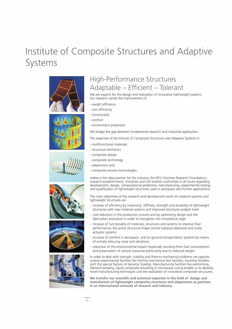
High-Performance StructuresAdaptable – Effi cient – TolerantWe are experts for the design and realization of innovative lightweight systems. Our research serves the improvement of:
- weight effi ciency
- cost effi ciency
- functionality
- comfort
- environment protection
We bridge the gap between fundamental research and industrial application.
The expertise of the Intitute of Composite Structures and Adaptive Systems in
- multifunctional materials
- structural mechanics
- composite design
- composite technology
- adaptronics and
- composite process technologies
makes it the ideal partner for the industry, the DFG (German Research Foundation), research establishments, ministries and civil aviation authorities in all issues regarding development, design, computational prediction, manufacturing, experimental testing, and qualifi cation of lightweight structures used in aerospace and further applications.
The main objectives of the research and development work on material systems and lightweight structures are
- increase of effi ciency by improving stiffness, strength and durability of lightweight structures with new material systems and improved structural analysis tools
- cost reduction in the production process and by optimizing design and the fabrication procedure in order to strengthen the competitive edge
- increase of functionality of materials, structures and systems to improve their performance; the active structural shape control replaces elaborate and costly actuator systems
- increase of comfort in aerospace and on-ground transportation systems by means of actively reducing noise and vibrations
- reduction of the environmental impact (especially resulting from fuel consumption) and preservation of natural resources particularly due to reduced weight.
In order to deal with strength, stability and thermo-mechanical problems we operate unique experimental facilities like thermo-mechanical test facilities, buckling facilities with the special feature of dynamic loading. Manufacturing facilities like preforming, fi lament winding, liquid composite moulding or microwave curing enable us to develop novel manufacturing techniques und the realization of innovative composite structures.
We transfer our scientifi c and technical expertise in the fi eld of design and manufacture of lightweight composite structures and adaptronics as partners in an international network of research and industry.

7
Institute of Composite Structures and Adaptive Systems – Our Fields of InnovationWe work along the full process chain in the fi elds of multifunctional materials, simula-tion methods, lightweight functional design, production technologies, adaptronics and up to entire production processes. This consideration of the full process chain is part of our strategy, and it is our conviction that successful research in the fi eld of functional CFRP structures is driven by collaborative work. How can research be organized in such a broad fi eld of scientifi c work, and how can each scientist preserve attention for the work of the others? Innovation is the total of two steps: invention and diffusion. In-vention is where we start with our ideas. Diffusion is where at the end we can present technical solutions to our customers. Innovation covers the full process chain and this is why we have decided to organize twelve times a year meetings with all scientists of our institute to discuss our long term strategic research topics.
Multi-phase materials like composites require the comprehensive understanding from Nano – Micro – Macro -scale of the components interaction. This includes the effect of nano-scaled additives to the resin as will as the effect of manufacturing defects like pores on the mechanical properties of the structure. Moreover, carbon nanotubes exhibit a signifi cant actuation effect in an electrolytic environment. Understanding the path from Nano to Macro means thorough research for our scientists looking for new technical applications.
Reliable design methods for Robust Primary Structures are already mandatory, but the challenge to ensure reliability (oder robustness) by adding additional functions into the structure. We strongly believe in the potential of function integration within the composite design, but there is the need to bring all of the elements of such a structure to the same level of reliability. Our scientists keep this in mind while they are making new inventions.
Compliant Aggregation of Functionalities aims for solutions, where integration of additional functions does not degrade the original load carrying function of the structure. To reach this goal the design principles must be adapted to the additional functions. For example the active shape control of a structure may not lead to additi-onal internal loads. Unconventional ideas from many people are required here to fi nd the right solutions.
Self controlled CFRP Processing is one of our most promising concepts for automa-tion in the fi eld of production of carbon fi bre reinforced polymer (CFRP) structures, but still in its infancy. With our competencies in ultrasonic NDT, process-simulation and in the fi eld of adaptronics as well as our long lasting experience in CFRP production tech-nologies, our scientists can build on an unique combination of knowledge.
Building Autonomous CFRP Structures is our vision of function integration. Any active system today requires external energy for control and actuation at least. The omission of the wiring is one of the conditions for an increasing application of function integration in structures. Our scientists know the vision and are looking for contribu-tions to its realization.
Sustainable Composites Processes will fi nally become a very important topic in the future for us. Not only the lightweight and multifunctional structure itself shell support the idea of sustainability, but also the way, how this structure is produced. Our scientist know about the need for further cost reduction but very soon this will be also a demand for reduction of consumables in production and minimization of scrap. The development of precise, effective and in-line quality automation along the production processes will be a new research fi eld for us.
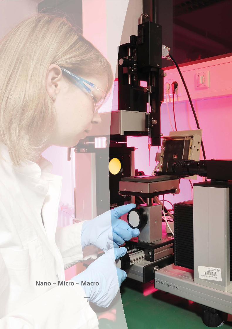
Nano – Micro – Macro
8
9
Actuation Performance of Aligned CNT-Structures
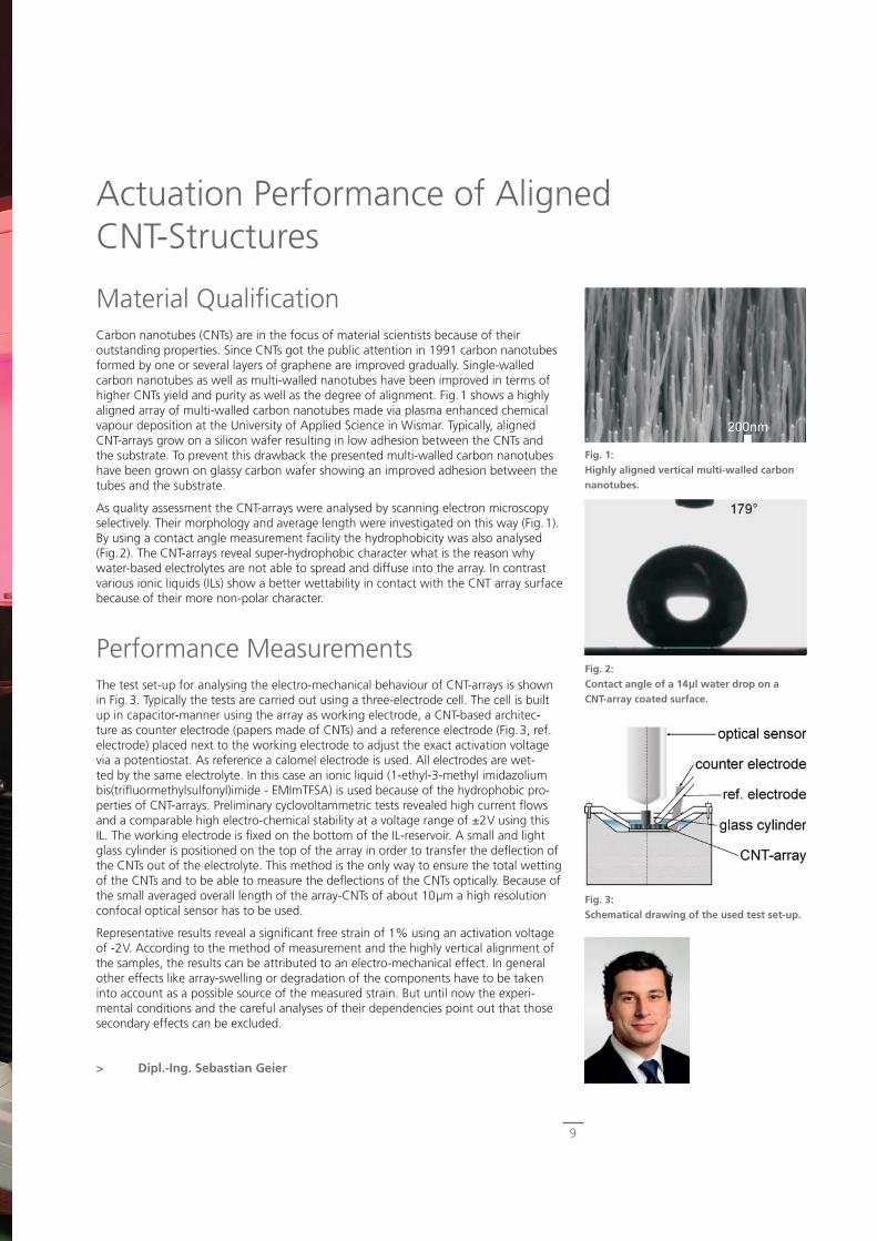
Material Qualifi cationCarbon nanotubes (CNTs) are in the focus of material scientists because of their outstanding properties. Since CNTs got the public attention in 1991 carbon nanotubes formed by one or several layers of graphene are improved gradually. Single-walled carbon nanotubes as well as multi-walled nanotubes have been improved in terms of higher CNTs yield and purity as well as the degree of alignment. Fig.1 shows a highly aligned array of multi-walled carbon nanotubes made via plasma enhanced chemical vapour deposition at the University of Applied Science in Wismar. Typically, aligned CNT-arrays grow on a silicon wafer resulting in low adhesion between the CNTs and the substrate. To prevent this drawback the presented multi-walled carbon nanotubes have been grown on glassy carbon wafer showing an improved adhesion between the tubes and the substrate.
As quality assessment the CNT-arrays were analysed by scanning electron microscopy selectively. Their morphology and average length were investigated on this way (Fig.1). By using a contact angle measurement facility the hydrophobicity was also analysed (Fig.2). The CNT-arrays reveal super-hydrophobic character what is the reason why water-based electrolytes are not able to spread and diffuse into the array. In contrast various ionic liquids (ILs) show a better wettability in contact with the CNT array surface because of their more non-polar character.
Performance MeasurementsThe test set-up for analysing the electro-mechanical behaviour of CNT-arrays is shown in Fig.3. Typically the tests are carried out using a three-electrode cell. The cell is built up in capacitor-manner using the array as working electrode, a CNT-based architec-ture as counter electrode (papers made of CNTs) and a reference electrode (Fig.3, ref. electrode) placed next to the working electrode to adjust the exact activation voltage via a potentiostat. As reference a calomel electrode is used. All electrodes are wet-ted by the same electrolyte. In this case an ionic liquid (1-ethyl-3-methyl imidazolium bis(trifl uormethylsulfonyl)imide - EMImTFSA) is used because of the hydrophobic pro-perties of CNT-arrays. Preliminary cyclovoltammetric tests revealed high current fl ows and a comparable high electro-chemical stability at a voltage range of ±2V using this IL. The working electrode is fi xed on the bottom of the IL-reservoir. A small and light glass cylinder is positioned on the top of the array in order to transfer the defl ection of the CNTs out of the electrolyte. This method is the only way to ensure the total wetting of the CNTs and to be able to measure the defl ections of the CNTs optically. Because of the small averaged overall length of the array-CNTs of about 10μm a high resolution confocal optical sensor has to be used.
Representative results reveal a signifi cant free strain of 1% using an activation voltage of -2V. According to the method of measurement and the highly vertical alignment of the samples, the results can be attributed to an electro-mechanical effect. In general other effects like array-swelling or degradation of the components have to be taken into account as a possible source of the measured strain. But until now the experi-mental conditions and the careful analyses of their dependencies point out that those secondary effects can be excluded.
> Dipl.-Ing. Sebastian Geier
Fig. 1:Highly aligned vertical multi-walled carbon nanotubes.
Fig. 3:Schematical drawing of the used test set-up.
Fig. 2:Contact angle of a 14μl water drop on a CNT-array coated surface.
10
Fig. 2:Filament winding.
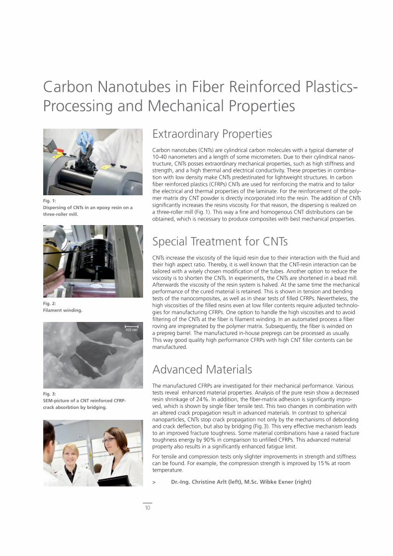
Extraordinary PropertiesCarbon nanotubes (CNTs) are cylindrical carbon molecules with a typical diameter of 10-40 nanometers and a length of some micrometers. Due to their cylindrical nanos-tructure, CNTs posses extraordinary mechanical properties, such as high stiffness and strength, and a high thermal and electrical conductivity. These properties in combina-tion with low density make CNTs predestinated for lightweight structures. In carbon fi ber reinforced plastics (CFRPs) CNTs are used for reinforcing the matrix and to tailor the electrical and thermal properties of the laminate. For the reinforcement of the poly-mer matrix dry CNT powder is directly incorporated into the resin. The addition of CNTs signifi cantly increases the resins viscosity. For that reason, the dispersing is realized on a three-roller mill (Fig.1). This way a fi ne and homogenous CNT distributions can be obtained, which is necessary to produce composites with best mechanical properties.
Special Treatment for CNTsCNTs increase the viscosity of the liquid resin due to their interaction with the fl uid and their high aspect ratio. Thereby, it is well known that the CNT-resin interaction can be tailored with a wisely chosen modifi cation of the tubes. Another option to reduce the viscosity is to shorten the CNTs. In experiments, the CNTs are shortened in a bead mill. Afterwards the viscosity of the resin system is halved. At the same time the mechanical performance of the cured material is retained. This is shown in tension and bending tests of the nanocomposites, as well as in shear tests of fi lled CFRPs. Nevertheless, the high viscosities of the fi lled resins even at low fi ller contents require adjusted technolo-gies for manufacturing CFRPs. One option to handle the high viscosities and to avoid fi ltering of the CNTs at the fi ber is fi lament winding. In an automated process a fi ber roving are impregnated by the polymer matrix. Subsequently, the fi ber is winded on a prepreg barrel. The manufactured in-house prepregs can be processed as usually. This way good quality high performance CFRPs with high CNT fi ller contents can be manufactured.
Advanced MaterialsThe manufactured CFRPs are investigated for their mechanical performance. Various tests reveal enhanced material properties. Analysis of the pure resin show a decreased resin shrinkage of 24%. In addition, the fi ber-matrix adhesion is signifi cantly impro-ved, which is shown by single fi ber tensile test. This two changes in combination with an altered crack propagation result in advanced materials. In contrast to spherical nanoparticles, CNTs stop crack propagation not only by the mechanisms of debonding and crack defl ection, but also by bridging (Fig.3). This very effective mechanism leads to an improved fracture toughness. Some material combinations have a raised fracture toughness energy by 90% in comparison to unfi lled CFRPs. This advanced material property also results in a signifi cantly enhanced fatigue limit.
For tensile and compression tests only slighter improvements in strength and stiffness can be found. For example, the compression strength is improved by 15% at room temperature.
> Dr.-Ing. Christine Arlt (left), M.Sc. Wibke Exner (right)
Carbon Nanotubes in Fiber Reinforced Plastics-Processing and Mechanical Properties
Fig. 1:Dispersing of CNTs in an epoxy resin on a three-roller mill.
Fig. 3:SEM-picture of a CNT reinforced CFRP-crack absorbtion by bridging.
11
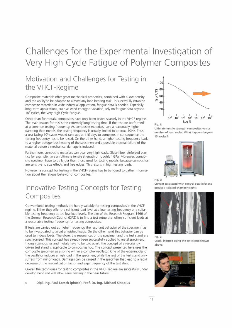
Fig. 1: Ultimate tensile strength composites versus number of load cycles. What happens beyond 106 cycles?
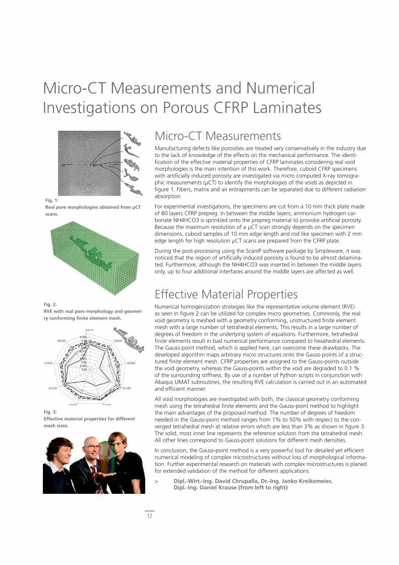
Fig. 2: Current test stand with control box (left) and acoustic-isolated chamber (right).
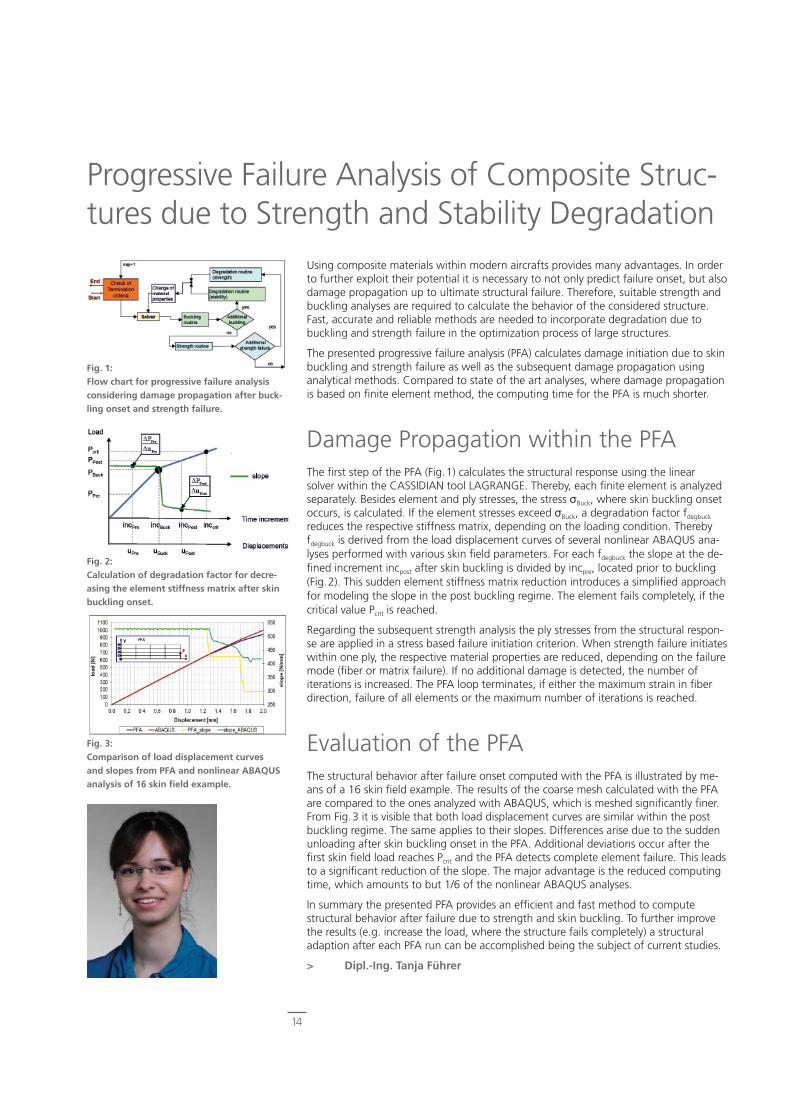
Fig. 3: Crack, induced using the test stand shown above.
Challenges for the Experimental Investigation of Very High Cycle Fatigue of Polymer Composites
Motivation and Challenges for Testing in the VHCF-RegimeComposite materials offer great mechanical properties, combined with a low density and the ability to be adapted to almost any load bearing task. To sucessfully establish composite materials in wide industrial application, fatigue data is needed. Especially long-term applications, such as wind energy or aviation, rely on fatigue data beyond 108 cycles, the Very High Cycle Fatigue.
Other than for metals, composites have only been tested scarcely in the VHCF-regime. The main reason for this is the extremely long testing time, if the test are performed at a common testing frequency. As composite materials have a reasonably higher damping than metals, the testing frequency is usually limited to approx. 10Hz. Thus, a test facing 108 cycles would take about 116 days to complete. In consequence the testing frequency has to be raised. On the other hand, a higher testing frequency leads to a higher autogenous heating of the specimen and a possible thermal failure of the material before a mechanical damage is induced.
Furthermore, composite materials can bear very high loads. Glass-fi bre reinforced plas-tics for example have an ultimate tensile strength of roughly 1GPa. Moreover, compo-site specimen have to be larger than those used for testing metals, because composites are sensitive to size effects and free edges. This results in high testing loads.
However, a concept for testing in the VHCF-regime has to be found to gather informa-tion about the fatigue behavior of composites.
Innovative Testing Concepts for Testing CompositesConventional testing methods are hardly suitable for testing composites in the VHCF regime. Either they offer the suffi cient load level at a low testing frequency or a suita-ble testing frequency at too low load levels. The aim of the Research Program 1466 of the German Research Council (DFG) is to fi nd a test setup that offers suffi cient loads at a reasonable testing frequency for testing composites.
If tests are carried out at higher frequency, the resonant behavior of the specimen has to be investigated to avoid unwished loads. On the other hand this behavior can be used to induce loads. Therefore, the resonances of the specimen and the test stand are synchronized. This concept has already been successfully applied to metal specimen; though composites and metals have to be told apart, the concept of a resonantly driven test stand is applicable to composites too. The concept presented here uses the composite specimen as a spring within a complex oscillator. One of the eigenmodes of the oscillator induces a high load in the specimen, while the rest of the test stand only suffers from minor loads. Damages can be caused in the specimen that lead to a rapid decrease of the magnifi cation factor and eigenfrequency of the test stand.
Overall the techniques for testing composites in the VHCF regime are succesfully under development and will allow serial testing in the near future.
> Dipl.-Ing. Paul Lorsch (photo), Prof. Dr.-Ing. Michael Sinapius
12
Micro-CT Measurements and Numerical Investigations on Porous CFRP Laminates
Micro-CT MeasurementsManufacturing defects like porosities are treated very conservatively in the industry due to the lack of knowledge of the effects on the mechanical performance. The identi-fi cation of the effective material properties of CFRP laminates considering real void morphologies is the main intention of this work. Therefore, cuboid CFRP specimens with artifi cially induced porosity are investigated via micro computed X-ray tomogra-phic measurements (μCT) to identify the morphologies of the voids as depicted in fi gure 1. Fibers, matrix and air entrapments can be separated due to different radiation absorption.
For experimental investigations, the specimens are cut from a 10 mm thick plate made of 80 layers CFRP prepreg. In between the middle layers, ammonium hydrogen car-bonate NH4HCO3 is sprinkled onto the prepreg material to provoke artifi cial porosity. Because the maximum resolution of a μCT scan strongly depends on the specimen dimensions, cuboid samples of 10 mm edge length and rod like specimen with 2 mm edge length for high resolution μCT scans are prepared from the CFRP plate.
During the post-processing using the ScanIP software package by Simpleware, it was noticed that the region of artifi cially induced porosity is found to be almost delamina-ted. Furthermore, although the NH4HCO3 was inserted in between the middle layers only, up to four additional interfaces around the middle layers are affected as well.
Effective Material PropertiesNumerical homogenization strategies like the representative volume element (RVE) as seen in fi gure 2 can be utilized for complex micro geometries. Commonly, the real void geometry is meshed with a geometry conforming, unstructured fi nite element mesh with a large number of tetrahedral elements. This results in a large number of degrees of freedom in the underlying system of equations. Furthermore, tetrahedral fi nite elements result in bad numerical performance compared to hexahedral elements. The Gauss-point method, which is applied here, can overcome these drawbacks. The developed algorithm maps arbitrary micro structures onto the Gauss-points of a struc-tured fi nite element mesh. CFRP properties are assigned to the Gauss-points outside the void geometry, whereas the Gauss-points within the void are degraded to 0.1 % of the surrounding stiffness. By use of a number of Python scripts in conjunction with Abaqus UMAT subroutines, the resulting RVE calculation is carried out in an automated and effi cient manner.
All void morphologies are investigated with both, the classical geometry conforming mesh using the tetrahedral fi nite elements and the Gauss-point method to highlight the main advantages of the proposed method. The number of degrees of freedom needed in the Gauss-point method ranges from 1% to 50% with respect to the con-verged tetrahedral mesh at relative errors which are less than 3% as shown in fi gure 3. The solid, most inner line represents the reference solution from the tetrahedral mesh. All other lines correspond to Gauss-point solutions for different mesh densities.
In conclusion, the Gauss-point method is a very powerful tool for detailed yet effi cient numerical modeling of complex microstructures without loss of morphological informa-tion. Further experimental research on materials with complex microstructures is planed for extended validation of the method for different applications.
> Dipl.-Wirt.-Ing. David Chrupalla, Dr.-Ing. Janko Kreikemeier, Dipl.-Ing. Daniel Krause (from left to right)
Fig. 1:Real pore morphologies obtained from μCT scans.
Fig. 2:RVE with real pore morphology and geomet-ry conforming fi nite element mesh.
Fig. 3:Effective material properties for different mesh sizes.

Robust Primary Structures
13
14
Progressive Failure Analysis of Composite Struc-tures due to Strength and Stability Degradation
Using composite materials within modern aircrafts provides many advantages. In order to further exploit their potential it is necessary to not only predict failure onset, but also damage propagation up to ultimate structural failure. Therefore, suitable strength and buckling analyses are required to calculate the behavior of the considered structure. Fast, accurate and reliable methods are needed to incorporate degradation due to buckling and strength failure in the optimization process of large structures.
The presented progressive failure analysis (PFA) calculates damage initiation due to skin buckling and strength failure as well as the subsequent damage propagation using analytical methods. Compared to state of the art analyses, where damage propagation is based on fi nite element method, the computing time for the PFA is much shorter.
Damage Propagation within the PFAThe fi rst step of the PFA (Fig.1) calculates the structural response using the linear solver within the CASSIDIAN tool LAGRANGE. Thereby, each fi nite element is analyzed separately. Besides element and ply stresses, the stress σBuck, where skin buckling onset occurs, is calculated. If the element stresses exceed σBuck, a degradation factor fdegbuck reduces the respective stiffness matrix, depending on the loading condition. Thereby fdegbuck is derived from the load displacement curves of several nonlinear ABAQUS ana-lyses performed with various skin fi eld parameters. For each fdegbuck the slope at the de-fi ned increment incpost after skin buckling is divided by incpre, located prior to buckling (Fig.2). This sudden element stiffness matrix reduction introduces a simplifi ed approach for modeling the slope in the post buckling regime. The element fails completely, if the critical value Pcrit is reached.
Regarding the subsequent strength analysis the ply stresses from the structural respon-se are applied in a stress based failure initiation criterion. When strength failure initiates within one ply, the respective material properties are reduced, depending on the failure mode (fi ber or matrix failure). If no additional damage is detected, the number of iterations is increased. The PFA loop terminates, if either the maximum strain in fi ber direction, failure of all elements or the maximum number of iterations is reached.
Evaluation of the PFAThe structural behavior after failure onset computed with the PFA is illustrated by me-ans of a 16 skin fi eld example. The results of the coarse mesh calculated with the PFA are compared to the ones analyzed with ABAQUS, which is meshed signifi cantly fi ner. From Fig.3 it is visible that both load displacement curves are similar within the post buckling regime. The same applies to their slopes. Differences arise due to the sudden unloading after skin buckling onset in the PFA. Additional deviations occur after the fi rst skin fi eld load reaches Pcrit and the PFA detects complete element failure. This leads to a signifi cant reduction of the slope. The major advantage is the reduced computing time, which amounts to but 1/6 of the nonlinear ABAQUS analyses.
In summary the presented PFA provides an effi cient and fast method to compute structural behavior after failure due to strength and skin buckling. To further improve the results (e.g. increase the load, where the structure fails completely) a structural adaption after each PFA run can be accomplished being the subject of current studies.
> Dipl.-Ing. Tanja Führer
Fig. 3:Comparison of load displacement curves and slopes from PFA and nonlinear ABAQUS analysis of 16 skin fi eld example.
Fig. 1:Flow chart for progressive failure analysis considering damage propagation after buck-ling onset and strength failure.
Fig. 2:Calculation of degradation factor for decre-asing the element stiffness matrix after skin buckling onset.
15
Modelling, Sizing and Optimization of Light-weight Structures within Aircraft PredesignFor contemporary preliminary aircraft design modularity, fl exibility and comprehensive interfaces are the key issues. Hence, a design framework is created that enables to set up a collaborative design process in order to evaluate various aircraft confi gurations. This capability requires seamless interdisciplinary communication and consistent data exchange formats. Therefore, the common multidisciplinary aircraft data format CPACS was introduced. It contains all aircraft related data in an abstract manner and enables interfacing between tools and disciplines (upper part of Fig.1). This abstract representa-tion of a whole aircraft allows the parametric modelling within various disciplines.
In this context modularity represents the ability to apply distinct methods within the aircraft model generation process in order to create different types of models based on the same set of data incorporating different levels of detail and fi delity (Fig.2). Concer-ning the design framework fl exibility addresses the ability to cope with unconventional aircraft concepts. Dynamic requirements imply the development and implementation of appropriate interfaces and tool wrappers so that all resulting models can effi ciently be adjusted within the design process and be stored within the corresponding dataset.
Sizing of Lightweight StructuresIn structure mechanics the geometry, stiffness and mass of each part of the aircraft, such as fuselage or main wing, is modeled. The simulated structure must withstand all given sets of applied loads. Thus, the sizing is carried out resulting in a structural design that fulfi lls all failure and design criteria considered like strength and stability and results in an updated mass of the design. The selection of the specifi c criterion can be varied depending on the model fi delity level and trade-off between calculation time and quality of the result.
The lower part of Fig.1 illustrates this sizing process. In a fi rst step the stresses and strains are calculated for each load case. The applied loads are previously calculated within the interdisciplinary aircraft design framework. Additionally stability issues can be investigated regarding normal and shear load. This way a reserve factor is calculated which is used for adjusting the thickness of the selected optimization region.
Benefi ts and PotentialsSizing a variety of parametric aircraft models improves the accuracy of mass prediction within the preliminary aircraft design process compared to common analytic, empiric or statistic mass estimation. Especially, improved mass estimation for novel aircraft confi gurations with no empirical data for statistical methods is enabled. Additionally, the center of gravity can be calculated more accurately which is an important input for loading/unloading analysis and fl ight mechanics. Trade studies concerning design para-meters can be carried out effi ciently. They enable the analyst to evaluate a technology with respect to its multidisciplinary usability. Further, this parametric aircraft framework allows performing aircraft topology optimizations. It is expected that those optimiza-tions will also be supported by surrogate models speeding up the optimization process and fi nding the optimum in an acceptable time frame.
> Dipl.-Ing. Falk Heinecke (left), Dipl.-Ing.-Inf. Sebastian Freund (right)
Fig. 1: Preliminary aircraft design framework (top) and structure sizing process (bottom).
Fig. 2: Modularity: Wing created as beam model and shell models (upper row), aircraft as seg-ments and whole aircraft (lower row).
16
CFRP Laminar Wing Design
New Design Concepts for New Require-ments Due to signifi cant changes in society and economy, future aircraft require new design concepts with increased cost effi ciency and ecological effi ciency. A promising approach is a wing with natural laminar fl ow, which provides up to 7% less fuel consumption through reduced friction in the boundary layer. This effect can be intensifi ed by the use of CFRP. This material has a high lightweight potential. Furthermore, the well-targeted use of its anisotropy can tailor an appropriate deformation behavior.
For an effi cient laminar wing, the transition point between laminar and turbulent fl ow has to be shifted backwards so as to provide an increased share of laminar fl ow. Since the laminar boundary layer reacts very sensitively to outer contour disturbances, a smoother surface and a signifi cant reduction of steps & gaps are necessary. Additio-nally, an appropriate ratio between spring-in effects from production and local stiffness is required in order to avoid high local deformations.
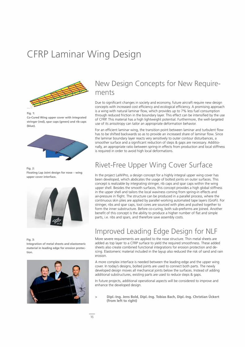
Rivet-Free Upper Wing Cover SurfaceIn the project LaWiPro, a design concept for a highly integral upper wing cover has been developed, which abdicates the usage of bolted joints on outer surfaces. This concept is realizable by integrating stringer, rib caps and spar caps within the wing upper shell. Besides the smooth surfaces, this concept provides a high global stiffness in the upper shell and tailors the local waviness coming from spring-in effects and air-pressure in fl ight. The structure can be produced in a parallel process, where the continuous skin plies are applied by parallel working automated tape layers (GroFi). For stringer, ribs and spar caps, tool cores are sourced with plies and pushed together to form the inner substructure. Before co-curing, both sub-preforms are joined. Another benefi t of this concept is the ability to produce a higher number of fl at and simple parts, i.e. ribs and spars, and therefore save assembly costs.
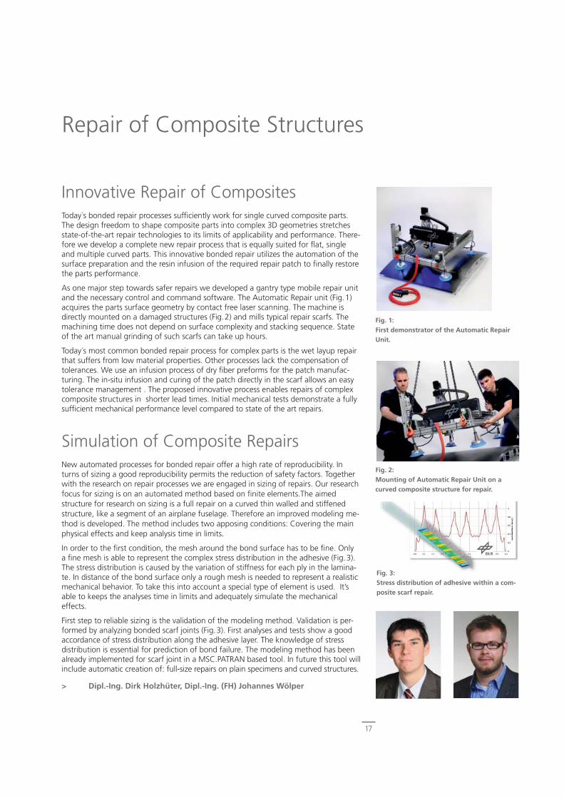
Improved Leading Edge Design for NLFMore severe requirements are applied to the nose structure. Thin metal sheets are added as top layer to a CFRP surface to yield the required smoothness. These added sheets also create combined functional integrations for erosion protection and de-icing. Elastomeric material included in the layup also reduced the risk of sand and rain erosion.
A more complex interface is needed between the leading edge and the upper wing cover. In today’s designs, bolted joints are used to connect both parts. The newly developed design moves all mechanical joints below the surfaces. Instead of adding additional substructures, existing parts are used to reduce steps & gaps.
In future projects, additional operational aspects will be considered to improve and enhance the developed design.
> Dipl.-Ing. Jens Bold, Dipl.-Ing. Tobias Bach, Dipl.-Ing. Christian Ückert (from left to right)
Fig. 1:Co-Cured Wing upper cover with integrated stringer (red), spar caps (green) and rib caps (blue).
Fig. 2:Floating Lap Joint design for nose – wing upper cover interface.
Fig. 3:Integration of metal sheets and elastomeric material in leading edge for erosion protec-tion.
17
Repair of Composite Structures
Innovative Repair of CompositesToday´s bonded repair processes suffi ciently work for single curved composite parts. The design freedom to shape composite parts into complex 3D geometries stretches state-of-the-art repair technologies to its limits of applicability and performance. There-fore we develop a complete new repair process that is equally suited for fl at, single and multiple curved parts. This innovative bonded repair utilizes the automation of the surface preparation and the resin infusion of the required repair patch to fi nally restore the parts performance.
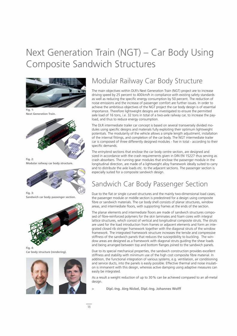
As one major step towards safer repairs we developed a gantry type mobile repair unit and the necessary control and command software. The Automatic Repair unit (Fig.1) acquires the parts surface geometry by contact free laser scanning. The machine is directly mounted on a damaged structures (Fig.2) and mills typical repair scarfs. The machining time does not depend on surface complexity and stacking sequence. State of the art manual grinding of such scarfs can take up hours.
Today´s most common bonded repair process for complex parts is the wet layup repair that suffers from low material properties. Other processes lack the compensation of tolerances. We use an infusion process of dry fi ber preforms for the patch manufac-turing. The in-situ infusion and curing of the patch directly in the scarf allows an easy tolerance management . The proposed innovative process enables repairs of complex composite structures in shorter lead times. Initial mechanical tests demonstrate a fully suffi cient mechanical performance level compared to state of the art repairs.
Simulation of Composite RepairsNew automated processes for bonded repair offer a high rate of reproducibility. In turns of sizing a good reproducibility permits the reduction of safety factors. Together with the research on repair processes we are engaged in sizing of repairs. Our research focus for sizing is on an automated method based on fi nite elements.The aimed structure for research on sizing is a full repair on a curved thin walled and stiffened structure, like a segment of an airplane fuselage. Therefore an improved modeling me-thod is developed. The method includes two apposing conditions: Covering the main physical effects and keep analysis time in limits.
In order to the fi rst condition, the mesh around the bond surface has to be fi ne. Only a fi ne mesh is able to represent the complex stress distribution in the adhesive (Fig.3). The stress distribution is caused by the variation of stiffness for each ply in the lamina-te. In distance of the bond surface only a rough mesh is needed to represent a realistic mechanical behavior. To take this into account a special type of element is used. It’s able to keeps the analyses time in limits and adequately simulate the mechanical effects.
First step to reliable sizing is the validation of the modeling method. Validation is per-formed by analyzing bonded scarf joints (Fig.3). First analyses and tests show a good accordance of stress distribution along the adhesive layer. The knowledge of stress distribution is essential for prediction of bond failure. The modeling method has been already implemented for scarf joint in a MSC.PATRAN based tool. In future this tool will include automatic creation of: full-size repairs on plain specimens and curved structures.
> Dipl.-Ing. Dirk Holzhüter, Dipl.-Ing. (FH) Johannes Wölper
Fig. 3:Stress distribution of adhesive within a com-posite scarf repair.
Fig. 2:Mounting of Automatic Repair Unit on a curved composite structure for repair.
Fig. 1:First demonstrator of the Automatic Repair Unit.
18
Next Generation Train (NGT) – Car Body Using Composite Sandwich Structures
Modular Railway Car Body StructureThe main objectives within DLR’s Next Generation Train (NGT) project are to increase driving speed by 25 percent to 400km/h in compliance with existing safety standards as well as reducing the specifi c energy consumption by 50 percent. The reduction of noise emissions and the increase of passenger comfort are further issues. In order to achieve the ambitious objectives of the NGT project the car body design is of essential importance. Therefore lightweight designs are investigated to ensure the permitted axle load of 16 tons, i.e. 32 tons in total of a two-axle railway car, to increase the pay-load, and thus to reduce energy consumption.
The DLR intermediate trailer car concept is based on several transversely divided mo-dules using specifi c designs and materials fully exploiting their optimum lightweight potentials. The modularity of the vehicle allows a simple length adjustment, installation of the internal fi ttings, and completion of the car body. The NGT intermediate trailer car is composed of three differently designed modules - fi ve in total - according to their specifi c demands.
The entry/end sections that enclose the car body centre section, are designed and sized in accordance with the crash requirements given in DIN EN 15227 thus serving as crash absorbers. The running gear modules that enclose the passenger module in the longitudinal direction, are made of a lightweight alloy framework ideally suited to carry and to distribute the axle loads etc. to the adjacent sections. The passenger section is especially suited for a composite sandwich design.
Sandwich Car Body Passenger SectionDue to the fl at or single curved structures and the mainly two-dimensional load cases, the passenger module or middle section is predestined for a design using composite fi bre or sandwich materials. The car body shell consists of planar structures, window areas, and intermediate fl oors, with supporting frames at the ends of the section.
The planar elements and intermediate fl oors are made of sandwich structures compo-sed of fi bre-reinforced polymers for the skin laminates and foam cores with integral lattice structures, which consist of vertical and longitudinal composite struts. The struts are used for the load introduction from frames or adjacent elements and form an inte-grated closed rib stringer framework together with the diagonal struts of the window framework. The integrated framework structure increases the tensile and compressive stiffness of the sandwich panels that reduces the susceptibility to buckling. The win-dow areas are designed as a framework with diagonal struts guiding the shear loads and being arranged between top and bottom fl anges joined to the sandwich panels.
Due to its special mechanical properties, the sandwich construction provides excellent stiffness and stability with minimum use of the high cost composite fi bre material. In addition, the functional integration of various systems, e.g. ventilation, air conditioning and service ducts, into the panels is easily possible. Effective thermal and noise insulati-on is immanent with this design, whereas active damping using adaptive measures can easily be integrated.
As a result a weight reduction of up to 30% can be achieved compared to an all-metal design.
> Dipl.-Ing. Jörg Nickel, Dipl.-Ing. Johannes Wolff
Fig. 1: Next Generation Train.
Fig. 2: Modular railway car body structure.
Fig. 3: Sandwich car body passenger section.
Fig. 4: Car body structure (rendering).

19
Enhancing the Mechanical Performance of Unidirectional CFRP by Metal-HybridizationIn almost every composite aerospace application, high structural effi ciency competes with damage tolerance requirements. Especially when high specifi c uniaxial mechani-cal properties are aspired, notch and impact sensitivity properties drastically limit the fi ber fraction in load direction. As a result, stiffness and strength per unit weight of the laminate in a given direction are lower than the corresponding properties for a unidirectional composite.
The approach to reduce the aforementioned disadvantages uses a new laminate lay-up with metal layer thickness less than 0.08mm and low metal volume fractions (Fig.1). The metal layers replace +/-45° and 90°-plies. Hence, stiffness and strength in 0°-di-rection are not reduced compared to the use of variant fi ber directions, while residual strength-after-impact is improved compared to pure unidirectional (UD-) laminates. In case of an impact or fracture, the metal layers defl ect inter-fi ber-fractures into delamination zones and serve as crack arrest layers . Fiber Metal Laminates are capable of absorbing energy through plastic deformation and through failure at the interfaces. Thus, energy dissipation is increased due to the larger number of interfaces within the laminate. However, a superior adhesion between the interfaces of the two constitu-ents is required to ensure these properties for undamaged or damaged parts especially under compression loading.
Combining Superior Surface TreatmentsGrit-blasting, a common pre-treatment process for steel surfaces, is not feasible for thin foils due to the risk of damaging the metallic substrate. Various pickling proces-ses were tested as alternative pre-treatment of the thin stainless steel (1.4310) foils. Specimens for the evaluation of the adhesion performance were fabricated using nitric-hydrofl uoric and nitric-phosphoric-hydrofl uoric acid as well as a nitrate free solution based on sulfuric-hydrochloric-hydrogen peroxide acid. The chemical pre-treatment was combined with a sol-gel post-treatment. Acid concentration and pickling duration were varied (see numbers given in Fig.2). Adhesion performance is evaluated by deter-mination of the apparent interlaminar shear strength using the short-beam method EN ISO 14130. Fig.2 shows that the nitrate-free 3 pre-treatment provides an even higher apparent interlaminar shear strength than the reference ‘Boeing sol-gel’ process which is based on grit-blasting. Specimens treated with the nitrate-free 3 process do all show cohesive failure in the matrix only.
To evaluate the properties of the novel material, compression and compression-after-impact tests were performed. Therefore, the unidirectional CFRP-steel specimens with a metal volume fraction M of 7.5% and metal layer thickness t = 0.05mm were tested in comparison with a UD and a highly 0°-dominated multiaxial reference lay-up (62.5/25/12.5). The results in Fig.3 show a catastrophic failure of the UD specimens after 30J impact. The compression-after-impact strength of UD-CFRP-steel and CFRP-(62.5/25/12.5) are quite similar, whereas compression strength and stiffness are increased by approx.48% compared to the multiaxial reference. Specifi c compression strength and specifi c compression modulus are increased by 14% and 13%, respec-tively.
Thus, the investigated surface treatment guarantees superior adhesion within the novel material providing enhanced compression stiffness and strength in combination with an adequate residual strength-after-impact in comparison to state-of-the-art pure CFRP laminates.
> Dipl.-Ing. Daniel Stefaniak
Fig. 1:Unidirectional CFRP-metal laminate.
Fig. 2:Apparent interlaminar shear strength using different surface pre-treatments.
Fig. 3:Compression properties.

Compliant Aggregation of Functionalities
20
21
Function Integration Function integration in context of design issues describes the aim to aggregate multiple useful functionalities in as few parts as possible. Integrated structures lead to reduced assembly and joining efforts and to much better and effi cient use of the structures material in many cases. The customer’s value is not directly given by the number of integrated functionalities, but the aggregation of functionalities offers additional be-nefi ts such as reduced weight, reduced life cycle costs and increased range of applica-tion. Although the integration of multiple functionalities is part of almost each design recommendation, clear instructions how to conduct lightweight design are hardly given. Focusing on fi ber reinforced plastics (FRP) the aggregation of multiple functions gains growing importance. Regarding high-performance structures, mainly carbon fi ber reinforced plastics (CFRP) are used. After substituting metal components by composite structures in the recent years, the integration of multiple functions is the next challen-ge for engineers striving for highly effi cient structures. New materials with superior properties are a prerequisite for technological innovations. Especially the integration of new functionalities is the key to further enhance the competitiveness and application range of composite materials. The collaborative research on composite materials within interdisciplinary and international teams is focused on the following areas:
- Integration of new functionalities
- Improvement of properties
- Advancement of processability
- Provision of reliable material data
- Qualifi cation of new structural concepts
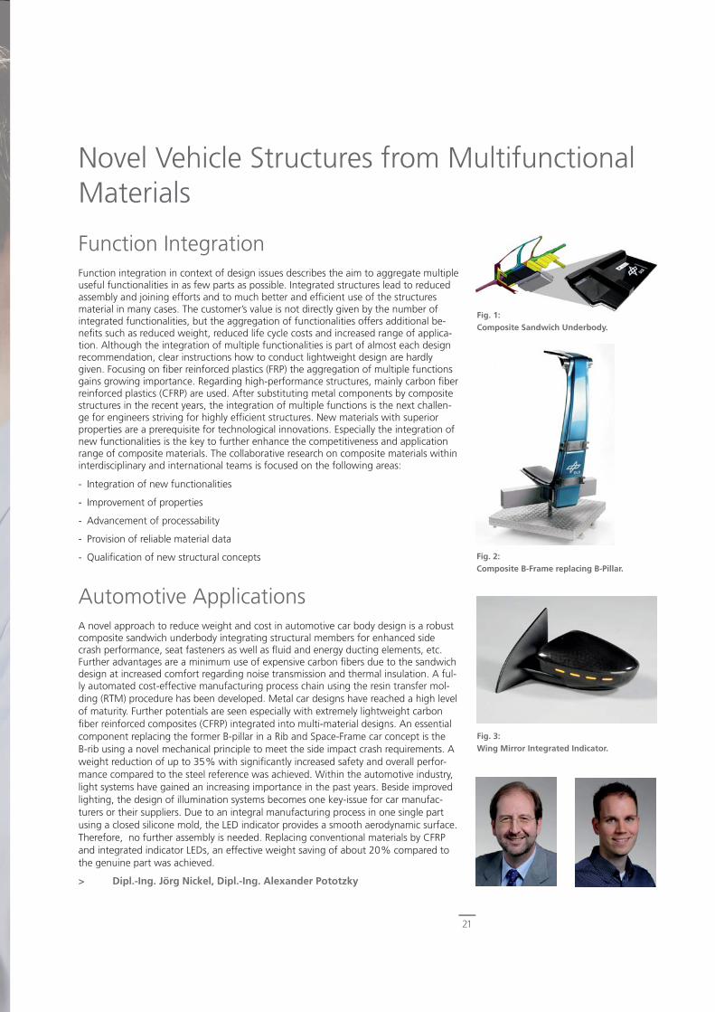
Automotive Applications A novel approach to reduce weight and cost in automotive car body design is a robust composite sandwich underbody integrating structural members for enhanced side crash performance, seat fasteners as well as fl uid and energy ducting elements, etc. Further advantages are a minimum use of expensive carbon fi bers due to the sandwich design at increased comfort regarding noise transmission and thermal insulation. A ful-ly automated cost-effective manufacturing process chain using the resin transfer mol-ding (RTM) procedure has been developed. Metal car designs have reached a high level of maturity. Further potentials are seen especially with extremely lightweight carbon fi ber reinforced composites (CFRP) integrated into multi-material designs. An essential component replacing the former B-pillar in a Rib and Space-Frame car concept is the B-rib using a novel mechanical principle to meet the side impact crash requirements. A weight reduction of up to 35% with signifi cantly increased safety and overall perfor-mance compared to the steel reference was achieved. Within the automotive industry, light systems have gained an increasing importance in the past years. Beside improved lighting, the design of illumination systems becomes one key-issue for car manufac-turers or their suppliers. Due to an integral manufacturing process in one single part using a closed silicone mold, the LED indicator provides a smooth aerodynamic surface. Therefore, no further assembly is needed. Replacing conventional materials by CFRP and integrated indicator LEDs, an effective weight saving of about 20% compared to the genuine part was achieved.
> Dipl.-Ing. Jörg Nickel, Dipl.-Ing. Alexander Pototzky
Novel Vehicle Structures from Multifunctional Materials
Fig. 1:Composite Sandwich Underbody.
Fig. 2:Composite B-Frame replacing B-Pillar.
Fig. 3:Wing Mirror Integrated Indicator.

22
Lightweight Airfreight Containers: High-Tech in a Box for Greener Logistics
Airfreight Containers: ChallengesAirfreight containers carry diverse freight items and protect them against damages. The different existing container types are related to the aircraft type and their lo-cation inside the airplane. They differ in size and shape. State-of-the-art main deck containers are made of aluminum alloys or polycarbonate. RFID-technology should be used to help in case of loss or misplacement of freight. However, this technology is not applicable with aluminum containers due to the shielding effect of the mate-rial. Airfreight containers are exposed to daily usage conditions, so repairs are often necessary. Common repair practices - for example patch repairs – always increase the weight of the container. Spare replacement containers are mandatory, because repairs are done at special repair stations, which are located outside the airport. Repairs are costly and time consuming. Besides costs for repair, the tare weight of the container has a major infl uence on the total cost of ownership (TCO). For these reasons, the aim of the DLR research is a to make airfreight transport more effi cient. The tare weight has to be as low as possible. By minimization of the tare weight, either more freight can be transported, or fuel can be saved. In any case, the environment can be protected by minimization of CO2-emissions. Also Life-Cycle-Costs are reduced by enhancing the robustness and alternative repair methods, which enable on-site repairs. Hence a replacement of damaged containers or sending them to specialized repair companies can be avoided. With the help of innovative material applications, RFID-technology will also be possible.
Transferring Innovation to PracticeFirst, all necessary and common requirements for airfreight containers were identifi ed and wishes for and problems of containers were collected from several logistic com-panies. DLR research engineers visited HUBs and airports to observe the handling of containers fi rst hand. Repair stations were also visited. Market analyses and feasibility studies were conducted. Design-concepts were evaluated with various tools developed at DLR. These tools evaluate, for example, weight, cost, global design and materials. Possible combinations of materials were identifi ed, which result in a reduction of weight while functionality is increased. With the support of FE-Models, simulations of necessary tests required by the IATA ULD Technical Manual for baseplate and con-tainers were carried out. The simulations were instrumental in the derivation of the required mechanical properties for the considered materials. In addition, real roller- and ball-tests were carried out in the institute. For the chosen materials concepts for pro-duction were developed. The design-concept, which was chosen during our research, is demonstrated using a real life-size container type (AAX). Its footprint is six square meters and the height is about two and a half meters. The weight reduction compared to existing AAX containers is about 25 percent.
The side panels are made of a very lightweight technical textile. Its fl exibility makes it more resistant to damage. Easier and low-cost repairs are possible, because it is no lon-ger necessary to replace damaged containers or to send them to specialized companies for repair work. Technical textiles also allow the utilization of radio frequency identifi -cation technologies (RFID). The baseplate is made of a hybrid material, which is capable of withstanding the stresses and strains caused by the rollers in the loading and the transport systems.
> Dipl.-Ing. Ivonne Bartsch
Fig. 2:Built demonstrator based on the Design-concept.
Fig. 1:CATIA Design-concept.
23
Natural Fiber Reinforced Plastics (NFRP) for Aircraft CabinsThe need for ecological benefi cial materials is growing all over the world and also in the aviation industry. For example renewable resources like fl ax offer good opportuni-ties to substitute glass fi bers in fi ber reinforced plastics. DLR examined the application of natural fi bers in aircraft cabins in a LUFO project together with Diehl Aircabin. As cellulose containing fi bers increase the risk of fi re compared to glass fi bers, the main task was the improvement of the fl ame retardancy of NFRP.
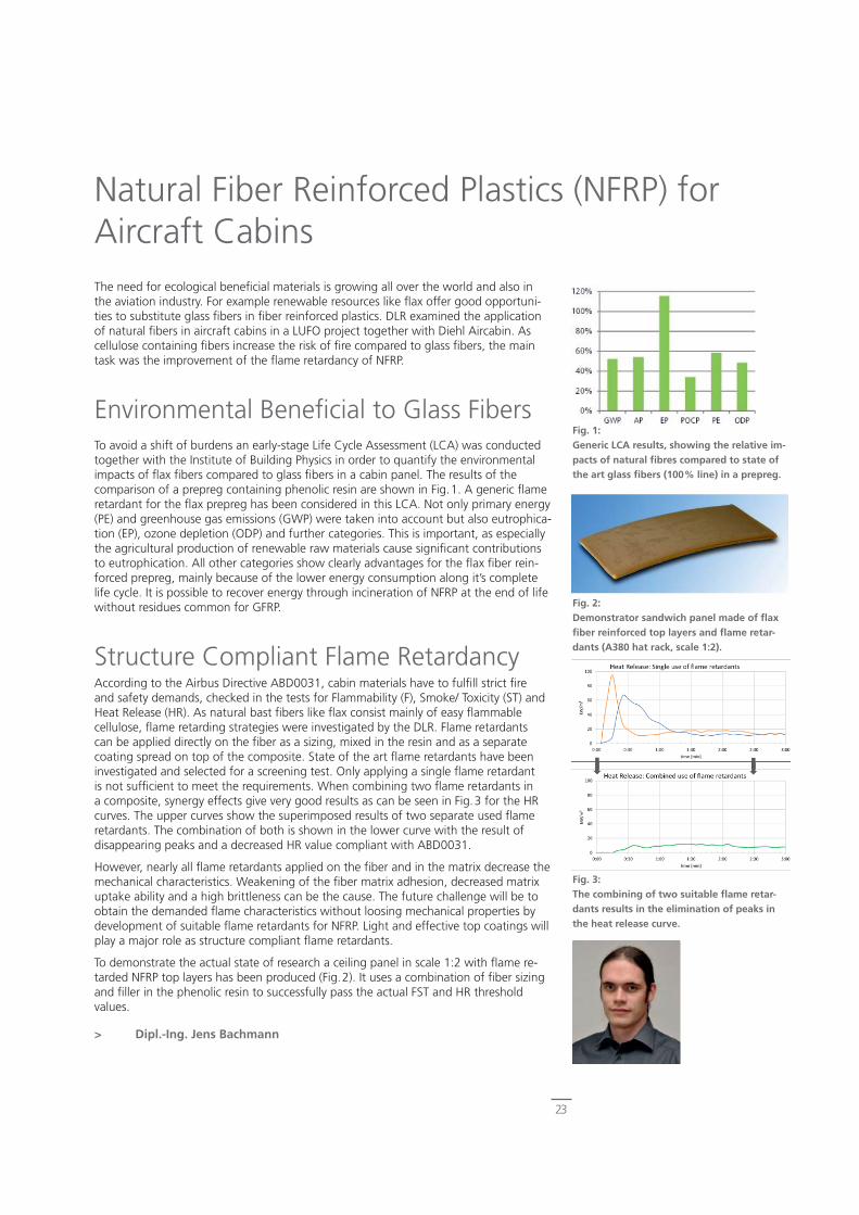
Environmental Benefi cial to Glass FibersTo avoid a shift of burdens an early-stage Life Cycle Assessment (LCA) was conducted together with the Institute of Building Physics in order to quantify the environmental impacts of fl ax fi bers compared to glass fi bers in a cabin panel. The results of the comparison of a prepreg containing phenolic resin are shown in Fig.1. A generic fl ame retardant for the fl ax prepreg has been considered in this LCA. Not only primary energy (PE) and greenhouse gas emissions (GWP) were taken into account but also eutrophica-tion (EP), ozone depletion (ODP) and further categories. This is important, as especially the agricultural production of renewable raw materials cause signifi cant contributions to eutrophication. All other categories show clearly advantages for the fl ax fi ber rein-forced prepreg, mainly because of the lower energy consumption along it’s complete life cycle. It is possible to recover energy through incineration of NFRP at the end of life without residues common for GFRP.
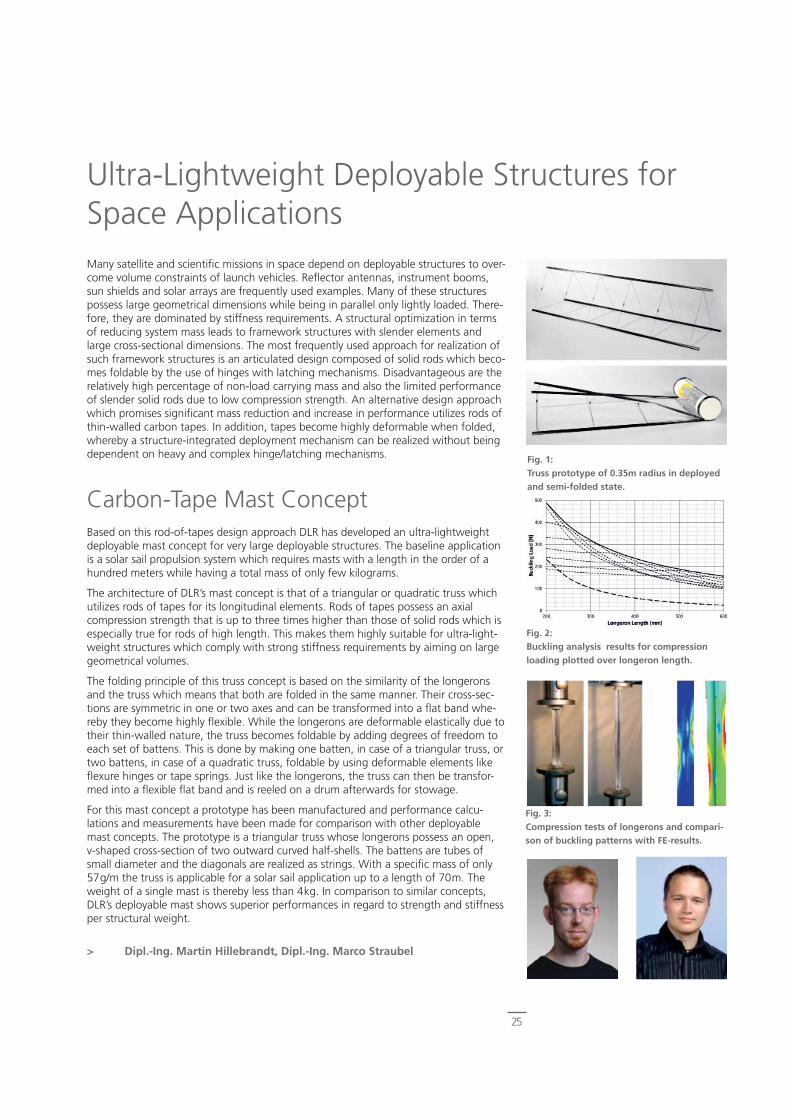
Structure Compliant Flame RetardancyAccording to the Airbus Directive ABD0031, cabin materials have to fulfi ll strict fi re and safety demands, checked in the tests for Flammability (F), Smoke/ Toxicity (ST) and Heat Release (HR). As natural bast fi bers like fl ax consist mainly of easy fl ammable cellulose, fl ame retarding strategies were investigated by the DLR. Flame retardants can be applied directly on the fi ber as a sizing, mixed in the resin and as a separate coating spread on top of the composite. State of the art fl ame retardants have been investigated and selected for a screening test. Only applying a single fl ame retardant is not suffi cient to meet the requirements. When combining two fl ame retardants in a composite, synergy effects give very good results as can be seen in Fig.3 for the HR curves. The upper curves show the superimposed results of two separate used fl ame retardants. The combination of both is shown in the lower curve with the result of disappearing peaks and a decreased HR value compliant with ABD0031.
However, nearly all fl ame retardants applied on the fi ber and in the matrix decrease the mechanical characteristics. Weakening of the fi ber matrix adhesion, decreased matrix uptake ability and a high brittleness can be the cause. The future challenge will be to obtain the demanded fl ame characteristics without loosing mechanical properties by development of suitable fl ame retardants for NFRP. Light and effective top coatings will play a major role as structure compliant fl ame retardants.
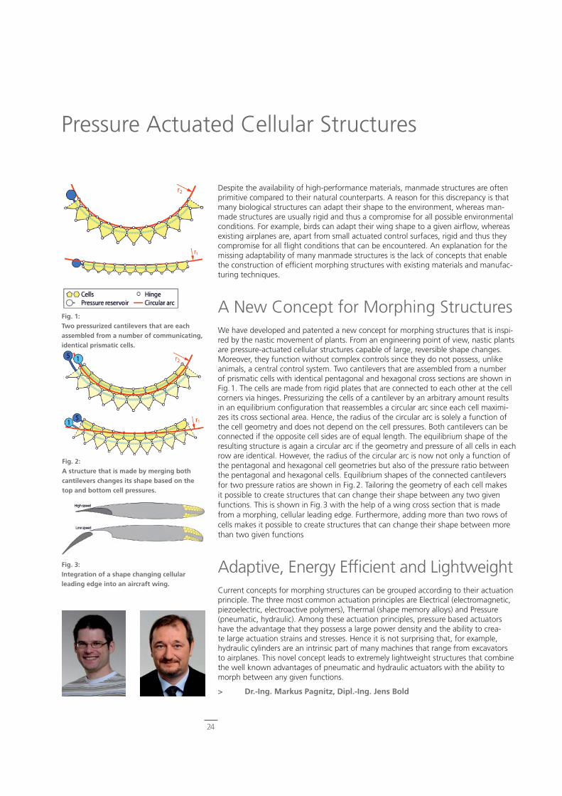
To demonstrate the actual state of research a ceiling panel in scale 1:2 with fl ame re-tarded NFRP top layers has been produced (Fig.2). It uses a combination of fi ber sizing and fi ller in the phenolic resin to successfully pass the actual FST and HR threshold values.
> Dipl.-Ing. Jens Bachmann
Fig. 1:Generic LCA results, showing the relative im-pacts of natural fi bres compared to state of the art glass fi bers (100% line) in a prepreg.
Fig. 2:Demonstrator sandwich panel made of fl ax fi ber reinforced top layers and fl ame retar-dants (A380 hat rack, scale 1:2).
Fig. 3:The combining of two suitable fl ame retar-dants results in the elimination of peaks in the heat release curve.
24
Despite the availability of high-performance materials, manmade structures are often primitive compared to their natural counterparts. A reason for this discrepancy is that many biological structures can adapt their shape to the environment, whereas man-made structures are usually rigid and thus a compromise for all possible environmental conditions. For example, birds can adapt their wing shape to a given airfl ow, whereas existing airplanes are, apart from small actuated control surfaces, rigid and thus they compromise for all fl ight conditions that can be encountered. An explanation for the missing adaptability of many manmade structures is the lack of concepts that enable the construction of effi cient morphing structures with existing materials and manufac-turing techniques.
A New Concept for Morphing StructuresWe have developed and patented a new concept for morphing structures that is inspi-red by the nastic movement of plants. From an engineering point of view, nastic plants are pressure-actuated cellular structures capable of large, reversible shape changes. Moreover, they function without complex controls since they do not possess, unlike animals, a central control system. Two cantilevers that are assembled from a number of prismatic cells with identical pentagonal and hexagonal cross sections are shown in Fig.1. The cells are made from rigid plates that are connected to each other at the cell corners via hinges. Pressurizing the cells of a cantilever by an arbitrary amount results in an equilibrium confi guration that reassembles a circular arc since each cell maximi-zes its cross sectional area. Hence, the radius of the circular arc is solely a function of the cell geometry and does not depend on the cell pressures. Both cantilevers can be connected if the opposite cell sides are of equal length. The equilibrium shape of the resulting structure is again a circular arc if the geometry and pressure of all cells in each row are identical. However, the radius of the circular arc is now not only a function of the pentagonal and hexagonal cell geometries but also of the pressure ratio between the pentagonal and hexagonal cells. Equilibrium shapes of the connected cantilevers for two pressure ratios are shown in Fig.2. Tailoring the geometry of each cell makes it possible to create structures that can change their shape between any two given functions. This is shown in Fig.3 with the help of a wing cross section that is made from a morphing, cellular leading edge. Furthermore, adding more than two rows of cells makes it possible to create structures that can change their shape between more than two given functions
Adaptive, Energy Effi cient and LightweightCurrent concepts for morphing structures can be grouped according to their actuation principle. The three most common actuation principles are Electrical (electromagnetic, piezoelectric, electroactive polymers), Thermal (shape memory alloys) and Pressure (pneumatic, hydraulic). Among these actuation principles, pressure based actuators have the advantage that they possess a large power density and the ability to crea-te large actuation strains and stresses. Hence it is not surprising that, for example, hydraulic cylinders are an intrinsic part of many machines that range from excavators to airplanes. This novel concept leads to extremely lightweight structures that combine the well known advantages of pneumatic and hydraulic actuators with the ability to morph between any given functions.
> Dr.-Ing. Markus Pagnitz, Dipl.-Ing. Jens Bold
Pressure Actuated Cellular Structures
Fig. 1:Two pressurized cantilevers that are each assembled from a number of communicating, identical prismatic cells.
Fig. 2:A structure that is made by merging both cantilevers changes its shape based on the top and bottom cell pressures.
Fig. 3:Integration of a shape changing cellular leading edge into an aircraft wing.
25
Ultra-Lightweight Deployable Structures for Space ApplicationsMany satellite and scientifi c missions in space depend on deployable structures to over-come volume constraints of launch vehicles. Refl ector antennas, instrument booms, sun shields and solar arrays are frequently used examples. Many of these structures possess large geometrical dimensions while being in parallel only lightly loaded. There-fore, they are dominated by stiffness requirements. A structural optimization in terms of reducing system mass leads to framework structures with slender elements and large cross-sectional dimensions. The most frequently used approach for realization of such framework structures is an articulated design composed of solid rods which beco-mes foldable by the use of hinges with latching mechanisms. Disadvantageous are the relatively high percentage of non-load carrying mass and also the limited performance of slender solid rods due to low compression strength. An alternative design approach which promises signifi cant mass reduction and increase in performance utilizes rods of thin-walled carbon tapes. In addition, tapes become highly deformable when folded, whereby a structure-integrated deployment mechanism can be realized without being dependent on heavy and complex hinge/latching mechanisms.
Carbon-Tape Mast ConceptBased on this rod-of-tapes design approach DLR has developed an ultra-lightweight deployable mast concept for very large deployable structures. The baseline application is a solar sail propulsion system which requires masts with a length in the order of a hundred meters while having a total mass of only few kilograms.
The architecture of DLR’s mast concept is that of a triangular or quadratic truss which utilizes rods of tapes for its longitudinal elements. Rods of tapes possess an axial compression strength that is up to three times higher than those of solid rods which is especially true for rods of high length. This makes them highly suitable for ultra-light-weight structures which comply with strong stiffness requirements by aiming on large geometrical volumes.
The folding principle of this truss concept is based on the similarity of the longerons and the truss which means that both are folded in the same manner. Their cross-sec-tions are symmetric in one or two axes and can be transformed into a fl at band whe-reby they become highly fl exible. While the longerons are deformable elastically due to their thin-walled nature, the truss becomes foldable by adding degrees of freedom to each set of battens. This is done by making one batten, in case of a triangular truss, or two battens, in case of a quadratic truss, foldable by using deformable elements like fl exure hinges or tape springs. Just like the longerons, the truss can then be transfor-med into a fl exible fl at band and is reeled on a drum afterwards for stowage.
For this mast concept a prototype has been manufactured and performance calcu-lations and measurements have been made for comparison with other deployable mast concepts. The prototype is a triangular truss whose longerons possess an open, v-shaped cross-section of two outward curved half-shells. The battens are tubes of small diameter and the diagonals are realized as strings. With a specifi c mass of only 57g/m the truss is applicable for a solar sail application up to a length of 70m. The weight of a single mast is thereby less than 4kg. In comparison to similar concepts, DLR’s deployable mast shows superior performances in regard to strength and stiffness per structural weight.
> Dipl.-Ing. Martin Hillebrandt, Dipl.-Ing. Marco Straubel
Fig. 2:Buckling analysis results for compression loading plotted over longeron length.
Fig. 3:Compression tests of longerons and compari-son of buckling patterns with FE-results.
Fig. 1:Truss prototype of 0.35m radius in deployed and semi-folded state.
26
A Launcher for the Sheffex III ExperimentFor the third Shefex mission, a cooperation between the DCTA (Departamento de Ciência e Tecnologia Aeroespacial) of Brazil and the DLR is established to develop a de-dicated launcher. The launcher is not only intended for Shefex III but can also be used as a launcher for small satellites as the name indicates.
The VLM (Veículo Lançador de Microssatélites) is a small rocket capable of lifting 500kg into a 100km suborbital trajectory (Sheffex III experiment) and smaller satellites to an orbit between 250km and 700km. It has three solid fuel stages. The third stage will have additional cold gas thrusters for the stabilisation of the experiment.
The DLR Institute of Composite Structures and Adaptive Systems is responsible for the development, prototype production and testing of the two interstages connecting the three stages. It also does the modal analyses of the complete rocket.
Interstage Structure Infl uences PayloadIn rocket structures, the need for a lightweight construction rises as the weight is loca-ted closer to the payload. In case of the payload adapter a kilogram of additional mass reduces the maximum possible payload mass by one kilogram. The closer the structure is to the fi rst stage – like the interstage 1-2 – the smaller is the impact on the payload mass. Nevertheless a lightweight design is also desirable for the structure of the inters-tage 1-2 because of high loads in this area.
The VLM interstages have the additional requirement to be suitable for a hot separa-tion. This means that the next stage is fi red just before separation. The hot separation is needed to avoid fi ns for stability during separation and requires an interstage with large holes for the hot gases.
Orthotropic Grid – Stiff Open StructureA composite grid structure is under consideration for the interstages 1-2 and 2-3 as it displays lightweight potential and the ability to allow hot gases to exit during the hot separation. The struts of the grid are made of unidirectional fi ber composites thus providing the maximum stiffness in the strut direction. Since the load is guided into the struts along the fi ber direction, the design can avoid excess structural weight. This truss type structure also allows for geometric and material tailoring to satisfy stiffness as well as stability. The stiffness of the interstage is given by the angle, cross section and strut pitch. The confi guration demands a very high stiffness in fl ight direction and negligible stiffness in all other direction. Therefore a highly orthotropic structure is chosen.
Consequently, a grid structure allows a good sizing for stiffness, stability and strength, while at the same time providing enough open area for the hot separation. Thus from the mechanical and the functional points of view, a composite grid structure has po-tential as an interstage structure.
> MSE Heike Loose-Busch, Dipl.-Ing. Olaf Mierheim, M.Sc. Steffen Niemann
Fig. 1:VLM for Shefex III with interstage 1-2.
Fig. 2:Different structural designs for the interstage 1-2.
VLM for Shefex III - Composite Structures in Space Transport
27
Asteroid (sampling) missions are of high interest for fi nding a missing link in the deve-lopment of life on earth. Still the step from atoms to the formation of higher molecules is not yet fully understood. One theory is the impact of asteroids on earth bringing these higher molecules with them. By an asteroid sampling mission this theory could be corroborated. Additionally the type and formation of differently classifi ed asteroids can be investigated.
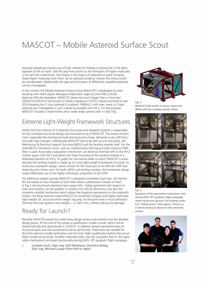
In this context the Mobile Asteroid Surface Scout (MASCOT) is developed at colla-borating with JAXA (Japan Aerospace Exploration Agency) and CNES (Centre National d’Études Spatiales). MASCOT, being not much bigger than a ‘shoe box’ (295x275x195mm³) will be part of JAXA’s Hayabusa 2 (HY-2) mission launched in late 2014 heading the C-class asteroid (C=carbon) 1999JU3. Until now, never a C-class asteroid was investigated in such a detail as possible with HY-2. For this purpose MASCOT includes 3 experiments and a wide angle camera with in total 3kg.
Extreme Light-Weight Framework StructuresWithin DLR the Institute of Composite Structures and Adaptive Systems is responsible for the complete structural design and manufacturing of MASCOT. The severe environ-ment, especially the mechanical loads during launch phase, demands a very stiff struc-ture with high strength. Additionally MASCOT had to be split up into two parts, the Mechanical & Electrical Support Structure (MESS) and the landing module itself. For the solid MESS’s framework struts with an unidirectional (UD) layup a high modulus (HM) fi ber is used. It provides a separation mechanism, an electrical interface (I/F) to the HY-2 mother space craft (S/C) and allows the fi xed mounting of the landing module in a dedicated position on HY-2. To guide the mechanical loads to which MASCOT is expo-sed also the landing module is made up of a very light-weight framework structure. Its struts are a sandwich design, which consist for the most part of an HM UD-CFRP face sheet ply and a foam core. For both, MESS and landing module, the framework design makes effectively use of the highly orthotropic properties of UD-CFRP.
For additional weight savings MASCOT is designed completely insert less. All internal I/Fs are based on resin threads or local solid carbon substitutions instead of foam. In Fig.2 the aluminium electronic box (upper left) , highly optimised with respect to mass and volume, can be spotted. It contains not only all electronics, but also the complete mobility mechanism which allows the hopping manoeuvres on the asteroid’s surface. All these features make MASCOT an extremely compact and highly optimised light-weight S/C structure which weigh 1kg only. At the same time it must withstand 50 times the total systems own weight, i. e. half a ton, without taking any damage.
Ready for Launch?Recently MASCOT passed the preliminary design review and entered now the detailed design phase. At the end of this phase a qualifi cation model is build, which will be tested statically and dynamically in 12/2012. In addition several standalone tests of structural parts and sub-components will be performed. These tests are needed for the fi nite element model verifi cation and the fi nal fl ight qualifi cation before the actual fl ight model can be build. Another important step was the successful test of the sepa-ration mechanism’s principal functionality during DLR’s 19th parabolic fl ight campaign.
> Cordelia Koch, Dipl.-Ing. Olaf Mierheim, Christine König, Dipl.-Ing. Michael Lange (from left to right)
MASCOT – Mobile Asteroid Surface Scout
Fig. 1:MASCOT CAD model. In brown colour the MESS with the landing module within.
Fig. 2:Sequence of the separation mechanism’s test during DLR’s 19th parabolic fl ight campaign under nearly zero gravity. The landing modu-le is “falling down” with approx. 30cm/s as it will be during its decent to the asteroid’s surface.
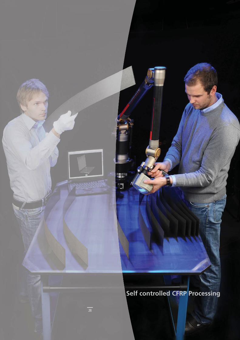
Self controlled CFRP Processing
28

29
Anisotropic material properties of composite materials are one key issue for their outstanding mechanical performance as strength and stiffness of a structure can be adjusted according to the demands by intelligent laminate stacking. However, those direction dependent properties in combination with currently high temperature process cycles lead to undesired deformations during the manufacturing processes. Those de-viations of the manufactured shape from the nominal shape induced by the material’s anisotropy are referred to as spring-in deformations. Commonly those spring-in devi-ations are undesired as they impede the assembly due to lacking geometrical fi delity. Nevertheless, there are selected applications as well, which could benefi t from those inevitable manufacturing deformations.
Composite‘s Anisotropy Inevitably Leads to Process Distortions as Spring-In.Conventional wing designs on today’s transport aircraft show predominantly turbulent airfl ow. In order to increase the portion of laminar fl ow on wings, extraordinary geo-metrical fi delity is required within the aspired operating range. Besides the aspect of steps and gaps, this also requires an appropriate accuracy of the surface contour. Loads during fl ight do not only result in a global wing bending. Local deformations arise when e.g. compression in the curved wing cover leads to out-of-plane deformations. Additionally suction on the wing skin leads to local bending and an inherent wavi-ness. Both of these phenomena can be predicted quite well nowadays. Investigations showed their magnitude to be in the same order as the ones resulting from manufac-turing, but often acting in the opposite direction. The question whether manufacturing deformations could be played off against the ones resulting from fl ight loads seemed to be not far to seek.
Using Spring-In Distortions to Counteract Waviness due to Aerodynamic LoadsThe aim of further research in this context will be to develop design capabilities for more laminar wings. Certainly the highly challenging requirements for laminar fl ow can only be fulfi lled within a small range of the fl ight envelope. On the other hand struc-tural integrity has to be shown for the whole envelope including any fl ight condition possible. This challenge becomes even more sophisticated when aeroelastic tailoring is an indispensable matter due to forward sweep of the wings. One main driver to avoid static divergence is to change the orientation of the main stiffness and hence prevent wash-in. Effi cient prediction of the resulting trapezoidal panels, e.g. in terms of stability is only one aspect to be dealt with. Within a multidisciplinary design process manufac-turing effects such as spring-in as well as effects due to aerodynamic loads should be considered simultaneously. Thus, the extreme requirements for natural laminar fl ow can be achieved which promises a signifi cant reduction of fuel burn. This represents a major key task for next generation aircraft considering increasing fuel costs and the need for reduction of the environmental impact as outlined by the ACARE program.
> Dipl.-Ing. Lars Heinrich, Dipl.-Ing. Erik Kappel
Multidisciplinary Design Process for CFRP Wings with More Natural Laminar Flow
Fig. 1:Waviness of a stiffened wing cover due to manufacturing deformations as spring-in.
Fig. 2:Waviness of a stiffened wing upper cover due to aerodynamic loads.
Fig. 3:Meeting NLF requirements by balancing out manufacturing deformations and waviness due to aerodynamic loads.
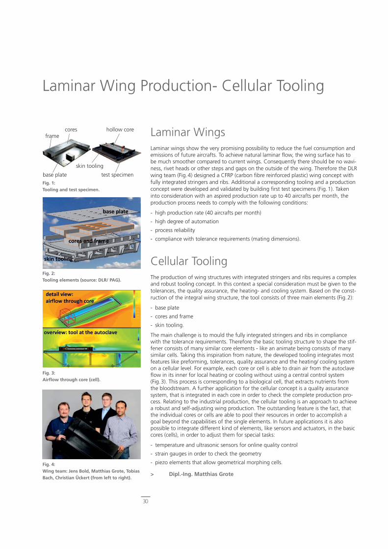
30
Laminar WingsLaminar wings show the very promising possibility to reduce the fuel consumption and emissions of future aircrafts. To achieve natural laminar fl ow, the wing surface has to be much smoother compared to current wings. Consequently there should be no wavi-ness, rivet heads or other steps and gaps on the outside of the wing. Therefore the DLR wing team (Fig.4) designed a CFRP (carbon fi bre reinforced plastic) wing concept with fully integrated stringers and ribs. Additional a corresponding tooling and a production concept were developed and validated by building fi rst test specimens (Fig.1). Taken into consideration with an aspired production rate up to 40 aircrafts per month, the production process needs to comply with the following conditions:
- high production rate (40 aircrafts per month)
- high degree of automation
- process reliability
- compliance with tolerance requirements (mating dimensions).
Cellular ToolingThe production of wing structures with integrated stringers and ribs requires a complex and robust tooling concept. In this context a special consideration must be given to the tolerances, the quality assurance, the heating- and cooling system. Based on the const-ruction of the integral wing structure, the tool consists of three main elements (Fig.2):
- base plate
- cores and frame
- skin tooling.
The main challenge is to mould the fully integrated stringers and ribs in compliance with the tolerance requirements. Therefore the basic tooling structure to shape the stif-fener consists of many similar core elements - like an animate being consists of many similar cells. Taking this inspiration from nature, the developed tooling integrates most features like preforming, tolerances, quality assurance and the heating/ cooling system on a cellular level. For example, each core or cell is able to drain air from the autoclave fl ow in its inner for local heating or cooling without using a central control system (Fig.3). This process is corresponding to a biological cell, that extracts nutrients from the bloodstream. A further application for the cellular concept is a quality assurance system, that is integrated in each core in order to check the complete production pro-cess. Relating to the industrial production, the cellular tooling is an approach to achieve a robust and self-adjusting wing production. The outstanding feature is the fact, that the individual cores or cells are able to pool their resources in order to accomplish a goal beyond the capabilities of the single elements. In future applications it is also possible to integrate different kind of elements, like sensors and actuators, in the basic cores (cells), in order to adjust them for special tasks:
- temperature and ultrasonic sensors for online quality control
- strain gauges in order to check the geometry
- piezo elements that allow geometrical morphing cells.
> Dipl.-Ing. Matthias Grote
Laminar Wing Production- Cellular Tooling
Fig. 1:Tooling and test specimen.
Fig. 2:Tooling elements (source: DLR/ PAG).
Fig. 3:Airfl ow through core (cell).
Fig. 4:Wing team: Jens Bold, Matthias Grote, Tobias Bach, Christian Ückert (from left to right).
framecores hollow core
skin tooling
base plate test specimen
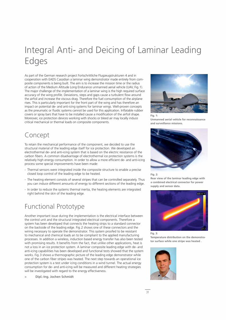
31
As part of the German research project Fortschrittliche Flugzeugstrukturen 4 and in cooperation with EADS Cassidian a laminar wing demonstrator made entirely from com-posite components is being built. The aim is to increase the mission time or the radius of action of the Medium Altitude Long Endurance unmanned aerial vehicle (UAV, Fig.1). The major challenge of the implementation of a laminar wing is the high required surface accuracy of the wing profi le. Deviations, steps and gaps cause a turbulent fl ow around the airfoil and increase the viscous drag. Therefore the fuel consumption of the airplane rises. This is particularly important for the front part of the wing and has therefore an impact on potential de- and anti-icing systems for laminar wings. Well-proven concepts as the pneumatic or fl uidic systems cannot be used for this application. Infl atable rubber covers or spray bars that have to be installed cause a modifi cation of the airfoil shape. Moreover, ice protection devices working with shocks or bleed air may locally induce critical mechanical or thermal loads on composite components.
ConceptTo retain the mechanical performance of the component, we decided to use the structural material of the leading edge itself for ice protection. We developed an electrothermal de- and anti-icing system that is based on the electric resistance of the carbon fi bers. A common disadvantage of electrothermal ice protection systems is the relatively high energy consumption. In order to allow a more effi cient de- and anti-icing process some special improvements have been made:
- Thermal sensors were integrated inside the composite structure to enable a precise closed loop control of the leading edge to be heated.
- The heating element consists of several stripes that can be controlled separately. Thus you can induce different amounts of energy to different sections of the leading edge.
- In order to reduce the systems thermal inertia, the heating elements are integrated right behind the skin of the leading edge.
Functional PrototypeAnother important issue during the implementation is the electrical interface between the control unit and the structural integrated electrical components. Therefore a system has been developed that connects the heating strips to a standard connector on the backside of the leading edge. Fig.2 shows one of these connectors and the wiring necessary to operate the demonstrator. This system proofed to be resistant to mechanical and chemical loads an to be compliant to the applied manufacturing processes. In addition a wireless, induction based energy transfer has also been tested with promising results. It benefi ts from the fact, that unlike other applications, heat is not a loss in an ice protection system. A laminar composite leading edge with de- and anti-icing capabilities has been developed and functional tests showed that the system works. Fig.3 shows a thermographic picture of the leading edge demonstrator while one of the carbon fi ber stripes was heated. The next step towards an operational ice protection system is a test under icing conditions in a wind tunnel. The actual energy consumption for de- and anti-icing will be measured and different heating strategies will be investigated with regard to the energy effectiveness.
> Dipl.-Ing. Jochen Schmidt
Integral Anti- and Deicing of Laminar Leading Edges
Fig. 1:Unmanned aerial vehicle for reconnaissance and surveillance missions.
Fig. 2:Rear view of the laminar leading edge with a combined electrical connector for power supply and sensor data.
Fig. 3:Temperature distribution on the demonstra-tor surface while one stripe was heated .
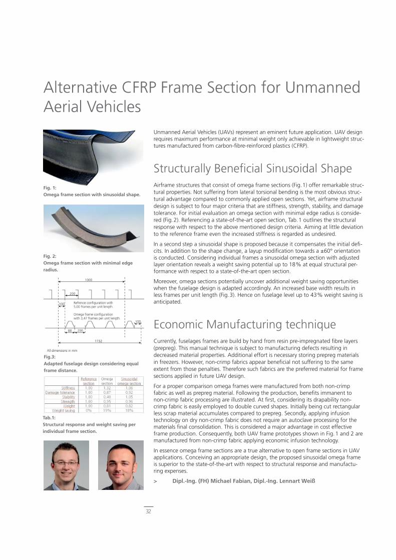
32
Unmanned Aerial Vehicles (UAVs) represent an eminent future application. UAV design requires maximum performance at minimal weight only achievable in lightweight struc-tures manufactured from carbon-fi bre-reinforced plastics (CFRP).
Structurally Benefi cial Sinusoidal ShapeAirframe structures that consist of omega frame sections (Fig.1) offer remarkable struc-tural properties. Not suffering from lateral torsional bending is the most obvious struc-tural advantage compared to commonly applied open sections. Yet, airframe structural design is subject to four major criteria that are stiffness, strength, stability, and damage tolerance. For initial evaluation an omega section with minimal edge radius is conside-red (Fig.2). Referencing a state-of-the-art open section, Tab.1 outlines the structural response with respect to the above mentioned design criteria. Aiming at little deviation to the reference frame even the increased stiffness is regarded as undesired.
In a second step a sinusoidal shape is proposed because it compensates the initial defi -cits. In addition to the shape change, a layup modifi cation towards a ±60° orientation is conducted. Considering individual frames a sinusoidal omega section with adjusted layer orientation reveals a weight saving potential up to 18% at equal structural per-formance with respect to a state-of-the-art open section.
Moreover, omega sections potentially uncover additional weight saving opportunities when the fuselage design is adapted accordingly. An increased base width results in less frames per unit length (Fig.3). Hence on fuselage level up to 43% weight saving is anticipated.
Economic Manufacturing techniqueCurrently, fuselages frames are build by hand from resin pre-impregnated fi bre layers (prepreg). This manual technique is subject to manufacturing defects resulting in decreased material properties. Additional effort is necessary storing prepreg materials in freezers. However, non-crimp fabrics appear benefi cial not suffering to the same extent from those penalties. Therefore such fabrics are the preferred material for frame sections applied in future UAV design.
For a proper comparison omega frames were manufactured from both non-crimp fabric as well as prepreg material. Following the production, benefi ts immanent to non-crimp fabric processing are illustrated. At fi rst, considering its drapability non-crimp fabric is easily employed to double curved shapes. Initially being cut rectangular less scrap material accumulates compared to prepreg. Secondly, applying infusion technology on dry non-crimp fabric does not require an autoclave processing for the materials fi nal consolidation. This is considered a major advantage in cost effective frame production. Consequently, both UAV frame prototypes shown in Fig.1 and 2 are manufactured from non-crimp fabric applying economic infusion technology.
In essence omega frame sections are a true alternative to open frame sections in UAV applications. Conceiving an appropriate design, the proposed sinusoidal omega frame is superior to the state-of-the-art with respect to structural response and manufactu-ring expenses.
> Dipl.-Ing. (FH) Michael Fabian, Dipl.-Ing. Lennart Weiß
Alternative CFRP Frame Section for Unmanned Aerial Vehicles
Fig. 1:Omega frame section with sinusoidal shape.
Fig. 2:Omega frame section with minimal edge radius.
Fig.3:Adapted fuselage design considering equal frame distance.
Tab.1:Structural response and weight saving per individual frame section.

Autonomous CFRP Structures
33

34
Improved Functionality and ComfortSignifi cant vibrations of vehicle exterior rear-view mirrors occur especially on mirrors of big cars, trucks and coaches and reduce, safety, comfort and even the functionality of the mirror systems. In extensive laboratory and road tests with commercial vehicles, the disturbing vibration sources were identifi ed as vehicle modes (vibrations) and as aerodynamic forces that concurrently act on the mirror. The measured mirror glass vibration amplitudes are presented in Fig.1. The spectra clearly depict the modes of the car body (rigid, torsion and bending), the door and the complete vehicle. Unfor-tunately one mirror mode is very close to the mode of the door, that gain the effects of the disturbing vibrations. Conventionally considered, the bearing of a mirror system has to be very soft in order to reduce the transmissibility of the vehicle vibrations to the mirror glass. On the other hand, high stiffnesses are required in order to generate the required reacting forces to the aerodynamic loads. A novel active vibration isolation interface (Fig.2) could be helpful to solve this confl ict because this interface reduces the vibrations in all present degrees of freedom (DOF). It consists of a double spiral spring system with applied piezoelectric foils that can be used as actuators and sensors. The spirals are placed between the mirror housing and the mirror glass in order to decouple the glass from its vibrant environment. This interface, that is patented by DLR conside-ring diverse structural modalities, has impressive properties: from vehicles point of view it is lightly damped and low stiff. No vehicle vibrations are passed on the mirror glass. Additionally, from the point of view of the directly acting air loads the glass is nearly infi nite stiff in combination with the double spirals. The mirrors glass keeps still even for higher speeds.
Active Interface PrototypesIn combination with controlled piezoelectric actuators the double spiral interface remarkably has infi nite and zero stiffness at the same time over a wide frequency range – at least from 0 to 100Hz.One of our fi rst prototypes of double spiral interfaces (Fig.3) has metallic spiral arms with rectangular geometry instead of the curved form (Fig.2). But nevertheless, the relevant DOF´s can be satisfi ed and the vibrations are not longer noticeable by the observer. The double spiral interface is a promising candidate for commercial use because of its advantages with respect to packaging (very fl at design) and series production. Furthermore we found out that the proposed double spiral interface is able to take over the function of the electrical motor that adjusts the mirror position.
Further Industrial ApplicationsDue to the outstanding isolation performance the active double spiral system was also embedded into a Mars lander system. Within this orbital structure, that serve as a geophy-sical monitoring station, it reduces the disturbing vibrations of sensitive measu-ring techniques by a factor of over 90! We suggest to apply the proposed isolation techniques also in binoculars with high magnifi cations and in telescopes, in wind turbi-nes (isolation of the gear unit), in laser pointers and in optical measuring techniques or in form measuring machines that are positioned in rough environments.
> Dipl.-Ing.(FH) Björn T. Kletz, Prof. Dr.-Ing. Dipl.-Phys. Jörg Melcher
Active Vibration Isolation of Rear-View Mirrors
Fig. 1: Spectra of disturbing acceleration amplitudes of rear-view mirror glasses in 3 directions.
Fig. 2:Double spiral interface with piezo-electric actuator pairs and corresponding isolation DOFs (suited to the coloured arrows).
Fig. 3:Rear-view mirror with the fi rst proto-type of the double spiral isolation interface.

35
Some years ago there have been investigations of the design and manufacturing of helicopter rotor blades suitable for individual blade control. The idea is to infl uence the aerodynamics of each individual blade depending on their position during the revoluti-on in order to signifi cantly reduce helicopter vibrations, power consumption and noise emissions. Two of the most promising concepts are the implementation of fl aps and the change of the blade twist. The order of magnitude to be reached with an active twist blade is a blade tip twist of 2° (Fig.1). The implementation of piezoelectric twist actuators into the blade skin is a basic prerequisite of an adaptive system.
The distinctiveness of this approach is the high degree of structural conformity of the actuator system. Both the outer shape as well as the inner spar structure stay basically untouched.
Steps Taken so FarThe basic working principle, that introduces twist into the blades, is the application of piezoelectric actuators with orthotropic strain characteristics. If the strain is applied under an angle close to 45°, the strain cause the blade to twist. After some numerical studies for the optimal actuator placement within the skin and on the blade surface, several model scale blades with a 2m radius have been designed and manufactured. The differences between the blades include actuator geometry (rhombic or rectangu-lar), plan form (rectangular or parabolic tip) and different degrees of orthotropy within the skin. It could be proven, that strong orthotropy or low overall torsion stiffness increases the resulting tip twist signifi cantly – but at the same time this orthotropy infl uences the dynamic behavior and the blade strength. Several of these blades were individually characterized using the DLR whirl tower (Fig.2). The experiments support the theses that the twist performance does not signifi cantly decrease with the rotation speed.
With this knowledge the next goals were the setup and the tests with an individual blade control system at the wind tunnel. For this reason a rectangular blade design based on an existing BO 105 model rotor blade set was chosen. The active system was structural dynamically designed yielding a blade dynamic that is similar to the dynamic properties of the existing passive blades. The goal is to obtain an active tip twist greater than 1,5°. These blades have been manufactured and are being tested at the whirl to-wer. They are instrumented with strain gauges and pressure sensors in order to monitor the blade motion and actuator performance.
Next Development StepsThe next steps will be the completion of the testing and the setup of the complete four bladed rotor (Fig. 3) at the DLR-FT Rotor Test Rig. This will be the fi rst test of the proposed blades in combination with a blade control system in a relevant environment. After the successful test of the rotor, the actively controlled rotor will be moved to the Large Low-Speed Facility (LLF) of German-Dutch Wind Tunnels (DNW) for vibration and noise measurements.
> Dipl.-Ing. Martin Schulz, Dr.-Ing. Johannes Riemenschneider, Torsten Mendrock, Dipl.-Ing. Steffen Opitz, Dipl.-Ing. Ralf Keimer, Dipl.-Ing. Steffen Kalow (from left to right)
Active Twist Rotors – From the Idea to the Wind Tunnel Model
Fig. 2:Test of a single active twist blade on a rotor test rig.
Fig. 3:Complete set (4 + spare blade) of fully instru-mented rotor blades for wind tunnel tests.
Fig. 1:Amplitudes of ±2° at the tip of the active twist blade.

36
The need for reduction of aircraft noise and combustion emissions is defi ned in the VISION 2020 as a challenge that has to be solved without violating the aerospace safety requirements. Today’s high lift confi gurations benefi t from open slots to archive increased maximum lift. Especially the slat gap (Fig.1) has a strong impact on the aero-dynamic high lift performance of the aircraft, needed during start and landing stages. On the other side, it is known to have a strong impact on the acoustic performance of a wing.
The slat is usually optimized for performance, any modifi cation of this – e.g. for an acoustic improvement – can at best be neutral, but mostly means a performance de-gradation for the high lift capability.
In other words: Two design points exist. One for aeroacoustics, the other for aerodyna-mics. This results in a compromise, (that is suboptimal for at least one of the require-ments) or in research for a tailored solution like it is performed in the projects SLED and OpenAir with the participation of DLR.
The research leads to the concept of the adaptive slat. Here, two design points can be met with one device, giving an additional degree of freedom to the optimization.
Multidisciplinary Design Process with an Experimental Proof of ConceptThe idea is to develop a structure that is fl exible enough to enable the required defor-mations and strong enough to sustain the appending aerodynamic and actuator loads. Furthermore, the structure has to meet tough requirements concerning the geometric fi delity of the airfoil in cruise fl ight conditions, in order to minimize the drag impact.
An iterative multidisciplinary design process defi ned by a combination of aeroacoustic, structural, and aerodynamic computations has been developed in cooperation with AIRBUS Germany to provide the required structural topology.
The result of the optimization is a tailored solution (Fig.1 and 2) that satisfi es aerody-namic, aeroacoustics and structural requirements. The concept consists of a deformab-le lip of the slat which enables to adapt the gap between slat an wing edge. Adjusting the gap enables in turn to switch between low noise and high lift coeffi cient.
An additional benefi t of this solution is the integrated passive safety releasing me-chanism: the initial tension of the slat trailing edge supported by aerodynamic loads restores the original slat shape in case of inactive system or if required by the fl ying conditions.
For an experimental proof of concept a series of tests were performed in the Aeroa-coustic Wind Tunnel Brunswick (AWB) to validate the aeroacoustic computations for various optimization parameters . More detailed investigations concerning the system integration of the adaptive slat mechanism are in progress as well to increase the technological readiness level of the system.
> Dipl.-Ing. Anton Rudenko
A Tailored Low Noise Solution without Losses of High Lift Performance
alpha
CL_
tota
l
-5 0 5 10 15 20 252
2.2
2.4
2.6
2.8
3
3.2
3.4
3.6
3.8
4
4.2
4.4
4.6
Equal performances for operational AoA
Adaptive slat: low performance at high AoA
SPL,
dB
7
Quiet for (but loud
CL
L p(O
A), d
B
Range relevant for acoustics
Range relevant for performancecertification (the A/C will never fly here in normal operation)
Conventional slat: high performance for low AoA
9
at high AoA
SP
L, d
B
alpha-5 0 5 10 15 20 25
70
Quiet for small , high aerodynamic performance (but loud) where needed = tailored solution
Tailored solution Conventional slat
Adaptive slat
L p(O
A),
dB
t: high ow AoA
90
80
Fig. 1:Deformed composite adaptive slat developed at DLR.
Fig. 2:Aerodynamically performance of the adaptive concept [Airbus Germany].
Fig. 3:
The tailored solution is quiet for small , combined with high performance (but loud) if needed [Airbus Germany].
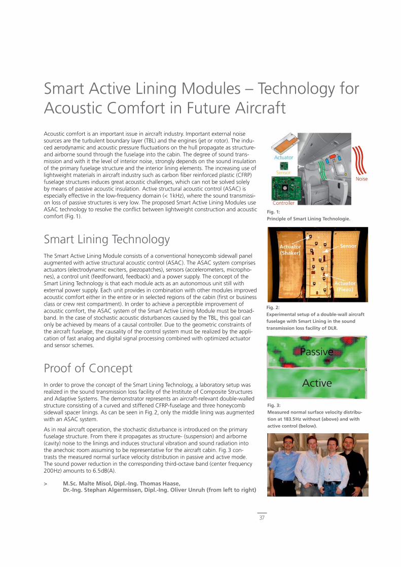
37
Acoustic comfort is an important issue in aircraft industry. Important external noise sources are the turbulent boundary layer (TBL) and the engines (jet or rotor). The indu-ced aerodynamic and acoustic pressure fl uctuations on the hull propagate as structure- and airborne sound through the fuselage into the cabin. The degree of sound trans-mission and with it the level of interior noise, strongly depends on the sound insulation of the primary fuselage structure and the interior lining elements. The increasing use of lightweight materials in aircraft industry such as carbon fi ber reinforced plastic (CFRP) fuselage structures induces great acoustic challenges, which can not be solved solely by means of passive acoustic insulation. Active structural acoustic control (ASAC) is especially effective in the low-frequency domain (< 1kHz), where the sound transmissi-on loss of passive structures is very low. The proposed Smart Active Lining Modules use ASAC technology to resolve the confl ict between lightweight construction and acoustic comfort (Fig.1).
Smart Lining TechnologyThe Smart Active Lining Module consists of a conventional honeycomb sidewall panel augmented with active structural acoustic control (ASAC). The ASAC system comprises actuators (electrodynamic exciters, piezopatches), sensors (accelerometers, micropho-nes), a control unit (feedforward, feedback) and a power supply. The concept of the Smart Lining Technology is that each module acts as an autonomous unit still with external power supply. Each unit provides in combination with other modules improved acoustic comfort either in the entire or in selected regions of the cabin (fi rst or business class or crew rest compartment). In order to achieve a perceptible improvement of acoustic comfort, the ASAC system of the Smart Active Lining Module must be broad-band. In the case of stochastic acoustic disturbances caused by the TBL, this goal can only be achieved by means of a causal controller. Due to the geometric constraints of the aircraft fuselage, the causality of the control system must be realized by the appli-cation of fast analog and digital signal processing combined with optimized actuator and sensor schemes.
Proof of ConceptIn order to prove the concept of the Smart Lining Technology, a laboratory setup was realized in the sound transmission loss facility of the Institute of Composite Structures and Adaptive Systems. The demonstrator represents an aircraft-relevant double-walled structure consisting of a curved and stiffened CFRP-fuselage and three honeycomb sidewall spacer linings. As can be seen in Fig.2, only the middle lining was augmented with an ASAC system.
As in real aircraft operation, the stochastic disturbance is introduced on the primary fuselage structure. From there it propagates as structure- (suspension) and airborne (cavity) noise to the linings and induces structural vibration and sound radiation into the anechoic room assuming to be representative for the aircraft cabin. Fig.3 con-trasts the measured normal surface velocity distribution in passive and active mode. The sound power reduction in the corresponding third-octave band (center frequency 200Hz) amounts to 6.5dB(A).
> M.Sc. Malte Misol, Dipl.-Ing. Thomas Haase, Dr.-Ing. Stephan Algermissen, Dipl.-Ing. Oliver Unruh (from left to right)
Smart Active Lining Modules – Technology for Acoustic Comfort in Future Aircraft
Fig. 1:Principle of Smart Lining Technologie.
Fig. 2:Experimental setup of a double-wall aircraft fuselage with Smart Lining in the sound transmission loss facility of DLR.
Fig. 3:Measured normal surface velocity distribu-tion at 183.5Hz without (above) and with active control (below).
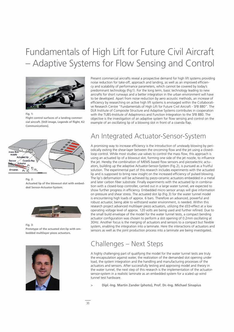
38
Present commercial aircrafts reveal a prospective demand for high lift systems providing noise reduction for take-off, approach and landing, as well as an improved effi cien-cy and scalability of performance parameters, which cannot be covered by today’s predominant technology (Fig1). For the long term, basic technology leading to new aircrafts for short runways and a better integration in the urban environment will have to be developed. Apart from noise reduction by aero acoustic methods, an increase of effi ciency by researching on active high lift systems is envisaged within the Collaborati-ve Research Centre “Fundamentals of High Lift for Future Civil Aircraft - SFB 880”. The DLR Institute of Composite Structure and Adaptive Systems contributes in cooperation with the TUBS-Institute of Adaptronics and Function Integration to the SFB 880. The objective is the investigation of an adaptive system for fl ow sensing and control on the example of an oscillating lip of a blowing slot in front of a coanda fl ap.
An Integrated Actuator-Sensor-SystemA promising way to increase effi ciency is the introduction of unsteady blowing by peri-odically exiting the shear-layer between the oncoming fl ow and the jet using a closed-loop control. While most studies use valves to control the mass fl ow, this approach is using an actuated lip of a blowout slot, forming one side of the jet nozzle, to infl uence the jet. Hereby the combination of MEMS based fl ow sensors and piezoelectric actu-ators, building up the adaptive Actuator-Sensor-System (Fig.2), is pursued as a fruitful solution. The experimental part of this research includes experiments with the actuated lip and is supposed to bring new insight on the increased effi ciency of pulsed blowing. The lip‘s deformation will be achieved by piezo-ceramic actuators embedded in a metal and later carbon fi ber substrate. Finally experiments with the actuated lip in combina-tion with a closed-loop controller, carried out in a large water tunnel, are expected to show further progress in effi ciency. Embedded micro sensor arrays will give information on pressure and shear stress. The actuated slot lip (Fig.3) for the water tunnel model is encountering high loads of approx. 6 bars. Therefore an advanced, powerful and robust actuator, being able to withstand water environment, is needed. Within this research project advanced multilayer piezo actuators, utilizing the d33-effect at a low operating voltage level of approx. 120 volts are being used and further refi ned. Due to the small build envelope of the model for the water tunnel tests, a compact bending actuator confi guration was chosen to perform a slot opening of 0.2mm oscillating at 30Hz. Another focus is the merging of actuators and sensors to a compact but fl exible system, enabling the integration into a laminate. Here the interactions of actuators and sensors as well as the joint production process into a laminate are being investigated.
Challenges – Next Steps A highly challenging part of qualifying the model for the water tunnel tests are truly the encapsulation against water, the realization of the demanded slot opening under load, the system integration and the handling and manufacturing processes of the actuators and sensors. After successfully testing and approving model and theory in the water tunnel, the next step of this research is the implementation of the actuator-sensor-system in a realistic laminate as an embedded system for a scaled up wind tunnel test hardware.
> Dipl.-Ing. Martin Zander (photo), Prof. Dr.-Ing. Michael Sinapius
Fundamentals of High Lift for Future Civil Aircraft – Adaptive Systems for Flow Sensing and Control
Fig. 1:Flight control surfaces of a landing commer-cial aircraft. [Still image, Legends of fl ight, K2 Communications].
Fig. 2:Actuated lip of the blowout slot with embed-ded Sensor-Actuator-System.
Fig. 3:Prototype of the actuated slot-lip with em-bedded multilayer piezo actuators.
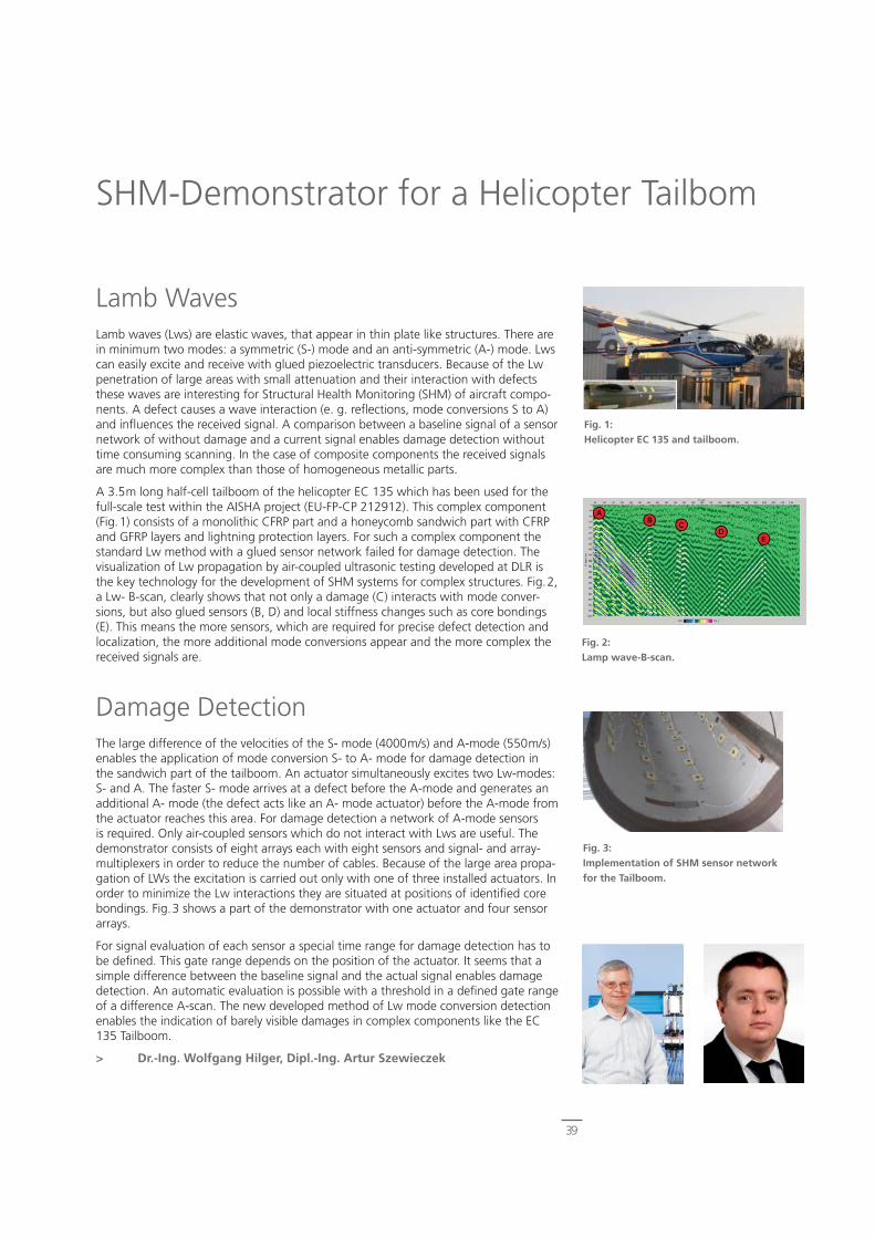
39
Fig. 1:Helicopter EC 135 and tailboom.
Fig. 2:Lamp wave-B-scan.
Fig. 3:Implementation of SHM sensor networkfor the Tailboom.
Lamb WavesLamb waves (Lws) are elastic waves, that appear in thin plate like structures. There are in minimum two modes: a symmetric (S-) mode and an anti-symmetric (A-) mode. Lws can easily excite and receive with glued piezoelectric transducers. Because of the Lw penetration of large areas with small attenuation and their interaction with defects these waves are interesting for Structural Health Monitoring (SHM) of aircraft compo-nents. A defect causes a wave interaction (e. g. refl ections, mode conversions S to A) and infl uences the received signal. A comparison between a baseline signal of a sensor network of without damage and a current signal enables damage detection without time consuming scanning. In the case of composite components the received signals are much more complex than those of homogeneous metallic parts.
A 3.5m long half-cell tailboom of the helicopter EC 135 which has been used for the full-scale test within the AISHA project (EU-FP-CP 212912). This complex component (Fig.1) consists of a monolithic CFRP part and a honeycomb sandwich part with CFRP and GFRP layers and lightning protection layers. For such a complex component the standard Lw method with a glued sensor network failed for damage detection. The visualization of Lw propagation by air-coupled ultrasonic testing developed at DLR is the key technology for the development of SHM systems for complex structures. Fig.2, a Lw- B-scan, clearly shows that not only a damage (C) interacts with mode conver-sions, but also glued sensors (B, D) and local stiffness changes such as core bondings (E). This means the more sensors, which are required for precise defect detection and localization, the more additional mode conversions appear and the more complex the received signals are.
Damage DetectionThe large difference of the velocities of the S- mode (4000m/s) and A-mode (550m/s) enables the application of mode conversion S- to A- mode for damage detection in the sandwich part of the tailboom. An actuator simultaneously excites two Lw-modes: S- and A. The faster S- mode arrives at a defect before the A-mode and generates an additional A- mode (the defect acts like an A- mode actuator) before the A-mode from the actuator reaches this area. For damage detection a network of A-mode sensors is required. Only air-coupled sensors which do not interact with Lws are useful. The demonstrator consists of eight arrays each with eight sensors and signal- and array-multiplexers in order to reduce the number of cables. Because of the large area propa-gation of LWs the excitation is carried out only with one of three installed actuators. In order to minimize the Lw interactions they are situated at positions of identifi ed core bondings. Fig.3 shows a part of the demonstrator with one actuator and four sensor arrays.
For signal evaluation of each sensor a special time range for damage detection has to be defi ned. This gate range depends on the position of the actuator. It seems that a simple difference between the baseline signal and the actual signal enables damage detection. An automatic evaluation is possible with a threshold in a defi ned gate range of a difference A-scan. The new developed method of Lw mode conversion detection enables the indication of barely visible damages in complex components like the EC 135 Tailboom.
> Dr.-Ing. Wolfgang Hilger, Dipl.-Ing. Artur Szewieczek
SHM-Demonstrator for a Helicopter Tailbom
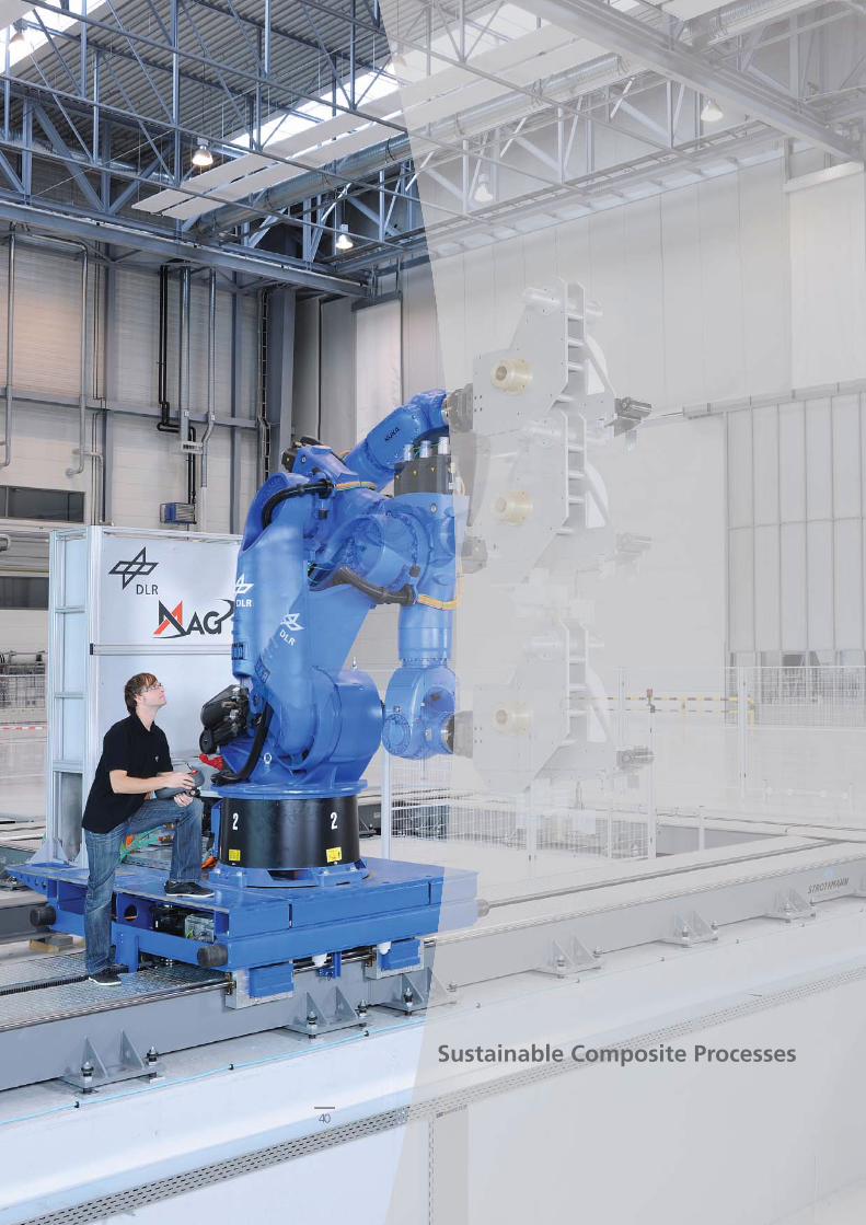
Sustainable Composite Processes
40

41
Why Monitoring Cure?For process monitoring in composite production temperature sensors such as thermo-couples are state of the art. Nevertheless by temperature measurements only indirect information about the current part quality can be derived. Through the temperature the cure rate of the resin is controlled while small temperature variations can cause considerable cure rate deviations or insuffi cient degree of cure. Regarding this, sensors which can obtain direct information about the resin’s cure state are of high interest. So called cure monitoring sensors are amongst others dielectric, resistive and ultrasonic sensors. The drawback of dielectric and resistive sensors is the required direct contact to the resin obtaining only the cure state on the surface. They affect the part surface, are diffi cult to integrate into the mould and their information content is limited.
Ultrasonic sensors on the other hand do not need direct contact to the resin and deliver information about the resin cure through the whole part thickness. The ultra-sound waves are sent from one actuator through the mould, pass through the part in production and then are registered by a sensor located on the opposite. With rising degree of cure the sound waves propagation speed increase allowing a highly sensitive cure monitoring.
Cure monitoring sensors can be a powerful tool in composite production. They can be used not only for quality assurance and documentation but offer as well a high potential for effective process control and optimization, trouble shooting and short run up time for new processes.
Piezoceramics as Cure Monitor SensorsIn actual applications of ultrasonic sensor technology the transducers are integrated into the mould by drilled holes and adapters (Fig.1). Tests have shown that in process monitoring they have a limited signal reliability due to unstable acoustic coupling bet-ween the transducers and the mould. When the transducers are not properly coupled the sound waves cannot propagate into the mould and the part in production and thus the monitoring fails. This problem was resolved by a surprisingly simple solution. Instead of using a transducer (working with a piezoceramic actuator) the piezoceramic itself has been applied to the mould by an adhesive layer (Fig.2). With this method remarkable signal amplitudes and high reliability has been achieved allowing more precise measurements and monitoring very thick laminates. But this is not the only advantage of the piezoceramics; they are smaller and therefore more easy to integrate and they are considerably less expensive than ultrasonic transducers, so altogether they offer a broader fi eld of application.
To give an example for the broad application range, their small size even allow to integrate them into a rheometer. Thus simultaneously the rheological properties of a resin while curing can be measured such as elastic and loss modulus and acoustic parameters i.e. sound velocity and attenuation in parallel. In difference to separate ex-periments this permits highly precise correlation between already established laboratory method for cure characterization and ultrasound measurement. These are valuable results for better understanding or “calibration” of the ultrasonic cure monitoring method.
> Dipl.-Ing. Nico Liebers
Piezoceramics as Effective and Flexible Sensors for Online Cure Monitoring
Fig. 2:Small and inexpensive piezoceramics.
Fig. 3:Piezoceramics integrated into rheometer.
Fig. 1:Ultrasound transducers integrated into mould for cure monitoring.
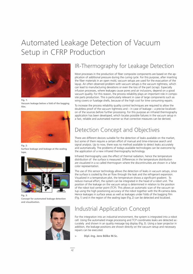
42
IR-Thermography for Leakage DetectionMost processes in the production of fi ber composite components are based on the ap-plication of additional pressure during the curing cycle. For this purpose, after inserting the fi ber materials in an open mold, vacuum setups are used for the evacuation of the layup. An often observed problem with vacuum setups is the vacuum tightness, which can lead to manufacturing deviations or even the loss of the part (scrap). Especially infusion processes, where leakages cause pores and air inclusions, depend on a good vacuum quality. For this reason, the process reliability plays an important role in compo-site parts production. This is particularly relevant in case of large components such as wing covers or fuselage shells, because of the high cost for time consuming repairs.
To increase the process reliability quality control techniques are required to allow the doubtless proof of the vacuum tightness and – in case of leakage – a precise localizati-on of the sources before further processing. For this purpose an infrared thermography application has been developed, which locates possible failures in the vacuum setup in a fast, reliable and automated manner so that corrective measures can be derived.
Detection Concept and ObjectivesThere are different devices suitable for the detection of leaks available on the market, but some of them require a certain effort of manual and time-intensive search and signal analysis. Up to now, there was no method available to detect leaks accurately and automatically. The problems of todays available technologies can be overcome by the application of a new infrared thermography technology.
Infrared thermography uses the effect of thermal radiation, hence the temperature distribution of the surface is measured. Differences in the temperature distribution are visualized in a so called thermogram where the discontinuities are shown in a false color representation.
The use of this sensor technology allows the detection of leaks in vacuum setups, since the surface is cooled by the air fl ow through the leak and the refrigerant expansion. Visualized in a temperature plot, the temperature shows a signifi cant gradient. To reduce manual effort, the system can be integrated in the head of a robot unit. The position of the leakage on the vacuum setup is determined in relation to the position of the robot tool center point (TCP). This allows an automatic scan of the vacuum se-tup using the high positioning accuracy of the robot together with the IR-camera data. Hence leakages in surface areas as well as leakages under folds of the bagging fi lm (Fig.1) and in the region of the sealing tape (Fig.2) can be detected and localized.
Industrial Application ConceptFor the integration into an industrial environment, the system is integrated into a robot cell. Using the automated image processing and TCP coordinates leaks are detected ac-curately and shown in an quality message log display (Fig.3). Using a laser projector in addition, the leakage positions are shown directly on the vacuum setup and necessary repairs can be executed.
> Dipl.-Ing. Jens Bölke M.Sc.
Automated Leakage Detection of Vacuum Setup in CFRP Production
Fig. 1:Vacuum leakage below a fold of the bagging fi lm.
Fig. 2:Surface leakage and leakage at the sealing tape.
Fig. 3:Concept for automated leakage detection and visualisation.

43
GroFi – an innovative Automated Fiber Placement (AFP) research facility, developed from ideas of the DLR and implemented at the Center for Lightweight-Production-Technology (ZLP) in Stade, based on multiple coordinated lay-up units determines the future AFP process for enhanced quality and effi ciency of CFRP structures production. To realise a fully automated production plant in accordance with the provided require-ments new sensor systems are demanded. Apart from the application of an edge detection system and a force torque sensor, that are both integrated into online path correction methods, an optical sensor is used for the quality monitoring.
Online Path CorrectionActual requirements in the production of composite structures defi ne tight geometrical tolerances. In addition to the avoidance of gaps and overlaps within one ply, material failures and also foreign objects have to be detected. At the GroFi research facility up to eight robots are involved in the production of one component. That results in increa-sed inaccuracies that have to observed and compensated. By use of a laser light section sensor fi xed at the lay-up head the relative position to the neighboured material tape or to a reference marker on the tool can be detected to initiate an online path correc-tion parallel to the tool surface. By this method the quality improvement is reached by minimising or control of the gap width. The compliance with defi ned restrictions has been proven in several tests with gap control in 0.1 ÷ 0.3mm steps.
Material Optimised Fiber PlacementCurrently, no compaction force is acquired between compaction roller and tool never mind the process is controlled. However, studies have shown the infl uence of the compaction force to the lay-up quality especially in steering areas where a path corrections results in lateral warping effects. Therefore a 6-axis force-torque sensor will be integrated at the lay-up head to meas-ure a pose-compensated compaction force. Based on this, a real-time position correc-tion in normal direction to the tool surface can be triggered to control the compaction force. On one hand manufacturing effects like bridging, buckling or pull ups can be minimised by increasing the compaction force in concave surface areas, on the other hand the lay-up on pressure sensitive materials i.e. honeycombs or foam is enabled.
Online Quality MonitoringEspecially in the aerostructures comprehensive measures are an integral part of the pro-duction process to ensure required laminate qualities. Actually, time consuming visual inspection is conducted ply-by-ply leading to signifi cant loss in production effi ciency. Hence an online quality monitoring shall be realised by means of an optical sensor sys-tem. Fixing the sensor to the lay-up head enables a measurement of the actual materi-al course and a detection of gaps, overlaps, defects and foreign objects. As a result of the 3D measurement a real-time inspection, an analysis of failure infl uences on follow-ing ply geometries and the release for next process steps can be realised. In addition, the online quality monitoring system leads to a substantial time reduction and an signifi cant enhancement of the plant effi ciency.
> Dipl.-Ing. Christian Krombholz
Process-Integrated Sensor Systems in the Auto-mated Fiber Placement Process
Fig. 3:Lay-up measurements for quality monitoring.
Fig. 1:Automated Fiber Placement research facility.
Fig. 2:Measurement accuracy of the laser light section sensor.
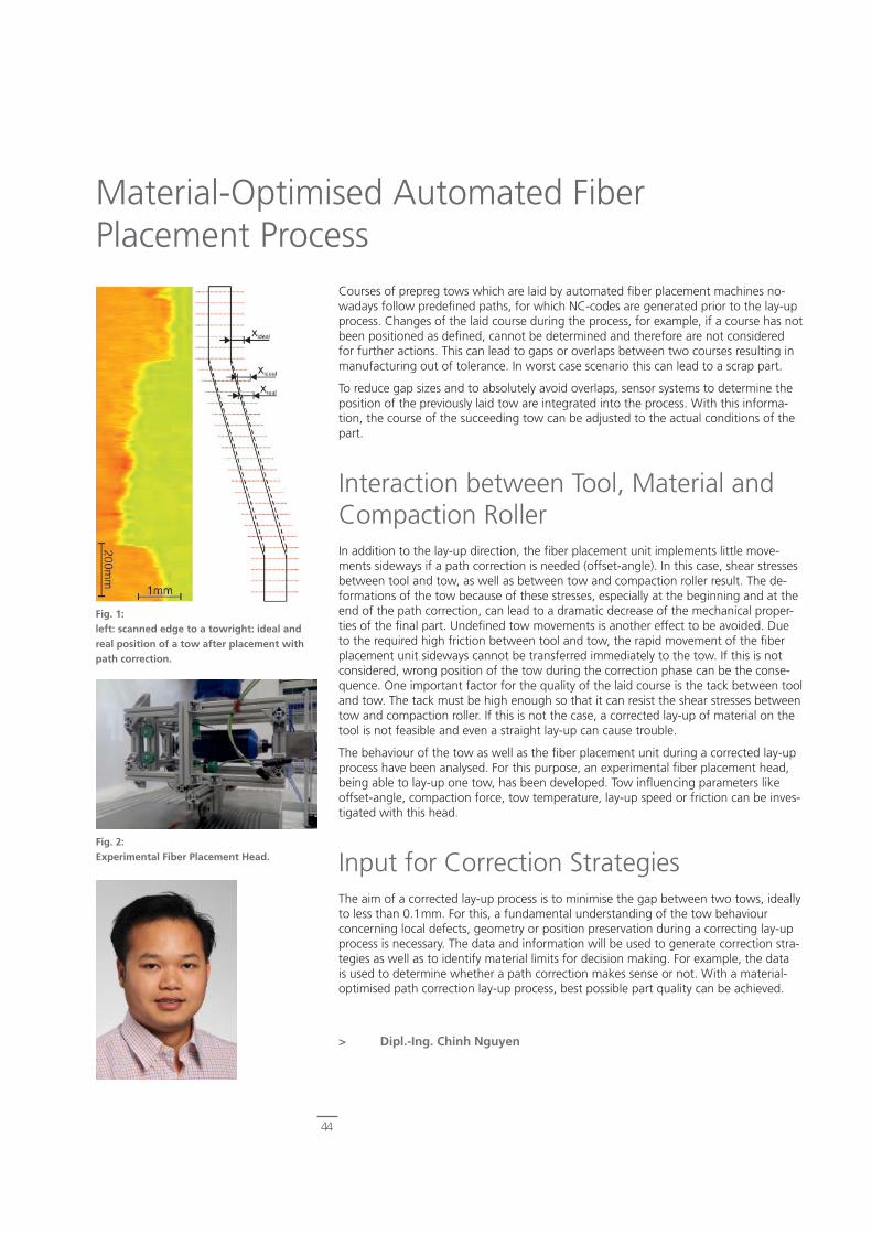
44
Courses of prepreg tows which are laid by automated fi ber placement machines no-wadays follow predefi ned paths, for which NC-codes are generated prior to the lay-up process. Changes of the laid course during the process, for example, if a course has not been positioned as defi ned, cannot be determined and therefore are not considered for further actions. This can lead to gaps or overlaps between two courses resulting in manufacturing out of tolerance. In worst case scenario this can lead to a scrap part.
To reduce gap sizes and to absolutely avoid overlaps, sensor systems to determine the position of the previously laid tow are integrated into the process. With this informa-tion, the course of the succeeding tow can be adjusted to the actual conditions of the part.
Interaction between Tool, Material and Compaction RollerIn addition to the lay-up direction, the fi ber placement unit implements little move-ments sideways if a path correction is needed (offset-angle). In this case, shear stresses between tool and tow, as well as between tow and compaction roller result. The de-formations of the tow because of these stresses, especially at the beginning and at the end of the path correction, can lead to a dramatic decrease of the mechanical proper-ties of the fi nal part. Undefi ned tow movements is another effect to be avoided. Due to the required high friction between tool and tow, the rapid movement of the fi ber placement unit sideways cannot be transferred immediately to the tow. If this is not considered, wrong position of the tow during the correction phase can be the conse-quence. One important factor for the quality of the laid course is the tack between tool and tow. The tack must be high enough so that it can resist the shear stresses between tow and compaction roller. If this is not the case, a corrected lay-up of material on the tool is not feasible and even a straight lay-up can cause trouble.
The behaviour of the tow as well as the fi ber placement unit during a corrected lay-up process have been analysed. For this purpose, an experimental fi ber placement head, being able to lay-up one tow, has been developed. Tow infl uencing parameters like offset-angle, compaction force, tow temperature, lay-up speed or friction can be inves-tigated with this head.
Input for Correction StrategiesThe aim of a corrected lay-up process is to minimise the gap between two tows, ideally to less than 0.1mm. For this, a fundamental understanding of the tow behaviour concerning local defects, geometry or position preservation during a correcting lay-up process is necessary. The data and information will be used to generate correction stra-tegies as well as to identify material limits for decision making. For example, the data is used to determine whether a path correction makes sense or not. With a material-optimised path correction lay-up process, best possible part quality can be achieved.
> Dipl.-Ing. Chinh Nguyen
Material-Optimised Automated Fiber Placement Process
Fig. 1:left: scanned edge to a towright: ideal and real position of a tow after placement with path correction.
Fig. 2:Experimental Fiber Placement Head.

45
Profi le of Departments
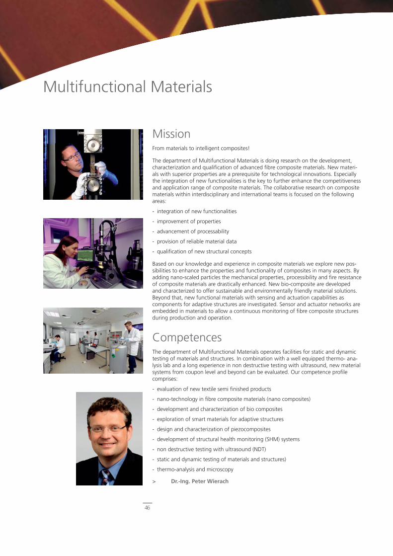
46
Multifunctional Materials
MissionFrom materials to intelligent composites!
The department of Multifunctional Materials is doing research on the development, characterization and qualifi cation of advanced fi bre composite materials. New materi-als with superior properties are a prerequisite for technological innovations. Especially the integration of new functionalities is the key to further enhance the competitiveness and application range of composite materials. The collaborative research on composite materials within interdisciplinary and international teams is focused on the following areas:
- integration of new functionalities
- improvement of properties
- advancement of processability
- provision of reliable material data
- qualifi cation of new structural concepts
Based on our knowledge and experience in composite materials we explore new pos-sibilities to enhance the properties and functionality of composites in many aspects. By adding nano-scaled particles the mechanical properties, processibility and fi re resistance of composite materials are drastically enhanced. New bio-composite are developed and characterized to offer sustainable and environmentally friendly material solutions. Beyond that, new functional materials with sensing and actuation capabilities as components for adaptive structures are investigated. Sensor and actuator networks are embedded in materials to allow a continuous monitoring of fi bre composite structures during production and operation.
CompetencesThe department of Multifunctional Materials operates facilities for static and dynamic testing of materials and structures. In combination with a well equipped thermo- ana-lysis lab and a long experience in non destructive testing with ultrasound, new material systems from coupon level and beyond can be evaluated. Our competence profi le comprises:
- evaluation of new textile semi fi nished products
- nano-technology in fi bre composite materials (nano composites)
- development and characterization of bio composites
- exploration of smart materials for adaptive structures
- design and characterization of piezocomposites
- development of structural health monitoring (SHM) systems
- non destructive testing with ultrasound (NDT)
- static and dynamic testing of materials and structures)
- thermo-analysis and microscopy
> Dr.-Ing. Peter Wierach
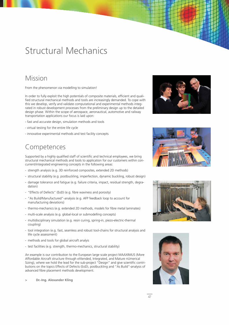
47
Structural Mechanics
MissionFrom the phenomenon via modelling to simulation!
In order to fully exploit the high potentials of composite materials, effi cient and quali-fi ed structural mechanical methods and tools are increasingly demanded. To cope with this we develop, verify and validate computational and experimental methods integ-rated in robust development processes from the preliminary design up to the detailed design phase. Within the scope of aerospace, aeronautical, automotive and railway transportation applications our focus is laid upon:
- fast and accurate design, simulation methods and tools
- virtual testing for the entire life cycle
- innovative experimental methods and test facility concepts
CompetencesSupported by a highly qualifi ed staff of scientifi c and technical employees, we bring structural mechanical methods and tools to application for our customers within con-current/integrated engineering concepts in the following areas:
- strength analysis (e.g. 3D reinforced composites, extended 2D methods)
- structural stability (e.g. postbuckling, imperfection, dynamic buckling, robust design)
- damage tolerance and fatigue (e.g. failure criteria, impact, residual strength, degra-dation)
- “Effects of Defects“ (EoD) (e.g. fi bre waviness and porosity)
- “As Build/Manufactured”-analysis (e.g. AFP feedback loop to account for manufacturing deviations)
- thermo-mechanics (e.g. extended 2D methods, models for fi bre metal laminates)
- multi-scale analysis (e.g. global-local or submodelling concepts)
- multidisciplinary simulation (e.g. resin curing, spring-in, piezo-electric-thermal coupling)
- tool integration (e.g. fast, seamless and robust tool-chains for structural analysis and life cycle assessment)
- methods and tools for global aircraft analyis
- test facilities (e.g. strength, thermo-mechanics, structural stability)
An example is our contribution to the European large scale project MAAXIMUS (More Affordable Aircraft structure through eXtended, Integrated, and Mature nUmerical Sizing), where we hold the lead for the sub-project “Design” and give scientifi c contri-butions on the topics Effects of Defects (EoD), postbuckling and “As Build”-analysis of advanced fi bre placement methods development.
> Dr.-Ing. Alexander Kling

48
Composite Design
MissionOur design for your structures!
The department Composite Design offers a closed development chain from the fi rst sketch of composite structures, their sizing up to a design for an effi cient production:
- preliminary design: Herein, design concepts, an adequate selection of materials, hybridisation, and further aspects specifi c to fi bre composites are being addressed.
- sizing: design concepts are optimized and assessed by using low and high fi delity simulation tools, which also take into account probabilistically distributed material and manufacturing parameters.
- detailed design: In the end the detailed design is realized under consideration of tolerance management, quality assurance and appropriate tool concepts.
Particular emphasis is placed on the design of multi-functional structures, which con-tain additional features like electrical conductivity, acoustic noise absorption, informati-on transmission etc. besides their required structural mechanical properties.
CompetencesFrom requirements via concepts to multi-functional structures
The department Composite Design proves itself as a strong link between research and industrial application in the following topics:
- door surround structures in future aircraft
- composite-driven design of airframe structures
- CFRP-metal hybrid structures in aerospace applications
- design considering relevant manufacturing aspects, e.g. spring-in effects
- tools and facilities for effi cient and economic CFRP-production
- deployable structures in ultra-lightweight space applications
- design of multi-functional lightweight terrestrial vehicles
The closed development chain and the design of multi-functional structures are subject of continuous common research work with our partners.
> Dr.-Ing. Christian Hühne
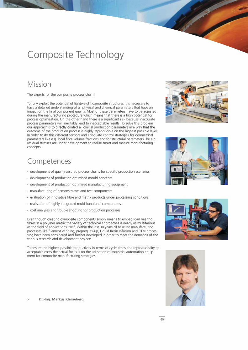
49
Composite Technology
MissionThe experts for the composite process chain!
To fully exploit the potential of lightweight composite structures it is necessary tohave a detailed understanding of all physical and chemical parameters that have animpact on the fi nal component quality. Most of these parameters have to be adjustedduring the manufacturing procedure which means that there is a high potential forprocess optimisation. On the other hand there is a signifi cant risk because inaccurateprocess parameters will inevitably lead to inacceptable results. To solve this problemour approach is to directly control all crucial production parameters in a way that theoutcome of the production process is highly reproducible on the highest possible level.In order to do this different sensors and adequate control strategies for geometricalparameters like e.g. local fi bre volume fractions and for structural parameters like e.g.residual stresses are under development to realise smart and mature manufacturingconcepts.
Competences- development of quality assured process chains for specifi c production scenarios
- development of production optimised mould concepts
- development of production optimised manufacturing equipment
- manufacturing of demonstrators and test components
- evaluation of innovative fi bre and matrix products under processing conditions
- realisation of highly integrated multi-functional components
- cost analyses and trouble shooting for production processes
Even though creating composite components simply means to embed load bearingfi bres in a polymer matrix the variety of technical approaches is nearly as multifariousas the fi eld of applications itself. Within the last 30 years all baseline manufacturingprocesses like fi lament winding, prepreg lay-up, Liquid Resin Infusion and RTM proces-sing have been considered and further developed in order to meet the demands of thevarious research and development projects.
To ensure the highest possible productivity in terms of cycle times and reproducibility atacceptable costs the actual focus is on the utilisation of industrial automation equip-ment for composite manufacturing strategies.
> Dr.-Ing. Markus Kleineberg
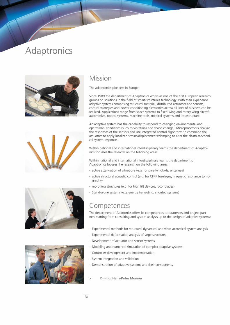
50
Adaptronics
MissionThe adaptronics pioneers in Europe!
Since 1989 the department of Adaptronics works as one of the fi rst European research groups on solutions in the fi eld of smart-structures technology. With their experience adaptive systems comprising structural material, distributed actuators and sensors, control strategies and power conditioning electronics across all lines of business can be realized. Applications range from space systems to fi xed-wing and rotary-wing aircraft, automotive, optical systems, machine tools, medical systems and infrastructure.
An adaptive system has the capability to respond to changing environmental and operational conditions (such as vibrations and shape change). Microprocessors analyze the responses of the sensors and use integrated control algorithms to command the actuators to apply localized strains/displacements/damping to alter the elasto-mechani-cal system response.
Within national and international interdisciplinary teams the department of Adaptro-nics focusses the research on the following areas:
Within national and international interdisciplinary teams the department of Adaptronics focuses the research on the following areas:
- active attenuation of vibrations (e.g. for parallel robots, antennas)
- active structural acoustic control (e.g. for CFRP fuselages, magnetic resonance tomo-graphy)
- morphing structures (e.g. for high lift devices, rotor blades)
- Stand-alone systems (e.g. energy harvesting, shunted systems)
CompetencesThe department of Adatronics offers its competences to customers and project part-ners starting from consulting and system analysis up to the design of adaptive systems:
- Experimental methods for structural dynamical and vibro-acoustical system analysis
- Experimental deformation analysis of large structures
- Development of actuator and sensor systems
- Modeling and numerical simulation of complex adaptive systems
- Controller development and implementation
- System integration and validation
- Demonstration of adaptive systems and their components
> Dr.-Ing. Hans-Peter Monner

51
Composite Process Technologies
MissionResearch on an industrial scale!
Research on CFRP sustainable and resource effi cient production processes is DLR’s new approach within the Center of Lightweight-Production-Technology (ZLP) in Stade. It offers opportunities in doing projects by considering industrial requirements in terms of scenarios and scale. By testing and simulation of processes in a full scale dimension, effects can be explored which otherwise could have shown up at later utilization of technology. Hence, the complete process chain could be examined before the industrial realization.
The department of Composite Process Technologies takes part in the ZLP. It provides the scientifi c backbone of the center in Stade. By doing fundamental research work in the fi eld of advanced fi ber placement, automated RTM processes and autoclave technology, production technologies will be developed and tested for application. An interdisciplinary approach between manufacturing engineering, design specialists and machine manufacturers will help to build up competences in the assessment of pro-duction chains. The major aim is to fi nd the optimum in production technologies with respect to effi ciency, energy and resource consumption, quality and cost and to give a feedback to design, as well as to materials and processes.
CompetencesThe core competences of the department refl ect the application of large scale research facilities:
- fi rst integrated advanced fi ber placement and automated tape laying machine
- fi rst fully automated RTM production line
- world’s biggest research autoclave
- development and simulation methods to improve the reliability of production processes
- process integrated data logging and data analyzing systems
As CFRP will become more and more important, research has to provide solutions for production, otherwise the breakthrough of this material could not be guaranteed. By obeying needs from various end users, the composite process technologies enhance the interdisciplinary approach to introduce CFRP for a broader application.
> Dipl.-Ing. Felix Kruse

52
Publications
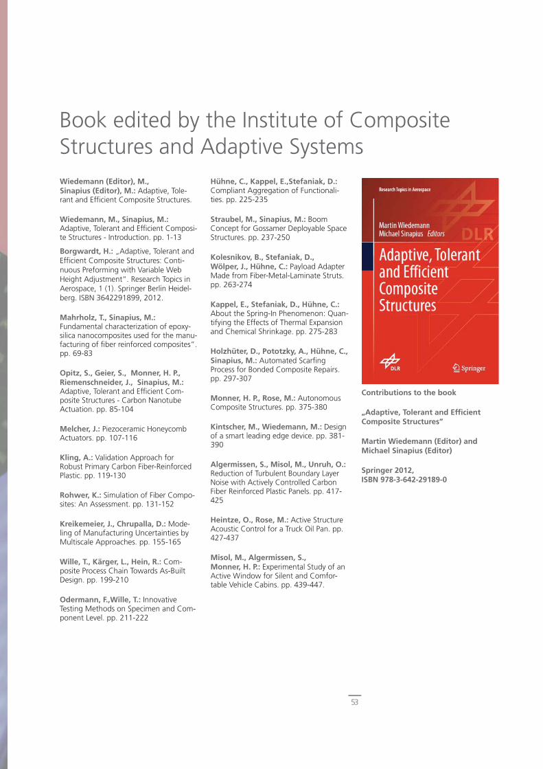
53
Book edited by the Institute of Composite Structures and Adaptive SystemsWiedemann (Editor), M., Sinapius (Editor), M.: Adaptive, Tole-rant and Effi cient Composite Structures.
Wiedemann, M., Sinapius, M.: Adaptive, Tolerant and Effi cient Composi-te Structures - Introduction. pp. 1-13
Borgwardt, H.: „Adaptive, Tolerant and Effi cient Composite Structures: Conti-nuous Preforming with Variable Web Height Adjustment“. Research Topics in Aerospace, 1 (1). Springer Berlin Heidel-berg. ISBN 3642291899, 2012.
Mahrholz, T., Sinapius, M.: Fundamental characterization of epoxy-silica nanocomposites used for the manu-facturing of fi ber reinforced composites”. pp. 69-83
Opitz, S., Geier, S., Monner, H. P.,Riemenschneider, J., Sinapius, M.:Adaptive, Tolerant and Effi cient Com-posite Structures - Carbon Nanotube Actuation. pp. 85-104
Melcher, J.: Piezoceramic Honeycomb Actuators. pp. 107-116
Kling, A.: Validation Approach for Robust Primary Carbon Fiber-Reinforced Plastic. pp. 119-130
Rohwer, K.: Simulation of Fiber Compo-sites: An Assessment. pp. 131-152
Kreikemeier, J., Chrupalla, D.: Mode-ling of Manufacturing Uncertainties by Multiscale Approaches. pp. 155-165
Wille, T., Kärger, L., Hein, R.: Com-posite Process Chain Towards As-Built Design. pp. 199-210
Odermann, F.,Wille, T.: Innovative Testing Methods on Specimen and Com-ponent Level. pp. 211-222
Hühne, C., Kappel, E.,Stefaniak, D.: Compliant Aggregation of Functionali-ties. pp. 225-235
Straubel, M., Sinapius, M.: Boom Concept for Gossamer Deployable Space Structures. pp. 237-250
Kolesnikov, B., Stefaniak, D., Wölper, J., Hühne, C.: Payload Adapter Made from Fiber-Metal-Laminate Struts. pp. 263-274
Kappel, E., Stefaniak, D., Hühne, C.: About the Spring-In Phenomenon: Quan-tifying the Effects of Thermal Expansion and Chemical Shrinkage. pp. 275-283
Holzhüter, D., Pototzky, A., Hühne, C., Sinapius, M.: Automated Scarfi ng Process for Bonded Composite Repairs. pp. 297-307
Monner, H. P., Rose, M.: Autonomous Composite Structures. pp. 375-380
Kintscher, M., Wiedemann, M.: Design of a smart leading edge device. pp. 381-390
Algermissen, S., Misol, M., Unruh, O.: Reduction of Turbulent Boundary Layer Noise with Actively Controlled Carbon Fiber Reinforced Plastic Panels. pp. 417-425
Heintze, O., Rose, M.: Active Structure Acoustic Control for a Truck Oil Pan. pp. 427-437
Misol, M., Algermissen, S., Monner, H. P.: Experimental Study of an Active Window for Silent and Comfor-table Vehicle Cabins. pp. 439-447.
Contributions to the book
„Adaptive, Tolerant and Effi cient Composite Structures”
Martin Wiedemann (Editor) and Michael Sinapius (Editor)
Springer 2012, ISBN 978-3-642-29189-0
54
Publications and Patents 2011 - 2012
Selected Publications in Journals, Books and Proceedings
Hillger, W., Szewieczek, A., Schmidt, D.: „Damage Detection in a Helicopter Composite Tailboom by Mode Conversion of Lamb Waves“. ISBN 978-3-940283-41-2, 2012.
Kubicka, M., Mahrholz, T., Kühn, A.,Wierach, P., Sinapius, M.: „Magne-tostrictive properties of epoxy resins modifi ed with Terfenol-D particles for detection of internal stress in CFRP“. Part 1: Materials and processes. Journal of Materials Science, 47, Seiten 5752-5759. Springer Verlag . DOI: 10.1007/s10853-012-6466-3, 2012.
Exner, W.,Arlt, C.,Mahrholz, T., Riedel, U., Sinapius, M.: „Nanoparticles with Various Surface Modifi cations as Functionalized Cross-Linking Agents for Composite Resin Materials“. Composites Science and Technology. DOI: 10.1016/j.compscitech.2012.03.024, 2012
Geier, S.,Mahrholz, T., Wierach, P., Sinapius, M.: „Carbon Nanotube-based Actuators“. Current Trends in Smart Technologies Fraunhofer Technical Purbli-cation Series, 2012.
Misol, M., Algermissen, S., Monner, H. P.: „Experimental investi-gation of different active noise control concepts applied to a passenger car equipped with an active windshield“. Journal of Sound and Vibration, 331, 10, Seiten 2209-2219. DOI: 10.1016/j.jsv.2012.01.001. ISSN 0022-460X, 2012.
Stefaniak, D., Kappel, E., Spröwitz, T.,Hühne, C.: Experimental identifi cation of process parameters inducing warpa-ge of autoclave-processed CFRP parts. Composites Part A: Applied Science and Manufacturing. Elsevier . DOI: 10.1016/j.compositesa.2012.02.013, 2012.
Kappel, E., Stefaniak, D., Spröwitz, T.,Hühne , C.: „A semi-analytical simulation strategy and its application to warpage of autoclave-processed CFRP parts“. Composites Part A: Applied Science and Manufacturing, 42, Seiten 1985-1994. Elsevier B.V., 2011.
Loose, S., Lauterbach, A., Algermissen, S., Heckmann, A.: „Ac-tivities in acoustics“. RTR Special - Next Generation Train, Seiten 51-60. Eurail-press. ISBN 1869-7801. ISSN 978 3 7771 0435 5, 2011.
Wenzel, J., Sinapius, M., Gabbert, U.: „Primary structure mass estimation in early phases of aircraft development using the fi nite element method“. CEAS Aeronaut J. Springer. DOI: 10.1007/s13272-011-0040-6, 2011.
Degenhardt, R., Szodruch, J., Plass, S.: „IFAR – The International Forum for Avi-ation Research“. In: Future Aeronautical Communications InTech. Seiten 335-348. ISBN 978 953 307 625 6, 2011.
Friedrich, M., Exner, W., Wietgrefe, M.: „Sensitivity analysis of infl uencing factors on impregnation process of closed mould RTM“. CEAS Aeronautical Journal. Sprin-ker. DOI: 10.1007/s13272-011-0032-6, 2011
Liebers, N., Ucan, H., Kühn, M., Kleineberg, M., Meyer, M.: „Master-box: new concept for a dynamic autocla-ve process control“. CEAS Aeronautical Journal, Volume 2, Combined 1 - 4 (De-cember 2011), Seiten 223-230. Springer Verlag. DOI: DOI 10.1007/s13272-011-0018-4. ISSN 1869-5582 (ISSN), 2011.
Könnicke, D., Kühn, A., Mahrholz, T.,Sinapius, M.: „Polymer nanocomposi-tes based on epoxy resin and ATH as a new fl ame retardant for CFRP: prepa-ration and thermal characterisation“. Journal of Materials Science, Springer Science+Business Media, LLC 2011, 46: 7046–7055 (2011), Seiten 7046-7055. Springer Science+Business Media, LLC 2011. DOI: 10.1007/s10853-011-5673-7, 2011.
Riemenschneider, J., Opitz, S.: Measu-rement of twist defl ection in active twist rotor“. Aerospace Science and Technolo-gy, 15 (3), Seiten 216-223. Elsevier Mas-son SAS. DOI: 10.1016/j.ast.2010.12.008 . ISSN 1270-9638, 2011.
Degenhardt, R.: „Auslegung von zukünftigen Flugzeugstrukturen aus CFK
bezüglich Stabilität“. Ingenieurspiegel, 1/2011, Seiten 70-71. Public Verlagsge-sellschaft und Anzeigenagentur mbH. ISSN 1868-5919, 2011.
Algermissen, S., Keimer, R., Rose, M.,Straubel, M., Sinapius, M., Monner, H. P.: „Smart-Structures Tech-nology for Parallel Robots“. Journal of Intelligent and Robotic Systems, Vol. 63, Seiten 547-574. Springer Verlag. DOI: 10.1007/s10846-010-9522-8, 2011.
Walter, S.; Steinmann, W.; Schütte, J.; Seide, G.; Gries, T.; Roth, G.; Wierach, P.; Sinapius, M.: „Characterisation of piezoelectric PVDF monofi laments. Mate-rials Technology“. Advanced Performance Materials, Volume 26, Number 3, , pp. 140-145(6), 2011
Selected Proceedings
Haase, T., Misol, M., Unruh, O.: „Opti-mal placement of fl at piezoactuators for an adaptive feedforward control system“. ICSV19 2012 , 08.-12. Juli 2012, Vilnius. Litauen.
Perner, M., Krombholz, C., Bock, M., Röstermundt, D., Monner, H. P.: „Cla-rifying Vibrational Issues of an Advanced Automated Fiber Placement Production Plant“. IEEE/ASME 2012, 11.-14. Juli 2012, KaoHsiung, Taiwan.
Stefaniak, D., Kappel E., Kolesnikov B., Hühne C.: „Improving the mechanical performance of unidi-rectional CFRP by metal-hybridization“. ECCM15 - 15th European Conference on Composite Materials, 24.-28. Juni 2012, Venedig, Italien. ISBN 9788888785332.
Pohl, M., Haase, T., Rose, M.: Actuator Placement for Shunt Damping of Panel Structures. In: European Acoustics Assosi-ation 2012. Euronoise 2012, 11.-13. Juni 2012, Prag, Tschechien. ISBN 978 80 01 05013 2.
Rohwer, K., Kappel, E.,Stefaniak, D., Wille, T.: „Spring-in and Warpage – Progress in Simulating Manufacturing Aspects“. 17th International Conference Mechanics of Composite Materials, 28. Mai - 1. Juni 2012, Riga, Lettland.

55
Hillebrandt, M., Straubel, M., Hühne, C.,Wiedemann, M.: „A New Deployable Truss for Gossamer Space Structures“. 53rd Structures, Structural Dynamics, and Materials and Co-located Conferences, 2012, Honolulu, United States of America.
Stefaniak, D., Kolesnikov, B., Kappel, E., Hühne, C.: „Improving Impact Endangered CFRP Structures by Metal-Hybridisation“. 12th European Conference on Spacecraft Structures, Materials & Environmental Testing, 20.-24. März 2012, Nordwijk, Niederlande.
Exner, W., Kubicka, M., Arlt, C.: Na-noparticles in High Performance CFRPS for Space Applications: Superior Material Performance“. 12th European Confe-rence on Spacecraft Structures, Materials & Enviromental testing, 20.-23.03.2012, Noordwijk, Niederlande.
Geier, S., Kintscher, M., Heintze, O.,Wierach, P., Monner, H. P., Wiedemann, M.: „Investigation of aligned carbon nanotube architectures to understand the actuation mechanism“. SPIE Smart Structures/NDE, 12. - 15. März 2012, San Diego, USA. Volltext nicht online.
Geier, S., Riemenschneider, J., Mahrholz, T., Wierach, P., Sinapius, M.: „Investigation of aligned carbon nanotube architectures to under-stand the actuation mechanism“. SPIE Smart Structures/NDE, 12. - 15. März 2012, San Diego, USA.
Patents:
Fink, A., Hühne. C.: „Wellenkupplung“, DE 102011109887.2, 10.08.2011,EP 12001728.0, 14.03.2012.
Fischer., F., Knote, A., Ströhlein, T.: „Verkehrsfl ugzeug mit und Verfahren zur Herstellung von eingefärbten Faserver-bundbauteilen“. EP 12170118.9, 30.05.2012.
Könnicke, D., Friedrich, M., Hindersmann, A., Wolff, J.: „Herstellung eines Verbundbauteils“, DE 102011111452.5, 30.08.2011.
Hühne, C., Kleineberg, M., Ströhlein, T.: „Formwerkzeug“DE 102011054465.8, 13.10.2011.
Geier, S., Heintze, O., Kintscher, M.Rudenko, A.: „Adaptiver Vorfl ügel“EP 12160666.9, 22.03.2012.
Peinke, J., Riemenschneider, J.: „Rotorblatt mit adaptivem Vorfl ügel für eine Windenergieanlage“DE 10201202746.3, 29.03.2012.
Fink, A., Hühne, C.: „Wellenkupplung“DE 102011117298.3, 01.11.2011.
Riemenschneider, J.: „Formvariables Formwerkzeug“, DE 10201052951.9, 24.08.2011.
Köke, H.: „Optimierungsverfahren“DE 102011056677.2, 20.12.2011.
Bölke, J., Hanke, M., Malzahn, S.Ucan, H.: DE 102011112520.9, 07.09.2011.
Opitz, S., Riemenschneider, J., Schulz, M.: EP 12169813.8, 29.05.2012.
Ucan, H., Krombholz, C., Stefaniak, D.,Bölke, J.: EP 12165997, 27.04.2012.
Holzhüter, D., Hühne, C., Kolesnikov, B., Steffen, O.: „Repa-raturverfahren“, DE 102011056088.2, 06.12.2011.
Fink, A., Hühne, C., Kolesnikov, B.,Niemann, S.: „Realitionssymmetrisches Strukturelement in gitterkonstruktion und Verfahren zu dessen Herstellung“, DE 102011121639.5, 20.12.2011.
Hindersmann, A., Malzahn, S., Torstrick, S.: „Formwerkzeug zur Her-stellung eines Formwerkzeuges“ DE 102011055547.1, 21.11.2011.
Kappel, E., Stahl, A., Köke, H.: „Prüf-verfahren“, DE 102012100973.2, 07.02.2012.
Homann, S., Keimer, R.: „Fahrzeugtür“, DE 102011081335.7, 22.08.2011.
Hilmer, P., Opitz, M.: „Flexibles Formwerkzeug“, DE 102012101704.2, 01.03.2012.
Danilov, M.: „Faserverbund Ferti-gungsanlage“, DE 102012102563.0, 26.03.2012.
Keck, R., Bartsch, I., Gerngroß, T., Nickel, J., Ückert, C., Hühne, C.: „Luft-frachtcontainer“, DE 102011054088.1, 30.09.2011.
Ströhlein, T., Knote, A., Melcher, J.: „Formstabile Hülle, insbesonde-re für einen Flugzeugrumpf“, DE 102012101914.2, 07.03.2012.
Hühne, C., Jörn, P., Niemann, S., Ströhlein, T., Kleineberg, M., Müller, M.: „Fertigungsverfahren für Tonnen mit Grid-Versteifungselementen“ DE 102012210043.1, 14.06.2012.
Riemenschneider, J.: „Rotorblatt varia-bler Geometrie“, DE 102012101514.7, 24.02.2012.
Assing, H., Borgwardt, H. Stahl, A.: „Gekrümmte Preform“, DE 102012101706.9, 01.03.2012.
Bold, J., Grote, M., Kleineberg, M., Wurl, T.: „Formwerkzeug“ DE 102012103674.8, 26.04.2012.
Bock, M., Krombholz, C., Perner, M., Röstermundt, D.: „Faser-Legevorrich-tung“ DE 102012102205.4, 15.03.2012.
Liebers, N., Raddatz, F., Schadow, F.:„Überwachung eines Herstellerprozes-ses“, DE 102012103453.1, 27.04.2012.
Kappel, E.: „Verformungsanalyse“, DE 102012105683.8, 28.06.2012.

DLR at a glance
DLR is Germany’s national research centre for aeronautics and space. Its extensive research and development work in Aero-nautics, Space, Energy, Transport and Security is integrated into national and international cooperative ventures. As Germany’s space agency, DLR has been given responsibility for the forward planning and the implementation of the German space program-me by the German federal government as well as for the interna-tional representation of German interests. Furthermore, Germany’s largest project management agency is also part of DLR.
Approximately 7000 people are employed at 16 locations in Germany: Cologne (headquarters), Augsburg, Berlin, Bonn, Braunschweig, Bremen, Goettingen, Hamburg, Juelich, Lampolds-hausen, Neustrelitz, Oberpfaffenhofen, Stade, Stuttgart, Trauen, and Weilheim. DLR also operates offi ces in Brussels, Paris, and Washington D.C.
DLR’s mission comprises the exploration of Earth and the Solar System, research for protecting the environment, for environment-friendly technologies, and for promoting mobility, communication, and security. DLR’s research portfolio ranges from basic research to the development of tomorrow’s products. In that way DLR contri-butes the scientifi c and technical know-how that it has gained to enhancing Germany’s industrial and technological reputation. DLR operates large-scale research facilities for DLR’s own projects and as a service provider for its clients and partners. It also promotes the next generation of scientists, provides competent advisory services to government, and is a driving force in the local regions of its fi eld centres.
Institute of Composite Structures and Adaptive SystemsLilienthalplatz 7D - 38108 Braunschweig
www.DLR.de/FA
Inno
vatio
n Re
port
201
2_E_
09/1
2
German Aerospace Center