Installations- und Bedienungsanleitung Installation and ... · 2 x HDMI, 1 x VGA plus analogem...
36
QuickSelect 3.0 + Multiformat HDBT Transceiver kaskadierbar in Reihenschaltung (Daisy Chain) Multiformat HDBT transceiver cascadable in series connection (daisy Chain) Art.-Nr. 7447000500 Ref. No. 7447000500 07.2018 GB D Installations- und Bedienungsanleitung Installation and operating instructions
Transcript of Installations- und Bedienungsanleitung Installation and ... · 2 x HDMI, 1 x VGA plus analogem...

QuickSelect 3.0+Multiformat HDBT Transceiver kaskadierbar in Reihenschaltung (Daisy Chain)
Multiformat HDBT transceiver cascadable in series connection (daisy Chain)
Art.-Nr. 7447000500Ref. No. 7447000500
07.2018
GB
D
Installations- und BedienungsanleitungInstallation and operating instructions
2
Inhaltsverzeichnis1. Sicherheitshinweise
2. AnschlüsseVorder-undRückseite
3. Lieferumfang
4. SystembeschreibungundFunktionen
5. Schnell-Inbetriebnahme
5.1. Geräteverkabeln
5.2. Geräte-Adressenmanuellkonfigurieren
5.3. Geräte-Adressenautomatischkonfigurieren(Adresse“99“)
5.4. EDID-InformationvomWiedergabegerätlesenundspeichern
5.5. Reihen-oderRingverkabelung?
6. KonfigurationmitdemgrafischenBenutzerinterface
6.1. BasisKonfiguration
6.2. ExpertenKonfiguration
7. RS232Steuerung
8. BedienungperShowMe-Taster
9. TechnischeDaten
10. VerfügbaresZubehör
11. Anwendungsbeispiele
11.1. EintischlösungmitHDBT-Wandanschlussfeld
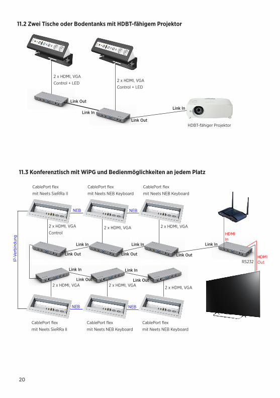
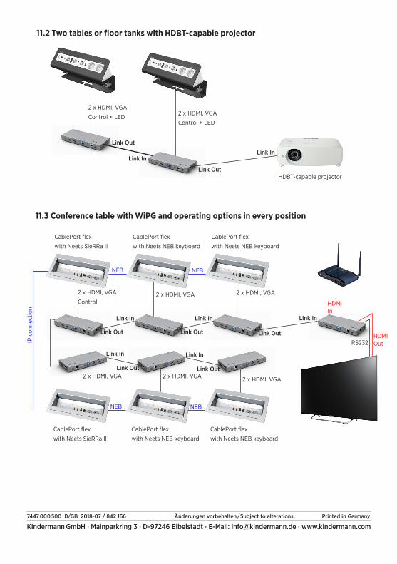
11.2. ZweiTischeoderBodentanksmitHDBT-fähigemProjektor
11.3. KonferenztischmitWiPGundBedienmöglichkeitenanjedemPlatz
D
3
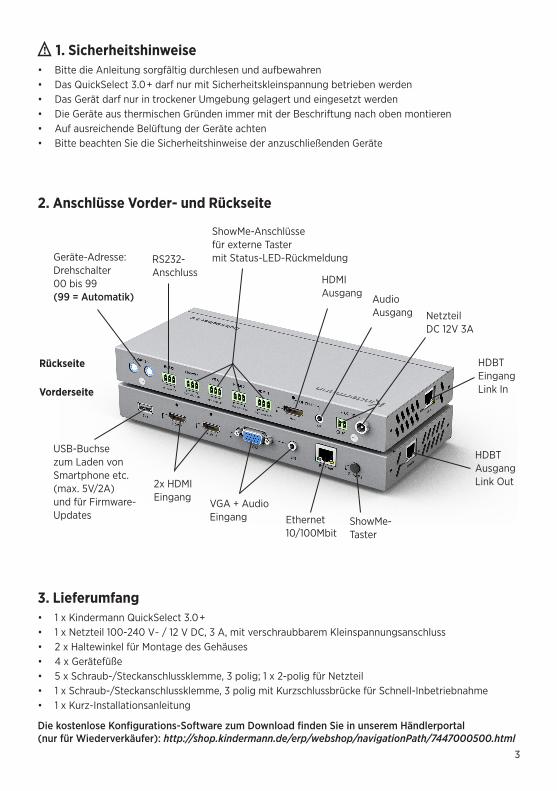
1. Sicherheitshinweise• Bitte die Anleitung sorgfältig durchlesen und aufbewahren• Das QuickSelect 3.0+ darf nur mit Sicherheitskleinspannung betrieben werden• Das Gerät darf nur in trockener Umgebung gelagert und eingesetzt werden• Die Geräte aus thermischen Gründen immer mit der Beschriftung nach oben montieren• Auf ausreichende Belüftung der Geräte achten• Bitte beachten Sie die Sicherheitshinweise der anzuschließenden Geräte
Geräte-Adresse: Drehschalter 00 bis 99 (99 = Automatik)
USB-Buchse zum Laden von Smartphone etc. (max. 5V/2A) und für Firmware-Updates
2x HDMI Eingang
VGA + Audio Eingang Ethernet
10/100MbitShowMe-Taster
HDMI Ausgang Audio
Ausgang
Rückseite
Vorderseite
Netzteil DC 12V 3A
HDBT Eingang Link In
HDBT Ausgang Link Out
RS232- Anschluss
ShowMe-Anschlüsse für externe Taster mit Status-LED-Rückmeldung
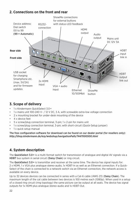
2. Anschlüsse Vorder- und Rückseite
3. Lieferumfang• 1 x Kindermann QuickSelect 3.0+• 1 x Netzteil 100-240 V~ / 12 V DC, 3 A, mit verschraubbarem Kleinspannungsanschluss• 2 x Haltewinkel für Montage des Gehäuses• 4 x Gerätefüße• 5 x Schraub-/Steckanschlussklemme, 3 polig; 1 x 2-polig für Netzteil• 1 x Schraub-/Steckanschlussklemme, 3 polig mit Kurzschlussbrücke für Schnell-Inbetriebnahme• 1 x Kurz-Installationsanleitung
Die kostenlose Konfigurations-Software zum Download finden Sie in unserem Händlerportal (nur für Wiederverkäufer): http://shop.kindermann.de/erp/webshop/navigationPath/7447000500.html
4
4. SystembeschreibungDas QuickSelect 3.0+ ist ein Multiformat Umschalter für die Übertragung von analogen und digitalen AV-Signalen über ein HDBT-Bussystem in Reihenschaltung (Daisy Chain) oder Ringschaltung.
Das QuickSelect 3.0+ ist Sender und Empfänger zugleich. Das Gerät besitzt Signal-Eingänge für: 2 x HDMI, 1 x VGA plus analogem Stereo-Audio, 1x HDBT-In sowie einen Ethernet-Anschluss. Wird ein QuickSelect über diesen Ethernet-Anschluss mit einem Netzwerk-Switch verbunden, steht der Netzwerk-zugang an jedem Gerät zur Verfügung. Das Gerät besitzt zwei Signal-Ausgänge: 1x HDMI plus analogen Stereo-Audio sowie 1x HDBT-Out.
Bis zu 32 Geräte können mit jeweils einem Cat-6 Kabel (AWG 23) aneinandergereiht werden (Daisy Chain). Die maximale Länge des Cat-Kabels zwischen zwei Geräten beträgt jeweils 100 Meter (1080p). Bei Verschaltung in Form eines geschlossenen Rings (Ringtopologie) ist die gleichzeitige Bildausgabe an allen Teilnehmerplätzen möglich.
Die Signal-Eingänge am Gerät können entweder direkt über den ShowMe-Taster oder über externe Taster (angeschlossen an Phoenix-Klemmen an der Rückseite) durchgeschaltet werden. Wird im Automatik- Modus eine aktive Quelle angesteckt, wird dieser Eingang durch eine automatische Signalerkennung direkt aktiviert.
Über die beiden Signalausgänge können unterschiedliche Signalquellen ausgegeben werden (eine lokale und eine vorgeschaltete Quelle).
Innerhalb der Reihenschaltung kann jedes Gerät auch eingespeiste Signale von vorherigen Sendern in der Kette über den HDMI-Ausgang ausgeben. Somit können auch mehrere Geräte am Ende der Kette, als Empfänger das gleiche Signal ausgeben (Split-Funktion). Das HDMI-Ausgangssignal hat die gleiche Auflösung wie der aktivierte Eingang. Analoge VGA-Eingangssignale können bis 1080p bzw. WUXGA-Auflösung skaliert werden. Die Wiedergabe analoger Audiosignale ist bei aktiviertem VGA-Eingang auch ohne angeschlossenes VGA-Signal möglich. Mit dieser „Audio-only“ Funktion ist z. B. die Wiedergabe von Musikdateien durch Smartphones oder MP3 Player möglich.
Über eine kostenlose Konfigurations-Software kann man alle Geräte, die über den Bus verbunden sind, über eine intuitive, grafische Oberfläche konfigurieren, visualisieren und steuern. Diese ist für einige Funktionen erforderlich.
Die automatische Adressvergabe der am Bus angeschlossenen Geräte kann manuell am Gerät, oder über die Software ausgelöst werden. Alternativ kann sie manuell über zwei BCD-Schalter am Gerät eingestellt werden.
Das Einlesen der EDID-Information von dem am letzten Quickselect per HDMI- oder HDBT-Ausgang angeschlossenen Endgerät (Display oder Projektor) kann manuell am Gerät oder über die Software ausgelöst werden. Alternativ können an den Eingängen des Quickselects vordefinierte (predefined) Tabellen hinterlegt werden. Somit stehen die EDID-Daten an allen Eingängen der Geräte zur Verfügung und fordern von den Signalquellen exakt diese Einstellungen an.
Die RS232-Schnittstelle an den Geräten dient der externen Steuerung der Einheiten, z. B. mit der Software oder mit einer Mediensteuerung. Mittels der Display Power Control Funktion ist das direkte, automatische Ein- und Ausschalten eines oder mehrerer Displays oder Projektoren bei Signalerkennung auch ohne externe Steuerung möglich. Zum Ein-/Ausschalten ist dabei ein Timeout konfigurierbar. Diese Gerätesteuerung ist per RS232 und per im HDBT-Out integrierten RS232 möglich (vorbehaltlich der Kom-patibilität des zu steuernden Geräts).
5
Funktionen• Eingangsselektion wahlweise über Kontakteingänge, ShowMe-Taster, RS232 oder per integrierter
automatischer Signalerkennung• Umsetzung des Eingangssignals auf HDBT um auf Cat-6/7 (AWG23) über eine große Entfernung
zu senden (Bild und Ton unidirektional, RS232 und LAN bidirektional)• Die Reichweite beträgt bei 1080p bis zu 100 m, 4K60 bis zu 30 m• Integriertes EDID Management• Unterstützt HDMI 1.4 mit 3D und 4K• Unterstützt HDCP• Über Kontakteingänge steuerbar, mit Rückmeldeausgängen für LED• RS232-Anschluss zur Steuerung des Systems: Kompatibel mit PC-Steuersoftware und
Mediensteuerungen auch von Fremdherstellern• Steuerfunktion: Über RS232 lassen sich Befehle an die am Empfänger angeschlossen Geräte senden• Stabiles, antistatisches Metallgehäuse für guten Langzeitschutz (inkl. Haltewinkel und Gerätefüße)• Skalierbares System (mehrere Geräte in einer Installation kombinierbar) für bis zu 32 Module in
Reihen- oder Ring-Topologie• Ringtopologie für gleichzeitige Bildausgabe an allen Teilnehmerplätzen• Display Power Control Funktion zum automatischen Ein- und Ausschalten eines oder mehrerer
Displays bei Signalerkennung. Ein-/Ausschalten mit einstellbarem Timeout.• Quick-Setup mit Auto-EDID für HDMI oder HDBT Bildausgabe• Freie Montagemöglichkeit, z. B. Auftisch Montage und Untertisch Montage, Zwischendecke• Verteilter Ethernet HUB bis zu 100Mbit
5. Schnell-InbetriebnahmeDie Schnell-Inbetriebnahme geschieht in 3 einfachen Schritten:
1. Geräte verkabeln
2. Geräte-Adressen vergeben (manuell oder automatisch)
3. EDID-Information vom Wiedergabegerät einlesen
Dank der Setup-Assistenten können die Standard-Einstellungen automatisch und schnell ausgeführt werden. Individuelle Einstellungen lassen sich mit einem Laptop mit Hilfe der kostenlosen Konfigura-tions-Software über den RS232-Anschluss vornehmen.
5.1 Geräte verkabelnAlle Netzteile an die Geräte anschließen, Überwurfmutter nur handfest anziehen. Netzstecker der Netzgeräte noch nicht in die Steckdose stecken.
QuickSelects im ausgeschalteten Zustand mit einem Cat-6 Kabel (AWG 23) verbinden, Link-Ausgang des ersten Gerätes mit dem Link-Eingang des nächsten QuickSelect 3.0+ verbinden, entsprechend fortfahren bis alle Geräte in Reihe verbunden sind.
Wiedergabegeräte an den HDMI-Ausgang oder den HDBT Link-out des letzten QuickSelects der Reihe anschließen. Nur bei benötigter Ringverschaltung den HDBT Link-Out Ausgang des letzten Quick-Selects mit dem Link-In des ersten Gerätes verbinden.

6
Medien-steuerung
Projektor
Laut-sprecher
RS232
HDMI max. 10 m
Audio
RS232
HDMI VGA AUDIO
HDMI VGA AUDIOHDMI VGA AUDIO
HDMI VGA AUDIO
Link outLink in
Link outLink in
Link outLink in
Link out
Link in
HDMI
HDMI
HDMI
HDMIAudioRS232
Cat-Kabel (HDBT)
Medien-steuerung
Projektor
Laut-sprecher
Display
HDMI VGA AUDIO
HDMI VGA AUDIO
HDMI VGA AUDIO
HDMI VGA AUDIO
Link outLink in
Link outLink in
Link outLink in
RS232
Audio
HDMI
HDMI max. 10 mRS232
RS232
HDMIAudioRS232
Cat-Kabel (HDBT)
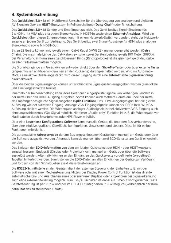
Anwendungsbeispiel: Reihenschaltung
Anwendungsbeispiel: Ringschaltung

7
5.2 Geräte-Adressen manuell konfigurierenMit Hilfe eines kleinen Schlitz-Schraubendrehers die beiden BCD-Drehschalter an der Rückseite jedes QuickSelect Gerätes auf eine individuelle Adresse zwischen 01…98 einstellen. Die Adresse 00 ist für den speziellen Fall einer Ringverkabelung reserviert und muss in diesem Fall zwingend dem „ersten“ Gerät des Rings zugeordnet werden.
5.3 Geräte-Adressen automatisch konfigurieren (Adresse “99“)Alternativ zur manuellen Adress-Konfiguration in 5.2 können die Adressen sämtlicher Geräte auch automatisch vergeben werden. Hierzu die BCD-Drehschalter aller Geräte auf der werksseitigen Einstellung “99“ belassen. Bei Ringverschaltung nur am ersten Gerät „00“ einstellen. Wir empfehlen die Verwendung der kostenlosen Konfigurations-Software. Ist diese nicht zur Hand, bitte wie folgt vorgehen:
Alle Netzteile, bis auf das erste der Kette, in Steckdose einstecken. Mitgelieferte oder selbst erstellte Kurzschlussklemme in Buchse “VGA“ in Rückseite des ersten Gerätes stecken. Nun Netzteil des ersten Gerätes einstecken. Im Verlauf der Adressvergabe blinken die LEDs der Signal-Eingänge an der Frontseite wiederholt 3x in schneller Folge. Kurzschlussklemme entfernen.
Kurzschlussklemme selbst erstellen: Kontakte KEY und GND einer mitgelieferten Schraub-/Steck- anschlussklemme mit einer Drahtbrücke verbinden.
5.4 EDID-Information vom Wiedergabegerät lesen und abspeichernMit AUTO EDID liest das QuickSelect über den HDBT- oder HDMI-Ausgang die darstellbaren Auflösungen des letzten Wiedergabegerätes in der Kette und speichert diese in allen QuickSelects ab.
Wir empfehlen die Verwendung der kostenlosen Konfigurations-Software. Ist diese nicht zur Hand, bitte wie folgt vorgehen:
Alle Netzteile, bis auf das erste der Kette, in Steckdose einstecken. Mitgelieferte oder selbst erstellte Kurzschlussklemme in Buchse “HDMI2“ in Rückseite des ersten Gerätes stecken. Nun Netzteil des ersten Gerätes einstecken. Im Verlauf des EDID Lese- und Speichervorgangs blinken die LEDs der Signal- Eingänge an der Frontseite wiederholt 3x in schneller Folge. Kurzschlussklemme entfernen.Die EDID-Information ist nun an allen HDMI Signal-Eingängen der Geräte gespeichert. Mit der EDID- Information wird die Auflösung der Grafik-Karte des Signalgebers (z. B. Laptop) automatisch an die Auflösung des Wiedergabe-Gerätes (z. B. Projektor) angepasst.
5.5 Reihen- oder Ringverkabelung?Die Quickselect 3.0+ zugrunde liegende sog. „HDBT“ Übertragungstechnik gestattet die gleichzeitige Übertragung von Video- und Audiosignalen sowie RS232 Steuerinformationen und 100MBit/s Ethernet. Dabei werden die Video- und Audiosignale richtungsgebunden in Art einer „Einbahnstraße“ jeweils vom Link-out Anschluss zum Link-In des nachfolgenden Quickselect Gerätes übertragen bis zum Ende der Kette bzw. bis zum Anzeigegerät. Im Gegensatz dazu werden RS232 Steuerinformationen und Ethernet bidirektional transportiert. Ein von einem Teilnehmer an einer beliebigen Stelle innerhalb der Kette eingespeistes Videosignal kann daher nur die nachgelagerten Geräte durchlaufen, nicht jedoch vorgelagerte Geräte.
Für einen typischen Besprechungsraum ist die Verkabelungsart „Reihenverkabelung“ die beste Wahl, da hierbei in der Regel nur ein einziges Anzeigegerät (Projektor, Display) an Ende der Signalkette benötigt wird und das HDBT Signal direkt in einen kompatiblen Projektor eingespeist werden kann. Auch eine Signalausgabe aller Quellen an mehr als ein Anzeigegerät ist möglich, solange sich diese am Ende der Kette befinden. Ist jedoch die Ausgabe eines beliebigen Teilnehmer Bildsignals an sämtlichen Plätzen einschließlich der vorgelagerten Plätze gewünscht, wie beispielsweise für EDV-Schulungsräume, so bietet sich eine Ringverkabelung an.
8
6. Konfiguration über die grafische Benutzeroberfläche (GUI)Die kostenlose Konfigurations-Software zum Download finden Sie in unserem Händlerportal(nur für Wiederverkäufer): http://shop.kindermann.de/erp/webshop/navigationPath/7447000500.html
Bitte stellen sie eine Verbindung zwischen Ihrem PC und dem QuickSelect 3.0+ System per RS232 her (Pinbelegung für GUI auf S. 19). Falls Ihr PC keinen RS232-Anschluss haben sollte, bedienen Sie sich bitte eines RS232/USB Adapters.Nach dem Verbinden des QuickSelect 3.0+ mit dem PC bitte dort obige Software starten.
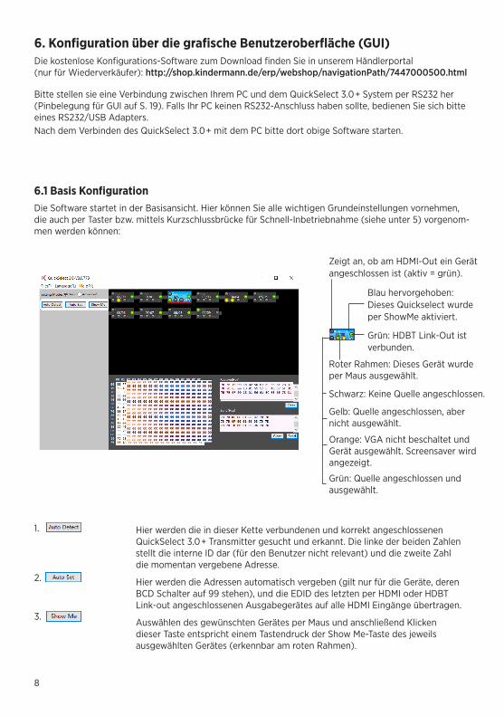
6.1 Basis KonfigurationDie Software startet in der Basisansicht. Hier können Sie alle wichtigen Grundeinstellungen vornehmen, die auch per Taster bzw. mittels Kurzschlussbrücke für Schnell-Inbetriebnahme (siehe unter 5) vorgenom-men werden können:
Hier werden die in dieser Kette verbundenen und korrekt angeschlossenen QuickSelect 3.0+ Transmitter gesucht und erkannt. Die linke der beiden Zahlen stellt die interne ID dar (für den Benutzer nicht relevant) und die zweite Zahl die momentan vergebene Adresse.
Hier werden die Adressen automatisch vergeben (gilt nur für die Geräte, deren BCD Schalter auf 99 stehen), und die EDID des letzten per HDMI oder HDBT Link-out angeschlossenen Ausgabegerätes auf alle HDMI Eingänge übertragen.
Auswählen des gewünschten Gerätes per Maus und anschließend Klicken dieser Taste entspricht einem Tastendruck der Show Me-Taste des jeweils ausgewählten Gerätes (erkennbar am roten Rahmen).
1.
2.
3.
Zeigt an, ob am HDMI-Out ein Gerät angeschlossen ist (aktiv = grün).
Blau hervorgehoben: Dieses Quickselect wurde per ShowMe aktiviert.
Grün: HDBT Link-Out ist verbunden.
Schwarz: Keine Quelle angeschlossen.
Gelb: Quelle angeschlossen, aber nicht ausgewählt.
Orange: VGA nicht beschaltet und Gerät ausgewählt. Screensaver wird angezeigt.
Grün: Quelle angeschlossen und ausgewählt.
Roter Rahmen: Dieses Gerät wurde per Maus ausgewählt.
9
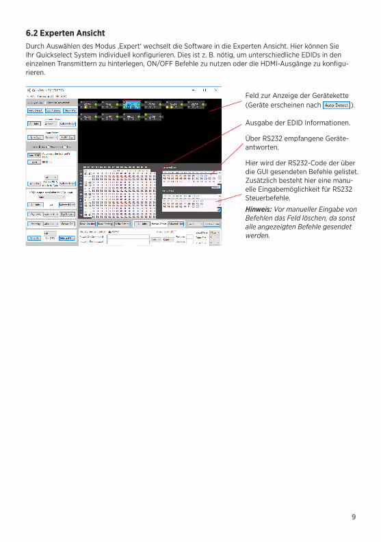
6.2 Experten AnsichtDurch Auswählen des Modus ‚Expert‘ wechselt die Software in die Experten Ansicht. Hier können Sie Ihr Quickselect System individuell konfigurieren. Dies ist z. B. nötig, um unterschiedliche EDIDs in den einzelnen Transmittern zu hinterlegen, ON/OFF Befehle zu nutzen oder die HDMI-Ausgänge zu konfigu-rieren.
Feld zur Anzeige der Gerätekette (Geräte erscheinen nach ).
Ausgabe der EDID Informationen.
Über RS232 empfangene Geräte-antworten.
Hier wird der RS232-Code der über die GUI gesendeten Befehle gelistet. Zusätzlich besteht hier eine manu-elle Eingabemöglichkeit für RS232 Steuerbefehle.
Hinweis: Vor manueller Eingabe von Befehlen das Feld löschen, da sonst alle angezeigten Befehle gesendet werden.

10
EDID Management:Mit der EDID-Konfiguration nehmen Sie Einfluss auf den EDID-Datenaustausch vom Anzeigegerät an die Signalquelle. Sie können EDID Werte vorgeben, um die Signalquellen zur Ausgabe dieser vorein-gestellten Formate aufzufordern. Dies betrifft bei HDMI und Displayport Audio und Video.
Das QuickSelect 3.0+ hat drei EDID Tabellen pro HDMI Eingang verfügbar: 1. Auto EDID, 2. Werksseitige (‚Predefined‘) EDID, 3 Benutzerspezifische (‚User‘) EDID.Die jeweilige Tabelle wird über den aktiven Modus in der GUI ausgewählt.
Info: Was ist EDIDDie EDID Information (Extended Display Identification Data) besteht aus einer einer 128 Byte- (VGA) bzw. 256 Byte-Datenstruktur (HDMI), die in einem Videodisplay/Projektor oder anderem Ausgabegerät gespeichert ist. Diese enthält die für das Ausgabegerät darstellbaren Auflösungen incl. Bildwiederholrate, Tonformate usw.Das Quellgerät fragt vor dem Bildaufbau das Ausgabegerät nach dieser Tabelle und wählt daraus eine möglichst passende Auflösung für die Bildausgabe.
Hinweis: Mit Hilfe der ShowMe-Anschlüsse für externe Taster wird nur die Quelle für das über HDBT-Out ausgegebene Signal gewählt, nicht für HDMI/Audio Out (außer es ist die Einstellung „Link In/Link Out“ gewählt). Die werksseitige Einstellung ist „Link In/Link Out“. Hierbei werden entweder über Link In vom voran- gehenden Modul ankommende Signale oder auch lokal eingespeiste Signale auf beiden Ausgängen HDMI und Link Out parallel ausgegeben.
Systemübersicht und Adressvergabe:
Mit dem Betätigen dieser Taste werden die in dieser Kette verbundenen und korrekt angeschlossenen, QuickSelect 3.0+ Transmitter gesucht und er-kannt. Die linke der beiden Zahlen stellt die interne ID dar (für den Benutzer nicht relevant) und die zweite Zahl die momentan vergebene Adresse.
Mit Auto Address werden die Adressen automatisch vergeben (gilt nur für die Geräte, deren BCD Schalter auf 99 stehen).
Ein Klicken auf diese Taste entspricht einem Tastendruck der ShowMe-Taste des jeweils ausgewählten Gerätes (erkennbar am roten Rahmen).
Hier kann für einzeln ausgewählte Geräte oder für alle Geräte der Kette die automatische Eingangswahl jedes Gerätes aktiviert/deaktiviert werden (Autosource on/off). Ist diese Funktion eingeschaltet, wird der Eingang auf ein neu anliegendes Bildsignal automatisch umgeschaltet. Übertragen wird dieses Bildsignal nur, wenn auch das Gerät aktiv ist (ShowMe Taste wurde gedrückt). Werksseitige Einstellung ist „Autosource on“.Die zusätzliche automatische Übertragung eines anliegenden Signals lässt sich mittels „Autoshow on“ aktivieren. Werksseitige Einstellung ist „Autoshow off“.
In diesem Abschnitt wird festgelegt welche der 4 Eingänge (Link In, HDMI1, HDMI2 oder VGA) auf den ‚HDBT-Out‘ zur Weiterleitung an die Folgekomponente gelegt wird. Über die Taste ‚HDMI Out‘ wird bestimmt, welcher dieser Eingänge auf den HDMI-Ausgang des ausgewählten QuickSelect 3.0+ gelegt wird. Somit kann ein lokal angeschlossener Vorschaumonitor das über ‚Link-In‘ ankommende oder über ein lokal per HDMI/VGA eingespeistes Bildsignal anzeigen.
11
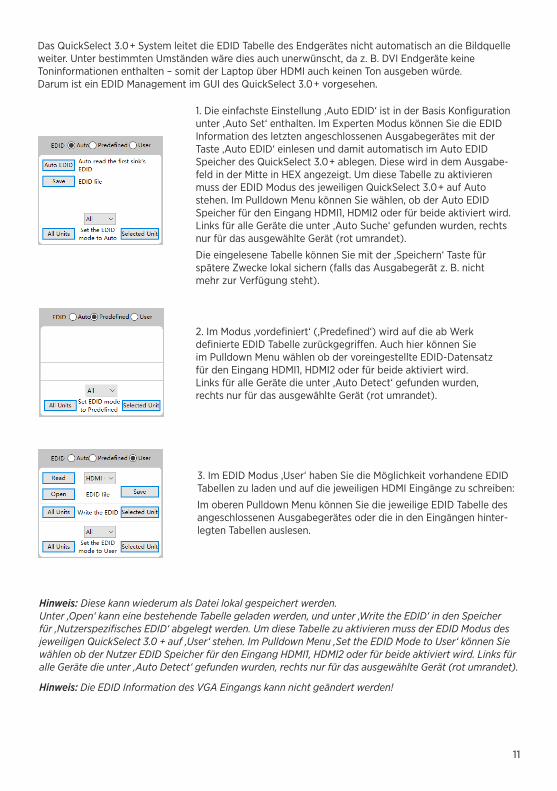
Das QuickSelect 3.0+ System leitet die EDID Tabelle des Endgerätes nicht automatisch an die Bildquelle weiter. Unter bestimmten Umständen wäre dies auch unerwünscht, da z. B. DVI Endgeräte keine Toninformationen enthalten – somit der Laptop über HDMI auch keinen Ton ausgeben würde. Darum ist ein EDID Management im GUI des QuickSelect 3.0+ vorgesehen.
1. Die einfachste Einstellung ‚Auto EDID‘ ist in der Basis Konfiguration unter ‚Auto Set‘ enthalten. Im Experten Modus können Sie die EDID Information des letzten angeschlossenen Ausgabegerätes mit der Taste ‚Auto EDID‘ einlesen und damit automatisch im Auto EDID Speicher des QuickSelect 3.0+ ablegen. Diese wird in dem Ausgabe-feld in der Mitte in HEX angezeigt. Um diese Tabelle zu aktivieren muss der EDID Modus des jeweiligen QuickSelect 3.0+ auf Auto stehen. Im Pulldown Menu können Sie wählen, ob der Auto EDID Speicher für den Eingang HDMI1, HDMI2 oder für beide aktiviert wird. Links für alle Geräte die unter ‚Auto Suche‘ gefunden wurden, rechts nur für das ausgewählte Gerät (rot umrandet).
Die eingelesene Tabelle können Sie mit der ‚Speichern‘ Taste für spätere Zwecke lokal sichern (falls das Ausgabegerät z. B. nicht mehr zur Verfügung steht).
2. Im Modus ‚vordefiniert‘ (‚Predefined‘) wird auf die ab Werk definierte EDID Tabelle zurückgegriffen. Auch hier können Sie im Pulldown Menu wählen ob der voreingestellte EDID-Datensatz für den Eingang HDMI1, HDMI2 oder für beide aktiviert wird. Links für alle Geräte die unter ‚Auto Detect‘ gefunden wurden, rechts nur für das ausgewählte Gerät (rot umrandet).
3. Im EDID Modus ‚User‘ haben Sie die Möglichkeit vorhandene EDID Tabellen zu laden und auf die jeweiligen HDMI Eingänge zu schreiben:
Im oberen Pulldown Menu können Sie die jeweilige EDID Tabelle des angeschlossenen Ausgabegerätes oder die in den Eingängen hinter-legten Tabellen auslesen.
Hinweis: Diese kann wiederum als Datei lokal gespeichert werden. Unter ‚Open‘ kann eine bestehende Tabelle geladen werden, und unter ‚Write the EDID‘ in den Speicher für ‚Nutzerspezifisches EDID‘ abgelegt werden. Um diese Tabelle zu aktivieren muss der EDID Modus des jeweiligen QuickSelect 3.0 + auf ‚User‘ stehen. Im Pulldown Menu ‚Set the EDID Mode to User‘ können Sie wählen ob der Nutzer EDID Speicher für den Eingang HDMI1, HDMI2 oder für beide aktiviert wird. Links für alle Geräte die unter ‚Auto Detect‘ gefunden wurden, rechts nur für das ausgewählte Gerät (rot umrandet).
Hinweis: Die EDID Information des VGA Eingangs kann nicht geändert werden!

12
VGA Signale: Verfügbare Auflösungen und Bildwiederholfrequenzen
Native/preferred timing 1920x1080p at 60Hz (16:9)
Modeline „1920x1080“ 148,500 1920 2008 2052 2200 1080 1081 1085 1125 +hsync +vsync
Detailed timing #1 1366x768p at 60Hz
Modeline „1366x768“ 85,500 1366 1436 1579 1792 768 771 774 798 +hsync +vsync
Detailed timing #2 1920x1200p at 60Hz (16:10)
Modeline „1920x1200“ 154,000 1920 1968 2000 2080 1200 1203 1209 1235 +hsync -vsync
Standard timings supported
720 x 400p at 70Hz - IBM VGA 640 x 480p at 60Hz - IBM VGA 640 x 480p at 72Hz - VESA 640 x 480p at 75Hz - VESA 800 x 600p at 60Hz - VESA 800 x 600p at 72Hz - VESA 800 x 600p at 75Hz - VESA 832 x 624p at 75Hz - Apple Mac II
1024 x 768p at 60Hz - VESA 1024 x 768p at 70Hz - VESA 1024 x 768p at 75Hz - VESA 1280 x 1024p at 75Hz - VESA 1152 x 870p at 75Hz - Apple Mac II 1280 x 960p at 75Hz - VESA STD 1600 x 1200p at 60Hz - VESA STD 1280 x 800p at 60Hz - VESA STD 1920 x 1080p at 60Hz - VESA STD 1400 x 1050p at 75Hz - VESA STD
VGA zu HDMI Wandler: Der integrierte VGA zu HDMI Scaler wandelt analoge Video- und Audiosignale in ein HDMI-Signal.
Um eine möglichst hohe Qualität der Ausgabe des zugespielten VGA Signals zu erreichen, kann die Auflösung des über VGA anliegenden Bildsignals ausgabeseitig angepasst werden. Links für alle Geräte die unter ‚Auto Detect‘ gefunden wurden, rechts nur für das ausgewählte Gerät (rot umrandet).
Für eine optimale Bildqualität sollte die native (physikalische) Auflösung des Ausgabegerätes eingestellt werden.
Falls dieser Wert auf Auto steht, werden folgende Zuordnungen verwendet:
13
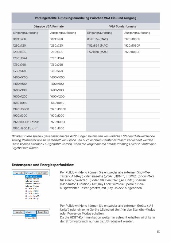
Voreingestellte Auflösungszuordnung zwischen VGA Ein- und Ausgang
Gängige VGA Formate VGA Sonderformate
Eingangsauflösung Ausgangsauflösung Eingangsauflösung Ausgangsauflösung
1024x768 1024x768 832x624 (MAC) 1920x1080P
1280x720 1280x720 1152x864 (MAC) 1920x1080P
1280x800 1280x800 1152x870 (MAC) 1920x1080P
1280x1024 1280x1024
1360x768 1360x768
1366x768 1366x768
1400x1050 1400x1050
1400x900 1400x900
1600x900 1600x900
1600x1200 1600x1200
1680x1050 1680x1050
1920x1080P 1920x1080P
1920x1200 1920x1200
1920x1080P Epson* 1920x1080P
1920x1200 Epson* 1920x1200
Hinweis: Diese speziell gekennzeichneten Auflösungen beinhalten vom üblichen Standard abweichende Timing Parameter wie sie vereinzelt von Epson und auch anderen Geräteherstellern verwendet werden. Diese können alternativ ausgewählt werden, wenn die vorgenannten Standardtimings nicht zu optimalen Ergebnissen führen.
Tastensperre und Energiesparfunktion:
Per Pulldown Menu können Sie entweder alle externen ShowMe- Taster (‚All-Key‘) oder einzelne (‚VGA‘‚ ‚HDMI1‘, ‚HDMI2‘, ‚Show-Me‘) für einen (‚Selected…‘) oder alle Benutzer (‚All Units‘) sperren (Moderator-Funktion). Mit ‚Key Lock‘ wird die Sperre für die ausgewählten Taster gesetzt, mit ‚Key Unlock‘ aufgehoben.
Per Pulldown Menu können Sie entweder alle externen Geräte (‚All Units‘) oder einzelne Geräte (‚Selected Unit‘) in den Standby-Modus oder Power-on Modus schalten.Da die HDBT-Kommunikation weiterhin aufrecht erhalten wird, kann der Stromverbrauch nur um ca. 1/3 reduziert werden.
14
Konfiguration eines QuickSelect 3.0+ sichern und laden:Mit dem Schaltflächen kann die gesamte aktuelle Konfiguration des ausgewählten QuickSelect 3.0+ (roter Rahmen) als Datei gesichert – und ebenso zurückgeschrieben werden.
Hinweis: Sichern Sie sich diese Einstellungen für Ihre Projektdokumentation, so können gleiche Settings schnell wieder eingespielt werden (Vorlage&Datensicherung).
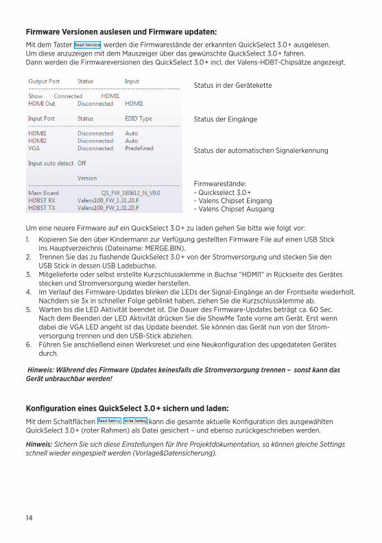
Firmware Versionen auslesen und Firmware updaten:Mit dem Taster werden die Firmwarestände der erkannten QuickSelect 3.0+ ausgelesen. Um diese anzuzeigen mit dem Mauszeiger über das gewünschte QuickSelect 3.0+ fahren. Dann werden die Firmwareversionen des QuickSelect 3.0+ incl. der Valens-HDBT-Chipsätze angezeigt.
Um eine neuere Firmware auf ein QuickSelect 3.0+ zu laden gehen Sie bitte wie folgt vor:
1. Kopieren Sie den über Kindermann zur Verfügung gestellten Firmware File auf einen USB Stick ins Hauptverzeichnis (Dateiname: MERGE.BIN).
2. Trennen Sie das zu flashende QuickSelect 3.0+ von der Stromversorgung und stecken Sie den USB Stick in dessen USB Ladebuchse.
3. Mitgelieferte oder selbst erstellte Kurzschlussklemme in Buchse “HDMI1“ in Rückseite des Gerätes stecken und Stromversorgung wieder herstellen.
4. Im Verlauf des Firmware-Updates blinken die LEDs der Signal-Eingänge an der Frontseite wiederholt. Nachdem sie 3x in schneller Folge geblinkt haben, ziehen Sie die Kurzschlussklemme ab.
5. Warten bis die LED Aktivität beendet ist. Die Dauer des Firmware-Updates beträgt ca. 60 Sec. Nach dem Beenden der LED Aktivität drücken Sie die ShowMe Taste vorne am Gerät. Erst wenn dabei die VGA LED angeht ist das Update beendet. Sie können das Gerät nun von der Strom- versorgung trennen und den USB-Stick abziehen.
6. Führen Sie anschließend einen Werksreset und eine Neukonfiguration des upgedateten Gerätes durch.
Hinweis: Während des Firmware Updates keinesfalls die Stromversorgung trennen – sonst kann das Gerät unbrauchbar werden!
Status in der Gerätekette
Status der Eingänge
Status der automatischen Signalerkennung
Firmwarestände:- Quickselect 3.0+- Valens Chipset Eingang- Valens Chipset Ausgang

15
7. RS232 SteuerungMit der kostenlosen Konfigurations-Software oder mit einer Mediensteuerung, kann das gesamte QuickSelect-System auch über den RS232 Anschluss in allen Einzelheiten gesteuert werden.
Der HDBT-Bus kann auch RS232-Steuerbefehle zur Steuerung weiterer Geräte wie Beamer und Display bidirektional übertragen (pass through). Schließen Sie z. B. die RS232-Schnittstelle der Mediensteuerung einfach an eine RS232-Klemme an.
Das ausführliche RS232-Protokoll und einen Treiber für Neets-Steuerungen finden Sie online unter: shop.kindermann.de/evp/webshop/navigation_Path/7447000500.html
RS232 Befehle manuell eingeben und Antworten auslesen:
Über diese Textfelder können Sie RS232 Befehle senden und die Antwort der QuickSelect 3.0+ Kette auslesen. Die Werte sind alle in HEX dargestellt.
Die Befehle der jeweiligen Steuerkommandos werden automatisch unter RS232-TxD (Hex) eingetragen und können z. B. zum Zwecke der Treibererstellung für Mediensteuerungen kopiert werden. Ebenso die jeweiligen Antworten der Geräte.
Hinweis: Es werden immer ALLE unter RS232-TxD eingetragenen Befehle hintereinander gesendet. Falls nur ein einzelner Befehl gesendet werden soll bitte das Feld vorher löschen und den Befehl alleinig eintragen.
Zurücksetzten eines/aller QuickSelect 3.0+ auf Werkseinstellungen:
Hinter dieser Funktion ist eine Sicherheitsabfrage eingebaut um versehentliches Überschreiben zu vermeiden. Falls ein Werksreset gewünscht ist, beachten Sie bitte auch die Adress-BCD-Schalter wieder auf 99 (Auslieferzustand) zu stellen.
Alternatives Zurücksetzen über Taster:1. Drücken und halten Sie den internen ShowMe-Taster und stellen die Stromversorgung wieder her.2. Halten Sie den Taster gedrückt, bis die LEDs an der Gerätefront ein paar Mal schnell aufblinken
- dann loslassen.3. Warten bis die LEDs ausgehen und nach einiger Zeit alle LEDs blinken (Zeichen für das Ende des
Werksresetes). Der Firmwarestand bleibt hierbei erhalten.
16
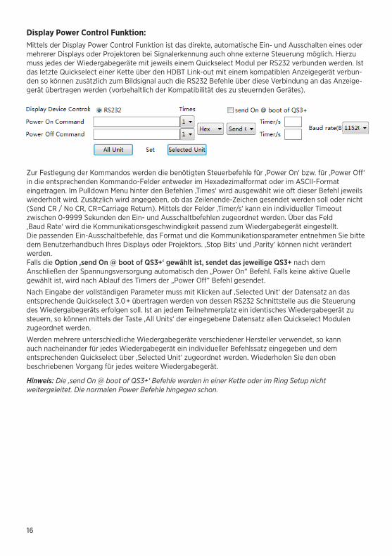
Display Power Control Funktion:Mittels der Display Power Control Funktion ist das direkte, automatische Ein- und Ausschalten eines oder mehrerer Displays oder Projektoren bei Signalerkennung auch ohne externe Steuerung möglich. Hierzu muss jedes der Wiedergabegeräte mit jeweils einem Quickselect Modul per RS232 verbunden werden. Ist das letzte Quickselect einer Kette über den HDBT Link-out mit einem kompatiblen Anzeigegerät verbun-den so können zusätzlich zum Bildsignal auch die RS232 Befehle über diese Verbindung an das Anzeige-gerät übertragen werden (vorbehaltlich der Kompatibilität des zu steuernden Gerätes).
Zur Festlegung der Kommandos werden die benötigten Steuerbefehle für ‚Power On‘ bzw. für ‚Power Off‘ in die entsprechenden Kommando-Felder entweder im Hexadezimalformat oder im ASCII-Format eingetragen. Im Pulldown Menu hinter den Befehlen ‚Times‘ wird ausgewählt wie oft dieser Befehl jeweils wiederholt wird. Zusätzlich wird angegeben, ob das Zeilenende-Zeichen gesendet werden soll oder nicht (Send CR / No CR, CR=Carriage Return). Mittels der Felder ‚Timer/s‘ kann ein individueller Timeout zwischen 0-9999 Sekunden den Ein- und Ausschaltbefehlen zugeordnet werden. Über das Feld ‚Baud Rate‘ wird die Kommunikationsgeschwindigkeit passend zum Wiedergabegerät eingestellt. Die passenden Ein-Ausschaltbefehle, das Format und die Kommunikationsparameter entnehmen Sie bitte dem Benutzerhandbuch Ihres Displays oder Projektors. ,Stop Bits‘ und ,Parity‘ können nicht verändert werden. Falls die Option ‚send On @ boot of QS3+‘ gewählt ist, sendet das jeweilige QS3+ nach dem Anschließen der Spannungsversorgung automatisch den „Power On“ Befehl. Falls keine aktive Quelle gewählt ist, wird nach Ablauf des Timers der „Power Off“ Befehl gesendet.
Nach Eingabe der vollständigen Parameter muss mit Klicken auf ‚Selected Unit‘ der Datensatz an das entsprechende Quickselect 3.0+ übertragen werden von dessen RS232 Schnittstelle aus die Steuerung des Wiedergabegeräts erfolgen soll. Ist an jedem Teilnehmerplatz ein identisches Wiedergabegerät zu steuern, so können mittels der Taste ‚All Units‘ der eingegebene Datensatz allen Quickselect Modulen zugeordnet werden.
Werden mehrere unterschiedliche Wiedergabegeräte verschiedener Hersteller verwendet, so kann auch nacheinander für jedes Wiedergabegerät ein individueller Befehlssatz eingegeben und dem entsprechenden Quickselect über ‚Selected Unit‘ zugeordnet werden. Wiederholen Sie den oben beschriebenen Vorgang für jedes weitere Wiedergabegerät.
Hinweis: Die ‚send On @ boot of QS3+‘ Befehle werden in einer Kette oder im Ring Setup nicht weitergeleitet. Die normalen Power Befehle hingegen schon.
17
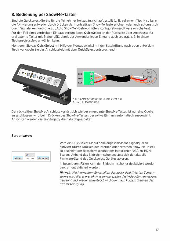
8. Bedienung per ShowMe-TasterSind die Quickselect-Geräte für die Teilnehmer frei zugänglich aufgestellt (z. B. auf einem Tisch), so kann die Aktivierung entweder durch Drücken der frontseitigen ShowMe Taste erfolgen oder auch automatisch durch Signalerkennung (hierzu „Auto ShowMe“-Betrieb mittels Konfigurationssoftware einschalten).Für den Fall eines verdeckten Einbaus verfügt jedes QuickSelect an der Rückseite über Anschlüsse für drei externe Taster mit Status-LED, damit der Anwender jeden Eingang auch separat, z. B. in einem Tischanschlussfeld anwählen kann.
Montieren Sie das QuickSelect mit Hilfe der Montagewinkel mit der Beschriftung nach oben unter dem Tisch, verkabeln Sie das Anschlussfeld mit dem QuickSelect entsprechend.
Der rückseitige ShowMe-Anschluss verhält sich wie der eingebaute ShowMe-Taster. Ist nur eine Quelle angeschlossen, wird beim Drücken des ShowMe-Tasters der aktive Eingang automatisch ausgewählt. Ansonsten werden die Eingänge zyklisch durchgeschaltet.
LEDNC
NO
C
+ -GND
KEY
z. B. CablePort desk2 für QuickSelect 3.0 Art-Nr. 7430 000 008
Screensaver:
Wird ein Quickselect Modul ohne angeschlossene Signalquellen aktiviert (durch Drücken der internen oder externen Show-Me Taste), so erscheint der Bildschirmschoner des integrierten VGA-zu-HDMI Scalers. Anhand des Bildschirmschoners lässt sich der aktuelle Firmware-Stand des Quickselect Gerätes ablesen.
In besonderen Fällen kann der Bildschirmschoner deaktiviert werden bzw. erneut aktiviert werden.
Hinweis: Nach erneutem Einschalten des zuvor deaktivierten Screen-savers wird dieser erst aktiv, wenn kurzzeitig das Video-Eingangssignal getrennt und wieder angesteckt wird oder nach kurzem Trennen der Stromversorgung.

18
9. Technische Daten
Eingang Ausgang
Video/Audio-schnittstellen
2 x HDMI (HDMI 1.4 mit HDCP), VGA, Audio (3,5 mm)
Video/Audio-schnittstellen
HDMI (HDMI 1.4 mit HDCP), Audio (3,5 mm)
HDBT HDBT-In HDBT HDBT-Out
USB-Buchse Typ-A, max. 2A
Steuerung
I/O Eingänge
Je ein Kontakteingang (3 pol. Phoenix Connector) für: - HDMI1, HDMI2 und VGA - ShowMe-Funktion
I/O Ausgänge
Je ein Ausgang (3 pol. Phoenix Connector) mit LED Treiber für: - HDMI1, HDMI2 und VGA - ShowMe-Funktion
RS232 3 pol. Phoenix Connector, zur Gerätesteuerung
Allgemein
Auflösungsbereich
HDMI: bis zu 4K2K@60 Hz (4:2:0), HDCP 2.0, inkl. 3D
VGA: 800x600, 832x624 (MAC), 1024x768, 1152x864, 1152x870 (MAC), 1280x720, 1280x768, 1280x800, 1280x960, 1280x1024, 1360x768, 1366x768, 1400x1050, 1440x900, 1600x1200, 1680x1050, 1920x1080P, 1920x1200
Betriebs- temperatur
Luftfeuchte
Lagertemperatur
0°C bis 35°C
10% bis 90%, nicht kondensierend
-20°C bis 70°C
Audio-Eingang HDMI: embedded VGA: 3,5 mm Stereo-Klinke Audio-Ausgang HDMI embedded +
3,5 mm Stereo-Klinke
EDID/DDC Unterstützt Extended Display Identification Data (EDID) und Display Data Chan-nel (DDC) Daten über DVI und HDMI Standarts, EDID und DDC Signale
HDCP Kompatibel mit High-bandwidth Digital Content Protection (HDCP 2.0).
Netzteil 100 VAC ~ 240 VAC, 50/60 Hz sekundär 12 V DC, 3A Energieverbrauch 12 W max
(ohne Ladefunktion)
Abmessungen Transmitter: 223 x 26 x 99 mm (BxHxT) Gewicht ca. 0,8 kg (ohne Netzteil)

19
10. Verfügbares Zubehör • RS232-Kabel vorkonfektioniert (7447 000 410)• VGA-Kabel (7483 000 4xx)• HDMI-Kabel, Typ A, 19-Pin (5809 000 1xx)• DP auf HDMI-Kabel (5809 000 60x)• HDMI Medienswitchkabel (5809 000 099)• VGA Medienswitchkabel (7483 000 300)• Neets Mediensteuerung (5555 000 0x0)
11. Anwendungsbeispiele11.1 Eintischlösung mit HDBT-Wandanschlussfeld
2 x HDMI, VGA
Control + LED
HDMI
HDBT- Transmitter(7456000543)
Link Out
Link In
RS232Medien- steuerung(5555000020)
9 6
5 1
Sub-D9
RS232-Kabel
RS232-Buchse
PC
RS232
Quickselect
Rx GND Tx
20
11.3 Konferenztisch mit WiPG und Bedienmöglichkeiten an jedem Platz
HDMIOut
HDMIIn
2 x HDMI, VGA
Control2 x HDMI, VGA 2 x HDMI, VGA
RS232
2 x HDMI, VGA2 x HDMI, VGA2 x HDMI, VGA
CablePort flex
mit Neets SieRRa II
CablePort flex
mit Neets SieRRa II
CablePort flex
mit Neets NEB Keyboard
CablePort flex
mit Neets NEB Keyboard
CablePort flex
mit Neets NEB Keyboard
CablePort flex
mit Neets NEB Keyboard
NEB
IP-V
erbi
ndun
g
NEB
NEB
NEB
Link Out
Link Out Link OutLink Out
Link Out
Link InLink In
Link In Link In Link In
11.2 Zwei Tische oder Bodentanks mit HDBT-fähigem Projektor
2 x HDMI, VGA
Control + LED
2 x HDMI, VGA
Control + LED
Link Out
Link InLink In
HDBT-fähiger ProjektorLink Out
21
Table of contents1. Safetyinstructions
2. Connectionsfrontandrear
3. Scopeofdelivery
4. Systemdescriptionandfunctions
5. Quicksystemsetup
5.1. Wiringdevices
5.2. Manualdeviceaddressawarding
5.3. Automaticdeviceaddressawarding(address“99“)
5.4. ReadingandsavingEDIDinformationofplaybackdevices
5.5. ChainorRing-Setup?
6. Configurationwiththegraphicaluserinterface
6.1. Basicconfiguration
6.2. Expertconfiguration
7. RS232control
8. OperationbyShowMebutton
9. Technicaldata
10. Availableaccessories
11. Applicationexamples
11.1. Single-tablesolutionwithHDBT-wallconnectionpanel
11.2. TwotablesorfloodtankswithHDBT-capableprojector
11.3. ConferencetablewithWiPGandoperatingoptionsineveryposition
GB
1. Safety instructions• Please read the instructions with care and keep them• The QuickSelect 3.0+ must only be operated with safety extra-low voltage• The device must only be stored and used in dry environments• Always install the device with the label up for thermal reasons• Ensure sufficient ventilation of the devices• Please observe the safety notes of the devices to be connected
22
3. Scope of delivery• 1 x Kindermann QuickSelect 3.0+• 1 x mains unit 100-240 V~ / 12 V DC, 3 A, with screwable extra-low voltage connection• 2 x mounting bracket for under-desk mounting of the device• 4 x device feet• 5 x screw/plug connection terminal, 3-pin; 1 x 2-pin for mains unit• 1 x screw/plug connection terminal, 3-pin; with short-circuit (Quick-Setup jumper)• 1 x quick setup manual
The free configuration software for download can be found on our dealer portal (for resellers only):http://shop.kindermann.de/erp/webshop/navigationPath/7447000500.html
4. System descriptionThe QuickSelect 3.0+ is a multi-format switch for transmission of analogue and digital AV signals via a HDBT bus system in serial circuit (Daisy Chain) or ring circuit.
The QuickSelect 3.0+ is transmitter and receiver at the same time. The device has signal inputs for: 2 x HDMI, 1 x VGA plus analogue stereo-audio, 1x HDBT-In as well as an Ethernet connection. If a Quick-Select of the chain is connected to a network switch via an Ethernet connection, the network access is available on every device.
Up to 32 devices devices can be connected in series with a Cat-6 cable (AWG 23) (Daisy Chain). The maximum length of the cat cable between two devices is 100 metres each (1080p). When used in a setup of a closed ring circuit (ring topology) the same picture can be output at all seats. The device has signal outputs for 1x HDMI plus analogue stereo-audio and 1x HDBT-Out.
Device address: Dial switch 00 to 99 (99 = Automatic)
USB socket for charging Smartphone etc. (max. 5V/2A) and for firmware updates
2x HDMI input
VGA + audio input Ethernet
10/100MbitShowMe button
HDMI output Audio
output
Rear side
Front side
Mains unit DC 12V 3A
HDBT input link in
HDBT output link out
RS232- connection
ShowMe connections for external buttons with status-LED feedback
2. Connections on the front and rear

23
Functions• Input selection either via contact inputs, ShowMe button, RS232 or by integrated automatic signal recognition.• Conversion of input signals to HDBT for long distance transmission via Cat-6/7 (AWG23) across
long distances (picture and sound unidirectional, RS232 and LAN bidirectional).• The range is up to 100 m at 1080p, 4K60 up to 30 m.• Integrated EDID management.• Supports HDMI 1.4 with 3D and 4K.• Supports HDCP.• Can be controlled via contact inputs, with feedback outputs for LED.• RS232-connection to control the system: Compatible with PC control software and media controls
also of third-party manufacturers.• Control function: RS232 can be used to send commands to the devices connected to the receiver.• Stable, anti-static metal housing for good long-term protection (incl. mounting brackets and device feet).• Scalable system (several devices can be combined in one installation) for up to 32 units in chain or ring
topology.• Ring topology for simultaneous local preview for each participant.• Display Power Control function for automatic power on/off switching of one or more display devices
upon signal detection. Power on/off switching with configurable timeout.• Quick setup with Auto-EDID function for HDMI or HDBT signal transmission.• Free installation option, e. g. on-table installation and undertable installation, interim ceiling.• Distributed Ethernet HUB up to 100Mbit.
The signal inputs at the device can either be activated directly via the ShowMe button or via external buttons (connected to Phoenix terminals at the rear). If an active source is connected in automatic mode, this input is directly activated by an automatic signal recognition.
Those outputs can be switched to different signal inputs (one locally and one HDBT-In).
Within the serial circuit, every device can output infed signals from previous transmitters in the chain via the HDMI-output. Thus, several devices can output the same signal as receivers at the end of the chain (split function). The HDMI output signal has the same resolution as the activated input. Analogue VGA input signals can be scaled up to 1080p or WUXGA resolution. The audio input can be used for playback of analogue audio only, even without an active VGA signal being connected to the VGA input (“Audio only” function). This function allows playback of music and other sound files by using smartphones and MP3 players.
A free configuration software can be used to configure, visualize and control all devices that are connected via the bus using an intuitive, graphical interface. To use some of the functions you´ll need to use this GUI.
The automatic address awarding of the devices connected to the bus can be triggered manually at the device or via the software. Alternatively, it can be set manually with two BCD switches at the device.
Reading the EDID information from the display device (display or projector) connected to the last Quickselect’s HDMI- or HDBT output can be triggered manually at the device or via the software. Alternatively, predefined tables can be filed at the Quickselect inputs. Thus, the EDID data will be available at all device inputs and demand precisely these settings from the signal sources.
The RS232 port at the devices serves external control of the units, e.g. with the software or a media control. The Display Power Control feature allows direct automatic power-on/off switching of one or more displays or projectors upon signal detection, even without using an external AV control system. For power on/off switching an individual timeout can be configured.This control via RS232 can be used locally or with the embedded RS232 in the HDBT-Out (only with compatible devices).
24
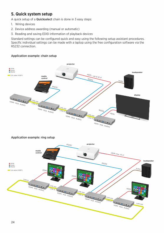
5. Quick system setupA quick setup of a Quickselect chain is done in 3 easy steps:
1. Wiring devices
2. Device address awarding (manual or automatic)
3. Reading and saving EDID information of playback devices
Standard settings can be configured quick and easy using the following setup assistant procedures. Specific individual settings can be made with a laptop using the free configuration software via the RS232 connection.
mediacontrol
projector
loudspeakerRS232
HDMI max. 10 m
audio
RS232
HDMI VGA AUDIO
HDMI VGA AUDIOHDMI VGA AUDIO
HDMI VGA AUDIO
Link outLink in
Link outLink in
Link outLink in
Link out
Link in
HDMI
HDMI
HDMI
HDMIAudioRS232
Cat cable (HDBT)
mediacontrol
projector
loudspeaker
display
HDMI VGA AUDIO
HDMI VGA AUDIO
HDMI VGA AUDIO
HDMI VGA AUDIO
Link outLink in
Link outLink in
Link outLink in
RS232
audio
HDMI
HDMI - up to 10 mRS232
RS232
HDMIAudioRS232
Cat cable (HDBT)
Application example: chain setup
Application example: ring setup

25
5.1 Wiring devicesConnect all mains units to the devices, only tightening the cap nut manually. Do not connect the mains units to the mains outlet.Connect deactivated QuickSelects with a cat-6 cable (AWG 23), connect link output of the first device to the link input of the next QuickSelect 3.0, proceed accordingly until all devices are connected in series.Connect playback device to the HDMI output or to the HDBT Link-out of the last QuickSelect in the series. Only if ring setup is required connect the HDBT Link-out of the last Quickselect to the first unit‘s Link-in.
5.2 Manual device address awardingUsing a flat-head small screwdriver set both BCD switches on the backside of the QuickSelect units to individual addresses between 01…98. Address 00 is reserved exclusively for the special case of a ring circuit, in which case this address must be assigned to only the “first” unit in the ring.
5.3 Automatic device address awarding (address “99“)Alternatively to manual address awarding according to 5.2 the addresses of all units can awarded automatically. Make sure that in this case all BCD switches must be kept in their default position “99”. Only in ring circuit set the “first” unit’s address to “00”. We recommend using the free configuration software. If the software is not at hand proceed as follows:Plug all mains units except for the first one in the chain into the mains socket. Plug the supplied Quick-Setup jumper into the socket “VGA“ at the rear of the first device. Now plug the mains unit of the first device into the mains socket. During the address awarding the LEDs of the signal inputs on the front light-up 3x several times. Remove the Quick-setup jumper.
Producing your own Quick-setup jumper: Connect the KEY and GND contacts of an enclosed 3-pin screw/plug connection terminal with a wire jumper.
5.4 Reading and saving EDID information of playback devicesThe QuickSelect uses AUTO EDID to read the resolution timings from the last display device in the chain via the HDBT- or HDMI connection and saves them in all QuickSelects. We recommend using the free configuration software. If the software is not at hand proceed as follows:Plug all mains units except for the first one in the chain into the mains socket. Plug the supplied Quick-Setup jumper into the socket “HDMI2“ at the rear of the first device. Now plug the mains unit of the first device into the mains socket. During the EDID reading and writing process the LEDs of the signal inputs on the front light-up 3x several times. Remove the Quick-setup jumper.The EDID information is now saved in all HDMI signal inputs of the devices. The EDID information is used to automatically adjust the resolution of the graphics card of the signal encoder (e. g. laptop) to the resolution of the playback device (e. g. projector).
5.5 Chain or ring setup?QuickSelect’s underlying so-called “HDBT” extender technology is capable of simultaneously transmitting video and audio signals, as well as RS232 control signals and 100Mbps Ethernet. Video and audio signals are transmitted unidirectional – similar to a “one-way street” – from one unit’s Link-out to the following Quickselect’s Link-in up to the end of the chain or to the display device. In opposite to that RS232 information and Ethernet is transmitted in a bi-directional way. Thus a video signal being fed into the chain at a random unit can only pass successive units, not preceding units.For a typical meeting room application doing the wiring in “chain topology” is the best choice, because in this scenario usually only a single display device is used at the end of the chain and the HDBT signal can be fed directly into a compatible projector. Even showing a signal on more than one display device is possible, as long as they are located at the end of the chain.In special cases like for example IT training rooms, when routing a video signal from a random Quickselect unit to all other participants is required (including preceding participants), ring setup is appropriate.
26
6. Configuration via the graphical user interface (GUI)The free configuration software for download can be found on our dealer portal (for resellers only): http://shop.kindermann.de/erp/webshop/navigationPath/7447000500.html
Please connect your PC to the QuickSelect 3.0+ System by RS232 (for pin assignment for GUI, see p. 35). If your PC has no RS232 connection, please use a RS232/USB adapter.After connecting the QuickSelect 3.0+ to the PC, start the above software on it.
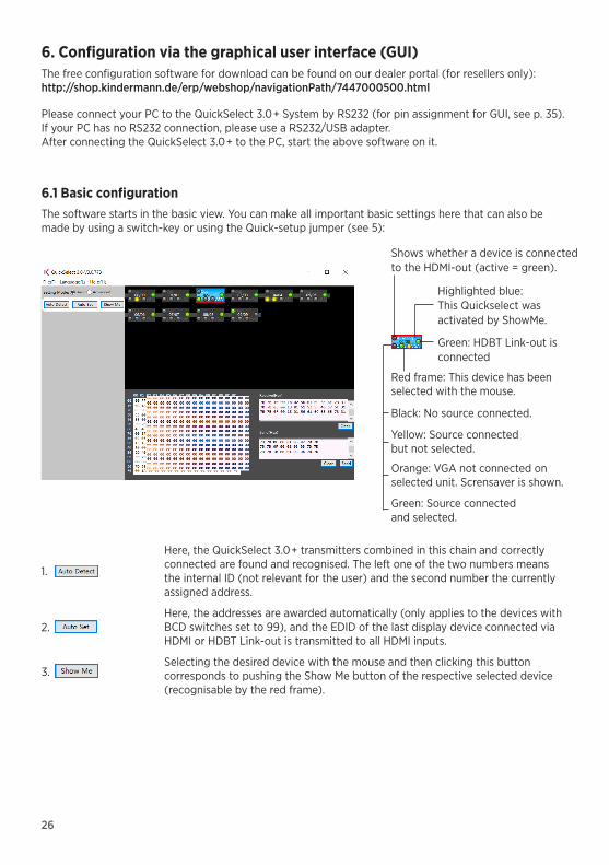
6.1 Basic configurationThe software starts in the basic view. You can make all important basic settings here that can also be made by using a switch-key or using the Quick-setup jumper (see 5):
Here, the QuickSelect 3.0+ transmitters combined in this chain and correctly connected are found and recognised. The left one of the two numbers means the internal ID (not relevant for the user) and the second number the currently assigned address.
Here, the addresses are awarded automatically (only applies to the devices with BCD switches set to 99), and the EDID of the last display device connected via HDMI or HDBT Link-out is transmitted to all HDMI inputs.
Selecting the desired device with the mouse and then clicking this button corresponds to pushing the Show Me button of the respective selected device (recognisable by the red frame).
1.
2.
3.
Shows whether a device is connected to the HDMI-out (active = green).
Highlighted blue: This Quickselect was activated by ShowMe.
Green: HDBT Link-out is connected
Black: No source connected.
Yellow: Source connected but not selected.
Orange: VGA not connected on selected unit. Scrensaver is shown.
Green: Source connected and selected.
Red frame: This device has been selected with the mouse.
27
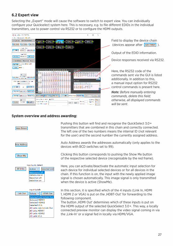
6.2 Expert viewSelecting the „Expert“ mode will cause the software to switch to expert view. You can individually configure your Quickselect system here. This is necessary, e.g. to file different EDIDs in the individual transmitters, use to power control via RS232 or to configure the HDMI outputs.
Field to display the device chain (devices appear after ).
Output of the EDID information.
Device responses received via RS232.
Here, the RS232 code of the commands sent via the GUI is listed additionally. In addition to this, a manual input option for RS232 control commands is present here.
Note: Before manually entering commands, delete this field; otherwise, all displayed commands will be sent.
System overview and address awarding:
Pushing this button will find and recognise the QuickSelect 3.0+ transmitters that are combined in this chain and correctly connected. The left one of the two numbers means the internal ID (not relevant for the user) and the second number the currently assigned address.
Auto Address awards the addresses automatically (only applies to the devices with BCD switches set to 99).
Clicking this button corresponds to pushing the Show Me button of the respective selected device (recognisable by the red frame).
Here, you can activate/deactivate the automatic input selection for each device for individual selected devices or for all devices in the chain. If this function is on, the input with the newly applied image signal is chosen automatically. This image signal is only transmitted when the device is active (ShowMe).
In this section, it is specified which of the 4 inputs (Link In, HDMI 1, HDMI 2 or VGA) is put on the ‚HDBT-Out‘ for forwarding to the following component.The button ‚HDMI Out‘ determines which of these inputs is put on the HDMI output of the selected QuickSelect 3.0+. This way, a locally connected preview monitor can display the video signal coming in via the ‚Link-In‘ or a signal fed in locally via HDMI/VGA.

28
EDID management:The EDID configuration is used to control the EDID data communication from the display device to the signal source. You can specify EDID values to force the video sources to output these pre-set signal timings. This affects both, audio and video in HDMI and display port signals.
The QuickSelect 3.0+ has three available EDID tables per HDMI input: 1. Auto EDID, 2. Predefined (factory-set) EDID, 3 user-specific EDID. The respective table is selected via the active mode in the GUI.
Info: What is EDIDEDID information (Extended Display Identification Data) is made up of a 128 Byte (VGA) or 256 Byte data structure (HDMI) that is saved in a video display/projector or another output device. It contains the resolutions that can be displayed for the output device, incl. refresh rate, audio formats etc.The source device asks the output device for this table before establishing the picture and selects the best resolution for the picture output from it.
Note: By using the external contact switches for source-switching only the signal on the HDBT-Out can be selected. Local HDMI-Out and Audio-Out will follow those commands only if „Link In/Link Out“ is selected.
The default setting is“Link In/Link out”. In this case any signal coming via Link In from the proceeding unit as well as signals infed locally will be available on both outputs, HDMI and Link Out, at the same time.
The QuickSelect 3.0+ system does not automatically forward the EDID table of the end device to the picture source. Under certain circumstances, this would also not be desired, singe, e.g., DVI end devices do not contain any sound information – thus the laptop would also not output any sound via HDMI. Therefore, EDID management is provided in the GUI of the QuickSelect 3.0+.
1. The simplest setting ‚Auto EDID‘ is part of the basic configuration under ‚Auto Set‘. In expert mode, you can read the EDID information from the last connected output device with the button ‚Auto EDID‘ and thus automatically file it in the Auto EDID memory of the Quick-Select 3.0+. This is displayed in the output field in the middle in HEX. To activate this table, the EDID mode of the respective QuickSelect 3.0+ must be set to auto. In the pulldown menu, you can choose whether the Auto EDID memory is activated for the input HDMI1, HDMI2 or both. On the left, for all devices that were found under ‚Auto search‘; on the right only for the selected device (framed red).
The captured EDID data can be saved locally for later purposes with the ‚Save‘ button (if the output device is e.g. no longer available).
2. In ‚Predefined‘ mode, a factory-set EDID is used. Again, you can choose in the pulldown menu whether the pre-set EDID data record for the input HDMI1, HDMI2 or for both is activated. On the left, for all devices that were found under ‚Auto Detect‘; on the right only for the selected device (framed red).

29
3. In EDID mode ‚User‘, you can load customized EDID tables and write to the respective HDMI inputs:
In the upper pulldown menu, you can read out the respective EDID table of the connected output device or the tables filed in the inputs
Note: This in turn can be saved locally as a file. Under ‘Open’, you can load a customized table that will be filed in the memory for ‚user- specific EDID‘ under ‚Write the EDID‘. To activate this table, the EDID mode of the respective QuickSelect 3.0+ must be set to ‘User’. In the pulldown menu ‘Set the EDID mode to User Mode’, you can choose if the user EDID memory is to be activated for the input HDMI1, HDMI2 or for both. On the left, for all devices that were found under ‚Auto Detect‘; on the right only for the selected device (framed red).
Note: The EDID information of the VGA input cannot be changed!
VGA Timing characteristics VGA signals: Available resolutions and refresh rates
Native/preferred timing 1920x1080p at 60Hz (16:9)
Modeline „1920x1080“ 148,500 1920 2008 2052 2200 1080 1081 1085 1125 +hsync +vsync
Detailed timing #1 1366x768p at 60Hz
Modeline „1366x768“ 85,500 1366 1436 1579 1792 768 771 774 798 +hsync +vsync
Detailed timing #2 1920x1200p at 60Hz (16:10)
Modeline „1920x1200“ 154,000 1920 1968 2000 2080 1200 1203 1209 1235 +hsync -vsync
Standard timings supported 720 x 400p at 70Hz - IBM VGA 640 x 480p at 60Hz - IBM VGA 640 x 480p at 72Hz - VESA 640 x 480p at 75Hz - VESA 800 x 600p at 60Hz - VESA 800 x 600p at 72Hz - VESA 800 x 600p at 75Hz - VESA 832 x 624p at 75Hz - Apple Mac II 1024 x 768p at 60Hz - VESA 1024 x 768p at 70Hz - VESA 1024 x 768p at 75Hz - VESA 1280 x 1024p at 75Hz - VESA 1152 x 870p at 75Hz - Apple Mac II 1280 x 960p at 75Hz - VESA STD 1600 x 1200p at 60Hz - VESA STD 1280 x 800p at 60Hz - VESA STD 1920 x 1080p at 60Hz - VESA STD 1400 x 1050p at 75Hz - VESA STD

30
VGA to HDMI converter: The integrated VGA to HDMI Scaler converts analogue video and audio signals into an HDMI signal.
To achieve the highest possible quality from the VGA source signal, the resolution of the video signal fed-in via VGA can be adjusted on the output side. On the left, for all devices that were found under ‚Auto Detect‘; on the right only for the selected device (framed red).
For best image quality, the native (physical) resolution of the output device should be set.If this value is set to Auto, the following assignments are used:
Pre-set resolution assignment between VGA in- and output
Common VGA formats VGA special formats
Input resolution Output resolution Input resolution Output resolution
1024x768 1024x768 832x624 (MAC) 1920x1080P
1280x720 1280x720 1152x864 (MAC) 1920x1080P
1280x800 1280x800 1152x870 (MAC) 1920x1080P
1280x1024 1280x1024
1360x768 1360x768
1366x768 1366x768
1400x1050 1400x1050
1400x900 1400x900
1600x900 1600x900
1600x1200 1600x1200
1680x1050 1680x1050
1920x1080P 1920x1080P
1920x1200 1920x1200
1920x1080P Epson* 1920x1080P
1920x1200 Epson* 1920x1200
Note: The resolutions marked with an asterisk (*) include timing parameters that differ from typical video timing standards and are used in rare cases by Epson and other device manufacturers. These timings can be used alternatively if the standard timings above to not lead to optimal results.

31
Key lock and energy saving function:
You can use the pulldown menu to either lock all external ShowMe buttons (‘All-Key’) or individual ones (‘VGA’, ‘HDMI1’, ‘HDMI2’) for a single user (‘Selected…’) or for all users (‘All Unit’) (moderator func-tion). Press ‘Key Lock’ or ‘Key Unlock’ to assign the selected status.
You can use the pulldown menu to either switch all devices (‘All Units’) or individual devices (‘Selected Unit’) to Standby mode or Power On mode.
Reading out the firmware versions and updating the firmware:Use the button to read out the firmware statuses of the recognised QuickSelect 3.0+. To display these, move the mouse pointer over the desired QuickSelect 3.0+. Then the firmware versions of the QuickSelect 3.0+ incl. the valens HDBT chip sets are displayed.
Status in the device chain
Status of the inputs
Status of the automatic signal recognition
firmware statuses:- Quickselect 3.0+- Valens chip set input- Valens chip set output
To load a newer firmware onto a QuickSelect 3.0+, proceed as follows:
1. Copy the firmware file provided by Kindermann to the root directory of an USB stick (Filename: MERGE.BIN).
2. Disconnect the QuickSelect 3.0+ to be flashed from the power supply and connect the USB stick to its USB charge socket.
3. Plug the supplied or a self-made Quick-Setup jumper into the socket “HDMI1“ at the rear of the device and restore power supply.
4. During the firmware update process the LEDs of the signal inputs on the front light-up several times. After they lit up 3x quickly disconnect the jumper on „HDMI1“.
5. Wait until the LED activity stops. The duration of the firmware update is approx. 60 sec. After the LED activity stopped press the ShowMe button on at the front. If the VGA LED lights up the Update is done. Now unpower the unit and remove the USB-Stick.
6. Then perform a factory reset and setup of the updated device.
Note: Never disconnect the power supply during the firmware update - the device may be rendered useless!

32
7. RS232 controlThe free configuration software or a media control also permits controlling the entire QuickSelect system via the RS232 connection in all details.
The HDBT-Bus can also transmit RS232-control commands for controlling further devices such as pro-jectors and display, bidirectionally (pass through). Connect e. g. the RS232-interface of the media control simply to a RS232-terminal.
The detailed RS232-protocol and a driver for Neets controls can be found online at: shop.kindermann.de/evp/webshop/navigation_Path/7447000500.html
Display Power Control function:The Display Power Control feature allows direct automatic power-on/off switching of one or more displays or projectors upon signal detection, even without using an external AV control system. To use this function each display device must be connected to an individual Quickselect unit via RS232. If the last Quickselect of a chain connects to a compatible display device via HDBT Link-out then both, the RS232 commands and the video signal, can be routed to the display device (only with compatible devices).
Backing up and loading the configuration of a QuickSelect 3.0 +:Use the buttons to back up the entire current configuration of the selected QuickSelect 3.0+ (red frame) as a file – and also recover it again.
Note: If you back up these settings for your project documentation, you can restore the same settings again (template&data backup).
Resetting one/all QuickSelect 3.0 + to factory settings:
This function has a safety prompt to prevent accidental overwriting. If a factory reset is desired, also ensure that you return the address BCD switches to 99 (factory condition).
Alternative resetting via button:1. Push and hold the internal ShowMe button and restore power supply.2. Keep the button pushed until the LEDs at the device front flash quickly a few times - then release.3. Wait until the LEDs go out and all LEDs flash after a while (sign for the end of the factory reset).
Enter RS232 commands manually and read out answers:
You can use these text fields to send RS232 commands and read the response of the QuickSelect 3.0+ chain. All values are displayed in HEX.
The commands of the respective control commands are automatically entered under RS232-TxD (Hex) and may be copied, e. g. for the purpose of driver creation for media controls. The same applies to the respective device feedbacks.
Note: ALL commands entered under RS232-TxD are always sent in sequence. If only a single command is to be sent, please clear the field first and enter the individual command.
33
e. g. CablePort desk2 for QuickSelect 3.0 Ref. No. 7430 000 008
LEDNC
NO
C
+ -GND
KEY
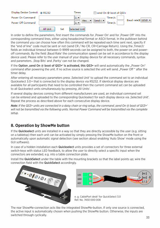
In order to define the parameters, first insert the commands for ‚Power On‘ and for ‚Power Off‘ into the corresponding command lines, either using hexadecimal format or ASCII format. In the pulldown behind the command you can choose how often this command will be repeated each time sent next, specify if the “end of line” code must be sent or not (send CR / No CR, CR=Carriage Return). Using the ‚Timer/s‘ fields an individual timeout between 0-9999 seconds can be assigned to both, the power-on and power-off commands. By the field ‚Baud Rate‘ the communication speed can be set in accordance to the display device used. Please refer to the user manual of your display device for all necessary commands, syntax and parameters. ‚Stop Bits‘ and ‚Parity‘ can not be changed.
If the Option ‚send On @ boot of QS3+‘ is activated, this QS3+ will send automatically the „Power On“ command after powering the unit. If no active source is selected the unit will send „Power Off “ after the timer delay.
After entering all necessary parameters press ‚Selected Unit‘ to upload the command set to an individual Quickselect 3.0+ that is connected to the display device via RS232. If identical display devices are available for all participants that need to be controlled then the current command set can be uploaded to all Quickselect units simultaneously by pressing ‚All Units‘.
If several display devices coming from different manufacturers are used, an individual command set can be entered and uploaded to the corresponding Quickselect for each display device via ‚Selected Unit‘. Repeat the process as described above for each consecutive display device.
Note: If the QS3+ units are connected in a daisy chain or ring setup, the command ‚send On @ boot of QS3+‘ will not be transmitted via the following units. Normal Power Command will be transmitted via the complete setup.
8. Operation by ShowMe buttonIf the Quickselect units are installed in a way so that they are directly accessible by the user (e.g. sitting on a tabletop) then each unit can be activated by simply pressing the ShowMe button on the front or automatically upon automatic signal detection (see section about enabling ‘Auto Show’ mode using the GUI software).
In case of a hidden installation each Quickselect units provides a set of connectors for three external switch-keys with status LED feedback, to allow the user to directly select a specific input when the connectors are extended, e.g. into a table connection plate.
Install the QuickSelect under the table with the mounting brackets so that the label points up; wire the connection field with the QuickSelect accordingly.
The rear ShowMe-connection acts like the integrated ShowMe-button. If only one source is connected, the active input is automatically chosen when pushing the ShowMe button. Otherwise, the inputs are switched through cyclically.
34
9. Technical data
Input Output
Video/Audio interfaces
2 x HDMI (HDMI 1.4 with HDCP), VGA, audio (3.5 mm)
Video/Audio interfaces
HDMI (HDMI 1.4 with HDCP), audio (3.5 mm)
HDBT HDBT-In HDBT HDBT-Out
USB socket Type-A, max. 2A
Control
I/O inputs
One contact input (3-pin. Phoenix connector) each for:- HDMI1, HDMI2 and VGA- ShowMe-function
I/O outputs
One output (3-pin. Phoenix connector) each with LED driver for:- HDMI1, HDMI2 and VGA- ShowMe-function
RS232 3-pin. Phoenix connector for device control
General
Resolution range
HDMI: up to 4K2K@60 Hz (4:2:0), HDCP 2.0, incl. 3D
VGA: 800x600, 832x624 (MAC), 1024x768, 1152x864, 1152x870 (MAC), 1280x720, 1280x768, 1280x800, 1280x960, 1280x1024, 1360x768, 1366x768, 1400x1050, 1440x900, 1600x1200, 1680x1050, 1920x1080P, 1920x1200
Operating temperature
Humidity
Storage temperature
0°C up to 35°C
10% up to 90%, non-condensing
-20°C up to 70°C
Audio inputHDMI: embeddedVGA: 3.5 mm headphone jack
Audio outputHDMI embedded +3.5 mm headphone jack
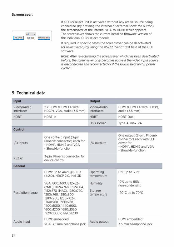
Screensaver:
If a Quickselect unit is activated without any active source being connected (by pressing the internal or external Show-Me button), the screensaver of the internal VGA-to-HDMI scaler appears. The screensaver shows the current installed firmware version of the individual Quickselect module.
If required in specific cases the screensaver can be deactivated (or re-activated) by using the RS232 “Send” text field of the GUI software.
Note: After re-activating the screensaver which has been deactivated before, the screensaver only becomes active if the video input source is disconnected and reconnected or if the Quickselect unit is power cycled.

35
10. Available accessories • RS232 cable pre-configurated (7447 000 410)• VGA cable (7483 000 4xx)• HDMI cable, typ A, 19-pin (5809 000 1xx)• DP to HDMI cable (5809 000 60x)• HDMI media switch cable (5809 000 099)• VGA media switch cable (7483 000 300)• Neets media control (5555 000 0x0)
11. Application examples11.1 Single-table solution with HDBT wall-connection
2 x HDMI, VGA
Control + LED
HDMI
HDBT Transmitter(7456000543)
Link Out
Link In
RS232Media control(5555000020)
9 6
5 1
Sub-D9
RS232-Kabel
RS232-Buchse
PC
RS232
Quickselect
Rx GND Tx
EDID/DDC Supports Extended Display Identification Data (EDID) and Display Data Channel (DDC) data via DVI and HDMI Standards, EDID and DDC signals
HDCP Compatible with high-bandwidth Digital Content Protection (HDCP 2.0).
Mains unit 100 VAC ~ 240 VAC, 50/60 Hz secondary 12 V DC, 3A
Energy consumption
12 W max. (without charging function)
Dimensions Transmitter: 223 x 26 x 99 mm (WxHxD) Weight approx. 0.8 kg
(without mains unit)
7447 000 500 D/GB 2018-07 / 842 166 Änderungen vorbehalten/Subject to alterations Printed in Germany
Kindermann GmbH · Mainparkring 3 · D-97246 Eibelstadt · E-Mail: [email protected] · www.kindermann.com
11.3 Conference table with WiPG and operating options in every position
HDMIOut
HDMIIn
2 x HDMI, VGA
Control2 x HDMI, VGA 2 x HDMI, VGA
RS232
2 x HDMI, VGA2 x HDMI, VGA2 x HDMI, VGA
CablePort flex
with Neets SieRRa II
CablePort flex
with Neets SieRRa II
CablePort flex
with Neets NEB keyboard
CablePort flex
with Neets NEB keyboard
CablePort flex
with Neets NEB keyboard
CablePort flex
with Neets NEB keyboard
NEB
IP c
onne
ctio
n
NEB
NEB
NEB
Link Out
Link Out Link OutLink Out
Link Out
Link InLink In
Link In Link In Link In
11.2 Two tables or floor tanks with HDBT-capable projector
2 x HDMI, VGA
Control + LED
2 x HDMI, VGA
Control + LED
Link Out
Link InLink In
HDBT-capable projectorLink Out