KESSEL - Schaltgerät Aqualift Comfort 230V Mono/Duo Page 35 · 4/68 2019/03 ALLGEMEINES 1....
68
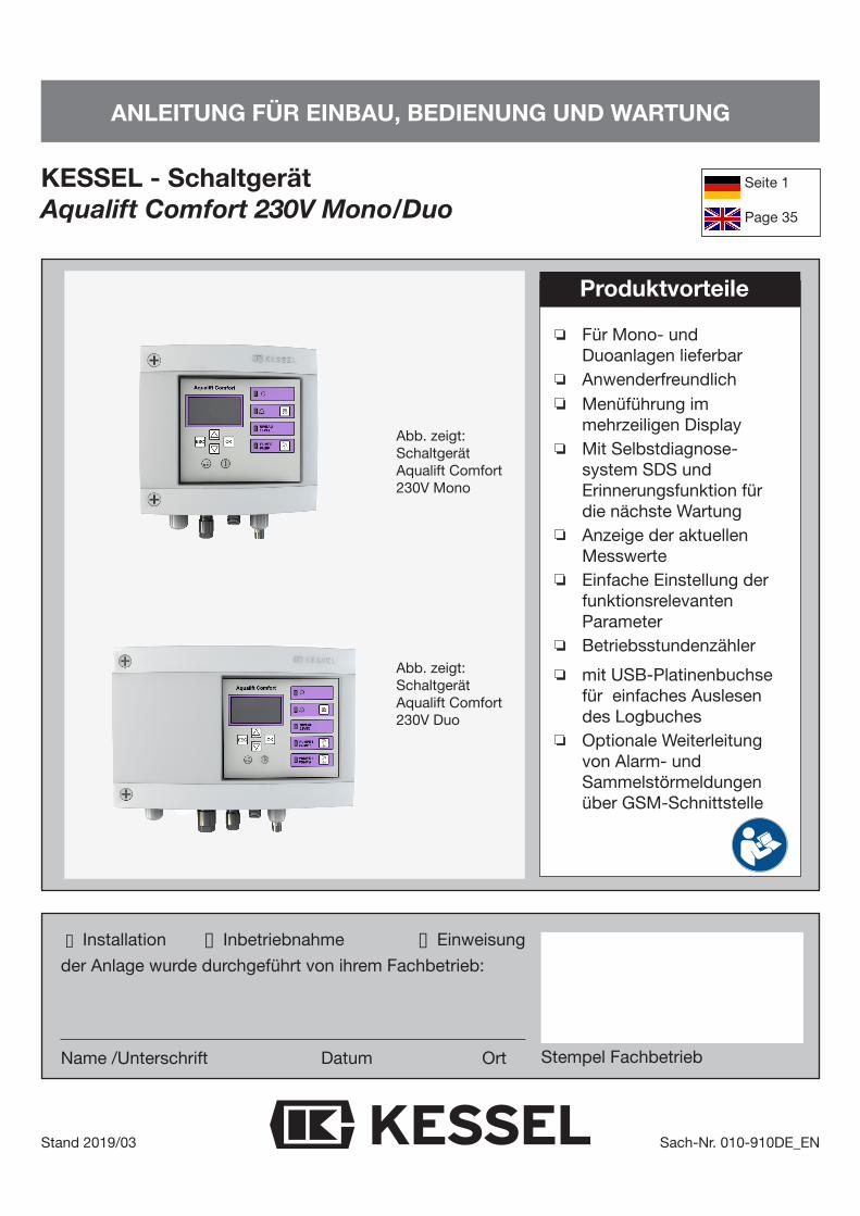
ANLEITUNG FÜR EINBAU, BEDIENUNG UND WARTUNG KESSEL - Schaltgerät Aqualift Comfort 230V Mono/Duo Stand 2019/03 Sach-Nr. 010-910DE_EN o Installation o Inbetriebnahme o Einweisung der Anlage wurde durchgeführt von ihrem Fachbetrieb: Name /Unterschrift Datum Ort Für Mono- und Duoanlagen lieferbar Anwenderfreundlich Menüführung im mehrzeiligen Display Mit Selbstdiagnose- system SDS und Erinnerungsfunktion für die nächste Wartung Anzeige der aktuellen Messwerte Einfache Einstellung der funktionsrelevanten Parameter Betriebsstundenzähler mit USB-Platinenbuchse für einfaches Auslesen des Logbuches Optionale Weiterleitung von Alarm- und Sammelstörmeldungen über GSM-Schnittstelle Produktvorteile Seite 1 Page 35 Stempel Fachbetrieb Abb. zeigt: Schaltgerät Aqualift Comfort 230V Mono Abb. zeigt: Schaltgerät Aqualift Comfort 230V Duo
Transcript of KESSEL - Schaltgerät Aqualift Comfort 230V Mono/Duo Page 35 · 4/68 2019/03 ALLGEMEINES 1....
ANLEITUNG FÜR EINBAU, BEDIENUNG UND WARTUNG
KESSEL - Schaltgerät Aqualift Comfort 230V Mono/Duo
Stand 2019/03 Sach-Nr. 010-910DE_EN
o Installation o Inbetriebnahme o Einweisung
der Anlage wurde durchgeführt von ihrem Fachbetrieb:
Name /Unterschrift Datum Ort
Für Mono- und Duoanlagen lieferbarAnwenderfreundlichMenüführung im mehrzeiligen Display Mit Selbstdiagnose- system SDS und Erinnerungsfunktion für die nächste WartungAnzeige der aktuellen MesswerteEinfache Einstellung der funktionsrelevanten ParameterBetriebsstundenzähler
mit USB-Platinenbuchse für einfaches Auslesen des LogbuchesOptionale Weiterleitung von Alarm- und Sammelstörmeldungen über GSM-Schnittstelle
Produktvorteile
Seite 1
Page 35
Stempel Fachbetrieb
Abb. zeigt: SchaltgerätAqualift Comfort 230V Mono
Abb. zeigt: SchaltgerätAqualift Comfort 230V Duo
2/68 2019/03
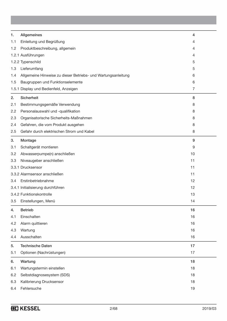
1. Allgemeines 4
1.1 Einleitung und Begrüßung 4
1.2 Produktbeschreibung, allgemein 4
1.2.1 Ausführungen 4
1.2.2 Typenschild 5
1.3 Lieferumfang 5
1.4 Allgemeine Hinweise zu dieser Betriebs- und Wartungsanleitung 6
1.5 Baugruppen und Funktionselemente 6
1.5.1 Display und Bedienfeld, Anzeigen 7
2. Sicherheit 8
2.1 Bestimmungsgemäße Verwendung 8
2.2 Personalauswahl und -qualifikation 8
2.3 Organisatorische Sicherheits-Maßnahmen 8
2.4 Gefahren, die vom Produkt ausgehen 8
2.5 Gefahr durch elektrischen Strom und Kabel 8
3. Montage 9
3.1 Schaltgerät montieren 9
3.2 Abwasserpumpe(n) anschließen 10
3.3 Niveaugeber anschließen 11
3.3.1 Drucksensor 11
3.3.2 Alarmsensor anschließen 11
3.4 Erstinbetriebnahme 12
3.4.1 Initialisierung durchführen 12
3.4.2 Funktionskontrolle 13
3.5 Einstellungen, Menü 14
4. Betrieb 16
4.1 Einschalten 16
4.2 Alarm quittieren 16
4.3 Wartung 16
4.4 Ausschalten 16
5. Technische Daten 17
5.1 Optionen (Nachrüstungen) 17
6. Wartung 18
6.1 Wartungstermin einstellen 18
6.2 Selbstdiagnosesystem (SDS) 18
6.3 Kalibrierung Drucksensor 18
6.4 Fehlersuche 19
3/682019/03
7. Anhang 20
7.1 Menüstruktur 20
7.2 Schaltgerät umrüsten, spezielle Bedingungen 23
7.2.1 Anschlüsse auf Klemmleiste herstellen 23
7.3 Alternative Sensorkonfiguration (Schwimmer und Sensoren anschließen) 24
7.3.1 Aqualift Comfort Mono 230V 24
7.3.2 Aqualift Comfort Duo 230V 28
7.4 Sonstiges 32
7.4.1 Anschlusskabel Pumpe / Sensor kürzen oder verlängern 32
7.4.2 Update und Daten auslesen 32
7.4.3 USB Anschluss herausführen 33
7.4.4 Menüstruktur Expertenmodus 33
4/68 2019/03
ALLGEMEINES
1. Allgemeines
1.1. Einleitung und Begrüßung
Sehr geehrte Kundin
sehr geehrter Kunde,
wir freuen uns, dass Sie sich für den Erwerb eines unserer Produkte entschieden haben. Sicher wird dieses Ihre Anforderungen in vollem Umfang erfüllen. Wir wünschen ihnen einen reibungslosen und erfolgreichen Einbau.
Im Bemühen unseren Qualitätsstandard auf höchstmöglichem Niveau zu halten, sind wir natürlich auch auf Ihre Mithilfe angewiesen. Bitte teilen Sie uns Möglichkeiten zur Verbesserung unserer Produkte mit.
Haben Sie Fragen? Wir freuen uns auf Ihre Kontaktaufnahme.
1.2. Produktbeschreibung, allgemein
Das Schaltgerät Aqualift stellt die Steuerung einer Hebeanlage für fäkalienfreies und fäkalienhaltiges Abwasser dar. Die Schaltsignale der Sensoren für den Abwasserpegel werden elektronisch verarbeitet. Als Niveauerfas-sung können Schwimmerschalter oder ein Drucksensor verwendet werden. Ist das Füllvolumen erreicht, wird das Abpumpen aktiviert. Je nach Ausführung werden dazu eine oder zwei Abwasserpumpen eingeschaltet. Ist der Pegelstand wieder entsprechend abgesunken, wird das Abpumpen beendet.
Sind zwei Abwasserpumpen angeschlossen, werden diese je nach Füllvolumen und Positionierung der Niveau-sensoren entweder einzeln oder gemeinsam eingeschaltet.
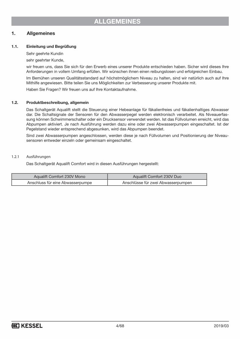
1.2.1 Ausführungen
Das Schaltgerät Aqualift Comfort wird in diesen Ausführungen hergestellt:
Aqualift Comfort 230V Mono Aqualift Comfort 230V Duo
Anschluss für eine Abwasserpumpe Anschlüsse für zwei Abwasserpumpen
5/682019/03
ALLGEMEINES
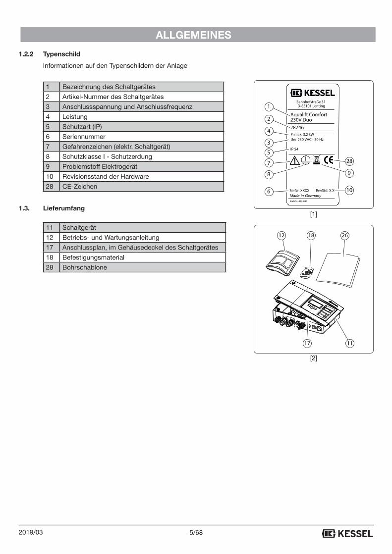
1.2.2 Typenschild
Informationen auf den Typenschildern der Anlage
1 Bezeichnung des Schaltgerätes
2 Artikel-Nummer des Schaltgerätes
3 Anschlussspannung und Anschlussfrequenz
4 Leistung
5 Schutzart (IP)
6 Seriennummer
7 Gefahrenzeichen (elektr. Schaltgerät)
8 Schutzklasse I - Schutzerdung
9 Problemstoff Elektrogerät
10 Revisionsstand der Hardware
28 CE-Zeichen
1.3. Lieferumfang
11 Schaltgerät
12 Betriebs- und Wartungsanleitung
17 Anschlussplan, im Gehäusedeckel des Schaltgerätes
18 Befestigungsmaterial
28 Bohrschablone
12 18 26
17 11
Aqualift Comfort230V Duo
IP 54
28746
SerNr. XXXX
P: max. 3,2 kW Ue: 230 VAC - 50 Hz
Bahnhofstraße 31D-85101 Lenting
RevStd. X.X
SachNr. 422-046
1
2
4
3
5
7
8
6
28
9
10
[1]
[2]
6/68 2019/03
ALLGEMEINES
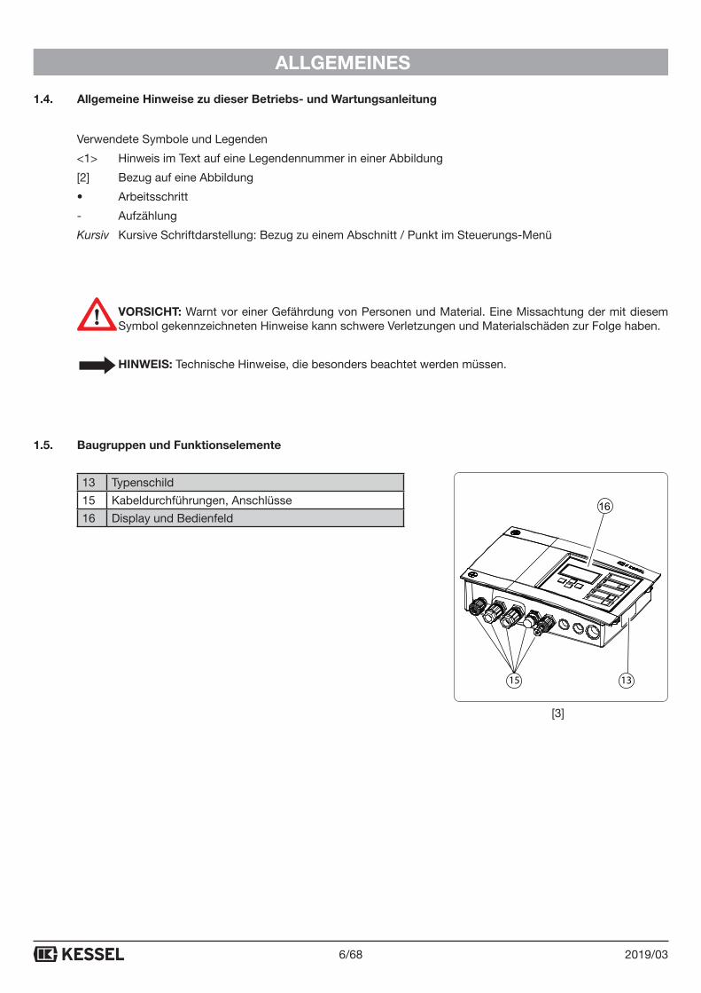
1.4. Allgemeine Hinweise zu dieser Betriebs- und Wartungsanleitung
Verwendete Symbole und Legenden
<1> Hinweis im Text auf eine Legendennummer in einer Abbildung
[2] Bezug auf eine Abbildung
• Arbeitsschritt
- Aufzählung
Kursiv Kursive Schriftdarstellung: Bezug zu einem Abschnitt / Punkt im Steuerungs-Menü
VORSICHT: Warnt vor einer Gefährdung von Personen und Material. Eine Missachtung der mit diesem Symbol gekennzeichneten Hinweise kann schwere Verletzungen und Materialschäden zur Folge haben.
HINWEIS: Technische Hinweise, die besonders beachtet werden müssen.
1.5. Baugruppen und Funktionselemente
13 Typenschild
15 Kabeldurchführungen, Anschlüsse
16 Display und Bedienfeld
1315
16
[3]
7/682019/03
ALLGEMEINES
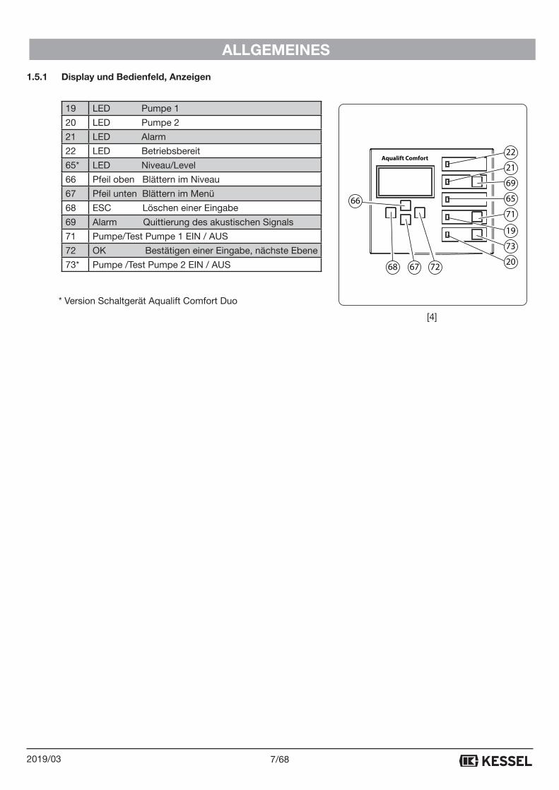
1.5.1 Display und Bedienfeld, Anzeigen
19 LED Pumpe 1
20 LED Pumpe 2
21 LED Alarm
22 LED Betriebsbereit
65* LED Niveau/Level
66 Pfeil oben Blättern im Niveau
67 Pfeil unten Blättern im Menü
68 ESC Löschen einer Eingabe
69 Alarm Quittierung des akustischen Signals
71 Pumpe/Test Pumpe 1 EIN / AUS
72 OK Bestätigen einer Eingabe, nächste Ebene
73* Pumpe /Test Pumpe 2 EIN / AUS
* Version Schaltgerät Aqualift Comfort Duo
Aqualift Comfort22
21
69
65
71
19
73
20726768
66
[4]
8/68 2019/03
SICHERHEIT
2. Sicherheit2.1. Bestimmungsgemäße Verwendung
Das Schaltgerät Aqualift ist ausschließlich für die Steuerung von Hebeanlagen (DIN EN 12050 Teil 1-3) und Pump-stationen für fäkalienfreies und fäkalienhaltiges* Abwasser zu verwenden.
Ein Einsatz des Schaltgeräts in explosionsgefährdeter Umgebung ist unzulässig.
Je nach Ausführung (siehe 1.2.1) ist der Anschluss von Schwimmerschaltern vorgesehen
Alle nicht durch eine ausdrückliche und schriftliche Freigabe des Herstellers erfolgten
- Um- oder Anbauten
- Verwendungen von nicht originalen Ersatzteilen
- Durchführungen von Reparaturen durch nicht vom Hersteller autorisierten
Betrieben oder Personen
können zum Verlust der Gewährleistung führen.
* Unter Beachtung nationaler Anforderungen an den Explosionsschutz (ATEX).
2.2. Personalauswahl und -qualifikation
Personen, die das Schaltgerät Aqualift Comfort bedienen und/oder montieren, müssen
- mindestens 18 Jahre alt sein.
- für die jeweiligen Tätigkeiten ausreichend geschult sein.
- die einschlägigen technischen Regeln und Sicherheitsvorschriften kennen und befolgen.
Der Betreiber entscheidet über die erforderlichen Qualifikationen für das
- Bedienpersonal
- Wartungspersonal
- Instandhaltungspersonal
Der Betreiber hat dafür Sorge zu tragen, dass nur qualifiziertes Personal am Schaltgerät Aqualift Comfort tätig wird.
Qualifiziertes Personal sind Personen, die durch ihre Ausbildung und Erfahrung sowie ihrer Kenntnisse einschlägi-ger Bestimmungen, gültiger Normen und Unfallverhütungsvorschriften die jeweils erforderlichen Tätigkeiten aus-führen und dabei mögliche Gefahren erkennen und vermeiden können.
Arbeiten an elektrischen Bauteilen dürfen nur von dafür ausgebildetem Fachpersonal und unter Einhaltung aller geltenden Regelungen der Unfallverhütungsvorschriften (UVVen) vorgenommen werden.
2.3. Organisatorische Sicherheits-Maßnahmen
Die Betriebs- und Wartungsanleitung ist stets am Schaltgerät Aqualift Comfort verfügbar zu halten.
2.4. Gefahren, die vom Produkt ausgehen
Das Schaltgerät selbst ist NICHT für den Einbau in einem Schacht vorgesehen.
Gefahr durch elektrischen Strom und Kabel Alle spannungsführenden Bauteile sind gegen unbeabsichtigte Berührung geschützt. Vor einem Öffnen von Ge-häuseabdeckungen, Steckern und Kabeln sind diese spannungsfrei zu machen. Arbeiten an elektrischen Bautei-len dürfen nur von Fachpersonal (Siehe 2.2) durchgeführt werden.
9/682019/03
MONTAGE
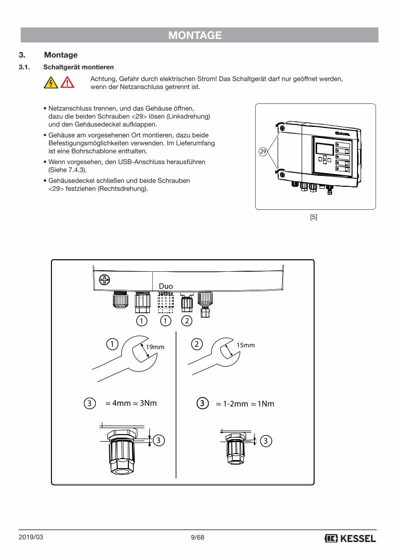
3. Montage3.1. Schaltgerät montieren
Achtung, Gefahr durch elektrischen Strom! Das Schaltgerät darf nur geöffnet werden, wenn der Netzanschluss getrennt ist.
• Netzanschluss trennen, und das Gehäuse öffnen, dazu die beiden Schrauben <29> lösen (Linksdrehung) und den Gehäusedeckel aufklappen.
• Gehäuse am vorgesehenen Ort montieren, dazu beide Befestigungsmöglichkeiten verwenden. Im Lieferumfang ist eine Bohrschablone enthalten.
• Wenn vorgesehen, den USB-Anschluss herausführen (Siehe 7.4.3).
• Gehäusedeckel schließen und beide Schrauben <29> festziehen (Rechtsdrehung).
29
[5]
19mm 15mm
1 1 2
2
= 1-2mm 1Nm= 4mm 3Nm
3
333 ≈ ≈
1
3
Duo
10/68 2019/03
MONTAGE
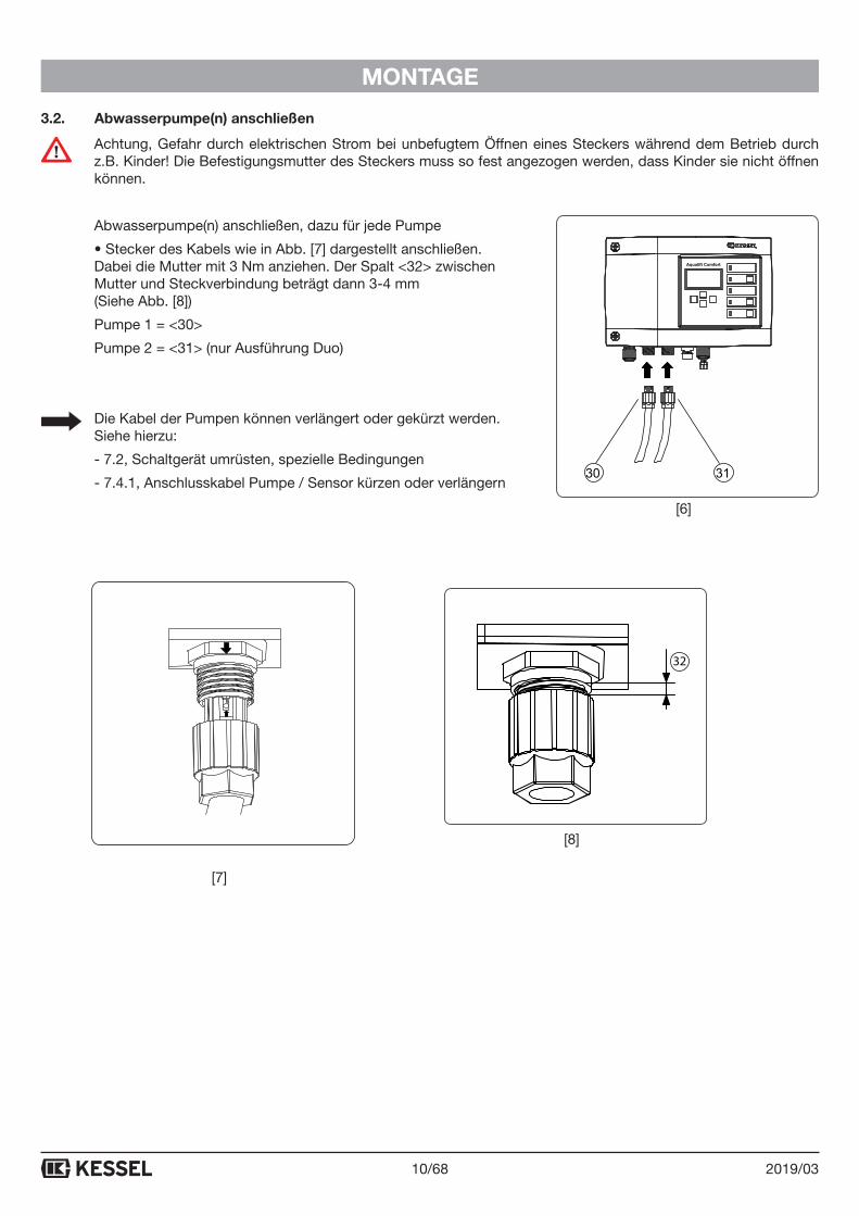
3.2. Abwasserpumpe(n) anschließen
Achtung, Gefahr durch elektrischen Strom bei unbefugtem Öffnen eines Steckers während dem Betrieb durch z.B. Kinder! Die Befestigungsmutter des Steckers muss so fest angezogen werden, dass Kinder sie nicht öffnen können.
Abwasserpumpe(n) anschließen, dazu für jede Pumpe
• Stecker des Kabels wie in Abb. [7] dargestellt anschließen. Dabei die Mutter mit 3 Nm anziehen. Der Spalt <32> zwischen Mutter und Steckverbindung beträgt dann 3-4 mm (Siehe Abb. [8])
Pumpe 1 = <30>
Pumpe 2 = <31> (nur Ausführung Duo)
Die Kabel der Pumpen können verlängert oder gekürzt werden. Siehe hierzu:
- 7.2, Schaltgerät umrüsten, spezielle Bedingungen
- 7.4.1, Anschlusskabel Pumpe / Sensor kürzen oder verlängern
Aqualift Comfort
3130
32
[6]
[7]
[8]
11/682019/03
MONTAGE
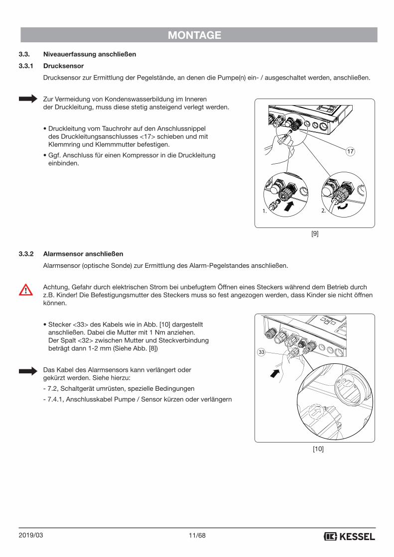
3.3. Niveauerfassung anschließen
3.3.1 Drucksensor
Drucksensor zur Ermittlung der Pegelstände, an denen die Pumpe(n) ein- / ausgeschaltet werden, anschließen.
Zur Vermeidung von Kondenswasserbildung im Inneren der Druckleitung, muss diese stetig ansteigend verlegt werden.
• Druckleitung vom Tauchrohr auf den Anschlussnippel des Druckleitungsanschlusses <17> schieben und mit Klemmring und Klemmmutter befestigen.
• Ggf. Anschluss für einen Kompressor in die Druckleitung einbinden.
3.3.2 Alarmsensor anschließen
Alarmsensor (optische Sonde) zur Ermittlung des Alarm-Pegelstandes anschließen.
Achtung, Gefahr durch elektrischen Strom bei unbefugtem Öffnen eines Steckers während dem Betrieb durch z.B. Kinder! Die Befestigungsmutter des Steckers muss so fest angezogen werden, dass Kinder sie nicht öffnen können.
• Stecker <33> des Kabels wie in Abb. [10] dargestellt anschließen. Dabei die Mutter mit 1 Nm anziehen. Der Spalt <32> zwischen Mutter und Steckverbindung beträgt dann 1-2 mm (Siehe Abb. [8])
Das Kabel des Alarmsensors kann verlängert oder gekürzt werden. Siehe hierzu:
- 7.2, Schaltgerät umrüsten, spezielle Bedingungen
- 7.4.1, Anschlusskabel Pumpe / Sensor kürzen oder verlängern
33
1. 2.
17
[9]
[10]
12/68 2019/03
MONTAGE
3.4. Erstinbetriebnahme
Ein Trockenlauf der Pumpe(n) ist unbedingt zu vermeiden. Tipp: Befüllen Sie den Abwasserbehälter vor dem Herstellen der Netzspannung so weit mit Wasser, dass im Fall eines unbeabsichtigten Einschaltens der Pumpe(n) (z.B. fehlerhafter Anschluss eines Niveausensors) diese nicht trocken laufen können.
• Netzspannung herstellen
Schaltgerät mit Netzspannung versorgen, die Initialisierung beginnt. Während für ca. 4 Sekunden die LED‘S leuch-ten, werden die elektrischen Bauteile überprüft, die Batterie für die Netzausfall-Meldung aktiviert und das Menü 0.1. Sprache angezeigt. Anschließend kann die Initialisierung durchgeführt werden.
Wird im Display nicht die Initialisierung (Menü 0.1. Sprache) angeboten, wurde das Schaltgerät bereits initialisiert. In diesem Fall sind die eingestellten Parameter zu überprüfen oder die Werkseinstellungen herzustellen (Punkt 3.8 Rücksetzen im Kapitel 7.1). Nach der Herstellung der Werkseinstellungen wird automatisch die Initialisierung des Schaltgeräts angeboten.
Bitte beachten Sie, dass der Zähler für Wartungsintervall und Schaltspiele beim Rücksetzen unberücksichtigt bleibt.
3.4.1 Initialisierung durchführen
Mit der Initialisierung wird die Alarm-Netzausfall-Batterie aktiviert.
Bei der Initialisierung werden folgende Eingaben erwartet:
- Sprache
- Datum / Uhrzeit
- Typ Aqualift
- Sensor-Konfiguration
- Wartungsintervall
Sprache
• Landessprache mit den Pfeiltasten auswählen und mit OK bestätigen, das Menü Datum/Uhrzeit wird angezeigt.
Datum / Uhrzeit
• Die jeweils blinkende Ziffer in Datum und Uhrzeit einstellen und mit OK bestätigen. Nach der letzten Eingabe, erscheint das Menü Sensor-Konfiguration.
Sensor-Konfiguration
Nur erforderlich, wenn bei Typ Aqualift eine Sonder-Hebeanlage oder eine Sonder-Pumpstation eingestellt wird.
• Art der angeschlossenen Sensoren mit den Pfeiltasten auswählen und mit OK bestätigen.
• Parameter im Software-Menü 3.1 anpassen.

13/682019/03
MONTAGE
Typ Aqualift
Sind die Pumpen der Anlage auf das Schaltgerät abgestimmt (Original KESSEL-Produkte), Einstellung wie bei A) beschrieben vornehmen, wenn nicht, weiter bei B).
• OK betätigen
• A) Art der angeschlossene(n) Pumpe(n) mit den Pfeiltasten auswählen und mit OK bestätigen, das Menü 0 Sys-teminfo wird angezeigt - das Schaltgerät ist betriebsbereit.
• B) Mit den Pfeiltasten Sonder-Hebeanlage auswählen und mit OK bestätigen, das Menü 0 Systeminfo wird an-gezeigt. Nun müssen alle Anlagenparameter eingestellt werden. Für Einstellungen zu Schwimmer und Sensoren siehe 7.2 und 7.3.
Sicherstellen, dass der auf dem Typenschild der angeschlossenen Pumpe(n) ausgewiesene Stromaufnahmebe-reich nicht über dem Maximalwert des Schaltgeräts liegt. Das Schaltgerät könnte im Betrieb Schaden nehmen bzw. würde eine Fehlermeldung ausgeben.
Wartungsintervall
Ist kein Wartungstermin eingegeben, wird das im Klartext im Display angezeigt. Die Eingabe eines Wartungster-mins erfolgt über das Menü (siehe 6.1, Wartungstermin einstellen).
3.4.2 Funktionskontrolle
Vorbereitung
- Sicherstellen, dass der Abwasserbehälter, den die Pumpe(n) entleeren sollen, in möglichst kurzer Zeit mit Wasser gefüllt werden kann.
- Im Abwasserbehälter eine Markierung etwas unterhalb des Pegelstandes anbringen, an dem der Alarm ausge-löst werden soll.
Zur Funktionskontrolle werden 2 Prüfvorgänge durchgeführt.
1. Überprüfung der Pumpe(n)
2. Überprüfung des Alarmschalters
1. Überprüfung der Pumpe(n)
• Schaltgerät einschalten
• Mittels Handsteuerung die Pumpe vorübergehend ausschalten. Dazu die Taste <71>* betätigen, die dazugehörige LED blinkt und die Pumpe ist ausgeschaltet.
* bei Ausführung Duo auch die Taste <73> betätigen
Das Schaltgerät stellt die Handsteuerung selbstständig nach einer kurzen Zeitspanne wieder in den Automatikbetrieb zurück. Die Pumpe wird dann beim Erreichen des jeweiligen Pegelstandes eingeschaltet. Sollte das anschließende Befüllen des Abwasserbehälters länger dauern als diese Zeitspanne, so muss erneut auf die Taste(n) Handsteuerung gedrückt werden, um die Pumpe(n) vorübergehend auszuschalten.
Aqualift Comfort
69
71
73
[11]
14/68 2019/03
MONTAGE
• Abwasserbehälter bis zur Markierung befüllen.
• Handbetrieb nicht weiterführen, dazu Taste <71> (<73>) nicht erneut betätigen, das Schaltgerät schaltet an-schließend die Pumpe(n) ein, der Abwasserbehälter wird entleert*.
* bei der Ausführung Duo darauf achten, dass das Ausschalten der zweiten Pumpe entsprechend zum Pegel-stand des Abwassers funktioniert.
2. Überprüfung des Alarmsensors
• Abwasserbehälter wie unter 1. Überprüfung der Pumpe(n) beschrieben befüllen, jedoch den Pegelstand so über die Markierung hinaus ansteigen lassen, dass am Schaltgerät Alarm ausgelöst wird (Signalton ertönt / Alarm-LED blinkt).
• Wasserzufuhr abstellen.
• Handbetrieb nicht weiterführen, deshalb Taste <71> (<73>) nicht erneut betätigen, das Schaltgerät schaltet an-schließend die Pumpe(n) ein, der Abwasserbehälter wird entleert.
• Alarm am Schaltgerät quittieren, dazu Taste <69> betätigen, die Alarm-LED erlischt.
Die Anlage (Schaltgerät mit Pumpe(n)) ist betriebsbereit.
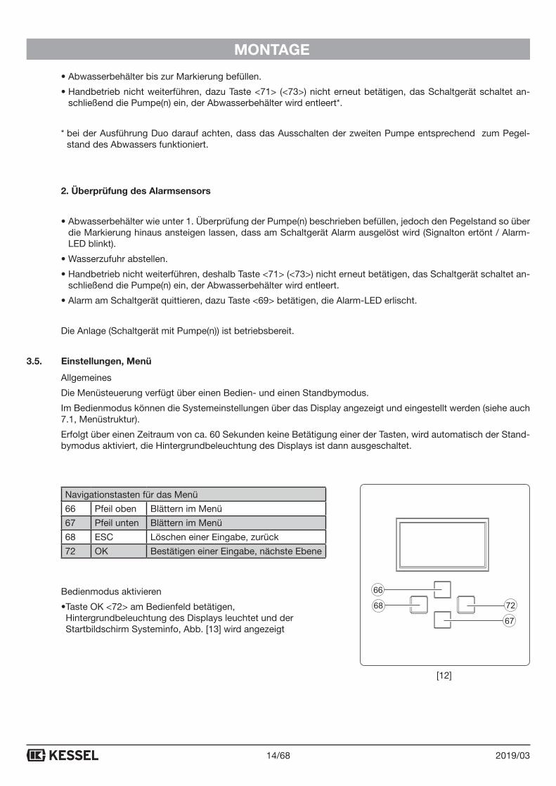
3.5. Einstellungen, Menü
Allgemeines
Die Menüsteuerung verfügt über einen Bedien- und einen Standbymodus.
Im Bedienmodus können die Systemeinstellungen über das Display angezeigt und eingestellt werden (siehe auch 7.1, Menüstruktur).
Erfolgt über einen Zeitraum von ca. 60 Sekunden keine Betätigung einer der Tasten, wird automatisch der Stand-bymodus aktiviert, die Hintergrundbeleuchtung des Displays ist dann ausgeschaltet.
Navigationstasten für das Menü
66 Pfeil oben Blättern im Menü
67 Pfeil unten Blättern im Menü
68 ESC Löschen einer Eingabe, zurück
72 OK Bestätigen einer Eingabe, nächste Ebene
Bedienmodus aktivieren
• Taste OK <72> am Bedienfeld betätigen, Hintergrundbeleuchtung des Displays leuchtet und der Startbildschirm Systeminfo, Abb. [13] wird angezeigt
[12]
15/682019/03
ALLGEMEINES
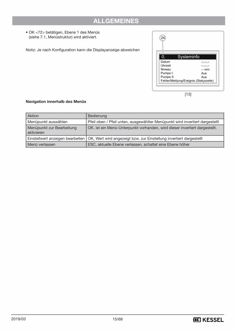
• OK <72> betätigen, Ebene 1 des Menüs (siehe 7.1, Menüstruktur) wird aktiviert.
Notiz: Je nach Konfiguration kann die Displayanzeige abweichen
Navigation innerhalb des Menüs
Aktion Bedienung
Menüpunkt auswählen Pfeil oben / Pfeil unten, ausgewählter Menüpunkt wird invertiert dargestellt
Menüpunkt zur Bearbeitung aktivieren
OK. ist ein Menü-Unterpunkt vorhanden, wird dieser invertiert dargestellt.
Einstellwert anzeigen bearbeiten OK, Wert wird angezeigt bzw. zur Einstellung invertiert dargestellt
Menü verlassen ESC, aktuelle Ebene verlassen, schaltet eine Ebene höher
DatumUhrzeitNiveau:Pumpe I:Pumpe II:Fehler/Meldung/Ereignis (Statuszeile)
--,--,----,--,---- mmAusAus
24
[13]
16/68 2019/03
BETRIEB
4. Betrieb4.1. Einschalten
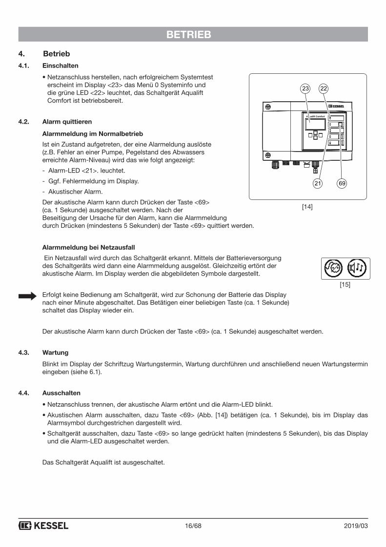
• Netzanschluss herstellen, nach erfolgreichem Systemtest erscheint im Display <23> das Menü 0 Systeminfo und die grüne LED <22> leuchtet, das Schaltgerät Aqualift Comfort ist betriebsbereit.
4.2. Alarm quittieren
Alarmmeldung im Normalbetrieb
Ist ein Zustand aufgetreten, der eine Alarmeldung auslöste (z.B. Fehler an einer Pumpe, Pegelstand des Abwassers erreichte Alarm-Niveau) wird das wie folgt angezeigt:
- Alarm-LED <21>. leuchtet.
- Ggf. Fehlermeldung im Display.
- Akustischer Alarm.
Der akustische Alarm kann durch Drücken der Taste <69> (ca. 1 Sekunde) ausgeschaltet werden. Nach der Beseitigung der Ursache für den Alarm, kann die Alarmmeldung durch Drücken (mindestens 5 Sekunden) der Taste <69> quittiert werden.
Alarmmeldung bei Netzausfall
Ein Netzausfall wird durch das Schaltgerät erkannt. Mittels der Batterieversorgung des Schaltgeräts wird dann eine Alarmmeldung ausgelöst. Gleichzeitig ertönt der akustische Alarm. Im Display werden die abgebildeten Symbole dargestellt.
Erfolgt keine Bedienung am Schaltgerät, wird zur Schonung der Batterie das Display nach einer Minute abgeschaltet. Das Betätigen einer beliebigen Taste (ca. 1 Sekunde) schaltet das Display wieder ein.
Der akustische Alarm kann durch Drücken der Taste <69> (ca. 1 Sekunde) ausgeschaltet werden.
4.3. Wartung
Blinkt im Display der Schriftzug Wartungstermin, Wartung durchführen und anschließend neuen Wartungstermin eingeben (siehe 6.1).
4.4. Ausschalten
• Netzanschluss trennen, der akustische Alarm ertönt und die Alarm-LED blinkt.
• Akustischen Alarm ausschalten, dazu Taste <69> (Abb. [14]) betätigen (ca. 1 Sekunde), bis im Display das Alarmsymbol durchgestrichen dargestellt wird.
• Schaltgerät ausschalten, dazu Taste <69> so lange gedrückt halten (mindestens 5 Sekunden), bis das Display und die Alarm-LED ausgeschaltet werden.
Das Schaltgerät Aqualift ist ausgeschaltet.
Aqualift Comfort
23 22
21 69
[14]
[15]
17/682019/03
TECHNISCHE DATEN
5. Technische Daten
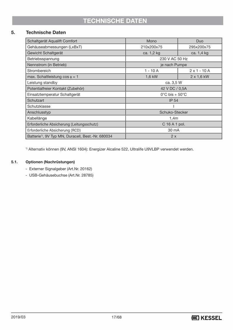
Schaltgerät Aqualift Comfort Mono Duo
Gehäuseabmessungen (LxBxT) 210x200x75 295x200x75
Gewicht Schaltgerät ca. 1,2 kg ca. 1,4 kg
Betriebsspannung 230 V AC 50 Hz
Nennstrom (in Betrieb) je nach Pumpe
Strombereich 1 - 10 A 2 x 1 - 10 A
max. Schaltleistung cos ɸ = 1 1,6 kW 2 x 1,6 kW
Leistung standby ca. 3,5 W
Potentialfreier Kontakt (Zubehör) 42 V DC / 0,5A
Einsatztemperatur Schaltgerät 0°C bis + 50°C
Schutzart IP 54
Schutzklasse I
Anschlusstyp Schuko-Stecker
Kabellänge 1,4m
Erforderliche Absicherung (Leitungsschutz) C 16 A 1 pol.
Erforderliche Absicherung (RCD) 30 mA
Batterie1), 9V Typ MN, Duracell, Best.-Nr. 680034 2 x
1) Alternativ können (9V, ANSI 1604): Energizer Alcaline 522, Ultralife U9VLBP verwendet werden.
5.1. Optionen (Nachrüstungen)
- Externer Signalgeber (Art.Nr. 20162)
- USB-Gehäusebuchse (Art.Nr. 28785)
18/68 2019/03
WARTUNG
6. Wartung
6.1. Wartungstermin einstellen
Der Wartungstermin wird über das Menü 2, Punkt 2.4 eingestellt (Siehe 7.1). Folgen Sie dem Bildschirmdialog (zur Bedienung siehe 3.5, Einstellungen, Menü).
6.2. Selbstdiagnosesystem (SDS)
Das Selbstdiagnosesystem prüft automatisch (Intervall einstellbar) nachstehend beschriebene Anlagenfunktio-nen. Diese Einstellungen werden über das Menü 3.1.9 (Siehe 7.1) vorgenommen.
Prüfung: Pumpe 1, Pumpe 2 (Duo), Batterie
Tritt ein Fehler auf, erscheint eine Klartextmeldung im Display und die Alarm-LED leuchtet.
6.3. Kalibrierung Drucksensor
Durch einen normalen Alterungsprozess kann es zur Abweichung des Niveaus am Drucksensor kommen.
Die Kalibrierung des Drucksensors kann unter Menüpunkt 2.7. durchgeführt werden und erfolgt automatisch.
Eine jährliche Kalibrierung wird empfohlen.
-> Bitte beachten Sie, dass die Kalibrierung bei einer Raumtemperatur von 10°C bis 30°C durchgeführt werden sollte.
19/682019/03
WARTUNG
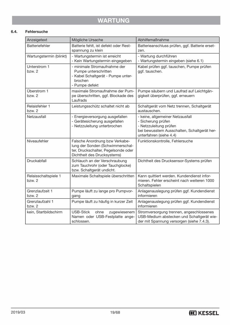
6.4. Fehlersuche
Anzeigetext Mögliche Ursache Abhilfemaßnahme
Batteriefehler Batterie fehlt, ist defekt oder Rest-spannung zu klein
Batterieanschluss prüfen, ggf. Batterie erset-zen.
Wartungstermin (blinkt) - Wartungstermin ist erreicht- Kein Wartungstermin eingegeben
- Wartung durchführen- Wartungstermin eingeben (siehe 6.1)
Unterstrom 1 bzw. 2
- minimale Stromaufnahme der Pumpe unterschritten
- Kabel Schaltgerät - Pumpe unter-brochen
- Pumpe defekt
Kabel prüfen ggf. tauschen, Pumpe prüfen ggf. tauschen.
Überstrom 1 bzw. 2
maximale Stromaufnahme der Pum-pe überschritten, ggf. Blockade des Laufrads
Pumpe säubern und Laufrad auf Leichtgän-gigkeit überprüfen, ggf. erneuern
Relaisfehler 1 bzw. 2
Leistungsschütz schaltet nicht ab Schaltgerät vom Netz trennen, Schaltgerät austauschen.
Netzausfall
- Energieversorgung ausgefallen- Gerätesicherung ausgefallen- Netzzuleitung unterbrochen
- keine, allgemeiner Netzausfall- Sicherung prüfen- Netzzuleitung prüfenbei bewusstem Ausschalten, Schaltgerät her-unterfahren (siehe 4.4)
Niveaufehler Falsche Anordnung bzw Verkabe-lung der Sonden (Schwimmerschal-ter, Druckschalter, Pegelsonde oder Dichtheit des Drucksystems)
Funktionskontrolle, Fehlersuche
Druckabfall Schlauch an der Verschraubung zum Tauchrohr (oder Tauchglocke) bzw. Schaltgerät undicht.
Dichtheit des Drucksensor-Systems prüfen
Relaisschaltspiele 1 bzw. 2
Maximale Schaltspiele überschritten Kann quittiert werden. Kundendienst infor-mieren. Fehler erscheint nach weiteren 1000 Schaltspielen
Grenzlaufzeit 1 bzw. 2
Pumpe läuft zu lange pro Pumpvor-gang
Anlagenauslegung prüfen ggf. Kundendienst informieren
Grenzlaufzahl 1 bzw. 2
Pumpe läuft zu häufig in kurzer Zeit Anlagenauslegung prüfen ggf. Kundendienst informieren
kein, Startbildschirm USB-Stick ohne zugewiesenem Namen oder USB-Festplatte ange-schlossen.
Stromversorgung trennen, angeschlossenes USB-Medium abstecken und Schaltgerät wie-der mit Spannung versorgen (siehe 7.4.3).
20/68 2019/03
ANHANG
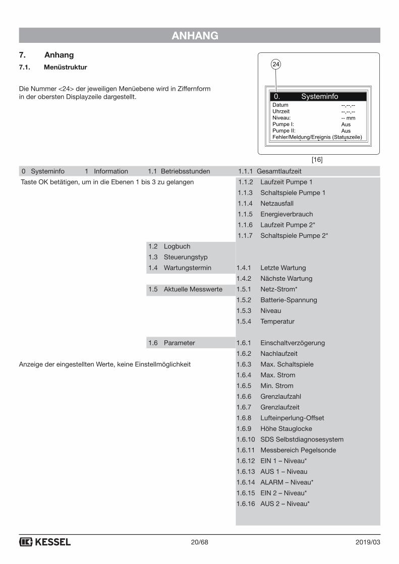
7. Anhang7.1. Menüstruktur
Die Nummer <24> der jeweiligen Menüebene wird in Ziffernform in der obersten Displayzeile dargestellt.
0 Systeminfo 1 Information 1.1 Betriebsstunden 1.1.1 Gesamtlaufzeit
Taste OK betätigen, um in die Ebenen 1 bis 3 zu gelangen 1.1.2 Laufzeit Pumpe 1
1.1.3 Schaltspiele Pumpe 1
1.1.4 Netzausfall
1.1.5 Energieverbrauch
1.1.6 Laufzeit Pumpe 2*
1.1.7 Schaltspiele Pumpe 2*
1.2 Logbuch
1.3 Steuerungstyp
1.4 Wartungstermin 1.4.1 Letzte Wartung
1.4.2 Nächste Wartung
1.5 Aktuelle Messwerte 1.5.1 Netz-Strom*
1.5.2 Batterie-Spannung
1.5.3 Niveau
1.5.4 Temperatur
1.6 Parameter 1.6.1 Einschaltverzögerung
1.6.2 Nachlaufzeit
Anzeige der eingestellten Werte, keine Einstellmöglichkeit 1.6.3 Max. Schaltspiele
1.6.4 Max. Strom
1.6.5 Min. Strom
1.6.6 Grenzlaufzahl
1.6.7 Grenzlaufzeit
1.6.8 Lufteinperlung-Offset
1.6.9 Höhe Stauglocke
1.6.10 SDS Selbstdiagnosesystem
1.6.11 Messbereich Pegelsonde
1.6.12 EIN 1 – Niveau*
1.6.13 AUS 1 – Niveau
1.6.14 ALARM – Niveau*
1.6.15 EIN 2 – Niveau*
1.6.16 AUS 2 – Niveau*
DatumUhrzeitNiveau:Pumpe I:Pumpe II:Fehler/Meldung/Ereignis (Statuszeile)
--,--,----,--,---- mmAusAus
24
[16]
21/682019/03
ANHANG
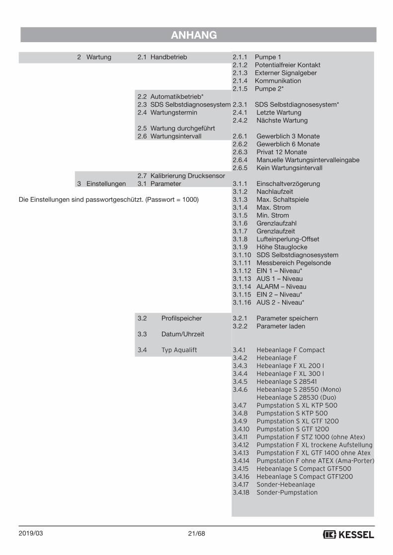
2 Wartung 2.1 Handbetrieb 2.1.1 Pumpe 1 2.1.2 Potentialfreier Kontakt 2.1.3 Externer Signalgeber 2.1.4 Kommunikation 2.1.5 Pumpe 2*
2.2 Automatikbetrieb* 2.3 SDS Selbstdiagnosesystem 2.3.1 SDS Selbstdiagnosesystem* 2.4 Wartungstermin 2.4.1 Letzte Wartung 2.4.2 Nächste Wartung 2.5 Wartung durchgeführt 2.6 Wartungsintervall 2.6.1 Gewerblich 3 Monate 2.6.2 Gewerblich 6 Monate 2.6.3 Privat 12 Monate 2.6.4 Manuelle Wartungsintervalleingabe 2.6.5 Kein Wartungsintervall 2.7 Kalibrierung Drucksensor 3 Einstellungen 3.1 Parameter 3.1.1 Einschaltverzögerung 3.1.2 NachlaufzeitDie Einstellungen sind passwortgeschützt. (Passwort = 1000) 3.1.3 Max. Schaltspiele 3.1.4 Max. Strom 3.1.5 Min. Strom 3.1.6 Grenzlaufzahl 3.1.7 Grenzlaufzeit 3.1.8 Lufteinperlung-Offset 3.1.9 Höhe Stauglocke 3.1.10 SDS Selbstdiagnosesystem 3.1.11 Messbereich Pegelsonde 3.1.12 EIN 1 – Niveau* 3.1.13 AUS 1 – Niveau 3.1.14 ALARM – Niveau 3.1.15 EIN 2 – Niveau* 3.1.16 AUS 2 - Niveau* 3.2 Profilspeicher 3.2.1 Parameter speichern 3.2.2 Parameter laden 3.3 Datum/Uhrzeit
3.4 Typ Aqualift 3.4.1 Hebeanlage F Compact 3.4.2 Hebeanlage F 3.4.3 Hebeanlage F XL 200 l 3.4.4 Hebeanlage F XL 300 l 3.4.5 Hebeanlage S 28541 3.4.6 Hebeanlage S 28550 (Mono) Hebeanlage S 28530 (Duo) 3.4.7 Pumpstation S XL KTP 500 3.4.8 Pumpstation S KTP 500 3.4.9 Pumpstation S XL GTF 1200 3.4.10 Pumpstation S GTF 1200 3.4.11 Pumpstation F STZ 1000 (ohne Atex) 3.4.12 Pumpstation F XL trockene Aufstellung 3.4.13 Pumpstation F XL GTF 1400 ohne Atex 3.4.14 Pumpstation F ohne ATEX (Ama-Porter) 3.4.15 Hebeanlage S Compact GTF500 3.4.16 Hebeanlage S Compact GTF1200 3.4.17 Sonder-Hebeanlage 3.4.18 Sonder-Pumpstation
22/68 2019/03
ANHANG
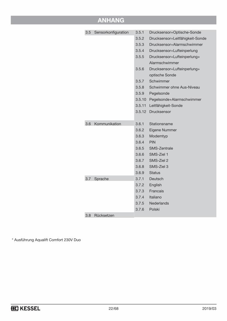
3.5 Sensorkonfiguration 3.5.1 Drucksensor+Optische-Sonde
3.5.2 Drucksensor+Leitfähigkeit-Sonde
3.5.3 Drucksensor+Alarmschwimmer
3.5.4 Drucksensor+Lufteinperlung
3.5.5 Drucksensor+Lufteinperlung+
Alarmschwimmer
3.5.6 Drucksensor+Lufteinperlung+
optische Sonde
3.5.7 Schwimmer
3.5.8 Schwimmer ohne Aus-Niveau
3.5.9 Pegelsonde
3.5.10 Pegelsonde+Alarmschwimmer
3.5.11 Leitfähigkeit-Sonde
3.5.12 Drucksensor
3.6 Kommunikation 3.6.1 Stationsname
3.6.2 Eigene Nummer
3.6.3 Modemtyp
3.6.4 PIN
3.6.5 SMS-Zentrale
3.6.6 SMS-Ziel 1
3.6.7 SMS-Ziel 2
3.6.8 SMS-Ziel 3
3.6.9 Status
3.7 Sprache 3.7.1 Deutsch
3.7.2 English
3.7.3 Francais
3.7.4 Italiano
3.7.5 Nederlands
3.7.6 Polski
3.8 Rücksetzen
* Ausführung Aqualift Comfort 230V Duo
23/682019/03
ANHANG
7.2. Schaltgerät umrüsten, spezielle Bedingungen
Achtung, Gefahr durch elektrischen Strom! Nachstehend beschriebe Umrüstungen dürfen aus-schließlich durch autorisiertes Elektrofachpersonal durchgeführt werden (Siehe 2.2, Personalaus-wahl und -qualifikation).
7.2.1 Anschlüsse auf Klemmleiste herstellen
Sollen Sonden oder Pumpen angeschlossen werden, die nicht vom Hersteller KESSEL mit einer passenden elek-trischen Steckverbindung ausgerüstet sind, können
- entsprechende Steckverbindungen beim Hersteller KESSEL bestellt werden.
- die Anschlüsse im Gehäuseinneren an den Klemmleisten hergestellt werden. Dazu wie folgt verfahren:
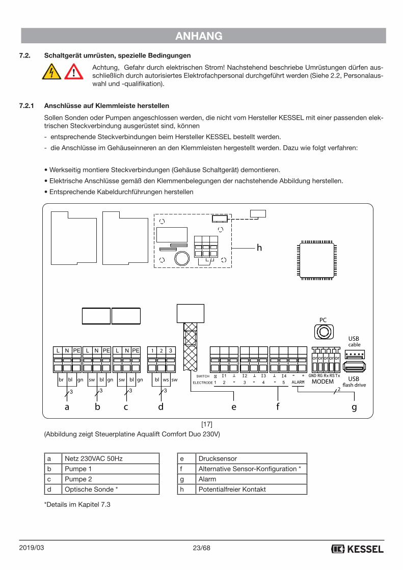
• Werkseitig montiere Steckverbindungen (Gehäuse Schaltgerät) demontieren.
• Elektrische Anschlüsse gemäß den Klemmenbelegungen der nachstehende Abbildung herstellen.
• Entsprechende Kabeldurchführungen herstellen
(Abbildung zeigt Steuerplatine Aqualift Comfort Duo 230V)
a Netz 230VAC 50Hz e Drucksensor
b Pumpe 1 f Alternative Sensor-Konfiguration *
c Pumpe 2 g Alarm
d Optische Sonde * h Potentialfreier Kontakt
a b c d e f
PC
TxRSRxRGGND
or or oror or
USBcable
USB�ash driveMODEM
21
I1 I2 I3 I4 - +
ALARM
�
-- -gn wsbr bl gnblsw gnblsw swbl
2
g
h
[17]
*Details im Kapitel 7.3
24/68 2019/03
ANHANG
7.3. Alternative Sensorkonfiguration (Schwimmer und Sensoren anschließen)
Die nachstehenden Anschlussbeschreibungen beziehen sich auf die im Menü 3.5 auswählbaren Sensorkonfigurationen.
7.3.1 Aqualift Comfort Mono 230V
Menüpunkt 3.5.1, Drucksensor und Optische-Sonde
Diese Sensorkonfiguration ist folgenden im Menü auswählbaren Anlagenkonfigurationen (Typ Aqualift) zugeord-net: 3.4.1 und 3.4.6 bis 3.4.12. Anschlüsse der Sensoren siehe Kapitel 3.3.1 und 3.3.2.
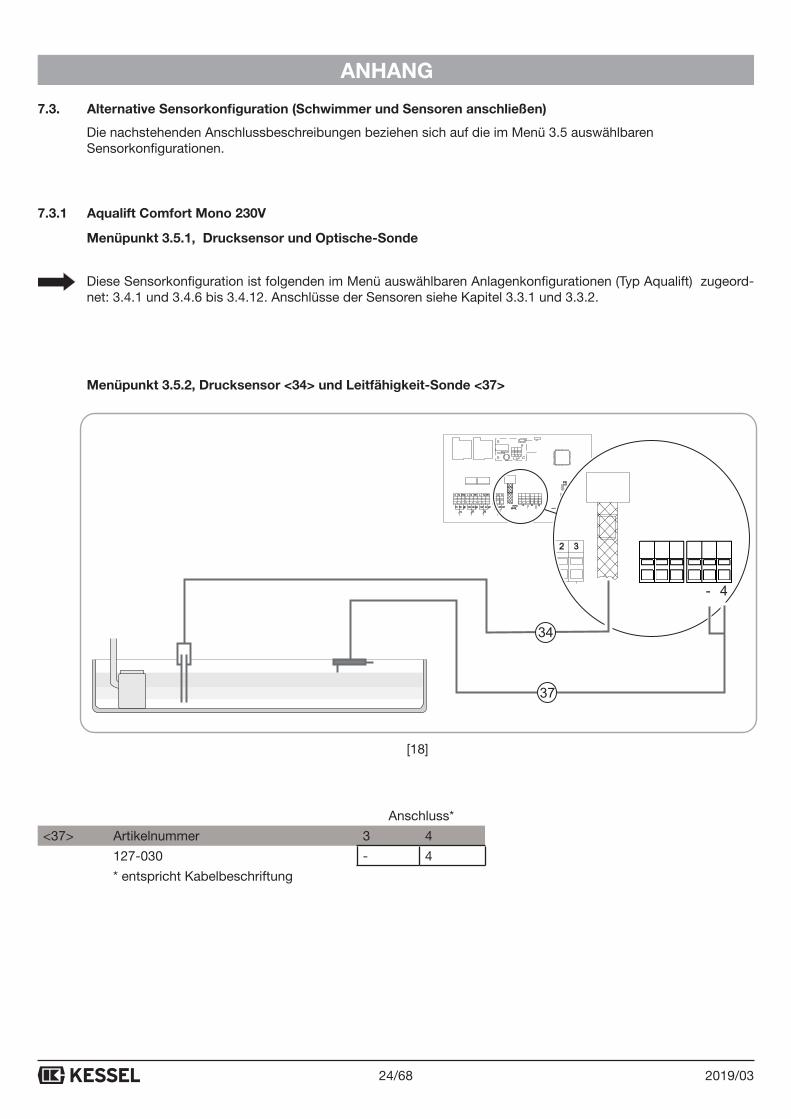
Menüpunkt 3.5.2, Drucksensor <34> und Leitfähigkeit-Sonde <37>
Anschluss*
<37> Artikelnummer 3 4
127-030 - 4
* entspricht Kabelbeschriftung
PC
TxRSRxRGGND
or or oror or
USBcable
USBfash drive
MODEM
21
(/(&752'(
I1 �I2 I3 I4 - +�
ALARM-- -gn wsbr bl gnblsw gnblsw swbl�
4321 -
37
34
[18]
25/682019/03
ANHANG
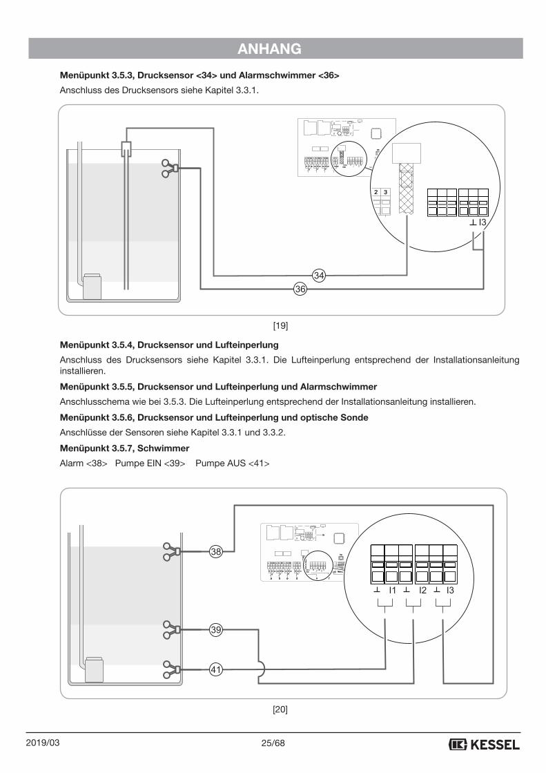
Menüpunkt 3.5.3, Drucksensor <34> und Alarmschwimmer <36>
Anschluss des Drucksensors siehe Kapitel 3.3.1.
Menüpunkt 3.5.4, Drucksensor und Lufteinperlung
Anschluss des Drucksensors siehe Kapitel 3.3.1. Die Lufteinperlung entsprechend der Installationsanleitung installieren.
Menüpunkt 3.5.5, Drucksensor und Lufteinperlung und Alarmschwimmer
Anschlusschema wie bei 3.5.3. Die Lufteinperlung entsprechend der Installationsanleitung installieren.
Menüpunkt 3.5.6, Drucksensor und Lufteinperlung und optische Sonde
Anschlüsse der Sensoren siehe Kapitel 3.3.1 und 3.3.2.
Menüpunkt 3.5.7, Schwimmer
Alarm <38> Pumpe EIN <39> Pumpe AUS <41>
PC
TxRSRxRGGND
or or oror or
USBcable
USBfash drive
MODEM
21
(/(&752'(
I1 �I2 I3 I4 - +�
ALARM-- -gn wsbr bl gnblsw gnblsw swbl�
I3
36
34
a b c d e f
PC
TxRSRxRGGND
or or oror or
USBcable
USBfash drive
MODEM
21
(/(&752'(
I1 �I2 I3 I4 - +�
ALARM-- -gn wsbr bl gnblsw gnblsw swbl
2
�
g
h
I1 I2 I3
38
39
41
[19]
[20]
26/68 2019/03
ANHANG
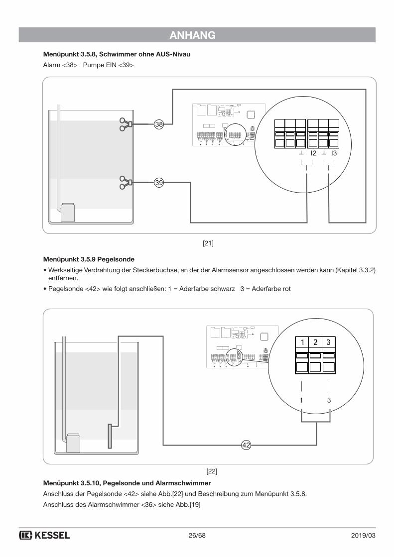
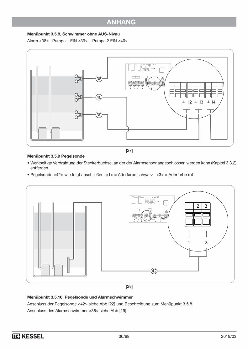
Menüpunkt 3.5.8, Schwimmer ohne AUS-Nivau
Alarm <38> Pumpe EIN <39>
Menüpunkt 3.5.9 Pegelsonde
• Werkseitige Verdrahtung der Steckerbuchse, an der der Alarmsensor angeschlossen werden kann (Kapitel 3.3.2) entfernen.
• Pegelsonde <42> wie folgt anschließen: 1 = Aderfarbe schwarz 3 = Aderfarbe rot
Menüpunkt 3.5.10, Pegelsonde und Alarmschwimmer
Anschluss der Pegelsonde <42> siehe Abb.[22] und Beschreibung zum Menüpunkt 3.5.8.
Anschluss des Alarmschwimmer <36> siehe Abb.[19]
a b c d e f
PC
TxRSRxRGGND
or or oror or
USBcable
USBfash drive
MODEM
21
(/(&752'(
I1 �I2 I3 I4 - +�
ALARM-- -gn wsbr bl gnblsw gnblsw swbl
2
�
g
h
I1 I2 I3
38
39
a b c d e f
PC
TxRSRxRGGND
or or oror or
USBcable
USBfash drive
MODEM
21
(/(&752'(
I1 �I2 I3 I4 - +�
ALARM-- -gn wsbr bl gnblsw gnblsw swbl
2
�
g
h
1 2 3
42
[21]
[22]
27/682019/03
ANHANG
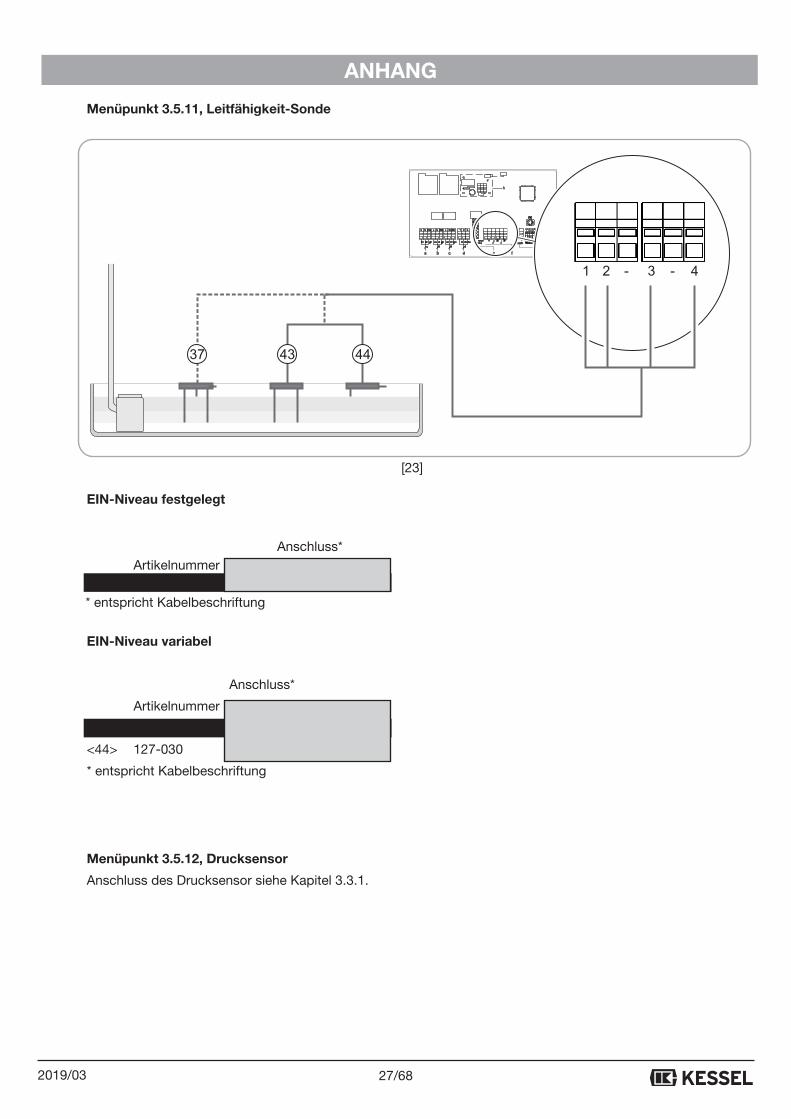
Menüpunkt 3.5.11, Leitfähigkeit-Sonde
EIN-Niveau festgelegt
Anschluss* Artikelnummer 1 2 3 4 <37> 127-033 x x x x * entspricht Kabelbeschriftung
EIN-Niveau variabel
Anschluss*
Artikelnummer 1 2 3 4
<43> 127-029 x x
<44> 127-030 x x
* entspricht Kabelbeschriftung
Menüpunkt 3.5.12, Drucksensor
Anschluss des Drucksensor siehe Kapitel 3.3.1.
PC
TxRSRxRGGND
or or oror or
USBcable
USBfash drive
MODEM
21
(/(&752'(
I1 �I2 I3 I4 - +�
ALARM-- -gn wsbr bl gnblsw gnblsw swbl�
a b c d e f
PC
TxRSRxRGGND
or or oror or
USBcable
USBfash drive
MODEM
21
(/(&752'(
I1 �I2 I3 I4 - +�
ALARM-- -gn wsbr bl gnblsw gnblsw swbl
2
�
g
h
2 3 41 - -
43 4437
[23]

28/68 2019/03
ANHANG
7.3.2 Aqualift Comfort Duo 230V
Menüpunkt 3.5.1, Drucksensor und Optische-Sonde
Diese Sensorkonfiguration ist folgenden im Menü auswählbaren Anlagenkonfigurationen (Typ Aqualift) zugeord-net: 3.4.1 und 3.4.6 bis 3.4.12. Anschlüsse der Sensoren siehe Kapitel 3.3.1 und 3.3.2.
Menüpunkt 3.5.2, Drucksensor <34> und Leitfähigkeit-Sonde <37>
Anschluss*
<37> Artikelnummer 4 5
127-034 - 5
* entspricht Kabelbeschriftung
PC
TxRSRxRGGND
or or oror or
USBcable
USBfash drive
MODEM
21
(/(&752'(
I1 �I2 I3 I4 - +�
ALARM-- -gn wsbr bl gnblsw gnblsw swbl�
321
55-
37
34
[24]

29/682019/03
ANHANG
Menüpunkt 3.5.3, Drucksensor <34> und Alarmschwimmer <36>
Anschluss des Drucksensors siehe Kapitel 3.3.1.
Menüpunkt 3.5.4, Drucksensor und Lufteinperlung
Anschluss des Drucksensors siehe Kapitel 3.3.1. Die Lufteinperlung entsprechend der Installationsanleitung installieren.
Menüpunkt 3.5.5, Drucksensor und Lufteinperlung und Alarmschwimmer
Anschlusschema wie bei 3.5.3. Die Lufteinperlung entsprechend der Installationsanleitung installieren.
Menüpunkt 3.5.6, Drucksensor und Lufteinperlung und optische Sonde
Anschlüsse der Sensoren siehe Kapitel 3.3.1 und 3.3.2.
Menüpunkt 3.5.7, Schwimmer
Alarm <38> Pumpe 1 EIN <39> Pumpe 2 EIN <40> Pumpe AUS <41>
PC
TxRSRxRGGND
or or oror or
USBcable
USBfash drive
MODEM
21
(/(&752'(
I1 �I2 I3 I4 - +�
ALARM-- -gn wsbr bl gnblsw gnblsw swbl�
321 I4
36
34
a b c d e f
PC
TxRSRxRGGND
or or oror or
USBcable
USBfash drive
MODEM
21
(/(&752'(
I1 �I2 I3 I4 - +�
ALARM-- -gn wsbr bl gnblsw gnblsw swbl
2
�
g
h
I1 I2 I3 I4
38
39
41
40
41 39 40 38
[25]
[26]
30/68 2019/03
ANHANG
Menüpunkt 3.5.8, Schwimmer ohne AUS-Nivau
Alarm <38> Pumpe 1 EIN <39> Pumpe 2 EIN <40>
Menüpunkt 3.5.9 Pegelsonde
• Werkseitige Verdrahtung der Steckerbuchse, an der der Alarmsensor angeschlossen werden kann (Kapitel 3.3.2) entfernen.
• Pegelsonde <42> wie folgt anschließen: <1> = Aderfarbe schwarz <3> = Aderfarbe rot
Menüpunkt 3.5.10, Pegelsonde und Alarmschwimmer
Anschluss der Pegelsonde <42> siehe Abb.[22] und Beschreibung zum Menüpunkt 3.5.8.
Anschluss des Alarmschwimmer <36> siehe Abb.[19]
a b c d e f
PC
TxRSRxRGGND
or or oror or
USBcable
USBfash drive
MODEM
21
(/(&752'(
I1 �I2 I3 I4 - +�
ALARM-- -gn wsbr bl gnblsw gnblsw swbl
2
�
g
h
I2 I3 I4
38
39
40
a b c d e f
PC
TxRSRxRGGND
or or oror or
USBcable
USBfash drive
MODEM
21
(/(&752'(
I1 �I2 I3 I4 - +�
ALARM-- -gn wsbr bl gnblsw gnblsw swbl
2
�
g
h
1 2 3
42
[27]
[28]
31/682019/03
ANHANG
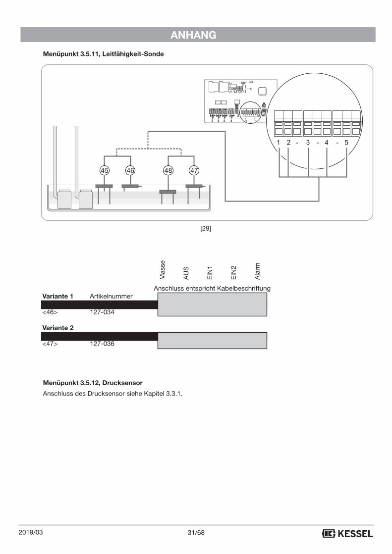
Menüpunkt 3.5.11, Leitfähigkeit-Sonde
Anschluss entspricht Kabelbeschriftung Variante 1 Artikelnummer 1 2 3 4 5 <45> 127-047 x x x <46> 127-034 x x Variante 2 <48> 127-037 x x <47> 127-036 x x x
Menüpunkt 3.5.12, Drucksensor
Anschluss des Drucksensor siehe Kapitel 3.3.1.
PC
TxRSRxRGGND
or or oror or
USBcable
USBfash drive
MODEM
21
(/(&752'(
I1 �I2 I3 I4 - +�
ALARM-- -gn wsbr bl gnblsw gnblsw swbl�
a b c d e f
PC
TxRSRxRGGND
or or oror or
USBcable
USBfash drive
MODEM
21
(/(&752'(
I1 �I2 I3 I4 - +�
ALARM-- -gn wsbr bl gnblsw gnblsw swbl
2
�
g
h
3 4 521 - - -
47484645
Mas
se
AU
S
EIN
1
EIN
2
Ala
rm
[29]
32/68 2019/03
ANHANG
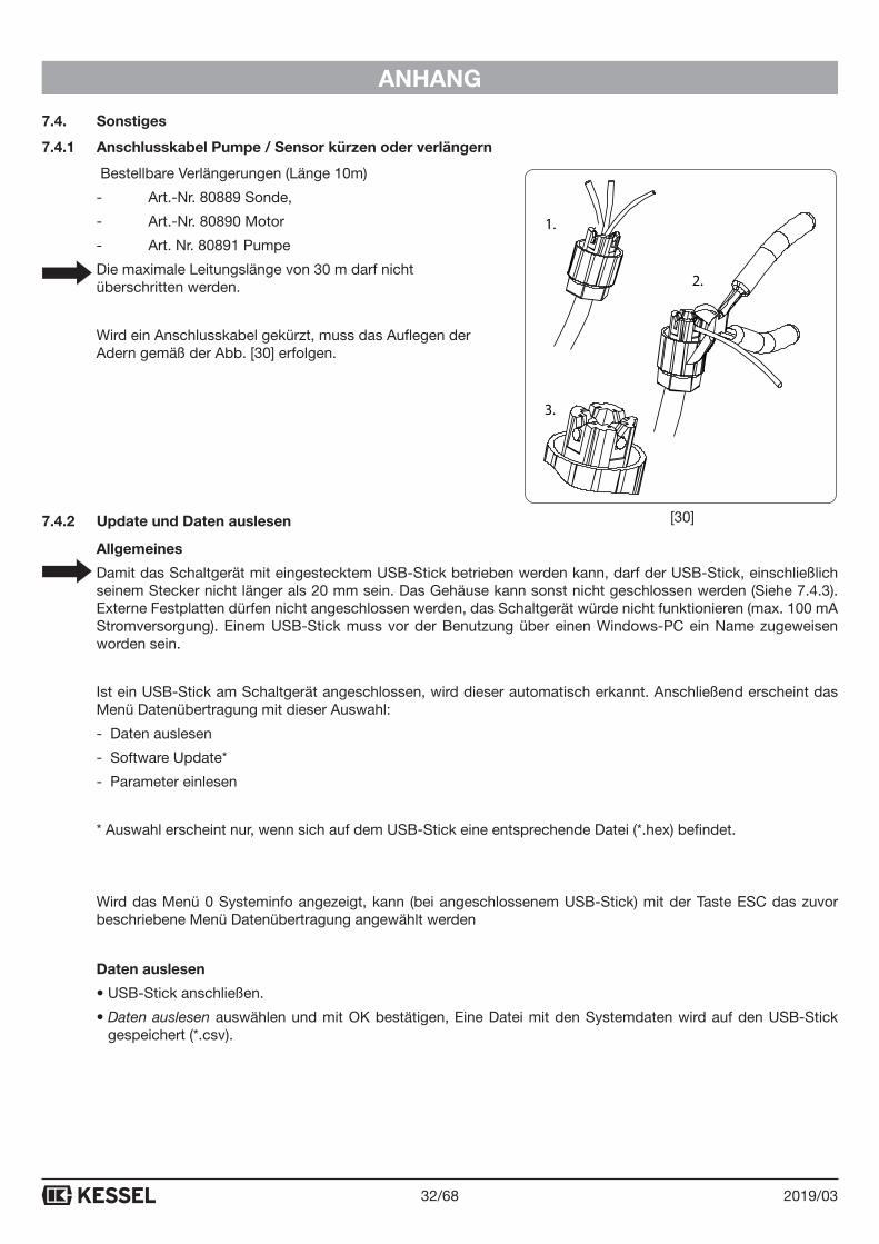
7.4. Sonstiges
7.4.1 Anschlusskabel Pumpe / Sensor kürzen oder verlängern
Bestellbare Verlängerungen (Länge 10m)
- Art.-Nr. 80889 Sonde,
- Art.-Nr. 80890 Motor
- Art. Nr. 80891 Pumpe
Die maximale Leitungslänge von 30 m darf nicht überschritten werden.
Wird ein Anschlusskabel gekürzt, muss das Auflegen der Adern gemäß der Abb. [30] erfolgen.
7.4.2 Update und Daten auslesen
Allgemeines
Damit das Schaltgerät mit eingestecktem USB-Stick betrieben werden kann, darf der USB-Stick, einschließlich seinem Stecker nicht länger als 20 mm sein. Das Gehäuse kann sonst nicht geschlossen werden (Siehe 7.4.3). Externe Festplatten dürfen nicht angeschlossen werden, das Schaltgerät würde nicht funktionieren (max. 100 mA Stromversorgung). Einem USB-Stick muss vor der Benutzung über einen Windows-PC ein Name zugeweisen worden sein.
Ist ein USB-Stick am Schaltgerät angeschlossen, wird dieser automatisch erkannt. Anschließend erscheint das Menü Datenübertragung mit dieser Auswahl:
- Daten auslesen
- Software Update*
- Parameter einlesen
* Auswahl erscheint nur, wenn sich auf dem USB-Stick eine entsprechende Datei (*.hex) befindet.
Wird das Menü 0 Systeminfo angezeigt, kann (bei angeschlossenem USB-Stick) mit der Taste ESC das zuvor beschriebene Menü Datenübertragung angewählt werden
Daten auslesen
• USB-Stick anschließen.
• Daten auslesen auswählen und mit OK bestätigen, Eine Datei mit den Systemdaten wird auf den USB-Stick gespeichert (*.csv).
2.
3.
1.
[30]
33/682019/03
ANHANG
Update durchführen
(Nur möglich, wenn sich eine entsprechende Datei (*.hex) auf dem USB-Stick befindet)
• USB-Stick anschließen, Menü Datenübertragung wird angezeigt.
• Software Update auswählen, Passwort eingeben und mit OK bestätigen, das Update wird automatisch durch-geführt, dazu dem Displaydialog folgen.
Parameter einlesen
(Nur möglich, wenn sich eine entsprechende Datei (*.csv) auf dem USB-Stick befindet)
• USB-Stick anschließen, , Menü Datenübertragung wird angezeigt.
• Parameter einlesen auswählen, Passwort eingeben und mit OK bestätigen, das Einlesen wird automatisch durchgeführt.
7.4.3 USB Anschluss herausführen
Damit der auf der Platine befindliche USB-Anschluss ohne ein Öffnen des Gehäuses zugängig wird, kann eine USB-Gehäusebuchse mit Kabel und Stecker zum Einbau in das Gehäuse des Schaltgerätes bei KESSEL bestellt werden (Siehe 5.1).
7.4.4 Menüstruktur Expertenmodus
3.9 Experten-Modus 3.9.1 Netz Einschaltverzögerung
3.9.2 Alternierender Betrieb
3.9.3 Batterieüberwachung
3.9.4 Automatische Alarmquittierung
Hinweis: Die Firmenbezeichnung KESSEL ist in den meisten Ländern ein eingetragener Firmenname. Die Produkt-bezeichnung Aqualift ist in den meisten Ländern ein eingetragenes Warenzeichen bzw. ein Warenzeichen.

Führend in Entwässerung
Privater Wohnungsbauohne Kanalanbindung
1 2 3 4 5
Öffentlicher Bauz.B. Freizeitanlagen
6 4
Privater WohnungsbauEin- und Mehrfamilienhaus
Gewerblicher Bauz.B. Tankstellen
Gewerblicher Bauz.B. Hotel
Öffentlicher Bauz.B. Krankenhaus
4 5
Gewerblicher Bauz.B. Industriebau
1 Rückstauverschlüsse 2 Rückstauhebeanlagen 3 Hebeanlagen
4 Abläufe / Rinnen 5 Abscheider 6 Kleinkläranlagen
1 2 3 4 5
1 2 3 4 5
1 2 3 4
2 3 5
MANUAL FOR INSTALLATION, OPERATION AND MAINTENANCE
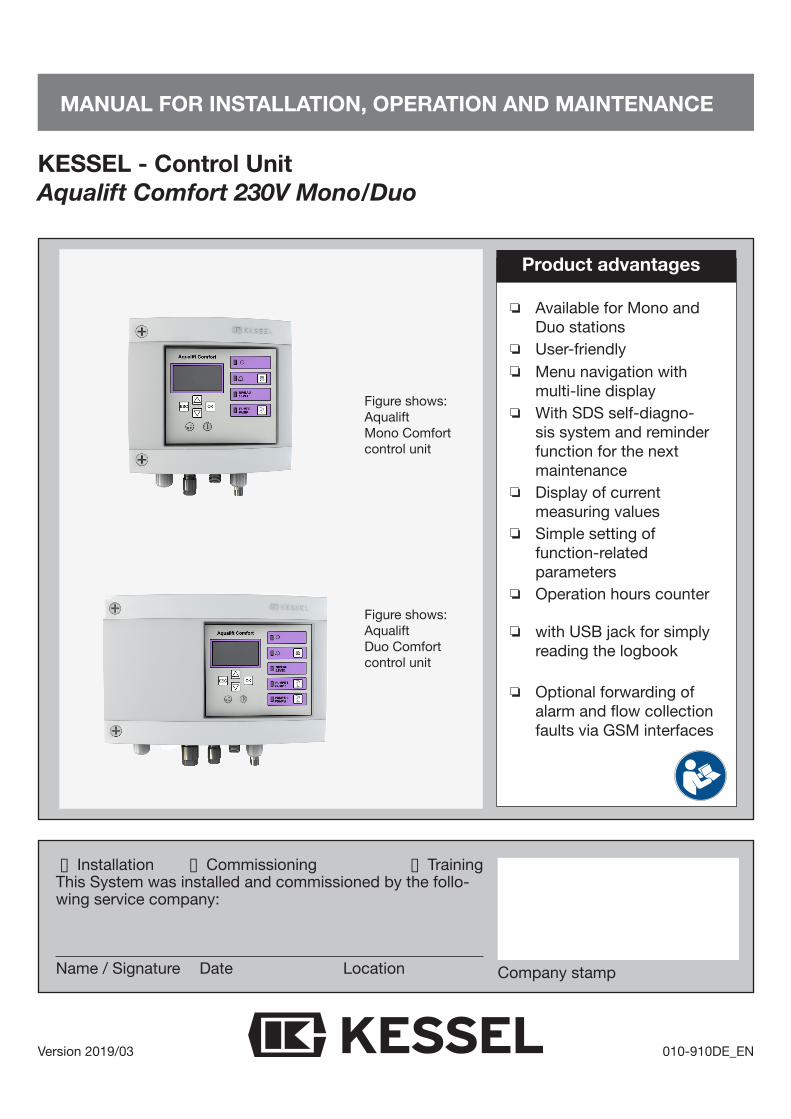
KESSEL - Control Unit Aqualift Comfort 230V Mono/Duo
Version 2019/03 010-910DE_EN
o Installation o Commissioning o TrainingThis System was installed and commissioned by the follo-wing service company:
Name / Signature Date Location
Available for Mono and Duo stationsUser-friendlyMenu navigation with multi-line displayWith SDS self-diagno-sis system and reminder function for the nextmaintenanceDisplay of current measuring valuesSimple setting of function-related parametersOperation hours counter
with USB jack for simply reading the logbook
Optional forwarding of alarm and flow collection faults via GSM interfaces
Product advantages
Company stamp
Figure shows:Aqualift Mono Comfort control unit
Figure shows:Aqualift Duo Comfort control unit
36/68 2019/03
1. General 38
1.1 Introduction and welcome 38
1.2 Product description, general 38
1.2.1 Versions 38
1.2.2 Type plate 39
1.3 Delivery scope 39
1.4 General information about this operating and maintenance manual 40
1.5 Assemblies and functional elements 40
1.5.1 Display and control panel, displays 41
2. Safety 42
2.1 Proper use 42
2.2 Staff selection and qualification 42
2.3 Organisational safety measures 42
2.4 Risks arising from the product 42
2.5 Risk due to electrical current and cables 42
3. Assembly 43
3.1 Assembling the control unit 43
3.2 Connecting the wastewater pump(s) 44
3.3 Connecting the level detector 45
3.3.1 Pressure sensor (option) 45
3.3.2 Connecting the alarm sensor 45
3.4 Initial start-up 46
3.4.1 Performing initialisation 46
3.4.2 Function check 47
3.5 Settings, menu 48
4. Operating mode 50
4.1 Switching on 50
4.2 Acknowledging alarm 50
4.3 Maintenance 50
4.4 Switching off 50
5. Technical data 51
5.1 Options (retrofits) 51
6. Maintenance 52
6.1 Setting the maintenance date 52
6.2 Self diagnosis system (SDS) 52
6.3 Calibrating the pressure sensor 52
6.4 Troubleshooting 53
37/682019/03
7. Appendix 54
7.1 Menu structure 54
7.2 Control unit retrofits, special conditions 57
7.2.1 Terminal strip connections 57
7.3 Alternative sensor configuration (connecting floaters and sensors) 58
7.3.1 Aqualift Comfort Mono 230V 58
7.3.2 Aqualift Comfort Duo 230V 62
7.4 Miscellaneous 66
7.4.1 Shortening or extending the pump/sensor connection cable 66
7.4.2 Updates and data read 66
7.4.3 Leading out the USB connection 67
7.4.4 Menüstruktur Expertenmodus 67
38/68 2019/03
GENERAL
1. General
1.1. Introduction and welcome
We are delighted that you have decided to purchase one of our products. It is sure to satisfy your requirements to the full. We wish you a problem-free and successful installation.
In our efforts to maintain our quality standard at the highest possible level, we are naturally dependent on your support. Please let us know any possible ways to improve our products.
Do you have any questions? We shall be glad to hear from you.
1.2. Product description, general
The Aqualift control unit provides the control for a lifting station for wastewater with or without sewage. The swit-ching signals from the sensors for the wastewater level are processed electronically. Either a level switch or a pressure sensor may be used as the level detector. Pumping is activated once the filling volume is reached. Either one or two wastewater pumps are then switched on, depending on the version. Pumping stops when the level has fallen again to a suitable degree.
If two wastewater pumps are connected, they are activated either individually or together depending on the filling volume and the positioning of the level sensors.
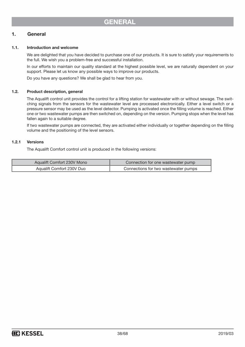
1.2.1 Versions
The Aqualift Comfort control unit is produced in the following versions:
Aqualift Comfort 230V Mono Connection for one wastewater pump
Aqualift Comfort 230V Duo Connections for two wastewater pumps
39/682019/03
GENERAL
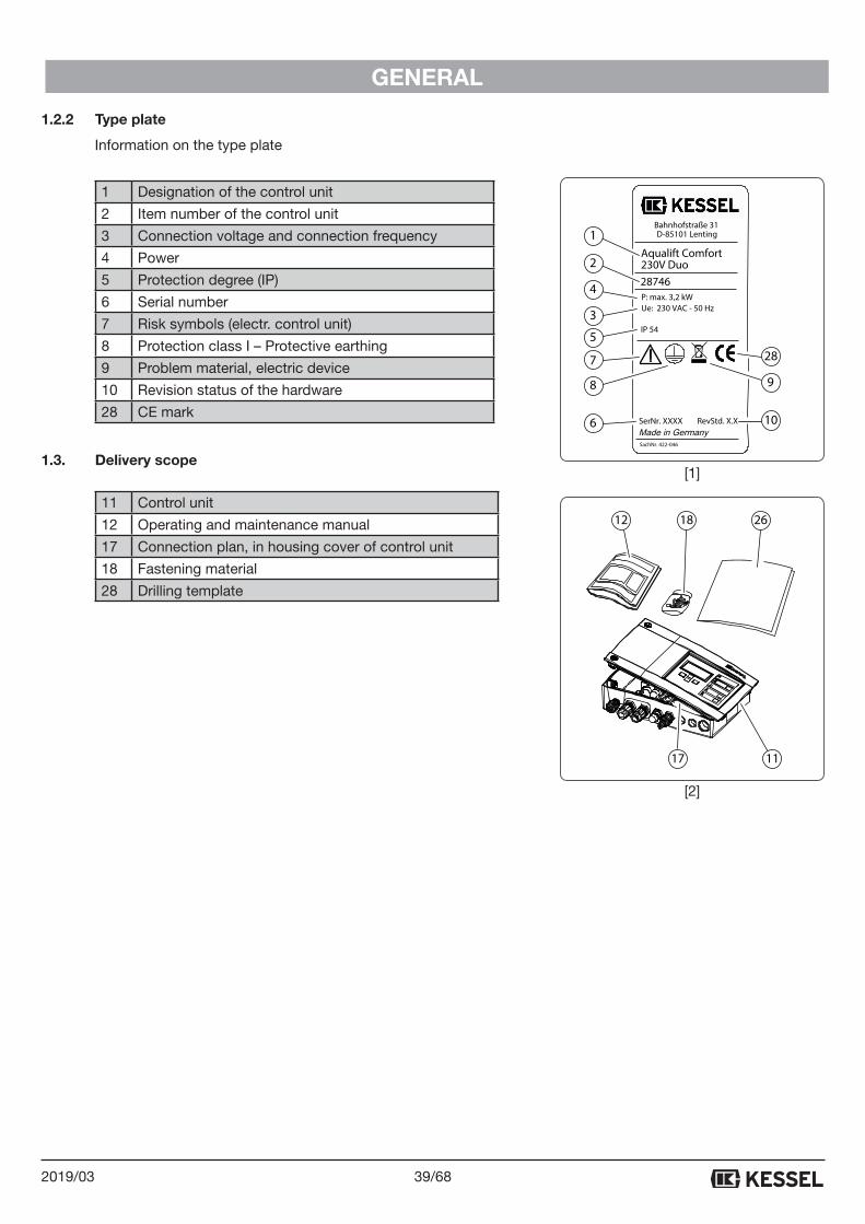
1.2.2 Type plate
Information on the type plate
1 Designation of the control unit
2 Item number of the control unit
3 Connection voltage and connection frequency
4 Power
5 Protection degree (IP)
6 Serial number
7 Risk symbols (electr. control unit)
8 Protection class I – Protective earthing
9 Problem material, electric device
10 Revision status of the hardware
28 CE mark
1.3. Delivery scope
11 Control unit
12 Operating and maintenance manual
17 Connection plan, in housing cover of control unit
18 Fastening material
28 Drilling template
12 18 26
17 11
Aqualift Comfort230V Duo
IP 54
28746
SerNr. XXXX
P: max. 3,2 kW Ue: 230 VAC - 50 Hz
Bahnhofstraße 31D-85101 Lenting
RevStd. X.X
SachNr. 422-046
1
2
4
3
5
7
8
6
28
9
10
[1]
[2]
40/68 2019/03
GENERAL
1.4. General information about this operating and maintenance manual
Used symbols and legends
<1> Reference in the text to a legend number in an illustration
[2] Reference to an illustration
• Work step
- List
Italics Text in italics: reference to a paragraph/item in the control menu
CAUTION: Warns about a risk to persons and material. Disregarding the instructions designated with this symbol may lead to serious injuries and material damage
NOTE: Technical information that must be observed carefully.
1.5. Assemblies and functional elements
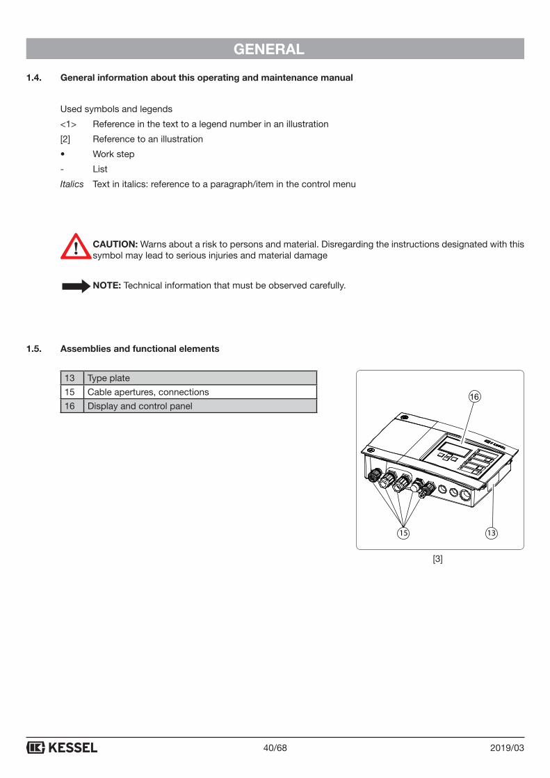
13 Type plate
15 Cable apertures, connections
16 Display and control panel
1315
16
[3]
41/682019/03
GENERAL
1.5.1 Display and control panel, displays
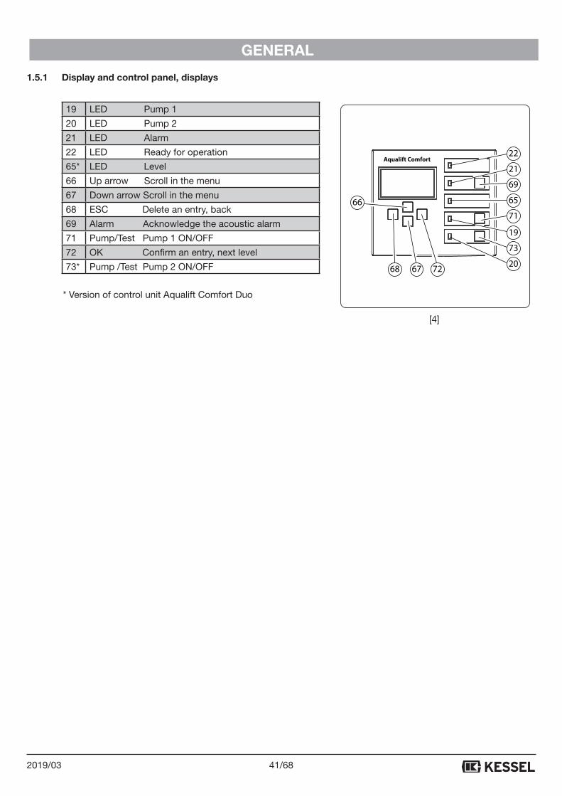
19 LED Pump 1
20 LED Pump 2
21 LED Alarm
22 LED Ready for operation
65* LED Level
66 Up arrow Scroll in the menu
67 Down arrow Scroll in the menu
68 ESC Delete an entry, back
69 Alarm Acknowledge the acoustic alarm
71 Pump/Test Pump 1 ON/OFF
72 OK Confirm an entry, next level
73* Pump /Test Pump 2 ON/OFF
* Version of control unit Aqualift Comfort Duo
Aqualift Comfort22
21
69
65
71
19
73
20726768
66
[4]
42/68 2019/03
SAFETY
2. Safety2.1. Proper use
The Aqualift control unit may be used exclusively for controlling lifting stations (DIN EN 12050 Parts 1–3) and pumping stations for wastewater with sewage* and without sewage.
Any use of the control unit in an environment at risk from explosions is not permissible.
Depending on the version (see 1.2.1), it is possible to connect float switches.
Any of the following actions that are not approved explicitly and in writing by the manufacturer:
- Conversions or attachments,
- Use of non-original spare parts,
- Performance of repair work by companies or persons not authorised by the manufacturer,
may render the warranty invalid.
* In compliance with national explosion protection requirements (ATEX).
2.2. Staff selection and qualification
Persons who operate and/or assemble the Aqualift control unit must:
- Be at least 18 years old,
- Be trained adequately for the respective tasks,
- Be familiar with and follow the relevant technical rules and safety regulations.
The operator decides about the necessary qualifications for the
- Operating staff
- Maintenance staff
- Service staff.
The operator must ensure that only qualified staff work on the Aqualift Comfort control unit.
“Qualified staff” refers to persons who are able to perform the relevant tasks thanks to their training and experien-ce and their knowledge of the relevant provisions, applicable standards and accident prevention regulations and who are able in the process to detect and avoid any possible risks.
Any work on electrical components may be carried out only by trained technical staff and in compliance with all applicable provisions of the accident prevention regulations.
2.3. Organisational safety measures
The operating and maintenance manual must always be kept available at the Aqualift Comfort control unit.
2.4. Risks arising from the product
The control unit itself is NOT intended for installation in underground chambers.
2.5. Risk due to electrical current and cables
All live components are protected against unintentional contact. Housing covers, plugs and cables must be de-energised before being opened. Any work on electrical components may be carried out only by technical staff (see 2.2).
43/682019/03
ASSEMBLY
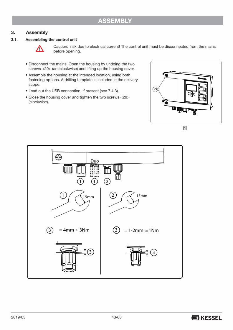
3. Assembly3.1. Assembling the control unit
Caution: risk due to electrical current! The control unit must be disconnected from the mains before opening.
• Disconnect the mains. Open the housing by undoing the two screws <29> (anticlockwise) and lifting up the housing cover.
• Assemble the housing at the intended location, using both fastening options. A drilling template is included in the delivery scope.
• Lead out the USB connection, if present (see 7.4.3).
• Close the housing cover and tighten the two screws <29> (clockwise).
29
[5]
19mm 15mm
1 1 2
2
= 1-2mm 1Nm= 4mm 3Nm
3
333 ≈ ≈
1
3
Duo
44/68 2019/03
ASSEMBLY
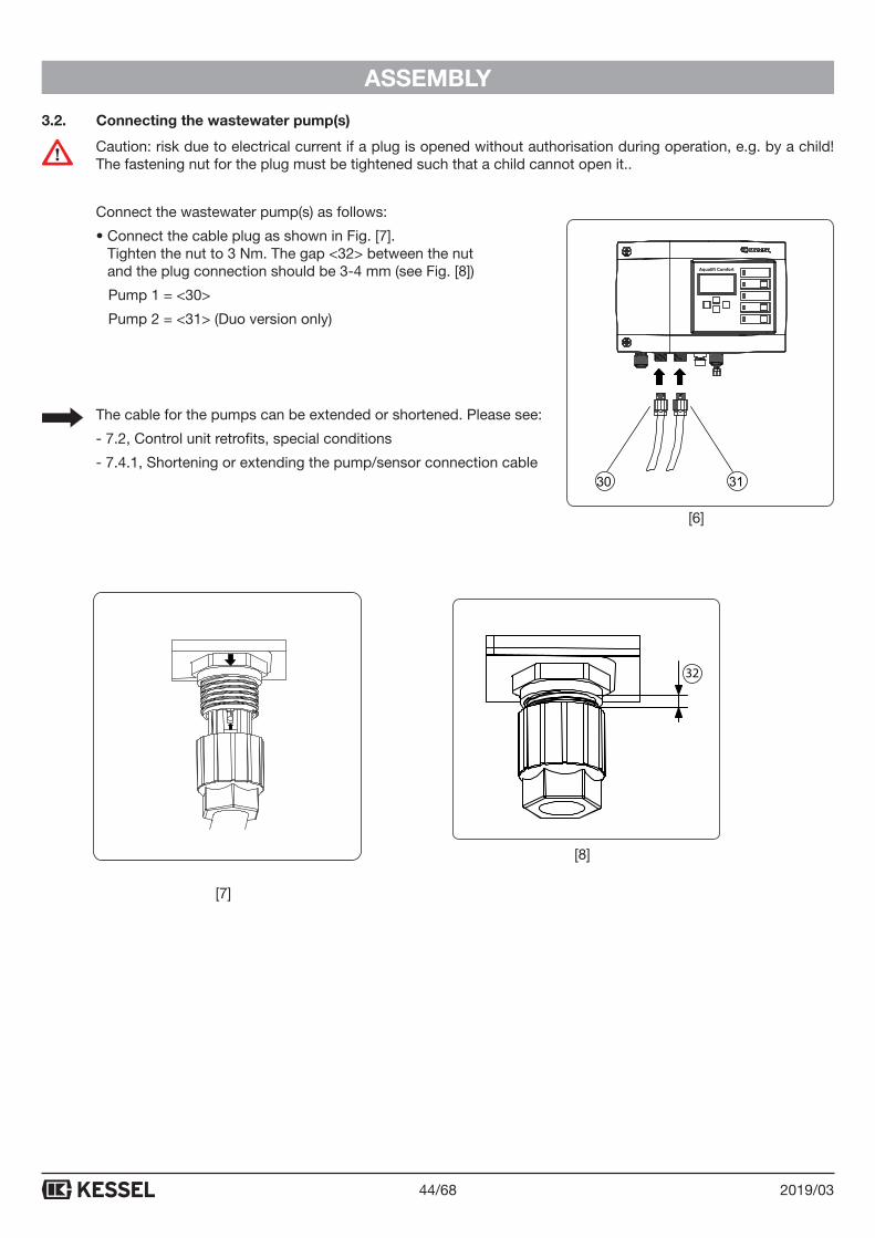
3.2. Connecting the wastewater pump(s)
Caution: risk due to electrical current if a plug is opened without authorisation during operation, e.g. by a child! The fastening nut for the plug must be tightened such that a child cannot open it..
Connect the wastewater pump(s) as follows:
• Connect the cable plug as shown in Fig. [7]. Tighten the nut to 3 Nm. The gap <32> between the nut and the plug connection should be 3-4 mm (see Fig. [8])
Pump 1 = <30>
Pump 2 = <31> (Duo version only)
The cable for the pumps can be extended or shortened. Please see:
- 7.2, Control unit retrofits, special conditions
- 7.4.1, Shortening or extending the pump/sensor connection cable
Aqualift Comfort
3130
32
[6]
[7]
[8]
45/682019/03
ASSEMBLY
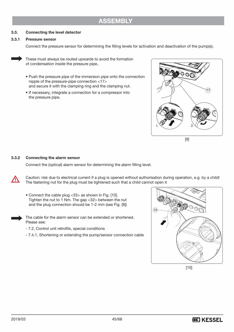
3.3. Connecting the level detector
3.3.1 Pressure sensor
Connect the pressure sensor for determining the filling levels for activation and deactivation of the pump(s).
These must always be routed upwards to avoid the formation of condensation inside the pressure pipe..
• Push the pressure pipe of the immersion pipe onto the connection nipple of the pressure-pipe connection <17> and secure it with the clamping ring and the clamping nut.
• If necessary, integrate a connection for a compressor into the pressure pipe.
3.3.2 Connecting the alarm sensor
Connect the (optical) alarm sensor for determining the alarm filling level.
Caution: risk due to electrical current if a plug is opened without authorisation during operation, e.g. by a child! The fastening nut for the plug must be tightened such that a child cannot open it
• Connect the cable plug <33> as shown in Fig. [10]. Tighten the nut to 1 Nm. The gap <32> between the nut and the plug connection should be 1-2 mm (see Fig. [8])
The cable for the alarm sensor can be extended or shortened. Please see:
- 7.2, Control unit retrofits, special conditions
- 7.4.1, Shortening or extending the pump/sensor connection cable
33
1. 2.
17
[9]
[10]
46/68 2019/03
ASSEMBLY
3.4. Initial start-up
A dry run of the pump(s) must be avoided without fail. Tip: Before connecting the mains voltage, fill the waste-water container with water so that the pump(s) cannot run dry if they should be switched on accidentally (e.g. incorrect connection of a level sensor).
• Connecting the mains voltage
Supply the control unit with mains voltage; the initialisation will then begin. While the LEDs light up for approx. 4 seconds, the electrical components are checked, the battery for the power outage message is activated and the 0.1. Language menu is displayed. The initialisation procedure can then be carried out
If the initialisation option (0.1. Language menu) is not available in the display, the control unit has already been initialised. In this case, the set parameters must be checked or the factory settings must be restored (see item 3.8 Reset in Section 7.1). After the factory settings are restored, the option to initialise the control unit is offered automatically.
Please note that the counter for the maintenance interval and run occurs is not taken into account in the event of a reset.
3.4.1 Performing initialisation
The alarm power outage battery is activated during initialisation
During initialisation, the following entries are expected:
- Language
- Date/Time
- Type Aqualift
- Sensor-configuration
- Maintenance interval
Language
• Select the national language with the arrow keys and confirm with OK; the Date/Time menu is displayed.
Date/Time
• Set each respective flashing figure in the date and time and confirm with OK. After the final entry, the Sen-sor-configuration menu appears.
Sensor-configuration
Only required if a Special lifting station or a Special pumping station is configured for Type Aqualift.
• Select the type of the connected sensors with the arrow keys and confirm with OK.
• Adjust the parameters in software menu 3.1.
47/682019/03
ASSEMBLY
Type Aqualift
If the system pumps are tailored to the control unit (original KESSEL products), configure as per A). Otherwise, proceed as per B).
• Press OK
• A) Select the type of the connected pump(s) with the arrow keys and confirm with OK; the 0 System info menu is displayed – the control unit is now ready for operation.
• B) Select Special lifting station with the arrow keys and confirm with OK; the 0 System info menu is displayed. You now need to configure all the system parameters. For floater and sensor settings, see 7.2 and 7.3.
Make sure that the power usage range displayed on the type plate of the connected pump(s) does not exceed the maximum rating for the control unit. This could damage the control unit during operation and/or issue an error message.
Maintenance interval
If no maintenance date is entered, this will be shown in plain text in the display. A maintenance date is entered using the menu (see 6.1, Setting the maintenance date).
3.4.2 Function check
Preparation
- Make sure that the wastewater container that the pump(s) will drain can be filled with water in as short a time as possible.
- In the wastewater container, apply a marking slightly below the filling level at which the alarm should be triggered.
For the function check, two different test procedures are carried out.
1. Check of the pump(s)
2. Check of the alarm switch
1. Check of the pump(s)
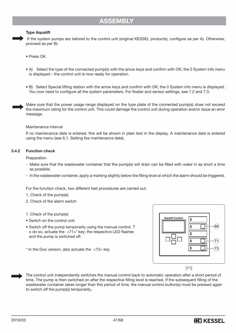
• Switch on the control unit.
• Switch off the pump temporarily using the manual control. T o do so, actuate the <71>* key; the respective LED flashes and the pump is switched off.
* In the Duo version, also actuate the <73> key
The control unit independently switches the manual control back to automatic operation after a short period of time. The pump is then switched on after the respective filling level is reached. If the subsequent filling of the wastewater container takes longer than this period of time, the manual control button(s) must be pressed again to switch off the pump(s) temporarily..
Aqualift Comfort
69
71
73
[11]
48/68 2019/03
ASSEMBLY
• Fill the wastewater container up to the marking.
• Do not continue with manual operation; for this purpose, ensure that the <71> (<73>) key is not pressed again, the control unit will then switch the pump(s) on again and the wastewater container will be drained*.
* In the Duo version, please ensure that the switching off of the second pump works properly according to the level of the wastewater.
2. Check of the alarm sensor
• Fill the wastewater container as described under 1. Check of the pump(s), but allow the level to climb above the marking so that an alarm is triggered on the control unit (audible alarm is sounded/alarm LED flashes).
• Switch off the water supply.
• Do not continue with manual operation; for this purpose, ensure that the <71> (<73>) key is not pressed again, the control unit will then switch the pump(s) on again and the wastewater container will be drained.
• Acknowledge the alarm on the control unit by pressing the <69> key; the alarm LED is switched off.
The system (control unit with pump(s)) is ready for operation.
.
3.5. Settings, menu
General
The menu control features an operating and a standby mode.
In the operating mode, the system settings can be displayed and adjusted using the display (see also 7.1, Menu structure).
If none of the keys is actuated for a period of approx. 60 seconds, the standby mode is activated automatically and the background lighting of the display is switched off.
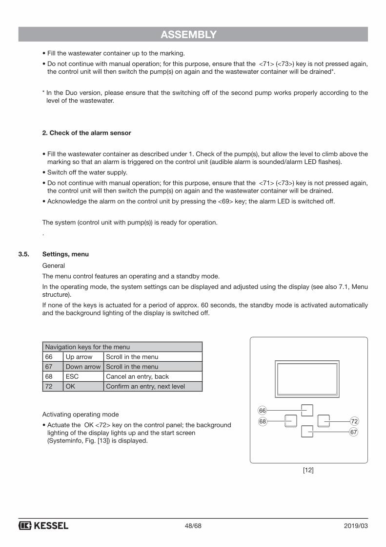
Navigation keys for the menu
66 Up arrow Scroll in the menu
67 Down arrow Scroll in the menu
68 ESC Cancel an entry, back
72 OK Confirm an entry, next level
Activating operating mode
• Actuate the OK <72> key on the control panel; the background lighting of the display lights up and the start screen (Systeminfo, Fig. [13]) is displayed.
[12]
49/682019/03
GENERAL
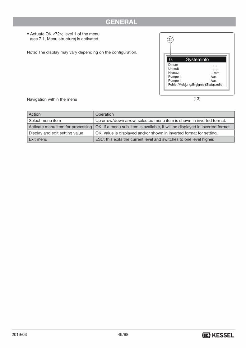
• Actuate OK <72>; level 1 of the menu (see 7.1, Menu structure) is activated.
Note: The display may vary depending on the configuration.
Navigation within the menu
Action Operation
Select menu item Up arrow/down arrow, selected menu item is shown in inverted format.
Activate menu item for processing OK. If a menu sub-item is available, it will be displayed in inverted format
Display and edit setting value OK. Value is displayed and/or shown in inverted format for setting.
Exit menu ESC; this exits the current level and switches to one level higher.
DatumUhrzeitNiveau:Pumpe I:Pumpe II:Fehler/Meldung/Ereignis (Statuszeile)
--,--,----,--,---- mmAusAus
24
[13]
50/68 2019/03
OPERATING MODE
4. Operating mode4.1. Switching on
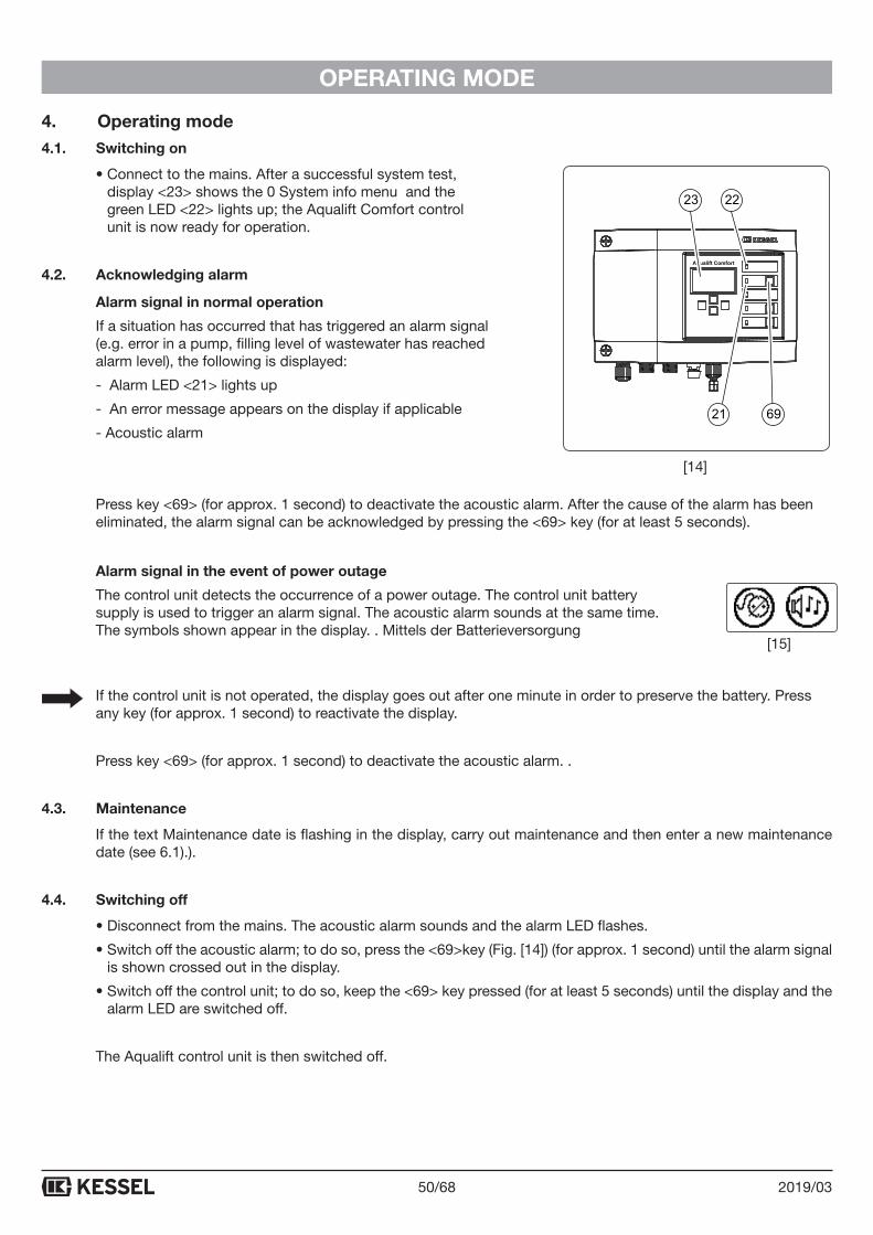
• Connect to the mains. After a successful system test, display <23> shows the 0 System info menu and the green LED <22> lights up; the Aqualift Comfort control unit is now ready for operation.
4.2. Acknowledging alarm
Alarm signal in normal operation
If a situation has occurred that has triggered an alarm signal (e.g. error in a pump, filling level of wastewater has reached alarm level), the following is displayed:
- Alarm LED <21> lights up
- An error message appears on the display if applicable
- Acoustic alarm
Press key <69> (for approx. 1 second) to deactivate the acoustic alarm. After the cause of the alarm has been eliminated, the alarm signal can be acknowledged by pressing the <69> key (for at least 5 seconds).
Alarm signal in the event of power outage
The control unit detects the occurrence of a power outage. The control unit battery supply is used to trigger an alarm signal. The acoustic alarm sounds at the same time. The symbols shown appear in the display. . Mittels der Batterieversorgung
If the control unit is not operated, the display goes out after one minute in order to preserve the battery. Press any key (for approx. 1 second) to reactivate the display.
Press key <69> (for approx. 1 second) to deactivate the acoustic alarm. .
4.3. Maintenance
If the text Maintenance date is flashing in the display, carry out maintenance and then enter a new maintenance date (see 6.1).).
4.4. Switching off
• Disconnect from the mains. The acoustic alarm sounds and the alarm LED flashes.
• Switch off the acoustic alarm; to do so, press the <69>key (Fig. [14]) (for approx. 1 second) until the alarm signal is shown crossed out in the display.
• Switch off the control unit; to do so, keep the <69> key pressed (for at least 5 seconds) until the display and the alarm LED are switched off.
The Aqualift control unit is then switched off.
Aqualift Comfort
23 22
21 69
[14]
[15]
51/682019/03
TECHNICAL DATA
5. Technical data
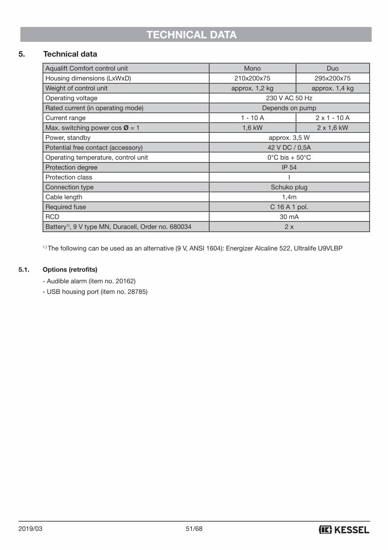
Aqualift Comfort control unit Mono Duo
Housing dimensions (LxWxD) 210x200x75 295x200x75
Weight of control unit approx. 1,2 kg approx. 1,4 kg
Operating voltage 230 V AC 50 Hz
Rated current (in operating mode) Depends on pump
Current range 1 - 10 A 2 x 1 - 10 A
Max. switching power cos Ø = 1 1,6 kW 2 x 1,6 kW
Power, standby approx. 3,5 W
Potential free contact (accessory) 42 V DC / 0,5A
Operating temperature, control unit 0°C bis + 50°C
Protection degree IP 54
Protection class I
Connection type Schuko plug
Cable length 1,4m
Required fuse C 16 A 1 pol.
RCD 30 mA
Battery1), 9 V type MN, Duracell, Order no. 680034 2 x
1.) The following can be used as an alternative (9 V, ANSI 1604): Energizer Alcaline 522, Ultralife U9VLBP
5.1. Options (retrofits)
- Audible alarm (item no. 20162)
- USB housing port (item no. 28785)
52/68 2019/03
MAINTENANCE
6. Maintenance
6.1. Setting the maintenance date
The maintenance date is set using menu 2, Item 2.4 (see 7.1). Follow the dialogue on the screen (for operation, see 3.5, Settings, menu).
6.2. Self diagnosis system (SDS)
The self diagnosis system performs an automatic check (at a configurable interval) of the system functions descri-bed below. These settings can be adjusted via menu 3.1.9 (see 7.1).
Check: Pump 1, Pump 2 (Duo), battery
If an error occurs, a plain-text message appears in the display and the alarm LED lights up.
6.3. Calibrating the pressure sensor
The pressure sensor level may drift as the result of a normal ageing process.
The pressure sensor can be automatically calibrated under menu item 2.7. We recommend an annual calibration.
-> Please note that calibration should be carried out at a room temperature of 10°C to 30°C.
53/682019/03
MAINTENANCE
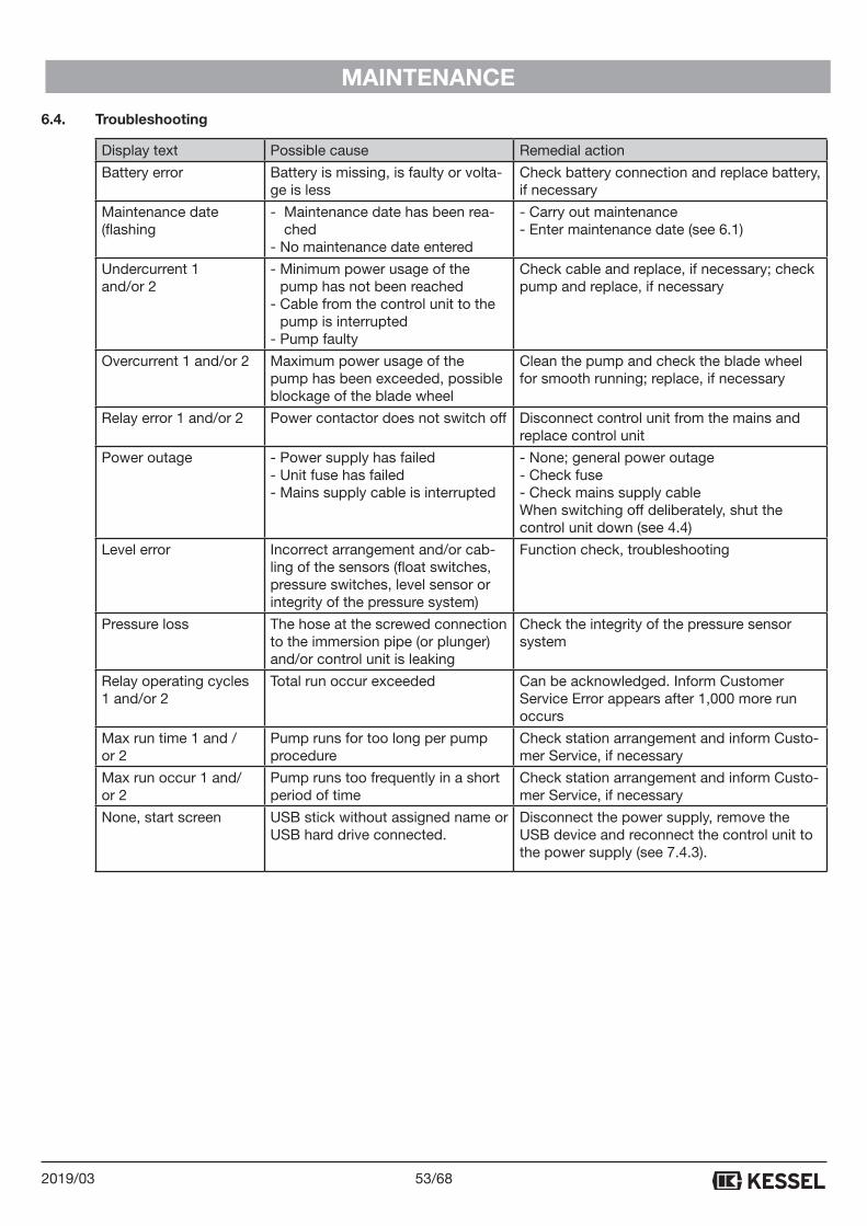
6.4. Troubleshooting
Display text Possible cause Remedial action
Battery error Battery is missing, is faulty or volta-ge is less
Check battery connection and replace battery, if necessary
Maintenance date (flashing
- Maintenance date has been rea-ched
- No maintenance date entered
- Carry out maintenance - Enter maintenance date (see 6.1)
Undercurrent 1 and/or 2
- Minimum power usage of the pump has not been reached
- Cable from the control unit to the pump is interrupted
- Pump faulty
Check cable and replace, if necessary; check pump and replace, if necessary
Overcurrent 1 and/or 2 Maximum power usage of the pump has been exceeded, possible blockage of the blade wheel
Clean the pump and check the blade wheel for smooth running; replace, if necessary
Relay error 1 and/or 2 Power contactor does not switch off Disconnect control unit from the mains and replace control unit
Power outage - Power supply has failed- Unit fuse has failed- Mains supply cable is interrupted
- None; general power outage- Check fuse- Check mains supply cableWhen switching off deliberately, shut the control unit down (see 4.4)
Level error Incorrect arrangement and/or cab-ling of the sensors (float switches, pressure switches, level sensor or integrity of the pressure system)
Function check, troubleshooting
Pressure loss The hose at the screwed connection to the immersion pipe (or plunger) and/or control unit is leaking
Check the integrity of the pressure sensor system
Relay operating cycles 1 and/or 2
Total run occur exceeded Can be acknowledged. Inform Customer Service Error appears after 1,000 more run occurs
Max run time 1 and /or 2
Pump runs for too long per pump procedure
Check station arrangement and inform Custo-mer Service, if necessary
Max run occur 1 and/or 2
Pump runs too frequently in a short period of time
Check station arrangement and inform Custo-mer Service, if necessary
None, start screen USB stick without assigned name or USB hard drive connected.
Disconnect the power supply, remove the USB device and reconnect the control unit to the power supply (see 7.4.3).
54/68 2019/03
APPENDIX
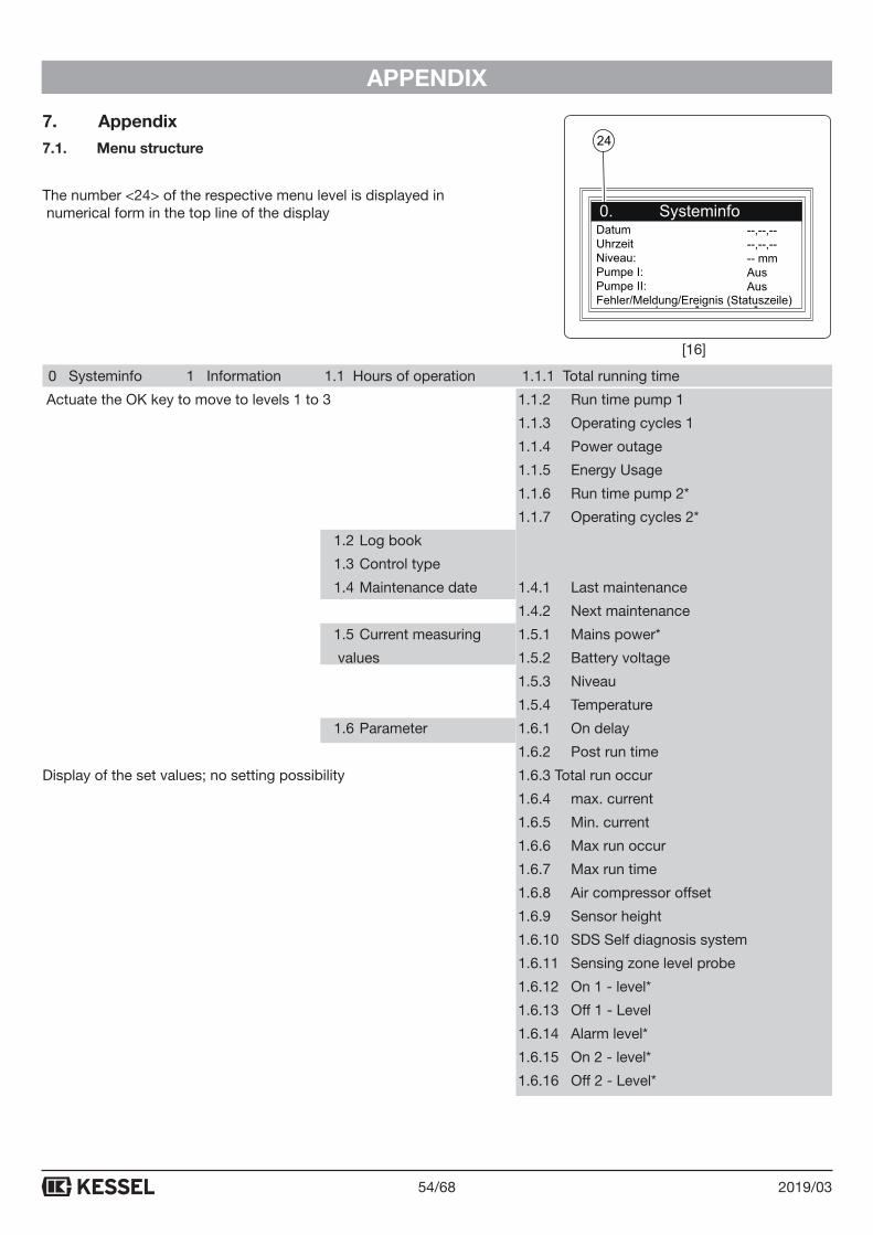
7. Appendix7.1. Menu structure
The number <24> of the respective menu level is displayed in numerical form in the top line of the display
0 Systeminfo 1 Information 1.1 Hours of operation 1.1.1 Total running time
Actuate the OK key to move to levels 1 to 3 1.1.2 Run time pump 1
1.1.3 Operating cycles 1
1.1.4 Power outage
1.1.5 Energy Usage
1.1.6 Run time pump 2*
1.1.7 Operating cycles 2*
1.2 Log book
1.3 Control type
1.4 Maintenance date 1.4.1 Last maintenance
1.4.2 Next maintenance
1.5 Current measuring 1.5.1 Mains power*
values 1.5.2 Battery voltage
1.5.3 Niveau
1.5.4 Temperature
1.6 Parameter 1.6.1 On delay
1.6.2 Post run time
Display of the set values; no setting possibility 1.6.3 Total run occur
1.6.4 max. current
1.6.5 Min. current
1.6.6 Max run occur
1.6.7 Max run time
1.6.8 Air compressor offset
1.6.9 Sensor height
1.6.10 SDS Self diagnosis system
1.6.11 Sensing zone level probe
1.6.12 On 1 - level*
1.6.13 Off 1 - Level
1.6.14 Alarm level*
1.6.15 On 2 - level*
1.6.16 Off 2 - Level*
DatumUhrzeitNiveau:Pumpe I:Pumpe II:Fehler/Meldung/Ereignis (Statuszeile)
--,--,----,--,---- mmAusAus
24
[16]
55/682019/03
APPENDIX
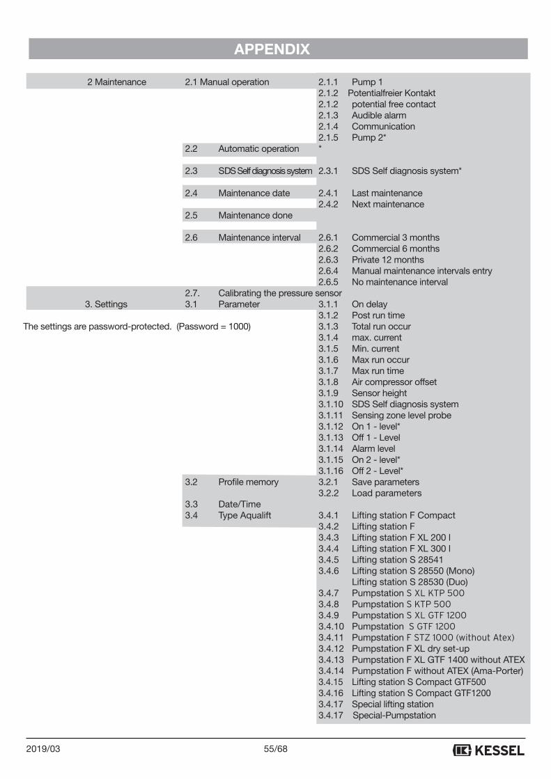
2 Maintenance 2.1 Manual operation 2.1.1 Pump 1 2.1.2 Potentialfreier Kontakt
2.1.2 potential free contact 2.1.3 Audible alarm 2.1.4 Communication 2.1.5 Pump 2* 2.2 Automatic operation * 2.3 SDS Self diagnosis system 2.3.1 SDS Self diagnosis system* 2.4 Maintenance date 2.4.1 Last maintenance 2.4.2 Next maintenance 2.5 Maintenance done
2.6 Maintenance interval 2.6.1 Commercial 3 months 2.6.2 Commercial 6 months 2.6.3 Private 12 months 2.6.4 Manual maintenance intervals entry 2.6.5 No maintenance interval 2.7. Calibrating the pressure sensor 3. Settings 3.1 Parameter 3.1.1 On delay 3.1.2 Post run time The settings are password-protected. (Password = 1000) 3.1.3 Total run occur 3.1.4 max. current 3.1.5 Min. current 3.1.6 Max run occur 3.1.7 Max run time 3.1.8 Air compressor offset 3.1.9 Sensor height 3.1.10 SDS Self diagnosis system 3.1.11 Sensing zone level probe 3.1.12 On 1 - level* 3.1.13 Off 1 - Level 3.1.14 Alarm level 3.1.15 On 2 - level* 3.1.16 Off 2 - Level* 3.2 Profile memory 3.2.1 Save parameters 3.2.2 Load parameters 3.3 Date/Time 3.4 Type Aqualift 3.4.1 Lifting station F Compact 3.4.2 Lifting station F 3.4.3 Lifting station F XL 200 l 3.4.4 Lifting station F XL 300 l 3.4.5 Lifting station S 28541 3.4.6 Lifting station S 28550 (Mono) Lifting station S 28530 (Duo) 3.4.7 Pumpstation S XL KTP 500 3.4.8 Pumpstation S KTP 500 3.4.9 Pumpstation S XL GTF 1200 3.4.10 Pumpstation S GTF 1200 3.4.11 Pumpstation F STZ 1000 (without Atex) 3.4.12 Pumpstation F XL dry set-up 3.4.13 Pumpstation F XL GTF 1400 without ATEX 3.4.14 Pumpstation F without ATEX (Ama-Porter) 3.4.15 Lifting station S Compact GTF500 3.4.16 Lifting station S Compact GTF1200 3.4.17 Special lifting station 3.4.17 Special-Pumpstation
56/68 2019/03
APPENDIX
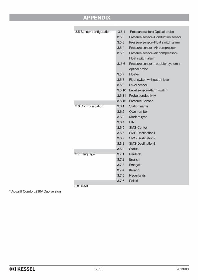
3.5 Sensor-configuration 3.5.1 Pressure switch+Optical probe
3.5.2 Pressure sensor+Conduction sensor
3.5.3 Pressure sensor+Float switch alarm
3.5.4 Pressure sensor+Air compressor
3.5.5 Pressure sensor+Air compressor+
Float switch alarm
3..5.6 Pressure sensor + bubbler system +
optical probe
3.5.7 Floater
3.5.8 Float switch without off level
3.5.9 Level sensor
3.5.10 Level sensor+Alarm switch
3.5.11 Probe conductivity
3.5.12 Pressure Sensor
3.6 Communication 3.6.1 Station name
3.6.2 Own number
3.6.3 Modem type
3.6.4 PIN
3.6.5 SMS-Center
3.6.6 SMS-Destination1
3.6.7 SMS-Destination2
3.6.8 SMS-Destination3
3.6.9 Status
3.7 Language 3.7.1 Deutsch
3.7.2 English
3.7.3 Français
3.7.4 Italiano
3.7.5 Nederlands
3.7.6 Polski
3.8 Reset
* Aqualift Comfort 230V Duo version
57/682019/03
APPENDIX
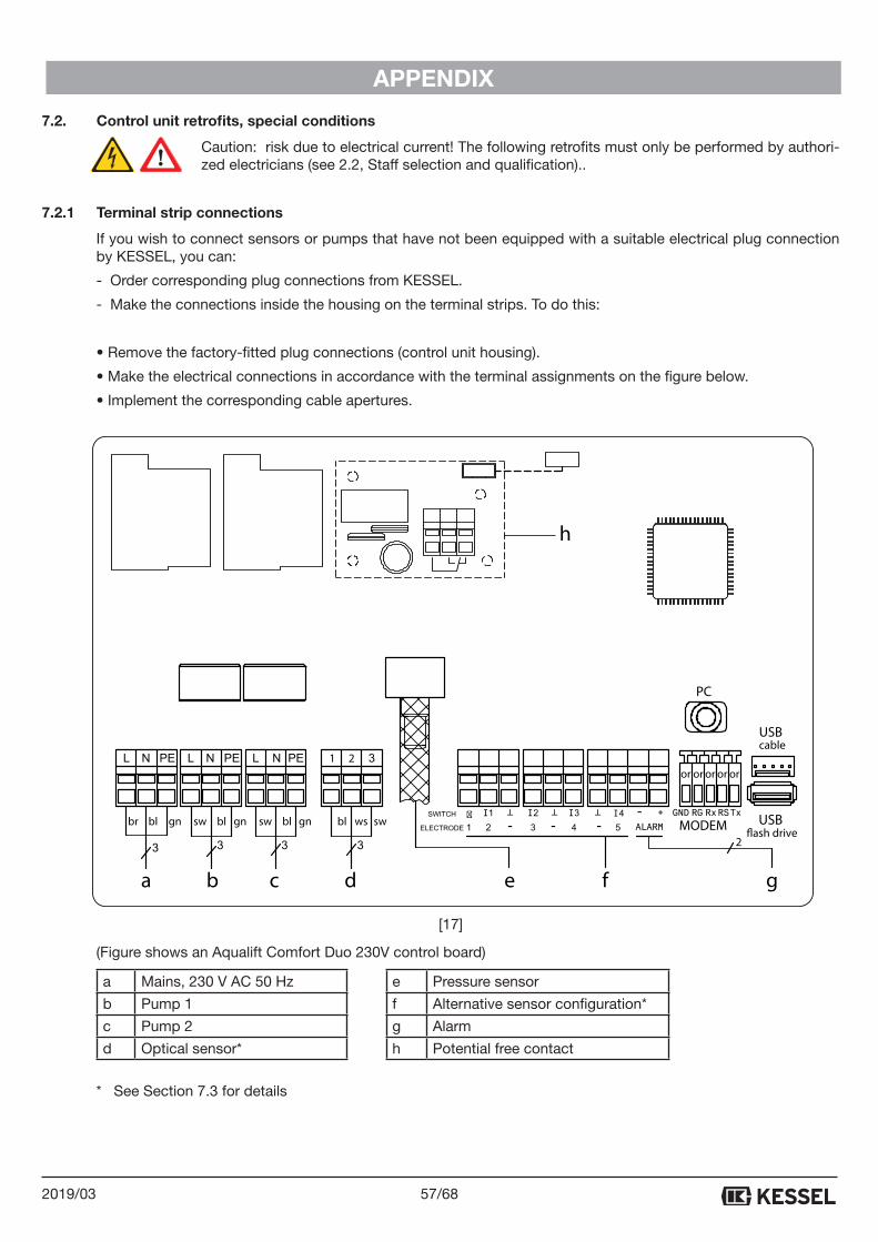
7.2. Control unit retrofits, special conditions
Caution: risk due to electrical current! The following retrofits must only be performed by authori-zed electricians (see 2.2, Staff selection and qualification)..
7.2.1 Terminal strip connections
If you wish to connect sensors or pumps that have not been equipped with a suitable electrical plug connection by KESSEL, you can:
- Order corresponding plug connections from KESSEL.
- Make the connections inside the housing on the terminal strips. To do this:
• Remove the factory-fitted plug connections (control unit housing).
• Make the electrical connections in accordance with the terminal assignments on the figure below.
• Implement the corresponding cable apertures.
(Figure shows an Aqualift Comfort Duo 230V control board)
a Mains, 230 V AC 50 Hz e Pressure sensor
b Pump 1 f Alternative sensor configuration*
c Pump 2 g Alarm
d Optical sensor* h Potential free contact
* See Section 7.3 for details
a b c d e f
PC
TxRSRxRGGND
or or oror or
USBcable
USB�ash driveMODEM
21
I1 I2 I3 I4 - +
ALARM
�
-- -gn wsbr bl gnblsw gnblsw swbl
2
g
h
[17]
58/68 2019/03
APPENDIX
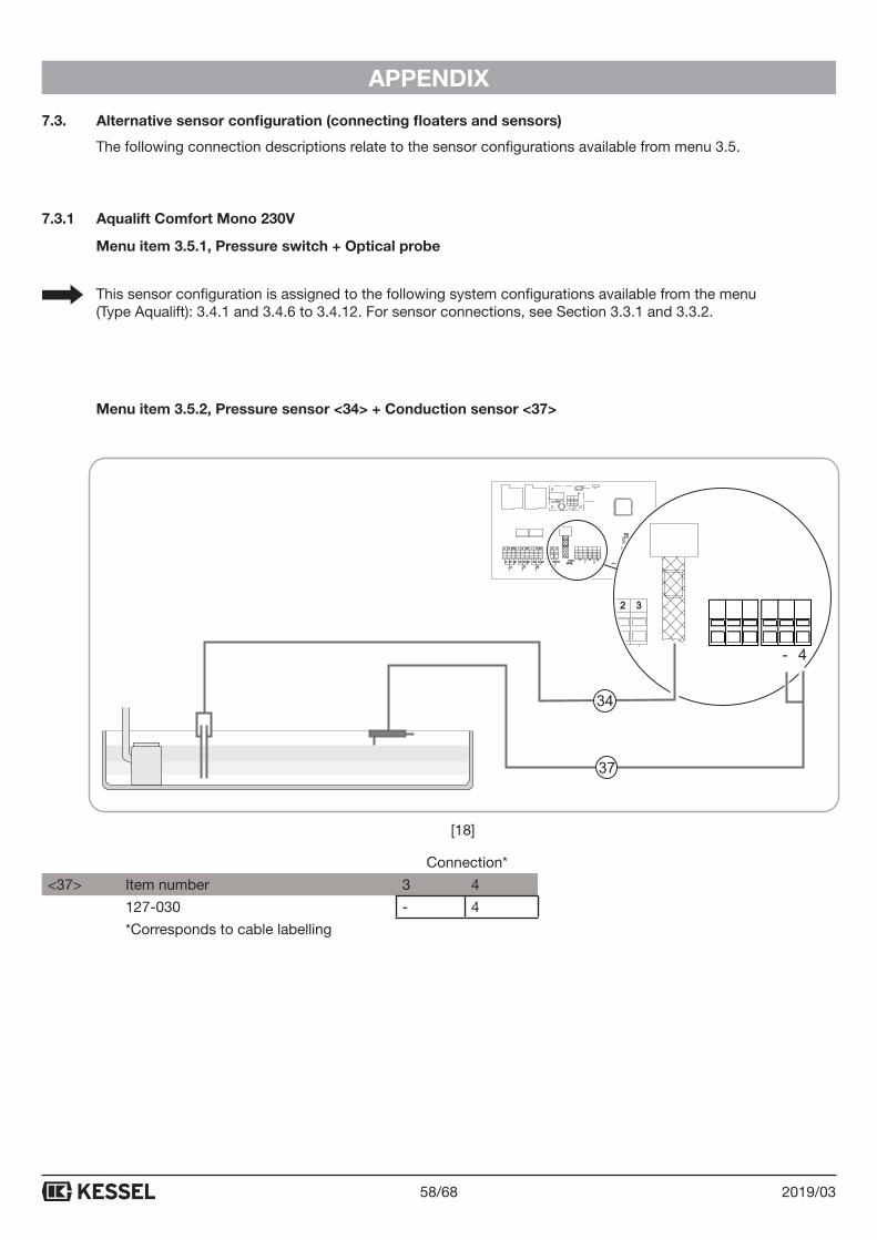
7.3. Alternative sensor configuration (connecting floaters and sensors)
The following connection descriptions relate to the sensor configurations available from menu 3.5.
7.3.1 Aqualift Comfort Mono 230V
Menu item 3.5.1, Pressure switch + Optical probe
This sensor configuration is assigned to the following system configurations available from the menu (Type Aqualift): 3.4.1 and 3.4.6 to 3.4.12. For sensor connections, see Section 3.3.1 and 3.3.2.
Menu item 3.5.2, Pressure sensor <34> + Conduction sensor <37>
Connection*
<37> Item number 3 4
127-030 - 4
*Corresponds to cable labelling
PC
TxRSRxRGGND
or or oror or
USBcable
USBfash drive
MODEM
21
(/(&752'(
I1 �I2 I3 I4 - +�
ALARM-- -gn wsbr bl gnblsw gnblsw swbl�
4321 -
37
34
[18]
59/682019/03
APPENDIX
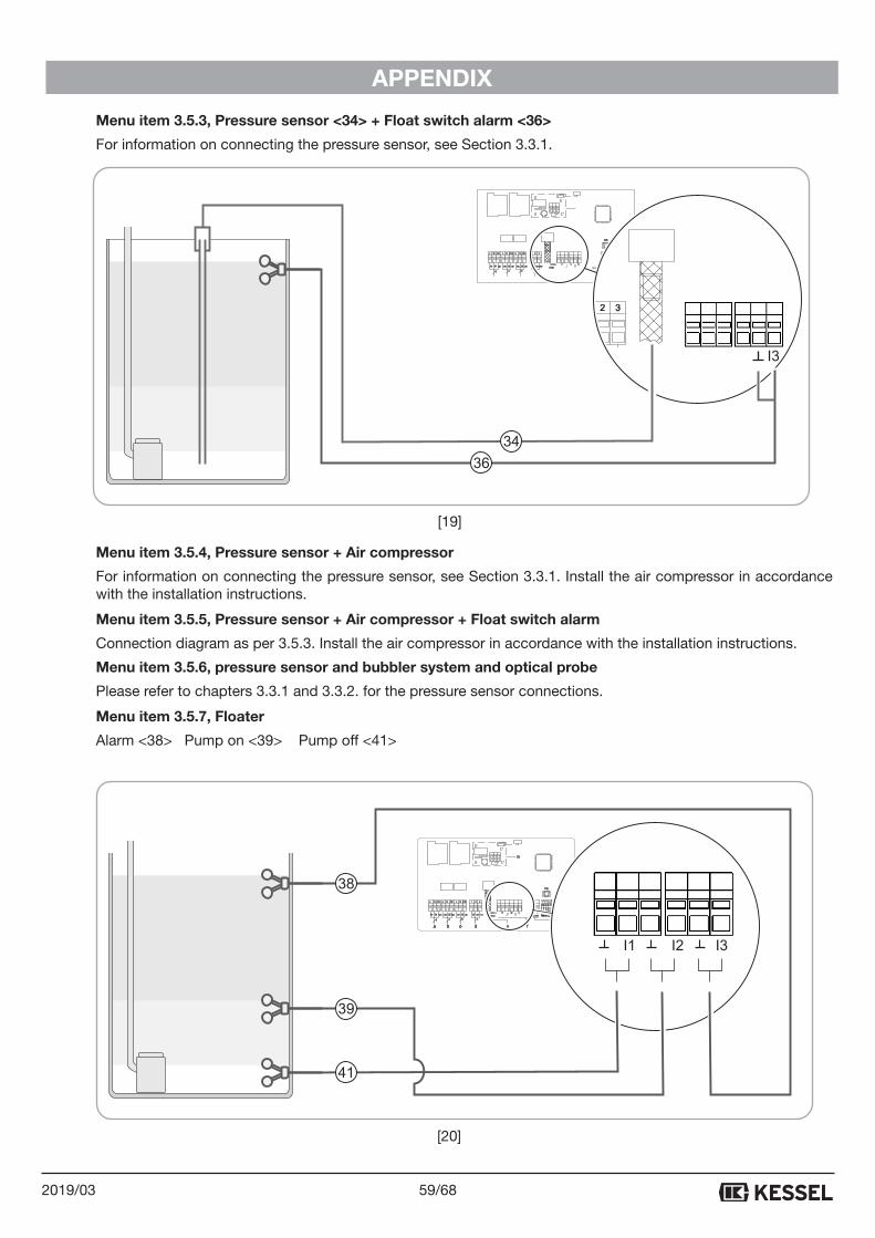
Menu item 3.5.3, Pressure sensor <34> + Float switch alarm <36>
For information on connecting the pressure sensor, see Section 3.3.1.
Menu item 3.5.4, Pressure sensor + Air compressor
For information on connecting the pressure sensor, see Section 3.3.1. Install the air compressor in accordance with the installation instructions.
Menu item 3.5.5, Pressure sensor + Air compressor + Float switch alarm
Connection diagram as per 3.5.3. Install the air compressor in accordance with the installation instructions.
Menu item 3.5.6, pressure sensor and bubbler system and optical probe
Please refer to chapters 3.3.1 and 3.3.2. for the pressure sensor connections.
Menu item 3.5.7, Floater
Alarm <38> Pump on <39> Pump off <41>
PC
TxRSRxRGGND
or or oror or
USBcable
USBfash drive
MODEM
21
(/(&752'(
I1 �I2 I3 I4 - +�
ALARM-- -gn wsbr bl gnblsw gnblsw swbl�
I3
36
34
a b c d e f
PC
TxRSRxRGGND
or or oror or
USBcable
USBfash drive
MODEM
21
(/(&752'(
I1 �I2 I3 I4 - +�
ALARM-- -gn wsbr bl gnblsw gnblsw swbl
2
�
g
h
I1 I2 I3
38
39
41
[19]
[20]
60/68 2019/03
APPENDIX
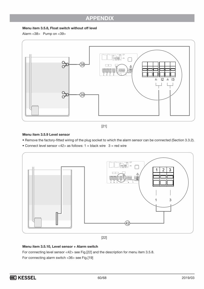
Menu item 3.5.8, Float switch without off level
Alarm <38> Pump on <39>
Menu item 3.5.9 Level sensor
• Remove the factory-fitted wiring of the plug socket to which the alarm sensor can be connected (Section 3.3.2).
• Connect level sensor <42> as follows: 1 = black wire 3 = red wire
Menu item 3.5.10, Level sensor + Alarm switch
For connecting level sensor <42> see Fig.[22] and the description for menu item 3.5.8.
For connecting alarm switch <36> see Fig.[19]
a b c d e f
PC
TxRSRxRGGND
or or oror or
USBcable
USBfash drive
MODEM
21
(/(&752'(
I1 �I2 I3 I4 - +�
ALARM-- -gn wsbr bl gnblsw gnblsw swbl
2
�
g
h
I1 I2 I3
38
39
a b c d e f
PC
TxRSRxRGGND
or or oror or
USBcable
USBfash drive
MODEM
21
(/(&752'(
I1 �I2 I3 I4 - +�
ALARM-- -gn wsbr bl gnblsw gnblsw swbl
2
�
g
h
1 2 3
42
[21]
[22]

61/682019/03
APPENDIX
Menu item 3.5.11, Probe conductivity
EIN-Niveau festgelegt
Connection* Item number 1 2 3 127-033 x x x * Corresponds to cable labelling
ON - level fixed
Connection*
Item number 1 2 3 4
<43> 127-029 x x
<44> 127-030 x x
* Corresponds to cable labelling
On - level variable
Menu item 3.5.12, Pressure Sensor
For information on connecting the pressure sensor, see Section 3.3.1
PC
TxRSRxRGGND
or or oror or
USBcable
USBfash drive
MODEM
21
(/(&752'(
I1 �I2 I3 I4 - +�
ALARM-- -gn wsbr bl gnblsw gnblsw swbl�
a b c d e f
PC
TxRSRxRGGND
or or oror or
USBcable
USBfash drive
MODEM
21
(/(&752'(
I1 �I2 I3 I4 - +�
ALARM-- -gn wsbr bl gnblsw gnblsw swbl
2
�
g
h
2 3 41 - -
43 4437
[23]
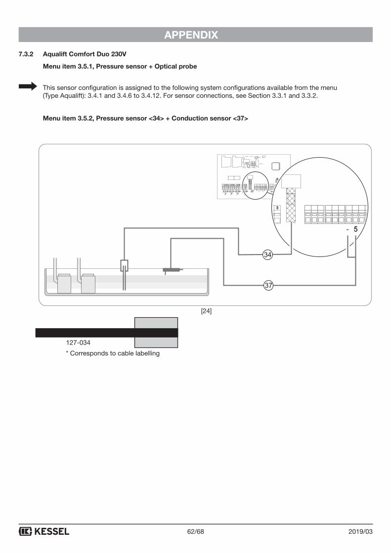
62/68 2019/03
APPENDIX
7.3.2 Aqualift Comfort Duo 230V
Menu item 3.5.1, Pressure sensor + Optical probe
This sensor configuration is assigned to the following system configurations available from the menu (Type Aqualift): 3.4.1 and 3.4.6 to 3.4.12. For sensor connections, see Section 3.3.1 and 3.3.2.
Menu item 3.5.2, Pressure sensor <34> + Conduction sensor <37>
Connection*
<37> Item number 4 5
127-034 - 5
* Corresponds to cable labelling
PC
TxRSRxRGGND
or or oror or
USBcable
USBfash drive
MODEM
21
(/(&752'(
I1 �I2 I3 I4 - +�
ALARM-- -gn wsbr bl gnblsw gnblsw swbl�
321
55-
37
34
[24]
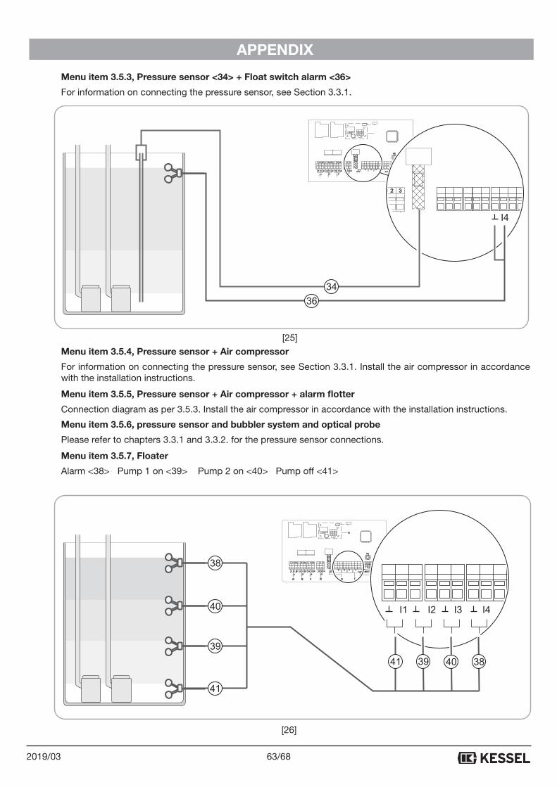
63/682019/03
APPENDIX
Menu item 3.5.3, Pressure sensor <34> + Float switch alarm <36>
For information on connecting the pressure sensor, see Section 3.3.1.
Menu item 3.5.4, Pressure sensor + Air compressor
For information on connecting the pressure sensor, see Section 3.3.1. Install the air compressor in accordance with the installation instructions.
Menu item 3.5.5, Pressure sensor + Air compressor + alarm flotter
Connection diagram as per 3.5.3. Install the air compressor in accordance with the installation instructions.
Menu item 3.5.6, pressure sensor and bubbler system and optical probe
Please refer to chapters 3.3.1 and 3.3.2. for the pressure sensor connections.
Menu item 3.5.7, Floater
Alarm <38> Pump 1 on <39> Pump 2 on <40> Pump off <41>
PC
TxRSRxRGGND
or or oror or
USBcable
USBfash drive
MODEM
21
(/(&752'(
I1 �I2 I3 I4 - +�
ALARM-- -gn wsbr bl gnblsw gnblsw swbl�
321 I4
36
34
a b c d e f
PC
TxRSRxRGGND
or or oror or
USBcable
USBfash drive
MODEM
21
(/(&752'(
I1 �I2 I3 I4 - +�
ALARM-- -gn wsbr bl gnblsw gnblsw swbl
2
�
g
h
I1 I2 I3 I4
38
39
41
40
41 39 40 38
[25]
[26]
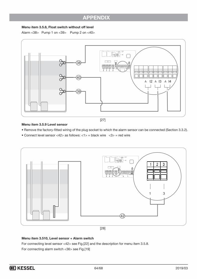
64/68 2019/03
APPENDIX
Menu item 3.5.8, Float switch without off level
Alarm <38> Pump 1 on <39> Pump 2 on <40>
Menu item 3.5.9 Level sensor
• Remove the factory-fitted wiring of the plug socket to which the alarm sensor can be connected (Section 3.3.2).
• Connect level sensor <42> as follows: <1> = black wire <3> = red wire
Menu item 3.510, Level sensor + Alarm switch
For connecting level sensor <42> see Fig.[22] and the description for menu item 3.5.8.
For connecting alarm switch <36> see Fig.[19]
a b c d e f
PC
TxRSRxRGGND
or or oror or
USBcable
USBfash drive
MODEM
21
(/(&752'(
I1 �I2 I3 I4 - +�
ALARM-- -gn wsbr bl gnblsw gnblsw swbl
2
�
g
h
I2 I3 I4
38
39
40
a b c d e f
PC
TxRSRxRGGND
or or oror or
USBcable
USBfash drive
MODEM
21
(/(&752'(
I1 �I2 I3 I4 - +�
ALARM-- -gn wsbr bl gnblsw gnblsw swbl
2
�
g
h
1 2 3
42
[27]
[28]
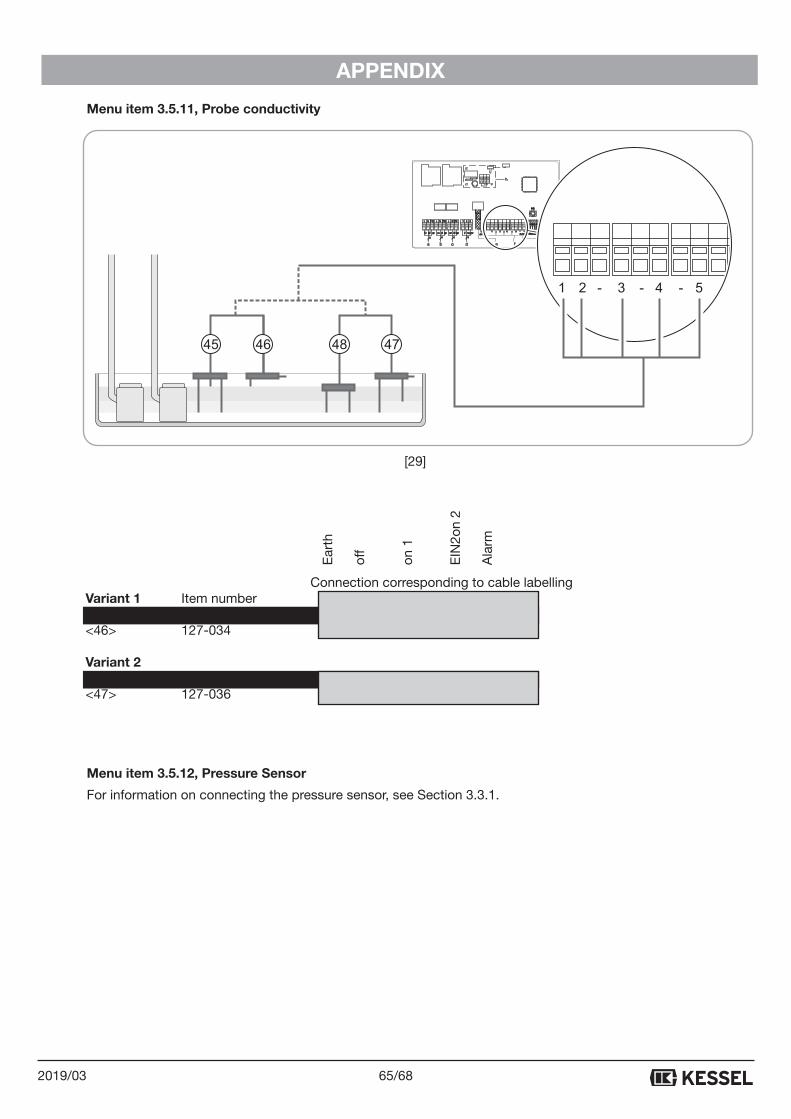
65/682019/03
APPENDIX
Menu item 3.5.11, Probe conductivity
Connection corresponding to cable labelling Variant 1 Item number 1 2 3 4 5 <45> 127-047 x x x <46> 127-034 x x Variant 2 <48> 127-037 x x <47> 127-036 x x x
Menu item 3.5.12, Pressure Sensor
For information on connecting the pressure sensor, see Section 3.3.1.
PC
TxRSRxRGGND
or or oror or
USBcable
USBfash drive
MODEM
21
(/(&752'(
I1 �I2 I3 I4 - +�
ALARM-- -gn wsbr bl gnblsw gnblsw swbl�
a b c d e f
PC
TxRSRxRGGND
or or oror or
USBcable
USBfash drive
MODEM
21
(/(&752'(
I1 �I2 I3 I4 - +�
ALARM-- -gn wsbr bl gnblsw gnblsw swbl
2
�
g
h
3 4 521 - - -
47484645
Ear
th
off
on 1
EIN
2on
2
Ala
rm
[29]
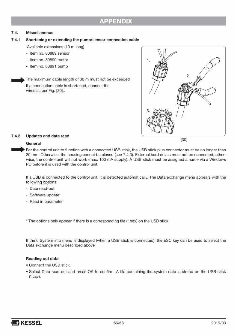
66/68 2019/03
APPENDIX
7.4. Miscellaneous
7.4.1 Shortening or extending the pump/sensor connection cable
Available extensions (10 m long)
- Item no. 80889 sensor
- Item no. 80890 motor
- Item no. 80891 pump
The maximum cable length of 30 m must not be exceeded
If a connection cable is shortened, connect the wires as per Fig. [30]..
7.4.2 Updates and data read
General
For the control unit to function with a connected USB stick, the USB stick plus connector must be no longer than 20 mm. Otherwise, the housing cannot be closed (see 7.4.3). External hard drives must not be connected; other-wise, the control unit will not work (max. 100 mA supply). A USB stick must be assigned a name via a Windows PC before it is used with the control unit.
If a USB is connected to the control unit, it is detected automatically. The Data exchange menu appears with the following options:
- Data read-out
- Software update*
- Read in parameter
* The options only appear if there is a corresponding file (*.hex) on the USB stick
If the 0 System info menu is displayed (when a USB stick is connected), the ESC key can be used to select the Data exchange menu described above
Reading out data
• Connect the USB stick.
• Select Data read-out and press OK to confirm. A file containing the system data is stored on the USB stick (*.csv).
2.
3.
1.
[30]
67/682019/03
APPENDIX
Performing an update
((Only possible when a corresponding file (*.hex) is on the USB stick)
• Connect the USB stick, the Data exchange menu is displayed.
• Select Software update, enter password and press OK to confirm. The update is performed automatically; follow the display dialogue.
Reading in parameters
(Only possible when a corresponding file (*.csv) is on the USB stick)
• Connect the USB stick, the Data exchange menu is displayed.
• Select Read in parameter, enter password and press OK to confirm. The read-in process is performed automatically.
7.4.3 Leading out the USB connection
To enable access to the USB connection on the circuit board without opening the housing, a USB housing port with cable and plug can be ordered from KESSEL for installation in the control unit housing (see 5.1)..
7.4.4 Menüstruktur Expertenmodus
3.9 Expert mode 3.9.1 Power-up delay
3.9.2 Alternating operation
3.9.3 Battery monitoring
3.9.4 Automatic alarm acknowledgement
Note: KESSEL is a registered company name in most countries. Aqualift is a registered trademark or a trademark in most countries.
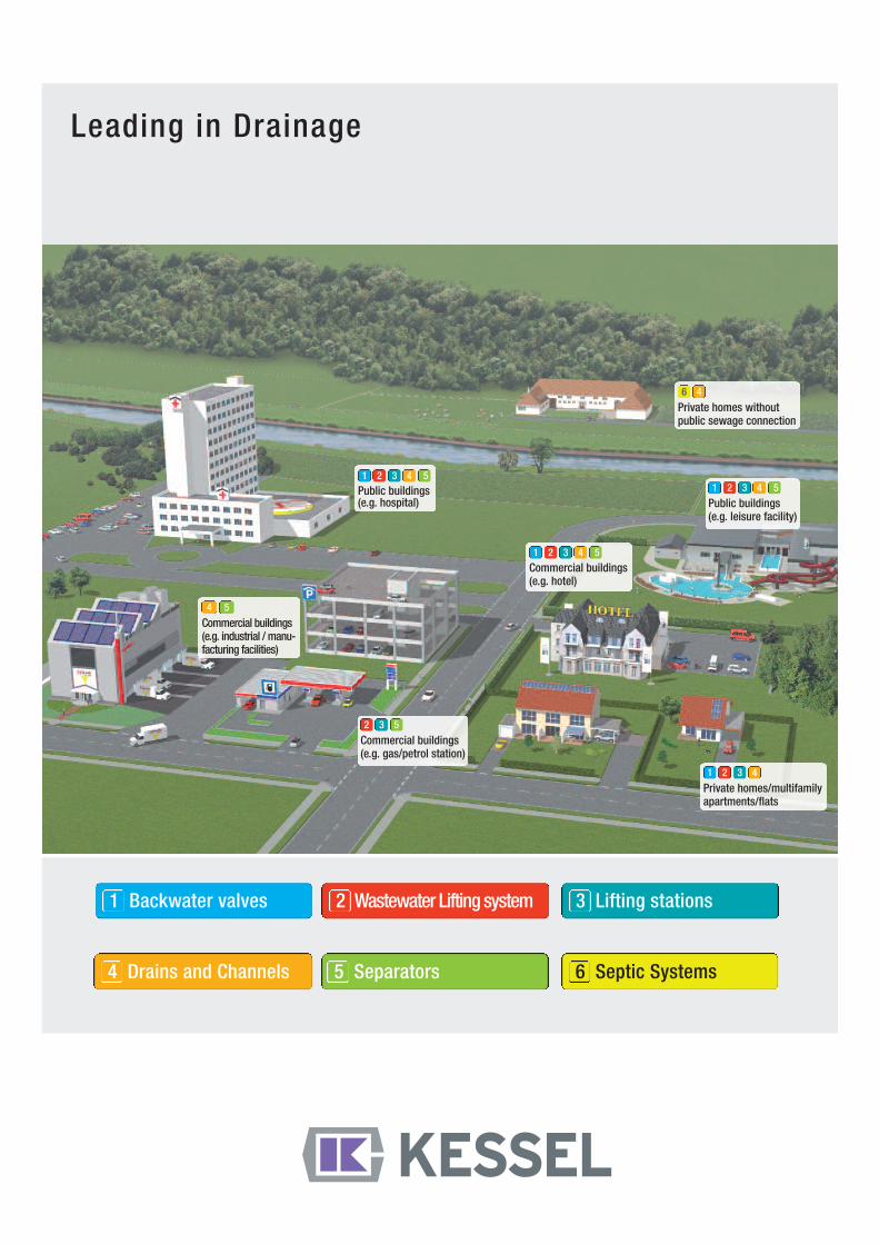
Leading in Drainage
Private homes withoutpublic sewage connection
1 2 3 4 5
Public buildings(e.g. leisure facility)
6 4
Private homes/multifamilyapartments/flats
Commercial buildings(e.g. gas/petrol station)
Commercial buildings(e.g. hotel)
Public buildings(e.g. hospital)
4 5
Commercial buildings(e.g. industrial / manu-facturing facilities)
1 Backwater valves 2 Wastewater Lifting system 3 Lifting stations
4 Drains and Channels 5 Separators 6 Septic Systems
1 2 3 4 5
1 2 3 4 5
1 2 3 4
2 3 5