Ko abelgarnituren für Mittel- und Hochspannungsnetze n ... · with capacitive divider which are in...
21
Kontaktsysteme für Energienetze Contact systems for power networks Kabelgarnituren für Mittel- und Hochspannungsnetze Cable fittings for medium and high voltage networks
Transcript of Ko abelgarnituren für Mittel- und Hochspannungsnetze n ... · with capacitive divider which are in...
04
2 3
80
40
0 /
20
03
Konz
epti
on u
nd G
esta
ltung
:Vis
cher
& B
erne
t Gm
bH,A
gent
ur fü
r Mar
keti
ng u
nd W
erbu
ng,S
tutt
gart
F
ür D
ruck
fehl
er ü
bern
ehm
en w
ir k
eine
Haf
tung
/ T
echn
isch
e Ä
nder
unge
n vo
rbeh
alte
n
We
Can
Ass
ume
no L
iabi
lity
for P
rint
ing
Erro
rs /
Sub
ject
to T
echn
ical
Mod
ific
atio
n
Kontaktsysteme für Energienetze Contact systems for power networks
Kabelgarnituren für Mittel- und HochspannungsnetzeCable fittings for medium and high voltage networks
Kontaktsysteme GmbH & Co. KGRosenstraße 44
73650 WinterbachGermany
Telefon +49 (0)71 81 / 7005-0
Telefax +49 (0)71 81 / 7005-565
Email [email protected]
www.pfisterer.de
Ein Unternehmen der PFISTERER Gruppe
Umschlag 4 23.04.2004 9:36 Uhr Seite 1
Jeff Jhanke
TD
70
4.1 DSA-Spannungsprüfsysteme DSA-Voltage Detecting System
www. .de
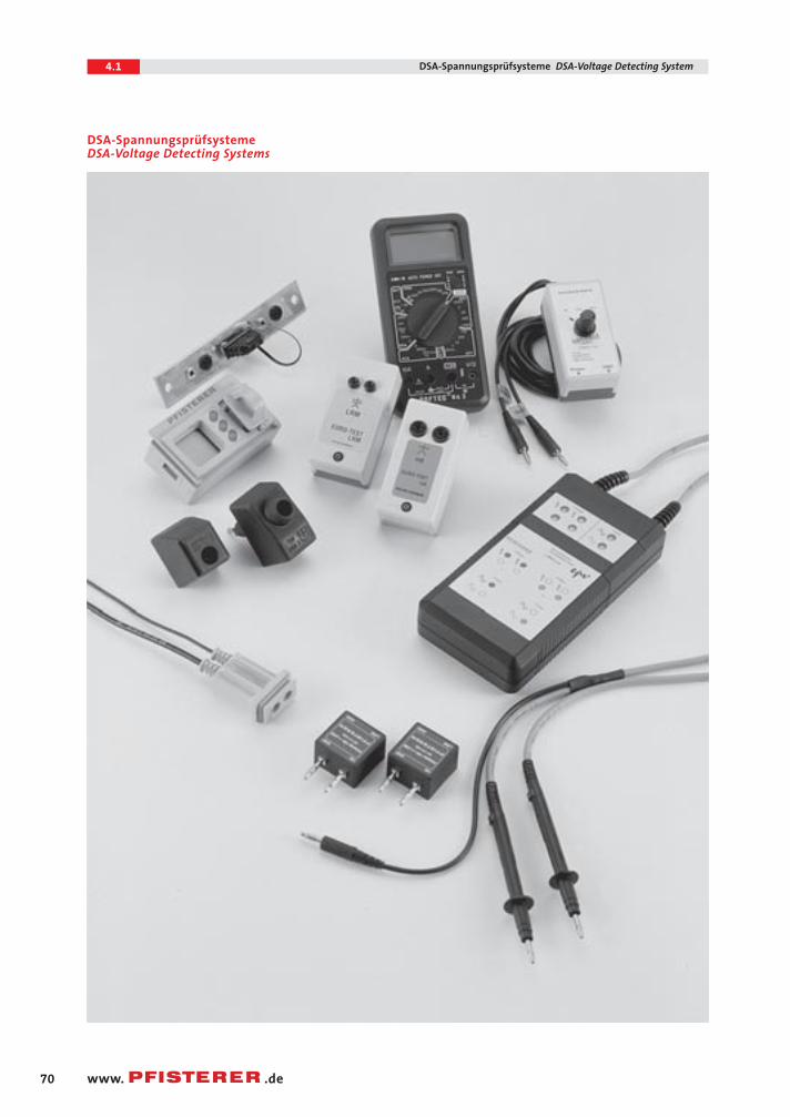
DSA-SpannungsprüfsystemeDSA-Voltage Detecting Systems
04.1 CONNEX 23.04.2004 11:33 Uhr Seite 70
71
4.1DSA-Spannungsprüfsysteme DSA-Voltage Detecting System
www. .de
Spannungsprüfsysteme
Das Feststellen der Spannungsfrei-heit an metallgekapselten Schalt-anlagen und Transformatoren mitsteckbaren berührungssicheren Kabelanschlüssen erfordert einePrüfung mit kapazitivem Span-nungsteiler und Dauerspannungs-anzeiger.Die DIN VDE 0682 Teil 415 definier-te das HR- und LRM-System.Das HR-System (hochohmigesSystem) wird mit folgenden Datencharakterisiert: Lastkapazität von 88 pF (XCmin = 36 MΩ), An-sprechspannung von 90 V und An-sprechstrom 2,5 µA. In Ergänzungdazu das NO-System (niederohmigesSystem): Lastkapazität 1592 pF (XCmin = 2 MΩ), Ansprechspannung5 V und Ansprechstrom 2,5 µA.
Voltage Detecting Systems
The absence of voltage on metal-enclosed switchgear and transformersequipped with plug-in type touch-proof cable terminations is verifiedby a test with a capacitive voltagedivider and a continuous voltageindicator. The HR- and LRM-systemshave been defined in SpecificationDIN VDE 0682 Part 415.The HR-system (high-resistance system) has a specified load capaci-tance of 88 pF (XCmin = 36 MΩ), athreshold voltage of 90 V and athreshold current of 2.5 µA. TheLRM-system (low-resistance system)has a specified load capacitance of1592 pF (XCmin = 2 MΩ), a thresholdvoltage of 5 V, and a threshold cur-rent of 2.5 µA.
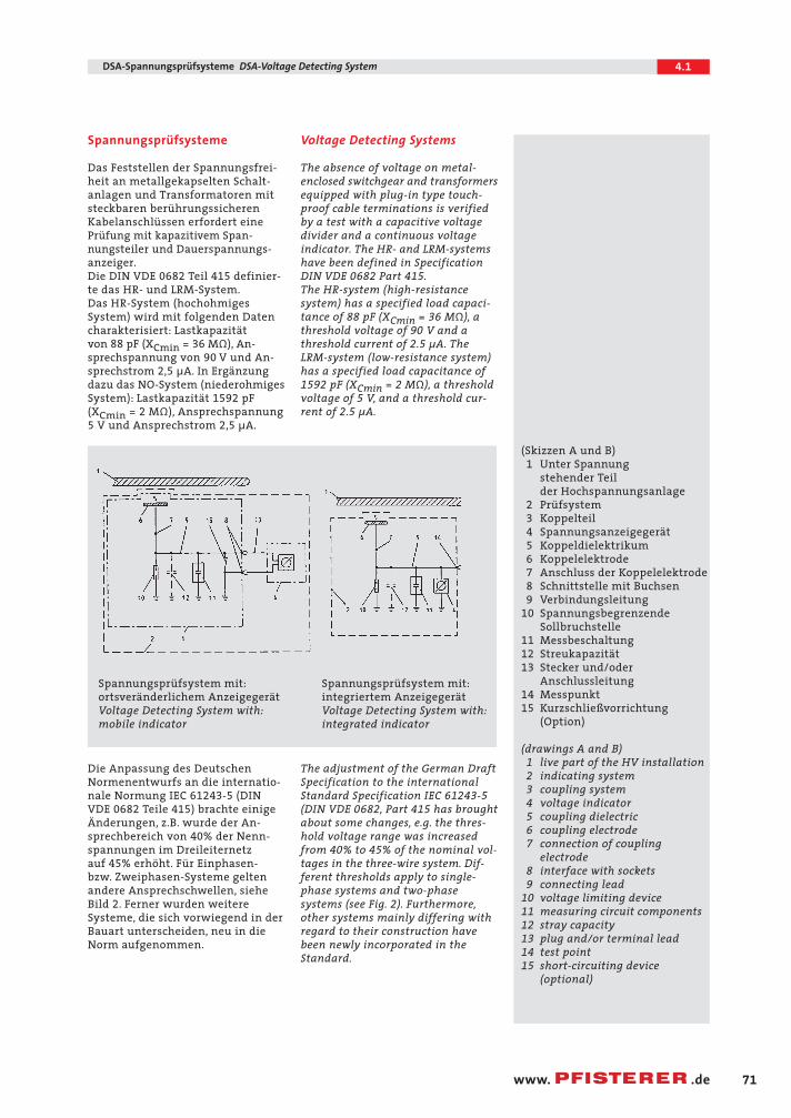
Spannungsprüfsystem mit:ortsveränderlichem AnzeigegerätVoltage Detecting System with:mobile indicator
Spannungsprüfsystem mit:integriertem AnzeigegerätVoltage Detecting System with:integrated indicator
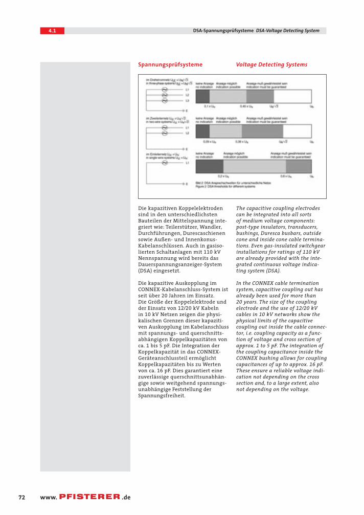
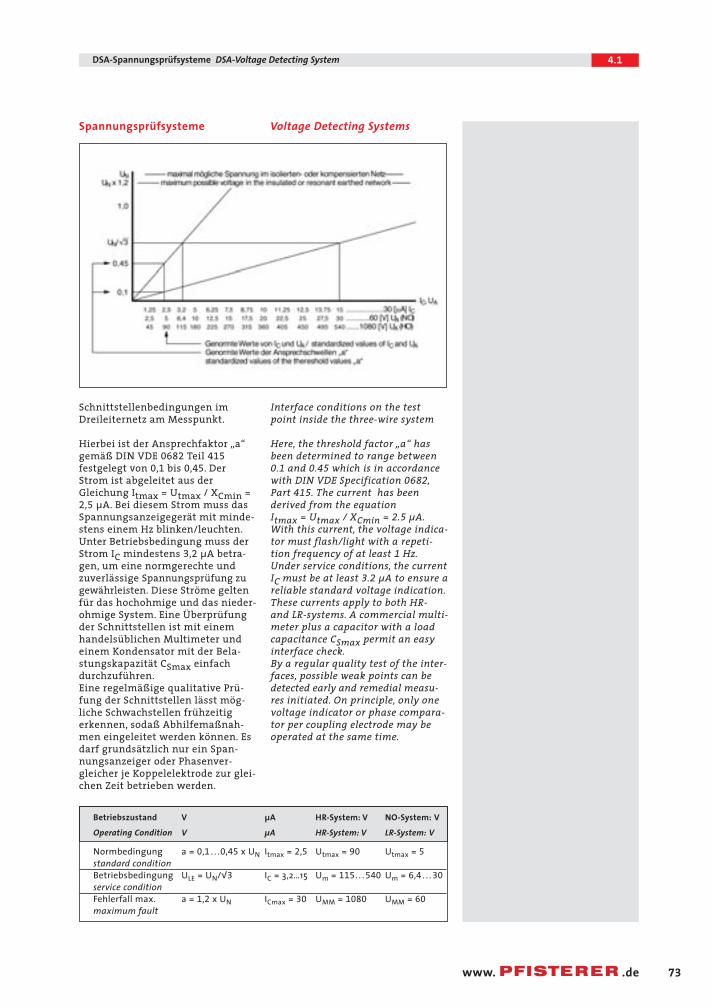
Die Anpassung des Deutschen Normenentwurfs an die internatio-nale Normung IEC 61243-5 (DINVDE 0682 Teile 415) brachte einigeÄnderungen, z.B. wurde der An-sprechbereich von 40% der Nenn-spannungen im Dreileiternetz auf 45% erhöht. Für Einphasen-bzw. Zweiphasen-Systeme geltenandere Ansprechschwellen, sieheBild 2. Ferner wurden weitereSysteme, die sich vorwiegend in derBauart unterscheiden, neu in dieNorm aufgenommen.
The adjustment of the German DraftSpecification to the internationalStandard Specification IEC 61243-5
(DIN VDE 0682, Part 415 has broughtabout some changes, e.g. the thres-hold voltage range was increasedfrom 40% to 45% of the nominal vol-tages in the three-wire system. Dif-ferent thresholds apply to single-phase systems and two-phasesystems (see Fig. 2). Furthermore,other systems mainly differing withregard to their construction havebeen newly incorporated in theStandard.
(Skizzen A und B)1 Unter Spannung
stehender Teil der Hochspannungsanlage
2 Prüfsystem3 Koppelteil4 Spannungsanzeigegerät5 Koppeldielektrikum6 Koppelelektrode7 Anschluss der Koppelelektrode8 Schnittstelle mit Buchsen9 Verbindungsleitung
10 Spannungsbegrenzende Sollbruchstelle
11 Messbeschaltung12 Streukapazität13 Stecker und/oder
Anschlussleitung14 Messpunkt15 Kurzschließvorrichtung
(Option)
(drawings A and B)1 live part of the HV installation2 indicating system3 coupling system4 voltage indicator5 coupling dielectric6 coupling electrode7 connection of coupling
electrode8 interface with sockets9 connecting lead
10 voltage limiting device11 measuring circuit components12 stray capacity13 plug and/or terminal lead14 test point15 short-circuiting device
(optional)
04.1 CONNEX 23.04.2004 11:33 Uhr Seite 71
72
4.1 DSA-Spannungsprüfsysteme DSA-Voltage Detecting System
www. .de
Die kapazitiven Koppelelektrodensind in den unterschiedlichstenBauteilen der Mittelspannung inte-griert wie: Teilerstützer, Wandler,Durchführungen, Durescaschienensowie Außen- und Innenkonus-Kabelanschlüssen. Auch in gasiso-lierten Schaltanlagen mit 110 kVNennspannung wird bereits dasDauerspannungsanzeiger-System(DSA) eingesetzt.
Die kapazitive Auskopplung imCONNEX-Kabelanschluss-System istseit über 20 Jahren im Einsatz.Die Größe der Koppelelektrode undder Einsatz von 12/20 kV Kabeln in 10 kV Netzen zeigen die physi-kalischen Grenzen dieser kapaziti-ven Auskopplung im Kabelanschlussmit spannungs- und querschnitts-abhängigen Koppelkapazitäten vonca. 1 bis 5 pF. Die Integration derKoppelkapazität in das CONNEX-Geräteanschlussteil ermöglichtKoppelkapazitäten bis zu Wertenvon ca. 16 pF. Dies garantiert einezuverlässige querschnittsunabhän-gige sowie weitgehend spannungs-unabhängige Feststellung derSpannungsfreiheit.
The capacitive coupling electrodescan be integrated into all sorts of medium voltage components:post-type insulators, transducers,bushings, Duresca busbars, outsidecone and inside cone cable termina-tions. Even gas-insulated switchgearinstallations for ratings of 110 kVare already provided with the inte-grated continuous voltage indica-ting system (DSA).
In the CONNEX cable terminationsystem, capacitive coupling out hasalready been used for more than 20 years. The size of the couplingelectrode and the use of 12/20 kV cables in 10 kV networks show thephysical limits of the capacitivecoupling out inside the cable connec-tor, i.e. coupling capacity as a func-tion of voltage and cross section ofapprox. 1 to 5 pF. The integration ofthe coupling capacitance inside theCONNEX bushing allows for couplingcapacitances of up to approx. 16 pF.These ensure a reliable voltage indi-cation not depending on the crosssection and, to a large extent, alsonot depending on the voltage.
Spannungsprüfsysteme Voltage Detecting Systems
04.1 CONNEX 23.04.2004 11:34 Uhr Seite 72
73
4.1DSA-Spannungsprüfsysteme DSA-Voltage Detecting System
www. .de
Schnittstellenbedingungen imDreileiternetz am Messpunkt.
Hierbei ist der Ansprechfaktor „a“ gemäß DIN VDE 0682 Teil 415
festgelegt von 0,1 bis 0,45. DerStrom ist abgeleitet aus derGleichung Itmax = Utmax / XCmin =2,5 µA. Bei diesem Strom muss dasSpannungsanzeigegerät mit minde-stens einem Hz blinken/leuchten.Unter Betriebsbedingung muss derStrom IC mindestens 3,2 µA betra-gen, um eine normgerechte undzuverlässige Spannungsprüfung zugewährleisten. Diese Ströme geltenfür das hochohmige und das nieder-ohmige System. Eine Überprüfungder Schnittstellen ist mit einemhandelsüblichen Multimeter undeinem Kondensator mit der Bela-stungskapazität CSmax einfachdurchzuführen.Eine regelmäßige qualitative Prü-fung der Schnittstellen lässt mög-liche Schwachstellen frühzeitigerkennen, sodaß Abhilfemaßnah-men eingeleitet werden können. Esdarf grundsätzlich nur ein Span-nungsanzeiger oder Phasenver-gleicher je Koppelelektrode zur glei-chen Zeit betrieben werden.
Interface conditions on the testpoint inside the three-wire system
Here, the threshold factor „a“ has been determined to range between 0.1 and 0.45 which is in accordancewith DIN VDE Specification 0682,Part 415. The current has been derived from the equation Itmax = Utmax / XCmin = 2.5 µA.With this current, the voltage indica-tor must flash/light with a repeti-tion frequency of at least 1 Hz.Under service conditions, the currentIC must be at least 3.2 µA to ensure areliable standard voltage indication.These currents apply to both HR- and LR-systems. A commercial multi-meter plus a capacitor with a loadcapacitance CSmax permit an easyinterface check.By a regular quality test of the inter-faces, possible weak points can bedetected early and remedial measu-res initiated. On principle, only one voltage indicator or phase compara-tor per coupling electrode may beoperated at the same time.
Betriebszustand V µA HR-System: V NO-System: V
Operating Condition V µA HR-System: V LR-System: V
Normbedingung a = 0,1 . . .0,45 x UN Itmax = 2,5 Utmax = 90 Utmax = 5standard conditionBetriebsbedingung ULE = UN/√3 IC = 3,2…15 Um = 115. . . 540 Um = 6,4 . . . 30service conditionFehlerfall max. a = 1,2 x UN ICmax = 30 UMM = 1080 UMM = 60maximum fault
Spannungsprüfsysteme Voltage Detecting Systems
04.1 CONNEX 23.04.2004 11:34 Uhr Seite 73
74
4.1 DSA-Spannungsprüfsysteme DSA-Voltage Detecting System
www. .de
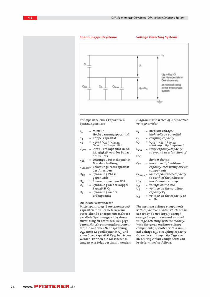
Prinzipskizze eines kapazitivenSpannungsteilers
L1 = Mittel-/ Hochspannungspotential
C1 = KoppelkapazitätC2 = C2W + C2L + CSmax
GesamterdkapazitätC2W = Streu-/Erdkapazität in Ab-
hängigkeit von der Bauart des Teilers
C2L = Leitungs-/Zusatzkapazität,Messbeschaltung
CSmax = Belastungs-/Erdkapazität des Anzeigers
ULE = Spannung Phase gegen Erde
UA = Spannung an dem DSA U1 = Spannung an der Koppel-
kapazität C1U2 = Spannung an der
Erdkapazität
Die heute verwendetenMittelspannungs-Bauelemente mitkapazitivem Teiler liefern keineausreichende Energie, um mehrereparallele Spannungsprüfsystemezuverlässig zu betreiben. Bei gege-benen Mittelspannungskomponen-ten, die mit einer NennspannungUN, einer Koppelkapazität C1 undeiner Streukapazität C2W betriebenwerden, können die Messbeschal-tungen wie folgt bestimmt werden:
Diagrammatic sketch of a capacitivevoltage divider
L1 = medium voltage/high voltage potential
C1 = coupling capacityC2 = C2W + C2L + CSmax,
total capacity to groundC2W = stray capacity/capacity
to ground as a function ofthe
divider designC2L = line capacity/additional
capacity, measuring circuitcomponents
CSmax = load capacitance/capacityto earth of the indicator
ULE = line-to-earth voltageUA = voltage on the DSAU1 = voltage on the coupling
capacity C1U2 = voltage on the capacity to
earth
The medium voltage componentswith capacitive divider which are inuse today do not supply enough energy to operate several parallelvoltage detecting systems reliably.With the given medium-voltagecomponents, operated with a nomi-nal voltage UN, a coupling capacityC1, and a stray capacity C2W, themeasuring circuit components canbe determined as follows:
Spannungsprüfsysteme Voltage Detecting Systems
04.1 CONNEX 23.04.2004 11:34 Uhr Seite 74
75
4.1DSA-Spannungsprüfsysteme DSA-Voltage Detecting System
www. .de
C2Lmin =
C1 x 0,12 x UN -1 - C2W - CSmaxUA
- maximale Kapazität der Mess-leitung einschließlich Zusatzbe-schaltung
- max. capacity of the measuringcircuit, including additional com-ponents
Aus Sicherheitsgründen wird fürdie Bestimmung der Messbeschal-tung C2Lmin und C2Lmax mit demminimalen Anzeigefaktor von 0,12
und dem maximalen Anzeigefaktorvon 0,4 gerechnet.
Beispiel 1:CONNEX-Kabelanschlussteil Gr. 3,400 mm2, 20 kV,HR-System CSmax = 88 pF und Utmax = 90 VUN = 20 kV, C1 = 3,4 pF, C2W = 18,6 pFBerechnung ergibt folgendesErgebnis:C2Lmin = 19,33 pF C2Lmax = 192 pFBei Verwendung eines Standard-Koaxialkabels mit 101 pF/m kann eine Leitungslänge bis 1,9 mrealisiert werden.
Beispiel 2:CONNEX-Kabelanschlussteil Gr. 3,400 mm2, 20 kV,LRM-System CSmax = 1592 pF und Utmax = 5 VUN = 20 kV, C1 = 3,4 pF, C2W = 18,6 pFBerechnung ergibt folgendesErgebnis:C2Lmin = 18 pF C2Lmax = 3826 pFBei Verwendung eines Koaxial-kabels der Standardlänge 6,6 m mit101 pF/m ist keine Zusatzkapazitäterforderlich.
Beispiel 3:CONNEX-Geräteanschlussteil Gr. 3,LRM-System CSmax = 1592 pF und Utmax = 5 VUN = 20 kV, C1 = 16 pF, C2W = 50 pFBerechnung ergibt folgendesErgebnis:C2Lmin = 6022 pF C2Lmax = 23942pFBei Verwendung eines Koaxial-kabels der Standardlänge 6,6 m mit 101 pF/m ist eine Zusatzkapa-zität von ca. 10 nF erforderlich.
For safety reasons, the determinationof the measuring circuit componentsC2Lmin and C2Lmax is based on theminimum indication factor of 0.12
and on the maximum indicationfactor of 0.4.
Example 1:CONNEX separable connector size 3,400 mm2, 20 kV,HR-system CSmax = 88 pF and Utmax = 90 VUN = 20 kV, C1 = 3.4 pF, C2W = 18.6 pFCalculation result:C2Lmin = 19.33 pF C2Lmax = 192 pFWhen using a standard coaxial cablewith 101 pF/m, a line length of up to1.9 m can be realised.
Example 2:CONNEX separable connector size 3,400 mm2, 20 kV,LRM-system CSmax = 1592 pF and Utmax = 5 VUN = 20 kV, C1 = 3.4 pF, C2W = 18.6 pFCalculation result:C2Lmin = 18 pF C2Lmax = 3826 pFWhen using a coaxial cable of astandard length of 6.6 m and with101 pF/m, no additional capacitanceis required.
Example 3:CONNEX bushing size 3,LRM-system CSmax = 1592 pF and Utmax = 5 VUN = 20 kV, C1 = 16 pF, C2W = 50 pFCalculation result:C2Lmin = 6022 pF C2Lmax = 23942 pFWhen using a coaxial cable of astandard length of 6.6 m and with101 pF/m, an additional capacitanceof approx. 10 nF is required.
C2Lmax =
C1 x 0,4 x UN -1 - C2W - CSmaxUA( )
( )C2Lmin =
C1 x 0,12 x UN -1 - C2W - CSmaxUA
C2Lmax =
C1 x 0,4 x UN -1 - C2W - CSmaxUA( )
( )
Spannungsprüfsysteme Voltage Detecting Systems
04.1 CONNEX 23.04.2004 11:34 Uhr Seite 75
76
4.1 DSA-Spannungsprüfsysteme DSA-Voltage Detecting System
www. .de
Spannungsprüfsysteme HR
Bei der Festlegung der Messbeschal-tung muss auch der Anschluss derMessleitung an der Koppelelektrodeberücksichtigt werden. Wegen dergeforderten hohen Isolationsfestig-keit setzen sich mechanisch abge-dichtete Schraubverbindungen undüberschrumpfbare Flachstecksystemedurch. Eine modulare Bauweise desMesspunktmoduls, bei der Messlei-tung und Schnittstelle zu einer Ein-heit verbunden sind, garantierteinen hohen Isolationspegel. Einekostengünstige, einfach zu hand-habende und sichere Montage wur-de hiermit realisiert.
In gasisolierten Schaltanlagen wirddas LRM-System immer häufigereingesetzt. Dieses System wurde inDIN VDE 0682 Teil 415 (IEC 61243-
5) aufgenommen. Elektrisch wur-den die Vorgaben für das NO-System vorgeschrieben. Anstelledes 6-mm-Klinkensteckers aus derUnterhaltungselektronik wurdehier auf ein bewährtes, vollisolier-tes, stoßfestes und wasserdichtesKunststoffgehäuse zurückgegriffen.Der Stiftabstand beträgt 14 mm,somit ist eine Verwechslung mitdem HR-System ausgeschlossen.Alle PFISTERER Dauerspannungsan-zeiger arbeiten ohne Fremdenergie,sind EMV-geprüft und mit dem CE-Kennzeichen versehen.
Integrierte Spannungsprüfsystememit Prüfbuchsen zum Phasenver-gleich. Ein Anschluss zur Fernüber-tragung der Spannungsanzeige sindderzeit in Entwicklung.
Voltage Detecting Systems HR
When determining the measuringcircuit components, the connectionof the measuring circuit to the coup-ling electrode must also be takeninto consideration. Because of thehigh insulation strength required,bolted connections that are mecha-nically sealed and flat-cable plugsystems that are sealed by heat-shrinking are gaining acceptance.A modular design of the test pointmodule, where test lead and inter-face form one unit, guarantees ahigh insulation level. Thus,a cost-effective, easy-to-handle andsafe assembly has been implemented.
In gas-insulated switchgear, theLRM-system is being used ever morefrequently. This system was incorpo-rated into the DIN VDE Specification0682, Part 415 (IEC 61243-5). Regar-ding the electrical requirements, the guidelines for the LRM-system havebeen specified. The 6 mm plugswitch as used in entertainmentelectronics was replaced by a plugwith a time-tried fully-insulated,shockproof and watertight plasticcasing, however with a distance bet-ween the pins of 14 mm to excludeconfusion with the HR-system. AllPFISTERER´s continuous voltage indi-cators operate without externalpower supply. They are EMC-testedand carry the CE marking.
Integrated voltage detecting systemswith test sockets for phase compari-son. A connection for remote trans-mission of the voltage indication iscurrently being developed.
04.1 CONNEX 23.04.2004 11:34 Uhr Seite 76
HR-Messpunktmodul/HR-Test Point Module
Nr. Kapazität Länge Ausführung/Design AnschlussNo. Capacity Length UES = Überspannungsableiter Connection
surge arrester
C = Kondensator/Capacitor
in mm ohne C ohne C mit UES Ringkabelschuh Stecker mit UES Winkelstecker Steckhülse+ Isolierkappe
without C without C with UES Cable Lug for Connector Elbow Connector Pin BushingLink Cable with UES + Insulating
CapA5–2,5 Bz galSN 4.8–0.8 Bz galSN
DIN 46225
827 022 010 190 pF 1900 P P827 022 011 660 pF 6600 P P827 022 012 450 pF 4500 P P
77
4.1DSA-Spannungsprüfsysteme DSA-Voltage Detecting System
www. .de
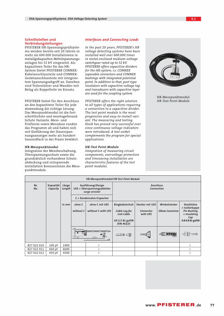
Schnittstellen undVerbindungsleitungen PFISTERER HR-Spannungsprüfsyste-me werden bereits seit 20 Jahren inmehr als 600.000 Installationen inmetallgekapselten Mittelspannungs-anlagen bis 52 kV eingesetzt. Alskapazitiven Teiler für das HR-System bietet PFISTERER CONNEX-Kabelanschlussteile und CONNEX-Geräteanschlussteile mit integrier-tem Spannungsabgriff an. Danebensind Teilerstützer und Wandler mitBelag als Koppelteile im Einsatz.
PFISTERER bietet für den Anschlussan den kapazitiven Teiler für jedeAnwendung die richtige Lösung.Das Messpunktmodul ist die fort-schrittlichste und montagefreund-lichste Variante. Mess- undPrüfleiste sowie Messdose rundendas Programm ab und haben sichseit Einführung der Dauerspan-nungsanzeiger mehr als hundert-tausendfach in der Praxis bewährt.
HR-MesspunktmodulIntegration der Messbeschaltung,Überspannungsschutz sowie diegrundsätzlich vorhandene Schutz-abdeckung und zeitsparendeInstallation kennzeichnen die Mess-punktmodule.
Interfaces and Connecting Leads
In the past 20 years, PFISTERER’s HRvoltage detecting systems have beeninstalled well over 600.000 times in metal-enclosed medium-voltageswitchgear rated up to 52 kV.PFISTERER offers capacitive dividersfor the HR-system, i.e. CONNEXseparable connectors and CONNEXbushings with integrated potentialpoint. In addition to that, post-typeinsulators with capacitive voltage tapand transducers with capacitive layerare used for the coupling system.
PFISTERER offers the right solutionto all types of applications requiring a connection to a capacitive divider.The test point module is the mostprogressive and easy-to-install vari-ant. The measuring and testingblock has proved very successful ever since continuous voltage indicatorswere introduced. A test socketcomplements the program for specialapplications.
HR-Test Point ModuleIntegration of measuring circuitcomponents, overvoltage protectionand timesaving installation are characteristic features of the testpoint modules.
HR-MesspunktmodulHR-Test Point Module
04.1 CONNEX 23.04.2004 11:34 Uhr Seite 77
78
4.1 DSA-Spannungsprüfsysteme DSA-Voltage Detecting System
www. .de
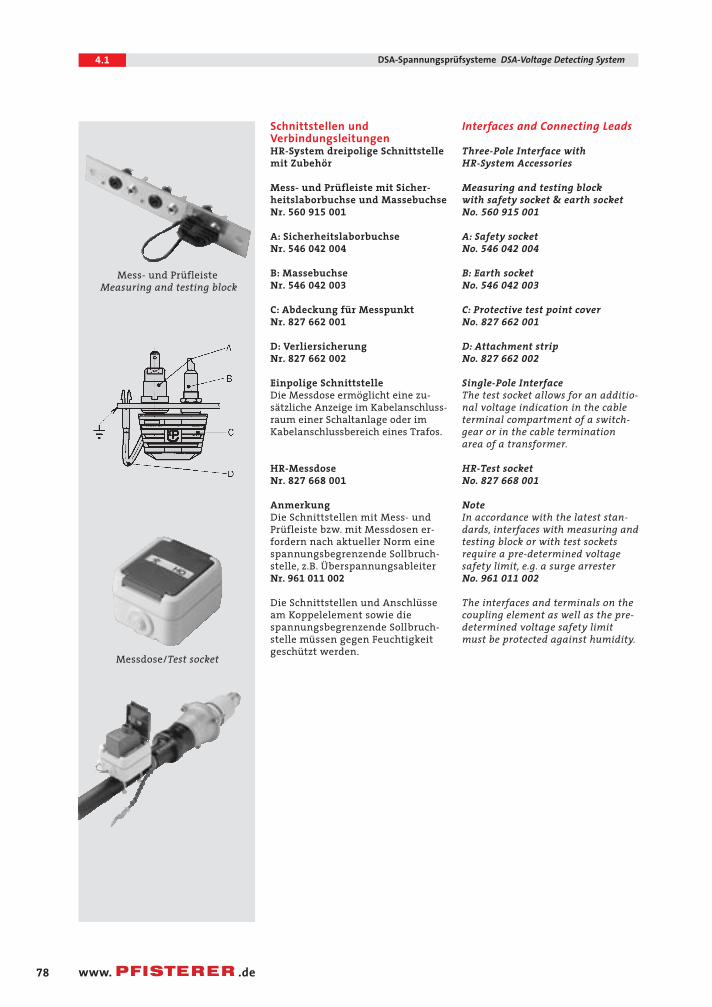
Schnittstellen undVerbindungsleitungen HR-System dreipolige Schnittstellemit Zubehör
Mess- und Prüfleiste mit Sicher-heitslaborbuchse und MassebuchseNr. 560 915 001
A: SicherheitslaborbuchseNr. 546 042 004
B: MassebuchseNr. 546 042 003
C: Abdeckung für MesspunktNr. 827 662 001
D: VerliersicherungNr. 827 662 002
Einpolige SchnittstelleDie Messdose ermöglicht eine zu-sätzliche Anzeige im Kabelanschluss-raum einer Schaltanlage oder imKabelanschlussbereich eines Trafos.
HR-MessdoseNr. 827 668 001
AnmerkungDie Schnittstellen mit Mess- undPrüfleiste bzw. mit Messdosen er-fordern nach aktueller Norm einespannungsbegrenzende Sollbruch-stelle, z.B. ÜberspannungsableiterNr. 961 011 002
Die Schnittstellen und Anschlüsseam Koppelelement sowie diespannungsbegrenzende Sollbruch-stelle müssen gegen Feuchtigkeitgeschützt werden.
Interfaces and Connecting Leads
Three-Pole Interface with HR-System Accessories
Measuring and testing block with safety socket & earth socketNo. 560 915 001
A: Safety socketNo. 546 042 004
B: Earth socketNo. 546 042 003
C: Protective test point coverNo. 827 662 001
D: Attachment stripNo. 827 662 002
Single-Pole InterfaceThe test socket allows for an additio-nal voltage indication in the cableterminal compartment of a switch-gear or in the cable terminationarea of a transformer.
HR-Test socketNo. 827 668 001
NoteIn accordance with the latest stan-dards, interfaces with measuring andtesting block or with test socketsrequire a pre-determined voltagesafety limit, e.g. a surge arrester No. 961 011 002
The interfaces and terminals on thecoupling element as well as the pre-determined voltage safety limitmust be protected against humidity.
Mess- und PrüfleisteMeasuring and testing block
Messdose/Test socket
04.1 CONNEX 23.04.2004 11:34 Uhr Seite 78
79
4.1DSA-Spannungsprüfsysteme DSA-Voltage Detecting System
www. .de
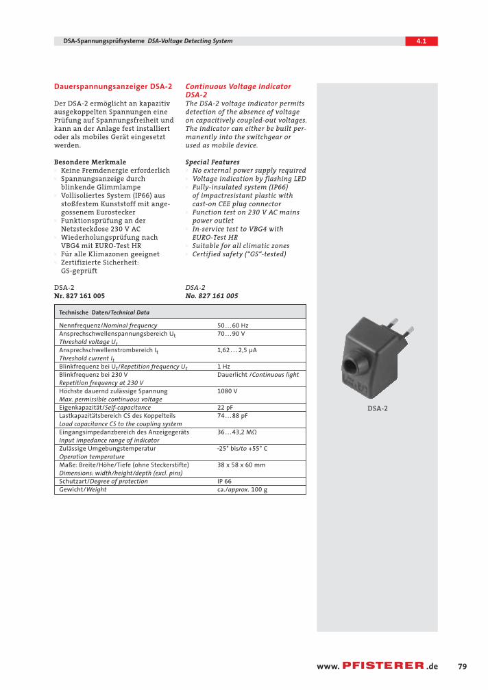
Dauerspannungsanzeiger DSA-2
Der DSA-2 ermöglicht an kapazitivausgekoppelten Spannungen einePrüfung auf Spannungsfreiheit undkann an der Anlage fest installiertoder als mobiles Gerät eingesetztwerden.
Besondere MerkmaleW Keine Fremdenergie erforderlichW Spannungsanzeige durch
blinkende GlimmlampeW Vollisoliertes System (IP66) aus
stoßfestem Kunststoff mit ange-gossenem Eurostecker
W Funktionsprüfung an der Netzsteckdose 230 V AC
W Wiederholungsprüfung nach VBG4 mit EURO-Test HR
W Für alle Klimazonen geeignetW Zertifizierte Sicherheit:
GS-geprüft
DSA-2
Nr. 827 161 005
Continuous Voltage IndicatorDSA-2
The DSA-2 voltage indicator permitsdetection of the absence of voltageon capacitively coupled-out voltages.The indicator can either be built per-manently into the switchgear orused as mobile device.
Special FeaturesW No external power supply requiredW Voltage indication by flashing LEDW Fully-insulated system (IP66)
of impactresistant plastic with cast-on CEE plug connector
W Function test on 230 V AC mains power outlet
W In-service test to VBG4 with EURO-Test HR
W Suitable for all climatic zonesW Certified safety (“GS“-tested)
DSA-2
No. 827 161 005
Technische Daten/Technical Data
Nennfrequenz/Nominal frequency 50 . . . 60 HzAnsprechschwellenspannungsbereich Ut 70 . . . 90 VThreshold voltage UtAnsprechschwellenstrombereich It 1,62 . . . 2,5 µAThreshold current ItBlinkfrequenz bei Ut/Repetition frequency Ut 1 HzBlinkfrequenz bei 230 V Dauerlicht /Continuous lightRepetition frequency at 230 VHöchste dauernd zulässige Spannung 1080 VMax. permissible continuous voltageEigenkapazität/Self-capacitance 22 pFLastkapazitätsbereich CS des Koppelteils 74 . . . 88 pFLoad capacitance CS to the coupling systemEingangsimpedanzbereich des Anzeigegeräts 36 . . . 43,2 MΩ
Input impedance range of indicatorZulässige Umgebungstemperatur –25° bis/to +55° COperation temperatureMaße: Breite/Höhe/Tiefe (ohne Steckerstifte) 38 x 58 x 60 mmDimensions: width/height/depth (excl. pins)Schutzart/Degree of protection IP 66
Gewicht/Weight ca./approx. 100 g
DSA-2
04.1 CONNEX 23.04.2004 11:34 Uhr Seite 79
80
4.1 DSA-Spannungsprüfsysteme DSA-Voltage Detecting System
www. .de
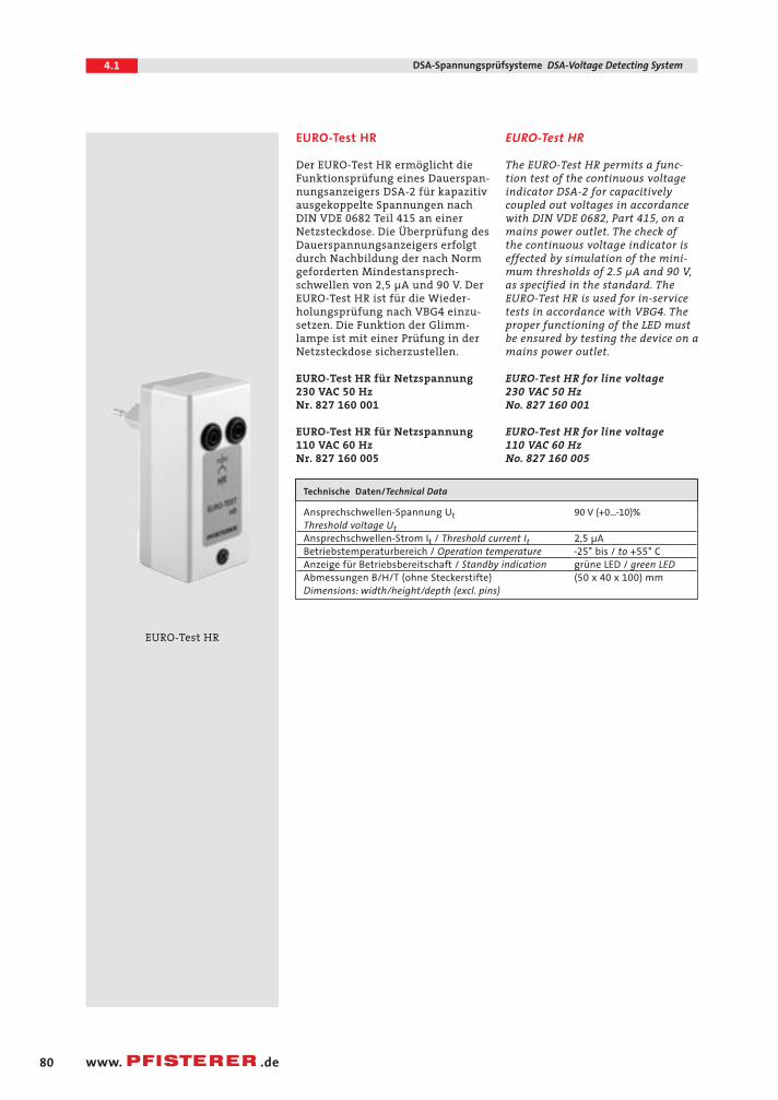
EURO-Test HR
Der EURO-Test HR ermöglicht dieFunktionsprüfung eines Dauerspan-nungsanzeigers DSA-2 für kapazitivausgekoppelte Spannungen nachDIN VDE 0682 Teil 415 an einerNetzsteckdose. Die Überprüfung desDauerspannungsanzeigers erfolgtdurch Nachbildung der nach Normgeforderten Mindestansprech-schwellen von 2,5 µA und 90 V. DerEURO-Test HR ist für die Wieder-holungsprüfung nach VBG4 einzu-setzen. Die Funktion der Glimm-lampe ist mit einer Prüfung in derNetzsteckdose sicherzustellen.
EURO-Test HR für Netzspannung 230 VAC 50 HzNr. 827 160 001
EURO-Test HR für Netzspannung 110 VAC 60 HzNr. 827 160 005
EURO-Test HR
The EURO-Test HR permits a func-tion test of the continuous voltageindicator DSA-2 for capacitively coupled out voltages in accordancewith DIN VDE 0682, Part 415, on amains power outlet. The check of the continuous voltage indicator iseffected by simulation of the mini-mum thresholds of 2.5 µA and 90 V,as specified in the standard. The EURO-Test HR is used for in-servicetests in accordance with VBG4. Theproper functioning of the LED must be ensured by testing the device on amains power outlet.
EURO-Test HR for line voltage 230 VAC 50 Hz No. 827 160 001
EURO-Test HR for line voltage 110 VAC 60 Hz No. 827 160 005
Technische Daten/Technical Data
Ansprechschwellen-Spannung Ut 90 V (+0…–10)%
Threshold voltage UtAnsprechschwellen-Strom It / Threshold current It 2,5 µABetriebstemperaturbereich / Operation temperature –25° bis / to +55° CAnzeige für Betriebsbereitschaft / Standby indication grüne LED / green LEDAbmessungen B/H/T (ohne Steckerstifte) (50 x 40 x 100) mmDimensions: width/height/depth (excl. pins)
EURO-Test HR
04.1 CONNEX 23.04.2004 11:34 Uhr Seite 80
81
4.1DSA-Spannungsprüfsysteme DSA-Voltage Detecting System
www. .de
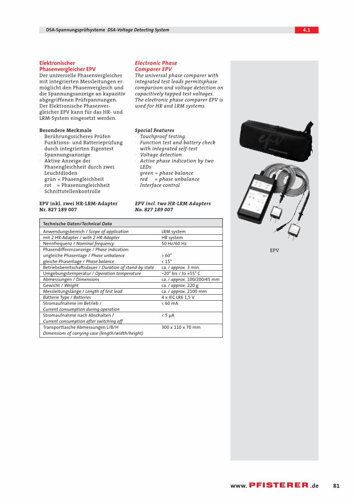
Elektronischer Phasenvergleicher EPVDer universelle Phasenvergleichermit integrierten Messleitungen er-möglicht den Phasenvergleich unddie Spannungsanzeige an kapazitivabgegriffenen Prüfspannungen.Der Elektronische Phasenver-gleicher EPV kann für das HR- undLRM-System eingesetzt werden.
Besondere MerkmaleW Berührungssicheres PrüfenW Funktions- und Batterieprüfung
durch integrierten EigentestW SpannungsanzeigeW Aktive Anzeige der
Phasengleichheit durch zwei Leuchtdiodengrün = Phasengleichheitrot = Phasenungleichheit
W Schnittstellenkontrolle
EPV inkl. zwei HR-LRM-AdapterNr. 827 189 007
Electronic Phase Comparer EPV The universal phase comparer withintegrated test leads permitsphasecomparison and voltage detection oncapacitively tapped test voltages.The electronic phase comparer EPV isused for HR and LRM systems.
Special FeaturesW Touchproof testingW Function test and battery check
with integrated self-testW Voltage detectionW Active phase indication by two
LEDs:green = phase balancered = phase unbalance
W Interface control
EPV incl. two HR-LRM AdaptersNo. 827 189 007
Technische Daten/Technical Data
Anwendungsbereich / Scope of application LRM systemmit 2 HR-Adapter / with 2 HR-Adapter HR systemNennfrequenz / Nominal frequency 50 Hz/60 HzPhasendifferenzanzeige / Phase indication:ungleiche Phasenlage / Phase unbalance > 60°gleiche Phasenlage / Phase balance < 15°Betriebsbereitschaftsdauer / Duration of stand-by state ca. / approx. 3 min.Umgebungstemperatur / Operation temperature –20° bis / to +55° CAbmessungen / Dimensions ca. / approx. 100/200/45 mmGewicht / Weight ca. / approx. 220 gMessleitungslänge / Length of test lead ca. / approx. 2100 mmBatterie Type / Batteries 4 x IEC LR6 1,5 VStromaufnahme im Betrieb / < 60 mACurrent consumption during operationStromaufnahme nach Abschalten / < 5 µACurrent consumption after switching offTransporttasche Abmessungen L/B/H 300 x 110 x 70 mmDimensions of carrying case (length/width/height)
EPV
04.1 CONNEX 23.04.2004 11:34 Uhr Seite 81
82
4.1 DSA-Spannungsprüfsysteme DSA-Voltage Detecting System
www. .de
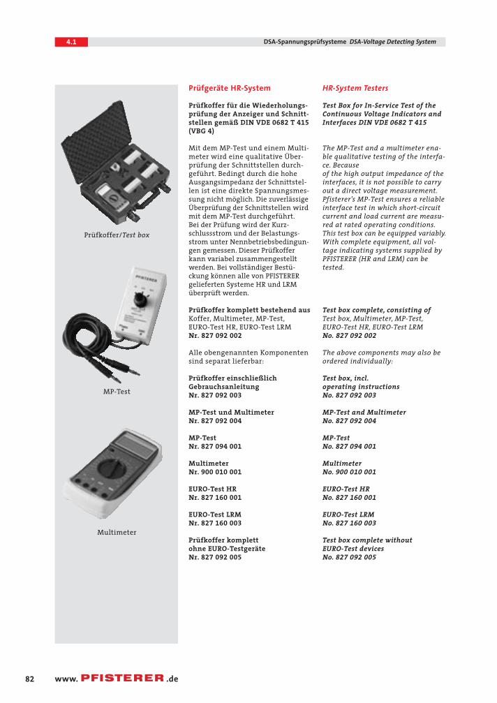
Prüfgeräte HR-System
Prüfkoffer für die Wiederholungs-prüfung der Anzeiger und Schnitt-stellen gemäß DIN VDE 0682 T 415
(VBG 4)
Mit dem MP-Test und einem Multi-meter wird eine qualitative Über-prüfung der Schnittstellen durch-geführt. Bedingt durch die hoheAusgangsimpedanz der Schnittstel-len ist eine direkte Spannungsmes-sung nicht möglich. Die zuverlässige Überprüfung der Schnittstellen wirdmit dem MP-Test durchgeführt.Bei der Prüfung wird der Kurz-schlussstrom und der Belastungs-strom unter Nennbetriebsbedingun-gen gemessen. Dieser Prüfkofferkann variabel zusammengestelltwerden. Bei vollständiger Bestü-ckung können alle von PFISTERERgelieferten Systeme HR und LRMüberprüft werden.
Prüfkoffer komplett bestehend aus Koffer, Multimeter, MP-Test,EURO-Test HR, EURO-Test LRMNr. 827 092 002
Alle obengenannten Komponentensind separat lieferbar:
Prüfkoffer einschließlichGebrauchsanleitungNr. 827 092 003
MP-Test und MultimeterNr. 827 092 004
MP-TestNr. 827 094 001
MultimeterNr. 900 010 001
EURO-Test HRNr. 827 160 001
EURO-Test LRMNr. 827 160 003
Prüfkoffer komplettohne EURO-TestgeräteNr. 827 092 005
HR-System Testers
Test Box for In-Service Test of theContinuous Voltage Indicators andInterfaces DIN VDE 0682 T 415
The MP-Test and a multimeter ena-ble qualitative testing of the interfa-ce. Because of the high output impedance of theinterfaces, it is not possible to carryout a direct voltage measurement.Pfisterer’s MP-Test ensures a reliableinterface test in which short-circuitcurrent and load current are measu-red at rated operating conditions.This test box can be equipped variably.With complete equipment, all vol-tage indicating systems supplied byPFISTERER (HR and LRM) can betested.
Test box complete, consisting ofTest box, Multimeter, MP-Test,EURO-Test HR, EURO-Test LRMNo. 827 092 002
The above components may also be ordered individually:
Test box, incl.operating instructionsNo. 827 092 003
MP-Test and MultimeterNo. 827 092 004
MP-TestNo. 827 094 001
MultimeterNo. 900 010 001
EURO-Test HRNo. 827 160 001
EURO-Test LRMNo. 827 160 003
Test box complete without EURO-Test devicesNo. 827 092 005
Prüfkoffer/Test box
MP-Test
Multimeter
04.1 CONNEX 23.04.2004 11:34 Uhr Seite 82
83
4.1DSA-Spannungsprüfsysteme DSA-Voltage Detecting System
www. .de
Spannungsprüfsysteme LRM
Das Spannungsprüfsystem LRM istvon den elektrischen Werten iden-tisch mit dem System LR. Unter-scheidungsmerkmal zu diesem istder Stiftabstand von 14 mm. Konse-quente Integration des Überspan-nungsableiters, der Messbeschaltungund der Messleitung in das Mess-punktmodul garantieren zusammenmit dem DauerspannungsanzeigerDSA-LRM und dem ElektronischenPhasenvergleicher EPV die zu-verlässige Anzeige und den Phasen-vergleich.
PFISTERER bietet für den Anschlussan den kapazitiven Teiler für jedeAnwendung die richtige Lösung. DasMesspunktmodul ist die fortschritt-lichste und montagefreundlichsteVariante. Die Integration der Mess-beschaltung, der Überspannungs-schutz sowie die grundsätzlich vor-handene Schutzabdeckung und diezeitsparende Installation kennzeich-nen diese Messpunktmodule.
Voltage Detecting System LRM
The LRM voltage detecting system is identical to the LR-system asfar as the electrical values are
concerned. The continuous voltageindicator DSA-LRM is howevercharacterised by a pin distance of 14 mm. The consistent integration of surge arrester, measuring circuitcomponents and test lead into thetest point module, along with thecontinuous voltage indicator DSA-LRM and the electronic phase com-parator EPV, ensure a reliable volta-ge indication and phase comparison.
PFISTERER offers the right solutionfor all types of applications requi-ring a connection to a capacitivedivider. The test point module is themost progressive and easy-to installvariant. The integration of the mea-suring circuit components, the over-voltage protection as well as the pro-tective cover that is always providedand the time-saving installation arespecial features of these test pointmodules.
04.1 CONNEX 23.04.2004 11:34 Uhr Seite 83
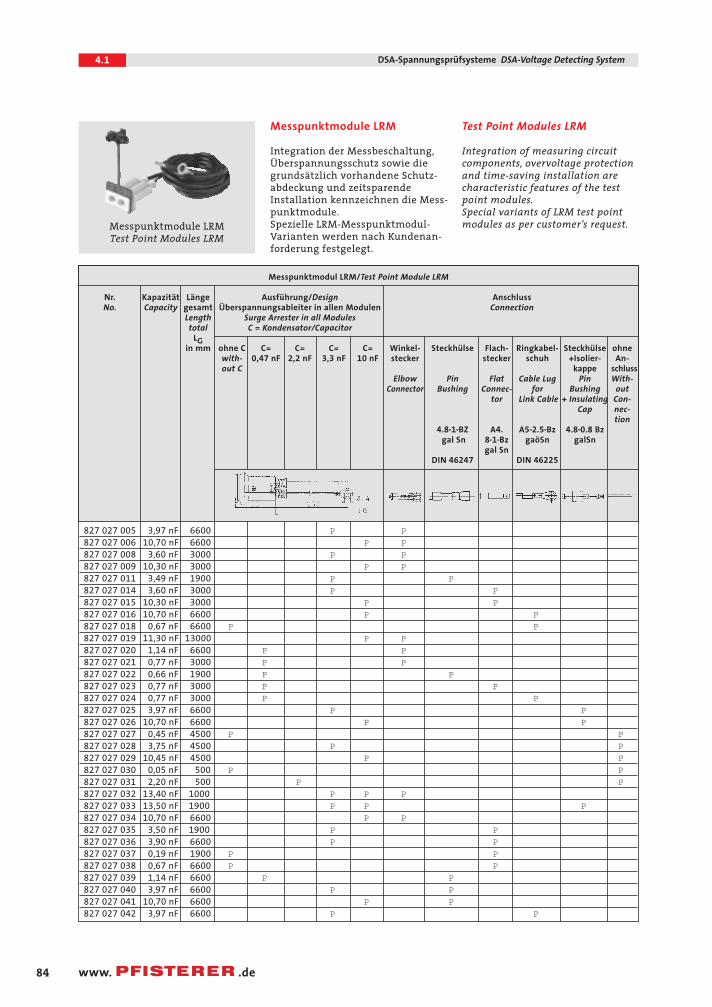
Messpunktmodul LRM/Test Point Module LRM
Nr. Kapazität Länge Ausführung/Design AnschlussNo. Capacity gesamt Überspannungsableiter in allen Modulen Connection
Length Surge Arrester in all Modulestotal C = Kondensator/Capacitor
LGin mm ohne C C= C= C= C= Winkel- Steckhülse Flach- Ringkabel- Steckhülse ohne
with- 0,47 nF 2,2 nF 3,3 nF 10 nF stecker stecker schuh +Isolier- An-out C kappe schluss
Elbow Pin Flat Cable Lug Pin With-Connector Bushing Connec- for Bushing out
tor Link Cable + Insulating Con-Cap nec-
tion4.8–1–BZ A4. A5–2.5–Bz 4.8–0.8 Bz
gal Sn 8–1–Bz gaöSn galSngal Sn
DIN 46247 DIN 46225
827 027 005 3,97 nF 6600 P P827 027 006 10,70 nF 6600 P P827 027 008 3,60 nF 3000 P P827 027 009 10,30 nF 3000 P P827 027 011 3,49 nF 1900 P P827 027 014 3,60 nF 3000 P P827 027 015 10,30 nF 3000 P P827 027 016 10,70 nF 6600 P P827 027 018 0,67 nF 6600 P P827 027 019 11,30 nF 13000 P P827 027 020 1,14 nF 6600 P P827 027 021 0,77 nF 3000 P P827 027 022 0,66 nF 1900 P P827 027 023 0,77 nF 3000 P P827 027 024 0,77 nF 3000 P P827 027 025 3,97 nF 6600 P P827 027 026 10,70 nF 6600 P P827 027 027 0,45 nF 4500 P P827 027 028 3,75 nF 4500 P P827 027 029 10,45 nF 4500 P P827 027 030 0,05 nF 500 P P827 027 031 2,20 nF 500 P P827 027 032 13,40 nF 1000 P P P827 027 033 13,50 nF 1900 P P P827 027 034 10,70 nF 6600 P P827 027 035 3,50 nF 1900 P P827 027 036 3,90 nF 6600 P P827 027 037 0,19 nF 1900 P P827 027 038 0,67 nF 6600 P P827 027 039 1,14 nF 6600 P P827 027 040 3,97 nF 6600 P P827 027 041 10,70 nF 6600 P P827 027 042 3,97 nF 6600 P P
84
4.1 DSA-Spannungsprüfsysteme DSA-Voltage Detecting System
www. .de
Messpunktmodule LRM
Integration der Messbeschaltung,Überspannungsschutz sowie diegrundsätzlich vorhandene Schutz-abdeckung und zeitsparende Installation kennzeichnen die Mess-punktmodule.Spezielle LRM-Messpunktmodul-Varianten werden nach Kundenan-forderung festgelegt.
Test Point Modules LRM
Integration of measuring circuitcomponents, overvoltage protectionand time-saving installation arecharacteristic features of the testpoint modules.Special variants of LRM test pointmodules as per customer’s request.Messpunktmodule LRM
Test Point Modules LRM
04.1 CONNEX 23.04.2004 11:34 Uhr Seite 84
85
4.1DSA-Spannungsprüfsysteme DSA-Voltage Detecting System
www. .de
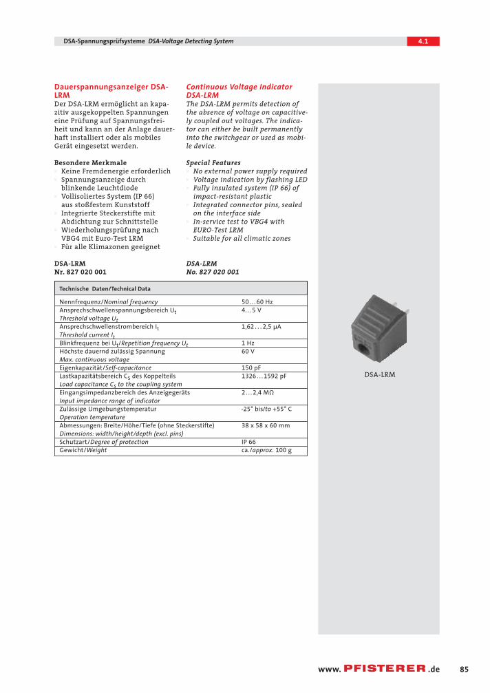
Dauerspannungsanzeiger DSA-LRM Der DSA-LRM ermöglicht an kapa-zitiv ausgekoppelten Spannungeneine Prüfung auf Spannungsfrei-heit und kann an der Anlage dauer-haft installiert oder als mobilesGerät eingesetzt werden.
Besondere MerkmaleW Keine Fremdenergie erforderlichW Spannungsanzeige durch
blinkende LeuchtdiodeW Vollisoliertes System (IP 66)
aus stoßfestem KunststoffW Integrierte Steckerstifte mit
Abdichtung zur SchnittstelleW Wiederholungsprüfung nach
VBG4 mit Euro-Test LRMW Für alle Klimazonen geeignet
DSA-LRMNr. 827 020 001
Continuous Voltage IndicatorDSA-LRMThe DSA-LRM permits detection ofthe absence of voltage on capacitive-ly coupled out voltages. The indica-tor can either be built permanently into the switchgear or used as mobi-le device.
Special FeaturesW No external power supply requiredW Voltage indication by flashing LEDW Fully insulated system (IP 66) of
impact-resistant plasticW Integrated connector pins, sealed
on the interface sideW In-service test to VBG4 with
EURO-Test LRMW Suitable for all climatic zones
DSA-LRMNo. 827 020 001
Technische Daten/Technical Data
Nennfrequenz/Nominal frequency 50 . . . 60 HzAnsprechschwellenspannungsbereich Ut 4. . . 5 VThreshold voltage UtAnsprechschwellenstrombereich It 1,62 . . . 2,5 µAThreshold current ItBlinkfrequenz bei Ut/Repetition frequency Ut 1 HzHöchste dauernd zulässig Spannung 60 VMax. continuous voltageEigenkapazität/Self-capacitance 150 pFLastkapazitätsbereich CS des Koppelteils 1326 . . . 1592 pFLoad capacitance CS to the coupling systemEingangsimpedanzbereich des Anzeigegeräts 2 . . . 2,4 MΩ
Input impedance range of indicatorZulässige Umgebungstemperatur –25° bis/to +55° COperation temperatureAbmessungen: Breite/Höhe/Tiefe (ohne Steckerstifte) 38 x 58 x 60 mmDimensions: width/height/depth (excl. pins)Schutzart/Degree of protection IP 66Gewicht/Weight ca./approx. 100 g
DSA-LRM
04.1 CONNEX 23.04.2004 11:34 Uhr Seite 85
86
4.1 DSA-Spannungsprüfsysteme DSA-Voltage Detecting System
www. .de
Prüfgeräte LRM-System
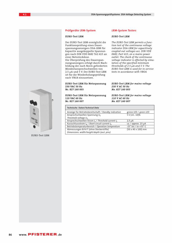
EURO-Test LRM
Der EURO-Test LRM ermöglicht dieFunktionsprüfung eines Dauer-spannungsanzeigers DSA-LRM fürkapazitiv ausgekoppelte Spannun-gen nach DIN VDE 0682 Teil 415 aneiner Netzsteckdose.Die Überprüfung des Dauerspan-nungsanzeigers erfolgt durch Nach-bildung der nach Norm gefordertenMindestansprechschwellen von 2,5 µA und 5 V. Der EURO-Test LRMist für die Wiederholungsprüfungnach VBG4 einzusetzen.
EURO-Test LRM für Netzspannung 230 VAC 50 HzNr. 827 160 003
EURO-Test LRM für Netzspannung 110 VAC 60 Hz Nr. 827 160 007
LRM-System Testers
EURO-Test LRM
The EURO-Test LRM permits a func-tion test of the continuous voltageindicator DSA-LRM for capacitivelycoupled out voltages acc. DIN VDE0682, Part 415, on a mains power outlet. The check of the continuousvoltage indicator is effected by simu-lation of the specified minimumthresholds of 2.5 µA and 5 V. The EURO-Test LRM is used for in-servicetests in accordance with VBG4.
EURO-Test LRM for mains voltage230 V AC 50 Hz No. 827 160 003
EURO-Test LRM for mains voltage 110 V AC 60 Hz No. 827 160 007
Technische Daten/Technical Data
Anzeige für Betriebsbereitschaft / Standby indication grüne LED / green LEDAnsprechschwellen-Spannung Ut 5 V (+0…–10)%
Threshold voltage UtAnsprechschwellen-Strom It / Threshold current It 2,5 µAKurzschlussstrom Ik / Short-circuit current Ik ca. / approx. 23 µABetriebstemperaturbereich / Operation temperature –25° bis / to +55° CAbmessungen B/H/T (ohne Steckerstifte) (50 x 40 x 100) mmDimensions: width/height/depth (excl. pins)
EURO-Test LRM
04.1 CONNEX 23.04.2004 11:34 Uhr Seite 86
87
4.1DSA-Spannungsprüfsysteme DSA-Voltage Detecting System
www. .de
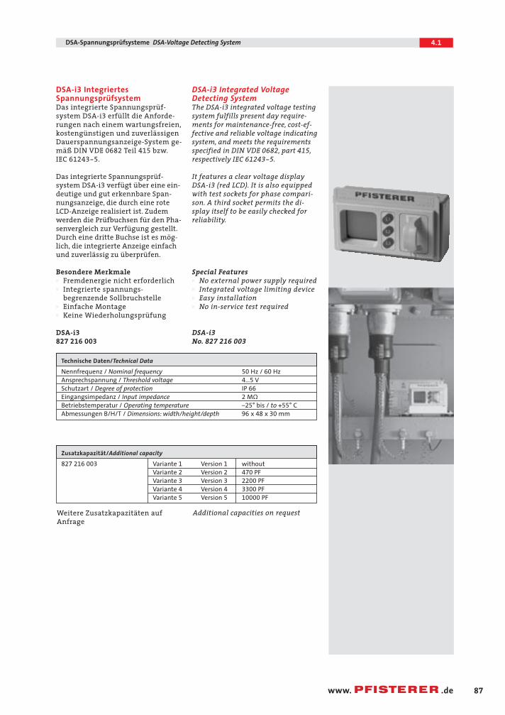
DSA-i3 IntegriertesSpannungsprüfsystemDas integrierte Spannungsprüf-system DSA-i3 erfüllt die Anforde-rungen nach einem wartungsfreien,kostengünstigen und zuverlässigenDauerspannungsanzeige-System ge-mäß DIN VDE 0682 Teil 415 bzw.IEC 61243-5.
Das integrierte Spannungsprüf-system DSA-i3 verfügt über eine ein-deutige und gut erkennbare Span-nungsanzeige, die durch eine roteLCD-Anzeige realisiert ist. Zudemwerden die Prüfbuchsen für den Pha-senvergleich zur Verfügung gestellt.Durch eine dritte Buchse ist es mög-lich, die integrierte Anzeige einfachund zuverlässig zu überprüfen.
Besondere MerkmaleW Fremdenergie nicht erforderlichW Integrierte spannungs-
begrenzende SollbruchstelleW Einfache MontageW Keine Wiederholungsprüfung
DSA-i3
827 216 003
DSA-i3 Integrated VoltageDetecting SystemThe DSA-i3 integrated voltage testingsystem fulfills present day require-ments for maintenance-free, cost-ef-fective and reliable voltage indicatingsystem, and meets the requirementsspecified in DIN VDE 0682, part 415,
respectively IEC 61243-5.
It features a clear voltage displayDSA-i3 (red LCD). It is also equippedwith test sockets for phase compari-son. A third socket permits the di-splay itself to be easily checked for reliability.
Special FeaturesW No external power supply requiredW Integrated voltage limiting deviceW Easy installationW No in-service test required
DSA-i3
No. 827 216 003
Technische Daten/Technical Data
Nennfrequenz / Nominal frequency 50 Hz / 60 HzAnsprechspannung / Threshold voltage 4…5 VSchutzart / Degree of protection IP 66Eingangsimpedanz / Input impedance 2 MΩBetriebstemperatur / Operating temperature –25° bis / to +55° CAbmessungen B/H/T / Dimensions: width/height/depth 96 x 48 x 30 mm
Zusatzkapazität/Additional capacity
827 216 003 Variante 1 Version 1 withoutVariante 2 Version 2 470 PF Variante 3 Version 3 2200 PF Variante 4 Version 4 3300 PFVariante 5 Version 5 10000 PF
Weitere Zusatzkapazitäten auf Anfrage
Additional capacities on request
04.1 CONNEX 23.04.2004 11:34 Uhr Seite 87
88
4.1 DSA-Spannungsprüfsysteme DSA-Voltage Detecting System
www. .de
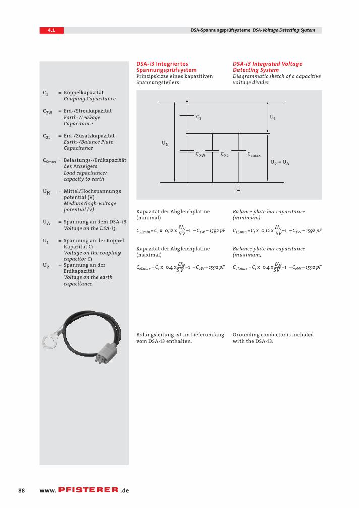
Prinzipskizze eines kapazitivenSpannungsteilers
Diagrammatic sketch of a capacitive voltage divider
DSA-i3 IntegriertesSpannungsprüfsystem
Kapazität der Abgleichplatine(minimal)
C2Lmin =C1 x 0,12 x UN –1 – C2W – 1592 pF5V
Kapazität der Abgleichplatine (maximal)
C2Lmax =C1 x 0,4 x UN –1 – C2W – 1592 pF5V
Erdungsleitung ist im Lieferumfangvom DSA-i3 enthalten.
DSA-i3 Integrated VoltageDetecting System
Balance plate bar capacitance(minimum)
C2Lmin =C1 x 0,12 x UN –1 – C2W – 1592 pF5V
Balance plate bar capacitance(maximum)
C2Lmax =C1 x 0,4 x UN –1 – C2W – 1592 pF5V
Grounding conductor is includedwith the DSA-i3.
C1 = KoppelkapazitätCoupling Capacitance
C2W = Erd-/StreukapazitätEarth-/Leakage Capacitance
C2L = Erd-/ZusatzkapazitätEarth-/Balance Plate Capacitance
CSmax = Belastungs-/Erdkapazitätdes AnzeigersLoad capacitance/capacity to earth
UN = Mittel/Hochspannungspotential (V)Medium/high-voltagepotential (V)
UA = Spannung an dem DSA-i3
Voltage on the DSA-i3
U1 = Spannung an der KoppelKapazität C1Voltage on the couplingcapacitor C1
U2 = Spannung an der ErdkapazitätVoltage on the earthcapacitance
U2 = UA
UN
C1 U1
C2W C2L Csmax
04.1 CONNEX 23.04.2004 11:34 Uhr Seite 88
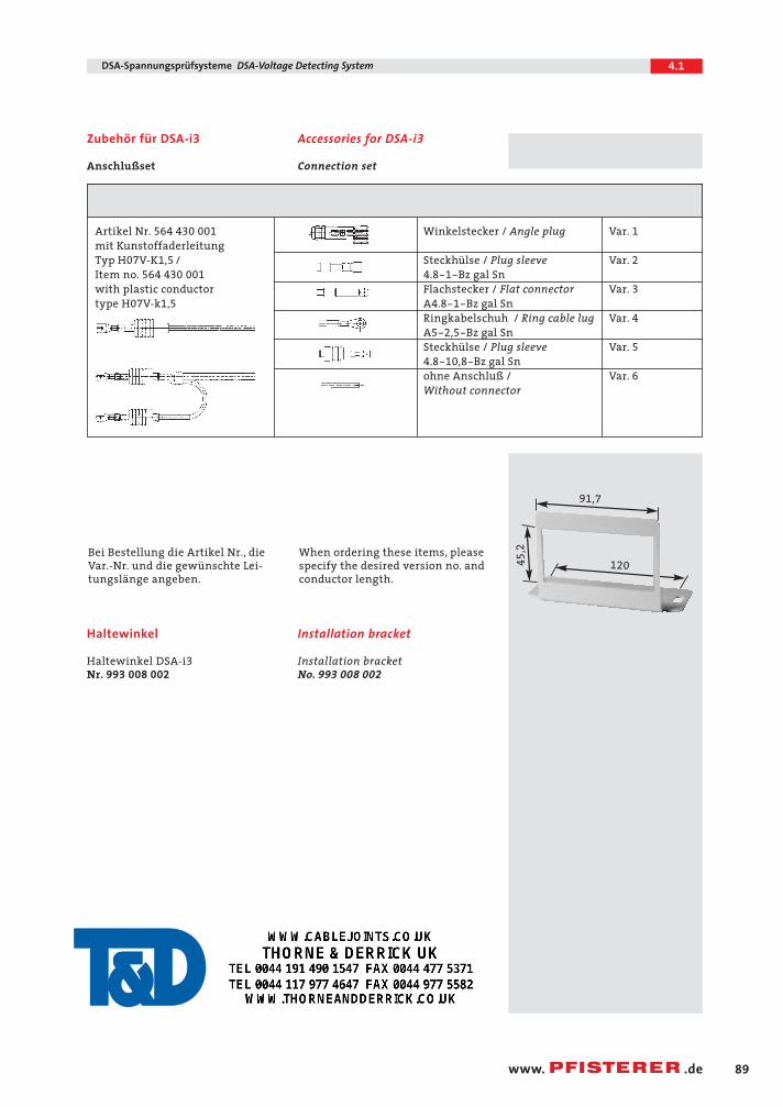
Anschluß DSA-i3 Anschluß zur Koppelkapazität C1
Artikel Nr. 564 430 001 Winkelstecker / Angle plug Var. 1
mit Kunstoffaderleitung Typ H07V-K1,5 / Steckhülse / Plug sleeve Var. 2
Item no. 564 430 001 4.8-1-Bz gal Snwith plastic conductor Flachstecker / Flat connector Var. 3
type H07V-k1,5 A4.8-1-Bz gal SnRingkabelschuh / Ring cable lug Var. 4
A5-2,5-Bz gal SnSteckhülse / Plug sleeve Var. 5
4.8-10,8-Bz gal Snohne Anschluß / Var. 6
Without connector
89
4.1DSA-Spannungsprüfsysteme DSA-Voltage Detecting System
www. .de
Zubehör für DSA-i3
Anschlußset
Accessories for DSA-i3
Connection set
Bei Bestellung die Artikel Nr., dieVar.-Nr. und die gewünschte Lei-tungslänge angeben.
When ordering these items, pleasespecify the desired version no. andconductor length.
Haltewinkel
Haltewinkel DSA-i3
Nr. 993 008 002
Installation bracket
Installation bracketNo. 993 008 002
91,7
45
,2
120
04.1 CONNEX 23.04.2004 11:34 Uhr Seite 89
Jeff Jhanke
TD