LT3 Drive: substitution of differentials in the drivetrain
12
EVS30 International Battery, Hybrid and Fuel Cell Electric Vehicle Symposium 1 EVS30 Symposium Stuttgart, Germany, October 9 - 11, 2017 LT3 Drive: substitution of differentials in the drivetrain Udo Eckloff 1 , Danilo Engelmann 2 , Werner Müller 3 1 Udo Eckloff, Dipl.-Holzwirt, innovation marketing, Müller Landmaschinen GmbH, Hofgut Gründelbuch, D-88637 Buchheim, [email protected] 2 Danilo Engelmann, Dipl.-Ing., academic staff, Karlsruhe Institute of Technology, Institute of Vehicle System Technology, Rintheimer Querallee 2, D-76131 Karlsruhe, [email protected] 3 Werner Müller, Master craftsmen for agricultural machinery CEO Müller Landmaschinen GmbH, Küferstr. 1, D-79848 Bonndorf, [email protected] Abstract The basic principle of the LT3 drive system is a planetary gearing with a rotatable ring gear. Rolling piston cylinders enable this rotation by acting on the cam disk shaped outside of the ring gear which fix or loosen the ring gear accordingly. By fixing the ring gear via the cylinders the gear ratio corresponds to the normal mechanical ratio of the gearing which is given by the combination of the planet gears and the ring gear. By loosening the ring gear completely there is no more power transmission to the carrier; hence, the carrier doesn’t rotate anymore. In between, the rotational speed can be adjusted continuously between 0 and the maximum speed within only a few milliseconds, “online”, as it were, depending on the compensatory need. The technology was verified by the chair of Mobile Machines (Mobima) at Karlsruhe Institute of Technology. During the current second development process, the controlling of the system via high pressure components was elaborated. Furthermore, LT3 was designed for high torques up to 8,000 Nm. A feasibility study for heavy-duty vehicles was completed successfully in 2016. The LT3 technology thereupon was ‘downsized’ for smaller systems. Possible applications for LT3 are all systems where synchronisation functions or to allow a superposition of the rotation speeds are necessary, especially with the objective to substitute the differential gear in electric vehicles with central motor. In today’s differential gears advanced driver-assistance systems normally intervene by brake action on the critical wheel. However, LT3 enables a planned control of each driven wheel. With that, active Torque Vectoring is possible which can operate foresightedly in every driving situation. Saving potential mainly in production is the result of using the LT3 system. Viscous coupling unit or Haldex unit as well as Torsen differential are dropped. Also, the ASR assistant is no longer needed. In E- mobility application, mainly in small vehicles, space could be used in a better way or rather the packaging could be designed more favourable because the LT3 drive takes two functions at once: speed reduction of the motor and differential compensation of the driven wheels.
Transcript of LT3 Drive: substitution of differentials in the drivetrain
EVS30 International Battery, Hybrid and Fuel Cell Electric Vehicle Symposium 1
EVS30 Symposium
Stuttgart, Germany, October 9 - 11, 2017
LT3 Drive: substitution of differentials in the drivetrain
Udo Eckloff 1, Danilo Engelmann 2, Werner Müller 3
1 Udo Eckloff, Dipl.-Holzwirt, innovation marketing, Müller Landmaschinen GmbH, Hofgut Gründelbuch,
D-88637 Buchheim, [email protected]
2 Danilo Engelmann, Dipl.-Ing., academic staff, Karlsruhe Institute of Technology, Institute of Vehicle System
Technology, Rintheimer Querallee 2, D-76131 Karlsruhe, [email protected]
3 Werner Müller, Master craftsmen for agricultural machinery CEO Müller Landmaschinen GmbH, Küferstr. 1,
D-79848 Bonndorf, [email protected]
Abstract
The basic principle of the LT3 drive system is a planetary gearing with a rotatable ring gear. Rolling piston
cylinders enable this rotation by acting on the cam disk shaped outside of the ring gear which fix or loosen
the ring gear accordingly.
By fixing the ring gear via the cylinders the gear ratio corresponds to the normal mechanical ratio of the
gearing which is given by the combination of the planet gears and the ring gear. By loosening the ring gear
completely there is no more power transmission to the carrier; hence, the carrier doesn’t rotate anymore. In
between, the rotational speed can be adjusted continuously between 0 and the maximum speed within only
a few milliseconds, “online”, as it were, depending on the compensatory need.
The technology was verified by the chair of Mobile Machines (Mobima) at Karlsruhe Institute of
Technology. During the current second development process, the controlling of the system via high
pressure components was elaborated. Furthermore, LT3 was designed for high torques up to 8,000 Nm. A
feasibility study for heavy-duty vehicles was completed successfully in 2016.
The LT3 technology thereupon was ‘downsized’ for smaller systems. Possible applications for LT3 are all
systems where synchronisation functions or to allow a superposition of the rotation speeds are necessary,
especially with the objective to substitute the differential gear in electric vehicles with central motor.
In today’s differential gears advanced driver-assistance systems normally intervene by brake action on the
critical wheel. However, LT3 enables a planned control of each driven wheel. With that, active Torque
Vectoring is possible which can operate foresightedly in every driving situation.
Saving potential mainly in production is the result of using the LT3 system. Viscous coupling unit or
Haldex unit as well as Torsen differential are dropped. Also, the ASR assistant is no longer needed. In E-
mobility application, mainly in small vehicles, space could be used in a better way or rather the packaging
could be designed more favourable because the LT3 drive takes two functions at once: speed reduction of
the motor and differential compensation of the driven wheels.
EVS30 International Battery, Hybrid and Fuel Cell Electric Vehicle Symposium 2
1 Motivation
Most of today’s vehicles have a central drive and the wheels are driven mechanically. In doing so, the
differential fulfils a significant role by enabling the drive of multiple wheels that remains free from
distortion having only one power source. Such gearings aren’t only used in lateral distribution to distribute
the power between the wheels of one axle but also in longitudinal distribution to distribute the power
between the different axles. Therefore, vehicles with four-wheel-drive have generally three differentials.
One disadvantage in distributing the traction force between the wheels via differentials is that the maximal
traction force for all wheels is limited by the wheel with the worst traction. In particular when the road
surface is bad or when high traction forces have to be transmitted this disadvantage comes into effect. By
locking the differential bad traction in such situations can be avoided, although cornering isn’t slip-free and
torsion-free anymore. The locking device on the axles needs additional space and increases the mass inertia
as well as drag losses. Furthermore, the individual control of torque and speed of each wheel isn’t possible
at all or only with high technical effort in those systems.
That’s why an ideal mechanical drive must offer the possibility to fully utilise the traction potential of each
wheel just like in a locked drivetrain. At the same time, it must allow cornering without difficulty. For this,
each driven wheel must be controllable individually and independently of the other wheels.
Those requirements only can be satisfied by a mechatronisation of the drivetrain. The Line Traction 3
system (LT3) represents one possible approach and will be presented in the following.
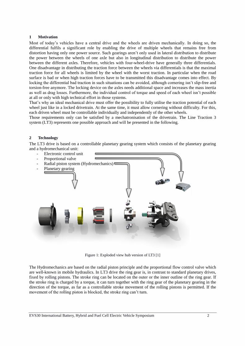
2 Technology
The LT3 drive is based on a controllable planetary gearing system which consists of the planetary gearing
and a hydromechanical unit:
- Electronic control unit
- Proportional valve
- Radial piston system (Hydromechanics)
- Planetary gearing
Figure 1: Exploded view hub version of LT3 [1]
The Hydromechanics are based on the radial piston principle and the proportional flow control valve which
are well-known in mobile hydraulics. In LT3 drive the ring gear is, in contrast to standard planetary drives,
fixed by rolling pistons. The stroke ring can be located on the outer or the inner outline of the ring gear. If
the stroke ring is charged by a torque, it can turn together with the ring gear of the planetary gearing in the
direction of the torque, as far as a controllable stroke movement of the rolling pistons is permitted. If the
movement of the rolling piston is blocked, the stroke ring can’t turn.
EVS30 International Battery, Hybrid and Fuel Cell Electric Vehicle Symposium 3
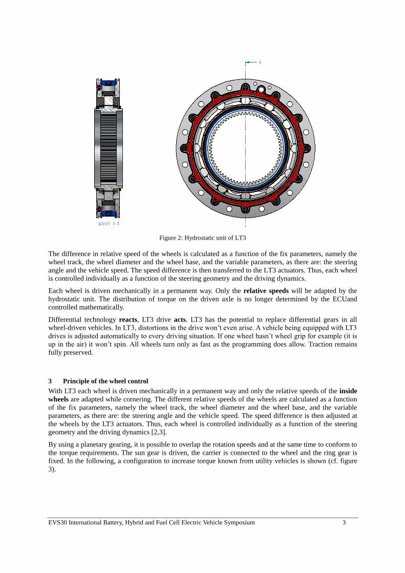
Figure 2: Hydrostatic unit of LT3
The difference in relative speed of the wheels is calculated as a function of the fix parameters, namely the
wheel track, the wheel diameter and the wheel base, and the variable parameters, as there are: the steering
angle and the vehicle speed. The speed difference is then transferred to the LT3 actuators. Thus, each wheel
is controlled individually as a function of the steering geometry and the driving dynamics.
Each wheel is driven mechanically in a permanent way. Only the relative speeds will be adapted by the
hydrostatic unit. The distribution of torque on the driven axle is no longer determined by the ECUand
controlled mathematically.
Differential technology reacts, LT3 drive acts. LT3 has the potential to replace differential gears in all
wheel-driven vehicles. In LT3, distortions in the drive won’t even arise. A vehicle being equipped with LT3
drives is adjusted automatically to every driving situation. If one wheel hasn’t wheel grip for example (it is
up in the air) it won’t spin. All wheels turn only as fast as the programming does allow. Traction remains
fully preserved.
3 Principle of the wheel control
With LT3 each wheel is driven mechanically in a permanent way and only the relative speeds of the inside
wheels are adapted while cornering. The different relative speeds of the wheels are calculated as a function
of the fix parameters, namely the wheel track, the wheel diameter and the wheel base, and the variable
parameters, as there are: the steering angle and the vehicle speed. The speed difference is then adjusted at
the wheels by the LT3 actuators. Thus, each wheel is controlled individually as a function of the steering
geometry and the driving dynamics [2,3].
By using a planetary gearing, it is possible to overlap the rotation speeds and at the same time to conform to
the torque requirements. The sun gear is driven, the carrier is connected to the wheel and the ring gear is
fixed. In the following, a configuration to increase torque known from utility vehicles is shown (cf. figure
3).
EVS30 International Battery, Hybrid and Fuel Cell Electric Vehicle Symposium 4
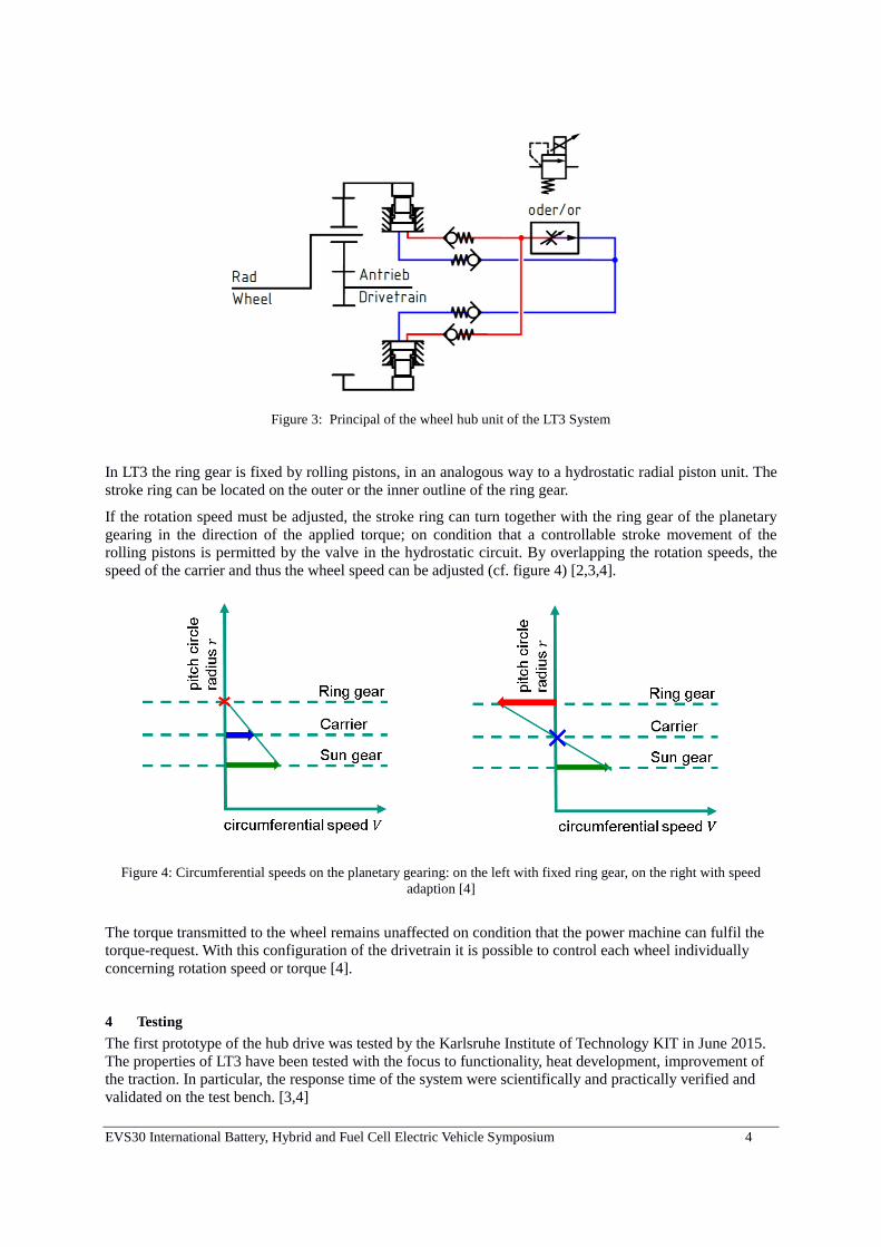
Figure 3: Principal of the wheel hub unit of the LT3 System
In LT3 the ring gear is fixed by rolling pistons, in an analogous way to a hydrostatic radial piston unit. The
stroke ring can be located on the outer or the inner outline of the ring gear.
If the rotation speed must be adjusted, the stroke ring can turn together with the ring gear of the planetary
gearing in the direction of the applied torque; on condition that a controllable stroke movement of the
rolling pistons is permitted by the valve in the hydrostatic circuit. By overlapping the rotation speeds, the
speed of the carrier and thus the wheel speed can be adjusted (cf. figure 4) [2,3,4].
Figure 4: Circumferential speeds on the planetary gearing: on the left with fixed ring gear, on the right with speed
adaption [4]
The torque transmitted to the wheel remains unaffected on condition that the power machine can fulfil the
torque-request. With this configuration of the drivetrain it is possible to control each wheel individually
concerning rotation speed or torque [4].
4 Testing
The first prototype of the hub drive was tested by the Karlsruhe Institute of Technology KIT in June 2015.
The properties of LT3 have been tested with the focus to functionality, heat development, improvement of
the traction. In particular, the response time of the system were scientifically and practically verified and
validated on the test bench. [3,4]
EVS30 International Battery, Hybrid and Fuel Cell Electric Vehicle Symposium 5
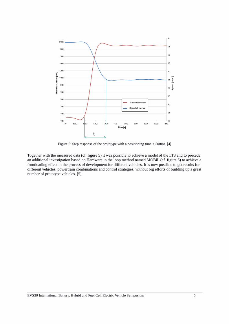
Figure 5: Step response of the prototype with a positioning time < 500ms [4]
Together with the measured data (cf. figure 5) it was possible to achieve a model of the LT3 and to precede
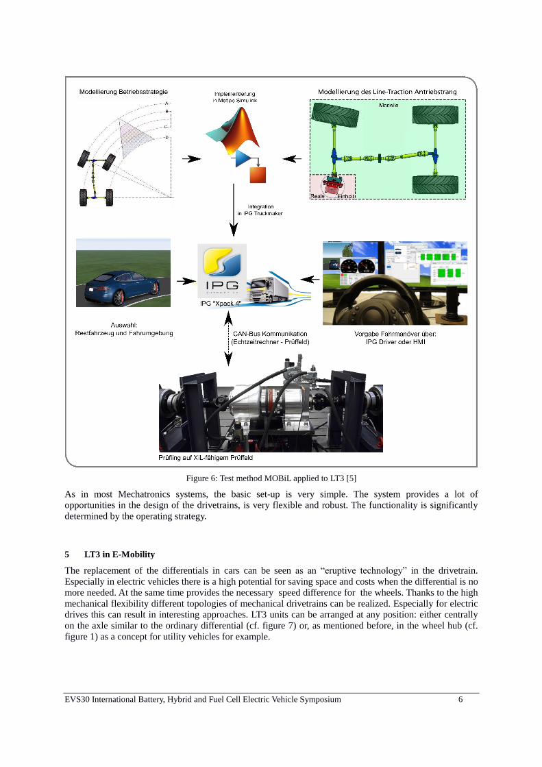
an additional investigation based on Hardware in the loop method named MOBiL (cf. figure 6) to achieve a
frontloading effect in the process of development for different vehicles. It is now possible to get results for
different vehicles, powertrain combinations and control strategies, without big efforts of building up a great
number of prototype vehicles. [5]
EVS30 International Battery, Hybrid and Fuel Cell Electric Vehicle Symposium 6
Figure 6: Test method MOBiL applied to LT3 [5]
As in most Mechatronics systems, the basic set-up is very simple. The system provides a lot of
opportunities in the design of the drivetrains, is very flexible and robust. The functionality is significantly
determined by the operating strategy.
5 LT3 in E-Mobility
The replacement of the differentials in cars can be seen as an “eruptive technology” in the drivetrain.
Especially in electric vehicles there is a high potential for saving space and costs when the differential is no
more needed. At the same time provides the necessary speed difference for the wheels. Thanks to the high
mechanical flexibility different topologies of mechanical drivetrains can be realized. Especially for electric
drives this can result in interesting approaches. LT3 units can be arranged at any position: either centrally
on the axle similar to the ordinary differential (cf. figure 7) or, as mentioned before, in the wheel hub (cf.
figure 1) as a concept for utility vehicles for example.
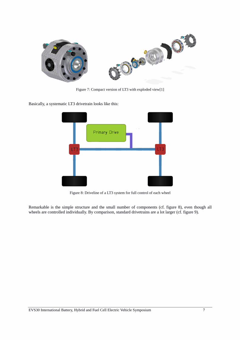
EVS30 International Battery, Hybrid and Fuel Cell Electric Vehicle Symposium 7
Figure 7: Compact version of LT3 with exploded view[1]
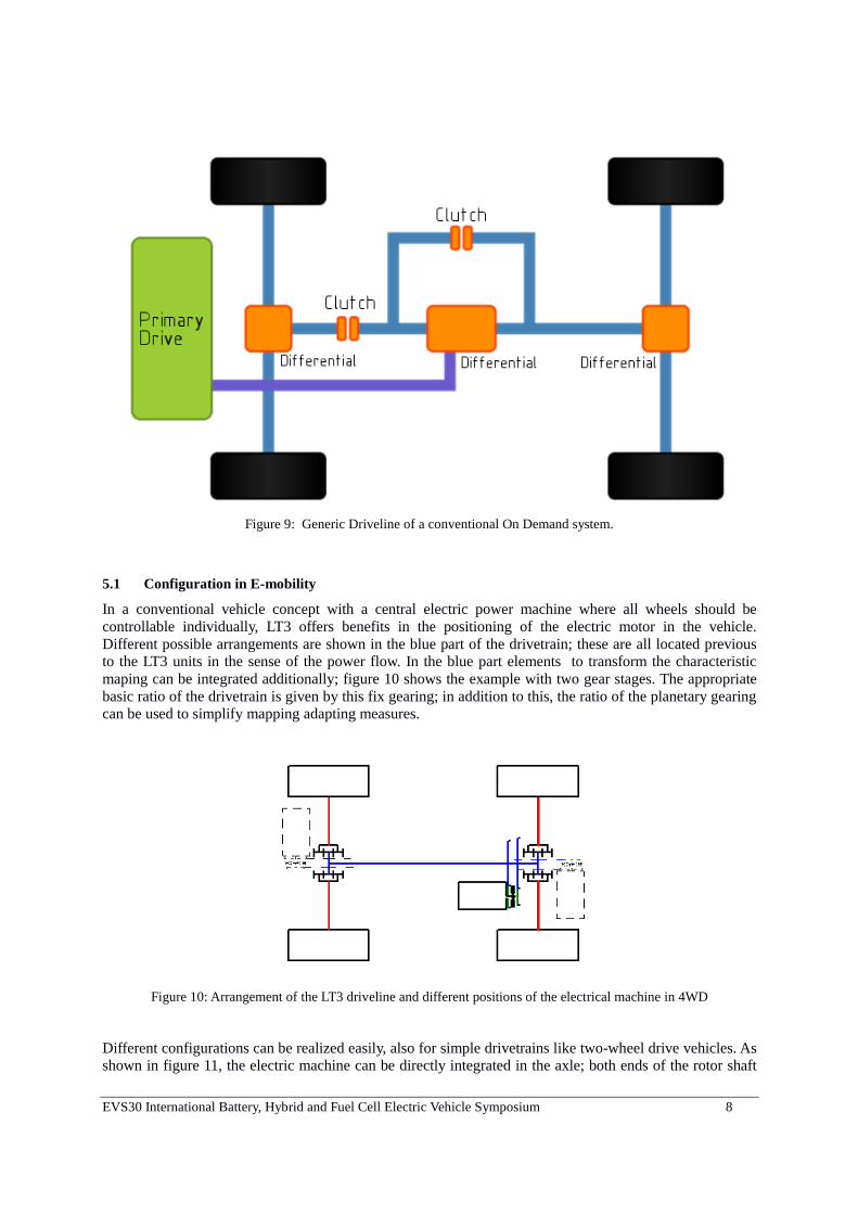
Basically, a systematic LT3 drivetrain looks like this:
Figure 8: Driveline of a LT3 system for full control of each wheel
Remarkable is the simple structure and the small number of components (cf. figure 8), even though all
wheels are controlled individually. By comparison, standard drivetrains are a lot larger (cf. figure 9).
EVS30 International Battery, Hybrid and Fuel Cell Electric Vehicle Symposium 8
Figure 9: Generic Driveline of a conventional On Demand system.
5.1 Configuration in E-mobility
In a conventional vehicle concept with a central electric power machine where all wheels should be
controllable individually, LT3 offers benefits in the positioning of the electric motor in the vehicle.
Different possible arrangements are shown in the blue part of the drivetrain; these are all located previous
to the LT3 units in the sense of the power flow. In the blue part elements to transform the characteristic
maping can be integrated additionally; figure 10 shows the example with two gear stages. The appropriate
basic ratio of the drivetrain is given by this fix gearing; in addition to this, the ratio of the planetary gearing
can be used to simplify mapping adapting measures.
Figure 10: Arrangement of the LT3 driveline and different positions of the electrical machine in 4WD
Different configurations can be realized easily, also for simple drivetrains like two-wheel drive vehicles. As shown in figure 11, the electric machine can be directly integrated in the axle; both ends of the rotor shaft
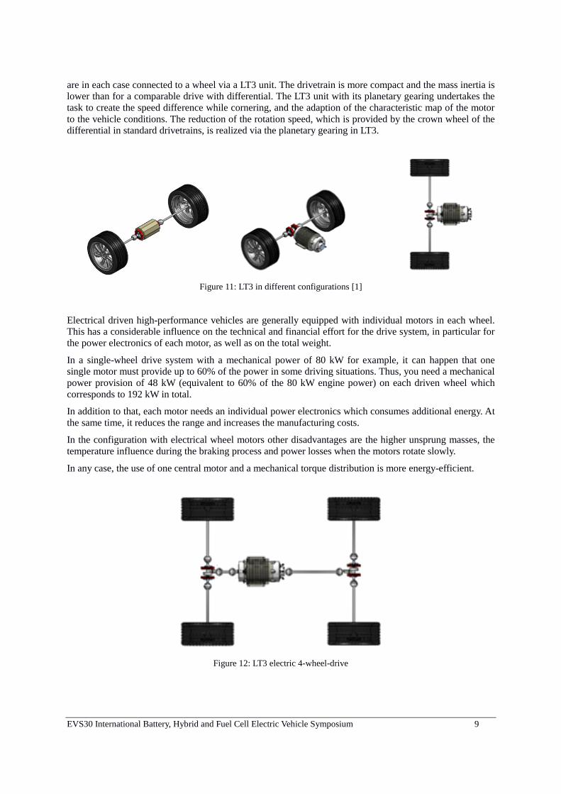
EVS30 International Battery, Hybrid and Fuel Cell Electric Vehicle Symposium 9
are in each case connected to a wheel via a LT3 unit. The drivetrain is more compact and the mass inertia is
lower than for a comparable drive with differential. The LT3 unit with its planetary gearing undertakes the
task to create the speed difference while cornering, and the adaption of the characteristic map of the motor
to the vehicle conditions. The reduction of the rotation speed, which is provided by the crown wheel of the
differential in standard drivetrains, is realized via the planetary gearing in LT3.
Figure 11: LT3 in different configurations [1]
Electrical driven high-performance vehicles are generally equipped with individual motors in each wheel.
This has a considerable influence on the technical and financial effort for the drive system, in particular for
the power electronics of each motor, as well as on the total weight.
In a single-wheel drive system with a mechanical power of 80 kW for example, it can happen that one
single motor must provide up to 60% of the power in some driving situations. Thus, you need a mechanical
power provision of 48 kW (equivalent to 60% of the 80 kW engine power) on each driven wheel which
corresponds to 192 kW in total.
In addition to that, each motor needs an individual power electronics which consumes additional energy. At
the same time, it reduces the range and increases the manufacturing costs.
In the configuration with electrical wheel motors other disadvantages are the higher unsprung masses, the
temperature influence during the braking process and power losses when the motors rotate slowly.
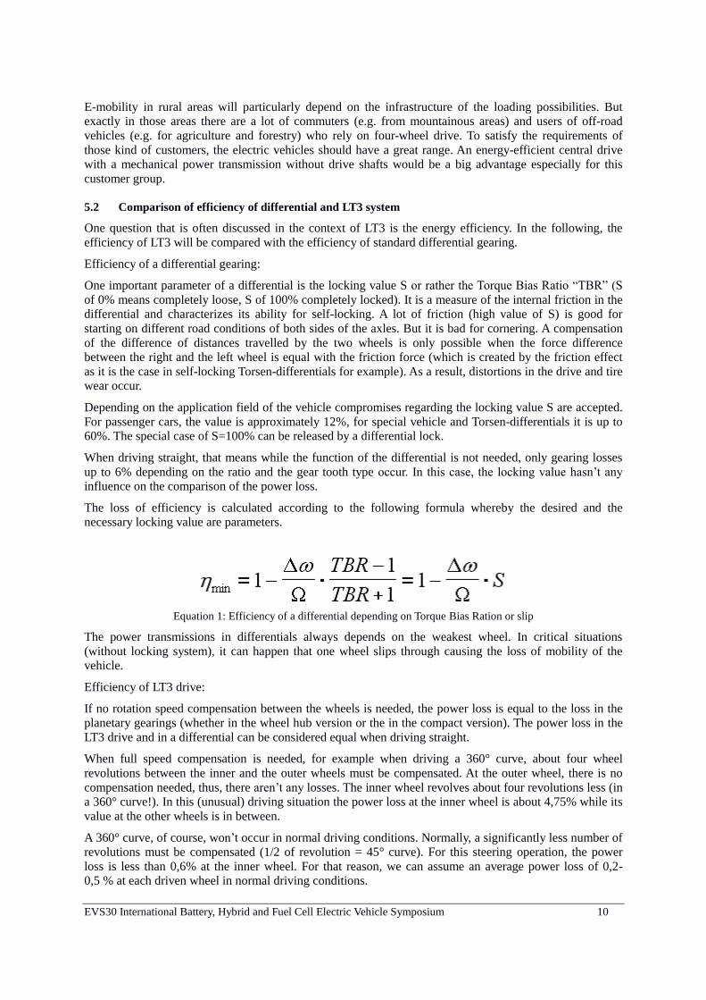
In any case, the use of one central motor and a mechanical torque distribution is more energy-efficient.
Figure 12: LT3 electric 4-wheel-drive
EVS30 International Battery, Hybrid and Fuel Cell Electric Vehicle Symposium 10
E-mobility in rural areas will particularly depend on the infrastructure of the loading possibilities. But
exactly in those areas there are a lot of commuters (e.g. from mountainous areas) and users of off-road
vehicles (e.g. for agriculture and forestry) who rely on four-wheel drive. To satisfy the requirements of
those kind of customers, the electric vehicles should have a great range. An energy-efficient central drive
with a mechanical power transmission without drive shafts would be a big advantage especially for this
customer group.
5.2 Comparison of efficiency of differential and LT3 system
One question that is often discussed in the context of LT3 is the energy efficiency. In the following, the
efficiency of LT3 will be compared with the efficiency of standard differential gearing.
Efficiency of a differential gearing:
One important parameter of a differential is the locking value S or rather the Torque Bias Ratio “TBR” (S
of 0% means completely loose, S of 100% completely locked). It is a measure of the internal friction in the
differential and characterizes its ability for self-locking. A lot of friction (high value of S) is good for
starting on different road conditions of both sides of the axles. But it is bad for cornering. A compensation
of the difference of distances travelled by the two wheels is only possible when the force difference
between the right and the left wheel is equal with the friction force (which is created by the friction effect
as it is the case in self-locking Torsen-differentials for example). As a result, distortions in the drive and tire
wear occur.
Depending on the application field of the vehicle compromises regarding the locking value S are accepted.
For passenger cars, the value is approximately 12%, for special vehicle and Torsen-differentials it is up to
60%. The special case of S=100% can be released by a differential lock.
When driving straight, that means while the function of the differential is not needed, only gearing losses
up to 6% depending on the ratio and the gear tooth type occur. In this case, the locking value hasn’t any
influence on the comparison of the power loss.
The loss of efficiency is calculated according to the following formula whereby the desired and the
necessary locking value are parameters.
Equation 1: Efficiency of a differential depending on Torque Bias Ration or slip
The power transmissions in differentials always depends on the weakest wheel. In critical situations
(without locking system), it can happen that one wheel slips through causing the loss of mobility of the
vehicle.
Efficiency of LT3 drive:
If no rotation speed compensation between the wheels is needed, the power loss is equal to the loss in the
planetary gearings (whether in the wheel hub version or the in the compact version). The power loss in the
LT3 drive and in a differential can be considered equal when driving straight.
When full speed compensation is needed, for example when driving a 360° curve, about four wheel
revolutions between the inner and the outer wheels must be compensated. At the outer wheel, there is no
compensation needed, thus, there aren’t any losses. The inner wheel revolves about four revolutions less (in
a 360° curve!). In this (unusual) driving situation the power loss at the inner wheel is about 4,75% while its
value at the other wheels is in between.
A 360° curve, of course, won’t occur in normal driving conditions. Normally, a significantly less number of
revolutions must be compensated (1/2 of revolution = 45° curve). For this steering operation, the power
loss is less than 0,6% at the inner wheel. For that reason, we can assume an average power loss of 0,2-0,5 % at each driven wheel in normal driving conditions.
EVS30 International Battery, Hybrid and Fuel Cell Electric Vehicle Symposium 11
Comparing the power losses of the two systems in 2WD vehicles you can notice that LT3 isn’t superior to
standard drive systems.
However, the advantage of LT3 regarding the power losses has a great impact in 4WD vehicles having two
transverse and one longitudinal differentials since the gearing losses of all differentials add up.
The advantage of LT3 is even greater in vehicles which are already equipped with planetary hub reduction
axles. The planetary gearing achieves the mechanical transmission, whereas the differential compensation
is realized by the hydrostatic unit directly at the ring gear. Here, only the power loss due to the speed
compensation occurs (max. 4,75% at the ‘low wheel’). There aren’t any differentials at all, thus, they do not
cause any power loss. Nevertheless, LT3 offers the same advantages as an open differential but with the full
functionality of an differential for heavy duty for use in terrain.
Consequences of LT3 for efficiency:
In the above comparative observations, the axle shift, the drag losses of the differentials, the float angle of
the wheels or the dynamic behaviour of the vehicle are not taken into consideration. The real power losses
can only be determined by a comparison of two concrete vehicles – one with a conventional differential, the
other one with a LT3 drive.
Given the complexity of the parameters, a precise and practical simulation can’t be realized. In the
experiments with the existing test specimen and simulation approach it was demonstrated that the
efficiency of the drive system only depends on the operating strategy of the concrete vehicle. The higher
the necessary locking value for the intended application and the number of driven axles, and depending on
the drive form (wheel hub or direct drive), the greater the advantage of LT3 regarding the efficiency of the
drivetrain.
The development of a drivable prototype will permit a concrete comparison after conclusion. Especially for
that reason we will use a close-to-production version of the system with the aim of demonstrating the
concrete differences.
EVS30 International Battery, Hybrid and Fuel Cell Electric Vehicle Symposium 12
Acknowledgments
The Authors would like to thank the Federal Ministry of Economics and Energy for project funding based
on a decision by the German Bundestag.
References
[1] Müller,W. ; Eckloff, U. ; Engelmann,D.; 2016 . Über “Linetraction 3” .Kurzbeschreibung , Bonndorf,
Müller Landmaschinen
[2] Müller, W., 2012. Gearbox Arrangement: 27.07.2011. Ger. patent specification WO2012000633A2.
05.01.2012
[3] Engelmann,D; Müller,W; Müller,J; Geimer,M: Anforderungen an den Antriebsstrang eines schweren
Nutzfahrzeugs. ATZ Offhighway 2/2015 P. 26-37
[4] Engelmann, D., Müller,W. ;Geimer,M., Project "Line Tractrion 3"- Mechanical driveline with active wheel
hubs. 16 Internationaler VDI-Kongress Getriebe in Fahrzeugen, Friedrichshafen 21. And 22.06.2016
[5] Brinkschulte,L; Engelmann, D.; Siebert, J.; et al. ; Project MOBiL – Eine auf mobile Arbeitsmaschine
optimirte Prüfmehode. 6. Fachtagung hybride und energieffiziente Antriebe , Karlsruhe 15.02.2017
Authors
Udo Eckloff, Dipl.-Holzwirt, Institute of Wood and World Forestry, University of Hamburg,
employment in Consulting for technical Innovation management Cologne, since 2010 self-
employed technical Innovation management, leading projects like small wind power plants
luvside, roboter cell Kern Cell, free wheel plastic Laudenbach, combined turning and milling
process V4A, SMA industrial endoscopy head, flexible SDK guide brush, various medical device
projects. Since 2013 2 development projects accompanying documentation, development,
promotion and marketing LT3. Additionally since 2016 project manager Plastics InnoCentre,
cluster Innonet Kunststoff®.
Danilo Engelmann, Dipl.-Ing., completed his studies of mechanical engineering at the KIT
(Karlsruher Institut für Technologie) in 2013, worked as Project Engineer for laser optical
measurement at the MOT - Forschungs- und Entwicklungsgesellschaft für Motorentechnik, Optik
und Thermodynamik mbH. Since 2014 Academic staff for powertrain control systems and the
scientific lead of the acoustic chassis dynamometer at the Chair of mobile Machines at the KIT.
Werner Müller, Master craftsmen for agricultural machinery
1980, from 1981 branch management of a trading and service company of agricultural machinery,
takeover of the existing company after 5 years, successful enlargement of the family business with
a total of 50 apprenticeships, currently 28 employees with high technical and scientific training.
Several proprietary developments such as articulated shaft pullers, forestry tractors. 2015
conversion of the individual company into a GmbH with family management. Since 2010 own
development work to today's LT3.