MA000 (de en) MA231 (de en) een Montageanleitung Assembly ...
12
1 / 12 PV-KST4/2.5...-UR PV-KST4/6...-UR PV-KST4/10... PV-KBT4/2.5...-UR PV-KBT4/6...-UR PV-KBT4/10... PV-KBT4/5...-UR PV-KBT4/8II-UR PV-KST4/5...-UR PV-KST4/8II-UR PV-SVK4 32.0717 PV-BVK4 32.0716 MA231 (de_en) Montageanleitung MA231 (de_en) Assembly instructions PV-Kupplungsstecker PV-KST4/...-UR PV-Kupplungsbuchse PV-KBT4/...-UR PV male cable coupler PV-KST4/...-UR PV female cable coupler PV-KBT4/...-UR Inhalt Sicherheitshinweise ���������������������������������������������������������������������2 Erforderliches Werkzeug ............................................................. 3 Vorbereitung der Leitung............................................................. 5 Crimpen ..................................................................................... 7 Montage-Prüfung ....................................................................... 9 Stecken und Trennen der Leitungskupplung - ohne Sicherungshülse PV-SSH4 ............................................ 10 - mit Sicherungshülse PV-SSH4 ............................................... 10 Hinweise zur Installation.............................................................11 Technische Daten ..................................................................... 12 Content Safety Instructions �����������������������������������������������������������������������2 Tools required ............................................................................. 3 Cable preparation ....................................................................... 5 Crimping..................................................................................... 7 Assembly check ......................................................................... 9 Mating and disconnecting the cable coupler - without safety lock clip PV-SSH4 ........................................... 10 - with safety lock clip PV-SSH4 ................................................ 10 Notes on installation ..................................................................11 Technical data .......................................................................... 12 Kupplungsstecker/Male cable coupler Kupplungsbuchse/Female cable coupler Optional PV-SSH4 Sicherungshülse/Safety lock clip (siehe/see www.staubli.com/electrical --> MA252) Verschlusskappen/Sealing caps
Transcript of MA000 (de en) MA231 (de en) een Montageanleitung Assembly ...

1 / 12
PV-KST4/2.5...-UR PV-KST4/6...-UR PV-KST4/10...
PV-KBT4/2.5...-UR PV-KBT4/6...-UR PV-KBT4/10...
PV-KBT4/5...-UR PV-KBT4/8II-UR
PV-KST4/5...-URPV-KST4/8II-UR
PV-SVK432.0717
PV-BVK432.0716
MA000 (de_en)Montageanleitung
MA000 (de_en)Assembly instructions
MA231 (de_en)Montageanleitung
MA231 (de_en)Assembly instructions
PV-Kupplungsstecker PV-KST4/...-UR PV-Kupplungsbuchse PV-KBT4/...-UR
PV male cable coupler PV-KST4/...-UR PV female cable coupler PV-KBT4/...-UR
InhaltSicherheitshinweise ���������������������������������������������������������������������2Erforderliches Werkzeug .............................................................3Vorbereitung der Leitung .............................................................5Crimpen .....................................................................................7Montage-Prüfung .......................................................................9Stecken und Trennen der Leitungskupplung- ohne Sicherungshülse PV-SSH4 ............................................10- mit Sicherungshülse PV-SSH4 ...............................................10Hinweise zur Installation .............................................................11Technische Daten .....................................................................12
ContentSafety Instructions �����������������������������������������������������������������������2Tools required ............................................................................. 3Cable preparation ....................................................................... 5Crimping ..................................................................................... 7Assembly check ......................................................................... 9Mating and disconnecting the cable coupler- without safety lock clip PV-SSH4 ........................................... 10- with safety lock clip PV-SSH4 ................................................ 10Notes on installation ..................................................................11Technical data .......................................................................... 12
Kupplungsstecker/Male cable couplerKupplungsbuchse/Female cable coupler
OptionalPV-SSH4
Sicherungshülse/Safety lock clip
(siehe/see www.staubli.com/electrical --> MA252)
Verschlusskappen/Sealing caps
2 / 12
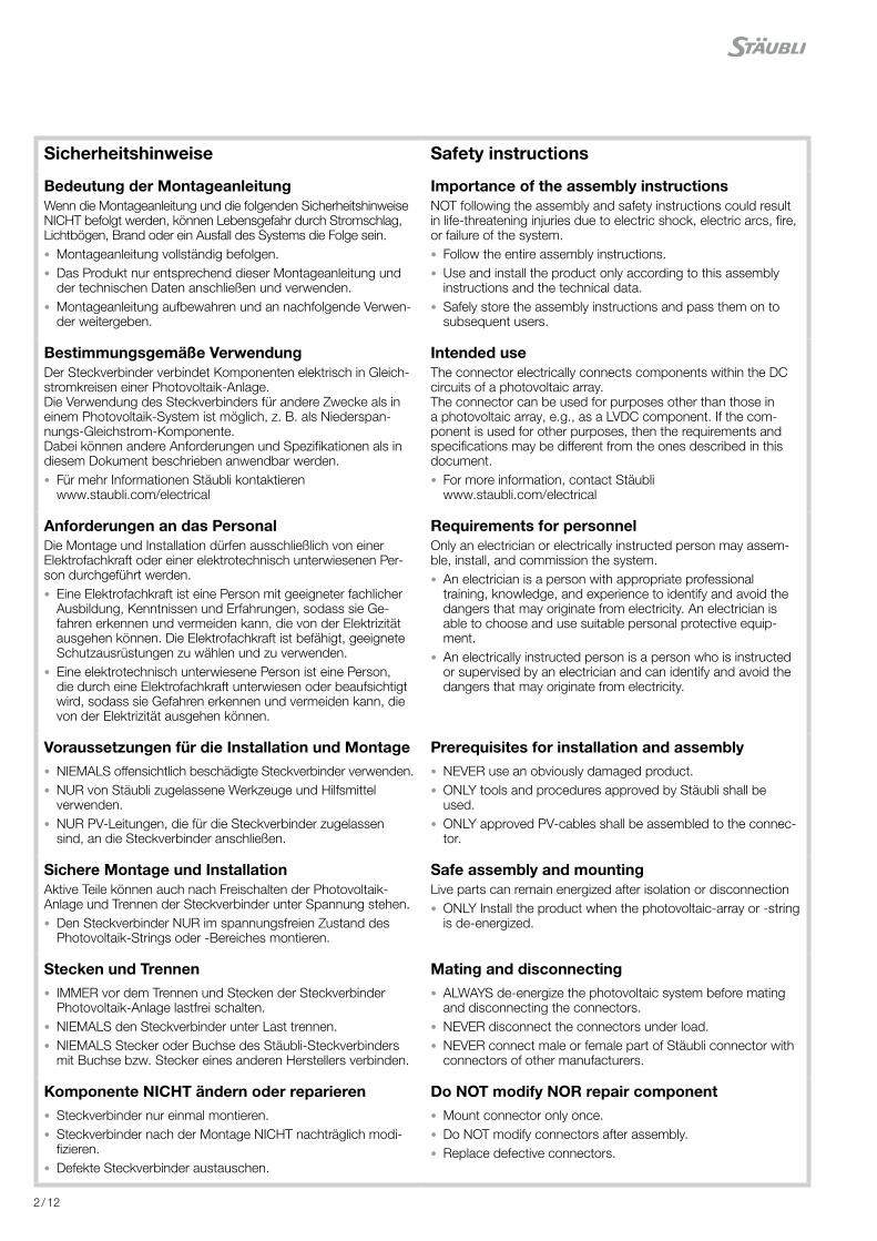
Sicherheitshinweise Safety instructions
Bedeutung der MontageanleitungWenn die Montageanleitung und die folgenden Sicherheitshinweise NICHT befolgt werden, können Lebensgefahr durch Stromschlag, Lichtbögen, Brand oder ein Ausfall des Systems die Folge sein. • Montageanleitung vollständig befolgen. • Das Produkt nur entsprechend dieser Montageanleitung und der technischen Daten anschließen und verwenden.
• Montageanleitung aufbewahren und an nachfolgende Verwen-der weitergeben.
Importance of the assembly instructionsNOT following the assembly and safety instructions could result in life-threatening injuries due to electric shock, electric arcs, fi re, or failure of the system. • Follow the entire assembly instructions. • Use and install the product only according to this assembly instructions and the technical data.
• Safely store the assembly instructions and pass them on to subsequent users.
Bestimmungsgemäße VerwendungDer Steckverbinder verbindet Komponenten elektrisch in Gleich-stromkreisen einer Photovoltaik-Anlage.Die Verwendung des Steckverbinders für andere Zwecke als in einem Photovoltaik-System ist möglich, z. B. als Niederspan-nungs-Gleichstrom-Komponente.Dabei können andere Anforderungen und Spezifi kationen als in diesem Dokument beschrieben anwendbar werden. • Für mehr Informationen Stäubli kontaktierenwww.staubli.com/electrical
Intended useThe connector electrically connects components within the DC circuits of a photovoltaic array. The connector can be used for purposes other than those in a photovoltaic array, e.g., as a LVDC component. If the com-ponent is used for other purposes, then the requirements and specifi cations may be diff erent from the ones described in this document. • For more information, contact Stäubliwww.staubli.com/electrical
Anforderungen an das PersonalDie Montage und Installation dürfen ausschließlich von einer Elektrofachkraft oder einer elektrotechnisch unterwiesenen Per-son durchgeführt werden. • Eine Elektrofachkraft ist eine Person mit geeigneter fachlicher Ausbildung, Kenntnissen und Erfahrungen, sodass sie Ge-fahren erkennen und vermeiden kann, die von der Elektrizität ausgehen können. Die Elektrofachkraft ist befähigt, geeignete Schutzausrüstungen zu wählen und zu verwenden.
• Eine elektrotechnisch unterwiesene Person ist eine Person, die durch eine Elektrofachkraft unterwiesen oder beaufsichtigt wird, sodass sie Gefahren erkennen und vermeiden kann, die von der Elektrizität ausgehen können.
Requirements for personnel Only an electrician or electrically instructed person may assem-ble, install, and commission the system. • An electrician is a person with appropriate professional training, knowledge, and experience to identify and avoid the dangers that may originate from electricity. An electrician is able to choose and use suitable personal protective equip-ment.
• An electrically instructed person is a person who is instructed or supervised by an electrician and can identify and avoid the dangers that may originate from electricity.
Voraussetzungen für die Installation und Montage • NIEMALS off ensichtlich beschädigte Steckverbinder verwenden. • NUR von Stäubli zugelassene Werkzeuge und Hilfsmittel verwenden.
• NUR PV-Leitungen, die für die Steckverbinder zugelassen sind, an die Steckverbinder anschließen.
Prerequisites for installation and assembly • NEVER use an obviously damaged product. • ONLY tools and procedures approved by Stäubli shall be used.
• ONLY approved PV-cables shall be assembled to the connec-tor.
Sichere Montage und InstallationAktive Teile können auch nach Freischalten der Photovoltaik-Anlage und Trennen der Steckverbinder unter Spannung stehen. • Den Steckverbinder NUR im spannungsfreien Zustand des Photovoltaik-Strings oder -Bereiches montieren.
Safe assembly and mountingLive parts can remain energized after isolation or disconnection • ONLY Install the product when the photovoltaic-array or -string is de-energized.
Stecken und Trennen • IMMER vor dem Trennen und Stecken der Steckverbinder Photovoltaik-Anlage lastfrei schalten.
• NIEMALS den Steckverbinder unter Last trennen. • NIEMALS Stecker oder Buchse des Stäubli-Steckverbinders mit Buchse bzw. Stecker eines anderen Herstellers verbinden.
Mating and disconnecting • ALWAYS de-energize the photovoltaic system before mating and disconnecting the connectors.
• NEVER disconnect the connectors under load. • NEVER connect male or female part of Stäubli connector with connectors of other manufacturers.
Komponente NICHT ändern oder reparieren • Steckverbinder nur einmal montieren. • Steckverbinder nach der Montage NICHT nachträglich modi-fi zieren.
• Defekte Steckverbinder austauschen.
Do NOT modify NOR repair component • Mount connector only once. • Do NOT modify connectors after assembly. • Replace defective connectors.
3 / 12
1
2PV-MS-PLS PV-MS
3
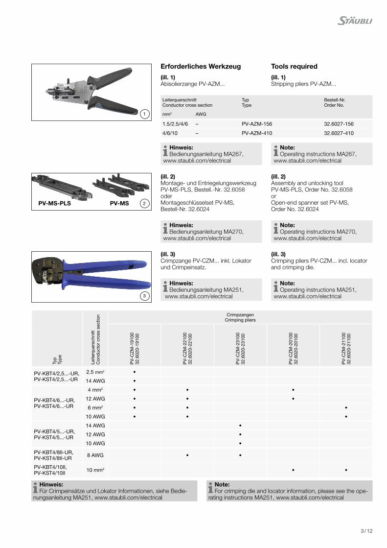
Erforderliches Werkzeug Tools required
(ill. 1)Abisolierzange PV-AZM...
(ill. 1)Stripping pliers PV-AZM...
Leiterquerschnitt Conductor cross section
Typ Type
Bestell-Nr. Order No.
mm2 AWG
1.5/2.5/4/6 – PV-AZM-156 32.6027-156
4/6/10 – PV-AZM-410 32.6027-410
Hinweis: Bedienungsanleitung MA267,
www.staubli.com/electrical Note: Operating instructions MA267,
www.staubli.com/electrical
(ill. 2)Montage- und Entriegelungswerkzeug PV-MS-PLS, Bestell.-Nr. 32.6058oder Montageschlüsselset PV-MS, Bestell-Nr. 32.6024
(ill. 2)Assembly and unlocking tool PV-MS-PLS, Order No. 32.6058or Open-end spanner set PV-MS, Order No. 32.6024
Hinweis: Bedienungsanleitung MA270,
www.staubli.com/electrical Note: Operating instructions MA270,
www.staubli.com/electrical
(ill. 3)Crimpzange PV-CZM... inkl. Lokator und Crimpeinsatz.
(ill. 3)Crimping pliers PV-CZM... incl. locator and crimping die.
Hinweis: Bedienungsanleitung MA251,
www.staubli.com/electrical Note: Operating instructions MA251,
www.staubli.com/electrical
Typ
Type
Leite
rque
rsch
nitt
Con
duct
or c
ross
sec
tion Crimpzangen
Crimping pliers
PV-
CZ
M-1
9100
32
.602
0-19
100
PV-
CZ
M-2
2100
32
.602
0-22
100
PV-
CZ
M-2
3100
32
.602
0-23
100
PV-
CZ
M-2
0100
32.6
020-
2010
0
PV-
CZ
M-2
1100
32.6
020-
2110
0
PV-KBT4/2,5...-UR, PV-KST4/2,5...-UR
2.5 mm2 •
14 AWG •
PV-KBT4/6...-UR, PV-KST4/6...-UR
4 mm2 • • •
12 AWG • • •
6 mm2 • • •
10 AWG • • •
PV-KBT4/5...-UR, PV-KST4/5...-UR
14 AWG •
12 AWG •
10 AWG •
PV-KBT4/8II-UR, PV-KST4/8II-UR 8 AWG • •
PV-KBT4/10II, PV-KST4/10II 10 mm2 • •
Hinweis: Für Crimpeinsätze und Lokator Informationen, siehe Bedie-
nungsanleitung MA251, www.staubli.com/electrical Note: For crimping die and locator information, please see the ope-
rating instructions MA251, www.staubli.com/electrical

4 / 12
5
6
7
4
8
(ill. 4)PV-WZ-Torque-Set, Bestell-Nr. 32.0065
(ill. 4)PV-WZ-Torque-Set, Order No. 32.0065
(ill. 5)PV-PST PrüfstiftBestell-Nr. 32.6028
(ill. 5)Test plug PV-PSTOrder No. 32.6028
(ill. 6)SW15 Gabelschlüssel
(ill. 6)Open-end spanner wrench 15 mm
(ill. 7)SW12 Drehmomentschlüssel
(ill. 7)Torque wrench 12 mm (1/2” drive)
(ill. 8)Kabelschere PV-WZ-KS, Bestell-Nr. 32.6080
(ill. 8)Cable cutter PV-WZ-KS, Order No. 32.6080
Hinweis: Bedienungsanleitung MA705,
www.staubli.com/electrical Note: Operating instructions MA705,
www.staubli.com/electrical
5 / 12
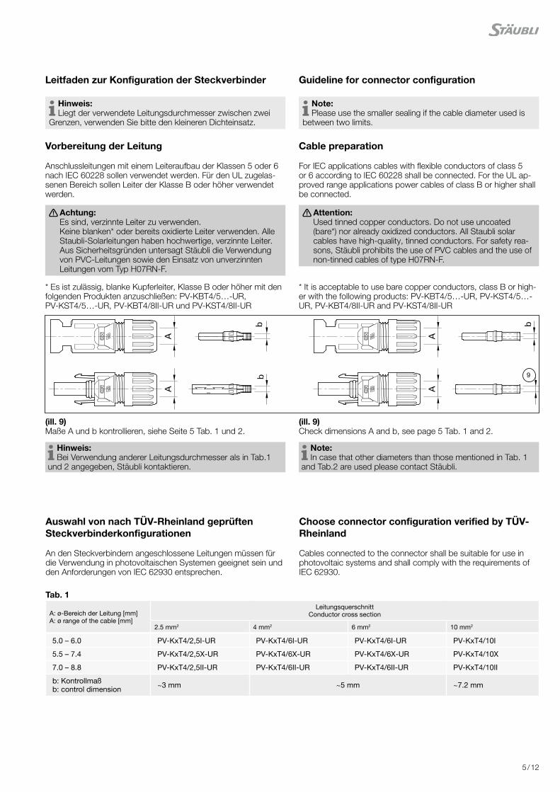
Leitfaden zur Konfiguration der Steckverbinder Guideline for connector configuration
Hinweis: Liegt der verwendete Leitungsdurchmesser zwischen zwei
Grenzen, verwenden Sie bitte den kleineren Dichteinsatz. Note: Please use the smaller sealing if the cable diameter used is
between two limits.
Vorbereitung der Leitung Cable preparation
Anschlussleitungen mit einem Leiteraufbau der Klassen 5 oder 6 nach IEC 60228 sollen verwendet werden. Für den UL zugelas-senen Bereich sollen Leiter der Klasse B oder höher verwendet werden.
For IEC applications cables with flexible conductors of class 5 or 6 according to IEC 60228 shall be connected. For the UL ap-proved range applications power cables of class B or higher shall be connected.
Achtung: Es sind, verzinnte Leiter zu verwenden. Keine blanken* oder bereits oxidierte Leiter verwenden. Alle Staubli-Solarleitungen haben hochwertige, verzinnte Leiter. Aus Sicherheitsgründen untersagt Stäubli die Verwendung von PVC-Leitungen sowie den Einsatz von unverzinnten Leitungen vom Typ H07RN-F.
Attention: Used tinned copper conductors. Do not use uncoated (bare*) nor already oxidized conductors. All Staubli solar cables have high-quality, tinned conductors. For safety rea-sons, Stäubli prohibits the use of PVC cables and the use of non-tinned cables of type H07RN-F.
* Es ist zulässig, blanke Kupferleiter, Klasse B oder höher mit den folgenden Produkten anzuschließen: PV-KBT4/5…-UR, PV-KST4/5…-UR, PV-KBT4/8II-UR und PV-KST4/8II-UR
* It is acceptable to use bare copper conductors, class B or high-er with the following products: PV-KBT4/5…-UR, PV-KST4/5…-UR, PV-KBT4/8II-UR and PV-KST4/8II-UR
(ill. 9)Maße A und b kontrollieren, siehe Seite 5 Tab. 1 und 2.
(ill. 9)Check dimensions A and b, see page 5 Tab. 1 and 2.
Hinweis: Bei Verwendung anderer Leitungsdurchmesser als in Tab.1
und 2 angegeben, Stäubli kontaktieren. Note: In case that other diameters than those mentioned in Tab. 1
and Tab.2 are used please contact Stäubli.
9
Tab. 1
A: ø-Bereich der Leitung [mm] A: ø range of the cable [mm]
Leitungsquerschnitt Conductor cross section
2.5 mm2 4 mm2 6 mm2 10 mm2
5.0 – 6.0 PV-KxT4/2,5I-UR PV-KxT4/6I-UR PV-KxT4/6I-UR PV-KxT4/10I
5.5 – 7.4 PV-KxT4/2,5X-UR PV-KxT4/6X-UR PV-KxT4/6X-UR PV-KxT4/10X
7.0 – 8.8 PV-KxT4/2,5II-UR PV-KxT4/6II-UR PV-KxT4/6II-UR PV-KxT4/10II
b: Kontrollmaß b: control dimension ~3 mm ~5 mm ~7.2 mm
Auswahl von nach TÜV-Rheinland geprüften Steckverbinderkonfigurationen
Choose connector configuration verified by TÜV-Rheinland
An den Steckverbindern angeschlossene Leitungen müssen für die Verwendung in photovoltaischen Systemen geeignet sein und den Anforderungen von IEC 62930 entsprechen.
Cables connected to the connector shall be suitable for use in photovoltaic systems and shall comply with the requirements of IEC 62930.
6 / 12
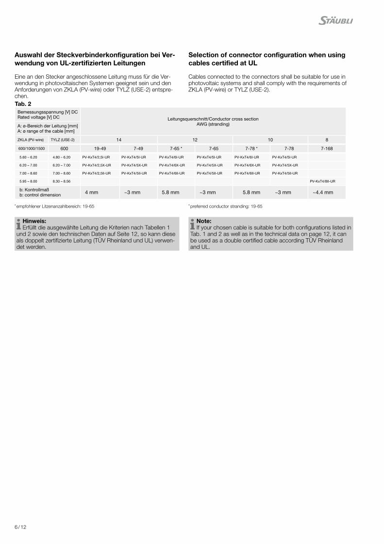
Auswahl der Steckverbinderkonfiguration bei Ver-wendung von UL-zertifizierten Leitungen
Selection of connector configuration when using cables certified at UL
Eine an den Stecker angeschlossene Leitung muss für die Ver-wendung in photovoltaischen Systemen geeignet sein und den Anforderungen von ZKLA (PV-wire) oder TYLZ (USE-2) entspre-chen.
Cables connected to the connectors shall be suitable for use in photovoltaic systems and shall comply with the requirements of ZKLA (PV-wire) or TYLZ (USE-2).
* empfohlener Litzenanzahlbereich: 19-65 * preferred conductor stranding: 19-65
Hinweis: Erfüllt die ausgewählte Leitung die Kriterien nach Tabellen 1
und 2 sowie den technischen Daten auf Seite 12, so kann diese als doppelt zertifizierte Leitung (TÜV Rheinland und UL) verwen-det werden.
Note: If your chosen cable is suitable for both configurations listed in
Tab. 1 and 2 as well as in the technical data on page 12, it can be used as a double certified cable according TÜV Rheinland and UL.
Tab. 2Bemessungsspannung [V] DCRated voltage [V] DC Leitungsquerschnitt/Conductor cross section
AWG (stranding)A: ø-Bereich der Leitung [mm] A: ø range of the cable [mm]
ZKLA (PV-wire) TYLZ (USE-2) 14 12 10 8
600/1000/1500 600 19-49 7-49 7-65 * 7-65 7-78 * 7-78 7-168
5.60 – 6.20 4.80 – 6.20 PV-KxT4/2,5I-UR PV-KxT4/5I-UR PV-KxT4/6I-UR PV-KxT4/5I-UR PV-KxT4/6I-UR PV-KxT4/5I-UR
6.20 – 7.00 6.20 – 7.00 PV-KxT4/2,5X-UR PV-KxT4/5X-UR PV-KxT4/6X-UR PV-KxT4/5X-UR PV-KxT4/6X-UR PV-KxT4/5X-UR
7.00 – 8.60 7.00 – 8.60 PV-KxT4/2,5II-UR PV-KxT4/5II-UR PV-KxT4/6II-UR PV-KxT4/5II-UR PV-KxT4/6II-UR PV-KxT4/5II-UR
5.95 – 8.00 8.30 – 8.56 PV-KxT4/8II-UR
b: Kontrollmaß b: control dimension 4 mm ~3 mm 5.8 mm ~3 mm 5.8 mm ~3 mm ~4.4 mm
7 / 12
10
L
11
C
12
K
B-Crimp
O-Crimp
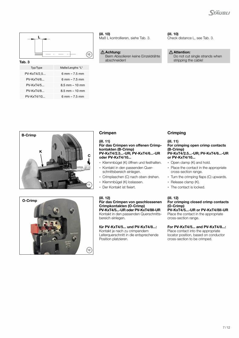
Typ/Type Maße/Lengths “L“
PV-KxT4/2,5... 6 mm – 7.5 mm
PV-KxT4/6... 6 mm – 7.5 mm
PV-KxT4/5... 8.5 mm – 10 mm
PV-KxT4/8... 8.5 mm – 10 mm
PV-KxT4/10... 6 mm – 7.5 mm
(ill. 10)Maß L kontrollieren, siehe Tab. 3.
(ill. 10)Check distance L, see Tab. 3.
Achtung: Beim Abisolieren keine Einzeldrähte abschneiden!
Attention: Do not cut single strands when stripping the cable!
Crimpen Crimping
(ill. 11)Für das Crimpen von offenen Crimp-kontakten (B-Crimp) PV-KxT4/2.5...-UR; PV-KxT4/6...-UR oder PV-KxT4/10... • Klemmbügel (K) öffnen und festhalten. • Kontakt in den passenden Quer-schnittsbereich einlegen.
• Crimplaschen (C) nach oben drehen. • Klemmbügel (K) loslassen. • Der Kontakt ist fixiert.
(ill. 11)For crimping open crimp contacts (B-Crimp) PV-KxT4/2.5...-UR; PV-KxT4/6...-UR or PV-KxT4/10... • Open clamp (K) and hold. • Place the contact in the appropriate cross-section range.
• Turn the crimping flaps (C) upwards. • Release clamp (K). • The contact is locked.
(ill. 12)Für das Crimpen von geschlossenen Crimpkontakten (O-Crimp)PV-KxT4/5...-UR oder PV-KxT4/8II-URKontakt in den passenden Querschnitts-bereich einlegen.
(ill. 12)For crimping closed crimp contacts (O-Crimp)PV-KxT4/5...-UR or PV-KxT4/8II-URPlace the contact in the appropriate cross-section range.
für PV-KxT4/5... und PV-KxT4/8...:Kontakt je nach zu crimpendem Leiterquerschnitt in die entsprechende Position platzieren.
For PV-KxT4/5... and PV-KxT4/8...:Place contact into the appropriate locator position, based on conductor cross-section to be crimped.
Tab. 3

8 / 12
13
14
15
16
(ill. 13)Sicherstellen, dass der Kontakt vor dem Crimpen vollständig in die Positionier-vorrichtung eingeführt wird.
(ill. 13)Make sure the contact is fully inserted into the locator before crimping.
(ill. 14)Zange leicht zusammendrücken, so dass die Crimplaschen innerhalb des Crimpeinsatzes liegen.
(ill. 14)Press the pliers gently together until the crimping flaps are properly located within the crimping die.
(ill. 15)Abisolierte Leitung einführen, bis die Litzen der Leitung am Klemmbügel anschlagen. Crimpzange ganz schließen.
(ill. 15)Insert the stripped cable end until the lead strands come up against the clamp. Completely close the crimping pliers.
(ill. 16)Crimpung visuell kontrollieren be- züglich der Kriterien, die in IEC 60352-2:2006 + A1:2013 beschrieben sind.
(ill. 16)Visually check the crimp according to the criteria written in IEC 60352-2:2006 + A1:2013.
Sicherstellen dass: • alle Litzen in der Crimphülse einge-schlossen sind
• die Crimphülse nicht deformiert ist und kein Teil der Crimplaschen fehlt
• die Crimpung symmetrisch ist • auf der Kontaktseite der Crimpung ein „Bündel“ Litzen sichtbar ist.
Confirm that: • all of the strands have been captured in the crimp sleeve
• the crimp sleeve is not deformed or missing any portion of the crimp flaps
• that the crimp is symmetrical • a “brush” of conductor strands are visible on the contact side of crimp.

9 / 12
17
18
19
0! >0
Montage-Prüfung Assembly check
(ill. 17)Angecrimpten Kontakt von hinten in die Isolation bis zum Einrasten einführen.Es ertönt ein „Klick“-Geräusch, sobald dieser vollständig eingeführt ist.Durch leichtes Ziehen an der Leitung prüfen, ob das Metallteil richtig einge-rastet ist.
(ill. 17)Insert the crimped contact into the insulator of the male or female coupler until engaged.You will typically hear a “click” sound once fully engaged.Pull gently the cable to verify that the metal part is correctly engaged.
(ill. 18)Prüfstift mit der entsprechenden Seite bis zum Anschlag in die Buchse bzw. in den Stecker stecken. Bei richtig montiertem Kontakt muss die weiße Markierung am Prüfstift noch sichtbar sein.
(ill. 18)Insert the appropriate end of the test pin into the male or female coupler as far as it will go. If the contact is assembled properly the white mark on the test pin must still be visible.
(ill. 19) • Leitungsverschraubung mit PV-MS oder PV-MS-PLS handfest anziehen.
• Leitungsverschraubung mit dem Drehmomentschlüssel und Adapter PV-WZ-AD/GWD anziehen und mit PV-MS oder PV-MS-PLS abstützen.
Das Anzugsdrehmoment muss für die verwendeten Solarleitung geeignet sein. Typische Werte liegen zwischen 3,4 N m und 3,5 N m1).1) Stäubli empfiehlt den eingesetzten Drehmoment-
schlüssel vor Montagebeginn zu kalibrieren. Der NFPA National Electric Code (NEC 2017) fordert den Einsatz eines kalibrierten Drehmo-mentschlüssels im Abschnitt 110.14(D).
(ill. 19) • Pre-tighten cable gland with tools PV-MS or PV-MS-PLS.
• tighten cable gland using adapter PV-WZ-AD/GWD affixed to the torque wrench while supporting the insulator front with PV-MS or PV-MS-PLS.
The tightening torque must be appro-priate for the solar cables used. Typical values are between 3.4 and 3.5 N m1).1) Stäubli recommends to use a calibrated torque
wrench for assembly. The NFPA National Electric Code (NEC 2017) requires the use of a calibrated torque wrench in section 110.14(D).
Hinweis: Die Umgebungstemperatur zur
Montage der Komponenten sollte zwischen -15 °C und 35 °C liegen
Note: For assembly of components an
ambient temperature between -15 °C and 35 °C is recommended.
Hinweis: Hutmutter nicht auf Block verschrauben. Note:
Do not bottom out the capnut.
10 / 12
22
20
21
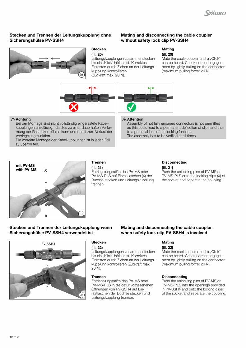
Stecken(ill. 20)Leitungskupplungen zusammenstecken bis ein „Klick“ hörbar ist. Korrektes Einrasten durch Ziehen an der Leitungs-kupplung kontrollieren (Zugkraft max. 20 N).
Mating(ill. 20)Mate the cable coupler until a „Click“ can be heard. Check correct engage-ment by lightly pulling on the connector (maximum pulling force: 20 N).
Trennen(ill. 21)Entriegelungsstifte des PV-MS oder PV-MS-PLS auf Einrastlaschen (X) der Buchse stecken und Leitungskupplung trennen.
Disconnecting(ill. 21)Push the unlocking pins of PV-MS or PV-MS-PLS onto the locking clips (X) of the socket and separate the coupling.
Stecken(ill. 22)Leitungskupplungen zusammenstecken bis ein „Klick“ hörbar ist. Korrektes Einrasten durch Ziehen an der Leitungs-kupplung kontrollieren (Zugkraft max. 20 N).
Mating(ill. 22)Mate the cable coupler until a „Click“ can be heard. Check correct engage-ment by lightly pulling on the connector (maximum pulling force: 20 N).
TrennenEntriegelungsstifte des PV-MS oder PV-MS-PLS in die dafür vorgesehenen Öffnungen von PV-SSH4 auf Ein-rastlaschen der Buchse stecken und Leitungskupplung trennen.
DisconnectingPush the unlocking pins of PV-MS or PV-MS-PLS into the openings provided in PV-SSH4 and onto the locking clips of the socket and separate the coupling.
mit PV-MSwith PV-MS
Stecken und Trennen der Leitungskupplung ohne Sicherungs hülse PV-SSH4
Mating and disconnecting the cable coupler without safety lock clip PV-SSH4
Stecken und Trennen der Leitungskupplung wenn Sicherungs hülse PV-SSH4 verwendet ist
Mating and disconnecting the cable coupler when safety lock clip PV-SSH4 is involved
Achtung Bei der Montage sind nicht vollständig eingerastete Kabel-kupplungen unzulässig, da dies zu einer dauerhaften Verfor-mung der Rasthaken führen kann und damit zum Verlust der Verriegelungsfunktion. Die korrekte Montage der Kabelkupplungen ist in jeden Fall zu überprüfen.
Attention Assembly of not fully engaged connectors is not permitted as this could lead to a permanent deflection of clips and thus to a potential loss of the locking function. The assembly has to be verified at all times.

11 / 12
Hinweise zur Installation Notes on installation
Hinweis: Wenn der Steckverbinder in Niederspannungs-Gleichstrom
Anwendungen für andere Zwecke als in einem Photovoltaik-System verwendet werden soll, befolgen Sie bitte die Hinweise im Stäubli Technical Description Report. https://spot.staubli.com/api/v1/bin/PRJaW2pVg8LoZg9YwGOoN1?query[formats_type]=pdf-web
Note: If the connector is to be used in low-voltage DC applications
other than those in a photovoltaic array, please consult the infor-mation as provided in the Stäubli Technical Description Report. https://spot.staubli.com/api/v1/bin/eZPBd5DJXyexvX13OyRo-Qa?query[formats_type]=pdf-web
Allgemeine Installationshinweise • Nicht gesteckte Steckverbinder sind mit Verschlusskappen (Buchse Bestell-Nr. 32.0716; Stecker Bestell-Nr. 32.0717) vor Umwelteinflüssen zu schützen (Feuchtigkeit, Schmutz, Staub etc.).
• Kontaminierte Steckverbinder nicht miteinander verbinden. • Steckverbinder dürfen nicht in Berührung mit jeglichen Chemi-kalien kommen.
General notes on installation • Unmated connectors must be protected from environmental im-pact (moisture, dirt, dust, etc.) with sealing caps (socket order no. 32.0716; plug order no. 32.0717).
• Do not mate contaminated connectors. • Connectors must not come into contact with any chemicals.
LeitungsführungDie Leitung muss so installiert werden, dass sie mindestens 20 mm gerade und ohne Biegung oder Belastung aus der Verschraubung bzw. den Dichtungen des Steckverbinders herausgeführt wird. Spezifikationen des Leitungsherstellers betreffend des Biegeradius beachten.
Cable routingCable management must allow a minimum of 20 mm of cablethat exits directly from the cable seal without bending or stress.Refer to cable manufacturers specification for minimum bendingradius.
Verunreinigte/beschädigte Steckverbinder: • Sicherstellen, dass der Steckverbinder nicht durch Umwelt-einflüsse verunreinigt wird (z. B. durch Erde, Wasser, Insekten, Staub).
• Sicherstellen, dass die Oberfläche des Steckverbinders nicht verunreinigt wird (z. B. durch Aufkleber, Farbe, Schrumpf-schläuche).
• Der Steckverbinder darf nicht direkt auf der Dachfläche liegen. • Sicherstellen, dass der Steckverbinder sich nicht an der tiefsten Stelle der Verkabelung befindet, wo sich Wasser ansammeln kann.
• Sicherstellen, dass der Steckverbinder nicht in stehendem Was-ser steht.
• Sicherstellen, dass die Kabelbinder nicht direkt am Steckerver-bindergehäuse befestigt werden.
Contaminated/damaged connectors: • Do not allow connectors to be contaminated by the environ-ment (e.g. soil, water, insects, dust).
• Do not allow the connector to be contaminated on its surface (e.g. stickers, paint, heat shrink tubing)
• Do not allow that the connector is directly on the roofing sur-face.
• Do not allow that the connector is at the lowest point of cabling where water can collect
• Do not allow that the connector is in standing water • Do not allow that cable ties to be mounted directly on the connector body.
Mechanische Beanspruchung: • Sicherstellen, dass die Steckverbinder keiner dauerhaften me-chanischen Zugbelastung oder Vibration ausgesetzt sind.
• Die Steckverbinder sollen nicht durch das Kabelmanagement belastet werden.
Mechanical stress: • Check that the connectors are not subjected to a permanent mechanical tensile load or vibration
• Connectors shall not be under strain from cable management.
Min. 20 mm
12 / 12
Hersteller/Producer: Stäubli Electrical Connectors AG Stockbrunnenrain 8 4123 Allschwil/Switzerland Tel. +41 61 306 55 55 Fax +41 61 306 55 56 mail [email protected] www.staubli.com/electrical
© b
y S
täub
li E
lect
rica
l Co
nnec
tors
AG
, Sw
itzer
land
– M
A23
1 –
09.2
021
– In
dex
e M
arke
ting
Com
mun
icat
ions
– Ä
nder
unge
n vo
rbeh
alte
n /
Sub
ject
to a
ltera
tions
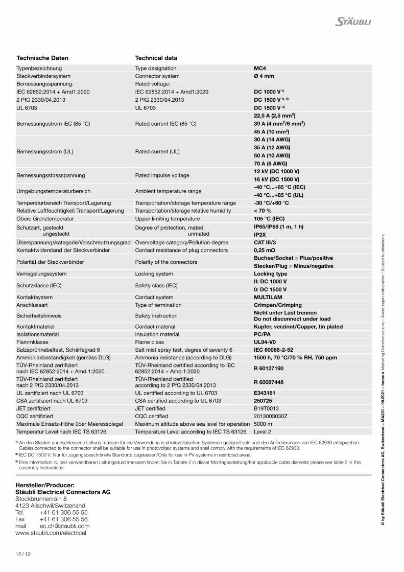
Technische Daten Technical data
Typenbezeichnung Type designation MC4Steckverbindersystem Connector system Ø 4 mmBemessungsspannung: IEC 62852:2014 + Amd1:20202 PfG 2330/04.2013UL 6703
Rated voltage: IEC 62852:2014 + Amd1:20202 PfG 2330/04.2013UL 6703
DC 1000 V 1)
DC 1500 V 1), 2)
DC 1500 V 3)
Bemessungsstrom IEC (85 °C) Rated current IEC (85 °C)22,5 A (2,5 mm²)39 A (4 mm²/6 mm²)45 A (10 mm2)
Bemessungsstrom (UL) Rated current (UL)
30 A (14 AWG)35 A (12 AWG)50 A (10 AWG)70 A (8 AWG)
Bemessungsstossspannung Rated impulse voltage12 kV (DC 1000 V)16 kV (DC 1500 V)
Umgebungstemperaturbereich Ambient temperature range-40 °C...+85 °C (IEC)-40 °C...+85 °C (UL)
Temperaturbereich Transport/Lagerung Transportation/storage temperature range -30 °C/+60 °CRelative Luftfeuchtigkeit Transport/Lagerung Transportation/storage relative humidity < 70 %Obere Grenztemperatur Upper limiting temperature 105 °C (IEC)
Schutzart, gesteckt ungesteckt
Degree of protection, mated unmated
IP65/IP68 (1 m, 1 h)IP2X
Überspannungskategorie/Verschmutzungsgrad Overvoltage category/Pollution degree CAT III/3Kontaktwiderstand der Steckverbinder Contact resistance of plug connectors 0,25 mΩ
Polarität der Steckverbinder Polarity of the connectorsBuchse/Socket = Plus/positiveStecker/Plug = Minus/negative
Verriegelungssystem Locking system Locking type
Schutzklasse (IEC) Safety class (IEC)II: DC 1000 V0: DC 1500 V
Kontaktsystem Contact system MULTILAMAnschlussart Type of termination Crimpen/Crimping
Sicherheitshinweis Safety instruction Nicht unter Last trennen Do not disconnect under load
Kontaktmaterial Contact material Kupfer, verzinnt/Copper, tin platedIsolationsmaterial Insulation material PC/PAFlammklasse Flame class UL94-V0Salzsprühnebeltest, Schärfegrad 6 Salt mist spray test, degree of severity 6 IEC 60068-2-52Ammoniakbeständigkeit (gemäss DLG) Ammonia resistance (according to DLG) 1500 h, 70 °C/70 % RH, 750 ppmTÜV-Rheinland zertifiziert nach IEC 62852:2014 + Amd.1:2020
TÜV-Rheinland certified according to IEC 62852:2014 + Amd.1:2020 R 60127190
TÜV-Rheinland zertifiziert nach 2 PfG 2330/04.2013
TÜV-Rheinland certified according to 2 PfG 2330/04.2013 R 60087448
UL zertifiziert nach UL 6703 UL certified according to UL 6703 E343181CSA zertifiziert nach UL 6703 CSA certified according to UL 6703 250725JET zertifiziert JET certified B19T0013CQC zertifiziert CQC certified 2013003030ZMaximale Einsatz-Höhe über Meeresspiegel Maximum altitude above sea level for operation 5000 mTemperatur Level nach IEC TS 63126 Temperature Level according to IEC TS 63126 Level 2
1) An den Stecker angeschlossene Leitung müssen für die Verwendung in photovoltaischen Systemen geeignet sein und den Anforderungen von IEC 62930 entsprechen. Cables connected to the connector shall be suitable for use in photovoltaic systems and shall comply with the requirements of IEC 62930.
2) IEC DC 1500 V: Nur für zugangsbeschränkte Standorte zugelassen/Only for use in PV-systems in restricted areas.3) Eine Information zu den verwendbaren Leitungsdurchmessern finden Sie in Tabelle 2 in dieser Montageanleitung/For applicable cable diameter please see table 2 in this
assembly instructions.