Model-Based Testing of Automotive HMIs with Consideration for
185
Model-Based Testing of Automotive HMIs with Consideration for Product Variability Dissertation an der Fakult¨ at f¨ ur Mathematik, Informatik und Statistik Ludwig-Maximilians-Universit¨ at M¨ unchen vorgelegt von Linshu Duan M¨ uchen, den 28. Juni 2012
Transcript of Model-Based Testing of Automotive HMIs with Consideration for
Model-Based Testing of AutomotiveHMIs with Consideration for
Product Variability
Dissertation
an der
Fakultat fur Mathematik, Informatik und Statistik
Ludwig-Maximilians-Universitat Munchen
vorgelegt von
Linshu Duan
Muchen, den 28. Juni 2012

Model-Based Testing of AutomotiveHMIs with Consideration for
Product Variability
Dissertation
submitted to
Fakultat fur Mathematik, Informatik und Statistik
Ludwig-Maximilians-Universitat Munchen
by
Linshu Duan
Munich, June 28, 2012

Erstgutachter: Prof. Dr. Heinrich Hussmann
Zweitgutachter: Prof. Dr. Detlef Zuhlke
Tag der mundlichen Prufung: 4. June 2012

Eidesstattliche Erklarung
Ich versichere an Eides Statt durch meine eigenhandige Unterschrift, dass ich die vor-liegende Arbeit selbststandig und ohne fremde Hilfe angefertigt habe. Alle Stellen, diewortlich oder dem Sinn nach auf Publikationen oder Vortragen anderer Autoren beruhen,sind als solche kenntlich gemacht. Ich versichere außerdem, dass ich keine andere als dieangegebene Literatur verwendet habe. Diese Versicherung bezieht sich auch auf alle inder Arbeit enthaltenen Zeichnungen, Skizzen, bildlichen Darstellungen und dergleichen.Die Arbeit wurde bisher keiner anderen Prufungsbehorde vorgelegt und auch noch nichtveroffentlicht.
Ingolstadt, den 28. Juni 2012Linshu Duan

Abstract
The human-machine interfaces (HMIs) of today’s premium automotive infotainment systemsare complex embedded systems which have special characteristics in comparison to GUIs ofstandard PC applications, in particular regarding their variability. The variability of info-tainment system HMIs results from different car models, product series, markets, equipmentconfiguration possibilities, system types and languages and necessitates enormous testing ef-forts. The model-based testing approach is a promising solution for reducing testing efforts andincreasing test coverage. However, while model-based testing has been widely used for functiontests of subsystems in practice, HMI tests have remained manual or only semi-automated andare very time-consuming and work-intensive. Also, it is very difficult to achieve systematicor high test coverage via manual tests. A large amount of research work has addressed GUItesting in recent years. In addition, variability is becoming an ever more popular topic in thedomain of software product line development. However, a model-based testing approach forcomplex HMIs which also considers variability is still lacking. This thesis presents a model-based testing approach for infotainment system HMIs with the particular aim of resolving thevariability problem. Furthermore, the thesis provides a foundation for future standards of HMItesting in practice.
The proposed approach is based on a model-based HMI testing framework which includestwo essential components: a test-oriented HMI specification and a test generation component.The test-oriented HMI specification has a layered structure and is suited to specifying datawhich is required for testing different features of the HMI. Both the dynamic behavior andthe representation of the HMI are the testing focuses of this thesis. The test generation com-ponent automatically generates tests from the test-oriented HMI specification. Furthermore,the framework can be extended in order to automatically execute the generated tests. Gen-erated tests must first be initialized, which means that they are enhanced with concrete userinput data. Afterwards, initialized tests can be automatically executed with the help of a testexecution tool which must be extended into the testing framework.
In this thesis, it is proposed to specify and test different HMI-variants which have a large set ofcommonalities based on the software product line approach. This means the test-oriented HMIspecification is extended in order to describe the commonalities and variabilities between HMIvariants of an HMI product line. In particular, strategies are developed in order to generatetests for different HMI products. One special feature is that redundancies are avoided both forthe test generation and the execution processes. This is especially important for the industrialpractice due to limited test resources. Modeling and testing variability of automotive HMIsmake up the main research contributions of this thesis.
We hope that the results presented in this thesis will offer GUI testing research a solutionfor model-based testing of multi-variant HMIs and provide the automotive industry with afoundation for future HMI testing standards.

Zusammenfassung
Die Mensch-Maschine-Schnittstellen (HMIs) von Infotainmentsystemen der heutigen Premi-umfahrzeuge sind sehr komplexe und eingebettete Systeme. Sie haben im Vergleich mitherkommlichen PC-Applikationen besondere Eigenschaften, insbesondere bezogen auf ihreVariabilitat. Die Variabilitat von Infotainmentsystem HMIs ergibt sich aus unterschiedlichenFahrzeugsmodellen, Produktserien, Markten, Ausstattungen, System- sowie Sprachvarianten.Die hohe Anzahl der Varianten fuhrt zu enorm hohem Testaufwand. Modellbasiertes Testen istein vielversprechender Ansatz, um den Testaufwand durch die automatische Testfallgenerierungund Testausfuhrung zu reduzieren und gleichzeitig die Testabdeckung zu erhohen. Wahrendmodellbasiertes Testen bereits fur Funktionstests haufig eingesetzt wird, bleiben HMI Testsmeist noch manuell oder teil-automatisiert. Außerdem kann durch manuelles Testen eine sys-tematische Testabdeckung nur sehr schwierig erreicht werden. Zahlreiche Forschungsarbeitenbefassen sich mit dem GUI-Testen. Variabilitat ist im Bereich der Software-Produktentwicklungein immer beliebteres Forschungsthema. Ein modellbasierter Testansatz fur komplexe HMIsmit Berucksichtigung der Variabilitat ist allerdings immer noch nicht vorhanden. Diese Dok-torarbeit prasentiert eine modellbasierte Testmethode fur Infotainmentsystem HMIs mit dembesonderen Ziel das Variabilitatsproblem zu losen. Zusatzlich bietet diese Doktorarbeit eineBasis fur zukunftiges HMI-Testen in der Industrie an.
Der Ansatz in dieser Doktorarbeit basiert auf einem modellbasiertem HMI-Testframework, daszwei essentielle Komponenten beinhaltet: eine Test-orientierte Spezifikation und eine Kompo-nente zur Testgenerierung. Die Test-orientierte Spezifikation hat eine geschichtete Strukturund ist darauf ausgerichtet, die furs Testen relevanten Daten zu spezifizieren. Sowohl dynamis-ches Menuverhalten als auch die Darstellung des HMI sind die Testziele. Die Testgenerierungerzeugt automatisch Tests aus der Test-orientierten HMI Spezifikation. Das Testframeworkkann um eine automatische Testausfuhrung erweitert werden. Nachdem die generierten Testsinstanziert werden, ist es moglich sie automatisch innerhalb eines Testautomatisierungsframe-works durchzufuhren.
Diese Doktorarbeit befasst sich mit Methoden, um die HMI-Varianten effizient zu spezifizierenund zu testen und basiert auf Ansatz fur Software Produktlinien. Das bedeutet, die Test-orientierte Spezifikation ist erweitert um sowohl die Gemeinsamkeiten als auch die Spezialitatender Varianten zu beschreiben. Insbesondere werden Strategien entwickelt, um Tests fur unter-schiedliche Varianten der Produktlinien automatisch zu generieren. Die Besonderheit dabei ist,dass Redundanzen sowohl fur den Generierungsvorgang als auch den Ausfuhrungsvorgang ver-mieden werden konnen. Das ist wegen den eingeschrankten Ressourcen und aus Effizientsgrundenbesonders wichtig fur die Industrie. Die Modellierung und das Testen von variantenreichenHMIs stellen die Hauptbeitrage dieser Dissertation dar.
Die Ergebnisse dieser Doktorarbeit konnen hoffentlich als eine Losung fur modellbasiertesTesten der multi-varianten HMIs dienen und der Automotive-Industrie eine Basis der zukunftigenHMI Testenstandards liefern.

Danksagung (Acknowledgments)
Diese Arbeit ist wahrend der Mitarbeit in der Abteilung Infotainmentsystem Entwicklung undTesten bei der AUDI AG als Doktorandin und unter Betreuung der Universitat Munchenentstanden. An dieser Stelle mochte ich mich bei allen Personen bedanken, die mich bei derPromotion und Erstellung dieser Arbeit unterstutzt haben.
Mein großter Dank geht an meinen Doktorvater Professor Hussmann, der mir wissenschaftlicheWerte durch zahlreiche Gesprachsstunden, E-Mails und Korrekturarbeiten vermittelt hat. Seinrespektvoller Umgang mit Menschen wird mir in meinem Leben immer ein Vorbild sein.
Herrn Professor Zuhlke danke ich sehr fur das entgegengebrachte Interesse und die Bereitschaftdas zweite Gutachten zu erstellen.
Ich mochte mich besonders bei Alexander Hofer bedanken. Als Betreuer bei der AUDI AGhat er mir die Chance fur eine Promotion bei Audi gegeben. Seine langjahrige Unterstutzunghat maßgeblich am Erfolg meiner Arbeit beigetragen. Ebenso bedanke ich mich bei meinemAbteilungsleiter wahrend der Doktorarbeit Dieter Niederkorn, fur die Schulung in der Kom-munikation und Arbeitsweise im Unternehmen. Mein Dank gilt ebenso allen Kollegen undStudenten fur die hervorragende Unterstutzung und Zusammenarbeit.
Meine Familie hat mir wahrend der gesamten Promotion unheimlich viel Unterstutzung gegeben.Mein herzlicher Dank geht an meine lieben Schwiegereltern Petra und Dirk Brand, die mir vielWarme und Liebe geschenkt haben. Mein lieber Dank gilt meinem Ehemann Sebastian Brand,der mir immer Zuspruch gegeben hat und mir in schwierigen und entscheidenden Phasen immerden Rucken freigehalten hat.
Mehr als nur Dank gebuhrt meinen Eltern. Sie haben mir in der fruhesten Kindheit bereitsWerte mitgegeben, die mir in meiner Ausbildung, beruflichen und privaten Leben immer zurrichtigen Entscheidung verholfen haben. Sie sind zwar wahrend meines Studiums und derPromotion nicht in meiner raumlicher Nahe gewesen, jedoch waren sie bei jeder Schwierigkeit,Freude, Spannung und Entscheidung eng bei mir. Sie geben mir unheimlich viel Energie furjede Phase des Lebens. Mein Gluck und meine Erfolge verdanke ich ihnen.

Contents
I. Introduction 1
1. Problem and Solution Summary 71.1. Problem summary . . . . . . . . . . . . . . . . . . . . . . . . . . . . . . . . . . 71.2. Solution summary . . . . . . . . . . . . . . . . . . . . . . . . . . . . . . . . . . 9
1.2.1. The framework for model-based HMI testing . . . . . . . . . . . . . . . 91.2.2. Integrating variability into model-based testing . . . . . . . . . . . . . . 10
1.3. Organization of this thesis . . . . . . . . . . . . . . . . . . . . . . . . . . . . . . 11
2. Fundamentals 132.1. Model-based testing . . . . . . . . . . . . . . . . . . . . . . . . . . . . . . . . . 13
2.1.1. Variants of MBT . . . . . . . . . . . . . . . . . . . . . . . . . . . . . . . 142.1.2. Test generation . . . . . . . . . . . . . . . . . . . . . . . . . . . . . . . . 152.1.3. Automated test executions . . . . . . . . . . . . . . . . . . . . . . . . . 172.1.4. Current situation of MBT in practice . . . . . . . . . . . . . . . . . . . 172.1.5. UML statechart . . . . . . . . . . . . . . . . . . . . . . . . . . . . . . . . 18
2.2. Automotive HMIs . . . . . . . . . . . . . . . . . . . . . . . . . . . . . . . . . . 182.2.1. The graphical representation of an HMI . . . . . . . . . . . . . . . . . . 192.2.2. The dynamics of an HMI . . . . . . . . . . . . . . . . . . . . . . . . . . 202.2.3. Development process of an HMI . . . . . . . . . . . . . . . . . . . . . . 212.2.4. Variants of HMI . . . . . . . . . . . . . . . . . . . . . . . . . . . . . . . 222.2.5. Conclusion: Automotive HMI vs. standard PC applications . . . . . . . 22
3. Related Work 233.1. Model-based GUI testing . . . . . . . . . . . . . . . . . . . . . . . . . . . . . . 243.2. Model-based testing of GUIs with variability . . . . . . . . . . . . . . . . . . . 283.3. Model-based development of GUIs with variability . . . . . . . . . . . . . . . . 303.4. Conclusion . . . . . . . . . . . . . . . . . . . . . . . . . . . . . . . . . . . . . . 31
II. Framework for Model-Based HMI Testing 33
4. The Framework for Model-Based HMI Testing 374.1. Components of the HMI testing framework . . . . . . . . . . . . . . . . . . . . 37
4.1.1. Related work . . . . . . . . . . . . . . . . . . . . . . . . . . . . . . . . . 404.2. Analysis of HMI error types . . . . . . . . . . . . . . . . . . . . . . . . . . . . . 40
4.2.1. Errors occurring in practice . . . . . . . . . . . . . . . . . . . . . . . . . 40
i
Contents
4.2.2. HMI errors addressed in this thesis . . . . . . . . . . . . . . . . . . . . . 44
4.3. Conclusions . . . . . . . . . . . . . . . . . . . . . . . . . . . . . . . . . . . . . . 47
5. The Test-Oriented HMI Specification 495.1. General requirements . . . . . . . . . . . . . . . . . . . . . . . . . . . . . . . . . 49
5.2. Requirements for the menu behavior model . . . . . . . . . . . . . . . . . . . . 52
5.3. Requirements for the representation layer . . . . . . . . . . . . . . . . . . . . . 59
5.3.1. Specification of screen contents . . . . . . . . . . . . . . . . . . . . . . . 60
5.3.2. Specification of possible triggerable events . . . . . . . . . . . . . . . . . 62
5.3.3. Meta-model of the representation layer . . . . . . . . . . . . . . . . . . . 63
5.4. Related work . . . . . . . . . . . . . . . . . . . . . . . . . . . . . . . . . . . . . 64
5.5. Conclusions . . . . . . . . . . . . . . . . . . . . . . . . . . . . . . . . . . . . . . 66
6. Test Generation 676.1. The menu behavior SC . . . . . . . . . . . . . . . . . . . . . . . . . . . . . . . . 67
6.2. A test generation algorithm . . . . . . . . . . . . . . . . . . . . . . . . . . . . . 68
6.3. Generated tests . . . . . . . . . . . . . . . . . . . . . . . . . . . . . . . . . . . . 71
6.3.1. Based on the transition coverage . . . . . . . . . . . . . . . . . . . . . . 71
6.3.2. Based on the path coverage . . . . . . . . . . . . . . . . . . . . . . . . . 72
6.3.3. Based on the state coverage . . . . . . . . . . . . . . . . . . . . . . . . . 73
6.4. Related work . . . . . . . . . . . . . . . . . . . . . . . . . . . . . . . . . . . . . 74
6.5. Conclusions . . . . . . . . . . . . . . . . . . . . . . . . . . . . . . . . . . . . . . 75
III. Integrating Variability Into Model-Based HMI Testing 77
7. HMI Specification With Variability 817.1. Feature specification . . . . . . . . . . . . . . . . . . . . . . . . . . . . . . . . . 82
7.1.1. Extended feature model . . . . . . . . . . . . . . . . . . . . . . . . . . . 82
7.1.2. Related work . . . . . . . . . . . . . . . . . . . . . . . . . . . . . . . . . 84
7.2. Menu behavior model with variability . . . . . . . . . . . . . . . . . . . . . . . 85
7.2.1. How to incorporate functional features into the menu behavior SC . . . 85
7.2.2. How to incorporate variant features into the menu behavior SC . . . . . 88
7.2.3. How to incorporate functional feature options into the menu behavior SC 91
7.2.4. Related work . . . . . . . . . . . . . . . . . . . . . . . . . . . . . . . . . 91
7.3. Representation layer with variability . . . . . . . . . . . . . . . . . . . . . . . . 93
7.3.1. Variability of abstract screens . . . . . . . . . . . . . . . . . . . . . . . . 93
7.3.2. Variability of representation units . . . . . . . . . . . . . . . . . . . . . 95
7.3.3. Extended meta-model for the representation layer . . . . . . . . . . . . 96
7.4. Related work . . . . . . . . . . . . . . . . . . . . . . . . . . . . . . . . . . . . . 98
7.5. Conclusions . . . . . . . . . . . . . . . . . . . . . . . . . . . . . . . . . . . . . . 99
8. Test Generation With Variability 1018.1. A test generation method . . . . . . . . . . . . . . . . . . . . . . . . . . . . . . 101
8.1.1. Generating test sequences . . . . . . . . . . . . . . . . . . . . . . . . . . 102
8.1.2. Constructing tests from test sequences . . . . . . . . . . . . . . . . . . . 115
8.1.3. Avoiding redundant tests . . . . . . . . . . . . . . . . . . . . . . . . . . 119
ii
Contents
8.1.4. Conclusions . . . . . . . . . . . . . . . . . . . . . . . . . . . . . . . . . . 1228.2. Some other coverage criteria . . . . . . . . . . . . . . . . . . . . . . . . . . . . . 1228.3. Conclusions . . . . . . . . . . . . . . . . . . . . . . . . . . . . . . . . . . . . . . 123
IV. Evaluation and Conclusions 125
9. Evaluation 1299.1. Data source for the evaluation . . . . . . . . . . . . . . . . . . . . . . . . . . . . 129
9.1.1. Proof-of-concept implementation . . . . . . . . . . . . . . . . . . . . . . 1299.1.2. An HMI development model from real life . . . . . . . . . . . . . . . . . 133
9.2. Evaluation . . . . . . . . . . . . . . . . . . . . . . . . . . . . . . . . . . . . . . . 1389.2.1. Design of the evaluation . . . . . . . . . . . . . . . . . . . . . . . . . . . 1389.2.2. Evaluation based on mathematical plausibility analysis . . . . . . . . . . 1409.2.3. General discussion . . . . . . . . . . . . . . . . . . . . . . . . . . . . . . 1419.2.4. Estimation with concrete data . . . . . . . . . . . . . . . . . . . . . . . 143
9.3. Conclusions . . . . . . . . . . . . . . . . . . . . . . . . . . . . . . . . . . . . . . 145
10.Conclusion and Future Work 14710.1. Summary . . . . . . . . . . . . . . . . . . . . . . . . . . . . . . . . . . . . . . . 14710.2. Future work . . . . . . . . . . . . . . . . . . . . . . . . . . . . . . . . . . . . . . 14910.3. Final words . . . . . . . . . . . . . . . . . . . . . . . . . . . . . . . . . . . . . . 153
V. Bibliography 155
Bibliography 157
URLs 166
iii

Part I.
Introduction
1

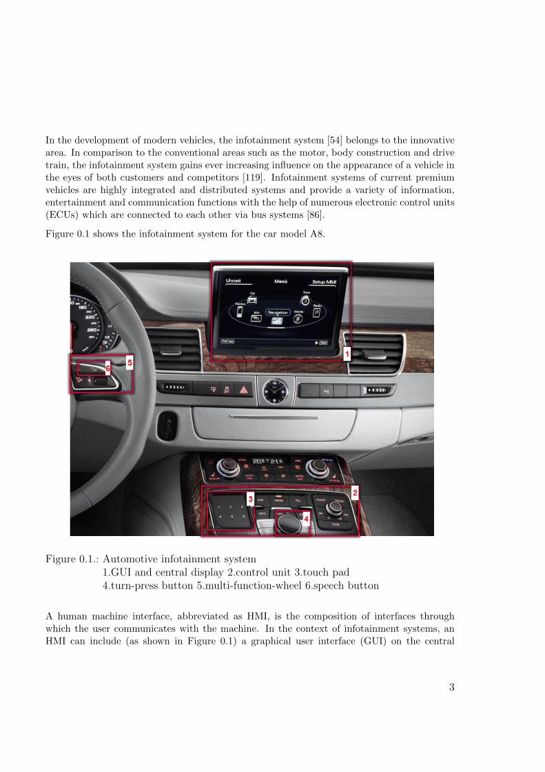
In the development of modern vehicles, the infotainment system [54] belongs to the innovativearea. In comparison to the conventional areas such as the motor, body construction and drivetrain, the infotainment system gains ever increasing influence on the appearance of a vehicle inthe eyes of both customers and competitors [119]. Infotainment systems of current premiumvehicles are highly integrated and distributed systems and provide a variety of information,entertainment and communication functions with the help of numerous electronic control units(ECUs) which are connected to each other via bus systems [86].
Figure 0.1 shows the infotainment system for the car model A8.
Figure 0.1.: Automotive infotainment system1.GUI and central display 2.control unit 3.touch pad4.turn-press button 5.multi-function-wheel 6.speech button
A human machine interface, abbreviated as HMI, is the composition of interfaces throughwhich the user communicates with the machine. In the context of infotainment systems, anHMI can include (as shown in Figure 0.1) a graphical user interface (GUI) on the central
3
Contents
display, a touch pad, buttons, a turn-press button, a multi-function wheel and speech inputand output facilities. In the A8, the touch pad, buttons and turn-press button are integratedinto one unit, known as the control unit. In many premium vehicles, the HMI also contains agraphical interface on the instrument cluster; this is not shown in Figure 0.1.
In spite of this general definition, the term “HMI” has a specific meaning in the context ofHMI development in the area of automotive infotainment systems. In this context, the HMIdoes not mean the hardware interfaces as introduced above, but the software of the graphicaluser interface. In most of the current research in this area, the term “HMI” is a synonym forthe graphical user interface of the central display [112] [45] [54].
In this thesis, the term “HMI” is assumed to have that same meaning. This means that the goalof this thesis is to test the graphical user interface on the central display. Both the graphicalrepresentation and the dynamic behavior of the HMI are focal points of this thesis. The HMIto be tested is modality-independent. This means the events to which the HMI reacts canbe triggered by different input sources. Furthermore, the GUI of the instrument cluster andconsequently the synchronization between the instrument cluster and the central display arenot included in the scope of this thesis.
The HMI of a current premium infotainment system can be a huge system. An Audi HMIcurrently in development contains up to 2200 screens, 100 pop-up menus, up to 10000 texts perlanguage and a very complex dynamic behavior. For instance, the description of the dynamicbehavior can require 200 diagrams, 50 hierarchies, 2400 view states and 14000 transitions. In[45], it was declared that up to 4000 UI elements such as screens, buttons, lists and messagesare used for the BMW 7-Series.
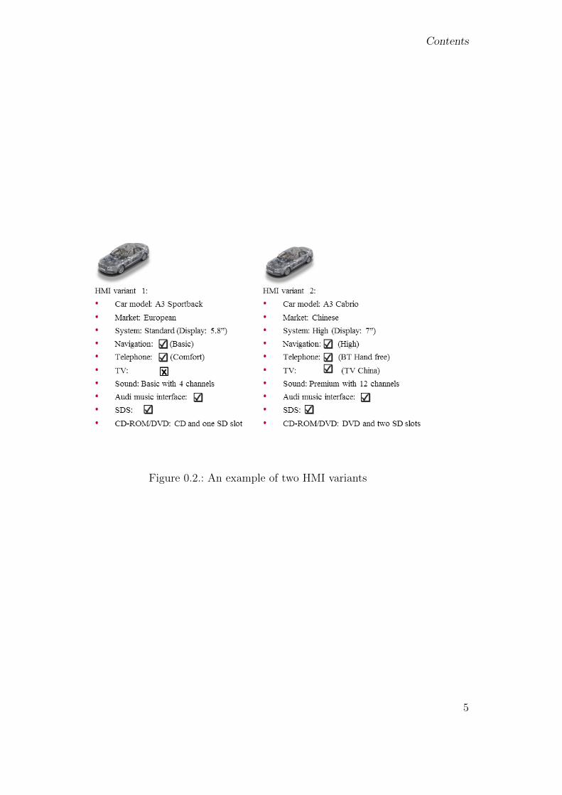
Furthermore, the HMI of a premium vehicle usually provides a large set of variants that area result of differing car models, markets, languages and system hardware [16]. Variants canalso be caused by individual combinations of functions, e.g. in some variants the navigationfunction is integrated; in others it is not. Figure 0.2 presents an example of two different HMIvariants. In practice, more than 100 variants are possible. This variability of HMIs results invery high testing complexity.
4
Contents
Figure 0.2.: An example of two HMI variants
5

Contents
6
Chapter 1.
Problem and Solution Summary
This thesis addresses the model-based testing of infotainment system HMIs with the particularaim of modeling and testing variability of the HMIs.
Current problems will be introduced from an industrial perspective as well as a research per-spective. Afterwards, an overview of the solution will be presented.
1.1. Problem summary
As mentioned above, the HMI of a current infotainment system can contain up to 2200 screens,100 pop-up menus, 10000 texts per language and a very complex dynamic behavior, the descrip-tion of which requires up to 200 diagrams, 50 hierarchies, 2400 states and 14000 transitions.More than 100 variants can be caused by different car models, markets, languages, systemhardware types and individual function configurations. HMI variability necessitates very highspecification and especially testing efforts.
Current situation
Currently, HMI tests are performed almost entirely manually in the serial development [27][112]. Once a test specification has been created for one project, it is usually manually adaptedfor later projects. In this process, defining new test cases and increasing test coverage areusually ignored due to limited time. Often, only the most important tests, which are usually asubset of the tests described in the test specification, can be executed. Manual testing is verytime-consuming and expensive. First of all, it is quite difficult to achieve systematic and hightest coverage via manual testing. Currently, increasing test coverage of infotainment systemHMIs is a common goal of many manufacturers, especially when it comes to test coverage offoreign language systems [27]. An internal statistic of a current infotainment system project hasshown that, although the HMI is only one small component out of many ECUs and bus systemsin an infotainment system, it produces about 10% of the errors. This statistic is based on theinternal evaluation of error tickets, which are randomly chosen from different developmentalphases. This result should provide an indication of the profitability of automating HMI testsand increasing test coverage.
7

Chapter 1. Problem and Solution Summary
Problems in the industry
Model-based testing [42] [105] [62], or MBT in short, makes possible automatic test generationand systematic test coverage. In combination with automated test execution, which is usu-ally called test automation [13], MBT provides a reduction in human resource requirementsand costs. Model-based testing of application functions is well established in industry today.However, model-based testing of infotainment system HMIs is still very rare.
The most efficient method of MBT is to verify the System Under Test (SUT) against testsgenerated from the specification. However, most HMI specifications are still informal, eventhough formal specifications are more precise and can be reused for development. Efforts toestablish formal specifications [37] have failed because the tools used are based on conceptsdesigned for development and are not intended for specification. Development tools supportthe complexity of code generation, whereas a specification should describe the requirements inabstract form only. The complexity involved in using development tools thus leads to a failureto create formal specifications.
Tests can also be generated from the system model (Section 2.1). However, a system modelis created for generating software code. It usually cannot be directly used for test generationdue to a lack of test data. The necessary test data must be extended in advance if a systemmodel is to be used for test generation. In this case, the code generator is validated againstthe test generator. Non-conformance between the implementation and the specification cannotbe detected. Therefore, MBT is meaningful only if the test model and the system model aredifferent.
Furthermore, an HMI testing concept that answers fundamental questions is still missing inthe industry. For instance, the issues regarding which HMI errors should and can be dealtwith, how to model the HMI for testing purposes, how to model variability and test differentvariants of the HMI, etc., have only recently been addressed [65].
Finally, variability is a new challenge for the development of infotainment system HMIs. Theindustry is still busy with variability development, e.g. in optimizing the development processand extending the development tools. The next step, i.e. testing under consideration ofvariability has not yet become a focus.
Problems in the research
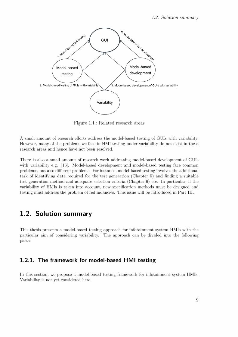
The research topic of this thesis spans the domains of GUI, model-based testing and variability,in which the GUI plays a central role. Related work can be found in the 4 domains which arepresented in Figure 1.1.
There are currently a number of research efforts that address the model-based testing of GUIapplications [84] [79] [104] [96] [20] [89]. The GUI applications in question are mostly standardPC applications such as a calendar which contains all the necessary logic and data within theapplication. In comparison to standard GUI applications for PCs, an infotainment system hasmany special characteristics such as embedding and variability which do not exist in standardGUI applications and therefore are not considered for testing. The special characteristics ofinfotainment system HMI will be introduced in Section 2.2.5.
8
1.2. Solution summary
Figure 1.1.: Related research areas
A small amount of research efforts address the model-based testing of GUIs with variability.However, many of the problems we face in HMI testing under variability do not exist in theseresearch areas and hence have not been resolved.
There is also a small amount of research work addressing model-based development of GUIswith variability e.g. [16]. Model-based development and model-based testing face commonproblems, but also different problems. For instance, model-based testing involves the additionaltask of identifying data required for the test generation (Chapter 5) and finding a suitabletest generation method and adequate selection criteria (Chapter 6) etc. In particular, if thevariability of HMIs is taken into account, new specification methods must be designed andtesting must address the problem of redundancies. This issue will be introduced in Part III.
1.2. Solution summary
This thesis presents a model-based testing approach for infotainment system HMIs with theparticular aim of considering variability. The approach can be divided into the followingparts:
1.2.1. The framework for model-based HMI testing
In this section, we propose a model-based testing framework for infotainment system HMIs.Variability is not yet considered here.
9
Chapter 1. Problem and Solution Summary
First, a statistical analysis has been done in order to identify the possible HMI errors occurringin practice. Based on this result, HMI errors which can be automatically detected in the testingframework will be clarified.
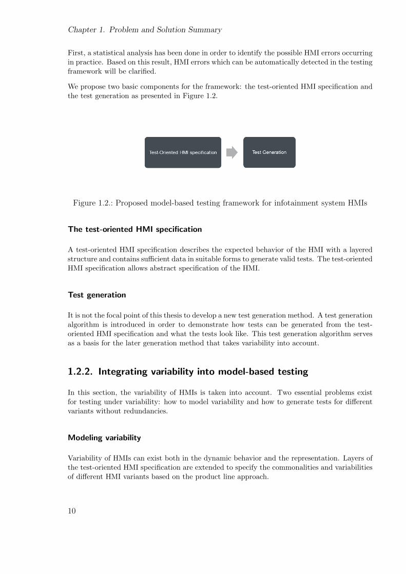
We propose two basic components for the framework: the test-oriented HMI specification andthe test generation as presented in Figure 1.2.
Figure 1.2.: Proposed model-based testing framework for infotainment system HMIs
The test-oriented HMI specification
A test-oriented HMI specification describes the expected behavior of the HMI with a layeredstructure and contains sufficient data in suitable forms to generate valid tests. The test-orientedHMI specification allows abstract specification of the HMI.
Test generation
It is not the focal point of this thesis to develop a new test generation method. A test generationalgorithm is introduced in order to demonstrate how tests can be generated from the test-oriented HMI specification and what the tests look like. This test generation algorithm servesas a basis for the later generation method that takes variability into account.
1.2.2. Integrating variability into model-based testing
In this section, the variability of HMIs is taken into account. Two essential problems existfor testing under variability: how to model variability and how to generate tests for differentvariants without redundancies.
Modeling variability
Variability of HMIs can exist both in the dynamic behavior and the representation. Layers ofthe test-oriented HMI specification are extended to specify the commonalities and variabilitiesof different HMI variants based on the product line approach.
10
1.3. Organization of this thesis
Test generation under variability
The test generation algorithm is extended to take account of the variabilities which are de-scribed in the test-oriented specification and to generate tests for different variants. It wouldbe inefficient to perform a test generation for each variant to be tested. Therefore, a testgeneration algorithm that takes account of the variabilities is designed to avoid redundant testgeneration.
However, tests generated for different variants still include a large set of identical tests, whichverify the commonality of different variants. A method is applied to automatically identifysuch tests and preserve them from redundant executions.
1.3. Organization of this thesis
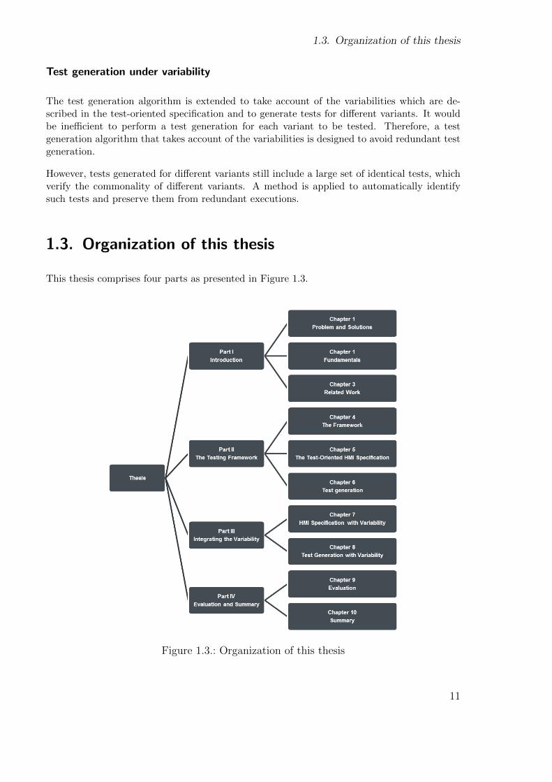
This thesis comprises four parts as presented in Figure 1.3.
Figure 1.3.: Organization of this thesis
11

Chapter 1. Problem and Solution Summary
The first part includes Chapter 1 to 3. Chapter 1 has introduced the problems and solutionsup to the present time. Chapter 2 gives an introduction to the fundamentals in the domains ofmodel-based testing and automotive HMIs. Chapter 4 presents some of the related work, com-pares this with the proposed approach and explains why existing approaches are not suitablefor testing infotainment system HMIs. References to other relevant work will be distributedthroughout the later chapters due to the diversity of the sub-topics.
In the second part, we demonstrate the proposed testing framework. Here variability is notyet considered. In Chapter 4, components of the framework and the testing goals are pre-sented. This thesis focuses on two types of tests: menu behavior tests verifying the dynamicbehavior and screen tests verifying different classes of screen contents. Chapter 5 describes therequirements of the test-oriented HMI specification. Chapter 6 demonstrates a test generationalgorithm and generated tests.
Part III focuses on variability. Chapter 7 introduces how to model variability. For modelingvariability, each layer of the test-oriented HMI specification introduced in Chapter 7 will beextended. Chapter 8 demonstrates a test generation method that considers variability and gen-erates tests for different variants without redundancies. Although redundant test generationscould be avoided, generated tests for different variants still contain identical tests, which verifythe commonality of these variants. At the end of chapter 8, a method of avoiding redundantexecutions of such tests will be introduced.
Part IV includes the evaluation and summary. Chapter 9 evaluates the modeling and test-ing concept for variability from the efficiency perspective. First, a mathematical plausibilityanalysis is demonstrated in order to show that the proposed modeling and testing conceptis profitable based on a practical HMI project. Second, a general discussion is led. Factorsare identified on which the efficiency improvement of the proposed approaches is dependent.Also, worst cases are identified in which it is not profitable to use these approaches. Finally,an demonstration of efficiency improvement is given using concrete data. Chapter 10 givesa summary and an overview of future work using the perspectives of the research and theindustry.
12
Chapter 2.
Fundamentals
This thesis proposes a model-based testing approach for infotainment system HMIs. Thischapter introduces the fundamentals of the domains of MBT and automotive HMI.
2.1. Model-based testing
Many different definitions of model-based testing (MBT) can be found in literature.
In [75], Whittaker and El-Far have given the following definition :
Model-based testing is [...] an approach that bases common testing tasks such as test casegeneration and test result evaluation on a model of the application under test.
In [87], MBT is defined as:
MBT approaches help automatically generate test cases using models extracted from softwareartifacts.
The developer of the UML2 Testing Profile (UTP) has given the following statement aboutthe MBT in [9]:
Model-based testing requires the systematic and possibly automatic derivation of tests frommodels. In our case, UML is the language for specifying models and UTP the formalism to
describe the derived tests.
The most important aspect of MBT is to automatically generate tests from a model, whichformally describes the expected behavior of the System Under Test (SUT).
13
Chapter 2. Fundamentals
2.1.1. Variants of MBT
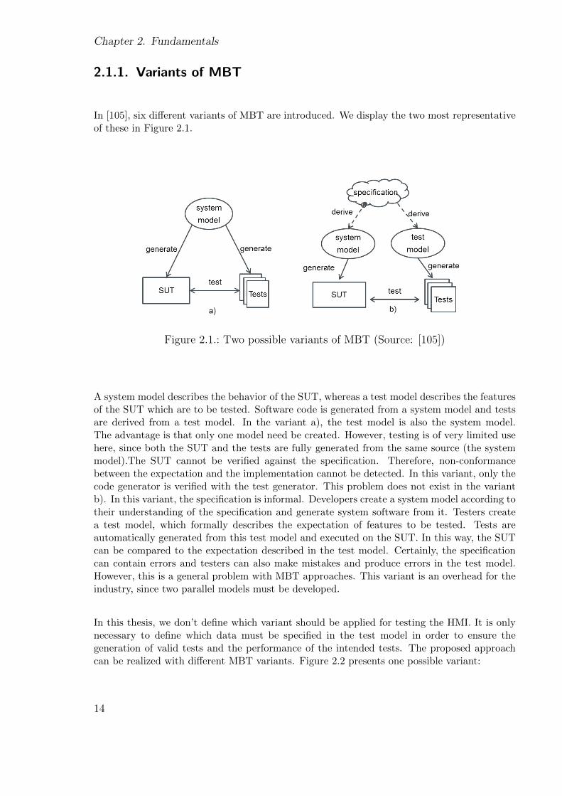
In [105], six different variants of MBT are introduced. We display the two most representativeof these in Figure 2.1.
Figure 2.1.: Two possible variants of MBT (Source: [105])
A system model describes the behavior of the SUT, whereas a test model describes the featuresof the SUT which are to be tested. Software code is generated from a system model and testsare derived from a test model. In the variant a), the test model is also the system model.The advantage is that only one model need be created. However, testing is of very limited usehere, since both the SUT and the tests are fully generated from the same source (the systemmodel).The SUT cannot be verified against the specification. Therefore, non-conformancebetween the expectation and the implementation cannot be detected. In this variant, only thecode generator is verified with the test generator. This problem does not exist in the variantb). In this variant, the specification is informal. Developers create a system model according totheir understanding of the specification and generate system software from it. Testers createa test model, which formally describes the expectation of features to be tested. Tests areautomatically generated from this test model and executed on the SUT. In this way, the SUTcan be compared to the expectation described in the test model. Certainly, the specificationcan contain errors and testers can also make mistakes and produce errors in the test model.However, this is a general problem with MBT approaches. This variant is an overhead for theindustry, since two parallel models must be developed.
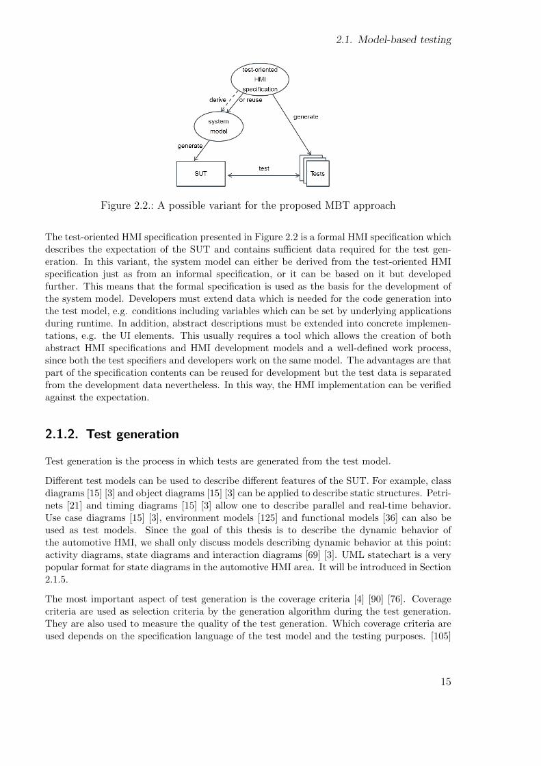
In this thesis, we don’t define which variant should be applied for testing the HMI. It is onlynecessary to define which data must be specified in the test model in order to ensure thegeneration of valid tests and the performance of the intended tests. The proposed approachcan be realized with different MBT variants. Figure 2.2 presents one possible variant:
14
2.1. Model-based testing
Figure 2.2.: A possible variant for the proposed MBT approach
The test-oriented HMI specification presented in Figure 2.2 is a formal HMI specification whichdescribes the expectation of the SUT and contains sufficient data required for the test gen-eration. In this variant, the system model can either be derived from the test-oriented HMIspecification just as from an informal specification, or it can be based on it but developedfurther. This means that the formal specification is used as the basis for the development ofthe system model. Developers must extend data which is needed for the code generation intothe test model, e.g. conditions including variables which can be set by underlying applicationsduring runtime. In addition, abstract descriptions must be extended into concrete implemen-tations, e.g. the UI elements. This usually requires a tool which allows the creation of bothabstract HMI specifications and HMI development models and a well-defined work process,since both the test specifiers and developers work on the same model. The advantages are thatpart of the specification contents can be reused for development but the test data is separatedfrom the development data nevertheless. In this way, the HMI implementation can be verifiedagainst the expectation.
2.1.2. Test generation
Test generation is the process in which tests are generated from the test model.
Different test models can be used to describe different features of the SUT. For example, classdiagrams [15] [3] and object diagrams [15] [3] can be applied to describe static structures. Petri-nets [21] and timing diagrams [15] [3] allow one to describe parallel and real-time behavior.Use case diagrams [15] [3], environment models [125] and functional models [36] can also beused as test models. Since the goal of this thesis is to describe the dynamic behavior ofthe automotive HMI, we shall only discuss models describing dynamic behavior at this point:activity diagrams, state diagrams and interaction diagrams [69] [3]. UML statechart is a verypopular format for state diagrams in the automotive HMI area. It will be introduced in Section2.1.5.
The most important aspect of test generation is the coverage criteria [4] [90] [76]. Coveragecriteria are used as selection criteria by the generation algorithm during the test generation.They are also used to measure the quality of the test generation. Which coverage criteria areused depends on the specification language of the test model and the testing purposes. [105]
15
Chapter 2. Fundamentals
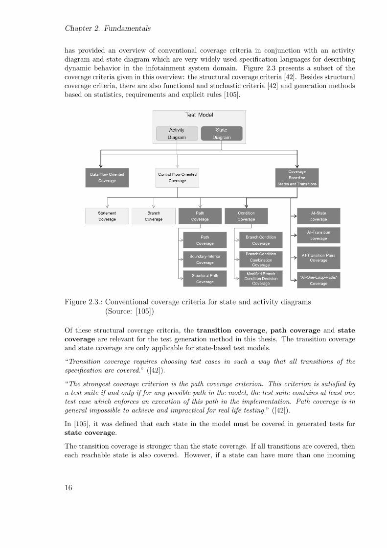
has provided an overview of conventional coverage criteria in conjunction with an activitydiagram and state diagram which are very widely used specification languages for describingdynamic behavior in the infotainment system domain. Figure 2.3 presents a subset of thecoverage criteria given in this overview: the structural coverage criteria [42]. Besides structuralcoverage criteria, there are also functional and stochastic criteria [42] and generation methodsbased on statistics, requirements and explicit rules [105].
Figure 2.3.: Conventional coverage criteria for state and activity diagrams(Source: [105])
Of these structural coverage criteria, the transition coverage, path coverage and statecoverage are relevant for the test generation method in this thesis. The transition coverageand state coverage are only applicable for state-based test models.
“Transition coverage requires choosing test cases in such a way that all transitions of thespecification are covered.” ([42]).
“The strongest coverage criterion is the path coverage criterion. This criterion is satisfied bya test suite if and only if for any possible path in the model, the test suite contains at least onetest case which enforces an execution of this path in the implementation. Path coverage is ingeneral impossible to achieve and impractical for real life testing.” ([42]).
In [105], it was defined that each state in the model must be covered in generated tests forstate coverage.
The transition coverage is stronger than the state coverage. If all transitions are covered, theneach reachable state is also covered. However, if a state can have more than one incoming
16
2.1. Model-based testing
transitions, it is possible that the state is covered via one of these transitions but the othertransition is not visited.
2.1.3. Automated test executions
MBT can also be combined with automated test executions; this is also called test automation[35] [61]. Test automation is the process in which tests are automatically executed in a testautomation environment. In connection with MBT, automatically generated tests should beautomatically executed.
Test models are usually abstract. This means they only contain events triggering transitionsand do not contain concrete user data such as a specific phone number to dial during testexecution. Therefore, generated tests are still not automatically executable. The process ofmapping abstract tests to executable tests is called test instantiation [13].
2.1.4. Current situation of MBT in practice
Today, model-based testing is well established in the automotive area for function tests [19]. AtAudi, infotainment system functions too are currently tested using model-based and automatedtests. However, HMI tests are performed almost entirely manually.
As explained in previous work [28], a function test verifies e.g. whether a phone contact canbe correctly added into the address book. To do this, a tester can create a test model whichdescribes the behavior, i.e. that a contact can be added into the address book, and definesthe expectation, i.e. that the added entry is subsequently available in the address book. Agenerated test contains the steps required to add a contact entry, followed by the verificationof the added entry. The available entries in the address book can be obtained e.g. from thedatabase or the bus system. In the automotive domain, EXAM [64] and MODENA [URLh]are widely used testing frameworks for car functions and infotainment system functions.
In comparison to function errors, HMI errors are very varied: an error can occur in menuchanges, in the graphical representation, in widget behaviors etc. In Section 4.2, more than 10types of HMI errors occurring in practice will be introduced. Current HMI industry testingframeworks are used for component tests by the suppliers who develop the HMIs. This meansthe HMI is tested as a single component without any connections to the other components of theinfotainment system, e.g. underlying applications and bus systems. Most of these HMI testingframeworks are based on the capture/reply method: while a tester manually executes the tests,the action sequences are captured which will later be executed on the HMI. Other availableHMI testing frameworks allow the manual creation of test scripts which are also composedentirely of user actions. This means that currently available HMI testing frameworks focusonly on the testing of user action sequences. Component tests are usually very limited. Theproblem is that it is not possible for HMI suppliers to perform integration tests because thedifferent components of the infotainment systems are developed by different suppliers and thefinal integration is usually done by the manufacturer. Furthermore, manual capture or creationof tests cannot achieve systematic test coverage. An HMI testing framework is still lackingwhich allows users to create an HMI test model describing the varied features of the HMI,
17
Chapter 2. Fundamentals
supports automatic test generation and hence enables specific forms of test coverage to beachieved systematically.
2.1.5. UML statechart
UML statechart (UML SC) [106] [26] is a very widely used specification language for describingdynamic system behaviors. A SC model describes the possible states of a system and possibleflows between these states. State changes are triggered by events via transitions which canbe labeled with guard conditions and actions. If the event of a transition has been triggeredand the guard conditions are fulfilled, then the actions will be performed and the next state isachieved. SC diagrams allow hierarchies.
UML SC allows the creation of semi-formal or formal specifications by explicitly and exactlydefining the used notation, syntax and semantics of the UML SC. For instance, the systemmodel, from which software code is to be automatically generated, must be a formal model.In Chapter 5, the formal definition of UML SC will be introduced.
2.2. Automotive HMIs
As already explained in the introduction, in the context of model-based testing for automotiveinfotainment system HMIs, the term “HMI” is synonymous with the “graphical user interface”presented on the central display.
Memon, in his thesis [84], defines the GUI as follows:
A GUI is the front-end to underlying code, and a software user interacts with the softwareusing the GUI. The user performs events such as mouse movements, object manipulation,
menu selections, and opening and closing of windows. The GUI, in turn, interacts with theunderlying code through messages and/or method calls.
An infotainment system HMI is a particularly complex GUI. It is the front-end of the infotain-ment system composed of different ECUs and bus systems. It reacts to user events triggeredvia different input facilities and interacts with the ECUs of the infotainment system via under-lying applications. An infotainment system HMI contains both the graphical representation,i.e. screens and their contained UI elements, and the dynamic behavior, i.e. the dynamicchanges between different screens.
18
2.2. Automotive HMIs
2.2.1. The graphical representation of an HMI
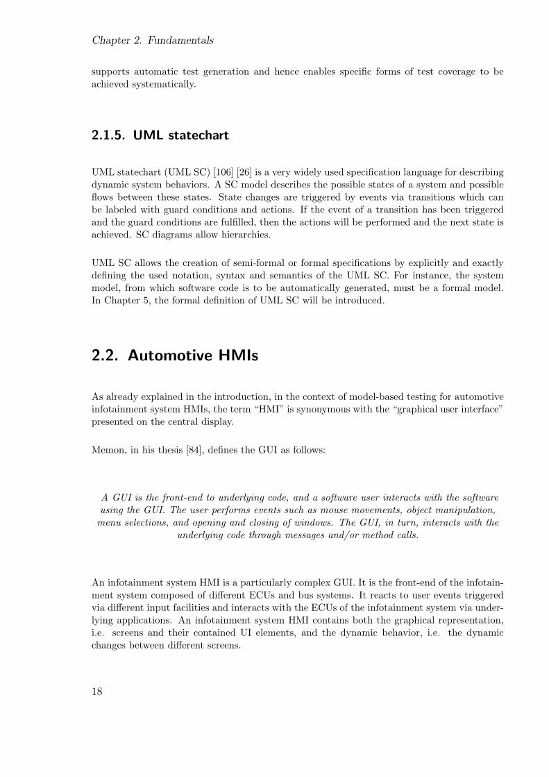
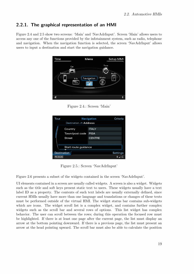
Figure 2.4 and 2.5 show two screens: ‘Main’ and ‘NavAdrInput’. Screen ‘Main’ allows users toaccess any one of the functions provided by the infotainment system, such as radio, telephoneand navigation. When the navigation function is selected, the screen ‘NavAdrInput’ allowsusers to input a destination and start the navigation guidance.
Figure 2.4.: Screen ‘Main’
Figure 2.5.: Screen ‘NavAdrInput’
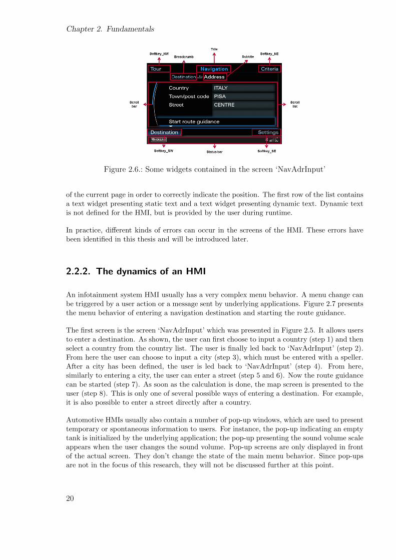
Figure 2.6 presents a subset of the widgets contained in the screen ‘NavAdrInput’.
UI elements contained in a screen are usually called widgets. A screen is also a widget. Widgetssuch as the title and soft keys present static text to users. These widgets usually have a textlabel ID as a property. The contents of such text labels are usually externally defined, sincecurrent HMIs usually have more than one language and translations or changes of these textsmust be performed outside of the virtual HMI. The widget status bar contains sub-widgetswhich are icons. The widget scroll list is a complex widget, and contains further complexwidgets such as the scroll bar and several rows of options. This list widget has complexbehavior. The user can scroll between the rows; during this operation the focused row mustbe highlighted. If there is at least one page after the current page, the list must display anarrow at the bottom pointing downward. If there is a previous page, the list must present anarrow at the head pointing upward. The scroll bar must also be able to calculate the position
19
Chapter 2. Fundamentals
Figure 2.6.: Some widgets contained in the screen ‘NavAdrInput’
of the current page in order to correctly indicate the position. The first row of the list containsa text widget presenting static text and a text widget presenting dynamic text. Dynamic textis not defined for the HMI, but is provided by the user during runtime.
In practice, different kinds of errors can occur in the screens of the HMI. These errors havebeen identified in this thesis and will be introduced later.
2.2.2. The dynamics of an HMI
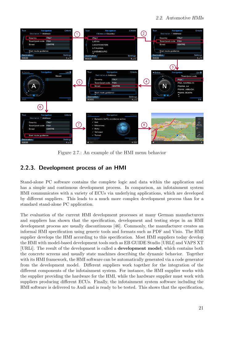
An infotainment system HMI usually has a very complex menu behavior. A menu change canbe triggered by a user action or a message sent by underlying applications. Figure 2.7 presentsthe menu behavior of entering a navigation destination and starting the route guidance.
The first screen is the screen ‘NavAdrInput’ which was presented in Figure 2.5. It allows usersto enter a destination. As shown, the user can first choose to input a country (step 1) and thenselect a country from the country list. The user is finally led back to ‘NavAdrInput’ (step 2).From here the user can choose to input a city (step 3), which must be entered with a speller.After a city has been defined, the user is led back to ‘NavAdrInput’ (step 4). From here,similarly to entering a city, the user can enter a street (step 5 and 6). Now the route guidancecan be started (step 7). As soon as the calculation is done, the map screen is presented to theuser (step 8). This is only one of several possible ways of entering a destination. For example,it is also possible to enter a street directly after a country.
Automotive HMIs usually also contain a number of pop-up windows, which are used to presenttemporary or spontaneous information to users. For instance, the pop-up indicating an emptytank is initialized by the underlying application; the pop-up presenting the sound volume scaleappears when the user changes the sound volume. Pop-up screens are only displayed in frontof the actual screen. They don’t change the state of the main menu behavior. Since pop-upsare not in the focus of this research, they will not be discussed further at this point.
20
2.2. Automotive HMIs
Figure 2.7.: An example of the HMI menu behavior
2.2.3. Development process of an HMI
Stand-alone PC software contains the complete logic and data within the application andhas a simple and continuous development process. In comparison, an infotainment systemHMI communicates with a variety of ECUs via underlying applications, which are developedby different suppliers. This leads to a much more complex development process than for astandard stand-alone PC application.
The evaluation of the current HMI development processes at many German manufacturersand suppliers has shown that the specification, development and testing steps in an HMIdevelopment process are usually discontinuous [46]. Commonly, the manufacturer creates aninformal HMI specification using generic tools and formats such as PDF and Visio. The HMIsupplier develops the HMI according to this specification. Most HMI suppliers today developthe HMI with model-based development tools such as EB GUIDE Studio [URLf] and VAPS XT[URLi]. The result of the development is called a development model, which contains boththe concrete screens and usually state machines describing the dynamic behavior. Togetherwith its HMI framework, the HMI software can be automatically generated via a code generatorfrom the development model. Different suppliers work together for the integration of thedifferent components of the infotainment system. For instance, the HMI supplier works withthe supplier providing the hardware for the HMI, while the hardware supplier must work withsuppliers producing different ECUs. Finally, the infotainment system software including theHMI software is delivered to Audi and is ready to be tested. This shows that the specification,
21
Chapter 2. Fundamentals
development and testing are disconnected in the development process and are performed bydifferent teams, usually using different tools.
2.2.4. Variants of HMI
HMIs of premium vehicles are usually provided in different variants. Variants can be necessi-tated by differing car models, markets, languages, system hardware types and also individualcombinations of functions. Figure 0.2 presents an example of two different HMI variants. Inpractice, more than 100 variants are possible. Different variants share a large set of common-alities. For instance, the same screen of different variants contains a set of common widgets.It contains only one or a few additional widgets for some of the variants. The menu behaviors,too, of different variants are very similar. Variability causes enormous testing complexity.
2.2.5. Conclusion: Automotive HMI vs. standard PC applications
Testing the automotive HMI faces more challenges than testing standard PC applications dueto its special characteristics.
Firstly, the HMI is an embedded system, which communicates with the ECUs via underlyingapplications. The dynamic menu behavior and the represented contents are dependent onthese underlying applications. Secondly, an infotainment system HMI is based on the conceptof screens and can include more than 2000 screens. Screens and screen changes must beespecially considered for testing. Thirdly, the HMI is usually provided in several languages.Therefore, concrete texts cannot be directly included in the HMI. Furthermore, the testingapproach must be realizable for the complex and noncontinuous development process. Finally,an infotainment system HMI has a large set of variants. Variability must be taken into accountwhen modeling and testing the HMI.
22

Chapter 3.
Related Work
The research presented in this thesis focuses on the model-based testing of automotive HMIs,which have a special characteristic: variability. As presented in Figure 3.1, the topic spans thedomains of GUIs, model-based testing and variability, in which the GUI plays the central role.In relation to the combination of GUI and model-based testing (model-based GUI testing,which is area 1 in Figure 3.1), a large set of research results and techniques can be found.GUIs which have variability are also research topics. Here, we will focus on the model-basedapproaches (area 2 and 3 in Figure 3.1), since model-based development is already in heavyuse for car infotainment systems. There are various research efforts in the domain of model-based development of GUIs (area 4 in Figure 3.1). The commonality between the model-basedtesting and model-based development of GUIs is that both domains rely on the same basis: theGUI modeling. Related work in model-based GUI development will be introduced in Section5.4 in the context of GUI modeling.
This section introduces related work in the areas 1-3 as presented in Figure 3.1, identifies thecommonalities and differences to our approaches and clarifies why the existing research resultscannot be used to resolve our problems. Due to the diversity of the subtopics covered, part ofthe related work will be presented in later chapters in the context of the respective subtopics.
Figure 3.1.: Related research areas
23
Chapter 3. Related Work
3.1. Model-based GUI testing
A number of research efforts are currently focused on model-based GUI testing (area 1 inFigure 3.1).
A number of approaches focus on the testing of Finite State Machines (FSM). Here, event-based modeling and state-based modeling can be distinguished.
In some early approaches of Atif Memon, [80] [81] and [72], the automatic test case generationfor GUIs is based on the planning technique: for a “given a set of operators, an initial stateand a goal state”, a sequence of operators can be generated which lead the system from theinitial state to the goal state. The precondition is that the GUI is described as a flow of allowedoperators. Atif Memon’s later approaches are mainly based on event-flow graphs which arealso FSMs. He has developed a comprehensive GUI testing framework in the doctoral thesis[84]. The GUI testing framework contains a GUI model as the central component which iscomposed of event-flow graphs. In order to obtain the GUI model, the hierarchical structureof the GUI is exploited and the most important event sequences are identified. The frameworkalso includes a test coverage evaluator, a test case generator, test oracles, a test executorand regression testers. Hierarchical and event-based coverage criteria are used for the testgeneration. By defining tests as event sequences, the thesis aims to test varied combinationsof user action sequences. In [83], several adequate event-based test coverages were introducedfor test generation from event-flow graphs. In this later work [79], the event-flow graph isrefined. Atif Memon later separately addressed the regression tests of GUIs in [82], the GUIsof world-wide-webs in [123] and test oracles of GUIs in [124]. In [12] Fevzi Belli proposed tomodel the GUI in terms of the allowed action sequences with a finite state machine. Eachstate represents an action which can be performed with the GUI. In order to generate tests,the FSM should be converted into an equivalent regular expression: “RegEx”. It was explainedthat although the test generation from a FSM can be performed efficiently, RegExs offers someessential advantages, e.g. that well-known algorithms such as event algebra can be used toreduce the complexity of the RegEx.
Event-based test models are not intuitive for specifying infotainment system HMIs in com-parison to state-based models. Infotainment system HMIs have a special characteristic: theycontain a large number of screens between which the user can switch. Each screen is intu-itively regarded as a state of the HMI, since switching from one screen to another screen issimilar to leaving one state and entering another state. Event-based test models would havean acceptance problem in the automotive HMI domain in which the UML SC is already widelyestablished in HMI specification and development.
The approach in [108] is also based on FSM. In this approach, one or a set of states representthe complete user interface in a way similar to the approach in [84]. This leads to the drawbackthat any further improvement or change of the system is inefficient, since many states mustbe adapted in the model. Furthermore, FSMs have the problem of the state explosion. Acomparison of state-based modeling and event-based modeling can be found in [126].
In [121] and [122], the authors address the challenge that the GUI can contain a large number ofstates and complex GUI dependencies. The authors have presented a different FSM model thatdivides the complete state space into different sub-state machines based on user tasks. User
24
3.1. Model-based GUI testing
tasks are action sequences which the user can perform with the GUI. They can be identifiedby the tester as a responsibility. For each responsibility, the tester identifies a machine model:the Complete Interaction Sequences (CIS) which is then used for the test generation.
In [63] and [62] Kervinen has proposed to separate the specification of the business logic andthe GUI details. An action model is used to describe the business logic which is based onthe Labeled Transition System (LTS). With the help of a refinement machine which is alsobased on the LTS, each action is mapped to an event which can be performed with the GUI.In order to generate tests, a composite LTS must be created by replacing the actions in theaction model with the help of the corresponding refinement machines. This LTS is used togenerate test cases via a test generation tool named TEMA.
Many approaches are based on Petri nets. The authors of [104] aim to test the structural rep-resentation of GUIs which is specified by Hierarchical Predicate Transitions Nets (HPrTNs).In this work, the original coverage criteria proposed for HPrTNs have been extended. Theapproach in [97] also proposes to model the GUI based on Petri nets. The focal point of thiswork is GUI design and automatic code generation.
The approaches introduced above propose the use of different specification languages: FSM,LTS, Petri nets and their variants. The common drawback of these approaches is that theproposed languages have a scalability problem when specifying huge and complex systemssuch as infotainment system HMIs. In particular, the approaches in which each state of awidget also makes up a state of the GUI such as [108] cannot be applied to infotainmentsystem HMIs which have more than 2000 screens; a large set of these screens have intelligentwidgets which have their own behavior.
In [89] it was proposed to model the GUI based on Hierarchical Finite State Machines (HFSMs).A test generation method has been introduced which directly generates tests from the HFSM.
Model-based testing of GUIs can also be based on UML diagrams. For instance, in [95] asubset of UML diagrams is extended in order to model the GUI. Use case diagrams and activitydiagrams are used to describe the purpose and usages, class diagrams are used to describe thestructure of GUI windows, and state machine diagrams are used to describe the behavior. Inthe testing process proposed in this work, the visual model is automatically transformed into aformal specification language, Spec#, according to some rules. The obtained formal model isthen refined and completed with method bodies that have been previously defined in Spec#.In this way, an executable model is obtained. Test cases are then automatically generatedfrom this model via the Spec Explorer which was developed by Microsoft. With the help ofan existing GUI mapping tool, abstract user actions can be associated with concrete actions.Finally, test cases are automatically executed on the SUT.
HFSM and UML used in the approaches above have improved scalability. However, these ap-proaches, and in fact all approaches introduced so far, only address the testing of user actionsequences, which is entirely adequate for testing simple standard PC applications. Infotain-ment system HMIs are not only characterized by complex menu behavior as explained abovebut also complex representation as well as multimedia applications [100]. The representationof infotainment system HMIs and multimedia applications includes textual contents (usuallyin several languages), visual contents, intelligent widgets and often also interrelations betweendifferent states of these listed components. In our research, we have identified 12 types of
25
Chapter 3. Related Work
HMI errors which have different sources and usually different symptoms (Section 4.2). There-fore, both the menu behavior and the representation should be separately and extensivelytested. Modeling and testing the allowed user actions alone cannot meet the needs of testinginfotainment system HMIs.
The NModel [55] which is developed by Microsoft Research is used in several approaches todescribe the GUI. It is a model-based testing framework and analysis tool for C# programs.It allows the user to formally describe the expectation of the SUT based on an FSM. Theconformance between the expectation and the SUT can be automatically determined by theconformance tester. In [20] the original idea is applied to test AHLTA-Mobiles. Due to thedrawback that the original NModel requires actions in the model to be bound to methodsin C#, [96] has extended NModel “by adding the capability to gather information about thephysical GUI objects that are the target of the user actions described in the model, and au-tomatically generate a .Net assembly with methods that simulate those actions upon the GUIapplication under test”. In common with many approaches introduced above, the NModelapproach has the scalability problem and only allows the specification of dynamic behavior. Afurther drawback of that approach is that the NModel framework was originally developed forC# applications. The test initialization and executions inside the framework are unsuitablefor infotainment system HMI tests.
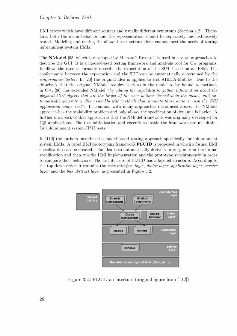
In [112] the authors introduced a model-based testing approach specifically for infotainmentsystem HMIs. A rapid HMI prototyping framework FLUID is proposed in which a formal HMIspecification can be created. The idea is to automatically derive a prototype from the formalspecification and then run the HMI implementation and the prototype synchronously in orderto compare their behaviors. The architecture of FLUID has a layered structure. According tothe top-down order, it contains the user interface layer, dialog layer, application layer, servicelayer and the bus abstract layer as presented in Figure 3.2.
Figure 3.2.: FLUID architecture (original figure from [112])
26
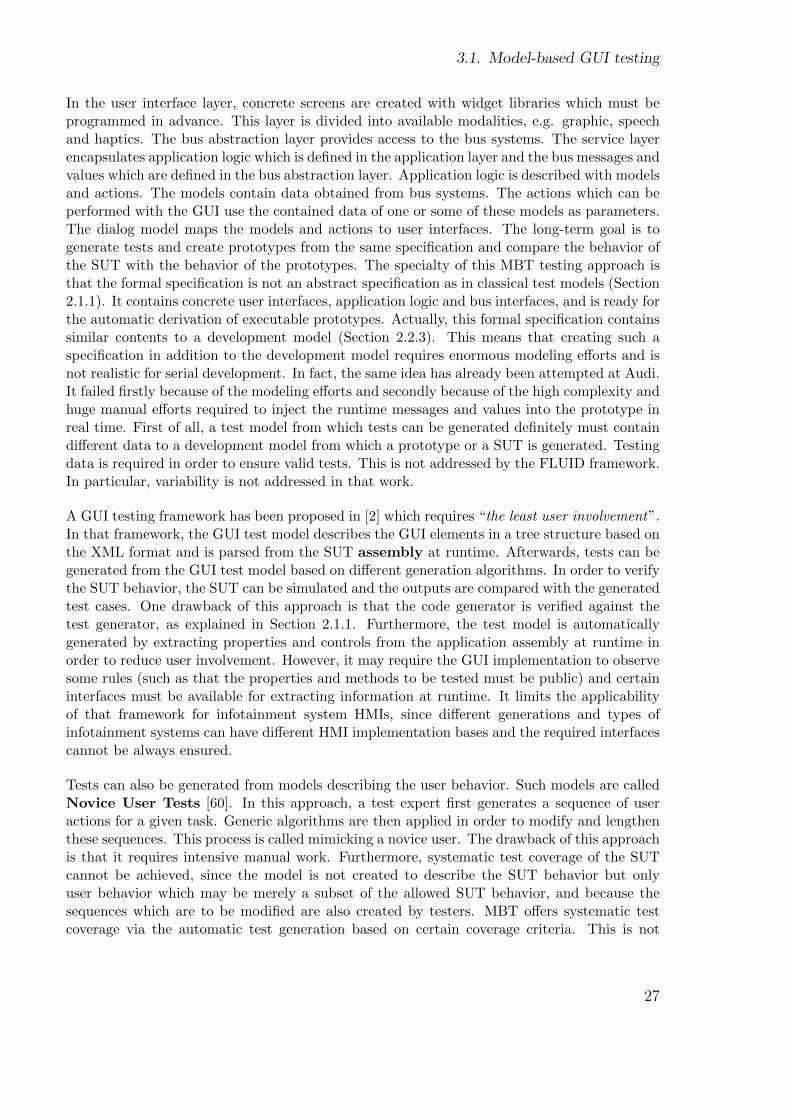
3.1. Model-based GUI testing
In the user interface layer, concrete screens are created with widget libraries which must beprogrammed in advance. This layer is divided into available modalities, e.g. graphic, speechand haptics. The bus abstraction layer provides access to the bus systems. The service layerencapsulates application logic which is defined in the application layer and the bus messages andvalues which are defined in the bus abstraction layer. Application logic is described with modelsand actions. The models contain data obtained from bus systems. The actions which can beperformed with the GUI use the contained data of one or some of these models as parameters.The dialog model maps the models and actions to user interfaces. The long-term goal is togenerate tests and create prototypes from the same specification and compare the behavior ofthe SUT with the behavior of the prototypes. The specialty of this MBT testing approach isthat the formal specification is not an abstract specification as in classical test models (Section2.1.1). It contains concrete user interfaces, application logic and bus interfaces, and is ready forthe automatic derivation of executable prototypes. Actually, this formal specification containssimilar contents to a development model (Section 2.2.3). This means that creating such aspecification in addition to the development model requires enormous modeling efforts and isnot realistic for serial development. In fact, the same idea has already been attempted at Audi.It failed firstly because of the modeling efforts and secondly because of the high complexity andhuge manual efforts required to inject the runtime messages and values into the prototype inreal time. First of all, a test model from which tests can be generated definitely must containdifferent data to a development model from which a prototype or a SUT is generated. Testingdata is required in order to ensure valid tests. This is not addressed by the FLUID framework.In particular, variability is not addressed in that work.
A GUI testing framework has been proposed in [2] which requires “the least user involvement”.In that framework, the GUI test model describes the GUI elements in a tree structure based onthe XML format and is parsed from the SUT assembly at runtime. Afterwards, tests can begenerated from the GUI test model based on different generation algorithms. In order to verifythe SUT behavior, the SUT can be simulated and the outputs are compared with the generatedtest cases. One drawback of this approach is that the code generator is verified against thetest generator, as explained in Section 2.1.1. Furthermore, the test model is automaticallygenerated by extracting properties and controls from the application assembly at runtime inorder to reduce user involvement. However, it may require the GUI implementation to observesome rules (such as that the properties and methods to be tested must be public) and certaininterfaces must be available for extracting information at runtime. It limits the applicabilityof that framework for infotainment system HMIs, since different generations and types ofinfotainment systems can have different HMI implementation bases and the required interfacescannot be always ensured.
Tests can also be generated from models describing the user behavior. Such models are calledNovice User Tests [60]. In this approach, a test expert first generates a sequence of useractions for a given task. Generic algorithms are then applied in order to modify and lengthenthese sequences. This process is called mimicking a novice user. The drawback of this approachis that it requires intensive manual work. Furthermore, systematic test coverage of the SUTcannot be achieved, since the model is not created to describe the SUT behavior but onlyuser behavior which may be merely a subset of the allowed SUT behavior, and because thesequences which are to be modified are also created by testers. MBT offers systematic testcoverage via the automatic test generation based on certain coverage criteria. This is not
27
Chapter 3. Related Work
applied in this approach.
The approaches introduced so far propose different model-based specification languages andmodel the GUI from different aspects. Coverage criteria are applied which are adequate forthe respective language and aspect. The commonality between the approach of this thesis andthose introduced so far is that all of them engage in modeling the GUI and generating testsfrom the model which is the basic principle of MBT. However, all the approaches introducedup to now address standalone PC applications which contain the complete application logicand required data within themselves. Applications which can communicate with backgroundsystems, databases or underlying applications have not been the focal point of current GUItesting research. For instance, the behavior of an infotainment system HMI is dependent onruntime data and the HMI must interact with underlying applications in order to providecomplete functions to the user. The challenge of testing such embedded GUI applicationsconsists of specifying the HMI behavior, which is dependent on the runtime data and the logicunderlying applications, even though both data and logic are unknown or not available duringthe specification.
Moreover, an infotainment system HMI is usually provided in numerous variants which sharea large set of commonalties. Testing variants implies new challenges which are not addressedin the GUI testing approaches listed above. For instance, modeling and testing each variantseparately would require enormous modeling and testing efforts. Therefore, a solution fortesting under variability especially for complex and embedded GUIs is required.
There are also GUI testing approaches which are not based on models e.g. the capture/replyconcept ([49] [78]) and the symbolic execution ([40]). In [19], computer vision is proposedfor testing GUIs. In this approach, “testers can write a visual test script that uses imagesto specify which GUI components to interact with and what visual feedback to be observed”.Test scripts can also be generated during a manual demonstration by capturing both the inputevents and the displayed screen images. Capture/reply and computer vision are very usefulmethods and already in use in the domain of infotainment systems. Our research aims atachieving a systematical test coverage and automatic test generation which are made possibleby MBT.
3.2. Model-based testing of GUIs with variability
In recent years, product line approaches have become ever more focused both in the area ofmodel-based development [1] [115] [116] and of model-based testing [93] [94] [120].
Model-based testing of GUIs with variability (area 2 in Figure 3.1) has just recently becomea topic in the research due to the internalization and growing number of variants in the au-tomotive domain. Therefore, little research can be found in this area. We first begin withapproaches which are based on the product line.
In [45], BMW Car IT has very roughly introduced their ideas of model-based HMI testing.Figure 3.3 is an original figure of this work which shows the work flow of their proposedapproach:
28

3.2. Model-based testing of GUIs with variability
Figure 3.3.: Work flow of the specification based testing (original figure from [45])
The dialog model describes the GUI structure (contained widgets), the dynamic behavior andinterfaces to underlying applications for all variants of the product line based on a domain-specific language. Simple variables are used to indicate for which variant a current GUI elementshould be displayed or a current interface is valid. Widget models are used to describe the be-haviors of widgets. Since for different variants, different widgets are in use, widget modelsdescribe the product line specific behavior. A mapping model is used to map entities from thedialog model to their implementations in the widget model. In order to generate tests for aparticular variant, a variant specific test model must be created. First, the dialog model istransformed into a product line specific dialog model based on a model transformation tech-nique. Second, the product line specific dialog model is transformed into an executable widgetmodel by applying product line specific mapping rules which are also not introduced. Finally,variant information is injected into the executable widget model to obtain the variant specifictest model. Test generation is not addressed. Continuations of this work are not available. Dueto the lack of technical details, it is quite difficult to compare the methods used. Nonetheless,the following points can be determined: first, in the specification language used, the dynamicbehavior and the GUI structure are described in the same model and are strongly dependenton each other while a separation is more efficient for testing, as explained above. The mergingof GUI structure and the dynamic behavior descriptions is also inflexible and work-intensivein the event of changes. Moreover, it is not possible to specify those cases in which variabilityexists in the menu behavior but not in the representation. Second, the work gives the impres-sion that the problem of variability has not been sufficiently analyzed. HMIs in real life havevery complex variability (Section 7.1 and 9.1.2) which is not manageable with single variables.Finally, the large challenge to avoid redundancies for the test generation and test executionhas not been focused upon.
“AutomotiveHMI” [URLd] is a collaborative research project in which many leading Germanmanufacturers and suppliers are participants and the author was also partially involved. Thegoal of the project is to optimize current infotainment system development processes andmethods. With the participation of Audi, model-based testing of HMIs, and in particularmodeling and testing variability, have become topics and a work package of the project. Atthe time of composing this thesis, the testing goals have been defined; however, there are stillno concrete results available.
Although the testing approach introduced in [88] is not based on a software product line, it doesaddress the testing of multiple GUI variants. The tool focuses on applications whose differentfront-end variants share the same business logic. The authors have mentioned Adobe Acrobat
29
Chapter 3. Related Work
Reader as an example of an application which runs on MS Windows, Mac OS, Linux, etc.The business logic is separated from the representation logic. The business logic is modeledwith the transitional model-based testing tool Spec Explorer while the representation logic isrecorded by a capture/reply tool. The testing tool provides a GUI Test Generator (GTG)which allows testers to define mappings between the business logic and the different variantsof the representation logic. Based on these mappings, the “GTG converts business logic testcases into presentation logic test cases” for different variants. In the applications which are thefocus of that work, the same business logic is bound to different front-ends which are separatelycaptured and described. In comparison, the variability in infotainment systems’ HMIs is muchmore complex. It exists both in the representation and in the business logic (menu behavior).In the representation, different variants share a huge set of commonalities. It is impractical todescribe these commonalities repeatedly for each variant. Therefore, a solution must be foundin order to specify the commonalities and the variations without redundancies for all variants.The largest challenge - to model and test variability in the menu behavior - does not exist intesting applications which have only one business logic.
3.3. Model-based development of GUIs with variability
Several works can be found relating to the domain of model-based development of GUIs withvariability (area 3 in Figure 3.1).
In [16], a method is proposed for the model-based development of automotive HMIs based onthe product line approach. In this approach, the menu flow of the HMI is described withinthe so-called screen flow model. The screen flow model is a product line screen flow model if itimplicitly describes all possible variants and contains variation points indicating the boundariesbetween different variants. The product line feature model describes the features of the productline. A mapping between it and the product line screen flow model must be performed basedon a mapping table. From the product line feature model, an application feature model canbe derived which describes the features provided by a particular variant of the product line.Based on that and the mapping, a variant screen flow model can be generated from the productline screen flow model. This variant screen flow model describes the screen flow of the definedvariant and is applied for the code generation. The product line feature model and variantfeature model used are introduced in detail.
The commonality between that approach and ours is that both approaches face the problemof modeling the product line and modeling variability in the menu behavior. The ideas arequite similar: feature models are used to model the product line and variation points areused in the menu behavior model in order to indicate for which variants that particular menubehavior is valid. However, variability in the representation is not considered in that work.Another difference between the approaches is in the procedure for code/test generation. Inthe approach proposed in [16], for each variant the respective menu behavior is extracted fromthe menu behavior describing all variants of the product line. Automatic code generationis performed from the extracted behavior. This makes sense for the software development,since for different variants potentially different libraries and frameworks must be bound duringcode generation. In contrast, for model-based testing, our approach tries to avoid generatingtests for each variant, since different variants share a large set of commonalities in the menu
30
3.4. Conclusion
behavior and repeated test generation for each variant means that the common behavior isunnecessarily visited as often as the number of variants to be tested. Due to the usually largenumber of variants in practice, avoiding redundant test generations is an important goal in ourapproach. Additionally, in model-based GUI testing, a problem must be faced that does notexist in GUI development: generated tests for different variants contain a large set of identicaltests which verify the common behavior. The test execution is very time-consuming, thereforethe redundant execution of identical tests must be avoided. Finally, in practice, infotainmentsystem HMIs do not only have features related to functions such as navigation and telephone,but also features related to the market and the language. The same function can be providedwith different options. This complexity is not considered in the approach proposed in [16].
3.4. Conclusion
One major finding of the categorization and evaluation of related work is that for each re-lated research area, several and often many approaches already exist. However, most of theseapproaches address only one or some of the sub-problems in comparison to this thesis. Forinstance, some address only the modeling of the GUI and some address only the testing of useraction sequences.
Furthermore, the lack of industrial context leads to another problem: very few of the existingapproaches face real-life complexity or aim for practical application. For instance, some ap-proaches are based on specification languages which are not scalable for complex systems andsome are based on very simplified product lines.
Finally, HMI testing under variability is still in its infancy. The characteristics of infotain-ment system HMIs and HMI product lines have not been sufficiently studied. Also, testingapproaches are lacking which are based on real-life HMI development processes.
31

Chapter 3. Related Work
32
Part II.
Framework for Model-Based HMITesting
33

As already explained, an HMI testing framework is still lacking which supports HMI integrationtests, allows users to create an HMI test model describing the varied features of the HMI,supports automatic test generation and hence enables systematic test coverage.
In this chapter, our model-based testing framework for infotainment system HMIs is introducedwhich fulfills the above requirements. In this introduction, variability of HMIs is not yetconsidered. The framework forms the basis of this thesis and also the basis of the solution fortesting under variability. The extension of the framework for testing under variability will bedescribed later, in Part III.
Firstly, the essential components of the framework are introduced: the test-oriented HMI spec-ification and the test generation. It will be discussed how extensions of additional componentsare possible in order to combine MBT with automated test executions. Afterward, possibleHMI errors occurring in practice are identified. Based on these, we will clarify which kindsof errors can be addressed by the framework and which are within the focus of this work.Requirements for the test-oriented HMI specification will then be introduced in detail. This isalso the main focal point of this part. Finally, a test generation algorithm and generated testsare introduced.
35

Chapter 3. Related Work
36
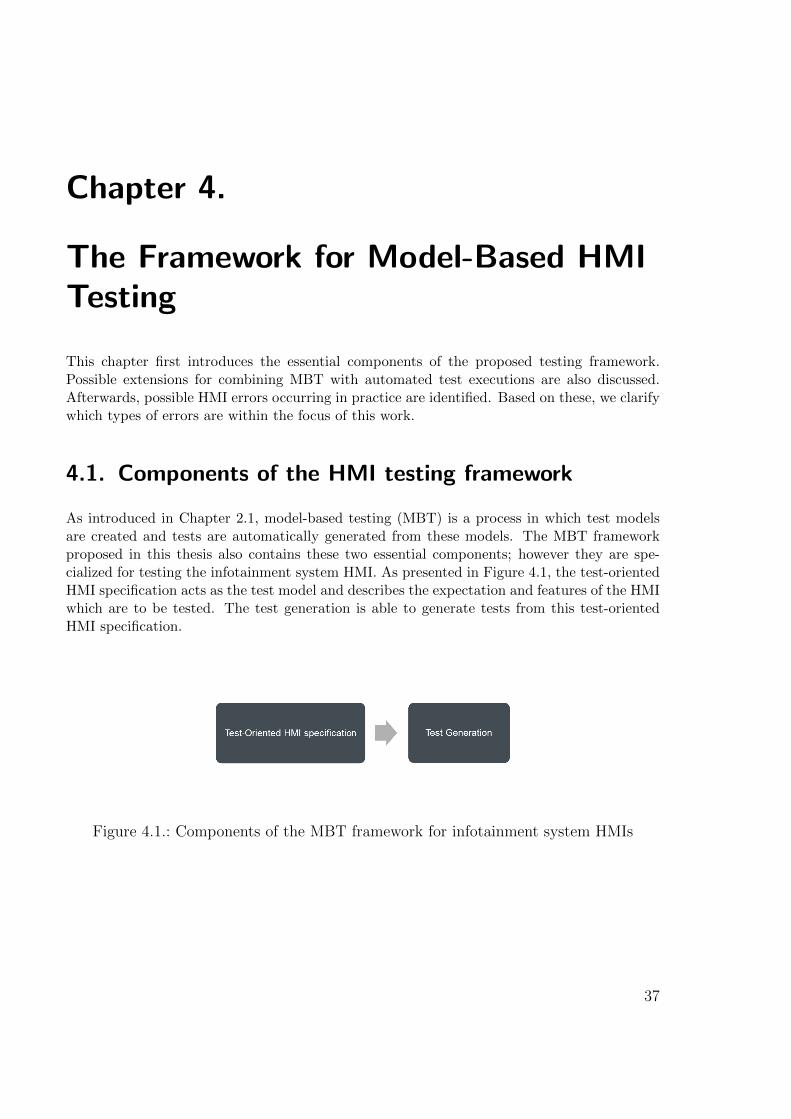
Chapter 4.
The Framework for Model-Based HMITesting
This chapter first introduces the essential components of the proposed testing framework.Possible extensions for combining MBT with automated test executions are also discussed.Afterwards, possible HMI errors occurring in practice are identified. Based on these, we clarifywhich types of errors are within the focus of this work.
4.1. Components of the HMI testing framework
As introduced in Chapter 2.1, model-based testing (MBT) is a process in which test modelsare created and tests are automatically generated from these models. The MBT frameworkproposed in this thesis also contains these two essential components; however they are spe-cialized for testing the infotainment system HMI. As presented in Figure 4.1, the test-orientedHMI specification acts as the test model and describes the expectation and features of the HMIwhich are to be tested. The test generation is able to generate tests from this test-orientedHMI specification.
Figure 4.1.: Components of the MBT framework for infotainment system HMIs
37
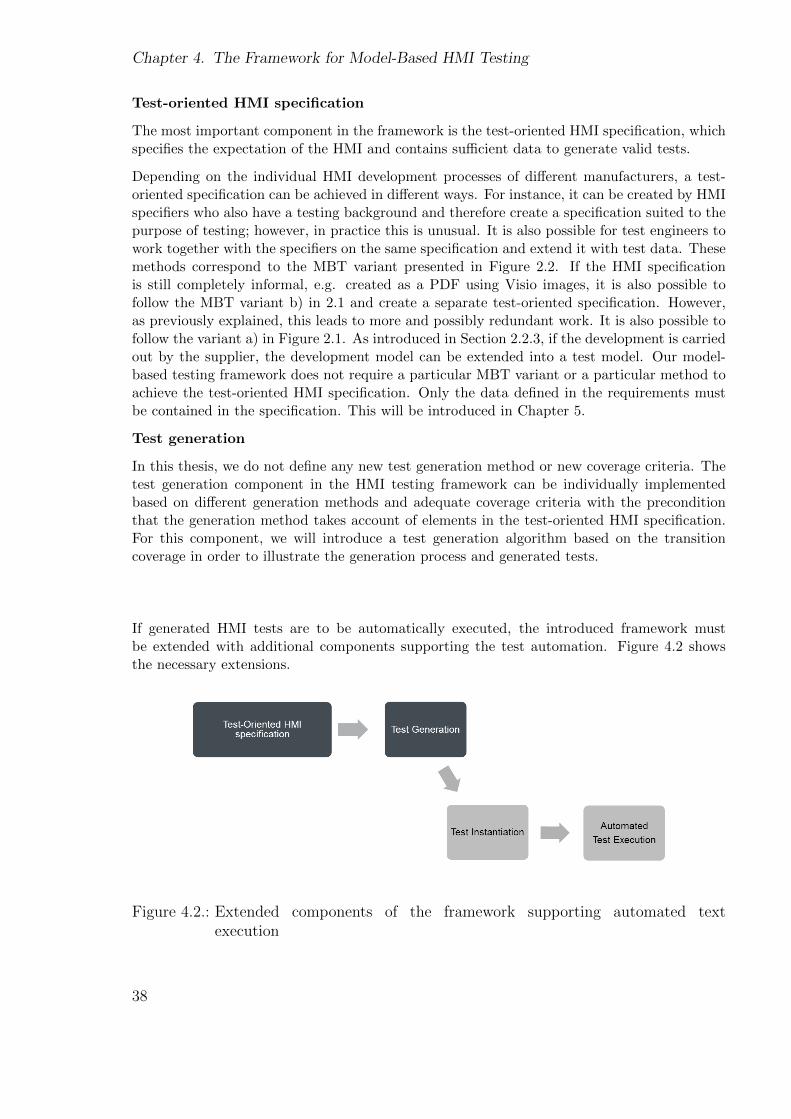
Chapter 4. The Framework for Model-Based HMI Testing
Test-oriented HMI specification
The most important component in the framework is the test-oriented HMI specification, whichspecifies the expectation of the HMI and contains sufficient data to generate valid tests.
Depending on the individual HMI development processes of different manufacturers, a test-oriented specification can be achieved in different ways. For instance, it can be created by HMIspecifiers who also have a testing background and therefore create a specification suited to thepurpose of testing; however, in practice this is unusual. It is also possible for test engineers towork together with the specifiers on the same specification and extend it with test data. Thesemethods correspond to the MBT variant presented in Figure 2.2. If the HMI specificationis still completely informal, e.g. created as a PDF using Visio images, it is also possible tofollow the MBT variant b) in 2.1 and create a separate test-oriented specification. However,as previously explained, this leads to more and possibly redundant work. It is also possible tofollow the variant a) in Figure 2.1. As introduced in Section 2.2.3, if the development is carriedout by the supplier, the development model can be extended into a test model. Our model-based testing framework does not require a particular MBT variant or a particular method toachieve the test-oriented HMI specification. Only the data defined in the requirements mustbe contained in the specification. This will be introduced in Chapter 5.
Test generation
In this thesis, we do not define any new test generation method or new coverage criteria. Thetest generation component in the HMI testing framework can be individually implementedbased on different generation methods and adequate coverage criteria with the preconditionthat the generation method takes account of elements in the test-oriented HMI specification.For this component, we will introduce a test generation algorithm based on the transitioncoverage in order to illustrate the generation process and generated tests.
If generated HMI tests are to be automatically executed, the introduced framework mustbe extended with additional components supporting the test automation. Figure 4.2 showsthe necessary extensions.
Figure 4.2.: Extended components of the framework supporting automated textexecution
38
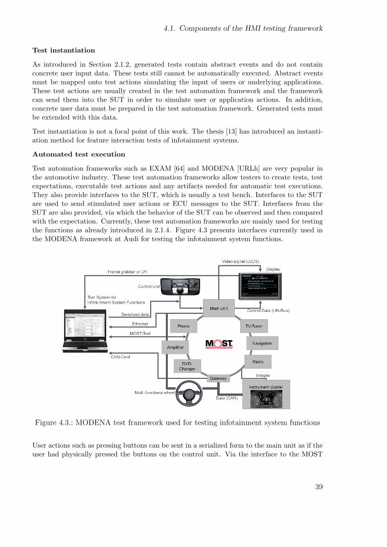
4.1. Components of the HMI testing framework
Test instantiation
As introduced in Section 2.1.2, generated tests contain abstract events and do not containconcrete user input data. These tests still cannot be automatically executed. Abstract eventsmust be mapped onto test actions simulating the input of users or underlying applications.These test actions are usually created in the test automation framework and the frameworkcan send them into the SUT in order to simulate user or application actions. In addition,concrete user data must be prepared in the test automation framework. Generated tests mustbe extended with this data.
Test instantiation is not a focal point of this work. The thesis [13] has introduced an instanti-ation method for feature interaction tests of infotainment systems.
Automated test execution
Test automation frameworks such as EXAM [64] and MODENA [URLh] are very popular inthe automotive industry. These test automation frameworks allow testers to create tests, testexpectations, executable test actions and any artifacts needed for automatic test executions.They also provide interfaces to the SUT, which is usually a test bench. Interfaces to the SUTare used to send stimulated user actions or ECU messages to the SUT. Interfaces from theSUT are also provided, via which the behavior of the SUT can be observed and then comparedwith the expectation. Currently, these test automation frameworks are mainly used for testingthe functions as already introduced in 2.1.4. Figure 4.3 presents interfaces currently used inthe MODENA framework at Audi for testing the infotainment system functions.
Figure 4.3.: MODENA test framework used for testing infotainment system functions
User actions such as pressing buttons can be sent in a serialized form to the main unit as if theuser had physically pressed the buttons on the control unit. Via the interface to the MOST
39
Chapter 4. The Framework for Model-Based HMI Testing
bus [47], bus messages such as “incoming call” can be simulated as if the messages had beensent by the ECU. Values and messages sent in the MOST can be captured and used to observethe SUT behavior. With the help of a frame grabber [57], screenshots can be captured fromthe currently displayed screen. With the help of image processing methods [18] such as iconand text recognition, the graphical and textual contents of the screen can be analyzed.
Such test automation frameworks can be used for the automatic execution of HMI tests. Cur-rently available interfaces to the SUT are sufficient to execute generated HMI tests. In orderto observe the dynamic behavior and the graphical representation of the HMI, frame grabbersor cameras can be used. Ideally, an interface can be provided which can report the name andpossibly also the UI elements and their contents contained in the displayed screen.
4.1.1. Related work
In Section 3.1, a number of related works have already been introduced that propose frame-works for model-based GUI testing. Although the model types, specification languages andcoverage criteria used are very different, all frameworks are composed of the same essentialcomponents: the test model describing the expectations of the GUI implementation and thetest generator which generates tests from the test model. In the testing framework intro-duced in [13], test instantiation and automatic test execution are also considered. In [84], theframework additionally contains a regression tester.
4.2. Analysis of HMI error types
HMI errors are much more varied than function errors. In order to define which HMI errorsthe testing framework can and shall face, we must firstly find out which HMI errors can occurin practice. To do this, we have evaluated more than 200 HMI errors from a current practicalHMI project. For the evaluation, an error is regarded as an HMI error if it is directly observablein the HMI. These errors are chosen from different phases of the project. We have classifiedthe errors according to their error sources.
4.2.1. Errors occurring in practice
4.2.1.1 Menu behavior errors
In this work, failures caused by erroneous implementation of the menu behavior are called menubehavior errors. The symptom of this error type is either switching to an unexpected screen ormissing menu changes. For example, one very frequent menu behavior error is that the user isled to an unexpected screen after he has pressed the return button. The expected behavior iseither that the return button should lead to the screen that the user has just visited, or to thescreen above the current one in the hierarchy. Developers often mistake these two concepts.Another frequent menu behavior error is an inconsistency in the menu navigation. In practice,the HMI implementation of a new generation is usually based on the old implementation.
40
4.2. Analysis of HMI error types
Often, changes must be performed in many places e.g. due to a new menu navigation concept.Developers often fail to make the changes in all the necessary places. If the menu behavior isdeveloped based on state diagrams, errors are commonly caused by the erroneous next stateof transitions, wrong events, wrong conditions or wrong positions of history states.
In rare cases, the same symptom (wrong menu switch symptom) is not caused by erroneousimplementation of the menu behavior, but by errors in the underlying applications. For in-stance, the menu behavior is correctly implemented as specified and two transitions startingfrom the same state are labeled with “if” and “else” conditions respectively. The values ofthese conditions are expected to be set by an underlying application during runtime. However,an erroneous assignment by the underlying application gives the impression that the menubehavior contains a failure. As explained previously, errors are classified based on the errorsources. Therefore these types of errors are classified into the “application and frameworkerrors” category.
4.2.1.2 Errors occurring inside screens
Errors of this class are observable in single screens and are caused by the erroneous implemen-tation of single screens. They can be screen content errors, design errors and widget errors.
Screen content errors
Screens usually contain texts, icons and pictures. The statistical analysis has shown the fol-lowing types of screen content errors:
Text content errors: A text field can present static or dynamic text. Static text is definedin the HMI specification or external text tools, e.g. the text title “navigation” in the screen‘NavAdrInput’ presented in Figure 2.6. Wrong content in such static text is very common. Forinstance, instead of “navig.” the text is defined as “navigation”. Wrong line breaks in a longtext can also be classified as text content errors.
A text field can also present dynamic text, which is not specified in the HMI specificationor external text tools. Dynamic text content is usually sent from the underlying applicationsduring runtime; for example, an incoming call number. In the evaluation, we encounteredan error in which the HMI displays a set of zeros instead of the number for an incomingcall. Experiences have shown that these types of errors are usually caused by underlyingapplications or interfaces between the HMI and underlying applications. Therefore they belongto the“application and framework errors” class.
Text order errors: Many screens contain more than one text row, the order of which ispredefined in the specification. For instance, in the screen presented in Figure 2.5 the text“country” should be intuitively positioned above the text “city” and “city” should be positionedabove “street”. In practice, incorrect text order often occurs.
Language errors: In the early phases of an HMI development, language errors are especiallyfrequent. A language error is, for example, where some German text still exists in a Chinesesystem due to the translation being overlooked. The distinction between language errors andtext content errors is sometimes unclear; however, text errors caused by erroneous or lack oftranslations can be classified as language errors.
41
Chapter 4. The Framework for Model-Based HMI Testing
Icon or picture errors: The use of wrong icons also occurs in practice. Usually, the HMIimplementation of the new generation is based on the old implementation. In the early phasesof development, the replacement of old icons with new ones is frequently overlooked.
Icon order errors: Similarly to the texts, icons should also be presented in a predefinedorder. For instance, in the status bar shown in Figure 2.6, icons representing different statusessuch as the current time, traffic information, incoming messages or signal strength have apredefined order. Although these icons are not all displayed at the same time, the ordermust be maintained. The evaluation has shown that errors involving wrong icon orders haveoccurred.
Missing or unexpected UI elements: Texts or icons can also be completely missing or occurunexpectedly in a screen. A very frequent error is that an empty row is missing e.g. between aninformation text field and the confirmation button. Some widgets are not constantly displayedin the screen but only under particular runtime conditions, for example the icon indicating anincoming call. An error in which such a widget is completely omitted from the screen belongsto this current class. If it is correctly displayed in the screen, but does not appear when theruntime condition is fulfilled, then this error is caused by erroneous implementation of thewidget behavior and belongs to the widget behavior error class.
Missing or unexpected elements can also be caused by underlying applications. For example,in the case of an incoming message, the underlying application must send an event to theHMI, which afterwards displays the ‘incoming message’ icon in the screen. However, if theunderlying application sends no event or the wrong event e.g. the event for an incoming call,an error is observable in the HMI, but is not caused by the HMI. These types of errors are alsoclassified as “application and framework errors”.
Wrong types of widgets: In some cases, the wrong type of widget is used in the screen, e.g.a check box is used instead of a drop-down list.
Design errors
Design rules define how screen contents should be represented in terms of position, distances,colors, fonts etc. Errors caused by breaking the design rules are design errors. Shifting ofpixels is a frequent design error. Design rules also define how a long text displayed in one rowshould be handled. For instance, up to a certain number of characters may be shown and theremaining characters replaced with “...”. We came across several errors in which the text wasnot correctly cut.
Widget behavior errors
Infotainment system HMIs usually contain many intelligent widgets with their own behavior,e.g. the scroll list in Figure 2.6. Errors occur frequently in widget behavior; for instance, thescroll list does not display the arrows indicating previous or next pages. The behavior of adrop-down list or check box can also be erroneous. For instance, a drop-down list should offerthe“off” option when the bluetooth interface is on, but continues to display the “on” option.As explained previously, a simple icon can also have a particular behavior; for example theincoming call icon. In an erroneous case, the icon does not appear or disappear. Many textsand icons demonstrate the behavior of being either active or deactivated. In Audi’s HMI,inactive elements are displayed in the color gray. The evaluation has shown that many errors
42
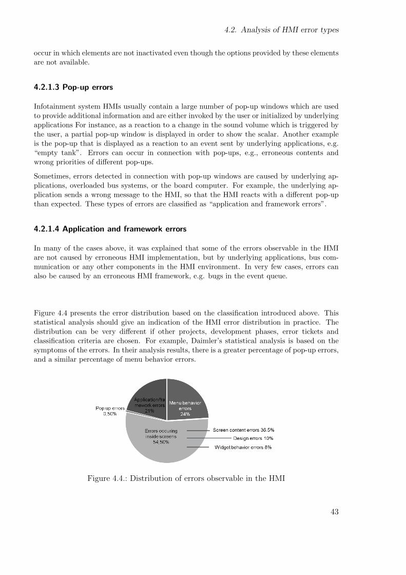
4.2. Analysis of HMI error types
occur in which elements are not inactivated even though the options provided by these elementsare not available.
4.2.1.3 Pop-up errors
Infotainment system HMIs usually contain a large number of pop-up windows which are usedto provide additional information and are either invoked by the user or initialized by underlyingapplications For instance, as a reaction to a change in the sound volume which is triggered bythe user, a partial pop-up window is displayed in order to show the scalar. Another exampleis the pop-up that is displayed as a reaction to an event sent by underlying applications, e.g.“empty tank”. Errors can occur in connection with pop-ups, e.g., erroneous contents andwrong priorities of different pop-ups.
Sometimes, errors detected in connection with pop-up windows are caused by underlying ap-plications, overloaded bus systems, or the board computer. For example, the underlying ap-plication sends a wrong message to the HMI, so that the HMI reacts with a different pop-upthan expected. These types of errors are classified as “application and framework errors”.
4.2.1.4 Application and framework errors
In many of the cases above, it was explained that some of the errors observable in the HMIare not caused by erroneous HMI implementation, but by underlying applications, bus com-munication or any other components in the HMI environment. In very few cases, errors canalso be caused by an erroneous HMI framework, e.g. bugs in the event queue.
Figure 4.4 presents the error distribution based on the classification introduced above. Thisstatistical analysis should give an indication of the HMI error distribution in practice. Thedistribution can be very different if other projects, development phases, error tickets andclassification criteria are chosen. For example, Daimler’s statistical analysis is based on thesymptoms of the errors. In their analysis results, there is a greater percentage of pop-up errors,and a similar percentage of menu behavior errors.
Figure 4.4.: Distribution of errors observable in the HMI
43

Chapter 4. The Framework for Model-Based HMI Testing
Figure 4.5 presents the distribution of true HMI errors:
Figure 4.5.: HMI error distribution
This chart clearly shows that menu behavior errors and screen content errors make up thegreater part of HMI errors. There is a high percentage of menu behavior errors, but they havea single error source, namely the behavior model in a model-based development. This meansthat if a specification of expected menu behavior is available and automatic test generation isapplied, about 30% of HMI errors can be detected, according to the claims of MBT approachesthat test coverage can be systematically achieved. The specification of the expected screencontents also requires more effort, which is currently low in relation to the high percentage(about 46%) of the HMI errors that are screen content errors. This means that if an HMItesting framework focuses on menu behavior tests and screen content tests, a significant effectcan be achieved with low efforts.
4.2.2. HMI errors addressed in this thesis
In the last section, the types of HMI errors that occur in practice were introduced. Of these,menu behavior errors and screen content errors, which make up the greater part of HMI errorsoccurring in practice, are the focal points of this thesis.
Detecting design errors is another research area. Currently, a thesis focusing on design testsof infotainment system HMIs is in process [50]. In order to test the behavior of intelligentwidgets, their behavior must be specified in a similar way to the menu behavior. Widgetbehavior tests are not a focal point of this work. Both design tests and widget behaviortests must also be driven by menu behavior tests. Pop-ups usually have their own behaviorsuch as to appear and disappear. This behavior can be described similarly to the menubehavior. A characteristic of pop-ups is the priority between different pop-up menus. Ifpop-up tests are intended, the behavior and the priority should be the test focuses. Pop-up tests are not within the focus of this work. The logic of underlying applications andthe interactions between different components in the HMI environment are not describablein an HMI specification. Also, in the current HMI development process in practice, therecan be no complete specification describing all sub-components of the infotainment systemand their interactions. Specifications are only available for each component and the interfaces
44

4.2. Analysis of HMI error types
between them, because such a huge infotainment system is developed by a number of suppliers.Therefore, application and framework errors cannot directly be detected by testing the HMIand are not within the focus of this thesis.
Menu behavior errors
Detecting menu behavior errors is the main focal point of this work. In this thesis, tests whichare created for detecting menu behavior errors are called menu behavior tests and can beformally defined as follows:
Definition. A menu behavior test is defined as a tuple MTest = (Cons, Steps) whereCons is a set of conditions and Steps is a sequence of test steps. If Cons is empty it must notbe explicitly declared. The sequence Steps is defined as Steps = 〈 step0, ..., stepk 〉 where stepiwith 0 ≤ i ≤k ∈ AC ∪ EXP. AC is a set of test actions which are abstract events generatedfrom the behavior model of the test-oriented HMI specification. EXP is a set of expectations inthe form of names of expected screens. step0 must be the name of the initial screen, which isexpected if the SUT is started.
A menu behavior test shall only be started if all conditions ∈ Cons are fulfilled.
The following is the menu behavior test verifying the menu behavior described in Figure 2.7:
(NavAdrInput) → (country) → [NavCountryList] → (chooseCountry) → (NavAdrInput) →(city) → [NavCitySpeller] → (enterCity) → (NavAdrInput) → (street) → [NavStreetSpeller]→ (enterStreet) → (NavAdrInput) → (start) → [NavCalculation] → [NavMap]
In this sample test, the condition set Cons is empty. The set Steps is composed of both testactions and expectations of screens from which the expectation is shown in “[ ]” and the testactions are shown in “( )”. In this thesis, we will continue to use this notation for menubehavior tests. Later, it will be shown that these test actions are events in the test-orientedHMI specification which trigger transitions.
These generated tests must be initialized for automatic test executions. Abstract events suchas ‘country’ must be mapped to test actions simulating the user’s focusing on the first lineand pressing enter on the control unit. Events such as ‘chooseCountry’ must be mapped to atest action which is bound to concrete user input data such as “Italy”. During the automatictest execution, in order to verify whether an expected screen is presented on the display, eitheran interface that exports the screen name or some screen recognition method [10] must beavailable.
Menu behavior tests mainly detect menu behavior errors. They also coincidentally detectsome of the application and framework errors such as a delay in screen change caused byoverloaded bus systems or wrong events sent by underlying applications. The precondition ofgenerating menu behavior tests is that the expected menu behavior is specified in the test-oriented specification.
45
Chapter 4. The Framework for Model-Based HMI Testing
Screen content errors
Screen content tests are also a focal point of this work. Firstly, the definition of screen contenttests is introduced.
Definition. Tests which are used to detect screen content errors or a subset of screen contenterrors are called screen content tests.
The following shows how the menu behavior shown above can be extended with a screen contenttest:
[NavAdrInput] → {navadrinput.title.text, mask title} →{navadrinput.subtitle.text, mask subtitle} → (nav) ...
Steps in “{ }” are extended test steps, which describe the expectation of screen contents. Step{navadrinput.title.text, mask title} is composed of a text label ID “navadrinput.title.text” anda mask ID “mask title”. This means that the text content saved under the text label ID isexpected in the pixel area defined under the mask ID. Later, in Chapter 5.1, it will be explainedthat due to the variety of languages provided, text contents should not be directly specified asproperties of widgets, but externally in the so-called text tool. A text widget only has a textlabel ID as a property which is a reference to the text content. Similarly, it will be explainedthat design information such as the position of a text, which is defined as a mask (Section 5.1),should also be specified externally. A widget contains only a mask ID as a property. Therefore,generated screen content tests still only contain text label IDs and mask IDs. For automatedtest execution, this screen content test also has to be initialized. The activated language ofthe current SUT to be tested is usually known and is available as a global variable in the testautomation framework. The text content in the correct language and the coordinate of themask must be obtained. An initialized screen content test contains the following data for theEnglish language:
[NavAdrInput] → {“Navigation”, “offsetX=241;offsetY=5;sizeX=318;sizeY=55”} →{“Address”, “offsetX=30;offsetY=60;sizeX=750;sizeY=45”} → (nav) ...
Screen content tests are driven by menu behavior tests. This means the screen content testscannot be performed until a menu behavior test has driven the SUT to the particular screenswhose contents are to be tested.
With screen content tests as demonstrated above, text contents and text orders can be verified.Missing texts, too, can be detected. Testing the icons and widget types is very similar. Foran icon or a widget, the reference to the icon or widget template must be given as a propertyinstead of the text label ID. Errors can be detected with the help of picture recognition usingimage processing. Language errors are not directly detectable. Tools such as language checkersmust be used and native speakers are usually required. However, menu behavior tests can beused to support the detection of languages errors. During the execution of menu behaviortests for foreign language systems, screenshots of the visited screens can be captured. Nativespeakers do not have to manually execute these test themselves. They can easily review thecaptured screenshots on a PC. Testing language is not within the focus of this thesis and willnot be further discussed at this point.
46
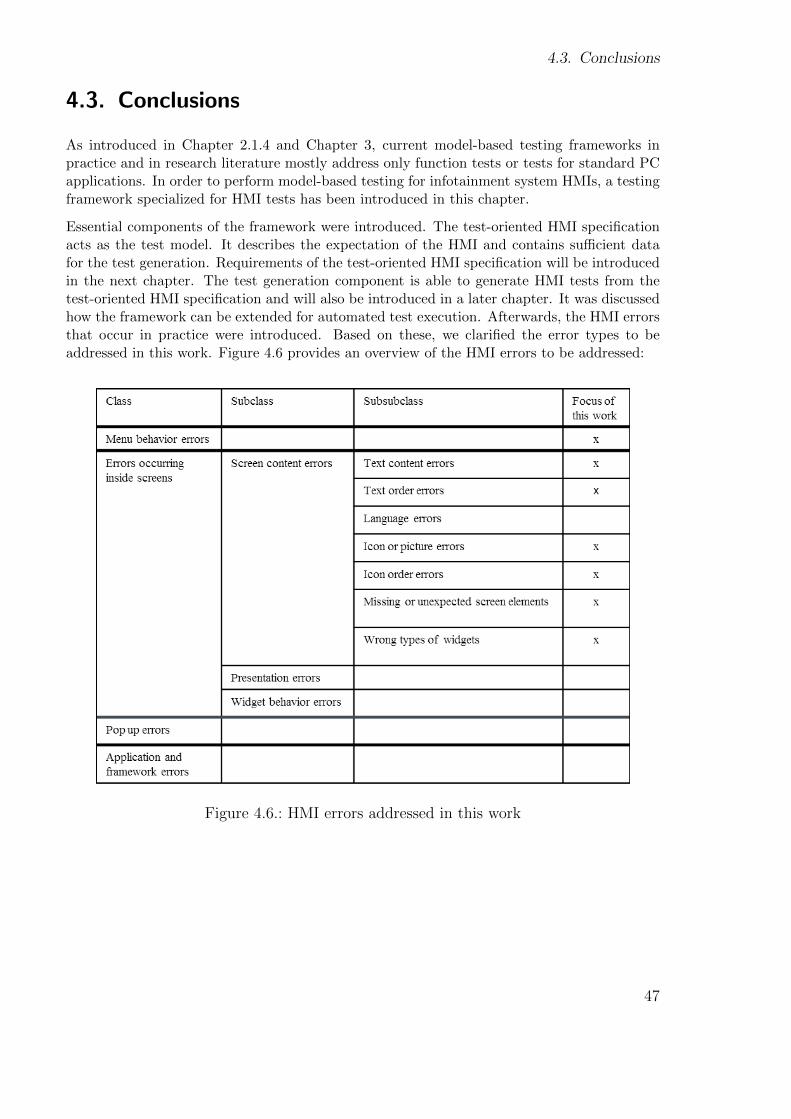
4.3. Conclusions
4.3. Conclusions
As introduced in Chapter 2.1.4 and Chapter 3, current model-based testing frameworks inpractice and in research literature mostly address only function tests or tests for standard PCapplications. In order to perform model-based testing for infotainment system HMIs, a testingframework specialized for HMI tests has been introduced in this chapter.
Essential components of the framework were introduced. The test-oriented HMI specificationacts as the test model. It describes the expectation of the HMI and contains sufficient datafor the test generation. Requirements of the test-oriented HMI specification will be introducedin the next chapter. The test generation component is able to generate HMI tests from thetest-oriented HMI specification and will also be introduced in a later chapter. It was discussedhow the framework can be extended for automated test execution. Afterwards, the HMI errorsthat occur in practice were introduced. Based on these, we clarified the error types to beaddressed in this work. Figure 4.6 provides an overview of the HMI errors to be addressed:
Figure 4.6.: HMI errors addressed in this work
47

Chapter 4. The Framework for Model-Based HMI Testing
48
Chapter 5.
The Test-Oriented HMI Specification
In the last chapter it was stated that the main focal point of this thesis is testing the menubehavior. Screen content tests should also be addressed. The precondition to do these testsis that the expectations of the menu behavior and the screen contents which are to be testedmust be specified. In this thesis, they must be specified in the so-called test-oriented HMIspecification. In particular, the specification must contain sufficient data to generate valid tests.In this chapter, the requirements of the test-oriented HMI specification will be introduced.
5.1. General requirements
Informal specifications consisting of, for example, PDF, Visio and Photoshop files cannotbe used for test generation. In order to generate tests automatically, the test-oriented HMIspecification must fulfill the following requirements:
Requirement 1: The notation, syntax and semantics which are used in the test-oriented HMIspecification must be precisely defined.
In this thesis, we do not define requirements for which specification languages should be usedfor the test-oriented HMI specification. The requirement is that for each specification languageused, the notations, syntax and their semantics must be precisely defined. This is necessaryfor the test generation. For instance, UML SC is a very popular specification language fordescribing dynamic behavior which, however, leaves the notation and semantics open. In orderto apply a code generator to automatically derive software code from a model which is describedwith UML SC, the notation and syntax used, and their semantics, must be precisely definedand taken into account by the code generator.
In order to specify the screens for screen content tests, it is sufficient to describe the screensabstractly. Development tools such as EB GUIDE Studio and VAPS XT allow users to createconcrete screens with available widget libraries or to integrate self-created widget libraries. Fora specification, concrete screens are not necessary and lead to unnecessary complexity. Thereare many specification languages that can be used for an abstract description of screens suchas OEM XML [7], UIML [99], XUL [32] and XAML [73] which will be introduced in Section5.4.
No matter which specification languages are used for the test-oriented HMI specification, theirsemantics must be well-defined. Furthermore, the required data (introduced in later chapters)
49
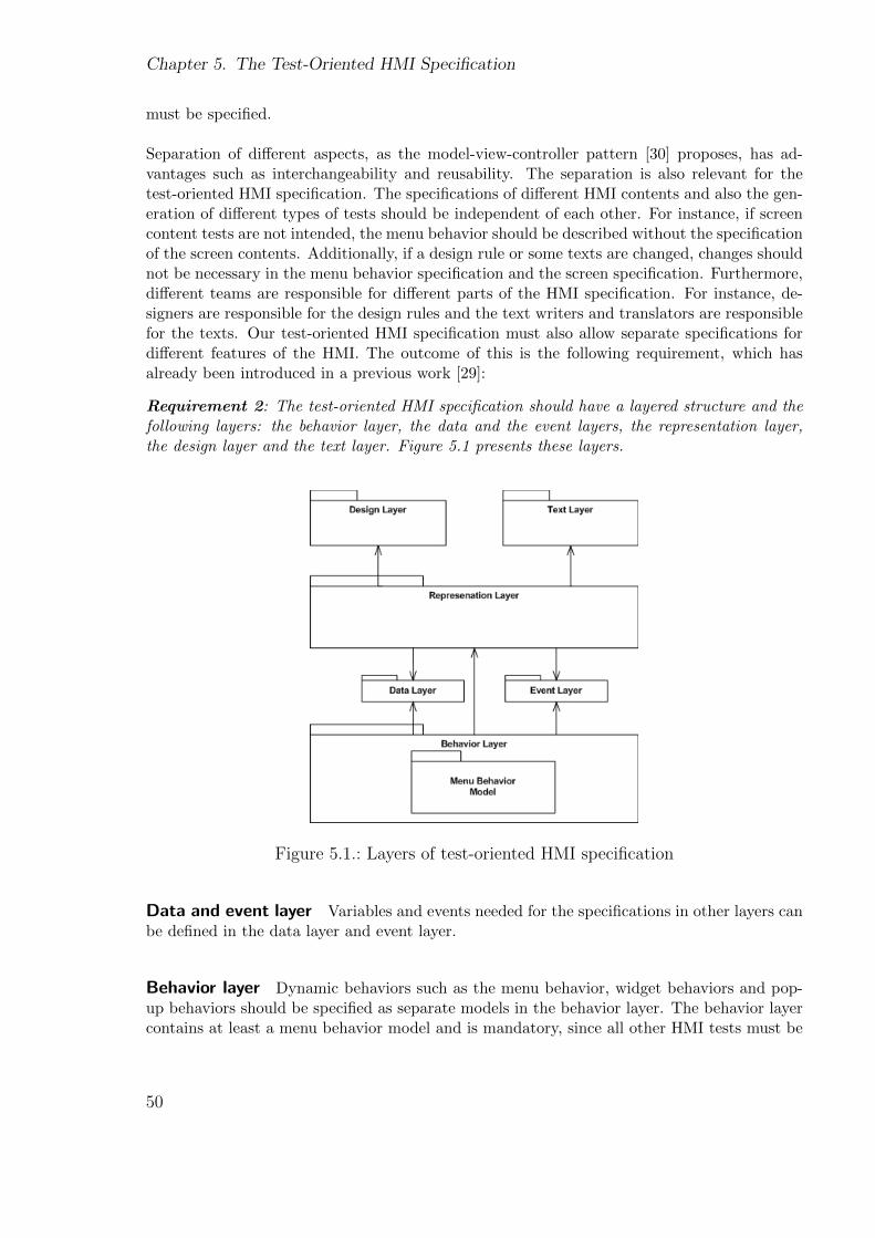
Chapter 5. The Test-Oriented HMI Specification
must be specified.
Separation of different aspects, as the model-view-controller pattern [30] proposes, has ad-vantages such as interchangeability and reusability. The separation is also relevant for thetest-oriented HMI specification. The specifications of different HMI contents and also the gen-eration of different types of tests should be independent of each other. For instance, if screencontent tests are not intended, the menu behavior should be described without the specificationof the screen contents. Additionally, if a design rule or some texts are changed, changes shouldnot be necessary in the menu behavior specification and the screen specification. Furthermore,different teams are responsible for different parts of the HMI specification. For instance, de-signers are responsible for the design rules and the text writers and translators are responsiblefor the texts. Our test-oriented HMI specification must also allow separate specifications fordifferent features of the HMI. The outcome of this is the following requirement, which hasalready been introduced in a previous work [29]:
Requirement 2: The test-oriented HMI specification should have a layered structure and thefollowing layers: the behavior layer, the data and the event layers, the representation layer,the design layer and the text layer. Figure 5.1 presents these layers.
Figure 5.1.: Layers of test-oriented HMI specification
Data and event layer Variables and events needed for the specifications in other layers canbe defined in the data layer and event layer.
Behavior layer Dynamic behaviors such as the menu behavior, widget behaviors and pop-up behaviors should be specified as separate models in the behavior layer. The behavior layercontains at least a menu behavior model and is mandatory, since all other HMI tests must be
50
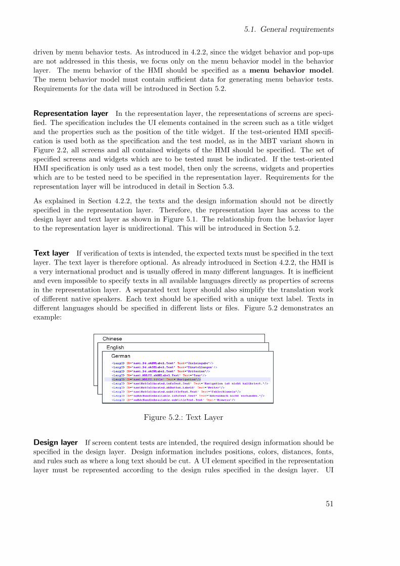
5.1. General requirements
driven by menu behavior tests. As introduced in 4.2.2, since the widget behavior and pop-upsare not addressed in this thesis, we focus only on the menu behavior model in the behaviorlayer. The menu behavior of the HMI should be specified as a menu behavior model.The menu behavior model must contain sufficient data for generating menu behavior tests.Requirements for the data will be introduced in Section 5.2.
Representation layer In the representation layer, the representations of screens are speci-fied. The specification includes the UI elements contained in the screen such as a title widgetand the properties such as the position of the title widget. If the test-oriented HMI specifi-cation is used both as the specification and the test model, as in the MBT variant shown inFigure 2.2, all screens and all contained widgets of the HMI should be specified. The set ofspecified screens and widgets which are to be tested must be indicated. If the test-orientedHMI specification is only used as a test model, then only the screens, widgets and propertieswhich are to be tested need to be specified in the representation layer. Requirements for therepresentation layer will be introduced in detail in Section 5.3.
As explained in Section 4.2.2, the texts and the design information should not be directlyspecified in the representation layer. Therefore, the representation layer has access to thedesign layer and text layer as shown in Figure 5.1. The relationship from the behavior layerto the representation layer is unidirectional. This will be introduced in Section 5.2.
Text layer If verification of texts is intended, the expected texts must be specified in the textlayer. The text layer is therefore optional. As already introduced in Section 4.2.2, the HMI isa very international product and is usually offered in many different languages. It is inefficientand even impossible to specify texts in all available languages directly as properties of screensin the representation layer. A separated text layer should also simplify the translation workof different native speakers. Each text should be specified with a unique text label. Texts indifferent languages should be specified in different lists or files. Figure 5.2 demonstrates anexample:
Figure 5.2.: Text Layer
Design layer If screen content tests are intended, the required design information should bespecified in the design layer. Design information includes positions, colors, distances, fonts,and rules such as where a long text should be cut. A UI element specified in the representationlayer must be represented according to the design rules specified in the design layer. UI
51
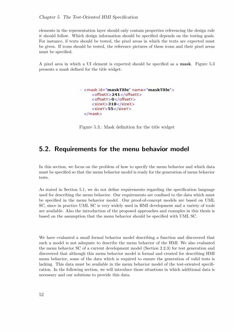
Chapter 5. The Test-Oriented HMI Specification
elements in the representation layer should only contain properties referencing the design ruleit should follow. Which design information should be specified depends on the testing goals.For instance, if texts should be tested, the pixel areas in which the texts are expected mustbe given. If icons should be tested, the reference pictures of these icons and their pixel areasmust be specified.
A pixel area in which a UI element is expected should be specified as a mask. Figure 5.3presents a mask defined for the title widget:
Figure 5.3.: Mask definition for the title widget
5.2. Requirements for the menu behavior model
In this section, we focus on the problem of how to specify the menu behavior and which datamust be specified so that the menu behavior model is ready for the generation of menu behaviortests.
As stated in Section 5.1, we do not define requirements regarding the specification languageused for describing the menu behavior. Our requirements are confined to the data which mustbe specified in the menu behavior model. Our proof-of-concept models are based on UMLSC, since in practice UML SC is very widely used in HMI development and a variety of toolsare available. Also the introduction of the proposed approaches and examples in this thesis isbased on the assumption that the menu behavior should be specified with UML SC.
We have evaluated a small formal behavior model describing a function and discovered thatsuch a model is not adequate to describe the menu behavior of the HMI. We also evaluatedthe menu behavior SC of a current development model (Section 2.2.3) for test generation anddiscovered that although this menu behavior model is formal and created for describing HMImenu behavior, some of the data which is required to ensure the generation of valid tests islacking. This data must be available in the menu behavior model of the test-oriented specifi-cation. In the following section, we will introduce those situations in which additional data isnecessary and our solutions to provide this data.
52
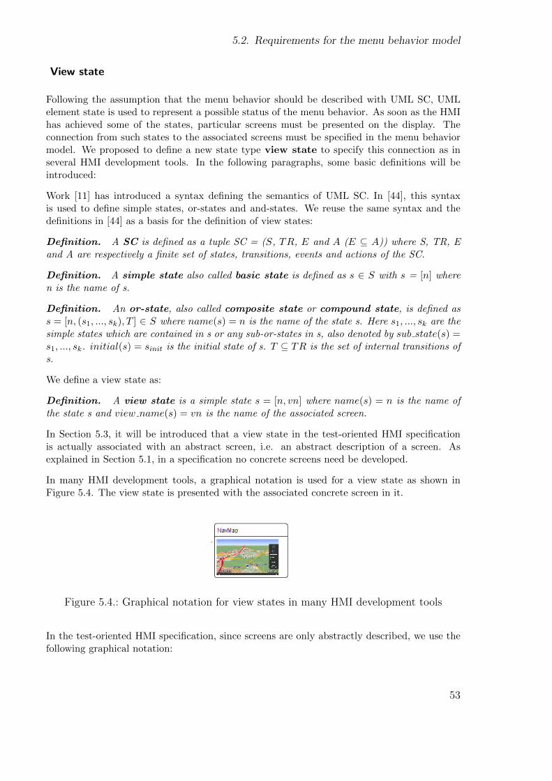
5.2. Requirements for the menu behavior model
View state
Following the assumption that the menu behavior should be described with UML SC, UMLelement state is used to represent a possible status of the menu behavior. As soon as the HMIhas achieved some of the states, particular screens must be presented on the display. Theconnection from such states to the associated screens must be specified in the menu behaviormodel. We proposed to define a new state type view state to specify this connection as inseveral HMI development tools. In the following paragraphs, some basic definitions will beintroduced:
Work [11] has introduced a syntax defining the semantics of UML SC. In [44], this syntaxis used to define simple states, or-states and and-states. We reuse the same syntax and thedefinitions in [44] as a basis for the definition of view states:
Definition. A SC is defined as a tuple SC = (S, TR, E and A (E ⊆ A)) where S, TR, Eand A are respectively a finite set of states, transitions, events and actions of the SC.
Definition. A simple state also called basic state is defined as s ∈ S with s = [n] wheren is the name of s.
Definition. An or-state, also called composite state or compound state, is defined ass = [n, (s1, ..., sk), T ] ∈ S where name(s) = n is the name of the state s. Here s1, ..., sk are thesimple states which are contained in s or any sub-or-states in s, also denoted by sub state(s) =s1, ..., sk. initial(s) = sinit is the initial state of s. T ⊆ TR is the set of internal transitions ofs.
We define a view state as:
Definition. A view state is a simple state s = [n, vn] where name(s) = n is the name ofthe state s and view name(s) = vn is the name of the associated screen.
In Section 5.3, it will be introduced that a view state in the test-oriented HMI specificationis actually associated with an abstract screen, i.e. an abstract description of a screen. Asexplained in Section 5.1, in a specification no concrete screens need be developed.
In many HMI development tools, a graphical notation is used for a view state as shown inFigure 5.4. The view state is presented with the associated concrete screen in it.
Figure 5.4.: Graphical notation for view states in many HMI development tools
In the test-oriented HMI specification, since screens are only abstractly described, we use thefollowing graphical notation:
53
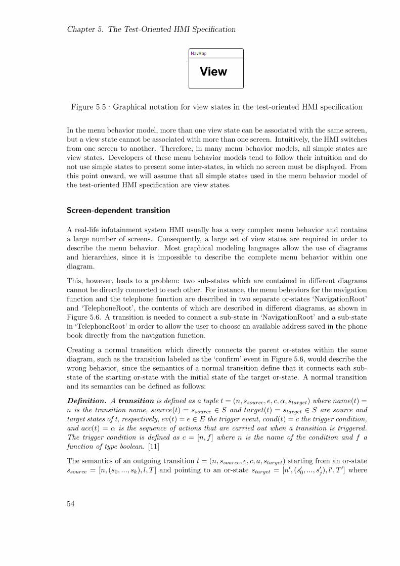
Chapter 5. The Test-Oriented HMI Specification
Figure 5.5.: Graphical notation for view states in the test-oriented HMI specification
In the menu behavior model, more than one view state can be associated with the same screen,but a view state cannot be associated with more than one screen. Intuitively, the HMI switchesfrom one screen to another. Therefore, in many menu behavior models, all simple states areview states. Developers of these menu behavior models tend to follow their intuition and donot use simple states to present some inter-states, in which no screen must be displayed. Fromthis point onward, we will assume that all simple states used in the menu behavior model ofthe test-oriented HMI specification are view states.
Screen-dependent transition
A real-life infotainment system HMI usually has a very complex menu behavior and containsa large number of screens. Consequently, a large set of view states are required in order todescribe the menu behavior. Most graphical modeling languages allow the use of diagramsand hierarchies, since it is impossible to describe the complete menu behavior within onediagram.
This, however, leads to a problem: two sub-states which are contained in different diagramscannot be directly connected to each other. For instance, the menu behaviors for the navigationfunction and the telephone function are described in two separate or-states ‘NavigationRoot’and ‘TelephoneRoot’, the contents of which are described in different diagrams, as shown inFigure 5.6. A transition is needed to connect a sub-state in ‘NavigationRoot’ and a sub-statein ‘TelephoneRoot’ in order to allow the user to choose an available address saved in the phonebook directly from the navigation function.
Creating a normal transition which directly connects the parent or-states within the samediagram, such as the transition labeled as the ‘confirm’ event in Figure 5.6, would describe thewrong behavior, since the semantics of a normal transition define that it connects each sub-state of the starting or-state with the initial state of the target or-state. A normal transitionand its semantics can be defined as follows:
Definition. A transition is defined as a tuple t = (n, ssource, e, c, α, starget) where name(t) =n is the transition name, source(t) = ssource ∈ S and target(t) = starget ∈ S are source andtarget states of t, respectively, ev(t) = e ∈ E the trigger event, cond(t) = c the trigger condition,and acc(t) = α is the sequence of actions that are carried out when a transition is triggered.The trigger condition is defined as c = [n, f ] where n is the name of the condition and f afunction of type boolean. [11]
The semantics of an outgoing transition t = (n, ssource, e, c, a, starget) starting from an or-statessource = [n, (s0, ..., sk), l, T ] and pointing to an or-state starget = [n′, (s′0, ..., s
′j), l
′, T ′] where
54
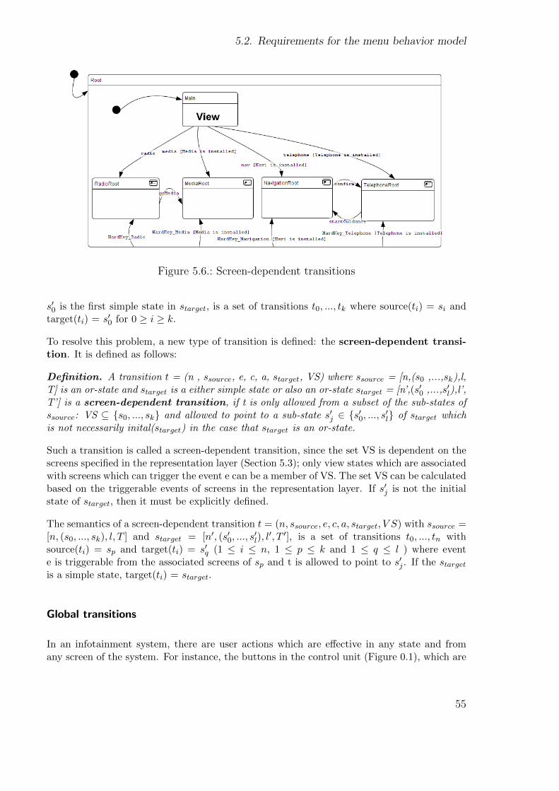
5.2. Requirements for the menu behavior model
Figure 5.6.: Screen-dependent transitions
s′0 is the first simple state in starget, is a set of transitions t0, ..., tk where source(ti) = si andtarget(ti) = s′0 for 0 ≥ i ≥ k.
To resolve this problem, a new type of transition is defined: the screen-dependent transi-tion. It is defined as follows:
Definition. A transition t = (n , ssource, e, c, a, starget, VS) where ssource = [n,(s0 ,...,sk),l,T] is an or-state and starget is a either simple state or also an or-state starget = [n’,(s′0 ,...,s′l),l’,T’] is a screen-dependent transition, if t is only allowed from a subset of the sub-states ofssource: VS ⊆ {s0, ..., sk} and allowed to point to a sub-state s′j ∈ {s′0, ..., s′l} of starget whichis not necessarily inital(starget) in the case that starget is an or-state.
Such a transition is called a screen-dependent transition, since the set VS is dependent on thescreens specified in the representation layer (Section 5.3); only view states which are associatedwith screens which can trigger the event e can be a member of VS. The set VS can be calculatedbased on the triggerable events of screens in the representation layer. If s′j is not the initialstate of starget, then it must be explicitly defined.
The semantics of a screen-dependent transition t = (n, ssource, e, c, a, starget, V S) with ssource =[n, (s0, ..., sk), l, T ] and starget = [n′, (s′0, ..., s
′l), l′, T ′], is a set of transitions t0, ..., tn with
source(ti) = sp and target(ti) = s′q (1 ≤ i ≤ n, 1 ≤ p ≤ k and 1 ≤ q ≤ l ) where evente is triggerable from the associated screens of sp and t is allowed to point to s′j . If the stargetis a simple state, target(ti) = starget.
Global transitions
In an infotainment system, there are user actions which are effective in any state and fromany screen of the system. For instance, the buttons in the control unit (Figure 0.1), which are
55
Chapter 5. The Test-Oriented HMI Specification
usually called hard keys, allow the user to directly access any function from any screen and atany time. Activities of this type can be described with the so-called global transitions:
Definition. A global transition is a transition global tr = (n, ssource, e, c, a, starget) wheressource is the root state of the SC. The definitions of the remaining elements are identical asfor a normal transition introduced above.
The set of global transitions is defined as GlobalTR ⊂ TR of the SC.
Figure 5.6 shows four global transitions allowing the user to directly access the four functionalfeatures. They start from the root state and point to the four respective functional featurestates.
Sufficient conditions in the menu behavior model are necessary to ensure the generation ofvalid tests, correct test execution and the reporting of correct testing results. In this thesis,PreStepsConditions, PrepareConditions and RuntimeConditions are defined in orderto specify the necessary conditions.
PreStepsCondition
In many situations, some user actions are allowed only if some other actions have been previ-ously performed. For example, to define a navigation goal, a country must be chosen beforea city can be entered, as shown in Figure 2.7. This means that before a country has beenentered by the user, the condition for the transition triggering the city input is not yet fulfilledand hence it is not possible for the user to enter a city. In the evaluated HMI developmentmodel, this complexity is wholly implemented in the underlying application. The transitiontriggering the city input is labeled with a condition containing the string “[...]” as shown inFigure 5.7, whose variables can be set by the underlying application. The underlying appli-cation calculates whether a city input is allowed and informs the HMI of this by assigningthe values of the condition. This type of implementation is very popular due to the principleof a light GUI which should not contain much complexity. However, this solution leads to aserious problem for test generation. Since this logic is irreproducible in the menu behaviormodel, many generated tests would contain an illegal order of test steps; for example, enteringa city first and then a country. At the time of creating an HMI specification, interfaces tounderlying applications are usually still undefined. Nevertheless, the behaviors of underlyingapplications are either not available or not available in a useful form for the test generation.Therefore, in order to avoid creating invalid tests, such logic must be completely specified inthe test-oriented HMI specification.
There can be different ways to specify the allowed orders of user actions. One way is to definemore view states associated with the same screen ‘NavAdrInput’ which represent differentintermediate states; for example, view state A presents the status that no country has beenentered yet and view state B presents the status that a country has been entered. However,this way is unintuitive since according to intuition each screen presents a unique state of the
56
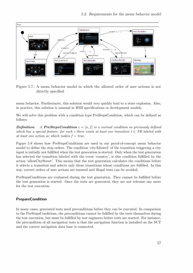
5.2. Requirements for the menu behavior model
Figure 5.7.: A menu behavior model in which the allowed order of user actions is notdirectly specified
menu behavior. Furthermore, this solution would very quickly lead to a state explosion. Also,in practice, this solution is unusual in HMI specifications or development models.
We will solve this problem with a condition type PreStepsCondition, which can be defined asfollows:
Definition. A PreStepsCondition c = [n, f ] is a normal condition as previously definedwhich has a special feature: for each c there exists at least one transition t ∈ TR labeled withat least one action ac which makes f = true.
Figure 5.8 shows how PreStepsConditions are used in our proof-of-concept menu behaviormodel to define the step orders. The condition ‘cityAllowed’ of the transition triggering a cityinput is initially not fulfilled when the test generation is started. Only when the test generationhas selected the transition labeled with the event ‘country’, is this condition fulfilled by theaction ‘allowCityStreet’. This means that the test generation calculates the conditions beforeit selects a transition and selects only those transitions whose conditions are fulfilled. In thisway, correct orders of user actions are ensured and illegal tests can be avoided.
PreStepsConditions are evaluated during the test generation. They cannot be fulfilled beforethe test generation is started. Once the tests are generated, they are not relevant any morefor the test execution.
PrepareCondition
In many cases, generated tests need preconditions before they can be executed. In comparisonto the PreStepsConditions, the preconditions cannot be fulfilled by the tests themselves duringthe test execution, but must be fulfilled by test engineers before tests are started. For instance,the precondition of all navigation tests is that the navigation function is installed on the SUTand the correct navigation data base is connected.
57
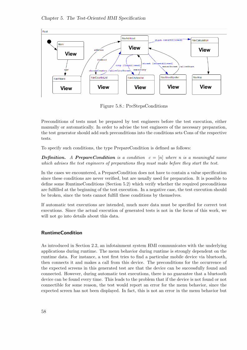
Chapter 5. The Test-Oriented HMI Specification
Figure 5.8.: PreStepsConditions
Preconditions of tests must be prepared by test engineers before the test execution, eithermanually or automatically. In order to advise the test engineers of the necessary preparation,the test generator should add such preconditions into the conditions sets Cons of the respectivetests.
To specify such conditions, the type PrepareCondition is defined as follows:
Definition. A PrepareCondition is a condition c = [n] where n is a meaningful namewhich advises the test engineers of preparations they must make before they start the test.
In the cases we encountered, a PrepareCondition does not have to contain a value specificationsince these conditions are never verified, but are usually used for preparation. It is possible todefine some RuntimeConditions (Section 5.2) which verify whether the required preconditionsare fulfilled at the beginning of the test execution. In a negative case, the test execution shouldbe broken, since the tests cannot fulfill these conditions by themselves.
If automatic test executions are intended, much more data must be specified for correct testexecutions. Since the actual execution of generated tests is not in the focus of this work, wewill not go into details about this data.
RuntimeCondition
As introduced in Section 2.2, an infotainment system HMI communicates with the underlyingapplications during runtime. The menu behavior during runtime is strongly dependent on theruntime data. For instance, a test first tries to find a particular mobile device via bluetooth,then connects it and makes a call from this device. The preconditions for the occurrence ofthe expected screens in this generated test are that the device can be successfully found andconnected. However, during automatic test executions, there is no guarantee that a bluetoothdevice can be found every time. This leads to the problem that if the device is not found or notconnectible for some reason, the test would report an error for the menu behavior, since theexpected screen has not been displayed. In fact, this is not an error in the menu behavior but
58
5.3. Requirements for the representation layer
an error due to a missing runtime condition. This results in very time-consuming test resultevaluations.
To solve this problem, the runtime data for the preconditions of an expectation must be verifiedduring runtime. For this, type RuntimeCondition is defined.
Definition. A RuntimeCondition is defined as a tuple c = [n, f ] where n is the nameof the condition and the variables in function f should be bound to runtime data by the testinstantiation.
As introduced in Section 4.1, runtime data can be captured from interfaces such as the MOST-bus. In this way, a RuntimeCondition can be verified during runtime. If a RuntimeConditionis not fulfilled, a runtime error instead of a menu behavior error should be reported.
In the case that RuntimeCondition is required, the definition of menu behavior tests introducedin Section 4.2.2 must be extended. Steps = (step0, ..., stepk) where stepi with 0 ≤ i ≤k ∈ AC∪ EXP ∪ RuntimeCons where RuntimeCons is a set of RuntimeConditions.
Obviously, the differences between the defined types of conditions can be summarized as fol-lows: PreStepsConditions can be fulfilled by the tests themselves during the test execution.PrepareConditions must be fulfilled before the execution of a test is started. RuntimeCondi-tions are fulfilled during runtime by underlying applications.
Different event types
For automatic test executions, different event types must be defined to indicate to the testinstantiation how to handle these events.
For instance, type ApplicationEvent is defined for events initialized by underlying applicationssuch as the warning of an empty tank. Many menus require concrete user input data, e.g. aphone number to dial or a city name as in the example presented in Figure 5.8. Events such as‘chooseCountry’ and ‘enterCity’ must be bound to concrete user data by the test instantiation.We have defined the type ‘UserInputEvent’ to indicate to the test instantiation that it shouldfirstly check whether concrete user input data has been predefined and then bind the eventswith it.
Depending on the test automation framework used and the individual testing goals of dif-ferent HMI testing projects, many more types of elements may be defined. In this thesis,automatic test execution is not our focal point. We merely present some challenges we havemet and hope to give some inspiration to practical projects.
5.3. Requirements for the representation layer
The representation layer is designed to specify information about screens. Information abouta screen contains firstly the contained UI elements and their properties, and secondly, events
59

Chapter 5. The Test-Oriented HMI Specification
which can be triggered by the screen. In this section we will introduce how we reuse andcombine existing approaches to specify this information about the screens.
5.3.1. Specification of screen contents
As introduced in Section 5.1, there are a number of specification languages for describing userinterfaces. In this thesis, we neither develop a new specification language for user interfacesnor require a particular specification language. We only require certain data which must bespecified for doing screen content tests. In order to introduce the requirements, we reuse theconcept of Model-based User Interface Development (MBUID) [100] and some definitions from[100] which will be extended in this thesis. The focal point of MBUID is to develop the userinterface.
The GUI development process in the MBUID contains the steps shown in Figure 5.9:
Figure 5.9.: The steps contained in a MBUID process
The task model and domain model are abstract models. The task model describes activities theuser can perform with the UI in order to apply certain functions. The domain model describesthe structure of the application logic.
“The abstract User Interface model (AUI) specifies the user interface in terms of Ab-stract Interaction Objects (AIO) which are platform- and modality-independent abstrac-tions of user interface elements.” ([100]) Modality-independent means that different modalitiessuch as graphics, speech and haptics are not distinguished for the AUIs and AIOs. There isstill no standard notation for AUI.
The Concrete User Interface model (CUI) implements and refines the AUIs for a concretemodality and platform. As for the AUI, there is still no standard notation for CUI.
Finally, the UI implementation is generated from the CUI model.
In order to abstractly specify the screen contents for performing screen content tests, we reusethe concept of the abstract user interface model: AUI. In the AUI, a presentation unit is anabstract form of a screen, into which AIOs are grouped. As yet, there is no common standardnotation for AUI models. The following class diagram presents the relationship between arepresentation layer and its contained AIOs.
60
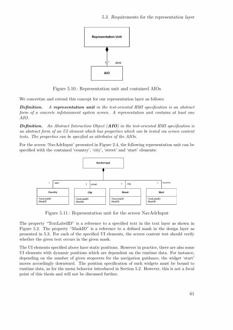
5.3. Requirements for the representation layer
Figure 5.10.: Representation unit and contained AIOs
We concretize and extend this concept for our representation layer as follows:
Definition. A representation unit in the test-oriented HMI specification is an abstractform of a concrete infotainment system screen. A representation unit contains at least oneAIO.
Definition. An Abstract Interaction Object (AIO) in the test-oriented HMI specification isan abstract form of an UI element which has properties which can be tested via screen contenttests. The properties can be specified as attributes of the AIOs.
For the screen ‘NavAdrInput’ presented in Figure 2.4, the following representation unit can bespecified with the contained ‘country’, ‘city’, ‘street’ and ‘start’ elements:
Figure 5.11.: Representation unit for the screen NavAdrInput
The property “TextLabelID” is a reference to a specified text in the text layer as shown inFigure 5.2. The property “MaskID” is a reference to a defined mask in the design layer aspresented in 5.3. For each of the specified UI elements, the screen content test should verifywhether the given text occurs in the given mask.
The UI elements specified above have static positions. However in practice, there are also someUI elements with dynamic positions which are dependent on the runtime data. For instance,depending on the number of given stopovers for the navigation guidance, the widget ‘start’moves accordingly downward. The position specification of such widgets must be bound toruntime data, as for the menu behavior introduced in Section 5.2. However, this is not a focalpoint of this thesis and will not be discussed further.
61
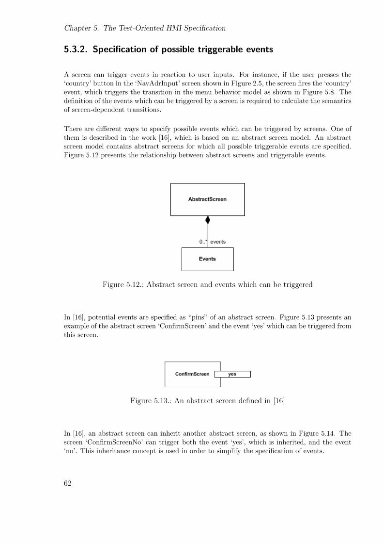
Chapter 5. The Test-Oriented HMI Specification
5.3.2. Specification of possible triggerable events
A screen can trigger events in reaction to user inputs. For instance, if the user presses the‘country’ button in the ‘NavAdrInput’ screen shown in Figure 2.5, the screen fires the ‘country’event, which triggers the transition in the menu behavior model as shown in Figure 5.8. Thedefinition of the events which can be triggered by a screen is required to calculate the semanticsof screen-dependent transitions.
There are different ways to specify possible events which can be triggered by screens. One ofthem is described in the work [16], which is based on an abstract screen model. An abstractscreen model contains abstract screens for which all possible triggerable events are specified.Figure 5.12 presents the relationship between abstract screens and triggerable events.
Figure 5.12.: Abstract screen and events which can be triggered
In [16], potential events are specified as “pins” of an abstract screen. Figure 5.13 presents anexample of the abstract screen ‘ConfirmScreen’ and the event ‘yes’ which can be triggered fromthis screen.
Figure 5.13.: An abstract screen defined in [16]
In [16], an abstract screen can inherit another abstract screen, as shown in Figure 5.14. Thescreen ‘ConfirmScreenNo’ can trigger both the event ‘yes’, which is inherited, and the event‘no’. This inheritance concept is used in order to simplify the specification of events.
62

5.3. Requirements for the representation layer
Figure 5.14.: Inheritance in the abstract screen model
This concept will be reused in this thesis in order to specify the potential events which can betriggered by screens.
5.3.3. Meta-model of the representation layer
In Section 5.3.1 and Section 5.3.2, existing approaches which are to be reused in this thesishave been introduced. In this section, we will introduce the meta-model for the representationlayer. The meta-model defines the data which is required for testing and should be specifiedfor screens in the representation layer.
Figure 5.15.: Meta-model for the representation layer
As shown in Figure 5.15, the representation layer of the test-oriented HMI specification con-tains abstract screens. For each abstract screen, events which can be triggered are specified.An abstract screen is also associated with a representation unit, which describes the screencontents, thus the contained UI elements and their properties which are to be tested.
Figure 5.16 shows the specification of screen ‘NavAdrInput’:
63
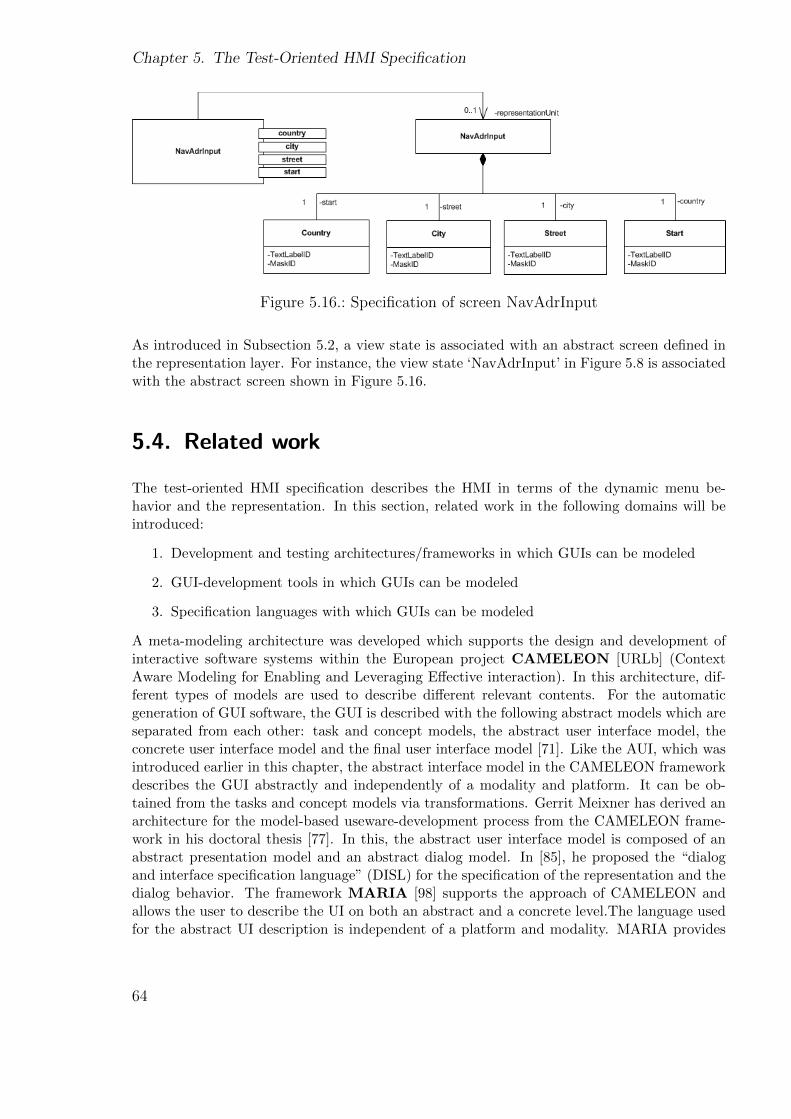
Chapter 5. The Test-Oriented HMI Specification
Figure 5.16.: Specification of screen NavAdrInput
As introduced in Subsection 5.2, a view state is associated with an abstract screen defined inthe representation layer. For instance, the view state ‘NavAdrInput’ in Figure 5.8 is associatedwith the abstract screen shown in Figure 5.16.
5.4. Related work
The test-oriented HMI specification describes the HMI in terms of the dynamic menu be-havior and the representation. In this section, related work in the following domains will beintroduced:
1. Development and testing architectures/frameworks in which GUIs can be modeled
2. GUI-development tools in which GUIs can be modeled
3. Specification languages with which GUIs can be modeled
A meta-modeling architecture was developed which supports the design and development ofinteractive software systems within the European project CAMELEON [URLb] (ContextAware Modeling for Enabling and Leveraging Effective interaction). In this architecture, dif-ferent types of models are used to describe different relevant contents. For the automaticgeneration of GUI software, the GUI is described with the following abstract models which areseparated from each other: task and concept models, the abstract user interface model, theconcrete user interface model and the final user interface model [71]. Like the AUI, which wasintroduced earlier in this chapter, the abstract interface model in the CAMELEON frameworkdescribes the GUI abstractly and independently of a modality and platform. It can be ob-tained from the tasks and concept models via transformations. Gerrit Meixner has derived anarchitecture for the model-based useware-development process from the CAMELEON frame-work in his doctoral thesis [77]. In this, the abstract user interface model is composed of anabstract presentation model and an abstract dialog model. In [85], he proposed the “dialogand interface specification language” (DISL) for the specification of the representation and thedialog behavior. The framework MARIA [98] supports the approach of CAMELEON andallows the user to describe the UI on both an abstract and a concrete level.The language usedfor the abstract UI description is independent of a platform and modality. MARIA provides
64
5.4. Related work
a number of languages which can be used to concretize the abstract description for particularplatforms and modalities. Many other frameworks in which GUIs can be modeled have alreadybeen introduced in Chapter 3.
Several industrial tools are developed for the model-based GUI development: EB GUIDEStudio [URLf], IRIS [URLg], VAPS XT [URLi] and Altia&Rhapsody [URLa]. All ofthese tools allow the creation of concrete screens and the modeling of the behavior. However,these tools do not support abstract description of the screens, since they are GUI developmentand prototyping tools and do not focus on an abstract specification. The tool TERESA[14] supports the approach of CAMELEON and allows the design and development of multi-platform applications. An abstract specification of the UI is supported in this tool. However,TERESA is not supported anymore. Instead, the MARIAE (MARIA Environment) tool isproposed. This is based on the same concept as TERESA, uses the MARIA language andprovides additional functions such as the automatic import of services and annotations.
A number of specification languages support the abstract or concrete description of GUIs.
The Original Equipment Manufacturer XML (OEM XML) [7] is especially developed for theautomotive HMI domain. An abstract description of the HMI is supported. The completestructure of the HMI is described as a tree in which each node corresponds to a widget, whilethe structure and the behavior of a single widget are described in one or more separate XMLfiles. In this specification language, the description of the behavior is suboptimal. Similarly tothe modeling concept introduced in [108], the description of HMI states are dependent on thewidgets; in order to model a state, a corresponding widget must first be described.
Elektrobit [URLe] has developed an HMI specification language ICUC XML for Daimler AGwhich supports HMI development for trucks. The main purpose of this language is to allowthe storage and transmission of the contents from the HMI development models (Section 2.2.3)which are created with EB GUIDE Studio. Therefore, the language is not anticipated as beinguseful for abstract descriptions. The descriptions of the screens and the behavior are separatefrom one another.
The Extensible User Interface Language (XUL) [17] [32] is developed by the Mozilla projectfor developing cross-platform applications. The goal is to allow the porting of applications fordifferent platforms on which Mozilla applications run. XUL can be used for describing windowlayouts. The GUI is described with a structure which contains the graphical elements such aswindows and buttons. However, XUL is not complied with specifying dynamic behaviors.
The User Interface Markup Language (UIML) [99] was developed to describe the GUI indepen-dently of any particular programming language. It allows the separation of the representationand the behavior descriptions. Interpreters are used to translate the GUI elements in UIMLinto components of the used language such as Java or HTML. The drawback of this languageis that it describes the behavior based on a rule-based system where events are included in theconditions. In comparison to state-based descriptions as in many other XML-based languages,it is quite unusual to describe a state-oriented system such as the HMI with a rule-basedsystem.
There are a number of other XML-based specification languages, e.g. the State Chart XML(SCXML) [URLj] which can only describe the behavior, the Extensible Application MarkupLanguage (XAML) [73] which is used to simplify the creation of GUIs for .NET applications,
65
Chapter 5. The Test-Oriented HMI Specification
Adobe Flex 3 which is suitable for rapid prototyping, and the Presentation Markup Language(PreML) which is only conditionally suitable for modeling the representation etc. There arealso efforts aimed at new specification languages which combine the advantages of these existinglanguages and optimize them for modeling the infotainment system HMIs in an abstract way,such as [118] and the automotiveHMI project [URLd]. Each of these modeling languages has itsadvantages and drawbacks. A detailed comparison of many existing XML-based specificationlanguages can be found in [110] and [41]. We will not introduce all of them in detail here sincespecification languages are not within the focus of this thesis.
5.5. Conclusions
In the last chapter it was stated that the main focal point of this thesis is testing the menubehavior. Screen content tests should also be addressed. The precondition to perform thesetests is that the menu behavior and the screen contents which are to be tested are specified inthe test-oriented HMI specification. In this chapter, the test-oriented HMI specification wasintroduced, in particular the menu behavior model and the representation layer, which are themain components of the test-oriented HMI specification. Requirements have been defined fordata which must be specified in the menu behavior model and the representation layer. Thetest-oriented HMI specification is now ready for test generation.
66
Chapter 6.
Test Generation
As explained in Section 2.1, test generation is the process in which tests are automaticallygenerated from one or several test models based on particular coverage criteria. In our context,menu behavior tests should be generated from the menu behavior SC which is the test model.Currently, there already exist a number of test generation techniques (Section 6.4). In thisthesis, we do not aim to develop a new test generation technique, but only to demonstrate howmenu behavior tests can be generated from the menu behavior SC based on three conventionalstructural coverage criteria: transition coverage, path coverage and state coverage (Section2.1.2), which are adequate for state-based models. Generated tests based on these coveragecriteria in particular will be presented and compared. The advantages and drawbacks of usingthese coverage criteria will be discussed. First of all, we introduce the example menu behaviorSC from which tests should be generated.
6.1. The menu behavior SC
Figure 6.1 shows the menu behavior SC from which tests should be generated. This SCdescribes a subset of the menu behavior of the navigation function in a flat structure. Inpractice, a menu behavior SC usually has a large set of hierarchies due to the high complexity.However, we propose to allow the generation algorithm to be based on a SC model with aflat structure and flatten the hierarchical SC models before tests are generated from them.This firstly keeps the generation algorithm simple, adaptive and less error-prone, and secondlymakes the test generation more efficient, since it would be time-consuming if the test generationalgorithm had to resolve the same hierarchies for each generation activity. The process in whichthe hierarchies are resolved is called model flattening [107]. It must ensure that the resultantflattened SC model maintains the semantics of the original hierarchical SC.
The SC above describes the following menu behavior: the system starts with the screen ‘Main’.From ‘Main’, the user has the option to launch the navigation function, if the PrepareCondition“Navi is installed” is fulfilled, as introduced in Section 5.2. On choosing the navigation function,the user is led to the ‘NavWizard’ screen which offers the options to either define a destinationby entering an address or access the address book which contains predefined contact addresses.The second option is not completely described in this SC. For the first option, the user must firstchoose a country from the country list screen. After that, he can input either a city followed bya street or a street only, and then start the route guidance. This SC is extremely simplified in
67

Chapter 6. Test Generation
Figure 6.1.: Flattened SC model for test generation
order to keep the introduction easy. In practice, the menu behavior of the navigation functionis much more complicated and provides many more options for defining a navigation goal.
6.2. A test generation algorithm
In this section, we introduce in detail a test generation algorithm which is based on the tran-sition coverage. This algorithm traverses the SC model based on the depth-first search andsystematically generates the possible paths through the SC. It allows each cycle only once inorder to avoid test case explosion [70]. The principle of the test generation algorithm can bedescribed with the following rules:
• The generation algorithm begins with the initial state
• The generation algorithm carries out a depth-first search and systematically generatesthe possible paths through the SC. Each path is a test
• A cycle is only allowed once. This rule exists in order to avoid test case explosion
• If the test generation visits a state which has no outgoing transition, it closes the currentpath and continues with other unclosed paths if any are available
• If the test generation visits a state whose outgoing transitions have all been visitedalready, it closes the current path and continues with other unclosed paths if any areavailable
68
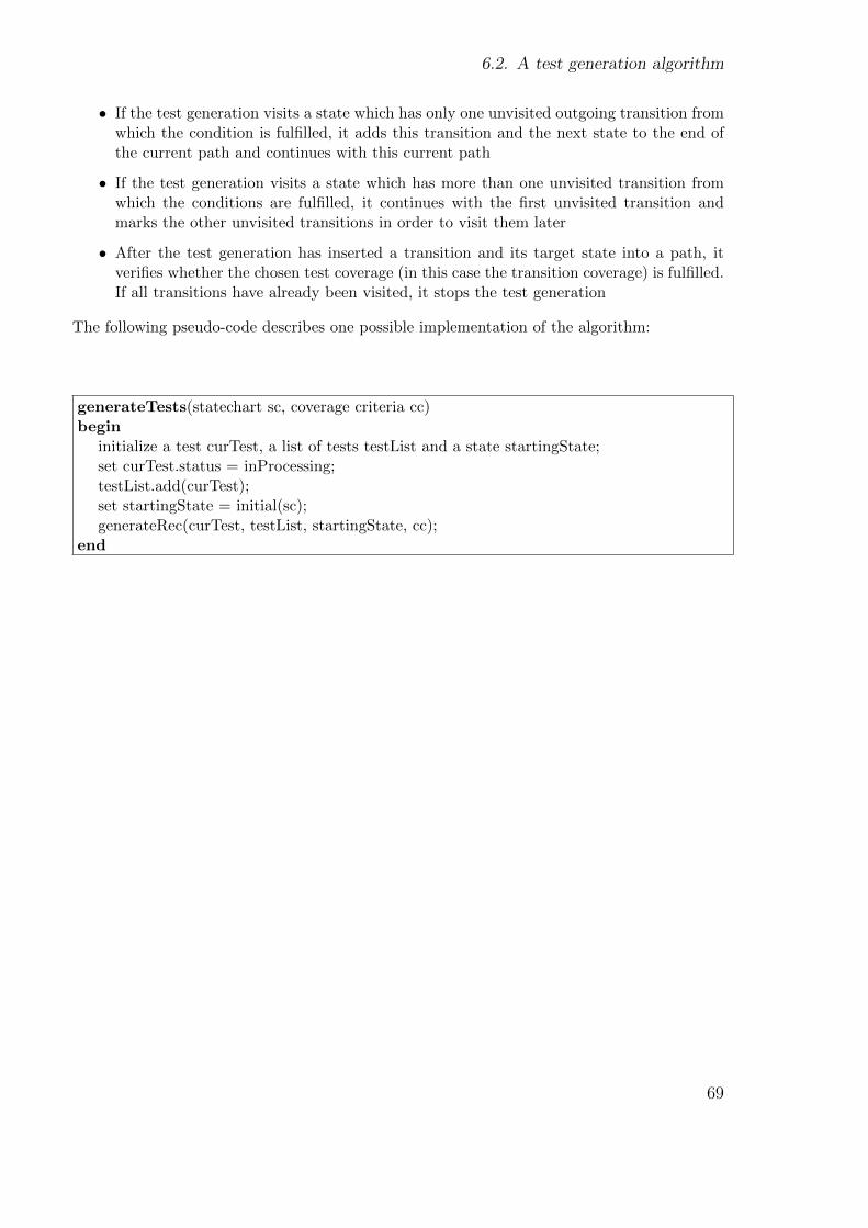
6.2. A test generation algorithm
• If the test generation visits a state which has only one unvisited outgoing transition fromwhich the condition is fulfilled, it adds this transition and the next state to the end ofthe current path and continues with this current path
• If the test generation visits a state which has more than one unvisited transition fromwhich the conditions are fulfilled, it continues with the first unvisited transition andmarks the other unvisited transitions in order to visit them later
• After the test generation has inserted a transition and its target state into a path, itverifies whether the chosen test coverage (in this case the transition coverage) is fulfilled.If all transitions have already been visited, it stops the test generation
The following pseudo-code describes one possible implementation of the algorithm:
generateTests(statechart sc, coverage criteria cc)begin
initialize a test curTest, a list of tests testList and a state startingState;set curTest.status = inProcessing;testList.add(curTest);set startingState = initial(sc);generateRec(curTest, testList, startingState, cc);
end
69
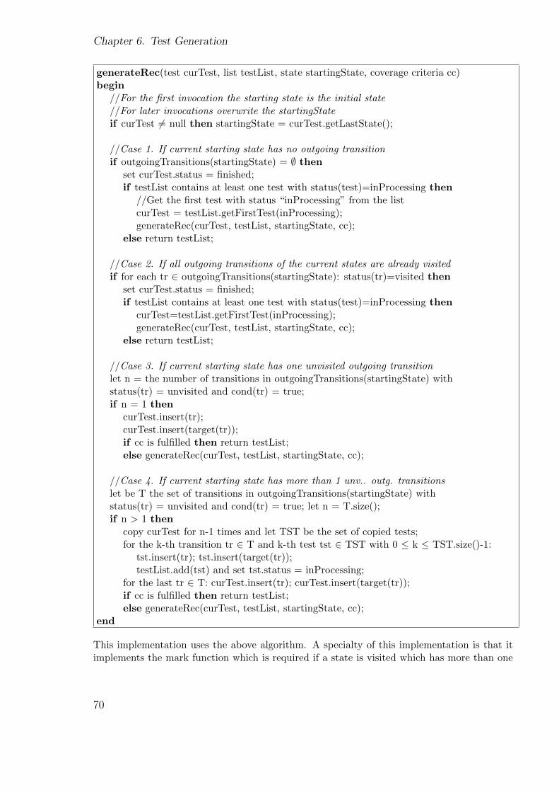
Chapter 6. Test Generation
generateRec(test curTest, list testList, state startingState, coverage criteria cc)begin
//For the first invocation the starting state is the initial state//For later invocations overwrite the startingStateif curTest 6= null then startingState = curTest.getLastState();
//Case 1. If current starting state has no outgoing transitionif outgoingTransitions(startingState) = ∅ then
set curTest.status = finished;if testList contains at least one test with status(test)=inProcessing then
//Get the first test with status “inProcessing” from the listcurTest = testList.getFirstTest(inProcessing);generateRec(curTest, testList, startingState, cc);
else return testList;
//Case 2. If all outgoing transitions of the current states are already visitedif for each tr ∈ outgoingTransitions(startingState): status(tr)=visited then
set curTest.status = finished;if testList contains at least one test with status(test)=inProcessing then
curTest=testList.getFirstTest(inProcessing);generateRec(curTest, testList, startingState, cc);
else return testList;
//Case 3. If current starting state has one unvisited outgoing transitionlet n = the number of transitions in outgoingTransitions(startingState) withstatus(tr) = unvisited and cond(tr) = true;if n = 1 then
curTest.insert(tr);curTest.insert(target(tr));if cc is fulfilled then return testList;else generateRec(curTest, testList, startingState, cc);
//Case 4. If current starting state has more than 1 unv.. outg. transitionslet be T the set of transitions in outgoingTransitions(startingState) withstatus(tr) = unvisited and cond(tr) = true; let n = T.size();if n > 1 then
copy curTest for n-1 times and let TST be the set of copied tests;for the k-th transition tr ∈ T and k-th test tst ∈ TST with 0 ≤ k ≤ TST.size()-1:
tst.insert(tr); tst.insert(target(tr));testList.add(tst) and set tst.status = inProcessing;
for the last tr ∈ T: curTest.insert(tr); curTest.insert(target(tr));if cc is fulfilled then return testList;else generateRec(curTest, testList, startingState, cc);
end
This implementation uses the above algorithm. A specialty of this implementation is that itimplements the mark function which is required if a state is visited which has more than one
70
6.3. Generated tests
unvisited transitions (Case 4), based on the copy path principle, i.e. if the test generation isin the view state ‘NavWizard’, only one path has been generated so far: Path 1 = [Main] →(nav) → [NavWizard]. The test generation detects that the view state NavWizard has twounvisited outgoing transitions, then creates a new path Path 2 by copying Path 1, adds one ofthe unvisited outgoing transitions (e.g. the one which is labeled with event ‘address’) to Path1, adds the other transition to Path 2, marks Path 2 as “inProcessing” and continues with Path1. Later, when Path 1 is finished, all paths with the status “inProcessing” are processed.
This is a quite an unusual implementation. But it has the advantage that it avoids “outliertests”: tests which are much longer than the others. We have also implemented the markfunction in the classical way by marking the actual unvisited transitions as “still unvisited”instead of copying the complete path. This implementation generates different tests from thefirst implementation. It generates one “outlier test”. This will be shown in the next section.In [105], the point is also raised that different implementations of the same test generationalgorithm based on the same coverage criteria usually produce very different tests. This is notcontrary to the determination of a test generator. Each test generator is deterministic andproduces the same results for the same model. However, different generators which implementthe same generation algorithm and are based on the same coverage criteria usually implementthe multitude of details in different ways, usually leading to different results.
In order to demonstrate the correctness of the implementation, we have generated tests fromseveral menu behavior SCs and verified whether the generated tests are valid and cover alltransitions.
6.3. Generated tests
6.3.1. Based on the transition coverage
The implementation which was described with pseudo-code generates the following three testswhich have the same condition set Cons = {[Navi is installed]}:
Test 1:[Main] → (nav) → [NavWizard] → (address) → [NavAdrInput] → (country) → [NavCoun-tryList] → (chooseCountry) → [NavAdrInput] → (city) → [NavCitySpeller] → (enterCity) →[NavAdrInput]
Test 2:[Main] → (nav) → [NavWizard] → (address) → [NavAdrInput] → (country) → [NavCoun-tryList]→ (chooseCountry)→ [NavAdrInput]→ (street)→ [NavStreetSpeller]→ (enterStreet)→ [NavAdrInput] → (start) → [NavCalculation] → [NavMap] → (SK Route) → [NavWiz-ard]
Test 3:[Main] → (nav) → [NavWizard] → (adrbook) → (NavToAdrbook)
The tests produced have comparable lengths due to the copy path principle. However, this testgeneration leads to the result that the typical way of entering a destination, i.e. first country,
71
Chapter 6. Test Generation
then city and finally street, is not covered. However, the generated tests fulfill the transitioncoverage.
The second implementation introduced above produces the following two tests:
Test 1:[Main] → (nav) → [NavWizard] → (address) → [NavAdrInput] → (country) → [NavCoun-tryList] → (chooseCountry) → [NavAdrInput] → (city) → [NavCitySpeller] → (enterCity) →[NavAdrInput] → (street) → [NavStreetSpeller] → (enterStreet) → [NavAdrInput] → (start)→ [NavCalculation] → [NavMap] → (SK Route) → [NavWizard]
Test 2:[Main] → (nav) → [NavWizard] → (adrbook) → (NavToAdrbook)
These two tests also cover all transitions in the SC. The classical way of defining a destinationis covered by Test 1. The length of Test 1 is unproblematic. However, from a larger menubehavior SC describing a very complex behavior, very long tests would be generated withthe drawback that if they are broken somewhere at the beginning, e.g. due to an unfulfilledcondition, the remaining steps can no longer be verified.
6.3.2. Based on the path coverage
In order to verify the possible scenarios of entering a destination and starting the route guid-ance, we have implemented an algorithm which is based on the path coverage. As introducedin Section 2.1.2, path coverage could lead to non-terminating generation if infinite paths existin the model. Therefore, we limit the number of generated tests using the following two strate-gies: first, each cycle is allowed only once (as we have done so far), and second, the algorithmshould only generate tests which end with the view state ‘NavMap’. This view state is chosensince our goal is to test the paths which enable the initiation of the guidance. The view state‘NavMap’ is expected as soon as the guidance is started. The following tests are generated:
Test 1:[Main] → (nav) → [NavWizard] → (address) → [NavAdrInput] → (country) → [NavCoun-tryList]→ (chooseCountry)→ [NavAdrInput]→ (street)→ [NavStreetSpeller]→ (enterStreet)→ [NavAdrInput] → (start) → [NavCalculation] → [NavMap]
Test 2:[Main] → (nav) → [NavWizard] → (address) → [NavAdrInput] → (country) → [NavCoun-tryList] → (chooseCountry) → [NavAdrInput] → (city) → [NavCitySpeller] → (enterCity) →[NavAdrInput] → (street) → [NavStreetSpeller] → (enterStreet) → [NavAdrInput] → (start)→ [NavCalculation] → [NavMap]
Test 3:[Main] → (nav) → [NavWizard] → (address) → [NavAdrInput] → (country) → [NavCoun-tryList]→ (chooseCountry)→ [NavAdrInput]→ (street)→ [NavStreetSpeller]→ (enterStreet)→ [NavAdrInput] → (city) → [NavCitySpeller] → (enterCity) → [NavAdrInput] → (start) →[NavCalculation] → [NavMap]
72

6.3. Generated tests
Obviously, all three possible paths to starting the route guidance are generated. Test generationfrom a more complex menu behavior SC has shown that most of the generated tests share alarge set of common step sequences. The same errors are repeatedly detected by many of thesetests. This means that the execution of more tests does not necessarily mean the detection ofmore errors, but merely consumes time resources. Therefore, the path coverage is only suitableduring less demanding project phases.
6.3.3. Based on the state coverage
The test generators which are based on the two different implementations of the mark functionseparately produce the following tests based on the state coverage :
Test 1:[Main] → (nav) → [NavWizard] → (address) → [NavAdrInput] → (country) → [NavCoun-tryList] → (chooseCountry) → [NavAdrInput] → (city) → [NavCitySpeller] → (enterCity) →[NavAdrInput]
Test 2:[Main] → (nav) → [NavWizard] → (address) → [NavAdrInput] → (country) → [NavCoun-tryList]→ (chooseCountry)→ [NavAdrInput]→ (street)→ [NavStreetSpeller]→ (enterStreet)→ [NavAdrInput] → (start) → [NavCalculation] → [NavMap]
Test 3:[Main] → (nav) → [NavWizard] → (adrbook) → (NavToAdrbook)
and
Test 1:[Main] → (nav) → [NavWizard] → (address) → [NavAdrInput] → (country) → [NavCoun-tryList] → (chooseCountry) → [NavAdrInput] → (city) → [NavCitySpeller] → (enterCity) →[NavAdrInput] → (street) → [NavStreetSpeller] → (enterStreet) → [NavAdrInput] → (start)→ [NavCalculation] → [NavMap]
Test 2:[Main] → (nav) → [NavWizard] → (adrbook) → (NavToAdrbook)
These tests together cover all states in the SC. In comparison to the results which were producedbased on the transition coverage, these tests are identical except that the transition with theevent ‘SK Route’ is not covered and the view state ‘NavWizard’ is not visited again via thistransition. This is because the state coverage is not as strong as the transition coverage; incases in which a state has more than one incoming transition, the state is usually covered viaone of them while the other transitions remain unvisited.
For a menu behavior SC, state coverage implies that each view state must be covered by thegenerated tests. This is especially helpful for testing foreign language systems. Using screen-shots captured from each screen visited during the test execution, the screens can be easilyreviewed by native speakers for language verification without the need for test benches/carsor manual executions of a generally very large number of tests.
73

Chapter 6. Test Generation
6.4. Related work
In this chapter, a test generation algorithm was introduced which generates tests from a menubehavior SC based on the depth-first search and transition coverage. A large number of testgeneration methods can be found in related research literature. These methods differ fromeach other in the applied generation techniques, model types (state-based or event-based),specification languages used, and chosen coverage criteria. In this section we introduce someof them.
In [51], the authors have proposed the transformation of the UML SC model into a flowgraph which is based on Extended Finite State Machines (EFSM). The flow graph describesboth the control flow and the data flow which are described in the SC. The transformationhas the advantage that conventional control and data flow analysis techniques and adequatecoverage criteria can be applied for the test selection.
A large number of efforts address the test generation from FSM. A survey of the problems,principles and methods of testing FSM can be found in [67].
In [38], elements in a UML SC are mapped into STRIPS, a planning language. In thisway, the test generation problem is transformed into the planning problem. With the state-of-the-art planning tool graphplan, test cases (which are sequences of messages) and test datacan automatically generated. This planning technique ensures that only those test sequencesare generated whose preconditions are satisfied. A generation algorithm which is also basedon the transition coverage has been demonstrated.
In [52], model checking is applied on UML SCs in order to perform test generation. Theproblem of test generation is transformed into the problem of finding counter-examples duringmodel checking. Control flow oriented coverage criteria, i.e. state coverage, configurationcoverage and transition coverage, and data flow oriented coverage criteria, i.e. all-def coverageand all-use coverage, can be applied to the test generation which is based on the model checkingtechnique.
In [58], a method was introduced for generating test cases from an Input/Output-Pairs La-bel Transitions System (IOLTS) based on model checking. In [43] too, the UML SC istransformed into an IOLTS in order to apply existing LTS test generation algorithms.
Depending on the model types, such as state-based or event-based, and the specification lan-guages used, different coverage criteria have been defined. For instance, in [91], generalcriteria for generating tests from state-based specifications have been proposed. In [83], cover-age criteria are introduced which are adequate for generating tests from event-flow graphs.
Basically, for the generation of HMI tests from our menu behavior SC, any generating techniquecan be applied which is suitable SC models. The main point is that the test generation mustbe extended to consider the elements which are used in the menu behavior SC, e.g. view statesand PreStepsConditions, and ensure the generation of valid tests. Any coverage criteria whichare adequate for state-based models can be applied.
74
6.5. Conclusions
6.5. Conclusions
In this section, it was introduced how menu behavior tests can be generated from a menubehavior SC based on three conventional structural coverage criteria. An algorithm was in-troduced which is based on the depth-first search and the transitions coverage. In contrastto many other test generation methods, the algorithm traverses the menu behavior SC anddirectly generates tests from the SC by selecting paths without model transformation, modelchecking, or any other complex techniques. One of the implementations of this algorithm wasdemonstrated as pseudo-code. Also, some advantages and disadvantages of the three differentcoverage criteria were discussed.
So far, we have not yet focused on the variability of infotainment system HMIs. The introducedalgorithm and implementations serve as the basis for the extensions for testing under variabilitywhich will be introduced in the next section. It will be shown how this algorithm can beextended to take SC elements representing variability into account and generate tests fordifferent variants at one stroke.
75

Chapter 6. Test Generation
76

Part III.
Integrating Variability IntoModel-Based HMI Testing
77

As explained in the introduction, infotainment system HMIs have a special characteristic:variability. Variability can be a result of product series such as different generations, marketvariants such as the European and Chinese markets, configuration variants such as with orwithout DVD player, and system variants such as standard display or display. In practice,there can be up to 100 HMI variants in the same development project. Variability poses ahuge challenge to the testing process.
Different variants of the HMI share a large set of commonalities in functions, looks and be-haviors. Due to these commonalities, it makes sense to regard these variants as a productfamily and hence specify and test them as products of a product family based on softwareproduct-line approaches [101] [66]. In the software product-line domain, the term “variant”(which we have used until now) is usually replaced with the term “product”. Therefore, fromnow on, the term “HMI product” is used as a synonym for “HMI variant”.
In this section, the proposed test-oriented HMI specification and generation method in PartII will be extended for testing under variability. First, we introduce how variability can beintegrated into the test-oriented HMI specification. Afterwards, it will be shown how menubehavior tests can be generated for different HMI products to be tested from such a menubehavior model. The particular aim of this generation method is to avoid redundant generationactivities. Finally, a solution will be provided for avoiding identical tests that verify thecommon behavior of different HMI products.
79

Chapter 6. Test Generation
80
Chapter 7.
HMI Specification With Variability
In this chapter, we describe how variability can be integrated into a test-oriented HMI speci-fication. To do this, we aim to answer the following questions:
• how to manage variability
• how to extend the menu behavior model to describe variability
• how to extend the representation to describe variability
A software product-line, also known as a product family, or in short SPL or PL, is a verywidely used approach to developing products that share commonalities. In [23], the softwareproduct-line is defined as follows:
A software product line is a set of software-intensive systems sharing a common, managedset of features that satisfy the specific needs of a particular market segment or mission and
that are developed from a common set of core assets in a prescribed way.
In order to test the variability of HMIs, our approach is also based on the concept of theproduct-line. This means we assume that the different HMI variants to be tested share a largeset of commonalities. We regard the composition of these variants as a product family andhence specify and test them as products of a product line. Both the commonalities and theindividuality of these HMI variants are specified in one test-oriented HMI specification.
Since the term “product” is usually used in this domain instead of “variant”, we also prefer theterm “HMI product” to “HMI variant”, which has been used until now. In literature, there area number of existing SPL development and testing approaches. However, due to the specialcharacteristics and development processes of infotainment system HMIs, different problemsmust be faced in our work. In Section 7.4, we will compare the challenges and solutions of ourwork and some related work.
Figure 7.1 shows three HMI products provided by a product line. This product line will beused as the ongoing example for this chapter. This example is highly simplified from a realisticproduct line.
81
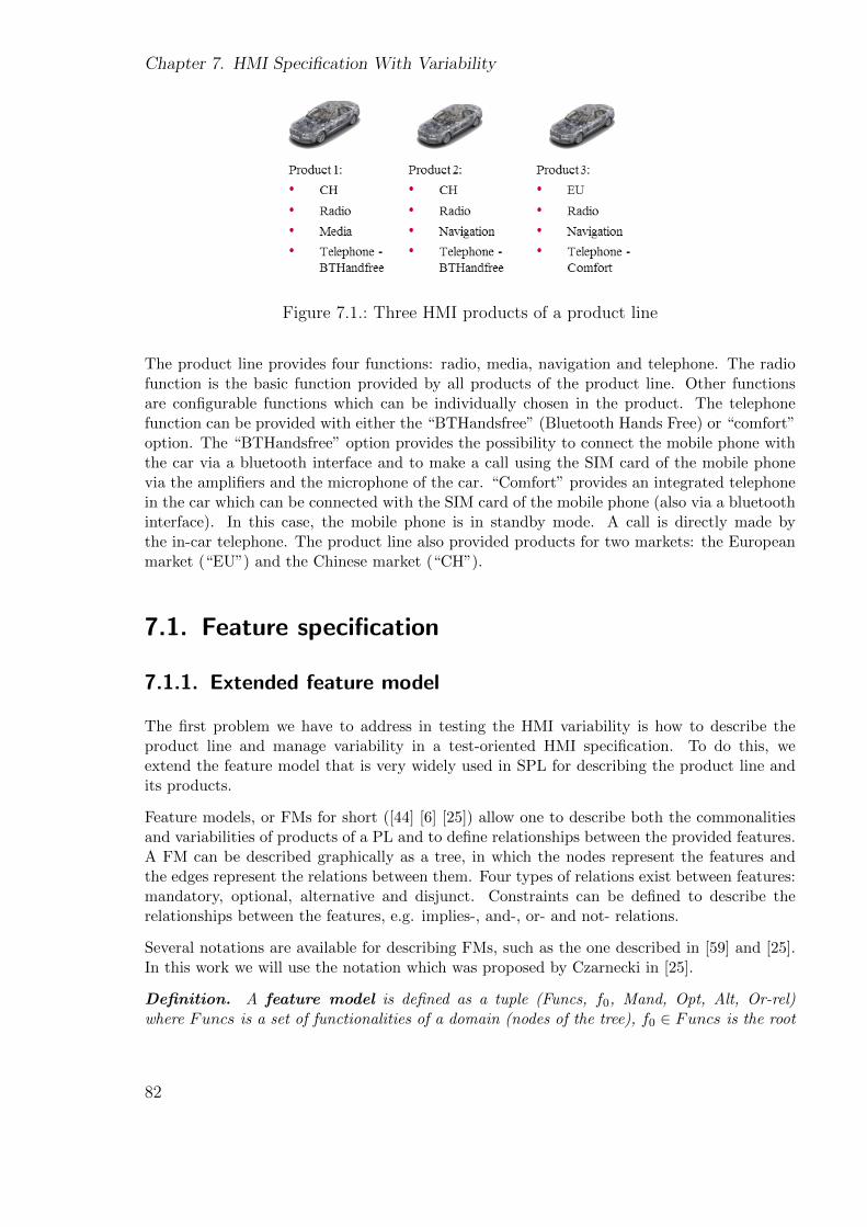
Chapter 7. HMI Specification With Variability
Figure 7.1.: Three HMI products of a product line
The product line provides four functions: radio, media, navigation and telephone. The radiofunction is the basic function provided by all products of the product line. Other functionsare configurable functions which can be individually chosen in the product. The telephonefunction can be provided with either the “BTHandsfree” (Bluetooth Hands Free) or “comfort”option. The “BTHandsfree” option provides the possibility to connect the mobile phone withthe car via a bluetooth interface and to make a call using the SIM card of the mobile phonevia the amplifiers and the microphone of the car. “Comfort” provides an integrated telephonein the car which can be connected with the SIM card of the mobile phone (also via a bluetoothinterface). In this case, the mobile phone is in standby mode. A call is directly made bythe in-car telephone. The product line also provided products for two markets: the Europeanmarket (“EU”) and the Chinese market (“CH”).
7.1. Feature specification
7.1.1. Extended feature model
The first problem we have to address in testing the HMI variability is how to describe theproduct line and manage variability in a test-oriented HMI specification. To do this, weextend the feature model that is very widely used in SPL for describing the product line andits products.
Feature models, or FMs for short ([44] [6] [25]) allow one to describe both the commonalitiesand variabilities of products of a PL and to define relationships between the provided features.A FM can be described graphically as a tree, in which the nodes represent the features andthe edges represent the relations between them. Four types of relations exist between features:mandatory, optional, alternative and disjunct. Constraints can be defined to describe therelationships between the features, e.g. implies-, and-, or- and not- relations.
Several notations are available for describing FMs, such as the one described in [59] and [25].In this work we will use the notation which was proposed by Czarnecki in [25].
Definition. A feature model is defined as a tuple (Funcs, f0, Mand, Opt, Alt, Or-rel)where Funcs is a set of functionalities of a domain (nodes of the tree), f0 ∈ Funcs is the root
82
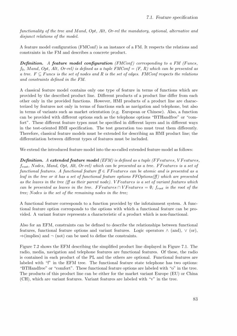
7.1. Feature specification
functionality of the tree and Mand, Opt, Alt, Or-rel the mandatory, optional, alternative anddisjunct relations of the model.
A feature model configuration (FMConf) is an instance of a FM. It respects the relations andconstraints in the FM and describes a concrete product.
Definition. A feature model configuration (FMConf) corresponding to a FM (Funcs,f0, Mand, Opt, Alt, Or-rel) is defined as a tuple FMConf = (F, R) which can be presented asa tree. F ⊆ Funcs is the set of nodes and R is the set of edges. FMConf respects the relationsand constraints defined in the FM.
A classical feature model contains only one type of feature in terms of functions which areprovided by the described product line. Different products of a product line differ from eachother only in the provided functions. However, HMI products of a product line are charac-terized by features not only in terms of functions such as navigation and telephone, but alsoin terms of variants such as market orientation (e.g. European or Chinese). Also, a functioncan be provided with different options such as the telephone options “BTHandfree” or “com-fort”. These different feature types must be specified in different layers and in different waysin the test-oriented HMI specification. The test generation too must treat them differently.Therefore, classical feature models must be extended for describing an HMI product line; thedifferentiation between different types of features must be included.
We extend the introduced feature model into the so-called extended feature model as follows:
Definition. A extended feature model (EFM) is defined as a tuple (FFeatures, V Features,froot, Nodes, Mand, Opt, Alt, Or-rel) which can be presented as a tree. FFeatures is a set offunctional features. A functional feature ff ∈ FFeatures can be atomic and is presented as aleaf in the tree or it has a set of functional feature options FFOptions(ff) which are presentedas the leaves in the tree (ff as their parent node). V Features is a set of variant features whichcan be presented as leaves in the tree. FFeatures ∩ V Features = ∅; froot is the root of thetree; Nodes is the set of the remaining nodes in the tree;
A functional feature corresponds to a function provided by the infotainment system. A func-tional feature option corresponds to the options with which a functional feature can be pro-vided. A variant feature represents a characteristic of a product which is non-functional.
Also for an EFM, constraints can be defined to describe the relationships between functionalfeatures, functional feature options and variant features. Logic operators ∧ (and), ∨ (or),⇒(implies) and ¬ (not) can be used to define the constraints.
Figure 7.2 shows the EFM describing the simplified product line displayed in Figure 7.1. Theradio, media, navigation and telephone features are functional features. Of these, the radiois contained in each product of the PL and the others are optional. Functional features arelabeled with “f” in the EFM tree. The functional feature state telephone has two options:“BTHandfree” or “comfort”. These functional feature options are labeled with “o” in the tree.The products of this product line can be either for the market variant Europe (EU) or China(CH), which are variant features. Variant features are labeled with “v” in the tree.
83
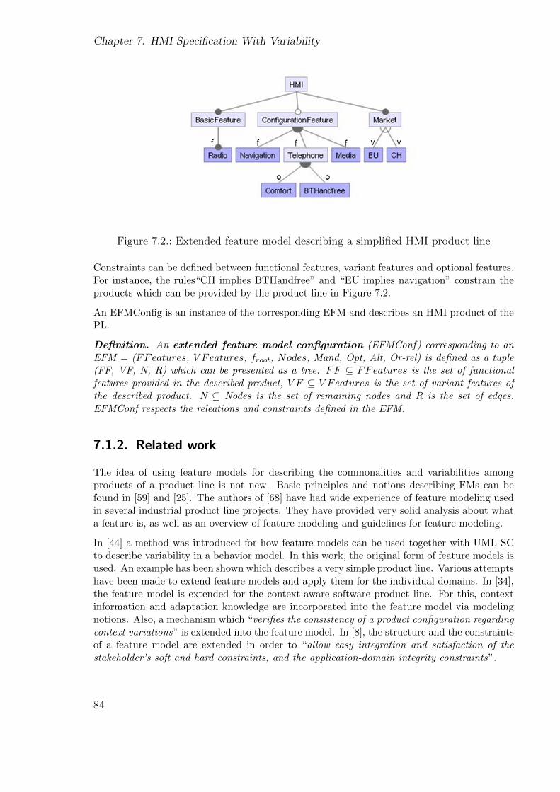
Chapter 7. HMI Specification With Variability
Figure 7.2.: Extended feature model describing a simplified HMI product line
Constraints can be defined between functional features, variant features and optional features.For instance, the rules“CH implies BTHandfree” and “EU implies navigation” constrain theproducts which can be provided by the product line in Figure 7.2.
An EFMConfig is an instance of the corresponding EFM and describes an HMI product of thePL.
Definition. An extended feature model configuration (EFMConf) corresponding to anEFM = (FFeatures, V Features, froot, Nodes, Mand, Opt, Alt, Or-rel) is defined as a tuple(FF, VF, N, R) which can be presented as a tree. FF ⊆ FFeatures is the set of functionalfeatures provided in the described product, V F ⊆ V Features is the set of variant features ofthe described product. N ⊆ Nodes is the set of remaining nodes and R is the set of edges.EFMConf respects the releations and constraints defined in the EFM.
7.1.2. Related work
The idea of using feature models for describing the commonalities and variabilities amongproducts of a product line is not new. Basic principles and notions describing FMs can befound in [59] and [25]. The authors of [68] have had wide experience of feature modeling usedin several industrial product line projects. They have provided very solid analysis about whata feature is, as well as an overview of feature modeling and guidelines for feature modeling.
In [44] a method was introduced for how feature models can be used together with UML SCto describe variability in a behavior model. In this work, the original form of feature models isused. An example has been shown which describes a very simple product line. Various attemptshave been made to extend feature models and apply them for the individual domains. In [34],the feature model is extended for the context-aware software product line. For this, contextinformation and adaptation knowledge are incorporated into the feature model via modelingnotions. Also, a mechanism which “verifies the consistency of a product configuration regardingcontext variations” is extended into the feature model. In [8], the structure and the constraintsof a feature model are extended in order to “allow easy integration and satisfaction of thestakeholder’s soft and hard constraints, and the application-domain integrity constraints”.
84
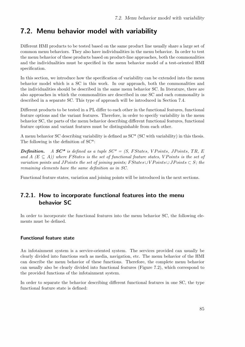
7.2. Menu behavior model with variability
7.2. Menu behavior model with variability
Different HMI products to be tested based on the same product line usually share a large set ofcommon menu behaviors. They also have individualities in the menu behavior. In order to testthe menu behavior of these products based on product-line approaches, both the commonalitiesand the individualities must be specified in the menu behavior model of a test-oriented HMIspecification.
In this section, we introduce how the specification of variability can be extended into the menubehavior model which is a SC in this work. In our approach, both the commonalities andthe individualities should be described in the same menu behavior SC. In literature, there arealso approaches in which the commonalities are described in one SC and each commonality isdescribed in a separate SC. This type of approach will be introduced in Section 7.4.
Different products to be tested in a PL differ to each other in the functional features, functionalfeature options and the variant features. Therefore, in order to specify variability in the menubehavior SC, the parts of the menu behavior describing different functional features, functionalfeature options and variant features must be distinguishable from each other.
A menu behavior SC describing variability is defined as SC* (SC with variability) in this thesis.The following is the definition of SC*:
Definition. A SC* is defined as a tuple SC* = (S, FStates, V Points, JPoints, TR, Eand A (E ⊆ A)) where FStates is the set of functional feature states, V Points is the set ofvariation points and JPoints the set of joining points; FStates∪V Points∪JPoints ⊂ S; theremaining elements have the same definition as in SC.
Functional feature states, variation and joining points will be introduced in the next sections.
7.2.1. How to incorporate functional features into the menubehavior SC
In order to incorporate the functional features into the menu behavior SC, the following ele-ments must be defined.
Functional feature state
An infotainment system is a service-oriented system. The services provided can usually beclearly divided into functions such as media, navigation, etc. The menu behavior of the HMIcan describe the menu behavior of these functions. Therefore, the complete menu behaviorcan usually also be clearly divided into functional features (Figure 7.2), which correspond tothe provided functions of the infotainment system.
In order to separate the behavior describing different functional features in one SC, the typefunctional feature state is defined:
85
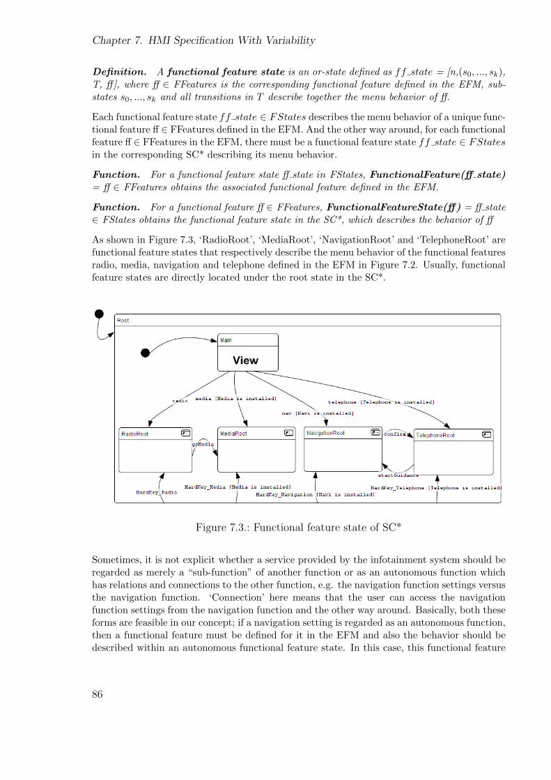
Chapter 7. HMI Specification With Variability
Definition. A functional feature state is an or-state defined as ff state = [n,(s0, ..., sk),T, ff], where ff ∈ FFeatures is the corresponding functional feature defined in the EFM, sub-states s0, ..., sk and all transitions in T describe together the menu behavior of ff.
Each functional feature state ff state ∈ FStates describes the menu behavior of a unique func-tional feature ff ∈ FFeatures defined in the EFM. And the other way around, for each functionalfeature ff ∈ FFeatures in the EFM, there must be a functional feature state ff state ∈ FStatesin the corresponding SC* describing its menu behavior.
Function. For a functional feature state ff state in FStates, FunctionalFeature(ff state)= ff ∈ FFeatures obtains the associated functional feature defined in the EFM.
Function. For a functional feature ff ∈ FFeatures, FunctionalFeatureState(ff) = ff state∈ FStates obtains the functional feature state in the SC*, which describes the behavior of ff
As shown in Figure 7.3, ‘RadioRoot’, ‘MediaRoot’, ‘NavigationRoot’ and ‘TelephoneRoot’ arefunctional feature states that respectively describe the menu behavior of the functional featuresradio, media, navigation and telephone defined in the EFM in Figure 7.2. Usually, functionalfeature states are directly located under the root state in the SC*.
Figure 7.3.: Functional feature state of SC*
Sometimes, it is not explicit whether a service provided by the infotainment system should beregarded as merely a “sub-function” of another function or as an autonomous function whichhas relations and connections to the other function, e.g. the navigation function settings versusthe navigation function. ‘Connection’ here means that the user can access the navigationfunction settings from the navigation function and the other way around. Basically, both theseforms are feasible in our concept; if a navigation setting is regarded as an autonomous function,then a functional feature must be defined for it in the EFM and also the behavior should bedescribed within an autonomous functional feature state. In this case, this functional feature
86
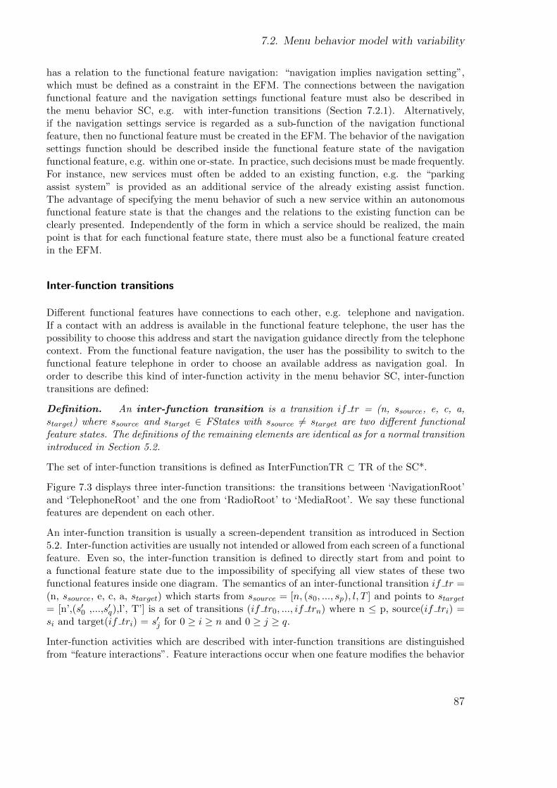
7.2. Menu behavior model with variability
has a relation to the functional feature navigation: “navigation implies navigation setting”,which must be defined as a constraint in the EFM. The connections between the navigationfunctional feature and the navigation settings functional feature must also be described inthe menu behavior SC, e.g. with inter-function transitions (Section 7.2.1). Alternatively,if the navigation settings service is regarded as a sub-function of the navigation functionalfeature, then no functional feature must be created in the EFM. The behavior of the navigationsettings function should be described inside the functional feature state of the navigationfunctional feature, e.g. within one or-state. In practice, such decisions must be made frequently.For instance, new services must often be added to an existing function, e.g. the “parkingassist system” is provided as an additional service of the already existing assist function.The advantage of specifying the menu behavior of such a new service within an autonomousfunctional feature state is that the changes and the relations to the existing function can beclearly presented. Independently of the form in which a service should be realized, the mainpoint is that for each functional feature state, there must also be a functional feature createdin the EFM.
Inter-function transitions
Different functional features have connections to each other, e.g. telephone and navigation.If a contact with an address is available in the functional feature telephone, the user has thepossibility to choose this address and start the navigation guidance directly from the telephonecontext. From the functional feature navigation, the user has the possibility to switch to thefunctional feature telephone in order to choose an available address as navigation goal. Inorder to describe this kind of inter-function activity in the menu behavior SC, inter-functiontransitions are defined:
Definition. An inter-function transition is a transition if tr = (n, ssource, e, c, a,starget) where ssource and starget ∈ FStates with ssource 6= starget are two different functionalfeature states. The definitions of the remaining elements are identical as for a normal transitionintroduced in Section 5.2.
The set of inter-function transitions is defined as InterFunctionTR ⊂ TR of the SC*.
Figure 7.3 displays three inter-function transitions: the transitions between ‘NavigationRoot’and ‘TelephoneRoot’ and the one from ‘RadioRoot’ to ‘MediaRoot’. We say these functionalfeatures are dependent on each other.
An inter-function transition is usually a screen-dependent transition as introduced in Section5.2. Inter-function activities are usually not intended or allowed from each screen of a functionalfeature. Even so, the inter-function transition is defined to directly start from and point toa functional feature state due to the impossibility of specifying all view states of these twofunctional features inside one diagram. The semantics of an inter-functional transition if tr =(n, ssource, e, c, a, starget) which starts from ssource = [n, (s0, ..., sp), l, T ] and points to starget= [n’,(s′0 ,...,s′q),l’, T’] is a set of transitions (if tr0, ..., if trn) where n ≤ p, source(if tri) =si and target(if tri) = s′j for 0 ≥ i ≥ n and 0 ≥ j ≥ q.
Inter-function activities which are described with inter-function transitions are distinguishedfrom “feature interactions”. Feature interactions occur when one feature modifies the behavior
87
Chapter 7. HMI Specification With Variability
of another feature, whereas an inter-function activity in this thesis denotes the situation thatresults in a switch from one functional feature to another one. The thesis [13] addresses theproblem of detecting conflicts and errors caused by feature interactions.
Breaking and broken states
Definition. A simple state s is a breaking-function state if s is the source state of atransition that is in the semantics of inter-function transition.
Inter-function transitions start and point to functional feature states because it is impossibledirectly to connect a sub-state of a functional feature state with a sub-state in another func-tional feature state due to the diagram concept. A breaking-function state is a state fromwhich an inter-function transition should start. It is called a breaking-function state becausethis state offers the possibility to break out of the current function and access another function.A breaking-function state is usually a view state, since usually a screen offers the possibilityto switch to another function.
Definition. A simple state s is a broken-function state if s is the target state of atransition that is in the semantics of inter-function transition.
A broken-function state is a state to which an inter-function transition should point. It iscalled a broken-function state because the current function is “broken in” by an inter-functiontransition from this state. A broken-function state can be a view state and also a pseudo state[3] such as a history state [69] [3]. Also, a breaking-function state can be a broken-functionstate and vice versa.
For example, the transition which is labeled with the event ‘confirm’ in Figure 7.3 allowsthe user to switch directly from the functional feature navigation into telephone in order tochoose an existing contact address as a destination. This option is only provided in the viewstate ‘NavToAdrbook’ (shown in Figure 6.1) by pressing a contained button which triggers theevent ‘confirm’. The view state is a breaking-function state since it offers the possibility tobreak out of the current functional feature. The transition with the event ‘confirm’ leads theuser to the view state ‘TelContact’ in which existing contacts are listed. So ‘TelContact’ is abroken-function state since the current functional feature telephone is broken in this state.
7.2.2. How to incorporate variant features into the menu behaviorSC
Variant features affect the allowed functional features and functional feature options of anHMI product, as already introduced for the product line shown in Figure 7.2. The variantfeatures also impact the look that is the representation of screens of an HMI product. Forinstance, the screen enabling the user to define a navigation goal must additionally display anentry “province” for the Chinese market. This will be introduced later in Section 7.3. In thissection, it will be introduced how variant features affect the menu behavior of a product. Forinstance, the menu behavior for the Chinese market must allow users to input a province. In
88
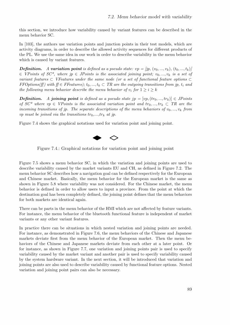
7.2. Menu behavior model with variability
this section, we introduce how variability caused by variant features can be described in themenu behavior SC.
In [103], the authors use variation points and junction points in their test models, which areactivity diagrams, in order to describe the allowed activity sequences for different products ofthe PL. We use the same idea in our work in order to describe variability in the menu behaviorwhich is caused by variant features.
Definition. A variation point is defined as a pseudo state: vp = [jp, (v0, ..., vk), (t0, ..., tk)]∈ VPoints of SC*, where jp ∈ JPoints is the associated joining point; v0, ..., vk is a set ofvariant features ⊂ VFeatures under the same node (or a set of functional feature options ⊂FFOptions(ff) with ff ∈ FFeatures); t0, ..., tk ⊂ TR are the outgoing transitions from jp, ti andthe following menu behavior describe the menu behavior of vi for 1 ≥ i ≥ k
Definition. A joining point is defined as a pseudo state jp = [vp, (tr0, ..., trk)] ∈ JPointsof SC* where vp ∈ VPoints is the associated variation point and tr0, ..., trk ⊂ TR are theincoming transitions of jp. The separate descriptions of the menu behaviors of v0, ..., vk fromvp must be joined via the transitions tr0,...,trk at jp.
Figure 7.4 shows the graphical notations used for variation point and joining point.
Figure 7.4.: Graphical notations for variation point and joining point
Figure 7.5 shows a menu behavior SC, in which the variation and joining points are used todescribe variability caused by the market variants EU and CH, as defined in Figure 7.2. Themenu behavior SC describes how a navigation goal can be defined respectively for the Europeanand Chinese market. Basically, the menu behavior for the European market is the same asshown in Figure 5.8 where variability was not considered. For the Chinese market, the menubehavior is defined in order to allow users to input a province. From the point at which thedestination goal has been completely defined, the joining point defines that the menu behaviorsfor both markets are identical again.
There can be parts in the menu behavior of the HMI which are not affected by feature variants.For instance, the menu behavior of the bluetooth functional feature is independent of marketvariants or any other variant features.
In practice there can be situations in which nested variation and joining points are needed.For instance, as demonstrated in Figure 7.6, the menu behaviors of the Chinese and Japanesemarkets deviate first from the menu behavior of the European market. Then the menu be-haviors of the Chinese and Japanese markets deviate from each other at a later point. Orfor instance, as shown in Figure 7.7, one variation and joining points pair is used to specifyvariability caused by the market variant and another pair is used to specify variability causedby the system hardware variant. In the next section, it will be introduced that variation andjoining points are also used to describe variability caused by functional feature options. Nestedvariation and joining point pairs can also be necessary.
89
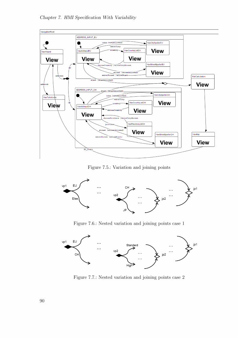
Chapter 7. HMI Specification With Variability
Figure 7.5.: Variation and joining points
Figure 7.6.: Nested variation and joining points case 1
Figure 7.7.: Nested variation and joining points case 2
90
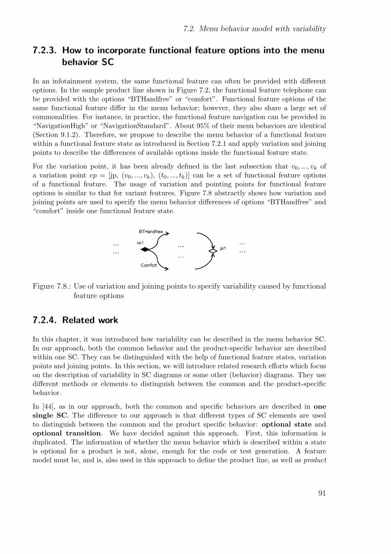
7.2. Menu behavior model with variability
7.2.3. How to incorporate functional feature options into the menubehavior SC
In an infotainment system, the same functional feature can often be provided with differentoptions. In the sample product line shown in Figure 7.2, the functional feature telephone canbe provided with the options “BTHandfree” or “comfort”. Functional feature options of thesame functional feature differ in the menu behavior; however, they also share a large set ofcommonalities. For instance, in practice, the functional feature navigation can be provided in“NavigationHigh” or “NavigationStandard”. About 95% of their menu behaviors are identical(Section 9.1.2). Therefore, we propose to describe the menu behavior of a functional featurewithin a functional feature state as introduced in Section 7.2.1 and apply variation and joiningpoints to describe the differences of available options inside the functional feature state.
For the variation point, it has been already defined in the last subsection that v0, ..., vk ofa variation point vp = [jp, (v0, ..., vk), (t0, ..., tk)] can be a set of functional feature optionsof a functional feature. The usage of variation and pointing points for functional featureoptions is similar to that for variant features. Figure 7.8 abstractly shows how variation andjoining points are used to specify the menu behavior differences of options “BTHandfree” and“comfort” inside one functional feature state.
Figure 7.8.: Use of variation and joining points to specify variability caused by functionalfeature options
7.2.4. Related work
In this chapter, it was introduced how variability can be described in the menu behavior SC.In our approach, both the common behavior and the product-specific behavior are describedwithin one SC. They can be distinguished with the help of functional feature states, variationpoints and joining points. In this section, we will introduce related research efforts which focuson the description of variability in SC diagrams or some other (behavior) diagrams. They usedifferent methods or elements to distinguish between the common and the product-specificbehavior.
In [44], as in our approach, both the common and specific behaviors are described in onesingle SC. The difference to our approach is that different types of SC elements are usedto distinguish between the common and the product specific behavior: optional state andoptional transition. We have decided against this approach. First, this information isduplicated. The information of whether the menu behavior which is described within a stateis optional for a product is not, alone, enough for the code or test generation. A featuremodel must be, and is, also used in this approach to define the product line, as well as product
91

Chapter 7. HMI Specification With Variability
configurations. If any changes occur in the product line, e.g. an optional feature becomesa standard feature, both the feature model and the menu behavior SC must be changed.Secondly, in order to define whether a state or a transition is optional, the HMI specifier has notonly to possess knowledge about the behavior of the functional feature, but also inform himselfabout the current product line definitions. In our approach, any product line information iscentrally managed within the feature model and feature model configurations.
In [120], state machines are left unchanged. Only the content classes of state machines arechanged. Instead of using inheritance between state machines, inheritance between theircontext classes is used. The state machines are used as a behavior description of these classes.In this way, a product of an inheriting class contains not only the feature which is describedin its own state machine, but also the features which are described in the states machines ofthe inherited classes. The first problem is the difficulty of specifying the connections betweendifferent state machines. Second, if the features of one product are changed, all inheritingproducts which are not intended to be changed must be redefined. Furthermore, the conceptof a feature model is much easier and more intuitive than content classes of state machines.
In contrast to our approach, the approach in [114] describes each feature of the product line ina separate SC. This means that each product is described with several SCs (a subset of theseSCs) and their relationships to each other. Each feature in the feature model is associatedwith a SC. The SCs which together should describe the behavior of a particular product canbe derived from the respective configuration. Therefore, the challenge is to bind several SCstogether instead of distinguishing between the common and the product-specific behavior inone single SC. Basically, it is not critical whether to use one single SC or several SCs. We havedecided on one single SC since the HMI specifications and development models in practiceare usually based on one single SC in which some composite states are used to describe thebehavior of different features. This is more easily acceptable.
Specifying variability which results from different variant features and functional feature op-tions is not within the focus of any of the three introduced approaches.
In [103], activity diagrams are used as test models which describe the allowed user actionsequences in the domain engineering phase. Variation points and junction points are used todescribe how different products of the product line can differ in the user action sequences. “Ajunction point is a special node in the test model in which all variants of the variation pointare joined and continue in the same control flow.” In the subsequent work [113], the activitydiagram is called a flow-based test model and is used to describe the data flow of the system.The variation and junction points are used in a very similar way as in our approach. The smalldifference is that each outgoing transition of a variation point represents a complete productof the product line. Complex feature combinations or options are not in the focus of theirwork.
Besides the dynamic behavior, variability can also occur in other aspects of a software system.For instance, in [74], [56] and [48], use case models are extended for variability. In [24] and[22], different UML diagrams are extended for variability.
92

7.3. Representation layer with variability
7.3. Representation layer with variability
In Section 5.3, the meta-model for the representation layer was introduced. Figure 7.9 showsthe meta-model presented in Figure 5.15 again.
Figure 7.9.: Meta-model for the representation layer without variability
The meta-model above defines elements which can be used in the representation layer tospecify the screens. Here, variability has not yet been taken into account. In this section, therepresentation layer will be extended for variability by adding parameterized inheritances intothe meta-model.
We use parameterized inheritances [39] [109] in order to describe variability in the representa-tion layer. A parameterized inheritance is an inheritance of which the super-class is specializedby parameters. Up to now, normal inheritance has been used in the meta-model in orderto simplify the specification of possible screen-triggerable events. In contrast, parameterizedinheritances will be used to specify variability in the representation layer.
7.3.1. Variability of abstract screens
Sometimes functional features, functional feature options, and variant features can affect theevents which can be triggered by a screen. In this section, we introduce how variability can bedescribed for abstract screens.
The functional features provided in a particular product affect the triggerable events of somescreens. For example, the screen ‘Main’ (shown in Figure 2.4) must only trigger the event ‘nav’if the functional feature navigation is available in the product. Screen ‘Main’ also has a basisevent - the radio event - which can be triggered in any product of the PL. Therefore, in orderto avoid repeated specifications of such basis events for each provided product, parameterizedinheritances can be used. Figure 7.10 shows how parameterized inheritance is used for thescreen ‘Main’.
93
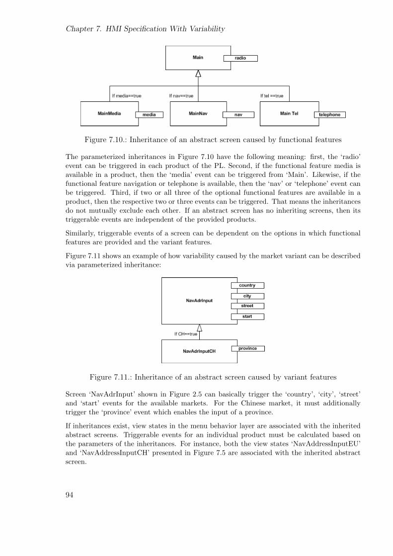
Chapter 7. HMI Specification With Variability
Figure 7.10.: Inheritance of an abstract screen caused by functional features
The parameterized inheritances in Figure 7.10 have the following meaning: first, the ‘radio’event can be triggered in each product of the PL. Second, if the functional feature media isavailable in a product, then the ‘media’ event can be triggered from ‘Main’. Likewise, if thefunctional feature navigation or telephone is available, then the ‘nav’ or ‘telephone’ event canbe triggered. Third, if two or all three of the optional functional features are available in aproduct, then the respective two or three events can be triggered. That means the inheritancesdo not mutually exclude each other. If an abstract screen has no inheriting screens, then itstriggerable events are independent of the provided products.
Similarly, triggerable events of a screen can be dependent on the options in which functionalfeatures are provided and the variant features.
Figure 7.11 shows an example of how variability caused by the market variant can be describedvia parameterized inheritance:
Figure 7.11.: Inheritance of an abstract screen caused by variant features
Screen ‘NavAdrInput’ shown in Figure 2.5 can basically trigger the ‘country’, ‘city’, ‘street’and ‘start’ events for the available markets. For the Chinese market, it must additionallytrigger the ‘province’ event which enables the input of a province.
If inheritances exist, view states in the menu behavior layer are associated with the inheritedabstract screens. Triggerable events for an individual product must be calculated based onthe parameters of the inheritances. For instance, both the view states ‘NavAddressInputEU’and ‘NavAddressInputCH’ presented in Figure 7.5 are associated with the inherited abstractscreen.
94
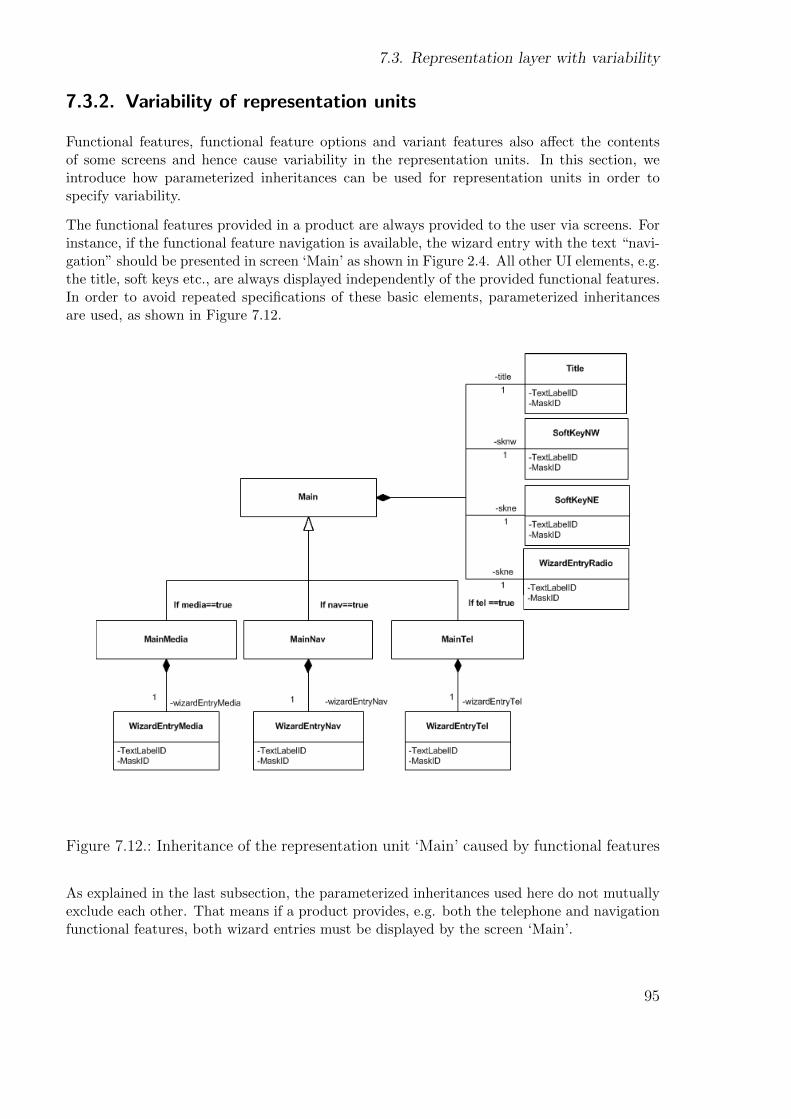
7.3. Representation layer with variability
7.3.2. Variability of representation units
Functional features, functional feature options and variant features also affect the contentsof some screens and hence cause variability in the representation units. In this section, weintroduce how parameterized inheritances can be used for representation units in order tospecify variability.
The functional features provided in a product are always provided to the user via screens. Forinstance, if the functional feature navigation is available, the wizard entry with the text “navi-gation” should be presented in screen ‘Main’ as shown in Figure 2.4. All other UI elements, e.g.the title, soft keys etc., are always displayed independently of the provided functional features.In order to avoid repeated specifications of these basic elements, parameterized inheritancesare used, as shown in Figure 7.12.
Figure 7.12.: Inheritance of the representation unit ‘Main’ caused by functional features
As explained in the last subsection, the parameterized inheritances used here do not mutuallyexclude each other. That means if a product provides, e.g. both the telephone and navigationfunctional features, both wizard entries must be displayed by the screen ‘Main’.
95
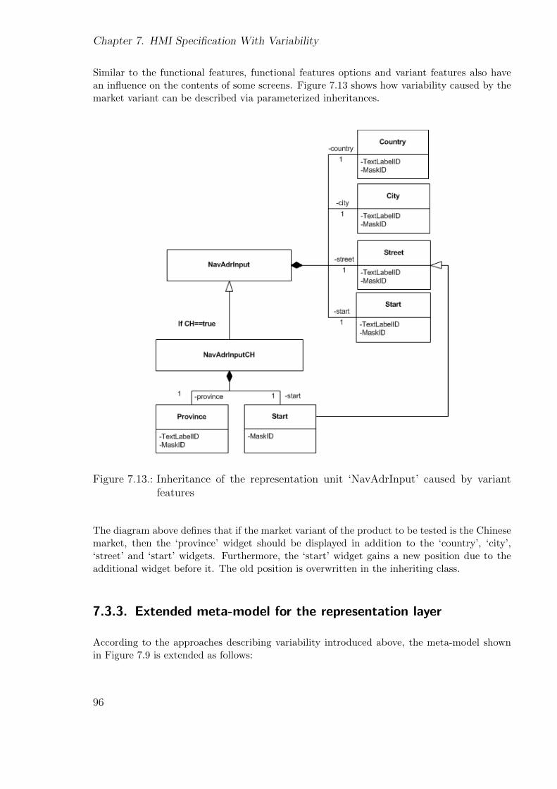
Chapter 7. HMI Specification With Variability
Similar to the functional features, functional features options and variant features also havean influence on the contents of some screens. Figure 7.13 shows how variability caused by themarket variant can be described via parameterized inheritances.
Figure 7.13.: Inheritance of the representation unit ‘NavAdrInput’ caused by variantfeatures
The diagram above defines that if the market variant of the product to be tested is the Chinesemarket, then the ‘province’ widget should be displayed in addition to the ‘country’, ‘city’,‘street’ and ‘start’ widgets. Furthermore, the ‘start’ widget gains a new position due to theadditional widget before it. The old position is overwritten in the inheriting class.
7.3.3. Extended meta-model for the representation layer
According to the approaches describing variability introduced above, the meta-model shownin Figure 7.9 is extended as follows:
96
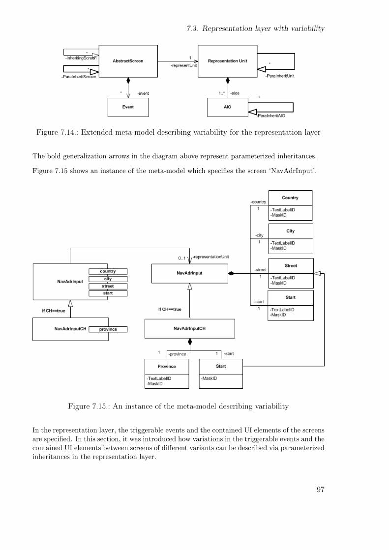
7.3. Representation layer with variability
Figure 7.14.: Extended meta-model describing variability for the representation layer
The bold generalization arrows in the diagram above represent parameterized inheritances.
Figure 7.15 shows an instance of the meta-model which specifies the screen ‘NavAdrInput’.
Figure 7.15.: An instance of the meta-model describing variability
In the representation layer, the triggerable events and the contained UI elements of the screensare specified. In this section, it was introduced how variations in the triggerable events and thecontained UI elements between screens of different variants can be described via parameterizedinheritances in the representation layer.
97
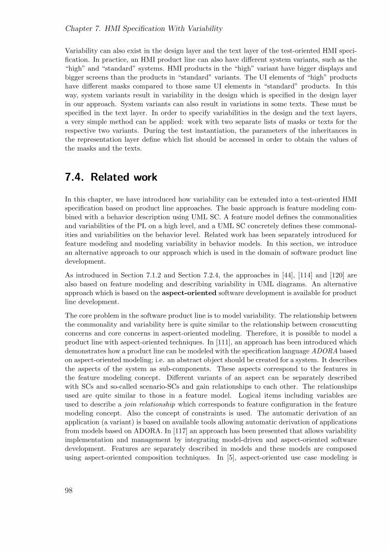
Chapter 7. HMI Specification With Variability
Variability can also exist in the design layer and the text layer of the test-oriented HMI speci-fication. In practice, an HMI product line can also have different system variants, such as the“high” and “standard” systems. HMI products in the “high” variant have bigger displays andbigger screens than the products in “standard” variants. The UI elements of “high” productshave different masks compared to those same UI elements in “standard” products. In thisway, system variants result in variability in the design which is specified in the design layerin our approach. System variants can also result in variations in some texts. These must bespecified in the text layer. In order to specify variabilities in the design and the text layers,a very simple method can be applied: work with two separate lists of masks or texts for therespective two variants. During the test instantiation, the parameters of the inheritances inthe representation layer define which list should be accessed in order to obtain the values ofthe masks and the texts.
7.4. Related work
In this chapter, we have introduced how variability can be extended into a test-oriented HMIspecification based on product line approaches. The basic approach is feature modeling com-bined with a behavior description using UML SC. A feature model defines the commonalitiesand variabilities of the PL on a high level, and a UML SC concretely defines these commonal-ities and variabilities on the behavior level. Related work has been separately introduced forfeature modeling and modeling variability in behavior models. In this section, we introducean alternative approach to our approach which is used in the domain of software product linedevelopment.
As introduced in Section 7.1.2 and Section 7.2.4, the approaches in [44], [114] and [120] arealso based on feature modeling and describing variability in UML diagrams. An alternativeapproach which is based on the aspect-oriented software development is available for productline development.
The core problem in the software product line is to model variability. The relationship betweenthe commonality and variability here is quite similar to the relationship between crosscuttingconcerns and core concerns in aspect-oriented modeling. Therefore, it is possible to model aproduct line with aspect-oriented techniques. In [111], an approach has been introduced whichdemonstrates how a product line can be modeled with the specification language ADORA basedon aspect-oriented modeling; i.e. an abstract object should be created for a system. It describesthe aspects of the system as sub-components. These aspects correspond to the features inthe feature modeling concept. Different variants of an aspect can be separately describedwith SCs and so-called scenario-SCs and gain relationships to each other. The relationshipsused are quite similar to those in a feature model. Logical items including variables areused to describe a join relationship which corresponds to feature configuration in the featuremodeling concept. Also the concept of constraints is used. The automatic derivation of anapplication (a variant) is based on available tools allowing automatic derivation of applicationsfrom models based on ADORA. In [117] an approach has been presented that allows variabilityimplementation and management by integrating model-driven and aspect-oriented softwaredevelopment. Features are separately described in models and these models are composedusing aspect-oriented composition techniques. In [5], aspect-oriented use case modeling is
98
7.5. Conclusions
adapted for product lines. A study of how product line modeling can be supported by aspect-oriented methods can be found in [92].
In comparison to the aspect-oriented techniques, feature models and UML SCs are very intu-itive and have already been accepted by the industry for practical applications. In particular, itmust be considered that the people creating HMI specifications usually do not have a technicalbackground. Aspect-oriented modeling techniques are “oversized” for the goal of creating HMIspecifications.
7.5. Conclusions
Variability can be caused first by the functional features provided by a product, second bythe options in which functional features are provided, and third by the variant features of theproduct. In this chapter, we have introduced how the variability caused by these factors canbe integrated into test-oriented HMI specification.
Firstly, an extended feature model (EFM) was proposed, which is used to describe an HMIproduct line. Extended feature configurations (EFMConfig) respect the respective EFM anddescribe single HMI products. Secondly, new elements are inserted into the SC in order todescribe variability. A SC describing variability is defined as a SC*. In a SC*, the behaviors ofdifferent functional features are separately specified with the help of functional feature states.Finally, variability is also integrated into the representation layer with the help of parameterizedinheritances.
By doing this, the test-oriented HMI specification provides the basis for testing an HMI productline and its HMI products.
99

Chapter 7. HMI Specification With Variability
100
Chapter 8.
Test Generation With Variability
In the last chapter, a test-oriented HMI specification was introduced which describes theexpectation of all potential products of an HMI product line. In this section, we focus onthe problem of how menu behavior tests can be generated from such a test-oriented HMIspecification taking into account variability in the different products to be tested.
The largest challenge here is to avoid redundant test generations. As explained previously,different HMI products of the same product line share a large set of menu behaviors. If thetest generation activity must be repeated for each product to be tested, the common set ofmenu behaviors will be requested as often as the number of products to be tested. Due to thehigh degree of commonality and the large number of products to be tested in practice, muchgeneration time would be wasted. Furthermore, the generated tests for different productswould have a large set of identical tests or test steps which verify the common behavior ofdifferent products. Redundant executions of these tests would also lead to a heavy loss oftime.
In this section, we introduce a test generation method which first generates tests for all potentialproducts to be tested, second, avoids redundant test generations, and third, allows us to identifycommon tests and common test steps in order to preserve them from redundant executions.
The test generation based on the transition coverage will first be introduced in detail. Laterin Section 8.2, test generation based on some other coverage criteria will be discussed.
8.1. A test generation method
In Section 6.2, a test generation algorithm based on transition coverage was introduced, which,however, does not consider variability of HMIs. In this section, we first prepare the menubehavior SC for test generation and extend this algorithm to generate test sequences which areparts of tests for all potential products to be tested (Subsection 8.1.1), and then introduce howtests can be created from these sequences for a particular product to be tested (Subsection8.1.2).
Test sequences are a sequence of test steps and parts of tests. Tests can be created from severaltest sequences. The formal definition of a test sequence will be introduced later.
101
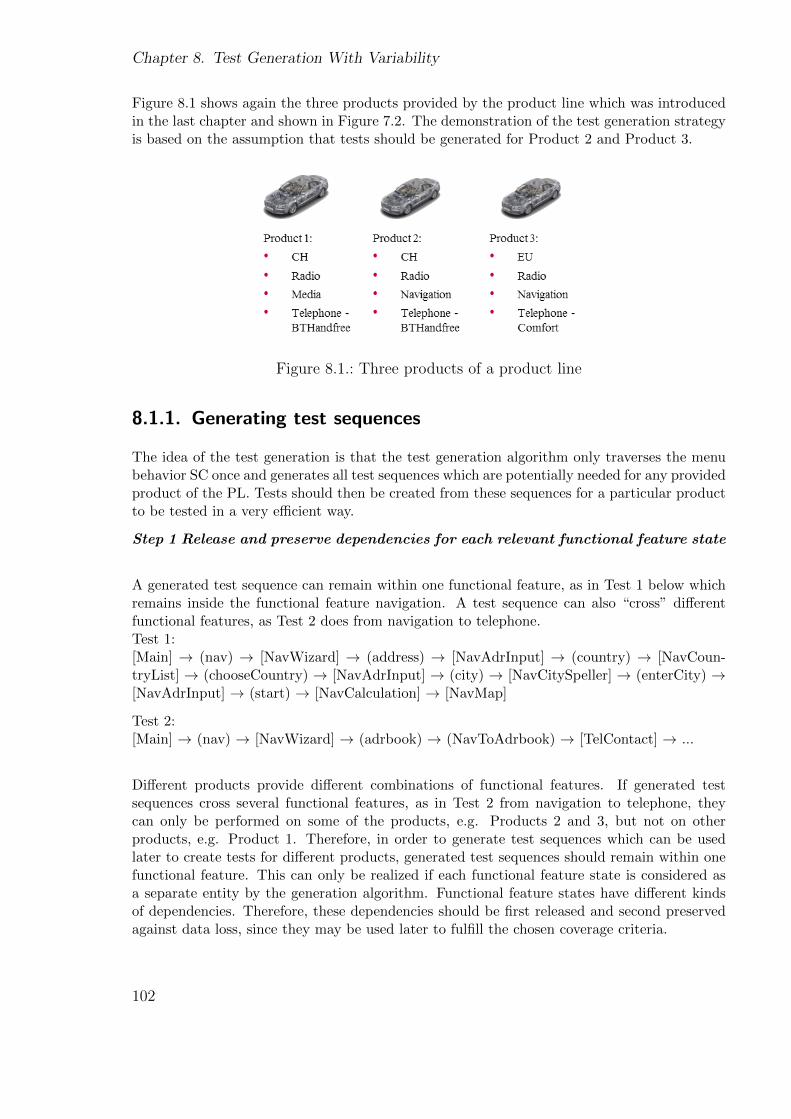
Chapter 8. Test Generation With Variability
Figure 8.1 shows again the three products provided by the product line which was introducedin the last chapter and shown in Figure 7.2. The demonstration of the test generation strategyis based on the assumption that tests should be generated for Product 2 and Product 3.
Figure 8.1.: Three products of a product line
8.1.1. Generating test sequences
The idea of the test generation is that the test generation algorithm only traverses the menubehavior SC once and generates all test sequences which are potentially needed for any providedproduct of the PL. Tests should then be created from these sequences for a particular productto be tested in a very efficient way.
Step 1 Release and preserve dependencies for each relevant functional feature state
A generated test sequence can remain within one functional feature, as in Test 1 below whichremains inside the functional feature navigation. A test sequence can also “cross” differentfunctional features, as Test 2 does from navigation to telephone.Test 1:[Main] → (nav) → [NavWizard] → (address) → [NavAdrInput] → (country) → [NavCoun-tryList] → (chooseCountry) → [NavAdrInput] → (city) → [NavCitySpeller] → (enterCity) →[NavAdrInput] → (start) → [NavCalculation] → [NavMap]
Test 2:[Main] → (nav) → [NavWizard] → (adrbook) → (NavToAdrbook) → [TelContact] → ...
Different products provide different combinations of functional features. If generated testsequences cross several functional features, as in Test 2 from navigation to telephone, theycan only be performed on some of the products, e.g. Products 2 and 3, but not on otherproducts, e.g. Product 1. Therefore, in order to generate test sequences which can be usedlater to create tests for different products, generated test sequences should remain within onefunctional feature. This can only be realized if each functional feature state is considered asa separate entity by the generation algorithm. Functional feature states have different kindsof dependencies. Therefore, these dependencies should be first released and second preservedagainst data loss, since they may be used later to fulfill the chosen coverage criteria.
102
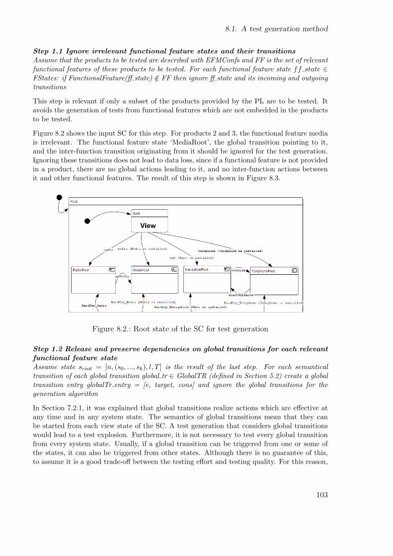
8.1. A test generation method
Step 1.1 Ignore irrelevant functional feature states and their transitionsAssume that the products to be tested are described with EFMConfs and FF is the set of relevantfunctional features of these products to be tested. For each functional feature state ff state ∈FStates: if FunctionalFeature(ff state) /∈ FF then ignore ff state and its incoming and outgoingtransitions
This step is relevant if only a subset of the products provided by the PL are to be tested. Itavoids the generation of tests from functional features which are not embedded in the productsto be tested.
Figure 8.2 shows the input SC for this step. For products 2 and 3, the functional feature mediais irrelevant. The functional feature state ‘MediaRoot’, the global transition pointing to it,and the inter-function transition originating from it should be ignored for the test generation.Ignoring these transitions does not lead to data loss, since if a functional feature is not providedin a product, there are no global actions leading to it, and no inter-function actions betweenit and other functional features. The result of this step is shown in Figure 8.3.
Figure 8.2.: Root state of the SC for test generation
Step 1.2 Release and preserve dependencies on global transitions for each relevantfunctional feature stateAssume state sroot = [n, (s0, ..., sk), l, T ] is the result of the last step. For each semanticaltransition of each global transition global tr ∈ GlobalTR (defined in Section 5.2) create a globaltransition entry globalTr entry = [e, target, cons] and ignore the global transitions for thegeneration algorithm
In Section 7.2.1, it was explained that global transitions realize actions which are effective atany time and in any system state. The semantics of global transitions mean that they canbe started from each view state of the SC. A test generation that considers global transitionswould lead to a test explosion. Furthermore, it is not necessary to test every global transitionfrom every system state. Usually, if a global transition can be triggered from one or some ofthe states, it can also be triggered from other states. Although there is no guarantee of this,to assume it is a good trade-off between the testing effort and testing quality. For this reason,
103
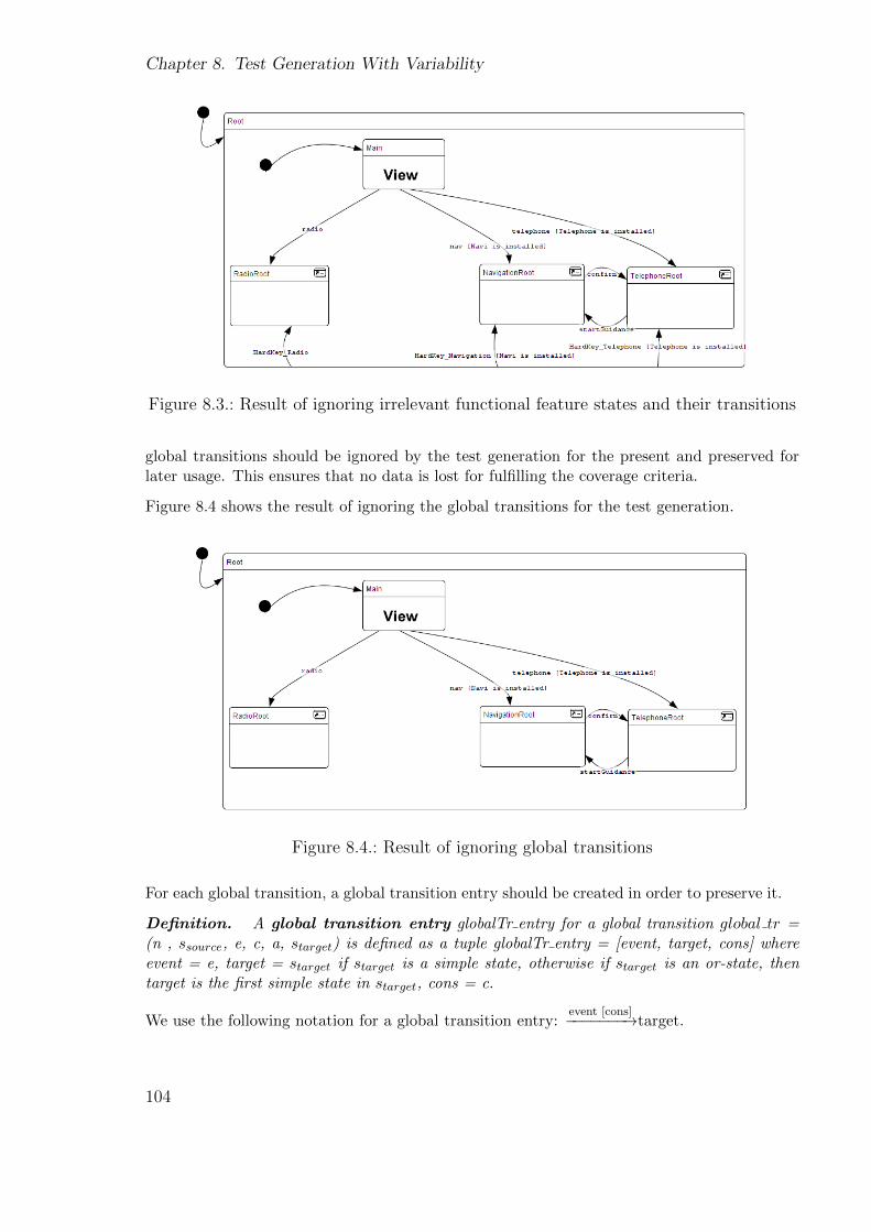
Chapter 8. Test Generation With Variability
Figure 8.3.: Result of ignoring irrelevant functional feature states and their transitions
global transitions should be ignored by the test generation for the present and preserved forlater usage. This ensures that no data is lost for fulfilling the coverage criteria.
Figure 8.4 shows the result of ignoring the global transitions for the test generation.
Figure 8.4.: Result of ignoring global transitions
For each global transition, a global transition entry should be created in order to preserve it.
Definition. A global transition entry globalTr entry for a global transition global tr =(n , ssource, e, c, a, starget) is defined as a tuple globalTr entry = [event, target, cons] whereevent = e, target = starget if starget is a simple state, otherwise if starget is an or-state, thentarget is the first simple state in starget, cons = c.
We use the following notation for a global transition entry:event [cons]−−−−−−−→target.
104
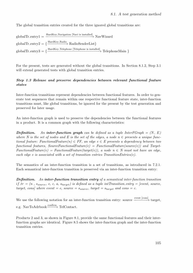
8.1. A test generation method
The global transition entries created for the three ignored global transitions are:
globalTr entry1 =HardKey Navigation [Navi is installed]−−−−−−−−−−−−−−−−−−−−−−−−→ NavWizard
globalTr entry2 = { HardKey Radio−−−−−−−−−→ RadioSenderList}
globalTr entry3 = { HardKey Telephone [Telephone is installed]−−−−−−−−−−−−−−−−−−−−−−−−−−→ TelephoneMain }
For the present, tests are generated without the global transitions. In Section 8.1.2, Step 3.1will extend generated tests with global transition entries.
Step 1.3 Release and preserve dependencies between relevant functional featurestates
Inter-function transitions represent dependencies between functional features. In order to gen-erate test sequences that remain within one respective functional feature state, inter-functiontransitions must, like global transitions, be ignored for the present by the test generation andpreserved for later usage.
An inter-function graph is used to preserve the dependencies between the functional featuresin a product. It is a common graph with the following characteristics:
Definition. An inter-function graph can be defined as a tuple InterFGraph = (N , E)where N is the set of nodes and E is the set of the edges, a node n ∈ presents a unique func-tional feature: FunctionalFeature(n) ∈ FF, an edge e ∈ E presents a dependency between twofunctional features, SourceFunctionalFeature(e) = FunctionalFeature(source(e)) and Target-FunctionalFeature(e) = FunctionalFeature(target(e)), a node n ∈ N must not have an edge,each edge e is associated with a set of transition entries TransitionEntries(e).
The semantics of an inter-function transition is a set of transitions, as introduced in 7.2.1.Each semantical inter-function transition is preserved via an inter-function transition entry:
Definition. An inter-function transition entry of a semantical inter-function transitionif tr = (n , ssource, e, c, a, starget) is defined as a tuple intTransition entry = [event, source,target, cons] where event = e, source = ssource, target = starget and cons = c.
We use the following notation for an inter-function transition entry: sourceevent [cons]−−−−−−−→ target,
e.g. NavToAdrbookconfirm−−−−→ TelContact.
Products 2 and 3, as shown in Figure 8.1, provide the same functional features and their inter-function graphs are identical. Figure 8.5 shows the inter-function graph and the inter-functiontransition entries.
105
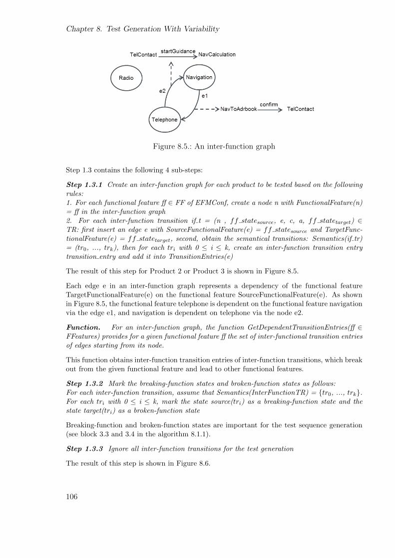
Chapter 8. Test Generation With Variability
Figure 8.5.: An inter-function graph
Step 1.3 contains the following 4 sub-steps:
Step 1.3.1 Create an inter-function graph for each product to be tested based on the followingrules:1. For each functional feature ff ∈ FF of EFMConf, create a node n with FunctionalFeature(n)= ff in the inter-function graph2. For each inter-function transition if t = (n , ff statesource, e, c, a, ff statetarget) ∈TR: first insert an edge e with SourceFunctionalFeature(e) = ff statesource and TargetFunc-tionalFeature(e) = ff statetarget, second, obtain the semantical transitions: Semantics(if tr)= (tr0, ..., trk), then for each tri with 0 ≤ i ≤ k, create an inter-function transition entrytransition entry and add it into TransitionEntries(e)
The result of this step for Product 2 or Product 3 is shown in Figure 8.5.
Each edge e in an inter-function graph represents a dependency of the functional featureTargetFunctionalFeature(e) on the functional feature SourceFunctionalFeature(e). As shownin Figure 8.5, the functional feature telephone is dependent on the functional feature navigationvia the edge e1, and navigation is dependent on telephone via the node e2.
Function. For an inter-function graph, the function GetDependentTransitionEntries(ff ∈FFeatures) provides for a given functional feature ff the set of inter-functional transition entriesof edges starting from its node.
This function obtains inter-function transition entries of inter-function transitions, which breakout from the given functional feature and lead to other functional features.
Step 1.3.2 Mark the breaking-function states and broken-function states as follows:For each inter-function transition, assume that Semantics(InterFunctionTR) = {tr0, ..., trk}.For each tri with 0 ≤ i ≤ k, mark the state source(tri) as a breaking-function state and thestate target(tri) as a broken-function state
Breaking-function and broken-function states are important for the test sequence generation(see block 3.3 and 3.4 in the algorithm 8.1.1).
Step 1.3.3 Ignore all inter-function transitions for the test generation
The result of this step is shown in Figure 8.6.
106
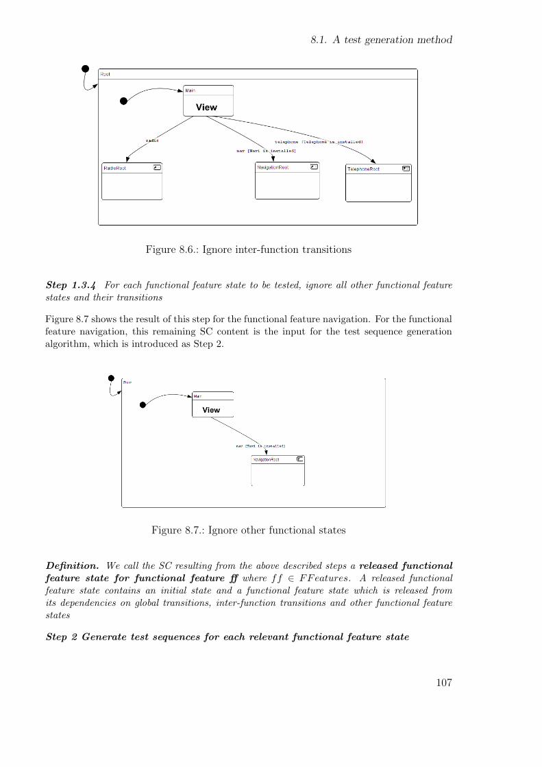
8.1. A test generation method
Figure 8.6.: Ignore inter-function transitions
Step 1.3.4 For each functional feature state to be tested, ignore all other functional featurestates and their transitions
Figure 8.7 shows the result of this step for the functional feature navigation. For the functionalfeature navigation, this remaining SC content is the input for the test sequence generationalgorithm, which is introduced as Step 2.
Figure 8.7.: Ignore other functional states
Definition. We call the SC resulting from the above described steps a released functionalfeature state for functional feature ff where ff ∈ FFeatures. A released functionalfeature state contains an initial state and a functional feature state which is released fromits dependencies on global transitions, inter-function transitions and other functional featurestates
Step 2 Generate test sequences for each relevant functional feature state
107
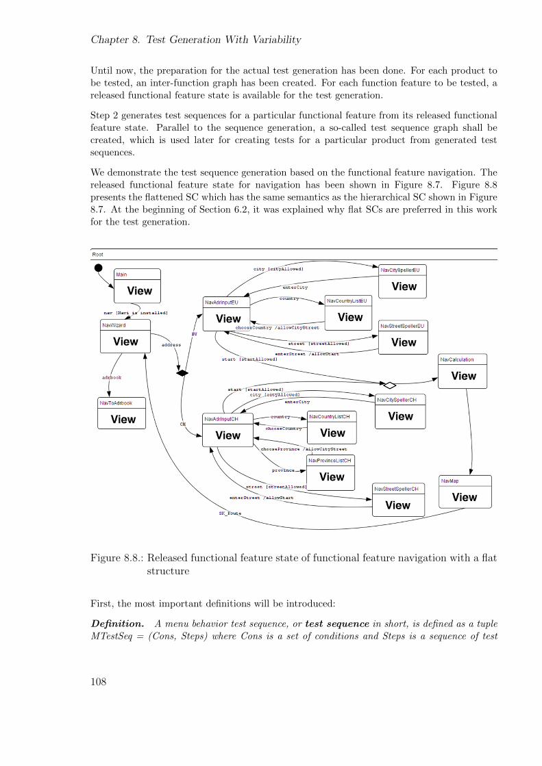
Chapter 8. Test Generation With Variability
Until now, the preparation for the actual test generation has been done. For each product tobe tested, an inter-function graph has been created. For each function feature to be tested, areleased functional feature state is available for the test generation.
Step 2 generates test sequences for a particular functional feature from its released functionalfeature state. Parallel to the sequence generation, a so-called test sequence graph shall becreated, which is used later for creating tests for a particular product from generated testsequences.
We demonstrate the test sequence generation based on the functional feature navigation. Thereleased functional feature state for navigation has been shown in Figure 8.7. Figure 8.8presents the flattened SC which has the same semantics as the hierarchical SC shown in Figure8.7. At the beginning of Section 6.2, it was explained why flat SCs are preferred in this workfor the test generation.
Figure 8.8.: Released functional feature state of functional feature navigation with a flatstructure
First, the most important definitions will be introduced:
Definition. A menu behavior test sequence, or test sequence in short, is defined as a tupleMTestSeq = (Cons, Steps) where Cons is a set of conditions and Steps is a sequence of test
108

8.1. A test generation method
steps. The definitions of Cons and Steps are the same as in the definition of a menu behaviortest 4.2.2. The difference is that step0, which is the first step from Steps, can but does nothave to be the name of the initial screen which is expected when the SUT is started.
A test is composed of one or several test sequences in a particular order. A test starts from theinitial screen and is executable if its conditions are fulfilled, whereas test sequences usually donot start from the initial screen and usually need other test sequences as previous sequences.
We use the same notation for test sequences as for tests.
Definition. A test sequence graph seqGraph is a finite and directed graph without cycles.It is defined as seqGraph = (init, N , V Nodes, JNodes, E) where “init” is the initial node, Nis the set of nodes, each n ∈ N is associated with a test sequence Seq(n), VNodes is the set ofvariation nodes, JNodes is the set of junction nodes and E is the set of the edges.
Definition. A variation node is defined as vn = [jn, (v0, ..., vk), (e0, ..., ek)] ∈ VNodes ofa test sequence graph, where jn ∈ JNodes is the associated junction node; v0, ..., vk is a set ofvariant features ⊂ VFeatures or a set of functional feature options ⊂ FFOptions(ff) with ff ∈FFeatures, e0, ..., ek ⊂ E are the edges outgoing from jn.
Definition. A junction node is defined as jn = [vn] ∈ JNodes, where vn ∈ VNodes is theassociated variation node in the test sequence graph.
For variation nodes and junction nodes, we use the same notation as for variation points andjoining points of a SC*.
Function. For a node n ∈ N, the function BreakingFunction(n)= {true, false} returnswhether the associated test sequence Seq(n) ends with a breaking-function state.
Function. For a given inter-function graph, GetNodesEndingWith(state s) returns a setof nodes Nodes ⊂ N where for each n ∈ Nodes the associated test sequence Seq(n) ends withs.
Function. For a given inter-function graph, GetNodesStartingWith(state s) returns aset of nodes Nodes ⊂ N where for each n ∈ Nodes the associated test sequence Seq(n) startswith s.
Basic functions available for a common graph such as parent(node n) and children(node n) arealso valid for the test sequence graph.
An example of a test sequence graph can be found in Figure 8.10.
Now we are ready to introduce the test sequence generation algorithm. In order to simplifythe introduction, we assume that nested variation and joining pairs have not occurred. Weextend the algorithm described in Section 6.2 which is based on the transition coverage withthe following new rules:
• The generation algorithm generates test sequences instead of tests.
• The generation algorithm generates a test sequence graph in addition to the test se-quences.
109

Chapter 8. Test Generation With Variability
• The generation algorithm takes variation points and joining points into account as fol-lows:When the algorithm visits a variation point, it ends the current sequence, creates a nodefor it in the test sequence graph, and adds a variation node after the created node.The algorithm continues traversing the SC*. When it visits the respective joining point,current sequences are ended and the algorithm generates a junction node.
• The generation algorithm is extended to take account of breaking- and broken- functionstates as follows:When the algorithm visits a breaking-function state s, it ends the current sequence withs and creates a node for it. When the algorithm visits a broken-function state s, it endsthe current sequence with the previous state of s, creates a node for it, and begins a newsequence starting with s.
This means that the algorithm cuts a test sequence at special elements such as variant pointsand breaking-function states. The goal is to break tests into test sequences at a good time sothat sequences can be used later to construct tests for different products. The test sequencegraph is used to manage the order of generated sequences. The input of the algorithm is aflattened released functional feature state of the particular functional feature to be tested. Thealgorithm should be performed for each functional feature to be tested.
Figure 8.9 graphically illustrates how the test sequence generation algorithm traverses thereleased functional feature state of navigation based on transition coverage.
Figure 8.9.: Algorithm generating test sequences
110

8.1. A test generation method
The 8 generated test sequences are as follows:
s1:[Main] → (nav) → [NavWizard] → (address)
s2:[Main] → (nav) → [NavWizard] → (adrbook) → [NavToAdrbook]
s3:[NavAdrInput] → (country) → [NavCountryList] → (chooseCountry) → [NavAdrInput] →(city) → [NavCitySpeller] → (enterCity) → [NavAdrInput]
s4:[NavAdrInput] → (country) → [NavCountryList] → (chooseCountry) → [NavAdrInput] →(street) → [NavStreetSpeller] → (enterStreet) → [NavAdrInput] → (start)
s5:[NavAdrInput] → (country) → [NavCountryList] → (chooseCountry) → [NavAdrInput]
s6:[NavAdrInput] → (province) → [NavProvinceList] → (chooseProvince) → [NavAdrInput] →(city) → [NavCitySpeller] → (enterCity) → [NavAdrInput]
s7:[NavAdrInput] → (province) → [NavProvinceList] → (chooseProvince) → [NavAdrInput] →(street) → [NavStreetSpeller] → (enterStreet) → [NavAdrInput] → (start)
s8:[NavCalculation] → [NavMap] → (SK Route) → [NavWizard]
Sequences s3, s4, s5, s6 and s7 are variant-feature specific. Sequences s1, s2 and s8 are variant-feature common.
The created test sequence graph is shown in Figure 8.10.
Figure 8.10.: Test sequence graph of functional feature navigation
111
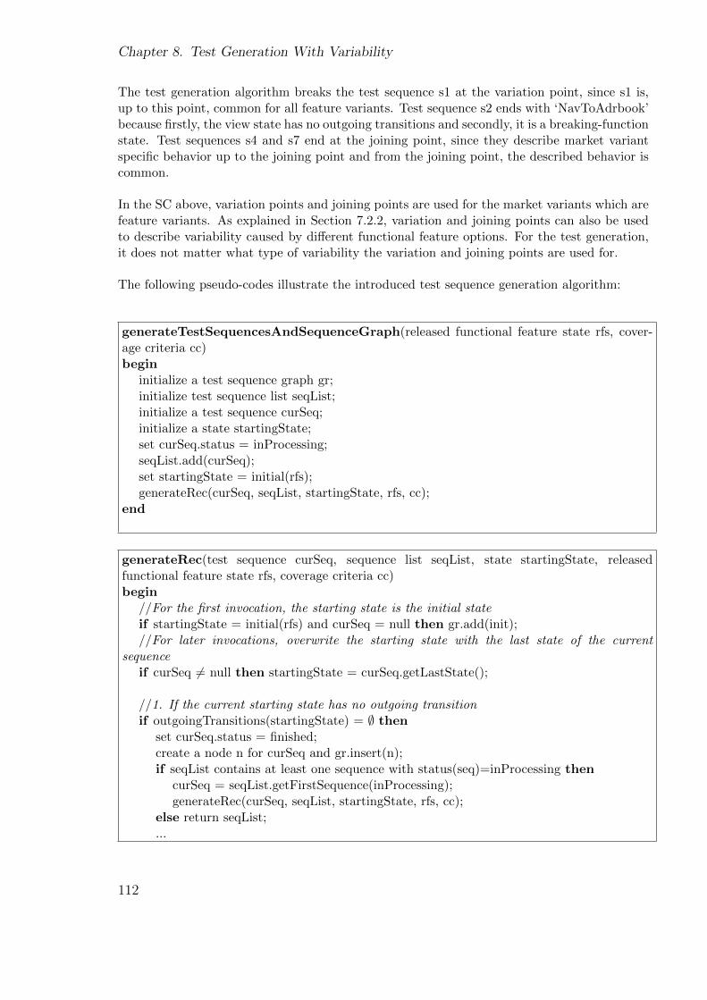
Chapter 8. Test Generation With Variability
The test generation algorithm breaks the test sequence s1 at the variation point, since s1 is,up to this point, common for all feature variants. Test sequence s2 ends with ‘NavToAdrbook’because firstly, the view state has no outgoing transitions and secondly, it is a breaking-functionstate. Test sequences s4 and s7 end at the joining point, since they describe market variantspecific behavior up to the joining point and from the joining point, the described behavior iscommon.
In the SC above, variation points and joining points are used for the market variants which arefeature variants. As explained in Section 7.2.2, variation and joining points can also be usedto describe variability caused by different functional feature options. For the test generation,it does not matter what type of variability the variation and joining points are used for.
The following pseudo-codes illustrate the introduced test sequence generation algorithm:
generateTestSequencesAndSequenceGraph(released functional feature state rfs, cover-age criteria cc)begin
initialize a test sequence graph gr;initialize test sequence list seqList;initialize a test sequence curSeq;initialize a state startingState;set curSeq.status = inProcessing;seqList.add(curSeq);set startingState = initial(rfs);generateRec(curSeq, seqList, startingState, rfs, cc);
end
generateRec(test sequence curSeq, sequence list seqList, state startingState, releasedfunctional feature state rfs, coverage criteria cc)begin
//For the first invocation, the starting state is the initial stateif startingState = initial(rfs) and curSeq = null then gr.add(init);//For later invocations, overwrite the starting state with the last state of the current
sequenceif curSeq 6= null then startingState = curSeq.getLastState();
//1. If the current starting state has no outgoing transitionif outgoingTransitions(startingState) = ∅ then
set curSeq.status = finished;create a node n for curSeq and gr.insert(n);if seqList contains at least one sequence with status(seq)=inProcessing then
curSeq = seqList.getFirstSequence(inProcessing);generateRec(curSeq, seqList, startingState, rfs, cc);
else return seqList;...
112
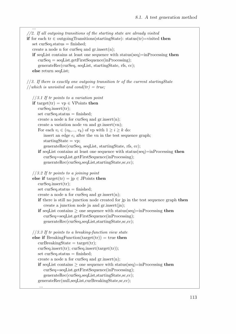
8.1. A test generation method
...//2. If all outgoing transitions of the starting state are already visitedif for each tr ∈ outgoingTransitions(startingState): status(tr)=visited then
set curSeq.status = finished;create a node n for curSeq and gr.insert(n);if seqList contains at least one sequence with status(seq)=inProcessing then
curSeq = seqList.getFirstSequence(inProcessing);generateRec(curSeq, seqList, startingState, rfs, cc);
else return seqList;
//3. If there is exactly one outgoing transition tr of the current startingState//which is unvisited and cond(tr) = true;
//3.1 If tr points to a variation pointif target(tr) = vp ∈ VPoints then
curSeq.insert(tr);set curSeq.status = finished;create a node n for curSeq and gr.insert(n);create a variation node vn and gr.insert(vn);For each vi ∈ (v0,..., vk) of vp with 1 ≥ i ≥ k do:
insert an edge ei after the vn in the test sequence graph;startingState = vp;generateRec(curSeq, seqList, startingState, rfs, cc);
if seqList contains at least one sequence with status(seq)=inProcessing thencurSeq=seqList.getFirstSequence(inProcessing);generateRec(curSeq,seqList,startingState,sc,cc);
//3.2 If tr points to a joining pointelse if target(tr) = jp ∈ JPoints then
curSeq.insert(tr);set curSeq.status = finished;create a node n for curSeq and gr.insert(n);if there is still no junction node created for jp in the test sequence graph then
create a junction node jn and gr.insert(jn);if seqList contains ≥ one sequence with status(seq)=inProcessing then
curSeq=seqList.getFirstSequence(inProcessing);generateRec(curSeq,seqList,startingState,sc,cc);
//3.3 If tr points to a breaking-function view stateelse if BreakingFunction(target(tr)) = true then
curBreakingState = target(tr);curSeq.insert(tr); curSeq.insert(target(tr));set curSeq.status = finished;create a node n for curSeq and gr.insert(n);if seqList contains ≥ one sequence with status(seq)=inProcessing then
curSeq=seqList.getFirstSequence(inProcessing);generateRec(curSeq,seqList,startingState,sc,cc);
generateRec(null,seqList,curBreakingState,sc,cc);...
113
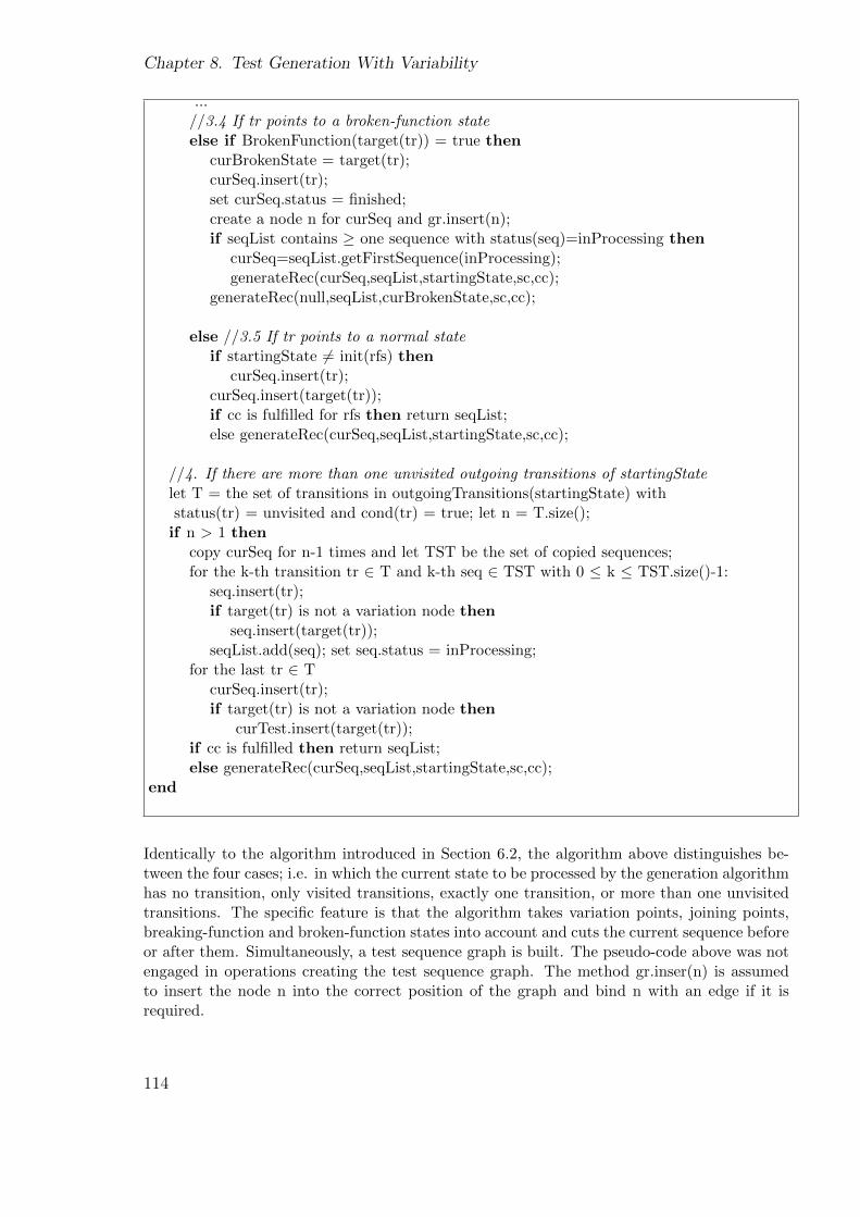
Chapter 8. Test Generation With Variability
...//3.4 If tr points to a broken-function stateelse if BrokenFunction(target(tr)) = true then
curBrokenState = target(tr);curSeq.insert(tr);set curSeq.status = finished;create a node n for curSeq and gr.insert(n);if seqList contains ≥ one sequence with status(seq)=inProcessing then
curSeq=seqList.getFirstSequence(inProcessing);generateRec(curSeq,seqList,startingState,sc,cc);
generateRec(null,seqList,curBrokenState,sc,cc);
else //3.5 If tr points to a normal stateif startingState 6= init(rfs) then
curSeq.insert(tr);curSeq.insert(target(tr));if cc is fulfilled for rfs then return seqList;else generateRec(curSeq,seqList,startingState,sc,cc);
//4. If there are more than one unvisited outgoing transitions of startingStatelet T = the set of transitions in outgoingTransitions(startingState) withstatus(tr) = unvisited and cond(tr) = true; let n = T.size();
if n > 1 thencopy curSeq for n-1 times and let TST be the set of copied sequences;for the k-th transition tr ∈ T and k-th seq ∈ TST with 0 ≤ k ≤ TST.size()-1:
seq.insert(tr);if target(tr) is not a variation node then
seq.insert(target(tr));seqList.add(seq); set seq.status = inProcessing;
for the last tr ∈ TcurSeq.insert(tr);if target(tr) is not a variation node then
curTest.insert(target(tr));if cc is fulfilled then return seqList;else generateRec(curSeq,seqList,startingState,sc,cc);
end
Identically to the algorithm introduced in Section 6.2, the algorithm above distinguishes be-tween the four cases; i.e. in which the current state to be processed by the generation algorithmhas no transition, only visited transitions, exactly one transition, or more than one unvisitedtransitions. The specific feature is that the algorithm takes variation points, joining points,breaking-function and broken-function states into account and cuts the current sequence beforeor after them. Simultaneously, a test sequence graph is built. The pseudo-code above was notengaged in operations creating the test sequence graph. The method gr.inser(n) is assumedto insert the node n into the correct position of the graph and bind n with an edge if it isrequired.
114
8.1. A test generation method
8.1.2. Constructing tests from test sequences
So far, we have produced the following results:
• A list of global transition entries
• For each product to be tested, an inter-function graph
• For each functional feature to be tested:
– a test sequence graph
– a set of test sequences
The introduced test sequence generation was based on the transition coverage. In this sectionit is explained how tests can be constructed from these results for a given product to be tested.The constructed tests should also together fulfill the transition coverage. The demonstrationis based on the ongoing example; tests shall be created for the functional feature navigationfor Products 2 and 3 shown in Figure 8.1.
Step 3 Restore dependencies
In step 1, dependencies on global transitions and other relevant functional feature states werereleased for a functional feature state. They were preserved with the help of global transitionentries and an inter-function graph. Test sequences were generated without them. This meansthat the generated test sequences still do not fulfill the chosen coverage criteria, in our ex-ample the transition coverage. Now, in order to construct tests covering all transitions, thesedependencies must be considered by the test construction.
Step 3.1 Restore dependencies on global transitionsFor each global transition entry globalTr entry = [event, target, cons] ∈ GobalTREntries,create a test sequence testSeq = (Cons, Steps) with Cons = (cons), Steps = {step0, step1},step0 = event and step1 = target. For each created test sequence, create a node and insert itrandomly or according to some rules into the test sequence graph.
As explained in Step 1, global transitions are triggerable from any state of the system. Itis neither logical nor possible to test every global transition from every system state. Theimplementation of a global transition is correct if it can be triggered from one arbitrary state.Therefore, we have found the trade-off between testing effort and test quality, i.e. we testeach global transition from one system state only. To do this, a created test sequence for aglobal transition entry needs to be added into the test sequence graph only once. The insertionposition is not important and can be individually defined. We propose to insert it after the firstnodes under the initial node in order to avoid unnecessarily long tests and execution times.
Created test sequences for the global transition entries shown in Section 8.1.1 are:
g1: (HardKey Navigation) → [NavWizard], Cons = {[Navi is installed]}g2: (HardKey Radio) → [RadioSenderList]g3: (HardKey Telephone) → [TelephoneMain], Cons = {[Telephone is installed]}
115
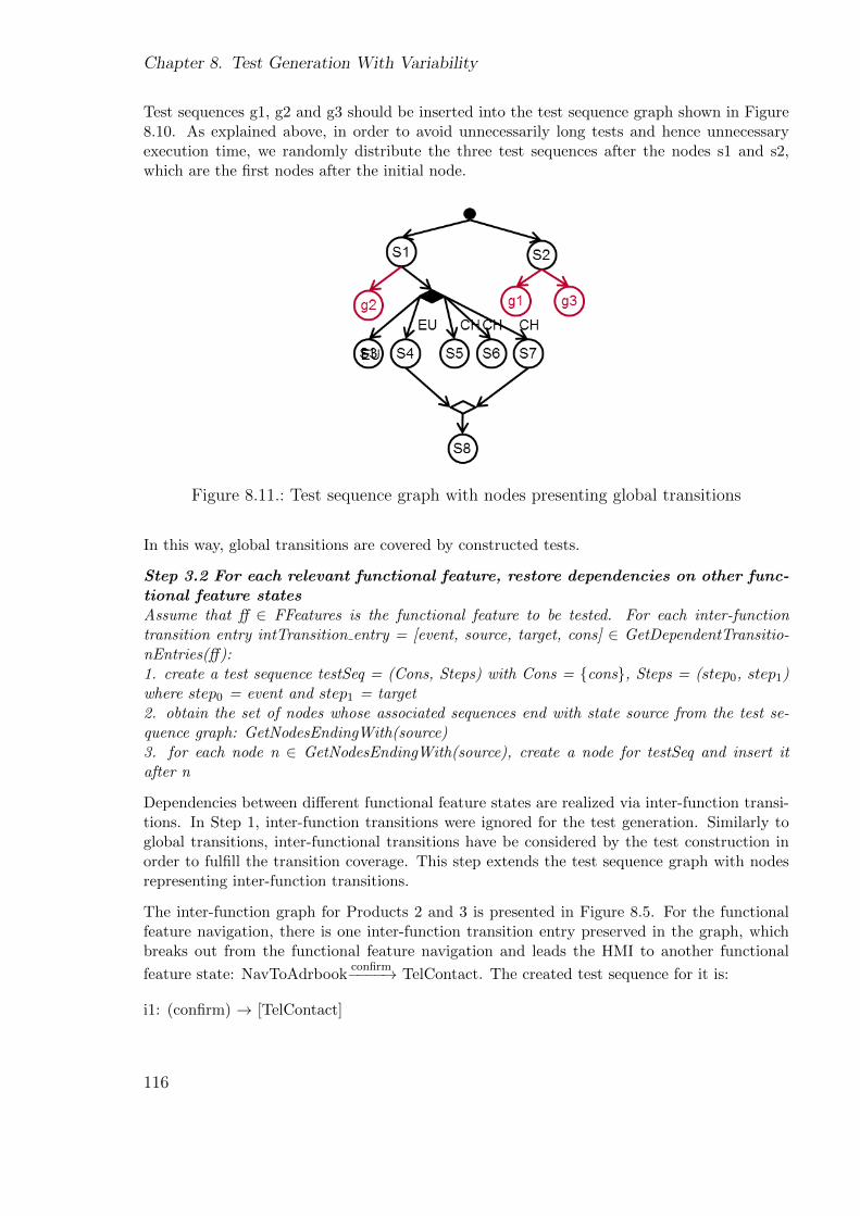
Chapter 8. Test Generation With Variability
Test sequences g1, g2 and g3 should be inserted into the test sequence graph shown in Figure8.10. As explained above, in order to avoid unnecessarily long tests and hence unnecessaryexecution time, we randomly distribute the three test sequences after the nodes s1 and s2,which are the first nodes after the initial node.
Figure 8.11.: Test sequence graph with nodes presenting global transitions
In this way, global transitions are covered by constructed tests.
Step 3.2 For each relevant functional feature, restore dependencies on other func-tional feature statesAssume that ff ∈ FFeatures is the functional feature to be tested. For each inter-functiontransition entry intTransition entry = [event, source, target, cons] ∈ GetDependentTransitio-nEntries(ff):1. create a test sequence testSeq = (Cons, Steps) with Cons = {cons}, Steps = (step0, step1)where step0 = event and step1 = target2. obtain the set of nodes whose associated sequences end with state source from the test se-quence graph: GetNodesEndingWith(source)3. for each node n ∈ GetNodesEndingWith(source), create a node for testSeq and insert itafter n
Dependencies between different functional feature states are realized via inter-function transi-tions. In Step 1, inter-function transitions were ignored for the test generation. Similarly toglobal transitions, inter-functional transitions have be considered by the test construction inorder to fulfill the transition coverage. This step extends the test sequence graph with nodesrepresenting inter-function transitions.
The inter-function graph for Products 2 and 3 is presented in Figure 8.5. For the functionalfeature navigation, there is one inter-function transition entry preserved in the graph, whichbreaks out from the functional feature navigation and leads the HMI to another functional
feature state: NavToAdrbookconfirm−−−−→ TelContact. The created test sequence for it is:
i1: (confirm) → [TelContact]
116
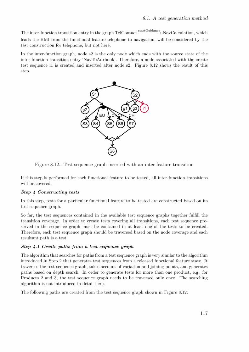
8.1. A test generation method
The inter-function transition entry in the graph TelContactstartGuidance−−−−−−−−→ NavCalculation, which
leads the HMI from the functional feature telephone to navigation, will be considered by thetest construction for telephone, but not here.
In the inter-function graph, node s2 is the only node which ends with the source state of theinter-function transition entry ‘NavToAdrbook’. Therefore, a node associated with the createtest sequence i1 is created and inserted after node s2. Figure 8.12 shows the result of thisstep.
Figure 8.12.: Test sequence graph inserted with an inter-feature transition
If this step is performed for each functional feature to be tested, all inter-function transitionswill be covered.
Step 4 Constructing tests
In this step, tests for a particular functional feature to be tested are constructed based on itstest sequence graph.
So far, the test sequences contained in the available test sequence graphs together fulfill thetransition coverage. In order to create tests covering all transitions, each test sequence pre-served in the sequence graph must be contained in at least one of the tests to be created.Therefore, each test sequence graph should be traversed based on the node coverage and eachresultant path is a test.
Step 4.1 Create paths from a test sequence graph
The algorithm that searches for paths from a test sequence graph is very similar to the algorithmintroduced in Step 2 that generates test sequences from a released functional feature state. Ittraverses the test sequence graph, takes account of variation and joining points, and generatespaths based on depth search. In order to generate tests for more than one product, e.g. forProducts 2 and 3, the test sequence graph needs to be traversed only once. The searchingalgorithm is not introduced in detail here.
The following paths are created from the test sequence graph shown in Figure 8.12:
117
Chapter 8. Test Generation With Variability
For the European market:Path 1: s1 - s3Path 2: s1 - s4 - s8
For the Chinese market:Path 3: s1 - s5Path 4: s1 - s6Path 5: s1 - s7 - s8
Common for both markets:Path 6: s1 - g2Path 7: s2 - g1Path 8: s2 - g3Path 9: s2 - i1
If global transitions and inter-function transitions are not required for testing, tests should begenerated from the test sequence graph shown in Figure 8.10. In this case, there is only onecommon test for both markets:
Path 10: s2
Tests for Product 2 are composed of the paths for the Chinese market and the common paths.Tests for Product 3 are composed of the paths for the European market and the commonpaths.
Step 4.2 Instantiate created paths into tests
Instantiated tests from the above paths are as follows:
Tests for the European market:
Test 1:[Main] → (nav) → [NavWizard] → (address) → [NavAdrInput] → (country) → [NavCoun-tryList] → (chooseCountry) → [NavAdrInput] → (city) → [NavCitySpeller] → (enterCity) →[NavAdrInput]
Test 2:[Main] → (nav) → [NavWizard] → (address) → [NavAdrInput] → (country) → [NavCoun-tryList]→ (chooseCountry)→ [NavAdrInput]→ (street)→ [NavStreetSpeller]→ (enterStreet)→ [NavAdrInput] → (start) → [NavCalculation] → [NavMap] → (SK Route) → [NavWiz-ard]
Tests for the Chinese market:
Test 3:[Main] → (nav) → [NavWizard] → (address) → [NavAdrInput] → (country) → [NavCoun-tryList] → (chooseCountry) → [NavAdrInput]
Test 4:[Main] → (nav) → [NavWizard] → (address) → [NavAdrInput] → (province) →
118

8.1. A test generation method
[NavProvinceList] → (chooseProvince) → [NavAdrInput] → (city) → [NavCitySpeller] → (en-terCity) → [NavAdrInput]
Test 5:[Main] → (nav) → [NavWizard] → (address) → [NavAdrInput] → (province) →[NavProvinceList] → (chooseProvince) → [NavAdrInput] → (street) → [NavStreetSpeller] →(enterStreet) → [NavAdrInput] → (start) → [NavCalculation] → [NavMap] → (SK Route) →[NavWizard]
Common tests for both market variants:
Test 6:[Main] → (nav) → [NavWizard] → (address) → (HardKey Radio) → [RadioSenderList]
Test 7:[Main] → (nav) → [NavWizard] → (adrbook) → [NavToAdrbook] →(HardKey Navigation) → [NavWizard]
Test 8:[Main] → (nav) → [NavWizard] → (adrbook) → [NavToAdrbook] →(HardKey Telephone) → [TelephoneMain]
Test 9:[Main] → (nav) → [NavWizard] → (adrbook) → [NavToAdrbook] → (confirm) → [TelCon-tact]
If global transitions and inter-function transitions are not intended for testing, the commontest for both market variants is:
Test 10:[Main] → (nav) → [NavWizard] → (adrbook) → [NavToAdrbook]
8.1.3. Avoiding redundant tests
Until now, it has been introduced how tests can be generated for different variants without theneed for the generation process to be repeated. However, generated tests for different productsstill have a large set of identical tests which verify the common behavior of these products. Forinstance, Test 6 to Test 10 listed at the end of the last step are contained in the tests generatedfor both Product 2 and Product 3, and would be executed for both products. Also, the testsgenerated for the functional feature radio which has no variability in the menu behavior wouldbe executed for all three products.
It can never be assured that the same tests verifying common behavior do not produce newor different errors for different products. Therefore, if sufficient testing resources are available,these tests should be executed for each product. However, in the case of limited testingresources, a trade-off must be made between the testing effort and the quality.
In this step, such identical tests verifying common behavior of different products to be testedwill be detected and avoided for the test execution. We assume that tests have been generated
119
Chapter 8. Test Generation With Variability
for all three products shown in Figure 8.1 and that the products should be tested in the orderin which they are graphically displayed.
The functional feature radio is provided by all three products and does not have variability inthe menu behavior. Nor does it have any dependencies on other functional features, as shownin Figure 8.5. According to the trade-off principle between the testing effort and quality, it issufficient to execute generated tests for the functional feature radio only once for Product 1.Furthermore, Products 1 and 2 both provide the functional feature telephone in the same option“BTHandfree”. Tests generated for this option should also be executed only once for Product1 and do not need to be repeated for Product 2. However, since the dependencies between thefunctional feature telephone and navigation are not available in Product 1, tests verifying thesedependencies must be executed for Product 2. Additionally, Test 6 to Test 10 listed at theend of Step 4.2 are generated for both Product 2 and Product 3 which have different marketvariants. They are variant feature unspecific, i.e. they test the part of the menu behaviorwhich is common for both variants. However, they would be redundantly executed a secondtime. Similarly, different functional feature options of the same functional feature also canshare a large set of common behaviors. Tests generated from common behaviors would also beredundantly executed.
In order to avoid redundant test executions, the following rules must be followed:
1. Already tested functional features should not be tested again if they have no variabilityin the menu behavior (e.g. the functional feature radio)
2. If a functional feature has variability in the menu behavior which is caused by variantfeatures, tests for each variant feature should be executed once, and only once (e.g. thefunctional feature navigation)
3. If a functional feature has variability in the menu behavior which is caused by functionalfeature options, tests for each functional feature option should be executed once, andonly once (e.g. the functional feature telephone)
4. If a functional feature has behavior which is unspecific for any variant features or func-tional feature options, tests verifying this unspecific behavior should be executed onlyonce
5. Untested dependencies of already tested functional features should be tested (e.g. thedependencies between the functional features telephone and navigation)
Based on the idea in [113], the FVD-matrix (F: functional feature, V: variant feature and D:dependencies) is defined to realize the rules above. A FVD-matrix is a matrix which recordsthe already tested entities by performed test executions. Based on the content of the FVD-matrix, it can be calculated which tests should be performed for the next product to be tested.The entities can be:
• a functional feature, if it has no variability in the menu behavior, such as the functionalfeature radio
• a functional feature option of a functional feature, if this functional feature is providedin more than one option and the current option has no variability in the menu behavior,such as “telephone-BTHandfree” or “telephone-comfort”
120
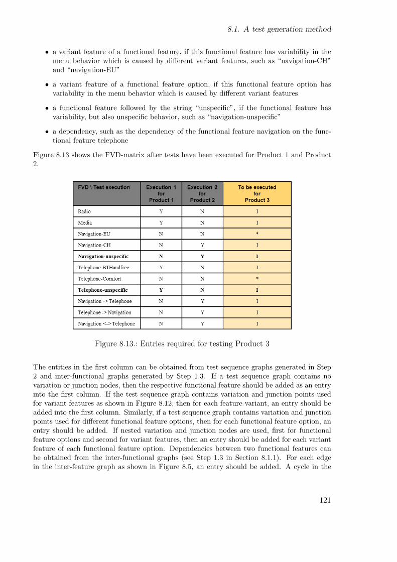
8.1. A test generation method
• a variant feature of a functional feature, if this functional feature has variability in themenu behavior which is caused by different variant features, such as “navigation-CH”and “navigation-EU”
• a variant feature of a functional feature option, if this functional feature option hasvariability in the menu behavior which is caused by different variant features
• a functional feature followed by the string “unspecific”, if the functional feature hasvariability, but also unspecific behavior, such as “navigation-unspecific”
• a dependency, such as the dependency of the functional feature navigation on the func-tional feature telephone
Figure 8.13 shows the FVD-matrix after tests have been executed for Product 1 and Product2.
Figure 8.13.: Entries required for testing Product 3
The entities in the first column can be obtained from test sequence graphs generated in Step2 and inter-functional graphs generated by Step 1.3. If a test sequence graph contains novariation or junction nodes, then the respective functional feature should be added as an entryinto the first column. If the test sequence graph contains variation and junction points usedfor variant features as shown in Figure 8.12, then for each feature variant, an entry should beadded into the first column. Similarly, if a test sequence graph contains variation and junctionpoints used for different functional feature options, then for each functional feature option, anentry should be added. If nested variation and junction nodes are used, first for functionalfeature options and second for variant features, then an entry should be added for each variantfeature of each functional feature option. Dependencies between two functional features canbe obtained from the inter-functional graphs (see Step 1.3 in Section 8.1.1). For each edgein the inter-feature graph as shown in Figure 8.5, an entry should be added. A cycle in the
121
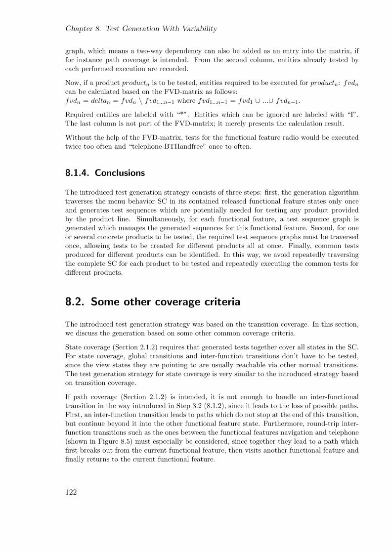
Chapter 8. Test Generation With Variability
graph, which means a two-way dependency can also be added as an entry into the matrix, iffor instance path coverage is intended. From the second column, entities already tested byeach performed execution are recorded.
Now, if a product productn is to be tested, entities required to be executed for productn: fvdncan be calculated based on the FVD-matrix as follows:fvdn = deltan = fvdn \ fvd1...n−1 where fvd1...n−1 = fvd1 ∪ ...∪ fvdn−1.
Required entities are labeled with “*”. Entities which can be ignored are labeled with “I”.The last column is not part of the FVD-matrix; it merely presents the calculation result.
Without the help of the FVD-matrix, tests for the functional feature radio would be executedtwice too often and “telephone-BTHandfree” once to often.
8.1.4. Conclusions
The introduced test generation strategy consists of three steps: first, the generation algorithmtraverses the menu behavior SC in its contained released functional feature states only onceand generates test sequences which are potentially needed for testing any product providedby the product line. Simultaneously, for each functional feature, a test sequence graph isgenerated which manages the generated sequences for this functional feature. Second, for oneor several concrete products to be tested, the required test sequence graphs must be traversedonce, allowing tests to be created for different products all at once. Finally, common testsproduced for different products can be identified. In this way, we avoid repeatedly traversingthe complete SC for each product to be tested and repeatedly executing the common tests fordifferent products.
8.2. Some other coverage criteria
The introduced test generation strategy was based on the transition coverage. In this section,we discuss the generation based on some other common coverage criteria.
State coverage (Section 2.1.2) requires that generated tests together cover all states in the SC.For state coverage, global transitions and inter-function transitions don’t have to be tested,since the view states they are pointing to are usually reachable via other normal transitions.The test generation strategy for state coverage is very similar to the introduced strategy basedon transition coverage.
If path coverage (Section 2.1.2) is intended, it is not enough to handle an inter-functionaltransition in the way introduced in Step 3.2 (8.1.2), since it leads to the loss of possible paths.First, an inter-function transition leads to paths which do not stop at the end of this transition,but continue beyond it into the other functional feature state. Furthermore, round-trip inter-function transitions such as the ones between the functional features navigation and telephone(shown in Figure 8.5) must especially be considered, since together they lead to a path whichfirst breaks out from the current functional feature, then visits another functional feature andfinally returns to the current functional feature.
122
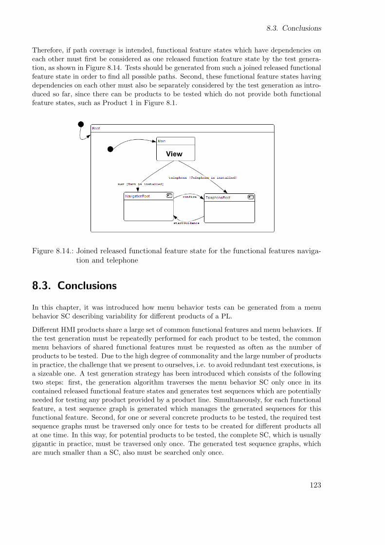
8.3. Conclusions
Therefore, if path coverage is intended, functional feature states which have dependencies oneach other must first be considered as one released function feature state by the test genera-tion, as shown in Figure 8.14. Tests should be generated from such a joined released functionalfeature state in order to find all possible paths. Second, these functional feature states havingdependencies on each other must also be separately considered by the test generation as intro-duced so far, since there can be products to be tested which do not provide both functionalfeature states, such as Product 1 in Figure 8.1.
Figure 8.14.: Joined released functional feature state for the functional features naviga-tion and telephone
8.3. Conclusions
In this chapter, it was introduced how menu behavior tests can be generated from a menubehavior SC describing variability for different products of a PL.
Different HMI products share a large set of common functional features and menu behaviors. Ifthe test generation must be repeatedly performed for each product to be tested, the commonmenu behaviors of shared functional features must be requested as often as the number ofproducts to be tested. Due to the high degree of commonality and the large number of productsin practice, the challenge that we present to ourselves, i.e. to avoid redundant test executions, isa sizeable one. A test generation strategy has been introduced which consists of the followingtwo steps: first, the generation algorithm traverses the menu behavior SC only once in itscontained released functional feature states and generates test sequences which are potentiallyneeded for testing any product provided by a product line. Simultaneously, for each functionalfeature, a test sequence graph is generated which manages the generated sequences for thisfunctional feature. Second, for one or several concrete products to be tested, the required testsequence graphs must be traversed only once for tests to be created for different products allat one time. In this way, for potential products to be tested, the complete SC, which is usuallygigantic in practice, must be traversed only once. The generated test sequence graphs, whichare much smaller than a SC, also must be searched only once.
123
Chapter 8. Test Generation With Variability
The introduced test generation strategy was based on transition coverage. We also brieflydiscussed test generation with variability based on state coverage and path coverage. It wasshown that the test generation strategy must be adapted for other coverage criteria. Althoughwe could not present all possible coverage criteria in this work, we hope to provide inspirationto both research and industry via the proposed approach.
124
Part IV.
Evaluation and Conclusions
125


This is the final part of the thesis. In this section, the variability approaches introduced in IIIwill be evaluated. We will also give a summary of the focuses of this thesis and the proposedsolutions. Even though model-based testing of infotainment system HMIs has recently becomea hot topic in the automotive industry and in research, there are still a large number of openresearch questions to be answered. Finally, we will introduce future work in the domain ofmodel-based HMI testing from the perspectives of the industry and research.
127

Chapter 8. Test Generation With Variability
128
Chapter 9.
Evaluation
The main focal points of this thesis are firstly modeling the menu behavior with variability(Section 7.2) and secondly generating menu behavior tests without redundancies for potentialproducts which are to be tested (Chapter 8).
The purpose of this chapter is to evaluate these approaches. The evaluation will be done fromthe efficiency aspect by estimating the efficiency improvement, i.e. the time saved by using ourapproaches. For this estimation, we use the data which is obtained from our proof-of-conceptimplementation and an HMI development model (Section 2.2.3) from real life. Both datasources will be introduced in Section 9.1. The evaluation consists of mathematical analyseswhich prove the plausibility of the proposed approaches, general discussions about factorsinfluencing efficiency, and also concrete data demonstrating the efficiency improvements.
9.1. Data source for the evaluation
In this section, we introduce our proof-of-concept implementation and an HMI developmentmodel from real life. We perform measurements based on the proof-of-concept implementationand attend to several numbers from the practical HMI development model. Based on thecomparison of these data, we afterwards estimate how the efficiency of testing a real-life HMIproduct line can be improved by using our approaches.
9.1.1. Proof-of-concept implementation
In order to prove the plausibility of the concept, we have implemented a strongly simplifiedproduct line, a menu behavior SC with variability, and a test generator which generates testsfrom this SC without redundancies. These implementations have already been introduced asthe ongoing example in earlier chapters. We give a summary of them at this point. The figuresshown again here do not contain any changes.
129
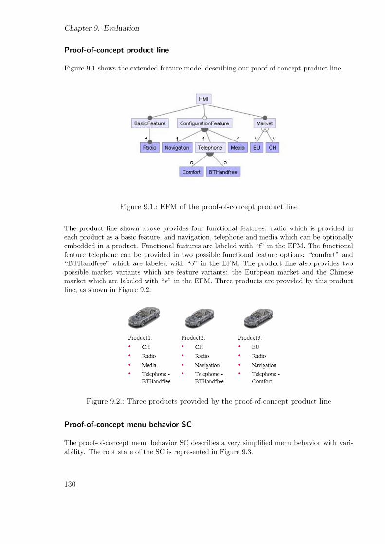
Chapter 9. Evaluation
Proof-of-concept product line
Figure 9.1 shows the extended feature model describing our proof-of-concept product line.
Figure 9.1.: EFM of the proof-of-concept product line
The product line shown above provides four functional features: radio which is provided ineach product as a basic feature, and navigation, telephone and media which can be optionallyembedded in a product. Functional features are labeled with “f” in the EFM. The functionalfeature telephone can be provided in two possible functional feature options: “comfort” and“BTHandfree” which are labeled with “o” in the EFM. The product line also provides twopossible market variants which are feature variants: the European market and the Chinesemarket which are labeled with “v” in the EFM. Three products are provided by this productline, as shown in Figure 9.2.
Figure 9.2.: Three products provided by the proof-of-concept product line
Proof-of-concept menu behavior SC
The proof-of-concept menu behavior SC describes a very simplified menu behavior with vari-ability. The root state of the SC is represented in Figure 9.3.
130
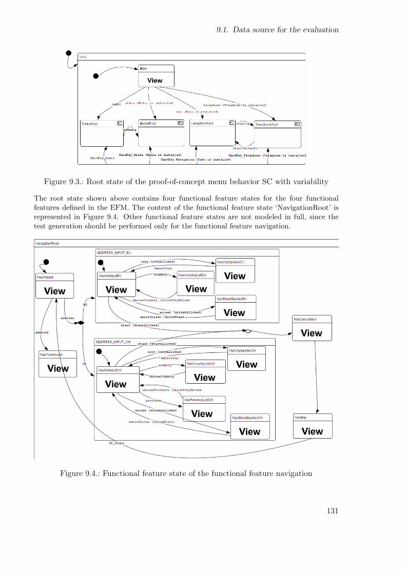
9.1. Data source for the evaluation
Figure 9.3.: Root state of the proof-of-concept menu behavior SC with variability
The root state shown above contains four functional feature states for the four functionalfeatures defined in the EFM. The content of the functional feature state ‘NavigationRoot’ isrepresented in Figure 9.4. Other functional feature states are not modeled in full, since thetest generation should be performed only for the functional feature navigation.
Figure 9.4.: Functional feature state of the functional feature navigation
131
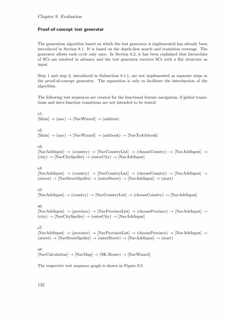
Chapter 9. Evaluation
Proof-of-concept test generator
The generation algorithm based on which the test generator is implemented has already beenintroduced in Section 8.1. It is based on the depth-first search and transition coverage. Thegenerator allows each cycle only once. In Section 6.2, it has been explained that hierarchiesof SCs are resolved in advance and the test generator receives SCs with a flat structure asinput.
Step 1 and step 2, introduced in Subsection 8.1.1, are not implemented as separate steps inthe proof-of-concept generator. The separation is only to facilitate the introduction of thealgorithm.
The following test sequences are created for the functional feature navigation, if global transi-tions and inter-function transitions are not intended to be tested:
s1:[Main] → (nav) → [NavWizard] → (address)
s2:[Main] → (nav) → [NavWizard] → (adrbook) → [NavToAdrbook]
s3:[NavAdrInput] → (country) → [NavCountryList] → (chooseCountry) → [NavAdrInput] →(city) → [NavCitySpeller] → (enterCity) → [NavAdrInput]
s4:[NavAdrInput] → (country) → [NavCountryList] → (chooseCountry) → [NavAdrInput] →(street) → [NavStreetSpeller] → (enterStreet) → [NavAdrInput] → (start)
s5:[NavAdrInput] → (country) → [NavCountryList] → (chooseCountry) → [NavAdrInput]
s6:[NavAdrInput] → (province) → [NavProvinceList] → (chooseProvince) → [NavAdrInput] →(city) → [NavCitySpeller] → (enterCity) → [NavAdrInput]
s7:[NavAdrInput] → (province) → [NavProvinceList] → (chooseProvince) → [NavAdrInput] →(street) → [NavStreetSpeller] → (enterStreet) → [NavAdrInput] → (start)
s8:[NavCalculation] → [NavMap] → (SK Route) → [NavWizard]
The respective test sequence graph is shown in Figure 9.5.
132
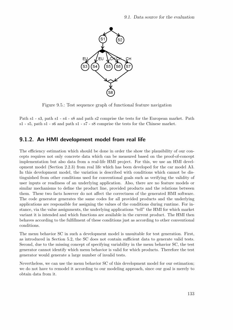
9.1. Data source for the evaluation
Figure 9.5.: Test sequence graph of functional feature navigation
Path s1 - s3, path s1 - s4 - s8 and path s2 comprise the tests for the European market. Paths1 - s5, path s1 - s6 and path s1 - s7 - s8 comprise the tests for the Chinese market.
9.1.2. An HMI development model from real life
The efficiency estimation which should be done in order the show the plausibility of our con-cepts requires not only concrete data which can be measured based on the proof-of-conceptimplementation but also data from a real-life HMI project. For this, we use an HMI devel-opment model (Section 2.2.3) from real life which has been developed for the car model A3.In this development model, the variation is described with conditions which cannot be dis-tinguished from other conditions used for conventional goals such as verifying the validity ofuser inputs or readiness of an underlying application. Also, there are no feature models orsimilar mechanisms to define the product line, provided products and the relations betweenthem. These two facts however do not affect the correctness of the generated HMI software.The code generator generates the same codes for all provided products and the underlyingapplications are responsible for assigning the values of the conditions during runtime. For in-stance, via the value assignments, the underlying applications “tell” the HMI for which marketvariant it is intended and which functions are available in the current product. The HMI thenbehaves according to the fulfillment of these conditions just as according to other conventionalconditions.
The menu behavior SC in such a development model is unsuitable for test generation. First,as introduced in Section 5.2, the SC does not contain sufficient data to generate valid tests.Second, due to the missing concept of specifying variability in the menu behavior SC, the testgenerator cannot identify which menu behavior is valid for which products. Therefore the testgenerator would generate a large number of invalid tests.
Nevertheless, we can use the menu behavior SC of this development model for our estimation;we do not have to remodel it according to our modeling approach, since our goal is merely toobtain data from it.
133
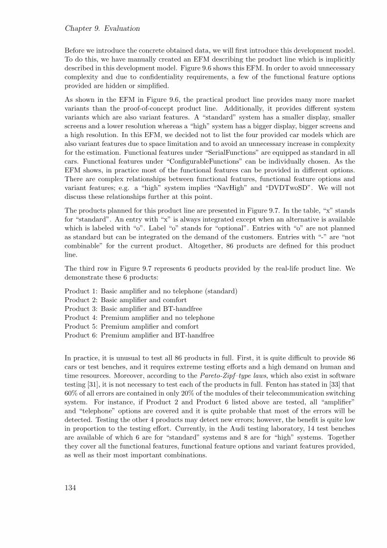
Chapter 9. Evaluation
Before we introduce the concrete obtained data, we will first introduce this development model.To do this, we have manually created an EFM describing the product line which is implicitlydescribed in this development model. Figure 9.6 shows this EFM. In order to avoid unnecessarycomplexity and due to confidentiality requirements, a few of the functional feature optionsprovided are hidden or simplified.
As shown in the EFM in Figure 9.6, the practical product line provides many more marketvariants than the proof-of-concept product line. Additionally, it provides different systemvariants which are also variant features. A “standard” system has a smaller display, smallerscreens and a lower resolution whereas a “high” system has a bigger display, bigger screens anda high resolution. In this EFM, we decided not to list the four provided car models which arealso variant features due to space limitation and to avoid an unnecessary increase in complexityfor the estimation. Functional features under “SerialFunctions” are equipped as standard in allcars. Functional features under “ConfigurableFunctions” can be individually chosen. As theEFM shows, in practice most of the functional features can be provided in different options.There are complex relationships between functional features, functional feature options andvariant features; e.g. a “high” system implies “NavHigh” and “DVDTwoSD”. We will notdiscuss these relationships further at this point.
The products planned for this product line are presented in Figure 9.7. In the table, “x” standsfor “standard”. An entry with “x” is always integrated except when an alternative is availablewhich is labeled with “o”. Label “o” stands for “optional”. Entries with “o” are not plannedas standard but can be integrated on the demand of the customers. Entries with “-” are “notcombinable” for the current product. Altogether, 86 products are defined for this productline.
The third row in Figure 9.7 represents 6 products provided by the real-life product line. Wedemonstrate these 6 products:
Product 1: Basic amplifier and no telephone (standard)Product 2: Basic amplifier and comfortProduct 3: Basic amplifier and BT-handfreeProduct 4: Premium amplifier and no telephoneProduct 5: Premium amplifier and comfortProduct 6: Premium amplifier and BT-handfree
In practice, it is unusual to test all 86 products in full. First, it is quite difficult to provide 86cars or test benches, and it requires extreme testing efforts and a high demand on human andtime resources. Moreover, according to the Pareto-Zipf–type laws, which also exist in softwaretesting [31], it is not necessary to test each of the products in full. Fenton has stated in [33] that60% of all errors are contained in only 20% of the modules of their telecommunication switchingsystem. For instance, if Product 2 and Product 6 listed above are tested, all “amplifier”and “telephone” options are covered and it is quite probable that most of the errors will bedetected. Testing the other 4 products may detect new errors; however, the benefit is quite lowin proportion to the testing effort. Currently, in the Audi testing laboratory, 14 test benchesare available of which 6 are for “standard” systems and 8 are for “high” systems. Togetherthey cover all the functional features, functional feature options and variant features provided,as well as their most important combinations.
134

9.1. Data source for the evaluation
Figure 9.6.: EFM describing the practical product line
135

Chapter 9. Evaluation
Figure 9.7.: Products of the practical HMI development model
136
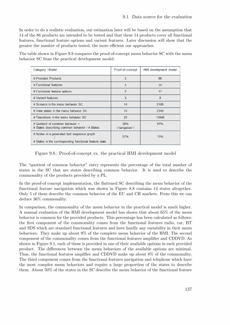
9.1. Data source for the evaluation
In order to do a realistic evaluation, our estimation later will be based on the assumption that14 of the 86 products are intended to be tested and that these 14 products cover all functionalfeatures, functional feature options and variant features. Later discussion will show that thegreater the number of products tested, the more efficient our approaches.
The table shown in Figure 9.8 compares the proof-of-concept menu behavior SC with the menubehavior SC from the practical development model:
Figure 9.8.: Proof-of-concept vs. the practical HMI development model
The “quotient of common behavior” entry represents the percentage of the total number ofstates in the SC that are states describing common behavior. It is used to describe thecommonality of the products provided by a PL.
In the proof-of concept implementation, the flattened SC describing the menu behavior of thefunctional feature navigation which was shown in Figure 8.8 contains 14 states altogether.Only 5 of them describe the common behavior of the EU and CH markets. From this we candeduce 36% commonality.
In comparison, the commonality of the menu behavior in the practical model is much higher.A manual evaluation of the HMI development model has shown that about 65% of the menubehavior is common for the provided products. This percentage has been calculated as follows:the first component of the commonality comes from the functional features radio, car, BTand SDS which are standard functional features and have hardly any variability in their menubehaviors. They make up about 9% of the complete menu behavior of the HMI. The secondcomponent of the commonality comes from the functional features amplifier and CDDVD. Asshown in Figure 9.1, each of these is provided in one of their available options in each providedproduct. The differences between the menu behaviors of the available options are minimal.Thus, the functional features amplifier and CDDVD make up about 8% of the commonality.The third component comes from the functional features navigation and telephone which havethe most complex menu behaviors and require a large proportion of the states to describethem. About 50% of the states in the SC describe the menu behavior of the functional feature
137
Chapter 9. Evaluation
navigation. Although navigation is not provided in all products, it is provided in 62 of the 86products, i.e. about 70% of available products. The menu behaviors of the options “NavBasic”and “NavHigh” have a large set of commonalities: about 95%. Therefore, we calculate that50% * 70% * 95% = 34% of the menu behavior of the functional feature navigation is thecommon behavior. Similarly to navigation, the functional feature telephone requires about25% of the states to describe its menu behavior and is provided in 72 of the 86 products(84%). The menu behaviors of different functional feature options contain about 65% commonbehaviors. Thus, telephone adds 25% * 84% * 65% = 14% common behavior. Altogether,about 9% + 8% + 34% + 14% = 65% of the menu behaviors are common in the developmentmodel.
In the proof-of-concept implementation, the sequence graph generated for navigation contains8 nodes (Figure 9.5), i.e. about 57% of the states from which the sequence graph is generated.This percentage is actually unrealistic. In the practical menu behavior SC, the number of thenodes in a test sequence graph is only about 15% of the number of the states from which thesequence graph is generated. This means that a generated test sequence graph is much smallerthan the functional feature state from which the graph is generated.
9.2. Evaluation
In this section, the approaches of modeling menu behavior with variability (introduced inSection 7.2) and generating tests without redundancies (introduced in Chapter 8) will beevaluated.
The evaluation consists of the following three components: first, in Section 9.2.2, it will bemathematically calculated that the proposed approaches always achieve an efficiency improve-ment for a chosen practical HMI project. Second, in Section 9.2.3, there will be a generaldiscussion about which factors the efficiency improvement is dependent upon. In addition,worst cases will be identified in which the approaches are not profitable. Finally, in Section9.2.4, an estimation with concrete data will be made in order to demonstrate how much timewould be saved for a project in practice by using our approaches.
First, the design of the evaluation will be introduced.
9.2.1. Design of the evaluation
We compare the efficiency for the following methods:
Method 1: A menu behavior SC is available which describes variability based on the modelingapproach introduced in Section 7.2. A test generation method is available which generates testsfrom this SC for different products of the PL and avoids redundancies as introduced in Chapter8.
Method 2: A menu behavior SC is available which describes variability based on the modelingapproach introduced in Section 7.2. The test generation used does not avoid redundancies.This means that for each product to be tested, it traverses all relevant parts of the SC.
138
9.2. Evaluation
Method 3: A menu behavior SC is available which has no clear concept to describe variability,similar to the one in the practical HMI development model. Consequently, the describedvariability is untraceable for the test generation. The test generation nevertheless generatestests from this SC and cannot avoid redundancies.
The primary goal is to show that the test generation time of Method 1 is better than the testgeneration time of Method 2 based on a mathematical analysis. Thus the efficiency of theproposed generation method which avoids redundant test generations is evaluated. Second, ifit is possible to show that the generation time of Method 2 is better than that of Method 3,then the efficiency of the proposed method modeling variability is evaluated. We will first showthese statements based on mathematical analyses. Then we will discuss generally on whichfactors the efficiency improvements of our proposed approaches are dependent. Finally, we willgive an estimate of the saved generation time for these three methods using concrete data.
For the evaluation, we assume that a systematic test coverage is set as the testing goal bychoosing several products for testing which cover all functional features, variant features andfunctional feature options. We assume that n is the number of chosen products to be testedand n > 1, since it is unrealistic that only one product of a product line is to be tested.
For the test generation we use flattened SCs.
In order to compare the test generation times of the three methods, we present the requiredgeneration time of each method as an equation.
For Method 1, the generation algorithm needs to traverse the menu behavior SC only once andprepares all potentially needed test sequences and test sequence graphs. Due to the assumptionthat the chosen products to be tested cover all functional features, all generated test sequencegraphs have to be traversed once. The equation describing the generation time can be shownas:
Tgeneration c1 = TtraverseCompleteSC + TtraverseAllGraphs
According to the test generation method introduced in 8.1, if more products are to be tested,Tgeneration c1 remains the same. If a subset of the products are to be tested which do not coverall functional features, then not all of the generated test sequence graphs have to be traversed.The generation time is smaller than Tgeneration c1.
For Method 2, a menu behavior SC is available which describes variability based on the pro-posed approach. The test generation is a normal test generation which is not intended toavoid redundancies. We assume that the test generation algorithm takes the elements de-scribing variability into account and only traverses the SC in parts which are relevant for thecurrent product. For each product, the test generation algorithm has to be performed once.Therefore, the test generation time can be calculated as:
Tgeneration c2 = TtraversePartSC product1 + ... + TtraversePartSC productn
where n is the number of products to be tested.
For Method 3, the complete SC must be traversed once for each product, since the SC doesnot contain elements indicating common or product specific behaviors for the test generator.
139
Chapter 9. Evaluation
As explained previously, since the test generation algorithm produces invalid tests, manualadaption of generated tests is required. Therefore, the test generation time of Method 3 iscomposed of traversing the complete menu behavior SC as often as the number of productswhich are to be tested plus manual correction of the generated tests. We do not yet have anyexperience of how time consuming the manual work can be. However, the effort would becomeunmanageable as the number of products which are to be tested increases.
Tgeneration c3 = n * TtraverseCompleteSC + n * Tmanual
where n is the number of products to be tested.
9.2.2. Evaluation based on mathematical plausibility analysis
In this section, we mathematically show that based on the real-life HMI development modeland the assumption that the chosen products to be tested cover all functional features, thetest generation time of Method 1 is better than the test generation time of Method 2, and thetest generation time of Method 2 is better than that of Method 3.
Statement 1: Tgeneration c2 > Tgeneration c1
Proof:The time T of depth search is linear [URLc]. Consequently:1. Since the complete menu behavior is composed of common and specific behaviors:TtraverseCompleteSC = Ttraverse common + Ttraverse specific
2.Since the common behavior amounts to 65% of the total behavior (Table 9.8):Ttraverse common = TtraverseCompleteSC *65%
3. Since the nodes in generated test sequence graphs are about 15% of the states in the SC:Tgeneration c1 = TtraverseCompleteSC + TtraverseAllGraphs
= TtraverseCompleteSC + 15% * TtraverseCompleteSC
For Method 2, the common behaviors are visited n times and the rest, which describeproduct specific behaviors, are visited at least once completely. Consequently:TtraversePartSC product1+...+TtraversePartSC productn ≥ n * Ttraverse common + Ttraverse specific
where n is the number of products to be tested and n > 1
Consequently:
Tgeneration c2 = TtraversePartSC product1 + ... + TtraversePartSC productn
≥ n * Ttraverse common + Ttraverse specific
= (Ttraverse common + Ttraverse specific) + (n-1) * Ttraverse common
= TtraverseCompleteSC + (n-1) * Ttraverse common
> TtraverseCompleteSC + Ttraverse common
= TtraverseCompleteSC + 65% * TtraverseCompleteSC
>> TtraverseCompleteSC + 15% * TtraverseCompleteSC
= TtraverseCompleteSC + TtraverseAllGraphs
= Tgeneration c1
Therefore: Tgeneration c2 > Tgeneration c1
140
9.2. Evaluation
Tgeneration c2 > Tgeneration c1 shows that for the HMI development project from real life andbased on the assumption that the chosen products to be tested cover all provided functional fea-tures, functional feature options and variant features, the proposed generation method whichavoids redundant test generations saves generation time and hence achieves an improvementin efficiency.
Statement 2: Tgeneration c3 > Tgeneration c2
Proof:
Tgeneration c3 = n * TtraverseCompleteSC + n * Tmanual
> n * TtraverseCompleteSC
> TtraversePartSC product1 + ... + TtraversePartSC productn
= Tgeneration c2
Therefore: Tgeneration c3 > Tgeneration c2
Tgeneration c3 > Tgeneration c2 shows that for the HMI development project from real life andbased on the assumption that the chosen products to be tested together cover all providedfunctional features, functional feature options and variant features, the proposed approachmodeling variability in the menu behavior SC saves generation time and hence achieves animprovement in efficiency.
9.2.3. General discussion
In the last subsection, it was mathematically shown that the proposed modeling and testgeneration approaches are efficient, based on the assumptions that 14 chosen products of apractical HMI project should be tested and that together they cover all provided functionalfeatures, functional feature options and variant features. In this section, we leave this concreteproject and its assumptions and generally discuss the factors on which the improvement inefficiency is dependent.
The improvement in efficiency brought about by employing the proposed approaches is depen-dent on the following factors:
Factor 1 The number of layers in the menu behavior SC hierarchy
For our proof-of-concept test generator, we decided to use flattened SCs as explained at the endof Subsection 9.1.1. If the menu behavior SC is not flattened in advance, the test generationmust resolve the same hierarchies every time the SC is traversed. In Methods 2 and 3, the SCtraversal must be repeated for each product to be tested, whereas for Method 1 the traversal isdone only once, regardless of the number of products to be tested. Therefore, if the used testgeneration is not based on flattened SCs, then the more hierarchy layers are used to describethe menu behavior, the more efficient is our generation approach.
Factor 2 Commonality of the menu behavior between the products
141
Chapter 9. Evaluation
In Methods 2 and 3, the parts of the SC describing the common behavior of different productsmust be traversed for each product which is to be tested. That means the more similar themenu behaviors of different products are to each other, the more states must be redundantlyvisited for Methods 2 and 3 and consequently the more efficient are the proposed approaches.
Factor 3 The number of products to be tested
The test generation time of Method 1 does not increase with the number of products to betested. In contrast, for Methods 2 and 3, the test generation must be performed as often as thenumber of products to be tested. At the end of the last subsection, it was shown that basedon the practical HMI project, the test generation approach does not achieve any efficiencyimprovement if only one product of the PL is to be tested. However, for testing two or moreproducts it is profitable to use the test generation method which avoids redundancies. Thismeans that the more products there are to be tested, the better the efficiency of the proposedapproaches.
Factor 4 The difference between the number of nodes in the generated test sequence graphsand the number of states in the SC
The test generation time of Method 1 comprises the time for traversing the SC and the time fortraversing the relevant test sequence graphs. The advantage is that each test sequence graph isusually much smaller than the functional feature state from which it is generated. Each nodeof the test sequence graph “replaces” a sequence of states in the SC. Therefore the smaller thegenerated test sequence graphs are in comparison to their functional feature states, the moreefficient the test generation method.
There can be cases in which the proposed test generation approach is not profitable, e.g.the case described at the end of Section 9.2.2 in which only one product is to be tested forthe practical HMI development project. Generally, in cases where there is a disadvantageouscombination of a very low number of products to be tested, a very low commonality betweenthe behaviors of these products, and test sequence graphs which have sizes comparable to thefunctional feature states, the proposed generation method may be unprofitable. First, projectsin which model-based testing approaches are applied usually have the goal of achieving a sys-tematic and higher test coverage by testing as many products as possible. Second, it onlymakes sense to specify, develop and test the products as a product line if they have a large setof commonalities. Furthermore, it is unrealistic for a test sequence graph in practice to haveas many nodes as the states in the respective functional feature state, since a menu behaviorSC in practice does not contain so many variation points, junction points, breaking-functionstates or broken-function states which break a test sequence. This means that generated testsequences usually contain many steps and a test sequence graph is much smaller than therespective functional feature state. The proposed approach of modeling the menu behavioralways achieves an improvement in efficiency due to the avoidance of invalid tests and manualwork.
142
9.2. Evaluation
9.2.4. Estimation with concrete data
In this section we use some concrete data in order to show how much time can be saved by ourapproaches for the practical HMI development project. The time savings are estimated usingdata obtained from the proof-of-concept implementation and the practical HMI developmentmodel. Therefore, the results are strongly dependent on these data sources. They cannot serveas absolute statements but only provide an impression.
As explained above, 14 test benches are currently used in Audi’s laboratory for function testsof the product line which we have introduced to be tested, and which provides 86 products.In order to provide a realistic impression, we first show the time saved for testing only 14products and then for testing all 86 products.
The test generation time is strongly dependent on the number of states contained in the menubehavior SC, the processor and RAM of the PC on which the test generation is executed, andalso the generator itself. To traverse our proof-of-concept menu behavior SC, which contains14 view states, and to finish generating tests, our proof-of-concept test generator needs about5 seconds. This is expressed as follows:
Tgeneration prototype = t = 5s
Method 1:
The menu behavior SC in the practical HMI development model contains 2349 view states(Table 9.8) which are about 2349 / 14 ≈ 168 times of the states in the proof-of-concept menubehavior SC. Since the searching time of depth search is linear, generating tests from thepractical development model is approximately:
TtraverseCompleteSC ≈ 168 * Tgeneration prototype = 168 * t
As shown in Table 9.8, generated test sequence graphs contain about 15% nodes as the statesin the functional feature states. Consequently:
TtraverseAllGraphs ≈ 15% * TtraverseCompleteSC = 15% * 168 * t = 25.2 * t
Therefore, for Method 1:
Tgeneration c1 = TtraverseCompleteSC + TtraverseAllGraphs = 193.2 * twith t = 5 sTgeneration c1 ≈ 16 min
The test generation time was estimated based on the measurement results of the proof-of-concept implementations and the numbers obtained from the real-life projects. This estimationshows that based on our proposed approaches, the test generation would take about 16 minin order to generate tests which cover all functional features, variant features and functionalfeature options on the same PC as the proof-on-concept test generation was executed. Thegeneration time is independent of the number of products to be tested as long as all functionalfeatures, variant features and functional feature options shall be covered by the generated tests.
143
Chapter 9. Evaluation
Method 2:
In the practical HMI development model, about 65% of the behavior describes the commonbehavior of different products. Consequently:
TtraversePartSC product1 + ... + TtraversePartSC product14
≥ 14 * Ttraverse common + Ttraverse specific
≈ 14* 65% * TtraverseCompleteSC + 35% * TtraverseCompleteSC
≈ 14* 65% * 168 * t + 35% * 168 * t= 1587.6 * t
Therefore, for Method 2:
Tgeneration c2 = TtraversePartSC product 1 + ... + TtraversePartSC product 14 = 1587.6 * t
Consequently:Tgeneration c2 = 8.3 * Tgeneration c1
And with t = 5 s:Tgeneration c2 ≈ 132.3 min
For Method 2, the test generation has to be performed once for each product to be tested. Therequired generation time for Method 2 is about 8.3 times the generation time for Method 1.On the same PC as used for the first estimation, the test generation would take about 132.3minutes. By applying the proposed test generation method, about 88% of the generation timecan be saved.
Method 3:
For Method 3, even though we have no experience of the time demanded by the manual work,the time taken just to traverse the SC can already give a impression.
14 * TtraverseCompleteSC ≈ 14 * 168 * t = 2352 * t
Therefore:
Tgeneration c3 = 14 * TtraverseCompleteSC + 14 * Tmanual = 2352 * t + 7 * Tmanual
Consequently:Tgeneration c3 >> 12 * Tgeneration c1
with t = 5 sTgeneration c3 ≈ 196 min + 7 * Tmanual
In this method, not only the test generation, but also the manual adaptation of generatedtests has to be performed once for each product to be tested. Ignoring the time required forthe manual work, the test generation alone for Method 3 required more than 3 hours which ismore than 12 times the generation time for Method 1.
144
9.3. Conclusions
As discussed in the last section, the more products there are to be tested, the greater thedifference between the test generation times for the three methods. In the following section,we perform the same estimations for the case in which all 86 products are to be tested.
The test generation time of Method 1 remains the same:
Tgeneration c1 = TtraverseCompleteSC + TtraverseAllGraphs = 193.2 * twith t = 5 sTgeneration c1 ≈ 16 min
For Method 2:
Tgeneration c2 = TtraversePartSC product1 + ... + TtraversePartSC product86 ≈ 9450 * t
Consequently:Tgeneration c2 = 49 * Tgeneration c1
with t = 5 sTgeneration c2 ≈ 13 h
And for Method 3:
Tgeneration c3 = 86 * TtraverseCompleteSC + 86 * Tmanual ≈ 14448 * t + 86 * Tmanual
Consequently:Tgeneration c3 >> 75 * Tgeneration c1
with t = 5 sTgeneration c3 ≈ 20 h + 86 * Tmanual
The numbers above confirm our discussion above that the more products there are to betested, the greater the efficiency improvement that can be achieved by applying our proposedapproaches. In the case of testing all 86 available products, the test generation for Method2 requires 13 hours, i.e. 49 times the generation time for Method 1 which remains the samedespite the growing number of products to be tested. For Method 3, the test generation timealone requires 20 hours. If the time for manual adaptation is taken into account, the testgeneration effort would be extreme and unacceptable for serial HMI development.
9.3. Conclusions
In this chapter, the variability modeling and testing approaches have been evaluated from theefficiency aspect. We have first mathematically shown that the proposed approaches alwaysachieve an efficiency improvement for real-life HMI projects. Afterwards, it was generallydiscussed on which factors the efficiency improvement is dependent. Also, worst cases inwhich the test generation approach is unprofitable were discussed. It was explained thatsuch cases are rare for projects in which model-based testing approaches are applied. Finally,we demonstrated concrete data. In practice, it is usual to test only some available productvariants in full. In our estimation, if only 14 of 86 products are to be tested, at least 88% of the
145
Chapter 9. Evaluation
generation time can be saved by applying our approaches. The difference between 16 minutesand 3 hours clearly demonstrates that our approaches can achieve an enormous improvementin efficiency for real-life projects. The case of testing all 86 products makes the benefits ofour approaches even clearer; at least 98% of the generation time can be saved, i.e. about 13hours.
146
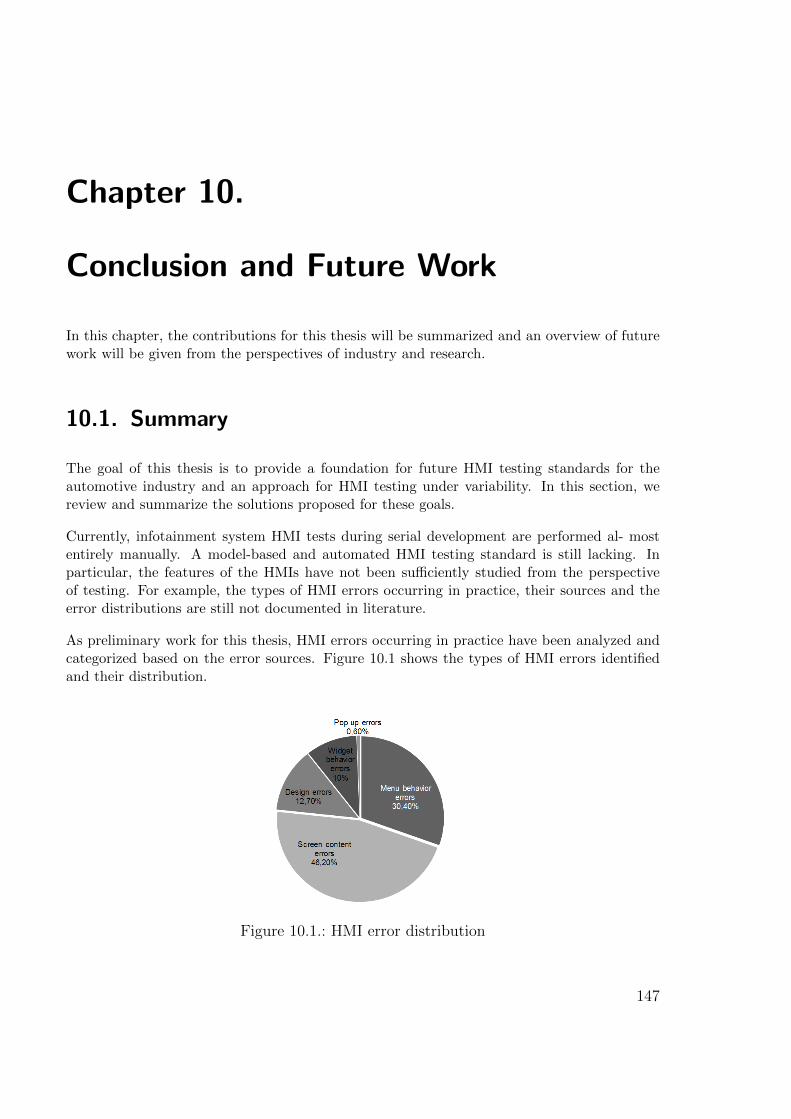
Chapter 10.
Conclusion and Future Work
In this chapter, the contributions for this thesis will be summarized and an overview of futurework will be given from the perspectives of industry and research.
10.1. Summary
The goal of this thesis is to provide a foundation for future HMI testing standards for theautomotive industry and an approach for HMI testing under variability. In this section, wereview and summarize the solutions proposed for these goals.
Currently, infotainment system HMI tests during serial development are performed al- mostentirely manually. A model-based and automated HMI testing standard is still lacking. Inparticular, the features of the HMIs have not been sufficiently studied from the perspectiveof testing. For example, the types of HMI errors occurring in practice, their sources and theerror distributions are still not documented in literature.
As preliminary work for this thesis, HMI errors occurring in practice have been analyzed andcategorized based on the error sources. Figure 10.1 shows the types of HMI errors identifiedand their distribution.
Figure 10.1.: HMI error distribution
147
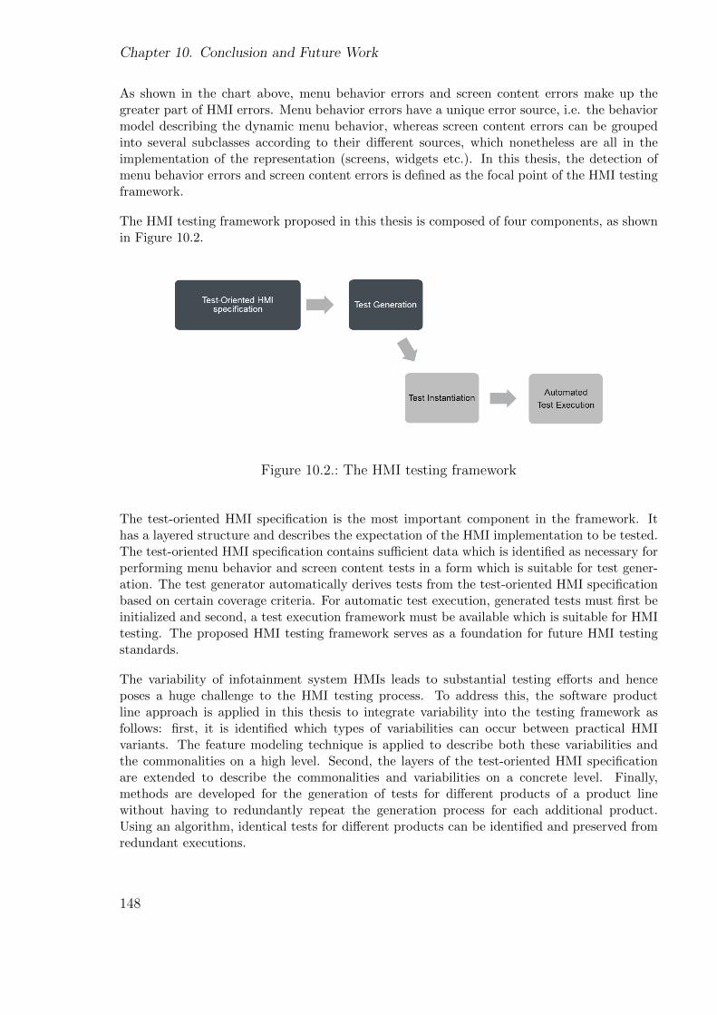
Chapter 10. Conclusion and Future Work
As shown in the chart above, menu behavior errors and screen content errors make up thegreater part of HMI errors. Menu behavior errors have a unique error source, i.e. the behaviormodel describing the dynamic menu behavior, whereas screen content errors can be groupedinto several subclasses according to their different sources, which nonetheless are all in theimplementation of the representation (screens, widgets etc.). In this thesis, the detection ofmenu behavior errors and screen content errors is defined as the focal point of the HMI testingframework.
The HMI testing framework proposed in this thesis is composed of four components, as shownin Figure 10.2.
Figure 10.2.: The HMI testing framework
The test-oriented HMI specification is the most important component in the framework. Ithas a layered structure and describes the expectation of the HMI implementation to be tested.The test-oriented HMI specification contains sufficient data which is identified as necessary forperforming menu behavior and screen content tests in a form which is suitable for test gener-ation. The test generator automatically derives tests from the test-oriented HMI specificationbased on certain coverage criteria. For automatic test execution, generated tests must first beinitialized and second, a test execution framework must be available which is suitable for HMItesting. The proposed HMI testing framework serves as a foundation for future HMI testingstandards.
The variability of infotainment system HMIs leads to substantial testing efforts and henceposes a huge challenge to the HMI testing process. To address this, the software productline approach is applied in this thesis to integrate variability into the testing framework asfollows: first, it is identified which types of variabilities can occur between practical HMIvariants. The feature modeling technique is applied to describe both these variabilities andthe commonalities on a high level. Second, the layers of the test-oriented HMI specificationare extended to describe the commonalities and variabilities on a concrete level. Finally,methods are developed for the generation of tests for different products of a product linewithout having to redundantly repeat the generation process for each additional product.Using an algorithm, identical tests for different products can be identified and preserved fromredundant executions.
148
10.2. Future work
By applying the model-based testing approach in the HMI testing framework, specific formsof test coverage can be achieved systematically. Automated test execution can greatly sup-port foreign language system tests. During automated test executions, screenshots can beautomatically captured of the screens visited; these screenshots can then be easily reviewed bynative-speaker testers in order to verify the languages. In this way, it is not necessary to occupytest benches/cars or to manually execute the usually large number of tests. In particular, dueto the proposed variability approaches, testing a large number of HMI variants can be muchmore efficient. First, the specification efforts can be reduced by avoiding redundant descrip-tions of commonalities. Second, the testing efforts can be reduced by avoiding redundant testgenerations and executions. The evaluation has shown that at least 88% of the test generationtime can be saved on a practical HMI project by applying our generation approach.
At this point, we summarize the main contributions of this thesis:
• The HMI testing framework
– serves as a foundation for future HMI testing standards for the automotive industry
– supports abstract specifications of HMIs from test perspectives
– supports automatic test generation
– enables systematic test coverage
– allows automatic test execution
• Extensions of the HMI testing framework for variability
– provide an approach for testing complex and embedded GUIs/HMIs under vari-ability
– allow the specification of different HMI variants as a product line
– allow the testing of different HMI variants as a product line
– enable efficient test generation and avoid redundancies
– significantly reduce the required effort
10.2. Future work
In order to apply the results of this thesis in practice, the testing concept can be furthercompleted, refined and made more efficient.
Extension of the testing scope
The verification of menu behavior and screen content representation is defined as the focalpoint of the testing framework. As introduced in Section 4.2, the detection of several othererror types can also be integrated into the test framework, i.e. pop-up behaviors, widgetbehaviors and dynamic contents. Also, design tests can be integrated into the framework.Design tests are used to verify whether design rules such as positions, color and fonts are
149
Chapter 10. Conclusion and Future Work
observed in the HMI implementation. In a doctoral thesis currently in progress, design testsof infotainment system HMIs are investigated and the preliminary results documented in [50].In that thesis, design tests require formal design information as a precondition. Due to thelayered structure of our testing framework, design information can be specified in the designlayer without having to adapt the current framework. Therefore, the results of that thesiscan be considered to extend our testing framework for design tests. Recently, animationsand 3D representations have gradually been implemented in automotive HMIs. The testingof animations and 3D representations represents a major challenge for future HMI testing.Additionally, many errors can only be detected via stress tests which are usually performedby experienced testers in practice. Stress tests involve the whole infotainment system and more:the HMI, the instrument cluster, speech input and output facilities, underlying applications andbus systems. Activities which do not belong to infotainment system functions, e.g. electricallychanging the seat setting, can also stress the behavior of the HMI. Integrating stress testsinto the testing framework could be a huge challenge for future work but very effective. Thetesting framework can also be extended for negative tests, which e.g. avoid the occurrenceof certain scenarios, user inputs or exceeded reply time. The generation of efficientregression tests for HMIs is also a very significant topic. For this, methods must be appliedwhich are able to identify the “affected” tests in order to regenerate them exclusively. Finally,multi-modality has not been a focal point of this thesis. Testing the speech facilities andtouch behaviors as well as the graphical behaviors of infotainment system HMIs based onmodel-based approaches is still a little-investigated field.
Intelligent and efficient testing
There is still great potential to improve the efficiency of the current testing approach, forwhich Artificial Intelligence (AI) methods can be considered. For instance, the number ofgenerated HMI tests is still uncontrolled and usually very high. Many of the generated testsare very similar to each other in that they visit the same screens, have many overlapping teststeps, require similar user inputs or produce similar outputs. According to the Pareto-Zipf–type laws ([31]), reducing the number of generated tests using an intelligent strategy canreduce testing efforts without affecting quality. Artificial Neural Network (ANN) has alreadybeen used for reducing tests generated from data-based models. By identifying input-outputrelationships based on the ANN, equivalent classes of generated tests can be determined. Thegoal is to select one or several representatives from each class. HMI models are usually event-based models. ANN or similar AI methods need to be extended for event-based models andespecially HMI tests. For instance, it is conceivable to define relationships for screens based oncertain occurring orders and identify screen relationships in order to identify equivalent classes.The same idea can also be applied for user actions. The quality of generated tests still hasscope for improvement. For instance, in order to select test cases having higher probabilitiesof error detection, AI methods such as AI planning [53] and generic methods [102] can beconsidered. This would be a very attractive topic, since HMI testing in serial developmentusually suffers from a lack of time.
Adequate coverage criteria for HMI tests
In this thesis, test generation has been mainly based on the conventional structural coverages.Further coverage criteria still need to be defined which are especially adequate for HMItesting.
150
10.2. Future work
An infotainment system provides numerous functions. A user generally uses several of themmuch more frequently than others. Similarly, the HMI usually provides several options forthe user to access the same function, e.g. in order to start the navigation guidance, theuser can input a city followed by a street or choose the center of the city. The user usuallyemploys one or some of these options much more frequently than others. This means thatdifferent functions and scenarios have higher priorities for testing. This fact should be betterconsidered in future HMI testing. In order to generate tests according to these priorities, akind of “usage-oriented coverage” could be defined and applied. For instance, the prioritiesof screens, transitions and/or transition sequences could be labeled with properties . Differentlevels of tests could be generated based on these priorities. For instance, level I contains testsverifying the correct start-up of the system and the accessibility of the functions, while levelII contains tests verifying the basic functions or the most used functions etc. It could beeven more interesting to define several different “usage profiles” for different testing phasesand testing goals. For instance, one usage profile is defined for generating minimal tests, onefor stress tests and one for random tests. One could imagine that users in Asian or Arabiancounties interact differently with the HMI than users in European countries. Therefore, usageprofiles can also be defined for market-specific tests. Up to now we have only focused oncoverage criteria for testing the dynamic behavior of HMIs. Coverage criteria still need bedefined for other types of tests, e.g. for design tests it must be defined which types of widgetsand which of their properties are to be tested.
Until now we are only focused on coverage criteria for testing the dynamic behavior of HMIsuntil now. Coverage criteria still need be defined for other types of tests, e,g. for design testsit must be defined which types of widgets and which properties of them are to be tested.
Adaptive HMI testing
Future HMI testing can be made more adaptive to improve testing efficiency. For example,in connection with regression tests, the testing concept must ensure that scenarios which havebeen verified as erroneous in one of the previous HMI versions must be retested for the nextHMI version. This requires traceability from a generated test to the scenario described inthe specification. The scenario can be traced, for example, by marking the screens, widgets,user actions and/or user action sequences. For the next HMI version to be tested, if it isdetected that changes have occurred in the traced scenario, then one or several new testsshould be generated from the specification which corresponds to the HMI version to be tested.Otherwise, the old tests can be reused for retesting. In order to “learn” from past errors andensure they are retested, a kind of “past error coverage” can be considered which defineswhich past errors must be covered by the tests. Ideally, “past error coverage” can be used incombination with a variable which defines up to which past version errors should be“retested”for the current version. Also, scenarios which are verified to be less error-prone or never error-prone in past tests can be considered for omission from certain test phases. Maybe it is alsopossible to learn from early errors and create new tests which have a higher probability ofdetecting them. Furthermore, generated tests still cannot achieve the quality of testing byexperienced test experts who usually find more complicated errors. It would also be a veryattractive research area to learn from human testers and generate more intelligent HMI tests.The scope for making the HMI testing more adaptive is still wide.
151
Chapter 10. Conclusion and Future Work
Avoiding errors during specification construction
Model-based testing approaches imply the problem that if errors exist in the specification,the SUT is verified against erroneous tests. This leads to “falsified” testing results and henceunnecessary effort for error logging. In future HMI testing, errors shall ideally be detected andavoided during the construction of specifications.
Many modeling errors can be determined on the tool level. For instance, trivial errors such asunreachable states and duplicated transitions can already be automatically reported by most ofthe HMI development tools during specification. Future HMI specification tools should betterdetermine more complex modeling errors such as conflicts in the conditions or HMI-specificerrors such as an outgoing transition starting from a view state of which the associated screencannot trigger the event of this transition.
Errors can also occur during specification which are not so trivial, e.g. inconsistency of theoperation concept. For instance, in the operation concept for one market, it is defined that“return” buttons always lead the user to the previous screen visited by the user, whereas foranother market, it is defined that “return” buttons always lead the user to the next screenup in the screen hierarchy. Mistakes can be made with the operation concepts, which leadsto inconsistency in the specification. In order to avoid these types of errors, patterns canbe considered. For instance, for different markets, patterns for the “return” concept can bepredefined which must be observed in the whole specification of the corresponding market.
Usability testing for HMIs
Usability is still a very complex and hot topic in the area of user interfaces. A number of userstudies are being conducted by various manufacturers. Although there are perhaps no GUIswhich have absolutely perfect usability, several heuristics and standards are however acceptedfrom which metrics could be derived for usability measurement. Such metrics could be usedfor automated and model-based usability testing of infotainment system HMIs, which is stillan open area and a very interesting research topic. For instance, a Japanese guideline forinfotainment system HMIs defines that a function which requires more than four user actionshas a low level of usability and must be deactivated during driving. Such usability problems canbe precluded in the specification phase, e.g. by extending specification tools with constraintslimiting the number of allowed user actions in order to access a screen from the initial screenor the number of screen hierarchies.
Application in practice
In order to apply the results of this thesis in serial development, manufacturers’ HMI de-velopment processes may need to be adapted. The proposed approach requires a compatibledevelopment process, capable teams and suitable tools. For instance, many manufacturers havenot directly integrated the development of foreign language system HMIs into the developmentprocess for their home market. Either there are no explicit specifications for foreign HMIs orthe deviations from the HMIs for the home market are described in a separate document.Development processes need be adapted or optimized for applying the proposed approach.Additionally, capable teams which are able to, for example, extend the HMI specification withthe required test information, are necessary. In addition, suitable tools must be available,which, for example, allow abstract and uncompleted HMI specifications.
152
10.3. Final words
10.3. Final words
Although the testing framework can and needs to be further refined and made more efficient,the first fundamentals have been provided by this thesis for HMI testing under variability.For the first time, HMI errors occurring in practice have been studied and categorized. TheHMI testing framework is based on the goal of efficiently and independently detecting theseerrors with as little specification efforts as possible. Furthermore, HMI variability with real-life complexity has been analyzed and integrated into the testing framework. The proposedvariability specification and testing approaches have been evaluated to be extremely time-saving. The evaluation in Chapter 9 has shown that at least 88% of the generation time canbe saved by applying the variability solutions for a practical HMI project. We are convincedthat based on the results of this thesis, a systematic test coverage and hence better qualitycan be achieved with much lower effort and costs for future HMI testing and especially formulti-variant HMI testing.
153

Chapter 10. Conclusion and Future Work
154
Part V.
Bibliography
155

Bibliography
[1] de Almeida, E. S. (Hrsg.) ; Kishi, T. (Hrsg.) ; Schwanninger, C. (Hrsg.) ; John, I.(Hrsg.) ; Schmid, K. (Hrsg.): Software Product Lines - 15th International Conference,SPLC 2011, Munich, Germany, August 22-26, 2011. IEEE, 2011 . – ISBN 978–1–4577–1029–2
[2] Alsmadi, I. M.: Building a user interface test automation framework using the datamodel. Fargo, ND, USA, Diss., 2008. – AAI3305533
[3] Ambler, S. W.: The Elements of UML(TM) 2.0 Style. New York, NY, USA : CambridgeUniversity Press, 2005. – ISBN 0521616786
[4] Ammann, P. ; Offutt, J. ; Xu, W. : Formal methods and testing. Berlin, Heidelberg: Springer-Verlag, 2008. – ISBN 3–540–78916–2, 978–3–540–78916–1, Kapitel Coveragecriteria for state based specifications, S. 118–156
[5] Anthonysamy, P. ; Some, S. S.: Aspect-oriented use case modeling for software productlines. ACM Press, 2008, S. 1–8
[6] Antkiewicz, M. ; Czarnecki, K. : FeaturePlugin: feature modeling plug-in for Eclipse.In: Burke, M. G. (Hrsg.): ETX, ACM, 2004, S. 67–72
[7] AUDI AG and BMW and Daimler AG and Porsche and VW: XML-Sprachezur Beschreibung von HMIs fur Infotainmentsysteme und Kombiinstrumente. 2007. –Internal document of project automotiveHMI
[8] Bagheri, E. ; Di Noia, T. ; Ragone, A. ; Gasevic, D. : Configuring software productline feature models based on Stakeholders’ soft and hard requirements. In: Proceedingsof the 14th international conference on Software product lines: going beyond. Berlin,Heidelberg : Springer-Verlag, 2010 (SPLC’10). – ISBN 3–642–15578–2, 978–3–642–15578–9, S. 16–31
[9] Baker, P. ; Dai, Z. R. ; Grabowski, J. ; Haugen, y. ; Schieferdecker, I. ;Williams, C. : Model-Driven Testing: Using the UML Testing Profile. 1. Springer,Berlin, 2007. – ISBN 3540725628
[10] Bauer, S. : Implementierung praktischer Anwendung zur Unterstuetzung der Tes-tautomatisierung von Automotive Infotainmentsystemen basierend auf der Analyse desHuman-Machine-Interface, Ludwig-Maximilians-Universitat Munchen, Diploma thesis,2011
[11] von der Beeck, M. : A structured operational semantics for UML-statecharts. In:Software and Systems Modeling V1 (2002), Dezember, Nr. 2, S. 130–141. – ISSN 1619–1366
157
Bibliography
[12] Belli, F. : Finite-State Testing and Analysis of Graphical User Interfaces. In: ISSRE’01: Proceedings of the 12th International Symposium on Software Reliability Engineer-ing. Washington, DC, USA : IEEE Computer Society, 2001. – ISBN 0–7695–1306–9,S. 34
[13] Benz, S. : Generating tests for feature interaction, Technical University Munich, Diss.,2010
[14] Berti, S. ; Correani, F. ; Mori, G. ; Paterno, F. ; Santoro, C. ; Moruzzi, V. G.:TERESA: A Transformation-based Environment for Designing and Developing Multi-Device Interfaces. In: Evaluation (2004), S. 1–2
[15] Books, H. : UML Diagrams, Including: State Diagram, Sequence Diagram, Class Dia-gram, System Sequence Diagram, Deployment Diagram, Package Diagram, ComponentDiagram, Activity Diagram, Communication Diagram, Timing Diagram (Unified Mod-eling Language), Object Diagrams. 1st. Hephaestus Books, 2011. – ISBN 0321635841,9780321635846
[16] Born, M. ; Ekine, O. ; Ashley, J. : A model-driven product line approach for HMIdevelopment. In: Tagungsband der PIK 2009-Produktlinien im Kontext Bd. 111, 2009,S. 26–33
[17] Bullard, V. ; Smith, K. ; Daconta, M. : Essential XUL programming. Wiley, 2001(Wiley computer publishing). – ISBN 9780471415800
[18] Camastra, F. : Image Processing: Principles and Applications [book review]. In: IEEETransactions on Neural Networks 18 (2007), Nr. 2, S. 610
[19] Chang, T.-H. ; Yeh, T. ; Miller, R. C.: GUI testing using computer vision. In: CHI’10: Proceedings of the 28th international conference on Human factors in computingsystems. New York, NY, USA : ACM, 2010. – ISBN 978–1–60558–929–9, S. 1535–1544
[20] Chinnapongse, V. ; Lee, I. ; Sokolsky, O. ; Wang, S. ; Jones, P. L.: Model-Based Testing of GUI-Driven Applications. In: Software Technologies for Embedded andUbiquitous Systems Bd. 5860/2009. Springer-verlag New York Inc, 2009. – 7th IFIP WG10.2 International Workshop, SEUS 2009 Newport Beach, CA, USA, 2009 Proceedings,S. 203–214
[21] Claude, G. ; Ruediger, V. : Petri Nets for Systems Engineering: A Guide to Modeling,Verification, and Applications. Springer Berlin Heidelberg, 2002
[22] Clauss, M. : Generic Modeling using UML extensions for variability. In: Proceedingsof OOPSLA Workshop on Domain-specific Visual Languages. Tampa, FL, USA, 2001,S. 11–18
[23] Clements, P. ; Northrop, L. : Salion, Inc: a software product line case study. CarnegieMellon University, Software Engineering Institute, 2002 (Technical report)
[24] Czarnecki, K. : Mapping features to models: A template approach based on superim-posed variants. In: GPCE 2005 - Generative Programming and Component Enginering.4th International Conference, Springer, 2005, S. 422–437
158
Bibliography
[25] Czarnecki, K. ; Eisenecker, U. W.: Generative programming: methods, tools, andapplications. New York, NY, USA : ACM Press/Addison-Wesley Publishing Co., 2000.– ISBN 0–201–30977–7
[26] Drusinsky, D. : Modeling and Verification Using UML Statecharts, First Edition :A Working Guide to Reactive System Design, Runtime Monitoring and Execution-basedModel Checking. Newnes, April 2006. – ISBN 0750679492
[27] Duan, L. ; Hoefer, A. ; Hussmann, H. : Model-Based Testing of Automotive HMIsbased on a Test-Oriented HMI Specification Model. In: Proceedings of the the 2nd In-ternational Conference on Advances in System Testing and Validation Lifecycle (VALID2010), August 22-27 2010, Nice, France, IEEE, 2010
[28] Duan, L. ; Hussmann, H. ; Hoefer, A. : A Test-Oriented HMI Specification Modelfor Model-Based Testing of Automotive Human-Machine Interfaces. In: Fahnrich, K.-P. (Hrsg.) ; Franczyk, B. (Hrsg.): GI Jahrestagung (2) Bd. 176, GI, 2010. – ISBN978–3–88579–270–3, S. 339–344
[29] Duan, L. ; Hussmann, H. ; Niederkorn, D. ; Hoefer, A. : Model-Based Testing forthe Menu Behavior of Automotive Infotainment System HMIs. In: Proceedings of the1st International Workshop on Model-based Interactive Ubiquitous Systems 2011. Pisa,Italy : CEUR, 2011, S. 15–20
[30] Education, L. O.: Model View Controller Design Pattern. In: Online 3 (2007), Nr.Wong 2003, S. 2000–2007
[31] Endres, A. ; Rombach, D. : A Handbook of Software and Systems Engineering: Em-pirical Observations, Laws and Theories. illustrated. Addison Wesley, Mai 2003. – ISBN0321154207
[32] Feldt, K. : Programming Firefox: Building Rich Internet Applications with Xul.O’Reilly Media, Inc., 2007. – ISBN 0596102437
[33] Fenton, N. E. ; Ohlsson, N. : Quantitative Analysis of Faults and Failures in aComplex Software System. In: IEEE Trans. Softw. Eng. 26 (2000), August, S. 797–814.– ISSN 0098–5589
[34] Fernandes, P. ; Werner, C. ; Teixeira, E. : An Approach for Feature Modeling ofContext-Aware Software Product Line. In: Journal of Universal Computer Science 17(2011), Mar, Nr. 5, S. 807–829
[35] Fewster, M. ; Graham, D. : Software test automation: effective use of test executiontools. New York, NY, USA : ACM Press/Addison-Wesley Publishing Co., 1999. – ISBN0–201–33140–3
[36] Filip, J. ; Haindl, M. : Bidirectional Texture Function Modeling: A State of the ArtSurvey. In: IEEE Trans. Pattern Anal. Mach. Intell. 31 (2009), November, S. 1921–1940.– ISSN 0162–8828
[37] Fleischmann, T. : Model Based HMI Specification in an Automotive Context. In:Human Interface and the Management of Information. Methods, Techniques and Toolsin Information Design Bd. 4557/2007. Springer Berlin / Heidelberg, 2007, S. 31–39
159
Bibliography
[38] Frohlich, P. ; Link, J. : Automated Test Case Generation from Dynamic Models. In:Proceedings of the 14th European Conference on Object-Oriented Programming. London,UK : Springer-Verlag, 2000 (ECOOP ’00). – ISBN 3–540–67660–0, S. 472–492
[39] Gacek, C. ; Anastasopoules, M. : Implementing product line variabilities. In:SIGSOFT Softw. Eng. Notes 26 (2001), May, S. 109–117. – ISSN 0163–5948
[40] Ganov, S. R. ; Killmar, C. ; Khurshid, S. ; Perry, D. E.: Test generation for graph-ical user interfaces based on symbolic execution. In: Proceedings of the 3rd internationalworkshop on Automation of software test. New York, NY, USA : ACM, 2008 (AST ’08).– ISBN 978–1–60558–030–2, S. 33–40
[41] Garcıa, J. G. ; Calleros, J. M. G. ; Vanderdonckt, J. ; Arteaga, J. M.: ATheoretical Survey of User Interface Description Languages: Preliminary Results. In:LA-WEB/CLIHC, IEEE Computer Society, 2009. – ISBN 978–0–7695–3856–3, S. 36–43
[42] Gaston, C. ; Seifert, D. : Evaluating Coverage Based Testing. In: Model-BasedTesting of Reactive Systems. Springer-Verlag New York, LLC, 2005
[43] Gnesi, S. ; Latella, D. ; Massink, M. : Formal Test-Case Generation for UML Stat-echarts. In: Proceedings of the Ninth IEEE International Conference on EngineeringComplex Computer Systems Navigating Complexity in the e-Engineering Age. Washing-ton, DC, USA : IEEE Computer Society, 2004. – ISBN 0–7695–2109–6, S. 75–84
[44] Gonzalez, A. ; Luna, C. : Behavior Specification of Product Lines via Feature Mod-els and UML Statecharts with Variabilities. In: Proceedings of the 2008 InternationalConference of the Chilean Computer Science Society. Washington, DC, USA : IEEEComputer Society, 2008. – ISBN 978–0–7695–3403–9, S. 32–41
[45] Grandy, H. ; Benz, S. : Specification based testing of automotive human machineinterfaces. In: GI Jahrestagung’09 Bd. 154, GI, 2009, S. 2720–2727
[46] Gross, A. ; Eisenbarth, M. ; Naegele, F. ; Klaus, A. ; Maier, A. ; Orfgen, M.; Kuemmerling, M. : HMI-Entwicklungsprozesse. Research project automotiveHMI,2011. – Internal document
[47] Grzemba, A. : MOST The Automotive Multimedia Network. Franzis, 2008
[48] Halmans, G. ; Pohl, K. : Communicating the variability of a software-product familyto customers. In: Informatik - Forschung und Entwicklung 18 (2004), April, Nr. 3, S.113–131
[49] Hammontree, M. L. ; Hendrickson, J. J. ; Hensley, B. W.: Integrated data captureand analysis tools for research and testing on graphical user interfaces. In: Proceedingsof the SIGCHI conference on Human factors in computing systems. New York, NY, USA: ACM, 1992 (CHI ’92). – ISBN 0–89791–513–5, S. 431–432
[50] Heilemann, M. ; Palm, G. : Automatisierte Verifikation des Designs der grafischenBenutzeroberflache von Infotainmentsystemen mit einem Bayes’schen Netzwerk. In: IN-FORMATIK 2011 Informatik schafft Communities Proceedings der 41. GI-Jahrestagung,2011, S. 212–227
160
Bibliography
[51] Hong, H. S. ; Kim, Y. G. ; Cha, S. D. ; Bae, D. H. ; Ural, H. : A Test SequenceSelection Method for Statecharts 1 Introduction. In: Science And Technology 10 (2000),Nr. 4, S. 203–227
[52] Hong, H. S. ; Lee, I. ; Sokolsky, O. ; Cha, S. D.: Automatic Test Generation fromStatecharts Using Model Checking. In: BRICS, Proceedings of the Workshop on FormalApproaches to Testing of Software, FATES’01g. Aalborg, Denmark, 2001, S. 15–30
[53] Howe, A. E. ; Mayrhauser, A. v. ; Mraz, R. T.: Test Case Generation as an AIPlanning Problem. In: Automated Software Engg. 4 (1997), January, S. 77–106. – ISSN0928–8910
[54] Huang, Y. ; McMurran, R. ; Amor-Segan, M. ; Dhadyalla, G. ; Jones, R. P. ;Bennett, P. ; Mouzakitis, A. ; Kieloch, J. : Development of an automated testingsystem for vehicle infotainment system. In: The International Journal of AdvancedManufacturing Technology (2010), S. 1–14
[55] Jacky, J. ; Veanes, M. ; Campbell, C. ; Schulte, W. : Model-Based Software Testingand Analysis with C#. 1. Cambridge University Press, 2007. – ISBN 0521687616,9780521687614
[56] John, I. ; Muthig, D. : Tailoring Use Cases for Product Line Modeling. In: Proceedingsof the International Workshop on Requirements Engineering for Product Lines, 2002, S.26–32
[57] Jones, J. P.: A concurrent on-board vision system for a mobile robot. In: Proceedingsof the third conference on Hypercube concurrent computers and applications - Volume 2.New York, NY, USA : ACM, 1988 (C3P). – ISBN 0–89791–278–0, S. 1022–1032
[58] Jeron, T. ; Morel, P. : Test Generation Derived from Model-Checking. In: Halb-wachs, N. (Hrsg.) ; Peled, D. (Hrsg.): CAV Bd. 1633, Springer, 1999. – ISBN 3–540–66202–2, S. 108–121
[59] Kang, K. C. ; Lee, J. ; Donohoe, P. : Feature-oriented product line engineering. In:Software, IEEE 19 (2002), Juli, Nr. 4, S. 58–65. – ISSN 0740–7459
[60] Kasik, D. J. ; George, H. G.: Toward automatic generation of novice user test scripts.In: Proceedings of the SIGCHI conference on Human factors in computing systems:common ground. New York, NY, USA : ACM, 1996 (CHI ’96). – ISBN 0–89791–777–4,S. 244–251
[61] Kasurinen, J. ; Taipale, O. ; Smolander, K. : Software test automation in practice:empirical observations. In: Adv. Soft. Eng. 2010 (2010), January, S. 4:1–4:13. – ISSN1687–8655
[62] Kervinen, A. : Towards practical model-based testing: improvements in modelling andtest generation. Tampere University of Technology, 2008. – ISBN 9789521520655
[63] Kervinen, A. ; Maunumaa, M. ; Paakkonen, T. ; Katara, M. : Model-basedtesting through a GUI. In: Proceedings of the 5th International Workshop on FormalApproaches to Testing of Software (FATES 2005), number 3997 in Lecture Notes inComputer Science, Springer, 2006, S. 16–31
161

Bibliography
[64] Kiffe, G. : EXtended Automation Method (EXAM) Konzeptpapier Version 3.0. Ingol-stadt: Audi AG, 2010. – Internal document
[65] Kuemmerling, M. ; Meixner, G. : Modellbasiertes Austauschformat zur optimiertenHMI-Entwicklung. In: ATZ elektronik (2011)
[66] Lamancha, B. P. ; Usaola, M. P. ; Velthius, M. P.: Software Product Line Testing -A Systematic Review. In: ICSOFT (1). Sofia, Bulgaria : INSTICC Press, 2009. – ISBN978–989–674–009–2, S. 23–30
[67] Lee, D. ; Yannakakis, M. : Principles and methods of testing finite state machines -a survey. In: Proceedings of the IEEE 84 (1996), Nr. 8, S. 1090–1123
[68] Lee, K. ; Kang, K. C. ; Lee, J. : Concepts and Guidelines of Feature Modeling forProduct Line Software Engineering. Bd. LNCS 2319. Springer, 2002, S. 62–77
[69] Leffingwell, D. : Agile Software Requirements: Lean Requirements Practices forTeams, Programs, and the Enterprise. 1st. Addison-Wesley Professional, 2011. – ISBN0321635841, 9780321635846
[70] Legeard, B. ; Peureux, F. ; Utting, M. : Controlling test case explosion in testgeneration from B formal models: Research Articles. In: Softw. Test. Verif. Reliab. 14(2004), June, S. 81–103. – ISSN 0960–0833
[71] Limbourg, Q. ; Vanderdonckt, J. ; Michotte, B. ; Bouillon, L. ; Lopez-Jaquero,V. : UsiXML: A Language Supporting Multi-path Development of User Interfaces.Berlin, Heidelberg : Springer Berlin / Heidelberg, 2005, Kapitel 12, S. 134–135
[72] M., M. A. ; E., P. M. ; Lou, S. M.: Hierarchical GUI Test Case Generation UsingAutomated Planning. In: IEEE Trans. Softw. Eng. 27 (2001), Nr. 2, S. 144–155. – ISSN0098–5589
[73] MacVittie, L. A.: XAML in a Nutshell (In a Nutshell (O’Reilly)). O’Reilly Media,Inc., 2006. – ISBN 0596526733
[74] von der Maßen, T. ; Lichter, H. : Modellierung von Variabilitat mit UML UseCases. In: Softwaretechnik-Trends 23 (2003), Nr. 1
[75] Marciniak, J. J.: Encyclopedia of Software Engineering. 2nd. New York, NY, USA :John Wiley & Sons, Inc., 2002. – ISBN 0471210072
[76] Mc Quillan, J. A. ; Power, J. F.: A Survey of UML-Based Coverage Criteria forSoftware Testing / Department of Computer Science. Maynooth, Co. Kildare, Ireland,2005. – Forschungsbericht
[77] Meixner, G. : Entwicklung einer modellbasierten Architektur fur multimodale Be-nutzungsschnittstellen, Fachbereich Maschinenbau und Verfahrenstechnik, TU Kaiser-slautern, PhD-Thesis, February 2010. – 201 S
[78] Memon, A. M.: Advances in GUI Testing. In: Zelkowitz, M. V. (Hrsg.): HighlyDependable Software – Advances in Computers Bd. 58. Academic Press, 2003, S. 149–201
162

Bibliography
[79] Memon, A. M.: An event-flow model of GUI-based applications for testing. In: SoftwareTesting Verification and Reliability 17 (2007), Nr. 3, S. 137–157
[80] Memon, A. M. ; Pollack, M. E. ; Soffa, M. L.: Using a goal-driven approach togenerate test cases for GUIs. In: Proceedings of the 21st international conference onSoftware engineering. New York, NY, USA : ACM, 1999 (ICSE ’99). – ISBN 1–58113–074–0, S. 257–266
[81] Memon, A. M. ; Pollack, M. E. ; Soffa, M. L.: Plan Generation for GUI Testing.In: Proceedings of The Fifth International Conference on Artificial Intelligence Planningand Scheduling, AAAI Press, April 2000, S. 226–235
[82] Memon, A. M. ; Soffa, M. L.: Regression testing of GUIs. In: Proceedings of the 9thEuropean Software Engineering Conference (ESEC) and 11th ACM SIGSOFT Interna-tional Symposium on the Foundations of Software Engineering (FSE-11), ACM Press,2003, S. 118–127
[83] Memon, A. M. ; Soffa, M. L. ; Pollack, M. E.: Coverage criteria for GUI testing.In: Proceedings of the 8th European software engineering conference held jointly with9th ACM SIGSOFT international symposium on Foundations of software engineeringESECFSE9 26 (2001), Nr. 5, S. 256
[84] Memon, A. M.: A comprehensive framework for testing graphical user interfaces, Diss.,2001. – AAI3026063
[85] Mueller, W. ; Schaefer, R. ; Bleul, S. : Interactive Multimodal User Interfaces forMobile Devices. In: Proceedings of Hawaii International Conference on System Sciences,HICSS 37, 2004, S. 5–8
[86] Muller-Bagehl, C. (Hrsg.) ; Endt, P. (Hrsg.): Haus der Technik Fachbuch. Bd. 38:Infotainment/Telematik im Fahrzeug: Trends fur die Serienentwicklung . Renningen :Expert, 2004. – ISBN 3–816–92440–9
[87] Neto, A. C. D. ; Travassos, G. H.: Model-based testing approaches selection forsoftware projects. In: Information & Software Technology 51 (2009), Nr. 11, S. 1487–1504
[88] Nguyen, D. H. ; Strooper, P. ; Suess, J. G.: Model-based testing of multiple GUIvariants using the GUI test generator. In: Proceedings of the 5th Workshop on Au-tomation of Software Test. New York, NY, USA : ACM, 2010 (AST ’10). – ISBN978–1–60558–970–1, S. 24–30
[89] Nikolai, A. P. ; Paiva, A. C. R. ; Tillmann, N. ; Faria, J. C. P. ; M, R. F. A.:Modeling and Testing Hierarchical GUIs. In: Proc.ASM05. Universite de Paris 12,2005, S. 8–11
[90] Offutt, J. ; Abdurazik, A. : Generating Tests from UML Specifications. In: France,R. (Hrsg.) ; Rumpe, B. (Hrsg.): UML’99 - The Unified Modeling Language. Beyondthe Standard. Second International Conference, Fort Collins, CO, USA, October 28-30.1999, Proceedings Bd. 1723, Springer, 1999, S. 416–429
163
Bibliography
[91] Offutt, J. ; Liu, S. ; Abdurazik, A. ; Ammann, P. : Generating test data from state-based specifications. In: The Journal of Software Testing, Verification and Reliability13 (2003), S. 25–53
[92] Oldevik, J. : Can aspects model product lines? In: Proceedings of the 2008 AOSDworkshop on Early aspects. New York, NY, USA : ACM, 2008 (EA ’08). – ISBN978–1–60558–143–9, S. 3:1–3:8
[93] Olimpiew, E. M.: Model-based testing for software product lines. Fairfax, VA, USA,Diss., 2008. – AAI3310145
[94] Olimpiew, E. M. ; Gomaa, H. : Model-based testing for applications derived fromsoftware product lines. In: Proceedings of the 1st international workshop on Advancesin model-based testing. New York, NY, USA : ACM, 2005 (A-MOST ’05). – ISBN1–59593–115–5, S. 1–7
[95] Paiva, A. C. R. ; Faria, J. C. P. ; Vidal, R. F. A. M.: Towards the Integration ofVisual and Formal Models for GUI Testing. In: Electr. Notes Theor. Comput. Sci. 190(2007), Nr. 2, S. 99–111
[96] Paiva, A. C. R. ; Faria, J. C. P. ; Tillmann, N. ; Vidal, R. F. A. M.: A Model-to-Implementation Mapping Tool for Automated Model-Based GUI Testing. In: Lau, K.-K.(Hrsg.) ; Banach, R. (Hrsg.): ICFEM Bd. 3785, Springer, 2005. – ISBN 3–540–29797–9,S. 450–464
[97] Palanque, P. A. ; Bastide, R. : Petri net based Design of User-driven InterfacesUsing the Interactive Cooperative Objects Formalism. In: Paterno, F. (Hrsg.): De-sign, Specification and Verification of Interactive Systems 94, Proceedings of the FirstInternational Eurographics Workshop, June 8-10, 1994, Bocca di Magra, Italy, Springer,1994. – ISBN 3–540–59480–9, S. 383–400
[98] Paterno’, F. ; Santoro, C. ; Spano, L. D.: MARIA: A universal, declarative, multipleabstraction-level language for service-oriented applications in ubiquitous environments.In: ACM Trans. Comput.-Hum. Interact. 16 (2009), November, Nr. 4, S. 1–30
[99] Phanouriou, C. : UIML: A Device-Independent User Interface Markup Language,Citeseer, Diss., 2000. – 161 S
[100] Pleuss, A. ; Hussmann, H. : Model-Driven Development of Interactive MultimediaApplications with MML. In: Hussmann, H. (Hrsg.) ; Meixner, G. (Hrsg.) ; Zuehlke,D. (Hrsg.): Model-Driven Development of Advanced User Interfaces Bd. 340. SpringerBerlin / Heidelberg, 2011, S. 199–218
[101] Pohl, K. ; Bockle, G. ; Van Der Linden, F. : Software product line engineering:foundations, principles, and techniques. Springer, 2005. – 467 S
[102] Popovic, M. ; Velikic, I. : A Generic Model-Based Test Case Generator. In: Pro-ceedings of the 12th IEEE International Conference and Workshops on Engineering ofComputer-Based Systems. Washington, DC, USA : IEEE Computer Society, 2005. –ISBN 0–7695–2308–0, S. 221–228
164
Bibliography
[103] Reis, S. ; Pohl, K. : Wiederverwendung von Integrationstestfallen in der Software-Produktlinienentwicklung. In: Inform., Forsch. Entwickl. 22 (2008), Nr. 4, S. 267–283
[104] Reza, H. ; Endapally, S. ; Grant, E. : A Model-Based Approach for Testing GUIUsing Hierarchical Predicate Transition Nets. In: Proceedings of the International Con-ference on Information Technology. Washington, DC, USA : IEEE Computer Society,2007 (ITNG ’07). – ISBN 0–7695–2776–0, S. 366–370
[105] Rossner, T. (Hrsg.) ; Brandes, C. (Hrsg.) ; Goetz, H. (Hrsg.) ; Winter, M. (Hrsg.):Basiswissen-Modellbasierter Test. Bd. 424. dpunkt.verlag, 2010
[106] Samek, M. : Practical UML Statecharts in C/C++, Second Edition: Event-DrivenProgramming for Embedded Systems. 2. Newton, MA, USA : Newnes, 2008. – ISBN0750687061, 9780750687065
[107] Schwarzl, C. ; Peischl, B. : Test Sequence Generation from Communicating UMLState Charts: An Industrial Application of Symbolic Transition Systems. In: Proceedingsof the 2010 10th International Conference on Quality Software. Washington, DC, USA: IEEE Computer Society, 2010 (QSIC ’10). – ISBN 978–0–7695–4131–0, S. 122–131
[108] Shehady, R. K. ; Siewiorek, D. P.: A Method to Automate User Interface Test-ing Using Variable Finite State Machines. In: Proceedings of the 27th InternationalSymposium on Fault-Tolerant Computing (FTCS ’97). Washington, DC, USA : IEEEComputer Society, 1997 (FTCS ’97). – ISBN 0–8186–7831–3, S. 80–
[109] Smaragdakis, Y. ; Batory, D. : Mixin layers: an object-oriented implementationtechnique for refinements and collaboration-based designs. In: ACM Trans. Softw. Eng.Methodol. 11 (2002), April, S. 215–255. – ISSN 1049–331X
[110] Souchon, N. ; Vanderdonckt, J. : A review of XML-compliant user interface de-scription languages. In: Lecture notes in computer science 2844 (2003), S. 377–391
[111] Stoiber, R. ; Meier, S. ; Glinz, M. : Visualizing Product Line Domain Variabilityby Aspect-Oriented Modeling. In: Proceedings of the Second International Workshopon Requirements Engineering Visualization. Washington, DC, USA : IEEE ComputerSociety, 2007 (REV ’07). – ISBN 0–7695–3248–9, S. 8–
[112] Stolle, R. ; Benedek, T. ; Knuechel, C. : Model-Based Test Automation for Au-tomotive HMIs. In: Jahrestagung der ASIM/GI-Fachgruppe 4.5.5 Simulation technis-cher Systeme, Simulations- und Testmethoden fuer Software in Fahrzeugsystemen, ISSN1436-9915. Berlin, Germany, 2005
[113] Stricker, V. ; Metzger, A. ; Pohl, K. : Avoiding redundant testing in applicationengineering. In: Proceedings of the 14th international conference on Software productlines: going beyond. Berlin, Heidelberg : Springer-Verlag, 2010 (SPLC’10). – ISBN3–642–15578–2, 978–3–642–15578–9, S. 226–240
[114] Szasz, N. ; Vilanova, P. : Statecharts and Variabilities. In: Heymans, P. (Hrsg.) ;Kang, K. C. (Hrsg.) ; Metzger, A. (Hrsg.) ; Pohl, K. (Hrsg.) ; Heymans, P. (Hrsg.); Kang, K. C. (Hrsg.) ; Metzger, A. (Hrsg.) ; Pohl, K. (Hrsg.): VaMoS, 2008 (ICBResearch Report), S. 131–140
165

Bibliography
[115] Tawhid, R. ; Petriu, D. C.: Automatic Derivation of a Product Performance Modelfrom a Software Product Line Model. In: SPLC, 2011, S. 80–89
[116] Thiel, S. ; Hein, A. : Modeling and Using Product Line Variability in AutomotiveSystems. In: IEEE Softw. 19 (2002), July, S. 66–72. – ISSN 0740–7459
[117] Voelter, M. ; Groher, I. : Product Line Implementation using Aspect-Oriented andModel-Driven Software Development. In: Proceedings of the 11th International SoftwareProduct Line Conference. Washington, DC, USA : IEEE Computer Society, 2007. –ISBN 0–7695–2888–0, S. 233–242
[118] Weber, M. ; Berton, A. ; Reich, B. : Abstrakte Beschreibung automobiler HMI-Systeme (Abstract Description of Automobile HMI systems). In: i-com 8 (2009), Nr. 2,S. 15–18
[119] Wegner, G. ; Endt, P. ; Angelski, C. : Das elektrische Lastenheft als Mit-tel zur Kostenreduktion bei der Entwicklung der Menschen-Machine-Schnittstelle vonInfotinament-Systemen im Fahrzeug. In: Infotainment Telematik im Fahrzeug. Expert-Verlag GmbH, 2004, S. 38–45
[120] Weissleder, S. ; Sokenou, D. ; Schlinglo, B.-H. : Reusing State Machines forAutomatic Test Generation in Product Lines. In: 1st Workshop on Model-based Testingin Practice (MoTiP 2008). Berlin, Germany, Juni 2008
[121] White, L. ; Almezen, H. : Generating Test Cases for GUI Responsibilities UsingComplete Interaction Sequences. In: Proceedings of the 11th International Symposiumon Software Reliability Engineering. Washington, DC, USA : IEEE Computer Society,2000 (ISSRE ’00). – ISBN 0–7695–0807–3, S. 110–
[122] White, L. ; Almezen, H. ; Alzeidi, N. : User-Based Testing of GUI Sequences andTheir Interactions. In: Proceedings of the 12th International Symposium on SoftwareReliability Engineering. Washington, DC, USA : IEEE Computer Society, 2001 (ISSRE’01). – ISBN 0–7695–1306–9, S. 54–
[123] Xie, Q. ; Memon, A. M.: Model-Based Testing of Community-Driven Open-Source GUIApplications. In: Proceedings of the 22nd IEEE International Conference on SoftwareMaintenance. Washington, DC, USA : IEEE Computer Society, 2006. – ISBN 0–7695–2354–4, S. 145–154
[124] Xie, Q. ; Memon, A. M.: Designing and comparing automated test oracles for GUI-based software applications. In: ACM Trans. Softw. Eng. Methodol. 16 (2007), Februar,Nr. 1, S. 4+. – ISSN 1049–331X
[125] Yatake, K. ; Aoki, T. : Automatic generation of model checking scripts based onenvironment modeling. In: Proceedings of the 17th international SPIN conference onModel checking software. Berlin, Heidelberg : Springer-Verlag, 2010 (SPIN’10). – ISBN3–642–16163–4, 978–3–642–16163–6, S. 58–75
[126] Zhu, H. ; He, X. : A Theory of Testing High Level Petri Nets. In: Proceedings of theInternational Conference on Software: Theory and Practice, 16th IFIP World ComputerCongress, 2000, S. 443–450
166
URLs
[URLa] Altia / Rhapsody connection. http://www-304.ibm.com/partnerworld/gsd/solutiondetails.do?solution=45525&expand=true&lc=en.
[URLb] CAMELEON project web site. http://giove.cnuce.cnr.it/projects/cameleon.html.
[URLc] Depth-first search. http://www.thi.informatik.uni-frankfurt.de/AlgorithmenTheorie/WS1011/rep/Tag%201/Kapitel3.pdf.
[URLd] Home page automotiveHMI. http://www.automotive-hmi.org/index.php?id=5.
[URLe] Home page Elektrobit. http://www.elektrobit.com/.
[URLf] Home page GUIDE. http://www.eb-guide-blog.com/hmi/eb-guide-studio/.
[URLg] Home page IRIS. http://www.sme.de/index.php/en/geschaeftsbereiche/automotive-infotainment/iris.
[URLh] Home page MODENA. http://www.berner-mattner.com/en/berner-mattner-home/products/modena/index.html.
[URLi] Home page VAPS XT. http://www.loyola.com/gis/partners/presagis/vaps-xt.html.
[URLj] Homepage StateChartXML . http://www.w3.org/TR/scxml/.
167


![Testing Testing: Putting Translation Usability to the Test · Juho Suokas & Kaisa Pukarinen & Stuart von Wolff & Kaisa Koskinen trans-kom 8 [2] (2015): 499-519 Testing Testing Seite](https://static.fdokument.com/doc/165x107/5c6634e409d3f2c14e8bbfef/testing-testing-putting-translation-usability-to-the-juho-suokas-kaisa-pukarinen.jpg)