MODEL CT-S651 Type II User’s Manualcdn.cnetcontent.com/5a/26/5a269ef8-a493-4aef-b156-2b... ·...
59
LINE THERMAL PRINTER MODEL CT-S651 Type II User’s Manual
Transcript of MODEL CT-S651 Type II User’s Manualcdn.cnetcontent.com/5a/26/5a269ef8-a493-4aef-b156-2b... ·...
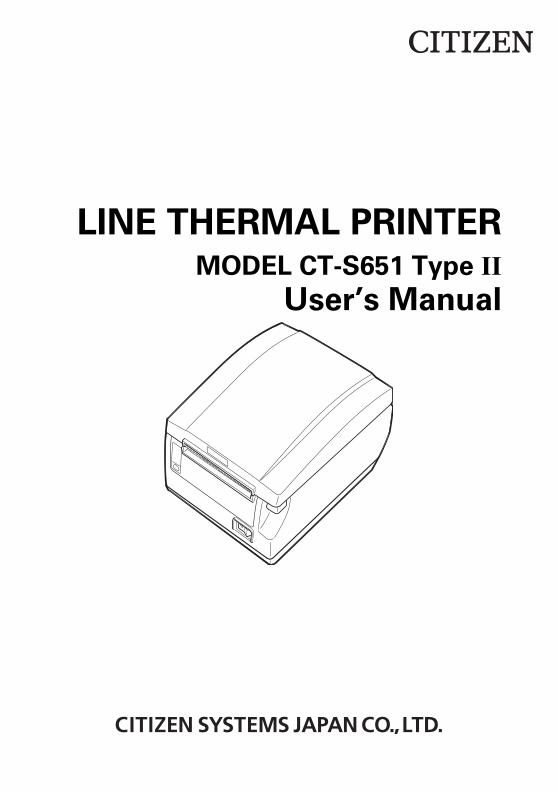
LINE THERMAL PRINTERMODEL CT-S651 Type II
User’s Manual

WEEE MARK
En
Wenn Sie dieses Produkt entsorgen wollen, dann tun Sie dies bitte nicht zusammen mit demHaushaltsmüll. Es gibt im Rahmen der WEEE-Direktive innerhalb der Europäischen Union(Direktive 2002/96/EC) gesetzliche Bestimmungen für separate Sammelsysteme für gebrauchteelektronische Geräte und Produkte.
Ge
Si vous souhaitez vous débarrasser de cet appareil, ne le mettez pas à la poubelle avec vosordures ménagères. Il existe un système de récupération distinct pour les vieux appareilsélectroniques conformément à la législation WEEE sur le recyclage des déchets deséquipements électriques et électroniques (Directive 2002/96/EC) qui est uniquement valabledans les pays de l’Union européenne.Les appareils et les machines électriques et électroniques contiennent souvent des matièresdangereuses pour l’homme et l’environnement si vous les utilisez et vous vous en débarrassezde façon inappropriée.
Fr
Si desea deshacerse de este producto, no lo mezcle con residuos domésticos de caráctergeneral. Existe un sistema de recogida selectiva de aparatos electrónicos usados, segúnestablece la legislación prevista por la Directiva 2002/96/CE sobre residuos de aparatoseléctricos y electrónicos (RAEE), vigente únicamente en la Unión Europea.
Sp
Se desiderate gettare via questo prodotto, non mescolatelo ai rifiuti generici di casa. Esisteun sistema di raccolta separato per i prodotti elettronici usati in conformità alla legislazioneRAEE (Direttiva 2002/96/CE), valida solo all’interno dell’Unione Europea.
It
Deponeer dit product niet bij het gewone huishoudelijk afval wanneer u het wilt verwijderen. Erbestaat ingevolge de WEEE-richtlijn (Richtlijn 2002/96/EG) een speciaal wettelijkvoorgeschreven verzamelsysteem voor gebruikte elektronische producten, welk alleen geldtbinnen de Europese Unie.
Du
Hvis du vil skille dig af med dette produkt, må du ikke smide det ud sammen med dit almindeligehusholdningsaffald. Der findes et separat indsamlingssystem for udtjente elektroniske produkteri overensstemmelse med lovgivningen under WEEE-direktivet (direktiv 2002/96/EC), somkun er gældende i den Europæiske Union.
Da
Se quiser deitar fora este produto, não o misture com o lixo comum. De acordo com a legislaçãoque decorre da Directiva REEE – Resíduos de Equipamentos Eléctricos e Electrónicos (2002/96/CE), existe um sistema de recolha separado para os equipamentos electrónicos fora deuso, em vigor apenas na União Europeia.
Por
Pol Jeżeli zamierzasz pozbyć się tego produktu, nie wyrzucaj go razem ze zwykłymidomowymi odpadkami. Według dyrektywy WEEE (Dyrektywa 2002/96/EC)obowiązującej w Unii Europejskiej dla używanych produktów elektronicznychnależy stosować oddzielne sposoby utylizacji.
If you want to dispose of this product, do not mix it with general household waste. There is a separate collection systems for used electronics products in accordance with legislation under the WEEE Directive (Directive 2002/96/EC) and is effective only within European Union.

Declaration of Conformity
This printer conforms to the following Standards:
The Low Voltage Directive 2006/95/EC, the EMC Directive 2004/108/EC, the RoHSDirective 2011/65/EU, and the WEEE Directive 2002/96/EC.
LVD : EN60950-1
EMC: EN55022 Class AEN61000-3-2EN61000-3-3EN55024
This declaration applies only to the 230-V model.
IMPORTANT: This equipment generates, uses, and can radiate radio frequencyenergy and if not installed and used in accordance with the instruction manual, maycause interference to radio communications. It has been tested and found to complywith the limits for a Class A computing device pursuant to Subpart J of Part 15 of FCCRules, which are designed to provide reasonable protection against such interferencewhen operated in a commercial environment. Operation of this equipment in aresidential area is likely to cause interference, in which case the user at his ownexpense will be required to take whatever measures may be necessary to correct theinterference.CAUTION: Use shielded cable for this equipment.
Sicherheitshinweis Die Steckdose zum Anschluß dieses Druckers muß nahe dem Gerät angebracht undleicht zugänglich sein.
For Uses in Canada This Class A Information Technology Equipment (ITE) complies with Canadian CANICES-3(A)/NMB-3(A).This Information Technology Equipment (ITE) does not exceed the Class A limits forradio noise emissions from digital apparatus set out in the Radio InterferenceRegulations of the Canadian Department of Communications.
Pour L’utilisateurs Canadiens Cet Equipements informatiques (EI) de la classe A est conforme a la norme CANICES-3(A)/NMB-3(A) du Canada. Le present Equipements informatiques (EI) n’emet pas de bruite radio electriquesdepassant les limites applicables aux appareils numeriques de la classe A prescritesdans le Reglement sur le brouillage radioelectrique edicte par le ministere desCommunications du Canada.

GENERAL PRECAUTIONS
Before using this product, be sure to read through this manual. Afterhaving read this manual, keep it in a safe, readily accessible place forfuture reference.
The information contained herein is subject to change without priornotice.
Reproduction or transfer of part or all of this document in any means isprohibited without permission from Citizen Systems.
Note that Citizen Systems is not responsible for any operation resultsregardless of omissions, errors, or misprints in this manual.
Note that Citizen Systems is not responsible for any trouble caused as aresult of using options or consumables that are not specified in thismanual.
Except explained elsewhere in this manual, do not attempt to service,disassemble, or repair this product.
Note that Citizen Systems is not responsible for any damage attributableto incorrect operation/handling or improper operating environments thatare not specified in this manual.
Data is basically for temporary use and not stored for an extended periodof time or permanently. Please note that Citizen Systems is notresponsible for damage or lost profit resulting from the loss of datacaused by accidents, repairs, tests or other occurrences.
If you find omissions, errors, or have questions, please contact yourCitizen Systems dealer.
If you find any pages missing or out of order, contact your Citizen Systemsdealer for a replacement.
"Made for iPod," "Made for iPhone," and "Made for iPad" mean that an electronic accessory has been designed to connect specifically to iPod, iPhone, or iPad, respectively, and has been certified by the developer to meet Apple performance standards. Apple is not responsible for the operation of this device or its compliance with safety and regulatory standards. Please note that the use of this accessory with iPod, iPhone or iPad may affect wireless performance.
iPad, iPhone and iPod touch are trademarks of Apple Inc., registered in the U.S. and othercountries. iPad Air and iPad mini are trademarks of Apple Inc.
EPSON and ESC/POS are registered trademarks of Seiko Epson Corporation. QR Code is a registered trademark of DENSO WAVE INCORPORATED. Ethernet is a registered trademark of Fuji Xerox Corporation. Bluetooth® is a registered trademark of Bluetooth-SIG Inc. CITIZEN is a registered trademark of Citizen Watch Co., Ltd. Japan All other trademarks are the property of their respective owners. Citizen Systems use these trademarks in accordance with the license of relevant owners.
Copyright ©2016 by CITIZEN SYSTEMS JAPAN CO., LTD.
— 1 —
Before using this product for the first time, carefully read these SAFETY PRECAUTIONS.Improper handling may result in accidents (fire, electric shock or injury).In order to prevent injury to operators, third parties, or damage to property, specialwarning symbols are used in the User’s Manual to indicate important items to be strictlyobserved.
After having read this Manual, keep it in a safe, readily accessible place for futurereference.
Some of the descriptions contained in this manual may not be relevant to some printermodels.
The following describes the degree of hazard and damage that could occur if the printeris improperly operated by ignoring the instructions indicated by the warning symbols.
SAFETY PRECAUTIONS ...WHICH SHOULD BE STRICTLY OBSERVED
WARNINGNeglecting precautions indicated by this symbol may result in fatal or serious injury.
CAUTIONNeglecting precautions indicated by this symbol may result in injury or damage toproperty.
This symbol is used to alert your attention to important items.
This symbol is used to alert you to the danger of electric shock or electrostaticdamage.
This symbol denotes a request to unplug the printer from the wall outlet.
This symbol is used to indicate that the power supply must be grounded.
This symbol is used to indicate useful information, such as procedures,instructions or the like.
This symbol is used to indicate prohibited actions.
— 2 —
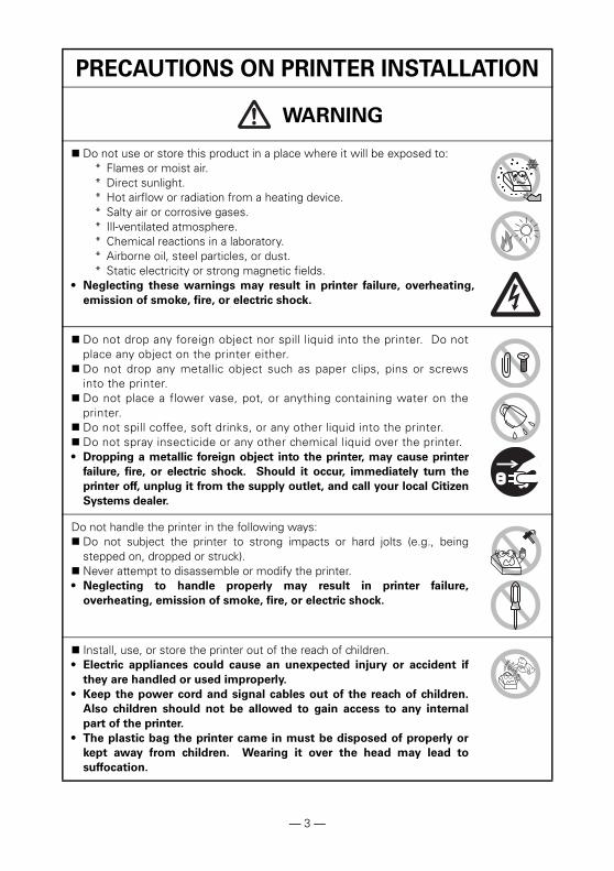
PRECAUTIONS ON PRINTER INSTALLATION
WARNING
Do not use or store this product in a place where it will be exposed to:* Flames or moist air.* Direct sunlight.* Hot airflow or radiation from a heating device.* Salty air or corrosive gases.* Ill-ventilated atmosphere.* Chemical reactions in a laboratory.* Airborne oil, steel particles, or dust.* Static electricity or strong magnetic fields.
• Neglecting these warnings may result in printer failure, overheating,
emission of smoke, fire, or electric shock.
Do not drop any foreign object nor spill liquid into the printer. Do notplace any object on the printer either.
Do not drop any metallic object such as paper clips, pins or screwsinto the printer.
Do not place a flower vase, pot, or anything containing water on theprinter.
Do not spill coffee, soft drinks, or any other liquid into the printer. Do not spray insecticide or any other chemical liquid over the printer.• Dropping a metallic foreign object into the printer, may cause printer
failure, fire, or electric shock. Should it occur, immediately turn the
printer off, unplug it from the supply outlet, and call your local Citizen
Systems dealer.
Do not handle the printer in the following ways: Do not subject the printer to strong impacts or hard jolts (e.g., being
stepped on, dropped or struck). Never attempt to disassemble or modify the printer.• Neglecting to handle properly may result in printer failure,
overheating, emission of smoke, fire, or electric shock.
Install, use, or store the printer out of the reach of children.• Electric appliances could cause an unexpected injury or accident if
they are handled or used improperly.
• Keep the power cord and signal cables out of the reach of children.
Also children should not be allowed to gain access to any internal
part of the printer.
• The plastic bag the printer came in must be disposed of properly or
kept away from children. Wearing it over the head may lead to
suffocation.
— 3 —
CAUTION
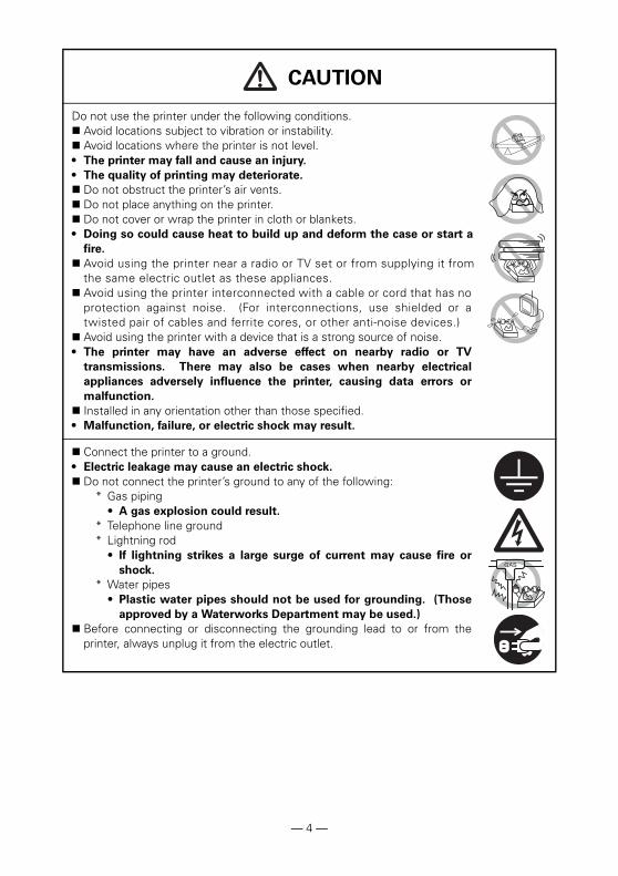
Do not use the printer under the following conditions. Avoid locations subject to vibration or instability. Avoid locations where the printer is not level.• The printer may fall and cause an injury.
• The quality of printing may deteriorate.
Do not obstruct the printer’s air vents. Do not place anything on the printer. Do not cover or wrap the printer in cloth or blankets.• Doing so could cause heat to build up and deform the case or start a
fire.
Avoid using the printer near a radio or TV set or from supplying it fromthe same electric outlet as these appliances.
Avoid using the printer interconnected with a cable or cord that has noprotection against noise. (For interconnections, use shielded or atwisted pair of cables and ferrite cores, or other anti-noise devices.)
Avoid using the printer with a device that is a strong source of noise.• The printer may have an adverse effect on nearby radio or TV
transmissions. There may also be cases when nearby electrical
appliances adversely influence the printer, causing data errors or
malfunction.
Installed in any orientation other than those specified.• Malfunction, failure, or electric shock may result.
Connect the printer to a ground.• Electric leakage may cause an electric shock.
Do not connect the printer’s ground to any of the following:* Gas piping
• A gas explosion could result. * Telephone line ground* Lightning rod
• If lightning strikes a large surge of current may cause fire or
shock. * Water pipes
• Plastic water pipes should not be used for grounding. (Those
approved by a Waterworks Department may be used.) Before connecting or disconnecting the grounding lead to or from the
printer, always unplug it from the electric outlet.
— 4 —
PRECAUTIONS IN HANDLING THE PRINTER
WARNING
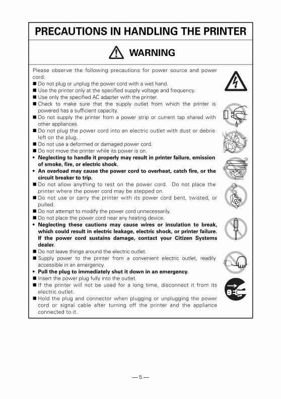
Please observe the following precautions for power source and powercord: Do not plug or unplug the power cord with a wet hand. Use the printer only at the specified supply voltage and frequency. Use only the specified AC adapter with the printer. Check to make sure that the supply outlet from which the printer is
powered has a sufficient capacity. Do not supply the printer from a power strip or current tap shared with
other appliances. Do not plug the power cord into an electric outlet with dust or debris
left on the plug. Do not use a deformed or damaged power cord. Do not move the printer while its power is on.• Neglecting to handle it properly may result in printer failure, emission
of smoke, fire, or electric shock.
• An overload may cause the power cord to overheat, catch fire, or the
circuit breaker to trip.
Do not allow anything to rest on the power cord. Do not place theprinter where the power cord may be stepped on.
Do not use or carry the printer with its power cord bent, twisted, orpulled.
Do not attempt to modify the power cord unnecessarily. Do not place the power cord near any heating device.• Neglecting these cautions may cause wires or insulation to break,
which could result in electric leakage, electric shock, or printer failure.
If the power cord sustains damage, contact your Citizen Systems
dealer.
Do not leave things around the electric outlet. Supply power to the printer from a convenient electric outlet, readily
accessible in an emergency.• Pull the plug to immediately shut it down in an emergency.
Insert the power plug fully into the outlet. If the printer will not be used for a long time, disconnect it from its
electric outlet. Hold the plug and connector when plugging or unplugging the power
cord or signal cable after turning off the printer and the applianceconnected to it.
— 5 —
CAUTION
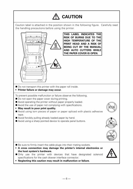
Caution label is attached in the position shown in the following figure. Carefully readthe handling precautions before using the printer.
Do not transport this printer with the paper roll inside.• Printer failure or damage may occur.
To prevent possible malfunction or failure observe the following. Do not open the paper cover during printing. Avoid operating the printer without paper properly loaded. Avoid the use of paper not complying with specifications.• May result in poor print quality.
Avoid using torn pieces of paper or paper spliced with plastic adhesivetape.
Avoid forcibly pulling already loaded paper by hand. Avoid using a sharp pointed device to operate panel buttons.
Be sure to firmly insert the cable plugs into their mating sockets.• A cross connection may damage the printer’s internal electronics or
the host system’s hardware.
Only use the printer with devices that have designated solenoidspecifications for the cash drawer interface connector.
• Neglecting this caution may result in malfunction or failure.
THIS LABEL INDICATES THE
RISK OF BURNS DUE TO THE
HIGH TEMPERATURE OF THE
PRINT HEAD AND A RISK OF
BEING CUT BY THE MANUAL
AND AUTO CUTTERS WHILE
THE PAPER COVER IS OPEN.
— 6 —
CAUTION
To prevent injury and printer failures from worsening, observe the following:While the paper cover is open, be careful to not touch the manual
cutter that is in the paper eject slot. Do not touch the printing surface of the thermal head. Do not touch any of the moving parts (e.g., paper cutter, gears, active
electric parts) while the printer is working. In case of trouble do not attempt to repair the printer. Ask Citizen
Systems service for repair. Be careful that the covers do not pinch your hands or fingers. Be careful of the sharp edges on the printer. Do not allow them to
injure you or damage property.• May result in electric shock, burn, or injury.
DAILY MAINTENANCE
Observe the following precautions for daily maintenance.When cleaning the printer, always turn it off and unplug it from the
electric outlet. Use a soft, dry cloth for cleaning the surface of the printer case.
For severe stains, use a soft cloth slightly dampened with water.Never use organic cleaning solvent such as alcohol, paint thinner,trichloroethylene, benzene, or ketone. Never use a chemicallyprocessed cleaning cloth.
To remove paper dust, use a soft brush.
CAUTION• The thermal head is at a dangerously high temperature immediately after printing.
Allow it to cool off before starting maintenance work.
If the printer emits smoke, an odd smell, or unusual noise while
printing, immediately abort the current print session and
unplug the printer from the electric outlet.
Visit the following site to get documentation, drivers, utilities, and otherinformation.http://www.citizen-systems.co.jp/english/support/index.html
— 7 —

— 8 —
1. GENERAL OUTLINE.................................................................... 91.1 Features........................................................................................... 91.2 Unpacking...................................................................................... 101.3 Model Classification ...................................................................... 101.4 Basic Specifications....................................................................... 11
2. EXPLANATION OF PRINTER PARTS .......................................122.1 Printer Appearance ........................................................................ 122.2 Inside the Paper Cover .................................................................. 152.3 Other Built-in Functions................................................................. 16
3. SETUP........................................................................................183.1 Connecting the AC Power Cord .................................................... 183.2 Connecting Interface Cables ......................................................... 193.3 Bluetooth Interface Board ............................................................. 213.4 Ethernet (LAN) Interface Board ..................................................... 233.5 Wireless LAN Interface Board ....................................................... 263.6 Connecting the Cash Drawer ........................................................ 303.7 Precautions for Installing the Printer ............................................. 323.8 Partition for Paper Roll ................................................................... 333.9 Setting the DIP Switch on the Serial Interface Board.................... 343.10 Adjusting the Paper Near-end Sensor.......................................... 353.11 Loading Paper .............................................................................. 363.12 Attaching the Power Switch Cover.............................................. 373.13 Attaching the Interface Cover...................................................... 383.14 Removing the Interface Cover..................................................... 383.15 Installing a Driver ......................................................................... 393.16 Precautions for Creating Applications and Practical
Operations ................................................................................... 39
4. MAINTENANCE AND TROUBLESHOOTING...........................404.1 Periodic Cleaning ........................................................................... 404.2 Clearing a Cutter Lock (1) .............................................................. 414.3 Clearing a Cutter Lock (2) .............................................................. 414.4 Self test ......................................................................................... 434.5 Hexadecimal Dump Printing .......................................................... 444.6 Error Messages ............................................................................. 454.7 Paper Jams.................................................................................... 474.8 Serial Interface Operation Precautions .......................................... 47
5. OTHER .......................................................................................485.1 External Views and Dimensions .................................................... 485.2 Printing Paper ................................................................................ 495.3 Manual Setting of Memory Switches............................................ 50
THE TABLE OF CONTENTS
The CT-S651II line thermal printer series is designed for use with a broad arrayof terminal equipment including data, POS, and kitchen terminals.These printers have extensive features so they can be used in a wide range ofapplications.
High-speed (220 mm/s) printing Design so compact it can be installed anywhere (maximum 3-inch (83-mm)
paper roll size)Waterproof construction prevents water from entering through the top Paper is output from the front so the printer can be placed in restricted spaces Choose from two models with either 3-inch (83/80 mm) or 2-inch (60/58 mm)
wide paper rolls Built-in power supply or AC adapter types available Printer status and errors indicated by LED and a buzzer Equipped with a fast and quiet cutter Easy to clear cutter jams Interchangeable interface Built-in cash drawer kick-out interface USB power supply OFFMemory switches make customization possible Store user-defined characters and logos on user memory Barcode and 2D barcode printing supported 16 level greyscale and clear printing Paper saving functions Japanese Kanji, Chinese(simplified and traditional) and Hangul supported Driver and utility software included Apple MFi certified Bluetooth communication support (Bluetooth model)
1. GENERAL OUTLINE
1.1 Features
— 9 —
Make sure the following items are included with your printer.
Model numbers indicate printer features according to the following system.
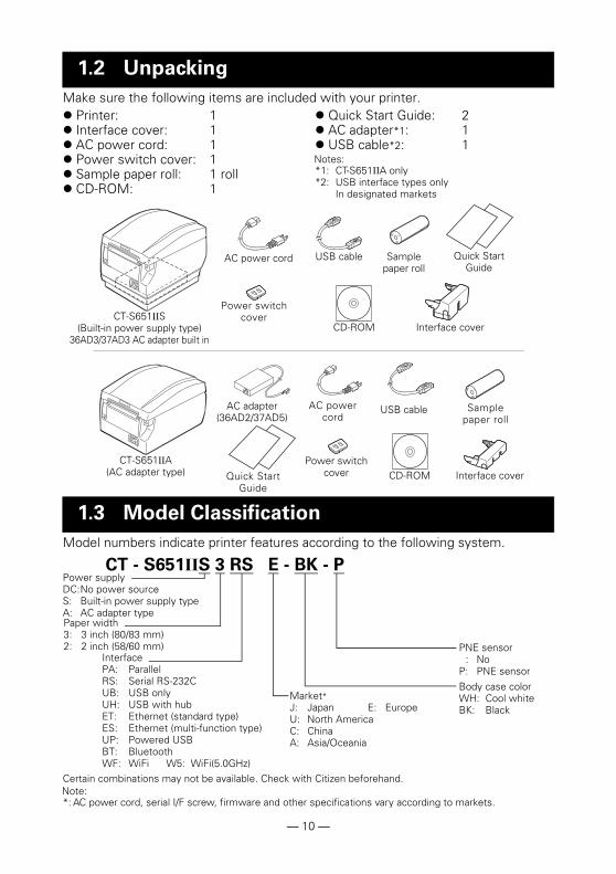
Certain combinations may not be available. Check with Citizen beforehand.Note:*: AC power cord, serial I/F screw, firmware and other specifications vary according to markets.
1.2 Unpacking
Printer: 1 Interface cover: 1 AC power cord: 1 Power switch cover: 1 Sample paper roll: 1 roll CD-ROM: 1
Quick Start Guide: 2 AC adapter*1: 1 USB cable*2: 1Notes:*1: CT-S651IIA only*2: USB interface types only
In designated markets
1.3 Model Classification
CT-S651IIS(Built-in power supply type)
36AD3/37AD3 AC adapter built in
AC power cord
Power switch cover
USB cable Quick Start Guide
CT-S651IIA(AC adapter type)
AC adapter(36AD2/37AD5)
AC power cord
Quick Start Guide
CD-ROM
USB cable Sample paper roll
Interface cover
Interface coverCD-ROM
Sample paper roll
Power switch cover
CT - S651IIS 3 RS E - BK - PPower supplyDC:No power sourceS: Built-in power supply typeA: AC adapter type
InterfacePA: ParallelRS: Serial RS-232CUB: USB onlyUH: USB with hubET: Ethernet (standard type)ES: Ethernet (multi-function type)UP: Powered USBBT: BluetoothWF: WiFi W5: WiFi(5.0GHz)
Market*J: Japan E: EuropeU: North AmericaC: ChinaA: Asia/Oceania
Paper width3: 3 inch (80/83 mm)2: 2 inch (58/60 mm)
Body case colorWH: Cool whiteBK: Black
PNE sensor: No
P: PNE sensor
— 10 —
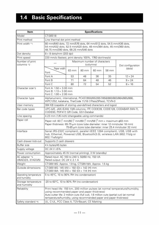
1.4 Basic Specifications
Item Specifications
Model CT-S651II
Print method Line thermal dot print methodPrint width *1 80 mm/640 dots, 72 mm/576 dots, 64 mm/512 dots, 54.5 mm/436 dots,
54 mm/432 dots, 52.5 mm/420 dots, 48 mm/384 dots, 45 mm/360 dots, 48.75 mm/390 dots, 68.25 mm/546 dots
Dot density 8 8 dots/mm (203 dpi)Print speed 220 mm/s (fastest, print density 100%, 1760 dot-lines/s)Number of print columns *2
— Maximum number of characters (columns) Dot configuration
(dots)Paper width83 mm 80 mm 60 mm 58 mm
FontFont A 53 48 36 35 1224Font B 71 64 48 46 9 24Font C 80 72 54 52 8 16
Character size*3 Font A: 1.50 3.00 mmFont B: 1.13 3.00 mmFont C: 1.00 2.00 mm
Character type Alphanumeric, international, PC437/850/852/857/858/860/863/864/865/866, WPC1252, katakana, ThaiCode 11/18 (1Pass/3Pass), TCVN-3
User memory 384 KB (capable of storing user-defined characters and logos)Bar code types UPC-A/E, JAN (EAN) 13/8 columns, ITF, CODE39, CODE128, CODABAR (NW-7),
CODE93, PDF417, QR Code, GS1-DatabarLine spacing 4.23 mm (1/6 inch) (changeable using commands)Paper roll Paper roll: 83 mm/80 mm/60 mm/58 mm maximum 83 mm
Paper thickness: 65-75 m (core tube diameter: inner 12 mm/outer 18 mm) 75-85 m (core tube diameter: inner 25.4 mm/outer 32 mm)
Interface Serial (RS-232C compliant), parallel (IEEE 1284 compliant), USB, USB with hub, Ethernet, Powered USB, Bluetooth(3.0), wireless LAN (802.11b/g or 802.11a/b/g/n)
Cash drawer kick-out Supports 2 cash drawersBuffer size 4 k bytes/45 bytesSupply voltage DC 24 V 5%Power consumption Approximately 45 W (normal printing), 3 W (standby)AC adapter *4(36AD2/3, 37AD3/5)
Rated input: AC 100 to 240 V, 50/60 Hz, 150 VARated output: DC 24 V, 2.1 A
Weight CT-S651IIS: Approx. 1.9 kg, CT-S651IIA: Approx. 1.5 kgOutside dimensions CT-S651IIS: 145 (W) 192 (D) 142 (H) mm
CT-S651IIA: 145 (W) 192 (D) 114 (H) mmOperating temperature and humidity
5 to 45°C, 10 to 90% RH (no condensation)
Storage temperature and humidity
-20 to 60°C, 10 to 90% RH (no condensation)
Reliability Print head life: 150 km, 200 million pulses (at normal temperature/humidity, using recommended paper and paper thickness)Auto cutter life: 2 million cuts (full cut), 1.6 million cuts (partial cut) (at normal temperature/humidity, using recommended paper and paper thickness)
Safety standard *5 UL, C-UL, FCC Class A, TÜV-Bauart, CE Marking
+0-1
+0-1
+0-1
+0-1
— 11 —
Notes:*1: When paper width is 83, 80, 60, or 58 mm.*2: The number of printable columns is selected using a memory switch.
The numbers of columns noted in this table refer to typical models. The number of columnsvaries depending on specifications.
*3: Characters appear small because the dimensions include a blank area surrounding each character.*4: The 36AD2/37AD5 is the AC adapter packaged as an accessory with the CT-S651IIA.
The 36AD3/37AD3 is the AC adapter built in to the CT-S651IIS.*5: Compliant if the Citizen Systems AC adapter (36AD2/3, 37AD3/5) is used.
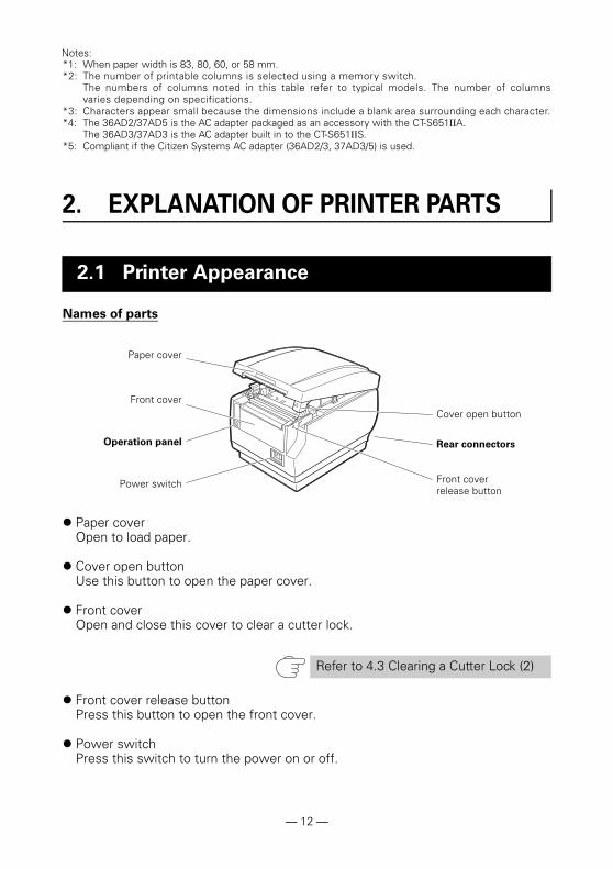
Names of parts
Paper coverOpen to load paper.
Cover open buttonUse this button to open the paper cover.
Front coverOpen and close this cover to clear a cutter lock.
Front cover release buttonPress this button to open the front cover.
Power switchPress this switch to turn the power on or off.
2. EXPLANATION OF PRINTER PARTS
2.1 Printer Appearance
Refer to 4.3 Clearing a Cutter Lock (2)
Paper cover
Cover open button
Power switch
Front cover
Rear connectorsOperation panel
Front cover release button
— 12 —
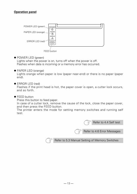
Operation panel
POWER LED (green)Lights when the power is on, turns off when the power is off.Flashes when data is incoming or a memory error has occurred.
PAPER LED (orange)Lights orange when paper is low (paper near-end) or there is no paper (paperend).
ERROR LED (red)Flashes if the print head is hot, the paper cover is open, a cutter lock occurs,and so forth.
FEED buttonPress this button to feed paper.In case of a cutter lock, remove the cause of the lock, close the paper cover,and then press the FEED button.The printer enters the mode for setting memory switches and running selftest.
Refer to 4.4 Self test
Refer to 4.6 Error Messages
Refer to 5.3 Manual Setting of Memory Switches
POWER LED (green)
PAPER LED (orange)
ERROR LED (red)
FEED button
— 13 —
Rear connectors
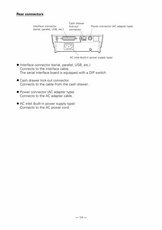
Interface connector (serial, parallel, USB, etc.)Connects to the interface cable.The serial interface board is equipped with a DIP switch.
Cash drawer kick-out connectorConnects to the cable from the cash drawer.
Power connector (AC adapter type)Connects to the AC adapter cable.
AC inlet (built-in power supply type)Connects to the AC power cord.
Interface connector (serial, parallel, USB, etc.)
Cash drawer kick-out connector
Power connector (AC adapter type)
AC inlet (built-in power supply type)
— 14 —

PlatenFeeds the paper.Do not remove the platen except to do maintenance.
Paper near-end sensor (PNE sensor)Detects when the paper is near the end of the roll. Adjust the position of thesensor to determine when it detects the end of the paper is near.
Button to change paper near-end sensorChange the position of the paper near-end sensor to match the paper beingused.
Manual cutterFor cutting the paper manually when printing is finished.
Auto cutterAutomatically cuts the paper when printing is finished.
Print head (thermal)Prints characters and graphic data on paper (paper rolls).
2.2 Inside the Paper Cover
Refer to 3.10 Adjusting the Paper Near-end Sensor
Refer to 5.3 Manual Setting of Memory Switches
Platen
Button to change paper near-end sensor
Print head (thermal)
Auto cutter
Paper near-end sensor (PNE sensor)
Paper-end sensor(PE sensor)
Manual cutter
— 15 —
Paper end sensor (PE sensor)Detects when there is no paper. Printing stops when this sensor detects thereis no paper.
BuzzerBuzzes when errors occur or when operations or command operations areperformed.
User memoryYou can save user-defined logo and character data in this memory. Dataremains stored in this memory even if the printer is turned off. Forinformation on how to save data, refer to the Command Reference.
Memory switchSetting of various kinds of functions can be stored in memory. Settingsremain stored in the memory even if the printer is turned off.
USB power supply OFF (When memory switch MSW6-3 is set to ON)When the printer is connected to a PC by USB, turning off PC power or terminatingthe USB connection causes printer USB power to turn off three seconds later.This mode is canceled when the PC is turned back on or when a USB connectionis established.
Paper saving functionsMemory switches MSW8-3 through MSW8-5 can be used to configure thesettings below, which save paper.•Top margin suppression
The printer back feeds the paper before printing which reduces the blank spaceat the top edge of the paper.The back feed amount can be specified.
•Line gap reduceAutomatically compresses the linefeed amount between lines. The compressionratio can be specified.
•Text compression vertical/horizontalMakes the print size smaller.The compression amount is specified by a combination of vertical and horizontalcompression ratios.
2.3 Other Built-in Functions
Refer to 4.6 Error Messages
CAUTION
The POWER LED is unlit when USB power supply is OFF, and the power OFF state cannotbe identified.
Pressing POWER while USB power is off does not turn on power immediately. After awhile, USB power supply OFF is canceled and pressing POWER turns on power normally.
— 16 —
Auto side shift (MSW8-6)This function dissipates heat load during frequent heat generation by a verticalruled line or other specific head heating element.If no data is received within 15 seconds after each cut or print, the print position isautomatically slid N* dots to the right. The original print position is returned to atthe next slide timing.* N is the MSW8-6 setting value.
CAUTION
Before configuring the top margin suppression setting, first remove any partially cut paperfrom the printer. Failure to do so can cause the cut paper to be torn off by the next printoperation, which can cause printer trouble.
Note the following precautions when using text compression.• Compressed text is more difficult to read than the original text.
• Horizontally compressing text also makes the print range smaller, so the number of
print lines does not change. Pay close attention to the print range when using
narrow paper.
• Do not use compressed text when printing a bar code. Doing so may make the bar
code unreadable.
If the right margin is too narrow, this may result in some print characters being cut off. Thisfunction is disabled under initial settings. To enable this function, use MSW8-6 to specify anappropriate value for the maximum slide amount.
— 17 —
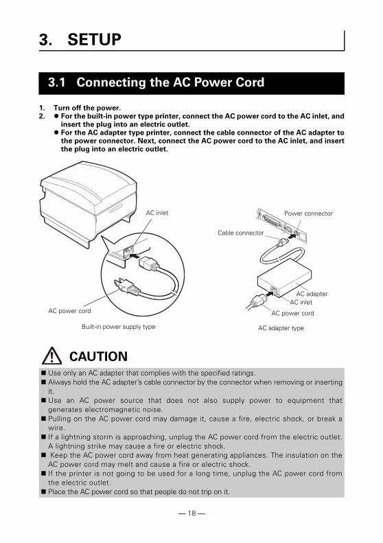
1. Turn off the power.2. For the built-in power type printer, connect the AC power cord to the AC inlet, and
insert the plug into an electric outlet. For the AC adapter type printer, connect the cable connector of the AC adapter to
the power connector. Next, connect the AC power cord to the AC inlet, and insertthe plug into an electric outlet.
3. SETUP
3.1 Connecting the AC Power Cord
CAUTION Use only an AC adapter that complies with the specified ratings. Always hold the AC adapter’s cable connector by the connector when removing or inserting
it. Use an AC power source that does not also supply power to equipment that
generates electromagnetic noise. Pulling on the AC power cord may damage it, cause a fire, electric shock, or break a
wire. If a lightning storm is approaching, unplug the AC power cord from the electric outlet.
A lightning strike may cause a fire or electric shock. Keep the AC power cord away from heat generating appliances. The insulation on the
AC power cord may melt and cause a fire or electric shock. If the printer is not going to be used for a long time, unplug the AC power cord from
the electric outlet. Place the AC power cord so that people do not trip on it.
AC inlet
AC power cord
Power connector
AC inletAC adapter
AC power cord
Cable connector
Built-in power supply type AC adapter type
— 18 —
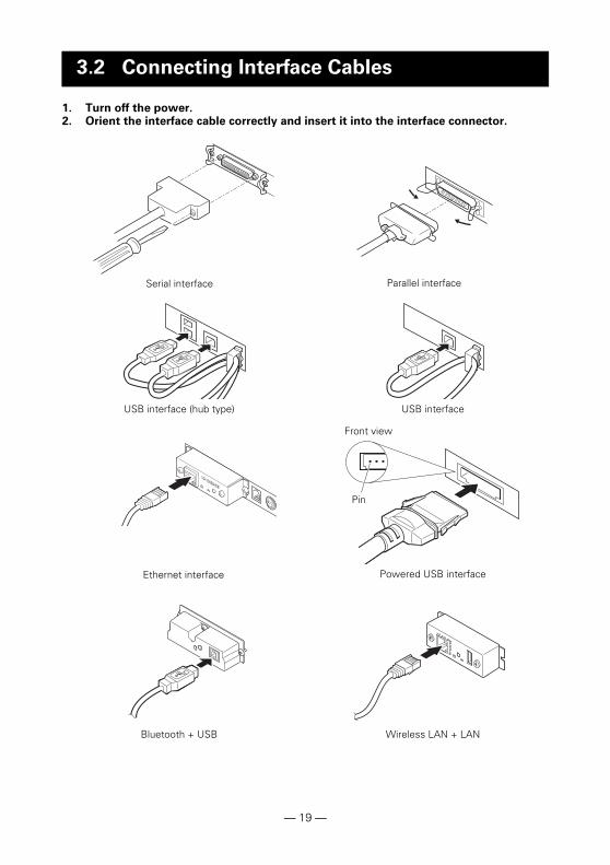
1. Turn off the power.2. Orient the interface cable correctly and insert it into the interface connector.
3.2 Connecting Interface Cables
10/100BASE
Serial interface Parallel interface
USB interface (hub type) USB interface
Ethernet interface Powered USB interface
Front view
Pin
Bluetooth + USB Wireless LAN + LAN
— 19 —
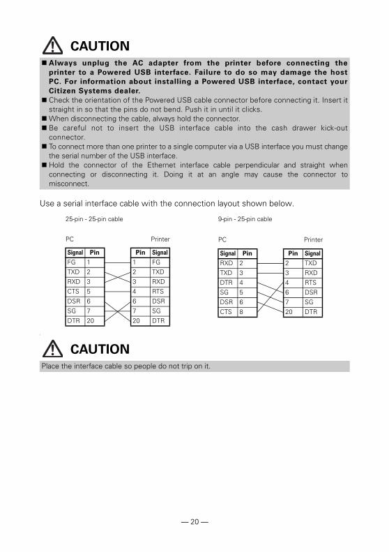
Use a serial interface cable with the connection layout shown below.
]
CAUTION
Always unplug the AC adapter from the printer before connecting the
printer to a Powered USB interface. Failure to do so may damage the host
PC. For information about installing a Powered USB interface, contact your
Citizen Systems dealer.
Check the orientation of the Powered USB cable connector before connecting it. Insert itstraight in so that the pins do not bend. Push it in until it clicks.
When disconnecting the cable, always hold the connector. Be careful not to insert the USB interface cable into the cash drawer kick-out
connector. To connect more than one printer to a single computer via a USB interface you must change
the serial number of the USB interface. Hold the connector of the Ethernet interface cable perpendicular and straight when
connecting or disconnecting it. Doing it at an angle may cause the connector tomisconnect.
CAUTION
Place the interface cable so people do not trip on it.
25-pin - 25-pin cable
PC Printer
Signal Pin Pin Signal
RXD 2 2 TXD
TXD 3 3 RXD
DTR 4 4 RTS
SG 5 6 DSR
DSR 6 7 SG
CTS 8 20 DTR
9-pin - 25-pin cable
PC Printer
Signal Pin Pin Signal
FG 1 1 FG
TXD 2 2 TXD
RXD 3 3 RXD
CTS 5 4 RTS
DSR 6 6 DSR
SG 7 7 SG
DTR 20 20 DTR
— 20 —

Bluetooth status LED
The LED on the Bluetooth interface board on the rear of the printer indicates thestatus below.
Pairing operation
You need to perform the operations below the first time you establish a Bluetoothconnection for Bluetooth data communication.
A: Detect Bluetooth devices B: Configure pairing settings
A: Detecting Bluetooth devices
Confirm that Bluetooth is enabled on the host PC before searching for Bluetoothdevices.This product will show up as "CT-S651II_XX"(XX is last 2 digits of unique BD address.)when it is detected.Select this product from among the detected devices.Note: You can search for devices and change the names.When memory switch MSW13-5 is set to "No Response" nothing is displayed bydevice detection.You can temporarily switch this setting to device detection (detect mode) by pushingthe switch on the Bluetooth interface board. Detect mode is exited when theconnection between the host PC is terminated.
3.3 Bluetooth Interface Board
Status Description LED Status
Detection standby (Discoverable)
Standing by for detection and connection
Connection standby (Connectable)
Standing by for connection
iOS connection Data session unopened
Communicating iOS: data session openedOther OS: connection established and communication in progress
Error Error or settings being configured
Unlit
Status LED Switch
— 21 —
B: Configuring pairing settings
Normally, selecting the printer during device detection will transition directly topairing settings.
The operation required to configure pairing settings depends on whether SSP (securesimple pairing) is enabled on the host PC.If SSP is enabled on the host PC, pairing can be achieved without additionaloperations.If SSP is disabled on the host PC, you will be prompted to input a passkey.Input the passkey as described below. Passkey Last four digits of the address on the self test printout (Letters A through F are uppercase)
Example: If the address is 01:23:45:67:89:ABthe passkey is 89AB.
If you delete paring information from the host PC without deleting the correspondingpairing information on the printer, the printer may not show up if you detect devicesagain with the host PC.To delete printer pairing information, hold down the switch on the Bluetooth interfaceboard for two seconds or more.Deleting pairing information on the printer will put the printer into discovery mode.
Auto reconnection
With iOS device Bluetooth communication, a connection between a paired iOSdevice and the printer is not automatically restored after it is lost. However, whenauto reconnection is enabled, the printer tries to reconnect with an iOS device aftertwo-way communication is enabled and automatically restores the connection.
Enabling and disabling auto reconnection
To change the setting of this feature, the following method is provided.Press the FEED button 3 times during self test -> Auto reconnect = ValidPress the FEED button 4 times during self test -> Auto reconnect = Invalid
At the end of self printing, new setting will be printed as Auto reconnect [Valid] or[Invalid].
CAUTION
Some host PC configurations and models may not transition directly to pairing settings afterthe printer is selected during device detection.
CAUTION
This function is enabled when shipped from the factory. (MSW13-6)
Auto reconnection can take some time to connect when the host is not an iOS device.
Even if the partner device is an iOS device, the conditions below can interfere with the autoreconnection function.
• When you want Bluetooth communication to cut off after printing is complete
• When there are multiple iOS devices printing on the same printer
Under such conditions, disable auto reconnection.
Refer to 4.4 Self test
— 22 —
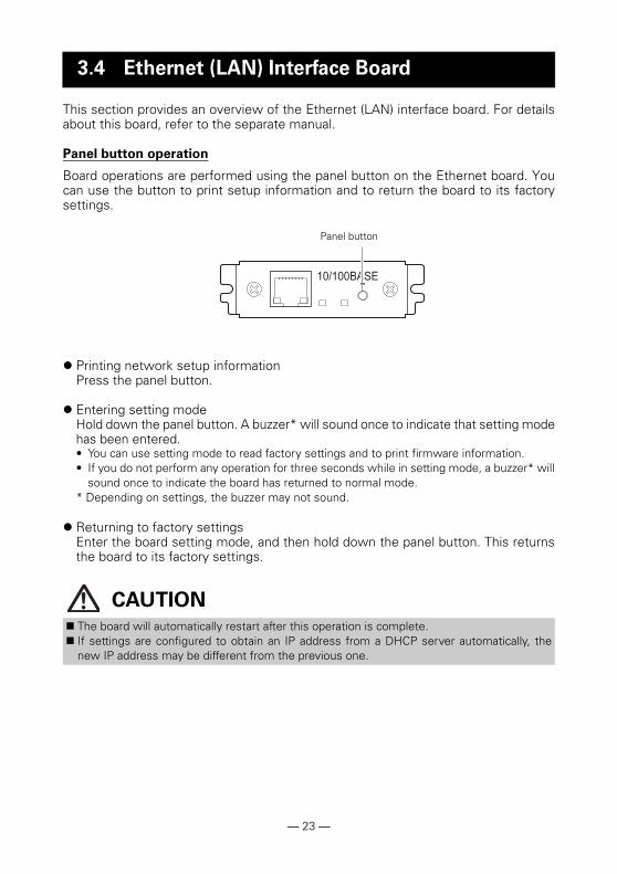
This section provides an overview of the Ethernet (LAN) interface board. For detailsabout this board, refer to the separate manual.
Panel button operation
Board operations are performed using the panel button on the Ethernet board. Youcan use the button to print setup information and to return the board to its factorysettings.
Printing network setup informationPress the panel button.
Entering setting modeHold down the panel button. A buzzer* will sound once to indicate that setting modehas been entered.• You can use setting mode to read factory settings and to print firmware information.• If you do not perform any operation for three seconds while in setting mode, a buzzer* will
sound once to indicate the board has returned to normal mode.* Depending on settings, the buzzer may not sound.
Returning to factory settingsEnter the board setting mode, and then hold down the panel button. This returnsthe board to its factory settings.
3.4 Ethernet (LAN) Interface Board
CAUTION
The board will automatically restart after this operation is complete. If settings are configured to obtain an IP address from a DHCP server automatically, the
new IP address may be different from the previous one.
10/100BASE
Panel button
— 23 —
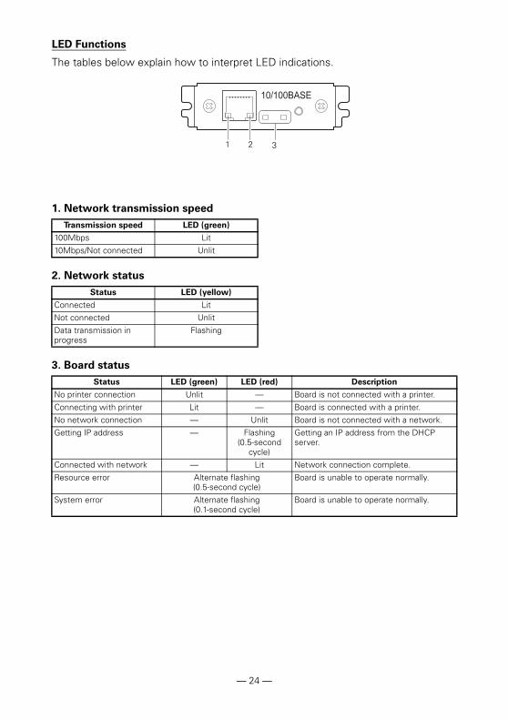
LED Functions
The tables below explain how to interpret LED indications.
1. Network transmission speed
2. Network status
3. Board status
Transmission speed LED (green)
100Mbps Lit
10Mbps/Not connected Unlit
Status LED (yellow)
Connected Lit
Not connected Unlit
Data transmission in progress
Flashing
Status LED (green) LED (red) Description
No printer connection Unlit — Board is not connected with a printer.
Connecting with printer Lit — Board is connected with a printer.
No network connection — Unlit Board is not connected with a network.
Getting IP address — Flashing(0.5-second
cycle)
Getting an IP address from the DHCP server.
Connected with network — Lit Network connection complete.
Resource error Alternate flashing (0.5-second cycle)
Board is unable to operate normally.
System error Alternate flashing (0.1-second cycle)
Board is unable to operate normally.
10/100BASE
1 2 3
— 24 —
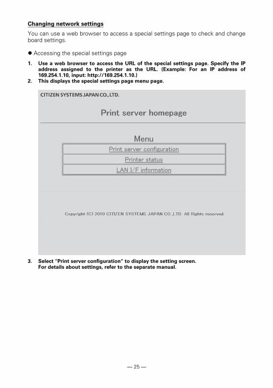
Changing network settings
You can use a web browser to access a special settings page to check and changeboard settings.
Accessing the special settings page
1. Use a web browser to access the URL of the special settings page. Specify the IPaddress assigned to the printer as the URL. (Example: For an IP address of169.254.1.10, input: http://169.254.1.10.)
2. This displays the special settings page menu page.
3. Select "Print server configuration" to display the setting screen.For details about settings, refer to the separate manual.
— 25 —
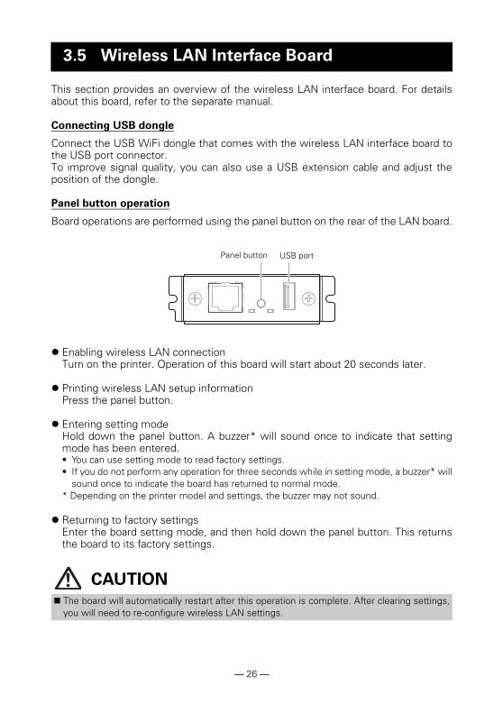
This section provides an overview of the wireless LAN interface board. For detailsabout this board, refer to the separate manual.
Connecting USB dongle
Connect the USB WiFi dongle that comes with the wireless LAN interface board tothe USB port connector.To improve signal quality, you can also use a USB extension cable and adjust theposition of the dongle.
Panel button operation
Board operations are performed using the panel button on the rear of the LAN board.
Enabling wireless LAN connectionTurn on the printer. Operation of this board will start about 20 seconds later.
Printing wireless LAN setup informationPress the panel button.
Entering setting modeHold down the panel button. A buzzer* will sound once to indicate that settingmode has been entered. • You can use setting mode to read factory settings.• If you do not perform any operation for three seconds while in setting mode, a buzzer* will
sound once to indicate the board has returned to normal mode.* Depending on the printer model and settings, the buzzer may not sound.
Returning to factory settingsEnter the board setting mode, and then hold down the panel button. This returnsthe board to its factory settings.
3.5 Wireless LAN Interface Board
CAUTION
The board will automatically restart after this operation is complete. After clearing settings,you will need to re-configure wireless LAN settings.
Panel button USB port
— 26 —
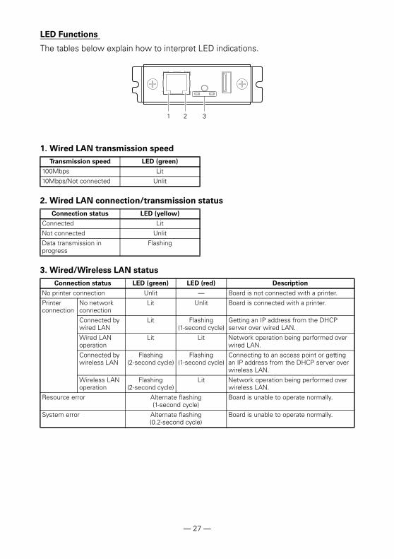
LED Functions
The tables below explain how to interpret LED indications.
1. Wired LAN transmission speed
2. Wired LAN connection/transmission status
3. Wired/Wireless LAN status
Transmission speed LED (green)
100Mbps Lit
10Mbps/Not connected Unlit
Connection status LED (yellow)
Connected Lit
Not connected Unlit
Data transmission in progress
Flashing
Connection status LED (green) LED (red) Description
No printer connection Unlit — Board is not connected with a printer.
Printer connection
No network connection
Lit Unlit Board is connected with a printer.
Connected by wired LAN
Lit Flashing (1-second cycle)
Getting an IP address from the DHCP server over wired LAN.
Wired LAN operation
Lit Lit Network operation being performed over wired LAN.
Connected by wireless LAN
Flashing (2-second cycle)
Flashing (1-second cycle)
Connecting to an access point or getting an IP address from the DHCP server over wireless LAN.
Wireless LAN operation
Flashing (2-second cycle)
Lit Network operation being performed over wireless LAN.
Resource error Alternate flashing (1-second cycle)
Board is unable to operate normally.
System error Alternate flashing (0.2-second cycle)
Board is unable to operate normally.
1 2 3
— 27 —
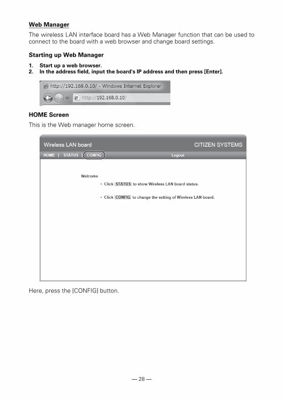
Web Manager
The wireless LAN interface board has a Web Manager function that can be used toconnect to the board with a web browser and change board settings.
Starting up Web Manager
1. Start up a web browser. 2. In the address field, input the board's IP address and then press [Enter].
HOME Screen
This is the Web manager home screen.
Here, press the [CONFIG] button.
— 28 —

CONFIG Screen
This will display the Login dialog box shown below. Log in as an administrator andthen configure wireless LAN interface board settings.
User NameInput a board administrator user name. (Initial setting: admin)
PasswordInput the administrator user password. (Initial setting: admin)
[Login] buttonAfter inputting an administrator user name and password, click the [Login] button.This displays the setting screen.
For details about settings, refer to the separate manual.
— 29 —
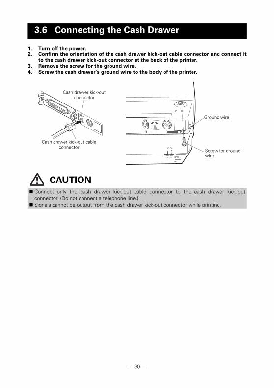
1. Turn off the power.2. Confirm the orientation of the cash drawer kick-out cable connector and connect it
to the cash drawer kick-out connector at the back of the printer.3. Remove the screw for the ground wire.4. Screw the cash drawer’s ground wire to the body of the printer.
3.6 Connecting the Cash Drawer
CAUTION
Connect only the cash drawer kick-out cable connector to the cash drawer kick-outconnector. (Do not connect a telephone line.)
Signals cannot be output from the cash drawer kick-out connector while printing.
Cash drawer kick-out connector
Cash drawer kick-out cable connector
Ground wire
Screw for ground wire
— 30 —

(1) Connector pin configuration
(2) Electric characteristics1) Drive voltage: 24 VDC2) Drive current: Approx. 1 A max. (not to exceed 510 ms.)3) DRSW signal: Signal levels: “L” = 0 to 0.8 V, “H” = 2 to 3.3 V
(3) DRSW signalDRSW signal status can be tested with the DLE+EOT, GS+a, or GS+rcommand or at pin 34 on the parallel interface port.
(4) Drive circuit
No. Signal Function
1 FG Frame ground Connector used:TM5RJ3-66 (Hirose) or equivalent
Applicable connector:TM3P-66P (Hirose) or equivalent
2 DRAWER1 Cash drawer 1 drive signal
3 DRSW Cash drawer switch input
4 VDR Cash drawer drive power supply
5 DRAWER2 Cash drawer 2 drive signal
6 GND Signal ground (common ground on circuits)
CAUTION Cash drawers 1 and 2 cannot be operated at the same time. The solenoid used for the cash drawer should be 24 or more. Do not allow the
electric current to exceed 1 A. Excessive current could damage or burn out thecircuits.
Cash drawer kick-out connector
Cash drawer open/close switch
Shielded
Cash drawer Printer
— 31 —
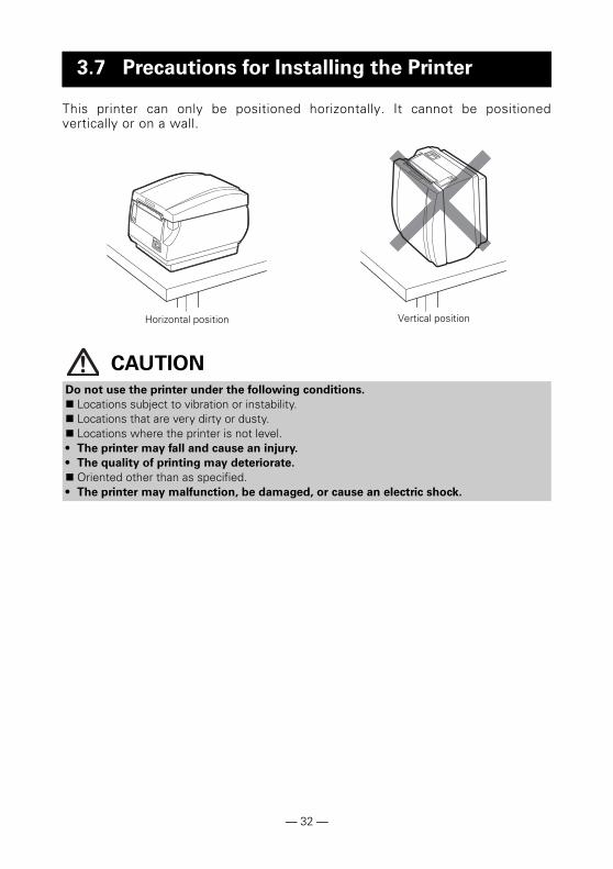
This printer can only be positioned horizontally. It cannot be positionedvertically or on a wall.
3.7 Precautions for Installing the Printer
CAUTION
Do not use the printer under the following conditions.
Locations subject to vibration or instability. Locations that are very dirty or dusty. Locations where the printer is not level.• The printer may fall and cause an injury.
• The quality of printing may deteriorate.
Oriented other than as specified.• The printer may malfunction, be damaged, or cause an electric shock.
Horizontal position Vertical position
— 32 —
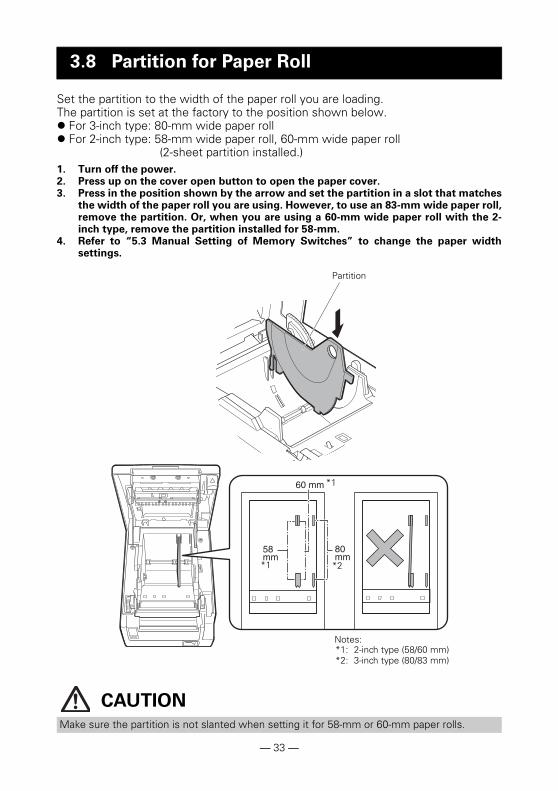
Set the partition to the width of the paper roll you are loading.The partition is set at the factory to the position shown below. For 3-inch type: 80-mm wide paper roll For 2-inch type: 58-mm wide paper roll, 60-mm wide paper roll
(2-sheet partition installed.)1. Turn off the power.2. Press up on the cover open button to open the paper cover.3. Press in the position shown by the arrow and set the partition in a slot that matches
the width of the paper roll you are using. However, to use an 83-mm wide paper roll,remove the partition. Or, when you are using a 60-mm wide paper roll with the 2-inch type, remove the partition installed for 58-mm.
4. Refer to “5.3 Manual Setting of Memory Switches” to change the paper widthsettings.
3.8 Partition for Paper Roll
CAUTION
Make sure the partition is not slanted when setting it for 58-mm or 60-mm paper rolls.
Partition
*1
*2*1
Notes:*1: 2-inch type (58/60 mm)*2: 3-inch type (80/83 mm)
— 33 —
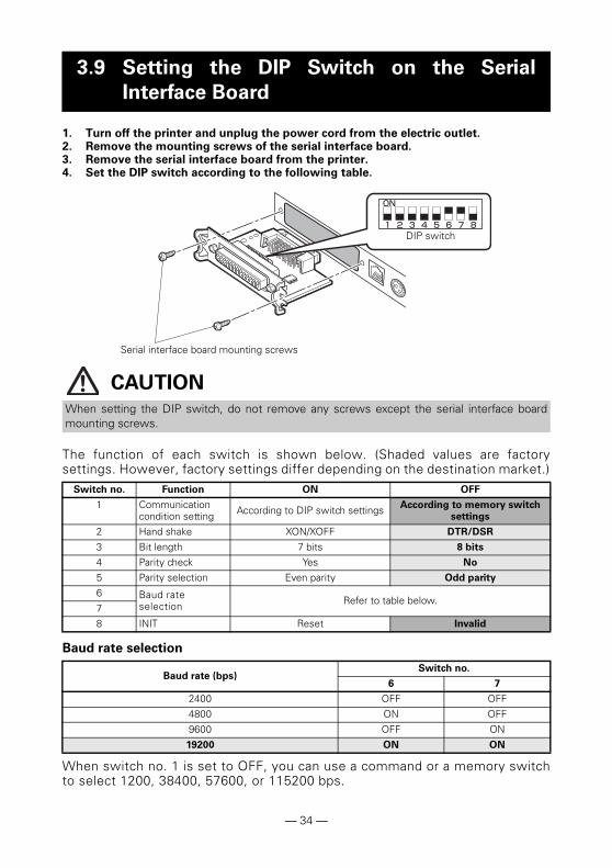
1. Turn off the printer and unplug the power cord from the electric outlet.2. Remove the mounting screws of the serial interface board.3. Remove the serial interface board from the printer.4. Set the DIP switch according to the following table.
The function of each switch is shown below. (Shaded values are factorysettings. However, factory settings differ depending on the destination market.)
Baud rate selection
When switch no. 1 is set to OFF, you can use a command or a memory switchto select 1200, 38400, 57600, or 115200 bps.
3.9 Setting the DIP Switch on the Serial
Interface Board
CAUTION
When setting the DIP switch, do not remove any screws except the serial interface boardmounting screws.
Switch no. Function ON OFF
1 Communication condition setting According to DIP switch settings According to memory switch
settings
2 Hand shake XON/XOFF DTR/DSR
3 Bit length 7 bits 8 bits
4 Parity check Yes No
5 Parity selection Even parity Odd parity
6 Baud rate selection Refer to table below.
7
8 INIT Reset Invalid
Baud rate (bps)Switch no.
6 7
2400 OFF OFF
4800 ON OFF9600 OFF ON19200 ON ON
DIP switch
Serial interface board mounting screws
— 34 —

Change the settings of the paper near-end sensor to set the position at whichthe near-end of the paper is detected.
1. Use a pointed object, such as a pen, to gently press the button to change the papernear-end sensor.
2. Press and hold down the button while moving the paper near-end sensor up anddown. The sensor positions are shown below for the various diameters of the paperroll used.
Note:*: Position of sensor when shipped from factory. However, factory settings differ depending on the
destination market.
3.10 Adjusting the Paper Near-end Sensor
(Unit: mm)
Sensor positionExterior diameter when detected as
near end
Exterior/ interior diameter of core of
paper roll used
A Approximately 31 18/12
B* Approximately 23 18/12
C Paper near-end sensor function is off
CAUTION
The diameter of the roll of paper that is detected is an estimate. Some variations mayoccur depending on the paper.
Button to change paper near-end sensor
— 35 —
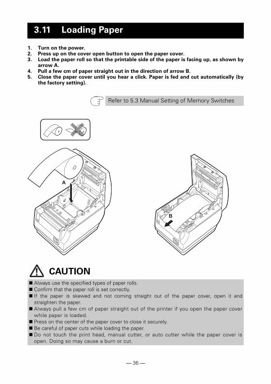
1. Turn on the power.2. Press up on the cover open button to open the paper cover.3. Load the paper roll so that the printable side of the paper is facing up, as shown by
arrow A.4. Pull a few cm of paper straight out in the direction of arrow B.5. Close the paper cover until you hear a click. Paper is fed and cut automatically (by
the factory setting).
3.11 Loading Paper
Refer to 5.3 Manual Setting of Memory Switches
CAUTION
Always use the specified types of paper rolls. Confirm that the paper roll is set correctly. If the paper is skewed and not coming straight out of the paper cover, open it and
straighten the paper. Always pull a few cm of paper straight out of the printer if you open the paper cover
while paper is loaded. Press on the center of the paper cover to close it securely. Be careful of paper cuts while loading the paper. Do not touch the print head, manual cutter, or auto cutter while the paper cover is
open. Doing so may cause a burn or cut.
— 36 —
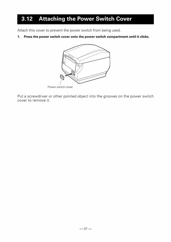
Attach this cover to prevent the power switch from being used.
1. Press the power switch cover onto the power switch compartment until it clicks.
Put a screwdriver or other pointed object into the grooves on the power switchcover to remove it.
3.12 Attaching the Power Switch Cover
Power switch cover
— 37 —
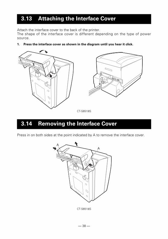
Attach the interface cover to the back of the printer.The shape of the interface cover is different depending on the type of powersource.
1. Press the interface cover as shown in the diagram until you hear it click.
Press in on both sides at the point indicated by A to remove the interface cover.
3.13 Attaching the Interface Cover
3.14 Removing the Interface Cover
CT-S651IIS
CT-S651IIS
— 38 —
Drivers are included on the CD-ROM that comes with the printer.Install the driver required by your printer.For information about driver installation, functions, and operations, see theinformation provided on the CD-ROM for each driver.Visit the site below to download the latest driver versions and information.
http://www.citizen-systems.co.jp/english/support/download/printer/driver/
If printing is done immediately after the paper is partially cut and torn off, the top ofthe next print out may be distorted.We recommend advancing the paper one line after cutting before printing.
If you are using a serial interface that has a slow data transmission speed, streaksmay appear in the printouts when you are printing graphics or gradated text, whichrequire large amounts of data.
USB interfaces may be susceptible to the effects of electromagnetic interferencefrom the host or environment.If this is the case, try using a cable with ferrite cores on both ends, which are veryeffective at eliminating EMI.
3.15 Installing a Driver
3.16 Precautions for Creating Applications
and Practical Operations
— 39 —

A dirty print head or platen may reduce printing quality or cause malfunctions.We recommend cleaning the printer periodically (every 2 to 3 months) as shownbelow.
1. Turn off the power.2. Press up on the cover open button to open the paper cover. 3. Wait a few minutes until the print head cools.4. Use a cotton swab dampened with ethyl alcohol to wipe off any dirt and dust that is
on the print head and platen.
4. MAINTENANCE AND TROUBLESHOOTING
4.1 Periodic Cleaning
CAUTION
The print head is hot immediately after printing. Do not touch it. Do not touch the print head with bare hands or metal objects.
Platen
Print head
— 40 —
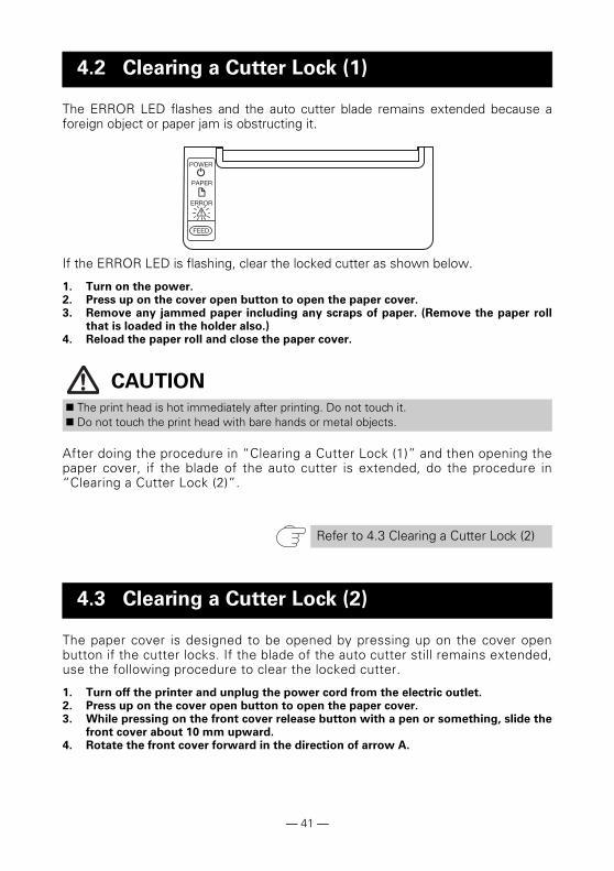
The ERROR LED flashes and the auto cutter blade remains extended because aforeign object or paper jam is obstructing it.
If the ERROR LED is flashing, clear the locked cutter as shown below.
1. Turn on the power.2. Press up on the cover open button to open the paper cover.3. Remove any jammed paper including any scraps of paper. (Remove the paper roll
that is loaded in the holder also.)4. Reload the paper roll and close the paper cover.
After doing the procedure in “Clearing a Cutter Lock (1)” and then opening thepaper cover, if the blade of the auto cutter is extended, do the procedure in“Clearing a Cutter Lock (2)”.
The paper cover is designed to be opened by pressing up on the cover openbutton if the cutter locks. If the blade of the auto cutter still remains extended,use the following procedure to clear the locked cutter.
1. Turn off the printer and unplug the power cord from the electric outlet.2. Press up on the cover open button to open the paper cover.3. While pressing on the front cover release button with a pen or something, slide the
front cover about 10 mm upward.4. Rotate the front cover forward in the direction of arrow A.
4.2 Clearing a Cutter Lock (1)
CAUTION
The print head is hot immediately after printing. Do not touch it. Do not touch the print head with bare hands or metal objects.
Refer to 4.3 Clearing a Cutter Lock (2)
4.3 Clearing a Cutter Lock (2)
— 41 —
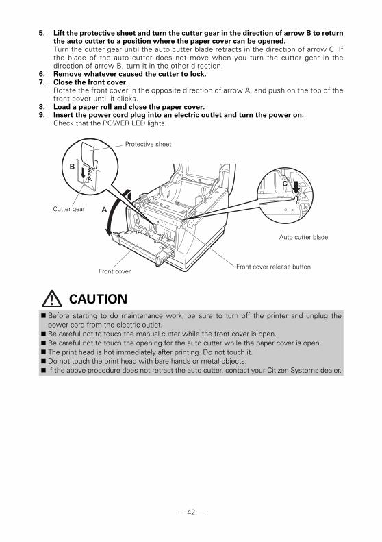
5. Lift the protective sheet and turn the cutter gear in the direction of arrow B to returnthe auto cutter to a position where the paper cover can be opened.Turn the cutter gear until the auto cutter blade retracts in the direction of arrow C. Ifthe blade of the auto cutter does not move when you turn the cutter gear in thedirection of arrow B, turn it in the other direction.
6. Remove whatever caused the cutter to lock.7. Close the front cover.
Rotate the front cover in the opposite direction of arrow A, and push on the top of thefront cover until it clicks.
8. Load a paper roll and close the paper cover.9. Insert the power cord plug into an electric outlet and turn the power on.
Check that the POWER LED lights.
CAUTION
Before starting to do maintenance work, be sure to turn off the printer and unplug thepower cord from the electric outlet.
Be careful not to touch the manual cutter while the front cover is open. Be careful not to touch the opening for the auto cutter while the paper cover is open. The print head is hot immediately after printing. Do not touch it. Do not touch the print head with bare hands or metal objects. If the above procedure does not retract the auto cutter, contact your Citizen Systems dealer.
Protective sheet
Front cover release button
Cutter gear
Front cover
Auto cutter blade
— 42 —
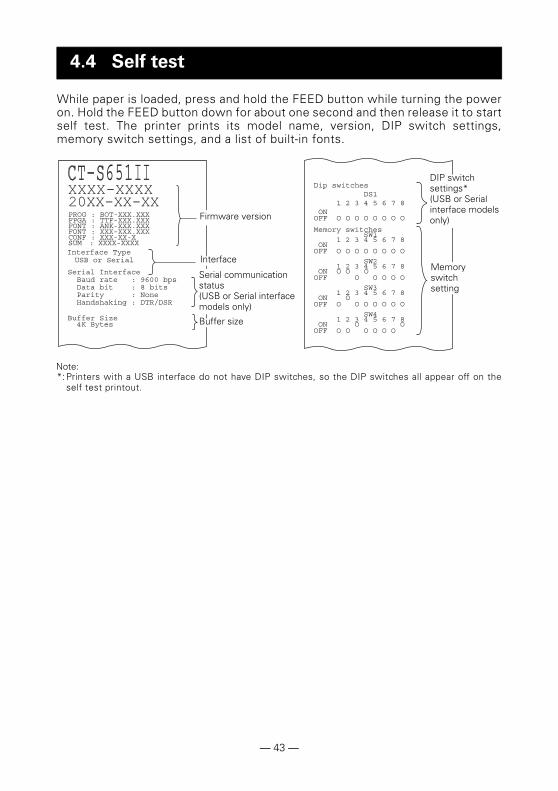
While paper is loaded, press and hold the FEED button while turning the poweron. Hold the FEED button down for about one second and then release it to startself test. The printer prints its model name, version, DIP switch settings,memory switch settings, and a list of built-in fonts.
Note:*:Printers with a USB interface do not have DIP switches, so the DIP switches all appear off on the
self test printout.
4.4 Self test
Buffer size
Serial communication status(USB or Serial interface models only)
Interface
Firmware version
Memory switch setting
DIP switch settings*(USB or Serial interface models only)
— 43 —

Print received data in hexadecimal. If problems such as missing or duplicateddata occur, this function allows you to check whether or not the printer isreceiving data correctly.
How to do hexadecimal dump printing
1. Load paper.2. While the paper cover is open, press and hold the FEED button while turning the
power on, and then close the paper cover.3. The printer prints “HEX dump print mode” followed by the received data printed in
hexadecimal numbers and some characters.
How to stop hexadecimal dump printing
Do one of the following to stop printing. Press the FEED button three times in a row Turn off the power Receive a reset command from an interface
Print exampleHEX dump print mode61 62 63 64 65 66 67 0A 0D 0D 0D 0D abcdefg.....0D 0D 0D .....
4.5 Hexadecimal Dump Printing
CAUTION
The printer prints “.” if there is no character corresponding to the data. None of the commands function during hexadecimal dump printing. If print data does not cover a complete line, press the FEED button to advance the
paper.
— 44 —

Paper-endThe end of the roll of paper is detected at two stages, paper near-end andpaper-end.When paper near-end is detected, the PAPER LED lights. Prepare a new paperroll.When paper end is detected, the PAPER LED and ERROR LED light. Load anew paper roll.
Paper cover openDo not open the paper cover during printing. If the paper cover is opened, theERROR LED lights or flashes. Check the paper and always pull a few cm ofpaper straight out of the printer before closing the paper cover. Printingresumes. Sending a command to resume printing may be required dependingon the memory switch setting.
Cutter lockedIf the auto cutter cannot move because of a paper jam or something else, theERROR LED flashes. Remove the cause of the trouble and press the FEEDbutton. If the auto cutter still does not operate and the paper cover does notopen, refer to “4.3 Clearing a Cutter Lock (2)”.
Print head hotWhen you print dense characters, dark images, or for an extended time in ahot environment, the print head temperature increases. If the print headexceeds a specified temperature, the printer stops printing and waits for theprint head to cool. When this happens, the ERROR LED flashes. Printingresumes automatically when the print head cools.
4.6 Error Messages
Refer to 4.3 Clearing a Cutter Lock (2)
— 45 —

The status display for various messages is shown below.
Notes:*1: If the paper cover or front cover is open in standby.*2: If the paper cover or front cover is open when printing or feeding paper.*3: Buzzer sounds when MSW5-1 (buzzer setting) is set to ON. Note, however, that some combinations of
settings of MSW5-1 and MSW10-6 may change the condition in which buzzer sounds.
StatusPOWER LED
(green)
PAPER LED
(orange)
ERROR LED
(red) Buzzer*3
Paper near-end Lights Lights — No
Paper-end Lights Lights Lights Yes
Paper cover open or front cover open*1
Lights — Lights Yes
Paper cover open or front cover open*2
Lights — Yes
Cutter locked Lights — Yes
Memory error — — Yes
Print head hot Lights — No
Low-voltage error Lights — Yes
High-voltage error Lights — Yes
Waiting for macro to execute — — No
— 46 —
Take care to avoid obstruction of the paper outlet and paper jamming around theoutlet during printing.If paper cannot get out of the printer, it can roll up on the platen inside the printer andcause an error.If the paper wraps around the platen, open the paper cover and carefully pull thepaper out.
While using the serial interface, certain printing conditions can cause white stripes inprintouts and feed failure. To avoid these problems, change memory switch settingsas described below.
1. Change MSW7-1 (serial baud rate) to a faster baud rate setting.2. Change MSW10-2 (print speed) to a lower level.
4.7 Paper Jams
4.8 Serial Interface Operation Precautions
CAUTION
Depending on the serial interface transmission speed, ambient temperature, print data duty,and other factors, changing the above settings may not eliminate the problems.
— 47 —

(Unit: mm)
5. OTHER
5.1 External Views and Dimensions
Built-in power supply type
AC adapter type
192 31145
140 155
1614
2
192 31145
114
— 48 —
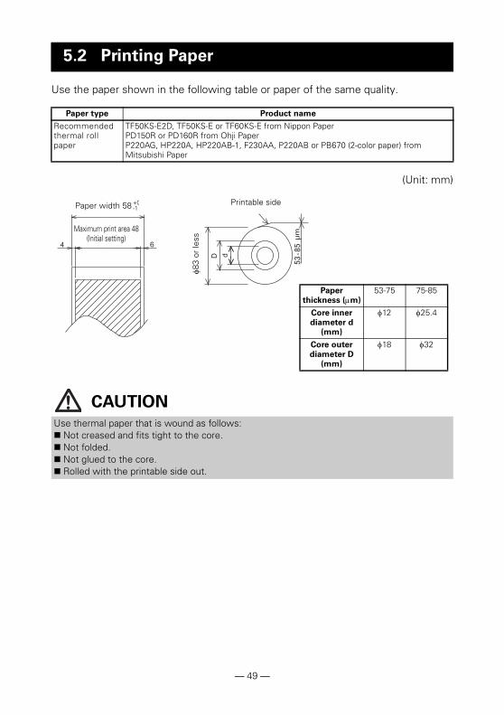
Use the paper shown in the following table or paper of the same quality.
(Unit: mm)
5.2 Printing Paper
Paper type Product name
Recommended thermal roll paper
TF50KS-E2D, TF50KS-E or TF60KS-E from Nippon PaperPD150R or PD160R from Ohji PaperP220AG, HP220A, HP220AB-1, F230AA, P220AB or PB670 (2-color paper) from Mitsubishi Paper
CAUTION
Use thermal paper that is wound as follows: Not creased and fits tight to the core. Not folded. Not glued to the core. Rolled with the printable side out.
Printable side8
3 or
less
Paper width 58 +0-1
Paper
thickness (m)
53-75 75-85
Core inner
diameter d
(mm)
12 25.4
Core outer
diameter D
(mm)
18 32
Maximum print area 48(Initial setting)
— 49 —

Memory switches are used to set various printer settings. The memory switchescan be set manually (set by hand on the printer) or by commands. This sectionexplains how to perform manual settings.For information on how to set the memory switches using commands, pleaserefer to the Command Reference.
Quick setting mode
The settings for the memory switches for a replacement printer’s manufacturer,model, paper width, and character spacing can be set at the same time to theoptimum settings.Do the settings while confirming the selected items on the printout.
1. Load paper.2. While the paper cover is open, press and hold the FEED button while turning the
power on.3. Press the FEED button three times and close the paper cover.
The printer enters memory switch quick setting mode.The selectable item “Manufacturer” and the selection are printed.
4. Press the FEED button.A selection is printed in order through the cycle each time the FEED button is pressed.Press the FEED button until the selection you want is printed.
5. Press the FEED button for at least two seconds.The selection is set.If there is another selectable item, it and the selection are printed.
6. Repeat steps 4 and 5 to select and set the printer’s model, paper width, characterspacing (EPSON T88 only).When all the items are set, “Save To Memory” is printed.
7. Press the FEED button for at least two seconds.The changed memory switch settings are saved and a list of them is printed.The printer exits quick setting mode when printing is finished.
5.3 Manual Setting of Memory Switches
Selectable itemSelection
— 50 —
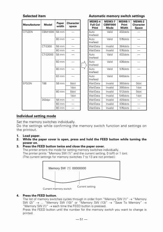
Individual setting mode
Set the memory switches individually.Do the settings while confirming the memory switch function and settings onthe printout.
1. Load paper.2. While the paper cover is open, press and hold the FEED button while turning the
power on.3. Press the FEED button twice and close the paper cover.
The printer enters the mode for setting memory switches individually.The printer prints “Memory SW (1)” and the current setting, 0 (off) or 1 (on).(The current settings for memory switches 7 to 13 are not printed.)
4. Press the FEED button.The list of memory switches cycles through in order from “Memory SW (1)” “MemorySW (2)” ... “Memory SW (10)” or “Memory SW (13)” “Save To Memory” “Memory SW (1)” each time the FEED button is pressed.Press the FEED button until the number for the memory switch you want to change isprinted.
Selected item Automatic memory switch settings
Manufacturer ModelPaper
width
Character
space
MSW2-4
Full Col
MSW3-7
CBM1000
Mode
MSW8-1
Width
MSW6-2
Character
Space
CITIZEN CBM1000 58 mm — Auto linefeed
Valid 432dots —
80 mm — Auto linefeed
Valid 576dots —
CT-S300 58 mm — WaitData Invalid 384dots —
80 mm — WaitData Invalid 576dots —
CT-S2000 58 mm — Auto linefeed
Valid 432dots —
60 mm — Auto linefeed
Valid 436dots —
80 mm — Auto linefeed
Valid 576dots —
83 mm — Auto linefeed
Valid 640dots —
EPSON T88 58 mm 0dot WaitData Invalid 360dots 0dot
1dot WaitData Invalid 390dots 1dot
80 mm 0dot WaitData Invalid 512dots 0dot
1dot WaitData Invalid 546dots 1dot
203dpi 58 mm — WaitData Invalid 420dots —
60 mm — WaitData Invalid 436dots —
80 mm — WaitData Invalid 576dots —
Current memory switchCurrent setting
— 51 —
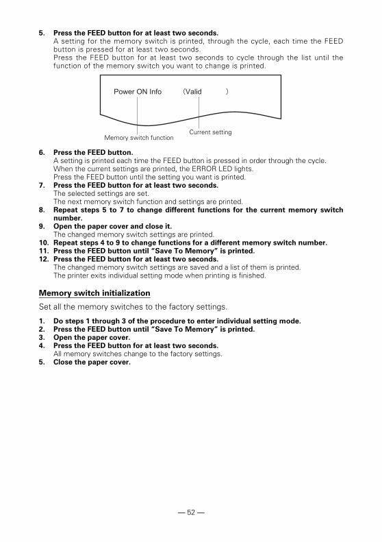
5. Press the FEED button for at least two seconds.A setting for the memory switch is printed, through the cycle, each time the FEEDbutton is pressed for at least two seconds.Press the FEED button for at least two seconds to cycle through the list until thefunction of the memory switch you want to change is printed.
6. Press the FEED button.A setting is printed each time the FEED button is pressed in order through the cycle.When the current settings are printed, the ERROR LED lights.Press the FEED button until the setting you want is printed.
7. Press the FEED button for at least two seconds.The selected settings are set.The next memory switch function and settings are printed.
8. Repeat steps 5 to 7 to change different functions for the current memory switchnumber.
9. Open the paper cover and close it.The changed memory switch settings are printed.
10. Repeat steps 4 to 9 to change functions for a different memory switch number.11. Press the FEED button until “Save To Memory” is printed.12. Press the FEED button for at least two seconds.
The changed memory switch settings are saved and a list of them is printed.The printer exits individual setting mode when printing is finished.
Memory switch initialization
Set all the memory switches to the factory settings.
1. Do steps 1 through 3 of the procedure to enter individual setting mode.2. Press the FEED button until “Save To Memory” is printed.3. Open the paper cover.4. Press the FEED button for at least two seconds.
All memory switches change to the factory settings.5. Close the paper cover.
Memory switch functionCurrent setting
— 52 —
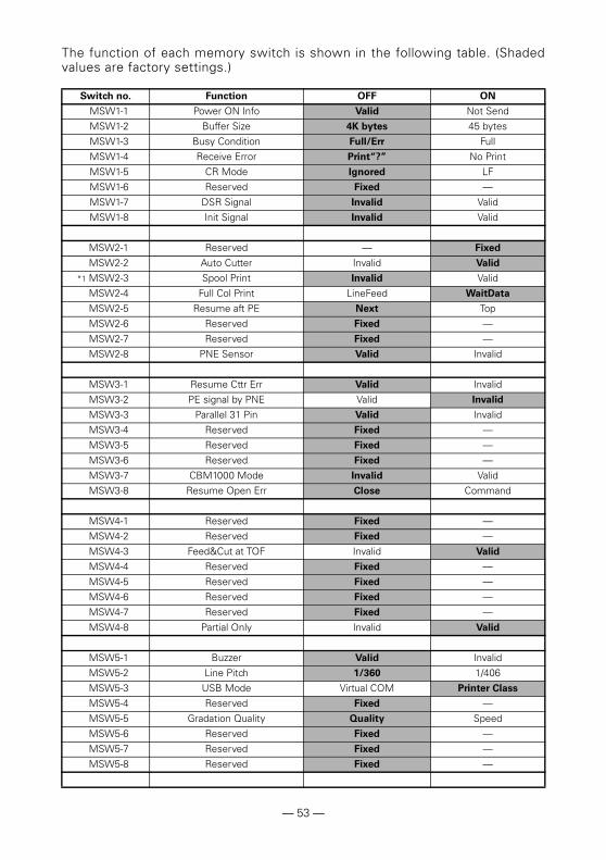
The function of each memory switch is shown in the following table. (Shadedvalues are factory settings.)
Switch no. Function OFF ON
MSW1-1 Power ON Info Valid Not Send
MSW1-2 Buffer Size 4K bytes 45 bytes
MSW1-3 Busy Condition Full/Err Full
MSW1-4 Receive Error Print“?” No Print
MSW1-5 CR Mode Ignored LF
MSW1-6 Reserved Fixed —
MSW1-7 DSR Signal Invalid Valid
MSW1-8 Init Signal Invalid Valid
MSW2-1 Reserved — Fixed
MSW2-2 Auto Cutter Invalid Valid
*1 MSW2-3 Spool Print Invalid Valid
MSW2-4 Full Col Print LineFeed WaitData
MSW2-5 Resume aft PE Next Top
MSW2-6 Reserved Fixed —
MSW2-7 Reserved Fixed —
MSW2-8 PNE Sensor Valid Invalid
MSW3-1 Resume Cttr Err Valid Invalid
MSW3-2 PE signal by PNE Valid Invalid
MSW3-3 Parallel 31 Pin Valid Invalid
MSW3-4 Reserved Fixed —
MSW3-5 Reserved Fixed —
MSW3-6 Reserved Fixed —
MSW3-7 CBM1000 Mode Invalid Valid
MSW3-8 Resume Open Err Close Command
MSW4-1 Reserved Fixed —
MSW4-2 Reserved Fixed —
MSW4-3 Feed&Cut at TOF Invalid Valid
MSW4-4 Reserved Fixed —
MSW4-5 Reserved Fixed —
MSW4-6 Reserved Fixed —
MSW4-7 Reserved Fixed —
MSW4-8 Partial Only Invalid Valid
MSW5-1 Buzzer Valid Invalid
MSW5-2 Line Pitch 1/360 1/406
MSW5-3 USB Mode Virtual COM Printer Class
MSW5-4 Reserved Fixed —
MSW5-5 Gradation Quality Quality Speed
MSW5-6 Reserved Fixed —
MSW5-7 Reserved Fixed —
MSW5-8 Reserved Fixed —
— 53 —
MSW6-1 Act. For Driver Invalid Valid
MSW6-2 Character Space Invalid Valid
MSW6-3 USB Power Save Invalid Valid
MSW6-4 Reserved Fixed —
MSW6-5 Reserved Fixed —
MSW6-6 Reserved Fixed —
MSW6-7 Reserved Fixed —
MSW6-8 Reserved Fixed —
Switch no. Function Initial setting Setting value
*2 MSW7-1 Baud Rate 9600 bps 1200 bps, 2400 bps, 4800 bps, 9600 bps, 19200 bps, 38400 bps, 57600 bps, 115200 bps
*2 MSW7-2 Data Length 8bits 7bits, 8bits
MSW7-3 Stop Bit 1bit 1bit, 2bits*2 MSW7-4 Parity NONE NONE, ODD, EVEN*2 MSW7-5 Flow Control DTR/DSR DTR/DSR, XON/XOFF
MSW7-6 DMA Control Valid Valid, Invalid
MSW7-7 VCom Protocol PC Setting PC Setting, DTR/DSR, XON/XOFF
MSW8-1 Print Width 576dots 640 dots, 576 dots, 546 dots, 512 dots, 436 dots,432 dots, 420 dots, 390 dots, 384 dots, 360 dots
MSW8-2 Paper Type 1 Color
Normal
1 Color Normal, 2 Color Normal
MSW8-3 Top Margin 11mm 3mm, 4mm, 5mm, 6mm, 7mm, 8mm, 9mm, 10mm, 11mm
MSW8-4 Line Gap Reduce Invalid Invalid, 3/4, 2/3, 1/2, 1/3, 1/4, 1/5, ALL
MSW8-5 Reduced Char V/H 100% / 100% 100% / 100%, 75% / 100%, 50% / 100%, 100% /75%, 75% / 75%, 50% / 75%
MSW8-6 Auto Side Shift Invalid Invalid, 1 dots, 2 dots, 3 dots, 4 dots, 5 dots, 6 dots, 7 dots
MSW8-7 Liner Free Mode Invalid Invalid, 1h, 6h, 12h, 18h, 24h, 5m, 10m, 15m, 20m, 30m
MSW9-1 Code Page PC 437 PC 437, Katakana, PC 850, PC 858, PC 860, PC 863, PC 865, PC 852, PC 866, PC 857, WPC1252, Space page, PC 864, ThaiCode11 1Pass, ThaiCode11 3Pass, ThaiCode18 1Pass, ThaiCode18 3Pass, TCVN-3
MSW9-2 Int’Char Set USA USA, France, Germany, England, Denmark, Sweden, Italy, Spain, Japan, Norway, Denmark 2, Spain 2, Latin America, Korea, Croatia, China, Vietnam
MSW9-4 Multi-byte Char Invalid JIS(JPN), SJIS:CP932 (JPN), SJIS:X0213(JPN), GB18030(CHN), KS Hangul(KOR), EUC Hangul(KOR), BIG5(TWN), Invalid
MSW10-1 Print Density 100 % 70 %, 75 %, 80 %, 85 %, 90 %, 95 %, 100 %, 105 %, 110 %, 115 %, 120 %, 125 %, 130 %, 135 %, 140 %
MSW10-2 Print Speed Level 9 Level 1, Level 2, Level 3, Level 4, Level 5, Level 6, Level 7, Level 8, Level 9
MSW10-3 ACK Timing Before Busy Before Busy, Same Period, After Busy
Switch no. Function OFF ON
— 54 —

*1: If print data is very dense, the print head is hot, data transmission is slow, or some other conditions, themotor and printing may occasionally stop which causes white stripes in the printout. To print high-density data, set MSW2-3 (Spool Print) to ON to reduce striping, although this increases the time beforeprinting starts.For a serial interface, increase the transmission speed to prevent the motor from stopping.
*2: The values for memory switches MSW7-X are only effective when DIP switch no. 1 is set to OFF.
MSW10-4 Old Command Invalid Invalid, CBM1, CBM2
MSW10-5 Buzzer Event Not by
C.Open
All Event/Error, Not by C.Open, Not by C.Open/PE
MSW10-6 Buzzer Sound Tone 2 Tone 1, Tone 2, Tone 3, Tone 4
MSW13-1 Security/Target Low/All Low/All, Mid/All, Mid/Paired only, Hi/All, Hi/Paired only
MSW13-5 BT Device Scan Discoverable No Response, Discoverable
MSW13-6 Auto Reconnect Valid Invalid, Valid
Switch no. Function Initial setting Setting value
— 55 —

CT-S651II_UM_110ENA10580E-1610
October 2016


![CT Methoden 2016.ppt [Kompatibilitätsmodus]CT.pdf · 1 CT Methoden Florian Vogt Lernziele •Vergleich zum konventionellen Röntgen •CT Inkremental-/ Spiraltechnik •Bildnachverarbeitung](https://static.fdokument.com/doc/165x107/5b4884707f8b9a3a058ce47b/ct-methoden-2016ppt-kompatibilitaetsmodus-ctpdf-1-ct-methoden-florian-vogt.jpg)