Modell der BR V 160 22175 - static.maerklin.de · with radio and television reception, when the...
36
Modell der BR V 160 22175
Transcript of Modell der BR V 160 22175 - static.maerklin.de · with radio and television reception, when the...

Modell der BR V 160
22175

2
Inhaltsverzeichnis: SeiteInformationen zum Vorbild 4Sicherheitshinweise 6Wichtige Hinweise 6Funktionen 6Hinweise zum Digitalbetrieb 6Schaltbare Funktionen 7Parameter / Register 8Ergänzendes Zubehör 30Wartung und Instandhaltung 30Ersatzteile 34
Table of Contents: Page Information about the prototype 4Safety Notes 9Important Notes 9Functions 9Notes on digital operation 9Controllable Functions 10Parameter / Register 11Completing accessories 30Service and maintenance 30Spare Parts 34
Sommaire : PageInformations concernant la locomotive réelle 5Remarques importantes sur la sécurité 12Information importante 12Fonctionnement 12Remarques relatives au fonctionnement en mode digital 12Fonctions commutables 13Paramètre / Registre 14Accessoires complémentaires 30Entretien et maintien 30Pièces de rechange 34
Inhoudsopgave: PaginaInformatie van het voorbeeld 5Veiligheidsvoorschriften 15Belangrijke aanwijzing 15Functies 15Aanwijzingen voor digitale besturing 15Schakelbare functies 16Parameter / Register 17Aanvullende toebehoren 30Onderhoud en handhaving 30Onderdelen 34

3
Indice de contenido: PáginaAviso de seguridad 18Notas importantes 18Funciones 18Informaciones para el funcionamiento digital 18Funciones posibles 19Parámetro / Registro 20Accesorios complementarios 30El mantenimiento 30Recambios 34
Indice del contenuto: PaginaAvvertenze per la sicurezza 21Avvertenze importanti 21Funzioni 21Istruzioni per la funzione digitale 21Funzioni commutabili 22Parametro / Registro 23Accessori complementari 30Manutenzione ed assistere 30Pezzi di ricambio 34
Innehållsförteckning: SidaSäkerhetsanvisningar 24Viktig information 24Funktioner 24Anvisningar för digital drift 24Kopplingsbara funktioner 25Parameter / Register 26Ytterligare tillbehör 30Underhåll och reparation 30Reservdelar 34
Indholdsfortegnelse: SideVink om sikkerhed 27Vigtige bemærkninger 27Funktioner 27Henvisninger til digitaldrift 27Styrbare funktioner 28Parameter / Register 29Ekstra tilbehør 30Service og reparation 30Reservedele 34

4
Information zum Vorbild: 1956 vereinbarte das Bundesbahn-Zentralamt München mit der Lokomotivfabrik Krupp in Essen die Entwicklung einer einmotorigen Mehrzweck-Diesellokomotive. Geplant war ursprünglich eine Maschine mit einer Nennleistung von 1.600 PS und eine Baureihenbezeichnung entsprechend der damaligen Gepflogenheiten als V 160. Sie sollte zwei Führerstände, zwei zweiachsige Drehgestelle, eine Höchst-geschwindigkeit von 120 km/h, eine größte Länge über Puffer von rund 16.000 mm sowie ausreichende Zugheizung für einen D-Zug mit zehn Wagen besitzen. Eine maximale Radsatzlast von 18 t sollte auch noch einen Einsatz auf ausgebauten Nebenstrecken ermöglichen. Für die Leis-tungsübertragung waren hydraulische Strömungsgetriebe vorgesehen. Noch während der Entwicklungsphase der V 160 konnte die Motorleistung durch verbesserte Aufladung und Ladeluftkühlung auf 1.900 PS gesteigert werden. 1960/61 lieferte die Firma Krupp sechs Prototypen als V 160 001-006, die mit unterschiedlichen 1.900-PS-Motoren und Getrieben ausgerüstet waren. 1962/63 folgten vier wei-tere Maschinen (V 160 007-010) von Henschel. Die ersten neun Loks besaßen unterhalb der Stirnfenster einen wohlge-rundeten Vorbau, der ihnen schnell den Spitznamen „Lollo“ (nach der italienischen Filmschauspielerin Gina Lollobrigida) einbrachte.
Information about the Prototype: In 1956 the German Federal Railroad‘s central office in Mu-nich contracted with the locomotive builder Krupp in Essen to develop a single-motor, general-purpose diesel locomo-tive. Originally, the plan was for a unit with a nominal power output of 1,600 horsepower and a class designation of V 160 in keeping with the conventions of that time. The plan for the locomotive was for two engineer‘s cabs, two two-axle trucks, a maximum speed of 120 km/h / 75 mph, a maximum length over the buffers of around 16,000 mm / 52 feet 6 inches as well as sufficient train heating for an express train of ten cars. A maximum axle load of 18 metric tons was planned to enable operation on expanded branch lines. Hydraulic fluid transmissions were planned for transmitting power to the wheels. During the development phase of the V 160 it was possible to increase the motor performance to 1,900 horsepower with improved supercharging and forced air cooling. In 1960/61 the firm of Krupp delivered six prototypes as the road numbers V 160 001-006, which were equipped with dif-ferent 1,900 horsepower motors and gear drives. In 1962/63 four additional units followed (V 160 007-010) from Henschel. The first nine locomotives had fully rounded ends beneath the windshields which quickly gave them the nickname “Lollo“ (after the Italian film star Gina Lollobrigida).
5
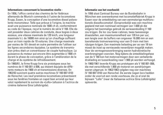
Informations concernant la locomotive réelle : En 1956, l’office central des chemins de fer fédéraux allemands de Munich commanda à l’usine de locomotives Krupp, Essen, la conception d’une locomotive diesel polyva-lente monomoteur. Telle que prévue à l’origine, la machine avait une puissance nominale de 1600 ch et, conformément au code de l’époque, reçut le numéro de série V 160. Elle de-vait posséder deux cabines de conduite, deux bogies à deux essieux, une vitesse maximale de 120 km/h, une longueur maximale h.t. de 16000 mm ainsi qu’un chauffage suffisant pour un train rapide de 10 voitures. Une charge maximale par essieu de 18 t devait en outre permettre de l’utiliser sur les lignes secondaires équipées. Le système de transmis-sion prévu était un convertisseur de couple hydraulique. La puissance du moteur put encore être augmentée à 1900 ch durant la phase de conception, grâce à l‘amélioration de la charge et du système de refroidissement. En 1960/61, la firme Krupp livra six prototypes sous les numéros de V 160 001 à 006, qui étaient équipés de diffé-rents moteurs de 1900 ch et transmissions diverses. En 1962/63 suivirent quatre autres machines (V 160 007-010) de Henschel. Les neuf premières locomotives présentaient sous les fenêtres frontales un capot bien arrondi qui leur valut rapidement le surnom de «Lollo» (allusion à l’actrice de cinéma italienne Gina Lollobrigida).
Informatie van het voorbeeld: In 1956 sloot Centraal Bureau van de Bundesbahn in München een overeenkomst met locomotieffabriek Krupp in Essen voor de ontwikkeling van een eenmotorige multifunc-tionele diesellocomotief. Oorspronkelijk was een machine gepland met een nominaal vermogen van 1.600 pk die volgens het toenmalige gebruik de serieaanduiding V 160 zou krijgen. De loc zou twee cabines, twee tweeassige draaistellen, een maximumsnelheid van 120 km per uur, een lengte over de buffers van ongeveer 16.000 mm en een toereikende treinverwarming voor een D-trein met tien rijtuigen krijgen. Een maximale belasting per as van 18 ton moest de inzet op vernieuwde nevenlijnen mogelijk maken. Voor de vermogensoverbrenging waren hydrokinetische overbrengingen voorzien. Nog tijdens de ontwikkelingsfase van de V 160 kon het motorvermogen door een verbeterde druklading en tussenkoeling naar 1.900 pk worden verhoogd. In 1960/1961 leverde Krupp zes prototypen als V 160 001-006, die met verschillende 1.900 pk-motoren en aandrijvingen waren uitgerust. In 1962/1963 volgden nog vier machines (V 160 007-010) van Henschel. De eerste negen locs hadden onder de voorruit een ronde voorbouw, die ze al snel de bijnaam “Lollo“ (naar de Italiaanse actrice Gina Lollobrigida) opleverde.
6
Sicherheitshinweise • DieLokdarfnurmiteinemdafürbestimmtenBetriebssys-
tem eingesetzt werden.• Analogmax.14Volt=,digitalmax.22Volt~.• DieLokdarfnurauseinerLeistungsquelleversorgtwerden.• BeachtenSieunbedingtdieSicherheitshinweiseinder
Bedienungsanleitung zu Ihrem Betriebssystem.•FürdenkonventionellenBetriebderLokmussdas
Anschlussgleis entstört werden. Dazu ist das Entstörset 611 655 zu verwenden. Für Digitalbetrieb ist das Entstörset nicht geeignet.
• ACHTUNG! Funktionsbedingte scharfe Kanten und Spitzen.•SetzenSiedasModellkeinerdirektenSonneneinstrah-
lung, starken Temperaturschwankungen oder hoher Luftfeuchtigkeit aus.
Wichtige Hinweise•DieBedienungsanleitungunddieVerpackungsindBe-
standteil des Produktes und müssen deshalb aufbewahrt sowie bei Weitergabe des Produktes mitgegeben werden.
•FürReparaturenoderErsatzteilewendenSiesichbitteanIhren Trix-Fachhändler.
•http://www.maerklin.com/en/imprint.html• GewährleistungundGarantiegemäßderbeiliegenden
Garantieurkunde.
Funktionen • EingebauteElektronikzumwahlweisenBetriebmit
konventionellem Gleichstrom-Fahrgerät, Trix Systems oder Digitalsystemen nach NMRA-Norm.
• AutomatischeSystemerkennungzwischenDigital-undAnalog-Betrieb.
•DervolleFunktionsumfangistnurunterTrixSystemsundunter DCC verfügbar.
• Eingebaute,fahrtrichtungsabhängigeStirnbeleuchtung. Im Digitalbetrieb schaltbar.
•BefahrbarerMindestradius360mm.
Hinweise zum Digitalbetrieb • DiegenaueVorgehensweisezumEinstellenderdiversen
Parameter entnehmen Sie bitte der Bedienungsanleitung Ihrer Mehrzug-Zentrale.
•DieabWerkeingestelltenWertesindsogewählt,dassbestmöglichstes Fahrverhalten gewährleistet ist.
• DerBetriebmitgegenpoligerGleichspannungimBremsabschnitt ist mit der werkseitigen Einstellung nicht möglich. Ist diese Eigenschaft gewünscht, so muss auf den konventionellen Gleichstrombetrieb verzichtet werden (CV29/Bit2=0).

7
Schaltbare Funktionen
Stirnbeleuchtung an Funktion f0 Funktion f0
Geräusch:Betriebsgeräusch — Funktion 2 Funktion f2 Funktion f2
Geräusch:Signalhorn1 — Funktion 3 Funktion f3 Funktion f3
ABV aus — Funktion 4 Funktion f4 Funktion f4
Geräusch:Bremsenquietschenaus — Funktion 5 Funktion f5 Funktion f5
Spitzensignal Lokseite 2 aus — Funktion 6 Funktion f6 Funktion f6
Geräusch:Signalhorn2 — Funktion 7 Funktion f7 Funktion f7
Spitzensignal Lokseite 1 aus — Funktion 8 Funktion f8 Funktion f8
Rangierlicht Doppel-A — + 6 + 8 Funktion f0 + f6 + f8 Funktion f0 + f6 + f8
STOP mobile station
1 5f0 f8 f0f8f0 - f3 f4 - f7

8
CV Bedeutung Wert DCC ab Werk
1 Adresse 1 - 127 3
2 PoM Minimalgeschwindigkeit 0 - 255 13
3 PoM Anfahrverzögerung 0 - 255 5
4 PoM Bremsverzögerung 0 - 255 3
5 PoM Maximalgeschwindigkeit 0 - 255 203
8 Werkreset/Herstellerkennung 8 131
13 PoM Funktionen F1 - F8 im Analogbetrieb 0 - 255 0
14 PoM Funktionen F9 - F15 und Licht im Analogbetrieb 0 - 255 1
17 Erweiterte Adresse (oberer Teil) CV29,Bit5=1 192
18 Erweiterte Adresse (unterer Teil) CV29,Bit5=1 128
19 Traktionsadresse 0 - 255 0
21 PoM Funktionen F1 - F8 bei Traktion 0 - 255 0
22 PoM Funktionen F9 - F15 und Licht bei Traktion 0 - 255 0
29
Bit0:UmpolungFahrtrichtung Bit1:AnzahlFahrstufen14oder28/128 Bit2:DCCBetriebmitBremsstrecke(keinAnalogbetriebmöglich) Bit5:Adressumfang7Bit/14Bit
0 / 1 0 / 2 0 / 4
0 / 32
6*
63 PoM Lautstärke 0 - 255 255
PoM=ProgramontheMain;mussvomSteuergerätunterstütztwerden* Die Werte der gewünschten Einstellungen sind zu addieren!

9
Functions • Built-inelectroniccircuitforoperationwithaconventi-
onal DC power pack, Trix Systems or NMRA DCC digital systems.
• Automaticsystemrecognitionbetweendigitalandanalogoperation.
•ThefullrangeoffunctionsisonlyavailableunderTrixSystems and under DCC.
• Built-inheadlightsthatchangeoverwiththedirectionoftravel. They can be turned on and off in digital operation.
•Minimumradiusforoperationis360mm/14-3/16“.
Notes on digital operation •Theoperatinginstructionsforyourcentralunitwillgive
you exact procedures for setting the different parameters. • Thevaluessetatthefactorywereselectedtoguarantee
the best possible running characteristics. • Thesettingdoneatthefactorydoesnotpermitoperation
with opposite polarity DC power in the braking block. If you want this characteristic, you must do without conven-tionalDCpoweroperation(CV29/Bit2=0).
Safety Notes• Thislocomotiveisonlytobeusedwiththeoperating
system it is designed for.• Analogmax.14voltsDC,digitalmax.22voltsAC.• Thislocomotivemustnotbesuppliedwithpowerfrom
more than one power pack.• Pleasemakenoteofthesafetynotesintheinstructionsfor
your operating system.•Thefeedertrackmustbeequippedtopreventinterference
with radio and television reception, when the locomotive is to be run in conventional operation. The 611 655 inter-ference suppression set is to be used for this purpose. The interference suppression set is not suitable for digital operation.
•WARNING! Sharp edges and points required for operation.•Donotexposethemodeltodirectsunlight,extreme
changes in temperature, or high humidity.
Important Notes•Theoperatinginstructionsandthepackagingareacom-
ponent part of the product and must therefore be kept as well as transferred along with the product to others.
•PleaseseeyourauthorizedTrixdealerforrepairsorspareparts.
•http://www.maerklin.com/en/imprint.html• Thewarrantycardincludedwiththisproductspecifiesthe
warranty conditions.

10
Controllable Functions
Headlights on Function f0 Function f0
Soundeffect:Operatingsounds — Function 2 Function f2 Function f2
Soundeffect:Horn1 — Function 3 Function f3 Function f3
ABV off — Function 4 Function f4 Function f4
Soundeffect:Squealingbrakesoff — Function 5 Function f5 Function f5
Headlights at engineer´s cab 2 off — Function 6 Function f6 Function f6
Soundeffect:Horn2 — Function 7 Function f7 Function f7
Headlights at engineer´s cab 1 off — Function 8 Function f8 Function f8
Double A switching light — + 6 + 8 Function f0 + f6 + f8 Function f0 + f6 + f8
STOP mobile station
1 5f0 f8 f0f8f0 - f3 f4 - f7

11
PoM=ProgramontheMain;mustbesupportedbythecontroller* The values for the desired settings must be added.
CV Discription DCC Value Factory-Set
1 Address 1 - 127 3
2 PoM Minimum Speed 0 - 255 13
3 PoM Acceleration delay 0 - 255 5
4 PoM Braking delay 0 - 255 3
5 PoM Maximum speed 0 - 255 203
8 Factory Reset / Manufacturer Recognition 8 131
13 PoM Functions F1 - F8 in analog operation 0 - 255 0
14 PoM Functions F9 - F15 and lights in analog operation 0 - 255 1
17 Extended address (upper part) CV29,Bit5=1 192
18 Extended address (lower part) CV29,Bit5=1 128
19 Multiple Unit Address 0 - 255 0
21 PoM Functions F1 - F8 on Multiple Unit 0 - 255 0
22 PoM Functions F9 - F15 and lights on Multiple Unit 0 - 255 0
29
Bit0:Reversingdirection Bit1:Numberofspeedlevels14or28/128 Bit2:DCCoperationwithbrakingarea(noanalogoperationpossible) Bit5:Addresslength7Bit/14Bit
0 / 1 0 / 2 0 / 4
0 / 32
6*
63 PoM Volume 1 - 255 255

12
Remarques importantes sur la sécurité • Lalocomotivenepeutêtreutiliséequ‘aveclesystème
d‘exploitation indiqué.• Analogiquemax.14volts=,digitalmax.22volts~.• Lalocomotivenepeutpasêtrealimentéeélectriquement
par plus d‘une source de courant à la fois.• Ilestimpératifdetenircomptedesremarquessurla
sécurité décrites dans le mode d‘emploi de votre système d‘exploitation.
•Pour l’exploitation de la locomotive en mode conventi-onnel, la voie de raccordement doit être déparasitée. A cet effet, utiliser le set de déparasitage réf. 611 655. Le set de déparasitage ne convient pas pour l’exploitation en mode numérique.
• ATTENTION! Pointes et bords coupants lors du fonctionne-ment du produit.
•Nepasexposerlemodèleàunensoleillementdirect,àdefortes variations de température ou à un taux d‘humidité important.
Information importante •Lanoticed‘utilisationetl’emballagefontpartieintégranteduproduit;ilsdoiventdoncêtreconservéset,lecaséchéant, transmis avec le produit.
•Pourtouteréparationouremplacementdepièces,adressez vous à votre détaillant-spécialiste Trix.
•http://www.maerklin.com/en/imprint.html• Garantielégaleetgarantiecontractuelleconformément
au certificat de garantie ci-joint.
Fonctionnement • Electroniqueintégréepourexploitationauchoixavec
transformateur-régulateur conventionnel délivrant du courant continu, avec Trix Systems ou avec des systèmes de conduite digitale conformes aux normes NMRA.
• Reconnaissanceautomatiquedusystèmeentreexploita-tions numérique et analogique.
•L’intégralitédesfonctionsestdisponibleuniquementenexploitation Trix Systems et DCC.
• Feuxdesignalisations‘inversantselonlesensdemarche;feux commutables en exploitation digital.
•Rayonminimald’inscriptionencourbe360mm.
Remarques relatives au fonctionnement en mode digital •Encequiconcernelaprocédurederéglagedesdiverspa-
ramètres, veuillez vous référer au mode d‘emploi de votre centrale de commande multitrain.
•Lesvaleursparamétréesd’usinesontchoisiesdemanièreàgarantir le meilleur comportement de roulement possible.
• L’exploitationaveccourantcontinudepolaritéinversedans les sections de freinage n’est pas possible avec le réglage d’usine. Si cette propriété est désirée, il faut alors renoncer à l’exploitation conventionnelle en courant conti-nu(CV29/Bit2=0).

13
Fonctions commutables
Fanal Activé Fonction f0 Fonction f0
Bruitage:Bruitd’exploitation — Fonction 2 Fonction f2 Fonction f2
Bruitage:Trompe1 — Fonction 3 Fonction f3 Fonction f3
ABV désactivé — Fonction 4 Fonction f4 Fonction f4
Bruitage:Grincementdefreinsdésactivé — Fonction 5 Fonction f5 Fonction f5
Fanal de la cabine de conduite 2 éteint — Fonction 6 Fonction f6 Fonction f6
Bruitage:Trompe2 — Fonction 7 Fonction f7 Fonction f7
Fanal de la cabine de conduite 1 éteint — Fonction 8 Fonction f8 Fonction f8
Feu de manœuvre double A — + 6 + 8 Fonction f0 + f6 + f8 Fonction f0 + f6 + f8
STOP mobile station
1 5 f0 f8 f0f8f0 - f3 f4 - f7

14
PoM=ProgramontheMain;doitêtreprisenchargeparl’appareildecommande* Les valeurs des réglages désirés sont à additioner.
CV Affectation DCC Valeur Parm. Usine
1 Adresse 1 - 127 3
2 PoM Vitesse minimale 0 - 255 13
3 PoM Temporisation d‘accélération 0 - 255 5
4 PoM Temporisation de freinage 0 - 255 3
5 PoM Vitesse maximale 0 - 255 203
8 Réinitialisation d’usine/identification du fabricant 8 131
13 PoM Fonctions F1 - F8 en mode analog 0 - 255 0
14 PoM Fonctions F9 - F15 et éclairage en mode analog 0 - 255 1
17 Adresse étendue (partie supérieure) CV29,Bit5=1 192
18 Adresse étendue (partie inférieure) CV29,Bit5=1 128
19 Adresse traction 0 - 255 0
21 PoM Fonctions F1 - F8 pour traction 0 - 255 0
22 PoM Fonctions F9 - F15 et éclairage traction 0 - 255 0
29
Bit0:Inv.polaritéSensdemarche Bit1:Nombredecransdemarche14ou28/128 Bit2:Mode DCC avec dist. de freinage (mode analog impossible) Bit5:Capacitéd’adresses7Bit/14Bit
0 / 1 0 / 2 0 / 4
0 / 32
6*
63 PoM Volume haut-parleur 1 - 255 255

15
Veiligheidsvoorschriften• Delocmagalleenmeteendaarvoorbestemdbedrijfssys-
teem gebruikt worden.• Analoogmax.14Volt=,digitaalmax.22Volt~.• Delocmagnietvanuitmeerdanéénstroomvoorziening
gelijktijdig gevoed worden.• Leesookaandachtigdeveiligheidsvoorschrifteninde
gebruiksaanwijzing van uw bedrijfssysteem. •Voorhetconventionelebedrijfmetdelocdientde
aansluitrail te worden ontstoort. Hiervoor dient men de ontstoor-set 611 655 te gebruiken. Voor het digitale bedrijf is deze ontstoor-set niet geschikt.
• OPGEPAST! Functionele scherpe kanten en punten.•Stelhetmodelnietblootaanindirectezonnestraling,
sterke temperatuurwisselingen of hoge luchtvochtigheid.
Belangrijke aanwijzing•Degebruiksaanwijzingendeverpakkingzijneenbestand-
deel van het product en dienen derhalve bewaard en meegeleverd te worden bij het doorgeven van het product.
•VoorreparatiesenonderdelenkuntzichtotuwTrixhande-laar wenden.
•http://www.maerklin.com/en/imprint.html• Vrijwaringengarantieovereenkomstighetbijgevoegde
garantiebewijs.
Functies• Ingebouwdeelektronicadiehetmogelijkmaaktomnaar
keuze met, een conventionele gelijkstroomrijregelaar, Trix Systems of digitaalsysteem volgens NMRA-norm te rijden.
• Automatischesysteemherkenningtussendigitaal-enanaloogbedrijf.
•Devolledigetoegangtotallefunctiesisalleenmogelijkmet Trix Systems of met DCC bedrijf.
• Ingebouwde,rijrichtingsafhankelijkefrontverlichtingisinhet digitaalsysteem schakelbaar.
•Minimaleteberijdenradius:360mm.
Aanwijzingen voor digitale besturing •Hetopdejuistewijzeinstellenvandediverseparame-
ters staat beschreven in de handleiding van uw digitale Centrale.
•Devanafdefabriekingesteldewaardenzijnzoingestelddat de rij-eigenschappen optimaal zijn.
• Hetbedrijfmettegengepooldegelijkspanningindeafrem-sectie is met de fabrieksinstelling niet mogelijk. Indien deze eigenschap wenselijk is, dan moet worden afgezien van het conventioneelgelijkstroombedrijf(CV29/Bit2=0).
16
Schakelbare functies
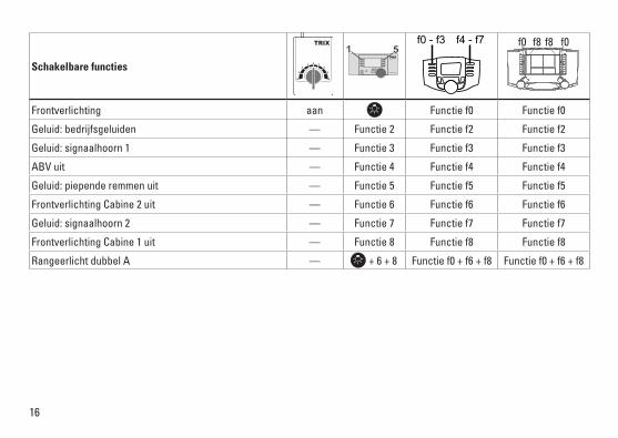
Frontverlichting aan Functie f0 Functie f0
Geluid:bedrijfsgeluiden — Functie 2 Functie f2 Functie f2
Geluid:signaalhoorn1 — Functie 3 Functie f3 Functie f3
ABV uit — Functie 4 Functie f4 Functie f4
Geluid:piependeremmenuit — Functie 5 Functie f5 Functie f5
Frontverlichting Cabine 2 uit — Functie 6 Functie f6 Functie f6
Geluid:signaalhoorn2 — Functie 7 Functie f7 Functie f7
Frontverlichting Cabine 1 uit — Functie 8 Functie f8 Functie f8
Rangeerlicht dubbel A — + 6 + 8 Functie f0 + f6 + f8 Functie f0 + f6 + f8
STOP mobile station
1 5f0 f8 f0f8f0 - f3 f4 - f7

17
PoM=ProgramontheMain;dientdoorhetbesturingsapparaatondersteuntteworden.* De waarde van de gewenste instellingen moeten bij elkaar opgeteld worden.
CV Betekenis Waarde DCC Af fabriek
1 Adres 1 - 127 3
2 PoM Minimale snelheid 0 - 255 13
3 PoM Optrekvertraging 0 - 255 5
4 PoM Afremvertraging 0 - 255 3
5 PoM Maximumsnelheid 0 - 255 203
8 Fabrieksinstelling/fabriekherkenning 8 131
13 PoM functies F1 - F8 in analoogbedrijf 0 - 255 0
14 PoM functies F9 - F15 en licht in analoogbedrijf 0 - 255 1
17 Uitgebreld adres (bovenste gedeelte) CV29,Bit5=1 192
18 Uitgebreld adres (onderste gedeelte) CV29,Bit5=1 128
19 tractieadres 0 - 255 0
21 PoM functies F1 - F8 in tractie 0 - 255 0
22 PoM functies F9 - F15 en licht in tractie 0 - 255 0
29
Bit0:ompolenrijrichting Bit1:aantalrijstappen14of28/128 Bit2:DCCbedrijfmetafremtraject(geenanaloogbedrijfmogelijk) Bit5:adresomvang7Bit/14Bit
0 / 1 0 / 2 0 / 4
0 / 32
6*
63 PoM Volume 1 - 255 255
18
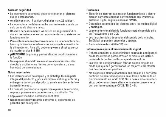
Aviso de seguridad • Lalocomotorasolamentedebefuncionarenelsistema
que le corresponda. • Analógicasmax.14voltios=,digitalesmax.22voltios~.• Lalocomotoranodeberárecibircorrientemásquedeun
solo punto de abasto a la vez. • Observenecesariamentelosavisosdeseguridadindica-
dos en las instrucciones correspondientes a su sistema de funcionamiento.
•Paraelfuncionamientoconvencionaldelalocomotorade-bensuprimirselasinterferenciasenlavíadeconexióndelaalimentación.Paraellodebeemplearseelsetsupresorde interferencias 611 655.
• ¡ATENCIÓN! Esquinas y puntas afiladas condicionadas a lafunción.
•Noexponerelmodeloenminiaturaalaradiaciónsolardirecta, a oscilaciones fuertes de temperatura o a una humedad del aire elevada.
Notas importantes•Lasinstruccionesdeempleoyelembalajeformanparte
íntegra del producto y, por este motivo, deben guardarse y entregarse junto con el producto en el caso de venderlo o transmitirlo a otro.
•Encasodeprecisarunareparaciónopiezasderecambio,rogamos ponerse en contacto con su distribuidor Trix.
•http://www.maerklin.com/en/imprint.html• Responsabilidadygarantíaconformealdocumentode
garantía que se adjunta.
Funciones• Electrónicaincorporadaparaunfuncionamientoadiscre-ciónencorrientecontinuaconvencional,TrixSystemsosistemas Digital según las normas NMRA.
• Detecciónautomáticadelsistemaentrelosmodosdigitalyanalógico.
• Laplenafuncionalidaddefuncionesestádisponiblesóloen Trix Systems y en DCC.
• Losfarosfrontalesdependendelsentidodelamarcha. En Digital se pueden encender y apagar.
•Radiomínimodescribible360mm.
Informaciones para el funcionamiento digital • Deberáconsultarelprocedimientoexactodeconfiguraci-óndelosdiversosparámetrosenelmanualdeinstruc-ciones de la central multitren que desee utilizar.
• Losvaloresconfiguradosenfábricasehanelegidodemodo que queden garantizadas las mejores característi-casdeconducciónposibles.
• Noesposibleelfuncionamientocontensióndecorrientecontinua de polaridad opuesta en el tramo de frenado en funcionamiento en modo DCC. Si se desea esta caracterí-stica, debe renunciarse al funcionamiento convencional concorrientecontinua(CV29/Bit2=0).

19
Funciones posibles
Faros frontales encendido Funciónf0 Funciónf0
Ruido:ruidodeexplotación — Función2 Funciónf2 Funciónf2
Ruido:Bocina1 — Función3 Funciónf3 Funciónf3
ABV apagado — Función4 Funciónf4 Funciónf4
Ruido:Desconectarchirridodelosfrenos — Función5 Funciónf5 Funciónf5
Faros frontales a la cabina 2 de enganche — Función6 Funciónf6 Funciónf6
Ruido:Bocina2 — Función7 Funciónf7 Funciónf7
Faros frontales a la cabina 1 de enganche — Función8 Funciónf8 Funciónf8
Luces de maniobra doble A — + 6 + 8 Funciónf0+f6+f8 Funciónf0+f6+f8
STOP mobile station
1 5 f0 f8 f0f8f0 - f3 f4 - f7

20
PoM=ProgramontheMain;debesersoportadoporlaunidaddecontrol* ¡Los valores de los ajustes deseados deben sumarse!
CV Significado Valor DCC Preselección
1 Códigos 1 - 127 3
2 PoM Velocidad mínima 0 - 255 13
3 PoM Arranque progresivo 0 - 255 5
4 PoM Frenado progresivo 0 - 255 3
5 PoM Velocidad máxima 0 - 255 203
8 Resetdefábrica/códigodefabricante 8 131
13 PoM FuncionesF1-F8enelmodoanalógico 0 - 255 0
14 PoM FuncionesF9-F15ylucesenelmodoanalógico 0 - 255 1
17 Direcciónampliada(partesuperior) CV29,Bit5=1 192
18 Direcciónampliada(parteinferior) CV29,Bit5=1 128
19 Direccióndetracción 0 - 255 0
21 PoM FuncionesF1-F8entracción 0 - 255 0
22 PoM FuncionesF9-F15ylucesentracción 0 - 255 0
29
Bit0:Cambiodepolaridaddelsentidodemarcha Bit1:Númerodenivelesdemarcha14ó28/128 Bit2:ModoDCCcontrayectodefrenado(noesposibleelmodoanalógico) Bit5:Tamañodedirecciones7Bits/14Bits
0 / 1 0 / 2 0 / 4
0 / 32
6*
63 PoM Volumen del sonido 1 - 255 255

21
Avvertenze per la sicurezza •Talelocomotivadevevenireimpiegatasoltantoconun
sistema di esercizio prestabilito a questo scopo.• Analogicomax.14Volt=,max.digitale22Volt~.• Lalocomotivanondevevenirealimentatanellostesso
tempo con più di una sorgente di potenza.• Vogliateprestareassolutamenteattenzionealleavver-
tenze di sicurezza nelle istruzioni di impiego per il Vostro sistema di funzionamento.
•Perilfunzionamentotradizionaledellalocomotivailbinario di alimentazione deve essere protetto dai disturbi. A tale scopo si deve impiegare il corredo antidisturbi 611 655. Tale corredo antidisturbi non è adatto per il funzionamento Digital.
• AVVERTENZA! Per motivi funzionali i bordi e le punte sono spigolosi.
•Nonesponetetalemodelloadalcunirraggiamentosolarediretto, a forti escursioni di temperatura oppure a elevata umidità dell’aria.
Avvertenze importanti•Leistruzionidiimpiegoel’imballaggiocostituisconoun
componente sostanziale del prodotto e devono pertanto venire conservati nonché consegnati insieme in caso di ulteriore cessione del prodotto.
•Perleriparazioniolepartidiricambio,contrattareilrivenditore Trix.
•http://www.maerklin.com/en/imprint.html• Prestazionidigaranziaegaranziainconformitàall’acclu-
so certificato di garanzia.
Funzioni• Moduloelettronicoincorporatoperilfunzionamentoa
scelta con un tradizionale regolatore di marcia in corrente continua, Trix Systems oppure sistemi digitali in base alla normativa NMRA.
• RiconoscimentoautomaticodelsistematraesercizioDigital ed analogico.
•Lacompletadotazionedifunzionièdisponibilesoltantosotto Trix Systems e sotto DCC.
• IIlluminazioneditestaincorporata,dipendentedalladire-zione di marcia. Commutabile nel funzionamento Digital.
•Raggiominimopercorribile360mm.
Istruzioni per la funzione digitale • L’esattoprocedimentoperl’impostazionedeidifferentipa-
rametri siete pregati di ricavarlo dalle istruzioni di servizio della Vostra centrale per molti treni.
•I valori impostati dalla fabbrica sono scelti in modo tale che sia assicurato il comportamento di marcia migliore possibile.
• Unfunzionamentocontensionecontinuadipolaritàinvertita nella sezione di frenatura, in caso di esercizio con DCC, non è possibile. Se si desidera questa caratteristica, si deve in tal caso rinunciare al funzionamento tradizionale incorrentecontinua(CV29/Bit2=0).

22
Funzioni commutabili
Illuminazione di testa accesa Funzione f0 Funzione f0
Rumore:rumoridiesercizio — Funzione 2 Funzione f2 Funzione f2
Rumore:tromba1 — Funzione 3 Funzione f3 Funzione f3
ABV spento — Funzione 4 Funzione f4 Funzione f4
Rumore:stridoredeifreniescluso — Funzione 5 Funzione f5 Funzione f5
Illuminazione di testa della cabina 2 spento — Funzione 6 Funzione f6 Funzione f6
Rumore:tromba2 — Funzione 7 Funzione f7 Funzione f7
Illuminazione di testa della cabina 1 spento — Funzione 8 Funzione f8 Funzione f8
Fanale di manovra a doppia A — + 6 + 8 Funzione f0 + f6 + f8 Funzione f0 + f6 + f8
STOP mobile station
1 5 f0 f8 f0f8f0 - f3 f4 - f7

23
PoM=Programmazioneinlinea;deveesseresupportatadall’apparatodicomando* I valori delle impostazioni desiderate si devono sommare!
CV Significato Valore DCC Di fabbrica
1 Indirizzo 1 - 127 3
2 PoM Velocità minima 0 - 255 13
3 PoM Ritardo di avviamento 0 - 255 5
4 PoM Ritardo di frenatura 0 - 255 3
5 PoM Velocità massima 0 - 255 203
8 Ripristino di fabbrica/Identificazione di produzione 8 131
13 PoM Funzioni F1 - F8 in esercizio analogico 0 - 255 0
14 PoM Funzioni F9 - F15 e luci in esercizio analogico 0 - 255 1
17 Indirizzo ampliato (parte superiore) CV29,Bit5=1 192
18 Indirizzo ampliato (parte inferiore) CV29,Bit5=1 128
19 Indirizzo di trazione 0 - 255 0
21 PoM Funzioni F1 - F8 durante trazione 0 - 255 0
22 PoM Funzioni F9 - F15 e luci durante trazione 0 - 255 0
29
Bit0:Scambiopolisensodimarcia Bit1:numerogradazionidimarcia14o28/128 Bit2:EsercizioDCCcontrattadifrenata (nessun esercizio analogico possibile) Bit5:Ampiezzaindirizzo7Bit/14Bit
0 / 1 0 / 2 0 / 4
0 / 32
6*
63 PoM Intensità del suono 1 - 255 255

24
Säkerhetsanvisningar • Loketfårendastkörasmeddärtillavsettdriftsystem.• Analogmax.14Volt=,digitalmax.22Volt~.• Loketfårintesamtidigtförsörjasavmeränenkraftkälla.• Beaktaalltidsäkerhetsanvisningarnaibruksanvisningen
som hör till respektive driftsystemet. •Närdenmotorförseddalokdelenskakörasmedkonven-
tionell drift måste anlutningsskenan vara avstörd. Till detta använder man anslutningsgarnityr 611 655 med avstörning och överbelastningsskydd. Avstörningsskyddet får inte användas vid digital körning.
• VARNING! Funktionsbetingade vassa kanter och spetsar.•Modellenfårinteutsättasfördirektsolljus,häftigatempe-
raturväxlingar eller hög luftfuktighet.
Viktig information•Bruksanvisningenochförpackningenärendelavproduk-
ten och måste därför sparas och alltid medfölja produkten. •KontaktadinTrix-handlareförreparationerellerreservdelar.•http://www.maerklin.com/en/imprint.html• Garantivillkorframgåravbifogadegarantibevis.
Funktioner • Inbyggdelektronikförvalfridriftmedkonventionell
likströmskörenhet, Trix Systems eller Digitalsystem enligt NMRA-standard.
• Automatisksystem-igenkänningmellandigital-ochana-logtrafik.
•Fullständigtfunktionsomfångerhållsendastvidanvänd-ning av Trix Systems eller DCC.
• Körriktningsberoendefrontbelysning. Kan kopplas in vid digital drift.
•Kanköraspåenminstaradieav360mm.
Anvisningar för digital drift • Detaljeradeanvisningarförattställainolikaparametrar
finns i bruksanvisningen till Er digitala flertågs-körkontroll. •Fabriksinställdavärdenharvaltsförattgebästamöjliga
köregenskaper. • VidDCC-driftkanmaninteköramedtvåpolig
likspänning på ett bromsavsnitt. Önskar man ändå genomföra en sådan körning, så måste man förlita sig på konventionelllikströmsdrift(CV29/Bit2=0).

25
Kopplingsbara funktioner
Frontstrålkastare till Funktion f0 Funktion f0
Ljud:Trafikljud — Funktion 2 Funktion f2 Funktion f2
Ljud:Signalhorn1 — Funktion 3 Funktion f3 Funktion f3
ABV från — Funktion 4 Funktion f4 Funktion f4
Ljud:Bromsgnissel,från — Funktion 5 Funktion f5 Funktion f5
Frontstrålkastare Förarhytt 2 från — Funktion 6 Funktion f6 Funktion f6
Ljud:Signalhorn2 — Funktion 7 Funktion f7 Funktion f7
Frontstrålkastare Förarhytt 1 från — Funktion 8 Funktion f8 Funktion f8
Rangerljus dubbel A — + 6 + 8 Funktion f0 + f6 + f8 Funktion f0 + f6 + f8
STOP mobile station
1 5 f0 f8 f0f8f0 - f3 f4 - f7

26
PoM=ProgramontheMain;fordrarunderstödfrånkörkontrollen* De önskade inställningarnas värden ska adderas/läggas samman!
CV Betydelse Värde DCC Fabr.inst.
1 Adress 1 - 127 3
2 PoM Minimihastighet 0 - 255 13
3 PoM Accelerationsfördröjning 0 - 255 5
4 PoM Bromsfördröjning 0 - 255 3
5 PoM Maxfart 0 - 255 203
8 Återställning till fabrikens/tillverkarens ursprungsinställningar 8 131
13 PoM Funktion F1 – F8 vid analog drift 0 - 255 0
14 PoM Funktion F9 – F15 samt loklyktor vid analogdrift 0 - 255 1
17 Utvidgad adress (övre del) CV29,Bit5=1 192
18 Utvidgad adress (undre del) CV29,Bit5=1 128
19 Multippelkopplingsadresser 0 - 255 0
21 PoM Funktion F1 – F8 vid Multippelkoppling 0 - 255 0
22 PoM Funktion F9 – F15 samt strålkastare vid Multippelkoppling 0 - 255 0
29
Bit0:Polomkastningkörriktning Bit1:Antalpådragssteg14eller28/128 Bit2:DCCTrafikm.bromssträcka(ingenanalogkörningmöjlig) Bit5:Adressomfattning7Bit/14Bit
0 / 1 0 / 2 0 / 4
0 / 32
6*
63 PoM Ljudstyrka 1 - 255 255

27
Vink om sikkerhed• Lokomotivetmåkunanvendesmedetdriftssystem,derer
beregnet dertil. • Analogmax.14volt=,digitalmax.22volt~.• Lokomotivetmåikkeforsynesframereendénstrømkilde
ad gangen.• Værunderalleomstændighederopmærksompådevink
om sikkerhed, som findes i brugsanvisningen for Deres driftssystem.
•Vedkonventioneldriftaflokomotivetskaltilslutningssporetstøjdæmpes. Dertil skal anvendes støjdæmpningssættet 611 655. Støjdæmpningssættet er ikke egnet til digital drift.
• ADVARSEL! Skarpe kanter og spidser pga. funktionen.•Modellenmåikkeudsættesfordirektesollys,storetempe-
raturudsving eller høj luftfugtighed.
Vigtige bemærkninger•Betjeningsvejledningogemballagehørertilproduktetog
skal derfor gemmes og medfølge, hvis produktet gives videre til andre.
•AngåendereparationerellerreservedelebedesDehen-vende Dem til Deres Trix-forhandler.
•http://www.maerklin.com/en/imprint.html• Garantiifølgevedlagtegarantibevis.
Funktioner • Indbyggetelektroniktilvalgfridriftmedkonventionelt
jævnstrømskøreudstyr, Trix Systems eller Digitalsystemer efter NMRA-norm.
• Automatisksystemgenkendelsemellemdigital-ogana-logdrift.
•DetkomplettefunktionsomfangerkuntilrådighedunderTrix Systems og under DCC.
• Innebygd,kjøreretningsavhengigfrontlys. Kan tændes og slukkes til digitaldrift.
•Farbarmindsteradius360mm.
Henvisninger til digitaldrift • Dennøjagtigefremgangsmådetilindstillingafdeforskel-
lige parametre findes i betjeningsvejledningen til Deres flertogs-central.
•Deværdier,dererindstilletfrafabrikken,ervalgtsåledes,at der sikres de bedst mulige kørselsforhold.
• DetervedDCC-driftikkemuligtatanvendedriftmedmodpolet jævnspænding i bremseafsnittet. Hvis denne egenskab ønskes, må der gives afkald på den konventio-nellejævnstrømsdrift(CV29/Bit2=0).

28
Styrbare funktioner
Frontbelysning an Funktion f0 Funktion f0
Lyd:Driftslyd — Funktion 2 Funktion f2 Funktion f2
Lyd:Horn1 — Funktion 3 Funktion f3 Funktion f3
ABV fra — Funktion 4 Funktion f4 Funktion f4
Lyd:Pibendebremserfra — Funktion 5 Funktion f5 Funktion f5
Frontbelysning Kabine 2 fra — Funktion 6 Funktion f6 Funktion f6
Lyd:Horn2 — Funktion 7 Funktion f7 Funktion f7
Frontbelysning Kabine 1 fra — Funktion 8 Funktion f8 Funktion f8
Rangerlys dobbelt A — + 6 + 8 Funktion f0 + f6 + f8 Funktion f0 + f6 + f8
STOP mobile station
1 5 f0 f8 f0f8f0 - f3 f4 - f7

29
PoM=ProgramontheMain;skalværeunderstøttetafstyreenheden* Værdierne for de ønskede indstillinger skal lægges sammen!
CV Betydning Værdi DCC Fra fabrikken
1 Adresse 1 - 127 3
2 PoM Mindstehastighed 0 - 255 13
3 PoM Kørselsforsinkelse 0 - 255 5
4 PoM Bremseforsinkelse 0 - 255 3
5 PoM Maksimalhastighed 0 - 255 203
8 Fabriksnulstilling/Producentmærke 8 131
13 PoM Funktionerne F1 - F8 i analogdrift 0 - 255 0
14 PoM Funktionerne F9 - F15 og lys i analogdrift 0 - 255 1
17 Udvidet adresse (Øverste del) CV29,Bit5=1 192
18 Udvidet adresse (Nederste del) CV29,Bit5=1 128
19 Traktionsadresse 0 - 255 0
21 PoM Funktionerne F1 - F8 ved traktion 0 - 255 0
22 PoM Funktionerne F9 - F15 og lys ved traktion 0 - 255 0
29
Bit0:Omstyringkøreretning Bit1:Antalstillinger14eller28/128 Bit2:DCC-driftmedbremselængde(analogdriftikkemulig) Bit5:Adresselængde7Bit/14Bit
0 / 1 0 / 2 0 / 4
0 / 32
6*
63 PoM Lydstyrke 1 - 255 255

30
2.

31
2.
1.
1.
1.1.
2.
3.

32
6662
6
Trix

33
40hTrix

34
Det
ails
der
Dar
stel
lung
kön
nen
von
dem
Mod
ell a
bwei
chen
.
12
2
2
1
65
7
7
94
9
8
4 12
10
13
3
14
13
12
11
1
1
2

35
Hinweis:EinigeTeilewerdennurohneodermitandererFarbgebungangeboten.Teile, die hier nicht aufgeführt sind, können nur im Rahmen einer Reparatur im Märklin-Reparatur-Service repariert werden.
1 Puffer rund E761 720 Puffer flach E123 252 2 Zubehör-Set Steckt. Pufferbohle E113 120 3 Schraube E786 430 4 Leiterplatte Stirnbeleuchtung E164 400 5 Decoder 166 910 6 Schraube E786 330 7 Schraube E786 750 8 Motor E162 120 9 Kardanwelle E104 432 10 Treibgestell vorne E172 452 11 Treibgestell hinten E172 461 12 Haftreifen E220 510 13 Kupplung E701 630 14 Schleifer E204 535

Gebr. Märklin & Cie. GmbH Stuttgarter Straße 55 - 57 73033 GöppingenDeutschlandwww.trix.de
168446/1211/Ha1EfÄnderungen vorbehalten
© by Gebr. Märklin & Cie. GmbH
This device complies with Part 15 of the FCC Rules. Operationissubjecttothefollowingtwoconditions:(1) This device may not cause harmful interference, and (2) this device must accept any interference received, including interference that may cause undesired operation.
www.maerklin.com/en/imprint.html