Modell der Dampfl okomotive BR 50.40 22051 · diceerd vermogen van 1.540 pki. Ze waren in...
44
Modell der Dampflokomotive BR 50.40 22051
Transcript of Modell der Dampfl okomotive BR 50.40 22051 · diceerd vermogen van 1.540 pki. Ze waren in...
Modell der Dampfl okomotive BR 50.40
22051
2
Inhaltsverzeichnis: SeiteInformationen zum Vorbild 4Sicherheitshinweise 6Wichtige Hinweise 6Funktionen 6Hinweise zum Digitalbetrieb 6Schaltbare Funktionen 7Parameter/Register 8Betriebshinweise 30Wartung und Instandhaltung 34Ersatzteile 41
Table of Contents: Page Information about the prototype 4Safety Notes 9Important Notes 9Functions 9Notes on digital operation 9Controllable Functions 10Parameter/Register 11Information about operation 30Service and maintenance 34Spare Parts 41
Sommaire : PageInformations concernant la locomotive réelle 5Remarques importantes sur la sécurité 12Informations importante 12Fonctionnement 12Remarques relatives au fonctionnement en mode digital 12Fonctions commutables 13Paramètre/Registre 14Remarques sur l’exploitation 30Entretien et maintien 34Pièces de rechange 41
Inhoudsopgave: PaginaInformatie van het voorbeeld 5Veiligheidsvoorschriften 15Belangrijke informatie 15Functies 15Aanwijzingen voor digitale besturing 15Schakelbare functies 16Parameter/Register 17Opmerkingen over de werking 30Onderhoud en handhaving 34Onderdelen 41
3
Indice de contenido: PáginaAviso de seguridad 18Informaciones importantes 18Funciones 18Informaciones para el funcionamiento digital 18Funciones posibles 19Parámetro/Registro 20Instrucciones de uso 30El mantenimiento 34Recambios 41
Indice del contenuto: PaginaAvvertenze per la sicurezza 21Avvertenze importanti 21Funzioni 21Istruzioni per la funzione digitale 21Funzioni commutabili 22Parametro/Registro 23Avvertenze per il funzionamento 30Manutenzione ed assistere 34Pezzi di ricambio 41
Innehållsförteckning: SidaSäkerhetsanvisningar 24Viktiga informationer 24Funktioner 24Anvisningar för digital drift 24Kopplingsbara funktioner 25Parameter/Register 26Driftanvisningar 30Underhåll och reparation 34Reservdelar 41
Indholdsfortegnelse: SideVink om sikkerhed 27Vigtige oplysninger 27Funktioner 27Henvisninger til digitaldrift 27Styrbare funktioner 28Parameter/Register 29Brugsanvisninger 30Service og reparation 34Reservedele 41
4
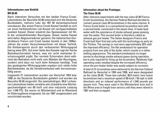
Informationen zum Vorbild: BR 50.40Nach intensiven Versuchen mit den beiden Franco-Crosti-Lokomotiven der Baureihe 42.90 entschied sich die Deutsche Bundesbahn, mehrere Loks der BR 50 dementsprechend umzubauen. Bei einem Franco-Crosti-Kessel handelt es sich um einen herkömmlichen Lok-Kessel mit nachgeschaltetem zweitem Kessel. Dieser erwärmt das Speisewasser mit Hil-fe der vorbeiströmenden Rauchgase. Dieser zweite Kessel wird daher Abgasvorwärmer genannt. Die italienischen Kon-strukteure Franco und Crosti bauten bereits in den 1930er-Jahren die ersten Versuchsmaschinen mit dieser Technik. Die Kohleersparnis durch den verbesserten Wirkungsgrad betrug etwa 20%. Auf einer Seite des Kessels ragt der flache Betriebsschornstein heraus, was ein recht markantes Er-scheinungsbild ergibt. Der normale Schornstein dient wäh-rend des Betriebes nicht mehr zum Ableiten der Rauchgase, sondern wird dazu nur noch beim Anheizen benötigt. Trotz des gesteigerten Wirkungsgrades ergaben sich relativ hohe Betriebskosten, da die Vorwärmerkessel sehr korrosionsan-fällig waren.Insgesamt 31 Lokomotiven wurden von Henschel 1954 bzw. 1958 an die Deutsche Bundesbahn geliefert und wurden als Baureihe 50.40 eingereiht. Die zweizylindrigen, 90,6 t schwe-ren Lokomotiven hatten vorwärts wie rückwärts eine Höchst-geschwindigkeit von 80 km/h und eine induzierte Leistung von 1.540 PSi. Sie waren im Münsterland und im Rheinland im Güterzugdienst eingesetzt, bis sie 1967 ausgemustert und verschrottet wurden.
Information about the Prototype: The Class 50.40After intensive experiments with the two class 42.90 Franco-Crosti locomotives, the German Federal Railroad decided to convert several class 50 locomotives in the same manner. A Franco Crosti boiler is a conventional locomotive tank with a second boiler connected in the steam lines. It heats feed water with the assistance of smoke exhaust gases passing over the water. This second boiler is therefore called an exhaust gas pre-heater. The Italian designers Franco and Crosti built their first test units with this technology as early as the Thirties. The savings in coal were approximately 20% with the improved efficiency. The flat smokestack for operation projects from one side of the boiler, which results in a rather striking appearance. The standard smokestack no longer serves to discharge smoke exhaust gases during operation, but is only required for firing up the locomotive. Relatively high operating costs resulted despite the increased efficiency, since the pre-heater boiler was easily subject to corrosion.A total of 31 locomotives were delivered to the German Federal Railroad by Henschel in 1954 and 1958, and were designated as the class 50.40. These two-cylinder, 90.6 metric tons heavy locomotives had a maximum speed of 80 km/h / 50 mph in both directions and an indexed performance of 1,540 pounds per square inch. They were used in the Münsterland area and in the Rhine area in freight train service until they were retired in 1967 and then scrapped.
5
Informations concernant la locomotive réelle: BR 50.40Après des essais intensifs avec les deux locomotives Fran-co-Crosti de la série 42.90, la Deutsche Bundesbahn décida de transformer en conséquence plusieurs locomotives de la BR 50. Une chaudière Franco-Crosti est une chaudiè-re de locomotive traditionnelle équipée d‘une seconde chaudière montée en aval. Cette dernière préchauffe l‘eau d’alimentation à l‘aide des gaz de fumée en circulation. Cette seconde chaudière est donc appelée «préchauffeur à gaz d‘échappement». Les premières machines d’essai équipées de cette technique furent construites par les Italiens Franco et Crosti dès les années 30. L‘économie de charbon réalisée grâce à l‘amélioration de l‘efficacité était d‘environ 20%. La cheminée d‘exploitation, de forme plate, dépasse de l‘un des côtés de la chaudière, conférant à l‘ensemble une allure ori-ginale. En service, la cheminée normale ne sert plus à éva-cuer les gaz de fumée, fonction qu‘elle ne remplit désormais plus que lors de la mise en chauffe. Malgré l‘amélioration du degré d‘efficacité, les coûts d‘exploitation s‘avérèrent rela-tivement élevés, car la chaudière de préchauffage était très sensible à la corrosion.Au total, 31 locomotives immatriculées dans la série 50.40 fu-rent livrées par Henschel à la Deutsche Bundesbahn en 1954, resp. 1958. Ces locomotives à deux cylindres et d‘un poids de 90,6 t affichaient une vitesse maximale de 80 km/h, en mar-che avant comme en marche arrière, ainsi qu‘une puissance développée de 1540 ch. Elles furent affectées au trafic mar-chandises dans la région de Münster et en Rhénanie jusqu‘à ce qu‘elles soient réformées et mises à la ferraille en 1967.
Informatie van het voorbeeld: Serie 50.40Na intensieve tests met de beide Franco-Crosti-locomotie-ven van de serie 42.90 besloot de Deutsche Bundesbahn meerdere locs van de serie 50 dienovereenkomstig om te bouwen. Bij een Franco-Crosti-ketel gaat het om een traditionele loc-ketel met nageschakeld een tweede ketel. Deze verwarmt het voedingswater met behulp van de voor-bijstromende rookgassen. Deze tweede ketel wordt daarom uitlaatgasvoorverwarmer genoemd. De Italiaanse construc-teurs Franco en Crosti bouwden reeds in de jaren dertig de eerste testmachines met deze techniek. De besparing op kolen door het verbeterde rendement bedroeg ongeveer 20%. Op een zijde van de ketel steekt de platte bedrijfs-schoorsteen uit, wat stellig een markante verschijning op-levert. De normale schoorsteen dient tijdens het bedrijf niet meer voor het afvoeren van de rookgassen, maar is daartoe alleen nog bij het opstoken nodig. Ondanks de toegenomen effectiviteit ontstonden relatief hoge bedrijfskosten, omdat de voorverwarmerketels zeer corrosiegevoelig waren.In totaal werden 31 locomotieven door Henschel in 1954, resp. in 1958 aan de Deutsche Bundesbahn geleverd en ze werden als serie 50.40 in het bestand opgenomen. De tweecilinder, 90,6 t zware locomotieven hadden vooruit en achteruit een maximumsnelheid van 80 km/h en een geïn-diceerd vermogen van 1.540 pki. Ze waren in Münsterland en in het Rijnland in de goederentreindienst ingezet tot ze in 1967 buiten dienst gesteld en verschroot werden.
6
Sicherheitshinweise • DieLokdarfnurmiteinemdafürbestimmtenBetriebssys-
tem eingesetzt werden.• Analogmax.15Volt=,digitalmax.22Volt~.• DieLokdarfnurausalseinerLeistungsquelleversorgt
werden.• BeachtenSieunbedingtdieSicherheitshinweiseinder
Bedienungsanleitung zu Ihrem Betriebssystem.• FürdenkonventionellenBetriebderLokmussdasAn-
schlussgleis entstört werden. Dazu ist das Entstörset 611 655 zu verwenden. Für Digitalbetrieb ist das Entstör-set nicht geeignet.
• ACHTUNG! Funktionsbedingte scharfe Kanten und Spitzen.• SetzenSiedasModellkeinerdirektenSonneneinstrah-
lung, starken Temperaturschwankungen oder hoher Luftfeuchtigkeit aus.
Wichtige Hinweise • DieBedienungsanleitungunddieVerpackungsind
Bestandteil des Produktes und müssen deshalb aufbe-wahrt sowie bei Weitergabe des Produktes mitgegeben werden.
• FürReparaturenoderErsatzteilewendenSiesichbitteanIhren Trix-Fachhändler.
• http://www.maerklin.com/en/imprint.html
Funktionen • EingebauteElektronikzumwahlweisenBetriebmit
konventionellem Gleichstrom-Fahrgerät (max. ±12 Volt), Trix Systems oder Digitalsystemen nach NMRA-Norm.
• AutomatischeSystemerkennungzwischenDigital-undAnalog-Betrieb.
• DervolleFunktionsumfangistnurunterTrixSystemsundunter DCC verfügbar.
• Eingebaute,fahrtrichtungsabhängigeStirnbeleuchtung. Im Digitalbetrieb schaltbar.
• BefahrbarerMindestradius360mm.
Hinweise zum Digitalbetrieb • DiegenaueVorgehensweisezumEinstellenderdiversen
Parameter entnehmen Sie bitte der Bedienungsanleitung Ihrer Mehrzug-Zentrale.
• DieabWerkeingestelltenWertesindsogewählt,dassbestmöglichstes Fahrverhalten gewährleistet ist.
• DerBetriebmitgegenpoligerGleichspannungimBremsabschnitt ist mit der werkseitigen Einstellung nicht möglich. Ist diese Eigenschaft gewünscht, so muss auf den konventionellen Gleichstrombetrieb verzichtet werden(CV29/Bit2=0).
Jegliche Garantie-, Gewährleistungs- und Schadensersatzansprüche sind ausge-schlossen, wenn in Trix-Produkten nicht von Trix freigegebene Fremdteile eingebaut werden und/oder Trix-Produkte umgebaut werden und die eingebauten Fremdteile bzw. der Umbau für sodann aufgetretene Mängel und/oder Schäden ursächlich war. Die Darlegungs- und Beweislast dafür, dass der Einbau von Fremdteilen oder der Umbau in bzw. von Trix-Produkten für aufgetretene Mängel und/oder Schäden nicht ursächlich war, trägt die für den Ein- und/oder Umbau verantwortliche Person und/ oder Firma bzw. der Kunde.
7
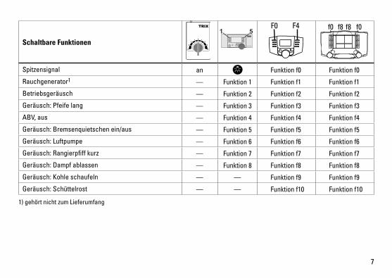
Schaltbare Funktionen
Spitzensignal an Funktion f0 Funktion f0
Rauchgenerator1 — Funktion 1 Funktion f1 Funktion f1
Betriebsgeräusch — Funktion 2 Funktion f2 Funktion f2
Geräusch:Pfeifelang — Funktion 3 Funktion f3 Funktion f3
ABV, aus — Funktion 4 Funktion f4 Funktion f4
Geräusch:Bremsenquietschenein/aus — Funktion 5 Funktion f5 Funktion f5
Geräusch:Luftpumpe — Funktion 6 Funktion f6 Funktion f6
Geräusch:Rangierpfiffkurz — Funktion 7 Funktion f7 Funktion f7
Geräusch:Dampfablassen — Funktion 8 Funktion f8 Funktion f8
Geräusch:Kohleschaufeln — — Funktion f9 Funktion f9
Geräusch:Schüttelrost — — Funktion f10 Funktion f10
STOP mobile station
1 5 f0 f8 f0f8F0 F4
1) gehört nicht zum Lieferumfang

8
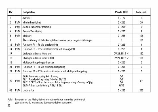
CV Bedeutung Wert DCC ab Werk
1 Adresse 1 - 127 3
2 PoM Minimalgeschwindigkeit 0 - 255 20
3 PoM Anfahrverzögerung 0 - 255 6
4 PoM Bremsverzögerung 0 - 255 4
5 PoM Maximalgeschwindigkeit 0 - 255 195
8 Werkreset/Herstellerkennung 8 131
13 PoM Funktionen F1 - F8 im Analogbetrieb 0 - 255 1
14 PoM Funktionen F9 - F15 und Licht im Analogbetrieb 0 - 255 1
17 Erweiterte Adresse (oberer Teil) CV29,Bit5=1 192
18 Erweiterte Adresse (unterer Teil) CV29,Bit5=1 128
19 Traktionsadresse 0 - 255 0
21 PoM Funktionen F1 - F8 bei Traktion 0 - 255 0
22 PoM Funktionen F9 - F15 und Licht bei Traktion 0 - 255 0
29 PoM
Bit0:UmpolungFahrtrichtung Bit1:AnzahlFahrstufen14oder28/128 Bit2:DCCBetriebmitBremsstrecke(keinAnalogbetriebmöglich) Bit5:Adressumfang7Bit/14Bit
0/1 0/2 0/4
0/32
6*
63 PoM Lautstärke 0 - 255 255
PoM Program on the Main; muss vom Steuergerät unterstützt werden.* Die Werte der gewünschten Einstellungen sind zu addieren!
9
Functions • Built-inelectroniccircuitforoperationwithaconven-
tional DC power pack (max. ±12 volts), Trix Systems or NMRA DCC digital systems.
• Automaticsystemrecognitionbetweendigitalandanalogoperation.
• ThefullrangeoffunctionsisonlyavailableunderTrixSystems and under DCC.
• Built-inheadlightsthatchangeoverwiththedirectionoftravel. They can be turned on and off in digital operation.
• Minimumradiusforoperationis360mm/14-3/16“.
Notes on digital operation • Theoperatinginstructionsforyourcentralunitwillgive
you exact procedures for setting the different parame-ters.
• Thevaluessetatthefactorywereselectedtoguaranteethe best possible running characteristics.
• Thesettingdoneatthefactorydoesnotpermitoperationwith opposite polarity DC power in the braking block. If you want this characteristic, you must do without conventionalDCpoweroperation(CV29/Bit2=0).
No warranty or damage claims shall be accepted in those cases where parts neither manufactured nor approved by Trix have been installed in Trix products or where Trix products have been converted in such a way that the non-Trix parts or the conversion were causal to the defects and/or damage arising. The burden of presenting evidence and the burden of proof thereof, that the installation of non-Trix parts or the conversion in or of Trix products was not causal to the defects and/or damage arising, is borne by the person and/or company responsible for the installation and/or conversion, or by the customer.
Safety Notes• Thislocomotiveisonlytobeusedwiththeoperating
system it is designed for.• Analogmax.15voltsDC,digitalmax.22voltsAC.• Thislocomotivemustnotbesuppliedwithpowernever
from more than one power source.• Pleasemakenoteofthesafetynotesintheinstructions
for your operating system.• Thefeedertrackmustbeequippedtopreventinter-
ference with radio and television reception, when the locomotive is to be run in conventional operation. The 611 655 interference suppression set is to be used for this purpose. The interference suppression set is not suitable for digital operation.
• WARNING! Sharp edges and points required for operation.• Donotexposethemodeltodirectsunlight,extreme
changes in temperature, or high humidity.
Important Notes• Theoperatinginstructionsandthepackagingareacom-
ponent part of the product and must therefore be kept as well as transferred along with the product to others.
• PleaseseeyourauthorizedTrixdealerforrepairsorspare parts.
• http://www.maerklin.com/en/imprint.html
10
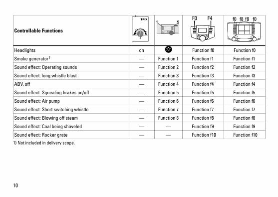
Controllable Functions
Headlights on Function f0 Function f0
Smoke generator1 — Function 1 Function f1 Function f1
Soundeffect:Operatingsounds — Function 2 Function f2 Function f2
Soundeffect:longwhistleblast — Function 3 Function f3 Function f3
ABV, off — Function 4 Function f4 Function f4
Soundeffect:Squealingbrakeson/off — Function 5 Function f5 Function f5
Soundeffect:Airpump — Function 6 Function f6 Function f6
Soundeffect:Shortswitchingwhistle — Function 7 Function f7 Function f7
Soundeffect:Blowingoffsteam — Function 8 Function f8 Function f8
Soundeffect:Coalbeingshoveled — — Function f9 Function f9
Soundeffect:Rockergrate — — Function f10 Function f10
STOP mobile station
1 5 f0 f8 f0f8F0 F4
1) Not included in delivery scope.
11
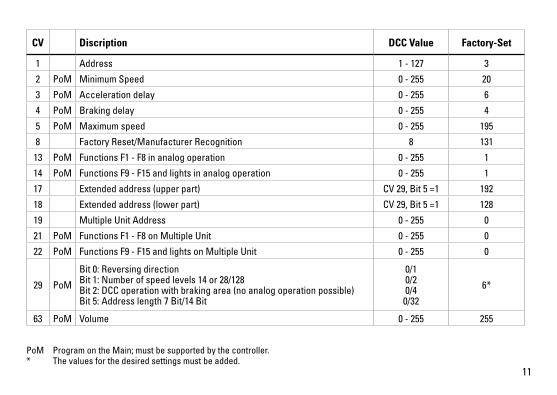
PoM Program on the Main; must be supported by the controller.* The values for the desired settings must be added.
CV Discription DCC Value Factory-Set
1 Address 1 - 127 3
2 PoM Minimum Speed 0 - 255 20
3 PoM Acceleration delay 0 - 255 6
4 PoM Braking delay 0 - 255 4
5 PoM Maximum speed 0 - 255 195
8 Factory Reset/Manufacturer Recognition 8 131
13 PoM Functions F1 - F8 in analog operation 0 - 255 1
14 PoM Functions F9 - F15 and lights in analog operation 0 - 255 1
17 Extended address (upper part) CV29,Bit5=1 192
18 Extended address (lower part) CV29,Bit5=1 128
19 Multiple Unit Address 0 - 255 0
21 PoM Functions F1 - F8 on Multiple Unit 0 - 255 0
22 PoM Functions F9 - F15 and lights on Multiple Unit 0 - 255 0
29 PoM
Bit0:Reversingdirection Bit1:Numberofspeedlevels14or28/128 Bit2:DCCoperationwithbrakingarea(noanalogoperationpossible) Bit5:Addresslength7Bit/14Bit
0/1 0/2 0/4
0/32
6*
63 PoM Volume 0 - 255 255

12
Remarques importantes sur la sécurité • Lalocomotivenepeutêtreutiliséequ‘aveclesystème
d‘exploitation indiqué.• Analogiquemax.15Volt=,numériquemax.22Volt~.• Lalocomotivenepeutpasêtrealimentéeélectriquement
par plus d‘une source de courant à la fois.• Ilestimpératifdetenircomptedesremarquessurla
sécurité décrites dans le mode d‘emploi de votre système d‘exploitation.
• Pour l’exploitation de la locomotive en mode conventi-onnel,lavoiederaccordementdoitêtredéparasitée.Acet effet, utiliser le set de déparasitage réf. 611 655. Le set de déparasitage ne convient pas pour l’exploitation en mode numérique.
• ATTENTION! Pointes et bords coupants lors du fonctionne-ment du produit.
• Nepasexposerlemodèleàunensoleillementdirect,à de fortes variations de température ou à un taux d‘humidité important.
Informations importante• Lanoticed‘utilisationetl’emballagefontpartieintégranteduproduit;ilsdoiventdoncêtreconservéset,lecaséchéant, transmis avec le produit.
• Pourtouteréparationouremplacementdepièces,adressez vous à votre détaillant-spécialiste Trix.
• http://www.maerklin.com/en/imprint.html
Fonctionnement • Electroniqueintégréepourexploitationauchoixavectrans-
formateur-régulateur conventionnel délivrant du courant continu (max. ±12 volts), avec Trix Systems ou avec des systèmes de conduite digitale conformes aux normes NMRA.
• Reconnaissanceautomatiquedusystèmeentreexploita-tions numérique et analogique.
• L’intégralitédesfonctionsestdisponibleuniquementenexploitation Trix Systems et DCC.
• Feuxdesignalisations‘inversantselonlesensdemar-che; feux commutables en exploitation digital.
• Rayonminimald’inscriptionencourbe360mm.
Remarques relatives au fonctionnement en mode digital • Encequiconcernelaprocédurederéglagedesdivers
paramètres, veuillez vous référer au mode d‘emploi de votre centrale de commande multitrain.
• Lesvaleursparamétréesd’usinesontchoisiesdemanièreà garantir le meilleur comportement de roulement possible.
• L’exploitationaveccourantcontinudepolaritéinversedans les sections de freinage n’est pas possible avec le réglage d’usine. Si cette propriété est désirée, il faut alors renoncer à l’exploitation conventionnelle en cou-rantcontinu(CV29/Bit2=0).
Tout recours à une garantie commerciale ou contractuelle ou à une demande de dommages-intérêtestexclusidespiècesnonautoriséesparTrixsontintégréesdansles produits Trix et/ou si les produits Trix sont transformés et si les pièces d’autres fabricants montées ou la transformation constituent la cause des défauts et/ou dommages apparus. C’est à la personne et/ou la société responsable du montage/de la transformation ou au client qu’incombe la charge de prouver que le montage des pièces d’autres fabricants sur des produits Trix ou la transformation des produits Trix n’est pas à l’origine des défauts et ou dommages apparus.

13
Fonctions commutables
Fanal éclairage Activé Fonction f0 Fonction f0
Générateur de fumée1 — Fonction 1 Fonction f1 Fonction f1
Bruitage:bruitd’exploitation — Fonction 2 Fonction f2 Fonction f2
Bruitage:siffletlongueur — Fonction 3 Fonction f3 Fonction f3
ABV,darrêt — Fonction 4 Fonction f4 Fonction f4
Bruitage:grincementdefreinsmarche/arrêt — Fonction 5 Fonction f5 Fonction f5
Bruitage:Compresseur — Fonction 6 Fonction f6 Fonction f6
Bruitage:Siffletpourmanœuvrecourt — Fonction 7 Fonction f7 Fonction f7
Bruitage:Échappementdelavapeur — Fonction 8 Fonction f8 Fonction f8
Bruitage:Pelletageducharbon — — Fonction f9 Fonction f9
Bruitage:Grilleàsecousses — — Fonction f10 Fonction f10
STOP mobile station
1 5 f0 f8 f0f8F0 F4
1) Ne fait pas partie de la fourniture.
14
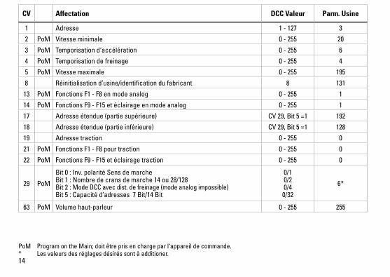
PoM ProgramontheMain;doitêtreprisenchargeparl’appareildecommande.* Les valeurs des réglages désirés sont à additioner.
CV Affectation DCC Valeur Parm. Usine
1 Adresse 1 - 127 3
2 PoM Vitesse minimale 0 - 255 20
3 PoM Temporisation d‘accélération 0 - 255 6
4 PoM Temporisation de freinage 0 - 255 4
5 PoM Vitesse maximale 0 - 255 195
8 Réinitialisation d’usine/identification du fabricant 8 131
13 PoM Fonctions F1 - F8 en mode analog 0 - 255 1
14 PoM Fonctions F9 - F15 et éclairage en mode analog 0 - 255 1
17 Adresse étendue (partie supérieure) CV29,Bit5=1 192
18 Adresse étendue (partie inférieure) CV29,Bit5=1 128
19 Adresse traction 0 - 255 0
21 PoM Fonctions F1 - F8 pour traction 0 - 255 0
22 PoM Fonctions F9 - F15 et éclairage traction 0 - 255 0
29 PoM
Bit0:Inv.polaritéSensdemarche Bit1:Nombredecransdemarche14ou28/128 Bit2:Mode DCC avec dist. de freinage (mode analog impossible) Bit5:Capacitéd’adresses7Bit/14Bit
0/1 0/2 0/4
0/32
6*
63 PoM Volume haut-parleur 0 - 255 255

15
Veiligheidsvoorschriften• Delocmagalleenmeteendaarvoorbestemdbedrijfssys-
teem gebruikt worden.• Analoogmax.15Volt=,digitaalmax.22Volt~.• Delocmagnietvanuitmeerdanéénstroomvoorziening
gelijktijdig gevoed worden.• Leesookaandachtigdeveiligheidsvoorschrifteninde
gebruiksaanwijzing van uw bedrijfssysteem. • Voorhetconventionelebedrijfmetdelocdientde
aansluitrail te worden ontstoort. Hiervoor dient men de ontstoor-set 611 655 te gebruiken. Voor het digitale bedrijf is deze ontstoor-set niet geschikt.
• OPGEPAST! Functionele scherpe kanten en punten.• Stelhetmodelnietblootaanindirectezonnestraling,
sterke temperatuurwisselingen of hoge luchtvochtigheid.
Belangrijke informatie• Degebruiksaanwijzingendeverpakkingzijneenbe-
standdeel van het product en dienen derhalve bewaard en meegeleverd te worden bij het doorgeven van het product.
• VoorreparatiesenonderdelenkuntzichtotUwTrixhandelaar wenden.
• http://www.maerklin.com/en/imprint.html
Functies• Ingebouwdeelektronicadiehetmogelijkmaaktomnaar
keuze met, een conventionele gelijkstroomrijregelaar (max. ±12 Volt), Trix Systems of digitaalsysteem volgens NMRA-norm te rijden.
• Automatischesysteemherkenningtussendigitaal-enanaloogbedrijf.
• Devolledigetoegangtotallefunctiesisalleenmogelijkmet Trix Systems of met DCC bedrijf.
• Ingebouwde,rijrichtingsafhankelijkefrontverlichting.• Minimaleteberijdenradius:360mm.
Aanwijzingen voor digitale besturing • Hetopdejuistewijzeinstellenvandediverseparame-
ters staat beschreven in de handleiding van uw digitale Centrale.
• Devanafdefabriekingesteldewaardenzijnzoingestelddat de rij-eigenschappen optimaal zijn.
• Hetbedrijfmettegengepooldegelijkspanningindeafrem-sectie is met de fabrieksinstelling niet mogelijk. Indien deze eigenschap wenselijk is, dan moet worden afgezien van hetconventioneelgelijkstroombedrijf(CV29/Bit2=0).
Elke aanspraak op garantie en schadevergoeding is uitgesloten, wanneer in Trix-producten niet door Trix vrijgegeven vreemde onderdelen ingebouwd en/of Trix-producten omgebouwd worden en de ingebouwde vreemde onderdelen resp. de ombouw oorzaak van nadien opgetreden defecten en/of schade was. De aantoonplicht en de bewijslijst daaromtrent, dat de inbouw van vreemde onderdelen in Trix-producten of de ombouw van Trix-producten niet de oorzaak van opgetreden defecten en/of schade is geweest, berust bij de voor de inbouw en/of ombouw verantwoordelijke persoon en/of firma danwel bij de klant.
16
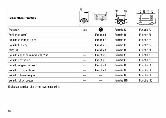
Schakelbare functies
Frontsein aan Functie f0 Functie f0
Rookgenerator1 — Functie 1 Functie f1 Functie f1
Geluid:bedrijfsgeluiden — Functie 2 Functie f2 Functie f2
Geluid:fluitlang — Functie 3 Functie f3 Functie f3
ABV, uit — Functie 4 Functie f4 Functie f4
Geluid:piependeremmenaan/uit — Functie 5 Functie f5 Functie f5
Geluid:luchtpomp — Functie 6 Functie f6 Functie f6
Geluid:rangeerfluitkort — Functie 7 Functie f7 Functie f7
Geluid:stoomafblazen — Functie 8 Functie f8 Functie f8
Geluid:kolenscheppen — — Functie f9 Functie f9
Geluid:schudrooster — — Functie f10 Functie f10
STOP mobile station
1 5 f0 f8 f0f8F0 F4
1) Maakt geen deel uit van het leveringspakket.
17
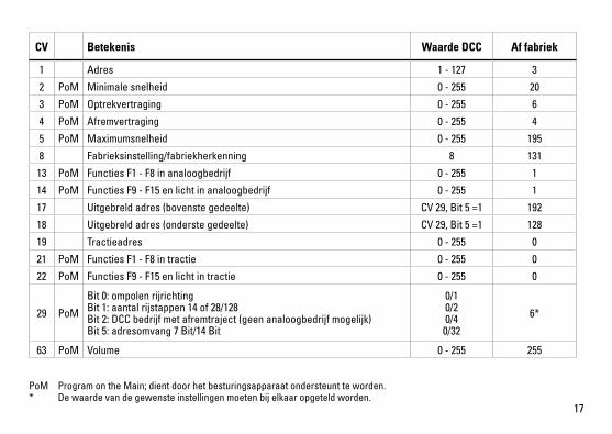
PoM Program on the Main; dient door het besturingsapparaat ondersteunt te worden. * De waarde van de gewenste instellingen moeten bij elkaar opgeteld worden.
CV Betekenis Waarde DCC Af fabriek
1 Adres 1 - 127 3
2 PoM Minimale snelheid 0 - 255 20
3 PoM Optrekvertraging 0 - 255 6
4 PoM Afremvertraging 0 - 255 4
5 PoM Maximumsnelheid 0 - 255 195
8 Fabrieksinstelling/fabriekherkenning 8 131
13 PoM Functies F1 - F8 in analoogbedrijf 0 - 255 1
14 PoM Functies F9 - F15 en licht in analoogbedrijf 0 - 255 1
17 Uitgebreld adres (bovenste gedeelte) CV29,Bit5=1 192
18 Uitgebreld adres (onderste gedeelte) CV29,Bit5=1 128
19 Tractieadres 0 - 255 0
21 PoM Functies F1 - F8 in tractie 0 - 255 0
22 PoM Functies F9 - F15 en licht in tractie 0 - 255 0
29 PoM
Bit0:ompolenrijrichting Bit1:aantalrijstappen14of28/128 Bit2:DCCbedrijfmetafremtraject(geenanaloogbedrijfmogelijk) Bit5:adresomvang7Bit/14Bit
0/1 0/2 0/4
0/32
6*
63 PoM Volume 0 - 255 255
18
Aviso de seguridad • Lalocomotorasolamentedebefuncionarenelsistema
que le corresponda. • Analógicasmáx.15voltios=,digitalesmáx.22voltios~.• Lalocomotoranodeberárecibircorrientemásquedeun
solo punto de abasto a la vez. • Observenecesariamentelosavisosdeseguridadindica-
dos en las instrucciones correspondientes a su sistema de funcionamiento.
• Paraelfuncionamientoconvencionaldelalocomotoradebensuprimirselasinterferenciasenlavíadeconexióndelaalimentación.Paraellodebeemplearseelsetsupresor de interferencias 611 655.
• ¡ATENCIÓN! Esquinas y puntas afiladas condicionadas a lafunción.
• Noexponerelmodeloenminiaturaalaradiaciónsolardirecta, a oscilaciones fuertes de temperatura o a una humedad del aire elevada.
Informaciones importantes • Lasinstruccionesdeempleoyelembalajeformanparte
íntegra del producto y, por este motivo, deben guardarse y entregarse junto con el producto en el caso de venderlo o transmitirlo a otro.
• Encasodeprecisarunareparaciónopiezasderecambio,rogamos ponerse en contacto con su distribuidor Trix.
• http://www.maerklin.com/en/imprint.html
Funciones• Electrónicaincorporadaparaunfuncionamientoadiscre-ciónencorrientecontinuaconvencional(máx.±12V.),TrixSystems o sistemas Digital según las normas NMRA.
• Detecciónautomáticadelsistemaentrelosmodosdigitalyanalógico.
• Laplenafuncionalidaddefuncionesestádisponiblesóloen Trix Systems y en DCC.
• Losfarosfrontalesdependendelsentidodelamarcha. En Digital se pueden encender y apagar.
• Radiomínimodescribe360mm.
Informaciones para el funcionamiento digital • Deberáconsultarelprocedimientoexactodeconfi-guracióndelosdiversosparámetrosenelmanualdeinstrucciones de la central multitren que desee utilizar.
• Losvaloresconfiguradosenfábricasehanelegidodemodo que queden garantizadas las mejores característi-casdeconducciónposibles.
• Noesposibleelfuncionamientocontensióndecorrientecontinua de polaridad opuesta en el tramo de frenado en funcionamiento en modo DCC. Si se desea esta caracterí-stica, debe renunciarse al funcionamiento convencional concorrientecontinua(CV29/Bit2=0).
Seexcluyetododerechodegarantía,prestacióndegarantíaeindemnizaciónsobreaquellos productos Trix en los que se hubieran montado piezas ajenas no autorizadas por Trix y/o sobre aquellos productos Trix que hayan sido modificados cuando la piezas ajenasmontadasolamodificaciónseanlascausasdelosdesperfectosy/odañosposteriormente surgidos. La persona y/o empresa o el cliente responsable del montaje omodificaciónseráelresponsabledeprobaryalegarqueelmontajedepiezasajenasolamodificaciónen/deproductosTrixnosonlascausasdelosdesperfectosy/odañossurgidos.

19
Funciones posibles
Faros frontales encendido Funciónf0 Funciónf0
Generador de humo1 — Función1 Funciónf1 Funciónf1
Ruido:Ruidodeexplotación — Función2 Funciónf2 Funciónf2
Ruido del silbido larga — Función3 Funciónf3 Funciónf3
ABV, apagado — Función4 Funciónf4 Funciónf4
Ruido:Chirridodelosfrenosencendido/apagado — Función5 Funciónf5 Funciónf5
Ruido:Bombadeaire — Función6 Funciónf6 Funciónf6
Ruido:Silbatodemaniobrascorta — Función7 Funciónf7 Funciónf7
Ruido:Purgarvapor — Función8 Funciónf8 Funciónf8
Ruido:Cargarcarbónconpala — — Funciónf9 Funciónf9
Ruido:Parrillavibratoria — — Funciónf10 Funciónf10
STOP mobile station
1 5 f0 f8 f0f8F0 F4
1) No está incluido en el conjunto de piezas suministradas.

20
PoM Program on the Main; debe ser soportado por la unidad de control. * ¡Los valores de los ajustes deseados deben sumarse!
CV Significado Valor DCC Preselec-ción
1 Códigos 1 - 127 3
2 PoM Velocidad mínima 0 - 255 20
3 PoM Arranque progresivo 0 - 255 6
4 PoM Frenado progresivo 0 - 255 4
5 PoM Velocidad máxima 0 - 255 195
8 Resetdefábrica/códigodefabricante 8 131
13 PoM FuncionesF1-F8enelmodoanalógico 0 - 255 1
14 PoM FuncionesF9-F15ylucesenelmodoanalógico 0 - 255 1
17 Direcciónampliada(partesuperior) CV29,Bit5=1 192
18 Direcciónampliada(parteinferior) CV29,Bit5=1 128
19 Direccióndetracción 0 - 255 0
21 PoM FuncionesF1-F8entracción 0 - 255 0
22 PoM FuncionesF9-F15ylucesentracción 0 - 255 0
29 PoM
Bit0:Cambiodepolaridaddelsentidodemarcha Bit1:Númerodenivelesdemarcha14ó28/128 Bit2:ModoDCCcontrayectodefrenado(noesposibleelmodoanalógico) Bit5:Tamañodedirecciones7Bits/14Bits
0/1 0/2 0/4
0/32
6*
63 PoM Volumen del sonido 0 - 255 255
21
Avvertenze per la sicurezza • Talelocomotivadevevenireimpiegatasoltantoconun
sistema di esercizio prestabilito a questo scopo.• Analogicomax.15Volt=,digitalemax.22Volt~.• Lalocomotivanondevevenirealimentatanellostesso
tempo con più di una sorgente di potenza.• Vogliateprestareassolutamenteattenzionealleavverten-
ze di sicurezza nelle istruzioni di impiego per il Vostro sistema di funzionamento.
• Perilfunzionamentotradizionaledellalocomotivailbinario di alimentazione deve essere protetto dai disturbi. A tale scopo si deve impiegare il corredo antidisturbi 611 655. Tale corredo antidisturbi non è adatto per il funzionamento Digital.
• AVVERTENZA! Per motivi funzionali i bordi e le punte sono spigolosi.
• Nonesponetetalemodelloadalcunirraggiamentosolarediretto, a forti escursioni di temperatura oppure a elevata umidità dell’aria.
Avvertenze importanti• Leistruzionidiimpiegoel’imballaggiocostituisconoun
componente sostanziale del prodotto e devono pertanto venire conservati nonché consegnati insieme in caso di ulteriore cessione del prodotto.
• Perleriparazioniolepartidiricambio,contrattareilrivenditore Trix.
• http://www.maerklin.com/en/imprint.html
Funzioni• Moduloelettronicoincorporatoperilfunzionamentoa
scelta con un tradizionale regolatore di marcia in corren-te continua (max. 12 volt), Trix Systems oppure sistemi digitali in base alla normativa NMRA.
• RiconoscimentoautomaticodelsistematraesercizioDigital ed analogico.
• Lacompletadotazionedifunzionièdisponibilesoltantosotto Trix Systems e sotto DCC.
• IIlluminazioneditestaincorporata,dipendentedalladire-zione di marcia. Commutabile nel funzionamento Digital.
• Raggiominimopercorribile360mm.
Istruzioni per la funzione digitale • L’esattoprocedimentoperl’impostazionedeidifferenti
parametri siete pregati di ricavarlo dalle istruzioni di servizio della Vostra centrale per molti treni.
• I valori impostati dalla fabbrica sono scelti in modo tale che sia assicurato il comportamento di marcia migliore possibile.
• Unfunzionamentocontensionecontinuadipolaritàin-vertita nella sezione di frenatura, in caso di esercizio con DCC, non è possibile. Se si desidera questa caratteristica, si deve in tal caso rinunciare al funzionamento tradiziona-leincorrentecontinua(CV29/Bit2=0).
Trix non fornisce alcuna garanzia, assicurazione e risarcimento danni in caso di montag-gio sui prodotti Trix di componenti non espressamente approvati dalla ditta. Trix altresì non risponde in caso di modifiche al prodotto, qualora i difetti e i danni riscontrati sullo stesso siano stati causati da modifiche non autorizzate o dal montaggio di componente esterni da lei non approvati. L‘onere della prova che i componenti montati e le modifiche apportate non sono state la causa del danno o del difetto, resta a carico del cliente o della persona/ditta che ha effettuato il montaggio di componenti estranei o che ha apportato modifiche non autorizzate.
22
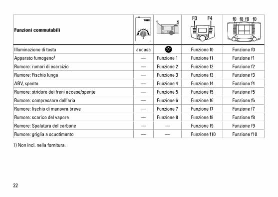
Funzioni commutabili
Illuminazione di testa accesa Funzione f0 Funzione f0
Apparato fumogeno1 — Funzione 1 Funzione f1 Funzione f1
Rumore:rumoridiesercizio — Funzione 2 Funzione f2 Funzione f2
Rumore:Fischiolunga — Funzione 3 Funzione f3 Funzione f3
ABV, spente — Funzione 4 Funzione f4 Funzione f4
Rumore:stridoredeifreniaccese/spente — Funzione 5 Funzione f5 Funzione f5
Rumore:compressoredell’aria — Funzione 6 Funzione f6 Funzione f6
Rumore:fischiodimanovrabreve — Funzione 7 Funzione f7 Funzione f7
Rumore:scaricodelvapore — Funzione 8 Funzione f8 Funzione f8
Rumore:Spalaturadelcarbone — — Funzione f9 Funzione f9
Rumore:grigliaascuotimento — — Funzione f10 Funzione f10
STOP mobile station
1 5 f0 f8 f0f8F0 F4
1) Non incl. nella fornitura.
23
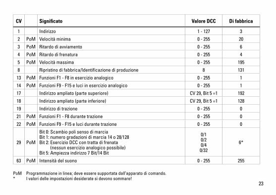
PoM Programmazione in linea; deve essere supportata dall’apparato di comando.* I valori delle impostazioni desiderate si devono sommare!
CV Significato Valore DCC Di fabbrica
1 Indirizzo 1 - 127 3
2 PoM Velocità minima 0 - 255 20
3 PoM Ritardo di avviamento 0 - 255 6
4 PoM Ritardo di frenatura 0 - 255 4
5 PoM Velocità massima 0 - 255 195
8 Ripristino di fabbrica/Identificazione di produzione 8 131
13 PoM Funzioni F1 - F8 in esercizio analogico 0 - 255 1
14 PoM Funzioni F9 - F15 e luci in esercizio analogico 0 - 255 1
17 Indirizzo ampliato (parte superiore) CV29,Bit5=1 192
18 Indirizzo ampliato (parte inferiore) CV29,Bit5=1 128
19 Indirizzo di trazione 0 - 255 0
21 PoM Funzioni F1 - F8 durante trazione 0 - 255 0
22 PoM Funzioni F9 - F15 e luci durante trazione 0 - 255 0
29 PoM
Bit0:Scambiopolisensodimarcia Bit1:numerogradazionidimarcia14o28/128 Bit2:EsercizioDCCcontrattadifrenata (nessun esercizio analogico possibile) Bit5:Ampiezzaindirizzo7Bit/14Bit
0/1 0/2 0/4
0/32
6*
63 PoM Intensità del suono 0 - 255 255
24
Säkerhetsanvisningar • Loketfårendastkörasmeddärtillavsettdriftsystem.• Analogmax.15Volt=,digitalmax.22Volt~.• Loketfårintesamtidigtförsörjasavmeränenkraftkälla.• Beaktaalltidsäkerhetsanvisningarnaibruksanvisningen
som hör till respektive driftsystemet. • Närdenmotorförseddalokdelenskakörasmedkon-
ventionell drift måste anlutningsskenan vara avstörd. Till detta använder man anslutningsgarnityr 611 655 med avstörning och överbelastningsskydd. Avstörningsskyd-det får inte användas vid digital körning.
• VARNING! Funktionsbetingade vassa kanter och spetsar.• Modellenfårinteutsättasfördirektsolljus,häftigatem-
peraturväxlingar eller hög luftfuktighet.
Viktiga informationer • Bruksanvisningenochförpackningenärendelav
produkten och måste därför sparas och alltid medfölja produkten.
• KontaktadinTrix-handlareförreparationerellerreserv-delar.
• http://www.maerklin.com/en/imprint.html
Funktioner • Inbyggdelektronikförvalfridriftmedkonventionell
likströmskörenhet (max ±12 Volt), Trix Systems eller Digitalsystem enligt NMRA-standard.
• Automatisksystem-igenkänningmellandigital-ochanalogtrafik.
• Fullständigtfunktionsomfångerhållsendastvidanvänd-ning av Trix Systems eller DCC.
• Körriktningsberoendefrontbelysning. Kan kopplas in vid digital drift.
• Kanköraspåenminstaradieav360mm.
Anvisningar för digital drift • Detaljeradeanvisningarförattställainolikaparametrar
finns i bruksanvisningen till Er digitala flertågs-körkon-troll.
• Fabriksinställdavärdenharvaltsförattgebästamöjligaköregenskaper.
• VidDCC-driftkanmaninteköramedtvåpoliglikspänningpå ett bromsavsnitt. Önskar man ändå genomföra en sådan körning, så måste man förlita sig på konventionell likströmsdrift(CV29/Bit2=0).
Varje form av anspråk på garanti och skadestånd är utesluten om delar används i Trix-produkter som inte har godkänts av Trix och/eller om Trix-produkter har modifi erats och de inbyggda främmande delarna resp. modifi eringen var upphov till de därefter uppträdande felen och/eller skadorna. Bevisbördan för att inbyggnaden av främmande delar i eller ombyggnaden av Trix-produkter inte är upphovet till de uppträdande felen och/eller skadorna, bär den person och/eller företag resp. kund som är ansvarig för in- och/eller ombyggnaden.
25
Kopplingsbara funktioner
Frontstrålkastare till Funktion f0 Funktion f0
Röksats1 — Funktion 1 Funktion f1 Funktion f1
Ljud:Trafikljud — Funktion 2 Funktion f2 Funktion f2
Ljud:Lokvisslalångt — Funktion 3 Funktion f3 Funktion f3
ABV, från — Funktion 4 Funktion f4 Funktion f4
Ljud:Bromsgnissel,till/från — Funktion 5 Funktion f5 Funktion f5
Ljud:Luftpump — Funktion 6 Funktion f6 Funktion f6
Ljud:Rangervisslakort — Funktion 7 Funktion f7 Funktion f7
Ljud:Ångasläppsut — Funktion 8 Funktion f8 Funktion f8
Ljud:Kolskyfflas — — Funktion f9 Funktion f9
Ljud:Rosterskakas — — Funktion f10 Funktion f10
STOP mobile station
1 5 f0 f8 f0f8F0 F4
1) Ingår inte i leveransen.
26
PoM Program on the Main; debe ser soportado por la unidad de control. * ¡Los valores de los ajustes deseados deben sumarse!
CV Betydelse Värde DCC Fabr.inst.
1 Adress 1 - 127 3
2 PoM Minimihastighet 0 - 255 20
3 PoM Accelerationsfördröjning 0 - 255 6
4 PoM Bromsfördröjning 0 - 255 4
5 PoM Maxfart 0 - 255 195
8 Återställningtillfabrikens/tillverkarensursprungsinställningar 8 131
13 PoM Funktion F1 – F8 vid analog drift 0 - 255 1
14 PoM Funktion F9 – F15 samt loklyktor vid analogdrift 0 - 255 1
17 Utvidgad adress (övre del) CV29,Bit5=1 192
18 Utvidgad adress (undre del) CV29,Bit5=1 128
19 Multippelkopplingsadresser 0 - 255 0
21 PoM Funktion F1 – F8 vid Multippelkoppling 0 - 255 0
22 PoM Funktion F9 – F15 samt strålkastare vid Multippelkoppling 0 - 255 0
29 PoM
Bit0:Polomkastningkörriktning Bit1:Antalpådragssteg14eller28/128 Bit2:DCCTrafikm.bromssträcka(ingenanalogkörningmöjlig) Bit5:Adressomfattning7Bit/14Bit
0/1 0/2 0/4
0/32
6*
63 PoM Ljudstyrka 0 - 255 255
27
Vink om sikkerhed• Lokomotivetmåkunanvendesmedetdriftssystem,derer
beregnet dertil. • Analogmax.15Volt=,digitalmax.22Volt~.• Lokomotivetmåikkeforsynesframereendénstrømkilde
ad gangen.• Værunderalleomstændighederopmærksompådevink
om sikkerhed, som findes i brugsanvisningen for Deres driftssystem.
• Vedkonventioneldriftaflokomotivetskaltilslutningsspo-retstøjdæmpes.Dertilskalanvendesstøjdæmpningssæt-tet611655.Støjdæmpningssætteterikkeegnettildigitaldrift.
• ADVARSEL! Skarpe kanter og spidser pga. funktionen.• Modellenmåikkeudsættesfordirektesollys,storetemperaturudsvingellerhøjluftfugtighed.
Vigtige oplysninger • Betjeningsvejledningogemballagehørertilproduktetogskalderforgemmesogmedfølge,hvisproduktetgivesvidere til andre.
• AngåendereparationerellerreservedelebedesDehenvende Dem til Deres Trix-forhandler.
• http://www.maerklin.com/en/imprint.html
Funktioner • Indbyggetelektroniktilvalgfridriftmedkonventioneltjævnstrømskøreudstyr(maks.±12volt),TrixSystemsellerDigitalsystemer efter NMRA-norm.
• Automatisksystemgenkendelsemellemdigital-ogana-logdrift.
• DetkomplettefunktionsomfangerkuntilrådighedunderTrix Systems og under DCC.
• Innebygd,kjøreretningsavhengigfrontlys. Kantændesogslukkestildigitaldrift.
• Farbarmindsteradius360mm.
Henvisninger til digitaldrift • Dennøjagtigefremgangsmådetilindstillingafdeforskel-
lige parametre findes i betjeningsvejledningen til Deres flertogs-central.
• Deværdier,dererindstilletfrafabrikken,ervalgtsåle-des,atdersikresdebedstmuligekørselsforhold.
• DetervedDCC-driftikkemuligtatanvendedriftmedmodpoletjævnspændingibremseafsnittet.Hvisdenneegenskabønskes,mådergivesafkaldpådenkonventio-nellejævnstrømsdrift(CV29/Bit2=0).
Ethvert garanti-, mangelsansvars- og skadeserstatningskrav er udelukket, hvis der indbygges fremmeddele i Trixprodukter, der ikke er frigivet dertil af Trix og/eller hvis Trixprodukter bygges om og de indbyggede fremmeddele hhv. ombygningen var årsag til sådanne opståede mangler og/eller skader. Det påhviler kunden hhv. den person og/eller det firma, der er ansvarlig for ind- og/eller ombygningen, at påvise hhv. bevise, at indbygningen af fremmeddele i, eller ombygningen af Trixprodukter ikke var årsag til opståede mangler og/eller skader.
28
Styrbare funktioner
Frontbelysning an Funktion f0 Funktion f0
Røggenerator1 — Funktion 1 Funktion f1 Funktion f1
Lyd:Driftslyd — Funktion 2 Funktion f2 Funktion f2
Lyd:Lokomotivfløjtelangt — Funktion 3 Funktion f3 Funktion f3
ABV, fra — Funktion 4 Funktion f4 Funktion f4
Lyd:Pibendebremsertil/fra — Funktion 5 Funktion f5 Funktion f5
Lyd:Luftpumpe — Funktion 6 Funktion f6 Funktion f6
Lyd:Rangerfløjtkort — Funktion 7 Funktion f7 Funktion f7
Lyd:Dampudledning — Funktion 8 Funktion f8 Funktion f8
Lyd:Skovlingafkul — — Funktion f9 Funktion f9
Lyd:Rysterist — — Funktion f10 Funktion f10
STOP mobile station
1 5 f0 f8 f0f8F0 F4
1) Medleveres ikke.
29
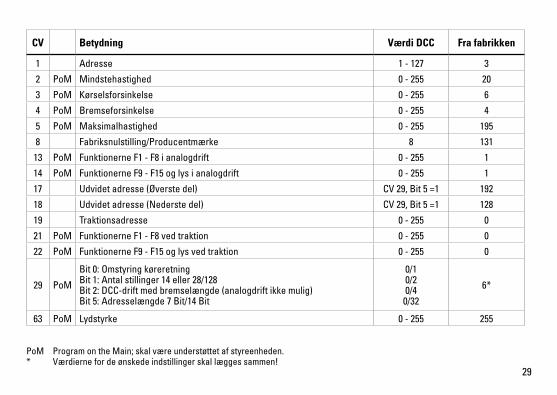
PoM ProgramontheMain;skalværeunderstøttetafstyreenheden.* Værdiernefordeønskedeindstillingerskallæggessammen!
CV Betydning Værdi DCC Fra fabrikken
1 Adresse 1 - 127 3
2 PoM Mindstehastighed 0 - 255 20
3 PoM Kørselsforsinkelse 0 - 255 6
4 PoM Bremseforsinkelse 0 - 255 4
5 PoM Maksimalhastighed 0 - 255 195
8 Fabriksnulstilling/Producentmærke 8 131
13 PoM Funktionerne F1 - F8 i analogdrift 0 - 255 1
14 PoM Funktionerne F9 - F15 og lys i analogdrift 0 - 255 1
17 Udvidet adresse (Øverste del) CV29,Bit5=1 192
18 Udvidet adresse (Nederste del) CV29,Bit5=1 128
19 Traktionsadresse 0 - 255 0
21 PoM Funktionerne F1 - F8 ved traktion 0 - 255 0
22 PoM Funktionerne F9 - F15 og lys ved traktion 0 - 255 0
29 PoM
Bit0:Omstyringkøreretning Bit1:Antalstillinger14eller28/128 Bit2:DCC-driftmedbremselængde(analogdriftikkemulig) Bit5:Adresselængde7Bit/14Bit
0/1 0/2 0/4
0/32
6*
63 PoM Lydstyrke 0 - 255 255
30
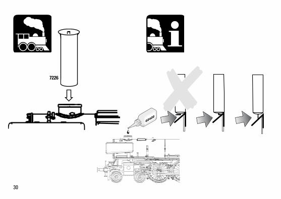
7226
31
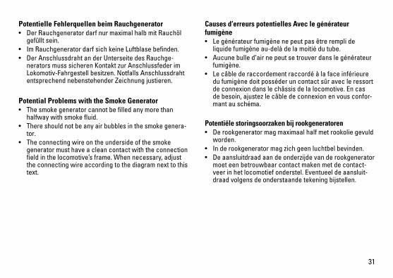
Potentielle Fehlerquellen beim Rauchgenerator• DerRauchgeneratordarfnurmaximalhalbmitRauchöl
gefüllt sein.• ImRauchgeneratordarfsichkeineLuftblasebefinden.• DerAnschlussdrahtanderUnterseitedesRauchge-
nerators muss sicheren Kontakt zur Anschlussfeder im Lokomotiv-Fahrgestell besitzen. Notfalls Anschlussdraht entsprechend nebenstehender Zeichnung justieren.
Potential Problems with the Smoke Generator• Thesmokegeneratorcannotbefilledanymorethan
halfway with smoke fluid.• There should not be any air bubbles in the smoke genera-
tor.• Theconnectingwireontheundersideofthesmoke
generator must have a clean contact with the connection field in the locomotive’s frame. When necessary, adjust the connecting wire according to the diagram next to this text.
Causes d‘erreurs potentielles Avec le générateur fumigène• Legénérateurfumigènenepeutpasêtreremplide
liquide fumigène au-delà de la moitié du tube. • Aucunebulled‘airnepeutsetrouverdanslegénérateur
fumigène.• Lecâblederaccordementraccordéàlafaceinférieure
du fumigène doit posséder un contact sûr avec le ressort de connexion dans le châssis de la locomotive. En cas de besoin, ajustez le câble de connexion en vous confor-mant au schéma.
Potentiële storingsoorzaken bij rookgeneratoren• Derookgeneratormagmaximaalhalfmetrookoliegevuld
worden.• Inderookgeneratormagzichgeenluchtbelbevinden.• Deaansluitdraadaandeonderzijdevanderookgenerator
moet een betrouwbaar contact maken met de contact-veer in het locomotief onderstel. Eventueel de aansluit-draad volgens de onderstaande tekening bijstellen.

32
Instrucciones importantes para el buen uso del fumíge-no• Llenarelcartuchosolamentehastalamitadconlíquido
fumígeno.• Prestaratenciónquenoseformeunaburbujadeaireen
el cartucho.• Elhilotomacorrientedelabasedebetenerunbuen
contacto con el resorte que está en el bastidor de la locomotora. Si fuera necesario, ajustar el hilo tomacor-rientesegúnlailustración.Incasodinecessità,siregoliil conduttore di alimentazione in modo corrispondente al disegno che si trova qui accanto.
Potenziali origini di guasti nel caso dell’apparato fumogeno• L’apparatofumogenocomemassimodeveessereriempi-
to solamente a metà di olio vaporizzabile. • Nell’apparatofumogenonondevetrovarsialcunabolla
d’aria.• Ilconduttoredialimentazionesullafacciainferiore
dell’apparato fumogeno deve possedere un sicuro contatto verso la molla di connessione nel telaio della locomotiva. In caso di necessità, si regoli il conduttore di alimentazione in modo corrispondente al disegno che si trova qui accanto.
Potentiella felkällor på rökgeneratorn• Rökgeneratornfårmaximaltfyllastillhälftenmedrökväts-
ka• Irökgeneratornfårintefinnasnågonluftblåsa• Anslutningstrådenpårökgeneratornsundersidamåsteha
en säker kontakt med anslutningsfjädern i lokets chassi. I nödfall måste anslutningstråden justeras enligt tecknin-gen bredvid. I nödfall måste anslutningstråden justeras enligt teckningen bredvid.
Potentielle fejlkilder ved røggeneratoren• Røggeneratorenmåmaksimaltværehalvtfyldtmedrøgolie.
• Dermåikkeværenogenluftboblerirøggeneratoren.• Derskalværeengodogsikkerkontaktmellemtilslut-ningstrådenpåundersidenafrøggeneratorenogtilslut-ningsfjederenilokomotivetsunderstel.Inødstilfældeskaltilslutningstrådenjusteresifølgetegningenhervedsidenaf.
33
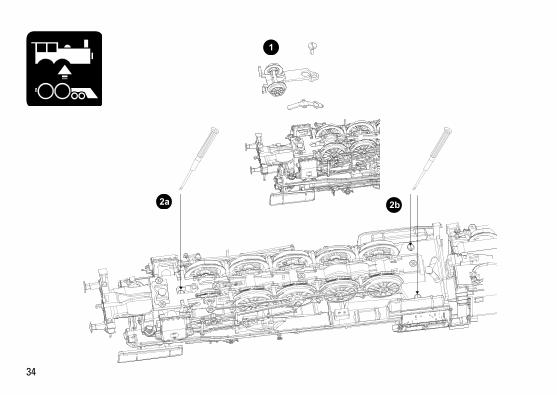
34
2b2a
1
35
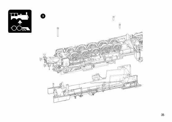
3
36
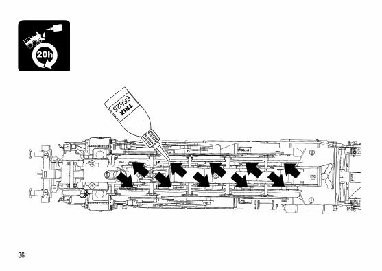
20h
66625
37
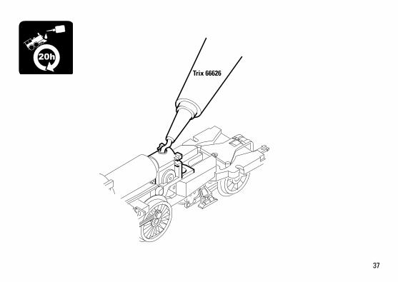
Trix 66626
20h
38
39

40
1.
2.

41
Det
ails
der
Dar
stel
lung
kön
nen
von
dem
Mod
ell a
bwei
chen
.
1
225
16
46
7
6
4
4
1121
24
26
22
23
4
6
10
9 5
42
618
18
1812
63
10
10
19
17
18
13
13
14
20
26
20
Det
ails
der
Dar
stel
lung
kö
nnen
von
dem
Mod
ell
abw
eich
en.
43
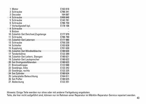
Hinweis:EinigeTeilewerdennurohneodermitandererFarbgebungangeboten.Teile, die hier nicht aufgeführt sind, können nur im Rahmen einer Reparatur im Märklin-Reparatur-Service repariert werden.
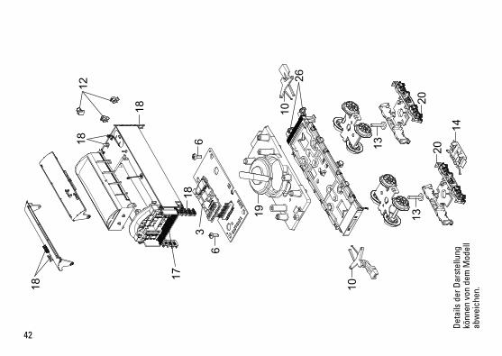
1 Motor E163 818 2 Schraube E786 341 3 Decoder 164 087 4 Schraube E499 840 5 Schraube E143 781 6 Schraube E786 750 7 Vorlaufgestell kpl. E178 106 8 Schraube – 9 Bolzen – 10 Zubehör-Set Deichsel,Zugstange E177 979 11 Schraube E786 790 12 Zubehör-Set Laternen E177 980 13 Schraube E750 230 14 Schleifer E103 828 15 Kupplung E701 630 16 Zubehör-Set Windleitbleche E180 620 17 Tenderbühne E122 289 18 Zubehör-Set Leitern, Stangen E180 621 19 Zubehör-Set Lautsprecher E180 622 20 Set Drehgestellblenden E180 623 21 Bremsattrappe E122 088 22 Gestänge, links E122 242 23 Gestänge, rechts E122 225 24 Set Zylinder E180 624 25 Leiterplatte Beleuchtung E164 011 26 Set Puffer E180 625 27 Abdeckung E122 251
164516/1011/Ha1EfÄnderungen vorbehalten
© by Gebr. Märklin & Cie. GmbH
Gebr. Märklin & Cie. GmbH Stuttgarter Straße 55 - 5773033 GöppingenDeutschlandwww.trix.de
This device complies with Part 15 of the FCC Rules. Operationissubjecttothefollowingtwoconditions:(1) This device may not cause harmful interference, and (2) this device must accept any interference received, including interference that may cause undesired operation.
www.maerklin.com/en/imprint.html