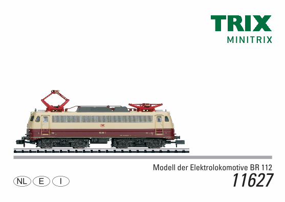
Modell der Elektrolokomotive BR 112 D GB USA F 11627 · die DB ab Oktober 1962 die dank einer...
56
Modell der Elektrolokomotive BR 112 11627 D GB USA F
Transcript of Modell der Elektrolokomotive BR 112 D GB USA F 11627 · die DB ab Oktober 1962 die dank einer...

Modell der Elektrolokomotive BR 112
11627D GB USA F

2

3
Inhaltsverzeichnis SeiteInformationen zum Vorbild 4Sicherheitshinweise 6 Wichtige Hinweise 6Funktionen 6Hinweis zum Digitalbetrieb 6Schaltbare Funktionen 7Configurations Variablen (DCC, CVs) 8Parameter (SX2) 10Wartung und Instandhaltung 24Ersatzteile 26
Table of Contents Page Information about the prototype 5Safety Notes 12Important Notes 12Functions 12Note on digital operation 12Controllable Functions 13Configuration Variables (DCC, CVs) 14Paramètre (SX2) 16Service and maintenance 24Spare Parts 26
Sommaire PageInformations concernant la locomotive réelle 5Remarques importantes sur la sécurité 18Information importante 18Fonctionnement 18Remarques relatives au fonctionement en mode digital 18Fonctions commutables 19Variables de configuration (DCC, CVs) 20Parameter (SX2) 22Entretien et maintien 24Pièces de rechange 26
4
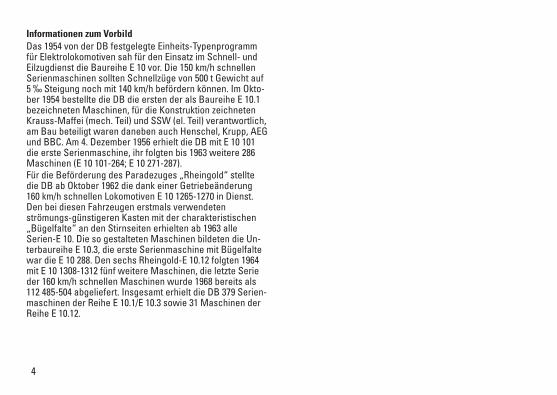
Informationen zum Vorbild Das 1954 von der DB festgelegte Einheits-Typenprogramm für Elektrolokomotiven sah für den Einsatz im Schnell- und Eilzugdienst die Baureihe E 10 vor. Die 150 km/h schnellen Serienmaschinen sollten Schnellzüge von 500 t Gewicht auf 5 ‰ Steigung noch mit 140 km/h befördern können. Im Okto-ber 1954 bestellte die DB die ersten der als Baureihe E 10.1 bezeichneten Maschinen, für die Konstruktion zeichneten Krauss-Maffei (mech. Teil) und SSW (el. Teil) verantwortlich, am Bau beteiligt waren daneben auch Henschel, Krupp, AEG und BBC. Am 4. Dezember 1956 erhielt die DB mit E 10 101 die erste Serienmaschine, ihr folgten bis 1963 weitere 286 Maschinen (E 10 101-264; E 10 271-287). Für die Beförderung des Paradezuges „Rheingold“ stellte die DB ab Oktober 1962 die dank einer Getriebeänderung 160 km/h schnellen Lokomotiven E 10 1265-1270 in Dienst. Den bei diesen Fahrzeugen erstmals verwendeten strömungs-günstigeren Kasten mit der charakteristischen „Bügelfalte“ an den Stirnseiten erhielten ab 1963 alle Serien-E 10. Die so gestalteten Maschinen bildeten die Un-terbaureihe E 10.3, die erste Serienmaschine mit Bügelfalte war die E 10 288. Den sechs Rheingold-E 10.12 folgten 1964 mit E 10 1308-1312 fünf weitere Maschinen, die letzte Serie der 160 km/h schnellen Maschinen wurde 1968 bereits als 112 485-504 abgeliefert. Insgesamt erhielt die DB 379 Serien-maschinen der Reihe E 10.1/E 10.3 sowie 31 Maschinen der Reihe E 10.12.

5
Information about the prototypeThe DB standard type program for electric locomotives laid down in 1954 foresaw the use of the class E 10 in express and fast train service. These regular produc-tion locomotives were capable of 150 km/h / 94 mph and were designed to pull 500 metric ton express trains up 0.5% grades at 140 km/h / 87 mph. In October of 1954, the DB ordered the first units designated as the class E 10.1. Krauss-Maffei was responsible for the mechanical part of the design and SSW did the electrical part. Henschel, Krupp, AEG, and BBC also participated in the building of the locomotives. On December 4, 1956, the DB the first regular production unit as road number E 10 101. By 1963 another 286 units had followed it (E 10 101-264; E 10 271-287). Starting in October of 1962 the DB placed road numbers E 10 1265-1270 in service as motive power for the flagship train “Rheingold”. Thanks to a gear change, they were capable of 160 km/h / 100 mph. The streamlined body with the characteristic “Bügelfalte” / “Pants Crease” on the ends used for the first time on these locomotives was applied starting in 1963 to all class E 10 units. Locomotives designed this way formed the sub-class E 10.3. The first regular production unit with the pants crease was road number E 10 288. The six Rheingold E 10.12 units were fol-lowed in 1964 by five more locomotives, road numbers E 10 1308-1312. The last series of 160 km/h / 100 mph units were already delivered in 1968 as road numbers 112 485-504. The DB took delivery of 379 regular production units of the classes E 10.1/E 10.3 as well as 31 units of the class E 10.12.
Informations concernant le modèle réel Le programme type de standardisation, établi par la DB en 1954 pour les locomotives électriques, prévoyait la série E 10 pour le service de trains rapides et directs. Ces machines de série aptes à 150 km/h devaient être capables de remorquer des trains rapides de 500 t encore à 140 km/h sur des rampes de 5 ‰. En octobre 1954, la DB commanda les premières machines immatriculées dans la série E 10.1, dont la construction était principalement confiée à Krauss-Maffei (pour la partie mécanique) et à SSW (partie électrique), mais également à Henschel, Krupp, AEG et BBC. Le 4 décembre 1956, la DB reçut avec la E 10 101 la première machine de série, suivie jusqu’en 1963 de 286 autres machines (E 10 101-264; E 10 271-287). Pour remorquer le train de prestige « Rheingold », la DB, à partir d’octobre 1962, mit en service les locomotives E 10 1265-1270 capables d’atteindre les 160 km/h grâce à une modification de leur système de transmission. A partir de 1963, toutes E 10 de série furent équipées de la supers-tructure aérodynamique avec le «pli» caractéristique sur la partie frontale, dont ces engins furent les premiers nantis. Les machines ainsi dessinées formaient la sous-série E 10.3, la première machine de série avec le « pli » était la E 10 288. Aux 6 E 10.12 Rheingold succédèrent en 1964 avec E 10 1308-1312 cinq autres machines, la dernière série des machines de 160 km/h fut livrée en 1968 déjà comme E 10 1308. Au total, la DB reçut 379 machines de la série E 10.1/E 10.3 ainsi que 31 machines de la série E 10.12.
6
Sicherheitshinweise• DieLokdarfnurmiteinemdafürbestimmtenBetriebssys-
tem eingesetzt werden.• DieLokdarfnichtmitmehralseinerLeistungsquelle
versorgt werden.• BeachtenSieunbedingtdieSicherheitshinweiseinder
Bedienungsanleitung zu Ihrem Betriebssystem.• Analog14Volt=,digital22Volt~.• FürdenkonventionellenBetriebderLokmussdas
Anschlussgleis entstört werden. Dazu ist das Entstörset 14972 zu verwenden. Für Digitalbetrieb ist das Entstörset nicht geeignet.
• SetzenSiedasModellkeinerdirektenSonneneinstrah-lung, starken Temperaturschwankungen oder hoher Luftfeuchtigkeit aus.
• DasverwendeteGleisanschlusskabeldarfmaximal 2 Meter lang sein.
• ACHTUNG! Funktionsbedingte scharfe Kanten und Spitzen. • VerbauteLED`sentsprechenderLaserklasse1nach
Norm EN 60825-1.
Wichtige Hinweise• DieBedienungsanleitungunddieVerpackungsind
Bestandteile des Produktes und müssen deshalb aufbe-wahrt sowie bei Weitergabe des Produktes mitgegeben werden.
• FürReparaturenoderErsatzteilewendenSiesichbitteanIhren Trix-Fachhändler.
• GewährleistungundGarantiegemäßderbeiliegendenGarantieurkunde.
• Entsorgung:www.maerklin.com/en/imprint.htmlAllgemeiner Hinweis zur Vermeidung elektromagnetischer Störungen: UmdenbestimmungsgemäßenBetriebzugewährleisten,istein permanenter, einwandfreier Rad-Schiene-Kontakt der Fahrzeuge erforderlich. Führen Sie keine Veränderungen an stromführenden Teilen durch.
Funktionen• EingebauteElektronikzumwahlweisenBetriebmit
konventionellem Gleichstrom-Fahrgerät (max. ±12 Volt), Trix Systems, Trix Selectrix (SX1) und Selectrix 2 (SX2) oder Digitalsystemen nach NMRA-Norm.
• AutomatischeSystemerkennungzwischenDigital-undAnalog-Betrieb.
• KeineautomatischeSystemerkennungzwischendenDigital-Systemen.
• Dreilicht-Spitzensignalvorne,zweiroteSchlusslichterhinten, mit der Fahrtrichtung wechselnd.
• LokistnichtfürfunktionsfähigenOberleitungsbetriebvorbereitet.
Hinweis zum Digitalbetrieb • BeimerstenBetriebineinemDigital-System(SX1,SX2
oder DCC) muss der Decoder auf dieses Digital-System eingestellt werden. Dazu ist der Decoder einmal in diesem Digitalsystem zu programmieren (z.B. Adresse ändern).
7
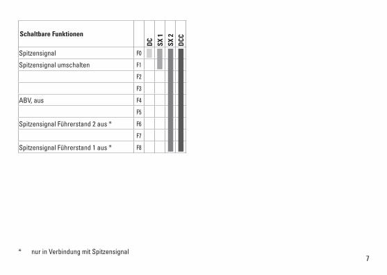
Schaltbare Funktionen
DC
SX 1
SX 2
DCC
Spitzensignal F0
Spitzensignal umschalten F1
F2
F3
ABV, aus F4
F5
Spitzensignal Führerstand 2 aus * F6
F7
Spitzensignal Führerstand 1 aus * F8
* nur in Verbindung mit Spitzensignal

8
CV Bedeutung Wert DCC ab Werk
1 Adresse 1 – 127 3
2 Minimalgeschwindigkeit 0 – 15 10
3 Anfahrverzögerung 0 – 255 5
4 Bremsverzögerung 0 – 255 5
5 Maximalgeschwindigkeit 0 – 127 99
8 Reset 8 —
13 Analog Funktionen; Bit 0 – 7 =̂ F1 – F8 0 – 255 1
14 Analog Funktionen; Bit 0 – 5 =̂ F9 – F12 0 – 63 3
17 ErweiterteAdresse(obererTeil)(CV29,Bit5=1) 0 – 255 192
18 ErweiterteAdresse(untererTeil)(CV29,Bit5=1) 0 – 255 0
19 Traktionsadresse(0=inaktiv,Wert+128=inverseFahrtrichtung) 0 – 127 0
21 Traktions-Modus; Bit 0 – 7 =̂ F1 – F8 0 – 255 0
22 Traktions-Modus; Bit 0 – 1 =̂ FLf – FLr, Bit 2 – 5 =̂ F9 – F12 0 – 63 0
29
Bit0:UmpolungFahrtrichtungBit1:AnzahlFahrstufen14-28/126Bit2:DCCBetriebmitBremsstrecke DCC-, Selectrix- und Gleichstrombetrieb Bit5:Adressumfang7Bit/14Bit
0 – 255 14
33 Funktionszuordnung F0 vorwärts 0 – 255 1
34 Funktionszuordnung F0 rückwärts 0 – 255 2
35 Funktionszuordnung F1 0 – 255 9
9
CV Bedeutung Wert DCC ab Werk
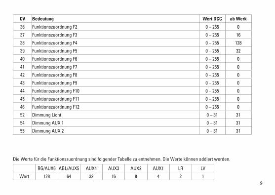
36 Funktionszuordnung F2 0 – 255 0
37 Funktionszuordnung F3 0 – 255 16
38 Funktionszuordnung F4 0 – 255 128
39 Funktionszuordnung F5 0 – 255 32
40 Funktionszuordnung F6 0 – 255 0
41 Funktionszuordnung F7 0 – 255 0
42 Funktionszuordnung F8 0 – 255 0
43 Funktionszuordnung F9 0 – 255 0
44 Funktionszuordnung F10 0 – 255 0
45 Funktionszuordnung F11 0 – 255 0
46 Funktionszuordnung F12 0 – 255 0
52 Dimmung Licht 0 – 31 31
54 Dimmung AUX 1 0 – 31 31
55 Dimmung AUX 2 0 – 31 31
Die Werte für die Funktionszuordnung sind folgender Tabelle zu entnehmen. Die Werte können addiert werden.
RG/AUX6 ABL/AUX5 AUX4 AUX3 AUX2 AUX1 LR LV
Wert 128 64 32 16 8 4 2 1

10
par Bedeutung Wert SX2 ab Werk
001 Adresse Einer- u. Zehner-Stelle 0 – 99 1
002 Adresse Hunderter- u. Tausender-Stelle 0 – 99 10
008 Traktionsadresse Einer- u. Zehner-Stelle 0 – 99 0
009 Traktionsadresse Hunderter- u. Tausender-Stell 0 – 99 0
011 Anfahrverzögerung 0 – 255 5
012 Bremsverzögerung 0 – 255 5
013 Maximalgeschwindigkeit 0 – 127 99
014 Mindestgeschwindigkeit 0 – 15 10
018 Geschwindigkeit Rangiergang 0 – 127 99
021 Bremsabschnitte; 1 oder 2 0, 1 1
028 Traktions-Modus; Bit 0 – 7 =̂ F1 – F8 0 – 255 1
029 Traktions-Modus; Bit 0 – 1 =̂ FLf – FLr, Bit 2 – 5 =̂ F9 – F12 0 – 255 3
061 Funktionszuordnung F0 vorwärts 0 – 255 1
062 Funktionszuordnung F0 rückwärts 0 – 255 2
063 Funktionszuordnung F1 0 – 255 9
064 Funktionszuordnung F2 0 – 255 0
065 Funktionszuordnung F3 0 – 255 16
066 Funktionszuordnung F4 0 – 255 128
067 Funktionszuordnung F5 0 – 255 32

11WerkseinstellungfürSX1:01-732,erweitert:00-274
par Bedeutung Wert SX2 ab Werk
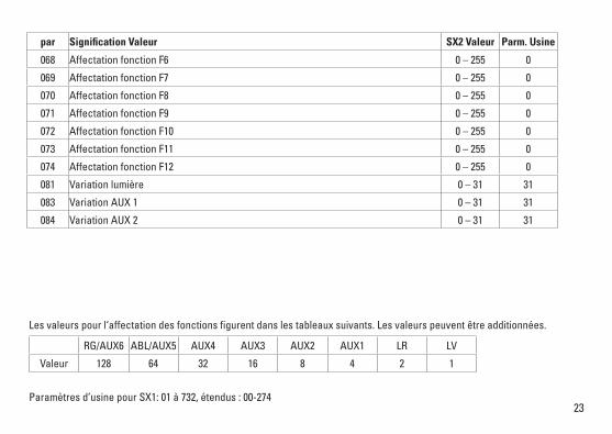
068 Funktionszuordnung F6 0 – 255 0
069 Funktionszuordnung F7 0 – 255 0
070 Funktionszuordnung F8 0 – 255 0
071 Funktionszuordnung F9 0 – 255 0
072 Funktionszuordnung F10 0 – 255 0
073 Funktionszuordnung F11 0 – 255 0
074 Funktionszuordnung F12 0 – 255 0
081 Dimmung Licht 0 – 31 31
083 Dimmung AUX1 0 – 31 31
084 Dimmung AUX2 0 – 31 31
Die Werte für die Funktionszuordnung sind folgender Tabelle zu entnehmen. Die Werte können addiert werden.
RG/AUX6 ABL/AUX5 AUX4 AUX3 AUX2 AUX1 LR LV
Wert 128 64 32 16 8 4 2 1
12
• Disposing:www.maerklin.com/en/imprint.htmlGeneral Note to Avoid Electromagnetic Interference: A permanent, flawless wheel-rail contact is required in order to guarantee operation for which a model is designed.Do not make any changes to current-conducting parts.
Functions • Built-inelectroniccircuitforoptionaloperationwith
a conventional DC train controller (max. ±12 volts), Trix Systems, Trix Selectrix (SX1), and Selectrix 2 (SX2), or digital systems adhering to the NMRA standards.
• Automaticsystemrecognitionbetweendigitalandanalogoperation.
• Noautomaticsystemrecognitionbetweenthedigitalsystems.
• Tripleheadlightsinthefront,dualredmarkerlightsintherear, that change over with the direction of travel.
• Locomotiveisnotequippedforoperationoffofcatenary.
Note on digital operation • Whenoperatinginadigitalsystemforthefirsttime(SX1,
SX2, or DCC), the decoder must be set to this digital sys-tem. To do this, the decoder must be programmed once in thisdigitalsystem(example:changetheaddress).
Safety Notes• Thislocomotiveisonlytobeusedwiththeoperating
system it is designed for.• Thislocomotivemustnotbesuppliedwithpowerfrom
more than one power pack.• Paycloseattentiontothesafetynotesintheinstructions
for your operating system.• Analog14voltsDC,digital22voltsAC.• Thefeedertrackmustbeequippedtopreventinter-
ference with radio and television reception, when the locomotive is to be run in conventional operation. The 14972 interference suppression set is to be used for this purpose. The interference suppression set is not suitable for digital operation.
• Donotexposethemodeltodirectsunlight,extremechanges in temperature, or high humidity.
• Thewireusedforfeederconnectionstothetrackmaybea maximum of 2 meters / 78 inches long.
• WARNING! Sharp edges and points required for operation. • TheLEDsinthisitemcorrespondtoLaserClass1accor-
ding to Standard EN 60825-1.
Important Notes• Theoperatinginstructionsandthepackagingareacom-
ponent part of the product and must therefore be kept as well as transferred along with the product to others.
• PleaseseeyourauthorizedTrixdealerforrepairsorspare parts.
• Thewarrantycardincludedwiththisproductspecifiesthe warranty conditions.
13
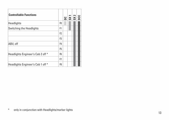
Controllable Functions
DC
SX 1
SX 2
DCC
Headlights F0
Switching the Headlights F1
F2
F3
ABV, off F4
F5
Headlights Engineer‘s Cab 2 off * F6
F7
Headlights Engineer‘s Cab 1 off * F8
* only in conjunction with Headlights/marker lights
14
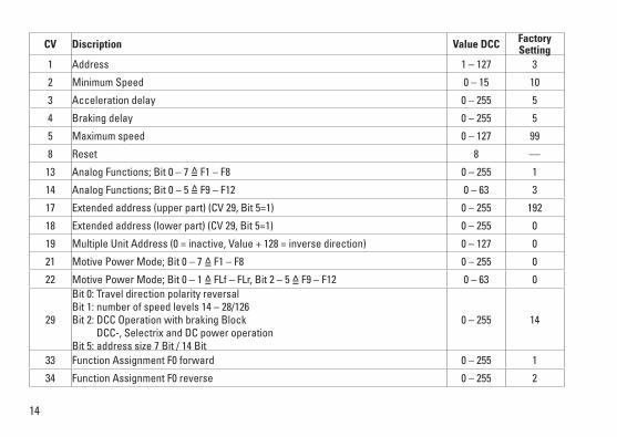
CV Discription Value DCC Factory Setting
1 Address 1 – 127 3
2 Minimum Speed 0 – 15 10
3 Acceleration delay 0 – 255 5
4 Braking delay 0 – 255 5
5 Maximum speed 0 – 127 99
8 Reset 8 —
13 Analog Functions; Bit 0 – 7 =̂ F1 – F8 0 – 255 1
14 Analog Functions; Bit 0 – 5 =̂ F9 – F12 0 – 63 3
17 Extendedaddress(upperpart)(CV29,Bit5=1) 0 – 255 192
18 Extendedaddress(lowerpart)(CV29,Bit5=1) 0 – 255 0
19 MultipleUnitAddress(0=inactive,Value+128=inversedirection) 0 – 127 0
21 Motive Power Mode; Bit 0 – 7 =̂ F1 – F8 0 – 255 0
22 Motive Power Mode; Bit 0 – 1 =̂ FLf – FLr, Bit 2 – 5 =̂ F9 – F12 0 – 63 0
29
Bit0:TraveldirectionpolarityreversalBit1:numberofspeedlevels14–28/126Bit2:DCCOperationwithbrakingBlock DCC-, Selectrix and DC power operation Bit5:addresssize7Bit/14Bit
0 – 255 14
33 Function Assignment F0 forward 0 – 255 1
34 Function Assignment F0 reverse 0 – 255 2

15
CV Discription Value DCC Factory Setting
35 Function Assignment F1 0 – 255 9
36 Function Assignment F2 0 – 255 0
37 Function Assignment F3 0 – 255 16
38 Function Assignment F4 0 – 255 128
39 Function Assignment F5 0 – 255 32
40 Function Assignment F6 0 – 255 0
41 Function Assignment F7 0 – 255 0
42 Function Assignment F8 0 – 255 0
43 Function Assignment F9 0 – 255 0
44 Function Assignment F10 0 – 255 0
45 Function Assignment F11 0 – 255 0
46 Function Assignment F12 0 – 255 0
52 Dimming of lights 0 – 31 31
54 Dimming of AUX 1 0 – 31 31
55 Dimming of AUX 2 0 – 31 31
The values for the function assignment can be found in the following table. The values can be added.
RG/AUX6 ABL/AUX5 AUX4 AUX3 AUX2 AUX1 LR LV
Value 128 64 32 16 8 4 2 1
16
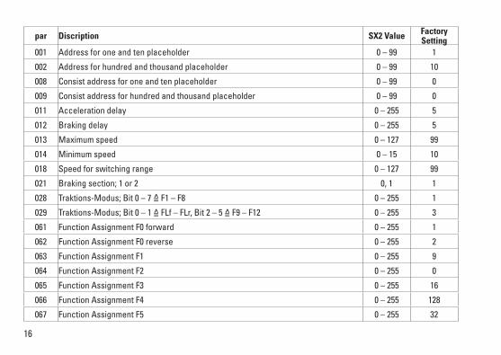
par Discription SX2 Value Factory Setting
001 Address for one and ten placeholder 0 – 99 1
002 Address for hundred and thousand placeholder 0 – 99 10
008 Consist address for one and ten placeholder 0 – 99 0
009 Consist address for hundred and thousand placeholder 0 – 99 0
011 Acceleration delay 0 – 255 5
012 Braking delay 0 – 255 5
013 Maximum speed 0 – 127 99
014 Minimum speed 0 – 15 10
018 Speed for switching range 0 – 127 99
021 Braking section; 1 or 2 0, 1 1
028 Traktions-Modus; Bit 0 – 7 =̂ F1 – F8 0 – 255 1
029 Traktions-Modus; Bit 0 – 1 =̂ FLf – FLr, Bit 2 – 5 =̂ F9 – F12 0 – 255 3
061 Function Assignment F0 forward 0 – 255 1
062 Function Assignment F0 reverse 0 – 255 2
063 Function Assignment F1 0 – 255 9
064 Function Assignment F2 0 – 255 0
065 Function Assignment F3 0 – 255 16
066 Function Assignment F4 0 – 255 128
067 Function Assignment F5 0 – 255 32
17FactorysettingforSX1:01-732,advanced:00-274
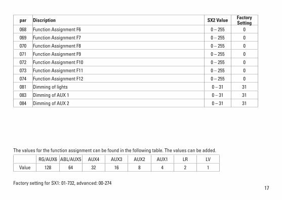
par Discription SX2 Value Factory Setting
068 Function Assignment F6 0 – 255 0
069 Function Assignment F7 0 – 255 0
070 Function Assignment F8 0 – 255 0
071 Function Assignment F9 0 – 255 0
072 Function Assignment F10 0 – 255 0
073 Function Assignment F11 0 – 255 0
074 Function Assignment F12 0 – 255 0
081 Dimming of lights 0 – 31 31
083 Dimming of AUX 1 0 – 31 31
084 Dimming of AUX 2 0 – 31 31
The values for the function assignment can be found in the following table. The values can be added.
RG/AUX6 ABL/AUX5 AUX4 AUX3 AUX2 AUX1 LR LV
Value 128 64 32 16 8 4 2 1
18
Remarques importantes sur la sécurité• Lalocomotivenepeutêtreutiliséequ‘aveclesystème
d‘exploitation indiqué.• Lalocomotivenepeutêtrealimentéeencourantquepar
une seule source de courant.• Veuillezimpérativementrespecterlesremarquessur
la sécurité décrites dans le mode d’emploi en ce qui concerne le système d’exploitation.
• Analogique14V=,numérique22Volt~.• Pourl’exploitationdelalocomotiveenmodeconventi-
onnel, la voie de raccordement doit être déparasitée. A cet effet, utiliser le set de déparasitage réf. 14972. Le set de déparasitage ne convient pas pour l’exploitation en mode numérique.
• Nepasexposerlemodèleàunensoleillementdirect,à de fortes variations de température ou à un taux d‘humidité important.
• Lecâblederaccordementàlavoieutilisénedoitenaucun cas dépasser deux mètres.
• ATTENTION! Pointes et bords coupants lors du fonction-nement du produit.
• LesDELinstalléescorrespondentàlaclasselaser1selon la norme EN 60825-1.
Information importante• Lanoticed‘utilisationetl’emballagefontpartieintégrante
du produit ; ils doivent donc être conservés et, le cas échéant, transmis avec le produit.
• Pourtouteréparationouremplacementdepièces,adressez vous à votre détaillant-spécialiste Trix.
• Garantielégaleetgarantiecontractuelleconformémentau certificat de garantie ci-joint.
• Elimination:www.maerklin.com/en/imprint.htmlIndication d‘ordre général pour éviter les interférences électromagnétiques: La garantie de l‘exploitation normale nécessite un contact roue-rail permanent et irréprochable. Ne procédez à aucune modification sur des éléments conducteurs de courant.
Fonctionnement• Module électronique intégré pour exploitation au choix avec
régulateur de marche conventionnel c.c. (max. ±12 volts), Trix Systems, Trix Selectrix (SX1) et Selectrix 2 (SX2) ou systèmes numériques conformes à la norme NMRA.
• Reconnaissanceautomatiquedusystèmeentreexploita-tions numérique et analogique.
• Pasdereconnaissanceautomatiquedusystèmeentreles systèmes numériques.
• Feux de signalisation triples à l‘avant, deux feux rouges de fin de convoi à l‘arrière avec inversion selon sens de marche.
• Lalocomotiven‘estpaséquipéepouruneexploitationavec alimentation par caténaire.
Remarques relatives au fonctionnement en mode digital • Unepremièreexploitationensystèmenumérique
(SX1, SX2 ou DCC) exige un réglage correspondant du décodeur. A cet effet, le décodeur doit être programmé une fois dans ce système numérique (modification de l’adresse par ex.).
19
Fonctions commutables
DC
SX 1
SX 2
DCC
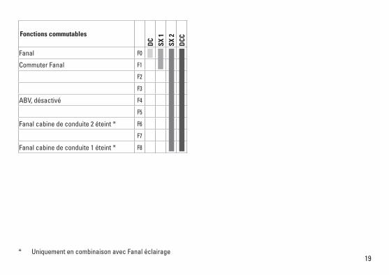
Fanal F0
Commuter Fanal F1
F2
F3
ABV, désactivé F4
F5
Fanal cabine de conduite 2 éteint * F6
F7
Fanal cabine de conduite 1 éteint * F8
* Uniquement en combinaison avec Fanal éclairage

20
CV Signification Valeur DCC Valeur Parm. Usine
1 Adresse 1 – 127 3
2 Vitesse min 0 – 15 10
3 Temporisation d‘accélération 0 – 255 5
4 Temporisation de freinage 0 – 255 5
5 Vitesse maximale 0 – 127 99
8 Réinitialisation 8 —
13 Fonctions analogiques; Bit 0 – 7 =̂ F1 – F8 0 – 255 1
14 Fonctions analogiques; Bit 0 – 5 =̂ F9 – F12 0 – 63 3
17 Adresseétendue(partiesupérieure)(CV29,Bit5=1) 0 – 255 192
18 Adresseétendue(partieinférieure)(CV29,Bit5=1) 0 – 255 0
19 Adressepourlatraction(0=inactif,Valeur+128=directioninverse) 0 – 127 0
21 Mode traction, bit 0 à 7 =̂ F1 à F8 0 – 255 0
22 Mode traction; bit 0 à 1 =̂ FLf à FLr, Bit 2 à 5 =̂ F9 à F12 0 – 63 0
29
Bit0:inversiondepolarité,sensdemarcheBit1:Nombredecransdemarche14–28/126Bit2:ExploitationDCCaveczonedefreinage. DCC-, Selectrix et courant continu Bit5:tailled‘adresse7Bits/14Bits
0 – 255 14
33 Affectation fonction F0 en avant 0 – 255 1
34 Affectation fonction F0 en arrière 0 – 255 2
35 Affectation fonction F1 0 – 255 9
21
CV Signification Valeur DCC Valeur Parm. Usine
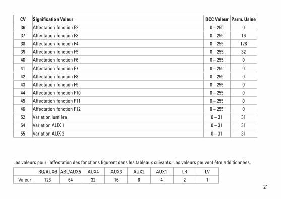
36 Affectation fonction F2 0 – 255 0
37 Affectation fonction F3 0 – 255 16
38 Affectation fonction F4 0 – 255 128
39 Affectation fonction F5 0 – 255 32
40 Affectation fonction F6 0 – 255 0
41 Affectation fonction F7 0 – 255 0
42 Affectation fonction F8 0 – 255 0
43 Affectation fonction F9 0 – 255 0
44 Affectation fonction F10 0 – 255 0
45 Affectation fonction F11 0 – 255 0
46 Affectation fonction F12 0 – 255 0
52 Variation lumière 0 – 31 31
54 Variation AUX 1 0 – 31 31
55 Variation AUX 2 0 – 31 31
Les valeurs pour l‘affectation des fonctions figurent dans les tableaux suivants. Les valeurs peuvent être additionnées.
RG/AUX6 ABL/AUX5 AUX4 AUX3 AUX2 AUX1 LR LV
Valeur 128 64 32 16 8 4 2 1
22
par Signification Valeur SX2 Valeur Parm. Usine
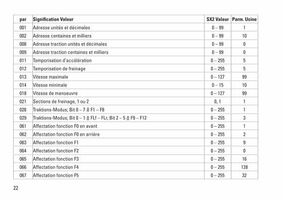
001 Adresse unités et décimales 0 – 99 1
002 Adresse centaines et milliers 0 – 99 10
008 Adresse traction unités et décimales 0 – 99 0
009 Adresse traction centaines et milliers 0 – 99 0
011 Temporisation d’accélération 0 – 255 5
012 Temporisation de freinage 0 – 255 5
013 Vitesse maximale 0 – 127 99
014 Vitesse minimale 0 – 15 10
018 Vitesse de manoeuvre 0 – 127 99
021 Sections de freinage, 1 ou 2 0, 1 1
028 Traktions-Modus; Bit 0 – 7 =̂ F1 – F8 0 – 255 1
029 Traktions-Modus; Bit 0 – 1 =̂ FLf – FLr, Bit 2 – 5 =̂ F9 – F12 0 – 255 3
061 Affectation fonction F0 en avant 0 – 255 1
062 Affectation fonction F0 en arrière 0 – 255 2
063 Affectation fonction F1 0 – 255 9
064 Affectation fonction F2 0 – 255 0
065 Affectation fonction F3 0 – 255 16
066 Affectation fonction F4 0 – 255 128
067 Affectation fonction F5 0 – 255 32
23Paramètresd’usinepourSX1:01à732,étendus:00-274
par Signification Valeur SX2 Valeur Parm. Usine
068 Affectation fonction F6 0 – 255 0
069 Affectation fonction F7 0 – 255 0
070 Affectation fonction F8 0 – 255 0
071 Affectation fonction F9 0 – 255 0
072 Affectation fonction F10 0 – 255 0
073 Affectation fonction F11 0 – 255 0
074 Affectation fonction F12 0 – 255 0
081 Variation lumière 0 – 31 31
083 Variation AUX 1 0 – 31 31
084 Variation AUX 2 0 – 31 31
Les valeurs pour l‘affectation des fonctions figurent dans les tableaux suivants. Les valeurs peuvent être additionnées.
RG/AUX6 ABL/AUX5 AUX4 AUX3 AUX2 AUX1 LR LV
Valeur 128 64 32 16 8 4 2 1

24
66626Märklin7149
7149
MINITRIX
40h OIL
66623
25
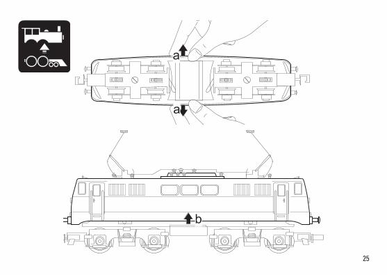
a
a
b
2610
7
3
6
5
2
1
2
4
3
6
8 9
7
10
8
9
11
12
11
12
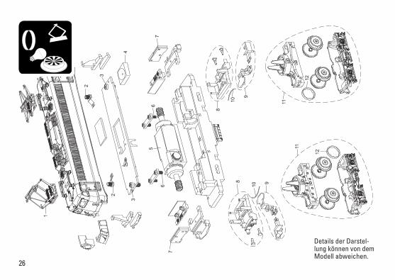
Details der Darstel-lung können von dem Modell abweichen.

27
1 Scherenstromabnehmer E237 089 2 Schraube E19 8002 28 3 Schraube E19 8052 28 4 Lautsprecher — 5 Motor E117 504 6 Schraube E19 8001 28 7 Beleuchtungsplatine E117 505 8 Pufferbohle E238 675 9 Kupplung E238 674 10 Federstab E117 511 11 Drehgestell komplett E238 676 12 Haftreifen E12 2258 00
Schnellzugwagen Übergang E12 5516 00 Sicherungsscheibe E608 020 Steckbolzen E14 0382 08 Kupplung E176 301 Radsatz E31 3010 05
Hinweis:EinigeTeilewerdennurohneodermitandererFarbgebung angeboten. Teile, die hier nicht aufgeführt sind, können nur im Rahmen einer Reparatur im Märklin-Reparatur-Service repariert werden.
Note:Severalpartsareofferedunpaintedorinanothercolor. Parts that are not listed here can only be repaired by the Märklin repair service department.
Remarque:Certainsélémentssontproposésuniquementsans livrée ou dans une livrée différente. Les pièces ne figu-rant pas dans cette liste peuvent être réparées uniquement par le service de réparation Märklin.

Due to different legal requirements regarding electro-magnetic compatibility, this item may be used in the USA only after separate certification for FCC com-pliance and an adjustment if necessary. Use in the USA without this certification is not permitted and absolves us of any liability. If you should want such certification to be done, please contact us – also due to the additional costs incurred for this.
www.maerklin.com/en/imprint.html
Gebr. Märklin & Cie. GmbH StuttgarterStraße55-5773033 Göppingen Germanywww.trix.de
277006/0817/Sm2EfÄnderungen vorbehalten
© Gebr. Märklin & Cie. GmbH
NL
Modell der Elektrolokomotive BR 112
11627

2
3
Índice PáginaInformaciones sobre el modelo real 5Aviso de seguridad 12Notas importantes 12Funciones 12Indicaciones para el funcionamiento digital 12Funciones conmutables 13Variables de Configuración (DCC, CVs) 14Parámetro (SX2) 16Mantenimiento y conservación 24Piezas de repuesto 26
Elenco del contenuto Pagina Informazioni sul prototipo 5Avvertenze per la sicurezza 18Avvertenze importanti 18Funzioni 18Istruzioni per la funzione digitale 18Funzioni commutabili 19Variabili di configurazione (DCC, CV) 20Parametro (SX2) 22Assistenza e manutenzione 24Parti di ricambio 26
Inhoudsopgave PaginaInformatie van het voorbeeld 4Veiligheidsvoorschriften 6Belangrijke aanwijzing 6Functies 6Aanwijzingen voor digitale besturing 6Schakelbare functies 7Configuratie variabelen (DCC, CV’s) 8Parameter (SX2) 10Onderhoud en handhaving 24Onderdelen 26
4
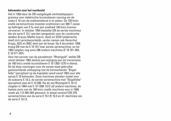
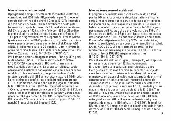
Informatie over het voorbeeldHet in 1954 door de DB vastgelegde eenheidstypepro-gramma voor elektrische locomotieven voorzag om de reeks E 10 van de sneltreindienst in te zetten. De 150 km/u snelle seriemachines moesten sneltreinen van 500 T zwaar op hellingen van 5 ‰ met een snelheid 140 km/u kunnen vervoeren. In oktober 1954 bestelde DB de eerste machines die als serie E 10.1 werden aangeduid; voor de constructie stelden Krauss-Maffei (mech. deel) en SSW (elektrische deel) zich verantwoordelijk, verder namen ook Henschel, Krupp, AEG en BBC deel aan de bouw. Op 4 december 1956 kreeg DB met de E 10 101 haar eerste seriemachine, en tot 1963 volgden nog eens 286 andere machines (E 10 101-264; E 10 271-287). Voor het vervoer van de paradetrein “Rheingold” stelde DB vanaf oktober 1962 dankzij een wijziging aan de transmissie de 160 km/u snelle locomotieven E 10 1265-1270 in dienst. De bij deze voertuigen voor de eerste maal gebruikte gestroomlijnde omkapping met de kenmerkende “Bügel-falte” (persplooi) op de kopzijden werd vanaf 1963 voor alle series E 10 behouden. Deze machines stonden model voor de subserie E 10.3, de eerste seriemachine met “Bügelfalte” (persplooi) was de E 10 288. Na de zes Rheingold-E 10.12 volgden in 1964 met E 10 1308-1312 vijf andere machines, de laatste serie van de 160 km/u snelle machines was in 1968 reeds als 112 485-504 geleverd. In totaal verwierf DB 379 seriemachines van de serie E 10.1/E 10.3 en 31 machines van de serie E 10.12.
5
Informatie over het voorbeeldIl programma dei tipi unificati per le locomotive elettriche, consolidato nel 1954 dalla DB, prevedeva per l’impiego nel servizio dei treni rapidi e diretti il Gruppo E 10. Tali macchie di serie con velocità di 150 km/h avrebbero dovuto poter trainare treni rapidi del peso di 500 tonnellate su pendenza del 5 ‰ ancora ai 140 km/h. Nell’ottobre 1954 la DB ordinò le prime di tali macchine contraddistinte come Gruppo E 10.1, per la progettazione erano responsabili Krauss-Maffei (parte meccanica) e SSW (parte elettrica), nella costruzione oltre a queste presero parte anche Henschel, Krupp, AEG e BBC. Il 4 dicembre 1956 la DB con la E 10 101 ricevette la prima macchina di serie, ad essa fecero seguito entro il 1963 ulteriori 286 macchine (E 10 101-264; E 10 271-287). Per il traino del treno di rappresentanza „Rheingold“ a parti-re da ottobre 1962 la DB mise in servizio le locomotive E 10 1265-1270 con velocità di 160 km/h, grazie a una modifica della trasmissione. La cassa con più favorevole aerodinamica, utilizzata per la prima volta nel caso di questi rotabili, con la caratteristica „piega dei pantaloni“ alle te-state, a partire dal 1963 la ricevettero tutte le E 10 di serie. Le macchine così configurate costituirono il sottogruppo E 10.3, la prima macchia di serie con la piega dei pantaloni fu la E 10 288. Alle sei E 10.12 del Rheingold seguirono nel 1964 cinque ulteriori macchine con le E 10 1308-1312, l’ultima serie di tali macchine con velocità di 160 km/h venne conse-gnata nel 1968 già come 112 485-504. Complessivamente la DB ricevette 379 macchine di serie del Gruppo E 10.1/E 10.3 nonché 31 macchine del Gruppo E 10.12.
Informaciones sobre el modelo realEl programa de modelos uniἀcados establecido en 1954 por los DB para locomotoras eléctricas había previsto la serie E 10 para su uso en el servicio de rápidos y expresos. Las máquinas de serie, capaces de circular a 150 km/h, se habían concebido para arrastrar expresos de 500 t de peso por rampas de 5 ‰, todo ello a una velocidad de 140 km/h. En octubre de 1954, los DB pidieron las primeras máquinas, designadas serie E 10.1, siendo responsables de su diseño Krauss-Maffei (parte mecánica) y SSW (parte eléctrica), habiendo participado en su construcción también Henschel, Krupp, AEG y BBC. El 4 de diciembre de 1956, los DB recibieron la primera máquina de serie, la E 10 101, a la cual siguieron hasta 1963 286 máquinas adicionales (E 10 101-264; E 10 271-287). Para el arrastre del tren insignia „Rheingold“, los DB pusie-ron en servicio a partir de 1962 las locomotoras E 10 1265-1270, que alcanzaban una velocidad de 160 km/h gracias a una modificación del reductor. La caja de caracterí-sticas aerodinámicas favorables utilizada por primera vez en estos vehículos, con su „arruga de plancha“ característica en los testeros, se incorporó a partir de 1963 a todas las E 10 de serie. Las máquinas de este modo diseñadas configuraron la subserie E 10.3, siendo la primera máquina de serie con ar-ruga de plancha la E 10 288. Tras las séis E 10.12 para arrastre de trenes Rheingold llegaron en 1964 cinco máquinas adicio-nales, las E 10 1308-1312, entregándose en 1968 la última serie de estas máquinas capaces de circular a 160 km/h, la 112 485-504. En total, los DB recibieron 379 máquinas de pro-ducción serie de la serie de modelos E 10.1/E 10.3 así como 31 máquinas de la serie E 10.12.
6
Veiligheidsvoorschriften• Delocmagalleenmeteendaarvoorbestemdbedrijfssys-
teem gebruikt worden.• Delocmagnietvanuitmeerdaneenstroomvoorziening
gelijktijdig gevoed worden.• Leesookaandachtigdeveiligheidsvoorschrifteninde
gebruiksaanwijzing van uw bedrijfssysteem. • Analoog14Volt=,digitaal22Volt~.• Voorhetconventionelebedrijfmetdelocdientde
aansluitrail te worden ontstoort. Hiervoor dient men de ontstoor-set 14972 te gebruiken. Voor het digitale bedrijf is deze ontstoor-set niet geschikt.
• Stelhetmodelnietblootaanindirectezonnestraling,sterke temperatuurwisselingen of hoge luchtvochtigheid.
• Degebruikteaansluitkabelmagmaximaal2meterlangzijn.• OPGEPAST! Functionele scherpe kanten en punten. • IngebouwdeLED’skomenovereenmetdelaserklasse1
volgens de norm EN 60825-1.
Belangrijke aanwijzing• Degebruiksaanwijzingendeverpakkingzijneenbe-
standdeel van het product en dienen derhalve bewaard en meegeleverd te worden bij het doorgeven van het product.
• VoorreparatiesenonderdelenkuntzichtotUwTrixhandelaar wenden.
• Vrijwaringengarantieovereenkomstighetbijgevoegdegarantiebewijs.
• Afdanken:www.maerklin.com/en/imprint.html
Algemene aanwijzing voor het vermijden van elektroma-gnetische storingen:Om een betrouwbaar bedrijf te garanderen is een per-manent, vlekkeloos wielas - rail contact van het voertuig noodzakelijk. Voer geen wijzigingen uit aan de stroomvoe-rende delen.
Functies• Ingebouwdeelektronicanaarkeuzetoepasbaarmet
conventionele gelijkstroomregelaar (max. ±12 volt), Trix Systems, Trix Selectrix (SX1) en Selectrix 2 (SX2) of digitaalsystemen volgens NMRA-norm.
• Automatischesysteemherkenningtussendigitaal-enanaloogbedrijf.
• Geenautomatischeherkenningtussendedigitale systemen.
• Drie-lichtsfrontseinvoor,tweerodesluitseinenachter,wisselend met de rijrichting.
• Locisnietvoorbereidvoorhetrijdenopbovenleiding.
Aanwijzingen voor digitale besturing • Bijhetvoorheteerstinbedrijfnemenineendigitaalsy-
steem (Sx1, Sx2 of DCC) moet de decoder ingesteld op dit digitale systeem. Hiervoor moet de decoder éénmaal in dat digitale systeem geprogrammeerd worden (bijv. het adres wijzigen).
7
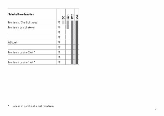
Schakelbare functies
DC
SX 1
SX 2
DCC
Frontsein / Sluitlicht rood F0
Frontsein omschakelen F1
F2
F3
ABV, uit F4
F5
Frontsein cabine 2 uit * F6
F7
Frontsein cabine 1 uit * F8
* alleen in combinatie met Frontsein
8
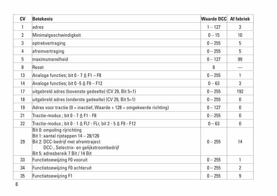
CV Betekenis Waarde DCC Af fabriek
1 adres 1 – 127 3
2 Minimalgeschwindigkeit 0 – 15 10
3 optrekvertraging 0 – 255 5
4 afremvertraging 0 – 255 5
5 maximumsnelheid 0 – 127 99
8 Reset 8 —
13 Analoge functies; bit 0 - 7 =̂ F1 – F8 0 – 255 1
14 Analoge functies; bit 0 -5 =̂ F9 – F12 0 – 63 3
17 uitgebreldadres(bovenstegedeelte)(CV29,Bit5=1) 0 – 255 192
18 uitgebreldadres(onderstegedeelte)(CV29,Bit5=1) 0 – 255 0
19 Adresvoortractie(0=inactief,Waarde+128=omgekeerderichting) 0 – 127 0
21 Tractie-modus ; bit 0 - 7 =̂ F1 - F8 0 – 255 0
22 Tractie-modus ; bit 0 - 1 =̂ FLf - FLr, bit 2 - 5 =̂ F9 - F12 0 – 63 0
29
Bit0:ompolingrijrichtingBit1:aantalrijstappen14–28/126Bit2:DCC-bedrijfmetafremtraject DCC-, Selectrix- en gelijkstroombedrijf Bit5:adresbereik7Bit/14Bit
0 – 255 14
33 Functietoewijzing F0 vooruit 0 – 255 1
34 Functietoewijzing F0 achteruit 0 – 255 2
35 Functietoewijzing F1 0 – 255 9
9
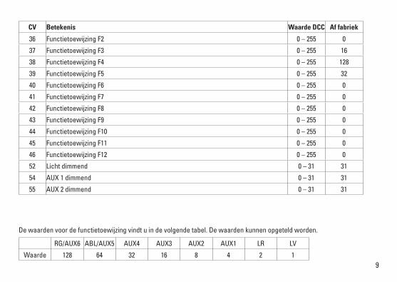
CV Betekenis Waarde DCC Af fabriek
36 Functietoewijzing F2 0 – 255 0
37 Functietoewijzing F3 0 – 255 16
38 Functietoewijzing F4 0 – 255 128
39 Functietoewijzing F5 0 – 255 32
40 Functietoewijzing F6 0 – 255 0
41 Functietoewijzing F7 0 – 255 0
42 Functietoewijzing F8 0 – 255 0
43 Functietoewijzing F9 0 – 255 0
44 Functietoewijzing F10 0 – 255 0
45 Functietoewijzing F11 0 – 255 0
46 Functietoewijzing F12 0 – 255 0
52 Licht dimmend 0 – 31 31
54 AUX1dimmend 0 – 31 31
55 AUX2dimmend 0 – 31 31
De waarden voor de functietoewijzing vindt u in de volgende tabel. De waarden kunnen opgeteld worden.
RG/AUX6 ABL/AUX5 AUX4 AUX3 AUX2 AUX1 LR LV
Waarde 128 64 32 16 8 4 2 1
10
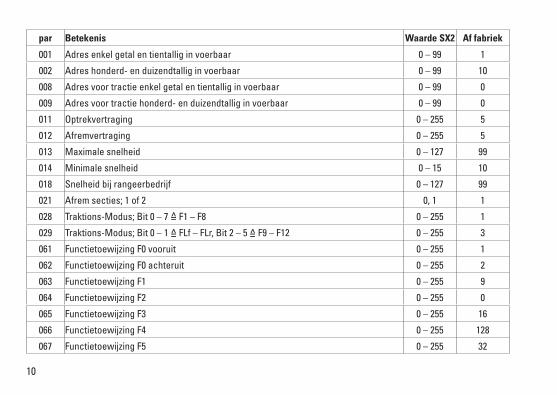
par Betekenis Waarde SX2 Af fabriek
001 Adres enkel getal en tientallig in voerbaar 0 – 99 1
002 Adres honderd- en duizendtallig in voerbaar 0 – 99 10
008 Adres voor tractie enkel getal en tientallig in voerbaar 0 – 99 0
009 Adres voor tractie honderd- en duizendtallig in voerbaar 0 – 99 0
011 Optrekvertraging 0 – 255 5
012 Afremvertraging 0 – 255 5
013 Maximale snelheid 0 – 127 99
014 Minimale snelheid 0 – 15 10
018 Snelheid bij rangeerbedrijf 0 – 127 99
021 Afrem secties; 1 of 2 0, 1 1
028 Traktions-Modus; Bit 0 – 7 =̂ F1 – F8 0 – 255 1
029 Traktions-Modus; Bit 0 – 1 =̂ FLf – FLr, Bit 2 – 5 =̂ F9 – F12 0 – 255 3
061 Functietoewijzing F0 vooruit 0 – 255 1
062 Functietoewijzing F0 achteruit 0 – 255 2
063 Functietoewijzing F1 0 – 255 9
064 Functietoewijzing F2 0 – 255 0
065 Functietoewijzing F3 0 – 255 16
066 Functietoewijzing F4 0 – 255 128
067 Functietoewijzing F5 0 – 255 32
11FabrieksinstellingvoorSX1:01-732,uitgebreid:00-274
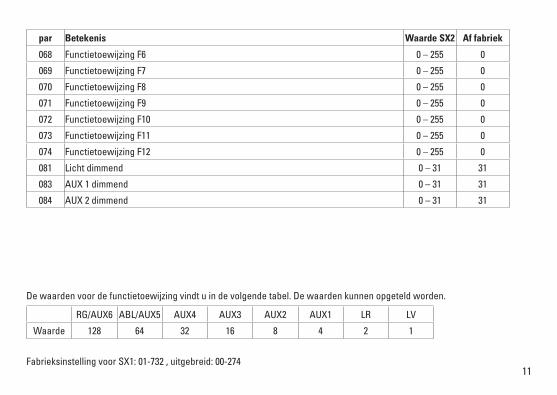
par Betekenis Waarde SX2 Af fabriek
068 Functietoewijzing F6 0 – 255 0
069 Functietoewijzing F7 0 – 255 0
070 Functietoewijzing F8 0 – 255 0
071 Functietoewijzing F9 0 – 255 0
072 Functietoewijzing F10 0 – 255 0
073 Functietoewijzing F11 0 – 255 0
074 Functietoewijzing F12 0 – 255 0
081 Licht dimmend 0 – 31 31
083 AUX1dimmend 0 – 31 31
084 AUX2dimmend 0 – 31 31
De waarden voor de functietoewijzing vindt u in de volgende tabel. De waarden kunnen opgeteld worden.
RG/AUX6 ABL/AUX5 AUX4 AUX3 AUX2 AUX1 LR LV
Waarde 128 64 32 16 8 4 2 1

12
Aviso de seguridad• Lalocomotorasolamentedebefuncionarenelsistema
que le corresponda.• Laalimentacióndelalocomotoradeberárealizarse
desde una sola fuente de suminitro.• Observenecesariamentelosavisosdeseguridadindica-
dos en las instrucciones correspondientes a su sistema de funcionamiento.
• Analógicasmax.14Voltios=,digitalesmax.22voltios~• Paraelfuncionamientoconvencionaldelalocomotora
deben suprimirse las interferencias en la vía de conexión de la alimentación. Para ello debe emplearse el set supresor de interferencias 14972.
• Noexponerelmodeloenminiaturaalaradiaciónsolardirecta, a oscilaciones fuertes de temperatura o a una humedad del aire elevada.
• Elcabledeconexiónalavíautilizadodebetenerunalongitud máxima de 2 metros.
• ¡ATENCIÓN! Esquinas y puntas afiladas condicionadas a la función.
• LosLEDsincorporadoscorrespondenalaclasedeláser1 según la norma europea EN 60825-1.
Notas importantes• Lasinstruccionesdeempleoyelembalajeformanparte
íntegra del producto y, por este motivo, deben guardarse y entregarse junto con el producto en el caso de venderlo o transmitirlo a otro.
• Encasodeprecisarunareparaciónopiezasderecambio,rogamos ponerse en contacto con su distribuidor Trix.
• Responsabilidadygarantíaconformealdocumentodegarantía que se adjunta.
• Eliminación:www.maerklin.com/en/imprint.htmlConsejo general para evitar las interferencias electroma-gnéticas: Para garantizar un funcionamiento según las previsiones se requiere un contacto rueda-carril de los vehículos permanente sin anomalías. No realice ninguna modificación en piezas conductoras de la corriente.
Funciones• Electrónicaintegradaparafuncionamientoopcionalconel
aparato de conducción de corriente continua convencio-nal (máx. ±12 voltios), Trix Systems, Trix Selectrix (SX1) y Selectrix 2 (SX2) o sistemas digitales según norma NMRA.
• Detecciónautomáticadelsistemaentrelosmodosdigitaly analógico.
• Noexistereconocimientoautomáticodelsistemaentrelos sistemas digitales.
• Señaldecabezadetresluces,doslucesdecolarojasde-trás, con alternancia en función del sentido de la marcha.
• Lalocomotoranoestápreparadaparaunserviciodesdecatenaria funcionalmente operativo.
Indicaciones para el funcionamiento digital• Enelfuncionamientoporprimeravezconunsistema
digital (SX1, SX2 o DCC), el decoder se debe configurar para este sistema digital. Para tal fin, se debe programar el decoder una vez en este sistema digital (p. ej., cambiar la dirección).
13
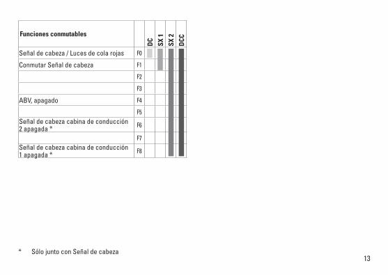
Funciones conmutables
DC
SX 1
SX 2
DCC
Señal de cabeza / Luces de cola rojas F0
Conmutar Señal de cabeza F1
F2
F3
ABV, apagado F4
F5Señal de cabeza cabina de conducción 2 apagada * F6
F7Señal de cabeza cabina de conducción 1 apagada * F8
* Sólo junto con Señal de cabeza
14
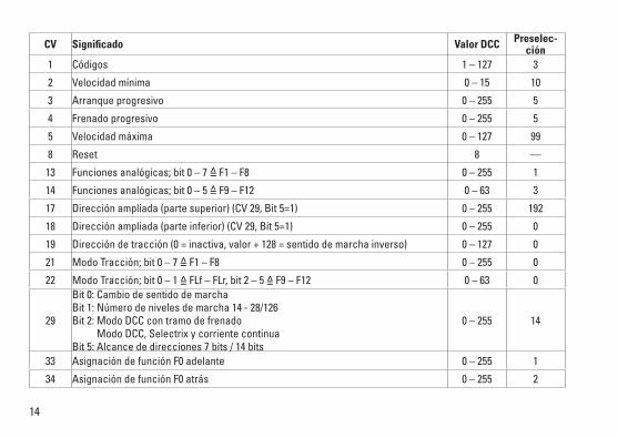
CV Significado Valor DCC Preselec-ción
1 Códigos 1 – 127 3
2 Velocidad mínima 0 – 15 10
3 Arranque progresivo 0 – 255 5
4 Frenado progresivo 0 – 255 5
5 Velocidad máxima 0 – 127 99
8 Reset 8 —
13 Funciones analógicas; bit 0 – 7 =̂ F1 – F8 0 – 255 1
14 Funciones analógicas; bit 0 – 5 =̂ F9 – F12 0 – 63 3
17 Direcciónampliada(partesuperior)(CV29,Bit5=1) 0 – 255 192
18 Direcciónampliada(parteinferior)(CV29,Bit5=1) 0 – 255 0
19 Direccióndetracción(0=inactiva,valor+128=sentidodemarchainverso) 0 – 127 0
21 Modo Tracción; bit 0 – 7 =̂ F1 – F8 0 – 255 0
22 Modo Tracción; bit 0 – 1 =̂ FLf – FLr, bit 2 – 5 =̂ F9 – F12 0 – 63 0
29
Bit0:CambiodesentidodemarchaBit1:Númerodenivelesdemarcha14-28/126Bit2:ModoDCCcontramodefrenado Modo DCC, Selectrix y corriente continua Bit5:Alcancededirecciones7bits/14bits
0 – 255 14
33 Asignación de función F0 adelante 0 – 255 1
34 Asignación de función F0 atrás 0 – 255 2
15
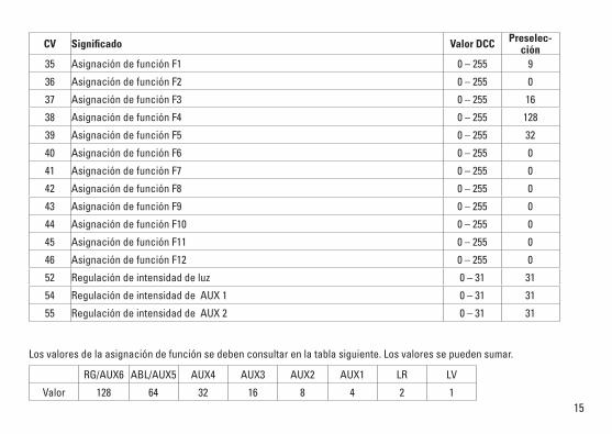
CV Significado Valor DCC Preselec-ción
35 Asignación de función F1 0 – 255 9
36 Asignación de función F2 0 – 255 0
37 Asignación de función F3 0 – 255 16
38 Asignación de función F4 0 – 255 128
39 Asignación de función F5 0 – 255 32
40 Asignación de función F6 0 – 255 0
41 Asignación de función F7 0 – 255 0
42 Asignación de función F8 0 – 255 0
43 Asignación de función F9 0 – 255 0
44 Asignación de función F10 0 – 255 0
45 Asignación de función F11 0 – 255 0
46 Asignación de función F12 0 – 255 0
52 Regulación de intensidad de luz 0 – 31 31
54 RegulacióndeintensidaddeAUX1 0 – 31 31
55 RegulacióndeintensidaddeAUX2 0 – 31 31
Los valores de la asignación de función se deben consultar en la tabla siguiente. Los valores se pueden sumar.
RG/AUX6 ABL/AUX5 AUX4 AUX3 AUX2 AUX1 LR LV
Valor 128 64 32 16 8 4 2 1
16
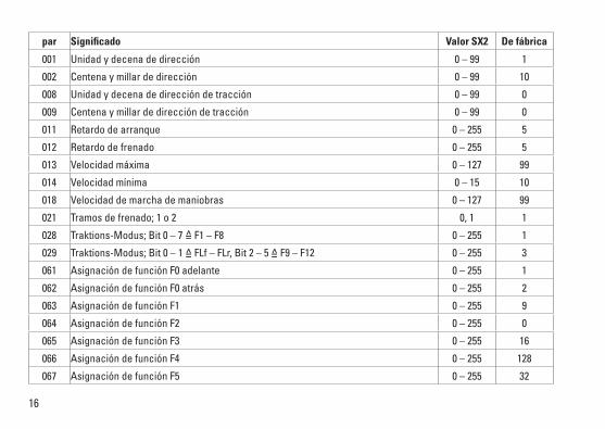
par Significado Valor SX2 De fábrica
001 Unidadydecenadedirección 0 – 99 1
002 Centena y millar de dirección 0 – 99 10
008 Unidadydecenadedireccióndetracción 0 – 99 0
009 Centena y millar de dirección de tracción 0 – 99 0
011 Retardo de arranque 0 – 255 5
012 Retardo de frenado 0 – 255 5
013 Velocidad máxima 0 – 127 99
014 Velocidad mínima 0 – 15 10
018 Velocidad de marcha de maniobras 0 – 127 99
021 Tramos de frenado; 1 o 2 0, 1 1
028 Traktions-Modus; Bit 0 – 7 =̂ F1 – F8 0 – 255 1
029 Traktions-Modus; Bit 0 – 1 =̂ FLf – FLr, Bit 2 – 5 =̂ F9 – F12 0 – 255 3
061 Asignación de función F0 adelante 0 – 255 1
062 Asignación de función F0 atrás 0 – 255 2
063 Asignación de función F1 0 – 255 9
064 Asignación de función F2 0 – 255 0
065 Asignación de función F3 0 – 255 16
066 Asignación de función F4 0 – 255 128
067 Asignación de función F5 0 – 255 32
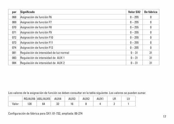
17ConfiguracióndefábricaparaSX1:01-732,ampliada:00-274
par Significado Valor SX2 De fábrica
068 Asignación de función F6 0 – 255 0
069 Asignación de función F7 0 – 255 0
070 Asignación de función F8 0 – 255 0
071 Asignación de función F9 0 – 255 0
072 Asignación de función F10 0 – 255 0
073 Asignación de función F11 0 – 255 0
074 Asignación de función F12 0 – 255 0
081 Regulación de intensidad de luz normal 0 – 31 31
083 RegulacióndeintensidaddeAUX1 0 – 31 31
084 RegulacióndeintensidaddeAUX2 0 – 31 31
Los valores de la asignación de función se deben consultar en la tabla siguiente. Los valores se pueden sumar.
RG/AUX6 ABL/AUX5 AUX4 AUX3 AUX2 AUX1 LR LV
Valor 128 64 32 16 8 4 2 1
18
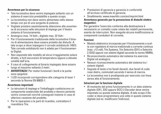
Avvertenze per la sicurezza• Talelocomotivadevevenireimpiegatasoltantoconun
sistema di esercizio prestabilito a questo scopo.• Lalocomotivanondevevenirealimentatanellostesso
tempo con più di una sorgente di potenza.• Vogliateprestareassolutamenteattenzionealleavverten-
ze di sicurezza nelle istruzioni di impiego per il Vostro sistema di funzionamento.
• Analogicomax.14Volt=,digitalemax.22Volt~• Perilfunzionamentotradizionaledellalocomotivailbina-
rio di alimentazione deve essere protetto dai disturbi. A tale scopo si deve impiegare il corredo antidisturbi 14972. Tale corredo antidisturbi non è adatto per il funzionamen-to Digital.
• Nonesponetetalemodelloadalcunirraggiamentosolarediretto, a forti escursioni di temperatura oppure a elevata umidità dell’aria.
• Ilcavodicollegamentoalbinarioimpiegatodeveesserelungo al massimo soltanto 2 metri.
• AVVERTENZA! Per motivi funzionali i bordi e le punte sono spigolosi.
• ILEDincorporaticorrispondonoallacategoriadilaser1secondo la Norma EN 60825-1.
Avvertenze importanti• Leistruzionidiimpiegoel’imballaggiocostituisconoun
componente sostanziale del prodotto e devono pertanto venire conservati nonché consegnati insieme in caso di ulteriore cessione del prodotto.
• Perleriparazioniolepartidiricambio,contrattareilrivenditore Trix.
• Prestazionidigaranziaegaranziainconformitàall’accluso certificato di garanzia.
• Smaltimento:www.maerklin.com/en/imprint.htmlAvvertenza generale per la prevenzione di disturbi elettro-magnetici: Per garantire l’esercizio conforme alla destinazione è necessario un contatto ruota-rotaia dei rotabili permanente, esente da interruzioni. Non eseguite alcuna modificazione ai componenti conduttori di corrente.
Funzioni• Modulo elettronico incorporato per il funzionamento a scel-
ta con regolatore di marcia tradizionale a corrente continua (max. ±12 volt), Trix Systems, Trix Selectrix (SX1) e Selectrix 2 (SX2) oppure con sistemi digitali secondo le norme NMRA.
• RiconoscimentoautomaticodelsistematraesercizioDigital ed analogico.
• Nessunriconoscimentoautomaticodelsistematraisistemi digitali.
• Segnaleditestaatrefanalidavanti,duefanalidicodarossi dietro, commutati secondo il senso di marcia.
• Lalocomotivanonèpredispostaperesercizioconlineaaerea atta al funzionamento.
Istruzioni per la funzione digitale• Almomentodelprimofunzionamentoinundatosistema
digitale (SX1, SX2 oppure DCC) il Decoder deve venire impostato su questo sistema digitale. A tale scopo il De-coder si deve programmare una volta in questo sistema digitale (ad es. modificare l’indirizzo).
19
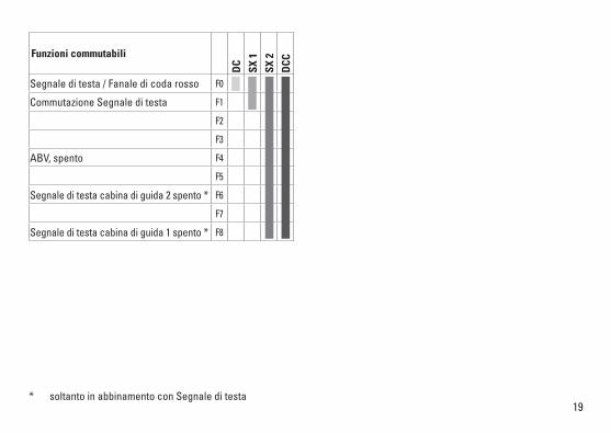
Funzioni commutabili
DC
SX 1
SX 2
DCC
Segnale di testa / Fanale di coda rosso F0
Commutazione Segnale di testa F1
F2
F3
ABV, spento F4
F5
Segnale di testa cabina di guida 2 spento * F6
F7
Segnale di testa cabina di guida 1 spento * F8
* soltanto in abbinamento con Segnale di testa

20
CV Significato Valore DCC Di fabbrica
1 Indirizzo 1 – 127 3
2 Velocità minima 0 – 15 10
3 Ritardo di avviamento 0 – 255 5
4 Ritardo di frenatura 0 – 255 5
5 Velocità massima 0 – 127 99
8 Ripristino 8 —
13 Funzioni analogiche; Bit 0 – 7 =̂ F1 – F8 0 – 255 1
14 Funzioni analogiche; Bit 0 – 5 =̂ F9 – F12 0 – 63 3
17 Indirizzoampliato(partesuperiore)(CV29,Bit5=1) 0 – 255 192
18 Indirizzoampliato(parteinferiore)(CV29,Bit5=1) 0 – 255 0
19 Indirizzotraz.multipla(0=inattiva,valore+128=sensodimarciainverso) 0 – 127 0
21 Modalità di trazione; Bit 0 – 7 =̂ F1 – F8 0 – 255 0
22 Modalità di trazione; Bit 0 – 1 =̂ FLf – FLr, Bit 2 – 5 =̂ F9 – F12 0 – 63 0
29
Bit0:inversionepolaritàdelsensodimarciaBit1:numerogradazionidimarcia14-28/126Bit2:EsercizioDCCcontrattadifrenatura Esercizio DCC, Selectrix e corrente continua Bit5:Ampiezzaindirizzo7Bit/14Bit
0 – 255 14
33 Assegnazione funzione F0 avanti 0 – 255 1
34 Assegnazione funzione F0 indietro 0 – 255 2
35 Assegnazione funzione F1 0 – 255 9
21
CV Significato Valore DCC Di fabbrica
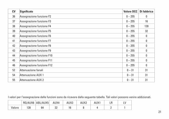
36 Assegnazione funzione F2 0 – 255 0
37 Assegnazione funzione F3 0 – 255 16
38 Assegnazione funzione F4 0 – 255 128
39 Assegnazione funzione F5 0 – 255 32
40 Assegnazione funzione F6 0 – 255 0
41 Assegnazione funzione F7 0 – 255 0
42 Assegnazione funzione F8 0 – 255 0
43 Assegnazione funzione F9 0 – 255 0
44 Assegnazione funzione F10 0 – 255 0
45 Assegnazione funzione F11 0 – 255 0
46 Assegnazione funzione F12 0 – 255 0
52 Attenuazione fanali 0 – 31 31
54 AttenuazioneAUX1 0 – 31 31
55 AttenuazioneAUX2 0 – 31 31
I valori per l’assegnazione delle funzioni sono da ricavare dalla seguente tabella. Tali valori possono venire addizionati.
RG/AUX6 ABL/AUX5 AUX4 AUX3 AUX2 AUX1 LR LV
Valore 128 64 32 16 8 4 2 1
22
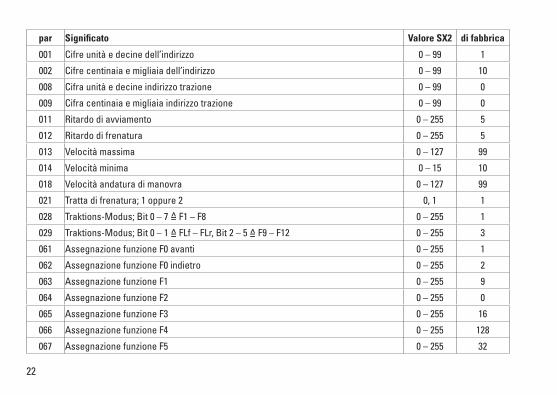
par Significato Valore SX2 di fabbrica
001 Cifre unità e decine dell’indirizzo 0 – 99 1
002 Cifre centinaia e migliaia dell’indirizzo 0 – 99 10
008 Cifra unità e decine indirizzo trazione 0 – 99 0
009 Cifra centinaia e migliaia indirizzo trazione 0 – 99 0
011 Ritardo di avviamento 0 – 255 5
012 Ritardo di frenatura 0 – 255 5
013 Velocità massima 0 – 127 99
014 Velocità minima 0 – 15 10
018 Velocità andatura di manovra 0 – 127 99
021 Tratta di frenatura; 1 oppure 2 0, 1 1
028 Traktions-Modus; Bit 0 – 7 =̂ F1 – F8 0 – 255 1
029 Traktions-Modus; Bit 0 – 1 =̂ FLf – FLr, Bit 2 – 5 =̂ F9 – F12 0 – 255 3
061 Assegnazione funzione F0 avanti 0 – 255 1
062 Assegnazione funzione F0 indietro 0 – 255 2
063 Assegnazione funzione F1 0 – 255 9
064 Assegnazione funzione F2 0 – 255 0
065 Assegnazione funzione F3 0 – 255 16
066 Assegnazione funzione F4 0 – 255 128
067 Assegnazione funzione F5 0 – 255 32
23ImpostazionedifabbricaperSX1:01-732,esteso:00-274
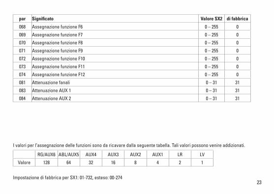
par Significato Valore SX2 di fabbrica
068 Assegnazione funzione F6 0 – 255 0
069 Assegnazione funzione F7 0 – 255 0
070 Assegnazione funzione F8 0 – 255 0
071 Assegnazione funzione F9 0 – 255 0
072 Assegnazione funzione F10 0 – 255 0
073 Assegnazione funzione F11 0 – 255 0
074 Assegnazione funzione F12 0 – 255 0
081 Attenuazione fanali 0 – 31 31
083 AttenuazioneAUX1 0 – 31 31
084 AttenuazioneAUX2 0 – 31 31
I valori per l’assegnazione delle funzioni sono da ricavare dalla seguente tabella. Tali valori possono venire addizionati.
RG/AUX6 ABL/AUX5 AUX4 AUX3 AUX2 AUX1 LR LV
Valore 128 64 32 16 8 4 2 1
24
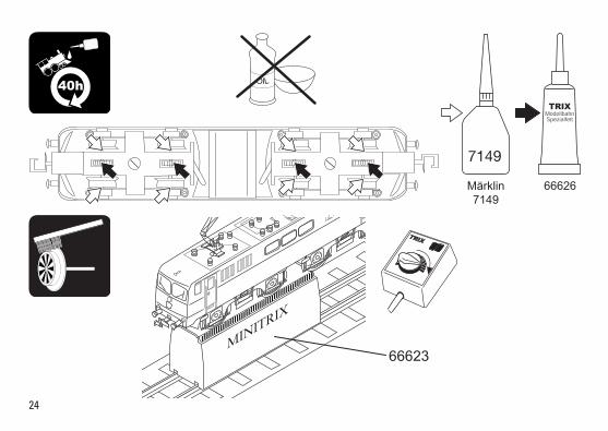
66626Märklin7149
7149
MINITRIX
40h OIL
66623

25
a
a
b

2610
7
3
6
5
2
1
2
4
3
6
8 9
7
10
8
9
11
12
11
12
Details der Darstel-lung können von dem Modell abweichen.

27
Opmerking:enkeledelenwordenalleenkleurloosofineenandere kleur aangeboden. Delen die niet in de in de lijst voorkomen, kunnen alleen via een reparatie in het Märklin-service-centrum hersteld/vervangen worden.
Nota:algunaspiezasestándisponiblessólosinoconotrocolor. Las piezas que no figuran aquí pueden repararse únicamente en el marco de una reparación en el servicio de reparación de Märklin.
Avvertenza:Alcunielementivengonopropostisolosenzao con differente colorazione. I pezzi che non sono qui spe-cificati possono venire riparati soltanto nel quadro di una riparazione presso il Servizio Riparazioni Märklin.
1 Scherenstromabnehmer E237 089 2 Schraube E19 8002 28 3 Schraube E19 8052 28 4 Lautsprecher — 5 Motor E117 504 6 Schraube E19 8001 28 7 Beleuchtungsplatine E117 505 8 Pufferbohle E238 675 9 Kupplung E238 674 10 Federstab E117 511 11 Drehgestell komplett E238 676 12 Haftreifen E12 2258 00
Schnellzugwagen Übergang E12 5516 00 Sicherungsscheibe E608 020 Steckbolzen E14 0382 08 Kupplung E176 301 Radsatz E31 3010 05
Due to different legal requirements regarding electro-magnetic compatibility, thisitemmaybeusedintheUSAonlyafterseparatecertificationforFCCcom-pliance and an adjustment if necessary. UseintheUSAwithoutthiscertificationisnotpermittedandabsolvesusofanyliability. If you should want such certification to be done, please contact us – also due to the additional costs incurred for this.
www.maerklin.com/en/imprint.html
Gebr. Märklin & Cie. GmbH Stuttgarter Straße 55 - 57 73033 Göppingen Germanywww.trix.de
277007/0817/Sm2EfÄnderungen vorbehalten
© Gebr. Märklin & Cie. GmbH