
Monitoring Quality of Service:Architectural Design and ... Ernst... · D I S S E R T A T I O N...
164
DISSERTATION Monitoring Quality of Service in Service-oriented Systems: Architectural Design and Stakeholder Support ausgef¨ uhrt zum Zwecke der Erlangung des akademischen Grades eines Doktors der technischen Wissenschaften unter der Leitung von Univ.-Prof. Dr. Schahram DUSTDAR E 184 Institut fur Informationssysteme eingereicht an der Technischen Universit¨ at Wien Fakult¨ at f ¨ ur Informatik von Dipl.-Ing. Ernst Oberortner 0027144 Poststrasse 4 A-9551 Bodensdorf Wien, Februar 2011
Transcript of Monitoring Quality of Service:Architectural Design and ... Ernst... · D I S S E R T A T I O N...
D I S S E R T A T I O N
Monitoring Quality of Service in Service-oriented Systems:Architectural Design and Stakeholder Support
ausgefuhrt zum Zwecke der Erlangung des akademischen Grades eines
Doktors der technischen Wissenschaftenunter der Leitung von
Univ.-Prof. Dr. Schahram DUSTDAR
E 184
Institut fur Informationssysteme
eingereicht an der Technischen Universitat Wien
Fakultat fur Informatik
von
Dipl.-Ing. Ernst Oberortner
0027144
Poststrasse 4
A-9551 Bodensdorf
Wien, Februar 2011

ii
Abstract
In a service-oriented system, services are utilized to perform inter- and cross-organization businesstasks with few human intervention. Between a service provider and a service consumer contractscan exist containing performance-related Quality of Service (QOS) agreements, called Service LevelAgreement (SLA). A services provider must prevent SLA violations in order to avoid serious financialconsequences and a diminished reputation. Service consumers want to ensure that they get the servicethey pay for. In order to prevent and detect violations of the performance-related agreements during theSLA’s validity, a monitoring infrastructure is required. To design an architecture of a QoS monitoringinfrastructure, many architectural design decisions must be faced, depend on business and technicalrequirements. At early stages, the infrastructure’s requirements are fuzzy and incomplete, making laterchanges inevitable. The design process and the specification of the negotiated performance-relatedQoS properties involve various differently skilled stakeholders, ranging from business to technicalexperts.In this thesis, we present an architectural design decision model that covers design decisions aboutmeasuring, storing, and evaluating performance-related QoS properties. The model proposes architec-tural solutions for the design decisions that fulfill the requirements. Model-driven Development (MDD)makes it possible to generate the QoS monitoring infrastructure almost automatically. To support thedifferently skilled stakeholders to specify the performance-related agreements, we utilize Domain-specific Language (DSL). The specified performance-related agreements are then monitored duringthe SLA’s validity. We develop the model-driven DSLs using an incremental development approach.We evaluate our work in the scope of an industrial case study dealing with advanced multi-mediaservices that have to comply with performance-related QoS agreements.The presented architectural design decision model guides the designers through the decision mak-ing process. Utilizing model-driven DSLs, business stakeholders can specify the performance-relatedagreements without technical knowledge. The stakeholders with a technical expertise describe thetechnological artifacts to monitor the performance-related agreements during the SLAs’ validity. De-veloping model-driven DSLs incrementally helps the developers to deal with permanent changingrequirements.
i

ii
Kurzfassung
In service-orientierten Systemen werden Services angeboten welche inner- und außerbetrieblicheAufgaben hauptsachlich automatisch abarbeiten. Zwischen den Service Anbietern und den ServiceKonsumenten konnen Vertrage vereinbart werden, welche Klausen uber die Performanz der Servicesdefinieren. Solche Vertrage werden als Service Level Agreements (SLA) bezeichnet. Ein ServiceAnbieter muss sicherstellen, dass die vertraglichen Vereinbarungen erfullt werden um Ponale zu ver-meiden sowie, viel schlimmer noch, seinen Ruf zu schadigen. Ein Service Konsument mochte gernewissen, ob der Service Anbieter auch wirklich die Vereinbarungen erfullt bzw. nach Vertragsendeerfullt hat. Daher ist eine Uberwachung der Performanz der Services bezuglich der vertraglichenVereinbarung unabdinglich. Ziel der Arbeit ist es, systematisch die Messung und die Uberwachungvon QoS-Parametern in service-orientierten Systemen zu unterstutzen. In der Entwurfsphase einerUberwachungsinfrastruktur mussen Losungen fur Architekturentscheidungen getroffen werden,welche die betrieblichen und technischen Anforderung erfullen. Außerdem sind viele Akteureinvolviert welche unterschiedliches Hintergrundwissen und Interessen haben. Uberdies sind dieAnforderungen an die Uberwachungsstruktur zu Beginn nicht klar definiert. Dadurch sind spatereAnderungen in der Architektur und in dessen Implementierung unumganglich.
In dieser Dissertation wird ein Modell vorgestellt um den Entwurf einer Uberwachungsstruktur zuvereinfachen. Das Modell stellt Architekturlosungen fur die Architekturentscheidungen vor, welchegrundlegende Anforderungen erfullen. Das vorgestellte Entwurfsmodell hilft Designern eine betrieb-soptimale Uberwachungsstruktur zu entwerfen. Modell-getriebene Softwareentwicklung ermoglichteine automatische Generierung der Uberwachungskomponenten. Damit die Akteure die vertraglichenVereinbarungen spezifizieren konnen, werden modellgetriebene domanen-spezifische Sprachen ver-wendet. Die Verwendung von modellgetriebenen Sprachen ermoglicht Business-Experten die ver-traglichen Vereinbarungen zu definieren ohne uber ein technologisches Wissen zu verfugen. Außerdemwird ein inkrementeller Entwicklungsansatz vorgestellt welcher den Umgang mit spateren Anderungenerleichtert. Es wird eine Fallstudie prasentiert welche als Evaluationsgrundlage dient. Die Fallstudiebeschaftigt sich mit Multimedia Services um Filme oder Live-Streams in einer gewunschten Spracheanzusehen.
iii

iv

To my parents and Verena.From the bottom of my heart.

vi
Contents
Abstract i
Kurzfassung iii
List of Tables xi
List of Figures xiii
Glossary xv
Previously Published Work xvii
Acknowledgements xix
1 Introduction 11.1 Problem Statement . . . . . . . . . . . . . . . . . . . . . . . . . . . . . . . . . . . . 11.2 A Justifying Scenario . . . . . . . . . . . . . . . . . . . . . . . . . . . . . . . . . . . 21.3 Research Questions . . . . . . . . . . . . . . . . . . . . . . . . . . . . . . . . . . . . 41.4 Scientific Contributions . . . . . . . . . . . . . . . . . . . . . . . . . . . . . . . . . . 51.5 Organization of the Thesis . . . . . . . . . . . . . . . . . . . . . . . . . . . . . . . . 6
2 Background 92.1 Service-oriented Distributed Systems . . . . . . . . . . . . . . . . . . . . . . . . . . . 92.2 Service Level Agreements (SLA) . . . . . . . . . . . . . . . . . . . . . . . . . . . . . 11
2.2.1 Performance-related QoS Properties . . . . . . . . . . . . . . . . . . . . . . . 122.3 Summary . . . . . . . . . . . . . . . . . . . . . . . . . . . . . . . . . . . . . . . . . 14
3 A Case Study 153.1 The Case Study’s Scenario . . . . . . . . . . . . . . . . . . . . . . . . . . . . . . . . 15
3.1.1 An Example Scenario . . . . . . . . . . . . . . . . . . . . . . . . . . . . . . 163.1.2 The Case Study’s Services . . . . . . . . . . . . . . . . . . . . . . . . . . . . 17
3.2 The Case Study’s QoS Compliance Concerns . . . . . . . . . . . . . . . . . . . . . . 173.3 The Case Study’s Requirements . . . . . . . . . . . . . . . . . . . . . . . . . . . . . 183.4 Summary . . . . . . . . . . . . . . . . . . . . . . . . . . . . . . . . . . . . . . . . . 19
vii
4 An Architectural Decisions Model to Design a QoS Monitoring Infrastructure 214.1 Background . . . . . . . . . . . . . . . . . . . . . . . . . . . . . . . . . . . . . . . . 22
4.1.1 Patterns . . . . . . . . . . . . . . . . . . . . . . . . . . . . . . . . . . . . . . 224.1.2 Patterns in Distributed Systems . . . . . . . . . . . . . . . . . . . . . . . . . 23
4.2 Features of a QoS Monitoring Infrastructure . . . . . . . . . . . . . . . . . . . . . . . 254.3 Requirements on a QoS monitoring infrastructure . . . . . . . . . . . . . . . . . . . . 28
4.3.1 Decision criteria . . . . . . . . . . . . . . . . . . . . . . . . . . . . . . . . . 294.3.2 System-specific Requirements . . . . . . . . . . . . . . . . . . . . . . . . . . 304.3.3 Implementation-specific Requirements . . . . . . . . . . . . . . . . . . . . . 32
4.4 Architectural Design Decision Model for Designing a QoS Monitoring Infrastructure . 334.4.1 Design Decision:
WHICH SLA PARTY NEEDS QOS MONITORING? . . . . . . . . . . . . . . . 344.4.2 Design Decision:
WHERE SHOULD THE PERFORMANCE-RELATED QOS PROPERTIES BE
MEASURED? . . . . . . . . . . . . . . . . . . . . . . . . . . . . . . . . . . . 364.4.3 Design Decision:
WHEN SHOULD THE PERFORMANCE-RELATED QOS PROPERTIES BE MEA-SURED? . . . . . . . . . . . . . . . . . . . . . . . . . . . . . . . . . . . . . . 46
4.4.4 Design Decision:WHEN SHOULD THE PERFORMANCE-RELATED QOS MEASUREMENTS BE
EVALUATED? . . . . . . . . . . . . . . . . . . . . . . . . . . . . . . . . . . . 484.4.5 Design Decision:
WHERE SHOULD THE PERFORMANCE-RELATED QOS MEASUREMENTS BE
EVALUATED? . . . . . . . . . . . . . . . . . . . . . . . . . . . . . . . . . . . 514.4.6 Design Decision:
WHERE SHOULD THE PERFORMANCE-RELATED QOS MEASUREMENTS BE
STORED? . . . . . . . . . . . . . . . . . . . . . . . . . . . . . . . . . . . . . 534.5 Relationships between the Architectural Design Decisions . . . . . . . . . . . . . . . 564.6 Evaluation of the Model in the Case Study . . . . . . . . . . . . . . . . . . . . . . . . 57
4.6.1 The Case Study’s QoS Monitoring Requirements . . . . . . . . . . . . . . . . 574.6.2 The Case Study’s Solutions . . . . . . . . . . . . . . . . . . . . . . . . . . . 584.6.3 Implementation of the Measuring Solutions within the Case Study . . . . . . . 594.6.4 QoS Measurements during the Runtime . . . . . . . . . . . . . . . . . . . . . 63
4.7 Discussion . . . . . . . . . . . . . . . . . . . . . . . . . . . . . . . . . . . . . . . . . 654.7.1 Aspect-oriented Implementation of the Measuring Patterns . . . . . . . . . . . 654.7.2 Model-driven Generation of the Measuring Patterns . . . . . . . . . . . . . . . 65
4.8 Summary . . . . . . . . . . . . . . . . . . . . . . . . . . . . . . . . . . . . . . . . . 66
5 Supporting the Stakeholders to Specify QoS Compliance Concerns 675.1 Background . . . . . . . . . . . . . . . . . . . . . . . . . . . . . . . . . . . . . . . . 67
5.1.1 Model-driven Development (MDD) . . . . . . . . . . . . . . . . . . . . . . . 675.1.2 Domain-specific Languages (DSL) . . . . . . . . . . . . . . . . . . . . . . . . 695.1.3 Model-driven DSLs . . . . . . . . . . . . . . . . . . . . . . . . . . . . . . . . 70
5.2 Our Model-driven DSL Approach to Support the Stakeholders . . . . . . . . . . . . . 71
viii
5.3 An Explorative Study: DSLs for SOAs . . . . . . . . . . . . . . . . . . . . . . . . . . 735.3.1 The Study’s Claims of Investigation . . . . . . . . . . . . . . . . . . . . . . . 735.3.2 Study Details . . . . . . . . . . . . . . . . . . . . . . . . . . . . . . . . . . . 745.3.3 Study Results . . . . . . . . . . . . . . . . . . . . . . . . . . . . . . . . . . . 78
5.4 QuaLa: A Model-driven DSL for Specifying QoS Compliance Concerns . . . . . . . . 805.4.1 The high-level QuaLa . . . . . . . . . . . . . . . . . . . . . . . . . . . . . . 815.4.2 The low-level QuaLa . . . . . . . . . . . . . . . . . . . . . . . . . . . . . . . 825.4.3 QuaLa Code Generation Templates . . . . . . . . . . . . . . . . . . . . . . . 845.4.4 Using QuaLa within the Case Study . . . . . . . . . . . . . . . . . . . . . . . 855.4.5 QuaLa – Concluding Remarks . . . . . . . . . . . . . . . . . . . . . . . . . . 89
5.5 Similar DSL Projects . . . . . . . . . . . . . . . . . . . . . . . . . . . . . . . . . . . 905.5.1 A DSL for Specifying a Role-Based Pageflow of Web Applications . . . . . . 905.5.2 QoSTIL – QoS Test Instrumentation Language . . . . . . . . . . . . . . . . . 92
5.6 Lessons Learned during the DSL Projects . . . . . . . . . . . . . . . . . . . . . . . . 945.7 Related Work . . . . . . . . . . . . . . . . . . . . . . . . . . . . . . . . . . . . . . . 95
5.7.1 Related Languages for Specifying QoS . . . . . . . . . . . . . . . . . . . . . 955.7.2 Related DSL Development Approaches . . . . . . . . . . . . . . . . . . . . . 96
5.8 Summary . . . . . . . . . . . . . . . . . . . . . . . . . . . . . . . . . . . . . . . . . 97
6 Incremental Development of Model-driven DSLs 996.1 An Incremental Development Approach . . . . . . . . . . . . . . . . . . . . . . . . . 996.2 Incremental Development of the QuaLa DSL . . . . . . . . . . . . . . . . . . . . . . 101
6.2.1 Researching the Incremental Development Approach . . . . . . . . . . . . . . 1016.2.2 The Evolution of QuaLa . . . . . . . . . . . . . . . . . . . . . . . . . . . . . 1026.2.3 Research Results of the Incremental Development Approach . . . . . . . . . . 107
6.3 Related Work on DSL Development . . . . . . . . . . . . . . . . . . . . . . . . . . . 1106.4 Summary . . . . . . . . . . . . . . . . . . . . . . . . . . . . . . . . . . . . . . . . . 111
7 Extending an Existing Process-driven SOA to QoS-awareness 1137.1 An Existing Process-driven SOA . . . . . . . . . . . . . . . . . . . . . . . . . . . . . 1137.2 Requirements on the QoS-aware Process-driven SOAs . . . . . . . . . . . . . . . . . 1147.3 A QoS-aware Process-driven SOA . . . . . . . . . . . . . . . . . . . . . . . . . . . . 1157.4 A Case Study’s Architectural Walkthrough . . . . . . . . . . . . . . . . . . . . . . . . 1177.5 Summary . . . . . . . . . . . . . . . . . . . . . . . . . . . . . . . . . . . . . . . . . 118
8 Conclusion 1198.1 Summary of the Research Questions . . . . . . . . . . . . . . . . . . . . . . . . . . . 1198.2 Summary of the Scientific Contributions . . . . . . . . . . . . . . . . . . . . . . . . . 1208.3 Potential Future Research . . . . . . . . . . . . . . . . . . . . . . . . . . . . . . . . . 122
Bibliography 123
ix
A Summary of Architectural Design Decisions, Requirements, and Solutions 135A.1 Design Decision:
WHICH SLA PARTY NEEDS QOS MONITORING? . . . . . . . . . . . . . . . . . . . . 135A.2 Design Decision:
WHERE SHOULD THE PERFORMANCE-RELATED QOS PROPERTIES BE MEASURED? 136A.3 Design Decision:
WHEN SHOULD THE PERFORMANCE-RELATED QOS PROPERTIES BE MEASURED? . 138A.4 Design Decision:
WHEN SHOULD THE PERFORMANCE-RELATED QOS MEASUREMENTS BE EVALU-ATED? . . . . . . . . . . . . . . . . . . . . . . . . . . . . . . . . . . . . . . . . . . . 139
A.5 Design Decision:WHERE SHOULD THE PERFORMANCE-RELATED QOS MEASUREMENTS BE EVALU-ATED? . . . . . . . . . . . . . . . . . . . . . . . . . . . . . . . . . . . . . . . . . . . 140
A.6 Design Decision:WHERE SHOULD THE PERFORMANCE-RELATED QOS MEASUREMENTS BE STORED? 141
x
List of Tables
3.1 The Mobile Virtual Network Operator (MVNO)’s offered services . . . . . . . . . . . . 173.2 QOS compliance concerns . . . . . . . . . . . . . . . . . . . . . . . . . . . . . . . . . 17
6.1 Initial QOS compliance concerns . . . . . . . . . . . . . . . . . . . . . . . . . . . . . 1036.2 Intermediate QOS compliance concerns . . . . . . . . . . . . . . . . . . . . . . . . . 1056.3 Final version of QOS compliance concerns . . . . . . . . . . . . . . . . . . . . . . . . 106
A.1 WHICH SLA PARTY NEEDS QOS MONITORING? . . . . . . . . . . . . . . . . . . . . 135A.2 HOW TO MEASURE PERFORMANCE-RELATED QOS PROPERTIES? . . . . . . . . . . 137A.3 WHEN SHOULD THE PERFORMANCE-RELATED QOS PROPERTIES BE MEASURED? . 138A.4 WHEN SHOULD THE PERFORMANCE-RELATED QOS MEASUREMENTS BE EVALU-
ATED? . . . . . . . . . . . . . . . . . . . . . . . . . . . . . . . . . . . . . . . . . . . 139A.5 WHERE SHOULD THE PERFORMANCE-RELATED QOS MEASUREMENTS BE EVALU-
ATED? . . . . . . . . . . . . . . . . . . . . . . . . . . . . . . . . . . . . . . . . . . . 140A.6 WHERE SHOULD THE PERFORMANCE-RELATED QOS MEASUREMENTS BE STORED? 141
xi

xii
List of Figures
1.1 A justifying scenario . . . . . . . . . . . . . . . . . . . . . . . . . . . . . . . . . . . 3
2.1 The SOA triangle . . . . . . . . . . . . . . . . . . . . . . . . . . . . . . . . . . . . . 102.2 A process-driven SOA . . . . . . . . . . . . . . . . . . . . . . . . . . . . . . . . . . 112.3 Measuring points of performance-related QOS concerns . . . . . . . . . . . . . . . . . 12
3.1 An example scenario of the MVNO case study . . . . . . . . . . . . . . . . . . . . . . 16
4.1 An overview of existing patterns in distributed systems . . . . . . . . . . . . . . . . . 234.2 Using the WEB PROXY pattern . . . . . . . . . . . . . . . . . . . . . . . . . . . . . . 254.3 Features of a QoS monitoring infrastructure . . . . . . . . . . . . . . . . . . . . . . . 264.4 Influences between the criteria and requirements . . . . . . . . . . . . . . . . . . . . . 294.5 WHICH SLA PARTY NEEDS QOS MONITORING? . . . . . . . . . . . . . . . . . . . . 344.6 WHERE SHOULD THE PERFORMANCE-RELATED QOS PROPERTIES BE MEASURED? 374.7 The QOS INLINE pattern . . . . . . . . . . . . . . . . . . . . . . . . . . . . . . . . . 384.8 The QOS WRAPPER pattern . . . . . . . . . . . . . . . . . . . . . . . . . . . . . . . . 404.9 The QOS INTERCEPTOR pattern . . . . . . . . . . . . . . . . . . . . . . . . . . . . . 424.10 The QOS REMOTE PROXY pattern . . . . . . . . . . . . . . . . . . . . . . . . . . . . 444.11 WHEN SHOULD THE PERFORMANCE-RELATED QOS PROPERTIES BE MEASURED? . 464.12 WHEN SHOULD THE PERFORMANCE-RELATED QOS MEASUREMENTS BE EVALU-
ATED? . . . . . . . . . . . . . . . . . . . . . . . . . . . . . . . . . . . . . . . . . . . 484.13 ONLINE QOS MONITOR . . . . . . . . . . . . . . . . . . . . . . . . . . . . . . . . . . 494.14 OFFLINE QOS MONITOR . . . . . . . . . . . . . . . . . . . . . . . . . . . . . . . . . 504.15 WHERE SHOULD THE PERFORMANCE-RELATED QOS MEASUREMENTS BE EVALU-
ATED? . . . . . . . . . . . . . . . . . . . . . . . . . . . . . . . . . . . . . . . . . . . 514.16 LOCALIZED QOS OBSERVER . . . . . . . . . . . . . . . . . . . . . . . . . . . . . . . 524.17 CENTRALIZED QOS OBSERVER . . . . . . . . . . . . . . . . . . . . . . . . . . . . . 524.18 WHERE SHOULD THE PERFORMANCE-RELATED QOS MEASUREMENTS BE STORED? 544.19 LOCALIZED QOS STORAGE . . . . . . . . . . . . . . . . . . . . . . . . . . . . . . . . 544.20 CENTRALIZED QOS STORAGE . . . . . . . . . . . . . . . . . . . . . . . . . . . . . . 554.21 Influences between the architectural design decisions . . . . . . . . . . . . . . . . . . 564.22 Proposed solutions of our architectural design decision model . . . . . . . . . . . . . . 584.23 Measuring the round-trip time following the QOS INLINE pattern . . . . . . . . . . . . 604.24 Measuring the round-trip time following the QOS WRAPPER pattern . . . . . . . . . . 60
xiii
4.25 Measuring the round-trip time following the QOS INTERCEPTOR pattern . . . . . . . . 614.26 Measuring the round-trip time following the QOS REMOTE PROXY pattern . . . . . . . 624.27 CXF implementation of the measuring patterns . . . . . . . . . . . . . . . . . . . . . 64
5.1 A model-driven DSL’s major artifacts . . . . . . . . . . . . . . . . . . . . . . . . . . 715.2 Separating a model-driven DSL into high- and low-level DSLs . . . . . . . . . . . . . 725.3 Experiments Overview . . . . . . . . . . . . . . . . . . . . . . . . . . . . . . . . . . 755.4 The high-level Quality of Service Language (QUALA)’s language model . . . . . . . . 815.5 The high-level QUALA’s concrete syntax . . . . . . . . . . . . . . . . . . . . . . . . . 825.6 The low-level QUALA’s language model . . . . . . . . . . . . . . . . . . . . . . . . . 835.7 The QUALA code generation template for generating a QOS INTERCEPTOR . . . . . . . 845.8 Using the high-level QUALA within the case study . . . . . . . . . . . . . . . . . . . . 865.9 Example of using the low-level QUALA for specifying the technological artifacts . . . . 875.10 Extending the high-level QUALA specifications with technological artifacts . . . . . . . 885.11 A generated QOS INTERCEPTOR for measuring the processing time . . . . . . . . . . . 895.12 The Pageflow DSL’s language model . . . . . . . . . . . . . . . . . . . . . . . . . . . 915.13 An example of using the Pageflow DSL . . . . . . . . . . . . . . . . . . . . . . . . . 925.14 The QoSTIL’s core language model . . . . . . . . . . . . . . . . . . . . . . . . . . . 935.15 A QoSTIL example . . . . . . . . . . . . . . . . . . . . . . . . . . . . . . . . . . . . 94
6.1 An incremental development approach . . . . . . . . . . . . . . . . . . . . . . . . . . 1006.2 The initial version of QUALA . . . . . . . . . . . . . . . . . . . . . . . . . . . . . . . 1046.3 An intermediate version of QUALA . . . . . . . . . . . . . . . . . . . . . . . . . . . . 1056.4 QUALA’s final version . . . . . . . . . . . . . . . . . . . . . . . . . . . . . . . . . . . 1076.5 Quantitative evaluation of the QuaLa DSL’s evolution . . . . . . . . . . . . . . . . . . 108
7.1 An existing architecture for modelling process-driven SOAs . . . . . . . . . . . . . . 1147.2 A QoS-aware Process-driven SOA . . . . . . . . . . . . . . . . . . . . . . . . . . . . 115
xiv
Glossary
BPEL Business Process Execution Language
CEP Complex Event Processing
DSL Domain-specific Language
ESB Enterprise Service Bus
GOF Gang of Four
GPL General Purpose Language
LOC Lines of Code
MDD Model-driven Development
MVNO Mobile Virtual Network Operator
POSA Pattern-Oriented Software Architecture
QOS Quality of Service
QUALA Quality of Service Language
SLA Service Level Agreement
SOA Service-oriented Architecture
SOAP Simple Object Access Protocol
SOC Service-oriented Computing
UDDI Universal Description, Discovery, and Integration
VBMF View-based Modelling Framework
WSDL Web Service Description Language
xv

xvi
Previously Published Work
• The foundations of the thesis’ case study (see Chapter 3) and the incremental development ap-proach (see Chapter 6) were published recently in our following paper:
E. Oberortner, U. Zdun, S. Dustdar, A. Betkowska Cavalcante, and M. Tluczek.Supporting the Evolution of Model-driven Service-oriented Systems: A Case Studyon QoS-aware Process-driven SOAs. In IEEE International Conference on Service-Oriented Computing and Applications (SOCA), pages 14, 2010.
• The background information about patterns in distributed systems (see 4.1.2) and performance-related QOS properties are published at the Pattern Languages of Programs (PLoP) conferencein 2010. The paper also covers the thesis’ patterns for measuring the performance-related QoSproperties (see Section 4.4.2) and the implementation of the patterns within the case study (seeSection 4.6.3).
E. Oberortner, U. Zdun, and S. Dustdar. Patterns for Measuring Performance-RelatedQoS Properties in Distributed Systems, 2010. In Proceedings of the 17th PatternLanguages of Programs (PLoP) Conference (PLoP), Reno, NV, October 2010.
• Background information on MDD and DSLs (see Section 5.1.3, the approach of tailoring a model-driven DSL to the stakeholders’ expertise (see Section 5.2), and an early version of the QuaLaDSL (see Section 5.4) were published in the following paper:
E. Oberortner, U. Zdun, and S. Dustdar. Tailoring a model-driven Quality-of-ServiceDSL for various stakeholders. In MISE’09: Proceedings of the 2009 ICSE Workshopon Modeling in Software Engineering, pages 20–25, Washington, DC, USA, 2009.IEEE Computer Society.
• The final version of the QuaLa DSL is described in the following paper:
H. Tran, T. Holmes, E. Oberortner, E. Mulo, A. Betkowska Cavalcante, J. Serafinski,M. Tluczek, A. Birukou, F. Daniel, P.Silveira, U. Zdun, S. Dustdar. An End-to-EndFramework for Business Compliance in Process-Driven SOAs. In Proceedings ofSYNASC 2010, September 2010, IEEE Press.
xvii
• The explorative study of our model-driven DSL approach (see Section 5.3) and some back-ground information about model-driven development (see Section 5.1.1) were published in thefollowing paper:
E. Oberortner, U. Zdun, and S. Dustdar. Domain-Specic Languages for Service-Oriented Architectures: An Explorative Study. In P. Mahonen, K. Pohl, and T. Priol,editors, ServiceWave, volume 5377 of Lecture Notes in Computer Science, pages159–170. Springer, 2008.
• Our model-driven approach to specify a role-based page flow of web applications (see Section5.5.1) is published in the following paper:
E. Oberortner, M. Vasko, and S. Dustdar. Towards Modeling Role-Based PageowDefinitions within Web Applications. In Proceedings of the 4th International Work-shop on Model-Driven Web Engineering (MDWE), volume 389 of CEUR WorkshopProceedings, pages 1–15, Toulouse, France, Sept. 2008.
• We have submitted the architectural decision model, its requirements, and pattern-based solu-tions (see Chapter 4) to the 2011 EuroPLoP conference.
E. Oberortner, S. Sobernig, U. Zdun, R. Hanmer, S. Dustdar. An Pattern-based Ar-chitectural Decision Model to Design a QoS Monitoring Infrastructure in Service-oriented Systems. Submitted to the 16th European Conference on Pattern Languagesof Programs (EuroPLoP), 2011, Irsee, Germany.
xviii
Acknowledgements
My first thank goes to my supervisors Professor Dr. Schahram Dustdar and Professor Dr. Uwe Zdun.Both guided me through my PhD studies, helped me whenever I had questions, and gave promptfeedback to me. Their guidance and great support helped me to build a professional research career.Thanks to their great mentoring, assistance, and patience.
My deepest thank goes to my parents, Christine and Ernst. You are here for me at every time, supportme in every situation, and you’ll stand behind me in whatever i do. Saying thanks to you is not enough.
From the bottom of my heart I want to thank my beloved girl, my dear, Verena. Thank you for lovingme, being my best friend, and supporting me in every difficult moment. You make my life livable evenmore.
Many thanks to my colleagues and friends at the Distributed Systems Group (DSG) at the ViennaUniversity of Technology. Mainly I want to thank Emmanuel Mulo, Huy Tran, and Ta’id Holmes. Itwas a great pleasure working and collaborating with you.
I want to thank all my friends, mainly Gerald Novak, Marcus Brandauer, and Helmut Faland. Youprovide me a lot of joy and fun beside work. Thanks to all colleagues of the KSV Wienstrom Attacki(http://www.attacki.at) and KSV Wienstrom Scorpions (http://www.ksvscorpions.at) hockey teams forhaving so much fun on and off the ice.
I say thanks to Benoit Langelier for proof-reading the thesis, explaining how to formulate the contri-butions better and more understandable. I am also grateful to the anonymous reviewers for numerouscritical comments and insights that were extremely helpful for my work. Thanks to Andy Carlson,Stefan Sobernig, and Robert Hanmer for their constructive and supporting help during the shepherdingprocess of the presented patterns to improve the quality of the patterns and the work itself.
This work was supported by the European Union FP7 project COMPAS (http://www.compas-ict.eu),grant no. 215175.
xix

xx
Chapter 1
Introduction
1.1 Problem Statement
In service-oriented systems, business activities are aligned with inner- and cross-organizationl IT ser-
vices. Benefits are increased productivity, efficiency, and flexibility [137]. Service providers provide
services to consumers that can invoke the services to automate their business activities. Contracts exist
between service providers and service consumers that are called Service Level Agreement (SLA). An
SLA is a contract that contains – among other things – agreements on performance-related Quality of
Service (QOS) properties when the consumer accesses the providers’ services over a network. SLAs
assure that the consumers get the service they paid for and that the service provider fulfils the SLA
guarantees. A current shortcoming is the lack of integration of negotiated SLAs into service-oriented
systems [25, 88].
Service providers need to know what they can promise within the SLAs and what their IT infras-
tructure can deliver. Violating a negotiated SLA results in the payment of penalties to the service
consumers or to external auditing institutions. Moreover, the reputation of the service provider be-
comes diminished from violating SLAs. On the other hand, the service consumers want to observe
and validate that the server provider does not violate the guaranteed SLAs. From there, a monitoring
infrastructure for observing the performance-related QOS agreements is vital [45, 47, 59].
Designing a QOS monitoring infrastructure is a challenging and comprehensive task. The QOS
monitoring infrastructure must adhere to various business and technical requirements, such as the QOS
monitoring should have a minimal performance overhead, or the services’ implementation should not
be modified. A service provider has different requirements on the QOS monitoring infrastructure then a
service consumer. A service consumer must prevent SLA violations during the SLA’s validity, whereas
a service consumer wants to detect SLA violations after the SLA’s validity. Performance-related QOS
properties can be measured, evaluated, and stored in various ways. Resultant, to design an optimal
1
QOS monitoring infrastructure to fulfill the requirements, many architectural design decisions must be
taken [77].
Monitoring performance-related QOS agreements, involves many stakeholders with different back-
grounds, ranging from business to technical experts [80]. Business experts know how to formulate
performance-related QOS agreements in the SLAs. Technical experts know how to measure, store,
and evaluate the performance-related QOS agreements in the used technologies. To support the stake-
holders, the requirements on the QOS domain must be stated clearly. For example, it must be known
which performance-related QOS properties an SLA can contain and how the agreements should be
specified. But, at early stages, the requirements are fuzzy and incomplete, stemming from the stake-
holders’ different interpretations of the QOS domain and background knowledge. Hence, in later stages
requirement updates and extensions are inevitable [82].
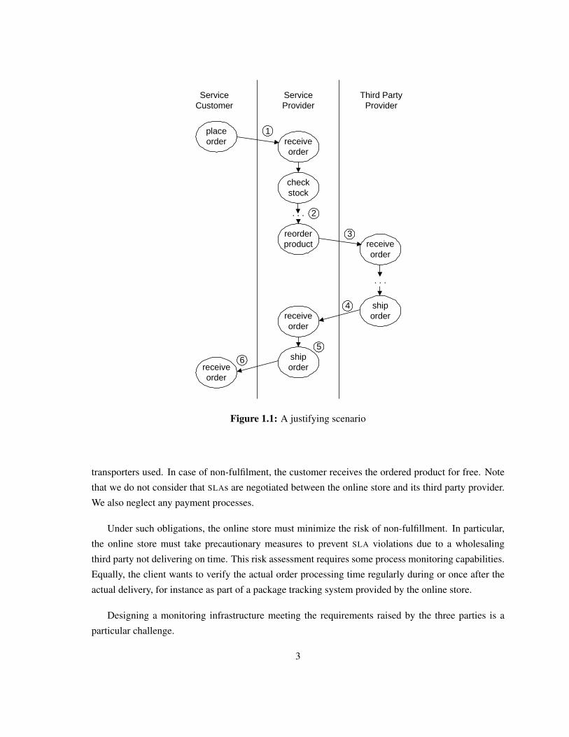
1.2 A Justifying ScenarioIn this section, we give an example to justify the importance of a QOS monitoring infrastructure. The
scenario focuses on an online store, making it possible to order products online. In Figure 1.1, we
present the example of a business process for handling online orders. The business process activities
involved are realized by human and IT services alike.
In this simple process scenario, the provider and consumer roles alternate between the parties
involved. The online store acts as service provider towards its online clients while the store itself
consumes third parties’ services. The following parties participate in the business process:
• A service provider offers services with a specific functionality to its customers. In our example,
the service provider is the online store and offers services to its customers to order some products
online.
• A service consumer accesses the offered services to request the services’ functionality. To order
some products online, the service consumers, i.e., online buyers, places an order by accessing
the online store’s web site, ordering the products in a desired quantity.
• Third party providers offer services to support the functionality of the service provider’s offered
services. For example, to process the consumer’s order request, the online store has to reorder
the requested products in case they are out of stock.
Consider an online buyer ordering a book at the online store. Assume that there is a binding
agreement between the online store (as the service provider) and its clients (as the service consumers)
regarding the maximum duration of order processing. This order processing time amounts to five
working days and represents the maximum time in which the online store commits to dispatch the
orders. However, it does not include the delivery time taken by the postal services or other intermediate
2
1place order
. . .
checkstock
receive order
shiporderreceive
order
ServiceCustomer
ServiceProvider
Third PartyProvider
2
3
4
5
6
reorder product
receive order
receive order
. . .
ship order
Figure 1.1: A justifying scenario
transporters used. In case of non-fulfilment, the customer receives the ordered product for free. Note
that we do not consider that SLAs are negotiated between the online store and its third party provider.
We also neglect any payment processes.
Under such obligations, the online store must minimize the risk of non-fulfillment. In particular,
the online store must take precautionary measures to prevent SLA violations due to a wholesaling
third party not delivering on time. This risk assessment requires some process monitoring capabilities.
Equally, the client wants to verify the actual order processing time regularly during or once after the
actual delivery, for instance as part of a package tracking system provided by the online store.
Designing a monitoring infrastructure meeting the requirements raised by the three parties is a
particular challenge.
3
1.3 Research QuestionsResearch Question I:
How to design a QOS monitoring infrastructure that fulfills the requirements?
The in the SLA negotiated performance-related QOS properties must be monitored during or after
the SLAs’ validity. This research question concentrates on various design decisions that must be faced
during the design process of a QOS monitoring infrastructure. We focus on design decisions about
where and when to measure the performance-related QOS properties, where and when to evaluate the
measurements, and where to store the measurements for a later evaluation.
Research Question II:
How to support the differently skilled stakeholders to specify the performance-related QOS
agreements?
Stakeholders are differently skilled, ranging from business to technical background knowledge.
Business experts know how the performance-related QOS properties are specified within the SLAs.
Technical experts are experienced in the underlying technologies to monitor the performance-related
QOS properties during the SLAs’ validity. This research question focuses on the problem of including
all stakeholders within the design process and to specify the SLAs’ performance-related QOS properties.
Research Question III:
How to develop an appropriate stakeholder support, dealing with permanent changing requirements?
In early stages, the requirements on a QOS monitoring infrastructure are fuzzy and incomplete,
stemming from different stakeholder expertise and interpretations of the QOS domain. After becoming
more familiar with the domain concepts, the requirements of the QOS monitoring infrastructure evolve
and change. The later the changes, the more complex and time-consuming the updates. This research
questions focuses on approaching solutions to deal with changing requirements.
Research Question IV:
How to integrate a QOS monitoring solution into an existing service-oriented system?
Nowadays, enterprises start to utilize service-oriented distributed system to automate their business
processes and to enhance cross-organizational transactions. Such systems are called process-driven
SOAs [137]. To ensure an enterprise’s internal policies, stemming from performance-related SLA
negotiations, we want to research how to use the thesis’ contributions to integrate a QOS monitoring
infrastructure into an existing process-driven SOA.
4
1.4 Scientific ContributionsContribution I:
An architectural decision model to design a QoS monitoring infrastructure
To the best of our knowledge, there exists no guidelines to design an appropriate QoS monitor-
ing infrastructure. To answer Research Question I, we present a novel architectural design decision
model that consists of relevant questions that arise through the decision making process. The model
contains requirements on the QOS monitoring infrastructure and provides design solutions that extend
and utilize well-established design patterns. In our model, we base the solutions on design patterns
to monitor performance-related QOS properties, presented in the Gang of Four (GOF) book [35], the
Pattern-Oriented Software Architecture (POSA) series [18, 19, 103], and the Remoting Patterns book
[124]. The selection of the solutions depends on the QOS monitoring infrastructure’s requirements. We
evaluate the solutions against the challenging design problems and give advice in the decision making
related to building QOS-aware service-oriented systems.
Contribution II:
Supporting the stakeholders with tailored domain-specific languages
After having designed a QOS monitoring infrastructure, utilizing the architectural design deci-
sion model (Contribution I), the differently skilled stakeholders must be supported to specify the
performance-related QOS properties embedded in the SLAs. We present a novel approach that focuses
on Domain-specific Language (DSL) to contribute to Research Question II. The DSLs are divided into
multiple sub-languages at different abstraction levels. Each sub-language is tailored to the appropri-
ate stakeholders’ expertise. Our approach is evaluated by an explorative study of providing tailored
languages within service-oriented architectures (SOA). We illustrate a developed model-driven DSL
within the scope of an industrial case study for specifying a service’s performance-related QOS com-
pliance concerns and actions in case of violations. The DSL is separated into two sub-languages,
tailored for business and technical experts.
Contribution III:
Incremental development of domain-specific languages
To support the stakeholders (Contribution II), the development of model-driven DSLs must deal
with permanent changing requirements. To avoid complex and time-consuming updates in later de-
velopment stages, we present an incremental development approach. Within the case study, we have
researched (1) the applicability of the incremental approach, (2) the impact of requirement changes in
later development stages, (3) possible drawbacks of using a non-incremental development approach,
and (4) general recommendations for developing model-driven DSLs incrementally. We present the
5
findings during the development of the a model-driven DSL within the case study to contribute to
Research Question III.
Contribution IV:
Applying the aforementioned contributions to extend an existing service-oriented system to
QOS-awareness
To answer Research Question IV we use the aforementioned contributions to extend an existing
service-oriented system to monitor the SLAs’ performance-related QOS agreements. First, we utilize
the architectural design decision model (Contribution I) to design an appropriate QOS monitoring in-
frastructure. To support the stakeholders (Contribution II), we integrate our developed model-driven
DSL for specifying the SLAs’ performance-related QOS compliance concerns. Based on the QOS spec-
ifications, the DSL’s code generator generates executable code for measuring, storing, and evaluating
the performance-related QOS properties. We demonstrate how we integrate QOS monitoring infrastruc-
ture into the existing service-oriented system.
1.5 Organization of the ThesisIn this section we give a brief overview of the thesis’ structure, its chapters, and the chapters’ contri-
butions.
Chapter 2: BackgroundWe explain the required background knowledge for a better understanding of the contributions in this
chapter. We explain what web services and SOAs are, and give more detail information about SLAs
and performance-related QOS properties.
Chapter 3: A Case StudyIn this chapter we present a case study that builds the foundation to evaluate the thesis’ contributions.
The case study deals with advanced multimedia services, making it possible to watch movies or live
streams in a favoured language. The services must comply to performance-related QOS agreements
that are explained within the chapter.
Chapter 4: An Architectural Decisions Model to Design a QOS Monitoring InfrastructureWe present an architectural design decision model in this chapter that builds the first contribution of
the thesis. The model consists of architectural design decisions that must be faced during the decision
making process, such as where to measure, evaluate, or store the performance-related QOS properties.
We list the model’s requirements on a QOS monitoring infrastructure and present our model’s architec-
tural solutions to measure, evaluate, and store the performance-related QOS agreements in this chapter.
6
The solutions utilize and extend well-established design patterns. We present how we have utilized the
model’s proposed solutions in the scope of the case study.
Chapter 5: Supporting the Stakeholders to Specify QOS Compliance ConcernsIn this chapter we present the thesis’ third contributions, i.e., our approach to support the stakeholders
with model-driven DSLs. We evaluate the approach with an explorative study over three experiments.
The utilization of the approach is demonstrated on a developed DSL within the case study.
Chapter 6: Incremental Development of Model-driven DSLsIn Chapter 6 we introduce an incremental development approach to develop model-driven DSLs. We
have researched the approach in the scope of the case study and present the findings during the devel-
opment of the case study’s DSL.
Chapter 7: Extending a Process-driven SOA to QOS-awarenessWe take the thesis’ first and second contribution to extend an existing process-driven SOA to moni-
tor performance-related QOS agreements. We illustrate how to monitor QOS and how to support the
stakeholders to specify the services’ performance-related QOS compliance concerns.
Chapter 8: ConclusionIn this chapter we conclude the thesis by iterating the thesis’ research questions and contributions. We
also present potential future research in Chapter 8.
7

8
Chapter 2
Background
In this chapter we explain background information for a better understanding of the concepts and
approaches presented in the thesis. We organize the chapter as follows: We start with a basic introduc-
tion to service-oriented distributed systems in Section 2.1, including web services, Service-oriented
Architecture (SOA), and process-driven SOAs. In Section 2.2 we give basic background information
on Service Level Agreement (SLA) and the performance-related Quality of Service (QOS) properties
that are of interest in the thesis. We briefly summarize the chapter in Section 2.3.
2.1 Service-oriented Distributed SystemsIn traditional distributed systems, a conventional middleware resides between interacting clients or ap-
plications and mediates their interaction. The middleware is centralized in an organization’s distributed
system and used by every client or application. Should the organization’s clients or applications wish
to interact with clients or applications of another organization, both organizations must agree on a
common middleware [4].
Web services tackle this problem by using a program to invoke services that are located across
the organizations’ borders. A web service is a procedure, method, or object with a stable, published
interface. Web services can be invoked by exchanging XML-based messages via Internet-based pro-
tocols [130]. Three XML-based standards have been proposed: (1) the Web Service Description
Language (WSDL) [126] for describing the services’ interfaces, (2) Universal Description, Discov-
ery, and Integration (UDDI) [75] for advertising and discovering services, and (3) the Simple Object
Access Protocol (SOAP) [125] for invoking services [45]. For the communication between services
Service-oriented Computing (SOC) is paradigm to utilize services as the basic constructs to support
the development of compositions of distributed applications. In the field of SOC, an SOA is build to
develop cross-organizational distributed systems [4, 89]. In an SOA, all functions and services, are
defined using a description language and have invokeable, platform-independent interfaces that are
9
ServiceRegistry
ServiceConsumer 1: publish Service
Provider2: query
3: consume
Figure 2.1: The SOA triangle
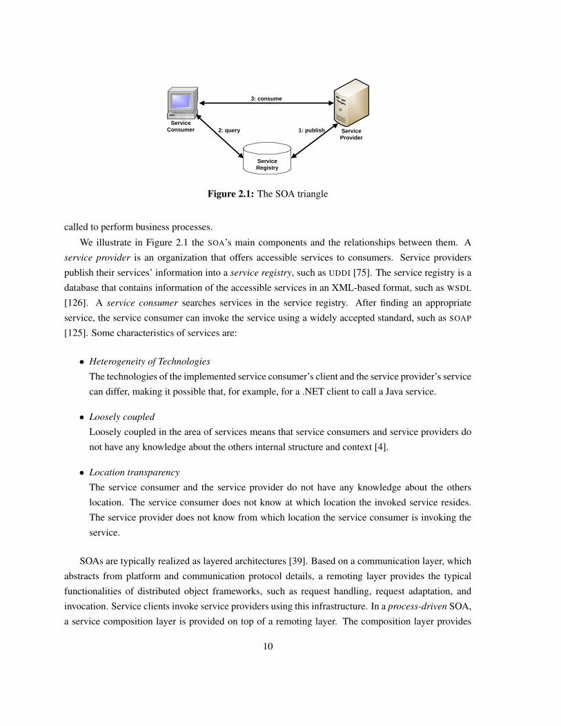
called to perform business processes.
We illustrate in Figure 2.1 the SOA’s main components and the relationships between them. A
service provider is an organization that offers accessible services to consumers. Service providers
publish their services’ information into a service registry, such as UDDI [75]. The service registry is a
database that contains information of the accessible services in an XML-based format, such as WSDL
[126]. A service consumer searches services in the service registry. After finding an appropriate
service, the service consumer can invoke the service using a widely accepted standard, such as SOAP
[125]. Some characteristics of services are:
• Heterogeneity of Technologies
The technologies of the implemented service consumer’s client and the service provider’s service
can differ, making it possible that, for example, for a .NET client to call a Java service.
• Loosely coupled
Loosely coupled in the area of services means that service consumers and service providers do
not have any knowledge about the others internal structure and context [4].
• Location transparency
The service consumer and the service provider do not have any knowledge about the others
location. The service consumer does not know at which location the invoked service resides.
The service provider does not know from which location the service consumer is invoking the
service.
SOAs are typically realized as layered architectures [39]. Based on a communication layer, which
abstracts from platform and communication protocol details, a remoting layer provides the typical
functionalities of distributed object frameworks, such as request handling, request adaptation, and
invocation. Service clients invoke service providers using this infrastructure. In a process-driven SOA,
a service composition layer is provided on top of a remoting layer. The composition layer provides
10
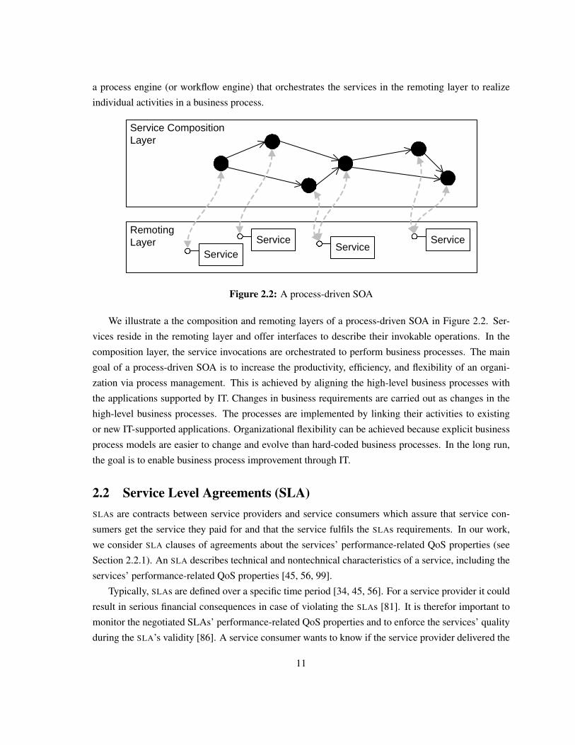
a process engine (or workflow engine) that orchestrates the services in the remoting layer to realize
individual activities in a business process.
RemotingLayer
Service CompositionLayer
ServiceService
ServiceService
Figure 2.2: A process-driven SOA
We illustrate a the composition and remoting layers of a process-driven SOA in Figure 2.2. Ser-
vices reside in the remoting layer and offer interfaces to describe their invokable operations. In the
composition layer, the service invocations are orchestrated to perform business processes. The main
goal of a process-driven SOA is to increase the productivity, efficiency, and flexibility of an organi-
zation via process management. This is achieved by aligning the high-level business processes with
the applications supported by IT. Changes in business requirements are carried out as changes in the
high-level business processes. The processes are implemented by linking their activities to existing
or new IT-supported applications. Organizational flexibility can be achieved because explicit business
process models are easier to change and evolve than hard-coded business processes. In the long run,
the goal is to enable business process improvement through IT.
2.2 Service Level Agreements (SLA)SLAs are contracts between service providers and service consumers which assure that service con-
sumers get the service they paid for and that the service fulfils the SLAs requirements. In our work,
we consider SLA clauses of agreements about the services’ performance-related QoS properties (see
Section 2.2.1). An SLA describes technical and nontechnical characteristics of a service, including the
services’ performance-related QoS properties [45, 56, 99].
Typically, SLAs are defined over a specific time period [34, 45, 56]. For a service provider it could
result in serious financial consequences in case of violating the SLAs [81]. It is therefor important to
monitor the negotiated SLAs’ performance-related QoS properties and to enforce the services’ quality
during the SLA’s validity [86]. A service consumer wants to know if the service provider delivered the
11
service quality as negotiated in the SLAs. This is mainly of importance after the SLA’s validity.
2.2.1 Performance-related QoS Properties
A service’s performance-related QOS attributes are non-functional properties of the service’s perfor-
mance [85]. Service consumers invoke services over the Internet, making it challenging to deliver the
service’s quality because of the Internet’s dynamic and unpredictable nature [63].
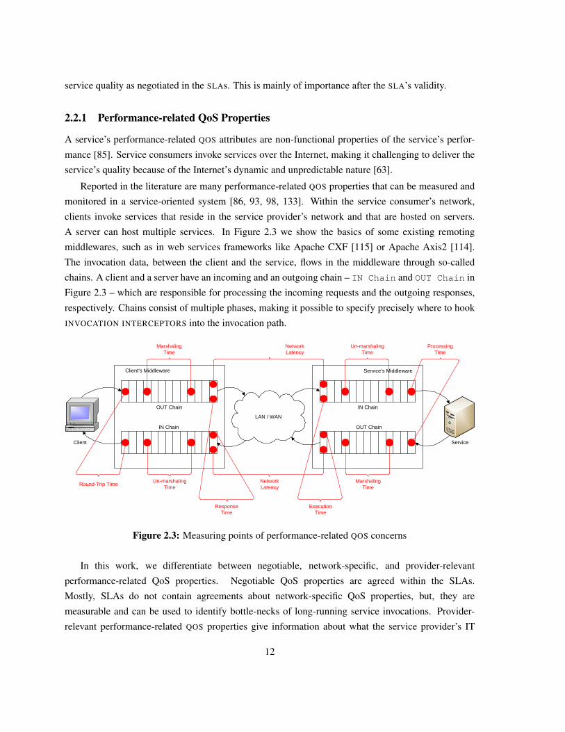
Reported in the literature are many performance-related QOS properties that can be measured and
monitored in a service-oriented system [86, 93, 98, 133]. Within the service consumer’s network,
clients invoke services that reside in the service provider’s network and that are hosted on servers.
A server can host multiple services. In Figure 2.3 we show the basics of some existing remoting
middlewares, such as in web services frameworks like Apache CXF [115] or Apache Axis2 [114].
The invocation data, between the client and the service, flows in the middleware through so-called
chains. A client and a server have an incoming and an outgoing chain – IN Chain and OUT Chain in
Figure 2.3 – which are responsible for processing the incoming requests and the outgoing responses,
respectively. Chains consist of multiple phases, making it possible to specify precisely where to hook
INVOCATION INTERCEPTORS into the invocation path.
Marshaling Time
Un-marshaling Time
OUT Chain IN Chain
OUT ChainIN Chain
MarshalingTime
Un-marshalingTime
Round-Trip Time
ResponseTime
NetworkLatency
NetworkLatency
ProcessingTime
LAN / WAN
Client’s Middleware Service’s Middleware
Client Service
ExecutionTime
Figure 2.3: Measuring points of performance-related QOS concerns
In this work, we differentiate between negotiable, network-specific, and provider-relevant
performance-related QoS properties. Negotiable QoS properties are agreed within the SLAs.
Mostly, SLAs do not contain agreements about network-specific QoS properties, but, they are
measurable and can be used to identify bottle-necks of long-running service invocations. Provider-
relevant performance-related QOS properties give information about what the service provider’s IT
12
infrastructure can deliver, such as how many clients can invoke the service simultaneously.
Negotiable performance-related QoS properties
• Round-Trip Time
For a service consumer, it is important to know how long it takes to receive the requested data
or results from the service. The elapsed time between the sending of the client’s request and
receiving the service’s response is referred to the service’s round-trip time.
• Processing Time
On the server-side the processing time is the elapsed time for processing the client’s incoming
request. It does not take into account the performance-related QoS properties of processing the
incoming requests and outgoing response in the underlying middleware.
• Response Time
The response time is a client-side QoS property and measures the elapsed time between trans-
mitting the marshaled invocation data to the server and the reception of the server’s response. In
the terminology of SLAs, the response time often refers to the elapsed time of responding to a
problem in case the service is down.
• Up-Time
In the literature, a service’s up-time is often referred as the service’s availability (e.g., [63, 85,
97]). However, using the term “availability” can lead to misunderstandings between a service
provider and a service consumer [119]. For example, for the service consumer a service is avail-
able if it is accessible. But, for a service provider, a service is available if it is operating. To avoid
misunderstandings, we define a service’s up-time that the service is being up and running and
returning correct results to the service consumers. The correctness of the results does not refer to
the content of the results In comparison, Mani and Nagarajan [63] use the term “Accessibility”.
Network-specific performance-related QoS properties
• Marshaling Time
The invocation data must be marshaled for its transmission over the underlying network. At the
client-side, the marshaling time measures the elapsed time of marshaling the outgoing invocation
data of the service request. At the server-side, the marshaling time measures the elapsed time of
marshaling the invocation data of the service’s response.
• Execution Time
The execution time is a server-side QOS property. It is a measure of the complete required time
of a client’s request, i.e., unmarshaling, processing, and marshaling.
13
• Network Latency
The required time for transmitting the marshaled invocation data over the network is called
network latency. It requires measuring points at the client- and the server-side. Network latency
can be measured during the sending of the client’s request and its reception at the server-side.
Also, network latency is the elapsed time of transmitting the marshaled service’s response from
the service to the client over the network.
• Un-marshaling Time
The marshaled invocation data must be un-marshaled to be process-able in the overlying lay-
ers. At the server-side, the un-marshaling time measures the elapsed time of un-marshaling
the incoming invocation data of the service request. At the client-side, the un-marshaling time
measures the elapsed time of un-marshaling the invocation data of the service’s response.
Provider-relevant QoS properties
• Throughput
The throughput is the number of successfully processed service requests within a given period
of time.
• Scalability
When the system is changing in size or in volume, a service must deliver its functionality without
influencing the service’s performance-related QOS properties quality attributes. Scalability is a
performance-related QOS property that gives information about how an increasing number of
service consumers impact the service’s performance.
• Robustness
A service’s robustness is a measurement of the probability that a service can react properly to
invalid, incomplete, or conflicting incoming requests. Rosenberg et al. [98] advice to measure
the robustness by “tracking all the incorrect input messages and put it in relation with all valid
responses”.
2.3 SummaryIn this chapter we gave some background information on web services, SOAs, process-driven SOAs,
as well as SLAs and performance-related QOS properties in service-oriented systems. The concepts
explained are helpful for a better understanding of the following chapters and the contributions of the
thesis.
14
Chapter 3
A Case Study
In this chapter we present an industrial case study that we conducted within an European research
project. The case study builds the basis for the contributions of this thesis as well as for the evaluation
of the thesis’ contributions.
The chapter is organized as follows: In Section 3.1 we describe the case study’s scenario, exemplify
it, and describe the case study’s services. Section 3.2 concentrates on the services’ Quality of Service
(QOS) compliance concerns. We explain the case study’s context and main development requirements
in Section 3.3. The chapter concludes with a brief summary in Section 3.4.
3.1 The Case Study’s Scenario
The case study’s scenario focuses on advanced telecom services offered by Mobile Virtual Network
Operator (MVNO). Such services combine value-added application capabilities with the Internet and
Next Generation Mobile Telecommunication Network capabilities. All these capabilities are inte-
grated by the MVNO’s services to provide combinations of controls for calls and sessions, messaging
features, presence, and location features, multimedia content streaming, or parental monitoring. An
MVNO serves as a proxy between customers and the audio and video streaming providers. It offers ser-
vices to processes media search requests and to provide favoured movie and audio content streaming,
making it possible for the customers to watch, for example, live soccer matches with a selected audio
commentary language.
The MVNO environment is particularly challenging, because the network infrastructure and many
applications are owned and managed by different enterprises (i.e., the MVNO, the network providers,
and third-party application providers).
15
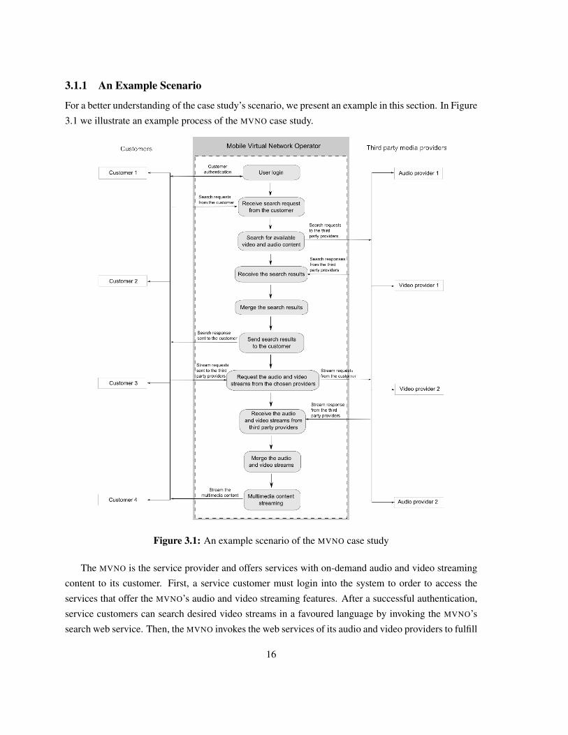
3.1.1 An Example Scenario
For a better understanding of the case study’s scenario, we present an example in this section. In Figure
3.1 we illustrate an example process of the MVNO case study.
Figure 3.1: An example scenario of the MVNO case study
The MVNO is the service provider and offers services with on-demand audio and video streaming
content to its customer. First, a service customer must login into the system to order to access the
services that offer the MVNO’s audio and video streaming features. After a successful authentication,
service customers can search desired video streams in a favoured language by invoking the MVNO’s
search web service. Then, the MVNO invokes the web services of its audio and video providers to fulfill
16
the service customer’s request. The MVNO receives the responses from the audio and video providers,
assembles them, and returns a list of possible streaming endpoints to the customer. The customer starts
the multimedia streaming by selecting one endpoint.
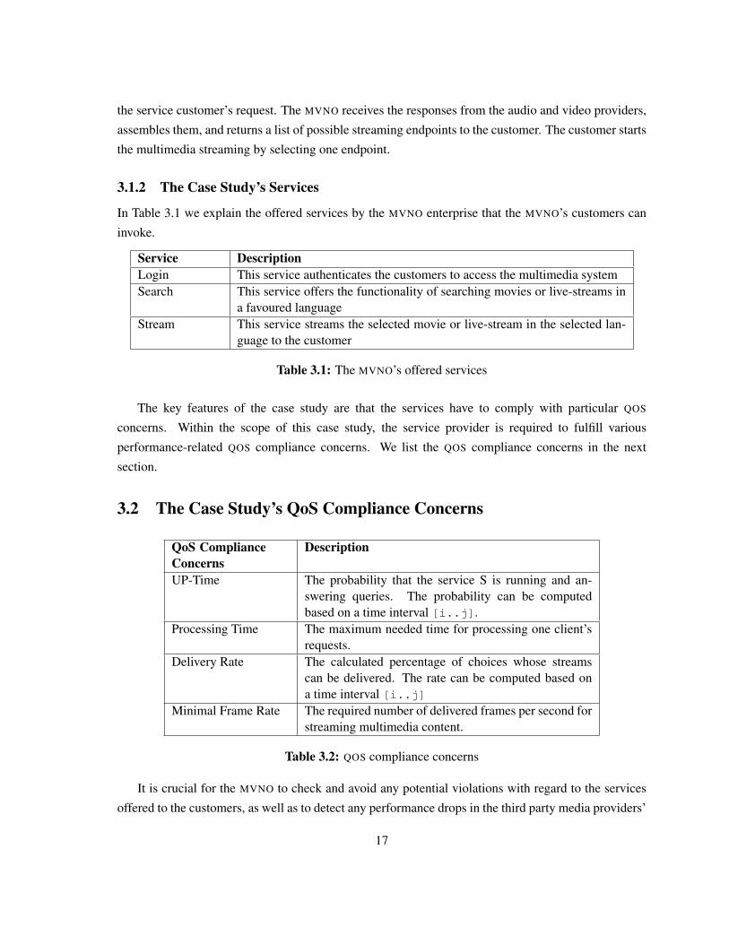
3.1.2 The Case Study’s Services
In Table 3.1 we explain the offered services by the MVNO enterprise that the MVNO’s customers can
invoke.
Service DescriptionLogin This service authenticates the customers to access the multimedia systemSearch This service offers the functionality of searching movies or live-streams in
a favoured languageStream This service streams the selected movie or live-stream in the selected lan-
guage to the customer
Table 3.1: The MVNO’s offered services
The key features of the case study are that the services have to comply with particular QOS
concerns. Within the scope of this case study, the service provider is required to fulfill various
performance-related QOS compliance concerns. We list the QOS compliance concerns in the next
section.
3.2 The Case Study’s QoS Compliance Concerns
QoS ComplianceConcerns
Description
UP-Time The probability that the service S is running and an-swering queries. The probability can be computedbased on a time interval [i..j].
Processing Time The maximum needed time for processing one client’srequests.
Delivery Rate The calculated percentage of choices whose streamscan be delivered. The rate can be computed based ona time interval [i..j]
Minimal Frame Rate The required number of delivered frames per second forstreaming multimedia content.
Table 3.2: QOS compliance concerns
It is crucial for the MVNO to check and avoid any potential violations with regard to the services
offered to the customers, as well as to detect any performance drops in the third party media providers’
17
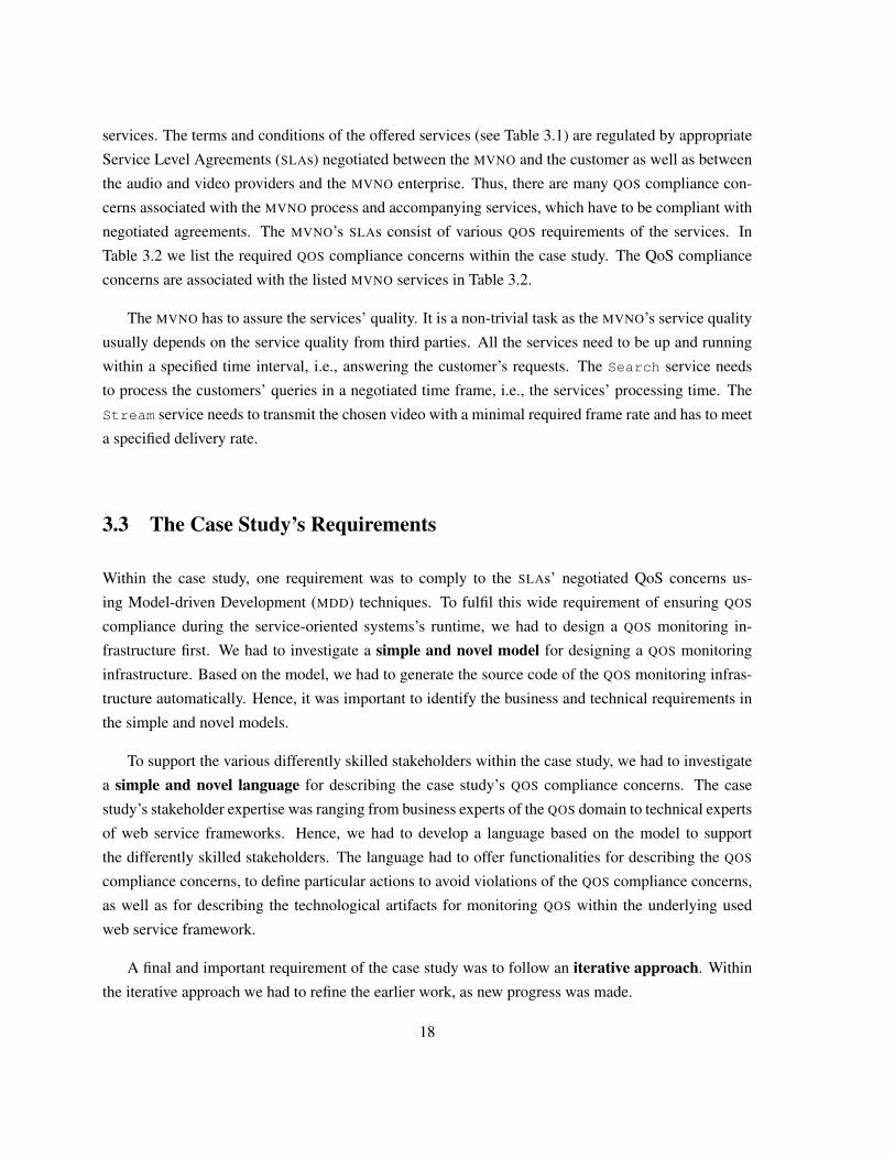
services. The terms and conditions of the offered services (see Table 3.1) are regulated by appropriate
Service Level Agreements (SLAs) negotiated between the MVNO and the customer as well as between
the audio and video providers and the MVNO enterprise. Thus, there are many QOS compliance con-
cerns associated with the MVNO process and accompanying services, which have to be compliant with
negotiated agreements. The MVNO’s SLAs consist of various QOS requirements of the services. In
Table 3.2 we list the required QOS compliance concerns within the case study. The QoS compliance
concerns are associated with the listed MVNO services in Table 3.2.
The MVNO has to assure the services’ quality. It is a non-trivial task as the MVNO’s service quality
usually depends on the service quality from third parties. All the services need to be up and running
within a specified time interval, i.e., answering the customer’s requests. The Search service needs
to process the customers’ queries in a negotiated time frame, i.e., the services’ processing time. The
Stream service needs to transmit the chosen video with a minimal required frame rate and has to meet
a specified delivery rate.
3.3 The Case Study’s Requirements
Within the case study, one requirement was to comply to the SLAs’ negotiated QoS concerns us-
ing Model-driven Development (MDD) techniques. To fulfil this wide requirement of ensuring QOS
compliance during the service-oriented systems’s runtime, we had to design a QOS monitoring in-
frastructure first. We had to investigate a simple and novel model for designing a QOS monitoring
infrastructure. Based on the model, we had to generate the source code of the QOS monitoring infras-
tructure automatically. Hence, it was important to identify the business and technical requirements in
the simple and novel models.
To support the various differently skilled stakeholders within the case study, we had to investigate
a simple and novel language for describing the case study’s QOS compliance concerns. The case
study’s stakeholder expertise was ranging from business experts of the QOS domain to technical experts
of web service frameworks. Hence, we had to develop a language based on the model to support
the differently skilled stakeholders. The language had to offer functionalities for describing the QOS
compliance concerns, to define particular actions to avoid violations of the QOS compliance concerns,
as well as for describing the technological artifacts for monitoring QOS within the underlying used
web service framework.
A final and important requirement of the case study was to follow an iterative approach. Within
the iterative approach we had to refine the earlier work, as new progress was made.
18
3.4 SummaryIn Chapter 3 we have explained an industrial case study that was conducted within an three-year Eu-
ropean research project. The case study focuses on telecommunication services that have to fulfil QOS
compliance concerns. We listed the case study’s services, presented an example, listed the required
QOS compliance concerns and explained the case study’s main requirements. We use the case study
for describing and evaluating the main contributions of this thesis.
19

20
Chapter 4
An Architectural Decisions Model toDesign a QoS Monitoring Infrastructure
Designing a monitoring infrastructure is a challenging and comprehensive task. Many architectural
design decisions must be taken about measuring, evaluating, and storing the performance-related QoS
agreements [77]. To give some examples, performance monitoring can be realized at different network
communication layers, either at the client-side, at the server-side, in intermediary components, or any
combination of the latter.
In this chapter we present an architectural design decision model (Contribution I) that identifies
relevant design decisions arising throughout the decision making process. The model aligns the design
decisions to possible design solutions. The solutions, in turn, are based upon established design pat-
terns in their solution space. The model guides you in selecting solutions according to the business and
technical requirements imposed on your QoS monitoring infrastructure. Our model’s design decisions,
requirements, and solutions come from a thorough literature review of QoS monitoring frameworks,
such as presented in [10, 15, 38, 48, 58, 68, 96, 98, 100, 139].
The presented architectural design decisions and solutions focus on preventing and detecting SLA
violations. We document design practices and patterns of monitoring performance-related QoS prop-
erties, such as round-trip time, network latency, or processing time [86, 93, 98, 133]. We give advice
in the decision making process for designing QoS-aware distributed systems. The background of this
work are established patterns, presented in the Gang of Four (GOF) book [35], the Pattern-Oriented
Software Architecture (POSA) series [18, 19, 103], and the Remoting Patterns book [124].
The chapter is organized as follows: In Section 4.1 we give background information on patterns
itself and patterns in distributed systems. Section 4.2 explains the main components and features of a
QoS monitoring infrastructure that are of interest. Then, in Section 4.3 we explain the requirements on
a QoS monitoring infrastructure that have discovered within the case study and a thorough literature
21
review. The architectural design decision model is presented in 4.4, including several design deci-
sions, requirements, and solutions. The relationships between the design decisions, influenced by the
requirements, is illustrated in 4.5. In Section 4.6 we evaluate the architectural design decision model
in the scope of the case study. A discussion of using Model-driven Development (MDD) to generate the
architectural design solutions is given in Section 4.7. We summarize and conclude the chapter briefly
with Section 4.8.
4.1 BackgroundIn this section we explain required background knowledge for a better understanding of the chapter’s
contributions. First, we describe what patterns are and of which parts they consist. Then, we describe
well-established patterns in distributed systems that build the foundation of the solutions proposed
within the architectural design decision model.
4.1.1 Patterns
The Gang-of-Four [35] bases their defintion of a pattern on Christopher Alexander’s definition [3]:
“Each pattern describes a problem which occurs over and over again in our environment. A
pattern describes the core solution to that problem, in such a way that you can use this solution a
million times over, without ever doing it the same way twice.”
The Hillside Group [22], the home of design patterns and the host of various pattern conferences,
defines a design pattern as follows:
“A design pattern is a well-established design solution to a problem in a particular context”
Resultant from both definitions, each pattern consists of a context, a problem, and a solution. Every
pattern has its forces, but, every pattern brings consequences as well. The well-established solution of
a pattern is proven by the pattern’s known uses.
• The pattern’s context is the scope of the pattern’s application area.
• The pattern’s problem is the recurring design problem within the pattern’s context. The pat-
tern’s problem states when to apply the pattern. The problem statement can contain various
pre-conditions that must be met before the pattern’s problem arises.
• The pattern’s solution is a description of how to apply the pattern to solve the problem within
the given context. The solution describes elements to make up the design, their relationships,
responsibilities, and collaborations.
22
• The pattern’s forces are the resultant strengths of applying the pattern for solving the problem.
Forces describe the benefits of applying the pattern.
• The pattern’s consequences are the trade-offs of applying the pattern for solving the problem.
Consequences can also result in new arising problems.
• The pattern’s known uses describe were the pattern is applied in the literature or in existing
systems. The known uses are proofs of pattern’s solution.
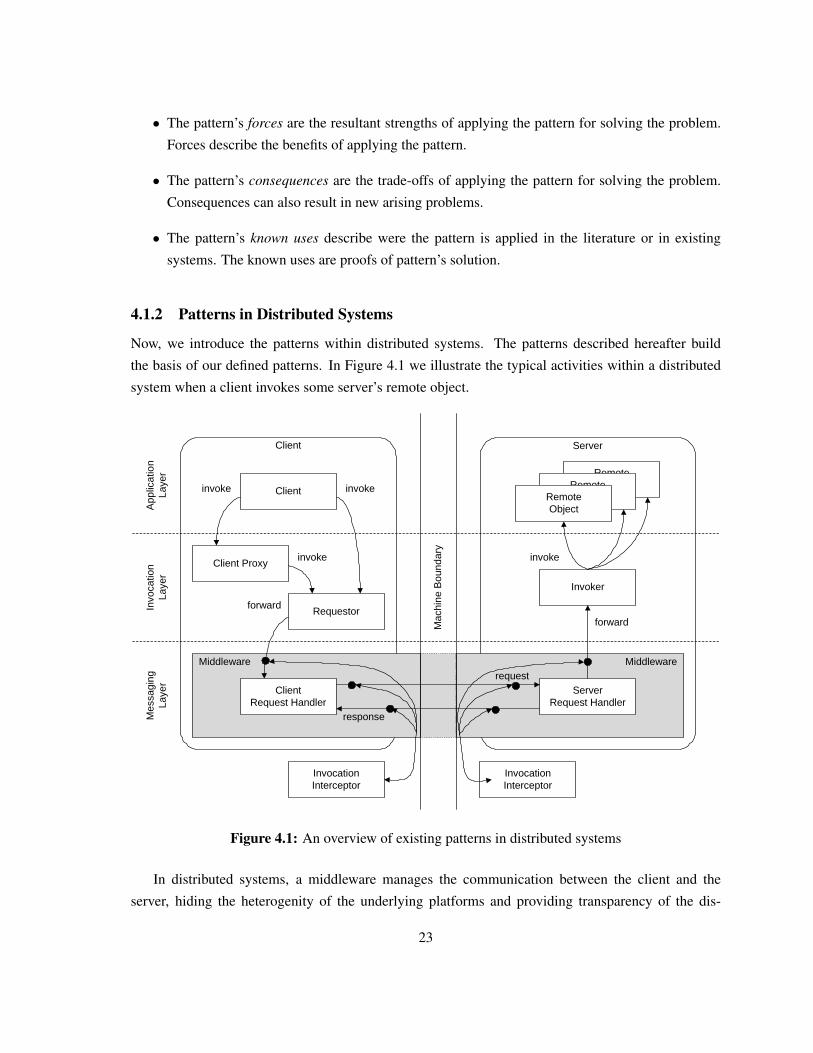
4.1.2 Patterns in Distributed Systems
Now, we introduce the patterns within distributed systems. The patterns described hereafter build
the basis of our defined patterns. In Figure 4.1 we illustrate the typical activities within a distributed
system when a client invokes some server’s remote object.
RemoteObjectRemote
ObjectClient
Client Proxy
Requestor
Client Request Handler
RemoteObject
Invoker
Server Request Handler
Client Server
request
response
forward
invokeinvoke
forward
invokeinvoke
App
licat
ion
Laye
rIn
voca
tion
Laye
rM
essa
ging
Laye
r
Mac
hine
Bou
ndar
y
Middleware Middleware
InvocationInterceptor
InvocationInterceptor
Figure 4.1: An overview of existing patterns in distributed systems
In distributed systems, a middleware manages the communication between the client and the
server, hiding the heterogenity of the underlying platforms and providing transparency of the dis-
23
tributed communications. The middleware can access the network services offered by the operating
system for accessing and transmitting requests to the server’s remote objects over the network [124].
For accessing the client’s middleware, the REQUESTOR pattern can be used [124]. The RE-
QUESTOR invokes the remote object’s operation using the underlying middleware. Also, the client’s
application can access the middleware following the CLIENT PROXY pattern [124] to provide a good
separation of concerns and to attach additional information to the client’s requests. The CLIENT PROXY
invokes the middleware using the REQUESTOR pattern. The implementation of the client’s middleware
can follow the CLIENT REQUEST HANDLER pattern [124], to send the requests over the network to the
server and to handle the server’s response.
The implementation of the server’s middleware can follow the SERVER REQUEST HANDLER pat-
tern [124]. A SERVER REQUEST HANDLER receives the incoming requests, performs additional pro-
cessing, and forwards the requests to the INVOKER of the remote objects. The INVOKER [124] receives
the requests from the SERVER REQUEST HANDLER, can perform additional processing again, and dis-
patches the request to the corresponding remote object. After the remote object processed the incoming
request it sends the response back to the INVOKER, which performs some additional processing, and
forwards the response to the SERVER REQUEST HANDLER. The SERVER REQUEST HANDLER can
perform again some additional processing and forwards the response to the requestor.
The INVOCATION INTERCEPTOR pattern [124], which is based on the INTERCEPTOR pattern
[103], provides hooks in the invocation path to perform additionally required actions, such as logging
or securing the invocation data. Mostly, the client’s or server’s middleware provides functionalities for
placing INVOCATION INTERCEPTORS into the invocation path. Hence, an INVOCATION INTERCEP-
TOR can process and manipulate the available invocation data, which depends on the INVOCATION
INTERCEPTOR’s place in the invocation path. The middleware can provide the feature of attaching
and changing an INVOCATION INTERCEPTOR dynamically during the runtime of the system, such as
by using an API or configuration files. As a consequence, the INVOCATION INTERCEPTOR implies a
higher complexity of the middleware’s implementation. An INVOCATION INTERCEPTOR can attach
the context-specific information to the INVOCATION CONTEXT [124] of the invocation data. In this
paper, we assume the usage of the INVOCATION CONTEXT pattern for storing the performance-related
QoS measurements during remote object invocations.
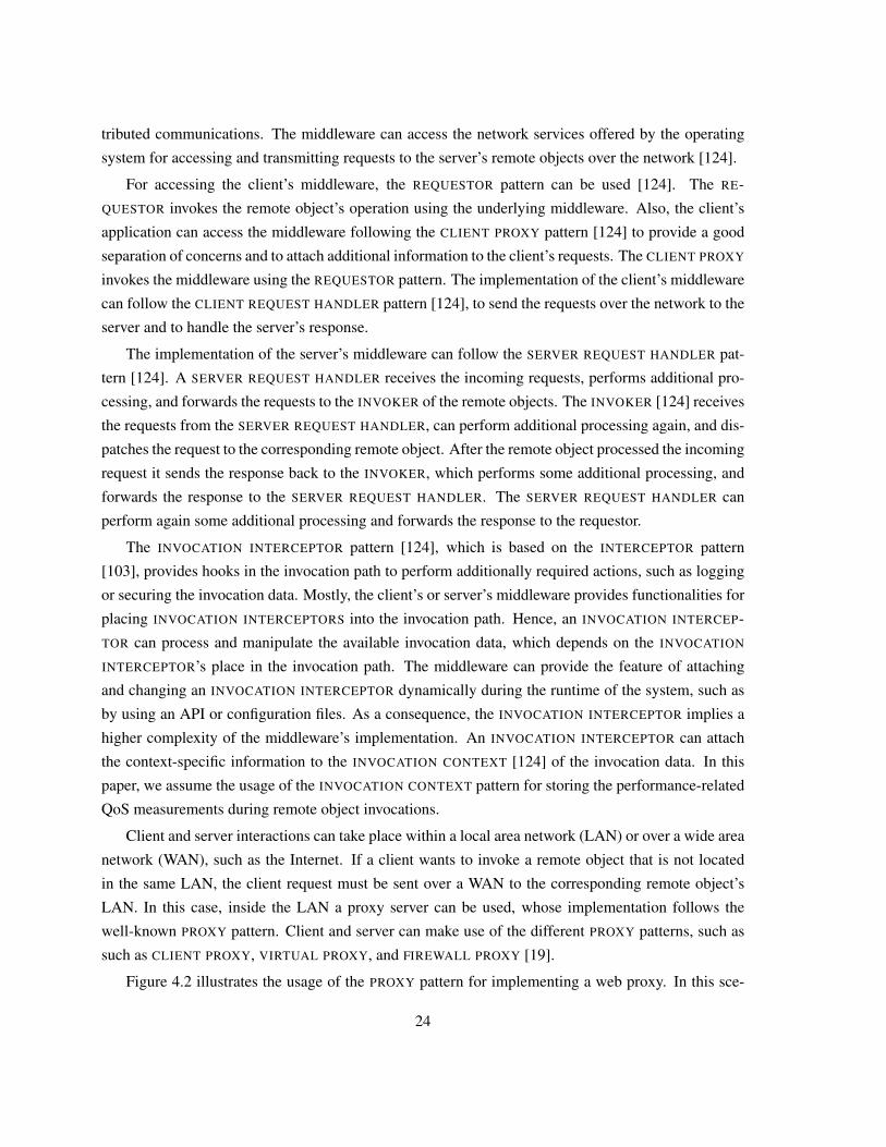
Client and server interactions can take place within a local area network (LAN) or over a wide area
network (WAN), such as the Internet. If a client wants to invoke a remote object that is not located
in the same LAN, the client request must be sent over a WAN to the corresponding remote object’s
LAN. In this case, inside the LAN a proxy server can be used, whose implementation follows the
well-known PROXY pattern. Client and server can make use of the different PROXY patterns, such as
such as CLIENT PROXY, VIRTUAL PROXY, and FIREWALL PROXY [19].
Figure 4.2 illustrates the usage of the PROXY pattern for implementing a web proxy. In this sce-
24
WAN
Web Proxy
LAN
ServerServer
Server
Web Proxy
LAN
ClientClient
Client
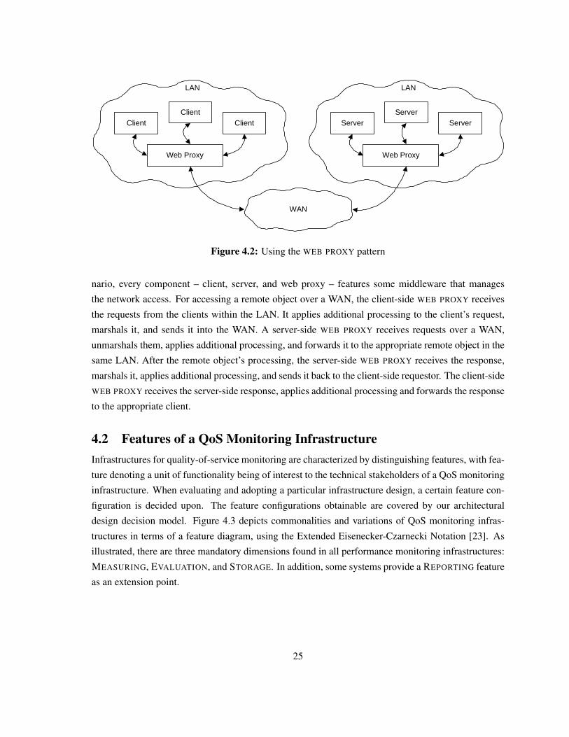
Figure 4.2: Using the WEB PROXY pattern
nario, every component – client, server, and web proxy – features some middleware that manages
the network access. For accessing a remote object over a WAN, the client-side WEB PROXY receives
the requests from the clients within the LAN. It applies additional processing to the client’s request,
marshals it, and sends it into the WAN. A server-side WEB PROXY receives requests over a WAN,
unmarshals them, applies additional processing, and forwards it to the appropriate remote object in the
same LAN. After the remote object’s processing, the server-side WEB PROXY receives the response,
marshals it, applies additional processing, and sends it back to the client-side requestor. The client-side
WEB PROXY receives the server-side response, applies additional processing and forwards the response
to the appropriate client.
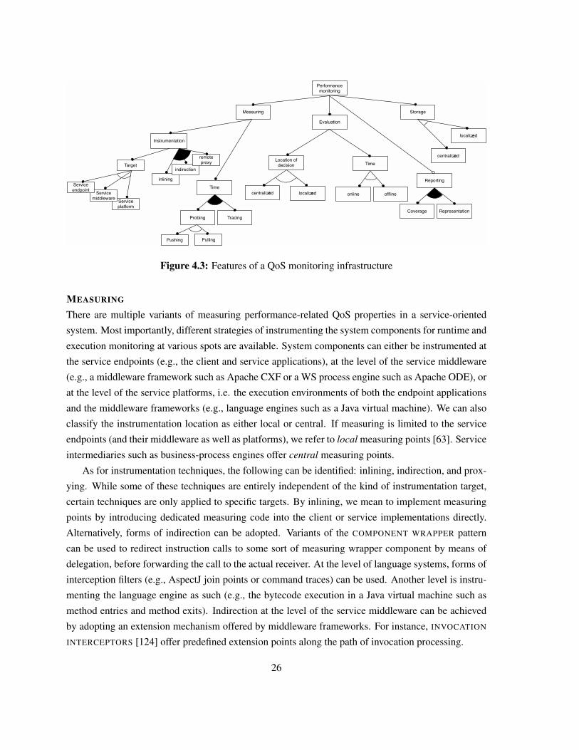
4.2 Features of a QoS Monitoring InfrastructureInfrastructures for quality-of-service monitoring are characterized by distinguishing features, with fea-
ture denoting a unit of functionality being of interest to the technical stakeholders of a QoS monitoring
infrastructure. When evaluating and adopting a particular infrastructure design, a certain feature con-
figuration is decided upon. The feature configurations obtainable are covered by our architectural
design decision model. Figure 4.3 depicts commonalities and variations of QoS monitoring infras-
tructures in terms of a feature diagram, using the Extended Eisenecker-Czarnecki Notation [23]. As
illustrated, there are three mandatory dimensions found in all performance monitoring infrastructures:
MEASURING, EVALUATION, and STORAGE. In addition, some systems provide a REPORTING feature
as an extension point.
25
inlining
indirection
Service platform
Measuring
Performancemonitoring
Evaluation
Location of decision Time
centralized localized offlineonline
Storage
localized
centralizedremoteproxy
Instrumentation
Reporting
Time
TracingProbing
Pushing Pulling
RepresentationCoverage
Target
Service middleware
Service endpoint
Figure 4.3: Features of a QoS monitoring infrastructure
MEASURING
There are multiple variants of measuring performance-related QoS properties in a service-oriented
system. Most importantly, different strategies of instrumenting the system components for runtime and
execution monitoring at various spots are available. System components can either be instrumented at
the service endpoints (e.g., the client and service applications), at the level of the service middleware
(e.g., a middleware framework such as Apache CXF or a WS process engine such as Apache ODE), or
at the level of the service platforms, i.e. the execution environments of both the endpoint applications
and the middleware frameworks (e.g., language engines such as a Java virtual machine). We can also
classify the instrumentation location as either local or central. If measuring is limited to the service
endpoints (and their middleware as well as platforms), we refer to local measuring points [63]. Service
intermediaries such as business-process engines offer central measuring points.
As for instrumentation techniques, the following can be identified: inlining, indirection, and prox-
ying. While some of these techniques are entirely independent of the kind of instrumentation target,
certain techniques are only applied to specific targets. By inlining, we mean to implement measuring
points by introducing dedicated measuring code into the client or service implementations directly.
Alternatively, forms of indirection can be adopted. Variants of the COMPONENT WRAPPER pattern
can be used to redirect instruction calls to some sort of measuring wrapper component by means of
delegation, before forwarding the call to the actual receiver. At the level of language systems, forms of
interception filters (e.g., AspectJ join points or command traces) can be used. Another level is instru-
menting the language engine as such (e.g., the bytecode execution in a Java virtual machine such as
method entries and method exits). Indirection at the level of the service middleware can be achieved
by adopting an extension mechanism offered by middleware frameworks. For instance, INVOCATION
INTERCEPTORS [124] offer predefined extension points along the path of invocation processing.
26
Looking at the service interactions, indirection can also be achieved by deploying service-level
proxying within the service consumers’ or service providers’ networks. In such a setting, a REMOTE
PROXY service responsible for measuring the QoS properties [124] trades service invocations on behalf
of the actual service implementations.
As for the timing of measurement, measurements can either be piggybacked onto actual service
invocations (Tracing) and/or a monitoring system allows to create mock-up invocations to perform
the measurements without interfering with actual invocations (Probing). We refer to such invocations
as probes. Probes are either generated and emitted on demand (Pushing), e.g., at regular intervals
following a specified probing strategy, or triggered by certain system-wide events (Pulling).
EVALUATION
When designing a monitoring system, it must be decided on when (Time) and on where to evaluate
performance-related QoS measurements (Location of decsision). As for the timing, SLA performance
evaluation can either happen during the service (and therefore SLA) performance (online) or after the
delivery of the service, i.e., after an SLA’s duraction of validity. While offline evaluation satisfies the
requirements emerging from SLA accounting and reporting, online evaluation enables scenarios of
preventing SLA violations as part of the SLA management.
Another important variation in monitoring systems results from organising the evaluation feature
in a centralized or in a localized manner. A centralized evaluation is performed by a central evalua-
tion component, responsible for all clients and services in a service-oriented system. For instance, a
business-process execution engine may be extended to perform the role of the evaluation component.
Adopting a centralized evaluation has important implications. For instance, centralized evaluations can
be performed faster because the performance-related QoS measurements must not be collected from
each client or service. However, the clients and/or services have to submit the performance-related
QoS measurements over the network to the centralized evaluation component.
Localized evaluation re-locates the responsibility of performing evaluations at each of the ser-
vice endpoints, i.e., both service clients and service providers. While localizing evaluations avoids
introducing a single point of failure, the evaluation overhead potentially affects the actual activities
performed by clients and providers in a negative manner. A particular performance overhead is in-
curred if predictive SLA monitoring is performed and if multiple clients and services are become
subject to monitoring. Also, evaluating SLA performance based on aggregated measurements from a
system-wide (global) perspective is hindered.
STORAGE
The monitoring data can be stored locally or centrally. Storing the measurements locally implies that
the evaluation becomes more complex in case the SLAs are defined for multiple clients or services.
27
Storing the QoS measurements centrally facilitates the operation of a central evaluation component,
however, the time-to-response of the monitoring system in case of SLA violations is degraded because
the clients and the services must store the their data into a centralized storage over the network.
REPORTING (optional)
Feature-complete and production-grade QoS monitoring systems offer a Reporting feature for present-
ing QoS evaluation results to the stakeholders, for instance, to the finance department for billing, to the
engineers for diagnosing and planning, or directly to the service consumers [119]. A possible solution
to report the QoS monitoring results is a web-based dashboard, as described in [105]. While do not
fully cover issues pertaining to such a reporting feature in the scope of this paper, we review selected
technical aspects, especially the choice of Representation (e.g., processable report formats, UI-based
reporting, notification schemes) and Coverage (i.e., the range of reported details and the level of gran-
ularity). Many of the architectural design decisions documented in this paper directly affect the design
decision process for reporting and violation management components.
4.3 Requirements on a QoS monitoring infrastructure
In this section, we explain the criteria driving the decision-find process and the various requirements
imposed on a QoS monitoring infrastructure. Both, criteria and requirements, influence the architec-
tural design decision and the selection of an appropriate solution. In our model, we differentiate in
our model between decision criteria, system-specific, and implementation-specific requirements. Cri-
teria are characteristics that must be known a-priori to making any design decisions, such as whether
services are provided or whether the provided services invoke services of some third party providers.
System-specific requirements concentrate on the general requirements on the QoS monitoring infras-
tructure and its architecture. At this level, technical details regarding the implementation of the QoS
monitoring infrastructure are omitted. For example, system-specific requirements are scalability or
reusability. Implementation-specific requirements focus on realizing the components forming the QoS
monitoring infrastructure. For instance, a given scenario might require access to the clients’ or ser-
vices’ implementations.
In Figure 4.4, we illustrate how the requirements influence themselves. For example, requiring a
QoS monitoring infrastructure that has a minimal performance overhead induces to design a scalable
QoS monitoring infrastructure. Understanding the interrelatedness of requirements helps to compre-
hend the relationships between the architectural design decisions. In the following, we elaborate on
the decision criteria, system-specific, and implementation-specific requirements, as well as their influ-
ences.
28
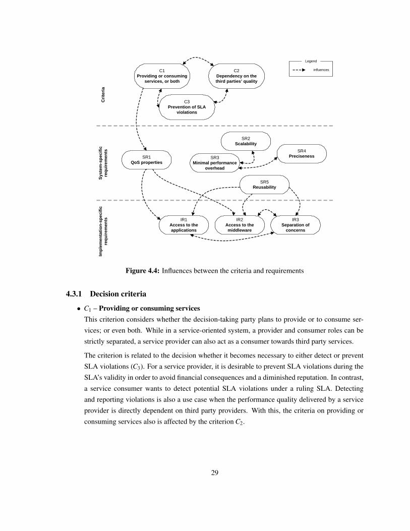
C3Prevention of SLA
violations
SR1QoS properties
SR2Scalability
C2Dependency on the third parties’ quality
IR2Access to the middleware
IR1Access to the applications
SR3Minimal performance
overhead
SR5Reusability
IR3Separation of
concerns
Impl
emen
tatio
n-sp
ecifi
c re
quire
men
tsS
yste
m-s
peci
fic
requ
irem
ents
influences
Legend
C1Providing or consuming
services, or both
SR4Preciseness
Crit
eria
Figure 4.4: Influences between the criteria and requirements
4.3.1 Decision criteria
• C1 – Providing or consuming servicesThis criterion considers whether the decision-taking party plans to provide or to consume ser-
vices; or even both. While in a service-oriented system, a provider and consumer roles can be
strictly separated, a service provider can also act as a consumer towards third party services.
The criterion is related to the decision whether it becomes necessary to either detect or prevent
SLA violations (C3). For a service provider, it is desirable to prevent SLA violations during the
SLA’s validity in order to avoid financial consequences and a diminished reputation. In contrast,
a service consumer wants to detect potential SLA violations under a ruling SLA. Detecting
and reporting violations is also a use case when the performance quality delivered by a service
provider is directly dependent on third party providers. With this, the criteria on providing or
consuming services also is affected by the criterion C2.
29
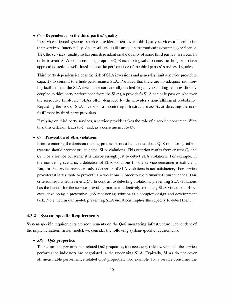
• C2 – Dependency on the third parties’ qualityIn service-oriented systems, service providers often invoke third party services to accomplish
their services’ functionality. As a result and as illustrated in the motivating example (see Section
1.2), the services’ quality so become dependent on the quality of some third parties’ services. In
order to avoid SLA violations, an appropriate QoS monitoring solution must be designed to take
appropriate actions well-timed in case the performance of the third parties’ services degrades.
Third party dependencies bear the risk of SLA inversions and generally limit a service providers
capacity to commit to a high-performance SLA. Provided that there are no adequate monitor-
ing facilities and the SLA details are not carefully crafted (e.g., by excluding features directly
coupled to third party performance from the SLA), a provider’s SLA can only pass on whatever
the respective third-party SLAs offer, degraded by the provider’s non-fulfillment probability.
Regarding the risk of SLA inversion, a monitoring infrastructure assists at detecting the non-
fulfillment by third-party providers.
If relying on third party services, a service provider takes the role of a service consumer. With
this, this criterion leads to C1 and, as a consequence, to C3.
• C3 – Prevention of SLA violationsPrior to entering the decision making process, it must be decided if the QoS monitoring infras-
tructure should prevent or just detect SLA violations. This criterion results from criteria C1 and
C2. For a service consumer it is maybe enough just to detect SLA violations. For example, in
the motivating scenario, a detection of SLA violations for the service consumer is sufficient.
But, for the service provider, only a detection of SLA violations is not satisfactory. For service
providers it is desirable to prevent SLA violations in order to avoid financial consequences. This
criterion results from criteria C1. In contrast to detecting violations, preventing SLA violations
has the benefit for the service-providing parties to effectively avoid any SLA violations. How-
ever, developing a preventive QoS monitoring solution is a complex design and development
task. Note that, in our model, preventing SLA violations implies the capacity to detect them.
4.3.2 System-specific Requirements
System-specific requirements are requirements on the QoS monitoring infrastructure independent of
the implementation. In our model, we consider the following system-specific requirements:
• SR1 – QoS propertiesTo measure the performance-related QoS properties, it is necessary to know which of the service
performance indicators are negotiated in the underlying SLA. Typically, SLAs do not cover
all measurable performance-related QoS properties. For example, for a service consumer the
30
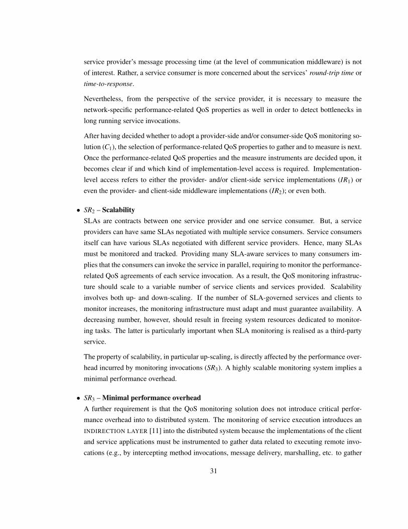
service provider’s message processing time (at the level of communication middleware) is not
of interest. Rather, a service consumer is more concerned about the services’ round-trip time or
time-to-response.
Nevertheless, from the perspective of the service provider, it is necessary to measure the
network-specific performance-related QoS properties as well in order to detect bottlenecks in
long running service invocations.
After having decided whether to adopt a provider-side and/or consumer-side QoS monitoring so-
lution (C1), the selection of performance-related QoS properties to gather and to measure is next.
Once the performance-related QoS properties and the measure instruments are decided upon, it
becomes clear if and which kind of implementation-level access is required. Implementation-
level access refers to either the provider- and/or client-side service implementations (IR1) or
even the provider- and client-side middleware implementations (IR2); or even both.
• SR2 – ScalabilitySLAs are contracts between one service provider and one service consumer. But, a service
providers can have same SLAs negotiated with multiple service consumers. Service consumers
itself can have various SLAs negotiated with different service providers. Hence, many SLAs
must be monitored and tracked. Providing many SLA-aware services to many consumers im-
plies that the consumers can invoke the service in parallel, requiring to monitor the performance-
related QoS agreements of each service invocation. As a result, the QoS monitoring infrastruc-
ture should scale to a variable number of service clients and services provided. Scalability
involves both up- and down-scaling. If the number of SLA-governed services and clients to
monitor increases, the monitoring infrastructure must adapt and must guarantee availability. A
decreasing number, however, should result in freeing system resources dedicated to monitor-
ing tasks. The latter is particularly important when SLA monitoring is realised as a third-party
service.
The property of scalability, in particular up-scaling, is directly affected by the performance over-
head incurred by monitoring invocations (SR3). A highly scalable monitoring system implies a
minimal performance overhead.
• SR3 – Minimal performance overheadA further requirement is that the QoS monitoring solution does not introduce critical perfor-
mance overhead into to distributed system. The monitoring of service execution introduces an
INDIRECTION LAYER [11] into the distributed system because the implementations of the client
and service applications must be instrumented to gather data related to executing remote invo-
cations (e.g., by intercepting method invocations, message delivery, marshalling, etc. to gather
31
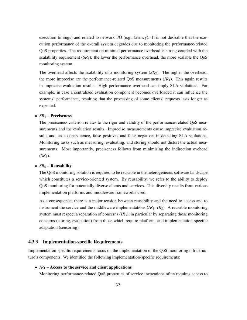
execution timings) and related to network I/O (e.g., latency). It is not desirable that the exe-
cution performance of the overall system degrades due to monitoring the performance-related
QoS properties. The requirement on minimal performance overhead is strong coupled with the
scalability requirement (SR2): the lower the performance overhead, the more scalable the QoS
monitoring system.
The overhead affects the scalability of a monitoring system (SR2). The higher the overhead,
the more imprecise are the performance-related QoS measurements (IR4). This again results
in imprecise evaluation results. High performance overhead can imply SLA violations. For
example, in case a centralized evaluation component becomes overloaded it can influence the
systems’ performance, resulting that the processing of some clients’ requests lasts longer as
expected.
• SR4 – PrecisenessThe preciseness criterion relates to the rigor and validity of the performance-related QoS mea-
surements and the evaluation results. Imprecise measurements cause imprecise evaluation re-
sults and, as a consequence, false positives and false negatives in detecting SLA violations.
Monitoring tasks such as measuring, evaluating, and storing should not distort the actual mea-
surements. Most importantly, preciseness follows from minimising the indirection ovehead
(SR3).
• SR5 – ReusabilityThe QoS monitoring solution is required to be reusable in the heterogeneous software landscape
which constitutes a service-oriented system. By reusability, we refer to the ability to deploy
QoS monitoring for potentially diverse clients and services. This diversity results from various
implementation platforms and middleware frameworks used.
As a consequence, there is a major tension between reusability and the need to access and to
instrument the service and the middleware implementations (IR1, IR2). A reusable monitoring
system must respect a separation of concerns (IR3), in particular by separating those monitoring
concerns (storing, evaluation) from those which require platform- and implementation-specific
adaptation (sensoring).
4.3.3 Implementation-specific Requirements
Implementation-specific requirements focus on the implementation of the QoS monitoring infrastruc-
ture’s components. We identified the following implementation-specific requirements:
• IR1 – Access to the service and client applicationsMonitoring performance-related QoS properties of service invocations often requires access to
32
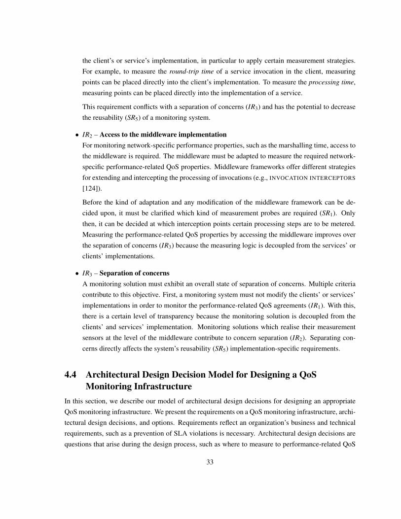
the client’s or service’s implementation, in particular to apply certain measurement strategies.
For example, to measure the round-trip time of a service invocation in the client, measuring
points can be placed directly into the client’s implementation. To measure the processing time,
measuring points can be placed directly into the implementation of a service.
This requirement conflicts with a separation of concerns (IR3) and has the potential to decrease
the reusability (SR5) of a monitoring system.
• IR2 – Access to the middleware implementationFor monitoring network-specific performance properties, such as the marshalling time, access to
the middleware is required. The middleware must be adapted to measure the required network-
specific performance-related QoS properties. Middleware frameworks offer different strategies
for extending and intercepting the processing of invocations (e.g., INVOCATION INTERCEPTORS
[124]).
Before the kind of adaptation and any modification of the middleware framework can be de-
cided upon, it must be clarified which kind of measurement probes are required (SR1). Only
then, it can be decided at which interception points certain processing steps are to be metered.
Measuring the performance-related QoS properties by accessing the middleware improves over
the separation of concerns (IR3) because the measuring logic is decoupled from the services’ or
clients’ implementations.
• IR3 – Separation of concernsA monitoring solution must exhibit an overall state of separation of concerns. Multiple criteria
contribute to this objective. First, a monitoring system must not modify the clients’ or services’
implementations in order to monitor the performance-related QoS agreements (IR1). With this,
there is a certain level of transparency because the monitoring solution is decoupled from the
clients’ and services’ implementation. Monitoring solutions which realise their measurement
sensors at the level of the middleware contribute to concern separation (IR2). Separating con-
cerns directly affects the system’s reusability (SR5) implementation-specific requirements.
4.4 Architectural Design Decision Model for Designing a QoSMonitoring Infrastructure
In this section, we describe our model of architectural design decisions for designing an appropriate
QoS monitoring infrastructure. We present the requirements on a QoS monitoring infrastructure, archi-
tectural design decisions, and options. Requirements reflect an organization’s business and technical
requirements, such as a prevention of SLA violations is necessary. Architectural design decisions are
questions that arise during the design process, such as where to measure to performance-related QoS
33
properties in the clients or services. Options provide solutions for an architectural design decision,
dependent on the requirements.
We describe for each architectural design decisions the requirements and proposed solutions. The
proposed solutions are based on patterns [35] that are well-established solutions to a problem in a
certain context. We describe for each pattern its forces and consequences.
4.4.1 Design Decision:WHICH SLA PARTY NEEDS QOS MONITORING?
First, it must be decided if a service provider or a service consumer wants to introduce a QoS mon-
itoring solution. In our model, this architectural design decision is the first of the decision making
process.
We illustrate in Figure 4.5 the model’s solutions for this design decision that is influenced by the
requirement if services are provided or consumed. Our model provides three different architectural de-
cision options — SERVICE PROVIDER QOS MONITORING, SERVICE CONSUMER QOS MONITORING,
and COMBINED QOS MONITORING.
C1Providing or
consuming services
Which SLA party needs QoS monitoring?
SERVICE PROVIDER QOS
MONITORING
SERVICE CONSUMERQOS
MONITORING
COMBINED QOS
MONITORING
alternative alternative alternative
combines
influences
Figure 4.5: WHICH SLA PARTY NEEDS QOS MONITORING?
34
Solution: SERVICE PROVIDER QOS MONITORING
Integrate a QoS monitoring infrastructure into the service provider’s network.
�� �
In case of providing services, our model proposes a SERVICE PROVIDER QOS MONITORING so-
lution. A SERVICE PROVIDER QOS MONITORING solution makes it possible to measure server-side
performance-related QoS properties. Client-side performance-related QoS properties can not be mea-
sured.
Known Uses:
• Windows Performance Counters (WPC) [73] of the the Windows Communication Foundation
(WCF) [72] can be utilized to perform server-side QoS monitoring. WPCs are part of the .NET
framework [70].
• Mani and Nagarajan [63] explain the measuring of performance-related QoS properties within a
client’s implementation.
Solution: CLIENT-SIDE QOS MONITORING
Integrate a QoS monitoring infrastructure into the service consumer’s network.
�� �
In case of consuming services, our model proposes a SERVICE CONSUMER QOS MONITORING
solution. A SERVICE CONSUMER QOS MONITORING solution makes it possible to measure client-
side performance-related QoS properties. Server-side performance-related QoS properties can not be
measured.
Known Uses:
• Rosenberg [96] developed a SERVICE PROVIDER QOS MONITORING solution, called
QUATSCH. The performance-related QoS properties are measured during probe service
requests.
Solution: COMBINED QOS MONITORING
Integrate a common QoS monitoring infrastructure into the service consumer’s and serviceprovider’s network. Measure the performance-related QoS properties in both networks andcombine both measurements to evaluate the performance-related agreements.
35
�� �
In case service provider and service consumer agree on a common QoS monitoring infrastruc-
ture, a COMBINED QOS MONITORING solution is proposed. As illustrated in Figure 4.5, a COMBINED
QOS MONITORING solution combines the SERVICE PROVIDER QOS MONITORING and SERVICE CON-
SUMER QOS MONITORING solutions. This solution makes it possible to measure client- and server-side
performance-related QoS properties.
Known Uses:
• Michlmayr et al. [67] present a combined monitoring solution, requiring access to the clients’
and services’ implementation.
• Sahai et al. [100] introduce an SLA monitoring engine with two monitoring components. One
in the service provider’s network and one in the service consumer’s network.
4.4.2 Design Decision:WHERE SHOULD THE PERFORMANCE-RELATED QOS PROPERTIES BEMEASURED?
This architectural design decision focuses on how to instrument the clients’ and the services’ imple-
mentations to measure the performance-related QoS properties of service invocations. This can be
done in various ways and layers of the network communication, such as in the application layer, the
network layer, or by extending some used middleware.
In Figure 4.6 we illustrate how the requirements influence this design decision and which design
solutions our model offers. The model’s solutions are patterns that extend and utilize existing well-
established design patterns, such as the WRAPPER pattern, the INTERCEPTOR pattern, the INVOCATION
INTERCEPTOR pattern, or the PROXY pattern [35, 103, 124].
Measuring the performance-related QoS properties should deliver precise measurements, produce
a minimal performance overhead, and should not decrease the system’s scalability. The implementa-
tion of the measuring logic should provide separation of concerns in order to be reusable. Dependent
on which performance-related QoS properties should be measured, access to the clients’ or services’
implementation or to the middleware’s implementation is required.
Pattern: QOS INLINE
An SLA contains negotiated performance-related QoS properties where only the elapsed time of a
remote object invocation is relevant to the client, i.e., the round-trip time. For the server it is relevant
36
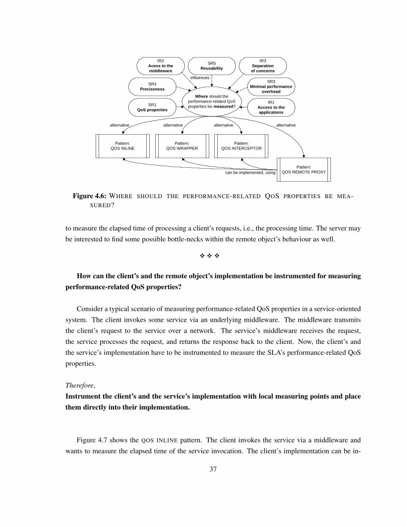
SR3Minimal performance
overheadWhere should the
performance-related QoS properties be measured?
SR4Preciseness
SR1QoS properties
SR5Reusability
IR1Access to the applications
IR3Separation of concerns
IR2Acess to the middleware
Pattern:QOS INLINE
Pattern:QOS WRAPPER
Pattern:QOS INTERCEPTOR
Pattern:QOS REMOTE PROXY
alternative alternative alternative alternative
can be implemented, using
influences
Figure 4.6: WHERE SHOULD THE PERFORMANCE-RELATED QOS PROPERTIES BE MEA-SURED?
to measure the elapsed time of processing a client’s requests, i.e., the processing time. The server may
be interested to find some possible bottle-necks within the remote object’s behaviour as well.
�� �
How can the client’s and the remote object’s implementation be instrumented for measuringperformance-related QoS properties?
Consider a typical scenario of measuring performance-related QoS properties in a service-oriented
system. The client invokes some service via an underlying middleware. The middleware transmits
the client’s request to the service over a network. The service’s middleware receives the request,
the service processes the request, and returns the response back to the client. Now, the client’s and
the service’s implementation have to be instrumented to measure the SLA’s performance-related QoS
properties.
Therefore,
Instrument the client’s and the service’s implementation with local measuring points and placethem directly into their implementation.
Figure 4.7 shows the QOS INLINE pattern. The client invokes the service via a middleware and
wants to measure the elapsed time of the service invocation. The client’s implementation can be in-
37
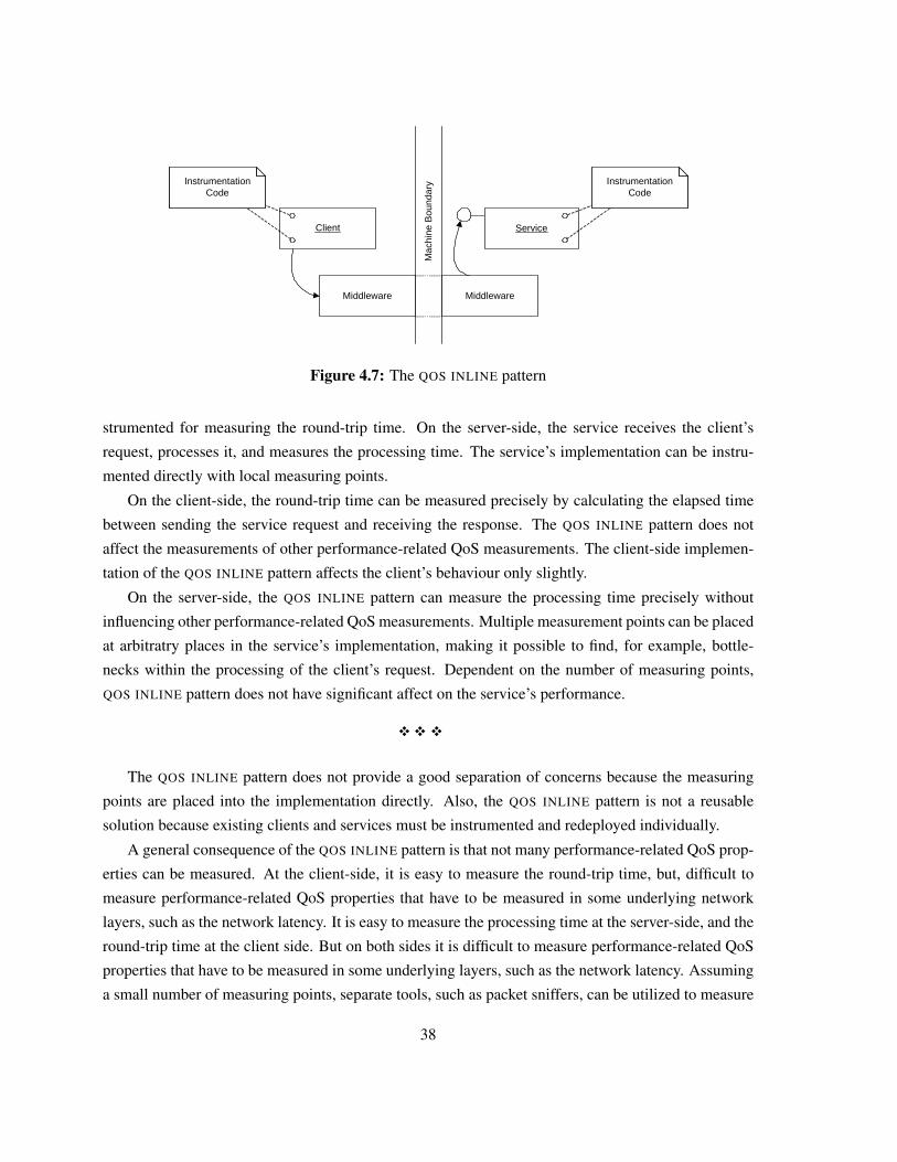
Client
Mac
hine
Bou
ndar
y
Service
Middleware Middleware
Instrumentation Code
Instrumentation Code
Instrumentation Code
Instrumentation Code
Figure 4.7: The QOS INLINE pattern
strumented for measuring the round-trip time. On the server-side, the service receives the client’s
request, processes it, and measures the processing time. The service’s implementation can be instru-
mented directly with local measuring points.
On the client-side, the round-trip time can be measured precisely by calculating the elapsed time
between sending the service request and receiving the response. The QOS INLINE pattern does not
affect the measurements of other performance-related QoS measurements. The client-side implemen-
tation of the QOS INLINE pattern affects the client’s behaviour only slightly.
On the server-side, the QOS INLINE pattern can measure the processing time precisely without
influencing other performance-related QoS measurements. Multiple measurement points can be placed
at arbitratry places in the service’s implementation, making it possible to find, for example, bottle-
necks within the processing of the client’s request. Dependent on the number of measuring points,
QOS INLINE pattern does not have significant affect on the service’s performance.
�� �
The QOS INLINE pattern does not provide a good separation of concerns because the measuring
points are placed into the implementation directly. Also, the QOS INLINE pattern is not a reusable
solution because existing clients and services must be instrumented and redeployed individually.
A general consequence of the QOS INLINE pattern is that not many performance-related QoS prop-
erties can be measured. At the client-side, it is easy to measure the round-trip time, but, difficult to
measure performance-related QoS properties that have to be measured in some underlying network
layers, such as the network latency. It is easy to measure the processing time at the server-side, and the
round-trip time at the client side. But on both sides it is difficult to measure performance-related QoS
properties that have to be measured in some underlying layers, such as the network latency. Assuming
a small number of measuring points, separate tools, such as packet sniffers, can be utilized to measure
38
the performance-related QoS properties that are not measurable with the QOS INLINE pattern.
Every source code can be extended with time measurements using the QOS INLINE pattern. The
QOS INLINE pattern can not be applied in service-oriented systems only, also in local function calls or
object method invocations. Using the QOS INLINE pattern is advisable if the QoS measurements are
relevant in the client’s or service’s application layer.
Known Uses:
• Mani and Nagarajan [63] explain QoS in service-oriented systems by using the QOS INLINE
pattern to measure the elapsed time of a service invocation, i.e., the round-trip time.
Pattern: QOS WRAPPER
The negotiated SLAs between client and server include performance-related QoS properties with re-
spect to the elapsed times of service invocations. The client and services must be instrumented for
measuring the performance-related QoS agreements. The client’s and the service’s implementation
should be instrumented with a reusable solution that provides separation of concerns.
�� �
Which solution is reusable and provides a good separation of concerns for instrumenting theclient’s and the service’s for measuring performance-related QoS properties?
As proposed by the QOS INLINE pattern, measuring performance-related QoS properties during
service invocations can be done by placing measuring points into the client’s or service’s implemen-
tation directly. But, this solution does not provide separation of concerns and reusability. It is not
possible to attach the measuring of the performance-related QoS properties to existing clients and ser-
vices without redeployment. For improvement, the performance-related QoS properties have to be
measured separated from the client’s and service’s implementation.
Therefore,
Instrument the client’s and service’s implementations with local QOS WRAPPERS that are re-sponsible for measuring the performance-related QoS properties. Let a client invoke a serviceusing a client-side QOS WRAPPER. Extend a service with a server-side QOS WRAPPER that re-ceives the client’s requests.
Figure 4.8 illustrates the QOS WRAPPER pattern. The client invokes a service using a client-side
QOS WRAPPER that offers the client the service’s operations, takes over the service invocation, and
39
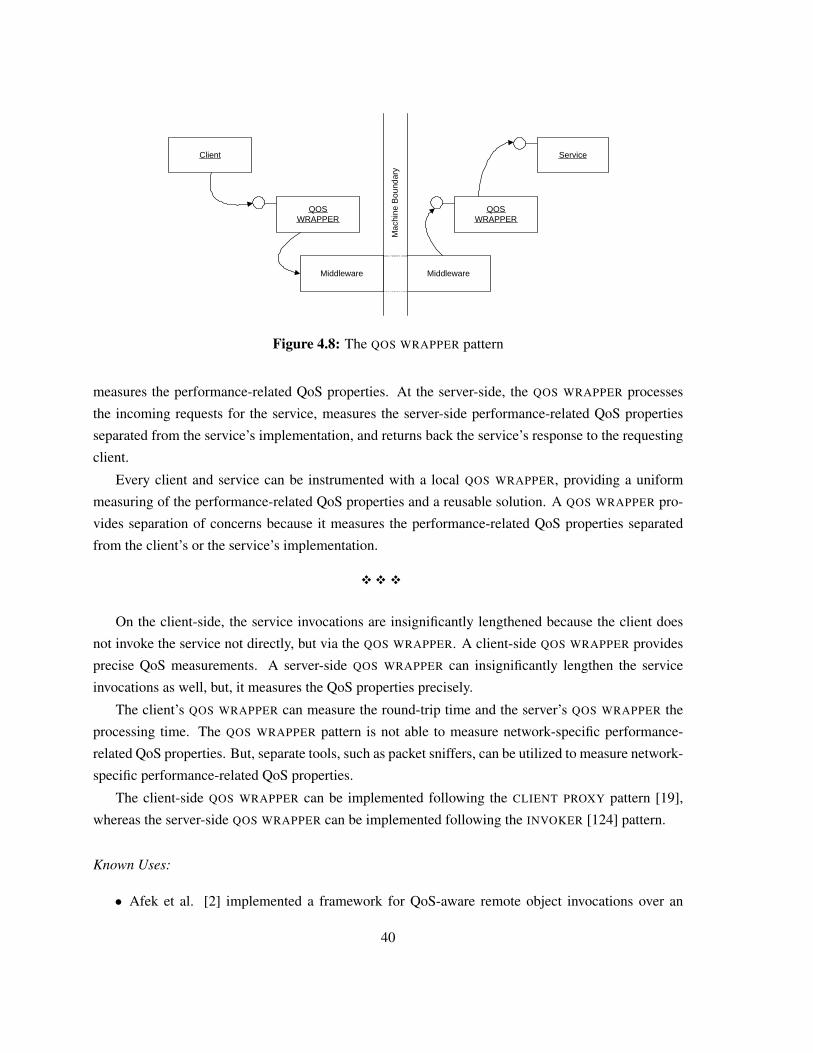
Client
QOSWRAPPER
Mac
hine
Bou
ndar
y
Service
QOSWRAPPER
Middleware Middleware
Figure 4.8: The QOS WRAPPER pattern
measures the performance-related QoS properties. At the server-side, the QOS WRAPPER processes
the incoming requests for the service, measures the server-side performance-related QoS properties
separated from the service’s implementation, and returns back the service’s response to the requesting
client.
Every client and service can be instrumented with a local QOS WRAPPER, providing a uniform
measuring of the performance-related QoS properties and a reusable solution. A QOS WRAPPER pro-
vides separation of concerns because it measures the performance-related QoS properties separated
from the client’s or the service’s implementation.
�� �
On the client-side, the service invocations are insignificantly lengthened because the client does
not invoke the service not directly, but via the QOS WRAPPER. A client-side QOS WRAPPER provides
precise QoS measurements. A server-side QOS WRAPPER can insignificantly lengthen the service
invocations as well, but, it measures the QoS properties precisely.
The client’s QOS WRAPPER can measure the round-trip time and the server’s QOS WRAPPER the
processing time. The QOS WRAPPER pattern is not able to measure network-specific performance-
related QoS properties. But, separate tools, such as packet sniffers, can be utilized to measure network-
specific performance-related QoS properties.
The client-side QOS WRAPPER can be implemented following the CLIENT PROXY pattern [19],
whereas the server-side QOS WRAPPER can be implemented following the INVOKER [124] pattern.
Known Uses:
• Afek et al. [2] implemented a framework for QoS-aware remote object invocations over an
40
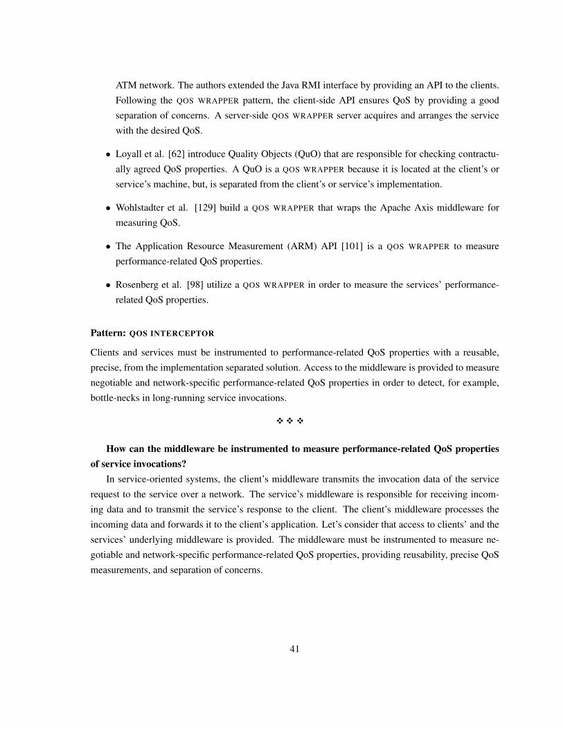
ATM network. The authors extended the Java RMI interface by providing an API to the clients.
Following the QOS WRAPPER pattern, the client-side API ensures QoS by providing a good
separation of concerns. A server-side QOS WRAPPER server acquires and arranges the service
with the desired QoS.
• Loyall et al. [62] introduce Quality Objects (QuO) that are responsible for checking contractu-
ally agreed QoS properties. A QuO is a QOS WRAPPER because it is located at the client’s or
service’s machine, but, is separated from the client’s or service’s implementation.
• Wohlstadter et al. [129] build a QOS WRAPPER that wraps the Apache Axis middleware for
measuring QoS.
• The Application Resource Measurement (ARM) API [101] is a QOS WRAPPER to measure
performance-related QoS properties.
• Rosenberg et al. [98] utilize a QOS WRAPPER in order to measure the services’ performance-
related QoS properties.
Pattern: QOS INTERCEPTOR
Clients and services must be instrumented to performance-related QoS properties with a reusable,
precise, from the implementation separated solution. Access to the middleware is provided to measure
negotiable and network-specific performance-related QoS properties in order to detect, for example,
bottle-necks in long-running service invocations.
�� �
How can the middleware be instrumented to measure performance-related QoS propertiesof service invocations?
In service-oriented systems, the client’s middleware transmits the invocation data of the service
request to the service over a network. The service’s middleware is responsible for receiving incom-
ing data and to transmit the service’s response to the client. The client’s middleware processes the
incoming data and forwards it to the client’s application. Let’s consider that access to clients’ and the
services’ underlying middleware is provided. The middleware must be instrumented to measure ne-
gotiable and network-specific performance-related QoS properties, providing reusability, precise QoS
measurements, and separation of concerns.
41
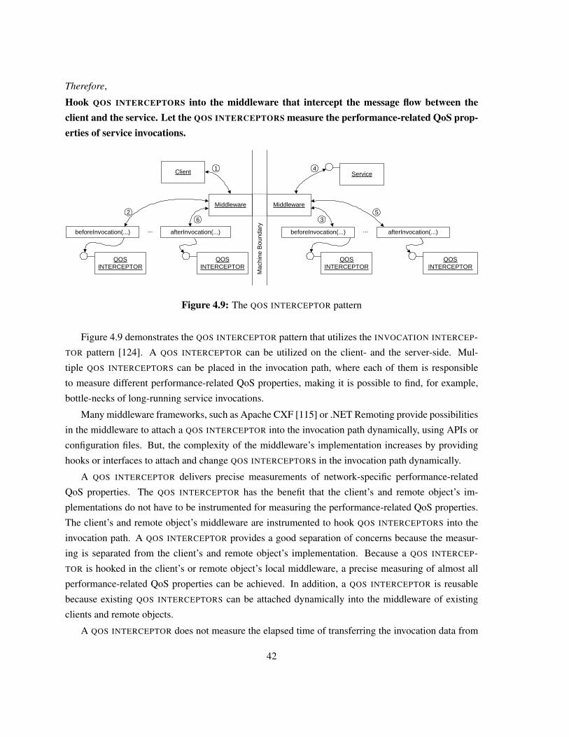
Therefore,
Hook QOS INTERCEPTORS into the middleware that intercept the message flow between theclient and the service. Let the QOS INTERCEPTORS measure the performance-related QoS prop-erties of service invocations.
Client
Middleware
Mac
hine
Bou
ndar
y
beforeInvocation(...) afterInvocation(...)...
QOSINTERCEPTOR
QOSINTERCEPTOR
Middleware
beforeInvocation(...) afterInvocation(...)...
QOSINTERCEPTOR
QOSINTERCEPTOR
4
5
1
23
7 Service
6
Figure 4.9: The QOS INTERCEPTOR pattern
Figure 4.9 demonstrates the QOS INTERCEPTOR pattern that utilizes the INVOCATION INTERCEP-
TOR pattern [124]. A QOS INTERCEPTOR can be utilized on the client- and the server-side. Mul-
tiple QOS INTERCEPTORS can be placed in the invocation path, where each of them is responsible
to measure different performance-related QoS properties, making it is possible to find, for example,
bottle-necks of long-running service invocations.
Many middleware frameworks, such as Apache CXF [115] or .NET Remoting provide possibilities
in the middleware to attach a QOS INTERCEPTOR into the invocation path dynamically, using APIs or
configuration files. But, the complexity of the middleware’s implementation increases by providing
hooks or interfaces to attach and change QOS INTERCEPTORS in the invocation path dynamically.
A QOS INTERCEPTOR delivers precise measurements of network-specific performance-related
QoS properties. The QOS INTERCEPTOR has the benefit that the client’s and remote object’s im-
plementations do not have to be instrumented for measuring the performance-related QoS properties.
The client’s and remote object’s middleware are instrumented to hook QOS INTERCEPTORS into the
invocation path. A QOS INTERCEPTOR provides a good separation of concerns because the measur-
ing is separated from the client’s and remote object’s implementation. Because a QOS INTERCEP-
TOR is hooked in the client’s or remote object’s local middleware, a precise measuring of almost all
performance-related QoS properties can be achieved. In addition, a QOS INTERCEPTOR is reusable
because existing QOS INTERCEPTORS can be attached dynamically into the middleware of existing
clients and remote objects.
A QOS INTERCEPTOR does not measure the elapsed time of transferring the invocation data from
42
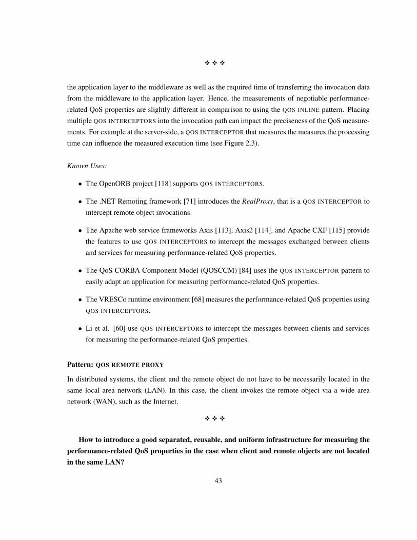
�� �
the application layer to the middleware as well as the required time of transferring the invocation data
from the middleware to the application layer. Hence, the measurements of negotiable performance-
related QoS properties are slightly different in comparison to using the QOS INLINE pattern. Placing
multiple QOS INTERCEPTORS into the invocation path can impact the preciseness of the QoS measure-
ments. For example at the server-side, a QOS INTERCEPTOR that measures the measures the processing
time can influence the measured execution time (see Figure 2.3).
Known Uses:
• The OpenORB project [118] supports QOS INTERCEPTORS.
• The .NET Remoting framework [71] introduces the RealProxy, that is a QOS INTERCEPTOR to
intercept remote object invocations.
• The Apache web service frameworks Axis [113], Axis2 [114], and Apache CXF [115] provide
the features to use QOS INTERCEPTORS to intercept the messages exchanged between clients
and services for measuring performance-related QoS properties.
• The QoS CORBA Component Model (QOSCCM) [84] uses the QOS INTERCEPTOR pattern to
easily adapt an application for measuring performance-related QoS properties.
• The VRESCo runtime environment [68] measures the performance-related QoS properties using
QOS INTERCEPTORS.
• Li et al. [60] use QOS INTERCEPTORS to intercept the messages between clients and services
for measuring the performance-related QoS properties.
Pattern: QOS REMOTE PROXY
In distributed systems, the client and the remote object do not have to be necessarily located in the
same local area network (LAN). In this case, the client invokes the remote object via a wide area
network (WAN), such as the Internet.
�� �
How to introduce a good separated, reusable, and uniform infrastructure for measuring theperformance-related QoS properties in the case when client and remote objects are not locatedin the same LAN?
43
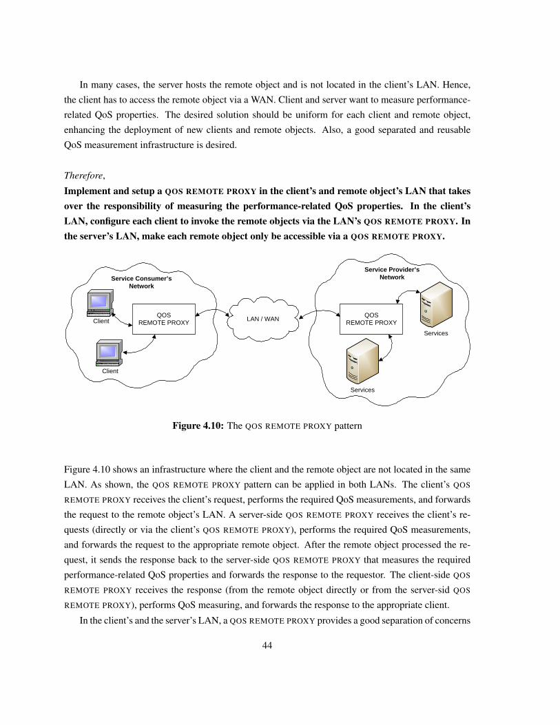
In many cases, the server hosts the remote object and is not located in the client’s LAN. Hence,
the client has to access the remote object via a WAN. Client and server want to measure performance-
related QoS properties. The desired solution should be uniform for each client and remote object,
enhancing the deployment of new clients and remote objects. Also, a good separated and reusable
QoS measurement infrastructure is desired.
Therefore,
Implement and setup a QOS REMOTE PROXY in the client’s and remote object’s LAN that takesover the responsibility of measuring the performance-related QoS properties. In the client’sLAN, configure each client to invoke the remote objects via the LAN’s QOS REMOTE PROXY. Inthe server’s LAN, make each remote object only be accessible via a QOS REMOTE PROXY.
Client
Client
QOSREMOTE PROXY
QOSREMOTE PROXY
Services
Services
Service Consumer’s Network
LAN / WAN
Service Provider’s Network
Figure 4.10: The QOS REMOTE PROXY pattern
Figure 4.10 shows an infrastructure where the client and the remote object are not located in the same
LAN. As shown, the QOS REMOTE PROXY pattern can be applied in both LANs. The client’s QOS
REMOTE PROXY receives the client’s request, performs the required QoS measurements, and forwards
the request to the remote object’s LAN. A server-side QOS REMOTE PROXY receives the client’s re-
quests (directly or via the client’s QOS REMOTE PROXY), performs the required QoS measurements,
and forwards the request to the appropriate remote object. After the remote object processed the re-
quest, it sends the response back to the server-side QOS REMOTE PROXY that measures the required
performance-related QoS properties and forwards the response to the requestor. The client-side QOS
REMOTE PROXY receives the response (from the remote object directly or from the server-sid QOS
REMOTE PROXY), performs QoS measuring, and forwards the response to the appropriate client.
In the client’s and the server’s LAN, a QOS REMOTE PROXY provides a good separation of concerns
44
because the measuring of the performance-related QoS properties is separated. Also, there is no impact
on the client’s and server’s performance. In addition a QOS REMOTE PROXY is a reusable solution.
Each new client can be configured to invoke the remote object via the client’s LAN QOS REMOTE
PROXY. Also, it is possible to configure each remote object that is only accessible via the server’s
LAN QOS REMOTE PROXY.
�� �
At minimum one extra hop in the client’s and server’s LAN is needed because of accessing the QOS
REMOTE PROXY instead of accessing the WAN or the remote object directly. Hence, the measurements
of the performance-related QoS properties at the QOS REMOTE PROXY differ from the client’s and
remote object’s local QoS measurements. In case the client and the server are measuring the negotiated
performance-related QoS properties independently, both can fake the QoS measurements.
A client-side QOS REMOTE PROXY can affect the client’s performance slightly. But, a QOS RE-
MOTE PROXY can impact the performance of the client’s LAN because each client has to invoke the
remote object via the QOS REMOTE PROXY. On the server-side, a QOS REMOTE PROXY does not affect
the performance of the remote object directly, but, it can have an impact on the server’s LAN. A QOS
REMOTE PROXY inside the server’s LAN can be implemented as a load-balancer, gateway, reverse
proxy, dispatcher, as well as a firewall following the appropriate patterns [19].
The QOS REMOTE PROXY does not necessarily require that the client and the remote object are
located in different LANs. In a case where client and remote object are located in the same LAN, the
setup of one QOS REMOTE PROXY inside the LAN is adequate.
Known Uses:
• Wang et al. [127] introduce a QoS-Adaptation proxy that receives the clients’ requests, performs
the QoS measurements, and forwards the clients’ requests to their destinations. The clients’
applications remain unchanged while the proxy performs the necessary adaptations and QoS
measurements.
• The Corba IIOP specifications [83] introduce the VisiBroker [17] environment that uses the QOS
REMOTE PROXY pattern for measuring the performance-related QoS properties.
• The Apache TCPMon [117] tool can be instrumented to serve as a proxy between the clients
and the server’s remote objects. An implementation of the QOS REMOTE PROXY is to extend
this tool for measuring performance-related QoS properties.
• Sahai et al. [100] introduce a QOS REMOTE PROXY for monitoring SLAs in web service-oriented
distributed systems.
45
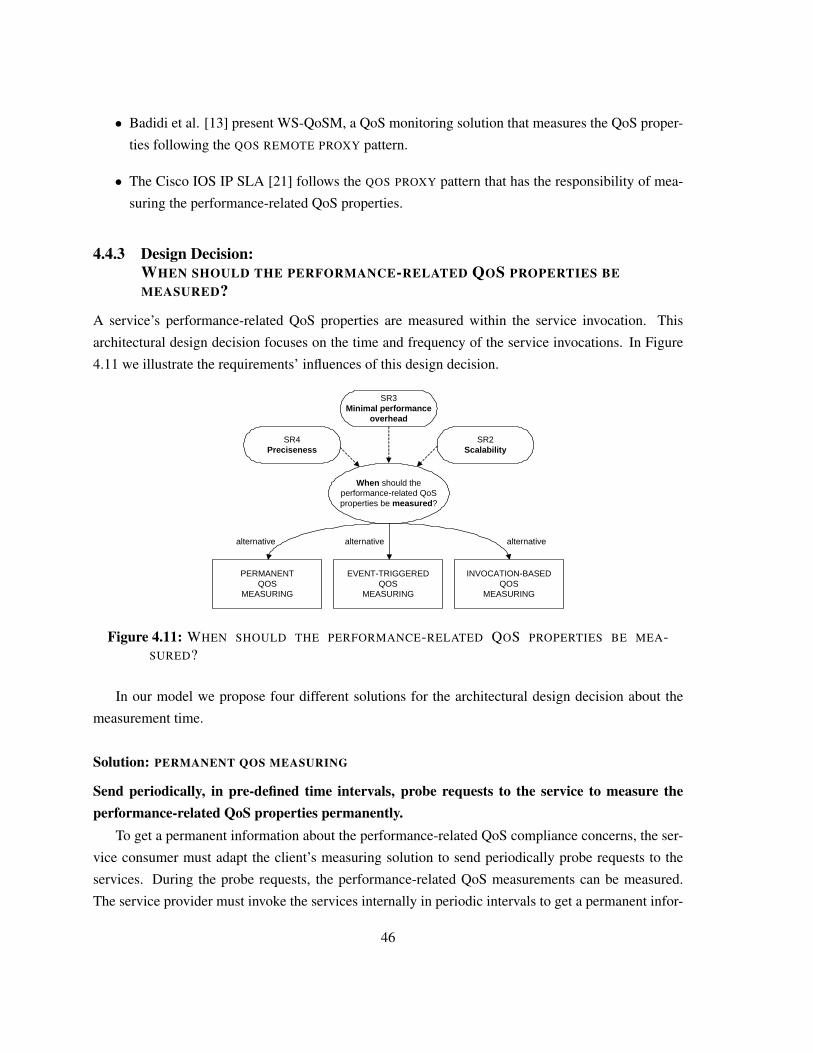
• Badidi et al. [13] present WS-QoSM, a QoS monitoring solution that measures the QoS proper-
ties following the QOS REMOTE PROXY pattern.
• The Cisco IOS IP SLA [21] follows the QOS PROXY pattern that has the responsibility of mea-
suring the performance-related QoS properties.
4.4.3 Design Decision:WHEN SHOULD THE PERFORMANCE-RELATED QOS PROPERTIES BEMEASURED?
A service’s performance-related QoS properties are measured within the service invocation. This
architectural design decision focuses on the time and frequency of the service invocations. In Figure
4.11 we illustrate the requirements’ influences of this design decision.
SR3Minimal performance
overhead
When should the performance-related QoS properties be measured?
SR4Preciseness
SR2Scalability
PERMANENTQOS
MEASURING
EVENT-TRIGGEREDQOS
MEASURING
INVOCATION-BASEDQOS
MEASURING
alternative alternative alternative
Figure 4.11: WHEN SHOULD THE PERFORMANCE-RELATED QOS PROPERTIES BE MEA-SURED?
In our model we propose four different solutions for the architectural design decision about the
measurement time.
Solution: PERMANENT QOS MEASURING
Send periodically, in pre-defined time intervals, probe requests to the service to measure theperformance-related QoS properties permanently.
To get a permanent information about the performance-related QoS compliance concerns, the ser-
vice consumer must adapt the client’s measuring solution to send periodically probe requests to the
services. During the probe requests, the performance-related QoS measurements can be measured.
The service provider must invoke the services internally in periodic intervals to get a permanent infor-
46
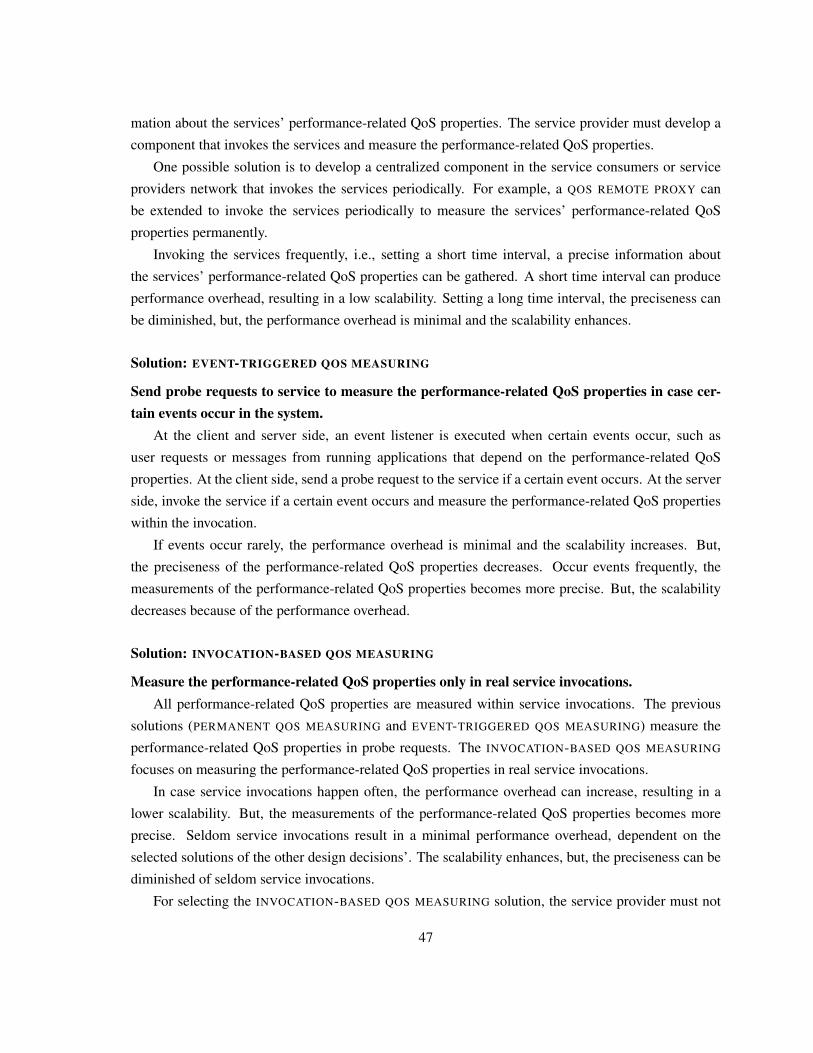
mation about the services’ performance-related QoS properties. The service provider must develop a
component that invokes the services and measure the performance-related QoS properties.
One possible solution is to develop a centralized component in the service consumers or service
providers network that invokes the services periodically. For example, a QOS REMOTE PROXY can
be extended to invoke the services periodically to measure the services’ performance-related QoS
properties permanently.
Invoking the services frequently, i.e., setting a short time interval, a precise information about
the services’ performance-related QoS properties can be gathered. A short time interval can produce
performance overhead, resulting in a low scalability. Setting a long time interval, the preciseness can
be diminished, but, the performance overhead is minimal and the scalability enhances.
Solution: EVENT-TRIGGERED QOS MEASURING
Send probe requests to service to measure the performance-related QoS properties in case cer-tain events occur in the system.
At the client and server side, an event listener is executed when certain events occur, such as
user requests or messages from running applications that depend on the performance-related QoS
properties. At the client side, send a probe request to the service if a certain event occurs. At the server
side, invoke the service if a certain event occurs and measure the performance-related QoS properties
within the invocation.
If events occur rarely, the performance overhead is minimal and the scalability increases. But,
the preciseness of the performance-related QoS properties decreases. Occur events frequently, the
measurements of the performance-related QoS properties becomes more precise. But, the scalability
decreases because of the performance overhead.
Solution: INVOCATION-BASED QOS MEASURING
Measure the performance-related QoS properties only in real service invocations.All performance-related QoS properties are measured within service invocations. The previous
solutions (PERMANENT QOS MEASURING and EVENT-TRIGGERED QOS MEASURING) measure the
performance-related QoS properties in probe requests. The INVOCATION-BASED QOS MEASURING
focuses on measuring the performance-related QoS properties in real service invocations.
In case service invocations happen often, the performance overhead can increase, resulting in a
lower scalability. But, the measurements of the performance-related QoS properties becomes more
precise. Seldom service invocations result in a minimal performance overhead, dependent on the
selected solutions of the other design decisions’. The scalability enhances, but, the preciseness can be
diminished of seldom service invocations.
For selecting the INVOCATION-BASED QOS MEASURING solution, the service provider must not
47
develop a component that sends probe requests to the services in order to measure the services’
performance-related QoS properties.
4.4.4 Design Decision:WHEN SHOULD THE PERFORMANCE-RELATED QOS MEASUREMENTS BEEVALUATED?
The next architectural decision focuses on the evaluation of the performance-related QoS measure-
ments. In our terminology, evaluating means to check the performance-related QoS measurements
regarding the SLAs in order to detect or prevent SLA violations.
SR2Scalability
When should the performance-related QoS properties be evaluated ?
SR4Preciseness
SR3Minimal performance
overhead
C2Dependency on the third parties’ qualityC3
Prevention of SLA violations
ONLINE QOS
MONITOR
OFFLINEQOS
MONITOR
alternative alternative
can be utilized as
influences
Figure 4.12: WHEN SHOULD THE PERFORMANCE-RELATED QOS MEASUREMENTS BE EVAL-UATED?
In Figure 4.12 we illustrate the design decisions requirements and the proposed solutions. The
evaluation solution should deliver precise results in order to detect or prevent SLA violations. In
case the services’ performance depends on some third parties’ services, the evaluation solution should
alert performance drops well-timed. But, the evaluation solution should have minimal performance
overhead in a high scalable system. An ONLINE QOS MONITOR can be used as an OFFLINE QOS
MONITOR.
In the following, we present our model’s solutions for this architectural design decision. The
presented solutions are derivations of the QOS OBSERVER pattern [124].We explain the solutions’
forces and consequences regarding the requirements.
48
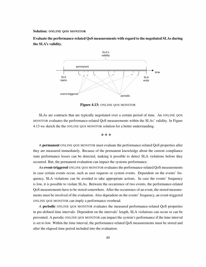
Solution: ONLINE QOS MONITOR
Evaluate the performance-related QoS measurements with regard to the negotiated SLAs duringthe SLA’s validity.
time
SLAstarts
SLAends
SLA’svalidity
periodicevent-triggered
permanent
Figure 4.13: ONLINE QOS MONITOR
SLAs are contracts that are typically negotiated over a certain period of time. An ONLINE QOS
MONITOR evaluates the performance-related QoS measurements within the SLAs’ validity. In Figure
4.13 we sketch the the ONLINE QOS MONITOR solution for a better understanding.
�� �
A permanent ONLINE QOS MONITOR must evaluate the performance-related QoS properties after
they are measured immediately. Because of the permanent knowledge about the current compliance
state performance losses can be detected, making it possible to detect SLA violations before they
occurred. But, the permanent evaluation can impact the systems performance.
An event-triggered ONLINE QOS MONITOR evaluates the performance-related QoS measurements
in case certain events occur, such as user requests or system events. Dependent on the events’ fre-
quency, SLA violations can be avoided to take appropriate actions. In case the events’ frequency
is low, it is possible to violate SLAs. Between the occurrence of two events, the performance-related
QoS measurements have to be stored somewhere. After the occurrence of an event, the stored measure-
ments must be involved of the evaluation. Also dependent on the events’ frequency, an event-triggered
ONLINE QOS MONITOR can imply a performance overhead.
A periodic ONLINE QOS MONITOR evaluates the measured performance-related QoS properties
in pre-defined time intervals. Dependent on the intervals’ length, SLA violations can occur or can be
prevented. A perodic ONLINE QOS MONITOR can impact the system’s performance if the time interval
is set to low. Within the time interval, the performance-related QoS measurements must be stored and
after the elapsed time period included into the evaluation.
49
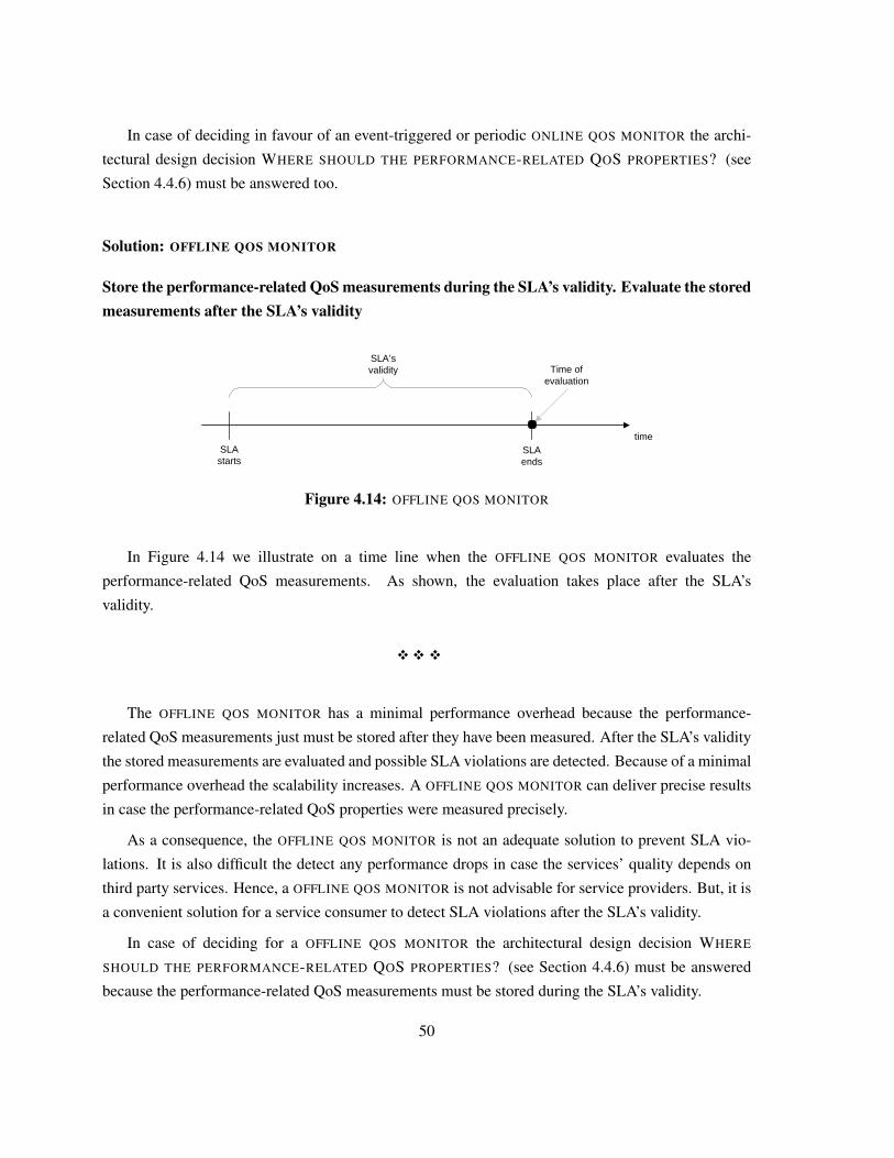
In case of deciding in favour of an event-triggered or periodic ONLINE QOS MONITOR the archi-
tectural design decision WHERE SHOULD THE PERFORMANCE-RELATED QOS PROPERTIES? (see
Section 4.4.6) must be answered too.
Solution: OFFLINE QOS MONITOR
Store the performance-related QoS measurements during the SLA’s validity. Evaluate the storedmeasurements after the SLA’s validity
timeSLAstarts
SLAends
SLA’svalidity Time of
evaluation
Figure 4.14: OFFLINE QOS MONITOR
In Figure 4.14 we illustrate on a time line when the OFFLINE QOS MONITOR evaluates the
performance-related QoS measurements. As shown, the evaluation takes place after the SLA’s
validity.
�� �
The OFFLINE QOS MONITOR has a minimal performance overhead because the performance-
related QoS measurements just must be stored after they have been measured. After the SLA’s validity
the stored measurements are evaluated and possible SLA violations are detected. Because of a minimal
performance overhead the scalability increases. A OFFLINE QOS MONITOR can deliver precise results
in case the performance-related QoS properties were measured precisely.
As a consequence, the OFFLINE QOS MONITOR is not an adequate solution to prevent SLA vio-
lations. It is also difficult the detect any performance drops in case the services’ quality depends on
third party services. Hence, a OFFLINE QOS MONITOR is not advisable for service providers. But, it is
a convenient solution for a service consumer to detect SLA violations after the SLA’s validity.
In case of deciding for a OFFLINE QOS MONITOR the architectural design decision WHERE
SHOULD THE PERFORMANCE-RELATED QOS PROPERTIES? (see Section 4.4.6) must be answered
because the performance-related QoS measurements must be stored during the SLA’s validity.
50
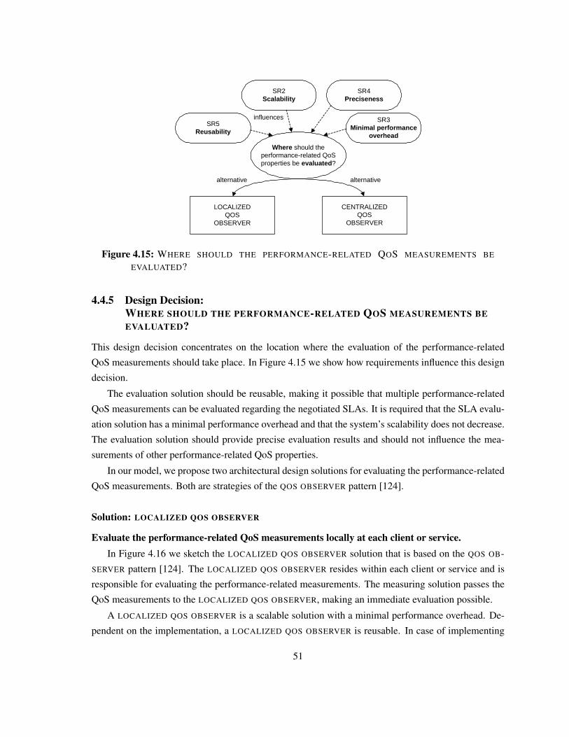
SR3Minimal performance
overhead
Where should the performance-related QoS properties be evaluated?
SR5Reusability
SR2Scalability
LOCALIZED QOS
OBSERVER
CENTRALIZED QOS
OBSERVER
alternative alternative
influences
SR4Preciseness
Figure 4.15: WHERE SHOULD THE PERFORMANCE-RELATED QOS MEASUREMENTS BE
EVALUATED?
4.4.5 Design Decision:WHERE SHOULD THE PERFORMANCE-RELATED QOS MEASUREMENTS BEEVALUATED?
This design decision concentrates on the location where the evaluation of the performance-related
QoS measurements should take place. In Figure 4.15 we show how requirements influence this design
decision.
The evaluation solution should be reusable, making it possible that multiple performance-related
QoS measurements can be evaluated regarding the negotiated SLAs. It is required that the SLA evalu-
ation solution has a minimal performance overhead and that the system’s scalability does not decrease.
The evaluation solution should provide precise evaluation results and should not influence the mea-
surements of other performance-related QoS properties.
In our model, we propose two architectural design solutions for evaluating the performance-related
QoS measurements. Both are strategies of the QOS OBSERVER pattern [124].
Solution: LOCALIZED QOS OBSERVER
Evaluate the performance-related QoS measurements locally at each client or service.In Figure 4.16 we sketch the LOCALIZED QOS OBSERVER solution that is based on the QOS OB-
SERVER pattern [124]. The LOCALIZED QOS OBSERVER resides within each client or service and is
responsible for evaluating the performance-related measurements. The measuring solution passes the
QoS measurements to the LOCALIZED QOS OBSERVER, making an immediate evaluation possible.
A LOCALIZED QOS OBSERVER is a scalable solution with a minimal performance overhead. De-
pendent on the implementation, a LOCALIZED QOS OBSERVER is reusable. In case of implementing
51
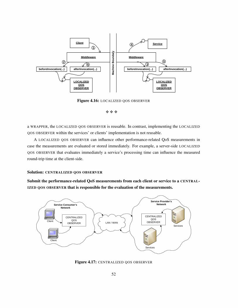
Client
Middleware
Mac
hin
e B
ou
nd
ary
afterInvocation(...)
LOCALIZEDQOS
OBSERVER
Middleware
beforeInvocation(...) afterInvocation(...)
35
17 Service4
beforeInvocation(...)
2
LOCALIZED QOS
OBSERVER
6
Figure 4.16: LOCALIZED QOS OBSERVER
�� �
a WRAPPER, the LOCALIZED QOS OBSERVER is reusable. In contrast, implementing the LOCALIZED
QOS OBSERVER within the services’ or clients’ implementation is not reusable.
A LOCALIZED QOS OBSERVER can influence other performance-related QoS measurements in
case the measurements are evaluated or stored immediately. For example, a server-side LOCALIZED
QOS OBSERVER that evaluates immediately a service’s processing time can influence the measured
round-trip time at the client-side.
Solution: CENTRALIZED QOS OBSERVER
Submit the performance-related QoS measurements from each client or service to a CENTRAL-IZED QOS OBSERVER that is responsible for the evaluation of the measurements.
Client
Client
CENTRALIZED QOS
OBSERVER
CENTRALIZEDQOS
OBSERVER
Services
Services
Service Consumer’s Network
LAN / WAN
Service Provider’s Network
Figure 4.17: CENTRALIZED QOS OBSERVER
52
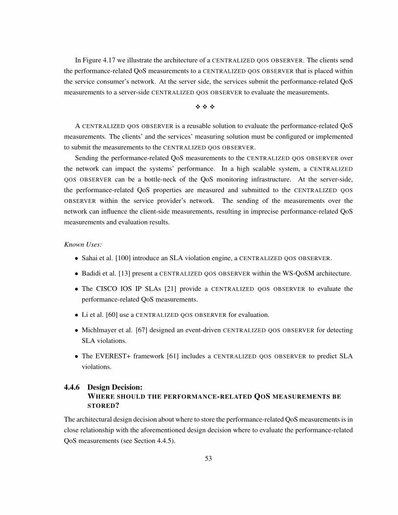
In Figure 4.17 we illustrate the architecture of a CENTRALIZED QOS OBSERVER. The clients send
the performance-related QoS measurements to a CENTRALIZED QOS OBSERVER that is placed within
the service consumer’s network. At the server side, the services submit the performance-related QoS
measurements to a server-side CENTRALIZED QOS OBSERVER to evaluate the measurements.
�� �
A CENTRALIZED QOS OBSERVER is a reusable solution to evaluate the performance-related QoS
measurements. The clients’ and the services’ measuring solution must be configured or implemented
to submit the measurements to the CENTRALIZED QOS OBSERVER.
Sending the performance-related QoS measurements to the CENTRALIZED QOS OBSERVER over
the network can impact the systems’ performance. In a high scalable system, a CENTRALIZED
QOS OBSERVER can be a bottle-neck of the QoS monitoring infrastructure. At the server-side,
the performance-related QoS properties are measured and submitted to the CENTRALIZED QOS
OBSERVER within the service provider’s network. The sending of the measurements over the
network can influence the client-side measurements, resulting in imprecise performance-related QoS
measurements and evaluation results.
Known Uses:
• Sahai et al. [100] introduce an SLA violation engine, a CENTRALIZED QOS OBSERVER.
• Badidi et al. [13] present a CENTRALIZED QOS OBSERVER within the WS-QoSM architecture.
• The CISCO IOS IP SLAs [21] provide a CENTRALIZED QOS OBSERVER to evaluate the
performance-related QoS measurements.
• Li et al. [60] use a CENTRALIZED QOS OBSERVER for evaluation.
• Michlmayer et al. [67] designed an event-driven CENTRALIZED QOS OBSERVER for detecting
SLA violations.
• The EVEREST+ framework [61] includes a CENTRALIZED QOS OBSERVER to predict SLA
violations.
4.4.6 Design Decision:WHERE SHOULD THE PERFORMANCE-RELATED QOS MEASUREMENTS BESTORED?
The architectural design decision about where to store the performance-related QoS measurements is in
close relationship with the aforementioned design decision where to evaluate the performance-related
QoS measurements (see Section 4.4.5).
53
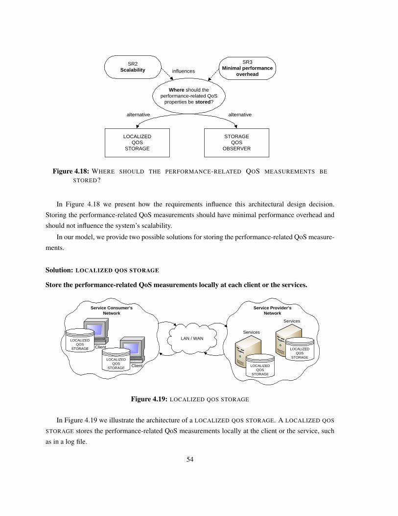
SR3Minimal performance
overhead
Where should the performance-related QoS
properties be stored?
SR2Scalability
LOCALIZED QOS
STORAGE
STORAGE QOS
OBSERVER
alternative alternative
influences
Figure 4.18: WHERE SHOULD THE PERFORMANCE-RELATED QOS MEASUREMENTS BE
STORED?
In Figure 4.18 we present how the requirements influence this architectural design decision.
Storing the performance-related QoS measurements should have minimal performance overhead and
should not influence the system’s scalability.
In our model, we provide two possible solutions for storing the performance-related QoS measure-
ments.
Solution: LOCALIZED QOS STORAGE
Store the performance-related QoS measurements locally at each client or the services.
LAN / WAN
Client
Client
LOCALIZED QOS
STORAGE
Service Consumer’s Network
Service Provider’s Network
Services
Services
LOCALIZED QOS
STORAGELOCALIZED
QOS STORAGE
LOCALIZED QOS
STORAGE
Figure 4.19: LOCALIZED QOS STORAGE
In Figure 4.19 we illustrate the architecture of a LOCALIZED QOS STORAGE. A LOCALIZED QOS
STORAGE stores the performance-related QoS measurements locally at the client or the service, such
as in a log file.
54
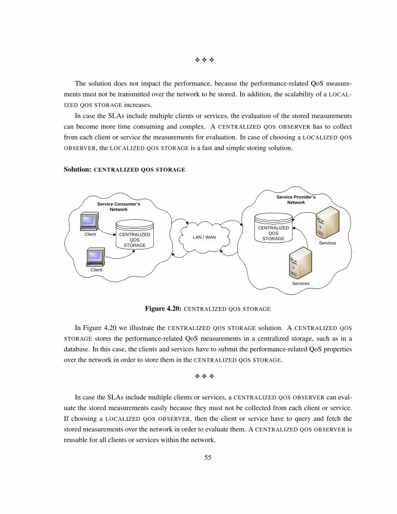
�� �
The solution does not impact the performance, because the performance-related QoS measure-
ments must not be transmitted over the network to be stored. In addition, the scalability of a LOCAL-
IZED QOS STORAGE increases.
In case the SLAs include multiple clients or services, the evaluation of the stored measurements
can become more time consuming and complex. A CENTRALIZED QOS OBSERVER has to collect
from each client or service the measurements for evaluation. In case of choosing a LOCALIZED QOS
OBSERVER, the LOCALIZED QOS STORAGE is a fast and simple storing solution.
Solution: CENTRALIZED QOS STORAGE
Client
Client
Services
Services
Service Consumer’s Network
LAN / WAN
Service Provider’s Network
CENTRALIZED QOS
STORAGE
CENTRALIZED QOS
STORAGE
Figure 4.20: CENTRALIZED QOS STORAGE
In Figure 4.20 we illustrate the CENTRALIZED QOS STORAGE solution. A CENTRALIZED QOS
STORAGE stores the performance-related QoS measurements in a centralized storage, such as in a
database. In this case, the clients and services have to submit the performance-related QoS properties
over the network in order to store them in the CENTRALIZED QOS STORAGE.
�� �
In case the SLAs include multiple clients or services, a CENTRALIZED QOS OBSERVER can eval-
uate the stored measurements easily because they must not be collected from each client or service.
If choosing a LOCALIZED QOS OBSERVER, then the client or service have to query and fetch the
stored measurements over the network in order to evaluate them. A CENTRALIZED QOS OBSERVER is
reusable for all clients or services within the network.
55
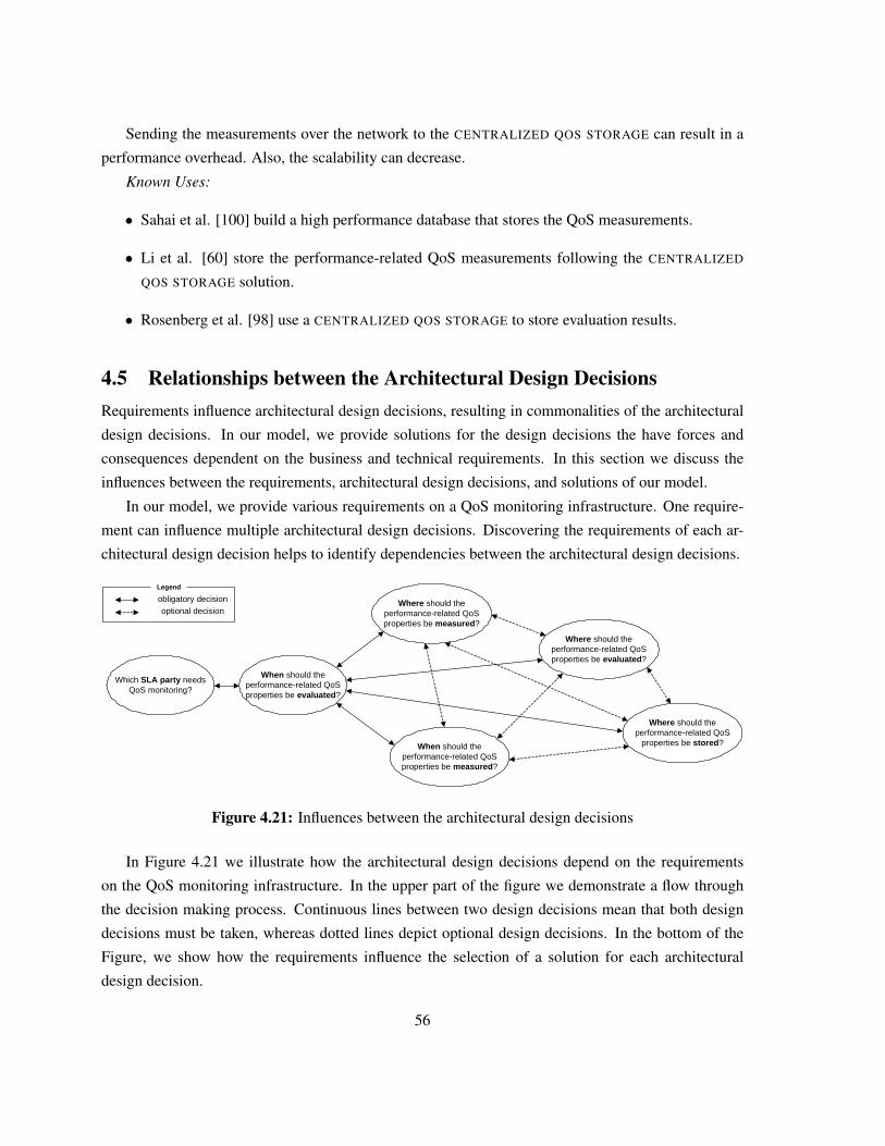
Sending the measurements over the network to the CENTRALIZED QOS STORAGE can result in a
performance overhead. Also, the scalability can decrease.
Known Uses:
• Sahai et al. [100] build a high performance database that stores the QoS measurements.
• Li et al. [60] store the performance-related QoS measurements following the CENTRALIZED
QOS STORAGE solution.
• Rosenberg et al. [98] use a CENTRALIZED QOS STORAGE to store evaluation results.
4.5 Relationships between the Architectural Design DecisionsRequirements influence architectural design decisions, resulting in commonalities of the architectural
design decisions. In our model, we provide solutions for the design decisions the have forces and
consequences dependent on the business and technical requirements. In this section we discuss the
influences between the requirements, architectural design decisions, and solutions of our model.
In our model, we provide various requirements on a QoS monitoring infrastructure. One require-
ment can influence multiple architectural design decisions. Discovering the requirements of each ar-
chitectural design decision helps to identify dependencies between the architectural design decisions.
Which SLA party needs QoS monitoring?
Where should the performance-related QoS properties be measured?
When should the performance-related QoS properties be evaluated?
Where should the performance-related QoS properties be evaluated?
Where should the performance-related QoS
properties be stored?
Legend
obligatory decisionoptional decision
When should the performance-related QoS properties be measured?
Figure 4.21: Influences between the architectural design decisions
In Figure 4.21 we illustrate how the architectural design decisions depend on the requirements
on the QoS monitoring infrastructure. In the upper part of the figure we demonstrate a flow through
the decision making process. Continuous lines between two design decisions mean that both design
decisions must be taken, whereas dotted lines depict optional design decisions. In the bottom of the
Figure, we show how the requirements influence the selection of a solution for each architectural
design decision.
56
First, a design solution for the design decision WHICH SLA PARTY REQUIRES QOS MONITOR-
ING? must be taken. Depend on the requirements (providing or consuming services), a service provider
or a service consumer wants a QoS monitoring infrastructure, or a combined QoS monitoring solution
is required. After the designer knows the requirements and enters them into our model, our model pro-
poses an appropriate solution. The design decision WHEN SHOULD THE PERFORMANCE-RELATED
QOS PROPERTIES BE EVALUATED? has additional requirements, such as scalability, minimal perfor-
mance overhead, or preciseness. To propose an appropriate solutions, our model needs to know the
requirements.
Our model stores the already entered requirements and proposes solutions automatically. For ex-
ample, if a scalable evaluation solution with a minimal performance overhead is required at any taken
design decision, our model also proposes scalable solutions with a minimal performance overhead for
the subsequent decision. After entering more and more requirements, our architectural design decision
model can propose multiple solutions, making it possible that not every design decision must be taken.
It would be possible to enter all the requirements at the beginning of the decision making process
and that the model proposes the solutions for measuring, storing, and evaluating the performance-
related QoS measurements. We have decided in favour of an interactive decision making process,
entering the requirements iterative during the decision making process. This brings the benefit that the
designers can go some steps back or forward within the decision making process, making it possible
that the model proposes optimal solutions.
4.6 Evaluation of the Model in the Case StudyIn this section we present how we evaluate the presented architectural design decision model in the
scope of the case study (see Chapter 3). We first list the requirements on the case study’s QoS
monitoring infrastructure, followed by the model’s proposed architectural solutions. We have imple-
mented the measuring solutions in the case study and visualize runtime measurements of the services’
performance-related QoS properties.
4.6.1 The Case Study’s QoS Monitoring Requirements
The MVNO provides services to service consumers to stream multimedia content. The service con-
sumers and the MVNO negotiate SLAs regarding the multimedia services’ performance-related QoS
properties. The MVNO as a service provider wants to introduce a QoS monitoring infrastructure,
where the services’ performance quality depends on the performance quality of the third parties’ ser-
vices. As a service provider, the MVNO has to prevent SLA violations in order to avoid financial
consequences and a diminished reputation.
57
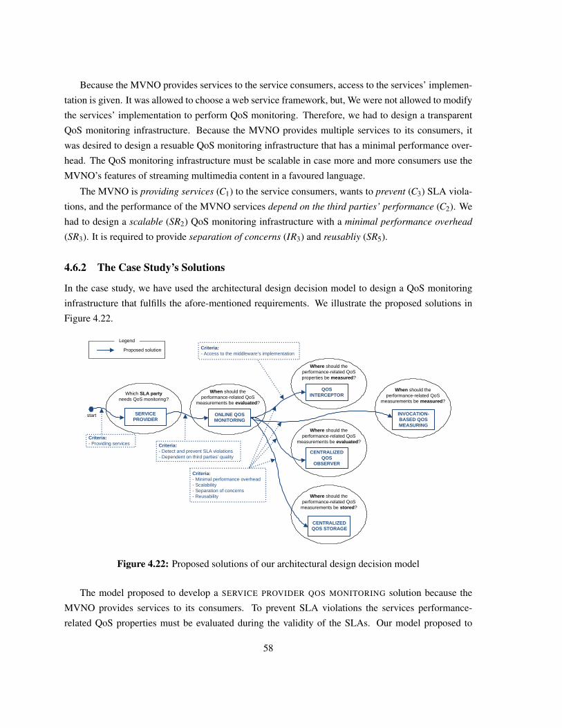
Because the MVNO provides services to the service consumers, access to the services’ implemen-
tation is given. It was allowed to choose a web service framework, but, We were not allowed to modify
the services’ implementation to perform QoS monitoring. Therefore, we had to design a transparent
QoS monitoring infrastructure. Because the MVNO provides multiple services to its consumers, it
was desired to design a resuable QoS monitoring infrastructure that has a minimal performance over-
head. The QoS monitoring infrastructure must be scalable in case more and more consumers use the
MVNO’s features of streaming multimedia content in a favoured language.
The MVNO is providing services (C1) to the service consumers, wants to prevent (C3) SLA viola-
tions, and the performance of the MVNO services depend on the third parties’ performance (C2). We
had to design a scalable (SR2) QoS monitoring infrastructure with a minimal performance overhead
(SR3). It is required to provide separation of concerns (IR3) and reusabliy (SR5).
4.6.2 The Case Study’s Solutions
In the case study, we have used the architectural design decision model to design a QoS monitoring
infrastructure that fulfills the afore-mentioned requirements. We illustrate the proposed solutions in
Figure 4.22.
SERVICE PROVIDER
Which SLA party needs QoS monitoring?
QOS INTERCEPTOR
Where should the performance-related QoS properties be measured?
Criteria:- Access to the middleware’s implementation
ONLINE QOS MONITORING
When should the performance-related QoS
measurements be evaluated?
Criteria:- Detect and prevent SLA violations- Dependent on third parties’ quality
CENTRALIZED QOS
OBSERVER
Where should the performance-related QoS
measurements be evaluated?
Criteria:- Minimal performance overhead- Scalability- Separation of concerns- Reusability
CENTRALIZED QOS STORAGE
Where should the performance-related QoS
measurements be stored?
start
Proposed solution
Legend
Criteria:- Providing services
INVOCATION-BASED QOS MEASURING
When should the performance-related QoS
measurements be measured?
Figure 4.22: Proposed solutions of our architectural design decision model
The model proposed to develop a SERVICE PROVIDER QOS MONITORING solution because the
MVNO provides services to its consumers. To prevent SLA violations the services performance-
related QoS properties must be evaluated during the validity of the SLAs. Our model proposed to
58
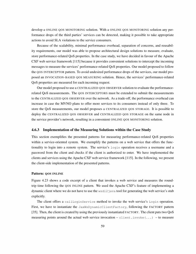
develop a ONLINE QOS MONITORING solution. With a ONLINE QOS MONITORING solution any per-
formance drops of the third parties’ services can be detected, making it possible to take appropriate
actions to avoid SLA violations to the service consumers.
Because of the scalability, minimal performance overhead, separation of concerns, and reusabil-
ity requirements, our model was able to propose architectural design solutions to measure, evaluate,
store performance-related QoS properties. In the case study, we have decided in favour of the Apache
CXF web service framework [115] because it provides convenient solutions to intercept the incoming
messages to measure the services’ performance-related QoS properties. Our model proposed to follow
the QOS INTERCEPTOR pattern. To avoid undesired performance drops of the services, our model pro-
posed an INVOCATION-BASED QOS MEASURING solution. Hence, the services’ performance-related
QoS properties are measured for each incoming request.
Our model proposed to use a CENTRALIZED QOS OBSERVER solution to evaluate the performance-
related QoS measurements. The QOS INTERCEPTORS must be extended to submit the measurements
to the CENTRALIZED QOS OBSERVER over the network. As a trade-off, the performance overhead can
increase in case the MVNO plans to offer more services to its consumers instead of only three. To
store the QoS measurements, our model proposes a CENTRALIZED QOS STORAGE. It is possible to
deploy the CENTRALIZED QOS OBSERVER and CENTRALIZED QOS STORAGE on the same node in
the service provider’s network, resulting in a convenient ONLINE QOS MONITORING solution.
4.6.3 Implementation of the Measuring Solutions within the Case Study
This section exemplifies the presented patterns for measuring performance-related QoS properties
within a service-oriented system. We exemplify the patterns on a web service that offers the func-
tionality to login into a remote system. The service’s login operation receives a username and a
password from the client and checks if the client is authorized to enter. We have implemented the
clients and services using the Apache CXF web service framework [115]. In the following, we present
the client-side implementation of the presented patterns.
Pattern: QOS INLINE
Figure 4.23 shows a code excerpt of a client that invokes a web service and measures the round-
trip time following the QOS INLINE pattern. We used the Apache CXF’s feature of implementing a
dynamic client where we do not have to use the wsdl2java tool for generating the web service’s stub
explicitly.
The client offers a callLoginService method to invoke the web service’s Login operation.
First, we have to instantiate the JaxWsDynamicClientFactory, following the FACTORY pattern
[35]. Then, the client is created by using the previously instantiated FACTORY. The client puts two QoS
measuring points around the actual web service invocation – client.invoke(...) – to measure
59
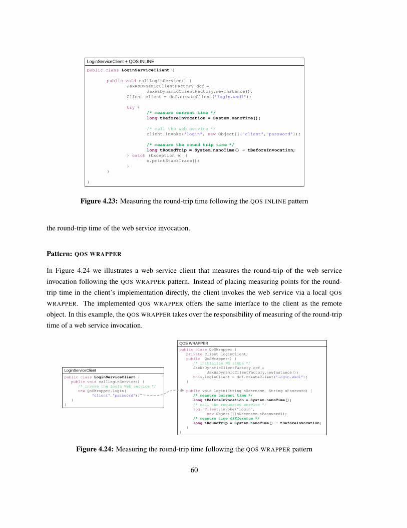
public class LoginServiceClient {
public void callLoginService() {JaxWsDynamicClientFactory dcf =
JaxWsDynamicClientFactory.newInstance();Client client = dcf.createClient("login.wsdl");
try {/* measure current time */long tBeforeInvocation = System.nanoTime();
/* call the web service */client.invoke("login", new Object[]{"client","password"});
/* measure the round trip time */long tRoundTrip = System.nanoTime() - tBeforeInvocation;
} catch (Exception e) {e.printStackTrace();
}}
}
LoginServiceClient + QOS INLINE
Figure 4.23: Measuring the round-trip time following the QOS INLINE pattern
the round-trip time of the web service invocation.
Pattern: QOS WRAPPER
In Figure 4.24 we illustrates a web service client that measures the round-trip of the web service
invocation following the QOS WRAPPER pattern. Instead of placing measuring points for the round-
trip time in the client’s implementation directly, the client invokes the web service via a local QOS
WRAPPER. The implemented QOS WRAPPER offers the same interface to the client as the remote
object. In this example, the QOS WRAPPER takes over the responsibility of measuring of the round-trip
time of a web service invocation.
public class QoSWrapper {private Client loginClient;public QoSWrapper() {
/* initialize WS stubs */JaxWsDynamicClientFactory dcf =
JaxWsDynamicClientFactory.newInstance();this.loginClient = dcf.createClient("login.wsdl");
}
public void login(String sUsername, String sPassword) {/* measure current time */long tBeforeInvocation = System.nanoTime();/* call the requested service */loginClient.invoke("login",
new Object[]{sUsername,sPassword});/* measure time difference */long tRoundTrip = System.nanoTime() - tBeforeInvocation;
}}
public class LoginServiceClient {public void callLoginService() {
/* invoke the Login Web service */new QoSWrapper.login(
"client","password");}
}
LoginServiceClient
QOS WRAPPER
Figure 4.24: Measuring the round-trip time following the QOS WRAPPER pattern
60
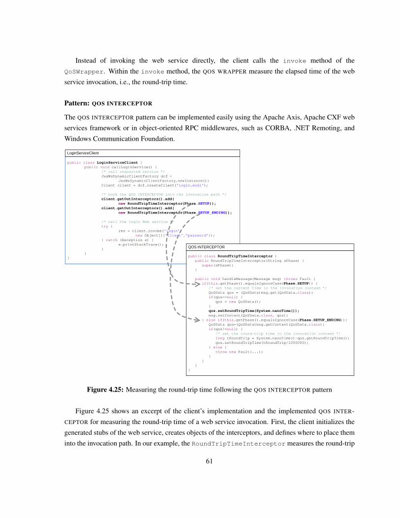
Instead of invoking the web service directly, the client calls the invoke method of the
QoSWrapper. Within the invoke method, the QOS WRAPPER measure the elapsed time of the web
service invocation, i.e., the round-trip time.
Pattern: QOS INTERCEPTOR
The QOS INTERCEPTOR pattern can be implemented easily using the Apache Axis, Apache CXF web
services framework or in object-oriented RPC middlewares, such as CORBA, .NET Remoting, and
Windows Communication Foundation.
public class LoginServiceClient {public void callLoginService() {
/* call requested service */JaxWsDynamicClientFactory dcf =
JaxWsDynamicClientFactory.newInstance();Client client = dcf.createClient("login.wsdl");
/* hook the QOS INTERCEPTOR into the invocation path */client.getOutInterceptors().add(
new RoundTripTimeInterceptor(Phase.SETUP));client.getOutInterceptors().add(
new RoundTripTimeInterceptor(Phase.SETUP_ENDING));
/* call the Login Web service */try {
res = client.invoke("login", new Object[]{"client","password"});
} catch (Exception e) {e.printStackTrace();
}}
}public class RoundTripTimeInterceptor {
public RoundTripTimeInterceptor(String sPhase) {super(sPhase);
}
public void handleMessage(Message msg) throws Fault {if(this.getPhase().equalsIgnoreCase(Phase.SETUP)) {
/* set the current time in the invocation context */QoSData qos = (QoSData)msg.get(QoSData.class);if(qos==null) {
qos = new QoSData();}qos.setRoundTripTime(System.nanoTime());msg.setContent(QoSData.class, qos);
} else if(this.getPhase().equalsIgnoreCase(Phase.SETUP_ENDING)){QoSData qos=(QoSData)msg.getContent(QoSData.class);if(qos!=null) {
/* set the round-trip time in the invocation context */long tRoundTrip = System.nanoTime()-qos.getRoundTripTime();qos.setRoundTripTime(tRoundTrip/1000000);
} else {throw new Fault(...);
}}
}}
LoginServiceClient
QOS INTERCEPTOR
Figure 4.25: Measuring the round-trip time following the QOS INTERCEPTOR pattern
Figure 4.25 shows an excerpt of the client’s implementation and the implemented QOS INTER-
CEPTOR for measuring the round-trip time of a web service invocation. First, the client initializes the
generated stubs of the web service, creates objects of the interceptors, and defines where to place them
into the invocation path. In our example, the RoundTripTimeInterceptor measures the round-trip
61
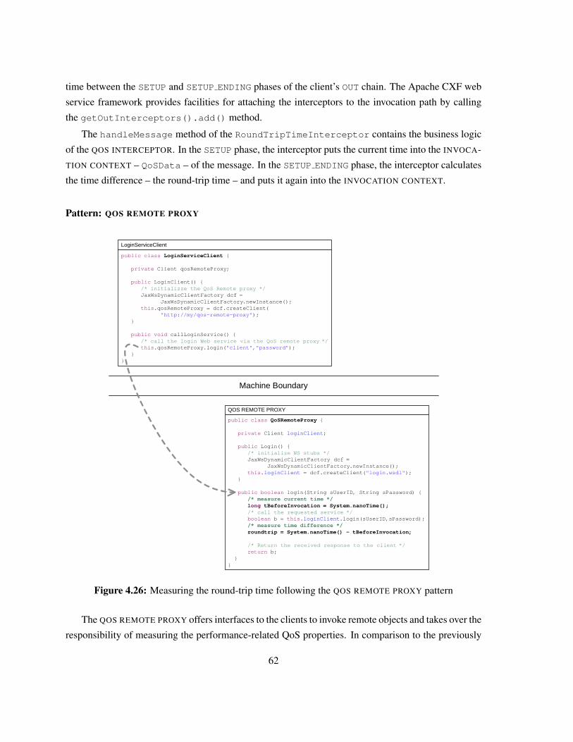
time between the SETUP and SETUP ENDING phases of the client’s OUT chain. The Apache CXF web
service framework provides facilities for attaching the interceptors to the invocation path by calling
the getOutInterceptors().add() method.
The handleMessage method of the RoundTripTimeInterceptor contains the business logic
of the QOS INTERCEPTOR. In the SETUP phase, the interceptor puts the current time into the INVOCA-
TION CONTEXT – QoSData – of the message. In the SETUP ENDING phase, the interceptor calculates
the time difference – the round-trip time – and puts it again into the INVOCATION CONTEXT.
Pattern: QOS REMOTE PROXY
public class LoginServiceClient {
private Client qosRemoteProxy;
public LoginClient() {/* initializze the QoS Remote proxy */JaxWsDynamicClientFactory dcf =
JaxWsDynamicClientFactory.newInstance();this.qosRemoteProxy = dcf.createClient(
"http://my/qos-remote-proxy");}
public void callLoginService() {/* call the login Web service via the QoS remote proxy */this.qosRemoteProxy.login("client","password");
}}
Machine Boundary
public class QoSRemoteProxy {
private Client loginClient;
public Login() {/* initialize WS stubs */JaxWsDynamicClientFactory dcf =
JaxWsDynamicClientFactory.newInstance();this.loginClient = dcf.createClient("login.wsdl");
}
public boolean login(String sUserID, String sPassword) {/* measure current time */long tBeforeInvocation = System.nanoTime();/* call the requested service */boolean b = this.loginClient.login(sUserID,sPassword);/* measure time difference */roundtrip = System.nanoTime() - tBeforeInvocation;
/* Return the received response to the client */return b;
}}
LoginServiceClient
QOS REMOTE PROXY
Figure 4.26: Measuring the round-trip time following the QOS REMOTE PROXY pattern
The QOS REMOTE PROXY offers interfaces to the clients to invoke remote objects and takes over the
responsibility of measuring the performance-related QoS properties. In comparison to the previously
62
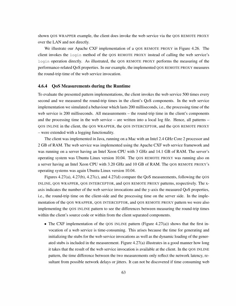
shown QOS WRAPPER example, the client does invoke the web service via the QOS REMOTE PROXY
over the LAN and not directly.
We illustrate our Apache CXF implementation of a QOS REMOTE PROXY in Figure 4.26. The
client invokes the login method of the QOS REMOTE PROXY instead of calling the web service’s
login operation directly. As illustrated, the QOS REMOTE PROXY performs the measuring of the
performance-related QoS properties. In our example, the implemented QOS REMOTE PROXY measures
the round-trip time of the web service invocation.
4.6.4 QoS Measurements during the Runtime
To evaluate the presented pattern implementations, the client invokes the web service 500 times every
second and we measured the round-trip times in the client’s QoS components. In the web service
implementation we simulated a behaviour which lasts 200 milliseconds, i.e., the processing time of the
web service is 200 milliseconds. All measurements – the round-trip time in the client’s components
and the processing time in the web service – are written into a local log file. Hence, all patterns –
QOS INLINE in the client, the QOS WRAPPER, the QOS INTERCEPTOR, and the QOS REMOTE PROXY
– were extended with a logging functionality.
The client was implemented in Java, running on a Mac with an Intel 2.4 GHz Core 2 processor and
2 GB of RAM. The web service was implemented using the Apache CXF web service framework and
was running on a server having an Intel Xeon CPU with 3 GHz and 14.1 GB of RAM. The server’s
operating system was Ubuntu Linux version 10.04. The QOS REMOTE PROXY was running also on
a server having an Intel Xeon CPU with 3.20 GHz and 10 GB of RAM. The QOS REMOTE PROXY’s
operating systems was again Ubuntu Linux version 10.04.
Figures 4.27(a), 4.27(b), 4.27(c), and 4.27(d) compare the QoS measurements, following the QOS
INLINE, QOS WRAPPER, QOS INTERCEPTOR, and QOS REMOTE PROXY patterns, respectively. The x-
axis indicates the number of the web service invocations and the y-axis the measured QoS properties,
i.e., the round-trip time on the client-side and the processing time on the server side. In the imple-
mentation of the QOS WRAPPER, QOS INTERCEPTOR, and QOS REMOTE PROXY pattern we were also
implementing the QOS INLINE pattern to see the differences between measuring the round-trip times
within the client’s source code or within from the client separated components.
• The CXF implementation of the QOS INLINE pattern (Figure 4.27(a)) shows that the first in-
vocation of a web service is time-consuming. This arises because the time for generating and
initializing the stubs for the web service invocations as well as the dynamic loading of the gener-
ated stubs is included in the measurement. Figure 4.27(a) illustrates in a good manner how long
it takes that the result of the web service invocation is available at the client. In the QOS INLINE
pattern, the time difference between the two measurements only reflect the network latency, re-
sultant from possible network delays or jitters. It can not be discovered if time consuming web
63
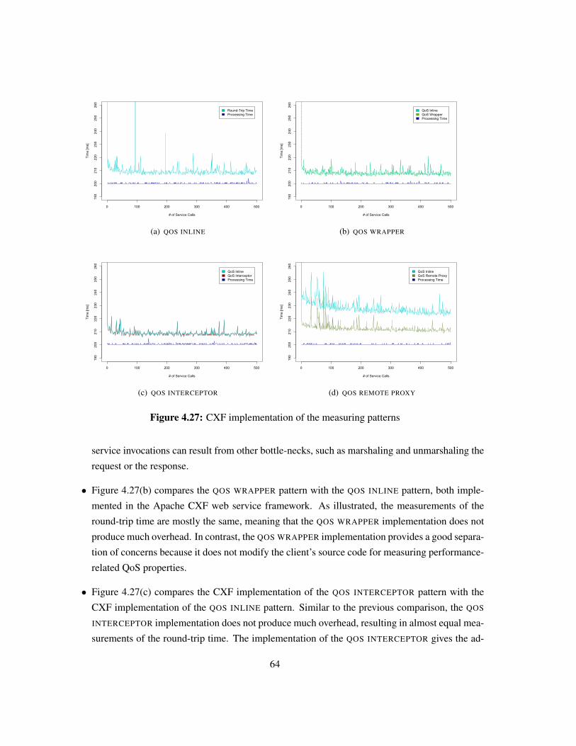
0 100 200 300 400 500
190
200
210
220
230
240
250
260
# of Service Calls
Tim
e [m
s]
Round-Trip TimeProcessing Time
(a) QOS INLINE
0 100 200 300 400 500
190
200
210
220
230
240
250
260
# of Service Calls
Tim
e [m
s]
QoS InlineQoS WrapperProcessing Time
(b) QOS WRAPPER
0 100 200 300 400 500
190
200
210
220
230
240
250
260
# of Service Calls
Tim
e [m
s]
QoS InlineQoS InterceptorProcessing Time
(c) QOS INTERCEPTOR
0 100 200 300 400 500
190
200
210
220
230
240
250
260
# of Service Calls
Tim
e [m
s]
QoS InlineQoS Remote ProxyProcessing Time
(d) QOS REMOTE PROXY
Figure 4.27: CXF implementation of the measuring patterns
service invocations can result from other bottle-necks, such as marshaling and unmarshaling the
request or the response.
• Figure 4.27(b) compares the QOS WRAPPER pattern with the QOS INLINE pattern, both imple-
mented in the Apache CXF web service framework. As illustrated, the measurements of the
round-trip time are mostly the same, meaning that the QOS WRAPPER implementation does not
produce much overhead. In contrast, the QOS WRAPPER implementation provides a good separa-
tion of concerns because it does not modify the client’s source code for measuring performance-
related QoS properties.
• Figure 4.27(c) compares the CXF implementation of the QOS INTERCEPTOR pattern with the
CXF implementation of the QOS INLINE pattern. Similar to the previous comparison, the QOS
INTERCEPTOR implementation does not produce much overhead, resulting in almost equal mea-
surements of the round-trip time. The implementation of the QOS INTERCEPTOR gives the ad-
64
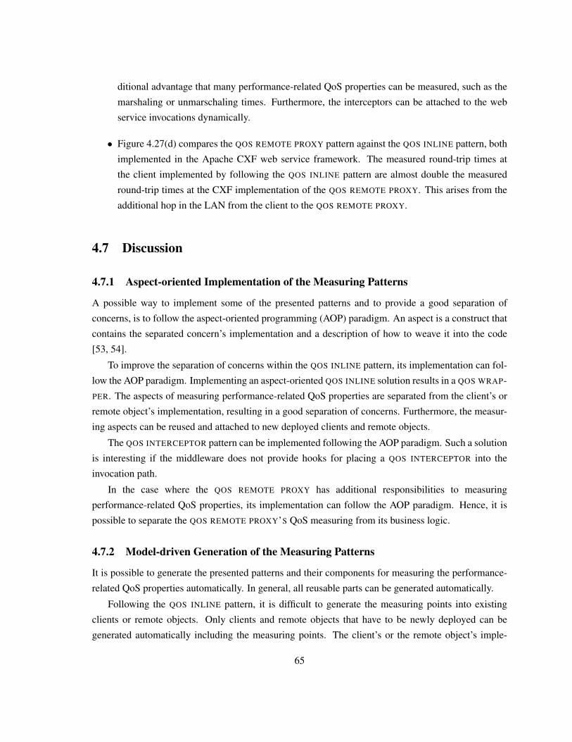
ditional advantage that many performance-related QoS properties can be measured, such as the
marshaling or unmarschaling times. Furthermore, the interceptors can be attached to the web
service invocations dynamically.
• Figure 4.27(d) compares the QOS REMOTE PROXY pattern against the QOS INLINE pattern, both
implemented in the Apache CXF web service framework. The measured round-trip times at
the client implemented by following the QOS INLINE pattern are almost double the measured
round-trip times at the CXF implementation of the QOS REMOTE PROXY. This arises from the
additional hop in the LAN from the client to the QOS REMOTE PROXY.
4.7 Discussion
4.7.1 Aspect-oriented Implementation of the Measuring Patterns
A possible way to implement some of the presented patterns and to provide a good separation of
concerns, is to follow the aspect-oriented programming (AOP) paradigm. An aspect is a construct that
contains the separated concern’s implementation and a description of how to weave it into the code
[53, 54].
To improve the separation of concerns within the QOS INLINE pattern, its implementation can fol-
low the AOP paradigm. Implementing an aspect-oriented QOS INLINE solution results in a QOS WRAP-
PER. The aspects of measuring performance-related QoS properties are separated from the client’s or
remote object’s implementation, resulting in a good separation of concerns. Furthermore, the measur-
ing aspects can be reused and attached to new deployed clients and remote objects.
The QOS INTERCEPTOR pattern can be implemented following the AOP paradigm. Such a solution
is interesting if the middleware does not provide hooks for placing a QOS INTERCEPTOR into the
invocation path.
In the case where the QOS REMOTE PROXY has additional responsibilities to measuring
performance-related QoS properties, its implementation can follow the AOP paradigm. Hence, it is
possible to separate the QOS REMOTE PROXY’S QoS measuring from its business logic.
4.7.2 Model-driven Generation of the Measuring Patterns
It is possible to generate the presented patterns and their components for measuring the performance-
related QoS properties automatically. In general, all reusable parts can be generated automatically.
Following the QOS INLINE pattern, it is difficult to generate the measuring points into existing
clients or remote objects. Only clients and remote objects that have to be newly deployed can be
generated automatically including the measuring points. The client’s or the remote object’s imple-
65
mentation has to be developed manually. Following the AOP paradigm, it is possible to generate the
required aspects for measuring the performance-related QoS properties automatically.
A QOS WRAPPER can be generated automatically and the generic parts of the client’s and remote
object’s implementations for accessing the client or remote object via the QOS WRAPPER.
QOS INTERCEPTORS can be generated and attached to the client’s and remote object’s middleware
automatically for measuring the performance-related QoS properties. Existing clients and remote ob-
jects can be extended easily.
It is possible to generate a QOS REMOTE PROXY automatically. New clients can be generated and
configured to access the remote objects only via the generated QOS REMOTE PROXY. Also, it is pos-
sible to generate the remote objects automatically and to configure them that they are only accessible
via a QOS REMOTE PROXY. Existing clients and services must be re-configured or re-deployed.
4.8 SummaryIn this chapter we have presented an architectural design decisions model, guiding designers through
the decision making process of a QoS monitoring infrastructure. In the scope of our work, a QoS mon-
itoring infrastructure has to measure, evaluate, and store performance-related QoS properties, agreed
within SLAs. Reporting of the evaluation and eventual SLA violations is however out of scope.
The architectural design decision model covers design decisions, requirements, and proposes de-
sign solutions. We have discovered the requirements and architectural design decisions in a thorough
literature review and within the scope of the case study (see Chapter 3). The model’s architectural
design solutions extend and utilized well-established design patterns, such as the WRAPPER pattern
[35], the INTERCEPTOR pattern, or the QOS OBSERVER pattern [124].
We have evaluated the model in the scope of the case study and presented the proposed solutions
for the case study. We have also implemented the presented patterns for measuring the performance-
related QoS properties in the case study and demonstrated some runtime QoS measurements. A dis-
cussion on using AOP or MDD to enhance the development of the QoS monitoring infrastructure’s
components is given. The models architectural design decisions, requirements, and solutions are sum-
marized in the thesis’ Appendix A.
66
Chapter 5
Supporting the Stakeholders to SpecifyQoS Compliance Concerns
Nowadays, many languages for specifying the performance-related QoS compliance concerns of
distributed and service-oriented system exist, such as described in [40, 48, 56]. But, to the best of
our knowledge, no language exists to specify the performance-related QoS agreements supporting
technical and non-technical stakeholders. In this chapter, we present our approach of utilizing
Domain-specific Language (DSL) that are developed following the Model-driven Development (MDD)
paradigm. Our approach tailors the model-driven DSLs for the stakeholders, dependent on their
domain and technical knowledge.
This chapter is organized as follows: Section 5.1 explains some needed background information
for a better understanding of our approach. In Section 5.2 we illustrate our approach to support the
differently skilled stakeholders. Section 5.3 presents a performed explorative study of our approach
to develop model-driven DSLs for Service-oriented Architectures (SOAs). Then, in Section 5.4 we
present a model-driven DSL that we have developed within the scope of the industrial case study
presented in Chapter 3. In Section 5.5 we explain developed model-driven DSLs that also follow our
approach. Section 5.6 lists some lessons that we have learned during the development of the various
model-driven DSLs. We list related works in 5.7. Section 5.8 summarizes and concludes this chapter.
5.1 Background
5.1.1 Model-driven Development (MDD)
MDD is a paradigm for developing software by providing a separation of the software’s functionality
and the software’s underlying technology. Models are used for designing systems, understanding them
better, specifying required functionalities, and creating documentation. Usual development approaches
67
separate the models and the code by using, for example, models as documentation of the code. In MDD,
the models’ stakeholder do not see the source code because models replace the source code. Models
are transformed by using code generators or transformation rules to executable source code. Then,
the generated source code can be debugged, tested, and extended by manually written code by the
programmers [50, 102].
To get a better understanding of MDD, we first explain the MDD’s terminology. A Domain, also
refered to application domain, is a bounded region of interests or knowledge, such as banking, health-
care, or telecommunication. An Architecture describes the artifacts of a system and the rules for the
interaction between the artifacts using some connectors. A Model describes or specifies the domain’s
elements and its relationships. A model is an abstract representation of structure, functionality, and
behaviour of a system. A model’s Semantics describe the elements of a model and its meanings. A
Model Transformation maps a model to another model of the same system or transforms the model into
executable source code. A Modeling language is an interface for the models’ stakeholders, making it
possible that the stakeholders can specify model instances.
Mainly, MDD focuses on [108]:
• Increasing the speed of development
Executable code can be achieved in a fast way by applying model transformations
• Better maintenance of software
Bugs within the generated code can be abolished by simply changing the transformation rules.
This results in a better avoidance of redundancy and improved maintenance facilities.
• Higher degree of reusing software
Once defined architectures, modeling languages and transformations can be reused for the de-
velopment of other software systems.
• Better manageability of complexity by abstraction
The efforts of programming should be eliminated through modeling languages.
• Raising the level of abstraction
Because models describe systems and their required functionalites, the technological details are
hidden from the models’ stakeholders. The code generators transform the models into executable
source code.
• Interoperability and portability
To raise the level of abstraction, MDD should be domain-specific. The modeling language and the
model transformations need to be domain-specific [50]. In the following we describe the artifacts of
68
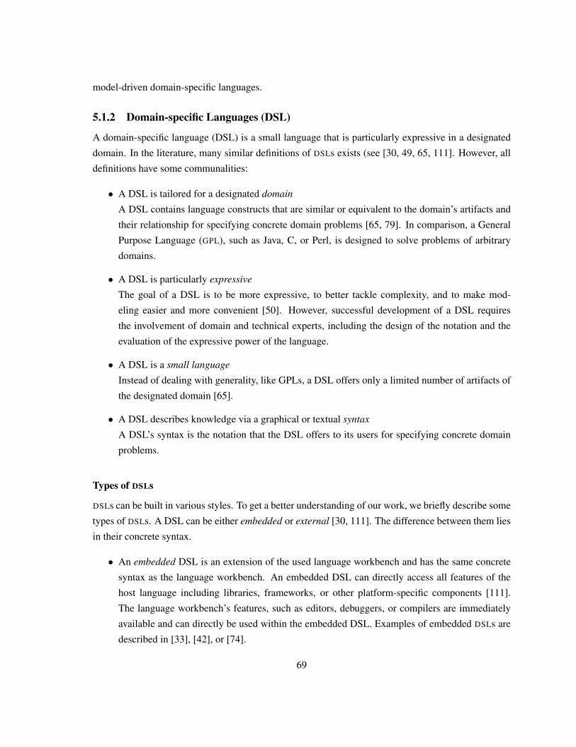
model-driven domain-specific languages.
5.1.2 Domain-specific Languages (DSL)
A domain-specific language (DSL) is a small language that is particularly expressive in a designated
domain. In the literature, many similar definitions of DSLs exists (see [30, 49, 65, 111]. However, all
definitions have some communalities:
• A DSL is tailored for a designated domain
A DSL contains language constructs that are similar or equivalent to the domain’s artifacts and
their relationship for specifying concrete domain problems [65, 79]. In comparison, a General
Purpose Language (GPL), such as Java, C, or Perl, is designed to solve problems of arbitrary
domains.
• A DSL is particularly expressive
The goal of a DSL is to be more expressive, to better tackle complexity, and to make mod-
eling easier and more convenient [50]. However, successful development of a DSL requires
the involvement of domain and technical experts, including the design of the notation and the
evaluation of the expressive power of the language.
• A DSL is a small language
Instead of dealing with generality, like GPLs, a DSL offers only a limited number of artifacts of
the designated domain [65].
• A DSL describes knowledge via a graphical or textual syntax
A DSL’s syntax is the notation that the DSL offers to its users for specifying concrete domain
problems.
Types of DSLs
DSLs can be built in various styles. To get a better understanding of our work, we briefly describe some
types of DSLs. A DSL can be either embedded or external [30, 111]. The difference between them lies
in their concrete syntax.
• An embedded DSL is an extension of the used language workbench and has the same concrete
syntax as the language workbench. An embedded DSL can directly access all features of the
host language including libraries, frameworks, or other platform-specific components [111].
The language workbench’s features, such as editors, debuggers, or compilers are immediately
available and can directly be used within the embedded DSL. Examples of embedded DSLs are
described in [33], [42], or [74].
69
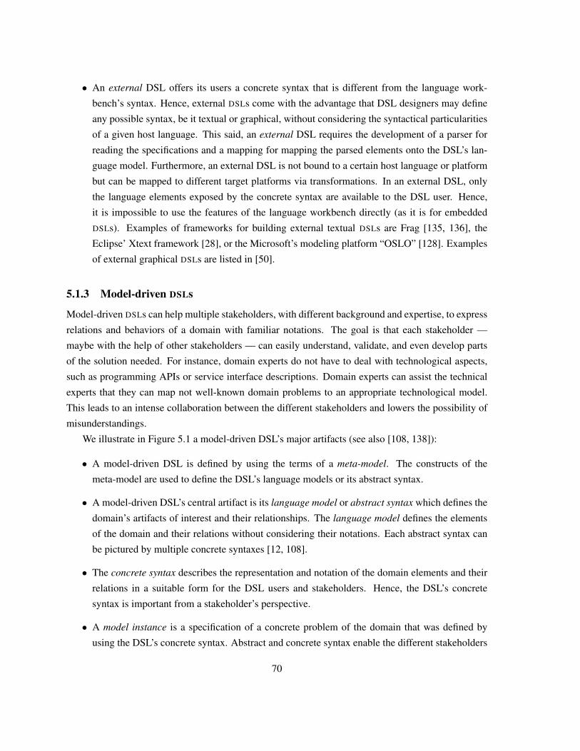
• An external DSL offers its users a concrete syntax that is different from the language work-
bench’s syntax. Hence, external DSLs come with the advantage that DSL designers may define
any possible syntax, be it textual or graphical, without considering the syntactical particularities
of a given host language. This said, an external DSL requires the development of a parser for
reading the specifications and a mapping for mapping the parsed elements onto the DSL’s lan-
guage model. Furthermore, an external DSL is not bound to a certain host language or platform
but can be mapped to different target platforms via transformations. In an external DSL, only
the language elements exposed by the concrete syntax are available to the DSL user. Hence,
it is impossible to use the features of the language workbench directly (as it is for embedded
DSLs). Examples of frameworks for building external textual DSLs are Frag [135, 136], the
Eclipse’ Xtext framework [28], or the Microsoft’s modeling platform “OSLO” [128]. Examples
of external graphical DSLs are listed in [50].
5.1.3 Model-driven DSLs
Model-driven DSLs can help multiple stakeholders, with different background and expertise, to express
relations and behaviors of a domain with familiar notations. The goal is that each stakeholder —
maybe with the help of other stakeholders — can easily understand, validate, and even develop parts
of the solution needed. For instance, domain experts do not have to deal with technological aspects,
such as programming APIs or service interface descriptions. Domain experts can assist the technical
experts that they can map not well-known domain problems to an appropriate technological model.
This leads to an intense collaboration between the different stakeholders and lowers the possibility of
misunderstandings.
We illustrate in Figure 5.1 a model-driven DSL’s major artifacts (see also [108, 138]):
• A model-driven DSL is defined by using the terms of a meta-model. The constructs of the
meta-model are used to define the DSL’s language models or its abstract syntax.
• A model-driven DSL’s central artifact is its language model or abstract syntax which defines the
domain’s artifacts of interest and their relationships. The language model defines the elements
of the domain and their relations without considering their notations. Each abstract syntax can
be pictured by multiple concrete syntaxes [12, 108].
• The concrete syntax describes the representation and notation of the domain elements and their
relations in a suitable form for the DSL users and stakeholders. Hence, the DSL’s concrete
syntax is important from a stakeholder’s perspective.
• A model instance is a specification of a concrete problem of the domain that was defined by
using the DSL’s concrete syntax. Abstract and concrete syntax enable the different stakeholders
70
Model Instance
Concrete Syntax
Language Model(Abstract Syntax)
Meta-Modelbased on
defined in
based on
*
Transformation
1
*
1
represents
1
*
* 1
use defined using
**
Schematic Recurring Code
produces
*1..*
1..* 1..*
Individual Codeuses
* *
Figure 5.1: A model-driven DSL’s major artifacts
to define model instances with a familiar notation. Also, we can say that a model instance is a
DSL program.
• The ultimate goal of the transformations, which are defined on the model, is to transform the
model instances into executable languages, such as programming languages or web service
frameworks. There are different kinds of transformations, such as model-to-model or model-
to-code transformations. In addition, there are different ways to specify transformations, such
as transformation rules, imperative transformations, or template-based transformations, exist.
The transformations generate all those parts of the (executable) code which are schematic and
recurring, and hence can be automated.
5.2 Our Model-driven DSL Approach to Support the StakeholdersTo offer expressive and convenient languages for the different stakeholders, our approach provides a
horizontal separation of model-driven DSLs into multiple sub-languages, where each sub-language is
tailored to the appropriate stakeholders. We illustrate our approach of separating model-driven DSLs –
from now on just called DSL – into two sub-languages at different levels of abstraction in Figure 5.2.
In this approach, we distinguish between high-level and low-level artifacts. Due to the diverse
backgrounds and knowledges of the different stakeholders, it makes sense to present to each group
of stakeholders only the models they need for their work, and omit other details, as proposed in [91].
We separated the artifacts into high- and low-level ones to achieve better understandability for the
different stakeholders. High-level artifacts are relevant for non-technical stakeholders and represent
71
High-level DSLSyntax
High-Level Language
Model
Low-level DSLSyntax
extends
Low-Level Language
Model
extends
represents
represents
*
*
1
1
High-Level Model
Instance
Low-LevelModel
Instance
extends
instanceOf *
*
1
1 instanceOf
defined in
1 *
defined in
1 *
Domain Expert
Technical Expert
Figure 5.2: Separating a model-driven DSL into high- and low-level DSLs
the domain’s artifacts that are of interest as well as their the domain’s artifacts relationships. Low-
level technical artifacts are relevant for technical stakeholders and represent the technology’s artifacts
that are needed for mapping the high-level artifacts onto the technological ones.
We design and tailor a high-level DSLs to support the domain experts, making it possible for
domain experts to work with a language in which the domain artifacts are depicted in or close to the
domain’s artifacts. For instance, in the banking domain terms like account, bond, fund, or stock order
are used in the high-level DSL.
Technical experts can express the additionally needed technical aspects with a low-level DSL
where the terminologies and notations are close or equal to the artifacts of the underlying technol-
ogy or platform. Technical experts utilize the low-level DSL to specify the technical details that are
missing in the high-level DSLs. These details are needed by the model-driven code generator to turn
the model instances, expressed in the DSLs, into an executable code (see Figure 5.1). For instance, in
the process-driven SOA domain, relevant low-level concerns are service, service deployment, process
variable, or database connection.
High-level and low-level DSLs represent appropriate language models. Low-level language models
extend the high-level language models or vice versa, e.g., by using inheritance. Language models can
have multiple DSL syntaxes. In our approach, we base the syntax of the high-level and low-level
languages on its language models. Furthermore, language models can have multiple language model
instances, which are defined using the DSL’s syntax. High-level DSL syntaxes, language models, and
model instances extend low-level DSL syntaxes, language models, and model instances respectively.
The DSLs are used to define model instances of the high-level and low-level language models. Each
model instance represents concrete solutions of a particular problem of the domain. After the definition
72
of high-level and low-level model instances, schematic recurring code can be generated automatically,
as illustrated in Figure 5.1.
Following our approach does not mean that only a separation into two levels, such as high-level
and low-level, is possible. It is also possible to provide multiple different levels of abstractions where
each level of abstraction is tailored to the designated stakeholders. The number of different levels
of abstractions depends on the problem domain, as well as on the number of the different type of
stakeholders.
5.3 An Explorative Study: DSLs for SOAsMany DSLs for specific aspects of SOAs have been designed (see for instance [37, 64]). But, to the
best of our knowledge, no study provides evidence for specific aspects and claims associated to SOA
DSLs. Hence, this research field is clearly an explorative nature. For this reason, we have decided to
use an explorative, qualitative research method to get insights and evidences in this study, following a
similar approach to constructing a grounded theory [110].
In our case, the initial analysis has been performed by developing some DSLs in various projects
(we also considered those reported in [36, 134]), as well as a thorough literature review and discussions
with experienced and novice DSL developers. There are many ways to implement a DSL, such as using
MDD or extending a dynamic language (see [31] for details). We have decided in favor of model-driven
DSLs because, in our experience, the explicit support for language models is useful for representing
the various domain concerns to the stakeholders, especially of a process-driven SOA.
5.3.1 The Study’s Claims of Investigation
After the initial investigation phase, we decided to conduct an in-depth study of specific claims as-
sociated to model-driven DSLs using a controlled series of three prototyping experiments. In each
experiment, we have developed a number of MDD-based DSL prototypes, as well as a model-driven
infrastructure to generate a running process-driven SOA from the models expressed in the DSLs. The
experiments deal with process-driven SOAs, as well as an extension of process-driven SOAs with Web
UIs. In our experiments we focused on the design decisions made and on the design trade-offs that
have been considered. At first we will to describe the experiments in detail and afterwards the main
results. In the scope of this study, we tried to provide evidence or counter-evidence for the claims.
All three prototyping experiments have been conducted in a project that has run for twelve months
and included four developers. Two developers worked with approximately 50% of their time for
the full project duration, one contributed 20% of his time for the full duration, and one contributed
approximately 50% of his time for five months. The project not only included DSL development, but
also development of other artifacts, such as models and transformations, needed to obtain a running
73
prototype solution.
Claim I
Developing model-driven DSLs follows a systematic development approach [37, 107].
Claim II
A process-driven SOA encompasses multiple concerns, such as orchestration of business processes,
information in processes, collaboration between processes and services, data, transactions, human-
computer interaction, service deployment, and many more. To express these concerns, it is claimed
that using model-driven DSLs reduces the complexity of the overall system, compared to a system
developed without DSL and MDD support [5].
Claim III
Using model-driven DSLs for expressing SOA concerns enables developers and other stakeholders to
work at a higher level of abstraction compared to using technical interfaces, such as programming
APIs, executable process models expressed in BPEL code, or service interface descriptions such as
WSDL (see [123]). Hence, model-driven DSLs can be tailored by providing constructs that are com-
mon to the domain the different stakeholders work in [8]. This enhances the readability and under-
standability of each DSL for the different stakeholders. Nevertheless, the different levels of abstrac-
tions imply the definition of integration points or transformation rules between the constructs of the
DSLs from the different layers.
Claim IV
Due to the different levels of abstraction, it is claimed that language models should provide clear
extension points for integrating new concerns [109].
5.3.2 Study Details
In our study, we performed three controlled experiments, in which a number of model-driven DSL
prototypes have been developed:
• Basic concernsIn this experiment we realized a number of DSLs for expressing a process-driven SOA’s basic
concerns, such as flow, information, and collaboration.
• Extensional concernsThis experiment focused on extending process-driven SOAs with additional DSLs for supporting
long-running transactions and human participation.
74
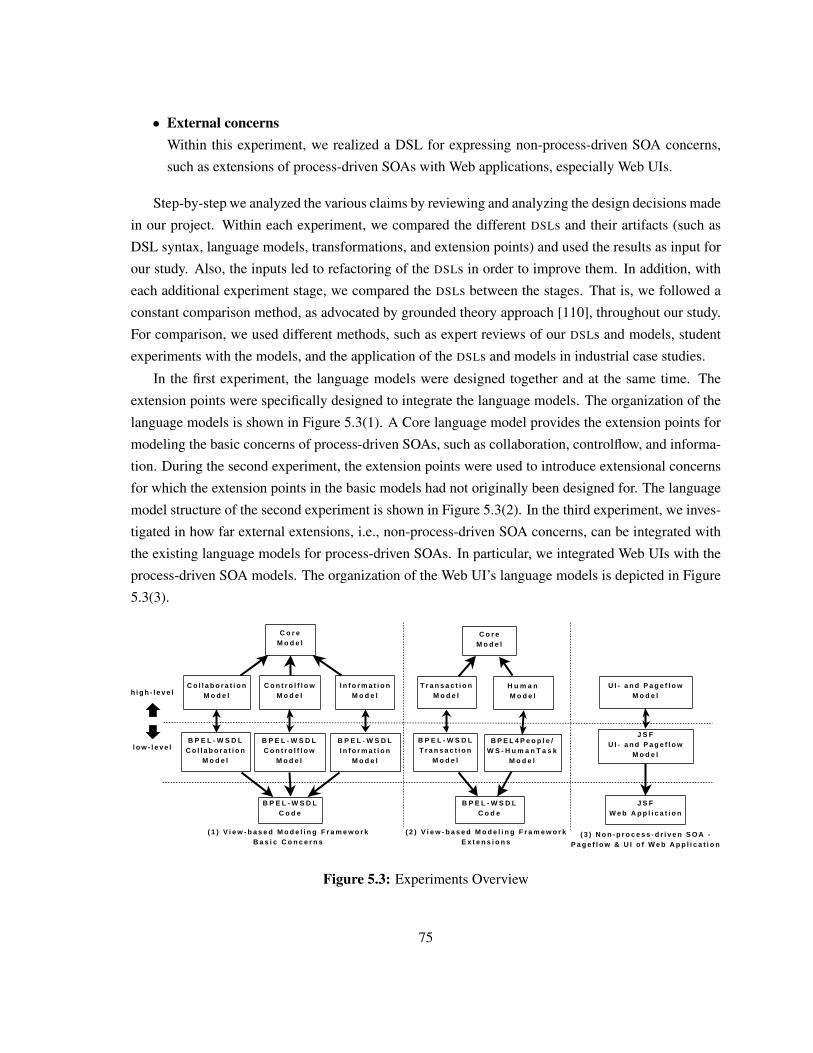
• External concernsWithin this experiment, we realized a DSL for expressing non-process-driven SOA concerns,
such as extensions of process-driven SOAs with Web applications, especially Web UIs.
Step-by-step we analyzed the various claims by reviewing and analyzing the design decisions made
in our project. Within each experiment, we compared the different DSLs and their artifacts (such as
DSL syntax, language models, transformations, and extension points) and used the results as input for
our study. Also, the inputs led to refactoring of the DSLs in order to improve them. In addition, with
each additional experiment stage, we compared the DSLs between the stages. That is, we followed a
constant comparison method, as advocated by grounded theory approach [110], throughout our study.
For comparison, we used different methods, such as expert reviews of our DSLs and models, student
experiments with the models, and the application of the DSLs and models in industrial case studies.
In the first experiment, the language models were designed together and at the same time. The
extension points were specifically designed to integrate the language models. The organization of the
language models is shown in Figure 5.3(1). A Core language model provides the extension points for
modeling the basic concerns of process-driven SOAs, such as collaboration, controlflow, and informa-
tion. During the second experiment, the extension points were used to introduce extensional concerns
for which the extension points in the basic models had not originally been designed for. The language
model structure of the second experiment is shown in Figure 5.3(2). In the third experiment, we inves-
tigated in how far external extensions, i.e., non-process-driven SOA concerns, can be integrated with
the existing language models for process-driven SOAs. In particular, we integrated Web UIs with the
process-driven SOA models. The organization of the Web UI’s language models is depicted in Figure
5.3(3).
C o r eM o d e l
C o l l a b o r a t i o nM o d e l
C o n t r o l f l o wM o d e l
I n f o r m a t i o nM o d e l
B P E L - W S D LC o l l a b o r a t i o n
M o d e l
B P E L - W S D LC o n t r o l f l o w
M o d e l
B P E L - W S D LI n f o r m a t i o n
M o d e l
B P E L - W S D LC o d e
h i g h - l e v e l
l o w - l e v e l
( 1 ) V i e w - b a s e d M o d e l i n g F r a m e w o r kB a s i c C o n c e r n s
C o r eM o d e l
T r a n s a c t i o nM o d e l
H u m a nM o d e l
B P E L - W S D LT r a n s a c t i o n
M o d e l
B P E L 4 P e o p l e /W S - H u m a n T a s k
M o d e l
B P E L - W S D LC o d e
( 2 ) V i e w - b a s e d M o d e l i n g F r a m e w o r kE x t e n s i o n s
U I - a n d P a g e f l o wM o d e l
J S FU I - a n d P a g e f l o w
M o d e l
J S FW e b A p p l i c a t i o n
( 3 ) N o n - p r o c e s s - d r i v e n S O A -P a g e f l o w & U I o f W e b A p p l i c a t i o n
Figure 5.3: Experiments Overview
75
Process-driven SOA Basic Concern Language Models
The first experiment concentrates on basic concerns of process-driven SOAs, as well as following our
model-driven DSL approach by providing high- and low-level DSLs for the different stakeholders [8].
The View-based Modeling Framework (VbMF) [121, 122] is a model-driven framework for reducing
the development complexity in process-driven SOAs, as well as for improving the models’ interop-
erability and reusability. It provides multiple language models, high-level and low-level ones, each
responsible for a different concern of process-driven SOAs, such as flow, collaboration, or informa-
tion. We illustrate the connection between the high-level and low-level language models in Figure
5.3(1).
In this experiment, we used a systematic top-down development approach as follows. First, high-
level language models were designed. A central core language model provides extension points for
defining new language models for the appropriate concerns. Furthermore, it provides extension points
for various language models for basic and extensional concerns. The following language models
extend the core language model for modeling basic concerns of process-driven SOAs:
• The controlflow language model offers constructs for modeling controlflows of business pro-
cesses, which consist of many activities and control structures. Activities are process tasks, such
as service invocations or data handling. The execution order of activities is described through
control structures, such as conditional switches.
• To compose the functionality provided by services or other processes, the collaboration lan-
guage model is used. This language model extends the core language model to represent inter-
actions between a business process and its partners.
• The information language model represents the flow of data objects inside the business process.
Furthermore, it provides a representation of message objects traveling back and forth between
the process and the external world.
For each high-level language model, except the core language model, the low-level language mod-
els were designed as an extension of the high-level language models. Both the high-level and low-level
language models are close to the concepts of BPEL and WSDL. Finally, the DSL syntaxes were de-
veloped. The high-level DSL syntaxes are based on the constructs of the high-level language models,
whereas low-level DSL syntaxes are based on the constructs of the low-level language models. Hence,
domain experts can – with the help of technical experts – use the high-level DSLs for modeling domain
concerns, and technical experts can model technical concerns with the low-level DSLs.
76
Process-driven SOA Extensions
In contrast to the first experiment, which analyzed the basic concerns of process-driven SOAs, this
experiment uses the introduced extension points of the core language model for integrating extensional
concerns, such as an process-driven SOA’s transaction and human interaction concerns. The goal of
this experiment is to figure out if a systematic top-down development approach, as used in the first
experiment, can be applied for extensional concerns of process-driven SOAs. We show the structure
of the high- and low-level language models for both experiments in Figure 5.3(2).
To extend VbMF for long-running transactions, transactional concerns were integrated into the
VbMF through a newly defined language model [121, 122]. In the same way as the controlflow,
collaboration, and information language models were created, the first step was to design a high-
level transaction language model which extends the core language model. Afterwards, a low-level
transaction language model was designed which extends the high-level transaction language model.
Like the low-level language models of the first experiment, the low-level transaction language model
is based on BPEL and WSDL concepts too. Finally, the high-level and low-level DSLs’ syntaxes were
developed to support the modeling of transactions, based on the constructs of the appropriate language
model.
A second extension of VbMF is the support of human interactions in process-driven SOA [41].
Again, a high-level human language model was designed which extends the core language model.
Human aspects are assigned to processes and activities. A low-level human language model extends
the high-level human language model, and it is based on concepts of BPEL4People [43] and WS-
HumanTask [1]. Finally, the high- and low-level DSLs’ syntaxes were implemented, based on the
appropriate language models, to support the modeling of human tasks for SOA-based business pro-
cesses.
Non-Process-Driven SOA Extensions: Web User Interfaces
The third experiment followed again a systematic top-down development approach, as adopted in
the first two experiments. The language model hierarchy is depicted in Figure 5.3(3). The goal of this
experiment is to figure out, if the systematic development approach can also be applied to extensions of
process-driven SOAs with non-process-driven SOA concerns. The experiment deals with the modeling
of web UIs for web pages, as well as process-oriented modeling of the pageflow through Java-like
IF-ELSE statements. Web UIs contain the input and output components which are displayed to the
user on the web pages. The pageflow provides the basis for selecting the subsequent web page that
should be displayed to the user, dependent on the current page and the user interactions, such as which
link or button the user presses.
First, the high-level language model is introduced for modeling the pageflow and the UIs of the
Web pages. A low-level language model for modeling the pageflow is introduced which is based on
77
the pageflow definition of the Java Server Faces (JSF) [112] web application technology. The DSLs
were implemented to provide suitable modeling of the pageflow and the UIs. The developed DSLs
provide constructs that are very similar to the language model. In this experiment, there was no need
for a mapping between the constructs of the DSL and the constructs of the language model.
5.3.3 Study Results
The experiments provided some useful insights into design decisions required during the design of
model-driven DSLs for process-driven SOAs:
• There exists a design decision regarding the relation between the DSL’s concrete syntax and the
DSL’s language model
We observed that in all three experiments the relationship between the names used in the DSL
syntaxes and the names of the constructs defined in the language models was a concern. In all
three experiments, we decided that the DSL syntaxes provide constructs that are named equiv-
alently to the constructs in the language model. If the DSL syntax constructs are not named
equivalently to the language model constructs, a more complex mapping between DSL and lan-
guage model constructs is required, which means that extra efforts are required to develop this
mapping. The mapping might also make the relationships between syntax constructs and models
harder to understand. However, with a different naming in models and syntaxes, the syntax and
modeling elements can be tailored more easily.
• Low-level language models are extensions of high-level language models
In all three experiments, the low-level language models are extensions of the high-level lan-
guage models. Hence, a relationship exists between them. A design decision must be made,
in which order and dependency the high-level and low-level models are designed. The high-
level language models can be designed first, followed by the low-level language models. Hence,
domain concerns can be expressed close to their domain notions, such as compliance concerns
in business processes. Another possible design approach is to derive the high-level language
models from the low-level language models, which are based on technical concerns, such as
constructs similar to BPEL (as done in our basic models). In this case, emphasis must be put
on the high-level design of technical concerns, in order to make them understandable to domain
experts, too. This is often not easy. Yet another approach is to design high- and low-level lan-
guage models and DSLs in parallel. The main problem lies in the huge differences between the
offered constructs of the languages. Examples are languages like the Business Process Modeling
Notation (BPMN) and BPEL. This approach requires a mapping between the often incompatible
high-level and low-level language models, with possible inconsistencies. A part of this design
decision is the development order of the high- and low-level language models and DSL syntaxes.
78
If possible, the design of the high-level DSL syntax and language models should be performed
together with the domain experts.
• There is a trade-off between the extension points and the language models’ complexity
In the first two experiments, which deal with basic and extensional concerns of process-driven
SOAs, multiple language models where used. Multiple language models reduce the complexity
by separation of concerns. This leads to providing tailored views for the different stakeholders.
The main challenge of splitting lies in finding appropriate extension points to merge models.
Poor extension points can lead to inconsistencies between the models. In addition, merging
through extension points is more complex than using modeling abstractions, such as associa-
tions. In the third experiment, one language model is used for modeling the pageflow and UIs
of Web applications. Having only one language model does not provide a good separation of
concerns for the development team and other stakeholders, but, on the other hand, there is no
need for providing suitably designed extension and integration points, as well as possibly com-
plex merging algorithms for the integration of multiple models. The design decision is whether
it makes sense to split one language model into multiple models or not, and if splitting is chosen,
where to split. Trade-offs for this design decision regard the number of concerns, development
teams, and stakeholders.
Evidences for the claims:
• It is possible to follow a systematic top-down development approach, such as the one described
in our three experiments in Section 5.3.2. In our case, this is not only valid for process-driven
SOAs but also for non-process-driven SOA concerns, such as in our case Web applications.
• The systematic development approach used for the basic concerns of process-driven SOAs, such
as controlflow, collaboration, or information of process-driven SOAs, can be followed for mod-
eling extensional concerns, such as the transactional or human concerns in our experiments.
• Through a separation in high- and low-level DSLs, it is possible to support different stakeholders
with different background and knowledge, i.e., domain experts and technical experts.
• Model-driven DSLs can enhance the understandability and readability for the individual stake-
holders of a process-driven SOA. Furthermore, model-driven DSLs can reduce the complexity
of process-driven SOAs.
79
Counter-evidences and design trade-offs:
• It is possible that the integration of high- and low-level concerns lead to DSL language design
issues, such as redundancy in languages, inconsistencies, and which language should be chosen
for overlapping concerns.
• Detailed separations of one language model into multiple ones can result in loose coupling of the
different language models. Thus, the result is: the more detailed the separation, the more com-
plex the model integration points for merging the different application models. Possible ways to
achieve model integration are name-based matching, ontology-based matching, or inheritance.
Hence, there is a trade-off between the complexity of the integration points and the degree of
separation of concerns achieved in the language models.
• We observed another trade-off between model integration point design for the different stake-
holders and the understandability, as well as the readability. The more complex the integration
points are, the less understandable and readable the DSLs and/or their language models become
in many cases. Hence, enhancing understandability and readability for one type of stakeholders
increases the complexity of integrating models for other stakeholders. That is, the complexity
for stakeholders, who need to integrate and understand all models at once, can rise even though
the complexity for individual stakeholders decreases.
5.4 QuaLa: A Model-driven DSL for Specifying QoS ComplianceConcerns
In this section, we present a model-driven DSL, named Quality of Service Language (QUALA). QUALA
was developed within the scope of the industrial case study, presented in Chapter 3. QUALA follows
our approach of developing model-driven DSLs to support the various stakeholders (see Section 5.2.
The purpose of QUALA is to enable the case study’s stakeholders to specify the case study’s web
services’ QoS compliance concerns that are defined within SLAs. Furthermore, actions can be defined
which should be performed if the SLA’s QoS negotiations get violated. QUALA provides the facility of
specifying QoS compliance concern rules, making it possible to describe the QoS compliance concerns
to perform predictive QoS monitoring.
Within the case study, we divided QUALA into two DSLs: The first one, the high-level QUALA, is
tailored for domain experts, whereas the second one, the low-level QUALA, is tailored for technical
experts. The low-level QUALA extends the high-level one with the additionally needed technical arti-
facts. Merging both DSLs results in a complete description of the case study’s QoS-aware web services,
making it possible to generate the web services and the QoS monitoring infrastructure automatically.
80
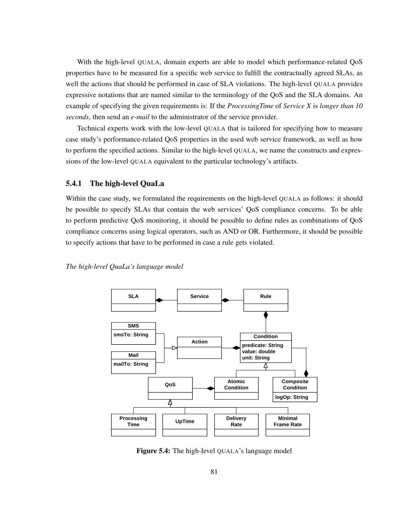
With the high-level QUALA, domain experts are able to model which performance-related QoS
properties have to be measured for a specific web service to fulfill the contractually agreed SLAs, as
well the actions that should be performed in case of SLA violations. The high-level QUALA provides
expressive notations that are named similar to the terminology of the QoS and the SLA domains. An
example of specifying the given requirements is: If the ProcessingTime of Service X is longer than 10
seconds, then send an e-mail to the administrator of the service provider.
Technical experts work with the low-level QUALA that is tailored for specifying how to measure
case study’s performance-related QoS properties in the used web service framework, as well as how
to perform the specified actions. Similar to the high-level QUALA, we name the constructs and expres-
sions of the low-level QUALA equivalent to the particular technology’s artifacts.
5.4.1 The high-level QuaLa
Within the case study, we formulated the requirements on the high-level QUALA as follows: it should
be possible to specify SLAs that contain the web services’ QoS compliance concerns. To be able
to perform predictive QoS monitoring, it should be possible to define rules as combinations of QoS
compliance concerns using logical operators, such as AND or OR. Furthermore, it should be possible
to specify actions that have to be performed in case a rule gets violated.
The high-level QuaLa’s language model
ServiceSLA
predicate: Stringvalue: doubleunit: String
ConditionAction
smsTo: String
SMS
mailTo: String
QoS
ProcessingTime
UpTimeDelivery
RateMinimal
Frame Rate
Rule
logOp: String
CompositeCondition
AtomicCondition
Figure 5.4: The high-level QUALA’s language model
81
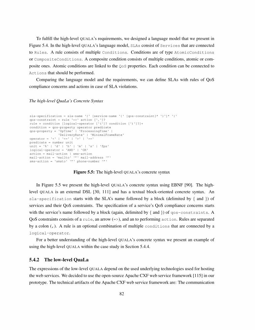
To fulfill the high-level QUALA’s requirements, we designed a language model that we present in
Figure 5.4. In the high-level QUALA’s language model, SLAs consist of Services that are connected
to Rules. A rule consists of multiple Conditions. Conditions are of type AtomicConditions
or CompositeConditions. A composite condition consists of multiple conditions, atomic or com-
posite ones. Atomic conditions are linked to the QoS properties. Each condition can be connected to
Actions that should be performed.
Comparing the language model and the requirements, we can define SLAs with rules of QoS
compliance concerns and actions in case of SLA violations.
The high-level QuaLa’s Concrete Syntax
sla-specification = sla-name ‘{‘ [service-name ‘{‘ [qos-constraint]* ‘}‘]* ‘}‘qos-constraint = rule ‘=>‘ action [‘,‘]?rule = condition [logical-operator [‘(‘]? condition [‘)‘]?]+condition = qos-property operator predicateqos-property = ‘UpTime‘ | ‘ProcessingTime‘ |
‘DeliveryRate‘ | ‘MinimalFrameRate‘operator = ‘<‘ | ‘<=‘ | ‘>‘ | ‘>=‘ predicate = number unitunit = ‘%‘ | ‘d‘ | ‘h‘ | ‘m‘ | ‘s‘ | ‘fps‘logical-operator = ‘AND‘ | ‘OR‘action = mail-action | sms-actionmail-action = ‘mailto‘ ‘”‘ mail-address ‘”‘sms-action = ‘smsto‘ ‘”‘ phone-number ‘”‘
Figure 5.5: The high-level QUALA’s concrete syntax
In Figure 5.5 we present the high-level QUALA’s concrete syntax using EBNF [90]. The high-
level QUALA is an external DSL [30, 111] and has a textual block-oriented concrete syntax. An
sla-specification starts with the SLA’s name followed by a block (delimited by { and }) of
services and their QoS constraints. The specification of a service’s QoS compliance concerns starts
with the service’s name followed by a block (again, delimited by { and }) of qos-constraints. A
QoS constraints consists of a rule, an arrow (=>), and an to performing action. Rules are separated
by a colon (,). A rule is an optional combination of multiple conditions that are connected by a
logical-operator.
For a better understanding of the high-level QUALA’s concrete syntax we present an example of
using the high-level QUALA within the case study in Section 5.4.4.
5.4.2 The low-level QuaLa
The expressions of the low-level QUALA depend on the used underlying technologies used for hosting
the web services. We decided to use the open-source Apache CXF web service framework [115] in our
prototype. The technical artifacts of the Apache CXF web service framework are: The communication
82
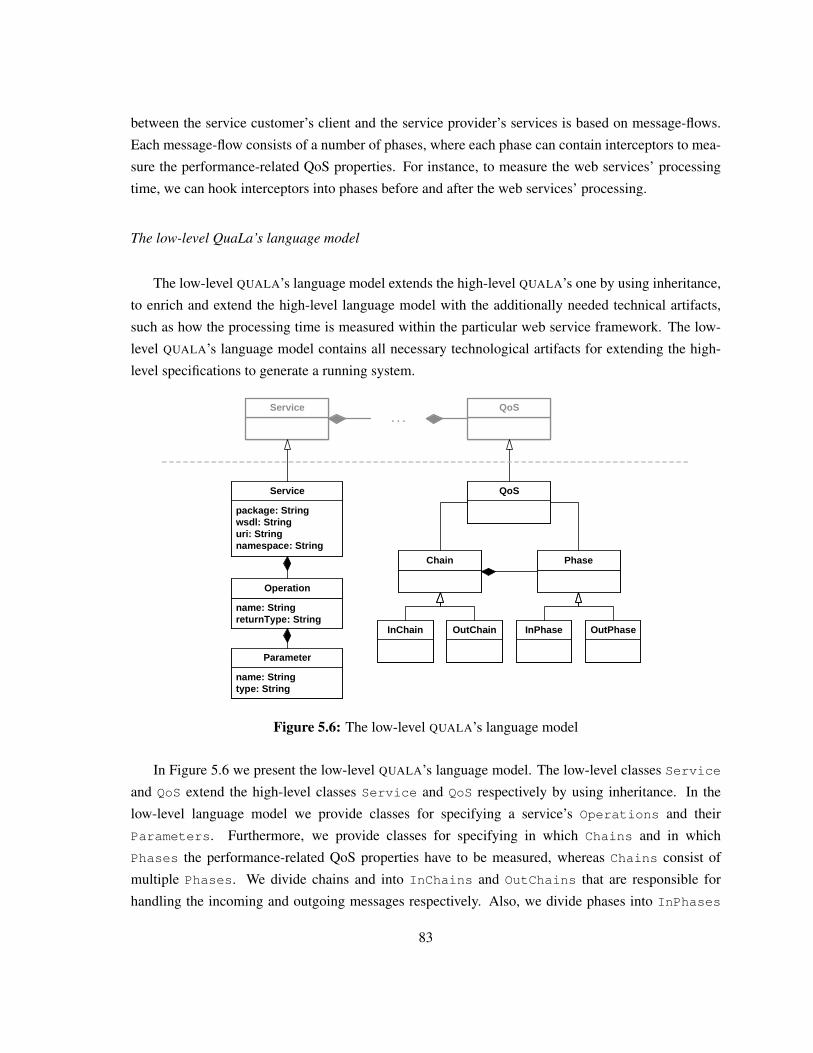
between the service customer’s client and the service provider’s services is based on message-flows.
Each message-flow consists of a number of phases, where each phase can contain interceptors to mea-
sure the performance-related QoS properties. For instance, to measure the web services’ processing
time, we can hook interceptors into phases before and after the web services’ processing.
The low-level QuaLa’s language model
The low-level QUALA’s language model extends the high-level QUALA’s one by using inheritance,
to enrich and extend the high-level language model with the additionally needed technical artifacts,
such as how the processing time is measured within the particular web service framework. The low-
level QUALA’s language model contains all necessary technological artifacts for extending the high-
level specifications to generate a running system.
Service QoS. . .
package: Stringwsdl: Stringuri: Stringnamespace: String
Service QoS
name: StringreturnType: String
Operation
name: Stringtype: String
Parameter
Chain Phase
InChain OutChain InPhase OutPhase
Figure 5.6: The low-level QUALA’s language model
In Figure 5.6 we present the low-level QUALA’s language model. The low-level classes Service
and QoS extend the high-level classes Service and QoS respectively by using inheritance. In the
low-level language model we provide classes for specifying a service’s Operations and their
Parameters. Furthermore, we provide classes for specifying in which Chains and in which
Phases the performance-related QoS properties have to be measured, whereas Chains consist of
multiple Phases. We divide chains and into InChains and OutChains that are responsible for
handling the incoming and outgoing messages respectively. Also, we divide phases into InPhases
83
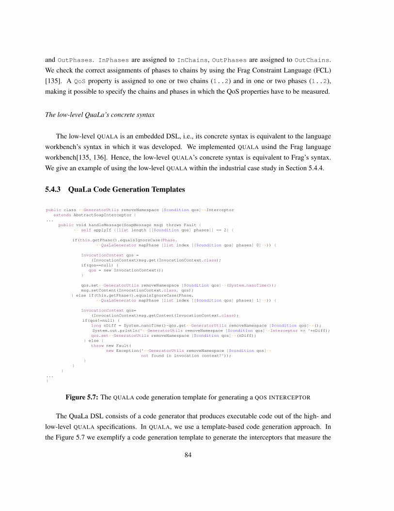
and OutPhases. InPhases are assigned to InChains, OutPhases are assigned to OutChains.
We check the correct assignments of phases to chains by using the Frag Constraint Language (FCL)
[135]. A QoS property is assigned to one or two chains (1..2) and in one or two phases (1..2),
making it possible to specify the chains and phases in which the QoS properties have to be measured.
The low-level QuaLa’s concrete syntax
The low-level QUALA is an embedded DSL, i.e., its concrete syntax is equivalent to the language
workbench’s syntax in which it was developed. We implemented QUALA usind the Frag language
workbench[135, 136]. Hence, the low-level QUALA’s concrete syntax is equivalent to Frag’s syntax.
We give an example of using the low-level QUALA within the industrial case study in Section 5.4.4.
5.4.3 QuaLa Code Generation Templates
public class <~GeneratorUtils removeNamespace [$condition qos]~>Interceptorextends AbstractSoapInterceptor {
...public void handleMessage(SoapMessage msg) throws Fault {
<~ self applyIf {[list length [[$condition qos] phases]] == 2} {
if(this.getPhase().equalsIgnoreCase(Phase.<~QuaLaGenerator mapPhase [list index [[$condition qos] phases] 0]~>)) {
InvocationContext qos =(InvocationContext)msg.get(InvocationContext.class);
if(qos==null) {qos = new InvocationContext();
}
qos.set<~GeneratorUtils removeNamespace [$condition qos]~>(System.nanoTime());msg.setContent(InvocationContext.class, qos);
} else if(this.getPhase().equalsIgnoreCase(Phase.<~QuaLaGenerator mapPhase [list index [[$condition qos] phases] 1]~>)) {
InvocationContext qos=(InvocationContext)msg.getContent(InvocationContext.class);
if(qos!=null) {long nDiff = System.nanoTime()-qos.get<~GeneratorUtils removeNamespace [$condition qos]~>();System.out.println("<~GeneratorUtils removeNamespace [$condition qos]~>Interceptor => "+nDiff);qos.set<~GeneratorUtils removeNamespace [$condition qos]~>(nDiff);
} else {throw new Fault(
new Exception("<~GeneratorUtils removeNamespace [$condition qos]~>not found in invocation context!"));
}}
}...}
Figure 5.7: The QUALA code generation template for generating a QOS INTERCEPTOR
The QuaLa DSL consists of a code generator that produces executable code out of the high- and
low-level QUALA specifications. In QUALA, we use a template-based code generation approach. In
the Figure 5.7 we exemplify a code generation template to generate the interceptors that measure the
84
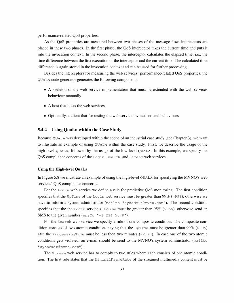
performance-related QoS properties.
As the QoS properties are measured between two phases of the message-flow, interceptors are
placed in these two phases. In the first phase, the QoS interceptor takes the current time and puts it
into the invocation context. In the second phase, the interceptor calculates the elapsed time, i.e., the
time difference between the first execution of the interceptor and the current time. The calculated time
difference is again stored in the invocation context and can be used for further processing.
Besides the interceptors for measuring the web services’ performance-related QoS properties, the
QUALA code generator generates the following components:
• A skeleton of the web service implementation that must be extended with the web services
behaviour manually
• A host that hosts the web services
• Optionally, a client that for testing the web service invocations and behaviours
5.4.4 Using QuaLa within the Case Study
Because QUALA was developed within the scope of an industrial case study (see Chapter 3), we want
to illustrate an example of using QUALA within the case study. First, we describe the usage of the
high-level QUALA, followed by the usage of the low-level QUALA. In this example, we specify the
QoS compliance concerns of the Login, Search, and Stream web services.
Using the High-level QuaLa
In Figure 5.8 we illustrate an example of using the high-level QUALA for specifying the MVNO’s web
services’ QoS compliance concerns.
For the Login web service we define a rule for predictive QoS monitoring. The first condition
specifies that the UpTime of the Login web service must be greater than 99% (>99%), otherwise we
have to inform a system administrator (mailto "[email protected]"). The second condition
specifies that the the Login service’s UpTime must be greater than 95% (>95%), otherwise send an
SMS to the given number (smsTo "+1 234 5678").
For the Search web service we specify a rule of one composite condition. The composite con-
dition consists of two atomic conditions saying that the UpTime must be greater than 99% (>99%)
AND the ProcessingTime must be less then two minutes (<2min). In case one of the two atomic
conditions gets violated, an e-mail should be send to the MVNO’s system administrator (mailto
The Stream web service has to comply to two rules where each consists of one atomic condi-
tion. The first rule states that the MinimalFrameRate of the streamed multimedia content must be
85
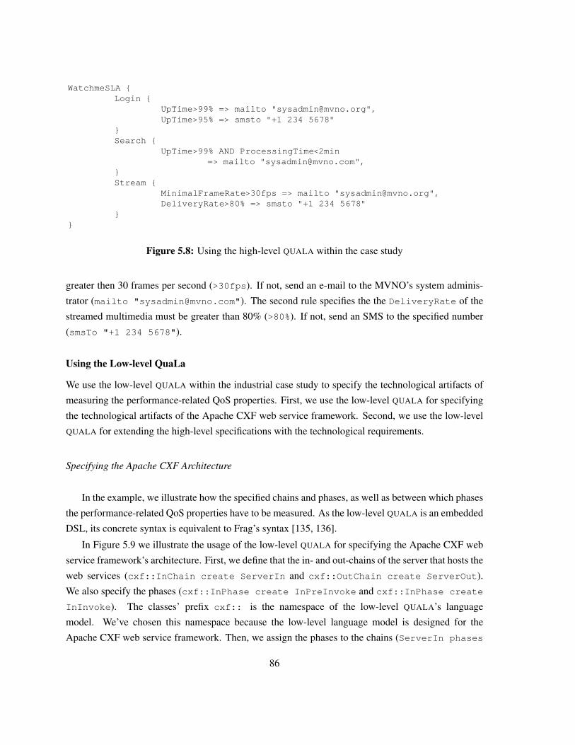
WatchmeSLA {Login {
UpTime>99% => mailto "[email protected]",UpTime>95% => smsto "+1 234 5678"
} Search {
UpTime>99% AND ProcessingTime<2min => mailto "[email protected]",
} Stream {
MinimalFrameRate>30fps => mailto "[email protected]",DeliveryRate>80% => smsto "+1 234 5678"
} }
Figure 5.8: Using the high-level QUALA within the case study
greater then 30 frames per second (>30fps). If not, send an e-mail to the MVNO’s system adminis-
trator (mailto "[email protected]"). The second rule specifies the the DeliveryRate of the
streamed multimedia must be greater than 80% (>80%). If not, send an SMS to the specified number
(smsTo "+1 234 5678").
Using the Low-level QuaLa
We use the low-level QUALA within the industrial case study to specify the technological artifacts of
measuring the performance-related QoS properties. First, we use the low-level QUALA for specifying
the technological artifacts of the Apache CXF web service framework. Second, we use the low-level
QUALA for extending the high-level specifications with the technological requirements.
Specifying the Apache CXF Architecture
In the example, we illustrate how the specified chains and phases, as well as between which phases
the performance-related QoS properties have to be measured. As the low-level QUALA is an embedded
DSL, its concrete syntax is equivalent to Frag’s syntax [135, 136].
In Figure 5.9 we illustrate the usage of the low-level QUALA for specifying the Apache CXF web
service framework’s architecture. First, we define that the in- and out-chains of the server that hosts the
web services (cxf::InChain create ServerIn and cxf::OutChain create ServerOut).
We also specify the phases (cxf::InPhase create InPreInvoke and cxf::InPhase create
InInvoke). The classes’ prefix cxf:: is the namespace of the low-level QUALA’s language
model. We’ve chosen this namespace because the low-level language model is designed for the
Apache CXF web service framework. Then, we assign the phases to the chains (ServerIn phases
86
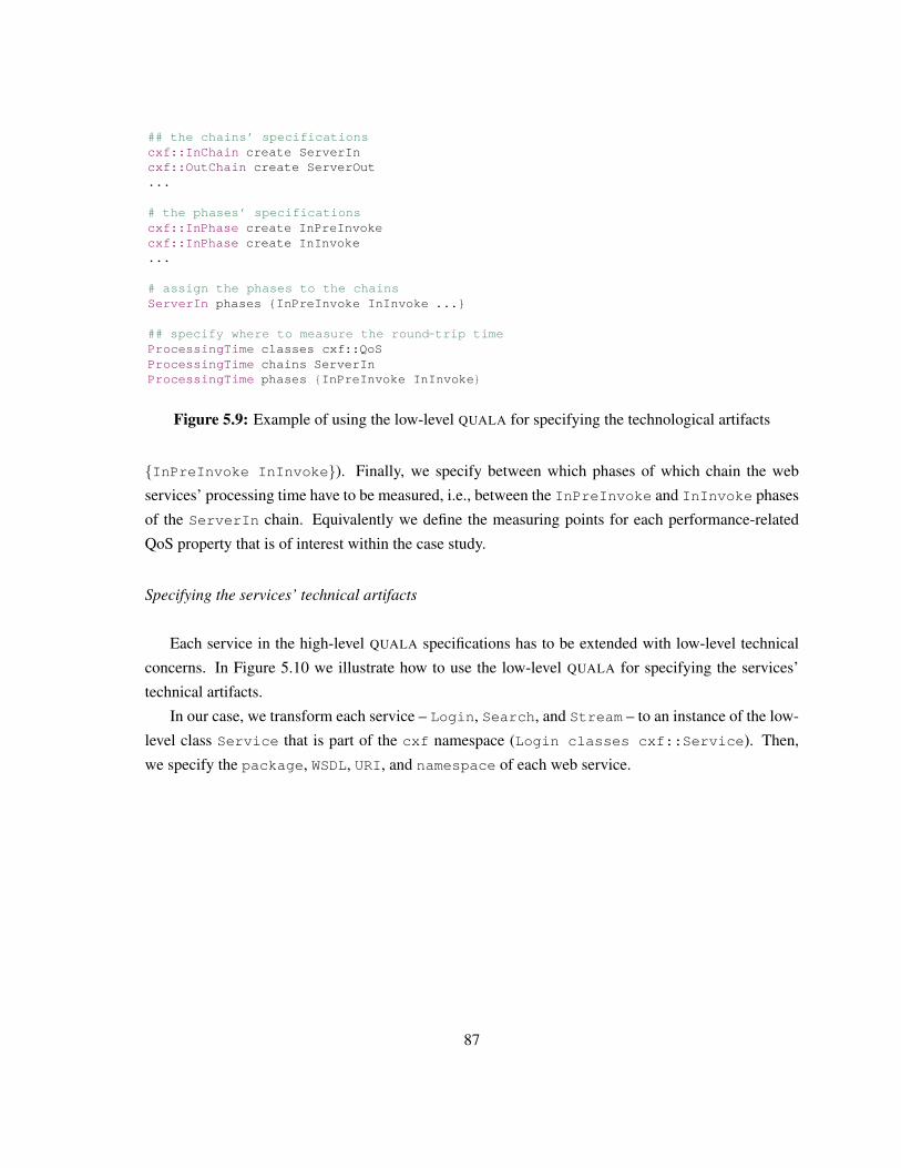
## the chains’ specificationscxf::InChain create ServerIncxf::OutChain create ServerOut...
# the phases’ specificationscxf::InPhase create InPreInvokecxf::InPhase create InInvoke...
# assign the phases to the chainsServerIn phases {InPreInvoke InInvoke ...}
## specify where to measure the round-trip timeProcessingTime classes cxf::QoS ProcessingTime chains ServerInProcessingTime phases { InPreInvoke InInvoke }
Figure 5.9: Example of using the low-level QUALA for specifying the technological artifacts
{InPreInvoke InInvoke}). Finally, we specify between which phases of which chain the web
services’ processing time have to be measured, i.e., between the InPreInvoke and InInvoke phases
of the ServerIn chain. Equivalently we define the measuring points for each performance-related
QoS property that is of interest within the case study.
Specifying the services’ technical artifacts
Each service in the high-level QUALA specifications has to be extended with low-level technical
concerns. In Figure 5.10 we illustrate how to use the low-level QUALA for specifying the services’
technical artifacts.
In our case, we transform each service – Login, Search, and Stream – to an instance of the low-
level class Service that is part of the cxf namespace (Login classes cxf::Service). Then,
we specify the package, WSDL, URI, and namespace of each web service.
87
## LOGIN SERVICELogin classes cxf::ServiceLogin package "eu.compas.watchme"Login uri "http://localhost:5001/watchme/login"Login wsdl "http://localhost:5001/watchme/login?wsdl"Login namespace "http://www.compas-ict.eu/watchme/login"Login operations [list build \
[cxf::Operation create login -name "login" -returnType UUID -parameters [list build \[cxf::Parameter create pUsername -name "username" -type String][cxf::Parameter create pPassword -name "password" -type String]]]]
## SEARCH SERVICESearch classes cxf::ServiceSearch package "eu.compas.watchme"Search uri "http://localhost:5001/watchme/search"Search wsdl "http://localhost:5001/watchme/search?wsdl"Search namespace "http://www.compas-ict.eu/watchme/search"Search operations [list build \
[cxf::Operation create search -name "search" -returnType String -parameters [list build \[cxf::Parameter create sMovie -name "movie" -type String][cxf::Parameter create sLanguage -name "language" -type String]]]]
## STREAM SERVICEStream classes cxf::ServiceStream package "eu.compas.watchme"Stream uri "http://localhost:5001/watchme/stream"Stream wsdl "http://localhost:5001/watchme/stream?wsdl"Stream namespace "http://www.compas-ict.eu/watchme/stream"Stream operations [list build \
[cxf::Operation create stream -name "stream" -parameters [list build \[cxf::Parameter create sStreamID -name "streamID" -type String]]]]
Figure 5.10: Extending the high-level QUALA specifications with technological artifacts
Generated Code
Now, we illustrate an excerpt of the case study’s generated code by using QUALA. In Figure 5.11 we
exemplify the generated QOS INTERCEPTOR for measuring the processing time.
As specified in the low-level QUALA (see Figure 5.9), we place the interceptor for measuring the
web service’s processing time into the two phases PreInvoke and Invoke. As specified in the code
generation template (see Figure 5.7), in the PreInvoke phase the interceptors puts the current time
into the invocation context, i.e., the current time before the web service invocation. In the Invoke
phase the interceptors takes the current time again, i.e., the time after the web service invocation.
The time difference between the time before and after the web service invocation results in the web
service’s processing time.
88
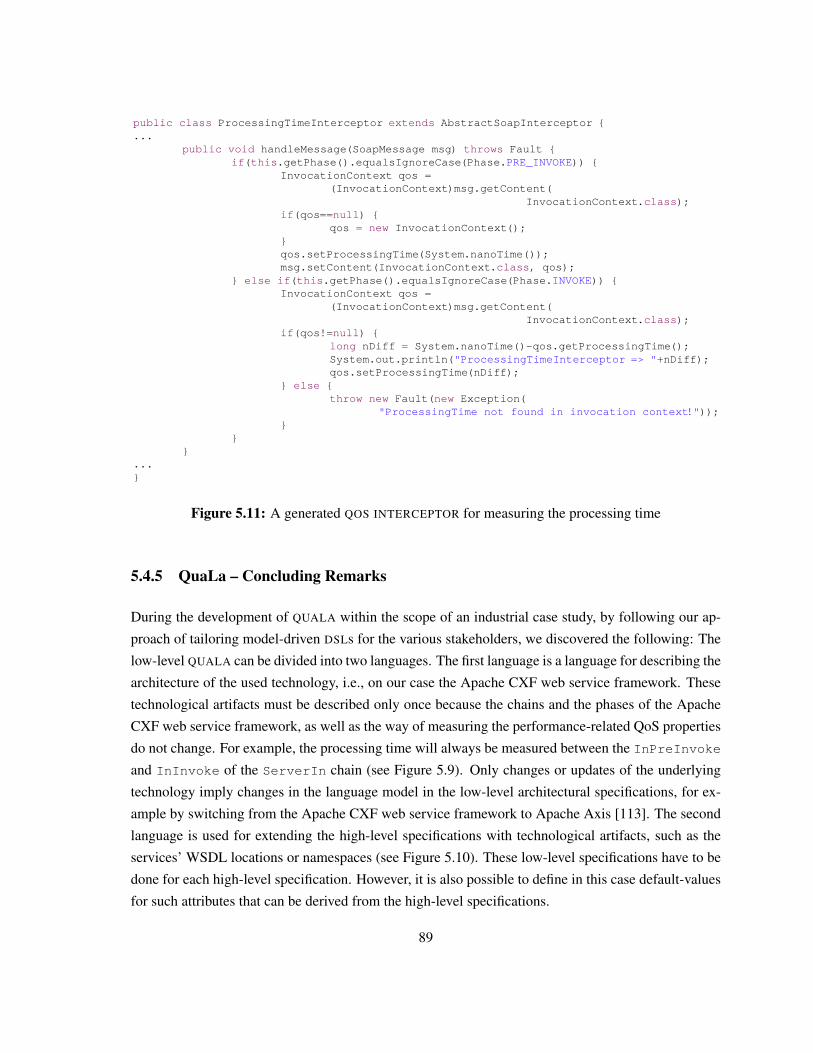
public class ProcessingTimeInterceptor extends AbstractSoapInterceptor {...
public void handleMessage(SoapMessage msg) throws Fault {if(this.getPhase().equalsIgnoreCase(Phase.PRE_INVOKE)) {
InvocationContext qos =(InvocationContext)msg.getContent(
InvocationContext.class);if(qos==null) {
qos = new InvocationContext();}qos.setProcessingTime(System.nanoTime());msg.setContent(InvocationContext.class, qos);
} else if(this.getPhase().equalsIgnoreCase(Phase.INVOKE)) {InvocationContext qos =
(InvocationContext)msg.getContent(InvocationContext.class);
if(qos!=null) {long nDiff = System.nanoTime()-qos.getProcessingTime();System.out.println("ProcessingTimeInterceptor => "+nDiff);qos.setProcessingTime(nDiff);
} else {throw new Fault(new Exception(
"ProcessingTime not found in invocation context!"));}
}}
...}
Figure 5.11: A generated QOS INTERCEPTOR for measuring the processing time
5.4.5 QuaLa – Concluding Remarks
During the development of QUALA within the scope of an industrial case study, by following our ap-
proach of tailoring model-driven DSLs for the various stakeholders, we discovered the following: The
low-level QUALA can be divided into two languages. The first language is a language for describing the
architecture of the used technology, i.e., on our case the Apache CXF web service framework. These
technological artifacts must be described only once because the chains and the phases of the Apache
CXF web service framework, as well as the way of measuring the performance-related QoS properties
do not change. For example, the processing time will always be measured between the InPreInvoke
and InInvoke of the ServerIn chain (see Figure 5.9). Only changes or updates of the underlying
technology imply changes in the language model in the low-level architectural specifications, for ex-
ample by switching from the Apache CXF web service framework to Apache Axis [113]. The second
language is used for extending the high-level specifications with technological artifacts, such as the
services’ WSDL locations or namespaces (see Figure 5.10). These low-level specifications have to be
done for each high-level specification. However, it is also possible to define in this case default-values
for such attributes that can be derived from the high-level specifications.
89
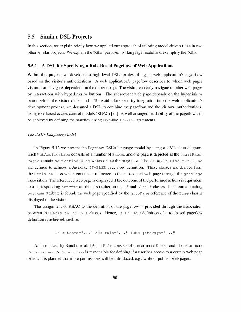
5.5 Similar DSL ProjectsIn this section, we explain briefly how we applied our approach of tailoring model-driven DSLs in two
other similar projects. We explain the DSLs’ purpose, its’ language model and exemplify the DSLs.
5.5.1 A DSL for Specifying a Role-Based Pageflow of Web Applications
Within this project, we developed a high-level DSL for describing an web-application’s page flow
based on the visitor’s authorizations. A web application’s pageflow describes to which web pages
visitors can navigate, dependent on the current page. The visitor can only navigate to other web pages
by interactions with hyperlinks or buttons. The subsequent web page depends on the hyperlink or
button which the visitor clicks and . To avoid a late security integration into the web application’s
development process, we designed a DSL to combine the pageflow and the visitors’ authorizations,
using role-based access control models (RBAC) [94]. A well arranged readability of the pageflow can
be achieved by defining the pageflow using Java-like IF-ELSE statements.
The DSL’s Language Model
In Figure 5.12 we present the Pageflow DSL’s language model by using a UML class diagram.
Each WebApplication consists of a number of Pages, and one page is depicted as the startPage.
Pages contain NavigationRules which define the page flow. The classes If, ElseIf and Else
are defined to achieve a Java-like IF-ELSE page flow definition. These classes are derived from
the Decision class which contains a reference to the subsequent web page through the gotoPage
association. The referenced web page is displayed if the outcome of the performed actions is equivalent
to a corresponding outcome attribute, specified in the If and ElseIf classes. If no corresponding
outcome attribute is found, the web page specified by the gotoPage reference of the Else class is
displayed to the visitor.
The assignment of RBAC to the definition of the pageflow is provided through the association
between the Decision and Role classes. Hence, an IF-ELSE definition of a rolebased pageflow
definition is achieved, such as
IF outcome="..." AND role="..." THEN gotoPage="..."
As introduced by Sandhu et al. [94], a Role consists of one or more Users and of one or more
Permissions. A Permission is responsible for defining if a user has access to a certain web page
or not. It is planned that more permissions will be introduced, e.g., write or publish web pages.
90
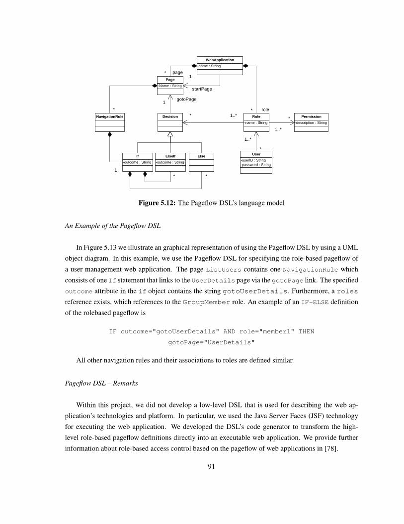
-name : String
WebApplication
-Name : String
Page
NavigationRule Decision
-outcome : String
If
-outcome : String
ElseIf Else
-name : String
Role
-userID : String-password : String
User
-description : String
Permission
1
-role
1..**
1..*
1
-page*
-startPage
1
*
1
1
1 *1 *
-gotoPage1
1..*
* page
*
startPage
gotoPage
role
* *
1
* *
*
*
1
*
Figure 5.12: The Pageflow DSL’s language model
An Example of the Pageflow DSL
In Figure 5.13 we illustrate an graphical representation of using the Pageflow DSL by using a UML
object diagram. In this example, we use the Pageflow DSL for specifying the role-based pageflow of
a user management web application. The page ListUsers contains one NavigationRule which
consists of one If statement that links to the UserDetails page via the gotoPage link. The specified
outcome attribute in the if object contains the string gotoUserDetails. Furthermore, a roles
reference exists, which references to the GroupMember role. An example of an IF-ELSE definition
of the rolebased pageflow is
IF outcome="gotoUserDetails" AND role="member1" THEN
gotoPage="UserDetails"
All other navigation rules and their associations to roles are defined similar.
Pageflow DSL – Remarks
Within this project, we did not develop a low-level DSL that is used for describing the web ap-
plication’s technologies and platform. In particular, we used the Java Server Faces (JSF) technology
for executing the web application. We developed the DSL’s code generator to transform the high-
level role-based pageflow definitions directly into an executable web application. We provide further
information about role-based access control based on the pageflow of web applications in [78].
91
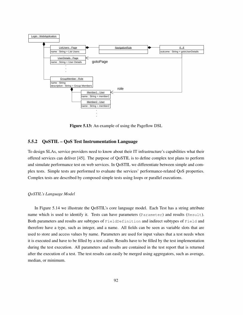
Login : WebApplication
name : String = List Users
ListUsers : Page
name : String = User Details
UserDetails : Page
1
1
name : Stringdescription : String = Group Members
GroupMember : Role
11
name : String = member1
Member1 : User
name : String = member2
Member2 : User
outcome : String = gotoUserDetails
if : If
11
.
.
.
role
gotoPage
.
.
.
NavigationRule
1
Figure 5.13: An example of using the Pageflow DSL
5.5.2 QoSTIL – QoS Test Instrumentation Language
To design SLAs, service providers need to know about their IT infrastructure’s capabilities what their
offered services can deliver [45]. The purpose of QoSTIL is to define complex test plans to perform
and simulate performance test on web services. In QoSTIL we differentiate between simple and com-
plex tests. Simple tests are performed to evaluate the services’ performance-related QoS properties.
Complex tests are described by composed simple tests using loops or parallel executions.
QoSTIL’s Language Model
In Figure 5.14 we illustrate the QoSTIL’s core language model. Each Test has a string attribute
name which is used to identify it. Tests can have parameters (Parameter) and results (Result).
Both parameters and results are subtypes of FieldDefinition and indirect subtypes of Field and
therefore have a type, such as integer, and a name. All fields can be seen as variable slots that are
used to store and access values by name. Parameters are used for input values that a test needs when
it is executed and have to be filled by a test caller. Results have to be filled by the test implementation
during the test execution. All parameters and results are contained in the test report that is returned
after the execution of a test. The test results can easily be merged using aggregators, such as average,
median, or minimum.
92
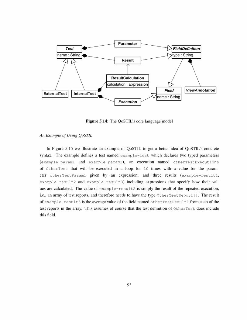
name : String
Test
calculation : Expression
ResultCalculation
type : String
FieldDefinition
Execution
InternalTestExternalTest
Parameter
Result
name : String
Field ViewAnnotation
Figure 5.14: The QoSTIL’s core language model
An Example of Using QoSTIL
In Figure 5.15 we illustrate an example of QoSTIL to get a better idea of QoSTIL’s concrete
syntax. The example defines a test named example-test which declares two typed parameters
(example-param1 and example-param2), an execution named otherTestExecutions
of OtherTest that will be executed in a loop for 10 times with a value for the param-
eter otherTestParam1 given by an expression, and three results (example-result1,
example-result2 and example-result3) including expressions that specify how their val-
ues are calculated. The value of example-result2 is simply the result of the repeated execution,
i.e., an array of test reports, and therefore needs to have the type OtherTestReport[]. The result
of example-result3 is the average value of the field named otherTestResult1 from each of the
test reports in the array. This assumes of course that the test definition of OtherTest does include
this field.
93
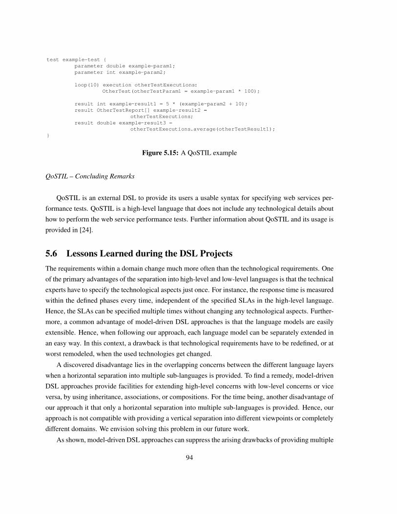
test example-test {parameter double example-param1;parameter int example-param2;
loop(10) execution otherTestExecutions:OtherTest(otherTestParam1 = example-param1 * 100);
result int example-result1 = 5 * (example-param2 + 10);result OtherTestReport[] example-result2 =
otherTestExecutions;result double example-result3 =
otherTestExecutions.average(otherTestResult1);}
Figure 5.15: A QoSTIL example
QoSTIL – Concluding Remarks
QoSTIL is an external DSL to provide its users a usable syntax for specifying web services per-
formance tests. QoSTIL is a high-level language that does not include any technological details about
how to perform the web service performance tests. Further information about QoSTIL and its usage is
provided in [24].
5.6 Lessons Learned during the DSL ProjectsThe requirements within a domain change much more often than the technological requirements. One
of the primary advantages of the separation into high-level and low-level languages is that the technical
experts have to specify the technological aspects just once. For instance, the response time is measured
within the defined phases every time, independent of the specified SLAs in the high-level language.
Hence, the SLAs can be specified multiple times without changing any technological aspects. Further-
more, a common advantage of model-driven DSL approaches is that the language models are easily
extensible. Hence, when following our approach, each language model can be separately extended in
an easy way. In this context, a drawback is that technological requirements have to be redefined, or at
worst remodeled, when the used technologies get changed.
A discovered disadvantage lies in the overlapping concerns between the different language layers
when a horizontal separation into multiple sub-languages is provided. To find a remedy, model-driven
DSL approaches provide facilities for extending high-level concerns with low-level concerns or vice
versa, by using inheritance, associations, or compositions. For the time being, another disadvantage of
our approach it that only a horizontal separation into multiple sub-languages is provided. Hence, our
approach is not compatible with providing a vertical separation into different viewpoints or completely
different domains. We envision solving this problem in our future work.
As shown, model-driven DSL approaches can suppress the arising drawbacks of providing multiple
94
languages which are tailored for the appropriate stakeholders. The following section mentions some
related work and their differences to our approach.
5.7 Related WorkIn this section we present some related work to our approach for supporting the stakeholders with
model-driven DSLs. First, we list some languages for specifying QoS in distributed and service-
oriented systems, followed by some approaches for developing DSLs.
5.7.1 Related Languages for Specifying QoS
In the literature, many languages for specifying a distributed system’s QoS compliance concerns exists.
To the best of our knowledge, there exists no language that provides a separation between technical
and non-technical artifacts relevant for QoS monitoring. Furthermore, many developed DSLs of the
QoS domain do not follow the MDD paradigm.
Although HQML (Hierarchical QoS Markup Language) provides three different levels of abstrac-
tions, it is an XML-based language, making it hard to use for non-technical stakeholders. HQML was
designed for specifying the QoS concerns of web-based applications. The highest HQML abstraction
level is the user level for specifying the application’s attributes (e.g., description of service provider
or service consumer), the QoS criteria (e.g, low, average, or high), and the service provider’s price
models (e.g., for transmitted byte charge). The application level QoS specifications includes the ap-
plication’s QoS compliance concerns. The resource level QoS specifications relate to the system’s
resource requirements, such as memory, bandwidth, or cpu.
The Distributed QoS Modeling Language (QML) [40], introduced by Frølund and Koistinen, is a
language for specifying QoS in distributed object systems. The language consists of three elements:
contract type, contract, and profile. Contracts are instances of contract types which consist of so-
called dimensions, such as Time-to-Failure (TTF), availability, or number of failures. Dimensions are
comparable to QoS concerns. Similar to our work, a contract is a list of QoS constraints, such as
latency < 3s. A profile describes the QoS properties of a service and is linked service’s interface.
To ease the integration with existing service descriptions, such as WSDL [126] or BPEL [76], the
SLAng language [56] is defined by an XML-Schema. Using SLAng makes it possible to (1) give
information about the service provider and service consumer, (2) define contractual statements, such
as the SLA’s duration and the payments in case of violation, and (3) technical QoS constraints. SLAng
separates SLAs in horizontal and vertical types to regulate the different types of the involved parties.
Vertical SLAs are application, hosting, persistence, and communication. Horizontal SLAs are service,
container, and networking. SLAng also supports the specification of responsibilities of the service
provider, the service consumer, or both.
95
The Contract Description Language (CDL) of the QuO framework [62] is designed to define SLAs
between clients and remote objects within distributed systems. CDL allows to organize the possible
QoS states, the needed monitoring and controlling information, actions if QoS states change, and when
the information should be available.
The web service level agreements (WSLA) framework [48] offers an XML-based language for
specifying the web services’ performance-related QoS compliance concerns. The provided language
by the WSLA framework is allows to specify SLA’s parties, services, and obligations.
5.7.2 Related DSL Development Approaches
Pitkanen and Mikkonen [95] argue that well designed DSLs, modeling tools, and code generators in-
crease the productivity. They concentrate on lightweight and modular DSLs instead of full-blown
DSLs. Some situations of full-blown DSLs are described, e.g., several different implementation plat-
forms. The lightweight approach can be an aid in defining the scope and concepts of DSLs before the
implementation of a full-blown DSL starts. In comparison to our study, the systematic development
approach can be applied to lightweight, as well as full-blown DSLs. The different design decisions
and/or trade-offs, described in Section 5.3.3, are also valid for developing lightweight model-driven
DSLs.
Bierhoff et al. [52] describe an incremental approach for developing DSLs. First, they choose an
application and develop a DSL which is expressive enough to describe the application. Also, domain
boundaries are defined. Then, the DSL grows until it is too expensive to extend it more. The approach
is demonstrated on CRUD applications, i.e., create, retrieve, update, delete applications. The approach
by Bierhoff et al. reflects the evolution of our three experiments described in Section 5.3.2. Also, we
started by an initial experiment and extended it incrementally.
Maximilien et al. [64] developed a DSL for Web APIs and Services Mashups. A number of inter-
esting design issues for DSLs are mentioned: (1) levels of abstraction, (2) terse code, (3) simple and
natural syntax, and (4) code generation. These goals are very similar to our proposed claims. The
developed DSL is used for SOAs, and the described approach and results are in line with our results.
Tolvanen [46] provides a guidance for defining and developing DSLs based on his long-year ex-
periences in building DSLs. The development process is divided into four phases: (1) Identifying
abstractions, (2) specifying the language models, (3) creating notations for the language based on the
language models, and (4) defining model validators and code generators. The development phases are
very similar to our observations. We started by defining abstractions of the domain, designed high-
and low-level language models, developed a DSL with notations equivalent to the language models.
Also, we provide model validators and code generators. The proposed approach by Tolvanen is simi-
lar to our systematic development approach for model-driven DSLs: (1) identifying the concepts of the
domain and their relations, (2) designing the language models, (3) developing the DSLs based on the
96
language models, and (4) generating code of valid domain models through a code generator.
5.8 SummaryIn this chapter, we presented an approach to support the differently skilled stakeholders that are in-
volved in the design and development process of a QoS monitoring infrastrucutre. In our approach, we
use model-driven DSLs that are tailored for the non-technical and technical stakeholders. Following
our approach, low-level DSLs provide constructs that are tailored for technical experts, whereas high-
level DSLs are tailored for domain experts. A suitable separation of concerns can be established by
splitting the language model into high- and low-level models, where the high-level model extends the
low-level model. Hence, a separation of technical and domain concerns can be established to present
only the appropriate concerns to each of the different groups of stakeholders.
We have evaluated our approach with an explorative study on developing model-driven DSLs for
SOAs. Within three experiments we have stated claims of investigations, illustrated the projects, and
presented the evidences and counter-evidences of the stated claims. We have shown a developed
model-driven DSL within the scope of the industrial case study, named QUALA. We separated QuaLa
into two languages. The high-level QuaLa is tailored for experts of the QoS domain in order to specify
the services’ QoS compliance concerns. The low-level QuaLa is tailored for technical experts in order
to specify where and how to measure the performance-related QoS properties within the Apache CXF
web service framework.
97

98
Chapter 6
Incremental Development ofModel-driven DSLs
To support the differently skilled stakeholders, we utilize model-driven Domain-specific Languages
(DSLs), as described in the previous chapter (Chapter 5). However, developing model-driven DSLs
conceals many problems. Because of a lacking domain understanding, the DSL’s requirements are
fuzzy and incomplete at early development stages. Fuzzy preliminary requirements are often quickly
stretched out, and later on incrementally updated following subsequent communications between the
stakeholders and the developers. After learning and knowing the domain concepts better, the stake-
holders interpret the concepts differently. As a consequence, later changes are inevitable. To avoid
complex and time-consuming updates, an incremental development approach is desired to keep the
subsequent updates small and lightweight [49].
This chapter is organized as follows: In the following section, Section 6.1, we present an utilized
incremental development approach to develop a model-driven DSLs. In Section 6.2 we exemplify how
we have researched the incremental development approach during the development of the case study’s
Quality of Service Language (QUALA) DSL, dealing with permanent updates (see Section 5.4). Related
DSL development approaches are listed in Section 6.3. The chapter concludes with a brief summary
in Section 6.4.
6.1 An Incremental Development ApproachTo put things right, we followed an incremental development approach that is based on existing de-
velopment approaches. We applied the incremental development approach to develop the case study’s
QUALA DSL and state questions under research during the development lifecycle within the case study.
The findings provide answers to the questions and should help developers of model-driven DSLs avoid
complex and time-consuming updates in later development stages.
99
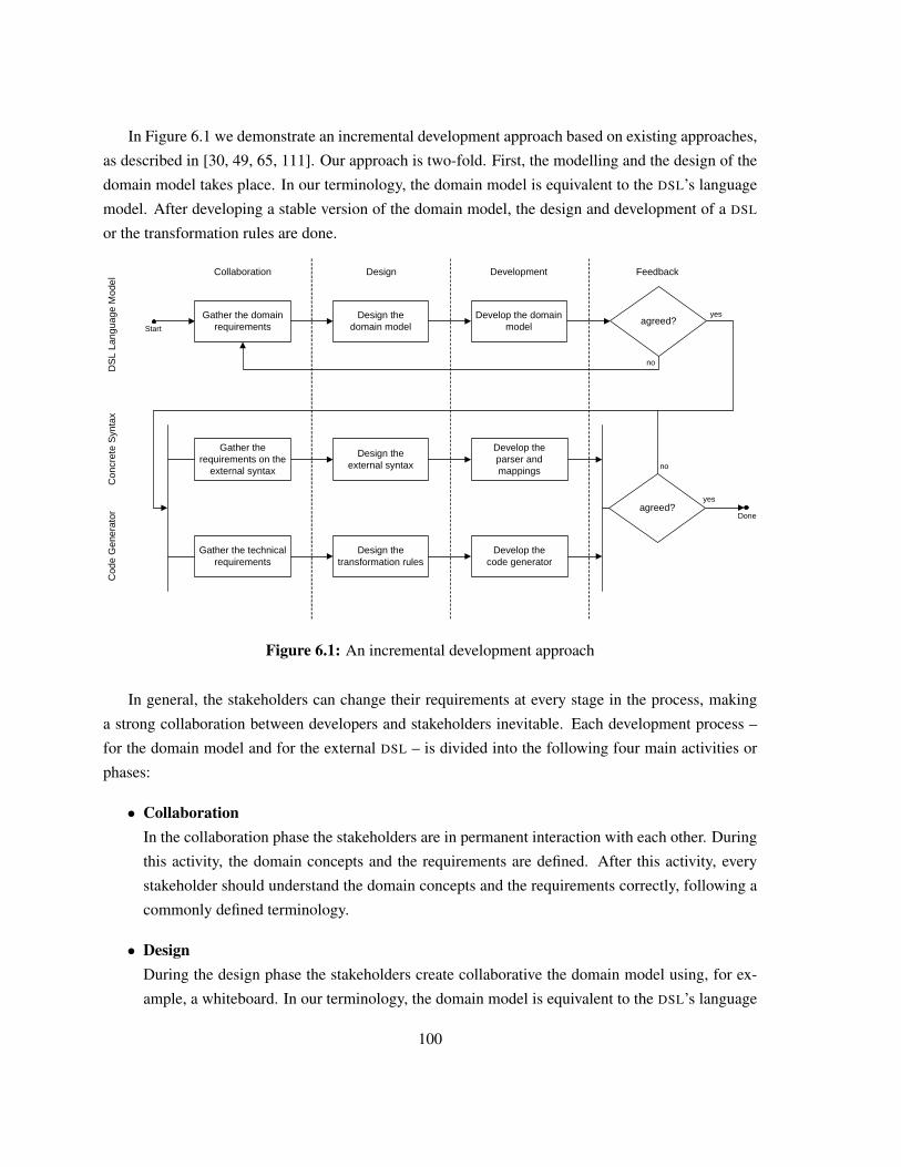
In Figure 6.1 we demonstrate an incremental development approach based on existing approaches,
as described in [30, 49, 65, 111]. Our approach is two-fold. First, the modelling and the design of the
domain model takes place. In our terminology, the domain model is equivalent to the DSL’s language
model. After developing a stable version of the domain model, the design and development of a DSL
or the transformation rules are done.
Develop the domain model
agreed?yes
no
Design the domain model
Design theexternal syntax
Develop theparser and mappings
Start
Done
no
Gather the domain requirements
Gather the requirements on the
external syntax
DesignCollaboration Development
yes
Feedback
DS
L La
ngua
ge M
odel
Con
cret
e S
ynta
x
Design the transformation rules
Develop the code generator
agreed?
no
Gather the technical requirements
Cod
e G
ener
ator
Figure 6.1: An incremental development approach
In general, the stakeholders can change their requirements at every stage in the process, making
a strong collaboration between developers and stakeholders inevitable. Each development process –
for the domain model and for the external DSL – is divided into the following four main activities or
phases:
• CollaborationIn the collaboration phase the stakeholders are in permanent interaction with each other. During
this activity, the domain concepts and the requirements are defined. After this activity, every
stakeholder should understand the domain concepts and the requirements correctly, following a
commonly defined terminology.
• DesignDuring the design phase the stakeholders create collaborative the domain model using, for ex-
ample, a whiteboard. In our terminology, the domain model is equivalent to the DSL’s language
100
model. The design of the domain model is based on the requirements and the gathered under-
standings about the domain. It is advisable that all stakeholders perform this activity together,
for example by using domain analysis techniques [6]. This can also help in determining the
scope of the domain [7].
• DevelopmentIn the development stage the language developers develop the DSL’s language model, using their
favourite modeling tool or language workbench.
• FeedbackAfter having developed the DSL’s language model, the stakeholders give feedback on the model.
The stakeholders test the developed language model and evaluate that the model contains the re-
quired domain concepts and that they can be expressed well. In case the domain model does not
fulfil the requirements, the incremental process must be restarted. Otherwise, the development
of the DSL transformation rules and concrete syntax can start.
At every stage of the development process, the stakeholders can change or extend the requirements.
Hence, the DSL developers have to discuss the new requirements with the domain experts and perform
changes in the domain model and its dependent components. In the presented approach, the DSL
developers must collaborate with the domain experts until the design of the domain model is finished.
Afterwards, the changes can be taken into the updating process of the DSL. The same incremental
development approach can be used for each feature of the DSL.
6.2 Incremental Development of the QuaLa DSLWithin the case study, the requirements on the Quality of Service (QOS) domain and the QUALA DSL
were changing and extending. Requirement changes and the QUALA’s actual version were discussed in
several meetings and telephone conferences during the case study’s lifecycle. Within the case study, we
research the incremental development approach. We present the evolution of the QUALA DSL in three
different versions – initial, intermediate, and final. Then, we present the findings of the incremental
development of the case study’s QUALA DSL.
6.2.1 Researching the Incremental Development Approach
To research the incremental development approach, we state four questions under research during the
development of the QUALA DSL (see Section 5.4) within the case study (see Chapter 3).
101
Question I
Is the incremental development approach applicable within the case study?
We apply the presented incremental development approach to develop QUALA within the industrial
case study. This question focuses on the applicability of the incremental development approach.
Question II
How do changes in the DSL’s language model impact its dependent components?
Permanently changing domain requirements result in changes to the domain model, i.e., the DSL’s
language model. Based on the DSL’s language model are the transformation rules and the DSL’s
concrete syntax. This question focuses on the impact of domain model changes to its dependent
components’ implementation.
Question III
What are the benefits of incremental development instead of following a non-incremental
development approach?
To keep changes and updates in later stages of the development lifecycle as small as possible,
we have followed an incremental development approach. This question focuses on the benefits of
following an incremental rather than a non-incremental development approach.
Question IV
Are there general recommendations for similar projects?
We have developed the QUALA DSL within the case study to specify the QOS compliance concerns
of a process-driven SOA. This question concentrates on the generalization of the findings during the
incremental development of QUALA. General recommendations should help to develop model-driven
DSLs incrementally in various projects.
6.2.2 The Evolution of QuaLa
In this section, we illustrate the evolution of the case study’s QUALA DSL (see Section 5.4), stem-
ming from evolving domain requirements. We present the evolution of QUALA’s language model,
its external concrete syntax, and their relationship on three versions – initial, intermediate, and final.
The specification of the QOS compliance concerns, using the external syntax, is exemplified for the
MVNO’s Search service (see Table 3.1).
102
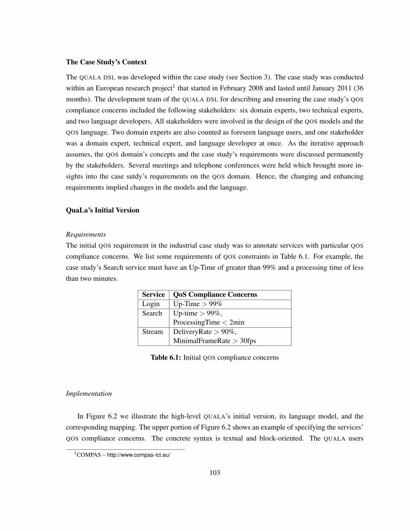
The Case Study’s Context
The QUALA DSL was developed within the case study (see Section 3). The case study was conducted
within an European research project1 that started in February 2008 and lasted until January 2011 (36
months). The development team of the QUALA DSL for describing and ensuring the case study’s QOS
compliance concerns included the following stakeholders: six domain experts, two technical experts,
and two language developers. All stakeholders were involved in the design of the QOS models and the
QOS language. Two domain experts are also counted as foreseen language users, and one stakeholder
was a domain expert, technical expert, and language developer at once. As the iterative approach
assumes, the QOS domain’s concepts and the case study’s requirements were discussed permanently
by the stakeholders. Several meetings and telephone conferences were held which brought more in-
sights into the case sutdy’s requirements on the QOS domain. Hence, the changing and enhancing
requirements implied changes in the models and the language.
QuaLa’s Initial Version
Requirements
The initial QOS requirement in the industrial case study was to annotate services with particular QOS
compliance concerns. We list some requirements of QOS constraints in Table 6.1. For example, the
case study’s Search service must have an Up-Time of greater than 99% and a processing time of less
than two minutes.
Service QoS Compliance ConcernsLogin Up-Time > 99%Search Up-time > 99%,
ProcessingTime < 2minStream DeliveryRate > 90%,
MinimalFrameRate > 30fps
Table 6.1: Initial QOS compliance concerns
Implementation
In Figure 6.2 we illustrate the high-level QUALA’s initial version, its language model, and the
corresponding mapping. The upper portion of Figure 6.2 shows an example of specifying the services’
QOS compliance concerns. The concrete syntax is textual and block-oriented. The QUALA users
1COMPAS – http://www.compas-ict.eu/
103
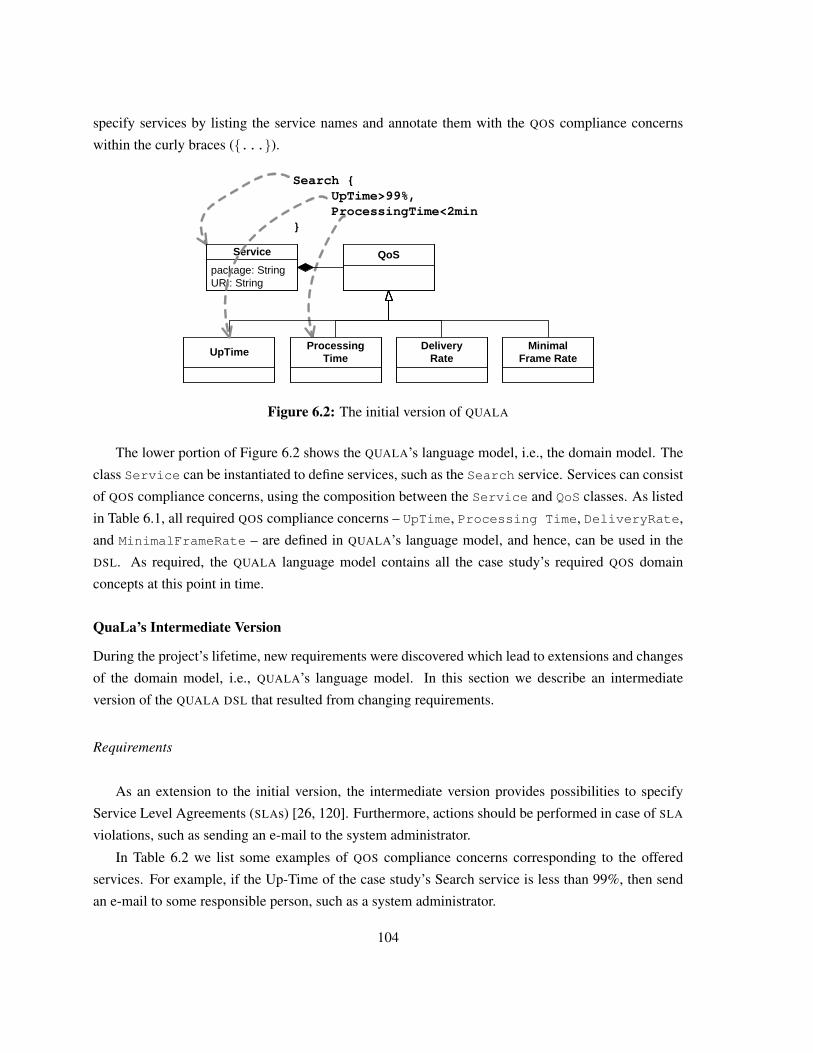
specify services by listing the service names and annotate them with the QOS compliance concerns
within the curly braces ({...}).
Search {UpTime>99%, ProcessingTime<2min
}
package: StringURI: String
Service QoS
UpTimeProcessing
TimeDelivery
RateMinimal
Frame Rate
Figure 6.2: The initial version of QUALA
The lower portion of Figure 6.2 shows the QUALA’s language model, i.e., the domain model. The
class Service can be instantiated to define services, such as the Search service. Services can consist
of QOS compliance concerns, using the composition between the Service and QoS classes. As listed
in Table 6.1, all required QOS compliance concerns – UpTime, Processing Time, DeliveryRate,
and MinimalFrameRate – are defined in QUALA’s language model, and hence, can be used in the
DSL. As required, the QUALA language model contains all the case study’s required QOS domain
concepts at this point in time.
QuaLa’s Intermediate Version
During the project’s lifetime, new requirements were discovered which lead to extensions and changes
of the domain model, i.e., QUALA’s language model. In this section we describe an intermediate
version of the QUALA DSL that resulted from changing requirements.
Requirements
As an extension to the initial version, the intermediate version provides possibilities to specify
Service Level Agreements (SLAs) [26, 120]. Furthermore, actions should be performed in case of SLA
violations, such as sending an e-mail to the system administrator.
In Table 6.2 we list some examples of QOS compliance concerns corresponding to the offered
services. For example, if the Up-Time of the case study’s Search service is less than 99%, then send
an e-mail to some responsible person, such as a system administrator.
104
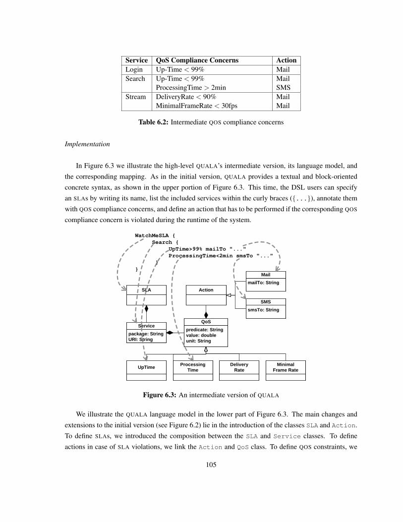
Service QoS Compliance Concerns ActionLogin Up-Time < 99% MailSearch Up-Time < 99% Mail
ProcessingTime > 2min SMSStream DeliveryRate < 90% Mail
MinimalFrameRate < 30fps Mail
Table 6.2: Intermediate QOS compliance concerns
Implementation
In Figure 6.3 we illustrate the high-level QUALA’s intermediate version, its language model, and
the corresponding mapping. As in the initial version, QUALA provides a textual and block-oriented
concrete syntax, as shown in the upper portion of Figure 6.3. This time, the DSL users can specify
an SLAs by writing its name, list the included services within the curly braces ({...}), annotate them
with QOS compliance concerns, and define an action that has to be performed if the corresponding QOS
compliance concern is violated during the runtime of the system.
WatchMeSLA {Search {
UpTime>99% mailTo "..."ProcessingTime<2min smsTo "..."
}}
package: StringURI: String
Service
SLA Action
mailTo: String
smsTo: String
SMS
predicate: Stringvalue: doubleunit: String
QoS
UpTimeProcessing
TimeDelivery
RateMinimal
Frame Rate
Figure 6.3: An intermediate version of QUALA
We illustrate the QUALA language model in the lower part of Figure 6.3. The main changes and
extensions to the initial version (see Figure 6.2) lie in the introduction of the classes SLA and Action.
To define SLAs, we introduced the composition between the SLA and Service classes. To define
actions in case of SLA violations, we link the Action and QoS class. To define QOS constraints, we
105
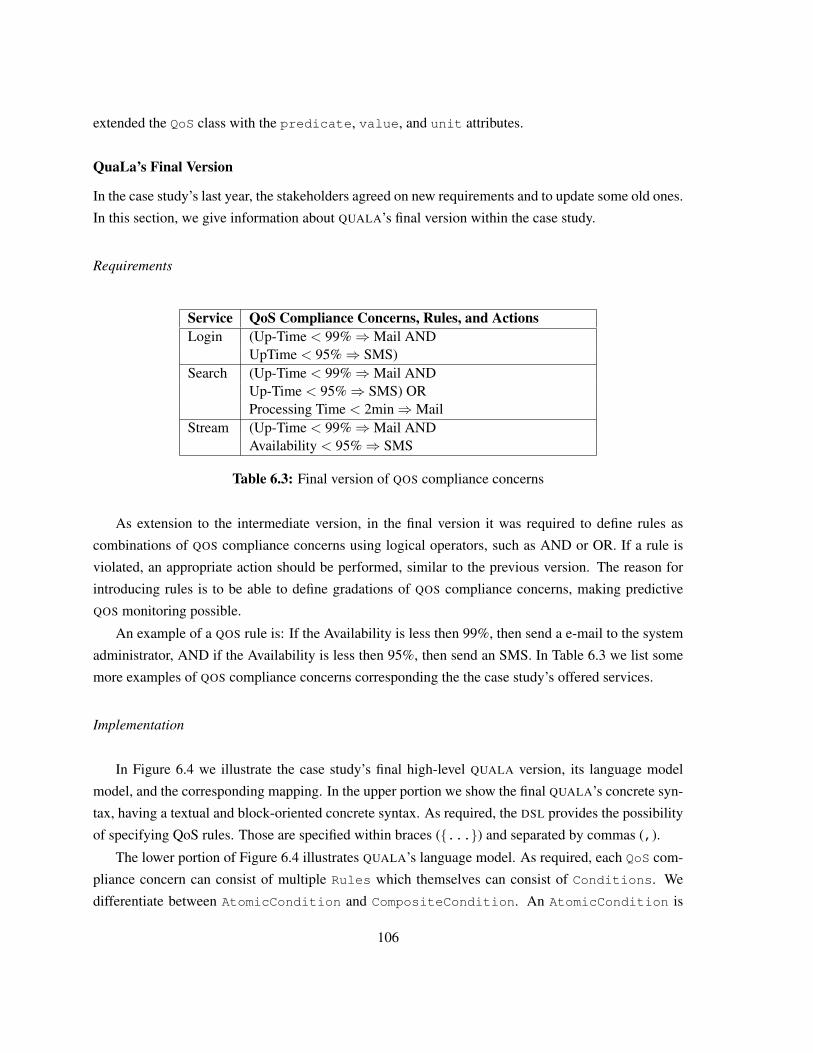
extended the QoS class with the predicate, value, and unit attributes.
QuaLa’s Final Version
In the case study’s last year, the stakeholders agreed on new requirements and to update some old ones.
In this section, we give information about QUALA’s final version within the case study.
Requirements
Service QoS Compliance Concerns, Rules, and ActionsLogin (Up-Time < 99%⇒Mail AND
UpTime < 95%⇒ SMS)Search (Up-Time < 99%⇒Mail AND
Up-Time < 95%⇒ SMS) ORProcessing Time < 2min⇒Mail
Stream (Up-Time < 99%⇒Mail ANDAvailability < 95%⇒ SMS
Table 6.3: Final version of QOS compliance concerns
As extension to the intermediate version, in the final version it was required to define rules as
combinations of QOS compliance concerns using logical operators, such as AND or OR. If a rule is
violated, an appropriate action should be performed, similar to the previous version. The reason for
introducing rules is to be able to define gradations of QOS compliance concerns, making predictive
QOS monitoring possible.
An example of a QOS rule is: If the Availability is less then 99%, then send a e-mail to the system
administrator, AND if the Availability is less then 95%, then send an SMS. In Table 6.3 we list some
more examples of QOS compliance concerns corresponding the the case study’s offered services.
Implementation
In Figure 6.4 we illustrate the case study’s final high-level QUALA version, its language model
model, and the corresponding mapping. In the upper portion we show the final QUALA’s concrete syn-
tax, having a textual and block-oriented concrete syntax. As required, the DSL provides the possibility
of specifying QoS rules. Those are specified within braces ({...}) and separated by commas (,).
The lower portion of Figure 6.4 illustrates QUALA’s language model. As required, each QoS com-
pliance concern can consist of multiple Rules which themselves can consist of Conditions. We
differentiate between AtomicCondition and CompositeCondition. An AtomicCondition is
106
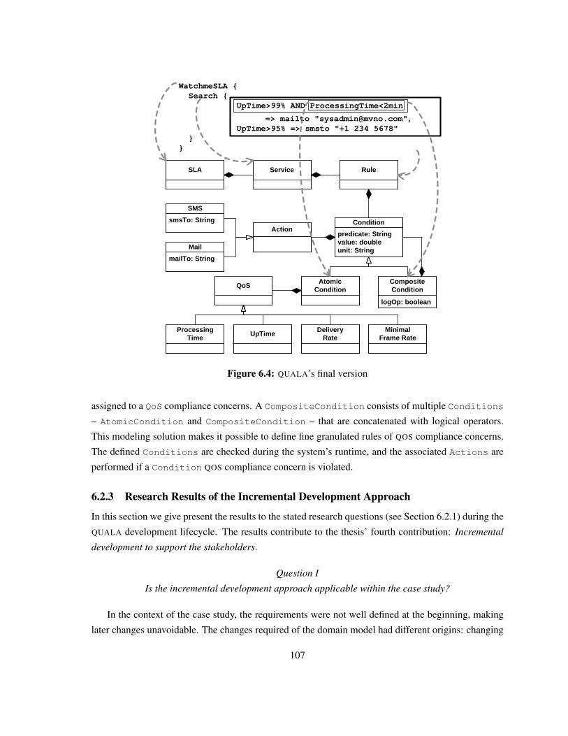
WatchmeSLA {Search {
UpTime>99% AND ProcessingTime<2min
=> mailto "[email protected]",UpTime>95% => smsto "+1 234 5678"
} }
ServiceSLA
predicate: Stringvalue: doubleunit: String
ConditionAction
smsTo: String
SMS
mailTo: String
QoS
ProcessingTime
UpTimeDelivery
RateMinimal
Frame Rate
Rule
logOp: boolean
CompositeCondition
AtomicCondition
Figure 6.4: QUALA’s final version
assigned to a QoS compliance concerns. A CompositeCondition consists of multiple Conditions
– AtomicCondition and CompositeCondition – that are concatenated with logical operators.
This modeling solution makes it possible to define fine granulated rules of QOS compliance concerns.
The defined Conditions are checked during the system’s runtime, and the associated Actions are
performed if a Condition QOS compliance concern is violated.
6.2.3 Research Results of the Incremental Development Approach
In this section we give present the results to the stated research questions (see Section 6.2.1) during the
QUALA development lifecycle. The results contribute to the thesis’ fourth contribution: Incremental
development to support the stakeholders.
Question I
Is the incremental development approach applicable within the case study?
In the context of the case study, the requirements were not well defined at the beginning, making
later changes unavoidable. The changes required of the domain model had different origins: changing
107
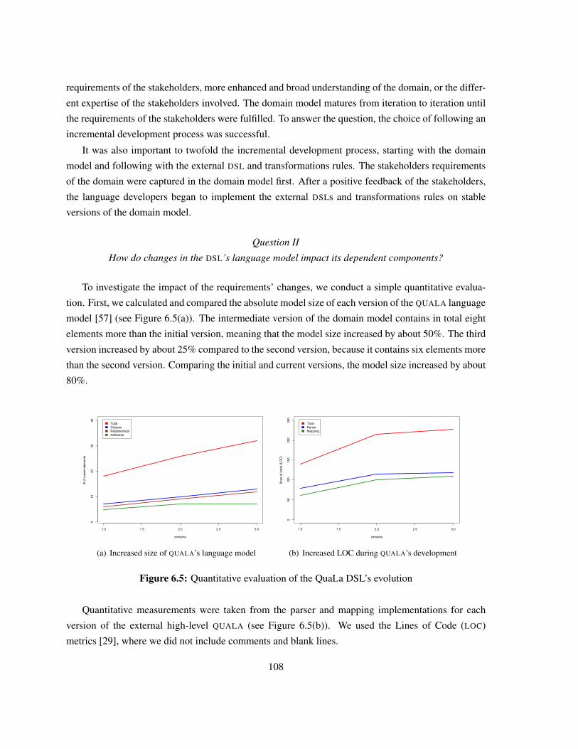
requirements of the stakeholders, more enhanced and broad understanding of the domain, or the differ-
ent expertise of the stakeholders involved. The domain model matures from iteration to iteration until
the requirements of the stakeholders were fulfilled. To answer the question, the choice of following an
incremental development process was successful.
It was also important to twofold the incremental development process, starting with the domain
model and following with the external DSL and transformations rules. The stakeholders requirements
of the domain were captured in the domain model first. After a positive feedback of the stakeholders,
the language developers began to implement the external DSLs and transformations rules on stable
versions of the domain model.
Question II
How do changes in the DSL’s language model impact its dependent components?
To investigate the impact of the requirements’ changes, we conduct a simple quantitative evalua-
tion. First, we calculated and compared the absolute model size of each version of the QUALA language
model [57] (see Figure 6.5(a)). The intermediate version of the domain model contains in total eight
elements more than the initial version, meaning that the model size increased by about 50%. The third
version increased by about 25% compared to the second version, because it contains six elements more
than the second version. Comparing the initial and current versions, the model size increased by about
80%.
1.0 1.5 2.0 2.5 3.0
010
2030
40
versions
# of
mod
el e
lem
ents
TotalClassesRelationshipsAttributes
(a) Increased size of QUALA’s language model
1.0 1.5 2.0 2.5 3.0
050
100
150
200
250
versions
lines
of c
ode
(LO
C)
TotalParserMapping
(b) Increased LOC during QUALA’s development
Figure 6.5: Quantitative evaluation of the QuaLa DSL’s evolution
Quantitative measurements were taken from the parser and mapping implementations for each
version of the external high-level QUALA (see Figure 6.5(b)). We used the Lines of Code (LOC)
metrics [29], where we did not include comments and blank lines.
108
The intermediate version requires eight more parsing rules and five more mappings in comparison
to the initial version. The reason lies in the comprehensive concrete syntax – compare the two syntaxes
in Figure 6.2 and 6.3. The implementation of the intermediate QUALA’s components has 75 LOCs
more than the first one, meaning an increase of about 50%. Comparing the concrete syntaxes of the
final and the intermediate version – see Figures 6.3 and 6.4 – the final version of the QUALA does not
have many differences to the second version. The final QUALA increased about 25% compared to the
intermediate one, but, increased about 85% in comparison to the initial one.
Question III
What can be the drawbacks of following a non-incremental development approach?
In an early stage of the development process the stakeholders’ requirements are not well-defined
and are subject to constant changes. Changes in the requirements change the domain model and affect
its dependent components, such as code generators, parsers, or mappings. Comparing the enhancement
of the QUALA implementations (see Figures 6.5(a) and 6.5(b)), a linear relation between the evolving
domain model and the implementations can be observed. This means that the higher the number of
changes in the language model, the higher the update efforts of the parsers and transformation rules.
During the case study we discovered that it is not advisable to follow a non-incremental development
approach and to develop the whole solution at once after a long design phase. To answer the question,
a drawback of non-incremental development approaches is that the later and bigger the changes are
the more complex is the development effort of new and changing requirements. As a result, a non-
incremental development approach has to deal with time-consuming maintenance phases.
Question IV
Are there general recommendations for similar projects?
The current domain model contains four QOS compliance concerns that originate from the case
study’s requirements. Many other QOS measurements exists, such as described in [92], [98], [133],
or [85]. Every version of the domain model and its dependent components can be extended easily.
We recommend an incremental DSL development where in every iteration different features and sub-
domains can be considered. It is important that changes on the domain model do not require costly
and complex changes in the transformation rules or the external DSLs. One general recommendation is
that the development of an external DSL or the transformation rules should only start when the domain
experts are able to work with the concepts contained in the domain model and all requirements are
fulfilled. The need for code generators or an external DSL can arise at any time during the development
process.
In every iteration of an incremental development approach the requirements of new features and
sub-domains can be considered, which can result only in extensions. For example, an extension of the
109
initial version (see Figure 6.2) was the specification of SLAs. In the second version (see 6.3) we had
only to introduce the SLA class for SLA specifications. The transformation rules, parsers, or mappings
can support the new features of the domain model easier at every iteration stage. Changes and updates
can be kept small and lightweight because the domain model can evolve in a more independent way
from the components that depend on the domain model.
A current shortcoming of embedded DSLs is their concrete syntax, making it difficult to use for do-
main experts who are unfamiliar with programming language concepts. Using tools, such as GraphViz
[9] or Prefuse [14], enable the language developers to represent the current domain concepts to the do-
main experts in a graphical and understandable way. This can improve the domain experts’ feedback
should modification be needed.
6.3 Related Work on DSL DevelopmentKelly and Tolvanen [50] recommend that the DSL be maintained by a pilot DSL to see the influence
of the required changes. The presented incremental DSL development is in contrast to our approach
tailored for their MetaEdit+ CASE tool [51].
Pitkanen and Mikkonen [95] present a lightweight development approach, starting with high-level
modelling of the domain specifications and transforming them into an architectural design model using
a transformation tool. Comparable to our approach, their development approach does not include
feedback loops. Their approach can be used in the initial development stage of our approach.
Sheard [104] gives a summary about a project that focuses on the evolution of DSLs. The evolution
is divided in three stages: Infancy, Adolescence, and Maturity. An example of a embedded DSL’s
evolution is presented, where the developers ran into limitations of embedded DSLs, such as syntax,
error messages, or performance. The project described does not follow the MDD paradigm, but, there
is still a need for research to update the code generators and parsers if the concrete syntax or the domain
model are changed.
Sprinkle et al. [106] formalize the evolution of the domain, the DSL, and the domain model. The
authors consider various cases of evolution, such as domain semantics, domain types, or language
syntax. Compared to our work, Sprinkle et al. do not consider changes in the usability of the DSL, i.e.,
the DSL’s concrete syntax.
Bierhoff et al. [16] describe an incremental DSL development approach, where the DSL is based
on an existing system. The DSL evolves until it is expressive enough to specify the applications func-
tionality. Our approach is designed to develop model-driven systems from scratch which evolve on
changing requirements.
Kosar et al. [55] compares various DSL implementation approaches of Mernik et al. [65] based
on one DSL. The authors provide empirical results from implementing one language following ten
different implementation approaches. In contrast to our approach, the implementation is considered as
110
a sub-process of the whole development process.
The W3C specifications WS-Agreement [131] and WS-Policy [132] provide facilities for speci-
fying QOS constraints in web service-oriented systems. During the implementation of the industrial
case study we did not want to be tied to existing standards. However, it is possible to define trans-
formation rules for mapping the case study’s QOS specifications onto WS-Agreement or WS-Policy
specifications.
Nowadays, many tools exist to facilitate DSL development, such as xText [27], JetBrain’s MPS
[44], Ruby [32], or the MS DSL Tools [69]. Because most of the tools do not support model-driven
DSLs, the DSL development approach starts with the definition of the DSL’s concrete syntax that is
mostly described in EBNF form. The tools do support the DSL evolution by regenerating the parsers
and code generators if the concrete syntax gets changed. Our incremental development approach starts
with the definition of the domain model, i.e., the DSL’s language model, which evolves during the
collaborations with the stakeholders.
6.4 SummaryIn this chapter, Chapter 6, we have presented the an incremental development approach to develop
model-driven DSLs. We have conducted and researched the approach within the industrial research
case study (see Chapter 3) during the development of the QUALA DSL (see Section 5.4).
As first step, we started to collaborate with the stakeholder, discovering the concepts of the QOS
domain and discussing the QUALA DSL’s requirements. After designing and developing the domain
model, i.e., the QUALA language model, the stakeholders gave feedback. In the case study, the QOS
compliance concerns changed and were enhanced, making the maintenance of the QUALA DSL’s imple-
mentation complex. We presented the evolution of the domain model and the DSL’s external concrete
syntax.
We have researched the incremental development approach during the QUALA DSL’s development.
Therefore, we stated research questions, focusing on the applicability of the incremental development
approach, the impact of requirement changes in later development stages, general recommendations for
similar model-driven DSL projects, and possible drawbacks of following a non-incremental approach.
The findings discovered during the development within the case study answer the stated research ques-
tions.
111

112
Chapter 7
Extending an Existing Process-drivenSOA to QoS-awareness
Nowadays, many organizations use a process-driven Service-oriented Architecture (SOA) to automate
their business processes. The business processes’ activities are aligned with IT web services to accom-
plish tasks mostly automatically [137]. However, an organization’s business processes must adhere
to many business compliance concerns, stemming from regulations, legislations, or internal policies
[87]. In this chapter we explain how we have applied the architectural decision model (see Chapter
4) to extend an existing process-driven SOA to comply to internal Quality of Service (QOS) policies
stemming from Service Level Agreement (SLA) upon the IT web services’ performance. Furthermore,
we will explain how we integrate the QuaLa DSL (see Section 5.4) into the existing process-driven
SOA to support the stakeholders.
The chapter is structured as follows: In the following section, Section 7.1, we explain an existing
process-driven SOA that is not QoS-aware. In Section 7.2 we explain the requirements for extending
the existing architecture. The designed and developed QoS-aware process-driven SOA is explained
in Section 7.3. In Section 7.4 we illustrate an architectural walkthrough based on the case study (see
Chapter 3) for a better understanding of the QoS-aware architecture. We briefly summarize the chapter
in Section 7.5.
7.1 An Existing Process-driven SOAIn Figure 7.1 we present an existing architecture that was build for modelling process-driven SOAs.
The architecture is two-fold. First, at the design time, the modelling of the process-driven SOA’s
business processes, as well as the code generation of executable processes takes place. Second, during
the runtime, an application server hosts a process engine and the web services. The process engine
executes the generated business process code by orchestrating the web services.
113
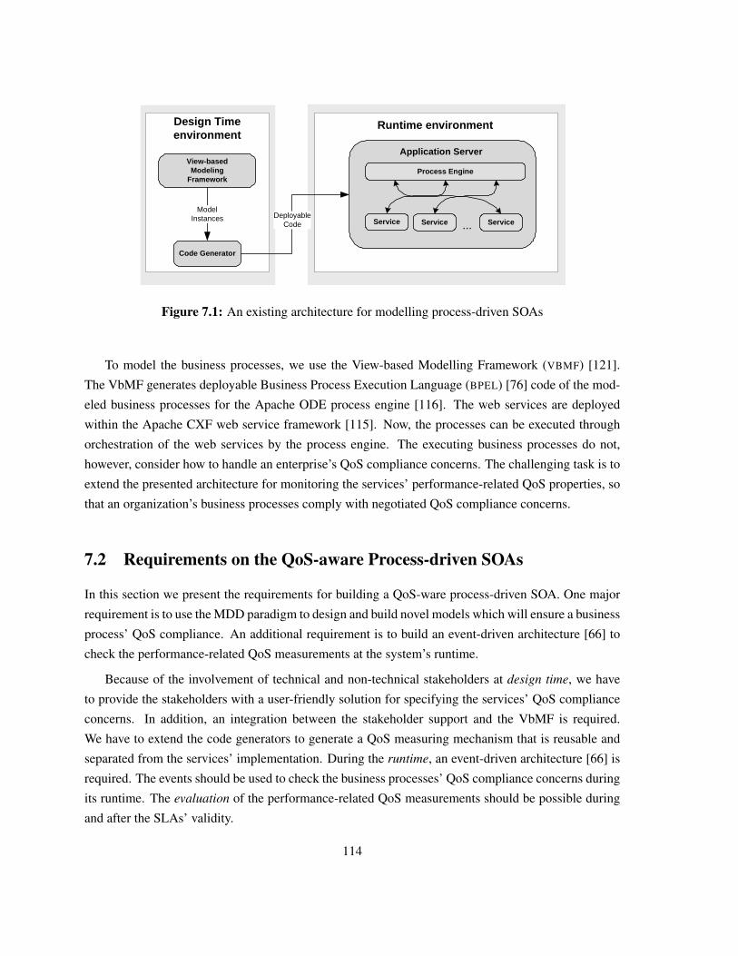
Code Generator
Deployable Code
View-based Modeling
Framework
Runtime environment
Application Server
Process Engine
Service
ModelInstances Service Service
Design Time environment
...
Figure 7.1: An existing architecture for modelling process-driven SOAs
To model the business processes, we use the View-based Modelling Framework (VBMF) [121].
The VbMF generates deployable Business Process Execution Language (BPEL) [76] code of the mod-
eled business processes for the Apache ODE process engine [116]. The web services are deployed
within the Apache CXF web service framework [115]. Now, the processes can be executed through
orchestration of the web services by the process engine. The executing business processes do not,
however, consider how to handle an enterprise’s QoS compliance concerns. The challenging task is to
extend the presented architecture for monitoring the services’ performance-related QoS properties, so
that an organization’s business processes comply with negotiated QoS compliance concerns.
7.2 Requirements on the QoS-aware Process-driven SOAs
In this section we present the requirements for building a QoS-ware process-driven SOA. One major
requirement is to use the MDD paradigm to design and build novel models which will ensure a business
process’ QoS compliance. An additional requirement is to build an event-driven architecture [66] to
check the performance-related QoS measurements at the system’s runtime.
Because of the involvement of technical and non-technical stakeholders at design time, we have
to provide the stakeholders with a user-friendly solution for specifying the services’ QoS compliance
concerns. In addition, an integration between the stakeholder support and the VbMF is required.
We have to extend the code generators to generate a QoS measuring mechanism that is reusable and
separated from the services’ implementation. During the runtime, an event-driven architecture [66] is
required. The events should be used to check the business processes’ QoS compliance concerns during
its runtime. The evaluation of the performance-related QoS measurements should be possible during
and after the SLAs’ validity.
114
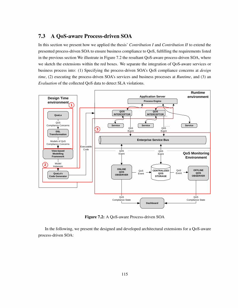
7.3 A QoS-aware Process-driven SOAIn this section we present how we applied the thesis’ Contribution I and Contribution II to extend the
presented process-driven SOA to ensure business compliance to QoS, fulfilling the requirements listed
in the previous section We illustrate in Figure 7.2 the resultant QoS-aware process-driven SOA, where
we sketch the extensions within the red boxes. We separate the integration of QoS-aware services or
business process into: (1) Specifying the process-driven SOA’s QoS compliance concerns at design
time, (2) executing the process-driven SOA’s services and business processes at Runtime, and (3) an
Evaluation of the collected QoS data to detect SLA violations.
QuaLa
QoS Compliance Concerns
Models of QoS Compliance Concerns
DSL Transformation
Design Time environment
QuaLa’sCode Generator
View-based Modelling
Framework
ModelInstances
Application Server
Process Engine
Service
...QOS
INTERCEPTOR
Service Service
QOSINTERCEPTOR
Enterprise Service Bus
. . . QoS
EventQoS
Event
Runtime environment
Executable Code
ONLINEQOS
OBSERVER
Dashboard
QoSEvent
QoSEvent QoS Monitoring
Environment
1
2
3
CENTRALIZED QOS
STORAGE
QoSEvent
OFFLINEQOS
OBSERVER
QoSCompliance State
QoSEvent
QoSCompliance State
Figure 7.2: A QoS-aware Process-driven SOA
In the following, we present the designed and developed architectural extensions for a QoS-aware
process-driven SOA:
115
Applying Contribution I:
An architectural decision model to design a QoS monitoring infrastructure
To measure the performance-related QoS properties, we implemented a Code Generator that gen-
erates QOS INTERCEPTORS for measuring the required performance-related QoS properties. We have
decided in favour of the QOS INTERCEPTOR pattern, because it is, as required, a reusable solution
and separates the measuring logic from the services’ implementation. In addition, the Apache CXF
web service framework [115] provides a convenient solution for hooking a QOS INTERCEPTOR into to
service invocation path.
To fulfill the requirement of building an event-driven architecture, we use an Enterprise Service
Bus (ESB) that manages the exchange of the events. The ESB uses a publish/subscribe mechanism
for receiving and submitting the events for pre-defined topics. When invoking a web service, the
service’s QOS INTERCEPTOR emits events about the services’ performance-related quality to the ESB.
For example, the ESB defines a topic for events, such as QoS. Then, the QOS INTERCEPTORS emit the
events to the ESB for the QoS topic, and each subscriber of the QoS topic receives the events.
To be aware of SLA violations regarding to the service consumers and to the third party providers,
the resulting architecture provides an ONLINE QOS MONITOR and an OFFLINE QOS MONITOR (see
Section 4.4.4).
To detect SLA violations during runtime, we decided in favor of a ONLINE QOS MONITORING
(see Section 4.4.4) that uses a CENTRALIZED QOS OBSERVER (see Section 4.4.5) and extends the
QOS OBSERVER pattern [124]. The CENTRALIZED QOS OBSERVER subscribes to the ESB using the
pre-defined topic for QoS events. All published events have a common format that contains an event
type, a timestamp of occurrence, and some type-dependent properties. The online QoS monitoring and
management concepts will be provided to validate the compliance concerns that can only be validated
at runtime and to provide governance of compliance concerns. We detect SLA violations by imple-
menting the CENTRALIZED QOS OBSERVER with a Complex Event Processing (CEP) logic. SLA
violations are forwarded to a web-based dashboard, such as described in [105]. The dashboard serves
as a visualization medium for displaying the business processes’ and services’ performance-related
QoS measurements and eventual SLA violations.
To detect SLA violations after the SLA duration, we needed a OFFLINE QOS MONITORING so-
lution. We decided to develop an Event Log component that is subscribed to the ESB’s QoS topic,
receives the events, and stores them in a centralized storage. To evaluate the received events after the
business processes’ execution, we developed an Evaluation Component that is responsible for eval-
uating the received events regarding SLA violations. Equivalent as the ONLINE QOS MONITORING
component, the evaluation component forwards the evaluation results to the dashboard.
However, there is no component in the architecture to predict SLA violations automatically, such
as described in [20], [139], or [58]. The QuaLa DSL can be used to define appropriate rules to fire
116
actions in order to take well-timed corrective actions manually. In addition, the architecture does not
provide mechanisms that perform appropriate actions automatically to prevent SLA violations.
Applying Contribution II:
Supporting the stakeholders with tailored domain-specific languages
To support the differently skilled stakeholders we use model-driven DSLs (see Chapter 5). In
Section 5.4 we present the Quality of Service Language (QUALA), a tailored model-driven Domain-
specific Language (DSL) to specify the services’ QoS compliance concerns as well as to specify the
technical details to measure the performance-related QoS properties. We use QuaLa within this archi-
tecture to support the stakeholders.
In addition, we have built an DSL Editor that can be used by the stakeholders for describing the
services’ QoS compliance concerns. For an integration with VbMF, we had to build a DSL Transfor-
mation that integrates the QuaLa specifications, i.e., the services’ QoS compliance concerns, with the
VbMF modelled business process and services.
7.4 A Case Study’s Architectural Walkthrough
For a better understanding of the model-driven process-driven SOA for ensuring QoS-aware business
processes, we describe the architecture for the case study (see Chapter 3). The case study’s MVNO
(i.e., the service provider) requires an ONLINE QOS MONITORING solution to get a permanent overview
of the services’ QoS compliance state, making it possible for the MVNO to prevent SLA violations
when services quality decrease.
At the design time, the MVNO’s domain experts use the high-level QuaLa DSL (see Section 5.4.1)
to specify the QoS compliance concerns of the business processes’ services, i.e., Login, Search,
and Stream. Technical experts use the low-level QuaLa DSL (see Section 5.4.2) to extend the high-
level specifications with required technical artefacts to generate an executable QoS-aware business
processes. Examples of using the high-level and low-level QuaLa DSL are given in Section 5.4.4.
During the business processes’ runtime, at every invocation of a QoS-aware web service, the ser-
vices’ QOS INTERCEPTOR emits events to the ESB. The QOS OBSERVER of the ONLINE QOS MON-
ITORING component receives the events, evaluates them, and forwards the evaluation results to the
dashboard. The MVNO’s auditors see the evaluation results on the dashboard and can take appropriate
actions manually to prevent possible SLA violations. For example, if auditors observe a permanent
decreasing quality of the Search service, they can inform the technical experts to check for reasons
and to take counteractive actions.
117
7.5 SummaryIn this chapter we illustrated how we have extended an existing model-driven process-driven SOA to
ensure business compliance. We concentrated on performance-related QoS compliance concerns that
are defined in SLAs between the service provider and a service consumer. We have shown where
the extended architecture reflects the main contributions of this thesis and gave an architectural walk-
through based on the case study (see Section 3).
The QoS-aware process-driven SOA is an event-driven architecture, meaning that events are used
to validate the business’ QoS compliance. We have illustrated the support of the various stakehold-
ers to specify the process-driven SOA’s QoS compliance concerns, as well as the placement of the
generated QOS INTERCEPTORS for measuring the performance-related QoS properties. The presented
architecture provides online and offline QoS monitoring, making it possible to detect SLA violations
during and after the business processes execution.
118
Chapter 8
Conclusion
Monitoring Quality of Service (QOS) in service-oriented systems is inevitable in case Service Level
Agreements (SLAs) upon the services’ performance-related QoS compliance concerns are negotiated
between service providers and service consumers. To design a QoS monitoring infrastructure, archi-
tectural design decisions about measuring, evaluating, and storing the performance-related agreements
must be taken. To specify the performance-related agreements, differently skilled stakeholders must
be supported, ranging from business to technical experts. Because of fuzzy requirements on the QoS
domain in the early development stages, the requirements enhance and change frequently.
In this chapter we conclude the thesis. In Section 8.1 we summarize the thesis’ questions under
research (see Section 1.3). Then, we iterate over the thesis’ contributions (see Section 1.4) in Section
8.2. In Section 8.3 we explain potential future research challenges in the area of monitoring QoS in
service-oriented systems.
8.1 Summary of the Research QuestionsResearch Question I:
How to design a QoS monitoring infrastructure in order to detect or prevent SLA violations?
During the design of an appropriate QoS monitoring infrastructure, many architectural design de-
cisions arise. This research question concentrated on the various design decisions that must be taken
during the decision making process. In this thesis, we focus on architectural design decisions about
measuring, storing, and evaluating the performance-related QoS properties that are negotiated within
SLAs.
119
Research Question II:
How to support the differently skilled stakeholders to specify the performance-related QoS
agreements?
After having designed a QoS monitoring infrastructure, most of its component can be generated
automatically using Model-driven Development (MDD). Various stakeholders are involved in the man-
agement and maintenance phases of the running QoS monitoring infrastructure. The stakeholders are
differently skilled, ranging from business to technical background knowledge. Business experts know
how and which performance-related QoS properties are specified within the SLAs. Technical experts
have experience in the used technologies to develop a QoS monitoring infrastructure. This research
question focuses on the problem of including all stakeholders within the process of a specifying the
performance-related QoS clauses within the SLAs.
Research Question III:
How to develop an appropriate stakeholder support, dealing with permanent changing requirements?
In early stages, the requirements of a QoS monitoring infrastructure are fuzzy and incomplete,
stemming from different stakeholder interpretations of the QoS domain. After becoming more familiar
with the domain concepts, the requirements of the QoS monitoring infrastructure evolve and change.
The later the changes, the more complex and time-consuming the updates. The research questions
focuses on approaching solutions to deal with permanent changing requirements.
Research Question IV:
How to integrate a QoS monitoring solution into an existing service-oriented system?
Nowadays, organizations utilize service-oriented system to automate their inner- and cross-
organizational business processes. A service-oriented system must be extended to ensure internal
policies, stemming from performance-related QoS negotiations within SLAs. In thesis we wanted
to research how the thesis’ contributions can be used to extend an existing process-driven Service-
oriented Architecture (SOA) to comply to performance-related agreements.
8.2 Summary of the Scientific ContributionsContribution I:
An architectural decision model to design a QoS monitoring infrastructure
In this thesis we have present an architectural design decision model to help the designers through
the decision making process. We concentrated on design decisions regarding measuring, storing,
120
and evaluating performance-related QoS agreements. The architectural decision model contains de-
sign decisions and requirements that we have discovered in a thorough literature review as well as
within the case study (see 3). In the model, we differentiate between criteria, system-specific, and
implementation-specific requirements. The presented model proposes design solutions that are based
upon well-established design patterns. Criteria and requirements influence design decisions in the se-
lection of the model’s design solutions. We have evaluated the architectural decision model within the
case study (see Section 3).
Contribution II:
Supporting the stakeholders with tailored domain-specific languages
To support the differently skilled stakeholders we introduce an approach to specify performance-
related QoS properties embedded in the SLAs. The approach focuses on utilizing Domain-specific
Languages (DSLs), developed following the MDD paradigm. In our approach, we divide a model-driven
DSL into multiple sub-languages at different abstraction levels. Each sub-language is tailored to the
appropriate stakeholders. We have evaluated the approach within an explorative study of providing
tailored languages within SOAs. We illustrate the Quality of Service Language (QUALA) DSL, a
developed model-driven DSL within the scope of an industrial case study for specifying a service’s
performance-related QoS compliance concerns and actions in case of violations. The DSL is separated
into two different languages, tailored for business and technical experts.
Contribution III:
Incremental development of domain-specific languages
In this thesis we have presented an incremental development approach to develop model-driven
DSLs. We have made a study and researched the approach within the case study (see Chapter 3). The
study’s research questions focus on (1) the applicability of an incremental approach, (2) the impact
of changing requirements, (3) drawbacks of non-incremental development approaches, and (4) general
recommendations for developing model-driven DSLs incrementally. We provide answers to the study’s
research questions based on the findings during the incremental development of the case study’s QuaLa
DSL.
Contribution IV:
Extending an existing process-driven SOA to QOS-awareness
We have used the aforementioned contributions to extend an existing process-driven SOA to mon-
itor performance-related QoS agreements. The existing system consists of a modelling framework to
generate executable business processes that orchestrate the SOA’s services. First, we had to utilize
121
the architectural design decision model to design an appropriated QoS monitoring infrastructure. The
resultant QoS monitoring infrastructure uses QOS INTERCEPTORS to measure, a CENTRALIZED ON-
LINE QOS OBSERVER and a CENTRALIZED OFFLINE QOS OBSERVERS to evaluate, and a CENTRAL-
IZED QOS STORAGE to store the performance-related QoS properties. We had afterwards to develop
a DSL to support the stakeholders in specifying the services’ performance-related QoS properties.
We extended the QuaLa DSL (see Section 5.4) to integrate with the existing modelling framework.
Then, we extend the QuaLa code generator to generate QOS INTERCEPTORS that measure the ser-
vices’ performance-related QoS properties and submit the measurements to the CENTRALIZED QOS
OBSERVER for evaluation.
8.3 Potential Future ResearchAs illustrated, monitoring agreements on the services’ performance in a service-oriented systems is a
challenging task. In the thesis we present approaches to reduce the design and development efforts of a
QoS monitoring infrastructure, involving differently skilled stakeholders. However, there are still a lot
of research challenges in this area. In this section we explain some, from our point of view, potential
research challenges.
In this thesis, we have presented a QoS monitoring infrastructure that informs some system admin-
istrators or responsible persons via an e-mail or an SMS in case of potential future SLA violations. The
system administrators or responsible persons must take appropriate actions to avoid the SLA violations
manually. Can such corrective provisions be automated?
In the thesis’ contributions we have used MDD to generate the QoS monitoring infrastructure’s
components automatically. We have used DSLs to support the differently skilled stakeholders to spec-
ify the services’ performance-related QoS agreemements. But, the generated code must be extended
with manual implementations. Is it possible to enable full code generation?
A QoS monitoring infrastructure is a complex software system that has many requirements. Ful-
filling one requirement can bring trade-offs for other requirements. We have presented an architectural
design decision model to enhance the decision making process and to fulfill the requirements as good
as possible. In the future, we want to research general architectural decision models to design complex
distributed systems. How can the requirements of such a system be gathered from the stakeholders?
And how can MDD help to develop complex distributed systems?
122
Bibliography
[1] A. Agrawal, M. Amend, M. Das, C. Keller, M. Kloppmann, D. Konig, F. Leymann, R. Muller,G. Pfau, K. Ploesser, R. Rangaswamy, A. Rickayzen, M. Rowley, P. Schmidt, I. Trickovic, A.Yiu, and M. Zeller. Web Services Human Task (WS-HumanTask), version 1.0, 2007. → pages77
[2] Y. Afek, M. Merritt, and G. Stupp. Remote Object Oriented Programming with Quality ofService or Java’s RMI over ATM, 1996. → pages 40, 136
[3] C. Alexander, S. Ishikawa, and M. Silverstein. A Pattern Language: Towns, Buildings,Construction. Oxford University Press, New York, 1977. ISBN 0195019199. → pages 22
[4] G. Alonso, F. Casati, H. Kuno, and V. Machiraju. Web Services – Concepts, Architectures andApplications. Springer, October 2003. ISBN 3642078885. → pages 9, 10
[5] Anton Jansen and Jan Bosch. Software Architecture as a Set of Architectural DesignDecisions. In WICSA ’05: Proceedings of the 5th Working IEEE/IFIP Conference on SoftwareArchitecture, pages 109–120, Washington, DC, USA, 2005. IEEE Computer Society. ISBN0-7695-2548-2. doi:http://dx.doi.org/10.1109/WICSA.2005.61. → pages 74
[6] G. Arango. Domain analysis – from art form to engineering discipline. SIGSOFT Softw. Eng.Notes, 14(3):152–159, 1989. ISSN 0163-5948. doi:http://doi.acm.org/10.1145/75200.75224.→ pages 101
[7] Arie Deursen and Paul Klint. Little Languages: Little Maintenance? Technical report, CWI(Centre for Mathematics and Computer Science), Amsterdam, The Netherlands, 1997. →pages 101
[8] Arno Schmidmeier. Aspect oriented DSLs for business process implementation. In DSAL ’07:Proceedings of the 2nd workshop on Domain specific aspect languages, page 5, New York,NY, USA, 2007. ACM. ISBN 978-1-59593-659-8.doi:http://doi.acm.org/10.1145/1255400.1255405. → pages 74, 76
[9] AT&T Research. Graphviz - Graph Visualization Software. http://www.graphviz.org/. →pages 110
[10] C. Aurrecoechea, A. T. Campbell, and L. Hauw. A survey of QoS architectures. MultimediaSystems, 6:138–151, May 1998. ISSN 0942-4962. doi:10.1007/s005300050083. URLhttp://portal.acm.org/citation.cfm?id=277956.277958. → pages 21
123
[11] P. Avgeriou and U. Zdun. Architectural Patterns Revisited – A Pattern Language. InProceedings of 10th European Conference on Pattern Languages of Programs (EuroPlop2005), pages 1 – 39, Irsee, Germany, July 2005. → pages 31
[12] T. Baar. Correctly defined concrete syntax. Software and System Modeling, 7(4):383–398,2008. → pages 70
[13] E. Badidi, L. Esmahi, M. A. Serhani, and M. Elkoutbi. WS-QoSM: A Broker-basedArchitecture for Web Services QoS Management. In Innovations in Information Technology,2006, pages 1–5, 2006. doi:10.1109/INNOVATIONS.2006.301883. → pages 46, 53, 137, 140
[14] Berkely Institute of Design. The Prefuse Visualization Toolkit. http://prefuse.org/. → pages110
[15] P. Bianco, G. A. Lewis, and P. Merson. Service Level Agreements in Service-OrientedArchitecture Environments. Technical report, Software Engineering Institute, Carnegie MellonUniversity, Pittsburgh, PA, 2001. → pages 21
[16] K. Bierhoff, E. Liongosari, and K. Swaminathan. Incremental Development of aDomain-Specific Language That Supports Multiple Application Styles. In OOPSLA – 6thWorkshop on Domain Specific Modeling, pages 67–78, October 2006. → pages 110
[17] Borland. VisiBroker – A Robust CORBA Environment for Distributed Processing, 2009. →pages 45, 137
[18] F. Buschmann, R. Meunier, H. Rohnert, P. Sommerlad, and M. Stal. Pattern-Oriented SoftwareArchitecture, Volume 1: A System of Patterns. Wiley, 1996. ISBN 978-0-471-95869-7. →pages 5, 21
[19] F. Buschmann, K. Henney, and D. C. Schmidt. Pattern-Oriented Software Architecture,Volume 4: A Pattern Language for Distributed Computing. Wiley, 2007. ISBN978-0-470-05902-9. → pages 5, 21, 24, 40, 45
[20] M. Castellanos, F. Casati, U. Dayal, and M.-C. Shan. Intelligent Management of SLAs forComposite Web Services. In N. Bianchi-Berthouze, editor, Databases in NetworkedInformation Systems, volume 2822 of Lecture Notes in Computer Science, pages 158–171.Springer Berlin / Heidelberg, 2003. → pages 116
[21] Cisco. Cisco IOS IP Service Level Agreements (SLAs), 2011. http://www.cisco.com/go/ipsla(last accessed: February 2011). → pages 46, 53, 137, 140
[22] J. O. Coplien. Design Pattern Definition – Software Patterns.http://hillside.net/patterns/222-design-pattern-definition (last accessed: February 2011). →pages 22
[23] K. Czarnecki and U. W. Eisenecker. Generative Programming — Methods, Tools, andApplications. Addison-Wesley Longman Publishing Co., Inc., 6th edition, 2000. → pages 25
124
[24] H. Czedik-Eysenberg. Generating Performance-Related Quality of Service Tests for WebServices using a Domain-Specific Language. Master Thesis, Vienna University of Technology,2011. → pages 94
[25] F. Daniel, F. Casati, V. D’Andrea, E. Mulo, U. Zdun, S. Dustdar, S. Strauch, D. Schumm,F. Leymann, S. Sebahi, F. d. Marchi, and M.-S. Hacid. Business Compliance Governance inService-Oriented Architectures. In Proceedings of the 2009 International Conference onAdvanced Information Networking and Applications, pages 113–120, Washington, DC, USA,2009. IEEE Computer Society. ISBN 978-0-7695-3638-5. doi:10.1109/AINA.2009.112. URLhttp://portal.acm.org/citation.cfm?id=1578016.1578257. → pages 1
[26] G. Di Modica, O. Tomarchio, and L. Vita. Dynamic SLAs management in service orientedenvironments. Journal of Systems and Software, 82(5):759–771, 2009. ISSN 0164-1212.doi:http://dx.doi.org/10.1016/j.jss.2008.11.010. → pages 104
[27] Eclipse. Xtext, 2009. http://www.eclipse.org/Xtext/. → pages 111
[28] Eclipse.org. Xtext – Language Development Framework. http://www.eclipse.org/Xtext/. →pages 70
[29] N. Fenton and S. L. Pfleeger. Software metrics (2nd ed.): a rigorous and practical approach.PWS Publishing Co., Boston, MA, USA, 1997. ISBN 0-534-95600-9. → pages 108
[30] M. Fowler. Domain-Specific Languages. Addison-Wesley Professional, October 2010. ISBN0321712943. → pages 69, 82, 100
[31] M. Fowler. Language Workbenches: The Killer-App for Domain Specific Languages?http://www.martinfowler.com/articles/languageWorkbench.html, June 2005. → pages 73
[32] J. Freeze. Creating DSLs with Ruby, 2006.http://www.artima.com/rubycs/articles/ruby as dsl.html. → pages 111
[33] J. Freeze. Creating DSLs with Ruby. Ruby Code & Style, March 2006. → pages 69
[34] S. Frølund and J. Koistinen. Quality of Service Specification in Distributed Object SystemsDesign. In COOTS, pages 1–18. USENIX, 1998. → pages 11
[35] E. Gamma, R. Helm, R. Johnson, and J. Vlissides. Design Patterns: Elements of ReusableObject-Oriented Software. Addison-Wesley Professional, 1995. → pages 5, 21, 22, 34, 36, 59,66
[36] M. Goedicke, K. Koellmann, and U. Zdun. Designing runtime variation points in product linearchitectures: three cases. Science of Computer Programming, 53(3):353–380, 2004. → pages73
[37] J. Greenfield and K. Short. Software Factories: Assembling Applications with Patterns,Frameworks, Models & Tools. J. Wiley and Sons Ltd., 2004. → pages 73, 74
125
[38] R. Hauck and H. Reiser. Monitoring Quality of Service across Organizational Boundaries. InProceedings of the Third International IFIP/GI Working Conference on Trends in DistributedSystems: Towards a Universal Service Market, pages 124–137, London, UK, 2000.Springer-Verlag. ISBN 3-540-41024-4. → pages 21
[39] C. Hentrich and U. Zdun. Patterns for Process-Oriented Integration in Service-OrientedArchitectures. In Proceedings of 11th European Conference on Pattern Languages ofPrograms (EuroPlop 2006), pages 141–189, Irsee, Germany, July 2006. → pages 10
[40] J. Hoffert, D. Schmidt, and A. Gokhale. DQML: A Modeling Language for ConfiguringDistributed Publish/Subscribe Quality of Service Policies. In Proceedings of the OTM 2008Confederated International Conferences, CoopIS, DOA, GADA, IS, and ODBASE 2008. Part Ion On the Move to Meaningful Internet Systems:, OTM ’08, pages 515–534, Berlin,Heidelberg, 2008. Springer-Verlag. ISBN 978-3-540-88870-3.doi:http://dx.doi.org/10.1007/978-3-540-88871-0 38. → pages 67, 95
[41] T. Holmes, H. Tran, U. Zdun, and S. Dustdar. Modeling Human Aspects of Business Processes- A View-Based, Model-Driven Approach. In ECMDA-FA, pages 246–261, 2008.doi:10.1007/978-3-540-69100-6 17. → pages 77
[42] P. Hudak. Building Domain-Specific Embedded Languages. ACM Comput. Surv., 28,December 1996. ISSN 0360-0300. → pages 69
[43] IBM and SAP. WS-BPEL Extension for People.http://www.ibm.com/developerworks/webservices/library/specification/ws-bpel4people/. →pages 77
[44] JetBrains. Meta Programming System, 2009. http://www.jetbrains.com/mps/index.html. →pages 111
[45] L. jie Jin, V. Machiraju, and A. Sahai. Analysis on Service Level Agreement of Web Services.Technical report, HP Laboratories, 2002. → pages 1, 9, 11, 92
[46] Juha-Pekka Tolvanen. Domain-Specific Modeling: How to Start Defining Your OwnLanguage. http://www.devx.com/enterprise/Article/30550 (last accessed: July 2008). → pages96
[47] A. Keller and H. Ludwig. The WSLA Framework: Specifying and Monitoring Service LevelAgreements for Web Services. Journal of Network and Systems Management, 11(1):57–81,2003. ISSN 1064-7570. doi:http://dx.doi.org/10.1023/A:1022445108617. → pages 1
[48] A. Keller and H. Ludwig. The WSLA Framework: Specifying and Monitoring Service LevelAgreements for Web Services. Journal of Network and Systems Management, 11:57–81, 2003.ISSN 1064-7570. URL http://dx.doi.org/10.1023/A:1022445108617.10.1023/A:1022445108617. → pages 21, 67, 96
[49] S. Kelly and J.-P. Tolvanen. Domain-Specific Modeling: Enabling Full Code Generation. JohnWiley & Sons, March 2008. ISBN 0470036664. → pages 69, 99, 100
126
[50] S. Kelly and J.-P. Tolvanen. Domain-Specific Modeling: Enabling Full Code Generation. JohnWiley & Sons, March 2008. ISBN 0470036664. → pages 68, 69, 70, 110
[51] S. Kelly, K. Lyytinen, and M. Rossi. MetaEdit+: A Fully Configurable Multi-User andMulti-Tool CASE and CAME Environment. In CAiSE 96: Proceedings of the 8thInternational Conference on Advances Information System Engineering, pages 1–21, London,UK, 1996. Springer-Verlag. ISBN 3-540-61292-0. → pages 110
[52] Kevin Bierhoff and Edy S. Liongosari and Kishore S. Swaminathan. Incremental Developmentof a Domain-Specific Language That Supports Multiple Application Styles. In OOPSLA 6thWorkshop on Domain Specific Modeling, pages 67–78, October 2006. → pages 96
[53] G. Kiczales, J. Lamping, A. Mendhekar, C. Maeda, C. V. Lopes, J.-M. Loingtier, and J. Irwin.Aspect–Oriented Programming. In ECOOP, pages 220–242, 1997. → pages 65
[54] G. Kiczales, E. Hilsdale, J. Hugunin, M. Kersten, J. Palm, and W. G. Griswold. An Overviewof AspectJ. In ECOOP ’01: Proceedings of the 15th European Conference on Object-OrientedProgramming, pages 327–353, London, UK, 2001. Springer-Verlag. ISBN 3-540-42206-4. →pages 65
[55] T. Kosar, P. E. Martınez Lopez, P. A. Barrientos, and M. Mernik. A preliminary study onvarious implementation approaches of domain-specific language. Inf. Softw. Technol., 50(5):390–405, 2008. ISSN 0950-5849. doi:http://dx.doi.org/10.1016/j.infsof.2007.04.002. → pages110
[56] D. D. Lamanna, J. Skene, and W. Emmerich. SLAng: A Language for Defining Service LevelAgreements. In Proceedings of the The Ninth IEEE Workshop on Future Trends of DistributedComputing Systems, FTDCS ’03, pages 100–, Washington, DC, USA, 2003. IEEE ComputerSociety. ISBN 0-7695-1910-5. → pages 11, 67, 95
[57] C. F. J. Lange. Model Size Matters. In Workshop on Model Size Metrics at MoDELS06, 2006.→ pages 108
[58] P. Leitner, A. Michlmayr, F. Rosenberg, and S. Dustdar. Monitoring, Prediction and Preventionof SLA Violations in Composite Services. In ICWS, pages 369–376. IEEE Computer Society,2010. ISBN 978-0-7695-4128-0. → pages 21, 116
[59] L. Lewis and P. Ray. Service level management definition, architecture, and researchchallenges. In Global Telecommunications Conference, 1999. GLOBECOM ’99, volume 3,pages 1974–1978 vol.3, 1999. doi:10.1109/GLOCOM.1999.832515. → pages 1
[60] Z. Li, Y. Jin, and J. Han. A Runtime Monitoring and Validation Framework for Web ServiceInteractions. In Proceedings of the Australian Software Engineering Conference, pages 70–79,Washington, DC, USA, 2006. IEEE Computer Society. ISBN 0-7695-2551-2.doi:10.1109/ASWEC.2006.6. → pages 43, 53, 56, 136, 139, 140, 141
[61] D. Lorenzoli and G. Spanoudakis. EVEREST+: Run-time SLA violations prediction. InProceedings of the 5th International Workshop on Middleware for Service Oriented
127
Computing, MW4SOC ’10, pages 13–18, New York, NY, USA, 2010. ACM. ISBN978-1-4503-0452-8. doi:http://doi.acm.org/10.1145/1890912.1890915. URLhttp://doi.acm.org/10.1145/1890912.1890915. → pages 53, 139, 140
[62] J. Loyall, R. Schantz, J. Zinky, and D. Bakken. Specifying and Measuring Quality of Servicein Distributed Object Systems. Object-Oriented Real-Time Distributed Computing, IEEEInternational Symposium on, 0, 1998.doi:http://doi.ieeecomputersociety.org/10.1109/ISORC.1998.666767. → pages 41, 96, 136
[63] A. Mani and A. Nagarajan. Understanding quality of service for Web services – Improving theperformance of your Web services, 2002.http://www.ibm.com/developerworks/library/ws-quality.html, last accessed: February 2011. →pages 12, 13, 26, 35, 39, 135, 136
[64] E. M. Maximilien, H. Wilkinson, N. Desai, , and S. Tai. A domain specific-language for webapis and services mashups. In Proceedings of 5th International Conference on ServiceOriented Computing (ICSOC), LNCS 4749, Springer-Verlag, pages 13–26, Vienna, Austria,2007. → pages 73, 96
[65] M. Mernik, J. Heering, and A. M. Sloane. When and how to develop domain-specificlanguages. ACM Comput. Surv., 37(4):316–344, 2005. ISSN 0360-0300.doi:http://doi.acm.org/10.1145/1118890.1118892. → pages 69, 100, 110
[66] B. M. Michelson. Event-Driven Architecture Overview. Patricia Seybold Group, 2006. →pages 114
[67] A. Michlmayr, F. Rosenberg, P. Leitner, and S. Dustdar. Comprehensive QoS monitoring ofWeb services and event-based SLA violation detection. In MWSOC ’09: Proceedings of the4th International Workshop on Middleware for Service Oriented Computing, pages 1–6, NewYork, NY, USA, 2009. ACM. ISBN 978-1-60558-848-3.doi:http://doi.acm.org/10.1145/1657755.1657756. → pages 36, 53, 135, 139, 140
[68] A. Michlmayr, F. Rosenberg, P. Leitner, and S. Dustdar. End-to-End Support for QoS-AwareService Selection, Binding, and Mediation in VRESCo. IEEE Transactions on ServicesComputing, 3:193–205, 2010. ISSN 1939-1374.doi:http://doi.ieeecomputersociety.org/10.1109/TSC.2010.20. → pages 21, 43, 136
[69] Microsoft. Domain-Specific Language Tools, 2009.http://msdn.microsoft.com/en-us/library/bb126235.aspx. → pages 111
[70] Microsoft. .NET, . http://www.microsoft.com/net/. → pages 35
[71] Microsoft. .NET Remoting, .http://msdn.microsoft.com/en-us/library/kwdt6w2k(v=vs.71).aspx. → pages 43, 136
[72] Microsoft. Windows Communication Framework, .http://msdn.microsoft.com/en-us/netframework/aa663324.aspx. → pages 35
128
[73] Microsoft. Windows Performance Counters, .http://msdn.microsoft.com/en-us/library/ms735098.aspx. → pages 35, 135
[74] E. Mulo, U. Zdun, and S. Dustdar. An event view model and DSL for engineering anevent-based SOA monitoring infrastructure. In J. Bacon, P. R. Pietzuch, J. Sventek, andU. Cetintemel, editors, DEBS, pages 62–72. ACM, 2010. ISBN 978-1-60558-927-5. → pages69
[75] OASIS. Universal Description, Discovery and Integration (UDDI).http://www.oasis-open.org/committees/uddi-spec/doc/tcspecs.htm. → pages 9, 10
[76] OASIS. Web Services Business Process Execution Language Version 2.0, 2007.http://docs.oasis-open.org/wsbpel/2.0/OS/wsbpel-v2.0-OS.html. → pages 95, 114
[77] E. Oberortner, U. Zdun, and S. Dustdar. Patterns for Measuring Performance-Related QoSProperties in Distributed Systems. In Pattern Languages of Programming Conference (PLoP).→ pages 2, 21
[78] E. Oberortner, M. Vasko, and S. Dustdar. Towards Modeling Role-Based Pageflow Definitionswithin Web Applications. In Proc. of the 4th International Workshop on Model-Driven WebEngineering (MDWE 2008), volume 389 of CEUR Workshop Proceedings, pages 1–15,Toulouse, France, Sept. 2008. CEUR-WS.org. URLhttp://CEUR-WS.org/Vol-389/paper01.pdf. → pages 91
[79] E. Oberortner, U. Zdun, and S. Dustdar. Domain-Specific Languages for Service-OrientedArchitectures: An Explorative Study. In ServiceWave ’08: Proceedings of the 1st EuropeanConference on Towards a Service-Based Internet, pages 159–170, Berlin, Heidelberg, 2008.Springer-Verlag. ISBN 978-3-540-89896-2.doi:http://dx.doi.org/10.1007/978-3-540-89897-9 14. → pages 69
[80] E. Oberortner, U. Zdun, and S. Dustdar. Tailoring a model-driven Quality-of-Service DSL forvarious stakeholders. In MISE ’09: Proceedings of the 2009 ICSE Workshop on Modeling inSoftware Engineering, pages 20–25, Washington, DC, USA, 2009. IEEE Computer Society.ISBN 978-1-4244-3722-1. doi:http://dx.doi.org/10.1109/MISE.2009.5069892. → pages 2
[81] E. Oberortner, U. Zdun, and S. Dustdar. Tailoring a model-driven Quality-of-Service DSL forVarious Stakeholders. In MISE ’09: Proceedings of the 2009 ICSE Workshop on Modeling inSoftware Engineering, pages 20–25, Washington, DC, USA, 2009. IEEE Computer Society.ISBN 978-1-4244-3722-1. doi:http://dx.doi.org/10.1109/MISE.2009.5069892. → pages 11
[82] E. Oberortner, U. Zdun, S. Dustdar, A. Betkowska Cavalcante, and M. Tluczek. Supporting theEvolution of Model-driven Service-oriented Systems: A Case Study on QoS-awareProcess-driven SOAs. In IEEE International Conference on Service-Oriented Computing andApplications (SOCA), pages 1–4, 2010. doi:10.1109/SOCA.2010.5707172. → pages 2
[83] Object Management Group (OMG). Common Object Request Broker Architecture/InternetInter-ORB Protocol (CORBA/IIOP), 2008. → pages 45, 137
129
[84] Object Management Group (OMG. Quality Of Service For CCM (QOSCCM), 2008. → pages43, 136
[85] L. O’Brien, P. Merson, and L. Bass. Quality Attributes for Service-Oriented Architectures. InSDSOA ’07: Proceedings of the International Workshop on Systems Development in SOAEnvironments, Washington, DC, USA, 2007. IEEE Computer Society. ISBN 0-7695-2960-7.doi:http://dx.doi.org/10.1109/SDSOA.2007.10. → pages 12, 13, 109
[86] L. O’Brien, P. Merson, and L. Bass. Quality Attributes for Service-Oriented Architectures. InSDSOA ’07: Proceedings of the International Workshop on Systems Development in SOAEnvironments, page 3, Washington, DC, USA, 2007. IEEE Computer Society. ISBN0-7695-2960-7. doi:http://dx.doi.org/10.1109/SDSOA.2007.10. → pages 11, 12, 21
[87] M. Papazoglou. Compliance Requirements for Business-process driven SOAs. In A. Mazzeo,R. Bellini, and G. Motta, editors, E-Government Ict Professionalism and Competences ServiceScience, volume 280 of IFIP International Federation for Information Processing, pages183–194. Springer Boston, 2008. → pages 113
[88] M. Papazoglou. Compliance Requirements for Business-process driven SOAs. In A. Mazzeo,R. Bellini, and G. Motta, editors, E-Government Ict Professionalism and Competences ServiceScience, volume 280 of IFIP International Federation for Information Processing, pages183–194. Springer Boston, 2008. → pages 1
[89] M. P. Papazoglou. Service-Oriented Computing: Concepts, Characteristics and Directions. InWISE, pages 3–12. IEEE Computer Society, 2003. ISBN 0-7695-1999-7. → pages 9
[90] R. E. Pattis. EBNF: A Notation to Describe Syntax. online available athttp://www.cs.cmu.edu/∼pattis/misc/ebnf.pdf. → pages 82
[91] V. Perrone, D. Bolchini, and P. Paolini. A Stakeholders Centered Approach for ConceptualModeling of Communication-Intensive Applications. In SIGDOC ’05: Proceedings of the23rd annual international conference on Design of communication, pages 25–33, New York,NY, USA, 2005. ACM. ISBN 1-59593-175-9.doi:http://doi.acm.org/10.1145/1085313.1085323. → pages 71
[92] S. Ran. A model for web services discovery with QoS. SIGecom Exch., 4(1):1–10, 2003.doi:http://doi.acm.org/10.1145/844357.844360. → pages 109
[93] S. Ran. A Model for Web Services Discovery with QoS. SIGecom Exch., 4(1):1–10, 2003.doi:http://doi.acm.org/10.1145/844357.844360. → pages 12, 21
[94] Ravi S. Sandhu and Edward J. Coyne and Hal L. Feinstein and Charles E. Youman.Role-Based Access Control Models. Computer, 29(2):38–47, 1996. ISSN 0018-9162.doi:http://dx.doi.org/10.1109/2.485845. → pages 90
[95] Risto Pitkanen and Tommi Mikkonen. Lightweight Domain-Specific Modeling andModel-Driven Development. In OOPSLA, 6th Workshop on Domain Specific Modeling, pages159–168, October 2006. → pages 96, 110
130

[96] F. Rosenberg. QoS-Aware Composition of Adaptive Service-Oriented Systems. PhD thesis,Vienna University of Technology, 2010. → pages 21, 35, 135
[97] F. Rosenberg, C. Platzer, and S. Dustdar. Bootstrapping Performance and DependabilityAttributes of Web Services. In ICWS ’06: Proceedings of the IEEE International Conferenceon Web Services, pages 205–212, Washington, DC, USA, 2006. IEEE Computer Society.ISBN 0-7695-2669-1. doi:http://dx.doi.org/10.1109/ICWS.2006.39. → pages 13
[98] F. Rosenberg, C. Platzer, and S. Dustdar. Bootstrapping Performance and DependabilityAttributes of Web Services. In ICWS ’06: Proceedings of the IEEE International Conferenceon Web Services, pages 205–212, Washington, DC, USA, 2006. IEEE Computer Society.ISBN 0-7695-2669-1. doi:http://dx.doi.org/10.1109/ICWS.2006.39. → pages 12, 14, 21, 41,56, 109, 136, 140
[99] A. Sahai, A. Sahai, A. Durante, A. Durante, V. Machiraju, and V. Machiraju. TowardsAutomated SLA Management for Web Services. Technical report, Software TechnologyLaboratory, HP Laboratories, 2001. → pages 11
[100] A. Sahai, V. Machiraju, M. Sayal, L. J. Jin, and F. Casati. Automated SLA Monitoring for WebServices. In IEEE/IFIP DSOM, pages 28–41. Springer-Verlag, 2002. → pages 21, 36, 45, 53,56, 135, 137, 139, 140, 141
[101] SAS. ARM – Application Response Measurement. (last accessed: February 2011). → pages41, 136
[102] D. C. Schmidt. Model-Driven Engineering. IEEE Computer, 39(2), February 2006. → pages68
[103] D. C. Schmidt, H. Rohnert, M. Stal, and D. Schultz. Pattern-Oriented Software Architecture:Patterns for Concurrent and Networked Objects. John Wiley & Sons, Inc., New York, NY,USA, 2000. ISBN 0471606952. → pages 5, 21, 24, 36
[104] T. Sheard. Evolving Domain Specific Languages – Project Summary. → pages 110
[105] P. Silveira, C. Rodrıguez, F. Casati, F. Daniel, V. D’Andrea, C. Worledge, and Z. Taheri. Onthe Design of Compliance Governance Dashboards for Effective Compliance and AuditManagement. In Proceedings of the 3rd Workshop on Non-Functional Properties and SLAManagement in Service-Oriented Computing (NFPSLAM-SOC’09), 2009. → pages 28, 116
[106] J. Sprinkle, J. Gray, and M. Mernik. Fundamental Limitations in Domain-Specific LanguageEvolution. IEEE Transactions on Software Engineering, 35(3), 2009. → pages 110
[107] T. Stahl and M. Voelter. Model-Driven Software Development. J. Wiley and Sons Ltd., 2006.→ pages 74
[108] T. Stahl, M. Voelter, and K. Czarnecki. Model-Driven Software Development: Technology,Engineering, Management. John Wiley & Sons, 2006. ISBN 0470025700. → pages 68, 70
131
[109] Steve Cook. Domain-Specific Modeling and Model Driven Architectures.http://www.bptrends.com, 2004. → pages 74
[110] A. Strauss and J. Corbin. Grounded theory in practice. Sage, London, 1997. → pages 73, 75
[111] M. Strembeck and U. Zdun. An Approach for the Systematic Development ofDomain-Specific Languages. Softw. Pract. Exper., 39(15):1253–1292, 2009. ISSN 0038-0644.doi:http://dx.doi.org/10.1002/spe.v39:15. → pages 69, 82, 100
[112] Sun Developer Network. JavaServer Faces Technology.Available online at http://java.sun.com/javaee/javaserverfaces/. → pages 78
[113] The Apache Software Foundation. Apache Axis, . http://axis.apache.org/. → pages 43, 89, 136
[114] The Apache Software Foundation. Apache Axis2, . http://ws.apache.org/axis2/. → pages 12,43, 136
[115] The Apache Software Foundation. Apache CXF, . http://cxf.apache.org/. → pages 12, 42, 43,59, 82, 114, 116, 136
[116] The Apache Software Foundation. Apache ODE, . http://ode.apache.org/. → pages 114
[117] The Apache Software Foundation. Apache TCPMon, .http://ws.apache.org/commons/tcpmon/. → pages 45, 137
[118] The Community OpenORB Project. OpenORB. http://openorb.sourceforge.net/. → pages 43,136
[119] The Open Group. SLA Management Handbook – Volume 4: Enterprise Perspective, 2004. →pages 13, 28
[120] The Service Level Agreement Zone. SLA Information Zone, 2002. http://www.sla-zone.co.uk(last accessed: January 2010). → pages 104
[121] H. Tran, U. Zdun, and S. Dustdar. View-based and Model-driven Approach for Reducing theDevelopment Complexity in Process-Driven SOA. In W. Abramowicz and L. A. Maciaszek,editors, BPSC, volume 116 of LNI, pages 105–124. GI, 2007. ISBN 978-3-88579-210-9. →pages 76, 77, 114
[122] H. Tran, U. Zdun, and S. Dustdar. View-based integration of process-driven soa models atvarious abstraction levels. In R.-D. Kutsche and N. Milanovic, Editors, Proceedings of FirstInternational Workshop on Model-Based Software and Data Integration MBSDI 2008, pages55–66. Springer, April 2008. → pages 76, 77
[123] Vito Perrone and Davide Bolchini and Paolo Paolini. A Stakeholders Centered Approach forConceptual Modeling of Communication-Intensive Applications. In SIGDOC ’05:Proceedings of the 23rd annual international conference on Design of communication, pages25–33, New York, NY, USA, 2005. ACM. ISBN 1-59593-175-9.doi:http://doi.acm.org/10.1145/1085313.1085323. → pages 74
132
[124] M. Voelter, M. Kircher, and U. Zdun. Remoting Patterns – Foundations of Enterprise, Internet,and Realtime Distributed Object Middleware. Wiley & Sons, October 2004. → pages 5, 21,24, 26, 27, 33, 36, 40, 42, 48, 51, 66, 116
[125] W3C. Simple Object Access Protocol (SOAP), 2000. http://www.w3.org/TR/soap. → pages 9,10
[126] W3C. Web Services Description Language (WSDL), 2001. http://www.w3.org/TR/wsdl. →pages 9, 10, 95
[127] Q. Wang, Q. Ye, and L. Cheng. An Inter-Application and Inter-Client Priority-Based QoSProxy Architecture for Heterogeneous Networks. In ISCC ’05: Proceedings of the 10th IEEESymposium on Computers and Communications, pages 819–824, Washington, DC, USA,2005. IEEE Computer Society. ISBN 0-7695-2373-0.doi:http://dx.doi.org/10.1109/ISCC.2005.30. → pages 45, 137
[128] S. Wildermuth. Textual Domain Specific Languages for Developers, 2009.http://msdn.microsoft.com/en-us/library/dd441702.aspx. → pages 70
[129] E. Wohlstadter, S. Tai, T. Mikalsen, I. Rouvellou, and P. Devanbu. GlueQoS: Middleware toSweeten Quality-of-Service Policy Interactions. In Proceedings of the 26th InternationalConference on Software Engineering, ICSE ’04, pages 189–199, Washington, DC, USA, 2004.IEEE Computer Society. ISBN 0-7695-2163-0. → pages 41, 136
[130] World Wide Web Consortium (W3C). Web Services Architecture Requirements, 2004.http://www.w3.org/TR/wsa-reqs/. → pages 9
[131] World-Wide-Web Consortium (W3C). Web Services Agreement Specification(WS-Agreement), 2004. → pages 111
[132] World-Wide-Web Consortium (W3C). Web Services Policy 1.5 - Framework, 2007.http://www.w3.org/TR/ws-policy/. → pages 111
[133] W. D. Yu, R. B. Radhakrishna, S. Pingali, and V. Kolluri. Modeling the Measurements of QoSRequirements in Web Service Systems. Simulation, 83(1):75–91, 2007. ISSN 0037-5497.doi:http://dx.doi.org/10.1177/0037549707079228. → pages 12, 21, 109
[134] U. Zdun. Tailorable language for behavioral composition and configuration of softwarecomponents. Computer Languages, Systems and Structures: An International Journal, 32(1):56–82, 2006. → pages 73
[135] U. Zdun. The Frag Language. http://frag.sourceforge.net/. → pages 70, 84, 86
[136] U. Zdun. A DSL toolkit for deferring architectural decisions in DSL-based software design.Information and Software Technology, 52(7):733 – 748, 2010. ISSN 0950-5849.doi:DOI:10.1016/j.infsof.2010.03.004. → pages 70, 84, 86
133
[137] U. Zdun and S. Dustdar. Model-Driven and Pattern-Based Integration of Process-Driven SOAModels. In F. Leymann, W. Reisig, S. R. Thatte, and W. M. P. van der Aalst, editors, The Roleof Business Processes in Service Oriented Architectures, volume 06291 of Dagstuhl SeminarProceedings. Internationales Begegnungs- und Forschungszentrum fuer Informatik (IBFI),Schloss Dagstuhl, Germany, 2006. → pages 1, 4, 113
[138] U. Zdun and M. Strembeck. Reusable Architectural Decisions for DSL Design: FoundationalDecisions in DSL Development. In Proc. of the 14th European Conference on PatternLanguages of Programs (EuroPLoP), Irsee Monastery, Germany, July 2009. → pages 70
[139] L. Zeng, C. Lingenfelder, H. Lei, and H. Chang. Event-Driven Quality of Service Prediction.In Proceedings of the 6th International Conference on Service-Oriented Computing, ICSOC’08, pages 147–161, Berlin, Heidelberg, 2008. Springer-Verlag. ISBN 978-3-540-89647-0.doi:http://dx.doi.org/10.1007/978-3-540-89652-4 14. → pages 21, 116
134
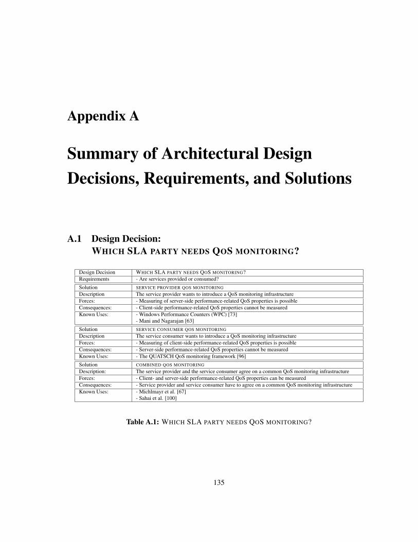
Appendix A
Summary of Architectural DesignDecisions, Requirements, and Solutions
A.1 Design Decision:WHICH SLA PARTY NEEDS QOS MONITORING?
Design Decision WHICH SLA PARTY NEEDS QOS MONITORING?Requirements - Are services provided or consumed?
Solution SERVICE PROVIDER QOS MONITORING
Description The service provider wants to introduce a QoS monitoring infrastructureForces: - Measuring of server-side performance-related QoS properties is possibleConsequences: - Client-side performance-related QoS properties cannot be measuredKnown Uses: - Windows Performance Counters (WPC) [73]
- Mani and Nagarajan [63]
Solution SERVICE CONSUMER QOS MONITORING
Description The service consumer wants to introduce a QoS monitoring infrastructureForces: - Measuring of client-side performance-related QoS properties is possibleConsequences: - Server-side performance-related QoS properties cannot be measuredKnown Uses: - The QUATSCH QoS monitoring framework [96]
Solution COMBINED QOS MONITORING
Description: The service provider and the service consumer agree on a common QoS monitoring infrastructureForces: - Client- and server-side performance-related QoS properties can be measuredConsequences: - Service provider and service consumer have to agree on a common QoS monitoring infrastructureKnown Uses: - Michlmayr et al. [67]
- Sahai et al. [100]
Table A.1: WHICH SLA PARTY NEEDS QOS MONITORING?
135
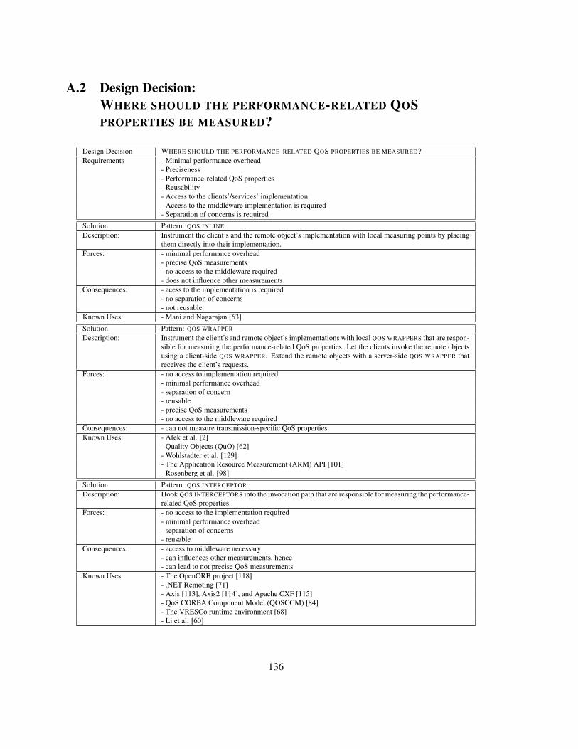
A.2 Design Decision:WHERE SHOULD THE PERFORMANCE-RELATED QOSPROPERTIES BE MEASURED?
Design Decision WHERE SHOULD THE PERFORMANCE-RELATED QOS PROPERTIES BE MEASURED?Requirements - Minimal performance overhead
- Preciseness- Performance-related QoS properties- Reusability- Access to the clients’/services’ implementation- Access to the middleware implementation is required- Separation of concerns is required
Solution Pattern: QOS INLINE
Description: Instrument the client’s and the remote object’s implementation with local measuring points by placingthem directly into their implementation.
Forces: - minimal performance overhead- precise QoS measurements- no access to the middleware required- does not influence other measurements
Consequences: - acess to the implementation is required- no separation of concerns- not reusable
Known Uses: - Mani and Nagarajan [63]
Solution Pattern: QOS WRAPPER
Description: Instrument the client’s and remote object’s implementations with local QOS WRAPPERS that are respon-sible for measuring the performance-related QoS properties. Let the clients invoke the remote objectsusing a client-side QOS WRAPPER. Extend the remote objects with a server-side QOS WRAPPER thatreceives the client’s requests.
Forces: - no access to implementation required- minimal performance overhead- separation of concern- reusable- precise QoS measurements- no access to the middleware required
Consequences: - can not measure transmission-specific QoS propertiesKnown Uses: - Afek et al. [2]
- Quality Objects (QuO) [62]- Wohlstadter et al. [129]- The Application Resource Measurement (ARM) API [101]- Rosenberg et al. [98]
Solution Pattern: QOS INTERCEPTOR
Description: Hook QOS INTERCEPTORS into the invocation path that are responsible for measuring the performance-related QoS properties.
Forces: - no access to the implementation required- minimal performance overhead- separation of concerns- reusable
Consequences: - access to middleware necessary- can influences other measurements, hence- can lead to not precise QoS measurements
Known Uses: - The OpenORB project [118]- .NET Remoting [71]- Axis [113], Axis2 [114], and Apache CXF [115]- QoS CORBA Component Model (QOSCCM) [84]- The VRESCo runtime environment [68]- Li et al. [60]
136
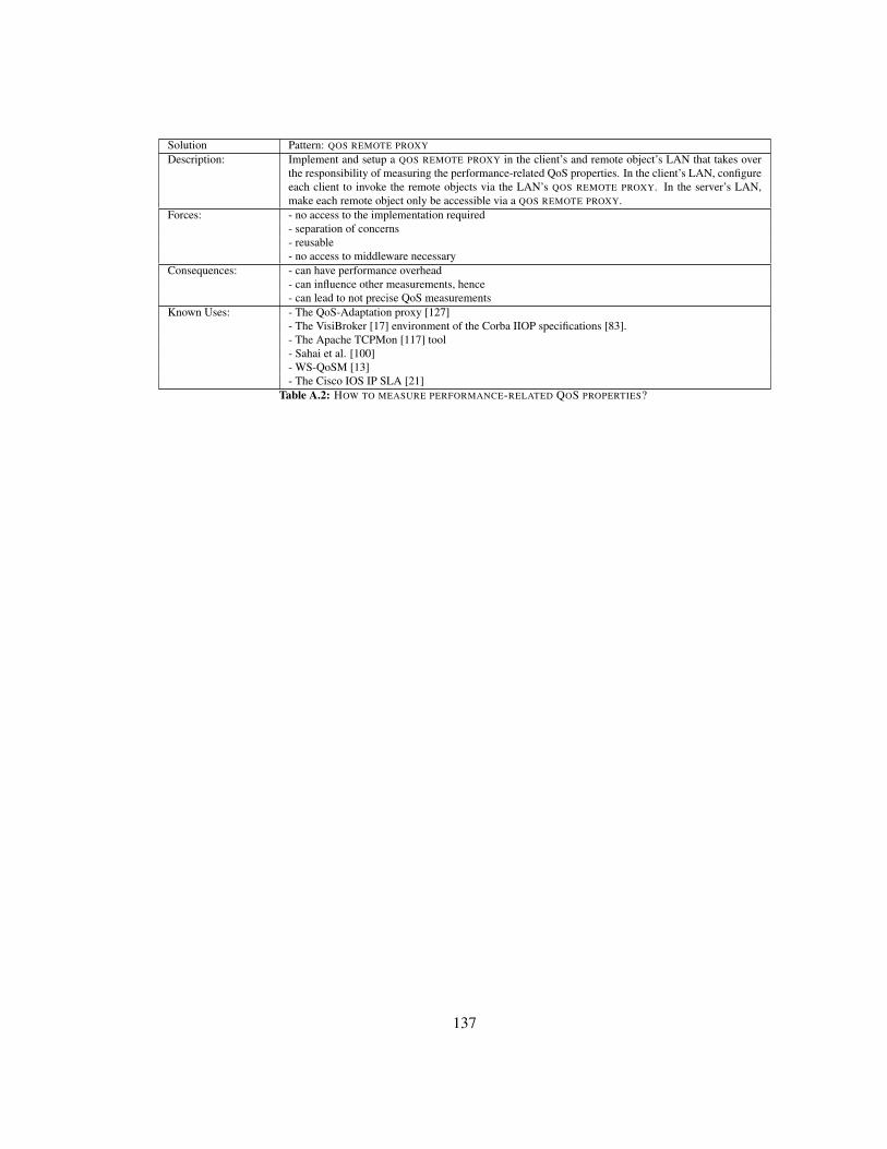
Solution Pattern: QOS REMOTE PROXY
Description: Implement and setup a QOS REMOTE PROXY in the client’s and remote object’s LAN that takes overthe responsibility of measuring the performance-related QoS properties. In the client’s LAN, configureeach client to invoke the remote objects via the LAN’s QOS REMOTE PROXY. In the server’s LAN,make each remote object only be accessible via a QOS REMOTE PROXY.
Forces: - no access to the implementation required- separation of concerns- reusable- no access to middleware necessary
Consequences: - can have performance overhead- can influence other measurements, hence- can lead to not precise QoS measurements
Known Uses: - The QoS-Adaptation proxy [127]- The VisiBroker [17] environment of the Corba IIOP specifications [83].- The Apache TCPMon [117] tool- Sahai et al. [100]- WS-QoSM [13]- The Cisco IOS IP SLA [21]
Table A.2: HOW TO MEASURE PERFORMANCE-RELATED QOS PROPERTIES?
137
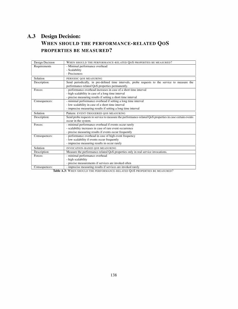
A.3 Design Decision:WHEN SHOULD THE PERFORMANCE-RELATED QOSPROPERTIES BE MEASURED?
Design Decision WHEN SHOULD THE PERFORMANCE-RELATED QOS PROPERTIES BE MEASURED?Requirements - Minimal performance overhead
- Scalability- Preciseness
Solution PERIODIC QOS MEASURING
Description: Send periodically, in pre-defined time intervals, probe requests to the service to measure theperformance-related QoS properties permanently.
Forces: - performance overhead increases in case of a short time interval- high scalability in case of a long time interval- precise measuring results if setting a short time interval
Consequences: - minimal performance overhead if setting a long time interval- low scalability in case of a short time interval- imprecise measuring results if setting a long time interval
Solution Pattern: EVENT-TRIGGERED QOS MEASURING
Description: Send probe requests to service to measure the performance-related QoS properties in case certain eventsoccur in the system.
Forces: - minimal performance overhead if events occur rarely- scalability increases in case of rare event occurrence- precise measuring results if events occur frequently
Consequences: - performance overhead in case of high event frequency- low scalability if events occur frequently- imprecise measuring results in occur rarely
Solution INVOCATION-BASED QOS MEASURING
Description: Measure the performance-related QoS properties only in real service invocations.Forces: - minimal performance overhead
- high scalability- precise measurements if services are invoked often
Consequences: - imprecise measuring results if services are invoked rarelyTable A.3: WHEN SHOULD THE PERFORMANCE-RELATED QOS PROPERTIES BE MEASURED?
138
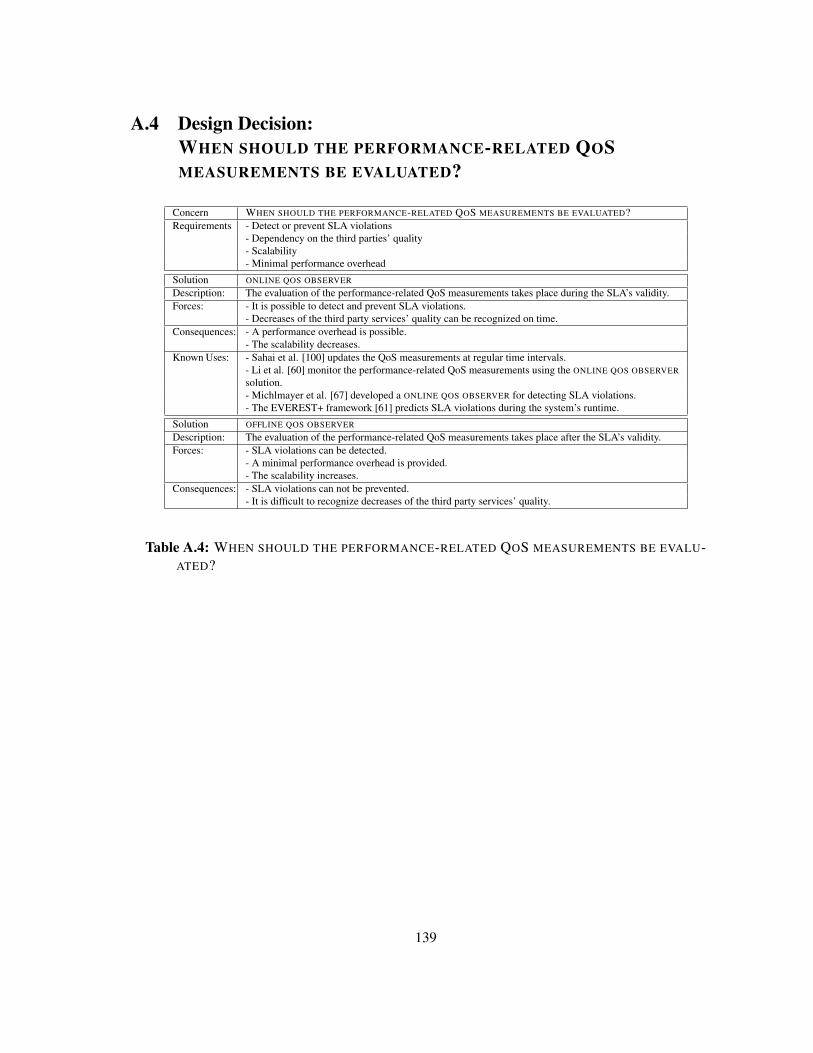
A.4 Design Decision:WHEN SHOULD THE PERFORMANCE-RELATED QOSMEASUREMENTS BE EVALUATED?
Concern WHEN SHOULD THE PERFORMANCE-RELATED QOS MEASUREMENTS BE EVALUATED?Requirements - Detect or prevent SLA violations
- Dependency on the third parties’ quality- Scalability- Minimal performance overhead
Solution ONLINE QOS OBSERVER
Description: The evaluation of the performance-related QoS measurements takes place during the SLA’s validity.Forces: - It is possible to detect and prevent SLA violations.
- Decreases of the third party services’ quality can be recognized on time.Consequences: - A performance overhead is possible.
- The scalability decreases.Known Uses: - Sahai et al. [100] updates the QoS measurements at regular time intervals.
- Li et al. [60] monitor the performance-related QoS measurements using the ONLINE QOS OBSERVERsolution.- Michlmayer et al. [67] developed a ONLINE QOS OBSERVER for detecting SLA violations.- The EVEREST+ framework [61] predicts SLA violations during the system’s runtime.
Solution OFFLINE QOS OBSERVER
Description: The evaluation of the performance-related QoS measurements takes place after the SLA’s validity.Forces: - SLA violations can be detected.
- A minimal performance overhead is provided.- The scalability increases.
Consequences: - SLA violations can not be prevented.- It is difficult to recognize decreases of the third party services’ quality.
Table A.4: WHEN SHOULD THE PERFORMANCE-RELATED QOS MEASUREMENTS BE EVALU-ATED?
139
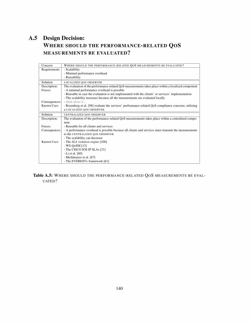
A.5 Design Decision:WHERE SHOULD THE PERFORMANCE-RELATED QOSMEASUREMENTS BE EVALUATED?
Concern WHERE SHOULD THE PERFORMANCE-RELATED QOS MEASUREMENTS BE EVALUATED?Requirements - Scalability
- Minimal performance overhead- Reusability
Solution LOCALIZED QOS OBSERVER
Description: The evaluation of the performance-related QoS measurements takes place within a localized componentForces: - A minimal performance overhead is possible
- Reusable in case the evaluation is not implemented with the clients’ or services’ implementation.- The scalability increases because all the measurements are evaluated locally
Consequences: - think about it...Known Uses: - Rosenberg et al. [98] evaluate the services’ performance-related QoS compliance concerns, utilizing
a LOCALIZED QOS OBSERVER.
Solution CENTRALIZED QOS OBSERVER
Description: The evaluation of the performance-related QoS measurements takes place within a centralized compo-nent
Forces: - Reusable for all clients and servicesConsequences: - A performance overhead is possible because all clients and services must transmit the measurements
to the CENTRALIZED QOS OBSERVER- The scalability can decrease
Known Uses: - The SLA violation engine [100]- WS-QoSM [13]- The CISCO IOS IP SLAs [21]- Li et al. [60]- Michlmayer et al. [67]- The EVEREST+ framework [61]
Table A.5: WHERE SHOULD THE PERFORMANCE-RELATED QOS MEASUREMENTS BE EVAL-UATED?
140
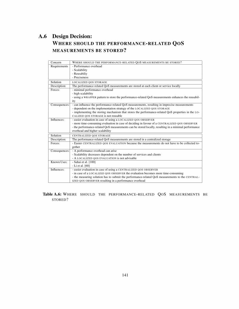
A.6 Design Decision:WHERE SHOULD THE PERFORMANCE-RELATED QOSMEASUREMENTS BE STORED?
Concern WHERE SHOULD THE PERFORMANCE-RELATED QOS MEASUREMENTS BE STORED?Requirements - Performance overhead
- Scalability- Reusabiliy- Preciseness
Solution LOCALIZED QOS STORAGE
Description: The performance-related QoS measurements are stored at each client or service locallyForces: - minimal performance overhead
- high scalability- using a WRAPPER pattern to store the performance-related QoS measurements enhances the reusabil-ity
Consequences: - can influence the performance-related QoS measurements, resulting in imprecise measurements- dependent on the implementation strategy of the LOCALIZED QOS STORAGE- implementing the storing mechanism that stores the performance-related QoS properties in the LO-CALIZED QOS STORAGE is not reusable
Influences: - easier evaluation in case of using a LOCALIZED QOS OBSERVER- more time-consuming evaluation in case of deciding in favour of a CENTRALIZED QOS OBSERVER- the performance-related QoS measurements can be stored locally, resulting in a minimal performanceoverhead and higher scalability
Solution CENTRALIZED QOS STORAGE
Description: The performance-related QoS measurements are stored in a centralized storageForces: - Easier CENTRALIZED QOS EVALUATION because the measurements do not have to be collected to-
getherConsequences: - A performance overhead can arise
- Scalability decreases dependent on the number of services and clients- A LOCALIZED QOS EVALUATION is not advisable
Known Uses: - Sahai et al. [100]- Li et al. [60]
Influences: - easier evaluation in case of using a CENTRALIZED QOS OBSERVER- in case of a LOCALIZED QOS OBSERVER the evaluation becomes more time-consuming- the measuring solution has to submit the performance-related QoS measurements to the CENTRAL-IZED QOS OBSERVER resulting in a performance overhead
Table A.6: WHERE SHOULD THE PERFORMANCE-RELATED QOS MEASUREMENTS BE
STORED?
141

142


![57. Treffen des Arbeitskreises Instandhaltung...IBM Predictive Maintenance and Quality [3] Siemens Plant Maintenance & Condition Monitoring [2] Oracle PeopleSoft Asset Management [1]](https://static.fdokument.com/doc/165x107/5f03a7957e708231d40a1e21/57-treffen-des-arbeitskreises-instandhaltung-ibm-predictive-maintenance-and.jpg)