Montageanleitung für das Modell JULES VERNE Best.-Nr ... · PDF fileGRAUPNER GmbH & Co....
43
GRAUPNER GmbH & Co. KG D-73230 KIRCHHEIM/TECK GERMANY Keine Haftung für Druckfehler. Technische Änderungen vorbehalten! ID# 47496 10/2003 1 Montageanleitung für das Modell JULES VERNE Best.-Nr.: 2097 Beschreibung des Original In Zusammenarbeit mit dem holländischen Yachtdesigner Rene van der Velden entstand das Modell der JULES VERNE. Diese Motoryacht im „Retrodesign“ entspricht in Form und Farbgebung den typischen Mahagoniholzyachten der 30-er und 40-er Jahre. Bei der 1998 gebauten JULES VERNE wurden die Designelemente der früheren Yachten mit denen der modernen optimal kombiniert. Das Ergebnis ist eine der formschönsten Yachten im „Retrodesign“. Da heute aus Kostengründen kaum noch Holzrümpfe hergestellt werden, wurde bei der JULES VERNE der Rumpf aus Aluminium gefertigt und mahagonifarben lackiert. Mit den beiden je 660 PS starken Antriebsmotoren erreicht die Originalyacht eine Geschwindigkeit von ca. 26 kn. Beschreibung des Modells Das Modell der JULES VERNE wurde nach Originalunterlagen des Designers im Maßstab 1:20 entwickelt. Da gewisse handwerkliche Fähigkeiten sowie Erfahrung im Schiffsmodellbau benötigt werden, ist das Modell nur für den erfahrenen Modellbauer zu empfehlen. Alle gerundeten Teile sind aus tiefgezogenem ABS hergestellt und die schwer zu bearbeitenden Teile, wie Rumpf, Hecktreppe, Deck und Abdeckung sind schon CNC-bearbeitet (ausgefräst). Die Holzteile sind vorgestanzt, gefräst oder gelasert und verkürzen damit die Bauzeit. Im Baukasten sind die Beschlagteile aus gespritztem Kunststoff, wie Scheibenwischer, Lüfter, Lampen, Radargerät, usw., schon beigelegt. Die Lampengehäuse im Beschlagsatz sind mittels Mini-Glühlämpchen Ø2,4 mm leicht beleuchtbar. Technische Daten Modell Vorbild Länge ca. 925mm 18,50m Breite ca. 250mm Gesamtgewicht mit RC ca. 4,6kg Leergewicht ca. 2,3kg Maßstab 1:20 Wichtige Sicherheitshinweise Sie haben einen Bausatz erworben, aus dem – zusammen mit entsprechendem geeignetem Zubehör – ein funktionsfähiges RC-Modell fertiggestellt werden kann. Die Einhaltung der Montage- und Betriebsanleitung im Zusammenhang mit dem Modell sowie die Installation, der Betrieb, die Verwendung und Wartung der mit dem Modell zusammenhängenden Komponenten können von GRAUPNER nicht überwacht werden. Daher übernimmt GRAUPNER keinerlei Haftung für Verluste, Schäden oder Kosten, die sich aus dem fehlerhaften Betrieb, aus fehlerhaftem Verhalten bzw. in irgendeiner Weise mit dem vorgenannten zusammenhängend ergeben. Soweit vom Gesetzgeber nicht zwingend vorgeschrieben, ist die Verpflichtung der Firma GRAUPNER zur Leistung von Schadensersatz, aus welchem Grund auch immer ausgeschlossen (inkl. Personenschäden, Tod, Beschädigung von Gebäuden sowie auch Schäden durch Umsatz- oder Geschäftverlust, durch Geschäftsunterbrechung oder andere indirekte oder direkte Folgeschäden), die von dem Einsatz des Modells herrühren. Die Gesamthaftung ist unter allen Umständen und in jedem Fall beschränkt auf den Betrag, den Sie tatsächlich für dieses Modell gezahlt haben. Die Inbetriebnahme und der Betrieb des Modells erfolgt einzig und allein auf Gefahr des Betreibers. Nur ein vorsichtiger und überlegter Umgang beim Betrieb schützt vor Personen- und Sachschäden. Prüfen Sie vor dem ersten Einsatz des Modells, ob Ihre Privat-Haftpflichtversicherung den Betrieb von Modellschiffen dieser Art mit einschließt. Schließen Sie gegebenenfalls eine spezielle RC-Modell- Haftplichtversicherung ab. Diese Sicherheitshinweise müssen unbedingt aufbewahrt werden und müssen bei einem Weiterverkauf des Modells an den Käufer weitergegeben werden.
Transcript of Montageanleitung für das Modell JULES VERNE Best.-Nr ... · PDF fileGRAUPNER GmbH & Co....

GRAUPNER GmbH & Co. KG D-73230 KIRCHHEIM/TECK GERMANY Keine Haftung für Druckfehler. Technische Änderungen vorbehalten! ID# 47496 10/2003
1
Montageanleitung für das Modell JULES VERNE Best.-Nr.: 2097
Beschreibung des Original
In Zusammenarbeit mit dem holländischen Yachtdesigner Rene van der Velden entstand das Modell der JULES VERNE. Diese Motoryacht im „Retrodesign“ entspricht in Form und Farbgebung den typischen Mahagoniholzyachten der 30-er und 40-er Jahre. Bei der 1998 gebauten JULES VERNE wurden die Designelemente der früheren Yachten mit denen der modernen optimal kombiniert. Das Ergebnis ist eine der formschönsten Yachten im „Retrodesign“. Da heute aus Kostengründen kaum noch Holzrümpfe hergestellt werden, wurde bei der JULES VERNE der Rumpf aus Aluminium gefertigt und mahagonifarben lackiert. Mit den beiden je 660 PS starken Antriebsmotoren erreicht die Originalyacht eine Geschwindigkeit von ca. 26 kn.
Beschreibung des Modells
Das Modell der JULES VERNE wurde nach Originalunterlagen des Designers im Maßstab 1:20 entwickelt. Da gewisse handwerkliche Fähigkeiten sowie Erfahrung im Schiffsmodellbau benötigt werden, ist das Modell nur für den erfahrenen Modellbauer zu empfehlen. Alle gerundeten Teile sind aus tiefgezogenem ABS hergestellt und die schwer zu bearbeitenden Teile, wie Rumpf, Hecktreppe, Deck und Abdeckung sind schon CNC-bearbeitet (ausgefräst). Die Holzteile sind vorgestanzt, gefräst oder gelasert und verkürzen damit die Bauzeit. Im Baukasten sind die Beschlagteile aus gespritztem Kunststoff, wie Scheibenwischer, Lüfter, Lampen, Radargerät, usw., schon beigelegt. Die Lampengehäuse im Beschlagsatz sind mittels Mini-Glühlämpchen Ø2,4 mm leicht beleuchtbar.
Technische Daten Modell Vorbild
Länge ca. 925mm 18,50m Breite ca. 250mm Gesamtgewicht mit RC ca. 4,6kg Leergewicht ca. 2,3kg Maßstab 1:20
Wichtige Sicherheitshinweise
Sie haben einen Bausatz erworben, aus dem – zusammen mit entsprechendem geeignetem Zubehör – ein funktionsfähiges RC-Modell fertiggestellt werden kann. Die Einhaltung der Montage- und Betriebsanleitung im Zusammenhang mit dem Modell sowie die Installation, der Betrieb, die Verwendung und Wartung der mit dem Modell zusammenhängenden Komponenten können von GRAUPNER nicht überwacht werden. Daher übernimmt GRAUPNER keinerlei Haftung für Verluste, Schäden oder Kosten, die sich aus dem fehlerhaften Betrieb, aus fehlerhaftem Verhalten bzw. in irgendeiner Weise mit dem vorgenannten zusammenhängend ergeben. Soweit vom Gesetzgeber nicht zwingend vorgeschrieben, ist die Verpflichtung der Firma GRAUPNER zur Leistung von Schadensersatz, aus welchem Grund auch immer ausgeschlossen (inkl. Personenschäden, Tod, Beschädigung von Gebäuden sowie auch Schäden durch Umsatz- oder Geschäftverlust, durch Geschäftsunterbrechung oder andere indirekte oder direkte Folgeschäden), die von dem Einsatz des Modells herrühren. Die Gesamthaftung ist unter allen Umständen und in jedem Fall beschränkt auf den Betrag, den Sie tatsächlich für dieses Modell gezahlt haben. Die Inbetriebnahme und der Betrieb des Modells erfolgt einzig und allein auf Gefahr des Betreibers. Nur ein vorsichtiger und überlegter Umgang beim Betrieb schützt vor Personen- und Sachschäden. Prüfen Sie vor dem ersten Einsatz des Modells, ob Ihre Privat-Haftpflichtversicherung den Betrieb von Modellschiffen dieser Art mit einschließt. Schließen Sie gegebenenfalls eine spezielle RC-Modell-Haftplichtversicherung ab. Diese Sicherheitshinweise müssen unbedingt aufbewahrt werden und müssen bei einem Weiterverkauf des Modells an den Käufer weitergegeben werden.

GRAUPNER GmbH & Co. KG D-73230 KIRCHHEIM/TECK GERMANY Keine Haftung für Druckfehler. Technische Änderungen vorbehalten! ID# 47496 10/2003
2
Garantiebedingungen Die Garantie besteht aus der kostenlosen Reparatur bzw. dem Umtausch von solchen Teilen, die während der Garantiezeit von 24 Monaten, ab dem Datum des Kaufes nachgewiesene Fabrikations- oder Materialfehler aufweisen. Weitergehende Ansprüche sind ausgeschlossen. Transport-, Verpackungs- und Fahrtkosten gehen zu Lasten des Käufers. Für Transportschäden wird keine Haftung übernommen. Bei der Einsendung an GRAUPNER bzw. an die für das jeweilige Land zuständige Servicestelle sind eine sachdienliche Fehlerbeschreibung und die Rechnung mit dem Kaufdatum beizufügen. Die Garantie ist hinfällig, wenn der Ausfall des Teils oder des Modells von einem Unfall, unsachgemäßer Behandlung oder falscher Verwendung herrührt. Folgende Punkte müssen unbedingt beachtet werden:
• Das Modell ist nicht für Kinder unter 14 Jahre geeignet. • Das Modell, aufgrund der hohen Geschwindigkeit, NIEMALS betreiben wenn sich Menschen und
Tiere im Wasser befinden, da sonst erhebliche Verletzungsgefahr für diese besteht. • Lassen Sie Ihr Modell nicht in Naturschutz-, Landschaftsschutz-, oder Gewässerschutzgebieten
fahren. Informieren Sie sich bei Ihrer Gemeinde über die für den Schiffsmodellbau freigegebenen Gewässer.
• Fahren Sie niemals in Salzwasser. Selbst die salzhaltige Seeluft kann die technischen Komponenten Ihres Modells angreifen, oxidieren bzw. sogar zerstören.
• Fahren Sie nie bei widrigen Witterungsbedingungen, wie z.B. Regen, Gewitter, stärkerem Wind, höherem Wellengang, starker Strömung des Gewässers usw..
• Kontrollieren Sie, bevor Sie das Modell fahren lassen, dieses auf eine sichere Funktion der Fernsteuerung sowie die Steckverbindungen auf sichere und feste Verbindung.
• Sollten Trockenbatterien zur Stromversorgung verwendet werden, dürfen diese niemals nachgeladen werden. Nur Akkus dürfen nachgeladen werden.
• Die Akkus müssen geladen sein und die Reichweite der Fernsteuerung muss überprüft worden sein. Besonders die Sender- und Empfängerakkus müssen vor jeder Fahrt geladen werden.
• Prüfen Sie, ob der von Ihnen genutzte Kanal frei ist. Fahren Sie niemals, wenn Sie sich nicht sicher sind, ob der Kanal frei ist.
• Beachten Sie die Empfehlungen und Hinweise zu Ihrer Fernsteuerung und Zubehörteilen. • Arbeiten Sie an den Antriebsteilen nur bei abgezogener Motorstromversorgung. • Bei angeschlossenem Fahrakku dürfen Sie und andere Personen niemals in den Bereich der
Schiffsschrauben kommen, da durch diese eine erhebliche Verletzungsgefahr besteht. • Die empfohlene Betriebsspannung nicht übersteigen. Eine höhere Spannung kann zum Überhitzen
der Motoren bzw. des Fahrtreglers führen oder die elektrischen Leitungen können durchschmoren. Dadurch kann das Modell zerstört werden da, bzw. ein Schwelbrand entstehen kann.
• Achten Sie auf Leichtläufigkeit aller Antriebskomponenten. Dies gilt besonders während des Fahrbetriebs, da sich Blätter und andere Dinge in den Antriebskomponenten verfangen können. In einem solchen Fall kann der Motor, Fahrtregler bzw. das Ruderservo durch Überbelastung zerstört werden.
• Achten Sie darauf, dass die Servos in ihrem Verfahrweg mechanisch nicht begrenzt werden. • Batterien und Akkus dürfen nicht kurzgeschlossen werden, sowie nicht direkt dem Wasser ausgesetzt
werden. • Lassen Sie die Motoren und den Fahrtregler nach jeder Fahrt abkühlen. Fassen Sie die
möglicherweise heißen Teile nicht an. • Entnehmen Sie die Akkus bzw. Batterien beim Transport und Nichtgebrauch des Modells. • Setzen Sie das Modell nicht starker Luftfeuchtigkeit, Hitze, Kälte sowie Schmutz aus. • Sichern Sie das Modell und RC-Komponenten beim Transport gegen Beschädigung sowie
Verrutschen. • Betreiben Sie das Modell an einem bewegten Wasser (z.B. Fluss), beachten Sie, dass bei einer
möglichen Fehlfunktion bzw. leeren Akkus, das Modell abtreiben kann. • Bringen Sie bei einer evtl. Bergung des Modells sich nicht selbst sowie andere in Gefahr. • Achten Sie besonders auf die Wasserdichtheit des Modells. Ein Modellboot kann sinken bei
entsprechendem Wassereinbruch. Kontrollieren Sie das Modell vor jeder Fahrt, ob irgendeine Beschädigung vorliegt und ob Wasser durch die Wellenanlage bzw. Ruderanlage eindringen kann.
• Sichern Sie das Modell gegen Wassereinbruch. Achten Sie darauf, dass der Aufbau während der Fahrt nicht vom Modell herunterrutschen kann. Sorgen Sie dafür, das selbst wenn Wasser in das Modell eindringt, dieses nicht an die RC-Komponenten gelangen kann. Wasserschäden sind keine Garantiefälle!
GRAUPNER GmbH & Co. KG D-73230 KIRCHHEIM/TECK GERMANY Keine Haftung für Druckfehler. Technische Änderungen vorbehalten! ID# 47496 10/2003
3
• Bei parallel angeschlossenen Fahrakkus dürfen diese nur während des Fahrbetriebs angeschlossen sein, da ohne Last sonst Wechselwirkungen zwischen den beiden Akkus auftreten und diese die Akkus beschädigen könnten. Stecken Sie daher die Akkus erst bei Beginn des Fahrbetriebs an und bei Beendigung wieder ab. Keinesfalls dürfen die Akkus mit angeschlossenen Parallelkabel gelagert werden.
Pflege und Wartung
• Säubern Sie das Modell nach jedem Gebrauch. Entfernen Sie evtl. eingedrungenes Wasser. Sollte Wasser in die RC-Komponenten eingedrungen sein, legen Sie diese trocken und schicken Sie diese zur Kontrolle an die zuständige GRAUPNER Servicestelle ein.
• Säubern Sie das Modell und die RC-Komponenten nur mit geeigneten Reinigungsmitteln. Informieren Sie sich hierzu bei Ihrem Fachhändler.
• Schmieren Sie die Schiffswellen und Ruderwellen regelmäßig ab. • Wenn das Modell längere Zeit nicht betrieben werden soll, müssen alle bewegten Teile (Schiffswelle
usw.) demontiert, gesäubert und neu abgeschmiert werden.
Hinweise zum Bau des Modells
• Vor dem Bau des Modells sollte man unbedingt den Bauplan und die Anleitung bis zum Schluss studieren. Die Stückliste ist als Hilfsmittel zu benutzen. Anleitung und Stückliste sind in Reihenfolge des Zusammenbaus gehalten.
• Schneiden Sie die Stege, die die ausgefrästen Holzteile in der Platte halten, mittels einer Schere aus. • Da die tiefgezogenen ABS-Teile fertigungstechnisch bedingt immer einen leichten Radius haben,
sollten Holzteile die auf die ABS-Teile aufgelegt werden, auf der Unterseite immer etwas rund geschliffen werden. Dann liegen Sie spaltfrei und bündig auf.
• Die gelaserten Holzteile haben fertigungsbedingt immer eine schwarze Schneidelinie. Diese lässt sich durch abschleifen beseitigen.
• Heben Sie für den Bau des Modells alle Holz-, ABS- und Drahtreste auf, da aus diesen noch weitere Kleinteile gefertigt werden müssen.
• Wenn in das Modell Sonderfunktionen eingebaut werden sollen, müssen diese vor Baubeginn mit eingeplant werden. Tipps und Hinweise dazu stehen am Ende der Bauanleitung.
• Achten Sie bei diesem Modell besonders auf einen möglichst tiefen Schwerpunkt. • Achten Sie beim Einsatz von Werkzeugen auf die möglichen Gefahren. • Entstören Sie die Elektromotoren mindestens mit je einem 470 nF Kondensator (Best.-Nr. 3588),
indem Sie die beiden Motoranschlüsse mit dem Kondensator verbinden (siehe Skizze auf dem Bauplan).
• Die elektrischen Leitungen sauber, ohne Kreuzungen verlegen. Es darf keinesfalls die Plusleitung mit der Minusleitung elektrisch in Kontakt kommen.
• Verwenden Sie nur geeignete Kabel, die den im Betrieb auftretenden Stromstärken genügen. • Verlegen Sie die Empfangsantenne möglichst weit entfernt von den Fahrstrom leitenden Kabeln
(mindestens 3 cm). • Verwenden Sie zum Schmieren der Wellenanlage nur Fett oder Öl, welches das Wasser nicht
gefährdet bzw. verschmutzt (z.B. Best.-Nr.: 570). • Säubern Sie jede Klebeverbindung von Fettresten, bevor Sie diese verkleben. Dies kann durch
anschleifen und säubern mit einem nicht nachfettenden Spülmittel erfolgen. Das gleiche gilt für die zu lackierenden Oberflächen um eine gute Haltbarkeit der Farbe zu erreichen. Vor dem Festkleben von Teilen im Schiffsrumpf, unbedingt die entsprechenden Flächen mit feinem Schleifpapier aufrauen und gründlich mit Spiritus entfetten. Sonst ist keine ausreichende Verklebung gewährleistet.
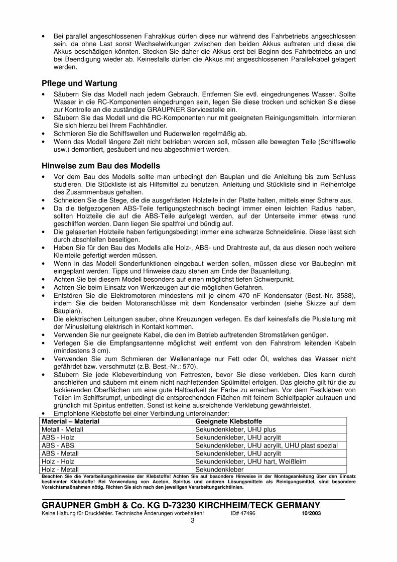
• Empfohlene Klebstoffe bei einer Verbindung untereinander: Material – Material Geeignete Klebstoffe Metall - Metall Sekundenkleber, UHU plus ABS - Holz Sekundenkleber, UHU acrylit ABS - ABS Sekundenkleber, UHU acrylit, UHU plast spezial ABS - Metall Sekundenkleber, UHU acrylit Holz - Holz Sekundenkleber, UHU hart, Weißleim Holz - Metall Sekundenkleber Beachten Sie die Verarbeitungshinweise der Klebstoffe! Achten Sie auf besondere Hinweise in der Montageanleitung über den Einsatz bestimmter Klebstoffe! Bei Verwendung von Aceton, Spiritus und anderen Lösungsmitteln als Reinigungsmittel, sind besondere Vorsichtsmaßnahmen nötig. Richten Sie sich nach den jeweiligen Verarbeitungsrichtlinien.

GRAUPNER GmbH & Co. KG D-73230 KIRCHHEIM/TECK GERMANY Keine Haftung für Druckfehler. Technische Änderungen vorbehalten! ID# 47496 10/2003
4
Montageanleitung
1. Stecken Sie den Schiffsständer aus den beiden Seitenteilen (Teil 1), dem vorderen Stützbrett (Teil 2) und hinteren Stützbrett (Teil 3) zusammen. Die Teile müssen vorher aufgedoppelt werden, d.h. jeweils zwei gleiche Teile müssen übereinander geklebt werden. Verkleben Sie die Teile des Ständers mit Weißleim (TIPP: legen Sie auf die aufgedoppelten Holzteile während der Trockenzeit ein Gewicht, damit die Teile sauber zusammen gedrückt werden. TIPP 2: um das lackierte Modell später vor Kratzern zu schützen, sollten Sie etwas Filz oder vergleichbares auf die Auflageflächen kleben).
2. Längen Sie die Messingrohre für die Ruderanlage (Teil 5) auf 25mm ab. Schleifen Sie die Klebefläche der Rohre an und kleben Sie diese nach Plan in die beiden Ø4mm Bohrungen im Rumpf (Teil 4). Achten Sie darauf, das beide richtig ausgerichtet sind (TIPP: dies geht einfacher, wenn Sie die Ruderanlagen (Teil 6) zum Ausrichten einstecken). Verkleben Sie die Rohre gut mit UHU acrylit indem Sie eine große Leimraupe um die Rohre ziehen, so dass sie die späteren Belastungen im Betrieb aushalten.
3. Stecken Sie in die beiden Ruderhebel (Teil 7) je einen Stellring (Teil 8) und schrauben Sie je eine Befestigungsschraube (Teil 9) in den Ruderhebel. Montieren Sie die Ruderhebel auf die Ruderanlagen. Kürzen Sie die Ruderwellen kurz über den Ruderhebeln, da sonst die Hecktreppe (Teil 33) nicht über die Ruderanlage passt.
4. Stellen Sie aus dem Ø1,5mm Stahldraht das Ruder-Verbindungsgestänge (Teil 10) her. Längen Sie ca. 85mm vom Draht ab. Biegen Sie beide Enden ab, so dass ein Mittelstück von ca. 65mm verbleibt. Wichtig ist, dass beide Ruderhebel wie im Plan dargestellt parallel zueinander stehen. Stecken Sie das Verbindungsgestänge in die Ruderhebel und sichern Sie die Enden mit je einem Sicherungsclip (Teil 11).
5. Fertigen Sie aus dem Ø1,5mm Stahldraht das Rudergestänge (Teil 12) an. Biegen Sie es an einem Ende ca. 10mm ab. Stecken Sie das abgebogenen Ende in den Ruderhebel und sichern Sie das Ende mit einem Sicherungsclip (Teil 11).
6. Schneiden Sie den Servoträger (Teil 13) aus. Schrauben Sie das Ruderservo (Teil 14) in die Öffnung mit dem beim Servo beiliegenden Schrauben (TIPP: stechen Sie die Bohrlöcher im Servoträger mit einem spitzen Gegenstand, z.B. Nagel, leicht an und drehen Sie die Schrauben direkt in das ABS). Montieren Sie den Gestängeanschluss (Teil 15) in eine auf Ø2mm aufgebohrte Öffnung im Servoruderhebel. Sichern Sie den Gestängeanschluss mit der Befestigungsmutter (Teil 16). Kleben Sie den Servoträger in den Rumpf. Stecken Sie das Rudergestänge in den Gestängeschluss (evtl. müssen Sie den Ruderhebel vom Servo abschrauben um das Gestänge einstecken zu können), stellen das Servo und die Ruder mittig und sichern das Gestänge mit dem Gewindestift (Teil 17). Kürzen Sie das Gestänge so, dass nur noch ein ca. 4mm langes Stück aus dem Gestängeanschluss heraussteht.
7. Montieren Sie an die Stevenrohre (Teil 18) die Lagerböcke (Teil 19) mit den Befestigungsschrauben (Teil 20). Bohren Sie das Stevenrohr durch die Öffnung im Lagebock mit einem Ø2mm Bohrer auf. Dies ist die spätere Schmierbohrung für die Stevenrohre (TIPP: wer möchte kann noch ein Stück Schlauch auf die Schmiernippel stecken, z.B. Best.-Nr. 1668.3).
8. Montieren Sie die beiden Motorträgereinheiten zusammen. Schrauben Sie dazu die Wellenkupplung (Teil 21) mit den Gewindestiften (Teil 22) auf dem Motor (Teil 23) fest. Es sollte zwischen Kupplung und Motor ein kleiner Luftspalt verbleiben. Schrauben Sie dann den Motor an den Motorträger (Teil 24) mit den Motorbefestigungsschrauben (Teil 25) fest. Schneiden Sie an dem Motorträger auf der Stevenrohrseite mit einem Messer die beiden Schlitze auf. Stecken Sie dann die Befestigungsschraube in die kleinen Bohrungen ein und fixieren Sie diese locker mit der Mutter (Teil 26).
9. Löten Sie die Entstörkondensatoren (Teil 27) mit den Motoranschlusskabeln (Teil 28) an die Motoren. Die zweite Motoreinheit muss anders gepolt angeschlossen werden, damit diese in die andere Richtung dreht (siehe Schaltplan).
10. Stecken Sie jetzt die Motoreinheiten auf die Stevenrohre und schrauben diese in der richtigen Position fest (evtl. müssen die Bohrungen im Rumpf noch etwas nachgearbeitet werden). Fertigen Sie jetzt die Motorträgerstützen (Teil 29) aus der 10 x 10mm Kieferleiste. Achten Sie darauf, das die Stützen die Motoreinheit nicht nach oben verspannen und auf dem Rumpf sauber aufliegen. Kleben Sie die Stützen fest. Bohren Sie Ø1,5mm Löcher in die Stützen und schrauben Sie dann die Motoreinheit mit den Befestigungsschrauben (Teil 30) fest. Auch jetzt darauf achten, dass die Einheit nicht verspannt wird.
11. Schrauben Sie die Schiffsschrauben (Teil 31) auf die Wellenenden der Stevenrohre. Auf die richtige Drehrichtung achten!
12. Schneiden Sie die Finne (Teil 32) in der Kante aus und kleben Sie diese mit UHU acrylit gerade

GRAUPNER GmbH & Co. KG D-73230 KIRCHHEIM/TECK GERMANY Keine Haftung für Druckfehler. Technische Änderungen vorbehalten! ID# 47496 10/2003
5
ausgerichtet unten an den Rumpf. Die Verklebung sollte einen Grundkontakt aushalten können, die Finne soll die Ruder- und Wellenanlagen vor einer Beschädigung schützen.
13. Der Rumpf und die Hecktreppe (Teil 33) müssen noch nachgearbeitet werden, damit sie an den Klebekanten sauber aufliegen. Dies betrifft besonders die Kanten, da hier aus fertigungstechnischen Gründen noch ein kleiner Rand vorhanden ist, dieser muss unbedingt geglättet werden. Im Bereich, wo später das Deck unter die Treppe geklebt wird, muss die Treppen innen eine Fase erhalten. Nur so liegt das Deck sauber an der Treppe an.
14. Verkleben Sie den Rumpf mit der Hecktreppe. Richten Sie die Kanten der Treppen und des Rumpfs aus und pressen Sie die Klebeflächen während der Trockenzeit mit Klemmen (z.B. mit Best.-Nr. 542.1 oder 542.2) zusammen. Nur so erreichen Sie einen möglichst geringen Versatz in der Rumpfoberfläche (das bedeutet weniger Spachtelarbeit). Evtl. noch verbliebene Öffnungen sollten innen gut mit UHU acrylit geschlossen werden. Verspachteln Sie die Außenflächen und verschleifen Sie diese. Der letzte Feinschliff erfolgt erst nach Montage des Decks.
15. Einbau des optionalen Querstrahlruders: Entstören Sie den Motor des Querstrahlruders (Teil 34) mit einem Entstörkondensator (entspricht Teil 27) und schließen Sie ein Motoranschlusskabel an (entspricht Teil 28). Kleben Sie das Querstrahlruder im Modell zusammen (nicht außerhalb verkleben, sonst passt es nicht mehr ins Modell), fixieren Sie das Ruder mit Sekundenkleber (der Elektromotor sollte schräg nach oben stehen) und verkleben Sie es komplett an den Rumpfwänden mit UHU acrylit. Es muss 100% wasserdicht sein. Dann können Sie die Außenseiten der Rohre abschneiden und glätten.
16. Kein Einbau eines Querstrahlruders: Wenn Sie kein Querstrahlruder verwenden möchten, müssen Sie die Löcher innerhalb des Rumpfes zukleben. Schneiden Sie aus ABS-Resten Platten aus, die das Loch großflächig abdecken, fixieren Sie diese mit Sekundenkleber und verkleben sie mit UHU acrylit. Auch hier auf 100% Wasserdichtigkeit achten (HINWEIS: es ist später nur noch schwer möglich, ein Querstrahlruder einzubauen, die Entscheidung eins einzubauen sollte daher jetzt fallen).
17. Kleben Sie die RC-Platte (Teil 35) nach Plan in den Rumpf. Lassen Sie bei eingebautem Querstrahlruder ausreichend Platz um dieses warten zu können. Wenn Sie möchten, können Sie die RC-Platte komplett weglassen und die RC-Komponenten mit Klettband direkt an der Rumpfwand befestigen. Dies bringt technisch gesehen keine Nachteile.
18. Das Deck (Teil 36) muss noch nachgearbeitet werden, wie schon beim Rumpf und der Hecktreppe geschehen. Kleben Sie das Deck auf den Rumpf. Beginnen Sie mit dem Verkleben im Bereich der Hecktreppe, tragen Sie ein ca. 30cm langes Stück UHU plast spezial auf und fixieren Sie die Klebestelle während der Trockenzeit mit Federklammern (z.B. Best.-Nr. 524.1) oder Klebeband. Nach dem Anziehen des Klebstoffs wird das nächste Stück verklebt, usw. bis das Deck mit den Rumpf komplett verklebt ist (HINWEIS: durch die Kapillarwirkung zieht der Klebstoff in die Fuge zwischen Deck und Rumpf, dies gilt nur bei Verwendung von dünnflüssigen Klebstoffen). WICHTIG: Achten Sie darauf, dass die beiden Kanten vom Deck und dem Rumpf möglichst parallel aufeinander liegen und die Kante des Rumpfs sollte ein wenig über die Kante des Deck herausstehen. Da die Kante später noch verschiffen wird, brauchen Sie sich um überquellenden Klebstoff keine Gedanken machen.
19. Kontrollieren Sie, ob noch irgend eine Öffnung in der Rumpfeinheit ist. Verschließen Sie diese im Innenbereich gut mit UHU acrylit. Achten Sie darauf, dass die Rumpfeinheit wirklich 100% wasserdicht ist (TIPP: bei größeren Öffnungen sollten Sie außen ein Stück Klebeband aufbringen und dann erst den UHU acrylit auftragen. So dringt kein Klebstoff nach außen, der später mühevoll wieder abgeschliffen werden muss.).
20. Spachteln Sie jetzt alle Übergänge zwischen Deck, Rumpf und Hecktreppe und verschleifen Sie diese. Die Bereiche, wo später die Holzteile für das Deck aufgelegt werden, brauchen nicht unbedingt gespachtelt werden. Hier reicht es aus zu überprüfen, das die Fuge gut verklebt ist und die Flächen bündig zueinander stehen, so das die Holzteile plan aufliegen.
21. Arbeiten Sie die Kanten, wo jetzt die 3 x 3mm ABS-Leisten angesetzt werden, möglichst scharfkantig aus. Fertigen Sie die unteren Scheuerleisten (Teil 37) aus der ABS-Leiste an, eine Seite muss jeweils leicht spitz angeschliffen werden (nicht die Seite anspitzen, die aufgeklebt wird!). Auf dem Rumpf ist eine Linie eingeprägt, kleben Sie die Leiste dort auf. Fertigen Sie die oberen Scheuerleisten (Teil 38) aus dem selben Material an. Biegen Sie die Leisten so vor, das sie in etwa der Rumpfkontur entsprechen. Kleben Sie die Leisten dann an den Rumpf an. Achten Sie darauf, das die Leiste bündig zum Deck ist (die Holzteile des Decks müssen später plan aufliegen).
22. Kleben Sie mit doppelseitigem Klebeband das Holzdeck (Teil 39) vorläufig auf das Deck. Es reicht aus nur mehrere kleine Stellen mit dem Klebeband zu fixieren, das Holzdeck darf sich nur nicht verschieben lassen und sauber im Innenbereich des Aufbaus anliegen. Nun können Sie den Rumpf vorsichtig bis zum Holzdeck herunterschleifen. Achten Sie darauf, möglichst nicht das Holzdeck anzuschleifen. Entfernen Sie vorsichtig wieder das Holzdeck. Nun sollte der Rumpf feingeschliffen

GRAUPNER GmbH & Co. KG D-73230 KIRCHHEIM/TECK GERMANY Keine Haftung für Druckfehler. Technische Änderungen vorbehalten! ID# 47496 10/2003
6
und lackiert werden. 23. Lackieren Sie das Holzdeck mehrmals auf beiden Seiten mit Klarlack. Sie sollten nach jedem
Lackauftrag die Oberseite des Deck vorsichtig mit feinen Schleifpapier (Körnung 600 oder 800) abschleifen. Tragen Sie nicht zuviel des Materials ab, da Sie sonst die Lasergravur der Plankenstöße abschleifen. Das Deck ist fertig, wenn eine glatte Oberfläche und ein seidenmatter Glanz erreicht ist.
24. Beizen Sie die Zierauflagen (Teil 40) teakfarben und lackieren Sie die Auflagen beidseitig mit Klarlack. Kleben Sie die Auflagen auf das Holzdeck. Achten Sie darauf, dass kein Klebstoff auf das Holzdeck läuft.
25. Kleben Sie das Holzdeck auf das Deck. Hier eignet sich am Besten dickflüssiger Sekundenkleber, da dieser relativ lange zum Abbinden braucht. Setzen Sie in regelmäßigen Abständen Klebertropfen auf das Deck und legen Sie das Deck vorsichtig auf. Achten Sie darauf, dass das Deck richtig ausgerichtet ist und das kein Klebstoff auf den lackierten Rumpf kommt (TIPP: um sicher zu gehen, sollten Sie den Rumpf im gefährdeten Bereich abkleben).
26. Schleifen Sie den Rumpf im Bereich der Scheuerleiste nochmals vorsichtig plan. Lackieren Sie die Schleifkante in der Rumpffarbe nach. Stellen Sie die Scheuerleiste (Teil 41) her. Kleben Sie zuerst die beiden lange Stücke mit Sekundenkleber an die Rumpfseite. Stellen Sie dann die Scheuerleiste für den Bugbereich her, indem Sie diese vorsichtig nach der Rumpfkontur vorbiegen. Kleben Sie dann das vorgebogene Stück auf (TIPP: es ist einfacher die Scheuerleistenstücke vor dem Aufkleben zu lackieren. TIPP2: auch hier kann es sinnvoll sein die Bereiche, wo kein Klebstoff auf die Oberfläche kommen soll, abzukleben).
27. Passen Sie die Treppenstufen (Teil 42) und das Deck für die Badeplattform (Teil 43) an. Behandeln die Teile wie das Holzdeck und kleben es auf den Rumpf. Achten Sie darauf die Treppenstufen in der richtigen Reihenfolge aufzukleben. Sie sind der Breite nach unterschiedlich, die schmalste Stufe ist oben und die Breiteste ist unten. Die Stufen passen immer nur in eine bestimmte Stelle, dies lässt sich am leichtesten durch ausprobieren ermitteln (TIPP: markieren Sie die Stufen auf den Unterseite, um später die Reihenfolge nicht wieder ermitteln zu müssen).
28. Kontrollieren Sie, ob der Aufbau (Teil 44) sauber auf dem Deck aufliegt, arbeiten Sie ihn evtl. noch etwas nach.
29. Passen Sie die Holzteile für den Aufbau an. Beginnen Sie mit den Seitenverkleidungen (Teil 45). Kleben Sie diese vorläufig mit wenig doppelseitigen Klebeband am Aufbau fest. Schleifen Sie vorsichtig, ohne die Fensterflächen am Aufbau zu zerkratzen (am besten Abkleben), den Winkel zu den seitlichen Fensterverkleidungen (Teil 46) an.
30. Kleben Sie die mittlere Fensterverkleidung (Teil 47) vorläufig mit doppelseitigen Klebeband fest. Darauf achten, dass das Fenster genau mittig sitzt, evtl. müssen die Seiten etwas angepasst werden.
31. Kleben Sie jetzt die seitlichen Fensterverkleidungen vorläufig mit doppelseitigen Klebeband fest. Die Seite an welche die mittlere Fensterverkleidung anstößt, muss eine Fase bekommen, damit kein Spalt zwischen den beiden Teilen ist. Passen Sie dann die Außenseite an die Seitenverkleidung an. Achten Sie darauf, dass die Fenster nicht schief sitzen oder die Fensterrahmen unterschiedliche Breiten bekommen. Also immer Material auf beiden Seiten abtragen.
32. Entfernen Sie wieder alle Verkleidungen. Nun können die Verkleidungen gebeizt werden und mit Klarlack gestrichen werden.
33. Lackieren Sie den Aufbau. Kleben Sie hierzu die sichtbaren Fensterbereiche ab und lackieren den Aufbau. Die beiden Oberlichter müssen im Bereich der Fensterflächen ebenfalls abgeklebt werden und auch lackiert werden. Nach dem Trocknen können die fertigen Verkleidungen mit Sekundenkleber aufgeklebt werden. Achten Sie darauf, dass kein Sekundenkleber auf die Fensterbereiche kommt (TIPP: da normaler Sekundenkleber „ausblühen“ kann, sollten Sie lösungsmittelfreien Sekundenkleber [Styroporsekundenkleber] verwenden, z.B. Best.-Nr. 5820).
34. Setzen Sie die Brückenrückwand (Teil 48) auf den Aufbau und kontrollieren Sie ob diese richtig sitzt und spaltfrei an der Seitenverkleidung anliegt. Beizen Sie und lackieren Sie diese und kleben die Rückwand auf den Aufbau.
35. Passen Sie das Brückendeck (Teil 49), die Treppenstufe (Teil 50), das Achterdeck (Teil 51) und das Backdeck (Teil 52) in den Aufbau ein. Behandeln die Teile wie das Holzdeck und kleben es auf den Aufbau. Speziell das Backdeck sollte auf der Unterseite ausgerundet werden, damit es spaltfrei und oben bündig in den Aufbau passt.
36. Stellen Sie aus dem Ø1,0mm ABS-Rundstab die Schutzbügel (Teil 53) für die beiden Oberlichter her. Auf den Oberlichtern sind Markierungen die zur Positionierung und Längenvorgabe dienen. Längen Sie die Rundstäbe entsprechend ab und kleben Sie diese mit einem winzigen Tropfen Sekundenkleber auf die entsprechende Position (TIPP: um immer gleiche und parallele Abstände zwischen den Bügeln zu erreichen, sollten Sie ein Stück Holz auf die benötigte Breite ausarbeiten und dieses immer zwischen die Bügel legen während Sie die Bügel verkleben. TIPP 2: um den winzigen

GRAUPNER GmbH & Co. KG D-73230 KIRCHHEIM/TECK GERMANY Keine Haftung für Druckfehler. Technische Änderungen vorbehalten! ID# 47496 10/2003
7
Tropfen Sekundenkleber besser auftragen zu können, nehmen Sie ein Stück dünnen Draht, den Sie in Sekundenkleber tauchen. Mit dem Draht lässt sich der Tropfen optimal platzieren). Lackieren Sie die Schutzbügel in Edelstahlfarben. Um einen ausreichenden Farbeffekt zu erhalten, reicht es aus nur die obere Hälfe des Rundmaterial zu lackieren. Nach eigenem Ermessen können Sie auch aus einem Ø1,0mm Stahldraht, möglichst mit blanker Oberfläche, die Schutzbügel herstellen.
37. Fertigen Sie die Sichtschutzplatte (Teil 54) für das hintere Oberlicht nach Plan aus ABS Resten an. Lackieren Sie die Seite, die man später durch das Oberlicht sehen kann, mit einer dunklen Farbe und kleben Sie die Platte unter den Aufbau. Achten Sie darauf, dass die Platte gut verklebt ist, da hier später das Klettband zur Aufbausicherung angebracht wird.
38. Schneiden Sie jetzt das Dach (Teil 55) an den Markierungslinien aus. Im Bereich der seitlichen Fenster sollten Sie beim Ausschneiden darauf achten, dass das Dach die gleiche geschwungene Form erhält, wie die Fenster. Schneiden Sie deshalb in diesem Bereich nicht sofort auf der Linie entlang, sondern arbeiten Sie sich heran. Sollte der Abstand der beiden Formen unterschiedlich sein, sieht es später nicht gut aus. Kleben Sie das Dach noch nicht fest, da vorher noch die Fensterverkleidungen für die Brückenfenster montiert werden müssen. Dies erfolgt in einem späteren Arbeitsschritt.
39. Kleben Sie die aus ABS Resten hergestellten Abstandshalter (Teil 56) in die Innenseiten des Dachs (im Bereich, wo später an der Außenseite der Schriftzug Jules Verne steht) ein (TIPP: sie lassen sich auch aus Sperrholzresten der Fensterverkleidungen herstellen).
40. Fixieren Sie das Dach mit doppelseitigen Klebeband auf dem Aufbau um die Tiefziehteile für das Cockpit leichter anpassen zu können. Nehmen Sie nur soviel Klebeband damit das Dach hält und sich wieder leicht abnehmen lässt.
41. Schneiden Sie jetzt die folgenden ABS Teile aus: das Cockpit (Teil 57), das Cockpitunterteil (Teil 58), den Niedergang (Teil 59), den Fahrersitz (Teil 60) und die beiden Teile der oberen Sitzbank (Teile 61+62). Hierbei ist es wichtig sich langsam an die richtige Passung heranzutasten. Lassen Sie daher noch etwas Material neben den Markierungslinien stehen und schleifen Sie das Material stufenweise herunter, bis alle Teile zusammenpassen. Die auf dem Brückendeck eingelaserten Linien helfen zur Anpassung der Teile. (TIPP: achten Sie darauf, dass der Decksprung auch auf Auflageflächen der Sitze übertragen werden muss. TIPP 2: wenn die Tiefziehteile im Klebebereich etwas verzogen sind, sollten Sie aus den 4mm dicken Holzresten kleine Platten herstellen, die Sie unten einkleben. Damit lassen sich die Teile auch leichter verkleben).
42. Führen Sie jetzt die gleichen Arbeitsschritte bei der unteren Sitzbank (Teile 63+64+65) aus. Schneiden Sie aus ABS Resten für die untere Sitzbank eine Rückwand (Teil 66) aus. Sie muss nur den sichtbaren Bereich abdecken, der über die Seitenverkleidung heraussteht. Wenn alle Teile gut zusammenpassen können Sie die Teile zusammenkleben und lackieren. Dies gilt auch für die Fläche auf dem Aufbau, die durch das Dach nicht abgedeckt wird (TIPP: kleben Sie das Dekor auf das Cockpitteil, bevor Sie dieses im Modell montieren). Die Beschlagteile für das Cockpit werden in einem späteren Arbeitsschritt montiert, da sie sonst bei der weiteren Montage leicht abbrechen können.
43. Stellen Sie die den oberen Tisch (Teile 67+68+69+71+73) und den unteren Tisch (Teile 67+68+70+72+74) her. Bevor Sie die beiden Tischflächen einkleben, sollten Sie die Tische fertig lackieren und die Holzteile beizen und lackieren. Dann können Sie die Tische auf das Modell kleben.
44. Stellen Sie die den Handlauf (Teil 75) für Brückenrückwand aus dem Biegeholz her. Nach dem Beizen und Lackieren können Sie diesen mittig auf die Brückenrückwand mit dickflüssigem Sekundenkleber kleben. Achten Sie darauf, das kein Sekundenkleber auf die Rückwand läuft.
45. Passen die äußeren Fensterverkleidungen (Teile 76+77+78) und die inneren Verkleidungen (Teile 76+79+80) für das Dach, wie schon bei den Fensterverkleidungen für den Aufbau beschrieben, an. Achten Sie beim Anpassen darauf, dass die Fensterbereiche sauber übereinanderliegen. Ein Versatz würde unsauber aussehen.
46. Fertigen Sie jetzt die Lüftungsklappen (Teil 81) aus ABS Resten an. Kleben Sie diese auf die Fensterverkleidungen auf. Bohren Sie für die Scheibenwischer ein Ø1,5mm Loch in die Verkleidungen, die Scheibenwischer werden aber erst in einem späteren Arbeitsschritt montiert.
47. Bearbeiten Sie die Oberkante der Fensterverkleidungen sauber plan und fertigen Sie die Zierleisten (Teile 82+83+84+85+86) an. Lackieren Sie diese und kleben Sie diese mit dickflüssigem Sekundenkleber vorsichtig auf die Verkleidungen. Achten Sie darauf, dass kein Sekundenkleber auf die Holzteile läuft (TIPP: vorgebogen lassen sich die Teile leichter aufkleben).
48. Fertigen Sie aus ABS- oder Holzresten eine Schablone, um die Kontur der beiden Türen mit einem weichen Bleistift aufzeichnen zu können.
49. Kleben Sie jetzt das Dach auf den Aufbau. Achten Sie darauf, dass das Dach überall ohne Druck sauber aufliegt, arbeiten Sie evtl. noch etwas nach. Dies gilt besonders für den Bereich der Sitzbänke und des Niedergangs.

GRAUPNER GmbH & Co. KG D-73230 KIRCHHEIM/TECK GERMANY Keine Haftung für Druckfehler. Technische Änderungen vorbehalten! ID# 47496 10/2003
8
50. Fertigen Sie aus dem Biegeholz die beiden Handläufe (Teil 87 + 88) an. Bearbeiten Sie die Handläufe wie den Handlauf für die Brückenrückwand und kleben Sie diese auf die Seitenverkleidungen. Im Bereich der aufgezeichneten Tür muss je eine Kerbe in die Handläufe eingearbeitet werden (Sonst könnte man die Türen nicht öffnen). Achten Sie darauf, dass die Handläufe nicht mittig aufgeklebt werden, sondern sie stehen nach außen heraus.
51. Stellen Sie den Heckhandlauf aus den Handlaufstützen (Teil 89) und den Handlauf (Teil 90) aus Ø2mm ABS Rundmaterial her. Markieren Sie zuerst die beiden Bohrungen in den Seitenteilen, die anderen Bohrungen sind im Aufbau markiert. Bohren Sie die Markierungen mit einem Ø2mm Bohrer auf und stecken Sie die Handlaufstützen in die Bohrungen (nicht verkleben!). Stecken Sie dann den Handlauf in die Stützen und ziehen Sie ihn durch alle Stützen hindurch. Die Form des Handlauf ergibt sich hierbei von selbst. Verkleben Sie nun den Handlauf, aber noch nicht an den Aufbau. Kürzen Sie die Enden des Handlaufs. Lackieren Sie ihn edelstahlfarben. Stecken Sie ihn wieder in den Aufbau und verkleben Sie ihn. Kürzen Sie die Stützen von innen, da sonst der Aufbau nicht richtig auf dem Deck aufliegt.
52. Fertigen Sie jetzt den Bootskran aus den folgenden Teilen: Fundament (Teil 91), äußerer Ausleger (Teil 92), innerer Ausleger (Teil 93), Lasche (Teil 94), Spannschloss (Teil 95) und dem Splint (Teil 96). Schneiden Sie die Tiefziehteile aus und kleben Sie den inneren Ausleger in den äußeren. Es sollte noch ein ca. 5mm langes Stück aus einem Ende herausstehen. Kleben Sie den Ausleger auf das Fundament. Montieren Sie die an den Enden begradigte Lasche an ein Ende des Spannschlosses mit dem Splint, legen Sie das andere Ende in die Mulde im Fundament und kleben Sie die Lasche an den Ausleger. Verkleben Sie jetzt das andere Ende mit dem Fundament. Lackieren sie den Kran schwarz, das Spannschloss soll einen Hydraulikzylinder darstellen, lackieren Sie das Gewinde daher silbern.
53. Schneiden Sie die Unter- (Teil 97) und die Oberschale (Teil 98) des Schlauchboots grob aus, lassen Sie mindestens einen Kleberand von ca. 5mm stehen. Verkleben Sie die beiden Schalen und verschleifen Sie den Kleberand nach einer ausreichenden Trockenzeit. Es sollte ein Rand von ca. 1 bis 2mm stehen bleiben. Verkleben Sie die beiden Hälften des Außenbordmotors (Teil 99) innen mit viel UHU acrylit, es muss später im Bereich der Klebekante genügend Klebstoff vorhanden sein, damit die beiden Hälften zusammenbleiben. Entfernen Sie jetzt die Außenfläche um den Außenbordmotor und verschleifen Sie die Kante sauber. Fertigen Sie aus einem Rest des Ø1mm ABS Rundmaterials das Wellenstück (Teil 100) und kleben es an den entsprechend mittig vorgebohrten Anschlussbereich am Außenborder. Lackieren Sie den Außenborder und kleben Sie den Propeller auf den Wellenzapfen.
54. Fertigen Sie die beiden Auflagen (Teil 102) für das Schlauchboot aus ABS- oder Holzresten. Kleben die Auflagen unten an das Boot.
55. Schneiden Sie die Abdeckung (Teil 103) für das Schlauchboot aus. Option: An den Spitzen der Abdeckung sind Markierungen, wenn Sie diese aufbohren können Sie die Abdeckung z.B. mit dünnem Takelgarn am Schlauchboot festziehen. Dann brauchen Sie das Schlauchboot innen nicht auszustatten.
56. Lackieren Sie das Schlauchboot mit der Hauptfarbe weiß. Die Farben für den Innenausbau können Sie nach Ihren Wünschen wählen, sie sollten aber zu den Hauptfarben der JULES VERNE passen.
57. Kleben Sie den Außenbordmotor an das Boot. Die untere Flosse vom Außenborder sollte aufliegen und die Abdeckung über den Motor passen. Montieren Sie das Steuerrad (Teil 104) an das Armaturenbrett. Biegen Sie aus dem Ø1,5mm Stahldraht den Gashebel (Teil 105), bohren Sie entsprechendes Loch in das Armaturenbrett und kleben Sie den Gashebel fest. Fixieren Sie die Abdeckung mit ein paar Streifen doppelseitigen Klebeband, so können Sie diese jederzeit wieder abnehmen.
58. Kleben Sie das Schlauchboot und den Kran auf den Aufbau. 59. Kleben Sie die beiden Hälften des Heckflaggenstocks (Teil 106) zusammen. Schleifen Sie vorsichtig
den Flaggenstock rund. Bohren Sie ein entsprechendes Loch in den Aufbau und kleben Sie den Flaggenstock von unten fest. Die Bohrung im Deck ist dafür gedacht, dass der Flaggenstock nicht stört beim Aufsetzen des Aufbaus. Sollte die Bohrung nicht ausreichen, erweitern Sie diese, bis der Aufbau sauber aufliegt.
60. Stellen Sie die Lüfter (Teil 107) her, indem sie diese bis zum ersten Ring kürzen. Lackieren Sie diese silbern und kleben Sie diese auf die Markierungen auf dem Aufbau.
61. Fertigen Sie die vordere Handreling (Teil 108), indem Sie diese besonders vorsichtig oben rundschleifen (TIPP: schleifen Sie nur immer einen kurzen Bereich den Sie von unten festhalten können, so besteht weniger Bruchgefahr). Beizen und lackieren Sie die Reling und kleben Sie diese mit dickflüssigen Sekundenkleber vorsichtig auf das Backdeck. Verfahren Sie mit der Dachreling (Teil 109) entsprechend. HINWEIS: sollte beim Schleifen der Relingteile diese doch brechen, kleben Sie die Stelle mit wenig Weißleim zusammen. Sorgen Sie dafür, das KEIN Weißleim auf der Oberfläche

GRAUPNER GmbH & Co. KG D-73230 KIRCHHEIM/TECK GERMANY Keine Haftung für Druckfehler. Technische Änderungen vorbehalten! ID# 47496 10/2003
9
zurückbleibt. Also sofort mit einem feuchten Lappen wegwischen. 62. Kleben Sie die drei Teile des Masts (Teil 110) mit Weißleim zusammen. Verschleifen Sie dann die
Flächen sauber und runden Sie die Ecken aus. Die Fläche, mit der der Mast später an die Brückenrückwand geklebt wird, sollte nicht abgerundet werden. Sägen Sie für den Radarträger (Teil 111) und den Querträger (Teil 112) und die beiden Lampenträger (Teil 114) mit einem 1mm breiten Sägeblatt nach Plan gerade Schlitze in den Mast. In diese Schlitze werden die beiden Trägerteile eingeklebt. Kleben Sie dann die Abstützung für den Radarträger (Teil 113) unter diesen. Evtl. müssen Sie die Abstützung noch etwas anpassen.
63. Kleben Sie dann die beiden Lampenträger in die Schlitze und kleben Sie den Träger für das Ankerlicht (Teil 115) oben auf den Mast. Achten Sie darauf, dass alle Lampenträger gerade stehen, bezogen auf die Klebefläche des Masts zur Brückenrückwand.
64. Fertigen Sie aus ABS Resten die beiden Scharnierflächen (Teil 116) und kleben Sie diese seitlich an den Mast.
65. Kleben Sie den Mast mit dickflüssigen Sekundenkleber an die Brückenrückwand. Achten Sie darauf, dass der Mast gerade steht.
66. Fertigen Sie den Hecklampenträger (Teil 117) und die dazu gehörige Abstützung (Teil 118) aus ABS Resten. Kleben Sie die Abstützung unter den Träger, passen Sie die Einheit an die Schräge des Aufbaus an und kleben Sie diese fest.
67. Montieren Sie den Radarkörper (Teil 119) zusammen und kleben Sie die Radarantenne (Teil 120) auf diese Einheit. Kleben Sie die komplette Einheit auf den Mast.
68. Kleben Sie die vorher lackierten Bootslampen (Teil 121) und das Ankerlicht (Teil 122) (das ist die Lampe ohne die gerade Rückwand) auf die entsprechenden Positionen auf den Mast und auf den Hecklampenträger.
69. Kleben Sie alle folgenden Beschlagteile auf den Aufbau: das Steuerrad (Teil 104), die beiden Gashebel (Teil 123), den Telefonhörer (Teil 124), das Nebelhorn (Teil 125) und die Scheibenwischer (Teil 126) (TIPP: Sie können das Steuerrad leichter befestigen, indem Sie ein kurzes Stück vom Ø1,5mm Stahldraht abschneiden und diesen in das Cockpit einkleben).
70. Schneiden Sie den Halter (Teil 127) für den Rettungsring (Teil 128) aus. Kleben Sie diesen nach Plan innen an die Seitenverkleidung. Stecken Sie den Rettungsring in die Halterung.
71. Markieren Sie Positionen für die Relingstützen (Teil 129) auf dem Rumpf. Bohren Sie an den Markierungen mit einem Ø1mm Bohrer ca. 4mm tief (TIPP: wenn Sie einen Stellring auf den Bohrer in der richten Höhe befestigen, können Sie nicht aus Versehen tiefer bohren. Fest aufgewickeltes Klebeband ist auch geeignet. Diese Version ist aber nicht 100% sicher, da das Klebeband verrutschen kann).
72. Kürzen Sie die Relingstützen nach Plan, stecken Sie diese in die Bohrungen und richten Sie diese aus (WICHTIG: da ca. 1mm von der Relingstütze in den Handlauf geklebt wird, die muss beim kürzen berücksichtigt werden). Hierzu wird ein Stück dünner Draht in die Bohrung gesteckt um die Bohrung so auszurichten, dass später die Diamantlitze entsprechend zum Handlauf verläuft. Kleben Sie die ausgerichteten Relingstützen mit dünnflüssigen Sekundenkleber fest.
73. Fertigen Sie aus dem Biegeholz die beiden Handläufe der Reling (Teil 130). Biegen Sie die geschliffenen und gebeizten Handläufe möglichst präzise vor. Sie sollten die Form möglichst beibehalten. Markieren Sie dann die erste Position einer mittigen Relingstütze am Handlauf, körnen Sie die Stelle mittig an und bohren Sie mit einem Ø2mm Bohrer den Handlauf ca. 1,2mm tief an (TIPP: auch hier hilft der Stellring auf dem Bohrer, dass der Handlauf nicht durchgebohrt wird). Stecken Sie den Handlauf auf die Relingstütze und markieren Sie die beiden umliegenden Stützen. Bohren Sie diese Markierungen wieder auf und arbeiten Sie sich so weiter, bis Sie für alle Stützen die Bohrungen fertig haben. Kürzen Sie jetzt die Enden das Handlaufs und passen Sie diese an das Deck an.
74. Verkleben Sie jetzt den Handlauf mit Sekundenkleber und kleben Sie nach Trocknung der Handlaufverklebung die beiden Enden ebenfalls mit Sekundenkleber am Rumpf fest (TIPP: hier hilft Aktivator für Sekundenkleber (z.B. Best.-Nr. 953.150), um die Klebestelle schnell zu fixieren).
75. Verfahren Sie jetzt mit dem zweiten Handlauf wie mit dem Ersten. 76. Lackieren Sie den Handlauf mehrfach mit Klarlack, es darf keine Feuchtigkeit in das Holz kommen
können, da dieses sonst stark aufquellen kann und der Handlauf zerstört wird. 77. Ziehen Sie jetzt den unteren Durchzug (Teil 131) durch die Relingstützen. Fixieren Sie ein Ende in der
Bohrung mit Sekundenkleber, spannen Sie die Diamantlitze und fixieren Sie das andere Ende ebenfalls mit Sekundenkleber. Die Diamantlitze sollte möglichst überall auf leichter Spannung sein und nicht durchhängen. Fixieren Sie dann alle Durchzüge mit einem Tropfen Sekundenkleber. Schneiden Sie dann die überhängenden Enden ab.
78. Stellen Sie den vorderen Flaggenstock (Teil 132) aus dem Buchenrundstab her. Schleifen Sie ihn

GRAUPNER GmbH & Co. KG D-73230 KIRCHHEIM/TECK GERMANY Keine Haftung für Druckfehler. Technische Änderungen vorbehalten! ID# 47496 10/2003
10
leicht konisch zu und fertigen Sie aus ABS Resten die obere runde Abdeckplatte (Teil 133) an. Kleben Sie diese oben auf den Flaggenstock. Um den Flaggenstock zu verstärken ist es empfehlenswert, diesen unten aufzubohren um ein kurzes Stück Draht einkleben zu können. Bohren Sie ein entsprechendes Loch in den Rumpf und kleben Sie den Flaggenstock fest.
79. Bearbeiten Sie die Belegklampen (Teil 134) nach Plan (sie haben dann einen gleichmäßigen Überhang auf beiden Seiten). Kleben Sie dann die fertigen Klampen und die Lippen (Teil 135) nach Plan auf den Rumpf.
80. Fertigen Sie aus ABS Resten die beiden Positionslampenträger (Teil 136 + 137) an. Achten Sie darauf, dass die beiden Teile spiegelsymmetrisch aufgebaut werden. Passen Sie die beiden Lampenträger an die Reling an und kleben Sie diese an die Reling. Lackieren Sie die Lampenträger schwarz und kleben Sie die Positionslampen auf die Träger. Wenn Sie die Lampen nicht beleuchten wollen, können Sie diese von innen mit der entsprechenden Farbe lackieren. So wird ein gute Gesamtwirkung erreicht.
81. Schneiden Sie mit einer scharfen Schere bzw. Messer den Dekorbogen aus und kleben Sie die Dekors nach Kartondeckelbild auf die entsprechenden Positionen. Die weiße Linie über dem Wasserpass lässt sich leicht mittels eines weißen Zierlinienbands (z.B. Best.-Nr. 623.8) darstellen.
82. Schneiden Sie sich zwei ca. 45mm lange Stücke vom Klettband (Teil 139) ab und kleben Sie die Streifen auf das Deck, im Bugbereich in die kleine Mulde, im Heckbereich unter das Heckoberlicht. Die beiden Streifen halten den Aufbau im Betrieb fest. Das restliche Klettband dient zur Befestigung der RC-Komponenten und der Fahrakkus.
83. Der Anschluss der RC-Komponenten erfolgt nach dem Schaltplan auf dem Bauplan. Die Empfängerantenne wird mittels Klebeband innen im Rumpf festgeklebt (möglichst weit über der Wasserlinie, da sonst der Empfang zu schlecht wird). Nach eigenem Ermessen kann auch eine Stabantenne außen am Modell angebracht werden. Dies ist dann besonders wichtig, wenn Sie mit Ihrem Modell auch weiter wegfahren wollen. Das Antennenkabel am Empfänger muss dann entsprechend der Stabantennenlänge gekürzt werden.

GRAUPNER GmbH & Co. KG D-73230 KIRCHHEIM/TECK GERMANY Keine Haftung für Druckfehler. Technische Änderungen vorbehalten! ID# 47496 10/2003
11
Mögliche Sonderfunktionen
Sonderfunktion Benötigtes Zubehör Hinweise zur Montage und Betrieb Querstrahlruder Querstrahlruder (Best.-Nr. 1785),
Fahrtregler MICRO SPEED 10 (Best.-Nr. 2736), Verteilerkabel (Best.-Nr. 3086)
Der Einbau ist in der Montageanleitung beschrieben. Die Wirkung des Querstrahlruders ist sehr gut, es sollte daher möglichst nur gedrosselt betrieben werden.
Soundmodul Soundmodul POLIZEIBOOT (Best.-Nr. 2460), Lautsprecher (Best.-Nr. 2354)
Im Baukasten ist eine tiefgezogene Lautsprecherbox enthalten (Markierung darauf: Lautsprechersymbol). Schneiden Sie im vorderen Oberlicht die Fenster aus, die Box ist so ausgelegt, das der Lautsprecher unter den offenen Fenstern liegt. Befestigen Sie die Box mittels Klettband, damit Sie die Möglichkeit das Querstrahlruder warten zu können nicht verlieren. Achten Sie darauf, das der Lautsprecher luftdicht in der Box liegt, dies gilt auch für die Kabeldurchführung, da er sonst die tiefen Frequenzen nicht richtig darstellt.
Beleuchtung Positionslichter (Best.-Nr. 1087.6), Topp- und Hecklicht (Best.-Nr. 353.6a), Ankerlicht (Best.-Nr. 353.6a), Innenbeleuchtung (Best.-Nr. 351)
Schalten Sie die Beleuchtung so, dass die Positionslampen, Topp- und Hecklicht immer gleichzeitig leuchten. Das Ankerlicht darf nur allein leuchten oder mit der Innenbeleuchtung zusammen. Diese sollte so montiert werden, dass die Fenster nur leicht leuchten. Achten Sie auf die Spannungen der Lämpchen, da es unterschiedliche Betriebsspannungen gibt. Die Auswahl der Betriebspannung liegt im eigenen Ermessen (Vorschlag: 6V). Es ist empfehlenswert, die Lämpchen mit leichter Unterspannung zu betrieben (z.B. eine 6V Lampe mit 4,8V), da die Lampen dann eine deutlich höhere Lebenserwartung haben. TIPP: für die Stromversorgung der Positionslichter können Sie die Relingstütze als Stromleiter verwenden.
Drehbares Radargerät
Mini-Getriebemotor 3V für Radarantenne (Best.-Nr. 1752)
Nehmen Sie zur Anlenkung der Radarantenne einen möglichst dünnen Stahldraht, den Sie in den Antennendrehkörper kleben. Der Draht wird dann durch den Aufbau geführt und unten der Getriebemotor angeschlossen. Hierzu sollen Sie eine M2 Gewindebuchse auf den Draht löten (z.B. Best.-Nr. 3526) und diese in den Getriebemotoranschluss drehen. Die Befestigung des Motors kann aus ABS Resten hergestellt werden. WICHTIG: der Draht und die Antenne müssen möglichst leichtgängig laufen, da sie sonst während des Betriebs stark ruckeln.
HINWEIS: es wird hier nicht beschrieben wie die Sonderfunktionen, außer dem Querstrahlruder, elektrisch angeschlossen werden müssen bzw. durch die Fernsteuerung geschaltet werden. Es wird angenommen, dass dies dem Modellbauer bekannt ist, da das Modell nicht für den Anfänger konzipiert ist.

GRAUPNER GmbH & Co. KG D-73230 KIRCHHEIM/TECK GERMANY Keine Haftung für Druckfehler. Technische Änderungen vorbehalten! ID# 47496 10/2003
12
Lackierung
• Fragen Sie Ihren Modellbauhändler oder den Farbenfachhändler nach den optimalen Farben. • Verwenden Sie NUR Farben vom gleichen Hersteller und Lacktyp, da sonst die Farben miteinander
reagieren können und sich wieder ablösen bzw. Blasen werfen. Seien Sie besonders vorsichtig bei der Kombination von Sprühdosenfarben und Streichfarben, probieren Sie immer an Reststücken, ob die Farben miteinander reagieren.
• Um eine gute Haftung der Farben zu erreichen, schleifen Sie mit feinem Nassschleifpapier (Körnung 600 bis 800) die Oberflächen an. Entfetten Sie danach die Oberfläche mit einem nicht nachfettenden Spülmittel oder Spiritus. Bis zur Lackierung sollte die Oberfläche möglichst nicht mehr angefasst werden, da der Hautschweiß wieder neues Fett auf die Oberfläche bringt.
• Die ungebeizten und nicht sichtbaren Holzteile sollten mit mehrmaligen Anstrich mittels Porenfüller (z.B. GLATTFIX Best.-Nr. 207) oder Klarlack (z.B. HYDRO-AEROFIX Best.-Nr. 926.1) gegen das Wasser geschützt werden.
• Kleben Sie beim Spritzen der Farbe alle Bereiche, die nicht lackiert werden sollen, komplett ab. Dichten Sie alle Öffnungen ab, da der feine Farbnebel in alle noch so kleine Öffnungen kommt.
• Beachten Sie die Verarbeitungshinweise der Lacke. • Machen Sie sich vor Baubeginn Überlegungen wie und in welcher Reihenfolge Sie das Modell
lackieren. Bestimmte Stellen lassen sich später nur schwer oder gar nicht mehr lackieren.
Beizen der Holzteile
• Die Holzteile des Aufbau müssen mit teakfarbener Beize gefärbt werden. Geeignet ist z.B. die Beize von CLOU 2528 Teak, die im Baumarkt erhältlich ist. Beachten Sie die Verarbeitungshinweise der Beize, sie muss auch mit dem Klarlack verträglich sein (TIPP: das Verhalten der Beize an Versuchteilen testen).
• Gebeizte Holzteile sollten möglichst nicht mehr auf der Oberfläche geschliffen werden, da sonst evtl. die gebeizten Holzbereiche abgeschliffen werden. Ein erneuter Auftrag der Beize würde die Färbung verstärken und evtl. Flecken ergeben.
• Mit Klebstoffen bzw. Farben getränkte Holzteile lassen sich nicht mehr beizen! Die Holzteile müssen unbedingt vor dem Verkleben gebeizt werden.
• Wenn z.B. die Handläufe auf die Holzwände aufgeklebt werden sollen, ist es empfehlenswert diese komplett anzufertigen, zu beizen, mit Klarlack zu lackieren und dann erst anzukleben.
• Die gebeizten Holzteile sollten möglichst mit seidenmatten Klarlack gestrichen werden, da dies später besonders realistisch wirkt.
Farbgebung Damit die richtigen Farbtöne leichter ausgewählt werden können, werden die Farben nur mit den RAL-Tönen angegeben. Mit diesen Angaben können Sie in jedem Farbenfachgeschäft sich die Farben zusammenstellen lassen. Teilen Sie dem Fachberater im Farbenfachgeschäft den vorgesehenen Einsatzzweck der Farben mit, damit er die richtigen Lacktyp auswählt. Wir empfehlen einen Kunstharztyp. Überwasserschiff, Aufbau: Mahagonibraun RAL 8016 Unterwasserschiff, Dach, Sitzflächen, Schlauchboot: Verkehrsweiß RAL 9016 Brücken- und Aufbauteile, Sitze, Tische, Cockpit: Lehmbraun RAL 8003 Schlauchbootabdeckung, Sitzflächen: Reinweiß RAL 9010 Lüfter, Horn: Silber, sollte möglichst Chromfarben sein Heckhandlauf, Tischbeine, Streben auf Oberlichtern, Scheuerleiste, Abschlussleiste der Brückenfenster, Außenbordmotor: Edelstahlfarben Kran, Positionslampenträger: Schwarz Positionslampen: Rot (Backbord), Grün (Steuerbord) Rettungsring: Leuchtorange RAL 2005
Jungfernfahrt
Laden Sie die Akkus und testen Sie die Funktionen und die Reichweite des Modells. Nun können Sie zur Jungfernfahrt starten. Machen Sie sich mit dem Fahrverhalten vertraut. Viel Spaß beim Bau und Fahren mit Ihrem Modell der JULES VERNE.
GRAUPNER GmbH & Co. KG D-73230 KIRCHHEIM/TECK GERMANY Keine Haftung für Druckfehler. Technische Änderungen vorbehalten! ID# 47496 10/2003
13
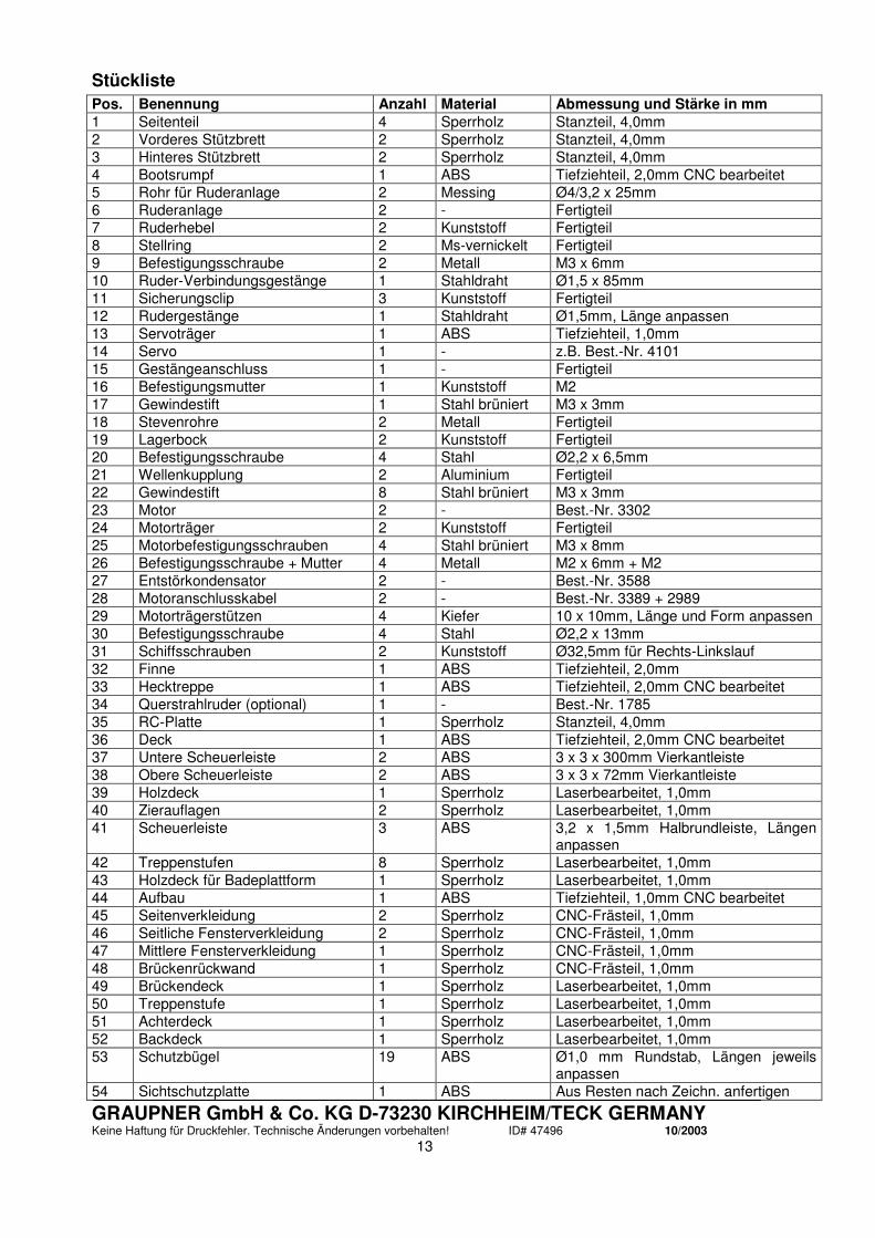
Stückliste
Pos. Benennung Anzahl Material Abmessung und Stärke in mm 1 Seitenteil 4 Sperrholz Stanzteil, 4,0mm 2 Vorderes Stützbrett 2 Sperrholz Stanzteil, 4,0mm 3 Hinteres Stützbrett 2 Sperrholz Stanzteil, 4,0mm 4 Bootsrumpf 1 ABS Tiefziehteil, 2,0mm CNC bearbeitet 5 Rohr für Ruderanlage 2 Messing Ø4/3,2 x 25mm 6 Ruderanlage 2 - Fertigteil 7 Ruderhebel 2 Kunststoff Fertigteil 8 Stellring 2 Ms-vernickelt Fertigteil 9 Befestigungsschraube 2 Metall M3 x 6mm 10 Ruder-Verbindungsgestänge 1 Stahldraht Ø1,5 x 85mm 11 Sicherungsclip 3 Kunststoff Fertigteil 12 Rudergestänge 1 Stahldraht Ø1,5mm, Länge anpassen 13 Servoträger 1 ABS Tiefziehteil, 1,0mm 14 Servo 1 - z.B. Best.-Nr. 4101 15 Gestängeanschluss 1 - Fertigteil 16 Befestigungsmutter 1 Kunststoff M2 17 Gewindestift 1 Stahl brüniert M3 x 3mm 18 Stevenrohre 2 Metall Fertigteil 19 Lagerbock 2 Kunststoff Fertigteil 20 Befestigungsschraube 4 Stahl Ø2,2 x 6,5mm 21 Wellenkupplung 2 Aluminium Fertigteil 22 Gewindestift 8 Stahl brüniert M3 x 3mm 23 Motor 2 - Best.-Nr. 3302 24 Motorträger 2 Kunststoff Fertigteil 25 Motorbefestigungsschrauben 4 Stahl brüniert M3 x 8mm 26 Befestigungsschraube + Mutter 4 Metall M2 x 6mm + M2 27 Entstörkondensator 2 - Best.-Nr. 3588 28 Motoranschlusskabel 2 - Best.-Nr. 3389 + 2989 29 Motorträgerstützen 4 Kiefer 10 x 10mm, Länge und Form anpassen 30 Befestigungsschraube 4 Stahl Ø2,2 x 13mm 31 Schiffsschrauben 2 Kunststoff Ø32,5mm für Rechts-Linkslauf 32 Finne 1 ABS Tiefziehteil, 2,0mm 33 Hecktreppe 1 ABS Tiefziehteil, 2,0mm CNC bearbeitet 34 Querstrahlruder (optional) 1 - Best.-Nr. 1785 35 RC-Platte 1 Sperrholz Stanzteil, 4,0mm 36 Deck 1 ABS Tiefziehteil, 2,0mm CNC bearbeitet 37 Untere Scheuerleiste 2 ABS 3 x 3 x 300mm Vierkantleiste 38 Obere Scheuerleiste 2 ABS 3 x 3 x 72mm Vierkantleiste 39 Holzdeck 1 Sperrholz Laserbearbeitet, 1,0mm 40 Zierauflagen 2 Sperrholz Laserbearbeitet, 1,0mm 41 Scheuerleiste 3 ABS 3,2 x 1,5mm Halbrundleiste, Längen
anpassen 42 Treppenstufen 8 Sperrholz Laserbearbeitet, 1,0mm 43 Holzdeck für Badeplattform 1 Sperrholz Laserbearbeitet, 1,0mm 44 Aufbau 1 ABS Tiefziehteil, 1,0mm CNC bearbeitet 45 Seitenverkleidung 2 Sperrholz CNC-Frästeil, 1,0mm 46 Seitliche Fensterverkleidung 2 Sperrholz CNC-Frästeil, 1,0mm 47 Mittlere Fensterverkleidung 1 Sperrholz CNC-Frästeil, 1,0mm 48 Brückenrückwand 1 Sperrholz CNC-Frästeil, 1,0mm 49 Brückendeck 1 Sperrholz Laserbearbeitet, 1,0mm 50 Treppenstufe 1 Sperrholz Laserbearbeitet, 1,0mm 51 Achterdeck 1 Sperrholz Laserbearbeitet, 1,0mm 52 Backdeck 1 Sperrholz Laserbearbeitet, 1,0mm 53 Schutzbügel 19 ABS Ø1,0 mm Rundstab, Längen jeweils
anpassen 54 Sichtschutzplatte 1 ABS Aus Resten nach Zeichn. anfertigen

GRAUPNER GmbH & Co. KG D-73230 KIRCHHEIM/TECK GERMANY Keine Haftung für Druckfehler. Technische Änderungen vorbehalten! ID# 47496 10/2003
14
55 Dach 1 ABS Tiefziehteil, 1,0mm 56 Abstandshalter 2 ABS oder Holz ca. 60 x 10 x 1mm, aus Resten
anfertigen 57 Cockpit 1 ABS Tiefziehteil, 1,0mm 58 Cockpitunterteil 1 ABS Tiefziehteil, 1,0mm 59 Niedergang 1 ABS Tiefziehteil, 1,0mm 60 Fahrersitz 1 ABS Tiefziehteil, 1,0mm 61 Obere Sitzbank (langer Schenkel) 1 ABS Tiefziehteil, 1,0mm 62 Obere Sitzbank (kurzer Schenkel) 1 ABS Tiefziehteil, 1,0mm 63 Untere Sitzbank (kurzer Schenkel
– links) 1 ABS Tiefziehteil, 1,0mm
64 Untere Sitzbank (langer Schenkel) 1 ABS Tiefziehteil, 1,0mm 65 Untere Sitzbank (kurzer Schenkel
– rechts) 1 ABS Tiefziehteil, 1,0mm
66 Rückwand 1 ABS Aus Resten nach Zeichn. anfertigen 67 Tischfuß 2 ABS Tiefziehteil, 1,0mm 68 Tischbein 2 Aluminium Ø4/3,2 x 30mm 69 Obere Tischplatte 1 ABS Tiefziehteil, 1,0mm 70 Untere Tischplatte 1 ABS Tiefziehteil, 1,0mm 71 Oberes Tischunterteil 1 ABS Tiefziehteil, 1,0mm 72 Unteres Tischunterteil 1 ABS Tiefziehteil, 1,0mm 73 Obere Tischfläche 1 Sperrholz Laserbearbeitet, 1,0mm 74 Untere Tischfläche 1 Sperrholz Laserbearbeitet, 1,0mm 75 Handlauf für Brückenrückwand 1 Buche Biegeholzleisten 5 x 2 x 110mm 76 Seitenfensterverkleidung 4 Sperrholz CNC-Frästeil, 1,0mm 77 Äußere Fensterverkleidung 2 Sperrholz CNC-Frästeil, 1,0mm 78 Äußere Mittelfensterverkleidung 1 Sperrholz CNC-Frästeil, 1,0mm 79 Innere Fensterverkleidung 2 Sperrholz CNC-Frästeil, 1,0mm 80 Innere Mittelfensterverkleidung 1 Sperrholz CNC-Frästeil, 1,0mm 81 Lüftungsklappen 6 ABS 15 x 4 x 1mm, aus Resten anfertigen 82 Zierleiste, Seite links 1 ABS 3,2 x 1,5mm Halbrundleiste, Länge
anpassen 83 Zierleiste, vorne links 1 ABS 3,2 x 1,5mm Halbrundleiste, Länge
anpassen 84 Zierleiste, Mitte 1 ABS 3,2 x 1,5mm Halbrundleiste, Länge
anpassen 85 Zierleiste, vorne rechts 1 ABS 3,2 x 1,5mm Halbrundleiste, Länge
anpassen 86 Zierleiste, Seite rechts 1 ABS 3,2 x 1,5mm Halbrundleiste, Länge
anpassen 87 Handlauf, links 1 Buche Biegeholzleisten 5 x 2 x 110mm 88 Handlauf, rechts 1 Buche Biegeholzleisten 5 x 2 x 110mm 89 Handlaufstützen 7 Kunststoff Fertigteil 90 Handlauf 1 ABS Ø2mm Rundstab, Länge anpassen 91 Kranfundament 1 ABS Tiefziehteil, 1,0mm 92 Äußerer Kranausleger 1 ABS Tiefziehteil, 1,0mm 93 Innerer Kranausleger 1 ABS Tiefziehteil, 1,0mm 94 Lasche 1 Kunststoff Fertigteil 95 Spannschloss 1 Messing, vern. Fertigteil 96 Splint 1 Metall Fertigteil 97 Schlauchbootunterschale 1 ABS Tiefziehteil, 1,0mm 98 Schlauchbootoberschale 1 ABS Tiefziehteil, 1,0mm 99 Außenbordmotorhalbschalen 2 ABS Tiefziehteil, 1,0mm 100 Wellenstück 1 ABS Ø1mm Rundstab, Länge ca. 10mm 101 Propeller 1 Kunststoff Ø20mm, Fertigteil 102 Auflagen für Schlauchboot 2 ABS oder Holz Aus Resten nach Zeichn. anfertigen 103 Abdeckung für Schlauchboot 1 ABS Tiefziehteil, 1,0mm 104 Steuerrad 2 Kunststoff Fertigteil
GRAUPNER GmbH & Co. KG D-73230 KIRCHHEIM/TECK GERMANY Keine Haftung für Druckfehler. Technische Änderungen vorbehalten! ID# 47496 10/2003
15
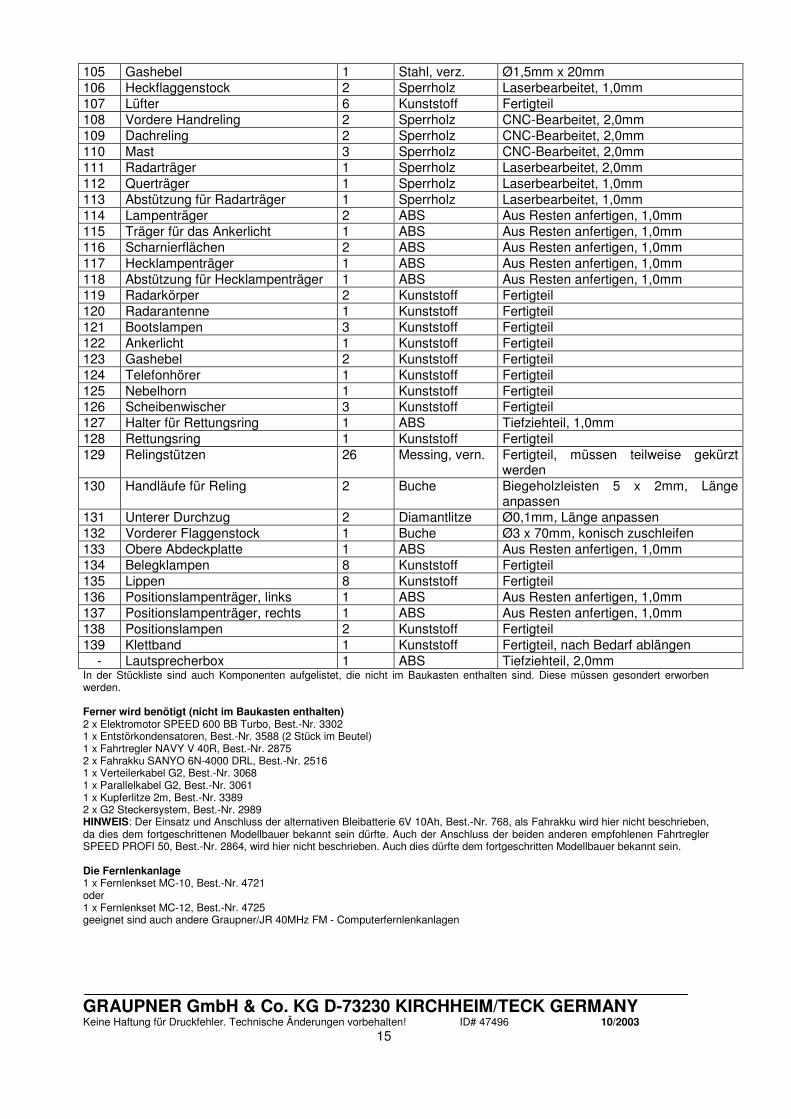
105 Gashebel 1 Stahl, verz. Ø1,5mm x 20mm 106 Heckflaggenstock 2 Sperrholz Laserbearbeitet, 1,0mm 107 Lüfter 6 Kunststoff Fertigteil 108 Vordere Handreling 2 Sperrholz CNC-Bearbeitet, 2,0mm 109 Dachreling 2 Sperrholz CNC-Bearbeitet, 2,0mm 110 Mast 3 Sperrholz CNC-Bearbeitet, 2,0mm 111 Radarträger 1 Sperrholz Laserbearbeitet, 2,0mm 112 Querträger 1 Sperrholz Laserbearbeitet, 1,0mm 113 Abstützung für Radarträger 1 Sperrholz Laserbearbeitet, 1,0mm 114 Lampenträger 2 ABS Aus Resten anfertigen, 1,0mm 115 Träger für das Ankerlicht 1 ABS Aus Resten anfertigen, 1,0mm 116 Scharnierflächen 2 ABS Aus Resten anfertigen, 1,0mm 117 Hecklampenträger 1 ABS Aus Resten anfertigen, 1,0mm 118 Abstützung für Hecklampenträger 1 ABS Aus Resten anfertigen, 1,0mm 119 Radarkörper 2 Kunststoff Fertigteil 120 Radarantenne 1 Kunststoff Fertigteil 121 Bootslampen 3 Kunststoff Fertigteil 122 Ankerlicht 1 Kunststoff Fertigteil 123 Gashebel 2 Kunststoff Fertigteil 124 Telefonhörer 1 Kunststoff Fertigteil 125 Nebelhorn 1 Kunststoff Fertigteil 126 Scheibenwischer 3 Kunststoff Fertigteil 127 Halter für Rettungsring 1 ABS Tiefziehteil, 1,0mm 128 Rettungsring 1 Kunststoff Fertigteil 129 Relingstützen 26 Messing, vern. Fertigteil, müssen teilweise gekürzt
werden 130 Handläufe für Reling 2 Buche Biegeholzleisten 5 x 2mm, Länge
anpassen 131 Unterer Durchzug 2 Diamantlitze Ø0,1mm, Länge anpassen 132 Vorderer Flaggenstock 1 Buche Ø3 x 70mm, konisch zuschleifen 133 Obere Abdeckplatte 1 ABS Aus Resten anfertigen, 1,0mm 134 Belegklampen 8 Kunststoff Fertigteil 135 Lippen 8 Kunststoff Fertigteil 136 Positionslampenträger, links 1 ABS Aus Resten anfertigen, 1,0mm 137 Positionslampenträger, rechts 1 ABS Aus Resten anfertigen, 1,0mm 138 Positionslampen 2 Kunststoff Fertigteil 139 Klettband 1 Kunststoff Fertigteil, nach Bedarf ablängen
- Lautsprecherbox 1 ABS Tiefziehteil, 2,0mm In der Stückliste sind auch Komponenten aufgelistet, die nicht im Baukasten enthalten sind. Diese müssen gesondert erworben werden. Ferner wird benötigt (nicht im Baukasten enthalten) 2 x Elektromotor SPEED 600 BB Turbo, Best.-Nr. 3302 1 x Entstörkondensatoren, Best.-Nr. 3588 (2 Stück im Beutel) 1 x Fahrtregler NAVY V 40R, Best.-Nr. 2875 2 x Fahrakku SANYO 6N-4000 DRL, Best.-Nr. 2516 1 x Verteilerkabel G2, Best.-Nr. 3068 1 x Parallelkabel G2, Best.-Nr. 3061 1 x Kupferlitze 2m, Best.-Nr. 3389 2 x G2 Steckersystem, Best.-Nr. 2989 HINWEIS: Der Einsatz und Anschluss der alternativen Bleibatterie 6V 10Ah, Best.-Nr. 768, als Fahrakku wird hier nicht beschrieben, da dies dem fortgeschrittenen Modellbauer bekannt sein dürfte. Auch der Anschluss der beiden anderen empfohlenen Fahrtregler SPEED PROFI 50, Best.-Nr. 2864, wird hier nicht beschrieben. Auch dies dürfte dem fortgeschritten Modellbauer bekannt sein. Die Fernlenkanlage 1 x Fernlenkset MC-10, Best.-Nr. 4721 oder 1 x Fernlenkset MC-12, Best.-Nr. 4725 geeignet sind auch andere Graupner/JR 40MHz FM - Computerfernlenkanlagen

GRAUPNER GmbH & Co. KG D-73230 KIRCHHEIM/TECK GERMANY Keine Haftung für Druckfehler. Technische Änderungen vorbehalten! ID# 47496 10/2003
16
Building instructions for the JULES VERNE, Order No. 2097
The full-size vessel
Our model of the JULES VERNE was developed in conjunction with the Dutch designer Rene van der Velden. This is a “retro-look” motor yacht, and is similar in shape and colour scheme to the characteristic mahogany vessels constructed in the 1930’s and 40’s. The full-size JULES VERNE was built in 1998, and combines in an ideal way the essential design elements of those earlier boats with modern facilities and refinements. The result is one of the most elegant yachts of the “retro-style” to be produced to date. For reasons of cost timber-built hulls are virtually never built nowadays, so the hull of the JULES VERNE is made of aluminium and painted mahogany brown. The boat’s two engines, each rated at 660 BHP, endow it with a top speed of around 26 kn. The model Our model of the JULES VERNE is designed to a scale of 1:20, and is based on the designer’s original drawings. The kit does call for certain manual skills and a modicum of experience in marine modelling, so it is only recommended to the experienced boat-builder. All the rounded parts are vacuum-moulded in ABS, and the parts which normally present problems are also CNC-trimmed (machined), including the hull, stern steps, deck and superstructure. The wooden parts are die-stamped, machined or laser-cut in order to shorten the building time. The kit includes injection-moulded plastic fittings such as windscreen wipers, ventilators, lamps, radar unit etc. as standard. The lamp housings in the fittings set can easily be made to work by fitting miniature 2.4 mm Ø filament bulbs. Specification Model Full-size Length approx. 925 mm 18.50 mm Beam approx. 250 mm All-up weight inc. RC approx. 4.6 kg Dry weight approx. 2.3 kg Scale 1:20
Important safety notes
You have purchased a kit which can be assembled to produce a fully working RC model when fitted out with the appropriate accessories. As manufacturers, we at GRAUPNER are not in a position to influence the way you assemble, operate and maintain the model, nor the way you operate other components used in connection with the model. For this reason we are obliged to deny all liability for loss, damage or costs which are incurred due to the incompetent or incorrect use, defective handling or operation of our products, or which are connected with such operation in any way. Unless otherwise prescribed by binding law, the obligation of the GRAUPNER company to pay compensation, regardless of the legal argument employed, is excluded. This includes personal injury, death, damage to buildings, loss of trade or turnover, interruption of business or other indirect or direct damages which are caused by the operation of the model. Under all circumstances and in all cases the company’s overall liability is limited to the amount which you actually paid for this model. The model is operated at the sole risk of the operator. To avoid injury to persons and damage to property please handle your model boat carefully and operate it conscientiously at all times. Before you run the boat for the first time it is important to check that your private third party insurance policy covers you for operating model boats of this kind. If you are not sure, take out a special insurance policy designed to cover the risks of RC modelling. These safety notes are important, and must be kept in a safe place. If you ever dispose of the model, be sure to pass them on to the new owner.

GRAUPNER GmbH & Co. KG D-73230 KIRCHHEIM/TECK GERMANY Keine Haftung für Druckfehler. Technische Änderungen vorbehalten! ID# 47496 10/2003
17
Guarantee conditions
The guarantee provides for free repair or replacement of any part which exhibits proven manufacturing or material faults within the guarantee period of 24 months from the date of purchase. We will not consider any claims beyond these conditions. The cost of transport, packing and carriage are payable by the purchaser. We accept no liability for transit damage. If you send goods to GRAUPNER or to the approved Graupner service centre for your country, be sure to enclose an accurate description of the fault together with the dated purchase receipt. The guarantee is invalid if the component or model fails due to an accident, incompetent handling or incorrect usage. The following points are important and must be observed at all times: This model is not suitable for young persons under 14 years of age. This is a high-speed model, which means that you must NEVER operate it when there are persons or animals in the water, otherwise there is a serious risk of causing injury. Never run your model in protected sites, animal or plant sanctuaries or sites of special scientific interest (SSSIs). Check with your local authority that the stretch of water you wish to use is suitable for model boats. Do not run the boat in salt water. Even salt-laden sea air can attack the technical components of your model and may even destroy them. Never run your boat in adverse conditions, e.g. rain, storm, strong wind, choppy water or strong currents. Before you run the model check that the radio control system is working reliably, and that all connections are secure. If you are using dry cells as power supply, note that they must not be recharged. Only batteries marked as “rechargeable” can be recharged safely. Ensure that all batteries are fully charged before every run. Check the range of your radio control system. It is particularly important that the transmitter and receiver batteries are fully charged before each session. Ensure that the channel you intend to use is not already in use by other modellers. Never run your boat if you are not certain that your channel is free. Read and observe the instructions and recommendations provided by the manufacturer of your radio control system and accessory components. Do not work on the power system unless the motor is disconnected from the drive battery. When the drive battery is connected, keep well clear of the area around the propellers, as this represents the greatest risk of accident and injury. Make sure any spectators do the same. Do not exceed the recommended voltage of the drive battery. Increasing the voltage may cause the motors and/or the speed controller to overheat, and the electrical leads can even melt. In the worst case this may cause the model to go up in flames and be completely ruined. Check that all the drive train components work smoothly and freely. This applies in particular when you are running the model, as leaves and other detritus can get caught up in the power train. If this happens and you do not remove the obstruction, the speed controller or rudder servo may be ruined due to overloading. Ensure that the servos are not mechanically obstructed at any point in their travel. Dry cells and rechargeable batteries must never be short-circuited. Do not allow them to come into direct contact with water. Allow the drive motor and speed controller to cool down after each run. Don’t touch the hot surfaces! Remove all batteries from the model prior to transporting and storing it. Do not subject the model to severe humidity, heat, cold or dirt. Secure the model and your RC equipment carefully when transporting them. They may be seriously damaged if they are free to slide about. If you wish to operate the model on moving water (e.g. a river), remember that it could be washed away downstream if the battery fails or a malfunction occurs. If you have to salvage the model, take care not to risk your own life or that of others. Check regularly that the boat is completely watertight, as it may sink if too much water enters the hull. Check the boat for damage before every run, and ensure that water cannot penetrate the hull through the shaft or rudder openings. Take great care to prevent water entering the boat. Secure the superstructure carefully, so that there is no chance of it falling off when the boat is running. If you are using drive batteries connected in parallel they must not be inter-connected until the boat is ready to run; the packs may affect each other under no-load conditions, and this can cause damage to the batteries. You can avoid this problem by not connecting the batteries until the boat is otherwise ready to run, and disconnecting them immediately after each run. Never store batteries connected by parallel cables.

GRAUPNER GmbH & Co. KG D-73230 KIRCHHEIM/TECK GERMANY Keine Haftung für Druckfehler. Technische Änderungen vorbehalten! ID# 47496 10/2003
18
Care and maintenance
Clean the model carefully after every run, and remove any water which penetrates the hull. If water gets inside any RC component, dry the unit out and send it to your nearest GRAUPNER service department for checking. No claim under guarantee will be considered for damage caused by water. Clean the model and RC components using suitable cleaning agents only. Ask your model shop for information. Lubricate the propeller shafts and rudder shafts at regular intervals. If the model is not to be run for a considerable time it is important to dismantle all the moving parts (propeller shafts etc.), and clean and re-lubricate them.
Building the model
Before you start building the boat be sure to study the plan and read right through the instructions. We recommend that you refer constantly to the parts list as an aid to construction. The instructions and parts list reflect the sequence of assembly. You will find small lugs connecting the machine-cut wooden parts to their sheets. Cut through the lugs with a pair of scissors. The vacuum-moulding process inevitably produces slightly rounded shapes. Where wooden parts are to be glued to moulded plastic components, sand the joint surface of the wooden part slightly concave to obtain a snug fit, without gaps. The laser cutting process inevitably generates a black edge to the cut wooden parts. This can easily be sanded off. Don’t throw away scrap wood, ABS and wire immediately as these materials may be required to make other small parts. If you wish to fit auxiliary working systems, be sure to plan for the installation before you start construction. You will find information and tips on such systems at the end of the building instructions. The Centre of Gravity of this model should be as low as possible. Bear in mind that tools can be dangerous; always be careful when handling them. The electric motors must be suppressed. The minimum is one 470 nF capacitor (Order No. 3588) for each motor, soldered between the terminals as a bridge (see sketch on the plan). Deploy all electrical cables in an orderly fashion, without crossing them over. Never allow a positive (+) contact to touch a negative (-) contact. Use cable of adequate cross-section, capable of carrying the high currents which will flow when the boat is running. Deploy the receiver aerial as far from high-current cables as possible (at least 3 cm). Lubricate the shaft system using a type of grease or oil which does not soil or contaminate water, e.g. Order No. 570. Before gluing parts together clean the joint surfaces carefully, i.e. remove all traces of grease. This is best done by sanding, followed by wiping with a non-greasy liquid detergent. The same applies to all surfaces which are to be painted, otherwise the paint will not adhere well. Before gluing parts to the hull sand the surfaces with fine abrasive paper and de-grease them using methylated spirits (“meths”). If you neglect to do this, the joints will be weak and may fail at any time. Recommended adhesives for various types of joint: Material - material Suitable adhesives Metal - metal Cyano-acrylate, UHU plus ABS - wood Cyano-acrylate, UHU acrylit ABS - ABS Cyano-acrylate, UHU acrylit, UHU plast spezial ABS - metal Cyano-acrylate, UHU acrylit Wood - wood Cyano-acrylate, UHU hart, white glue Wood - metal Cyano-acrylate Read the instructions supplied with the adhesives. Be sure to observe any special notes in the instructions regarding particular adhesives. If you are using acetone, methylated spirits or any other solvent as a cleaning agent, special safety measures are necessary. Read the instructions supplied with these materials.
Assembly instructions
Assemble the boatstand from the two side panels (part 1), the front support (part 2) and the rear support
GRAUPNER GmbH & Co. KG D-73230 KIRCHHEIM/TECK GERMANY Keine Haftung für Druckfehler. Technische Änderungen vorbehalten! ID# 47496 10/2003
19
(part 3). Note that the parts must first be glued together in pairs, i.e. each part consists of two panels which must be glued together with their edges flush. Fix the stand components together using white glue. TIP: weight the doubled wooden parts down while the glue is hardening, so that the surfaces make good contact overall. TIP 2: apply felt or some other soft material to the contact surfaces of the stand to avoid scratching the painted model. Cut the brass tubes which form the rudder bushes (part 5) to a length of 25 mm. Sand the joint surface of the tubes and glue them in the two 4 mm Ø holes in the hull (part 4) in the position shown in the drawing. Ensure that both tubes are exactly parallel and angled as shown on the plan. TIP: this is easier to check if you fit the rudder units (part 6) in the bushes temporarily. Glue the two tubes securely to the hull and apply a generous fillet of UHU acrylit round them, as they have to withstand considerable loads when the boat is running. Push a collet (part 8) into each of the tillers (part 7) and fit a retaining screw (part 9) in each one. Fit the tillers on the rudder units. Cut off the excess rudder shaft material just above the tillers, otherwise the rudder system will foul the stern steps (part 33). The rudder link rod (part 10) is made from 1.5 mm Ø steel rod: cut a piece about 85 mm long from the rod supplied, and bend both ends down at right-angles to leave a straight centre section about 65 mm long. It is important that both tillers are exactly parallel, as shown on the plan. Connect the link rod to the tillers and secure each end with a pushrod keeper (part 11). The rudder pushrod (part 12) is made up from the same 1.5 mm Ø steel rod. Bend the final 10 mm at one end at right-angles. Connect the formed end to the tiller and secure the end with another pushrod keeper (part 11). Cut out the servo mount (part 13). Fix the rudder servo (part 14) in the opening using the screws supplied with the servo. TIP: push a pointed object such as a thin nail through the plastic at the hole positions, then drive the screws directly into the ABS. Open up the linkage hole in the servo output arm to 2 mm Ø and install the pushrod connector (part 15) in it. Secure the pushrod connector with the retaining nut (part 16). Glue the servo mount in the hull in the position shown. Fit the rudder pushrod through the pushrod connector (you may need to remove the output arm from the servo in order to insert the pushrod), then set the servo and rudders to centre and tighten the grubscrew (part 17) in the pushrod connector to clamp the pushrod in place. Remove the excess pushrod length, leaving about 4 mm projecting from the pushrod connector. Fix the stern tubes (part 18) to the brackets (part 19) using the retaining screws (part 20). Drill a 2 mm Ø hole in the stern tubes through the opening in the brackets; this forms the lubrication hole for the stern tubes. TIP: if you wish you can fit a piece of tubing onto the lubricating nipple, e.g. Order No. 1668.3. The next step is to fix the two motor mount units together: screw the shaft coupling (part 21) to the motor (part 23) using the grubscrews (part 22). There should be a slight gap between the coupling and the motor. Screw the motors to the motor mounts (part 24) using the motor retaining screws (part 25). Cut the two slots in the motor mount on the stern tube side using a sharp knife. Fit the retaining screw in the small holes and fit the nut (part 26) loosely to prevent it falling out again. Solder the suppressor capacitors (part 27) to the motor terminals together with the power leads (part 28). Note that the second motor unit must be connected with reversed polarity so that it rotates in the opposite direction (see wiring diagram). Now fit the motor assemblies on the stern tubes and fix them in the correct position by tightening the screws. Note: you may have to adjust the holes in the hull slightly. Make up the motor mount braces (part 29) from the 10 x 10 mm spruce strip supplied. Ensure that the braces do not force the motor assembly upwards; the mounts must make good contact with the hull. Glue the braces in place when you are satisfied. Drill 1.5 mm Ø holes in the braces then fix the motor assembly in place using the retaining screws (part 30). Check once more that the assembly is not under stress or tension. Screw the propellers (part 31) on the end of the stern tube shafts. The propellers are handed, so make sure you fit them on the appropriate shafts. Cut out the fin strake (part 32) as shown and glue it to the bottom of the hull using UHU acrylit, taking care to keep it aligned “straight ahead”. The strake protects the rudder and shaft systems from damage if the hull strikes bottom, so make sure that the glued joint is really sound. The hull and the stern staircase (part 33) must now be trimmed to ensure that they make good contact where they join. This applies in particular to the edges, as the manufacturing technique produces a small flange which will need to be sanded smooth. The staircase will need to be chamfered on the inside in the area where the deck will later be glued. This is essential, otherwise the joint between the deck and the staircase will not be neat and accurate. The hull can now be glued to the stern staircase: align the edges of the staircase and the hull and press the joint surfaces together using clamps (e.g. Order No. 542.1 or 542.2) while the glue is setting. This technique is necessary in order to avoid an offset in the top surface of the hull, and this in turn means less

GRAUPNER GmbH & Co. KG D-73230 KIRCHHEIM/TECK GERMANY Keine Haftung für Druckfehler. Technische Änderungen vorbehalten! ID# 47496 10/2003
20
filling and sanding. Any openings or gaps should be sealed carefully on the inside using UHU acrylit. Fill any gaps in the outside surfaces and sand back flush. The joints will need to be fine-sanded, but this is not carried out until the deck has been fitted. Installing the optional bow thruster: suppress the motor of the bow thruster (part 34) using one suppressor capacitor (part 27), and connect the power leads (part 28) to the motor terminals. The bow thruster must be assembled inside the model; don’t glue the parts together outside the boat, otherwise it will be impossible to install. Tack the assembly in place using cyano, with the electric motor standing upright at an angle, then apply plenty of UHU acrylit all round the joints with the hull sides. Work carefully here, as the joints must be 100% watertight. Omitting the bow thruster: if you do not wish to fit a bow thruster, the holes in the hull must be sealed. Cut plates from scrap ABS sheet, making them large enough to cover the hole with a generous overlap all round. Glue them in place with cyano, and apply a fillet of UHU acrylit. Here again take care to make the joints 100% watertight. NOTE: it is very difficult to install a bow thruster once the model is complete, so the decision to install one really has to be made at this stage. Glue the RC plate (part 35) in the hull in the position shown on the plan. Allow plenty of space around the bow thruster (if fitted) so that you have good access to it for maintenance. As an alternative you may prefer to omit the RC plate completely and fix the receiving system components directly to the hull sides using Velcro (hook-and-loop) tape. There are no technical disadvantages to this option. The deck (part 36) must be trimmed carefully to fit, as already described for the hull and stern staircase. The deck can then be glued to the hull. Start by gluing it in the area of the stern staircase by applying a fillet of UHU plast spezial adhesive about 30 cm long and fixing the glued joint with spring clamps (e.g. Order No. 524.1) while the glue is setting. Once the glue has set, repeat the procedure with the next section, and continue until the deck is completely attached to the hull. NOTE: the glue penetrates into the gap between deck and hull through the capillary effect, but this only works with low-viscosity (thin) adhesives. IMPORTANT: ensure that the edges of the deck and the hull line up as accurately as possible, otherwise you may build a twist into the finished hull. You don’t need to be concerned about excess glue being squeezed out of the joint, as the glued edges have to be sanded back later in any case. Check carefully that there are no openings or gaps at any point round the hull / deck joint. If you find a gap, seal it on the inside using plenty of UHU acrylit. It really is essential that the hull should be 100% watertight. TIP: if you have to fill a fairly large opening, apply a piece of adhesive tape over the outside before applying UHU acrylit on the inside. This prevents glue penetrating to the outside, in which case you would have the tiresome task of sanding it off again when dry. Now apply filler to all the areas where the deck, the hull and the stern staircase meet, and sand the filler back flush. You do not need to fill the areas where the wooden deck components will be fitted later; in this case it is sufficient to check that any gaps are completely filled with glue, and that the surfaces line up flush so that the wooden parts lie flat when fitted. Locate the edges where the 3 x 3 mm ABS strips are to be fitted, and sand them to as sharp an edge as possible. Cut the lower rubbing strakes (part 37) from the square-section ABS strip; note that one side must be sanded to a slight taper (don’t chamfer the face which is to be glued). You will find a line moulded into the hull where the strip is to be fitted. Cut the upper rubbing strakes (part 38) from the same material. Pre-bend the strips in such a way that they approximately follow the shape of the hull sides, then glue the strips to the hull. It is important that the strips are flush with the deck, i.e. the wooden parts of the deck must rest flat on them. Use double-sided tape to attach the wooden deck (part 39) to the deck temporarily. Just use a few small pieces of tape to ensure that the wooden deck cannot shift, and check that it is a snug fit on the inside in the superstructure area. The next stage is to sand back the hull flush with the wooden deck. Work carefully here, and take great care not to sand away the wooden deck. Carefully remove the wooden deck again when the task is finished. The hull can now be fine-sanded overall and painted. Apply several coats of clear lacquer to both sides of the wooden deck. Carefully rub down the top surface of the deck after applying each coat using fine abrasive paper (600- or 800-grit). Take care not to remove too much material, otherwise the laser engraving of the planking joints will disappear. The deck is finished when the surface is perfectly smooth, with an even, semi-matt gloss. Stain the ornamental linings (part 40) in a teak colour, and apply clear lacquer to them on both sides when the stain is dry. Stick the linings to the wooden deck, taking care to avoid glue getting onto the surface. The wooden deck can now be glued to the boat. For this we recommend a high-viscosity (thick) cyano-acrylate glue, as it hardens relatively slowly. Apply drops of adhesive to the deck at regular intervals, and carefully place the deck on the model. Ensure that the deck is correctly positioned, and take care not to allow any glue to run onto the painted surfaces of the hull. TIP: to be on the safe side it is a good idea to mask off the area of the hull most likely to be soiled in this way. When the glue has set hard, carefully sand the hull again to provide a flat surface to accept the rubbing
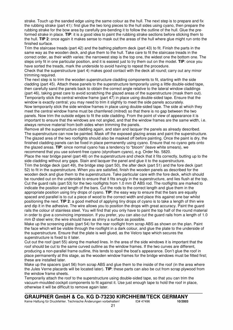
GRAUPNER GmbH & Co. KG D-73230 KIRCHHEIM/TECK GERMANY Keine Haftung für Druckfehler. Technische Änderungen vorbehalten! ID# 47496 10/2003
21
strake. Touch up the sanded edge using the same colour as the hull. The next step is to prepare and fix the rubbing strake (part 41): first glue the two long pieces to the hull sides using cyano, then prepare the rubbing strake for the bow area by carefully pre-bending it to follow the outline of the hull. Glue the pre-formed strake in place. TIP: it is a good idea to paint the rubbing strake sections before sticking them to the hull. TIP 2: once again it makes sense to mask out the areas of the hull where glue might run onto the finished surface. Trim the staircase treads (part 42) and the bathing platform deck (part 43) to fit. Finish the parts in the same way as the wooden deck, and glue them to the hull. Take care to fit the staircase treads in the correct order, as their width varies: the narrowest step is the top one, the widest one the bottom one. The steps only fit in one particular position, and it is easiest just to try them out on the model. TIP: once you have sorted the treads, mark the underside to avoid having to repeat the procedure. Check that the superstructure (part 4) makes good contact with the deck all round; carry out any minor trimming required. The next step is to trim the wooden superstructure cladding components to fit, starting with the side cladding (part 45). Attach these panels to the superstructure temporarily using a little double-sided tape, then carefully sand the panels back to obtain the correct angle relative to the lateral window claddings (part 46), taking great care to avoid scratching the glazed areas of the superstructure (mask them out). Temporarily stick the central window frame (part 47) in place using double-sided tape. Ensure that the window is exactly central; you may need to trim it slightly to meet the side panels accurately. Now temporarily stick the side window frames in place using double-sided tape. The side at which they meet the central window frame must be chamfered (mitred) so that there is no gap between the two panels. Now trim the outside edges to fit the side cladding. From the point of view of appearance it is important to ensure that the windows are not angled, and that the window frames are the same width, i.e. always remove material from both sides when trimming the panels. Remove all the superstructure cladding again, and stain and lacquer the panels as already described. The superstructure can now be painted. Mask off the exposed glazing areas and paint the superstructure. The glazed area of the two rooflights should also be masked off before painting. Once the paint is dry, the finished cladding panels can be fixed in place permanently using cyano. Ensure that no cyano gets onto the glazed areas. TIP: since normal cyano has a tendency to “bloom” (leave white smears), we recommend that you use solvent-free cyano (styrofoam cyano), e.g. Order No. 5820. Place the rear bridge panel (part 48) on the superstructure and check that it fits correctly, butting up to the side cladding without any gaps. Stain and lacquer the panel and glue it to the superstructure. Trim the bridge deck (part 49), the bridge step (part 50), the after deck (part 51) and the fore deck (part 52) to fit in the superstructure. When you are satisfied, finish the wooden panels as described for the wooden deck and glue them to the superstructure. Take particular care with the fore deck, which should be rounded out on the underside to ensure that it fits snugly in the superstructure, and lies flush at the top. Cut the guard rails (part 53) for the two rooflights from 1.0 mm Ø ABS rod. The rooflights are marked to indicate the position and length of the bars. Cut the rods to the correct length and glue them in the appropriate position using tiny drops of cyano. TIP: the easy way to ensure that the bars are equally spaced and parallel is to cut a piece of wood to the correct width and place this against one bar whilst positioning the next. TIP 2: a good method of applying tiny drops of cyano is to take a length of thin wire and dip it in the adhesive. The wire allows you to position the drops with great accuracy. Paint the guard rails the colour of stainless steel. You will find that you only have to paint the top half of the round material in order to give a convincing impression. If you prefer, you can also cut the guard rails from a length of 1.0 mm Ø steel wire; the wire should have as shiny a surface as possible. Make up the screening plate (part 54) for the rear rooflight from scrap ABS as shown on the plan. Paint the face which will be visible through the rooflight in a dark colour, and glue the plate to the underside of the superstructure. Ensure that the plate is well glued, as the Velcro tape which secures the superstructure is fixed to it later. Cut out the roof (part 55) along the marked lines. In the area of the side windows it is important that the roof should be cut to the same curved outline as the window frames. If the two curves are different, producing a non-parallel frame outline, this tends to spoil the boat’s appearance. Don’t glue the roof in place permanently at this stage, as the wooden window frames for the bridge windows must be fitted first; these are installed later. Make up the spacers (part 56) from scrap ABS and glue them to the inside of the roof (in the area where the Jules Verne placards will be located later). TIP: these parts can also be cut from scrap plywood from the window frame sheets. Temporarily attach the roof to the superstructure using double-sided tape, so that you can trim the vacuum-moulded cockpit components to fit against it. Use just enough tape to hold the roof in place, otherwise it will be difficult to remove again later.

GRAUPNER GmbH & Co. KG D-73230 KIRCHHEIM/TECK GERMANY Keine Haftung für Druckfehler. Technische Änderungen vorbehalten! ID# 47496 10/2003
22
Now cut out the following ABS parts: the cockpit (part 57), the bottom cockpit section (part 58), the companionway (part 59), the skipper’s seat (part 60) and the two parts of the upper bench seat (parts 61 + 62). Work carefully when cutting; it is best to trim the mouldings gradually to obtain a snug fit. We suggest that you cut out the parts slightly oversize initially, then sand back the material gradually until all the parts fit together. The laser-engraved joint lines on the bridge deck act as a useful guide for positioning these parts. TIP: ensure that the support surface of the bench seats follows the camber of the deck. TIP 2: if you find that the joint area of the vacuum-moulded parts tends to distort, cut small stiffening plates from 4 mm thick scrap wood and glue them in the bottom of the mouldings. This also provides a larger gluing area when fixing the parts in place. Repeat the procedure outlined above with the lower bench seat (parts 63 + 64 + 65). Cut the back panel (part 66) for the lower bench seat from scrap ABS; it only needs to cover the exposed area which projects above the side cladding. When you are satisfied that all the parts fit together well, glue them together and paint them. Repeat this process with the section of the superstructure which is not covered by the roof. TIP: we recommend that you apply the decals to the cockpit section before installing this in the model. The cockpit fittings are best fitted at a later stage, as they can easily be broken off during subsequent work otherwise. Assemble the upper table (parts 67 + 68 + 69 + 71 + 73) and the lower table (parts 67 + 68 + 70 + 72 + 74). Before you glue the two table tops in place you should paint the components and stain and lacquer the wooden parts. The completed tables can then be glued to the model. Make up the handrail (part 75) for the rear bridge panel from the flexible beech strip. After staining and lacquering the rail glue it centrally to the rear bridge panel using thick cyano. Take care that no cyano runs onto the back panel. Trim the outer window frames (part 76 + 77 + 78) and the inner cladding panels (parts 76 + 79 + 80) for the roof, as already described for the superstructure. Check that the frames on both sides of the glazed areas line up accurately, as offset frames look untidy. Cut the ventilator flaps (part 81) from scrap ABS and glue them to the window frames. Drill a series of 1.5 mm Ø holes in the window frames for the windscreen wipers. Don’t install the wipers at this stage; they are fitted later. Carefully sand the top edge of the window frames absolutely flat, and cut the trim rails (parts 82 + 83 + 84 + 85 + 86) to shape as shown. Paint the rails and glue them carefully to the frames using thick cyano. Ensure that no cyano runs onto the wooden parts. TIP: the rails will be easier to glue in place if you pre-curve them first. Cut a door template from scrap ABS or wood to enable you to mark the position of the two doors using a soft pencil. The roof can now be glued to the superstructure. Check that the roof makes good contact with the superstructure all round, without requiring pressure; trim the moulding if necessary. This applies in particular to the area of the bench seats and the companionways. Cut the two handrails (parts 87 + 88) from the flexible beech strip. Finish the handrails as described for the rear bridge panel handrail, and glue these to the side cladding panels. Cut a notch in each handrail at the marked door positions; without the notch it would not be possible to open the doors. Note that the handrails should project outward slightly, i.e. they should not be fitted centrally. The stern handrail is made up from the handrail stanchions (part 89) and the handrail (part 90), which consists of 2 mm Ø ABS round rod. First mark the two holes in the side panels; the other holes are marked on the superstructure. Drill 2 mm Ø holes at the marked points and push the handrail stanchions in the holes (don’t glue them yet). Thread the handrail through the first stanchion, then pull it through all the remaining stanchions. The plastic handrail will take up the correct shape automatically. Glue the handrail to the stanchions, but not to the superstructure. Remove the handrail assembly and shorten the ends of the rail. Paint it stainless steel colour, then plug it into the superstructure again and glue the assembly in place. Cut off excess stanchion material on the inside, otherwise the superstructure will not rest properly on the deck. The next step is to assemble the derrick (crane) from the following parts: base (part 91), external outrigger (part 92), internal outrigger (part 93), tongue (part 94), turnbuckle (part 95) and split pin (part 96). Cut out the vacuum-moulded parts and glue the internal outrigger into the external outrigger. Note that a piece about 5 mm long should project out of one end. Glue the outrigger to the base. Straighten the ends of the tongue and attach it to one end of the turnbuckle using the split pin. Place the other end in the recess in the derrick base and glue the tongue to the outrigger. Now glue the other end to the base. Paint the derrick black overall except for the turnbuckle. This is intended to represent a hydraulic cylinder, so the threaded part should be painted silver. Cut the two shells of the inflatable boat - bottom section (part 97) and top section (part 98) - to approximate size, leaving a gluing flange at least 5 mm wide. Glue the two shells together, allow the glue

GRAUPNER GmbH & Co. KG D-73230 KIRCHHEIM/TECK GERMANY Keine Haftung für Druckfehler. Technische Änderungen vorbehalten! ID# 47496 10/2003
23
to set hard, then sand back the joint line to an even width of about 1 mm to 2 mm. Glue together the two shells of the outboard motor (part 99), applying plenty of UHU acrylit on the inside; there must be enough adhesive in the area of the glued joint to ensure that the two halves remain together when the joint line is sanded back. When the glue has set hard remove the outer flange around the outboard motor and sand the edge smooth. Cut the shaft spigot (part 100) from a scrap piece of 1 mm Ø ABS round rod. Drill a hole in the appropriate part of the outboard motor and glue the spigot in it. Paint the outboard motor and glue the propeller to the shaft spigot. Make the two supports (part 102) for the inflatable boat from scrap ABS or wood, and glue the supports to the underside of the boat. Cut out the cover (part 103) for the inflatable boat. Option: you will find marked points at the peaks of the cover; if you drill these out you can lash the cover to the inflatable boat using thin thread or similar; in this case you don’t need to fit out the inside of the inflatable boat. The inflatable boat should be painted white overall. If you wish to fit out the interior, use the colours of your choice but make sure that they harmonise with the main colours of the JULES VERNE. The outboard motor can now be glued to the inflatable boat. The bottom fin of the motor should rest on the boat, and the cover should fit over the motor. Fit the steering wheel (part 104) to the instrument panel. Bend the throttle lever (part 105) to shape from 1.5 mm Ø steel rod, drill a hole for it in the instrument panel and glue the throttle lever in place. Fix the cover to the inflatable boat with a few strips of double-sided tape so that it can be removed again at any time. Glue the inflatable boat and the derrick to the superstructure. Glue the two halves of the stern flagstock (part 106) together, and carefully sand the flagstock to a round profile when the glue is dry. Drill a hole in the superstructure at the indicated point and glue the flagstock in place permanently from the underside. The hole in the deck is designed to clear the flagstock when the superstructure is fitted on the boat. If the hole does not provide clearance, enlarge it until the superstructure fits snugly. Prepare the ventilators (part 107) by cutting them down at the first ring. Paint them silver and glue them to the superstructure at the marked points. Prepare the forward handrail (part 108) by very carefully sanding it to a round section at the top. TIP: sand just a short section at a time, holding the rail firmly at the bottom; this reduces the risk of breakage. Stain and lacquer the railing and glue it to the fore deck using thick cyano. Repeat the procedure with the roof railing (part 109). NOTE: if the railing components should break in spite of your care, glue the parts together again with a little white glue. Take care that NO white glue remains on the surface, as this would prevent it accepting stain, i.e. wipe off the glue immediately with a soft cloth. Glue the three parts of the mast (part 110) together using white glue. Sand the surfaces smooth and round off the corners when the glue has set hard. Do not round off the area which will be glued to the rear bridge panel later. Using a saw blade 1 mm wide cut straight slots in the mast in the positions shown on the plan to accept the radar support (part 111), the transverse support (part 112) and the two lamp bearers (part 114). Glue the two supports in the slots. Glue the radar strut (part 113) under the support; you may need to trim the strut slightly to fit. Glue the two lamp bearers in the slots and glue the anchor light bearer (part 115) to the top of the mast. Ensure that all the lamp bearers are at right-angles to the surface of the mast which will be glued to the rear bridge panel. Cut the two hinge plates (part 116) from scrap ABS and glue them to the sides of the mast. Glue the mast to the rear bridge panel using thick cyano. Check that the mast is vertical as viewed from the stern. Make up the stern lamp bearer (part 117) and its strut (part 118) from scrap ABS material. Glue the strut to the underside of the bearer, trim this assembly to fit against the angled part of the superstructure and glue it in place. Assemble the radar housing (part 119) and glue the radar antenna (part 120) to it. Glue the completed radar assembly to the mast. Paint the boat lamps (part 121) and the anchor light (part 122 - the lamp without the straight back panel) in the stated colours, and glue them in the appropriate positions on the mast and the stern lamp bearer. All the following fittings can now be glued to the superstructure: the ship’s wheel (part 104), the two throttle levers (part 123), the telephone handset (part 124), the foghorn (part 125) and the windscreen wipers (part 126). TIP: the ship’s wheel is easier to attach if you cut a short piece of 1.5 mm steel rod and glue this in the cockpit beforehand. Cut out the holder (part 127) for the lifebelt (part 128). Glue this to the inside of the side cladding as shown on the plan, and insert the lifebelt in the holder. Mark the position of the railing stanchions (part 129) on the hull. Drill 1 mm Ø holes at the marked points to a depth of about 4 mm. TIP: attach a collet to the drill bit at the correct height to avoid accidentally

GRAUPNER GmbH & Co. KG D-73230 KIRCHHEIM/TECK GERMANY Keine Haftung für Druckfehler. Technische Änderungen vorbehalten! ID# 47496 10/2003
24
drilling the holes deeper than intended. Winding adhesive tape tightly round the drill also works, but this is not 100% reliable as the tape may slip. Shorten the railing stanchions as shown on the plan, fit them in the holes and align them carefully by fitting a piece of thin wire through the rail holes. This should ensure that the braided wire which forms the lower rail has a straight run. When you are sure the railing stanchions are correctly aligned, glue them in place using low-viscosity (thin) cyano. The two handrails (part 130) are made from the flexible beech strip supplied. Bend the rails to shape as accurately as possible, and check that they retain their shape as far as possible before finishing them with stain and lacquer in the usual way. Mark the position of one centre railing stanchion on the handrail, punch a point in the centre of the rail and drill a 2 mm Ø blind hole to a depth of about 1.2 mm. TIP: as mentioned previously, a collet on the drill helps avoid drilling right through the handrail. Fit the rail on the railing stanchion and mark the position of the two adjacent stanchions. Drill blind holes at the marked points, and continue to work in this way until you have drilled the holes for all the stanchions. Shorten the ends of the handrail and trim them to fit neatly against the deck. The handrail can now be glued to the stanchions using cyano. When the glue has set hard glue the two ends to the hull permanently using cyano. TIP: cyano activator (Order No. 953.150) is helpful here, as it accelerates the hardening of the adhesive. Repeat the procedure with the second handrail. Apply several coats of clear lacquer to the handrail. It is particularly important to avoid the wood absorbing moisture, as it will then swell up considerably and ruin the handrail’s appearance. The next step is to fit the lower rail (part 131) through the railing stanchions. Fix one end of the braided wire in the hole with cyano, place the wire under tension and fix the other end with cyano in the same way. Ideally the braided wire should be under light but even tension along its entire length, without any hint of sagging. When you are satisfied, fix the rails to all the stanchions with a drop of cyano. Finish the job by cutting off the overhanging ends. Make the forward flagstock (part 132) from the beech dowel supplied and sand it to a slight taper. Cut the round top cover plate (part 133) from scrap ABS and glue it to the tip of the flagstock. To reinforce the flagstock joint we recommend that you drill a hole in the bottom and glue a short piece of rod in it. Drill a hole in the hull at the stated position and glue the flagstock in place permanently. Cut down the cleats (part 134) as shown on the plan: they should have an even overhang at both ends. Glue the prepared cleats and the fairleads (part 135) to the hull in the positions shown on the plan. Assemble the two navigation lamp brackets (part 136 + 137) from scrap ABS. Ensure that the two parts are built up as a mirror-image pair. Trim the two lamp brackets to fit on the railings and glue them in place as shown. Paint the lamp brackets black and glue the navigation lamps inside them. If you do not wish to fit working lamps, you can simply paint them the appropriate colour on the inside; this gives a good overall impression. Cut out the decals from the decal sheet using a pair of sharp scissors or a knife, and apply them in the appropriate positions on the boat, as shown in the kit box illustration. The white line on the hull sides above the waterline can easily be applied using a strip of white trim tape (e.g. Order No. 623.8). Cut two pieces of Velcro tape (part 139) about 45 mm long and stick the strips to the deck: one in the small recess in the bow area, one at the rear below the stern rooflight. The two strips hold the superstructure firmly in place when the boat is running. The remaining Velcro tape is used to secure the RC components and drive batteries. Connect the RC system components as shown in the wiring diagram on the plan. The receiver aerial is fixed to the inside of the hull using Velcro tape (as far as possible above the waterline, otherwise radio reception will be affected). If you prefer, a vertical whip aerial can be mounted on the outside of the model. This is strongly recommended if you wish to run your model at considerable range. If you fit a whip, the aerial wire attached to the receiver must be shortened by the length of the whip aerial.

GRAUPNER GmbH & Co. KG D-73230 KIRCHHEIM/TECK GERMANY Keine Haftung für Druckfehler. Technische Änderungen vorbehalten! ID# 47496 10/2003
25
Optional auxiliary working systems
Working system Accessories required Notes on installation and operation Bow thruster Bow thruster (Order No.
1785), MICRO SPEED 10 speed controller (Order No. 2736), distributor cable (Order No. 3086)
The method of installation is described in the instructions supplied with the set. The effectiveness of the bow thruster is very good, i.e. the motor should generally be operated throttled well back.
Sound module POLICE BOAT sound module (Order No. 2460), loudspeaker (Order No. 2354)
The kit includes a vacuum-moulded loudspeaker box (marked with a loudspeaker symbol). Cut out the windows in the forward rooflight. The box is designed to be installed with the loudspeaker located under the open windows. Fix the box using Velcro tape so that access is still possible to the bow thruster for maintenance.
Lighting system Navigation lights (Order No. 1087.6), masthead and stern lights (Order No. 353.6a), anchor light (Order No. 353.6a), interior lighting system (Order No. 351)
Wire the lighting system in such a way that the navigation lights, masthead light and stern lights are always switched on at the same time. The anchor light should only come on alone or together with the interior lighting. Interior lighting should be designed to provide only gentle illumination. Check the voltage of the bulbs, as different operating voltages are available. The operating voltage is left up to you (we suggest: 6 V). It is advisable to run the bulbs at slightly lower voltage than rated (e.g. 4.8 V for a 6 V bulb), as the lamps then last much longer. TIP: railing stanchions can be used as conductors for the power supply to the navigation lights.
Rotating radar 3V mini geared motor for radar antenna (Order No. 1752)
To actuate the radar antenna use a length of very thin steel wire glued into the rotating antenna. Run the wire down through the superstructure and connect it to the geared motor underneath. This is done by soldering an M2 threaded coupler (e.g. Order No. 3526) to the wire and screwing this to the geared motor’s output. A mounting bracket for the motor can be made from scrap ABS material.
NOTE: with the exception of the bow thruster, these instructions do not describe in detail the electrical connections of the auxiliary working systems, nor the method of controlling them using the radio control system. We assume that the modeller installing such systems has sufficient expertise, as this model is not intended for beginners in any case.
Painting
Ask your model shop or local paint supplier for recommendations regarding paint types. We strongly recommend that you use ONLY paints of a single type made by the same manufacturer, otherwise the colours may interact, and dissolve each other or produce bubbles. Be particularly careful when combining spray cans with brushing paints; always carry out a test on a piece of scrap material to ensure that they are compatible with each other. To ensure that the paint adheres well, sand the surfaces overall with fine wet-and-dry paper (600- to 800-grit) beforehand, then de-grease the surfaces using a non-greasy liquid detergent or methylated spirits. Try not to touch the cleaned surfaces after this, as your skin contains grease which will then be deposited on the model. Wooden parts which are not exposed and therefore do not need to be stained should be given several coats of sanding sealer (e.g. GLATTFIX, Order No. 207) or clear lacquer (e.g. HYDRO-AEROFIX, Order No. 926.1), to prevent them absorbing moisture. When spraying, carefully mask off all areas which are not to be painted. Seal all openings too, as the fine mist of paint will penetrate into any opening, no matter how small. Read and observe the instructions supplied with the paints you intend to use. Before you start construction it is worthwhile considering carefully the order in which the model is to be
GRAUPNER GmbH & Co. KG D-73230 KIRCHHEIM/TECK GERMANY Keine Haftung für Druckfehler. Technische Änderungen vorbehalten! ID# 47496 10/2003
26
painted, as some areas may be difficult or even impossible to paint when already installed in or on the model.
Staining the wooden parts
The wooden parts of the superstructure should be dyed using teak-coloured stain. One suitable stain is CLOU 2528 Teak, which is available from builders’ suppliers. Observe the manufacturer’s notes when applying the stain; it is important that it should be compatible with the clear lacquer you intend to use. TIP: check the behaviour of the stain on some scrap wood beforehand. Stained wooden parts should not be sanded subsequently, as it is very easy to sand off the stained area. Touching up the stain then produces local darkening and an uneven finish. Stain will not “take” on wooden parts which are already soaked in glue or paint. Bear this in mind, and be sure to stain the wooden parts before gluing them. For example, where the handrails are to be glued to wooden cladding panels you should adopt this procedure: make the parts, trim them carefully to fit, then stain and lacquer them completely. Allow the lacquer to dry before gluing the parts together. Wherever possible the stained wooden parts should be finished using semi-matt clear lacquer, as this looks much more realistic on the finished model than gloss lacquer. Colour scheme In the list below the colours are stated only as RAL hues; this should help in selecting the correct colours. Armed with this information you should be able to obtain all the colours you need from any specialist paint supplier. Explain to your contact in the paint shop your intended use for the paints, as this will help him select the most suitable type. We recommend synthetic enamel paints. Upper hull, superstructure: Mahogany brown, RAL 8016 Underwater hull, roof, seat surfaces, inflatable boat: Traffic white, RAL 9016 Bridge and superstructure sections, seats, tables, cockpit: Earth brown, RAL 8003 Inflatable boat cover, seat surfaces: Pure white, RAL 9010 Ventilators, horn: Silver, if possible chrome effect Stern handrail, table legs, rooflight guard rails, rubbing strakes, bridge window rail, outboard motor: Stainless steel effect Derrick, navigation lamp brackets: Black Navigation lamps: Red (port), green (starboard) Lifebelt: Fluorescent orange, RAL 2005
Maiden voyage
Charge up the batteries and carefully check all the model’s working systems in turn. When all the checks have been completed satisfactorily, you are ready to launch the boat for its maiden run. Take your time, run the boat slowly at first, and allow yourself to become familiar with the model’s handling on the water. Bear in mind that this boat is capable of fairly high speeds, and is therefore more difficult to master completely than a slow-running vessel. We wish you lots of luck and many hours of pleasure building and running your JULES VERNE.
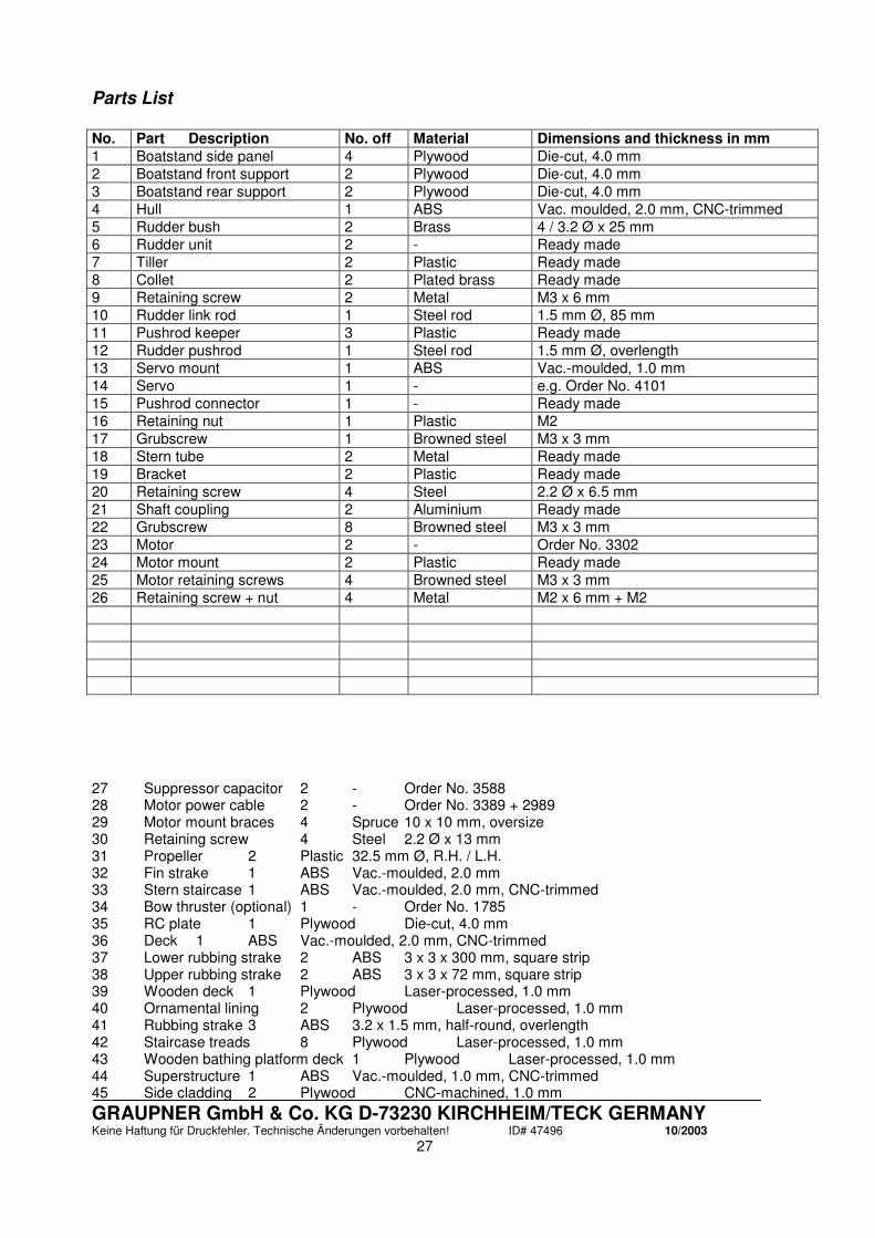
GRAUPNER GmbH & Co. KG D-73230 KIRCHHEIM/TECK GERMANY Keine Haftung für Druckfehler. Technische Änderungen vorbehalten! ID# 47496 10/2003
27
Parts List
No. Part Description No. off Material Dimensions and thickness in mm 1 Boatstand side panel 4 Plywood Die-cut, 4.0 mm 2 Boatstand front support 2 Plywood Die-cut, 4.0 mm 3 Boatstand rear support 2 Plywood Die-cut, 4.0 mm 4 Hull 1 ABS Vac. moulded, 2.0 mm, CNC-trimmed 5 Rudder bush 2 Brass 4 / 3.2 Ø x 25 mm 6 Rudder unit 2 - Ready made 7 Tiller 2 Plastic Ready made 8 Collet 2 Plated brass Ready made 9 Retaining screw 2 Metal M3 x 6 mm 10 Rudder link rod 1 Steel rod 1.5 mm Ø, 85 mm 11 Pushrod keeper 3 Plastic Ready made 12 Rudder pushrod 1 Steel rod 1.5 mm Ø, overlength 13 Servo mount 1 ABS Vac.-moulded, 1.0 mm 14 Servo 1 - e.g. Order No. 4101 15 Pushrod connector 1 - Ready made 16 Retaining nut 1 Plastic M2 17 Grubscrew 1 Browned steel M3 x 3 mm 18 Stern tube 2 Metal Ready made 19 Bracket 2 Plastic Ready made 20 Retaining screw 4 Steel 2.2 Ø x 6.5 mm 21 Shaft coupling 2 Aluminium Ready made 22 Grubscrew 8 Browned steel M3 x 3 mm 23 Motor 2 - Order No. 3302 24 Motor mount 2 Plastic Ready made 25 Motor retaining screws 4 Browned steel M3 x 3 mm 26 Retaining screw + nut 4 Metal M2 x 6 mm + M2 27 Suppressor capacitor 2 - Order No. 3588 28 Motor power cable 2 - Order No. 3389 + 2989 29 Motor mount braces 4 Spruce 10 x 10 mm, oversize 30 Retaining screw 4 Steel 2.2 Ø x 13 mm 31 Propeller 2 Plastic 32.5 mm Ø, R.H. / L.H. 32 Fin strake 1 ABS Vac.-moulded, 2.0 mm 33 Stern staircase 1 ABS Vac.-moulded, 2.0 mm, CNC-trimmed 34 Bow thruster (optional) 1 - Order No. 1785 35 RC plate 1 Plywood Die-cut, 4.0 mm 36 Deck 1 ABS Vac.-moulded, 2.0 mm, CNC-trimmed 37 Lower rubbing strake 2 ABS 3 x 3 x 300 mm, square strip 38 Upper rubbing strake 2 ABS 3 x 3 x 72 mm, square strip 39 Wooden deck 1 Plywood Laser-processed, 1.0 mm 40 Ornamental lining 2 Plywood Laser-processed, 1.0 mm 41 Rubbing strake 3 ABS 3.2 x 1.5 mm, half-round, overlength 42 Staircase treads 8 Plywood Laser-processed, 1.0 mm 43 Wooden bathing platform deck 1 Plywood Laser-processed, 1.0 mm 44 Superstructure 1 ABS Vac.-moulded, 1.0 mm, CNC-trimmed 45 Side cladding 2 Plywood CNC-machined, 1.0 mm

GRAUPNER GmbH & Co. KG D-73230 KIRCHHEIM/TECK GERMANY Keine Haftung für Druckfehler. Technische Änderungen vorbehalten! ID# 47496 10/2003
28
46 Side window cladding 2 Plywood CNC-machined, 1.0 mm 47 Central window frame 1 Plywood CNC-machined, 1.0 mm 48 Rear bridge panel 1 Plywood CNC-machined, 1.0 mm 49 Bridge deck 1 Plywood Laser-processed, 1.0 mm 50 Bridge step 1 Plywood Laser-processed, 1.0 mm 51 After deck 1 Plywood Laser-processed, 1.0 mm 52 Fore deck 1 Plywood Laser-processed, 1.0 mm 53 Guard rail 19 ABS 1.0 mm Ø rod, overlength 54 Screening plate 1 ABS As plan, make from scrap 55 Roof 1 ABS Vac.-moulded, 1.0 mm 56 Spacer 2 ABS or wood approx. 60 x 10 x 1 mm, make from scrap 57 Cockpit 1 ABS Vac.-moulded, 1.0 mm 58 Bottom cockpit section 1 ABS Vac.-moulded, 1.0 mm 59 Companionway 1 ABS Vac.-moulded, 1.0 mm 60 Skipper’s seat 1 ABS Vac.-moulded, 1.0 mm 61 Upper bench seat (long) 1 ABS Vac.-moulded, 1.0 mm 62 Upper bench seat (short) 1 ABS Vac.-moulded, 1.0 mm 63 Lower bench seat (short, left) 1 ABS Vac.-moulded, 1.0 mm 64 Lower bench seat (long) 1 ABS Vac.-moulded, 1.0 mm 65 Lower bench seat (short, right) 1 ABS Vac.-moulded, 1.0 mm 66 Back panel 1 ABS As plan, make from scrap 67 Table base 2 ABS Vac.-moulded, 1.0 mm 68 Table leg 2 Aluminium 4 / 3.2 Ø x 30 mm 69 Upper table top 1 ABS Vac.-moulded, 1.0 mm 70 Lower table top 1 ABS Vac.-moulded, 1.0 mm 71 Upper table bottom section 1 ABS Vac.-moulded, 1.0 mm 72 Lower table bottom section 1 ABS Vac.-moulded, 1.0 mm 73 Upper table top insert 1 Plywood Laser-processed, 1.0 mm 74 Lower table top insert 1 Plywood Laser-processed, 1.0 mm 75 Rear bridge panel handrail 1 Beech Flexible wood strip, 5 x 2 x 110 mm 76 Side window frame 4 Plywood CNC-machined, 1.0 mm 77 Outer window frame 2 Plywood CNC-machined, 1.0 mm 78 Outer central window frame 1 Plywood CNC-machined, 1.0 mm 79 Inner window frame 2 Plywood CNC-machined, 1.0 mm 80 Central inner window frame 1 Plywood CNC-machined, 1.0 mm 81 Ventilator flaps 6 ABS 15 x 4 x 1 mm, make from scrap 82 Trim rail, left, side 1 ABS 3.2 x 1.5 mm, half-round, overlength 83 Trim rail, front, left 1 ABS 3.2 x 1.5 mm, half-round, overlength 84 Trim rail, centre 1 ABS 3.2 x 1.5 mm, half-round, overlength 85 Trim rail, front, right 1 ABS 3.2 x 1.5 mm, half-round, overlength 86 Trim rail, right, side 1 ABS 3.2 x 1.5 mm, half-round, overlength 87 Handrail, left 1 Beech Flexible wood strip, 5 x 2 x 110 mm 88 Handrail, right 1 Beech Flexible wood strip, 5 x 2 x 110 mm 89 Handrail stanchions 7 Plastic Ready made 90 Handrail 1 ABS 2 mm Ø round rod, overlength 91 Derrick base 1 ABS Vac.-moulded, 1.0 mm 92 External derrick outrigger 1 ABS Vac.-moulded, 1.0 mm 93 Internal derrick outrigger 1 ABS Vac.-moulded, 1.0 mm 94 Tongue 1 Plastic Ready made 95 Turnbuckle 1 Plated brass Ready made 96 Split pin 1 Metal Ready made 97 Inflatable boat, bottom shell 1 ABS Vac.-moulded, 1.0 mm 98 Inflatable boat, top shell 1 ABS Vac.-moulded, 1.0 mm 99 Outboard motor shells 2 ABS Vac.-moulded, 1.0 mm 100 Shaft spigot 1 ABS 1 mm Ø round rod, length approx. 10 mm 101 Propeller 1 Plastic 20 mm Ø, ready made 102 Inflatable boat supports 2 ABS or wood As plan, make from scrap 103 Inflatable boat cover 1 ABS Vac.-moulded, 1.0 mm 104 Steering wheel 2 Plastic Ready made 105 Throttle lever 1 Plated steel 1.5 mm Ø x 20 mm

GRAUPNER GmbH & Co. KG D-73230 KIRCHHEIM/TECK GERMANY Keine Haftung für Druckfehler. Technische Änderungen vorbehalten! ID# 47496 10/2003
29
106 Stern flagstock 2 Plywood Laser-processed, 1.0 mm 107 Ventilator 6 Plastic Ready made 108 Forward handrail 2 Plywood CNC-trimmed, 2.0 mm 109 Roof railing 2 Plywood CNC-trimmed, 2.0 mm 110 Mast 3 Plywood CNC-trimmed, 2.0 mm 111 Radar support 1 Plywood Laser-processed, 2.0 mm 112 Transverse support 1 Plywood Laser-processed, 1.0 mm 113 Radar bearer strut 1 Plywood Laser-processed, 1.0 mm 114 Lamp bearer 2 ABS 1.0 mm, make from scrap 115 Anchor light bearer 1 ABS 1.0 mm, make from scrap 116 Hinge plates 2 ABS 1.0 mm, make from scrap 117 Stern lamp bearer 1 ABS 1.0 mm, make from scrap 118 Stern lamp bearer strut 1 ABS 1.0 mm, make from scrap 119 Radar housing 2 Plastic Ready made 120 Radar antenna 1 Plastic Ready made 121 Boat lamps 3 Plastic Ready made 122 Anchor light 1 Plastic Ready made 123 Throttle lever 2 Plastic Ready made 124 Telephone handset 1 Plastic Ready made 125 Foghorn 1 Plastic Ready made 126 Windscreen wiper 3 Plastic Ready made 127 Lifebelt holder 1 ABS Vac.-moulded, 1.0 mm 128 Lifebelt 1 Plastic Ready made 129 Railing stanchion 26 Plated brass Ready made, some require shortening 130 Handrails 2 Beech Flexible wood strip, 5 x 2 mm, overlength 131 Bottom rail 2 Braided wire 0.1 mm Ø, overlength 132 Forward flagstock 1 Beech 3 Ø x 70 mm, taper as shown 133 Top cover plate 1 ABS 1.0 mm, make from scrap 134 Cleats 8 Plastic Ready made 135 Fairleads 8 Plastic Ready made 136 Navigation lamp bracket, left 1 ABS 1.0 mm, make from scrap 137 Navigation lamp bracket, right 1 ABS 1.0 mm, make from scrap 138 Navigation lamps 2 Plastic Ready made 139 Velcro (hook-and-loop) tape 1 Plastic Ready made, overlength - Loudspeaker box 1 ABS Vac.-moulded, 2.0 mm The Parts List includes components which are not contained in the kit; these must be obtained separately. You will also need the following items (not included in the kit) 2 x SPEED 600 BB Turbo electric motors, Order No. 3302 1 x suppressor capacitor, Order No. 3588 (pack of 2) 1 x NAVY V 40 R speed controller, Order No. 2875 2 x SANYO 6N-4000 DRL drive batteries, Order No. 2516 1 x G2 distributor cable, Order No. 3068 1 x G2 parallel cable, Order No. 3061 1 x copper flex, 2 m, Order No. 3389 2 x G2 connector systems, Order No. 2989 Radio control system 1 x MC-10 radio control set, Order No. 4721 or 1 x MC-12 radio control set, Order No. 4725 Other Graupner/JR FM computer radio control systems on the 40 MHz band can also be used.

GRAUPNER GmbH & Co. KG D-73230 KIRCHHEIM/TECK GERMANY Keine Haftung für Druckfehler. Technische Änderungen vorbehalten! ID# 47496 10/2003
30
Instructions de montage pour le modèle JULES VERNE Réf. N°2097
Description de l’original :
Le JULES VERNE résulte d’un travail en collaboration avec le concepteur de Yatchs Hollandais René van der Velden. Ce Yatch à moteur en design ‘’Rétro’’ correspond dans la forme et la décoration aux Yatchs typiques en bois de Mahogany des années 30 et 40. Avec le JULES VERNE construit en 1998, les éléments de conception des anciens Yatchs ont été optipalement combinés avec les modernes. Le résultat est l’un de ces Yatchs de forme élégante en desing ‘’Rétro’’ .Comme les coques en bois ne sont plus fabriquées aujourd’hui pour des raisons de coût, la coque du JULES VERNE a été construite en aluminium et peinte en brun Mahogany. Avec les deux puissants moteurs de 660 CV chacun, ce Yatch atteint une vitesse d’environ 26 nœuds.
Description du modèle :
Le modèle JULES VERNE a été réalisé à l’échelle 1 :20 d’après les plans originaux du concepteur. Comme une certaine adresse manuelle ainsi qu’une expérience en modélisme naval sont nécessaires, ce modèle est seulement à conseiller aux modélistes déjà expérimentés. Toutes les pièces de forme arrondie sont moulées en ABS et les éléments difficiles à réaliser comme la coque, les escaliers de poupe, le pont et la superstructure sont usinées sur machine numérique (Fraisées). Les pièces en bois sont estampées, fraisées ou découpées au laser et réduisent ainsi le temps de construction. Les pièces d’accastillage telles que les essuie-glaces, les aérateurs, les lanternes, l’antenne radar, etc…sont en plastique injecté et fournies dans la boite de construction. Les corps de lanterne dans le jeu d’accastillage sont facilement éclairables avec des ampoules miniatures de φ 2,4mm.
Caractéristiques techniques Modèle Original
Longueur, env. 925mm 18,50m Largeur, env. 250mm Poids total avec R/C, env. 4,6kg Poids à vide, env. 2,3kg Echelle de reproduction 1:20
Conseils de sécurité importants
Vous avez fait l'acquisition d'une boite de construction avec les accessoires correspondants qui vont vous permettre la réalisation d'un modèle radiocommandé. Le respect des instructions de montage et d'utilisation relatives au modèle ainsi que l'installation, l'utilisation et l'entretien des éléments de son équipement ne peuvent pas être surveillés par la Firme GRAUPNER. C'est pourquoi nous déclinons toute responsabilité concernent les pertes, les dommages ou les coûts résultants d'une mauvaise utilisation ou d'un fonctionnement défectueux. Tant qu'elle n'y a pas été contrainte par le législateur, la responsabilité de la Firme GRAUPNER n'est aucunement engagée pour les dédommagements (incluant les dégâts personnels, les cas de décès, la détérioration de bâtiments ainsi que le remboursement des pertes commerciales dues à une interruption d'activité ou à la suite d'autres conséquences directes ou indirectes) provenant de l'utilisation du modèle. L'ensemble de sa responsabilité est en toutes circonstances et dans chaque cas strictement limitée au montant que vous avez réellement payé pour ce modèle. L'utilisation du modèle se fait uniquement aux risques et périls de son utilisateur. Seule une utilisation prudente et responsable évitera de causer des dégâts personnels et matériels. Avant la première utilisation du modèle, vérifiez si votre assurance personnelle couvre ce genre de risques. Contractez le cas échéant une assurance spéciale pour l'utilisation des modèles réduits radiocommandés. En cas de revente du modèle, ces conseils de sécurité devront être impérativement remis à l'acheteur.

GRAUPNER GmbH & Co. KG D-73230 KIRCHHEIM/TECK GERMANY Keine Haftung für Druckfehler. Technische Änderungen vorbehalten! ID# 47496 10/2003
31
Conditions de garantie: La garantie comprend la réparation gratuite ou l'échange des pièces présentant un défaut de fabrication ou de matière pendant une durée de 24 mois, à compter de la date de l'achat. Toutes autres réclamations sont exclues. Les frais de transport et d'emballage sont à la charge de l'acheteur. Nous déclinons toute responsabilité pour les détériorations survenues au cours du transport. Le retour au Service-après-Vente GRAUPNER, ou du Pays concerné doit être accompagné d'une description du défaut constaté et de la facture correspondante avec la date de l'achat. Le bénéfice de la garantie sera perdu lorsque le défaut de la pièce ou du modèle sera dû à un accident, à une manipulation incorrecte ou à une mauvaise utilisation. Les points suivants devront être impérativement observés: • Ce modèle ne convient pas aux enfants en dessous de 14 ans. • En raison de la haute vitesse qu’il peut atteindre, ne faites JAMAIS naviguer ce modèle dans des
eaux où se trouvent des personnes ou des animaux, car autrement il existe un sérieux danger de blessure pour eux.
• Ne faites pas naviguer votre modèle sur des eaux situées dans une nature protégée. Informez-vous auprès de votre commune s’il existe un plan d’eau autorisé pour la navigation des modèles de bateaux.
• Ne naviguez jamais dans de l’eau salée. Même l’air salé sur la mer peut endommager les composants techniques de votre modèle et même les détruire.
• Ne naviguez jamais par de mauvaises conditions atmosphériques, par ex. sous la pluie, un orage, un vent fort, un fort clapot ou dans une eau courante, etc…
• Assurez-vous du parfait fonctionnement de l’installation R/C ainsi que du branchement correct de tous les connecteurs avant de faire naviguer le modèle.
• Les batteries devront être bien chargés, particulièrement celle de l’émetteur et l’accu de réception et la portée de l’installation R/C devra être vérifiée avant chaque séance de navigation.
• Assurez-vous que le canal de la fréquence que vous utilisez est libre ; ne naviguez jamais tant que vous n’êtes pas sûr qu’il n’est pas déjà utilisé.
• Observez les conseils et les avertissements donnés dans les instructions d’utilisation de votre ensemble R/C et de ses accessoires.
• Travaillez sur les éléments de la propulsion uniquement avec l’alimentation du moteur déconnectée. • Lorsque les batteries de propulsion sont connectées, ne vous tenez jamais vous-même ou d’autres
personnes dans le champ de rotation des hélices, car il existe dans cette zone un sérieux danger de blessure.
• Ne dépassez pas la tension d’alimentation conseillée. Une tension trop élevée peut faire surchauffer les moteurs ou le régulateur de vitesse en faisant fondre les fils électriques ; le modèle peut ainsi prendre feu et être détruit.
• Veillez à la libre rotation de tous les éléments de la propulsion. Ceci vaut particulièrement durant la navigation, car des feuilles ou d’autres débris flottants peuvent bloquer les hélices ou les gouvernails; dans un tel cas, les moteurs, le régulateur de vitesse ou le servo du gouvernail pourront être détruits par une surcharge.
• Veiller à ce que le servo du gouvernail puisse se déplacer sur la totalité de sa course, sans être bloqué mécaniquement.
• Laissez les moteurs et le régulateur de vitesse se refroidir après chaque navigation ; ne touchez pas les éléments échauffés.
• Retirez les batteries de propulsion du modèle durant son transport et lorsqu’il n’est pas utilisé. • N’exposez pas le modèle à une forte humidité, à une chaleur ou un froid excessifs ainsi qu’aux
salissures. • Protégez le modèle et les éléments R/C contre tout risque de détérioration par des chocs durant son
transport. • Ne faites pas naviguer le modèle dans une eau courante (Par ex. une rivière) ; notez que par suite
d’un mauvais fonctionnement possible ou avec des batteries vides, le modèle peut dériver. • Ne vous mettez pas vous-même en danger ou quelqu’un d’autre pour une éventuelle tentative de
récupération du modèle. • Veillez particulièrement à la parfaite étanchéité du modèle ; un modèle de bateau peut couler à la
suite d’une infiltration d’eau dans la coque. Avant chaque séance de navigation, vérifiez que de l’eau ne puisse pas s’infiltrer par les arbre d’hélice ou les gouvernails.
• Veillez particulièrement à ce que la superstructure ne puisse pas se déplacer sur le modèle durant la navigation.
• Avec les batteries de propulsion commutées en parallèle, celles-ci devront être connectées

GRAUPNER GmbH & Co. KG D-73230 KIRCHHEIM/TECK GERMANY Keine Haftung für Druckfehler. Technische Änderungen vorbehalten! ID# 47496 10/2003
32
uniquement durant la navigation, car autrement un effet d’échange sans charge peut se produire entre les deux batteries et les détériorer. Pour cette raison, connecter les batteries juste avant la navigation et les déconnecter dès que celle-ci est terminée. Les batteries ne devront en aucun cas être chargées lorsqu’elle sont connectées en parallèle.
Entretien : • Nettoyez le modèle après chaque utilisation. Evacuez l’eau éventuellement infiltrée dans la coque. Si
de l’eau a pénétré dans les éléments R/C, laissez-les sécher et retournez-les au S.A.V. GRAUPNER pour contrôle.
• Nettoyez le modèle et les éléments R/C uniquement avec des produits de nettoyage adaptés ; informez-vous pour cela auprès de votre revendeur.
• Lubrifiez régulièrement les arbres d’hélice et les mèches de gouvernail. • Lorsque le modèle ne devra pas être utilisé pendant longtemps, toutes les pièces en mouvement
(Arbres d’hélice, etc…) devront être démontées, nettoyées et à nouveau lubrifiées. Conseils pour la construction du modèle : • Le plan de construction et la totalité des instructions de montage devront absolument être étudiés
avant de commencer la construction du modèle. La liste des pièces sera utilisée comme information complémentaire. Les instructions et la liste des pièces sont établis dans l’ordre des assemblages à effectuer.
• Couper l’entretoise qui maintient les pièces en bois fraisées sur la plaque avec des ciseaux. • Comme les pièces moulées en ABS présentent toujours un faible rayon pour des raison de technique
de fabrication, le bord des pièces en bois à joindre sur celles-ci devra toujours être un peu arrondi par ponçage afin d’obtenir un assemblage bien jointif.
• Les pièces découpées au laser présentent toujours une ligne de découpe noire qui pourra être éliminée par ponçage.
• Conserver toutes les chutes de bois, d’ABS et de fils métalliques, car celles-ci devront être utilisées pour la fabrication d’autres petites pièces.
• Lorsque le modèle devra être équipé de fonctions spéciales, celles-ci devront être planifiées avant de commencer la construction. Des astuces et des conseils pour cela sont donnés à la fin de ces instructions.
• Veiller particulièrement avec ce modèle à obtenir un centre de gravité le plus bas possible. • Veiller aux dangers possible avec l’utilisation des outils. • Antiparasiter les moteurs électriques chacun avec un condensateur de 470 nF (Réf. N°3588) en le
soudant en même temps que les fils d’alimentation sur les bornes des moteurs (Voir le schéma sur le plan).
• Disposer proprement les câblages électriques, sans faire de croisements. Les conducteurs Plus ne doivent en aucun cas venir en contact avec les conducteurs Moins.
• Utiliser uniquement des sections de fil suffisamment adaptés pour les courants de forte intensité. • Disposer le fil d’antenne de réception le plus éloigné possible des conducteurs de courant de forte
intensité (au moins 3 cm). • Utiliser uniquement une graisse ou une huile spéciale pour la lubrification de la transmission (Par ex.
Réf. N°570). • Eliminer toute trace de gras à chaque emplacement de collage avant d’effectuer celui-ci. Ceci pourra
se faire par un ponçage suivi d’un nettoyage avec un solvant neutre. Ceci vaut également pour la préparation des surfaces à peindre afin d’obtenir ne bonne adhérence de la peinture. Avant le collage des pièces dans la coque, dépolir les surfaces correspondantes avec du papier abrasif fin et les nettoyer avec de l’alcool. Autrement, aucun collage résistant ne peut être garanti.
• Colles conseillées pour le collage des différentes matières : Matière sur Matière Colle adaptée Métal - Métal Colle-seconde, UHU plus ABS - Bois Colle-seconde, UHU acrylit ABS - ABS Colle-seconde, UHU acrylit, UHU plast spéciale ABS - Métal Colle-seconde, UHU acrylit Bois - Bois Colle-seconde, UHU hart, Colle blanche Bois - Métal Colle-seconde Observez le mode d’emploi sur le conditionnement des colles ! Veillez particulièrement aux indications données dans les instructions de montage sur la colle à employer. Des précaution particulières doivent être prises pour l’utilisation de l’acétone, de l’alcool et d’autres solvants comme produit de nettoyage ; se référer également à chaque mode d’emploi.

GRAUPNER GmbH & Co. KG D-73230 KIRCHHEIM/TECK GERMANY Keine Haftung für Druckfehler. Technische Änderungen vorbehalten! ID# 47496 10/2003
33
Instructions de montage
1. Assembler le support du bateau composé des deux pièces latérales (1) et des montants avant (2) et arrière (3). Les pièces devront être doublées, c’est-à-dire que chacune des deux pièces de chaque devront être préalablement collées ensemble l’une sur l’autre avec de la colle blanche. (NOTE : Placer un poids sur les pièces doublées durant le séchage de la colle afin qu’elles soient bien pressées ensemble. NOTE 2 : Pour protéger ultérieurement la coque peinte, coller une bande de feutre ou de matière similaire sur la surface d’appui des montants).
2. Couper dans le tube de laiton deux longueurs de 25mm pour les jaumières de gouvernail (5). Dépolir la surface de collage des tubes et les coller dans les deux perçages de Ø 4mm dans la coque (4), conformément au plan et en veillant à ce qu’ils soient parfaitement alignés entre-eux. (NOTE : Ceci sera facilement vérifié en introduisant la mèche des gouvernails dans les jaumières. Bien coller les tubes en appliquant un bon congé de colle UHU acrylit .
3. Placer une bague d’arrêt (8) dans les deux bras de gouvernail (7)et visser une vis de fixation (9) dans ces derniers. Monter les bras sur la mèche des gouvernails. Raccourcir les mèches juste au dessus des bras, car autrement les escaliers de poupe (33) ne s’adapteraient pas sur les gouvernails.
4. Confectionner dans le fil d’acier de Ø 1,5mm la tringlerie de liaison des bras de gouvernail (10). Couper une longueur d’environ 85mm dans le fil d’acier. Couder les deux extrémités de façon à ce qu’il reste une longueur d’environ 65mm sur la partie centrale. Il est important que les deux bras de gouvernail soient parallèles entre-eux, comme représenté sur le plan. Introduire la tringlerie de liaison dans les bras de gouvernail et connecter chaque extrémité avec un clip de sécurité (11).
5. Confectionner la tringlerie de commande des gouvernails (12) dans le fil d’acier de Ø 1,5mm. Couder une extrémité sur environ 10mm, l’introduire dans le bras de gouvernail et la connecter avec un clip de sécurité (11).
6. Découper le support de servo (13). Fixer le servo de gouvernail (14) dans l’ouverture avec les vis fournies avec celui-ci. (NOTE : Pointer légèrement les perçages dans le support de servo avec un objet pointu, par ex. une grosse aiguille et fileter les vis directement dans l’ABS). Monter le raccord de tringlerie (15) dans un trou agrandi à Ø 2mm sur le palonnier du servo et fixer le raccord de tringlerie avec l’écrou (16). Coller le support de servo dans la coque. Introduire la tringlerie de commande du gouvernail dans le raccord de tringlerie (Démonter éventuellement le palonnier du servo pour pouvoir introduire la tringlerie), placer les gouvernails au neutre et bloquer la tringlerie avec la vis pointeau (17). Couper la tringlerie de façon à ce qu’elle dépasse encore sur une longueur d’environ 4mm du raccord de tringlerie.
7. Monter les palier-graisseurs (19) sur les tubes d’étambot (18) avec les vis de fixation (20). Percer les tubes d’étambot au travers de l’ouverture des palier-graisseurs avec un foret de Ø 2mm (NOTE : On pourra si désiré connecter un morceau de durit sur les embouts de graissage, par ex. Réf. N°1668.3).
8. Monter les deux ensembles bâti-moteur. Fixer pour cela les accouplements d’arbre (21) avec les vis pointeau (22) sur les moteurs (23). Un petit espace doit subsister entre l’accouplement et le moteur. Fixer ensuite les moteurs sur les bâtis (24) avec les vis de fixation (25). Découper les deux fentes sur les bâtis du côté des tubes d’étambot avec un couteau. Introduire ensuite les vis de fixation dans les petits perçages et fixer celles-ci avec un écrou (26).
9. Souder les condensateurs antiparasites (27) avec les fils d’alimentation (28) sur les bornes des moteurs. Les deux moteurs devront être connectés avec les polarités inversées afin qu’ils tournent vers la droite (Voir le schéma de câblage).
10. Introduire maintenant les ensembles moteur sur les tubes d’étambot et fixer ceux-ci dans la bonne position (les perçages dans la coque devront être éventuellement un peu rectifiés). Confectionner maintenant les appuis des bâti-moteurs (29) en baguette de pin de 10x10mm. Veiller à ce que les appuis ne compriment pas l’ensemble vers le haut et qu’ils reposent régulièrement sur la coque, puis les coller en place. Percer les trous de Ø1,5mm dans les appuis et fixer les ensembles moteur avec les vis de fixation (30) . Veiller également ici à ce que l’ensemble ne soit pas comprimé.
11. Visser les hélices marines (31) sur l’extrémité des arbres ; veiller au bon sens de rotation ! 12. Découper la nageoire (32) et la coller exactement alignée sous la coque avec de la UHU acrylit. Le
collage doit supporter un contact avec le sol ; la nageoire protège les gouvernails et les arbres d’hélice d’une détérioration.
13. La coque et les escaliers de poupe (33) devront encore être rectifiés afin qu’ils reposent proprement sur les bords de collage. Ceci concerne particulièrement les bords, car pour des raisons de technique de fabrication, il subsiste encore ici une petite bordure qui devra absolument être égalisée. A l’endroit où le pont sera ultérieurement collé sous les escaliers, ceux-ci doivent recevoir un chanfrein intérieur ; le pont reposera ainsi proprement sur les escaliers.
14. Coller les escaliers de poupe avec la coque. Aligner les escaliers et la coque et presser ensemble les surfaces de collage durant le temps de séchage avec des pinces à ressort (Par ex. avec les Réf.

GRAUPNER GmbH & Co. KG D-73230 KIRCHHEIM/TECK GERMANY Keine Haftung für Druckfehler. Technische Änderungen vorbehalten! ID# 47496 10/2003
34
N°542.1 ou 542.2). On obtiendra seulement ainsi aucun défaut sur la surface de la coque (ce qui signifie peu de travail de masticage). S’il subsiste éventuellement des ouvertures, bien les reboucher avec de la UHU acrylit . Mastiquer les surfaces extérieures et les poncer. Le dernier ponçage fin se fera après le montage du pont.
15. Montage de la propulsion d’étrave en option : Antiparasiter le moteur de la propulsion d’étrave (34) avec un condensateur (27) et connecter un cordon de raccordement moteur (28). Coller la propulsion d’étrave dans le modèle (ne pas la coller encore à l’extérieur, autrement elle ne s’adaptera plus dans le modèle). Coller la propulsion avec de la colle-seconde (le moteur électrique doit être incliné vers le haut), puis la coller complètement sur les parois de la coque avec de la UHU acrylit ; le collage doit être étanche à 100%.
16. Sans montage d’une propulsion d’étrave: Lorsqu’on ne veux pas monter une propulsion d’étrave, les ouvertures prévues devront être fermées à l’intérieur de la coque. Découper des plaques dans une chute d’ABS qui recouvriront les ouvertures sur une plus grande surface, les fixer avec de la colle-seconde, puis les coller avec de la UHU acrylit ; le collage doit être également ici étanche à 100%. (NOTE : Il serait très difficile de monter ultérieurement une propulsion d’étrave, la décision devra donc être prise dès maintenant).
17. Coller la platine R/C (35) dans la coque conformément au plan. En cas de montage d’une propulsion d’étrave, laisser suffisamment de place pour celle-ci. On pourra, si l’on veux, laisser de côté la platine R/C complète et fixer les éléments R/C directement sur les parois de la coque avec de la bande à crampons ; ceci n’apporte aucun inconvénient au point de vue technique.
18. Le pont (36) devra aussi être rectifié, comme il a déjà été indiqué pour la coque et les escaliers de poupe. Coller le pont sur la coque. Commencer par le collage au niveau des escaliers de poupe, appliquer de la UHU plast spéciale sur une partie d’une longueur d’environ 30 cm et fixer les emplacements de collage durant le temps de séchage avec des pinces à ressort (Par ex. Réf. N°524.1). Après la prise de la colle, la partie suivante sera collée, etc.. jusqu’à ce que le pont soit totalement collé sur la coque. (NOTE : Par l’effet de capillarité, la colle s’infiltre dans le joint entre le pont et la coque, mais ceci seulement avec l’utilisation d’une colle fluide). IMPORTANT : Veiller à ce que les deux bords du pont et de la coque soient le plus jointifs possible entre-eux afin que le pont soit collé bien de niveau avec la coque. Comme le bord sera encore poncé ultérieurement, ne pas trop s’inquiéter pour les bavures de colle.
19. Contrôler s’il subsiste encore une ouverture quelconque sur l’ensemble de la coque ; éventuellement bien la reboucher intérieurement avec de la UHU acrylit. Veiller à ce que l’ensemble de la coque soit réellement étanche à 100%. (NOTE : Avec de grandes ouvertures, coller d’abord un morceau de ruban adhésif à l’extérieur, puis appliquer ensuite de la UHU acrylit par l’intérieur. Ainsi, la colle ne coulera pas à l’extérieur et un pénible ponçage ultérieur pourra être évité.
20. Mastiquer maintenant tous les raccordements entre le pont, la coque et les escaliers de poupe, puis les poncer. Les endroits où les pièces en bois pour le pont seront ultérieurement rapportées ne nécessitent pas absolument un masticage. Il suffit de vérifier ici que le joint soit bien collé et que les surfaces soient de niveau entre-elles de façon à ce que la pièce en bois repose à plat.
21. Travailler les bords où les profilés d’ABS de 3x3mm seront rapportés , le plus en arête vive possible. Confectionner les listons inférieurs (37) en profilé d’ABS, un côté devra être légèrement effilé en pointe (ne pas effiler le côté qui sera collé !). Une ligne est gravée sur la coque ; coller les profilés sur celle-ci. Confectionner les listons supérieurs (38) dans le même matériel. Cintrer préalable les profilés à peu près en correspondance du contour de la coque, puis les coller sur celle-ci. Veiller à ce que les listons soient de niveau avec le pont (la partie en bois du pont devra reposer à plat ultérieurement).
22. Coller le pont en bois (39) provisoirement avec de la bande adhésive double-face sur le pont en ABS. Il suffit de le fixer avec la bande seulement à plusieurs petits emplacements, le pont en bois ne doit pas pouvoir se déplacer et reposer exactement dans la zone intérieure de la superstructure. La coque pourra maintenant être soigneusement poncée jusqu’au pont en bois ; veiller à ne pas poncer ce dernier ! Retirer ensuite le pont en bois avec précaution. La coque pourra maintenant être finement polie et peinte.
23. Enduire plusieurs fois le pont en bois sur les deux faces avec du vernis transparent. Après chaque couche de vernis, le dessus du pont sera soigneusement poncé avec du papier abrasif fin (Grain 600 ou 800). Ne pas poncer exagérément le bois, car autrement la gravure au laser du plancher disparaîtra. Le pont sera fini lorsque qu’une surface extérieure lisse et satinée sera obtenue.
24. Teinter les appuis décoratifs (40) de couleur Teak et les vernir des deux côtés. Coller les appuis sur le pont en pois en veillant à ce que la colle ne coule pas sur celui-ci.
25. Coller le pont en bois sur le pont en ABS. Le mieux est d’utiliser de la colle-seconde épaisse, car celle-ci met un temps relativement long à sécher. Déposer des gouttes de colle à intervalles réguliers sur le pont et le mettre soigneusement en place. Veiller à ce que le pont soit correctement aligné et à

GRAUPNER GmbH & Co. KG D-73230 KIRCHHEIM/TECK GERMANY Keine Haftung für Druckfehler. Technische Änderungen vorbehalten! ID# 47496 10/2003
35
ce que la colle ne coule pas sur la coque peinte. (NOTE : Pour en être assuré, masquer les zones dangereuses sur la coque).
26. Poncer à nouveau soigneusement la coque au niveau des listons. Peindre les bords dans la teinte de la coque. Poser les listons (41) ; coller d’abord les grandes longueurs sur les côtés de la coque avec de la colle-seconde. Poser ensuite le liston au niveau de la proue, en le cintrant soigneusement en correspondance du contour de la coque, puis le coller en place. (NOTE : Il sera plus facile de peindre les morceaux de liston avant de les coller en place. NOTE 2 : Il sera préférable également ici de masquer les surfaces sur lesquelles la colle ne devra pas couler).
27. Ajuster les marches d’escalier (42) et le pont pour la plate-forme du bain de soleil (43). Traiter les pièces comme pour le pont en bois et les coller sur le coque. Veiller à coller les marches d’escalier dans le bon ordre ; la largeur des marches est différente, la plus petite est en haut et la plus large est au bas des escaliers. Les marches s’adaptent toujours seulement à un certain endroit qui devra être déterminé par des essais. (NOTE : Marquer les marches sur le dessous pour ne pas avoir à déterminer à nouveau l’ordre par la suite).
28. Contrôler si la superstructure (44) s’adapte correctement sur le pont ; faire les rectifications éventuellement nécessaires.
29. Ajuster les pièces en bois pour la superstructure. Commencer avec les revêtements latéraux (45), les fixer provisoirement sur la superstructure avec quelques morceaux de bande adhésive double-face. Les poncer soigneusement sans rayer les surfaces des fenêtres sur la superstructure (les masquer de préférence), ainsi que l’équerre pour le revêtement des fenêtres latérales (46).
30. Fixer provisoirement le revêtement de la fenêtre centrale (47) avec de la bande adhésive double-face. Veiller à ce que la fenêtre soit exactement centrée, les côtés devront éventuellement être un peu ajustés.
31. Coller maintenant provisoirement les revêtements de fenêtre latéraux avec de la bande adhésive double-face. Le côté sur lequel touche le revêtement de la fenêtre centrale doit être chanfreiné afin qu’il ne subsiste aucun espace entre les deux pièces. Ajuster ensuite le côté extérieur sur le revêtement latéral. Veiller à ce que la fenêtre ne soit pas placée de travers, sinon l’encadrement aura des largeurs différentes. Retirer ainsi toujours la matière sur les deux côtés.
32. Retirer tous les revêtements qui pourront maintenant être teintés et enduits avec du vernis transparent.
33. Masquer les surfaces visibles des fenêtres et peindre la superstructure. Le vitrage des deux claire-voies sera également masqué pour peindre ces dernières. Après séchage, les revêtements terminés seront collés avec de la colle-seconde ; veiller à ce que la colle ne coule pas sur les vitrages. (NOTE : Comme la colle-seconde normale peut ternir les vitrages, utiliser de la colle-seconde sans solvant (Colle-seconde spéciale pour Styropor) , par ex. Réf. N°5820.
34. Poser la paroi de pont arrière (48) sur la superstructure et contrôler si celle-ci repose correctement et sans espace sur les revêtements latéraux. Teinter et vernir la paroi, puis la coller sur la superstructure.
35. Ajuster sur la superstructure le pont-passerelle (49), la marche (50), le pont de poupe (51) et le pont arrière (52). Traiter ces pièces comme pour le pont en bois et les coller sur la superstructure. Le pont arrière devra être spécialement arrondi sur le dessous afin qu’il s’adapte exactement et de niveau en haut dans la superstructure.
36. Préparer les barreaux de protection (53) en tourillon d’ABS de Ø 1,0mm pour les deux claire-voies. Des marquages sur les claire-voie servent pour leur positionnement et leur longueur. Les couper à la longueur requise dans le tourillon et les coller aux emplacements correspondants avec de minuscules gouttes de colle-seconde. (NOTE : Pour obtenir un espacement toujours régulier et parallèle entre les barreaux, confectionner une cale en bois de la largeur nécessaire et la placer entre les barreaux durant leur collage. NOTE 2 : Pour pouvoir déposer facilement les minuscules gouttes de colle-seconde, prendre un morceau de fil d’acier fin et le tremper dans la colle-seconde pour déposer les gouttes avec précision). Peindre les étriers de couleur acier inoxydable. Pour obtenir un effet suffisant, il suffit de peindre seulement le dessus des étriers. On pourra aussi confectionner les étriers dans du fil d’acier de Ø 1,0mm brillant si possible, sur initiative personnelle.
37. Confectionner la plaque de fermeture (54) pour la claire-voie arrière dans une chute d’ABS, conformément au plan. Peindre la face qui sera visible au travers de la claire-voie d’une couleur foncée et coller la plaque sous la superstructure. Veiller à ce que la plaque soit bien collée, car la bande à crampons pour la fixation de la superstructure sera rapportée ici ultérieurement.
38. Découper maintenant le toit (55) le long des lignes marquées. Au niveau des fenêtres latérales, veiller lors de la découpe à ce que le toit ait la même forme galbée que les fenêtres. Ne pas coller définitivement le toit, car les revêtements des fenêtres du pont-passerelle devront préalablement être montés ; ceci se fera dans une étape de travail ultérieure.

GRAUPNER GmbH & Co. KG D-73230 KIRCHHEIM/TECK GERMANY Keine Haftung für Druckfehler. Technische Änderungen vorbehalten! ID# 47496 10/2003
36
39. Coller les supports d’écartement (56) confectionnés dans des chutes d’ABS à l’intérieur du toit (au niveau où l’inscription Jules Verne sera apposée sur la face extérieure) . (NOTE : Ces pièces peuvent aussi être fabriquées dans des chutes de contre-plaqué des revêtements de fenêtre).
40. Fixer le toit sur la superstructure avec de la bande adhésive double-face pour pouvoir plus facilement ajuster la pièce moulée pour le cockpit. Utiliser seulement assez de bande adhésive afin que le toit soit maintenu et qu’il puisse être facilement retiré par la suite.
41. Découper maintenant les pièces en ABS suivantes : le cockpit (57), la partie inférieure du cockpit (58), l’escalier (59), le siège du pilote (60) et les deux pièces de la banquette supérieure (61+62). Il est important ici de chercher progressivement le bon ajustage ; laisser encore un peu de matière le long des lignes marquées et la poncer peu à peu, jusqu’à ce que toutes les pièces s’ajustent ensemble. Les lignes marquées au laser sur le pont-passerelle aident à l’adaptation des pièces. (NOTE : Veiller à ce que le relèvement du pont soit aussi reporté sur les surfaces d’appui du siège. NOTE 2 : Lorsque des pièces moulées sont un peu déformées au niveau du collage, confectionner des petites plaques dans des chutes de bois de 4mm d’épaisseur et les coller en dessous ; les pièces seront ainsi plus facilement collées en place).
42. Exécuter maintenant la même étape de travail pour la banquette inférieure (Pièces 63+64+65). Découper une cloison arrière (66) dans une chute d’ABS. Recouvrir seulement la partie visible qui dépasse sur les revêtements latéraux. Lorsque toutes les pièces sont bien ajustées, elles pourront être collées entre-elles et peintes. Ceci vaut également pour la surface sur la superstructure qui n’est pas recouverte par le du toit. (NOTE : Coller le motif de décoration sur la partie du cockpit avant de monter celui-ci dans le modèle). Les pièces d’accastillage pour le cockpit seront montées dans une étape de travail ultérieure, car autrement elles pourraient être facilement cassées au cours d’autres montages.
43. Assembler le table supérieure (Pièces 67+68+69+71+73) et la table inférieure (Pièces 67+68+70+72+74). Avant de coller le dessus les deux tables, elles devront être peintes et les pièces en bois teintées et vernies. Les tables pourront ensuite être collées sur le modèle.
44. Préparer la main courante (75) en bois cintré pour la paroi arrière. Après l’avoir teintée et vernie, elle pourra être collée centralement sur la paroi arrière avec de la colle-seconde épaisse ; veiller à ce que la colle ne coule pas sur la paroi.
45. Ajuster les revêtements extérieurs des fenêtres (Pièces 76+77+78) et les revêtements intérieurs (Pièces 76+79+80) pour le toit, comme il a déjà été décrit pour ceux de la superstructure. Veiller lors de l’ajustage à ce les revêtements se superposent exactement ; un décalage donnerait un mauvais aspect.
46. Confectionner maintenant les clapets d’aération (81) dans des chutes d’ABS et les coller sur les revêtements de fenêtre. Percer des trous de Ø 1,5mm dans les revêtements pour les essuie-glaces qui seront montés au cours d’une étape de travail ultérieure.
47. Préparer le bord supérieure des revêtements de fenêtre conformément au plan et confectionner les baguettes décoratives (Pièces 82+83+84+85+86). Vernir celles-ci et les coller soigneusement sur les revêtements avec de la colle-seconde épaisse ; veiller à ce que la colle ne coule pas sur les pièces en bois. (NOTE : Les pièces préalablement pré-cintrées seront plus faciles à coller).
48. Confectionner un gabarit dans une chute d’ABS ou de bois pour pouvoir tracer le contour des deux portes avec un crayon à mine tendre.
49. Coller maintenant le toit sur la superstructure. Veiller à ce qu’il repose correctement partout sans pression ; faire les rectifications éventuellement nécessaires. Ceci vaut particulièrement au niveau de la banquette et de l’escalier.
50. Confectionner les deux mains courantes (87 + 88) en bois cintré. Préparer celles-ci comme pour la main courante de la paroi arrière et les coller sur les revêtements latéraux. Pratiquer une encoche dans les mains courantes au niveau du tracé des portes (autrement les portes ne pourraient pas s’ouvrir). Veiller à ce que les mains courantes ne soient pas collées au milieu, mais un peu vers l’extérieur.
51. Confectionner la main courante de poupe avec les montants (89) et la main courante (90) en tourillon d’ABS de Ø 2mm. Marquer l’abord les deux perçages dans les pièces latérales, les autres perçages sont marqués sur la superstructure. Percer ces marquages avec un foret de Ø 2mm et y introduire les montants (ne pas les coller !). Passer ensuite la main courante au travers de tous les montants. La main courante se forme d’elle-même. Coller alors la main courante, mais pas encore les montants dans la superstructure. Raccourcir les extrémités de la main courante et la peindre de couleur acier inoxydable. La remettre en place sur la superstructure et la coller. Raccourcir les montants à l’intérieur, car autrement la superstructure ne reposerait pas correctement sur le pont.
52. Confectionner maintenant la grue du canot avec les pièces suivantes : socle (91), flèche extérieure (92), flèche intérieure (93), tirant (94), ridoir (95) et la goupille (96). Découper les pièces moulées et

GRAUPNER GmbH & Co. KG D-73230 KIRCHHEIM/TECK GERMANY Keine Haftung für Druckfehler. Technische Änderungen vorbehalten! ID# 47496 10/2003
37
coller la flèche intérieure dans la flèche extérieure ; une partie d’environ 5mm de longueur doit dépasser à une extrémité. Coller la flèche sur le socle. Monter le tirant aligné une extrémité et le ridoir avec la goupille, placer l’autre extrémité dans la cuvette du socle et coller le tirant sur la flèche. Coller maintenant l’autre extrémité dans le socle. Peindre la grue en noir, le ridoir doit représenter un cylindre hydraulique ; pour cette raison peindre le filetage en argent.
53. Découper grossièrement les coquilles inférieure (97) et supérieure (98) du canot pneumatique, laisser dépasser une bordure d’au moins 5mm de largeur. Coller ensemble les deux coquilles et poncer la bordure après un temps de séchage suffisant ; il doit rester une largeur d’environ 1 à 2mm. Coller ensemble les deux moitiés du moteur hors-bord (99) intérieurement avec beaucoup de UHU acrylit ; il doit rester ultérieurement suffisamment de colle au niveau des bords de collage afin que les deux moitiés restent bien assemblées. Retirer maintenant la surface extérieure pour le moteur hors-bord et poncer proprement les bords. Confectionner l’arbre d’hélice (100) dans une chute de tourillon d’ABS de Ø 1mm et le coller dans le perçage correspondant sur le moteur hors-bord. Peindre celui-ci et coller l’hélice sur l’arbre.
54. Confectionner les deux supports (102) pour le canot pneumatique dans des chutes d’ABS ou de bois. Coller les supports sous le canot.
55. Découper la bâche (103) pour le canot pneumatique. Option : La bâche porte des marquages aux angles, en les perçant, elle pourra être fixée sur le canot par ex. avec du fil de gréement fin. Le canot pneumatique ne nécessitera pas alors d’aménagement intérieur.
56. Peindre le canot pneumatique d’une teinte générale blanche. Les couleurs pour l’aménagement intérieur pourront être choisies au goût de chacun, mais la teinte générale du JULES VERNE est préférable.
57. Coller le moteur hors-bord sur le canot pneumatique. Le moteur doit être relevé et la bâche adaptée au dessus. Monter le volant (104) sur la planche de bord. Façonner la manette de gaz (105) dans du fil d’acier de Ø 1,5mm, percer un trou correspondant dans la planche de bord et y coller la manette de gaz. Fixer la bâche sur le canot avec une paire de bandes adhésives double-face afin de pouvoir la retirer à tout moment.
58. Coller le canot pneumatique et la grue sur la superstructure. 59. Coller ensemble les deux moitiés de la hampe du pavillon de poupe (106) et l’arrondir soigneusement.
Percer un trou correspondant dans la superstructure et y coller la hampe par le dessous. Le perçage dans le pont est destiné à ce que la hampe ne gêne pas la mise en place de la superstructure. Si ce perçage n’est pas suffisant, l’agrandir jusqu’à ce que la superstructure repose correctement.
60. Raccourcir les manches à air (107) jusqu’au premier anneau. Peindre celles-ci en argent et les coller sur les marquages sur la superstructure.
61. Confectionner les rambardes avant (108) ; les arrondir sur le haut avec un soin particulier. (NOTE : Poncer seulement une courte partie à la fois avoir de pouvoir toujours les maintenir par dessous, il y a ainsi peu de danger de rupture). Teinter et vernir les rambardes et les coller soigneusement sur le pont arrière avec de la colle-seconde épaisse. Procéder de même avec les rambardes de toit (109). (CONSEIL : Pour ne pas risquer de briser les pièces de rambarde en les ponçant, les coller à l’emplacement avec un peu de colle blanche. Veiller à à ce que le la colle ne reste pas sur la surface extérieure, sinon la nettoyer immédiatement avec un chiffon humide).
62. Coller ensemble les trois parties du mât (110) avec de la colle blanche. Poncer soigneusement les surfaces et arrondir les angles. La surface sur laquelle le mât sera collé ultérieurement sur la paroi arrière ne devra pas être arrondie. Scier les pièces pour le support de radar (111), le support transversal (112) et les deux supports de lanterne (114) . Pratiquer une entaille dans le mât avec une lame de scie de 1mm de largeur, conformément au plan ; les deux pièces support seront collées dans cette entaille. Coller ensuite l’appui (113) pour le support du radar sous celles-ci. L’appui devra éventuellement être un peu ajusté.
63. Coller ensuite les deux supports de lanterne dans l’entaille et le support pour le feu de mouillage (115) en haut du mât. Veiller à ce que tous les supports de lanterne soient en ligne droite et particulièrement la surface de collage du mât sur la paroi arrière.
64. Confectionner les deux charnières (116) dans des chutes d’ABS et les coller latéralement sur le mât. 65. Coller le mât sur la paroi arrière avec de la colle-seconde épaisse ; veiller à ce qu’il soit bien aligné. 66. Confectionner le support de lanterne de poupe (117) et son appui (118) dans des chutes d’ABS.
Coller l’appui sous le support, adapter l’ensemble à l’inclinaison de la superstructure et le coller en place.
67. Assembler le corps du radar (119) et coller l’antenne radar (120 sur cet ensemble. Coller l’ensemble complet sur le mât.
68. Coller les feux d’embarcation (121) préalablement peints et le feu de mouillage (122) (la lanterne sans cloison arrière plate) aux emplacements correspondants sur le mât et sur le support de la lanterne de

GRAUPNER GmbH & Co. KG D-73230 KIRCHHEIM/TECK GERMANY Keine Haftung für Druckfehler. Technische Änderungen vorbehalten! ID# 47496 10/2003
38
poupe. 69. Coller toutes les pièces d’accastillage suivantes sur la superstructure : le volant (104), les deux
manettes de gaz (123), le téléphone (124), la corne de brume (125) et les essuie-glaces (126). (NOTE : Le volant pourra être fixé facilement en coupant une courte longueur de fil d’acier de Ø 1,5mm et en la collant dans le cockpit).
70. Découper le support (127) pour la bouée de sauvetage (128). Coller celui-ci à l’intérieur du revêtement latéral, conformément au plan. Placer la bouée de sauvetage dans le support.
71. Marquer les positions sur la coque pour les montants de rambarde (129). Percer les marquages avec un foret de Ø 1mm sur environ 4mm de profondeur. (NOTE : En fixant une bague d’arrêt sur le foret à la bonne hauteur, on ne pourra pas percer plus profondément par mégarde. De la bande adhésive enroulée serrée sur le foret peut aussi convenir. Cette solution n’est cependant pas sûre à 100%, car la bande adhésive peut glisser !).
72. Raccourcir les montants de rambarde conformément au plan, les planter dans les perçages et les aligner. Pour cela, passer un fil d’acier fin dans le perçage des montants ou passera ultérieurement la filière en câble d’acier tressé, pour bien les aligner entre-eux.
73. Façonner les deux mains courantes de rambarde (130) en bois cintré. Les courber le plus précisément possible avant de les poncer et de les teinter ; elles doivent garder le plus possible leur forme. Marquer ensuite la première position d’un montant de rambarde central sur la main courante et la percer avec un foret de Ø 2mm, sur environ 1,2mm de profondeur. (NOTE : Une bague d’arrêt fixée sur le foret sera aussi utile ici pour ne pas traverser totalement la rambarde). Planter la main courante sur le montant de rambarde et marquer les deux montants adjacents. Percer à nouveau ces deux marquages et continuer ainsi jusqu'à ce que les perçages soient effectués pour tous les montants. Raccourcir maintenant les extrémités des mains courantes adapter celles-ci sur le pont.
74. Coller maintenant une main courante avec de la colle-seconde et après séchage du collage, coller de même les deux extrémités sur la coque. (NOTE : L’activateur en bombe pour colle-seconde, par ex. Réf. N°953.150, sera utile ici pour accélérer la prise des collages).
75. Procéder maintenant de la même façon pour le collage de la deuxième rambarde. 76. Enduire les mains courantes de plusieurs couches de vernis transparent ; aucune humidité ne doit
pénétrer dans le bois au risque de le détériorer. 77. Enfiler maintenant les filières (131) au travers des perçages dans les montants de rambarde. Fixer
une extrémité avec de la colle-seconde, tendre le câble en acier tressé et fixer l’autre extrémité de même avec de la colle-seconde. Le câble doit avoir partout si possible une légère tension et ne pas pendre. Fixer ensuite le passage du câble dans tous les montants avec une goutte de colle-seconde, puis couper les extrémités dépassantes.
78. Préparer la hampe du pavillon de proue (132) dans du tourillon de hêtre ; la poncer en forme légèrement conique, et confectionner le bout supérieur rond (133) dans une chute d’ABS ; coller celui-ci sur le haut de la hampe. Pour renforcer la fixation de la hampe du pavillon, il est conseillé de la percer à la base et de coller une petite longueur de fil d’acier dans le perçage. Percer un trou correspondant dans la proue de la coque pour y coller la hampe.
79. Préparer les taquets (134) comme représenté sur le plan. Coller les taquets terminés et les chaumards (135) sur la coque, conformément au plan.
80. Confectionner les écrans pour les deux feux de position (136 + 137) dans des chutes d’ABS ; veiller à ce que les deux pièces soient assemblées de façon symétriquement opposée. Adapter les deux écrans sur les rambardes et les coller sur celles-ci. Peindre les écrans en noir et coller dessus les feux de position. Si l’on ne désire pas éclairer les feux, peindre ceux-ci de couleur correspondante (rouge à babord , vert à tribord) pour obtenir un aspect réaliste.
81. Découper les motifs sur la planche de décoration avec des ciseaux et les coller aux emplacements correspondants, conformément aux illustrations sur le cartonnage de la boite de construction. La ligne blanche au dessus de la ligne de flottaison sera facilement représentée avec du ruban de décoration adhésif blanc (Par ex. Réf. N°623.8).
82. Couper deux pièces de bande à crampons (139) d’une longueur d’environ 45mm et les coller sur le pont ; l’une dans la petite cuvette au niveau de la proue, l’autre sous la claire-voie de poupe ; ces deux bandes maintiendront la superstructure en place durant la navigation. Le restant de la bande à crampons servira pour la fixation des éléments R/C et des accus de propulsion.
83. La connexion des éléments R/C se fera selon le schéma de câblage sur le plan. Le fil d’antenne de réception sera fixé à l’intérieur de la coque avec de la bande adhésive (le plus éloigné possible au-dessus de la ligne de flottaison, car autrement la réception serait mauvaise). Une antenne fouet pourra aussi être montée extérieurement sur le modèle sur initiative personnelle. Ceci est particulièrement important si l’on veut aussi faire naviguer le modèle à une plus grande distance. Le fil d’antenne du récepteur devra alors être raccourci sur la longueur correspondante de l’antenne fouet.
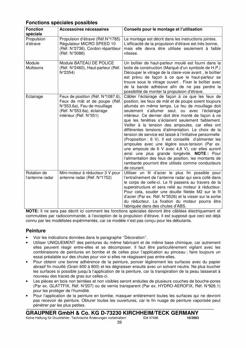
GRAUPNER GmbH & Co. KG D-73230 KIRCHHEIM/TECK GERMANY Keine Haftung für Druckfehler. Technische Änderungen vorbehalten! ID# 47496 10/2003
39
Fonctions spéciales possibles
Fonction spéciale
Accessoires nécessaires Conseils pour le montage et l’utilisation
Propulsion d’étrave
Propulsion d’étrave (Réf.N°1785) Régulateur MICRO SPEED 10 (Réf. N°2736), Cordon répartiteur (Réf. N°3086)
Le montage est décrit dans les instructions jointes. L’efficacité de la propulsion d’étrave est très bonne, mais elle devra être utilisée seulement à faible vitesse.
Module Multisons
Module BATEAU DE POLICE (Réf. N°2460), Haut-parleur (Réf. N°2354)
Un boîtier de haut-parleur moulé est fourni dans la boite de construction (Marqué d’un symbole de H.P.) Découper le vitrage de la claire-voie avant , le boîtier est prévu de façon à ce que le haut-parleur se trouve sous le vitrage ouvert . Fixer le boîtier avec de la bande adhésive afin de ne pas perdre la possibilité de monter la propulsion d’étrave.
Eclairage Feux de position (Réf. N°1087.6), Feux de mât et de poupe (Réf. N°353.6a), Feu de mouillage (Réf. N°353.6a), éclairage intérieur (Réf. N°351)
Câbler l’éclairage de façon à ce que les feux de position, les feux de mât et de poupe soient toujours allumés en même temps. Le feu de mouillage doit seulement s’allumer seul, ou avec l’éclairage intérieur. Ce dernier doit être monté de façon à ce que les fenêtres s’éclairent seulement faiblement. Veiller à la tension des ampoules, car elles ont différentes tensions d’alimentation. Le choix de la tension de service est laissé à l’initiative personnelle (Proposition : 6 V). Il est conseillé d’alimenter les ampoules avec une légère sous-tension (Par ex. une ampoule de 6 V avec 4,8 V), car elles auront ainsi une plus grande longévité. NOTE : Pour l’alimentation des feux de position, les montants de rambarde pourront être utilisés comme conducteurs de courant.
Rotation de l’antenne radar
Mini-moteur à réducteur 3 V pour antenne radar (Réf. N°1752)
Utiliser un fil d’acier le plus fin possible pour l’entraînement de l’antenne radar qui sera collé dans le corps de celle-ci. Le fil passera au travers de la superstructure et sera relié au moteur à réducteur. Pour cela, souder une douille filetée M2 sur le fil d’acier (Par ex. Réf. N°3526) et la visser sur la sortie du réducteur. La fixation du moteur pourra être fabriquée dans des chutes d’ABS.
NOTE: Il ne sera pas décrit ici comment les fonctions spéciales devront être câblées électriquement et commutées par radiocommande, à l’exception de la propulsion d’étrave. Il est supposé que ceci est déjà connu par les modélistes expérimentés, car ce modèle n’est pas conçu pour les débutants.
Peinture
• Voir les indications données dans le paragraphe ‘’Décoration’’. • Utiliser UNIQUEMENT des peintures du même fabricant et de même base chimique, car autrement
elles peuvent réagir entre-elles et se décomposer. Il faut être particulièrement vigilant avec les combinaisons de peintures en bombe et de celles pour l’application au pinceau ; faire toujours un essai préalable sur des chutes pour voir si elles ne réagissent pas entre-elles.
• Pour obtenir une bonne adhérence de la peinture, poncer légèrement les surfaces avec du papier abrasif fin mouillé (Grain 600 à 800) et les dégraisser ensuite avec un solvant neutre. Ne plus toucher les surfaces si possible jusqu’à l’application de la peinture, car la transpiration de la peau laisserait à nouveau des traces de gras sur celles-ci.
• Les pièces en bois non teintées et non visibles seront enduites de plusieurs couches de bouche-pores (Par ex. GLATTFIX, Réf. N°207) ou de vernis transparent (Par ex. HYDRO-AEROFIX, Réf. N°926.1) pour les protéger de l’humidité.
• Pour l’application de la peinture en bombe, masquer entièrement toutes les surfaces qui ne devront pas recevoir de peinture. Obturer toutes les ouvertures, car le fin nuage de peinture vaporisée peut pénétrer par les plus petites.

GRAUPNER GmbH & Co. KG D-73230 KIRCHHEIM/TECK GERMANY Keine Haftung für Druckfehler. Technische Änderungen vorbehalten! ID# 47496 10/2003
40
• Observer le mode d’emploi des peintures. • Avant de commencer la construction, réfléchir comment et dans quel ordre le modèle sera peint, car
certains endroits ne seront que très difficiles, voire même impossible à peindre ultérieurement.
Teinture des pièces en bois
• Les pièces en bois de la superstructure devront être d’une teinte Teak. Le produit adapté est par ex. la teinture CLOU 2528 Teak, disponible sur le marché. Observer le mode d’emploi de la teinture, elle doit aussi être recouverte ensuite par un vernis transparent . (NOTE : Vérifier le comportement de la teinture sur des pièces d’essai).
• Les pièces teintées ne devront plus être poncées sur leur surface extérieure, car autrement les parties teintées seront décolorées. Une nouvelle application de teinture foncera la teinte et fera éventuellement des taches.
• Les pièces en bois imprégnées de colle ou de peinture ne pourront plus être teintées. Les pièces en bois devront absolument être teintées avant leur collage.
• Lorsque par ex. une main courante doit être collée sur une cloison en bois, il est conseillé de la confectionner complètement, de la teindre , de la vernir et de la coller ensuite en place.
• Les pièces en bois teintées devront être enduites si possible avec du vernis satiné qui donne par la suite un effet particulièrement réaliste.
Décoration Afin de pouvoir choisir plus facilement les bonnes teintes, seules les peintures dans les tons RAL sont indiquées. Avec ces indications, on pourra trouver les teintes dans tous les magasins de peintures. Indiquer au vendeur l’utilisation prévue des peintures afin qu’il propose le bon type de peinture ; nous conseillons un type à base de résine synthétique. Coque au-dessus de la ligne de flottaison, superstructure : Brun Mahogany RAL 8016 Coque en-dessous de la ligne de flottaison, toit, surfaces des sièges, canot pneumatique : Blanc cassé RAL 9016 Ponts et parties de superstructure, sièges, tables, cockpit : Brun RAL 8003 Bâche du canot pneumatique, surfaces des sièges : Blanc pur RAL 9010 Manches à air, corne de brume Argent, si possible d’une teinte chromée Main courante de poupe, pieds de table, barreaux sur les claire-voies, listons, baguettes des fenêtres, moteur hors- bord : Couleur acier inoxydable Grue, écran des feux de position Noir Feux de position Rouge (Babord), Vert (Tribord) Bouée de sauvetage Orange fluorescent RAL 2005
Lancement
Charger les accu et tester les fonctions du modèle. Vous pourrez maintenant procéder au lancement. Familiarisez-vous d’abord avec le comportement du modèle en navigation. Notez que ce modèle atteint une vitesse relativement haute et qu’il est ainsi plus facile à maîtriser qu’un bateau plus lent. Nous vous souhaitons beaucoup de plaisir avec la construction et la navigation de votre modèle JULES VERNE !

GRAUPNER GmbH & Co. KG D-73230 KIRCHHEIM/TECK GERMANY Keine Haftung für Druckfehler. Technische Änderungen vorbehalten! ID# 47496 10/2003
41
Liste des pièces
Pce. Désignation Qté Matériel Dimensions et épaisseurs en mm. 1 Pièces latérales de support 4 C.T.P. Pièces estampées, 4mm 2 Montants avant 2 C.T.P. Pièces estampées, 4mm 3 Montants arrière 2 C.T.P. Pièces estampées, 4mm 4 Coque 1 ABS Pièce moulée 2mm, usinée CNC 5 Tubes pour jaumières 2 Laiton Ø 4/3,2 x 25mm 6 Gouvernails 2 - Pièces finies 7 Bras de gouvernail 2 Plastique Pièces finies 8 Bagues d’arrêt 2 Laiton nickelé Pièces finies 9 Vis de fixation 2 Métal M3 x 6mm 10 Tringlerie de liaison 1 Fil d’acier Ø 1,5 x 85mm 11 Clips de sécurité 3 Plastique Pièces finies 12 Tringlerie de commande 1 Fil d’acier Ø1,5mm, longueur à adapter 13 Support de servo 1 ABS Pièce moulée, 1mm 14 Servo de gouvernail 1 - Par ex., Réf. N°4101 15 Raccord de tringlerie 1 - Pièce finie 16 Ecrou de fixation 1 Plastique M2 17 Vis pointeau 1 Acier bruni M3 x 3mm 18 Tubes d’étambot 2 Métal Pièces finies 19 Paliers graisseurs 2 Plastique Pièces finies 20 Vis de fixation 4 Acier Ø2,2 x 6,5mm 21 Accouplements d’arbre 2 Aluminium Pièces finies 22 Vis pointeau 8 Acier bruni M3 x 3mm 23 Moteurs 2 - Réf. N°3302 24 Bâti-moteurs 2 Plastique Pièces finies 25 Vis de fixation moteur 4 Acier bruni M3 x 8mm 26 Vis de fixation + Ecrous 4 Métal M2 x 6mm + M2 27 Condensateurs antiparasites 2 - Réf. N°3588 28 Fils d’alimentation moteur 2 - Réf. N°3389 + 2989 29 Appuis de bâti-moteur 4 Pin 10x10mm, longueur et forme à adapter 30 Vis de fixation 4 Acier Ø2,2 x 13mm 31 Hélices marines 2 Plastique Ø32,5mm pour rotation droite/gauche 32 Nageoire 1 ABS Pièce moulée, 2mm 33 Escalier de poupe 1 ABS Pièce moulée, 2mm, usinée CNC 34 Propulsion d’étrave (En option) 1 - Réf. N°1785 35 Platine R/C 1 C.T.P. Pièce estampée, 4mm 36 Pont 1 ABS Pièce moulée, 2mm, usinée CNC 37 Listons inférieurs 2 ABS 3 x 3 x 300mm Profilés carrés 38 Listons supérieurs 2 ABS 3 x 3 x 72mm Profilés carrés 39 Pont en bois 1 C.T.P. Découpé au laser, 1mm 40 Appuis décoratifs 2 C.T.P. Découpés au laser, 1mm 41 Listons 3 ABS 3,2x1,5mm, Profilés demi-rond,
longueur à adapter 42 Marches d’escalier 8 C.T.P. Découpées au laser, 1mm 43 Pont en bois pour plate-forme de
bain de soleil 1 C.T.P. Découpé au laser, 1mm
44 Superstructure 1 ABS Pièce moulée, 1mm, usinée CNC 45 Revêtements latéraux 2 C.T.P. Pièces fraisées CNC, 1mm 46 Revêtements de fenêtre latéraux 2 C.T.P. Pièces fraisées CNC, 1mm 47 Revêtement de fenêtre central 1 C.T.P. Pièce fraisée CNC, 1mm 48 Paroi arrière 1 C.T.P. Pièce fraisée CNC, 1mm 49 Pont passerelle 1 C.T.P. Découpé au laser, 1mm 50 Marche 1 C.T.P. Découpé au laser, 1mm 51 Pont de poupe 1 C.T.P. Découpé au laser, 1mm 52 Pont arrière 1 C.T.P. Découpé au laser, 1mm 53 Barreaux de protection 19 ABS Tourillon Ø 1mm, longueurs à adapter
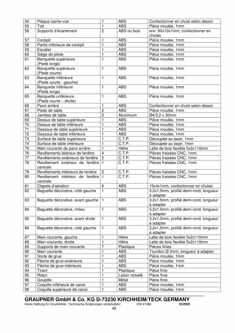
GRAUPNER GmbH & Co. KG D-73230 KIRCHHEIM/TECK GERMANY Keine Haftung für Druckfehler. Technische Änderungen vorbehalten! ID# 47496 10/2003
42
54 Plaque cache-vue 1 ABS Confectionner en chute selon dessin 55 Toit 1 ABS Pièce moulée, 1mm 56 Supports d’écartement 2 ABS ou bois env. 60x10x1mm, confectionner en
chutes 57 Cockpit 1 ABS Pièce moulée, 1mm 58 Partie inférieure de cockpit 1 ABS Pièce moulée, 1mm 59 Escalier 1 ABS Pièce moulée, 1mm 60 Siège de pilote 1 ABS Pièce moulée, 1mm 61 Banquette supérieure
(Pieds longs) 1 ABS Pièce moulée, 1mm
62 Banquette supérieure (Pieds courts)
1 ABS Pièce moulée, 1mm
63 Banquette inférieure (Pieds courts - gauche)
1 ABS Pièce moulée, 1mm
64 Banquette inférieure (Pieds longs)
1 ABS Pièce moulée, 1mm
65 Banquette unférieure (Pieds courts – droite)
1 ABS Pièce moulée, 1mm
66 Paroi arrière 1 ABS Confectionner en chute selon dessin 67 Pieds de table 2 ABS Pièce moulée, 1mm 68 Jambes de table 2 Aluminium Ø4/3,2 x 30mm 69 Dessus de table supérieure 1 ABS Pièce moulée, 1mm 70 Dessus de table inférieure 1 ABS Pièce moulée, 1mm 71 Dessous de table supérieure 1 ABS Pièce moulée, 1mm 72 Dessous de table inférieure 1 ABS Pièce moulée, 1mm 73 Surface de table supérieure 1 C.T.P. Découpée au laser, 1mm 74 Surface de table inférieure 1 C.T.P. Découpée au laser, 1mm 75 Main courante de paroi arrière 1 Hêtre Latte de bois flexible 5x2x110mm 76 Revêtements latéraux de fenêtre 4 C.T.P. Pièces fraisées CNC, 1mm 77 Revêtements extérieurs de fenêtre 2 C.T.P. Pièces fraisées CNC, 1mm 78 Revêtement extérieur de fenêtre
centrale 1 C.T.P. Pièces fraisées CNC, 1mm
79 Revêtements intérieurs de fenêtre 2 C.T.P. Pièces fraisées CNC, 1mm 80 Revêtement intérieur de fenêtre
centrale 1 C.T.P. Pièces fraisées CNC, 1mm
81 Clapets d’aération 6 ABS 15x4x1mm, confectionner en chutes 82 Baguette décorative, côté gauche 1 ABS 3,2x1,5mm, profilé demi-rond, longueur
à adapter 83 Baguette décorative, avant gauche 1 ABS 3,2x1,5mm, profilé demi-rond, longueur
à adapter 84 Baguette décorative, milieu 1 ABS 3,2x1,5mm, profilé demi-rond, longueur
à adapter 85 Baguette décorative, avant droite 1 ABS 3,2x1,5mm, profilé demi-rond, longueur
à adapter 86 Baguette décorative, côté gauche 1 ABS 3,2x1,5mm, profilé demi-rond, longueur
à adapter 87 Main courante, gauche 1 Hêtre Latte de bois flexible 5x2x110mm 88 Main courante, droite 1 Hêtre Latte de bois flexible 5x2x110mm 89 Supports de main courante 7 Plastique Pièces finies 90 Main courante 1 ABS Tourillon Ø 2mm, longueur à adapter 91 Socle de grue 1 ABS Pièce moulée, 1mm 92 Flèche de grue extérieure 1 ABS Pièce moulée, 1mm 93 Flèche de grue intérieure 1 ABS Pièce moulée, 1mm 94 Tirant 1 Plastique Pièce finie 95 Ridoir 1 Laiton nickelé Pièce finie 96 Goupille 1 Métal Pièce finie 97 Coquille inférieure de canot 1 ABS Pièce moulée, 1mm 98 Coquille supérieure de canot 1 ABS Pièce moulée, 1mm
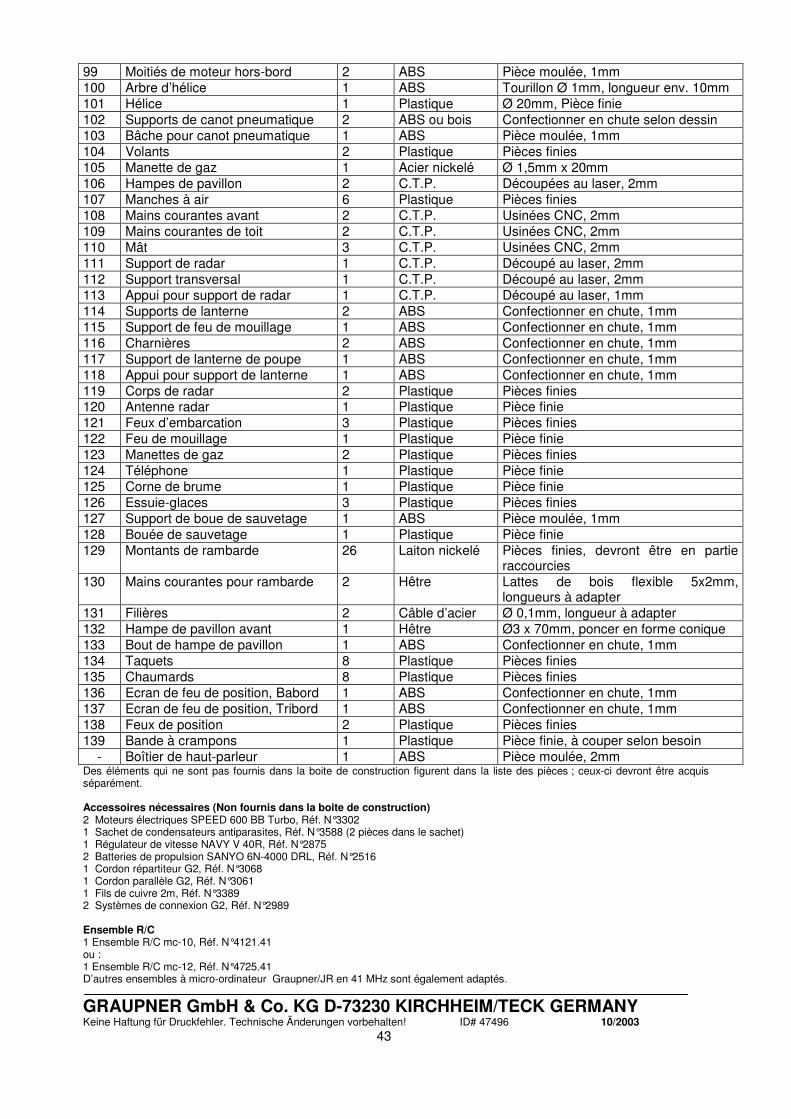
GRAUPNER GmbH & Co. KG D-73230 KIRCHHEIM/TECK GERMANY Keine Haftung für Druckfehler. Technische Änderungen vorbehalten! ID# 47496 10/2003
43
99 Moitiés de moteur hors-bord 2 ABS Pièce moulée, 1mm 100 Arbre d’hélice 1 ABS Tourillon Ø 1mm, longueur env. 10mm 101 Hélice 1 Plastique Ø 20mm, Pièce finie 102 Supports de canot pneumatique 2 ABS ou bois Confectionner en chute selon dessin 103 Bâche pour canot pneumatique 1 ABS Pièce moulée, 1mm 104 Volants 2 Plastique Pièces finies 105 Manette de gaz 1 Acier nickelé Ø 1,5mm x 20mm 106 Hampes de pavillon 2 C.T.P. Découpées au laser, 2mm 107 Manches à air 6 Plastique Pièces finies 108 Mains courantes avant 2 C.T.P. Usinées CNC, 2mm 109 Mains courantes de toit 2 C.T.P. Usinées CNC, 2mm 110 Mât 3 C.T.P. Usinées CNC, 2mm 111 Support de radar 1 C.T.P. Découpé au laser, 2mm 112 Support transversal 1 C.T.P. Découpé au laser, 2mm 113 Appui pour support de radar 1 C.T.P. Découpé au laser, 1mm 114 Supports de lanterne 2 ABS Confectionner en chute, 1mm 115 Support de feu de mouillage 1 ABS Confectionner en chute, 1mm 116 Charnières 2 ABS Confectionner en chute, 1mm 117 Support de lanterne de poupe 1 ABS Confectionner en chute, 1mm 118 Appui pour support de lanterne 1 ABS Confectionner en chute, 1mm 119 Corps de radar 2 Plastique Pièces finies 120 Antenne radar 1 Plastique Pièce finie 121 Feux d’embarcation 3 Plastique Pièces finies 122 Feu de mouillage 1 Plastique Pièce finie 123 Manettes de gaz 2 Plastique Pièces finies 124 Téléphone 1 Plastique Pièce finie 125 Corne de brume 1 Plastique Pièce finie 126 Essuie-glaces 3 Plastique Pièces finies 127 Support de boue de sauvetage 1 ABS Pièce moulée, 1mm 128 Bouée de sauvetage 1 Plastique Pièce finie 129 Montants de rambarde 26 Laiton nickelé Pièces finies, devront être en partie
raccourcies 130 Mains courantes pour rambarde 2 Hêtre Lattes de bois flexible 5x2mm,
longueurs à adapter 131 Filières 2 Câble d’acier Ø 0,1mm, longueur à adapter 132 Hampe de pavillon avant 1 Hêtre Ø3 x 70mm, poncer en forme conique 133 Bout de hampe de pavillon 1 ABS Confectionner en chute, 1mm 134 Taquets 8 Plastique Pièces finies 135 Chaumards 8 Plastique Pièces finies 136 Ecran de feu de position, Babord 1 ABS Confectionner en chute, 1mm 137 Ecran de feu de position, Tribord 1 ABS Confectionner en chute, 1mm 138 Feux de position 2 Plastique Pièces finies 139 Bande à crampons 1 Plastique Pièce finie, à couper selon besoin
- Boîtier de haut-parleur 1 ABS Pièce moulée, 2mm Des éléments qui ne sont pas fournis dans la boite de construction figurent dans la liste des pièces ; ceux-ci devront être acquis séparément. Accessoires nécessaires (Non fournis dans la boite de construction) 2 Moteurs électriques SPEED 600 BB Turbo, Réf. N°3302 1 Sachet de condensateurs antiparasites, Réf. N°3588 (2 pièces dans le sachet) 1 Régulateur de vitesse NAVY V 40R, Réf. N°2875 2 Batteries de propulsion SANYO 6N-4000 DRL, Réf. N°2516 1 Cordon répartiteur G2, Réf. N°3068 1 Cordon parallèle G2, Réf. N°3061 1 Fils de cuivre 2m, Réf. N°3389 2 Systèmes de connexion G2, Réf. N°2989
Ensemble R/C 1 Ensemble R/C mc-10, Réf. N°4121.41 ou : 1 Ensemble R/C mc-12, Réf. N°4725.41 D’autres ensembles à micro-ordinateur Graupner/JR en 41 MHz sont également adaptés.