Motorschutzschaltgeräte Protective motor...
23
BA228BB0516A4 Originalbetriebsanleitung Rosenberg Ventilatoren GmbH · Maybachstraße 1 · 74653 Künzelsau-Gaisbach Tel.: +49(0)7940/142-0 · Fax.: +49(0)7940/142-125 · Email: [email protected] · www.rosenberg-gmbh.com Betriebsanleitung Operating instruction EN DE MSE / MSD 1 MSRE / MSRD 1 MSRFE / MSRFE 1 MSD 1 K MSD 1 MSD 2-D MSDRD 2 MSRFD 2 MSD 2 K MSD 2 K-D Motorschutzschaltgeräte Protective motor switch
Transcript of Motorschutzschaltgeräte Protective motor...

BA228BB0516A4
Originalbetriebsanleitung Rosenberg Ventilatoren GmbH · Maybachstraße 1 · 74653 Künzelsau-Gaisbach
Tel.: +49(0)7940/142-0 · Fax.: +49(0)7940/142-125 · Email: [email protected] · www.rosenberg-gmbh.com
Betriebsanleitung Operating instruction
EN DE
MSE / MSD 1
MSRE / MSRD 1
MSRFE / MSRFE 1
MSD 1 K
MSD 1
MSD 2-D
MSDRD 2
MSRFD 2
MSD 2 K
MSD 2 K-D
Motorschutzschaltgeräte Protective motor switch
2 BA228BB0516A4
1 Inhaltsverzeichnis / Contents
1 Inhaltsverzeichnis / Contents 2
2 Sicherheitshinweise / Safety instructions 3
3 Gültigkeitsbereich / Scope 4
4 Konformität / Compliance 4
5 Beschreibung / Description 5
5.1 Allgemeine Beschreibung aller Motorschutz- Schaltgeräte / General description of all protective motor switches 5
5.2 Drehzahlumschaltung bei Motorschutzschaltgeräten / Speed change by protective motor switches 6
5.2.1 MSE 1, MSD 1 6
5.2.2 MSD 2 6
5.2.3 MSD 2-D 6
5.2.4 MSRE 1, MSRD 1, MSRD 2 7
5.2.5 MSRFE 1, MSRFD 1, MSRFD 2 7
5.2.6 MSAD 2 7
5.2.7 MSD 1 K 7
5.2.8 MSD 2 K 8
5.2.9 MSD 2 K-D 8
6 Typenschild / Data plate 8
6.1 Technische Daten / Technical data 8
6.2 Wiedereinschaltung nach Netzausfall / Switching on again after power failure 9
7 Montage und Inbetriebnahme Installation 9
7.1 Vorsicherung / Fuse protection 10
7.2 Hauptschalter / Main switch 10
7.3 Leitungsquerschnitt / Cable diameter 10
7.4 Maximale Umgebungstemperatur / Maximum ambient temperature 10
8 Wartung / Maintenance 10
8.1 Reinigen / Cleaning 11
8.2 Auswechseln der Steuersicherung / Replacement of protective motor switch safety fuse 11
9 Lagerung, Transport / Storage, Transport 12
10 Entsorgung / Disposal 12
10.1 Demontage vorbereiten / Preparing disassembly 12
10.2 Maschine zerlegen / Dismantling machine 13
10.3 Komponenten entsorgen / Dispose of components 13
11 Kundendienst, Herstelleradresse / Service, Address of producer 14
12 Anhang Anschlussbilder / Appendix: connection diag rams 15
12.1 MSE 1, MSD 1 15
12.1.1 1 ~ Motorschutz- Schaltgeräte / Protective motor switch (L1, N, PE) 01.101 15
12.1.2 3 ~ Motorschutz- Schaltgeräte / Protective motor switch (L1, L2, L3, N, PE) 01.102 15
12.1.3 3 ~ Motorschutz- Schaltgeräte / Protective motor switch (L1, L2, L3, N, PE) 01.224 16
12.2 MSD 2 16
12.2.1 3 ~ Motorschutz- Schaltgeräte / Protective motor switch (L1, L2, L3, N, PE) 01.118 16
12.3 MSD 2-D 17
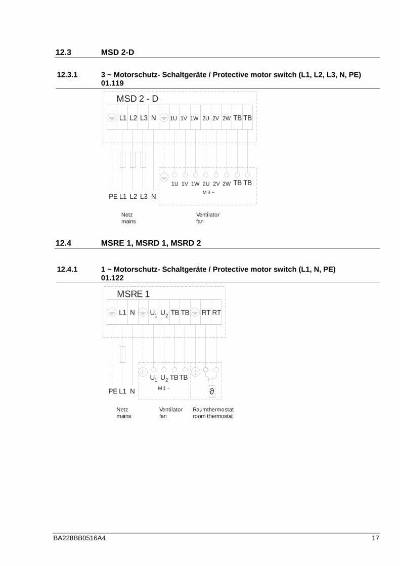
12.3.1 3 ~ Motorschutz- Schaltgeräte / Protective motor switch (L1, L2, L3, N, PE) 01.119 17
12.4 MSRE 1, MSRD 1, MSRD 2 17
12.4.1 1 ~ Motorschutz- Schaltgeräte / Protective motor switch (L1, N, PE) 01.122 17
12.4.2 3 ~ Motorschutz- Schaltgeräte / Protective motor switch (L1, L2, L3, N, PE) 01.124 18
12.4.3 3 ~ Motorschutz- Schaltgeräte / Protective motor switch (L1, L2, L3, N, PE) 01.125 18
12.5 MSRFE 1, MSRFD 1, MSRFD 2 19
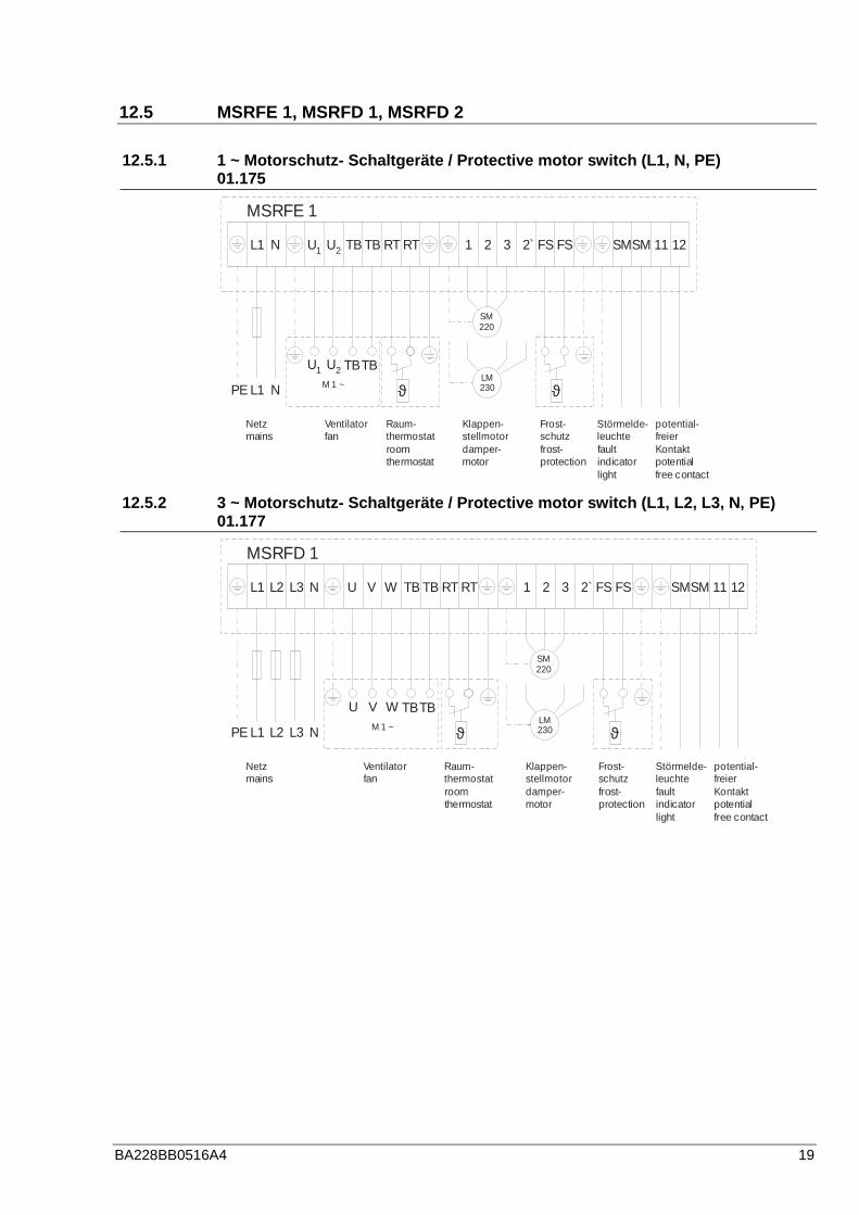
12.5.1 1 ~ Motorschutz- Schaltgeräte / Protective motor switch (L1, N, PE) 01.175 19
12.5.2 3 ~ Motorschutz- Schaltgeräte / Protective motor switch (L1, L2, L3, N, PE) 01.177 19
12.5.3 3 ~ Motorschutz- Schaltgeräte / Protective motor switch (L1, L2, L3, N, PE) 01.178 20
12.6 MSAD 2 20
12.6.1 3 ~ Motorschutz- Schaltgeräte / Protective motor switch (L1,L2, L3, N, PE) 01.163 20
12.7 MSD 1 K, MSD 2 K, MSD 2 K-D 21
12.7.1 3 ~ Motorschutz- Schaltgeräte / Protective motor switch (L1,L2, L3, N, PE) 01.102b 21
12.7.2 3 ~ Motorschutz- Schaltgeräte / Protective motor switch (L1,L2, L3, N, PE) 01.118b 21
12.7.3 3 ~ Motorschutz- Schaltgeräte / Protective motor switch (L1,L2, L3, N, PE) 01.351 22
13 Notizen / Note 23

BA228BB0516A4 3
2 Sicherheitshinweise / Safety instructions
Folgende Symbole weisen Sie auf bestimm-te Gefährdungen hin oder geben Ihnen Hinweise zum sicheren Betrieb.
The following symbols refer to particular dangers or give advice on safe operation.
Achtung! Gefahrenstelle! Sicher-heitshinweis! Attention! Danger! Safety advice!
- Sicherungen dürfen nur ersetzt und nicht repariert oder überbrückt wer-den.
- Die Schaltgeräte dürfen nicht im Ex- Bereich montiert werden.
- Fuses must be replaced and not repaired or bridged.
- The protective motor switch may not be installed in the Ex area.
Gefahr durch elektrischen Strom oder hohe Spannung! Danger from electric current or high
voltage!
- Es ist grundsätzlich verboten, Ar-beiten an unter Spannung stehen-den Teilen durchzuführen. Schutz-art des geöffneten Gerätes ist IP 00! Gefährliche Spannungen kön-nen direkt berührt werden.
- Während des Betriebes muss das Gerät geschlossen oder im Schalt-schrank eingebaut sein.
- Spannungsfreiheit muss mit einem zweipoligem Spannungsprüfer kon-trolliert werden.
- It is strictly forbidden for work to be carried out on any components while they are connected to live voltage. The open equipment is protected to IP00! It is possible to come into direct contact with dan-gerous voltages.
- During operation the equipment must be closed or installed in a switching cabinet.
- Check to ensure voltage is not ap-plied to input terminals prior to commencing work with protecting motor switch.
Wichtige Hinweise, Informationen Important instruc tions, information
4 BA228BB0516A4
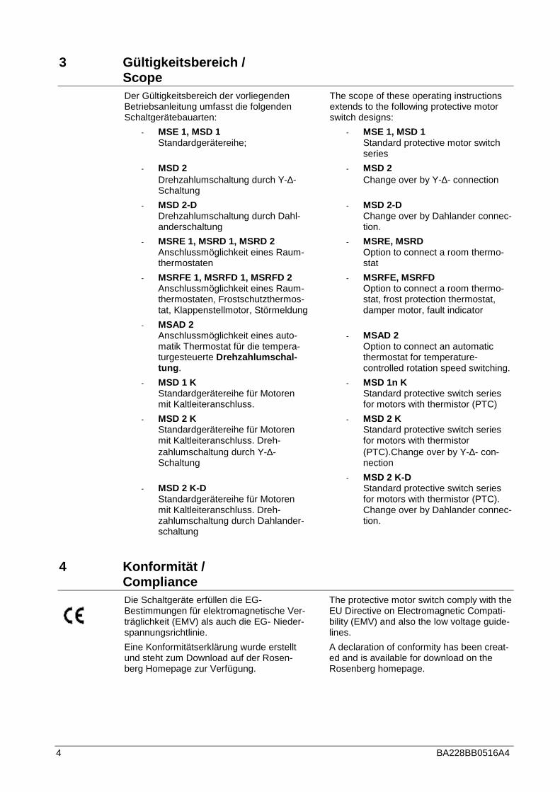
3 Gültigkeitsbereich / Scope
Der Gültigkeitsbereich der vorliegenden Betriebsanleitung umfasst die folgenden Schaltgerätebauarten:
- MSE 1, MSD 1 Standardgerätereihe;
- MSD 2 Drehzahlumschaltung durch Y-∆-Schaltung
- MSD 2-D Drehzahlumschaltung durch Dahl-anderschaltung
- MSRE 1, MSRD 1, MSRD 2 Anschlussmöglichkeit eines Raum-thermostaten
- MSRFE 1, MSRFD 1, MSRFD 2 Anschlussmöglichkeit eines Raum-thermostaten, Frostschutzthermos-tat, Klappenstellmotor, Störmeldung
- MSAD 2 Anschlussmöglichkeit eines auto-matik Thermostat für die tempera-turgesteuerte Drehzahlumschal-tung .
- MSD 1 K Standardgerätereihe für Motoren mit Kaltleiteranschluss.
- MSD 2 K Standardgerätereihe für Motoren mit Kaltleiteranschluss. Dreh-zahlumschaltung durch Y-∆-Schaltung
- MSD 2 K-D Standardgerätereihe für Motoren mit Kaltleiteranschluss. Dreh-zahlumschaltung durch Dahlander-schaltung
The scope of these operating instructions extends to the following protective motor switch designs:
- MSE 1, MSD 1 Standard protective motor switch series
- MSD 2 Change over by Y-∆- connection
- MSD 2-D Change over by Dahlander connec-tion.
- MSRE, MSRD Option to connect a room thermo-stat
- MSRFE, MSRFD Option to connect a room thermo-stat, frost protection thermostat, damper motor, fault indicator
- MSAD 2 Option to connect an automatic thermostat for temperature-controlled rotation speed switching.
- MSD 1n K Standard protective switch series for motors with thermistor (PTC)
- MSD 2 K Standard protective switch series for motors with thermistor (PTC).Change over by Y-∆- con-nection
- MSD 2 K-D Standard protective switch series for motors with thermistor (PTC). Change over by Dahlander connec-tion.
4 Konformität / Compliance
Die Schaltgeräte erfüllen die EG-Bestimmungen für elektromagnetische Ver-träglichkeit (EMV) als auch die EG- Nieder-spannungsrichtlinie.
The protective motor switch comply with the EU Directive on Electromagnetic Compati-bility (EMV) and also the low voltage guide-lines.
Eine Konformitätserklärung wurde erstellt und steht zum Download auf der Rosen-berg Homepage zur Verfügung.
A declaration of conformity has been creat-ed and is available for download on the Rosenberg homepage.
BA228BB0516A4 5
5 Beschreibung / Description
Die vorliegende Betriebsanleitung ist eine Gesamtbetriebsanleitung der unter 3. Gül-tigkeitsbereich aufgeführten Geräte. Motor-schutz Schaltgeräte eignen sich zum Schutz von Motoren / Ventilatoren mit Thermokontaktanschluss (gekennzeichnet durch ein T in der Typenbezeichnung) bzw. Kaltleiteranschluss (gekennzeichnet durch ein K in der Typenbezeichnung). Geräte die für den Anschluss an das 1~Netz bestimmt sind, enthalten in der Typenbezeichnung ein E (z.B. MSE, MSRE, MSRFE,...). Die Schaltgeräte die für den Anschluss an das 3~Netz bestimmt sind enthalten in der Ty-penbezeichnung ein D (z.B. MSD, MSRD, MSRFD, MSD 1 K ...).
These operating instructions are a complete set of operating instructions for the protec-tive motor switches mentioned under 3. Scope. Protective motor switch are suitable for the protection of motors/fans with ther-mocontact connection (marked by a T in the type designation) and /or thermistor (PTC) (marked by a K in the type designation). Protective motor switches that are intended for connection to the single-phase mains have an E in the model code (e.g. MSE, MSRE, MSRFE,...). Protective motor switches intended for 3-phase mains have a D in the model code (e.g. MSD, MSRD, MSRFD, MSD 1 K ...).
Den Spannungs- und Frequenzanga-ben auf dem Typenschild der Schalt-geräte ist unbedingt folge zu leisten.
The voltage and frequency infor-mation on the type plate of the pro-tective motor switch is to be ob-served without exception.
Ebenfalls werden in dieser Betriebsanlei-tung Schaltgeräte beschrieben die funkti-onsgleich sind aber für den Anschluss an unterschiedlichen Netzspannungen vorge-sehen sind. Vor der Inbetriebnahme sind die Angaben auf dem Typenschild mit den Angaben auf der Auftragsbestätigung zu vergleichen. Nähere Hinweise zum Typen-schild sind in Kapitel 6 zu finden.
In these operating instructions protective motor switches are also described which are functionally the same but which are intended for connection to different mains voltages. Before operation, the statements on the type plate should be compared with the information on the order confirmation. More details on the type plate are to be found in Chapter 6.
5.1 Allgemeine Beschreibung aller Motorschutz- Schal tgeräte / General description of all protective motor switche s
Motorschutz Schaltgeräte eignen sich zum Schutz von Motoren / Ventilatoren mit Thermokontaktanschluss bzw. Kaltleiteran-schluss. Dabei ist zu beachten, dass der maximal zulässige Strom des Schaltgerätes nicht überschritten wird (siehe Angaben auf dem Typenschild).Die im Schaltgerät ein-gebaute Betriebsmeldeleuchte signalisiert den eingeschalteten Zustand des Gerätes.
Protective motor switch are suitable for the protection of motors / fans with thermal contact connection and/or thermistor (PTC). It is to be noted that the maximally permis-sible current of the protective motor switch is not exceeded (see type plate) The opera-tion indicator light built into the protective motor switch shows that the protective mo-tor switch is switched on.
Mit der im Schaltgerät ein gebauten orangen Signalleuchte werden keine Störungen des Gerätes signalisiert. Die eingebaute Signalleuchte zeigt nur den eingeschalteten Betriebszu-stand des Gerätes an.
Protective motor switch faults are not shown by the orange indicator light built into the protective motor switch. The built-in indicator light only shows that the protective motor switch is switched on.
Der Motorschutz erfolgt durch Anschluss des Motor- Thermokontakt. Ausnahme Schaltgeräte MSD 1 K, MSD 2 K und MSD 2 K-D. Bei Rosenberg Außenläufermotoren ist dieser Thermokontaktanschluss bzw. Kaltleiteranschluss durch zwei weiße Litzen gekennzeichnet.
Bis auf die Schaltgeräte mit Kaltleiteran-
Motor protection is provided by connection with the motor thermocontact. Exception protective motor switches MSD 1 K, MSD 2 K and MSD 2 K-D. With Rosenberg exter-nal rotor motors, this thermocontact con-nection and/or thermistor (PTC) is indicated by two white flexes.
Exception the protective motor switches

6 BA228BB0516A4
schluss sind grundsätzlich alle Schaltgeräte für die Ansteuerung mehrerer Motoren / Ventilatoren geeignet (Gruppensteuerung). Es ist darauf zu achten, dass die Summe der Einzelströme den Gesamtstrom nicht übersteigt.
with thermistor (PTC) connection all protec-tive motor switches are suitable for operat-ing several motors / fans (group control). One should ensure that the total of the indi-vidual current figures does not exceed the total permitted current.
Die Schaltgeräte MSD 1 K, MSD 2 K und MSD 2K-D sind für den An-schluss von Kaltleitern vorgesehen. Die maximale Spannung darf an die-sen Kontakten 2,5 Volt nicht über-steigen. Der Anschluss von mehre-ren Motoren an diese Geräte ist nicht zulässig.
The protective motor switch es are intended for the connection of ther-mistors (PTC). The maximum voltage may not exceed 2.5 V at these con-tacts. The connection of several mo-tors to these devices is not permis-sible.
5.2 Drehzahlumschaltung bei Motorschutzschaltgeräten / Speed change by protective motor switches
Motorschutzschaltgeräte die nur für das Ein- und Ausschalten des angeschlossenen Motors / Ventilators geeignet sind, sind mit einer 1 in der Typenbezeichnung gekenn-zeichnet.
Motorschutzschaltgeräte die für Motoren mit zwei Drehzahlen geeignet sind, sind mit einer 2 in der Typenbezeichnung gekenn-zeichnet. Dabei ist jedoch folgendes zu beachten:
- Geräte mit Drehzahlumschaltung durch Y-∆∆∆∆- Umschaltung sind mit einer 2 in der Typenbezeichnung gekennzeichnet.
- Geräte mit Drehzahlumschaltung durch Dahlanderschaltung sind mit einer 2 - D in der Typenbe-zeichnung gekennzeichnet.
Protective motor switch for single speed motors / fans are marked by a 1 in the type designation.
Protective motor switches for double speed motors / fans are marked by a 2 in the type designation. However the following is to be considered:
- Devices with two numbers of revo-lutions change-over by Y-∆∆∆∆- con-nection are marked by 2 in the type designation.
- Devices with two numbers of revo-lutions change-over by Dahlander-connection are marked by 2 in the type designation.
5.2.1 MSE 1, MSD 1
Standardausführung, Funktionsbeschrei-bung siehe 5.1. und 5.2.
Standard equipment, functional description: see 5.1 and 5.2
5.2.2 MSD 2
Standardausführung, Funktionsbeschrei-bung siehe 5.1. und 5.2.
- Drehzahlumschaltung durch Y-∆∆∆∆-Schaltung.
Standard equipment, functional description: see 5.1 and 5.2
- Number of revolutions change-over by Y-∆∆∆∆- connection.
5.2.3 MSD 2-D
Standardausführung, Funktionsbeschrei-bung siehe 5.1. und 5.2.
- Drehzahlumschaltung durch Dahl-anderschaltung.
Standard equipment, functional description: see 5.1 and 5.2
- Number of revolutions change-over by Dahlander- connection.

BA228BB0516A4 7
5.2.4 MSRE 1, MSRD 1, MSRD 2
Standardausführung, Funktionsbeschrei-bung siehe 5.1. und 5.2.
Zusätzlich können mit einem externen po-tentialfreien Kontakt die Geräte in der vor-gewählten Stufe „AUS“ und „EIN“ geschal-tet werden (z.B. Raumthermostatan-schluss).
Standard equipment, functional description: see 5.1. und 5.2.
In addition, with an external potential-free contact, the protective motor switch can be switched “ON” and “OFF” at the pre-selected level (e.g. room thermostat con-nection).
5.2.5 MSRFE 1, MSRFD 1, MSRFD 2
Standardausführung, Funktionsbeschrei-bung siehe 5.1. und 5.2.
Zusätzlich können mit einem externen po-tentialfreien Kontakt die Geräte in der vor-gewählten Stufe „AUS“ und „EIN“ geschal-tet werden (z.B. Raumthermostatan-schluss).
Ebenfalls befindet sich die Anschlussmög-lichkeit eines Frostschutzthermostat, Klap-penstellmotor, Störmeldung und potential-freier Hilfskontakt.
Standard equipment, functional description: see 5.1. und 5.2.
In addition, with an external potential-free contact, the protective motor switch can be switched “ON” and “OFF” at the pre-selected level (e.g. room thermostat con-nection).
There is also the option to connect a frost protection thermostat, damper motor, fault signal and a potential-free spare contact.
5.2.6 MSAD 2
Am Stufenschalter können die Drehzahlstu-fen 1-2 von Hand durchgeschaltet werden. Wird auf die Betriebsart Automatik umge-schaltet so wird die Drehzahlstufe des Mo-tors in 2 Stufen der Raumtemperatur ange-passt.
Der Temperaturbereich des 2- Stufen- Raumthermostat reicht von 0.. + 40 °C. Der Stufenabstand beträgt ca. 1,5 K. Wird z.B. eine Temperatur von 20 °C auf dem Ther-mostat eingestellt, dann startet der ange-schlossene Motor / Ventilator bei ca. 21,5 °C in der niedrigsten Drehzahlstufe. Wer-den die 23°C überschritten, schaltet das Thermostat den Motor in die nächst höhere Drehzahlstufe
Bei Abkühlen der Raumtemperatur erfolgt der Vorgang in umgekehrter Reihenfolge.
Rotation speed levels 1-2 can be selected from step-switch. If you switch to Automatic operating mode, the rotation speed level of the motor is adjusted to the room tempera-ture in 4 steps.
The temperature range of the 2-level room thermostat is from 0.. +40 ºC. The size of the steps is about 1.5 K. If for instance the thermostat is set to a temperature of 20 ºC, then the motor/fan connected starts at about 21.5 ºC at the lowest rotation speed level. If 23 ºC is exceeded, the thermostat switches the motor to the next higher rota-tion speed.
When the room temperature cools down, the process happens in reverse.
Wir der Standard 2 - Stufen Autom a-tik Raumthermostat nicht verwendet, sind die Angaben des eingesetzten Thermostaten zu beachten z.B. max. Temperaturbereich, Stufenabstand.
If the standard 2-level automatic room thermostat is not used, the instructions for the thermostat used are to be observed e.g. max. temper-ature range, size of the steps.
5.2.7 MSD 1 K
Standardausführung, Funktionsbeschrei-bung siehe 5.1. und 5.2.
Das Schaltgerät ist nur für den Anschluss von Motoren / Ventilatoren mit Kaltleiter geeignet.
Standard equipment, functional description: see 5.1. und 5.2.
The protective motor switch is suitable only for the connection by motors / fans with thermistor (PTC).
8 BA228BB0516A4
5.2.8 MSD 2 K
Standardausführung, Funktionsbeschrei-bung siehe 5.1. und 5.2.
- Drehzahlumschaltung durch Y-∆∆∆∆-Schaltung.
Das Schaltgerät ist nur für den Anschluss von Motoren / Ventilatoren mit Kaltleiter geeignet.
Standard equipment, functional description: see 5.1. und 5.2.
- Number of revolutions change-over by Y-∆∆∆∆- connection.
The protective motor switch is suitable only for the connection by motors / fans with thermistor (PTC).
5.2.9 MSD 2 K-D
Standardausführung, Funktionsbeschrei-bung siehe 5.1. und 5.2.
- Drehzahlumschaltung durch Dahlanderschaltung.
Das Schaltgerät ist nur für den Anschluss von Motoren / Ventilatoren mit Kaltleiter geeignet.
Standard equipment, functional description: see 5.1. und 5.2.
- Number of revolutions change-over by Dahlander- connection.
The protective motor switch is suitable only for the connection by motors / fans with thermistor (PTC).
6 Typenschild / Type plate
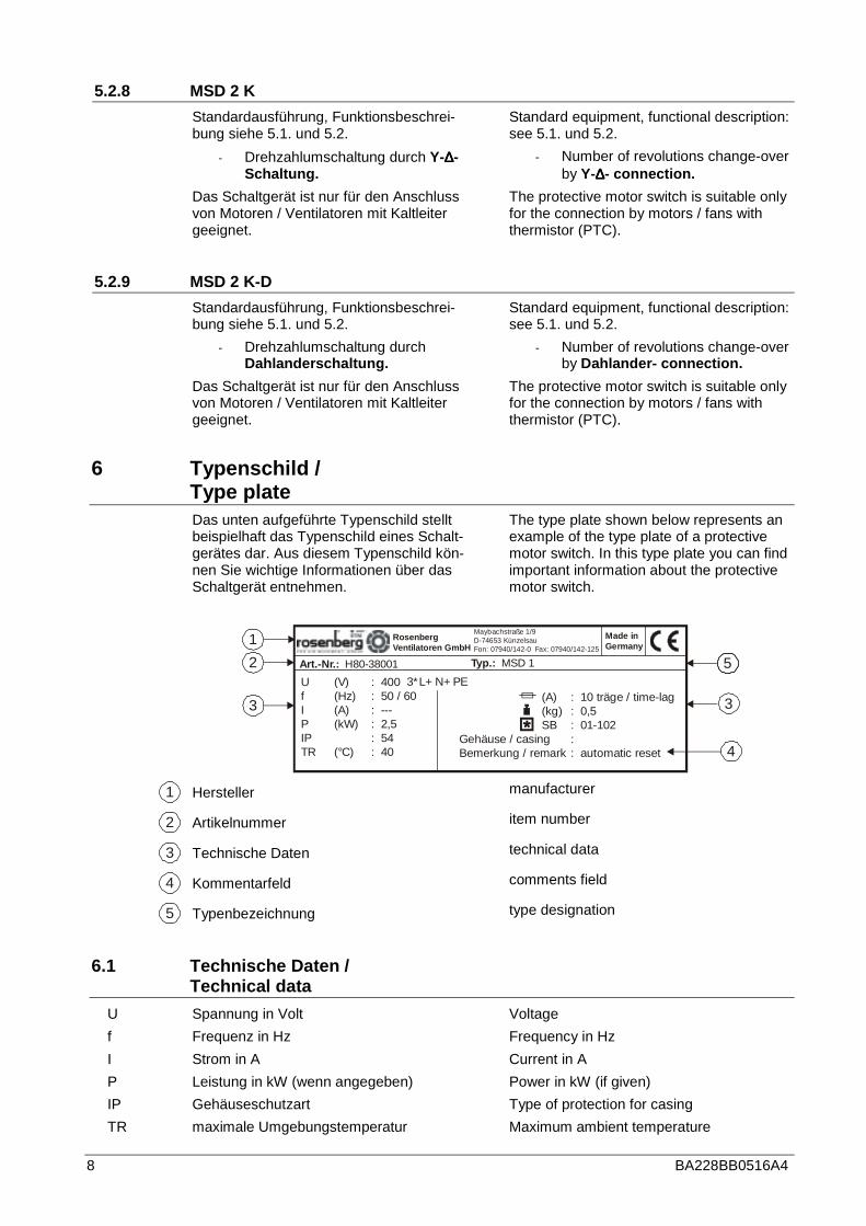
Das unten aufgeführte Typenschild stellt beispielhaft das Typenschild eines Schalt-gerätes dar. Aus diesem Typenschild kön-nen Sie wichtige Informationen über das Schaltgerät entnehmen.
The type plate shown below represents an example of the type plate of a protective motor switch. In this type plate you can find important information about the protective motor switch.
1
2
3
4
U (V) : 400f (Hz) : 50 / 60I (A) : ---P (kW) : 2,5IP : 54TR (°C) : 40
Art.-Nr.: H80-38001 Typ.: MSD 1
Made inGermany
RosenbergVentilatoren GmbH
Maybachstraße 1/9D-74653 KünzelsauFon: 07940/142-0 Fax: 07940/142-125
3*L+ N+ PE
5
3(A) : 10 träge / time-lag(kg) : 0,5SB : 01-102
Gehäuse / casing : Bemerkung / remark : automatic reset
1 Hersteller manufacturer
2 Artikelnummer item number
3 Technische Daten technical data
4 Kommentarfeld comments field
5 Typenbezeichnung type designation
6.1 Technische Daten / Technical data
U Spannung in Volt Voltage
f Frequenz in Hz Frequency in Hz
I Strom in A Current in A
P Leistung in kW (wenn angegeben) Power in kW (if given)
IP Gehäuseschutzart Type of protection for casing
TR maximale Umgebungstemperatur Maximum ambient temperature
BA228BB0516A4 9
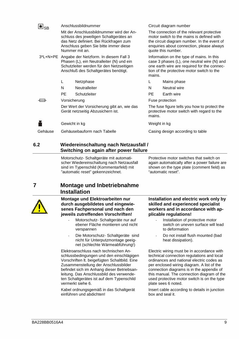
SB Anschlussbildnummer
Mit der Anschlussbildnummer wird der An-schluss des jeweiligen Schaltgerätes an das Netz definiert. Bei Rückfragen zum Anschluss geben Sie bitte immer diese Nummer mit an.
Circuit diagram number
The connection of the relevant protective motor switch to the mains is defined with the circuit diagram number. In the event of enquiries about connection, please always quote this number.
3*L+N+PE Angabe der Netzform. In diesem Fall 3 Phasen (L), ein Neutralleiter (N) und ein Schutzleiter werden für den Netzseitigen Anschluß des Schaltgerätes benötigt.
L Netzphase
N Neutralleiter
PE Schutzleiter
Information on the type of mains. In this case 3 phases (L), one neutral wire (N) and one earth wire are required for the connec-tion of the protective motor switch to the mains.
L Mains phase
N Neutral wire
PE Earth wire
Vorsicherung
Der Wert der Vorsicherung gibt an, wie das Gerät netzseitig Abzusichern ist.
Fuse protection
The fuse figure tells you how to protect the protective motor switch with regard to the mains.
Gewicht in kg Weight in kg
Gehäuse Gehäusebauform nach Tabelle Casing design according to table
6.2 Wiedereinschaltung nach Netzausfall / Switching on again after power failure
Motorschutz- Schaltgeräte mit automati-scher Wiedereinschaltung nach Netzausfall sind im Typenschild (Kommentarfeld) mit "automatic reset" gekennzeichnet.
Protective motor switches that switch on again automatically after a power failure are shown on the type plate (comment field) as “automatic reset”.
7 Montage und Inbetriebnahme Installation
Montage und Elektroarbe iten nur durch ausgebildetes und eingewie-senes Fachpersonal und nach den jeweils zutreffenden Vorschriften!
Installation and electric work only by skilled and experienced specialist workers and in accordance with ap-plicable regulations!
- Motorschutz- Schaltgeräte nur auf ebener Fläche montieren und nicht verspannen
- Die Motorschutz- Schaltgeräte sind nicht für Unterputzmontage geeig-net (schlechte Wärmeabführung!)
- Installation of protective motor switch on uneven surface will lead to deformation
- Do not install flush mounted (bad heat dissipation).
Elektroanschluss nach technischen An-schlussbedingungen und den einschlägigen Vorschriften lt. beigefügten Schaltbild. Eine Zusammenstellung der Anschlussbilder befindet sich im Anhang dieser Betriebsan-leitung. Das Anschlussbild des verwende-ten Schaltgerätes ist auf dem Typenschild vermerkt siehe 6.
Kabel ordnungsgemäß in das Schaltgerät einführen und abdichten!
Electric wiring must be in accordance with technical connection regulations and local ordinances and national electric codes as per enclosed wiring diagram. A list of the connection diagrams is in the appendix of this manual. The connection diagram of the used protective motor switch is on the type plate sees 6 noted.
Insert cable according to details in junction box and seal it.
10 BA228BB0516A4
7.1 Vorsicherung / Fuse protection
Es wird eine Abs icherung gemäß VDE 0550, Teil 1, § 6 über Kurz-schluss - Schutzsicherungen emp-fohlen (siehe Typenschild).
We recommend a fuse in a ccordance with VDE 0550, part 1, § 6 about short-circuit fuses (see type plate).
Die Vorsicherung ist gemäß den A n-gaben auf dem Typenschild zu wäh-len.
Fuse protection is to be selected according to the information on the type plate.
7.2 Hauptschalter / Main switch
Bauseits ist ein Hauptschalter g e-mäß DIN 60204 Teil 1 vorzusehen!
On site a main switch in a ccordance with DIN 60204, part 1 is required.
7.3 Leitungsquerschnitt / Cable diameter
Die Leitungsquerschnitte sind gemäß DIN VDE 0298, Teil 4, Tabelle 2 zu wählen.
Please select the power cable diameter according to DIN VDE 0298, part 4, table 2
7.4 Maximale Umgebungstemperatur / Maximum ambient temperature
Die Motorschutz- Schaltgeräte sind für den Betrieb bei einer maximalen Umgebungs-temperatur von 40°C zugelassen.
It is permitted to operate the protective motor switches in an ambient temperature of up to 40 ºC.
Es ist nicht zulässig die Moto r-schutz- Schaltgeräte auf aktive Ma-schinen- oder Anlagenteile zu mon-tieren die durch den Betrieb der Ma-schine oder Anlage thermischen Be-lastungen ausgesetzt sind. Ebenso ist es unzulässig die Motor-schutz- Schaltgeräte in der Nähe von Wärmequellen zu montieren, wenn die Gefahr besteht, dass die Oberflä-chentemperatur des ausgeschalteten Schaltgerätes, an irgend einer Stelle, durch Wärmestrahlung eine Oberflä-chentemperatur von 40°C erreichen kann.
It is not permitted to mount the pro-tective motor switches on to working machine or plant parts if they would be subject to a thermal load from the machine or plant.
It is also not permitted to mount the protective motor switches in the vi-cinity of sources of heat if there is a risk that the surface temperature of the switched-off protective motor switch might reach a temperature of 40 ºC at any point on its surface.
8 Wartung / Maintenance
Im Normalfall sind unsere Moto r-schutz- Schaltgeräte wartungsfrei! Unter extremen Betriebsbedingun-gen können jedoch kleinere War-tungsarbeiten anfallen!
Our switches are mainten ance free with normal operation! When using them under extreme conditions sim-ple maintenance work may be re-quired!
- Wartungsarbeiten nur durch aus-gebildetes und eingewiesenes Fachpersonal und nach den jeweils zutreffenden Vorschriften!
- Maintenance work only by skilled and trained specialist workers and in accordance with applicable regu-lations.
BA228BB0516A4 11
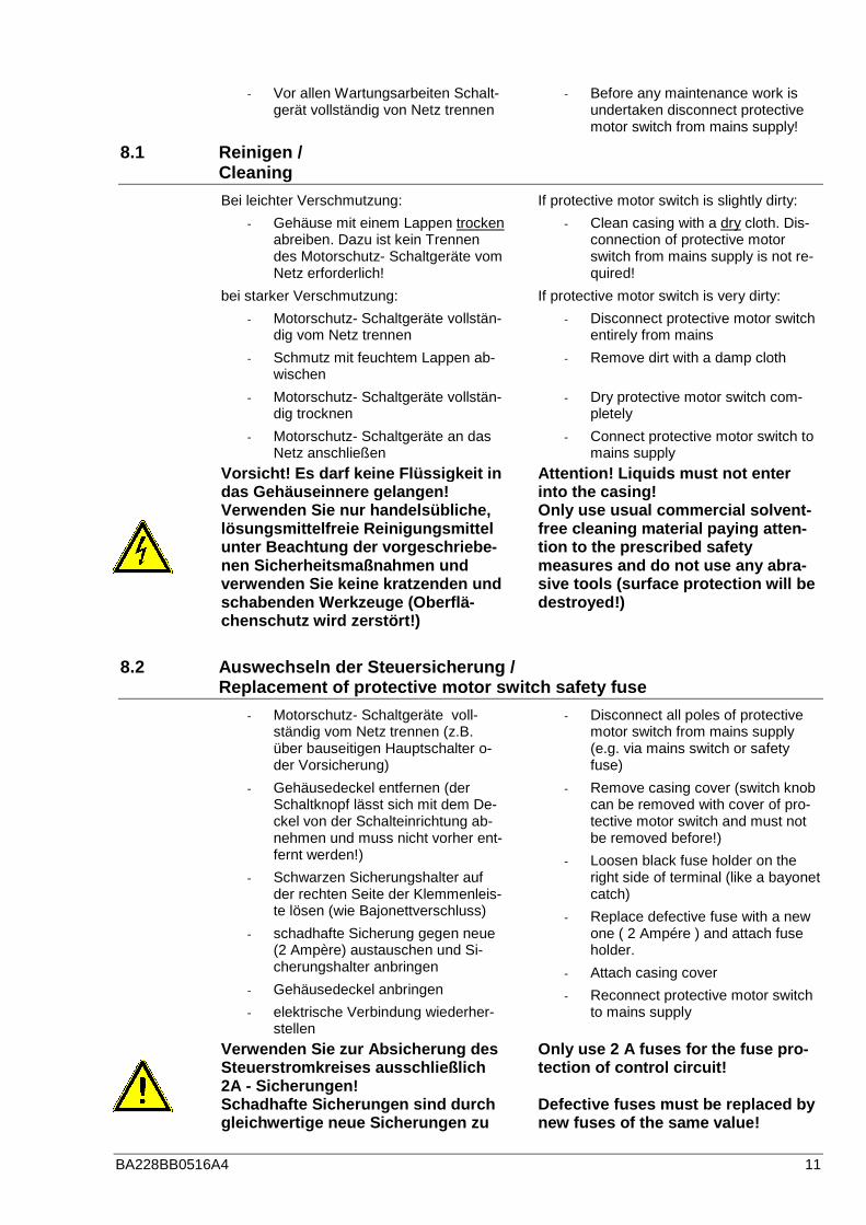
- Vor allen Wartungsarbeiten Schalt-gerät vollständig von Netz trennen
- Before any maintenance work is undertaken disconnect protective motor switch from mains supply!
8.1 Reinigen / Cleaning
Bei leichter Verschmutzung:
- Gehäuse mit einem Lappen trocken abreiben. Dazu ist kein Trennen des Motorschutz- Schaltgeräte vom Netz erforderlich!
bei starker Verschmutzung:
- Motorschutz- Schaltgeräte vollstän-dig vom Netz trennen
- Schmutz mit feuchtem Lappen ab-wischen
- Motorschutz- Schaltgeräte vollstän-dig trocknen
- Motorschutz- Schaltgeräte an das Netz anschließen
If protective motor switch is slightly dirty:
- Clean casing with a dry cloth. Dis-connection of protective motor switch from mains supply is not re-quired!
If protective motor switch is very dirty:
- Disconnect protective motor switch entirely from mains
- Remove dirt with a damp cloth
- Dry protective motor switch com-pletely
- Connect protective motor switch to mains supply
Vorsicht! Es darf keine Flüssi gkeit in das Gehäuseinnere gelangen! Verwenden Sie nur handelsübliche, lösungsmittelfreie Reinigungsmittel unter Beachtung der vorgeschriebe-nen Sicherheitsmaßnahmen und verwenden Sie keine kratzenden und schabenden Werkzeuge (Oberflä-chenschutz wird zerstört!)
Attention! Liquids must not e nter into the casing! Only use usual commercial solvent-free cleaning material paying atten-tion to the prescribed safety measures and do not use any abra-sive tools (surface protection will be destroyed!)
8.2 Auswechseln der Steuersicherung / Replacement of protective motor switch safety fuse
- Motorschutz- Schaltgeräte voll-ständig vom Netz trennen (z.B. über bauseitigen Hauptschalter o-der Vorsicherung)
- Gehäusedeckel entfernen (der Schaltknopf lässt sich mit dem De-ckel von der Schalteinrichtung ab-nehmen und muss nicht vorher ent-fernt werden!)
- Schwarzen Sicherungshalter auf der rechten Seite der Klemmenleis-te lösen (wie Bajonettverschluss)
- schadhafte Sicherung gegen neue (2 Ampère) austauschen und Si-cherungshalter anbringen
- Gehäusedeckel anbringen
- elektrische Verbindung wiederher-stellen
- Disconnect all poles of protective motor switch from mains supply (e.g. via mains switch or safety fuse)
- Remove casing cover (switch knob can be removed with cover of pro-tective motor switch and must not be removed before!)
- Loosen black fuse holder on the right side of terminal (like a bayonet catch)
- Replace defective fuse with a new one ( 2 Ampére ) and attach fuse holder.
- Attach casing cover
- Reconnect protective motor switch to mains supply
Verwenden Sie zur Absich erung des Steuerstromkreises ausschließlich 2A - Sicherungen! Schadhafte Sicherungen sind durch gleichwertige neue Sicherungen zu
Only use 2 A fuses for the fuse pr o-tection of control circuit! Defective fuses must be replaced by new fuses of the same value!

12 BA228BB0516A4
ersetzen!
9 Lagerung, Transport / Storage, Transport
- Lagern Sie das Motorschutz- Schaltgeräte in seiner Originalver-packung trocken und wetterge-schützt.
- Decken Sie offene Paletten mit Planen ab und schützen Sie die Motorschutz- Schaltgeräte vor Schmutzeinwirkung (z.B. Späne, Steine, Draht usw.).
- Halten Sie Lagertemperaturen zwi-schen - 30 °C und + 40 °C ein.
- Transportieren Sie das Motor-schutz- Schaltgeräte mit geeigne-ten Lastaufnahmemitteln und be-achten Sie die Körperlichen Hebe-kräfte (⇒ Gewicht lt. Motorschutz- Schaltgerätetypenschild).
- Vermeiden Sie Beschädigungen des Gehäuses.
- Store the protective motor switch in a dry place and weather protected in its original packing.
- Cover open pallets with a tarpaulin and protect the protective motor switches against penetration by dirt (e.g. stones, splinters, wires, etc.).
- Keep storage temperatures be-tween - 30 °C and + 40 °C.
- Transport the fan with suitable load-bearing means and consider the physical lifting capacities (⇒�weight as shown on the type plate).
- Avoid distortion of casing or other damage.
10 Entsorgung / Disposal
Beachten Sie bei der Entsorgung des Geräts alle relevanten, in Ihrem Land geltenden Anforderungen und Best-immungen Der Schutz der Umwelt und die Schonung der Ressourcen ist für Rosenberg Ventilato-ren GmbH ein wichtiges Thema. Aus die-sem Grund wurden schon bei der Entwick-lung unserer Ventilatoren auf umweltfreund-liche Gestaltung, technische Sicherheit und Gesundheitsschutz geachtet. Im folgenden Kapitel finden Sie Empfehlun-gen für eine umweltfreundliche Entsorgung der Maschine und ihrer Komponenten.
Please note all the relevant requ i-rements and regulations in your country when disposing the device. The protection of the environment and the conservation of resources are important issues for Rosenberg Ventilatoren GmbH. For this reason, environmentally friendly design and technical safety as well as health protection were already respected in the development of our fans: In the following section you will find rec-ommendations for environmentally friend-ly disposal of the machine and its compo-nents.
10.1 Demontage vorbereiten / Preparing disassembly
Die Demontage der Maschine muss durch ausgebildetes und eingewiesenes Fachper-sonal durchgeführt oder beaufsichtigt wer-den. Bei der Verwertung und Entsorgung von Rosenberg Produkten sind die regional geltenden Anforderungen und Bestimmun-gen einzuhalten.
Die Demontage ist wie folgt vorzubereiten:
The dismantling of the machine must be carried out or supervised by a trained and qualified staff. For the recycling and disposal of Rosen-berg products the local requirements must be followed.
The dismantling must be prepared as
BA228BB0516A4 13
1. Nehmen sie Kontakt mit einem Ent-sorgungsfachbetrieb auf und klären Sie, wie und in welcher Qualität die Demontage der Komponenten er-folgen soll.
2. Trennen Sie die Maschine vom Stromnetz und entfernen Sie alle Kabel.
3. Entfernen Sie ggf. alle Flüssigkeiten wie z.B. Öl und entsorgen Sie diese entsprechend den regional gelten-den Anforderungen.
4. Transportieren Sie die Maschine an einen für die Demontage geeigne-ten Platz.
follows:
1. Get in touch with a waste manage-ment company in your area. Clarify, how and in which quality the dis-mantling of the components should take place.
2. Disconnect the machine from the mains all and remove all cables.
3. If necessary, remove all liquids, such as oil and remove this accord-ing to the local requirements.
4. Transport the machine to a suitable location for disassembly.
10.2 Maschine zerlegen / Dismantling machine
Zerlegen Sie die Maschine nach allgemei-ner maschinenbautypischer Vorgehenswei-se.
Disassemble the machine according to general mechanics typical procedure.
Die Maschine besteht aus Teilen mit hohem Gewicht. Diese können beim Zerlegen herunterfallen. Schwere Körperverletzung und Sachschäden können die Folge sein. Sichern Sie Maschinenteile gegen Absturz, bevor Sie diese lösen.
The machine is made up of heavy parts. These can fall during dismant-ling. Serious injury and property damage may result. Secure machine parts against falling before you remove this.
10.3 Komponenten entsorgen / Dispose of components
Bauteile Die Maschine besteht zum Größtenteils aus metallischen Werkstoffen. Diese gelten allgemein als uneingeschränkt recyclingfä-hig. Für die Verwertung müssen die Werk-stoffe nach den folgenden Kategorien ge-trennt werden.
- Stahl und Eisen
- Aluminium
- Buntmetall
- ⇒ (Isolierung wird beim Kupfer-Recycling verascht)
- Isoliermaterial
- Kabel und Leitungen
- Ggf. Elektronikschrott
- Kunststoffe
Hilfsstoffe und Chemikalien Trennen Sie die Hilfsstoffe und Chemikalien
Components The machine consists mainly of metallic materials. These are generally considered fully recyclable. Unplug the components for recycling according to the following catego-ries:
- Steel and Iron
- Aluminum
- Non-ferrous metal
- ⇒ (Insulation is incinerated during copper recycling)
- Insulating material
- Cables and wires
- If applicable electrical scrap
- Plastics
Materials and chemicals Separate the materials and chemicals for

14 BA228BB0516A4
zur Entsorgung z.B. nach folgenden Kate-gorien:
- Fett
- Lackrückstände
Entsorgen Sie die getrennten Komponenten entsprechend den regional geltenden An-forderungen. Das gilt auch für Lappen und Putzmittel mit denen Arbeiten an der Ma-schine durchgeführt wurden.
Verpackungsmaterial
- Nehmen Sie bei Bedarf Kontakt mit einem Entsorgungsfachbetrieb auf.
- Holzverpackungen für den See-transport bestehen aus imprägnier-tem Holz. Beachten sie die regional geltenden Anforderungen.
- Schaumstoff Verpackungen, Ver-packungsfolien und Kartonagen können ohne weiteres der Werk-stoffverwertung zugeführt werden. Verschmutzte Verpackungsmateria-lien können einer thermischen Ver-wertung zugeführt werden.
disposal, e.g. according to the following categories:
- Fat
- Paint residues
Dispose the separated components accord-ing to the local regulations. The same goes for cloths and cleaning substances which work was carried out on the machine.
Packing material
- When needed, take contact with a waste management company.
- Wood packaging for sea transport consists of impregnated wood. Please note the local regulations.
- The foam packaging, packaging foils and cartons can be supplied readily to the material-recovery. Contaminated packaging materials can be supplied to a thermal utiliza-tion.
11 Kundendienst, Herstelleradresse / Service, Address of producer
Rosenberg-Produkte unterliegen einer ständigen Qualitätskontrolle und entspre-chen den geltenden Vorschriften.
Für alle Fragen, die Sie im Zusammenhang mit unseren Produkten haben, wenden Sie sich bitte an den Ersteller Ihrer lufttechni-schen Anlage, an eine unserer Niederlas-sungen oder direkt an:
Rosenberg-products are subject to regular quality controls and are in accordance with applicable regulations. In case you have any questions with regard to our products please contact either the installer of your air handling unit or one of our distributors directly at:
Rosenberg Ventilatoren GmbH
Maybachstraße 1
D-74653 Künzelsau- Gaisbach
Tel.: 07940/142-0
Fax: 07940/142-125
Email: [email protected]
Internet: www.rosenberg-gmbh.com

BA228BB0516A4 15
12 Anhang Anschlussbilder / Appendix: connection diagrams
12.1 MSE 1, MSD 1
12.1.1 1 ~ Motorschutz- Schaltgeräte / Protective mo tor switch (L1, N, PE) 01.101
1U 2U
1U 2U
L1 N
L1 NPE
TB
TB
TB
TBM 1 ~
1 Drehzahl / speed
Netzmains
Ventilatorfan
MSE 1
12.1.2 3 ~ Motorschutz- Schaltgeräte / Protective mo tor switch (L1, L2, L3, N, PE) 01.102
L1 L2 L3 N
L1 L2 L3 NPE
U V W
U V W
TB
TB
TB
TBM 3 ~
Netzmains
Ventilatorfan
MSD 1

16 BA228BB0516A4
12.1.3 3 ~ Motorschutz- Schaltgeräte / Protective mo tor switch (L1, L2, L3, N, PE) 01.224
L1 L2 L3 N
L1 L2 L3 NPE
U V W U V W
U V W U V W
TB
TB
TB
TBM 3 ~
Netzmains
Ventilatorfan
MSD 1 14 kW
1 1 1 2 2 2
1 1 1 2 2 2
12.2 MSD 2
12.2.1 3 ~ Motorschutz- Schaltgeräte / Protective mo tor switch (L1, L2, L3, N, PE) 01.118
L1 L2 L3 N
L1 L2 L3 NPE
U
U
V
V
W
W
W
W
U
U
V
V
TB
TB
TB
TBM 3 ~
Netzmains
Ventilatorfan
MSD 2
1 1
1
1
1
2
2
2
2
2
21
BA228BB0516A4 17
12.3 MSD 2-D
12.3.1 3 ~ Motorschutz- Schaltgeräte / Protective mo tor switch (L1, L2, L3, N, PE) 01.119
L1 L2 L3 N
L1 L2 L3 NPE
1U
1U
1V
1V
1W
1W
2U
2U
2V
2V
2W
2W
TB
TB
TB
TBM 3 ~
Netzmains
Ventilatorfan
MSD 2 - D
12.4 MSRE 1, MSRD 1, MSRD 2
12.4.1 1 ~ Motorschutz- Schaltgeräte / Protective mo tor switch (L1, N, PE) 01.122
1U 2U
1U 2U
L1 N
L1 NPE
TB
TB
TB RT RT
TBM 1 ~
Netzmains
Ventilatorfan
MSRE 1
ϑ
Raumthermostatroom thermostat

18 BA228BB0516A4
12.4.2 3 ~ Motorschutz- Schaltgeräte / Protective mo tor switch (L1, L2, L3, N, PE) 01.124
U V W
U V W
L1 L2 L3 N
L1 L2 L3 NPE
TB
TB
TB RT RT
TBM 3 ~
Netzmains
Ventilatorfan
MSRD 1
ϑ
Raumthermostatroom thermostat
12.4.3 3 ~ Motorschutz- Schaltgeräte / Protective mo tor switch (L1, L2, L3, N, PE) 01.125
U V W W U V
U V W W U V
L1 L2 L3 N
L1 L2 L3 NPE
TB
TB
TB RT RT
TBM 3 ~
Netzmains
Ventilatorfan
MSRD 2
ϑ
Raumthermostatroom thermostat
1 1 1 2 2 2
1 1 1 2 2 2
BA228BB0516A4 19
12.5 MSRFE 1, MSRFD 1, MSRFD 2
12.5.1 1 ~ Motorschutz- Schaltgeräte / Protective mo tor switch (L1, N, PE) 01.175
1U 2U
1U 2U
L1 N
L1 NPE
TB
TB
TB RT FS FS SMSM 11 12RT 1 2 3 2`
TBM 1 ~
Netzmains
Ventilatorfan
MSRFE 1
ϑ ϑ
Raum-thermostatroomthermostat
Klappen-stellmotordamper-motor
Frost-schutzfrost-protection
Störmelde-leuchtefaultindicatorlight
potential-freierKontaktpotentialfree contact
SM220
LM230
12.5.2 3 ~ Motorschutz- Schaltgeräte / Protective mo tor switch (L1, L2, L3, N, PE) 01.177
U V W
U V W
L1 L2 L3 N
L1 L2 L3 NPE
TB
TB
TB RT FS FS SMSM 11 12RT 1 2 3 2`
TBM 1 ~
Netzmains
Ventilatorfan
MSRFD 1
ϑ ϑ
Raum-thermostatroomthermostat
Frost-schutzfrost-protection
Störmelde-leuchtefaultindicatorlight
potential-freierKontaktpotentialfree contact
SM220
LM230
Klappen-stellmotordamper-motor
20 BA228BB0516A4
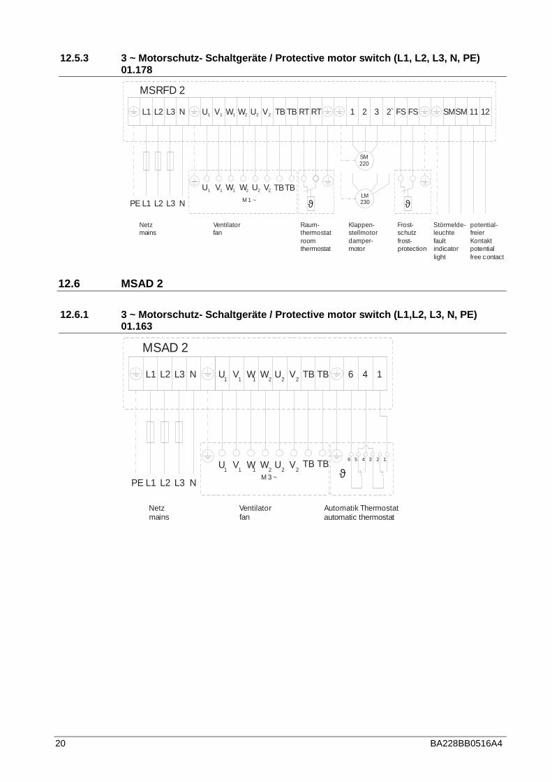
12.5.3 3 ~ Motorschutz- Schaltgeräte / Protective mo tor switch (L1, L2, L3, N, PE) 01.178
U V W W U V
U V W W U V
L1 L2 L3 N
L1 L2 L3 NPE
TB
TB
TB RT FS FS SMSM 11 12RT 1 2 3 2`
TBM 1 ~
Netzmains
Ventilatorfan
MSRFD 2
ϑ ϑ
Raum-thermostatroomthermostat
Klappen-stellmotordamper-motor
Frost-schutzfrost-protection
Störmelde-leuchtefaultindicatorlight
potential-freierKontaktpotentialfree contact
1 1 1 2 2 2
1 1 1 2 2 2
SM220
LM230
12.6 MSAD 2
12.6.1 3 ~ Motorschutz- Schaltgeräte / Protective mo tor switch (L1,L2, L3, N, PE) 01.163
L1 L2 L3 N
L1 L2 L3 NPE
U
U
V
V
W
W
W
W
U
U
V
V
TB
TB
TB 6 4 1
TBM 3 ~
Netzmains
Ventilatorfan
MSAD 2
1 1
1
1
1
2
2
2
2
2
21
6 5 4 3 2 1
Automatik Thermostatautomatic thermostat
ϑ

BA228BB0516A4 21
12.7 MSD 1 K, MSD 2 K, MSD 2 K-D
12.7.1 3 ~ Motorschutz- Schaltgeräte / Protective mo tor switch (L1,L2, L3, N, PE) 01.102b
L1 L2 L3 N
L1 L2 L3 NPE
TP
TP
TP
TP
Netzmains
MSD 1 K
U V W
U V WM 3 ~
1 Drehzahl / speed
Ventilatorfan
12.7.2 3 ~ Motorschutz- Schaltgeräte / Protective mo tor switch (L1,L2, L3, N, PE) 01.118b
L1 L2 L3 N
L1 L2 L3 NPE
TP
TP
TP
TP
Netzmains
MSD 2 K
U1 V1 W1 W2 U2 V2
U1 V1 W1 W2 U2 V2
M 3 ~
Ventilatorfan

22 BA228BB0516A4
12.7.3 3 ~ Motorschutz- Schaltgeräte / Protective mo tor switch (L1,L2, L3, N, PE) 01.351
L1 L2 L3 N
L1 L2 L3 N PE
1U 2U1V 2V1W 2W
1U 2U1V 2V1W 2W
TP
TP
TP
TP
MSD 2K - D
M 3 ~ 2 Drehzahl / speed / vitesses
Netz /mains
Ventilator /fan

BA228BB0516A4 23
13 Notizen / Note