Optical lattice clock - 国立情報学研究所 / National Institute of ......Photon counts (arb....
30
Optical lattice clock Tetsuya Ido (井戸 哲也) National Institute of Information and Communications Technology (NICT) 1
Transcript of Optical lattice clock - 国立情報学研究所 / National Institute of ......Photon counts (arb....

Optical lattice clock
Tetsuya Ido (井戸 哲也)National Institute of Information and Communications Technology (NICT)
1

Personal research background• Ph. D thesis in ’98 in Tokyo (Prof. Shimizu)
– Dynamics of cite‐hopping processes of cold atoms in optical lattices
• Post doc. in Gonokami JST‐ERATO project (98.4‐02.9)– Cold Sr experiment from scratch with Katori
• Post doc. In Jun Ye’s group in JILA (’02.10‐’06.6)– Built a Sr system, learn lots for precision spectroscopy
• JST‐PRESTO (’05.10‐’09.03)– HHG of NIR pulses to obtain coherent VUV pulses for a state‐detection of Al+ or In+ ions (ongoing zt NICT)
• NICT Space‐Time Standards section (’06.10 – ’12.10 )– Sr lattice clock, fiber‐transfer
(Temporarily (?) at Strategic Planning Section )2
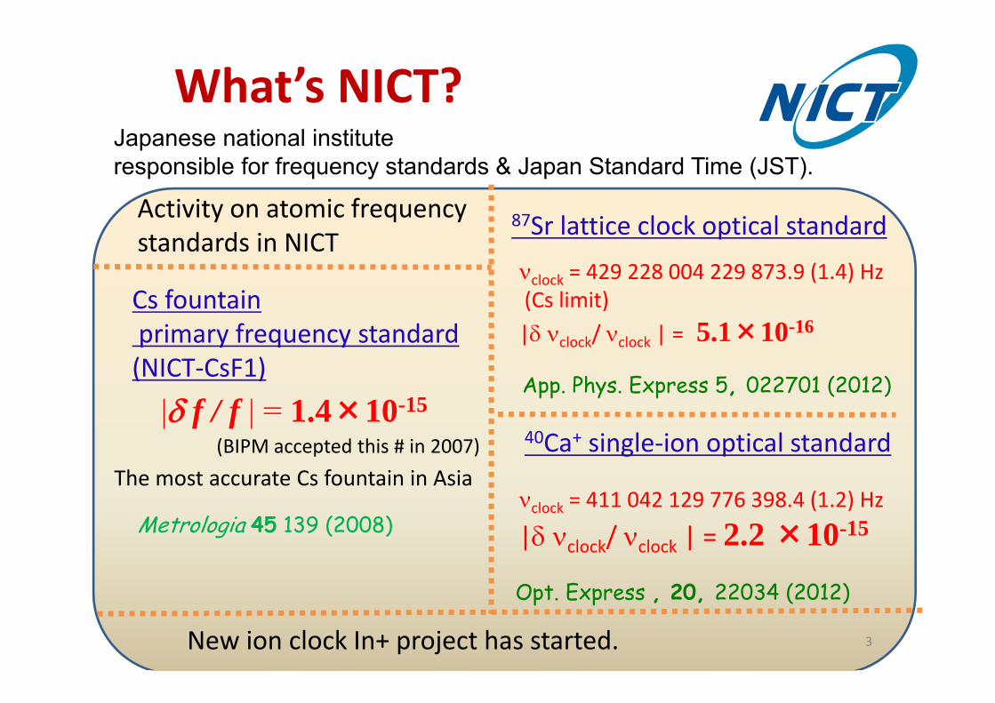
What’s NICT?Japanese national instituteresponsible for frequency standards & Japan Standard Time (JST).
40Ca+ single‐ion optical standard
clock = 411 042 129 776 398.4 (1.2) Hz
| clock/ clock | = 2.2 ×10⁻¹⁵
Opt. Express , 20, 22034 (2012)
Cs fountainprimary frequency standard(NICT‐CsF1)
|f / f | = 1.4×10⁻¹⁵
The most accurate Cs fountain in Asia
New ion clock In+ project has started.
Activity on atomic frequency standards in NICT
(BIPM accepted this # in 2007)
Metrologia 45 139 (2008)
87Sr lattice clock optical standard
clock = 429 228 004 229 873.9 (1.4) Hz (Cs limit)| clock/ clock | = 5.1×10⁻¹⁶
App. Phys. Express 5, 022701 (2012)
3

MeasurementEvaluation of the nature quantitatively
Result of the measurement (Normally expressed as a number)
=Value to be measured
Standard
Uncertainty of measurement
=
In case ofoptical frequency, … <10‐19 (frequency comb) ~10‐17 (Al+, Yb+, Sr)
Invention of frequency combs has reduced 1st term in early 2000s.Then, second term needs to be improved. → lattice clock & QIP clock proposed in 2001
by Wineland
Measurement consists of (i) ratio measurement and (ii) preparation of standards.
QIP: Quantum Information Processing 4

Are we ready to redefine the SI second ?
No.Requirement
• Saturation of the progress in optical clocks• Method to confirm the agreement of frequencies all over the world
GPS
VLBI
QZSS
Atomic clockAtomic clock
Communicationsatellites
Ordinary time transfer using satellites
Currently 10‐15 level
Uncertainty and stabilityincompatible with superb characteristics of optical standards
5

Detector
Feedback SystemLocks Oscillator to atomic resonance
a
Optical Clock Components
Clock Oscillator
High-Q resonatorLaser linewidth < 1 Hz
Laser
Atoms
Coherent Optical pulses out
Microwave pulses out456 986 240 494 158
Optical Freq. SynthesizerDivider
Counter
1) Highly stable lasers
2) Precision atomic spectroscopy
3) Ultrafast optical frequency comb (Clockwork)
Diddams et al., Science 293, 825 (2001).Ye et al, Phys. Rev. Lett. 87, 270801 (2001).
6

Before the lattice clock
neutral atomENSEMBLE of atoms
in free space
Residual Doppler shiftsDoppler-free spectroscopySaturated-absorption;Ramsey
better S/N ~ (Natom)1/2
atom-atom interactions-cold-collision shifts
trapped ionSINGLE ion
in Lamb-Dicke regime
Sideband cooling enablesLamb-Dicke regime
Recoil & Doppler free spectrum
High line-Q (long int~1/)Shot noise; Nion=1
trapping EM field→micromotion
, ( )REx
Laser cooling&
Spectroscopy
Precision1( / ) ; /Q S N Q
Uncertainties&
Improvements7

Single Trapped Ion(Accuracy)
• Tight Confinement– No Doppler– Long Interrogation Times
• No Collisions
NT
NSQcyclenoise
111
0
Free Neutral Atoms(Stability)
• Many Quantum Absorbers– Large N
Merge together !!Tight confinement of neutral atomsw/o perturbation to clock frequency
What lattice clocks aimed: equivalently lots of ion clocks at once
8

The Lamb‐Dicke regime
• Optical dipole potential for 1S0, 3P1 states• ; resolved sideband•Recoil frequency << • ; elastic scattering of photons
kHz1.72
nPnS ,, 13
01
Couplingby FORT laser
1S0
Singlet states
3P0, 1, 2
Triplet states
Spectroscopy
F
F
: vibrational frequency
Definition:Spatial confinement << transition wavelength
9

Optical dipole trapfor alkaline earth atoms
5s5p
5p2 3P0,1,2
5s2 1S0
5s5p 1P1 5s6s 3S1
2nd coolingR=689nm
1st coolingB =460nm
5s5p 1D2
3P0 3P2
5s4d 3D1,2,3
5s5d3D1,2,3
cooling transition
Clock transition
F
F3P1
688nm 2.9um
•Electronic states coupled to those with same spin.•3P1 has resonance at 688nm and 2.9um
Key points
Far‐off resonant Optical trap(FORT)
10

D. Wineland and W. Itano, “Laser cooling of atoms”Phys. Rev. A, 20, 1521 (1979)
atomic (true) resonancex: vibration frequency of confinmentR: photon recoil energy
2
Spectrum of free atoms with velocity distribution
Center shifts one recoil frequency from true resonance frequency
Confinements allows us to know where the resonance is.
Absorption(from |g>)
Emission(from |e>)
11

-200 -100 0 100 200
0
5
10
15
Pho
ton
coun
ts (a
rb. u
nits
)
Probe-laser frequency (kHz)
1/e full width 100kHz
X10
Suppression of photon‐recoil shift in Lamb‐Dicke regime
2/ / 2 5kHzRE h hk m
2abs 0 / ( )Rk v E O v
free space
1 0/ 1I I Lamb-Dicke regime:abs 0 n confined space: -60 -40 -20 0 20 40
0.2
0.4
0.6
0.8
1.0
1.2
1.4
1.6
1.8
2.0
Sca
ttere
d ph
oton
cou
nts
Probe laser frequency (kHz)
FWHM: 10.86kHz
Doppler shift
Recoil shift
T. Ido and H. Katori, PRL 91 053001 (2003).12

429 228 004 229 873.9 (1.4) Hz (Cs limit)[1] G. K. Campbell, et al., Metrologia 45, 539 (2008).[2] X. Baillard, et al., EPJD 48, 11 (2008).[3] F. L. Hong, et al., Opt. Lett. 34, 692 (2009).[4] St. Falke, et al., Metrologia, 48 399(2011)[5] A. Yamaguchi, et al., Appl. Phys. Express 5 022701 (2012)
Absolute frequency measured in NICT
13
[1] [2] [3] [4] [5]
Japanese Sr large uncertainty?
No. Basically due to the lack of stable Cs fountain clocks in Japan.Both Japanese clocks rely on International Atomic Time

Goal:Confirmation of same frequency in ~10-16 between the clocks locatedat NICT and the Univ. of Tokyo by a fiber-link
Tokyo is the only area that has two optical lattice clocks in distant laboratories.
14

Fiber link of clocks located at NICT and UT
Our link
[1] M. Kumagai et al., Opt. Let. 34, 19, 2949 (2009). [2] M. Musha et al., Opt. Exp. 16, 21, 16459 (2008).[3] N. Newbury et al., Opt. Let. 32, 21, 3056 (2007).[4] H. Jiang et al., J. Opt. Soc. Am. B 25,12,2029 (2008).[5] G. Grosche et al., Opt. Lett. 34, 2270 (2009).
[1] [2] [3] [4] [5]
Google map
Tokyo Bay60-km–long fiber
Urban Fiber link in Tokyo
Phase noise per km Otemachi
Probably due to(1) Almost half of the link is buried
along a subway line(2) About one third of the link
is wired in the air
Much larger amount of phase noise
Almost of the link noise comes from NICT‐Otemachi part
15
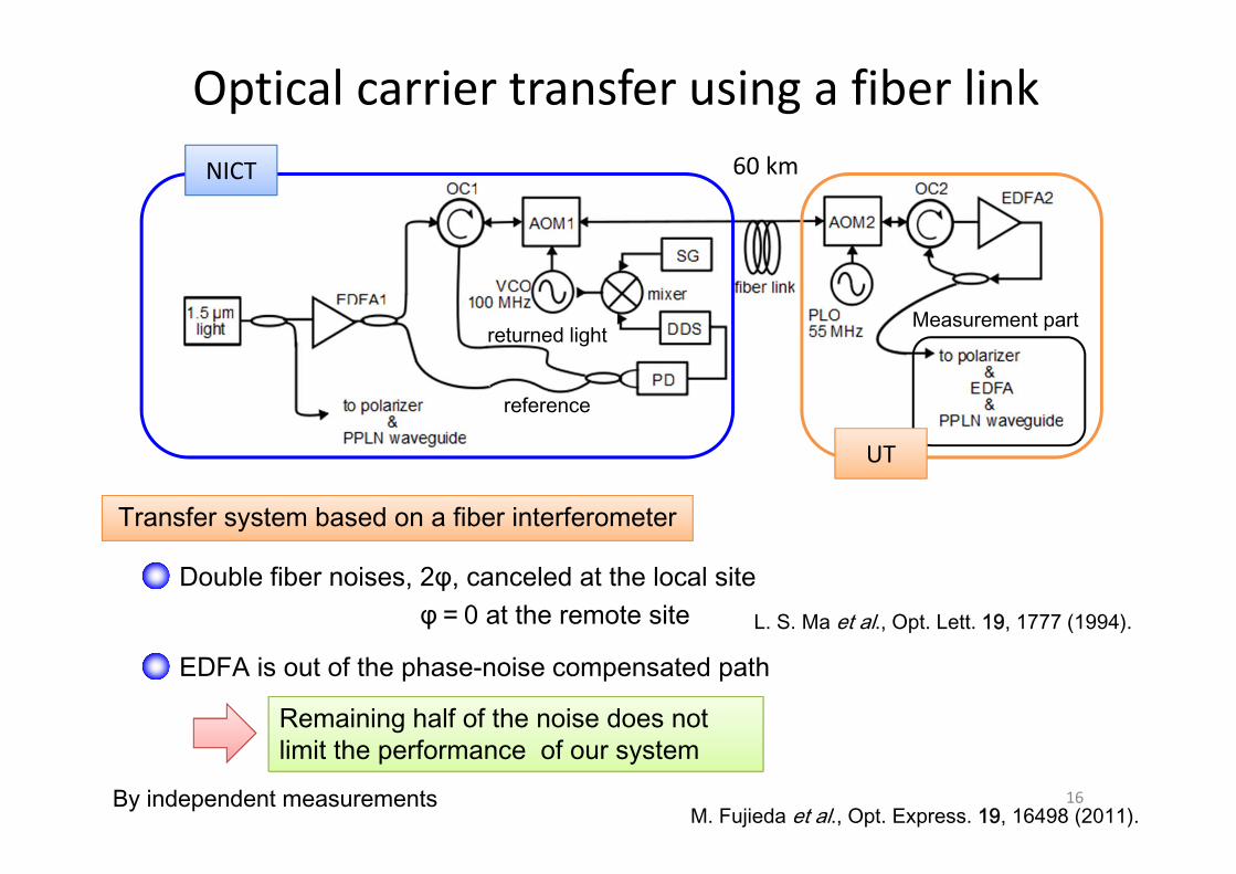
Double fiber noises, 2φ, canceled at the local siteφ=0 at the remote site
Optical carrier transfer using a fiber link60 kmNICT
L. S. Ma et al., Opt. Lett. 19, 1777 (1994).
Remaining half of the noise does not limit the performance of our system
By independent measurements
EDFA is out of the phase-noise compensated path
Transfer system based on a fiber interferometer
M. Fujieda et al., Opt. Express. 19, 16498 (2011).
UT
Measurement part
reference
returned light
16
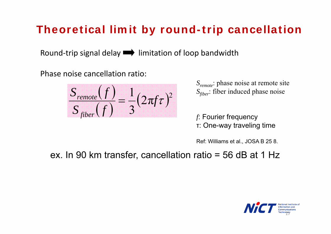
Theoretical limit by round-trip cancellation
Round‐trip signal delay limitation of loop bandwidth
Phase noise cancellation ratio:
2π2
31 f
fSfS
fiber
remote Sremote: phase noise at remote siteSfiber: fiber induced phase noise
f: Fourier frequencyτ: One-way traveling time
Ref: Williams et al., JOSA B 25 8.
ex. In 90 km transfer, cancellation ratio = 56 dB at 1 Hz
17

10-2
100
102
104
106
10-1 100 101 102 103
Sφ
[dB
c/H
z]
Fourier frequency [Hz]
Evaluation of the fiber link
NICTKoganei UTOtemachi45 km
15 dB loss15 km15 dB
Total length: 90 km, optical loss: 30 dB
Unstabilized
Stabilized
56 d
B
18

10-18
10-17
10-16
10-15
10-14
10-13
10-12
100 101 102 103 104
Alla
n de
viat
ion
Averaging time [s]
15h - 18h
Unstabilized
Stabilized
by 53131A (Λ)
by K+K (Π)
10-18
10-17
10-16
10-15
10-14
10-13
10-12
100 101 102 103 104
Alla
n de
viat
ion
Averaging time [s]
25h - 28h
Unstabilized
Stabilized
by K+K (Π)
by 53131A (Λ)
Typical optical lattice clock
Should be donein midnight in current circumstances
Overall system instability: 2×10-15 at 1s7×10-17 at 1000s
Including: ・EDFA・waveguide PPLN・frequency comb
Instability of a fiber link: Day & NightTransfer instability of out‐of‐loop beat
in NICT‐Otemachi round‐trip link
1:00am‐3:00am3:00pm‐5:00pm
Otemachi45 km 15 km
Dominant phase noise
10-18
103
19

Google map
NICT
UT (Hongo)
45 km12 km
Air part
Otemachi
Beat measurement
769 nm 698 nm
87Sr698 nm
56 m
NICT
UT
87Sr
24 km×2
Optical Carrier transfer
769 nm
1538 nm laser
×257km
All‐optical direct comparison between NICT & UT clock
20

NIC
T-
UT
(Hz)
Frequency difference & stability between distant Sr clocks
Dick-effect-limited instability
UT : /100.6 15
NICT : /105.1 14
Obtained instability/106.1 14
Offset: predominantly due to differential gravity shift
A Hz-level frequency difference is clearly visible over the time scale of minutes
5×10-16consistent
21

UT (Hz) NICT (Hz)contributor Correction Uncertainty Correction Uncertainty
AC Stark –Lattice 0.19 0.10 0.10 0.10AC Stark -Probe 0.00 0.00 0.01 0.01BBR 2.17 0.10 2.26 0.102nd Zeeman 1.24 0.10 0.23 0.10Gravitational shift -0.95 0.09 -3.57 0.05Collision 0.00 0.10 -0.04 0.12Servo error 0.00 0.01 0.00 0.01Total 2.65 0.22 -1.01 0.22
Corrections and uncertainties at UT and NICT
Elevation of a lattice clock from Earth’s geoid surface
56 m
Musashino-highland
UT: 20.37 ± 2 mNICT: 76.33 ± 1 m
Systematic shift ofFrequency difference
NICT ー UT = 3.66 (0.31)Hz
(0.78)(Link uncertainty to SI second)
22

<
Total systematic uncertaintyof two clocks (0.31Hz)
Frequency difference between two distant Sr clocks
No limitation imposed by the fiber transfer
Agreement between institutes for the 1st time in 10-16 level !
Frequency difference after correcting systematic frequency shift
Measurement records in the range of 900-12000s
(Solid black line in figure) (dashed lines in figure)
Total systematic uncertainty0.31Hz (7.3×10‐16)
Weighted mean0.04Hz (1.0×10‐16)
23

Atomic clocks: tools to measure gravity ?
Only for accurate measurement of Gravity force,gravimeter is very accurate. The state‐of‐the‐art uncertainty is 1×10‐9.
But only shows spatial gradient of the potential .
Clocks directly observe the potential.
Gravitational potential:Just a concept in classical mechanics.But accurate clocks changes it to a real object of observation.
24
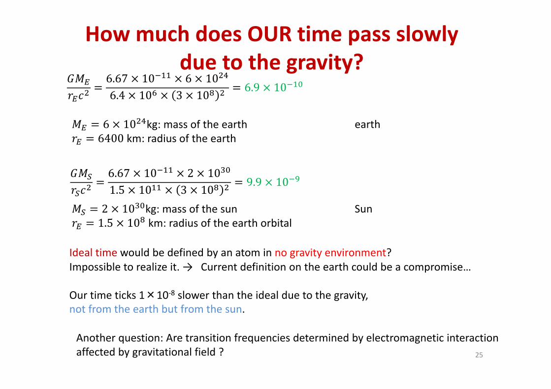
6.67 10 6 106.4 10 3 10 6.9 10
6 10 kg: mass of the earth6400 km: radius of the earth
6.67 10 2 101.5 10 3 10 9.9 10
2 10 kg: mass of the sun1.5 10 km: radius of the earth orbital
Ideal time would be defined by an atom in no gravity environment? Impossible to realize it. → Current definition on the earth could be a compromise…
Our time ticks 1×10‐8 slower than the ideal due to the gravity, not from the earth but from the sun.
Another question: Are transition frequencies determined by electromagnetic interaction affected by gravitational field ?
How much does OUR time pass slowly due to the gravity?
earth
Sun
25

R. Le Targat et al., arxiv:1301.6046
Atomic clocks show that space and time is not independent (general relativity)
And… may show that transition frequency is affected by gravity thorough a coupling of to gravity. Gravity & EM force coupled → info to know correlation between gravity & othersComparing transition frequency in summer and winter?Snow can be kept until next summer. But frequency cannot.
All we can do is to make absolute frequency measurement in summer and winter…
If is coupled to the gravity, f(Sr)/f(Cs) may show annual oscillations.
The ratio between two optical transitions should be more sensitive to detect the coupling.
AIST will join soon. The largest community !!26

27
All optical measurement of frequency ratios : That’s the measurements based on optical standard
698 nm laserstabilized by Sr lattice
Ti:S Comb
Frequency comb stabilization
729 nm laserstabilized by Ca+
measurement PLLfbf
Sufficient for evaluation at the level of 10-16
2 1 2 12
1
1 / /ceo PLL bCa
Sr Sr
N N f N N f fNN
(~107 Hz)
(~1014 Hz)~1 ~10-7
, , : 10-10 fractional accuracyPLLfCEOf bf
Sr
Ca
Frequency ratio
Frequency bridge by optical frequency comb

28
Stability and Frequency Ratio
Reproducibility of <10-15 is consistent with the systematic uncertainties of two clocks
= 0.957 631 202 358 049 9 (2 3)Sr
Ca
Frequency ratio
100 101 102 103 10410-16
10-15
Alla
n s
tanda
rd d
evi
atio
n
Averaging Time (sec)
Ca+-Sr Sr interleaved meas.
/101 14
/104.2 14
Instability at the ratio measurement
55840 55860 55880 56060 56080 56100
-3
-2
-1
0
1
2
3
C
a/S
r-0.9
5763
1202
3580
50 (X
10-1
5 )Modified Julian Date
Total uncertainty
Ratios measured at each of 6 days
K. Matsubara et al., Opt. Express, 20 22034 (2012).

Sr and Ca+ : bridge between the most majorlattice clocks & ion clocks
Sr: 5 in operation and others will soon followCa+: 3 in operation
Locally availableat U. Tokyo and SYRTE
QIP ion clockAl+: spectroscopyCa+: logic (& spectroscopy)
1. test of the ‐variation using a sensitive neutral Hg clock & insensitive Al+ clock
2. Ca+ as a logic ion also works as a meter to probe the electromagnetic environment of the trap center. → Need the frequency as accurate as possible
Ca+ clock will not be an ultimate. But still there is reason for an accurate characterization.
29

Summary
Optical clocks will redefine the second after• progress is slowed• method to confirm the identical frequency across the sea is established
Lattice clocks• Lots of ion clocks equivalent• Sr: the most popular second representation of the second• Yb: NIST & AIST→ lately recognized as a second representation
Ratio, ratio, ratio
measurement = evaluation of a ratio against a standard
NICT‐UT link, variation, gravity coupling, Ca+/Sr ratio, …
Absolute frequency based on Cs is no longer absolute at the ultimate of metrology. Ratio, in other words relative things are what we can trust.
30