PfDProf. Dr.-IKlIng. Klau s DMüllD. Müller-Glaser 25.3
55
Kompetenzbereichssympo „Model-Driven Engineerin P fD I Kl Prof. Dr.-Ing. Klau 25.3 osium Systeme und Prozesse ng for Automotive Systems“ D Müll Gl us D. Müller-Glaser 3.2010 Copyright © 2010 FZI Karlsruhe kmg
Transcript of PfDProf. Dr.-IKlIng. Klau s DMüllD. Müller-Glaser 25.3

Kompetenzbereichssympop y p„Model-Driven Engineerin
P f D I KlProf. Dr.-Ing. Klau25.3
osium Systeme und Prozesseyng for Automotive Systems“
D Müll Glus D. Müller-Glaser3.2010
Copyright © 2010 FZI Karlsruhe kmg

ITIV Einordnung des Ing
Universität Kar
11 Fakultäten
Fakultät für Elektrotechnik un
13 Institute
Institut für TeInformationsverar
nstituts
rlsruhe (TH)
ca.19800 Studenten
nd Informationstechnik
ca. 1850 Studenten
chnik der beitung (ITIV)
Copyright © 2010 FZI Karlsruhe kmg
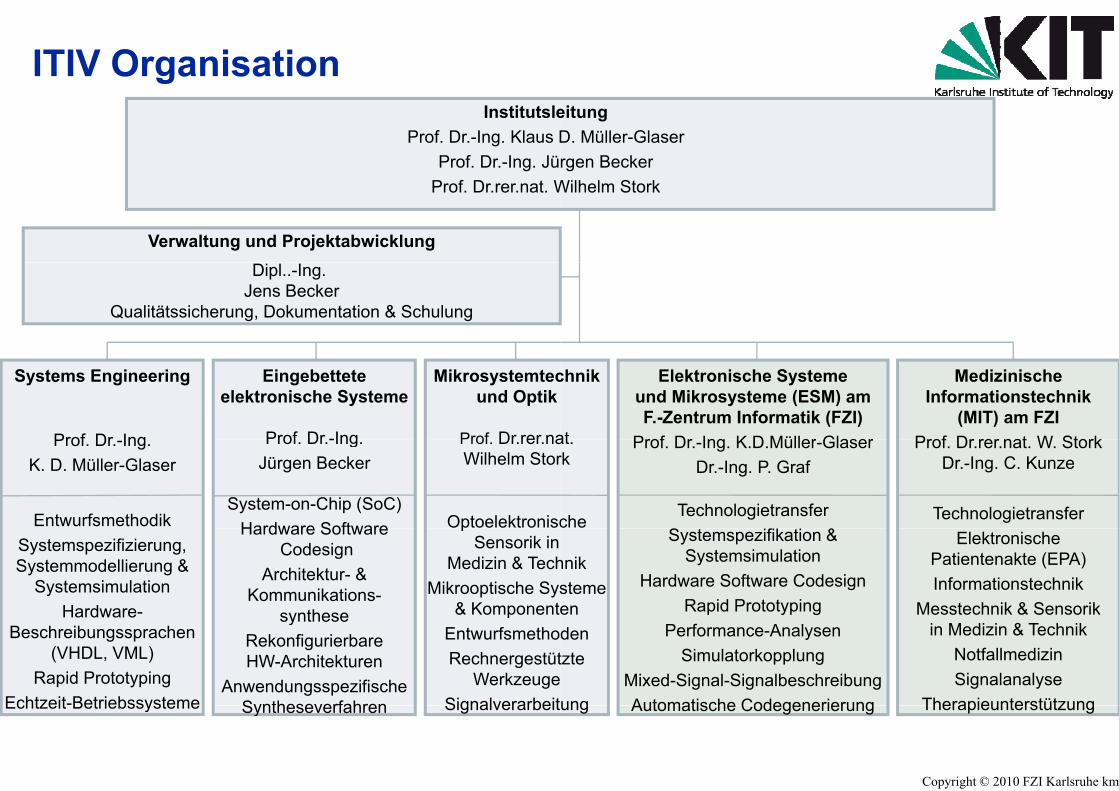
ITIV OrganisationInstitutsle
Prof. Dr.-Ing. Klaus DProf. Dr.-Ing. Jü
Prof. Dr.rer.nat. W
Verwaltung und ProjektabwicklungDipl..-Ing.
Jens BeckerQualitätssicherung, Dokumentation & Schulung
Systems Engineering
Prof Dr Ing
Eingebetteteelektronische Systeme
Prof Dr -Ing
Mikrosystemtecund Optik
Prof Dr rer naProf. Dr.-Ing.K. D. Müller-Glaser
Entwurfsmethodik
Prof. Dr.-Ing.Jürgen Becker
System-on-Chip (SoC)Hardware Software
Prof. Dr.rer.naWilhelm Stor
OptoelektroniscSystemspezifizierung,Systemmodellierung &
SystemsimulationHardware-
Hardware SoftwareCodesign
Architektur- & Kommunikations-
synthese
pSensorik in
Medizin & TechMikrooptische Sys
& KomponentHardwareBeschreibungssprachen
(VHDL, VML)Rapid Prototyping
Echtzeit-Betriebssysteme
syntheseRekonfigurierbareHW-Architekturen
AnwendungsspezifischeSyntheseverfahren
pEntwurfsmethoRechnergestüt
WerkzeugeSignalverarbeitEchtzeit Betriebssysteme Syntheseverfahren Signalverarbeit
eitungD. Müller-Glaserrgen Becker
Wilhelm Stork
chnik
at
Elektronische Systemeund Mikrosysteme (ESM) am F.-Zentrum Informatik (FZI)
Prof Dr Ing K D Müller Glaser
MedizinischeInformationstechnik
(MIT) am FZIProf Dr rer nat W Storkat.
rk
che
Prof. Dr.-Ing. K.D.Müller-GlaserDr.-Ing. P. Graf
TechnologietransferS f &
Prof. Dr.rer.nat. W. StorkDr.-Ing. C. Kunze
Technologietransfer
hnikstemeen
Systemspezifikation &Systemsimulation
Hardware Software CodesignRapid Prototyping
ElektronischePatientenakte (EPA)Informationstechnik
Messtechnik & Sensorikdentzte
ung
Performance-AnalysenSimulatorkopplung
Mixed-Signal-SignalbeschreibungAutomatische Codegenerierung
in Medizin & TechnikNotfallmedizinSignalanalyse
Therapieunterstützung
Copyright © 2010 FZI Karlsruhe kmg
ung Automatische Codegenerierung Therapieunterstützung

KIT Innovation
Ihr ForschungsdienstleiIhr ForschungsdienstleiTechnologieberater –
FZIFZIForschungszentruForschungszentruForschungszentruForschungszentruInformatikInformatikan der Universität Karlsruhean der Universität Karlsruhe
Forschungsbereich ESS: Embedded Systems a
ister undister und
umumumum
and Sensors Engineering
Copyright © 2010 FZI Karlsruhe kmg

Das�FZI:Informatik�&�ihre�Anwendun
� Das industrienahe Informatik-Forsdes Landes Baden-Württembergg
� Mittelständischer Forschungsdiens
� Gemeinnützige Stiftung bürgerlich
� ca. 130 Wissenschaftlerinnen und Wissenschaftler
� über 150 Projekte p. a.
� Enge Vernetzung mit der universit
ngen
schungsinstitut
stleister
en Rechts
ären Forschung
Copyright © 2010 FZI Karlsruhe kmg5

MitarbeiterInstitutsleitungWissenschaftliche MitarbVerwaltung, Technik, WeExterne LehrbeauftragteExterne LehrbeauftragteForschungsbereich ESSForschungsgruppe hipeg g pp p
Firmenausgründ
Mitarbeiter & StudenMitarbeiter & Studen
3beiter 32
erkstatt 14e 3e 3S 20r.campus 12pungen 5
nten des Instituts
Copyright © 2010 FZI Karlsruhe kmg
nten des Instituts

ITIV Arbeitsfelder Embedded SIdee
HW-Beschreibungs-sprachen
SW-Beschreibungs-sprachensprachen
Digital (VHDL) Analog (VHDL-AMS, MAST)
���������� ���������������
��������� ����������� ����� �!��� ���� �"�#���
$�%�&���� '�
sprachenUML, Statecharts (Statemate)
Blockdiagramme (Matlab SIMULI
$�%�&���� '��(��)�$*
�+��
Entwurfs-automatisierung Code Generierung
ZielarchitekturengLaufzeitmodellierungSyntheseverfahren
&
&
&
&
ZielarchitekturenCodegeneratoren
::
Idle
public class GActionTreeModelextends GUMLTreeModel{public GActionTreeModel(
super(theRootObject, theBridge);setSortTree(false);
} public class GActionTreeModelextends GUMLTreeModel{public GActionTreeModel(
super(theRootObject, theBridge);setSortTree(false);
RealisierungElektronische Systeme
& & Idle
Elektronische SystemeSystem on Chip (SoC)Mikrooptische SystemeIntelligente Sensoren
Prototypenentwicklung
TechnologietTelekommunikation –
Automatisierung – AuKooperationsprojekte un
Schulungen für Ind
Systems
SystementwurfSpezifikation Modellierung SimulationRad 1 Rad 1
ASR KontrolleASR Kontrolle
Spezifikation - Modellierung - SimulationRequirements Engineering
Echtzeitanforderungen
FreiFrei
BremsenBremsen
Rad 1 Rad 1Rad 1
Bremsen
Frei
Rad 2
Bremsen
Frei
,NK)
Rapid PrototypingHardwareplattformen
Codegenerierungg gEchtzeitbetriebssysteme
Konfigurierbare Schnittstellen
transfer– Medizintechniktomobilelektronikd Auftragsforschung
Copyright © 2010 FZI Karlsruhe kmg
dustriekunden
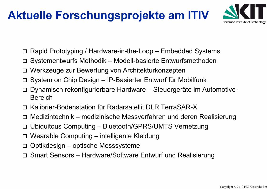
Aktuelle Forschungsprog p
� Rapid Prototyping / Hardware-in-the� Systementwurfs Methodik – Modell-� Systementwurfs Methodik Modell� Werkzeuge zur Bewertung von Arch� System on Chip Design – IP-Basier� Dynamisch rekonfigurierbare Hardw
BereichK lib i B d t ti fü R d t� Kalibrier-Bodenstation für Radarsat
� Medizintechnik – medizinische Mes� Ubiquitous Computing Bluetooth/G� Ubiquitous Computing – Bluetooth/G� Wearable Computing – intelligente � Optikdesign – optische Messsystem� Optikdesign optische Messsystem� Smart Sensors – Hardware/Softwar
ojekte am ITIVj
e-Loop – Embedded Systems-basierte Entwurfsmethodenbasierte Entwurfsmethodenhitekturkonzeptenrter Entwurf für Mobilfunkware – Steuergeräte im Automotive-
t llit DLR T SAR Xtellit DLR TerraSAR-Xssverfahren und deren RealisierungGPRS/UMTS VernetzungGPRS/UMTS VernetzungKleidung
memere Entwurf und Realisierung
Copyright © 2010 FZI Karlsruhe kmg
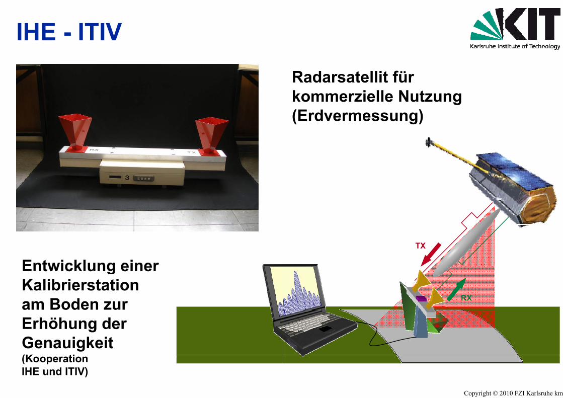
IHE - ITIV
Entwicklung einerEntwicklung einerKalibrierstationam Boden zurErhöhung derGenauigkeit(K ti(KooperationIHE und ITIV)
Radarsatellit fürkommerzielle Nutzung(Erdvermessung)
TX
RX
Copyright © 2010 FZI Karlsruhe kmg

TerraSAR – Hochfrequenz- uElektronikElektronik
DetectorDetector
InterconnectInterconnect
PMUPMU
DisplayDisplayp yp y
und Digital-
VCOVCO
Mixer UnitMixer Unit
VCOVCO
RxTx Module RxTx Module
RF-Temp.-SensorRF-Temp.-Sensor
ECUECUECU(ADC, FPGA, processor)
ECU(ADC, FPGA, processor)
KeyboardKeyboard
Copyright © 2010 FZI Karlsruhe kmg

Daimler Coop.: Body Functions On-Demand
Demo Application: Cabin FunctionsDemo Application: Cabin Functions
Seat Control(right)
R Vi
Seat Control(right)
R Vi
FPGA-based
Window Lifts(back)
Rear ViewMirror(right)
FPGA-based
Window Lifts(back)
Rear ViewMirror(right)
AutomotiveECU System
Rear ViewMirror(right)
Window Lifts(front)
AutomotiveECU System
Rear ViewMirror(right)
Window Lifts(front)
Seat Control(left)
(right)(front)
Seat Control(left)
(right)(front)
Daimler A
FPGA System
by Dynamic Reconfiguration
Analysis: Design Alternatives
- mC vs. FPGA vs. ASICG lGoals:-> Reduction of Architecture Variants
-> Easy Life-Cycle Updates
-> Complexity Reduction (Verification!)
FPGAs Xilinx VirtexXC2V3000
# Frames
AG:
m: I-Cell
per Slot
Copyright © 2010 FZI Karlsruhe kmg

SecuritySecurityProjektinhalte
Side Channel Security von Xilinx FSide Channel Security von Xilinx FSicheres Einbringen von kryptograSchlüsseln in elektronische SystemSchlüsseln in elektronische SystemTechnologie Monitoring
ZieleSichere Implementierung von SecuSichere Implementierung von SecuHW � Resistenz gegen Attacken üStromverbrauchsmessungen)g )Vollständige Absicherung sicherheSchlüssel) während des Betriebs uelektronischen Geräten.Auswahl möglicher HW Bausteine l A f dlow-power Anforderungen.
FPGAsFPGAsaphischenme (bspw ECU)me (bspw. ECU)
urityapplikationen auf rekonfigurierbarerurityapplikationen auf rekonfigurierbarerüber Seitenkanäle (z.B.
itskritischer Elemente (geheime und der Initialisierung von
zur Erfüllung sicherheitsrelevanter und
Copyright © 2010 FZI Karlsruhe kmg
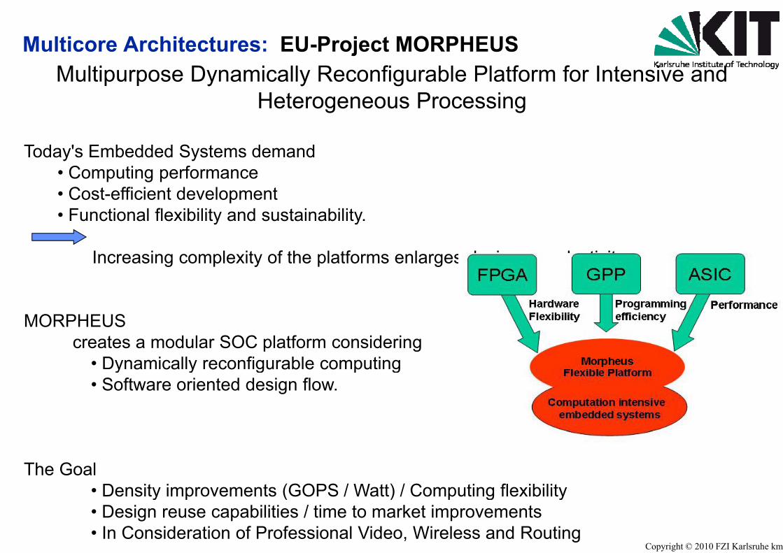
Multicore Architectures: EU-ProjectMultipurpose Dynamically Reconfi
Heterogeneou
Today's Embedded Systems demand• Computing performance• Cost-efficient development• Functional flexibility and sustainability.
Increasing complexity of the platforms
MORPHEUScreates a modular SOC platform conside
• Dynamically reconfigurable computiny a ca y eco gu ab e co pu• Software oriented design flow.
The Goal• Density improvements (GOPS / Watt)Density improvements (GOPS / Watt)• Design reuse capabilities / time to ma• In Consideration of Professional Vide
MORPHEUSgurable Platform for Intensive and us Processing
enlarges design - productivity gap
ringgg
) / Computing flexibility
Copyright © 2010 FZI Karlsruhe kmg
) / Computing flexibilityarket improvements eo, Wireless and Routing
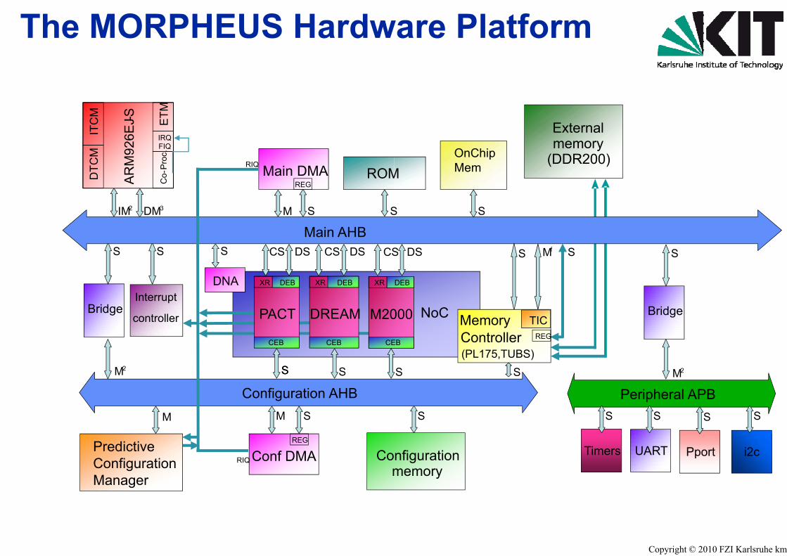
The MORPHEUS Hardw
J-SCM
ETM
J-SCM
ETM
Main DMAREGA
RM
926E
J
ITC
DTC
M
EC
o-P
roc.
IRQFIQ
AR
M92
6EJ
ITC
DTC
M
EC
o-P
roc.
IRQFIQ
RIQROM
S
2IM DM3 S
REG
S
Main AHBM
S
DNA
CS
M20
XR
PACTBridge
S DSCS
Interrupt
S
DREAM
XR DEB
DSCS
XR DEB
M20
CE
PACTBridge
M2 S
controller DREAM
CEB
SS
CEB
M S
M
Configuration AHBS
SS
M
Com
Conf DMAREG
RIQPredictiveConfigurationManager
ware Platform
Externalmemory
(DDR200)M
OnChipMem
SS
N C
DSS
000
DEB
S Mf S
Bridge
S
NoC
S
000
EB
S
MemoryController(PL175,TUBS)
TICREG
Bridge
M2S
S
S
S M2
Peripheral APBS S S S
nfigurationmemory
Timers UART Pport i2c
Copyright © 2010 FZI Karlsruhe kmg
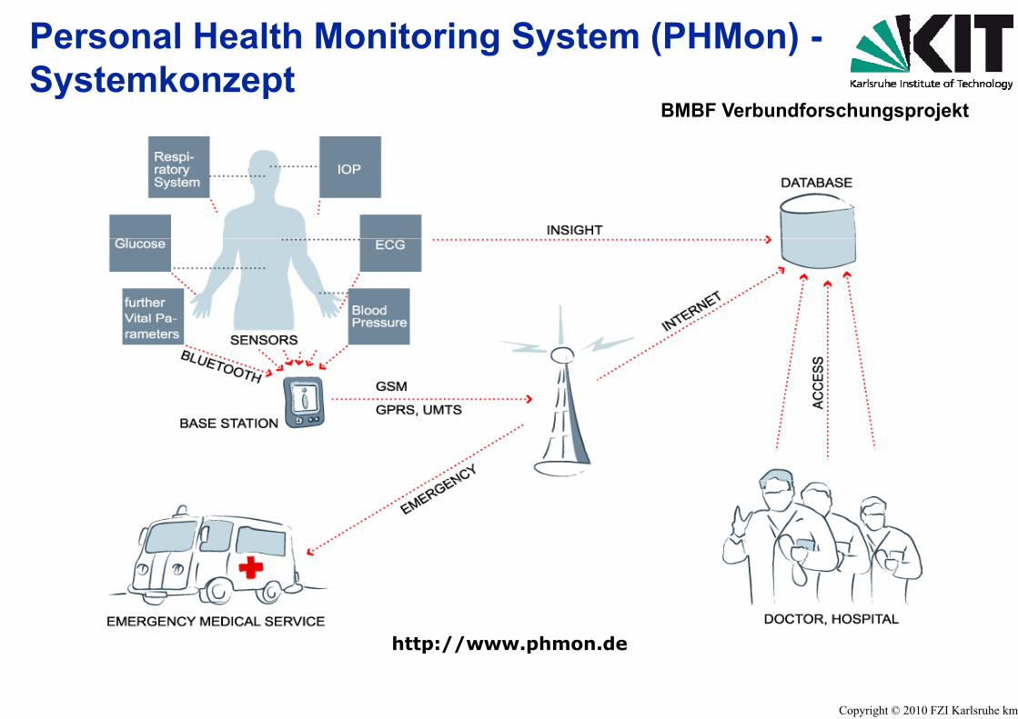
Personal Health MonitoringSystemkonzeptSystemkonzept
http://wwwhttp://www
System (PHMon) -
BMBF Verbundforschungsprojekt
w phmon de
Copyright © 2010 FZI Karlsruhe kmg
w.phmon.de

Anwendungsfeld
Methoden und rechnergfür den Entwurf von vertSystemen im Automobil
gestützte Werkzeugeteilten Elektrik/Elektronik-
Copyright © 2010 FZI Karlsruhe kmg

General structure of an elec
ator
s
optical
mechanicalA
ctua
ent
oad
Re
mechanical
thermal
electricalnviro
nme
, driv
er, r
o
terf
aces
electrical
magnetic
ors
En car,
Spec
ial i
nt
Sens
o S
ctronic control unit
Power electronics
trol
Analogsignal
processing
Micro ControllerDSP
eal Time Operating System Supp
ly
stem
Con
t
Pow
erSys
DigitalSignal
Processing
Communication with other Systemsother Systems
Copyright © 2010 FZI Karlsruhe kmgBenz

Embedded systems in yRelatively high production volumes (5.0High number of variants (countries, cusReusabilityL t il bilit 15Long term availability: > 15 yearstough operating conditions
� Temperature range: -40� Temperature range: -40� Supply voltage: 6V … 14V … 28V � Mechanical stress: acceleration, vibratio� Chemical stress: humidity, oil, exhaust g� Electromagnetic compatibility
High reliability: << 1ppm/hHigh reliability: << 1ppm/hPerformance, Reliability, Safety, SecurityEnergy Consumption (5% of fuel for EEEnergy Consumption (5% of fuel for EEDiagnosis and Maintainability (Service,
a car000 – 1.000.000)stomers),
s
0°C +125°C +175°C0 C … +125 C … +175 C… (42V)
ongases, road salt …
h Failure rateh Failure ratey, Costs, Weight, 3D shape and volumeE-Systems)E Systems), Updates, Lifelong-Guaranty)
Copyright © 2010 FZI Karlsruhe kmg

Hierarchical OrganizatioProcessesProcesses
Car programrequirementsq
Emmission lawsStrategic
requirements Specification and De
SystemSpecification
SystemSimulation
Development ofHW /SW
Specification
PrototypeDevelopme
MechatronicVehicleS t p
HWDesign
HWSimulation
PrototypeAssembly
System
ElectronicControl Design Simulation AssemblyControlUnit (HW)
E b dd d AutocodePrototyping
SWCoding
Development ofControl Algorithms
and OnboardDiagnostics10s + 10
s+5+-+
EmbeddedRealtimeSoftware
Multiple interleaving
Concurrent Engineering distribuConcurrent Engineering distribu
Requires comprehensive strictly controlled design methodology s
on of Design
sign Manufacturing Service
eent
CalibrationVehicle
Validation
Release toManufacturing Manufacturing
FunctionalTest Service
ey
DesignVerification
Release toManufacturing Manufacturing
FunctionalTesty Verification Manufacturing Manufacturing Test
void main(){...}void initialization(){...}static void control (input, states, output){...}
Static andDynamic Test
g design processes
uted between OEM and supplier
Copyright © 2010 FZI Karlsruhe kmg
uted between OEM and supplier
life cycle model (V-Model)supporting computer aided design tools
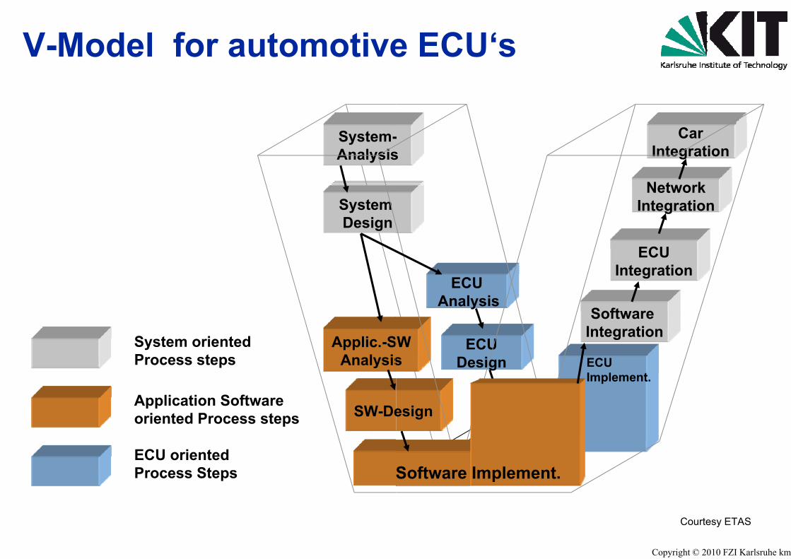
V-Model for automotive
System-Analysis
SystemDesign
System oriented Process steps
Applic.-SAnalysis
Application Softwareoriented Process steps SW-De
ECU orientedProcess Steps
e ECU‘s
-s
CarIntegration
NetworkNetworkIntegration
ECU
ECUAnalysis
ECUIntegration
Soft are
SWs
ECUDesign ECU
I l t
SoftwareIntegration
esign
Implement.
Software Implement.
Copyright © 2010 FZI Karlsruhe kmg
Courtesy ETAS
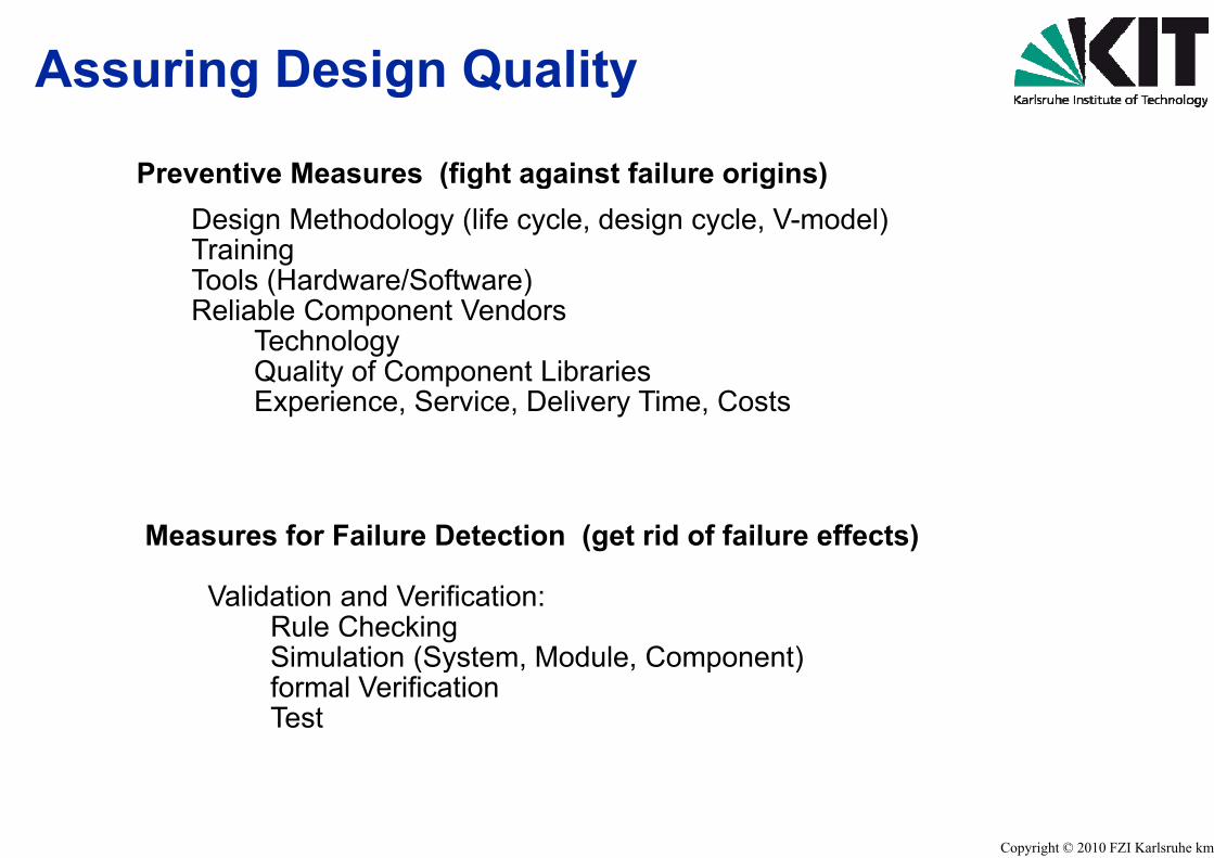
Assuring Design Qualitg g
Preventive Measures (fight agains( g gDesign Methodology (life cycle, dTraining Tools (Hardware/Software)Tools (Hardware/Software)Reliable Component Vendors
Technology Quality of Component LibrarQuality of Component LibrarExperience, Service, Delive
Measures for Failure Detection (g
Validation and Verification: Rule Checking Simulation (System, Modu( y ,formal Verification Test
tyy
st failure origins)g )design cycle, V-model)
riesriesry Time, Costs
et rid of failure effects)
le, Component), p )
Copyright © 2010 FZI Karlsruhe kmg

Verification and Validation in S
Verification1. The process of determining, whether th
development cycle fulfils the requirem“Am I building the product right”g p g
2. The act of reviewing, inspecting, testinotherwise establishing and documentidocuments conform to specified requir
3. Formal proof of correctness4. In systems engineering a generalized t
• test (using precision instrumentatio( g p• demonstration (a functional test)• analysis ( or simulation) or• examination (or documentation)examination (or documentation)
ValidationDetermination of the correctness of the fiDetermination of the correctness of the fi
development project with respect to th“Am I building the right product?”
Systems Engineering
he product of a given phase of the system ents established during the previous phase.
ng, checking, auditing, comparing or ng whether items, processes, services or rements
term that can mean: on))
nal system (SW HW) produced from anal system (SW, HW) produced from ahe user’s needs and requirements
Copyright © 2010 FZI Karlsruhe kmg

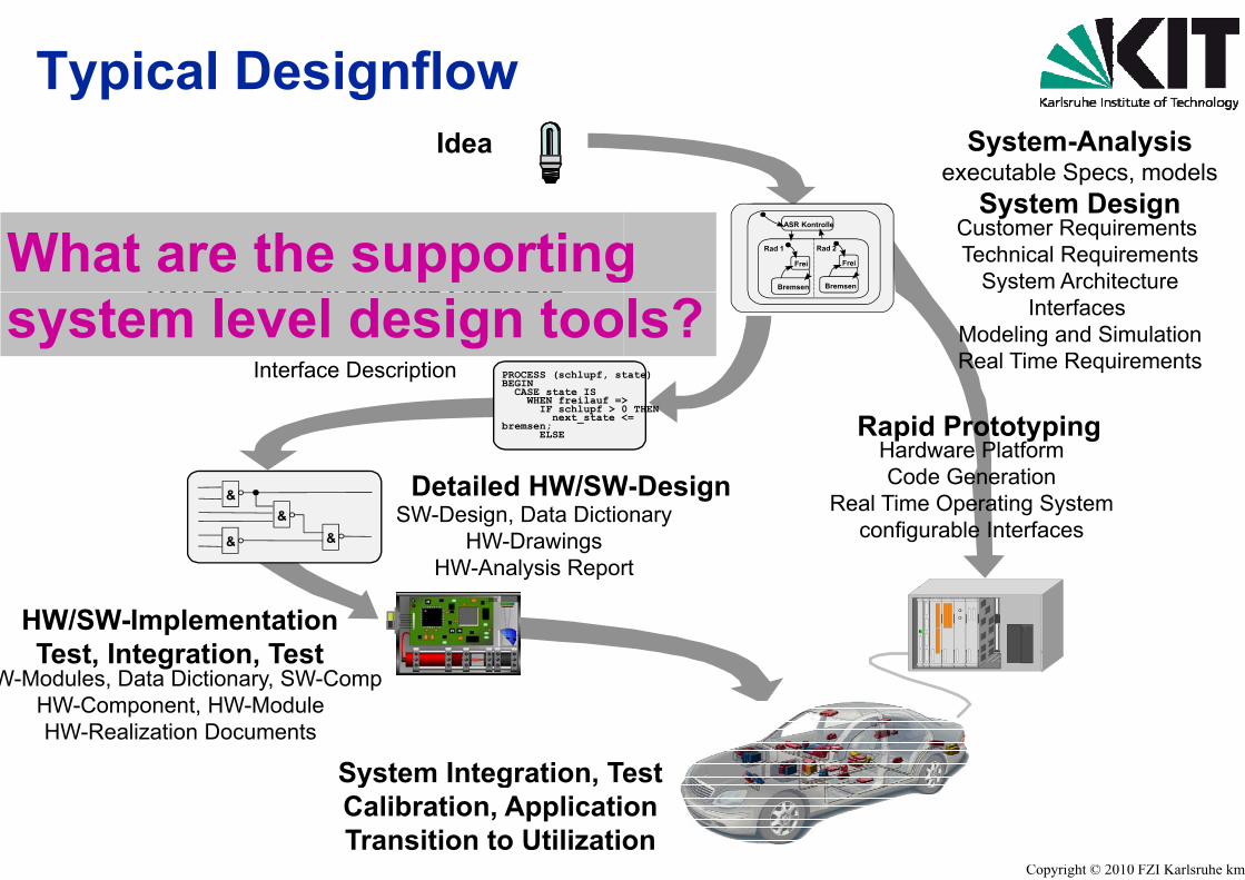
Typical Designflowyp gIdea
HW/SW-Requirements Analysis
PROCESS (schlupf, stBEGIN
CASE state IS
HW/SW Requirements AnalysisPreliminary HW/SW-Design
HW-Architecture, SW-ArchitectureInterface Description
Detailed HW/SW
CASE state ISWHEN freilauf =>
IF schlupf > 0next_state <
bremsen;ELSE
&
&
&&
Detailed HW/SWSW-Design, Data Dictio
HW-DrawingsHW-Analysis Repor
HW/SW-ImplementationTest, Integration, Test
W-Modules, Data Dictionary, SW-Comp
System Integration, Te
, y, pHW-Component, HW-ModuleHW-Realization Documents
y g ,Calibration, ApplicatiTransition to Utilizatio
System-Analysisexecutable Specs, models
S t D iFreiFrei
BremsenBremsen
Rad 1 Rad 1
ASR KontrolleASR Kontrolle
Rad 1
Bremsen
Frei
Rad 2
Bremsen
Frei
System DesignCustomer RequirementsTechnical Requirements
System Architecture
tate)
yInterfaces
Modeling and SimulationReal Time Requirements
Rapid PrototypingHardware PlatformCode GenerationW-Design
>0 THEN<=
Real Time Operating Systemconfigurable Interfaces
W-Designonary
rt
Test
Copyright © 2010 FZI Karlsruhe kmg
onon

Rapid Prototyping - HaLoopLoop
SimValidatingthe Model
SimulatedECU
RapidPrototyping
Test-Pattern
RealECU
Validatingthe ECU System
Re
ECUthe ECU System
Besides review, inspection, audits otheMiL, SiL, Simulation,Component Test, Int
System Test, Drive Test, Maint
ardware in the
mulationSimulated
Environment
Hardware-in-the-Loop
ment DataMeasure-ment Data
RealEnvironment
alization
Environment
r means for verification and validation:, Rapid Prototyping,
Copyright © 2010 FZI Karlsruhe kmg
tegration Test (HiL)tenance Test, Life Time Tests
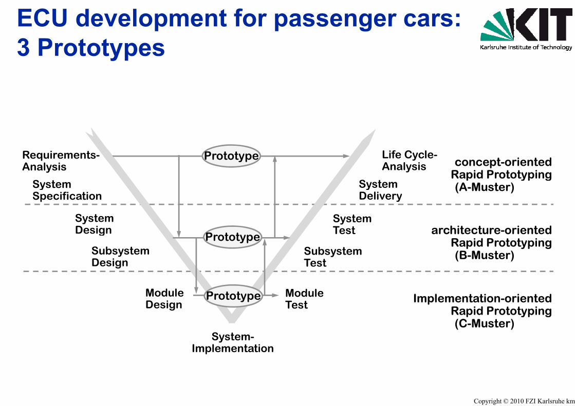
ECU development for p3 Prototypes3 Prototypes
Requirements-Analysis
S t
Prototype
SystemSpecification
SystemDesign
SubsystemDesign
Prototype
ModuleDesign
MT
Prototype
System-Implementation
assenger cars:
concept-orientedRapid Prototyping
Life Cycle-Analysis
S tp yp g
(A-Muster)
hi i dSystem
SystemDelivery
architecture-orientedRapid Prototyping(B-Muster) Subsystem
Test
Test
Implementation-orientedRapid Prototyping
ModuleTest p yp g
(C-Muster)
Copyright © 2010 FZI Karlsruhe kmg

Hardware-in-the-Loop Testp t
Copyright © 2010 FZI Karlsruhe kmg
HiL-Test System
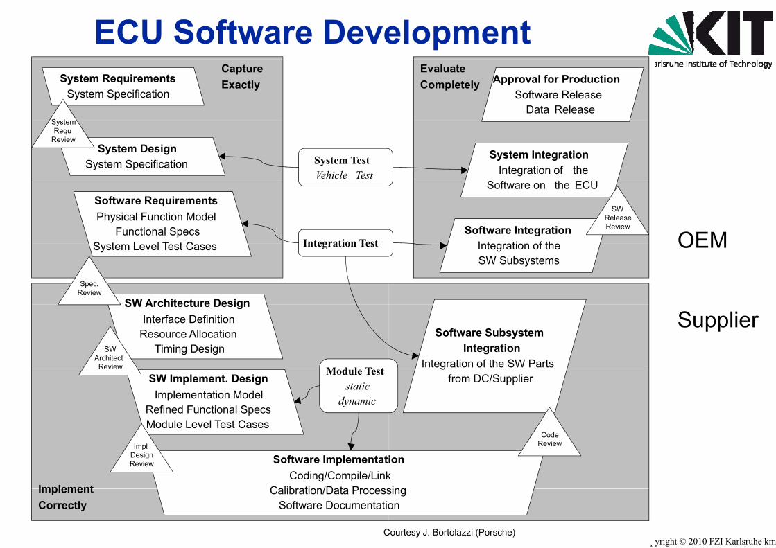
ECU Software DeveSystem Requirements
System Specification
S t
CaptureExactly
System TestVehicle Test
System DesignSystem Specification
SystemRequ
Review
Integration Test
Software RequirementsPhysical Function Model
Functional SpecsS t L l T t C Integration Test
SW Architecture Design
System Level Test Cases
Spec.Review
SW Architecture DesignInterface Definition
Resource AllocationTiming DesignSW
Architect. Review Module Test
staticdynamic
SW Implement. DesignImplementation Model
Refined Functional SpecsModule Level Test Cases
Review
Software ImplementatCoding/Compile/Link
Calibration/Data Process
Module Level Test Cases
Impl.DesignReview
Implement
C
Calibration/Data ProcessSoftware Documentatio
ImplementCorrectly
elopmentApproval for Production
Software ReleaseData Release
EvaluateCompletely
System IntegrationIntegration of the
S ft th ECU
Software IntegrationI t ti f th
Software on the ECU
SWReleaseReview
OEMIntegration of theSW Subsystems
OEM
Software SubsystemIntegration
Integration of the SW Parts
Supplier
Integration of the SW Partsfrom DC/Supplier
ionksing
CodeReview
Copyright © 2010 FZI Karlsruhe kmgCourtesy J. Bortolazzi (Porsche)
singon
Typical Designflowyp gIdea
HW/SW-Requirements AnalysisWhat are the supporting
PROCESS (schlupf, stBEGIN
CASE state IS
HW/SW Requirements AnalysisPreliminary HW/SW-Design
HW-Architecture, SW-ArchitectureInterface Description
system level design too
Detailed HW/SW
CASE state ISWHEN freilauf =>
IF schlupf > 0next_state <
bremsen;ELSE
&
&
&&
Detailed HW/SWSW-Design, Data Dictio
HW-DrawingsHW-Analysis Repor
HW/SW-ImplementationTest, Integration, Test
W-Modules, Data Dictionary, SW-Comp
System Integration, Te
, y, pHW-Component, HW-ModuleHW-Realization Documents
y g ,Calibration, ApplicatiTransition to Utilizatio
System-Analysisexecutable Specs, models
S t D iFreiFrei
BremsenBremsen
Rad 1 Rad 1
ASR KontrolleASR Kontrolle
Rad 1
Bremsen
Frei
Rad 2
Bremsen
Frei
System DesignCustomer RequirementsTechnical Requirements
System Architectureg
tate)
yInterfaces
Modeling and SimulationReal Time Requirements
ls?
Rapid PrototypingHardware PlatformCode GenerationW-Design
>0 THEN<=
Real Time Operating Systemconfigurable Interfaces
W-Designonary
rt
Test
Copyright © 2010 FZI Karlsruhe kmg
onon
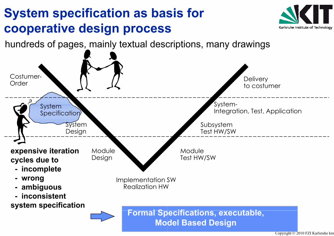
System specification as basti d icooperative design process
hundreds of pages, mainly textual desc
Costumer-CostumerOrder
S tSystemSpecification
SystemDesignDesign
ModuleDesign
expensive iterationl d t Design
Implementation S
cycles due to- incomplete- wrong
Realization HW- ambiguous- inconsistent
system specificationF l SFormal Sp
Mo
sis for scriptions, many drawings
Delivery
System-
Deliveryto costumer
SubsystemTest HW/SW
System-Integration, Test, Application
ModuleTest HW/SW
Test HW/SW
SW
Test HW/SW
W
ifi ti t bl
Copyright © 2010 FZI Karlsruhe kmg
pecifications, executable,del Based Design
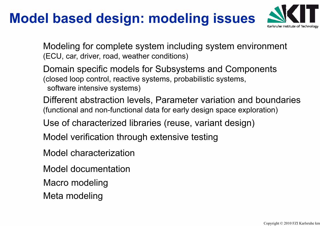
Model based design: mg
Modeling for complete systemg p y(ECU, car, driver, road, weather con
Domain specific models for S(closed loop control, reactive systemsoftware intensive systems)
Different abstraction levels PDifferent abstraction levels, P(functional and non-functional data
Use of characterized librariesUse of characterized librariesModel verification through ext
M d l h t i tiModel characterization
Model documentationMacro modeling Meta modeling
odeling issuesg
m including system environmentg ynditions)
Subsystems and Componentsms, probabilistic systems,
Parameter variation and boundariesParameter variation and boundariesfor early design space exploration)
s (reuse, variant design)s (reuse, variant design)tensive testing
Copyright © 2010 FZI Karlsruhe kmg
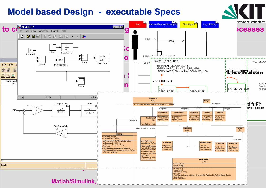
Model based Design - execut
to control technical processes, cogn
Closed Loop Con(continuou
Reactive Su(discrete event(discrete, event
Cognitive Subsystems, WaCognitive Subsystems, Wa(probability density functio
-argum
Communication- and SoftwMessage
-command : FwString-commandLine : FwString
+getArguments() : FwASamplerContainer+getCommand() : FwString+getCommandLine() : FwString+Message()
1
designers prefer varioubest-of-point tools for
+Message()+setCommand( theCommand : FwString )+setCommandLine( thecommandLine : FwSt+toString() : FwString
best-of-point tools for
Matlab/Simulink, ASCET, State
table Specs
nitive processes, compute processes
ntrol Subsystemss systems)
ubsystemsdriven systems)driven systems)
aiting Queues, Time LinesFwContainer
(rtfw)
+LookUp( key : FwString rvalue : FwElement*& ) : FwBool
Analyse<<import>>aiting Queues, Time Lines
on driven, timing diagrams)+LookUp( key : FwString, rvalue : FwElement & ) : FwBool
MessageProzessor
FwASamplerContainer(rtfw)
+LookUp( key : FwString ) : FwElement
GetError<<import>>
<<import>>-index2Steps
1ments
1
FloodCounter
+FloodCounter()+Init() : void+Update() : void
ThetaEncoder
+Init() : void+ThetaEncoder()+Update() : void
TraySensor
+Init() : void+TraySensor()+Update() : void
ZEncoder
+Init() : void+Update() : void+ZEncoder()
XEncoder
+Init() : void+Update() : void+XEncoder()
<<import>> <<import>> <<import>> <<import>> <<import>>
ware intensive SubsystemsCommandProzessor
-run : FwBoolean#sendString : FwString
+CommandProzessor( messageProzessor : MessageProzessor* )GetStatus
+Execute() : FwBoolean+GetNextMessage() : Message*+Init() : void+MessageProzessor()+Parse( messageStr : FwString* ) : Message+SendAnswer( answer : FwString ) : void+~MessageProzessor()
fcntl
1
p
<<import>>
1
-commands 1
1
-iElements1
1
-oElements 1
ZButtomSensor
+Init() : voidFloodCounter
+Fl dC t ()
XEndSensor
+Init() : voidZTopSensor
+I it() id
FwIElement(rtfw)
Bytes(rtfw)
<<import>>
us description methods,r different applications
( g g )+Execute() : FwBoolean+GetCommand( name : FwString ) : Command+GetIElement( name : FwString ) : FwIElement+GetOElement( name : FwString ) : FwOElement+Init() : void+SendAnswer( answer : FwString ) : void+~CommandProzessor()
+Execute() : FwBoolean+GetKindOfTray() : FwInt+GetStatus( commandProzessor : CommandProzessor )+GetTrayCoordinate( x : FwInt, y : FwInt ) : TrayPosition*+Init() : void+IsValidCommand( m : Message* ) : FwBoolean
tring )
IPortPCIModul1(rtfw)
#address : FwInt#startBit : FwByte
Di bl () id
()+Update() : void+ZButtomSensor()
+FloodCounter()+Init() : void+Update() : void
()+Update() : void+XEndSensor()
+Init() : void+Update() : void+ZTopSensor()
Copyright © 2010 FZI Karlsruhe kmg
r different applications
mate, Stateflow, UML, SysML
+Disable() : void+Enable() : void+GetAddress( : void )+Init() : void+IPortPCIModul1( name, address : FwInt, startBit : FwByte, nBit : FwByte, nBytes : FwInt )+Update() : void+~IPortPCIModul1()
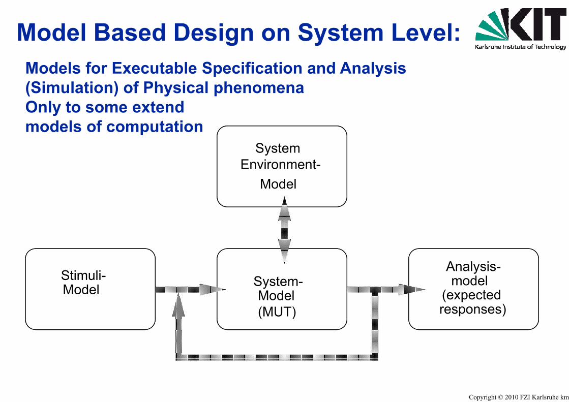
Model Based Design ongModels for Executable Specificatio(Simulation) of Physical phenome(Simulation) of Physical phenomeOnly to some extendmodels of computation
SysteEnviron
p
Mod
Stimuli-Model Syste
Mode(MUT(MUT
n System Level:yon and Analysis nana
emnment-del
Analysis-em-elT)
Analysismodel
(expectedresponses)T) responses)
Copyright © 2010 FZI Karlsruhe kmg

Abstraction Levels for MSimulationSimulation
AbstractionAbstraction-levels Ove
Closed Loopidealized Se
Digital
Timing
DigitalCircuits
Macro models
Timing
AnalogCircuits
simpSens
d
Physical modelsProcess,
Sensor/Actuator-models
mod
1 10 103102
Modeling and
System A1A2
Be/act
erall System p / Reactive Controlensor/Actuator
Register-TransferCONTROL
RAM ALU ROM
Be/act
Logic
plifiedor/Actuator-
d ldels
106105104 Complexity
Copyright © 2010 FZI Karlsruhe kmg
y(# of Components)
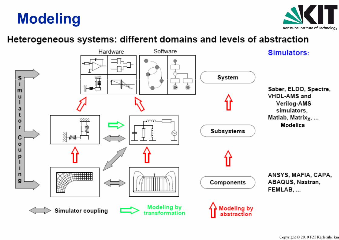
Modelingg
Modelica
Copyright © 2010 FZI Karlsruhe kmg

System Level Modelingy g
Complex, Heterogeneous: mechanical, electricalp gMulti Domain Multi Ph
Tight coupling between: complete system, systsubsystems, componemanufacturer and techMulti View, Multi Abstr
Long iteration cycles: design, manufacturingSimulation is a must
Complicated non-linearities: strong functional inflelectrostatic force prop
l ki i tseveral working points
Dynamic systems: extremely different timtiff diff ti l tistiff differential equatio
Time and space derivatives: FEM Simulation and
g and Simulationg
l, fluidical, optical phenomena and their couplingsp p p ghysics Systems
tem environmententshnology dependenciesraction Level Approach
g and test very expensive and time consuming
luence, small signal behavior not sufficient:p. V2 ,capacitance prop. 1/d, Hysteresis,s
me constants: > 10 orders of magnitude,ton systems
Analysis, 3D fields and waves
Copyright © 2010 FZI Karlsruhe kmg

System Level Modelingy gMechanicsElectrostaticsElectromagnetic Fields Thermal problems Multi-Physics Problemsy
g and Simulationg
Copyright © 2010 FZI Karlsruhe kmg
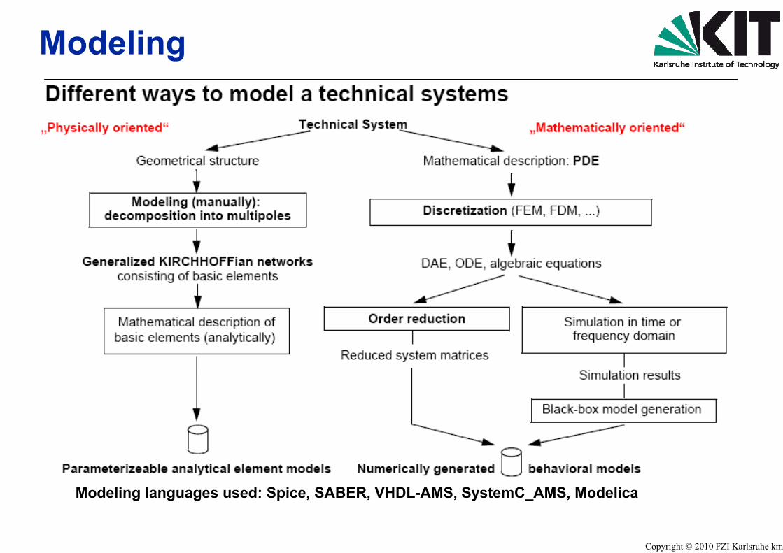
Modelingg
Modeling languages used: Spice SABER VHModeling languages used: Spice, SABER, VHHDL-AMS SystemC AMS Modelica
Copyright © 2010 FZI Karlsruhe kmg
HDL-AMS, SystemC_AMS, Modelica

Modeling for heterogeneous electro
ArchitectureModelling with UML
BatchController
Buffer::Buffer SocketListItem1 *
outputBuffer 1
ProcessorBuffer SocketListItem
inputBuffer
1 *
1
Real time Studio (ARTiSAN)
Event d
Real-time Studio (ARTiSAN)Rhapsody in C++ (i-Logix)Rose (Rational Software, IBM)Together (Borland)Poseidon (Gentleware)
Modelling w
IdleIdle
Poseidon (Gentleware)MagicDraw (NoMagic)Ameos (Aonix)TAU2 (Telelogic)
evAck /Actio/Actio
Rhapsody in Statemate (i-Stateflow (ThASCET (ETA
onic embedded systems
Signal flow orientedM d lli ith bl k diModelling with block diagrams
ASCET (ETAS) MATLAB/Simulink (The MathWorks)
driven
MATLAB/Simulink (The MathWorks)MATRIXx (National Instruments)
with state charts
Sending Waiting_For_Repeat
evRepeat[myCondition]
Sending Waiting_For_Repeat
Waiting_For_Ack evBusyon1()
Waiting_For_Ack evBusyon1()
C++ (i-Logix) -Logix)he MathWorks)AS)
Copyright © 2010 FZI Karlsruhe kmg
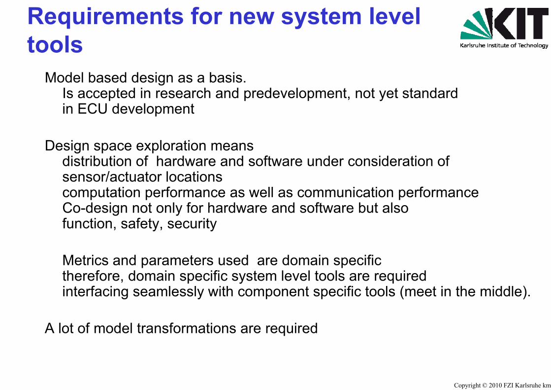
Requirements for new toolstools
Model based design as a basis.Is accepted in research and predein ECU development
Design space exploration meansdistribution of hardware and softw
/ t t l tisensor/actuator locationscomputation performance as well Co-design not only for hardware afunction, safety, security
Metrics and parameters used areMetrics and parameters used aretherefore, domain specific systeminterfacing seamlessly with compo
A lot of model transformations are re
system level
evelopment, not yet standard
ware under consideration of
as communication performanceand software but also
e domain specifice domain specificm level tools are requiredonent specific tools (meet in the middle).
equired
Copyright © 2010 FZI Karlsruhe kmg
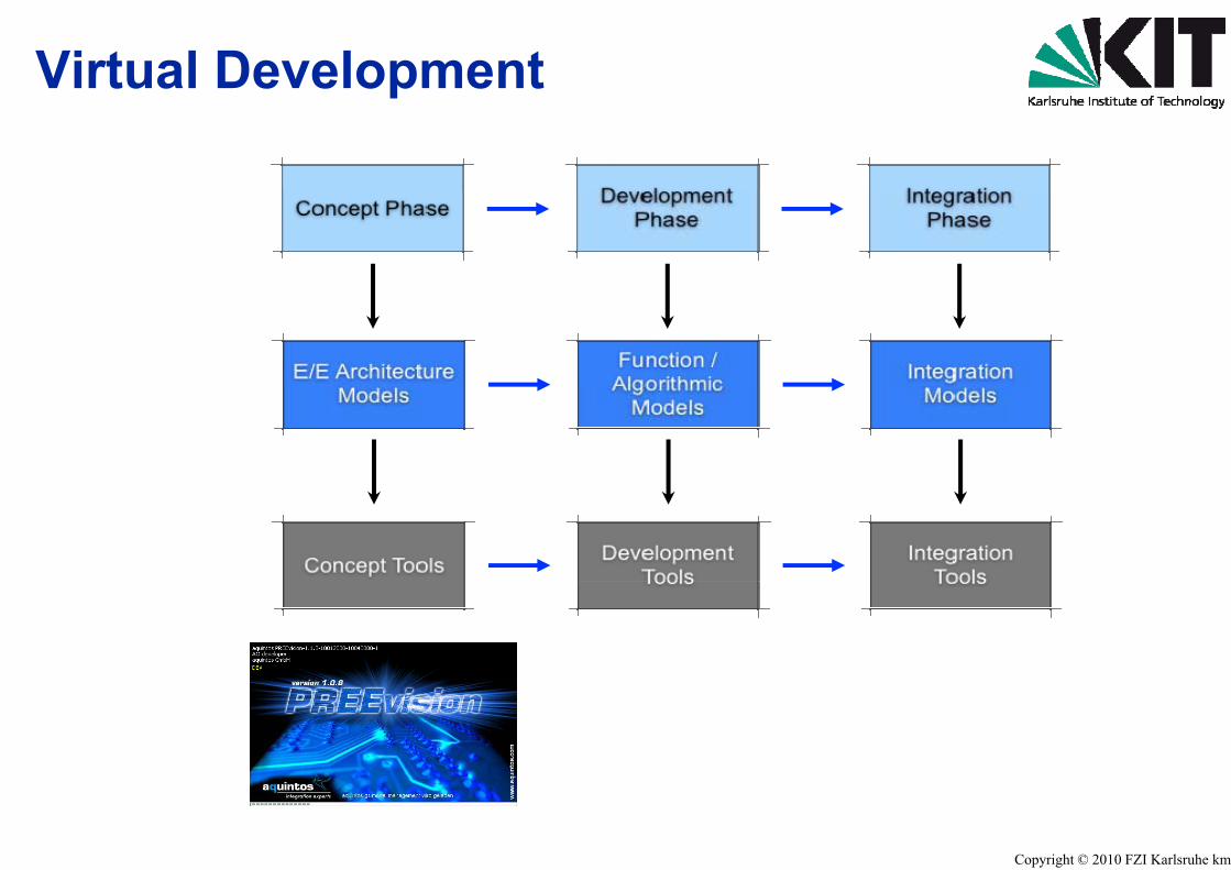
Virtual Developmentp
e.g.e.g.PRPREEEEvisionvision
Copyright © 2010 FZI Karlsruhe kmg

E/E Architecture DeveloPREEvision®PREEvision®
Concept Phase
analysis
requirements
analysis
accecptance
systemspecification
software hardware
validation
specification specification
coarsedesign
hardwaredesign
hsdesign
pdesign
opment with
service
system test
test
hw integration module integration
system integration& operational test
verification
check ofcomponents
modulartest
& test & testverification
hardwarestructure
programmetest
Copyright © 2010 FZI Karlsruhe kmg
programmingimplementation
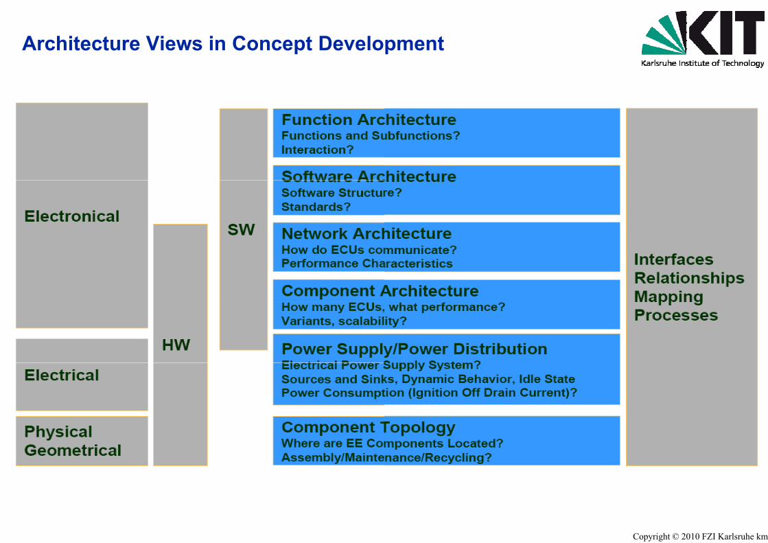
Architecture Views in Concept Development
Copyright © 2010 FZI Karlsruhe kmg
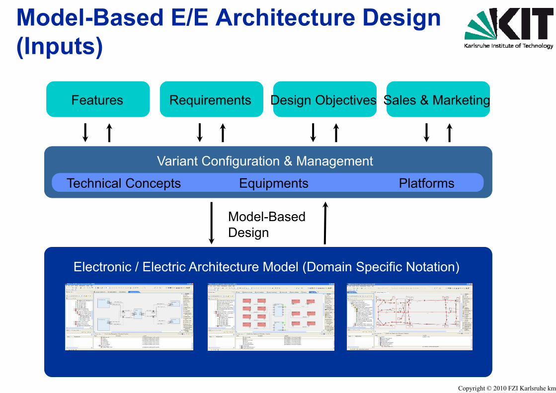
Model-Based E/E Archit(Inputs)(Inputs)
Features Requirements D
Variant Configuration
Technical Concepts Equipm
Model-Ba
El t i / El t i A hit t M
Model BaDesign
Electronic / Electric Architecture Mo
tecture Design
Design Objectives Sales & Marketing
n & Management
ments Platforms
ased
d l (D i S ifi N t ti )
ased
odel (Domain Specific Notation)
Copyright © 2010 FZI Karlsruhe kmg

Model-Based E/E Archit(Outputs)(Outputs)
Electronic / Electric Architecture
Features Requirements Functions Electr
ModeDesig
Model Optimization - Consiste
g
Architecture MetricArchitectureHandbook
MetricResults
tecture Design
Model (Domain Specific Notation)
Harnessronics Network Electrics Geometry
el-Basedgn
ency Checks - Refactorings - ...
g
B h k Various
Copyright © 2010 FZI Karlsruhe kmg
Benchmarks VariousExports
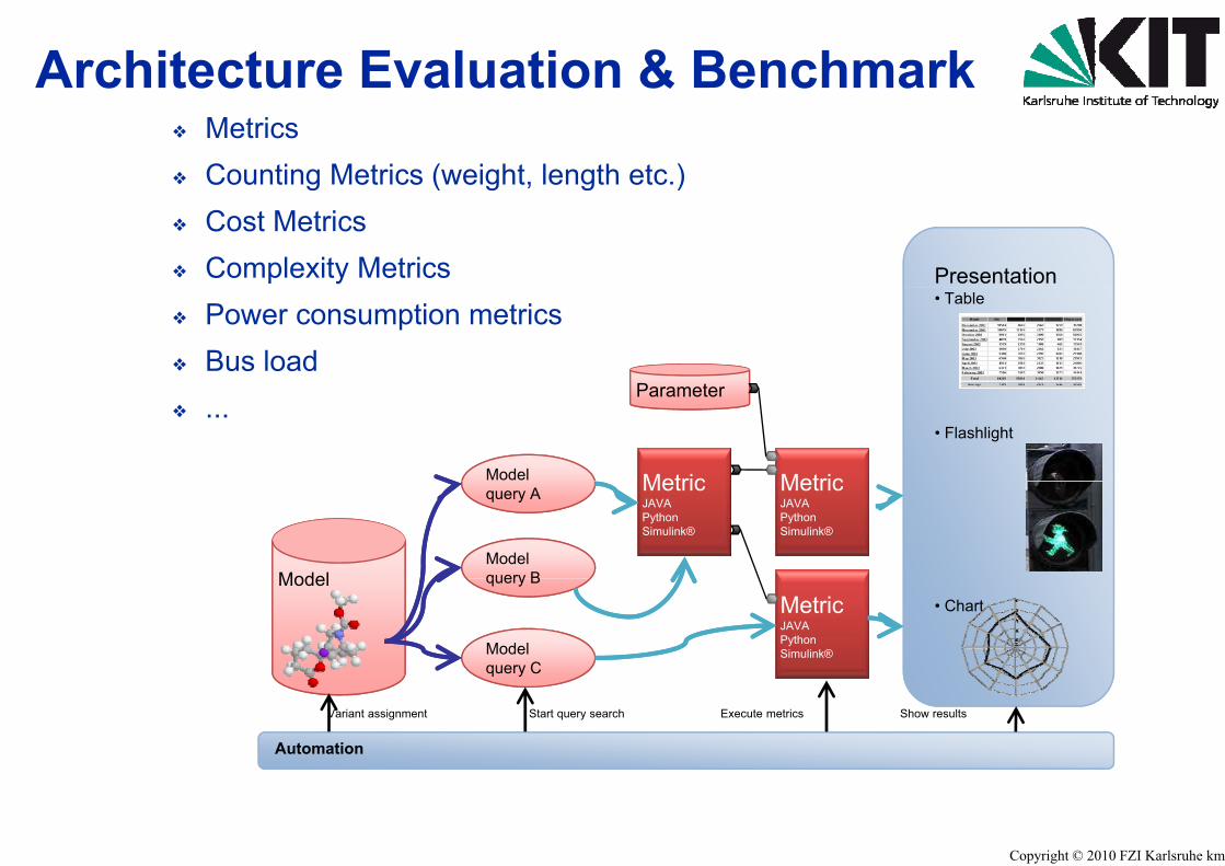
Architecture Evaluation� Metrics� Counting Metrics (weight, lengthg ( g g� Cost Metrics� Complexity Metrics� Power consumption metrics� Bus load
Model
� ...
Model
query A
Modelquery BModel query B
Modelquery Cq y
Automation
Variant assignment Start query searc
n & Benchmark
h etc.)
Presentation
)
P t
• Table
Parameter
• Flashlight
MetricMetric MetricJAVAPythonSimulink®
MetricJAVAPythonSimulink®
• ChartMetricJAVAPythonSimulink®
ch Execute metrics Show results
Copyright © 2010 FZI Karlsruhe kmg

Describing/Comparing Ag p g
p21
p1
p1
0
-
p5
Architectures
,5 Architecture 1Architecture 2
p
Architecture 2
p3
2
p4
Copyright © 2010 FZI Karlsruhe kmg
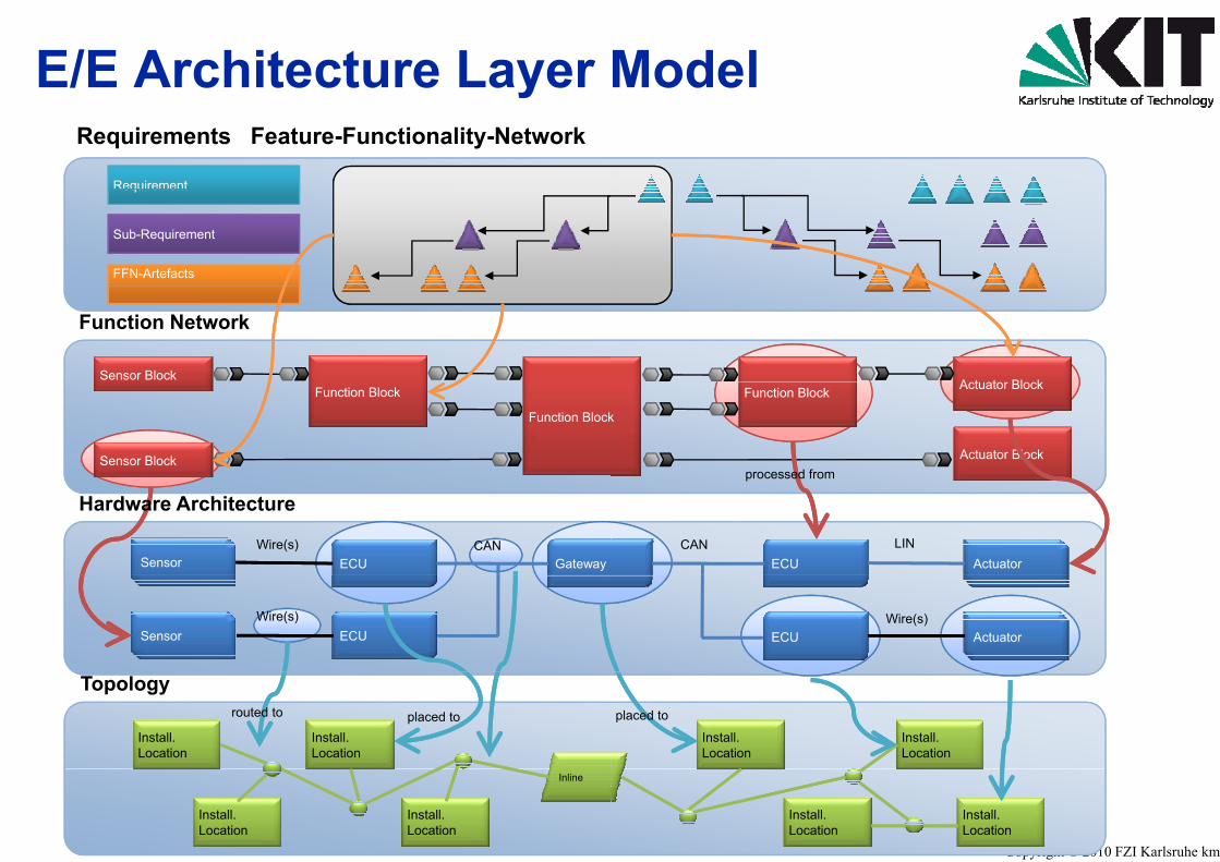
E/E Architecture Layery
Requirement
Requirements / Feature-Functionality-Network
Requirement
Sub-Requirement
FFN-Artefacts
Sensor Block
Function Network
Sensor Block
Function Block
Function Block
GatewayECUSensorCANWire(s)
Hardware Architecture
ECUSensorWire(s)
Install.Location
Install.Location
placed torouted to
Topology
Install.Location
Install.Location
Inline
Model
Actuator Block
k
Function Block Actuator Block
Actuator Blockprocessed from
ECU ActuatorCAN LIN
p
ECU ActuatorWire(s)
Install.Location
Install.Location
placed to
Copyright © 2010 FZI Karlsruhe kmg
Install.Location
Install.Location
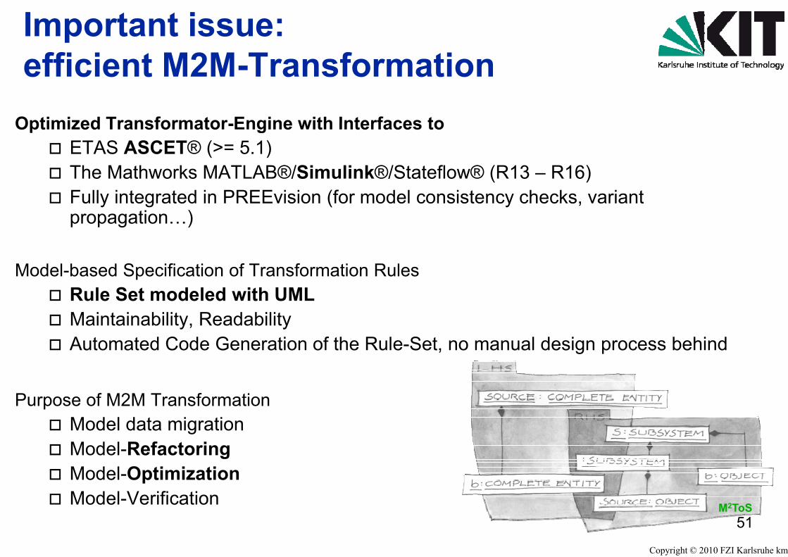
Important issue:efficient M2M Transformefficient M2M-Transform
Optimized Transformator Engine with InterfacOptimized Transformator-Engine with Interfac� ETAS ASCET® (>= 5.1)� The Mathworks MATLAB®/Simulink®/S� Fully integrated in PREEvision (for mod
propagation…)
Model-based Specification of Transformation Ru� Rule Set modeled with UML� Maintainability, Readability� Automated Code Generation of the Rule
Purpose of M2M Transformation� Model data migration� Model-Refactoring� Model-Optimization� Model Verification� Model-Verification
mationmationces toces to
Stateflow® (R13 – R16)del consistency checks, variant
ules
e-Set, no manual design process behind
Copyright © 2010 FZI Karlsruhe kmg
51M2ToS
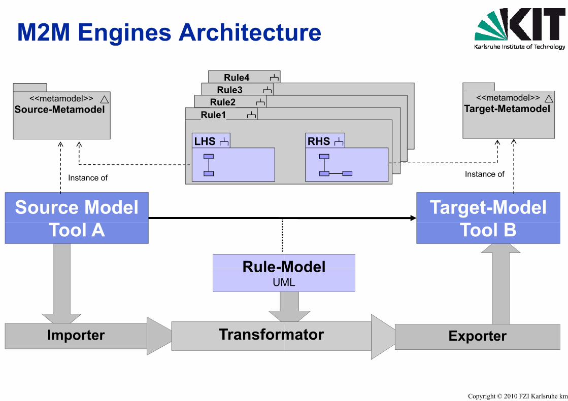
M2M Engines ArchitectgRule4
R le3Rule3Rule2<<metamodel>>
Source-Metamodel Rule1
LHS
Instance of
Source ModelT l A
Instance of
Rule-M
Tool A
Rule-MUM
Importer Transform
ure
<<metamodel>>Target-Metamodel
RHS
Instance of
Target-ModelT l B
Model
Tool B
ModelML
52mator Exporter
Copyright © 2010 FZI Karlsruhe kmg
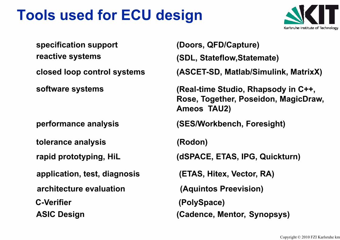
Tools used for ECU de
specification supportreactive systems
closed loop control systems
software systems
performance analysis
rapid prototyping, HiL
tolerance analysis
p p yp g,
application, test, diagnosis
architect re e al ation
ASIC DesignC-Verifier architecture evaluation
ASIC Design
esign
(Doors, QFD/Capture) (SDL, Stateflow,Statemate)
(ASCET-SD, Matlab/Simulink, MatrixX)
(Real-time Studio, Rhapsody in C++,Rose, Together, Poseidon, MagicDraw,A TAU2)Ameos TAU2)
(SES/Workbench, Foresight)
(dSPACE, ETAS, IPG, Quickturn)
(Rodon)
( , , , )
(ETAS, Hitex, Vector, RA)
(Aq intos Pree ision)
(Cadence Mentor Synopsys)(PolySpace)(Aquintos Preevision)
Copyright © 2010 FZI Karlsruhe kmg
(Cadence, Mentor, Synopsys)
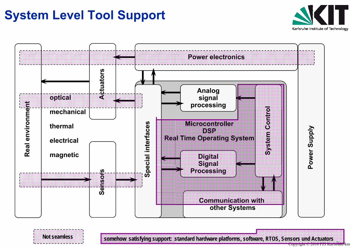
System Level Tool Support
ator
soptical
h i lA
ctua
ent
Rea
mechanical
thermal
nviro
nme
face
sReaelectrical
magneticRea
l e
cial
inte
rf
Sens
ors
Spec
S
Not seamless somehow satisfying support: s
Power electronics
ol
Analogsignal
processing
MicrocontrollerDSP
al Time Operating System pply
m C
ontr
o
al Time Operating System
ower
Sup
Syst
e
DigitalSignal PSignal
Processing
Communication with other Systems
Copyright © 2010 FZI Karlsruhe kmgBenzstandard hardware platforms, software, RTOS, Sensors und Actuators

Conclusion (1)• What system level tools should
� Documentation (readable for men s
( )
� Documentation (readable for men, s� Data exchange between all designe� Data exchange between computer ag p
databases� Intellectual Property, reusable in libr
P t i d f i t d i� Parameterized for variant design� Supporting standards and guideline� Testable (Fault models automatic M� Testable (Fault models, automatic M
(automatic generation of test pattern(what is modeled, but also what is n
� Seamless in design flow(Analysis, Design, Verification, IntegDiagnosis)g )
� Reviews, Rule Checking, Simulation� Synthesis, automatic, interactive op� allow access for automatic paramete
d providespecific for application domain)specific for application domain)ers across company boundariesaided tools supporting distributed pp g
raries
s (e.g. HIS, Autosar)Model validation) quality assuredModel validation), quality assuredn and test bench) and documented not modeled)
gration, Validation, Test, Application,
n, Formal Verification, Model Checking timizing (e.g. RP-Code, Production Code)
Copyright © 2010 FZI Karlsruhe kmg
er-extraction

Conclusion (2)( )Design studies show:• Model based methodologies and too• Model based methodologies and too• Seamless design flow only partially • Interfaces for Modeling SimulationInterfaces for Modeling, Simulation,• hard problem for design of embedde
� Cross sensitivity of Components (ins� Safety, Security, Function-Codesign� According modeling is really time and� Mixed-Mode Multi-Level-Simulation� Mixed-Mode, Multi-Level-Simulation� Formal Verification und Validation no
• Non functional requirementsTi f d t d• Time-, frequency- und parameter-do
� Module / System-Integration und –Te� Cross-sensitivities, EMC, Certification
Model based system design is possiblebut there are many design and analydesign phasesdesign phases.
ols are well performing and promisingols are well performing and promisinggiven (e.g. digital hardware, software).Characterization mostly manualCharacterization mostly manual
ed systemsufficient characterization)
d cost consumingrequiredrequired
ot possible?!
imainestn
e,ysis steps still missing, especially in early
Copyright © 2010 FZI Karlsruhe kmg
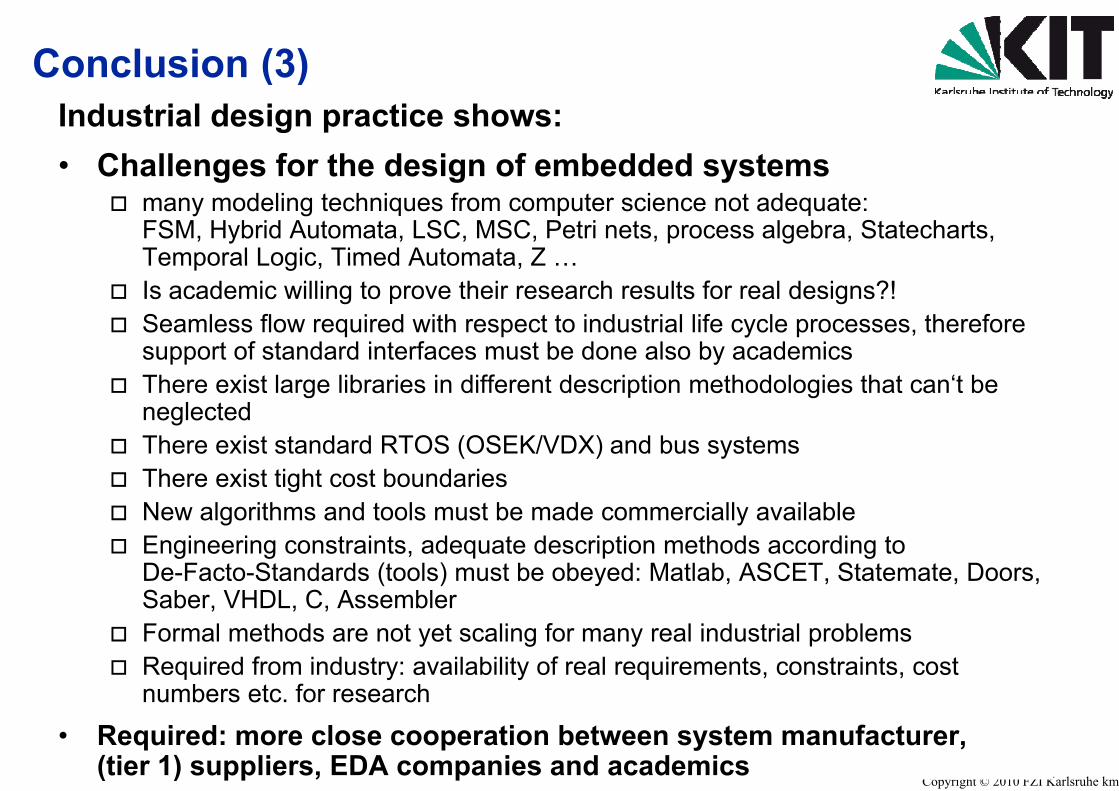
Conclusion (3)( )Industrial design practice shows:• Challenges for the design of emChallenges for the design of em
� many modeling techniques from compFSM, Hybrid Automata, LSC, MSC, PTemporal Logic Timed Automata ZTemporal Logic, Timed Automata, Z …
� Is academic willing to prove their rese� Seamless flow required with respect t
support of standard interfaces must bsupport of standard interfaces must b� There exist large libraries in different d
neglected� Th i t t d d RTOS (OSEK/V� There exist standard RTOS (OSEK/V� There exist tight cost boundaries� New algorithms and tools must be ma� Engineering constraints, adequate de
De-Facto-Standards (tools) must be oSaber, VHDL, C, Assembler
� Formal methods are not yet scaling fo� Required from industry: availability of
numbers etc. for research
• Required: more close cooperation b(tier 1) suppliers, EDA companies a
mbedded systemsmbedded systemsputer science not adequate:
Petri nets, process algebra, Statecharts, …earch results for real designs?!to industrial life cycle processes, therefore e done also by academicse done also by academicsdescription methodologies that can‘t be
DX) d b tDX) and bus systems
ade commercially available escription methods according toobeyed: Matlab, ASCET, Statemate, Doors,
or many real industrial problemsreal requirements, constraints, cost
Copyright © 2010 FZI Karlsruhe kmg
between system manufacturer, and academics

Thank you very much y yfor your attention
Contact:Klaus Müller-GlaserKarlsruhe Institute of Technology [email protected]://www.itiv.kit.edu
Copyright © 2010 FZI Karlsruhe kmg