Pompe Chimie Verticale Typ/Type RCEV - glynwed.es · G-X3 NiCrMoCu 3020 – RC 30.20 G-NiMo 17 Cr...
10
Vertikale Chemie-Kreiselpumpe Vertical Chemical Centrifugal Pump Pompe Chimie Verticale Typ/Type RCEV RHEINHUTTE PUMPEN ..
-
Upload
nguyenhuong -
Category
Documents
-
view
223 -
download
0
Transcript of Pompe Chimie Verticale Typ/Type RCEV - glynwed.es · G-X3 NiCrMoCu 3020 – RC 30.20 G-NiMo 17 Cr...
Vertikale Chemie-KreiselpumpeVertical Chemical Centrifugal PumpPompe Chimie Verticale
Typ/Type RCEV
RHEINHUTTEP U M P E N
..
Vertikale Chemie-Kreiselpumpe Typ RCEVVertical Chemical Centrifugal Pump Type RCEVPompe Chimie Verticale Type RCEV
2
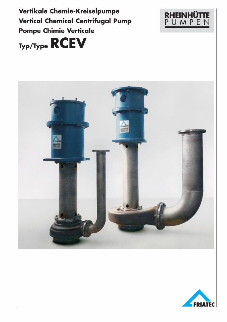
● Konstruktive Merkmale– schwere Chemieausführung mit
Doppelspiralgehäuse, dadurchminimale Radialkräfte
– hochgezogene Lagerung ohne Gleit-lager im Fördergut
– trockenlaufsicher– Einbau in Behälter– wartungsfreundliche Gestaltung– geschlossenes Laufrad mit Vorder-
und Rückschaufeln– beheiztes Wellenschutzrohr und
Druckrohr möglich– bewährte Hydraulik der Chemie-
pumpenbaureihe RCE– niedrige Strömungsgeschwindig-
keiten reduzieren Korrosion/Abrasion– Wälzlager fettgeschmiert
● Einsatzgebiete– mechanisch verunreinigte, korrosive
oder neutrale Flüssigkeiten wie Phos-phorsäure, stark verunreinigterSchwefel, Titandioxidaufschlämmun-gen, Kupferaufschlußsäuren
– Flüssigkeiten, die keine lokale Er-wärmung durch Gleitlager vertragen,z. B. konzentrierte Ammoniumnitrat-lösungen, DNT-Gemische
● Tauchtiefen– Bei Bauform Y maximale Tauchtiefe
2000 mm; Stufung 250 mm– Bei Bauform A maximale Tauchtiefe
1750 mm; Stufung 250 mmEine Verlängerung der Pumpe durchSaugrohr ist möglich
● Design Features– heavy duty chemical design with
double spiral volute housing tominimise radial forces
– extended shaft bearing arrangementwithout any sleeve bearing in themedium
– safe against dry running– installation into vessel or pit– easy of service and maintenance– closed impeller with front and back
vanes– heated shaft pipe and discharge tube
possible– hydraulics of proven design, identical
with RCE pump series– low flow velocities – reduction of
corrosion/abrasion– grease lubricated anti-friction top
bearing
● Areas of Application– mechanically polluted, corrosive or
neutral liquids, i.e.phosphoric acid, heavily contami-nated sulphur, titanium dioxide sus-pensions, acids for copper proces-sing
– liquids sensitive to local heating dueto sleeve bearing, such asconcentrated ammonium nitratesolutions, DNT-mixtures
● Depth of Submersion– For design Y maximum depth of
submersion 2000 mm; depths insteps of 250 mm.
– For design A maximum depth ofsubmersion 1750 mm; depths insteps of 250 mm.An extension of pump is possible bymeans of suction piping.
● Particularités constructives– pompe chimie lourde avec volute
à double spirale réduisant lapoussée axiale au minimum
– guidage de l’arbre au-dessus de laplaque de pose, sans palier lissedans le fluide pompé
– pas de risque de marche à sec– implantation en cuve– entretien et maintenance aisés– turbine fermée avec ailettes frontales
et dorsales– colonne de suspension et tube de
refoulement peuvent être livrés avecréchauffage
– cellule hydraulique éprouvée de lasérie des pompes chimie RCE
– faibles vitesses de circulation duliquide pompé – reduction desphénomènes corrosion/abrasion
– roulements lubrifiés à la graisse
● Domaines d’application– liquides corrosifs ou neutres, chargés
mécaniquement tels que: acidephosphorique, soufre liquide trèssale, boues de dioxide de titane,extraction de cuivre
– liquides qui ne supportent pas unéchauffement local dans les palierslisses. Par ex: solutions de nitrated’ammonium concentrées, mélangede DNT
● Hauteur de suspension– Avec exécution Y hauteur de
suspension maximum 2000 mm;gradation 250 mm.
– Avec exécution A hauteur desuspension maximum 1750 mm.Gradation 250 mm.La pompe peut être prolongée d’untube d’aspiration.
Werkstoff-Kurzbezeich-nung nach DIN 17006Material designationto DIN 17006Désignation matériauselon DIN 17006
Werkstoff-Kurzbezeich-nung nach DIN 17006Material designationto DIN 17006Désignation matériauselon DIN 17006
Werkstoff-Nr. nachDIN 17007Material No.to DIN 17007No matériau selonDIN 17007
Werkstoff-Nr. nachDIN 17007Material No.to DIN 17007No matériau selonDIN 17007
RheinhütteWerkstoff-BezeichnungRheinhütte materialdesignationDésignation matériauRheinhütte
RheinhütteWerkstoff-BezeichnungRheinhütte materialdesignationDésignation matériauRheinhütte
GG 25 0.6025 –GS-C 25 1.0619 –G-X260 CrMo 271 0.9650 V 5700G-X5 CrMo 29 2 – 1.4136 SG-X2 CrNi 22 11 – 1.4306 S
G-X6 CrNiMo 18 10 1.4408 –G-X5 CrNiMoCu 28 5 – HA 28.5G-X3 NiCrMoCu 30 20 – RC 30.20G-NiMo 17 Cr (2.4686) R 70 C1Diverse Sonderwerkstoffe/Various special materials/Autres matériaux spéciaux
Werkstoffe Materials Matériaux
● Wellenabdichtungen– Abdichtungen nicht von Flüssigkeit
berührt; in Wellenschutzrohr nachoben steigende Flüssigkeit läuft durchÜberlaufbohrungen zurück in Behälter
● Shaft Sealing– sealing not in contact with liquid;
rising fluid in shaft pipe runs throughoverflow holes back into container
● Etanchéité d’arbre– le passage d’arbre n’est pas en con-
tact avec le liquide; le liquide refoulédans la colonne de suspension est dé-versé dans la cuve par un trop plein.

3
Ausführung mit Wellendichtring Bauform Yfür offene Behälter, vor dem Wälzlager ist ein Dichtring ange-ordnet, rechteckiger Auflageflansch und Traglagerlaterne auseinem Gußteil
Design Y with shaft sealing ringfor open containers, sealing ring fitted in front of anti-frictionbearing, rectangular support flange and thrust bearing lanternform one cast part.
Exécution Y avec joint d’étanchéitépour réservoirs ouverts; roulement protégé par une bagued’étanchéité, plaque de pose rectangulaire et lanterne paliercoulées en une seule pièce.
Ausführung mit Stopfbuchse Bauform Afür geschlossene Behälter bei korrosiven Gasen; lange Stopf-buchse mit Sperring, runde Aufsetzplatte. Das Druckrohr wirdgasdicht durch die Aufsetzplatte geführt.
Design A with stuffing boxfor closed containers and for corrosive gases; extended stuff-ing box with lantern ring, circular support plate. The dischargepipe passes through a gastight joint in the sole plate.
Exècution A avec presse-étoupepour réservoirs fermés et en présence de vapeurs corrosives;presse-étoupe long avec lanterne d’arrosage, plaque de poseronde. Passage du tube de refoulement dans la plaque depose étanche aux gaz.

SchnittzeichnungSectional DrawingPlan-coupe
Bauform Y für offene BehälterDesign Y for open containersExécution Y pour cuves ouvertes
4
Die bildliche Darstellung entspricht imwesentlichen der AusführungKonstruktive Änderungen behalten wiruns vor.
Teil-Nr. und Benennung nach DIN24250
Teileverzeichnis Seite 8
Pump complies generally with drawingbut the design is subject to alteration.
Part-No. and designation in accordancewith DIN 24250
Parts list page 8
Soius réserve de modification
No. de pièces et désignation selonDIN 24250
Désignations page 8
DN d4 k1 Dd2 z1
32 78 100 14040 88 110 150
450 102 125 16565 122 145 185 1880 138 160 200
100 158 180 220125 188 210 250 8150 212 240 285200 268 295 340
23250 320 350 395
12300 370 400 445
5
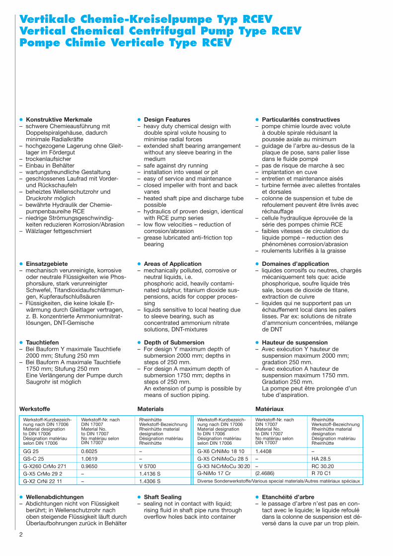
EinbaumaßeDimensionsEncombrement
Größe Pumpe Aufsetzplatte Laterne WellenendeLT* Size DN Pump Suspension Flange Lanterne Shaft End
Modéle Pompe Bride de suspension Pedestal Bout d’arbreC E G b J K L M d1
32/130 32 105 165 315 40 490 550 240 300 2332/160 32 105 175 325 40 490 550 240 300 2340/130 40 105 165 315 40 490 550 240 300 2340/160 40 105 200 350 40 490 550 240 300 2340/200 40 130 200 350 40 490 550 240 300 2340/260 40 150 225 425 40 490 550 240 300 2350/130 50 120 175 325 40 490 550 240 300 2350/160 50 120 185 325 40 490 550 240 300 23
II 50/200 50 150 200 365 40 490 550 240 300 2350/260 50 150 225 420 40 490 550 240 300 2365/160 65 130 200 350 40 490 550 240 300 2365/200 65 160 225 390 40 490 550 240 300 2365/260 65 160 250 450 40 490 550 240 300 2380/160 80 160 200 350 50 490 550 240 300 2380/200 80 160 225 390 50 490 550 240 300 2380/260 80 160 250 480 50 490 550 240 300 23
100/200 100 160 250 450 50 490 550 240 300 2365/80/360 65/80 170 295 555 50 590 650 240 300 23
80/320 80 200 275 505 50 590 650 240 300 23III 125/260 125 200 300 535 50 590 650 240 300 23
125/320 125 200 325 625 50 590 650 240 300 23150/260 150 220 325 600 80 590 650 240 300 23100/430 100 200 350 650 50 620 700 270 350 27200/320 200 220 400 700 80 620 700 270 350 27
IV200/380 200 240 450 770 80 620 700 270 350 27250/430 250 250 550 900 100 620 700 270 350 27
* LT = Lagerträger / Bearing bracket / Corps de palier
B F D1 h d3 u t l455 30 330 95 38 10 41,5 60455 30 330 95 38 10 41,5 60455 30 330 95 38 10 41,5 60455 30 330 95 38 10 41,5 60455 30 330 95 38 10 41,5 60455 30 330 95 38 10 41,5 60455 30 330 95 38 10 41,5 60455 30 330 95 38 10 41,5 60455 30 330 95 38 10 41,5 60455 30 330 95 38 10 41,5 60455 30 330 95 38 10 41,5 60455 30 330 95 38 10 41,5 60455 30 330 95 38 10 41,5 60455 30 330 95 38 10 41,5 60455 30 330 95 38 10 41,5 60455 30 330 95 38 10 41,5 60455 30 330 95 38 10 41,5 60560 30 440 135 48 14 51,5 90560 30 440 135 48 14 51,5 90560 30 440 135 48 14 51,5 90560 30 440 135 48 14 51,5 90560 30 440 135 48 14 51,5 90550 35 640 185 68 20 72,5 110550 35 640 185 68 20 72,5 110550 35 640 185 68 20 72,5 110550 35 640 185 68 20 72,5 110
Saug- und Druckflansch(DNS / DND) nach:DIN 2501, PN 10
Suction and DischargeFlange (DNS / DND) to:DIN 2501, PN 10
Bride d’aspiration et derefoulement (DNS / DND)selon: DIN 2501, PN 10
TT= 500 + a750 + a
1000 + a1250 + a1500 + a1750 + a2000 + a
M
KJ
L
d1
Ansicht AView AVue
A
D1
E
G
TT
F
h
l
lmin
bB
C
SaugflanschSuction FlangeBride d’aspiration
DruckflanschDischange FlangeBride de refoulement
ÜberlaufOverflowTrop-plein
FettanschlußGrease connectionRaccord de graisse
Wellenende, Paßfeder nachShaft end, Key toBout d’arbre clavette selonDIN 6885
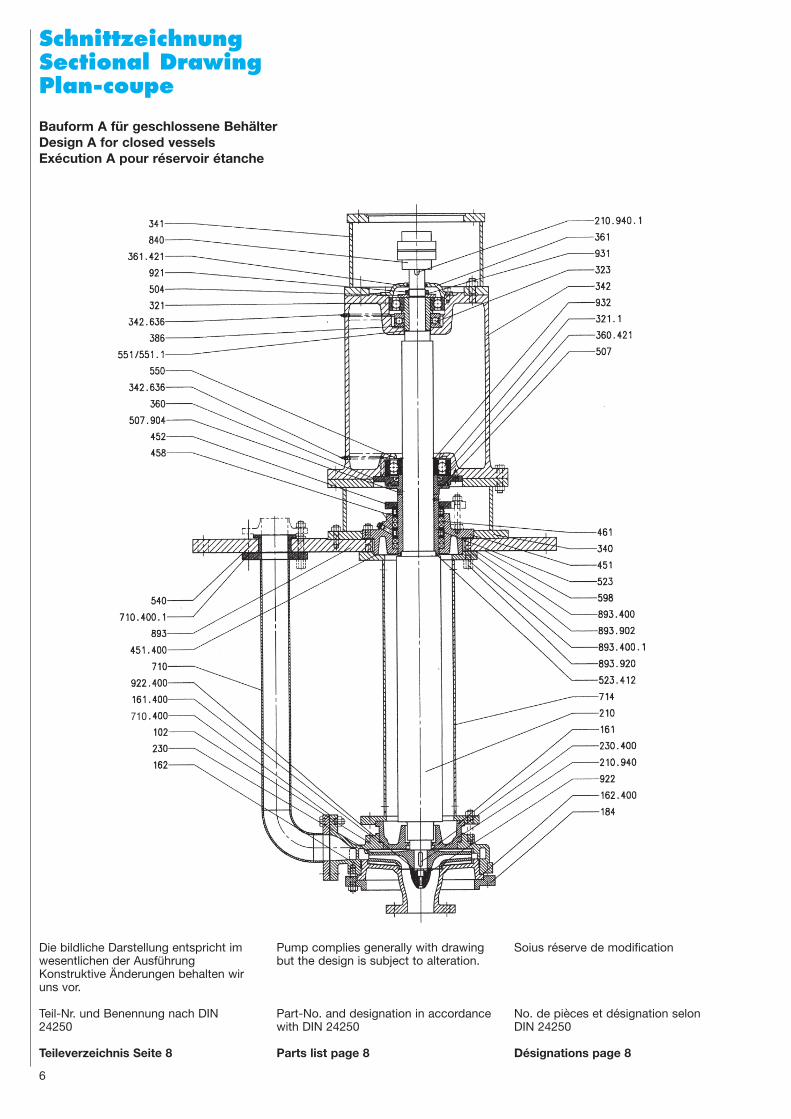
SchnittzeichnungSectional DrawingPlan-coupe
Bauform A für geschlossene BehälterDesign A for closed vesselsExécution A pour réservoir étanche
6
Die bildliche Darstellung entspricht imwesentlichen der AusführungKonstruktive Änderungen behalten wiruns vor.
Teil-Nr. und Benennung nach DIN24250
Teileverzeichnis Seite 8
Pump complies generally with drawingbut the design is subject to alteration.
Part-No. and designation in accordancewith DIN 24250
Parts list page 8
Soius réserve de modification
No. de pièces et désignation selonDIN 24250
Désignations page 8
710

7
Größe Pumpe Aufsetzplatte Laterne WellenendeLT* Size DN Pump Suspension Flange Lanterne Shaft End
Modéle Pompe Bride de suspension Pedestal Bout d’arbreC E G b J K L M d1 z DN1 F
32/130 32 105 165 315 40 840 895 55 290 30 24 700 4032/160 32 105 175 325 40 840 895 60 300 30 24 700 4040/130 40 105 165 315 40 840 895 65 305 30 24 700 4040/160 40 105 200 350 40 840 895 85 340 30 24 700 4040/200 40 130 200 350 40 840 895 85 340 30 24 700 4040/260 40 150 225 425 40 840 895 95 365 30 24 700 4050/130 50 120 175 325 40 840 895 90 350 30 24 700 4050/160 50 120 185 325 40 840 895 95 360 30 24 700 40
II 50/200 50 150 200 365 40 950 1015 105 375 33 24 800 4050/260 50 150 225 420 40 950 1015 115 400 33 24 800 4065/160 65 130 200 350 40 840 895 90 340 30 24 700 4065/200 65 160 225 390 40 950 1015 105 365 33 24 800 4065/260 65 160 250 450 40 950 1015 115 390 33 24 800 4080/160 80 160 200 350 50 950 1015 110 365 33 24 800 4080/200 80 160 225 390 50 950 1015 120 390 33 24 800 4080/260 80 160 250 480 50 950 1015 135 415 33 24 800 40
100/200 100 160 250 450 50 1050 1115 155 450 33 28 900 4065/80/360 65/80 170 295 555 50 1050 1115 155 405 33 28 900 40
80/320 80 200 275 505 50 1050 1115 135 440 33 28 900 40III 125/260 125 200 300 535 50 1160 1230 195 535 36 28 1000 40
125/320 125 200 325 625 50 1160 1230 195 560 36 28 1000 40150/260 150 220 325 600 80 1380 1455 230 595 39 32 1200 40100/430 100 200 350 650 50 1160 1230 180 550 36 28 1000 40200/320 200 220 400 700 80 1590 1675 320 770 42 36 1400 40
IV 200/380 200 240 450 770 80 1590 1675 335 820 42 36 1400 40250/430 250 250 550 900 100 1820 1915 425 1000 48 40 1600 40
* LT = Lagerträger / Bearing bracket / Corps de palier
B D1 h d3 u t l655 330 95 38 10 41,5 60655 330 95 38 10 41,5 60655 330 95 38 10 41,5 60655 330 95 38 10 41,5 60655 330 95 38 10 41,5 60655 330 95 38 10 41,5 60655 330 95 38 10 41,5 60655 330 95 38 10 41,5 60655 330 95 38 10 41,5 60655 330 95 38 10 41,5 60655 330 95 38 10 41,5 60655 330 95 38 10 41,5 60655 330 95 38 10 41,5 60655 330 95 38 10 41,5 60655 330 95 38 10 41,5 60655 330 95 38 10 41,5 60655 330 95 38 10 41,5 60780 440 135 48 14 51,5 90780 440 135 48 14 51,5 90780 440 135 48 14 51,5 90780 440 135 48 14 51,5 90780 440 135 48 14 51,5 90800 640 185 68 20 72,5 110800 640 185 68 20 72,5 110800 640 185 68 20 72,5 110800 640 185 68 20 72,5 110
DN d4 k1 D d2 g d5 z1
32 78 100 140 70
40 88 110 150 804
50 102 125 165 95
65 122 145 185 18 115M 16
80 138 160 200 130
100 158 180 220 150
125 188 210 250 180 8
150 212 240 285 200
200 268 295 340 25523 M 20
250 320 350 395 31012
300 370 400 445 360
Saug- und Druckflansch/Suction and Discharge Flange/Bride d’aspiration et de refpoulement: DIN 2501, PN 10
B1 / B0 Spermedium-EintrittB1 / B0 Seal liquid inlet / outletB1 / B0 Entrée / Sortie liq. de blocage
TT = 500750
10001250150017502000
L
M
z x d1
30°
JK
A
B1
B0
Ansicht AView AVue
Wellenende, Paßfeder nachShaft end, Key toBout d’arbre clavette selonDIN 6885
D1
E
G
TT
F
h
l
lmin
bB
C
SaugflanschSuction FlangeBride d’aspiration
DruckflanschDischange FlangeBride de refoulement
ÜberlaufOverflowTrop-plein
FettanschlußGrease connectionRaccord de graisse
8
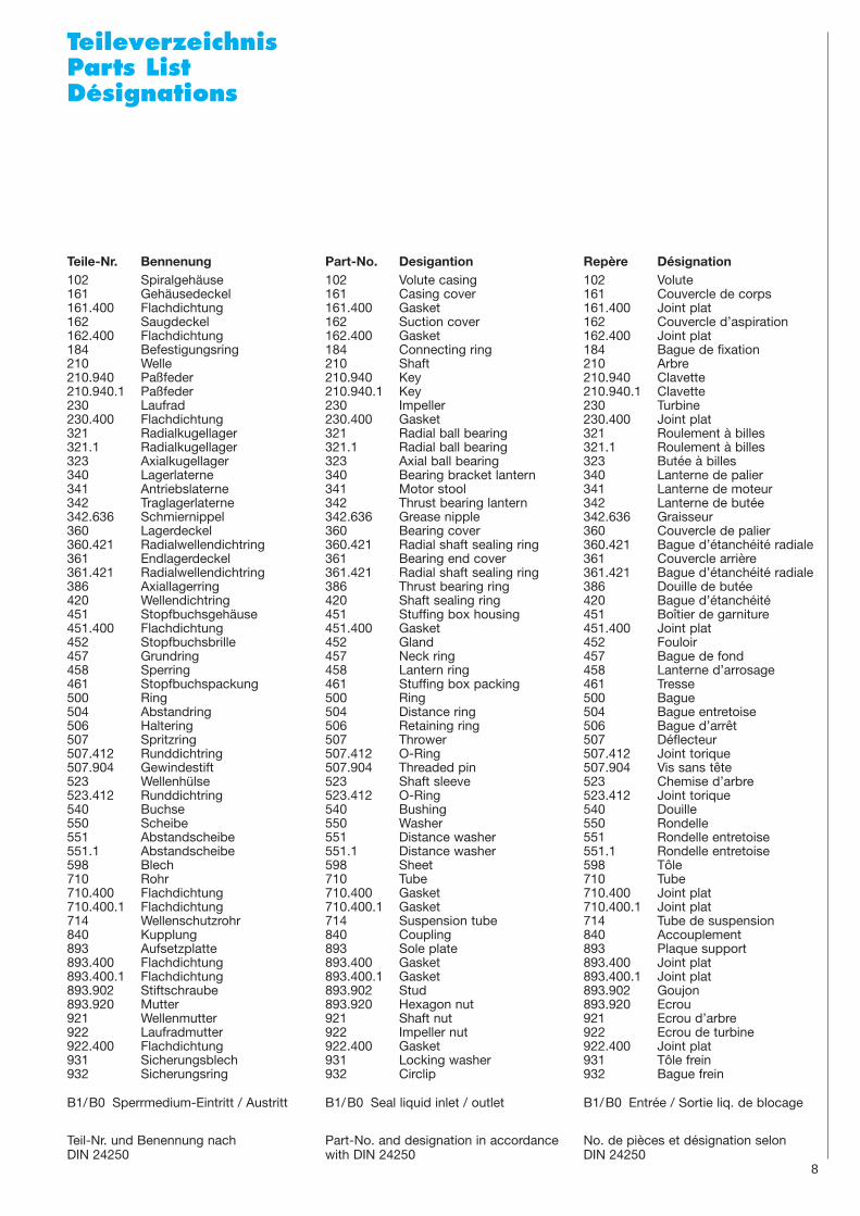
TeileverzeichnisParts ListDésignations
Teile-Nr. Bennenung102 Spiralgehäuse161 Gehäusedeckel161.400 Flachdichtung162 Saugdeckel162.400 Flachdichtung184 Befestigungsring210 Welle210.940 Paßfeder210.940.1 Paßfeder230 Laufrad230.400 Flachdichtung321 Radialkugellager321.1 Radialkugellager323 Axialkugellager340 Lagerlaterne341 Antriebslaterne342 Traglagerlaterne342.636 Schmiernippel360 Lagerdeckel360.421 Radialwellendichtring361 Endlagerdeckel361.421 Radialwellendichtring386 Axiallagerring420 Wellendichtring451 Stopfbuchsgehäuse451.400 Flachdichtung452 Stopfbuchsbrille457 Grundring458 Sperring461 Stopfbuchspackung500 Ring504 Abstandring506 Haltering507 Spritzring507.412 Runddichtring507.904 Gewindestift523 Wellenhülse523.412 Runddichtring540 Buchse550 Scheibe551 Abstandscheibe551.1 Abstandscheibe598 Blech710 Rohr710.400 Flachdichtung710.400.1 Flachdichtung714 Wellenschutzrohr840 Kupplung893 Aufsetzplatte893.400 Flachdichtung893.400.1 Flachdichtung893.902 Stiftschraube893.920 Mutter921 Wellenmutter922 Laufradmutter922.400 Flachdichtung931 Sicherungsblech932 Sicherungsring
B1/B0 Sperrmedium-Eintritt / Austritt
Part-No. Desigantion102 Volute casing161 Casing cover161.400 Gasket162 Suction cover162.400 Gasket184 Connecting ring210 Shaft210.940 Key210.940.1 Key230 Impeller230.400 Gasket321 Radial ball bearing321.1 Radial ball bearing323 Axial ball bearing340 Bearing bracket lantern341 Motor stool342 Thrust bearing lantern342.636 Grease nipple360 Bearing cover360.421 Radial shaft sealing ring361 Bearing end cover361.421 Radial shaft sealing ring386 Thrust bearing ring420 Shaft sealing ring451 Stuffing box housing451.400 Gasket452 Gland457 Neck ring458 Lantern ring461 Stuffing box packing 500 Ring504 Distance ring506 Retaining ring507 Thrower507.412 O-Ring507.904 Threaded pin523 Shaft sleeve523.412 O-Ring540 Bushing550 Washer551 Distance washer551.1 Distance washer598 Sheet710 Tube710.400 Gasket710.400.1 Gasket714 Suspension tube840 Coupling893 Sole plate893.400 Gasket893.400.1 Gasket893.902 Stud893.920 Hexagon nut921 Shaft nut922 Impeller nut922.400 Gasket931 Locking washer932 Circlip
B1/B0 Seal liquid inlet / outlet
Repère Désignation102 Volute161 Couvercle de corps161.400 Joint plat162 Couvercle d’aspiration162.400 Joint plat184 Bague de fixation210 Arbre210.940 Clavette 210.940.1 Clavette230 Turbine230.400 Joint plat321 Roulement à billes321.1 Roulement à billes323 Butée à billes340 Lanterne de palier341 Lanterne de moteur342 Lanterne de butée342.636 Graisseur360 Couvercle de palier360.421 Bague d’étanchéité radiale361 Couvercle arrière361.421 Bague d’étanchéité radiale386 Douille de butée420 Bague d’étanchéité451 Boîtier de garniture451.400 Joint plat452 Fouloir457 Bague de fond458 Lanterne d’arrosage461 Tresse 500 Bague504 Bague entretoise506 Bague d’arrêt507 Déflecteur507.412 Joint torique507.904 Vis sans tête523 Chemise d’arbre523.412 Joint torique540 Douille550 Rondelle551 Rondelle entretoise551.1 Rondelle entretoise598 Tôle710 Tube710.400 Joint plat710.400.1 Joint plat714 Tube de suspension840 Accouplement893 Plaque support893.400 Joint plat893.400.1 Joint plat893.902 Goujon893.920 Ecrou921 Ecrou d’arbre922 Ecrou de turbine922.400 Joint plat931 Tôle frein932 Bague frein
B1/B0 Entrée / Sortie liq. de blocage
Teil-Nr. und Benennung nachDIN 24250
Part-No. and designation in accordancewith DIN 24250
No. de pièces et désignation selonDIN 24250

9
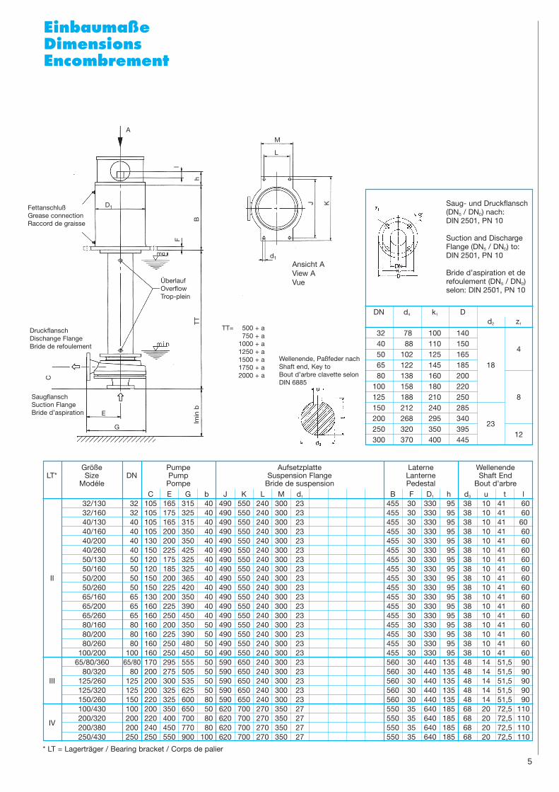
LeistungsbereichRange ChartPlage d’utilisation
10
7080
1 2 3 4 5 10 20 30 40 50 100 200 300 400 500 1000 1500
1,5
2
3
4
5
6
7389
20
30
40
50
60
10
20
50
100
200
50Hz n= 1450
40/260
40/200
32/160
32/130
40/160
40/130
50/200
50/160
50/260
65/200
65/160
65/26080/260
80/200
80/160
100/200
65/80/360125/320
125/260
150/260
100/430
5
80/320
250/430
200/380
200/320
Förderstrom Q/Quantity Q/Debit Q (m3/h)
Förd
erhö
he H
in m
· D
iffer
entia
l Hea
d H
in m
· H
aute
ur m
anom
étriq
ue H
en
m
Förd
erhö
he H
in f
t ·
Diff
eren
tial H
ead
H in
ft
· H
aute
ur m
anom
étriq
ue H
en
ft
4.4 10 20 50 100 200 500 1000 2000 US .GMP
3.7 10 20 50 100 200 500 1000 2000 IMP.GMP
7080
1 2 3 4 5 10 20 30 40 50 100 200 300 400 500 1000 1500
5
67
89
10
20
30
90
40
5060
30
50
100
200
100
20
500
50Hz n= 2900
80/160
80/200
65/160
50/130
65/200
50/160
50/200
40/130
40/160
32/130
32/160
40/200
Förderstrom Q/Quantity Q/Debit Q (m3/h)
Förd
erhö
he H
in m
· D
iffer
entia
l Hea
d H
in m
· H
aute
ur m
anom
étriq
ue H
en
m
Förd
erhö
he H
in f
t ·
Diff
eren
tial H
ead
H in
ft
· H
aute
ur m
anom
étriq
ue H
en
ft

FRIATEC-Rheinhütte GmbH & Co.Postfach/P.O.B. 12 05 4565083 Wiesbaden
Rheingaustraße 96-10065203 Wiesbaden
Tel. 0611/6 04-0Fax 0611/6 04-3 28www.friatec.de · [email protected] 19
06 ·
3 ·
III ·
01
Gr.
3.19
.000
3-06
97, d
-e-f