Presentazione di PowerPoint - aliaxis-ui.ru · z.B. an Tanks eingesetzt we rden. • Der...
22
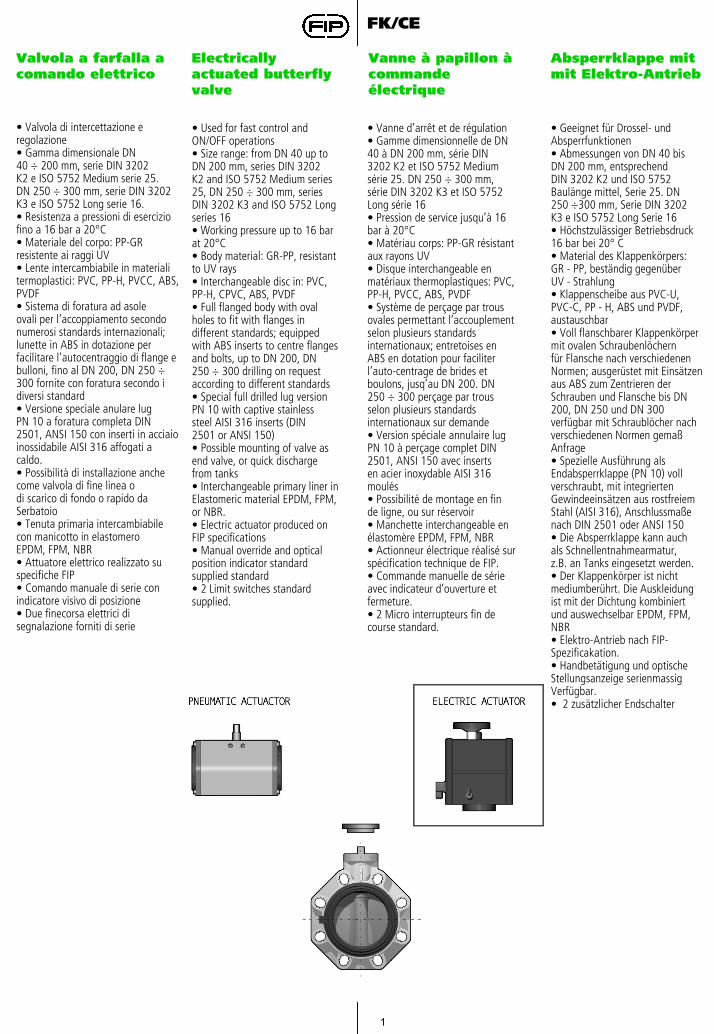
1 FK/CE Valvola a farfalla a comando elettrico Electrically actuated butterfly valve Vanne à papillon à commande électrique Absperrklappe mit mit Elektro-Antrieb • Geeignet für Drossel- und Absperrfunktionen • Abmessungen von DN 40 bis DN 200 mm, entsprechend DIN 3202 K2 und ISO 5752 Baulänge mittel, Serie 25. DN 250 ÷300 mm, Serie DIN 3202 K3 e ISO 5752 Long Serie 16 • Höchstzulässiger Betriebsdruck 16 bar bei 20° C • Material des Klappenkörpers: GR - PP, beständig gegenüber UV - Strahlung • Klappenscheibe aus PVC-U, PVC-C, PP - H, ABS und PVDF, austauschbar • Voll flanschbarer Klappenkörper mit ovalen Schraubenlöchern für Flansche nach verschiedenen Normen; ausgerüstet mit Einsätzen aus ABS zum Zentrieren der Schrauben und Flansche bis DN 200, DN 250 und DN 300 verfügbar mit Schraublöcher nach verschiedenen Normen gemaß Anfrage • Spezielle Ausführung als Endabsperrklappe (PN 10) voll verschraubt, mit integrierten Gewindeeinsätzen aus rostfreiem Stahl (AISI 316), Anschlussmaße nach DIN 2501 oder ANSI 150 • Die Absperrklappe kann auch als Schnellentnahmearmatur, z.B. an Tanks eingesetzt werden. • Der Klappenkörper ist nicht mediumberührt. Die Auskleidung ist mit der Dichtung kombiniert und auswechselbar EPDM, FPM, NBR • Elektro-Antrieb nach FIP- Spezificakation. • Handbetätigung und optische Stellungsanzeige serienmassig Verfügbar. • 2 zusätzlicher Endschalter • Valvola di intercettazione e regolazione • Gamma dimensionale DN 40 ÷ 200 mm, serie DIN 3202 K2 e ISO 5752 Medium serie 25. DN 250 ÷ 300 mm, serie DIN 3202 K3 e ISO 5752 Long serie 16. • Resistenza a pressioni di esercizio fino a 16 bar a 20°C • Materiale del corpo: PP-GR resistente ai raggi UV • Lente intercambiabile in materiali termoplastici: PVC, PP-H, PVCC, ABS, PVDF • Sistema di foratura ad asole ovali per l’accoppiamento secondo numerosi standards internazionali; lunette in ABS in dotazione per facilitare l’autocentraggio di flange e bulloni, fino al DN 200, DN 250 ÷ 300 fornite con foratura secondo i diversi standard • Versione speciale anulare lug PN 10 a foratura completa DIN 2501, ANSI 150 con inserti in acciaio inossidabile AISI 316 affogati a caldo. • Possibilità di installazione anche come valvola di fine linea o di scarico di fondo o rapido da Serbatoio • Tenuta primaria intercambiabile con manicotto in elastomero EPDM, FPM, NBR • Attuatore elettrico realizzato su specifiche FIP • Comando manuale di serie con indicatore visivo di posizione • Due finecorsa elettrici di segnalazione forniti di serie • Used for fast control and ON/OFF operations • Size range: from DN 40 up to DN 200 mm, series DIN 3202 K2 and ISO 5752 Medium series 25, DN 250 ÷ 300 mm, series DIN 3202 K3 and ISO 5752 Long series 16 • Working pressure up to 16 bar at 20°C • Body material: GR-PP, resistant to UV rays • Interchangeable disc in: PVC, PP-H, CPVC, ABS, PVDF • Full flanged body with oval holes to fit with flanges in different standards; equipped with ABS inserts to centre flanges and bolts, up to DN 200, DN 250 ÷ 300 drilling on request according to different standards • Special full drilled lug version PN 10 with captive stainless steel AISI 316 inserts (DIN 2501 or ANSI 150) • Possible mounting of valve as end valve, or quick discharge from tanks • Interchangeable primary liner in Elastomeric material EPDM, FPM, or NBR. • Electric actuator produced on FIP specifications • Manual override and optical position indicator standard supplied standard • 2 Limit switches standard supplied. • Vanne d’arrêt et de régulation • Gamme dimensionnelle de DN 40 à DN 200 mm, série DIN 3202 K2 et ISO 5752 Medium série 25. DN 250 ÷ 300 mm, série DIN 3202 K3 et ISO 5752 Long série 16 • Pression de service jusqu’à 16 bar à 20°C • Matériau corps: PP-GR résistant aux rayons UV • Disque interchangeable en matériaux thermoplastiques: PVC, PP-H, PVCC, ABS, PVDF • Système de perçage par trous ovales permettant l’accouplement selon plusieurs standards internationaux; entretoises en ABS en dotation pour faciliter l’auto-centrage de brides et boulons, jusq’au DN 200. DN 250 ÷ 300 perçage par trous selon plusieurs standards internationaux sur demande • Version spéciale annulaire lug PN 10 à perçage complet DIN 2501, ANSI 150 avec inserts en acier inoxydable AISI 316 moulés • Possibilité de montage en fin de ligne, ou sur réservoir • Manchette interchangeable en élastomère EPDM, FPM, NBR • Actionneur électrique réalisé sur spécification technique de FIP. • Commande manuelle de série avec indicateur d’ouverture et fermeture. • 2 Micro interrupteurs fin de course standard.
Transcript of Presentazione di PowerPoint - aliaxis-ui.ru · z.B. an Tanks eingesetzt we rden. • Der...
1
FK/CE
Valvola a farfalla a comando elettrico
Electrically actuated butterfly valve
Vanne à papillon àcommande électrique
Absperrklappe mit mit Elektro-Antrieb
• Geeignet für Drossel- undAbsperrfunktionen• Abmessungen von DN 40 bisDN 200 mm, entsprechendDIN 3202 K2 und ISO 5752Baulänge mittel, Serie 25. DN250 ÷300 mm, Serie DIN 3202K3 e ISO 5752 Long Serie 16• Höchstzulässiger Betriebsdruck16 bar bei 20° C• Material des Klappenkörpers:GR - PP, beständig gegenüberUV - Strahlung• Klappenscheibe aus PVC-U,PVC-C, PP - H, ABS und PVDF,austauschbar• Voll flanschbarer Klappenkörpermit ovalen Schraubenlöchernfür Flansche nach verschiedenenNormen; ausgerüstet mit Einsätzen aus ABS zum Zentrieren der Schrauben und Flansche bis DN 200, DN 250 und DN 300 verfügbar mit Schraublöcher nach verschiedenen Normen gemaßAnfrage• Spezielle Ausführung alsEndabsperrklappe (PN 10) voll verschraubt, mit integriertenGewindeeinsätzen aus rostfreiem Stahl (AISI 316), Anschlussmaße nach DIN 2501 oder ANSI 150• Die Absperrklappe kann auchals Schnellentnahmearmatur,z.B. an Tanks eingesetzt werden.• Der Klappenkörper ist nicht mediumberührt. Die Auskleidungist mit der Dichtung kombiniertund auswechselbar EPDM, FPM, NBR• Elektro-Antrieb nach FIP-Spezificakation.• Handbetätigung und optische Stellungsanzeige serienmassig Verfügbar.• 2 zusätzlicher Endschalter
• Valvola di intercettazione eregolazione• Gamma dimensionale DN40 ÷ 200 mm, serie DIN 3202K2 e ISO 5752 Medium serie 25.DN 250 ÷ 300 mm, serie DIN 3202K3 e ISO 5752 Long serie 16.• Resistenza a pressioni di eserciziofino a 16 bar a 20°C• Materiale del corpo: PP-GRresistente ai raggi UV• Lente intercambiabile in materialitermoplastici: PVC, PP-H, PVCC, ABS, PVDF• Sistema di foratura ad asoleovali per l’accoppiamento secondo numerosi standards internazionali; lunette in ABS in dotazione per facilitare l’autocentraggio di flange e bulloni, fino al DN 200, DN 250 ÷ 300 fornite con foratura secondo idiversi standard• Versione speciale anulare lugPN 10 a foratura completa DIN2501, ANSI 150 con inserti in acciaio inossidabile AISI 316 affogati a caldo.• Possibilità di installazione anchecome valvola di fine linea odi scarico di fondo o rapido daSerbatoio• Tenuta primaria intercambiabilecon manicotto in elastomeroEPDM, FPM, NBR• Attuatore elettrico realizzato su specifiche FIP• Comando manuale di serie con indicatore visivo di posizione• Due finecorsa elettrici di segnalazione forniti di serie
• Used for fast control andON/OFF operations• Size range: from DN 40 up toDN 200 mm, series DIN 3202K2 and ISO 5752 Medium series 25, DN 250 ÷ 300 mm, series DIN 3202 K3 and ISO 5752 Longseries 16• Working pressure up to 16 barat 20°C• Body material: GR-PP, resistantto UV rays• Interchangeable disc in: PVC,PP-H, CPVC, ABS, PVDF• Full flanged body with ovalholes to fit with flanges in different standards; equipped with ABS inserts to centre flangesand bolts, up to DN 200, DN250 ÷ 300 drilling on requestaccording to different standards• Special full drilled lug versionPN 10 with captive stainlesssteel AISI 316 inserts (DIN2501 or ANSI 150)• Possible mounting of valve asend valve, or quick dischargefrom tanks• Interchangeable primary liner inElastomeric material EPDM, FPM, or NBR.• Electric actuator produced on FIP specifications• Manual override and optical position indicator standard supplied standard• 2 Limit switches standard supplied.
• Vanne d’arrêt et de régulation• Gamme dimensionnelle de DN40 à DN 200 mm, série DIN3202 K2 et ISO 5752 Mediumsérie 25. DN 250 ÷ 300 mm,série DIN 3202 K3 et ISO 5752Long série 16• Pression de service jusqu’à 16bar à 20°C• Matériau corps: PP-GR résistantaux rayons UV• Disque interchangeable en matériaux thermoplastiques: PVC,PP-H, PVCC, ABS, PVDF• Système de perçage par trousovales permettant l’accouplementselon plusieurs standardsinternationaux; entretoises enABS en dotation pour faciliterl’auto-centrage de brides etboulons, jusq’au DN 200. DN250 ÷ 300 perçage par trousselon plusieurs standards internationaux sur demande• Version spéciale annulaire lugPN 10 à perçage complet DIN2501, ANSI 150 avec insertsen acier inoxydable AISI 316moulés• Possibilité de montage en finde ligne, ou sur réservoir• Manchette interchangeable enélastomère EPDM, FPM, NBR• Actionneur électrique réalisé sur spécification technique de FIP.• Commande manuelle de série avec indicateur d’ouverture et fermeture.• 2 Micro interrupteurs fin de course standard.
2
FK/CE
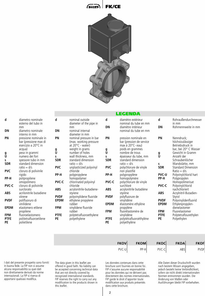
LEGENDAd nominal outside
diameter of the pipe in mm
DN nominal internal diameter in mm
PN nominal pressure in bar(max. working pressureat 20°C - water)
g weight in gramsU number of holess wall thickness, mmSDR standard dimension
ratio = d/sPVC unplasticized polyvinyl
chloridePP-H polypropylene
homopolymerPVC-C chlorinated polyvinyl
chlorideABS acrylonitrile-butadiene-
styrenePVDF polyvinylidene fluorideEPDM ethylene propylene
rubberFPM vinylidene fluoride
rubberPTFE polytetrafluoroethylenePE polyethylene
d diamètre extérieurnominal du tube en mm
DN diamètre intérieur nominal du tube en mm
PN pression nominale en bar (pression de service max à 20°C- eau)
g poids en grammesU nombre de trouss épaisseur du tube, mmSDR standard dimension
ratio = d/sPVC polychlorure de vinyle
non plastifiéPP-H polypropylène
homopolymèrePVC-C polychlorure de vinyle
surchloréABS acrylonitrile butadiène
styrènePVDF polyfluorure de
vinylidèneEPDM élastomère ethylène
propylèneFPM fluorélastomère de
vinylidènePTFE polytétrafluoroéthylènePE polyethylène
d Rohraußendurchmesserin mm
DN Rohrnennweite in mm
PN Nenndruck; höchstzulässigerBetriebsdruck inbar, bei 20° C Wasser
g Gewicht in GrammU Anzahl der
Schraubenlöchers Wandstärke, mmSDR Standard Dimension
Ratio = d/sPVC-U Polyvinylchlorid hartPP-H Polypropylen
HomopolimerisatPVC-C Polyvinylchlorid
nachchloriertABS Acrylnitril-Butadien-
StyrolPVDF PolyvinylidenfluoridEPDM Ethylenpropylen-
dienelastomerFPM FluorelastomerPTFE PolytetraflourethylenPE Polyethylen
d diametro nominaleesterno del tubo in mm
DN diametro nominaleinterno in mm
PN pressione nominale in bar (pressione max di esercizio a 20°C in acqua)
g peso in grammiU numero dei foris spessore tubo in mmSDR standard dimension
ratio = d/sPVC cloruro di polivinile
rigidoPP-H polipropilene
omopolimeroPVC-C cloruro di polivinile
surcloratoABS acrilonitrile butadiene
stirenePVDF polifluoruro di
vinilideneEPDM elastomero etilene
propileneFPM fluoroelastomeroPTFE politetrafluoroetilenePE polietilene
FKOV FKOM FKOC FKOA FKOF
PVC-U PP-H PVC-C ABS PVDF
I dati del presente prospetto sono fornitiin buona fede. La FIP non si assumealcuna responsabilità su quei datinon direttamente derivati da normeinternazionali. La FIP si riserva di apportarvi qualsiasi modifica.
The data given in this leaflet areoffered in good faith. No liability canbe accepted concerning technical datathat are not directly covered by recognized international standards. FIP reserves the right to carry out anymodification to the products shown inthis Ieaflet.
Les données contenues dans cettebrochure sont fournies en bonne foi.FIP n’assume aucune responsabilitépour les données qui ne dérivent pasdirectement des normes internationales.FIP garde le droit d’apporter toutemodification aux produits présentésdans cette brochure.
Alle Daten dieser Druckschrift wurdennach bestem Wissen angegeben,jedoch besteht keine Verbindlichkeit,sofern sie nicht direkt internationalenNormen entnommen wurden. Die Änderung von Maßen oder Ausführungen bleibt FIP vorbehalten.

3
FK/CE
Dati Tecnici
Technical Data
Données Techniques
Technische Daten
1
PVC PP-H
ABSPVC-C
PVDF
1
Variazione della pressione in funzione della temperatura per acqua o fluidi non pericolosi nei confronti dei quali il materiale è classificato CHIMICAMENTE RESISTENTE. In altri casi è richiesta un’adeguata diminuzione della pressione nominale PN. (25 anni con fattore di sicurezza).
Pressure/temperature rating forwater and harmless fluids to which the material is RESISTANT. In other cases a reduction of therated PN is required.(25 years with safety factor).
Variation de la pression enfonction de la température pourl’eau et les fluides non agressifspour lequel le matériau est considéréCHIMIQUEMENT RESISTANT. Pour les outres cas une diminution du PN est nécessaire.(25 années avec facteur de sécurité inclus).
Druck/Temperatur-Diagramm fürWasser und ungefährliche Mediengegen die das Material BESTÄNDIG ist.In allen anderen Fällen ist eineentsprechende Reduzierung derDruckstufe erforderlich.(Unter Berücksichtigung des Sicherheitsfaktors für 25 Jahre).
4
FK/CE
2
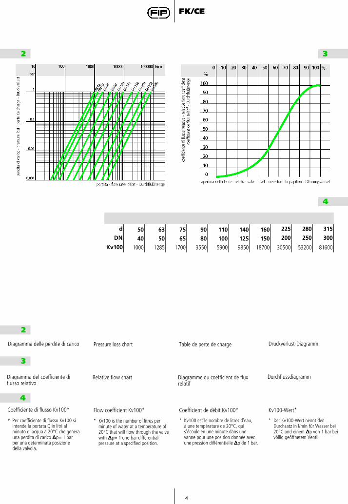
Diagramma delle perdite di carico Pressure loss chart Table de perte de charge Druckverlust-Diagramm
2 3
4
d 50 63 75 90 110 140 160 225 280 315
DN 40 50 65 80 100 125 150 200 250 300
Kv100 1000 1285 1700 3550 5900 9850 18700 30500 53200 81600
3
DurchflussdiagrammDiagramma del coefficiente di flusso relativo
Relative flow chart Diagramme du coefficient de flux relatif
4Coefficiente di flusso Kv100* Flow coefficient Kv100* Coefficient de débit Kv100* Kv100-Wert*
* Per coefficiente di flusso Kv100 si intende la portata Q in litri al minuto di acqua a 20°C che genera una perdita di carico ∆p= 1 bar per una determinata posizione della valvola.
* Kv100 est le nombre de litres d’eau,à une température de 20°C, quis’écoule en une minute dans unevanne pour une position donnée avecune pression différentielle ∆p de 1 bar.
* Der Kv100-Wert nennt denDurchsatz in l/min für Wasser bei20°C und einem ∆p von 1 bar beivöllig geöffnetem Ventil.
* Kv100 is the number of litres perminute of water at a temperature of20°C that will flow through the valvewith ∆p= 1 one-bar differential-pressure at a specified position.
5
FK/CE
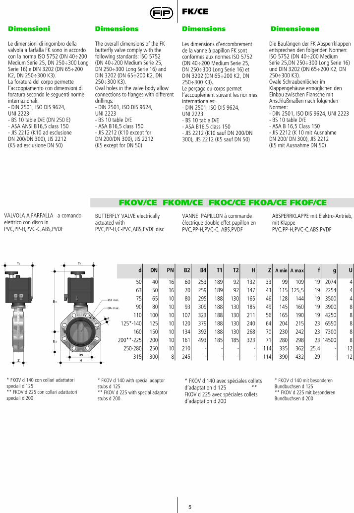
Dimensioni Dimensions Dimensions Dimensionen
Le dimensioni di ingombro della valvola a farfalla FK sono in accordo con la norma ISO 5752 (DN 40÷200 Medium Serie 25, DN 250÷300 Long Serie 16) e DIN 3202 (DN 65÷200 K2, DN 250÷300 K3).La foratura del corpo permettel’accoppiamento con dimensioni di foratura secondo le seguenti norme internazionali:- DIN 2501, ISO DIS 9624,UNI 2223- BS 10 table D/E (DN 250 E)- ASA ANSI B16,5 class 150- JIS 2212 (K10 ad esclusioneDN 200/DN 300), JIS 2212(K5 ad esclusione DN 50)
The overall dimensions of the FKbutterfly valve comply with thefollowing standards: ISO 5752(DN 40÷200 Medium Serie 25,DN 250÷300 Long Serie 16) andDIN 3202 (DN 65÷200 K2, DN250÷300 K3).Oval holes in the valve body allowconnections to flanges with differentdrillings:- DIN 2501, ISO DIS 9624,UNI 2223- BS 10 table D/E- ASA B16,5 class 150- JIS 2212 (K10 except forDN 200/DN 300), JIS 2212(K5 except for DN 50)
Die Baulängen der FK Absperrklappen entsprechen den folgenden Normen: ISO 5752 (DN 40÷200 Medium Serie 25,DN 250÷300 Long Serie 16) und DIN 3202 (DN 65÷200 K2, DN 250÷300 K3).Ovale Schraubenlöcher imKlappengehäuse ermöglichen denEinbau zwischen Flansche mitAnschlußmaßen nach folgendenNormen:- DIN 2501, ISO DIS 9624, UNI 2223- BS 10 table D/E- ASA B 16,5 Class 150- JIS 2212 (K 10 mit AusnahmeDN 200/ DN 300), JIS 2212(K5 mit Ausnahme DN 50)
Les dimensions d’encombrementde la vanne à papillon FK sontconformes aux normes ISO 5752(DN 40÷200 Medium Serie 25,DN 250÷300 Long Serie 16) etDIN 3202 (DN 65÷200 K2, DN250÷300 K3).Le perçage du corps permet l’accouplement suivant les nor mesinternationales:- DIN 2501, ISO DIS 9624,UNI 2223- BS 10 table D/E- ASA B16,5 class 150- JIS 2212 (K10 sauf DN 200/DN300), JIS 2212 (K5 sauf DN 50)
FKOV/CE FKOM/CE FKOC/CE FKOA/CE FKOF/CE
VALVOLA A FARFALLA a comando elettrico con disco in PVC,PP-H,PVC-C,ABS,PVDF
BUTTERFLY VALVE electricallyactuated withPVC,PP-H,C-PVC,ABS,PVDF disc
VANNE PAPILLON à commande électrique double effet papillon en PVC,PP-H,PVC-C, ABS,PVDF
ABSPERRKLAPPE mit Elektro-Antrieb, mit Klappe PVC,PP-H,PVC-C,ABS,PVDF
* FKOV d 140 con collari adattatori speciali d 125 ** FKOV d 225 con collari adattatori speciali d 200
* FKOV d 140 with special adaptorstubs d 125** FKOV d 225 with special adaptorstubs d 200
d DN PN B2 B4 T1 T2 H Z A min A max f g U
50 40 16 60 253 189 92 132 33 99 109 19 2074 463 50 16 70 259 189 92 147 43 115 125,5 19 2254 475 65 10 80 295 188 130 165 46 128 144 19 3500 490 80 10 93 309 188 130 185 49 145 160 19 3900 8
110 100 10 107 323 188 130 211 56 165 190 19 4250 8125*-140 125 10 120 379 188 130 240 64 204 215 23 6550 8
160 150 10 134 392 188 130 268 70 230 242 23 7300 8200**-225 200 10 161 493 185 185 323 71 280 298 23 14500 8
250-280 250 10 210 - - - - 114 335 362 25,4 - 12315 300 8 245 - - - - 114 390 432 29 - 12
* FKOV d 140 mit besonderen Bundbuchsen d 125 ** FKOV d 225 mit besonderen Bundbuchsen d 200
* FKOV d 140 avec spéciales collets d’adaptation d 125 ** FKOV d 225 avec spéciales collets d’adaptation d 200
6
FK/CE
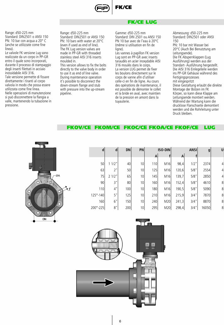
FK/CE LUG
Range: d50-225 mmStandard: DIN2501 o ANSI 150PN: 10 bar con acqua a 20° C(anche se utilizzate come finelinea).Le valvole FK versione Lug sonorealizzate da un corpo in PP-GRentro il quale sono incorporati,durante il processo di stampaggiodegli inserti filettati in acciaioinossidabile AISI 316.Tale versione permette di fissaredirettamente i tiranti al corpovalvola in modo che possa essereutilizzata come fine linea.Nelle operazioni di manutenzionesi può disconnettere la flangia avalle, mantenendo la tubazione inpressione.
Gamme: d50-225 mmStandard: DIN 2501 ou ANSI 150PN 10 bar avec de l’eau à 20°C(même si utilisation en fin deligne).Les vannes à papillon FK versionLug sont en PP-GR avec insertstaraudés en acier inoxydable AISI316 moulés dans le corps.La version LUG permet de fixerles boulons directement sur lecorps de vanne afin d’utilisercelle-ci en fin de ligne. Au coursdes opérations de maintenance, ilest possible de démonter le colletet la bride en aval, avec maintiende la pression en amont dans latuyauterie.
Range: d50-225 mmStandard: DIN2501 or ANSI 150PN: 10 bars with water at 20°C(even if used as end of line).The FK Lug version valves aremade in PP-GR with threadedstainless steel AISI 316 insertsmoulded in.This version allows to fix the boltsdirectly to the valve body in orderto use it as end of line valve.During maintenance operationit’s possible to disconnect thedown-stream flange and stubwith pressure into the up-streampipeline.
Abmessung: d50-225 mmStandard: DIN2501 oder ANSI150PN: 10 bar mit Wasser bei20°C (Auch Bei Benutztung amLeitungsende).Die FK Absperrklappen (LugAusführung) werden aus derStandart- Ausführung hergestellt.Die AISI 316 Einlegeteile werdenins PP-GR Gehäuse während desFertigingsprozessesmit eingespritztDiese Gestaltung erlaubt die direkteMontage der Bolzen im FKKörper, so kann diese Klappe amLeitungsende montiert werden.Während der Wartung kann diedrucklose Flanschseite demontiertwerden und die Rohrleitung unterDruck bleiben.
FKOV/CE FKOM/CE FKOC/CE FKOA/CE FKOF/CE LUG
g
A f A f
50 1 1/2" 40 10 110 M16 98,4 1/2" 2374 4
63 2" 50 10 125 M16 120,6 5/8" 2554 4
75 2 1/2" 65 10 145 M16 139,7 5/8" 2850 4
90 3" 80 10 160 M16 152,4 5/8" 4610 8
110 4" 100 10 180 M16 190,5 5/8" 5090 8
125*-140 5" 125 10 210 M16 215,9 3/4" 7870 8
160 6" 150 10 240 M20 241,3 3/4" 8870 8
200*-225 8" 200 10 295 M20 298,4 3/4" 16050 8
ISO-DIN ANSI Ud d DN PN
7
FK/CE
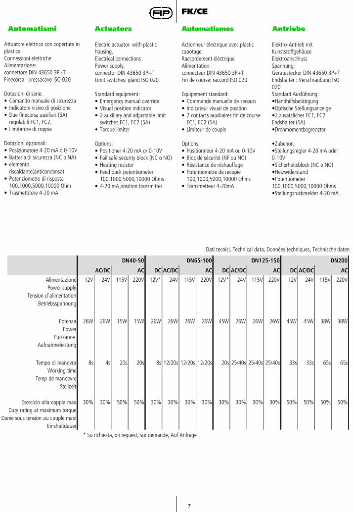
Automatismi Actuators AntriebeAutomatismes
Attuatore elettrico con copertura in plastica.Connessioni elettricheAlimentazione: connettore DIN 43650 3P+TFinecorsa: pressacavo ISO 020
Dotazioni di serie:• Comando manuale di sicurezza• Indicatore visivo di posizione• Due finecorsa ausiliari (5A)
regolabili FC1, FC2.• Limitatore di coppia
Dotazioni opzionali:• Posizionatore 4-20 mA o 0-10V• Batteria di sicurezza (NC o NA)• elemento
riscaldante(anticondensa)• Potenziometro di risposta
100,1000,5000,10000 Ohm • Trasmettitore 4-20 mA
Electric actuator with plastic housing.Electrical connectionsPower supply: connector DIN 43650 3P+TLimit switches: gland ISO 020
Standard equipment:• Emergency manual override• Visual position indicator• 2 auxiliary and adjustable limit
switches FC1, FC2 (5A)• Torque limiter
Options:• Positioner 4-20 mA or 0-10V• Fail safe security block (NC o NO)• Heating resistor• Feed back potentiometer
100,1000,5000,10000 Ohms• 4-20 mA position transmitter.
Actionneur électrique avec plastic capotage.Raccordement éléctriqueAlimentation: connecteur DIN 43650 3P+TFin de course: raccord ISO 020
Equipement standard:• Commande manuelle de secours• Indicateur visual de position• 2 contacts auxiliaires fin de course
FC1, FC2 (5A)• Limiteur de couple
Options:• Positionneur 4-20 mA ou 0-10V• Bloc de sécurité (NF ou NO)• Résistance de réchauffage• Potentiomètre de recopie
100,1000,5000,10000 Ohms• Transmetteur 4-20mA
Elektro-Antrieb mit KunststoffgehäuseElektroanschlussSpannung: Geratestecker DIN 43650 3P+TEndshalter : Verschraubung ISO 020Standard Ausführung:•Handhilfsbetätigung•Optische Stellungsanzeige•2 zusätzlicher FC1, FC2Endshalter (5A)•Drehmomentbegrenzter
•Zubehör:•Stellungsregler 4-20 mA oder 0-10V•Sicherheitsblock (NC o NO)•Heizwiderstand•Potentiometer 100,1000,5000,10000 Ohms•Stellungsruckmelder 4-20 mA .
Dati tecnici, Technical data, Données techniques, Technische daten
DN40-50 DN65-100 DN125-150 DN200
AC DC AC/DC AC DC AC/DC AC DC AC/DC AC
Alimentazione 12V 24V 115V 220V 12V* 24V 115V 220V 12V* 24V 115V 220V 12V 24V 115V 220VPower supply
Tension d'alimentationBetriebsspannung
Potenza 26W 26W 15W 15W 26W 26W 26W 26W 45W 26W 26W 26W 45W 45W 38W 38WPower
Puissance Aufnahmeleistung
Tempo di manovra 8s 4s 20s 20s 8s 12/20s 12/20s 12/20s 20s 25/40s 25/40s 25/40s 33s 33s 65s 65sWorking time
Temp de manoevreStellzeit
Esercizio alla coppia max 30% 30% 50% 50% 30% 30% 30% 30% 30% 30% 30% 30% 50% 50% 50% 50%Duty rating at maximum torque
Durée sous tension au couple maxiEinshaltdauer
AC/DC
* Su richiesta, on request, sur demande, Auf Anfrage
8
FK/CE
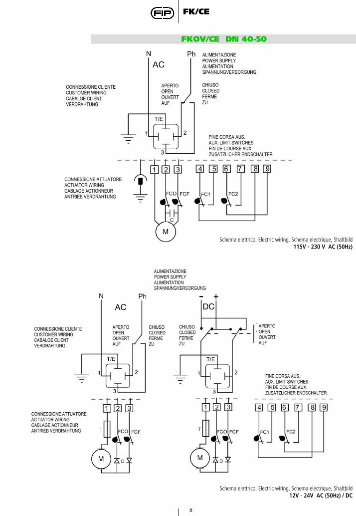
FKOV/CE DN 40-50
Schema elettrico, Electric wiring, Schema electrique, Shaltbild115V - 230 V AC (50Hz)
Schema elettrico, Electric wiring, Schema electrique, Shaltbild12V - 24V AC (50Hz) / DC
9
FK/CE
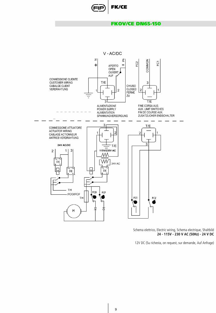
FKOV/CE DN65-150
Schema elettrico, Electric wiring, Schema electrique, Shaltbild24 - 115V - 230 V AC (50Hz) - 24 V DC
12V DC (Su richesta, on request, sur demande, Auf Anfrage)
10
FK/CE
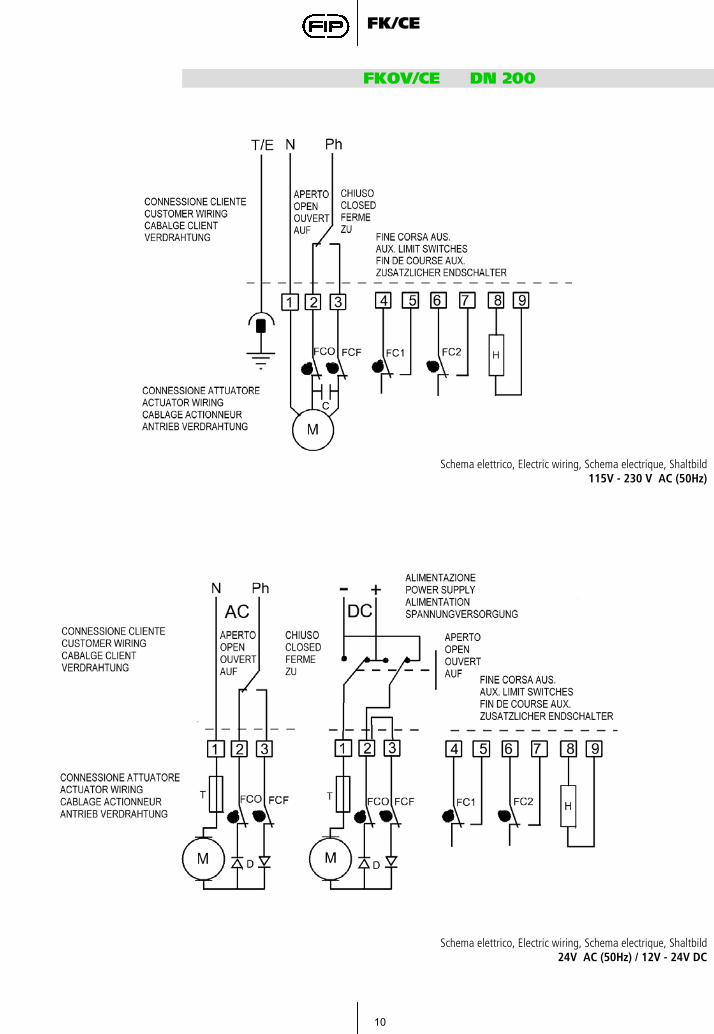
FKOV/CE DN 200
Schema elettrico, Electric wiring, Schema electrique, Shaltbild115V - 230 V AC (50Hz)
Schema elettrico, Electric wiring, Schema electrique, Shaltbild24V AC (50Hz) / 12V - 24V DC
11
FK/CE
Accessori attuatore
Actuator accessories
Accessoires pour l’actionneur
Antriebe Zubehör
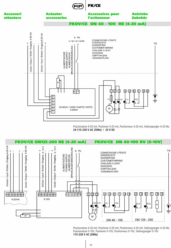
FKOV/CE DN 40 - 100 RE (4-20 mA)
Posizionatore 4-20 mA, Positioner 4-20 mA, Positionneur 4-20 mA, Stellungsregler 4-20 Ma24-115-230 V AC (50Hz) / 24 V DC
FKOV/CE DN125-200 RE (4-20 mA) FKOV/CE DN 40-100 RV (0-10V)
Posizionatore 4-20 mA, Positioner 4-20 mA, Positionneur 4-20 mA, Stellungsregler 4-20 MaPosizionatore 0-10V, Positioner 0-10V, Positionneur 0-10V, Stellungsregler 0-10V115-230 V AC (50Hz)
12
FK/CE
Accessori attuatore
Actuator accessories
Accessoires pour l’actionneur
Antriebe Zubehör
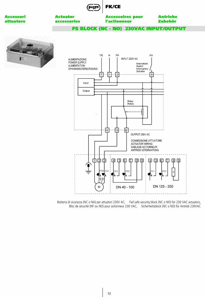
FS BLOCK (NC - NO) 230VAC INPUT/OUTPUT
Batteria di sicurezza (NC o NA) per attuatori 230V AC, Fail safe security block (NC o NO) for 230 VAC actuators,Bloc de sécurité (NF ou NO) pour actionneur 230 VAC, Sicherheitsblock (NC o NO) für Antrieb 230VAC
13
FK/CE
Accessori attuatore
Actuator accessories
Accessoires pour l’actionneur
Antriebe Zubehör
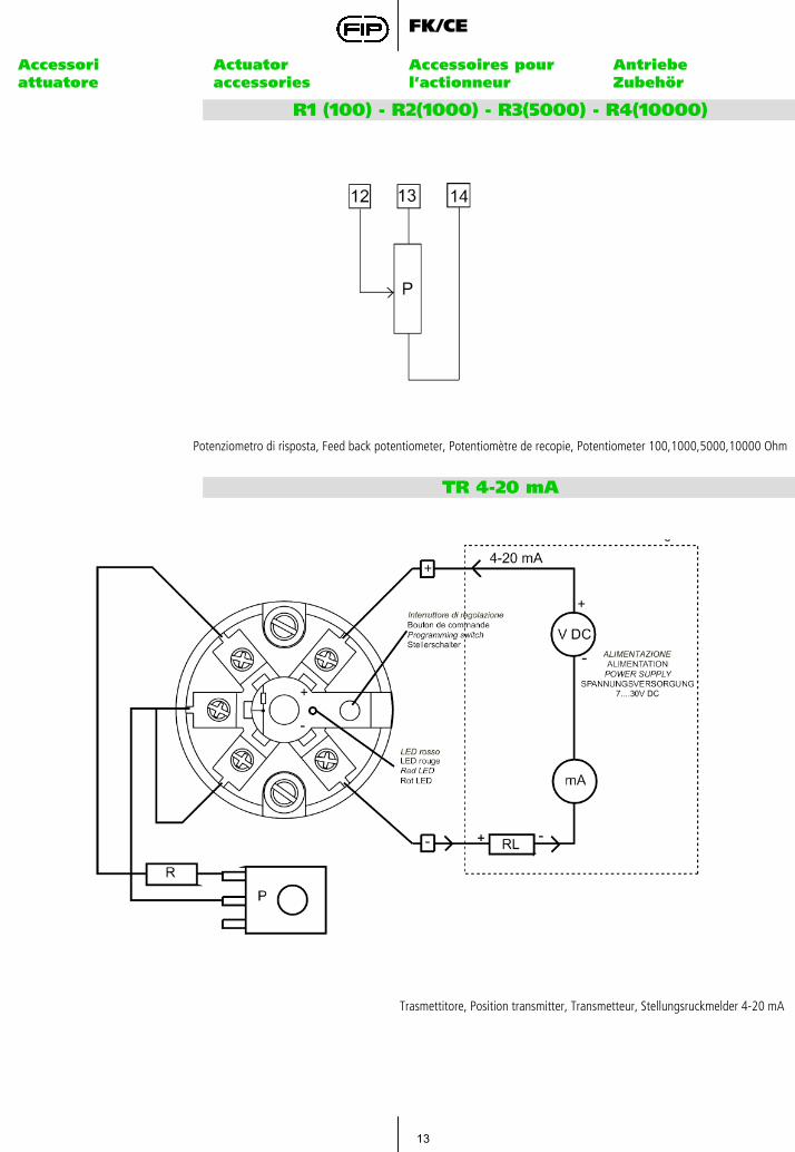
R1 (100) - R2(1000) - R3(5000) - R4(10000)
Potenziometro di risposta, Feed back potentiometer, Potentiomètre de recopie, Potentiometer 100,1000,5000,10000 Ohm
TR 4-20 mA
Trasmettitore, Position transmitter, Transmetteur, Stellungsruckmelder 4-20 mA

14
FK/CE
Posizionamento delle lunette
Inserts posiotioning Positionnements des entretoises
Positionen de Zentriereinsätze
Posizionamento delle lunette.Le lunette di autocentraggiodevono essere inserite nelle apposite guide delle asole sul corpo valvola lato scritte con le scritte verso l’alto, e posizionate secondo la tipologia di foratura delle flange come indicato nella tabella seguente:
The inserts have to be insertedinto the holes from the side ofthe body corresponding to themarking indicating the diameter,and positioned according to thetype of drilling of the flanges ashere after indicated:
Les entretoises doivent êtreinsérées dans les guides destrous, à partir du coté du corpscorrespondant aux marquages indiquant le diamètre, et positionnés selon le perçage des brides comme indiqué dans le tableau suivante:
in den Schraubenlöchern.Die Einsätze müssen axial indie ovalen Schraubenlöcherdes Gehäuses gemäß derPositionsangaben, eingesetzt werden.Die Position ist abhängig vonder Abmessung und der Serie, derder Flansch entspricht.
15
FK/CE
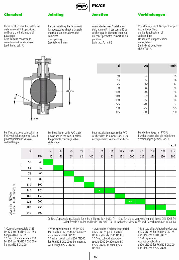
Giunzioni Jointing Jonction Verbindungen
Prima di effettuare l’installazionedella valvola FK è opportunoverificare che il diametro di passaggiodella cartella consenta lacorretta apertura del disco(vedi I min, tab. A)
Vor Montage der FKAbsperrklappenist zu überprüfen,ob die Bundbuchsen ein vollständigesÖffnen der Klappenscheibeermöglichen(I min-Maß beachten)siehe Tab. A
Before installing the FK valve itis suggested to check that stubinternal diameter allows the completedisc opening(see tab. A, I min)
Avant d’effectuer l’installationde la vanne FK il est conseillé devérifier que le diametre interieurdu collet permette l’ouverture dupapillon(voir tab. A, I min)
d DN I min
50 40 2563 50 2875 65 4790 80 64
110 100 84140 125 108160 150 134225 200 187280 250 225315 300 280
Per l’installazione con collari inPVC vedi nella seguente Tab. Bgli accoppiamenti valvola-collareflangia
For installation with PVC stubsplease see in the Tab. B belowthe possible couplings valve-stubflange
Pour installation avec collet PVCverifier dans le suivant Tab. B lesaccouplements vanne-collet-bride
Für die Montage mit PVC-UBundbuchsen siehe die möglichenVerbindungen gemaß Tab. B
* Con collare speciale d125 DN125 per FK d140 DN125 e flangia d140 DN125** Con collare speciale d200DN200 per FK d225 DN200 eflangia d225 DN200
* Mit spezieller Adapterbundbuchsed125 DN125 für FK d140 DN125und Flansche d140 DN125** Mit spezieller Adapterbundbuchsed200 DN200 für FK d225 DN200und Flansche d225 DN200
* With special stub d125 DN125 for FK d140 DN125 to be mountedwith flange d140 DN125** With special stub d200 DN200 for FK d225 DN200 to be mountedwith flange d225 DN200
* Avec collet d’adaptation spéciald125 DN125 pour FK d140 DN125 et bride d140 DN125** Avec collet d’adaptation speciald200 DN200 pour FK d225 DN200 et bride d225 DN200**
16
FK/CE
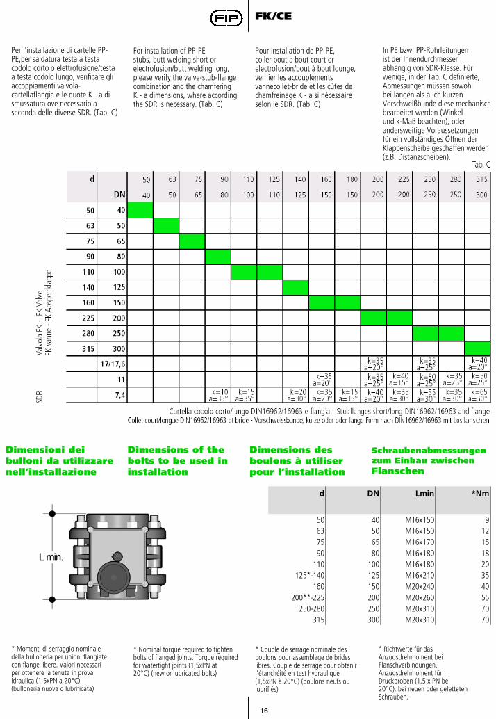
In PE bzw. PP-Rohrleitungenist der Innendurchmesserabhängig von SDR-Klasse. Fürwenige, in der Tab. C definierte,Abmessungen müssen sowohlbei langen als auch kurzenVorschweißbunde diese mechanischbearbeitet werden (Winkelund k-Maß beachten), oderandersweitige Voraussetzungenfür ein vollständiges Öffnen derKlappenscheibe geschaffen werden(z.B. Distanzscheiben).
Per l’installazione di cartelle PP-PE,per saldatura testa a testa codolo corto o elettrofusione/testaa testa codolo lungo, verificare gliaccoppiamenti valvola-cartellaflangia e le quote K - a di smussatura ove necessario a seconda delle diverse SDR. (Tab. C)
For installation of PP-PEstubs, butt welding short orelectrofusion/butt welding long,please verify the valve-stub-flangecombination and the chamferingK - a dimensions, where accordingthe SDR is necessary. (Tab. C)
Pour installation de PP-PE,coller bout a bout court orelectrofusion/bout à bout lounge,verifier les accouplements vannecollet-bride et les cùtes de chamfreinage K - a si nécessaire selon le SDR. (Tab. C)
Dimensioni deibulloni da utilizzarenell’installazione
Dimensions of thebolts to be used ininstallation
Dimensions desboulons à utiliserpour l’installation
Schraubenabmessungenzum Einbau zwischenFlanschen
d DN Lmin *Nm
50 40 M16x150 963 50 M16x150 1275 65 M16x170 1590 80 M16x180 18
110 100 M16x180 20125*-140 125 M16x210 35
160 150 M20x240 40200**-225 200 M20x260 55
250-280 250 M20x310 70315 300 M20x310 70
* Momenti di serraggio nominaledella bulloneria per unioni flangiatecon flange libere. Valori necessariper ottenere la tenuta in provaidraulica (1,5xPN a 20°C)(bulloneria nuova o lubrificata)
* Richtwerte für dasAnzugsdrehmoment beiFlanschverbindungen. Anzugsdrehmoment fürDruckproben (1,5 x PN bei20°C), bei neuen oder gefettetenSchrauben.
* Nominal torque required to tightenbolts of flanged joints. Torque requiredfor watertight joints (1,5xPN at20°C) (new or lubricated bolts)
* Couple de serrage nominale desboulons pour assemblage de brideslibres. Couple de serrage pour obtenirl’étanchéité en test hydraulique(1,5xPN à 20°C) (boulons neufs oulubrifiés)
17
FK/CE
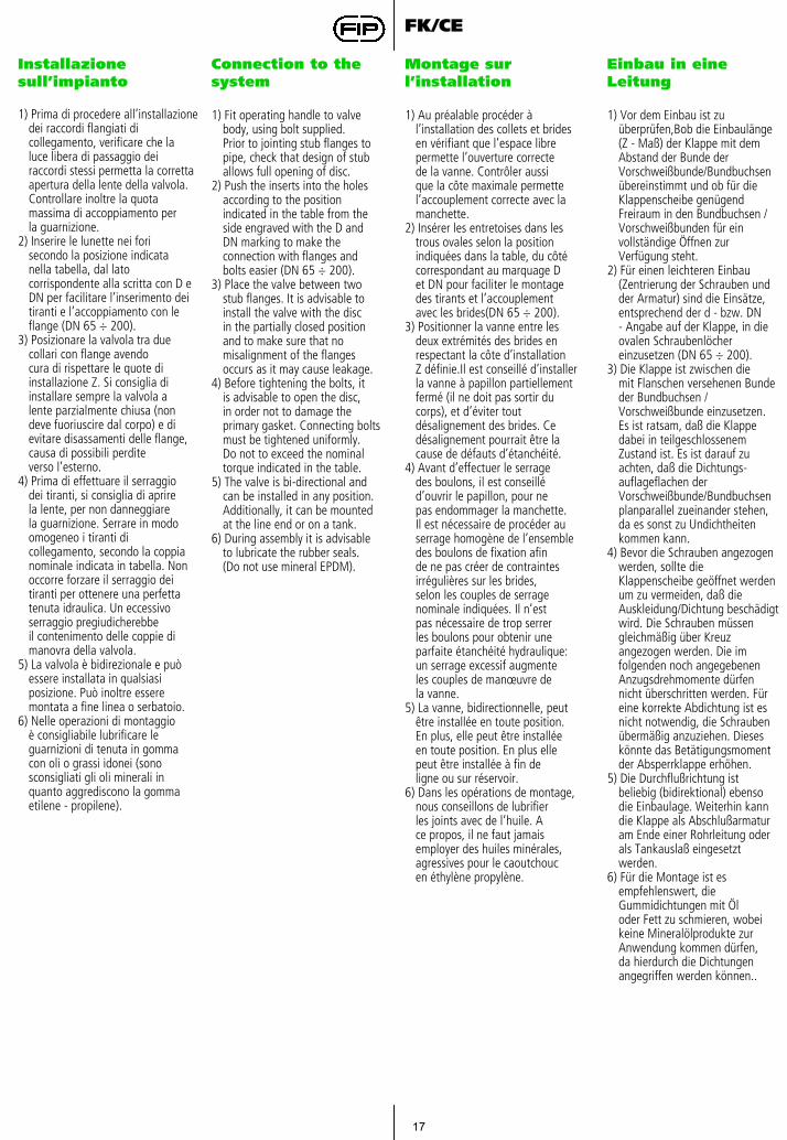
Installazione sull’impianto
Connection to the system
Montage sur l’installation
Einbau in eine Leitung
1) Prima di procedere all’installazionedei raccordi flangiati dicollegamento, verificare che laluce libera di passaggio dei raccordi stessi permetta la correttaapertura della lente della valvola.Controllare inoltre la quotamassima di accoppiamento perla guarnizione.
2) Inserire le lunette nei forisecondo la posizione indicatanella tabella, dal lato corrispondente alla scritta con D e DN per facilitare l’inserimento deitiranti e l’accoppiamento con leflange (DN 65 ÷ 200).
3) Posizionare la valvola tra duecollari con flange avendocura di rispettare le quote diinstallazione Z. Si consiglia diinstallare sempre la valvola alente parzialmente chiusa (nondeve fuoriuscire dal corpo) e dievitare disassamenti delle flange,causa di possibili perditeverso l’esterno.
4) Prima di effettuare il serraggiodei tiranti, si consiglia di aprirela lente, per non danneggiarela guarnizione. Serrare in modoomogeneo i tiranti di collegamento, secondo la coppia nominale indicata in tabella. Nonoccorre forzare il serraggio deitiranti per ottenere una perfettatenuta idraulica. Un eccessivoserraggio pregiudicherebbeil contenimento delle coppie dimanovra della valvola.
5) La valvola è bidirezionale e puòessere installata in qualsiasiposizione. Può inoltre esseremontata a fine linea o serbatoio.
6) Nelle operazioni di montaggioè consigliabile lubrificare leguarnizioni di tenuta in gommacon oli o grassi idonei (sonosconsigliati gli oli minerali inquanto aggrediscono la gommaetilene - propilene).
1) Fit operating handle to valvebody, using bolt supplied.Prior to jointing stub flanges topipe, check that design of stuballows full opening of disc.
2) Push the inserts into the holesaccording to the position indicated in the table from theside engraved with the D andDN marking to make the connection with flanges and bolts easier (DN 65 ÷ 200).
3) Place the valve between twostub flanges. It is advisable toinstall the valve with the discin the partially closed positionand to make sure that no misalignment of the flanges occurs as it may cause leakage.
4) Before tightening the bolts, itis advisable to open the disc,in order not to damage the primary gasket. Connecting boltsmust be tightened uniformly.Do not to exceed the nominaltorque indicated in the table.
5) The valve is bi-directional andcan be installed in any position.Additionally, it can be mountedat the line end or on a tank.
6) During assembly it is advisableto lubricate the rubber seals.(Do not use mineral EPDM).
1) Au préalable procéder à l’installation des collets et bridesen vérifiant que l’espace librepermette l’ouverture correctede la vanne. Contrôler aussique la côte maximale permettel’accouplement correcte avec lamanchette.
2) Insérer les entretoises dans lestrous ovales selon la positionindiquées dans la table, du côtécorrespondant au marquage Det DN pour faciliter le montagedes tirants et l’accouplementavec les brides(DN 65 ÷ 200).
3) Positionner la vanne entre lesdeux extrémités des brides enrespectant la côte d’installationZ définie.Il est conseillé d’installerla vanne à papillon partiellementfermé (il ne doit pas sortir du corps), et d’éviter tout désalignement des brides. Cedésalignement pourrait être lacause de défauts d’étanchéité.
4) Avant d’effectuer le serragedes boulons, il est conseilléd’ouvrir le papillon, pour nepas endommager la manchette.Il est nécessaire de procéder auserrage homogène de l’ensembledes boulons de fixation afinde ne pas créer de contraintesirrégulières sur les brides,selon les couples de serragenominale indiquées. Il n’estpas nécessaire de trop serrerles boulons pour obtenir uneparfaite étanchéité hydraulique:un serrage excessif augmenteles couples de manœuvre dela vanne.
5) La vanne, bidirectionnelle, peutêtre installée en toute position.En plus, elle peut être installéeen toute position. En plus ellepeut être installée à fin deligne ou sur réservoir.
6) Dans les opérations de montage,nous conseillons de lubrifierles joints avec de l’huile. Ace propos, il ne faut jamaisemployer des huiles minérales,agressives pour le caoutchoucen éthylène propylène.
1) Vor dem Einbau ist zu überprüfen,Bob die Einbaulänge(Z - Maß) der Klappe mit dem Abstand der Bunde der Vorschweißbunde/Bundbuchsen übereinstimmt und ob für die Klappenscheibe genügend Freiraum in den Bundbuchsen / Vorschweißbunden für ein vollständige Öffnen zur Verfügung steht.
2) Für einen leichteren Einbau(Zentrierung der Schrauben undder Armatur) sind die Einsätze,entsprechend der d - bzw. DN- Angabe auf der Klappe, in dieovalen Schraubenlöcher einzusetzen (DN 65 ÷ 200).
3) Die Klappe ist zwischen diemit Flanschen versehenen Bunde der Bundbuchsen /Vorschweißbunde einzusetzen.Es ist ratsam, daß die Klappe dabei in teilgeschlossenemZustand ist. Es ist darauf zu achten, daß die Dichtungs-auflageflachen der Vorschweißbunde/Bundbuchsenplanparallel zueinander stehen,da es sonst zu Undichtheitenkommen kann.
4) Bevor die Schrauben angezogenwerden, sollte die Klappenscheibe geöffnet werden um zu vermeiden, daß die Auskleidung/Dichtung beschädigt wird. Die Schrauben müssen gleichmäßig über Kreuz angezogen werden. Die im folgenden noch angegebenen Anzugsdrehmomente dürfen nicht überschritten werden. Für eine korrekte Abdichtung ist es nicht notwendig, die Schrauben übermäßig anzuziehen. Dieses könnte das Betätigungsmoment der Absperrklappe erhöhen.
5) Die Durchflußrichtung ist beliebig (bidirektional) ebenso die Einbaulage. Weiterhin kann die Klappe als Abschlußarmaturam Ende einer Rohrleitung oder als Tankauslaß eingesetzt werden.
6) Für die Montage ist es empfehlenswert, die Gummidichtungen mit Öloder Fett zu schmieren, wobeikeine Mineralölprodukte zurAnwendung kommen dürfen,da hierdurch die Dichtungenangegriffen werden können..
18
FK/CE
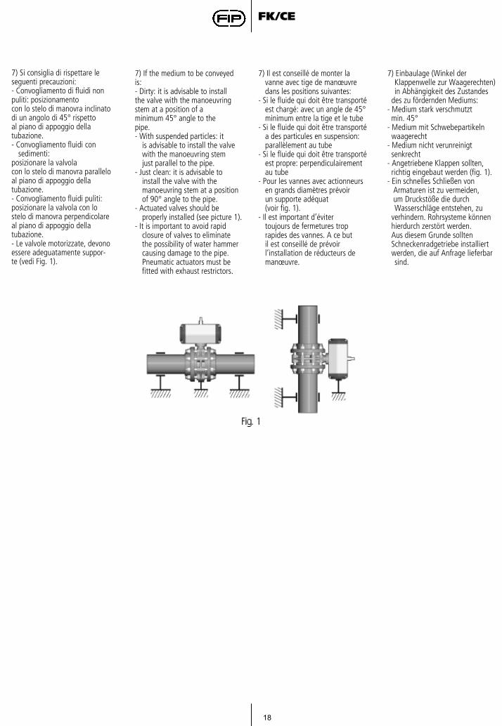
7) Si consiglia di rispettare leseguenti precauzioni:- Convogliamento di fluidi nonpuliti: posizionamentocon lo stelo di manovra inclinatodi un angolo di 45° rispettoal piano di appoggio dellatubazione.- Convogliamento fluidi con
sedimenti:posizionare la valvolacon lo stelo di manovra paralleloal piano di appoggio dellatubazione.- Convogliamento fluidi puliti:posizionare la valvola con lostelo di manovra perpendicolareal piano di appoggio dellatubazione.- Le valvole motorizzate, devonoessere adeguatamente suppor-te (vedi Fig. 1).
7) If the medium to be conveyedis:- Dirty: it is advisable to installthe valve with the manoeuvringstem at a position of aminimum 45° angle to thepipe.- With suspended particles: it
is advisable to install the valvewith the manoeuvring stemjust parallel to the pipe.
- Just clean: it is advisable toinstall the valve with the manoeuvring stem at a position of 90° angle to the pipe.
- Actuated valves should be properly installed (see picture 1).
- It is important to avoid rapidclosure of valves to eliminatethe possibility of water hammercausing damage to the pipe. Pneumatic actuators must be fitted with exhaust restrictors.
7) Il est conseillé de monter lavanne avec tige de manœuvredans les positions suivantes:
- Si le fluide qui doit être transportéest chargé: avec un angle de 45° minimum entre la tige et le tube
- Si le fluide qui doit être transportéa des particules en suspension: parallèlement au tube
- Si le fluide qui doit être transportéest propre: perpendiculairementau tube
- Pour les vannes avec actionneursen grands diamètres prévoirun supporte adéquat(voir fig. 1).
- Il est important d’évitertoujours de fermetures troprapides des vannes. A ce butil est conseillé de prévoirl’installation de réducteurs demanœuvre.
7) Einbaulage (Winkel der Klappenwelle zur Waagerechten) in Abhängigkeit des Zustandes
des zu fördernden Mediums:- Medium stark verschmutztmin. 45°
- Medium mit Schwebepartikelnwaagerecht
- Medium nicht verunreinigtsenkrecht
- Angetriebene Klappen sollten,richtig eingebaut werden (fig. 1).
- Ein schnelles Schließen vonArmaturen ist zu vermeiden,um Druckstöße die durch Wasserschläge entstehen, zu
verhindern. Rohrsysteme könnenhierdurch zerstört werden.Aus diesem Grunde solltenSchneckenradgetriebe installiertwerden, die auf Anfrage lieferbar sind.
19
FK/CE
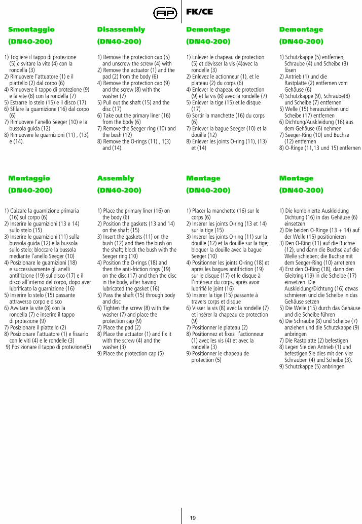
Smontaggio
(DN40-200)
Disassembly
(DN40-200)
Demontage
(DN40-200)
Demontage
(DN40-200)
1) Togliere il tappo di protezione(5) e svitare la vite (4) con la rondella (3)
2) Rimuovere l’attuatore (1) e il piattello (2) dal corpo (6)
4) Rimuovere il tappo di protezione (9) e la vite (8) con la rondella (7)
5) Estrarre lo stelo (15) e il disco (17)6) Sfilare la guarnizione (16) dal corpo
(6)7) Rimuovere l’anello Seeger (10) e la
bussola guida (12)8) Rimuovere le guarnizioni (11) , (13)
e (14).
1) Remove the protection cap (5)and unscrew the screw (4) with
2) Remove the actuator (1) and the pad (2) from the body (6)
4) Remove the protection cap (9)and the screw (8) with thewasher (7)
5) Pull out the shaft (15) and thedisc (17)
6) Take out the primary liner (16)from the body (6)
7) Remove the Seeger ring (10) and the bush (12)
8) Remove the O-rings (11) , 1(3) and (14).
1) Enlever le chapeau de protection (5) et dévisser la vis (4)avec la rondelle (3)
2) Enlevez le actionneur (1), et le plateau (2) du corps (6)
4) Enlever le chapeau de protection (9) et la vis (8) avec la rondelle (7)
5) Enlever la tige (15) et le disque (17)
6) Sortir la manchette (16) du corps (6)
7) Enlever la bague Seeger (10) et la douille (12)
8) Enlever les joints O-ring (11), (13) et (14)
1) Schutzkappe (5) entfernen,Schraube (4) und Scheibe (3)lösen
2) Antrieb (1) und dieRastplatte (2) entfernen vom Gehäuse (6)
4) Schutzkappe (9), Schraube(8)und Scheibe (7) entfernen
5) Welle (15) herausziehen undScheibe (17) entfernen
6) Dichtung/Auskleidung (16) ausdem Gehäuse (6) nehmen
7) Seeger-Ring (10) und Buchse(12) entfernen
8) O-Ringe (11,13 und 15) entfernen
Montaggio
(DN40-200)
Assembly
(DN40-200)
Montage
(DN40-200)
Montage
(DN40-200)
1) Calzare la guarnizione primaria(16) sul corpo (6)
2) Inserire le guarnizioni (13 e 14)sullo stelo (15)
3) Inserire le guarnizioni (11) sullabussola guida (12) e la bussolasullo stelo; bloccare la bussolamediante l’anello Seeger (10)
4) Posizionare le guarnizioni (18)e successivamente gli anelliantifrizione (19) sul disco (17) e il disco all’interno del corpo, dopo aver lubrificato la guarnizione (16)
5) Inserire lo stelo (15) passante attraverso corpo e disco
6) Avvitare la vite (8) con larondella (7) e inserire il tappodi protezione (9)
7) Posizionare il piattello (2) 8) Posizionare l’attuatore (1) e fissarlo
con le viti (4) e le rondelle (3)9) Posizionare il tappo di protezione(5)
1) Place the primary liner (16) onthe body (6)
2) Position the gaskets (13 and 14) on the shaft (15)
3) Insert the gaskets (11) on thebush (12) and then the bush on the shaft; block the bush with the Seeger ring (10)
4) Position the O-rings (18) andthen the anti-friction rings (19)on the disc (17) and then the disc in the body, after havinglubricated the gasket (16)
5) Pass the shaft (15) through bodyand disc
6) Tighten the screw (8) with the washer (7) and place theprotection cap (9)
7) Place the pad (2) 8) Place the actuator (1) and fix it
with the screw (4) and the washer (3)
9) Place the protection cap (5)
1) Placer la manchette (16) sur le corps (6)
2) Insérer les joints O-ring (13 et 14) sur la tige (15)
3) Insérer les joints O-ring (11) sur la douille (12) et la douille sur la tige; bloquer la douille avec la bague Seeger (10)
4) Positionner les joints O-ring (18) et aprés les bagues antifriction (19) sur le disque (17) et le disque à l’intérieur du corps, aprés avoir lubrifié le joint (16)
5) Insérer la tige (15) passante à travers corps et disque
6) Visser la vis (8) avec la rondelle (7) et insérer la chapeau de protection (9)
7) Positionner le plateau (2) 8) Positionnez et fixez l’actionneur
(1) avec les vis (4) et avec la rondelle (3)
9) Positionner le chapeau de protection (5)
1) Die kombinierte Auskleidung Dichtung (16) in das Gehäuse (6) einsetzen
2) Die beiden O-Ringe (13 + 14) auf der Welle (15) positionieren
3) Den O-Ring (11) auf die Buchse (12), und dann die Buchse auf die Welle schieben; die Buchse mit dem Seeger-Ring (10) arretieren
4) Erst den O-Ring (18), dann den Gleitring (19) in die Scheibe (17) einsetzen. Die Auskleidung/Dichtung (16) etwas schmieren und die Scheibe in das Gehäuse setzen
5) Die Welle (15) durch das Gehäuse und die Scheibe führen
6) Die Schraube (8) und Scheibe (7) anziehen und die Schutzkappe (9) anbringen
7) Die Rastplatte (2) befestigen8) Legen Sie den Antrieb (1) und
befestigen Sie dies mit den vier Schrauben (4) und Scheibe (3).
9) Schutzkappe (5) anbringen
20
FK/CE
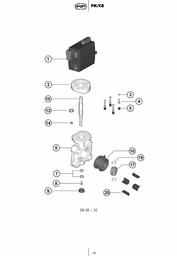
DN 40 ÷ 50

21
FK/CE
DN 65 ÷ 200
22
FK/CE
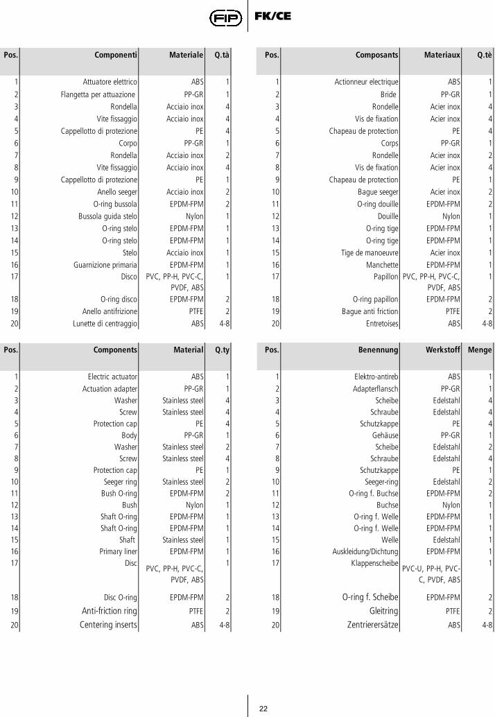
Pos. Componenti Materiale Q.tà Pos. Composants Materiaux Q.tè
1 Attuatore elettrico ABS 1 1 Actionneur electrique ABS 1
2 Flangetta per attuazione PP-GR 1 2 Bride PP-GR 1
3 Rondella Acciaio inox 4 3 Rondelle Acier inox 4
4 Vite fissaggio Acciaio inox 4 4 Vis de fixation Acier inox 4
5 Cappellotto di protezione PE 4 5 Chapeau de protection PE 4
6 Corpo PP-GR 1 6 Corps PP-GR 1
7 Rondella Acciaio inox 2 7 Rondelle Acier inox 2
8 Vite fissaggio Acciaio inox 4 8 Vis de fixation Acier inox 4
9 Cappellotto di protezione PE 1 9 Chapeau de protection PE 1
10 Anello seeger Acciaio inox 2 10 Bague seeger Acier inox 2
11 O-ring bussola EPDM-FPM 2 11 O-ring douille EPDM-FPM 2
12 Bussola guida stelo Nylon 1 12 Douille Nylon 1
13 O-ring stelo EPDM-FPM 1 13 O-ring tige EPDM-FPM 1
14 O-ring stelo EPDM-FPM 1 14 O-ring tige EPDM-FPM 1
15 Stelo Acciaio inox 1 15 Tige de manoeuvre Acier inox 1
16 Guarnizione primaria EPDM-FPM 1 16 Manchette EPDM-FPM 117 Disco PVC, PP-H, PVC-C,
PVDF, ABS1 17 Papillon PVC, PP-H, PVC-C,
PVDF, ABS1
18 O-ring disco EPDM-FPM 2 18 O-ring papillon EPDM-FPM 2
19 Anello antifrizione PTFE 2 19 Bague anti friction PTFE 2
20 Lunette di centraggio ABS 4-8 20 Entretoises ABS 4-8
Pos. Components Material Q.ty Pos. Benennung Werkstoff Menge
1 Electric actuator ABS 1 1 Elektro-antireb ABS 1
2 Actuation adapter PP-GR 1 2 Adapterflansch PP-GR 13 Washer Stainless steel 4 3 Scheibe Edelstahl 44 Screw Stainless steel 4 4 Schraube Edelstahl 45 Protection cap PE 4 5 Schutzkappe PE 46 Body PP-GR 1 6 Gehäuse PP-GR 17 Washer Stainless steel 2 7 Scheibe Edelstahl 28 Screw Stainless steel 4 8 Schraube Edelstahl 49 Protection cap PE 1 9 Schutzkappe PE 1
10 Seeger ring Stainless steel 2 10 Seeger-ring Edelstahl 211 Bush O-ring EPDM-FPM 2 11 O-ring f. Buchse EPDM-FPM 212 Bush Nylon 1 12 Buchse Nylon 113 Shaft O-ring EPDM-FPM 1 13 O-ring f. Welle EPDM-FPM 114 Shaft O-ring EPDM-FPM 1 14 O-ring f. Welle EPDM-FPM 115 Shaft Stainless steel 1 15 Welle Edelstahl 116 Primary liner EPDM-FPM 1 16 Auskleidung/Dichtung EPDM-FPM 117 Disc
PVC, PP-H, PVC-C, PVDF, ABS
1 17 KlappenscheibePVC-U, PP-H, PVC-
C, PVDF, ABS
1
18 Disc O-ring EPDM-FPM 2 18 O-ring f. Scheibe EPDM-FPM 2
19 Anti-friction ring PTFE 2 19 Gleitring PTFE 2
20 Centering inserts ABS 4-8 20 Zentrierersätze ABS 4-8