Programmhandbuch Programming manual - ifm.com · system zusammenpassen, ist ein erneuter Download...
143
Programmhandbuch Programming manual Download Tool DEUTSCH ENGLISH R Sachnr. 7390277 / 00 07 / 2003
Transcript of Programmhandbuch Programming manual - ifm.com · system zusammenpassen, ist ein erneuter Download...
ProgrammhandbuchProgramming manual
Download Tool
DEU
TSC
HEN
GLI
SH
R
Sach
nr.
7390
277
/00
07
/200
3
DOWNLOAD CP9010
SEITE 2
Microsoft und Windows sind eingetragene Warenzeichen der Microsoft Corporation.
Die überlassene Software ist für den normalen Gebrauch auf handelsüblichen Personalcomputerngeeignet. Eine Gewähr für unterbrechungsfreien oder fehlerfreien Betrieb oder die Freiheit von Com-puterviren sowie dafür, daß jeder eventuell auftretende Fehler beseitigt wird, kann nach dem Standder Softwaretechnik nicht übernommen werden. Insbesondere haftet ifm electronic gmbh bei einemfehlerhaften Programm nicht für beim Kunden entstehende Kosten (z.B. Wartung, Reparatur oderMängelbehebung). Der Ausschluß gilt nicht für Schäden, für die aufgrund unabdingbarer gesetzlicherVorschriften zwingend gehaftet wird.
Das Programm ist speziell für die Steuerungssysteme der ifm electronic gmbh entwickelt worden.Daher ist die Funktion nur bei diesen Steuerungen möglich. Versuche der Ankoppelung an Fremdsy-steme können zu gravierenden Schäden führen.
DOWNLOAD CP9010
SEITE 3
Bestimmungsgemäße Verwendung
Die Software ermöglicht das Up- und Downloaden von Projektdateien bzw. An-wendungsprogrammen in ifm Steuerungen ecomat 100 Typ R 360 oder in diekompatible Platinensteuerung CS0015. Betriebssysteme können aktualisiert bzw.installiert werden.
Eigenschaften im Überblick:
• Up- und Download über serielle oder CAN-Schnittstelle• Sichern von Speicherinhalten• Wartungsfunktionen• Password-Schutz für Projektdateien
Die IEC 1131-3 konformen Projekte bzw. Anwendungsprogramme müssen zumDownload als Hex-Datei vorliegen (*.H86). Nach dem Laden eines Anwendungs-programmes kann dieses gestartet werden.
Für sicherheitsgerichtete Steuerungen wird die Unversehrtheit der H86-Datei mit-tels der Prüfsumme der Datei überprüft (CRC).
Eine H86-Datei kann mit einer in der Steuerung befindlichen Software verglichenwerden. Die Prüfsumme der H86-Datei wird dabei mit der Prüfsumme in derSteuerung verglichen.
Ein bereits in der Steuerung befindliches Anwendungsprogramm kann ausgelesenwerden (Upload). Um sicherzustellen, dass Anwendungsprogramm und Betriebs-system zusammenpassen, ist ein erneuter Download nur möglich, wenn die aktu-elle Version des Betriebssystems die gleiche ist wie zum Zeitpunkt des Uploads.
Die Version bzw. Kennung des Betriebssystems1) kann abgefragt werden.
Ausserdem ist es möglich nichtflüchtige Daten der Steuerung auszulesen undwieder zurückzuschreiben (remanente „auto-save“ Daten, Flash-Daten wie z.BBetriebsstundenzähler, Kennlinien, Tabellen etc. oder Daten des seriellenEEPROMs) 2).
Systemvoraussetzungen
• Personal-Computer IBM oder kompatibel; Pentium Prozessor• Microsoft Windows ® 3.1 , 95 , 98 , 2000 , ME , XP , NT4 (SP6)• 4 MB RAM-Speicher (oder höher)• 4 MB freier Speicherplatz auf der Festplatte• 1 freie serielle Schnittstelle (RS 232)
oder alternativ 1 CAN-Interface (z.B. CPC-PP; Bestell-Nr. EC2040)
DEU
TSC
H
1) wird auch als „Laufzeitsystem“ bezeichnet;das Laufzeitsystem ist das Ladeprogramm für ein Anwendungsprogramm
2) möglich ab Betriebsystem Version „I“
Installation
• Starten Sie Windows und legen Sie die CD-ROM in Ihr CD-Laufwerk• Wählen Sie in der Menüleiste „Start“ ➔ „Ausführen“.• Geben Sie „D:\setup.exe“ ein. Bestätigen Sie mit OK.Sollte Ihr CD-ROM Laufwerk mit einem anderen Buchstaben als „D“ angespro-chen werden, geben Sie an Stelle von D diesen Buchstaben ein.• Folgen Sie den Anweisungen des Setup-Programms.
Hinweis: Eine bereits installierte ältere Version des Download Tools muss vor einerNeuinstallation gelöscht bzw. deinstalliert werden.
Programmfunktionen
■■ Programm starten
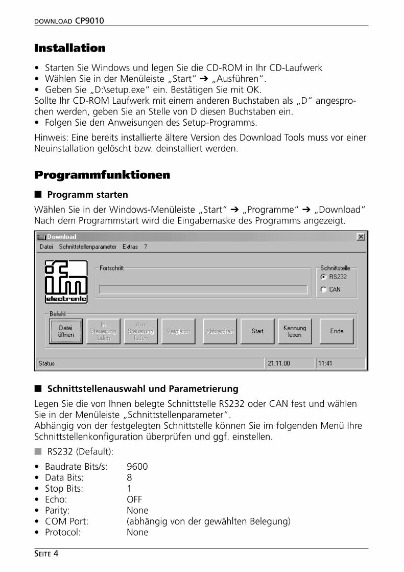
Wählen Sie in der Windows-Menüleiste „Start“ ➔ „Programme“ ➔ „Download“Nach dem Programmstart wird die Eingabemaske des Programms angezeigt.
■■ Schnittstellenauswahl und Parametrierung
Legen Sie die von Ihnen belegte Schnittstelle RS232 oder CAN fest und wählenSie in der Menüleiste „Schnittstellenparameter“.Abhängig von der festgelegten Schnittstelle können Sie im folgenden Menü IhreSchnittstellenkonfiguration überprüfen und ggf. einstellen.
■■ RS232 (Default):
• Baudrate Bits/s: 9600• Data Bits: 8• Stop Bits: 1• Echo: OFF• Parity: None• COM Port: (abhängig von der gewählten Belegung)• Protocol: None
DOWNLOAD CP9010
SEITE 4
DEU
TSC
H
DOWNLOAD CP9010
SEITE 5
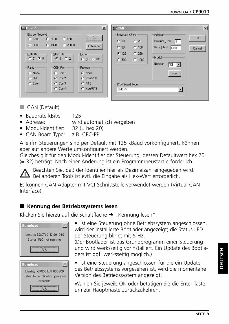
■■ CAN (Default):
• Baudrate kBit/s: 125• Adresse: wird automatisch vergeben• Modul-Identifier: 32 (= hex 20)• CAN Board Type: z.B. CPC-PP
Alle ifm Steuerungen sind per Default mit 125 kBaud vorkonfiguriert, könnenaber auf andere Werte umkonfiguriert werden.Gleiches gilt für den Modul-Identifier der Steuerung, dessen Defaultwert hex 20(= 32) beträgt. Nach einer Änderung ist ein Programmneustart erforderlich.
Beachten Sie, daß der Identifier hier als Dezimalzahl eingegeben wird.Bei anderen Tools ist evtl. die Eingabe als Hex-Wert erforderlich.
Es können CAN-Adapter mit VCI-Schnittstelle verwendet werden (Virtual CANInterface).
■■ Kennung des Betriebssystems lesen
Klicken Sie hierzu auf die Schaltfläche ➔ „Kennung lesen“.
• Ist eine Steuerung ohne Betriebssystem angeschlossen,wird der installierte Bootlader angezeigt; die Status-LEDder Steuerung blinkt mit 5 Hz.(Der Bootlader ist das Grundprogramm einer Steuerungund wird werksseitig vorinstalliert. Ein Update des Bootla-ders ist ggf. werksseitig möglich.)
• Ist eine Steuerung angeschlossen für die ein Updatedes Betriebssystems vorgesehen ist, wird die momentaneVersion des Betriebssystem angezeigt.
Wählen Sie jeweils OK oder betätigen Sie die Enter-Tasteum zur Hauptmaste zurückzukehren.
Identity: BOOTLD_D 991019
Status: PLC not running
Identity: CR0501_H 000309
Status: No application program
available
■■ Festlegen der Dateioptionen
• Wählen Sie in der Menüleiste „Datei“ ➔ „Dateioptionen“.
• Bestimmen Sie die Datentypen, die sie down-oder uploaden möchten.
Defaulteinstellung:„Laufzeitsystem/Anwendungsprogramm“.
Wählen Sie OK oder betätigen Sie die Enter-Taste um zur Hauptmaste zurückzukehren.
Hinweis: Es ist möglich mehrere Dateioptionen anzu-wählen. Beim Upload aus der Steuerung wird
stets eine H86-Datei erzeugt die alle angewählten Datentypen enthält.
Aus dieser Datei kann der gewünschte Datentyp generiert werden indem voreinem Download durch erneutes Aufrufen der Dateioptionen der gewünschteDatentyp angewählt wird.
■■ Neuinstallation/Update des Betriebssystems
Wurde bei der Abfrage „Kennung lesen“ festgestellt, daß kein oder ein veraltetesBetriebssystem vorhanden ist, müssen Sie ein aktuelles System downloaden.
• Klicken Sie auf die Schaltfläche ➔ „Datei öffnen“.
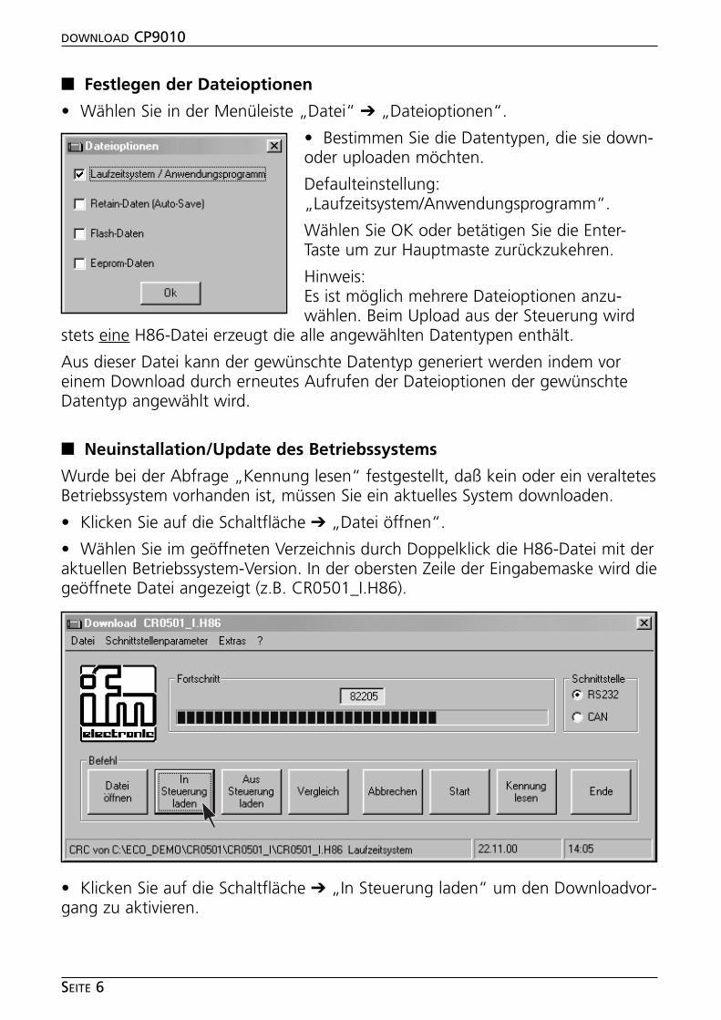
• Wählen Sie im geöffneten Verzeichnis durch Doppelklick die H86-Datei mit deraktuellen Betriebssystem-Version. In der obersten Zeile der Eingabemaske wird diegeöffnete Datei angezeigt (z.B. CR0501_I.H86).
• Klicken Sie auf die Schaltfläche ➔ „In Steuerung laden“ um den Downloadvor-gang zu aktivieren.
DOWNLOAD CP9010
SEITE 6
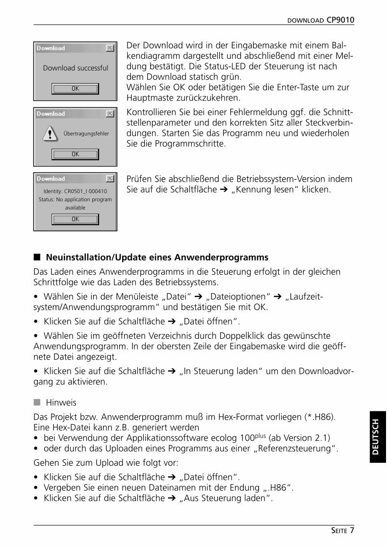
Der Download wird in der Eingabemaske mit einem Bal-kendiagramm dargestellt und abschließend mit einer Mel-dung bestätigt. Die Status-LED der Steuerung ist nachdem Download statisch grün.Wählen Sie OK oder betätigen Sie die Enter-Taste um zurHauptmaste zurückzukehren.
Kontrollieren Sie bei einer Fehlermeldung ggf. die Schnitt-stellenparameter und den korrekten Sitz aller Steckverbin-dungen. Starten Sie das Programm neu und wiederholenSie die Programmschritte.
Prüfen Sie abschließend die Betriebssystem-Version indemSie auf die Schaltfläche ➔ „Kennung lesen“ klicken.
■■ Neuinstallation/Update eines Anwenderprogramms
Das Laden eines Anwenderprogramms in die Steuerung erfolgt in der gleichenSchrittfolge wie das Laden des Betriebssystems.
• Wählen Sie in der Menüleiste „Datei“ ➔ „Dateioptionen“ ➔ „Laufzeit-system/Anwendungsprogramm“ und bestätigen Sie mit OK.
• Klicken Sie auf die Schaltfläche ➔ „Datei öffnen“.
• Wählen Sie im geöffneten Verzeichnis durch Doppelklick das gewünschteAnwendungsprogramm. In der obersten Zeile der Eingabemaske wird die geöff-nete Datei angezeigt.
• Klicken Sie auf die Schaltfläche ➔ „In Steuerung laden“ um den Downloadvor-gang zu aktivieren.
■■ Hinweis
Das Projekt bzw. Anwenderprogramm muß im Hex-Format vorliegen (*.H86).Eine Hex-Datei kann z.B. generiert werden• bei Verwendung der Applikationssoftware ecolog 100plus (ab Version 2.1)• oder durch das Uploaden eines Programms aus einer „Referenzsteuerung“.
Gehen Sie zum Upload wie folgt vor:
• Klicken Sie auf die Schaltfläche ➔ „Datei öffnen“.• Vergeben Sie einen neuen Dateinamen mit der Endung „.H86“.• Klicken Sie auf die Schaltfläche ➔ „Aus Steuerung laden“.
DEU
TSC
H
DOWNLOAD CP9010
SEITE 7
Download successful
Übertragungsfehler
Identity: CR0501_I 000410
Status: No application program
available
■■ Starten der installierten Anwendersoftware
• Klicken Sie auf die Schaltfläche ➔ „Start“.
Das Programm wird gestartet; die Status-LED der Steuerung geht von statischgrün in Blinken über.
Der Startbefehl bleibt auch nach einem Spannungsausfall gesetzt, d.h. dasAnwenderprogramm startet beim Wiedereinschalten der Spannung automatisch.
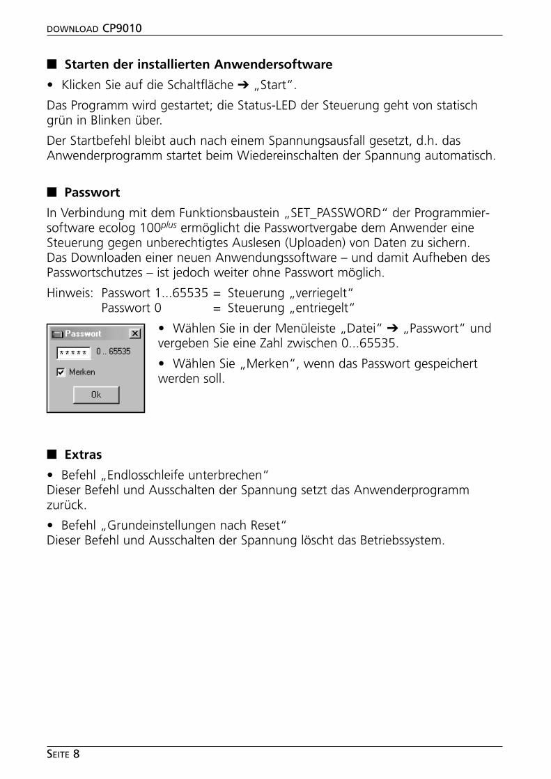
■■ Passwort
In Verbindung mit dem Funktionsbaustein „SET_PASSWORD“ der Programmier-software ecolog 100plus ermöglicht die Passwortvergabe dem Anwender eineSteuerung gegen unberechtigtes Auslesen (Uploaden) von Daten zu sichern.Das Downloaden einer neuen Anwendungssoftware – und damit Aufheben desPasswortschutzes – ist jedoch weiter ohne Passwort möglich.
Hinweis: Passwort 1...65535 = Steuerung „verriegelt“Passwort 0 = Steuerung „entriegelt“
• Wählen Sie in der Menüleiste „Datei“ ➔ „Passwort“ undvergeben Sie eine Zahl zwischen 0...65535.
• Wählen Sie „Merken“, wenn das Passwort gespeichertwerden soll.
■■ Extras
• Befehl „Endlosschleife unterbrechen“Dieser Befehl und Ausschalten der Spannung setzt das Anwenderprogrammzurück.
• Befehl „Grundeinstellungen nach Reset“Dieser Befehl und Ausschalten der Spannung löscht das Betriebssystem.
DOWNLOAD CP9010
SEITE 8

Programming manual
ENG
LISH
DOWNLOAD CP9010
PAGE 9
Microsoft and Windows are registered trademarks of Microsoft Corporation.
The software is suitable for normal use on common personal computers. According to the presentstate of software technology no guarantee can be assumed for the correct operation or absence ofcomputer viruses nor for the removal of any fault which may occur. In the case of an incorrect pro-gram ifm electronic cannot be held liable for cost incurred at the customer (e.g. maintenance, repairor rectification of faults). The exclusion does not apply to damage for which liability is mandatoryaccording to peremptory legal provisions.
The program has been specifically developed for the control systems of ifm electronic gmbh. It there-fore only functions with these controllers. Attempts to use it with systems from other manufacturerscan lead to serious damage.
Functions and features
The software enables the upload and download of project files or applicationprograms in the ifm ecomat 100 controllers type R360 or in the compatibleCS0015 pcb controller. Operating systems can be updated or installed.
Overview of the features:
• upload and download via the serial or CAN interface• saving memory contents• maintenance functions• password protection for project files
The projects or application programs according to IEC 1131-3 require a hex file(*.H86) for downloading. After the loading of an application program they canbe started.
For safety-oriented controllers the intactness of the H86 file is checked by meansof the check sum of the file (CRC).
An H86 file can be verified by a software in the controller. The check sum of theH86 file is compared with the check sum in the controller.
An application program in the controller can be uploaded. To ensure that theapplication program and the operating system match, another download is onlypossible if the current version of the operating system is the same as at the timeof the upload.
The version or the identity of the operating system1) can be displayed.
Moreover it is possible to upload and download non-volatile data of the con-troller (retain "auto-save" data, flash data such as operating time counter, char-acteristic curves, tables etc. or data of the serial EEPROM)2).
System requirements
• personal computer IBM or compatible, Pentium processor• Microsoft Windows ® 3.1 , 95 , 98 , 2000 , ME , XP , NT4 (SP6)• 4 MB RAM memory (or higher)• 4 MB free memory capacity on hard disk• 1 free serial interface (RS 232)
or 1 CAN interface (e.g. CPC-PP; order no. EC2040) as an alternative
DOWNLOAD CP9010
PAGE 10
1) is also called "Runtime System";the runtime system is the loading program for an application program
2) possible as from operation system version "I"
Installation
• Start Windows and insert the CD-ROM into your CD drive.• In the menu bar select "Start" ➔ "Run", enter "D:\setup.exe" and press OK.If your CD-ROM drive is addressed with a letter other than "D", enter this letterinstead of D.• Follow the instructions of the setup program.
Note: An older version of the download tool already installed must be deleted ordeinstalled before a new installation.
Program functions
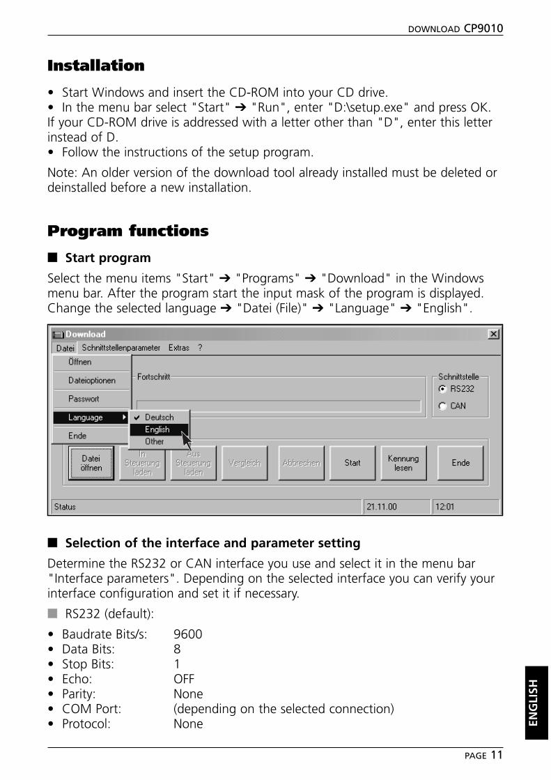
■■ Start program
Select the menu items "Start" ➔ "Programs" ➔ "Download" in the Windowsmenu bar. After the program start the input mask of the program is displayed.Change the selected language ➔ "Datei (File)" ➔ "Language" ➔ "English".
■■ Selection of the interface and parameter setting
Determine the RS232 or CAN interface you use and select it in the menu bar"Interface parameters". Depending on the selected interface you can verify yourinterface configuration and set it if necessary.
■■ RS232 (default):
• Baudrate Bits/s: 9600• Data Bits: 8• Stop Bits: 1• Echo: OFF• Parity: None• COM Port: (depending on the selected connection)• Protocol: None EN
GLI
SH
DOWNLOAD CP9010
PAGE 11
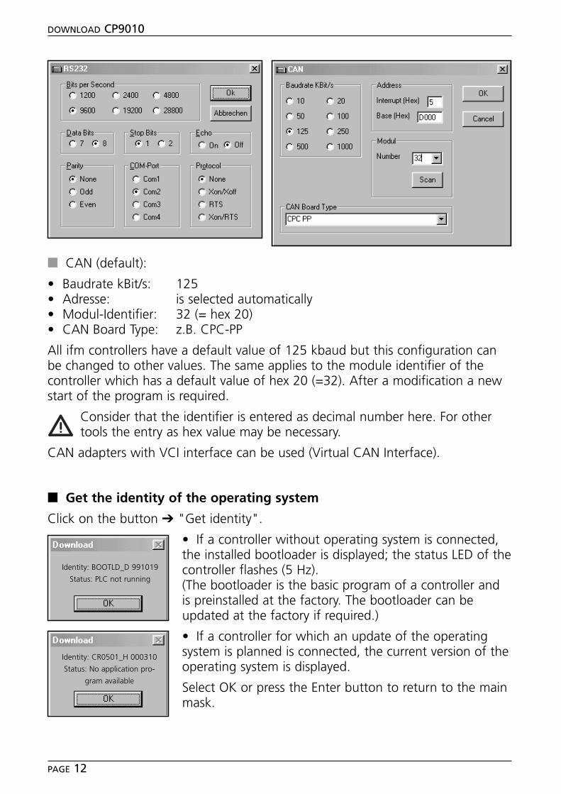
■■ CAN (default):
• Baudrate kBit/s: 125• Adresse: is selected automatically• Modul-Identifier: 32 (= hex 20)• CAN Board Type: z.B. CPC-PP
All ifm controllers have a default value of 125 kbaud but this configuration canbe changed to other values. The same applies to the module identifier of thecontroller which has a default value of hex 20 (=32). After a modification a newstart of the program is required.
Consider that the identifier is entered as decimal number here. For othertools the entry as hex value may be necessary.
CAN adapters with VCI interface can be used (Virtual CAN Interface).
■■ Get the identity of the operating system
Click on the button ➔ "Get identity".
• If a controller without operating system is connected,the installed bootloader is displayed; the status LED of thecontroller flashes (5 Hz).(The bootloader is the basic program of a controller andis preinstalled at the factory. The bootloader can beupdated at the factory if required.)
• If a controller for which an update of the operatingsystem is planned is connected, the current version of theoperating system is displayed.
Select OK or press the Enter button to return to the mainmask.
DOWNLOAD CP9010
PAGE 12
Identity: BOOTLD_D 991019
Status: PLC not running
Identity: CR0501_H 000310
Status: No application pro-
gram available
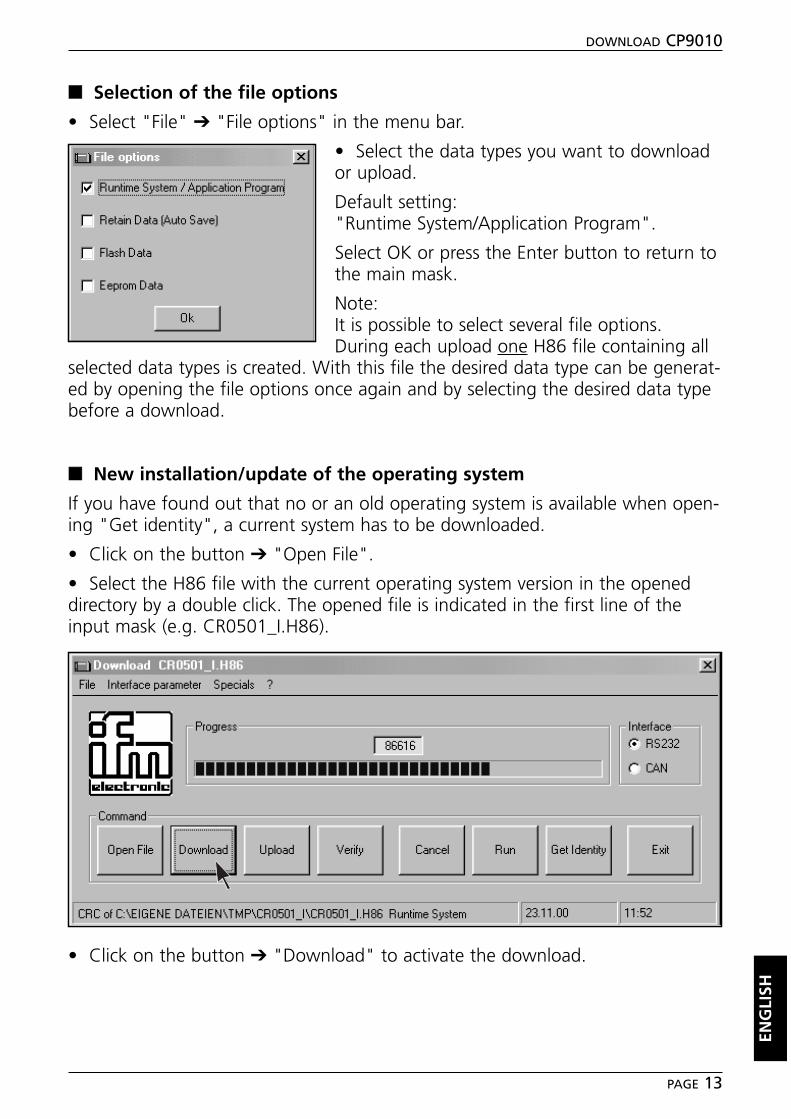
■■ Selection of the file options
• Select "File" ➔ "File options" in the menu bar.
• Select the data types you want to downloador upload.
Default setting:"Runtime System/Application Program".
Select OK or press the Enter button to return tothe main mask.
Note: It is possible to select several file options.During each upload one H86 file containing all
selected data types is created. With this file the desired data type can be generat-ed by opening the file options once again and by selecting the desired data typebefore a download.
■■ New installation/update of the operating system
If you have found out that no or an old operating system is available when open-ing "Get identity", a current system has to be downloaded.
• Click on the button ➔ "Open File".
• Select the H86 file with the current operating system version in the openeddirectory by a double click. The opened file is indicated in the first line of theinput mask (e.g. CR0501_I.H86).
• Click on the button ➔ "Download" to activate the download.
ENG
LISH
DOWNLOAD CP9010
PAGE 13
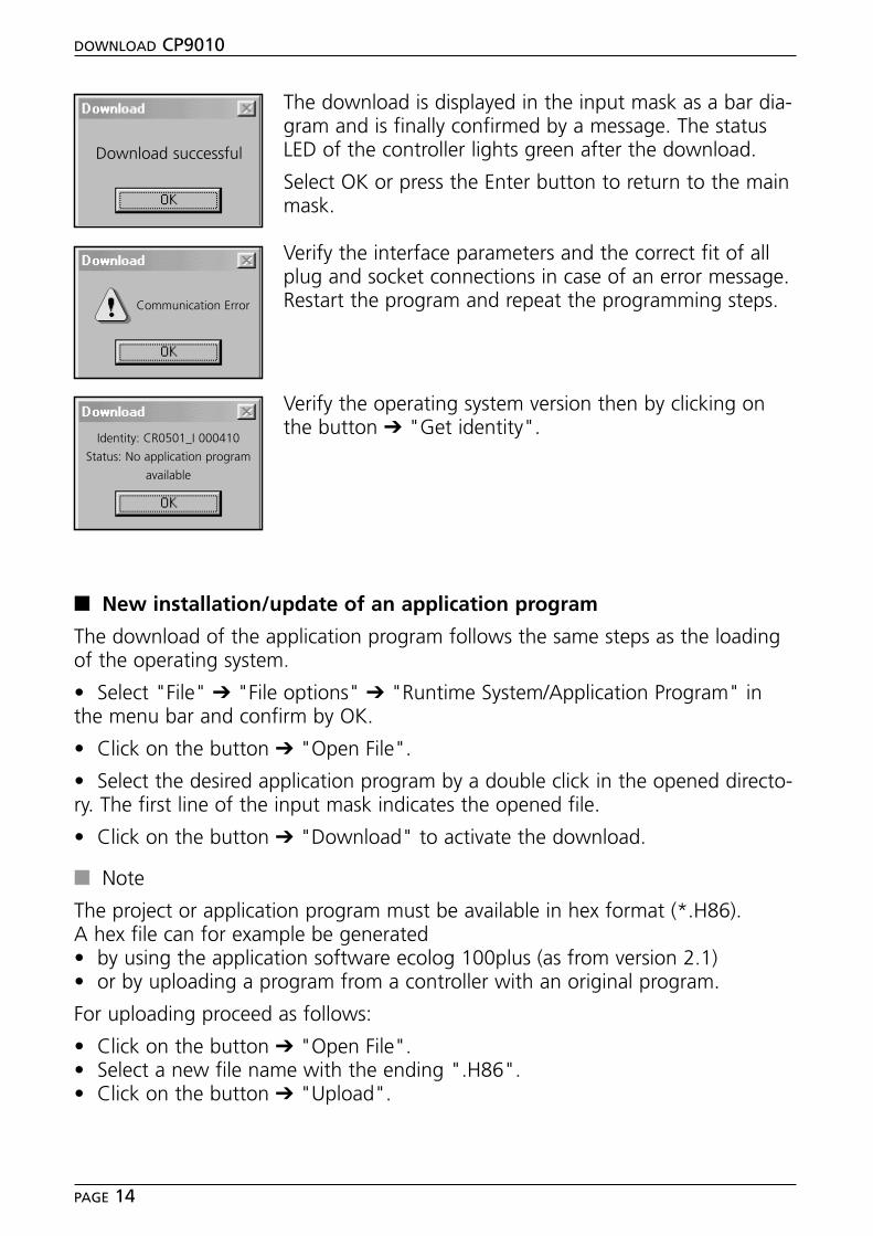
The download is displayed in the input mask as a bar dia-gram and is finally confirmed by a message. The statusLED of the controller lights green after the download.
Select OK or press the Enter button to return to the mainmask.
Verify the interface parameters and the correct fit of allplug and socket connections in case of an error message.Restart the program and repeat the programming steps.
Verify the operating system version then by clicking onthe button ➔ "Get identity".
■■ New installation/update of an application program
The download of the application program follows the same steps as the loadingof the operating system.
• Select "File" ➔ "File options" ➔ "Runtime System/Application Program" inthe menu bar and confirm by OK.
• Click on the button ➔ "Open File".
• Select the desired application program by a double click in the opened directo-ry. The first line of the input mask indicates the opened file.
• Click on the button ➔ "Download" to activate the download.
■■ Note
The project or application program must be available in hex format (*.H86).A hex file can for example be generated• by using the application software ecolog 100plus (as from version 2.1)• or by uploading a program from a controller with an original program.
For uploading proceed as follows:
• Click on the button ➔ "Open File".• Select a new file name with the ending ".H86".• Click on the button ➔ "Upload".
DOWNLOAD CP9010
PAGE 14
Download successful
Communication Error
Identity: CR0501_I 000410
Status: No application program
available
■■ Start the installed application program
• Click on the button ➔ "Start".
The program is started, the status LED of the controller that lights green starts toflash.
The start command remains set even after power failure, i.e. the application pro-gram starts automatically when power is applied again.
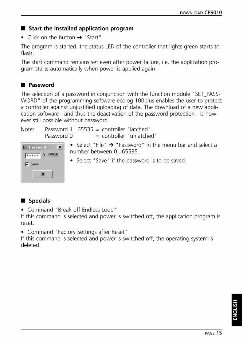
■■ Password
The selection of a password in conjunction with the function module "SET_PASS-WORD" of the programming software ecolog 100plus enables the user to protecta controller against unjustified uploading of data. The download of a new appli-cation software - and thus the deactivation of the password protection - is how-ever still possible without password.
Note: Password 1...65535 = controller "latched"Password 0 = controller "unlatched"
• Select "File" ➔ "Password" in the menu bar and select anumber between 0...65535.
• Select "Save" if the password is to be saved.
■■ Specials
• Command "Break off Endless Loop"If this command is selected and power is switched off, the application program isreset.
• Command "Factory Settings after Reset"If this command is selected and power is switched off, the operating system isdeleted.
ENG
LISH
DOWNLOAD CP9010
PAGE 15

Tech
nisc
he Ä
nder
unge
n be
halte
n w
ir un
s oh
ne v
orhe
rige
Ank
ündi
gung
vor
.Pa
pier
chl
orfr
ei g
eble
icht

ProgrammhandbuchProgramming manual
CANmemTool
Configurator
DEU
TSC
HEN
GLI
SH
R
CARD ERRORCARD ACCESS
ONERROR
CAN
Sach
nr.
7390
371
/00
07
/200
3
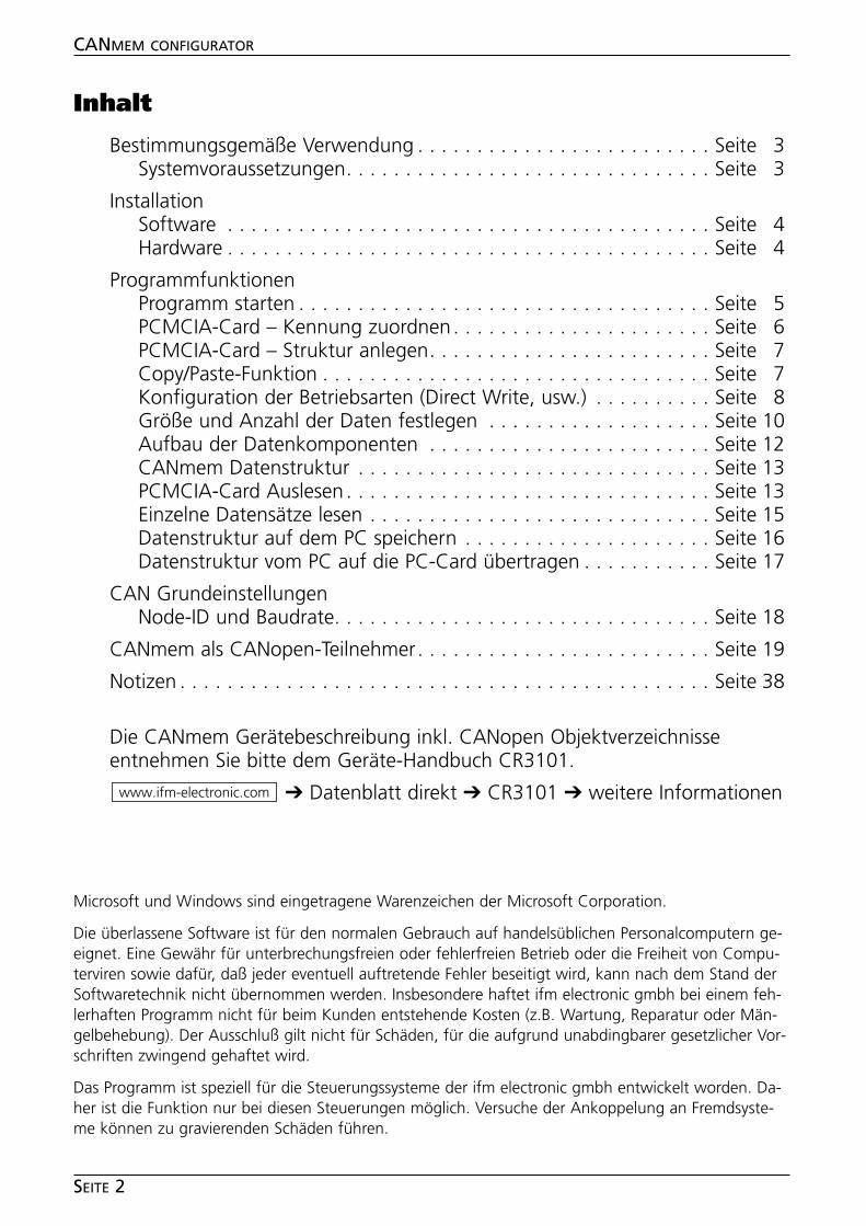
Inhalt
Bestimmungsgemäße Verwendung . . . . . . . . . . . . . . . . . . . . . . . . . Seite 3Systemvoraussetzungen. . . . . . . . . . . . . . . . . . . . . . . . . . . . . . . Seite 3
InstallationSoftware . . . . . . . . . . . . . . . . . . . . . . . . . . . . . . . . . . . . . . . . . Seite 4Hardware . . . . . . . . . . . . . . . . . . . . . . . . . . . . . . . . . . . . . . . . . Seite 4
ProgrammfunktionenProgramm starten . . . . . . . . . . . . . . . . . . . . . . . . . . . . . . . . . . . Seite 5PCMCIA-Card – Kennung zuordnen. . . . . . . . . . . . . . . . . . . . . . Seite 6PCMCIA-Card – Struktur anlegen. . . . . . . . . . . . . . . . . . . . . . . . Seite 7Copy/Paste-Funktion . . . . . . . . . . . . . . . . . . . . . . . . . . . . . . . . . Seite 7Konfiguration der Betriebsarten (Direct Write, usw.) . . . . . . . . . . Seite 8Größe und Anzahl der Daten festlegen . . . . . . . . . . . . . . . . . . . Seite 10Aufbau der Datenkomponenten . . . . . . . . . . . . . . . . . . . . . . . . Seite 12CANmem Datenstruktur . . . . . . . . . . . . . . . . . . . . . . . . . . . . . . Seite 13PCMCIA-Card Auslesen . . . . . . . . . . . . . . . . . . . . . . . . . . . . . . . Seite 13Einzelne Datensätze lesen . . . . . . . . . . . . . . . . . . . . . . . . . . . . . Seite 15Datenstruktur auf dem PC speichern . . . . . . . . . . . . . . . . . . . . . Seite 16Datenstruktur vom PC auf die PC-Card übertragen . . . . . . . . . . . Seite 17
CAN GrundeinstellungenNode-ID und Baudrate. . . . . . . . . . . . . . . . . . . . . . . . . . . . . . . . Seite 18
CANmem als CANopen-Teilnehmer. . . . . . . . . . . . . . . . . . . . . . . . . Seite 19
Notizen . . . . . . . . . . . . . . . . . . . . . . . . . . . . . . . . . . . . . . . . . . . . . Seite 38
Die CANmem Gerätebeschreibung inkl. CANopen Objektverzeichnisseentnehmen Sie bitte dem Geräte-Handbuch CR3101.
➔ Datenblatt direkt ➔ CR3101 ➔ weitere Informationenwww.ifm-electronic.com
CANMEM CONFIGURATOR
SEITE 2
Microsoft und Windows sind eingetragene Warenzeichen der Microsoft Corporation.
Die überlassene Software ist für den normalen Gebrauch auf handelsüblichen Personalcomputern ge-eignet. Eine Gewähr für unterbrechungsfreien oder fehlerfreien Betrieb oder die Freiheit von Compu-terviren sowie dafür, daß jeder eventuell auftretende Fehler beseitigt wird, kann nach dem Stand derSoftwaretechnik nicht übernommen werden. Insbesondere haftet ifm electronic gmbh bei einem feh-lerhaften Programm nicht für beim Kunden entstehende Kosten (z.B. Wartung, Reparatur oder Män-gelbehebung). Der Ausschluß gilt nicht für Schäden, für die aufgrund unabdingbarer gesetzlicher Vor-schriften zwingend gehaftet wird.
Das Programm ist speziell für die Steuerungssysteme der ifm electronic gmbh entwickelt worden. Da-her ist die Funktion nur bei diesen Steuerungen möglich. Versuche der Ankoppelung an Fremdsyste-me können zu gravierenden Schäden führen.
CANMEM CONFIGURATOR
SEITE 3
Bestimmungsgemäße Verwendung
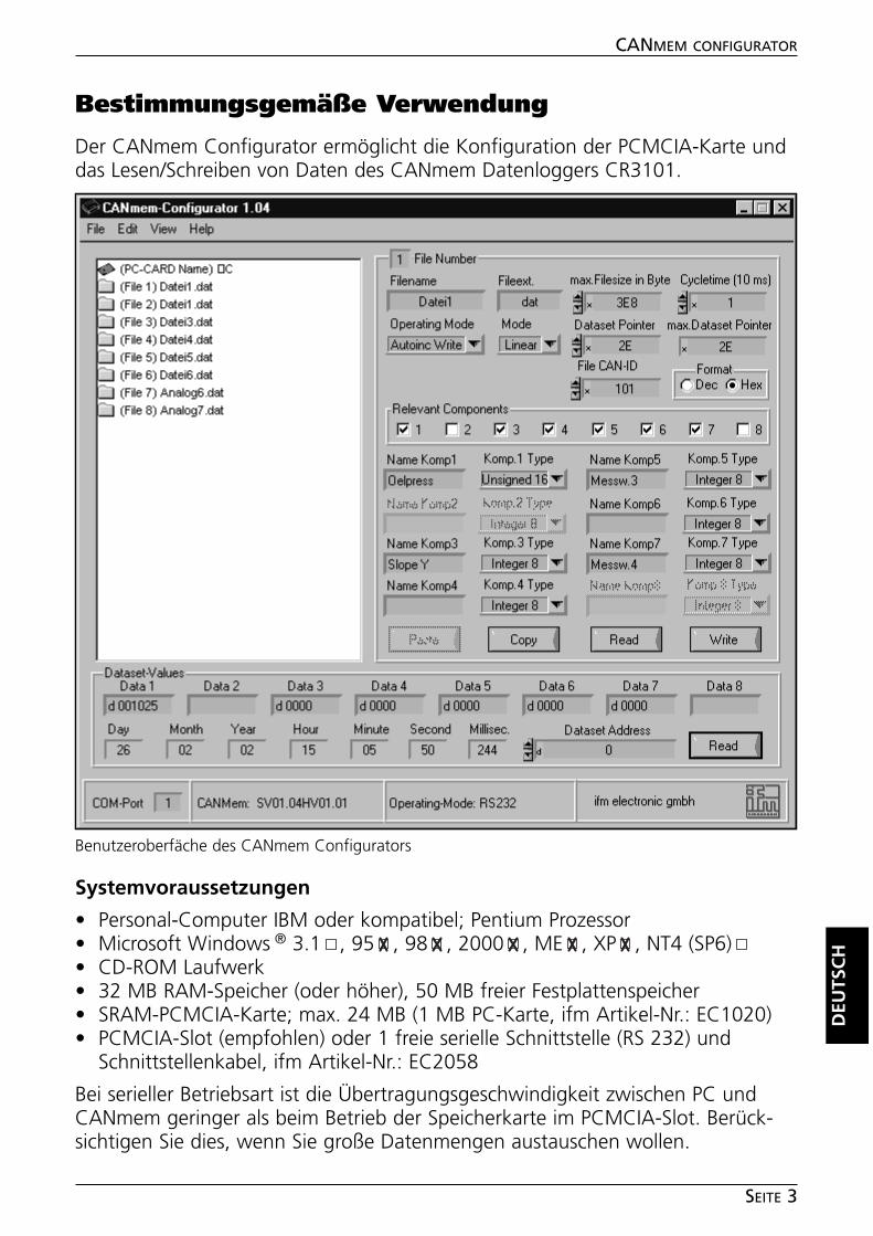
Der CANmem Configurator ermöglicht die Konfiguration der PCMCIA-Karte unddas Lesen/Schreiben von Daten des CANmem Datenloggers CR3101.
Systemvoraussetzungen
• Personal-Computer IBM oder kompatibel; Pentium Prozessor• Microsoft Windows ® 3.1 , 95 , 98 , 2000 , ME , XP , NT4 (SP6)• CD-ROM Laufwerk• 32 MB RAM-Speicher (oder höher), 50 MB freier Festplattenspeicher• SRAM-PCMCIA-Karte; max. 24 MB (1 MB PC-Karte, ifm Artikel-Nr.: EC1020)• PCMCIA-Slot (empfohlen) oder 1 freie serielle Schnittstelle (RS 232) und
Schnittstellenkabel, ifm Artikel-Nr.: EC2058
Bei serieller Betriebsart ist die Übertragungsgeschwindigkeit zwischen PC undCANmem geringer als beim Betrieb der Speicherkarte im PCMCIA-Slot. Berück-sichtigen Sie dies, wenn Sie große Datenmengen austauschen wollen.
DEU
TSC
HBenutzeroberfäche des CANmem Configurators
Installation
■■ Software
• Starten Sie Windows und legen Sie die CD-ROM in Ihr CD-Laufwerk.• Wählen Sie in der Menüleiste „Start“ ➔ „Ausführen“.• Geben Sie „D:\CANmem\Konfigurator\setup.exe“ ein. Bestätigen Sie mit OK.Sollte Ihr CD-ROM Laufwerk mit einem anderen Buchstaben als „D“ angespro-chen werden, geben Sie an Stelle von D diesen Buchstaben ein.• Folgen Sie den Anweisungen des Setup-Programms.• Führen Sie entsprechend der vorgesehenen Betriebsart die Anweisungen a)oder b) aus.
a) Betriebsart RS232 (serielle Schnittstelle)
• Verbinden Sie die RS232-Schnittstelle des CANmem mit der seriellen Schnitt-stelle Ihres PCs (Schnittstellenkabel, ifm Artikel-Nr.: EC2058).• Versorgen Sie das CANmem über den 3,5 mm Hohlsteckeranschluß (Stecker-Netzteil, ifm Artikel-Nr.: EC2059) mit der Betriebsspannung (siehe ggf. CANmemGeräte-Handbuch, Elektrischer Anschluß).
b) Betriebsart PCMCIA-Socket (PC-interner PCMCIA Slot)
• Installieren Sie die Treiberdatei „SwapFTL.exe“ von der CD-ROM in das neu an-gelegte Verzeichnis "C:\Programme\CANmem-Configurator".
CANMEM CONFIGURATOR
SEITE 4
Programmfunktionen
■■ Programm starten
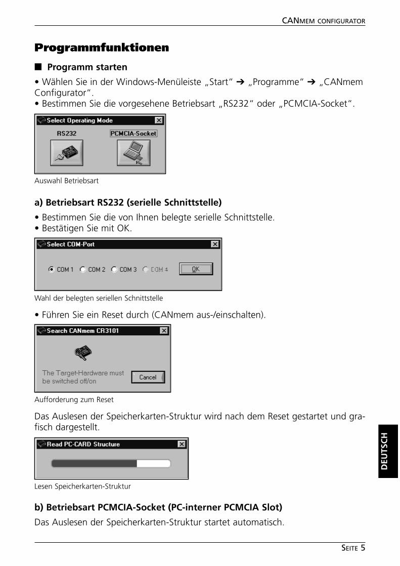
• Wählen Sie in der Windows-Menüleiste „Start“ ➔ „Programme“ ➔ „CANmemConfigurator“.• Bestimmen Sie die vorgesehene Betriebsart „RS232“ oder „PCMCIA-Socket“.
a) Betriebsart RS232 (serielle Schnittstelle)
• Bestimmen Sie die von Ihnen belegte serielle Schnittstelle.• Bestätigen Sie mit OK.
• Führen Sie ein Reset durch (CANmem aus-/einschalten).
Das Auslesen der Speicherkarten-Struktur wird nach dem Reset gestartet und gra-fisch dargestellt.
b) Betriebsart PCMCIA-Socket (PC-interner PCMCIA Slot)
Das Auslesen der Speicherkarten-Struktur startet automatisch.
DEU
TSC
H
CANMEM CONFIGURATOR
SEITE 5
Auswahl Betriebsart
Lesen Speicherkarten-Struktur
Wahl der belegten seriellen Schnittstelle
Aufforderung zum Reset
■■ PCMCIA-Card – Kennung zuordnen
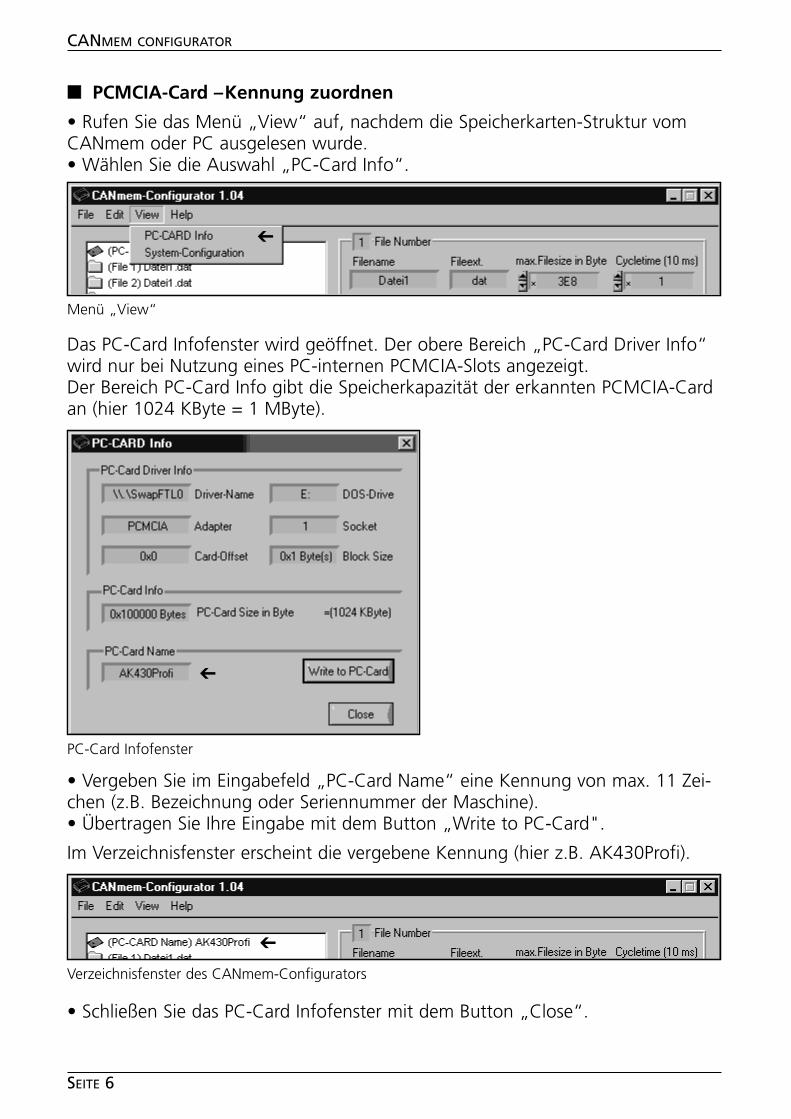
• Rufen Sie das Menü „View“ auf, nachdem die Speicherkarten-Struktur vomCANmem oder PC ausgelesen wurde.• Wählen Sie die Auswahl „PC-Card Info“.
Das PC-Card Infofenster wird geöffnet. Der obere Bereich „PC-Card Driver Info“wird nur bei Nutzung eines PC-internen PCMCIA-Slots angezeigt.Der Bereich PC-Card Info gibt die Speicherkapazität der erkannten PCMCIA-Cardan (hier 1024 KByte = 1 MByte).
• Vergeben Sie im Eingabefeld „PC-Card Name“ eine Kennung von max. 11 Zei-chen (z.B. Bezeichnung oder Seriennummer der Maschine).• Übertragen Sie Ihre Eingabe mit dem Button „Write to PC-Card".
Im Verzeichnisfenster erscheint die vergebene Kennung (hier z.B. AK430Profi).
• Schließen Sie das PC-Card Infofenster mit dem Button „Close“.
CANMEM CONFIGURATOR
SEITE 6
PC-Card Infofenster
Verzeichnisfenster des CANmem-Configurators
➔
Menü „View“
➔
➔
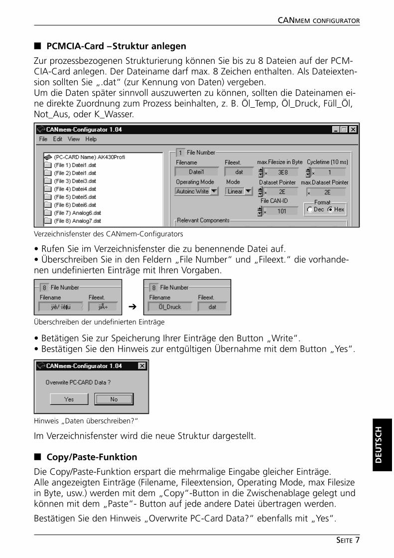
■■ PCMCIA-Card – Struktur anlegen
Zur prozessbezogenen Strukturierung können Sie bis zu 8 Dateien auf der PCM-CIA-Card anlegen. Der Dateiname darf max. 8 Zeichen enthalten. Als Dateiexten-sion sollten Sie „.dat“ (zur Kennung von Daten) vergeben.Um die Daten später sinnvoll auszuwerten zu können, sollten die Dateinamen ei-ne direkte Zuordnung zum Prozess beinhalten, z. B. Öl_Temp, Öl_Druck, Füll_Öl,Not_Aus, oder K_Wasser.
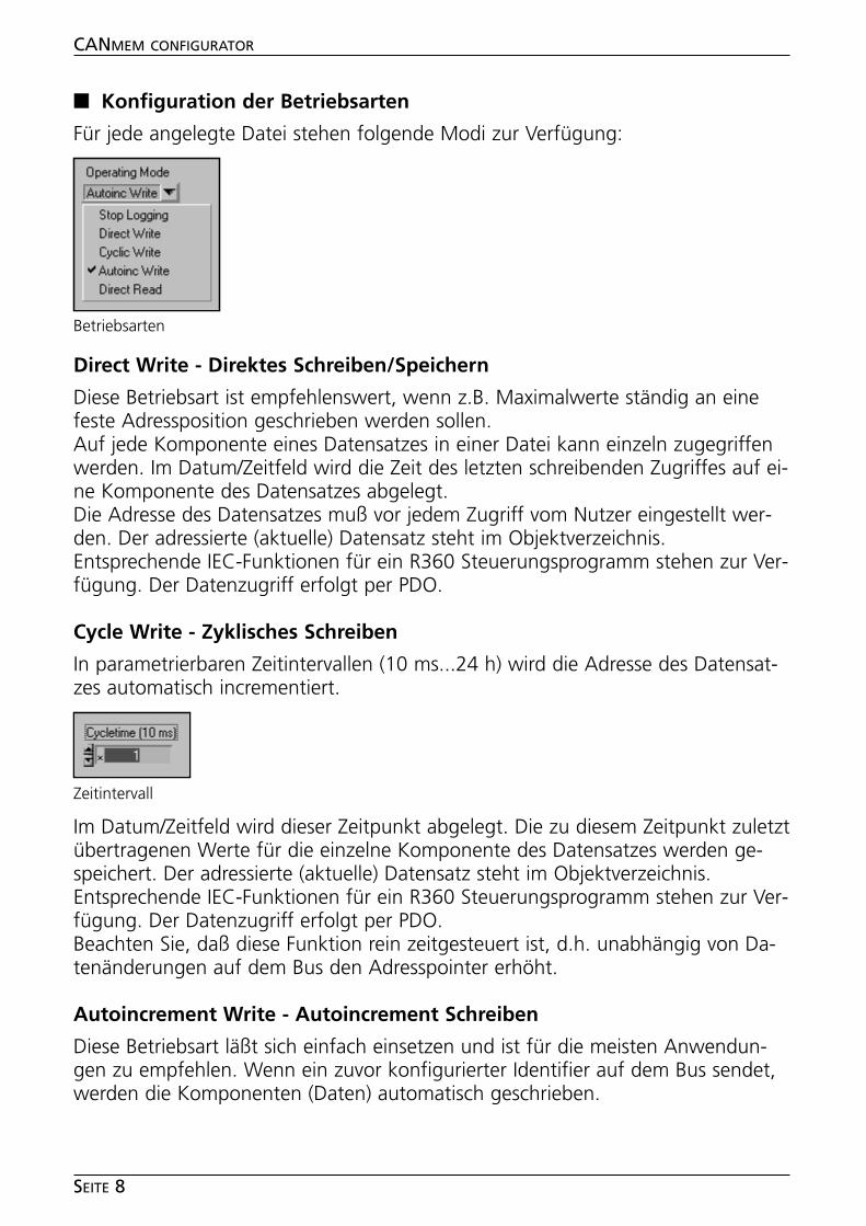
• Rufen Sie im Verzeichnisfenster die zu benennende Datei auf.• Überschreiben Sie in den Feldern „File Number“ und „Fileext.“ die vorhande-nen undefinierten Einträge mit Ihren Vorgaben.
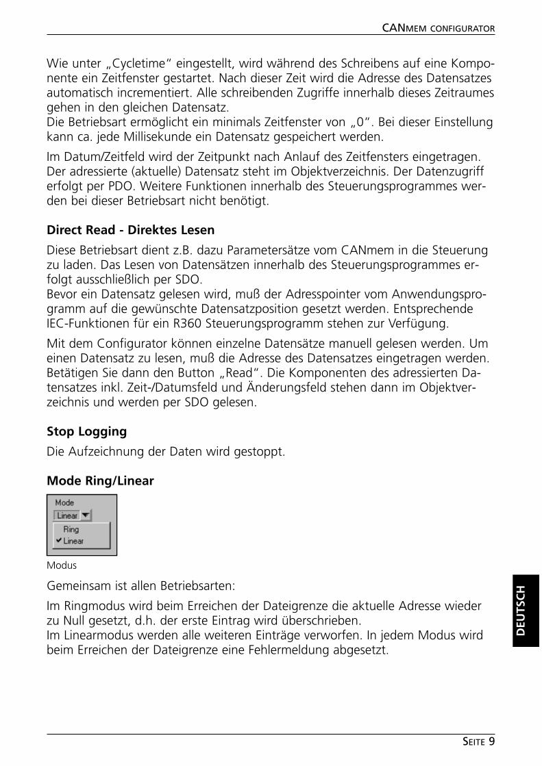
• Betätigen Sie zur Speicherung Ihrer Einträge den Button „Write“.• Bestätigen Sie den Hinweis zur entgültigen Übernahme mit dem Button „Yes“.
Im Verzeichnisfenster wird die neue Struktur dargestellt.
■■ Copy/Paste-Funktion
Die Copy/Paste-Funktion erspart die mehrmalige Eingabe gleicher Einträge.Alle angezeigten Einträge (Filename, Fileextension, Operating Mode, max Filesizein Byte, usw.) werden mit dem „Copy“-Button in die Zwischenablage gelegt undkönnen mit dem „Paste“- Button auf jede andere Datei übertragen werden.
Bestätigen Sie den Hinweis „Overwrite PC-Card Data?“ ebenfalls mit „Yes“.
DEU
TSC
H
CANMEM CONFIGURATOR
SEITE 7
Verzeichnisfenster des CANmem-Configurators
Überschreiben der undefinierten Einträge
Hinweis „Daten überschreiben?“
➔
■■ Konfiguration der Betriebsarten
Für jede angelegte Datei stehen folgende Modi zur Verfügung:
Direct Write - Direktes Schreiben/Speichern
Diese Betriebsart ist empfehlenswert, wenn z.B. Maximalwerte ständig an einefeste Adressposition geschrieben werden sollen.Auf jede Komponente eines Datensatzes in einer Datei kann einzeln zugegriffenwerden. Im Datum/Zeitfeld wird die Zeit des letzten schreibenden Zugriffes auf ei-ne Komponente des Datensatzes abgelegt.Die Adresse des Datensatzes muß vor jedem Zugriff vom Nutzer eingestellt wer-den. Der adressierte (aktuelle) Datensatz steht im Objektverzeichnis.Entsprechende IEC-Funktionen für ein R360 Steuerungsprogramm stehen zur Ver-fügung. Der Datenzugriff erfolgt per PDO.
Cycle Write - Zyklisches Schreiben
In parametrierbaren Zeitintervallen (10 ms...24 h) wird die Adresse des Datensat-zes automatisch incrementiert.
Im Datum/Zeitfeld wird dieser Zeitpunkt abgelegt. Die zu diesem Zeitpunkt zuletztübertragenen Werte für die einzelne Komponente des Datensatzes werden ge-speichert. Der adressierte (aktuelle) Datensatz steht im Objektverzeichnis.Entsprechende IEC-Funktionen für ein R360 Steuerungsprogramm stehen zur Ver-fügung. Der Datenzugriff erfolgt per PDO.Beachten Sie, daß diese Funktion rein zeitgesteuert ist, d.h. unabhängig von Da-tenänderungen auf dem Bus den Adresspointer erhöht.
Autoincrement Write - Autoincrement Schreiben
Diese Betriebsart läßt sich einfach einsetzen und ist für die meisten Anwendun-gen zu empfehlen. Wenn ein zuvor konfigurierter Identifier auf dem Bus sendet,werden die Komponenten (Daten) automatisch geschrieben.
CANMEM CONFIGURATOR
SEITE 8
Betriebsarten
Zeitintervall
Wie unter „Cycletime“ eingestellt, wird während des Schreibens auf eine Kompo-nente ein Zeitfenster gestartet. Nach dieser Zeit wird die Adresse des Datensatzesautomatisch incrementiert. Alle schreibenden Zugriffe innerhalb dieses Zeitraumesgehen in den gleichen Datensatz.Die Betriebsart ermöglicht ein minimals Zeitfenster von „0“. Bei dieser Einstellungkann ca. jede Millisekunde ein Datensatz gespeichert werden.
Im Datum/Zeitfeld wird der Zeitpunkt nach Anlauf des Zeitfensters eingetragen.Der adressierte (aktuelle) Datensatz steht im Objektverzeichnis. Der Datenzugrifferfolgt per PDO. Weitere Funktionen innerhalb des Steuerungsprogrammes wer-den bei dieser Betriebsart nicht benötigt.
Direct Read - Direktes Lesen
Diese Betriebsart dient z.B. dazu Parametersätze vom CANmem in die Steuerungzu laden. Das Lesen von Datensätzen innerhalb des Steuerungsprogrammes er-folgt ausschließlich per SDO.Bevor ein Datensatz gelesen wird, muß der Adresspointer vom Anwendungspro-gramm auf die gewünschte Datensatzposition gesetzt werden. EntsprechendeIEC-Funktionen für ein R360 Steuerungsprogramm stehen zur Verfügung.
Mit dem Configurator können einzelne Datensätze manuell gelesen werden. Umeinen Datensatz zu lesen, muß die Adresse des Datensatzes eingetragen werden.Betätigen Sie dann den Button „Read“. Die Komponenten des adressierten Da-tensatzes inkl. Zeit-/Datumsfeld und Änderungsfeld stehen dann im Objektver-zeichnis und werden per SDO gelesen.
Stop Logging
Die Aufzeichnung der Daten wird gestoppt.
Mode Ring/Linear
Gemeinsam ist allen Betriebsarten:
Im Ringmodus wird beim Erreichen der Dateigrenze die aktuelle Adresse wiederzu Null gesetzt, d.h. der erste Eintrag wird überschrieben.Im Linearmodus werden alle weiteren Einträge verworfen. In jedem Modus wirdbeim Erreichen der Dateigrenze eine Fehlermeldung abgesetzt.
DEU
TSC
H
CANMEM CONFIGURATOR
SEITE 9
Modus
■■ Größe und Anzahl der Daten festlegen
Nachdem die Dateien strukturiert wurden, muß deren maximale Größe und dieAnzahl der jeweils enthaltenen Datensätze festgelegt werden.
Beispiel:
Es wird eine 1 MB PCMCIA-Card eingesetzt und die 8 angelegten Dateien sollendie gleiche Speichergröße haben. 1 MB entspricht einer Speicherkapazität von1024 x 1024 Byte = 1045884 Byte (dezimal).
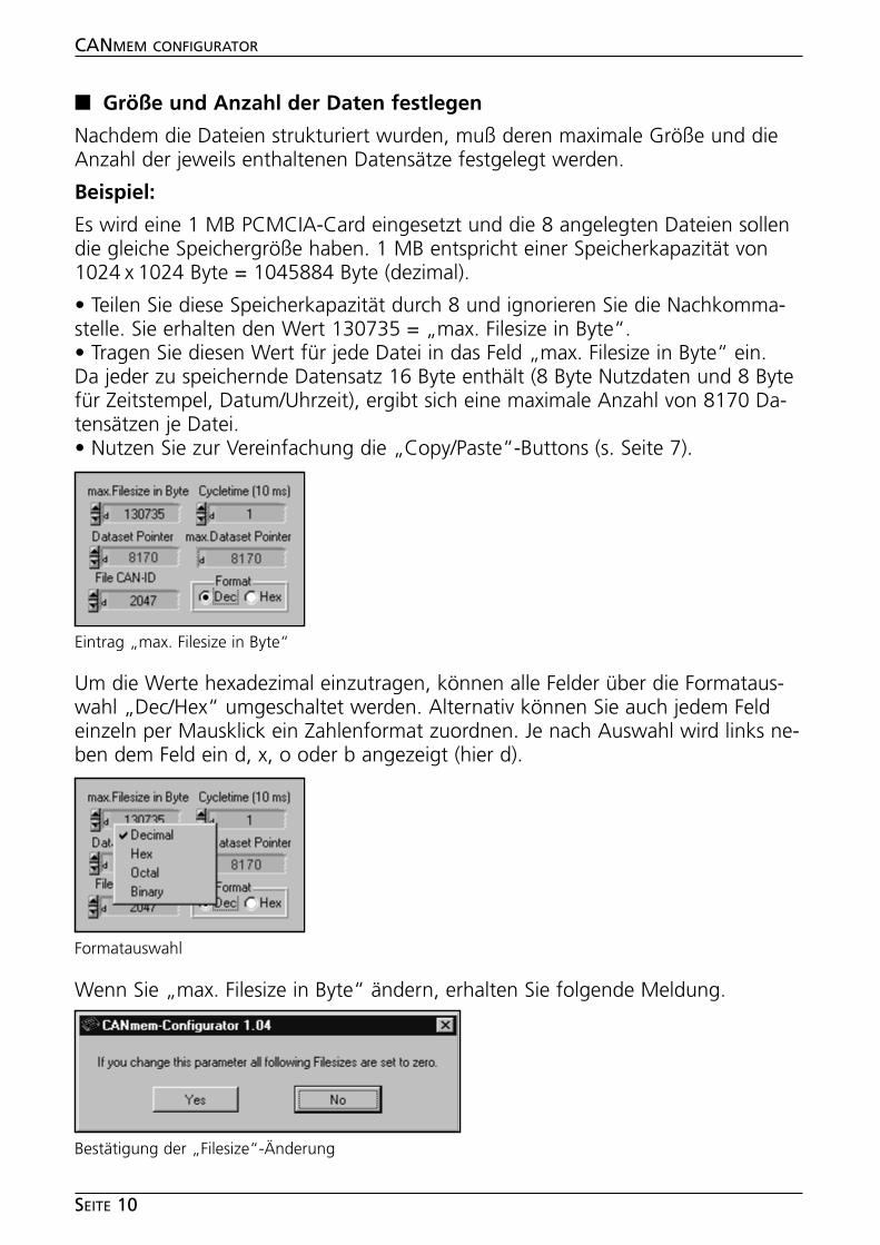
• Teilen Sie diese Speicherkapazität durch 8 und ignorieren Sie die Nachkomma-stelle. Sie erhalten den Wert 130735 = „max. Filesize in Byte“.• Tragen Sie diesen Wert für jede Datei in das Feld „max. Filesize in Byte“ ein.Da jeder zu speichernde Datensatz 16 Byte enthält (8 Byte Nutzdaten und 8 Bytefür Zeitstempel, Datum/Uhrzeit), ergibt sich eine maximale Anzahl von 8170 Da-tensätzen je Datei.• Nutzen Sie zur Vereinfachung die „Copy/Paste“-Buttons (s. Seite 7).
Um die Werte hexadezimal einzutragen, können alle Felder über die Formataus-wahl „Dec/Hex“ umgeschaltet werden. Alternativ können Sie auch jedem Feldeinzeln per Mausklick ein Zahlenformat zuordnen. Je nach Auswahl wird links ne-ben dem Feld ein d, x, o oder b angezeigt (hier d).
Wenn Sie „max. Filesize in Byte“ ändern, erhalten Sie folgende Meldung.
CANMEM CONFIGURATOR
SEITE 10
Eintrag „max. Filesize in Byte“
Formatauswahl
Bestätigung der „Filesize“-Änderung
• Bestätigen Sie diese Meldung mit „Yes“. Die nachfolgenden Dateien werdenüberschrieben.
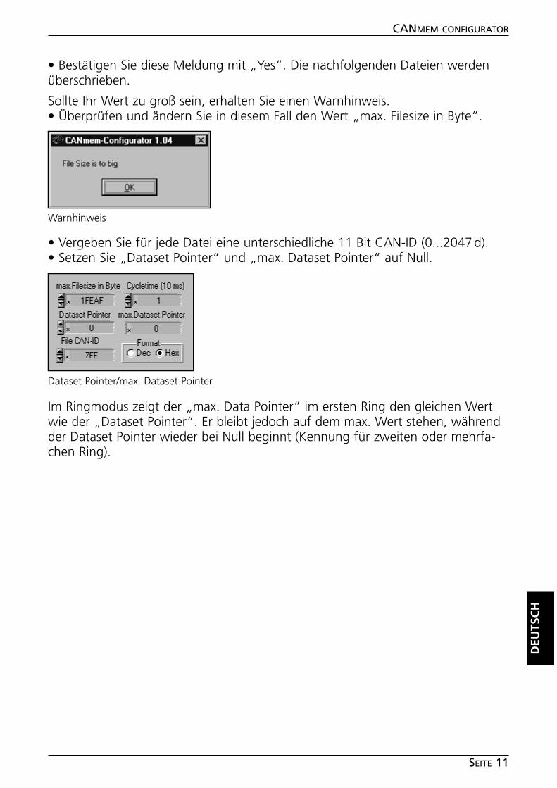
Sollte Ihr Wert zu groß sein, erhalten Sie einen Warnhinweis.• Überprüfen und ändern Sie in diesem Fall den Wert „max. Filesize in Byte“.
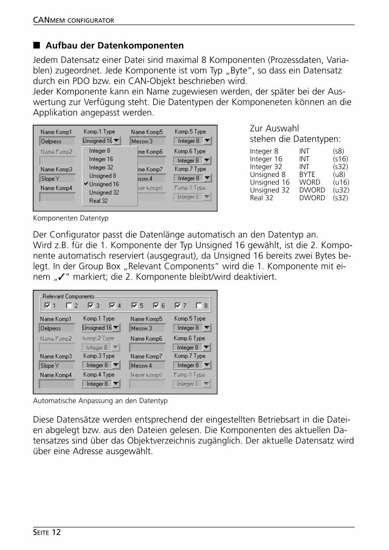
• Vergeben Sie für jede Datei eine unterschiedliche 11 Bit CAN-ID (0...2047d).• Setzen Sie „Dataset Pointer“ und „max. Dataset Pointer“ auf Null.
Im Ringmodus zeigt der „max. Data Pointer“ im ersten Ring den gleichen Wertwie der „Dataset Pointer“. Er bleibt jedoch auf dem max. Wert stehen, währendder Dataset Pointer wieder bei Null beginnt (Kennung für zweiten oder mehrfa-chen Ring).
DEU
TSC
H
CANMEM CONFIGURATOR
SEITE 11
Warnhinweis
Dataset Pointer/max. Dataset Pointer
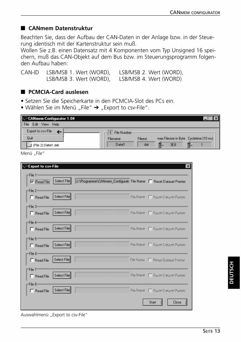
■■ Aufbau der Datenkomponenten
Jedem Datensatz einer Datei sind maximal 8 Komponenten (Prozessdaten, Varia-blen) zugeordnet. Jede Komponente ist vom Typ „Byte“, so dass ein Datensatzdurch ein PDO bzw. ein CAN-Objekt beschrieben wird.Jeder Komponente kann ein Name zugewiesen werden, der später bei der Aus-wertung zur Verfügung steht. Die Datentypen der Komponeneten können an dieApplikation angepasst werden.
Der Configurator passt die Datenlänge automatisch an den Datentyp an.Wird z.B. für die 1. Komponente der Typ Unsigned 16 gewählt, ist die 2. Kompo-nente automatisch reserviert (ausgegraut), da Unsigned 16 bereits zwei Bytes be-legt. In der Group Box „Relevant Components“ wird die 1. Komponente mit ei-nem „✓“ markiert; die 2. Komponente bleibt/wird deaktiviert.
Diese Datensätze werden entsprechend der eingestellten Betriebsart in die Datei-en abgelegt bzw. aus den Dateien gelesen. Die Komponenten des aktuellen Da-tensatzes sind über das Objektverzeichnis zugänglich. Der aktuelle Datensatz wirdüber eine Adresse ausgewählt.
CANMEM CONFIGURATOR
SEITE 12
Komponenten Datentyp
Automatische Anpassung an den Datentyp
Zur Auswahlstehen die Datentypen:Integer 8 INT (s8)Integer 16 INT (s16)Integer 32 INT (s32)Unsigned 8 BYTE (u8)Unsigned 16 WORD (u16)Unsigned 32 DWORD (u32)Real 32 DWORD (s32)
■■ CANmem Datenstruktur
Beachten Sie, dass der Aufbau der CAN-Daten in der Anlage bzw. in der Steue-rung identisch mit der Kartenstruktur sein muß.Wollen Sie z.B. einen Datensatz mit 4 Komponenten vom Typ Unsigned 16 spei-chern, muß das CAN-Objekt auf dem Bus bzw. im Steuerungsprogramm folgen-den Aufbau haben:
CAN-ID LSB/MSB 1. Wert (WORD), LSB/MSB 2. Wert (WORD),LSB/MSB 3. Wert (WORD), LSB/MSB 4. Wert (WORD)
■■ PCMCIA-Card auslesen
• Setzen Sie die Speicherkarte in den PCMCIA-Slot des PCs ein.• Wählen Sie im Menü „File“ ➔ „Export to csv-File“.
DEU
TSC
H
CANMEM CONFIGURATOR
SEITE 13
Menü „File“
➔
Auswahlmenü „Export to csv-File“
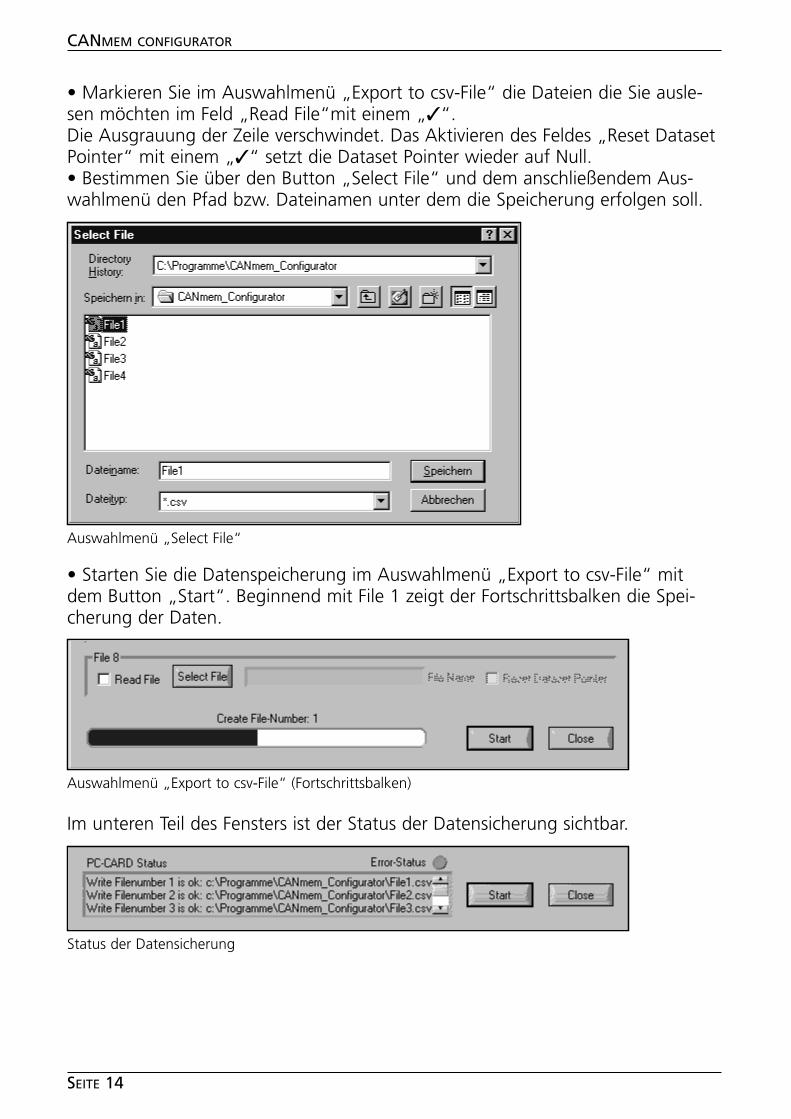
• Markieren Sie im Auswahlmenü „Export to csv-File“ die Dateien die Sie ausle-sen möchten im Feld „Read File“mit einem „✓“.Die Ausgrauung der Zeile verschwindet. Das Aktivieren des Feldes „Reset DatasetPointer“ mit einem „✓“ setzt die Dataset Pointer wieder auf Null. • Bestimmen Sie über den Button „Select File“ und dem anschließendem Aus-wahlmenü den Pfad bzw. Dateinamen unter dem die Speicherung erfolgen soll.
• Starten Sie die Datenspeicherung im Auswahlmenü „Export to csv-File“ mitdem Button „Start“. Beginnend mit File 1 zeigt der Fortschrittsbalken die Spei-cherung der Daten.
Im unteren Teil des Fensters ist der Status der Datensicherung sichtbar.
CANMEM CONFIGURATOR
SEITE 14
Auswahlmenü „Select File“
Auswahlmenü „Export to csv-File“ (Fortschrittsbalken)
Status der Datensicherung
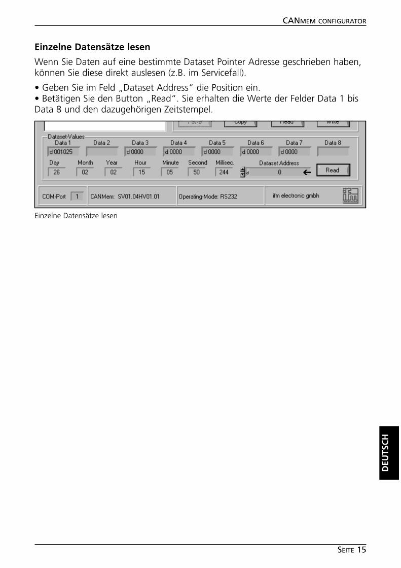
Einzelne Datensätze lesen
Wenn Sie Daten auf eine bestimmte Dataset Pointer Adresse geschrieben haben,können Sie diese direkt auslesen (z.B. im Servicefall).
• Geben Sie im Feld „Dataset Address“ die Position ein.• Betätigen Sie den Button „Read“. Sie erhalten die Werte der Felder Data 1 bisData 8 und den dazugehörigen Zeitstempel.
DEU
TSC
H
CANMEM CONFIGURATOR
SEITE 15
Einzelne Datensätze lesen
➔
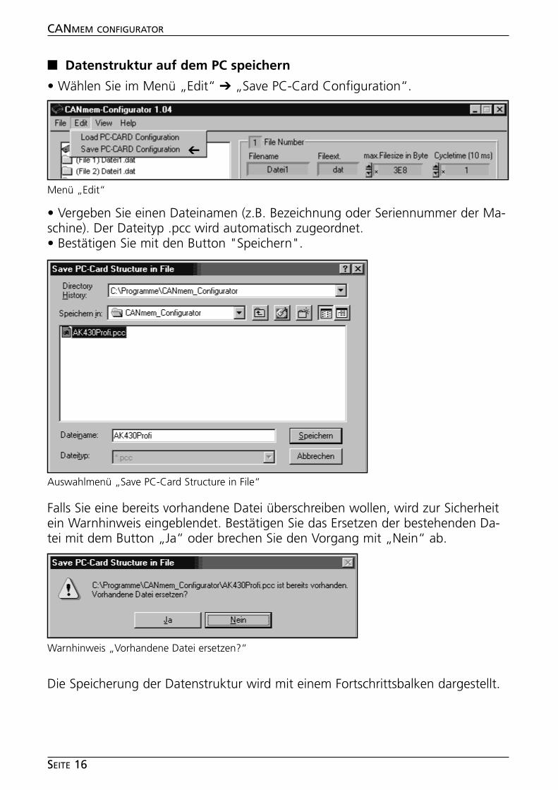
■■ Datenstruktur auf dem PC speichern
• Wählen Sie im Menü „Edit“ ➔ „Save PC-Card Configuration“.
• Vergeben Sie einen Dateinamen (z.B. Bezeichnung oder Seriennummer der Ma-schine). Der Dateityp .pcc wird automatisch zugeordnet.• Bestätigen Sie mit den Button "Speichern".
Falls Sie eine bereits vorhandene Datei überschreiben wollen, wird zur Sicherheitein Warnhinweis eingeblendet. Bestätigen Sie das Ersetzen der bestehenden Da-tei mit dem Button „Ja“ oder brechen Sie den Vorgang mit „Nein“ ab.
Die Speicherung der Datenstruktur wird mit einem Fortschrittsbalken dargestellt.
CANMEM CONFIGURATOR
SEITE 16
Menü „Edit“
➔
Auswahlmenü „Save PC-Card Structure in File“
Warnhinweis „Vorhandene Datei ersetzen?“
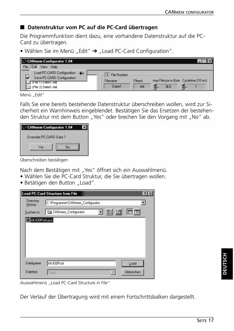
■■ Datenstruktur vom PC auf die PC-Card übertragen
Die Programmfunktion dient dazu, eine vorhandene Datenstruktur auf die PC-Card zu übertragen.
• Wählen Sie im Menü „Edit“ ➔ „Load PC-Card Configuration“.
Falls Sie eine bereits bestehende Datenstruktur überschreiben wollen, wird zur Si-cherheit ein Warnhinweis eingeblendet. Bestätigen Sie das Ersetzen der bestehen-den Struktur mit dem Button „Yes“ oder brechen Sie den Vorgang mit „No“ ab.
Nach dem Bestätigen mit „Yes“ öffnet sich ein Auswahlmenü.• Wählen Sie die PC-Card Struktur, die Sie übertragen wollen.• Betätigen den Button „Load“.
Der Verlauf der Übertragung wird mit einem Fortschrittsbalken dargestellt.
DEU
TSC
H
CANMEM CONFIGURATOR
SEITE 17
Menü „Edit“
➔
Überschreiben bestätigen
Auswahlmenü „Load PC-Card Structure in File“
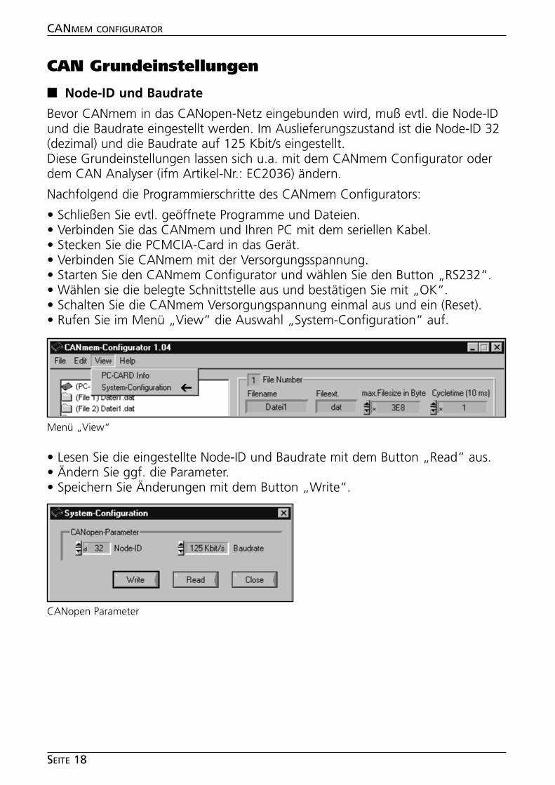
CAN Grundeinstellungen
■■ Node-ID und Baudrate
Bevor CANmem in das CANopen-Netz eingebunden wird, muß evtl. die Node-IDund die Baudrate eingestellt werden. Im Auslieferungszustand ist die Node-ID 32(dezimal) und die Baudrate auf 125 Kbit/s eingestellt.Diese Grundeinstellungen lassen sich u.a. mit dem CANmem Configurator oderdem CAN Analyser (ifm Artikel-Nr.: EC2036) ändern.
Nachfolgend die Programmierschritte des CANmem Configurators:
• Schließen Sie evtl. geöffnete Programme und Dateien.• Verbinden Sie das CANmem und Ihren PC mit dem seriellen Kabel.• Stecken Sie die PCMCIA-Card in das Gerät.• Verbinden Sie CANmem mit der Versorgungsspannung.• Starten Sie den CANmem Configurator und wählen Sie den Button „RS232“.• Wählen sie die belegte Schnittstelle aus und bestätigen Sie mit „OK“.• Schalten Sie die CANmem Versorgungspannung einmal aus und ein (Reset).• Rufen Sie im Menü „View“ die Auswahl „System-Configuration“ auf.
• Lesen Sie die eingestellte Node-ID und Baudrate mit dem Button „Read“ aus.• Ändern Sie ggf. die Parameter.• Speichern Sie Änderungen mit dem Button „Write“.
CANMEM CONFIGURATOR
SEITE 18
Menü „View“
➔
CANopen Parameter
CANmem als CANopen-Teilnehmer
Nach den Grundeinstellungen kann der Datenschreiber/Datenlogger CANmem indas CANopen-Netz eingebunden werden.Bevor CAN-Objekte empfangen werden können, muß CANmem von einem CAN-open Master in den Zustand „Operational“ gesetzt werden. Sobald ein eingestell-ter Identifier auf dem Bus sendet, blinken die Status LEDs „CAN“ und „Card Ac-cess“ auf. Das Gerät zeichnet jetzt auf.
Datentest
Bei Dateien mit Vorgabewerten/Sollwerttabellen wird beim Erstellen der Dateienam PC eine Check-Sum gebildet.Diese Check-Sum wird auf der PC-Card abgelegt. Bei jedem Einschalten der Ver-sorgungspannung oder beim Wechsel der Speicherkarte wird vom Gerät ebenfallsdie Check-Sum über den Inhalt dieser Daten errechnet und mit der abgelegtenCheck-Sum verglichen. Stimmen die beiden Werte nicht überein, wird eine Feh-lermeldung gesendet.
DEU
TSC
H
CANMEM CONFIGURATOR
SEITE 19
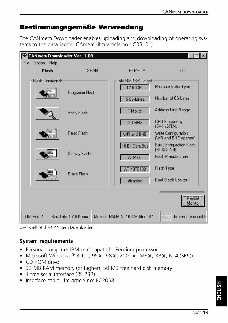
Contents
Function and features . . . . . . . . . . . . . . . . . . . . . . . . . . . . . . . . . . page 21System requirements. . . . . . . . . . . . . . . . . . . . . . . . . . . . . . . . . page 21
InstallationSoftware . . . . . . . . . . . . . . . . . . . . . . . . . . . . . . . . . . . . . . . . . page 22Hardware. . . . . . . . . . . . . . . . . . . . . . . . . . . . . . . . . . . . . . . . . page 22
Program functionsStart program. . . . . . . . . . . . . . . . . . . . . . . . . . . . . . . . . . . . . . page 23Assign PCMCIA card code. . . . . . . . . . . . . . . . . . . . . . . . . . . . . page 24Create PCMCIA card structure. . . . . . . . . . . . . . . . . . . . . . . . . . page 25Copy/Paste function . . . . . . . . . . . . . . . . . . . . . . . . . . . . . . . . . page 25Configuration of the operating modes (Direct Write etc.) . . . . . . page 26Define size and quantity of data . . . . . . . . . . . . . . . . . . . . . . . . page 28Structure of the data components . . . . . . . . . . . . . . . . . . . . . . . page 30CANmem data structure . . . . . . . . . . . . . . . . . . . . . . . . . . . . . . page 31Read PCMCIA card . . . . . . . . . . . . . . . . . . . . . . . . . . . . . . . . . . page 31Read individual data records . . . . . . . . . . . . . . . . . . . . . . . . . . . page 33Save data structure on the PC . . . . . . . . . . . . . . . . . . . . . . . . . . page 34Transfer data structure from PC to PC card. . . . . . . . . . . . . . . . . page 35
CAN initial settingsNode ID and baud rate . . . . . . . . . . . . . . . . . . . . . . . . . . . . . . . page 36
CANmem as CANopen participant . . . . . . . . . . . . . . . . . . . . . . . . . page 37
Notes . . . . . . . . . . . . . . . . . . . . . . . . . . . . . . . . . . . . . . . . . . . . . . Seite 38
For the CANmem device description incl. CANopen object directoriesplease see the device manual CR3101.
➔ Data sheet direct ➔ CR3101 ➔ Additional datawww.ifm-electronic.com
CANMEM CONFIGURATOR
PAGE 20
Microsoft and Windows are registered trademarks of Microsoft Corporation.
The software is suitable for normal use on common personal computers. According to the presentstate of software technology no guarantee can be assumed for the correct operation or absence ofcomputer viruses nor for the removal of any fault which may occur. In case of an incorrect programifm electronic gmbh cannot be held liable for cost incurred at the customer (e.g. maintenance, repairor rectification of faults). The exclusion does not apply to damage for which liability is mandatory ac-cording to peremptory legal provisions.
The program has been specifically developed for the control systems of ifm electronic gmbh. It there-fore only functions with these controllers. Attempts to use it with systems from other manufacturerscan lead to serious damage.
Function and features
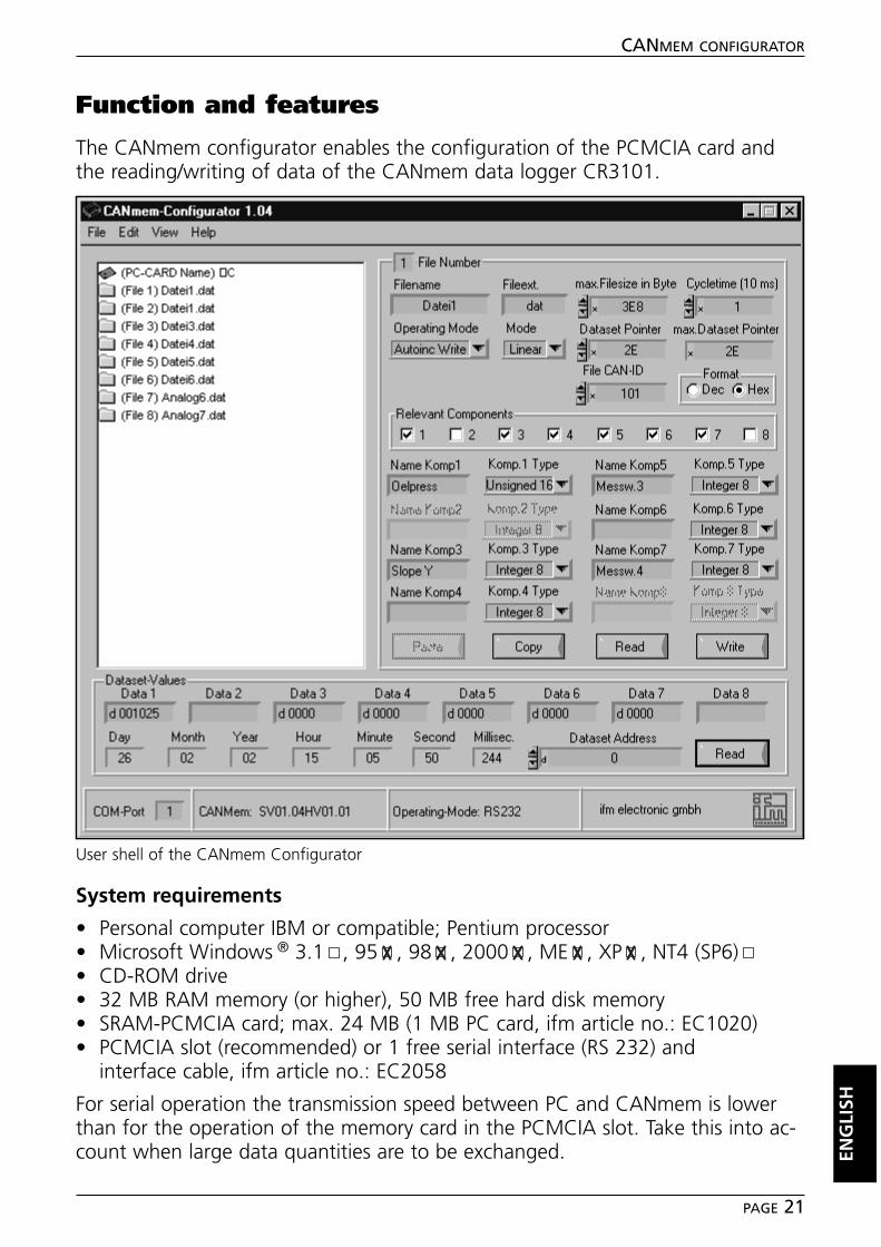
The CANmem configurator enables the configuration of the PCMCIA card andthe reading/writing of data of the CANmem data logger CR3101.
System requirements
• Personal computer IBM or compatible; Pentium processor• Microsoft Windows ® 3.1 , 95 , 98 , 2000 , ME , XP , NT4 (SP6)• CD-ROM drive• 32 MB RAM memory (or higher), 50 MB free hard disk memory• SRAM-PCMCIA card; max. 24 MB (1 MB PC card, ifm article no.: EC1020)• PCMCIA slot (recommended) or 1 free serial interface (RS 232) and
interface cable, ifm article no.: EC2058
For serial operation the transmission speed between PC and CANmem is lowerthan for the operation of the memory card in the PCMCIA slot. Take this into ac-count when large data quantities are to be exchanged. EN
GLI
SH
CANMEM CONFIGURATOR
PAGE 21
User shell of the CANmem Configurator
Installation
■■ Software
• Start Windows and insert the CD-ROM into your CD drive.• Select "Run" in the menu bar "Start".• Enter "D:\CANmem/Konfigurator\setup.exe". Click on the button "OK".If your CD-ROM drive is addressed with a letter other than "D", enter this letterinstead of D.• Follow the instructions of the setup program.• Execute the instructions a) or b) according to the planned operating mode.
a) operating mode RS232 (serial interface)
• Connect the RS232 interface of the CANmem with the serial interface of yourPC (interface cable ifm article no.: EC2058).• Supply the CANmem with the operating voltage (see CANmem device manual,Electrical connection) via the 3.5 mm hollow plug (plug-in power supply, ifm arti-cle no.: EC2059).
b) Operating mode PCMCIA socket (internal PCMCIA slot of the PC)
• Copy the driver file "SwapFTL.exe" from the CD-ROM into the newly createddirectory "C:\Programs\CANcom_Configurator".
CANMEM CONFIGURATOR
PAGE 22
Program functions
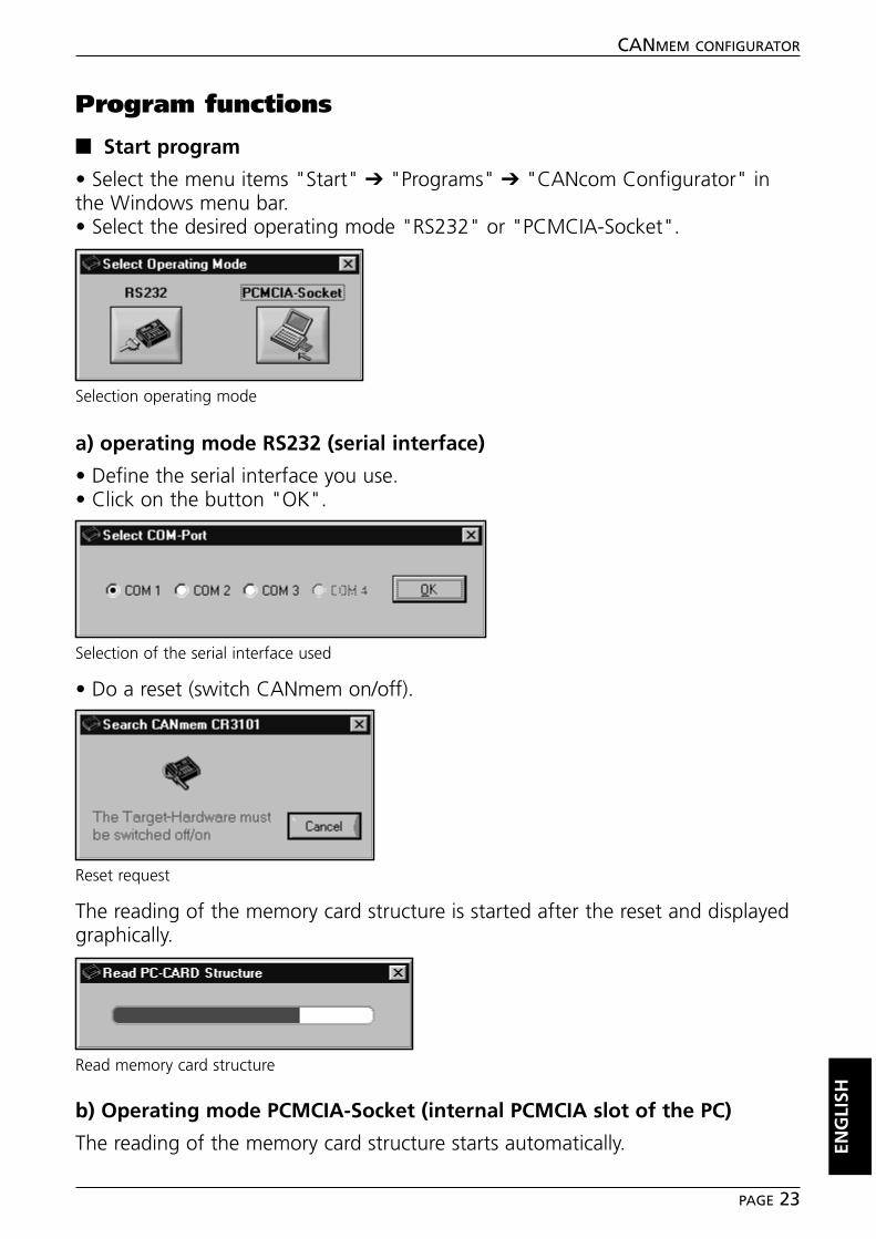
■■ Start program
• Select the menu items "Start" ➔ "Programs" ➔ "CANcom Configurator" inthe Windows menu bar.• Select the desired operating mode "RS232" or "PCMCIA-Socket".
a) operating mode RS232 (serial interface)
• Define the serial interface you use.• Click on the button "OK".
• Do a reset (switch CANmem on/off).
The reading of the memory card structure is started after the reset and displayedgraphically.
b) Operating mode PCMCIA-Socket (internal PCMCIA slot of the PC)
The reading of the memory card structure starts automatically. ENG
LISH
CANMEM CONFIGURATOR
PAGE 23
Selection operating mode
Read memory card structure
Selection of the serial interface used
Reset request
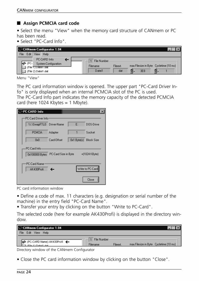
■■ Assign PCMCIA card code
• Select the menu "View" when the memory card structure of CANmem or PChas been read.• Select "PC-Card Info".
The PC card information window is opened. The upper part "PC-Card Driver In-fo" is only displayed when an internal PCMCIA slot of the PC is used.The PC-Card Info part indicates the memory capacity of the detected PCMCIAcard (here 1024 Kbytes = 1 Mbyte).
• Define a code of max. 11 characters (e.g. designation or serial number of themachine) in the entry field "PC-Card Name".• Transfer your entry by clicking on the button "Write to PC-Card".
The selected code (here for example AK430Profi) is displayed in the directory win-dow.
• Close the PC card information window by clicking on the button "Close".
CANMEM CONFIGURATOR
PAGE 24
PC card information window
Menu "View"
➔
➔
Directory window of the CANmem Configurator
➔
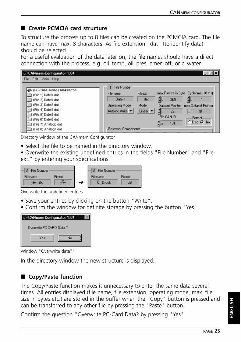
■■ Create PCMCIA card structure
To structure the process up to 8 files can be created on the PCMCIA card. The filename can have max. 8 characters. As file extension "dat" (to identify data)should be selected.For a useful evaluation of the data later on, the file names should have a directconnection with the process, e.g. oil_temp, oil_pres, emer_off, or c_water.
• Select the file to be named in the directory window.• Overwrite the existing undefined entries in the fields "File Number" and "File-ext." by entering your specifications.
• Save your entries by clicking on the button "Write".• Confirm the window for definite storage by pressing the button "Yes".
In the directory window the new structure is displayed.
■■ Copy/Paste function
The Copy/Paste function makes it unnecessary to enter the same data severaltimes. All entries displayed (file name, file extension, operating mode, max. filesize in bytes etc.) are stored in the buffer when the "Copy" button is pressed andcan be transferred to any other file by pressing the "Paste" button.
Confirm the question "Overwrite PC-Card Data? by pressing "Yes". ENG
LISH
CANMEM CONFIGURATOR
PAGE 25
Directory window of the CANmem Configurator
Overwrite the undefined entries
Window "Overwrite data?"
➔
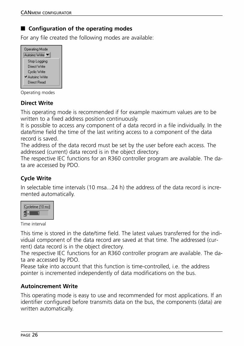
■■ Configuration of the operating modes
For any file created the following modes are available:
Direct Write
This operating mode is recommended if for example maximum values are to bewritten to a fixed address position continuously.It is possible to access any component of a data record in a file individually. In thedate/time field the time of the last writing access to a component of the datarecord is saved.The address of the data record must be set by the user before each access. Theaddressed (current) data record is in the object directory.The respective IEC functions for an R360 controller program are available. The da-ta are accessed by PDO.
Cycle Write
In selectable time intervals (10 msa...24 h) the address of the data record is incre-mented automatically.
This time is stored in the date/time field. The latest values transferred for the indi-vidual component of the data record are saved at that time. The addressed (cur-rent) data record is in the object directory.The respective IEC functions for an R360 controller program are available. The da-ta are accessed by PDO.Please take into account that this function is time-controlled, i.e. the addresspointer is incremented independently of data modifications on the bus.
Autoincrement Write
This operating mode is easy to use and recommended for most applications. If anidentifier configured before transmits data on the bus, the components (data) arewritten automatically.
CANMEM CONFIGURATOR
PAGE 26
Operating modes
Time interval
As set in "Cycletime", a time window is started during the writing on a compo-nent. When this time has elapsed, the address of the data record is incrementedautomatically. All write accesses within this time are saved in the same datarecord.The operating mode enables a minimum time window of "0". With this setting adata record can be saved approx. each millisecond.
The time is saved in the date/time window when Cycletime has elapsed. The ad-dressed (current) data record is in the object directory. The data are accessed byPDO. Further functions within the controller program are not required for this op-erating mode.
Direct Read
This operating mode is for example used to load parameter sets from the CAN-mem to the controller. Within the controller program the data records are onlyread by SDO.Before a data record is read, the address pointer must be set to the desired datarecord position by the user program. The respective IEC functions for an R360controller program are available.
The configurator enables manual reading of individual data records. To read a da-ta record, the address of the data record must be entered. Confirm by pressingthe "Read" button. The components of the addressed data record incl. time/datefield and modification field are then in the object directory and are read by SDO.
Stop Logging
The logging of data is stopped.
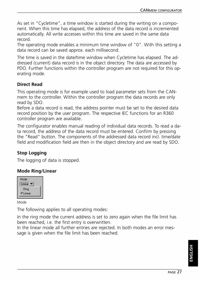
Mode Ring/Linear
The following applies to all operating modes:
In the ring mode the current address is set to zero again when the file limit hasbeen reached, i.e. the first entry is overwritten.In the linear mode all further entries are rejected. In both modes an error mes-sage is given when the file limit has been reached.
ENG
LISH
CANMEM CONFIGURATOR
PAGE 27
Mode
■■ Define size and quantity of data
When the files have been structured, their maximum size and the quantity of da-ta records contained must be defined.
Example:A 1 MB PCMCIA card is used and the 8 files created are to have the same memo-ry size. 1 MB corresponds to a storage capacity of 1024 x 1024 bytes = 1045884bytes (decimal).
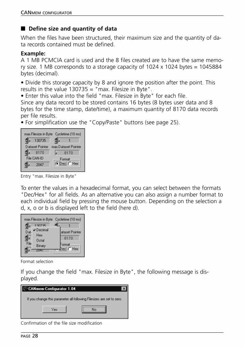
• Divide this storage capacity by 8 and ignore the position after the point. Thisresults in the value 130735 = "max. Filesize in Byte".• Enter this value into the field "max. Filesize in Byte" for each file.Since any data record to be stored contains 16 bytes (8 bytes user data and 8bytes for the time stamp, date/time), a maximum quantity of 8170 data recordsper file results.• For simplification use the "Copy/Paste" buttons (see page 25).
To enter the values in a hexadecimal format, you can select between the formats"Dec/Hex" for all fields. As an alternative you can also assign a number format toeach individual field by pressing the mouse button. Depending on the selection ad, x, o or b is displayed left to the field (here d).
If you change the field "max. Filesize in Byte", the following message is dis-played.
CANMEM CONFIGURATOR
PAGE 28
Entry "max. Filesize in Byte"
Format selection
Confirmation of the file size modification
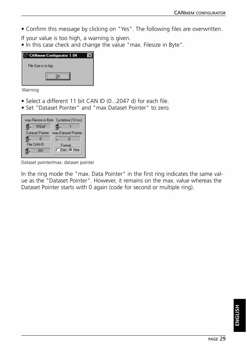
• Confirm this message by clicking on "Yes". The following files are overwritten.
If your value is too high, a warning is given.• In this case check and change the value "max. Filesize in Byte".
• Select a different 11 bit CAN ID (0...2047 d) for each file.• Set "Dataset Pointer" and "max Dataset Pointer" to zero.
In the ring mode the "max. Data Pointer" in the first ring indicates the same val-ue as the "Dataset Pointer". However, it remains on the max. value whereas theDataset Pointer starts with 0 again (code for second or multiple ring).
ENG
LISH
CANMEM CONFIGURATOR
PAGE 29
Warning
Dataset pointer/max. dataset pointer
■■ Structure of the data components
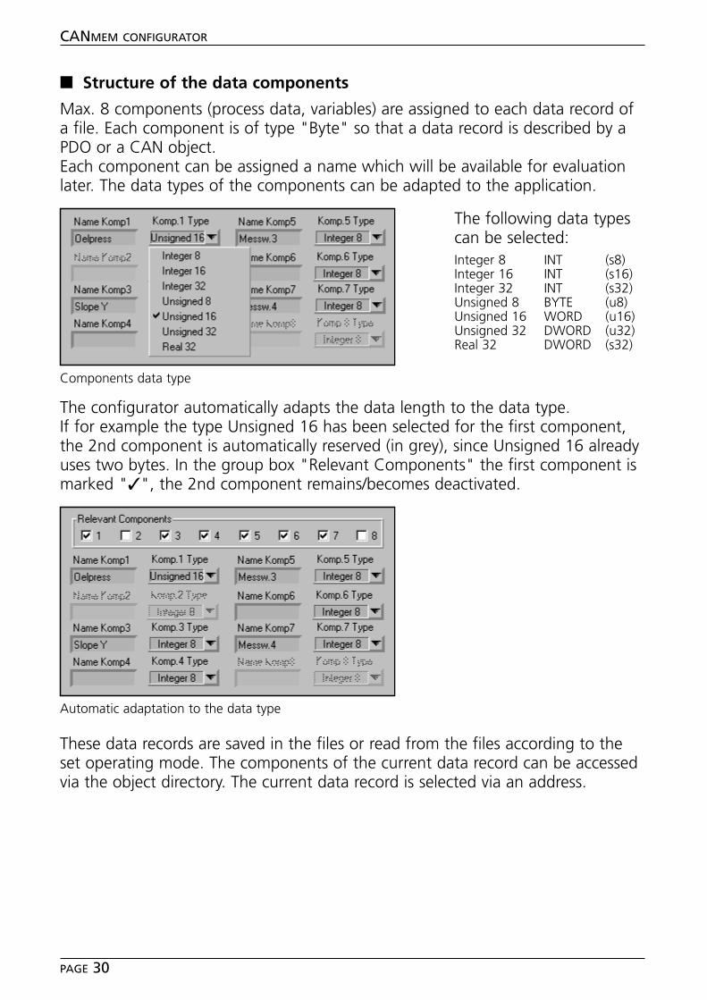
Max. 8 components (process data, variables) are assigned to each data record ofa file. Each component is of type "Byte" so that a data record is described by aPDO or a CAN object.Each component can be assigned a name which will be available for evaluationlater. The data types of the components can be adapted to the application.
The configurator automatically adapts the data length to the data type.If for example the type Unsigned 16 has been selected for the first component,the 2nd component is automatically reserved (in grey), since Unsigned 16 alreadyuses two bytes. In the group box "Relevant Components" the first component ismarked "✓", the 2nd component remains/becomes deactivated.
These data records are saved in the files or read from the files according to theset operating mode. The components of the current data record can be accessedvia the object directory. The current data record is selected via an address.
CANMEM CONFIGURATOR
PAGE 30
Components data type
Automatic adaptation to the data type
The following data typescan be selected:Integer 8 INT (s8)Integer 16 INT (s16)Integer 32 INT (s32)Unsigned 8 BYTE (u8)Unsigned 16 WORD (u16)Unsigned 32 DWORD (u32)Real 32 DWORD (s32)
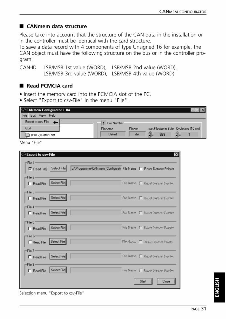
■■ CANmem data structure
Please take into account that the structure of the CAN data in the installation orin the controller must be identical with the card structure.To save a data record with 4 components of type Unsigned 16 for example, theCAN object must have the following structure on the bus or in the controller pro-gram:
CAN-ID LSB/MSB 1st value (WORD), LSB/MSB 2nd value (WORD),LSB/MSB 3rd value (WORD), LSB/MSB 4th value (WORD)
■■ Read PCMCIA card
• Insert the memory card into the PCMCIA slot of the PC.• Select "Export to csv-File" in the menu "File".
ENG
LISH
CANMEM CONFIGURATOR
PAGE 31
Menu "File"
➔
Selection menu "Export to csv-File"
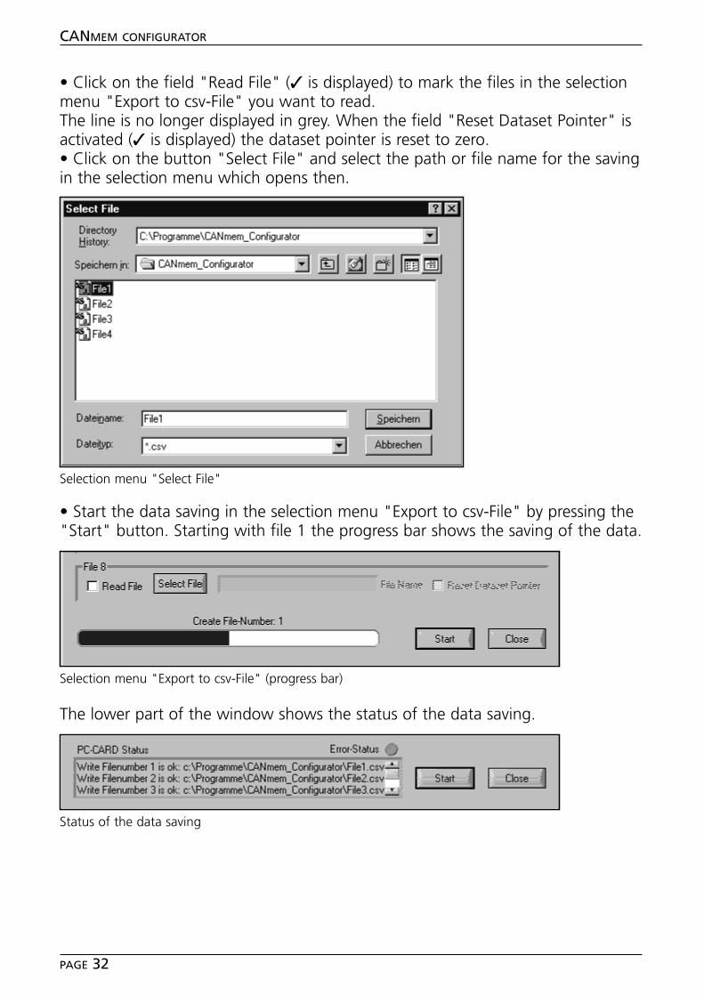
• Click on the field "Read File" (✓ is displayed) to mark the files in the selectionmenu "Export to csv-File" you want to read. The line is no longer displayed in grey. When the field "Reset Dataset Pointer" isactivated (✓ is displayed) the dataset pointer is reset to zero. • Click on the button "Select File" and select the path or file name for the savingin the selection menu which opens then.
• Start the data saving in the selection menu "Export to csv-File" by pressing the"Start" button. Starting with file 1 the progress bar shows the saving of the data.
The lower part of the window shows the status of the data saving.
CANMEM CONFIGURATOR
PAGE 32
Selection menu "Select File"
Selection menu "Export to csv-File" (progress bar)
Status of the data saving
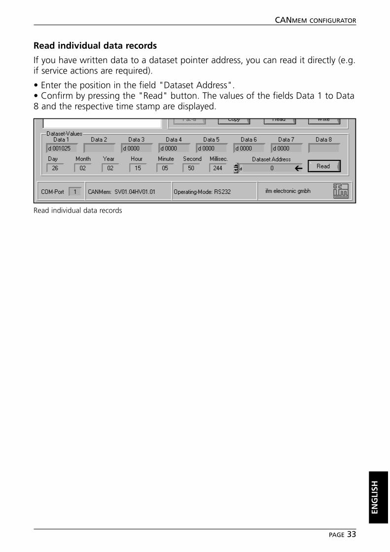
Read individual data records
If you have written data to a dataset pointer address, you can read it directly (e.g.if service actions are required).
• Enter the position in the field "Dataset Address".• Confirm by pressing the "Read" button. The values of the fields Data 1 to Data8 and the respective time stamp are displayed.
ENG
LISH
CANMEM CONFIGURATOR
PAGE 33
Read individual data records
➔

■■ Save data structure on the PC
• Select "Save PC-Card Configuration" in the "Edit" menu.
• Select a file name (e.g. designation or serial number of the machine). The filetype .pcc is assigned automatically.• Confirm by pressing the "Save" button.
If you want to overwrite an already existing file, a warning is displayed as safety.Confirm the replacement of the existing file by clicking on the "Yes" button orcancel the operation by clicking on "No".
The saving of the data structure is displayed by a progress bar.
CANMEM CONFIGURATOR
PAGE 34
"Edit" menu
➔
Selection menu "Save PC-Card Structure in File"
Warning "Do you want to replace it?"
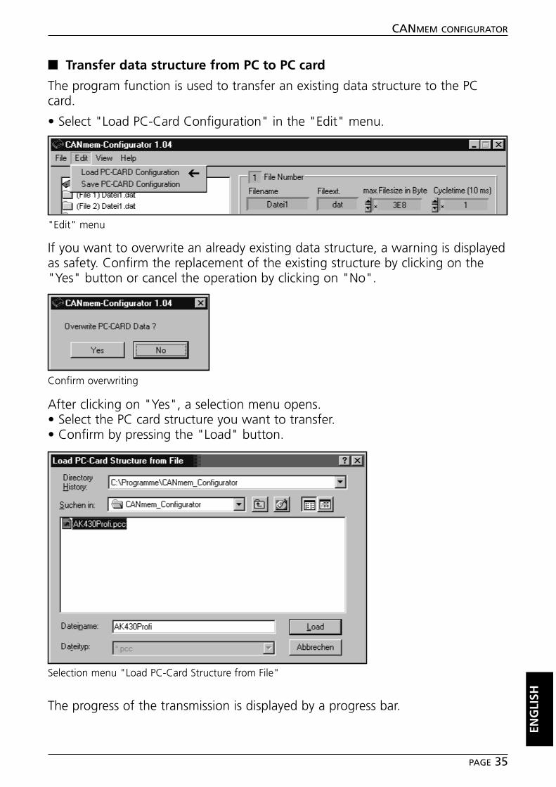
■■ Transfer data structure from PC to PC card
The program function is used to transfer an existing data structure to the PCcard.
• Select "Load PC-Card Configuration" in the "Edit" menu.
If you want to overwrite an already existing data structure, a warning is displayedas safety. Confirm the replacement of the existing structure by clicking on the"Yes" button or cancel the operation by clicking on "No".
After clicking on "Yes", a selection menu opens.• Select the PC card structure you want to transfer.• Confirm by pressing the "Load" button.
The progress of the transmission is displayed by a progress bar.
ENG
LISH
CANMEM CONFIGURATOR
PAGE 35
"Edit" menu
➔
Confirm overwriting
Selection menu "Load PC-Card Structure from File"
CAN initial settings
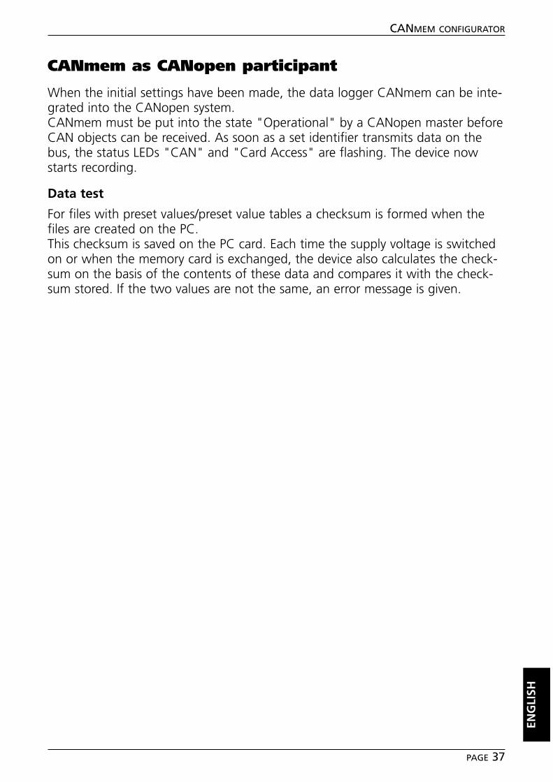
■■ Node ID and baud rate
Before CANmem is integrated into the CANopen system, it may be necessary toset the node ID and the baud rate. When delivered the node ID is 32 (decimal)and the baud rate is set to 125 Kbits/s.These initial settings can among others be changed by the CANmem configuratoror the CAN analyser (ifm article no.: EC2036).
The programming steps of the CANmem configurator are as follows:
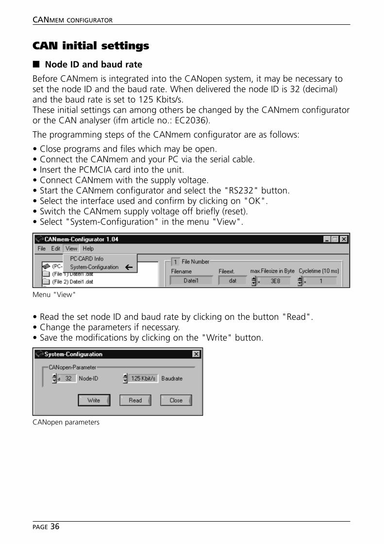
• Close programs and files which may be open.• Connect the CANmem and your PC via the serial cable.• Insert the PCMCIA card into the unit.• Connect CANmem with the supply voltage.• Start the CANmem configurator and select the "RS232" button.• Select the interface used and confirm by clicking on "OK".• Switch the CANmem supply voltage off briefly (reset).• Select "System-Configuration" in the menu "View".
• Read the set node ID and baud rate by clicking on the button "Read".• Change the parameters if necessary.• Save the modifications by clicking on the "Write" button.
CANMEM CONFIGURATOR
PAGE 36
Menu "View"
➔
CANopen parameters
CANmem as CANopen participant
When the initial settings have been made, the data logger CANmem can be inte-grated into the CANopen system.CANmem must be put into the state "Operational" by a CANopen master beforeCAN objects can be received. As soon as a set identifier transmits data on thebus, the status LEDs "CAN" and "Card Access" are flashing. The device nowstarts recording.
Data test
For files with preset values/preset value tables a checksum is formed when thefiles are created on the PC.This checksum is saved on the PC card. Each time the supply voltage is switchedon or when the memory card is exchanged, the device also calculates the check-sum on the basis of the contents of these data and compares it with the check-sum stored. If the two values are not the same, an error message is given.
ENG
LISH
CANMEM CONFIGURATOR
PAGE 37
Notizen / Notes
CANMEM CONFIGURATOR
PAGE 38

Tech
nisc
he Ä
nder
unge
n be
halte
n w
ir un
s oh
ne v
orhe
rige
Ank
ündi
gung
vor
.Pa
pier
chl
orfr
ei g
eble
icht
ProgrammhandbuchProgramming manual
CANmemTool
Downloader
DEU
TSC
HEN
GLI
SH
R
CARD ERRORCARD ACCESS
ONERROR
CAN
Sach
nr.
7390
372
/00
07
/200
3
Inhalt
Bestimmungsgemäße Verwendung . . . . . . . . . . . . . . . . . . . . . . . . . Seite 3Systemvoraussetzungen. . . . . . . . . . . . . . . . . . . . . . . . . . . . . . . Seite 3
InstallationSoftware . . . . . . . . . . . . . . . . . . . . . . . . . . . . . . . . . . . . . . . . . Seite 4Hardware . . . . . . . . . . . . . . . . . . . . . . . . . . . . . . . . . . . . . . . . . Seite 4
ProgrammfunktionenProgramm starten . . . . . . . . . . . . . . . . . . . . . . . . . . . . . . . . . . . Seite 5CANmem initialisieren und Flash-Informationen auslesen. . . . . . . Seite 5Betriebssystem in CANmem laden . . . . . . . . . . . . . . . . . . . . . . . Seite 7
FehlerbehebungSchnittstellen . . . . . . . . . . . . . . . . . . . . . . . . . . . . . . . . . . . . . . Seite 9Preloader . . . . . . . . . . . . . . . . . . . . . . . . . . . . . . . . . . . . . . . . . Seite 9Übertragungsfehler während Programmierung/Verifizierung . . . . Seite 10
Notizen . . . . . . . . . . . . . . . . . . . . . . . . . . . . . . . . . . . . . . . . . . . . . Seite 22
Die CANmem Gerätebeschreibung inkl. CANopen Objektverzeichnisseentnehmen Sie bitte dem Geräte-Handbuch CR3101.
➔ Datenblatt direkt ➔ CR3101 ➔ weitere Informationen
Hinweis zu diesem Handbuch
Dieses Handbuch beschreibt alle Programmfunktionen, die für das Downloa-den eines Betriebssystems notwendig sind.Nicht beschriebene Funktionen, wie z.B. das Löschen des Flash-Speichers,sind unseren Entwicklern vorbehalten und für die Nutzung des Datenloggersnicht zwingend notwendig.
www.ifm-electronic.com
CANMEM DOWNLOADER
SEITE 2
Microsoft und Windows sind eingetragene Warenzeichen der Microsoft Corporation.
Die überlassene Software ist für den normalen Gebrauch auf handelsüblichen Personalcomputern ge-eignet. Eine Gewähr für unterbrechungsfreien oder fehlerfreien Betrieb oder die Freiheit von Compu-terviren sowie dafür, daß jeder eventuell auftretende Fehler beseitigt wird, kann nach dem Stand derSoftwaretechnik nicht übernommen werden. Insbesondere haftet ifm electronic gmbh bei einem feh-lerhaften Programm nicht für beim Kunden entstehende Kosten (z.B. Wartung, Reparatur oder Män-gelbehebung). Der Ausschluß gilt nicht für Schäden, für die aufgrund unabdingbarer gesetzlicher Vor-schriften zwingend gehaftet wird.
Das Programm ist speziell für die Steuerungssysteme der ifm electronic gmbh entwickelt worden. Da-her ist die Funktion nur bei diesen Steuerungen möglich. Versuche der Ankoppelung an Fremdsyste-me können zu gravierenden Schäden führen.
CANMEM DOWNLOADER
SEITE 3
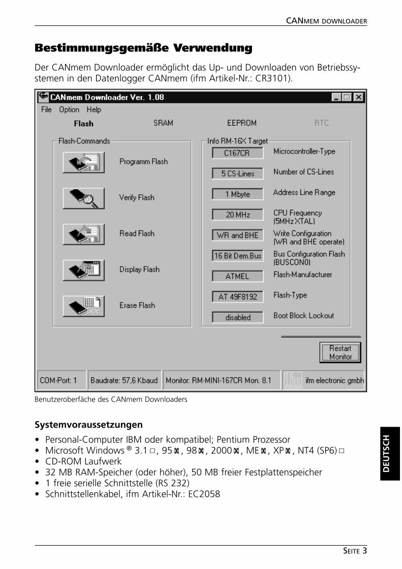
Bestimmungsgemäße Verwendung
Der CANmem Downloader ermöglicht das Up- und Downloaden von Betriebssy-stemen in den Datenlogger CANmem (ifm Artikel-Nr.: CR3101).
Systemvoraussetzungen
• Personal-Computer IBM oder kompatibel; Pentium Prozessor• Microsoft Windows ® 3.1 , 95 , 98 , 2000 , ME , XP , NT4 (SP6)• CD-ROM Laufwerk• 32 MB RAM-Speicher (oder höher), 50 MB freier Festplattenspeicher• 1 freie serielle Schnittstelle (RS 232)• Schnittstellenkabel, ifm Artikel-Nr.: EC2058
DEU
TSC
H
Benutzeroberfäche des CANmem Downloaders
Installation
■■ Software
• Starten Sie Windows und legen Sie die CD-ROM in Ihr CD-Laufwerk.• Wählen Sie in der Menüleiste „Start“ ➔ „Ausführen“.• Geben Sie „D:\CANmem-Downloader\setup.exe“ ein. Bestätigen Sie mit OK.Sollte Ihr CD-ROM Laufwerk mit einem anderen Buchstaben als „D“ angespro-chen werden, geben Sie an Stelle von D diesen Buchstaben ein.• Folgen Sie den Anweisungen des Setup-Programms.• Kopieren Sie das Betriebssystem (bin.-Datei) von der CD-ROM in das neu ange-legte Verzeichnis "C:\Programme\CANmem-Downloader".
■■ Hardware
• Verbinden Sie die RS232-Schnittstelle des CANmem mit der seriellen Schnitt-stelle Ihres PCs (Schnittstellenkabel, ifm Artikel-Nr.: EC2058).• Versorgen Sie das CANmem über den 3,5 mm Hohlsteckeranschluß (Stecker-Netzteil, ifm Artikel-Nr.: EC2059) mit der Betriebsspannung (siehe ggf. CANmemGeräte-Handbuch).
CANMEM DOWNLOADER
SEITE 4
Programmfunktionen
■■ Programm starten
• Wählen Sie in der Windows-Menüleiste „Start“ ➔ „Programme“ ➔ „CAN-mem-Downloader“.
■■ CANmem initialisieren und Flash-Informationen auslesen
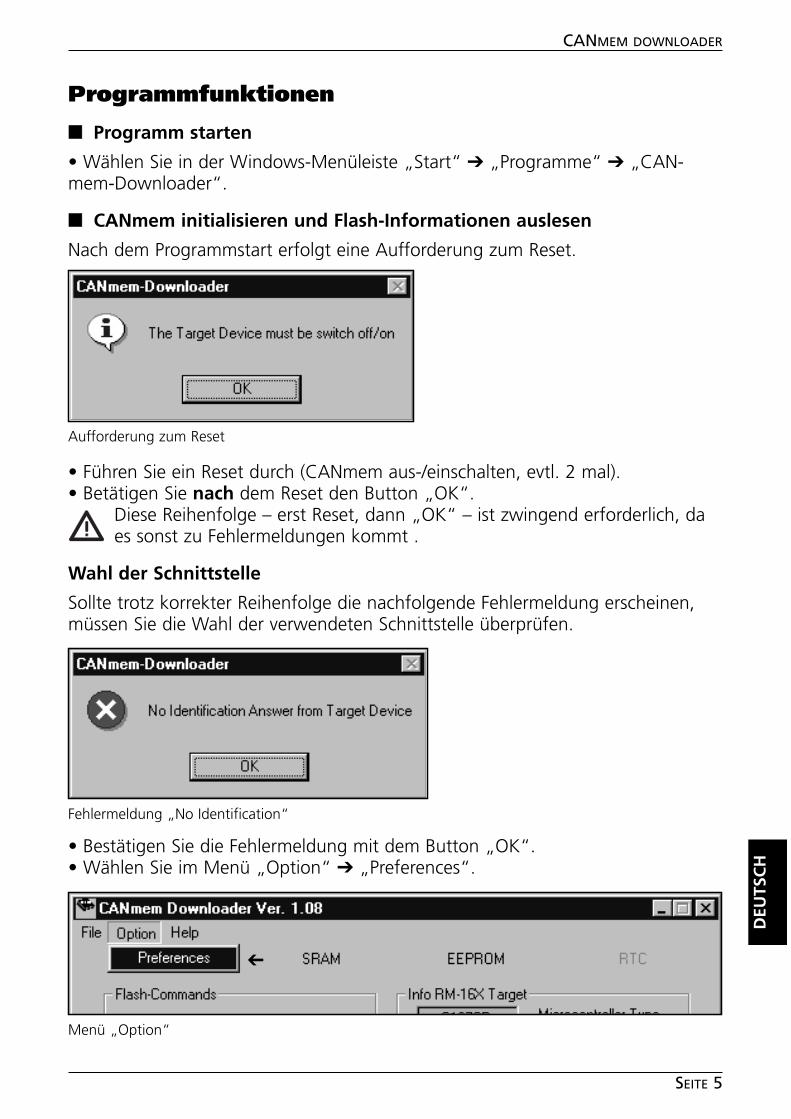
Nach dem Programmstart erfolgt eine Aufforderung zum Reset.
• Führen Sie ein Reset durch (CANmem aus-/einschalten, evtl. 2 mal).• Betätigen Sie nach dem Reset den Button „OK“.
Diese Reihenfolge – erst Reset, dann „OK“ – ist zwingend erforderlich, daes sonst zu Fehlermeldungen kommt .
Wahl der Schnittstelle
Sollte trotz korrekter Reihenfolge die nachfolgende Fehlermeldung erscheinen,müssen Sie die Wahl der verwendeten Schnittstelle überprüfen.
• Bestätigen Sie die Fehlermeldung mit dem Button „OK“.• Wählen Sie im Menü „Option“ ➔ „Preferences“.
DEU
TSC
H
CANMEM DOWNLOADER
SEITE 5
Aufforderung zum Reset
Fehlermeldung „No Identification“
Menü „Option“
➔
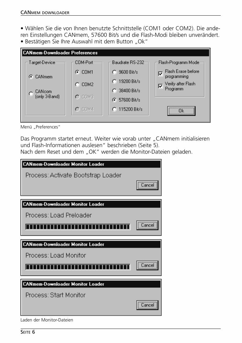
• Wählen Sie die von Ihnen benutzte Schnittstelle (COM1 oder COM2). Die ande-ren Einstellungen CANmem, 57600 Bit/s und die Flash-Modi bleiben unverändert.• Bestätigen Sie Ihre Auswahl mit dem Button „Ok“
Das Programm startet erneut. Weiter wie vorab unter „CANmem initialisierenund Flash-Informationen auslesen“ beschrieben (Seite 5).Nach dem Reset und dem „OK“ werden die Monitor-Dateien geladen.
CANMEM DOWNLOADER
SEITE 6
Laden der Monitor-Dateien
Menü „Preferences“
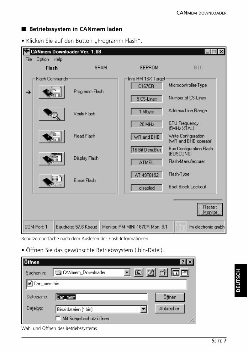
■■ Betriebssystem in CANmem laden
• Klicken Sie auf den Button „Programm Flash“.
• Öffnen Sie das gewünschte Betriebssystem (.bin-Datei).
DEU
TSC
H
CANMEM DOWNLOADER
SEITE 7
Benutzeroberfäche nach dem Auslesen der Flash-Informationen
➔
Wahl und Öffnen des Betriebssystems
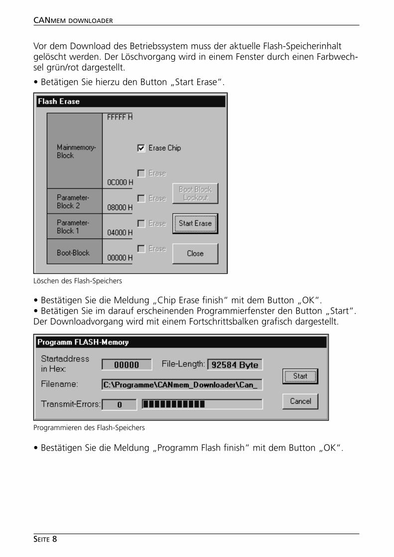
Vor dem Download des Betriebssystem muss der aktuelle Flash-Speicherinhaltgelöscht werden. Der Löschvorgang wird in einem Fenster durch einen Farbwech-sel grün/rot dargestellt.
• Betätigen Sie hierzu den Button „Start Erase“.
• Bestätigen Sie die Meldung „Chip Erase finish“ mit dem Button „OK“.• Betätigen Sie im darauf erscheinenden Programmierfenster den Button „Start“.Der Downloadvorgang wird mit einem Fortschrittsbalken grafisch dargestellt.
• Bestätigen Sie die Meldung „Programm Flash finish“ mit dem Button „OK“.
CANMEM DOWNLOADER
SEITE 8
Löschen des Flash-Speichers
Programmieren des Flash-Speichers
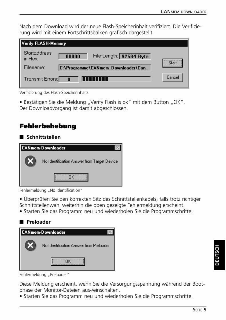
Nach dem Download wird der neue Flash-Speicherinhalt verifiziert. Die Verifizie-rung wird mit einem Fortschrittsbalken grafisch dargestellt.
• Bestätigen Sie die Meldung „Verify Flash is ok“ mit dem Button „OK“.Der Downloadvorgang ist damit abgeschlossen.
Fehlerbehebung
■■ Schnittstellen
• Überprüfen Sie den korrekten Sitz des Schnittstellenkabels, falls trotz richtigerSchnittstellenwahl weiterhin die oben gezeigte Fehlermeldung erscheint.• Starten Sie das Programm neu und wiederholen Sie die Programmschritte.
■■ Preloader
Diese Meldung erscheint, wenn Sie die Versorgungsspannung während der Boot-phase der Monitor-Dateien aus-/einschalten.• Starten Sie das Programm neu und wiederholen Sie die Programmschritte.
DEU
TSC
H
CANMEM DOWNLOADER
SEITE 9
Verifizierung des Flash-Speicherinhalts
Fehlermeldung „No Identification“
Fehlermeldung „Preloader“
■■ Übertragungsfehler während der Programmierung/Verifizierung
Die Datenübertragung wird in der Grundeinstellung mit 57,6 KBaud durchge-führt. Im Einzelfall kann es bei manchen PCs zu Übertragungsproblemen kom-men.
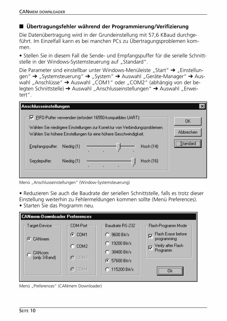
• Stellen Sie in diesem Fall die Sende- und Empfangspuffer für die serielle Schnitt-stelle in der Windows-Systemsteuerung auf „Standard“.
Die Parameter sind einstellbar unter Windows-Menüleiste „Start“ ➔ „Einstellun-gen“ ➔ „Systemsteuerung“ ➔ „System“ ➔ Auswahl „Geräte-Manager“ ➔ Aus-wahl „Anschlüsse“ ➔ Auswahl „COM1“ oder „COM2“ (abhängig von der be-legten Schnittstelle) ➔ Auswahl „Anschlusseinstellungen“ ➔ Auswahl „Erwei-tert“.
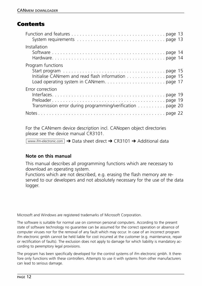
• Reduzieren Sie auch die Baudrate der seriellen Schnittstelle, falls es trotz dieserEinstellung weiterhin zu Fehlermeldungen kommen sollte (Menü Preferences).• Starten Sie das Programm neu.
CANMEM DOWNLOADER
SEITE 10
Menü „Anschlusseinstellungen“ (Window-Systemsteuerung)
Menü „Preferences“ (CANmem Downloader)

ENG
LISH
CANMEM DOWNLOADER
SEITE 11
Contents
Function and features . . . . . . . . . . . . . . . . . . . . . . . . . . . . . . . . . . page 13System requirements . . . . . . . . . . . . . . . . . . . . . . . . . . . . . . . . page 13
InstallationSoftware . . . . . . . . . . . . . . . . . . . . . . . . . . . . . . . . . . . . . . . . . page 14Hardware. . . . . . . . . . . . . . . . . . . . . . . . . . . . . . . . . . . . . . . . . page 14
Program functionsStart program . . . . . . . . . . . . . . . . . . . . . . . . . . . . . . . . . . . . . page 15Initialise CANmem and read flash information . . . . . . . . . . . . . . page 15Load operating system in CANmem. . . . . . . . . . . . . . . . . . . . . . page 17
Error correctionInterfaces. . . . . . . . . . . . . . . . . . . . . . . . . . . . . . . . . . . . . . . . . page 19Preloader . . . . . . . . . . . . . . . . . . . . . . . . . . . . . . . . . . . . . . . . . page 19Transmission error during programming/verification . . . . . . . . . . page 20
Notes . . . . . . . . . . . . . . . . . . . . . . . . . . . . . . . . . . . . . . . . . . . . . . page 22
For the CANmem device description incl. CANopen object directoriesplease see the device manual CR3101.
➔ Data sheet direct ➔ CR3101 ➔ Additional data
Note on this manual
This manual describes all programming functions which are necessary todownload an operating system.Functions which are not described, e.g. erasing the flash memory are re-served to our developers and not absolutely necessary for the use of the datalogger.
www.ifm-electronic.com
CANMEM DOWNLOADER
PAGE 12
Microsoft and Windows are registered trademarks of Microsoft Corporation.
The software is suitable for normal use on common personal computers. According to the presentstate of software technology no guarantee can be assumed for the correct operation or absence ofcomputer viruses nor for the removal of any fault which may occur. In case of an incorrect programifm electronic gmbh cannot be held liable for cost incurred at the customer (e.g. maintenance, repairor rectification of faults). The exclusion does not apply to damage for which liability is mandatory ac-cording to peremptory legal provisions.
The program has been specifically developed for the control systems of ifm electronic gmbh. It there-fore only functions with these controllers. Attempts to use it with systems from other manufacturerscan lead to serious damage.
Bestimmungsgemäße Verwendung
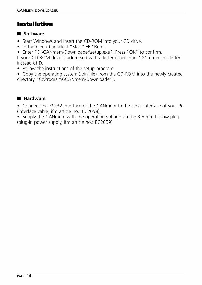
The CANmem Downloader enables uploading and downloading of operating sys-tems to the data logger CAmem (ifm article no.: CR3101).
System requirements
• Personal computer IBM or compatible; Pentium processor• Microsoft Windows ® 3.1 , 95 , 98 , 2000 , ME , XP , NT4 (SP6)• CD-ROM drive• 32 MB RAM memory (or higher), 50 MB free hard disk memory• 1 free serial interface (RS 232)• Interface cable, ifm article no: EC2058
ENG
LISH
CANMEM DOWNLOADER
PAGE 13
User shell of the CANmem Downloader
Installation
■■ Software
• Start Windows and insert the CD-ROM into your CD drive.• In the menu bar select "Start" ➔ "Run".• Enter "D:\CANmem-Downloader\setup.exe". Press "OK" to confirm.If your CD-ROM drive is addressed with a letter other than "D", enter this letterinstead of D.• Follow the instructions of the setup program.• Copy the operating system (.bin file) from the CD-ROM into the newly createddirectory "C:\Programs\CANmem-Downloader".
■■ Hardware
• Connect the RS232 interface of the CANmem to the serial interface of your PC(interface cable, ifm article no.: EC2058).• Supply the CANmem with the operating voltage via the 3.5 mm hollow plug(plug-in power supply, ifm article no.: EC2059).
CANMEM DOWNLOADER
PAGE 14
Program functions
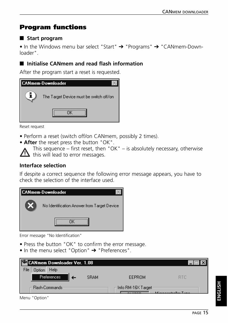
■■ Start program
• In the Windows menu bar select "Start" ➔ "Programs" ➔ "CANmem-Down-loader".
■■ Initialise CANmem and read flash information
After the program start a reset is requested.
• Perform a reset (switch off/on CANmem, possibly 2 times).• After the reset press the button "OK".
This sequence – first reset, then "OK" – is absolutely necessary, otherwisethis will lead to error messages.
Interface selection
If despite a correct sequence the following error message appears, you have tocheck the selection of the interface used.
• Press the button "OK" to confirm the error message.• In the menu select "Option" ➔ "Preferences".
ENG
LISH
CANMEM DOWNLOADER
PAGE 15
Reset request
Error message "No Identification"
Menu "Option"
➔

• Select the interface you use (COM1 or COM2). The other settings CANmem,57600 Bit/s and the flash modes remain unchanged.• Press the button "Ok" to confirm your selection.
The program restarts. Continue as described under "Initialise CANmem and readflash information" (page 15).After the reset and "OK" the monitor files are loaded.
CANMEM DOWNLOADER
PAGE 16
Loading of the monitor files
Menu "Preferences"
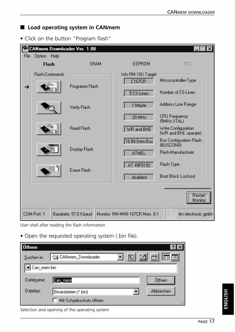
■■ Load operating system in CANmem
• Click on the button "Program flash".
• Open the requested operating system (.bin file).
ENG
LISH
CANMEM DOWNLOADER
PAGE 17
User shell after reading the flash information
➔
Selection and opening of the operating system

Before downloading the operating system the current flash memory contentsmust be erased. The erasing operation is indicated in a window by a colourchange green/red.
• To do so, press the button "Start Erase".
• Press the button "OK" to confirm the message "Chip Erase finish".• Press the button "Start" in the programming window. Downloading is graphi-cally shown with a progressive bar.
• Press the button "OK" to confirm the message "Program Flash finish".
CANMEM DOWNLOADER
PAGE 18
Erasing of the flash memory
Programming of the flash memory
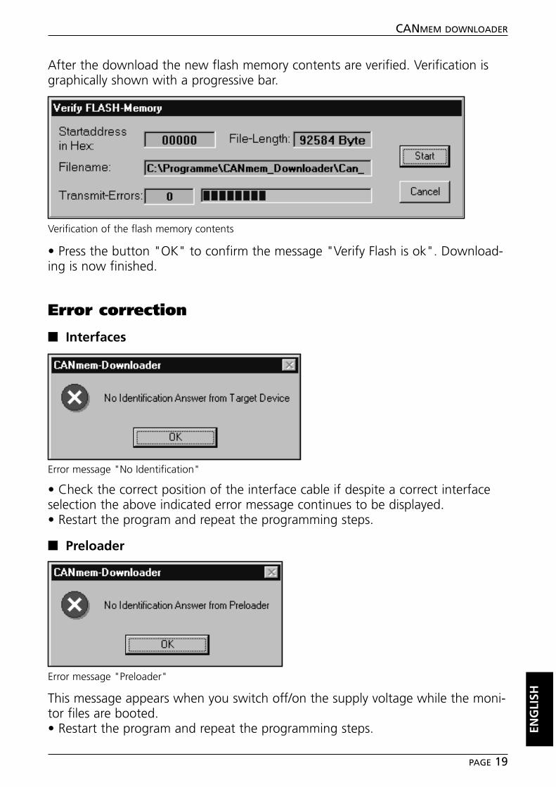
After the download the new flash memory contents are verified. Verification isgraphically shown with a progressive bar.
• Press the button "OK" to confirm the message "Verify Flash is ok". Download-ing is now finished.
Error correction
■■ Interfaces
• Check the correct position of the interface cable if despite a correct interfaceselection the above indicated error message continues to be displayed.• Restart the program and repeat the programming steps.
■■ Preloader
This message appears when you switch off/on the supply voltage while the moni-tor files are booted.• Restart the program and repeat the programming steps. EN
GLI
SH
CANMEM DOWNLOADER
PAGE 19
Verification of the flash memory contents
Error message "No Identification"
Error message "Preloader"
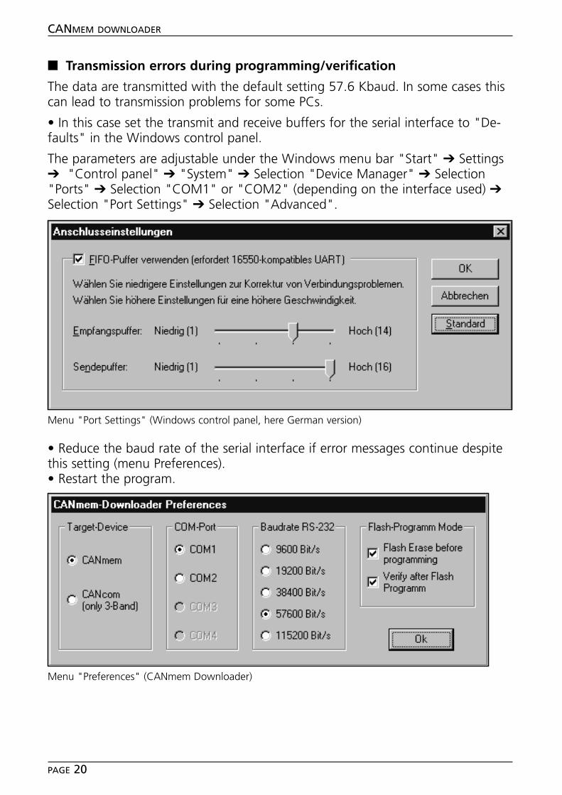
■■ Transmission errors during programming/verification
The data are transmitted with the default setting 57.6 Kbaud. In some cases thiscan lead to transmission problems for some PCs.
• In this case set the transmit and receive buffers for the serial interface to "De-faults" in the Windows control panel.
The parameters are adjustable under the Windows menu bar "Start" ➔ Settings➔ "Control panel" ➔ "System" ➔ Selection "Device Manager" ➔ Selection"Ports" ➔ Selection "COM1" or "COM2" (depending on the interface used) ➔Selection "Port Settings" ➔ Selection "Advanced".
• Reduce the baud rate of the serial interface if error messages continue despitethis setting (menu Preferences). • Restart the program.
CANMEM DOWNLOADER
PAGE 20
Menu "Port Settings" (Windows control panel, here German version)
Menu "Preferences" (CANmem Downloader)

ENG
LISH
CANMEM DOWNLOADER
PAGE 21

Notizen / Notes
CANMEM DOWNLOADER
PAGE 22

Tech
nisc
he Ä
nder
unge
n be
halte
n w
ir un
s oh
ne v
orhe
rige
Ank
ündi
gung
vor
.Pa
pier
chl
orfr
ei g
eble
icht
ProgrammhandbuchProgramming manual
CANmemTool
Reader
WRITE PRO
TECT
PCMCIA-CARD
DEU
TSC
HEN
GLI
SH
R
Sach
nr.
7390
373
/00
08
/200
2
Inhalt
Bestimmungsgemäße Verwendung . . . . . . . . . . . . . . . . . . . . . . . . . Seite 3Systemvoraussetzungen. . . . . . . . . . . . . . . . . . . . . . . . . . . . . . . Seite 3
SoftwareinstallationProgramm . . . . . . . . . . . . . . . . . . . . . . . . . . . . . . . . . . . . . . . . Seite 4Treiber . . . . . . . . . . . . . . . . . . . . . . . . . . . . . . . . . . . . . . . . . . . Seite 4
ProgrammfunktionenProgramm starten . . . . . . . . . . . . . . . . . . . . . . . . . . . . . . . . . . . Seite 5Konfiguration . . . . . . . . . . . . . . . . . . . . . . . . . . . . . . . . . . . . . . Seite 6Dateien lesen . . . . . . . . . . . . . . . . . . . . . . . . . . . . . . . . . . . . . . Seite 8
Hinweise zum csv-Format . . . . . . . . . . . . . . . . . . . . . . . . . . . . . . . . Seite 8
Notizen . . . . . . . . . . . . . . . . . . . . . . . . . . . . . . . . . . . . . . . . . . . . . Seite 18
Die CANmem Gerätebeschreibung inkl. CANopen Objektverzeichnisseentnehmen Sie bitte dem Geräte-Handbuch CR3101.
➔ Datenblatt direkt ➔ CR3101 ➔ weitere Informationenwww.ifm-electronic.com
CANMEM READER
SEITE 2
Microsoft, Windows und Excel sind eingetragene Warenzeichen der Microsoft Corporation,Lotus 1-2-3 ist ein eingetragenes Warenzeichen der Lotus Development Corporation.
Die überlassene Software ist für den normalen Gebrauch auf handelsüblichen Personalcomputern ge-eignet. Eine Gewähr für unterbrechungsfreien oder fehlerfreien Betrieb oder die Freiheit von Compu-terviren sowie dafür, daß jeder eventuell auftretende Fehler beseitigt wird, kann nach dem Stand derSoftwaretechnik nicht übernommen werden. Insbesondere haftet ifm electronic gmbh bei einem feh-lerhaften Programm nicht für beim Kunden entstehende Kosten (z.B. Wartung, Reparatur oder Män-gelbehebung). Der Ausschluß gilt nicht für Schäden, für die aufgrund unabdingbarer gesetzlicher Vor-schriften zwingend gehaftet wird.
Das Programm ist speziell für die Steuerungssysteme der ifm electronic gmbh entwickelt worden. Da-her ist die Funktion nur bei diesen Steuerungen möglich. Versuche der Ankoppelung an Fremdsyste-me können zu gravierenden Schäden führen.
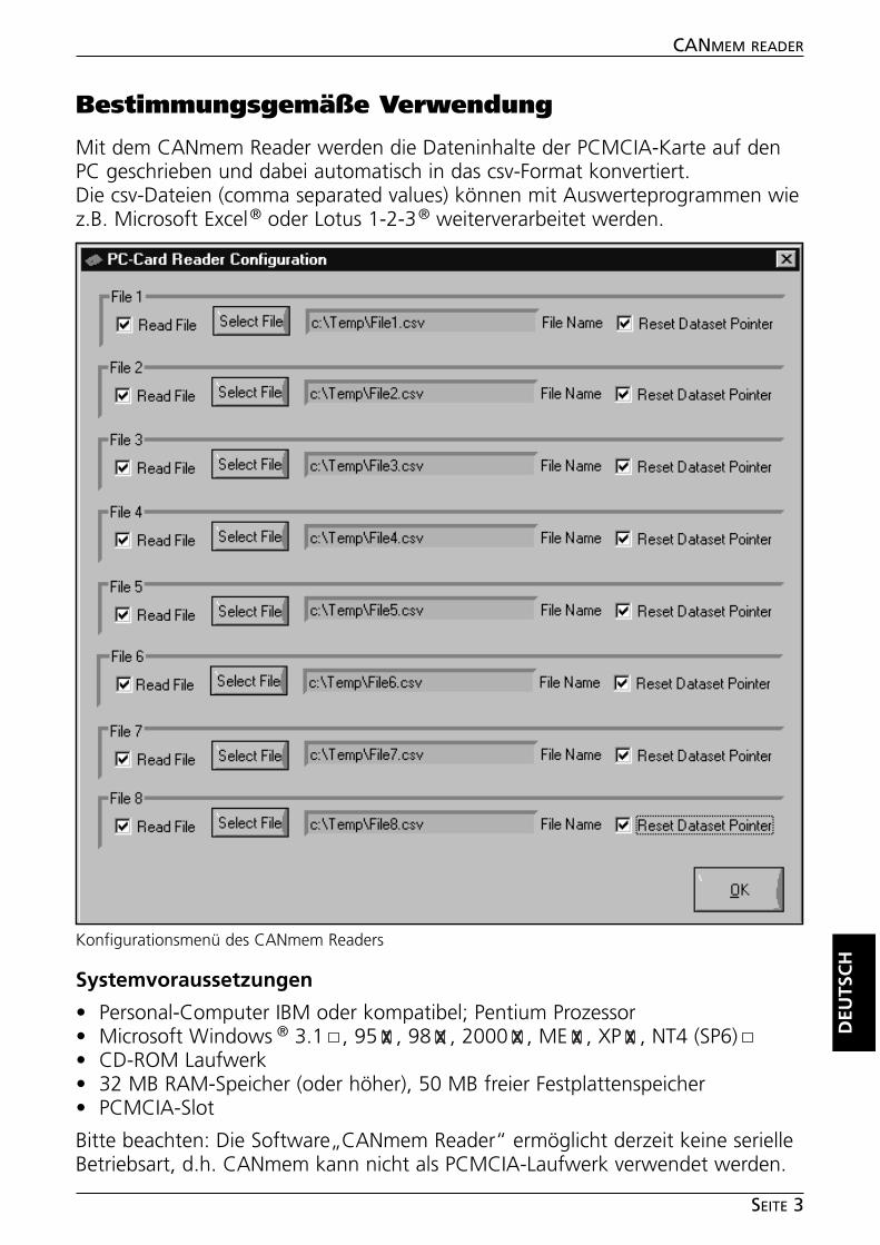
CANMEM READER
SEITE 3
Bestimmungsgemäße Verwendung
Mit dem CANmem Reader werden die Dateninhalte der PCMCIA-Karte auf denPC geschrieben und dabei automatisch in das csv-Format konvertiert.Die csv-Dateien (comma separated values) können mit Auswerteprogrammen wiez.B. Microsoft Excel® oder Lotus 1-2-3® weiterverarbeitet werden.
Systemvoraussetzungen
• Personal-Computer IBM oder kompatibel; Pentium Prozessor• Microsoft Windows ® 3.1 , 95 , 98 , 2000 , ME , XP , NT4 (SP6)• CD-ROM Laufwerk• 32 MB RAM-Speicher (oder höher), 50 MB freier Festplattenspeicher• PCMCIA-Slot
Bitte beachten: Die Software„CANmem Reader“ ermöglicht derzeit keine serielleBetriebsart, d.h. CANmem kann nicht als PCMCIA-Laufwerk verwendet werden.
DEU
TSC
H
Konfigurationsmenü des CANmem Readers
Softwareinstallation
■■ Programm
• Starten Sie Windows und legen Sie die CD-ROM in Ihr CD-Laufwerk.• Wählen Sie in der Menüleiste „Start“ ➔ „Ausführen“.• Geben Sie „D:\CANmem-Reader\setup.exe“ ein. Bestätigen Sie mit OK.Sollte Ihr CD-ROM Laufwerk mit einem anderen Buchstaben als „D“ angespro-chen werden, geben Sie an Stelle von D diesen Buchstaben ein.• Folgen Sie den Anweisungen des Setup-Programms.
■■ Treiber SwapFTL
CANmem Reader benötigt den Treiber „SwapFTL“.Falls Sie vorab das Softwaretool „CANmem Configurator“ in der BetriebsartPCMCIA-Socket verwendet haben, ist der Treiber bereits auf Ihrem Rechner instal-liert (siehe ggf. Programmhandbuch „CANmem Configurator, Seite 4).
• Ist dies nicht der Fall, installieren Sie die Treiberdatei „SwapFTL .exe“ von derCD-ROM in das neu angelegte Verzeichnis "C:\Programme\CANmem-Reader".
Hinweis:
In Ausnahmefällen kann es zu Konflikten mit bereits eingesteckten PCMCIA-Komponenten (z.B. Netzwerkkarten) kommen.
Diese Komponenten müssen dann für den Zeitraum des Lesens entfernt werden.Je nach PC-System, wird der SwapFTL-Treiber erst aktiviert, wenn die CANmemSpeicherkarte-Karte in den PCMCIA-Slot gesteckt wird.
CANMEM READER
SEITE 4
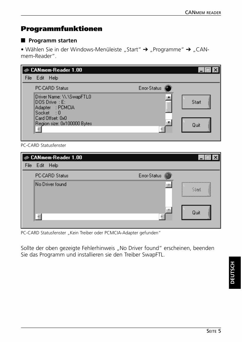
Programmfunktionen
■■ Programm starten
• Wählen Sie in der Windows-Menüleiste „Start“ ➔ „Programme“ ➔ „CAN-mem-Reader“.
Sollte der oben gezeigte Fehlerhinweis „No Driver found“ erscheinen, beendenSie das Programm und installieren sie den Treiber SwapFTL.
DEU
TSC
H
CANMEM READER
SEITE 5
PC-CARD Statusfenster „Kein Treiber oder PCMCIA-Adapter gefunden“
PC-CARD Statusfenster
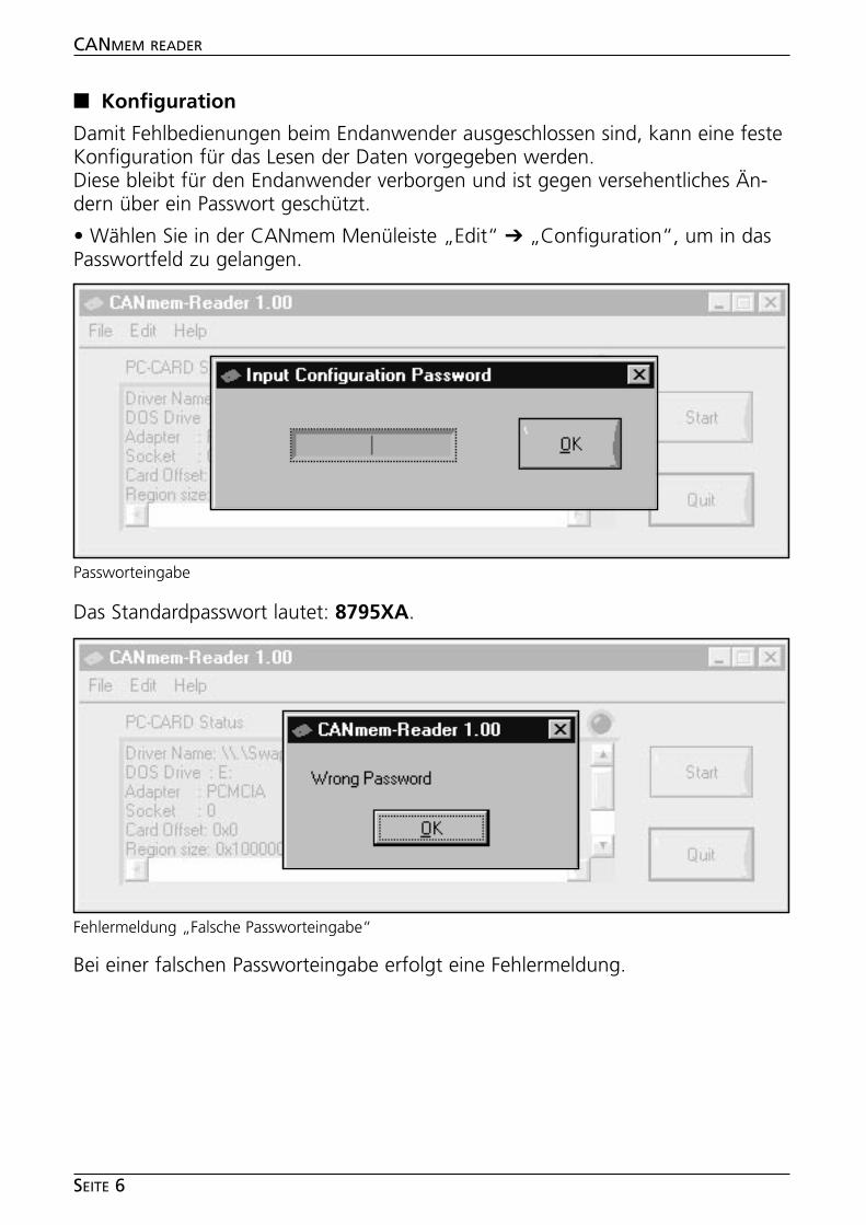
■■ Konfiguration
Damit Fehlbedienungen beim Endanwender ausgeschlossen sind, kann eine festeKonfiguration für das Lesen der Daten vorgegeben werden.Diese bleibt für den Endanwender verborgen und ist gegen versehentliches Än-dern über ein Passwort geschützt.
• Wählen Sie in der CANmem Menüleiste „Edit“ ➔ „Configuration“, um in dasPasswortfeld zu gelangen.
Das Standardpasswort lautet: 8795XA.
Bei einer falschen Passworteingabe erfolgt eine Fehlermeldung.
CANMEM READER
SEITE 6
Passworteingabe
Fehlermeldung „Falsche Passworteingabe“
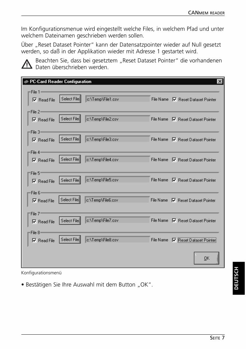
Im Konfigurationsmenue wird eingestellt welche Files, in welchem Pfad und unterwelchem Dateinamen geschrieben werden sollen.
Über „Reset Dataset Pointer“ kann der Datensatzpointer wieder auf Null gesetztwerden, so daß in der Applikation wieder mit Adresse 1 gestartet wird.
Beachten Sie, dass bei gesetztem „Reset Dataset Pointer“ die vorhandenenDaten überschrieben werden.
• Bestätigen Sie Ihre Auswahl mit dem Button „OK“.
DEU
TSC
H
CANMEM READER
SEITE 7
Konfigurationsmenü
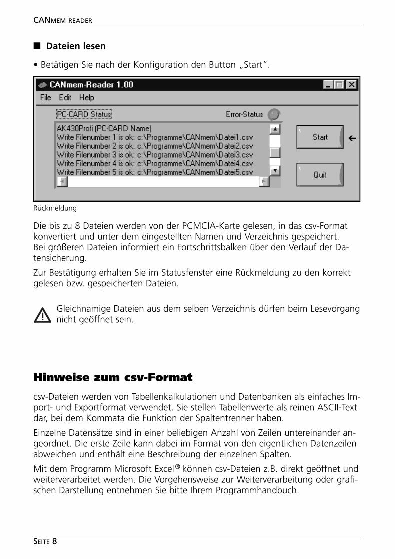
■■ Dateien lesen
• Betätigen Sie nach der Konfiguration den Button „Start“.
Die bis zu 8 Dateien werden von der PCMCIA-Karte gelesen, in das csv-Formatkonvertiert und unter dem eingestellten Namen und Verzeichnis gespeichert.Bei größeren Dateien informiert ein Fortschrittsbalken über den Verlauf der Da-tensicherung.
Zur Bestätigung erhalten Sie im Statusfenster eine Rückmeldung zu den korrektgelesen bzw. gespeicherten Dateien.
Gleichnamige Dateien aus dem selben Verzeichnis dürfen beim Lesevorgangnicht geöffnet sein.
Hinweise zum csv-Format
csv-Dateien werden von Tabellenkalkulationen und Datenbanken als einfaches Im-port- und Exportformat verwendet. Sie stellen Tabellenwerte als reinen ASCII-Textdar, bei dem Kommata die Funktion der Spaltentrenner haben.
Einzelne Datensätze sind in einer beliebigen Anzahl von Zeilen untereinander an-geordnet. Die erste Zeile kann dabei im Format von den eigentlichen Datenzeilenabweichen und enthält eine Beschreibung der einzelnen Spalten.
Mit dem Programm Microsoft Excel® können csv-Dateien z.B. direkt geöffnet undweiterverarbeitet werden. Die Vorgehensweise zur Weiterverarbeitung oder grafi-schen Darstellung entnehmen Sie bitte Ihrem Programmhandbuch.
CANMEM READER
SEITE 8
Rückmeldung
➔
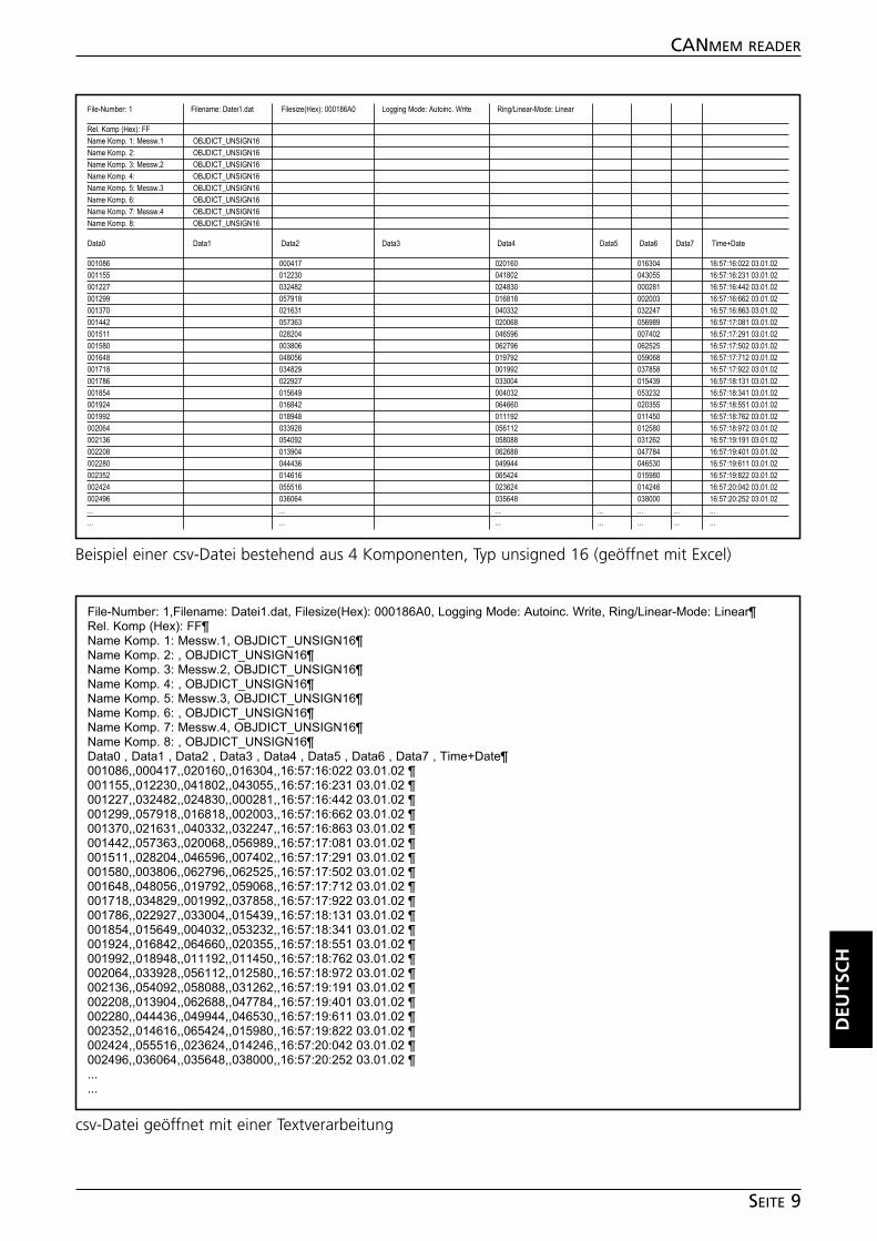
DEU
TSC
H
CANMEM READER
SEITE 9
File-Number: 1,Filename: Datei1.dat, Filesize(Hex): 000186A0, Logging Mode: Autoinc. Write, Ring/Linear-Mode: Linear¶Rel. Komp (Hex): FF¶Name Komp. 1: Messw.1, OBJDICT_UNSIGN16¶Name Komp. 2: , OBJDICT_UNSIGN16¶Name Komp. 3: Messw.2, OBJDICT_UNSIGN16¶Name Komp. 4: , OBJDICT_UNSIGN16¶Name Komp. 5: Messw.3, OBJDICT_UNSIGN16¶Name Komp. 6: , OBJDICT_UNSIGN16¶Name Komp. 7: Messw.4, OBJDICT_UNSIGN16¶Name Komp. 8: , OBJDICT_UNSIGN16¶Data0 , Data1 , Data2 , Data3 , Data4 , Data5 , Data6 , Data7 , Time+Date¶001086,,000417,,020160,,016304,,16:57:16:022 03.01.02 ¶001155,,012230,,041802,,043055,,16:57:16:231 03.01.02 ¶001227,,032482,,024830,,000281,,16:57:16:442 03.01.02 ¶001299,,057918,,016818,,002003,,16:57:16:662 03.01.02 ¶001370,,021631,,040332,,032247,,16:57:16:863 03.01.02 ¶001442,,057363,,020068,,056989,,16:57:17:081 03.01.02 ¶001511,,028204,,046596,,007402,,16:57:17:291 03.01.02 ¶001580,,003806,,062796,,062525,,16:57:17:502 03.01.02 ¶001648,,048056,,019792,,059068,,16:57:17:712 03.01.02 ¶001718,,034829,,001992,,037858,,16:57:17:922 03.01.02 ¶001786,,022927,,033004,,015439,,16:57:18:131 03.01.02 ¶001854,,015649,,004032,,053232,,16:57:18:341 03.01.02 ¶001924,,016842,,064660,,020355,,16:57:18:551 03.01.02 ¶001992,,018948,,011192,,011450,,16:57:18:762 03.01.02 ¶002064,,033928,,056112,,012580,,16:57:18:972 03.01.02 ¶002136,,054092,,058088,,031262,,16:57:19:191 03.01.02 ¶002208,,013904,,062688,,047784,,16:57:19:401 03.01.02 ¶002280,,044436,,049944,,046530,,16:57:19:611 03.01.02 ¶002352,,014616,,065424,,015980,,16:57:19:822 03.01.02 ¶002424,,055516,,023624,,014246,,16:57:20:042 03.01.02 ¶002496,,036064,,035648,,038000,,16:57:20:252 03.01.02 ¶......
Beispiel einer csv-Datei bestehend aus 4 Komponenten, Typ unsigned 16 (geöffnet mit Excel)
csv-Datei geöffnet mit einer Textverarbeitung
File-Number: 1 Filename: Datei1.dat Filesize(Hex): 000186A0 Logging Mode: Autoinc. Write Ring/Linear-Mode: Linear
Rel. Komp (Hex): FFName Komp. 1: Messw.1 OBJDICT_UNSIGN16Name Komp. 2: OBJDICT_UNSIGN16Name Komp. 3: Messw.2 OBJDICT_UNSIGN16Name Komp. 4: OBJDICT_UNSIGN16Name Komp. 5: Messw.3 OBJDICT_UNSIGN16Name Komp. 6: OBJDICT_UNSIGN16Name Komp. 7: Messw.4 OBJDICT_UNSIGN16Name Komp. 8: OBJDICT_UNSIGN16
Data0 Data1 Data2 Data3 Data4 Data5 Data6 Data7 Time+Date
001086 000417 020160 016304 16:57:16:022 03.01.02 001155 012230 041802 043055 16:57:16:231 03.01.02 001227 032482 024830 000281 16:57:16:442 03.01.02 001299 057918 016818 002003 16:57:16:662 03.01.02 001370 021631 040332 032247 16:57:16:863 03.01.02 001442 057363 020068 056989 16:57:17:081 03.01.02 001511 028204 046596 007402 16:57:17:291 03.01.02 001580 003806 062796 062525 16:57:17:502 03.01.02 001648 048056 019792 059068 16:57:17:712 03.01.02 001718 034829 001992 037858 16:57:17:922 03.01.02 001786 022927 033004 015439 16:57:18:131 03.01.02 001854 015649 004032 053232 16:57:18:341 03.01.02 001924 016842 064660 020355 16:57:18:551 03.01.02 001992 018948 011192 011450 16:57:18:762 03.01.02 002064 033928 056112 012580 16:57:18:972 03.01.02 002136 054092 058088 031262 16:57:19:191 03.01.02 002208 013904 062688 047784 16:57:19:401 03.01.02 002280 044436 049944 046530 16:57:19:611 03.01.02 002352 014616 065424 015980 16:57:19:822 03.01.02 002424 055516 023624 014246 16:57:20:042 03.01.02 002496 036064 035648 038000 16:57:20:252 03.01.02 ... ... ... ... ... ... ...... ... ... ... ... ... ...
Contents
Function and features . . . . . . . . . . . . . . . . . . . . . . . . . . . . . . . . . . page 11System requirements. . . . . . . . . . . . . . . . . . . . . . . . . . . . . . . . . page 11
Software installationProgram. . . . . . . . . . . . . . . . . . . . . . . . . . . . . . . . . . . . . . . . . . page 12Driver. . . . . . . . . . . . . . . . . . . . . . . . . . . . . . . . . . . . . . . . . . . . page 12
Program functionsStart the program . . . . . . . . . . . . . . . . . . . . . . . . . . . . . . . . . . . page 13Configuration. . . . . . . . . . . . . . . . . . . . . . . . . . . . . . . . . . . . . . page 14Read files . . . . . . . . . . . . . . . . . . . . . . . . . . . . . . . . . . . . . . . . . page 16
Notes on the csv format. . . . . . . . . . . . . . . . . . . . . . . . . . . . . . . . . page 16
Notes . . . . . . . . . . . . . . . . . . . . . . . . . . . . . . . . . . . . . . . . . . . . . . Seite 18
The description of the CANmem device incl. CANopen object directoriesis given in the device manual CR3101.
➔ Data sheet direct ➔ CR3101 ➔ Additional datawww.ifm-electronic.com
CANMEM READER
PAGE 10
Microsoft, Windows and Excel are registered trademarks of Microsoft Corporation, Lotus 1-2-3 is aregistered trademark of Lotus Development Corporation.
The software is suitable for normal use on common personal computers. According to the presentstate of software technology no guarantee can be assumed for the correct operation or absence ofcomputer viruses nor for the removal of any fault which may occur. In case of an incorrect programifm electronic gmbh cannot be held liable for cost incurred at the customer (e.g. maintenance, repairor rectification of faults). The exclusion does not apply to damage for which liability is mandatory ac-cording to peremptory legal provisions.
The program has been specifically developed for the control systems of ifm electronic gmbh. It there-fore only functions with these controllers. Attempts to use it with systems from other manufacturerscan lead to serious damage.
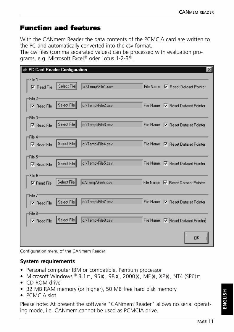
Function and features
With the CANmem Reader the data contents of the PCMCIA card are written tothe PC and automatically converted into the csv format.The csv files (comma separated values) can be processed with evaluation pro-grams, e.g. Microsoft Excel® oder Lotus 1-2-3®.
System requirements
• Personal computer IBM or compatible, Pentium processor• Microsoft Windows ® 3.1 , 95 , 98 , 2000 , ME , XP , NT4 (SP6)• CD-ROM drive• 32 MB RAM memory (or higher), 50 MB free hard disk memory• PCMCIA slot
Please note: At present the software "CANmem Reader" allows no serial operat-ing mode, i.e. CANmem cannot be used as PCMCIA drive. EN
GLI
SH
CANMEM READER
PAGE 11
Configuration menu of the CANmem Reader
Software installation
■■ Program
• Start Windows and insert the CD-ROM into your CD drive.• In the menu bar select "Start" ➔ "Run".• Enter "D:\CANmem-Reader\setup.exe". Press "OK" to confirm.If your CD-ROM drive is addressed with a letter other than "D", enter this letterinstead of D.• Follow the instructions of the setup program.
■■ Driver SwapFTL
CANmem Reader needs the driver "SwapFTL".If you have already used the software tool "CANmem Configurator" in the oper-ating mode PCMCIA socket, the driver is already installed on your computer (seethe program manual "CANmem Configurator).
• If this is not the case, install the driver file "SwapFTL.exe" from the CD-ROMinto the newly created directory "C:\Programs\CANmem-Reader".
Note:
In exceptional cases this can lead to conflicts with the PCMCIA components al-ready inserted (e.g. network cards).
These components then have to be removed during the reading operation. De-pending on the PC system the SwapFTL driver is only activated when the CAN-mem memory card is inserted into the PCMCIA slot.
CANMEM READER
PAGE 12
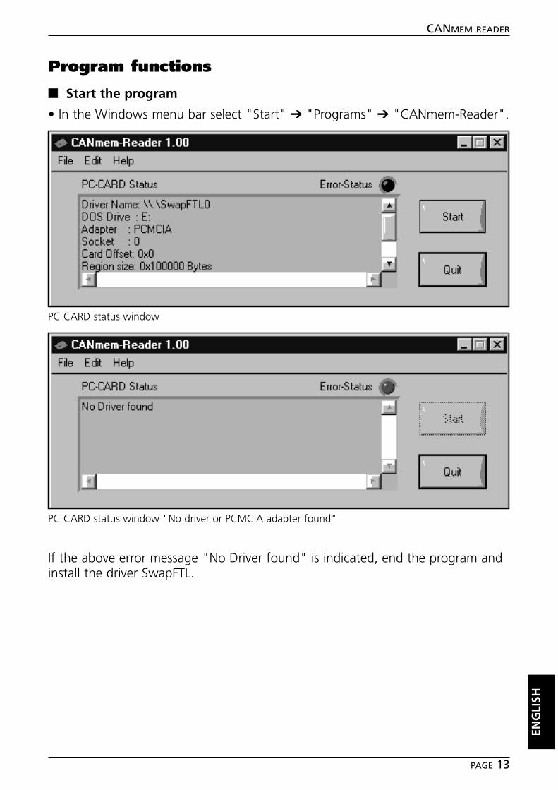
Program functions
■■ Start the program
• In the Windows menu bar select "Start" ➔ "Programs" ➔ "CANmem-Reader".
If the above error message "No Driver found" is indicated, end the program andinstall the driver SwapFTL.
ENG
LISH
CANMEM READER
PAGE 13
PC CARD status window "No driver or PCMCIA adapter found"
PC CARD status window
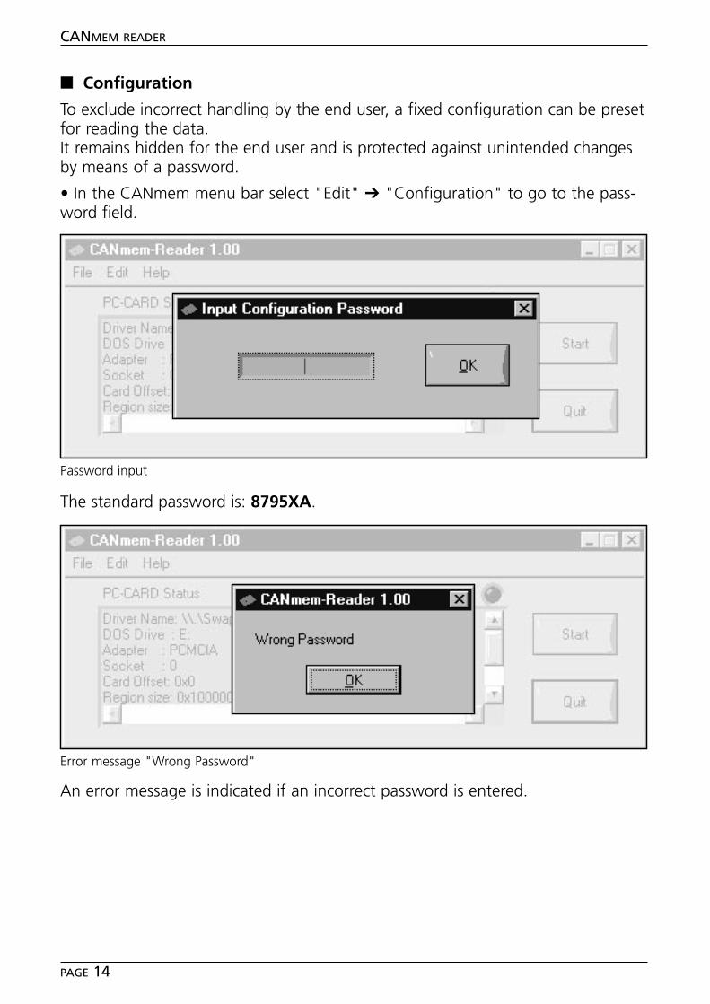
■■ Configuration
To exclude incorrect handling by the end user, a fixed configuration can be presetfor reading the data.It remains hidden for the end user and is protected against unintended changesby means of a password.
• In the CANmem menu bar select "Edit" ➔ "Configuration" to go to the pass-word field.
The standard password is: 8795XA.
An error message is indicated if an incorrect password is entered.
CANMEM READER
PAGE 14
Password input
Error message "Wrong Password"
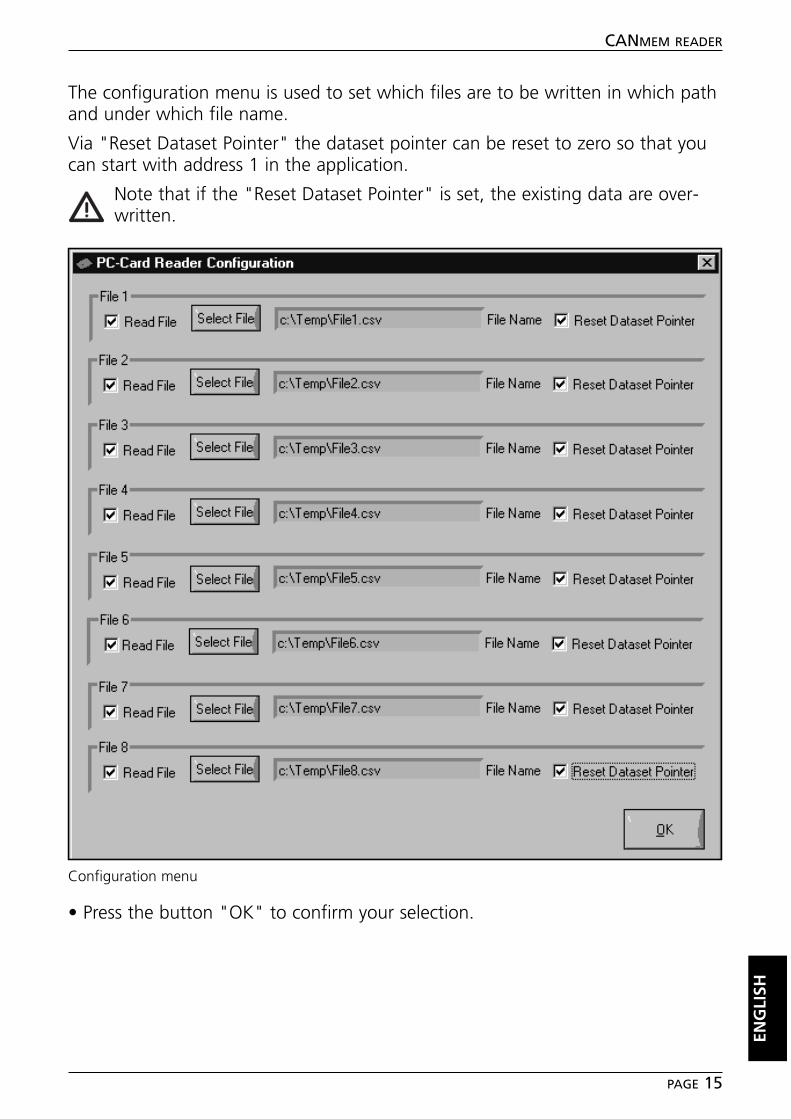
The configuration menu is used to set which files are to be written in which pathand under which file name.
Via "Reset Dataset Pointer" the dataset pointer can be reset to zero so that youcan start with address 1 in the application.
Note that if the "Reset Dataset Pointer" is set, the existing data are over-written.
• Press the button "OK" to confirm your selection.
ENG
LISH
CANMEM READER
PAGE 15
Configuration menu
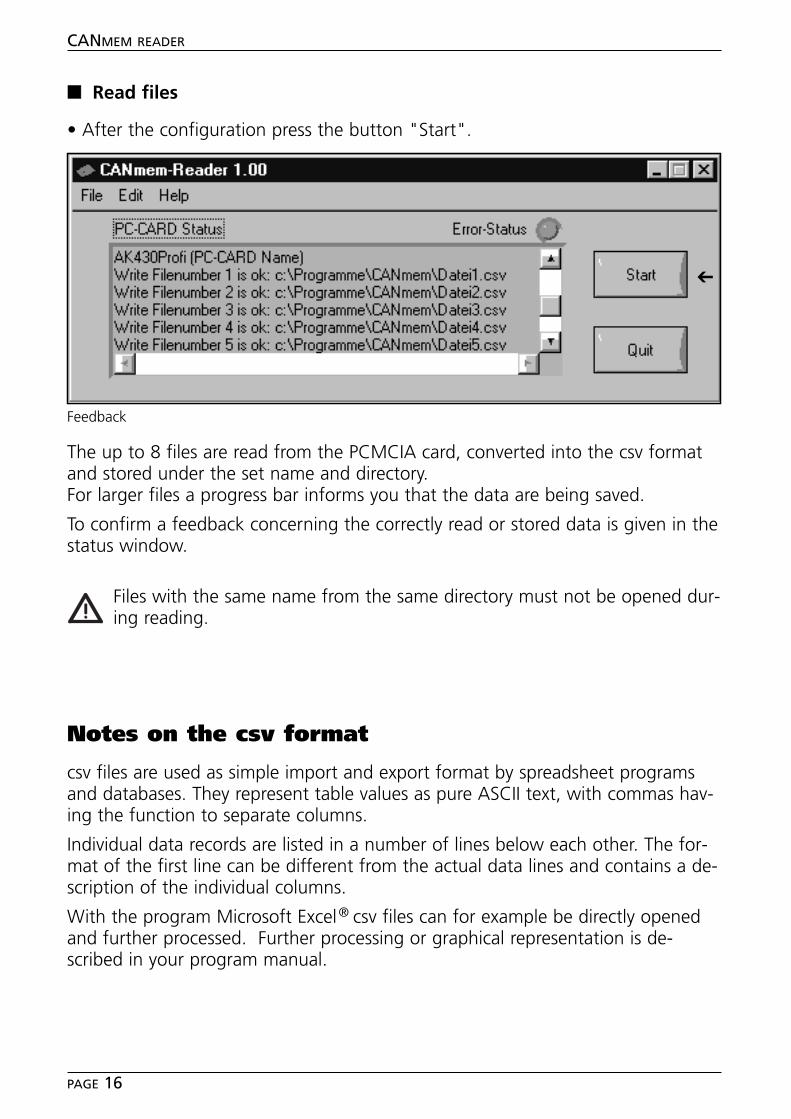
■■ Read files
• After the configuration press the button "Start".
The up to 8 files are read from the PCMCIA card, converted into the csv formatand stored under the set name and directory.For larger files a progress bar informs you that the data are being saved.
To confirm a feedback concerning the correctly read or stored data is given in thestatus window.
Files with the same name from the same directory must not be opened dur-ing reading.
Notes on the csv format
csv files are used as simple import and export format by spreadsheet programsand databases. They represent table values as pure ASCII text, with commas hav-ing the function to separate columns.
Individual data records are listed in a number of lines below each other. The for-mat of the first line can be different from the actual data lines and contains a de-scription of the individual columns.
With the program Microsoft Excel® csv files can for example be directly openedand further processed. Further processing or graphical representation is de-scribed in your program manual.
CANMEM READER
PAGE 16
Feedback
➔
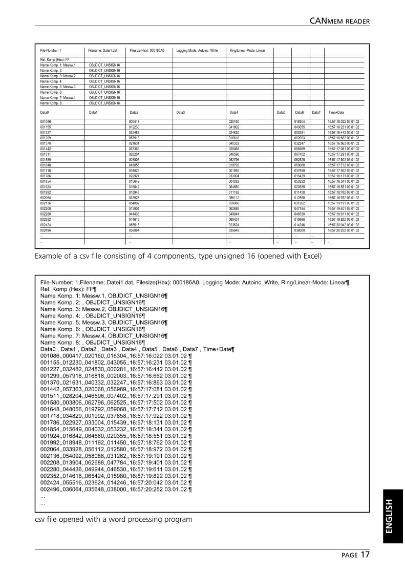
ENG
LISH
CANMEM READER
PAGE 17
File-Number: 1,Filename: Datei1.dat, Filesize(Hex): 000186A0, Logging Mode: Autoinc. Write, Ring/Linear-Mode: Linear¶Rel. Komp (Hex): FF¶Name Komp. 1: Messw.1, OBJDICT_UNSIGN16¶Name Komp. 2: , OBJDICT_UNSIGN16¶Name Komp. 3: Messw.2, OBJDICT_UNSIGN16¶Name Komp. 4: , OBJDICT_UNSIGN16¶Name Komp. 5: Messw.3, OBJDICT_UNSIGN16¶Name Komp. 6: , OBJDICT_UNSIGN16¶Name Komp. 7: Messw.4, OBJDICT_UNSIGN16¶Name Komp. 8: , OBJDICT_UNSIGN16¶Data0 , Data1 , Data2 , Data3 , Data4 , Data5 , Data6 , Data7 , Time+Date¶001086,,000417,,020160,,016304,,16:57:16:022 03.01.02 ¶001155,,012230,,041802,,043055,,16:57:16:231 03.01.02 ¶001227,,032482,,024830,,000281,,16:57:16:442 03.01.02 ¶001299,,057918,,016818,,002003,,16:57:16:662 03.01.02 ¶001370,,021631,,040332,,032247,,16:57:16:863 03.01.02 ¶001442,,057363,,020068,,056989,,16:57:17:081 03.01.02 ¶001511,,028204,,046596,,007402,,16:57:17:291 03.01.02 ¶001580,,003806,,062796,,062525,,16:57:17:502 03.01.02 ¶001648,,048056,,019792,,059068,,16:57:17:712 03.01.02 ¶001718,,034829,,001992,,037858,,16:57:17:922 03.01.02 ¶001786,,022927,,033004,,015439,,16:57:18:131 03.01.02 ¶001854,,015649,,004032,,053232,,16:57:18:341 03.01.02 ¶001924,,016842,,064660,,020355,,16:57:18:551 03.01.02 ¶001992,,018948,,011192,,011450,,16:57:18:762 03.01.02 ¶002064,,033928,,056112,,012580,,16:57:18:972 03.01.02 ¶002136,,054092,,058088,,031262,,16:57:19:191 03.01.02 ¶002208,,013904,,062688,,047784,,16:57:19:401 03.01.02 ¶002280,,044436,,049944,,046530,,16:57:19:611 03.01.02 ¶002352,,014616,,065424,,015980,,16:57:19:822 03.01.02 ¶002424,,055516,,023624,,014246,,16:57:20:042 03.01.02 ¶002496,,036064,,035648,,038000,,16:57:20:252 03.01.02 ¶......
Example of a csv file consisting of 4 components, type unsigned 16 (opened with Excel)
csv file opened with a word processing program
File-Number: 1 Filename: Datei1.dat Filesize(Hex): 000186A0 Logging Mode: Autoinc. Write Ring/Linear-Mode: Linear
Rel. Komp (Hex): FFName Komp. 1: Messw.1 OBJDICT_UNSIGN16Name Komp. 2: OBJDICT_UNSIGN16Name Komp. 3: Messw.2 OBJDICT_UNSIGN16Name Komp. 4: OBJDICT_UNSIGN16Name Komp. 5: Messw.3 OBJDICT_UNSIGN16Name Komp. 6: OBJDICT_UNSIGN16Name Komp. 7: Messw.4 OBJDICT_UNSIGN16Name Komp. 8: OBJDICT_UNSIGN16
Data0 Data1 Data2 Data3 Data4 Data5 Data6 Data7 Time+Date
001086 000417 020160 016304 16:57:16:022 03.01.02 001155 012230 041802 043055 16:57:16:231 03.01.02 001227 032482 024830 000281 16:57:16:442 03.01.02 001299 057918 016818 002003 16:57:16:662 03.01.02 001370 021631 040332 032247 16:57:16:863 03.01.02 001442 057363 020068 056989 16:57:17:081 03.01.02 001511 028204 046596 007402 16:57:17:291 03.01.02 001580 003806 062796 062525 16:57:17:502 03.01.02 001648 048056 019792 059068 16:57:17:712 03.01.02 001718 034829 001992 037858 16:57:17:922 03.01.02 001786 022927 033004 015439 16:57:18:131 03.01.02 001854 015649 004032 053232 16:57:18:341 03.01.02 001924 016842 064660 020355 16:57:18:551 03.01.02 001992 018948 011192 011450 16:57:18:762 03.01.02 002064 033928 056112 012580 16:57:18:972 03.01.02 002136 054092 058088 031262 16:57:19:191 03.01.02 002208 013904 062688 047784 16:57:19:401 03.01.02 002280 044436 049944 046530 16:57:19:611 03.01.02 002352 014616 065424 015980 16:57:19:822 03.01.02 002424 055516 023624 014246 16:57:20:042 03.01.02 002496 036064 035648 038000 16:57:20:252 03.01.02 ... ... ... ... ... ... ...... ... ... ... ... ... ...
CANMEM READER
PAGE 18
Notizen / Notes

Tech
nisc
he Ä
nder
unge
n be
halte
n w
ir un
s oh
ne v
orhe
rige
Ank
ündi
gung
vor
.Pa
pier
chl
orfr
ei g
eble
icht
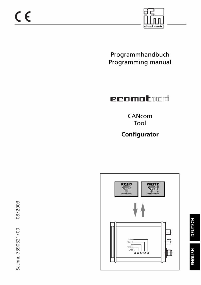
ProgrammhandbuchProgramming manual
CANcomTool
Configurator
DEU
TSC
HEN
GLI
SH
R
GSMRS232
ONERROR
CAN
Sach
nr.
7390
321
/00
08
/200
3
Inhalt
Bestimmungsgemäße Verwendung . . . . . . . . . . . . . . . . . . . . . . . . . Seite 3Systemvoraussetzungen. . . . . . . . . . . . . . . . . . . . . . . . . . . . . . . Seite 3
InstallationSoftware . . . . . . . . . . . . . . . . . . . . . . . . . . . . . . . . . . . . . . . . . Seite 4Hardware . . . . . . . . . . . . . . . . . . . . . . . . . . . . . . . . . . . . . . . . . Seite 4
ProgrammfunktionenProgramm starten . . . . . . . . . . . . . . . . . . . . . . . . . . . . . . . . . . . Seite 4Geräteinformationen aus CANcom lesen . . . . . . . . . . . . . . . . . . Seite 5Vorhandene Konfigurationsdatei in CANcom laden . . . . . . . . . . . Seite 6Konfigurationsdaten aus CANcom lesen. . . . . . . . . . . . . . . . . . . Seite 6CANopen-Parameter . . . . . . . . . . . . . . . . . . . . . . . . . . . . . . . . . Seite 7GSM-Parameter . . . . . . . . . . . . . . . . . . . . . . . . . . . . . . . . . . . . Seite 8Operating-Parameter. . . . . . . . . . . . . . . . . . . . . . . . . . . . . . . . . Seite 10SMS-Funktionen . . . . . . . . . . . . . . . . . . . . . . . . . . . . . . . . . . . . Seite 11GPS-Parameter . . . . . . . . . . . . . . . . . . . . . . . . . . . . . . . . . . . . . Seite 12Neue Konfigurationsdaten in CANcom laden . . . . . . . . . . . . . . . Seite 13Neue Konfigurationsdaten speichern . . . . . . . . . . . . . . . . . . . . . Seite 13
FehlerbehebungKein DCD-/DSR-Signal . . . . . . . . . . . . . . . . . . . . . . . . . . . . . . . . Seite 13
Notizen . . . . . . . . . . . . . . . . . . . . . . . . . . . . . . . . . . . . . . . . . . . . . Seite 26
CANCOM CONFIGURATOR
SEITE 2
Microsoft und Windows sind eingetragene Warenzeichen der Microsoft Corporation.
Die überlassene Software ist für den normalen Gebrauch auf handelsüblichen Personalcomputern ge-eignet. Eine Gewähr für unterbrechungsfreien oder fehlerfreien Betrieb oder die Freiheit von Compu-terviren sowie dafür, daß jeder eventuell auftretende Fehler beseitigt wird, kann nach dem Stand derSoftwaretechnik nicht übernommen werden. Insbesondere haftet ifm electronic gmbh bei einem feh-lerhaften Programm nicht für beim Kunden entstehende Kosten (z.B. Wartung, Reparatur oder Män-gelbehebung). Der Ausschluß gilt nicht für Schäden, für die aufgrund unabdingbarer gesetzlicher Vor-schriften zwingend gehaftet wird.
Das Programm ist speziell für die Steuerungssysteme der ifm electronic gmbh entwickelt worden. Da-her ist die Funktion nur bei diesen Steuerungen möglich. Versuche der Ankoppelung an Fremdsyste-me können zu gravierenden Schäden führen.
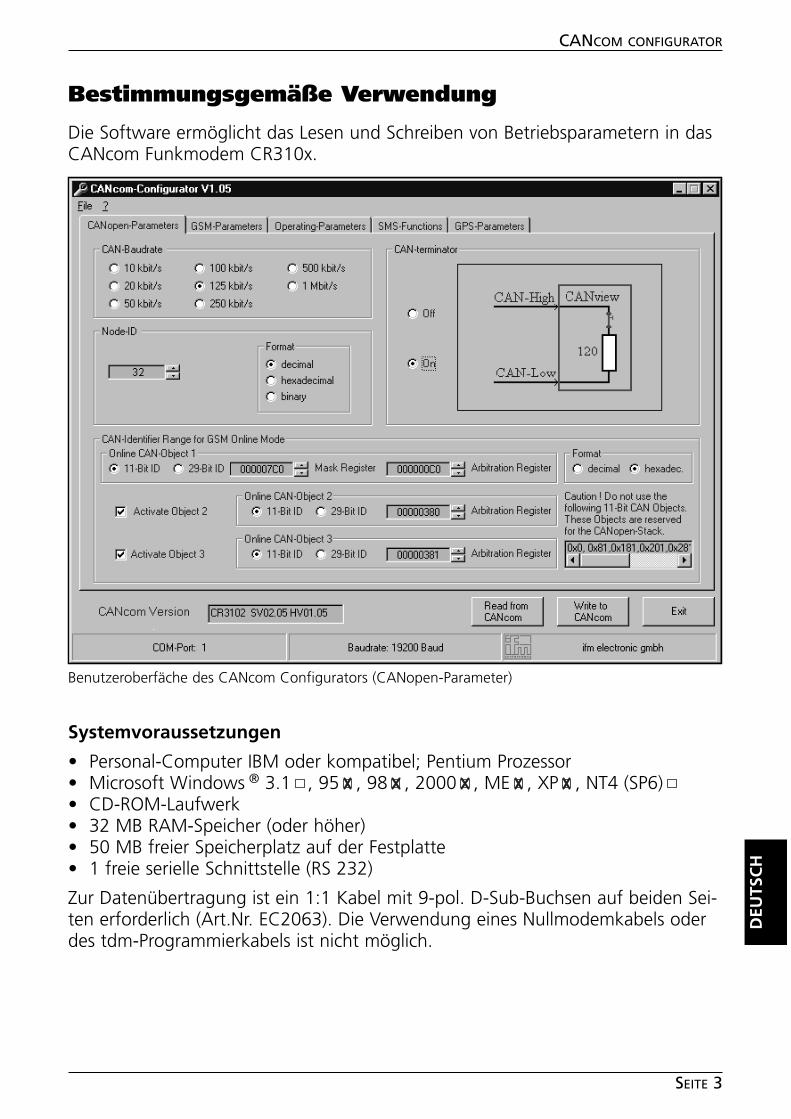
CANCOM CONFIGURATOR
SEITE 3
Bestimmungsgemäße Verwendung
Die Software ermöglicht das Lesen und Schreiben von Betriebsparametern in dasCANcom Funkmodem CR310x.
Systemvoraussetzungen
• Personal-Computer IBM oder kompatibel; Pentium Prozessor• Microsoft Windows ® 3.1 , 95 , 98 , 2000 , ME , XP , NT4 (SP6)• CD-ROM-Laufwerk• 32 MB RAM-Speicher (oder höher)• 50 MB freier Speicherplatz auf der Festplatte• 1 freie serielle Schnittstelle (RS 232)
Zur Datenübertragung ist ein 1:1 Kabel mit 9-pol. D-Sub-Buchsen auf beiden Sei-ten erforderlich (Art.Nr. EC2063). Die Verwendung eines Nullmodemkabels oderdes tdm-Programmierkabels ist nicht möglich.
DEU
TSC
H
Benutzeroberfäche des CANcom Configurators (CANopen-Parameter)
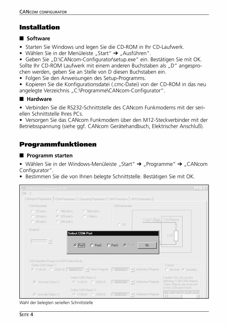
Installation
■■ Software
• Starten Sie Windows und legen Sie die CD-ROM in Ihr CD-Laufwerk.• Wählen Sie in der Menüleiste „Start“ ➔ „Ausführen“.• Geben Sie „D:\CANcom-Configurator\setup.exe“ ein. Bestätigen Sie mit OK.Sollte Ihr CD-ROM Laufwerk mit einem anderen Buchstaben als „D“ angespro-chen werden, geben Sie an Stelle von D diesen Buchstaben ein.• Folgen Sie den Anweisungen des Setup-Programms.• Kopieren Sie die Konfigurationsdatei (.cmc-Datei) von der CD-ROM in das neuangelegte Verzeichnis „C:\Programme\CANcom-Configurator“.
■■ Hardware
• Verbinden Sie die RS232-Schnittstelle des CANcom Funkmodems mit der seri-ellen Schnittstelle Ihres PCs.• Versorgen Sie das CANcom Funkmodem über den M12-Steckverbinder mit derBetriebsspannung (siehe ggf. CANcom Gerätehandbuch, Elektrischer Anschluß).
Programmfunktionen
■■ Programm starten
• Wählen Sie in der Windows-Menüleiste „Start“ ➔ „Programme“ ➔ „CANcomConfigurator“. • Bestimmen Sie die von Ihnen belegte Schnittstelle. Bestätigen Sie mit OK.
CANCOM CONFIGURATOR
SEITE 4
Wahl der belegten seriellen Schnittstelle
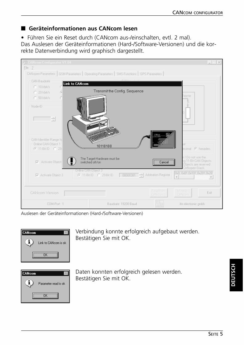
■■ Geräteinformationen aus CANcom lesen
• Führen Sie ein Reset durch (CANcom aus-/einschalten, evtl. 2 mal).Das Auslesen der Geräteinformationen (Hard-/Software-Versionen) und die kor-rekte Datenverbindung wird graphisch dargestellt.
Verbindung konnte erfolgreich aufgebaut werden.Bestätigen Sie mit OK.
Daten konnten erfolgreich gelesen werden.Bestätigen Sie mit OK.
DEU
TSC
H
CANCOM CONFIGURATOR
SEITE 5
Auslesen der Geräteinformationen (Hard-/Software-Versionen)
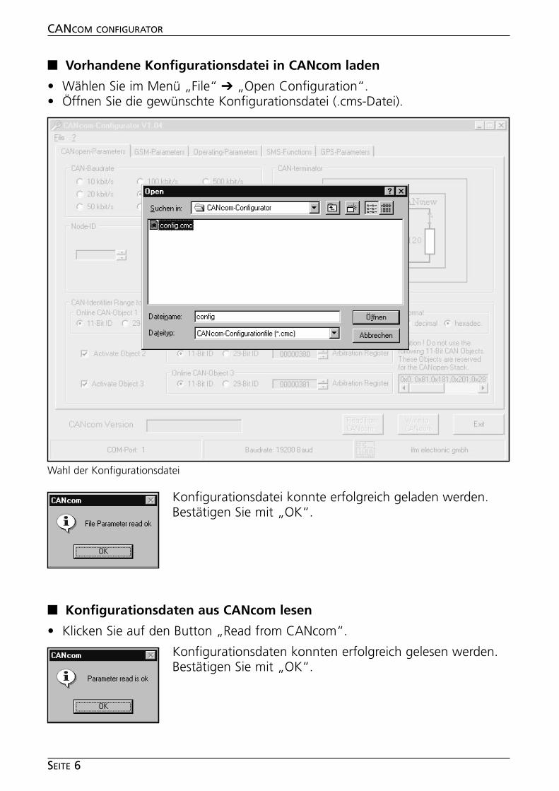
■■ Vorhandene Konfigurationsdatei in CANcom laden
• Wählen Sie im Menü „File“ ➔ „Open Configuration“.• Öffnen Sie die gewünschte Konfigurationsdatei (.cms-Datei).
Konfigurationsdatei konnte erfolgreich geladen werden.Bestätigen Sie mit „OK“.
■■ Konfigurationsdaten aus CANcom lesen
• Klicken Sie auf den Button „Read from CANcom“.
Konfigurationsdaten konnten erfolgreich gelesen werden.Bestätigen Sie mit „OK“.
CANCOM CONFIGURATOR
SEITE 6
Wahl der Konfigurationsdatei
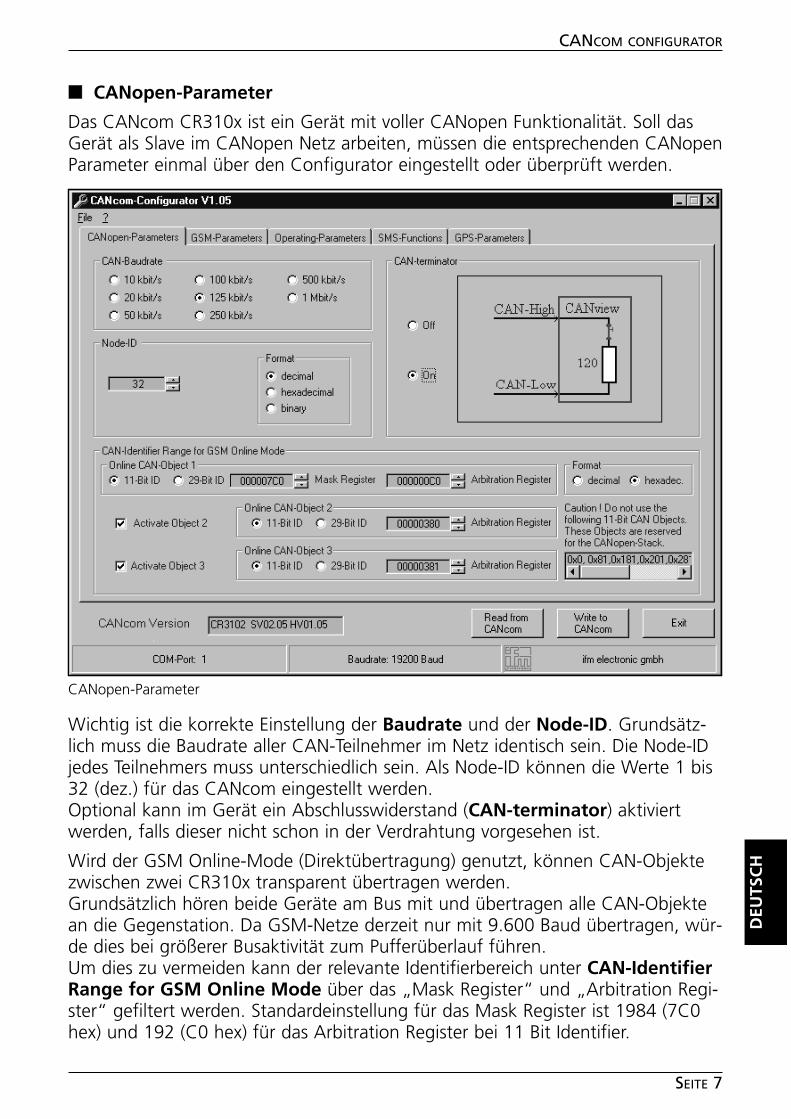
■■ CANopen-Parameter
Das CANcom CR310x ist ein Gerät mit voller CANopen Funktionalität. Soll dasGerät als Slave im CANopen Netz arbeiten, müssen die entsprechenden CANopenParameter einmal über den Configurator eingestellt oder überprüft werden.
Wichtig ist die korrekte Einstellung der Baudrate und der Node-ID. Grundsätz-lich muss die Baudrate aller CAN-Teilnehmer im Netz identisch sein. Die Node-IDjedes Teilnehmers muss unterschiedlich sein. Als Node-ID können die Werte 1 bis32 (dez.) für das CANcom eingestellt werden. Optional kann im Gerät ein Abschlusswiderstand (CAN-terminator) aktiviertwerden, falls dieser nicht schon in der Verdrahtung vorgesehen ist.
Wird der GSM Online-Mode (Direktübertragung) genutzt, können CAN-Objektezwischen zwei CR310x transparent übertragen werden.Grundsätzlich hören beide Geräte am Bus mit und übertragen alle CAN-Objektean die Gegenstation. Da GSM-Netze derzeit nur mit 9.600 Baud übertragen, wür-de dies bei größerer Busaktivität zum Pufferüberlauf führen.Um dies zu vermeiden kann der relevante Identifierbereich unter CAN-IdentifierRange for GSM Online Mode über das „Mask Register“ und „Arbitration Regi-ster“ gefiltert werden. Standardeinstellung für das Mask Register ist 1984 (7C0hex) und 192 (C0 hex) für das Arbitration Register bei 11 Bit Identifier.
DEU
TSC
H
CANCOM CONFIGURATOR
SEITE 7
CANopen-Parameter
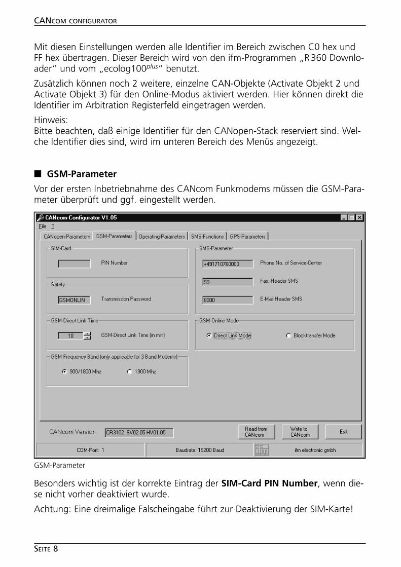
Mit diesen Einstellungen werden alle Identifier im Bereich zwischen C0 hex undFF hex übertragen. Dieser Bereich wird von den ifm-Programmen „R360 Downlo-ader“ und vom „ecolog100plus“ benutzt.
Zusätzlich können noch 2 weitere, einzelne CAN-Objekte (Activate Objekt 2 undActivate Objekt 3) für den Online-Modus aktiviert werden. Hier können direkt dieIdentifier im Arbitration Registerfeld eingetragen werden.
Hinweis:Bitte beachten, daß einige Identifier für den CANopen-Stack reserviert sind. Wel-che Identifier dies sind, wird im unteren Bereich des Menüs angezeigt.
■■ GSM-Parameter
Vor der ersten Inbetriebnahme des CANcom Funkmodems müssen die GSM-Para-meter überprüft und ggf. eingestellt werden.
Besonders wichtig ist der korrekte Eintrag der SIM-Card PIN Number, wenn die-se nicht vorher deaktiviert wurde.
Achtung: Eine dreimalige Falscheingabe führt zur Deaktivierung der SIM-Karte!
CANCOM CONFIGURATOR
SEITE 8
GSM-Parameter
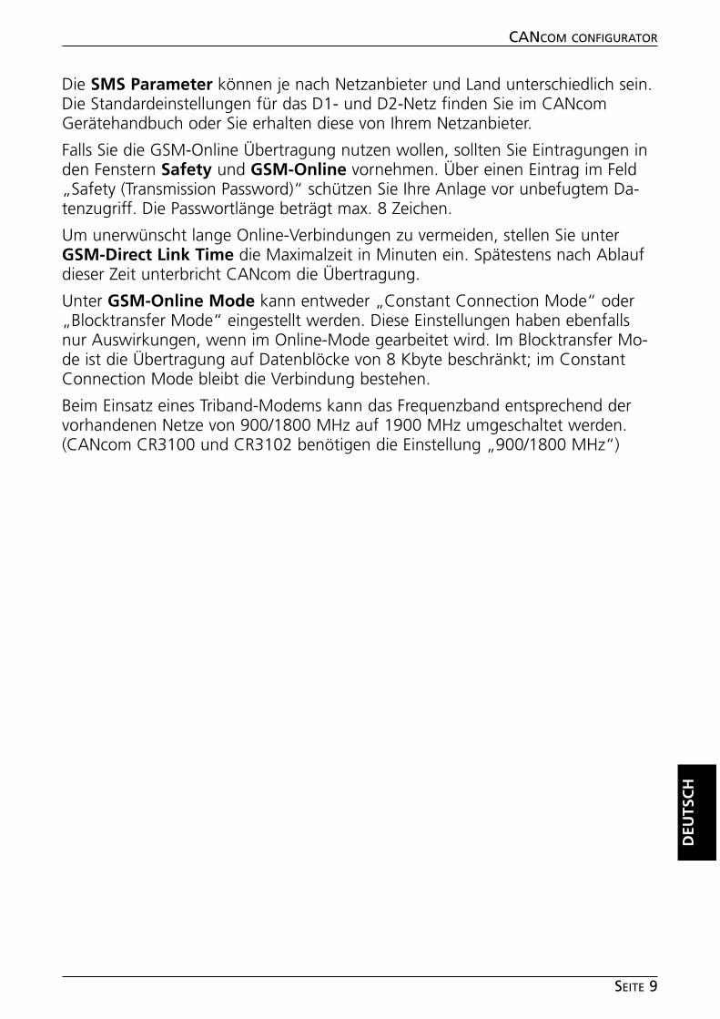
Die SMS Parameter können je nach Netzanbieter und Land unterschiedlich sein.Die Standardeinstellungen für das D1- und D2-Netz finden Sie im CANcomGerätehandbuch oder Sie erhalten diese von Ihrem Netzanbieter.
Falls Sie die GSM-Online Übertragung nutzen wollen, sollten Sie Eintragungen inden Fenstern Safety und GSM-Online vornehmen. Über einen Eintrag im Feld„Safety (Transmission Password)“ schützen Sie Ihre Anlage vor unbefugtem Da-tenzugriff. Die Passwortlänge beträgt max. 8 Zeichen.
Um unerwünscht lange Online-Verbindungen zu vermeiden, stellen Sie unterGSM-Direct Link Time die Maximalzeit in Minuten ein. Spätestens nach Ablaufdieser Zeit unterbricht CANcom die Übertragung.
Unter GSM-Online Mode kann entweder „Constant Connection Mode“ oder„Blocktransfer Mode“ eingestellt werden. Diese Einstellungen haben ebenfallsnur Auswirkungen, wenn im Online-Mode gearbeitet wird. Im Blocktransfer Mo-de ist die Übertragung auf Datenblöcke von 8 Kbyte beschränkt; im ConstantConnection Mode bleibt die Verbindung bestehen.
Beim Einsatz eines Triband-Modems kann das Frequenzband entsprechend dervorhandenen Netze von 900/1800 MHz auf 1900 MHz umgeschaltet werden.(CANcom CR3100 und CR3102 benötigen die Einstellung „900/1800 MHz“)
DEU
TSC
H
CANCOM CONFIGURATOR
SEITE 9
■■ Operating-Parameter
Hier werden einige allgemeine Betriebsdaten des Gerätes erfasst und gezählt.Sie dienen lediglich der Kontrolle, sollten aber vor der ersten Inbetriebnahmeüber Reset Counter zurückgesetzt werden.
• Operating Hours Counter = Betriebsstundenzähler• GSM Registration Counter = Anzahl der Einbuchungen ins Netz • ON/OFF-Switch Counter = Anzahl der Einschaltvorgänge• SMS-Receive Counter = Anzahl der empfangenen SMS• SMS-Transmit Counter = Anzahl der gesendeten SMS
CANCOM CONFIGURATOR
SEITE 10
Operating-Parameter
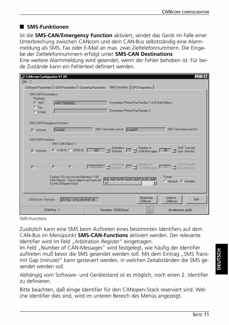
■■ SMS-Funktionen
Ist die SMS-CAN/Emergency Function aktiviert, sendet das Gerät im Falle einerUnterbrechung zwischen CANcom und dem CAN-Bus selbstständig eine Alarm-meldung als SMS, Fax oder E-Mail an max. zwei Zieltelefonnummern. Die Einga-be der Zieltelefonnummern erfolgt unter SMS-CAN Destinations.Eine weitere Alarmmeldung wird gesendet, wenn der Fehler behoben ist. Für bei-de Zustände kann ein Fehlertext definiert werden.
Zusätzlich kann eine SMS beim Auftreten eines bestimmten Identifiers auf demCAN-Bus im Menüpunkt SMS-CAN-Functions aktiviert werden. Der relevanteIdentifier wird im Feld „Arbitration Register“ eingetragen.Im Feld „Number of CAN-Messages“ wird festgelegt, wie häufig der Identifierauftreten muß bevor die SMS gesendet werden soll. Mit dem Eintrag „SMS Trans-mit Gap (minute)“ kann gesteuert werden, in welchen Zeitabständen die SMS ge-sendet werden soll.
Abhängig vom Software- und Gerätestand ist es möglich, noch einen 2. Identifierzu definieren.
Bitte beachten, daß einige Identifier für den CANopen-Stack reserviert sind. Wel-che Identifier dies sind, wird im unteren Bereich des Menüs angezeigt.
DEU
TSC
H
CANCOM CONFIGURATOR
SEITE 11
SMS-Functions
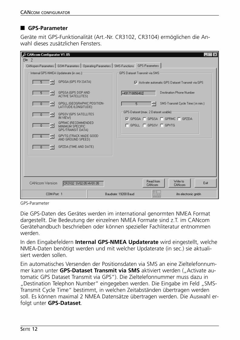
■■ GPS-Parameter
Geräte mit GPS-Funktionalität (Art.-Nr. CR3102, CR3104) ermöglichen die An-wahl dieses zusätzlichen Fensters.
Die GPS-Daten des Gerätes werden im international genormten NMEA Formatdargestellt. Die Bedeutung der einzelnen NMEA Formate sind z.T. im CANcomGerätehandbuch beschrieben oder können spezieller Fachliteratur entnommenwerden.
In den Eingabefeldern Internal GPS-NMEA Updaterate wird eingestellt, welcheNMEA-Daten benötigt werden und mit welcher Updaterate (in sec.) sie aktuali-siert werden sollen.
Ein automatisches Versenden der Positionsdaten via SMS an eine Zieltelefonnum-mer kann unter GPS-Dataset Transmit via SMS aktiviert werden („Activate au-tomatic GPS Dataset Transmit via GPS“). Die Zieltelefonnummer muss dazu in„Destination Telephon Number“ eingegeben werden. Die Eingabe im Feld „SMS-Transmit Cycle Time“ bestimmt, in welchen Zeitabständen übertragen werdensoll. Es können maximal 2 NMEA Datensätze übertragen werden. Die Auswahl er-folgt unter GPS-Dataset.
CANCOM CONFIGURATOR
SEITE 12
GPS-Parameter
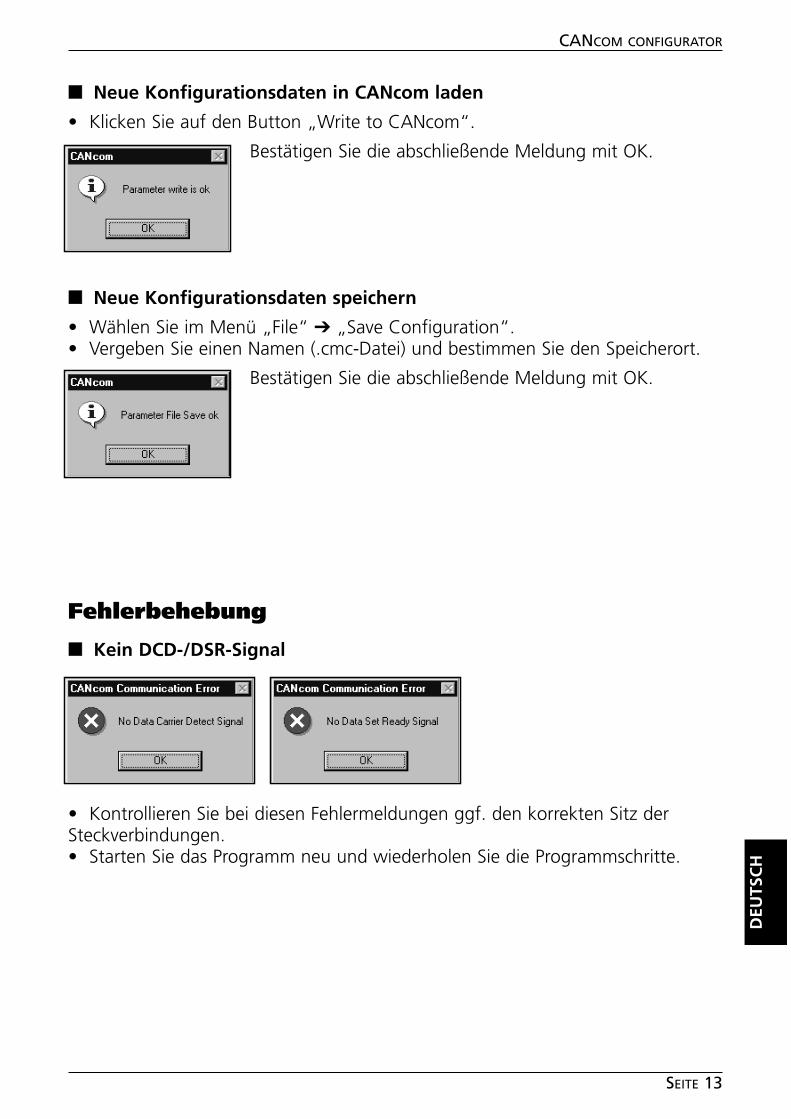
■■ Neue Konfigurationsdaten in CANcom laden
• Klicken Sie auf den Button „Write to CANcom“.
Bestätigen Sie die abschließende Meldung mit OK.
■■ Neue Konfigurationsdaten speichern
• Wählen Sie im Menü „File“ ➔ „Save Configuration“.• Vergeben Sie einen Namen (.cmc-Datei) und bestimmen Sie den Speicherort.
Bestätigen Sie die abschließende Meldung mit OK.
Fehlerbehebung
■■ Kein DCD-/DSR-Signal
• Kontrollieren Sie bei diesen Fehlermeldungen ggf. den korrekten Sitz derSteckverbindungen.• Starten Sie das Programm neu und wiederholen Sie die Programmschritte.
DEU
TSC
H
CANCOM CONFIGURATOR
SEITE 13
Contents
Function and features . . . . . . . . . . . . . . . . . . . . . . . . . . . . . . . . . . page 15System requirements. . . . . . . . . . . . . . . . . . . . . . . . . . . . . . . . . page 15
InstallationSoftware . . . . . . . . . . . . . . . . . . . . . . . . . . . . . . . . . . . . . . . . . page 16Hardware . . . . . . . . . . . . . . . . . . . . . . . . . . . . . . . . . . . . . . . . . page 16
Program functionsStart program. . . . . . . . . . . . . . . . . . . . . . . . . . . . . . . . . . . . . . page 16Read device information from CANcom . . . . . . . . . . . . . . . . . . . page 17Load existing configuration file in CANcom . . . . . . . . . . . . . . . . page 18Read configuration data from CANcom . . . . . . . . . . . . . . . . . . . page 18CANopen-Parameters . . . . . . . . . . . . . . . . . . . . . . . . . . . . . . . . page 19GSM-Parameters. . . . . . . . . . . . . . . . . . . . . . . . . . . . . . . . . . . . page 20Operating-Parameters . . . . . . . . . . . . . . . . . . . . . . . . . . . . . . . . page 22SMS-Functions . . . . . . . . . . . . . . . . . . . . . . . . . . . . . . . . . . . . . page 23GPS-Parameters . . . . . . . . . . . . . . . . . . . . . . . . . . . . . . . . . . . . page 24Load new configuration data in CANcom. . . . . . . . . . . . . . . . . . page 25Save new configuration data . . . . . . . . . . . . . . . . . . . . . . . . . . . page 25
Error correctionNo DCD/DSR signal . . . . . . . . . . . . . . . . . . . . . . . . . . . . . . . . . . page 25
Notes . . . . . . . . . . . . . . . . . . . . . . . . . . . . . . . . . . . . . . . . . . . . . . page 26
CANCOM CONFIGURATOR
PAGE 14
Microsoft and Windows are registered trademarks of Microsoft Corporation.
The software is suitable for normal use on common personal computers. According to the presentstate of software technology no guarantee can be assumed for the correct operation or absence ofcomputer viruses nor for the removal of any fault which may occur. In the case of an incorrect pro-gram ifm electronic cannot be held liable for cost incurred at the customer (e.g. maintenance, repairor rectification of faults). The exclusion does not apply to damage for which liability is mandatory ac-cording to peremptory legal provisions.
The program has been specifically developed for the control systems of ifm electronic gmbh. It there-fore only functions with these controllers. Attempts to use it with systems from other manufacturerscan lead to serious damage.
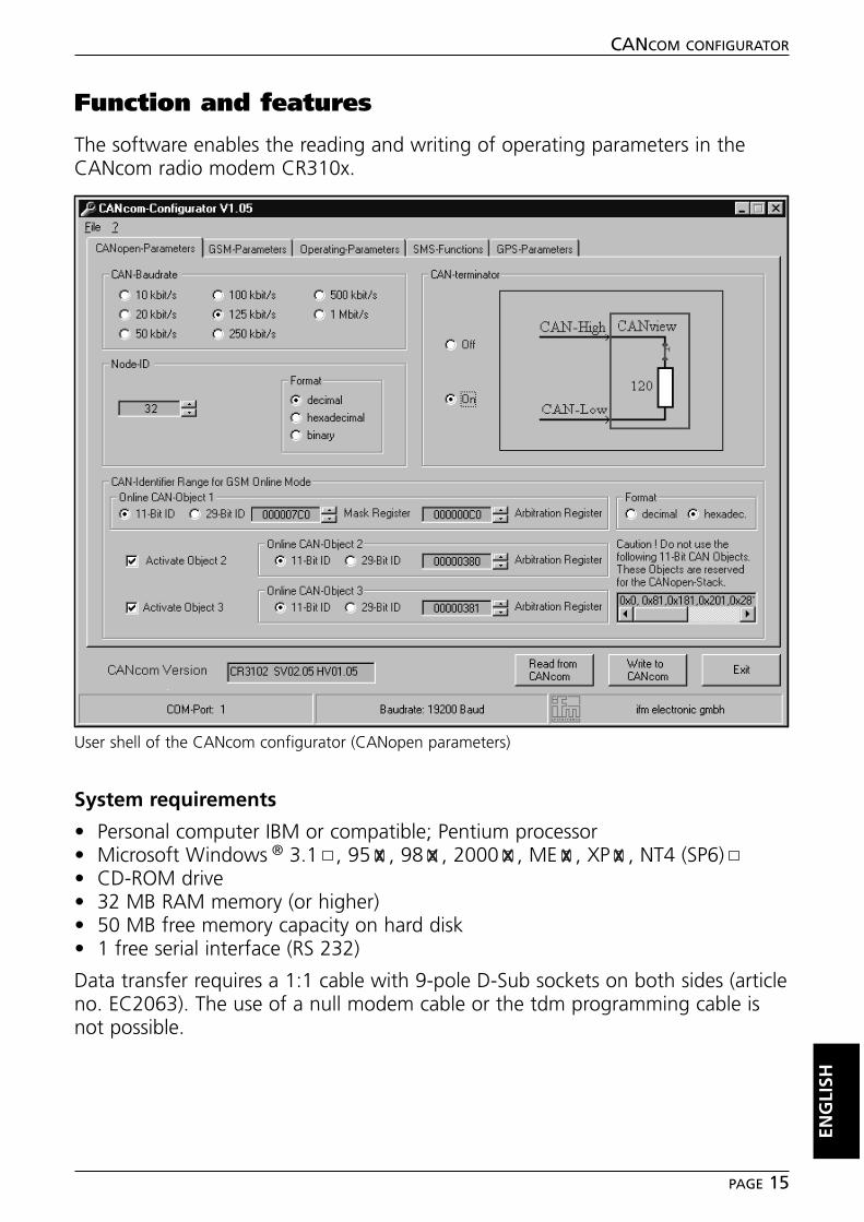
Function and features
The software enables the reading and writing of operating parameters in theCANcom radio modem CR310x.
System requirements
• Personal computer IBM or compatible; Pentium processor• Microsoft Windows ® 3.1 , 95 , 98 , 2000 , ME , XP , NT4 (SP6)• CD-ROM drive• 32 MB RAM memory (or higher)• 50 MB free memory capacity on hard disk• 1 free serial interface (RS 232)
Data transfer requires a 1:1 cable with 9-pole D-Sub sockets on both sides (articleno. EC2063). The use of a null modem cable or the tdm programming cable isnot possible.
ENG
LISH
CANCOM CONFIGURATOR
PAGE 15
User shell of the CANcom configurator (CANopen parameters)
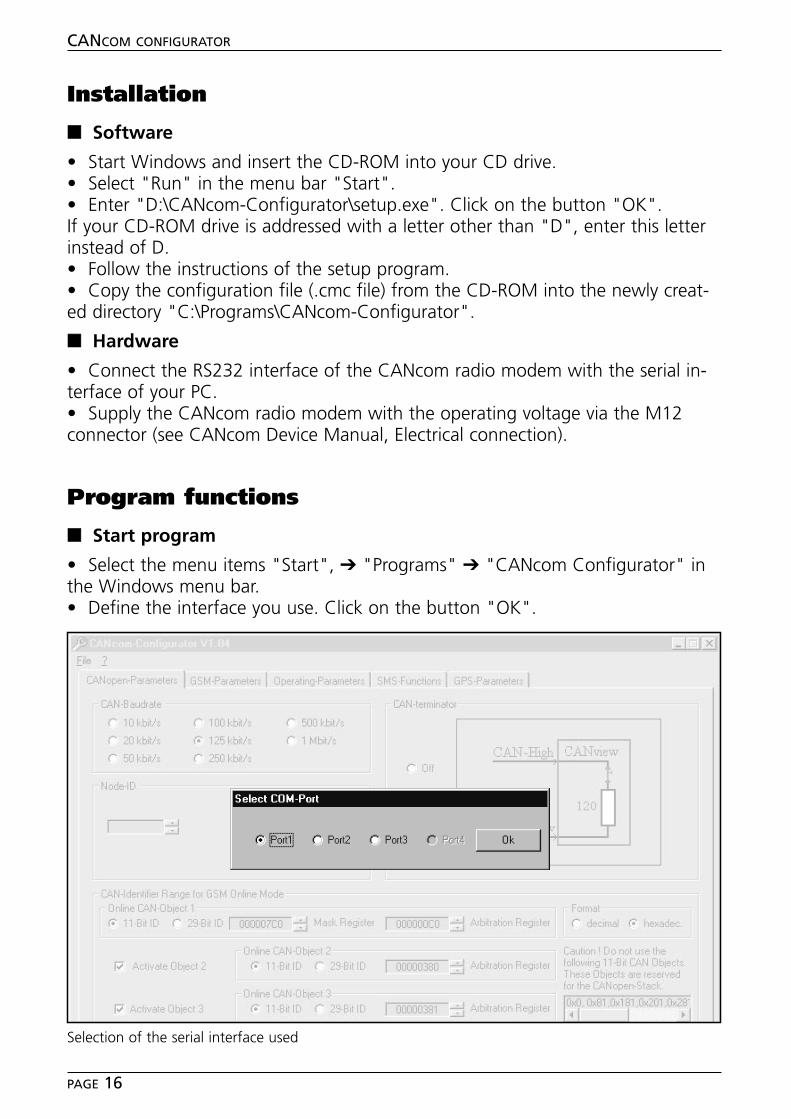
Installation
■■ Software
• Start Windows and insert the CD-ROM into your CD drive.• Select "Run" in the menu bar "Start".• Enter "D:\CANcom-Configurator\setup.exe". Click on the button "OK".If your CD-ROM drive is addressed with a letter other than "D", enter this letterinstead of D.• Follow the instructions of the setup program.• Copy the configuration file (.cmc file) from the CD-ROM into the newly creat-ed directory "C:\Programs\CANcom-Configurator".
■■ Hardware
• Connect the RS232 interface of the CANcom radio modem with the serial in-terface of your PC.• Supply the CANcom radio modem with the operating voltage via the M12connector (see CANcom Device Manual, Electrical connection).
Program functions
■■ Start program
• Select the menu items "Start", ➔ "Programs" ➔ "CANcom Configurator" inthe Windows menu bar.• Define the interface you use. Click on the button "OK".
CANCOM CONFIGURATOR
PAGE 16
Selection of the serial interface used
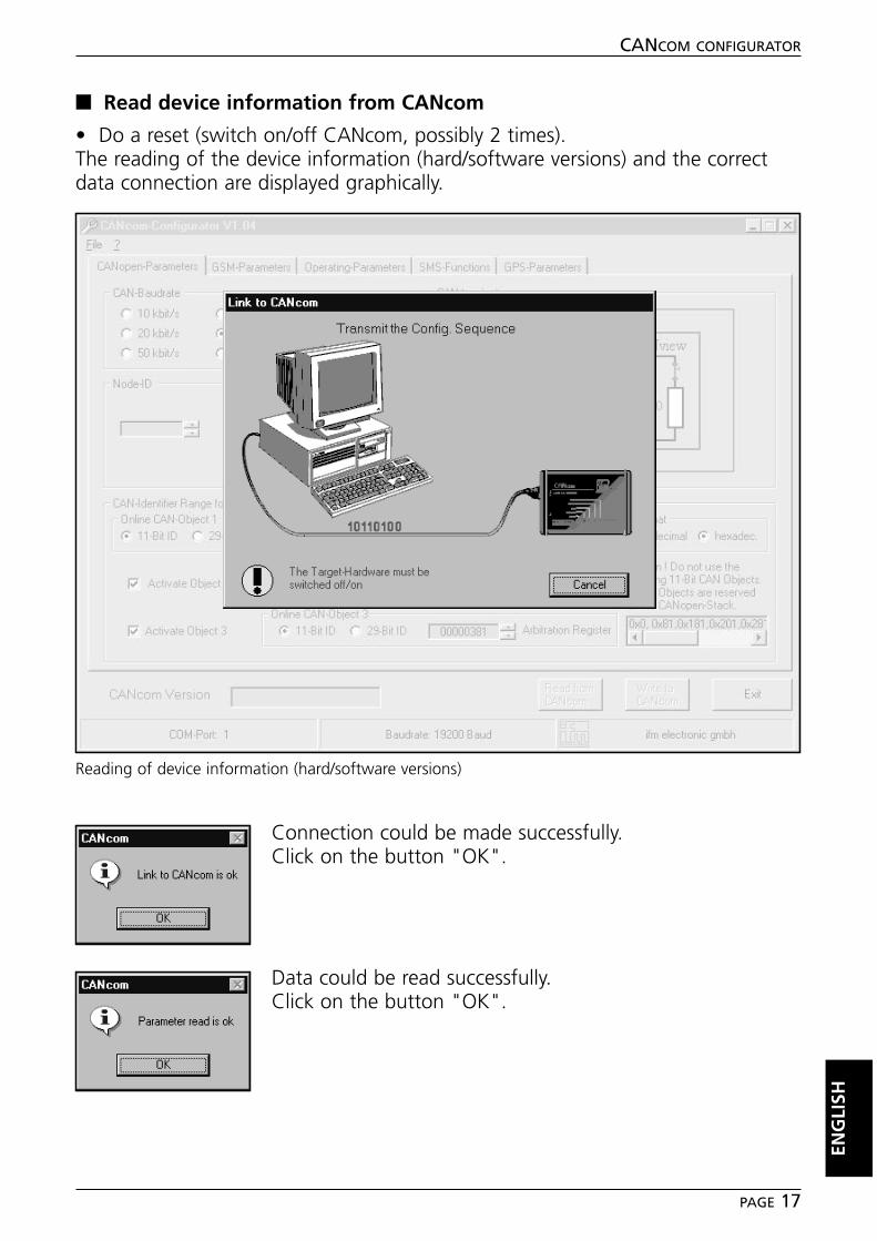
■■ Read device information from CANcom
• Do a reset (switch on/off CANcom, possibly 2 times).The reading of the device information (hard/software versions) and the correctdata connection are displayed graphically.
Connection could be made successfully.Click on the button "OK".
Data could be read successfully.Click on the button "OK".
ENG
LISH
CANCOM CONFIGURATOR
PAGE 17
Reading of device information (hard/software versions)

■■ Load existing configuration file in CANcom
• Select "Open Configuration" in the menu "File".• Open the desired configuration file (.cms file).
Configuration file could be loaded successfully.Click on the button "OK".
■■ Read configuration data from CANcom
• Click on the button "Read from CANcom".
Configuration data could be read successfully.Click on the button "OK".
CANCOM CONFIGURATOR
PAGE 18
Selection of the configuration file
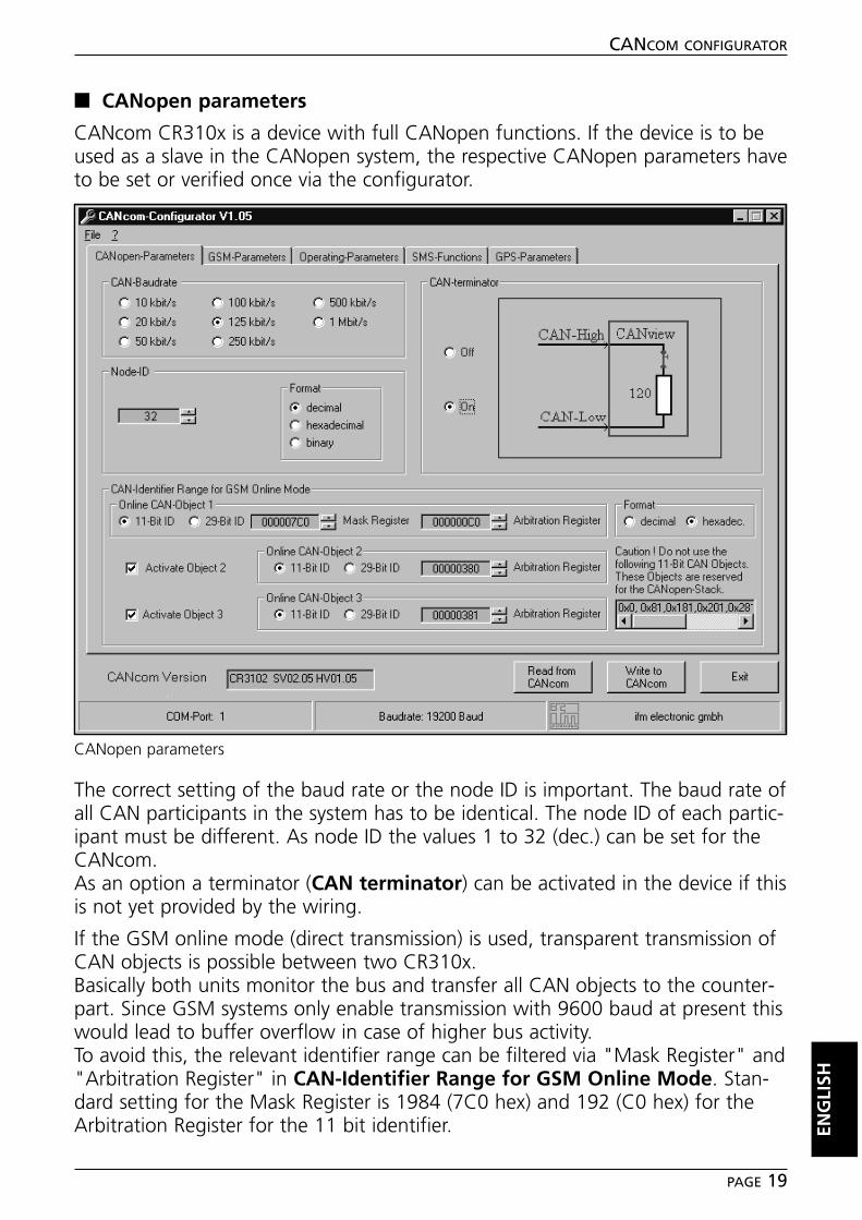
■■ CANopen parameters
CANcom CR310x is a device with full CANopen functions. If the device is to beused as a slave in the CANopen system, the respective CANopen parameters haveto be set or verified once via the configurator.
The correct setting of the baud rate or the node ID is important. The baud rate ofall CAN participants in the system has to be identical. The node ID of each partic-ipant must be different. As node ID the values 1 to 32 (dec.) can be set for theCANcom.As an option a terminator (CAN terminator) can be activated in the device if thisis not yet provided by the wiring.
If the GSM online mode (direct transmission) is used, transparent transmission ofCAN objects is possible between two CR310x.Basically both units monitor the bus and transfer all CAN objects to the counter-part. Since GSM systems only enable transmission with 9600 baud at present thiswould lead to buffer overflow in case of higher bus activity. To avoid this, the relevant identifier range can be filtered via "Mask Register" and"Arbitration Register" in CAN-Identifier Range for GSM Online Mode. Stan-dard setting for the Mask Register is 1984 (7C0 hex) and 192 (C0 hex) for theArbitration Register for the 11 bit identifier. EN
GLI
SH
CANCOM CONFIGURATOR
PAGE 19
CANopen parameters
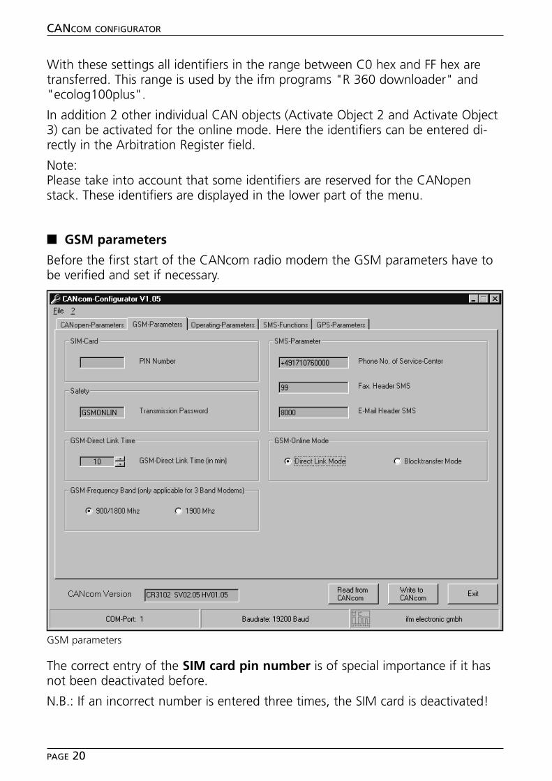
With these settings all identifiers in the range between C0 hex and FF hex aretransferred. This range is used by the ifm programs "R 360 downloader" and"ecolog100plus".
In addition 2 other individual CAN objects (Activate Object 2 and Activate Object3) can be activated for the online mode. Here the identifiers can be entered di-rectly in the Arbitration Register field.
Note:Please take into account that some identifiers are reserved for the CANopenstack. These identifiers are displayed in the lower part of the menu.
■■ GSM parameters
Before the first start of the CANcom radio modem the GSM parameters have tobe verified and set if necessary.
The correct entry of the SIM card pin number is of special importance if it hasnot been deactivated before.
N.B.: If an incorrect number is entered three times, the SIM card is deactivated!
CANCOM CONFIGURATOR
PAGE 20
GSM parameters

Depending on the system provider and the country the SMS parameters can bedifferent. The standard settings for the D1 and D2 net can be found in the CAN-com device manual or can be obtained from your system provider.
If you want to use the GSM online transmission, entries should be made in thewindows Safety and GSM Online. An entry in the field "Safety (TransmissionPassword)" protects your installation against unauthorised data access. The pass-word length is max. 8 characters.
To avoid undesired long online connections, set the maximum time in minutes inGSM Direct Link Time. If this time has elapsed, CANcom interrupts the trans-mission.
In GSM Online Mode either "Constant Connection Mode" or "BlocktransferMode" can be set. These settings only have effect if the online mode is used. Inthe Blocktransfer Mode the transmission of data blocks is limited to 8 Kbytes, inthe Constant Connection Mode the connection remains.
If a triband modem is used, the frequency band can be changed from 900/1800MHz to 1900 MHz depending on the existing systems. (CANcom CR3100 andCR3102 require the setting "900/1800 MHz".)
ENG
LISH
CANCOM CONFIGURATOR
PAGE 21
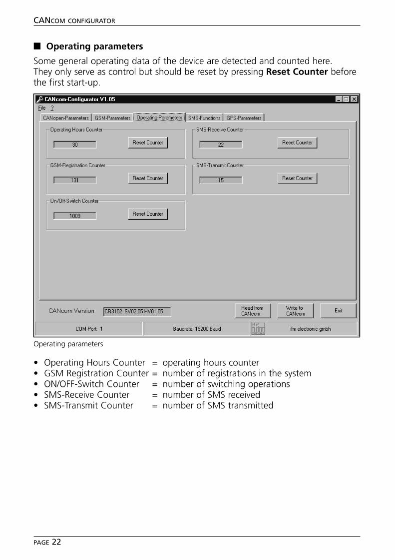
■■ Operating parameters
Some general operating data of the device are detected and counted here.They only serve as control but should be reset by pressing Reset Counter beforethe first start-up.
• Operating Hours Counter = operating hours counter• GSM Registration Counter = number of registrations in the system• ON/OFF-Switch Counter = number of switching operations• SMS-Receive Counter = number of SMS received• SMS-Transmit Counter = number of SMS transmitted
CANCOM CONFIGURATOR
PAGE 22
Operating parameters
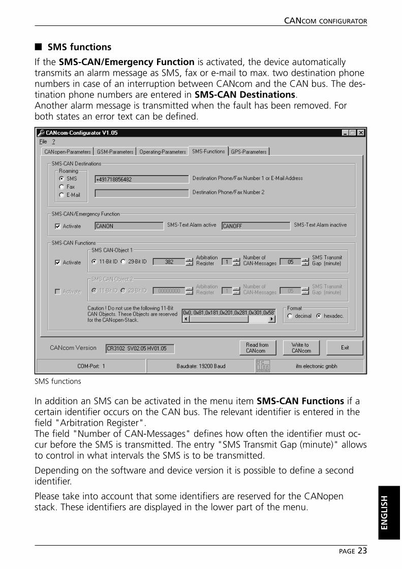
■■ SMS functions
If the SMS-CAN/Emergency Function is activated, the device automaticallytransmits an alarm message as SMS, fax or e-mail to max. two destination phonenumbers in case of an interruption between CANcom and the CAN bus. The des-tination phone numbers are entered in SMS-CAN Destinations.Another alarm message is transmitted when the fault has been removed. Forboth states an error text can be defined.
In addition an SMS can be activated in the menu item SMS-CAN Functions if acertain identifier occurs on the CAN bus. The relevant identifier is entered in thefield "Arbitration Register".The field "Number of CAN-Messages" defines how often the identifier must oc-cur before the SMS is transmitted. The entry "SMS Transmit Gap (minute)" allowsto control in what intervals the SMS is to be transmitted.
Depending on the software and device version it is possible to define a secondidentifier.
Please take into account that some identifiers are reserved for the CANopenstack. These identifiers are displayed in the lower part of the menu.
ENG
LISH
CANCOM CONFIGURATOR
PAGE 23
SMS functions
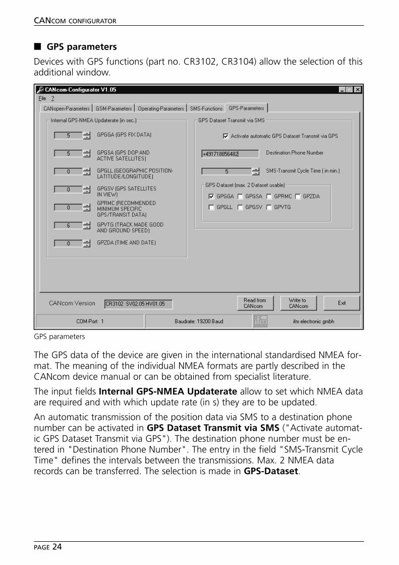
■■ GPS parameters
Devices with GPS functions (part no. CR3102, CR3104) allow the selection of thisadditional window.
The GPS data of the device are given in the international standardised NMEA for-mat. The meaning of the individual NMEA formats are partly described in theCANcom device manual or can be obtained from specialist literature.
The input fields Internal GPS-NMEA Updaterate allow to set which NMEA dataare required and with which update rate (in s) they are to be updated.
An automatic transmission of the position data via SMS to a destination phonenumber can be activated in GPS Dataset Transmit via SMS ("Activate automat-ic GPS Dataset Transmit via GPS"). The destination phone number must be en-tered in "Destination Phone Number". The entry in the field "SMS-Transmit CycleTime" defines the intervals between the transmissions. Max. 2 NMEA datarecords can be transferred. The selection is made in GPS-Dataset.
CANCOM CONFIGURATOR
PAGE 24
GPS parameters
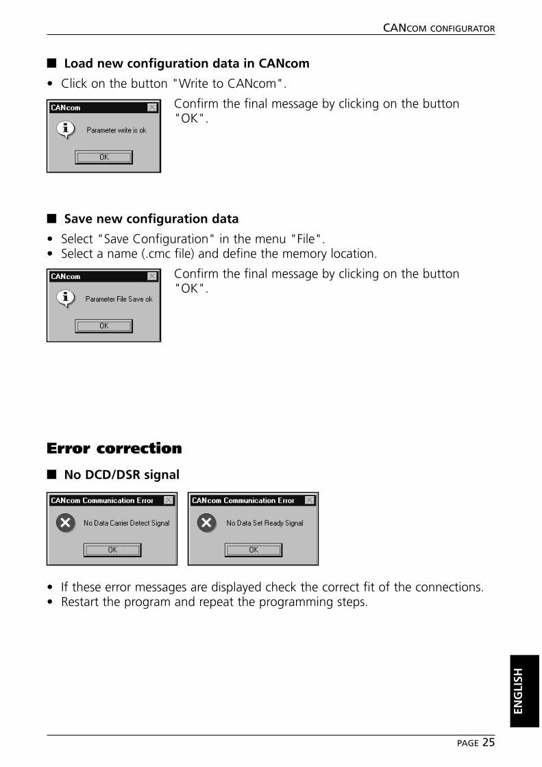
■■ Load new configuration data in CANcom
• Click on the button "Write to CANcom".
Confirm the final message by clicking on the button"OK".
■■ Save new configuration data
• Select "Save Configuration" in the menu "File".• Select a name (.cmc file) and define the memory location.
Confirm the final message by clicking on the button"OK".
Error correction
■■ No DCD/DSR signal
• If these error messages are displayed check the correct fit of the connections.• Restart the program and repeat the programming steps.
ENG
LISH
CANCOM CONFIGURATOR
PAGE 25

Notizen / Notes
CANCOM CONFIGURATOR
PAGE 26

Tech
nisc
he Ä
nder
unge
n be
halte
n w
ir un
s oh
ne v
orhe
rige
Ank
ündi
gung
vor
. • W
e re
serv
e th
e rig
ht to
mak
e te
chni
cal a
ltera
tions
with
out p
rior n
otic
e. •
Nou
s no
us ré
serv
ons
le d
roit
de m
odifi
er le
s do
nnée
s te
chni
ques
san
s pr
éavi
s.
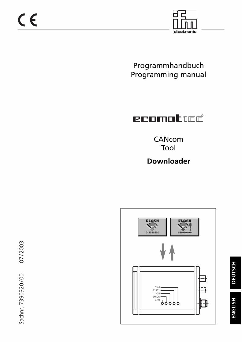
ProgrammhandbuchProgramming manual
CANcomTool
Downloader
DEU
TSC
HEN
GLI
SH
R
GSMRS232
ONERROR
CAN
Sach
nr.
7390
320
/00
07
/200
3
Inhalt
Bestimmungsgemäße Verwendung . . . . . . . . . . . . . . . . . . . . . . . . . Seite 3Systemvoraussetzungen . . . . . . . . . . . . . . . . . . . . . . . . . . . . . . . Seite 3
InstallationSoftware . . . . . . . . . . . . . . . . . . . . . . . . . . . . . . . . . . . . . . . . . . Seite 4Hardware . . . . . . . . . . . . . . . . . . . . . . . . . . . . . . . . . . . . . . . . . Seite 4
ProgrammfunktionenProgramm starten . . . . . . . . . . . . . . . . . . . . . . . . . . . . . . . . . . . Seite 4CANcom initialisieren und Flash-Informationen auslesen . . . . . . . . Seite 5Betriebssystem in CANcom laden . . . . . . . . . . . . . . . . . . . . . . . . Seite 6Betriebssystem aus CANcom lesen . . . . . . . . . . . . . . . . . . . . . . . Seite 7
FehlerbehebungKeine DCD-Signal. . . . . . . . . . . . . . . . . . . . . . . . . . . . . . . . . . . . Seite 9Probleme mit der Baudrate . . . . . . . . . . . . . . . . . . . . . . . . . . . . . Seite 9
Notizen . . . . . . . . . . . . . . . . . . . . . . . . . . . . . . . . . . . . . . . . . . . . . Seite18
CANCOM DOWNLOADER
SEITE 2
Microsoft und Windows sind eingetragene Warenzeichen der Microsoft Corporation.
Die überlassene Software ist für den normalen Gebrauch auf handelsüblichen Personalcomputerngeeignet. Eine Gewähr für unterbrechungsfreien oder fehlerfreien Betrieb oder die Freiheit von Com-puterviren sowie dafür, daß jeder eventuell auftretende Fehler beseitigt wird, kann nach dem Standder Softwaretechnik nicht übernommen werden. Insbesondere haftet ifm electronic gmbh bei einemfehlerhaften Programm nicht für beim Kunden entstehende Kosten (z.B. Wartung, Reparatur oderMängelbehebung). Der Ausschluß gilt nicht für Schäden, für die aufgrund unabdingbarer gesetzlicherVorschriften zwingend gehaftet wird.
Das Programm ist speziell für die Steuerungssysteme der ifm electronic gmbh entwickelt worden.Daher ist die Funktion nur bei diesen Steuerungen möglich. Versuche der Ankoppelung an Fremdsy-steme können zu gravierenden Schäden führen.
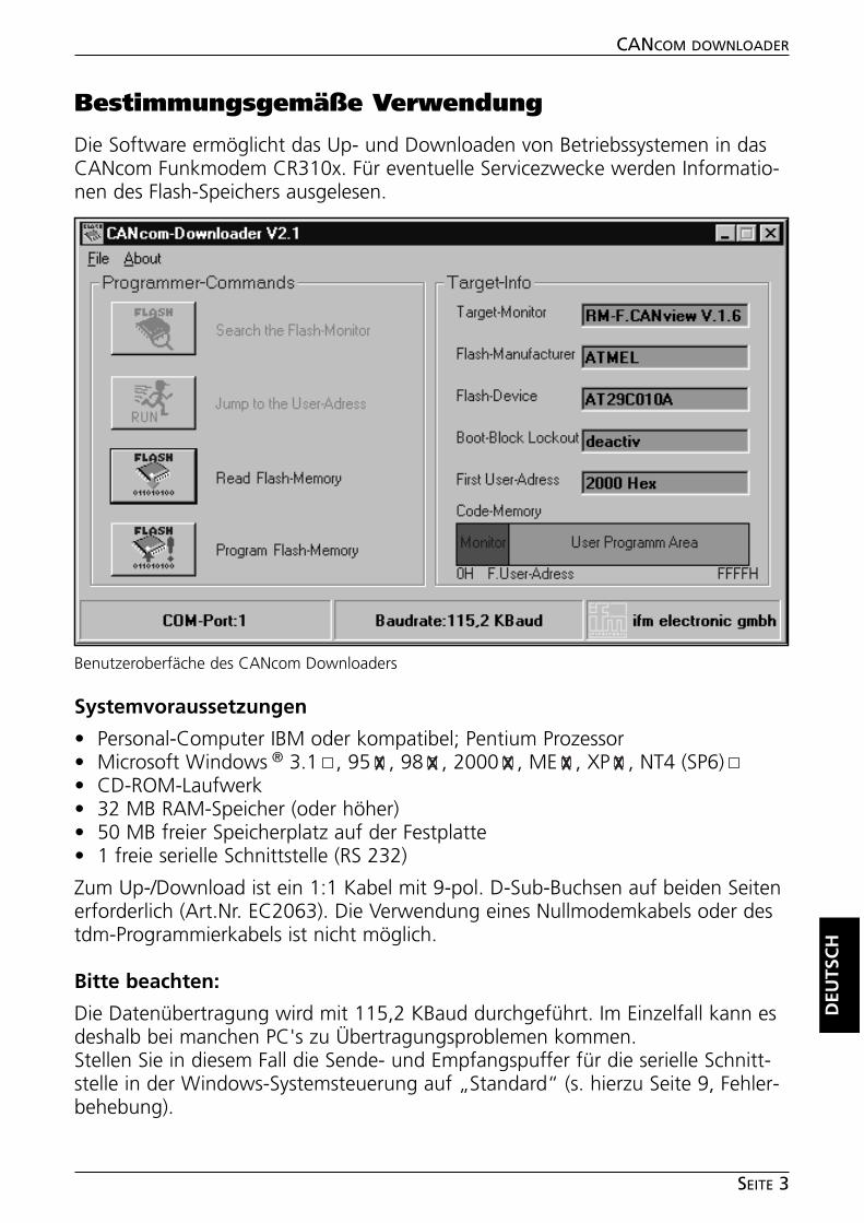
CANCOM DOWNLOADER
SEITE 3
Bestimmungsgemäße Verwendung
Die Software ermöglicht das Up- und Downloaden von Betriebssystemen in dasCANcom Funkmodem CR310x. Für eventuelle Servicezwecke werden Informatio-nen des Flash-Speichers ausgelesen.
Systemvoraussetzungen
• Personal-Computer IBM oder kompatibel; Pentium Prozessor• Microsoft Windows ® 3.1 , 95 , 98 , 2000 , ME , XP , NT4 (SP6)• CD-ROM-Laufwerk• 32 MB RAM-Speicher (oder höher)• 50 MB freier Speicherplatz auf der Festplatte• 1 freie serielle Schnittstelle (RS 232)
Zum Up-/Download ist ein 1:1 Kabel mit 9-pol. D-Sub-Buchsen auf beiden Seitenerforderlich (Art.Nr. EC2063). Die Verwendung eines Nullmodemkabels oder destdm-Programmierkabels ist nicht möglich.
Bitte beachten:
Die Datenübertragung wird mit 115,2 KBaud durchgeführt. Im Einzelfall kann esdeshalb bei manchen PC's zu Übertragungsproblemen kommen.Stellen Sie in diesem Fall die Sende- und Empfangspuffer für die serielle Schnitt-stelle in der Windows-Systemsteuerung auf „Standard“ (s. hierzu Seite 9, Fehler-behebung).
DEU
TSC
H
Benutzeroberfäche des CANcom Downloaders
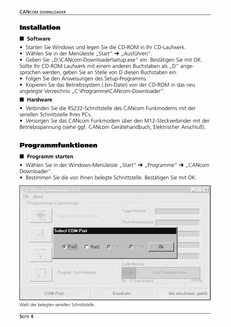
Installation
■■ Software
• Starten Sie Windows und legen Sie die CD-ROM in Ihr CD-Laufwerk.• Wählen Sie in der Menüleiste „Start“ ➔ „Ausführen“.• Geben Sie „D:\CANcom-Downloader\setup.exe“ ein. Bestätigen Sie mit OK.Sollte Ihr CD-ROM Laufwerk mit einem anderen Buchstaben als „D“ ange-sprochen werden, geben Sie an Stelle von D diesen Buchstaben ein.• Folgen Sie den Anweisungen des Setup-Programms.• Kopieren Sie das Betriebssystem (.bin-Datei) von der CD-ROM in das neuangelegte Verzeichnis „C:\Programme\CANcom-Downloader“.
■■ Hardware
• Verbinden Sie die RS232-Schnittstelle des CANcom Funkmodems mit derseriellen Schnittstelle Ihres PCs.• Versorgen Sie das CANcom Funkmodem über den M12-Steckverbinder mit derBetriebsspannung (siehe ggf. CANcom Gerätehandbuch, Elektrischer Anschluß).
Programmfunktionen
■■ Programm starten
• Wählen Sie in der Windows-Menüleiste „Start“ ➔ „Programme“ ➔ „CANcomDownloader“. • Bestimmen Sie die von Ihnen belegte Schnittstelle. Bestätigen Sie mit OK.
CANCOM DOWNLOADER
SEITE 4
Wahl der belegten seriellen Schnittstelle
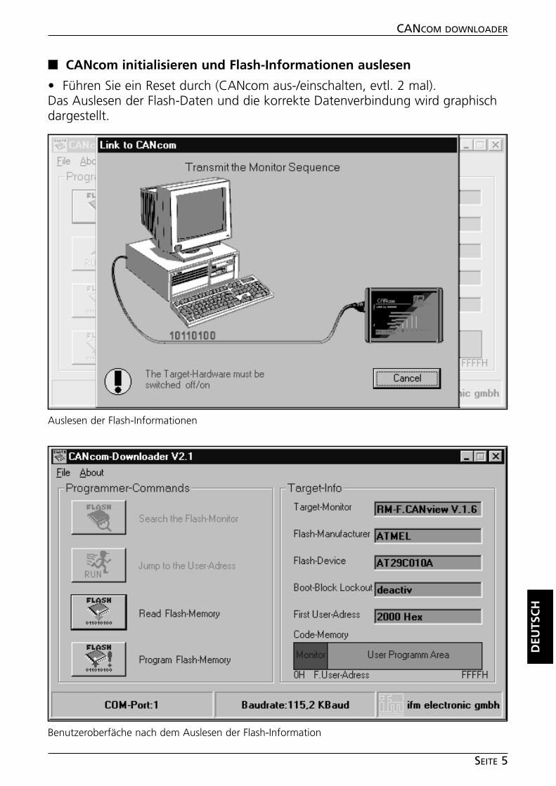
DEU
TSC
H
CANCOM DOWNLOADER
SEITE 5
■■ CANcom initialisieren und Flash-Informationen auslesen
• Führen Sie ein Reset durch (CANcom aus-/einschalten, evtl. 2 mal).Das Auslesen der Flash-Daten und die korrekte Datenverbindung wird graphischdargestellt.
Auslesen der Flash-Informationen
Benutzeroberfäche nach dem Auslesen der Flash-Information
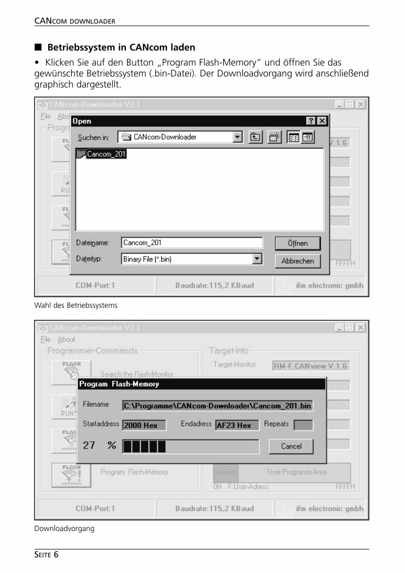
■■ Betriebssystem in CANcom laden
• Klicken Sie auf den Button „Program Flash-Memory“ und öffnen Sie dasgewünschte Betriebssystem (.bin-Datei). Der Downloadvorgang wird anschließendgraphisch dargestellt.
CANCOM DOWNLOADER
SEITE 6
Downloadvorgang
Wahl des Betriebssystems
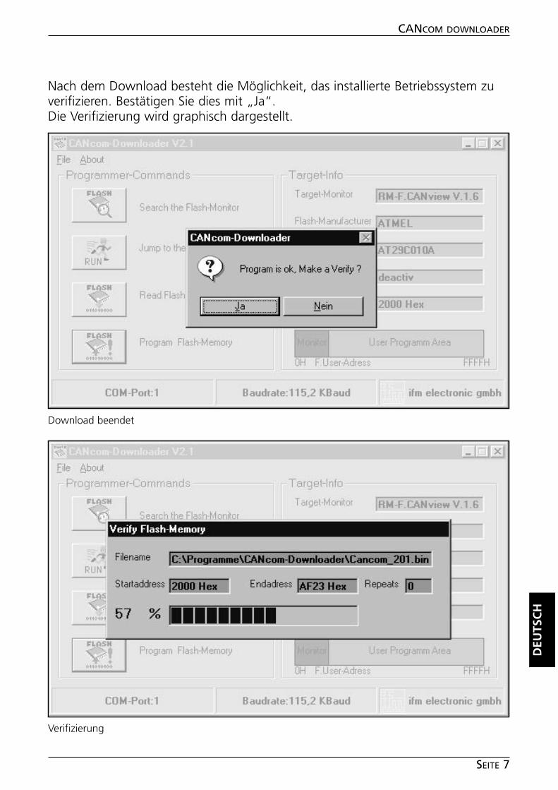
Nach dem Download besteht die Möglichkeit, das installierte Betriebssystem zuverifizieren. Bestätigen Sie dies mit „Ja“.Die Verifizierung wird graphisch dargestellt.
DEU
TSC
H
CANCOM DOWNLOADER
SEITE 7
Download beendet
Verifizierung
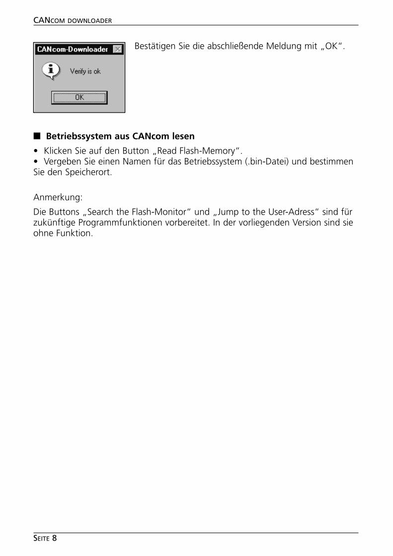
Bestätigen Sie die abschließende Meldung mit „OK“.
■■ Betriebssystem aus CANcom lesen
• Klicken Sie auf den Button „Read Flash-Memory“.• Vergeben Sie einen Namen für das Betriebssystem (.bin-Datei) und bestimmenSie den Speicherort.
Anmerkung:
Die Buttons „Search the Flash-Monitor“ und „Jump to the User-Adress“ sind fürzukünftige Programmfunktionen vorbereitet. In der vorliegenden Version sind sieohne Funktion.
CANCOM DOWNLOADER
SEITE 8
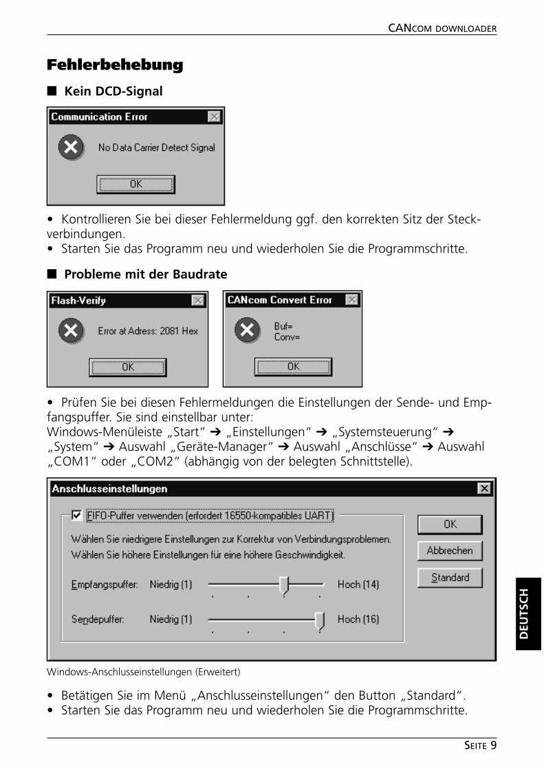
Fehlerbehebung
■■ Kein DCD-Signal
• Kontrollieren Sie bei dieser Fehlermeldung ggf. den korrekten Sitz der Steck-verbindungen.• Starten Sie das Programm neu und wiederholen Sie die Programmschritte.
■■ Probleme mit der Baudrate
• Prüfen Sie bei diesen Fehlermeldungen die Einstellungen der Sende- und Emp-fangspuffer. Sie sind einstellbar unter:Windows-Menüleiste „Start“ ➔ „Einstellungen“ ➔ „Systemsteuerung“ ➔„System“ ➔ Auswahl „Geräte-Manager“ ➔ Auswahl „Anschlüsse“ ➔ Auswahl„COM1“ oder „COM2“ (abhängig von der belegten Schnittstelle).
• Betätigen Sie im Menü „Anschlusseinstellungen“ den Button „Standard“.• Starten Sie das Programm neu und wiederholen Sie die Programmschritte.
DEU
TSC
H
CANCOM DOWNLOADER
SEITE 9
Windows-Anschlusseinstellungen (Erweitert)
Contents
Function and features . . . . . . . . . . . . . . . . . . . . . . . . . . . . . . . . . . page 11System requirements. . . . . . . . . . . . . . . . . . . . . . . . . . . . . . . . . page 11
InstallationSoftware . . . . . . . . . . . . . . . . . . . . . . . . . . . . . . . . . . . . . . . . . page 12Hardware . . . . . . . . . . . . . . . . . . . . . . . . . . . . . . . . . . . . . . . . . page 12
Program functionsStart program. . . . . . . . . . . . . . . . . . . . . . . . . . . . . . . . . . . . . . page 12Initialise CANcom and read flash information . . . . . . . . . . . . . . . page 13Load operating system in CANcom . . . . . . . . . . . . . . . . . . . . . . page 14Read the operating system from CANcom . . . . . . . . . . . . . . . . . page 16
Error correctionNo DCD signal . . . . . . . . . . . . . . . . . . . . . . . . . . . . . . . . . . . . . page 17Problems with the baud rate . . . . . . . . . . . . . . . . . . . . . . . . . . . page 17
Notes . . . . . . . . . . . . . . . . . . . . . . . . . . . . . . . . . . . . . . . . . . . . . . page 18
CANCOM DOWNLOADER
PAGE 10
Microsoft and Windows are registered trademarks of Microsoft Corporation.
The software is suitable for normal use on common personal computers. According to the presentstate of software technology no guarantee can be assumed for the correct operation or absence ofcomputer viruses nor for the removal of any fault which may occur. In the case of an incorrect pro-gram ifm electronic cannot be held liable for cost incurred at the customer (e.g. maintenance, repairor rectification of faults). The exclusion does not apply to damage for which liability is mandatoryaccording to peremptory legal provisions.
The program has been specifically developed for the control systems of ifm electronic gmbh. It there-fore only functions with these controllers. Attempts to use it with systems from other manufacturerscan lead to serious damage.
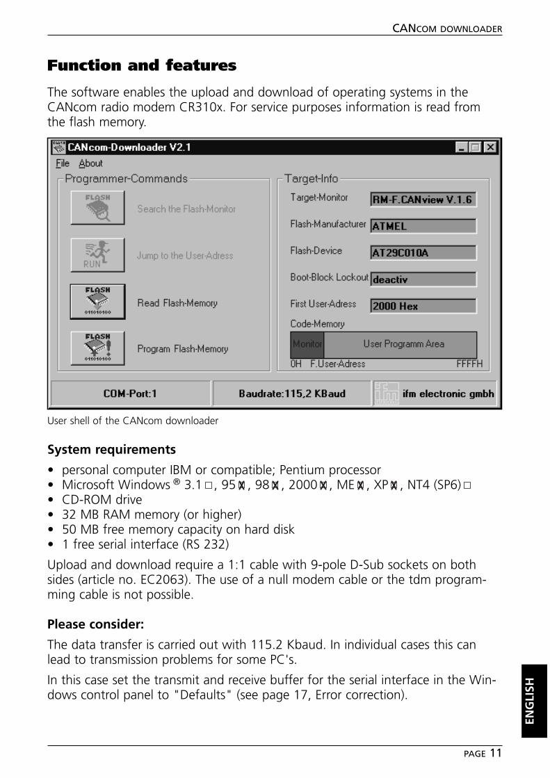
Function and features
The software enables the upload and download of operating systems in theCANcom radio modem CR310x. For service purposes information is read fromthe flash memory.
System requirements
• personal computer IBM or compatible; Pentium processor• Microsoft Windows ® 3.1 , 95 , 98 , 2000 , ME , XP , NT4 (SP6)• CD-ROM drive• 32 MB RAM memory (or higher)• 50 MB free memory capacity on hard disk• 1 free serial interface (RS 232)
Upload and download require a 1:1 cable with 9-pole D-Sub sockets on bothsides (article no. EC2063). The use of a null modem cable or the tdm program-ming cable is not possible.
Please consider:
The data transfer is carried out with 115.2 Kbaud. In individual cases this canlead to transmission problems for some PC's.
In this case set the transmit and receive buffer for the serial interface in the Win-dows control panel to "Defaults" (see page 17, Error correction).
ENG
LISH
CANCOM DOWNLOADER
PAGE 11
User shell of the CANcom downloader
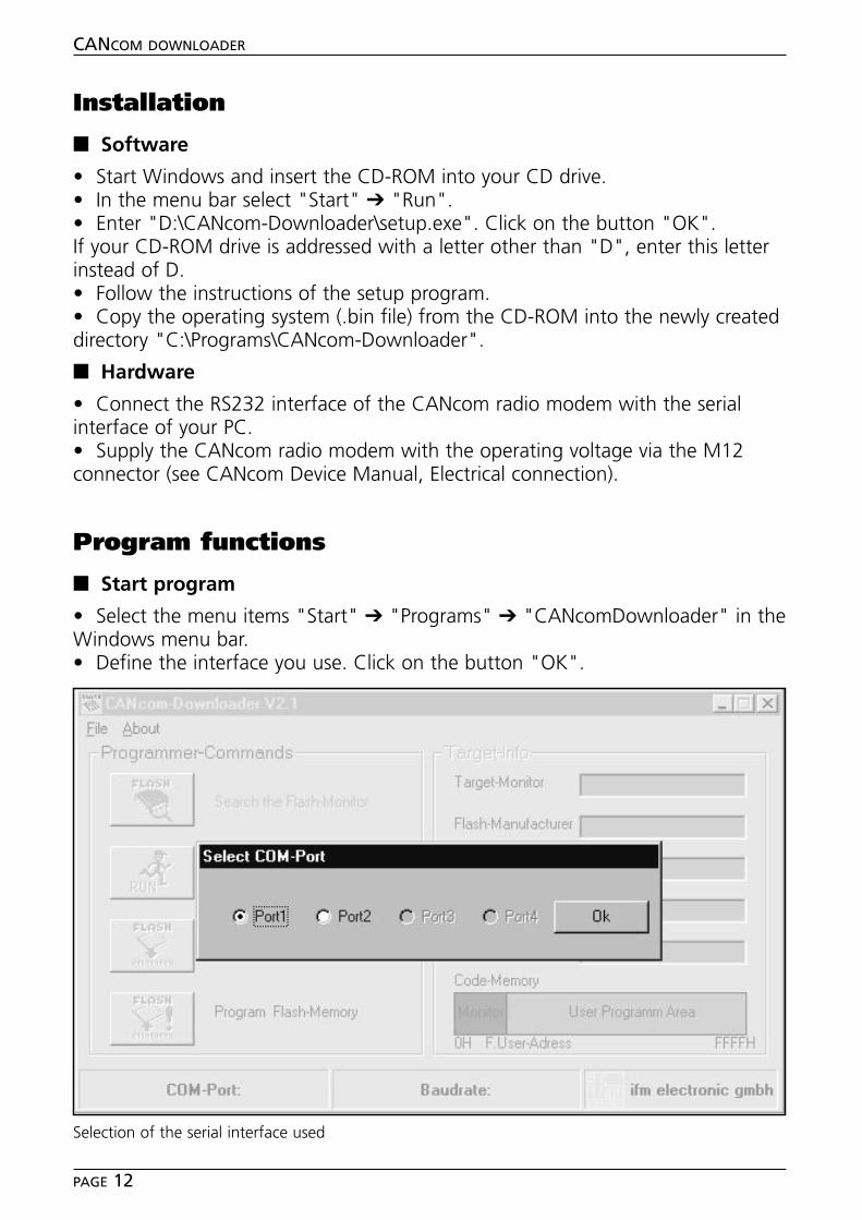
Installation
■■ Software
• Start Windows and insert the CD-ROM into your CD drive.• In the menu bar select "Start" ➔ "Run".• Enter "D:\CANcom-Downloader\setup.exe". Click on the button "OK".If your CD-ROM drive is addressed with a letter other than "D", enter this letterinstead of D.• Follow the instructions of the setup program.• Copy the operating system (.bin file) from the CD-ROM into the newly createddirectory "C:\Programs\CANcom-Downloader".
■■ Hardware
• Connect the RS232 interface of the CANcom radio modem with the serialinterface of your PC.• Supply the CANcom radio modem with the operating voltage via the M12connector (see CANcom Device Manual, Electrical connection).
Program functions
■■ Start program
• Select the menu items "Start" ➔ "Programs" ➔ "CANcomDownloader" in theWindows menu bar.• Define the interface you use. Click on the button "OK".
CANCOM DOWNLOADER
PAGE 12
Selection of the serial interface used
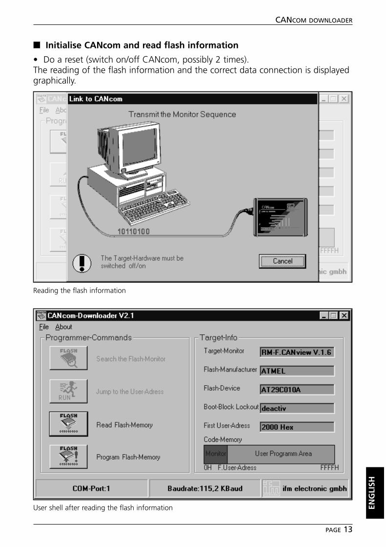
■■ Initialise CANcom and read flash information
• Do a reset (switch on/off CANcom, possibly 2 times).The reading of the flash information and the correct data connection is displayedgraphically.
ENG
LISH
CANCOM DOWNLOADER
PAGE 13
Reading the flash information
User shell after reading the flash information
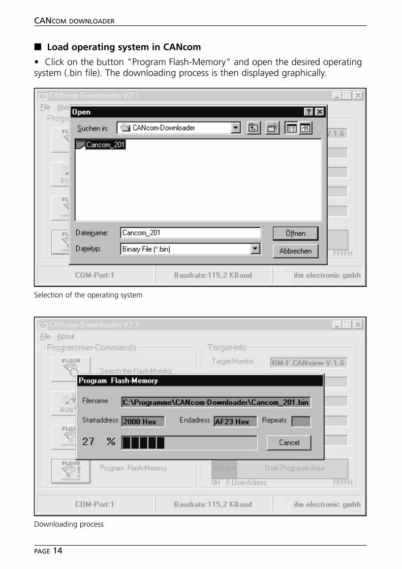
■■ Load operating system in CANcom
• Click on the button "Program Flash-Memory" and open the desired operatingsystem (.bin file). The downloading process is then displayed graphically.
CANCOM DOWNLOADER
PAGE 14
Downloading process
Selection of the operating system
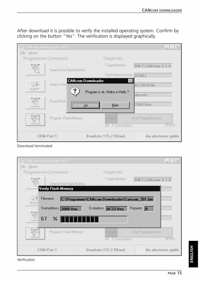
After download it is possible to verify the installed operating system. Confirm byclicking on the button "Yes". The verification is displayed graphically.
ENG
LISH
CANCOM DOWNLOADER
PAGE 15
Download terminated
Verification
Confirm the final message by clicking on the button"OK".
■■ Read the operating system from CANcom
• Click on the button "Read Flash-Memory".• Select a name for the operating system (.bin file) and define the memory loca-tion.
Note:
The buttons "Search the Flash-Monitor" and "Jump to the User-Adress" havebeen prepared for future program functions. In the current version they do notfunction.
CANCOM DOWNLOADER
PAGE 16
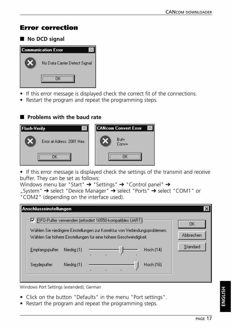
Error correction
■■ No DCD signal
• If this error message is displayed check the correct fit of the connections.• Restart the program and repeat the programming steps.
■■ Problems with the baud rate
• If this error message is displayed check the settings of the transmit and receivebuffer. They can be set as follows:Windows menu bar "Start" ➔ "Settings" ➔ "Control panel" ➔„System“ ➔ select "Device Manager" ➔ select "Ports" ➔ select "COM1" or"COM2" (depending on the interface used).
• Click on the button "Defaults" in the menu "Port settings".• Restart the program and repeat the programming steps. EN
GLI
SH
CANCOM DOWNLOADER
PAGE 17
Windows Port Settings (extended); German
Notizen / Notes
CANCOM DOWNLOADER
PAGE 18

Tech
nisc
he Ä
nder
unge
n be
halte
n w
ir un
s oh
ne v
orhe
rige
Ank
ündi
gung
vor
.Pa
pier
chl
orfr
ei g
eble
icht