RCV..1 RCV..2/3 CV..2/3 - tramec-getriebe.de · SIMBOLOGIA E UNITA‘ DI MISURA 4 SYMBOLS AND UNITS...
104
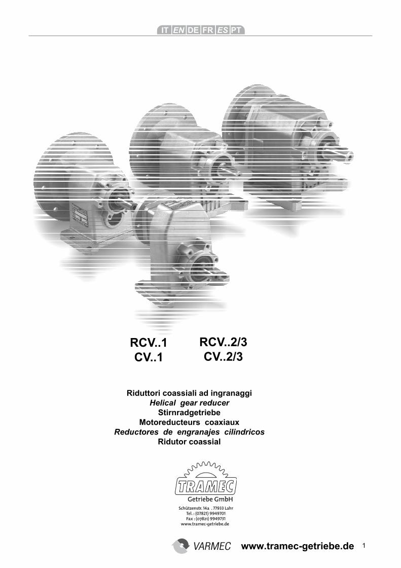
1 Riduttori coassiali ad ingranaggi Helical gear reducer Stirnradgetriebe Motoreducteurs coaxiaux Reductores de engranajes cilindricos Ridutor coassial RCV..1 CV..1 RCV..2/3 CV..2/3 www.tramec-getriebe.de
Transcript of RCV..1 RCV..2/3 CV..2/3 - tramec-getriebe.de · SIMBOLOGIA E UNITA‘ DI MISURA 4 SYMBOLS AND UNITS...
1
Riduttori coassiali ad ingranaggiHelical gear reducer
StirnradgetriebeMotoreducteurs coaxiaux
Reductores de engranajes cilindricosRidutor coassial
RCV..1 CV..1
RCV..2/3 CV..2/3
www.tramec-getriebe.de
2
Indice Index Inhaltsverzeichnis
SIMBOLOGIA E UNITA‘ DI MISURA 4
SYMBOLS AND UNITS OF MEASURE 4 SYMBOLE UND MAßEINHEITEN 4
INFORMAZIONI GENERALI 6 GENERAL INFORMATIONS 6GRUNDLEGENDE INFORMATI-ONEN 6
FATTORE DI SERVIZIO 8 SERVICE FACTOR 8 BETRIEBSFAKTOR 8
POTENZA TERMICA 10 THERMIC POWER 10 THERMISCHE LEISTUNG 10
SCELTA 12 SELECTION 12 GETRIEBEAUSWAHL 12
VERIFICHE 14 CHECK POINTS 14 NACHKONTROLLEN 14
CARATTERISTICHE COSTRUTTIVE 16 DESIGN CHARACTERISTICS 16
CHARAKTERISTISCHE MERKMALE 16
DESIGNAZIONE 18 DESIGNATION 18 GETRIEBEBEZEICHUNGEN 18
LUBRIFICAZIONE 20 LUBRICATION 20 SCHMIERUNG 20
CARICHI RADIALI E ASSIALI 24 RADIAL AND AXIAL LOADS 24 RADIAL UND AXIALLASTEN 24
SELEZIONE MOTORIDUTTORI 29 CHOOSING A MOTOR REDUCER 29AUSWAHL DER GETRIEBEMO-TOREN 29
DATI TECNICI 42 TECHNICAL DATA 42 TECHNISCHE DATEN 42
DIMENSIONI 46 DIMENSIONS 46 ABMESSUNGEN 46
MOMENTI D'INERZIA 76 MOMENTS OF INERTIA 76 TRÄGHEITSMOMENT 76
ATEX 84 ATEX 84 ATEX 84
CONDIZIONI DI FORNITURA 86HOW THE GEAR REDUCERS COME SUPPLIED 86 LIEFERBEDINGUNGEN 86
INSTALLAZIONE 86 INSTALLATION 86 INSTALLATION 86
MANUTENZIONE 88 MAINTENANCE 88 WARTUNG 88
STOCCAGGIO 90 STORAGE 90 LAGERUNG 90
PESI 92 WEIGHTS 92 GEWICHT 92
PARTI DI RICAMBIO 93 SPARE PARTS LIST 93 ERSATZTEILLISTE 93
MOTORI ELETTRICI 100 ELECTRIC MOTORS 100 ELEKTROMOTOREN 100
1
2
3
4
5
6
7
8
9
10
11
12
13
14
15
16
17
18
19
20
21
22
www.tramec-getriebe.de
3
Index Indice Indice
SYMBOLES ET UNITES DE ME-SURE 5
SIMBOLOGIA Y UNIDADES DE MEDIDA 5
SIMBOLOGIA E UNIDADE DE TAMANHO 5
INFORMATIONS GENERALES 7 INFORMACIÓN GENERAL 7 INFORMAÇÃO GENERAL 7
FACTEUR DE SERVICE 9 FACTOR DE SERVICIO 9 FATORE DE SERVIÇO 9
PUISSANCE THERMIQUE 11 POTENCIA TÉRMICA 11 POTÊNCIA TERMICA 11
SELECTION 13 SELECCION 13 ESCOLHA 13
CONTROLES 15 VERIFICACIONES 15 VERIFIQUE 15
CARACTERISTIQUE DE FABRICATION 17
CARACTERÍSTICAS CONSTRUCTIVAS 17
CARACTÉRISTICA CONSTRUTIVA 17
DESIGNATION 19 DESIGNACION 19 DESIGNAÇÃO 19
LUBRIFICATION 21 LUBRICACIÓN 21 LUBRIFICAÇÃO 21
CHARGES RADIALES ET AXIALES 25 CARGAS RADIALES Y AXIALES 25 CARGUE RADIAL E EMPUXO 25
SELECTION MOTO-REDUC-TEURS 29
SELECCION MOTORREDUCTO-RES 29 SELEÇÃO MOTORIDUTOR 29
CARACTÉRISTIQUES TECHNI-QUES 42 DATOS TÉCNICOS 42 CARACTERÍSTICAS TÉCNICAS 42
DIMENSIONS 46 DIMENSIONES 46 DIMENSÕES 46
MOMENTS D' INERTIE 76 MOMENTOS DE INERCIA 76 MOMENTO DE INERCIA 76
ATEX 85 ATEX 85 ATEX 85
CONDITION DE FOURNITURE 87CONDICIONES DE EQUIPAMI-ENTO 87 CONDIÇÃO DE FORNITURA 87
INSTALLATION 87 INSTALACIÓN 87 INSTALAÇÃO 87
ENTRETIEN 89 MANTENIMIENTO 89 MANUTENÇÃO 89
STOCKAGE 91 ALMACENAMIENTO 91 STOCCAGGIO 91
POIDS 92 PESOS 92 PESOS 92
LISTE DES PIECES DETACHEES 93 LISTA DE RECAMBIOS 93 LISTA DE RECAMBIOS 93
MOTEURS ELECTRIQUES 100 MOTORES ELÉTRICOS 100 MOTORES ELECTRICOS 100
1
2
3
4
5
6
7
8
9
10
11
12
13
14
15
16
17
18
19
20
21
22
www.tramec-getriebe.de
4
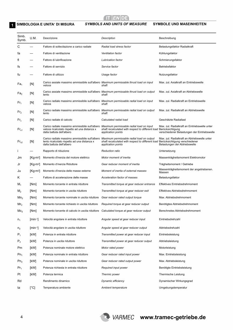
Simb. Symb.
U.M. Descrizione Description Beschreibung
C — Fattore di sollecitazione a carico radiale Radial load stress factor Belastungsfaktor Radialkraft
fa — Fattore di ventilazione Ventilation factor Kühlungsfaktor
fl — Fattore di lubrificazione Lubrication factor Schmierungsfaktor
fs — Fattore di servizio Service factor Betriebsfaktor
fu — Fattore di utilizzo Usage factor Nutzungsfaktor
Fa1 [N] Carico assiale massimo ammissibile sull'albero veloce
Maximum permissable thrust load on input shaft
Max. zul. Axialkraft an Eintriebswelle
Fa2 [N] Carico assiale massimo ammissibile sull'albero lento
Maximum permissable thrust load on output shaft
Max. zul. Axialkraft an Abtriebswelle
Fr1 [N] Carico radiale massimo ammissibile sull'albero veloce
Maximum permissable radial load on input shaft
Max. zul. Radialkraft an Eintriebswelle
Fr2 [N] Carico radiale massimo ammissibile sull'albero lento
Maximum permissable radial load on output shaft
Max. zul. Radialkraft an Abtriebswelle
Frc [N] Carico radiale di calcolo Calculated radial load Geschätzte Radiallast
Frx1 [N]Carico radiale massimo ammissibile sull'albero veloce ricalcolato rispetto ad una distanza x dalla battuta dell'albero
Maximum permissable radial load on input shaft recalculated with respect to different load application points
Max. zul. Radialkraft an Eintriebswelle unter Berücksichtigung verschiedener Belastungen der Eintriebswelle
Frx2 [N]Carico radiale massimo ammissibile sull'albero lento ricalcolato rispetto ad una distanza x dalla battuta dell'albero
Maximum permissable radial load on output shaft recalculated with respect to different load application points
Max. zul. Radialkraft an Abtriebswelle unter Berücksichtigung verschiedener Belastungen der Abtriebswelle
i — Rapporto di riduzione Reduction ratio Untersetzung
Jm [Kg.m2] Momento d'inerzia del motore elettrico Motor moment of inertia Massenträgheitsmoment Elektromotor
Jr [Kg.m2] Momento d‘inerzia Riduttore Gear reducer moment of inertia Trägheitsmoment / Getriebe
Ju [Kg.m2] Momento d'inerzia delle masse esterne Moment of inertia of external masses Massenträgheitsmoment der angetriebenen. Massen
K — Fattore di accelerazione delle masse Acceleration factor of masses Belastungsfaktor
M1 [Nm] Momento torcente in entrata riduttore Transmitted torque at gear reducer entrance Effektives Eintriebsdrehmoment
M2 [Nm] Momento torcente in uscita riduttore Transmitted torque at gear reducer exit Effektives Abtriebsdrehmoment
Mn2 [Nm] Momento torcente nominale in uscita riduttore Gear reducer rated output torque Max. Abtriebsdrehmoment
Mr2 [Nm] Momento torcente richiesto in uscita riduttore Required torque at gear reducer output Benötigtes Abtriebsdrehmoment
Mc2 [Nm] Momento torcente di calcolo in uscita riduttore Calculated torque at gear reducer output Berechnetes Abtriebsdrehmoment
n1 [min-1] Velocità angolare in entrata riduttore Angular speed at gear reducer input Eintriebsdrehzahl
n2 [min-1] Velocità angolare in uscita riduttore Angular speed at gear reducer output Abtriebsdrehzahl
P1 [kW] Potenza in entrata riduttore Transmitted power at gear reducer input Eintriebsleistung
P2 [kW] Potenza in uscita riduttore Transmitted power at gear reducer output Abtriebsleistung
Pm [kW] Potenza nominale motore elettrico Motor rated power Motorleistung
Pn1 [kW] Potenza nominale in entrata riduttore Gear reducer rated input power Max. Eintriebsleistung
Pn2 [kW] Potenza nominale in uscita riduttore Gear reducer rated output power Max. Abtriebsleistung
Pr1 [kW] Potenza richiesta in entrata riduttore Required input power Benötigte Eintriebsleistung
Pt [kW] Potenza termica Thermic power Thermische Leistung
Rd Rendimento dinamico Dynamic efficiency Dynamischer Wirkungsgrad
ta [°C] Temperatura ambiente Ambient temperature Umgebungstemperatur
SIMBOLOGIA E UNITA‘ DI MISURA SYMBOLS AND UNITS OF MEASURE SYMBOLE UND MAßEINHEITEN 1
www.tramec-getriebe.de
5
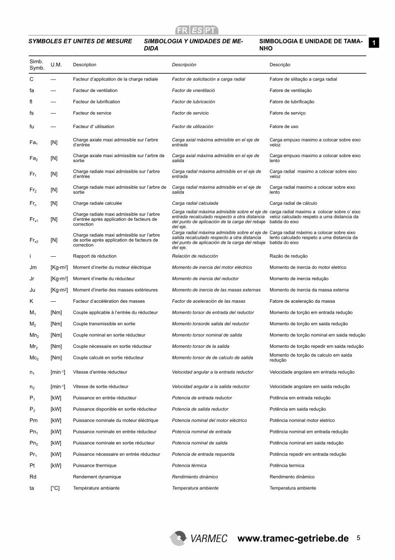
SYMBOLES ET UNITES DE MESURE SIMBOLOGIA Y UNIDADES DE ME-DIDA
SIMBOLOGIA E UNIDADE DE TAMA-NHO
1
Simb. Symb.
U.M. Description Descripción Descrição
C — Facteur d’application de la charge radiale Factor de solicitación a carga radial Fatore de silitação a carga radial
fa — Facteur de ventilation Factor de vnentilació Fatore de ventilação
fl — Facteur de lubrification Factor de lubricación Fatore de lubrificação
fs — Facteur de service Factor de servicio Fatore de serviço
fu — Facteur d' utilisation Factor de utilización Fatore de uso
Fa1 [N] Charge axiale maxi admissible sur l’arbre d’entrée
Carga axial máxima admisible en el eje de entrada
Carga empuxo maximo a colocar sobre eixo veloz
Fa2 [N] Charge axiale maxi admissible sur l’arbre de sortie
Carga axial máxima admisible en el eje de salida
Carga empuxo maximo a colocar sobre eixo lento
Fr1 [N] Charge radiale maxi admissible sur l’arbre d’entrée
Carga radial máxima admisible en el eje de entrada
Carga radial maximo a colocar sobre eixo veloz
Fr2 [N] Charge radiale maxi admissible sur l’arbre de sortie
Carga radial máxima admisible en el eje de salida
Carga radial maximo a colocar sobre eixo lento
Frc [N] Charge radiale calculée Carga radial calculada Carga radial de cálculo
Frx1 [N]Charge radiale maxi admissible sur l’arbre d’entrée après application de facteurs de correction
Carga radial máxima admisible sobre el eje de entrada recalculado respecto a otra distancia del punto de aplicación de la carga del rebaje del eje.
carga radial maximo a colocar sobre o’ eixo veloz calculado respeto a uma distancia da batida do eixo
Frx2 [N]Charge radiale maxi admissible sur l’arbre de sortie après application de facteurs de correction
Carga radial máxima admisible sobre el eje de salida recalculado respecto a otra distancia del punto de aplicación de la carga del rebaje del eje.
Carga radial máximo a colocar sobre eixo lento calculado respeto a uma distancia da batida do eixo
i — Rapport de réduction Relación de reducción Razão de redução
Jm [Kg.m2] Moment d’inertie du moteur éléctrique Momento de inercia del motor eléctrico Momento de inercia do motor eletrico
Jr [Kg.m2] Moment d’inertie du réducteur Momento de inercia del reductor Momento de inercia redução
Ju [Kg.m2] Moment d’inertie des masses extérieures Momento de inercia de las masas externas Momento de inercia da massa externa
K — Facteur d’accélération des masses Factor de aceleración de las masas Fatore de aceleração da massa
M1 [Nm] Couple applicable à l’entrée du réducteur Momento torsor de entrada del reductor Momento de torção em entrada redução
M2 [Nm] Couple transmissible en sortie Momento torsorde salida del reductor Momento de torção em saida redução
Mn2 [Nm] Couple nominal en sortie réducteur Momento torsor nominal de salida Momento de torção nominal em saida redução
Mr2 [Nm] Couple nécessaire en sortie réducteur Momento torsor de la salida Momento de torção repedir em saida redução
Mc2 [Nm] Couple calculé en sortie réducteur Momento torsor de de calculo de salida Momento de torção de calculo em saida redução
n1 [min-1] Vitesse d’entrée réducteur Velocidad angular a la entrada reductor Velocidade angolare em entrada redução
n2 [min-1] Vitesse de sortie réducteur Velocidad angular a la salida reductor Velocidade angolare em saida redução
P1 [kW] Puissance en entrée réducteur Potencia de entrada reductor Potência em entrada redução
P2 [kW] Puissance disponible en sortie réducteur Potencia de salida reductor Potência em saida redução
Pm [kW] Puissance nominale du moteur éléctrique Potencia nominal del motor eléctrico Potência nominal motor eletrico
Pn1 [kW] Puissance nominale en entrée réducteur Potencia nominal de entrada Potência nominal em entrada redução
Pn2 [kW] Puissance nominale en sortie réducteur Potencia nominal de salida Potência nominal em saida redução
Pr1 [kW] Puissance nécessaire en entrée réducteur Potencia de entrada requerida Potência repedir em entrada redução
Pt [kW] Puissance thermique Potencia térmica Potência termica
Rd Rendement dynamique Rendimiento dinàmico Rendimento dinâmico
ta [°C] Température ambiante Temperatura ambiente Temperatura ambiente
www.tramec-getriebe.de
6
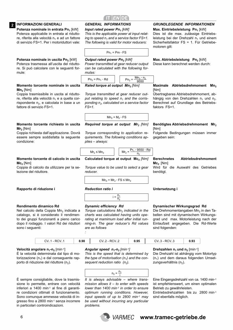
INFORMAZIONI GENERALI GENERAL INFORMATIONS
Potenza nominale in entrata Pn1 [kW]Potenza applicabile in entrata al ridutto-re, riferita alla velocità n1 e ad un fattore di servizio FS=1. Per i motoriduttori vale:
Potenza nominale in uscita Pn2 [kW]Potenza trasmessa all’uscita del ridutto-re. Si può calcolare con le seguenti for-mule:
Momento torcente nominale in uscita Mn2 [Nm]Coppia trasmissibile in uscita al ridutto-re, riferita alla velocità n1 e a quella cor-rispondente n2, e calcolata in base a un fattore di servizio FS=1.
Momento torcente richiesto in uscita Mr2 [Nm]Coppia richiesta dall’applicazione. Dovrà essere sempre soddisfatta la seguente condizione:
Momento torcente di calcolo in uscita Mc2 [Nm]Coppia di calcolo da utilizzare per la se-lezione del riduttore.
Rapporto di riduzione i
Rendimento dinamico RdNel calcolo della Coppia Mn2 indicata a catalogo, si è considerato il rendimen-to dei gruppi funzionanti a pieno carico dopo il rodaggio. I valori Rd dei riduttori sono i seguenti:
Velocità angolare n1-n2 [min-1]È la velocità determinata dal tipo di mo-torizzazione (n1) e dal conseguente rap-porto di riduzione del riduttore (n2).
È sempre consigliabile, dove la trasmis-sione lo permette, entrare con velocità inferiori a 1400 min-1 al fine di garanti-re condizioni ottimali di funzionamento. Sono comunque ammesse velocità di in-gresso fino a 2800 min-1 senza incorrere in particolari controindicazioni.
Pn1 = Pm . FS
Mn2 . n2
9550Pn2 =
Mn2 = M2 . FS
Mr2 ≤ Mn2Pr1 . 9550 . Rd
n2Mr2 =
Mc2 = Mr2 . FS ≤ Mn2
CV..1 - RCV..1 0.98 CV..2 - RCV..2 0.95 CV..3 - RCV..3 0.93
Input rated power Pn1 [kW]This is the applicable power at input relat-ing to speed n1 and a service factor FS=1.The following is valid for motor reducers:
Output rated power Pn2 [kW]Power transmitted at gear reducer output can be calculated with the following for-mulas:
Rated torque at output Mn2 [Nm] Torque transmitted at gear reducer out-put relating to speed n1 and the corris-ponding n2, calculated on a service factor FS=1.
Required torque at output Mr2 [Nm]
Torque corresponding to application re-quirements. The following conditions ap-plies – always:
Calculated torque at output Mc2 [Nm]
Torque value to be used to select a gear reducer.
Reduction ratio i
Dynamic efficiency Rd
Torque calculations Mn2 indicated in the charts was calculated having units ope-rating at mamimum load after initial run-ning-in. The gear reducer’s Rd values are as follows:
Angular speed n1-n2 [min-1]This is the speed that is determined by the type of motorisation (n1) and the con-sequent reduction ratio (n2).
It is always advisable – where trans-mission allows it – to enter with speeds lower than 1400 min-1 in order to ensure optimum running conditions. However, input speeds of up to 2800 min-1 may be used without incurring any particular problems.
Max. Eintriebsleistung Pn1 [kW]Dies ist die max. zulässige Eintriebs-leistung bei der Drehzahl n1 und einem Sicherheitsfaktor FS = 1. Für Getriebe-motoren gilt:
Max. Abtriebsleistung Pn2 [kW]Diese kann berechnet werden durch:
Maximale Abtriebsdrehmoment Mn2 [Nm]Übertragbares Abtriebsdrehmoment, ab-hängig von den Drehzahlen n1 und n2. Berechnet auf Grundlage des Betriebs-faktors FS=1.
Benötigtes Abtriebsdrehmoment Mr2 [Nm]Folgende Bedingungen müssen immer gegeben sein:
Berechnetes Abtriebsdrehmoment Mc2 [Nm]Wird für die Auswahl des Getriebes benötigt.
Untersetzung i
Dynamischer Wirkungsgrad RdDie Drehmomentangaben Mn2 in den Ta-bellen sind mit dynamischem Wirkungs-grad und max. Motorleistung nach der Einlaufzeit angegeben. Die Rd-Werte sind folgenden:
Drehzahlen n1 und n2 [min-1]Die Drehzahl ist abhängig vom Motortyp (n1) und dem daraus folgenden Umset-zungsverhältnis (n2).
Eine Eingangsdrehzahl von ca. 1400 min–1 ist empfehlenswert, um einen optimalen Betrieb zu gewährleisten.Eintriebsdrehzahlen bis zu 2800 min-1 sind ebenfalls möglich.
GRUNDLEGENDE INFORMATIONEN
Pn2 = Pn1 . Rd
n1 n2
i =
n1
in2 =
2
www.tramec-getriebe.de
7
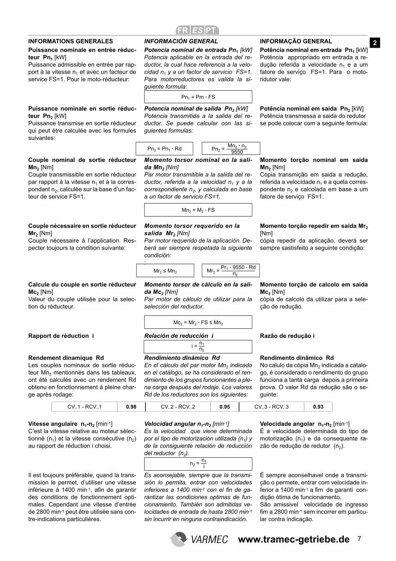
INFORMATIONS GENERALES INFORMACIÓN GENERAL
Puissance nominale en entrée réduc-teur Pn1 [kW]Puissance admissible en entrée par rap-port à la vitesse n1 et avec un facteur de service FS=1. Pour le moto-réducteur:
Puissance nominale en sortie réduc-teur Pn2 [kW]Puissance transmise en sortie réducteur qui peut étre calculée avec les formules suivantes:
Couple nominal de sortie réducteur Mn2 [Nm]Couple transmissible en sortie réducteur par rapport à la vitesse n1 et à la corres-pondant n2, calculée sur la base d’un fac-teur de service FS=1.
Couple nécessaire en sortie réducteur Mr2 [Nm]Couple nécessaire à l’application. Res-pecter toujours la condition suivante:
Calcule du couple en sortie réducteur Mc2 [Nm]Valeur du couple utilisée pour la selec-tion du réducteur.
Rapport de réduction i
Rendement dinamique RdLes couples nominaux de sortie réduc-teur Mn2 mentionnés dans les tableaux, ont été calculés avec un rendement Rd obtenu en fonctionnement à pleine char-ge après rodage:
Vitesse angulaire n1-n2 [min-1]C’est la vitesse relative au moteur sélec-tionné (n1) et la vitesse consécutive (n2) au rapport de réduction i choisi.
Il est toujours préférable, quand la trans-mission le permet, d’utiliser une vitesse inférieure à 1400 min-1, afin de garantir
des conditions de fonctionnement opti-males. Cependant une vitesse d’entrée de 2800 min-1 peut être utilisée sans con-tre-indications particulières.
Potencia nominal de entrada Pn1 [kW] Potencia aplicable en la entrada del re-ductor, la cual hace referencia a la velo-cidad n1 y a un factor de servicio FS=1. Para motorreductores es valida la si-guiente formula:
Potencia nominal de salida Pn2 [kW]Potencia transmitida a la salida del re-ductor. Se puede calcular con las si-guientes formulas:
Momento torsor nominal en la sali-da Mn2 [Nm]Par motor transmitible a la salida del re-ductor, referida a la velocidad n1 y a la correspondiente n2, y calculada en base a un factor de servicio FS=1.
Momento torsor requerido en la salida Mr2 [Nm]Par motor requerido de la aplicación. De-berá ser siempre respetada la siguiente condición::
Momento torsor de cálculo en la sali-da Mc2 [Nm]Par motor de cálculo de utilizar para la selección del reductor.
Relación de reducción i
Rendimiento dinámico RdEn el cálculo del par motor Mn2 indicado en el catálogo, se ha considerado el ren-dimiento de los grupos funcionantes a ple-na carga después del rodaje. Los valores Rd de los reductores son los siguientes:
Velocidad angular n1-n2 [min-1]Es la velocidad que viene determinada por el tipo de motorización utilizada (n1) y de la consiguiente relación de reducción del reductor (n2).
Es aconsejable, siempre que la transmi-sión lo permita, entrar con velocidades inferiores a 1400 min-1 con el fin de ga-rantizar las condiciones optimas de fun-cionamiento. También son admitidas ve-locidades de entrada de hasta 2800 min-1 sin incurrir en ninguna contraindicación.
Potência nominal em entrada Pn1 [kW]Potência appropriado em entrada a re-dução referida a velocidade n1 e a um fatore de serviço FS=1. Para o moto-ridutor vale:
Potência nominal em saida Pn2 [kW]Potência transmessa a saida do redutor se pode colocar com a seguinte formula:
Momento torção nominal em saida Mn2 [Nm]Cópia transmição em saida a redução, referida a velocidade n1 e a quela corres-pondente n2 e calcolada em base a um fatore de serviço FS=1.
Momento torção repedir em saida Mr2 [Nm]cópia repedir da aplicação, deverá ser sempre sastisfeito a seguinte condição:
Momento torção de calcolo em saida Mc2 [Nm]cópia de calcolo da utilizar para a sele-ção de redução.
Razão de redução i
Rendimento dinâmico RdNo calulo da cópia Mn2 indicada a catalo-go, é considerado o rendimento do grupo funciona a tanta carga depois a primeira prova. O valor Rd da redução são o se-guinte:
Velocidade angolar n1-n2 [min-1]É a velocidade determinada do tipo de motorização (n1) e da consequente ra-zão de redução de redutor (n2).
É sempre aconselhavel onde a transmi-ção o permete, entrar com velocidade in-ferior a 1400 min-1 a fim de garanti con-dição ótima de funcionamento.São amissivel velocidade de ingresso fim a 2800 min-1 sem incorrer em particu-lar contra indicação.
INFORMAÇÃO GENERAL
Pn1 = Pm . FS
Mn2 . n2
9550Pn2 =Pn2 = Pn1 . Rd
Mn2 = M2 . FS
Mr2 ≤ Mn2Pr1 . 9550 . Rd
n2Mr2 =
Mc2 = Mr2 . FS ≤ Mn2
CV..1 - RCV..1 0.98 CV..2 - RCV..2 0.95 CV..3 - RCV..3 0.93
n1 n2
i =
n1
in2 =
2
www.tramec-getriebe.de
8
FATTORE DI SERVIZIO FS SERVICE FACTOR FS
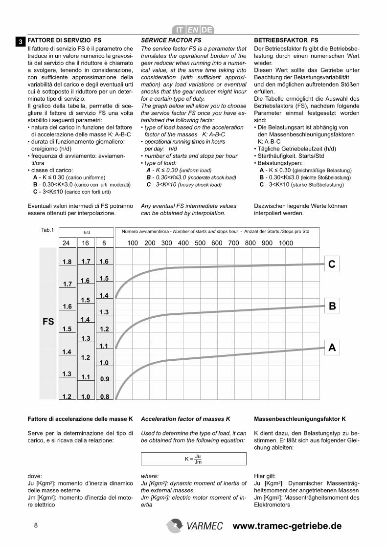
Il fattore di servizio FS è il parametro che traduce in un valore numerico la gravosi-tà del servizio che il riduttore è chiamato a svolgere, tenendo in considerazione, con sufficiente approssimazione della
variabilità del carico e degli eventuali urti cui è sottoposto il riduttore per un deter-minato tipo di servizio.Il grafico della tabella, permette di sce-gliere il fattore di servizio FS una volta stabilito i seguenti parametri:• natura del carico in funzione del fattore
di accelerazione delle masse K: A-B-C• durata di funzionamento giornaliero:
ore/giorno (h/d)• frequenza di avviamento: avviamen-
ti/ora• classe di carico:
A - K ≤ 0.30 (carico uniforme)B - 0.30<K≤3.0 (carico con urti moderati) C - 3<K≤10 (carico con forti urti)
Eventuali valori intermedi di FS potranno essere ottenuti per interpolazione.
Fattore di accelerazione delle masse K
Serve per la determinazione del tipo di carico, e si ricava dalla relazione:
dove:Ju [Kgm2]: momento d’inerzia dinamico delle masse esterne Jm [Kgm2]: momento d’inerzia del moto-re elettrico
Numero avviamenti/ora - Number of starts and stops hour - Anzahl der Starts /Stops pro Stdh/dTab.1
The service factor FS is a parameter that translates the operational burden of the gear reducer when running into a numer-ical value, at the same time taking into consideration (with sufficient approxi-mation) any load variations or eventual shocks that the gear reducer might incur for a certain type of duty.The graph below will allow you to choose the service factor FS once you have es-tablished the following facts:• type of load based on the acceleration
factor of the masses K: A-B-C• operational running times in hours
per day: h/d• number of starts and stops per hour
• type of load:
A - K ≤ 0.30 (uniform load)B - 0.30<K≤3.0 (moderate shock load) C - 3<K≤10 (heavy shock load)
Any eventual FS intermediate values can be obtained by interpolation.
Acceleration factor of masses K
Used to determine the type of load, it can be obtained from the following equation:
where:Ju [Kgm2]: dynamic moment of inertia of the external masses Jm [Kgm2]: electric motor moment of in-ertia
Der Betriebsfaktor fs gibt die Betriebsbe-lastung durch einen numerischen Wert wieder.Diesen Wert sollte das Getriebe unter Beachtung der Belastungsvariabilität und den möglichen auftretenden Stößen erfüllen.Die Tabelle ermöglicht die Auswahl des Betriebsfaktors (FS), nachdem folgende Parameter einmal festgesetzt worden sind:• Die Belastungsart ist abhängig von
den Massenbeschleunigungsfaktoren K: A-B-C
• Tägliche Getriebelaufzeit (h/d)
• Starthäufigkeit. Starts/Std
• Belastungstypen:
A - K ≤ 0.30 (gleichmäßige Belastung)B - 0.30<K≤3.0 (leichte Stoßbelastung) C - 3<K≤10 (starke Stoßbelastung)
Dazwischen liegende Werte können interpoliert werden.
Massenbeschleunigungsfaktor K
K dient dazu, den Belastungstyp zu be-stimmen. Er läßt sich aus folgender Glei-chung ableiten:
Hier gilt:Ju [Kgm2]: Dynamischer Massenträg-heitsmoment der angetriebenen Massen Jm [Kgm2]: Massenträgheitsmoment des Elektromotors
BETRIEBSFAKTOR FS
Ju Jm
K =
3
www.tramec-getriebe.de
9
FACTEUR DE SERVICE FS FACTOR DE SERVICIO FS
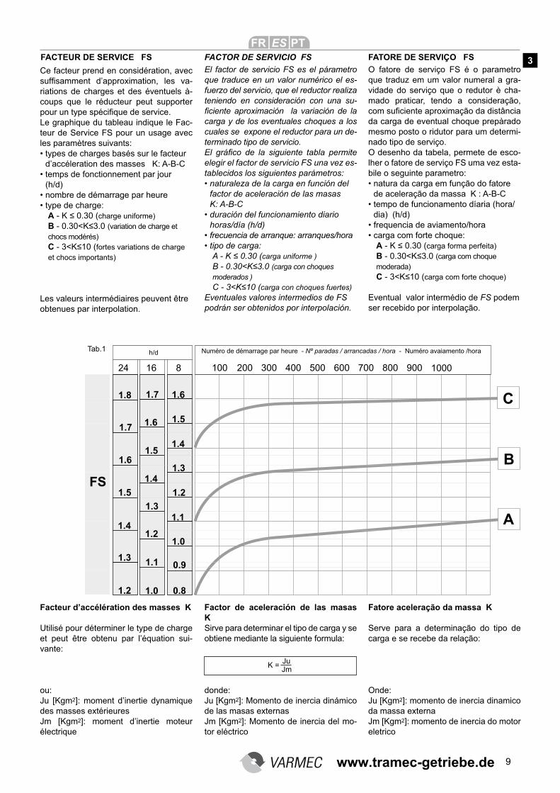
El factor de servicio FS es el párametro que traduce en un valor numérico el es-fuerzo del servicio, que el reductor realiza teniendo en consideración con una su-ficiente aproximación la variación de la
carga y de los eventuales choques a los cuales se expone el reductor para un de-terminado tipo de servicio. El gráfico de la siguiente tabla permite
elegir el factor de servicio FS una vez es-tablecidos los siguientes parámetros:• naturaleza de la carga en función del
factor de aceleración de las masas K: A-B-C
• duración del funcionamiento diario
horas/día (h/d)• frecuencia de arranque: arranques/hora
• tipo de carga:
A - K ≤ 0.30 (carga uniforme )B - 0.30<K≤3.0 (carga con choques moderados ) C - 3<K≤10 (carga con choques fuertes)
Eventuales valores intermedios de FS podrán ser obtenidos por interpolación.
Factor de aceleración de las masas KSirve para determinar el tipo de carga y se obtiene mediante la siguiente formula:
donde:Ju [Kgm2]: Momento de inercia dinámico de las masas externas Jm [Kgm2]: Momento de inercia del mo-tor eléctrico
O fatore de serviço FS é o parametro que traduz em um valor numeral a gra-vidade do serviço que o redutor è cha-mado praticar, tendo a consideração, com suficiente aproximação da distância
da carga de eventual choque prepàrado mesmo posto o ridutor para um determi-nado tipo de serviço.O desenho da tabela, permete de esco-lher o fatore de serviço FS uma vez esta-bile o seguinte parametro:• natura da carga em função do fatore
de aceleração da massa K : A-B-C• tempo de funcionamento díaria (hora/
dia) (h/d)• frequencia de aviamento/hora
• carga com forte choque:
A - K ≤ 0.30 (carga forma perfeita)B - 0.30<K≤3.0 (carga com choque moderada) C - 3<K≤10 (carga com forte choque)
Eventual valor intermédio de FS podem ser recebido por interpolação.
Fatore aceleração da massa K
Serve para a determinação do tipo de carga e se recebe da relação:
Onde:Ju [Kgm2]: momento de inercia dinamico da massa externa Jm [Kgm2]: momento de inercia do motor eletrico
FATORE DE SERVIÇO FS
Ce facteur prend en considération, avec suffisamment d’approximation, les va-riations de charges et des éventuels à-coups que le réducteur peut supporter pour un type spécifique de service.
Le graphique du tableau indique le Fac-teur de Service FS pour un usage avec les paramètres suivants:• types de charges basés sur le facteur
d’accéleration des masses K: A-B-C• temps de fonctionnement par jour
(h/d)• nombre de démarrage par heure
• type de charge:
A - K ≤ 0.30 (charge uniforme)B - 0.30<K≤3.0 (variation de charge et chocs modérés) C - 3<K≤10 (fortes variations de charge et chocs importants)
Les valeurs intermédiaires peuvent être obtenues par interpolation.
Facteur d’accélération des masses K
Utilisé pour déterminer le type de charge et peut être obtenu par l’équation sui-vante:
ou:Ju [Kgm2]: moment d’inertie dynamique des masses extérieures Jm [Kgm2]: moment d’inertie moteur électrique
Ju Jm
K =
Numéro de démarrage par heure - Nº paradas / arrancadas / hora - Numéro avaiamento /horah/dTab.1
3
www.tramec-getriebe.de
10
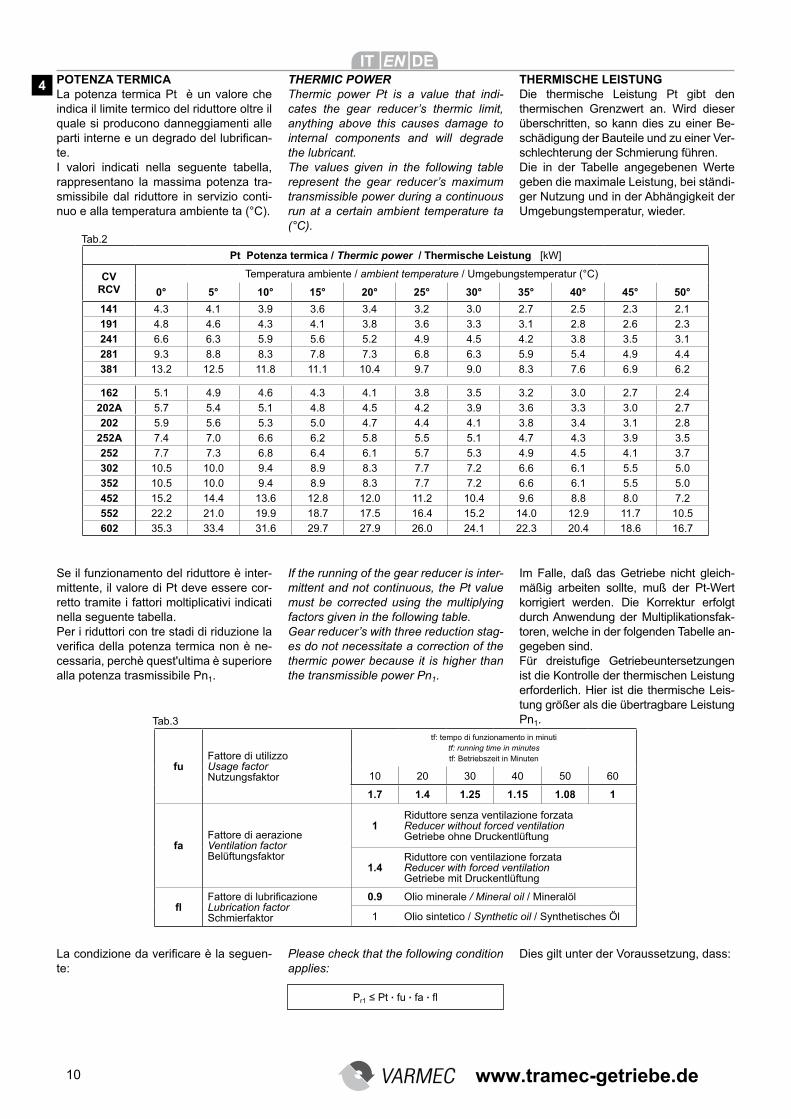
Pt Potenza termica / Thermic power / Thermische Leistung [kW]
CV RCV
Temperatura ambiente / ambient temperature / Umgebungstemperatur (°C)
0° 5° 10° 15° 20° 25° 30° 35° 40° 45° 50°
141 4.3 4.1 3.9 3.6 3.4 3.2 3.0 2.7 2.5 2.3 2.1
191 4.8 4.6 4.3 4.1 3.8 3.6 3.3 3.1 2.8 2.6 2.3
241 6.6 6.3 5.9 5.6 5.2 4.9 4.5 4.2 3.8 3.5 3.1
281 9.3 8.8 8.3 7.8 7.3 6.8 6.3 5.9 5.4 4.9 4.4
381 13.2 12.5 11.8 11.1 10.4 9.7 9.0 8.3 7.6 6.9 6.2
162 5.1 4.9 4.6 4.3 4.1 3.8 3.5 3.2 3.0 2.7 2.4
202A 5.7 5.4 5.1 4.8 4.5 4.2 3.9 3.6 3.3 3.0 2.7
202 5.9 5.6 5.3 5.0 4.7 4.4 4.1 3.8 3.4 3.1 2.8
252A 7.4 7.0 6.6 6.2 5.8 5.5 5.1 4.7 4.3 3.9 3.5
252 7.7 7.3 6.8 6.4 6.1 5.7 5.3 4.9 4.5 4.1 3.7
302 10.5 10.0 9.4 8.9 8.3 7.7 7.2 6.6 6.1 5.5 5.0
352 10.5 10.0 9.4 8.9 8.3 7.7 7.2 6.6 6.1 5.5 5.0
452 15.2 14.4 13.6 12.8 12.0 11.2 10.4 9.6 8.8 8.0 7.2
552 22.2 21.0 19.9 18.7 17.5 16.4 15.2 14.0 12.9 11.7 10.5
602 35.3 33.4 31.6 29.7 27.9 26.0 24.1 22.3 20.4 18.6 16.7
POTENZA TERMICALa potenza termica Pt è un valore che indica il limite termico del riduttore oltre il quale si producono danneggiamenti alle parti interne e un degrado del lubrifican-te. I valori indicati nella seguente tabella, rappresentano la massima potenza tra-smissibile dal riduttore in servizio conti-nuo e alla temperatura ambiente ta (°C).
Se il funzionamento del riduttore è inter-mittente, il valore di Pt deve essere cor-retto tramite i fattori moltiplicativi indicati nella seguente tabella.Per i riduttori con tre stadi di riduzione la verifica della potenza termica non è ne-cessaria, perchè quest'ultima è superiore alla potenza trasmissibile Pn1.
Pr1 ≤ Pt . fu . fa . fl
La condizione da verificare è la seguen-te:
fuFattore di utilizzo Usage factor Nutzungsfaktor
tf: tempo di funzionamento in minuti tf: running time in minutes tf: Betriebszeit in Minuten
10 20 30 40 50 60
1.7 1.4 1.25 1.15 1.08 1
faFattore di aerazione Ventilation factor Belüftungsfaktor
1Riduttore senza ventilazione forzata Reducer without forced ventilation Getriebe ohne Druckentlüftung
1.4Riduttore con ventilazione forzata Reducer with forced ventilation Getriebe mit Druckentlüftung
fl
Fattore di lubrificazione Lubrication factor Schmierfaktor
0.9 Olio minerale / Mineral oil / Mineralöl
1 Olio sintetico / Synthetic oil / Synthetisches Öl
THERMIC POWERThermic power Pt is a value that indi-cates the gear reducer’s thermic limit, anything above this causes damage to internal components and will degrade the lubricant.The values given in the following table represent the gear reducer’s maximum transmissible power during a continuous run at a certain ambient temperature ta (°C).
THERMISCHE LEISTUNGDie thermische Leistung Pt gibt den thermischen Grenzwert an. Wird dieser überschritten, so kann dies zu einer Be-schädigung der Bauteile und zu einer Ver-schlechterung der Schmierung führen. Die in der Tabelle angegebenen Werte geben die maximale Leistung, bei ständi-ger Nutzung und in der Abhängigkeit der Umgebungstemperatur, wieder.
If the running of the gear reducer is inter-mittent and not continuous, the Pt value must be corrected using the multiplying factors given in the following table.Gear reducer’s with three reduction stag-es do not necessitate a correction of the thermic power because it is higher than the transmissible power Pn1.
Im Falle, daß das Getriebe nicht gleich-mäßig arbeiten sollte, muß der Pt-Wert korrigiert werden. Die Korrektur erfolgt durch Anwendung der Multiplikationsfak-toren, welche in der folgenden Tabelle an-gegeben sind. Für dreistufige Getriebeuntersetzungen
ist die Kontrolle der thermischen Leistung erforderlich. Hier ist die thermische Leis-tung größer als die übertragbare Leistung Pn1.
Please check that the following condition applies:
Dies gilt unter der Voraussetzung, dass:
4
Tab.2
Tab.3
www.tramec-getriebe.de
11
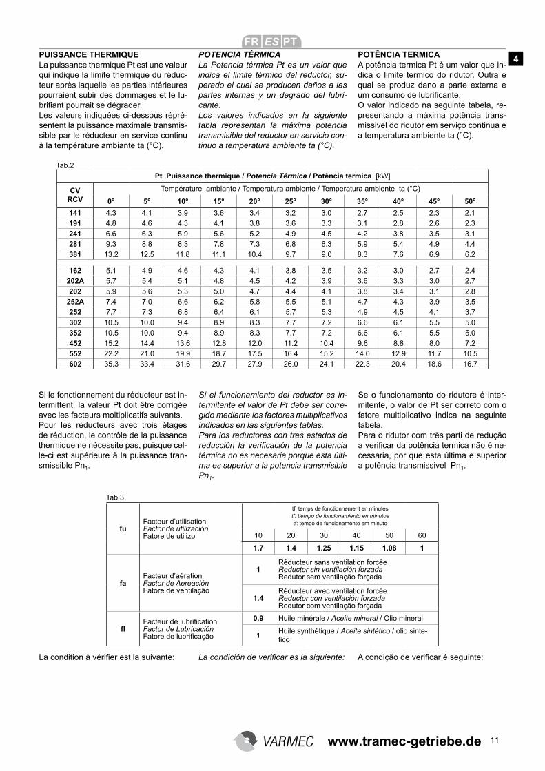
PUISSANCE THERMIQUELa puissance thermique Pt est une valeur qui indique la limite thermique du réduc-teur après laquelle les parties intérieures pourraient subir des dommages et le lu-brifiant pourrait se dégrader.
Les valeurs indiquées ci-dessous répré-sentent la puissance maximale transmis-sible par le réducteur en service continu à la température ambiante ta (°C).
POTENCIA TÉRMICALa Potencia térmica Pt es un valor que indica el limite térmico del reductor, su-perado el cual se producen daños a las partes internas y un degrado del lubri-cante.Los valores indicados en la siguiente tabla representan la máxima potencia transmisible del reductor en servicio con-tinuo a temperatura ambiente ta (°C).
POTÊNCIA TERMICAA potência termica Pt è um valor que in-dica o limite termico do ridutor. Outra e qual se produz dano a parte externa e um consumo de lubrificante.
O valor indicado na seguinte tabela, re-presentando a máxima potência trans-missivel do ridutor em serviço continua e a temperatura ambiente ta (°C).
Si le fonctionnement du réducteur est in-termittent, la valeur Pt doit être corrigée avec les facteurs moltiplicatifs suivants.Pour les réducteurs avec trois étages de réduction, le contrôle de la puissance thermique ne nécessite pas, puisque cel-le-ci est supérieure à la puissance tran-smissible Pn1.
Si el funcionamiento del reductor es in-termitente el valor de Pt debe ser corre-gido mediante los factores multiplicativos indicados en las siguientes tablas.Para los reductores con tres estados de reducción la verificación de la potencia
térmica no es necesaria porque esta últi-ma es superior a la potencia transmisible Pn1.
Se o funcionamento do ridutore é inter-mitente, o valor de Pt ser correto com o fatore multiplicativo indica na seguinte tabela.Para o ridutor com trēs parti de redução
a verificar da potência termica não é ne-cessaria, por que esta última e superior a potência transmissivel Pn1.
fuFacteur d’utilisation Factor de utilización Fatore de utilizo
tf: temps de fonctionnement en minutes tf: tiempo de funcionamiento en minutos tf: tempo de funcionamento em minuto
10 20 30 40 50 60
1.7 1.4 1.25 1.15 1.08 1
faFacteur d’aération Factor de Aereación Fatore de ventilação
1Réducteur sans ventilation forcéeReductor sin ventilación forzada Redutor sem ventilação forçada
1.4Réducteur avec ventilation forcéeReductor con ventilación forzada Redutor com ventilação forçada
fl
Facteur de lubrification Factor de Lubricación Fatore de lubrificação
0.9 Huile minérale / Aceite mineral / Olio mineral
1Huile synthétique / Aceite sintético / olio sinte-tico
La condition à vérifier est la suivante: La condición de verificar es la siguiente: A condição de verificar é seguinte:
4
Tab.2
Tab.3
Pt Puissance thermique / Potencia Térmica / Potência termica [kW]
CV RCV
Température ambiante / Temperatura ambiente / Temperatura ambiente ta (°C)
0° 5° 10° 15° 20° 25° 30° 35° 40° 45° 50°
141 4.3 4.1 3.9 3.6 3.4 3.2 3.0 2.7 2.5 2.3 2.1
191 4.8 4.6 4.3 4.1 3.8 3.6 3.3 3.1 2.8 2.6 2.3
241 6.6 6.3 5.9 5.6 5.2 4.9 4.5 4.2 3.8 3.5 3.1
281 9.3 8.8 8.3 7.8 7.3 6.8 6.3 5.9 5.4 4.9 4.4
381 13.2 12.5 11.8 11.1 10.4 9.7 9.0 8.3 7.6 6.9 6.2
162 5.1 4.9 4.6 4.3 4.1 3.8 3.5 3.2 3.0 2.7 2.4
202A 5.7 5.4 5.1 4.8 4.5 4.2 3.9 3.6 3.3 3.0 2.7
202 5.9 5.6 5.3 5.0 4.7 4.4 4.1 3.8 3.4 3.1 2.8
252A 7.4 7.0 6.6 6.2 5.8 5.5 5.1 4.7 4.3 3.9 3.5
252 7.7 7.3 6.8 6.4 6.1 5.7 5.3 4.9 4.5 4.1 3.7
302 10.5 10.0 9.4 8.9 8.3 7.7 7.2 6.6 6.1 5.5 5.0
352 10.5 10.0 9.4 8.9 8.3 7.7 7.2 6.6 6.1 5.5 5.0
452 15.2 14.4 13.6 12.8 12.0 11.2 10.4 9.6 8.8 8.0 7.2
552 22.2 21.0 19.9 18.7 17.5 16.4 15.2 14.0 12.9 11.7 10.5
602 35.3 33.4 31.6 29.7 27.9 26.0 24.1 22.3 20.4 18.6 16.7
www.tramec-getriebe.de
12
SCELTA
Per selezionare correttamente un ri-duttore o un motoriduttore, si consi-glia di operare come segue: Scelta motoriduttori RCVa) Determinare il fattore di servizio FS
in funzione del tipo di carico, del nu-mero di avviamenti/ora e del numero di ore di funzionamento giornaliero (tab.1).
b) Dalla coppia Mr2 conoscendo n2 e il rendimento dinamico (Rd), ricavare la potenza di entrata richiesta dall’appli-cazione: II valore Rd del riduttore è riportato nella tabella a pag. 6.
c) Ricercare fra le tabelle dei dati tecnici dei motoriduttori quella corrisponden-te ad una potenza motore:
Scegliere poi, in base alla velocità di uscita n2, il motoriduttore con un fat-tore di servizio FS calcolato maggiore o uguale al fattore di servizio FS della tabella 1.
Scelta dei riduttori CV e dei riduttori predisposti per motori IEC
a) Determinare il fattore di servizio Fs.
b) Conoscendo la coppia di uscita richie-sta dalla applicazione Mr2, si procede alla definizione della coppia di calco-lo:
c) Disponendo della coppia di calcolo Mc2 e del rapporto di riduzione [i], si ricercherà nelle tabelle il riduttore che, in funzione del rapporto [i] prossimo a quello calcolato, proponga una coppia nominale in uscita:
Se al riduttore scelto dovrà essere appli-cato un motore elettrico forma B5 verifi-carne l’applicabilità consultando le predi-sposizioni possibili (IEC B5, o IEC B14) riportate nelle tabelle dei dati tecnici.
Pm ≥ Pr1
Mc2 = Mr2 . FS
Mn2 ≥ Mc2
SELECTION
To correctly select a gear reducer or motor reducer, please follow these suggestions: Choosing a motor reducer RCVa) Determine the service factor FS
according to the type of load, the number of starts and stops per hour and the daily running hours (tab.1).
b) Providing that torque Mr2, speed n2 and dynamic efficiency Rd are known
you can obtain the input power required by the application using the following equation: The Rd value of the gear reducer is shown on page 6.
c) Consult the motor reducer technical data sheets and find the one corre-sponding to motor power:
Next, according to output speed n2, select a motor reducer having a cal-culated service factor FS higher than or equal to the service factor FS given in table 1.
Selecting CV gear reducers and redu-cers for IEC motors
a) Determine the service factor Fs.
b) Once you know the application requi-red output torque, the calculation of the torque can be defined:
c) Now that you have calculated the torque Mc2 and you also have the re-duction ratio [i], consult the tables to find the gear reducer that has a ratio
closest to your calculated ratio and gives a rated output torque of:
If an electric motor shape B5 has to be fit-ted to your chosen gear reducer, please verify just how feasible this is by check-ing the possible predispositions (IEC B5 or IEC B14) given in the technical data charts.
GETRIEBEAUSWAHL
Zur richtigen Getriebeauswahl sollte folgendes beachtet werden:
Auswahl des RCV – Getriebesa) Festlegung des Betriebsfaktors FS in
Abhängigkeit von der Belastung, der Starthäufigkeit pro Stunde und der
täglichen Betriebsdauer (Tabelle 1).
b) Ist das benötigte Abtriebsdrehmoment Mr2, die Abtriebsdrehzahl n2 und der
Wirkungsgrad µd bekannt, kann die Benötigte Leistung berechnet werden:
Der Wirkungsgrad Rd kann aus der Tabelle auf Seite 6 abgelesen werden.
c) Wählen Sie aus der Tabelle mit den technischen Daten das Getriebe aus, das die gewünschte Motorleistung angibt:
Dann wird, auf der Basis der Abtriebs-drehzahl n2, derjenige Getriebemotor ausgewählt, der einen Betriebsfaktor FS aufweist, welcher größer oder gleich dem Betriebsfaktor FS aus der Tabelle 1 ist..
Auswahl der CV-Getriebe und der Ge-triebe für IEC-Motoren
a) Festlegung des Betriebsfaktors fs.
b) Ist das benötigte Abtriebsdrehmoment Mr2 bekannt, kann das effektive Dreh-mome berechnet werden:
c) Nachdem Mc2 berechnet wurde und das Untersetzungsverhältnis [i] be-kannt ist, kann aus den Auswahlta-bellen jenes Getriebe ausgewählt werden, das dem berechneten in Un-tersetzung und Abtriebsdrehmoment am nächsten kommt:
Sollte das ausgewählte Getriebe mit ei-nem Drehstrommotor angetrieben wer-den, muss die Anbaumöglichkeit des Motors anhand der entsprechenden Aus-wahltabellen (IEC B5 oder IEC B14) ge-prüft werden.
Mr2 . n2
9550 . RdPr1 = [kW]
5
www.tramec-getriebe.de
13
SELECTION
Pour choisir correctement un réduc-teur ou un moto-réducteur utiliser la procédure suivante:
Sélection moto-réducteur RCVa) Déterminer le facteur de service FS
en fonction du type de charge, du numero de démarrages et du temps de fonctionnement par jour. (tab.1).
b) Du couple Mr2, connaissant n2 et le rendement dynamique (Rd) du réduc-teur, déterminer la puissance d’entrée nécessaire à l’application: Le valeur Rd du réducteur est indi-quée dans le tableau à pag. 7.
c) Rechercher parmis les tableaux des données techniques des moto-ré-ducteurs celle qui Corréspond à une puissance moteur:
Choisir, sur la base de la vitesse de sortie n2, le moto-réducteur avec fac-teur de service FS calculé supérieur ou égal au facteur de service FS du tableau 1.
Sélection des réducteurs CV et des réducteurs prévus pour moteur IEC
a) Déterminer le facteur de service FS.
b) Connaissant le couple de sortie né-cessaire à l’application Mr2, le calcul du couple se fait comme suit:
c) Connaissant Mc2 et [i], consulter la table de sélection des réducteurs en fonction de la vitesse n1 et choisir le réducteur qui suivant le rapport de réduction [i] le plus proche de celui calculé, fournira le couple nominal correspondant à:
Si le réducteur sélectionné doit être con-necté à un moteur électrique B5, contrô-ler cette possibilité en consultant les pré-dispositions possibles (IEC B5, ou IEC B 14) indiquées dans les tableaux des données techniques.
SELECCION
Para la correcta selección de un re-ductor o motorreductor se aconseja seguir los siguientes pasos:
Seleccion del motorreductor RCVa) Determinar el factor de servicio FS en
función del tipo de carga , del número de arranques/hora y del número de horas de funcionamiento diario (tab.1).
b) Del par motor Mr2, conociendo n2 y el rendimiento dinámico (Rd) recalcular la potencia de entrada requerida de la aplicación: El valor Rd reductor esta representa-do en la tabla a pag. 7.
c) Consultar entre las tablas de los da-tos técnicos de los motorreductores la que corresponde a una potencia del motor:
Después, en base a la velocidad de salida n2 seleccionar un motorreduc-tor con un factor de servicio FS calcu-lado, mayor o igual al factor de servi-cio FS de la tabla 1.
Selección de los reductores CV y de los motores predispuestos para mo-tores IEC
a) Determinar el factor de servicio FS.
b) Conociendo el par motor de salida para la aplicación Mr2, se procede a la definición del par motor calculado:
c) Disponiendo del par motor de cálculo Mc2 y de la relación de reducción [i], buscar en las tablas el reductor que en función de la relación [i] próximo al calculado proponga un motor nominal en salida:
Si al reductor seleccionado se le debe acoplar un motor eléctrico en forma B5 verificar su compatibilidad consultando
las predisposiciones posibles (IEC B5 - IEC B14)presentadas en las tablas de los datos técnicos.
ESCOLHA
Para selecionar corretamente um ri-dutor ou um motoridutor se aconse-lha de operar como segue: E s -Colha motoridutor RCVa) Determinar o fatore de serviço FS em
função o tipo de carga do número de aviamento/hora e do número de hora de funcionamento díaria (tab.1).
b) Da cópia Mr2 conhecendo n2 e o rendimento dinâmico (Rd) recebe a potência da aplicação:
O valor Rd ridutor é reportado na tabela a pag. 7.
c) Procura fazer a tabela do calculo tecnico do motoridutor aquela corres-pondente a uma potência motor:
Escolhendo depois, em base a velo-cidade de saida n2 o motoridutor com un fatore de serviço FS calculado maior ou igual ao fatore de serviço FS da tabela 1.
Escolha do ridutor CV e do ridutor predisposição para motor IEC
a) Determinar o fatore de serviço FS.
b) Conhecendo a cópia de saida da apli-cação Mr2, segue a definição da cópia
de cálculo:
c) Disposição da cópia de cálculo Mc2 e da razão de redução [i] se procurar na tabela o ridutor que em função da razão [i] proximo aquele calculo, pro-pondo uma cópia nominal em saida:
Se o ridutor escolhido deve ser aplica-do um motor elétrico forma B5 verificar
aplicação consultando a prédisposição possivel (IEC, B5 o IEC B14) riportar na tabela do calcúlo tecnico.
Mn2 ≥ Mc2
Mc2 = Mr2 . FS
Pm ≥ Pr1
Mr2 . n2
9550 . RdPr1 = [kW]
5
www.tramec-getriebe.de
14
VERIFICHE
Effettuata la corretta selezione del ridut-tore o motoriduttore, si consiglia di proce-dere alle seguenti verifiche:
Momento torcente massimoI sovraccarichi istantanei previsti dall’ap-plicazione non devono essere superiori al doppio dei valori di momento torcente del riduttore riportati a catalogo.
Potenza termicaLa potenza termica del riduttore deve avere un valore uguale o maggiore della potenza richiesta dall'applicazione (pag. 10).
Carichi radiali e assialiI carichi radiali e assiali agenti sugli alberi lenti e veloci devono rientrare nei valori di catalogo ammessi.
CHECK POINTS
Once you have correctly chosen the type of gear reducer or gearmotor, it is then advisable to check that the following ap-ply:
Maximum torqueThe maximum torque at instantaneous peak overloads of the application must not be higher than the double of the torque values of the gear reducer given in this catalogue.
Thermic powerA gear reducer’s thermic power value must be equal to or higher than the power needed by the appliance. (See pg. 10).
Radial and thrust loadsRadial and thrust loads on the input and output shafts must be within the permis-sible loads given in this catalogue.
NACHKONTROLLEN
Nachdem das richtige Getriebe bzw. der richtige Getriebemotor ausgewählt wur-de, empfehlen wir folgende Überprüfun-gen durchzuführen:
Maximales Drehmoment Die unmittelbaren Überbelastungen, welche von der Anwendung vorgesehen sind, dürfen nicht mehr als das Doppelte der im Katalog angegebenen Drehmo-mentwerte sein.
Thermische LeistungDie thermische Leistung des Getriebes sollte einen Wert größer oder gleich dem Wert haben, der der benötigten Leistung der Anwendung entspricht (s.S.10).
Radial und AxialbelastungDie Radial- und Axialbelastungen, welche auf die Ein - und Abtriebswellen wirken, sollten innerhalb der zugelassenen Kata-logwerte liegen.
6
www.tramec-getriebe.de
15
CONTROLES
Après avoir correctement sélectionné le réducteur ou moto-réducteur, il est re-commandé de vérifier ce qui suit:
Couple maximumLes surcharges instantanés prévues par l’application ne doivent pas excéder le double des valeurs du couple du réduc-teur indiquées dans le catalogue.
Puissance thermiqueLa puissance thermique du réducteur doit avoir une valeur supérieure ou égale à la puissance nécessaire à l’application (pag. 11).
Charges radiales et axialesLes charges radiales et axiales sur l’arbre d’entrée et de sortie doivent être dans les valeurs données.
VERIFICACIONES
Efectuada la correcta selección delreductor o moterreductor, se aconsejade proceder a las siguientes verificacio-nes:
Momento Torsor máximoLas sobrecargas instantáneas previstasen la aplicación no tienen que ser supe-riores al doble de los valores del momen-to torsor del reductor presentados en el catálogo.
Potencia TérmicaLa Potencia térmica del reductor debetener un valor igual o mayor a la Poten-cia requerida de la aplicación pag.11.
Cargas radiales y axialesLas cargas radiales y axiales que actúan en los ejes lentos (salida) y rápidos (en-trada) deben entrar en los valores admi-tidos en el catálogo.
VERIFIQUE
Efetuada a correta seleção do ridutor ou motoridutor se aconselha de seguir a se-guinte verificação:
Momento de torção maximoMais carga instantane previsto da aplica-ção não deve ser superior a dobro do va-lor do momento torção do ridutor riporta a catalogo.
Potência termicaA potência termica do ridutor deve ter um valor igual ou maior da potência da apli-cação (pag. 11).
Cargue radial e empuxoA cargue radial e empuxo em função ao eixo lento e veloz devem rientrare no va-lor do catalogo metido.
6
www.tramec-getriebe.de
16
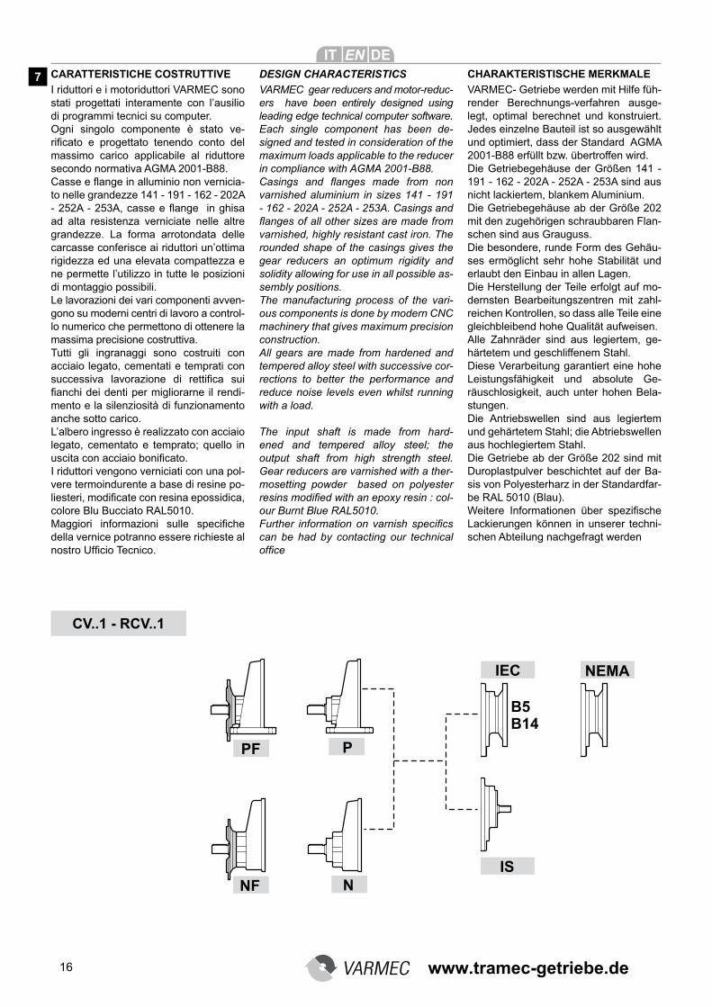
CARATTERISTICHE COSTRUTTIVE
I riduttori e i motoriduttori VARMEC sono stati progettati interamente con l’ausilio di programmi tecnici su computer.Ogni singolo componente è stato ve-rificato e progettato tenendo conto del
massimo carico applicabile al riduttore secondo normativa AGMA 2001-B88.Casse e flange in alluminio non vernicia-to nelle grandezze 141 - 191 - 162 - 202A - 252A - 253A, casse e flange in ghisa
ad alta resistenza verniciate nelle altre grandezze. La forma arrotondata delle carcasse conferisce ai riduttori un’ottima rigidezza ed una elevata compattezza e ne permette l’utilizzo in tutte le posizioni di montaggio possibili.Le lavorazioni dei vari componenti avven-gono su moderni centri di lavoro a control-lo numerico che permettono di ottenere la massima precisione costruttiva.Tutti gli ingranaggi sono costruiti con acciaio legato, cementati e temprati con successiva lavorazione di rettifica sui
fianchi dei denti per migliorarne il rendi-mento e la silenziosità di funzionamento anche sotto carico. L’albero ingresso è realizzato con acciaio legato, cementato e temprato; quello in uscita con acciaio bonificato.
I riduttori vengono verniciati con una pol-vere termoindurente a base di resine po-liesteri, modificate con resina epossidica,
colore Blu Bucciato RAL5010. Maggiori informazioni sulle specifiche
della vernice potranno essere richieste al nostro Ufficio Tecnico.
CV..1 - RCV..1
DESIGN CHARACTERISTICS
VARMEC gear reducers and motor-reduc-ers have been entirely designed using leading edge technical computer software.Each single component has been de-signed and tested in consideration of the maximum loads applicable to the reducer in compliance with AGMA 2001-B88.Casings and flanges made from non
varnished aluminium in sizes 141 - 191 - 162 - 202A - 252A - 253A. Casings and
flanges of all other sizes are made from
varnished, highly resistant cast iron. The rounded shape of the casings gives the gear reducers an optimum rigidity and solidity allowing for use in all possible as-sembly positions.The manufacturing process of the vari-ous components is done by modern CNC machinery that gives maximum precision construction.All gears are made from hardened and tempered alloy steel with successive cor-rections to better the performance and reduce noise levels even whilst running with a load.
The input shaft is made from hard-ened and tempered alloy steel; the output shaft from high strength steel. Gear reducers are varnished with a ther-mosetting powder based on polyester resins modified with an epoxy resin : col-our Burnt Blue RAL5010. Further information on varnish specifics
can be had by contacting our technical office
CHARAKTERISTISCHE MERKMALE
VARMEC- Getriebe werden mit Hilfe füh-render Berechnungs-verfahren ausge-legt, optimal berechnet und konstruiert. Jedes einzelne Bauteil ist so ausgewählt und optimiert, dass der Standard AGMA 2001-B88 erfüllt bzw. übertroffen wird.Die Getriebegehäuse der Größen 141 - 191 - 162 - 202A - 252A - 253A sind aus nicht lackiertem, blankem Aluminium.Die Getriebegehäuse ab der Größe 202 mit den zugehörigen schraubbaren Flan-schen sind aus Grauguss.Die besondere, runde Form des Gehäu-ses ermöglicht sehr hohe Stabilität und erlaubt den Einbau in allen Lagen.Die Herstellung der Teile erfolgt auf mo-dernsten Bearbeitungszentren mit zahl-reichen Kontrollen, so dass alle Teile eine gleichbleibend hohe Qualität aufweisen.Alle Zahnräder sind aus legiertem, ge-härtetem und geschliffenem Stahl. Diese Verarbeitung garantiert eine hohe Leistungsfähigkeit und absolute Ge-räuschlosigkeit, auch unter hohen Bela-stungen.Die Antriebswellen sind aus legiertem und gehärtetem Stahl; die Abtriebswellen aus hochlegiertem Stahl.Die Getriebe ab der Größe 202 sind mit Duroplastpulver beschichtet auf der Ba-sis von Polyesterharz in der Standardfar-be RAL 5010 (Blau). Weitere Informationen über spezifische
Lackierungen können in unserer techni-schen Abteilung nachgefragt werden
7
www.tramec-getriebe.de
17
CV..2-3 - RCV..2-3
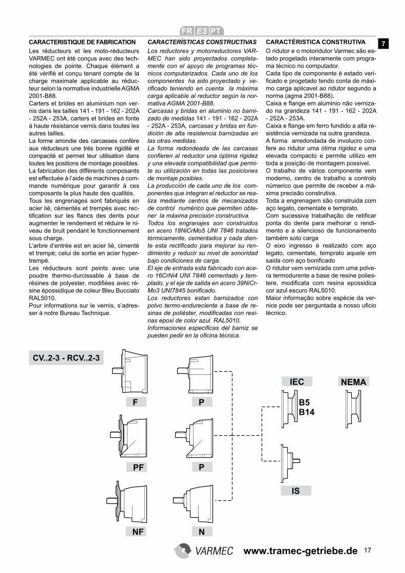
CARACTERISTIQUE DE FABRICATION
Les réducteurs et les moto-réducteurs VARMEC ont été conçus avec des tech-nologies de pointe. Chaque élément a été vérifié et conçu tenant compte de la
charge maximale applicable au réduc-teur selon la normative industrielle AGMA 2001-B88.Carters et brides en aluminium non ver-nis dans les tailles 141 - 191 - 162 - 202A - 252A - 253A, carters et brides en fonte à haute résistance vernis dans toutes les autres tailles.La forme arrondie des carcasses confère aux réducteurs une trés bonne rigidité et compacité et permet leur utilisation dans toutes les positions de montage possibles.La fabrication des différents composants est effectuée à l’aide de machines à com-mande numérique pour garantir à ces composants la plus haute des qualités.Tous les engrenages sont fabriqués en acier lié, cémentés et trempés avec rec-tification sur les flancs des dents pour
augmenter le rendement et réduire le ni-veau de bruit pendant le fonctionnement sous charge.L’arbre d’entrée est en acier lié, cimenté et trempé; celui de sortie en acier hyper-trempé.Les réducteurs sont peints avec une poudre thermo-durcissable à base de résines de polyester, modifiées avec ré-sine épossidique de coleur Bleu Bucciato RAL5010.Pour informations sur le vernis, s’adres-ser à notre Bureau Technique.
CARACTERÍSTICAS CONSTRUCTIVAS
Los reductores y motorreductores VAR-MEC han sido proyectados completa-mente con el apoyo de programas téc-nicos computarizados. Cada uno de los componentes ha sido proyectado y ve-rificado teniendo en cuenta la máxima
carga aplicable al reductor según la nor-mativa AGMA 2001-B88.Carcasas y bridas en aluminio no barni-zado de medidas 141 - 191 - 162 - 202A - 252A - 253A, carcasas y bridas en fun-dición de alta resistencia barnizadas en las otras medidas. La forma redondeada de las carcasas confieren al reductor una óptima rigidez
y una elevada compatibilidad que permi-te su utilización en todas las posiciones de montaje posibles. La producción de cada uno de los com-ponentes que integran el reductor se rea-liza mediante centros de mecanizados de control numérico que permiten obte-ner la máxima precisión constructiva.Todos los engranajes son construidos en acero 18NiCrMo5 UNI 7846 tratados térmicamente, cementados y cada dien-te esta rectificado para mejorar su ren-dimiento y reducir su nivel de sonoridad bajo condiciones de carga. El eje de entrada esta fabricado con ace-ro 16CrNi4 UNI 7846 cementado y tem-plado, y el eje de salida en acero 39NiCr-Mo3 UNI7845 bonificado.
Los reductores estan barnizados con polvo termo-endureciente a base de re-sinas de poliéster, modificadas con resi-nas epoxi de color azul RAL5010.Informaciones especificas del barniz se
pueden pedir en la oficina técnica.
CARACTÉRISTICA CONSTRUTIVA
O ridutor e o motoridutor Varmec são es-tado progetado interamente com progra-ma técnico no computador.Cada tipo de componente è estado veri-ficado e progetado tendo conta de máxi-mo carga aplicavel ao ridutor segundo a norma (agma 2001-B88).Caixa e flange em aluminio não verniza-do na grandeza 141 - 191 - 162 - 202A - 252A - 253A. Caixa e flange em ferro fundido a alta re-sistência vernizada na outra grandeza.A forma arredondada de involucro con-fere ao ridutor uma ótima rigidez e uma elevada compacto e permite utilizo em toda a posição de montagem possivel.O trabalho de vários componente vem moderno, centro de trabalho a controlo númerico que permite de receber a má-xima precisão construtiva.Toda a engrenagem são construida com aço legato, cementate e temprato.Com sucessiva trabalhação de retificar
ponta do dente para melhorar o rendi-mento e a silencioso de funcionamento também soto cargaO eixo ingresso è realizado com aço legato, cementate, temprato aquele em saida com aço bonificado
O ridutor vem vernizada com uma polve-ra termodurente a base de resine polies-tere, modificata com resina epossidica
cor azul escuro RAL5010. Maior informação sobre espécie da ver-nice pode ser perguntada a nosso uficio
técnico.
7
www.tramec-getriebe.de
18
DESIGNAZIONE / DESIGNATION / GETRIEBEBEZEICHUNGEN / DESIGNATION / DESIGNACION / DESIGNAÇÃO
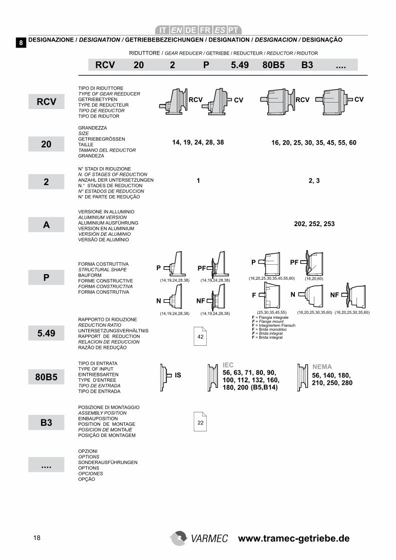
RCV 20 2 P 5.49 80B5 B3 ....
RCV
20
2
TIPO DI RIDUTTORE TYPE OF GEAR REEDUCER GETRIEBETYPEN TYPE DE REDUCTEUR TIPO DE REDUCTOR TIPO DE RIDUTOR
GRANDEZZA SIZE GETRIEBEGRÖSSEN TAILLE TAMANO DEL REDUCTOR GRANDEZA
N° STADI DI RIDUZIONE N. OF STAGES OF REDUCTION ANZAHL DER UNTERSETZUNGEN N.° STADES DE REDUCTION N° ESTADOS DE REDUCCION N° DE PARTE DE REDUÇÃO
FORMA COSTRUTTIVA STRUCTURAL SHAPE BAUFORM FORME CONSTRUCTIVE FORMA CONSTRUCTIVA FORMA CONSTRUTIVA
RAPPORTO DI RIDUZIONE REDUCTION RATIO UNTERSETZUNGSVERHÄLTNIS RAPPORT DE REDUCTION RELACION DE REDUCCION RAZÃO DE REDUÇÃO
TIPO DI ENTRATA TYPE OF INPUT EINTRIEBSARTEN TYPE D’ENTREE TIPO DE ENTRADA TIPO DE ENTRADA
POSIZIONE DI MONTAGGIO ASSEMBLY POSITION EINBAUPOSITION POSITION DE MONTAGE POSICION DE MONTAJE POSIÇÃO DE MONTAGEM
OPZIONI OPTIONSSONDERAUSFÜHRUNGEN OPTIONSOPCIONESOPÇÃO
P
5.49
80B5
B3
....
14, 19, 24, 28, 38 16, 20, 25, 30, 35, 45, 55, 60
1 2, 3
42
22
RIDUTTORE / GEAR REDUCER / GETRIEBE / REDUCTEUR / REDUCTOR / RIDUTOR
8
F = Flangia integrale F = Flange mount F = Integriertem Flansch F = Bride monobloc F = Brida integral F = Brida integral
(16,20,25,30,35,45,55,60)
(25,30,35,45,55)
(16,20,60)
(16,20,25,30,35,60) (16,20,25,30,35,60)
(14,19,24,28,38) (14,19,24,28,38)
(14,19,24,28,38) (14,19,24,28,38)
A
VERSIONE IN ALLUMINIO ALUMINIUM VERSION ALUMINIUM AUSFÜHRUNG VERSION EN ALUMINIUM VERSIÓN DE ALUMINIO VERSÃO DE ALUMÍNIO
202, 252, 253
www.tramec-getriebe.de
19
Opzioni riduttori
AV Anelli di tenuta in entrata e uscita in Viton
EV Anelli di tenuta in entrata in Viton (pag. 93-99)
EX Riduttore in versione AtexOA I riduttori sono forniti con olio lubrifi-
cante alimentareOS I riduttori della serie CV-RCV 45-55-
60 solitamente sprovvisti di lubrifi-cante, vengono forniti con olio sin-tetico
AU Dimensione dell’albero lento diverso dallo standard (specificare le dimen-sioni)
ME Riduttore con motore elettrico (spe-cificare le caratteristiche del motore elettrico)
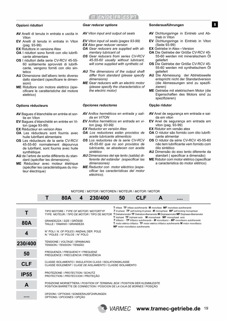
T 80A 4 230/400 50 CLF A ....
TIPO MOTORE / TYPE OF MOTOR / MOTORTYP TYPE MOTEUR / TIPO DE MOTOR / TIPO DE MOTOR
GRANDEZZA / SIZE / GRÖSSE TAILLE / TAMANO / GRANDEZA
N° POLI / N. OF POLES / ANZAHL DER POLE N.° POLES / N° POLOS / N° PÓLO
TENSIONE / VOLTAGE / SPANNUNG TENSION / TENSION / TENSÃO
MOTORE / MOTOR / MOTOREN / MOTEUR / MOTOR / MOTOR
FREQUENZA / FREQUENCY / FREQUENZ FREQUENCE / FRECUENCIA / FREQÜÊNCIA
CLASSE ISOLAMENTO / INSULATION CLASS / ISOLATIONSKLASSE CLASSE ISOLEMENT / CLASE DE AISLAMIENTO / CLASSE ISOLAMENTO
POSIZIONE MORSETTIERA / POSITION OF TERMINAL BOX / POSITION DER KLEMMLEISTE POSITION BARRETTE DE CONNECTION / POSICION DE LA CAJA DE BORNES / POSIÇÃO
OPZIONI / OPTIONS / SONDERAUSFÜHRUNGEN OPTIONS / OPCIONES / OPÇÃO
T
80A
4
230/400
50
CLF
IP55
A
Gear reducer options
AV Viton input and output oil seals
EV Viton input oil seals (pages 93-99)EX Atex gear reducer versionOA Gear reducers are supplied with ali-
mentary lubricant oilOS Gear reducers from series CV-RCV
45-55-60 usually without lubricant, will come supplied with synthetic oil
AU The dimensions of the output shaft differ from standard (please specify dimensions)
ME Gear reducers with an electric motor (please specify the characteristics of the electric motor)
Sonderausführungen
AV Dichtungsringe in Eintrieb und Ab-trieb in Viton
EV Dichtungsringe in Eintrieb in Viton (Seite 93-99)
EX Getriebe in Atex—VersionOA Die Getriebe der Größe CV-RCV 45-
55-60 werden mit mineralischem Öl geliefert
OS Die Getriebe der Größe CV-RCV 45-55-60 werden mit synthetischem Öl geliefert
AU Die Abmessung der Abtriebswelle entspricht nicht der Standardversion (die Abmessungen sind zu spezifi-zieren)
ME Getriebe mit elektrischem Motor (die Eigenschaften des Motors sind zu spezifizieren)
Options réducteurs
AV Bagues d’étanchéite en entrée et sor-tie en Viton
EV Bagues d’étanchéité en entrée en Vi-ton (page 93-99)
EX Réducteur en version AtexOA Les réducteurs sont fournis avec
huile lubrifiant alimentaireOS Les réducteurs de la serie CV-RCV
45-55-60 normalement dépourvus de lubrifiant, sont fournis avec huile synthétique
AU de l’arbre de sortie différents du stan-dard (spécifier les dimensions).
ME Réducteur avec moteur életrique (spécifier les caractéristiques du mo-teur électrique)
Opciones reductores
AV Anillos herméticos en entrada y sali-da en VITON
EV Anillos herméticos en entrada en vi-ton (pag. 93-99)
EX Reductor en versión AtexOA Los reductores están provistos de
aceite lubricante alimenticioOS Los reductores de la serie CV-RCV
45-55-60 que no son provistos de lubricante, se abastecen con aceite sintético
AU Dimensiones del eje lento (salida) di-ferente del estándar (especificar las dimensiones)
ME Reductor con motor eléctrico (espe-cificar las características del motor eléctrico).
Opção ridutor
AV Anel de segurança em entrada e sai-da em viton
EV Anel de segurança em entrada em viton (pag. 93-99)
EX Ridutor em versão atexOA O ridutor são fornido com ólio lubrifi-
cante alimentarOS O ridutor da série CV-RCV 45-55-60
não tem lubrificante vem fornido com ólio sintético
AU Dimensão do eixo lento diferente da standart ( specificar a dimensão)
ME Ridutor com motor elétrico (specificar a caracteristica do motor elétrico)
....
PROTEZIONE / PROTECTION / SCHUTZ PROTECTION / PROTECCION / PROTEÇÃO
T trifase TF trifase autofrenante M monofase MF monofase autofrenante
T tri-phase TF self-locking tri-phase M monophase MF self-locking monophase
T Drehstrommotor TF Drehstrom-Bremsmotor M Einphasenmotor MF Einphasen-Bremsmotor T triphasé TF triphasé auto M monophasé MF monophasé autoT trifàsico - TF trifàsico autofrenante - M monofasico - MF monofasico autofrenanteT motor elétrico trifásico TF motor elétrico trifásico autofrenante M motor monofásico MF motor monofásico autofrenante
8
www.tramec-getriebe.de
20
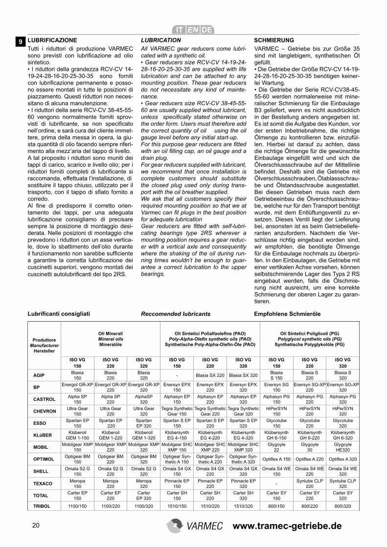
LUBRIFICAZIONE LUBRICATION
Tutti i riduttori di produzione VARMEC sono previsti con lubrificazione ad olio sintetico.• I riduttori della grandezza RCV-CV 14-19-24-28-16-20-25-30-35 sono forniti con lubrificazione permanente e posso-no essere montati in tutte le posizioni di piazzamento. Questi riduttori non neces-sitano di alcuna manutenzione.• I riduttori della serie RCV-CV 38-45-55-60 vengono normalmente forniti sprov-visti di lubrificante, se non specificato nell’ordine, e sarà cura del cliente immet-tere, prima della messa in opera, la giu-sta quantità di olio facendo sempre riferi-mento alla mezz’aria del tappo di livello.A tal proposito i riduttori sono muniti dei tappi di carico, scarico e livello olio; per i riduttori forniti completi di lubrificante si raccomanda, effettuata l’installazione, disostituire il tappo chiuso, utilizzato per il trasporto, con il tappo di sfiato fornito a corredo.Al fine di predisporre il corretto orien-tamento dei tappi, per una adeguata lubrificazione consigliamo di precisare sempre la posizione di montaggio desi-derata. Nelle posizioni di montaggio che prevedono i riduttori con un asse vertica-le, dove lo sbattimento dell’olio durante il funzionamento non sarebbe sufficiente a garantire la corretta lubrificazione dei cuscinetti superiori, vengono montati dei cuscinetti autolubrificanti del tipo 2RS.
ProduttoreManufacturer
Hersteller
Oli MineraliMineral oilsMineralöle
Oli Sintetici Polialfaolefine (PAO)Poly-Alpha-Olefin synthetic oils (PAO)
Synthetische Poly-Alpha-Olefin-Öle (PAO)
Oli Sintetici Poliglicoli (PG)Polyglycol synthetic oils (PG)
Synthetische Polyglykolöle (PG)
ISO VG ISO VG ISO VG ISO VG ISO VG ISO VG ISO VG ISO VG ISO VG 150 220 320 150 220 320 150 220 320
AGIP Blasia 150
Blasia 220
Blasia 320
- Blasia SX 220 Blasia SX 320 Blasia S 150
Blasia S 220
Blasia S 320
BP Energol GR-XP
150 Energol GR-XP
220 Energol GR-XP
320 Enersyn EPX
150 Enersyn EPX
220 Enersyn EPX
320 Enersyn SG
150 Enersyn SG-XP
220 Enersyn SG-XP
320
CASTROL Alpha SP
150 Alpha SP
220 AlphaSP
320 Alphasyn EP
150 Alphasyn EP
220 Alphasyn EP
320 Alphasyn PG
150 Alphasyn PG
220 Alphasyn PG
320
CHEVRON Ultra Gear
150 Ultra Gear
220 Ultra Gear
320 Tegra Synthetic
Gear 150 Tegra Synthetic
Gear 220 Tegra Synthetic
Gear 320 HiPerSYN
150 HiPerSYN
220 HiPerSYN
320
ESSO Spartan EP
150 Spartan EP
220 Spartan EP 320
Spartan S EP 150
Spartan S EP 220
Spartan S EP 320
Glycolube 150
Glycolube 220
Glycolube 320
KLüBER Klüberoil
GEM 1-150 Klüberoil
GEM 1-220 Klüberoil
GEM 1-320 Klübersynth EG 4-150
Klübersynth EG 4-220
Klübersynth EG 4-320
Klübersynth GH 6-150
Klübersynth GH 6-220
Klübersynth GH 6-320
MOBIL Mobilgear XMP
150 Mobilgear XMP
220 Mobilgear XMP
320 Mobilgear SHC
XMP 150 Mobilgear SHC
XMP 220 Mobilgear SHC
XMP 320 Glygoyle
22 Glygoyle
30 Glygoyle HE320
OPTIMOL Optigear BM
150 Optigear BM
220 Optigear BM
320 Optigear Syn-thetic A 150
Optigear Syn-thetic A 220
Optigear Syn-thetic A 320
Optiflex A 150 Optiflex A 220 Optiflex A 320
SHELL Omala S2 G
150 Omala S2 G
220 Omala S2 G
320 Omala S4 GX
150 Omala S4 GX
220 Omala S4 GX
320 Omala S4 WE
150 Omala S4 WE
220 Omala S4 WE
320
TEXACO Meropa
150 Meropa
220 Meropa
320 Pinnacle EP
150 Pinnacle EP
220 Pinnacle EP
320 -
Synlube CLP 220
Synlube CLP 320
TOTAL Carter EP
150 Carter EP
220 Carter EP 320
Carter SH 150
Carter SH 220
Carter SH 320
Carter SY 150
Carter SY 220
Carter SY 320
TRIBOL 1100/150 1100/220 1100/320 1510/150 1510/220 1510/320 800\150 800\220 800\320
Lubrificanti consigliati
SCHMIERUNG
All VARMEC gear reducers come lubri-cated with a synthetic oil.• Gear reducers size RCV-CV 14-19-24-28-16-20-25-30-35 are supplied with life lubrication and can be attached to any mounting position. These gear reducers do not necessitate any kind of mainte-nance.• Gear reducers size RCV-CV 38-45-55-60 are usually supplied without lubricant, unless specifically stated otherwise on the order form. Users must therefore add the correct quantity of oil using the oil gauge level before any initial start-up.For this purpose gear reducers are fitted with an oil filling cap, an oil gauge and a drain plug. For gear reducers supplied with lubricant, we recommend that once installation is complete customers should substitute the closed plug used only during trans-port with the oil breather supplied.We ask that all customers specify their required mounting position so that we at Varmec can fit plugs in the best position for adequate lubricationGear reducers are fitted with self-lubri-cating bearings type 2RS wherever a mounting position requires a gear reduc-er with a vertical axle and consequently where the shaking of the oil during run-ning times wouldn’t be enough to guar-antee a correct lubrication to the upper bearings.
VARMEC – Getriebe bis zur Größe 35 sind mit langlebigem, synthetischen Öl gefüllt.• Die Getriebe der Größe RCV-CV 14-19-24-28-16-20-25-30-35 benötigen keiner-lei Wartung. • Die Getriebe der Serie RCV-CV38-45-55-60 werden normalerweise mit mine-ralischer Schmierung für die Einbaulage B3 geliefert, wenn es nicht ausdrücklich in der Bestellung anders angegeben ist. Es ist somit die Aufgabe des Kunden, vor der ersten Inbetriebnahme, die richtige Ölmenge zu kontrollieren bzw. einzufül-len. Hierbei ist darauf zu achten, dass die richtige Ölmenge für die gewünschte Einbaulage eingefüllt wird und sich die Ölverschlussschraube auf der Mittellinie befindet. Deshalb sind die Getriebe mit Ölverschlussschrauben, Ölablassschrau-be und Ölstandsschraube ausgestattet. Bei diesen Getrieben muss nach dem Getriebeeinbau die Ölverschlussschrau-be, welche nur für den Transport benötigt wurde, mit dem Entlüftungsventil zu er-setzen. Dieses Ventil liegt der Lieferung bei, ansonsten ist es beim Getriebeliefe-ranten anzufordern. Nachdem die Ver-schlüsse richtig eingebaut worden sind, wir empfohlen, die benötigte Ölmenge für die Einbaulage nochmals zu überprü-fen. In den Einbaulagen, die Getriebe mit einer vertikalen Achse vorsehen, können selbstschmierende Lager des Typs 2 RS eingebaut werden, falls die Ölschmie-rung nicht ausreicht, um eine korrekte Schmierung der oberen Lager zu garan-tieren.
Reccomended lubricants Empfohlene Schmieröle
9
www.tramec-getriebe.de
21
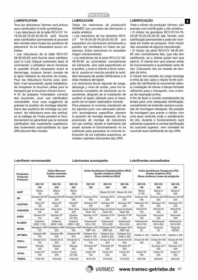
LUBRIFICATION LUBRICACIÓN LUBRIFICAÇÃO
Tous les réducteurs Varmec sont prévus avec lubrification à huile synthétique.
• Les réducteurs de la taille RCV-CV 14-
19-24-28-16-20-25-30-35 sont fournis avec lubrification permanente et peuvent
être montés dans toutes les positions de placement. Ils ne nécessitent aucun en-tretien.• Les réducteurs de la taille RCV-CV
38-45-55-60 sont fournis sans lubrifiant,
sauf si c’est indiqué autrement dans la commande. L’utilisateur devra introduire la quantité d’huile nécessaire avant le demarrage, toujours tenant compte de la ligne médiane du bouchon de niveau. Pour les réducteurs fournis avec lubri-fiant, il est recomandé, après installation,
de remplacer le bouchon utilisé pour le transport par le bouchon d’évent fourni.A fin de préparer l’orientation correcte
des bouchons, pour une lubrification
convenable, nous vous suggérons de préciser la position de montage désirée. Dans des positions de montage qui pré-voient les réducteurs avec axe vertical, où le battage de l’huile pendant le fonc-tionnement ne garantirait pas la correcte lubrification des roulements supérieurs,
des roulements auto-lubrifiants du type
2RS devront être montés.
Todos los reductores de producción VARMEC son provistos de lubricación a aceite sintético.• Los reductores de los tamaños RCV-
CV 14-19-24-28-16-20-25-30-35 son
equipados con lubricación permanente y pueden ser montados en todas las po-siciones. Estos reductores no necesitan ningún mantenimiento.• Los reductores de la serie RCV-CV 38-
45-55-60 se suministran normalmente sin lubricante, sino está especificado en
el pedido, y será el cliente a fornir antes de la puesta en marcha pondrá la canti-dad necesaria de aceite refiriéndose a la
línea mediana del tapón.Los reductores llevan tapones de carga, descarga y nivel de aceite, para los re-ductores completos de lubricante se re-comienda, después de la instalación de sustituir el tapón utilizado para el trans-porte con el tapón respiradero incluido.Para preparar la correcta orientación de los tapones para una adecuada lubrica-ción aconsejamos especificar siempre
la posición de montaje deseada. En las posiciones de montaje de reductores con eje vertical, donde el batimiento del aceite durante el funcionamiento no es suficiente para garantizar la correcta lu-bricación de los cojinetes superiores, se instalan cojinetes lubricantes tipo 2RS.
Todo o ridutor de produção Varmec, são previsto com lubrificação a ólio sintetico.
• O ridutor da grandeza RCV-CV14-19-
24-28-16-20-25-30-35 são fornido com lubrificação permanente e pode ser mon-tada em todas as posiçoes. Este ridutor não necessita de alguma manutenção• O ridutor da série RCV-CV 38-45-55-
60 vem normalmente fato, que não tem lubrificante, se o cliente quiser tem que
pedi-lo. O cliente tem que colocar antes do funcionamento a quantidade certa de olio. Colocando olio na metade da tam-pão da linha.O ridutor tem tampão de carga escariga e linha de olio; para o ridutor forniti com-pleto de lubrificante te recomendo efetu-ar instalação de deivar a tampa fechada utilizando para o transporto, com a tam-pa de respração juntos.A fim de fazer o correto orientamento da
tampa para uma adequada lubrificação,
conselhando de entender sempre a posi-ção de montagem desejada. Na posição de montagem que prever o ridutor com uma asse verticale onde o esbatimento do olio, durante o funcionamento será suficiente a garantir a correta lubrificação
do cuscineti superior, vem montada do cuscineti auto-lubrificante do tipo 2RS.
ProducteurProductorProductor
Huiles Mineraux Aceites minerales
Óleos minerais
Huiles Syntétiques Polyalphaoléfine (PAO)Aceites sintéticos (PAO)
Óleos sintéticos (PAO)
Huiles Syntétiques Polyglycols (PG)Aceites sintéticos (PG)
Óleos sintéticos à base de poliglicóis
ISO VG ISO VG ISO VG ISO VG ISO VG ISO VG ISO VG ISO VG ISO VG 150 220 320 150 220 320 150 220 320
AGIP Blasia 150
Blasia 220
Blasia 320
- Blasia SX 220 Blasia SX 320 Blasia S 150
Blasia S 220
Blasia S 320
BP Energol GR-XP
150 Energol GR-XP
220 Energol GR-XP
320 Enersyn EPX
150 Enersyn EPX
220 Enersyn EPX
320 Enersyn SG
150 Enersyn SG-XP
220 Enersyn SG-XP
320
CASTROL Alpha SP
150 Alpha SP
220 AlphaSP
320 Alphasyn EP
150 Alphasyn EP
220 Alphasyn EP
320 Alphasyn PG
150 Alphasyn PG
220 Alphasyn PG
320
CHEVRON Ultra Gear
150 Ultra Gear
220 Ultra Gear
320 Tegra Synthetic
Gear 150 Tegra Synthetic
Gear 220 Tegra Synthetic
Gear 320 HiPerSYN
150 HiPerSYN
220 HiPerSYN
320
ESSO Spartan EP
150 Spartan EP
220 Spartan EP 320
Spartan S EP 150
Spartan S EP 220
Spartan S EP 320
Glycolube 150
Glycolube 220
Glycolube 320
KLüBER Klüberoil
GEM 1-150 Klüberoil
GEM 1-220 Klüberoil
GEM 1-320 Klübersynth EG 4-150
Klübersynth EG 4-220
Klübersynth EG 4-320
Klübersynth GH 6-150
Klübersynth GH 6-220
Klübersynth GH 6-320
MOBIL Mobilgear XMP
150 Mobilgear XMP
220 Mobilgear XMP
320 Mobilgear SHC
XMP 150 Mobilgear SHC
XMP 220 Mobilgear SHC
XMP 320 Glygoyle
22 Glygoyle
30 Glygoyle HE320
OPTIMOL Optigear BM
150 Optigear BM
220 Optigear BM
320 Optigear Syn-thetic A 150
Optigear Syn-thetic A 220
Optigear Syn-thetic A 320
Optiflex A 150 Optiflex A 220 Optiflex A 320
SHELL Omala S2 G
150 Omala S2 G
220 Omala S2 G
320 Omala S4 GX
150 Omala S4 GX
220 Omala S4 GX
320 Omala S4 WE
150 Omala S4 WE
220 Omala S4 WE
320
TEXACO Meropa
150 Meropa
220 Meropa
320 Pinnacle EP
150 Pinnacle EP
220 Pinnacle EP
320 -
Synlube CLP 220
Synlube CLP 320
TOTAL Carter EP
150 Carter EP
220 Carter EP 320
Carter SH 150
Carter SH 220
Carter SH 320
Carter SY 150
Carter SY 220
Carter SY 320
TRIBOL 1100/150 1100/220 1100/320 1510/150 1510/220 1510/320 800\150 800\220 800\320
Lubrifiants recommandés Lubricantes aconsejados Lubrificantes aconselhados
9
www.tramec-getriebe.de

22
Posizioni di montaggio / Assembly position / Einbaulage
RCV B3 B5 B6 B7 B8 V1 V3 V5 V6
141 0.16 0.19 0.15 0.19 0.15
191 0.28
241 0.4
281 0.7 0.4 1.0 0.7
381 0.8 0.8 1.5 1.5 2.0 0.4 2.0 1.0 2.0
162 0.17 0.27 0.25 0.27 0.25
202A 0.2 0.33 0.28 0.33 0.28
202-203 0.55
252A-253A 0.55 0.55 0.6 0.55 0.6
252-253 0.7
302-303 1.3 1.5 1.3 1.5 1.3
352-353 1.3 1.5 1.3 1.5 1.3
452-453 2.5 2.3 2.3 2.3 2 2.9 3.4 3 3.4
552-553 3.8 3.5 3.5 3.5 3 4.5 5.8 5 5.5
602-603 8.5 8.5 8.0 8.0 8.5 12.5 12 12.5 12
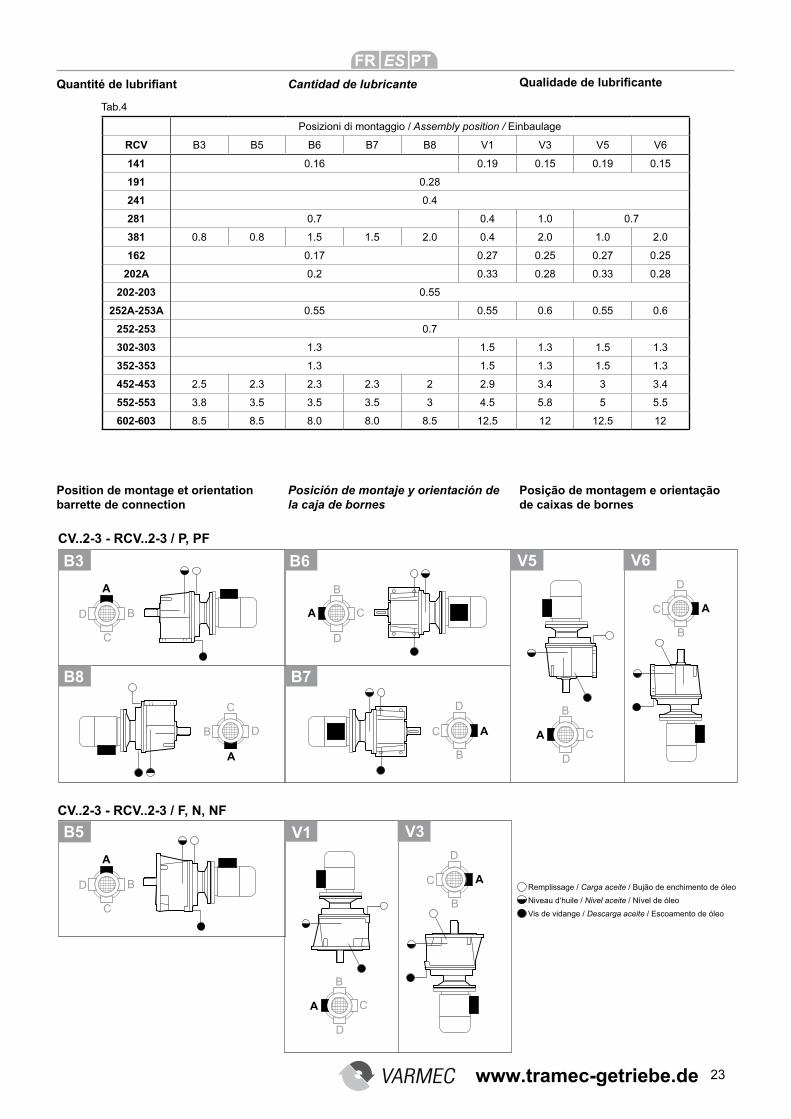
Quantità di lubrificante
Posizioni di montaggio e orientamen-to morsettiera
Quantity of lubricant Schmiermittelmenge
Assembly position and orientation of terminal box
Einbaulage und Einbau der War-tungsanschlüsse
Tab.4
Carico olio / Breather plug / Öleinfüllung
Livello olio / Level plug / Ölstand
Scarico olio / Drain plug / Ölablass
www.tramec-getriebe.de
23
Quantité de lubrifiant
Position de montage et orientation barrette de connection
Cantidad de lubricante Qualidade de lubrificante
Posición de montaje y orientación de la caja de bornes
Posição de montagem e orientação de caixas de bornes
Tab.4
Remplissage / Carga aceite / Bujão de enchimento de óleo
Niveau d‘huile / Nivel aceite / Nível de óleo
Vis de vidange / Descarga aceite / Escoamento de óleo
Posizioni di montaggio / Assembly position / Einbaulage
RCV B3 B5 B6 B7 B8 V1 V3 V5 V6
141 0.16 0.19 0.15 0.19 0.15
191 0.28
241 0.4
281 0.7 0.4 1.0 0.7
381 0.8 0.8 1.5 1.5 2.0 0.4 2.0 1.0 2.0
162 0.17 0.27 0.25 0.27 0.25
202A 0.2 0.33 0.28 0.33 0.28
202-203 0.55
252A-253A 0.55 0.55 0.6 0.55 0.6
252-253 0.7
302-303 1.3 1.5 1.3 1.5 1.3
352-353 1.3 1.5 1.3 1.5 1.3
452-453 2.5 2.3 2.3 2.3 2 2.9 3.4 3 3.4
552-553 3.8 3.5 3.5 3.5 3 4.5 5.8 5 5.5
602-603 8.5 8.5 8.0 8.0 8.5 12.5 12 12.5 12
www.tramec-getriebe.de
24
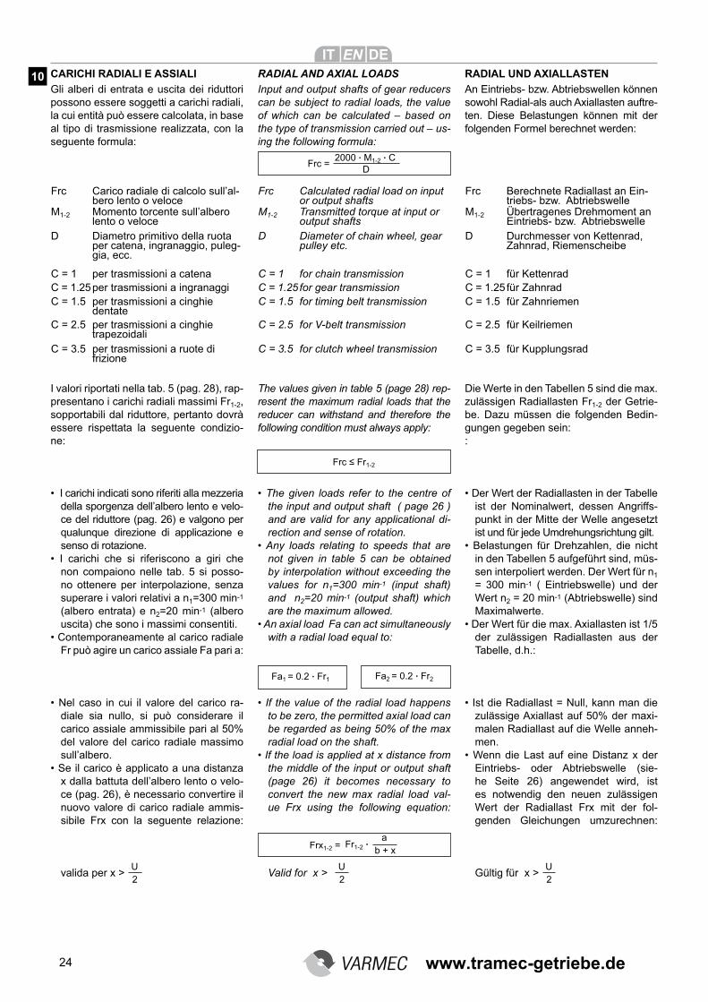
CARICHI RADIALI E ASSIALI RADIAL AND AXIAL LOADS
Gli alberi di entrata e uscita dei riduttori possono essere soggetti a carichi radiali, la cui entità può essere calcolata, in base al tipo di trasmissione realizzata, con la seguente formula:
2000 . M1-2 . C
DFrc =
Frc Carico radiale di calcolo sull’al-bero lento o veloce
M1-2 Momento torcente sull’albero lento o veloce
D Diametro primitivo della ruota per catena, ingranaggio, puleg-gia, ecc.
C = 1 per trasmissioni a catenaC = 1.25per trasmissioni a ingranaggiC = 1.5 per trasmissioni a cinghie
dentateC = 2.5 per trasmissioni a cinghie
trapezoidaliC = 3.5 per trasmissioni a ruote di
frizione
Frc ≤ Fr1-2
Fa1 = 0.2 . Fr1 Fa2 = 0.2 . Fr2
Fr1-2 . b + xFrx1-2 =a
I valori riportati nella tab. 5 (pag. 28), rap-presentano i carichi radiali massimi Fr1-2, sopportabili dal riduttore, pertanto dovrà essere rispettata la seguente condizio-ne:
• I carichi indicati sono riferiti alla mezzeria
della sporgenza dell’albero lento e velo-ce del riduttore (pag. 26) e valgono per qualunque direzione di applicazione e senso di rotazione.
• I carichi che si riferiscono a giri che
non compaiono nelle tab. 5 si posso-no ottenere per interpolazione, senza superare i valori relativi a n1=300 min-1 (albero entrata) e n2=20 min-1 (albero uscita) che sono i massimi consentiti.
• Contemporaneamente al carico radiale
Fr può agire un carico assiale Fa pari a:
• Nel caso in cui il valore del carico ra-diale sia nullo, si può considerare il carico assiale ammissibile pari al 50% del valore del carico radiale massimo sull’albero.
• Se il carico è applicato a una distanza
x dalla battuta dell’albero lento o velo-ce (pag. 26), è necessario convertire il nuovo valore di carico radiale ammis-sibile Frx con la seguente relazione: valida per x >
2U
RADIAL UND AXIALLASTEN
Input and output shafts of gear reducers can be subject to radial loads, the value of which can be calculated – based on the type of transmission carried out – us-ing the following formula:
Frc Calculated radial load on input or output shafts
M1-2 Transmitted torque at input or output shafts
D Diameter of chain wheel, gear pulley etc.
C = 1 for chain transmissionC = 1.25 for gear transmissionC = 1.5 for timing belt transmission
C = 2.5 for V-belt transmission
C = 3.5 for clutch wheel transmission
The values given in table 5 (page 28) rep-resent the maximum radial loads that the reducer can withstand and therefore the following condition must always apply:
• The given loads refer to the centre of
the input and output shaft ( page 26 ) and are valid for any applicational di-rection and sense of rotation.
• Any loads relating to speeds that are
not given in table 5 can be obtained by interpolation without exceeding the values for n1=300 min-1 (input shaft) and n2=20 min-1 (output shaft) which are the maximum allowed.
• An axial load Fa can act simultaneously
with a radial load equal to:
• If the value of the radial load happens
to be zero, the permitted axial load can be regarded as being 50% of the max radial load on the shaft.
• If the load is applied at x distance from
the middle of the input or output shaft (page 26) it becomes necessary to convert the new max radial load val-ue Frx using the following equation:
Valid for x >
2U
An Eintriebs- bzw. Abtriebswellen können sowohl Radial-als auch Axiallasten auftre-ten. Diese Belastungen können mit der folgenden Formel berechnet werden:
Frc Berechnete Radiallast an Ein-triebs- bzw. Abtriebswelle
M1-2 Übertragenes Drehmoment an Eintriebs- bzw. Abtriebswelle
D Durchmesser von Kettenrad, Zahnrad, Riemenscheibe
C = 1 für Kettenrad C = 1.25 für Zahnrad C = 1.5 für Zahnriemen
C = 2.5 für Keilriemen
C = 3.5 für Kupplungsrad
Die Werte in den Tabellen 5 sind die max. zulässigen Radiallasten Fr1-2 der Getrie-be. Dazu müssen die folgenden Bedin-gungen gegeben sein::
• Der Wert der Radiallasten in der Tabelle
ist der Nominalwert, dessen Angriffs-punkt in der Mitte der Welle angesetzt ist und für jede Umdrehungsrichtung gilt.
• Belastungen für Drehzahlen, die nicht
in den Tabellen 5 aufgeführt sind, müs-sen interpoliert werden. Der Wert für n1 = 300 min-1 ( Eintriebswelle) und der Wert n2 = 20 min-1 (Abtriebswelle) sind Maximalwerte.
• Der Wert für die max. Axiallasten ist 1/5
der zulässigen Radiallasten aus der Tabelle, d.h.:
• Ist die Radiallast = Null, kann man die
zulässige Axiallast auf 50% der maxi-malen Radiallast auf die Welle anneh-men.
• Wenn die Last auf eine Distanz x der
Eintriebs- oder Abtriebswelle (sie-he Seite 26) angewendet wird, ist es notwendig den neuen zulässigen Wert der Radiallast Frx mit der fol-genden Gleichungen umzurechnen:
Gültig für x >
2U
10
www.tramec-getriebe.de
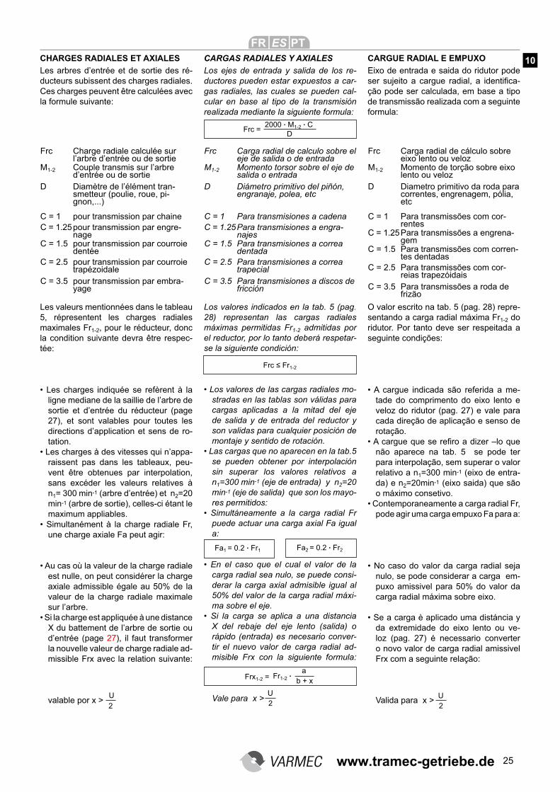
25
CHARGES RADIALES ET AXIALES CARGAS RADIALES Y AXIALES CARGUE RADIAL E EMPUXO
Les arbres d’entrée et de sortie des ré-ducteurs subissent des charges radiales. Ces charges peuvent être calculées avec la formule suivante:
2000 . M1-2 . C
DFrc =
Frc Charge radiale calculée sur l’arbre d’entrée ou de sortie
M1-2 Couple transmis sur l’arbre d’entrée ou de sortie
D Diamètre de l’élément tran-smetteur (poulie, roue, pi-gnon,...)
C = 1 pour transmission par chaineC = 1.25pour transmission par engre-
nageC = 1.5 pour transmission par courroie
dentéeC = 2.5 pour transmission par courroie
trapézoidaleC = 3.5 pour transmission par embra-
yage
Frc ≤ Fr1-2
2U
Fr1-2 . b + xFrx1-2 =
Los valores indicados en la tab. 5 (pag. 28) representan las cargas radiales máximas permitidas Fr1-2 admitidas por el reductor, por lo tanto deberá respetar-se la siguiente condición:
• Los valores de las cargas radiales mo-stradas en las tablas son válidas para cargas aplicadas a la mitad del eje de salida y de entrada del reductor y son validas para cualquier posición de montaje y sentido de rotación.
• Las cargas que no aparecen en la tab.5
se pueden obtener por interpolación sin superar los valores relativos a n1=300 min-1 (eje de entrada) y n2=20 min-1 (eje de salida) que son los mayo-res permitidos:
• Simultáneamente a la carga radial Fr
puede actuar una carga axial Fa igual a:
• En el caso que el cual el valor de la
carga radial sea nulo, se puede consi-derar la carga axial admisible igual al 50% del valor de la carga radial máxi-ma sobre el eje.
• Si la carga se aplica a una distancia
X del rebaje del eje lento (salida) o rápido (entrada) es necesario conver-tir el nuevo valor de carga radial ad-misible Frx con la siguiente formula: Vale para x >
a
Les valeurs mentionnées dans le tableau 5, répresentent les charges radiales maximales Fr1-2, pour le réducteur, donc la condition suivante devra être respec-tée:
• Les charges indiquée se refèrent à la
ligne mediane de la saillie de l’arbre de sortie et d’entrée du réducteur (page 27), et sont valables pour toutes les directions d’application et sens de ro-tation.
• Les charges à des vitesses qui n’appa-raissent pas dans les tableaux, peu-vent être obtenues par interpolation, sans excéder les valeurs relatives à n1= 300 min-1 (arbre d’entrée) et n2=20 min-1 (arbre de sortie), celles-ci étant le maximum appliables.
• Simultanément à la charge radiale Fr,
une charge axiale Fa peut agir:
• Au cas où la valeur de la charge radiale
est nulle, on peut considérer la charge axiale admissible égale au 50% de la valeur de la charge radiale maximale sur l’arbre.
• Si la charge est appliquée à une distance
X du battement de l’arbre de sortie ou d’entrée (page 27), il faut transformer la nouvelle valeur de charge radiale ad-missible Frx avec la relation suivante: valable por x >
2 U
Los ejes de entrada y salida de los re-ductores pueden estar expuestos a car-gas radiales, las cuales se pueden cal-cular en base al tipo de la transmisión realizada mediante la siguiente formula:
Frc Carga radial de calculo sobre el eje de salida o de entrada
M1-2 Momento torsor sobre el eje de salida o entrada
D Diámetro primitivo del piñón, engranaje, polea, etc
C = 1 Para transmisiones a cadenaC = 1.25Para transmisiones a engra-
najesC = 1.5 Para transmisiones a correa
dentadaC = 2.5 Para transmisiones a correa
trapecialC = 3.5 Para transmisiones a discos de
fricción
Eixo de entrada e saida do ridutor pode ser sujeito a cargue radial, a identifica-ção pode ser calculada, em base a tipo de transmissão realizada com a seguinte formula:
Frc Carga radial de cálculo sobre eixo lento ou veloz
M1-2 Momento de torção sobre eixo lento ou veloz
D Diametro primitivo da roda para correntes, engrenagem, pólia, etc
C = 1 Para transmissões com cor-rentes
C = 1.25Para transmissões a engrena-gem
C = 1.5 Para transmissões com corren-tes dentadas
C = 2.5 Para transmissões com cor-reias trapezóidais
C = 3.5 Para transmissões a roda de frizão
O valor escrito na tab. 5 (pag. 28) repre-sentando a carga radial máxima Fr1-2 do ridutor. Por tanto deve ser respeitada a seguinte condições:
• A cargue indicada são referida a me-tade do comprimento do eixo lento e veloz do ridutor (pag. 27) e vale para cada direção de aplicação e senso de rotação.
• A cargue que se refiro a dizer –lo que
não aparece na tab. 5 se pode ter para interpolação, sem superar o valor relativo a n1=300 min-1 (eixo de entra-da) e n2=20min-1 (eixo saida) que são o máximo consetivo.
• Contemporaneamente a carga radial Fr,
pode agir uma carga empuxo Fa para a:
• No caso do valor da carga radial seja
nulo, se pode considerar a carga em-puxo amissivel para 50% do valor da carga radial máxima sobre eixo.
• Se a carga è aplicado uma distáncia y
da extremidade do eixo lento ou ve-loz (pag. 27) é necessario converter o novo valor de carga radial amissivel Frx com a seguinte relação:
Valida para x >
2U
Fa1 = 0.2 . Fr1 Fa2 = 0.2 . Fr2
10
www.tramec-getriebe.de
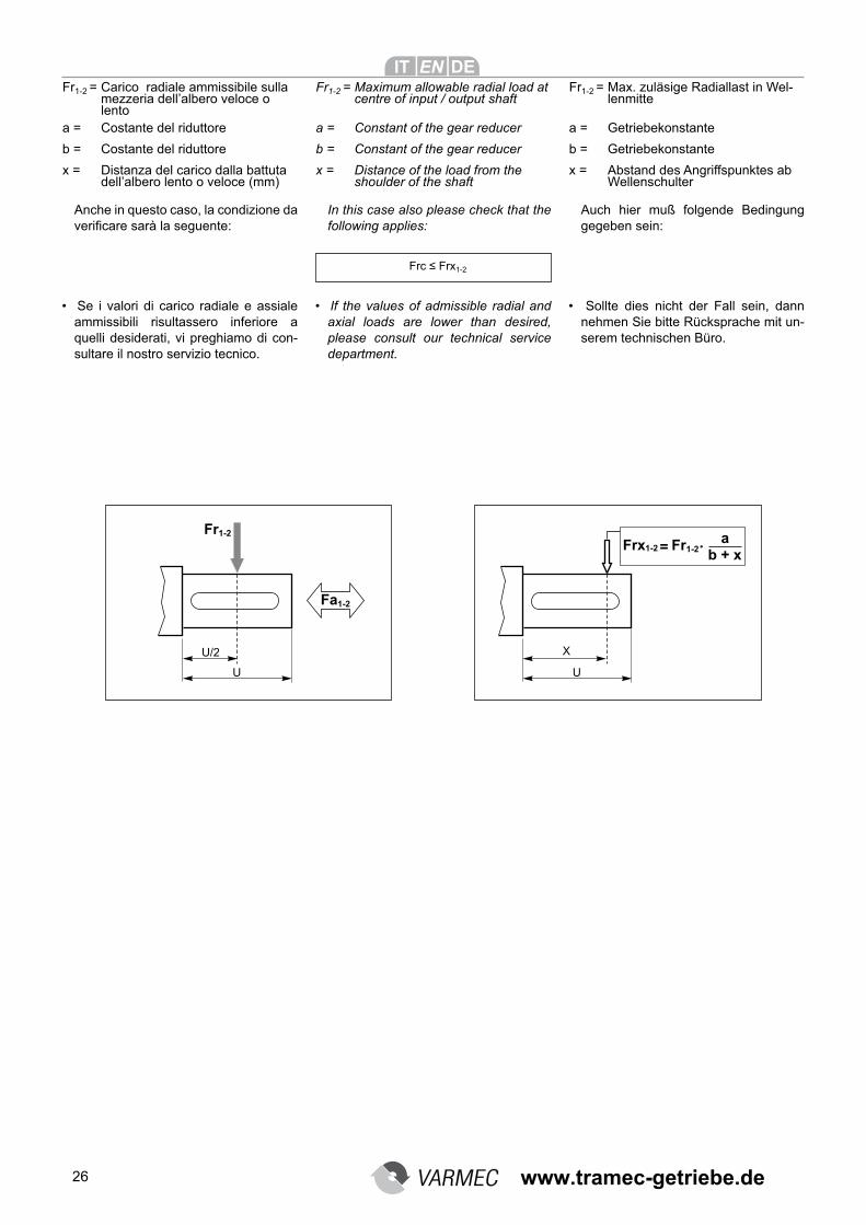
26
Fr1-2 = Carico radiale ammissibile sulla mezzeria dell’albero veloce o lento
a = Costante del riduttore
b = Costante del riduttore
x = Distanza del carico dalla battuta dell’albero lento o veloce (mm)
Anche in questo caso, la condizione da verificare sarà la seguente:
• Se i valori di carico radiale e assiale
ammissibili risultassero inferiore a quelli desiderati, vi preghiamo di con-sultare il nostro servizio tecnico.
Frc ≤ Frx1-2
Fr1-2 = Maximum allowable radial load at centre of input / output shaft
a = Constant of the gear reducer
b = Constant of the gear reducer
x = Distance of the load from the shoulder of the shaft
In this case also please check that the following applies:
• If the values of admissible radial and axial loads are lower than desired, please consult our technical service department.
Fr1-2 = Max. zuläsige Radiallast in Wel-lenmitte
a = Getriebekonstante
b = Getriebekonstante
x = Abstand des Angriffspunktes ab Wellenschulter
Auch hier muß folgende Bedingung gegeben sein:
• Sollte dies nicht der Fall sein, dann
nehmen Sie bitte Rücksprache mit un-serem technischen Büro.
www.tramec-getriebe.de
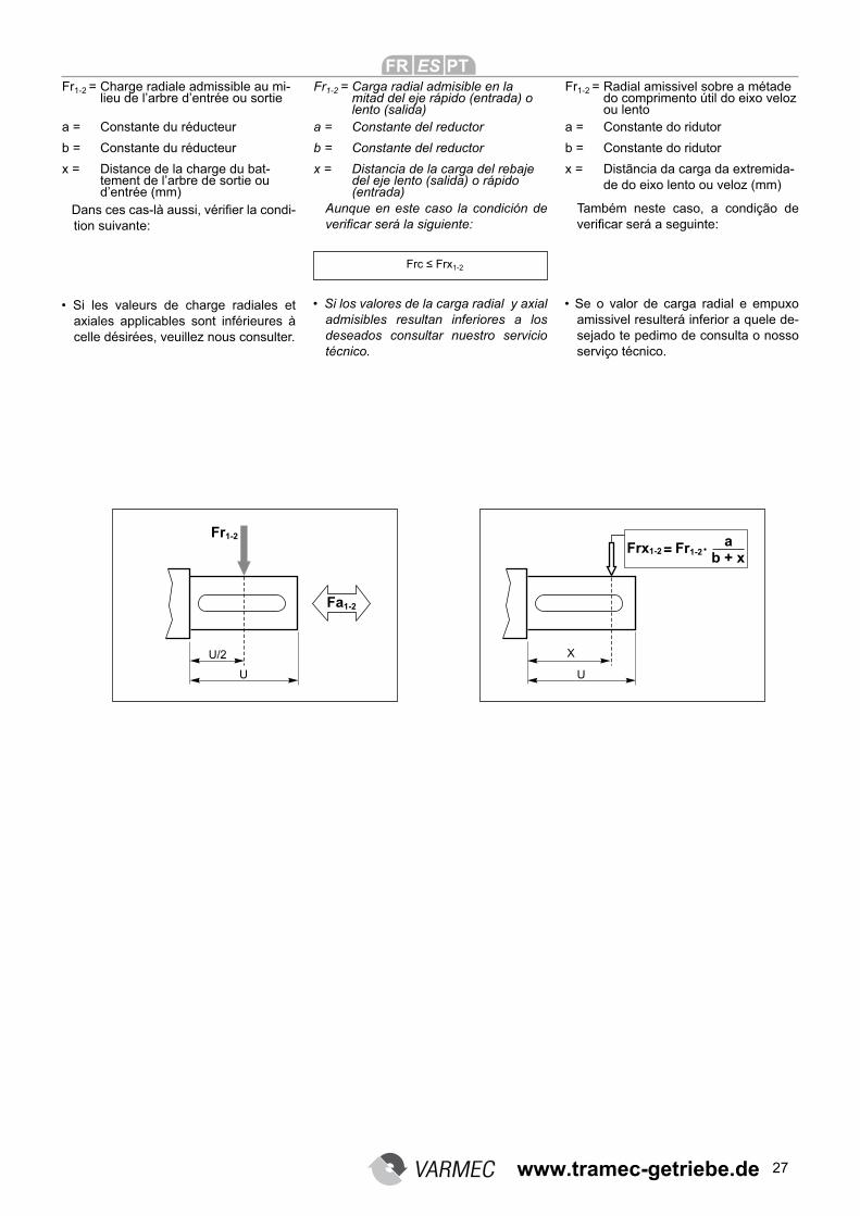
27
Fr1-2 = Charge radiale admissible au mi-lieu de l’arbre d’entrée ou sortie
a = Constante du réducteur
b = Constante du réducteur
x = Distance de la charge du bat-tement de l’arbre de sortie ou d’entrée (mm)
Dans ces cas-là aussi, vérifier la condi-tion suivante:
• Si les valeurs de charge radiales et
axiales applicables sont inférieures à celle désirées, veuillez nous consulter.
Frc ≤ Frx1-2
Fr1-2 = Carga radial admisible en la mitad del eje rápido (entrada) o lento (salida)
a = Constante del reductor
b = Constante del reductor
x = Distancia de la carga del rebaje del eje lento (salida) o rápido (entrada)
Aunque en este caso la condición de verificar será la siguiente:
• Si los valores de la carga radial y axial admisibles resultan inferiores a los deseados consultar nuestro servicio técnico.
Fr1-2 = Radial amissivel sobre a métade do comprimento útil do eixo veloz ou lento
a = Constante do ridutor
b = Constante do ridutor
x = Distãncia da carga da extremida-de do eixo lento ou veloz (mm)
Também neste caso, a condição de verificar será a seguinte:
• Se o valor de carga radial e empuxo
amissivel resulterá inferior a quele de-sejado te pedimo de consulta o nosso serviço técnico.
www.tramec-getriebe.de
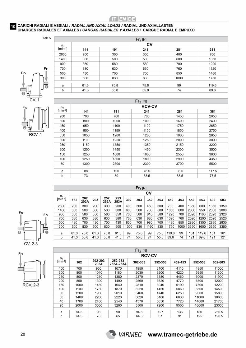
28
Fr2 [N]
n2 [min-1]
RCV-CV141 191 241 281 381
900 700 700 700 1450 2050
600 800 1000 1000 1600 2400
450 950 1100 1100 1750 2650
400 950 1150 1150 1850 2750
350 1050 1200 1200 1900 2850
300 1100 1250 1250 2000 3000
250 1150 1350 1350 2150 3200
200 1200 1450 1450 2300 3500
150 1250 1600 1600 2550 3800
100 1250 1800 1800 2900 4350
50 1300 2300 2300 3700 5500
a 88 100 78.5 98.5 117.5
b 73 80 53.5 68.5 77.5
Fr1 [N]
n1 [min-1]
CV141 191 241 281 381
2800 200 300 300 400 700
1400 300 500 500 600 1050
900 350 580 580 700 1220
700 380 630 630 760 1320
500 430 700 700 850 1480
300 500 830 830 1000 1750
a 61.3 75.8 75.8 99 119.6
b 41.3 55.8 55.8 74 89.6
Fr2 [N]
n2 [min-1]
RCV-CV
162 202-203202A
252-253 252A-253A 302-303 352-353 452-453 552-553 602-603
400 700 950 1070 1950 3100 4110 4850 11000300 800 1040 1180 2030 3200 4220 5950 11300250 800 1210 1380 2370 3380 4460 6000 11900200 850 1300 1490 2560 3620 4770 6500 12000150 1000 1430 1640 2810 3940 5190 7500 12200100 1100 1730 1870 3220 4450 5860 8500 1450080 1200 1950 2010 3460 4740 6250 9500 1580060 1400 2200 2220 3820 5180 6830 11000 1860040 1700 2400 2540 4370 5850 7720 14000 2170020 2000 3000 3200 5500 7200 9500 16000 23000
a 84.5 98 90 94.5 127 136 180 250.5b 64.5 78 65 64.5 87 91 125 190.5
Fr1 [N]
n1 [min-1]
CV
162 202202A 203 252
252A253
253A 302 303 352 353 452 453 552 553 602 603
2800 200 300 200 300 200 400 300 450 300 700 400 1350 600 1350 13501400 300 500 300 500 300 600 500 700 500 1050 600 2000 950 2000 2000900 350 580 350 580 350 700 580 810 580 1220 700 2320 1100 2320 2320700 380 630 380 630 380 760 630 880 630 1320 760 2520 1200 2520 2520500 430 700 430 700 430 850 700 980 700 1480 850 2830 1350 2830 2830300 500 830 500 830 500 1000 830 1160 830 1750 1000 3350 1600 3350 3350
a 61.3 75.8 61.3 75.8 61.3 99 75.8 99 75.8 119.6 99 161 119.6 161 161b 41.3 55.8 41.3 55.8 41.3 74 55.8 74 55.8 89.6 74 121 89.6 121 121
CV..1
RCV..1
CV..2-3
RCV..2-3
CARICHI RADIALI E ASSIALI / RADIAL AND AXIAL LOADS / RADIAL UND AXIALLASTENCHARGES RADIALES ET AXIALES / CARGAS RADIALES Y AXIALES / CARGUE RADIAL E EMPUXO
10
Tab.5
www.tramec-getriebe.de
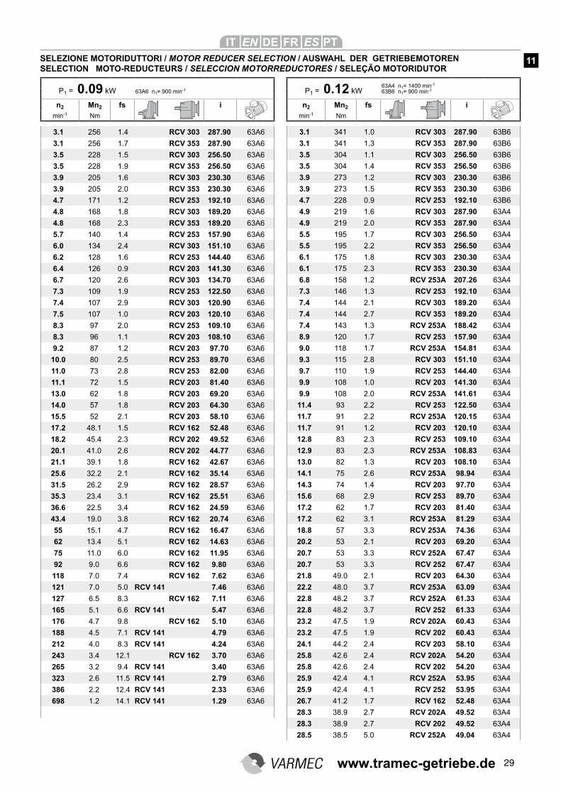
29
3.1 256 1.4 RCV 303 287.90 63A6
3.1 256 1.7 RCV 353 287.90 63A6
3.5 228 1.5 RCV 303 256.50 63A6
3.5 228 1.9 RCV 353 256.50 63A6
3.9 205 1.6 RCV 303 230.30 63A6
3.9 205 2.0 RCV 353 230.30 63A6
4.7 171 1.2 RCV 253 192.10 63A6
4.8 168 1.8 RCV 303 189.20 63A6
4.8 168 2.3 RCV 353 189.20 63A6
5.7 140 1.4 RCV 253 157.90 63A6
6.0 134 2.4 RCV 303 151.10 63A6
6.2 128 1.6 RCV 253 144.40 63A6
6.4 126 0.9 RCV 203 141.30 63A6
6.7 120 2.6 RCV 303 134.70 63A6
7.3 109 1.9 RCV 253 122.50 63A6
7.4 107 2.9 RCV 303 120.90 63A6
7.5 107 1.0 RCV 203 120.10 63A6
8.3 97 2.0 RCV 253 109.10 63A6
8.3 96 1.1 RCV 203 108.10 63A6
9.2 87 1.2 RCV 203 97.70 63A6
10.0 80 2.5 RCV 253 89.70 63A6
11.0 73 2.8 RCV 253 82.00 63A6
11.1 72 1.5 RCV 203 81.40 63A6
13.0 62 1.8 RCV 203 69.20 63A6
14.0 57 1.8 RCV 203 64.30 63A6
15.5 52 2.1 RCV 203 58.10 63A6
17.2 48.1 1.5 RCV 162 52.48 63A6
18.2 45.4 2.3 RCV 202 49.52 63A6
20.1 41.0 2.6 RCV 202 44.77 63A6
21.1 39.1 1.8 RCV 162 42.67 63A6
25.6 32.2 2.1 RCV 162 35.14 63A6
31.5 26.2 2.9 RCV 162 28.57 63A6
35.3 23.4 3.1 RCV 162 25.51 63A6
36.6 22.5 3.4 RCV 162 24.59 63A6
43.4 19.0 3.8 RCV 162 20.74 63A6
55 15.1 4.7 RCV 162 16.47 63A6
62 13.4 5.1 RCV 162 14.63 63A6
75 11.0 6.0 RCV 162 11.95 63A6
92 9.0 6.6 RCV 162 9.80 63A6
118 7.0 7.4 RCV 162 7.62 63A6
121 7.0 5.0 RCV 141 7.46 63A6
127 6.5 8.3 RCV 162 7.11 63A6
165 5.1 6.6 RCV 141 5.47 63A6
176 4.7 9.8 RCV 162 5.10 63A6
188 4.5 7.1 RCV 141 4.79 63A6
212 4.0 8.3 RCV 141 4.24 63A6
243 3.4 12.1 RCV 162 3.70 63A6
265 3.2 9.4 RCV 141 3.40 63A6
323 2.6 11.5 RCV 141 2.79 63A6
386 2.2 12.4 RCV 141 2.33 63A6
698 1.2 14.1 RCV 141 1.29 63A6
3.1 341 1.0 RCV 303 287.90 63B6
3.1 341 1.3 RCV 353 287.90 63B6
3.5 304 1.1 RCV 303 256.50 63B6
3.5 304 1.4 RCV 353 256.50 63B6
3.9 273 1.2 RCV 303 230.30 63B6
3.9 273 1.5 RCV 353 230.30 63B6
4.7 228 0.9 RCV 253 192.10 63B6
4.9 219 1.6 RCV 303 287.90 63A4
4.9 219 2.0 RCV 353 287.90 63A4
5.5 195 1.7 RCV 303 256.50 63A4
5.5 195 2.2 RCV 353 256.50 63A4
6.1 175 1.8 RCV 303 230.30 63A4
6.1 175 2.3 RCV 353 230.30 63A4
6.8 158 1.2 RCV 253A 207.26 63A4
7.3 146 1.3 RCV 253 192.10 63A4
7.4 144 2.1 RCV 303 189.20 63A4
7.4 144 2.7 RCV 353 189.20 63A4
7.4 143 1.3 RCV 253A 188.42 63A4
8.9 120 1.7 RCV 253 157.90 63A4
9.0 118 1.7 RCV 253A 154.81 63A4
9.3 115 2.8 RCV 303 151.10 63A4
9.7 110 1.9 RCV 253 144.40 63A4
9.9 108 1.0 RCV 203 141.30 63A4
9.9 108 2.0 RCV 253A 141.61 63A4
11.4 93 2.2 RCV 253 122.50 63A4
11.7 91 2.2 RCV 253A 120.15 63A4
11.7 91 1.2 RCV 203 120.10 63A4
12.8 83 2.3 RCV 253 109.10 63A4
12.9 83 2.3 RCV 253A 108.83 63A4
13.0 82 1.3 RCV 203 108.10 63A4
14.1 75 2.6 RCV 253A 98.94 63A4
14.3 74 1.4 RCV 203 97.70 63A4
15.6 68 2.9 RCV 253 89.70 63A4
17.2 62 1.7 RCV 203 81.40 63A4
17.2 62 3.1 RCV 253A 81.29 63A4
18.8 57 3.3 RCV 253A 74.36 63A4
20.2 53 2.1 RCV 203 69.20 63A4
20.7 53 3.3 RCV 252A 67.47 63A4
20.7 53 3.3 RCV 252 67.47 63A4
21.8 49.0 2.1 RCV 203 64.30 63A4
22.2 48.0 3.7 RCV 253A 63.09 63A4
22.8 48.2 3.7 RCV 252A 61.33 63A4
22.8 48.2 3.7 RCV 252 61.33 63A4
23.2 47.5 1.9 RCV 202A 60.43 63A4
23.2 47.5 1.9 RCV 202 60.43 63A4
24.1 44.2 2.4 RCV 203 58.10 63A4
25.8 42.6 2.4 RCV 202A 54.20 63A4
25.8 42.6 2.4 RCV 202 54.20 63A4
25.9 42.4 4.1 RCV 252A 53.95 63A4
25.9 42.4 4.1 RCV 252 53.95 63A4
26.7 41.2 1.7 RCV 162 52.48 63A4
28.3 38.9 2.7 RCV 202A 49.52 63A4
28.3 38.9 2.7 RCV 202 49.52 63A4
28.5 38.5 5.0 RCV 252A 49.04 63A4
P1 = 0.09 kW 63A6 n1= 900 min-1
n2 Mn2 fs i
min-1 Nm
SELEZIONE MOTORIDUTTORI / MOTOR REDUCER SELECTION / AUSWAHL DER GETRIEBEMOTORENSELECTION MOTO-REDUCTEURS / SELECCION MOTORREDUCTORES / SELEÇÃO MOTORIDUTOR
P1 = 0.12 kW63A4 n1= 1400 min-1
63B6 n1= 900 min-1
n2 Mn2 fs i
min-1 Nm
11
www.tramec-getriebe.de
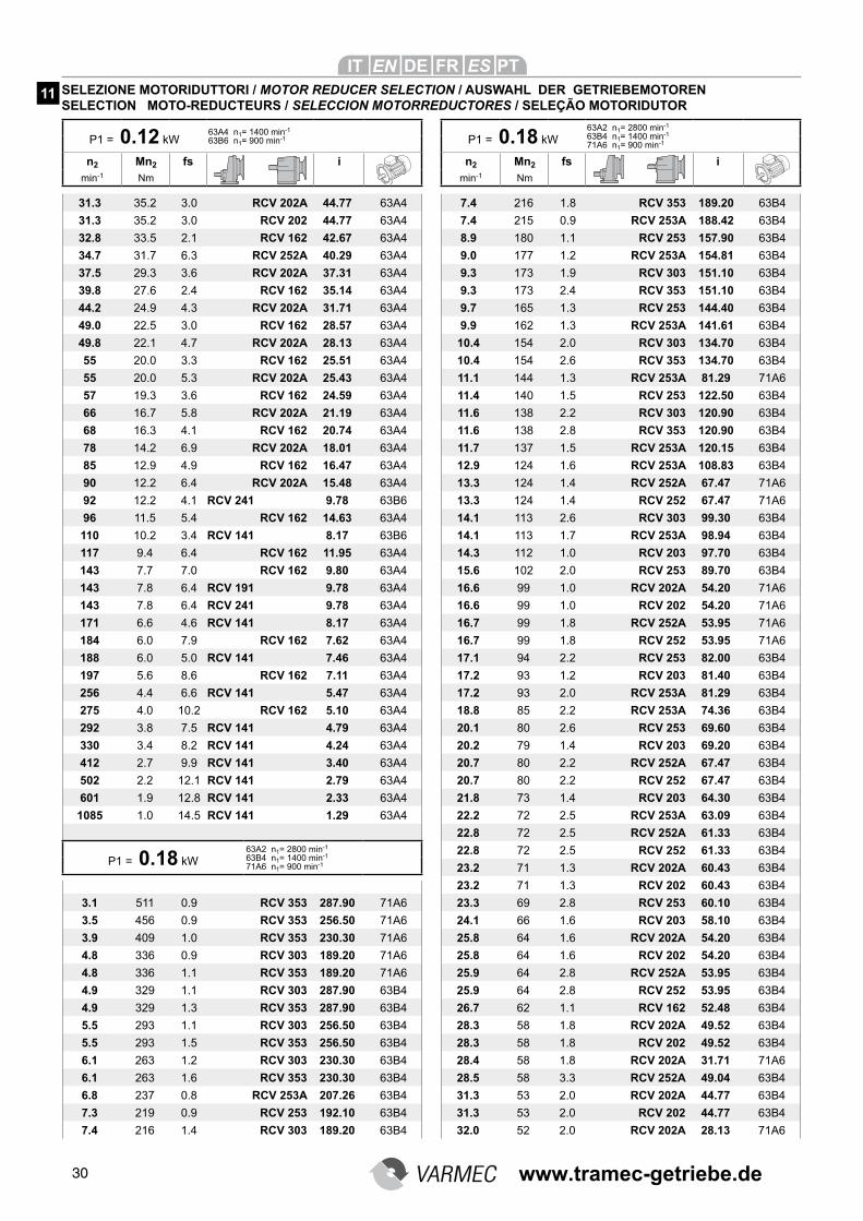
30
31.3 35.2 3.0 RCV 202A 44.77 63A4
31.3 35.2 3.0 RCV 202 44.77 63A4
32.8 33.5 2.1 RCV 162 42.67 63A4
34.7 31.7 6.3 RCV 252A 40.29 63A4
37.5 29.3 3.6 RCV 202A 37.31 63A4
39.8 27.6 2.4 RCV 162 35.14 63A4
44.2 24.9 4.3 RCV 202A 31.71 63A4
49.0 22.5 3.0 RCV 162 28.57 63A4
49.8 22.1 4.7 RCV 202A 28.13 63A4
55 20.0 3.3 RCV 162 25.51 63A4
55 20.0 5.3 RCV 202A 25.43 63A4
57 19.3 3.6 RCV 162 24.59 63A4
66 16.7 5.8 RCV 202A 21.19 63A4
68 16.3 4.1 RCV 162 20.74 63A4
78 14.2 6.9 RCV 202A 18.01 63A4
85 12.9 4.9 RCV 162 16.47 63A4
90 12.2 6.4 RCV 202A 15.48 63A4
92 12.2 4.1 RCV 241 9.78 63B6
96 11.5 5.4 RCV 162 14.63 63A4
110 10.2 3.4 RCV 141 8.17 63B6
117 9.4 6.4 RCV 162 11.95 63A4
143 7.7 7.0 RCV 162 9.80 63A4
143 7.8 6.4 RCV 191 9.78 63A4
143 7.8 6.4 RCV 241 9.78 63A4
171 6.6 4.6 RCV 141 8.17 63A4
184 6.0 7.9 RCV 162 7.62 63A4
188 6.0 5.0 RCV 141 7.46 63A4
197 5.6 8.6 RCV 162 7.11 63A4
256 4.4 6.6 RCV 141 5.47 63A4
275 4.0 10.2 RCV 162 5.10 63A4
292 3.8 7.5 RCV 141 4.79 63A4
330 3.4 8.2 RCV 141 4.24 63A4
412 2.7 9.9 RCV 141 3.40 63A4
502 2.2 12.1 RCV 141 2.79 63A4
601 1.9 12.8 RCV 141 2.33 63A4
1085 1.0 14.5 RCV 141 1.29 63A4
3.1 511 0.9 RCV 353 287.90 71A6
3.5 456 0.9 RCV 353 256.50 71A6
3.9 409 1.0 RCV 353 230.30 71A6
4.8 336 0.9 RCV 303 189.20 71A6
4.8 336 1.1 RCV 353 189.20 71A6
4.9 329 1.1 RCV 303 287.90 63B4
4.9 329 1.3 RCV 353 287.90 63B4
5.5 293 1.1 RCV 303 256.50 63B4
5.5 293 1.5 RCV 353 256.50 63B4
6.1 263 1.2 RCV 303 230.30 63B4
6.1 263 1.6 RCV 353 230.30 63B4
6.8 237 0.8 RCV 253A 207.26 63B4
7.3 219 0.9 RCV 253 192.10 63B4
7.4 216 1.4 RCV 303 189.20 63B4
7.4 216 1.8 RCV 353 189.20 63B4
7.4 215 0.9 RCV 253A 188.42 63B4
8.9 180 1.1 RCV 253 157.90 63B4
9.0 177 1.2 RCV 253A 154.81 63B4
9.3 173 1.9 RCV 303 151.10 63B4
9.3 173 2.4 RCV 353 151.10 63B4
9.7 165 1.3 RCV 253 144.40 63B4
9.9 162 1.3 RCV 253A 141.61 63B4
10.4 154 2.0 RCV 303 134.70 63B4
10.4 154 2.6 RCV 353 134.70 63B4
11.1 144 1.3 RCV 253A 81.29 71A6
11.4 140 1.5 RCV 253 122.50 63B4
11.6 138 2.2 RCV 303 120.90 63B4
11.6 138 2.8 RCV 353 120.90 63B4
11.7 137 1.5 RCV 253A 120.15 63B4
12.9 124 1.6 RCV 253A 108.83 63B4
13.3 124 1.4 RCV 252A 67.47 71A6
13.3 124 1.4 RCV 252 67.47 71A6
14.1 113 2.6 RCV 303 99.30 63B4
14.1 113 1.7 RCV 253A 98.94 63B4
14.3 112 1.0 RCV 203 97.70 63B4
15.6 102 2.0 RCV 253 89.70 63B4
16.6 99 1.0 RCV 202A 54.20 71A6
16.6 99 1.0 RCV 202 54.20 71A6
16.7 99 1.8 RCV 252A 53.95 71A6
16.7 99 1.8 RCV 252 53.95 71A6
17.1 94 2.2 RCV 253 82.00 63B4
17.2 93 1.2 RCV 203 81.40 63B4
17.2 93 2.0 RCV 253A 81.29 63B4
18.8 85 2.2 RCV 253A 74.36 63B4
20.1 80 2.6 RCV 253 69.60 63B4
20.2 79 1.4 RCV 203 69.20 63B4
20.7 80 2.2 RCV 252A 67.47 63B4
20.7 80 2.2 RCV 252 67.47 63B4
21.8 73 1.4 RCV 203 64.30 63B4
22.2 72 2.5 RCV 253A 63.09 63B4
22.8 72 2.5 RCV 252A 61.33 63B4
22.8 72 2.5 RCV 252 61.33 63B4
23.2 71 1.3 RCV 202A 60.43 63B4
23.2 71 1.3 RCV 202 60.43 63B4
23.3 69 2.8 RCV 253 60.10 63B4
24.1 66 1.6 RCV 203 58.10 63B4
25.8 64 1.6 RCV 202A 54.20 63B4
25.8 64 1.6 RCV 202 54.20 63B4
25.9 64 2.8 RCV 252A 53.95 63B4
25.9 64 2.8 RCV 252 53.95 63B4
26.7 62 1.1 RCV 162 52.48 63B4
28.3 58 1.8 RCV 202A 49.52 63B4
28.3 58 1.8 RCV 202 49.52 63B4
28.4 58 1.8 RCV 202A 31.71 71A6
28.5 58 3.3 RCV 252A 49.04 63B4
31.3 53 2.0 RCV 202A 44.77 63B4
31.3 53 2.0 RCV 202 44.77 63B4
32.0 52 2.0 RCV 202A 28.13 71A6
P1 = 0.12 kW63A4 n1= 1400 min-1
63B6 n1= 900 min-1
n2 Mn2 fs i
min-1 Nm
P1 = 0.18 kW
63A2 n1= 2800 min-1
63B4 n1= 1400 min-1
71A6 n1= 900 min-1
n2 Mn2 fs i
min-1 Nm
SELEZIONE MOTORIDUTTORI / MOTOR REDUCER SELECTION / AUSWAHL DER GETRIEBEMOTORENSELECTION MOTO-REDUCTEURS / SELECCION MOTORREDUCTORES / SELEÇÃO MOTORIDUTOR
11
P1 = 0.18 kW
63A2 n1= 2800 min-1
63B4 n1= 1400 min-1
71A6 n1= 900 min-1
www.tramec-getriebe.de
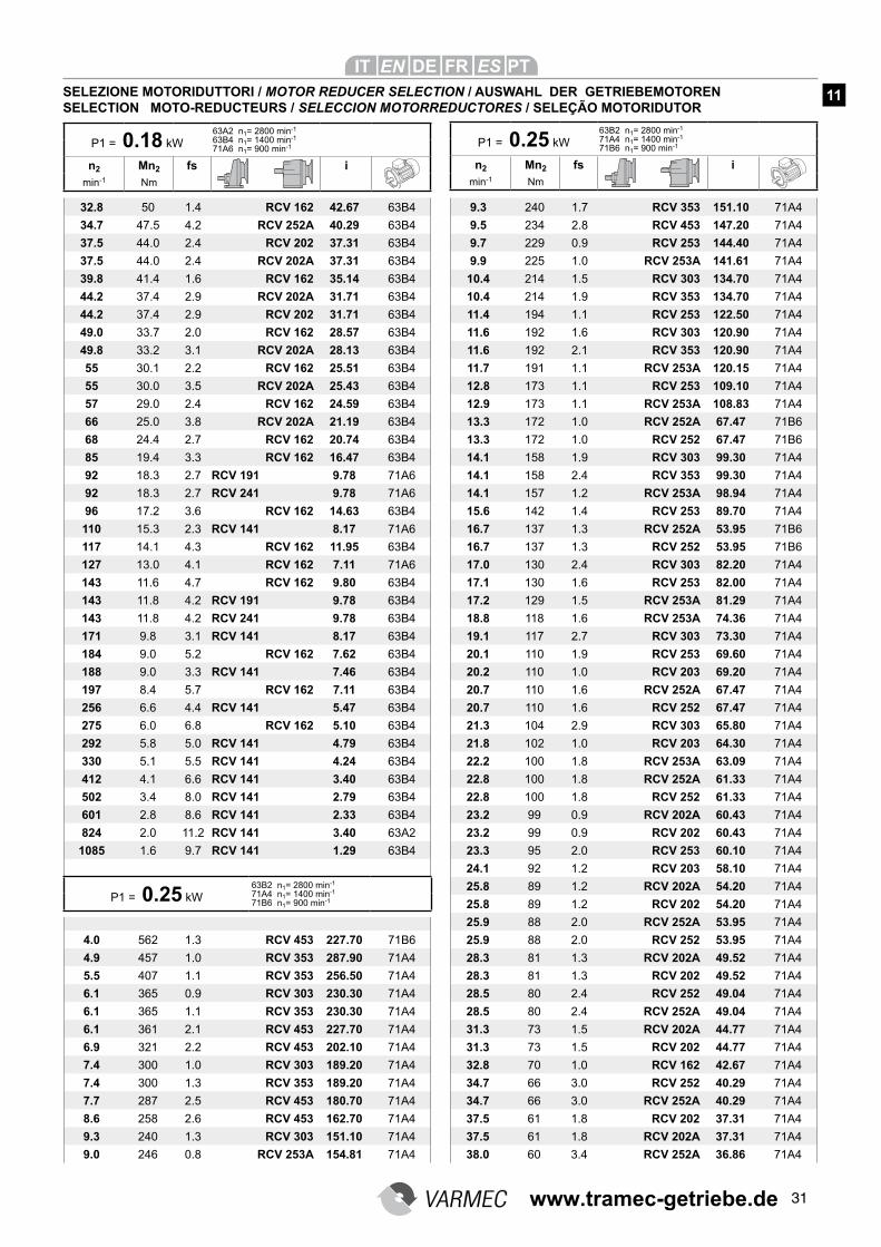
31
32.8 50 1.4 RCV 162 42.67 63B4
34.7 47.5 4.2 RCV 252A 40.29 63B4
37.5 44.0 2.4 RCV 202 37.31 63B4
37.5 44.0 2.4 RCV 202A 37.31 63B4
39.8 41.4 1.6 RCV 162 35.14 63B4
44.2 37.4 2.9 RCV 202A 31.71 63B4
44.2 37.4 2.9 RCV 202 31.71 63B4
49.0 33.7 2.0 RCV 162 28.57 63B4
49.8 33.2 3.1 RCV 202A 28.13 63B4
55 30.1 2.2 RCV 162 25.51 63B4
55 30.0 3.5 RCV 202A 25.43 63B4
57 29.0 2.4 RCV 162 24.59 63B4
66 25.0 3.8 RCV 202A 21.19 63B4
68 24.4 2.7 RCV 162 20.74 63B4
85 19.4 3.3 RCV 162 16.47 63B4
92 18.3 2.7 RCV 191 9.78 71A6
92 18.3 2.7 RCV 241 9.78 71A6
96 17.2 3.6 RCV 162 14.63 63B4
110 15.3 2.3 RCV 141 8.17 71A6
117 14.1 4.3 RCV 162 11.95 63B4
127 13.0 4.1 RCV 162 7.11 71A6
143 11.6 4.7 RCV 162 9.80 63B4
143 11.8 4.2 RCV 191 9.78 63B4
143 11.8 4.2 RCV 241 9.78 63B4
171 9.8 3.1 RCV 141 8.17 63B4
184 9.0 5.2 RCV 162 7.62 63B4
188 9.0 3.3 RCV 141 7.46 63B4
197 8.4 5.7 RCV 162 7.11 63B4
256 6.6 4.4 RCV 141 5.47 63B4
275 6.0 6.8 RCV 162 5.10 63B4
292 5.8 5.0 RCV 141 4.79 63B4
330 5.1 5.5 RCV 141 4.24 63B4
412 4.1 6.6 RCV 141 3.40 63B4
502 3.4 8.0 RCV 141 2.79 63B4
601 2.8 8.6 RCV 141 2.33 63B4
824 2.0 11.2 RCV 141 3.40 63A2
1085 1.6 9.7 RCV 141 1.29 63B4
4.0 562 1.3 RCV 453 227.70 71B6
4.9 457 1.0 RCV 353 287.90 71A4
5.5 407 1.1 RCV 353 256.50 71A4
6.1 365 0.9 RCV 303 230.30 71A4
6.1 365 1.1 RCV 353 230.30 71A4
6.1 361 2.1 RCV 453 227.70 71A4
6.9 321 2.2 RCV 453 202.10 71A4
7.4 300 1.0 RCV 303 189.20 71A4
7.4 300 1.3 RCV 353 189.20 71A4
7.7 287 2.5 RCV 453 180.70 71A4
8.6 258 2.6 RCV 453 162.70 71A4
9.3 240 1.3 RCV 303 151.10 71A4
9.0 246 0.8 RCV 253A 154.81 71A4
9.3 240 1.7 RCV 353 151.10 71A4
9.5 234 2.8 RCV 453 147.20 71A4
9.7 229 0.9 RCV 253 144.40 71A4
9.9 225 1.0 RCV 253A 141.61 71A4
10.4 214 1.5 RCV 303 134.70 71A4
10.4 214 1.9 RCV 353 134.70 71A4
11.4 194 1.1 RCV 253 122.50 71A4
11.6 192 1.6 RCV 303 120.90 71A4
11.6 192 2.1 RCV 353 120.90 71A4
11.7 191 1.1 RCV 253A 120.15 71A4
12.8 173 1.1 RCV 253 109.10 71A4
12.9 173 1.1 RCV 253A 108.83 71A4
13.3 172 1.0 RCV 252A 67.47 71B6
13.3 172 1.0 RCV 252 67.47 71B6
14.1 158 1.9 RCV 303 99.30 71A4
14.1 158 2.4 RCV 353 99.30 71A4
14.1 157 1.2 RCV 253A 98.94 71A4
15.6 142 1.4 RCV 253 89.70 71A4
16.7 137 1.3 RCV 252A 53.95 71B6
16.7 137 1.3 RCV 252 53.95 71B6
17.0 130 2.4 RCV 303 82.20 71A4
17.1 130 1.6 RCV 253 82.00 71A4
17.2 129 1.5 RCV 253A 81.29 71A4
18.8 118 1.6 RCV 253A 74.36 71A4
19.1 117 2.7 RCV 303 73.30 71A4
20.1 110 1.9 RCV 253 69.60 71A4
20.2 110 1.0 RCV 203 69.20 71A4
20.7 110 1.6 RCV 252A 67.47 71A4
20.7 110 1.6 RCV 252 67.47 71A4
21.3 104 2.9 RCV 303 65.80 71A4
21.8 102 1.0 RCV 203 64.30 71A4
22.2 100 1.8 RCV 253A 63.09 71A4
22.8 100 1.8 RCV 252A 61.33 71A4
22.8 100 1.8 RCV 252 61.33 71A4
23.2 99 0.9 RCV 202A 60.43 71A4
23.2 99 0.9 RCV 202 60.43 71A4
23.3 95 2.0 RCV 253 60.10 71A4
24.1 92 1.2 RCV 203 58.10 71A4
25.8 89 1.2 RCV 202A 54.20 71A4
25.8 89 1.2 RCV 202 54.20 71A4
25.9 88 2.0 RCV 252A 53.95 71A4
25.9 88 2.0 RCV 252 53.95 71A4
28.3 81 1.3 RCV 202A 49.52 71A4
28.3 81 1.3 RCV 202 49.52 71A4
28.5 80 2.4 RCV 252 49.04 71A4
28.5 80 2.4 RCV 252A 49.04 71A4
31.3 73 1.5 RCV 202A 44.77 71A4
31.3 73 1.5 RCV 202 44.77 71A4
32.8 70 1.0 RCV 162 42.67 71A4
34.7 66 3.0 RCV 252 40.29 71A4
34.7 66 3.0 RCV 252A 40.29 71A4
37.5 61 1.8 RCV 202 37.31 71A4
37.5 61 1.8 RCV 202A 37.31 71A4
38.0 60 3.4 RCV 252A 36.86 71A4
P1 = 0.18 kW
63A2 n1= 2800 min-1
63B4 n1= 1400 min-1
71A6 n1= 900 min-1
n2 Mn2 fs i
min-1 Nm
P1 = 0.25 kW
63B2 n1= 2800 min-1
71A4 n1= 1400 min-1
71B6 n1= 900 min-1
n2 Mn2 fs i
min-1 Nm
SELEZIONE MOTORIDUTTORI / MOTOR REDUCER SELECTION / AUSWAHL DER GETRIEBEMOTORENSELECTION MOTO-REDUCTEURS / SELECCION MOTORREDUCTORES / SELEÇÃO MOTORIDUTOR
11
P1 = 0.25 kW
63B2 n1= 2800 min-1
71A4 n1= 1400 min-1
71B6 n1= 900 min-1
www.tramec-getriebe.de
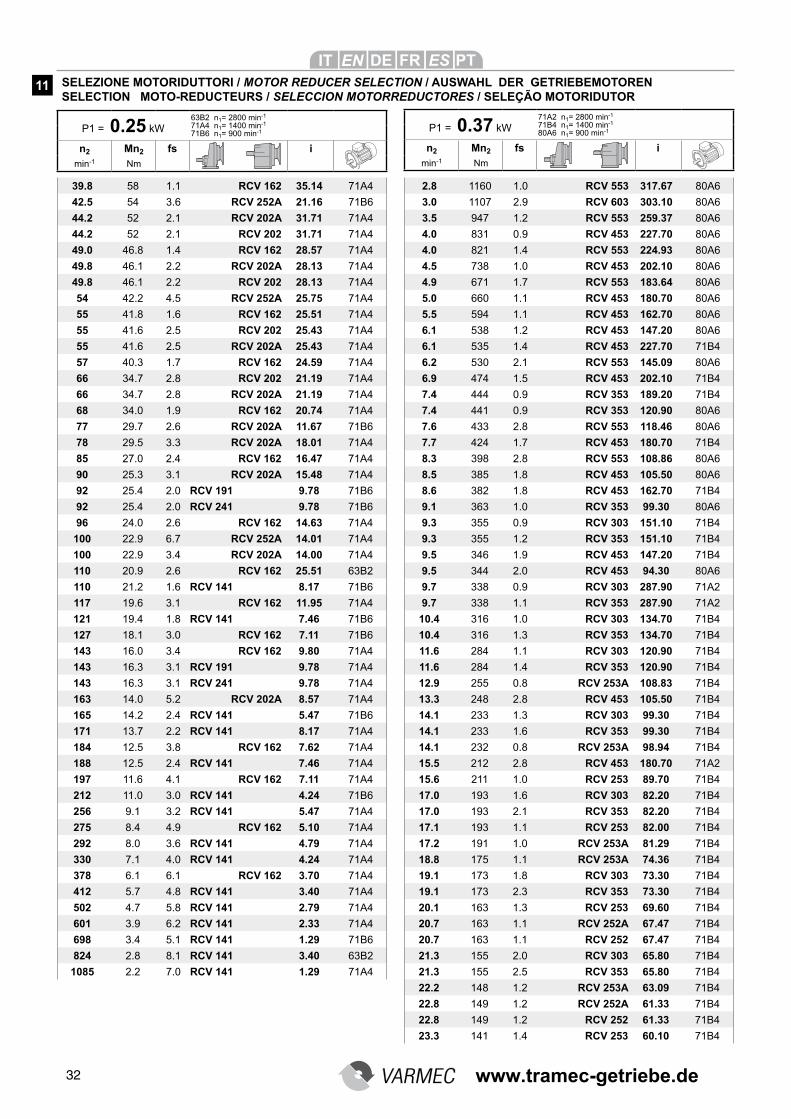
32
39.8 58 1.1 RCV 162 35.14 71A4
42.5 54 3.6 RCV 252A 21.16 71B6
44.2 52 2.1 RCV 202A 31.71 71A4
44.2 52 2.1 RCV 202 31.71 71A4
49.0 46.8 1.4 RCV 162 28.57 71A4
49.8 46.1 2.2 RCV 202A 28.13 71A4
49.8 46.1 2.2 RCV 202 28.13 71A4
54 42.2 4.5 RCV 252A 25.75 71A4
55 41.8 1.6 RCV 162 25.51 71A4
55 41.6 2.5 RCV 202 25.43 71A4
55 41.6 2.5 RCV 202A 25.43 71A4
57 40.3 1.7 RCV 162 24.59 71A4
66 34.7 2.8 RCV 202 21.19 71A4
66 34.7 2.8 RCV 202A 21.19 71A4
68 34.0 1.9 RCV 162 20.74 71A4
77 29.7 2.6 RCV 202A 11.67 71B6
78 29.5 3.3 RCV 202A 18.01 71A4
85 27.0 2.4 RCV 162 16.47 71A4
90 25.3 3.1 RCV 202A 15.48 71A4
92 25.4 2.0 RCV 191 9.78 71B6
92 25.4 2.0 RCV 241 9.78 71B6
96 24.0 2.6 RCV 162 14.63 71A4
100 22.9 6.7 RCV 252A 14.01 71A4
100 22.9 3.4 RCV 202A 14.00 71A4
110 20.9 2.6 RCV 162 25.51 63B2
110 21.2 1.6 RCV 141 8.17 71B6
117 19.6 3.1 RCV 162 11.95 71A4
121 19.4 1.8 RCV 141 7.46 71B6
127 18.1 3.0 RCV 162 7.11 71B6
143 16.0 3.4 RCV 162 9.80 71A4
143 16.3 3.1 RCV 191 9.78 71A4
143 16.3 3.1 RCV 241 9.78 71A4
163 14.0 5.2 RCV 202A 8.57 71A4
165 14.2 2.4 RCV 141 5.47 71B6
171 13.7 2.2 RCV 141 8.17 71A4
184 12.5 3.8 RCV 162 7.62 71A4
188 12.5 2.4 RCV 141 7.46 71A4
197 11.6 4.1 RCV 162 7.11 71A4
212 11.0 3.0 RCV 141 4.24 71B6
256 9.1 3.2 RCV 141 5.47 71A4
275 8.4 4.9 RCV 162 5.10 71A4
292 8.0 3.6 RCV 141 4.79 71A4
330 7.1 4.0 RCV 141 4.24 71A4
378 6.1 6.1 RCV 162 3.70 71A4
412 5.7 4.8 RCV 141 3.40 71A4
502 4.7 5.8 RCV 141 2.79 71A4
601 3.9 6.2 RCV 141 2.33 71A4
698 3.4 5.1 RCV 141 1.29 71B6
824 2.8 8.1 RCV 141 3.40 63B2
1085 2.2 7.0 RCV 141 1.29 71A4
2.8 1160 1.0 RCV 553 317.67 80A6
3.0 1107 2.9 RCV 603 303.10 80A6
3.5 947 1.2 RCV 553 259.37 80A6
4.0 831 0.9 RCV 453 227.70 80A6
4.0 821 1.4 RCV 553 224.93 80A6
4.5 738 1.0 RCV 453 202.10 80A6
4.9 671 1.7 RCV 553 183.64 80A6
5.0 660 1.1 RCV 453 180.70 80A6
5.5 594 1.1 RCV 453 162.70 80A6
6.1 538 1.2 RCV 453 147.20 80A6
6.1 535 1.4 RCV 453 227.70 71B4
6.2 530 2.1 RCV 553 145.09 80A6
6.9 474 1.5 RCV 453 202.10 71B4
7.4 444 0.9 RCV 353 189.20 71B4
7.4 441 0.9 RCV 353 120.90 80A6
7.6 433 2.8 RCV 553 118.46 80A6
7.7 424 1.7 RCV 453 180.70 71B4
8.3 398 2.8 RCV 553 108.86 80A6
8.5 385 1.8 RCV 453 105.50 80A6
8.6 382 1.8 RCV 453 162.70 71B4
9.1 363 1.0 RCV 353 99.30 80A6
9.3 355 0.9 RCV 303 151.10 71B4
9.3 355 1.2 RCV 353 151.10 71B4
9.5 346 1.9 RCV 453 147.20 71B4
9.5 344 2.0 RCV 453 94.30 80A6
9.7 338 0.9 RCV 303 287.90 71A2
9.7 338 1.1 RCV 353 287.90 71A2
10.4 316 1.0 RCV 303 134.70 71B4
10.4 316 1.3 RCV 353 134.70 71B4
11.6 284 1.1 RCV 303 120.90 71B4
11.6 284 1.4 RCV 353 120.90 71B4
12.9 255 0.8 RCV 253A 108.83 71B4
13.3 248 2.8 RCV 453 105.50 71B4
14.1 233 1.3 RCV 303 99.30 71B4
14.1 233 1.6 RCV 353 99.30 71B4
14.1 232 0.8 RCV 253A 98.94 71B4
15.5 212 2.8 RCV 453 180.70 71A2
15.6 211 1.0 RCV 253 89.70 71B4
17.0 193 1.6 RCV 303 82.20 71B4
17.0 193 2.1 RCV 353 82.20 71B4
17.1 193 1.1 RCV 253 82.00 71B4
17.2 191 1.0 RCV 253A 81.29 71B4
18.8 175 1.1 RCV 253A 74.36 71B4
19.1 173 1.8 RCV 303 73.30 71B4
19.1 173 2.3 RCV 353 73.30 71B4
20.1 163 1.3 RCV 253 69.60 71B4
20.7 163 1.1 RCV 252A 67.47 71B4
20.7 163 1.1 RCV 252 67.47 71B4
21.3 155 2.0 RCV 303 65.80 71B4
21.3 155 2.5 RCV 353 65.80 71B4
22.2 148 1.2 RCV 253A 63.09 71B4
22.8 149 1.2 RCV 252A 61.33 71B4
22.8 149 1.2 RCV 252 61.33 71B4
23.3 141 1.4 RCV 253 60.10 71B4
P1 = 0.25 kW
63B2 n1= 2800 min-1
71A4 n1= 1400 min-1
71B6 n1= 900 min-1
n2 Mn2 fs i
min-1 Nm
P1 = 0.37 kW
71A2 n1= 2800 min-1
71B4 n1= 1400 min-1
80A6 n1= 900 min-1
n2 Mn2 fs i
min-1 Nm
SELEZIONE MOTORIDUTTORI / MOTOR REDUCER SELECTION / AUSWAHL DER GETRIEBEMOTORENSELECTION MOTO-REDUCTEURS / SELECCION MOTORREDUCTORES / SELEÇÃO MOTORIDUTOR
11
www.tramec-getriebe.de
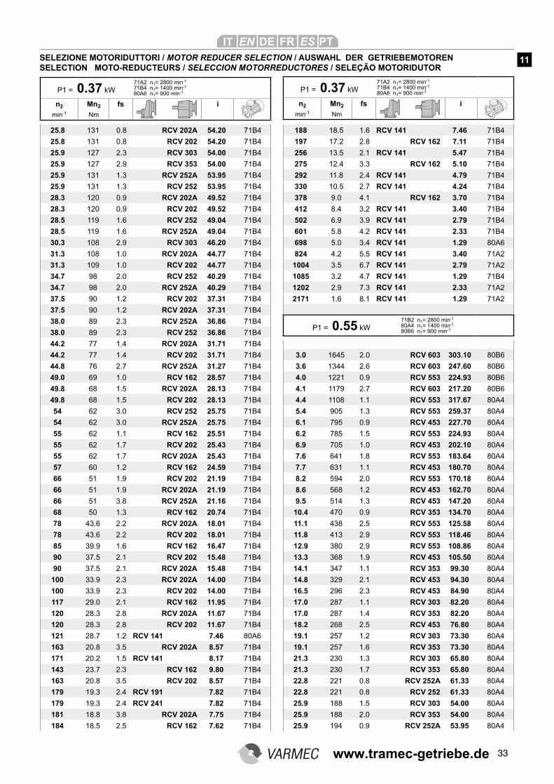
33
25.8 131 0.8 RCV 202A 54.20 71B4
25.8 131 0.8 RCV 202 54.20 71B4
25.9 127 2.3 RCV 303 54.00 71B4
25.9 127 2.9 RCV 353 54.00 71B4
25.9 131 1.3 RCV 252A 53.95 71B4
25.9 131 1.3 RCV 252 53.95 71B4
28.3 120 0.9 RCV 202A 49.52 71B4
28.3 120 0.9 RCV 202 49.52 71B4
28.5 119 1.6 RCV 252 49.04 71B4
28.5 119 1.6 RCV 252A 49.04 71B4
30.3 108 2.9 RCV 303 46.20 71B4
31.3 108 1.0 RCV 202A 44.77 71B4
31.3 109 1.0 RCV 202 44.77 71B4
34.7 98 2.0 RCV 252 40.29 71B4
34.7 98 2.0 RCV 252A 40.29 71B4
37.5 90 1.2 RCV 202 37.31 71B4
37.5 90 1.2 RCV 202A 37.31 71B4
38.0 89 2.3 RCV 252A 36.86 71B4
38.0 89 2.3 RCV 252 36.86 71B4
44.2 77 1.4 RCV 202A 31.71 71B4
44.2 77 1.4 RCV 202 31.71 71B4
44.8 76 2.7 RCV 252A 31.27 71B4
49.0 69 1.0 RCV 162 28.57 71B4
49.8 68 1.5 RCV 202A 28.13 71B4
49.8 68 1.5 RCV 202 28.13 71B4
54 62 3.0 RCV 252 25.75 71B4
54 62 3.0 RCV 252A 25.75 71B4
55 62 1.1 RCV 162 25.51 71B4
55 62 1.7 RCV 202 25.43 71B4
55 62 1.7 RCV 202A 25.43 71B4
57 60 1.2 RCV 162 24.59 71B4
66 51 1.9 RCV 202 21.19 71B4
66 51 1.9 RCV 202A 21.19 71B4
66 51 3.8 RCV 252A 21.16 71B4
68 50 1.3 RCV 162 20.74 71B4
78 43.6 2.2 RCV 202A 18.01 71B4
78 43.6 2.2 RCV 202 18.01 71B4
85 39.9 1.6 RCV 162 16.47 71B4
90 37.5 2.1 RCV 202 15.48 71B4
90 37.5 2.1 RCV 202A 15.48 71B4
100 33.9 2.3 RCV 202A 14.00 71B4
100 33.9 2.3 RCV 202 14.00 71B4
117 29.0 2.1 RCV 162 11.95 71B4
120 28.3 2.8 RCV 202A 11.67 71B4
120 28.3 2.8 RCV 202 11.67 71B4
121 28.7 1.2 RCV 141 7.46 80A6
163 20.8 3.5 RCV 202A 8.57 71B4
171 20.2 1.5 RCV 141 8.17 71B4
143 23.7 2.3 RCV 162 9.80 71B4
163 20.8 3.5 RCV 202 8.57 71B4
179 19.3 2.4 RCV 191 7.82 71B4
179 19.3 2.4 RCV 241 7.82 71B4
181 18.8 3.8 RCV 202A 7.75 71B4
184 18.5 2.5 RCV 162 7.62 71B4
188 18.5 1.6 RCV 141 7.46 71B4
197 17.2 2.8 RCV 162 7.11 71B4
256 13.5 2.1 RCV 141 5.47 71B4
275 12.4 3.3 RCV 162 5.10 71B4
292 11.8 2.4 RCV 141 4.79 71B4
330 10.5 2.7 RCV 141 4.24 71B4
378 9.0 4.1 RCV 162 3.70 71B4
412 8.4 3.2 RCV 141 3.40 71B4
502 6.9 3.9 RCV 141 2.79 71B4
601 5.8 4.2 RCV 141 2.33 71B4
698 5.0 3.4 RCV 141 1.29 80A6
824 4.2 5.5 RCV 141 3.40 71A2
1004 3.5 6.7 RCV 141 2.79 71A2
1085 3.2 4.7 RCV 141 1.29 71B4
1202 2.9 7.3 RCV 141 2.33 71A2
2171 1.6 8.1 RCV 141 1.29 71A2
3.0 1645 2.0 RCV 603 303.10 80B6
3.6 1344 2.6 RCV 603 247.60 80B6
4.0 1221 0.9 RCV 553 224.93 80B6
4.1 1179 2.7 RCV 603 217.20 80B6
4.4 1108 1.1 RCV 553 317.67 80A4
5.4 905 1.3 RCV 553 259.37 80A4
6.1 795 0.9 RCV 453 227.70 80A4
6.2 785 1.5 RCV 553 224.93 80A4
6.9 705 1.0 RCV 453 202.10 80A4
7.6 641 1.8 RCV 553 183.64 80A4
7.7 631 1.1 RCV 453 180.70 80A4
8.2 594 2.0 RCV 553 170.18 80A4
8.6 568 1.2 RCV 453 162.70 80A4
9.5 514 1.3 RCV 453 147.20 80A4
10.4 470 0.9 RCV 353 134.70 80A4
11.1 438 2.5 RCV 553 125.58 80A4
11.8 413 2.9 RCV 553 118.46 80A4
12.9 380 2.9 RCV 553 108.86 80A4
13.3 368 1.9 RCV 453 105.50 80A4
14.1 347 1.1 RCV 353 99.30 80A4
14.8 329 2.1 RCV 453 94.30 80A4
16.5 296 2.3 RCV 453 84.90 80A4
17.0 287 1.1 RCV 303 82.20 80A4
17.0 287 1.4 RCV 353 82.20 80A4
18.2 268 2.5 RCV 453 76.80 80A4
19.1 257 1.2 RCV 303 73.30 80A4
19.1 257 1.6 RCV 353 73.30 80A4
21.3 230 1.3 RCV 303 65.80 80A4
21.3 230 1.7 RCV 353 65.80 80A4
22.8 221 0.8 RCV 252A 61.33 80A4
22.8 221 0.8 RCV 252 61.33 80A4
25.9 188 1.5 RCV 303 54.00 80A4
25.9 188 2.0 RCV 353 54.00 80A4
25.9 194 0.9 RCV 252A 53.95 80A4
P1 = 0.37 kW
71A2 n1= 2800 min-1
71B4 n1= 1400 min-1
80A6 n1= 900 min-1
n2 Mn2 fs i
min-1 Nm
P1 = 0.37 kW
71A2 n1= 2800 min-1
71B4 n1= 1400 min-1
80A6 n1= 900 min-1
n2 Mn2 fs i
min-1 Nm
SELEZIONE MOTORIDUTTORI / MOTOR REDUCER SELECTION / AUSWAHL DER GETRIEBEMOTORENSELECTION MOTO-REDUCTEURS / SELECCION MOTORREDUCTORES / SELEÇÃO MOTORIDUTOR
11
P1 = 0.55 kW
71B2 n1= 2800 min-1
80A4 n1= 1400 min-1
80B6 n1= 900 min-1
www.tramec-getriebe.de
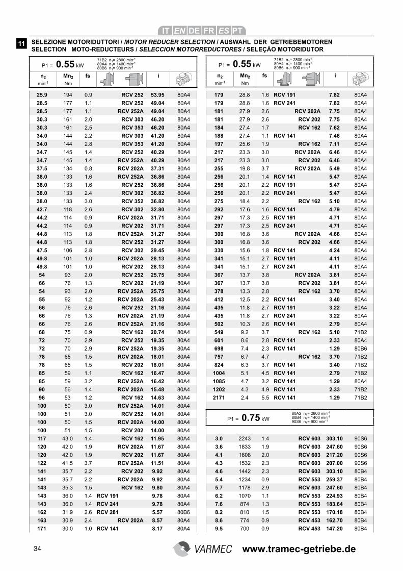
34
25.9 194 0.9 RCV 252 53.95 80A4
28.5 177 1.1 RCV 252 49.04 80A4
28.5 177 1.1 RCV 252A 49.04 80A4
30.3 161 2.0 RCV 303 46.20 80A4
30.3 161 2.5 RCV 353 46.20 80A4
34.0 144 2.2 RCV 303 41.20 80A4
34.0 144 2.8 RCV 353 41.20 80A4
34.7 145 1.4 RCV 252 40.29 80A4
34.7 145 1.4 RCV 252A 40.29 80A4
37.5 134 0.8 RCV 202A 37.31 80A4
38.0 133 1.6 RCV 252A 36.86 80A4
38.0 133 1.6 RCV 252 36.86 80A4
38.0 133 2.4 RCV 302 36.82 80A4
38.0 133 3.0 RCV 352 36.82 80A4
42.7 118 2.6 RCV 302 32.80 80A4
44.2 114 0.9 RCV 202A 31.71 80A4
44.2 114 0.9 RCV 202 31.71 80A4
44.8 113 1.8 RCV 252A 31.27 80A4
44.8 113 1.8 RCV 252 31.27 80A4
47.5 106 2.8 RCV 302 29.45 80A4
49.8 101 1.0 RCV 202A 28.13 80A4
49.8 101 1.0 RCV 202 28.13 80A4
54 93 2.0 RCV 252 25.75 80A4
66 76 1.3 RCV 202 21.19 80A4
54 93 2.0 RCV 252A 25.75 80A4
55 92 1.2 RCV 202A 25.43 80A4
66 76 2.6 RCV 252 21.16 80A4
66 76 1.3 RCV 202A 21.19 80A4
66 76 2.6 RCV 252A 21.16 80A4
68 75 0.9 RCV 162 20.74 80A4
72 70 2.9 RCV 252 19.35 80A4
72 70 2.9 RCV 252A 19.35 80A4
78 65 1.5 RCV 202A 18.01 80A4
78 65 1.5 RCV 202 18.01 80A4
85 59 1.1 RCV 162 16.47 80A4
85 59 3.2 RCV 252A 16.42 80A4
90 56 1.4 RCV 202A 15.48 80A4
96 53 1.2 RCV 162 14.63 80A4
100 50 3.0 RCV 252A 14.01 80A4
100 51 3.0 RCV 252 14.01 80A4
100 50 1.5 RCV 202A 14.00 80A4
100 51 1.5 RCV 202 14.00 80A4
117 43.0 1.4 RCV 162 11.95 80A4
120 42.0 1.9 RCV 202A 11.67 80A4
120 42.0 1.9 RCV 202 11.67 80A4
122 41.5 3.7 RCV 252A 11.51 80A4
141 35.7 2.2 RCV 202 9.92 80A4
141 35.7 2.2 RCV 202A 9.92 80A4
143 35.3 1.5 RCV 162 9.80 80A4
143 36.0 1.4 RCV 191 9.78 80A4
143 36.0 1.4 RCV 241 9.78 80A4
162 31.9 2.6 RCV 281 5.57 80B6
163 30.9 2.4 RCV 202A 8.57 80A4
171 30.0 1.0 RCV 141 8.17 80A4
179 28.8 1.6 RCV 191 7.82 80A4
179 28.8 1.6 RCV 241 7.82 80A4
181 27.9 2.6 RCV 202A 7.75 80A4
181 27.9 2.6 RCV 202 7.75 80A4
184 27.4 1.7 RCV 162 7.62 80A4
188 27.4 1.1 RCV 141 7.46 80A4
197 25.6 1.9 RCV 162 7.11 80A4
217 23.3 3.0 RCV 202A 6.46 80A4
217 23.3 3.0 RCV 202 6.46 80A4
255 19.8 3.7 RCV 202A 5.49 80A4
256 20.1 1.4 RCV 141 5.47 80A4
256 20.1 2.2 RCV 191 5.47 80A4
256 20.1 2.2 RCV 241 5.47 80A4
275 18.4 2.2 RCV 162 5.10 80A4
292 17.6 1.6 RCV 141 4.79 80A4
297 17.3 2.5 RCV 191 4.71 80A4
297 17.3 2.5 RCV 241 4.71 80A4
300 16.8 3.6 RCV 202A 4.66 80A4
300 16.8 3.6 RCV 202 4.66 80A4
330 15.6 1.8 RCV 141 4.24 80A4
341 15.1 2.7 RCV 191 4.11 80A4
341 15.1 2.7 RCV 241 4.11 80A4
367 13.7 3.8 RCV 202A 3.81 80A4
367 13.7 3.8 RCV 202 3.81 80A4
378 13.3 2.8 RCV 162 3.70 80A4
412 12.5 2.2 RCV 141 3.40 80A4
435 11.8 2.7 RCV 191 3.22 80A4
435 11.8 2.7 RCV 241 3.22 80A4
502 10.3 2.6 RCV 141 2.79 80A4
549 9.2 3.7 RCV 162 5.10 71B2
601 8.6 2.8 RCV 141 2.33 80A4
698 7.4 2.3 RCV 141 1.29 80B6
757 6.7 4.7 RCV 162 3.70 71B2
824 6.3 3.7 RCV 141 3.40 71B2
1004 5.1 4.5 RCV 141 2.79 71B2
1085 4.7 3.2 RCV 141 1.29 80A4
1202 4.3 4.9 RCV 141 2.33 71B2
2171 2.4 5.5 RCV 141 1.29 71B2
3.0 2243 1.4 RCV 603 303.10 90S6
3.6 1833 1.9 RCV 603 247.60 90S6
4.1 1608 2.0 RCV 603 217.20 90S6
4.3 1532 2.3 RCV 603 207.00 90S6
4.6 1442 2.3 RCV 603 303.10 80B4
5.4 1234 0.9 RCV 553 259.37 80B4
5.7 1178 2.9 RCV 603 247.60 80B4
6.2 1070 1.1 RCV 553 224.93 80B4
7.6 874 1.3 RCV 553 183.64 80B4
8.2 810 1.5 RCV 553 170.18 80B4
8.6 774 0.9 RCV 453 162.70 80B4
9.5 700 0.9 RCV 453 147.20 80B4
P1 = 0.55 kW
71B2 n1= 2800 min-1
80A4 n1= 1400 min-1
80B6 n1= 900 min-1
n2 Mn2 fs i
min-1 Nm
P1 = 0.55 kW
71B2 n1= 2800 min-1
80A4 n1= 1400 min-1
80B6 n1= 900 min-1
n2 Mn2 fs i
min-1 Nm
SELEZIONE MOTORIDUTTORI / MOTOR REDUCER SELECTION / AUSWAHL DER GETRIEBEMOTORENSELECTION MOTO-REDUCTEURS / SELECCION MOTORREDUCTORES / SELEÇÃO MOTORIDUTOR
11
P1 = 0.75 kW
80A2 n1= 2800 min-1
80B4 n1= 1400 min-1
90S6 n1= 900 min-1
www.tramec-getriebe.de
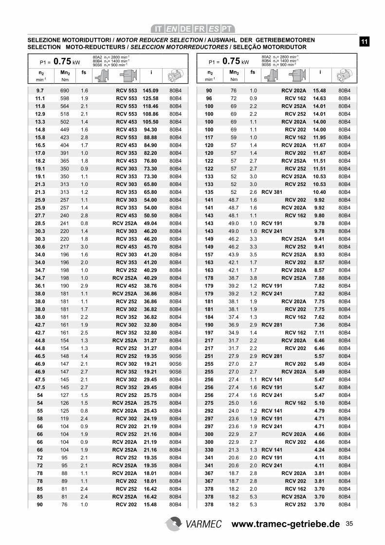
35
9.7 690 1.6 RCV 553 145.09 80B4
11.1 598 1.9 RCV 553 125.58 80B4
11.8 564 2.1 RCV 553 118.46 80B4
12.9 518 2.1 RCV 553 108.86 80B4
13.3 502 1.4 RCV 453 105.50 80B4
14.8 449 1.6 RCV 453 94.30 80B4
15.8 423 2.8 RCV 553 88.88 80B4
16.5 404 1.7 RCV 453 84.90 80B4
17.0 391 1.0 RCV 353 82.20 80B4
18.2 365 1.8 RCV 453 76.80 80B4
19.1 350 0.9 RCV 303 73.30 80B4
19.1 350 1.1 RCV 353 73.30 80B4
21.3 313 1.0 RCV 303 65.80 80B4
21.3 313 1.2 RCV 353 65.80 80B4
25.9 257 1.1 RCV 303 54.00 80B4
25.9 257 1.4 RCV 353 54.00 80B4
27.7 240 2.8 RCV 453 50.50 80B4
28.5 241 0.8 RCV 252A 49.04 80B4
30.3 220 1.4 RCV 303 46.20 80B4
30.3 220 1.8 RCV 353 46.20 80B4
30.6 217 3.0 RCV 453 45.70 80B4
34.0 196 1.6 RCV 303 41.20 80B4
34.0 196 2.0 RCV 353 41.20 80B4
34.7 198 1.0 RCV 252 40.29 80B4
34.7 198 1.0 RCV 252A 40.29 80B4
36.1 190 2.9 RCV 452 38.76 80B4
38.0 181 1.1 RCV 252A 36.86 80B4
38.0 181 1.1 RCV 252 36.86 80B4
38.0 181 1.7 RCV 302 36.82 80B4
38.0 181 2.2 RCV 352 36.82 80B4
42.7 161 1.9 RCV 302 32.80 80B4
42.7 161 2.5 RCV 352 32.80 80B4
44.8 154 1.3 RCV 252A 31.27 80B4
44.8 154 1.3 RCV 252 31.27 80B4
46.5 148 1.4 RCV 252 19.35 90S6
46.9 147 2.1 RCV 302 19.21 90S6
46.9 147 2.7 RCV 352 19.21 90S6
47.5 145 2.1 RCV 302 29.45 80B4
47.5 145 2.7 RCV 352 29.45 80B4
54 127 1.5 RCV 252 25.75 80B4
54 126 1.5 RCV 252A 25.75 80B4
55 125 0.8 RCV 202A 25.43 80B4
58 119 2.4 RCV 302 24.19 80B4
66 104 0.9 RCV 202 21.19 80B4
66 104 1.9 RCV 252 21.16 80B4
66 104 0.9 RCV 202A 21.19 80B4
66 104 1.9 RCV 252A 21.16 80B4
72 95 2.1 RCV 252 19.35 80B4
72 95 2.1 RCV 252A 19.35 80B4
78 88 1.1 RCV 202A 18.01 80B4
78 89 1.1 RCV 202 18.01 80B4
85 81 2.4 RCV 252 16.42 80B4
85 81 2.4 RCV 252A 16.42 80B4
90 76 1.0 RCV 202 15.48 80B4
90 76 1.0 RCV 202A 15.48 80B4
96 72 0.9 RCV 162 14.63 80B4
100 69 2.2 RCV 252A 14.01 80B4
100 69 2.2 RCV 252 14.01 80B4
100 69 1.1 RCV 202A 14.00 80B4
100 69 1.1 RCV 202 14.00 80B4
117 59 1.0 RCV 162 11.95 80B4
120 57 1.4 RCV 202A 11.67 80B4
120 57 1.4 RCV 202 11.67 80B4
122 57 2.7 RCV 252A 11.51 80B4
122 57 2.7 RCV 252 11.51 80B4
133 52 3.0 RCV 252A 10.53 80B4
133 52 3.0 RCV 252 10.53 80B4
135 52 2.6 RCV 381 10.40 80B4
141 48.7 1.6 RCV 202 9.92 80B4
141 48.7 1.6 RCV 202A 9.92 80B4
143 48.1 1.1 RCV 162 9.80 80B4
143 49.0 1.0 RCV 191 9.78 80B4
143 49.0 1.0 RCV 241 9.78 80B4
149 46.2 3.3 RCV 252A 9.41 80B4
149 46.2 3.3 RCV 252 9.41 80B4
157 43.9 3.5 RCV 252A 8.93 80B4
163 42.1 1.7 RCV 202 8.57 80B4
163 42.1 1.7 RCV 202A 8.57 80B4
178 38.7 3.8 RCV 252A 7.88 80B4
179 39.2 1.2 RCV 191 7.82 80B4
179 39.2 1.2 RCV 241 7.82 80B4
181 38.1 1.9 RCV 202A 7.75 80B4
181 38.1 1.9 RCV 202 7.75 80B4
184 37.4 1.3 RCV 162 7.62 80B4
190 36.9 2.9 RCV 281 7.36 80B4
197 34.9 1.4 RCV 162 7.11 80B4
217 31.7 2.2 RCV 202A 6.46 80B4
217 31.7 2.2 RCV 202 6.46 80B4
251 27.9 2.9 RCV 281 5.57 80B4
255 27.0 2.7 RCV 202 5.49 80B4
255 27.0 2.7 RCV 202A 5.49 80B4
256 27.4 1.1 RCV 141 5.47 80B4
256 27.4 1.6 RCV 191 5.47 80B4
256 27.4 1.6 RCV 241 5.47 80B4
275 25.0 1.6 RCV 162 5.10 80B4
292 24.0 1.2 RCV 141 4.79 80B4
297 23.6 1.9 RCV 191 4.71 80B4
297 23.6 1.9 RCV 241 4.71 80B4
300 22.9 2.7 RCV 202A 4.66 80B4
300 22.9 2.7 RCV 202 4.66 80B4
330 21.3 1.3 RCV 141 4.24 80B4
341 20.6 2.0 RCV 191 4.11 80B4
341 20.6 2.0 RCV 241 4.11 80B4
367 18.7 2.8 RCV 202A 3.81 80B4
367 18.7 2.8 RCV 202 3.81 80B4
378 18.2 2.0 RCV 162 3.70 80B4
378 18.2 5.3 RCV 252A 3.70 80B4
378 18.2 5.3 RCV 252 3.70 80B4
P1 = 0.75 kW
80A2 n1= 2800 min-1
80B4 n1= 1400 min-1
90S6 n1= 900 min-1
n2 Mn2 fs i
min-1 Nm
P1 = 0.75 kW
80A2 n1= 2800 min-1
80B4 n1= 1400 min-1
90S6 n1= 900 min-1
n2 Mn2 fs i
min-1 Nm
SELEZIONE MOTORIDUTTORI / MOTOR REDUCER SELECTION / AUSWAHL DER GETRIEBEMOTORENSELECTION MOTO-REDUCTEURS / SELECCION MOTORREDUCTORES / SELEÇÃO MOTORIDUTOR
11
www.tramec-getriebe.de
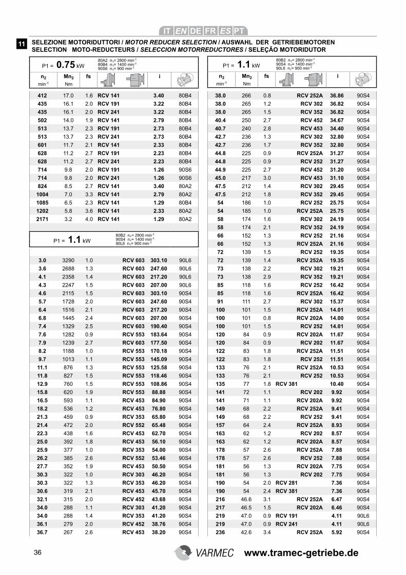
36
412 17.0 1.6 RCV 141 3.40 80B4
435 16.1 2.0 RCV 191 3.22 80B4
435 16.1 2.0 RCV 241 3.22 80B4
502 14.0 1.9 RCV 141 2.79 80B4
513 13.7 2.3 RCV 191 2.73 80B4
513 13.7 2.3 RCV 241 2.73 80B4
601 11.7 2.1 RCV 141 2.33 80B4
628 11.2 2.7 RCV 191 2.23 80B4
628 11.2 2.7 RCV 241 2.23 80B4
714 9.8 2.0 RCV 191 1.26 90S6
714 9.8 2.0 RCV 241 1.26 90S6
824 8.5 2.7 RCV 141 3.40 80A2
1004 7.0 3.3 RCV 141 2.79 80A2
1085 6.5 2.3 RCV 141 1.29 80B4
1202 5.8 3.6 RCV 141 2.33 80A2
2171 3.2 4.0 RCV 141 1.29 80A2
3.0 3290 1.0 RCV 603 303.10 90L6
3.6 2688 1.3 RCV 603 247.60 90L6
4.1 2358 1.4 RCV 603 217.20 90L6
4.3 2247 1.5 RCV 603 207.00 90L6
4.6 2115 1.5 RCV 603 303.10 90S4
5.7 1728 2.0 RCV 603 247.60 90S4
6.4 1516 2.1 RCV 603 217.20 90S4
6.8 1445 2.4 RCV 603 207.00 90S4
7.4 1329 2.5 RCV 603 190.40 90S4
7.6 1282 0.9 RCV 553 183.64 90S4
7.9 1239 2.7 RCV 603 177.50 90S4
8.2 1188 1.0 RCV 553 170.18 90S4
9.7 1013 1.1 RCV 553 145.09 90S4
11.1 876 1.3 RCV 553 125.58 90S4
11.8 827 1.5 RCV 553 118.46 90S4
12.9 760 1.5 RCV 553 108.86 90S4
15.8 620 1.9 RCV 553 88.88 90S4
16.5 593 1.1 RCV 453 84.90 90S4
18.2 536 1.2 RCV 453 76.80 90S4
21.3 459 0.9 RCV 353 65.80 90S4
21.4 472 2.0 RCV 552 65.48 90S4
22.3 438 1.6 RCV 453 62.70 90S4
25.0 392 1.8 RCV 453 56.10 90S4
25.9 377 1.0 RCV 353 54.00 90S4
26.2 385 2.6 RCV 552 53.46 90S4
27.7 352 1.9 RCV 453 50.50 90S4
30.3 322 1.0 RCV 303 46.20 90S4
30.3 322 1.3 RCV 353 46.20 90S4
30.6 319 2.1 RCV 453 45.70 90S4
32.1 315 2.0 RCV 452 43.68 90S4
34.0 288 1.1 RCV 303 41.20 90S4
34.0 288 1.4 RCV 353 41.20 90S4
36.1 279 2.0 RCV 452 38.76 90S4
36.7 267 2.6 RCV 453 38.20 90S4
38.0 266 0.8 RCV 252A 36.86 90S4
38.0 265 1.2 RCV 302 36.82 90S4
38.0 265 1.5 RCV 352 36.82 90S4
40.4 250 2.7 RCV 452 34.67 90S4
40.7 240 2.8 RCV 453 34.40 90S4
42.7 236 1.3 RCV 302 32.80 90S4
42.7 236 1.7 RCV 352 32.80 90S4
44.8 225 0.9 RCV 252A 31.27 90S4
44.8 225 0.9 RCV 252 31.27 90S4
44.9 225 2.7 RCV 452 31.20 90S4
45.0 217 3.0 RCV 453 31.10 90S4
47.5 212 1.4 RCV 302 29.45 90S4
47.5 212 1.8 RCV 352 29.45 90S4
54 186 1.0 RCV 252 25.75 90S4
54 185 1.0 RCV 252A 25.75 90S4
58 174 1.6 RCV 302 24.19 90S4
58 174 2.1 RCV 352 24.19 90S4
66 152 1.3 RCV 252 21.16 90S4
66 152 1.3 RCV 252A 21.16 90S4
72 139 1.5 RCV 252 19.35 90S4
72 139 1.4 RCV 252A 19.35 90S4
73 138 2.2 RCV 302 19.21 90S4
73 138 2.9 RCV 352 19.21 90S4
85 118 1.6 RCV 252 16.42 90S4
85 118 1.6 RCV 252A 16.42 90S4
91 111 2.7 RCV 302 15.37 90S4
100 101 1.5 RCV 252A 14.01 90S4
100 101 0.8 RCV 202A 14.00 90S4
100 101 1.5 RCV 252 14.01 90S4
120 84 0.9 RCV 202A 11.67 90S4
120 84 0.9 RCV 202 11.67 90S4
122 83 1.8 RCV 252A 11.51 90S4
122 83 1.8 RCV 252 11.51 90S4
133 76 2.1 RCV 252A 10.53 90S4
133 76 2.1 RCV 252 10.53 90S4
135 77 1.8 RCV 381 10.40 90S4
141 72 1.1 RCV 202 9.92 90S4
141 71 1.1 RCV 202A 9.92 90S4
149 68 2.2 RCV 252A 9.41 90S4
149 68 2.2 RCV 252 9.41 90S4
157 64 2.4 RCV 252A 8.93 90S4
163 62 1.2 RCV 202 8.57 90S4
163 62 1.2 RCV 202A 8.57 90S4
178 57 2.6 RCV 252A 7.88 90S4
178 57 2.6 RCV 252 7.88 90S4
181 56 1.3 RCV 202A 7.75 90S4
181 56 1.3 RCV 202 7.75 90S4
190 54 2.0 RCV 281 7.36 90S4
190 54 2.4 RCV 381 7.36 90S4
216 46.6 3.1 RCV 252A 6.47 90S4
217 46.5 1.5 RCV 202A 6.46 90S4
219 47.0 0.9 RCV 191 4.11 90L6
219 47.0 0.9 RCV 241 4.11 90L6
236 42.6 3.4 RCV 252A 5.92 90S4
P1 = 0.75 kW
80A2 n1= 2800 min-1
80B4 n1= 1400 min-1
90S6 n1= 900 min-1
n2 Mn2 fs i
min-1 Nm
P1 = 1.1 kW
80B2 n1= 2800 min-1
90S4 n1= 1400 min-1
90L6 n1= 900 min-1
n2 Mn2 fs i
min-1 Nm
SELEZIONE MOTORIDUTTORI / MOTOR REDUCER SELECTION / AUSWAHL DER GETRIEBEMOTORENSELECTION MOTO-REDUCTEURS / SELECCION MOTORREDUCTORES / SELEÇÃO MOTORIDUTOR
11
P1 = 1.1 kW
80B2 n1= 2800 min-1
90S4 n1= 1400 min-1
90L6 n1= 900 min-1
www.tramec-getriebe.de
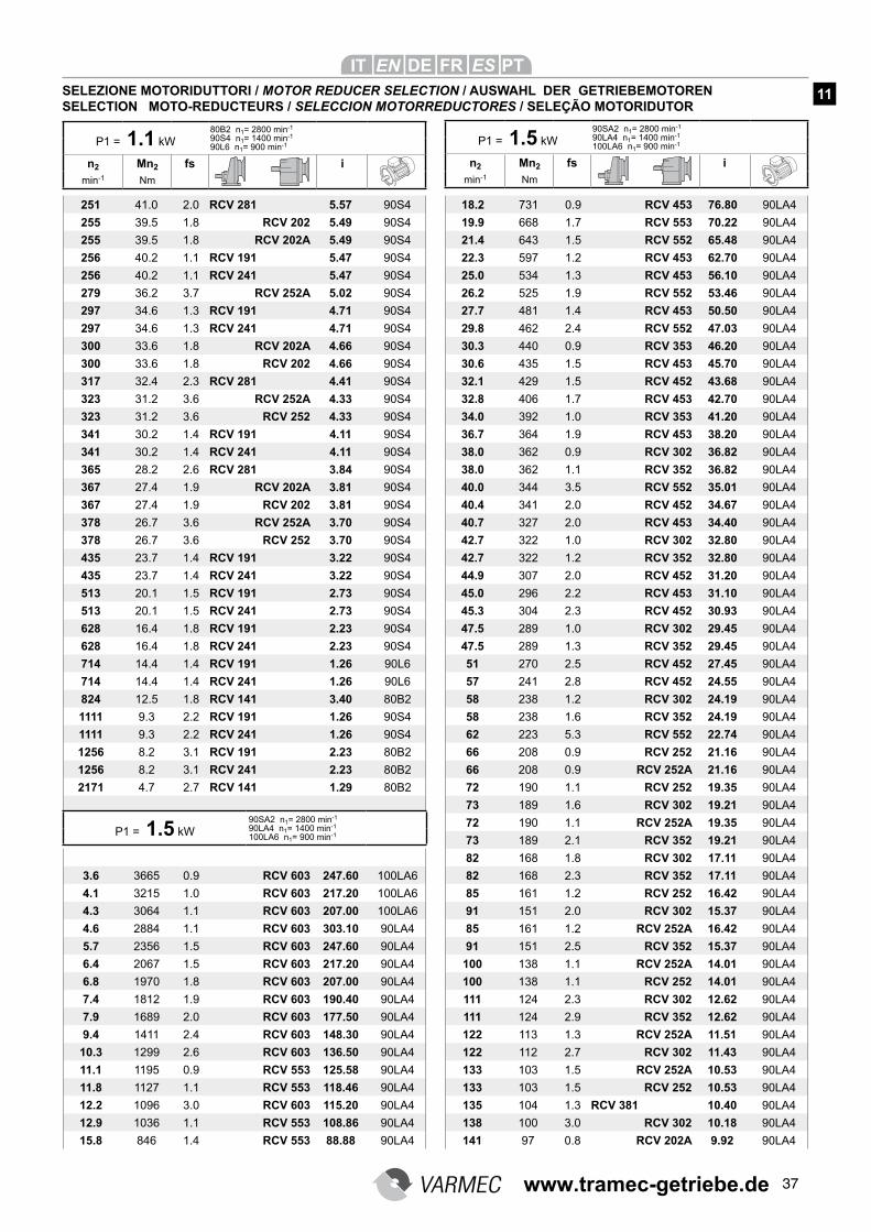
37
251 41.0 2.0 RCV 281 5.57 90S4
255 39.5 1.8 RCV 202 5.49 90S4
255 39.5 1.8 RCV 202A 5.49 90S4
256 40.2 1.1 RCV 191 5.47 90S4
256 40.2 1.1 RCV 241 5.47 90S4
279 36.2 3.7 RCV 252A 5.02 90S4
297 34.6 1.3 RCV 191 4.71 90S4
297 34.6 1.3 RCV 241 4.71 90S4
300 33.6 1.8 RCV 202A 4.66 90S4
300 33.6 1.8 RCV 202 4.66 90S4
317 32.4 2.3 RCV 281 4.41 90S4
323 31.2 3.6 RCV 252A 4.33 90S4
323 31.2 3.6 RCV 252 4.33 90S4
341 30.2 1.4 RCV 191 4.11 90S4
341 30.2 1.4 RCV 241 4.11 90S4
365 28.2 2.6 RCV 281 3.84 90S4
367 27.4 1.9 RCV 202A 3.81 90S4
367 27.4 1.9 RCV 202 3.81 90S4
378 26.7 3.6 RCV 252A 3.70 90S4
378 26.7 3.6 RCV 252 3.70 90S4
435 23.7 1.4 RCV 191 3.22 90S4
435 23.7 1.4 RCV 241 3.22 90S4
513 20.1 1.5 RCV 191 2.73 90S4
513 20.1 1.5 RCV 241 2.73 90S4
628 16.4 1.8 RCV 191 2.23 90S4
628 16.4 1.8 RCV 241 2.23 90S4
714 14.4 1.4 RCV 191 1.26 90L6
714 14.4 1.4 RCV 241 1.26 90L6
824 12.5 1.8 RCV 141 3.40 80B2
1111 9.3 2.2 RCV 191 1.26 90S4
1111 9.3 2.2 RCV 241 1.26 90S4
1256 8.2 3.1 RCV 191 2.23 80B2
1256 8.2 3.1 RCV 241 2.23 80B2
2171 4.7 2.7 RCV 141 1.29 80B2
3.6 3665 0.9 RCV 603 247.60 100LA6
4.1 3215 1.0 RCV 603 217.20 100LA6
4.3 3064 1.1 RCV 603 207.00 100LA6
4.6 2884 1.1 RCV 603 303.10 90LA4
5.7 2356 1.5 RCV 603 247.60 90LA4
6.4 2067 1.5 RCV 603 217.20 90LA4
6.8 1970 1.8 RCV 603 207.00 90LA4
7.4 1812 1.9 RCV 603 190.40 90LA4
7.9 1689 2.0 RCV 603 177.50 90LA4
9.4 1411 2.4 RCV 603 148.30 90LA4
10.3 1299 2.6 RCV 603 136.50 90LA4
11.1 1195 0.9 RCV 553 125.58 90LA4
11.8 1127 1.1 RCV 553 118.46 90LA4
12.2 1096 3.0 RCV 603 115.20 90LA4
12.9 1036 1.1 RCV 553 108.86 90LA4
15.8 846 1.4 RCV 553 88.88 90LA4
18.2 731 0.9 RCV 453 76.80 90LA4
19.9 668 1.7 RCV 553 70.22 90LA4
21.4 643 1.5 RCV 552 65.48 90LA4
22.3 597 1.2 RCV 453 62.70 90LA4
25.0 534 1.3 RCV 453 56.10 90LA4
26.2 525 1.9 RCV 552 53.46 90LA4
27.7 481 1.4 RCV 453 50.50 90LA4
29.8 462 2.4 RCV 552 47.03 90LA4
30.3 440 0.9 RCV 353 46.20 90LA4
30.6 435 1.5 RCV 453 45.70 90LA4
32.1 429 1.5 RCV 452 43.68 90LA4
32.8 406 1.7 RCV 453 42.70 90LA4
34.0 392 1.0 RCV 353 41.20 90LA4
36.7 364 1.9 RCV 453 38.20 90LA4
38.0 362 0.9 RCV 302 36.82 90LA4
38.0 362 1.1 RCV 352 36.82 90LA4
40.0 344 3.5 RCV 552 35.01 90LA4
40.4 341 2.0 RCV 452 34.67 90LA4
40.7 327 2.0 RCV 453 34.40 90LA4
42.7 322 1.0 RCV 302 32.80 90LA4
42.7 322 1.2 RCV 352 32.80 90LA4
44.9 307 2.0 RCV 452 31.20 90LA4
45.0 296 2.2 RCV 453 31.10 90LA4
45.3 304 2.3 RCV 452 30.93 90LA4
47.5 289 1.0 RCV 302 29.45 90LA4
47.5 289 1.3 RCV 352 29.45 90LA4
51 270 2.5 RCV 452 27.45 90LA4
57 241 2.8 RCV 452 24.55 90LA4
58 238 1.2 RCV 302 24.19 90LA4
58 238 1.6 RCV 352 24.19 90LA4
62 223 5.3 RCV 552 22.74 90LA4
66 208 0.9 RCV 252 21.16 90LA4
66 208 0.9 RCV 252A 21.16 90LA4
72 190 1.1 RCV 252 19.35 90LA4
73 189 1.6 RCV 302 19.21 90LA4
72 190 1.1 RCV 252A 19.35 90LA4
73 189 2.1 RCV 352 19.21 90LA4
82 168 1.8 RCV 302 17.11 90LA4
82 168 2.3 RCV 352 17.11 90LA4
85 161 1.2 RCV 252 16.42 90LA4
91 151 2.0 RCV 302 15.37 90LA4
85 161 1.2 RCV 252A 16.42 90LA4
91 151 2.5 RCV 352 15.37 90LA4
100 138 1.1 RCV 252A 14.01 90LA4
100 138 1.1 RCV 252 14.01 90LA4
111 124 2.3 RCV 302 12.62 90LA4
111 124 2.9 RCV 352 12.62 90LA4
122 113 1.3 RCV 252A 11.51 90LA4
122 112 2.7 RCV 302 11.43 90LA4
133 103 1.5 RCV 252A 10.53 90LA4
133 103 1.5 RCV 252 10.53 90LA4
135 104 1.3 RCV 381 10.40 90LA4
138 100 3.0 RCV 302 10.18 90LA4
141 97 0.8 RCV 202A 9.92 90LA4
P1 = 1.1 kW
80B2 n1= 2800 min-1
90S4 n1= 1400 min-1
90L6 n1= 900 min-1
n2 Mn2 fs i
min-1 Nm
P1 = 1.5 kW
90SA2 n1= 2800 min-1
90LA4 n1= 1400 min-1
100LA6 n1= 900 min-1
n2 Mn2 fs i
min-1 Nm
SELEZIONE MOTORIDUTTORI / MOTOR REDUCER SELECTION / AUSWAHL DER GETRIEBEMOTORENSELECTION MOTO-REDUCTEURS / SELECCION MOTORREDUCTORES / SELEÇÃO MOTORIDUTOR
11
P1 = 1.5 kW
90SA2 n1= 2800 min-1
90LA4 n1= 1400 min-1
100LA6 n1= 900 min-1
www.tramec-getriebe.de
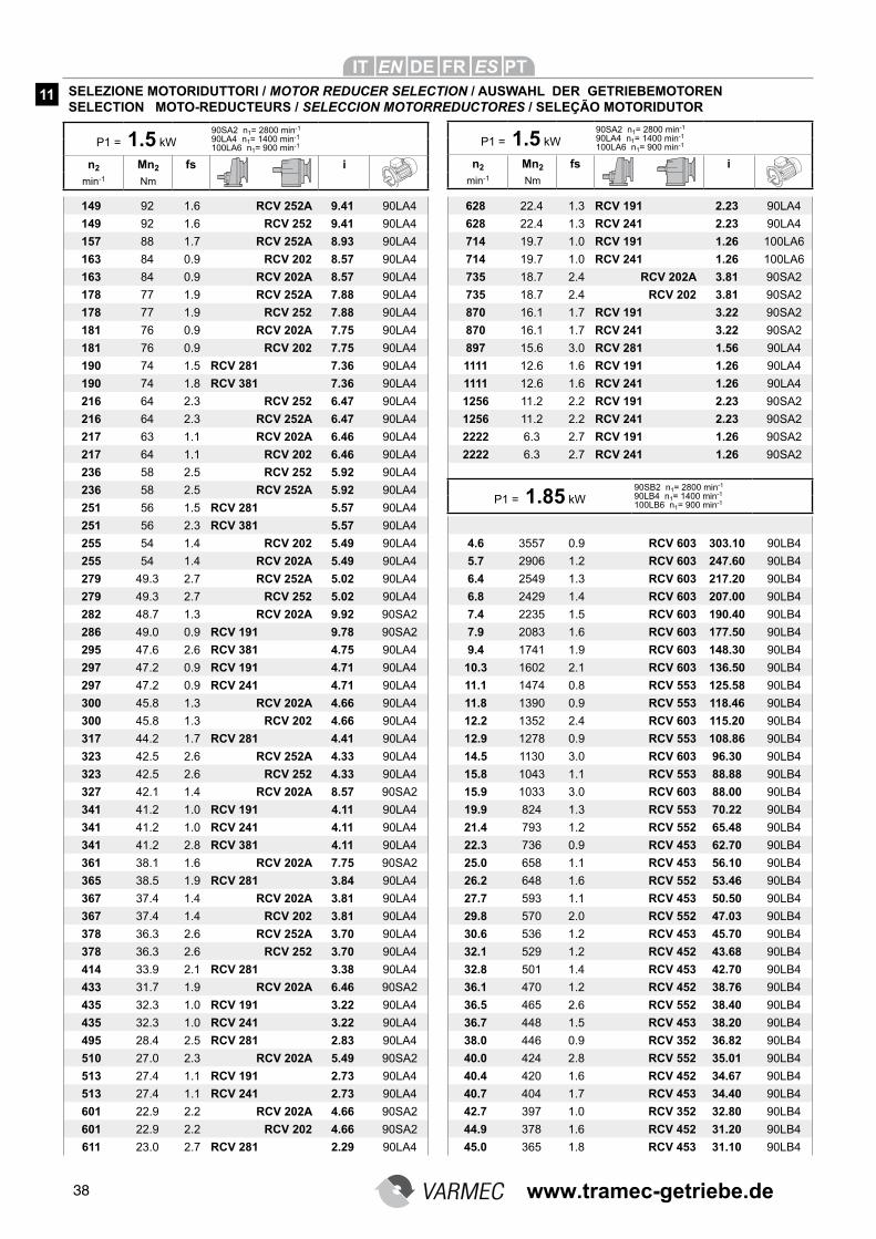
38
149 92 1.6 RCV 252A 9.41 90LA4
149 92 1.6 RCV 252 9.41 90LA4
157 88 1.7 RCV 252A 8.93 90LA4
163 84 0.9 RCV 202 8.57 90LA4
163 84 0.9 RCV 202A 8.57 90LA4
178 77 1.9 RCV 252A 7.88 90LA4
178 77 1.9 RCV 252 7.88 90LA4
181 76 0.9 RCV 202A 7.75 90LA4
181 76 0.9 RCV 202 7.75 90LA4
190 74 1.5 RCV 281 7.36 90LA4
190 74 1.8 RCV 381 7.36 90LA4
216 64 2.3 RCV 252 6.47 90LA4
216 64 2.3 RCV 252A 6.47 90LA4
217 63 1.1 RCV 202A 6.46 90LA4
217 64 1.1 RCV 202 6.46 90LA4
236 58 2.5 RCV 252 5.92 90LA4
236 58 2.5 RCV 252A 5.92 90LA4
251 56 1.5 RCV 281 5.57 90LA4
251 56 2.3 RCV 381 5.57 90LA4
255 54 1.4 RCV 202 5.49 90LA4
255 54 1.4 RCV 202A 5.49 90LA4
279 49.3 2.7 RCV 252A 5.02 90LA4
279 49.3 2.7 RCV 252 5.02 90LA4
282 48.7 1.3 RCV 202A 9.92 90SA2
286 49.0 0.9 RCV 191 9.78 90SA2
295 47.6 2.6 RCV 381 4.75 90LA4
297 47.2 0.9 RCV 191 4.71 90LA4
297 47.2 0.9 RCV 241 4.71 90LA4
300 45.8 1.3 RCV 202A 4.66 90LA4
300 45.8 1.3 RCV 202 4.66 90LA4
317 44.2 1.7 RCV 281 4.41 90LA4
323 42.5 2.6 RCV 252A 4.33 90LA4
323 42.5 2.6 RCV 252 4.33 90LA4
327 42.1 1.4 RCV 202A 8.57 90SA2
341 41.2 1.0 RCV 191 4.11 90LA4
341 41.2 1.0 RCV 241 4.11 90LA4
341 41.2 2.8 RCV 381 4.11 90LA4
361 38.1 1.6 RCV 202A 7.75 90SA2
365 38.5 1.9 RCV 281 3.84 90LA4
367 37.4 1.4 RCV 202A 3.81 90LA4
367 37.4 1.4 RCV 202 3.81 90LA4
378 36.3 2.6 RCV 252A 3.70 90LA4
378 36.3 2.6 RCV 252 3.70 90LA4
414 33.9 2.1 RCV 281 3.38 90LA4
433 31.7 1.9 RCV 202A 6.46 90SA2
435 32.3 1.0 RCV 191 3.22 90LA4
435 32.3 1.0 RCV 241 3.22 90LA4
495 28.4 2.5 RCV 281 2.83 90LA4
510 27.0 2.3 RCV 202A 5.49 90SA2
513 27.4 1.1 RCV 191 2.73 90LA4
513 27.4 1.1 RCV 241 2.73 90LA4
601 22.9 2.2 RCV 202A 4.66 90SA2
601 22.9 2.2 RCV 202 4.66 90SA2
611 23.0 2.7 RCV 281 2.29 90LA4
628 22.4 1.3 RCV 191 2.23 90LA4
628 22.4 1.3 RCV 241 2.23 90LA4
714 19.7 1.0 RCV 191 1.26 100LA6
714 19.7 1.0 RCV 241 1.26 100LA6
735 18.7 2.4 RCV 202A 3.81 90SA2
735 18.7 2.4 RCV 202 3.81 90SA2
870 16.1 1.7 RCV 191 3.22 90SA2
870 16.1 1.7 RCV 241 3.22 90SA2
897 15.6 3.0 RCV 281 1.56 90LA4
1111 12.6 1.6 RCV 191 1.26 90LA4
1111 12.6 1.6 RCV 241 1.26 90LA4
1256 11.2 2.2 RCV 191 2.23 90SA2
1256 11.2 2.2 RCV 241 2.23 90SA2
2222 6.3 2.7 RCV 191 1.26 90SA2
2222 6.3 2.7 RCV 241 1.26 90SA2
4.6 3557 0.9 RCV 603 303.10 90LB4
5.7 2906 1.2 RCV 603 247.60 90LB4
6.4 2549 1.3 RCV 603 217.20 90LB4
6.8 2429 1.4 RCV 603 207.00 90LB4
7.4 2235 1.5 RCV 603 190.40 90LB4
7.9 2083 1.6 RCV 603 177.50 90LB4
9.4 1741 1.9 RCV 603 148.30 90LB4
10.3 1602 2.1 RCV 603 136.50 90LB4
11.1 1474 0.8 RCV 553 125.58 90LB4
11.8 1390 0.9 RCV 553 118.46 90LB4
12.2 1352 2.4 RCV 603 115.20 90LB4
12.9 1278 0.9 RCV 553 108.86 90LB4
14.5 1130 3.0 RCV 603 96.30 90LB4
15.8 1043 1.1 RCV 553 88.88 90LB4
15.9 1033 3.0 RCV 603 88.00 90LB4
19.9 824 1.3 RCV 553 70.22 90LB4
21.4 793 1.2 RCV 552 65.48 90LB4
22.3 736 0.9 RCV 453 62.70 90LB4
25.0 658 1.1 RCV 453 56.10 90LB4
26.2 648 1.6 RCV 552 53.46 90LB4
27.7 593 1.1 RCV 453 50.50 90LB4
29.8 570 2.0 RCV 552 47.03 90LB4
30.6 536 1.2 RCV 453 45.70 90LB4
32.1 529 1.2 RCV 452 43.68 90LB4
32.8 501 1.4 RCV 453 42.70 90LB4
36.1 470 1.2 RCV 452 38.76 90LB4
36.5 465 2.6 RCV 552 38.40 90LB4
36.7 448 1.5 RCV 453 38.20 90LB4
38.0 446 0.9 RCV 352 36.82 90LB4
40.0 424 2.8 RCV 552 35.01 90LB4
40.4 420 1.6 RCV 452 34.67 90LB4
40.7 404 1.7 RCV 453 34.40 90LB4
42.7 397 1.0 RCV 352 32.80 90LB4
44.9 378 1.6 RCV 452 31.20 90LB4
45.0 365 1.8 RCV 453 31.10 90LB4
P1 = 1.5 kW
90SA2 n1= 2800 min-1
90LA4 n1= 1400 min-1
100LA6 n1= 900 min-1
n2 Mn2 fs i
min-1 Nm
P1 = 1.5 kW
90SA2 n1= 2800 min-1
90LA4 n1= 1400 min-1
100LA6 n1= 900 min-1
n2 Mn2 fs i
min-1 Nm
SELEZIONE MOTORIDUTTORI / MOTOR REDUCER SELECTION / AUSWAHL DER GETRIEBEMOTORENSELECTION MOTO-REDUCTEURS / SELECCION MOTORREDUCTORES / SELEÇÃO MOTORIDUTOR
11
P1 = 1.85 kW
90SB2 n1= 2800 min-1
90LB4 n1= 1400 min-1
100LB6 n1= 900 min-1
www.tramec-getriebe.de
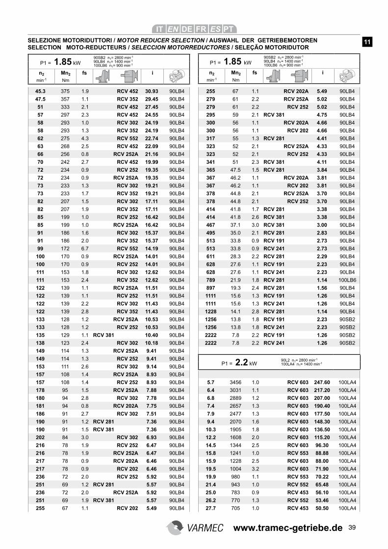
39
45.3 375 1.9 RCV 452 30.93 90LB4
47.5 357 1.1 RCV 352 29.45 90LB4
51 333 2.1 RCV 452 27.45 90LB4
57 297 2.3 RCV 452 24.55 90LB4
58 293 1.0 RCV 302 24.19 90LB4
58 293 1.3 RCV 352 24.19 90LB4
62 275 4.3 RCV 552 22.74 90LB4
63 268 2.5 RCV 452 22.09 90LB4
66 256 0.8 RCV 252A 21.16 90LB4
70 242 2.7 RCV 452 19.99 90LB4
72 234 0.9 RCV 252 19.35 90LB4
72 234 0.9 RCV 252A 19.35 90LB4
73 233 1.3 RCV 302 19.21 90LB4
73 233 1.7 RCV 352 19.21 90LB4
82 207 1.5 RCV 302 17.11 90LB4
82 207 1.9 RCV 352 17.11 90LB4
85 199 1.0 RCV 252 16.42 90LB4
85 199 1.0 RCV 252A 16.42 90LB4
91 186 1.6 RCV 302 15.37 90LB4
91 186 2.0 RCV 352 15.37 90LB4
99 172 6.7 RCV 552 14.19 90LB4
100 170 0.9 RCV 252A 14.01 90LB4
100 170 0.9 RCV 252 14.01 90LB4
111 153 1.8 RCV 302 12.62 90LB4
111 153 2.4 RCV 352 12.62 90LB4
122 139 1.1 RCV 252A 11.51 90LB4
122 139 1.1 RCV 252 11.51 90LB4
122 139 2.2 RCV 302 11.43 90LB4
122 139 2.8 RCV 352 11.43 90LB4
133 128 1.2 RCV 252A 10.53 90LB4
133 128 1.2 RCV 252 10.53 90LB4
135 129 1.1 RCV 381 10.40 90LB4
138 123 2.4 RCV 302 10.18 90LB4
149 114 1.3 RCV 252A 9.41 90LB4
149 114 1.3 RCV 252 9.41 90LB4
153 111 2.6 RCV 302 9.14 90LB4
157 108 1.4 RCV 252A 8.93 90LB4
157 108 1.4 RCV 252 8.93 90LB4
178 95 1.5 RCV 252A 7.88 90LB4
180 94 2.8 RCV 302 7.78 90LB4
181 94 0.8 RCV 202A 7.75 90LB4
186 91 2.7 RCV 302 7.51 90LB4
190 91 1.2 RCV 281 7.36 90LB4
190 91 1.5 RCV 381 7.36 90LB4
202 84 3.0 RCV 302 6.93 90LB4
216 78 1.9 RCV 252 6.47 90LB4
216 78 1.9 RCV 252A 6.47 90LB4
217 78 0.9 RCV 202A 6.46 90LB4
217 78 0.9 RCV 202 6.46 90LB4
236 72 2.0 RCV 252 5.92 90LB4
251 69 1.2 RCV 281 5.57 90LB4
236 72 2.0 RCV 252A 5.92 90LB4
251 69 1.9 RCV 381 5.57 90LB4
255 67 1.1 RCV 202 5.49 90LB4
255 67 1.1 RCV 202A 5.49 90LB4
279 61 2.2 RCV 252A 5.02 90LB4
279 61 2.2 RCV 252 5.02 90LB4
295 59 2.1 RCV 381 4.75 90LB4
300 56 1.1 RCV 202A 4.66 90LB4
300 56 1.1 RCV 202 4.66 90LB4
317 55 1.3 RCV 281 4.41 90LB4
323 52 2.1 RCV 252A 4.33 90LB4
323 52 2.1 RCV 252 4.33 90LB4
341 51 2.3 RCV 381 4.11 90LB4
365 47.5 1.5 RCV 281 3.84 90LB4
367 46.2 1.1 RCV 202A 3.81 90LB4
367 46.2 1.1 RCV 202 3.81 90LB4
378 44.8 2.1 RCV 252A 3.70 90LB4
378 44.8 2.1 RCV 252 3.70 90LB4
414 41.8 1.7 RCV 281 3.38 90LB4
414 41.8 2.6 RCV 381 3.38 90LB4
467 37.1 3.0 RCV 381 3.00 90LB4
495 35.0 2.1 RCV 281 2.83 90LB4
513 33.8 0.9 RCV 191 2.73 90LB4
513 33.8 0.9 RCV 241 2.73 90LB4
611 28.3 2.2 RCV 281 2.29 90LB4
628 27.6 1.1 RCV 191 2.23 90LB4
628 27.6 1.1 RCV 241 2.23 90LB4
789 21.9 1.8 RCV 281 1.14 100LB6
897 19.3 2.4 RCV 281 1.56 90LB4
1111 15.6 1.3 RCV 191 1.26 90LB4
1111 15.6 1.3 RCV 241 1.26 90LB4
1228 14.1 2.8 RCV 281 1.14 90LB4
1256 13.8 1.8 RCV 191 2.23 90SB2
1256 13.8 1.8 RCV 241 2.23 90SB2
2222 7.8 2.2 RCV 191 1.26 90SB2
2222 7.8 2.2 RCV 241 1.26 90SB2
5.7 3456 1.0 RCV 603 247.60 100LA4
6.4 3031 1.1 RCV 603 217.20 100LA4
6.8 2889 1.2 RCV 603 207.00 100LA4
7.4 2657 1.3 RCV 603 190.40 100LA4
7.9 2477 1.3 RCV 603 177.50 100LA4
9.4 2070 1.6 RCV 603 148.30 100LA4
10.3 1905 1.8 RCV 603 136.50 100LA4
12.2 1608 2.0 RCV 603 115.20 100LA4
14.5 1344 2.5 RCV 603 96.30 100LA4
15.8 1241 1.0 RCV 553 88.88 100LA4
15.9 1228 2.5 RCV 603 88.00 100LA4
19.5 1004 3.2 RCV 603 71.90 100LA4
19.9 980 1.1 RCV 553 70.22 100LA4
21.4 943 1.0 RCV 552 65.48 100LA4
25.0 783 0.9 RCV 453 56.10 100LA4
26.2 770 1.3 RCV 552 53.46 100LA4
27.7 705 1.0 RCV 453 50.50 100LA4
P1 = 1.85 kW
90SB2 n1= 2800 min-1
90LB4 n1= 1400 min-1
100LB6 n1= 900 min-1
n2 Mn2 fs i
min-1 Nm
P1 = 1.85 kW
90SB2 n1= 2800 min-1
90LB4 n1= 1400 min-1
100LB6 n1= 900 min-1
n2 Mn2 fs i
min-1 Nm
SELEZIONE MOTORIDUTTORI / MOTOR REDUCER SELECTION / AUSWAHL DER GETRIEBEMOTORENSELECTION MOTO-REDUCTEURS / SELECCION MOTORREDUCTORES / SELEÇÃO MOTORIDUTOR
11
P1 = 2.2 kW90L2 n1= 2800 min-1
100LA4 n1= 1400 min-1
www.tramec-getriebe.de
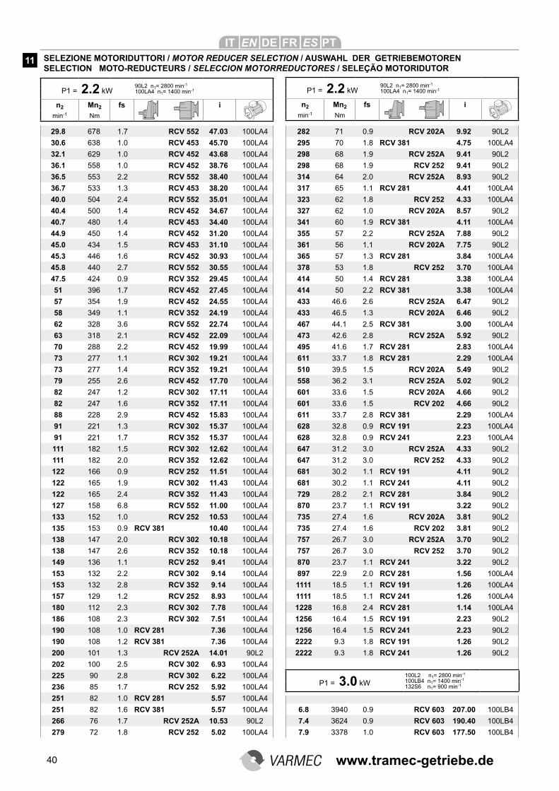
40
29.8 678 1.7 RCV 552 47.03 100LA4
30.6 638 1.0 RCV 453 45.70 100LA4
32.1 629 1.0 RCV 452 43.68 100LA4
36.1 558 1.0 RCV 452 38.76 100LA4
36.5 553 2.2 RCV 552 38.40 100LA4
36.7 533 1.3 RCV 453 38.20 100LA4
40.0 504 2.4 RCV 552 35.01 100LA4
40.4 500 1.4 RCV 452 34.67 100LA4
40.7 480 1.4 RCV 453 34.40 100LA4
44.9 450 1.4 RCV 452 31.20 100LA4
45.0 434 1.5 RCV 453 31.10 100LA4
45.3 446 1.6 RCV 452 30.93 100LA4
45.8 440 2.7 RCV 552 30.55 100LA4
47.5 424 0.9 RCV 352 29.45 100LA4
51 396 1.7 RCV 452 27.45 100LA4
57 354 1.9 RCV 452 24.55 100LA4
58 349 1.1 RCV 352 24.19 100LA4
62 328 3.6 RCV 552 22.74 100LA4
63 318 2.1 RCV 452 22.09 100LA4
70 288 2.2 RCV 452 19.99 100LA4
73 277 1.1 RCV 302 19.21 100LA4
73 277 1.4 RCV 352 19.21 100LA4
79 255 2.6 RCV 452 17.70 100LA4
82 247 1.2 RCV 302 17.11 100LA4
82 247 1.6 RCV 352 17.11 100LA4
88 228 2.9 RCV 452 15.83 100LA4
91 221 1.3 RCV 302 15.37 100LA4
91 221 1.7 RCV 352 15.37 100LA4
111 182 1.5 RCV 302 12.62 100LA4
111 182 2.0 RCV 352 12.62 100LA4
122 166 0.9 RCV 252 11.51 100LA4
122 165 1.9 RCV 302 11.43 100LA4
122 165 2.4 RCV 352 11.43 100LA4
127 158 6.8 RCV 552 11.00 100LA4
133 152 1.0 RCV 252 10.53 100LA4
135 153 0.9 RCV 381 10.40 100LA4
138 147 2.0 RCV 302 10.18 100LA4
138 147 2.6 RCV 352 10.18 100LA4
149 136 1.1 RCV 252 9.41 100LA4
153 132 2.2 RCV 302 9.14 100LA4
153 132 2.8 RCV 352 9.14 100LA4
157 129 1.2 RCV 252 8.93 100LA4
180 112 2.3 RCV 302 7.78 100LA4
186 108 2.3 RCV 302 7.51 100LA4
190 108 1.0 RCV 281 7.36 100LA4
190 108 1.2 RCV 381 7.36 100LA4
200 101 1.3 RCV 252A 14.01 90L2
202 100 2.5 RCV 302 6.93 100LA4
225 90 2.8 RCV 302 6.22 100LA4
236 85 1.7 RCV 252 5.92 100LA4
251 82 1.0 RCV 281 5.57 100LA4
251 82 1.6 RCV 381 5.57 100LA4
266 76 1.7 RCV 252A 10.53 90L2
279 72 1.8 RCV 252 5.02 100LA4
282 71 0.9 RCV 202A 9.92 90L2
295 70 1.8 RCV 381 4.75 100LA4
298 68 1.9 RCV 252A 9.41 90L2
298 68 1.9 RCV 252 9.41 90L2
314 64 2.0 RCV 252A 8.93 90L2
317 65 1.1 RCV 281 4.41 100LA4
323 62 1.8 RCV 252 4.33 100LA4
327 62 1.0 RCV 202A 8.57 90L2
341 60 1.9 RCV 381 4.11 100LA4
355 57 2.2 RCV 252A 7.88 90L2
361 56 1.1 RCV 202A 7.75 90L2
365 57 1.3 RCV 281 3.84 100LA4
378 53 1.8 RCV 252 3.70 100LA4
414 50 1.4 RCV 281 3.38 100LA4
414 50 2.2 RCV 381 3.38 100LA4
433 46.6 2.6 RCV 252A 6.47 90L2
433 46.5 1.3 RCV 202A 6.46 90L2
467 44.1 2.5 RCV 381 3.00 100LA4
473 42.6 2.8 RCV 252A 5.92 90L2
495 41.6 1.7 RCV 281 2.83 100LA4
611 33.7 1.8 RCV 281 2.29 100LA4
510 39.5 1.5 RCV 202A 5.49 90L2
558 36.2 3.1 RCV 252A 5.02 90L2
601 33.6 1.5 RCV 202A 4.66 90L2
601 33.6 1.5 RCV 202 4.66 90L2
611 33.7 2.8 RCV 381 2.29 100LA4
628 32.8 0.9 RCV 191 2.23 100LA4
628 32.8 0.9 RCV 241 2.23 100LA4
647 31.2 3.0 RCV 252A 4.33 90L2
647 31.2 3.0 RCV 252 4.33 90L2
681 30.2 1.1 RCV 191 4.11 90L2
681 30.2 1.1 RCV 241 4.11 90L2
729 28.2 2.1 RCV 281 3.84 90L2
870 23.7 1.1 RCV 191 3.22 90L2
735 27.4 1.6 RCV 202A 3.81 90L2
735 27.4 1.6 RCV 202 3.81 90L2
757 26.7 3.0 RCV 252A 3.70 90L2
757 26.7 3.0 RCV 252 3.70 90L2
870 23.7 1.1 RCV 241 3.22 90L2
897 22.9 2.0 RCV 281 1.56 100LA4
1111 18.5 1.1 RCV 191 1.26 100LA4
1111 18.5 1.1 RCV 241 1.26 100LA4
1228 16.8 2.4 RCV 281 1.14 100LA4
1256 16.4 1.5 RCV 191 2.23 90L2
1256 16.4 1.5 RCV 241 2.23 90L2
2222 9.3 1.8 RCV 191 1.26 90L2
2222 9.3 1.8 RCV 241 1.26 90L2
6.8 3940 0.9 RCV 603 207.00 100LB4
7.4 3624 0.9 RCV 603 190.40 100LB4
7.9 3378 1.0 RCV 603 177.50 100LB4
P1 = 2.2 kW90L2 n1= 2800 min-1
100LA4 n1= 1400 min-1
n2 Mn2 fs i
min-1 Nm
P1 = 2.2 kW90L2 n1= 2800 min-1
100LA4 n1= 1400 min-1
n2 Mn2 fs i
min-1 Nm
SELEZIONE MOTORIDUTTORI / MOTOR REDUCER SELECTION / AUSWAHL DER GETRIEBEMOTORENSELECTION MOTO-REDUCTEURS / SELECCION MOTORREDUCTORES / SELEÇÃO MOTORIDUTOR
11
P1 = 3.0 kW
100L2 n1= 2800 min-1
100LB4 n1= 1400 min-1
132S6 n1= 900 min-1
www.tramec-getriebe.de
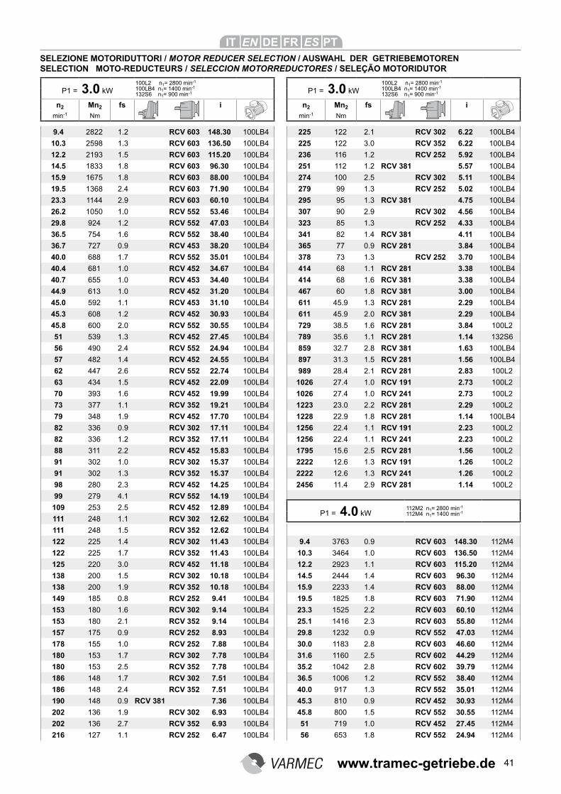
41
9.4 2822 1.2 RCV 603 148.30 100LB4
10.3 2598 1.3 RCV 603 136.50 100LB4
12.2 2193 1.5 RCV 603 115.20 100LB4
14.5 1833 1.8 RCV 603 96.30 100LB4
15.9 1675 1.8 RCV 603 88.00 100LB4
19.5 1368 2.4 RCV 603 71.90 100LB4
23.3 1144 2.9 RCV 603 60.10 100LB4
26.2 1050 1.0 RCV 552 53.46 100LB4
29.8 924 1.2 RCV 552 47.03 100LB4
36.5 754 1.6 RCV 552 38.40 100LB4
36.7 727 0.9 RCV 453 38.20 100LB4
40.0 688 1.7 RCV 552 35.01 100LB4
40.4 681 1.0 RCV 452 34.67 100LB4
40.7 655 1.0 RCV 453 34.40 100LB4
44.9 613 1.0 RCV 452 31.20 100LB4
45.0 592 1.1 RCV 453 31.10 100LB4
45.3 608 1.2 RCV 452 30.93 100LB4
45.8 600 2.0 RCV 552 30.55 100LB4
51 539 1.3 RCV 452 27.45 100LB4
56 490 2.4 RCV 552 24.94 100LB4
57 482 1.4 RCV 452 24.55 100LB4
62 447 2.6 RCV 552 22.74 100LB4
63 434 1.5 RCV 452 22.09 100LB4
70 393 1.6 RCV 452 19.99 100LB4
73 377 1.1 RCV 352 19.21 100LB4
79 348 1.9 RCV 452 17.70 100LB4
82 336 0.9 RCV 302 17.11 100LB4
82 336 1.2 RCV 352 17.11 100LB4
88 311 2.2 RCV 452 15.83 100LB4
91 302 1.0 RCV 302 15.37 100LB4
91 302 1.3 RCV 352 15.37 100LB4
98 280 2.3 RCV 452 14.25 100LB4
99 279 4.1 RCV 552 14.19 100LB4
109 253 2.5 RCV 452 12.89 100LB4
111 248 1.1 RCV 302 12.62 100LB4
111 248 1.5 RCV 352 12.62 100LB4
122 225 1.4 RCV 302 11.43 100LB4
122 225 1.7 RCV 352 11.43 100LB4
125 220 3.0 RCV 452 11.18 100LB4
138 200 1.5 RCV 302 10.18 100LB4
138 200 1.9 RCV 352 10.18 100LB4
149 185 0.8 RCV 252 9.41 100LB4
153 180 1.6 RCV 302 9.14 100LB4
153 180 2.1 RCV 352 9.14 100LB4
157 175 0.9 RCV 252 8.93 100LB4
178 155 1.0 RCV 252 7.88 100LB4
180 153 1.7 RCV 302 7.78 100LB4
180 153 2.5 RCV 352 7.78 100LB4
186 148 1.7 RCV 302 7.51 100LB4
186 148 2.4 RCV 352 7.51 100LB4
190 148 0.9 RCV 381 7.36 100LB4
202 136 1.9 RCV 302 6.93 100LB4
202 136 2.7 RCV 352 6.93 100LB4
216 127 1.1 RCV 252 6.47 100LB4
P1 = 3.0 kW
100L2 n1= 2800 min-1
100LB4 n1= 1400 min-1
132S6 n1= 900 min-1
n2 Mn2 fs i
min-1 Nm
SELEZIONE MOTORIDUTTORI / MOTOR REDUCER SELECTION / AUSWAHL DER GETRIEBEMOTORENSELECTION MOTO-REDUCTEURS / SELECCION MOTORREDUCTORES / SELEÇÃO MOTORIDUTOR
225 122 2.1 RCV 302 6.22 100LB4
225 122 3.0 RCV 352 6.22 100LB4
236 116 1.2 RCV 252 5.92 100LB4
251 112 1.2 RCV 381 5.57 100LB4
274 100 2.5 RCV 302 5.11 100LB4
279 99 1.3 RCV 252 5.02 100LB4
295 95 1.3 RCV 381 4.75 100LB4
307 90 2.9 RCV 302 4.56 100LB4
323 85 1.3 RCV 252 4.33 100LB4
341 82 1.4 RCV 381 4.11 100LB4
365 77 0.9 RCV 281 3.84 100LB4
378 73 1.3 RCV 252 3.70 100LB4
414 68 1.1 RCV 281 3.38 100LB4
414 68 1.6 RCV 381 3.38 100LB4
467 60 1.8 RCV 381 3.00 100LB4
611 45.9 1.3 RCV 281 2.29 100LB4
611 45.9 2.0 RCV 381 2.29 100LB4
729 38.5 1.6 RCV 281 3.84 100L2
789 35.6 1.1 RCV 281 1.14 132S6
859 32.7 2.8 RCV 381 1.63 100LB4
897 31.3 1.5 RCV 281 1.56 100LB4
989 28.4 2.1 RCV 281 2.83 100L2
1026 27.4 1.0 RCV 191 2.73 100L2
1026 27.4 1.0 RCV 241 2.73 100L2
1223 23.0 2.2 RCV 281 2.29 100L2
1228 22.9 1.8 RCV 281 1.14 100LB4
1256 22.4 1.1 RCV 191 2.23 100L2
1256 22.4 1.1 RCV 241 2.23 100L2
1795 15.6 2.5 RCV 281 1.56 100L2
2222 12.6 1.3 RCV 191 1.26 100L2
2222 12.6 1.3 RCV 241 1.26 100L2
2456 11.4 2.9 RCV 281 1.14 100L2
9.4 3763 0.9 RCV 603 148.30 112M4
10.3 3464 1.0 RCV 603 136.50 112M4
12.2 2923 1.1 RCV 603 115.20 112M4
14.5 2444 1.4 RCV 603 96.30 112M4
15.9 2233 1.4 RCV 603 88.00 112M4
19.5 1825 1.8 RCV 603 71.90 112M4
23.3 1525 2.2 RCV 603 60.10 112M4
25.1 1416 2.3 RCV 603 55.80 112M4
29.8 1232 0.9 RCV 552 47.03 112M4
30.0 1183 2.8 RCV 603 46.60 112M4
31.6 1160 2.5 RCV 602 44.29 112M4
35.2 1042 2.8 RCV 602 39.79 112M4
36.5 1006 1.2 RCV 552 38.40 112M4
40.0 917 1.3 RCV 552 35.01 112M4
45.3 810 0.9 RCV 452 30.93 112M4
45.8 800 1.5 RCV 552 30.55 112M4
51 719 1.0 RCV 452 27.45 112M4
56 653 1.8 RCV 552 24.94 112M4
P1 = 4.0 kW112M2 n1= 2800 min-1
112M4 n1= 1400 min-1
P1 = 3.0 kW
100L2 n1= 2800 min-1
100LB4 n1= 1400 min-1
132S6 n1= 900 min-1
n2 Mn2 fs i
min-1 Nm
www.tramec-getriebe.de
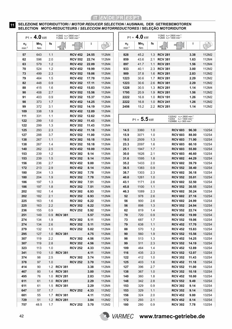
42
57 643 1.1 RCV 452 24.55 112M4
62 596 2.0 RCV 552 22.74 112M4
63 579 1.2 RCV 452 22.09 112M4
70 524 1.2 RCV 452 19.99 112M4
73 499 2.3 RCV 552 19.06 112M4
79 464 1.5 RCV 452 17.70 112M4
82 448 0.9 RCV 352 17.11 112M4
88 415 1.6 RCV 452 15.83 112M4
90 408 2.7 RCV 552 15.56 112M4
91 403 0.9 RCV 352 15.37 112M4
98 373 1.7 RCV 452 14.25 112M4
99 372 3.1 RCV 552 14.19 112M4
109 338 1.9 RCV 452 12.89 112M4
111 331 1.1 RCV 352 12.62 112M4
122 299 1.0 RCV 302 11.43 112M4
122 299 1.3 RCV 352 11.43 112M4
125 293 2.3 RCV 452 11.18 112M4
127 288 3.7 RCV 552 11.00 112M4
138 267 1.1 RCV 302 10.18 112M4
138 267 1.4 RCV 352 10.18 112M4
140 262 2.5 RCV 452 10.00 112M4
153 239 1.2 RCV 302 9.14 112M4
153 239 1.5 RCV 352 9.14 112M4
156 236 2.7 RCV 452 9.00 112M4
172 213 2.9 RCV 452 8.14 112M4
180 204 1.3 RCV 302 7.78 112M4
180 204 1.9 RCV 352 7.78 112M4
186 197 1.3 RCV 302 7.51 112M4
186 197 1.8 RCV 352 7.51 112M4
202 182 1.4 RCV 302 6.93 112M4
202 182 2.1 RCV 352 6.93 112M4
225 163 1.6 RCV 302 6.22 112M4
225 163 2.2 RCV 352 6.22 112M4
236 155 0.9 RCV 252 5.92 112M4
251 149 0.9 RCV 381 5.57 112M4
274 134 1.9 RCV 302 5.11 112M4
274 134 2.6 RCV 352 5.11 112M4
279 132 1.0 RCV 252 5.02 112M4
295 127 1.0 RCV 381 4.75 112M4
307 119 2.2 RCV 302 4.56 112M4
307 119 2.8 RCV 352 4.56 112M4
323 113 1.0 RCV 252 4.33 112M4
341 110 1.0 RCV 381 4.11 112M4
374 98 2.5 RCV 302 3.74 112M4
378 97 1.0 RCV 252 3.70 112M4
414 90 1.2 RCV 381 3.38 112M4
467 80 1.4 RCV 381 3.00 112M4
495 76 1.0 RCV 281 2.83 112M4
611 61 1.0 RCV 281 2.29 112M4
611 61 1.5 RCV 381 2.29 112M4
647 57 1.7 RCV 252 4.33 112M2
681 55 1.7 RCV 381 4.11 112M2
729 51 1.2 RCV 281 3.84 112M2
757 48.5 1.7 RCV 252 3.70 112M2
828 45.2 1.3 RCV 281 3.38 112M2
859 43.6 2.1 RCV 381 1.63 112M4
897 41.7 1.1 RCV 281 1.56 112M4
933 40.1 2.3 RCV 381 3.00 112M2
989 37.8 1.6 RCV 281 2.83 112M2
1223 30.6 1.7 RCV 281 2.29 112M2
1223 30.6 2.6 RCV 381 2.29 112M2
1228 30.5 1.3 RCV 281 1.14 112M4
1795 20.9 1.9 RCV 281 1.56 112M2
2222 16.8 1.0 RCV 191 1.26 112M2
2222 16.8 1.0 RCV 241 1.26 112M2
2456 15.2 2.2 RCV 281 1.14 112M2
14.5 3360 1.0 RCV 603 96.30 132S4
15.9 3071 1.0 RCV 603 88.00 132S4
19.5 2509 1.3 RCV 603 71.90 132S4
23.3 2097 1.6 RCV 603 60.10 132S4
25.1 1947 1.7 RCV 603 55.80 132S4
30.0 1626 2.1 RCV 603 46.60 132S4
31.6 1595 1.8 RCV 602 44.29 132S4
35.2 1433 2.0 RCV 602 39.79 132S4
36.5 1383 0.9 RCV 552 38.40 132S4
38.7 1303 2.3 RCV 602 36.18 132S4
40.0 1261 1.0 RCV 552 35.01 132S4
43.1 1171 2.6 RCV 602 32.50 132S4
45.8 1100 1.1 RCV 552 30.55 132S4
46.3 1089 2.3 RCV 602 30.24 132S4
52 978 2.6 RCV 602 27.16 132S4
56 900 2.6 RCV 602 24.99 132S4
56 898 1.3 RCV 552 24.94 132S4
62 819 1.4 RCV 552 22.74 132S4
70 720 0.9 RCV 452 19.99 132S4
73 687 1.7 RCV 552 19.06 132S4
79 638 1.1 RCV 452 17.70 132S4
88 570 1.2 RCV 452 15.83 132S4
90 560 1.9 RCV 552 15.56 132S4
98 513 1.3 RCV 452 14.25 132S4
99 511 2.3 RCV 552 14.19 132S4
109 464 1.4 RCV 452 12.89 132S4
116 435 2.3 RCV 552 12.07 132S4
122 412 1.0 RCV 352 11.43 132S4
125 403 1.6 RCV 452 11.18 132S4
127 396 2.7 RCV 552 11.00 132S4
138 367 1.0 RCV 352 10.18 132S4
140 360 1.8 RCV 452 10.00 132S4
148 342 2.8 RCV 552 9.49 132S4
153 329 0.9 RCV 302 9.14 132S4
153 329 1.1 RCV 352 9.14 132S4
156 324 2.0 RCV 452 9.00 132S4
172 293 2.1 RCV 452 8.14 132S4
180 280 0.9 RCV 302 7.78 132S4
P1 = 4.0 kW112M2 n1= 2800 min-1
112M4 n1= 1400 min-1
n2 Mn2 fs i
min-1 Nm
P1 = 4.0 kW112M2 n1= 2800 min-1
112M4 n1= 1400 min-1
n2 Mn2 fs i
min-1 Nm
SELEZIONE MOTORIDUTTORI / MOTOR REDUCER SELECTION / AUSWAHL DER GETRIEBEMOTORENSELECTION MOTO-REDUCTEURS / SELECCION MOTORREDUCTORES / SELEÇÃO MOTORIDUTOR
11
P1 = 5.5 kW
132SA2 n1= 2800 min-1
132S4 n1= 1400 min-1
132MB6 n1= 900 min-1
www.tramec-getriebe.de
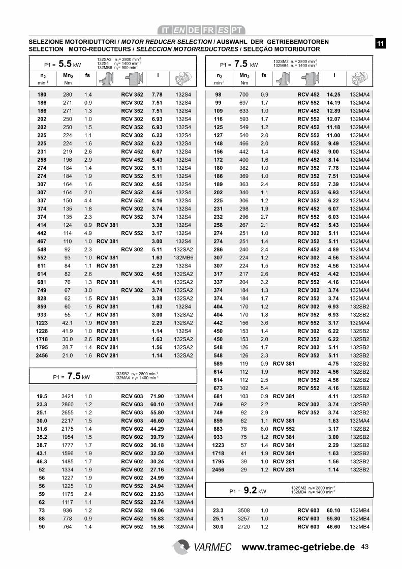
43
180 280 1.4 RCV 352 7.78 132S4
186 271 0.9 RCV 302 7.51 132S4
186 271 1.3 RCV 352 7.51 132S4
202 250 1.0 RCV 302 6.93 132S4
202 250 1.5 RCV 352 6.93 132S4
225 224 1.1 RCV 302 6.22 132S4
225 224 1.6 RCV 352 6.22 132S4
231 219 2.6 RCV 452 6.07 132S4
258 196 2.9 RCV 452 5.43 132S4
274 184 1.4 RCV 302 5.11 132S4
274 184 1.9 RCV 352 5.11 132S4
307 164 1.6 RCV 302 4.56 132S4
307 164 2.0 RCV 352 4.56 132S4
337 150 4.4 RCV 552 4.16 132S4
374 135 1.8 RCV 302 3.74 132S4
374 135 2.3 RCV 352 3.74 132S4
414 124 0.9 RCV 381 3.38 132S4
442 114 4.9 RCV 552 3.17 132S4
467 110 1.0 RCV 381 3.00 132S4
548 92 2.3 RCV 302 5.11 132SA2
552 93 1.0 RCV 381 1.63 132MB6
611 84 1.1 RCV 381 2.29 132S4
614 82 2.6 RCV 302 4.56 132SA2
681 76 1.3 RCV 381 4.11 132SA2
749 67 3.0 RCV 302 3.74 132SA2
828 62 1.5 RCV 381 3.38 132SA2
859 60 1.5 RCV 381 1.63 132S4
933 55 1.7 RCV 381 3.00 132SA2
1223 42.1 1.9 RCV 381 2.29 132SA2
1228 41.9 1.0 RCV 281 1.14 132S4
1718 30.0 2.6 RCV 381 1.63 132SA2
1795 28.7 1.4 RCV 281 1.56 132SA2
2456 21.0 1.6 RCV 281 1.14 132SA2
19.5 3421 1.0 RCV 603 71.90 132MA4
23.3 2860 1.2 RCV 603 60.10 132MA4
25.1 2655 1.2 RCV 603 55.80 132MA4
30.0 2217 1.5 RCV 603 46.60 132MA4
31.6 2175 1.4 RCV 602 44.29 132MA4
35.2 1954 1.5 RCV 602 39.79 132MA4
38.7 1777 1.7 RCV 602 36.18 132MA4
43.1 1596 1.9 RCV 602 32.50 132MA4
46.3 1485 1.7 RCV 602 30.24 132MA4
52 1334 1.9 RCV 602 27.16 132MA4
56 1227 1.9 RCV 602 24.99 132MA4
56 1225 1.0 RCV 552 24.94 132MA4
59 1175 2.4 RCV 602 23.93 132MA4
62 1117 1.1 RCV 552 22.74 132MA4
73 936 1.2 RCV 552 19.06 132MA4
88 778 0.9 RCV 452 15.83 132MA4
90 764 1.4 RCV 552 15.56 132MA4
98 700 0.9 RCV 452 14.25 132MA4
99 697 1.7 RCV 552 14.19 132MA4
109 633 1.0 RCV 452 12.89 132MA4
116 593 1.7 RCV 552 12.07 132MA4
125 549 1.2 RCV 452 11.18 132MA4
127 540 2.0 RCV 552 11.00 132MA4
148 466 2.0 RCV 552 9.49 132MA4
156 442 1.4 RCV 452 9.00 132MA4
172 400 1.6 RCV 452 8.14 132MA4
180 382 1.0 RCV 352 7.78 132MA4
186 369 1.0 RCV 352 7.51 132MA4
189 363 2.4 RCV 552 7.39 132MA4
202 340 1.1 RCV 352 6.93 132MA4
225 306 1.2 RCV 352 6.22 132MA4
231 298 1.9 RCV 452 6.07 132MA4
232 296 2.7 RCV 552 6.03 132MA4
258 267 2.1 RCV 452 5.43 132MA4
274 251 1.0 RCV 302 5.11 132MA4
274 251 1.4 RCV 352 5.11 132MA4
286 240 2.4 RCV 452 4.89 132MA4
307 224 1.2 RCV 302 4.56 132MA4
307 224 1.5 RCV 352 4.56 132MA4
317 217 2.6 RCV 452 4.42 132MA4
337 204 3.2 RCV 552 4.16 132MA4
374 184 1.3 RCV 302 3.74 132MA4
374 184 1.7 RCV 352 3.74 132MA4
404 170 1.2 RCV 302 6.93 132SB2
404 170 1.8 RCV 352 6.93 132SB2
442 156 3.6 RCV 552 3.17 132MA4
450 153 1.4 RCV 302 6.22 132SB2
450 153 2.0 RCV 352 6.22 132SB2
548 126 1.7 RCV 302 5.11 132SB2
548 126 2.3 RCV 352 5.11 132SB2
589 119 0.9 RCV 381 4.75 132SB2
614 112 1.9 RCV 302 4.56 132SB2
614 112 2.5 RCV 352 4.56 132SB2
673 102 5.4 RCV 552 4.16 132SB2
681 103 0.9 RCV 381 4.11 132SB2
749 92 2.2 RCV 302 3.74 132SB2
749 92 2.9 RCV 352 3.74 132SB2
859 82 1.1 RCV 381 1.63 132MA4
883 78 6.0 RCV 552 3.17 132SB2
933 75 1.2 RCV 381 3.00 132SB2
1223 57 1.4 RCV 381 2.29 132SB2
1718 41 1.9 RCV 381 1.63 132SB2
1795 39 1.0 RCV 281 1.56 132SB2
2456 29 1.2 RCV 281 1.14 132SB2
23.3 3508 1.0 RCV 603 60.10 132MB4
25.1 3257 1.0 RCV 603 55.80 132MB4
30.0 2720 1.2 RCV 603 46.60 132MB4
P1 = 7.5 kW132SB2 n1= 2800 min-1
132MA4 n1= 1400 min-1
P1 = 5.5 kW
132SA2 n1= 2800 min-1
132S4 n1= 1400 min-1
132MB6 n1= 900 min-1
n2 Mn2 fs i
min-1 Nm
SELEZIONE MOTORIDUTTORI / MOTOR REDUCER SELECTION / AUSWAHL DER GETRIEBEMOTORENSELECTION MOTO-REDUCTEURS / SELECCION MOTORREDUCTORES / SELEÇÃO MOTORIDUTOR
P1 = 7.5 kW132SM2 n1= 2800 min-1
132MB4 n1= 1400 min-1
n2 Mn2 fs i
min-1 Nm
11
P1 = 9.2 kW132SM2 n1= 2800 min-1
132MB4 n1= 1400 min-1
www.tramec-getriebe.de
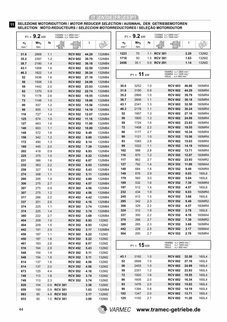
44
31.6 2668 1.1 RCV 602 44.29 132MB4
35.2 2397 1.2 RCV 602 39.79 132MB4
38.7 2180 1.4 RCV 602 36.18 132MB4
43.1 1958 1.6 RCV 602 32.50 132MB4
46.3 1822 1.4 RCV 602 30.24 132MB4
52 1636 1.6 RCV 602 27.16 132MB4
56 1506 1.6 RCV 602 24.99 132MB4
59 1442 2.0 RCV 602 23.93 132MB4
62 1370 0.9 RCV 552 22.74 132MB4
72 1178 2.6 RCV 602 19.55 132MB4
73 1148 1.0 RCV 552 19.06 132MB4
90 937 1.2 RCV 552 15.56 132MB4
99 855 1.3 RCV 552 14.19 132MB4
116 727 1.4 RCV 552 12.07 132MB4
125 674 1.0 RCV 452 11.18 132MB4
127 663 1.6 RCV 552 11.00 132MB4
140 603 1.1 RCV 452 10.00 132MB4
148 572 1.6 RCV 552 9.49 132MB4
156 542 1.2 RCV 452 9.00 132MB4
172 490 1.3 RCV 452 8.14 132MB4
189 445 2.0 RCV 552 7.39 132MB4
202 418 0.9 RCV 352 6.93 132MB4
225 375 1.0 RCV 352 6.22 132MB4
231 366 1.6 RCV 452 6.07 132MB4
232 363 2.2 RCV 552 6.03 132MB4
258 327 1.8 RCV 452 5.43 132MB4
274 308 1.1 RCV 352 5.11 132MB4
286 295 1.9 RCV 452 4.89 132MB4
306 275 2.7 RCV 552 4.57 132MB4
307 275 0.9 RCV 302 4.56 132MB4
307 275 1.2 RCV 352 4.56 132MB4
317 266 2.2 RCV 452 4.42 132MB4
337 251 2.6 RCV 552 4.16 132MB4
374 225 1.1 RCV 302 3.74 132MB4
374 225 1.4 RCV 352 3.74 132MB4
380 222 2.7 RCV 552 3.68 132MB4
404 209 1.0 RCV 302 6.93 132M2
404 209 1.5 RCV 352 6.93 132M2
442 191 2.9 RCV 552 3.17 132MB4
450 187 1.1 RCV 302 6.22 132M2
450 187 1.6 RCV 352 6.22 132M2
461 183 2.6 RCV 452 6.07 132M2
516 164 2.9 RCV 452 5.43 132M2
548 154 1.4 RCV 302 5.11 132M2
548 154 1.9 RCV 352 5.11 132M2
614 137 1.6 RCV 302 4.56 132M2
614 137 2.0 RCV 352 4.56 132M2
673 125 4.4 RCV 552 4.16 132M2
749 113 1.8 RCV 302 3.74 132M2
749 113 2.3 RCV 352 3.74 132M2
828 104 0.9 RCV 381 3.38 132M2
859 100 0.9 RCV 381 1.63 132MB4
883 95 4.9 RCV 552 3.17 132M2
933 92 1.0 RCV 381 3.00 132M2
1223 70 1.1 RCV 381 2.29 132M2
1718 50 1.5 RCV 381 1.63 132M2
2456 35.1 0.9 RCV 281 1.14 132M2
30.0 3252 1.0 RCV 603 46.60 160MR4
31.6 3190 0.9 RCV 602 44.29 160MR4
35.2 2866 1.0 RCV 602 39.79 160MR4
38.7 2606 1.1 RCV 602 36.18 160MR4
43.1 2341 1.3 RCV 602 32.50 160MR4
46.3 2178 1.1 RCV 602 30.24 160MR4
52 1957 1.3 RCV 602 27.16 160MR4
56 1800 1.3 RCV 602 24.99 160MR4
59 1724 1.6 RCV 602 23.93 160MR4
72 1408 2.2 RCV 602 19.55 160MR4
86 1177 2.7 RCV 602 16.34 160MR4
90 1121 1.0 RCV 552 15.56 160MR4
93 1083 2.8 RCV 602 15.03 160MR4
99 1022 1.1 RCV 552 14.19 160MA4
102 988 2.8 RCV 602 13.71 160MR4
116 870 1.2 RCV 552 12.07 160MR4
117 862 2.7 RCV 602 23.93 160MR2
127 792 1.4 RCV 552 11.00 160MA4
148 684 1.4 RCV 552 9.49 160MR4
149 676 2.9 RCV 602 6.03 160L6
179 565 3.0 RCV 602 5.04 160L6
189 532 1.6 RCV 552 7.39 160MR4
197 512 1.4 RCV 552 4.57 160L6
232 434 1.9 RCV 552 6.03 160MR4
245 412 1.5 RCV 552 3.68 160L6
295 342 2.3 RCV 552 9.49 160MR2
306 329 2.2 RCV 552 4.57 160MR4
324 312 1.8 RCV 552 2.78 160L6
337 300 2.2 RCV 552 4.16 160MA4
379 266 2.7 RCV 552 7.39 160MR2
380 265 2.3 RCV 552 3.68 160MR4
442 228 2.5 RCV 552 3.17 160MA4
504 200 2.7 RCV 552 2.78 160MR4
43.1 3192 1.0 RCV 602 32.50 160L4
52 2668 1.0 RCV 602 27.16 160L4
56 2455 1.0 RCV 602 24.99 160L4
59 2351 1.2 RCV 602 23.93 160L4
72 1920 1.6 RCV 602 19.55 160L4
86 1605 2.0 RCV 602 16.34 160L4
93 1476 2.0 RCV 602 15.03 160L4
99 1394 0.8 RCV 552 14.19 160L4
102 1347 2.0 RCV 602 13.71 160L4
125 1100 2.7 RCV 602 11.20 160L4
P1 = 9.2 kW132SM2 n1= 2800 min-1
132MB4 n1= 1400 min-1
n2 Mn2 fs i
min-1 Nm
P1 = 9.2 kW132SM2 n1= 2800 min-1
132MB4 n1= 1400 min-1
n2 Mn2 fs i
min-1 Nm
SELEZIONE MOTORIDUTTORI / MOTOR REDUCER SELECTION / AUSWAHL DER GETRIEBEMOTORENSELECTION MOTO-REDUCTEURS / SELECCION MOTORREDUCTORES / SELEÇÃO MOTORIDUTOR
11
P1 = 15 kW
160MB2 n1= 2800 min-1
160L4 n1= 1400 min-1
180L6 n1= 900 min-1
P1 = 11 kW
160MR2 n1= 2800 min-1
160MR4 n1= 1400 min-1
160L6 n1= 900 min-1
www.tramec-getriebe.de
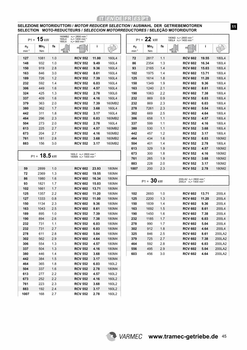
45
127 1081 1.0 RCV 552 11.00 160L4
148 932 1.0 RCV 552 9.49 160L4
150 919 2.8 RCV 602 9.36 160L4
163 846 3.0 RCV 602 8.61 160L4
189 726 1.2 RCV 552 7.39 160L4
232 592 1.4 RCV 552 6.03 160L4
306 449 1.6 RCV 552 4.57 160L4
324 425 1.3 RCV 552 2.78 180L6
337 409 1.6 RCV 552 4.16 160L4
379 363 2.0 RCV 552 7.39 160MB2
380 362 1.7 RCV 552 3.68 160L4
442 311 1.8 RCV 552 3.17 160L4
464 296 2.3 RCV 552 6.03 160MB2
504 273 2.0 RCV 552 2.78 160L4
613 225 2.7 RCV 552 4.57 160MB2
673 204 2.7 RCV 552 4.16 160MB2
761 181 2.8 RCV 552 3.68 160MB2
883 156 3.0 RCV 552 3.17 160MB2
59 2899 1.0 RCV 602 23.93 180M4
72 2369 1.3 RCV 602 19.55 180M4
86 1980 1.6 RCV 602 16.34 180M4
93 1821 1.7 RCV 602 15.03 180M4
102 1661 1.7 RCV 602 13.71 180M4
125 1357 2.2 RCV 602 11.20 180M4
127 1333 0.8 RCV 552 11.00 180M4
150 1134 2.3 RCV 602 9.36 180M4
163 1043 2.5 RCV 602 8.61 180M4
189 895 1.0 RCV 552 7.39 180M4
190 894 2.6 RCV 602 7.38 180M4
232 731 1.1 RCV 552 6.03 180M4
232 731 2.7 RCV 602 6.03 180M4
278 611 2.8 RCV 602 5.04 180M4
302 562 2.9 RCV 602 4.64 180M4
306 554 1.3 RCV 552 4.57 180M4
337 504 1.3 RCV 552 4.16 180M4
380 446 1.4 RCV 552 3.68 180M4
442 384 1.5 RCV 552 3.17 180M4
464 365 1.8 RCV 552 6.03 160L2
504 337 1.6 RCV 552 2.78 180M4
613 277 2.2 RCV 552 4.57 160L2
673 252 2.2 RCV 552 4.16 160L2
761 223 2.3 RCV 552 3.68 160L2
883 192 2.4 RCV 552 3.17 160L2
1007 168 2.7 RCV 552 2.78 160L2
72 2817 1.1 RCV 602 19.55 180L4
86 2354 1.3 RCV 602 16.34 180L4
93 2165 1.4 RCV 602 15.03 180L4
102 1975 1.4 RCV 602 13.71 180L4
125 1614 1.8 RCV 602 11.20 180L4
150 1349 1.9 RCV 602 9.36 180L4
163 1240 2.1 RCV 602 8.61 180L4
190 1063 2.2 RCV 602 7.38 180L4
232 869 0.9 RCV 552 6.03 180L4
232 869 2.3 RCV 602 6.03 180L4
278 7261 2.3 RCV 602 5.04 180L4
302 669 2.5 RCV 602 4.64 180L4
306 658 1.1 RCV 552 4.57 180L4
337 599 1.1 RCV 552 4.16 180L4
380 530 1.1 RCV 552 3.68 180L4
442 457 1.2 RCV 552 3.17 180L4
464 434 1.6 RCV 552 6.03 180M2
504 401 1.4 RCV 552 2.78 180L4
613 329 1.9 RCV 552 4.57 180M2
673 300 1.8 RCV 552 4.16 180M2
761 265 1.9 RCV 552 3.68 180M2
883 228 2.0 RCV 552 3.17 180M2
1007 200 2.3 RCV 552 2.78 180M2
102 2693 1.0 RCV 602 13.71 200L4
125 2200 1.3 RCV 602 11.20 200L4
150 1839 1.4 RCV 602 9.36 200L4
163 1692 1.5 RCV 602 8.61 200L4
190 1450 1.6 RCV 602 7.38 200L4
232 1185 1.7 RCV 602 6.03 200L4
278 990 1.7 RCV 602 5.04 200L4
302 912 1.8 RCV 602 4.64 200L4
325 846 2.5 RCV 602 8.61 200LA2
379 725 2.7 RCV 602 7.38 200LA2
464 592 2.8 RCV 602 6.03 200LA2
556 495 2.9 RCV 602 5.04 200LA2
603 456 3.0 RCV 602 4.64 200LA2
P1 = 30 kW200LA2 n1= 2800 min-1
200L4 n1= 1400 min-1
P1 = 18.5 kW160L2 n1= 2800 min-1
180M4 n1= 1400 min-1
P1 = 15 kW
160MB2 n1= 2800 min-1
160L4 n1= 1400 min-1
180L6 n1= 900 min-1
n2 Mn2 fs i
min-1 Nm
SELEZIONE MOTORIDUTTORI / MOTOR REDUCER SELECTION / AUSWAHL DER GETRIEBEMOTORENSELECTION MOTO-REDUCTEURS / SELECCION MOTORREDUCTORES / SELEÇÃO MOTORIDUTOR
P1 = 22 kW180M2 n1= 2800 min-1
180L4 n1= 1400 min-1
n2 Mn2 fs i
min-1 Nm
11
www.tramec-getriebe.de

1 www.tramec-getriebe.de
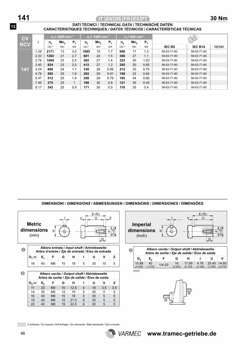
46
30 Nm 141
CV RCV
n1= 2800 min-1 n1= 1400 min-1 n1= 900 min-1
i n2 Mn2 P1 n2 Mn2 P1 n2 Mn2 P1
min-1 Nm kW min-1 Nm kW min-1 Nm kW IEC B5 IEC B14 NEMA
141
1.29 2171 13 3.0 1085 15 1.7 698 17 1.3 56-63-71-80 56-63-71-80
2.33 1202 21 2.7 601 24 1.5 386 27 1.1 56-63-71-80 56-63-71-80
2.79 1004 23 2.5 502 27 1.4 323 30 1.03 56-63-71-80 56-63-71-80
3.40 824 23 2.0 412 27 1.2 265 30 0.85 56-63-71-80 56-63-71-80
4.24 660 24 1.7 330 28 0.99 212 33 0.75 56-63-71-80 56-63-71-80
4.79 585 25 1.6 292 29 0.91 188 32 0.64 56-63-71-80 56-63-71-80
5.47 512 25 1.4 256 29 0.79 165 34 0.60 56-63-71-80 56-63-71-80
7.46 375 25 1 188 30 0.6 121 35 0.45 56-63-71-80 56-63-71-80
8.17 343 25 0.9 171 30 0.5 110 35 0.4 56-63-71-80 56-63-71-80
DIMENSIONI / DIMENSIONS / ABMESSUNGEN / DIMENSIONS / DIMENSIONES / DIMENSÕES
Albero entrata / Input shaft / Antriebswelle Arbre d‘entrée / Eje de entrada / Eixo de entrada
D1 h6 E1 F G H I U V Z
16 40 M6 15 18 5 25 10 5
Albero uscita / Output shaft / Abtriebswelle Arbre de sortie / Eje de salida / Eixo de saida
D2 h6 E2 F G H I U V Z
11 23 M4 10 12.5 4 16 3.5 3.514 30 M5 12 16 5 20 5 516 40 M6 16 18 5 30 5 519 40 M6 15 21.5 6 30 5 520 40 M8 19 22.5 6 30 5 5
Metric dimensions
(mm)
Imperial dimensions
(inch)
Albero uscita / Output shaft / Abtriebswelle Arbre de sortie / Eje de salida / Eixo de saida
D2 E2 F G H I U V
15.88 (0.625)
40 (1.575)
1/4-20 16 (0.630)
17.89 (0.704)
4.76 (0.188)
25.40 (1.000)
14.60 (0.575)
(Inch)
DATI TECNICI / TECHNICAL DATA / TECHNISCHE DATEN CARACTÉRISTIQUES TECHNIQUES / DATOS TÉCNICOS / CARACTERÍSTICAS TÉCNICAS
12
A richiesta / On request / Auf Anfrage / Sur demande / Bajo demanda / Sob consulta
www.tramec-getriebe.de
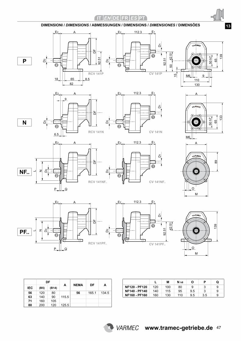
47
DIMENSIONI / DIMENSIONS / ABMESSUNGEN / DIMENSIONS / DIMENSIONES / DIMENSÕES
NF..
P
N
PF..
L M N h8 O P Q
NF120 - PF120 120 100 80 9 3 9NF140 - PF140 140 115 95 9.5 3 9NF160 - PF160 160 130 110 9.5 3.5 9
DFA NEMA DF A
IEC (B5) (B14)
56 120 80115.5
56 165.1 134.563 140 9071 160 10580 200 120 125.5
RCV 141NF.. CV 141NF..
RCV 141PF.. CV 141PF..
RCV 141N CV 141N
RCV 141P CV 141P
13
www.tramec-getriebe.de
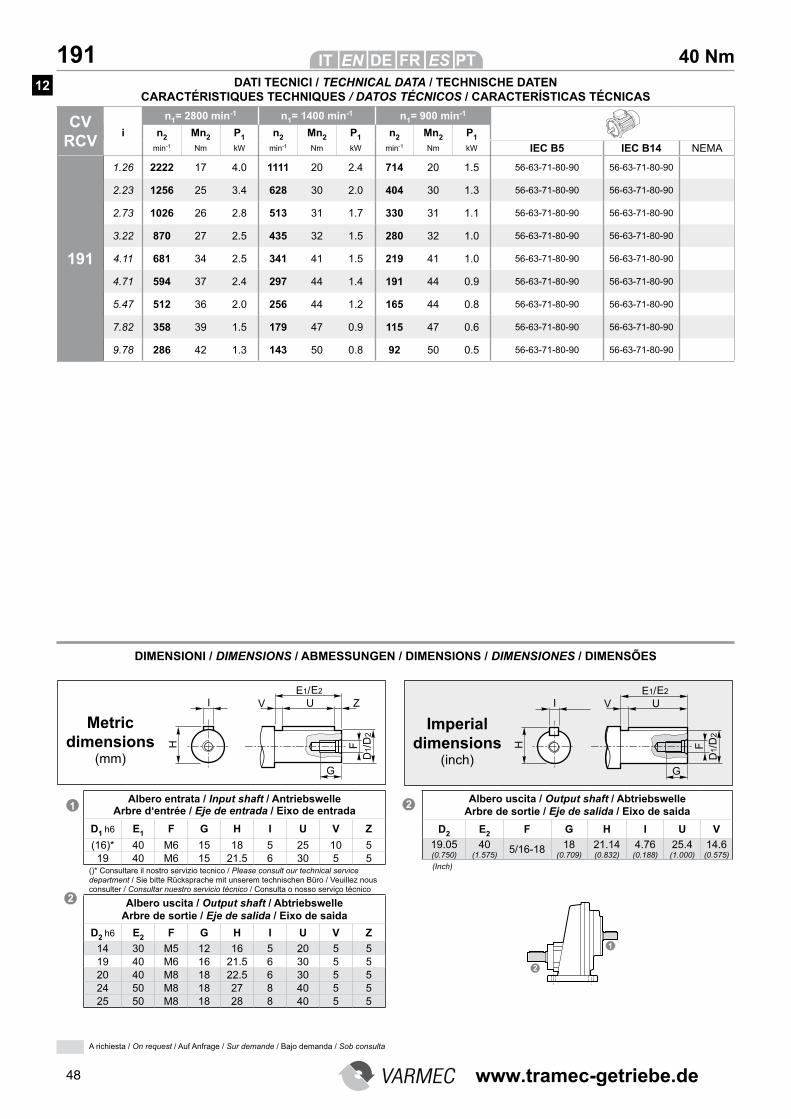
48
40 Nm 191
CV RCV
n1= 2800 min-1 n1= 1400 min-1 n1= 900 min-1
i n2 Mn2 P1 n2 Mn2 P1 n2 Mn2 P1
min-1 Nm kW min-1 Nm kW min-1 Nm kW IEC B5 IEC B14 NEMA
191
1.26 2222 17 4.0 1111 20 2.4 714 20 1.5 56-63-71-80-90 56-63-71-80-90
2.23 1256 25 3.4 628 30 2.0 404 30 1.3 56-63-71-80-90 56-63-71-80-90
2.73 1026 26 2.8 513 31 1.7 330 31 1.1 56-63-71-80-90 56-63-71-80-90
3.22 870 27 2.5 435 32 1.5 280 32 1.0 56-63-71-80-90 56-63-71-80-90
4.11 681 34 2.5 341 41 1.5 219 41 1.0 56-63-71-80-90 56-63-71-80-90
4.71 594 37 2.4 297 44 1.4 191 44 0.9 56-63-71-80-90 56-63-71-80-90
5.47 512 36 2.0 256 44 1.2 165 44 0.8 56-63-71-80-90 56-63-71-80-90
7.82 358 39 1.5 179 47 0.9 115 47 0.6 56-63-71-80-90 56-63-71-80-90
9.78 286 42 1.3 143 50 0.8 92 50 0.5 56-63-71-80-90 56-63-71-80-90
DATI TECNICI / TECHNICAL DATA / TECHNISCHE DATEN CARACTÉRISTIQUES TECHNIQUES / DATOS TÉCNICOS / CARACTERÍSTICAS TÉCNICAS
DIMENSIONI / DIMENSIONS / ABMESSUNGEN / DIMENSIONS / DIMENSIONES / DIMENSÕES
Albero entrata / Input shaft / Antriebswelle Arbre d‘entrée / Eje de entrada / Eixo de entrada
D1 h6 E1 F G H I U V Z
(16)* 40 M6 15 18 5 25 10 519 40 M6 15 21.5 6 30 5 5
()* Consultare il nostro servizio tecnico / Please consult our technical service department / Sie bitte Rücksprache mit unserem technischen Büro / Veuillez nous consulter / Consultar nuestro servicio técnico / Consulta o nosso serviço técnico
Albero uscita / Output shaft / Abtriebswelle Arbre de sortie / Eje de salida / Eixo de saida
D2 h6 E2 F G H I U V Z
14 30 M5 12 16 5 20 5 519 40 M6 16 21.5 6 30 5 520 40 M8 18 22.5 6 30 5 524 50 M8 18 27 8 40 5 525 50 M8 18 28 8 40 5 5
Albero uscita / Output shaft / Abtriebswelle Arbre de sortie / Eje de salida / Eixo de saida
D2 E2 F G H I U V
19.05 (0.750)
40 (1.575)
5/16-18 18 (0.709)
21.14 (0.832)
4.76 (0.188)
25.4 (1.000)
14.6 (0.575)
Metric dimensions
(mm)
Imperial dimensions
(inch)
(Inch)
12
A richiesta / On request / Auf Anfrage / Sur demande / Bajo demanda / Sob consulta
www.tramec-getriebe.de
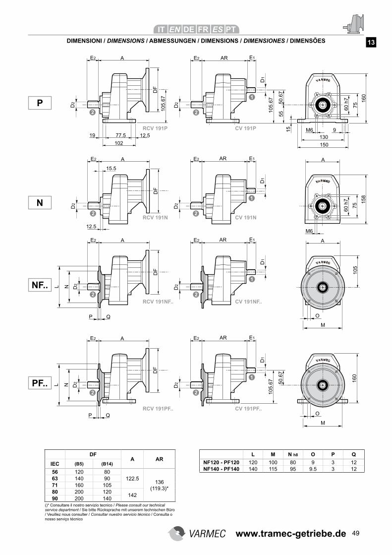
49
DIMENSIONI / DIMENSIONS / ABMESSUNGEN / DIMENSIONS / DIMENSIONES / DIMENSÕES
NF..
P
N
PF..
RCV 191NF.. CV 191NF..
RCV 191PF.. CV 191PF..
RCV 191N CV 191N
RCV 191P CV 191P
13
L M N h8 O P Q
NF120 - PF120 120 100 80 9 3 12NF140 - PF140 140 115 95 9.5 3 12
DFA AR
IEC (B5) (B14)
56 120 80122.5
136(119.3)*
63 140 9071 160 10580 200 120
14290 200 140
()* Consultare il nostro servizio tecnico / Please consult our technical service department / Sie bitte Rücksprache mit unserem technischen Büro / Veuillez nous consulter / Consultar nuestro servicio técnico / Consulta o nosso serviço técnico
www.tramec-getriebe.de
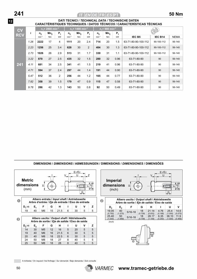
50
50 Nm 241
CV RCV
n1= 2800 min-1 n1= 1400 min-1 n1= 900 min-1
i n2 Mn2 P1 n2 Mn2 P1 n2 Mn2 P1
min-1 Nm kW min-1 Nm kW min-1 Nm kW IEC B5 IEC B14 NEMA
241
1.26 2222 17 4 1111 20 2.4 714 20 1.5 63-71-80-90-100-112 90-100-112 56-140
2.23 1256 25 3.4 628 30 2 404 30 1.3 63-71-80-90-100-112 90-100-112 56-140
2.73 1026 26 2.9 513 31 1.7 330 31 1.1 63-71-80-90-100-112 90-100-112 56-140
3.22 870 27 2.5 435 32 1.5 280 32 0.96 63-71-80-90 90 56-140
4.11 681 34 2.5 341 41 1.5 219 41 0.96 63-71-80-90 90 56-140
4.71 594 37 2.4 297 44 1.4 191 44 0.90 63-71-80-90 90 56-140
5.47 512 36 2 256 44 1.2 165 44 0.77 63-71-80-90 90 56-140
7.82 358 39 1.5 179 47 0.9 115 47 0.58 63-71-80-90 90 56-140
9.78 286 42 1.3 143 50 0.8 92 50 0.49 63-71-80-90 90 56-140
DATI TECNICI / TECHNICAL DATA / TECHNISCHE DATEN CARACTÉRISTIQUES TECHNIQUES / DATOS TÉCNICOS / CARACTERÍSTICAS TÉCNICAS
DIMENSIONI / DIMENSIONS / ABMESSUNGEN / DIMENSIONS / DIMENSIONES / DIMENSÕES
Albero entrata / Input shaft / Antriebswelle Arbre d‘entrée / Eje de entrada / Eixo de entrada
D1 h6 E1 F G H I U V Z
19 40 M6 15 21.5 6 30 5 5
Metric dimensions
(mm)
Imperial dimensions
(inch)
Albero uscita / Output shaft / Abtriebswelle Arbre de sortie / Eje de salida / Eixo de saida
D2 h6 E2 F G H I U V Z
14 30 M5 12 16 5 20 5 519 40 M6 16 21.5 6 30 5 520 40 M8 18 22.5 6 30 5 524 50 M8 18 27 8 40 5 525 50 M8 18 28 8 40 5 5
Albero uscita / Output shaft / Abtriebswelle Arbre de sortie / Eje de salida / Eixo de saida
D2 E2 F G H I U V
19.05 (0.750)
40 (1.575)
5/16-18 18 (0.709)
21.14 (0.832)
4.76 (0.188)
25.4 (1.000)
14.6 (0.575)
25.40 (1.000)
50 (1.969)
5/16-18 18 (0.709)
28.17 (1.109)
6.35 (0.250)
38.10 (1.500)
11.9 (0.469)
(Inch)
12
A richiesta / On request / Auf Anfrage / Sur demande / Bajo demanda / Sob consulta
www.tramec-getriebe.de
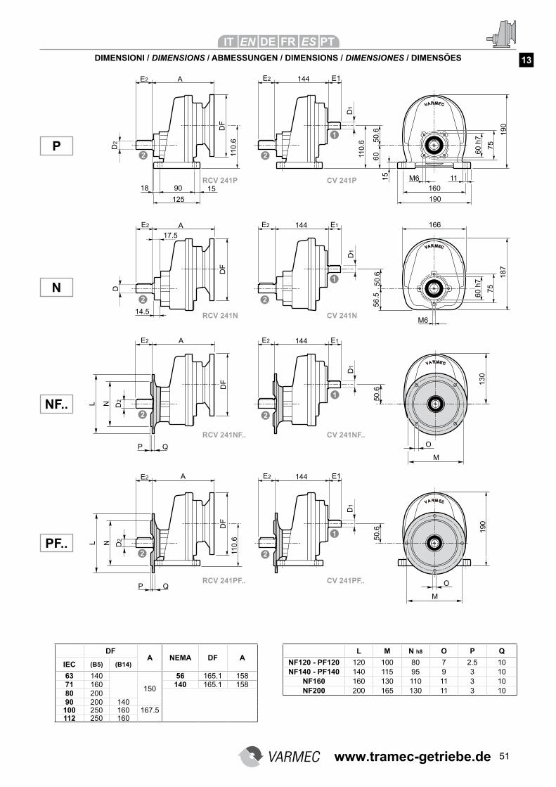
51
DIMENSIONI / DIMENSIONS / ABMESSUNGEN / DIMENSIONS / DIMENSIONES / DIMENSÕES
NF..
P
N
PF..
L M N h8 O P Q
NF120 - PF120 120 100 80 7 2.5 10NF140 - PF140 140 115 95 9 3 10
NF160 160 130 110 11 3 10NF200 200 165 130 11 3 10
DFA NEMA DF A
IEC (B5) (B14)
63 140
150
56 165.1 15871 160 140 165.1 15880 20090 200 140100 250 160 167.5112 250 160
RCV 241NF.. CV 241NF..
RCV 241PF.. CV 241PF..
RCV 241N CV 241N
RCV 241P CV 241P
13
www.tramec-getriebe.de
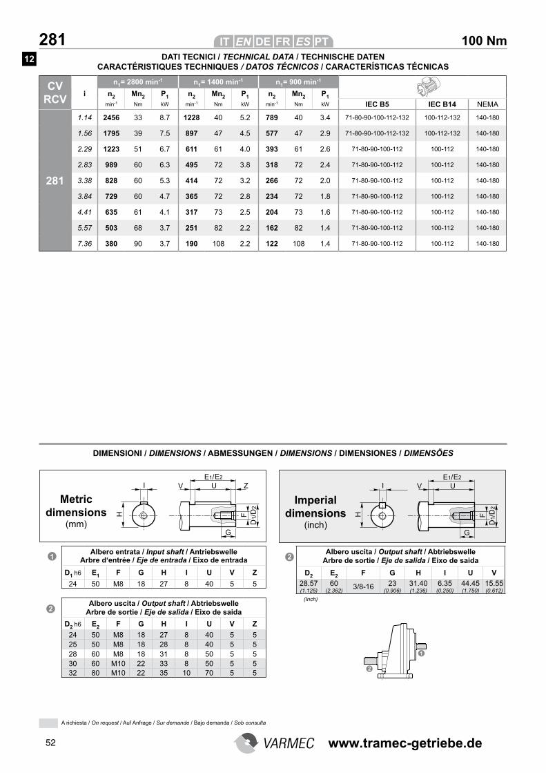
52
100 Nm 281
CV RCV
n1= 2800 min-1 n1= 1400 min-1 n1= 900 min-1
i n2 Mn2 P1 n2 Mn2 P1 n2 Mn2 P1
min-1 Nm kW min-1 Nm kW min-1 Nm kW IEC B5 IEC B14 NEMA
281
1.14 2456 33 8.7 1228 40 5.2 789 40 3.4 71-80-90-100-112-132 100-112-132 140-180
1.56 1795 39 7.5 897 47 4.5 577 47 2.9 71-80-90-100-112-132 100-112-132 140-180
2.29 1223 51 6.7 611 61 4.0 393 61 2.6 71-80-90-100-112 100-112 140-180
2.83 989 60 6.3 495 72 3.8 318 72 2.4 71-80-90-100-112 100-112 140-180
3.38 828 60 5.3 414 72 3.2 266 72 2.0 71-80-90-100-112 100-112 140-180
3.84 729 60 4.7 365 72 2.8 234 72 1.8 71-80-90-100-112 100-112 140-180
4.41 635 61 4.1 317 73 2.5 204 73 1.6 71-80-90-100-112 100-112 140-180
5.57 503 68 3.7 251 82 2.2 162 82 1.4 71-80-90-100-112 100-112 140-180
7.36 380 90 3.7 190 108 2.2 122 108 1.4 71-80-90-100-112 100-112 140-180
DIMENSIONI / DIMENSIONS / ABMESSUNGEN / DIMENSIONS / DIMENSIONES / DIMENSÕES
Metric dimensions
(mm)
Imperial dimensions
(inch)
Albero entrata / Input shaft / Antriebswelle Arbre d‘entrée / Eje de entrada / Eixo de entrada
D1 h6 E1 F G H I U V Z
24 50 M8 18 27 8 40 5 5
Albero uscita / Output shaft / Abtriebswelle Arbre de sortie / Eje de salida / Eixo de saida
D2 h6 E2 F G H I U V Z
24 50 M8 18 27 8 40 5 525 50 M8 18 28 8 40 5 528 60 M8 18 31 8 50 5 530 60 M10 22 33 8 50 5 532 80 M10 22 35 10 70 5 5
Albero uscita / Output shaft / Abtriebswelle Arbre de sortie / Eje de salida / Eixo de saida
D2 E2 F G H I U V
28.57 (1.125)
60 (2.362)
3/8-16 23 (0.906)
31.40 (1.236)
6.35 (0.250)
44.45 (1.750)
15.55 (0.612)
(Inch)
DATI TECNICI / TECHNICAL DATA / TECHNISCHE DATEN CARACTÉRISTIQUES TECHNIQUES / DATOS TÉCNICOS / CARACTERÍSTICAS TÉCNICAS
12
A richiesta / On request / Auf Anfrage / Sur demande / Bajo demanda / Sob consulta
www.tramec-getriebe.de
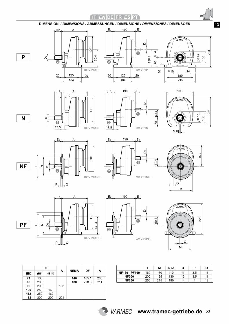
53
DIMENSIONI / DIMENSIONS / ABMESSUNGEN / DIMENSIONS / DIMENSIONES / DIMENSÕES
NF
P
N
PF
L M N h8 O P Q
NF160 - PF160 160 130 110 11 3.5 11NF200 200 165 130 13 3.5 11NF250 250 215 180 14 4 13
DFA NEMA DF A
IEC (B5) (B14)
71 160
195
140 165.1 20580 200 180 228.6 21190 200100 250 160112 250 160132 300 200 224
13
RCV 281NF.. CV 281NF..
RCV 281PF.. CV 281PF..
RCV 281N CV 281N
RCV 281P CV 281P
www.tramec-getriebe.de
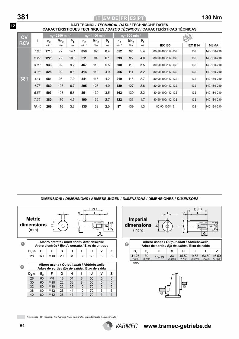
54
130 Nm 381
CV RCV
n1= 2800 min-1 n1= 1400 min-1 n1= 900 min-1
i n2 Mn2 P1 n2 Mn2 P1 n2 Mn2 P1
min-1 Nm kW min-1 Nm kW min-1 Nm kW IEC B5 IEC B14 NEMA
381
1.63 1718 77 14.1 859 92 8.4 552 92 5.4 80-90-100/112-132 132 140-180-210
2.29 1223 79 10.3 611 94 6.1 393 95 4.0 80-90-100/112-132 132 140-180-210
3.00 933 92 9.2 467 110 5.5 300 110 3.5 80-90-100/112-132 132 140-180-210
3.38 828 92 8.1 414 110 4.9 266 111 3.2 80-90-100/112-132 132 140-180-210
4.11 681 96 7.0 341 115 4.2 219 115 2.7 80-90-100/112-132 132 140-180-210
4.75 589 106 6.7 295 126 4.0 189 127 2.6 80-90-100/112-132 132 140-180-210
5.57 503 108 5.8 251 130 3.5 162 130 2.2 80-90-100/112-132 132 140-180-210
7.36 380 110 4.5 190 132 2.7 122 133 1.7 80-90-100/112-132 132 140-180-210
10.40 269 116 3.3 135 138 2.0 87 139 1.3 80-90-100/112 132 140-180-210
DIMENSIONI / DIMENSIONS / ABMESSUNGEN / DIMENSIONS / DIMENSIONES / DIMENSÕES
Metric dimensions
(mm)
Imperial dimensions
(inch)
Albero entrata / Input shaft / Antriebswelle Arbre d‘entrée / Eje de entrada / Eixo de entrada
D1 h6 E1 F G H I U V Z
28 60 M10 20 31 8 50 5 5
Albero uscita / Output shaft / Abtriebswelle Arbre de sortie / Eje de salida / Eixo de saida
D2 h6 E2 F G H I U V Z
28 60 M8 18 31 8 50 5 530 60 M10 22 33 8 50 5 532 80 M10 22 35 10 70 5 538 80 M12 28 41 10 70 5 540 80 M12 28 43 12 70 5 5
Albero uscita / Output shaft / Abtriebswelle Arbre de sortie / Eje de salida / Eixo de saida
D2 E2 F G H I U V
41.27 (1.625)
80 (3.150)
1/2-13 33 (1.299)
45.52 (1.792)
9.53 (0.375)
63.50 (2.500)
16.50 (0.650)
(Inch)
DATI TECNICI / TECHNICAL DATA / TECHNISCHE DATEN CARACTÉRISTIQUES TECHNIQUES / DATOS TÉCNICOS / CARACTERÍSTICAS TÉCNICAS
12
A richiesta / On request / Auf Anfrage / Sur demande / Bajo demanda / Sob consulta
www.tramec-getriebe.de
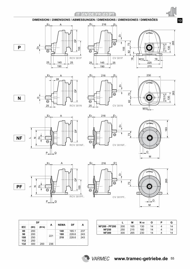
55
DIMENSIONI / DIMENSIONS / ABMESSUNGEN / DIMENSIONS / DIMENSIONES / DIMENSÕES
NF
P
N
PF
L M N h8 O P Q
NF200 - PF200 200 165 130 14 4 14NF250 250 215 180 14 4 14NF300 300 265 230 14 4 14
DFA NEMA DF A
IEC (B5) (B14)
80 200
221
140 165.1 23790 200 180 228.6 243
100 250 210 228.6 243112 250132 300 200 236
13
RCV 381NF.. CV 381NF..
RCV 381PF.. CV 381PF..
RCV 381N CV 381N
RCV 381P CV 381P
www.tramec-getriebe.de
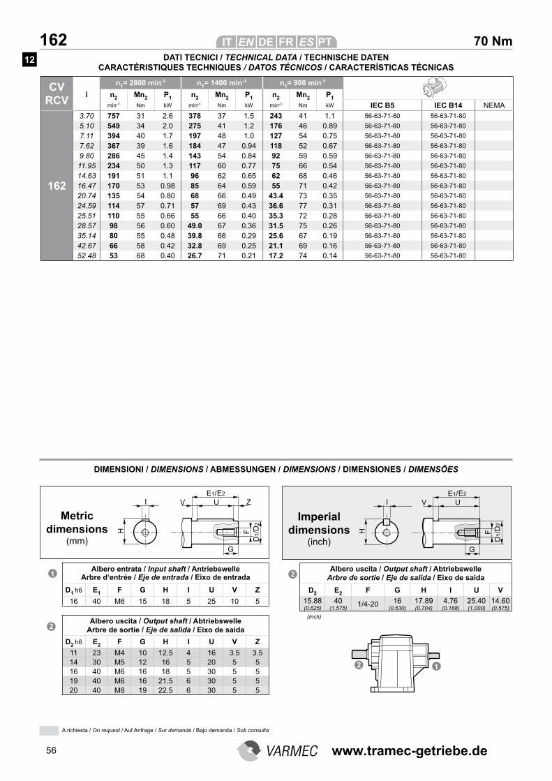
56
70 Nm 162
CV RCV
n1= 2800 min-1 n1= 1400 min-1 n1= 900 min-1
i n2 Mn2 P1 n2 Mn2 P1 n2 Mn2 P1
min-1 Nm kW min-1 Nm kW min-1 Nm kW IEC B5 IEC B14 NEMA
162
3.70 757 31 2.6 378 37 1.5 243 41 1.1 56-63-71-80 56-63-71-80
5.10 549 34 2.0 275 41 1.2 176 46 0.89 56-63-71-80 56-63-71-80
7.11 394 40 1.7 197 48 1.0 127 54 0.75 56-63-71-80 56-63-71-80
7.62 367 39 1.6 184 47 0.94 118 52 0.67 56-63-71-80 56-63-71-80
9.80 286 45 1.4 143 54 0.84 92 59 0.59 56-63-71-80 56-63-71-80
11.95 234 50 1.3 117 60 0.77 75 66 0.54 56-63-71-80 56-63-71-80
14.63 191 51 1.1 96 62 0.65 62 68 0.46 56-63-71-80 56-63-71-80
16.47 170 53 0.98 85 64 0.59 55 71 0.42 56-63-71-80 56-63-71-80
20.74 135 54 0.80 68 66 0.49 43.4 73 0.35 56-63-71-80 56-63-71-80
24.59 114 57 0.71 57 69 0.43 36.6 77 0.31 56-63-71-80 56-63-71-80
25.51 110 55 0.66 55 66 0.40 35.3 72 0.28 56-63-71-80 56-63-71-80
28.57 98 56 0.60 49.0 67 0.36 31.5 75 0.26 56-63-71-80 56-63-71-80
35.14 80 55 0.48 39.8 66 0.29 25.6 67 0.19 56-63-71-80 56-63-71-80
42.67 66 58 0.42 32.8 69 0.25 21.1 69 0.16 56-63-71-80 56-63-71-80
52.48 53 68 0.40 26.7 71 0.21 17.2 74 0.14 56-63-71-80 56-63-71-80
DIMENSIONI / DIMENSIONS / ABMESSUNGEN / DIMENSIONS / DIMENSIONES / DIMENSÕES
Metric dimensions
(mm)
Imperial dimensions
(inch)
Albero entrata / Input shaft / Antriebswelle Arbre d‘entrée / Eje de entrada / Eixo de entrada
D1 h6 E1 F G H I U V Z
16 40 M6 15 18 5 25 10 5
Albero uscita / Output shaft / Abtriebswelle Arbre de sortie / Eje de salida / Eixo de saida
D2 h6 E2 F G H I U V Z
11 23 M4 10 12.5 4 16 3.5 3.514 30 M5 12 16 5 20 5 516 40 M6 16 18 5 30 5 519 40 M6 16 21.5 6 30 5 520 40 M8 19 22.5 6 30 5 5
Albero uscita / Output shaft / Abtriebswelle Arbre de sortie / Eje de salida / Eixo de saida
D2 E2 F G H I U V
15.88 (0.625)
40 (1.575)
1/4-20 16 (0.630)
17.89 (0.704)
4.76 (0.188)
25.40 (1.000)
14.60 (0.575)
(Inch)
DATI TECNICI / TECHNICAL DATA / TECHNISCHE DATEN CARACTÉRISTIQUES TECHNIQUES / DATOS TÉCNICOS / CARACTERÍSTICAS TÉCNICAS
A richiesta / On request / Auf Anfrage / Sur demande / Bajo demanda / Sob consulta
12
www.tramec-getriebe.de
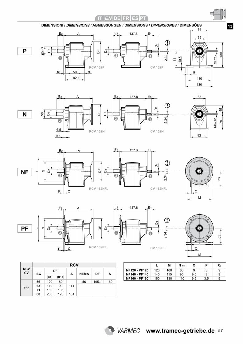
57
DIMENSIONI / DIMENSIONS / ABMESSUNGEN / DIMENSIONS / DIMENSIONES / DIMENSÕES
L M N h8 O P Q
NF120 - PF120 120 100 80 9 3 9NF140 - PF140 140 115 95 9.5 3 9NF160 - PF160 160 130 110 9.5 3.5 9
RCV CV
RCV
IECDF
A NEMA DF A(B5) (B14)
162
56 120 80141
56 165.1 16063 140 9071 160 10580 200 120 151
NF
P
N
PF
13
RCV 162NF.. CV 162NF..
RCV 162PF.. CV 162PF..
RCV 162N CV 162N
RCV 162P CV 162P
www.tramec-getriebe.de
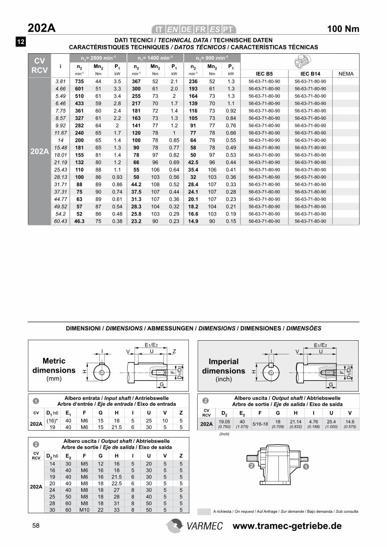
58
CV RCV
n1= 2800 min-1 n1= 1400 min-1 n1= 900 min-1
i n2 Mn2 P1 n2 Mn2 P1 n2 Mn2 P1
min-1 Nm kW min-1 Nm kW min-1 Nm kW IEC B5 IEC B14 NEMA
202A
3.81 735 44 3.5 367 52 2.1 236 52 1.3 56-63-71-80-90 56-63-71-80-90
4.66 601 51 3.3 300 61 2.0 193 61 1.3 56-63-71-80-90 56-63-71-80-90
5.49 510 61 3.4 255 73 2 164 73 1.3 56-63-71-80-90 56-63-71-80-90
6.46 433 59 2.8 217 70 1.7 139 70 1.1 56-63-71-80-90 56-63-71-80-90
7.75 361 60 2.4 181 72 1.4 116 73 0.92 56-63-71-80-90 56-63-71-80-90
8.57 327 61 2.2 163 73 1.3 105 73 0.84 56-63-71-80-90 56-63-71-80-90
9.92 282 64 2 141 77 1.2 91 77 0.76 56-63-71-80-90 56-63-71-80-90
11.67 240 65 1.7 120 78 1 77 78 0.66 56-63-71-80-90 56-63-71-80-90
14 200 65 1.4 100 78 0.85 64 78 0.55 56-63-71-80-90 56-63-71-80-90
15.48 181 65 1.3 90 78 0.77 58 78 0.49 56-63-71-80-90 56-63-71-80-90
18.01 155 81 1.4 78 97 0.82 50 97 0.53 56-63-71-80-90 56-63-71-80-90
21.19 132 80 1.2 66 96 0.69 42.5 96 0.44 56-63-71-80-90 56-63-71-80-90
25.43 110 88 1.1 55 106 0.64 35.4 106 0.41 56-63-71-80-90 56-63-71-80-90
28.13 100 86 0.93 50 103 0.56 32 103 0.36 56-63-71-80-90 56-63-71-80-90
31.71 88 89 0.86 44.2 108 0.52 28.4 107 0.33 56-63-71-80-90 56-63-71-80-90
37.31 75 90 0.74 37.5 107 0.44 24.1 107 0.28 56-63-71-80-90 56-63-71-80-90
44.77 63 89 0.61 31.3 107 0.36 20.1 107 0.23 56-63-71-80-90 56-63-71-80-90
49.52 57 87 0.54 28.3 104 0.32 18.2 104 0.21 56-63-71-80-90 56-63-71-80-90
54.2 52 86 0.48 25.8 103 0.29 16.6 103 0.19 56-63-71-80-90 56-63-71-80-90
60.43 46.3 75 0.38 23.2 90 0.23 14.9 90 0.15 56-63-71-80-90 56-63-71-80-90
DIMENSIONI / DIMENSIONS / ABMESSUNGEN / DIMENSIONS / DIMENSIONES / DIMENSÕES
Albero entrata / Input shaft / Antriebswelle Arbre d‘entrée / Eje de entrada / Eixo de entrada
CV D1 h6 E1 F G H I U V Z
202A(16)* 40 M6 15 18 5 25 10 519 40 M6 15 21.5 6 30 5 5
Albero uscita / Output shaft / Abtriebswelle Arbre de sortie / Eje de salida / Eixo de saida
CV RCV D2 h6 E2 F G H I U V Z
202A
14 30 M5 12 16 5 20 5 516 40 M6 16 18 5 30 5 519 40 M6 16 21.5 6 30 5 520 40 M8 18 22.5 6 30 5 524 40 M8 18 27 8 30 5 525 50 M8 18 28 8 40 5 528 60 M8 18 31 8 50 5 530 60 M10 22 33 8 50 5 5
Albero uscita / Output shaft / Abtriebswelle Arbre de sortie / Eje de salida / Eixo de saida
CV RCV D2 E2 F G H I U V
202A 19.05 (0.750)
40 (1.575)
5/16-1818
(0.709)
21.14 (0.832)
4.76 (0.188)
25.4 (1.000)
14.6 (0.575)
Metric dimensions
(mm)
Imperial dimensions
(inch)
(Inch)
DATI TECNICI / TECHNICAL DATA / TECHNISCHE DATEN CARACTÉRISTIQUES TECHNIQUES / DATOS TÉCNICOS / CARACTERÍSTICAS TÉCNICAS
A richiesta / On request / Auf Anfrage / Sur demande / Bajo demanda / Sob consulta
12
100 Nm 202A
www.tramec-getriebe.de
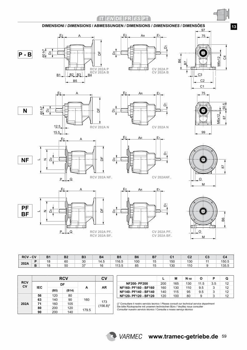
59
DIMENSIONI / DIMENSIONS / ABMESSUNGEN / DIMENSIONS / DIMENSIONES / DIMENSÕES
L M N h8 O P Q
NF200- PF200 200 165 130 11.5 3.5 12NF160- PF160 - BF160 160 130 110 9.5 3 12NF140- PF140 - BF140 140 115 95 9.5 3 12NF120- PF120 - BF120 120 100 80 9 3 12
RCV CV
RCV CV
IECDF
A AR(B5) (B14)
202A
56 120 80160
173(156.8)*
63 140 9071 160 10580 200 120
179.590 200 140
NF
P - B
N
PF BF
13
RCV 202A NF.. CV 202ANF..
RCV 202A PF.. CV 202A PF..
RCV 202A N CV 202A N
RCV 202A P CV 202A P
RCV - CV B1 B2 B3 B4 B5 B6 B7 C1 C2 C3 C4
202AP 18 60 30 14.5 116.5 100 15 150 130 11 150.5B 18 50 37 16 113.5 85 15 130 110 9 135.5
RCV 202A BF.. CV 202A BF..
RCV 202A B CV 202A B
()* Consultare il nostro servizio tecnico / Please consult our technical service departmentSie bitte Rücksprache mit unserem technischen Büro / Veuillez nous consulterConsultar nuestro servicio técnico / Consulta o nosso serviço técnico
www.tramec-getriebe.de
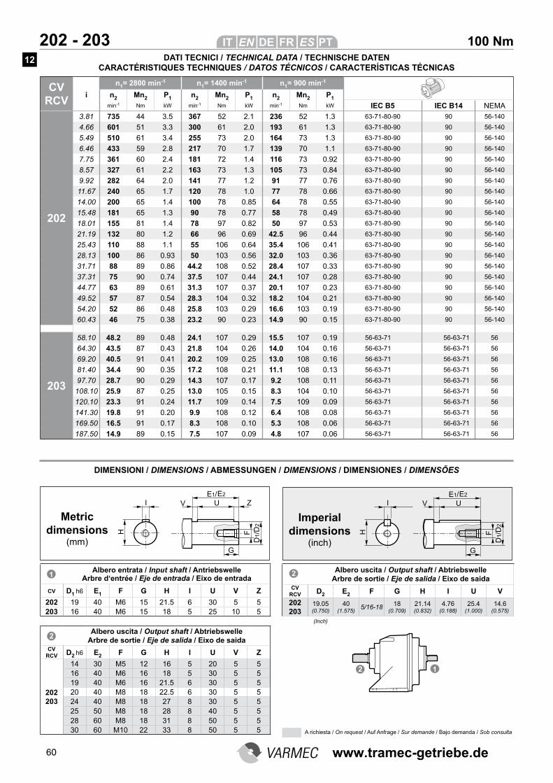
60
CV RCV
n1= 2800 min-1 n1= 1400 min-1 n1= 900 min-1
i n2 Mn2 P1 n2 Mn2 P1 n2 Mn2 P1
min-1 Nm kW min-1 Nm kW min-1 Nm kW IEC B5 IEC B14 NEMA
202
3.81 735 44 3.5 367 52 2.1 236 52 1.3 63-71-80-90 90 56-140
4.66 601 51 3.3 300 61 2.0 193 61 1.3 63-71-80-90 90 56-140
5.49 510 61 3.4 255 73 2.0 164 73 1.3 63-71-80-90 90 56-140
6.46 433 59 2.8 217 70 1.7 139 70 1.1 63-71-80-90 90 56-140
7.75 361 60 2.4 181 72 1.4 116 73 0.92 63-71-80-90 90 56-140
8.57 327 61 2.2 163 73 1.3 105 73 0.84 63-71-80-90 90 56-140
9.92 282 64 2.0 141 77 1.2 91 77 0.76 63-71-80-90 90 56-140
11.67 240 65 1.7 120 78 1.0 77 78 0.66 63-71-80-90 90 56-140
14.00 200 65 1.4 100 78 0.85 64 78 0.55 63-71-80-90 90 56-140
15.48 181 65 1.3 90 78 0.77 58 78 0.49 63-71-80-90 90 56-140
18.01 155 81 1.4 78 97 0.82 50 97 0.53 63-71-80-90 90 56-140
21.19 132 80 1.2 66 96 0.69 42.5 96 0.44 63-71-80-90 90 56-140
25.43 110 88 1.1 55 106 0.64 35.4 106 0.41 63-71-80-90 90 56-140
28.13 100 86 0.93 50 103 0.56 32.0 103 0.36 63-71-80-90 90 56-140
31.71 88 89 0.86 44.2 108 0.52 28.4 107 0.33 63-71-80-90 90 56-140
37.31 75 90 0.74 37.5 107 0.44 24.1 107 0.28 63-71-80-90 90 56-140
44.77 63 89 0.61 31.3 107 0.37 20.1 107 0.23 63-71-80-90 90 56-140
49.52 57 87 0.54 28.3 104 0.32 18.2 104 0.21 63-71-80-90 90 56-140
54.20 52 86 0.48 25.8 103 0.29 16.6 103 0.19 63-71-80-90 90 56-140
60.43 46 75 0.38 23.2 90 0.23 14.9 90 0.15 63-71-80-90 90 56-140
203
58.10 48.2 89 0.48 24.1 107 0.29 15.5 107 0.19 56-63-71 56-63-71 56
64.30 43.5 87 0.43 21.8 104 0.26 14.0 104 0.16 56-63-71 56-63-71 56
69.20 40.5 91 0.41 20.2 109 0.25 13.0 108 0.16 56-63-71 56-63-71 56
81.40 34.4 90 0.35 17.2 108 0.21 11.1 108 0.13 56-63-71 56-63-71 56
97.70 28.7 90 0.29 14.3 107 0.17 9.2 108 0.11 56-63-71 56-63-71 56
108.10 25.9 87 0.25 13.0 105 0.15 8.3 104 0.10 56-63-71 56-63-71 56
120.10 23.3 91 0.24 11.7 109 0.14 7.5 109 0.09 56-63-71 56-63-71 56
141.30 19.8 91 0.20 9.9 108 0.12 6.4 108 0.08 56-63-71 56-63-71 56
169.50 16.5 91 0.17 8.3 108 0.10 5.3 108 0.06 56-63-71 56-63-71 56
187.50 14.9 89 0.15 7.5 107 0.09 4.8 107 0.06 56-63-71 56-63-71 56
100 Nm 202 - 203
DIMENSIONI / DIMENSIONS / ABMESSUNGEN / DIMENSIONS / DIMENSIONES / DIMENSÕES
Albero entrata / Input shaft / Antriebswelle Arbre d‘entrée / Eje de entrada / Eixo de entrada
CV D1 h6 E1 F G H I U V Z
202 19 40 M6 15 21.5 6 30 5 5203 16 40 M6 15 18 5 25 10 5
Albero uscita / Output shaft / Abtriebswelle Arbre de sortie / Eje de salida / Eixo de saida
CV RCV D2 h6 E2 F G H I U V Z
202 203
14 30 M5 12 16 5 20 5 516 40 M6 16 18 5 30 5 519 40 M6 16 21.5 6 30 5 520 40 M8 18 22.5 6 30 5 524 40 M8 18 27 8 30 5 525 50 M8 18 28 8 40 5 528 60 M8 18 31 8 50 5 530 60 M10 22 33 8 50 5 5
Albero uscita / Output shaft / Abtriebswelle Arbre de sortie / Eje de salida / Eixo de saida
CV RCV D2 E2 F G H I U V
202 203
19.05 (0.750)
40 (1.575)
5/16-1818
(0.709)
21.14 (0.832)
4.76 (0.188)
25.4 (1.000)
14.6 (0.575)
Metric dimensions
(mm)
Imperial dimensions
(inch)
(Inch)
DATI TECNICI / TECHNICAL DATA / TECHNISCHE DATEN CARACTÉRISTIQUES TECHNIQUES / DATOS TÉCNICOS / CARACTERÍSTICAS TÉCNICAS
A richiesta / On request / Auf Anfrage / Sur demande / Bajo demanda / Sob consulta
12
www.tramec-getriebe.de
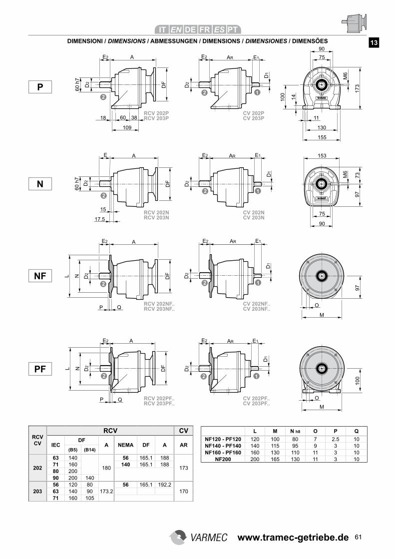
61
DIMENSIONI / DIMENSIONS / ABMESSUNGEN / DIMENSIONS / DIMENSIONES / DIMENSÕES
L M N h8 O P Q
NF120 - PF120 120 100 80 7 2.5 10NF140 - PF140 140 115 95 9 3 10NF160 - PF160 160 130 110 11 3 10
NF200 200 165 130 11 3 10
RCV CV
RCV CV
IECDF
A NEMA DF A AR(B5) (B14)
202
63 140
180
56 165.1 188
17371 160 140 165.1 18880 20090 200 140
20356 120 80
173.256 165.1 192.2
17063 140 9071 160 105
NF
P
N
PF
13
RCV 202NF..RCV 203NF..
CV 202NF..CV 203NF..
RCV 202PF..RCV 203PF..
CV 202PF..CV 203PF..
RCV 202NRCV 203N
CV 202NCV 203N
RCV 202PRCV 203P
CV 202PCV 203P
www.tramec-getriebe.de
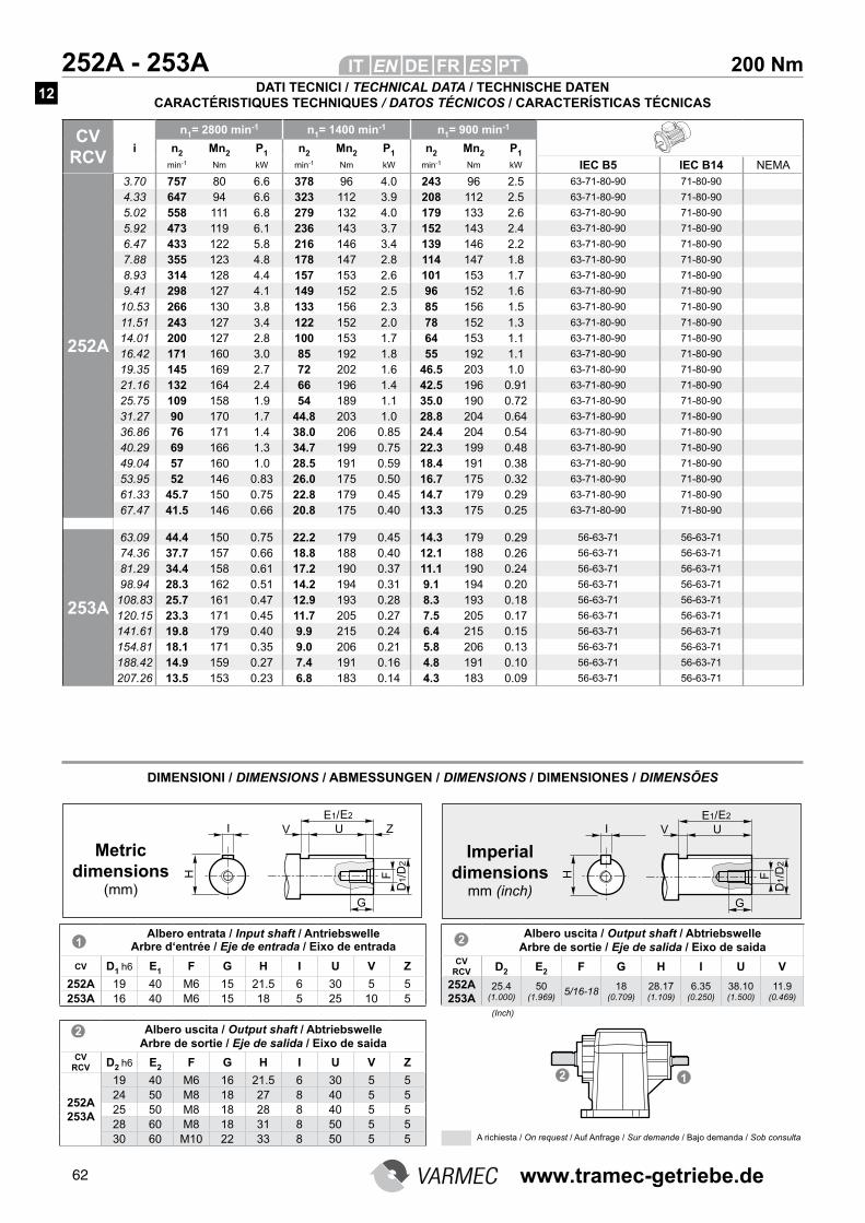
62
200 Nm 252A - 253A
CV RCV
n1= 2800 min-1 n1= 1400 min-1 n1= 900 min-1
i n2 Mn2 P1 n2 Mn2 P1 n2 Mn2 P1
min-1 Nm kW min-1 Nm kW min-1 Nm kW IEC B5 IEC B14 NEMA
252A
3.70 757 80 6.6 378 96 4.0 243 96 2.5 63-71-80-90 71-80-90
4.33 647 94 6.6 323 112 3.9 208 112 2.5 63-71-80-90 71-80-90
5.02 558 111 6.8 279 132 4.0 179 133 2.6 63-71-80-90 71-80-90
5.92 473 119 6.1 236 143 3.7 152 143 2.4 63-71-80-90 71-80-90
6.47 433 122 5.8 216 146 3.4 139 146 2.2 63-71-80-90 71-80-90
7.88 355 123 4.8 178 147 2.8 114 147 1.8 63-71-80-90 71-80-90
8.93 314 128 4.4 157 153 2.6 101 153 1.7 63-71-80-90 71-80-90
9.41 298 127 4.1 149 152 2.5 96 152 1.6 63-71-80-90 71-80-90
10.53 266 130 3.8 133 156 2.3 85 156 1.5 63-71-80-90 71-80-90
11.51 243 127 3.4 122 152 2.0 78 152 1.3 63-71-80-90 71-80-90
14.01 200 127 2.8 100 153 1.7 64 153 1.1 63-71-80-90 71-80-90
16.42 171 160 3.0 85 192 1.8 55 192 1.1 63-71-80-90 71-80-90
19.35 145 169 2.7 72 202 1.6 46.5 203 1.0 63-71-80-90 71-80-90
21.16 132 164 2.4 66 196 1.4 42.5 196 0.91 63-71-80-90 71-80-90
25.75 109 158 1.9 54 189 1.1 35.0 190 0.72 63-71-80-90 71-80-90
31.27 90 170 1.7 44.8 203 1.0 28.8 204 0.64 63-71-80-90 71-80-90
36.86 76 171 1.4 38.0 206 0.85 24.4 204 0.54 63-71-80-90 71-80-90
40.29 69 166 1.3 34.7 199 0.75 22.3 199 0.48 63-71-80-90 71-80-90
49.04 57 160 1.0 28.5 191 0.59 18.4 191 0.38 63-71-80-90 71-80-90
53.95 52 146 0.83 26.0 175 0.50 16.7 175 0.32 63-71-80-90 71-80-90
61.33 45.7 150 0.75 22.8 179 0.45 14.7 179 0.29 63-71-80-90 71-80-90
67.47 41.5 146 0.66 20.8 175 0.40 13.3 175 0.25 63-71-80-90 71-80-90
253A
63.09 44.4 150 0.75 22.2 179 0.45 14.3 179 0.29 56-63-71 56-63-71
74.36 37.7 157 0.66 18.8 188 0.40 12.1 188 0.26 56-63-71 56-63-71
81.29 34.4 158 0.61 17.2 190 0.37 11.1 190 0.24 56-63-71 56-63-71
98.94 28.3 162 0.51 14.2 194 0.31 9.1 194 0.20 56-63-71 56-63-71
108.83 25.7 161 0.47 12.9 193 0.28 8.3 193 0.18 56-63-71 56-63-71
120.15 23.3 171 0.45 11.7 205 0.27 7.5 205 0.17 56-63-71 56-63-71
141.61 19.8 179 0.40 9.9 215 0.24 6.4 215 0.15 56-63-71 56-63-71
154.81 18.1 171 0.35 9.0 206 0.21 5.8 206 0.13 56-63-71 56-63-71
188.42 14.9 159 0.27 7.4 191 0.16 4.8 191 0.10 56-63-71 56-63-71
207.26 13.5 153 0.23 6.8 183 0.14 4.3 183 0.09 56-63-71 56-63-71
DIMENSIONI / DIMENSIONS / ABMESSUNGEN / DIMENSIONS / DIMENSIONES / DIMENSÕES
Albero entrata / Input shaft / Antriebswelle Arbre d‘entrée / Eje de entrada / Eixo de entrada
CV D1 h6 E1 F G H I U V Z
252A 19 40 M6 15 21.5 6 30 5 5253A 16 40 M6 15 18 5 25 10 5
Albero uscita / Output shaft / Abtriebswelle Arbre de sortie / Eje de salida / Eixo de saida
CV RCV D2 h6 E2 F G H I U V Z
252A 253A
19 40 M6 16 21.5 6 30 5 524 50 M8 18 27 8 40 5 525 50 M8 18 28 8 40 5 528 60 M8 18 31 8 50 5 530 60 M10 22 33 8 50 5 5
Metric dimensions
(mm)
Imperial dimensions
mm (inch)
Albero uscita / Output shaft / Abtriebswelle Arbre de sortie / Eje de salida / Eixo de saida
CV RCV D2 E2 F G H I U V
252A 253A
25.4 (1.000)
50 (1.969)
5/16-1818
(0.709)
28.17 (1.109)
6.35 (0.250)
38.10 (1.500)
11.9 (0.469)
(Inch)
DATI TECNICI / TECHNICAL DATA / TECHNISCHE DATEN CARACTÉRISTIQUES TECHNIQUES / DATOS TÉCNICOS / CARACTERÍSTICAS TÉCNICAS
A richiesta / On request / Auf Anfrage / Sur demande / Bajo demanda / Sob consulta
12
www.tramec-getriebe.de
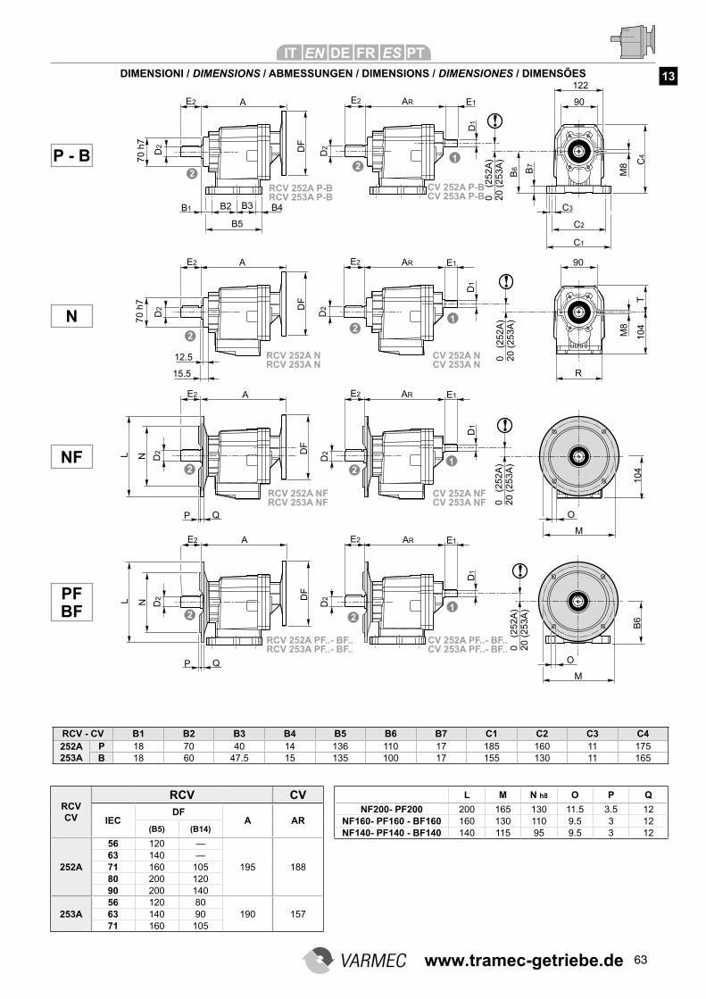
63
DIMENSIONI / DIMENSIONS / ABMESSUNGEN / DIMENSIONS / DIMENSIONES / DIMENSÕES 13
L M N h8 O P Q
NF200- PF200 200 165 130 11.5 3.5 12NF160- PF160 - BF160 160 130 110 9.5 3 12NF140- PF140 - BF140 140 115 95 9.5 3 12
RCV CV
RCV CV
IECDF
A AR(B5) (B14)
252A
56 120 —
195 18863 140 —71 160 10580 200 12090 200 140
253A56 120 80
190 15763 140 9071 160 105
RCV - CV B1 B2 B3 B4 B5 B6 B7 C1 C2 C3 C4252A253A
P 18 70 40 14 136 110 17 185 160 11 175B 18 60 47.5 15 135 100 17 155 130 11 165
NF
P - B
N
PF BF
RCV 252A NFRCV 253A NF
CV 252A NFCV 253A NF
RCV 252A PF..- BF..RCV 253A PF..- BF..
CV 252A PF..- BF..CV 253A PF..- BF..
RCV 252A NRCV 253A N
CV 252A NCV 253A N
RCV 252A P-BRCV 253A P-B
CV 252A P-BCV 253A P-B
www.tramec-getriebe.de
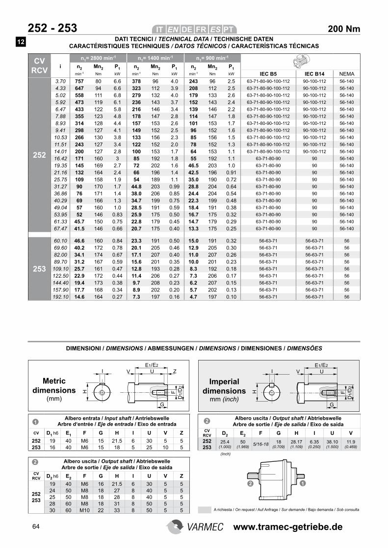
64
200 Nm 252 - 253
CV RCV
n1= 2800 min-1 n1= 1400 min-1 n1= 900 min-1
i n2 Mn2 P1 n2 Mn2 P1 n2 Mn2 P1
min-1 Nm kW min-1 Nm kW min-1 Nm kW IEC B5 IEC B14 NEMA
252
3.70 757 80 6.6 378 96 4.0 243 96 2.5 63-71-80-90-100-112 90-100-112 56-140
4.33 647 94 6.6 323 112 3.9 208 112 2.5 63-71-80-90-100-112 90-100-112 56-140
5.02 558 111 6.8 279 132 4.0 179 133 2.6 63-71-80-90-100-112 90-100-112 56-140
5.92 473 119 6.1 236 143 3.7 152 143 2.4 63-71-80-90-100-112 90-100-112 56-140
6.47 433 122 5.8 216 146 3.4 139 146 2.2 63-71-80-90-100-112 90-100-112 56-140
7.88 355 123 4.8 178 147 2.8 114 147 1.8 63-71-80-90-100-112 90-100-112 56-140
8.93 314 128 4.4 157 153 2.6 101 153 1.7 63-71-80-90-100-112 90-100-112 56-140
9.41 298 127 4.1 149 152 2.5 96 152 1.6 63-71-80-90-100-112 90-100-112 56-140
10.53 266 130 3.8 133 156 2.3 85 156 1.5 63-71-80-90-100-112 90-100-112 56-140
11.51 243 127 3.4 122 152 2.0 78 152 1.3 63-71-80-90-100-112 90-100-112 56-140
14.01 200 127 2.8 100 153 1.7 64 153 1.1 63-71-80-90-100-112 90-100-112 56-140
16.42 171 160 3 85 192 1.8 55 192 1.1 63-71-80-90 90 56-140
19.35 145 169 2.7 72 202 1.6 46.5 203 1.0 63-71-80-90 90 56-140
21.16 132 164 2.4 66 196 1.4 42.5 196 0.91 63-71-80-90 90 56-140
25.75 109 158 1.9 54 189 1.1 35.0 190 0.72 63-71-80-90 90 56-140
31.27 90 170 1.7 44.8 203 0.99 28.8 204 0.64 63-71-80-90 90 56-140
36.86 76 171 1.4 38.0 206 0.85 24.4 204 0.54 63-71-80-90 90 56-140
40.29 69 166 1.3 34.7 199 0.75 22.3 199 0.48 63-71-80-90 90 56-140
49.04 57 160 1.0 28.5 191 0.59 18.4 191 0.38 63-71-80-90 90 56-140
53.95 52 146 0.83 25.9 175 0.50 16.7 175 0.32 63-71-80-90 90 56-140
61.33 45.7 150 0.75 22.8 179 0.45 14.7 179 0.29 63-71-80-90 90 56-140
67.47 41.5 146 0.66 20.7 175 0.40 13.3 175 0.25 63-71-80-90 90 56-140
253
60.10 46.6 160 0.84 23.3 191 0.50 15.0 191 0.32 56-63-71 56-63-71 56
69.60 40.2 172 0.78 20.1 205 0.46 12.9 205 0.30 56-63-71 56-63-71 56
82.00 34.1 174 0.67 17.1 207 0.40 11.0 207 0.26 56-63-71 56-63-71 56
89.70 31.2 167 0.59 15.6 201 0.35 10.0 201 0.23 56-63-71 56-63-71 56
109.10 25.7 161 0.47 12.8 193 0.28 8.3 192 0.18 56-63-71 56-63-71 56
122.50 22.9 172 0.44 11.4 206 0.27 7.3 206 0.17 56-63-71 56-63-71 56
144.40 19.4 173 0.38 9.7 208 0.23 6.2 207 0.15 56-63-71 56-63-71 56
157.90 17.7 168 0.34 8.9 202 0.20 5.7 202 0.13 56-63-71 56-63-71 56
192.10 14.6 164 0.27 7.3 197 0.16 4.7 197 0.10 56-63-71 56-63-71 56
DIMENSIONI / DIMENSIONS / ABMESSUNGEN / DIMENSIONS / DIMENSIONES / DIMENSÕES
Albero entrata / Input shaft / Antriebswelle Arbre d‘entrée / Eje de entrada / Eixo de entrada
CV D1 h6 E1 F G H I U V Z
252 19 40 M6 15 21.5 6 30 5 5253 16 40 M6 15 18 5 25 10 5
Albero uscita / Output shaft / Abtriebswelle Arbre de sortie / Eje de salida / Eixo de saida
CV RCV D2 h6 E2 F G H I U V Z
252 253
19 40 M6 16 21.5 6 30 5 524 50 M8 18 27 8 40 5 525 50 M8 18 28 8 40 5 528 60 M8 18 31 8 50 5 530 60 M10 22 33 8 50 5 5
Metric dimensions
(mm)
Imperial dimensions
mm (inch)
Albero uscita / Output shaft / Abtriebswelle Arbre de sortie / Eje de salida / Eixo de saida
CV RCV D2 E2 F G H I U V
252 253
25.4 (1.000)
50 (1.969)
5/16-1818
(0.709)
28.17 (1.109)
6.35 (0.250)
38.10 (1.500)
11.9 (0.469)
(Inch)
DATI TECNICI / TECHNICAL DATA / TECHNISCHE DATEN CARACTÉRISTIQUES TECHNIQUES / DATOS TÉCNICOS / CARACTERÍSTICAS TÉCNICAS
A richiesta / On request / Auf Anfrage / Sur demande / Bajo demanda / Sob consulta
12
www.tramec-getriebe.de
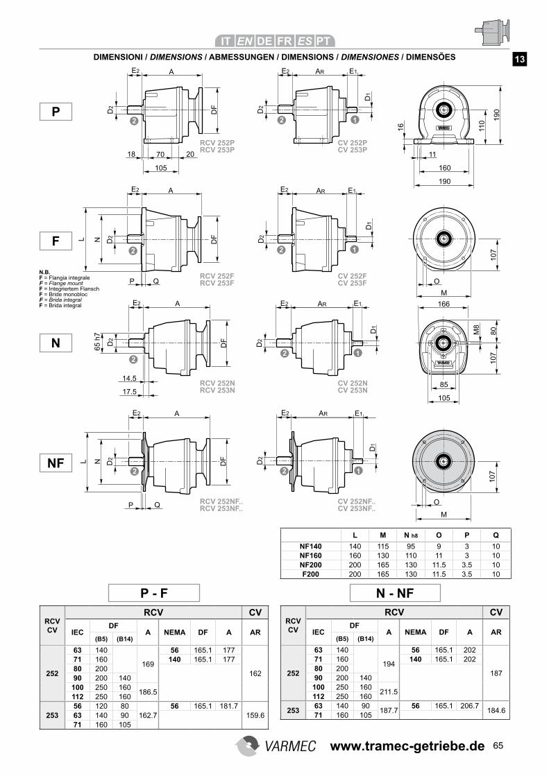
65
DIMENSIONI / DIMENSIONS / ABMESSUNGEN / DIMENSIONS / DIMENSIONES / DIMENSÕES
L M N h8 O P Q
NF140 140 115 95 9 3 10NF160 160 130 110 11 3 10NF200 200 165 130 11.5 3.5 10F200 200 165 130 11.5 3.5 10
RCV CV
RCV CV
IECDF
A NEMA DF A AR(B5) (B14)
252
63 140
169
56 165.1 177
162
71 160 140 165.1 17780 20090 200 140100 250 160
186.5112 250 160
25356 120 80
162.756 165.1 181.7
159.663 140 9071 160 105
NF
P
N
RCV CV
RCV CV
IECDF
A NEMA DF A AR(B5) (B14)
252
63 140
194
56 165.1 202
187
71 160 140 165.1 20280 20090 200 140100 250 160
211.5112 250 160
25363 140 90
187.756 165.1 206.7
184.671 160 105
F
P - F N - NF
13
RCV 252NRCV 253N
CV 252NCV 253N
RCV 252NF..RCV 253NF..
CV 252NF..CV 253NF..
RCV 252FRCV 253F
CV 252FCV 253F
RCV 252PRCV 253P
CV 252PCV 253P
N.B.F = Flangia integrale F = Flange mount F = Integriertem Flansch F = Bride monobloc F = Brida integral F = Brida integral
www.tramec-getriebe.de
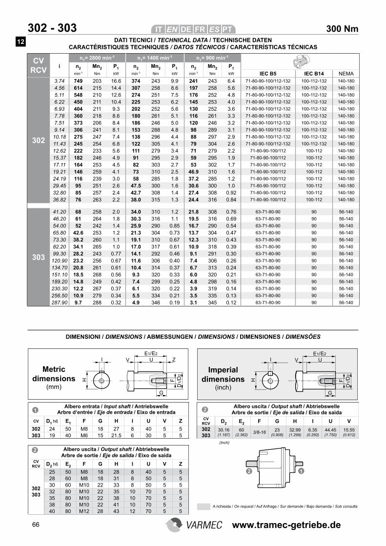
66
300 Nm 302 - 303
CV RCV
n1= 2800 min-1 n1= 1400 min-1 n1= 900 min-1
i n2 Mn2 P1 n2 Mn2 P1 n2 Mn2 P1
min-1 Nm kW min-1 Nm kW min-1 Nm kW IEC B5 IEC B14 NEMA
302
3.74 749 203 16.6 374 243 9.9 241 243 6.4 71-80-90-100/112-132 100-112-132 140-180
4.56 614 215 14.4 307 258 8.6 197 258 5.6 71-80-90-100/112-132 100-112-132 140-180
5.11 548 210 12.6 274 251 7.5 176 252 4.8 71-80-90-100/112-132 100-112-132 140-180
6.22 450 211 10.4 225 253 6.2 145 253 4.0 71-80-90-100/112-132 100-112-132 140-180
6.93 404 211 9.3 202 252 5.6 130 252 3.6 71-80-90-100/112-132 100-112-132 140-180
7.78 360 218 8.6 180 261 5.1 116 261 3.3 71-80-90-100/112-132 100-112-132 140-180
7.51 373 206 8.4 186 246 5.0 120 246 3.2 71-80-90-100/112-132 100-112-132 140-180
9.14 306 241 8.1 153 288 4.8 98 289 3.1 71-80-90-100/112-132 100-112-132 140-180
10.18 275 247 7.4 138 296 4.4 88 297 2.9 71-80-90-100/112-132 100-112-132 140-180
11.43 245 254 6.8 122 305 4.1 79 304 2.6 71-80-90-100/112-132 100-112-132 140-180
12.62 222 233 5.6 111 279 3.4 71 279 2.2 71-80-90-100/112 100-112 140-180
15.37 182 246 4.9 91 295 2.9 59 295 1.9 71-80-90-100/112 100-112 140-180
17.11 164 253 4.5 82 303 2.7 53 302 1.7 71-80-90-100/112 100-112 140-180
19.21 146 259 4.1 73 310 2.5 46.9 310 1.6 71-80-90-100/112 100-112 140-180
24.19 116 239 3.0 58 285 1.8 37.2 285 1.2 71-80-90-100/112 100-112 140-180
29.45 95 251 2.6 47.5 300 1.6 30.6 300 1.0 71-80-90-100/112 100-112 140-180
32.80 85 257 2.4 42.7 308 1.4 27.4 308 0.92 71-80-90-100/112 100-112 140-180
36.82 76 263 2.2 38.0 315 1.3 24.4 316 0.84 71-80-90-100/112 100-112 140-180
303
41.20 68 258 2.0 34.0 310 1.2 21.8 308 0.76 63-71-80-90 90 56-140
46.20 61 264 1.8 30.3 316 1.1 19.5 316 0.69 63-71-80-90 90 56-140
54.00 52 242 1.4 25.9 290 0.85 16.7 290 0.54 63-71-80-90 90 56-140
65.80 42.6 253 1.2 21.3 304 0.73 13.7 304 0.47 63-71-80-90 90 56-140
73.30 38.2 260 1.1 19.1 310 0.67 12.3 310 0.43 63-71-80-90 90 56-140
82.20 34.1 265 1.0 17.0 317 0.61 10.9 318 0.39 63-71-80-90 90 56-140
99.30 28.2 243 0.77 14.1 292 0.46 9.1 291 0.30 63-71-80-90 90 56-140
120.90 23.2 256 0.67 11.6 306 0.40 7.4 306 0.26 63-71-80-90 90 56-140
134.70 20.8 261 0.61 10.4 314 0.37 6.7 313 0.24 63-71-80-90 90 56-140
151.10 18.5 268 0.56 9.3 320 0.33 6.0 320 0.21 63-71-80-90 90 56-140
189.20 14.8 249 0.42 7.4 299 0.25 4.8 298 0.16 63-71-80-90 90 56-140
230.30 12.2 267 0.37 6.1 320 0.22 3.9 319 0.14 63-71-80-90 90 56-140
256.50 10.9 279 0.34 5.5 334 0.21 3.5 335 0.13 63-71-80-90 90 56-140
287.90 9.7 288 0.32 4.9 346 0.19 3.1 345 0.12 63-71-80-90 90 56-140
DIMENSIONI / DIMENSIONS / ABMESSUNGEN / DIMENSIONS / DIMENSIONES / DIMENSÕES
Albero entrata / Input shaft / Antriebswelle Arbre d‘entrée / Eje de entrada / Eixo de entrada
CV D1 h6 E1 F G H I U V Z
302 24 50 M8 18 27 8 40 5 5303 19 40 M6 15 21.5 6 30 5 5
Albero uscita / Output shaft / Abtriebswelle Arbre de sortie / Eje de salida / Eixo de saida
CV RCV D2 h6 E2 F G H I U V Z
302 303
25 50 M8 18 28 8 40 5 528 60 M8 18 31 8 50 5 530 60 M10 22 33 8 50 5 532 80 M10 22 35 10 70 5 535 80 M10 22 38 10 70 5 538 80 M10 22 41 10 70 5 540 80 M12 28 43 12 70 5 5
Metric dimensions
(mm)
Imperial dimensions
(inch)
Albero uscita / Output shaft / Abtriebswelle Arbre de sortie / Eje de salida / Eixo de saida
CV RCV D2 E2 F G H I U V
302 303
30.16 (1.187)
60 (2.362)
3/8-1623
(0.906)
32.99 (1.299)
6.35 (0.250)
44.45 (1.750)
15.55 (0.612)
(Inch)
DATI TECNICI / TECHNICAL DATA / TECHNISCHE DATEN CARACTÉRISTIQUES TECHNIQUES / DATOS TÉCNICOS / CARACTERÍSTICAS TÉCNICAS
A richiesta / On request / Auf Anfrage / Sur demande / Bajo demanda / Sob consulta
12
www.tramec-getriebe.de
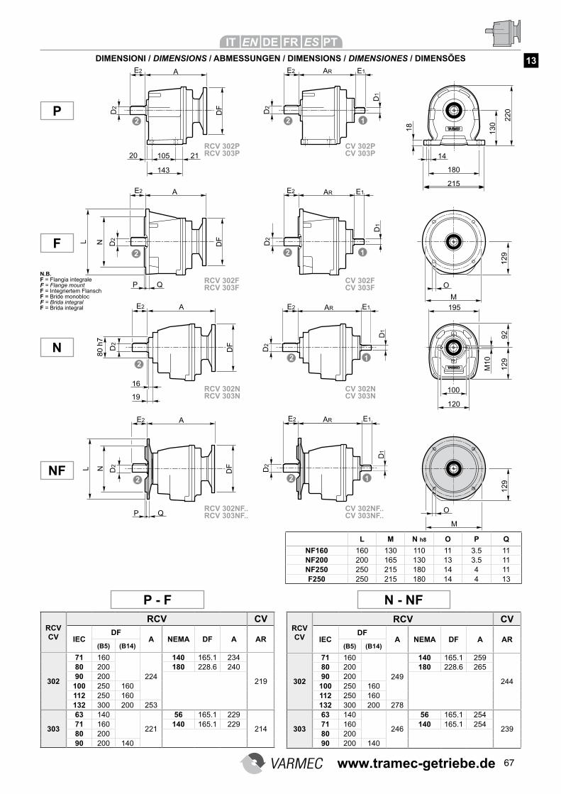
67
DIMENSIONI / DIMENSIONS / ABMESSUNGEN / DIMENSIONS / DIMENSIONES / DIMENSÕES
L M N h8 O P Q
NF160 160 130 110 11 3.5 11NF200 200 165 130 13 3.5 11NF250 250 215 180 14 4 11F250 250 215 180 14 4 13
RCV CV
RCV CV
IECDF
A NEMA DF A AR(B5) (B14)
302
71 160
224
140 165.1 234
219
80 200 180 228.6 24090 200100 250 160112 250 160132 300 200 253
303
63 140
221
56 165.1 229
21471 160 140 165.1 22980 20090 200 140
P - F N - NF
RCV CV
RCV CV
IECDF
A NEMA DF A AR(B5) (B14)
302
71 160
249
140 165.1 259
244
80 200 180 228.6 26590 200100 250 160112 250 160132 300 200 278
303
63 140
246
56 165.1 254
23971 160 140 165.1 25480 20090 200 140
NF
P
N
F
13
RCV 302NRCV 303N
CV 302NCV 303N
RCV 302NF..RCV 303NF..
CV 302NF..CV 303NF..
RCV 302FRCV 303F
CV 302FCV 303F
RCV 302PRCV 303P
CV 302PCV 303P
N.B.F = Flangia integrale F = Flange mount F = Integriertem Flansch F = Bride monobloc F = Brida integral F = Brida integral
www.tramec-getriebe.de

68
400 Nm 352 - 353
CV RCV
n1= 2800 min-1 n1= 1400 min-1 n1= 900 min-1
i n2 Mn2 P1 n2 Mn2 P1 n2 Mn2 P1
min-1 Nm kW min-1 Nm kW min-1 Nm kW IEC B5 IEC B14 NEMA
352
3.74 749 262 21 374 314 12.8 241 313 8.2 71-80-90-100-112-132 100-112-132 140-180
4.56 614 277 18.6 307 332 11.1 197 332 7.1 71-80-90-100-112-132 100-112-132 140-180
5.11 548 289 17.3 274 346 10.3 176 345 6.6 71-80-90-100-112-132 100-112-132 140-180
6.22 450 304 14.9 225 364 8.9 145 364 5.7 71-80-90-100-112-132 100-112-132 140-180
6.93 404 312 13.8 202 374 8.2 130 374 5.3 71-80-90-100-112-132 100-112-132 140-180
7.78 360 321 12.6 180 384 7.5 116 384 4.8 71-80-90-100-112-132 100-112-132 140-180
7.51 373 294 12.0 186 352 7.2 120 352 4.6 71-80-90-100-112-132 100-112-132 140-180
9.14 306 310 10.4 153 370 6.2 98 371 4.0 71-80-90-100-112-132 100-112-132 140-180
10.18 275 318 9.5 138 381 5.7 88 381 3.7 71-80-90-100-112-132 100-112-132 140-180
11.43 245 326 8.7 122 391 5.2 79 391 3.4 71-80-90-100-112-132 100-112-132 140-180
12.62 222 300 7.3 111 360 4.4 71 360 2.8 71-80-90-100-112 100-112 140-180
15.37 182 316 6.3 91 379 3.8 59 378 2.4 71-80-90-100-112 100-112 140-180
17.11 164 324 5.8 82 388 3.5 53 388 2.2 71-80-90-100-112 100-112 140-180
19.21 146 333 5.3 73 399 3.2 46.9 399 2.0 71-80-90-100-112 100-112 140-180
24.19 116 308 3.9 58 369 2.3 37.2 368 1.5 71-80-90-100-112 100-112 140-180
29.45 95 325 3.4 47.5 390 2.0 30.6 389 1.3 71-80-90-100-112 100-112 140-180
32.80 85 330 3.1 42.7 396 1.8 27.4 397 1.2 71-80-90-100-112 100-112 140-180
36.82 76 338 2.8 38.0 403 1.7 24.4 405 1.1 71-80-90-100-112 100-112 140-180
353
41.20 68 332 2.5 34.0 396 1.5 21.8 397 0.98 63-71-80-90 90 56-140
46.20 61 339 2.3 30.3 406 1.4 19.5 405 0.89 63-71-80-90 90 56-140
54.00 52 311 1.8 25.9 372 1.1 16.7 372 0.70 63-71-80-90 90 56-140
65.80 42.6 326 1.6 21.3 391 0.94 13.7 391 0.60 63-71-80-90 90 56-140
73.30 38.2 333 1.4 19.1 398 0.86 12.3 400 0.55 63-71-80-90 90 56-140
82.20 34.1 341 1.3 17.0 408 0.78 10.9 408 0.50 63-71-80-90 90 56-140
99.30 28.2 314 1.0 14.1 377 0.60 9.1 375 0.38 63-71-80-90 90 56-140
120.90 23.2 329 0.86 11.6 393 0.51 7.4 392 0.33 63-71-80-90 90 56-140
134.70 20.8 336 0.79 10.4 400 0.47 6.7 401 0.30 63-71-80-90 90 56-140
151.10 18.5 344 0.72 9.3 411 0.43 6.0 410 0.28 63-71-80-90 90 56-140
189.20 14.8 317 0.53 7.4 383 0.32 4.8 381 0.20 63-71-80-90 90 56-140
230.30 12.2 342 0.47 6.1 408 0.28 3.9 408 0.18 63-71-80-90 90 56-140
256.50 10.9 357 0.44 5.5 428 0.26 3.5 429 0.17 63-71-80-90 90 56-140
287.90 9.7 369 0.40 4.9 440 0.24 3.1 442 0.16 63-71-80-90 90 56-140
DIMENSIONI / DIMENSIONS / ABMESSUNGEN / DIMENSIONS / DIMENSIONES / DIMENSÕES
Albero entrata / Input shaft / Antriebswelle Arbre d‘entrée / Eje de entrada / Eixo de entrada
CV RCV D1 h6 E1 F G H I U V Z
352 24 50 M8 18 27 8 40 5 5353 19 40 M6 15 21.5 6 30 5 5
Albero uscita / Output shaft / Abtriebswelle Arbre de sortie / Eje de salida / Eixo de saida
CV RCV D2 h6 E2 F G H I U V Z
352 353
28 60 M8 18 31 8 50 5 530 60 M10 22 33 8 50 5 532 80 M10 22 35 10 70 5 535 80 M10 22 38 10 70 5 538 80 M10 22 41 10 70 5 540 80 M12 28 43 12 70 5 5
Metric dimensions
(mm)
Imperial dimensions
(inch)
Albero uscita / Output shaft / Abtriebswelle Arbre de sortie / Eje de salida / Eixo de saida
CV RCV D2 E2 F G H I U V
352 353
34.92 (1.375)
80 (3.150)
3/8-1623
(0.906)
38.42 (1.513)
7.92 (0.312)
63.50 (2.500)
16.50 (0.650)
(Inch)
DATI TECNICI / TECHNICAL DATA / TECHNISCHE DATEN CARACTÉRISTIQUES TECHNIQUES / DATOS TÉCNICOS / CARACTERÍSTICAS TÉCNICAS
A richiesta / On request / Auf Anfrage / Sur demande / Bajo demanda / Sob consulta
12
www.tramec-getriebe.de

69
DIMENSIONI / DIMENSIONS / ABMESSUNGEN / DIMENSIONS / DIMENSIONES / DIMENSÕES
L M N h8 O P Q
NF160 160 130 110 11 3.5 11NF200 200 165 130 13 3.5 11NF250 250 215 180 14 4 11F250 250 215 180 14 4 13
RCV CV
RCV CV
IECDF
A NEMA DF A AR(B5) (B14)
352
71 160
224
140 165.1 234
219
80 200 180 228.6 24090 200100 250 160112 250 160132 300 200 253
353
63 140
221
56 165.1 229
21471 160 140 165.1 22980 20090 200 140
RCV CV
RCV CV
IECDF
A NEMA DF A AR(B5) (B14)
352
71 160
249
140 165.1 259
244
80 200 180 228.6 26590 200100 250 160112 250 160132 300 200 278
353
63 140
246
56 165.1 254
23971 160 140 165.1 25480 20090 200 140
NF
P
N
F
P - F N - NF
13
RCV 352NRCV 353N
CV 352NCV 353N
RCV 352NF..RCV 353NF..
CV 352NF..CV 353NF..
RCV 352FRCV 353F
CV 352FCV 353F
RCV 352PRCV 353P
CV 352PCV 353P
N.B.F = Flangia integrale F = Flange mount F = Integriertem Flansch F = Bride monobloc F = Brida integral F = Brida integral
www.tramec-getriebe.de
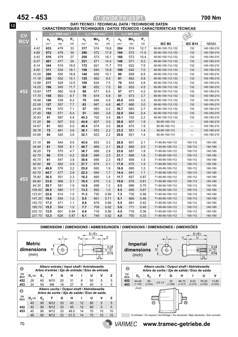
70
700 Nm 452 - 453
CV RCV
n1= 2800 min-1 n1= 1400 min-1 n1= 900 min-1
i n2 Mn2 P1 n2 Mn2 P1 n2 Mn2 P1
min-1 Nm kW min-1 Nm kW min-1 Nm kW IEC B5 IEC B14 NEMA
452
4.42 633 479 33 317 574 19.8 204 574 12.7 80-90-100-112-132 132 140-180-210
4.89 573 478 30 286 572 17.9 184 572 11.5 80-90-100-112-132 132 140-180-210
5.43 516 479 27 258 573 16.1 166 573 10.4 80-90-100-112-132 132 140-180-210
6.07 461 477 24 231 571 14.4 148 571 9.2 80-90-100-112-132 132 140-180-210
8.14 344 519 19.5 172 621 11.7 111 622 7.5 80-90-100-112-132 132 140-180-210
9.00 311 534 18.1 156 640 10.9 100 640 7.0 80-90-100-112-132 132 140-180-210
10.00 280 550 16.8 140 659 10.1 90 659 6.5 80-90-100-112-132 132 140-180-210
11.18 250 552 15.1 125 662 9.0 81 662 5.8 80-90-100-112-132 132 140-180-210
12.89 217 529 12.5 109 634 7.5 70 633 4.8 80-90-100-112-132 132 140-180-210
14.25 196 545 11.7 98 652 7.0 63 653 4.5 80-90-100-112-132 132 140-180-210
15.83 177 560 10.8 88 671 6.5 57 671 4.2 80-90-100-112-132 132 140-180-210
17.70 158 563 9.7 79 674 5.8 51 673 3.7 80-90-100-112-132 132 140-180-210
19.99 140 539 8.2 70 646 4.9 45.0 645 3.2 80-90-100-112-132 132 140-180-210
22.09 127 557 7.7 63 667 4.6 40.7 666 3.0 80-90-100-112-132 132 140-180-210
24.55 114 570 7.1 57 683 4.2 36.7 683 2.7 80-90-100-112-132 132 140-180-210
27.45 102 571 6.4 51 683 3.8 32.8 684 2.4 80-90-100-112-132 132 140-180-210
30.93 91 587 5.8 45.3 702 3.5 29.1 702 2.2 80-90-100-112-132 132 140-180-210
31.20 90 507 5.0 44.9 607 3.0 28.8 607 1.9 80-90-100-112 — 140-180-210
34.67 81 563 5.0 40.4 674 3.0 26.0 675 1.9 80-90-100-112 — 140-180-210
38.76 72 461 3.6 36.1 553 2.2 23.2 551 1.4 80-90-100-112 — 140-180-210
43.68 64 520 3.6 32.1 623 2.2 20.6 621 1.4 80-90-100-112 — 140-180-210
453
31.10 90 544 5.5 45.0 653 3.3 28.9 651 2.1 71-80-90-100-112 100-112 140-180
34.40 81 559 5.1 40.7 669 3.1 26.2 669 2.0 71-80-90-100-112 100-112 140-180
38.20 73 575 4.7 36.7 688 2.8 23.6 687 1.8 71-80-90-100-112 100-112 140-180
42.70 66 575 4.2 32.8 688 2.5 21.1 689 1.6 71-80-90-100-112 100-112 140-180
45.70 61 547 3.8 30.6 656 2.3 19.7 656 1.5 71-80-90-100-112 100-112 140-180
50.50 55 562 3.5 27.7 674 2.1 17.8 675 1.4 71-80-90-100-112 100-112 140-180
56.10 49.9 576 3.2 25.0 692 1.9 16.0 690 1.2 71-80-90-100-112 100-112 140-180
62.70 44.7 577 2.9 22.3 694 1.7 14.4 691 1.1 71-80-90-100-112 100-112 140-180
76.80 36.5 551 2.3 18.2 660 1.4 11.7 657 0.87 71-80-90-100-112 100-112 140-180
84.90 33.0 566 2.1 16.5 676 1.3 10.6 676 0.81 71-80-90-100-112 100-112 140-180
94.30 29.7 581 1.9 14.8 698 1.2 9.5 696 0.75 71-80-90-100-112 100-112 140-180
105.50 26.5 580 1.7 13.3 693 1.0 8.5 695 0.67 71-80-90-100-112 100-112 140-180
123.81 22.6 610 1.5 11.3 730 0.90 7.3 730 0.58 71-80-90-100-112 100-112 140-180
147.20 19.0 554 1.2 9.5 661 0.71 6.1 666 0.46 71-80-90-100-112 100-112 140-180
162.70 17.2 571 1.1 8.6 679 0.66 5.5 681 0.42 71-80-90-100-112 100-112 140-180
180.70 15.5 594 1.0 7.7 708 0.62 5.0 711 0.40 71-80-90-100-112 100-112 140-180
202.10 13.9 601 0.94 6.9 716 0.56 4.5 716 0.36 71-80-90-100-112 100-112 140-180
227.70 12.3 626 0.87 6.1 749 0.52 4.0 750 0.33 71-80-90-100-112 100-112 140-180
DIMENSIONI / DIMENSIONS / ABMESSUNGEN / DIMENSIONS / DIMENSIONES / DIMENSÕES
Albero entrata / Input shaft / Antriebswelle Arbre d‘entrée / Eje de entrada / Eixo de entrada
CV RCV D1 h6 E1 F G H I U V Z
452 28 60 M10 20 31 8 50 5 5453 24 50 M8 18 27 8 40 5 5
Albero uscita / Output shaft / Abtriebswelle Arbre de sortie / Eje de salida / Eixo de saida
CV RCV D2 h6 E2 F G H I U V Z
452 453
40 90 M12 33 43 12 80 5 542 90 M12 33 45 12 80 5 545 90 M12 33 48.5 14 70 10 1048 90 M12 33 51.5 14 70 10 10
Metric dimensions
(mm)
Imperial dimensions
(inch)
Albero uscita / Output shaft / Abtriebswelle Arbre de sortie / Eje de salida / Eixo de saida
CV RCV D2 E2 F G H I U V
452 453
44.45 (1.750)
90 (3.543)
1/2-1333
(1.299)
48.70 (1.917)
9.53 (0.375)
76.20 (3.000)
13.80 (0.543)
(Inch)
DATI TECNICI / TECHNICAL DATA / TECHNISCHE DATEN CARACTÉRISTIQUES TECHNIQUES / DATOS TÉCNICOS / CARACTERÍSTICAS TÉCNICAS
A richiesta / On request / Auf Anfrage / Sur demande / Bajo demanda / Sob consulta
12
www.tramec-getriebe.de
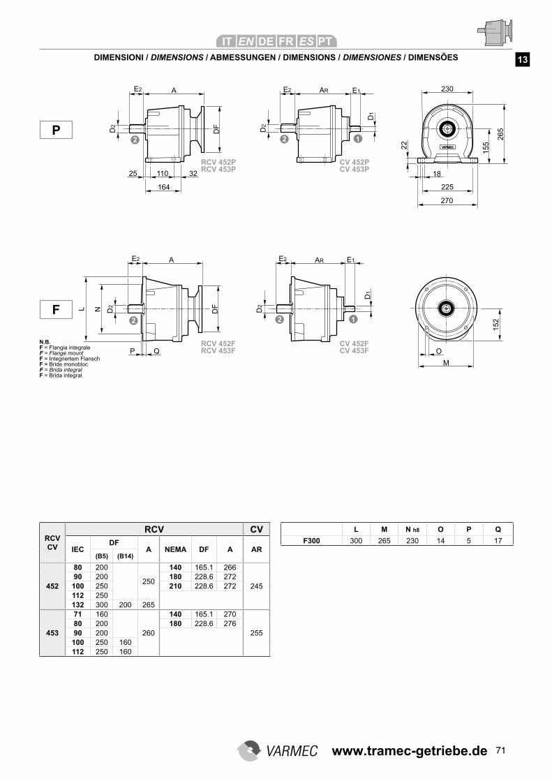
71
DIMENSIONI / DIMENSIONS / ABMESSUNGEN / DIMENSIONS / DIMENSIONES / DIMENSÕES
L M N h8 O P Q
F300 300 265 230 14 5 17RCV CV
RCV CV
IECDF
A NEMA DF A AR(B5) (B14)
452
80 200
250
140 165.1 266
24590 200 180 228.6 272100 250 210 228.6 272112 250132 300 200 265
453
71 160
260
140 165.1 270
25580 200 180 228.6 27690 200100 250 160112 250 160
P
F
13
RCV 452FRCV 453F
CV 452FCV 453F
RCV 452PRCV 453P
CV 452PCV 453P
N.B.F = Flangia integrale F = Flange mount F = Integriertem Flansch F = Bride monobloc F = Brida integral F = Brida integral
www.tramec-getriebe.de
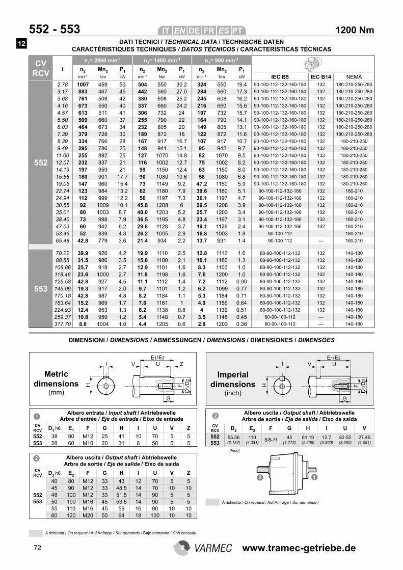
72
1200 Nm 552 - 553
CV RCV
n1= 2800 min-1 n1= 1400 min-1 n1= 900 min-1
i n2 Mn2 P1 n2 Mn2 P1 n2 Mn2 P1
min-1 Nm kW min-1 Nm kW min-1 Nm kW IEC B5 IEC B14 NEMA
552
2.78 1007 459 50 504 550 30.2 324 550 19.4 90-100-112-132-160-180 132 180-210-250-280
3.17 883 467 45 442 560 27.0 284 560 17.3 90-100-112-132-160-180 132 180-210-250-280
3.68 761 508 42 380 608 25.2 245 608 16.2 90-100-112-132-160-180 132 180-210-250-280
4.16 673 550 40 337 660 24.2 216 660 15.6 90-100-112-132-160-180 132 180-210-250-280
4.57 613 611 41 306 732 24 197 732 15.7 90-100-112-132-160-180 132 180-210-250-280
5.50 509 660 37 255 790 22 164 790 14.1 90-100-112-132-160-180 132 180-210-250-280
6.03 464 673 34 232 805 20 149 805 13.1 90-100-112-132-160-180 132 180-210-250-280
7.39 379 728 30 189 872 18 122 872 11.6 90-100-112-132-160-180 132 180-210-250-280
8.39 334 766 28 167 917 16.7 107 917 10.7 90-100-112-132-160-180 132 180-210-250
9.49 295 786 25 148 941 15.1 95 942 9.7 90-100-112-132-160-180 132 180-210-250
11.00 255 892 25 127 1070 14.9 82 1070 9.5 90-100-112-132-160-180 132 180-210-250
12.07 232 837 21 116 1002 12.7 75 1002 8.2 90-100-112-132-160-180 132 180-210-250
14.19 197 959 21 99 1150 12.4 63 1150 8.0 90-100-112-132-160-180 132 180-210-250
15.56 180 901 17.7 90 1080 10.6 58 1080 6.8 90-100-112-132-160-180 132 180-210-250
19.06 147 960 15.4 73 1149 9.2 47.2 1150 5.9 90-100-112-132-160-180 132 180-210-250
22.74 123 984 13.2 62 1180 7.9 39.6 1180 5.1 90-100-112-132-160 132 180-210
24.94 112 999 12.2 56 1197 7.3 36.1 1197 4.7 90-100-112-132-160 132 180-210
30.55 92 1009 10.1 45.8 1208 6 29.5 1208 3.9 90-100-112-132-160 132 180-210
35.01 80 1003 8.7 40.0 1203 5.2 25.7 1203 3.4 90-100-112-132-160 132 180-210
38.40 73 998 7.9 36.5 1195 4.8 23.4 1197 3.1 90-100-112-132-160 132 180-210
47.03 60 942 6.2 29.8 1128 3.7 19.1 1129 2.4 90-100-112-132-160 132 180-210
53.46 52 839 4.8 26.2 1005 2.9 16.8 1003 1.8 90-100-112 — 180-210
65.48 42.8 779 3.6 21.4 934 2.2 13.7 931 1.4 90-100-112 — 180-210
553
70.22 39.9 926 4.2 19.9 1110 2.5 12.8 1112 1.6 80-90-100-112-132 132 140-180
88.88 31.5 986 3.5 15.8 1180 2.1 10.1 1180 1.3 80-90-100-112-132 132 140-180
108.86 25.7 919 2.7 12.9 1101 1.6 8.3 1103 1.0 80-90-100-112-132 132 140-180
118.46 23.6 1000 2.7 11.8 1198 1.6 7.6 1200 1.0 80-90-100-112-132 132 140-180
125.58 42.8 927 4.5 11.1 1112 1.4 7.2 1112 0.90 80-90-100-112-132 132 140-180
145.09 19.3 917 2.0 9.7 1101 1.2 6.2 1099 0.77 80-90-100-112-132 132 140-180
170.18 42.8 987 4.8 8.2 1184 1.1 5.3 1184 0.71 80-90-100-112-132 132 140-180
183.64 15.2 969 1.7 7.6 1161 1 4.9 1156 0.64 80-90-100-112-132 132 140-180
224.93 12.4 953 1.3 6.2 1138 0.8 4 1139 0.51 80-90-100-112-132 132 140-180
259.37 10.8 959 1.2 5.4 1148 0.7 3.5 1148 0.45 80-90-100-112 — 140-180
317.70 8.8 1004 1.0 4.4 1205 0.6 2.8 1203 0.38 80-90-100-112 — 140-180
DIMENSIONI / DIMENSIONS / ABMESSUNGEN / DIMENSIONS / DIMENSIONES / DIMENSÕES
A richiesta / On request / Auf Anfrage / Sur demande /
Albero entrata / Input shaft / Antriebswelle Arbre d‘entrée / Eje de entrada / Eixo de entrada
CV RCV D1 h6 E1 F G H I U V Z
552 38 80 M12 25 41 10 70 5 5553 28 60 M10 20 31 8 50 5 5
Albero uscita / Output shaft / Abtriebswelle Arbre de sortie / Eje de salida / Eixo de saida
CV RCV D2 h6 E2 F G H I U V Z
552 553
40 80 M12 33 43 12 70 5 545 90 M12 33 48.5 14 70 10 1048 100 M12 33 51.5 14 90 5 550 100 M16 45 53.5 14 90 5 555 110 M16 45 59 16 90 10 1060 120 M20 50 64 18 100 10 10
Metric dimensions
(mm)
Imperial dimensions
(inch)
Albero uscita / Output shaft / Abtriebswelle Arbre de sortie / Eje de salida / Eixo de saida
CV RCV D2 E2 F G H I U V
552 553
55.56 (2.187)
110 (4.331)
5/8-1145
(1.772)
61.19 (2.409)
12.7 (0.500)
82.55 (3.250)
27.45 (1.081)
(Inch)
DATI TECNICI / TECHNICAL DATA / TECHNISCHE DATEN CARACTÉRISTIQUES TECHNIQUES / DATOS TÉCNICOS / CARACTERÍSTICAS TÉCNICAS
A richiesta / On request / Auf Anfrage / Sur demande / Bajo demanda / Sob consulta
12
www.tramec-getriebe.de
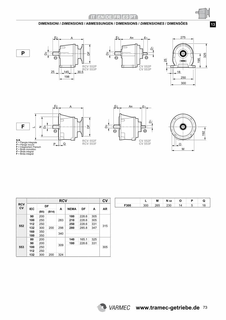
73
DIMENSIONI / DIMENSIONS / ABMESSUNGEN / DIMENSIONS / DIMENSIONES / DIMENSÕES
L M N h8 O P Q
F300 300 265 230 14 5 18RCV CV
RCV CV
IECDF
A NEMA DF A AR(B5) (B14)
552
90 200283
180 228.6 305
315
100 250 210 228.6 305112 250 250 228.6 331132 300 200 298 280 285.8 347160 350
340180 350
553
80 200
309
140 165.1 325
30590 200 180 228.6 331100 250112 250132 300 200 324
P
F
13
RCV 552FRCV 553F
CV 552FCV 553F
RCV 552PRCV 553P
CV 552PCV 553P
N.B.F = Flangia integrale F = Flange mount F = Integriertem Flansch F = Bride monobloc F = Brida integral F = Brida integral
www.tramec-getriebe.de
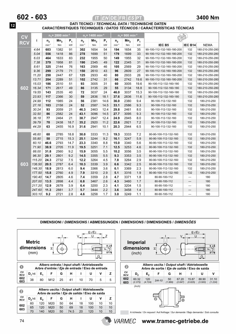
74
3400 Nm 602 - 603
CV RCV
n1= 2800 min-1 n1= 1400 min-1 n1= 900 min-1
i n2 Mn2 P1 n2 Mn2 P1 n2 Mn2 P1
min-1 Nm kW min-1 Nm kW min-1 Nm kW IEC B5 IEC B14 NEMA
602
4.64 603 1382 91 302 1654 54 194 1654 35 90-100-112-132-160-180-200 132 180-210-250-280
5.04 556 1418 86 278 1699 51 179 1699 33 90-100-112-132-160-180-200 132 180-210-250-280
6.03 464 1633 83 232 1955 50 149 1955 32 90-100-112-132-160-180-200 132 180-210-250-280
7.38 379 1958 81 190 2345 49 122 2345 31 90-100-112-132-160-180-200 132 180-210-250-280
8.61 325 2144 76 163 2569 46 105 2569 29 90-100-112-132-160-180-200 132 180-210-250-280
9.36 299 2179 71 150 2610 43 96 2609 27 90-100-112-132-160-180-200 132 180-210-250-280
11.20 250 2447 67 125 2933 40 80 2933 26 90-100-112-132-160-180-200 132 180-210-250-280
13.71 204 2289 51 102 2742 31 66 2742 19.6 90-100-112-132-160-180-200 132 180-210-250-280
15.03 186 2510 51 93 3005 31 60 3005 19.6 90-100-112-132-160-180 132 180-210-250-280
16.34 171 2617 49 86 3135 29 55 3134 18.8 90-100-112-132-160-180 132 180-210-250-280
19.55 143 2535 40 72 3037 24 46.0 3037 15.3 90-100-112-132-160-180 132 180-210-250-280
23.93 117 2366 30 59 2836 18.1 37.6 2836 11.6 90-100-112-132-160-180 132 180-210-250-280
24.99 112 1985 24 56 2381 14.6 36.0 2380 9.4 90-100-112-132-160 132 180-210-250
27.16 103 2158 24 52 2587 14.5 33.1 2586 9.3 90-100-112-132-160 132 180-210-250
30.24 93 2059 21 46.3 2463 12.4 29.8 2461 8.0 90-100-112-132-160 132 180-210-250
32.50 86 2582 24 43.1 3096 14.5 27.7 3095 9.3 90-100-112-132-160 132 180-210-250
36.18 77 2464 21 38.7 2947 12.4 24.9 2945 8.0 90-100-112-132-160 132 180-210-250
39.79 70 2438 18.7 35.2 2920 11.2 22.6 2921 7.2 90-100-112-132-160 132 180-210-250
44.29 63 2455 16.9 31.6 2941 10.1 20.3 2944 6.5 90-100-112-132-160 132 180-210-250
603
46.60 60 2785 18.8 30.0 3333 11.3 19.3 3333 7.2 80-90-100-112-132-160 132 180-210-250
55.80 50 2715 15.3 25.1 3244 9.2 16.1 3247 5.9 80-90-100-112-132-160 132 180-210-250
60.10 46.6 2793 14.7 23.3 3340 8.8 15.0 3340 5.6 80-90-100-112-132-160 132 180-210-250
71.90 38.9 2705 11.9 19.5 3251 7.1 12.5 3253 4.6 80-90-100-112-132-160 132 180-210-250
88.00 31.8 2560 9.2 15.9 3055 5.5 10.2 3056 3.5 80-90-100-112-132-160 132 180-210-250
96.30 29.1 2801 9.2 14.5 3355 5.5 9.3 3353 3.5 80-90-100-112-132-160 132 180-210-250
115.20 24.3 2732 7.5 12.2 3264 4.5 7.8 3264 2.9 80-90-100-112-132-160 132 180-210-250
136.50 20.5 2787 6.4 10.3 3339 3.9 6.6 3342 2.5 80-90-100-112-132-160 132 180-210-250
148.30 18.9 2813 6.0 9.4 3366 3.6 6.1 3369 2.3 80-90-100-112-132-160 132 180-210-250
177.50 15.8 2760 4.9 7.9 3310 2.9 5.1 3316 1.9 80-90-100-112-132-160 132 180-210-250
190.40 14.7 2805 4.6 7.4 3359 2.8 4.7 3371 1.8 80-90-100-112 — 180
207.00 13.5 2898 4.4 6.8 3467 2.6 4.3 3460 1.7 80-90-100-112 — 180
217.20 12.9 2678 3.9 6.4 3200 2.3 4.1 3204 1.5 80-90-100-112 — 180
247.60 11.3 2881 3.7 5.7 3444 2.2 3.6 3458 1.4 80-90-100-112 — 180
303.10 9.2 2721 2.8 4.6 3258 1.7 3.0 3249 1.1 80-90-100-112 — 180
DIMENSIONI / DIMENSIONS / ABMESSUNGEN / DIMENSIONS / DIMENSIONES / DIMENSÕES
Albero entrata / Input shaft / Antriebswelle Arbre d‘entrée / Eje de entrada / Eixo de entrada
CV RCV D1 h6 E1 F G H I U V Z
602 603 38 80 M12 25 41 10 70 5 5
Albero uscita / Output shaft / Abtriebswelle Arbre de sortie / Eje de salida / Eixo de saida
CV RCV D2 h6 E2 F G H I U V Z
602 603
60 120 M20 50 64 18 100 10 1065 120 M20 50 69 18 100 10 1070 140 M20 50 74.5 20 120 10 10
Metric dimensions
(mm)
Imperial dimensions
(inch)
Albero uscita / Output shaft / Abtriebswelle Arbre de sortie / Eje de salida / Eixo de saida
CV RCV D2 E2 F G H I U V
602 603
60.32 (2.375)
120 (4.724)
3/4-1050
(1.969)
67.20 (2.647)
15.87 (0.625)
88.90 (3.500)
31.10 (1.224)
(Inch)
DATI TECNICI / TECHNICAL DATA / TECHNISCHE DATEN CARACTÉRISTIQUES TECHNIQUES / DATOS TÉCNICOS / CARACTERÍSTICAS TÉCNICAS
A richiesta / On request / Auf Anfrage / Sur demande / Bajo demanda / Sob consulta
12
www.tramec-getriebe.de
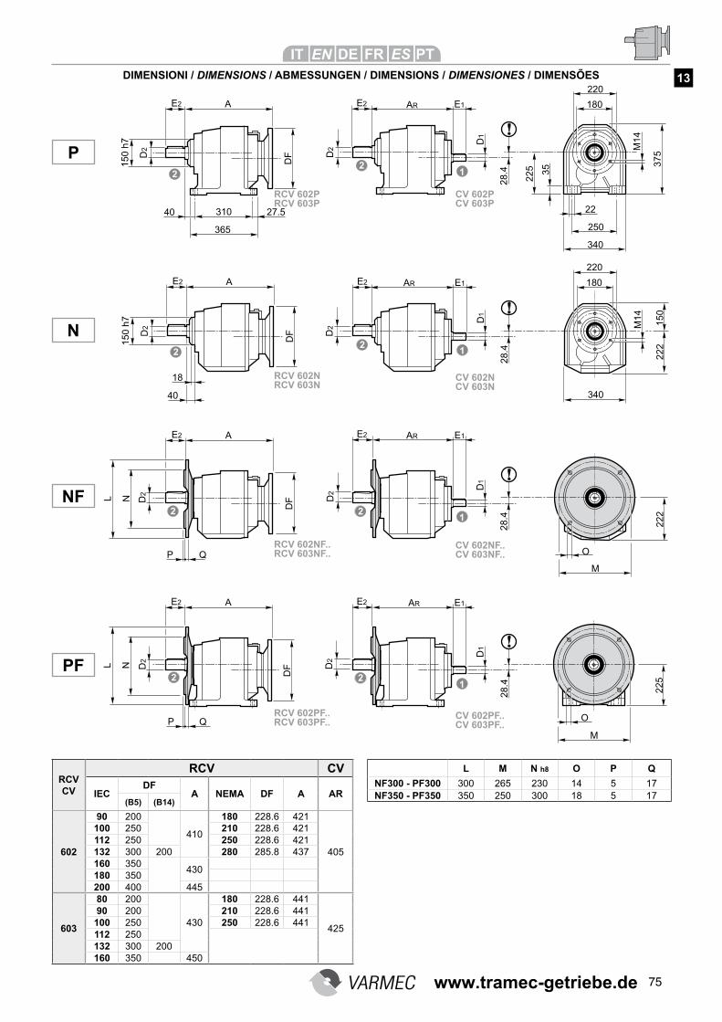
75
L M N h8 O P Q
NF300 - PF300 300 265 230 14 5 17NF350 - PF350 350 250 300 18 5 17
RCV CV
RCV CV
IECDF
A NEMA DF A AR(B5) (B14)
602
90 200
410
180 228.6 421
405
100 250 210 228.6 421112 250 250 228.6 421132 300 200 280 285.8 437160 350
430180 350200 400 445
603
80 200
430
180 228.6 441
425
90 200 210 228.6 441100 250 250 228.6 441112 250132 300 200160 350 450
NF
P
N
PF
DIMENSIONI / DIMENSIONS / ABMESSUNGEN / DIMENSIONS / DIMENSIONES / DIMENSÕES 13
RCV 602NF..RCV 603NF..
CV 602NF..CV 603NF..
RCV 602PF..RCV 603PF..
CV 602PF..CV 603PF..
RCV 602NRCV 603N
CV 602NCV 603N
RCV 602PRCV 603P
CV 602PCV 603P
www.tramec-getriebe.de
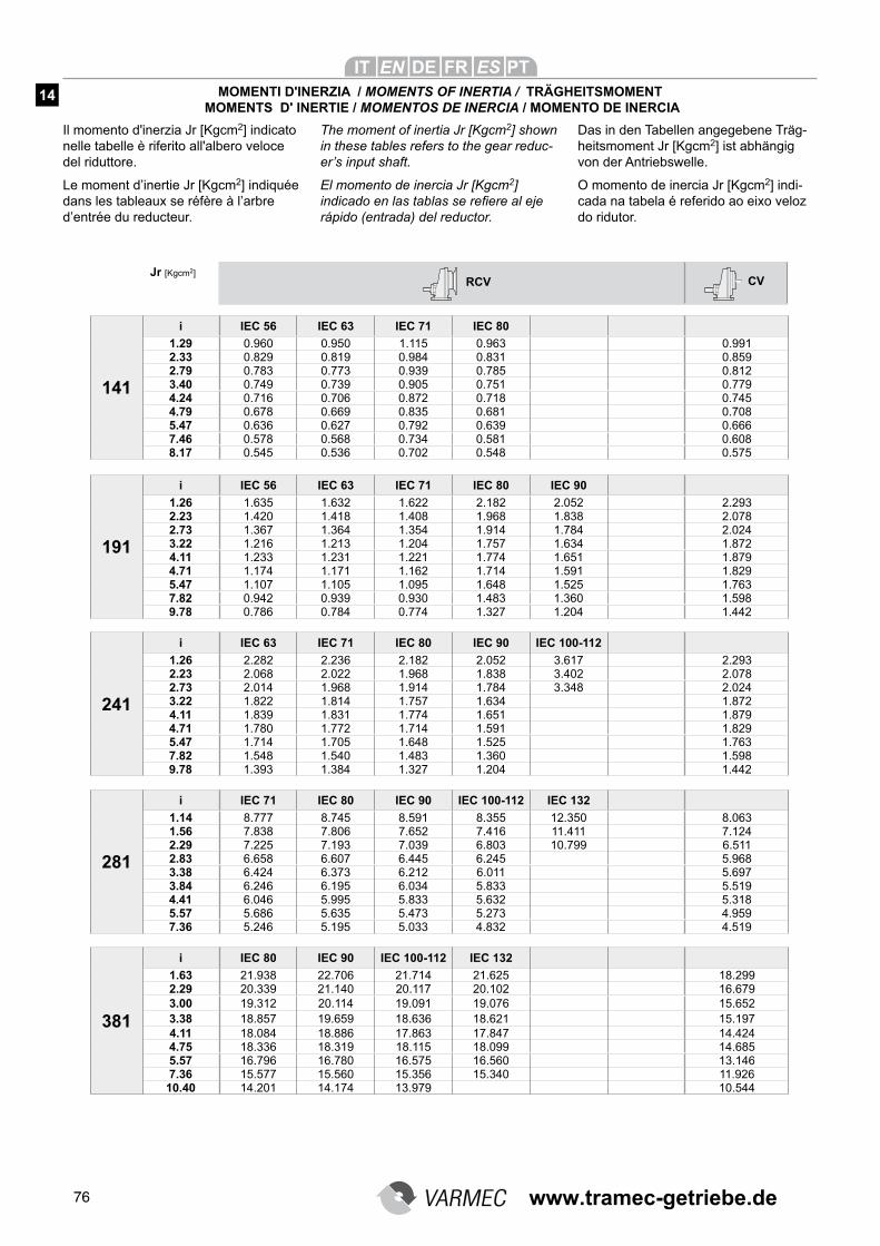
76
MOMENTI D'INERZIA / MOMENTS OF INERTIA / TRÄGHEITSMOMENT MOMENTS D' INERTIE / MOMENTOS DE INERCIA / MOMENTO DE INERCIA
Il momento d'inerzia Jr [Kgcm2] indicato nelle tabelle è riferito all'albero veloce del riduttore.
Le moment d’inertie Jr [Kgcm2] indiquée dans les tableaux se réfère à l’arbre d’entrée du reducteur.
The moment of inertia Jr [Kgcm2] shown
in these tables refers to the gear reduc-
er’s input shaft.
El momento de inercia Jr [Kgcm2]
indicado en las tablas se refiere al eje
rápido (entrada) del reductor.
Das in den Tabellen angegebene Träg-heitsmoment Jr [Kgcm2] ist abhängig von der Antriebswelle.
O momento de inercia Jr [Kgcm2] indi-cada na tabela é referido ao eixo veloz do ridutor.
14
141
i IEC 56 IEC 63 IEC 71 IEC 80
1.29 0.960 0.950 1.115 0.963 0.9912.33 0.829 0.819 0.984 0.831 0.8592.79 0.783 0.773 0.939 0.785 0.8123.40 0.749 0.739 0.905 0.751 0.7794.24 0.716 0.706 0.872 0.718 0.7454.79 0.678 0.669 0.835 0.681 0.7085.47 0.636 0.627 0.792 0.639 0.6667.46 0.578 0.568 0.734 0.581 0.6088.17 0.545 0.536 0.702 0.548 0.575
191
i IEC 56 IEC 63 IEC 71 IEC 80 IEC 90
1.26 1.635 1.632 1.622 2.182 2.052 2.2932.23 1.420 1.418 1.408 1.968 1.838 2.0782.73 1.367 1.364 1.354 1.914 1.784 2.0243.22 1.216 1.213 1.204 1.757 1.634 1.8724.11 1.233 1.231 1.221 1.774 1.651 1.8794.71 1.174 1.171 1.162 1.714 1.591 1.8295.47 1.107 1.105 1.095 1.648 1.525 1.7637.82 0.942 0.939 0.930 1.483 1.360 1.5989.78 0.786 0.784 0.774 1.327 1.204 1.442
241
i IEC 63 IEC 71 IEC 80 IEC 90 IEC 100-112
1.26 2.282 2.236 2.182 2.052 3.617 2.2932.23 2.068 2.022 1.968 1.838 3.402 2.0782.73 2.014 1.968 1.914 1.784 3.348 2.0243.22 1.822 1.814 1.757 1.634 1.8724.11 1.839 1.831 1.774 1.651 1.8794.71 1.780 1.772 1.714 1.591 1.8295.47 1.714 1.705 1.648 1.525 1.7637.82 1.548 1.540 1.483 1.360 1.5989.78 1.393 1.384 1.327 1.204 1.442
281
i IEC 71 IEC 80 IEC 90 IEC 100-112 IEC 132
1.14 8.777 8.745 8.591 8.355 12.350 8.0631.56 7.838 7.806 7.652 7.416 11.411 7.1242.29 7.225 7.193 7.039 6.803 10.799 6.5112.83 6.658 6.607 6.445 6.245 5.9683.38 6.424 6.373 6.212 6.011 5.6973.84 6.246 6.195 6.034 5.833 5.5194.41 6.046 5.995 5.833 5.632 5.3185.57 5.686 5.635 5.473 5.273 4.9597.36 5.246 5.195 5.033 4.832 4.519
381
i IEC 80 IEC 90 IEC 100-112 IEC 132
1.63 21.938 22.706 21.714 21.625 18.2992.29 20.339 21.140 20.117 20.102 16.6793.00 19.312 20.114 19.091 19.076 15.6523.38 18.857 19.659 18.636 18.621 15.1974.11 18.084 18.886 17.863 17.847 14.4244.75 18.336 18.319 18.115 18.099 14.6855.57 16.796 16.780 16.575 16.560 13.1467.36 15.577 15.560 15.356 15.340 11.926
10.40 14.201 14.174 13.979 10.544
RCV CVJr [Kgcm2]
www.tramec-getriebe.de
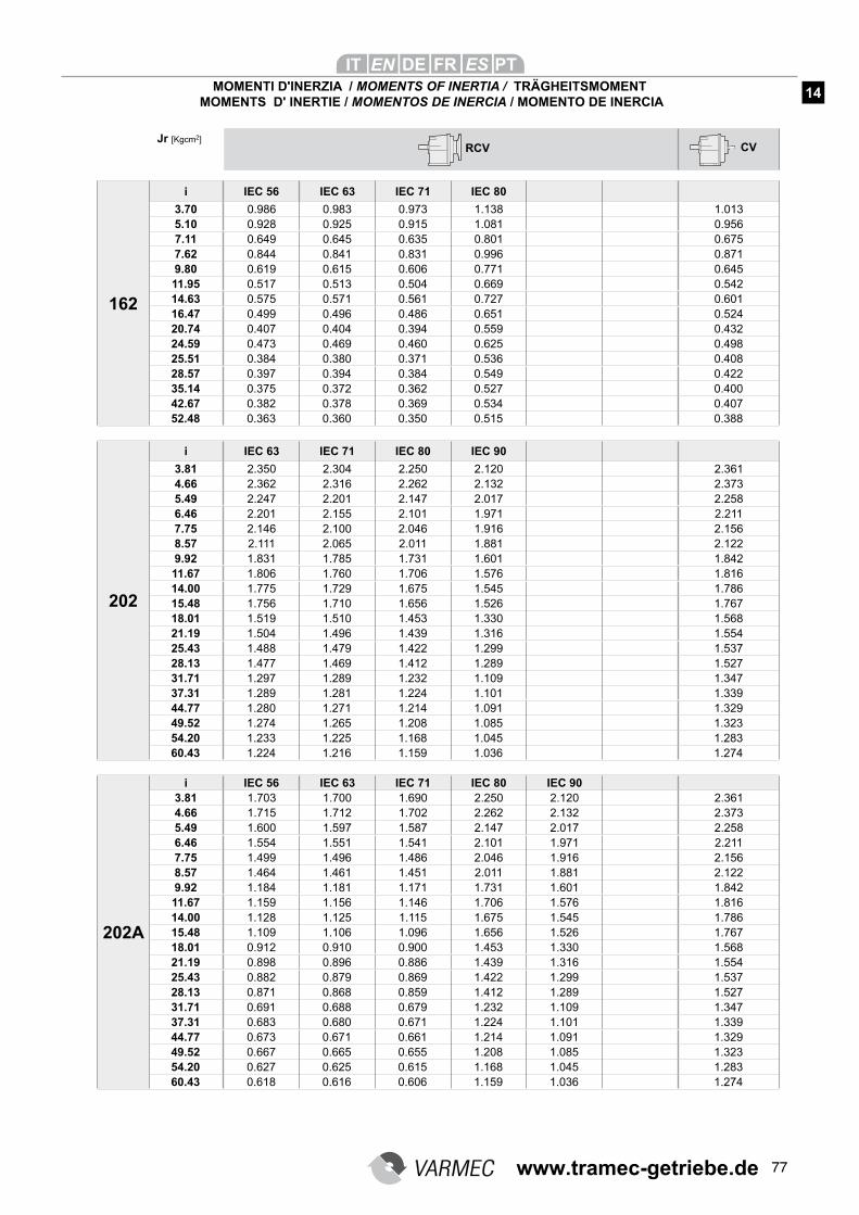
77
162
i IEC 56 IEC 63 IEC 71 IEC 80
3.70 0.986 0.983 0.973 1.138 1.0135.10 0.928 0.925 0.915 1.081 0.9567.11 0.649 0.645 0.635 0.801 0.6757.62 0.844 0.841 0.831 0.996 0.8719.80 0.619 0.615 0.606 0.771 0.64511.95 0.517 0.513 0.504 0.669 0.54214.63 0.575 0.571 0.561 0.727 0.60116.47 0.499 0.496 0.486 0.651 0.52420.74 0.407 0.404 0.394 0.559 0.43224.59 0.473 0.469 0.460 0.625 0.49825.51 0.384 0.380 0.371 0.536 0.40828.57 0.397 0.394 0.384 0.549 0.42235.14 0.375 0.372 0.362 0.527 0.40042.67 0.382 0.378 0.369 0.534 0.40752.48 0.363 0.360 0.350 0.515 0.388
202
i IEC 63 IEC 71 IEC 80 IEC 90
3.81 2.350 2.304 2.250 2.120 2.3614.66 2.362 2.316 2.262 2.132 2.3735.49 2.247 2.201 2.147 2.017 2.2586.46 2.201 2.155 2.101 1.971 2.2117.75 2.146 2.100 2.046 1.916 2.1568.57 2.111 2.065 2.011 1.881 2.1229.92 1.831 1.785 1.731 1.601 1.84211.67 1.806 1.760 1.706 1.576 1.81614.00 1.775 1.729 1.675 1.545 1.78615.48 1.756 1.710 1.656 1.526 1.76718.01 1.519 1.510 1.453 1.330 1.56821.19 1.504 1.496 1.439 1.316 1.55425.43 1.488 1.479 1.422 1.299 1.53728.13 1.477 1.469 1.412 1.289 1.52731.71 1.297 1.289 1.232 1.109 1.34737.31 1.289 1.281 1.224 1.101 1.33944.77 1.280 1.271 1.214 1.091 1.32949.52 1.274 1.265 1.208 1.085 1.32354.20 1.233 1.225 1.168 1.045 1.28360.43 1.224 1.216 1.159 1.036 1.274
202A
i IEC 56 IEC 63 IEC 71 IEC 80 IEC 903.81 1.703 1.700 1.690 2.250 2.120 2.3614.66 1.715 1.712 1.702 2.262 2.132 2.3735.49 1.600 1.597 1.587 2.147 2.017 2.2586.46 1.554 1.551 1.541 2.101 1.971 2.2117.75 1.499 1.496 1.486 2.046 1.916 2.1568.57 1.464 1.461 1.451 2.011 1.881 2.1229.92 1.184 1.181 1.171 1.731 1.601 1.84211.67 1.159 1.156 1.146 1.706 1.576 1.81614.00 1.128 1.125 1.115 1.675 1.545 1.78615.48 1.109 1.106 1.096 1.656 1.526 1.76718.01 0.912 0.910 0.900 1.453 1.330 1.56821.19 0.898 0.896 0.886 1.439 1.316 1.55425.43 0.882 0.879 0.869 1.422 1.299 1.53728.13 0.871 0.868 0.859 1.412 1.289 1.52731.71 0.691 0.688 0.679 1.232 1.109 1.34737.31 0.683 0.680 0.671 1.224 1.101 1.33944.77 0.673 0.671 0.661 1.214 1.091 1.32949.52 0.667 0.665 0.655 1.208 1.085 1.32354.20 0.627 0.625 0.615 1.168 1.045 1.28360.43 0.618 0.616 0.606 1.159 1.036 1.274
RCV CVJr [Kgcm2]
MOMENTI D'INERZIA / MOMENTS OF INERTIA / TRÄGHEITSMOMENT MOMENTS D' INERTIE / MOMENTOS DE INERCIA / MOMENTO DE INERCIA
14
www.tramec-getriebe.de
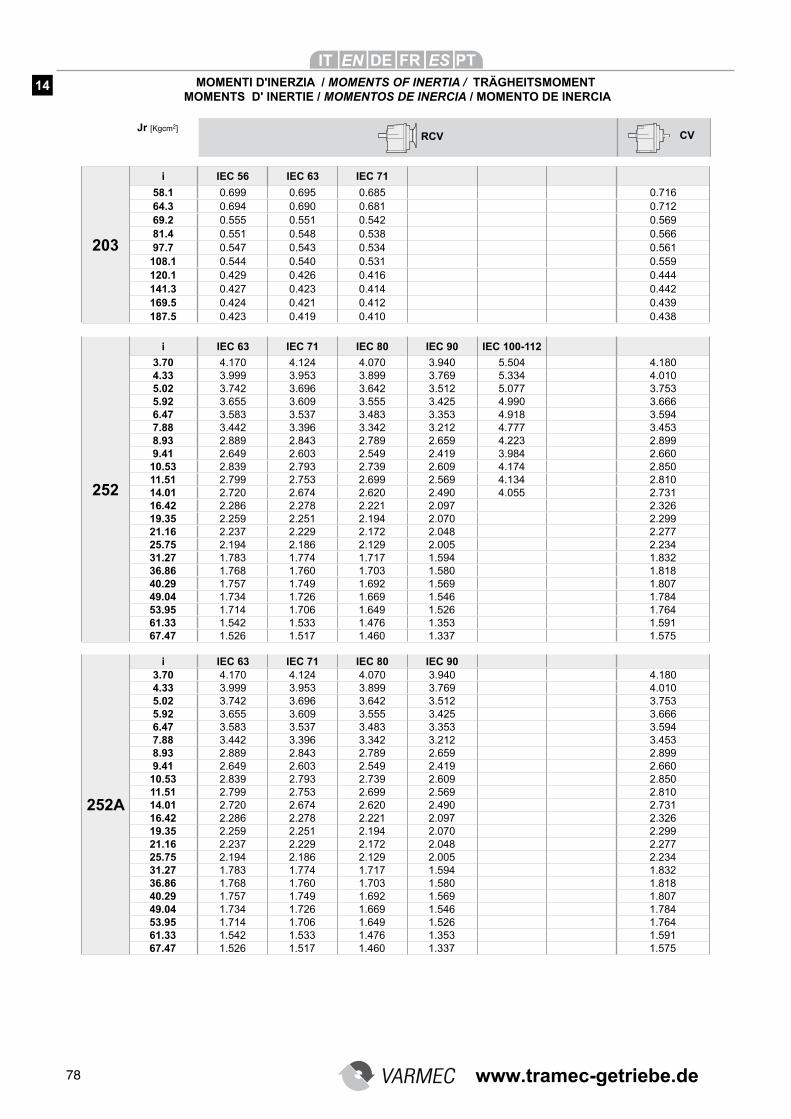
78
203
i IEC 56 IEC 63 IEC 71
58.1 0.699 0.695 0.685 0.71664.3 0.694 0.690 0.681 0.71269.2 0.555 0.551 0.542 0.56981.4 0.551 0.548 0.538 0.56697.7 0.547 0.543 0.534 0.561
108.1 0.544 0.540 0.531 0.559120.1 0.429 0.426 0.416 0.444141.3 0.427 0.423 0.414 0.442169.5 0.424 0.421 0.412 0.439187.5 0.423 0.419 0.410 0.438
252
i IEC 63 IEC 71 IEC 80 IEC 90 IEC 100-112
3.70 4.170 4.124 4.070 3.940 5.504 4.1804.33 3.999 3.953 3.899 3.769 5.334 4.0105.02 3.742 3.696 3.642 3.512 5.077 3.7535.92 3.655 3.609 3.555 3.425 4.990 3.6666.47 3.583 3.537 3.483 3.353 4.918 3.5947.88 3.442 3.396 3.342 3.212 4.777 3.4538.93 2.889 2.843 2.789 2.659 4.223 2.8999.41 2.649 2.603 2.549 2.419 3.984 2.660
10.53 2.839 2.793 2.739 2.609 4.174 2.85011.51 2.799 2.753 2.699 2.569 4.134 2.81014.01 2.720 2.674 2.620 2.490 4.055 2.73116.42 2.286 2.278 2.221 2.097 2.32619.35 2.259 2.251 2.194 2.070 2.29921.16 2.237 2.229 2.172 2.048 2.27725.75 2.194 2.186 2.129 2.005 2.23431.27 1.783 1.774 1.717 1.594 1.83236.86 1.768 1.760 1.703 1.580 1.81840.29 1.757 1.749 1.692 1.569 1.80749.04 1.734 1.726 1.669 1.546 1.78453.95 1.714 1.706 1.649 1.526 1.76461.33 1.542 1.533 1.476 1.353 1.59167.47 1.526 1.517 1.460 1.337 1.575
252A
i IEC 63 IEC 71 IEC 80 IEC 903.70 4.170 4.124 4.070 3.940 4.1804.33 3.999 3.953 3.899 3.769 4.0105.02 3.742 3.696 3.642 3.512 3.7535.92 3.655 3.609 3.555 3.425 3.6666.47 3.583 3.537 3.483 3.353 3.5947.88 3.442 3.396 3.342 3.212 3.4538.93 2.889 2.843 2.789 2.659 2.8999.41 2.649 2.603 2.549 2.419 2.660
10.53 2.839 2.793 2.739 2.609 2.85011.51 2.799 2.753 2.699 2.569 2.81014.01 2.720 2.674 2.620 2.490 2.73116.42 2.286 2.278 2.221 2.097 2.32619.35 2.259 2.251 2.194 2.070 2.29921.16 2.237 2.229 2.172 2.048 2.27725.75 2.194 2.186 2.129 2.005 2.23431.27 1.783 1.774 1.717 1.594 1.83236.86 1.768 1.760 1.703 1.580 1.81840.29 1.757 1.749 1.692 1.569 1.80749.04 1.734 1.726 1.669 1.546 1.78453.95 1.714 1.706 1.649 1.526 1.76461.33 1.542 1.533 1.476 1.353 1.59167.47 1.526 1.517 1.460 1.337 1.575
RCV CVJr [Kgcm2]
MOMENTI D'INERZIA / MOMENTS OF INERTIA / TRÄGHEITSMOMENT MOMENTS D' INERTIE / MOMENTOS DE INERCIA / MOMENTO DE INERCIA
14
www.tramec-getriebe.de
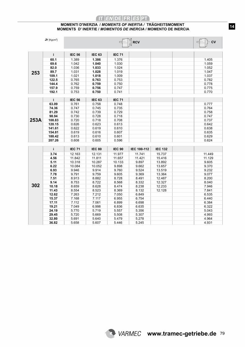
79
253
i IEC 56 IEC 63 IEC 71
60.1 1.389 1.386 1.376 1.40569.6 1.042 1.040 1.030 1.05982.0 1.036 1.033 1.024 1.05289.7 1.031 1.028 1.019 1.047
109.1 1.021 1.018 1.009 1.037122.5 0.765 0.763 0.753 0.782144.4 0.762 0.759 0.750 0.778157.9 0.759 0.756 0.747 0.775192.1 0.753 0.750 0.741 0.770
253A
i IEC 56 IEC 63 IEC 7163.09 0.761 0.758 0.748 0.77774.36 0.747 0.745 0.735 0.76481.29 0.742 0.739 0.729 0.75898.94 0.730 0.728 0.718 0.747
108.83 0.720 0.718 0.708 0.737120.15 0.626 0.623 0.613 0.642141.61 0.622 0.619 0.610 0.638154.81 0.619 0.616 0.607 0.635188.42 0.613 0.610 0.601 0.629207.26 0.608 0.605 0.596 0.624
302
i IEC 71 IEC 80 IEC 90 IEC 100-112 IEC 132
3.74 12.163 12.131 11.977 11.741 15.737 11.4494.56 11.842 11.811 11.657 11.421 15.416 11.1295.11 10.318 10.287 10.133 9.897 13.892 9.6056.22 10.084 10.052 9.898 9.662 13.657 9.3706.93 9.946 9.914 9.760 9.524 13.519 9.2327.78 9.791 9.759 9.605 9.369 13.364 9.0777.51 8.913 8.882 8.728 8.491 12.487 8.2009.14 8.753 8.722 8.568 8.332 12.327 8.040
10.18 8.659 8.628 8.474 8.238 12.233 7.94611.43 8.554 8.523 8.369 8.132 12.128 7.84112.62 7.263 7.212 7.050 6.849 6.53515.37 7.168 7.117 6.955 6.754 6.44017.11 7.112 7.061 6.899 6.698 6.38419.21 7.049 6.998 6.836 6.635 6.32224.19 5.770 5.719 5.557 5.356 5.04329.45 5.720 5.669 5.508 5.307 4.99332.80 5.691 5.640 5.479 5.278 4.96436.82 5.658 5.607 5.446 5.245 4.931
RCV CVJr [Kgcm2]
MOMENTI D'INERZIA / MOMENTS OF INERTIA / TRÄGHEITSMOMENT MOMENTS D' INERTIE / MOMENTOS DE INERCIA / MOMENTO DE INERCIA
14
www.tramec-getriebe.de
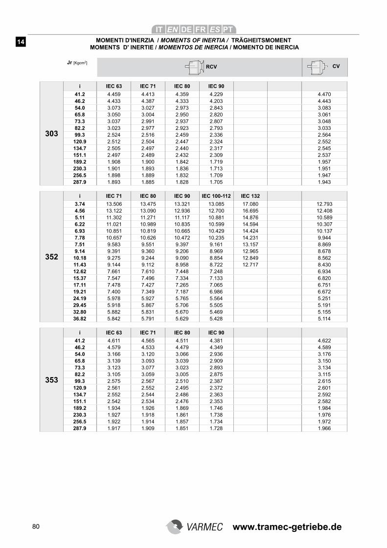
80
303
i IEC 63 IEC 71 IEC 80 IEC 90
41.2 4.459 4.413 4.359 4.229 4.47046.2 4.433 4.387 4.333 4.203 4.44354.0 3.073 3.027 2.973 2.843 3.08365.8 3.050 3.004 2.950 2.820 3.06173.3 3.037 2.991 2.937 2.807 3.04882.2 3.023 2.977 2.923 2.793 3.03399.3 2.524 2.516 2.459 2.336 2.564
120.9 2.512 2.504 2.447 2.324 2.552134.7 2.505 2.497 2.440 2.317 2.545151.1 2.497 2.489 2.432 2.309 2.537189.2 1.908 1.900 1.842 1.719 1.957230.3 1.901 1.893 1.836 1.713 1.951256.5 1.898 1.889 1.832 1.709 1.947287.9 1.893 1.885 1.828 1.705 1.943
352
i IEC 71 IEC 80 IEC 90 IEC 100-112 IEC 132
3.74 13.506 13.475 13.321 13.085 17.080 12.7934.56 13.122 13.090 12.936 12.700 16.695 12.4085.11 11.302 11.271 11.117 10.881 14.876 10.5896.22 11.021 10.989 10.835 10.599 14.594 10.3076.93 10.851 10.819 10.665 10.429 14.424 10.1377.78 10.657 10.626 10.472 10.235 14.231 9.9447.51 9.583 9.551 9.397 9.161 13.157 8.8699.14 9.391 9.360 9.206 8.969 12.965 8.678
10.18 9.275 9.244 9.090 8.854 12.849 8.56211.43 9.144 9.112 8.958 8.722 12.717 8.43012.62 7.661 7.610 7.448 7.248 6.93415.37 7.547 7.496 7.334 7.133 6.82017.11 7.478 7.427 7.265 7.065 6.75119.21 7.400 7.349 7.187 6.986 6.67224.19 5.978 5.927 5.765 5.564 5.25129.45 5.918 5.867 5.706 5.505 5.19132.80 5.882 5.831 5.670 5.469 5.15536.82 5.842 5.791 5.629 5.428 5.114
353
i IEC 63 IEC 71 IEC 80 IEC 90
41.2 4.611 4.565 4.511 4.381 4.62246.2 4.579 4.533 4.479 4.349 4.58954.0 3.166 3.120 3.066 2.936 3.17665.8 3.139 3.093 3.039 2.909 3.15073.3 3.123 3.077 3.023 2.893 3.13482.2 3.105 3.059 3.005 2.875 3.11599.3 2.575 2.567 2.510 2.387 2.615
120.9 2.561 2.552 2.495 2.372 2.601134.7 2.552 2.544 2.486 2.363 2.592151.1 2.542 2.534 2.476 2.353 2.582189.2 1.934 1.926 1.869 1.746 1.984230.3 1.927 1.918 1.861 1.738 1.976256.5 1.922 1.914 1.857 1.734 1.972287.9 1.917 1.909 1.851 1.728 1.966
RCV CVJr [Kgcm2]
MOMENTI D'INERZIA / MOMENTS OF INERTIA / TRÄGHEITSMOMENT MOMENTS D' INERTIE / MOMENTOS DE INERCIA / MOMENTO DE INERCIA
14
www.tramec-getriebe.de
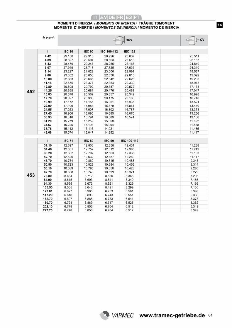
81
452
i IEC 80 IEC 90 IEC 100-112 IEC 132
4.42 29.150 29.918 28.926 28.837 25.5114.89 28.827 29.594 28.603 28.513 25.1875.43 28.479 29.247 28.255 28.166 24.8406.07 27.949 28.717 27.725 27.636 24.3108.14 23.227 24.029 23.006 22.991 19.5679.00 23.052 23.853 22.830 22.815 19.392
10.00 22.863 23.665 22.642 22.626 19.20311.18 22.575 23.377 22.354 22.339 18.91512.89 20.808 20.792 20.587 20.572 17.15814.25 20.698 20.681 20.476 20.461 17.04715.83 20.578 20.562 20.357 20.342 16.92817.70 20.397 20.380 20.175 20.160 16.74619.99 17.172 17.155 16.951 16.935 13.52122.09 17.100 17.084 16.879 16.864 13.45024.55 17.023 17.007 16.802 16.787 13.37327.45 16.906 16.890 16.685 16.670 13.25630.93 16.810 16.794 16.589 16.574 13.16031.20 15.279 15.252 15.058 11.62234.67 15.225 15.198 15.004 11.56838.76 15.142 15.115 14.921 11.48543.68 15.074 15.047 14.852 11.417
453
i IEC 71 IEC 80 IEC 90 IEC 100-112
31.10 12.697 12.803 12.658 12.431 11.28834.40 12.651 12.757 12.612 12.385 11.24238.20 12.602 12.707 12.563 12.335 11.19342.70 12.526 12.632 12.487 12.260 11.11745.70 10.754 10.860 10.715 10.488 9.34550.50 10.723 10.828 10.684 10.456 9.31456.10 10.689 10.795 10.650 10.423 9.28062.70 10.638 10.743 10.599 10.371 9.22976.80 8.634 8.712 8.560 8.368 7.20584.90 8.615 8.693 8.541 8.349 7.18694.30 8.595 8.673 8.521 8.329 7.166
105.50 8.565 8.643 8.491 8.299 7.136123.81 6.827 6.905 6.753 6.561 5.398147.20 6.818 6.896 6.743 6.551 5.388162.70 6.807 6.885 6.733 6.541 5.378180.70 6.791 6.869 6.717 6.525 5.362202.10 6.778 6.856 6.704 6.512 5.349227.70 6.778 6.856 6.704 6.512 5.349
RCV CVJr [Kgcm2]
MOMENTI D'INERZIA / MOMENTS OF INERTIA / TRÄGHEITSMOMENT MOMENTS D' INERTIE / MOMENTOS DE INERCIA / MOMENTO DE INERCIA
14
www.tramec-getriebe.de
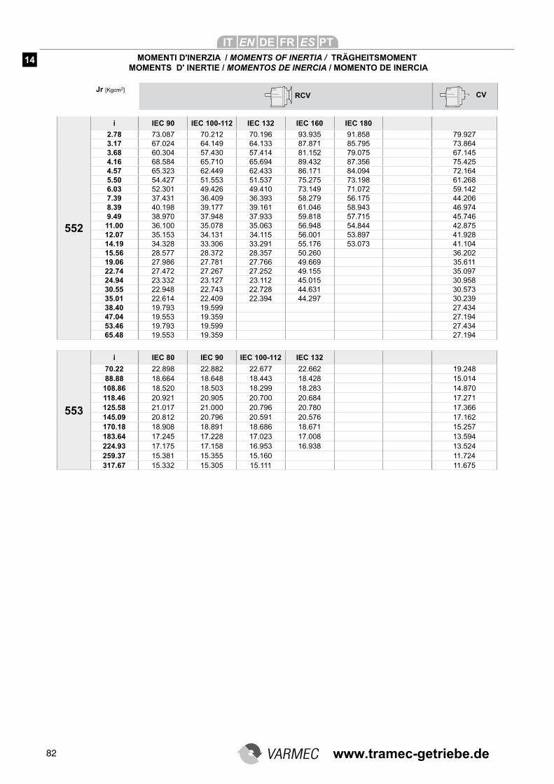
82
RCV CVJr [Kgcm2]
MOMENTI D'INERZIA / MOMENTS OF INERTIA / TRÄGHEITSMOMENT MOMENTS D' INERTIE / MOMENTOS DE INERCIA / MOMENTO DE INERCIA
14
552
i IEC 90 IEC 100-112 IEC 132 IEC 160 IEC 180
2.78 73.087 70.212 70.196 93.935 91.858 79.9273.17 67.024 64.149 64.133 87.871 85.795 73.8643.68 60.304 57.430 57.414 81.152 79.075 67.1454.16 68.584 65.710 65.694 89.432 87.356 75.4254.57 65.323 62.449 62.433 86.171 84.094 72.1645.50 54.427 51.553 51.537 75.275 73.198 61.2686.03 52.301 49.426 49.410 73.149 71.072 59.1427.39 37.431 36.409 36.393 58.279 56.175 44.2068.39 40.198 39.177 39.161 61.046 58.943 46.9749.49 38.970 37.948 37.933 59.818 57.715 45.74611.00 36.100 35.078 35.063 56.948 54.844 42.87512.07 35.153 34.131 34.115 56.001 53.897 41.92814.19 34.328 33.306 33.291 55.176 53.073 41.10415.56 28.577 28.372 28.357 50.260 36.20219.06 27.986 27.781 27.766 49.669 35.61122.74 27.472 27.267 27.252 49.155 35.09724.94 23.332 23.127 23.112 45.015 30.95830.55 22.948 22.743 22.728 44.631 30.57335.01 22.614 22.409 22.394 44.297 30.23938.40 19.793 19.599 27.43447.04 19.553 19.359 27.19453.46 19.793 19.599 27.43465.48 19.553 19.359 27.194
553
i IEC 80 IEC 90 IEC 100-112 IEC 132
70.22 22.898 22.882 22.677 22.662 19.24888.88 18.664 18.648 18.443 18.428 15.014
108.86 18.520 18.503 18.299 18.283 14.870118.46 20.921 20.905 20.700 20.684 17.271125.58 21.017 21.000 20.796 20.780 17.366145.09 20.812 20.796 20.591 20.576 17.162170.18 18.908 18.891 18.686 18.671 15.257183.64 17.245 17.228 17.023 17.008 13.594224.93 17.175 17.158 16.953 16.938 13.524259.37 15.381 15.355 15.160 11.724317.67 15.332 15.305 15.111 11.675
www.tramec-getriebe.de
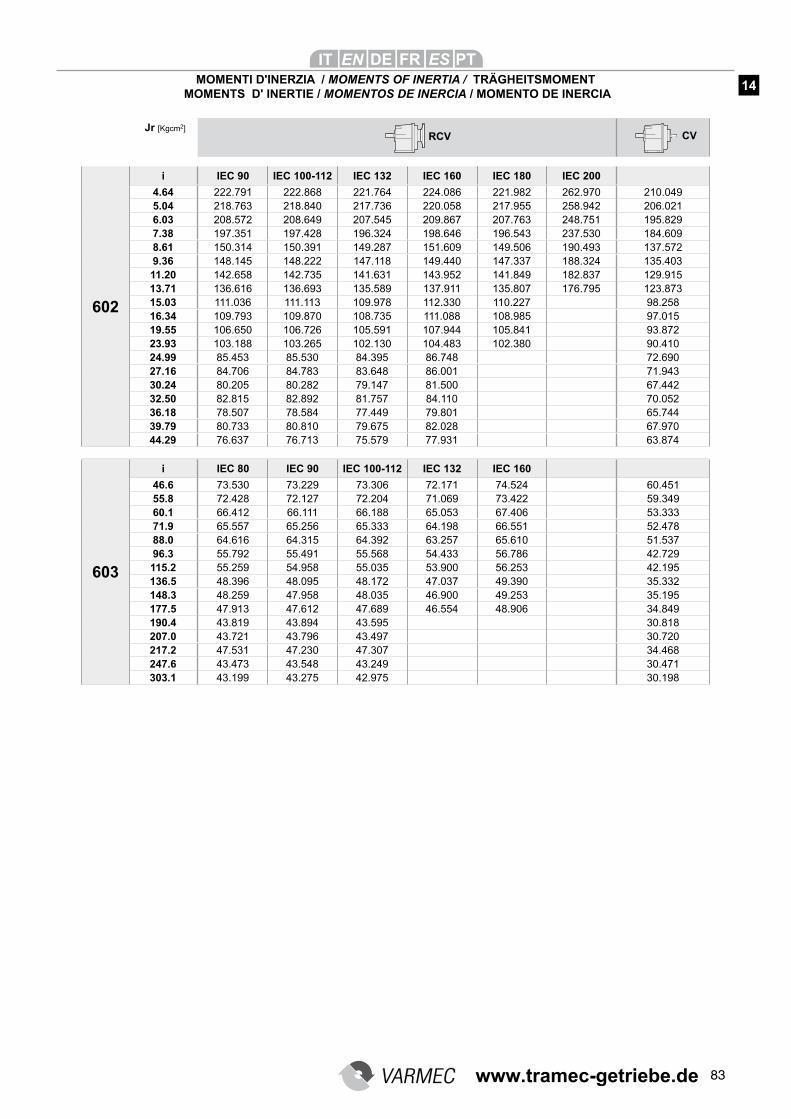
83
RCV CVJr [Kgcm2]
MOMENTI D'INERZIA / MOMENTS OF INERTIA / TRÄGHEITSMOMENT MOMENTS D' INERTIE / MOMENTOS DE INERCIA / MOMENTO DE INERCIA
14
602
i IEC 90 IEC 100-112 IEC 132 IEC 160 IEC 180 IEC 200
4.64 222.791 222.868 221.764 224.086 221.982 262.970 210.0495.04 218.763 218.840 217.736 220.058 217.955 258.942 206.0216.03 208.572 208.649 207.545 209.867 207.763 248.751 195.8297.38 197.351 197.428 196.324 198.646 196.543 237.530 184.6098.61 150.314 150.391 149.287 151.609 149.506 190.493 137.5729.36 148.145 148.222 147.118 149.440 147.337 188.324 135.40311.20 142.658 142.735 141.631 143.952 141.849 182.837 129.91513.71 136.616 136.693 135.589 137.911 135.807 176.795 123.87315.03 111.036 111.113 109.978 112.330 110.227 98.25816.34 109.793 109.870 108.735 111.088 108.985 97.01519.55 106.650 106.726 105.591 107.944 105.841 93.87223.93 103.188 103.265 102.130 104.483 102.380 90.41024.99 85.453 85.530 84.395 86.748 72.69027.16 84.706 84.783 83.648 86.001 71.94330.24 80.205 80.282 79.147 81.500 67.44232.50 82.815 82.892 81.757 84.110 70.05236.18 78.507 78.584 77.449 79.801 65.74439.79 80.733 80.810 79.675 82.028 67.97044.29 76.637 76.713 75.579 77.931 63.874
603
i IEC 80 IEC 90 IEC 100-112 IEC 132 IEC 160
46.6 73.530 73.229 73.306 72.171 74.524 60.45155.8 72.428 72.127 72.204 71.069 73.422 59.34960.1 66.412 66.111 66.188 65.053 67.406 53.33371.9 65.557 65.256 65.333 64.198 66.551 52.47888.0 64.616 64.315 64.392 63.257 65.610 51.53796.3 55.792 55.491 55.568 54.433 56.786 42.729115.2 55.259 54.958 55.035 53.900 56.253 42.195136.5 48.396 48.095 48.172 47.037 49.390 35.332148.3 48.259 47.958 48.035 46.900 49.253 35.195177.5 47.913 47.612 47.689 46.554 48.906 34.849190.4 43.819 43.894 43.595 30.818207.0 43.721 43.796 43.497 30.720217.2 47.531 47.230 47.307 34.468247.6 43.473 43.548 43.249 30.471303.1 43.199 43.275 42.975 30.198
www.tramec-getriebe.de
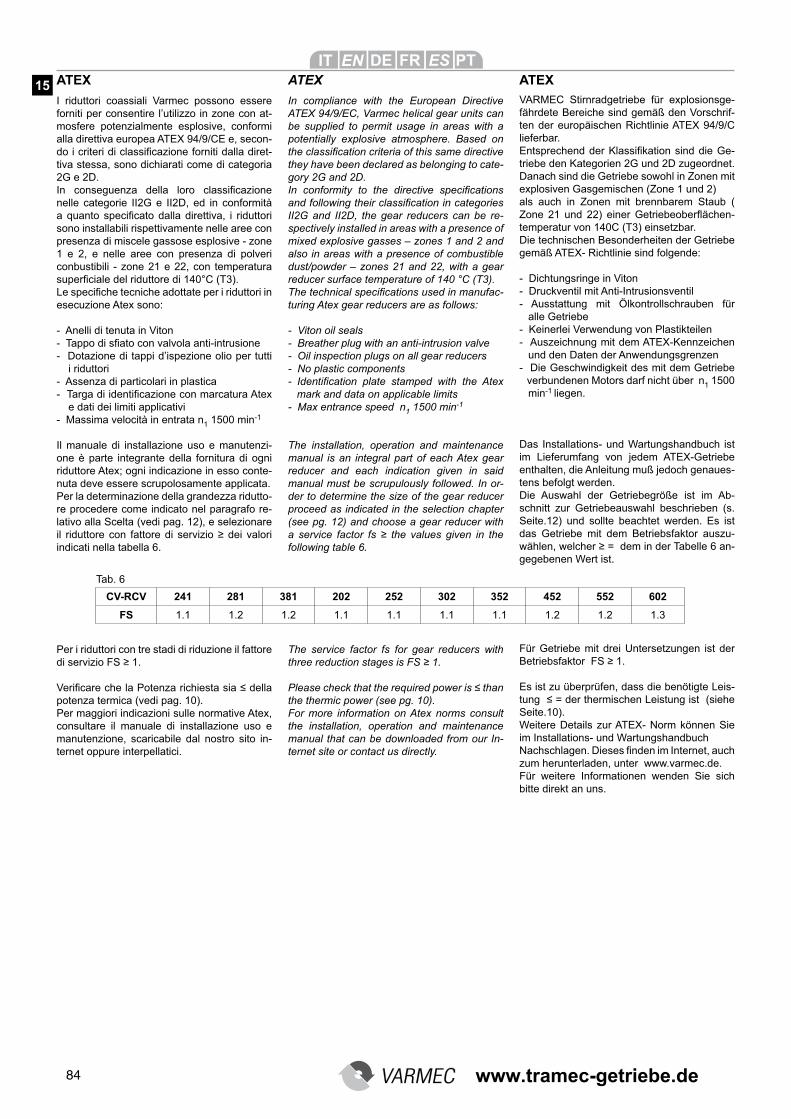
84
I riduttori coassiali Varmec possono essere forniti per consentire l’utilizzo in zone con at-mosfere potenzialmente esplosive, conformi alla direttiva europea ATEX 94/9/CE e, secon-do i criteri di classificazione forniti dalla diret-tiva stessa, sono dichiarati come di categoria 2G e 2D.In conseguenza della loro classificazione
nelle categorie II2G e II2D, ed in conformità a quanto specificato dalla direttiva, i riduttori
sono installabili rispettivamente nelle aree con presenza di miscele gassose esplosive - zone 1 e 2, e nelle aree con presenza di polveri conbustibili - zone 21 e 22, con temperatura superficiale del riduttore di 140°C (T3).
Le specifiche tecniche adottate per i riduttori in
esecuzione Atex sono:
- Anelli di tenuta in Viton- Tappo di sfiato con valvola anti-intrusione
- Dotazione di tappi d’ispezione olio per tutti i riduttori- Assenza di particolari in plastica- Targa di identificazione con marcatura Atex e dati dei limiti applicativi- Massima velocità in entrata n1 1500 min-1
Il manuale di installazione uso e manutenzi-one è parte integrante della fornitura di ogni riduttore Atex; ogni indicazione in esso conte-nuta deve essere scrupolosamente applicata.Per la determinazione della grandezza ridutto-re procedere come indicato nel paragrafo re-lativo alla Scelta (vedi pag. 12), e selezionare il riduttore con fattore di servizio ≥ dei valori
indicati nella tabella 6.
Per i riduttori con tre stadi di riduzione il fattore di servizio FS ≥ 1.
Verificare che la Potenza richiesta sia ≤ della
potenza termica (vedi pag. 10).Per maggiori indicazioni sulle normative Atex, consultare il manuale di installazione uso e manutenzione, scaricabile dal nostro sito in-ternet oppure interpellatici.
CV-RCV 241 281 381 202 252 302 352 452 552 602
FS 1.1 1.2 1.2 1.1 1.1 1.1 1.1 1.2 1.2 1.3
ATEX
In compliance with the European Directive
ATEX 94/9/EC, Varmec helical gear units can
be supplied to permit usage in areas with a
potentially explosive atmosphere. Based on
the classification criteria of this same directive
they have been declared as belonging to cate-
gory 2G and 2D.
In conformity to the directive specifications
and following their classification in categories
II2G and II2D, the gear reducers can be re-
spectively installed in areas with a presence of
mixed explosive gasses – zones 1 and 2 and
also in areas with a presence of combustible
dust/powder – zones 21 and 22, with a gear
reducer surface temperature of 140 °C (T3).
The technical specifications used in manufac-
turing Atex gear reducers are as follows:
- Viton oil seals
- Breather plug with an anti-intrusion valve
- Oil inspection plugs on all gear reducers
- No plastic components
- Identification plate stamped with the Atex
mark and data on applicable limits
- Max entrance speed n1 1500 min-1
The installation, operation and maintenance
manual is an integral part of each Atex gear
reducer and each indication given in said
manual must be scrupulously followed. In or-
der to determine the size of the gear reducer
proceed as indicated in the selection chapter
(see pg. 12) and choose a gear reducer with
a service factor fs ≥ the values given in the
following table 6.
The service factor fs for gear reducers with
three reduction stages is FS ≥ 1.
Please check that the required power is ≤ than
the thermic power (see pg. 10).
For more information on Atex norms consult
the installation, operation and maintenance
manual that can be downloaded from our In-
ternet site or contact us directly.
ATEXVARMEC Stirnradgetriebe für explosionsge-fährdete Bereiche sind gemäß den Vorschrif-ten der europäischen Richtlinie ATEX 94/9/C lieferbar.Entsprechend der Klassifikation sind die Ge-triebe den Kategorien 2G und 2D zugeordnet. Danach sind die Getriebe sowohl in Zonen mit explosiven Gasgemischen (Zone 1 und 2) als auch in Zonen mit brennbarem Staub ( Zone 21 und 22) einer Getriebeoberflächen-temperatur von 140C (T3) einsetzbar.Die technischen Besonderheiten der Getriebe gemäß ATEX- Richtlinie sind folgende:
- Dichtungsringe in Viton- Druckventil mit Anti-Intrusionsventil- Ausstattung mit Ölkontrollschrauben für alle Getriebe- Keinerlei Verwendung von Plastikteilen- Auszeichnung mit dem ATEX-Kennzeichen und den Daten der Anwendungsgrenzen- Die Geschwindigkeit des mit dem Getriebe verbundenen Motors darf nicht über n1 1500 min-1 liegen.
Das Installations- und Wartungshandbuch ist im Lieferumfang von jedem ATEX-Getriebe enthalten, die Anleitung muß jedoch genaues-tens befolgt werden.Die Auswahl der Getriebegröße ist im Ab-schnitt zur Getriebeauswahl beschrieben (s. Seite.12) und sollte beachtet werden. Es ist das Getriebe mit dem Betriebsfaktor auszu-wählen, welcher ≥ = dem in der Tabelle 6 an-gegebenen Wert ist.
Für Getriebe mit drei Untersetzungen ist der Betriebsfaktor FS ≥ 1.
Es ist zu überprüfen, dass die benötigte Leis-tung ≤ = der thermischen Leistung ist (siehe
Seite.10).Weitere Details zur ATEX- Norm können Sie im Installations- und Wartungshandbuch Nachschlagen. Dieses finden im Internet, auch
zum herunterladen, unter www.varmec.de.Für weitere Informationen wenden Sie sich bitte direkt an uns.
ATEX15
Tab. 6
www.tramec-getriebe.de
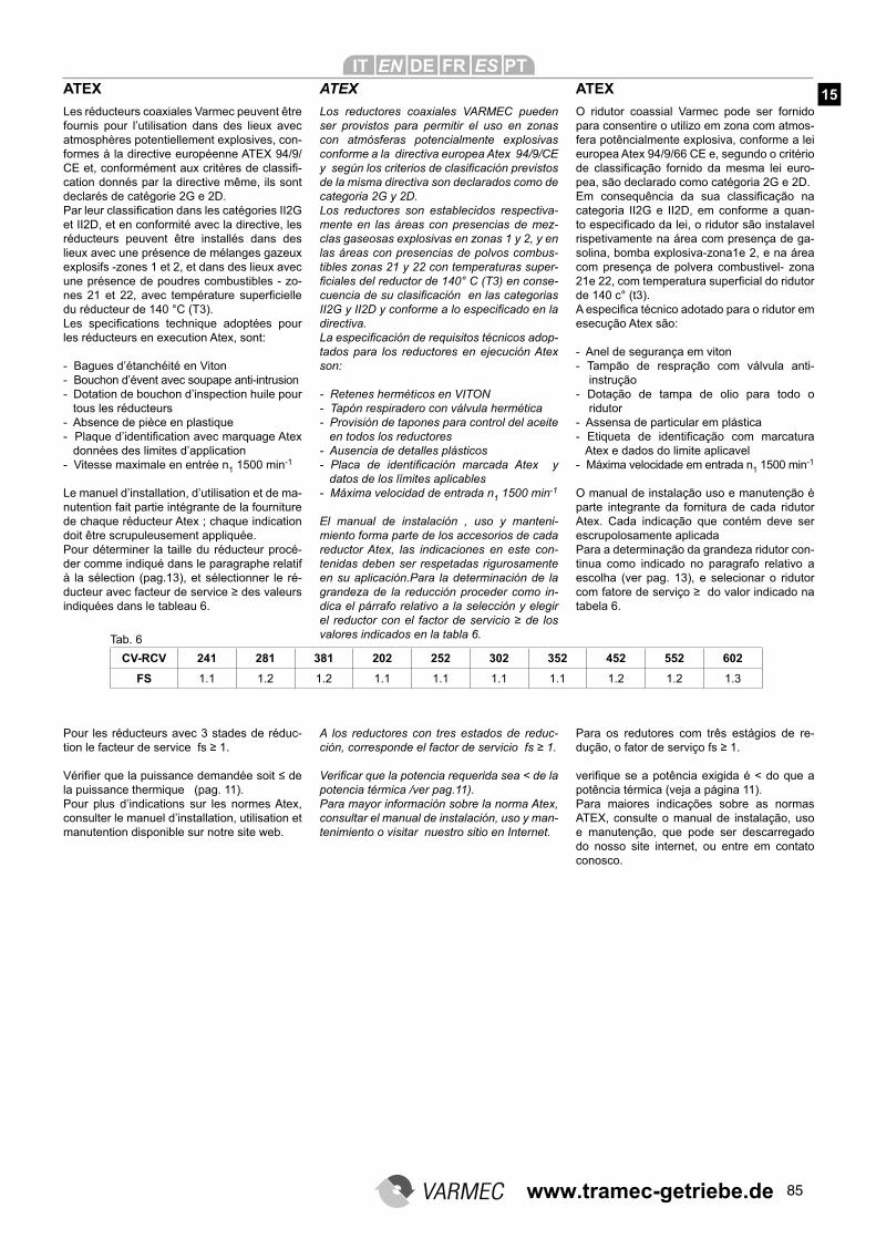
85
Les réducteurs coaxiales Varmec peuvent être fournis pour l’utilisation dans des lieux avec atmosphères potentiellement explosives, con-formes à la directive européenne ATEX 94/9/CE et, conformément aux critères de classifi-cation donnés par la directive même, ils sont declarés de catégorie 2G e 2D.Par leur classification dans les catégories II2G
et II2D, et en conformité avec la directive, les réducteurs peuvent être installés dans des lieux avec une présence de mélanges gazeux explosifs -zones 1 et 2, et dans des lieux avec une présence de poudres combustibles - zo-nes 21 et 22, avec température superficielle
du réducteur de 140 °C (T3).
Les specifications technique adoptées pour
les réducteurs en execution Atex, sont:
- Bagues d’étanchéité en Viton- Bouchon d’évent avec soupape anti-intrusion- Dotation de bouchon d’inspection huile pour tous les réducteurs- Absence de pièce en plastique- Plaque d’identification avec marquage Atex données des limites d’application- Vitesse maximale en entrée n1 1500 min-1
Le manuel d’installation, d’utilisation et de ma-nutention fait partie intégrante de la fourniture de chaque réducteur Atex ; chaque indication doit être scrupuleusement appliquée.Pour déterminer la taille du réducteur procé-der comme indiqué dans le paragraphe relatif à la sélection (pag.13), et sélectionner le ré-ducteur avec facteur de service ≥ des valeurs
indiquées dans le tableau 6.
Pour les réducteurs avec 3 stades de réduc-tion le facteur de service fs ≥ 1.
Vérifier que la puissance demandée soit ≤ de
la puissance thermique (pag. 11).Pour plus d’indications sur les normes Atex, consulter le manuel d’installation, utilisation et manutention disponible sur notre site web.
CV-RCV 241 281 381 202 252 302 352 452 552 602
FS 1.1 1.2 1.2 1.1 1.1 1.1 1.1 1.2 1.2 1.3
ATEX
Los reductores coaxiales VARMEC pueden
ser provistos para permitir el uso en zonas
con atmósferas potencialmente explosivas
conforme a la directiva europea Atex 94/9/CE
y según los criterios de clasificación previstos
de la misma directiva son declarados como de
categoria 2G y 2D.
Los reductores son establecidos respectiva-
mente en las áreas con presencias de mez-
clas gaseosas explosivas en zonas 1 y 2, y en
las áreas con presencias de polvos combus-
tibles zonas 21 y 22 con temperaturas super-
ficiales del reductor de 140° C (T3) en conse-
cuencia de su clasificación en las categorias
II2G y II2D y conforme a lo especificado en la
directiva.
La especificación de requisitos técnicos adop-
tados para los reductores en ejecución Atex
son:
- Retenes herméticos en VITON
- Tapón respiradero con válvula hermética
- Provisión de tapones para control del aceite
en todos los reductores
- Ausencia de detalles plásticos
- Placa de identificación marcada Atex y
datos de los límites aplicables
- Máxima velocidad de entrada n1 1500 min-1
El manual de instalación , uso y manteni-
miento forma parte de los accesorios de cada
reductor Atex, las indicaciones en este con-
tenidas deben ser respetadas rigurosamente
en su aplicación.Para la determinación de la
grandeza de la reducción proceder como in-
dica el párrafo relativo a la selección y elegir
el reductor con el factor de servicio ≥ de los
valores indicados en la tabla 6.
A los reductores con tres estados de reduc-
ción, corresponde el factor de servicio fs ≥ 1.
Verificar que la potencia requerida sea < de la
potencia térmica /ver pag.11).
Para mayor información sobre la norma Atex,
consultar el manual de instalación, uso y man-
tenimiento o visitar nuestro sitio en Internet.
ATEX
O ridutor coassial Varmec pode ser fornido para consentire o utilizo em zona com atmos-fera potêncialmente explosiva, conforme a lei europea Atex 94/9/66 CE e, segundo o critério de classificação fornido da mesma lei euro-pea, são declarado como catégoria 2G e 2D.
Em consequência da sua classificação na
categoria II2G e II2D, em conforme a quan-to especificado da lei, o ridutor são instalavel
rispetivamente na área com presença de ga-solina, bomba explosiva-zona1e 2, e na área com presença de polvera combustivel- zona 21e 22, com temperatura superficial do ridutor
de 140 c° (t3).
A especifica técnico adotado para o ridutor em
esecução Atex são:
- Anel de segurança em viton- Tampão de respração com válvula anti- instrução
- Dotação de tampa de olio para todo o ridutor- Assensa de particular em plástica- Etiqueta de identificação com marcatura Atex e dados do limite aplicavel- Máxima velocidade em entrada n1 1500 min-1
O manual de instalação uso e manutenção è
parte integrante da fornitura de cada ridutor Atex. Cada indicação que contém deve ser
escrupolosamente aplicadaPara a determinação da grandeza ridutor con-tinua como indicado no paragrafo relativo a escolha (ver pag. 13), e selecionar o ridutor com fatore de serviço ≥ do valor indicado na
tabela 6.
Para os redutores com três estágios de re-dução, o fator de serviço fs ≥ 1.
verifique se a potência exigida é < do que a
potência térmica (veja a página 11).Para maiores indicações sobre as normas ATEX, consulte o manual de instalação, uso
e manutenção, que pode ser descarregado
do nosso site internet, ou entre em contato conosco.
ATEX 15
Tab. 6
www.tramec-getriebe.de

1 www.tramec-getriebe.de
86
INSTALLAZIONE
Per l’installazione del riduttore è consiglia-bile attenersi alle seguenti indicazioni:• Verificare che non vi siano stati danni
durante lo stoccaggio o il trasporto• Pulire accuratamente il riduttore dai
resuidi dell’imballaggio a da eventuali prodotti protettivi
• Verificare che i dati riportati nella tar-ghetta di identificazione corrispondano a quelli specificati in fase di ordinativo
• Verificare che la struttura della mac-china sulla quale si installa il riduttore abbia caratteristiche di rigidezza e di robustezza sufficienti a supportarne il peso proprio e le forze generate nel funzionamento; accertarsi che la mac-china sia spenta e che ne sia impedito il riavvio accidentale
• II fissaggio sulla macchina deve essere stabile per evitare qualsiasi vibrazione; verificare che le superfici di accoppia-mento siano piane e ben pulite. Prima del montaggio lubrificare le superfici di contatto onde evitare grippaggi o os-sidazioni
• Assicurare l’allineamento tra motore - riduttore e tra riduttore - macchina operatrice
• Gli organi che vanno calettati sugli al-beri di uscita del riduttore devono es-sere lavorati con tolleranza ISO H7 per evitare accoppiamenti troppo bloccati che potrebbero danneggiare il riduttore stesso. Per il montaggio e lo smontag-gio di tali organi si consiglia l’utilizzo di adeguati tiranti ed estrattori usufruendo dell’apposito foro filettato posto in testa alle estremità degli alberi d’uscita. Non servirsi di martelli o altri strumenti im-propri per non danneggiare gli alberi o i supporti dei riduttori
• L’accoppiamento dell’albero di entrata cavo del riduttore, viene normalmente eseguito con perni aventi tolleranze ISO h6; in ogni caso il montaggio deve avvenire senza forzature
CONDIZIONI DI FORNITURA
I riduttori Varmec vengono forniti come segue:Già predisposti per essere installati nella
posizione di montaggio come definito in fase di ordine
Collaudati secondo specifiche interneLe superfici di accoppiamento non sono
verniciateSprovvisti di dadi e bulloni per il montag-
gio motori per la versione IECProvvisti di golfare di sollevamento per i
tipi RCV-CV 55-60Appositamente imballati per la spedizio-
ne
Please read this chapter carefully and
follow all instructions before installing the
gear reducer:
• Check that nothing has been damaged
during transport or storage
• Make sure that the gear reducer is free
from all packaging and any eventual
protective products
• Check that the information printed on the
identification plate correspond to those
specified on the order
• After making sure that the machine on
which the gear reducer is to be installed
is completely switched off and cannot
be accidentally turned on, check that it
is sturdy and rigid enough to withstand
the weight and the forces generated by
the gear reducer when running
• Make sure that the gear reducer is cor-
rectly secured to avoid any kind of vi-
brations and that the coupling parts are
flat and clean. Before assembly lubri-
cate the contact parts to avoid seizures
or oxidisation
• Check that the alignment between the
motor and the gear reducer and be-
tween the gear reducer and operation-
al machine is perfect
• Parts that connect to the gear reduc-
er’s output shaft must be machined to
ISO H7 tolerance to avoid any tightly
blocked couplings that could damage
the gear reducer. For the assembly
and removal of these parts use suit-
able pullers or extractors using the
specifically designed threaded hole at
the end of the output shaft. Do not use
hammers or other improper tools that
may damage the shafts or the support-
ing stand
• Coupling the gear reducer’s input hol-
low sshaft is normally done with shafts
with ISO h6 tolerance In all cases as-
sembly must never be forced
SUPPLIED TERMS
All Varmec gear reducers are supplied as
follows:
Ready made to be installed in the as-
sembly position previously stated dur-
ing ordering
Tried and tested to our internal specifica-
tions
Coupling surfaces are not varnished
Nuts and bolts are not supplied for the
assembly of motors for IEC versions
Types RCV-CV 55-60 come supplied with
lifting eye-bolt.
Appropriately and adequately packaged
for transport
Die folgenden Einbauanleitungen sollten beachtet werden:• Stellen Sie sicher, daß während des
Transports keinerlei Schäden verur-sacht wurden
• Entfernen Sie sorgfältig alle Reste der (Schutz-)Verpackung
• Stellen Sie sicher, daß die Angaben auf dem Typenschild mit Ihren Angaben in der Bestellung übereinstimmen
• Stellen Sie sicher, daß die Maschine, in die das Getriebe eingebaut werden soll, ausreichend robust und stabil ist, um dem Eigengewicht des Getriebes und den während der Inbetriebnahme auf-tretenden Kräften standzuhalten
• Stellen Sie sicher, daß das Getriebe gegen dauerhafte Vibrationseinflüsse geschützt ist
• Stellen Sie sicher, daß die Oberflächen-verbindungen gereinigt und eben sind. Vor der Montage müssen die Oberflä-chenkontakte geschmiert werden, um Oxidation und ein Heißlaufen zu ver-meiden
• Stellen Sie sicher, daß Motor und Ge-triebe miteinander verbunden sind und ebenso Maschine und Getriebe
• Alle Anbauteile, die an die Abtriebswel-len angebaut werden, müssen mit der Passung nach ISO H7 gefertigt sein, da es sonst durch Schwingungen zu einem frühzeitigen Getriebeausfall kommen kann. Für Montage und Demontage der Anbauteile wird der Gebrauch von ge-eigneten Zugstangen und Ausziehern empfohlen. Benutzen Sie hierfür die ei-gens dafür bestimmte Gewindebohrung an den Enden der Abtriebswellen. Ge-brauchen Sie keine Hämmer oder an-dere ungeeignete Werkzeuge, da sonst die Wellen oder die Halter der Getriebe beschädigt werden könnten
• Die Verbindung der Getriebeantriebs-welle wird normalerweise mit Stiften der Toleranz ISO h6 hergestellt. Eine Mon-tage unter erhöhter Kraftaufwendung sollte auf jeden Fall vermieden werden
LIEFERBEDINGUNGEN
Die Varmec Getriebe werden wie folgt ausgeliefert:Vorbereitet zum Einbau in die bestellte Einbaulage (die beigefügten Ventile und Entlüftungen müssen ggf. noch einge- baut werden)Nach internen Vorgaben überprüftKeine Lackierung der Oberflächenver-
bindungenDie Version IEC enthält keine Schrauben
und Muttern für die Montage des MotorsDie Typen RCV-CV-55-60 sind mit Hebe-
vorrichtungen (Ösen) ausgestattet
INSTALLATION INSTALLATION
16
17
www.tramec-getriebe.de
87
Observer la procédure d’installation sui-vante:• Vérifier l’absence de dommages éven-
tuellement subis pendant le stockage ou le transport
• Nettoyer le réducteur des résidus de l’emballage et d’autres produits de protection
• Vérifier que les données sur la plaque d’identification correspondent à celles de la commande
• Vérifier que la structure de la machine sur laquelle on installe le réducteur ait les caractéristiques de rigidité et robu-stesse aptes à en supporter le poids et les forces génerées par son fonction-nement; la machine doit être éteinte
• L’ancrage sur la machine doit être stable pour éviter des vibrations; véri-fier que les surfaces d’accouplement soient plat et propres. Avant le monta-ge, lubrifier les surfaces de contact afin d’éviter grippages et oxydation
• Vérifier que l’alignement entre le mo-teur et le réducteur ainsi qu’entre le réducteur et le système qu’il comman-de, soit correct
• Les éléments devant être montés sur l’arbre de sortie du réducteur doivent être usinés avec une tolérance ISO H7, afin d’éviter de provoquer des al-térations des éléments du réducteur. Pour monter ou démonter les élémen-ts employer des systémes de poussée ou d’extraction utilisants le trou tarau-dé situé en bout d’arbre de sortie ne pas utiliser de marteaux ou d’autres instruments impropres pour ne pas en-dommager les arbres ou les supports des réducteurs
• La tolérance d’usinage d’un arbre de-vant être inséré dans l’arbre d’entrée creux du réducteur, est ISO h6; en aucun cas un arbre ne doit être inséré sans être vérifié
CONDITION DE FOURNITURE
Les réducteurs Varmec sont fournis com-me suit:Déjà prêts à l’installation dans la position
de montage comme indiqué dans la commande
Eprouvés suivant spécifications internesLes surfaces d’accouplement ne sont
pas verniesDépourvus d’écrous et boulons pour le
montage moteurs pour la version IECPourvus de crochets pour le soulevement
pour le types RCV-CV 55-60Emballage express pour la livraison
Para la instalación del reductor se acon-
seja seguir las siguientes indicaciones:
• Verificar que no se hayan producidos
daños durante el almacenamiento y el
transporte
• Limpiar el reductor de los residuos del
embalaje y de eventuales productos
protectores
• Verificar que los datos reportados en la
placa de identificación correspondan a
los especificados en la orden
• Verificar que la estructura de la máqui-
na sobre la cual se instala el reductor
sea rígida y robusta para soportar el
propio peso y la fuerza generada del
funcionamiento; asegurarse que la
máquina este apagada y que no se
produzca un encendido accidental
• La fijación de la máquina debe ser esta-
ble para evitar cualquier vibración
• Verificar que las superficies del acopla-
miento sean planas y esten limpias.
Antes del montaje lubricar las superfi-
cies de contacto para evitar gripaje y
oxidación
• Asegurar el alineamiento entre motor-
reductor y entre reductor-máquina
operadora. Los órganos que van sobre
el eje de salida del reductor deben ser
trabajados con tolerancia ISO H7 para
evitar acoplamientos demasiado blo-
cados que puedan dañar el reductor .
Para el montaje y desmontaje de tales
órganos se aconseja la utilización de
adecuados tirantes y extractores apro-
vechando el correspondiente orificio
roscado dispuesto en las cabezas de
las extremidades de los ejes de salida.
No usar martillos u otros instrumentos
inadecuados para no dañar los ejes o
los soportes del reductor
• El acoplamiento del eje de entrada con
cavidad del reductor,es normalmente
seguido con pernos a juego minimo
ISO H6. En cada caso el montaje no
tiene que ser forzado
CONDICIONES DE EQUIPAMIENTO
Los reductores VARMEC vienen equipa-
dos de la siguiente manera:
Listos para ser instalados en la posición
de montaje descrita en el pedido
Aprobados segun normas internas
La superficie de los acoples no son bar-
nizadas
Desprovistos de tuercas y tornillos para
el montaje del motor IEC
Provistos de cancamo de elevación pa-
ralos tipos RCV-CV 55-60
Adecuadamente embalados para la
expedición
Para a instalação do ridutor e conselha-do ter as seguites indicações:• Verificar que não tene parte danificada
durante a armazenagem e o transporto• Limpar perfeitamente o ridutor do resto
da embalagem e da eventuale produ-tor protetivo
• Verificar que os dados reportados na etiqueta de identificação corresponde aquele especificado em fase de ordem
• Verificar que a estrutura da máquina sobre qual se instala o ridutor hajá ca-ractéristica de rigidez e de segurança suficiente a suportar o proprio peso, e a força geral no funcionamento: ob-servar se a máquina seja desligada e que seja impedida de perigo acidental
• A fixagem sobre a máquina deve ser estavel, para evitar qualquer vibração Verificar que a superficie de acopia-mento são direitas e bem limpos. An-tes da montagem lubrificar a superficie de contato onde evitar estraga e en-velhencer
• Segurança no aliamento no motor- ridu-tor pra ridutor- máquina de operação
• Os orgãos que vão caletati sobre eixo de saida do ridutor devem ser trabalha-da com tolerança ISO H7 para evitar acopiamento muito blocado que pode quebrar o ridutor para a montagem e desmontagem de tal organi se acon-selha o utilizo de adeguado tirante e estrator usufruindo do buraco filetado posicionado em cabeça a extremitar eixo saida
• Não usar martelo ou outro tipo de ins-trumento para não quebrar o eixo ou suporto do ridutor
• O acopiamento do eixo de entrada, cavo do ridutor, vem normalmente fato. Com perni avendo tolerança ISO h6; em cada caso a montagem deve chegar sem esforço
CONDIÇÃO DE FORNITURA
O ridutor Varmec vem fornido com o se-gue:È predisposto para ser instalado Laudo segundo especifido internoA superficie de acopiamento não são
vernizadoNão tem parafuso e porca para a monta-
gem do motor, para a versão IECTem de golfare de levantamento para o
tipo RCV-CV 55-60Apositamente embalado para a espedição
INSTALLATION INSTALACIÓN INSTALAÇÃO
16
17
www.tramec-getriebe.de
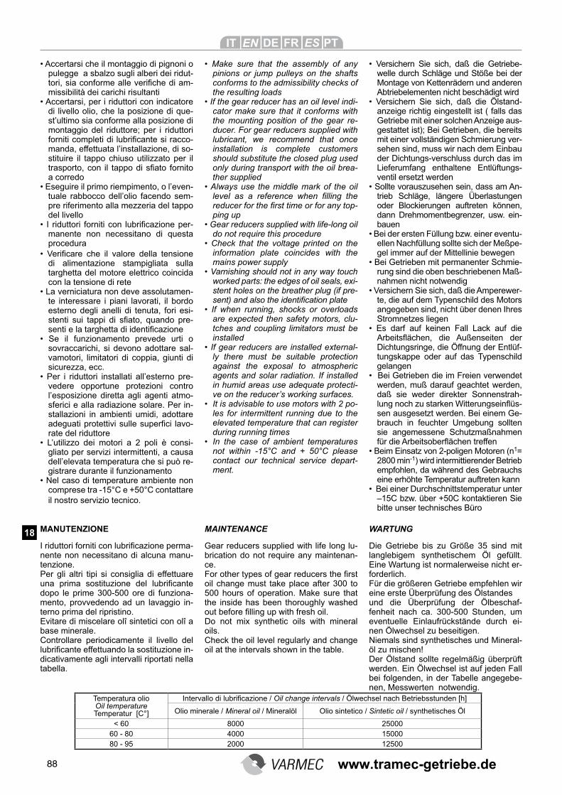
88
• Verificare che il valore della tensione di alimentazione stampigliata sulla targhetta del motore elettrico coincida con la tensione di rete
• La verniciatura non deve assolutamen-te interessare i piani lavorati, il bordo esterno degli anelli di tenuta, fori esi-stenti sui tappi di sfiato, quando pre-senti e la targhetta di identificazione
• Se il funzionamento prevede urti o sovraccarichi, si devono adottare sal-vamotori, limitatori di coppia, giunti di sicurezza, ecc.
• Per i riduttori installati all’esterno pre-vedere opportune protezioni contro l’esposizione diretta agli agenti atmo-sferici e alla radiazione solare. Per in-stallazioni in ambienti umidi, adottare adeguati protettivi sulle superfici lavo-rate del riduttore
• L’utilizzo dei motori a 2 poli è consi-gliato per servizi intermittenti, a causa dell’elevata temperatura che si può re-gistrare durante il funzionamento
• Nel caso di temperature ambiente non comprese tra -15°C e +50°C contattare il nostro servizio tecnico.
MANUTENZIONE MAINTENANCE
I riduttori forniti con lubrificazione perma-nente non necessitano di alcuna manu-tenzione.Per gli altri tipi si consiglia di effettuare una prima sostituzione del lubrificante dopo le prime 300-500 ore di funziona-mento, provvedendo ad un lavaggio in-terno prima del ripristino. Evitare di miscelare olî sintetici con olî a base minerale.Controllare periodicamente il livello del lubrificante effettuando la sostituzione in-dicativamente agli intervalli riportati nella tabella.
Temperatura olio Oil temperature Temperatur [C°]
Intervallo di lubrificazione / Oil change intervals / Ölwechsel nach Betriebsstunden [h]
Olio minerale / Mineral oil / Mineralöl Olio sintetico / Sintetic oil / synthetisches Öl
< 60 8000 2500060 - 80 4000 1500080 - 95 2000 12500
• Accertarsi che il montaggio di pignoni o pulegge a sbalzo sugli alberi dei ridut-tori, sia conforme alle verifiche di am-missibilità dei carichi risultanti
• Accertarsi, per i riduttori con indicatore di livello olio, che la posizione di que-st’ultimo sia conforme alla posizione di montaggio del riduttore; per i riduttori forniti completi di lubrificante si racco-manda, effettuata l’installazione, di so-stituire il tappo chiuso utilizzato per il trasporto, con il tappo di sfiato fornito a corredo
• Eseguire il primo riempimento, o l’even-tuale rabbocco dell’olio facendo sem-pre riferimento alla mezzeria del tappo del livello
• I riduttori forniti con lubrificazione per-manente non necessitano di questa procedura
• Make sure that the assembly of any pinions or jump pulleys on the shafts conforms to the admissibility checks of the resulting loads
• If the gear reducer has an oil level indi-cator make sure that it conforms with the mounting position of the gear re-ducer. For gear reducers supplied with lubricant, we recommend that once installation is complete customers should substitute the closed plug used only during transport with the oil brea-ther supplied
• Always use the middle mark of the oil level as a reference when filling the reducer for the first time or for any top-ping up
• Gear reducers supplied with life-long oil do not require this procedure
• Check that the voltage printed on the information plate coincides with the mains power supply
• Varnishing should not in any way touch worked parts: the edges of oil seals, exi-stent holes on the breather plug (if pre-sent) and also the identification plate
• If when running, shocks or overloads are expected then safety motors, clu-tches and coupling limitators must be installed
• If gear reducers are installed external-ly there must be suitable protection against the exposal to atmospheric agents and solar radiation. If installed in humid areas use adequate protecti-ve on the reducer’s working surfaces.
• It is advisable to use motors with 2 po-les for intermittent running due to the elevated temperature that can register during running times
• In the case of ambient temperatures not within -15°C and + 50°C please contact our technical service depart-ment.
• Versichern Sie sich, daß die Getriebe-welle durch Schläge und Stöße bei der Montage von Kettenrädern und anderen Abtriebelementen nicht beschädigt wird
• Versichern Sie sich, daß die Ölstand-anzeige richtig eingestellt ist ( falls das Getriebe mit einer solchen Anzeige aus-gestattet ist); Bei Getrieben, die bereits mit einer vollständigen Schmierung ver-sehen sind, muss wir nach dem Einbau der Dichtungs-verschluss durch das im Lieferumfang enthaltene Entlüftungs-ventil ersetzt werden
• Sollte vorauszusehen sein, dass am An-trieb Schläge, längere Überlastungen oder Blockierungen auftreten können, dann Drehmomentbegrenzer, usw. ein-bauen
• Bei der ersten Füllung bzw. einer eventu-ellen Nachfüllung sollte sich der Meßpe-gel immer auf der Mittellinie bewegen
• Bei Getrieben mit permanenter Schmie-rung sind die oben beschriebenen Maß-nahmen nicht notwendig
• Versichern Sie sich, daß die Amperewer-te, die auf dem Typenschild des Motors angegeben sind, nicht über denen Ihres Stromnetzes liegen
• Es darf auf keinen Fall Lack auf die Arbeitsflächen, die Außenseiten der Dichtungsringe, die Öffnung der Entlüf-tungskappe oder auf das Typenschild gelangen
• Bei Getrieben die im Freien verwendet werden, muß darauf geachtet werden, daß sie weder direkter Sonnenstrah-lung noch zu starken Witterungseinflüs-sen ausgesetzt werden. Bei einem Ge-brauch in feuchter Umgebung sollten sie angemessene Schutzmaßnahmen für die Arbeitsoberflächen treffen
• Beim Einsatz von 2-poligen Motoren (n1= 2800 min-1) wird intermittierender Betrieb empfohlen, da während des Gebrauchs eine erhöhte Temperatur auftreten kann
• Bei einer Durchschnittstemperatur unter –15C bzw. über +50C kontaktieren Sie bitte unser technisches Büro
Gear reducers supplied with life long lu-brication do not require any maintenan-ce.For other types of gear reducers the first oil change must take place after 300 to 500 hours of operation. Make sure that the inside has been thoroughly washed out before filling up with fresh oil.Do not mix synthetic oils with mineral oils.Check the oil level regularly and change oil at the intervals shown in the table.
Die Getriebe bis zu Größe 35 sind mit langlebigem synthetischem Öl gefüllt. Eine Wartung ist normalerweise nicht er-forderlich.Für die größeren Getriebe empfehlen wir eine erste Überprüfung des Ölstandes und die Überprüfung der Ölbeschaf-fenheit nach ca. 300-500 Stunden, um eventuelle Einlaufrückstände durch ei-nen Ölwechsel zu beseitigen.Niemals sind synthetisches und Mineral-öl zu mischen!Der Ölstand sollte regelmäßig überprüft werden. Ein Ölwechsel ist auf jeden Fall bei folgenden, in der Tabelle angegebe-nen, Messwerten notwendig.
WARTUNG 18
www.tramec-getriebe.de
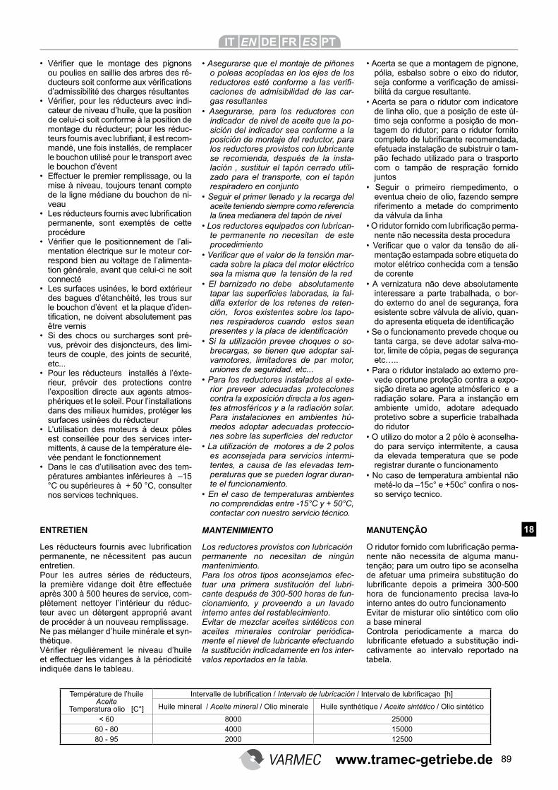
89
MANTENIMIENTO
Température de l’huile Aceite
Temperatura olio [C°]
Intervalle de lubrification / Intervalo de lubricación / Intervalo de lubrificaçao [h]
Huile mineral / Aceite mineral / Olio minerale Huile synthétique / Aceite sintético / Olio sintético
< 60 8000 2500060 - 80 4000 1500080 - 95 2000 12500
• Asegurarse que el montaje de piñones o poleas acopladas en los ejes de los reductores esté conforme a las verifi-caciones de admisibilidad de las car-gas resultantes
• Asegurarse, para los reductores con indicador de nivel de aceite que la po-sición del indicador sea conforme a la posición de montaje del reductor, para los reductores provistos con lubricante se recomienda, después de la insta-lación , sustituir el tapón cerrado utili-zado para el transporte, con el tapón respiradero en conjunto
• Seguir el primer llenado y la recarga del aceite teniendo siempre como referencia la linea medianera del tapón de nivel
• Los reductores equipados con lubrican-te permanente no necesitan de este procedimiento
• Verificar que el valor de la tensión mar-cada sobre la placa del motor eléctrico sea la misma que la tensión de la red
• El barnizado no debe absolutamente tapar las superficies laboradas, la fal-dilla exterior de los retenes de reten-ción, foros existentes sobre los tapo-nes respiraderos cuando estos sean presentes y la placa de identificación
• Si la utilización prevee choques o so-brecargas, se tienen que adoptar sal-vamotores, limitadores de par motor, uniones de seguridad. etc...
• Para los reductores instalados al exte-rior preveer adecuadas protecciones contra la exposición directa a los agen-tes atmosféricos y a la radiación solar. Para instalaciones en ambientes hú-medos adoptar adecuadas proteccio-nes sobre las superficies del reductor
• La utilización de motores a de 2 polos es aconsejada para servicios intermi-tentes, a causa de las elevadas tem-peraturas que se pueden lograr duran-te el funcionamiento.
• En el caso de temperaturas ambientes no comprendidas entre -15°C y + 50°C, contactar con nuestro servicio técnico.
Los reductores provistos con lubricación permanente no necesitan de ningún mantenimiento.Para los otros tipos aconsejamos efec-tuar una primera sustitución del lubri-cante después de 300-500 horas de fun-cionamiento, y proveendo a un lavado interno antes del restablecimiento.Evitar de mezclar aceites sintéticos con aceites minerales controlar periódica-mente el nievel de lubricante efectuando la sustitución indicadamente en los inter-valos reportados en la tabla.
• Acerta se que a montagem de pignone, pólia, esbalso sobre o eixo do ridutor, seja conforme a verificação de amissi-bilitá da cargue resultante.
• Acerta se para o ridutor com indicatore de linha olio, que a posição de este úl-timo seja conforme a posição de mon-tagem do ridutor; para o ridutor fornito completo de lubrificante recomendada, efetuada instalação de subistruir o tam-pão fechado utilizado para o trasporto com o tampão de respração fornido juntos
• Seguir o primeiro riempedimento, o eventua cheio de olio, fazendo sempre riferimento a metade do comprimento da válvula da linha
• O ridutor fornido com lubrificação perma-nente não necessita desta procedura
• Verificar que o valor da tensão de ali-mentação estampada sobre etiqueta do motor elétrico conhecida com a tensão de corente
• A vernizatura não deve absolutamente interessare a parte trabalhada, o bor-do externo do anel de segurança, fora esistente sobre válvula de alívio, quan-do apresenta etiqueta de identificação
• Se o funcionamento prevede choque ou tanta carga, se deve adotar salva-mo-tor, limite de cópia, pegas de segurança etc…..
• Para o ridutor instalado ao externo pre-vede oportune proteção contra a expo-sição direta ao agente atmósferico e a radiação solare. Para a instanção em ambiente umído, adotare adequado protetivo sobre a superficie trabalhada do ridutor
• O utilizo do motor a 2 pólo è aconselha-do para serviço intermitente, a causa da elevada temperatura que se pode registrar durante o funcionamento
• No caso de temperatura ambiental não meté-lo da –15c° e +50c° confira o nos-so serviço tecnico.
MANUTENÇÃO
O ridutor fornido com lubrificação perma-nente não necessita de alguma manu-tenção; para um outro tipo se aconselha de afetuar uma primeira substitução do lubrificante depois a primeira 300-500 hora de funcionamento precisa lava-lo interno antes do outro funcionamentoEvitar de misturar olio sintético com olio a base mineralControla periodicamente a marca do lubrificante efetuado a substitução indi-cativamente ao intervalo reportado na tabela.
• Vérifier que le montage des pignons ou poulies en saillie des arbres des ré-ducteurs soit conforme aux vérifications d’admissibilité des charges résultantes
• Vérifier, pour les réducteurs avec indi-cateur de niveau d’huile, que la position de celui-ci soit conforme à la position de montage du réducteur; pour les réduc-teurs fournis avec lubrifiant, il est recom-mandé, une fois installés, de remplacer le bouchon utilisé pour le transport avec le bouchon d’évent
• Effectuer le premier remplissage, ou la mise à niveau, toujours tenant compte de la ligne médiane du bouchon de ni-veau
• Les réducteurs fournis avec lubrification permanente, sont exemptés de cette procédure
• Vérifier que le positionnement de l’ali-mentation électrique sur le moteur cor-respond bien au voltage de l’alimenta-tion générale, avant que celui-ci ne soit connecté
• Les surfaces usinées, le bord extérieur des bagues d’étanchéité, les trous sur le bouchon d’évent et la plaque d’iden-tification, ne doivent absolutement pas être vernis
• Si des chocs ou surcharges sont pré-vus, prévoir des disjoncteurs, des limi-teurs de couple, des joints de securité, etc...
• Pour les réducteurs installés à l’éxte-rieur, prévoir des protections contre l’exposition directe aux agents atmos-phériques et le soleil. Pour l’installations dans des milieux humides, protéger les surfaces usinées du réducteur
• L’utilisation des moteurs à deux pôles est conseillée pour des services inter-mittents, à cause de la température éle-vée pendant le fonctionnement
• Dans le cas d’utilisation avec des tem-pératures ambiantes inférieures à –15 °C ou supérieures à + 50 °C, consulter nos services techniques.
ENTRETIEN
Les réducteurs fournis avec lubrification permanente, ne nécessitent pas aucun entretien. Pour les autres séries de réducteurs, la première vidange doit être effectuée après 300 à 500 heures de service, com-plètement nettoyer l’intérieur du réduc-teur avec un détergent approprié avant de procéder à un nouveau remplissage.Ne pas mélanger d’huile minérale et syn-thétique.Vérifier régulièrement le niveau d’huile et effectuer les vidanges à la périodicité indiquée dans le tableau.
18
www.tramec-getriebe.de
90
STOCCAGGIO
Per un corretto stoccaggio dei riduttori ricevuti consigliamo di eseguire le se-guenti raccomandazioni: • Escludere aree all’aperto, zone esposte
alle intemperie o con eccessiva umidità.• L’ambiente deve essere sufficientemen-
te pulito, esente da vibrazioni ecces-sive per non danneggiare i cuscinetti (tale necessità di contenere le vibra-zioni deve essere soddisfatta anche durante il trasporto)
• Interporre sempre tra il pavimento e il riduttore, uno strato di isolante che im-pedisca il diretto contatto
• Disporre il riduttore in modo che abbia una base d’oppoggio stabile ed accer-tarsi che non sussistano rischi di spo-stamenti imprevisti
• Ruotare semestralmente gli alberi di qualche giro per prevenire danneggia-menti a cuscinetti e anelli di tenuta
• Per periodi di stoccaggio superiori ai 60 giorni, le superfici interessate agli accoppiamenti devono essere protette con prodotti antiossidanti
• Per periodi di stoccaggio superiori ai 6 mesi, i riduttori dovranno avere le parti lavorate esterne e quelle di accoppia-mento ricoperte di grasso per evitare ossidazioni, inoltre per i riduttori forniti privi di lubrificante dovranno essere riempiti di olio, posizionando il tappo di sfiato nella posizione più alta, e pri-ma dell’utilizzo, riempiti con la corretta quantità e tipo di lubrificante previsto.
STORAGE
To ensure correct storage of the received
gear reducer(s), please take note of the
following recommendations:
• Do not store outside, in areas exposed
to bad weather or with excessive hu-
midity.
• The ambient must be sufficiently clean
and absent of any excessive vibrations
that could damage the bearings – this
is also true for transportation
• Always place some kind of isolating
material between the floor and the
gear reducer so that there is no direct
contact.
• Make sure that the gear reducer is on a
stable base and cannot be accidentally
knocked or moved
• Give the shafts a few turns every six
months to prevent damage to bearings
and oil seals
• For storage periods of over 60 days
coupling surfaces must be protected
with an anti-oxidant
• For storage periods of longer than 6
months all external working parts and
coupling parts must be greased to
avoid oxidisation. Take note that reduc-
ers supplied without lubricant should
be filled up with oil and the breather
plug should be in its highest position.
Before first use the gear reducer must
be filled with the correct type and quan-
tity of required lubricant.
LAGERUNG
Beachten Sie bitte folgendes, um die ge-lieferten Getriebe richtig zu lagern:
• Nicht im Freien lagern.• Die Umgebung muß ausreichend sau-
ber sein• Keine zu starken Vibrationen, damit die
Lager nicht beschädigt werden ( dies gilt auch für den Transport)
• Um direkten Bodenkontakt zu vermei-den, sollte die Lagerung immer auf ei-ner isolierenden Unterlage erfolgen
• Stellen Sie sicher, daß das Getriebe auf einer stabilen und sicheren Unterlage gelagert ist und keinen unvorherge-sehenen Stößen bzw. Bewegungen ausgesetzt ist
• Mindestens alle 6 Wochen sollten die Wellen bewegt werden, damit die La-ger und die Dichtungsringe nicht einro-sten
• Bei Lagerzeiten über 60 Tagen sollten alle bearbeiteten Flächen mit einem Rostschutzmittel behandelt werden
• Bei Lagerzeiten über 6 Monaten sollten alle bearbeiteten Flächen eingefettet werden, um Rostbildung zu vermeiden
• Zudem muß bei den Getrieben, die ohne Schmieröl geliefert werden, das Öl wieder aufgefüllt werden. Hier-zu wird das Entlüftungsventil auf die höchste Position eingestellt. Vor dem ersten Gebrauch sollte das Schmieröl nochmals auf die korrekte Menge und die richtige Typenart überprüft werden
19
www.tramec-getriebe.de
91
STOCKAGE
Observer les instructions suivantes afin de conserver en l’état la livraison des matériels:
• Ne pas stocker à l’éxterieur, des lo-caux exposés au mauvais temps ou avec une humidité excessive
• Le milieu doit être suffisamment pro-pre, sans vibrations excessive pour ne pas endommager les roulements (la necessité de limiter les vibrations doit être satisfaite pendant le transport aussi)
• Interposer toujours entre le sol et le ré-ducteur une couche isolante
• Le réducteur doit avoir une base d’ap-pui stable et vérifier l’absence de ris-ques de déplacement inprevus
• Tourner tous les 6 mois les arbres pour prévenir des dommages aux roule-ments et aux bagues d’étanchéité
• Pour un stockage d’une période supé-rieure à 60 jours, toutes les surfaces d’accouplement doivent être protégées avec un produit anti-oxydation
• Pour un stockage d’une période su-périeure à 6 mois, toutes les parties externes et les surfaces d’accouple-ment doivent être graissées afin d’évi-ter l’oxydation. De plus, les réducteurs fournis sans lubrifiant doivent être entiérement remplis, et le bouchon d’évent positionné en haut. Lors de la mise en utilisation des réducteurs, vi-danger ceux-ci jusq’à la quantité rec-comandée.
ALMACENAMIENTO
Para un correcto almacenamiento de los
reductores aconsejamos seguir las si-
guientes recomendaciones:
• Excluir áreas abiertas, zonas expue-
stas a la interperie o con excesiva hu-
medad
• El ambiente debe ser suficientemente
limpio, ausente de vibraciones exce-
sivas para no dañar los cojinetes ( tal
necesidad de contener las vibraciones
debe ser presente durante el transpor-
te)
• Interponer siempre entre el piso y el
reductor un estrato de pintura aislante
que impida el contacto directo
• Disponer el reductor de manera que
tenga una base de apoyo estable y
asegurarse que no existan riesgos de
improvistos improvisos
• Rotar semestralmente los ejes de cual-
quier giro para prevenir daños a coji-
netes y retenes herméticos
• Para periodos de almacenamientosu-
periores a los 60 días, las superficies
interesadas en los acoplamientos de-
ben ser protegidas con productos an-
tioxidantes
• Para periodos de almacenamiento su-
periores a 6 meses , los reductores
tendrán que tener las partes laboradas
externas y las de acoplamiento cubier-
tas de grasa para prevenir oxidaciones
y los reductores sin lubricante tendrán
que ser llenados de aceite poniendo el
tapón respiradero en la posición más
alta, y antes de la utilización deben ser
llenados con la correcta cantidad y tipo
de lubricante previsto
STOCCAGGIO
Para uma correta armazenagem de re-dução recebida, aconselhamo de segui-re a seguinte recomendação: • Não estar em aréa aberta, e nem em
lugar úmido. • O ambiente deve ser suficientemente
limpo. Não deve ter vibração para não quebrara o custinete ( tal necessidade de conter a vibração deve ser satisfei-ta também durante o transporto)
• Colocar semore no chão o ridutor, uma estrato de isolante que impedi o direto contato.
• Coloque a redução em modo que haja uma base de apoio estavel e tenha certeza que não aconteça risco de afa-samento imprevisto
• Girando semestralmente o eixo de qualquer giro para previnir estragos no parafusos e anel de segurança
• Para o período de armazenagem supe-rior ao 60 dia, a superficie interessado ao acopiamento devem ser protegido com produto anti-ossidante
• Para período de armazenagem superior a 6 meses o ridutor devem ter a parte trabalhada externa e aquele de aco-piamento coberto de graxa para evitar ossidação, o ridutor não contém olio lubrificante e deve ser cheio de olio. Posicionando o tampão de respração na posição mais alta, e antes do utilizo encher com a correta quantitade e tipo de lubrificante previsto.
19
www.tramec-getriebe.de
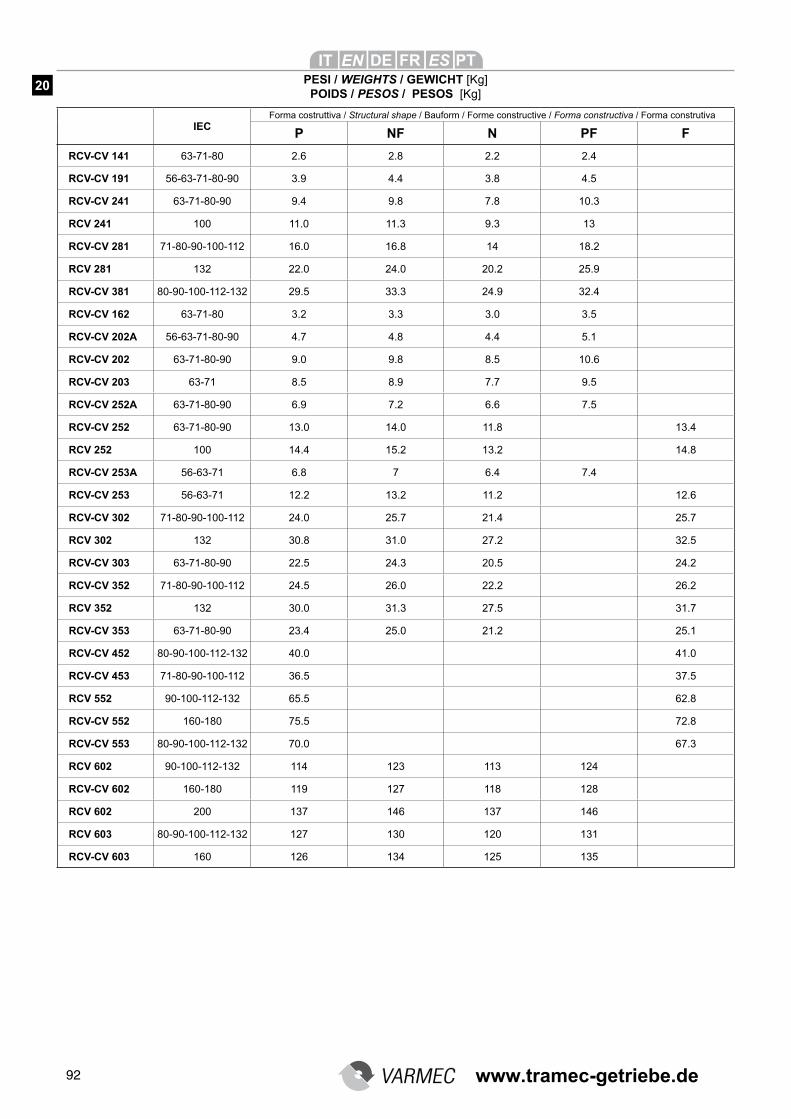
92
PESI / WEIGHTS / GEWICHT [Kg]POIDS / PESOS / PESOS [Kg]
20
IECForma costruttiva / Structural shape / Bauform / Forme constructive / Forma constructiva / Forma construtiva
P NF N PF F
RCV-CV 141 63-71-80 2.6 2.8 2.2 2.4
RCV-CV 191 56-63-71-80-90 3.9 4.4 3.8 4.5
RCV-CV 241 63-71-80-90 9.4 9.8 7.8 10.3
RCV 241 100 11.0 11.3 9.3 13
RCV-CV 281 71-80-90-100-112 16.0 16.8 14 18.2
RCV 281 132 22.0 24.0 20.2 25.9
RCV-CV 381 80-90-100-112-132 29.5 33.3 24.9 32.4
RCV-CV 162 63-71-80 3.2 3.3 3.0 3.5
RCV-CV 202A 56-63-71-80-90 4.7 4.8 4.4 5.1
RCV-CV 202 63-71-80-90 9.0 9.8 8.5 10.6
RCV-CV 203 63-71 8.5 8.9 7.7 9.5
RCV-CV 252A 63-71-80-90 6.9 7.2 6.6 7.5
RCV-CV 252 63-71-80-90 13.0 14.0 11.8 13.4
RCV 252 100 14.4 15.2 13.2 14.8
RCV-CV 253A 56-63-71 6.8 7 6.4 7.4
RCV-CV 253 56-63-71 12.2 13.2 11.2 12.6
RCV-CV 302 71-80-90-100-112 24.0 25.7 21.4 25.7
RCV 302 132 30.8 31.0 27.2 32.5
RCV-CV 303 63-71-80-90 22.5 24.3 20.5 24.2
RCV-CV 352 71-80-90-100-112 24.5 26.0 22.2 26.2
RCV 352 132 30.0 31.3 27.5 31.7
RCV-CV 353 63-71-80-90 23.4 25.0 21.2 25.1
RCV-CV 452 80-90-100-112-132 40.0 41.0
RCV-CV 453 71-80-90-100-112 36.5 37.5
RCV 552 90-100-112-132 65.5 62.8
RCV-CV 552 160-180 75.5 72.8
RCV-CV 553 80-90-100-112-132 70.0 67.3
RCV 602 90-100-112-132 114 123 113 124
RCV-CV 602 160-180 119 127 118 128
RCV 602 200 137 146 137 146
RCV 603 80-90-100-112-132 127 130 120 131
RCV-CV 603 160 126 134 125 135
www.tramec-getriebe.de
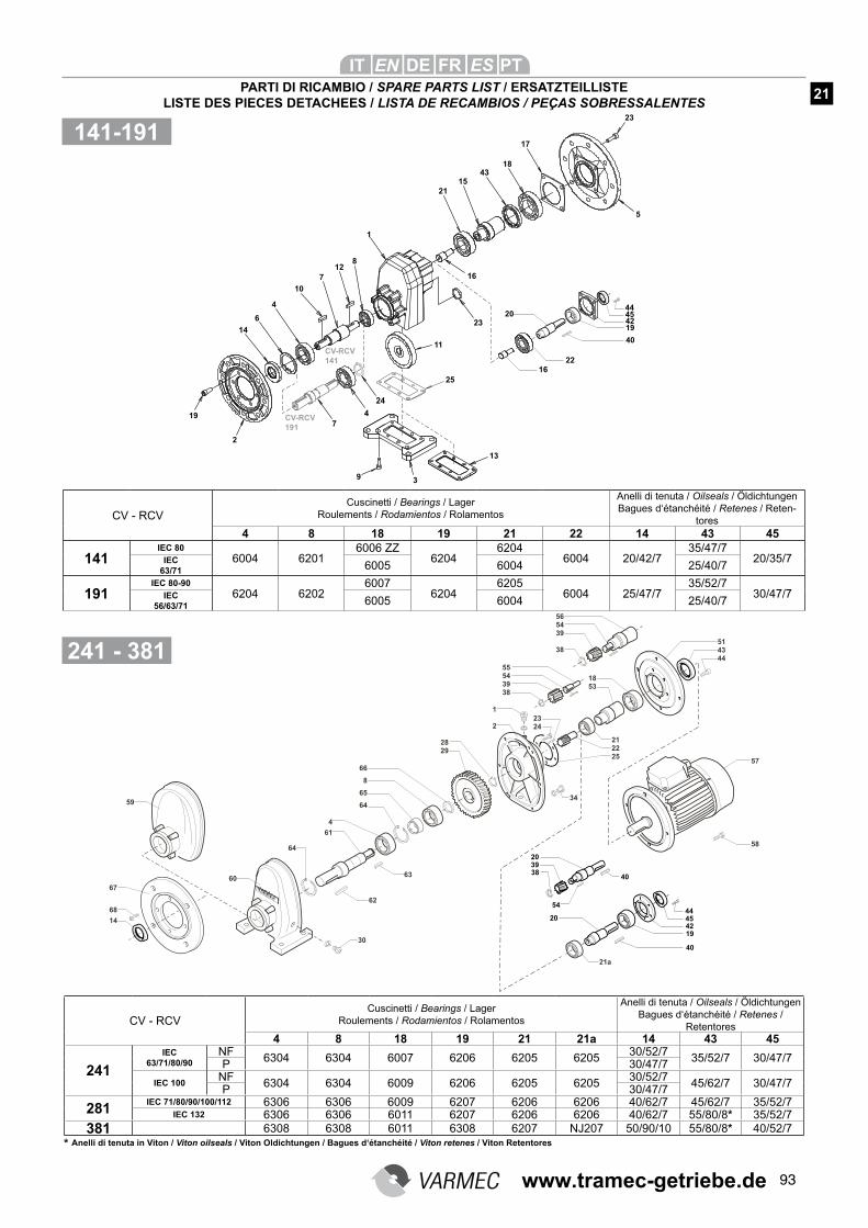
93
28
29
66
8
65
64
4
61
62
63
57
58
56
54
39
38
55
54
39
38
51
43
44
18
53
23
24
21
22
25
1
2
34
30
60
VARMEC
64
68
14
59
67
40
20
39
38
54
20
44
45
42
19
40
21a
CV - RCVCuscinetti / Bearings / Lager
Roulements / Rodamientos / Rolamentos
Anelli di tenuta / Oilseals / Öldichtungen Bagues d‘étanchéité / Retenes /
Retentores 4 8 18 19 21 21a 14 43 45
241IEC
63/71/80/90NF
6304 6304 6007 6206 6205 620530/52/7
35/52/7 30/47/7P 30/47/7
IEC 100NF
6304 6304 6009 6206 6205 620530/52/7
45/62/7 30/47/7P 30/47/7
281IEC 71/80/90/100/112 6306 6306 6009 6207 6206 6206 40/62/7 45/62/7 35/52/7
IEC 132 6306 6306 6011 6207 6206 6206 40/62/7 55/80/8* 35/52/7381 6308 6308 6011 6308 6207 NJ207 50/90/10 55/80/8* 40/52/7
15
2
1
7
14
43
236
4
18
8
21
19
12
10
16
11
2044454219
40
16
22
CV-RCV
141
CV-RCV
191
93
13
25
24
5
23
17
4
7
CV - RCVCuscinetti / Bearings / Lager
Roulements / Rodamientos / Rolamentos
Anelli di tenuta / Oilseals / Öldichtungen Bagues d‘étanchéité / Retenes / Reten-
tores4 8 18 19 21 22 14 43 45
141IEC 80
6004 62016006 ZZ
62046204
6004 20/42/735/47/7
20/35/7IEC 63/71 6005 6004 25/40/7
191IEC 80-90
6204 62026007
62046205
6004 25/47/735/52/7
30/47/7IEC 56/63/71 6005 6004 25/40/7
141-191
241 - 381
PARTI DI RICAMBIO / SPARE PARTS LIST / ERSATZTEILLISTELISTE DES PIECES DETACHEES / LISTA DE RECAMBIOS / PEÇAS SOBRESSALENTES
21
* Anelli di tenuta in Viton / Viton oilseals / Viton Oldichtungen / Bagues d‘étanchéité / Viton retenes / Viton Retentores
www.tramec-getriebe.de
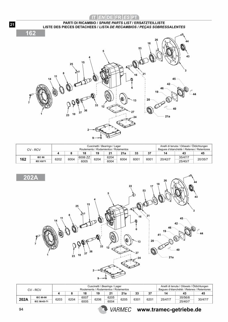
94
162
5
15
1
13
12
36
53
14
6
2310
11
37
8
18
4
22
7
25
16
33
21
17
3
43
4426
9
2
24
27
20
40
21a
19
4144
45
42
46
5
15
1
13
12
36
53
14
6
2310
11
37
8
18
4
7
25
16
33
21
3
43
4426
9
2
24
27
20
40
21a
1944
45
42
46
PARTI DI RICAMBIO / SPARE PARTS LIST / ERSATZTEILLISTELISTE DES PIECES DETACHEES / LISTA DE RECAMBIOS / PEÇAS SOBRESSALENTES
21
202A
CV - RCVCuscinetti / Bearings / Lager
Roulements / Rodamientos / RolamentosAnelli di tenuta / Oilseals / Öldichtungen
Bagues d‘étanchéité / Retenes / Retentores
4 8 18 19 21 21a 33 37 14 43 45
162IEC 80
6202 60046006 ZZ
62046204
6004 6001 6001 20/42/735/47/7
20/35/7IEC 63/71 6005 6004 25/40/7
CV - RCVCuscinetti / Bearings / Lager
Roulements / Rodamientos / RolamentosAnelli di tenuta / Oilseals / Öldichtungen
Bagues d‘étanchéité / Retenes / Retentores
4 8 18 19 21 21a 33 37 14 43 45
202AIEC 80-90
6203 62046007
62066205
6205 6301 6201 25/47/735/56/8
30/47/7IEC 56-63-71 6005 6004 25/40/7
www.tramec-getriebe.de
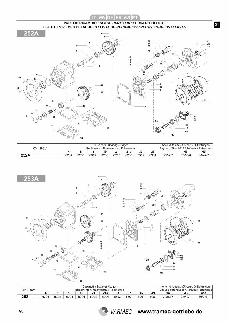
95
252A
56
54
39
38
57
58
55
54
39
38
18
53
21
22
28
29
4
8
9
10
33
35
36
37
11
32
20
444542
19
40
21a
5
6
51
43
44
26
12
13
16
25
2
3
34
31
45
46
47
48
49
23
24
60
5914
17
CV - RCVCuscinetti / Bearings / Lager
Roulements / Rodamientos / RolamentosAnelli di tenuta / Oilseals / Öldichtungen
Bagues d‘étanchéité / Retenes / Retentores 4 8 18 19 21 21a 33 37 45 49 14 43 45a
253 6204 6205 6005 6204 6004 6004 6302 6301 6001 6001 30/52/7 25/40/7 20/35/7
CV - RCVCuscinetti / Bearings / Lager
Roulements / Rodamientos / RolamentosAnelli di tenuta / Oilseals / Öldichtungen
Bagues d‘étanchéité / Retenes / Retentores 4 8 18 19 21 21a 33 37 14 43 45
252A 6204 6205 6007 6206 6205 6205 6302 6301 30/52/7 35/56/8 30/47/7
56
54
39
38
55
54
39
38
18
53
21
22
28
29
4
8
9
10
33
35
36
37
15
11
32
20
444542
19
40
21a
5
6
51
43
44
26
12
13
16
25
2
23
24
3
34
31
60
5914
17
PARTI DI RICAMBIO / SPARE PARTS LIST / ERSATZTEILLISTELISTE DES PIECES DETACHEES / LISTA DE RECAMBIOS / PEÇAS SOBRESSALENTES
253A
21
www.tramec-getriebe.de
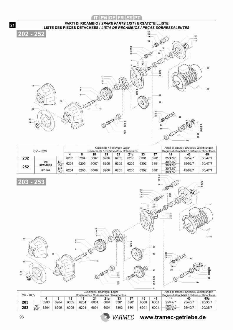
96
202 - 252
56
54
39
38
51
43
44
57
58
55
54
39
38
1
52
18
53
23
24
21
22
25
28
29
17
4
5
6
26
27
32
33
34
35
36
37
7
8
9
10
45
46
47
48
49
50
60
14
11
13
59
40
20
39
38
54
20
44
45a
42
19
40
21a
CV - RCVCuscinetti / Bearings / Lager
Roulements / Rodamientos / RolamentosAnelli di tenuta / Oilseals / Öldichtungen
Bagues d‘étanchéité / Retenes / Retentores 4 8 18 19 21 21a 33 37 45 49 14 43 45a
203 6203 6204 6005 6204 6004 6004 6301 6201 6000 6001 25/47/7 25/40/7 20/35/7
253 NF6204 6205 6005 6204 6004 6004 6302 6301 6201 6001
30/52/725/40/7 20/35/7
P-F 30/47/7
CV - RCVCuscinetti / Bearings / Lager
Roulements / Rodamientos / RolamentosAnelli di tenuta / Oilseals / Öldichtungen
Bagues d‘étanchéité / Retenes / Retentores 4 8 18 19 21 21a 33 37 14 43 45
202 6203 6204 6007 6206 6205 6205 6301 6201 25/47/7 35/52/7 30/47/7
252IEC
63/71/80/90NF
6204 6205 6007 6206 6205 6205 6302 630130/52/7
35/52/7 30/47/7P-F 30/47/7
IEC 100NF
6204 6205 6009 6206 6205 6205 6302 630130/52/7
45/62/7 30/47/7P-F 30/47/7
56
54
39
38
57
58
55
54
39
38
1
2
18
53
23
24
21
22
25
28
29
17
4
5
6
7
8
9
10
26
27
32
33
34
35
36
37
60
14
11
13
59
40
20
39
38
54
20
44
45
42
19
40
21a
51
43
44
15
16
PARTI DI RICAMBIO / SPARE PARTS LIST / ERSATZTEILLISTELISTE DES PIECES DETACHEES / LISTA DE RECAMBIOS / PEÇAS SOBRESSALENTES
21
203 - 253
www.tramec-getriebe.de
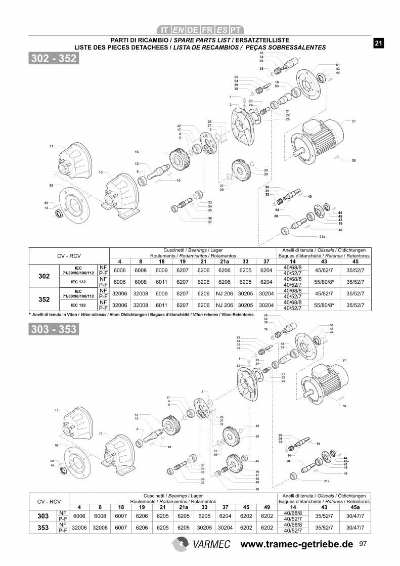
97
56
54
39
38
51
43
44
57
58
55
54
39
38
1
52
18
53
23
24
21
22
25
28
29
17
4
5
26
27
32
33
34
35
36
37
16
12
8
10
45
46
47
48
49
50
31
30
3
60
14
11
13
5940
20
39
38
54
20
44
45a
42
19
40
21a
57
58
10
33
34
35
36
37
16
12
8
32
17
4
5
26
27
3
56
54
39
38
55
54
39
38
51
43
44
18
53
23
24
21
22
25
1
2
28
29
31
30
60
14
11
13
59
40
20
39
38
54
20
44
45
42
19
40
21a
302 - 352
303 - 353
CV - RCVCuscinetti / Bearings / Lager
Roulements / Rodamientos / RolamentosAnelli di tenuta / Oilseals / Öldichtungen
Bagues d‘étanchéité / Retenes / Retentores 4 8 18 19 21 21a 33 37 45 49 14 43 45a
303 NF6006 6008 6007 6206 6205 6205 6205 6204 6202 6202
40/68/835/52/7 30/47/7
P-F 40/52/7
353 NF32006 32008 6007 6206 6205 6205 30205 30204 6202 6202
40/68/835/52/7 30/47/7
P-F 40/52/7
CV - RCVCuscinetti / Bearings / Lager
Roulements / Rodamientos / RolamentosAnelli di tenuta / Oilseals / Öldichtungen
Bagues d‘étanchéité / Retenes / Retentores 4 8 18 19 21 21a 33 37 14 43 45
302IEC
71/80/90/100/112NF
6006 6008 6009 6207 6206 6206 6205 620440/68/8
45/62/7 35/52/7P-F 40/52/7
IEC 132NF
6006 6008 6011 6207 6206 6206 6205 620440/68/8
55/80/8* 35/52/7P-F 40/52/7
352IEC
71/80/90/100/112NF
32006 32008 6009 6207 6206 NJ 206 30205 3020440/68/8
45/62/7 35/52/7P-F 40/52/7
IEC 132NF
32006 32008 6011 6207 6206 NJ 206 30205 3020440/68/8
55/80/8* 35/52/7P-F 40/52/7
PARTI DI RICAMBIO / SPARE PARTS LIST / ERSATZTEILLISTELISTE DES PIECES DETACHEES / LISTA DE RECAMBIOS / PEÇAS SOBRESSALENTES
21
* Anelli di tenuta in Viton / Viton oilseals / Viton Oldichtungen / Bagues d‘étanchéité / Viton retenes / Viton Retentores
www.tramec-getriebe.de
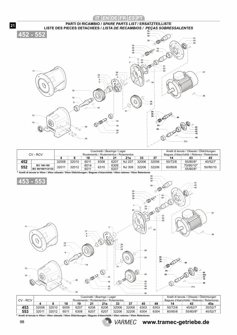
98
VARMEC
28
29
17
4
5
11
13
14
26
27
32
33
35
36
37
16
12
8
10
45
46
47
48
49
50
31
56
54
39
38
55
54
39
38
1
52
23
24
51
43
44
57
58
18
53
21
22
25
34
3
30
34
40
20
39
38
54
20
44
42
19
40
45a
21a
57
58
10
11
13
1433
35
36
37
16
12
8
32
17
4
5
26
27
3
56
54
39
38
55
54
39
38
51
43
44
18
53
23
24
21
22
25
1
2
28
29
31
34
VARMEC
30
34
40
20
39
38
54
20
44
45
42
19
40
21a
452 - 552
453 - 553
CV - RCVCuscinetti / Bearings / Lager
Roulements / Rodamientos / RolamentosAnelli di tenuta / Oilseals / Öldichtungen
Bagues d‘étanchéité / Retenes / Retentores 4 8 18 19 21 21a 33 37 14 43 45
452 32008 32010 6011 6308 6207 NJ 207 32006 32006 50/72/8 55/80/8* 40/52/7
552IEC 160-180
32011 320126014
63106309
NJ 309 32206 32206 60/85/870/90/10*
50/90/10IEC 90/100/112/132 6011 6207 55/80/8*
CV - RCVCuscinetti / Bearings / Lager
Roulements / Rodamientos / RolamentosAnelli di tenuta / Oilseals / Öldichtungen
Bagues d‘étanchéité / Retenes / Retentores 4 8 18 19 21 21a 33 37 45 49 14 43 45a
453 32008 32010 6009 6207 6206 6206 32006 32006 6303 6303 50/72/8 45/62/7 35/52/7
553 32011 32012 6011 6308 6207 6207 32206 32206 6304 6304 60/85/8 55/80/8* 40/52/7
PARTI DI RICAMBIO / SPARE PARTS LIST / ERSATZTEILLISTELISTE DES PIECES DETACHEES / LISTA DE RECAMBIOS / PEÇAS SOBRESSALENTES
21
* Anelli di tenuta in Viton / Viton oilseals / Viton Oldichtungen / Bagues d‘étanchéité / Viton retenes / Viton Retentores
* Anelli di tenuta in Viton / Viton oilseals / Viton Oldichtungen / Bagues d‘étanchéité / Viton retenes / Viton Retentores
www.tramec-getriebe.de
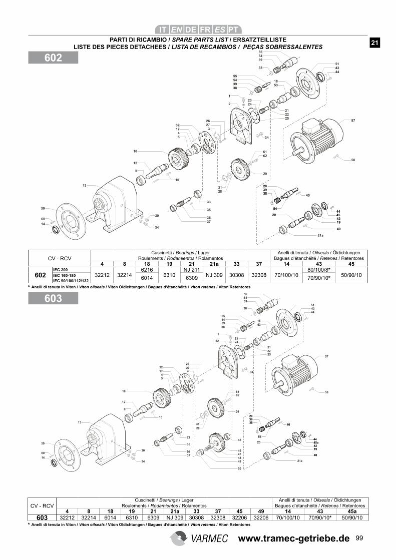
99
45
46
47
48
49
50
10
16
8
17
4
5
60
14
59
61
57
58
56
54
55
54
51
44
18
1
40
20
39
38
54
20
44
45a
42
19
40
21a
39
38
39
38
23
2452
34
21
22
25
43
53
62
29
26
27
3
32
31
28
33
35
36
37
12
30
34
13
57
58
10
13
33
35
36
37
16
12
8
32
17
4
5
26
27
3
56
54
39
38
55
54
39
38
51
43
44
18
53
23
24
21
22
25
1
2
29
31
28
34
30
34
60
14
59
61
62
20
39
3840
54
20
44
42
19
40
45
21a
602
603
CV - RCVCuscinetti / Bearings / Lager
Roulements / Rodamientos / RolamentosAnelli di tenuta / Oilseals / Öldichtungen
Bagues d‘étanchéité / Retenes / Retentores 4 8 18 19 21 21a 33 37 45 49 14 43 45a
603 32212 32214 6014 6310 6309 NJ 309 30308 32308 32206 32206 70/100/10 70/90/10* 50/90/10
CV - RCVCuscinetti / Bearings / Lager
Roulements / Rodamientos / RolamentosAnelli di tenuta / Oilseals / Öldichtungen
Bagues d‘étanchéité / Retenes / Retentores 4 8 18 19 21 21a 33 37 14 43 45
602IEC 200
32212 322146216
6310NJ 211
NJ 309 30308 32308 70/100/1080/100/8*
50/90/10IEC 160-1806014 6309 70/90/10*
IEC 90/100/112/132
PARTI DI RICAMBIO / SPARE PARTS LIST / ERSATZTEILLISTELISTE DES PIECES DETACHEES / LISTA DE RECAMBIOS / PEÇAS SOBRESSALENTES
21
* Anelli di tenuta in Viton / Viton oilseals / Viton Oldichtungen / Bagues d‘étanchéité / Viton retenes / Viton Retentores
* Anelli di tenuta in Viton / Viton oilseals / Viton Oldichtungen / Bagues d‘étanchéité / Viton retenes / Viton Retentores
www.tramec-getriebe.de
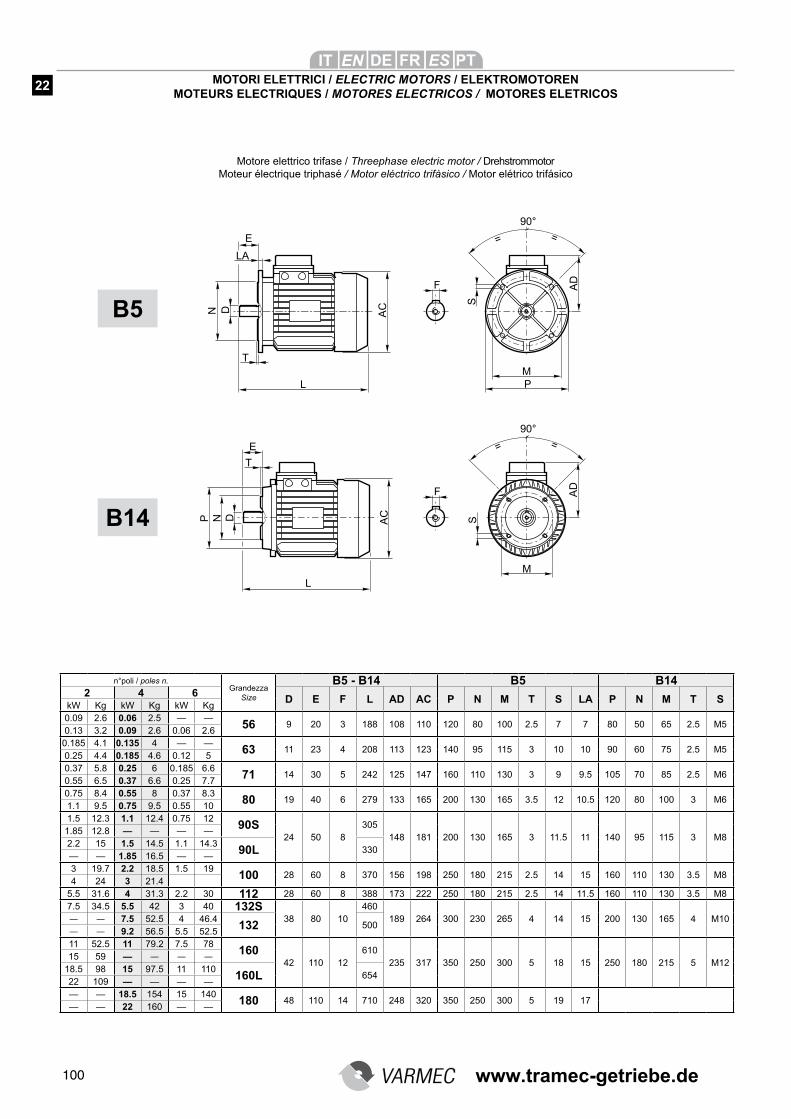
100
MOTORI ELETTRICI / ELECTRIC MOTORS / ELEKTROMOTORENMOTEURS ELECTRIQUES / MOTORES ELECTRICOS / MOTORES ELETRICOS
n°poli / poles n. Grandezza
Size
B5 - B14 B5 B142 4 6
D E F L AD AC P N M T S LA P N M T SkW Kg kW Kg kW Kg0.09 2.6 0.06 2.5 — —
56 9 20 3 188 108 110 120 80 100 2.5 7 7 80 50 65 2.5 M50.13 3.2 0.09 2.6 0.06 2.6
0.185 4.1 0.135 4 — —63 11 23 4 208 113 123 140 95 115 3 10 10 90 60 75 2.5 M5
0.25 4.4 0.185 4.6 0.12 5
0.37 5.8 0.25 6 0.185 6.671 14 30 5 242 125 147 160 110 130 3 9 9.5 105 70 85 2.5 M6
0.55 6.5 0.37 6.6 0.25 7.7
0.75 8.4 0.55 8 0.37 8.380 19 40 6 279 133 165 200 130 165 3.5 12 10.5 120 80 100 3 M6
1.1 9.5 0.75 9.5 0.55 10
1.5 12.3 1.1 12.4 0.75 1290S
24 50 8305
148 181 200 130 165 3 11.5 11 140 95 115 3 M81.85 12.8 — — — —2.2 15 1.5 14.5 1.1 14.3
90L 330— — 1.85 16.5 — —3 19.7 2.2 18.5 1.5 19
100 28 60 8 370 156 198 250 180 215 2.5 14 15 160 110 130 3.5 M84 24 3 21.4
5.5 31.6 4 31.3 2.2 30 112 28 60 8 388 173 222 250 180 215 2.5 14 11.5 160 110 130 3.5 M8
7.5 34.5 5.5 42 3 40 132S38 80 10
460
189 264 300 230 265 4 14 15 200 130 165 4 M10— — 7.5 52.5 4 46.4132 500
— — 9.2 56.5 5.5 52.5
11 52.5 11 79.2 7.5 78160
42 110 12
610
235 317 350 250 300 5 18 15 250 180 215 5 M1215 59 — — — —
18.5 98 15 97.5 11 110160L 654
22 109 — — — —— — 18.5 154 15 140
180 48 110 14 710 248 320 350 250 300 5 19 17— — 22 160 — —
B5
B14
Motore elettrico trifase / Threephase electric motor / DrehstrommotorMoteur électrique triphasé / Motor eléctrico trifàsico / Motor elétrico trifásico
22
www.tramec-getriebe.de
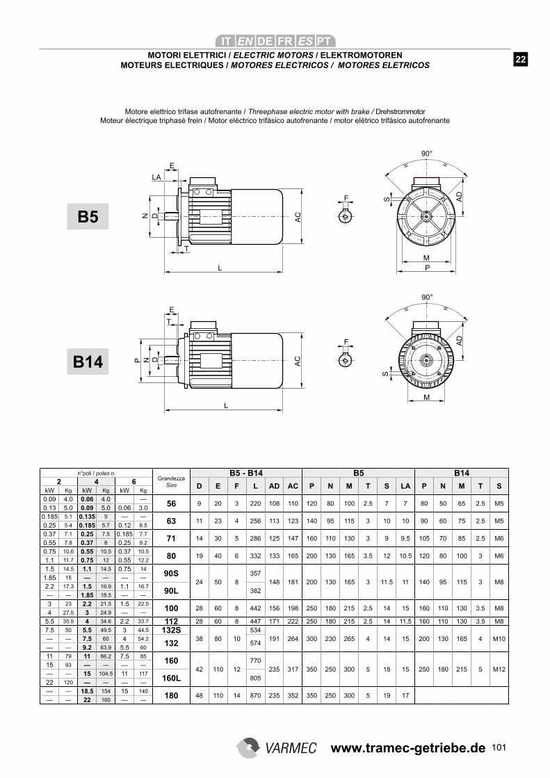
101
MOTORI ELETTRICI / ELECTRIC MOTORS / ELEKTROMOTORENMOTEURS ELECTRIQUES / MOTORES ELECTRICOS / MOTORES ELETRICOS
n°poli / poles n. Grandezza
Size
B5 - B14 B5 B142 4 6
D E F L AD AC P N M T S LA P N M T SkW Kg kW Kg kW Kg
0.09 4.0 0.06 4.0 —56 9 20 3 220 108 110 120 80 100 2.5 7 7 80 50 65 2.5 M5
0.13 5.0 0.09 5.0 0.06 3.0
0.185 5.1 0.135 5 — —63 11 23 4 256 113 123 140 95 115 3 10 10 90 60 75 2.5 M5
0.25 5.4 0.185 5.7 0.12 6.5
0.37 7.1 0.25 7.5 0.185 7.771 14 30 5 286 125 147 160 110 130 3 9 9.5 105 70 85 2.5 M6
0.55 7.8 0.37 8 0.25 9.2
0.75 10.6 0.55 10.5 0.37 10.580 19 40 6 332 133 165 200 130 165 3.5 12 10.5 120 80 100 3 M6
1.1 11.7 0.75 12 0.55 12.2
1.5 14.5 1.1 14.5 0.75 1490S
24 50 8357
148 181 200 130 165 3 11.5 11 140 95 115 3 M81.85 15 — — — —
2.2 17.3 1.5 16.9 1.1 16.790L 382
— — 1.85 18.5 — —
3 23 2.2 21.5 1.5 22.5100 28 60 8 442 156 198 250 180 215 2.5 14 15 160 110 130 3.5 M8
4 27.5 3 24.9 — —
5.5 35.5 4 34.6 2.2 33.7 112 28 60 8 447 171 222 250 180 215 2.5 14 11.5 160 110 130 3.5 M8
7.5 50 5.5 49.5 3 44.5 132S38 80 10
534
191 264 300 230 265 4 14 15 200 130 165 4 M10— — 7.5 60 4 54.2132 574
— — 9.2 63.9 5.5 60
11 79 11 86.2 7.5 85160
42 110 12
770
235 317 350 250 300 5 18 15 250 180 215 5 M1215 93 — — — —
— — 15 104.5 11 117160L 805
22 120 — — — —
— — 18.5 154 15 140180 48 110 14 870 235 352 350 250 300 5 19 17
— — 22 160 — —
B5
B14
Motore elettrico trifase autofrenante / Threephase electric motor with brake / DrehstrommotorMoteur électrique triphasé frein / Motor eléctrico trifàsico autofrenante / motor elétrico trifásico autofrenante
22
www.tramec-getriebe.de
102
Conditions générales de Garantie
La garantie concernant les défauts de construction dure un an à partir de la date de facturation de la marchandise. Varmec s’engage à subtituer ou à réparer les parties déféctueuses mais ne répondra pas des dom-mages direct ou indirects de n’importe quelle nature. VARMEC ne répondra non plus des réparations ou modifications apportées sans permission écrite de sa part.La marchandise de retour ne sera accep-tée par Varmec qu’en case d’expédition port franc.
Condiciones generales de garantía
La garantía relativa a defectos de construc-
ción tiene una duración de un año de la fecha
de facturación de la mercadería. Tal garantía
comporta para VARMEC la obligación de su-
stituir o reparar la parte defectuosa pero no
admite otros cargos por eventuales daños
directos o indirectos de cualquier naturaleza.
Queda fuera de toda garantía en el momento
que no se hayan cumplido todas las instrucci-
ones del manual de uso y mantenimiento o se
haya hecho alguna reparación o modificación
sin nuestro consentimiento escrito.
La mercadería que se ha devuelta solo se
aceptara enviada puerto franco.
Condições gerais de garantia
A garantia que cobre os defeitos de fabrica-ção tem a validade de um ano a partir da data de faturamento da mercadoria. Esta garantia comporta para a VARMEC o ônus da substi-tuição ou reparo das peças defeituosas, mas não inclui outras coberturas para eventuais danos diretos ou indiretos de qualquer natu-reza.A garantia perde a sua validade se não forem respeitadas as disposições indicadas no ma-nual de uso e manutenção e/ou se forem fei-tos reparos ou realizadas modificações sem a nossa autorização por escrito.A mercadoria devolvida só será aceita por nós se os custos de expedição forem pagos pelo remetente.
Condizioni generali di garanzia
La garanzia relativa a difetti di costruzione ha la durata di un anno dalla data di fatturazio-ne delle merce. Tale garanzia comporta per la VARMEC l’onere della sostituzione o ripa-razione delle parti difettose ma non ammette ulteriore addebiti per eventuali danni diretti o indiretti di qualsiasi natura. La garanzia deca-de nel caso in cui non siano state osservate le disposizioni riportate nel manuale di uso e ma-nutenzione e/o siano state eseguite riparazioni o apportate modifiche senza nostro consenso scritto.La merce di ritorno sarà da noi accetta-ta solo se spedita franco di ogni spesa.
General coditional of warranty
Warranty for manufacturing defects will
expire one-year the invoicing date. VARMEC
will replace or repair defective parts but will
not accept any further charges for direct or
indirect damages of any kind. The warranty
will become null and void if the instructions
given in the use and maintenance manual
are not complied with or if repairs or changes
are carried out without our prior written
authorization.
Returned goods will be accepted only if deli-
vered free of any charge.
Allgemeine garantiebedingungen
Die Garantie auf Herstellungsfehler dauert ein Jahr ab Rechnungsdatum der Ware. Aufgrund Garantie unterliegt der VARMEC die Pflicht der Ersetzung oder Reparatur der defekten Teile, jedoch nicht die Übernahme weiterer Belastungen für direkte oder indirekte Schä-den egal welcher Natur. Die Garantie verfällt bei Nichtbeachtung der in der betreffenden “Betriebs- und Instandhaltungsanleitung” an-geführten Anweisungen und/oder falls ohne unsere vorausgehende schriftliche Genehm- igung Reparaturen oder Änderungen vorge-nommen wurden. Die an uns zurückgesendete Ware akzeptie-ren wir nur wenn gebuehrenfrei geliefert.
CT-CV IT/EN/DE/FR/ES/PT P02W00 05/11
Cette catalogue annule et remplace toutes les autres editions au revisions.Tous les détails énumerés sont indicatifs et ils ne comportent aucune obligation de notre part.On se réserve le droit d’y apporter des modifi-cations sans préavis.
Este catálogo anula y sustituye las ediciones
o revisiones anteriores.
Todos los datos son indicativos y sin ningún
compromiso de nuestra parte.
Nos reservamos el derecho de realizar modifi-
caciones sin previo aviso.
Este catálogo anula e substitui qualquer outra edição ou revisão anterior.Todos os dados fornecidos são indicativos e não constituem nenhum compromisso da nos-sa parte. Reservamo-nos o direito de efetuar alterações sem aviso prévio.
Questo catalogo annulla e sostituisce ogni precedente edizione o revisione.Tutti i dati elencati sono indicativi e s’intendono senza impegno alcuno da parte nostra.Ci riserviamo il diritto di apportare modifiche senza preavviso.
This catalogue cancels and replaces any pre-
vious edition and revision.
All listed data are approximate and it’s under-
stood that this entails no obbligation on our
part.
We reserve the right to implement modificati-
ons without notice.
Mit der Ausgabe dieses Katalogs annullieren sich gleichzeitig alle bisherigen Katalogen. Sämtliche Daten sind Berechnete Werte die für den Verkäufer unverbindlich sind.Der Verkäufer behält sich das Recht vor, Än-der- ungen, ohne eine vorhergehende Advi-sierung durchzuführen.
www.tramec-getriebe.de