
Schmiersystem Lubrication system - atlantagmbh.de · 1/2019 Maße / Dimensions in mm ZE – 3...
10
Maße / Dimensions in mm ZE – 1 1/2013 Schmiersystem Lubrication system Seite Page Schmierbüchsen Typ 125 Lubricator Type 125 ZE-2 Schmierbüchsen Typ 475 Lubricator Type 475 ZE-3 Auswahl der Schmierung für Zahnstangentriebe Selection of the lubrication for rack drives ZE-4 Schmiereinheit Lubrication system ZE-5 – 6 Filzzahnrad Felt gear ZE-7 – 8 Schmiermittel-Zubehör Lubrication equipment, accessories ZE – 9 Schmiersysteme und Zubehör Lubricating systems and accessories ZE – 10
Transcript of Schmiersystem Lubrication system - atlantagmbh.de · 1/2019 Maße / Dimensions in mm ZE – 3...
Maße / Dimensions in mm ZE – 11/2013
SchmiersystemLubrication system
Seite Page
Schmierbüchsen Typ 125 Lubricator Type 125 ZE-2
Schmierbüchsen Typ 475 Lubricator Type 475 ZE-3
Auswahl der Schmierung für Zahnstangentriebe Selection of the lubrication for rack drives ZE-4
Schmiereinheit Lubrication system ZE-5 – 6
Filzzahnrad Felt gear ZE-7 – 8
Schmiermittel-Zubehör Lubrication equipment, accessories ZE – 9
Schmiersysteme und Zubehör Lubricating systems and accessories ZE – 10
Maße / Dimensions in mmZE – 2 1/2019
Schmiersysteme und ZubehörLubricating systems and accessories
Bestell-Nr. BildOrder code Fig.
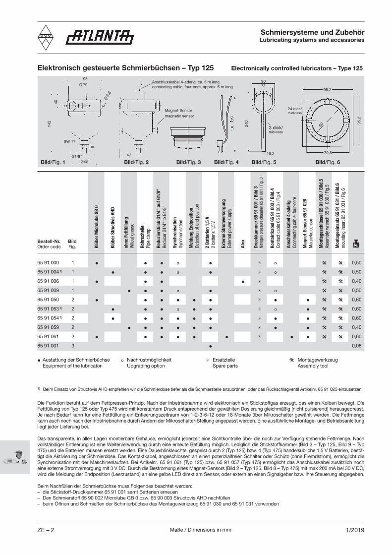
Elektronisch gesteuerte Schmierbüchsen – Typ 125 Electronically controlled lubricators – Type 125
Bild/Fig. 3Bild/Fig. 2
40
95
Ø6,
6
SW 17
Ø68
47
142
Ø 79
Bild/Fig. 1
95,2
24 dick/thickness
79,5
95,2
Bild/Fig. 4
240
3 dick/thickness
15,2
7290
60
Bild/Fig. 5
Die Funktion beruht auf dem Fettpressen-Prinzip. Nach der Inbetriebnahme wird elektronisch ein Stickstoffgas erzeugt, das einen Kolben bewegt. Die Fettfüllung von Typ 125 oder Typ 475 wird mit konstantem Druck entsprechend der gewählten Dosierung gleichmäßig (nicht pulsierend) herausgepresst. Je nach Bedarf kann für eine Fettfüllung ein Entleerungszeitraum von 1-2-3-6-12 oder 18 Monate über Mikroschalter gewählt werden. Die Fettmenge kann auch noch nach der Inbetriebnahme durch Ändern der Mikroschalter-Stellung angepasst werden. Eine ausführliche Montage- und Betriebsanleitung liegt jeder Lieferung bei.
Das transparente, in allen Lagen montierbare Gehäuse, ermöglicht jederzeit eine Sichtkontrolle über die noch zur Verfügung stehende Fettmenge. Nach vollständiger Entleerung ist eine Weiterverwendung durch eine erneute Befüllung möglich. Lediglich die Stickstoffkammer (Bild 3 – Typ 125, Bild 9 – Typ 475) und die Batterien müssen ersetzt werden. Eine Dauerblink leuchte, gespeist durch 2 (Typ 125) bzw. 4 (Typ 475) handelsübliche 1,5 V Batterien, bestä-tigt die Aktivierung der Schmierdose. Das Kontaktkabel, angeschlossen an einen potenzialfreien Schalter oder Schütz (ohne Fremdstrom), er möglicht die Synchronisation mit der Maschinenlaufzeit. Bei Artikelnr. 65 91 061 (Typ 125) bzw. 65 91 057 (Typ 475) ermöglicht das Anschlusskabel zusätzlich noch eine externe Stromversorgung mit 3 V DC. Durch die Bestromung eines Magnet-Sensors (Bild 2 – Typ 125, Bild 8 – Typ 475) mit max 200 mA bei 30 V DC, wird die Meldung der Endposition (Leerzustand) an eine gelbe LED direkt am Sensor, oder extern an einen Signalgeber bzw. Ihre Steuerung abgegeben.
Beim Nachfüllen der Schmierbüchse muss Folgendes beachtet werden:– die Stickstoff-Druckkammer 65 91 001 samt Batterien erneuen– Den Schmierstoff 65 90 002 Microlube GB 0 bzw. 65 90 003 Structovis AHD nachfüllen– beim Öffnen und Schmießen der Schmierbüchse das Montagewerkzeug 65 91 030 und 65 91 031 verwenden
1) Beim Einsatz von Structovis AHD empfehlen wir die Schmierdose tiefer als die Schmierstelle anzuordnen, oder das Rückschlagventil Artikelnr. 65 91 025 einzusetzen.
6
Bild/Fig. 6G1/8"
Anschlusskabel 4-aderig, ca. 5 m langconnecting cable, four-core, approx. 5 m long
Magnet-Sensormagnetic sensor
65 91 000 1 • • • º • 8 º @ @ 0,50
65 91 004 1) 1 • • • º • 8 º @ @ 0,50
65 91 006 1 • • • • 8 @ @ 0,40
65 91 009 1 • • • º • 8 º @ @ 0,50
65 91 050 2 • • • • • • 8 • • @ @ 0,60
65 91 053 1) 2 • • • º • • 8 º • @ @ 0,60
65 91 054 1) 2 • • • • • • 8 • • @ @ 0,60
65 91 059 2 • • • • • • 8 • • @ @ 0,40
65 91 061 2 • • • • • • 8 • • @ @ 0,60
65 91 001 3 • 0,08
• Austattung der Schmierbüchse º Nachrüstmöglichkeit 8Ersatzteile @Montagewerkzeug Equipment of the lubricator Upgrading option Spare parts Assembly tool
Klüb
er M
icro
lube
GB
0
Klüb
er S
truc
tivis
AHD
ohne
Fet
tfüllu
ngW
itout
gre
ase
Rohr
sche
llePi
pe c
lam
p
Redu
zier
stüc
k G1
/4"
auf G
1/8"
Redu
cer G
1/4"
to G
1/8"
Sync
hron
isat
ion
Sync
hron
isat
ion
Mel
dung
End
posi
tion
Dete
ctio
n of
end
pos
ition
2 Ba
tterie
n 1,
5 V
2 ba
tteris
1,5
V
Exte
rne
Stro
mve
rsor
gung
Exte
rnal
pow
er s
uppl
y
Atex
Druc
kkam
mer
65
91 0
01 /
Bild
3Ni
troge
n pr
essu
re c
ham
ber 6
5 91
001
/ Fi
g. 3
Mon
tage
schl
üsse
l 65
91 0
30 /
Bild
.5As
sem
bly
wre
nch
65 9
1 03
0 / F
ig.5
Kont
aktk
abel
65
91 0
03 /
Bild
.4Co
ntac
t cab
le 6
5 91
003
/ Fi
g.4
Ansc
hlus
skab
el 4
-ade
rigCc
onne
ctin
g ca
ble,
four
-cor
e
Mag
net-
Sens
or 6
5 91
026
Mag
netic
sen
sor
Mon
tage
eins
atz
65 9
1 03
1 / B
ild.6
mou
ntin
g in
sert
65 9
1 03
1 / F
ig.6

Maße / Dimensions in mm ZE – 31/2019
Schmiersysteme und ZubehörLubricating systems and accessories
Elektronisch gesteuerte Schmierbüchsen – Typ 475 Electronically controlled lubricators – Type 475
Bild/Fig. 8
60
Ø 120
Ø 8,5
Ø104
180
105
Bild/Fig. 7
135
Bild/Fig. 9
20
Bild/Fig. 10 Bild/Fig. 11G1/4"
143
Ø120 Ø90
135
30 dick/thickness
Ø130Ø105
280
3 dick/thickness
67
The function is based upon the grease gun principle. After starting the operation, a nitrogen gas is generated electronically which by means of a highly func-tional construction moves a piston causing the grease filling of Type 125 resp. Type 475 to emerge uni-formly (not pulsatingly) at a constant pressure set to the desired dosage. Depending on the individual requirements, an emptying time of 1-2-3-6-12 or 18 months can be set by means of a micro-switch. It is possible to adjust the grease quantity even after starting the operation by changing the micro-switch position accordingly. Detailed mounting and operating instructions come with every shipment.
The transparent housing, which can be mounted in any position, permits the visual inspection of the available grease filling at any time. When completely empty, it can be refilled and used again. Only the nitrogen chamber (Fig. 3 – Type 125, Fig. 9 – Type 475) and the batteries need to be replaced. A permanent signal lamp powered by 2 (Type 125) resp. 4 (Type 475) standard 1.5 V batteries confirms the activation of the lubricator. The contact cable - connected to a potential-free limit switch or contactor (no external power supply required) - permits synchronization with the machine operating time. When using the lubricator 65 91 061 (Type 125) resp. 65 91 057 (Type 475) , the connecting cable additionally permits external power supply with 3 V DC. By powering a magnetic sensor (Fig. 2 – Type 125, Fig. 8 – Type 475) with max. 200 mA at 30 V DC the end position (empty condition) indication is transmitted to a yellow LED directly at the sensor or externally to a signal indicator or to your control unit.
When replenishing the lubricator, consider the following:– replace the nitrogen chamber 65 91 001 together with the batteries– fill up with lubricant 65 90 002 Microlube GB 0 or 65 90 003 Structovis AHD– for closing and opening the lubricator, use the assembly tools 65 91 030 and 65 91 031.
1) When using Structovis AHD, we recommend to position the lubricator lower than the lubrication point or to use the check valve 65 91 025.
SW27
8
Bestell-Nr. BildOrder code Fig.
65 91 007 7 • • • • 8 @ @ 0,9
65 91 014 1) 7 • • • • 8 @ @ 0,9
65 91 069 7 • • • • 8 @ @ 0,5
65 91 067 8 • • • • • 8 • @ @ 1,0
65 91 056 8 • • • • • • 8 • • @ @ 1,1
65 91 057 8 • • • • • • 8 • • @ @ 1,1
65 91 068 8 • • • • • • 8 • • @ @ 0,6
65 91 058 8 • • • • • • 8 • • @ @ 1,1
• Austattung der Schmierbüchse º Nachrüstmöglichkeit 8Ersatzteile @Montagewerkzeug Equipment of the lubricator Upgrading option Spare parts Assembly tool
Klüb
er M
icro
lube
GB
0
Klüb
er S
truc
tivis
AHD
ohne
Fet
tfüllu
ngW
itout
gre
ase
Rohr
sche
llePi
pe c
lam
p
Redu
zier
stüc
k G1
/2"
auf G
1/4"
Redu
cer G
1/2"
to G
1/4"
Sync
hron
isat
ion
Sync
hron
isat
ion
Mel
dung
End
posi
tion
Dete
ctio
n of
end
pos
ition
4 Ba
tterie
n 1,
5 V
4 ba
tteris
1,5
V
Exte
rne
Stro
mve
rsor
gung
Exte
rnal
pow
er s
uppl
y
Atex
Druc
kkam
mer
65
91 0
17 /
Bild
9Ni
troge
n pr
essu
re c
ham
ber /
fig.
9
Mon
tage
schl
üsse
l 65
91 0
32 /
Bild
10
Asse
mbl
y w
renc
h 65
91
032
/ Fig
. 10
Ansc
hlus
skab
el 4
-ade
rigCc
onne
ctin
g ca
ble,
four
-cor
e
Mag
net-
Sens
or 6
5 91
026
Mag
netic
sen
sor
Mon
tage
eins
atz
65 9
1 03
3 / B
ild 1
1m
ount
ing
inse
rt 65
91
033
/ Fig
. 11

Maße / Dimensions in mmZE – 4 1/2013
Schmierung von ZahnstangentriebenBei Schmierung von Zahnstangentrieben über Filzrad und elek-tronisch gesteuerte Schmierbüchse kann der untenstehenden Tabelle die optimale Fettdosierung entnommen werden.
Lubrication of rack and pinion drivesWhen lubricating rack and pinion drives by means of a felt gearwheel and electronically controlled lubricator the optimal grease supply can be seen from the diagram below.
Zahnstangentriebe – Schmiermittel, ZubehörRack and pinion drives – Lubricating equipment, Accessories
Bei Schmierung über Gleitpinsel sollte die nächst größere Schalterstellung genommen werden. Zum Beispiel bei Mikro-schalter 4 für Filzradschmierung sollte für Gleitpinselschmierung bei gleicher Geschwindigkeit und gleichem Modul, 3 gewählt werden.
DruckaufbauAlle Mikroschalter auf „on“ stellen. Druckaufbauzeit 6 – 8 Stun-den . Danach gewünschte Laufzeit einstellen. Der Mikroschalter 7 muss dabei immer eingeschaltet sein. Vor der Inbetriebnahme der Schmierbüchse sollte der Verbindungsschlauch zwischen Filzrad und Schmierbüchse gefüllt- und das Filzrad mit Fett getränkt werden.
BatteriewechselDie Garantie der Batterielaufzeit beträgt 1 Jahr. Danach sollte ein Batteriewechsel vorgenommen werden. Auch wenn das Kontroll-Licht noch blinkt kann es sein dass die Batterieka-pazität schon nachgelassen hat. Die Schmierbüchse kann über ein Zwischenrelais auch durch externe Stromversorgung betrieben werden.
For lubrication with sliding brush use the next higher switch position. If, for example, micro-switch position 4 is chosen for felt-gearwheel lubrication, choose 3 for sliding-brush lubrication at the same speed and with the same module.
Pressure build-upSet all micro-switches to „ON“. Pressure build-up time 6 – 8 hours. Then set the desired time. The micro-switch 7 must be always on. Before starting up the lubricator the connecting hose between felt wheel and lubricator should be filled and the felt wheel soaked with grease.
Battery exchangeThe guaranteed service life of the battery is 1 year. Then the battery should be replaced. Although the control lamp may still flash it is possible that the battery capacity has already decreased. The lubricator can also be operated by means of external power supply via an intermediate relay.
Empfohlene Schmierstoffe für Zahnstangentriebe:
Filzzahnradschmierung: Klüber Microlube GB 0 Bestell-Nr. 65 90 002 (1 kg) Klüber Structovis AHD Bestell-Nr. 65 90 003 (1 kg)
Pinselschmierung: Klüber Microlube GB 0 Bestell-Nr. 65 90 002 (1 kg)
Weiterhin wurden folgende Schmierstoffe mit gutem Er-gebnis getestet: Oest Langzeitfett LT 200 BP Energrease LS EP 00 DEA Glissando 6833 EP 00 Fuchs Lubritech Gearmaster ZSA Molykote G-Rapid plus 3694
Recommended lubricants for rack drives:
Felt-gear lubrication: Klüber Microlube GB 0 Order code 65 90 002 (1 kg) Klüber Structovis AHD Order code 65 90 003 (1 kg)
Sliding brush lubrication: Klüber Microlube GB 0 Order code 65 90 002 (1 kg)
Furthermore the following lubricants have been tested with good results. Oest Langzeitfett LT 200 BP Energrease LS EP 00 DEA Glissando 6833 EP 00 Fuchs Lubritech Gearmaster ZSA Molykote G-Rapid plus 3694
Fettdosierung bei Filzradschmierung / Grease supply for felt-gearwheel lubrication

Maße / Dimensions in mm ZE – 51/2014
Zahnstangentriebe – Schmiermittel, ZubehörRack and pinion drives - Lubricating equipment, Accessories
Schmiereinheit für HT-Servo-Antriebssysteme mit KlemmverbindungLubrication unit for HT-Servo Drive System with output shaft for clamp connection
Montagemöglichkeiten / Units mounting possibilities
Bestellbeispiel: a = 80; m = 4 schrägverzahnt; nach Bild LO ⇒ 65 85 184 (Filzzahnrad montiert nach Maß „h2 = 85“ von Auflagefläche-Schmiereinheit).
Ordering example: a = 80; m = 4 helical tooth system, Fig. LO ⇒ 65 85 184 (Felt gear assembled according to the dimension „h2 = 85” of the mounting surface).
Bestell-Nr. | - gerade / straight für Bild 2, Schmierbüchse von ZE-2 und Filzzahnrad von ZE-7Order code ⁄ - schräg / helical for fig.2, lubricator of ZE-2 and felt gear of ZE-7Bild 1 Bild 2Fig. 1 Fig. 2 m z h h1 h2 h3 h4 b1 b2 s b H B L
ao = 50 95 96 49 33 17 3 30 113 140 10465 83 192 65 93 012 | 2 32 LU;RU RO;LO;RS;LS 25 37 1,4065 83 182 65 93 012 ⁄ 2 30 LU;RU RO;LO;RS;LS 25 37 1,4065 83 193 65 93 013 | 3 21 RS LU;RU RO;LO;LS 30 36 1,4465 83 183 65 93 013 ⁄ 3 20 RS LU;RU RO;LO;LS 30 36 1,4465 83 194 65 93 014 | 4 17 LU;RU RS RO;LO;LS 40 32 1,5465 83 184 65 93 014 ⁄ 4 15 LU;RU RS RO;LO;LS 40 32 1,54
ao = 63 115 80 64 48 29 3 41 133 162 13465 84 192 65 94 012 | 2 32 LU;RU RO;LO;RS;LS 25 37 2,0065 84 182 65 94 012 ⁄ 2 30 LU;RU RO;LO;RS;LS 25 37 2,0065 84 193 65 94 013 | 3 21 LU;RU RO;LO;RS LS 30 36 1,9065 84 183 65 94 013 ⁄ 3 20 LU;RU RO;LO;RS LS 30 36 1,9065 84 194 65 94 014 | 4 17 LU;RU;RS RO;LO;LS 40 32 2,0065 84 184 65 94 014 ⁄ 4 15 LU;RU;RS RO;LO;LS 40 32 2,00
ao = 80 130 103 85 57 36 3 51 148 198 15965 85 194 65 95 014 | 4 17;30* LU;RU LU*;RU* RO;LO;RS;LS RO*;LO*;RS*;LS* 40 32 2,5065 85 184 65 95 014 ⁄ 4 15;30* LU;RU LU*;RU* RO;LO;RS;LS RO*;LO*;RS*;LS* 40 32 2,5065 85 185 65 95 015 | 5 13 LU;RU RO;LO;RS;LS 50 35 2,7065 85 175 65 95 015 ⁄ 5 12 LU;RU RO;LO;RS;LS 50 35 2,7065 85 186 65 95 016 | 6 – 60 37 2,8065 85 176 65 95 016 ⁄ 6 13 LU;RU RO;LO;RS;LS 60 37 2,80
ao = 100 140 102 84 52 32 4 54 169 230 18265 86 185 65 96 015 1) | 5 15 LU;RU RO;LO;RS;LS 50 35 3,3065 86 175 65 96 015 1) ⁄ 5 15 LU;RU RO;LO;RS;LS 50 35 3,3065 86 186 65 96 016 1) | 6 13 LU;RU RO;LO;RS;LS 60 37 3,5065 86 176 65 96 016 1) ⁄ 6 13;15* LU;RU;LU*;RU* RO;LO;RS;LS;RO*;LO*;RS*;LS* 60 37 3,5065 86 188 65 96 018 1) | 8 – 80 38 4,3065 86 178 65 96 018 1) ⁄ 8 12 LU;RU RS RO;LO;LS 80 38 4,30
1) auch Schmierbüchse 475 cm3 von ZE-3 verwendbar / also lubricator 475 cm3 of ZE-3 usable
Verz
ahnu
ngTo
oth
syst
em
Bild/Fig. 1
Bild/Fig. 2
Maße / Dimensions in mmZE – 6 1/2014
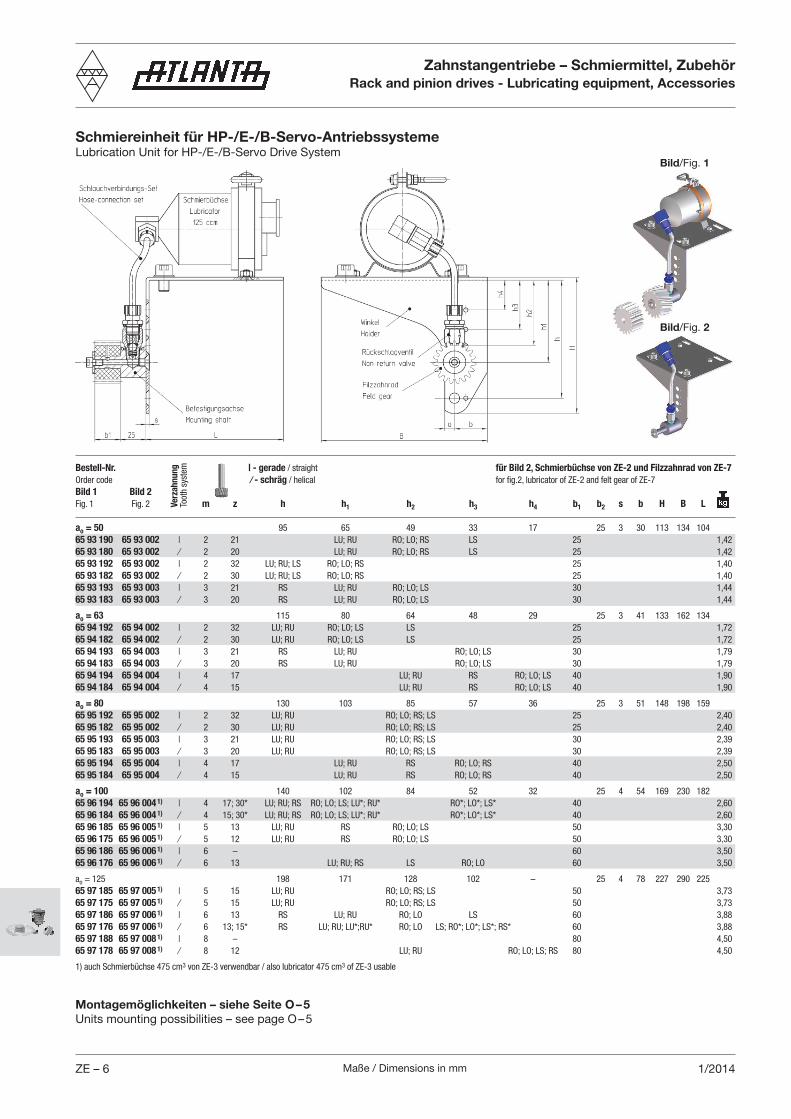
Schmiereinheit für HP-/E-/B-Servo-AntriebssystemeLubrication Unit for HP-/E-/B-Servo Drive System
Zahnstangentriebe – Schmiermittel, ZubehörRack and pinion drives - Lubricating equipment, Accessories
Montagemöglichkeiten – siehe Seite O – 5Units mounting possibilities – see page O – 5
Bestell-Nr. | - gerade / straight für Bild 2, Schmierbüchse von ZE-2 und Filzzahnrad von ZE-7Order code ⁄ - schräg / helical for fig.2, lubricator of ZE-2 and felt gear of ZE-7Bild 1 Bild 2Fig. 1 Fig. 2 m z h h1 h2 h3 h4 b1 b2 s b H B L
ao = 50 95 65 49 33 17 25 3 30 113 134 10465 93 190 65 93 002 | 2 21 LU; RU RO; LO; RS LS 25 1,4265 93 180 65 93 002 ⁄ 2 20 LU; RU RO; LO; RS LS 25 1,4265 93 192 65 93 002 | 2 32 LU; RU; LS RO; LO; RS 25 1,4065 93 182 65 93 002 ⁄ 2 30 LU; RU; LS RO; LO; RS 25 1,4065 93 193 65 93 003 | 3 21 RS LU; RU RO; LO; LS 30 1,4465 93 183 65 93 003 ⁄ 3 20 RS LU; RU RO; LO; LS 30 1,44
ao = 63 115 80 64 48 29 25 3 41 133 162 13465 94 192 65 94 002 | 2 32 LU; RU RO; LO; LS LS 25 1,7265 94 182 65 94 002 ⁄ 2 30 LU; RU RO; LO; LS LS 25 1,7265 94 193 65 94 003 | 3 21 RS LU; RU RO; LO; LS 30 1,7965 94 183 65 94 003 ⁄ 3 20 RS LU; RU RO; LO; LS 30 1,7965 94 194 65 94 004 | 4 17 LU; RU RS RO; LO; LS 40 1,9065 94 184 65 94 004 ⁄ 4 15 LU; RU RS RO; LO; LS 40 1,90
ao = 80 130 103 85 57 36 25 3 51 148 198 15965 95 192 65 95 002 | 2 32 LU; RU RO; LO; RS; LS 25 2,4065 95 182 65 95 002 ⁄ 2 30 LU; RU RO; LO; RS; LS 25 2,4065 95 193 65 95 003 | 3 21 LU; RU RO; LO; RS; LS 30 2,3965 95 183 65 95 003 ⁄ 3 20 LU; RU RO; LO; RS; LS 30 2,3965 95 194 65 95 004 | 4 17 LU; RU RS RO; LO; RS 40 2,5065 95 184 65 95 004 ⁄ 4 15 LU; RU RS RO; LO; RS 40 2,50
ao = 100 140 102 84 52 32 25 4 54 169 230 18265 96 194 65 96 004 1) | 4 17; 30* LU; RU; RS RO; LO; LS; LU*; RU* RO*; LO*; LS* 40 2,6065 96 184 65 96 004 1) ⁄ 4 15; 30* LU; RU; RS RO; LO; LS; LU*; RU* RO*; LO*; LS* 40 2,6065 96 185 65 96 005 1) | 5 13 LU; RU RS RO; LO; LS 50 3,3065 96 175 65 96 005 1) ⁄ 5 12 LU; RU RS RO; LO; LS 50 3,3065 96 186 65 96 006 1) | 6 – 60 3,5065 96 176 65 96 006 1) ⁄ 6 13 LU; RU; RS LS RO; LO 60 3,50
ao = 125 198 171 128 102 – 25 4 78 227 290 22565 97 185 65 97 005 1) | 5 15 LU; RU RO; LO; RS; LS 50 3,7365 97 175 65 97 005 1) ⁄ 5 15 LU; RU RO; LO; RS; LS 50 3,7365 97 186 65 97 006 1) | 6 13 RS LU; RU RO; LO LS 60 3,8865 97 176 65 97 006 1) ⁄ 6 13; 15* RS LU; RU; LU*;RU* RO; LO LS; RO*; LO*; LS*; RS* 60 3,8865 97 188 65 97 008 1) | 8 – 80 4,5065 97 178 65 97 008 1) ⁄ 8 12 LU; RU RO; LO; LS; RS 80 4,50
1) auch Schmierbüchse 475 cm3 von ZE-3 verwendbar / also lubricator 475 cm3 of ZE-3 usable
Verz
ahnu
ngTo
oth
syst
em
Bild/Fig. 1
Bild/Fig. 2
Maße / Dimensions in mm ZE – 71/2014
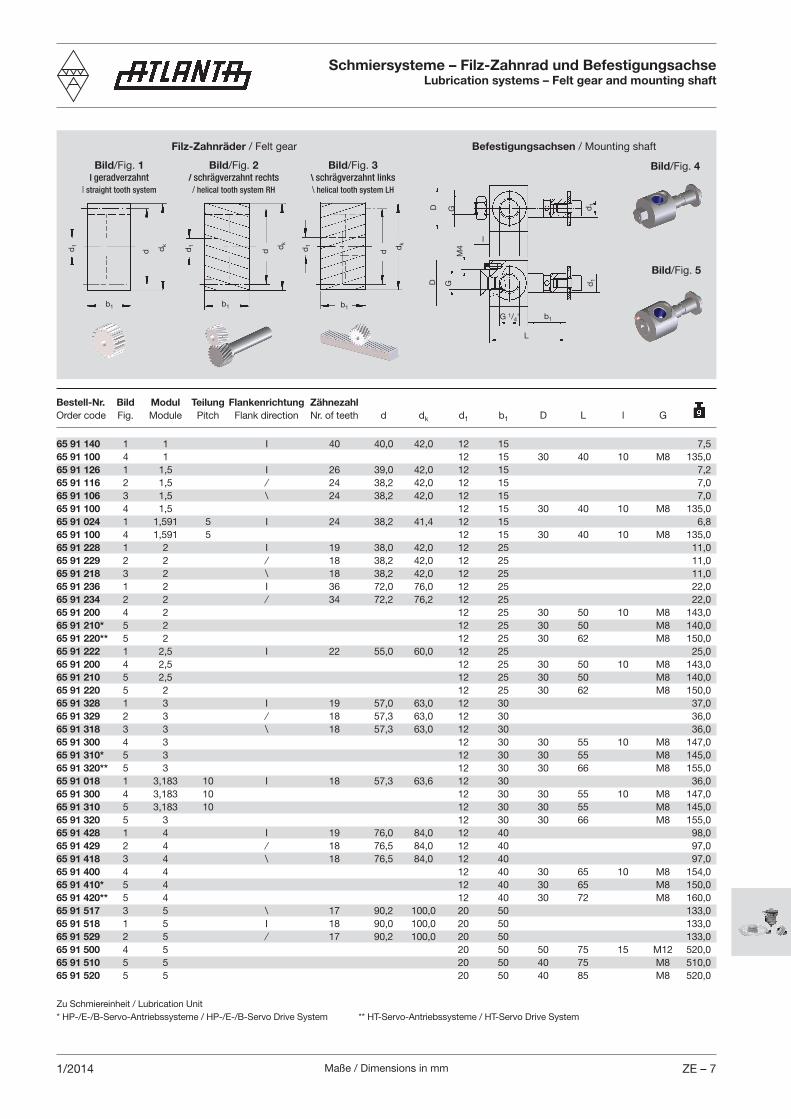
Schmiersysteme – Filz-Zahnrad und BefestigungsachseLubrication systems – Felt gear and mounting shaft
Bild/Fig. 1| geradverzahnt
| straight tooth system
Bild/Fig. 2/ schrägverzahnt rechts/ helical tooth system RH
b1
d1 dk
d
b1
dk
dd1
Bild/Fig. 3\ schrägverzahnt links\ helical tooth system LH
b1d
1 dk
d
L
d1
b1G 1/4"
GD
l
D G d1
M4
Filz-Zahnräder / Felt gear Befestigungsachsen / Mounting shaft
Zu Schmiereinheit / Lubrication Unit* HP-/E-/B-Servo-Antriebssysteme / HP-/E-/B-Servo Drive System ** HT-Servo-Antriebssysteme / HT-Servo Drive System
Bild/Fig. 4
Bild/Fig. 5
65 91 140 1 1 I 40 40,0 42,0 12 15 7,565 91 100 4 1 12 15 30 40 10 M8 135,065 91 126 1 1,5 I 26 39,0 42,0 12 15 7,265 91 116 2 1,5 ⁄ 24 38,2 42,0 12 15 7,065 91 106 3 1,5 \ 24 38,2 42,0 12 15 7,065 91 100 4 1,5 12 15 30 40 10 M8 135,065 91 024 1 1,591 5 I 24 38,2 41,4 12 15 6,865 91 100 4 1,591 5 12 15 30 40 10 M8 135,065 91 228 1 2 I 19 38,0 42,0 12 25 11,065 91 229 2 2 ⁄ 18 38,2 42,0 12 25 11,065 91 218 3 2 \ 18 38,2 42,0 12 25 11,065 91 236 1 2 I 36 72,0 76,0 12 25 22,065 91 234 2 2 ⁄ 34 72,2 76,2 12 25 22,065 91 200 4 2 12 25 30 50 10 M8 143,065 91 210* 5 2 12 25 30 50 M8 140,065 91 220** 5 2 12 25 30 62 M8 150,065 91 222 1 2,5 I 22 55,0 60,0 12 25 25,065 91 200 4 2,5 12 25 30 50 10 M8 143,065 91 210 5 2,5 12 25 30 50 M8 140,065 91 220 5 2 12 25 30 62 M8 150,065 91 328 1 3 I 19 57,0 63,0 12 30 37,065 91 329 2 3 ⁄ 18 57,3 63,0 12 30 36,065 91 318 3 3 \ 18 57,3 63,0 12 30 36,065 91 300 4 3 12 30 30 55 10 M8 147,065 91 310* 5 3 12 30 30 55 M8 145,065 91 320** 5 3 12 30 30 66 M8 155,065 91 018 1 3,183 10 I 18 57,3 63,6 12 30 36,065 91 300 4 3,183 10 12 30 30 55 10 M8 147,065 91 310 5 3,183 10 12 30 30 55 M8 145,065 91 320 5 3 12 30 30 66 M8 155,065 91 428 1 4 I 19 76,0 84,0 12 40 98,065 91 429 2 4 ⁄ 18 76,5 84,0 12 40 97,065 91 418 3 4 \ 18 76,5 84,0 12 40 97,065 91 400 4 4 12 40 30 65 10 M8 154,065 91 410* 5 4 12 40 30 65 M8 150,065 91 420** 5 4 12 40 30 72 M8 160,065 91 517 3 5 \ 17 90,2 100,0 20 50 133,065 91 518 1 5 I 18 90,0 100,0 20 50 133,065 91 529 2 5 ⁄ 17 90,2 100,0 20 50 133,065 91 500 4 5 20 50 50 75 15 M12 520,065 91 510 5 5 20 50 40 75 M8 510,065 91 520 5 5 20 50 40 85 M8 520,0
Bestell-Nr. Bild Modul Teilung Flankenrichtung ZähnezahlOrder code Fig. Module Pitch Flank direction Nr. of teeth d dk d1 b1 D L l G

Maße / Dimensions in mmZE – 8 1/2014
Schmiersysteme – Filz-Zahnrad und BefestigungsachseLubrication systems – Felt gear and mounting shaft
Bild/Fig. 1| geradverzahnt
| straight tooth system
Bild/Fig. 2/ schrägverzahnt rechts/ helical tooth system RH
b1
d1 dk
d
b1
dk
dd1
Bild/Fig. 3\ schrägverzahnt links\ helical tooth system LH
b1
d1 dk
d
L
d1
b1G 1/4"
GD
l
D G d1
M4
Filz-Zahnräder / Felt gear Befestigungsachsen / Mounting shaft
Zu Schmiereinheit / Lubrication Unit* HP-/E-/B-Servo-Antriebssysteme / HP-/E-/B-Servo Drive System ** HT-Servo-Antriebssysteme / HT-Servo Drive System
Bild/Fig. 4
Bild/Fig. 5
65 91 617 3 6 \ 17 108,2 120,0 20 60 234,065 91 618 1 6 I 18 108,0 120,0 20 60 234,065 91 629 2 6 ⁄ 17 108,2 120,0 20 60 234,065 91 600 4 6 20 60 50 85 15 M12 545,065 91 610* 5 6 20 60 40 85 M8 535,065 91 620** 5 6 20 60 40 97 M8 550,065 91 817 3 8 \ 17 144,3 160,0 20 80 562,065 91 818 1 8 I 18 144,0 160,0 20 80 562,065 91 829 2 8 ⁄ 17 144,3 160,0 20 80 562,065 91 800 4 8 20 80 50 105 15 M12 595,065 91 810* 5 8 20 80 50 105 M8 280,065 91 820** 5 8 20 80 50 118 M8 600,065 91 117 3 10 \ 17 180,4 200,0 25 100 750,065 91 118 1 10 I 18 180,0 200,0 25 100 750,065 91 129 2 10 ⁄ 17 180,4 200,0 25 100 750,065 91 101 4 10 25 100 50 125 15 M12 650,065 91 111 5 10 25 100 50 125 M8 645,065 91 114 3 12 \ 14 178,3 202,0 25 100 800,065 91 115 1 12 I 15 180,0 204,0 25 100 800,065 91 124 2 12 ⁄ 14 178,3 202,0 25 100 800,065 91 102 4 12 25 100 50 145 15 M12 830,065 91 112 5 12 25 100 50 145 M8 810,0
Bestell-Nr. Bild Modul Teilung Flankenrichtung ZähnezahlOrder code Fig. Module Pitch Flank direction Nr. of teeth d dk d1 b1 D L l G

Maße / Dimensions in mm ZE – 91/2013
Schmiersysteme und ZubehörLubricating systems and accessories
Bild/Fig. 1
Bestell-Nr. Bild Bezeichnung für ModulOrder code Fig. Description for module
65 91 010 1 Gleit-Schmierpinsel rund mit Innengewinde Sliding -type lubricating brush, round, with internal thread 1; 1,5; 2; 3; 4 1765 91 011 2 Gleit-Schmierpinsel flach mit Innengewinde Sliding -type lubricating brush, flat, with internal thread 5; 6; 8 2065 91 012 3 Gleit-Schmierpinsel flach mit Innengewinde Sliding -type lubricating brush, flat, with internal thread 10; 12 409 08 05 003 4 Reduzierstück G1/4" auf G1/8" Reducer 8
In Verbindung mit unseren Schmierbüchsen kann der Gleitpinsel (aus MS mit widerstandsfähigen Nylonborsten) für die Schmie-rung der Zahnstange oder des Ritzels verwendet werden. Bei der Montage des Gleitpinsels auf die Schmierbüchse mit 125 cm³ oder das Schlauchverbindungs-Set, muss das an der Schmier-büchse vorhandene Reduzierstück (Bild 4) verwendet werden. Bei der Schmierbüchse mit 475 cm³ Füllung muss das an der Schmierbüchse vorhanden kombiniert mit dem Reduzierstück aus Bild 4 verwendet werden.
Gleitpinsel-SchmierungSliding brush lubrication
The sliding brush (of MS with sturdy Nylon bristles) can be used in combination with our lubricators for lubricating either the rack or the pinion. During the assembly of the sliding brush onto the lubricator with 125 cm³ or the house-connection set, the existing lubricator reducer (Fig. 4) must be used. Using the lubricator with 475 cm³ the existing lubricator reducer must be used in combi-nation with the reducer out of Fig. 4.
SW17
G ¼”
27
25
G ¼”
SW17
6
Bild/Fig. 5
Bestell-Nr. Bild BezeichnungOrder code Fig. Description
65 91 020 5 Schlauchverbindungs-Set bestehend aus: Hose-connection set comprising: 25 2 m Kunststoff-Schlauch, 2 m plastic hose Alu-Verschraubung mit Innengewinde, Alumin. hose coupling with inside thread Alu-Verschraubung mit Außengewinde Alumin. hose coupling with outside thread65 91 021 5 Schlauchverbindungs-Set bestehend aus: Hose-connection set comprising: 25 2 m Kunststoff-Schlauch befüllt mit GB0, 2 m plastic hose filled with GB0 Alu-Verschraubung mit Innengewinde, Alumin. hose coupling with inside thread Alu-Verschraubung mit Außengewinde Alumin. hose coupling with outside thread65 91 025 6 Rückschlagventil 0,2 bar Non-return valve 0.2 bar
Hinweis:Vor Inbetriebnahme Schlauchverbindungs-Set mit Fett befüllen.Fette siehe Seite ZE-4.
Schlauchverbindungs-SetHose-connection set
Bild/Fig. 3
ReduzierstückReducer
RückschlagventilNon-return valve
Remark:Before starting the hose-connection set must be filled up with lubricant. Lubrication see on page ZE-4.
Bild/Fig. 2 Bild/Fig. 4
Bild/Fig. 6
Maße / Dimensions in mmZE – 10 1/2013
Schmiersysteme und ZubehörLubricating systems and accessories
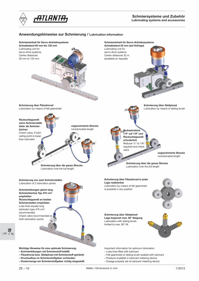
Anwendungshinweise zur Schmierung / Lubrication information
Schmiereinheit für Servo-AntriebssystemeAchsabstand 50 mm bis 125 mmLubricating unit for servo-drive systemsCenter distances 50 mm to 125 mm
Schmiereinheit für Servo-AntriebssystemeAchsabstand 32 mm (auf Anfrage)Lubricating unit for servo-drive systems Center distances 32 m (available on request)
Schmierung über FilzzahnradLubrication by means of felt gearwheel
Rückschlagventil wenn Schmierstelle tiefer als Schmier-büchseCheck-valve, if lubri-cating point is lower than lubricator
ungeschmierte Streckenonlubricated length
Schmierung über die ganze StreckeLubrication over the full length
Schmierung von zwei Schmierstellen Lubrication of 2 lubrication points
Schmierleitungen gleich langSchmierbüchse Typ 475 cm3 empfohlenRückschlagventil an beiden Schmierstellen empfohlenLube lines equally longlubricator type 475 cm3 recommendedCheck-valve recommended at both lubrication points
Wichtige Hinweise für eine optimale Schmierung:– Schmierleitungen mit Schmierstoff befüllt– Filzzahnrad bzw. Gleitpinsel mit Schmierstoff getränkt– Druckaufbau im Schmierstoffgeber vorhanden– Dosiermenge am Schmierstoffgeber richtig eingestellt
Schmierung über GleitpinselLubrication by means of sliding brush
Reduzierstück 1/4" auf 1/8" und Rückschlagventil erforderlichReducer ¼“ to 1/8“ required and check valve
Schmierung über die ganze StreckeLubrication over the full length
ungeschmierte Streckenonlubricated length
Schmierung über Filzzahnrad in jeder Lage realisierbarLubrication by means of felt gearwheel is possible in any position
Schmierung über Gleitpinsel Lage begrenzt max. 60° NeigungLubrication with sliding brush limited to max. 60° tilt
Important information for optimum lubrication:– Lube lines filled with lubricant– Felt gearwheel or sliding brush soaked with lubricant – Pressure available in lubricant metering device– Dosage properly set at lubricant metering device