SENSORIC - fischertechnik-museum.ch · 39574 KW 05/97• Printed in Germany • Technische...
36
SENSORIC SENSORIC PROFI PROFI
Transcript of SENSORIC - fischertechnik-museum.ch · 39574 KW 05/97• Printed in Germany • Technische...
fischerwerke Artur Fischer GmbH & Co. KGD-72178 WaldachtalTelefon 0 74 43/12-4 369
S E N S O R I CS E N S O R I CP RO F IP R O F I3
95
74
KW
05
/97
• P
rin
ted
in
Ge
rma
ny
• T
ec
hn
isc
he
Än
de
run
ge
n v
orb
eh
alt
en
• S
ub
jec
t to
te
ch
nic
al
mo
dif
ica
tio
ns
PROFI SENSORICPROFI SENSORIC
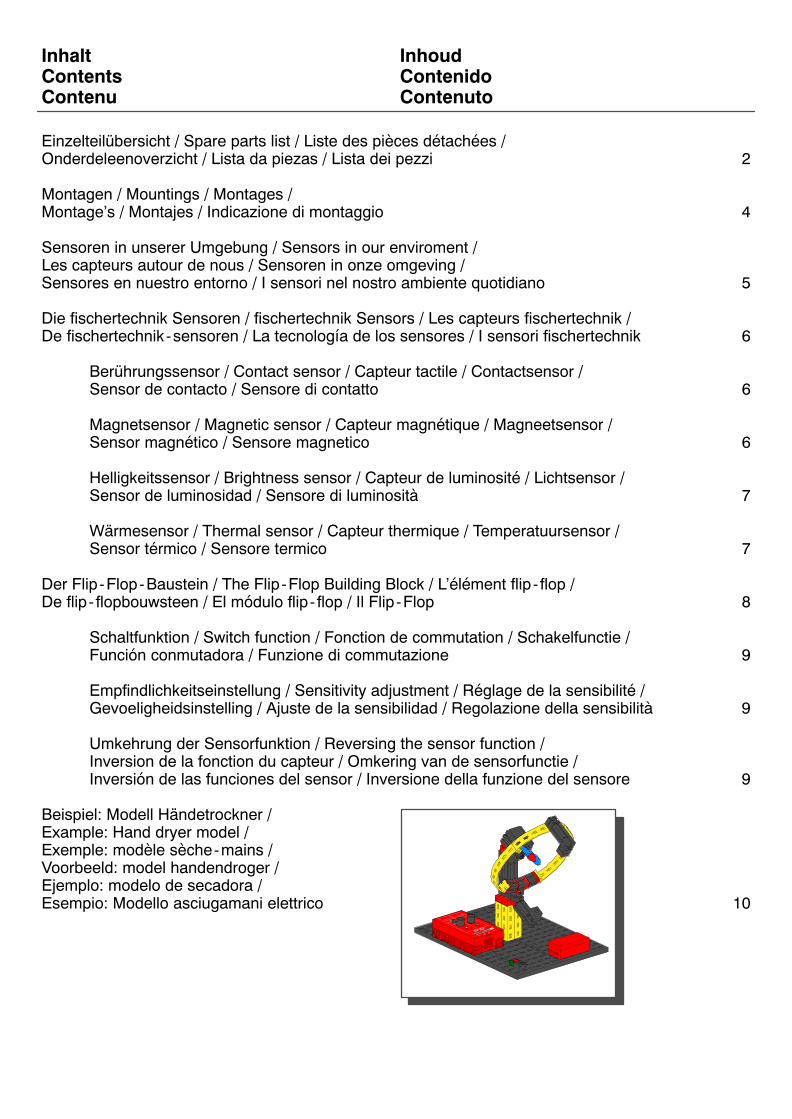
Inhalt InhoudContents ContenidoContenu Contenuto
Einzelteilübersicht / Spare parts list / Liste des pièces détachées /Onderdeleenoverzicht / Lista da piezas / Lista dei pezzi 2
Montagen / Mountings / Montages / Montage’s / Montajes / Indicazione di montaggio 4
Sensoren in unserer Umgebung / Sensors in our enviroment / Les capteurs autour de nous / Sensoren in onze omgeving / Sensores en nuestro entorno / I sensori nel nostro ambiente quotidiano 5
Die fischertechnik Sensoren / fischertechnik Sensors / Les capteurs fischertechnik / De fischertechnik-sensoren / La tecnología de los sensores / I sensori fischertechnik 6
Berührungssensor / Contact sensor / Capteur tactile / Contactsensor / Sensor de contacto / Sensore di contatto 6
Magnetsensor / Magnetic sensor / Capteur magnétique / Magneetsensor / Sensor magnético / Sensore magnetico 6
Helligkeitssensor / Brightness sensor / Capteur de luminosité / Lichtsensor / Sensor de luminosidad / Sensore di luminosità 7
Wärmesensor / Thermal sensor / Capteur thermique / Temperatuursensor / Sensor térmico / Sensore termico 7
Der Flip-Flop-Baustein / The Flip-Flop Building Block / L’élément flip- flop / De flip- flopbouwsteen / El módulo flip- flop / Il Flip-Flop 8
Schaltfunktion / Switch function / Fonction de commutation / Schakelfunctie / Función conmutadora / Funzione di commutazione 9
Empfindlichkeitseinstellung / Sensitivity adjustment / Réglage de la sensibilité / Gevoeligheidsinstelling / Ajuste de la sensibilidad / Regolazione della sensibilità 9
Umkehrung der Sensorfunktion / Reversing the sensor function / Inversion de la fonction du capteur / Omkering van de sensorfunctie / Inversión de las funciones del sensor / Inversione della funzione del sensore 9
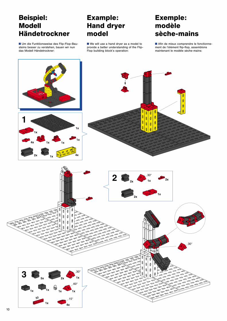
Beispiel: Modell Händetrockner / Example: Hand dryer model / Exemple: modèle sèche-mains / Voorbeeld: model handendroger / Ejemplo: modelo de secadora / Esempio: Modello asciugamani elettrico 10
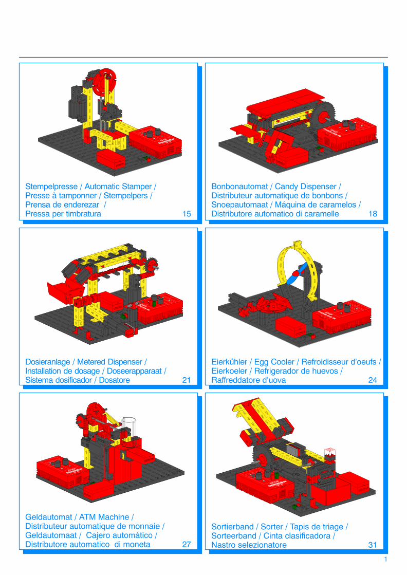
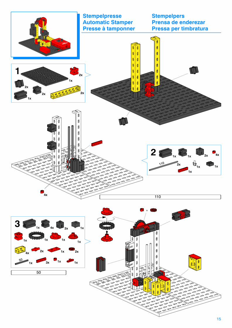
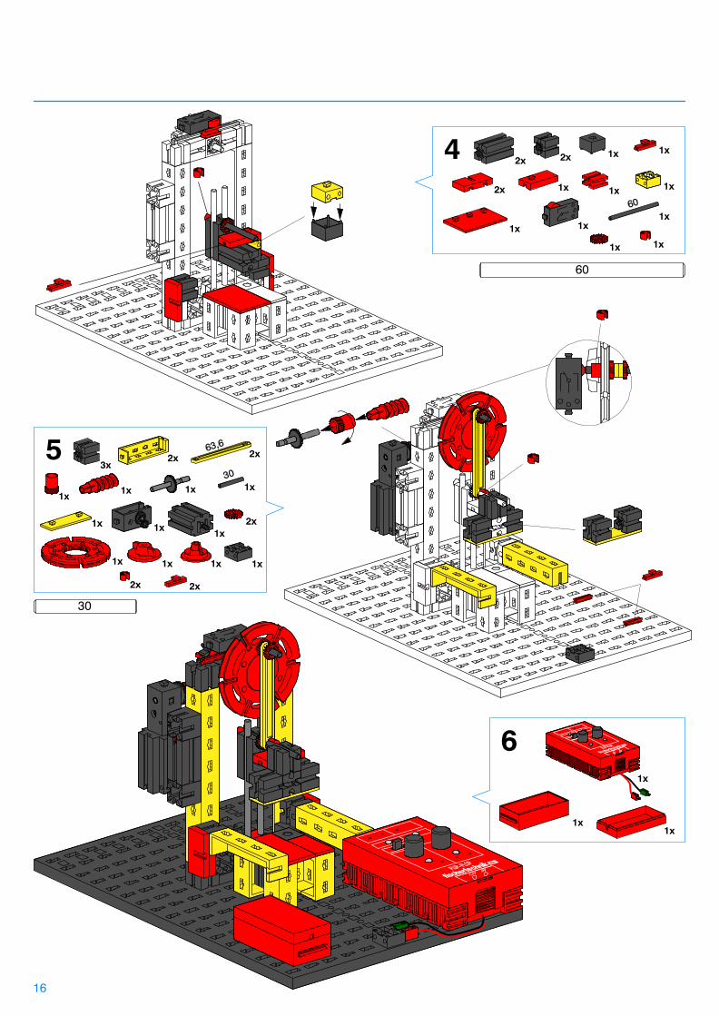
Stempelpresse / Automatic Stamper / Presse à tamponner / Stempelpers / Prensa de enderezar / Pressa per timbratura 15
1
Bonbonautomat / Candy Dispenser / Distributeur automatique de bonbons / Snoepautomaat / Máquina de caramelos / Distributore automatico di caramelle 18
Eierkühler / Egg Cooler / Refroidisseur d’oeufs /Eierkoeler / Refrigerador de huevos / Raffreddatore d’uova 24
Dosieranlage / Metered Dispenser / Installation de dosage / Doseerapparaat / Sistema dosificador / Dosatore 21
Geldautomat / ATM Machine / Distributeur automatique de monnaie / Geldautomaat / Cajero automático / Distributore automatico di moneta 27
Sortierband / Sorter / Tapis de triage / Sorteerband / Cinta clasificadora /Nastro selezionatore 31
2
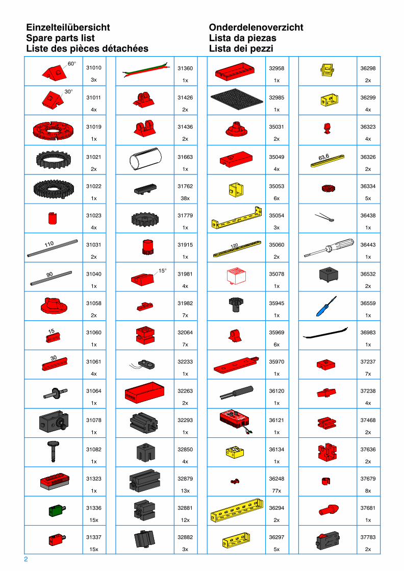
Einzelteilübersicht OnderdelenoverzichtSpare parts list Lista da piezasListe des pièces détachées Lista dei pezzi
60°31010
3x
31360
1x
32958
1x
36298
2x
30°31011
4x
31426
2x
32985
1x
36299
4x
31019
1x
31436
2x
35031
2x
36323
4x
31021
2x
31663
1x
35049
4x
36326
2x
31022
1x
31762
38x
35053
6x
36334
5x
31023
4x
31779
1x
35054
3x
36438
1x
31031
2x
31915
1x
35060
2x
36443
1x
31040
1x
15°31981
4x
35078
1x
36532
2x
31058
2x
31982
7x
35945
1x
36559
1x
31060
1x
32064
7x
35969
6x
36983
1x
31061
4x
32233
1x
35970
1x
37237
7x
31064
1x
32263
2x
36120
1x
37238
4x
31078
1x
32293
1x
36121
1x
37468
2x
31082
1x
32850
4x
36134
1x
37636
2x
31323
1x
32879
13x
36248
77x
37679
8x
31336
15x
32881
12x
36294
2x
37681
1x
31337
15x
32882
3x
36297
5x
37783
2x
3
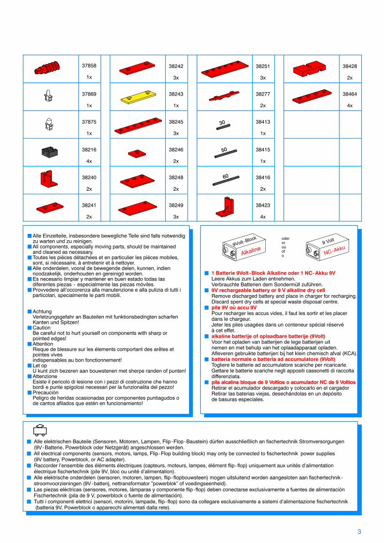
� 1 Batterie 9Volt-Block Alkaline oder 1 NC-Akku 9VLeere Akkus zum Laden entnehmen.Verbrauchte Batterien dem Sondermüll zuführen.
� 9V rechargeable battery or 9 V alkaline dry cellRemove discharged battery and place in charger for recharging.Discard spent dry cells at special waste disposal centre.
� pile 9V où accu 9VPour recharger les accus vides, il faut les sortir et les placerdans le chargeur.Jeter les piles usagées dans un conteneur spécial réservéà cet effet.
� alkaline batterije of oplaadbare batterije (9Volt) Voor het opladen van batterijen de lege batterijen uitnemen en met behulp van het oplaadapparaat opladen.Afleveren gebruikte batterijen bij het klein chemisch afval (KCA).
� batteria normale o batteria ad accumulatore (9Volt)Togliere le batterie ad accumulatore scariche per ricaricarle.Gettare le batterie scariche negli appositi cassonetti di raccoltadifferenziata.
� pila alcalina bloque de 9 Voltios o acumulador NC de 9 VoltiosRetirar el acumulador descargado y colocarlo en el cargadorRetirar las baterias viejas, desechándolas en un depósitode basuras especiales.
oderoroùofo
�Alle Einzelteile, insbesondere bewegliche Teile sind falls notwendig zu warten und zu reinigen.
�All components, especially moving parts, should be maintained and cleaned as necessary.
�Toutes les pièces détachées et en particulier les pièces mobiles, sont, si nécessaire, à entretenir et à nettoyer.
�Alle onderdelen, vooral de bewegende delen, kunnen, indien noodzakelijk, onderhouden en gereinigd worden.
�Es necesario limpiar y mantener en buen estado todas las diferentes piezas - especialmente las piezas móviles.
�Provvedere all’occorenza alla manutenzione e alla pulizia di tutti iparticolari, specialmente le parti mobili.
�AchtungVerletzungsgefahr an Bauteilen mit funktionsbedingten scharfenKanten und Spitzen!
�CautionBe careful not to hurt yourself on components with sharp or pointed edges!
�AttentionRisque de blessure sur les élements comportant des arêtes et pointes vivesindispensables au bon fonctionnement!
�Let opU kunt zich bezeren aan bouwstenen met sherpe randen of punten!
�AttenzioneEsiste il pericolo di lesione con i pezzi di costruzione che hanno bordi e punte spigolosi necessari per la funzionalita del pezzo!
�PrecauciónPeligro de heridas ocasionadas por componentes puntiagudos o de cantos afilados que estén en funcionamiento!
� Alle elektrischen Bauteile (Sensoren, Motoren, Lampen, Flip-Flop-Baustein) dürfen ausschließlich an fischertechnik Stromversorgungen(9V-Batterie, Powerblock oder Netzgerät) angeschlossen werden.
� All electrical components (sensors, motors, lamps, Flip-Flop building block) may only be connected to fischertechnik power supplies (9V battery, Powerblock, or AC adapter).
� Raccorder l’ensemble des éléments électriques (capteurs, moteurs, lampes, élément flip- flop) uniquement aux unités d’alimentation électrique fischertechnik (pile 9V, bloc ou unité d’alimentation).
� Alle elektrische onderdelen (sensoren, motoren, lampen, flip- flopbouwsteen) mogen uitsluitend worden aangesloten aan fischertechnik-stroomvoorzieningen (9V-batterij, nettransformator ”powerblok” of voedingseenheid).
� Las piezas eléctricas (sensores, motores, lámparas y componente flip- flop) deben conectarse exclusivamente a fuentes de alimentación Fischertechnik (pila de 9 V, powerblock o fuente de alimentación).
� Tutti i componenti elettrici (sensori, motorini, lampade, flip- flop) sono da collegare esclusivamente a sistemi d’alimentazione fischertechnik (batteria 9V, Powerblock o apparecchi alimentati dalla rete).
37858
1x
38242
3x
38251
3x
38428
2x
37869
1x
38243
1x
38277
2x
38464
4x
37875
1x
38245
3x
38413
1x
38216
4x
38246
2x
38415
1x
38240
2x
38248
2x
38416
2x
38241
2x
38249
3x
38423
4x

Montagen Montage’sMountings MontajesMontages Indicazione di montaggio
4
Batterie ist nicht Inhalt der PackungBattery not includedBatterie non compriseDe batterij wordt niet meegeleverdLa batteria non è compresaLa bateria no está incluida en el suministro
60
30
15
�
5 cm
010
cm
15 c
m20
cm
25 c
m
a
b
c
4mm
3cm 3cm
3cm0
1 x 40 cm
4 x 30 cm
LinsenlampeLens tip lampAmpoule lentilleLenslampjeBombilla lenticularLampada lenticolare
KugellampeBulb lampLampe sphériqueBolle lampBombilla globularLampada sferica
4 x 30 cm1 x 40 cm
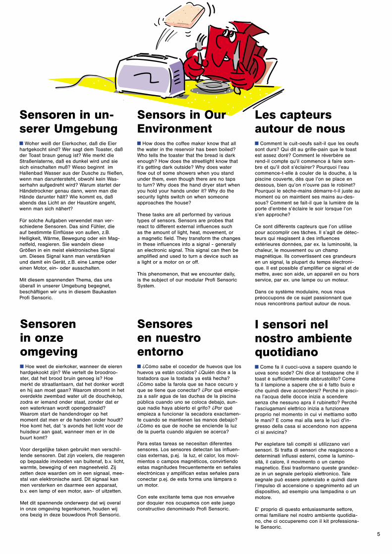
Sensoren in un-serer Umgebungy Woher weiß der Eierkocher, daß die Eierhartgekocht sind? Wer sagt dem Toaster, daßder Toast braun genug ist? Wie merkt dieStraßenlaterne, daß es dunkel wird und siesich einschalten muß? Wieso beginnt imHallenbad Wasser aus der Dusche zu fließen,wenn man daruntersteht, obwohl kein Was-serhahn aufgedreht wird? Warum startet derHändetrockner genau dann, wenn man dieHände darunter hält? Wie kommt es, daßabends das Licht an der Haustüre angeht,wenn man sich nähert?
Für solche Aufgaben verwendet man ver-schiedene Sensoren. Das sind Fühler, die auf bestimmte Einflüsse von außen, z.B.Helligkeit, Wärme, Bewegung oder ein Mag-netfeld, reagieren. Sie wandeln diese Größen in ein meist elektronisches Signal um. Dieses Signal kann man verstärken und damit ein Gerät, z.B. eine Lampe odereinen Motor, ein- oder ausschalten.
Mit diesem spannenden Thema, das uns überall in unserer Umgebung begegnet,beschäftigen wir uns in diesem BaukastenProfi Sensoric.
Sensors in OurEnvironmenty How does the coffee maker know that allthe water in the reservoir has been boiled?Who tells the toaster that the bread is darkenough? How does the streetlight know thatit’s getting dark outside? Why does waterflow out of some showers when you standunder them, even though there are no taps to turn? Why does the hand dryer start whenyou hold your hands under it? Why do thesecurity lights switch on when someoneapproaches the house?
These tasks are all performed by varioustypes of sensors. Sensors are probes thatreact to different external influences such as the amount of light, heat, movement, or a magnetic field. They transform the changesin these influences into a signal - generallyan electronic signal. This signal can then beamplified and used to turn a device such asa light or a motor on or off.
This phenomenon, that we encounter daily, is the subject of our modular Profi SensoricSystem.
Les capteursautour de nousy Comment le cuit-oeufs sait-il que les oeufssont durs? Qui dit au grille-pain que le toastest assez doré? Comment le réverbère serend-il compte qu’il commence à faire som-bre et qu’il doit s’éclairer? Pourquoi l’eaucommence-t-elle à couler de la douche, à lapiscine couverte, dès que l’on se place endessous, bien qu’on n’ouvre pas le robinet?Pourquoi le sèche-mains démarre-t-il juste aumoment où on maintient ses mains au-des-sous? Comment se fait-il que la lumière de laporte d’entrée s’éclaire le soir lorsque l’ons’en approche?
Ce sont différents capteurs que l’on utilisepour accomplir ces tâches. Il s’agit de détec-teurs qui réagissent à des influencesextérieures données, par ex. la luminosité, lachaleur, le mouvement ou un champmagnétique. Ils convertissent ces grandeursen un signal, la plupart du temps électroni-que. Il est possible d’amplifier ce signal et demettre, avec son aide, un appareil en ou horsservice, par ex. une lampe ou un moteur.
Dans ce système modulaire, nous nouspréoccupons de ce sujet passionnant quenous rencontrons partout autour de nous.
Sensoren in onze omgevingy Hoe weet de eierkoker, wanneer de eierenhardgekookt zijn? Wie vertelt de broodroo-ster, dat het brood bruin genoeg is? Hoemerkt de straatlantaarn, dat het donker wordten hij aan moet gaan? Waarom stroomt in hetoverdekte zwembad water uit de douchekop,zodra er iemand onder staat, zonder dat ereen waterkraan wordt opengedraaid?Waarom start de handendroger op hetmoment dat men er de handen onder houdt?Hoe komt het, dat ‘s avonds het licht voor dehuisdeur aan gaat, wanneer men er in debuurt komt?
Voor dergelijke taken gebruikt men verschil-lende sensoren. Dat zijn voelers, die reagerenop bepaalde invloeden van buitenaf, b.v. licht,warmte, beweging of een magneetveld. Zijzetten deze waarden om in een signaal, mee-stal van elektronische aard. Dit signaal kanmen versterken en daarmee een apparaat,b.v. een lamp of een motor, aan- of uitzetten.
Met dit spannende onderwerp dat wij overalin onze omgeving tegenkomen, houden wijons bezig in deze bouwdoos Profi Sensoric.
Sensores en nuestro entornoy ¿Cómo sabe el cocedor de huevos que loshuevos ya están cocidos? ¿Quién dice a latostadora que la tostada ya está hecha?¿Cómo sabe la farola que se hace oscuro yque se tiene que conectar? ¿Por qué empie-za a salir agua de las duchas de la piscinapública cuando uno se coloca debajo, aun-que nadie haya abierto el grifo? ¿Por quéempieza a funcionar la secadora exactamen-te cuando se mantienen las manos debajo?¿Cómo es que de noche se enciende la luzde la puerta cuando alguien se acerca?
Para estas tareas se necesitan diferentessensores. Los sensores detectan las influen-cias externas, p.ej. la luz, el calor, los movi-mientos o campos magnéticos, convirtiendoestas magnitudes frecuentemente en señaleselectrónicas y amplifican estas señales paraconectar p.ej. de esta forma una lámpara oun motor.
Con este excitante tema que nos envuelvepor doquier nos ocupamos con este juegoconstructivo denominado Profi Sensoric.
I sensori nelnostro ambientequotidianoy Come fa il cuoci-uova a sapere quando leuova sono sode? Chi dice al tostapane che iltoast è sufficientemente abbrustolito? Comefa il lampione a sapere che si è fatto buio eche quindi deve accendersi? Perché in pisci-na l’acqua delle docce inizia a scenderesenza che nessuno apra il rubinetto? Perchél’asciugamani elettrico inizia a funzionareproprio nel momento in cui vi mettiamo sottole mani? E come mai alla sera le luci d’in-gresso della casa si accendono non appenaci si avvicina?
Per espletare tali compiti si utilizzano varisensori. Si tratta di sensori che reagiscono adeterminati influssi esterni, come la lumino-sità, il calore, il movimento o un campomagnetico. Essi trasformano queste grandez-ze in un segnale perlopiù elettronico. Talesegnale può essere potenziato e quindi darel’impulso di accensione o spegnimento ad undispositivo, ad esempio una lampadina o unmotore.
E’ proprio di questo entusiasmante settore,ormai familiare nel nostro ambiente quotidia-no, che ci occuperemo con il kit professiona-le Sensoric.
5
6
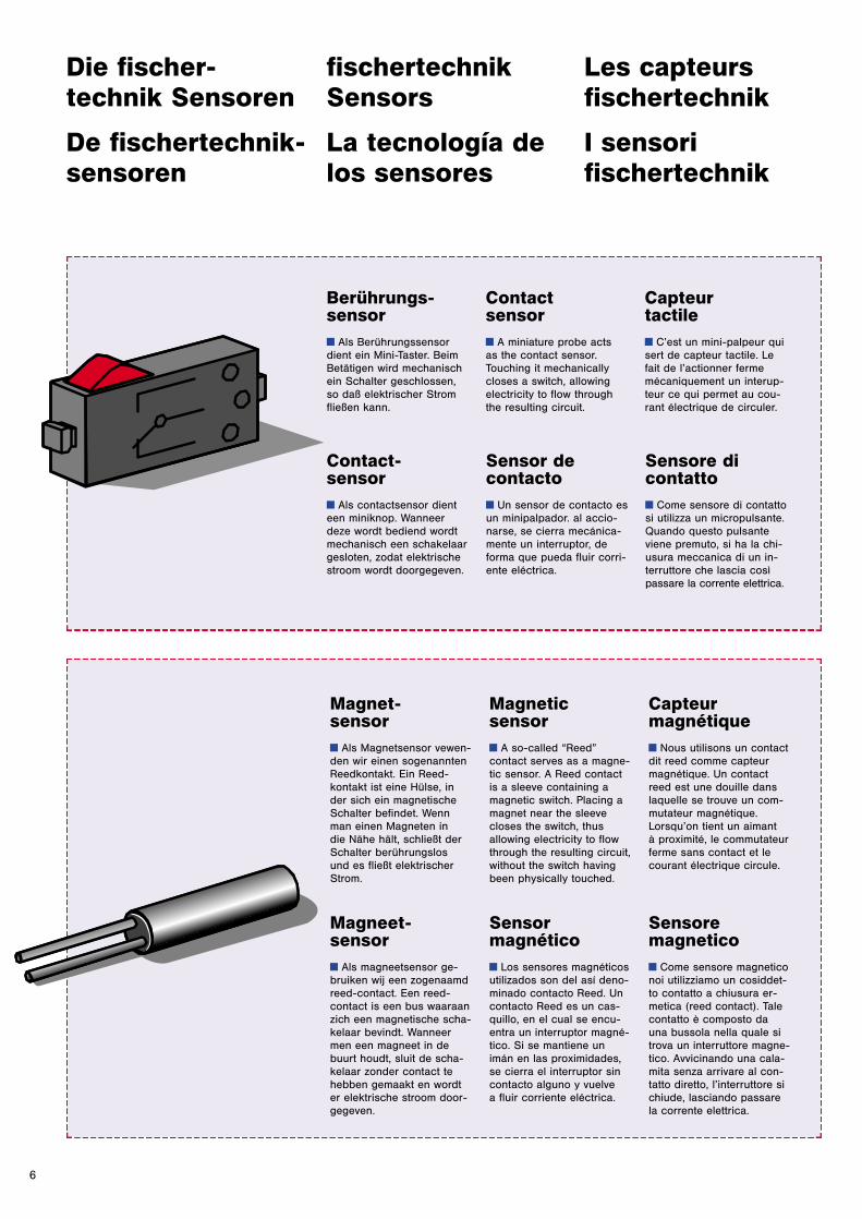
Berührungs-sensory Als Berührungssensordient ein Mini-Taster. BeimBetätigen wird mechanischein Schalter geschlossen,so daß elektrischer Stromfließen kann.
Contact sensory A miniature probe acts as the contact sensor.Touching it mechanicallycloses a switch, allowingelectricity to flow throughthe resulting circuit.
Capteur tactiley C’est un mini-palpeur quisert de capteur tactile. Le fait de l’actionner fermemécaniquement un interup-teur ce qui permet au cou-rant électrique de circuler.
fischertechnikSensors
La tecnología delos sensores
Les capteursfischertechnik
I sensori fischertechnik
Die fischer-technik Sensoren
De fischertechnik-sensoren
Contact-sensory Als contactsensor dienteen miniknop. Wanneerdeze wordt bediend wordtmechanisch een schakelaargesloten, zodat elektrischestroom wordt doorgegeven.
Sensor de contactoy Un sensor de contacto esun minipalpador. al accio-narse, se cierra mecánica-mente un interruptor, deforma que pueda fluir corri-ente eléctrica.
Sensore di contattoy Come sensore di contattosi utilizza un micropulsante.Quando questo pulsanteviene premuto, si ha la chi-usura meccanica di un in-terruttore che lascia cosìpassare la corrente elettrica.
Magnet-sensory Als Magnetsensor vewen-den wir einen sogenanntenReedkontakt. Ein Reed-kontakt ist eine Hülse, inder sich ein magnetischeSchalter befindet. Wennman einen Magneten in die Nähe hält, schließt derSchalter berührungslos und es fließt elektrischerStrom.
Magnetic sensory A so-called “Reed”contact serves as a magne-tic sensor. A Reed contactis a sleeve containing amagnetic switch. Placing amagnet near the sleeve closes the switch, thus allowing electricity to flowthrough the resulting circuit,without the switch havingbeen physically touched.
Capteurmagnétiquey Nous utilisons un contactdit reed comme capteurmagnétique. Un contactreed est une douille danslaquelle se trouve un com-mutateur magnétique.Lorsqu’on tient un aimant à proximité, le commutateurferme sans contact et lecourant électrique circule.
Magneet-sensory Als magneetsensor ge-bruiken wij een zogenaamdreed-contact. Een reed-contact is een bus waaraanzich een magnetische scha-kelaar bevindt. Wanneermen een magneet in debuurt houdt, sluit de scha-kelaar zonder contact tehebben gemaakt en wordter elektrische stroom door-gegeven.
Sensor magnéticoy Los sensores magnéticosutilizados son del así deno-minado contacto Reed. Uncontacto Reed es un cas-quillo, en el cual se encu-entra un interruptor magné-tico. Si se mantiene unimán en las proximidades,se cierra el interruptor sincontacto alguno y vuelve a fluir corriente eléctrica.
Sensore magneticoy Come sensore magneticonoi utilizziamo un cosiddet-to contatto a chiusura er-metica (reed contact). Talecontatto è composto da una bussola nella quale sitrova un interruttore magne-tico. Avvicinando una cala-mita senza arrivare al con-tatto diretto, l’interruttore sichiude, lasciando passarela corrente elettrica.
7
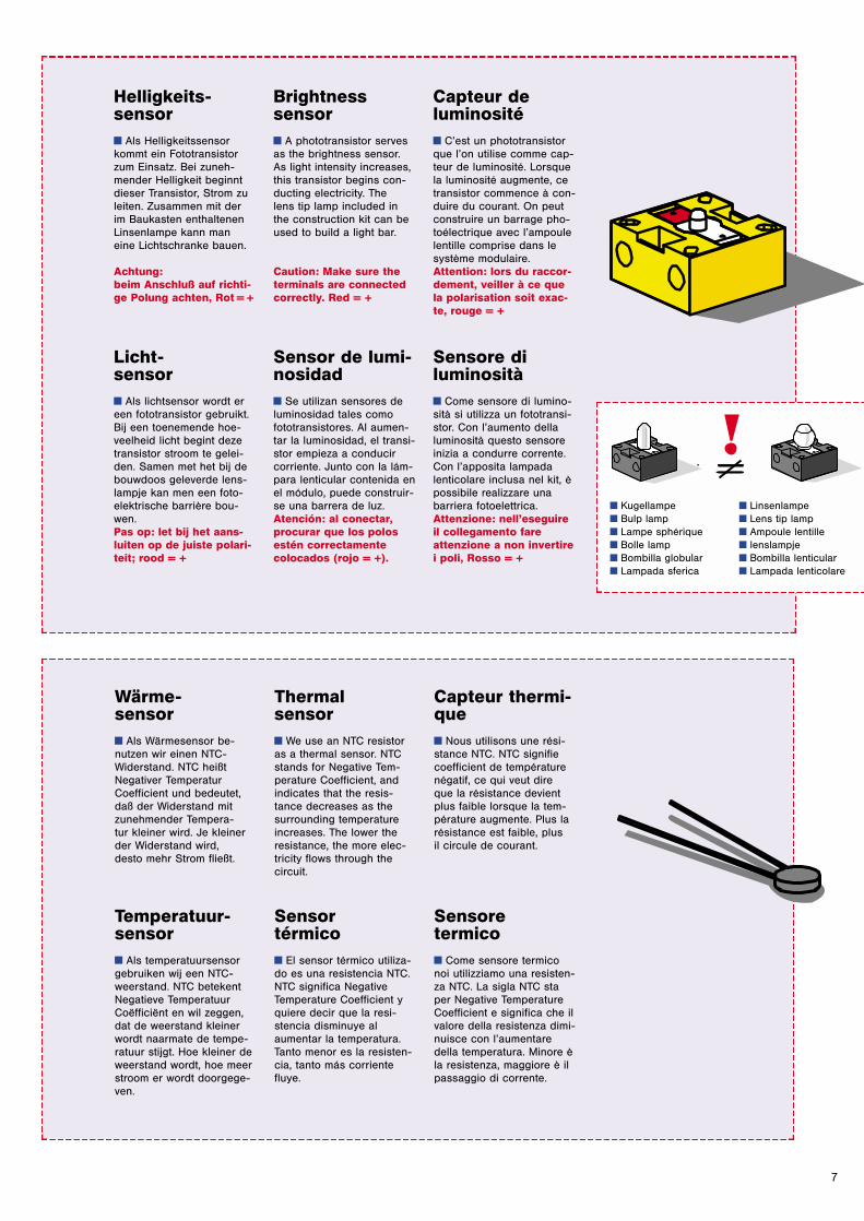
Helligkeits-sensory Als Helligkeitssensorkommt ein Fototransistorzum Einsatz. Bei zuneh-mender Helligkeit beginntdieser Transistor, Strom zuleiten. Zusammen mit derim Baukasten enthaltenenLinsenlampe kann man eine Lichtschranke bauen.
Achtung: beim Anschluß auf richti-ge Polung achten, Rot = +
Brightness sensory A phototransistor servesas the brightness sensor.As light intensity increases,this transistor begins con-ducting electricity. The lens tip lamp included inthe construction kit can beused to build a light bar.
Caution: Make sure theterminals are connectedcorrectly. Red = +
Capteur deluminositéy C’est un phototransistorque l’on utilise comme cap-teur de luminosité. Lorsquela luminosité augmente, cetransistor commence à con-duire du courant. On peutconstruire un barrage pho-toélectrique avec l’ampoulelentille comprise dans lesystème modulaire. Attention: lors du raccor-dement, veiller à ce quela polarisation soit exac-te, rouge = +
Licht-sensory Als lichtsensor wordt ereen fototransistor gebruikt.Bij een toenemende hoe-veelheid licht begint dezetransistor stroom te gelei-den. Samen met het bij debouwdoos geleverde lens-lampje kan men een foto-elektrische barrière bou-wen. Pas op: let bij het aans-luiten op de juiste polari-teit; rood = +
Sensor de lumi-nosidady Se utilizan sensores deluminosidad tales comofototransistores. Al aumen-tar la luminosidad, el transi-stor empieza a conducircorriente. Junto con la lám-para lenticular contenida enel módulo, puede construir-se una barrera de luz. Atención: al conectar,procurar que los polosestén correctamentecolocados (rojo = +).
Sensore diluminositày Come sensore di lumino-sità si utilizza un fototransi-stor. Con l’aumento dellaluminosità questo sensoreinizia a condurre corrente.Con l’apposita lampadalenticolare inclusa nel kit, èpossibile realizzare unabarriera fotoelettrica. Attenzione: nell’eseguireil collegamento fareattenzione a non invertirei poli, Rosso = +
Wärme-sensory Als Wärmesensor be-nutzen wir einen NTC-Widerstand. NTC heißtNegativer TemperaturCoefficient und bedeutet,daß der Widerstand mitzunehmender Tempera-tur kleiner wird. Je kleinerder Widerstand wird, desto mehr Strom fließt.
Thermal sensory We use an NTC resistoras a thermal sensor. NTCstands for Negative Tem-perature Coefficient, andindicates that the resis-tance decreases as thesurrounding temperatureincreases. The lower theresistance, the more elec-tricity flows through the circuit.
Capteur thermi-quey Nous utilisons une rési-stance NTC. NTC signifiecoefficient de températurenégatif, ce qui veut dire que la résistance devientplus faible lorsque la tem-pérature augmente. Plus larésistance est faible, plus il circule de courant.
Temperatuur-sensory Als temperatuursensorgebruiken wij een NTC-weerstand. NTC betekentNegatieve TemperatuurCoëfficiënt en wil zeggen,dat de weerstand kleinerwordt naarmate de tempe-ratuur stijgt. Hoe kleiner deweerstand wordt, hoe meerstroom er wordt doorgege-ven.
Sensor térmicoy El sensor térmico utiliza-do es una resistencia NTC.NTC significa NegativeTemperature Coefficient yquiere decir que la resi-stencia disminuye alaumentar la temperatura.Tanto menor es la resisten-cia, tanto más corrientefluye.
Sensore termicoy Come sensore termiconoi utilizziamo una resisten-za NTC. La sigla NTC staper Negative TemperatureCoefficient e significa che ilvalore della resistenza dimi-nuisce con l’aumentaredella temperatura. Minore èla resistenza, maggiore è ilpassaggio di corrente.
y Kugellampey Bulp lampy Lampe sphériquey Bolle lampy Bombilla globulary Lampada sferica
y Linsenlampey Lens tip lampy Ampoule lentilley lenslampjey Bombilla lenticulary Lampada lenticolare
8
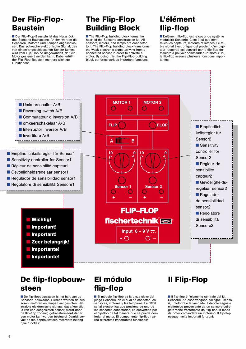
Der Flip-Flop-Bausteiny Der Flip-Flop-Baustein ist das Herzstückdes Sensoric Baukastens. An ihm werden dieSensoren, Motoren und Lampen angeschlos-sen. Das schwache elektronische Signal, dasvon einem angeschlossenen Sensor kommt,wird vom Flip-Flop so umgewandelt, daß einMotor gesteuert werden kann. Dabei erfülltder Flip-Flop-Baustein mehrere wichtigeFunktionen:
The Flip-FlopBuilding Blocky The Flip-Flop building block forms theheart of the Sensoric construction kit. Allsensors, motors, and lamps are connected to it. The Flip-Flop building block transformsthe weak electronic signal arriving from aconnected sensor in order to activate amotor. By doing this, the Flip-Flop buildingblock performs various important functions:
L’élémentflip-flopy L’élément flip-flop est le coeur du systèmemodulaire Sensoric. C’est à lui que sontreliés les capteurs, moteurs et lampes. Le fai-ble signal électronique qui provient d’un cap-teur raccordé est converti par le flip-flop demanière à pouvoir commander un moteur. Ici,le flip-flop assume plusieurs fonctions impor-tantes:
De flip-flopbouw-steeny De flip-flopbouwsteen is het hart van deSensoric-bouwdoos. Hieraan worden de sen-soren, motoren en lampen aangesloten. Hetzwakke elektronische signaal, dat afkomstigis van een aangesloten sensor, wordt door de flip-flop zodanig getransformeerd dat ereen motor kan worden bestuurd. Daarbij ver-vult de flip-flopbouwsteen meerdere belangrijke functies:
El módulo flip-flopy El módulo flip-flop es la pieza clave deljuego Sensoric, en el cual se conectan lossensores, motores y las lámparas. La débilseñal electrónica que proviene de uno de los sensores conectados, es convertida porel flip-flop de tal manera que se pueda con-trolar el motor. El componente flip-flop rea-liza diferentes importantes funciones:
Il Flip-Flop
y Il flip-flop è l’elemento centrale del kitSensoric. Ad esso vengono collegati i senso-ri, i motorini e le lampade. Il debole segnaleelettronico proveniente da un sensore colle-gato viene trasformato dal flip-flop in mododa poter comandare un motorino. Il flip-flopesegue molte importati funzioni:
y Wichtig!y Important!y Important!y Zeer belangrijk!y Importante!y Importante!
y Umkehrschalter A/B
y Reversing switch A/B
y Commutateur d´inversion A/B
y omkeerschakelaar A/B
y Interruptor inversor A/B
y Invertitore A/B
y Empfindlichkeitsregler für Sensor1
y Sensitivity controller for Sensor1
y Régleur de sensibilité capteur1
y Gevoeligheidsregelaar sensor1
y Regulador de sensibilidad sensor1
y Regolatore di sensibilità Sensore1
y Empfindlich-
keitsregler für
Sensor2
y Sensitivity
controller for
Sensor2
y Régleur de
sensibilité
capteur2
y Gevoeligheids-
regelaar sensor2
y Regulador
de sensibilidad
sensor2
y Regolatore
di sensibilità
Sensore2
9
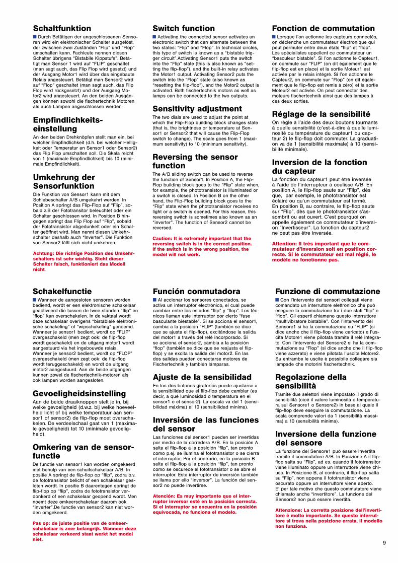
Switch functiony Activating the connected sensor activates anelectronic switch that can alternate between thetwo states: “Flip” and “Flop”. In technical circles,this type of switch is known as a “bistable trig-ger circuit”.Activating Sensor1 puts the switchinto the “Flip” state (this is also known as “set-ting the flip-flop”), and the built-in relay activatesthe Motor1 output. Activating Sensor2 puts theswitch into the “Flop” state (also known as“resetting the flip-flop”), and the Motor2 output isactivated. Both fischertechnik motors as well aslamps can be connected to the two outputs.
Sensitivity adjustmentThe two dials are used to adjust the point atwhich the Flip-Flop building block changes state(that is, the brightness or temperature at Sen-sor1 or Sensor2 that will cause the Flip-Flopswitch to change). The scale goes from 1 (maxi-mum sensitivity) to 10 (minimum sensitivity).
Reversing the sensor functionThe A/B sliding switch can be used to reversethe function of Sensor1. In Position A, the Flip-Flop building block goes to the “Flip” state when,for example, the phototransistor is illuminated ora switch is closed. In Position B on the otherhand, the Flip-Flop building block goes to the“Flip” state when the phototransistor receives nolight or a switch is opened. For this reason, thisreversing switch is sometimes also known as an“inverter”. The function of Sensor2 cannot bereversed.
Caution: It is extremely important that thereversing switch is in the correct position. If the switch is in the wrong position, themodel will not work.
Fonction de commutationy Lorsque l’on actionne les capteurs connectés,on déclenche un commutateur électronique quipeut permuter entre deux états “flip” et “flop”.Les spécialistes appellent ce commutateur un“basculeur bistable”. Si l’on actionne le Capteur1,on commute sur “FLIP” (on dit également que leflip-flop est en place) et la sortie Moteur1 estactivée par le relais intégré. Si l’on actionne leCapteur2, on commute sur “Flop” (on dit égale-ment que le flip-flop est remis à zéro) et la sortieMoteur2 est activée. On peut connecter desmoteurs fischertechnik ainsi que des lampes àces deux sorties.
Réglage de la sensibilité On règle à l’aide des deux boutons tournantsà quelle sensibilité (c’est-à-dire à quelle lumi-nosité ou température du capteur1 ou cap-teur 2) le flip-flop doit commuter. La graduati-on va de 1 (sensibilité maximale) à 10 (sensi-bilité minimale).
Inversion de la fonctiondu capteur La fonction du capteur1 peut être inversée à l’aide de l’interrupteur à coulisse A/B. Enposition A, le flip-flop saute sur “Flip”, dèsque, par exemple, le phototransistor estéclairé ou qu’un commutateur est fermé. En position B, au contraire, le flip-flop saute sur “Flip”, dès que le phototransistor s’as-sombrit ou est ouvert. C’est pourquoi onappelle également ce commutateur d’inversi-on “Invertisseur”. La fonction du capteur2 ne peut pas être inversée.
Attention: Il très important que le com-mutateur d’inversion soit en position cor-recte. Si le commutateur est mal réglé, lemodèle ne fonctionne pas.
Schakelfunctiey Wanneer de aangesloten sensoren wordenbediend, wordt er een elektronische schakelaargeactiveerd die tussen de twee standen “flip” en“flop” kan overschakelen. In de vaktaal wordtdeze schakelaar overigens “bistabiele elektroni-sche schakeling” of “wipschakeling” genoemd. Wanneer je sensor1 bedient, wordt op “FLIP”overgeschakeld (men zegt ook: de flip-flopwordt geschakeld) en de uitgang motor1 wordtaangestuurd via het ingebouwde relais.Wanneer je sensor2 bedient, wordt op “FLOP”overgeschakeld (men zegt ook: de flip-flopwordt teruggeschakeld) en wordt de uitgangmotor2 aangestuurd. Aan de beide uitgangenkunnen zowel de fischertechnik-motoren als ook lampen worden aangesloten.
GevoeligheidsinstellingAan de beide draaiknoppen stelt je in, bijwelke gevoeligheid (d.w.z. bij welke hoeveel-heid licht of bij welke temperatuur aan sen-sor1 of sensor2) de flip-flop moet overscha-kelen. De verdeelschaal gaat van 1 (maxima-le gevoeligheid) tot 10 (minimale gevoelig-heid).
Omkering van de sensor-functie De functie van sensor1 kan worden omgekeerdmet behulp van een schuifschakelaar A/B. Inpositie A springt de flip-flop op “flip”, zodra b.v.de fototransistor belicht of een schakelaar ges-loten wordt. In positie B daarentegen springt deflip-flop op “flip”, zodra de fototransistor ver-donkerd of een schakelaar geopend wordt. Mennoemt deze omkeerschakelaar daarom ook“inverter”.De functie van sensor2 kan niet wor-den omgekeerd.
Pas op: de juiste positie van de omkeer-schakelaar is zeer belangrijk. Wanneer dezeschakelaar verkeerd staat werkt het modelniet.
Función conmutadoray Al accionar los sensores conectados, seactiva un interruptor electrónico, el cual puedecambiar entre los estados “flip” y “flop”. Los téc-nicos llaman este interruptor por cierto “fasebasculante biestable”. Si se acciona el sensor1,cambia a la posición “FLIP” (también se diceque se ajusta el flip-flop), excitándose la salidadel motor1 a través del relé incorporado. Si se acciona el sensor2, cambia a la posición“flop” (también se dice que se reajusta el flip-flop) y se excita la salida del motor2. En las dos salidas pueden conectarse motores deFischertechnik y también lámparas.
Ajuste de la sensibilidadEn los dos botones giratorios puede ajustarse ala sensibilidad que el flip-flop debe cambiar (esdecir, a qué luminosidad o temperatura en elsensor1 o el sensor2). La escala va del 1 (sensi-bilidad máxima) al 10 (sensibilidad mínima).
Inversión de las funcionesdel sensorLas funciones del sensor1 pueden ser invertidaspor medio de la corredera A/B. En la posición Asalta el flip-flop a la posición “flip”, tan prontocomo p.ej. se ilumina el fototransistor o se cierrael interruptor. Por el contrario, en la posición Bsalta el flip-flop a la posición “flip”, tan prontocomo se oscurece el fototransistor o se abre elinterruptor. Este interruptor de inversión tambiénse llama por ello “inversor”. La función del sen-sor2 no puede invertirse.
Atención: Es muy importante que el inter-ruptor inversor esté en la posición correcta.Si el interruptor se encuentra en la posiciónequivocada, no funciona el modelo.
Funzione di commutazioney Con l’intervento dei sensori collegati vienecomandato un interruttore elettronico che puòeseguire la commutazione tra i due stati “flip” e“flop”. Gli esperti chiamano questo interruttore“multivibratore bistabile”. Con l’intervento delSensore1 si ha la commutazione su “FLIP” (sidice anche che il flip-flop viene caricato) e l’us-cita Motore1 viene pilotata tramite il relé integra-to. Con l’intervento del Sensore2 si ha la com-mutazione su “Flop” (si dice anche che il flip-flopviene azzerato) e viene pilotata l’uscita Motore2.Su entrambe le uscite è possibile collegare sialampade che motorini fischertechnik.
Regolazione della sensibilitàTramite due selettori viene impostato il grado disensibilità (cioé il valore luminosità o temperatu-ra sul Sensore1 o Sensore2) in base al quale ilflip-flop deve eseguire la commutazione. Lascala comprende valori da 1 (sensibilità massi-ma) a 10 (sensibilità minima).
Inversione della funzionedel sensore La funzione del Sensore1 può essere invertitatramite il commutatore A/B. In Posizione A il flip-flop salta su “Flip”, ad es. quando il fototransitorviene illuminato oppure un interruttore viene chi-uso. In Posizione B, al contrario, il flip-flop saltasu “Flip”, non appena il fototransistor vieneoscurato oppure un interruttore viene aperto. E’ per tale motivo che questo commutatore vienechiamato anche “invertitore”. La funzione delSensore2 non può essere invertita.
Attenzione: La corretta posizione dell’inverti-tore è molto importante. Se questo interrut-tore si trova nella posizione errata, il modellonon funziona.
Schaltfunktiony Durch Betätigen der angeschlossenen Senso-ren wird ein elektronischer Schalter ausgelöst,der zwischen zwei Zuständen “Flip” und “Flop”umschalten kann. Fachleute nennen diesenSchalter übrigens “Bistabile Kippstufe”. Betä-tigt man Sensor 1 wird auf “FLIP” geschaltet(man sagt auch, das Flip Flop wird gesetzt) undder Ausgang Motor1 wird über das eingebauteRelais angesteuert. Betätigt man Sensor2 wirdauf “Flop” geschaltet (man sagt auch, das FlipFlop wird rückgesetzt) und der Ausgang Mo-tor2 wird angesteuert. An den beiden Ausgän-gen können sowohl die fischertechnik Motorenals auch Lampen angeschlossen werden.
Empfindlichkeits-einstellungAn den beiden Drehknöpfen stellt man ein, beiwelcher Empfindlichkeit (d.h. bei welcher Hellig-keit oder Temperatur an Sensor1 oder Sensor2)das Flip Flop umschalten soll. Die Skala reichtvon 1 (maximale Empfindlichkeit) bis 10 (mini-male Empfindlichkeit).
Umkehrung derSensorfunktionDie Funktion von Sensor1 kann mit demSchiebeschalter A/B umgekehrt werden. InPosition A springt das Flip-Flop auf “Flip”, so-bald z.B der Fototransitor beleuchtet oder einSchalter geschlossen wird. In Position B hin-gegen springt das Flip Flop auf “Flip”, sobaldder Fototransistor abgedunkelt oder ein Schal-ter geöffnet wird. Man nennt diesen Umkehr-schalter deshalb auch “Inverter”. Die Funktionvon Sensor2 läßt sich nicht umkehren.
Achtung: Die richtige Position des Umkehr-schalters ist sehr wichtig. Steht dieserSchalter falsch, funktioniert das Modellnicht.
13
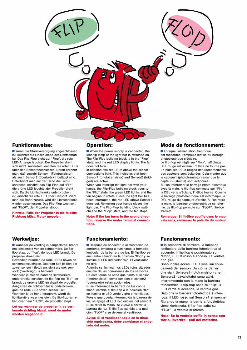
Funktionsweise:y Wenn die Stromversorgung angeschlossenist, leuchtet die Linsenlampe der Lichtschran-ke. Das Flip-Flop steht auf “Flop”, die roteLED-Anzeige leuchtet. Der Propeller drehtsich nicht. Außerdem leuchten die roten LEDsüber den Sensoranschlüssen. Daran erkenntman, daß sowohl Sensor1 (Fototransistor) als auch Sensor2 (überbrückt) betätigt sind. Unterbricht man mit der Hand die Licht-schranke, schaltet das Flip-Flop auf “Flip”,die grüne LED leuchtet,der Propeller drehtsich. Da die Lichtschranke unterbrochen ist, erlischt die rote LED über Sensor1. Ziehtman die Hand zurück, wird die Lichtschrankewieder geschlossen. Das Flip-Flop wechseltauf “FLOP”, der Propeller stoppt.
Hinweis: Falls der Propeller in die falscheRichtung bläst, Motor umpolen.
Operation:y When the power supply is connected, thelens tip lamp of the light bar is switched on.The Flip-Flop building block is in the “Flop”state, and the red LED display lights. The fandoes not turn.In addition, the red LEDs above the sensorconnections light. This indicates that bothSensor1 (phototransistor) and Sensor2 (brid-ged) are active.When you interrupt the light bar with yourhands, the Flip-Flop building block goes tothe “Flip” state, the green LED lights, and thefan begins to rotate. Since the light bar hasbeen interrupted, the red LED above Sensor1goes out. Removing your hands closes thelight bar. The Flip-Flop building block swit-ches to the “Flop” state, and the fan stops.
Note: If the fan turns in the wrong direc-tion, reverse the motor terminal connec-tions.
Mode de fonctionnement:y Lorsque l’alimentation électrique est raccordée, l’ampoule lentille du barragephotoélectrique s’éclaire. Le flip-flop est réglé sur “Flop”, l’affichageDEL rouge est éclairé. L’hélice ne tourne pas.En plus, les DELs rouges des raccordementsdes capteurs sont éclairées. Cela montre quele capteur1 (phototransistor) ainsi que lecapteur2 (shunté) sont actionnés. Si l’on interrompt le barrage photo-électriqueavec la main, le flip-flop commute sur “Flip”,la DEL verte s’éclaire, l’hélice tourne. Commele barrage photoélectrique est interrompu, laDEL rouge du capteur1 s’éteint. Si l’on retirela main, le barrage photoélectrique se refer-me. Le flip-flop permute sur “FLOP”, l’hélices’arrête.
Remarque: Si l’hélice souffle dans le mau-vais sens, renverser la polarité du moteur.
Werkwijze:y Wanneer de voeding is aangesloten, brandthet lenslampje van de lichtbarrière. De flip-flop staat op “flop”, de rode LED brandt. Depropeller draait niet.Bovendien branden de rode LED’s boven desensoraansluitingen. Daaraan kan je zien datzowel sensor1 (fototransistor) als ook sen-sor2 (overbrugd) is bediend. Wanneer je met de hand de lichtbarrièreonderbreekt, schakelt de flip-flop op “flip”, enbrandt de groene LED en draait de propeller.Aangezien de lichtbarrière is onderbroken,gaat de rode LED boven sensor1 uit.Wanneer je de hand terugtrekt, wordt delichtbarrière weer gesloten. De flip-flop scha-kelt over naar “FLOP”, de propeller stopt.
Let op: wanneer de propeller in de ver-keerde richting blaast, moet de motorworden omgepoold.
Funcionamiento:y Después de conectar la alimentación decorriente, empieza a iluminarse la bombillalenticular de la barrera de luz. El flip-flop seencuentra situado en la posición “flop” y seilumina el LED indicador rojo. El ventilador no gira.Además se iluminan los LEDs rojos situadosencima de las conexiones de los sensores.De esta forma se sabe que, tanto el senso1(fototransistor), como también el sensor2(puenteado) están accionados.Si se interrumpe la barrera de luz con lamano, cambia el flip-flop a la posición “flip”,se ilumina el LED verde y gira el ventilador.Puesto que queda interrumpida la barrera deluz, se apaga el LED rojo encima del sensor1.Si se retira la mano, se vuelve a cerrar labarrera de luz. El flip-flop cambia a la posi-ción “FLOP” y se detiene el ventilador.
Aviso: Si el ventilador sopla en la direc-ción equivocada, debe cambiarse el enpo-lado del motor.
Funzionamento:y In presenza di corrente, la lampada lenticolare della barriera fotoelettrica siaccende. Il flip-flop è posizionato su“Flop”, il LED rosso è acceso. La ventolanon gira.Sono inoltre accesi i LED rossi sui colle-gamenti dei sensori. Da ciò ne deriva che sia il Sensore1 (fototransistor) che ilSensore2 (cavallottato) sono attivi.Interrompendo con la mano la barrierafotoelettrica, il flip-flop salta su “Flip”, ilLED verde si accende, la ventola gira.Dato che la barriera fotoelettrica è inter-rotta, il LED rosso sul Sensore1 si spegne.Ritirando la mano, la barriera fotoelettricaviene ripristinata. Il flip-flop salta su“FLOP”, la ventola si arresta
Nota: Se la ventola soffia in senso con-trario, invertire i poli del motorino.
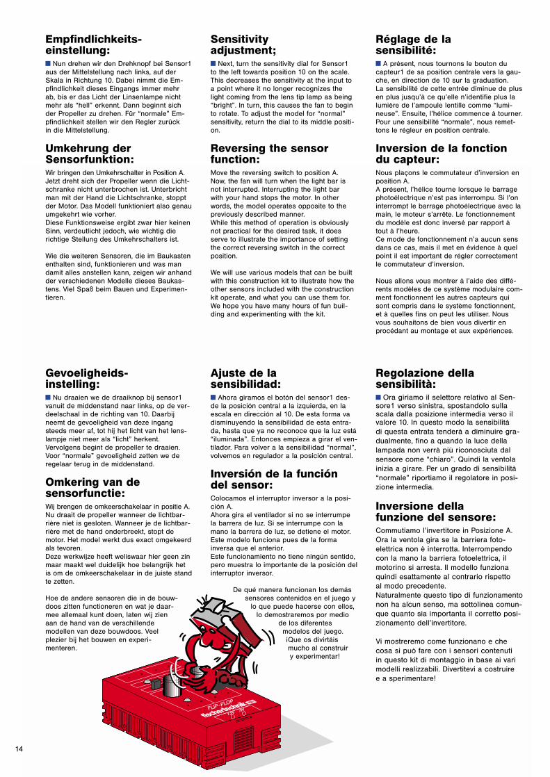
Sensitivityadjustment;y Next, turn the sensitivity dial for Sensor1to the left towards position 10 on the scale. This decreases the sensitivity at the input to a point where it no longer recognizes thelight coming from the lens tip lamp as being“bright”. In turn, this causes the fan to beginto rotate. To adjust the model for “normal”sensitivity, return the dial to its middle positi-on.
Reversing the sensorfunction:Move the reversing switch to position A.Now, the fan will turn when the light bar is not interrupted. Interrupting the light bar with your hand stops the motor. In otherwords, the model operates opposite to thepreviously described manner.While this method of operation is obviouslynot practical for the desired task, it doesserve to illustrate the importance of settingthe correct reversing switch in the correctposition.
We will use various models that can be builtwith this construction kit to illustrate how theother sensors included with the constructionkit operate, and what you can use them for.We hope you have many hours of fun buil-ding and experimenting with the kit.
Réglage de la sensibilité:y A présent, nous tournons le bouton ducapteur1 de sa position centrale vers la gau-che, en direction de 10 sur la graduation. La sensibilité de cette entrée diminue de plus en plus jusqu’à ce qu’elle n’identifie plus lalumière de l’ampoule lentille comme “lumi-neuse”. Ensuite, l’hélice commence à tourner.Pour une sensibilité “normale”, nous remet-tons le régleur en position centrale.
Inversion de la fonctiondu capteur:Nous plaçons le commutateur d’inversion enposition A.A présent, l’hélice tourne lorsque le barragephotoélectrique n’est pas interrompu. Si l’oninterrompt le barrage photoélectrique avec lamain, le moteur s’arrête. Le fonctionnementdu modèle est donc inversé par rapport àtout à l’heure. Ce mode de fonctionnement n’a aucun sensdans ce cas, mais il met en évidence à quelpoint il est important de régler correctementle commutateur d’inversion.
Nous allons vous montrer à l’aide des diffé-rents modèles de ce système modulaire com-ment fonctionnent les autres capteurs quisont compris dans le système fonctionnent, et à quelles fins on peut les utiliser. Nousvous souhaitons de bien vous divertir enprocédant au montage et aux expériences.
Ajuste de la sensibilidad:y Ahora giramos el botón del sensor1 des-de la posición central a la izquierda, en laescala en dirección al 10. De esta forma vadisminuyendo la sensibilidad de esta entra-da, hasta que ya no reconoce que la luz está“iluminada”. Entonces empieza a girar el ven-tilador. Para volver a la sensibilidad “normal”,volvemos en regulador a la posición central.
Inversión de la funcióndel sensor:Colocamos el interruptor inversor a la posi-ción A.Ahora gira el ventilador si no se interrumpela barrera de luz. Si se interrumpe con lamano la barrera de luz, se detiene el motor.Este modelo funciona pues de la formainversa que el anterior.Este funcionamiento no tiene ningún sentido,pero muestra lo importante de la posición delinterruptor inversor.
De qué manera funcionan los demássensores contenidos en el juego y
lo que puede hacerse con ellos,lo demostraremos por medio
de los diferentesmodelos del juego.¡Que os divirtáismucho al construir y experimentar!
Regolazione della sensibilità:y Ora giriamo il selettore relativo al Sen-sore1 verso sinistra, spostandolo sullascala dalla posizione intermedia verso ilvalore 10. In questo modo la sensibilità di questa entrata tenderà a diminuire gra-dualmente, fino a quando la luce dellalampada non verrà più riconosciuta dalsensore come “chiaro”. Quindi la ventolainizia a girare. Per un grado di sensibilità“normale” riportiamo il regolatore in posi-zione intermedia.
Inversione della funzione del sensore:Commutiamo l’invertitore in Posizione A.Ora la ventola gira se la barriera foto-elettrica non è interrotta. Interrompendocon la mano la barriera fotoelettrica, ilmotorino si arresta. Il modello funzionaquindi esattamente al contrario rispetto al modo precedente.Naturalmente questo tipo di funzionamentonon ha alcun senso, ma sottolinea comun-que quanto sia importanta il corretto posi-zionamento dell’invertitore.
Vi mostreremo come funzionano e checosa si può fare con i sensori contenuti in questo kit di montaggio in base ai varimodelli realizzabili. Divertitevi a costruire e a sperimentare!
14
Empfindlichkeits-einstellung:y Nun drehen wir den Drehknopf bei Sensor1aus der Mittelstellung nach links, auf derSkala in Richtung 10. Dabei nimmt die Em-pfindlichkeit dieses Eingangs immer mehr ab, bis er das Licht der Linsenlampe nichtmehr als “hell” erkennt. Dann beginnt sichder Propeller zu drehen. Für “normale” Em-pfindlichkeit stellen wir den Regler zurück in die Mittelstellung.
Umkehrung derSensorfunktion:Wir bringen den Umkehrschalter in Position A.Jetzt dreht sich der Propeller wenn die Licht-schranke nicht unterbrochen ist. Unterbrichtman mit der Hand die Lichtschranke, stopptder Motor. Das Modell funktioniert also genauumgekehrt wie vorher. Diese Funktionsweise ergibt zwar hier keinenSinn, verdeutlicht jedoch, wie wichtig dierichtige Stellung des Umkehrschalters ist.
Wie die weiteren Sensoren, die im Baukastenenthalten sind, funktionieren und was mandamit alles anstellen kann, zeigen wir anhandder verschiedenen Modelle dieses Baukas-tens. Viel Spaß beim Bauen und Experimen-tieren.
Gevoeligheids-instelling:y Nu draaien we de draaiknop bij sensor1vanuit de middenstand naar links, op de ver-deelschaal in de richting van 10. Daarbijneemt de gevoeligheid van deze ingangsteeds meer af, tot hij het licht van het lens-lampje niet meer als “licht” herkent.Vervolgens begint de propeller te draaien.Voor “normale” gevoeligheid zetten we deregelaar terug in de middenstand.
Omkering van de sensorfunctie:Wij brengen de omkeerschakelaar in positie A.Nu draait de propeller wanneer de lichtbar-rière niet is gesloten. Wanneer je de lichtbar-rière met de hand onderbreekt, stopt demotor. Het model werkt dus exact omgekeerdals tevoren. Deze werkwijze heeft weliswaar hier geen zinmaar maakt wel duidelijk hoe belangrijk hetis om de omkeerschakelaar in de juiste standte zetten.
Hoe de andere sensoren die in de bouw-doos zitten functioneren en wat je daar-mee allemaal kunt doen, laten wij zienaan de hand van de verschillende modellen van deze bouwdoos. Veel plezier bij het bouwen en experi-menteren.
15
1
4x
+
1x
1x1x
2x
2x 4x
2x
2x
1x
1x 1x
4x 2x 1x
2x
1x
1x
1x
2x4x
1x
3x1x
1x1x
1x
1x
2x1x
110
2x
2
3
50
Stempelpresse StempelpersAutomatic Stamper Prensa de enderezarPresse à tamponner Pressa per timbratura
16
5
2x 2x 1x
1x2x
1x
1x
1x
1x
1x1x
1x1x
1x1x
1x
3x2x
1x
2x
1x 1x
1x1x1x
2x
4
2x
1x
30
60
2x
1x
1x1x
1x
6

Schaltplan Stempelpresse Schakelschema StempelpersCircuit diagram Automatic Stamper Diagrama de circuitos Prensa de enderezarPlan électrique Presse à tamponner Schema elettrico Pressa per timbratura
17
FLIP-FLOP
10 0
+ - + -
A B
+ -
FLIP FLOP
M M
10 0
1 2
-
+
...
+ -
9 V
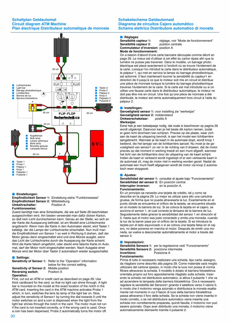
� Lichtschranke� Light bar� Barrage photoélectrique� Lichtbarrière� Barrera de luz� Barriera fotoelettrica
30 cm
B
� Einstellungen: Empfindlichkeit Sensor 1: So einstellen, daß die Lichtschranke auch
durch ein Stück Papier unterbrochen wird.Empfindlichkeit Sensor 2: MittelstellungUmkehrschalter: Position BFunktionsweise:Durch Unterbrechen der Lichtschranke wird die Presse in Gang gesetzt. Nach einem Stempelvorgang schaltet sie sich über den Tasterselbst wieder aus. Auf diese Art werden z.B. Fahrscheine oder Eintritts-karten abgestempelt.
� Settings:Sensitivity of Sensor 1: Adjust the sensitivity so that the light bar can
be interrupted by a piece of paper.Sensitivity of Sensor 2: Middle positionReversing switch: Position BOperation:Interrupting the light bar starts the press. Once the piece of paper hasbeen stamped, the probe switches the press off. This type of device isused, for example, to stamp bus or admission tickets.
� Réglages:Sensibilité capteur 1: le régler de manière que le barrage
photoélectrique soit également interrompu par un morceau de papier.
Sensibilité capteur 2: position centraleCommutateur d’inversion: position BMode de fonctionnement:L’interruption du barrage photoélectrique met la presse en marche.Après un tamponnement, elle se remet automatiquement hors circuit àl’aide du palpeur. C’est ainsi que sont tamponnés, par exemple, lestickets ou les billets d’entrée.
� Instellingen:Gevoeligheid sensor 1:zodanig instellen, dat de lichtbarrière ook
wordt onderbroken door een stuk papier.Gevoeligheid sensor 2:middenstandOmkeerschakelaar: positie BWerkwijze:Door het onderbreken van de lichtbarrière wordt de pers in werkinggezet. Na een stempelproces schakelt de pers zichzelf via de knopweer uit. Op deze manier worden b.v. kaartjes of entreebewijzen afgestempeld.
� Ajustes:Sensibilidad del sensor 1:Ajustarla de tal manera que la barrera de
luz sea incluso interrumpida por un trozo depapel.
Sensibilidad del sensor 2:En posición central.Interruptor inversor: en la posición B.Funcionamiento:Si se interrumpe la barrera de luz, se pone en marcha la prensa. Después de un punzonado, se vuelve a desconectar automáticamentea través del sensor. Se este modo pueden punzonarse p.ej. billetes oentradas.
� Impostazioni:Sensibilità Sensore 1: regolare in modo che la barriera fotoelettrica
venga interrotta anche con un pezzo di carta.Sensibilità Sensore 2: posizione intermediaInvertitore: Posizione BFunzionamento:Interrompendo la barriera fotoelettrica, la pressa viene azionata. Dopo aver eseguito una timbratura la pressa viene automaticamentedisinserita tramite il micro-pulsante. In questo modo è possibile timbrare ad es. biglietti d’autobus o biglietti d’ingresso agli spettacoli
30 cm 40 cm
� Kugellampe� Bulb lamp� Lampe sphérique� Bolle lamp� Bombilla globular� Lampada sferica
30 cm
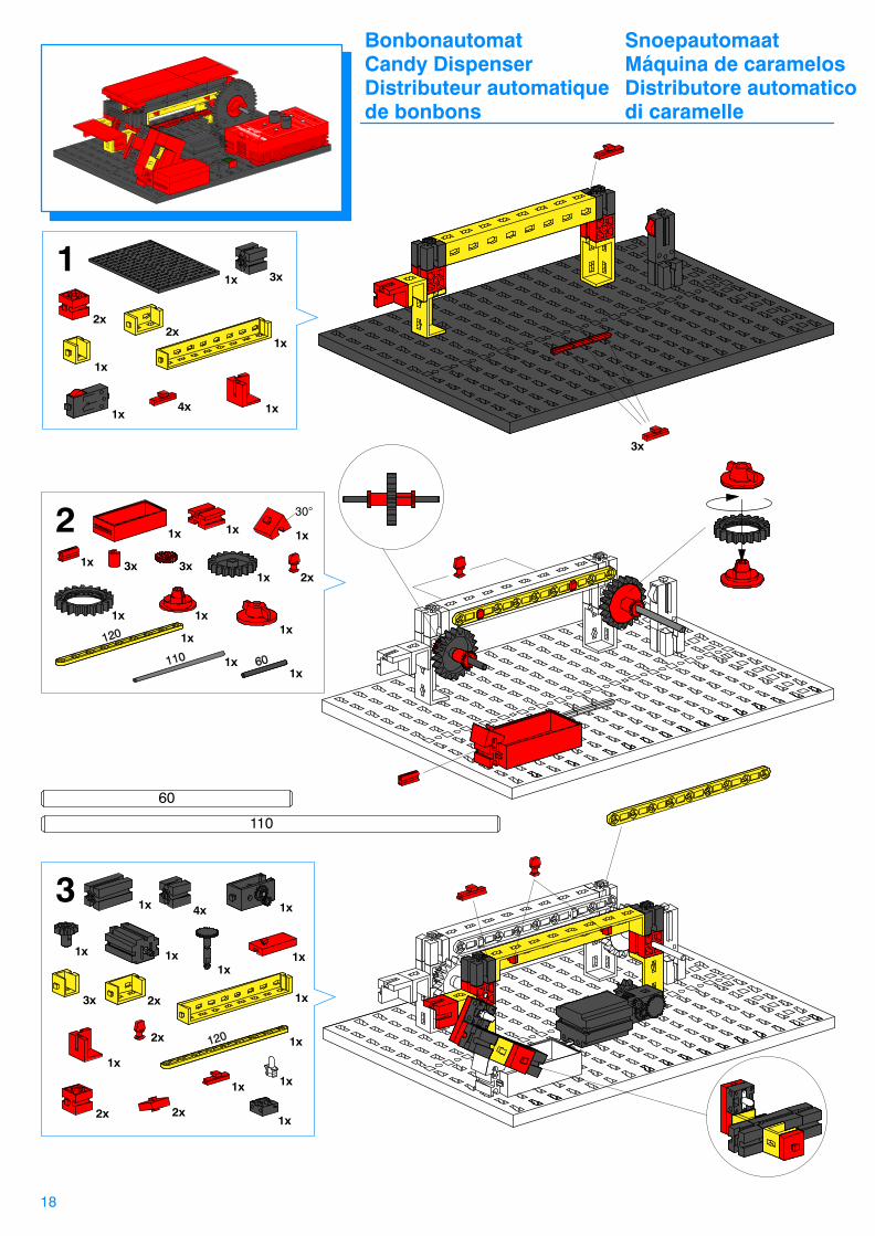
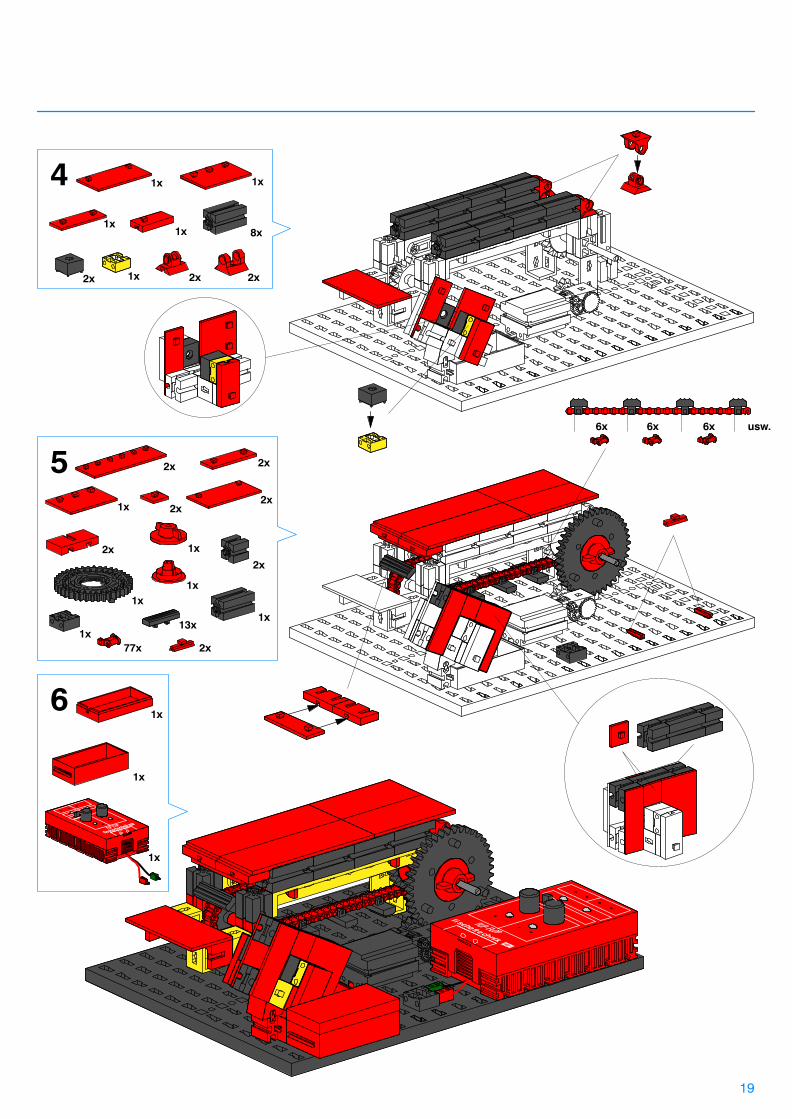
Bonbonautomat SnoepautomaatCandy Dispenser Máquina de caramelosDistributeur automatique Distributore automatico de bonbons di caramelle
18
11x
60
110
2x3x3x
1x
1x
1x
1x
1x1x
1x
1x 1x
1x
1x
3x
1x
2x1x
2x
1x4x
1x
2
3
30°
1x 4x 1x
1x 1x
1x
3x 2x 1x
2x
1x
2x
1x
2x
1x
1x
1x
1x
3x
19
4
5
1x
8x
1x
1x1x
1x2x 2x 2x
2x1x
2x2x
2x
1x
1x
1x
2x
1x
2x
77x
13x
6x 6x 6x usw.
2x1x
61x
1x
1x

Schaltplan Bonbonautomat Schakelschema SnoepautomaatCircuit diagram Candy Dispenser Diagrama de circuitos Máquina de caramelosPlan électrique Distributeur automatique de bonbons Schema elettrico Distributore automatico di caramelle
20
FLIP-FLOP
10 0
+ - + -
A B
+ -
FLIP FLOP
M M
10 0
1 2
-
+
...
+
30 cm
-
9 V
� Lichtschranke� Light bar� Barrage photoélectrique� Lichtbarrière� Barrera de luz� Barriera fotoelettrica
30 cm
B
� Einstellungen: Empfindlichkeit Sensor 1 und Sensor 2: MittelstellungUmkehrschalter: Position BFunktionsweise:Durch Einwerfen einer Münze wird die Lichtschranke unterbrochen.Das Förderband startet und bewegt sich ein Stück weiter. Nach Aus-gabe eines Bonbons oder Bausteins schaltet es sich über den Tasterautomatisch wieder ab. Hinweis: Läuft das Förderband in die falsche Richtung, Motor umpolen.
� Settings:Sensitivity of Sensor 1 and Sensor 2: Middle positionReversing switch: Position BOperation:Dropping a coin in the coin slot interrupts the light bar. This moves theconveyor belt forward. Once a piece of candy or other object has beendispensed, the probe automatically stops further conveyor belt movement.Note:If the conveyor belt moves in the wrong direction, reverse the motorterminal connections.
� Réglages:Sensibilité capteur 1 et capteur 2: position centraleCommutateur d’inversion: position BMode de fonctionnement:L’introduction d’une pièce de monnaie interrompt le barrage photo-électrique. La bande transporteuse démarre et se déplace d’un cran.Une fois que le bonbon ou l’élément a été distribué, le distributeur seremet automatiquement hors circuit à l’aide du palpeur. Remarque:si la bande transporteuse se déplace dans le mauvais sens, inverser lapolarité du moteur.
� Instellingen:Gevoeligheid sensor 1 en sensor 2: middenstandOmkeerschakelaar: positie BWerkwijze:Door het inwerpen van een munt wordt de lichtbarrière onderbroken.De transporteur start en beweegt een stukje verder. Na het afgeven vaneen snoepje of bouwsteen schakelt de transporteur zichzelf via de knopautomatisch weer uit. Let op:wanneer de transporteur in de verkeerde richting loopt, moet de motorworden omgepoold.
� Ajustes:Sensibilidad del sensor 1 y sensor 2: En posición central.Interruptor inversor: en la posición B.Funcionamiento:Si se tira una moneda, se interrumpe la barrera de luz. Se pone enmarcha la cinta transportadora y se desplaza una posición. Después dedescargar los caramelos o las piezas, se vuelve a desconectar automáticamente a través del sensor.Aviso:Si la cinta transportadora va en la dirección contraria, debe cambiarsela polación del motor.
� Impostazioni:Sensibilità Sensore1 e Sensore2: posizione intermediaInvertitore: Posizione BFunzionamento:Inserendo una moneta, la barriera fotoelettrica viene interrotta. Il nastrotrasportatore si mette in moto in fase di avanzamento. Dopo aver distribuito una caramella o un altro oggetto, il nastro viene automatica-mente disinserito tramite il micro-pulsante.Nota:Se il nastro trasportatore avanza nella direzione contraria, invertire i polidel motorino.
� Kugellampe� Bulb lamp� Lampe sphérique� Bolle lamp� Bombilla globular� Lampada sferica
30 cm
30 cm
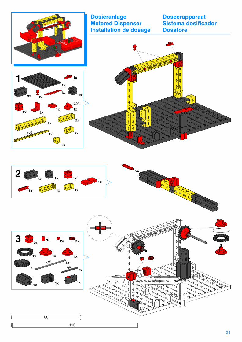
Dosieranlage DoseerapparaatMetered Dispenser Sistema dosificadorInstallation de dosage Dosatore
21
1
60
110
+
3x 5x
1x1x
1x
2x2x
1x
1x
2x
2x
6x
2x
1x
1x
1x
2x
2x
1x
5x
1x
2x
3x 2x
1x 1x
1x1x
1x
1x
1x 1x 1x
26x 1x
3
30°
22
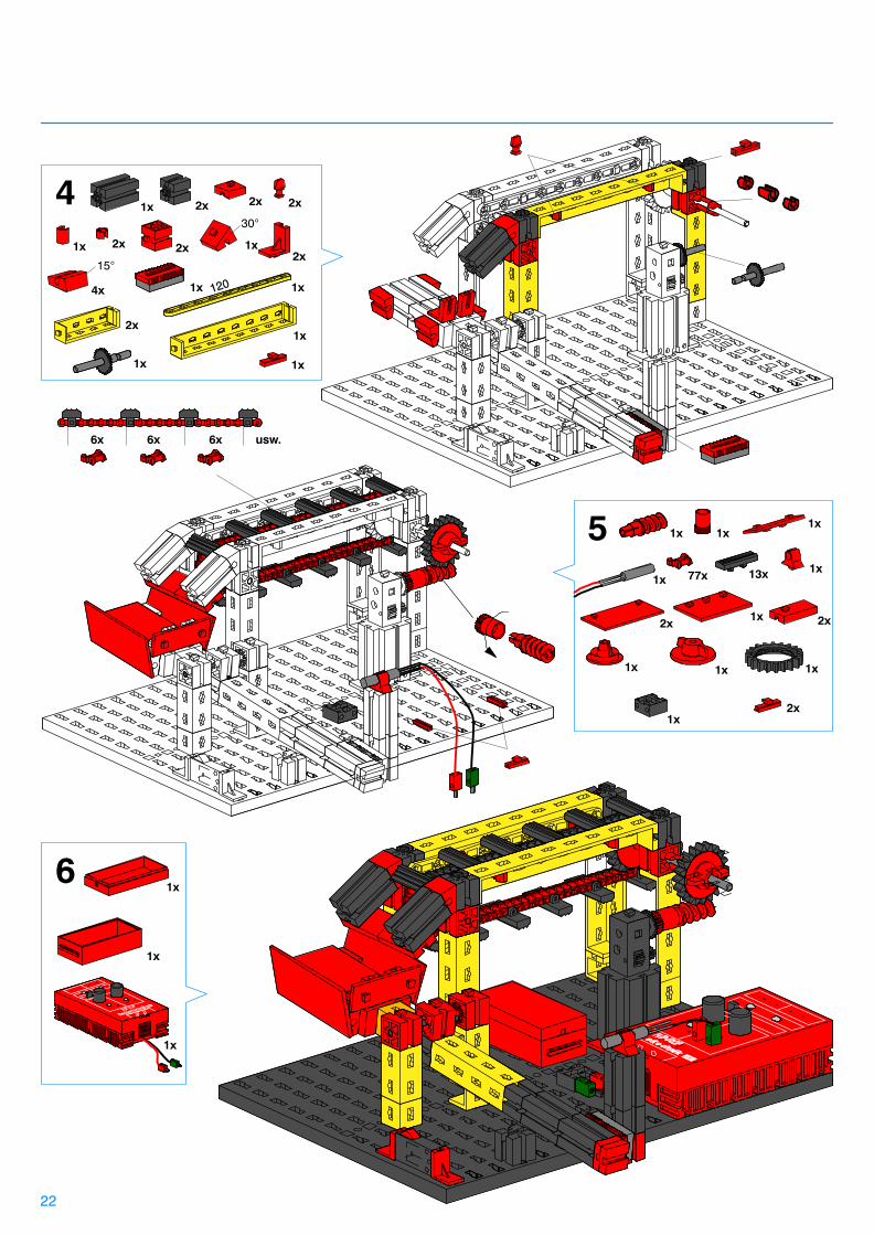
4
5
1x 2x 2x
4x
2x
1x
2x
2x1x
1x
1x2x
1x
1x
2x1x
1x 1x1x
2x
77x1x
1x 1x
13x
1x
30°
15°
1x
2x1x
2x1x
61x
1x
1x
6x 6x 6x usw.
Schaltplan Dosieranlage Schakelschema DoseerapparaatCircuit diagram Metered Dispenser Diagrama de circuitos Sistema dosificadorPlan électrique Installation de dosage Schema elettrico Dosatore
23
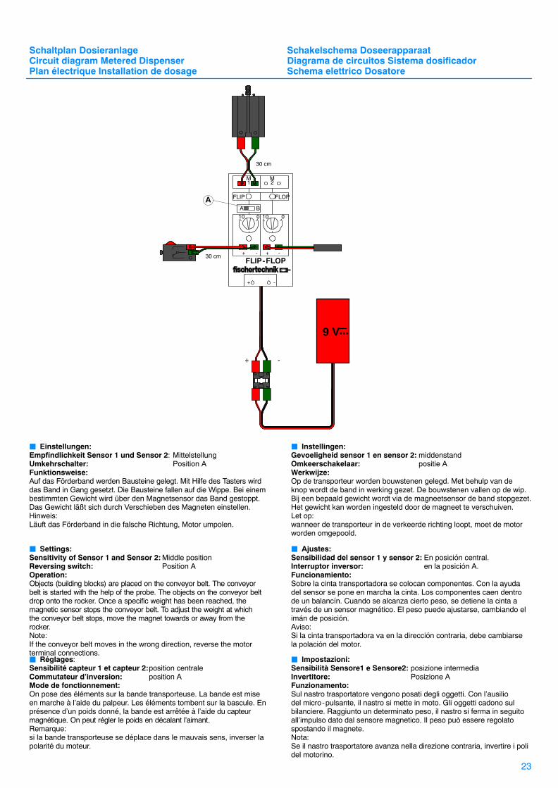
� Einstellungen: Empfindlichkeit Sensor 1 und Sensor 2: MittelstellungUmkehrschalter: Position AFunktionsweise:Auf das Förderband werden Bausteine gelegt. Mit Hilfe des Tasters wirddas Band in Gang gesetzt. Die Bausteine fallen auf die Wippe. Bei einembestimmten Gewicht wird über den Magnetsensor das Band gestoppt.Das Gewicht läßt sich durch Verschieben des Magneten einstellen.Hinweis:Läuft das Förderband in die falsche Richtung, Motor umpolen.
� Settings:Sensitivity of Sensor 1 and Sensor 2: Middle positionReversing switch: Position AOperation:Objects (building blocks) are placed on the conveyor belt. The conveyorbelt is started with the help of the probe. The objects on the conveyor beltdrop onto the rocker. Once a specific weight has been reached, the magnetic sensor stops the conveyor belt. To adjust the weight at whichthe conveyor belt stops, move the magnet towards or away from therocker.Note:If the conveyor belt moves in the wrong direction, reverse the motorterminal connections.� Réglages:Sensibilité capteur 1 et capteur 2:position centraleCommutateur d’inversion: position AMode de fonctionnement:On pose des éléments sur la bande transporteuse. La bande est miseen marche à l’aide du palpeur. Les éléments tombent sur la bascule. Enprésence d’un poids donné, la bande est arrêtée à l’aide du capteurmagnétique. On peut régler le poids en décalant l’aimant.Remarque:si la bande transporteuse se déplace dans le mauvais sens, inverser lapolarité du moteur.
� Instellingen:Gevoeligheid sensor 1 en sensor 2: middenstandOmkeerschakelaar: positie AWerkwijze:Op de transporteur worden bouwstenen gelegd. Met behulp van de knop wordt de band in werking gezet. De bouwstenen vallen op de wip.Bij een bepaald gewicht wordt via de magneetsensor de band stopgezet.Het gewicht kan worden ingesteld door de magneet te verschuiven.Let op:wanneer de transporteur in de verkeerde richting loopt, moet de motorworden omgepoold.
� Ajustes:Sensibilidad del sensor 1 y sensor 2: En posición central.Interruptor inversor: en la posición A.Funcionamiento:Sobre la cinta transportadora se colocan componentes. Con la ayudadel sensor se pone en marcha la cinta. Los componentes caen dentrode un balancín. Cuando se alcanza cierto peso, se detiene la cinta através de un sensor magnético. El peso puede ajustarse, cambiando elimán de posición.Aviso:Si la cinta transportadora va en la dirección contraria, debe cambiarsela polación del motor.
� Impostazioni:Sensibilità Sensore1 e Sensore2: posizione intermediaInvertitore: Posizione AFunzionamento:Sul nastro trasportatore vengono posati degli oggetti. Con l’ausilio del micro-pulsante, il nastro si mette in moto. Gli oggetti cadono sulbilanciere. Raggiunto un determinato peso, il nastro si ferma in seguitoall’impulso dato dal sensore magnetico. Il peso può essere regolatospostando il magnete.Nota:Se il nastro trasportatore avanza nella direzione contraria, invertire i polidel motorino.
FLIP-FLOP
10 0
+ - + -
A B
+ -
FLIP FLOP
M M
10 0
1 2
...
+ -
9 V
30 cm
A
30 cm
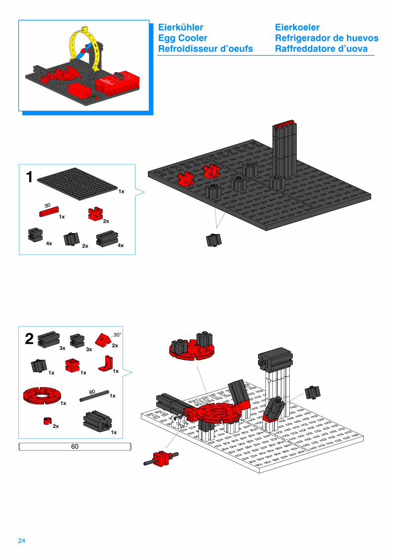
24
11x
1x2x
4x4x 2x
3x 3x
1x 1x
2x
1x
1x
2x
1x
1x
2
60
30°
Eierkühler EierkoelerEgg Cooler Refrigerador de huevosRefroidisseur d’oeufs Raffreddatore d’uova
2x
25
1x
2x
1x1x
3x
3
60°
1x
2x
1x
1x1x
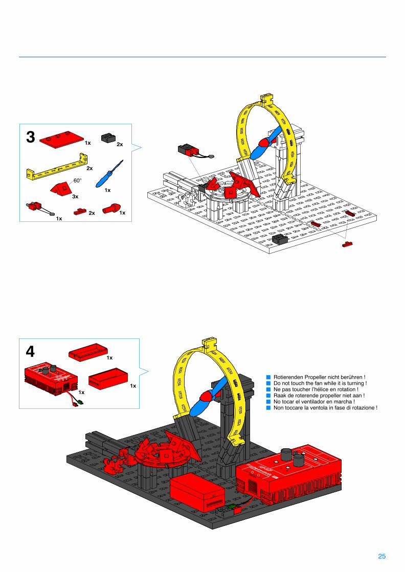
4� Rotierenden Propeller nicht berühren !� Do not touch the fan while it is turning !� Ne pas toucher l’hélice en rotation !� Raak de roterende propeller niet aan !� No tocar el ventilador en marcha !� Non toccare la ventola in fase di rotazione !

Schaltplan Eierkühler Schakelschema EierkoelerCircuit diagram Egg Cooler Diagrama de circuitos Refrigerador de huevosPlan électrique Refroidisseur d’oeufs Schema elettrico Raffreddatore d’uova
26
� Einstellungen: Empfindlichkeit Sensor 1: Einstellung siehe “Funktionsweise”Empfindlichkeit Sensor 2: MittelstellungUmkehrschalter: Position BFunktionsweise:Zunächst wird der Eierkühler kalibriert, d.h. man legt ein abgekühltesEi, das die gewünschte Temperatur besitzt, in die Halterung . Dannstellt man den Empfindlichkeitsregler von Sensor 1 so ein, daß derMotor gerade nicht läuft. Danach legt man ein zu heißes Ei in die Halterung. Über den Wärmesensor wird der Motor eingeschaltet. Wenn das Ei auf die gewünschte Temperatur abgekühlt ist, wird der Motor automatisch ausgeschaltet. Der Wärmesensor sollte sichmöglichst nahe an der Eioberfläche befinden.Hinweis: Bläst der Propeller in die falsche Richtung, Motor umpolen.
� Settings:Sensitivity of Sensor 1: Refer to the ”Operation” information below for
the correct setting.Sensitivity of Sensor 2: Middle positionReversing switch: Position BOperation:First, calibrate the egg cooler. To do this, place an egg that has beencooled to the desired temperature in the holder. Next, adjust the sensitivity controller for Sensor 1 until the motor just stops. Next, place a warm egg in the holder. The thermal sensor switches the motor and itsfan on. Once the fan has cooled the egg to the desired temperature, themotor automatically shuts off. Position the thermal sensor as near to thesurface of the egg as possible.Note:If the fan turns in the wrong direction, reverse the motor terminal connections.
� Réglages:Sensibilité capteur 1: réglage, voir “Mode de fonctionnement”Sensibilité capteur 2: position centraleCommutateur d’inversion: position BMode de fonctionnement:En premier lieu, le refroidisseur d’oeufs est calibré, c’est-à-dire que l’onpose dans la fixation un oeuf refroidi dont la température correspond àcelle désirée. Ensuite, on ajuste le régleur de sensibilité du capteur1 demanière que le moteur ne soit justement pas en train de tourner. Onpose ensuite un oeuf chaud dans la fixation. Le capteur thermique metle moteur en service. Lorsque l’oeuf a refroidi à la température désirée,le moteur se met automatiquement hors circuit. Le capteur thermiquedoit se trouver le plus près possible de la superficie de l’oeuf.Remarque:si l’hélice souffle dans le mauvais sens, inverser la polarité du moteur.
� Instellingen:Gevoeligheid sensor 1: voor instelling zie ”werkwijze”Gevoeligheid sensor 2: middenstandOmkeerschakelaar: positie BWerkwijze:Allereers wordt de eierkoeler gekalibreerd, d.w.z. je legt een afgekoeldei dat de gewenste temperatuur bezit in de houder. Vervolgens stelt jede gevoeligheidsregelaar van sensor1 zodanig in, dat de motor net nietloopt. Daarna legt je een te heet ei in de houder. Via de temperatuur-sensor wordt de motor in werking gezet. Wanneer het ei is afgekoeld totop de gewenste temperatuur, wordt de motor automatisch stopgezet. Detemperatuursensor dient zich zo dicht mogelijk bij het ei -oppervlak tebevinden.Let op:wanneer de propeller in de verkeerde richting blaast, moet de motorworden omgepoold.
� Ajustes:Sensibilidad del sensor 1: consultar el ajuste bajo ”Funcionamiento”Sensibilidad del sensor 2: En posición central.Interruptor inversor: en la posición B.Funcionamiento:En un principio se calibra la refrigeradora de huevos, es decir que sepone un huevo refrigerado en el soporte, el cual tenga la temperaturadeseada. Seguidamente se ajusta el regulador de sensibilidad del sensor 1, de tal manera que el motor justo no funcione. Seguidamentese coloca un huevo demasiado caliente en el soporte. A través delsensor térmico se desconecta el motor. Cuando el huevo está refrigerado a la temperatura deseada, se desconecta automáticamenteel motor. El sensor térmico debería encontrarse lo más próximo posiblea la superficie del huevo.Aviso:Si el ventilador sopla en la dirección contraria, debe cambiarse la polacióndel motor.
� Impostazioni:Sensibilità Sensore 1: per la regolazione vedi “Funzionamento”Sensibilità Sensore 2: posizione intermediaInvertitore: Posizione BFunzionamento:Prima di tutto si procede a calibrare il raffreddatore d’uova ponendo unuovo raffreddato alla temperatura desiderata sull’apposito supporto.Dopodiché si imposta il regolatore di sensibilità relativo al Sensore1 inmodo che il motorino non giri. Quindi si pone un uovo consideratotroppo caldo nell’apposito supporto. Il motorino viene azionato tramitel’impulso dato dal sensore termico. Quando un uovo viene raffreddatofino a raggiungere la temperatura desiderata, il motorino si disinserisceautomaticamente. Il sensore termico dovrebbe essere collocato il piùvicino possibile alla superficie dell’uovo. Nota:Se la ventola soffia in senso contrario, invertire i poli del motorino
FLIP-FLOP
10 0
+ - + -
A B
+ -
FLIP FLOP
M M
10 0
1 2
B
...
+ -
9 V
30 cm
30 cm

27
1
2x
1x
1x
1x
2x
2x
1x
1x
2x
1x
4x
1x
1x
2x
4x
6x
3x
2
1x
3
1x
1x
2x
1x
1x
1x
1x
1x
1x1x 1x
2x
2x
1x
90
Geldautomat GeldautomaatATM Machine Cajero automáticoDistributeur automatique Distributore automatico de monnaie di moneta

28
4
30
6050
+
1x
2x
5x
1x
1x1x
1x
1x
2x
1x 2x
1x
2x
2x
1x
1x
3x
1x1x
1x
2x2x
1x1x
1x
1x
1x
1x 1x 1x
50
30
60
5
2x 1x
29
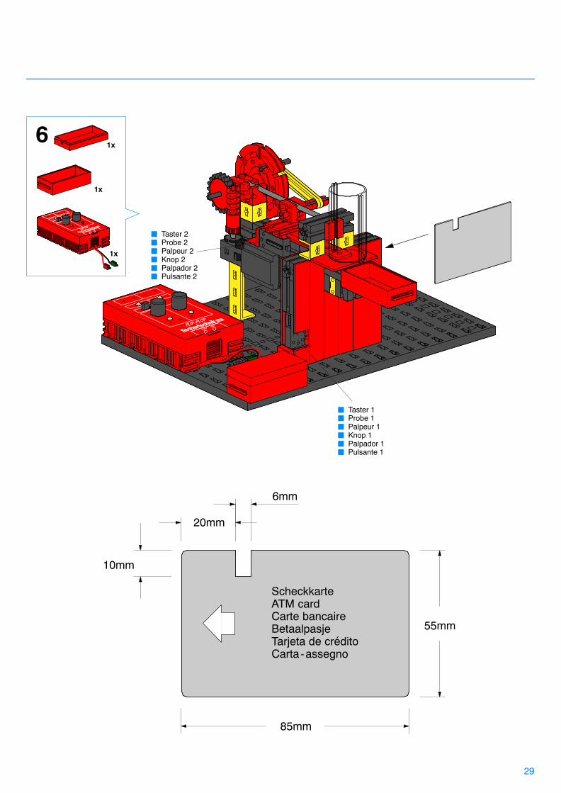
ScheckkarteATM cardCarte bancaireBetaalpasjeTarjeta de créditoCarta-assegno
85mm
55mm
20mm
6mm
10mm
61x
1x
1x
� Taster 2� Probe 2� Palpeur 2� Knop 2� Palpador 2� Pulsante 2
� Taster 1� Probe 1� Palpeur 1� Knop 1� Palpador 1� Pulsante 1
9 V
� Einstellungen: Empfindlichkeit Sensor 1: Einstellung siehe “Funktionsweise”Empfindlichkeit Sensor 2: MittelstellungUmkehrschalter: Position AFunktionsweise:Zuerst benötigt man eine Scheckkarte, die wie auf Seite 29 beschriebenausgeschnitten wird. Am besten verwendet man dafür dicken Karton,so daß kein Licht durchscheinen kann. Genau an der Stelle, wo sich ander Karte die Aussparung befindet, ist am Modell eine Lichtschrankeangebracht. Wenn man die Karte in den Automaten steckt, wird Taster 1betätigt, der die Lampe der Lichtschranke einschaltet. Nun muß mandie Empfindlichkeit von Sensor 1 so weit in Richtung 0 drehen, daß derMotor genau dann eingeschaltet wird und eine Münze ausgibt, wenndas Licht der Lichtschranke durch die Aussparung der Karte scheint.Wird die Karte falsch eingeführt, oder steckt eine falsche Karte im Auto-mat, darf der Motor nicht eingeschaltet werden. Nach Ausgabe einerMünze wird der Motor über Taster 2 automatisch wieder ausgeschaltet.
Schaltplan Geldautomat Schakelschema GeldautomaatCircuit diagram ATM Machine Diagrama de circuitos Cajero automáticoPlan électrique Distributeur automatique de monnaie Schema elettrico Distributore automatico di moneta
30
� Settings:Sensitivity of Sensor 1: Refer to the ”Operation” information
below for the correct setting.Sensitivity of Sensor 2: Middle positionReversing switch: Position AOperation:First, cut out an ATM or credit card as described on page 29. Usethick cardboard for the card, so that no light can shine through. A lightbar is mounted on the model at the exact location of the notch in theATM card. Inserting the card in the ATM machine activates Probe 1which, in turn, switches the lens tip lamp of the light bar on. Now,adjust the sensitivity of Sensor1 by turning the dial towards 0 until themotor switches on and a coin is dispensed when the light from thelight bar shines through the notch in the card. The motor must not runif the card is not inserted correctly, or if the wrong card is used. Oncea coin has been dispensed, Probe 2 automatically turns the motor off.
� Réglages:Sensibilité capteur 1: réglage, voir “Mode de fonctionnement”Sensibilité capteur 2: position centraleCommutateur d’inversion: position AMode de fonctionnement:On a besoin d’abord d’une carte bancaire découpée comme décrit enpage 29. Le mieux est d’utiliser à cet effet du carton épais afin que lalumière ne puisse pas traverser. Dans le modèle, un barrage photo-électrique est placé exactement à l’endroit où se trouve l’évidement dela carte. Lorsque l’on introduit la carte dans le distributeur automatique,le palpeur 1, qui met en service la lampe du barrage photoélectrique, est actionné. Il faut maintenant tourner la sensibilité du capteur1 endirection de 0 jusqu’à ce que le moteur soit mis en circuit et distribueune pièce de monnaie lorsque la lumière du barrage photoélectriquetraverse l’évidement de la carte. Si la carte est mal introduite ou si onutilise une fausse carte dans le distributeur automatique, le moteur nedoit pas être mis en circuit. Une fois qu’une pièce de monnaie a étédistribuée, le moteur est remis automatiquement hors circuit à l’aide dupalpeur 2.
� Instellingen:Gevoeligheid sensor 1: voor instelling zie ”werkwijze”Gevoeligheid sensor 2: middenstandOmkeerschakelaar: positie AWerkwijze:Eerst heb je een betaalpasje nodig, dat zoals is beschreven op pagina 29wordt uitgeknipt. Daarvoor kan je het beste dik karton nemen, zodat er geen licht doorheen kan schijnen. Precies op die plaats, waar zichaan de kaart de uitsparing bevindt, is aan het model een lichtbarrièreaangebracht. Wanneer je de kaart in de automaat stopt, wordt knop 1bediend, die het lampje van de lichtbarrière aanzet. Nu moet je de ge-voeligheid van sensor1 zo ver in de richting van 0 draaien, dat de motorprecies op dat moment in werking treedt en een munt afgeeft, wanneerhet licht van de lichtbarrière door de uitsparing van de kaart schijnt.Indien de kaart er verkeerd wordt ingestopt of er een verkeerde kaart inde automaat zit, mag de motor niet in werking worden gezet. Nadat deautomaat een munt heeft afgegeven wordt de motor via knop 2 automa-tisch weer stopgezet.
� Ajustes:Sensibilidad del sensor 1: consultar el ajuste bajo “Funcionamiento”Sensibilidad del sensor 2: En posición central.Interruptor inversor: en la posición A.Funcionamiento: En un principio se necesita una tarjeta de crédito, tal y como se describe en la página 29. Lo mejor es utilizar para ello una cartulinagruesa, de forma que no pueda atravesarla la luz. Exactamente en elpunto dónde se encuentra el orificio de la tarjeta, se encuentra situadoen el modelo la barrera de luz. Si se coloca la tarjeta en el cajero, seacciona el sensor 1, el cual conecta la lámpara de la barrera de luz.Seguidamente debe girarse la sensibilidad del sensor 1 en dirección al0, hasta que el motor sea justo conectado y emita una moneda, cuandola luz de la barrer pase por el orificio de la tarjeta. Si se introduce latarjeta por el lado equivocado o si se coloca una tarjeta falsa en el caj-ero, no debe ponerse en marcha el motor. Después de emitir una mo-neda, se vuelve a desconectar automáticamente el motor a través delsensor 2.
� Impostazioni:Sensibilità Sensore 1: per la regolazione vedi “Funzionamento”Sensibilità Sensore 2: posizione intermediaInvertitore: Posizione AFunzionamento:Prima di tutto è necessario realizzare una scheda, tipo carta-assegno,da ritagliare come descritto alla pagina 29. Come materiale sarà meglioutilizzare del cartone spesso, in modo che la luce non possa di normafiltrare attraverso la scheda. Il modello è dotato di barriera fotoelettricaorientata proprio sul foro appositamente ritagliato sulla scheda. Inser-endo la scheda nel distributore automatico, si attiva il pulsante 1 che vaad accendere la lampada della barriera fotoelettrica. Ora è necessarioregolare la sensibilità del Sensore1 girando il selettore verso il valore 0,in modo che il motorino venga azionato e distribuisca la moneta esatta-mente nel momento in cui il fascio di luce della barriera fotoelettricapassa attraverso il foro della scheda. Se la scheda non viene inserita inmodo corretto, o se nel distributore automatico viene inserita unascheda non correttamente preparata, quindi fasulla, il motorino non puòessere azionato. Dopo aver distribuito una moneta, il motorino vieneautomaticamente disinserito tramite il pulsante 2.
FLIP-FLOP
10 0
+ - + -
A B
+
-
FLIP FLOP
M M
10 0
1 2
+
+
...
-
A
� Lichtschranke� Light bar� Barrage photoélectrique� Lichtbarrière� Barrera de luz� Barriera fotoelettrica
30 cm
30 cm30 cm
30 cm
40 cm
� Taster 2� Probe 2� Palpeur 2� Knop 2� Palpador 2� Pulsante 2
� Taster 1� Probe 1� Palpeur 1� Knop 1� Palpador 1� Pulsante 1
� Kugellampe� Bulb lamp� Lampe sphérique� Bolle lamp� Bombilla globular� Lampada sferica

31
1
3x 2x
2x
1x
1x
3x
1x
1x
1x
1x3x
1x
2x
2x
1x
1x
1x
1x
4x 3x
3x
2x
2x
2x
2x
2x
1x
1x
1x
1x1x
1x1x
30°
2
30°
1x
1x
1x 1x
4x 2x 3x
2x 1x1x
3
1x
60
110
Sortierband SorteerbandSorter Cinta clasificadoraTapis de triage Nastro selezionatore
32
4 1x
1x 1x 2x
1x
1x
1x 2x
2x
1x1x
38x
1x
1x 1x 77x
2x1x
51x
1x
1x

FLIP-FLOP
� Einstellungen: Umkehrschalter: Position BEmpfindlichkeit Sensor 1 und Sensor 2: MittelstellungFunktionsweise:Das Sortierband trennt magnetische von nicht magnetischen Bausteinen. Als magnetisches Teil dient der fischertechnik Magnet, der an einem Baustein befestigt ist. Der Magnet ist so stark, daß ihn derMagnetsensor sicher erkennt. Beim Einschalten der Stromversorgungläuft zunächst das Band. Das leere Band wird über den Taster aus-geschaltet. Zum Starten legt man Bausteine auf die Rutsche. Die aufdas Band rutschenden Steine unterbrechen die Lichtschranke und setzen das Band in Gang. Alle nicht magnetischen Teile fallen in denBehälter. Kommt der Baustein mit Magnet am Magnetsensor vorbei,hält das Band an, die Lampe leuchtet und der Magnet kann aussortiertwerden. In Recycling-Centern wird auf diese Art z.B. Metall von anderen Abfällen getrennt.Hinweis: Läuft das Band in die falsche Richtung, Motor umpolen.
Schaltplan Sortierband Schakelschema SorteerbandCircuit diagram Sorter Diagrama de circuitos Cinta clasificadoraPlan électrique Tapis de triage Schema elettrico Nastro selezionatore
33
� Settings:Reversing switch: Position BSensitivity of Sensor 1 and Sensor 2: Middle positionOperation:The sorter separates magnetic from non-magnetic building blocks. Thefischertechnik magnet attached to a building blocks acts as a magneticpart. The magnet is strong enough for the magnetic sensor to recognizeit. When power is switched on, the conveyor belt begins running. Theprobe switches the empty conveyor belt off. To start the model, placesome building blocks on the slide. As the building blocks slide onto theconveyor belt, they interrupt the light bar, and the conveyor belt startsrunning. All non-magnetic parts fall into the container. When a buildingblock with a magnet passes the magnetic sensor, the conveyor beltstops, the light goes on, and the magnetic piece can be removed. Thisprocess is used by recycling centers to separate metal parts from otherwaste materials.Note:If the conveyor belt moves in the wrong direction, reverse the motorterminal connections.
� Réglages:Commutateur d’inversion: position BSensibilité capteur 1 et capteur 2: position centraleMode de fonctionnement:Le tapis de triage sépare les éléments magnétiques des éléments nonmagnétiques. L’aimant fischertechnik sert de pièce magnétique, il estfixé à un élément. L’aimant est si puissant que le capteur magnétiquel’identifie à coup sûr. Lors de la mise en circuit de l’alimentation électrique, le tapis se met en mouvement. Le tapis vide est mis horscircuit à l’aide du palpeur. Pour faire démarrer l’installation, on pose deséléments sur le glissoire. Les éléments qui glissent sur le tapis inter-rompent le barrage photoélectrique et mettent le tapis en marche.Toutes les pièces non magnétiques tombent dans le collecteur. Si l’élément qui comporte un aimant passe devant le capteur magnétique, letapis s’arrête, la lampe s’éclaire et l’aimant peut être retiré. Dans les centresde recyclage, on sépare ainsi, par exemple, le métal des autres déchets.Remarque:si le tapis se déplace dans le mauvais sens, inverser la polarité du mo-teur.� Instellingen:Omkeerschakelaar: positie BGevoeligheid sensor 1 en sensor 2: middenstandWerkwijze:De sorteerband scheidt magnetische van niet magnetische bouw-stenen. Als magnetisch onderdeel dient de fischertechnik-magneet, dieis bevestigd aan een bouwsteen. De magneet is zo sterk, dat de magneetsensor hem zeker herkent. Bij het aanzetten van de voedingbegint eerst de band te lopen. De lege band wordt via een knop afge-zet. Om de band te starten leg je bouwstenen op de glijbaan. De op deband glijdende stenen onderbreken de lichtbarrière en zetten de bandin werking. Alle niet magnetische onderdelen vallen in de bak. Wanneerer een bouwsteen met magneet langs de magneetsensor komt, stoptde band, brandt het lampje en kan de magneet worden uitgesorteerd. Inrecycling-centra wordt op deze manier b.v. metaal gescheiden vanander afval.Let op:wanneer de band in de verkeerde richting loopt, moet de motor wordenomgepoold.
� Ajustes:Interruptor inversor: en la posición BSensibilidad del sensor 1 y sensor 2: En posición central.Funcionamiento:La cinta clasificadora separa componentes magnéticos de los no magnéticos. Las piezas magnéticas utilizadas son imanes Fischertechnikque se encuentran fijados en las piezas. El imán tiene una fuerza talque es detectado seguramente por el sensor magnético.Si se conectala corriente, se pone en marcha primero la cinta. La cinta vacía es des-conectada a través del sensor. Para ponerla en marcha, se colocancomponentes encima del plano inclinado. Las piedras que caen encimade la cinta interrumpen la barrera de luz y ponen en marcha la cinta.Las piezas no magnéticas caen dentro del recipiente. Si pasa un componente y un imán cerca del sensor magnético, se detiene la cinta,se ilumina la lámpara y puede seleccionarse el imán. En centros dereciclaje se separa por este modo metal de otro tipo de desperdicios.Aviso:Si la cinta transportadora va en la dirección contraria, debe cambiarsela polación del motor.
� Impostazioni:Invertitore: Posizione BSensibilità Sensore 1 e Sensore 2: posizione intermediaFunzionamento:Il nastro selezionatore separa gli oggetti magnetici dagli oggetti nonmagnetici. Come elemento magnetico si utilizza il magnete fischertechnik fissato ad un oggetto. Il magnete è talmente potente daessere sicuramente riconosciuto dal sensore magnetico. Inserendo lacorrente il nastro si mette in moto. Il nastro vuoto viene fermato dal pulsante. Per iniziare è necessario porre degli oggetti, ad es. dellepietre, sullo scivolo. Gli oggetti che scivolano sul nastro interrompono labarriera fotoelettrica mettendo in movimento il nastro. Tutti i pezzi nonmagnetici ricadono nel recipiente. Quando l’oggetto su cui è fissato ilmagnete passa davanti al sensore magnetico, il nastro si ferma, la lampada si accende e il magnete può essere selezionato. E’ propriograzie a questo metodo che nei centri di riciclaggio vengono separati ades. gli oggetti metallici da tutti gli altri rifiuti. Nota:Se il nastro avanza nella direzione contraria, invertire i poli del motorino.
2
10 0
+ -
A B
+ -
FLIP FLOP
M M
10 0
1
+
B
� Lichtschranke� Light bar� Barrage photoélectrique� Lichtbarrière� Barrera de luz� Barriera fotoelettrica
� Kugellampe� Bulb lamp� Lampe sphérique� Bolle lamp� Bombilla globular� Lampada sferica
+
...
-
9 V
30 cm
30 cm
30 cm
30 cm
40 cm� Linsenlampe� Lens tip lamp� Ampoule lentille� Lenslampje� Bombilla lenticular� Lampada lenticolare
10
Beispiel: Modell Händetrocknery Um die Funktionsweise des Flip-Flop-Bau-steins besser zu verstehen, bauen wir nundas Modell Händetrockner:
Example: Hand dryermodely We will use a hand dryer as a model toprovide a better understanding of the Flip-Flop building block’s operation:
Exemple: modèle sèche-mainsy Afin de mieux comprendre le fonctionne-ment de l’élément flip-flop, assemblons maintenant le modèle sèche-mains:
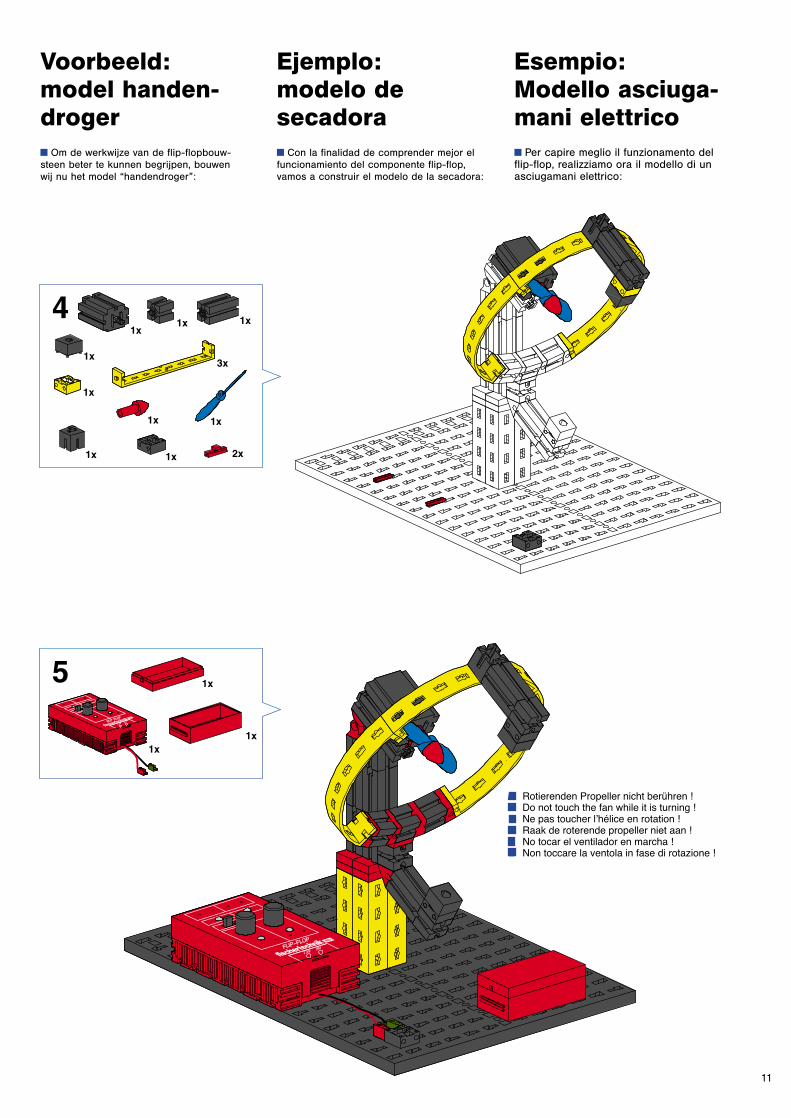
11
Voorbeeld:model handen-drogery Om de werkwijze van de flip-flopbouw-steen beter te kunnen begrijpen, bouwen wij nu het model “handendroger”:
Ejemplo: modelo de secadoray Con la finalidad de comprender mejor elfuncionamiento del componente flip-flop,vamos a construir el modelo de la secadora:
Esempio:Modello asciuga-mani elettricoy Per capire meglio il funzionamento delflip-flop, realizziamo ora il modello di unasciugamani elettrico:
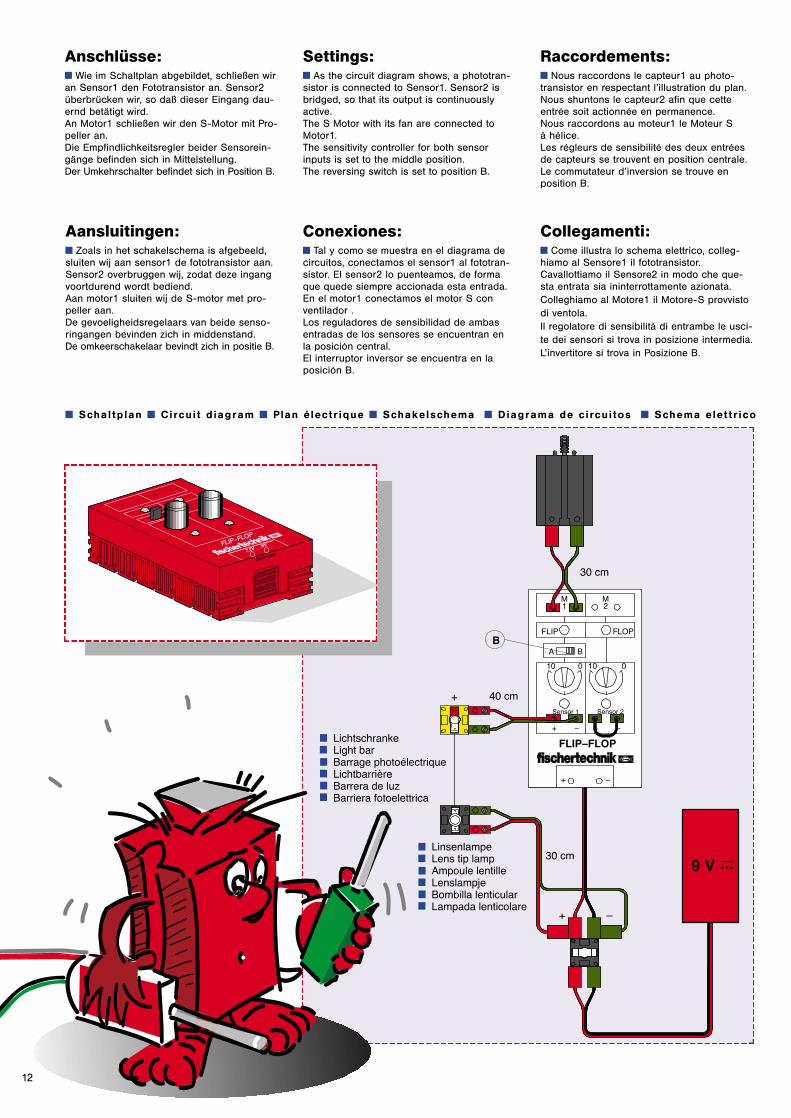
12
Anschlüsse:y Wie im Schaltplan abgebildet, schließen wiran Sensor1 den Fototransistor an. Sensor2überbrücken wir, so daß dieser Eingang dau-ernd betätigt wird. An Motor1 schließen wir den S-Motor mit Pro-peller an.Die Empfindlichkeitsregler beider Sensorein-gänge befinden sich in Mittelstellung.Der Umkehrschalter befindet sich in Position B.
Settings:y As the circuit diagram shows, a phototran-sistor is connected to Sensor1. Sensor2 isbridged, so that its output is continuouslyactive.The S Motor with its fan are connected toMotor1.The sensitivity controller for both sensorinputs is set to the middle position.The reversing switch is set to position B.
Raccordements:y Nous raccordons le capteur1 au photo-transistor en respectant l’illustration du plan.Nous shuntons le capteur2 afin que cetteentrée soit actionnée en permanence. Nous raccordons au moteur1 le Moteur S à hélice.Les régleurs de sensibilité des deux entréesde capteurs se trouvent en position centrale.Le commutateur d’inversion se trouve enposition B.
Aansluitingen:y Zoals in het schakelschema is afgebeeld,sluiten wij aan sensor1 de fototransistor aan.Sensor2 overbruggen wij, zodat deze ingangvoortdurend wordt bediend. Aan motor1 sluiten wij de S-motor met pro-peller aan.De gevoeligheidsregelaars van beide senso-ringangen bevinden zich in middenstand.De omkeerschakelaar bevindt zich in positie B.
Conexiones:y Tal y como se muestra en el diagrama decircuitos, conectamos el sensor1 al fototran-sistor. El sensor2 lo puenteamos, de formaque quede siempre accionada esta entrada.En el motor1 conectamos el motor S conventilador .Los reguladores de sensibilidad de ambasentradas de los sensores se encuentran enla posición central.El interruptor inversor se encuentra en laposición B.
Collegamenti:y Come illustra lo schema elettrico, colleg-hiamo al Sensore1 il fototransistor.Cavallottiamo il Sensore2 in modo che que-sta entrata sia ininterrottamente azionata. Colleghiamo al Motore1 il Motore-S provvistodi ventola.Il regolatore di sensibilità di entrambe le usci-te dei sensori si trova in posizione intermedia.L’invertitore si trova in Posizione B.
y S ch a l t p l a n y C i rc u i t d i a g r a m y P l a n é l e c t r i q u e y S ch a k e l s ch e m a y D i a g r a m a d e c i rc u i t o s y S ch e m a e l e t t r i c o

fischerwerke Artur Fischer GmbH & Co. KGD-72178 WaldachtalTelefon 0 74 43/12-4 369
S E N S O R I CS E N S O R I CP RO F IP R O F I
39
57
4 K
W 0
5/9
7•
Pri
nte
d i
n G
erm
an
y •
Te
ch
nis
ch
e Ä
nd
eru
ng
en
vo
rbe
ha
lte
n •
Su
bje
ct
to t
ec
hn
ica
l m
od
ific
ati
on
s
PROFI SENSORICPROFI SENSORIC