
Serie C 146 Schwere Steckverbinder - farnell.com · 6 Amphenol Kurzinformation Brief information C...
220
Series C 146 Heavy duty connectors Serie C 146 Schwere Steckverbinder Amphenol Amphenol-Tuchel Electronics GmbH
Transcript of Serie C 146 Schwere Steckverbinder - farnell.com · 6 Amphenol Kurzinformation Brief information C...
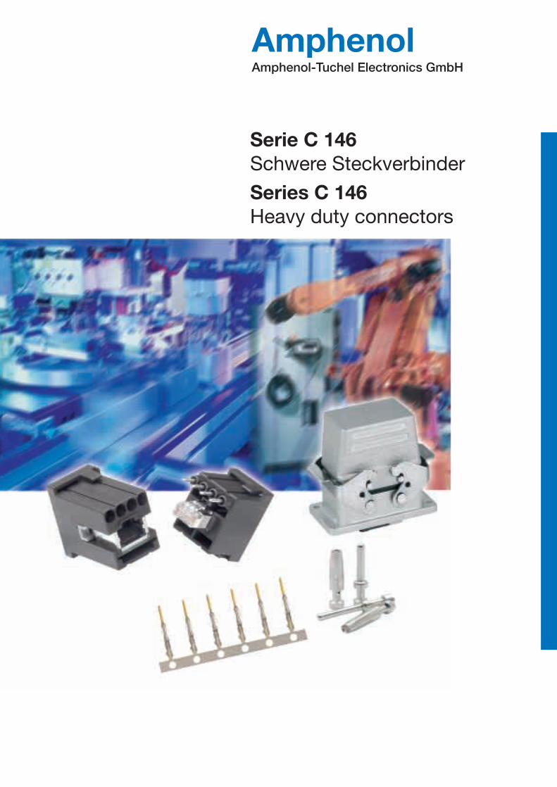
Series C 146Heavy duty connectors
Serie C 146Schwere Steckverbinder
AmphenolAmphenol-Tuchel Electronics GmbH

Das UnternehmenAmphenol-Tuchel Electronics GmbH ist ein Unternehmen der US-amerikanischen Amphenol Corporation. Unsere eigenständige globalePräsenz im Hinblick auf Entwicklung, Produktion und Vertrieb ermöglicht esuns, für unsere Kunden außergewöhnliche technische Lösungen und einenoptimalen Service zu bieten. Amphenol-Tuchel Electronics GmbH ist seitJahren ein erfolgreicher Partner seiner Kunden und setzt Maßstäbe in derVerbindungstechnik.
Allgemeine HinweiseDiese Steckverbinder sind in Übereinstimmung mit der Niederspannungs-richtlinie (73/23/EWG) und des Gerätesicherheitsgesetzes entwickelt undgefertigt und entsprechen im besonderen den Normen DIN EN 61984 (VDE 0627); IEC 60664-1 (VDE 0110-1) und IEC 60529.Die Steckverbinder dürfen nur entsprechend den angegebenen Bemessungs-größen eingesetzt werden.
Die angegebenen Bemaßungen bei den Montageausschnitten stellenAnhaltswerte dar und sind im konkreten Anwendungsfall auf die Produkteabzustimmen.
Die Überprüfung, ob in speziellen, von uns nicht vorgesehenen Anwendungs-bereichen die in diesem Katalog gezeigten Bauelemente anderen als denangegebenen Vorschriften entsprechen, obliegt dem Anwender.Konstruktionsänderungen aufgrund von Qualitätsverbesserungen, Weiterent-wicklungen oder Fertigungsfordernissen behalten wir uns vor. Mit denAngaben im Katalog werden die Bauelemente spezifiziert, nicht Eigenschaftenzugesichert. Weiterverwertung dieser Katalogunterlagen in jeder Form ist nurmit unserer schriftlichen Genehmigung gestattet (URHG, UWG, BGB).
General informationThese connectors are designed and produced in conformity with the lowvoltage directive (73/23/EWG) respectively Gerätesicherheitsgesetz (Germanlaw) and are especially in accordance with the standards DIN EN 61984(VDE0627); IEC 60664-1 (VDE 0110-1) nad IEC 60529.The connectors may be used only within the technical ratings.
The indicated dimensions with the panel cut-outs represent reference valuesand are in the concrete application with products to be co-ordinated.
It is the users responsability to check whether the components illustrated inthis catalogue comply with different regulations from those stated in specialfields of application which we are unable to foresee. We reserve the right tomodify designs in order to improve quality, keep pace with technologicaladvancement or meet particular requirements in production. This cataloguemust not be used in any form or manner without our prior approval in writing(Copyright Law, Fair Trading Law, Civil Code).
The CompanyAmphenol-Tuchel Electronics GmbH is a member of the USA basedAmphenol Corporation. With our own global presence we offer ourcustomers exceptional technical support and service in the areas of development, production and distribution. Amphenol-Tuchel ElectronicsGmbH has a successful history as a partner to our customers and setsstandards for connector technology.
2 Amphenol

Bestellnummernsystem / Part No. system
Serie C 146 D
Serie C 146 DD
Serie C 146 E
Serie C 146 EE
Serie C 146 E / D
Serie C 146 E / FE / KO
Serie C 146 M
Serie C 146 A
Serie C 146 HSE
Serie C 146 HvE
Serie C 146 S
Gehäuse / Housings
EMV Gehäuse / EMC housings
Zubehör / Accessories
Weitere Informationen/ Additional information
Maßzeichnungen Kontakte / Drawings of contactsSicherheitseinteilung / Safety classificationAllgemeine Technische Informationen / General technical informationBestellnummernverzeichnis / Summary of Part Numbers
• Bemessungsspannung 250 V• Bemessungsstrom 10 A ... 16 A• Anschlussart: crimpen• Kontaktdurchmesser 1,6 mm• Nach DIN EN 175 301 801 (DIN 43652)• Polzahl: 7, 15, 25, 40, 50, 64, 128
• Polzahl: 24, 42, 72, 108, 216
• Bemessungsspannung 400 V• Bemessungsstrom 16 A ... 22 A• Anschlussart: vorwiegend schrauben, crimpen• Kontaktdurchmesser 2,5 mm• Polzahl: 6, 10, 16, 24, 48
• Polzahl: 10, 18, 32, 46
Anschlussverteiler
Steckverbinder mit Eisenkonstantan Kontakten
• Modular aufgebauter Steckverbinder• Bemessungsspannung 63 - 1000 V• Bemessungsstrom 5 A ... 70 A• Anschlussart: crimpen• Polzahl: 3 - 280
• Schmale Bauform• Bemessungsspannung 250 / 400 V• Bemessungsstrom 14 A ... 18 A• Anschlussart: schrauben• Polzahl: 3, 4, 10, 16, 32
• Bemessungsspannung 400 V• Bemessungsstrom 42 A• Anschlussart: schrauben• Anschlussquerschnitt 6 mm2
• Polzahl: 6
• Bemessungsspannung 660 V• Bemessungsstrom 16 A ... 22 A• Anschlussart: schrauben• 2 nacheilende Schaltkontakte • Polzahl: 3, 6, 10, 16, 20, 26, 32
• Bemessungsspannung 125 - 600 V• Bemessungsstrom 10 A ... 70 A• Anschlussart: crimpen, schrauben, löten• Polzahl: 4, 57
• Rated voltage 250 V• Rated current 10 A ... 16 A• Termination: crimp• Contact diameter 1,6 mm• According to DIN EN 175 301 801 (DIN 43652)• Number of contacts: 7, 15, 25, 40, 50, 64, 128
• Number of contacts: 24, 42, 72, 108, 216
• Rated voltage 400 V• Rated current 16 A ... 22 A• Termination: mainly screw, crimp• Contact diameter 2,5 mm• Number of contacts: 6, 10 ,16, 24, 48
• Number of contacts: 10, 18, 32, 46
Terminal blocks
Connectors with iron-constantan contacts
• Modular connector• Rated voltage 63 - 1000 V• Rated current 5 A ... 70 A• Termination: crimp• Number of contacts: 3 - 280
• Narrow style• Rated voltage 250 / 400 V• Rated current 14 A ... 18 A• Termination: screw• Number of contacts: 3, 4, 10, 16, 32
• Rated voltage 400 V• Rated current 42 A• Termination: screw• Max. wire gauge 6 mm2
• Number of contacts: 6
• Rated voltage 660 V• Rated current 16 A ... 22 A• Termination: screw• 2 delayed mating contacts• Number of contacts: 3, 6, 10, 16, 20, 26, 32
• Rated voltage 125 - 600 V• Rated current 10 A ... 70 A• Termination: crimp, screw, solder• Number of contacts: 4, 57
4
5
25
29
45
49
53
57
85
93
97
105
113
167
179
187
191
192
212
Seite/PageInhaltsverzeichnis Content
Amphenol 3
D
DD
E
E/D
EE
E/FE/KO
M
A
HSE
HvE
S
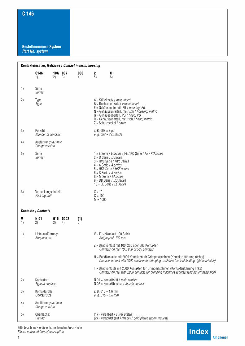
Kontakteinsätze, Gehäuse / Contact inserts, housing
C146 10A 007 000 2 C1) 2) 3) 4) 5) 6)
1) SerieSeries
2) Type A = Stifteinsatz / male insertType B = Buchseneinsatz / female insert
F = Gehäuseunterteil, PG / housing, PGN = Gehäuseunterteil, metrisch / housing, metricG = Gehäuseoberteil, PG / hood, PGR = Gehäuseoberteil, metrisch / hood, metricZ = Schutzdeckel / cover
3) Polzahl z. B. 007 = 7 polNumber of contacts e. g. 007 = 7 contacts
4) AusführungsvarianteDesign version
5) Serie 1 = E Serie / E series + FE / KO Serie / FE / KO seriesSeries 2 = D Serie / D series
3 = HVE Serie / HVE series4 = A Serie / A series5 = HSE Serie / HSE series6 = S Serie / S series8 = M Serie / M series9 = DD Serie / DD series10 = EE Serie / EE series
6) Verpackungseinheit X = 10Packing unit C = 100
M = 1000
Kontakte / Contacts
V N 01 016 0002 (1)1) 2) 3) 4) 5)
1) Lieferausführung: V = Einzelkontakt 100 StückSupplied as: Single pack 100 pcs.
Z = Bandkontakt mit 100, 200 oder 500 KontaktenContacts on reel 100, 200 or 500 contacts
H = Bandkontakte mit 2000 Kontakten für Crimpmaschinen (Kontaktzuführung rechts)Contacts on reel with 2000 contacts for crimping machines (contact feeding right hand side)
T = Bandkontakte mit 2000 Kontakten für Crimpmaschinen (Kontaktzuführung links)Contacts on reel with 2000 contacts for crimping machines (contact feeding left hand side)
2) Kontaktart: N 01 = Kontaktstift / male contactType of contact: N 02 = Kontaktbuchse / female contact
3) Kontaktgröße z. B. 016 = 1,6 mmContact size e. g. 016 = 1,6 mm
4) AusführungsvarianteDesign version
5) Oberfläche: (1) = versilbert / silver platedPlating: (2) = vergoldet (auf Anfrage) / gold plated (upon request)
4 Amphenol
Bestellnummern SystemPart No. system
C 146
Bitte beachten Sie die entsprechenden ZusatztextePlease notice additional description

C 146 D
• Bemessungsspannung 250 V• Bemessungsstrom 10 A ... 16 A• Anschlussart: crimpen• Kontaktdurchmesser 1,6 mm• nach DIN EN 175 301-801 (DIN 43652)• Polzahl: 7, 15, 25, 40, 50, 64, 128
• Rated voltage 250 V• Rated current 10 A ... 16 A• Termination: crimp• Contact diameter 1,6 mm• According to DIN EN 175 301-801 (DIN 43652)• Number of contacts: 7, 15, 25, 40, 50, 64, 128
Hauptmerkmale Main characteristics
Amphenol 5
D
SEV 250 V, 10 A
UL 600 V, 10 A E 63093600 V, 15 A (Hochstrom / High current)
CSA 600 V, 10 A 48932
Zulassungen / ApprovalsPrüfstelle / Testhouse Kennwerte / Characteristics Zulassungs-Nummer / Approval-No.
Zulassungen beziehen sich im allgemeinen auf repräsentativeAusführungen der Steckverbinderserie. Prüfumfang undPrüfvorschrift auf Anfrage.
In general approvals refer to representative versions of the connectorseries. Extent and specification of tests upon request.
6 Amphenol
KurzinformationBrief information
C 146 D
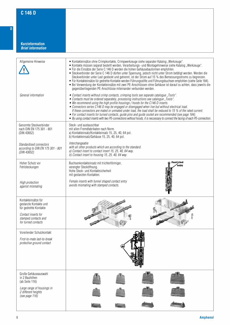
Allgemeine Hinweise
General information
• Kontakteinsätze ohne Crimpkontakte, Crimpwerkzeuge siehe separater Katalog „Werkzeuge“.• Kontakte müssen separat bestellt werden, Verarbeitungs- und Montagehinweise siehe Katalog „Werkzeuge“.• Für die Einsätze der Serie C 146 D werden die hohen Gehäusebauformen empfohlen.• Steckverbinder der Serie C 146 D dürfen unter Spannung, jedoch nicht unter Strom betätigt werden. Werden die
Steckverbinder unter Last gesteckt und getrennt, ist der Strom auf 15 % des Bemessungsstroms zu begrenzen.• Für Kontakteinsätze für gedrehte Kontakte werden Führungsstifte und Führungsbuchsen empfohlen (siehe Seite 184).• Bei Verwendung der Kontakteinsätze mit zwei PE-Anschlüssen ohne Gehäuse ist darauf zu achten, dass jeweils die
gegenüberliegenden PE-Anschlüsse miteinander verbunden werden.
• Contact inserts without crimp contacts, crimping tools see separate catalogue „Tools“.• Contacts must be ordered separately, processing instructions see catalogue „Tools“.• We recommend using the high profile housings / hoods for the C146 D inserts.• Connectors series C146 D may be engaged or disengaged when live but without electrical load.
If these connectors are mated or unmated under load, the load shall be reduced to 15 % of the rated current.• For contact inserts for turned contacts, guide pins and guide socket are recommended (see page 184).• By using contact inserts with two PE-connections without hoods, it is neccessary to connect the facing of each PE-connection.
Hoher Schutz vorFehlsteckungen
High protectionagainst mismating
Buchsenkontakteinsatz mit trichterförmiger,verengter Stecköffnung.Hohe Steck- und Kontaktsicherheit mit gestanzten Kontakten.
Female inserts with funnel shaped contact entry avoids mismating with stamped contacts.
Kontakteinsätze für gestanzte Kontakte und für gedrehte Kontakte
Contact inserts for stamped contacts and for turned contacts
Voreilender Schutzkontakt
First-to-mate last-to-break protective ground contact
Große Gehäuseauswahlin 2 Bauhöhen(ab Seite 116)
Large range of housings in2 different heights(see page 116)
Genormte Steckverbindernach DIN EN 175 301 - 801(DIN 43652)
Standardised connectorsaccording to DIN EN 175 301 - 801(DIN 43652)
Steck- und austauschbarmit allen Fremdfabrikaten nach Norm.a) Kontakteinsatz/Kontakteinsatz 15, 25, 40, 64 pol.b) Kontakteinsatz/Gehäuse 15, 25, 40, 64 pol.
Interchangeablewith all other products which are according to the standard.a) Contact insert to contact insert 15, 25, 40, 64 way.b) Contact insert to housing 15, 25, 40, 64 way.
D

D
Amphenol 7
Crimp TechnikCrimp technology
C 146 D
1) Erläuterung der Bestell-Nr. für die Kontakte siehe Seite 41) Explanation of the Part No. for contacts see page 4
Großer Crimpbereich
Large range of wire gauges
Gasdichte Verbindung(Kaltverschweißung)
Gas-tight (coldwelding)
Gestanzte Crimpkontakte mit Isolierungshalterung ummechanische Beanspruchung von der Crimpverbindungfernzuhalten
Stamped crimp contacts with insulation crimp,to absorbe mechanical stress from the crimped connection
Mechanischer Rasthakenanschlagbei Buchsen- und Stiftkontakt
Einfache Montage
Mechanical retention spring stop on female and male contact
Easy assembly
Kostengünstige, einfacheVerarbeitungWerkzeuge siehe Katalog „Werkzeuge“
Economical and easy processingTools see catalogue „Tools“
Hohe Strombelastbarkeit(siehe Derating Kurven)
High current carrying capacity(see derating curves)
Beispiel Einzelkontakt / Example single contact
Standardkontakt, Anschlussquerschnitt 2,5 mm2
Standard contact, wire gauge 2.5 mm2
Hochstromkontakt, Anschlussquerschnitt 2,5 mm2
High current contact, wire gauge 2.5 mm2
.N01 016 0003 (1) 1) .N01 016 0002 (1) 1) .N01 016 0005 (1) 1)
Hauptmerkmale der gestanzten CrimpkontakteMain characteristics of the stamped crimp contacts
IsolierungshalterungInsulation grip
KleinserieSmall series
SerieSeries
BuchsenkontaktFemale contact
StiftkontaktMale contact
Service-AnwendungenService application
Einzel-FertigungSingle production
Stro
mbe
last
bark
eit I
(A)
Curre
nt ca
rryin
g ca
pacit
y I (A
)
Bauelement Umgebungstemperatur Tu (°C)Ambient temperature Tamb (°C)
Stro
mbe
last
bark
eit I
(A)
Curre
nt ca
rryin
g ca
pacit
y I (A
)
Bauelement Umgebungstemperatur Tu (°C)Ambient temperature Tamb (°C)
1,5 2,50,5 1,0 1,50,14 0,25 0,5

8 Amphenol
Norm / Standard Wert / ValueAllgemeine Kennwerte
Kontakteinsätze / Connector inserts
Polzahl
DIN EN 175 301-801 (DIN 43652)Kontaktanordnung
Number of contacts
Contact arrangement
Anschlusstechnik Termination technique
V-0
crimpen / crimp, wire wrap
Max. Leiterdurchmesser Max. wire diameter 4,1 mm
7 15 25 40 502 x 25 64
• • • •
1282 x 64
Flammability
C 146 D
UL 94Brennbarkeit
250 V~ (400 V~ 1)) (600 V UL / CSA 5))
3
III
III b
4 kV
2,2 kV
siehe Derating Kurven / see derating curves
≥ 10 12 Ω 4)
Electrical Characteristics
Rated voltage
Pollution degree
Installation (overvoltage) category
Material group
Rated impulse withstand voltage
Voltage proof
IEC 60664-1
IEC 60664-1
IEC 60664-1
IEC 60664-1
IEC 60664-1
IEC 60512-2; Test 4 a
IEC 60512-3; Test 5 b
IEC 60512-2; Test 3 a
IEC 60068-1
IEC 60512-7; Test 13 b
IEC 60529
IEC 60512-5; Test 9 a
Rated current
Insulation resistance
Climatical Characteristics
Climatic category
Mechanical Characteristics
Insertion and withdrawal forces
IP-degree of protection pin insert
Weight pin insert
Weight socket insert
Mechanical operation
Insert
40 / 125 / 21
80-120N
100-150N
200-300N
60-90N
40-60N
20-30N
10-15Nungesteckt/unmated
IP00gesteckt/mated
IP20gesteckt/mated
IP20ungesteckt/unmated
IP208 g 28 g 34 g 53 g 68 g 65 g 130 g
8 g 30 g 38 g 64 g 76 g 82 g 164 g
≥ 500 Steckzyklen / mating cycles
PBTP PC GV 2)
grau / grey
Elektrische Kennwerte
Bemessungsspannung 3)
Verschmutzungsgrad
Überspannungskategorie
Isolierstoffgruppe
Bemessungs-Stoßspannung
Spannungsfestigkeit
Strombelastbarkeit
16 A 12 A 12 A 10 A 10 A 10 A 10 ARated current Tamb = 40 °CBemessungsstrom Tu = 40 °C
Isolationswiderstand
> 3,5 mmIEC 60664-1ClearanceLuftstrecke
> 4,6 mmIEC 60664-1CreepageKriechstrecke
Klimatische Kennwerte
Prüfklasse
IEC 60512-6; Test 11 iUpper temperature
Lower temperature
+ 125 °C / 1000 hObere Grenztemperatur
Untere Grenztemperatur IEC 60512-6; Test 11 i - 40 °C / 16 h
Mechanische Kennwerte
Steck- und Ziehkraft
IP-Schutzart Stifteinsatz
IEC 60529IP-degree of protection socket insertIP-Schutzart Buchseneinsatz
Gewicht Stifteinsatz
Gewicht Buchseneinsatz
Mechanische Lebensdauer
Werkstoffe
Kontakteinsatz
Farbe Colour
Materials
General Characteristics
1) bei modifizierter Kontaktanordnung, siehe Seite 24 / modified contact arrangement, see page 242) Polycarbonat-glasfaserverstärkt / polycarbonat-glas fibre filled3) Einschränkung für 8 pol mit Metallgehäuse siehe Seite 10 / Restriction for 8 contacts in metal housing see page 104) bei Beanspruchung > 10 10 Ω / Under operating condition > 10 10 Ω5) Hinweisschild für CSA-Anwendung siehe Seite 186 / Label for CSA application see page 186
Technische DatenCharacteristics
D

D
Amphenol 9
C 146 D
Gestanzte Crimpkontakte / Stamped crimp contacts
IEC 60512-2; Test 2 a
IEC 60512-9; Test 22 a
IEC 60512-9; Test 22 a
≤ 5 m Ω
≥ 2 p F
≥ 3,2 p F
Elektrische Kennwerte
Durchgangswiderstand
Kapazität Kontakt-Kontakt
Elektrische Kennwerte Electrical Characteristics
Kapazität Kontakt-Gehäuse
IEC 60512-5; Test 9 a
IEC 60512-2
≥ 500 Steckzyklen / mating cycles
Mechanische Kennwerte
Klimatische Kennwerte
Mechanische Lebensdauer
Werkstoffe
Cu Zn (Messing /brass)Stiftkontakt
Buchsenkontakt
Kontaktoberfläche
Gedrehte Crimpkontakte / Turned crimp contacts
Electrical Characteristics
Contact resistance
Capacity contact-contact
Capacity contact-housing
Mechanical Characteristics
Climatical Characteristics
Mechanical operation
IEC 60512-6; Test 11 i
IEC 60512-6; Test 11 i
+ 125 °CObere Grenztemperatur Upper temperature
- 40 °CUntere Grenztemperatur Lower temperature
Klimatische Kennwerte Climatical Characteristics
IEC 60512-6
IEC 60512-6
+ 100 °CObere Grenztemperatur Upper temperature
- 40 °CUntere Grenztemperatur Lower temperature
Male contact
Female contact
Contact plating
Materials
Cu Sn (Zinnbronze / Tin bronce)
Ag (silber / silver)
≤ 5 m Ω
Mechanische Kennwerte
Werkstoffe
Mechanical Characteristics
Materials
IEC 60512-5; Test 9 a
Durchgangswiderstand
Mechanische Lebensdauer
Contact resistance
Mechanical operation ≥ 500 Steckzyklen / mating cycles
Stiftkontakt
Buchsenkontakt
Kontaktoberfläche
Male contact
Female contact
Contact plating
Cu Zn (Messing / brass)
Cu Zn (Messing / brass)
Ag (silber / silver)
Technische DatenCharacteristics

10 Amphenol
Bezeichnung - AbbildungDescription - Figure
MaßzeichnungDrawing
Bestell Nr. / Part No.Stifteinsatz / Male insert Buchseneinsatz / Female insert
C 146 D
7 + ,8
SteckverbinderConnectors
Kontakteinsatz / Contact insert 7 +
250 V ~nur für Kunststoffgehäuseonly for thermoplastic housings
StifteinsatzMale insert
BuchseneinsatzFemale insert
StifteinsatzMale insert
BuchseneinsatzFemale insert
Gehäuse siehe Seite 116-119Housings see page 116-119
250 V~ in Kunststoffgehäusein thermoplastic housings
42 V~ in Metallgehäusein metal housings
Kontaktanordnung / Contact arrangement
Stifteinsatz / Male insert
Schutzkontakt voreilendProtective earthing contact preleading
C146 10A007 000 2 1)
(für gestanzte Crimpkontakte)(for stamped crimp contacts)
C146 10B007 000 2 1)
(für gestanzte Crimpkontakte)(for stamped crimp contacts)
C146 10A007 500 2(für gedrehte Crimpkontakte)(for turned crimp contacts)
C146 10B007 500 2(für gedrehte Crimpkontakte)(for turned crimp contacts)
Kontakteinsatz / Contact insert 8 pol
42 V ~
1) auch erhältlich als Großpackung, 100 Stück ... 000 2„C“ / also available for big volume, 100 pcs. ... 000 2„C“
StifteinsatzMale insert
BuchseneinsatzFemale insert
Buchseneinsatz / Female insert Stifteinsatz / Male insert
Hinweis: PE-Kontakt, bei Einsatz bis 42 V~ als Arbeitskontakt verwendbar.Note: For use up to 42 V~, the PE contact can be used as regular contact.
Buchseneinsatz / Female insert
StifteinsatzMale insert
BuchseneinsatzFemale insert
C146 10A008 000 2(für gestanzte Crimpkontakte)(for stamped crimp contacts)
C146 10A008 500 2(für gedrehte Crimpkontakte)(for turned crimp contacts)
C146 10B008 000 2(für gestanzte Crimpkontakte)(for stamped crimp contacts)
C146 10B008 500 2(für gedrehte Crimpkontakte)(for turned crimp contacts)
7 + 8 pol
PE PE
D

D
Amphenol 11
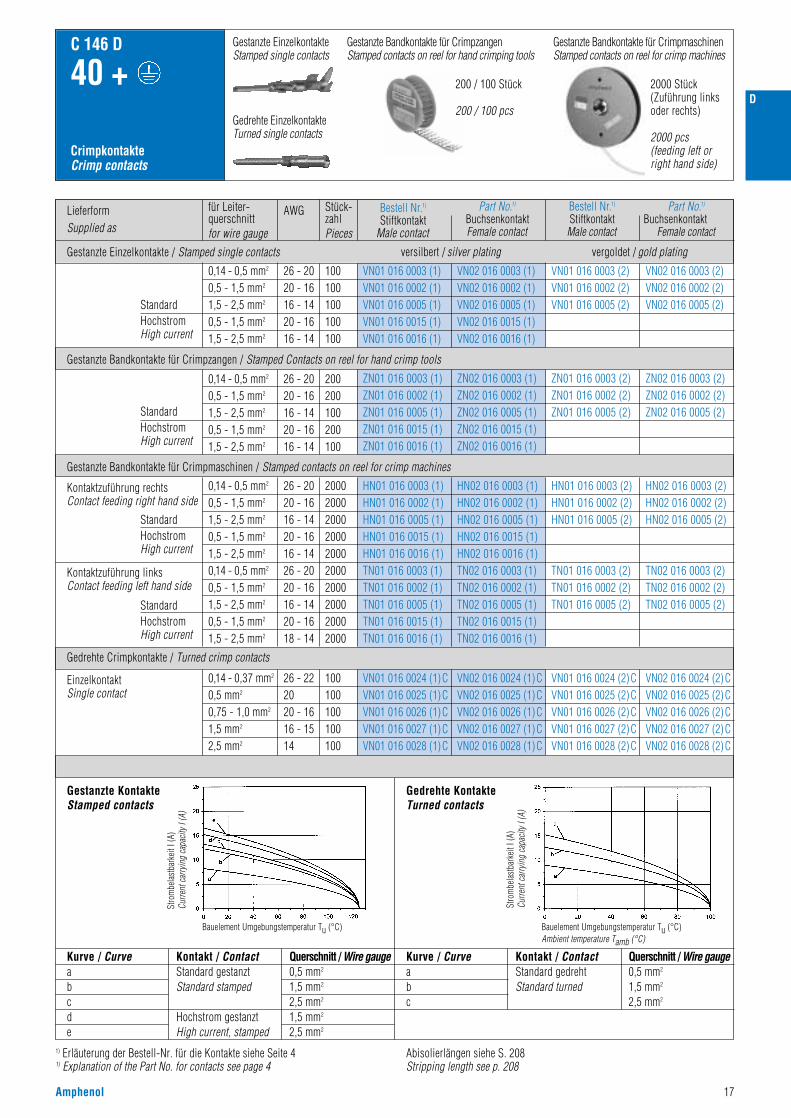
LieferformSupplied as
Gestanzte Einzelkontakte / Stamped single contacts
für Leiter-querschnittfor wire gauge
AWG Stück-zahlPieces
C 146 D
7 + ,8
CrimpkontakteCrimp contacts
StandardHochstromHigh current
StandardHochstromHigh current
StandardHochstromHigh current
StandardHochstromHigh current
0,14 - 0,5 mm2
0,5 - 1,5 mm2
1,5 - 2,5 mm2
0,5 - 1,5 mm2
1,5 - 2,5 mm2
0,14 - 0,5 mm2
0,5 - 1,5 mm2
1,5 - 2,5 mm2
0,5 - 1,5 mm2
1,5 - 2,5 mm2
0,14 - 0,5 mm2
0,5 - 1,5 mm2
1,5 - 2,5 mm2
0,5 - 1,5 mm2
1,5 - 2,5 mm2
0,14 - 0,5 mm2
0,5 - 1,5 mm2
1,5 - 2,5 mm2
0,5 - 1,5 mm2
1,5 - 2,5 mm2
26 - 2020 - 1616 - 1420 - 1616 - 14
26 - 2020 - 1616 - 1420 - 1616 - 14
26 - 2020 - 1616 - 1420 - 1616 - 1426 - 2020 - 1616 - 1420 - 1618 - 14
200200100200100
100100100100100
2000200020002000200020002000200020002000
VN01 016 0003 (1)VN01 016 0002 (1)VN01 016 0005 (1)VN01 016 0015 (1)VN01 016 0016 (1)
ZN01 016 0003 (1)ZN01 016 0002 (1)ZN01 016 0005 (1)ZN01 016 0015 (1)ZN01 016 0016 (1)
HN01 016 0003 (1)HN01 016 0002 (1)HN01 016 0005 (1)HN01 016 0015 (1)HN01 016 0016 (1)TN01 016 0003 (1)TN01 016 0002 (1)TN01 016 0005 (1)TN01 016 0015 (1)TN01 016 0016 (1)
ZN02 016 0003 (1)ZN02 016 0002 (1)ZN02 016 0005 (1)ZN02 016 0015 (1)ZN02 016 0016 (1)
ZN01 016 0003 (2)ZN01 016 0002 (2)ZN01 016 0005 (2)
ZN02 016 0003 (2)ZN02 016 0002 (2)ZN02 016 0005 (2)
VN02 016 0003 (1)VN02 016 0002 (1)VN02 016 0005 (1)VN02 016 0015 (1)VN02 016 0016 (1)
VN01 016 0003 (2)VN01 016 0002 (2)VN01 016 0005 (2)
VN02 016 0003 (2)VN02 016 0002 (2)VN02 016 0005 (2)
HN02 016 0003 (1)HN02 016 0002 (1)HN02 016 0005 (1)HN02 016 0015 (1)HN02 016 0016 (1)TN02 016 0003 (1)TN02 016 0002 (1)TN02 016 0005 (1)TN02 016 0015 (1)TN02 016 0016 (1)
HN01 016 0003 (2)HN01 016 0002 (2)HN01 016 0005 (2)
TN01 016 0003 (2)TN01 016 0002 (2)TN01 016 0005 (2)
HN02 016 0003 (2)HN02 016 0002 (2)HN02 016 0005 (2)
TN02 016 0003 (2)TN02 016 0002 (2)TN02 016 0005 (2)
Kontaktzuführung rechtsContact feeding right hand side
Gestanzte Bandkontakte für Crimpmaschinen / Stamped contacts on reel for crimp machines
Gestanzte Bandkontakte für Crimpzangen / Stamped Contacts on reel for hand crimp tools
Kontaktzuführung linksContact feeding left hand side
1) Erläuterung der Bestell-Nr. für die Kontakte siehe Seite 41) Explanation of the Part No. for contacts see page 4
Abisolierlängen siehe S. 208Stripping length see p. 208
Gestanzte Bandkontakte für CrimpmaschinenStamped contacts on reel for crimp machines
200 / 100 Stück
200 / 100 pcs
2000 Stück(Zuführung linksoder rechts)
2000 pcs(feeding left or right hand side)
0,14 - 0,37 mm2
0,5 mm2
0,75 - 1,0 mm2
1,5 mm2
2,5 mm2
26 - 222020 - 1616 - 1514
100100100100100
VN01 016 0024 (1)CVN01 016 0025 (1)CVN01 016 0026 (1)CVN01 016 0027 (1)CVN01 016 0028 (1)C
VN02 016 0024 (1)CVN02 016 0025 (1)CVN02 016 0026 (1)CVN02 016 0027 (1)CVN02 016 0028 (1)C
VN01 016 0024 (2)CVN01 016 0025 (2)CVN01 016 0026 (2)CVN01 016 0027 (2)CVN01 016 0028 (2)C
VN02 016 0024 (2)CVN02 016 0025 (2)CVN02 016 0026 (2)CVN02 016 0027 (2)CVN02 016 0028 (2)C
Gedrehte Crimpkontakte / Turned crimp contacts
Derating Kurven / Derating curves
Kurve / Curveabcde
Kontakt / ContactStandard gestanztStandard stamped
Hochstrom gestanztHigh current, stamped
Querschnitt / Wire gauge0,5 mm2
1,5 mm2
2,5 mm2
1,5 mm2
2,5 mm2
Kurve / Curveabc
Kontakt / ContactStandard gedrehtStandard turned
Querschnitt / Wire gauge0,5 mm2
1,5 mm2
2,5 mm2
EinzelkontaktSingle contact
Gestanzte EinzelkontakteStamped single contacts
Gestanzte Bandkontakte für CrimpzangenStamped contacts on reel for hand crimping tools
Gedrehte EinzelkontakteTurned single contacts
Stro
mbe
last
bark
eit I
(A)
Curre
nt ca
rryin
g ca
pacit
y I (A
)
Bauelement Umgebungstemperatur Tu (°C)Ambient temperature Tamb (°C)
Gestanzte KontakteStamped contacts
Stro
mbe
last
bark
eit I
(A)
Curre
nt ca
rryin
g ca
pacit
y I (A
)
Bauelement Umgebungstemperatur Tu (°C)Ambient temperature Tamb (°C)
Gedrehte KontakteTurned contacts
Bestell Nr.1)
Stiftkontakt Male contact
versilbert / silver plating vergoldet / gold plating
Part No.1)
BuchsenkontaktFemale contact
Bestell Nr.1)
StiftkontaktMale contact
Part No.1)
BuchsenkontaktFemale contact

12 Amphenol
Bezeichnung - AbbildungDescription - Figure
Montageanleitung, Ansicht von Steckverbinder-AnschlussseiteAssembly instructions, view from termination side
MaßzeichnungDrawing
Bestell Nr. / Part No.Stifteinsatz / Male insert Buchseneinsatz / Female insert
C146 10A015 000 2(für gestanzte Crimpkontakte)(for stamped crimp contacts)
C146 10A015 500 2(für gedrehte Crimpkontakte)(for turned crimp contacts)
C146 10A015 060 2(für gestanzte Crimpkontakte)(for stamped crimp contacts)
C146 10B015 000 2(für gestanzte Crimpkontakte)(for stamped crimp contacts)
C146 10B015 500 2(für gedrehte Crimpkontakte)(for turned crimp contacts)
C146 10B015 060 2(für gestanzte Crimpkontakte)(for stamped crimp contacts)
SteckverbinderConnectors
C 146 D
15 +
Kontakteinsatz Contact insert
C146 10A015 009 2 C146 10B015 009 2
Gehäuse siehe Seite 120–123Housings see page 120–123
250 V~ 10 A/15 A DIN EN 175 301-801 (DIN 43652)
Kontakteinsatz 2 X PE Anschluss 1)
Contact insert 2 X PE termination 1)
StifteinsatzMale insert
BuchseneinsatzFemale insert
StifteinsatzMale insert
StifteinsatzMale insert
BuchseneinsatzFemale insert
BuchseneinsatzFemale insert
StifteinsatzMale insert
BuchseneinsatzFemale insert
Montageausschnitt (Kontaktträger)Panel cut out (insert)
1) Beim Einbau der Steckverbinder in nicht leitende Gehäuse sind beide Schutzleiter (Ausführung 2 x PE) anzuschließen.If connectors are mounted in non conductive housings both protective earthing terminals shall be mounted.
2) IP-Schutzart im Anschlussbereich IP 00IP-degree of protection on termination side IP 00
Wickelanschluss 2)
Wire wrap termination
D

D
Amphenol 13
C 146 D
15 +
CrimpkontakteCrimp contacts
1) Erläuterung der Bestell-Nr. für die Kontakte siehe Seite 41) Explanation of the Part No. for contacts see page 4
Gestanzte Bandkontakte für CrimpmaschinenStamped contacts on reel for crimp machines
200 / 100 Stück
200 / 100 pcs
2000 Stück(Zuführung linksoder rechts)
2000 pcs(feeding left orright hand side)
Derating Kurven / Derating curves
Gestanzte EinzelkontakteStamped single contacts
Gestanzte Bandkontakte für CrimpzangenStamped contacts on reel for hand crimping tools
Gedrehte EinzelkontakteTurned single contacts
Kurve / Curveabcde
Kontakt / ContactStandard gestanztStandard stamped
Hochstrom gestanztHigh current, stamped
Querschnitt / Wire gauge0,5 mm2
1,5 mm2
2,5 mm2
1,5 mm2
2,5 mm2
Kurve / Curveabc
Kontakt / ContactStandard gedrehtStandard turned
Querschnitt / Wire gauge0,5 mm2
1,5 mm2
2,5 mm2
Stro
mbe
last
bark
eit I
(A)
Curre
nt ca
rryin
g ca
pacit
y I (A
)
Bauelement Umgebungstemperatur Tu (°C)Ambient temperature Tamb (°C)
Gestanzte KontakteStamped contacts
Stro
mbe
last
bark
eit I
(A)
Curre
nt ca
rryin
g ca
pacit
y I (A
)
Bauelement Umgebungstemperatur Tu (°C)Ambient temperature Tamb (°C)
Gedrehte KontakteTurned contacts
Abisolierlängen siehe S. 208Stripping length see p. 208
LieferformSupplied as
Gestanzte Einzelkontakte / Stamped single contacts
für Leiter-querschnittfor wire gauge
AWG Stück-zahlPieces
StandardHochstromHigh current
StandardHochstromHigh current
StandardHochstromHigh current
StandardHochstromHigh current
0,14 - 0,5 mm2
0,5 - 1,5 mm2
1,5 - 2,5 mm2
0,5 - 1,5 mm2
1,5 - 2,5 mm2
0,14 - 0,5 mm2
0,5 - 1,5 mm2
1,5 - 2,5 mm2
0,5 - 1,5 mm2
1,5 - 2,5 mm2
0,14 - 0,5 mm2
0,5 - 1,5 mm2
1,5 - 2,5 mm2
0,5 - 1,5 mm2
1,5 - 2,5 mm2
0,14 - 0,5 mm2
0,5 - 1,5 mm2
1,5 - 2,5 mm2
0,5 - 1,5 mm2
1,5 - 2,5 mm2
26 - 2020 - 1616 - 1420 - 1616 - 14
26 - 2020 - 1616 - 1420 - 1616 - 14
26 - 2020 - 1616 - 1420 - 1616 - 1426 - 2020 - 1616 - 1420 - 1618 - 14
200200100200100
100100100100100
2000200020002000200020002000200020002000
VN01 016 0003 (1)VN01 016 0002 (1)VN01 016 0005 (1)VN01 016 0015 (1)VN01 016 0016 (1)
ZN01 016 0003 (1)ZN01 016 0002 (1)ZN01 016 0005 (1)ZN01 016 0015 (1)ZN01 016 0016 (1)
HN01 016 0003 (1)HN01 016 0002 (1)HN01 016 0005 (1)HN01 016 0015 (1)HN01 016 0016 (1)TN01 016 0003 (1)TN01 016 0002 (1)TN01 016 0005 (1)TN01 016 0015 (1)TN01 016 0016 (1)
ZN02 016 0003 (1)ZN02 016 0002 (1)ZN02 016 0005 (1)ZN02 016 0015 (1)ZN02 016 0016 (1)
ZN01 016 0003 (2)ZN01 016 0002 (2)ZN01 016 0005 (2)
ZN02 016 0003 (2)ZN02 016 0002 (2)ZN02 016 0005 (2)
VN02 016 0003 (1)VN02 016 0002 (1)VN02 016 0005 (1)VN02 016 0015 (1)VN02 016 0016 (1)
VN01 016 0003 (2)VN01 016 0002 (2)VN01 016 0005 (2)
VN02 016 0003 (2)VN02 016 0002 (2)VN02 016 0005 (2)
HN02 016 0003 (1)HN02 016 0002 (1)HN02 016 0005 (1)HN02 016 0015 (1)HN02 016 0016 (1)TN02 016 0003 (1)TN02 016 0002 (1)TN02 016 0005 (1)TN02 016 0015 (1)TN02 016 0016 (1)
HN01 016 0003 (2)HN01 016 0002 (2)HN01 016 0005 (2)
TN01 016 0003 (2)TN01 016 0002 (2)TN01 016 0005 (2)
HN02 016 0003 (2)HN02 016 0002 (2)HN02 016 0005 (2)
TN02 016 0003 (2)TN02 016 0002 (2)TN02 016 0005 (2)
Kontaktzuführung rechtsContact feeding right hand side
Gestanzte Bandkontakte für Crimpmaschinen / Stamped contacts on reel for crimp machines
Gestanzte Bandkontakte für Crimpzangen / Stamped Contacts on reel for hand crimp tools
Kontaktzuführung linksContact feeding left hand side
0,14 - 0,37 mm2
0,5 mm2
0,75 - 1,0 mm2
1,5 mm2
2,5 mm2
26 - 222020 - 1616 - 1514
100100100100100
VN01 016 0024 (1)CVN01 016 0025 (1)CVN01 016 0026 (1)CVN01 016 0027 (1)CVN01 016 0028 (1)C
VN02 016 0024 (1)CVN02 016 0025 (1)CVN02 016 0026 (1)CVN02 016 0027 (1)CVN02 016 0028 (1)C
VN01 016 0024 (2)CVN01 016 0025 (2)CVN01 016 0026 (2)CVN01 016 0027 (2)CVN01 016 0028 (2)C
VN02 016 0024 (2)CVN02 016 0025 (2)CVN02 016 0026 (2)CVN02 016 0027 (2)CVN02 016 0028 (2)C
Gedrehte Crimpkontakte / Turned crimp contacts
EinzelkontaktSingle contact
Bestell Nr.1)
Stiftkontakt Male contact
Part No.1)
BuchsenkontaktFemale contact
Bestell Nr.1)
StiftkontaktMale contact
Part No.1)
BuchsenkontaktFemale contact
versilbert / silver plating vergoldet / gold plating

14 Amphenol
Bezeichnung - AbbildungDescription - Figure
Montageanleitung, Ansicht von Steckverbinder-AnschlussseiteAssembly instructions, view from termination side
MaßzeichnungDrawing
Bestell Nr. / Part No.Stifteinsatz / Male insert Buchseneinsatz / Female insert
C146 10A025 000 2(für gestanzte Crimpkontakte)(for stamped crimp contacts)
C146 10A025 500 2(für gedrehte Crimpkontakte)(for turned crimp contacts)
C146 10B025 000 2(für gestanzte Crimpkontakte)(for stamped crimp contacts)
C146 10B025 500 2(für gedrehte Crimpkontakte)(for turned crimp contacts)
SteckverbinderConnectors
C 146 D
25 +
Kontakteinsatz Contact insert
C146 10A025 009 2 C146 10B025 009 2
C146 10A025 060 2(für gestanzte Crimpkontakte)(for stamped crimp contacts)
C146 10B025 060 2(für gestanzte Crimpkontakte)(for stamped crimp contacts)
Gehäuse siehe Seite 124-127 Housings see page 124-127
250 V~ 10 A/15 A DIN EN 175 301-801 (DIN 43 652)
Kontakteinsatz 2 X PE Anschluss 1)
Contact insert 2 X PE termination 1)
StifteinsatzMale insert
BuchseneinsatzFemale insert
StifteinsatzMale insert
BuchseneinsatzFemale insert
StifteinsatzMale insert
BuchseneinsatzFemale insert
StifteinsatzMale insert
BuchseneinsatzFemale insert
Montageausschnitt (Kontaktträger)Panel cut out (insert)
Wickelanschluss2)
Wire wrap termination
1) Beim Einbau der Steckverbinder in nicht leitende Gehäuse sind beide Schutzleiter (Ausführung 2 x PE) anzuschließen.If connectors are mounted in non conductive housings both protective earthing terminals shall be mounted.
2) IP-Schutzart im Anschlussbereich IP 00IP-degree of protection on termination side IP 00
D

D
Amphenol 15
C 146 D
25 +
CrimpkontakteCrimp contacts
1) Erläuterung der Bestell-Nr. für die Kontakte siehe Seite 41) Explanation of the Part No. for contacts see page 4
Gestanzte EinzelkontakteStamped single contacts
Gestanzte Bandkontakte für CrimpzangenStamped contacts on reel for hand crimping tools
Gestanzte Bandkontakte für CrimpmaschinenStamped contacts on reel for crimp machines
200 / 100 Stück
200 / 100 pcs
Derating Kurven / Derating curves
Gedrehte EinzelkontakteTurned single contacts
Kurve / Curveabcde
Kontakt / ContactStandard gestanztStandard stamped
Hochstrom gestanztHigh current, stamped
Querschnitt / Wire gauge0,5 mm2
1,5 mm2
2,5 mm2
1,5 mm2
2,5 mm2
Kurve / Curveabc
Kontakt / ContactStandard gedrehtStandard turned
Querschnitt / Wire gauge0,5 mm2
1,5 mm2
2,5 mm2
Stro
mbe
last
bark
eit I
(A)
Curre
nt ca
rryin
g ca
pacit
y I (A
)
Bauelement Umgebungstemperatur Tu (°C)Ambient temperature Tamb (°C)
Gestanzte KontakteStamped contacts
Stro
mbe
last
bark
eit I
(A)
Curre
nt ca
rryin
g ca
pacit
y I (A
)
Bauelement Umgebungstemperatur Tu (°C)Ambient temperature Tamb (°C)
Gedrehte KontakteTurned contacts
Abisolierlängen siehe S. 208Stripping length see p. 208
LieferformSupplied as
Gestanzte Einzelkontakte / Stamped single contacts
für Leiter-querschnittfor wire gauge
AWG Stück-zahlPieces
StandardHochstromHigh current
StandardHochstromHigh current
StandardHochstromHigh current
StandardHochstromHigh current
0,14 - 0,5 mm2
0,5 - 1,5 mm2
1,5 - 2,5 mm2
0,5 - 1,5 mm2
1,5 - 2,5 mm2
0,14 - 0,5 mm2
0,5 - 1,5 mm2
1,5 - 2,5 mm2
0,5 - 1,5 mm2
1,5 - 2,5 mm2
0,14 - 0,5 mm2
0,5 - 1,5 mm2
1,5 - 2,5 mm2
0,5 - 1,5 mm2
1,5 - 2,5 mm2
0,14 - 0,5 mm2
0,5 - 1,5 mm2
1,5 - 2,5 mm2
0,5 - 1,5 mm2
1,5 - 2,5 mm2
26 - 2020 - 1616 - 1420 - 1616 - 14
26 - 2020 - 1616 - 1420 - 1616 - 14
26 - 2020 - 1616 - 1420 - 1616 - 1426 - 2020 - 1616 - 1420 - 1618 - 14
200200100200100
100100100100100
2000200020002000200020002000200020002000
VN01 016 0003 (1)VN01 016 0002 (1)VN01 016 0005 (1)VN01 016 0015 (1)VN01 016 0016 (1)
ZN01 016 0003 (1)ZN01 016 0002 (1)ZN01 016 0005 (1)ZN01 016 0015 (1)ZN01 016 0016 (1)
HN01 016 0003 (1)HN01 016 0002 (1)HN01 016 0005 (1)HN01 016 0015 (1)HN01 016 0016 (1)TN01 016 0003 (1)TN01 016 0002 (1)TN01 016 0005 (1)TN01 016 0015 (1)TN01 016 0016 (1)
ZN02 016 0003 (1)ZN02 016 0002 (1)ZN02 016 0005 (1)ZN02 016 0015 (1)ZN02 016 0016 (1)
ZN01 016 0003 (2)ZN01 016 0002 (2)ZN01 016 0005 (2)
ZN02 016 0003 (2)ZN02 016 0002 (2)ZN02 016 0005 (2)
VN02 016 0003 (1)VN02 016 0002 (1)VN02 016 0005 (1)VN02 016 0015 (1)VN02 016 0016 (1)
VN01 016 0003 (2)VN01 016 0002 (2)VN01 016 0005 (2)
VN02 016 0003 (2)VN02 016 0002 (2)VN02 016 0005 (2)
HN02 016 0003 (1)HN02 016 0002 (1)HN02 016 0005 (1)HN02 016 0015 (1)HN02 016 0016 (1)TN02 016 0003 (1)TN02 016 0002 (1)TN02 016 0005 (1)TN02 016 0015 (1)TN02 016 0016 (1)
HN01 016 0003 (2)HN01 016 0002 (2)HN01 016 0005 (2)
TN01 016 0003 (2)TN01 016 0002 (2)TN01 016 0005 (2)
HN02 016 0003 (2)HN02 016 0002 (2)HN02 016 0005 (2)
TN02 016 0003 (2)TN02 016 0002 (2)TN02 016 0005 (2)
Kontaktzuführung rechtsContact feeding right hand side
Gestanzte Bandkontakte für Crimpmaschinen / Stamped contacts on reel for crimp machines
Gestanzte Bandkontakte für Crimpzangen / Stamped Contacts on reel for hand crimp tools
Kontaktzuführung linksContact feeding left hand side
0,14 - 0,37 mm2
0,5 mm2
0,75 - 1,0 mm2
1,5 mm2
2,5 mm2
26 - 222020 - 1616 - 1514
100100100100100
VN01 016 0024 (1)CVN01 016 0025 (1)CVN01 016 0026 (1)CVN01 016 0027 (1)CVN01 016 0028 (1)C
VN02 016 0024 (1)CVN02 016 0025 (1)CVN02 016 0026 (1)CVN02 016 0027 (1)CVN02 016 0028 (1)C
VN01 016 0024 (2)CVN01 016 0025 (2)CVN01 016 0026 (2)CVN01 016 0027 (2)CVN01 016 0028 (2)C
VN02 016 0024 (2)CVN02 016 0025 (2)CVN02 016 0026 (2)CVN02 016 0027 (2)CVN02 016 0028 (2)C
Gedrehte Crimpkontakte / Turned crimp contacts
EinzelkontaktSingle contact
Bestell Nr.1)
Stiftkontakt Male contact
Part No.1)
BuchsenkontaktFemale contact
Bestell Nr.1)
StiftkontaktMale contact
Part No.1)
BuchsenkontaktFemale contact
versilbert / silver plating vergoldet / gold plating

16 Amphenol
Bezeichnung - AbbildungDescription - Figure
MaßzeichnungDrawing
Bestell Nr. / Part No.Stifteinsatz / Male insert Buchseneinsatz / Female insert
C146 10A040 000 2(für gestanzte Crimpkontakte)(for stamped crimp contacts)
C146 10A040 500 2(für gedrehte Crimpkontakte)(for turned crimp contacts)
C146 10B040 000 2(für gestanzte Crimpkontakte)(for stamped crimp contacts)
C146 10B040 500 2(für gedrehte Crimpkontakte) (for turned crimp contacts)
C146 10A040 060 2(für gestanzte Crimpkontakte)(for stamped crimp contacts)
C146 10B040 060 2(für gestanzte Crimpkontakte)(for stamped crimp contacts)
SteckverbinderConnectors
C 146 D
40 +
Kontakteinsatz Contact insert
C146 10A040 009 2 C146 10B040 009 2
Gehäuse siehe Seite 144–151Housings see page 144–151
250 V~ 10 A/15 A DIN EN 175 301-801 (DIN 43 652)
Montageanleitung, Ansicht von Steckverbinder-Anschlussseite / Assembly instructions, view from termination side
Kontakteinsatz 2 X PE Anschluss 1)
Contact insert 2 X PE termination 1)
StifteinsatzMale insert
BuchseneinsatzFemale insert
StifteinsatzMale insert
BuchseneinsatzFemale insert
StifteinsatzMale insert
BuchseneinsatzFemale insert
StifteinsatzMale insert
BuchseneinsatzFemale insert
Montageausschnitt (Kontaktträger)Panel cut out (insert)
Wickelanschluss 3)
Wire wrap termination
2) Für Gehäuse mit niedriger Bauform /for low profile housings
1) Beim Einbau der Steckverbinder in nicht leitende Gehäuse sind beide Schutzleiter (Ausführung 2 x PE) anzuschließen.If connectors are mounted in non conductive housings both protective earthing terminals shall be mounted.
3) IP-Schutzart im Anschlussbereich IP 00IP-degree of protection on termination side IP 00
D
D
Amphenol 17
C 146 D
40 +
CrimpkontakteCrimp contacts
1) Erläuterung der Bestell-Nr. für die Kontakte siehe Seite 41) Explanation of the Part No. for contacts see page 4
Gestanzte EinzelkontakteStamped single contacts
Gestanzte Bandkontakte für CrimpzangenStamped contacts on reel for hand crimping tools
Gestanzte Bandkontakte für CrimpmaschinenStamped contacts on reel for crimp machines
200 / 100 Stück
200 / 100 pcs
2000 Stück(Zuführung linksoder rechts)
2000 pcs(feeding left orright hand side)
Derating Kurven / Derating curves
Gedrehte EinzelkontakteTurned single contacts
Kurve / Curveabcde
Kontakt / ContactStandard gestanztStandard stamped
Hochstrom gestanztHigh current, stamped
Querschnitt / Wire gauge0,5 mm2
1,5 mm2
2,5 mm2
1,5 mm2
2,5 mm2
Kurve / Curveabc
Kontakt / ContactStandard gedrehtStandard turned
Querschnitt / Wire gauge0,5 mm2
1,5 mm2
2,5 mm2
Stro
mbe
last
bark
eit I
(A)
Curre
nt ca
rryin
g ca
pacit
y I (A
)
Bauelement Umgebungstemperatur Tu (°C)
Gestanzte KontakteStamped contacts
Stro
mbe
last
bark
eit I
(A)
Curre
nt ca
rryin
g ca
pacit
y I (A
)
Bauelement Umgebungstemperatur Tu (°C)Ambient temperature Tamb (°C)
Gedrehte KontakteTurned contacts
Abisolierlängen siehe S. 208Stripping length see p. 208
LieferformSupplied as
Gestanzte Einzelkontakte / Stamped single contacts
für Leiter-querschnittfor wire gauge
AWG Stück-zahlPieces
StandardHochstromHigh current
StandardHochstromHigh current
StandardHochstromHigh current
StandardHochstromHigh current
0,14 - 0,5 mm2
0,5 - 1,5 mm2
1,5 - 2,5 mm2
0,5 - 1,5 mm2
1,5 - 2,5 mm2
0,14 - 0,5 mm2
0,5 - 1,5 mm2
1,5 - 2,5 mm2
0,5 - 1,5 mm2
1,5 - 2,5 mm2
0,14 - 0,5 mm2
0,5 - 1,5 mm2
1,5 - 2,5 mm2
0,5 - 1,5 mm2
1,5 - 2,5 mm2
0,14 - 0,5 mm2
0,5 - 1,5 mm2
1,5 - 2,5 mm2
0,5 - 1,5 mm2
1,5 - 2,5 mm2
26 - 2020 - 1616 - 1420 - 1616 - 14
26 - 2020 - 1616 - 1420 - 1616 - 14
26 - 2020 - 1616 - 1420 - 1616 - 1426 - 2020 - 1616 - 1420 - 1618 - 14
200200100200100
100100100100100
2000200020002000200020002000200020002000
VN01 016 0003 (1)VN01 016 0002 (1)VN01 016 0005 (1)VN01 016 0015 (1)VN01 016 0016 (1)
ZN01 016 0003 (1)ZN01 016 0002 (1)ZN01 016 0005 (1)ZN01 016 0015 (1)ZN01 016 0016 (1)
HN01 016 0003 (1)HN01 016 0002 (1)HN01 016 0005 (1)HN01 016 0015 (1)HN01 016 0016 (1)TN01 016 0003 (1)TN01 016 0002 (1)TN01 016 0005 (1)TN01 016 0015 (1)TN01 016 0016 (1)
ZN02 016 0003 (1)ZN02 016 0002 (1)ZN02 016 0005 (1)ZN02 016 0015 (1)ZN02 016 0016 (1)
ZN01 016 0003 (2)ZN01 016 0002 (2)ZN01 016 0005 (2)
ZN02 016 0003 (2)ZN02 016 0002 (2)ZN02 016 0005 (2)
VN02 016 0003 (1)VN02 016 0002 (1)VN02 016 0005 (1)VN02 016 0015 (1)VN02 016 0016 (1)
VN01 016 0003 (2)VN01 016 0002 (2)VN01 016 0005 (2)
VN02 016 0003 (2)VN02 016 0002 (2)VN02 016 0005 (2)
HN02 016 0003 (1)HN02 016 0002 (1)HN02 016 0005 (1)HN02 016 0015 (1)HN02 016 0016 (1)TN02 016 0003 (1)TN02 016 0002 (1)TN02 016 0005 (1)TN02 016 0015 (1)TN02 016 0016 (1)
HN01 016 0003 (2)HN01 016 0002 (2)HN01 016 0005 (2)
TN01 016 0003 (2)TN01 016 0002 (2)TN01 016 0005 (2)
HN02 016 0003 (2)HN02 016 0002 (2)HN02 016 0005 (2)
TN02 016 0003 (2)TN02 016 0002 (2)TN02 016 0005 (2)
Kontaktzuführung rechtsContact feeding right hand side
Gestanzte Bandkontakte für Crimpmaschinen / Stamped contacts on reel for crimp machines
Gestanzte Bandkontakte für Crimpzangen / Stamped Contacts on reel for hand crimp tools
Kontaktzuführung linksContact feeding left hand side
0,14 - 0,37 mm2
0,5 mm2
0,75 - 1,0 mm2
1,5 mm2
2,5 mm2
26 - 222020 - 1616 - 1514
100100100100100
VN01 016 0024 (1)CVN01 016 0025 (1)CVN01 016 0026 (1)CVN01 016 0027 (1)CVN01 016 0028 (1)C
VN02 016 0024 (1)CVN02 016 0025 (1)CVN02 016 0026 (1)CVN02 016 0027 (1)CVN02 016 0028 (1)C
VN01 016 0024 (2)CVN01 016 0025 (2)CVN01 016 0026 (2)CVN01 016 0027 (2)CVN01 016 0028 (2)C
VN02 016 0024 (2)CVN02 016 0025 (2)CVN02 016 0026 (2)CVN02 016 0027 (2)CVN02 016 0028 (2)C
Gedrehte Crimpkontakte / Turned crimp contacts
EinzelkontaktSingle contact
Bestell Nr.1)
Stiftkontakt Male contact
Part No.1)
BuchsenkontaktFemale contact
Bestell Nr.1)
StiftkontaktMale contact
Part No.1)
BuchsenkontaktFemale contact
versilbert / silver plating vergoldet / gold plating
18 Amphenol
Bezeichnung - AbbildungDescription - Figure
MaßzeichnungDrawing
Bestell Nr. / Part No.Stifteinsatz / Male insert Buchseneinsatz / Female insert
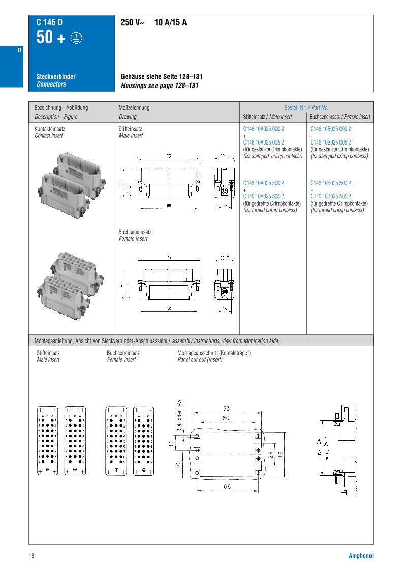
C146 10A025 000 2+C146 10A025 005 2(für gestanzte Crimpkontakte)(for stamped crimp contacts)
C146 10A025 500 2+C146 10A025 505 2(für gedrehte Crimpkontakte)(for turned crimp contacts)
C146 10B025 000 2+C146 10B025 005 2(für gestanzte Crimpkontakte)(for stamped crimp contacts)
C146 10B025 500 2+C146 10B025 505 2(für gedrehte Crimpkontakte)(for turned crimp contacts)
SteckverbinderConnectors
C 146 D
50 +
Kontakteinsatz Contact insert
Gehäuse siehe Seite 128–131 Housings see page 128–131
250 V~ 10 A/15 A
Montageanleitung, Ansicht von Steckverbinder-Anschlussseite / Assembly instructions, view from termination side
StifteinsatzMale insert
BuchseneinsatzFemale insert
StifteinsatzMale insert
BuchseneinsatzFemale insert
Montageausschnitt (Kontaktträger)Panel cut out (insert)
D

D
Amphenol 19
C 146 D
50 +
CrimpkontakteCrimp contacts
1) Erläuterung der Bestell-Nr. für die Kontakte siehe Seite 41) Explanation of the Part No. for contacts see page 4
Gestanzte EinzelkontakteStamped single contacts
Gestanzte Bandkontakte für CrimpzangenStamped contacts on reel for hand crimping tools
Gestanzte Bandkontakte für CrimpmaschinenStamped contacts on reel for crimp machines
200 / 100 Stück
200 / 100 pcs
2000 Stück(Zuführung linksoder rechts)
2000 pcs(feeding left orright hand side)
Derating Kurven / Derating curves
Gedrehte EinzelkontakteTurned single contacts
Kurve / Curveabcde
Kontakt / ContactStandard gestanztStandard stamped
Hochstrom gestanztHigh current, stamped
Querschnitt / Wire gauge0,5 mm2
1,5 mm2
2,5 mm2
1,5 mm2
2,5 mm2
Kurve / Curveabc
Kontakt / ContactStandard gedrehtStandard turned
Querschnitt / Wire gauge0,5 mm2
1,5 mm2
2,5 mm2
Stro
mbe
last
bark
eit I
(A)
Curre
nt ca
rryin
g ca
pacit
y I (A
)
Bauelement Umgebungstemperatur Tu (°C)Ambient temperature Tamb (°C)
Gestanzte KontakteStamped contacts
Stro
mbe
last
bark
eit I
(A)
Curre
nt ca
rryin
g ca
pacit
y I (A
)
Bauelement Umgebungstemperatur Tu (°C)Ambient temperature Tamb (°C)
Gedrehte KontakteTurned contacts
Abisolierlängen siehe S. 208Stripping length see p. 208
LieferformSupplied as
Gestanzte Einzelkontakte / Stamped single contacts
für Leiter-querschnittfor wire gauge
AWG Stück-zahlPieces
StandardHochstromHigh current
StandardHochstromHigh current
StandardHochstromHigh current
StandardHochstromHigh current
0,14 - 0,5 mm2
0,5 - 1,5 mm2
1,5 - 2,5 mm2
0,5 - 1,5 mm2
1,5 - 2,5 mm2
0,14 - 0,5 mm2
0,5 - 1,5 mm2
1,5 - 2,5 mm2
0,5 - 1,5 mm2
1,5 - 2,5 mm2
0,14 - 0,5 mm2
0,5 - 1,5 mm2
1,5 - 2,5 mm2
0,5 - 1,5 mm2
1,5 - 2,5 mm2
0,14 - 0,5 mm2
0,5 - 1,5 mm2
1,5 - 2,5 mm2
0,5 - 1,5 mm2
1,5 - 2,5 mm2
26 - 2020 - 1616 - 1420 - 1616 - 14
26 - 2020 - 1616 - 1420 - 1616 - 14
26 - 2020 - 1616 - 1420 - 1616 - 1426 - 2020 - 1616 - 1420 - 1618 - 14
200200100200100
100100100100100
2000200020002000200020002000200020002000
VN01 016 0003 (1)VN01 016 0002 (1)VN01 016 0005 (1)VN01 016 0015 (1)VN01 016 0016 (1)
ZN01 016 0003 (1)ZN01 016 0002 (1)ZN01 016 0005 (1)ZN01 016 0015 (1)ZN01 016 0016 (1)
HN01 016 0003 (1)HN01 016 0002 (1)HN01 016 0005 (1)HN01 016 0015 (1)HN01 016 0016 (1)TN01 016 0003 (1)TN01 016 0002 (1)TN01 016 0005 (1)TN01 016 0015 (1)TN01 016 0016 (1)
ZN02 016 0003 (1)ZN02 016 0002 (1)ZN02 016 0005 (1)ZN02 016 0015 (1)ZN02 016 0016 (1)
ZN01 016 0003 (2)ZN01 016 0002 (2)ZN01 016 0005 (2)
ZN02 016 0003 (2)ZN02 016 0002 (2)ZN02 016 0005 (2)
VN02 016 0003 (1)VN02 016 0002 (1)VN02 016 0005 (1)VN02 016 0015 (1)VN02 016 0016 (1)
VN01 016 0003 (2)VN01 016 0002 (2)VN01 016 0005 (2)
VN02 016 0003 (2)VN02 016 0002 (2)VN02 016 0005 (2)
HN02 016 0003 (1)HN02 016 0002 (1)HN02 016 0005 (1)HN02 016 0015 (1)HN02 016 0016 (1)TN02 016 0003 (1)TN02 016 0002 (1)TN02 016 0005 (1)TN02 016 0015 (1)TN02 016 0016 (1)
HN01 016 0003 (2)HN01 016 0002 (2)HN01 016 0005 (2)
TN01 016 0003 (2)TN01 016 0002 (2)TN01 016 0005 (2)
HN02 016 0003 (2)HN02 016 0002 (2)HN02 016 0005 (2)
TN02 016 0003 (2)TN02 016 0002 (2)TN02 016 0005 (2)
Kontaktzuführung rechtsContact feeding right hand side
Gestanzte Bandkontakte für Crimpmaschinen / Stamped contacts on reel for crimp machines
Gestanzte Bandkontakte für Crimpzangen / Stamped Contacts on reel for hand crimp tools
Kontaktzuführung linksContact feeding left hand side
0,14 - 0,37 mm2
0,5 mm2
0,75 - 1,0 mm2
1,5 mm2
2,5 mm2
26 - 222020 - 1616 - 1514
100100100100100
VN01 016 0024 (1)CVN01 016 0025 (1)CVN01 016 0026 (1)CVN01 016 0027 (1)CVN01 016 0028 (1)C
VN02 016 0024 (1)CVN02 016 0025 (1)CVN02 016 0026 (1)CVN02 016 0027 (1)CVN02 016 0028 (1)C
VN01 016 0024 (2)CVN01 016 0025 (2)CVN01 016 0026 (2)CVN01 016 0027 (2)CVN01 016 0028 (2)C
VN02 016 0024 (2)CVN02 016 0025 (2)CVN02 016 0026 (2)CVN02 016 0027 (2)CVN02 016 0028 (2)C
Gedrehte Crimpkontakte / Turned crimp contacts
EinzelkontaktSingle contact
Bestell Nr.1)
Stiftkontakt Male contact
Part No.1)
BuchsenkontaktFemale contact
Bestell Nr.1)
StiftkontaktMale contact
Part No.1)
BuchsenkontaktFemale contact
versilbert / silver plating vergoldet / gold plating
20 Amphenol
Bezeichnung - AbbildungDescription - Figure
MaßzeichnungDrawing
Bestell Nr. / Part No.Stifteinsatz / Male insert Buchseneinsatz / Female insert
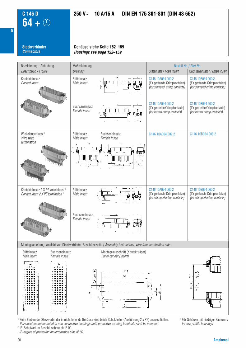
C146 10A064 000 2(für gestanzte Crimpkontakte)(for stamped crimp contacts)
C146 10A064 500 2(für gedrehte Crimpkontakte)(for turned crimp contacts)
C146 10B064 000 2(für gestanzte Crimpkontakte)(for stamped crimp contacts)
C146 10B064 500 2(für gedrehte Crimpkontakte)(for turned crimp contacts)
C146 10A064 060 2(für gestanzte Crimpkontakte)(for stamped crimp contacts)
C146 10B064 060 2(für gestanzte Crimpkontakte)(for stamped crimp contacts)
SteckverbinderConnectors
C 146 D
64 +
C146 10A064 009 2 C146 10B064 009 2
Gehäuse siehe Seite 152–159Housings see page 152–159
250 V~ 10 A/15 A DIN EN 175 301-801 (DIN 43 652)
Montageanleitung, Ansicht von Steckverbinder-Anschlussseite / Assembly instructions, view from termination side
Kontakteinsatz 2 X PE Anschluss 1)
Contact insert 2 X PE termination 1)
StifteinsatzMale insert
BuchseneinsatzFemale insert
BuchseneinsatzFemale insert
StifteinsatzMale insert
StifteinsatzMale insert
BuchseneinsatzFemale insert
StifteinsatzMale insert
BuchseneinsatzFemale insert
Montageausschnitt (Kontaktträger)Panel cut out (insert)
KontakteinsatzContact insert
Wickelanschluss 3)
Wire wraptermination
2) Für Gehäuse mit niedriger Bauform /for low profile housings
1) Beim Einbau der Steckverbinder in nicht leitende Gehäuse sind beide Schutzleiter (Ausführung 2 x PE) anzuschließen.If connectors are mounted in non conductive housings both protective earthing terminals shall be mounted.
3) IP-Schutzart im Anschlussbereich IP 00IP-degree of protection on termination side IP 00
D

D
Amphenol 21
C 146 D
64 +
CrimpkontakteCrimp contacts
1) Erläuterung der Bestell-Nr. für die Kontakte siehe Seite 41) Explanation of the Part No. for contacts see page 4
Gestanzte EinzelkontakteStamped single contacts
Gestanzte Bandkontakte für CrimpzangenStamped contacts on reel for hand crimping tools
Gestanzte Bandkontakte für CrimpmaschinenStamped contacts on reel for crimp machines
200 / 100 Stück
200 / 100 pcs
2000 Stück(Zuführung linksoder rechts)
2000 pcs(feeding left orright hand side)
Derating Kurven / Derating curves
Gedrehte EinzelkontakteTurned single contacts
Kurve / Curveabcde
Kontakt / ContactStandard gestanztStandard stamped
Hochstrom gestanztHigh current, stamped
Querschnitt / Wire gauge0,5 mm2
1,5 mm2
2,5 mm2
1,5 mm2
2,5 mm2
Kurve / Curveabc
Kontakt / ContactStandard gedrehtStandard turned
Querschnitt / Wire gauge0,5 mm2
1,5 mm2
2,5 mm2
Stro
mbe
last
bark
eit I
(A)
Curre
nt ca
rryin
g ca
pacit
y I (A
)
Bauelement Umgebungstemperatur Tu (°C)Ambient temperature Tamb (°C)
Gestanzte KontakteStamped contacts
Stro
mbe
last
bark
eit I
(A)
Curre
nt ca
rryin
g ca
pacit
y I (A
)
Bauelement Umgebungstemperatur Tu (°C)Ambient temperature Tamb (°C)
Gedrehte KontakteTurned contacts
Abisolierlängen siehe S. 208Stripping length see p. 208
LieferformSupplied as
Gestanzte Einzelkontakte / Stamped single contacts
für Leiter-querschnittfor wire gauge
AWG Stück-zahlPieces
StandardHochstromHigh current
StandardHochstromHigh current
StandardHochstromHigh current
StandardHochstromHigh current
0,14 - 0,5 mm2
0,5 - 1,5 mm2
1,5 - 2,5 mm2
0,5 - 1,5 mm2
1,5 - 2,5 mm2
0,14 - 0,5 mm2
0,5 - 1,5 mm2
1,5 - 2,5 mm2
0,5 - 1,5 mm2
1,5 - 2,5 mm2
0,14 - 0,5 mm2
0,5 - 1,5 mm2
1,5 - 2,5 mm2
0,5 - 1,5 mm2
1,5 - 2,5 mm2
0,14 - 0,5 mm2
0,5 - 1,5 mm2
1,5 - 2,5 mm2
0,5 - 1,5 mm2
1,5 - 2,5 mm2
26 - 2020 - 1616 - 1420 - 1616 - 14
26 - 2020 - 1616 - 1420 - 1616 - 14
26 - 2020 - 1616 - 1420 - 1616 - 1426 - 2020 - 1616 - 1420 - 1618 - 14
200200100200100
100100100100100
2000200020002000200020002000200020002000
VN01 016 0003 (1)VN01 016 0002 (1)VN01 016 0005 (1)VN01 016 0015 (1)VN01 016 0016 (1)
ZN01 016 0003 (1)ZN01 016 0002 (1)ZN01 016 0005 (1)ZN01 016 0015 (1)ZN01 016 0016 (1)
HN01 016 0003 (1)HN01 016 0002 (1)HN01 016 0005 (1)HN01 016 0015 (1)HN01 016 0016 (1)TN01 016 0003 (1)TN01 016 0002 (1)TN01 016 0005 (1)TN01 016 0015 (1)TN01 016 0016 (1)
ZN02 016 0003 (1)ZN02 016 0002 (1)ZN02 016 0005 (1)ZN02 016 0015 (1)ZN02 016 0016 (1)
ZN01 016 0003 (2)ZN01 016 0002 (2)ZN01 016 0005 (2)
ZN02 016 0003 (2)ZN02 016 0002 (2)ZN02 016 0005 (2)
VN02 016 0003 (1)VN02 016 0002 (1)VN02 016 0005 (1)VN02 016 0015 (1)VN02 016 0016 (1)
VN01 016 0003 (2)VN01 016 0002 (2)VN01 016 0005 (2)
VN02 016 0003 (2)VN02 016 0002 (2)VN02 016 0005 (2)
HN02 016 0003 (1)HN02 016 0002 (1)HN02 016 0005 (1)HN02 016 0015 (1)HN02 016 0016 (1)TN02 016 0003 (1)TN02 016 0002 (1)TN02 016 0005 (1)TN02 016 0015 (1)TN02 016 0016 (1)
HN01 016 0003 (2)HN01 016 0002 (2)HN01 016 0005 (2)
TN01 016 0003 (2)TN01 016 0002 (2)TN01 016 0005 (2)
HN02 016 0003 (2)HN02 016 0002 (2)HN02 016 0005 (2)
TN02 016 0003 (2)TN02 016 0002 (2)TN02 016 0005 (2)
Kontaktzuführung rechtsContact feeding right hand side
Gestanzte Bandkontakte für Crimpmaschinen / Stamped contacts on reel for crimp machines
Gestanzte Bandkontakte für Crimpzangen / Stamped Contacts on reel for hand crimp tools
Kontaktzuführung linksContact feeding left hand side
0,14 - 0,37 mm2
0,5 mm2
0,75 - 1,0 mm2
1,5 mm2
2,5 mm2
26 - 222020 - 1616 - 1514
100100100100100
VN01 016 0024 (1)CVN01 016 0025 (1)CVN01 016 0026 (1)CVN01 016 0027 (1)CVN01 016 0028 (1)C
VN02 016 0024 (1)CVN02 016 0025 (1)CVN02 016 0026 (1)CVN02 016 0027 (1)CVN02 016 0028 (1)C
VN01 016 0024 (2)CVN01 016 0025 (2)CVN01 016 0026 (2)CVN01 016 0027 (2)CVN01 016 0028 (2)C
VN02 016 0024 (2)CVN02 016 0025 (2)CVN02 016 0026 (2)CVN02 016 0027 (2)CVN02 016 0028 (2)C
Gedrehte Crimpkontakte / Turned crimp contacts
EinzelkontaktSingle contact
Bestell Nr.1)
Stiftkontakt Male contact
Part No.1)
BuchsenkontaktFemale contact
Bestell Nr.1)
StiftkontaktMale contact
Part No.1)
BuchsenkontaktFemale contact
versilbert / silver plating vergoldet / gold plating

22 Amphenol
Bezeichnung - AbbildungDescription - Figure
MaßzeichnungDrawing
Bestell Nr. / Part No.Stifteinsatz / Male insert Buchseneinsatz / Female insert
C146 10A064 000 2+C146 10A064 005 2(für gestanzte Crimpkontakte)(for stamped crimp contacts)
C146 10A064 500 2+C146 10A064 505 2(für gedrehte Crimpkontakte)(for turned crimp contacts)
C146 10B064 000 2+C146 10B064 005 2(für gestanzte Crimpkontakte)(for stamped crimp contacts)
C146 10B064 500 2+C146 10B064 505 2(für gedrehte Crimpkontakte)(for turned crimp contacts)
SteckverbinderConnectors
C 146 D
128 +
KontakteinsatzContact insert
Gehäuse siehe Seite 160–163Housings see page 160–163
250 V~ 10 A/15 A
Montageanleitung, Ansicht von Steckverbinder-Anschlussseite / Assembly instructions, view from termination side
StifteinsatzMale insert
BuchseneinsatzFemale insert
StifteinsatzMale insert
BuchseneinsatzFemale insert
Montageausschnitt (Kontaktträger)Panel cut out (insert)
D

D
Amphenol 23
C 146 D
128 +
CrimpkontakteCrimp contacts
1) Erläuterung der Bestell-Nr. für die Kontakte siehe Seite 41) Explanation of the Part No. for contacts see page 4
Gestanzte EinzelkontakteStamped single contacts
Gestanzte Bandkontakte für CrimpzangenStamped contacts on reel for hand crimping tools
Gestanzte Bandkontakte für CrimpmaschinenStamped contacts on reel for crimp machines
200 / 100 Stück
200 / 100 pcs
2000 Stück(Zuführung linksoder rechts)
2000 pcs(feeding left orright hand side)
Derating Kurven / Derating curves
Gedrehte EinzelkontakteClosed turned single contacts
Kurve / Curveabcde
Kontakt / ContactStandard gestanztStandard stamped
Hochstrom gestanztHigh current, stamped
Querschnitt / Wire gauge0,5 mm2
1,5 mm2
2,5 mm2
1,5 mm2
2,5 mm2
Kurve / Curveabc
Kontakt / ContactStandard gedrehtStandard turned
Querschnitt / Wire gauge0,5 mm2
1,5 mm2
2,5 mm2
Stro
mbe
last
bark
eit I
(A)
Curre
nt ca
rryin
g ca
pacit
y I (A
)
Bauelement Umgebungstemperatur Tu (°C)Ambient temperature Tamb (°C)
Gestanzte KontakteStamped contacts
Stro
mbe
last
bark
eit I
(A)
Curre
nt ca
rryin
g ca
pacit
y I (A
)
Bauelement Umgebungstemperatur Tu (°C)Ambient temperature Tamb (°C)
Gedrehte KontakteTurned contacts
Abisolierlängen siehe S. 208Stripping length see p. 208
LieferformSupplied as
Gestanzte Einzelkontakte / Stamped single contacts
für Leiter-querschnittfor wire gauge
AWG Stück-zahlPieces
StandardHochstromHigh current
StandardHochstromHigh current
StandardHochstromHigh current
StandardHochstromHigh current
0,14 - 0,5 mm2
0,5 - 1,5 mm2
1,5 - 2,5 mm2
0,5 - 1,5 mm2
1,5 - 2,5 mm2
0,14 - 0,5 mm2
0,5 - 1,5 mm2
1,5 - 2,5 mm2
0,5 - 1,5 mm2
1,5 - 2,5 mm2
0,14 - 0,5 mm2
0,5 - 1,5 mm2
1,5 - 2,5 mm2
0,5 - 1,5 mm2
1,5 - 2,5 mm2
0,14 - 0,5 mm2
0,5 - 1,5 mm2
1,5 - 2,5 mm2
0,5 - 1,5 mm2
1,5 - 2,5 mm2
26 - 2020 - 1616 - 1420 - 1616 - 14
26 - 2020 - 1616 - 1420 - 1616 - 14
26 - 2020 - 1616 - 1420 - 1616 - 1426 - 2020 - 1616 - 1420 - 1618 - 14
200200100200100
100100100100100
2000200020002000200020002000200020002000
VN01 016 0003 (1)VN01 016 0002 (1)VN01 016 0005 (1)VN01 016 0015 (1)VN01 016 0016 (1)
ZN01 016 0003 (1)ZN01 016 0002 (1)ZN01 016 0005 (1)ZN01 016 0015 (1)ZN01 016 0016 (1)
HN01 016 0003 (1)HN01 016 0002 (1)HN01 016 0005 (1)HN01 016 0015 (1)HN01 016 0016 (1)TN01 016 0003 (1)TN01 016 0002 (1)TN01 016 0005 (1)TN01 016 0015 (1)TN01 016 0016 (1)
ZN02 016 0003 (1)ZN02 016 0002 (1)ZN02 016 0005 (1)ZN02 016 0015 (1)ZN02 016 0016 (1)
ZN01 016 0003 (2)ZN01 016 0002 (2)ZN01 016 0005 (2)
ZN02 016 0003 (2)ZN02 016 0002 (2)ZN02 016 0005 (2)
VN02 016 0003 (1)VN02 016 0002 (1)VN02 016 0005 (1)VN02 016 0015 (1)VN02 016 0016 (1)
VN01 016 0003 (2)VN01 016 0002 (2)VN01 016 0005 (2)
VN02 016 0003 (2)VN02 016 0002 (2)VN02 016 0005 (2)
HN02 016 0003 (1)HN02 016 0002 (1)HN02 016 0005 (1)HN02 016 0015 (1)HN02 016 0016 (1)TN02 016 0003 (1)TN02 016 0002 (1)TN02 016 0005 (1)TN02 016 0015 (1)TN02 016 0016 (1)
HN01 016 0003 (2)HN01 016 0002 (2)HN01 016 0005 (2)
TN01 016 0003 (2)TN01 016 0002 (2)TN01 016 0005 (2)
HN02 016 0003 (2)HN02 016 0002 (2)HN02 016 0005 (2)
TN02 016 0003 (2)TN02 016 0002 (2)TN02 016 0005 (2)
Kontaktzuführung rechtsContact feeding right hand side
Gestanzte Bandkontakte für Crimpmaschinen / Stamped contacts on reel for crimp machines
Gestanzte Bandkontakte für Crimpzangen / Stamped Contacts on reel for hand crimp tools
Kontaktzuführung linksContact feeding left hand side
0,14 - 0,37 mm2
0,5 mm2
0,75 - 1,0 mm2
1,5 mm2
2,5 mm2
26 - 222020 - 1616 - 1514
100100100100100
VN01 016 0024 (1)CVN01 016 0025 (1)CVN01 016 0026 (1)CVN01 016 0027 (1)CVN01 016 0028 (1)C
VN02 016 0024 (1)CVN02 016 0025 (1)CVN02 016 0026 (1)CVN02 016 0027 (1)CVN02 016 0028 (1)C
VN01 016 0024 (2)CVN01 016 0025 (2)CVN01 016 0026 (2)CVN01 016 0027 (2)CVN01 016 0028 (2)C
VN02 016 0024 (2)CVN02 016 0025 (2)CVN02 016 0026 (2)CVN02 016 0027 (2)CVN02 016 0028 (2)C
Gedrehte Crimpkontakte / Turned crimp contacts
EinzelkontaktSingle contact
Bestell Nr.1)
Stiftkontakt Male contact
Part No.1)
BuchsenkontaktFemale contact
Bestell Nr.1)
StiftkontaktMale contact
Part No.1)
BuchsenkontaktFemale contact
versilbert / silver plating vergoldet / gold plating

24 Amphenol
Modifizierte Kontaktanordnung fürBemessungsspannungen von 400 V
Modified contact arrangementfor rated voltages of 400 V
Lösen der Kontakte 1)
Removal of contacts 1)
1) Weitere Informationen siehe Katalog „Werkzeuge“ / Further information see catalogue „Tools“
Demontage von Steckseite / front releas
(15) 7 + (25) 11 +
= Arbeitskontaktfull load contact
= Leerstelleunoccupied
InformationInformation
C 146 D
(40) 20 + (64) 32 +
Prinzip:• gestanzte Stiftkontakte
Stamped male contacts• gedrehte Kontakte
Turned contacts
• gestanzte BuchsenkontakteStamped female contacts
Bezeichnung / Decription
Werkzeuge / Tools 1)
Lösewerkzeug für KontakteRemoval tool for contacts
– – – FG 0300 146 1
0,14 - 0,5 mm2
0,5 - 1,5 mm2
– – TA 0100 146
0,14 - 0,5 mm2
0,5 - 1,5 mm2
1,5 - 2,5 mm2
TA 0001 146 000 1TA 0002 146 000 1TA 0007 146 000 3
TA 0000 202TA 0000 163TA 0000 141
TA 0000TA 0500
Service CrimpzangeService crimping tool
Crimpzange für EinzelkontakteCrimping tool for single contacts
für Leiterquerschnittfor wire gauge
Bestell Nr. / Part No.Kontaktaufnahme / Contact locator Crimpbacken / Crimping dies Werkzeuge / Tools
D

DD
Amphenol 25
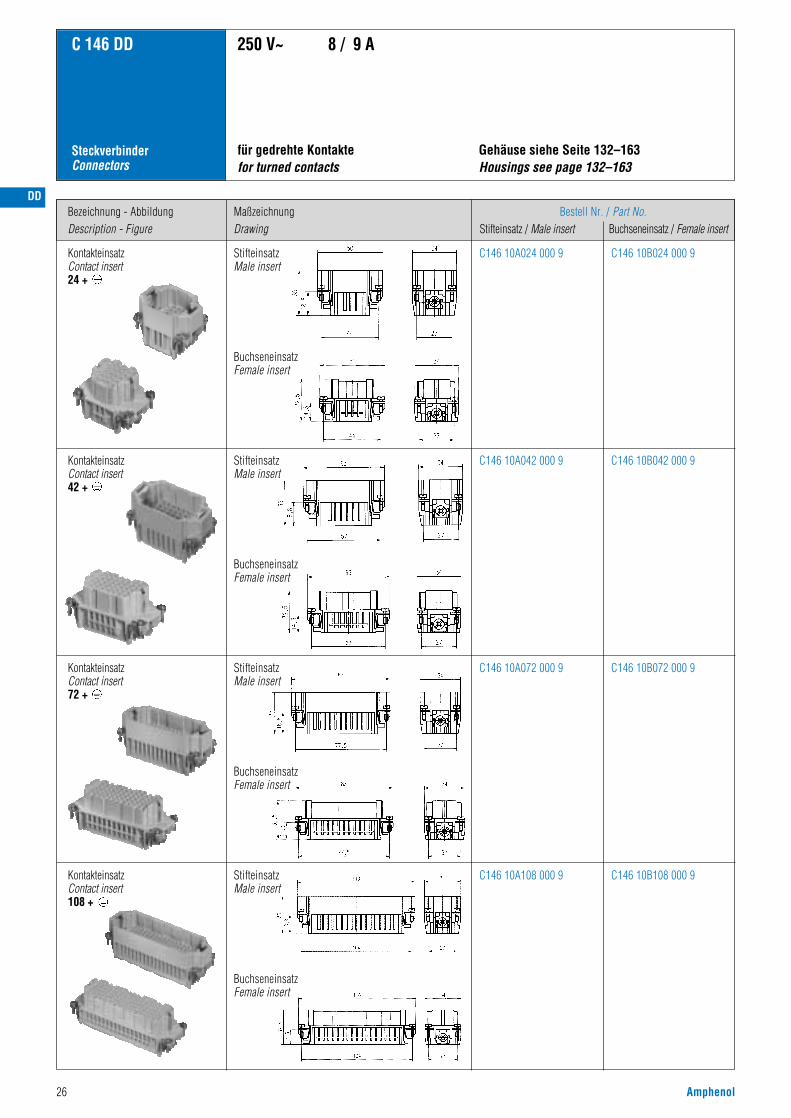
C 146 DD
• Bemessungsspannung 250 V• Bemessungsstrom 8 A ... 9 A• Anschlussart: crimpen• Polzahl: 24, 42, 72, 108
• Rated voltage 250 V• Rated current 8 A ... 9 A• Termination: crimp• Number of contacts: 24, 42, 72, 108
Hauptmerkmale Main characteristics
Zulassungen / ApprovalsPrüfstelle / Testhouse Kennwerte / Characteristics Zulassungs-Nummer / Approval-No.
Zulassungen beziehen sich im allgemeinen auf repräsentativeAusführungen der Steckverbinderserie. Prüfumfang undPrüfvorschrift auf Anfrage.
In general approvals refer to representative versions of the connectorseries. Extent and specification of tests upon request.
SEV 250 V, 10 A
UL 600 V, 8,5 A E 63093
CSA 600 V, 20 A LR 700721
DD
26 Amphenol
Bezeichnung - AbbildungDescription - Figure
MaßzeichnungDrawing
Bestell Nr. / Part No.Stifteinsatz / Male insert Buchseneinsatz / Female insert
C 146 DD
SteckverbinderConnectors
Kontakteinsatz Contact insert 24 +
Gehäuse siehe Seite 132–163Housings see page 132–163
für gedrehte Kontaktefor turned contacts
250 V~ 8 / 9 A
C146 10A024 000 9 C146 10B024 000 9
C146 10A042 000 9 C146 10B042 000 9
Kontakteinsatz Contact insert 72 +
C146 10A072 000 9 C146 10B072 000 9
C146 10A108 000 9 C146 10B108 000 9
KontakteinsatzContact insert42 +
StifteinsatzMale insert
BuchseneinsatzFemale insert
StifteinsatzMale insert
BuchseneinsatzFemale insert
StifteinsatzMale insert
BuchseneinsatzFemale insert
StifteinsatzMale insert
BuchseneinsatzFemale insert
Kontakteinsatz Contact insert108 +
DD
DD
Amphenol 27
1) Erläuterung der Bestell-Nr. für die Kontakte siehe Seite 41) Explanation of the Part No. for contacts see page 4
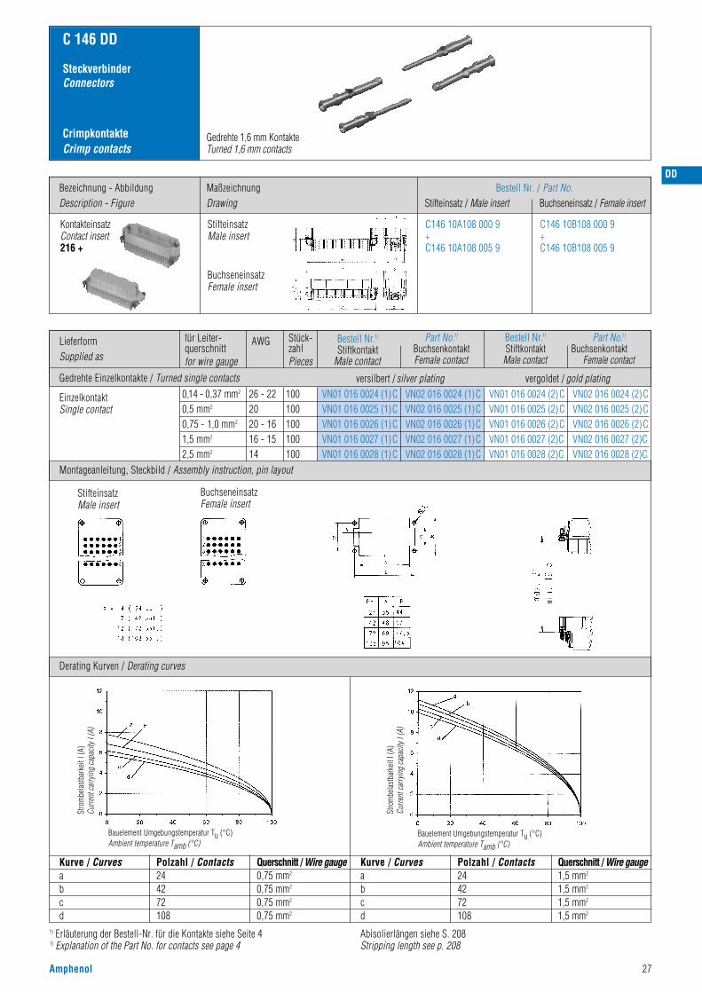
CrimpkontakteCrimp contacts
C 146 DD
SteckverbinderConnectors
Derating Kurven / Derating curves
Gedrehte 1,6 mm KontakteTurned 1,6 mm contacts
Kurve / Curvesabcd
Polzahl / Contacts244272108
Querschnitt / Wire gauge0,75 mm2
0,75 mm2
0,75 mm2
0,75 mm2
Kurve / Curvesabcd
Polzahl / Contacts244272108
Querschnitt / Wire gauge1,5 mm2
1,5 mm2
1,5 mm2
1,5 mm2
Stro
mbe
last
bark
eit I
(A)
Curre
nt ca
rryin
g ca
pacit
y I (A
)
Bauelement Umgebungstemperatur Tu (°C)Ambient temperature Tamb (°C)
Stro
mbe
last
bark
eit I
(A)
Curre
nt ca
rryin
g ca
pacit
y I (A
)
Bauelement Umgebungstemperatur Tu (°C)Ambient temperature Tamb (°C)
Abisolierlängen siehe S. 208Stripping length see p. 208
LieferformSupplied as
Gedrehte Einzelkontakte / Turned single contacts
für Leiter-querschnittfor wire gauge
AWG Stück-zahlPieces
Bestell Nr.1)
Stiftkontakt Male contact
Part No.1)
BuchsenkontaktFemale contact
Bestell Nr.1)
StiftkontaktMale contact
Part No.1)
BuchsenkontaktFemale contact
0,14 - 0,37 mm2
0,5 mm2
0,75 - 1,0 mm2
1,5 mm2
2,5 mm2
26 - 222020 - 1616 - 1514
100100100100100
VN01 016 0024 (1)CVN01 016 0025 (1)CVN01 016 0026 (1)CVN01 016 0027 (1)CVN01 016 0028 (1)C
VN02 016 0024 (1)CVN02 016 0025 (1)CVN02 016 0026 (1)CVN02 016 0027 (1)CVN02 016 0028 (1)C
VN01 016 0024 (2)CVN01 016 0025 (2)CVN01 016 0026 (2)CVN01 016 0027 (2)CVN01 016 0028 (2)C
VN02 016 0024 (2)CVN02 016 0025 (2)CVN02 016 0026 (2)CVN02 016 0027 (2)CVN02 016 0028 (2)C
EinzelkontaktSingle contact
C146 10A108 000 9+C146 10A108 005 9
C146 10B108 000 9+C146 10B108 005 9
StifteinsatzMale insert
BuchseneinsatzFemale insert
Kontakteinsatz Contact insert216 +
Montageanleitung, Steckbild / Assembly instruction, pin layout
StifteinsatzMale insert
BuchseneinsatzFemale insert
versilbert / silver plating vergoldet / gold plating
Bezeichnung - AbbildungDescription - Figure
MaßzeichnungDrawing
Bestell Nr. / Part No.Stifteinsatz / Male insert Buchseneinsatz / Female insert
28 Amphenol
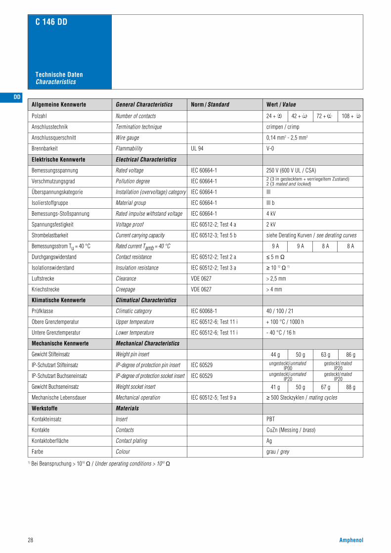
Norm / Standard Wert / Value
V-0
0,14 mm2 - 2,5 mm2
crimpen / crimp
24 + 42 + 72 + 108 +
C 146 DD
UL 94
Allgemeine Kennwerte
Polzahl
Anschlussquerschnitt
Anschlusstechnik
Brennbarkeit
Number of contacts
Wire gauge
Termination technique
Flammability
250 V (600 V UL / CSA)2 (3 in gestecktem + verriegeltem Zustand)2 (3 mated and locked)
III
III b
4 kV
2 kV
siehe Derating Kurven / see derating curves
≥ 10 12 Ω 1)
IEC 60664-1
IEC 60664-1
IEC 60664-1
IEC 60664-1
IEC 60664-1
IEC 60512-2; Test 4 a
IEC 60512-3; Test 5 b
IEC 60512-2; Test 3 a
IEC 60068-1
IEC 60512-5; Test 9 a
40 / 100 / 21
44 g
41 g
50 g
50 g
63 g
67 g
86 g
88 g
≥ 500 Steckzyklen / mating cycles
grau / grey
≤ 5 m Ω
9 A 9 A 8 A 8 A
IEC 60512-2; Test 2 a
IEC 60512-6; Test 11 i + 100 °C / 1000 h
IEC 60512-6; Test 11 i - 40 °C / 16 h
CuZn (Messing / brass)
PBT
Ag
Elektrische Kennwerte
Bemessungsspannung
Verschmutzungsgrad
Überspannungskategorie
Isolierstoffgruppe
Bemessungs-Stoßspannung
Spannungsfestigkeit
Strombelastbarkeit
Durchgangswiderstand
Isolationswiderstand
Klimatische Kennwerte
Prüfklasse
Obere Grenztemperatur
Untere Grenztemperatur
Mechanische Kennwerte
Gewicht Stifteinsatz
Gewicht Buchseneinsatz
Mechanische Lebensdauer
Werkstoffe
Kontakteinsatz
Kontakte
Kontaktoberfläche
Farbe
1) Bei Beanspruchung > 1010 Ω / Under operating conditions > 1010 Ω
Electrical Characteristics
Rated voltage
Pollution degree
Installation (overvoltage) category
Material group
Rated impulse withstand voltage
Voltage proof
Current carrying capacity
Bemessungsstrom Tu = 40 °C Rated current Tamb = 40 °C
Insulation resistance
> 2,5 mmVDE 0627Luftstrecke Clearance
> 4 mmVDE 0627Kriechstrecke Creepage
Climatical Characteristics
Climatic category
Mechanical Characteristics
Weight pin insert
Weight socket insert
Mechanical operation
Insert
Contact resistance
Upper temperature
Lower temperature
Contacts
Contact plating
Colour
Materials
General Characteristics
Technische DatenCharacteristics
IEC 60529IP-degree of protection pin insert ungesteckt/unmatedIP00
gesteckt/matedIP20
gesteckt/matedIP20
ungesteckt/unmatedIP20
IP-Schutzart Stifteinsatz
IEC 60529IP-degree of protection socket insertIP-Schutzart Buchseneinsatz
DD

E
C 146 E
• Bemessungsspannung 400 V• Bemessungsstrom 16 A ... 22 A• Anschlussart: schrauben oder crimpen• Kontaktdurchmesser 2,5 mm• Polzahl: 6, 10 ,16, 24, 48
• Rated voltage 400 V• Rated current 16 A ... 22 A• Termination: screw or crimp• Contact diameter 2,5 mm• Numbers of contacts: 6, 10, 16, 24, 48
Amphenol 29
Hauptmerkmale Main characteristics
SEV 400 V, 16 A
UL 600 V, 10 A E 63093
CSA 600 V, 15 A 48932
DB 400 V, 16 A BN 74 018
Zulassungen / ApprovalsPrüfstelle / Testhouse Kennwerte / Characteristics Zulassungs-Nummer / Approval-No.
Zulassungen beziehen sich im allgemeinen auf repräsentativeAusführungen der Steckverbinderserie. Prüfumfang undPrüfvorschrift auf Anfrage.
In general approvals refer to representative versions of the connectorseries. Extent and specification of tests upon request.
30 Amphenol
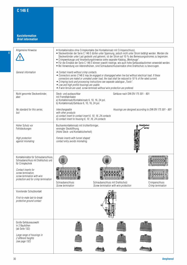
KurzinformationBrief information
C 146 E
Allgemeine Hinweise
General information
• Kontakteinsätze ohne Crimpkontakte (bei Kontakteinsatz mit Crimpanschluss).• Steckverbinder der Serie C 146 E dürfen unter Spannung, jedoch nicht unter Strom betätigt werden. Werden die
Steckverbinder unter Last gesteckt und getrennt, ist der Strom auf 10 % des Bemessungsstromes zu begrenzen.• Crimpwerkzeuge und Verarbeitungshinweise siehe separater Katalog „Werkzeuge“.• Für die Einsätze der Serie C 146 E können sowohl niedrige, wie auch hohe Gehäusebauformen verwendet werden.• Bei Verwendung von Aderendhülsen, sind Schraubanschlusseinsätze ohne Drahtschutz zu bevorzugen.
• Contact inserts without crimp contacts.• Connectors series C146 E may be engaged or disengaged when live but without electrical load. If these
connectors are mated or unmated under load, the load shall be reduced to 10 % of the rated current.• Crimping tools and processing instructions see separate catalogue „Tools“.• Low and high profile housings are usable.• If wire ferrule are used, screw terminals without wire protection are prefered.
Voreilender Schutzkontakt
First-to-mate last-to-breakprotective ground contact
Große Gehäuseauswahlin 2 Bauhöhen(ab Seite 132)
Large range of housings in2 different heights (see page 132)
Nicht genormte Steckverbinder,aber:
No standard for this series,but:
Steck- und austauschbarmit Fremdfabrikatena) Kontakteinsatz/Kontakteinsatz 6, 10, 16, 24 pol. b) Kontakteinsatz/Gehäuse 6, 10, 16, 24 pol.
Interchangeablewith other productsa) contact insert to contact insert 6, 10, 16, 24 contactsb) contact insert to housing 6, 10 ,16, 24 contacts
Gehäuse nach DIN EN 175 301 - 801
Housings are designed according to DIN EN 175 301 - 801
Hoher Schutz vorFehlsteckungen
High protectionagainst mismating
Buchsenkontakteinsatz mit trichterförmiger,verengter Stecköffnung.(Hohe Steck- und Kontaktsicherheit)
Female inserts with funnel shaped contact entry avoids mismating.
Kontakteinsätze für Schraubanschluss,Schraubanschluss mit Drahtschutz undfür Crimptechnik
Contact inserts for screw termination, screw termination with wire protection and for crimp termination
SchraubanschlussScrew termination
Schraubanschluss mit DrahtschutzScrew termination with wire protection
CrimpanschlussCrimp termination
E
E
Amphenol 31
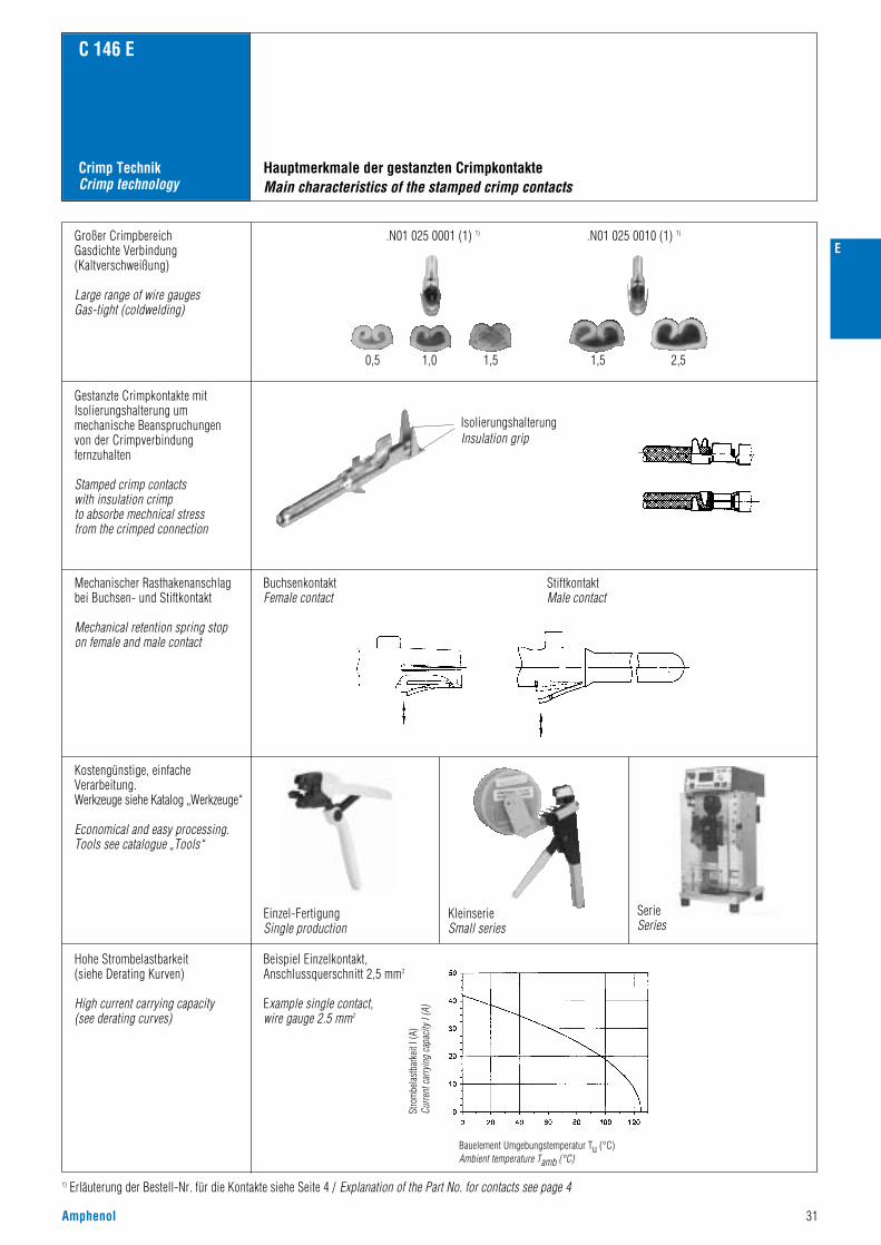
Crimp TechnikCrimp technology
C 146 E
1) Erläuterung der Bestell-Nr. für die Kontakte siehe Seite 4 / Explanation of the Part No. for contacts see page 4
Großer CrimpbereichGasdichte Verbindung(Kaltverschweißung)
Large range of wire gaugesGas-tight (coldwelding)
Gestanzte Crimpkontakte mitIsolierungshalterung ummechanische Beanspruchungenvon der Crimpverbindungfernzuhalten
Stamped crimp contacts with insulation crimpto absorbe mechnical stress from the crimped connection
Mechanischer Rasthakenanschlagbei Buchsen- und Stiftkontakt
Mechanical retention spring stop on female and male contact
Kostengünstige, einfacheVerarbeitung.Werkzeuge siehe Katalog „Werkzeuge“
Economical and easy processing.Tools see catalogue „Tools“
Hohe Strombelastbarkeit(siehe Derating Kurven)
High current carrying capacity(see derating curves)
Beispiel Einzelkontakt, Anschlussquerschnitt 2,5 mm2
Example single contact,wire gauge 2.5 mm2
Einzel-FertigungSingle production
Hauptmerkmale der gestanzten CrimpkontakteMain characteristics of the stamped crimp contacts
IsolierungshalterungInsulation grip
KleinserieSmall series
SerieSeries
BuchsenkontaktFemale contact
StiftkontaktMale contact
0,5
.N01 025 0001 (1) 1) .N01 025 0010 (1) 1)
1,0 1,5 1,5 2,5
Stro
mbe
last
bark
eit I
(A)
Curre
nt ca
rryin
g ca
pacit
y I (A
)
Bauelement Umgebungstemperatur Tu (°C)Ambient temperature Tamb (°C)

32 Amphenol
Norm / Standard Wert / ValueAllgemeine Kennwerte
Kontakteinsätze / Connector inserts
Polzahl
400 V (600 V UL / CSA 2))
3
III b
III
Number of contacts
Anschlusstechnik Termination technique crimpen / schrauben crimp / screw
Anschlussquerschnitt: crimpen, schrauben Wire gauge: crimp, screw 0,5 - 4 mm2 0,25 - 2,5 mm2
Brennbarkeit Flammability V-OUL 94
6 + 10 + 16 + 24 + 48 +
Electrical Characteristics
Rated voltage
Pollution degree
C 146 E
IEC 60664-1
IEC 60664-1
IEC 60664-1
IEC 60664-1
Elektrische Kennwerte
Bemessungsspannung
Verschmutzungsgrad
General Characteristics
Technische DatenCharacteristics
6,0 kV
2,8 kV
siehe Derating Kurven / see derating curves
Material group
Installation (overvoltage) category
Rated impulse withstand voltage
Voltage proof
IEC 60664-1
IEC 60512-2; Test 4 a
IEC 60512-2; Test 5 bCurrent carrying capacity
Isolierstoffgruppe
Überspannungskategorie
Bemessungs-Stoßspannung
Spannungsfestigkeit
Strombelastbarkeit
Rated current (Tamb = 40 °C)Bemessungsstrom (Tu = 40 °C)
Mechanische Lebensdauer
Climatical Characteristics
Mechanical Characteristics
< 5 mΩ
22 A 19 A 19 A 18 A 18 A
IEC 60512-2; Test 2 a
IEC 60068-1
IEC 60512-7; Test 13 b
IEC 60512-5; Test 9 a
Contact resistance
Climatic category
Insertion and withdrawal forces:crimpscrew
Weight:male insert crimp (f. stamped contacts)female insert crimp(f. stamped contacts)male insert screwfemale insert screw
Insert
40 / 125 / 21
33 g33 g43 g43 g
39 g39 g57 g57 g
45 g49 g78 g78 g
55 g62 g
105 g106 g
110 g124 g210 g212 g
PC GV (Polycarbonat)
grau / grey
Durchgangswiderstand
≥ 10 12 Ω 1)IEC 60512-2; Test 2 aInsulation resistanceIsolationswiderstand
> 4,0 mmClearanceLuftstrecke
> 6,3 mmDIN VDE 0627
DIN VDE 0627
CreepageKriechstrecke
Klimatische Kennwerte
Prüfklasse
Mechanische Kennwerte
Gesamt Steck- und Ziehkraftcrimpenschrauben
Gewicht:Stifteinsatz crimp (gestantzte Kontakte)Buchseneinsatz crimp (gest. Kontakte)Stifteinsatz schraubBuchseneinsatz schraub
Mechanical operation > 500 Steckzyklen / mating cycles
Werkstoffe
Kontakteinsatz
Screw contacts CuZn (Messing/brass)Schraubkontakte
Kontaktoberfläche Contact plating Ag (silber/silver)
Farbe Colour
Materials
IEC 60512-6; Test 11 iUpper temperature
Lower temperature
+ 125 °C / 1000 hObere Grenztemperatur
Untere Grenztemperatur IEC 60512-6; Test 11 i - 40 °C / 16 h
20-30 N 40-50 N 80-100 N 100-120 N 200-240 N10-20 N 30-40 N 45-60 N 70-100 N 140-200 N
1) Bei Beanspruchung > 10 10 Ω / Under operating conditions 10 10 Ω 2) Hinweisschild für CSA-Anwendungen siehe Seite 186 / Label for CSA application see page 1863) IP-Schutzart im Anschlussbereich der Schraubausführung IP 10 / IP-degree of protection on termination side of screw version IP 10
IEC 60529IP-degree of protection pin insert ungesteckt/unmatedIP00
gesteckt/matedIP20
gesteckt/matedIP20
ungesteckt/unmatedIP20
3) IP-Schutzart Stifteinsatz
IEC 60529IP-degree of protection socket insert3) IP-Schutzart Buchseneinsatz
E

E
Amphenol 33
C 146 E
Gestanzte Crimpkontakte / Stamped crimp contacts
IEC 60512-2; Test 2 a
IEC 60512-9; Test 22 a
IEC 60512-9; Test 22 a
< 5 m Ω
≥ 2 p F
≥ 3,2 p F
Elektrische Kennwerte
Durchgangswiderstand
Kapazität Kontakt-Kontakt
Kapazität Kontakt-Gehäuse
IEC 60512-5; Test 9 a ≥ 500 Steckzyklen / mating cycles
Mechanische Kennwerte
Mechanische Lebensdauer
Werkstoffe
CuZn (Messing /brass)Stiftkontakt
Buchsenkontakt
Kontaktoberfläche
Electrical Characteristics
Contact resistance
Capacity contact-contact
Capacity contact-housing
Mechanical Characteristics
Mechanical operation
Male contact
Female contact
Contact plating
Materials
CuSn (Zinnbronze / Tin bronce)
Ag
Technische DatenCharacteristics
Elektrische Kennwerte Electrical Characteristics
IEC 60512-2
Gedrehte Crimpkontakte / Turned crimp contacts
Klimatische Kennwerte Climatical Characteristics
IEC 60512-6
IEC 60512-6
+ 100 °CObere Grenztemperatur Upper temperature
- 40 °CUntere Grenztemperatur Lower temperature
≤ 5 m Ω
Mechanische Kennwerte
Werkstoffe
Mechanical Characteristics
Materials
IEC 60512-5; Test 9 a
Durchgangswiderstand
Mechanische Lebensdauer
Contact resistance
Mechanical operation ≥ 500 Steckzyclen / mating cycles
Stiftkontakt
Buchsenkontakt
Kontaktoberfläche
Male contact
Female contact
Contact plating
CuZn (Messing /brass)
CuZn (Messing /brass)
Ag

34 Amphenol
Bezeichnung - AbbildungDescription - Figure
MaßzeichnungDrawing
Bestell Nr. / Part No.Stifteinsatz / Male insert Buchseneinsatz / Female insert
C 146 E
6 +
SteckverbinderConnectors
Kontakteinsatz SchraubanschlussContact insert screw termination
Gehäuse siehe Seite 132–135Housings see page 132–135
400 V~ Kontakteinsatz für gestanzte Kontakte / Contact insert for stamped contacts
500 V~ Kontakteinsatz für Schraubanschluss und für gedrehte Kontakte /Contact insert for screw termination and for turned contacts
16 / 22 A
C146 10A006 002 1
C146 10A006 102 1(mit Drahtschutz with wire protection)
C146 10B006 002 1
C146 10B006 102 1(mit Drahtschutz with wire protection)
Kontakteinsatz für gestanzte KontakteContact insert for stamped contacts
C146 10A006 000 1 C146 10B006 000 1
Kontakteinsatz für gedrehte KontakteContact insert for turned contacts
C146 10A006 500 1 C146 10B006 500 1
StifteinsatzMale insert
BuchseneinsatzFemale insert
StifteinsatzMale insert
BuchseneinsatzFemale insert
StifteinsatzMale insert
BuchseneinsatzFemale insert
E

E
Amphenol 35
1) Erläuterung der Bestell-Nr. für die Kontakte siehe Seite 4Explanation of the Part No. for contacts see page 4
CrimpkontakteCrimp contacts
C 146 E
6 +
Montageanleitung, Steckbild / Assembly instruction, pin layout
Derating Kurven / Derating curves
Gestanzte Bandkontakte für CrimpmaschinenStamped contacts on reel for crimp machines
200 / 100 Stück
200 / 100 pcs
2000 Stück(Zuführung linksoder rechts)
2000 pcs(feeding left orright hand side)
Gestanzte EinzelkontakteStamped single contacts
Gestanzte Bandkontakte für CrimpzangenStamped contacts on reel for hand crimping tools
Gedrehte EinzelkontakteTurned single contacts
Kurve a: 1,5 mm2 LeiterquerschnittCurve a: 1,5 mm2 wire gauge
Kurve b: 2,5 mm2 LeiterquerschnittCurve b: 2,5 mm2 wire gauge
Stro
mbe
last
bark
eit I
(A)
Curre
nt ca
rryin
g ca
pacit
y I (A
)
Bauelement Umgebungstemperatur Tu (°C)Ambient temperature Tamb (°C)
Stro
mbe
last
bark
eit I
(A)
Curre
nt ca
rryin
g ca
pacit
y I (A
)
Bauelement Umgebungstemperatur Tu (°C)Ambient temperature Tamb (°C)
Stro
mbe
last
bark
eit I
(A)
Curre
nt ca
rryin
g ca
pacit
y I (A
)
Bauelement Umgebungstemperatur Tu (°C)Ambient temperature Tamb (°C)
Gestanzte KontakteStamped contacts
SchraubanschlussScrew termination
StifteinsatzMale insert
BuchseneinsatzFemale insert
Montageausschnitt (Kontaktträger)Panel cut out (insert)
Gedrehte KontakteTurned contacts
Abisolierlängen siehe S. 208Stripping length see p. 208
LieferformSupplied as
für Leiter-querschnittfor wire gauge
AWG Stück-zahlPieces
0,5 - 1,5 mm2
1,5 - 2,5 mm2
0,5 - 1,5 mm2
1,5 - 2,5 mm2
0,5 - 1,5 mm2
1,5 - 2,5 mm2
0,5 - 1,5 mm2
1,5 - 2,5 mm2
0,5 mm2
0,75 - 1,0 mm2
1,5 mm2
2,5 mm2
4,0 mm2
20 - 1616 - 14
20 - 1616- 14
20 - 1616 - 1420 - 1616 - 14
2018161412
200100
100100
2000200020002000
100100100100100
VN01 025 0001 (101)VN01 025 0010 (101)
ZN01 025 0001 (1)ZN01 025 0010 (1)
HN01 025 0001 (1)HN01 025 0010 (1)TN01 025 0001 (1)TN01 025 0010 (1)
VN01 025 0035 (1)CVN01 025 0036 (1)CVN01 025 0037 (1)CVN01 025 0038 (1)CVN01 025 0039 (1)C
VN02 025 0035 (1)CVN02 025 0036 (1)CVN02 025 0037 (1)CVN02 025 0038 (1)CVN02 025 0039 (1)C
VN01 025 0035 (2) CVN01 025 0036 (2) CVN01 025 0037 (2)CVN01 025 0038 (2)CVN01 025 0039 (2)C
VN02 025 0035 (2) CVN02 025 0036 (2) CVN02 025 0037 (2)CVN02 025 0038 (2)CVN02 025 0039 (2)C
ZN02 025 0001 (1)ZN02 025 0010 (1)
ZN01 025 0001 (2)ZN01 025 0010 (2)
ZN02 025 0001 (2)ZN02 025 0010 (2)
VN02 025 0001 (101)VN02 025 0010 (101)
VN01 025 0001 (102)VN01 025 0010 (102)
VN02 025 0001 (102)VN02 025 0010 (102)
HN02 025 0001 (1)HN02 025 0010 (1)TN02 025 0001 (1)TN02 025 0010 (1)
Kontaktzuführung rechtsContact feeding right hand side
EinzelkontaktSingle contact
Kontaktzuführung linksContact feeding left hand side
Gestanzte Bandkontakte für Crimpmaschinen / Stamped contacts on reel for crimp machines
Gedrehte Crimpkontakte / Turned crimp contacts
Gestanzte Bandkontakte für Crimpzangen / Stamped Contacts on reel for hand crimp tools
Bestell Nr.1)
Stiftkontakt Male contact
versilbert / silver platingGestanzte Einzelkontakte / Stamped single contacts vergoldet / gold plating
Part No.1)
BuchsenkontaktFemale contact
Bestell Nr.1)
StiftkontaktMale contact
Part No.1)
BuchsenkontaktFemale contact

36 Amphenol
Bezeichnung - AbbildungDescription - Figure
MaßzeichnungDrawing
Bestell Nr. / Part No.Stifteinsatz / Male insert Buchseneinsatz / Female insert
C 146 E
10 +
SteckverbinderConnectors
Kontakteinsatz SchraubanschlussContact insert screw termination
Gehäuse siehe Seite 136–143 Housings see page 136–143
C146 10A010 002 1
C146 10A010 102 1(mit Drahtschutz with wire protection)
C146 10B010 002 1
C146 10B010 102 1(mit Drahtschutz with wire protection)
Kontakteinsatz für gestanzte KontakteContact insert for stamped contacts
C146 10A010 000 1 C146 10B010 000 1
C146 10A010 500 1 C146 10B010 500 1
Kontakteinsatz für gedrehte KontakteContact insert for turned contacts
StifteinsatzMale insert
BuchseneinsatzFemale insert
StifteinsatzMale insert
BuchseneinsatzFemale insert
StifteinsatzMale insert
BuchseneinsatzFemale insert
400 V~ Kontakteinsatz für gestanzte Kontakte / Contact insert for stamped contacts
500 V~ Kontakteinsatz für Schraubanschluss und für gedrehte Kontakte /Contact insert for screw termination and for turned contacts
16 / 22 A
E
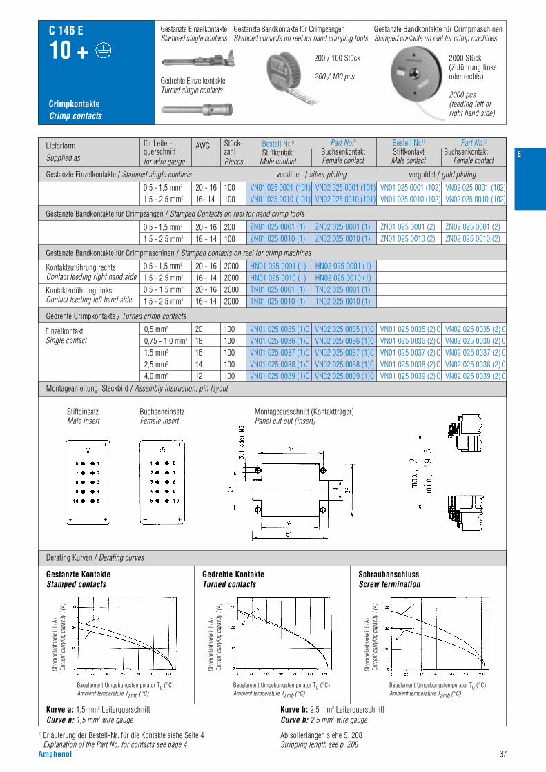
E
Amphenol 37
CrimpkontakteCrimp contacts
C 146 E
10 +
Derating Kurven / Derating curves
Gestanzte Bandkontakte für CrimpmaschinenStamped contacts on reel for crimp machines
200 / 100 Stück
200 / 100 pcs
2000 Stück(Zuführung linksoder rechts)
2000 pcs(feeding left orright hand side)
Gestanzte EinzelkontakteStamped single contacts
Gestanzte Bandkontakte für CrimpzangenStamped contacts on reel for hand crimping tools
Gedrehte EinzelkontakteTurned single contacts
Kurve a: 1,5 mm2 LeiterquerschnittCurve a: 1,5 mm2 wire gauge
Kurve b: 2,5 mm2 LeiterquerschnittCurve b: 2,5 mm2 wire gauge
Gestanzte KontakteStamped contacts
SchraubanschlussScrew termination
Montageausschnitt (Kontaktträger)Panel cut out (insert)
StifteinsatzMale insert
BuchseneinsatzFemale insert
Gedrehte KontakteTurned contacts
1) Erläuterung der Bestell-Nr. für die Kontakte siehe Seite 4Explanation of the Part No. for contacts see page 4
Stro
mbe
last
bark
eit I
(A)
Curre
nt ca
rryin
g ca
pacit
y I (A
)
Bauelement Umgebungstemperatur Tu (°C)Ambient temperature Tamb (°C)
Stro
mbe
last
bark
eit I
(A)
Curre
nt ca
rryin
g ca
pacit
y I (A
)
Bauelement Umgebungstemperatur Tu (°C)Ambient temperature Tamb (°C)
Stro
mbe
last
bark
eit I
(A)
Curre
nt ca
rryin
g ca
pacit
y I (A
)
Bauelement Umgebungstemperatur Tu (°C)Ambient temperature Tamb (°C)
Abisolierlängen siehe S. 208Stripping length see p. 208
LieferformSupplied as
für Leiter-querschnittfor wire gauge
AWG Stück-zahlPieces
0,5 - 1,5 mm2
1,5 - 2,5 mm2
0,5 - 1,5 mm2
1,5 - 2,5 mm2
0,5 - 1,5 mm2
1,5 - 2,5 mm2
0,5 - 1,5 mm2
1,5 - 2,5 mm2
0,5 mm2
0,75 - 1,0 mm2
1,5 mm2
2,5 mm2
4,0 mm2
20 - 1616 - 14
20 - 1616- 14
20 - 1616 - 1420 - 1616 - 14
2018161412
200100
100100
2000200020002000
100100100100100
VN01 025 0001 (101)VN01 025 0010 (101)
ZN01 025 0001 (1)ZN01 025 0010 (1)
HN01 025 0001 (1)HN01 025 0010 (1)TN01 025 0001 (1)TN01 025 0010 (1)
VN01 025 0035 (1)CVN01 025 0036 (1)CVN01 025 0037 (1)CVN01 025 0038 (1)CVN01 025 0039 (1)C
VN02 025 0035 (1)CVN02 025 0036 (1)CVN02 025 0037 (1)CVN02 025 0038 (1)CVN02 025 0039 (1)C
VN01 025 0035 (2) CVN01 025 0036 (2) CVN01 025 0037 (2)CVN01 025 0038 (2)CVN01 025 0039 (2)C
VN02 025 0035 (2) CVN02 025 0036 (2) CVN02 025 0037 (2)CVN02 025 0038 (2)CVN02 025 0039 (2)C
ZN02 025 0001 (1)ZN02 025 0010 (1)
ZN01 025 0001 (2)ZN01 025 0010 (2)
ZN02 025 0001 (2)ZN02 025 0010 (2)
VN02 025 0001 (101)VN02 025 0010 (101)
VN01 025 0001 (102)VN01 025 0010 (102)
VN02 025 0001 (102)VN02 025 0010 (102)
HN02 025 0001 (1)HN02 025 0010 (1)TN02 025 0001 (1)TN02 025 0010 (1)
Kontaktzuführung rechtsContact feeding right hand side
EinzelkontaktSingle contact
Kontaktzuführung linksContact feeding left hand side
Gestanzte Bandkontakte für Crimpmaschinen / Stamped contacts on reel for crimp machines
Gedrehte Crimpkontakte / Turned crimp contacts
Gestanzte Bandkontakte für Crimpzangen / Stamped Contacts on reel for hand crimp tools
Bestell Nr.1)
Stiftkontakt Male contact
Part No.1)
BuchsenkontaktFemale contact
Bestell Nr.1)
StiftkontaktMale contact
Part No.1)
BuchsenkontaktFemale contact
versilbert / silver platingGestanzte Einzelkontakte / Stamped single contacts vergoldet / gold plating
Montageanleitung, Steckbild / Assembly instruction, pin layout

38 Amphenol
Bezeichnung - AbbildungDescription - Figure
MaßzeichnungDrawing
Bestell Nr. / Part No.Stifteinsatz / Male insert Buchseneinsatz / Female insert
C 146 E
16 +
SteckverbinderConnectors
Kontakteinsatz SchraubanschlussContact insert screw termination
Gehäuse siehe Seite 144–151 Housings see page 144–151
C146 10A016 002 1
C146 10A016 102 1(mit Drahtschutz with wire protection)
C146 10B016 002 1
C146 10B016 102 1(mit Drahtschutz with wire protection)
Kontakteinsatz für gestanzte KontakteContact insert for stamped contacts
C146 10A016 000 1 C146 10B016 000 1
C146 10A016 500 1 C146 10B016 500 1
Kontakteinsatz für gedrehte KontakteContact insert for turned contacts
StifteinsatzMale insert
BuchseneinsatzFemale insert
StifteinsatzMale insert
BuchseneinsatzFemale insert
StifteinsatzMale insert
BuchseneinsatzFemale insert
400 V~ Kontakteinsatz für gestanzte Kontakte / Contact insert for stamped contacts
500 V~ Kontakteinsatz für Schraubanschluss und für gedrehte Kontakte /Contact insert for screw termination and for turned contacts
16 / 22 A
E
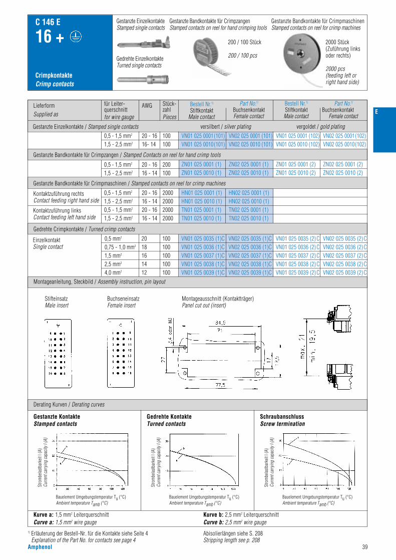
E
Amphenol 39
CrimpkontakteCrimp contacts
C 146 E
16 +
Montageanleitung, Steckbild / Assembly instruction, pin layout
Derating Kurven / Derating curves
Gestanzte Bandkontakte für CrimpmaschinenStamped contacts on reel for crimp machines
200 / 100 Stück
200 / 100 pcs
2000 Stück(Zuführung linksoder rechts)
2000 pcs(feeding left orright hand side)
Gestanzte EinzelkontakteStamped single contacts
Gestanzte Bandkontakte für CrimpzangenStamped contacts on reel for hand crimping tools
Gedrehte EinzelkontakteTurned single contacts
Kurve a: 1,5 mm2 LeiterquerschnittCurve a: 1,5 mm2 wire gauge
Kurve b: 2,5 mm2 LeiterquerschnittCurve b: 2,5 mm2 wire gauge
Gestanzte KontakteStamped contacts
SchraubanschlussScrew termination
Montageausschnitt (Kontaktträger)Panel cut out (insert)
StifteinsatzMale insert
BuchseneinsatzFemale insert
Gedrehte KontakteTurned contacts
1) Erläuterung der Bestell-Nr. für die Kontakte siehe Seite 4Explanation of the Part No. for contacts see page 4
Stro
mbe
last
bark
eit I
(A)
Curre
nt ca
rryin
g ca
pacit
y I (A
)
Bauelement Umgebungstemperatur Tu (°C)Ambient temperature Tamb (°C)
Stro
mbe
last
bark
eit I
(A)
Curre
nt ca
rryin
g ca
pacit
y I (A
)
Bauelement Umgebungstemperatur Tu (°C)Ambient temperature Tamb (°C)
Stro
mbe
last
bark
eit I
(A)
Curre
nt ca
rryin
g ca
pacit
y I (A
)
Bauelement Umgebungstemperatur Tu (°C)Ambient temperature Tamb (°C)
Abisolierlängen siehe S. 208Stripping length see p. 208
LieferformSupplied as
für Leiter-querschnittfor wire gauge
AWG Stück-zahlPieces
0,5 - 1,5 mm2
1,5 - 2,5 mm2
0,5 - 1,5 mm2
1,5 - 2,5 mm2
0,5 - 1,5 mm2
1,5 - 2,5 mm2
0,5 - 1,5 mm2
1,5 - 2,5 mm2
0,5 mm2
0,75 - 1,0 mm2
1,5 mm2
2,5 mm2
4,0 mm2
20 - 1616 - 14
20 - 1616- 14
20 - 1616 - 1420 - 1616 - 14
2018161412
200100
100100
2000200020002000
100100100100100
VN01 025 0001(101)VN01 025 0010(101)
ZN01 025 0001 (1)ZN01 025 0010 (1)
HN01 025 0001 (1)HN01 025 0010 (1)TN01 025 0001 (1)TN01 025 0010 (1)
VN01 025 0035 (1)CVN01 025 0036 (1)CVN01 025 0037 (1)CVN01 025 0038 (1)CVN01 025 0039 (1)C
VN02 025 0035 (1)CVN02 025 0036 (1)CVN02 025 0037 (1)CVN02 025 0038 (1)CVN02 025 0039 (1)C
VN01 025 0035 (2) CVN01 025 0036 (2) CVN01 025 0037 (2)CVN01 025 0038 (2)CVN01 025 0039 (2)C
VN02 025 0035 (2) CVN02 025 0036 (2) CVN02 025 0037 (2)CVN02 025 0038 (2)CVN02 025 0039 (2)C
ZN02 025 0001 (1)ZN02 025 0010 (1)
ZN01 025 0001 (2)ZN01 025 0010 (2)
ZN02 025 0001 (2)ZN02 025 0010 (2)
VN02 025 0001 (101)VN02 025 0010 (101)
VN01 025 0001 (102)VN01 025 0010 (102)
VN02 025 0001(102)VN02 025 0010(102)
HN02 025 0001 (1)HN02 025 0010 (1)TN02 025 0001 (1)TN02 025 0010 (1)
Kontaktzuführung rechtsContact feeding right hand side
EinzelkontaktSingle contact
Kontaktzuführung linksContact feeding left hand side
Gestanzte Bandkontakte für Crimpmaschinen / Stamped contacts on reel for crimp machines
Gedrehte Crimpkontakte / Turned crimp contacts
Gestanzte Bandkontakte für Crimpzangen / Stamped Contacts on reel for hand crimp tools
Bestell Nr.1)
Stiftkontakt Male contact
Part No.1)
BuchsenkontaktFemale contact
Bestell Nr.1)
StiftkontaktMale contact
Part No.1)
BuchsenkontaktFemale contact
versilbert / silver platingGestanzte Einzelkontakte / Stamped single contacts vergoldet / gold plating

40 Amphenol
Bezeichnung - AbbildungDescription - Figure
MaßzeichnungDrawing
Bestell Nr. / Part No.Stifteinsatz / Male insert Buchseneinsatz / Female insert
C 146 E
24 +
SteckverbinderConnectors
Kontakteinsatz SchraubanschlussContact insert screw termination
Gehäuse siehe Seite 152–159Housings see page 152–159
C146 10A024 002 1
C146 10A024 102 1(mit Drahtschutz with wire protection)
C146 10B024 002 1
C146 10B024 102 1(mit Drahtschutz with wire protection)
Kontakteinsatz für gestanzte KontakteContact insert for stamped contacts
C146 10A024 000 1 C146 10B024 000 1
C146 10A024 500 1 C146 10B024 500 1
Kontakteinsatz für gedrehte KontakteContact insert for turned contacts
BuchseneinsatzFemale insert
StifteinsatzMale insert
BuchseneinsatzFemale insert
StifteinsatzMale insert
BuchseneinsatzFemale insert
StifteinsatzMale insert
400 V~ Kontakteinsatz für gestanzte Kontakte / Contact insert for stamped contacts
500 V~ Kontakteinsatz für Schraubanschluss und für gedrehte Kontakte /Contact insert for screw termination and for turned contacts
16 / 22 A
E
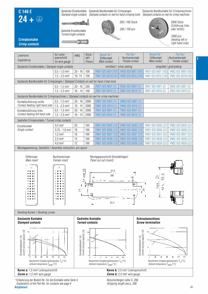
E
Amphenol 41
CrimpkontakteCrimp contacts
C 146 E
24 +
Montageanleitung, Steckbild / Assembly instruction, pin layout
Derating Kurven / Derating curves
Gestanzte Bandkontakte für CrimpmaschinenStamped contacts on reel for crimp machines
200 / 100 Stück
200 / 100 pcs
2000 Stück(Zuführung linksoder rechts)
2000 pcs(feeding left orright hand side)
Gestanzte EinzelkontakteStamped single contacts
Gestanzte Bandkontakte für CrimpzangenStamped contacts on reel for hand crimping tools
Gedrehte EinzelkontakteTurned single contacts
Kurve a: 1,5 mm2 LeiterquerschnittCurve a: 1,5 mm2 wire gauge
Kurve b: 2,5 mm2 LeiterquerschnittCurve b: 2,5 mm2 wire gauge
Gestanzte KontakteStamped contacts
SchraubanschlussScrew termination
Montageausschnitt (Kontaktträger)Panel cut out (insert)
StifteinsatzMale insert
BuchseneinsatzFemale insert
Gedrehte KontakteTurned contacts
1) Erläuterung der Bestell-Nr. für die Kontakte siehe Seite 4Explanation of the Part No. for contacts see page 4
Stro
mbe
last
bark
eit I
(A)
Curre
nt ca
rryin
g ca
pacit
y I (A
)
Bauelement Umgebungstemperatur Tu (°C)Ambient temperature Tamb (°C)
Stro
mbe
last
bark
eit I
(A)
Curre
nt ca
rryin
g ca
pacit
y I (A
)
Bauelement Umgebungstemperatur Tu (°C)Ambient temperature Tamb (°C)
Stro
mbe
last
bark
eit I
(A)
Curre
nt ca
rryin
g ca
pacit
y I (A
)
Bauelement Umgebungstemperatur Tu (°C)Ambient temperature Tamb (°C)
Abisolierlängen siehe S. 208Stripping length see p. 208
LieferformSupplied as
für Leiter-querschnittfor wire gauge
AWG Stück-zahlPieces
0,5 - 1,5 mm2
1,5 - 2,5 mm2
0,5 - 1,5 mm2
1,5 - 2,5 mm2
0,5 - 1,5 mm2
1,5 - 2,5 mm2
0,5 - 1,5 mm2
1,5 - 2,5 mm2
0,5 mm2
0,75 - 1,0 mm2
1,5 mm2
2,5 mm2
4,0 mm2
20 - 1616 - 14
20 - 1616- 14
20 - 1616 - 1420 - 1616 - 14
2018161412
200100
100100
2000200020002000
100100100100100
VN01 025 0001(101)VN01 025 0010(101)
ZN01 025 0001 (1)ZN01 025 0010 (1)
HN01 025 0001 (1)HN01 025 0010 (1)TN01 025 0001 (1)TN01 025 0010 (1)
VN01 025 0035 (1)CVN01 025 0036 (1)CVN01 025 0037 (1)CVN01 025 0038 (1)CVN01 025 0039 (1)C
VN02 025 0035 (1)CVN02 025 0036 (1)CVN02 025 0037 (1)CVN02 025 0038 (1)CVN02 025 0039 (1)C
VN01 025 0035 (2) CVN01 025 0036 (2) CVN01 025 0037 (2)CVN01 025 0038 (2)CVN01 025 0039 (2)C
VN02 025 0035 (2) CVN02 025 0036 (2) CVN02 025 0037 (2)CVN02 025 0038 (2)CVN02 025 0039 (2)C
ZN02 025 0001 (1)ZN02 025 0010 (1)
ZN01 025 0001 (2)ZN01 025 0010 (2)
ZN02 025 0001 (2)ZN02 025 0010 (2)
VN02 025 0001 (101)VN02 025 0010 (101)
VN01 025 0001 (102)VN01 025 0010 (102)
VN02 025 0001(102)VN02 025 0010(102)
HN02 025 0001 (1)HN02 025 0010 (1)TN02 025 0001 (1)TN02 025 0010 (1)
Kontaktzuführung rechtsContact feeding right hand side
EinzelkontaktSingle contact
Kontaktzuführung linksContact feeding left hand side
Gestanzte Bandkontakte für Crimpmaschinen / Stamped contacts on reel for crimp machines
Gedrehte Crimpkontakte / Turned crimp contacts
Gestanzte Bandkontakte für Crimpzangen / Stamped Contacts on reel for hand crimp tools
Bestell Nr.1)
Stiftkontakt Male contact
Part No.1)
BuchsenkontaktFemale contact
Bestell Nr.1)
StiftkontaktMale contact
Part No.1)
BuchsenkontaktFemale contact
versilbert / silver platingGestanzte Einzelkontakte / Stamped single contacts vergoldet / gold plating

42 Amphenol
Bezeichnung - AbbildungDescription - Figure
MaßzeichnungDrawing
Bestell Nr. / Part No.Stifteinsatz / Male insert Buchseneinsatz / Female insert
C 146 E
48 +
SteckverbinderConnectors
Kontakteinsatz SchraubanschlussContact insert screw termination
Gehäuse siehe Seite 160–163Housings see page 160–163
C146 10A024 002 1+C146 10A024 004 1
C146 10B024 002 1+C146 10B024 004 1
Kontakteinsatz Schraubanschlussmit DrahtschutzContact insert screw terminationwith wireprotection
C146 10A024 102 1+C146 10A024 104 1
C146 10B024 102 1+C146 10B024 104 1
Kontakteinsatz für gestanzte KontakteContact insert for stamped contacts
C146 10A024 000 1+C146 10A024 005 1
C146 10B024 000 1+C146 10B024 005 1
C146 10A024 500 1+C146 10A024 505 1
C146 10B024 500 1+C146 10B024 505 1
Kontakteinsatz für gedrehte KontakteContact insert for turned contacts
BuchseneinsatzFemale insert
StifteinsatzMale insert
BuchseneinsatzFemale insert
StifteinsatzMale insert
BuchseneinsatzFemale insert
StifteinsatzMale insert
BuchseneinsatzFemale insert
StifteinsatzMale insert
400 V~ Kontakteinsatz für gestanzte Kontakte / Contact insert for stamped contacts
500 V~ Kontakteinsatz für Schraubanschluss und für gedrehte Kontakte /Contact insert for screw termination and for turned contacts
16 / 22 A
E

E
Amphenol 43
CrimpkontakteCrimp contacts
C 146 E
48 +
Derating Kurven / Derating curves
Gestanzte Bandkontakte für CrimpmaschinenStamped contacts on reel for crimp machines
200 / 100 Stück
200 / 100 pcs
Gestanzte EinzelkontakteStamped single contacts
Gestanzte Bandkontakte für CrimpzangenStamped contacts on reel for hand crimping tools
Gedrehte EinzelkontakteTurned single contacts
Kurve a: 1,5 mm2 LeiterquerschnittCurve a: 1,5 mm2 wire gauge
Kurve b: 2,5 mm2 LeiterquerschnittCurve b: 2,5 mm2 wire gauge
Gestanzte KontakteStamped contacts
SchraubanschlussScrew termination
StifteinsatzMale insert
BuchseneinsatzFemale insert
Montageausschnitt (Kontaktträger)Panel cut out (insert)
Gedrehte KontakteTurned contacts
1) Erläuterung der Bestell-Nr. für die Kontakte siehe Seite 4Explanation of the Part No. for contacts see page 4
Stro
mbe
last
bark
eit I
(A)
Curre
nt ca
rryin
g ca
pacit
y I (A
)
Bauelement Umgebungstemperatur Tu (°C)Ambient temperature Tamb (°C)
Stro
mbe
last
bark
eit I
(A)
Curre
nt ca
rryin
g ca
pacit
y I (A
)
Bauelement Umgebungstemperatur Tu (°C)Ambient temperature Tamb (°C)
Stro
mbe
last
bark
eit I
(A)
Curre
nt ca
rryin
g ca
pacit
y I (A
)
Bauelement Umgebungstemperatur Tu (°C)Ambient temperature Tamb (°C)
Abisolierlängen siehe S. 208Stripping length see p. 208
LieferformSupplied as
für Leiter-querschnittfor wire gauge
AWG Stück-zahlPieces
0,5 - 1,5 mm2
1,5 - 2,5 mm2
0,5 - 1,5 mm2
1,5 - 2,5 mm2
0,5 - 1,5 mm2
1,5 - 2,5 mm2
0,5 - 1,5 mm2
1,5 - 2,5 mm2
0,5 mm2
0,75 - 1,0 mm2
1,5 mm2
2,5 mm2
4,0 mm2
20 - 1616 - 14
20 - 1616- 14
20 - 1616 - 1420 - 1616 - 14
2018161412
200100
100100
2000200020002000
100100100100100
VN01 025 0001(101)VN01 025 0010(101)
ZN01 025 0001 (1)ZN01 025 0010 (1)
HN01 025 0001 (1)HN01 025 0010 (1)TN01 025 0001 (1)TN01 025 0010 (1)
VN01 025 0035 (1)CVN01 025 0036 (1)CVN01 025 0037 (1)CVN01 025 0038 (1)CVN01 025 0039 (1)C
VN02 025 0035 (1)CVN02 025 0036 (1)CVN02 025 0037 (1)CVN02 025 0038 (1)CVN02 025 0039 (1)C
VN01 025 0035 (2) CVN01 025 0036 (2) CVN01 025 0037 (2)CVN01 025 0038 (2)CVN01 025 0039 (2)C
VN02 025 0035 (2) CVN02 025 0036 (2) CVN02 025 0037 (2)CVN02 025 0038 (2)CVN02 025 0039 (2)C
ZN02 025 0001 (1)ZN02 025 0010 (1)
ZN01 025 0001 (2)ZN01 025 0010 (2)
ZN02 025 0001 (2)ZN02 025 0010 (2)
VN02 025 0001 (101)VN02 025 0010 (101)
VN01 025 0001 (102)VN01 025 0010 (102)
VN02 025 0001(102)VN02 025 0010(102)
HN02 025 0001 (1)HN02 025 0010 (1)TN02 025 0001 (1)TN02 025 0010 (1)
Kontaktzuführung rechtsContact feeding right hand side
EinzelkontaktSingle contact
Kontaktzuführung linksContact feeding left hand side
Gestanzte Bandkontakte für Crimpmaschinen / Stamped contacts on reel for crimp machines
Gedrehte Crimpkontakte / Turned crimp contacts
Gestanzte Bandkontakte für Crimpzangen / Stamped Contacts on reel for hand crimp tools
Bestell Nr.1)
Stiftkontakt Male contact
Part No.1)
BuchsenkontaktFemale contact
Bestell Nr.1)
StiftkontaktMale contact
Part No.1)
BuchsenkontaktFemale contact
versilbert / silver platingGestanzte Einzelkontakte / Stamped single contacts vergoldet / gold plating
Montageanleitung, Steckbild / Assembly instruction, pin layout

44 Amphenol
Werkzeuge 1)
Tools 1)
C 146 E
1) Weitere Informationen siehe Katalog „Werkzeuge“ / Further information see catalogue „Tools“2) Incl. Prüfstiftset + Kontaktaufnahme / incl. calibration pin set + contact locator
Bezeichnung / Description
Lösewerkzeug für gestanzte KontakteRemoval tool for stamped contacts
– – – FG 0200 146 1
0,5 - 1,5 mm2
1,5 - 2,5 mm2
TA 0004 146 000 1TA 0005 146 000 3
TA 0000 163TA 0000 141
TA 0000
0,5 - 4,0 mm2 – – TB 0600 146 2)
Crimpzange für gestanzte EinzelkontakteCrimping tool for stamped single contacts
4-Kerb Crimpzange für gedrehte Kontakte4-indent crimping tool forturned contacts
für Leiterquerschnittfor wire gauge
Bestell Nr. / Part No.Kontaktaufnahme / Contact locator Crimpbacken / Crimping dies Werkzeuge / ToolsE
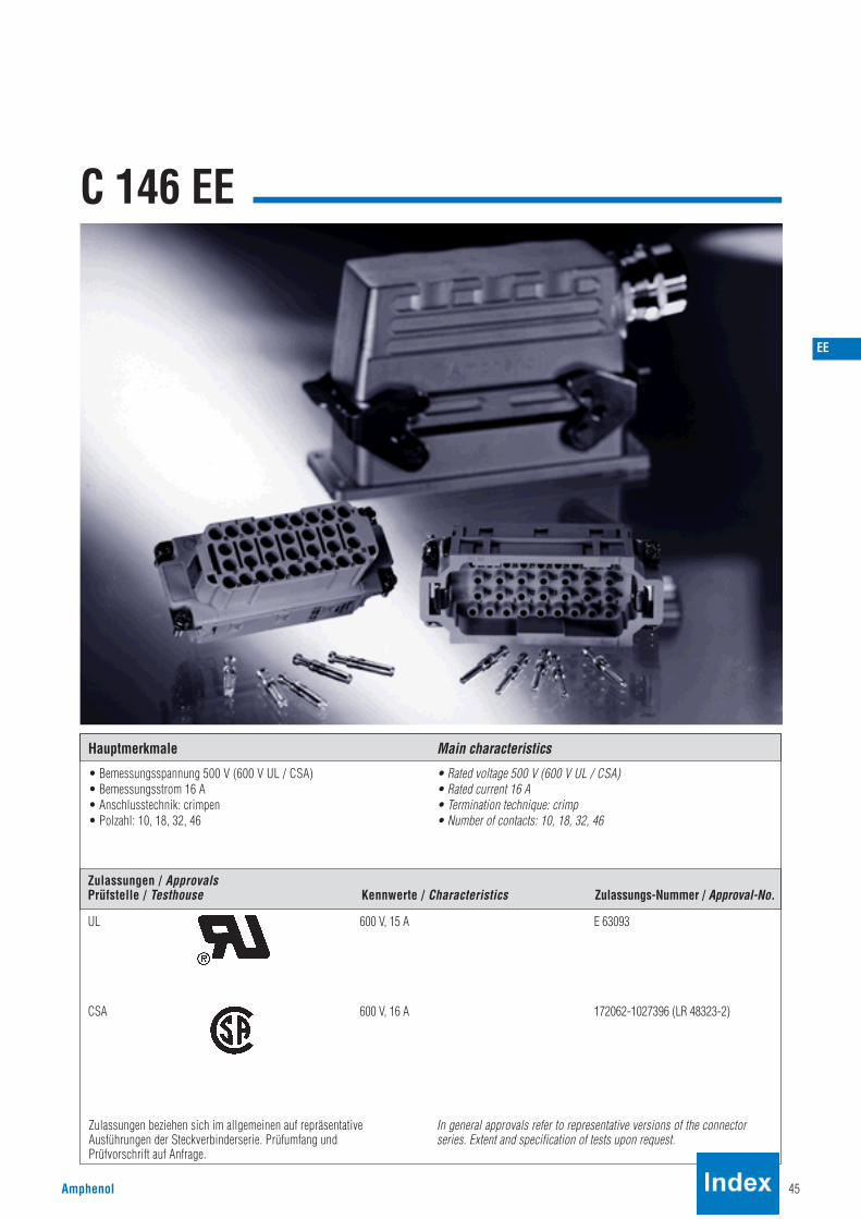
Amphenol 45
C 146 EE
EE
Hauptmerkmale Main characteristics
Zulassungen / ApprovalsPrüfstelle / Testhouse Kennwerte / Characteristics Zulassungs-Nummer / Approval-No.
• Bemessungsspannung 500 V (600 V UL / CSA)• Bemessungsstrom 16 A• Anschlusstechnik: crimpen• Polzahl: 10, 18, 32, 46
• Rated voltage 500 V (600 V UL / CSA)• Rated current 16 A• Termination technique: crimp• Number of contacts: 10, 18, 32, 46
UL 600 V, 15 A E 63093
CSA 600 V, 16 A 172062-1027396 (LR 48323-2)
Zulassungen beziehen sich im allgemeinen auf repräsentative Ausführungen der Steckverbinderserie. Prüfumfang und Prüfvorschrift auf Anfrage.
In general approvals refer to representative versions of the connector series. Extent and specification of tests upon request.

46 Amphenol
BezeichnungDescription
MaßzeichnungDrawing
Bestell Nr. / Part No.Stifteinsatz / Male insert Buchseneinsatz / Female insert
C 146 EE
SteckverbinderConnectors
C146 10A010 500 10 C146 10B010 500 10
Montageanleitung / Assembly instruction
Montageausschnitt (Kontaktträger)Panel cut out (insert)
Kontakteinsatz 10 +Contact insert 10 +
C146 10A018 500 10 C146 10B018 500 10Kontakteinsatz 18 +Contact insert 18 +
C146 10A032 500 10 C146 10B032 500 10Kontakteinsatz 32 +Contact insert 32 +
C146 10A046 500 10 C146 10B046 500 10Kontakteinsatz 46 +Contact insert 46 +
Gehäuse siehe Seite 132–159Housings see page 132–159
für gedrehte Kontaktefor turned contacts
500 V~ 16 A
StifteinsatzMale insert
StifteinsatzMale insert
BuchseneinsatzFemale insert
BuchseneinsatzFemale insert
StifteinsatzMale insert
BuchseneinsatzFemale insert
StifteinsatzMale insert
BuchseneinsatzFemale insert
EE
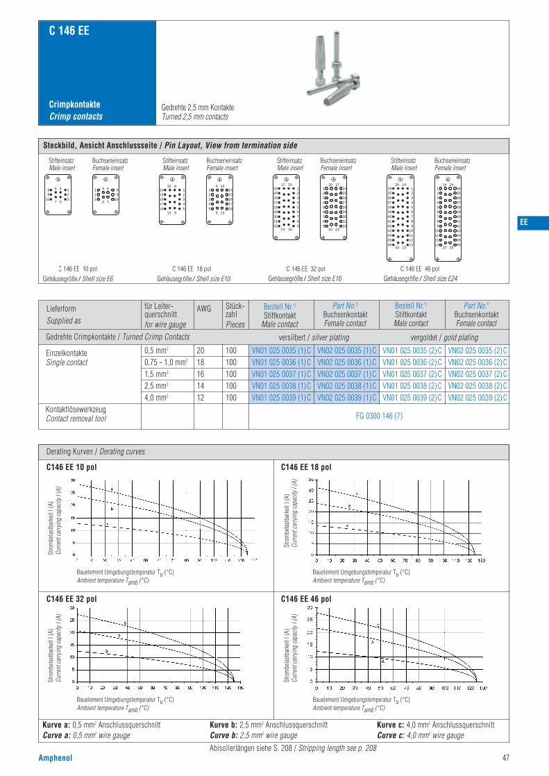
EE
Amphenol 47
CrimpkontakteCrimp contacts
C 146 EE
Derating Kurven / Derating curves
Gedrehte 2,5 mm KontakteTurned 2,5 mm contacts
Stro
mbe
last
bark
eit I
(A)
Curre
nt ca
rryin
g ca
pacit
y I (A
)
Bauelement Umgebungstemperatur Tu (°C)Ambient temperature Tamb (°C)
Stro
mbe
last
bark
eit I
(A)
Curre
nt ca
rryin
g ca
pacit
y I (A
)
Bauelement Umgebungstemperatur Tu (°C)Ambient temperature Tamb (°C)
Stro
mbe
last
bark
eit I
(A)
Curre
nt ca
rryin
g ca
pacit
y I (A
)
Bauelement Umgebungstemperatur Tu (°C)Ambient temperature Tamb (°C)
Stro
mbe
last
bark
eit I
(A)
Curre
nt ca
rryin
g ca
pacit
y I (A
)
Bauelement Umgebungstemperatur Tu (°C)Ambient temperature Tamb (°C)
Steckbild, Ansicht Anschlussseite / Pin Layout, View from termination side
Female insertBuchseneinsatz
Male insertStifteinsatz
Female insertBuchseneinsatz
Male insertStifteinsatz
Female insertBuchseneinsatz
Male insertStifteinsatz
Female insertBuchseneinsatz
Male insertStifteinsatz
10
89
7 5
913 9
10 6
15161718
142345
16 10
2345
115161718
14
13
23 16
17 10
2526272829303132
2423456
987
1
23
10 17
23456
987
12526272829303132
24
16
14 24
23 33
23456
13121110987
1
33 23
24 14
353637383940414243444546
3423456
13121110987
1353637383940414243444546
34
5
6 4
23
1 4 6
23
19
10
8
7
C 146 EE 46 polSteckbildC 146 EE 32 polSteckbildC 146 EE 18 polSteckbildC 146 EE 10 polGehäusegröße / Shell size E6 Gehäusegröße / Shell size E10 Gehäusegröße / Shell size E16 Gehäusegröße / Shell size E24
C146 EE 10 pol C146 EE 18 pol
C146 EE 32 pol C146 EE 46 pol
Kurve a: 0,5 mm2 AnschlussquerschnittCurve a: 0,5 mm2 wire gauge
Kurve b: 2,5 mm2 AnschlussquerschnittCurve b: 2,5 mm2 wire gauge
Kurve c: 4,0 mm2 AnschlussquerschnittCurve c: 4,0 mm2 wire gauge
Abisolierlängen siehe S. 208 / Stripping length see p. 208
LieferformSupplied as
Gedrehte Crimpkontakte / Turned Crimp Contacts
für Leiter-querschnittfor wire gauge
AWG Stück-zahlPieces
EinzelkontakteSingle contact
KontaktlösewerkzeugContact removal tool
0,5 mm2
0,75 - 1,0 mm2
1,5 mm2
2,5 mm2
4,0 mm2
201816 1412
100100100100100
VN01 025 0035 (1)CVN01 025 0036 (1)CVN01 025 0037 (1)CVN01 025 0038 (1)CVN01 025 0039 (1)C
VN02 025 0035 (1)CVN02 025 0036 (1)CVN02 025 0037 (1)CVN02 025 0038 (1)CVN02 025 0039 (1)C
VN01 025 0035 (2)CVN01 025 0036 (2)CVN01 025 0037 (2)CVN01 025 0038 (2)CVN01 025 0039 (2)C
VN02 025 0035 (2)CVN02 025 0036 (2)CVN02 025 0037 (2)CVN02 025 0038 (2)CVN02 025 0039 (2)C
Bestell Nr.1)
Stiftkontakt Male contact
versilbert / silver plating vergoldet / gold plating
Part No.1)
BuchsenkontaktFemale contact
Bestell Nr.1)
StiftkontaktMale contact
Part No.1)
BuchsenkontaktFemale contact
FG 0300 146 (7)

48 Amphenol
Norm / Standard Wert / Value
V-0
0,5 mm2 - 4,0 mm2
crimpen / crimp
10 + 18 + 32 + 46 +
C 146 EE
UL 94
Allgemeine Kennwerte
Polzahl
Anschlussquerschnitt
Anschlusstechnik
Brennbarkeit
Number of contacts
Wire gauge
Termination technique
Flammability
500 V (600 V UL / CSA)
3
III
III b
6 kV
3 kV
16 A
siehe Derating Kurven / see derating curves
≥ 10 12 Ω 1)
IEC 60664-1
IEC 60664-1
IEC 60664-1
IEC 60664-1
IEC 60664-1
IEC 60512-2; Test 4 a
IEC 60512-3; Test 5 b
IEC 60512-2; Test 3 a
IEC 60068-1
IEC 60512-5; Test 9 a
40 / 100 / 21
≥ 500 Steckzyklen / mating cycles
grau / grey
≤ 5 m ΩIEC 60512-2; Test 2 a
IEC 60512-6; Test 11 i + 100 °C / 1000 h
IEC 60512-6; Test 11 i - 40 °C / 16 h
CuZn (Messing / brass)
PC
Ag (silber / silver)
Elektrische Kennwerte
Bemessungsspannung
Verschmutzungsgrad
Überspannungskategorie
Isolierstoffgruppe
Bemessungs-Stoßspannung
Spannungsfestigkeit
Strombelastbarkeit
Durchgangswiderstand
Isolationswiderstand
Klimatische Kennwerte
Prüfklasse
Obere Grenztemperatur
Untere Grenztemperatur
Mechanische Kennwerte
Mechanische Lebensdauer
Werkstoffe
Kontakteinsatz
Kontakte
Kontaktoberfläche
Farbe
1) Bei Beanspruchung > 1010 Ω / Under operating conditions > 1010 Ω
Electrical Characteristics
Rated voltage
Pollution degree
Installation (overvoltage) category
Material group
Rated impulse withstand voltage
Voltage proof
Current carrying capacity
Bemessungsstrom Tu = 40 °C Rated current Tamb = 40 °C
Insulation resistance
> 5,5 mmIEC 60664-1Luftstrecke Clearance
> 10 mmIEC 60664-1Kriechstrecke Creepage
Climatical Characteristics
Climatic category
Mechanical Characteristics
Mechanical operation
Insert
Contact resistance
Upper temperature
Lower temperature
Contacts
Contact plating
Colour
Materials
General Characteristics
Technische DatenCharacteristics
IEC 60529IP-degree of protection pin insert ungesteckt/unmatedIP00
gesteckt/matedIP20
gesteckt/matedIP20
ungesteckt/unmatedIP20
IP-Schutzart Stifteinsatz
IEC 60529IP-degree of protection socket insertIP-Schutzart Buchseneinsatz
EE

E/D
Amphenol 49
C 146 E / D Anschlussverteiler / Terminal blocks
Hauptmerkmale Main characteristicsHauptmerkmale Main characteristics
Zulassungen / ApprovalsPrüfstelle / Testhouse Kennwerte / Characteristics Zulassungs-Nummer / Approval-No.
• Anschlussverteiler für KontakteinsätzeC 146 E 6 - 24 pol; C 146 D 40 - 64 pol
• Weitere Technische Daten auf Anfrage
• Terminal blocks for contacts inserts C 146 E 6 - 24 contacts; C 146 D 40 - 64 contacts
• Further characteristics upon request
C146 D
CSA 300 V, 5 A 48932
C 146 E
CSA 300 V, 9 A 48932
Zulassungen beziehen sich im allgemeinen auf repräsentativeAusführungen der Steckverbinderserie. Prüfumfang undPrüfvorschrift auf Anfrage.
In general approvals refer to representative versions of the connectorseries. Extent and specification of tests upon request.

50 Amphenol
KurzinformationBrief information
C 146 AnschlussverteilerTerminal blocks
Allgemeine Hinweise
General information
Für den Einsatz an industriellen Anlagen sowie an steuer- und regeltechnischen Geräten wurden die Anschluss-verteiler der Serie C 146 entwickelt.Die kompakte Bauweise dieser Kombination zwischen Steckverbinder und Reihenklemmen bringt Platzersparnis imSchaltschrank sowie reduzierte Verdrahtungs, Kontroll- und Montagekosten.Die auf einer Schräge angeordneten Anschlussklemmen sind auch in mehrreihiger Anordnung sehr gut zugänglich,die Beschriftung der Klemmstelle ist durchnummeriert (aufgedruckte Zahlen). Zusätzlich kann sie durchBezeichnungsschilder nochmals gekennzeichnet werden.Den Anschlussverteiler gibt es wahlweise mit rechts- oder linksseitigem Schutzleiteranschluss, um je nachEinsatzfall einen rechts-, bzw. linksseitigen Einbau in der Schaltschrankwand zu ermöglichen. DerSchutzleiteranschluss und die Klemme Nr. 1 befinden sich in beiden Einbaufällen an der Oberseite.Weitere technische Daten und Maße sowie die dazu passenden Gegenstecker und Gehäuse entnehmen Sie bitte dennachfolgenden Seiten.
The terminal blocks of the series C 146 were designed for application in industrial facilities and also for power andcontrol devices. The compact construction of this combination of connector and busbar will allow space savingsbehind the panel as well as termination-, inspection- and assembly cost.Due to the tapered arrangement of the termination clamps access is easy even on multi-row construction, theidentification of the stations is numeric (printed). Additional identification is possible with six digit numeric tags.The terminal blocks are available with right- or leftside PE termination to be mounted right or left on the panel walldepending on the individual application. In both applications the PE termination and clamp No.1 are on the upper side.On the following pages of the catalogue you will find information on further technical data and dimensions as wellas on the housings and connectors to be mated.
Montageanleitung, Steckbild / Assembly instruction, pin layout
Stift-/ Buchseneinsatzlinke Ausführung
Male/Female insertleft version
Stift-/ Buchseneinsatzrechte Ausführung
Male/Female insertright version
Kontakt Nr.1Contact No.1
E/D

E/D
Amphenol 51
Bezeichnung - AbbildungDescription - Figure
Maßzeichnung 6 + 1)
Drawing 6 + 1)
Bestell Nr. / Part No.Stifteinsatz / Male insert Buchseneinsatz / Female insert
C 146 E AVAnschlussverteilerTerminal blocks
SteckverbinderConnectors
KontakteinsatzSchutzkontakt - linksContact insert protection earth - left
6 +
10 +
16 +
24 +
Gehäuse siehe Seite 132-159Housings see page 132-159
400 V~ 16 A
C146 12A006 102 1
C146 12A010 102 1
C146 12A016 102 1
C146 12A024 102 1
C146 12B006 102 1
C146 12B010 102 1
C146 12B016 102 1
C146 12B024 102 1
C146 12A006 152 1
C146 12A010 152 1
C146 12A016 152 1
C146 12A024 152 1
C146 N21 040 E1 X(10 Stk./10 pcs)
C146 12B006 152 1
C146 12B010 152 1
C146 12B016 152 1
C146 12B024 152 1
KontakteinsatzSchutzkontakt - rechtsContact insert protection earth - right
6 +
10 +
16 +
24 +
Zubehör / Accesories
TragschienenadapterFixing element
1) Weitere Maße der Steckverbinder siehe Serie C146 E, Seite 34-40 / Further dimensions for the connectors see series C146 E, page 34-40.
StifteinsatzMale insert
BuchseneinsatzFemale insert
StifteinsatzMale insert
BuchseneinsatzFemale insert

C 146 D AVAnschlussverteilerTerminal blocks
SteckverbinderConnectors
Gehäuse siehe Seite 144-159 Housings see page 144-159
250 V~ 10 A
Bezeichnung - AbbildungDescription - Figure
MaßzeichnungDrawing
Bestell Nr. / Part No.Stifteinsatz / Male insert Buchseneinsatz / Female insert
KontakteinsatzSchutzkontakt - linksContact insert protection earth - left
40 +
64 +
C146 12A040 102 2
C146 12A064 102 2
C146 12B040 102 2
C146 12B064 102 2
C146 12A040 152 2
C146 12A064 152 2
C146 12B040 152 2
C146 12B064 152 2
52 Amphenol
Maßzeichnung 40 + 1)
Drawing 40 + 1)
C146 N21 040 E1 X(10 Stk./10 pcs)
Zubehör / Accesories
TragschienenadapterFixing element
1) Weitere Maße der Steckverbinder siehe Serie C146 D, Seite 16 und 20. / Further dimensions for the connectors see series C146 D, page 16 and 20.
StifteinsatzMale insert
BuchseneinsatzFemale insert
StifteinsatzMale insert
BuchseneinsatzFemale insert
KontakteinsatzSchutzkontakt - rechtsContact insert protection earth - right
40 +
64 +
E/D
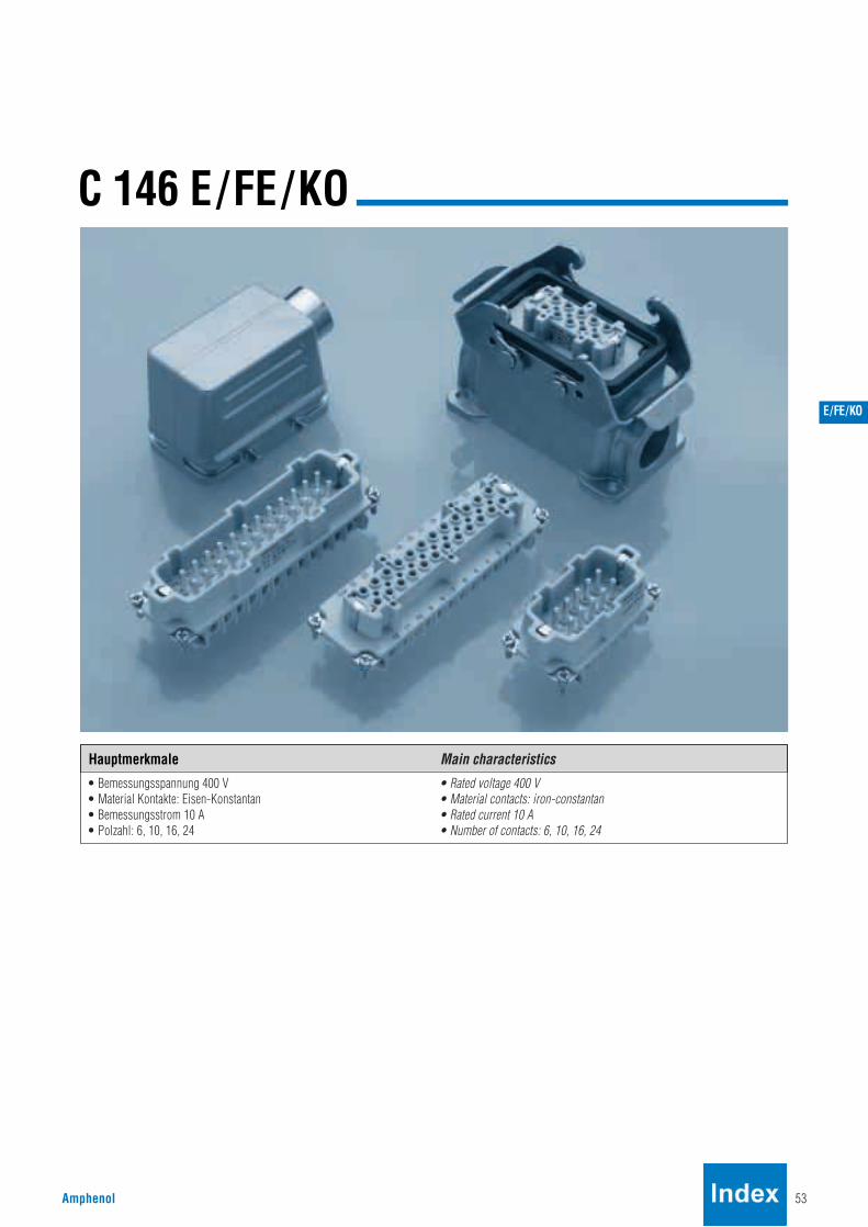
E/FE/KO
Amphenol 53
C 146 E/FE/KO
Hauptmerkmale Main characteristics
• Bemessungsspannung 400 V• Material Kontakte: Eisen-Konstantan• Bemessungsstrom 10 A• Polzahl: 6, 10, 16, 24
• Rated voltage 400 V• Material contacts: iron-constantan• Rated current 10 A• Number of contacts: 6, 10, 16, 24

54 Amphenol
Bezeichnung - AbbildungDescription - Figure
C 146 E/FE/KO
KurzinformationBrief information
Steckverbinder mit Eisen-(FE) und Konstantan(KO)-Kontaktelementenfinden vornehmlich in der Steuer- und Regeltechnik ihren Einsatz, und zwardort, wo es gilt, zwischen Eisen- bzw. Konstantan-Leitungen „Schnitt-stellen“ zu schaffen. FE/KO-Kabel werden üblicherweise als Verbindungs-glied zwischen Thermoelement und Regelgerät eingesetzt.
Z. B. : Messen und Regeln der Temperatur in Kunststoff-SpritzformenSpritzformen (Heißkanal-Anspritzung) mittels Thermofühler undelektronischem Regelgerät.
Durch das Einbringen von FE/KO-Steckverbindern in die „Thermofühler-leitung“ werden die Messergebnisse verfeinert, d. h. die Regelungenauigkeitwird stark reduziert.
Soll-Wert-Abweichung bei verschiedenen Kontaktwerkstoff-Paarungen
Die Werte sind auf eine Umgebungstemperatur von 100 °C bezogen.
Die Ursache der Sollwert-Abweichung (Übertragungsverlust) beiSteckverbindern mit Messingkontakten liegt in der selbsterzeugendenThermospannung (hervorgerufen durch den Wechsel von FE-Draht zuMessing-Kontaktelement) bzw. durch die Temperaturschwankungen an den Kontaktelementen.
Einsatz von Thermo-Werkstoffenin Abhängigkeit der Messtemperatur
Faktoren, die das Messergebnis zusätzlich beeinflussen• schwankende Umgebungstemperaturen (am Steckverbinder)
Connectors with iron (FE) and constantan (CO)contactsare basically used in measuring and control circuits to serve as interfacebetween FE/CO thermocouples and control unit, i. e. temperature control ofmoulds in injection moulding machines.Through the use of FE/CO connectors in the thermocouple circuit themeasuring results are more accurate, thus the tolerance of the temperaturecontrol is much narrower.
Amphenol’s Industial Connectors with iron (FE) an Contantan (CO) contactsare used to connect FE/CO thermocouples with electronic signal amplifiersin measuring and control circuits, i. e. for temperature control of mouldingmachines.
Errors with various combinations
The connection of unlike metals (FE/Brass and CO/Brass) generatethermoelectric voltage errors in the mesuring circuit caused by the flowfrom iron wire to the brass contact or by temperature changes at the contactelements.
By using FE/CO contacts respectively these deviations will be minimized.
Material / Temperature Range
Temperature changes cause errors:
Soll.-Temp.
100 °C
200 °C
300 °C
400 °C
+ 4 %
+ 2,5 %
+ 1,3 %
+ 1,5 %
- 16 %
- 8 %
- 12,7 %
- 4,5 %
- 4 %
- 3 %
- 1,3 %
- 1,0 %
- 2 %
- 1,5 %
0 %
0 %
Kontaktwerk-stoffe
Temperaturbereich
< 150 °C
150 °C - 450 °C
450 °C - ca. 1000 °C
Temperaturbereich
beliebig / Widerstandsmessung
FE-KO (Eisen/Konstantan)
Ni/Cr - Ni (Nickel/Cromleg./Nickel)
Temperatur range
< 150 °C
150 °C - 450 °C
450 °C - approx. 1000 °C
Material/measurement procedure
any/Resistance measurement
FE-CO (iron/Constantan)
Ni/Cr-Ni (Nickel/Chrome/Nickel)
ohne Thermo-Kontakte
MS/FE MS/KO
mit Thermo-Kontakte
FE/FE KO/KO Nominal Temp.100 °C
200 °C
300 °C
400 °C
+ 4 %
+ 2,5 %
+ 1,3 %
+ 1,5 %
- 16 %
- 8 %
- 12,7 %
- 4,5 %
- 4 %
- 3 %
- 1,3 %
- 1,0 %
- 2 %
- 1,5 %
0 %
0 %
Contact Material without Thermo Contacts
MS/FE MS/KO
with Thermo Contacts
FE/FE KO/KO
Messstelle°C
NominaleTemp.°CUmgebungstemperatur Ambient temperaturemV/°C
mV/°C
E/FE/KO
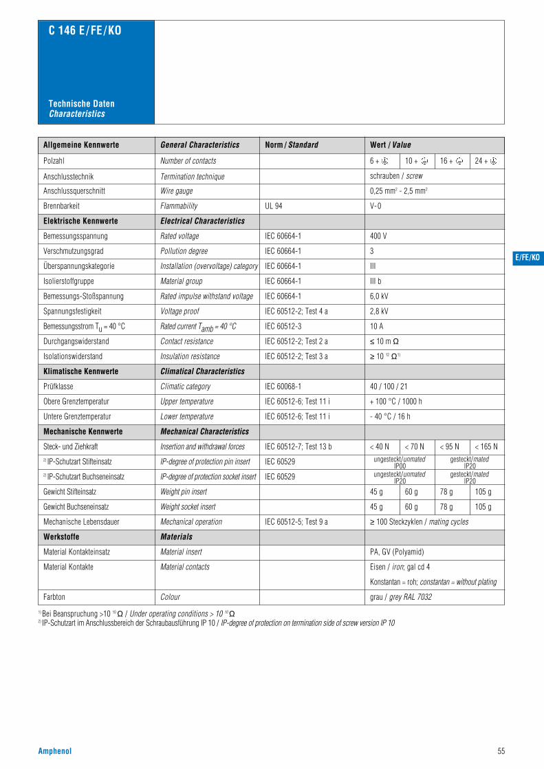
E/FE/KO
Amphenol 55
Norm / Standard Wert / ValueAllgemeine Kennwerte
Polzahl
400 V
3
III
III b
6,0 kV
2,8 kV
Number of contacts
Anschlusstechnik Termination technique
V-0
schrauben / screw
Anschlussquerschnitt Wire gauge 0,25 mm2 - 2,5 mm2
6 + 10 + 16 + 24 +
Flammability
Electrical Characteristics
Rated voltage
Pollution degree
C 146 E /FE /KO
Installation (overvoltage) category
Material group
Rated impulse withstand voltage
Voltage proof
IEC 60664-1
IEC 60664-1
IEC 60664-1
IEC 60664-1
IEC 60664-1
IEC 60512-2; Test 4 a
UL 94Brennbarkeit
Elektrische Kennwerte
Bemessungsspannung
Verschmutzungsgrad
Überspannungskategorie
Isolierstoffgruppe
Bemessungs-Stoßspannung
Spannungsfestigkeit
10 AIEC 60512-3Rated current Tamb = 40 °CBemessungsstrom Tu = 40 °C
General Characteristics
Technische DatenCharacteristics
grau / grey RAL 7032
≤ 10 m ΩIEC 60512-2; Test 2 a
IEC 60068-1
Contact resistance
Climatical Characteristics
Climatic category
Material insert
Material contacts
40 / 100 / 21
< 40 N < 70 N < 95 N < 165 N
45 g
45 g
60 g
60 g
78 g
78 g
105 g
105 g
PA, GV (Polyamid)
Eisen / iron; gal cd 4
Konstantan = roh; constantan = without plating
Durchgangswiderstand
≥ 10 12 Ω1)IEC 60512-2; Test 3 aInsulation resistanceIsolationswiderstand
Klimatische Kennwerte
Prüfklasse
IEC 60512-7; Test 13 b
IEC 60512-5; Test 9 a
Mechanical Characteristics
Insertion and withdrawal forces
Weight pin insert
Weight socket insert
Mechanical operation ≥ 100 Steckzyklen / mating cycles
Mechanische Kennwerte
Steck- und Ziehkraft
Gewicht Stifteinsatz
Gewicht Buchseneinsatz
Mechanische Lebensdauer
Werkstoffe
Material Kontakteinsatz
Material Kontakte
Farbton
1) Bei Beanspruchung >10 10 Ω / Under operating conditions > 10 10 Ω2) IP-Schutzart im Anschlussbereich der Schraubausführung IP 10 / IP-degree of protection on termination side of screw version IP 10
Colour
Materials
IEC 60512-6; Test 11 i + 100 °C / 1000 h
IEC 60512-6; Test 11 i - 40 °C / 16 h
Obere Grenztemperatur
Untere Grenztemperatur
Upper temperature
Lower temperature
IEC 60529IP-degree of protection pin insert ungesteckt/unmatedIP00
gesteckt/matedIP20
gesteckt/matedIP20
ungesteckt/unmatedIP20
2) IP-Schutzart Stifteinsatz
IEC 60529IP-degree of protection socket insert2) IP-Schutzart Buchseneinsatz
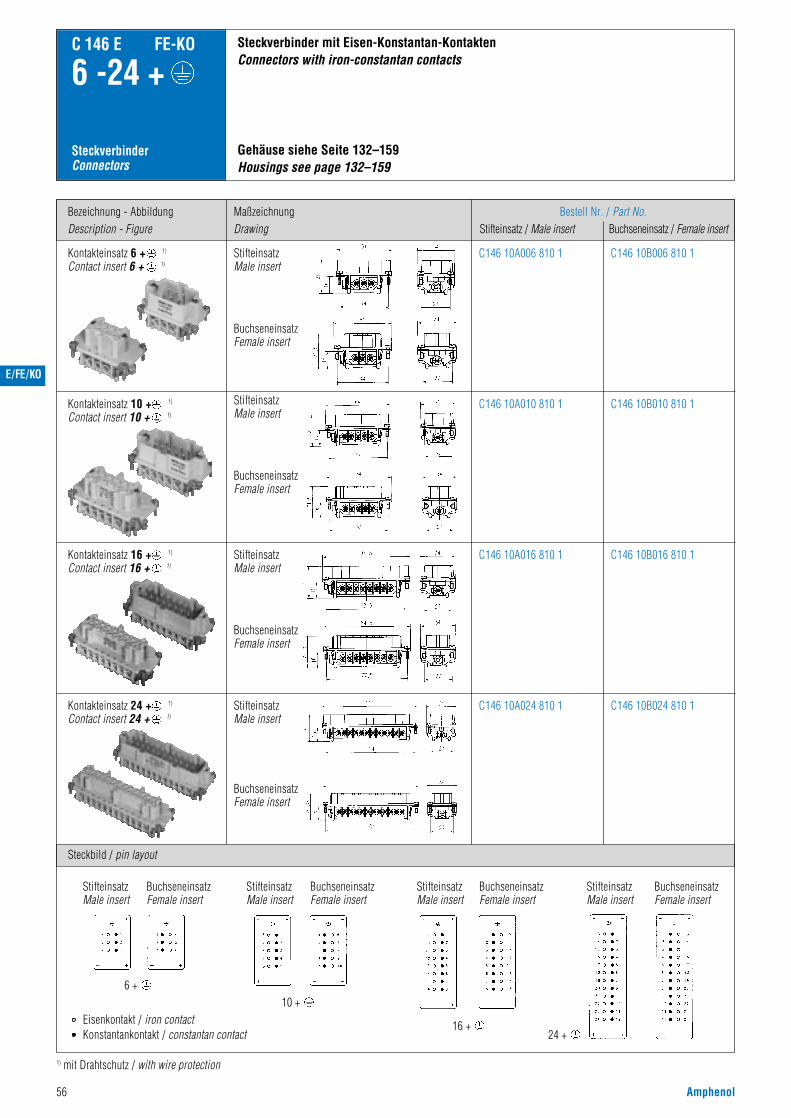
56 Amphenol
Bezeichnung - AbbildungDescription - Figure
Steckbild / pin layout
MaßzeichnungDrawing
Bestell Nr. / Part No.Stifteinsatz / Male insert Buchseneinsatz / Female insert
C 146 E FE-KO
6 -24 +
SteckverbinderConnectors
Kontakteinsatz 6 + 1)
Contact insert 6 + 1)
Gehäuse siehe Seite 132–159Housings see page 132–159
Steckverbinder mit Eisen-Konstantan-KontaktenConnectors with iron-constantan contacts
C146 10A006 810 1 C146 10B006 810 1
1) mit Drahtschutz / with wire protection
Kontakteinsatz 10 + 1)
Contact insert 10 + 1)C146 10A010 810 1
C146 10A016 810 1
C146 10A024 810 1
C146 10B010 810 1
C146 10B016 810 1
C146 10B024 810 1
StifteinsatzMale insert
BuchseneinsatzFemale insert
StifteinsatzMale insert
BuchseneinsatzFemale insert
StifteinsatzMale insert
BuchseneinsatzFemale insert
Kontakteinsatz 16 + 1)
Contact insert 16 + 1)
BuchseneinsatzFemale insert
StifteinsatzMale insert
Kontakteinsatz 24 + 1)
Contact insert 24 + 1)
StifteinsatzMale insert
BuchseneinsatzFemale insert
StifteinsatzMale insert
BuchseneinsatzFemale insert
StifteinsatzMale insert
BuchseneinsatzFemale insert
StifteinsatzMale insert
6 +10 +
16 +24 +
Eisenkontakt / iron contactKonstantankontakt / constantan contact
BuchseneinsatzFemale insert
E/FE/KO

M
Amphenol 57
C 146 M
• Modular aufgebauter Steckverbinder• Bemessungsspannung 63 - 1000 V• Bemessungsstrom 5 A ... 70 A• Anschlussart: crimpen• Polzahl: 3 - 280
• Modular connector• Rated voltage 63 - 1000 V• Rated current 5 A ... 70 A• Termination: crimp• Number of contacts: 3 - 280
VDE 56 79 ÜG
BGZ VBG 70
SEV
UL E 63093
CSA 48932
Kennwertesiehe Bemessungsspannungund Bemessungsstrom S. 61
Characteristics seerated voltage andrated current page 61
Zulassungen / ApprovalsPrüfstelle / Testhouse Zulassungs-Nummer / Approval-No.
Hauptmerkmale Main characteristics
Zulassungen beziehen sich im allgemeinen auf repräsentativeAusführungen der Steckverbinderserie. Prüfumfang undPrüfvorschrift auf Anfrage.
In general approvals refer to representative versions of the connectorseries. Extent and specification of tests upon request.
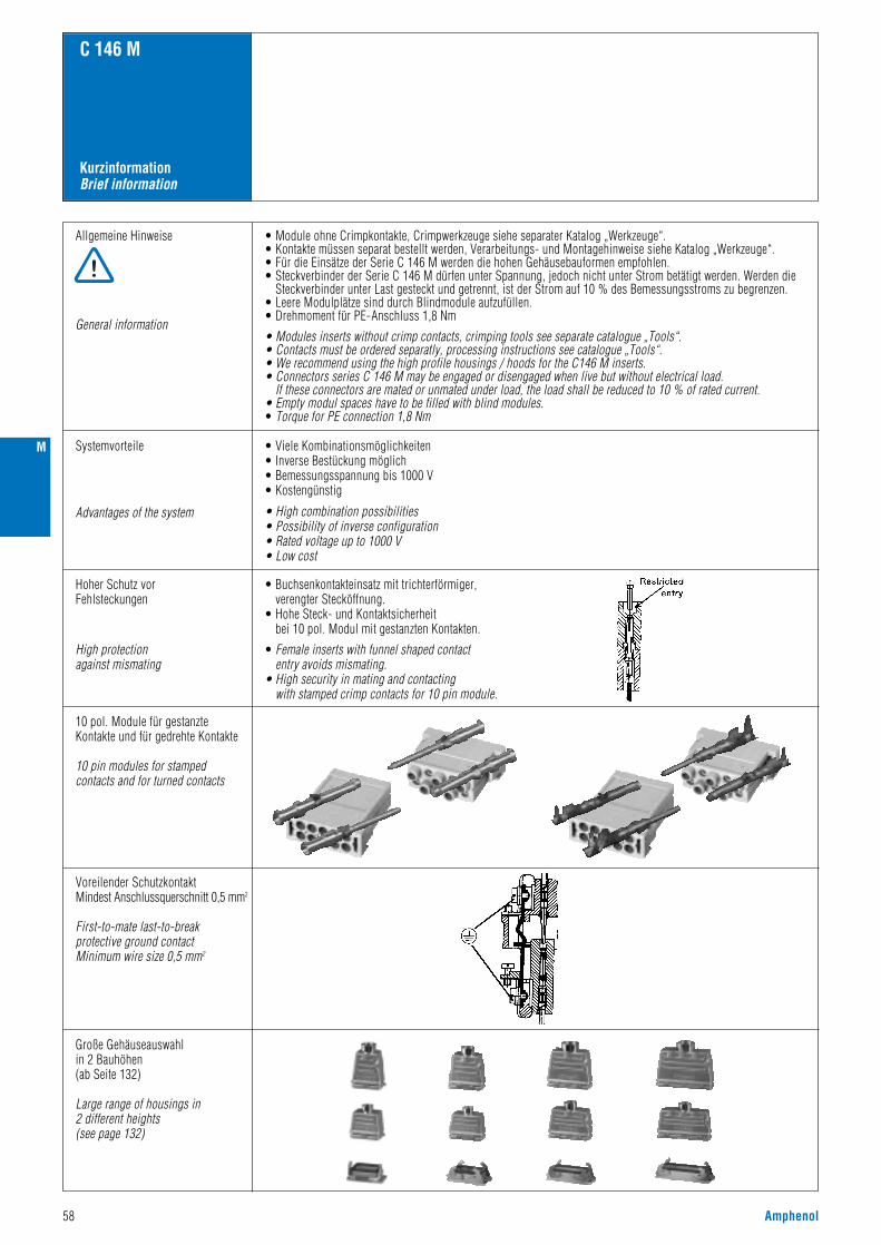
58 Amphenol
KurzinformationBrief information
C 146 M
Allgemeine Hinweise
General information
• Module ohne Crimpkontakte, Crimpwerkzeuge siehe separater Katalog „Werkzeuge“.• Kontakte müssen separat bestellt werden, Verarbeitungs- und Montagehinweise siehe Katalog „Werkzeuge“.• Für die Einsätze der Serie C 146 M werden die hohen Gehäusebauformen empfohlen.• Steckverbinder der Serie C 146 M dürfen unter Spannung, jedoch nicht unter Strom betätigt werden. Werden die
Steckverbinder unter Last gesteckt und getrennt, ist der Strom auf 10 % des Bemessungsstroms zu begrenzen.• Leere Modulplätze sind durch Blindmodule aufzufüllen.• Drehmoment für PE-Anschluss 1,8 Nm
• Modules inserts without crimp contacts, crimping tools see separate catalogue „Tools“.• Contacts must be ordered separatly, processing instructions see catalogue „Tools“.• We recommend using the high profile housings / hoods for the C146 M inserts.• Connectors series C 146 M may be engaged or disengaged when live but without electrical load.
If these connectors are mated or unmated under load, the load shall be reduced to 10 % of rated current.• Empty modul spaces have to be filled with blind modules.• Torque for PE connection 1,8 Nm
Systemvorteile
Advantages of the system
• Viele Kombinationsmöglichkeiten• Inverse Bestückung möglich• Bemessungsspannung bis 1000 V• Kostengünstig
• High combination possibilities• Possibility of inverse configuration• Rated voltage up to 1000 V• Low cost
Hoher Schutz vorFehlsteckungen
High protectionagainst mismating
• Buchsenkontakteinsatz mit trichterförmiger,verengter Stecköffnung.
• Hohe Steck- und Kontaktsicherheitbei 10 pol. Modul mit gestanzten Kontakten.
• Female inserts with funnel shaped contactentry avoids mismating.
• High security in mating and contactingwith stamped crimp contacts for 10 pin module.
10 pol. Module für gestanzteKontakte und für gedrehte Kontakte
10 pin modules for stampedcontacts and for turned contacts
Voreilender SchutzkontaktMindest Anschlussquerschnitt 0,5 mm2
First-to-mate last-to-break protective ground contactMinimum wire size 0,5 mm2
Große Gehäuseauswahlin 2 Bauhöhen (ab Seite 132)
Large range of housings in2 different heights(see page 132)
M

M
Amphenol 59
Crimp TechnikCrimp technology
C 146 M
Hauptmerkmale der gestanzten CrimpkontakteMain characteristics of the stamped crimp contacts
1) Erläuterung der Bestell-Nr. für die Kontakte siehe Seite 41) Explanation of the Part No. of contacts see page 4
Großer Crimpbereich
Large range of wire gauges
Gasdichte Verbindung(Kaltverschweißung)
Gas-tight (coldwelding)
Gestanzte Crimpkontakte mit Isolierungshalterung ummechanische Beanspruchung von der Crimpverbindungfernzuhalten
Stamped crimp contacts with insulation crimp,to absorbe mechanical stress from the crimped connection
Mechanischer Rasthakenanschlagbei Buchsen- und Stiftkontakt
Einfache Montage
Mechanical retention spring stop on female and male contact
Easy assembly
Kostengünstige, einfacheVerarbeitungWerkzeuge siehe Katalog „Werkzeuge“
Economical and easy processingTools see catalogue „Tools“
Hohe Strombelastbarkeit(siehe Derating Kurven)
High current carrying capacity(see derating curves)
Beispiel Einzelkontakt / Example single contact
Standardkontakt, Anschlussquerschnitt 2,5 mm2
Standard contact, wire gauge 2.5 mm2
Hochstromkontakt, Anschlussquerschnitt 2,5 mm2
High current contact, wire gauge 2.5 mm2
.N01 016 0003 (1) 1)
0,14 0,25 0,5 0,5 1,0 1,5 1,5 2,5
.N01 016 0002 (1) 1) .N01 016 0005 (1) 1)
IsolierungshalterungInsulation grip
KleinserieSmall series
SerieSeries
BuchsenkontaktFemale contact
StiftkontaktMale contact
Service-AnwendungenService application
Einzel-FertigungSingle production
Stro
mbe
last
bark
eit I
(A)
Curre
nt ca
rryin
g ca
pacit
y I (A
)
Bauelement Umgebungstemperatur Tu (°C)Ambient temperature Tamb (°C)
Stro
mbe
last
bark
eit I
(A)
Curre
nt ca
rryin
g ca
pacit
y I (A
)
Bauelement Umgebungstemperatur Tu (°C)Ambient temperature Tamb (°C)

60 Amphenol
BestellverfahrenHow to order
C 146 M
1) Rahmen
Frames
AuswahlChoice
Beispiel Bestell Nr. Example Part No.
C146 P16 001 G8
2) Module
Modules
C146 A03 001 E8
3) Kontakte
Contacts
VN01 036 0002 1C
4) Werkzeug
Tool
TA 0000+ TA 0000 124+ TA 0010 146 004
5) Gehäuse
Housings
C146 10G016 500 8
M

M
Amphenol 61
C 146 M
Technische Daten ÜbersichtCharacteristics Overview
Weitere technische Informationen, siehe folgende SeitenFurther technical characteristics, see the following pages
Allgemeine Kennwerte
Electrical Characteristics
Climatical Characteristics
Mechanical Characteristics
Elektrische Kennwerte
Klimatische Kennwerte
Mechanische Kennwerte
Werkstoffe Materials
General Characteristics
Polzahl
Kontaktdruchmesser in mm
Number of contacts
Contact diameter in mm
Crimpkontakt Crimp contact
20 10 10 1) 5 3 4 + / 5
1,61,0gestanztstamped
gestanztstamped
gedrehtturned
gedrehtturned
gedrehtturned
gestanztstamped
gedrehtturned
1,6 2,5 3,6 2,5 3,6 Koax
3
siehe Derating Kurven / see derating curves
≥ 1012 Ω
Bemessungsspannung 2)
Verschmutzungsgrad 2)
250 V63 V 250 V 400 V 630 V 1000 V 250 V
33 3 3 3 3 3
IIII II II II II II
10 A5 A 10 A 20 A 50 A 16 A
2110 V1680 V 2110 V 3510 V 4260 V 5700 V
4,0 kV4,0 kV 4,0 kV 6,0 kV 8,0 kV 8,0 kV
Rated voltage 2)
Pollution degree 2)
Isolierstoffgruppe 2) (PA) Material group 2) (PA)
Rated impulse withstand voltage 2)
Voltage proof 3)
Bemessungs-Stoßspannung 2)
Spannungsfestigkeit 3)
Rated current Tamb = 40 °CBemessungsstrom Tu = 40 °C
Strombelastbarkeit 4)
Isolationswiderstand 3)
Current carrying capacity 4)
Insulation resistance 3)
-40 °C - +125 °C -40 °C+100 °C - 40 °C / + 125 °CTemperaturbereich Temperatur range
15 - 20 N (Rahmen / frame)Steck- und Ziehkraft 5) Insertion and withdrawal forces 5)
< 5 mΩDurchgangswiderstand 3) Contact resistance 3)
Modul 1 2 3 4 5 6 7 8 9
3 5
gedrehtturned
gedrehtturned
3,6 2,5
1000 V 400 V
3 3
II II
50 A 20 A
5700 V 3510 V
8,0 kV 6,0 kV
Module
Anschlussart Termination technique
Brennbarkeit Flammability V-O
Rahmen
Module
Frames
Modules
PA 6.6 GF
PA 6.6 GF
Farbe Rahmen Colour frames
Farbe Module Colour modules
Kontakte Contacts
Kontaktoberfläche Contact plating Au Au AgAg
schwarz / black
schwarz / black / rotbraun / redbrown
Cu-Legierung / Cu-alloy
crimpen / crimp
1) auch LWL Kontakte möglich 1,0 mm POF / also FO 1,0 mm contacts available2) nach IEC 60664-1 / according to IEC 60664-13) nach IEC 60512-2 / according to IEC 60512-24) nach IEC 60512-3 / according to IEC 60512-35) nach IEC 60512-7 / according to IEC 60512-76) Ausnahme Stifteinsatz IP 20 siehe Module / Exception pin insert IP 20 see modules
Norm/StandardIEC 60529
IP-degree of protection pin insert gesteckt/matedIP20
gesteckt/matedIP20
ungesteckt/unmatedIP20
6) IP-Schutzart Stifteinsatz
IP-degree of protection socket insert6) IP-Schutzart Buchseneinsatz
ungesteckt/unmatedIP00
Norm/StandardIEC 60529

62 Amphenol
Module ÜbersichtModules Overview
C 146 M
Sitftmodul / pin module Buchsenmodul / socket module
Bezeichnung - AbbildungDescription - Figure
Nr.No.
MaßzeichnungDrawing
Bestell Nr. / Part No.Stiftmodule / Pin module Buchsenmodule /Socket module
C146 A20 001 G8 C146 B20 001 G820 pol. für gestanzte Kontakte20 contacts for stamped contacts
1
C146 D10 001 E8 C146 C10 001 G810 pol. für gestanzte Kontakte10 contacts for stamped contacts
2
C146 A10 001 E8 C146 B10 001 E810 pol. für gedrehte Kontakte10 contacts for turned contacts
3
C146 A05 001 E8 1) C146 B05 001 E8 1)5 pol. für gedrehte Kontakte5 contacts for turned contacts
4
C146 A03 001 E8 C146 B03 001 E83 pol. für gedrehte Kontakte3 contacts for turned contacts
3 pol. für gedrehte Kontakte3 contacts for turned contacts
5
C146 D04 001 E8(4 pol)
C146 D05 001 E8(4 + PE)
C146 D05 801 E8(5 pol)
C146 C04 001 E8(4 pol)
C146 C05 001 E8(4 + PE)
C146 C05 801 E8(5 pol)
5 pol. für gestanzte Kontakte5 contacts for stamped contacts
6
C146 A03 501 E8 C146 B03 501 E83 pol. für Koax Kontakte3 contacts for coax contacts
7
C146 A03 801 E8 C146 B03 801 E88
M

M
Amphenol 63
RahmenFrames
C 146 M
Rahmen für Stiftmodule 1)
Frame for pin modules 1)Rahmen für Buchsenmodule 1)
Frame for socket modules 1)
Bezeichnung - AbbildungDescription - Figure
Maßzeichnung / Drawing
Bezeichnung - AbbildungDescription - Figure
Maßzeichnung / Drawing
Bestell Nr. / Part No. 2)
Stiftmodule / pin module Buchsenmodule/socket module
C146 P06 001 G8
C146 P06 002 G8(2 x PE)
C146 S06 001 G8
C146 S06 002 G8(2 x PE)
Rahmen für 2 ModuleFrame for 2 modules
A - B
Gehäuse, siehe Seite 132–163Housings, see page 132–163
C146 P10 001 G8
C146 P10 002 G8(2 x PE)
C146 S10 001 G8
C146 S10 002 G8(2 x PE)
Rahmen für 3 ModuleFrame for 3 modules
A - C
C146 P16 001 G8
C146 P16 002 G8(2 x PE)
C146 S16 001 G8
C146 S16 002 G8(2 x PE)
Rahmen für 5 ModuleFrame for 5 modules
A - E
C146 P24 001 G8C146 P24 002 G8(2 x PE)
C146 P24 101 G8C146 P24 102 G8(2 x PE)
C146 S24 001 G8C146 S24 002 G8(2 x PE)
C146 S24 101 G8C146 S24 102 G8(2 x PE)
Rahmen für 7 ModuleFrame for 7 modules
A - G
T - Z
1) Im Rahmen für Stiftmodule können auch Buchsenmodule gesteckt werden (inverse Bestückung möglich).1) It is possible to mount socket modules in frames for pin modules (possibility of inverse configuration).2) Für den Einbau der Steckverbinder in nicht leitende Gehäuse sind beide Schutzleiter (Ausführung 2 x PE) anzuschließen.2) If connectors are mounted in non conductive housings both protective earthing terminals shall be mounted.
Rahmen für StiftmoduleFrame for pin modules
Rahmen für BuchsenmoduleFrame for socket module
Bestell Nr. / Part No. 2)
Rahmen für Stiftmodule Rahmen Buchsenmodule Frame for pin modules Frame for socket moduleKe
nnze
ich.
Posit
ions
C146 E12 001 E8 C146 F12 001 G8RJ ModulRJ module
C146 G01 014 G8 (2,5 mm)C146 G01 024 G8 (4,0 mm)
C146 G02 014 G8 (2,5 mm)C146 G02 024 G8 (4,0 mm)
C146 H01 034 G8 (2,5 mm)C146 H01 044 G8 (4,0 mm)
C146 H02 034 G8 (2,5 mm)C146 H02 044 G8 (4,0 mm)
Pneu Modul, 1 oder 2 VerbindungenPneumatic module, 1 or 2 connections
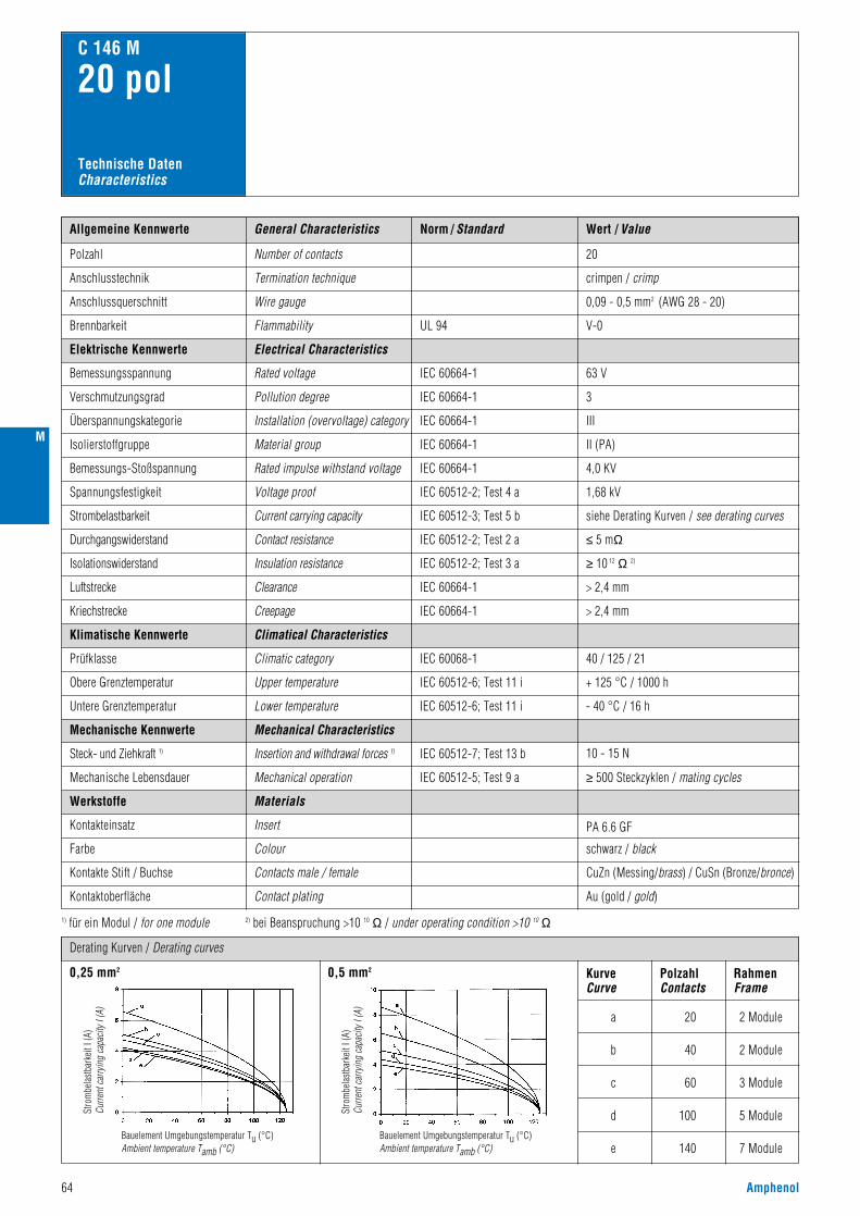
64 Amphenol
Norm / Standard Wert / ValueAllgemeine Kennwerte
Polzahl
63 V
3
III
II (PA)
4,0 KV
1,68 kV
siehe Derating Kurven / see derating curves
Number of contacts
Anschlusstechnik Termination technique
V-0
crimpen / crimp
Anschlussquerschnitt Wire gauge 0,09 - 0,5 mm2 (AWG 28 - 20)
20
Flammability
Electrical Characteristics
Rated voltage
Pollution degree
C 146 M
20 pol
Installation (overvoltage) category
Material group
Rated impulse withstand voltage
Voltage proof
IEC 60664-1
IEC 60664-1
IEC 60664-1
IEC 60664-1
IEC 60664-1
IEC 60512-2; Test 4 a
UL 94
IEC 60512-3; Test 5 b
IEC 60512-5; Test 9 a
Current carrying capacity
Mechanical operation
Insert
≥ 500 Steckzyklen / mating cycles
schwarz / black
Elektrische Kennwerte
Bemessungsspannung
Verschmutzungsgrad
Brennbarkeit
Überspannungskategorie
Isolierstoffgruppe
Bemessungs-Stoßspannung
Spannungsfestigkeit
Strombelastbarkeit
≤ 5 mΩIEC 60512-2; Test 2 aContact resistanceDurchgangswiderstand
≥ 10 12 Ω 2)IEC 60512-2; Test 3 aInsulation resistanceIsolationswiderstand
> 2,4 mmIEC 60664-1ClearanceLuftstrecke
> 2,4 mmIEC 60664-1CreepageKriechstrecke
IEC 60068-1
IEC 60512-7; Test 13 b
Climatical Characteristics
Climatic category
Mechanical Characteristics
Insertion and withdrawal forces 1)
40 / 125 / 21
Klimatische Kennwerte
Prüfklasse
IEC 60512-6; Test 11 iUpper temperature
Lower temperature
+ 125 °C / 1000 hObere Grenztemperatur
Untere Grenztemperatur IEC 60512-6; Test 11 i - 40 °C / 16 h
10 - 15 N
Mechanische Kennwerte
Steck- und Ziehkraft 1)
Mechanische Lebensdauer
Werkstoffe
Kontakteinsatz
Contacts male / female CuZn (Messing/brass) / CuSn (Bronze/bronce)Kontakte Stift / Buchse
Contact plating Au (gold / gold)Kontaktoberfläche
Farbe Colour
Materials
General Characteristics
1) für ein Modul / for one module 2) bei Beanspruchung >10 10 Ω / under operating condition >10 10 Ω
Technische DatenCharacteristics
Derating Kurven / Derating curves
0,25 mm2 0,5 mm2 KurveCurve
PolzahlContacts
RahmenFrame
a 20 2 Module
2 Module
3 Module
5 Module
7 Module
40
60
100
140
b
c
d
e
Stro
mbe
last
bark
eit I
(A)
Curre
nt ca
rryin
g ca
pacit
y I (A
)
Bauelement Umgebungstemperatur Tu (°C)Ambient temperature Tamb (°C)
Stro
mbe
last
bark
eit I
(A)
Curre
nt ca
rryin
g ca
pacit
y I (A
)
Bauelement Umgebungstemperatur Tu (°C)Ambient temperature Tamb (°C)
PA 6.6 GF
M

M
Amphenol 65
Einzelkontakte für Crimpzangen / single contacts for hand crimping tools vergoldet / gold plating
Bandkontakte für Crimpmaschinen/ Contacts on reel for crimp machines
LieferformSupplied as
AWGfür Leiterquerschnittfor wire gauge
für Leiterquerschnittfor wire gauge
StückzahlPieces
Bestell Nr. / Part No.Stiftkontakt / Male contact Buchsenkontakt / Female contact
Bestell Nr. / Part No.Kontaktaufnahme / Contact locator Crimpbacken / Crimping dies Werkzeuge / Tools
ModuleModules
C 146 M
20 pol
0,09 - 0,25 mm2
0,25 - 0,50 mm2
0,09 - 0,25 mm2
0,25 - 0,50 mm2
–
–
0,09 - 0,25 mm2
0,25 - 0,50 mm2
–
–
–
– 17D 438 SP
FG 1000 146
TA 0200 146
–
–
0,09 - 0,25 mm2
0,25 - 0,50 mm2
28 - 2424 - 2028 - 2424 - 20
28 - 2424 - 20
2000200010.00010.000
100100
TN01 010 0130 (2)TN01 010 0131 (2)FN01 010 0130 (2)FN01 010 0131 (2)
VN01 010 0130 (2)VN01 010 0131 (2)
TN02 010 0130 (2)TN02 010 0131 (2)FN02 010 0130 (2)FN02 010 0131 (2)
VN02 010 0130 (2)VN02 010 0131 (2)
Kontaktzuführung linksContact feeding left hand side
Bezeichnung / Description
Lösewerkzeug für KontakteRemoval tool for contacts
Lösewerkzeug für ModuleRemoval tool for modules
Service CrimpzangeService crimping tool
Bandkontakte für Crimpzangen / Contacts on reel for hand crimping tools
0,09 - 0,25 mm2
0,25 - 0,50 mm2
28 - 2424 - 20
500500
ZN01 010 0130 (2)ZN01 010 0131 (2)
ZN02 010 0130 (2)ZN02 010 0131 (2)
Bandkontakte für CrimpmaschinenContacts on reel for crimp machines
350 Stück
350 pcs
2000 Stück(Zuführung links)
2000 pcs(feeding lefthand side)
Bandkontakte für CrimpzangenContacts on reel for hand crimping tools
für gestanzte 1,0 mm Kontaktefor stamped 1,0 mm contacts
AbbildungFigure
Maßzeichnung / DrawingStiftmodul / Pin module Buchsenmodul /Socket module
Crimpkontakte / Crimp contacts
Werkzeuge / Tools 1)
C146 A20 001 G8 C146 B20 001 G8
Bei kleinen Leiterquerschnitten wird der Einsatz von Führungselementen empfohlen (siehe Seite 184)If small wire sizes are used, guide pins and guide sockets should be prefered to use (see page 184)1) Weitere Informationen siehe Katalog „Werkzeuge“ / Further information see catalogue „Tools“
Abisolierlängen siehe S. 208Stripping length see p. 208
Bestell Nr. / Part No.Stiftmodul / Pin module Buchsenmodul /Socket module

Norm / Standard Wert / ValueAllgemeine Kennwerte
Polzahl
250 V
3
III a
4,0 KV
2,11 kV
siehe Derating Kurven / see derating curves
Number of contacts
Anschlusstechnik Termination technique
V-0
crimpen / crimp
Anschlussquerschnitt Wire gauge 0,14 - 2,5 mm2 (AWG 26 - 14)
10
Flammability
Electrical Characteristics
Rated voltage
Pollution degree
C 146 M
10 pol
Installation (overvoltage) category
Material group
Rated impulse withstand voltage
Voltage proof
IEC 60664-1
IEC 60664-1
IEC 60664-1
IEC 60664-1
IEC 60664-1
IEC 60512-2; Test 4 a
UL 94
IEC 60512-3; Test 5 b
IEC 60512-5; Test 9 a
Current carrying capacity
Mechanical operation
Module
≥ 500 Steckzyklen / mating cycles
schwarz / black
Elektrische Kennwerte
Bemessungsspannung
Verschmutzungsgrad
Brennbarkeit
Überspannungskategorie
Isolierstoffgruppe
Bemessungs-Stoßspannung
Spannungsfestigkeit
Strombelastbarkeit
≤ 5 mΩIEC 60512-2; Test 2 aContact resistanceDurchgangswiderstand
≥ 10 12 Ω 2)IEC 60512-2; Test 3 aInsulation resistanceIsolationswiderstand
IEC 60068-1
IEC 60512-6; Test 11 i
IEC 60512-6; Test 11 i
IEC 60512-7; Test 13 b
Climatical Characteristics
Climatic category
Mechanical Characteristics
Insertion and withdrawal forces 1)
40 / 125 / 21
Klimatische Kennwerte
Prüfklasse
Upper temperature
Lower temperature
+ 125 °C / 1000 hObere Grenztemperatur
Untere Grenztemperatur - 40 °C / 16 h
20 - 25 N
Mechanische Kennwerte
Steck- und Ziehkraft 1)
Mechanische Lebensdauer
Werkstoffe
Modul
Male contact CuZn (Messing/brass)
CuSn (Bronze/bronce)
Stiftkontakt
Female contactBuchsenkontakt
Contact plating Ag (silber/silver)Kontaktoberfläche
Farbe Colour
Materials
General Characteristics
1) für ein Modul / for one module 2) bei Beanspruchung >10 10 Ω / under operating condition >10 10 Ω
Technische DatenCharacteristics
Module für gestanzte KontakteModules for stamped contacts
> 4,3 mmIEC 60664-1Clearance / CreepageLuftstrecke / Kriechstrecke
Derating Kurven / Derating curves
0,5 mm2 1,5 mm2 KurveCurve
PolzahlContacts
RahmenFrame
a 10 2 Module
2 Module
3 Module
5 Module
7 Module
20
30
50
70
b
c
d
e
66 Amphenol
Stro
mbe
last
bark
eit I
(A)
Curre
nt ca
rryin
g ca
pacit
y I (A
)
Bauelement Umgebungstemperatur Tu (°C)Ambient temperature Tamb (°C)
Stro
mbe
last
bark
eit I
(A)
Curre
nt ca
rryin
g ca
pacit
y I (A
)
Bauelement Umgebungstemperatur Tu (°C)Ambient temperature Tamb (°C)
II (PA)
PA 6.6 GF
M

M
Amphenol 67
ModuleModules
C 146 M
10 polBandkontakte für CrimpmaschinenContacts on reel for crimp machines
200 / 100 Stück
200 / 100 pcs
2000 Stück(Zuführung linksoder rechts)
2000 pcs(feeding left orright hand side)
gestanzte EinzelkontakteStamped single contacts
Bandkontakte für CrimpzangenContacts on reel for hand crimping tools
für gestanzte 1,6 mm Kontaktefor stamped 1,6 mm contacts
Crimpkontakte / Crimp contacts
C146 D10 001 E8 C146 C10 001 G8
für Leiterquerschnittfor wire gauge
Bestell Nr. / Part No.Kontaktaufnahme / Contact locator Crimpbacken / Crimping dies Werkzeuge / Tools
–
0,14 - 0,5 mm2
0,5 - 1,5 mm2
0,14 - 0,5 mm2
0,5 - 1,5 mm2
1,5 - 2,5 mm2
–
–
TA 0001 146 000 1TA 0002 146 000 1TA 0007 146 000 3
TA 0000 202TA 0000 163TA 0000 141
– FG 0300 146 1 / FG 1000 146
TA 0100 146
TA 0000
–
Bezeichnung / Description
Lösewerkzeug für Kontakte / ModuleRemoval tool for contacts / modules
Service CrimpzangeService crimping tool
Crimpzange für EinzelkontakteCrimping tool for single contacts
Werkzeuge / Tools 2)
1) Erläuterung der Bestell-Nr. für die Kontakte siehe Seite 4 / Explanation of the Part No. for contacts see page 42) Weitere Informationen siehe Katalog „Werkzeuge“ / Further information see catalogue „Tools“
Abisolierlängen siehe S. 208Stripping length see p. 208
AbbildungFigure
Maßzeichnung / DrawingStiftmodul / Pin module Buchsenmodul /Socket module
Bestell Nr. / Part No.Stiftmodul / Pin module Buchsenmodul /Socket module
LieferformSupplied as
Gestanzte Einzelkontakte / Stamped single contacts
für Leiter-querschnittfor wire gauge
AWG Stück-zahlPieces
StandardHochstromHigh current
0,14 - 0,5 mm2
0,5 - 1,5 mm2
1,5 - 2,5 mm2
0,5 - 1,5 mm2
1,5 - 2,5 mm2
26 - 2020 - 1616 - 1420 - 1616 - 14
100100100100100
VN01 016 0003 (1)VN01 016 0002 (1)VN01 016 0005 (1)VN01 016 0015 (1)VN01 016 0016 (1)
VN02 016 0003 (1)VN02 016 0002 (1)VN02 016 0005 (1)VN02 016 0015 (1)VN02 016 0016 (1)
VN01 016 0003 (2)VN01 016 0002 (2)VN01 016 0005 (2)
VN02 016 0003 (2)VN02 016 0002 (2)VN02 016 0005 (2)
Bestell Nr.1)
Stiftkontakt Male contact
versilbert / silver plating vergoldet / gold plating
Part No.1)
BuchsenkontaktFemale contact
Bestell Nr.1)
StiftkontaktMale contact
Part No.1)
BuchsenkontaktFemale contact
StandardHochstromHigh current
StandardHochstromHigh current
StandardHochstromHigh current
0,14 - 0,5 mm2
0,5 - 1,5 mm2
1,5 - 2,5 mm2
0,5 - 1,5 mm2
1,5 - 2,5 mm2
0,14 - 0,5 mm2
0,5 - 1,5 mm2
1,5 - 2,5 mm2
0,5 - 1,5 mm2
1,5 - 2,5 mm2
0,14 - 0,5 mm2
0,5 - 1,5 mm2
1,5 - 2,5 mm2
0,5 - 1,5 mm2
1,5 - 2,5 mm2
26 - 2020 - 1616 - 1420 - 1616 - 14
26 - 2020 - 1616 - 1420 - 1616 - 1426 - 2020 - 1616 - 1420 - 1618 - 14
200200100200100
2000200020002000200020002000200020002000
ZN01 016 0003 (1)ZN01 016 0002 (1)ZN01 016 0005 (1)ZN01 016 0015 (1)ZN01 016 0016 (1)
HN01 016 0003 (1)HN01 016 0002 (1)HN01 016 0005 (1)HN01 016 0015 (1)HN01 016 0016 (1)TN01 016 0003 (1)TN01 016 0002 (1)TN01 016 0005 (1)TN01 016 0015 (1)TN01 016 0016 (1)
ZN02 016 0003 (1)ZN02 016 0002 (1)ZN02 016 0005 (1)ZN02 016 0015 (1)ZN02 016 0016 (1)
ZN01 016 0003 (2)ZN01 016 0002 (2)ZN01 016 0005 (2)
ZN02 016 0003 (2)ZN02 016 0002 (2)ZN02 016 0005 (2)
HN02 016 0003 (1)HN02 016 0002 (1)HN02 016 0005 (1)HN02 016 0015 (1)HN02 016 0016 (1)TN02 016 0003 (1)TN02 016 0002 (1)TN02 016 0005 (1)TN02 016 0015 (1)TN02 016 0016 (1)
HN01 016 0003 (2)HN01 016 0002 (2)HN01 016 0005 (2)
TN01 016 0003 (2)TN01 016 0002 (2)TN01 016 0005 (2)
HN02 016 0003 (2)HN02 016 0002 (2)HN02 016 0005 (2)
TN02 016 0003 (2)TN02 016 0002 (2)TN02 016 0005 (2)
Kontaktzuführung rechtsContact feeding right hand side
Gestanzte Bandkontakte für Crimpmaschinen / Stamped contacts on reel for crimp machines
Gestanzte Bandkontakte für Crimpzangen / Stamped Contacts on reel for hand crimp tools
Kontaktzuführung linksContact feeding left hand side

Norm / Standard Wert / ValueAllgemeine Kennwerte
Polzahl
250 V
3
III
4,0 kV
2,21 kV
siehe Derating Kurven / see derating curves
Number of contacts
Anschlusstechnik Termination technique
V-0
crimpen / crimp
Anschlussquerschnitt Wire gauge 0,14 - 2,5 mm2 (AWG 26 - 14)
10
Flammability
Electrical Characteristics
Rated voltage
Pollution degree
C 146 M
10 pol
Installation (overvoltage) category
Material group
Rated impulse withstand voltage
Voltage proof
IEC 60664-1
IEC 60664-1
IEC 60664-1
IEC 60664-1
IEC 60664-1
IEC 60512-2; Test 4 a
UL 94
IEC 60512-3; Test 5 b
IEC 60512-5; Test 9 a
Current carrying capacity
Mechanical operation
Module
≥ 500 Steckzyklen / mating cycles
PA 6.6 GF
schwarz / black
Elektrische Kennwerte
Bemessungsspannung
Verschmutzungsgrad
Brennbarkeit
Überspannungskategorie
Isolierstoffgruppe
Bemessungs-Stoßspannung
Spannungsfestigkeit
Strombelastbarkeit
≤ 5 mΩIEC 60512-2; Test 2 aContact resistanceDurchgangswiderstand
≥ 10 12 Ω 2)IEC 60512-2; Test 3 aInsulation resistanceIsolationswiderstand
IEC 60068-1
IEC 60512-7; Test 13 b
Climatical Characteristics
Climatic category
Mechanical Characteristics
Insertion and withdrawal forces 1)
40 / 100 / 21
Klimatische Kennwerte
Prüfklasse
IEC 60512-6; Test 11 iUpper temperature
Lower temperature
+ 100 °C / 1000 hObere Grenztemperatur
Untere Grenztemperatur IEC 60512-6; Test 11 i - 40 °C / 16 h
25 - 30 N
Mechanische Kennwerte
Steck- und Ziehkraft 1)
Mechanische Lebensdauer
Werkstoffe
Modul
Contacts CuZn (Messing / brass)Kontakte
Contact plating Ag (silber / silver)Kontaktoberfläche
Farbe Colour
Materials
General Characteristics
1) für ein Modul / for one module 2) bei Beanspruchung >10 10 Ω / under operating condition >10 10 Ω
Technische DatenCharacteristics
> 4,3 mmIEC 60664-1ClearanceLuftstrecke
> 4,3 mmIEC 60664-1CreepageKriechstrecke
für gedrehte 1,6 mm Kontaktefor turned 1,6 mm contacts
Derating Kurven / Derating curves
0,5 mm2 1,5 mm2 KurveCurve
PolzahlContacts
RahmenFrame
a 10 2 Module
2 Module
3 Module
5 Module
7 Module
20
30
50
70
b
c
d
e
68 Amphenol
Stro
mbe
last
bark
eit I
(A)
Curre
nt ca
rryin
g ca
pacit
y I (A
)
Bauelement Umgebungstemperatur Tu (°C)Ambient temperature Tamb (°C)
Stro
mbe
last
bark
eit I
(A)
Curre
nt ca
rryin
g ca
pacit
y I (A
)
Bauelement Umgebungstemperatur Tu (°C)Ambient temperature Tamb (°C)
II (PA)M

M
Amphenol 69
ModuleModules
C 146 M
10 pol
für gedrehte 1,6 mm Kontaktefor turned 1,6 mm contacts
Crimpkontakte / Crimp contacts
Crimpkontakte / Crimp contacts
LieferformSupplied as
AWGfür Leiterquerschnittfor wire gauge
StückzahlPieces
Bestell Nr. 1) / Part No. 1)
Stiftkontakt / Male contact Buchsenkontakt / Female contact
1,0 mm POF/FO – 10 VN01 016 0040 (8) X VN02 016 0040 (8) XEinzelkontakt / Single contact
LWL Kontakte / FO contacts
C146 A10 001 E8 C146 B10 001 E8
für Leiterquerschnittfor wire gauge
Bestell Nr. / Part No.Kontaktaufnahme / Contact locator Crimpbacken / crimping dies Werkzeuge / Tools
–
–
0,14 - 1,0 mm2
1,5 mm2
2,5 mm2
1,0 mm POF/FO
–
–
TA 0010 146 000 1 TA 0000 184
– FG 0300 146 1
FG 1000 146
TA 0000
–
Bezeichnung / Description
Lösewerkzeug für KontakteRemoval tool for contacts
Lösewerkzeug für ModuleRemoval tool for modules
Crimpzange für EinzelkontakteCrimping tool for single contacts
Werkzeuge / Tools 2)
1) Erläuterung der Bestell-Nr. für die Kontakte siehe Seite 4 / Explanation of the Part No. for contacts see page 42) Weitere Informationen siehe Katalog „Werkzeuge“ / Further information see catalogue „Tools“3) incl. Abisolierwerkzeug, Kontaktaufnahme, Schleiflehre / incl. stripping tool, locator, abrasive adapter
TB 0500 146Crimpzange für LWL Kontakte 3)
Crimping tool for FO contacts 3)
AbbildungFigure
Maßzeichnung / DrawingStiftmodul / Pin module Buchsenmodul / Socket module
LWL-KontakteFO-contacts
Bestell Nr. / Part No.Stiftmodul / Pin module Buchsenmodul /Socket module
Abisolierlängen siehe S. 208Stripping length see p. 208
LieferformSupplied as
Gedrehte Crimpkontakte / Turned crimp contacts
für Leiter-querschnittfor wire gauge
AWG Stück-zahlPieces
EinzelkontakteSingle contact
26 - 222020 - 1616 - 1514
0,14 - 0,37mm2
0,5 mm2
0,75 - 1,0 mm2
1,5 mm2
2,5 mm2
100100100100100
VN01 016 0024 (1)CVN01 016 0025 (1)CVN01 016 0026 (1)CVN01 016 0027 (1)CVN01 016 0028 (1)C
VN02 016 0024 (1)CVN02 016 0025 (1)CVN02 016 0026 (1)CVN02 016 0027 (1)CVN02 016 0028 (1)C
VN01 016 0024 (2)CVN01 016 0025 (2)CVN01 016 0026 (2)CVN01 016 0027 (2)CVN01 016 0028 (2)C
VN02 016 0024 (2)CVN02 016 0025 (2)CVN02 016 0026 (2)CVN02 016 0027 (2)CVN02 016 0028 (2)C
Bestell Nr.1)
Stiftkontakt Male contact
Part No.1)
BuchsenkontaktFemale contact
Bestell Nr.1)
StiftkontaktMale contact
Part No.1)
BuchsenkontaktFemale contact
versilbert / silver plating vergoldet / gold plating

Norm / Standard Wert / ValueAllgemeine Kennwerte
Polzahl
siehe Derating Kurven / see derating curves
Number of contacts
Anschlusstechnik Termination technique
V-0
crimpen / crimp
Anschlussquerschnitt Wire gauge 0,5 - 4,0 mm2 (AWG 20 - 12)
5
Flammability
Electrical Characteristics
Rated voltage
Pollution degree
C 146 M
5 pol
Installation (overvoltage) category
Material group
Rated impulse withstand voltage
Voltage proof
IEC 60664-1
IEC 60664-1
IEC 60664-1
IEC 60664-1
IEC 60664-1
IEC 60512-2; Test 4 a
UL 94
IEC 60512-3; Test 5 b
IEC 60512-5; Test 9 a
Current carrying capacity
Mechanical operation
Module
≥ 500 Steckzyklen / mating cycles
Elektrische Kennwerte
Bemessungsspannung
Verschmutzungsgrad
Brennbarkeit
Überspannungskategorie
Isolierstoffgruppe
Bemessungs-Stoßspannung
Spannungsfestigkeit
Strombelastbarkeit
IEC 60512-2; Test 2 aContact resistanceDurchgangswiderstand
IEC 60512-2; Test 3 aInsulation resistanceIsolationswiderstand
IEC 60068-1
IEC 60512-7; Test 13 b
Climatical Characteristics
Climatic category
Mechanical Characteristics
Insertion and withdrawal forces 1)
Klimatische Kennwerte
Prüfklasse
IEC 60512-6; Test 11 iUpper temperature
Lower temperature
Obere Grenztemperatur
Untere Grenztemperatur IEC 60512-6; Test 11 i
Mechanische Kennwerte
Steck- und Ziehkraft 1)
Mechanische Lebensdauer
Werkstoffe
Modul
Contacts Cu-Legierung / Cu-alloyKontakte
Contact platingKontaktoberfläche
Farbe Colour
Materials
General Characteristics
1) für ein Modul / for one module 2) bei Beanspruchung >10 10 Ω / under operating condition >10 10 Ω
Technische DatenCharacteristics
IEC 60664-1ClearanceLuftstrecke
400 V
3
III
II
6,0 kV
3,51 kV
PA 6.6 GF
schwarz
≤ 2 mΩ
≥ 10 12 Ω 2)
40 / 125 / 21
+ 125 °C / 1000 h
- 40 °C / 16 h
25 - 30 N
Ag (silber / silver)
5,8 mm
5,8 mmIEC 60664-1CreepageKriechstrecke
Derating Kurven / Derating curves
2,5 mm2 4 mm2 KurveCurve
PolzahlContacts
RahmenFrame
a 5 2 Module
2 Module
3 Module
5 Module
7 Module
10
15
25
35
b
c
d
e
70 Amphenol
Stro
mbe
last
bark
eit I
(A)
Curre
nt ca
rryin
g ca
pacit
y I (A
)
Bauelement Umgebungstemperatur Tu (°C)Ambient temperature Tamb (°C)
Stro
mbe
last
bark
eit I
(A)
Curre
nt ca
rryin
g ca
pacit
y I (A
)
Bauelement Umgebungstemperatur Tu (°C)Ambient temperature Tamb (°C)
M

M
Amphenol 71
ModuleModules
C 146 M
5 pol
für gedrehte 2,5 mm Kontaktefor turned 2,5 mm contacts
C146 A05 001 E8 C146 B05 001 E8
für Leiterquerschnittfor wire gauge
Bestell Nr. / Part No.Kontaktaufnahme / Contact locator Crimpbacken / crimping dies Werkzeuge / Tools
–
–
0,5 - 2,5 mm2
4,0 mm2
–
–
TA 0010 146 000 2TA 0010 146 000 3
TA 0000 144TA 0000 124
– FG 0300 146 4
FG 1000 146
TA 0000
–
Bezeichnung / Description
Lösewerkzeug für KontakteRemoval tool for contacts
Lösewerkzeug für ModuleRemoval tool for modules
Crimpzange für EinzelkontakteCrimping tool for single contacts
Werkzeuge / Tools 2)
Gedrehte Crimpkontakte / Turned crimp contacts
1) Erläuterung der Bestell-Nr. für die Kontakte siehe Seite 4 / Explanation of the Part No. for contacts see page 42) Weitere Informationen siehe Katalog „Werkzeuge“ / further information see catalogue „Tools“
AbbildungFigure
Maßzeichnung / DrawingStiftmodul / Pin module Buchsenmodul /Socket module
Bestell Nr. / Part No.Stiftmodul / Pin module Buchsenmodul /Socket module
Abisolierlängen siehe S. 208Stripping length see p. 208
LieferformSupplied as
Gedrehte Crimpkontakte / Turned crimp contacts
für Leiter-querschnittfor wire gauge
AWG Stück-zahlPieces
EinzelkontakteSingle contact
0,5 mm2
0,75 - 1,0 mm2
1,5 mm2
2,5 mm2
4,0 mm2
2018161412
100100100100100
VN01 025 0029 (1)CVN01 025 0030 (1)CVN01 025 0031 (1)CVN01 025 0032 (1)CVN01 025 0033 (1)C
VN02 025 0029 (1)CVN02 025 0030 (1)CVN02 025 0031 (1)CVN02 025 0032 (1)CVN02 025 0033 (1)C
VN01 025 0029 (2)CVN01 025 0030 (2)CVN01 025 0031 (2)CVN01 025 0032 (2)CVN01 025 0033 (2)C
VN02 025 0029 (2)CVN02 025 0030 (2)CVN02 025 0031 (2)CVN02 025 0032 (2)CVN02 025 0033 (2)C
Bestell Nr.1)
Stiftkontakt Male contact
Part No.1)
BuchsenkontaktFemale contact
Bestell Nr.1)
StiftkontaktMale contact
Part No.1)
BuchsenkontaktFemale contact
versilbert / silver plating vergoldet / gold plating

Norm / Standard Wert / ValueAllgemeine Kennwerte
Polzahl
630 V
3
III
8,0 kV
4,26 kV
siehe Derating Kurven / see derating curves
Number of contacts
Anschlusstechnik Termination technique
V-0
crimpen / crimp
Anschlussquerschnitt Wire gauge 1,5 - 10 mm2 (AWG 16 - 8)
3
Flammability
Electrical Characteristics
Rated voltage
Pollution degree
C 146 M
3 pol
Installation (overvoltage) category
Material group
Rated impulse withstand voltage
Voltage proof
IEC 60664-1
IEC 60664-1
IEC 60664-1
IEC 60664-1
IEC 60664-1
IEC 60512-2 Test 4 a
UL 94
IEC 60512-3; Test 5 b
IEC 60068-1
IEC 60512-7; Test 13 b
IEC 60512-5; Test 9 a
Current carrying capacity
Climatical Characteristics
Climatic category
Mechanical Characteristics
Insertion and withdrawal forces 1)
Mechanical operation
Module
40 / 125 / 21
≥ 500 Steckzyklen / mating cycles
schwarz / black
Elektrische Kennwerte
Bemessungsspannung
Verschmutzungsgrad
Brennbarkeit
Überspannungskategorie
Isolierstoffgruppe
Bemessungs-Stoßspannung
Spannungsfestigkeit
Strombelastbarkeit
≤ 1 mΩIEC 60512-2; Test 2 aContact resistanceDurchgangswiderstand
≥ 10 12 Ω 2)IEC 60512-2; Test 3 aInsulation resistanceIsolationswiderstand
Klimatische Kennwerte
Prüfklasse
IEC 60512-6; Test 11 iUpper temperature
Lower temperature
+ 125 °C / 1000 hObere Grenztemperatur
Untere Grenztemperatur IEC 60512-6; Test 11 i - 40 °C / 16 h
20 - 30 N
Mechanische Kennwerte
Steck- und Ziehkraft 1)
Mechanische Lebensdauer
Werkstoffe
Modul
Contacts Cu-Legierung / Cu-alloyKontakte
Contact plating Ag (silber / silver)Kontaktoberfläche
Farbe Colour
Materials
General Characteristics
1) für ein Modul / for one module 2) bei Beanspruchung >10 10 Ω / under operating condition >10 10 Ω
Technische DatenCharacteristics
> 12 mmIEC 60664-1ClearanceLuftstrecke
> 12 mmIEC 60664-1CreepageKriechstrecke
Derating Kurven / Derating curves
6 mm2 10 mm2 KurveCurve
PolzahlContacts
RahmenFrame
a 3 2 Module
2 Module
3 Module
5 Module
7 Module
6
9
15
21
b
c
d
e
72 Amphenol
Stro
mbe
last
bark
eit I
(A)
Curre
nt ca
rryin
g ca
pacit
y I (A
)
Bauelement Umgebungstemperatur Tu (°C)Ambient temperature Tamb (°C)
Stro
mbe
last
bark
eit I
(A)
Curre
nt ca
rryin
g ca
pacit
y I (A
)
Bauelement Umgebungstemperatur Tu (°C)Ambient temperature Tamb (°C)
II (PA)
PA 6.6 GF
M

M
Amphenol 73
ModuleModules
C 146 M
3 pol
für gedrehte 3,6 mm Kontaktefor turned 3,6 mm contacts
C146 A03 001 E8 C146 B03 001 E8
Gedrehte Crimpkontakte / Turned crimp contacts
LieferformSupplied as
AWGfür Leiterquerschnittfor wire gauge
StückzahlPieces
Bestell Nr. 1) / Part No. 1)
Stiftkontakt / Male contact Buchsenkontakt / Female contact
1,5 mm2
2,5 mm2
4,0 mm2
6,0 mm2
10,0 mm2
161412108
100100100100100
VN01 036 0004 (1)CVN01 036 0005 (1)CVN01 036 0001 (1)CVN01 036 0002 (1)C 2)
VN01 036 0003 (1)C 2)
VN02 036 0004 (1)CVN02 036 0005 (1)CVN02 036 0001 (1)CVN02 036 0002 (1)C 2)
VN02 036 0003 (1)C 2)
EinzelkontaktSingle contact
Gedrehte Crimpkontakte / Turned crimp contacts
Kabelschuhe für Schutzleiteranschluss / Cable lugs for PE connection Bestell Nr. / Part No.Stückzahl / Pieces
6,0 mm2
10,0 mm2
N15 006 000 9ZN15 010 000 7Z
Kabelschuhcable lug
für Leiterquerschnittfor wire gauge
Bestell Nr. / Part No.Kontaktaufnahme / Contact locator Crimpbacken / Crimping dies Werkzeuge / Tools
–
–
1,5 - 2,5 mm2
4,0 mm2
6,0 mm2
1,5 -10,0 mm2
6,0 mm2
10,0 mm2
–
–
– 2020
–
–
–
TA 0010 146 000 5TA 0010 146 000 4TA 0010 146 000 4
TA 0000 144TA 0000 124TA 0000 124
– FG 0300 146 3
FG 1000 146
TA 0000
TB 0200 146
–
Bezeichnung / Description
Lösewerkzeug für KontakteRemoval tool for contacts
Lösewerkzeug für ModuleRemoval tool for modules
Crimpzange für EinzelkontakteCrimping tool for single contacts
Werkzeuge / Tools 3)
1) Erläuterung der Bestell-Nr. für die Kontakte siehe Seite 4 / Explanation of the Part No. for contacts see page 42) Bei den Leiterquerschnitten 6 + 10 mm2 sind Kabelschuhe für den Schutzleiteranschluss zu verwenden / For wire gauges 6 + 10 mm2 cable lugs have to be used for PE connection3) Weitere Informationen siehe Katalog „Werkzeuge“ / Further information see catalogue „Tools“4) incl. Prüfstiftset, Kontaktaufnahme / incl. calibration pin set, locatorAbisolierlängen siehe S. 208 / Stripping length see p. 208
TA 0000Crimpzange für KabelschuheCrimping tool for cable lugs
4-Kerb Crimpzange 4)
4-indet crimping tool 4)
TA 0000 180
AbbildungFigure
Maßzeichnung / DrawingStiftmodul / Pin module Buchsenmodul /Socket module
Bestell Nr. / Part No.Stiftmodul / Pin module Buchsenmodul /Socket module
versilbert / silver plating

Norm / Standard Wert / ValueAllgemeine Kennwerte
Polzahl
1000 V 1)
3
III
II
8,0 kV
5,7 kV
siehe Derating Kurven / see derating curves
Number of contacts
Anschlusstechnik Termination technique
V-0
crimpen / crimp
Anschlussquerschnitt Wire gauge 0,5 - 4,0 mm2 (AWG 20 - 12)
4 + / 5
Flammability
Electrical Characteristics
Rated voltage
Pollution degree
C 146 M
4 pol4+ 5 pol
Installation (overvoltage) category
Material group
Rated impulse withstand voltage
Voltage proof
IEC 60664-1
IEC 60664-1
IEC 60664-1
IEC 60664-1
IEC 60664-1
IEC 60512-2; Test 4 a
UL 94
IEC 60512-3; Test 5 bCurrent carrying capacity
Elektrische Kennwerte
Bemessungsspannung
Verschmutzungsgrad
Brennbarkeit
Überspannungskategorie
Isolierstoffgruppe
Bemessungs-Stoßspannung
Spannungsfestigkeit
Strombelastbarkeit
≤ 5 mΩIEC 60512-2; Test 2 aContact resistanceDurchgangswiderstand
≥ 10 12 ΩIEC 60512-2; Test 3 aInsulation resistanceIsolationswiderstand
IEC 60068-1
Climatical Characteristics
Climatic category
Mechanical Characteristics
40 / 125 / 21
Klimatische Kennwerte
Prüfklasse
IEC 60512-6; Test 11 iUpper temperature
Lower temperature
+ 125 °C / 1000 hObere Grenztemperatur
Untere Grenztemperatur IEC 60512-6; Test 11 i - 40 °C / 16 h
Mechanische Kennwerte
General Characteristics
Technische DatenCharacteristics
IEC 60512-5; Test 9 aMechanical operation
Module
≥ 500 Steckzyklen / mating cycles
PA 6.6 GF
schwarz / black
IEC 60512-7; Test 13 bInsertion and withdrawal forces 2)Steck- und Ziehkraft 2)
Mechanische Lebensdauer
IEC 60529IP-degree of protection 20
15 - 20 N
IP-Schutzart
Werkstoffe
Modul
Contacts male / female CuZn (Messing/brass) / CuSn (Bronze/bronce)Kontakte Stift / Buchse
Contact plating Ag (silber / silver)Kontaktoberfläche
Farbe Colour
Materials
1) 630 V bei Verwendung als Steckvorrichtung / 630 V if the modules are used as plug and socket device 2) für ein Modul / for one module
Derating Kurven / Derating curves
> 14 mmIEC 60664-1ClearanceLuftstrecke
> 14 mmIEC 60664-1CreepageKriechstrecke
1,5 mm2
0
5
10
15
20
25
30
0
a + b
c
d
e
10 20 30 40 50 60 70 80 90 100 110 120 130
4 mm2 KurveCurve
PolzahlContacts
RahmenFrame
a 5 2 Module
b 10 2 Module
c 15 3 Module
d 25 5 Module
e 35 7 Module
74 Amphenol
Stro
mbe
last
bark
eit I
(A)
Curre
nt ca
rryin
g ca
pacit
y I (A
)
Bauelement Umgebungstemperatur Tu (°C)Ambient temperature Tamb (°C)
Stro
mbe
last
bark
eit I
(A)
Curre
nt ca
rryin
g ca
pacit
y I (A
)
2,5 mm2
Stro
mbe
last
bark
eit I
(A)
Curre
nt ca
rryin
g ca
pacit
y I (A
)
Bauelement Umgebungstemperatur Tu (°C)Ambient temperature Tamb (°C)
M
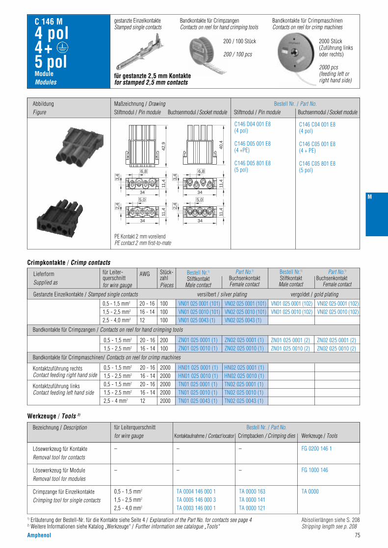
M
Amphenol 75
ModuleModules
C 146 M
4 pol4+ 5 pol
Bandkontakte für CrimpmaschinenContacts on reel for crimp machines
200 / 100 Stück
200 / 100 pcs
2000 Stück(Zuführung linksoder rechts)
2000 pcs(feeding left orright hand side)
Bandkontakte für CrimpzangenContacts on reel for hand crimping tools
gestanzte EinzelkontakteStamped single contacts
für gestanzte 2,5 mm Kontaktefor stamped 2,5 mm contacts
Bestell Nr. / Part No.Stiftmodul / Pin module Buchsenmodul /Socket module
Bandkontakte für Crimpzangen / Contacts on reel for hand crimping tools
Bandkontakte für Crimpmaschinen/ Contacts on reel for crimp machines
0,5 - 1,5 mm2
1,5 - 2,5 mm2
0,5 - 1,5 mm2
1,5 - 2,5 mm2
2,5 - 4 mm2
0,5 - 1,5 mm2
1,5 - 2,5 mm2
20 - 1616 - 1420 - 1616 - 1412
20 - 1616 - 14
20002000200020002000
200100
HN01 025 0001 (1)HN01 025 0010 (1)TN01 025 0001 (1)TN01 025 0010 (1)TN01 025 0043 (1)
ZN01 025 0001 (2)ZN01 025 0010 (2)
HN02 025 0001 (1)HN02 025 0010 (1)TN02 025 0001 (1)TN02 025 0010 (1)TN02 025 0043 (1)
ZN02 025 0001 (2)ZN02 025 0010 (2)
Kontaktzuführung rechtsContact feeding right hand side
Kontaktzuführung linksContact feeding left hand side
Crimpkontakte / Crimp contacts
C146 D04 001 E8(4 pol)
C146 D05 001 E8(4 +PE)
C146 D05 801 E8(5 pol)
C146 C04 001 E8(4 pol)
C146 C05 001 E8(4 + PE)
C146 C05 801 E8(5 pol)
für Leiterquerschnittfor wire gauge
Bestell Nr. / Part No.Kontaktaufnahme / Contact locator Crimpbacken / Crimping dies Werkzeuge / Tools
–
–
0,5 - 1,5 mm2
1,5 - 2,5 mm2
2,5 - 4,0 mm2
–
–
TA 0004 146 000 1TA 0005 146 000 3TA 0003 146 000 1
TA 0000 163TA 0000 141TA 0000 121
– FG 0200 146 1
FG 1000 146
TA 0000
–
Bezeichnung / Description
Lösewerkzeug für KontakteRemoval tool for contacts
Lösewerkzeug für ModuleRemoval tool for modules
Crimpzange für EinzelkontakteCrimping tool for single contacts
Werkzeuge / Tools 2)
1) Erläuterung der Bestell-Nr. für die Kontakte siehe Seite 4 / Explanation of the Part No. for contacts see page 42) Weitere Informationen siehe Katalog „Werkzeuge“ / Further information see catalogue „Tools“
AbbildungFigure
Maßzeichnung / DrawingStiftmodul / Pin module Buchsenmodul /Socket module
42,9
40,4
11,4
3,4
6,8
34
11,42,
4
5,0
34
11,4
3,4
6,8
34
11,42,
4
5,0
34
PE Kontakt 2 mm voreilendPE contact 2 mm first-to-mate
Abisolierlängen siehe S. 208Stripping length see p. 208
LieferformSupplied as
Gestanzte Einzelkontakte / Stamped single contacts
für Leiter-querschnittfor wire gauge
AWG Stück-zahlPieces
0,5 - 1,5 mm2
1,5 - 2,5 mm2
2,5 - 4,0 mm2
20 - 1616 - 1412
100100100
VN01 025 0001 (101)VN01 025 0010 (101)VN01 025 0043 (1)
VN02 025 0001 (101)VN02 025 0010 (101)VN02 025 0043 (1)
ZN01 025 0001 (1)ZN01 025 0010 (1)
ZN02 025 0001 (1)ZN02 025 0010 (1)
VN01 025 0001 (102)VN01 025 0010 (102)
VN02 025 0001 (102)VN02 025 0010 (102)
Bestell Nr.1)
Stiftkontakt Male contact
versilbert / silver plating vergoldet / gold plating
Part No.1)
BuchsenkontaktFemale contact
Bestell Nr.1)
StiftkontaktMale contact
Part No.1)
BuchsenkontaktFemale contact
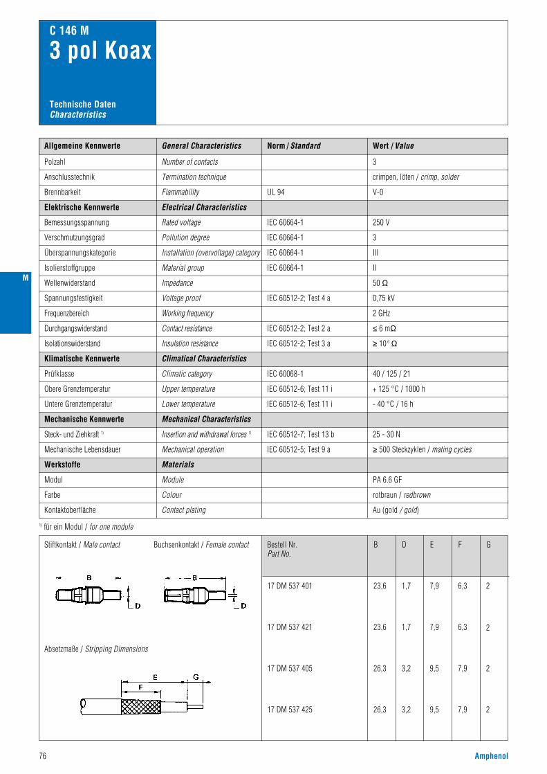
Norm / Standard Wert / ValueAllgemeine Kennwerte
Polzahl Number of contacts
Anschlusstechnik Termination technique crimpen, löten / crimp, solder
3
C 146 M
3 pol Koax
IEC 60512-5; Test 9 aMechanical operation
Module
≥ 500 Steckzyklen / mating cycles
25 - 30 N
PA 6.6 GF
250 V
3
III
II
50 Ω
0,75 kV
2 GHz
V-0Flammability
Electrical Characteristics
Rated voltage
Pollution degree
Installation (overvoltage) category
Material group
Impedance
Voltage proof
IEC 60664-1
IEC 60664-1
IEC 60664-1
IEC 60664-1
IEC 60512-2; Test 4 a
UL 94
Working frequency
Elektrische Kennwerte
Bemessungsspannung
Verschmutzungsgrad
Brennbarkeit
Überspannungskategorie
Isolierstoffgruppe
Wellenwiderstand
Spannungsfestigkeit
Frequenzbereich
IEC 60068-1
IEC 60512-7; Test 13 b
Climatical Characteristics
Climatic category
Mechanical Characteristics
Insertion and withdrawal forces 1)
40 / 125 / 21
≤ 6 mΩIEC 60512-2; Test 2 aContact resistanceDurchgangswiderstand
≥ 10 6 ΩIEC 60512-2; Test 3 aInsulation resistanceIsolationswiderstand
Klimatische Kennwerte
Prüfklasse
IEC 60512-6; Test 11 iUpper temperature
Lower temperature
+ 125 °C / 1000 hObere Grenztemperatur
Untere Grenztemperatur IEC 60512-6; Test 11 i - 40 °C / 16 h
Mechanische Kennwerte
Steck- und Ziehkraft 1)
Mechanische Lebensdauer
Werkstoffe
Modul
Contact plating Au (gold / gold)
rotbraun / redbrown
Kontaktoberfläche
Farbe Colour
Materials
General Characteristics
1) für ein Modul / for one module
Technische DatenCharacteristics
Bestell Nr.Part No.
Stiftkontakt / Male contact
Absetzmaße / Stripping Dimensions
Buchsenkontakt / Female contact
17 DM 537 401
17 DM 537 421
17 DM 537 405
17 DM 537 425
23,6
23,6
26,3
26,3
1,7
1,7
3,2
3,2
7,9
7,9
9,5
9,5
6,3
6,3
7,9
7,9
2
2
2
2
B D E F G
76 Amphenol
M

M
Amphenol 77
ModuleModules
C 146 M
3 pol Koax
für Koax-Kontaktefor coax-contacts
Bestell Nr. / Part No.Stiftmodul / Pin module Buchsenmodul /Socket module
Einzelkontakte / Single contacts
LieferformSupplied as
für Kabelgrößefor cable size
StückzahlPieces
Bestell Nr. / Part No.Stiftkontakt / Male contact Buchsenkontakt / Female contact
RG 174, 179, 316
RG 58
1
1
17 DM 537 401
17 DM 537 405
17 DM 537 421
17 DM 537 425
Crimpkontakte 1) / Crimp contacts 1)
C146 A03 501 E8 C146 B03 501 E8
für Kabelgrößefor cable size
6-Kant-Maß in mm6-hex-size in mm
Bestell Nr. / Part No.Crimpbacken / Crimping dies Werkzeuge / Tools
–
–
RG 58
RG 174, 179, 316
–
–
5,4 (6,5) (1,7)
3,25 (4,5) (1,7)
TA 0000 401
TA 0000 402
– FG 0300 146 3
FG 1000 146
TA 0000
TA 0000
–
Bezeichnung / Description
Lösewerkzeug für KontakteRemoval tool for contacts
Lösewerkzeug für ModuleRemoval tool for modules
Crimpzange für EinzelkontakteCrimping tool for single contacts
Werkzeuge 2) / Tools 2)
1) Weitere Kontakte auf Anfrage / Further contacts on request2) Weitere Informationen siehe Katalog „Werkzeuge“ / Further information see catalogue „Tools“
AbbildungFigure
Maßzeichnung / DrawingStiftmodul / Pin module Buchsenmodul /Socket module

Norm / Standard Wert / ValueAllgemeine Kennwerte
Polzahl
1000 V 1)
3
III
II
8,0 kV
5,7 kV
siehe Derating Kurven / see derating curves
Number of contacts
Anschlusstechnik Termination technique
V-0
crimpen / crimp
Anschlussquerschnitt Wire gauge 1,5 - 10 mm2 (AWG 16 - 8)
3
Flammability
Electrical Characteristics
Rated voltage
Pollution degree
C 146 M
3 pol
Installation (overvoltage) category
Material group
Rated impulse withstand voltage
Voltage proof
IEC 60664-1
IEC 60664-1
IEC 60664-1
IEC 60664-1
IEC 60664-1
IEC 60512-2; Test 4 a
UL 94
IEC 60512-3; Test 5 bCurrent carrying capacity
Elektrische Kennwerte
Bemessungsspannung
Verschmutzungsgrad
Brennbarkeit
Überspannungskategorie
Isolierstoffgruppe
Bemessungs-Stoßspannung
Spannungsfestigkeit
Strombelastbarkeit
≤ 1 mΩIEC 60512-2; Test 2 aContact resistanceDurchgangswiderstand
≥ 10 12 ΩIEC 60512-2; Test 3 aInsulation resistanceIsolationswiderstand
IEC 60068-1
Climatical Characteristics
Climatic category
Mechanical Characteristics
40 / 125 / 21
Klimatische Kennwerte
Prüfklasse
IEC 60512-6; Test 11 iUpper temperature
Lower temperature
+ 125 °C / 1000 hObere Grenztemperatur
Untere Grenztemperatur IEC 60512-6; Test 11 i - 40 °C / 16 h
Mechanische Kennwerte
General Characteristics
Technische DatenCharacteristics
IEC 60512-5; Test 9 aMechanical operation
Module
≥ 500 Steckzyklen / mating cycles
PA 6.6 GF
schwarz / black
IEC 60512-7; Test 13 bInsertion and withdrawal forces 2)Steck- und Ziehkraft 2)
Mechanische Lebensdauer
IEC 60529IP-degree of protection 20
20 - 30 N
IP-Schutzart
Werkstoffe
Modul
Contacts Cu-Legierung / Cu-alloyKontakte
Contact plating Ag (silber / silver)Kontaktoberfläche
Farbe Colour
Materials
1) 630 V bei Verwendung als Steckvorrichtung / 630 V if the modules are used as plug and socket device 2) für ein Modul / for one module
Derating Kurven / Derating curves
> 14 mmIEC 60664-1ClearanceLuftstrecke
> 14 mmIEC 60664-1CreepageKriechstrecke
6 mm2 10 mm2 KurveCurve
PolzahlContacts
RahmenFrame
a 3 2 Module
b 6 2 Module
c 9 3 Module
d 15 5 Module
e 21 7 Module
78 Amphenol
Stro
mbe
last
bark
eit I
(A)
Curre
nt ca
rryin
g ca
pacit
y I (A
)
Bauelement Umgebungstemperatur Tu (°C)Ambient temperature Tamb (°C)
Stro
mbe
last
bark
eit I
(A)
Curre
nt ca
rryin
g ca
pacit
y I (A
)
Bauelement Umgebungstemperatur Tu (°C)Ambient temperature Tamb (°C)
M

Amphenol 79
ModuleModules
C 146 M
3 pol
für gedrehte 3,6 mm Kontaktefor turned 3,6 mm contacts
alle Kontakte 2mm voreilend zu anderen Modulenall contacts 2mm first-to-mate to other modules
Bestell Nr. / Part No.
Stiftmodul / Pin module Buchsenmodul /Socket module
C146 A03 801 E8 C146 B03 801 E8
Crimpkontakte / Crimp contacts
Lieferform
Supplied as
AWGfür Leiterquerschnitt
for wire gauge
Stückzahl
Pieces
Bestell Nr. 1) / Part No. 1)
Stiftkontakt / Male contact Buchsenkontakt / Female contact
1,5 mm2
2,5 mm2
4,0 mm2
6,0 mm2
10,0 mm2
161412108
100100100100100
VN01 036 0004 (1)CVN01 036 0005 (1)CVN01 036 0001 (1)CVN01 036 0002 (1)C 2)
VN01 036 0003 (1)C 2)
VN02 036 0004 (1)CVN02 036 0005 (1)CVN02 036 0001 (1)CVN02 036 0002 (1)C 2)
VN02 036 0003 (1)C 2)
EinzelkontaktSingle contact
Crimpkontakte / Crimp contacts
Stückzahl / PiecesKabelschuhe für Schutzleiteranschluss / Cable lugs for PE connection Bestell Nr. / Part No.
6,0 mm2
10,0 mm2
N15 006 000 9ZN15 010 000 7Z
Kabelschuhcable lug
– 2020
1) Erläuterung der Bestell-Nr. für die Kontakte siehe Seite 4 / Explanation of the Part No. for contacts see page 42) Bei den Leiterquerschnitten 6 + 10 mm2 sind Kabelschuhe für den Schutzleiteranschluss zu verwenden / For wire gauges 6 + 10 mm2 cable lugs have to be used for PE connection3) Weitere Informationen siehe Katalog „Werkzeuge“ / Further information see catalogue „Tools“4) incl. Prüfstiftset, Kontaktaufnahme / incl. calibration pin set, locator
für Leiterquerschnitt
for wire gauge
Bestell Nr. / Part No.
Kontaktaufnahme / Contact locator Crimpbacken / Crimping dies Werkzeuge / Tools
–
–
1,5 - 2,5 mm2
4,0 mm2
6,0 mm2
1,5 -10,0 mm2
6,0 mm2
10,0 mm2
–
–
–
–
–
TA 0010 146 000 2TA 0010 146 000 4TA 0010 146 000 4
TA 0000 144TA 0000 124TA 0000 124
– FG 0300 146 3
FG 1000 146
TA 0000
TB 0200 146
–
Bezeichnung / Description
Lösewerkzeug für Kontakte
Removal tool for contacts
Lösewerkzeug für Module
Removal tool for modules
Crimpzange für Einzelkontakte
Crimping tool for single contacts
Werkzeuge / Tools 3)
TA 0000Crimpzange für Kabelschuhe
Crimping tool for cable lugs
4-Kerb Crimpzange 4)
4-indet crimping tool 4)
TA 0000 180
Abbildung
Figure
Maßzeichnung / Drawing
Stiftmodul / Pin module Buchsenmodul /Socket module
M
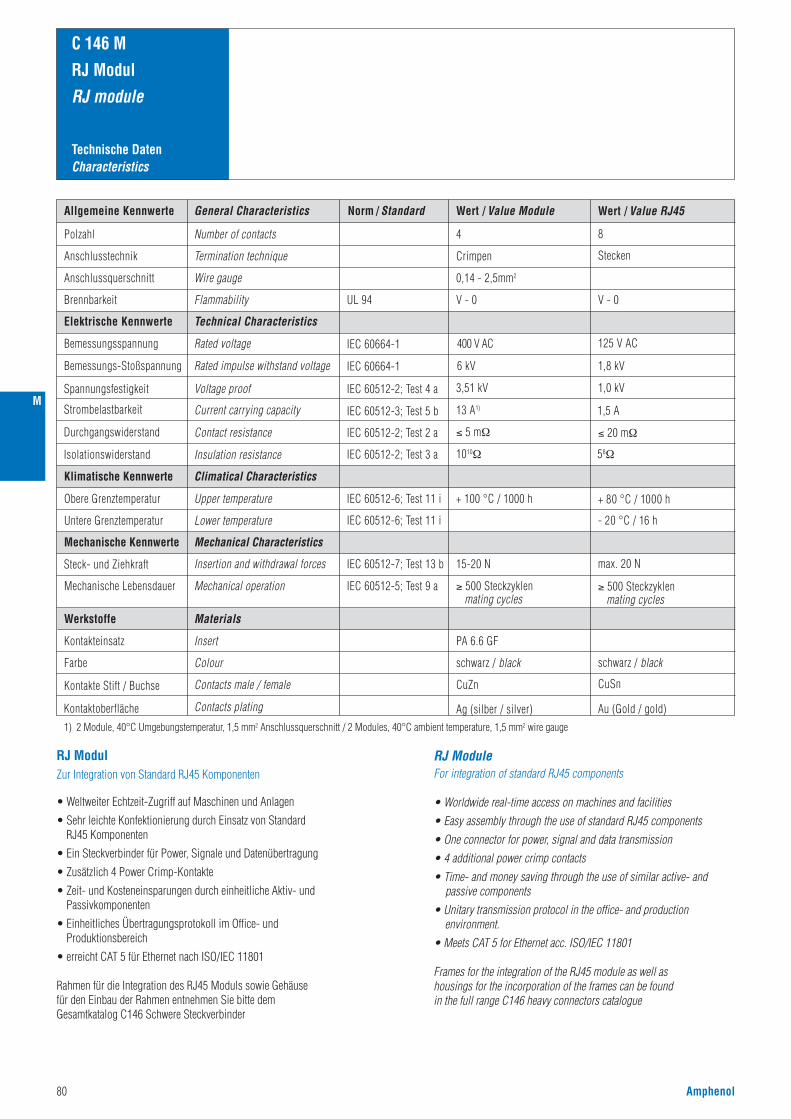
80 Amphenol
Technische DatenCharacteristics
C 146 M
RJ Modul
RJ module
Norm / Standard Wert / Value ModuleAllgemeine Kennwerte
Polzahl Number of contacts
Anschlusstechnik Termination technique
V - 0
Crimpen
Anschlussquerschnitt Wire gauge 0,14 - 2,5mm2
4
Flammability
Technical Characteristics
Rated voltage
Rated impulse withstand voltage
UL 94
Mechanical operation
Insert
≥ 500 Steckzyklen mating cycles
Elektrische Kennwerte
Bemessungsspannung
Brennbarkeit
Bemessungs-Stoßspannung
Climatical Characteristics
Mechanical Characteristics
Klimatische Kennwerte
Upper temperature
Lower temperature
Obere Grenztemperatur
Untere Grenztemperatur
Mechanische Kennwerte
Mechanische Lebensdauer
Werkstoffe
Kontakteinsatz
Contacts male / female CuZnKontakte Stift / Buchse
Farbe Colour
Materials
General Characteristics
400 V AC
6 kV
PA 6.6 GF
schwarz / black
+ 100 °C / 1000 h
Spannungsfestigkeit
Strombelastbarkeit
Durchgangswiderstand
Isolationswiderstand
Steck- und Ziehkraft
Kontaktoberfläche Contacts plating
Voltage proof
Current carrying capacity
Contact resistance
Insulation resistance
Insertion and withdrawal forces
IEC 60664-1
IEC 60664-1
IEC 60512-2; Test 4 a
IEC 60512-2; Test 2 a
IEC 60512-2; Test 3 a
IEC 60512-3; Test 5 b
IEC 60512-6; Test 11 i
IEC 60512-6; Test 11 i
IEC 60512-7; Test 13 b
IEC 60512-5; Test 9 a
3,51 kV
13 A1)
≤ 5 mΩ
Ag (silber / silver)
15-20 N
1010Ω
Wert / Value RJ45
8
Stecken
V - 0
125 V AC
1,8 kV
1,0 kV
1,5 A
≤ 20 mΩ
58Ω
+ 80 °C / 1000 h
- 20 °C / 16 h
≥ 500 Steckzyklen mating cycles
max. 20 N
Au (Gold / gold)
CuSn
schwarz / black
1) 2 Module, 40°C Umgebungstemperatur, 1,5 mm2 Anschlussquerschnitt / 2 Modules, 40°C ambient temperature, 1,5 mm2 wire gauge
RJ Modul Zur Integration von Standard RJ45 Komponenten
• Weltweiter Echtzeit-Zugriff auf Maschinen und Anlagen
• Sehr leichte Konfektionierung durch Einsatz von Standard RJ45 Komponenten
• Ein Steckverbinder für Power, Signale und Datenübertragung
• Zusätzlich 4 Power Crimp-Kontakte
• Zeit- und Kosteneinsparungen durch einheitliche Aktiv- und Passivkomponenten
• Einheitliches Übertragungsprotokoll im Office- und Produktionsbereich
• erreicht CAT 5 für Ethernet nach ISO/IEC 11801
Rahmen für die Integration des RJ45 Moduls sowie Gehäusefür den Einbau der Rahmen entnehmen Sie bitte demGesamtkatalog C146 Schwere Steckverbinder
RJ ModuleFor integration of standard RJ45 components
• Worldwide real-time access on machines and facilities
• Easy assembly through the use of standard RJ45 components
• One connector for power, signal and data transmission
• 4 additional power crimp contacts
• Time- and money saving through the use of similar active- and passive components
• Unitary transmission protocol in the office- and production environment.
• Meets CAT 5 for Ethernet acc. ISO/IEC 11801
Frames for the integration of the RJ45 module as well as housings for the incorporation of the frames can be foundin the full range C146 heavy connectors catalogue
M

ModuleModules
C 146 M
RJ Modul
RJ module
C146 E12 001 E8
Abbildung
Figure
Maßzeichnung
Drawing
Bestell Nr.
Part No.
C146 F12 001 G8
Stiftmodul / Pin module
Buchsenmodul /Socket module
Kabelverschraubung, geteilt (Verpackungseinheit 5 St.) Gland bushing, splitted (packing unit 5 pcs.)
Tüllengehäuse, 2x Abgang oben /Hood, 2x top entry C146 21R010 902 8C146 21R016 910 8C146 21R024 913 8
VN16 250 0131 V
10 pol 2xM25 ohne Stutzen / without stud16 pol 2xM25 ohne Stutzen / without stud 24 pol 1xM25 + 1xM40 ohne Stutzen / without stud
Amphenol 81
M
* Wenn Buchse eingefedert: 46,8 / If plug socket receded: 46,8
*

Technische DatenCharacteristics
Norm / Standard Wert / ValueAllgemeine Kennwerte
Kontaktzahl Number of contacts
Anschlusstechnik Termination technique
V-0
Schlauchanschluss / tube termination
Anschlussquerschnitt Wire gauge 2,5 mm / 4,0 mm
1 / 2
Flammability
Technical Characteristics
Operating pressure
Operating path
Locking
Pneumatic tube
UL 94
Mechanical operation
Module
5000 Steckzyklen / mating cycles
Technische Kennwerte
Betriebsdruck
Schaltweg
Brennbarkeit
Absperrung
Pneumatikschlauch
Climatical Characteristics
Mechanical Characteristics
Klimatische Kennwerte
Upper temperature
Lower temperature
Obere Grenztemperatur
Untere Grenztemperatur
Mechanische Kennwerte
Mechanische Lebensdauer
Werkstoffe
Modul
Contacts Messing MS 58 / Brass MS 58Kontakte
Farbe Colour
Materials
General Characteristics
8 bar mit PTFE-Schlauch (Teflon) / with PTFE tube
4,0 mm
einseitig absperrend / locking on one side
nur PTFE-Schläuche verwenden 1)
only use PTFE tubes 1)
PA 6.6 GF
schwarz / black
+100 °C
- 20 °C
1) Die Module sind speziell für den Einsatz von PTFE-Schläuchen konzipiert und dürfen nur in Verbindung mir diesen eingesetzt werden. Der Einsatz von Schläuchen aus anderem Material ist nicht zu empfehlen, da die oberen und unteren Grenztemperaturen nicht erreicht werden.1) The modules are specifically designed for the use of PTFE tubes and should only be used in conjunction with these. The use of tubes made from other materials is not recommended, as the higher and lower category temperatures will not be achievable.
Pneu Modul Leistung, Signal und Pneumatik in einem Steckverbinder
• Sehr stabile Messing-Kontakte
• Pneumatik-Buchsenkontakte mit Absperrung, schließt bei geöffnetem Steckverbinder
• Wahlweise mit 1 oder 2 Anschlüssen
• Anschluss für 2,5 mm oder 4 mm PTFE (Teflon)-Schläuchen
• Schläuche können von den Anschlüssen wieder demontiert werden
Rahmen für die Integration des Pneu Moduls sowie Gehäuse für den Einbau der Rahmen entnehmen Sie bitte dem Gesamtkatalog C146 Schwere Steckverbinder.
Pneumatic ModulePower, signal and pneumatic within a single connector
• Very stable brass contacts
• Pneumatic socket contacts with barrier, closes when the connector is open
• Available with single or double connections
• Connection for 2.5 mm or 4 mm PTFE (Teflon)-tubes
• Tubes can be disassembled from the terminations
Frames for the integration of the pneumatic module as well as housings for the incorporation of the frames can be found in the full range C146 heavy connectors catalogue.
82 Amphenol
C 146 M
Pneu Modul
Pneumatic module
M
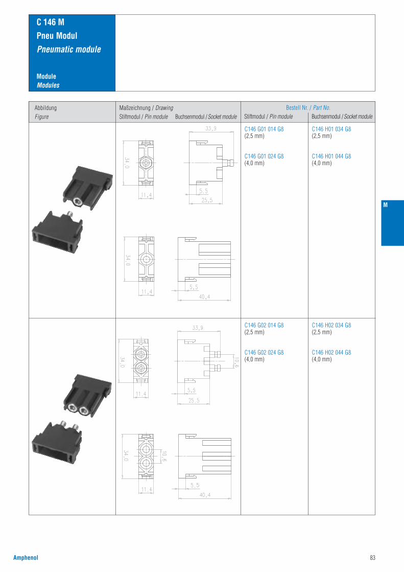
C 146 M
Amphenol 83
ModuleModules
C 146 M
Pneu Modul
Pneumatic module
C146 G01 014 G8
(2,5 mm)
C146 G01 024 G8
(4,0 mm)
C146 H01 034 G8
(2,5 mm)
C146 H01 044 G8
(4,0 mm)
Abbildung
Figure
Maßzeichnung / Drawing
Stiftmodul / Pin module Buchsenmodul /Socket module
Bestell Nr. / Part No.
Stiftmodul / Pin module Buchsenmodul /Socket module
C146 G02 014 G8
(2,5 mm)
C146 G02 024 G8
(4,0 mm)
C146 H02 034 G8
(2,5 mm)
C146 H02 044 G8
(4,0 mm)
M
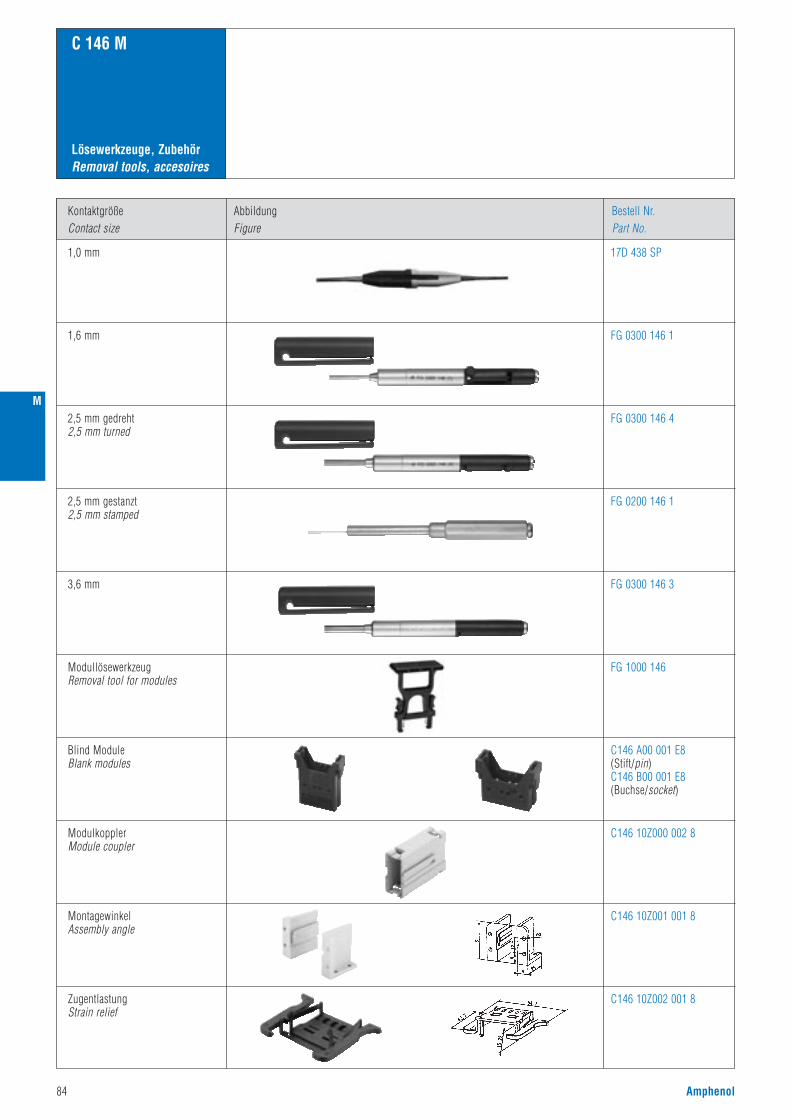
84 Amphenol
Lösewerkzeuge, ZubehörRemoval tools, accesoires
C 146 M
Kontaktgröße
Contact size
1,0 mm
Abbildung
Figure
Bestell Nr.
Part No.
1,6 mm
2,5 mm gedreht2,5 mm turned
2,5 mm gestanzt2,5 mm stamped
3,6 mm
ModullösewerkzeugRemoval tool for modules
FG 0300 146 4
FG 0200 146 1
FG 0300 146 3
FG 0300 146 1
17D 438 SP
FG 1000 146
ModulkopplerModule coupler
C146 10Z000 002 8
C146 10Z001 001 8
C146 10Z002 001 8
Blind ModuleBlank modules
C146 A00 001 E8(Stift/pin)C146 B00 001 E8(Buchse/socket)
MontagewinkelAssembly angle
ZugentlastungStrain relief
M

A
C 146 A
• Schmale Bauform• Bemessungsspannung 250 / 400 V• Bemessungsstrom 14 A ... 18 A• Anschlussart: schrauben• Polzahl: 3, 4, 10, 16, 32
• Narrow style• Rated voltage 250 / 400 V• Rated current 14 A ... 18 A• Termination: screw• Number of contacts: 3, 4, 10, 16, 32
Amphenol 85
Zulassungen / ApprovalsPrüfstelle / Testhouse Kennwerte / Characteristics Zulassungs-Nummer / Approval-No.
Hauptmerkmale Main characteristics
SEV 250 V, 10 A
UL 600 V, 14 A E 63093
CSA 600 V, 10 A; 16 A; 20 A LR 700721
Zulassungen beziehen sich im allgemeinen auf repräsentativeAusführungen der Steckverbinderserie. Prüfumfang undPrüfvorschrift auf Anfrage.
In general approvals refer to representative versions of the connectorseries. Extent and specification of tests upon request.

86 Amphenol
KurzinformationBrief information
C 146 A
Allgemeine Hinweise
General information
• Steckverbinder der Serie C 146 A dürfen unter Spannung, jedoch nicht unter Strom betätigt werden. Werden dieSteckverbinder als Steckvorrichtung eingesetzt, ist der Strom auf 10 % des Bemessungsstroms zu begrenzen.
• Für die Einsätze der Serie C 146 A (10 + 16 pol) können sowohl niedrige, wie auch hohe Gehäusebauformenverwendet werden.
• For series C 146 A connectors may be engaged or disengaged when live but without electrical load. If these connectors are used as plug and socket device, the load shall be reduced to 10 % of the rated current.
• Low and high profile housing for C 146 A series inserts for 10 and 16 contacts.
Nicht genormte Steckverbinder,aber:
No standard for this series,but:
• Steck- und austauschbarmit Fremdfabrikatena) Kontakteinsatz / Kontakteinsatzb) Kontakteinsatz / Gehäuse 10, 16 pol.
• Interchangeable with other makesa) contact insert to contact insertb) contact insert to housing 10 ,16 pin
Gehäuse nach CECC 75 301 - 801
Housings are designed according to CECC 75 301 - 801
Voreilender Schutzkontakt
First-to-mate last-to-breakprotective ground contact
Große Gehäuseauswahlin 2 Bauhöhen(ab Seite 116)
Large range of housings in2 different heights(see page 116)
A

A
Amphenol 87
Norm / Standard Wert / ValueAllgemeine Kennwerte
Polzahl Number of contacts
Anschlusstechnik Termination technique
V-0
schrauben / screw
Anschlussquerschnitt Wire gauge 0,25 - 2,5 mm2
3/4 + 10 + 16 + 32 +
Flammability
C 146 A
UL 94Brennbarkeit
General Characteristics
Technische DatenCharacteristics
400 V 250 V
3
III
III b
4,0 KV
2,8 KV
siehe Derating Kurven / see derating curves
Electrical Characteristics
Rated voltage
Pollution degree
Installation (overvoltage) category
Material group
Rated impulse withstand voltage
Voltage proof
IEC 60664-1
IEC 60664-1
IEC 60664-1
IEC 60664-1
IEC 60664-1
IEC 60512-2; Test 4 a
IEC 60512-3; Test 5 bCurrent carrying capacity
Elektrische Kennwerte
Bemessungsspannung
Verschmutzungsgrad
Überspannungskategorie
Isolierstoffgruppe
Bemessungs-Stoßspannung
Spannungsfestigkeit
Strombelastbarkeit
Rated current Tamp = 40 °CBemessungsstrom Tu = 40 °C
≤ 5 m ΩIEC 60512-2; Test 2 a
IEC 60068-1
Contact resistance
Climatical Characteristics
Climatic category 40 / 100 / 21
Durchgangswiderstand
≥ 10 12 Ω 1)IEC 60512-2; Test 3 aInsulation resistanceIsolationswiderstand
Klimatische Kennwerte
Prüfklasse
Insert
Contacts
Contact plating
PA PBT PBT PBT
Cu Zn (Messing / brass)
Ag (silber / silver)
IEC 60512-7; Test 13 b
IEC 60512-5; Test 9 a
Mechanical Characteristics
Insertion and withdrawal forces
Weight pin insert
Weight socket insert
Mechanical operation ≥ 500 Steckzyklen / mating cycles
Mechanische Kennwerte
Steck- und Ziehkraft
Gewicht Stifteinsatz
Gewicht Buchseneinsatz
Mechanische Lebensdauer
Werkstoffe
Kontakteinsatz
Kontakte
Kontaktoberfläche
1) Bei Beanspruchung > 1010 Ω / Under operating conditions > 1010 Ω2) IP-Schutzart im Anschlussbereich der Schraubausführung IP 10 / IP-degree of protection on termination side of screw version IP 10
Materials
IEC 60512-6; Test 11 iUpper temperature
Lower temperature
+ 100 °C / 1000 hObere Grenztemperatur
Untere Grenztemperatur IEC 60512-6; Test 11 i - 40 °C / 16 h
18 A 16 A 14 A 14 A
13 g
15 - 20 N
13 g
48 g
50 - 70 N
52 g
68 g
80-100 N
73 g
136 g
160-200 N
146 g
IEC 60529IP-degree of protection pin insert ungesteckt/unmatedIP00
gesteckt/matedIP20
gesteckt/matedIP20
ungesteckt/unmatedIP20
2) IP-Schutzart Stifteinsatz
IEC 60529IP-degree of protection socket insert2) IP-Schutzart Buchseneinsatz

88 Amphenol
Bezeichnung - AbbildungDescription - Figure
MaßzeichnungDrawing
Bestell Nr. / Part No.Stifteinsatz / Male insert Buchseneinsatz / Female insert
C 146 A
3 /4 +
SteckverbinderConnectors
Gehäuse siehe Seite 116-119 Housings see page 116-119
400 V~ 10 A
Derating Kurven / Derating curves
Kontakteinsatz Schraubanschluss3 +Contact insert screw termination3 +
C146 10A003 002 4 C146 10B003 002 4
Steckbild / pin layout
nur für Kunststoffgehäuseonly for thermoplastic housings
C146 10A004 002 4 C146 10B004 002 4
1,5 mm2
0
5
10
15
20
25
Umgebungstemperatur [°C]
Belas
tung
sstro
m [A
] .
0 20 40 60 80 100 120 140
2,5 mm2
0
5
10
15
20
25
30
35
Umgebungstemperatur [°C]
Belas
tung
sstro
m [A
] .
0 20 40 60 80 100 120 140
BuchseneinsatzFemale insert
StifteinsatzMale insert
16,7
20,8
23,3
M 39,5
20,816
,4
F
39,2
16,7
20,8
23,3
M 39,5
20,8
16,4
F
39,2
StifteinsatzMale insert
BuchseneinsatzFemale insert
3 + 4 +StifteinsatzMale insert
BuchseneinsatzFemale insert
StifteinsatzMale insert
BuchseneinsatzFemale insert
Kontakteinsatz Schraubanschluss4 +Contact insert screw termination4 +
25
20
15
10
5
00 20 40 60 80 100 120 140
Umgebungstemperatur(°C)Temperature (°C)
1,5 mm2
Belas
tung
sstro
m (A
)Cu
rrent
carry
ing
capa
city I
(A) 35
30
25
20
15
10
5
00 20 40 60 80 100 120 140
Umgebungstemperatur(°C)Temperature (°C)
2,5 mm2
Belas
tung
sstro
m (A
)Cu
rrent
carry
ing
capa
city I
(A)
A

A
Amphenol 89
Bezeichnung - AbbildungDescription - Figure
MaßzeichnungDrawing
Bestell Nr. / Part No.Stifteinsatz / Male insert Buchseneinsatz / Female insert
C 146 A
10 +
SteckverbinderConnectors
Gehäuse siehe Seite 120-123 Housings see page 120-123
250 V~ 16 A
Derating Kurven / Derating curves
Kontakteinsatz SchraubanschlussContact insert screw termination
C146 10A010 002 4
C146 10A010 102 4(mit Drahtschutz /with wire protection)
C146 10B010 002 4
C146 10B010 102 4(mit Drahtschutz /with wire protection)
Montageanleitung, Steckbild / Assembly instruction, pin layout
StifteinsatzMale insert
BuchseneinsatzFemale insert
Montageausschnitt (Kontaktträger)Panel cut out (insert)
StifteinsatzMale insert
BuchseneinsatzFemale insert
1,5 mm2
0
5
10
15
20
25
0 20 40 60 80 100 120 140Umgebungstemperatur [°C]
Belas
tung
sstro
m [A
] .
2,5 mm2
0
5
10
15
20
25
30
35
Umgebungstemperatur [°C]
Belas
tung
sstro
m [A
] .
0 20 40 60 80 100 120 140
25
20
15
10
5
00 20 40 60 80 100 120 140
Umgebungstemperatur(°C)Temperature (°C)
1,5 mm2
Belas
tung
sstro
m (A
)Cu
rrent
carry
ing
capa
city I
(A) 35
30
25
20
15
10
5
00 20 40 60 80 100 120 140
Umgebungstemperatur(°C)Temperature (°C)
2,5 mm2
Belas
tung
sstro
m (A
)Cu
rrent
carry
ing
capa
city I
(A)
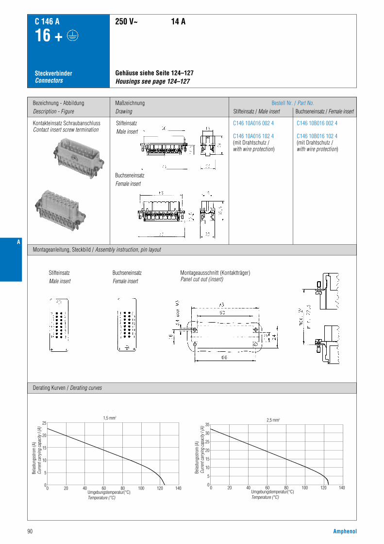
90 Amphenol
Bezeichnung - AbbildungDescription - Figure
MaßzeichnungDrawing
Bestell Nr. / Part No.Stifteinsatz / Male insert Buchseneinsatz / Female insert
C 146 A
16 +
SteckverbinderConnectors
Gehäuse siehe Seite 124–127 Housings see page 124–127
250 V~ 14 A
Derating Kurven / Derating curves
Kontakteinsatz SchraubanschlussContact insert screw termination
C146 10A016 002 4
C146 10A016 102 4(mit Drahtschutz /with wire protection)
C146 10B016 002 4
C146 10B016 102 4(mit Drahtschutz /with wire protection)
Montageanleitung, Steckbild / Assembly instruction, pin layout
StifteinsatzMale insert
BuchseneinsatzFemale insert
Montageausschnitt (Kontaktträger)Panel cut out (insert)
StifteinsatzMale insert
BuchseneinsatzFemale insert
1,5 mm2
0
5
10
15
20
25
0 20 40 60 80 100 120 140Umgebungstemperatur [°C]
Belas
tung
sstro
m [A
] .
2,5 mm2
0
5
10
15
20
25
30
35
Umgebungstemperatur [°C]
Belas
tung
sstro
m [A
] .
0 20 40 60 80 100 120 140
25
20
15
10
5
00 20 40 60 80 100 120 140
Umgebungstemperatur(°C)Temperature (°C)
1,5 mm2
Belas
tung
sstro
m (A
)Cu
rrent
carry
ing
capa
city I
(A) 35
30
25
20
15
10
5
00 20 40 60 80 100 120 140
Umgebungstemperatur(°C)Temperature (°C)
2,5 mm2
Belas
tung
sstro
m (A
)Cu
rrent
carry
ing
capa
city I
(A)
A

A
Amphenol 91
Bezeichnung - AbbildungDescription - Figure
MaßzeichnungDrawing
Bestell Nr. / Part No.Stifteinsatz / Male insert Buchseneinsatz / Female insert
C 146 A
32 +
SteckverbinderConnectors
Gehäuse siehe Seite 128–131Housings see page 128–131
250 V~ 14 A
Kontakteinsatz SchraubanschlussContact insert screw termination
C146 10A016 002 4(1 - 16)
+
C146 10A016 004 4(17 - 32)
C146 10B016 002 4(1 - 16)
+
C146 10B016 004 4(17 - 32)
C146 10A016 102 4(1 - 16)+
C146 10A016 104 4(17 - 32)(mit Drahtschutz / with wire protection)
C146 10B016 102 4(1 - 16)+
C146 10B016 104 4(17 - 32)(mit Drahtschutz / with wire protection)
Montageanleitung, Steckbild / Assembly instruction, pin layout
StifteinsatzMale insert
BuchseneinsatzFemale insert
Montageausschnitt (Kontaktträger)Panel cut out (insert)
StifteinsatzMale insert
BuchseneinsatzFemale insert

92 Amphenol
A

HSE
Amphenol 93
C 146 HSE
• Bemessungsspannung 400 V• Bemessungsstrom 42 A• Anschlussart: schrauben• Anschlussquerschnitt: 6mm2
• Polzahl: 6
• Rated voltage 400 V• Rated current 42 A• Termination: screw• Max. wire gauge 6 mm2
• Number of contacts: 6
Hauptmerkmale Main characteristics
UL 600 V, 35 A 48932
CSA 600 V, 35 A E 63093
Zulassungen / ApprovalsPrüfstelle / Testhouse Kennwerte / Characteristics Zulassungs-Nummer / Approval-No.
Zulassungen beziehen sich im allgemeinen auf repräsentativeAusführungen der Steckverbinderserie. Prüfumfang undPrüfvorschrift auf Anfrage.
In general approvals refer to representative versions of the connectorseries. Extent and specification of tests upon request.

94 Amphenol
Norm / Standard Wert / ValueAllgemeine Kennwerte
Polzahl Number of contacts
Anschlusstechnik Termination technique
V-0
schrauben / screw
Anschlussquerschnitt Wire gauge 0,5 - 6,0 mm2 (Ø 3,4 mm)
6 +
Flammability
C 146 HSE
UL 94Brennbarkeit
General Characteristics
Technische DatenCharacteristics
400 V (600 V UL / CSA2)
3
III
II
6,0 KV
2200 V
siehe Derating Kurven / see derating curves
42 A
Electrical Characteristics
Rated voltage
Pollution degree
Installation (overvoltage) category
Material group
Rated impulse withstand voltage
Voltage proof
IEC 60664-1
IEC 60664-1
IEC 60664-1
IEC 60664-1
IEC 60664-1
IEC 60512-2; Test 4 a
IEC 60512-3; Test 5 bRated current
Elektrische Kennwerte
Bemessungsspannung
Verschmutzungsgrad
Überspannungskategorie
Isolierstoffgruppe
Bemessungs-Stoßspannung
Spannungsfestigkeit
Strombelastbarkeit
Rated current Tamp = 40 °CBemessungsstrom Tu = 40 °C
schwarz / black
≤ 1 m ΩIEC 60512-2; Test 2 a
IEC 60068-1
Contact resistance
Climatical Characteristics
Climatic category
Insert
Contacts
Contact plating
40 / 125 / 21
40 - 60 N
PA, GV
Cu Zn (Messing / brass)
Ag (silber / silver)
Durchgangswiderstand
≥ 10 12 Ω 1)IEC 60512-2; Test 3 aInsulation resistanceIsolationswiderstand
≥ 3,5 mmIEC 60664-1ClearanceLuftstrecke
≥ 5,6 mmIEC 60664-1CreepageKriechstrecke
Klimatische Kennwerte
Prüfklasse
IEC 60512-7; Test 13 b
IEC 60512-5; Test 9 a
Mechanical Characteristics
Insertion and withdrawal forces
Weight pin insert
Weight socket insert
Mechanical operation
80 g
80 g
≥ 500 Steckzyklen / mating cycles
Mechanische Kennwerte
Steck- und Ziehkraft
Gewicht Stifteinsatz
Gewicht Buchseneinsatz
Mechanische Lebensdauer
Werkstoffe
Kontakteinsatz
Kontakte
Kontaktoberfläche
Farbe
1) Bei Beanspruchung > 1010 Ω / Under operating conditions > 1010 Ω2) Hinweisschild für CSA-Anwendung siehe Seite 186/ Label for CSA application see page 1863) IP-Schutzart im Anschlussbereich IP 10 / IP-degree of protection on termination side IP 10
Colour
Materials
IEC 60512-6; Test 11 i + 125 °C / 1000 h
IEC 60512-6; Test 11 i - 40 °C / 16 h
Obere Grenztemperatur
Untere Grenztemperatur
Upper temperature
Lower temperature
IEC 60529IP-degree of protection pin insert ungesteckt/unmatedIP00
gesteckt/matedIP20
gesteckt/matedIP20
ungesteckt/unmatedIP20
3) IP-Schutzart Stifteinsatz
IEC 60529IP-degree of protection socket insert3) IP-Schutzart Buchseneinsatz
HSE
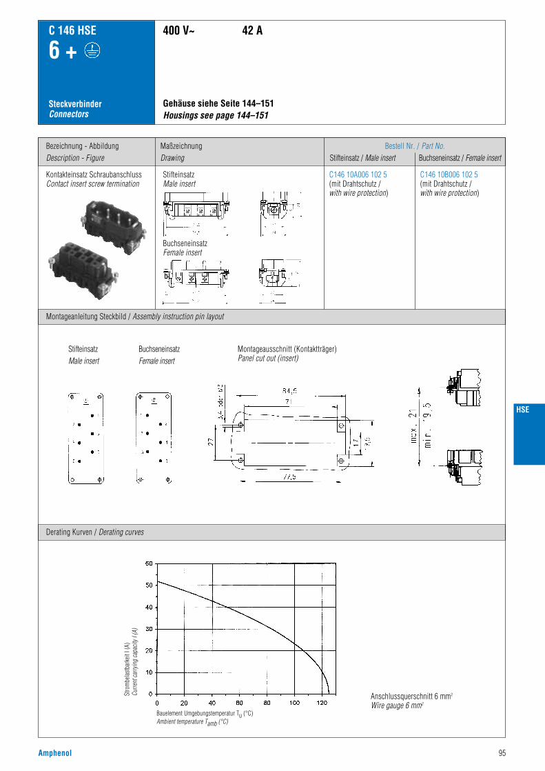
HSE
Amphenol 95
Bezeichnung - AbbildungDescription - Figure
Montageanleitung Steckbild / Assembly instruction pin layout
MaßzeichnungDrawing
Bestell Nr. / Part No.Stifteinsatz / Male insert Buchseneinsatz / Female insert
C 146 HSE
6 +
SteckverbinderConnectors
Kontakteinsatz SchraubanschlussContact insert screw termination
StifteinsatzMale insert
BuchseneinsatzFemale insert
Gehäuse siehe Seite 144–151 Housings see page 144–151
400 V~ 42 A
C146 10A006 102 5(mit Drahtschutz /with wire protection)
C146 10B006 102 5(mit Drahtschutz /with wire protection)
Derating Kurven / Derating curves
Anschlussquerschnitt 6 mm2
Wire gauge 6 mm2
Stro
mbe
last
bark
eit I
(A)
Curre
nt ca
rryin
g ca
pacit
y I (A
)
Bauelement Umgebungstemperatur Tu (°C)Ambient temperature Tamb (°C)
Montageausschnitt (Kontaktträger)Panel cut out (insert)
StifteinsatzMale insert
BuchseneinsatzFemale insert

96 Amphenol
HSE
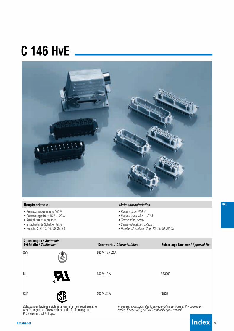
HvE
C 146 HvE
• Bemessungsspannung 660 V• Bemessungsstrom 16 A ... 22 A• Anschlussart: schrauben• 2 nacheilende Schaltkontakte• Polzahl: 3, 6, 10, 16, 20, 26, 32
• Rated voltage 660 V• Rated current 16 A ... 22 A• Termination: screw• 2 delayed mating contacts• Number of contacts: 3, 6, 10, 16, 20, 26, 32
Amphenol 97
Hauptmerkmale Main characteristics
Zulassungen / ApprovalsPrüfstelle / Testhouse Kennwerte / Characteristics Zulassungs-Nummer / Approval-No.
SEV 660 V, 16 / 22 A
UL 600 V, 10 A E 63093
CSA 600 V, 20 A 48932
Zulassungen beziehen sich im allgemeinen auf repräsentativeAusführungen der Steckverbinderserie. Prüfumfang undPrüfvorschrift auf Anfrage.
In general approvals refer to representative versions of the connectorseries. Extent and specification of tests upon request.

KurzinformationBrief information
C 146 HvE
Konstruktiver Aufbau der HvE-Steckverbindung
Construction of connectors Type HvE
Kontakteinsätze
Inserts
Gehäuse: (aus Alu-Druckguss)
Housings: (made of aluminium)
Verwendet werden beim 16-pol. HvE-Kontakteinsatz C 146 E-Gehäuse mit Isolationsauskleidung. (Isolationsfolie anInnenwand). Die Sperrstege an den Gehäuseinnenwänden (Schmalseite), die das Einsetzen der 660 V-Kontaktträger in400 V-Gehäusen verhindern, sind entfernt. Der 16-pol. HvE-Einsatz mit stirnseitigem Sperrstück ist jetzt montierbar.
C 146 E housings with an inside insulation (plastic foil) are used for the 16-contacts insert.The inside barriers at the narrow sides preventing mounting of 660 V-inserts in 400 V housings are removed and the 16-contacts insert is now mountable.
Die 3, 6 und 10-pol. HVE-Kontakteinsätze gehen aus den 10, 16 und 24-pol. Isolierkörpern der Baureihe C 146 E durchTeilbestückung und 2 zusätzlichen, nacheilenden Schaltkontakten hervor.Lediglich die Polzahl 16 HVE besitzt in der Steckgeometrie abweichende Kontaktträger. Ihre äußeren Abmessungen sindjedoch mit denen der Polzahl 24, Serie C 146 E identisch.Die nacheilenden Schaltkontakte ermöglichen den Anschluss einer Schützwicklung zum Zweck der elektrischen Ver-riegelung. Das bedeutet spannungslose Buchseneinsätze im ungesteckten Zustand.
Werden Steckverbinder ohne Schaltleistung als Steckverbinder mit Schaltleistung eingesetzt, so müssen dieelektrischen Leistungsdaten gemäß den Angaben des Herstellers reduziert werden. Diese Angaben sind beim Herstellerzu erfragen.
C 146 E-Stifteinsätze (400 V) und C 146 HvE-Buchseneinsätze sind nicht miteinander steckbar, da a) bei den 3, 6 und 10-pol. Buchseneinsätzen 2 nicht belegte Kontaktkammern verschlossen sind. (Blindstopfen).b) die 16-pol. HVE-Kontaktträger eine abweichende Steckgeometrie besitzen.
The HVE-inserts with 3, 6 and 10 contacts are basically the same as the 10, 16 and 24-contacts inserts of series C 146 E.However they are only partly loaded with contacts and have two delayed mating pilot duty contacts.Only type 16 HVE has special inserts with a different contact arrangement. The mounting dimensions are howeveridentical with the 24 contacts version of C 146 E.The delayed mating contacts are intended for switching a relay coil for electrically locking in order to have unloadedsocket contacts in an unmated condition.
If connectors without breaking capacity are used as connectors with breaking capacity the electrical power data must bereduced in accordance with the manufacturer's specification. These specifications are available from the manufacturer.
C 146 E inserts with pin contacts are not intermatable with C 146 HvE inserts with socket contacts due toa) two empty contact holes are closed at 3, 6 and 10 contact inserts.b) the 16 contacts HVE insert has a different contact arrangement.
Die Steckverbindung der Serie C 146 HvE sind wie folgt aus der Baureihe C 146 E abgeleitet:
The connectors of series C 146 HvE are based on series C 146 E with the following deviations:
Nicht genormte Steckverbinder,aber:
No standard for this series,but:
Steck- und austauschbarmit Fremdfabrikatena) Kontakteinsatz/Kontakteinsatzb) Kontakteinsatz/Gehäuse 6, 10, 16, 24 pol.
Intermateable and exchangeablewith other makesa) Contact insert to contact insert b) Contact insert to housing 6, 10 ,16, 24 pin
Gehäuse nach DIN 43620 (CECC 75 301-801, EN 175 301-801)
Housings are designed according to DIN 43620 (CECC 75 301-801, EN 175 301-801)
Voreilender Schutzkontakt
First-to-mate last-to-breakprotective ground contact
98 Amphenol
HvE
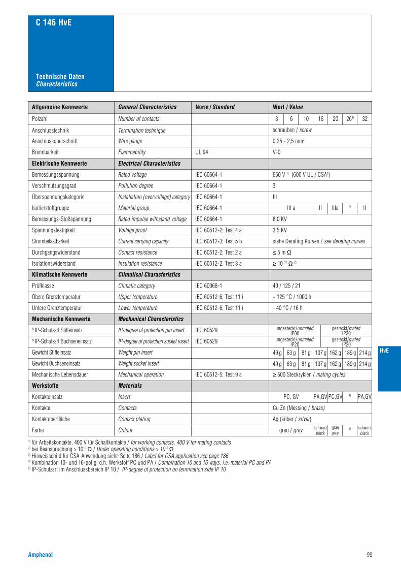
HvE
Norm / Standard Wert / ValueAllgemeine Kennwerte
Polzahl Number of contacts
Anschlusstechnik Termination technique
V-0
schrauben / screw
Anschlussquerschnitt Wire gauge 0,25 - 2,5 mm2
3 6 10 16 20 264) 32
Flammability
C 146 HvE
UL 94Brennbarkeit
660 V 1) (600 V UL / CSA3)
3
III
III a II4)IIIaII
8,0 KV
3,5 KV
siehe Derating Kurven / see derating curves
≤ 5 m Ω
Electrical Characteristics
Rated voltage
Pollution degree
Installation (overvoltage) category
Material group
Rated impulse withstand voltage
Voltage proof
IEC 60664-1
IEC 60664-1
IEC 60664-1
IEC 60664-1
IEC 60664-1
IEC 60512-2; Test 4 a
IEC 60512-3; Test 5 b
IEC 60512-2; Test 2 a
IEC 60068-1
Current carrying capacity
Contact resistance
Climatical Characteristics
Climatic category 40 / 125 / 21
Elektrische Kennwerte
Bemessungsspannung
Verschmutzungsgrad
Überspannungskategorie
Isolierstoffgruppe
Bemessungs-Stoßspannung
Spannungsfestigkeit
Strombelastbarkeit
Durchgangswiderstand
≥ 10 12 Ω 2)IEC 60512-2; Test 3 aInsulation resistanceIsolationswiderstand
Klimatische Kennwerte
Prüfklasse
IEC 60512-6; Test 11 iUpper temperature + 125 °C / 1000 hObere Grenztemperatur
IEC 60512-6; Test 11 iLower temperature - 40 °C / 16 hUntere Grenztemperatur
Mechanical Characteristics
grau / grey schwarzblack
schwarzblack
Insert
Contacts
Contact plating
PC, GV PA,GV PC,GV
graugrey
4)
4)
PA,GV
Cu Zn (Messing / brass)
Ag (silber / silver)
IEC 60512-5; Test 9 a
Weight pin insert
Weight socket insert
Mechanical operation
49 g 63 g 81 g 107 g 162 g 189 g 214 g
≥ 500 Steckzyklen / mating cycles
Mechanische Kennwerte
Gewicht Stifteinsatz
Gewicht Buchseneinsatz
Mechanische Lebensdauer
Werkstoffe
Kontakteinsatz
Kontakte
Kontaktoberfläche
Farbe
1) für Arbeitskontakte, 400 V für Schaltkontakte / for working contacts, 400 V for mating contacts2) bei Beanspruchung > 1010 Ω / Under operating conditions > 1010 Ω3) Hinweisschild für CSA-Anwendung siehe Seite 186 / Label for CSA application see page 1864) Kombination 10- und 16-polig; d.h. Werkstoff PC und PA / Combination 10 and 16 ways, i.e. material PC and PA5) IP-Schutzart im Anschlussbereich IP 10 / IP-degree of protection on termination side IP 10
Colour
Materials
General Characteristics
Technische DatenCharacteristics
49 g 63 g 81 g 107 g 162 g 189 g 214 g
Amphenol 99
IEC 60529IP-degree of protection pin insert ungesteckt/unmatedIP00
gesteckt/matedIP20
gesteckt/matedIP20
ungesteckt/unmatedIP20
5) IP-Schutzart Stifteinsatz
IEC 60529IP-degree of protection socket insert5) IP-Schutzart Buchseneinsatz
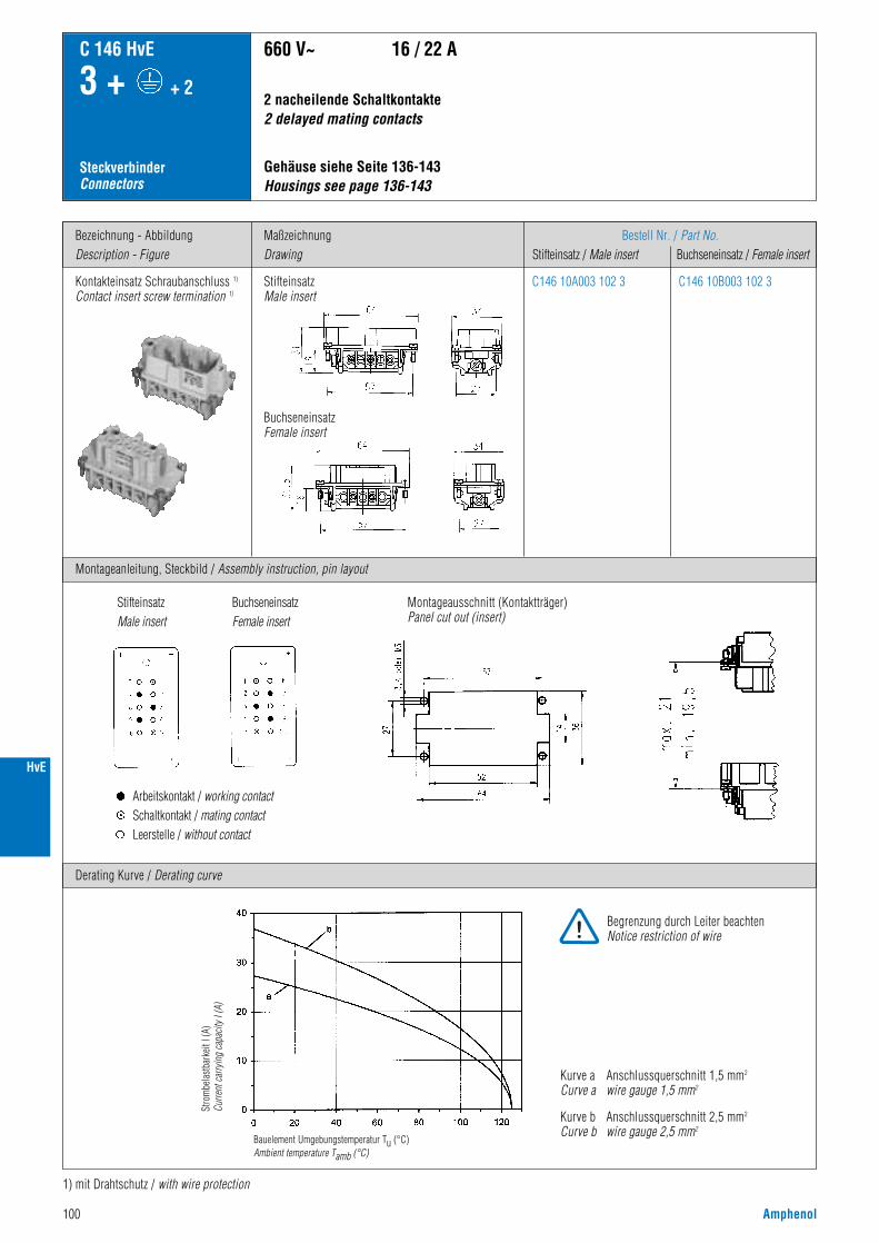
100 Amphenol
Bezeichnung - AbbildungDescription - Figure
Montageanleitung, Steckbild / Assembly instruction, pin layout
MaßzeichnungDrawing
Bestell Nr. / Part No.Stifteinsatz / Male insert Buchseneinsatz / Female insert
C 146 HvE
3 + + 2
SteckverbinderConnectors
Kontakteinsatz Schraubanschluss 1)
Contact insert screw termination 1)
Gehäuse siehe Seite 136-143 Housings see page 136-143
660 V~ 16 / 22 A
C146 10A003 102 3 C146 10B003 102 3
Derating Kurve / Derating curve
1) mit Drahtschutz / with wire protection
2 nacheilende Schaltkontakte 2 delayed mating contacts
Kurve a Anschlussquerschnitt 1,5 mm2
Curve a wire gauge 1,5 mm2
Kurve b Anschlussquerschnitt 2,5 mm2
Curve b wire gauge 2,5 mm2
StifteinsatzMale insert
BuchseneinsatzFemale insert
Stro
mbe
last
bark
eit I
(A)
Curre
nt ca
rryin
g ca
pacit
y I (A
)
Bauelement Umgebungstemperatur Tu (°C)Ambient temperature Tamb (°C)
Montageausschnitt (Kontaktträger)Panel cut out (insert)
StifteinsatzMale insert
BuchseneinsatzFemale insert
Arbeitskontakt / working contactSchaltkontakt / mating contactLeerstelle / without contact
Begrenzung durch Leiter beachtenNotice restriction of wire
HvE
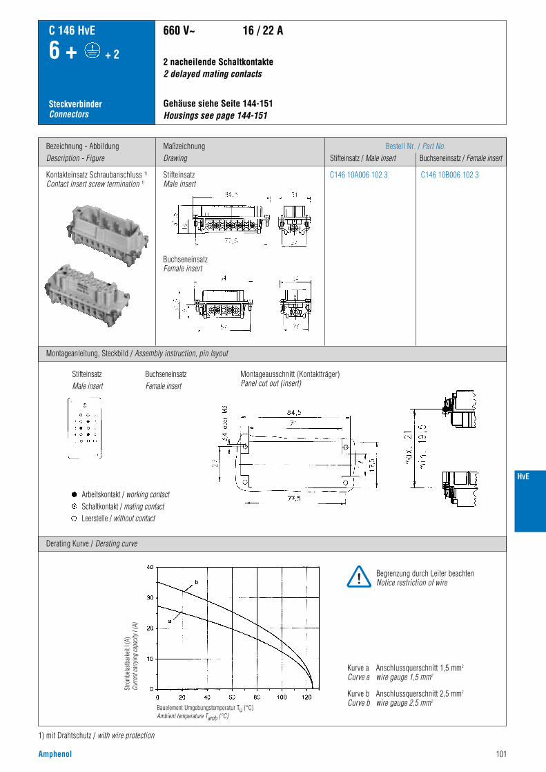
HvE
Amphenol 101
Bezeichnung - AbbildungDescription - Figure
Montageanleitung, Steckbild / Assembly instruction, pin layout
MaßzeichnungDrawing
Bestell Nr. / Part No.Stifteinsatz / Male insert Buchseneinsatz / Female insert
C 146 HvE
6 + + 2
SteckverbinderConnectors
Kontakteinsatz Schraubanschluss 1)
Contact insert screw termination 1)
Gehäuse siehe Seite 144-151Housings see page 144-151
660 V~ 16 / 22 A
C146 10A006 102 3 C146 10B006 102 3
Derating Kurve / Derating curve
1) mit Drahtschutz / with wire protection
2 nacheilende Schaltkontakte 2 delayed mating contacts
Kurve a Anschlussquerschnitt 1,5 mm2
Curve a wire gauge 1,5 mm2
Kurve b Anschlussquerschnitt 2,5 mm2
Curve b wire gauge 2,5 mm2
StifteinsatzMale insert
BuchseneinsatzFemale insert
Stro
mbe
last
bark
eit I
(A)
Curre
nt ca
rryin
g ca
pacit
y I (A
)
Bauelement Umgebungstemperatur Tu (°C)Ambient temperature Tamb (°C)
Montageausschnitt (Kontaktträger)Panel cut out (insert)
StifteinsatzMale insert
BuchseneinsatzFemale insert
Arbeitskontakt / working contactSchaltkontakt / mating contactLeerstelle / without contact
Begrenzung durch Leiter beachtenNotice restriction of wire

102 Amphenol
Bezeichnung - AbbildungDescription - Figure
Montageanleitung, Steckbild / Assembly instruction, pin layout
MaßzeichnungDrawing
Bestell Nr. / Part No.Stifteinsatz / Male insert Buchseneinsatz / Female insert
C 146 HvE
10 + + 2
SteckverbinderConnectors
Kontakteinsatz Schraubanschluss 1)
Contact insert screw termination 1)
Gehäuse siehe Seite 152-159Housings see page 152-159
2 nacheilende Schaltkontakte 2 delayed mating contacts
660 V~ 16 / 22 A
C146 10A010 102 3 C146 10B010 102 3
Derating Kurve / Derating curve
1) mit Drahtschutz / with wire protection
Kurve a Anschlussquerschnitt 1,5 mm2
Curve a wire gauge 1,5 mm2
Kurve b Anschlussquerschnitt 2,5 mm2
Curve b wire gauge 2,5 mm2
StifteinsatzMale insert
BuchseneinsatzFemale insert
Stro
mbe
last
bark
eit I
(A)
Curre
nt ca
rryin
g ca
pacit
y I (A
)
Bauelement Umgebungstemperatur Tu (°C)Ambient temperature Tamb (°C)
Montageausschnitt (Kontaktträger)Panel cut out (insert)
StifteinsatzMale insert
BuchseneinsatzFemale insert
Arbeitskontakt / working contactSchaltkontakt / mating contactLeerstelle / without contact
Begrenzung durch Leiter beachtenNotice restriction of wire
HvE

HvE
Amphenol 103
Bezeichnung - AbbildungDescription - Figure
Montageanleitung, Steckbild / Assembly instruction, pin layout
MaßzeichnungDrawing
Bestell Nr. / Part No.Stifteinsatz / Male insert Buchseneinsatz / Female insert
C 146 HvE
16 + + 2
SteckverbinderConnectors
Kontakteinsatz Schraubanschluss 1)
Contact insert screw termination 1)
2 nacheilende Schaltkontakte 2 delayed mating contacts
660 V~ 16 / 22 A
C146 10A016 102 3
C146 10A016 002 3(ohne Drahtschutzwithout wire protection)
C146 10B016 102 3
C146 10B016 002 3(ohne Drahtschutzwithout wire protection)
Derating Kurve / Derating curve
1) mit Drahtschutz / with wire protection
Kurve a Anschlussquerschnitt 1,5 mm2
Curve a wire gauge 1,5 mm2
Kurve b Anschlussquerschnitt 2,5 mm2
Curve b wire gauge 2,5 mm2
Gehäuse siehe Seite 164-165Housings see page 164-165
StifteinsatzMale insert
BuchseneinsatzFemale insert
Stro
mbe
last
bark
eit I
(A)
Curre
nt ca
rryin
g ca
pacit
y I (A
)
Bauelement Umgebungstemperatur Tu (°C)Ambient temperature Tamb (°C)
Montageausschnitt (Kontaktträger)Panel cut out (insert)
StifteinsatzMale insert
BuchseneinsatzFemale insert
Arbeitskontakt / working contactSchaltkontakt / mating contact
Begrenzung durch Leiter beachtenNotice restriction of wire

104 Amphenol
Bezeichnung - AbbildungDescription - Figure
Maßzeichnung / DrawingStifteinsatz / Male insert Buchseneinsatz / Female insert
Bestell Nr. / Part No.Stifteinsatz / Male insert Buchseneinsatz / Female insert
C 146 HvE
20 + + 4
26 + + 4
32 + + 4SteckverbinderConnectors
Gehäuse siehe Seite 160–163Housings see page 160–163
4 nacheilende Schaltkontakte 4 delayed mating contacts
660 V~ 16 / 22 A
1) mit Drahtschutz / with wire protection
Kontakteinsätze Schraubanschluss 1)
Contact inserts screw termination 1)
20 + + 4
C146 10A010 102 3(1 - 24)+C146 10A010 104 3(25 - 48)
C146 10B010 102 3(1 - 24)+C146 10B010 104 3(25 - 48)
Kontakteinsätze Schraubanschluss 1)
Contact inserts screw termination 1)
26 + + 4
Kontakteinsätze Schraubanschluss 1)
Contact inserts screw termination 1)
32 + + 4
C146 10A010 102 3(1 - 24)+C146 10A016 102 3(1 - 16)
C146 10A016 102 3(1 - 16)+C146 10A016 104 3(17 - 32)
C146 10A010 102 3(1 - 24)+C146 10B016 102 3(1 - 16)
C146 10B016 102 3(1 - 16)+C146 10B016 104 3(17 - 32)
Arbeitskontakt / working contactSchaltkontakt / mating contactLeerstelle / without contact
Arbeitskontakt / working contactSchaltkontakt / mating contactLeerstelle / without contact
Arbeitskontakt / working contactSchaltkontakt / mating contact
HvE

Amphenol 105
C 146 S
• Bemessungsspannung 125 - 600 V• Bemessungsstrom 10 A ... 70 A• Anschlussart: crimpen, schrauben, löten• Polzahl: 4, 57
• Rated voltage 125 - 600 V• Rated current 10 A ... 70 A• Termination: crimping, screw, solder• Number of contacts: 4, 57
Hauptmerkmale Main characteristics
Zulassungen / ApprovalsPrüfstelle / Testhouse Kennwerte / Characteristics Zulassungs-Nummer / Approval-No.
UL 600 V, 40 A (4 pol + PE / 4 contacts + PE) E 63093
CSA 600 V, 40 A (4 pol + PE / 4 contacts + PE) 48932
Zulassungen beziehen sich im allgemeinen auf repräsentativeAusführungen der Steckverbinderserie. Prüfumfang undPrüfvorschrift auf Anfrage.
In general approvals refer to representative versions of the connectorseries. Extent and specification of tests upon request.
S
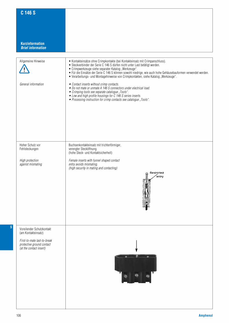
106 Amphenol
KurzinformationBrief information
C 146 S
Allgemeine Hinweise
General information
• Kontakteinsätze ohne Crimpkontakte (bei Kontakteinsatz mit Crimpanschluss).• Steckverbinder der Serie C 146 S dürfen nicht unter Last betätigt werden.• Crimpwerkzeuge siehe separater Katalog „Werkzeuge“.• Für die Einsätze der Serie C 146 S können sowohl niedrige, wie auch hohe Gehäusebauformen verwendet werden.• Verarbeitungs- und Montagehinweise von Crimpkontakten, siehe Katalog „Werkzeuge“.
• Contact inserts without crimp contacts.• Do not mate or unmate A 146 S connectors under electrical load.• Crimping tools see separate catalogue „Tools“.• Low and high profile housings for C 146 S series inserts.• Processing instruction for crimp contacts see catalogue „Tools“.
Hoher Schutz vorFehlsteckungen
High protectionagainst mismating
Buchsenkontakteinsatz mit trichterförmiger,verengter Stecköffnung.(hohe Steck- und Kontaktsicherheit)
Female inserts with funnel shaped contact entry avoids mismating.(high security in mating and contacting)
Voreilender Schutzkontakt(am Kontakteinsatz)
First-to-mate last-to-breakprotective ground contact(at the contact insert)
S

Amphenol 107
Norm / Standard Wert / ValueAllgemeine Kennwerte
Polzahl Number of contacts
Anschlusstechnik Termination technique schraubenscrew
lötensolder
crimpencrimp
Anschlussquerschnitt
Maximaler Leiterquerschnitt
Max. wire gauge
Schutzart Protection class
Max. wire diameter – – 3,5 mm
Brennbarkeit Flammability V-O V-1 V-1UL 94
4 + 57 + 57 +
16 mm2
IP 54
1,5 mm2 2,5 mm2
630 V 200 V 150 V
I III a
4,0 kV 3,0 kV
1,6 kV 1,4 kV
≥ 10 10 Ω ≥ 10 10 Ω
C 146 S
PA GV DAP PPO
Ag Ag
grau / grey
> 500 Steckzyclen / mating cycles
CuZn (Messing/brass)
Ag
3
II
6,0 kV
3,5 kV
siehe Derating Kurven / see derating curves
< 5 m Ω
IEC 60664-1
IEC 60664-1
IEC 60664-1
IEC 60664-1
IEC 60512-2; Test 4 a
IEC 60512-2
IEC 60512-2
IEC 60068-1
IEC 60529
40 / 125 / 56
≤ 70 N ≤ 200 N ≤ 250 N
150 g 205 g 60 g
170 g 95 g 55 g
25 / 85 /21 40 / 125 / 21
≥ 10 10 ΩIEC 60512-2
IEC 60664-1 6,4 mm 2 mm 1,6 mm
9,5 mm 2,5 mm 3 mmIEC 60664-1
Electrical Characteristics
Rated voltage
Pollution degree
Material group
Rated impulse withstand voltage
Voltage proof
Current carrying capacity
Contact resistance
Climatical Characteristics
Climatic category
Mechanical Characteristics
Insertion and withdrawal forces
Weight Male insert
Weight Female insert
Insert
Insulation resistance
Clearance
Creepage
Mechanical operation
Screw contacts
Contakt plating
Elektrische Kennwerte
Bemessungsspannung
Verschmutzungsgrad
Isolierstoffgruppe
Bemessungs-Stoßspannung
Spannungsfestigkeit
Strombelastbarkeit
Durchgangswiderstand
Isolationswiderstand
Luftstrecke
Kriechstrecke
Klimatische Kennwerte
Prüfklasse
Mechanische Kennwerte
Gesamt Steck- und Ziehkraft
Gewicht Stifteinsatz
Gewicht Buchseneinsatz
Mechanische Lebensdauer
Werkstoffe
Kontakteinsatz
Schraubkontakte
CuZn (Messing/brass)Male crimp contactsCrimpkontakt Stift
CuSn (Zinnbronze / Tin bronce)Female crimp contactsCrimpkontakt Buchse
Kontaktoberfläche
Farbe Colour
Aluminium Druckguss / Aluminium die castGehäuse Housings
Neoprene / NeopreneDichtgummi Rubber gasket
Materials
General Characteristics
Technische DatenCharacteristics
IEC 60529IP-degree of protection pin insert ungesteckt/unmatedIP00
gesteckt/matedIP20
gesteckt/matedIP20
ungesteckt/unmatedIP20
1) IP-Schutzart Stifteinsatz
IEC 60529IP-degree of protection socket insert1) IP-Schutzart Buchseneinsatz
1) IP-Schutzart im Anschlussbereich der Schraub-/Lötausführung IP 00IP-degree of protection on termination side of screw/solder version IP 00
S

108 Amphenol
Bezeichnung - AbbildungDescription - Figure
Steckbild / Pin layout
MaßzeichnungDrawing
Bestell Nr. / Part No.Stifteinsatz / Male insert Buchseneinsatz / Female insert
C 146 S
4 +
SteckverbinderConnectors
Kontakteinsatz Schraubanschlussmit DrahtschutzContact insert screw terminationwith wire protection
StifteinsatzMale insert
BuchseneinsatzFemale insert
Gehäuse siehe Seite 112 Housings see page 112
500 V~ 70 A
Derating Kurven / Derating curves
C146 10A004 102 6 C146 10B004 102 6
Anschlussquerschnitt 16 mm2
Wire gauge 16 mm2
StifteinsatzMale insert
BuchseneinsatzFemale insert
Stro
mbe
last
bark
eit I
(A)
Curre
nt ca
rryin
g ca
pacit
y I (A
)
Bauelement Umgebungstemperatur Tu (°C)Ambient temperature Tamb (°C)
S

Amphenol 109
S
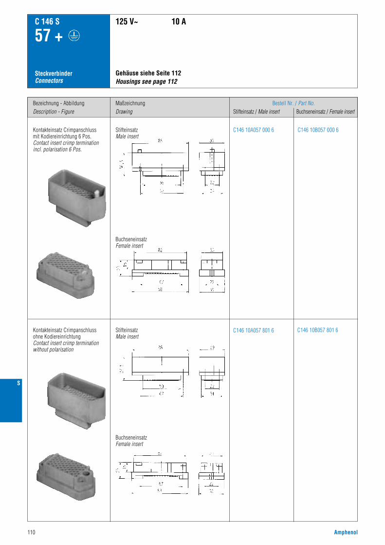
110 Amphenol
Bezeichnung - AbbildungDescription - Figure
MaßzeichnungDrawing
Bestell Nr. / Part No.Stifteinsatz / Male insert Buchseneinsatz / Female insert
C 146 S
57 +
SteckverbinderConnectors
Kontakteinsatz Crimpanschlussmit Kodiereinrichtung 6 Pos.Contact insert crimp terminationincl. polarisation 6 Pos.
125 V~ 10 A
C146 10A057 000 6 C146 10B057 000 6
Kontakteinsatz Crimpanschlussohne KodiereinrichtungContact insert crimp terminationwithout polarisation
C146 10A057 801 6 C146 10B057 801 6
StifteinsatzMale insert
BuchseneinsatzFemale insert
BuchseneinsatzFemale insert
Gehäuse siehe Seite 112 Housings see page 112
StifteinsatzMale insert
S
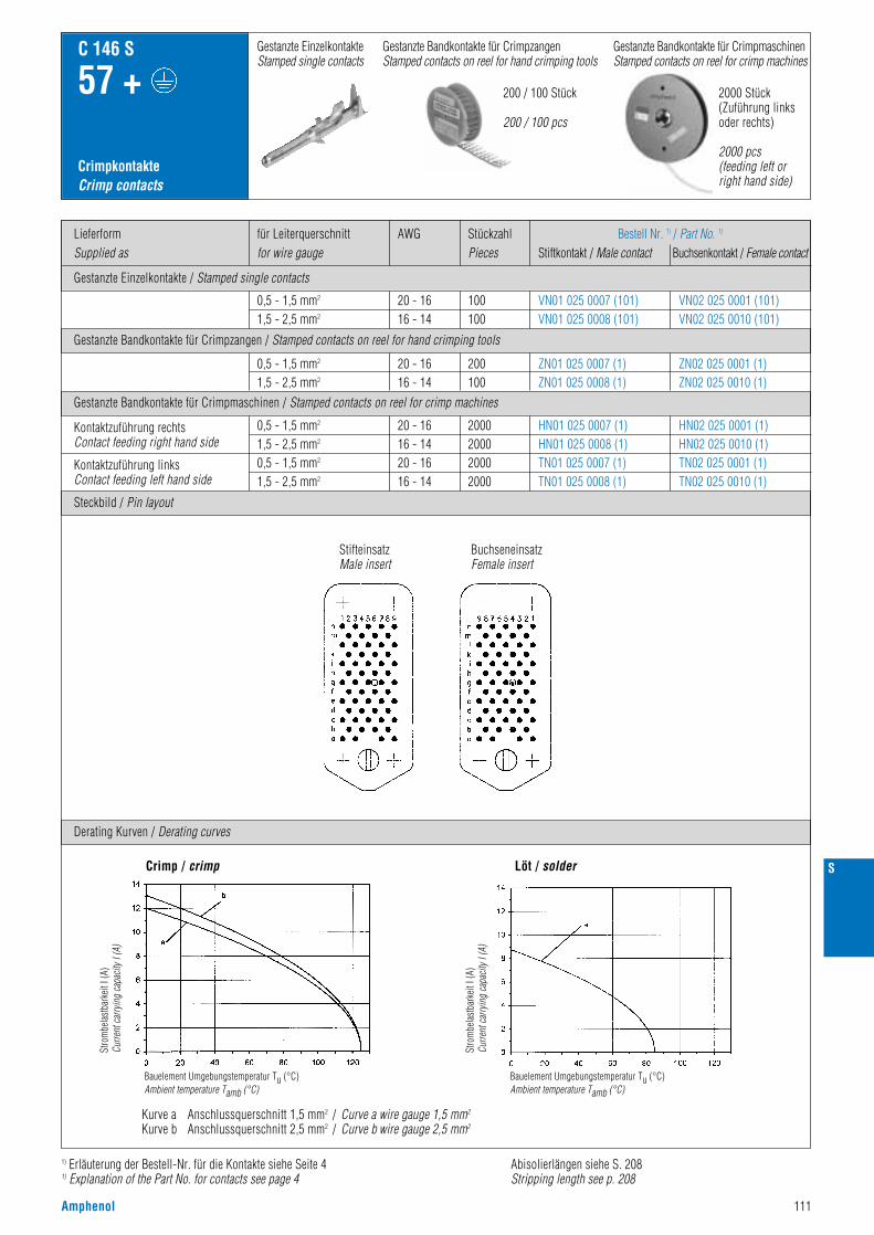
Amphenol 111
1) Erläuterung der Bestell-Nr. für die Kontakte siehe Seite 41) Explanation of the Part No. for contacts see page 4
Gestanzte Einzelkontakte / Stamped single contacts
Gestanzte Bandkontakte für Crimpzangen / Stamped contacts on reel for hand crimping tools
Gestanzte Bandkontakte für Crimpmaschinen / Stamped contacts on reel for crimp machines
LieferformSupplied as
AWGfür Leiterquerschnittfor wire gauge
StückzahlPieces
Bestell Nr. 1) / Part No. 1)
Stiftkontakt / Male contact Buchsenkontakt / Female contact
CrimpkontakteCrimp contacts
C 146 S
57 +
0,5 - 1,5 mm2
1,5 - 2,5 mm2
0,5 - 1,5 mm2
1,5 - 2,5 mm2
0,5 - 1,5 mm2
1,5 - 2,5 mm2
0,5 - 1,5 mm2
1,5 - 2,5 mm2
20 - 1616 - 1420 - 1616 - 14
20 - 1616 - 14
20 - 1616 - 14
2000200020002000
200100
100100
HN01 025 0007 (1)HN01 025 0008 (1)TN01 025 0007 (1)TN01 025 0008 (1)
ZN01 025 0007 (1)ZN01 025 0008 (1)
VN01 025 0007 (101)VN01 025 0008 (101)
HN02 025 0001 (1)HN02 025 0010 (1)TN02 025 0001 (1)TN02 025 0010 (1)
ZN02 025 0001 (1)ZN02 025 0010 (1)
VN02 025 0001 (101)VN02 025 0010 (101)
Kontaktzuführung rechtsContact feeding right hand side
Kontaktzuführung linksContact feeding left hand side
Steckbild / Pin layout
Derating Kurven / Derating curves
Crimp / crimp Löt / solder
Gestanzte Bandkontakte für CrimpmaschinenStamped contacts on reel for crimp machines
200 / 100 Stück
200 / 100 pcs
2000 Stück(Zuführung linksoder rechts)
2000 pcs(feeding left orright hand side)
Gestanzte EinzelkontakteStamped single contacts
Gestanzte Bandkontakte für CrimpzangenStamped contacts on reel for hand crimping tools
Kurve a Anschlussquerschnitt 1,5 mm2 / Curve a wire gauge 1,5 mm2
Kurve b Anschlussquerschnitt 2,5 mm2 / Curve b wire gauge 2,5 mm2
Stro
mbe
last
bark
eit I
(A)
Curre
nt ca
rryin
g ca
pacit
y I (A
)
Bauelement Umgebungstemperatur Tu (°C)Ambient temperature Tamb (°C)
Stro
mbe
last
bark
eit I
(A)
Curre
nt ca
rryin
g ca
pacit
y I (A
)
Bauelement Umgebungstemperatur Tu (°C)Ambient temperature Tamb (°C)
StifteinsatzMale insert
BuchseneinsatzFemale insert
Abisolierlängen siehe S. 208Stripping length see p. 208
S
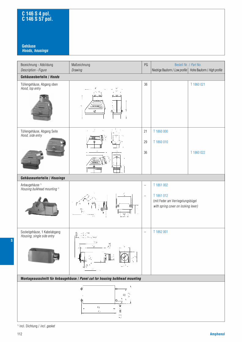
112 Amphenol
Gehäuseoberteile / Hoods
Bezeichnung - AbbildungDescription - Figure
MaßzeichnungDrawing
PG Bestell Nr. / Part No.Niedrige Bauform / Low profile Hohe Bauform / High profile
36 T 1860 021
Gehäuse Hoods, housings
C 146 S 4 pol.C 146 S 57 pol.
Gehäuseunterteile / Housings
Montageausschnitt für Anbaugehäuse / Panel cut for housing bulkhead mounting
Tüllengehäuse, Abgang obenHood, top entry
21
29
36
T 1860 000
T 1860 010
T 1860 022
Tüllengehäuse, Abgang SeiteHood, side entry
–
–
–
T 1862 001
T 1861 002
T 1861 012(mit Feder am Verriegelungsbügelwith spring cover on locking lever)
Anbaugehäuse 1)
Housing bulkhead mounting 1)
Sockelgehäuse, 1 KabelabgangHousing, single side entry
1) incl. Dichtung / incl. gasket
S

Amphenol 113
C 146 Gehäuse / Housings
• C 146 D / DD• C 146 E• C 146 M• C 146 A• C 146 HSE• C 146 HvE
• C 146 D / DD• C 146 E• C 146 M• C 146 A• C 146 HSE• C 146 HvE
Für Serien For series
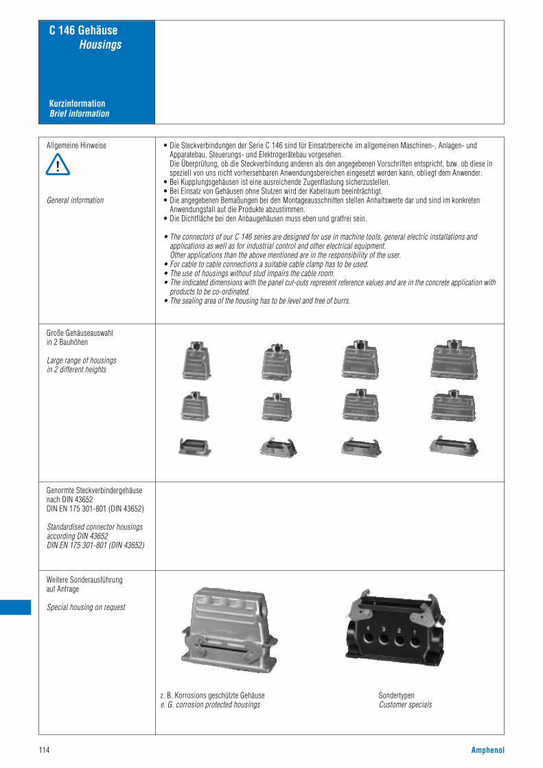
114 Amphenol
KurzinformationBrief information
C 146 GehäuseHousings
Allgemeine Hinweise
General information
• Die Steckverbindungen der Serie C 146 sind für Einsatzbereiche im allgemeinen Maschinen-, Anlagen- undApparatebau, Steuerungs- und Elektrogerätebau vorgesehen.Die Überprüfung, ob die Steckverbindung anderen als den angegebenen Vorschriften entspricht, bzw. ob diese inspeziell von uns nicht vorhersehbaren Anwendungsbereichen eingesetzt werden kann, obliegt dem Anwender.
• Bei Kupplungsgehäusen ist eine ausreichende Zugentlastung sicherzustellen.• Bei Einsatz von Gehäusen ohne Stutzen wird der Kabelraum beeinträchtigt.• Die angegebenen Bemaßungen bei den Montageausschnitten stellen Anhaltswerte dar und sind im konkreten
Anwendungsfall auf die Produkte abzustimmen.• Die Dichtfläche bei den Anbaugehäusen muss eben und gratfrei sein.
• The connectors of our C 146 series are designed for use in machine tools, general electric installations andapplications as well as for industrial control and other electrical equipment.Other applications than the above mentioned are in the responsibility of the user.
• For cable to cable connections a suitable cable clamp has to be used.• The use of housings without stud impairs the cable room.• The indicated dimensions with the panel cut-outs represent reference values and are in the concrete application with
products to be co-ordinated.• The sealing area of the housing has to be level and free of burrs.
Große Gehäuseauswahlin 2 Bauhöhen
Large range of housingsin 2 different heights
Genormte Steckverbindergehäusenach DIN 43652 DIN EN 175 301-801 (DIN 43652)
Standardised connector housingsaccording DIN 43652 DIN EN 175 301-801 (DIN 43652)
Weitere Sonderausführung auf Anfrage
Special housing on request
z. B. Korrosions geschützte Gehäusee. G. corrosion protected housings
SondertypenCustomer specials

Amphenol 115
Norm / Standard Wert / ValueAllgemeine Kennwerte
Schutzart Gehäuse Protection class housing
Schutzart Klappdeckelverriegeltunverriegelt
Protetion class spring coverlockedspring loaded
IP 65IP 54
IP 65
C 146 GehäuseHousings
Verriegelungssystem Locking system DIN EN 175 301-801(DIN 43 652)
1 Längsbügel / 1 locking lever
2 Querbügel / 2 locking levers
IEC 60068-1
Climatical Characteristics
Climatic category 40 / 100 / 21
Klimatische Kennwerte
Prüfklasse
IEC 60068-1Temperature range - 40 °C / + 100 °CTemperaturbereich
IEC 60512-6; Test 11 iUpper temperature + 100 °C / 1000 hObere Grenztemperatur
IEC 60512-6; Test 11 iLower temperature - 40 °C / 16 hUntere Grenztemperatur
Mechanical Characteristics
Zink-Druckguss / Zinc die cast alloy
Housings
Thermoplastic housing
≥ 500 Zyklen / cycles
Aluminium-Druckguss
Aluminium die cast alloy
PA
IEC 60512-5; Test 9 aMechanical operation
Mechanische Kennwerte
Mechanische Lebensdauer
Werkstoffe
Gehäuse
Kunststoffgehäuse
Metallgehäuse D 7 Metal housing D 7
PASchutzkappe Protective cover
NBRDichtgummi Rubber gasket
Stahl / verzinkt steel / zinc coatedVerriegelung Locking lever
Spezialbeschichtung / special surfaceOberfläche EMV Gehäuse Surface EMV housings
Materials
General Characteristics
Technische DatenCharacteristics
DIN EN 175 301-801(DIN 43 652)

116 Amphenol
Gehäuseoberteile / Hoods
Bezeichnung - AbbildungDescription - Figure
MaßzeichnungDrawing
PG Bestell Nr.Part No.
11 C146 10G003 600 4
C 146 D 7 pol.C 146 A 3/4 pol.
Gehäuse KunststoffHousings thermoplastic
11 C146 10G003 500 4Tüllengehäuse, seitlicher KabelausgangHood, side entry
– C146 10F003 000 4Anbaugehäuse (incl. Flachdichtung)Housing bulkhead mounting(incl. gasket)
– C146 10F003 004 4
11 C146 10F003 500 4Sockelgehäuse, 1 KabelausgangHousing, single side entry
11
–
C146 10G003 804 4
C146 10Z003 100 4
Montageausschnitt/panel cut out: 22 x 22 mm
Montageausschnitt/panel cut out: 22 x 22 mm
Montageausschnitt/panel cut out: 22 x 22 mm
Anbaugehäuse (incl. Flachdichtung)Housing bulkhead end mounting(incl. gasket)
Kupplungsgehäuse, 1 KabelausgangHood, cable to cable coupling
Schutzkappe für Gehäuseunterteile(nur in Verbindung mit Stifteinsatz)Cover for housings(only in connection with male insert)
PG-GewindePG-thread
Tüllengehäuse, gerader KabelausgangHood, top entry
Gehäuseunterteile / Housings
Schutzkappen / Protective cover

Amphenol 117
Gehäuseoberteile / Hoods
Bezeichnung - AbbildungDescription - Figure
MaßzeichnungDrawing
M Bestell Nr. / Part No.mit Stutzen / with stud ohne Stutzen / without stud
20
20
C146 10R003 600 4 (grau)
C146 16R003 600 4 (sw)
C 146 D 7 pol.C 146 A 3/4 pol.
Gehäuse KunststoffHousings thermoplastic
20
20
C146 10R003 500 4 (grau)
C146 16R003 500 4 (sw)
Tüllengehäuse, seitlicher KabelausgangHood, side entry
– C146 10F003 000 4 (grau)
C146 16F003 000 4 (sw)
Anbaugehäuse (incl. Flachdichtung)Housing bulkhead mounting(incl. gasket)
– C146 10F003 004 4
20
20
C146 10N003 500 4 (grau)mit Verschraubung/with gland bushing
C146 16N003 500 4 (sw)mit Verschraubung/with gland bushing
Sockelgehäuse, 1 KabelausgangHousing, single side entry
20
–
C146 10R003 804 4
C146 10Z003 100 4
Montageausschnitt/panel cut out: 22 x 22 mm
Montageausschnitt/panel cut out: 22 x 22 mm
Montageausschnitt/panel cut out: 22 x 22 mm
Anbaugehäuse (incl. Flachdichtung)Housing bulkhead end mounting(incl. gasket)
Kupplungsgehäuse, 1 KabelausgangHood, cable to cable coupling
Schutzkappe für Gehäuseunterteile(nur in Verbindung mit Stifteinsatz)Cover for housings(only in connection with male insert)
Metrisches GewindeMetric thread
Tüllengehäuse, gerader KabelausgangHood, top entry
Schutzkappen / Protective cover
Gehäuseunterteile / Housings

118 Amphenol
Gehäuseoberteile / Hoods
Bezeichnung - AbbildungDescription - Figure
MaßzeichnungDrawing
PG
11
C 146 D 7 pol.C 146 A 3/4 pol.
Gehäuse MetallHousings metal
11Tüllengehäuse, seitlicher KabelausgangHood, side entry
–Anbaugehäuse (incl. Flachdichtung)Housing bulkhead mounting(incl. gasket)
–Anbaugehäuse (incl. Flachdichtung)Housing bulkhead end mounting(incl. gasket)
11Sockelgehäuse, 1 KabelausgangHousing, single side entry
11
– C146 30Z003 100 4
Kupplungsgehäuse, 1 KabelausgangHood, cable to cable coupling
C146 30G003 600 4
C146 30G003 500 4
C146 30F003 000 4
C146 30F003 004 4
C146 30F003 500 4
C146 30G003 804 4
Verschraubung für Tüllen- und Sockelgehäuse siehe Seite 180 - 183 / gland bushings for hoods and housing see page 180-183
Tüllengehäuse, gerader KabelausgangHood, top entry
Schutzkappe für Gehäuseunterteile(nur in Verbindung mit Stifteinsatz)Cover for housings(only in connection with male insert)
Bestell Nr.Part No.
Gehäuseunterteile / Housings
Schutzkappen / Protective cover
PG-GewindePG-thread

Amphenol 119
Gehäuseoberteile / Hoods
Bezeichnung - AbbildungDescription - Figure
MaßzeichnungDrawing
M
20
C 146 D 7 pol.C 146 A 3/4 pol.
Gehäuse Metall (metrisch)Housings metal (metric)
20Tüllengehäuse, seitlicher KabelausgangHood, side entry
–Anbaugehäuse (incl. Flachdichtung)Housing bulkhead mounting(incl. gasket)
–Anbaugehäuse (incl. Flachdichtung)Housing bulkhead end mounting(incl. gasket)
20Sockelgehäuse, 1 KabelausgangHousing, single side entry
20
– C146 30Z003 100 4
Kupplungsgehäuse, 1 KabelausgangHood, cable to cable coupling
C146 30R003 600 4
C146 30R003 500 4
C146 30F003 000 4
C146 30F003 004 4
C146 30N003 500 4 C146 31N003 500 4
C146 30R003 804 4
Tüllengehäuse, gerader KabelausgangHood, top entry
Schutzkappe für Gehäuseunterteile(nur in Verbindung mit Stifteinsatz)Cover for housings(only in connection with male insert)
Gehäuseunterteile / Housings
Schutzkappen / Protective cover
Bestell Nr. / Part No.mit Stutzen / with stud ohne Stutzen / without stud
Metrisches GewindeMetric thread

120 Amphenol
Gehäuseoberteile / Hoods
Bezeichnung - AbbildungDescription - Figure
MaßzeichnungDrawing
PG
13,5
16
16
21
C146 10G010 600 4
C146 10G010 601 4
C146 10G015 601 2
C146 10G015 600 2
Gehäuse Housings
C 146 D 15 pol.C 146 A 10 pol.
Tüllengehäuse, Abgang obenHood, top entry
13,5
16
16
21
C146 10G010 501 4
C146 10G010 500 4
C146 10G015 501 2
C146 10G015 500 2
Tüllengehäuse, Abgang SeiteHood, side entry
–
13,5
16
21
h
47,5
47,5
59
C146 10F015 000 2
C146 10G010 804 4
C146 10G010 805 4
C146 10G015 804 2
KupplungsgehäuseHood, coupling application
Anbaugehäuse 1)
Housing, bulkhead mounting
– C146 10F015 003 2Anbaugehäuse, mit Klappdeckel 1)
Housing, bulkhead mounting, with spring cover
nach DIN EN 175 301 - 801 (DIN 43 652)
1) incl. Flachdichtung / incl. gasket
PG-GewindePG-thread
Bestell Nr. / Part No.Niedrige Bauform/ Hohe Bauform/Low profile High profile
Gehäuseunterteile / Housings
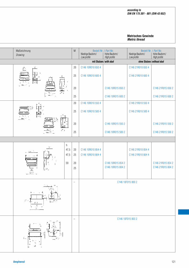
Amphenol 121
according to DIN EN 175 301 - 801 (DIN 43 652)
MaßzeichnungDrawing
20
25
20
25
C146 10R010 650 4
C146 10R010 600 4
C146 10R015 650 2
C146 10R015 600 2
C146 21R010 650 4
C146 21R010 600 4
C146 21R015 650 2
C146 21R015 600 2
20
25
20
25
C146 10R010 550 4
C146 10R010 500 4
C146 10R015 550 2
C146 10R015 500 2
C146 21R010 550 4
C146 21R010 500 4
C146 21R015 550 2
C146 21R015 500 2
–
20
25
20
25
h
47,5
47,5
59
C146 10F015 000 2
C146 10R010 854 4
C146 10R010 804 4
C146 10R015 854 2C146 10R015 804 2
C146 21R010 854 4
C146 21R010 804 4
C146 21R015 854 2C146 21R015 804 2
– C146 10F015 003 2
Metrisches GewindeMetric thread
M Bestell Nr. / Part No.Niedrige Bauform/ Hohe Bauform/Low profile High profile
Bestell Nr. / Part No.Niedrige Bauform/ Hohe Bauform/Low profile High profile
mit Stutzen /with stud ohne Stutzen /without stud
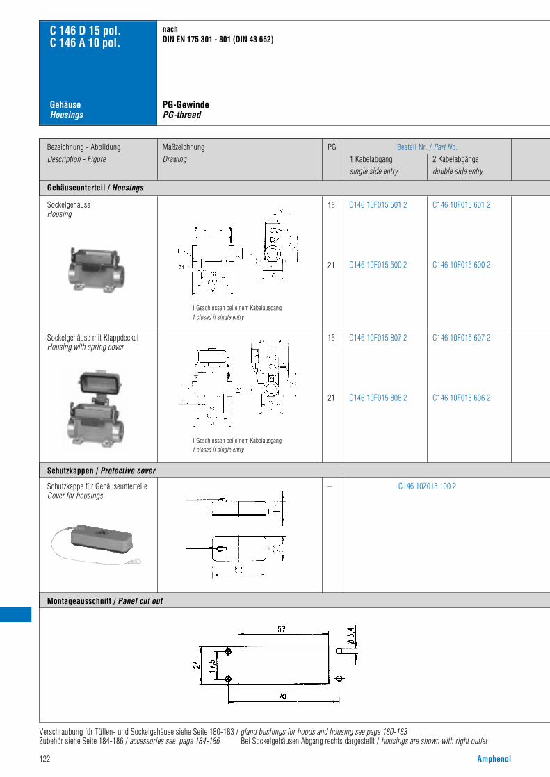
122 Amphenol
Gehäuseunterteil / Housings
Bezeichnung - AbbildungDescription - Figure
MaßzeichnungDrawing
PG Bestell Nr. / Part No.1 Kabelabgang 2 Kabelabgängesingle side entry double side entry
SockelgehäuseHousing
16
21
C146 10F015 601 2
C146 10F015 600 2
C146 10F015 501 2
C146 10F015 500 2
Sockelgehäuse mit KlappdeckelHousing with spring cover
16
21
C146 10F015 607 2
C146 10F015 606 2
C146 10F015 807 2
C146 10F015 806 2
– C146 10Z015 100 2
Gehäuse Housings
C 146 D 15 pol.C 146 A 10 pol.
Verschraubung für Tüllen- und Sockelgehäuse siehe Seite 180-183 / gland bushings for hoods and housing see page 180-183Zubehör siehe Seite 184-186 / accessories see page 184-186 Bei Sockelgehäusen Abgang rechts dargestellt / housings are shown with right outlet
nach DIN EN 175 301 - 801 (DIN 43 652)
Schutzkappe für GehäuseunterteileCover for housings
1 Geschlossen bei einem Kabelausgang1 closed if single entry
1 Geschlossen bei einem Kabelausgang1 closed if single entry
Montageausschnitt / Panel cut out
Schutzkappen / Protective cover
PG-GewindePG-thread
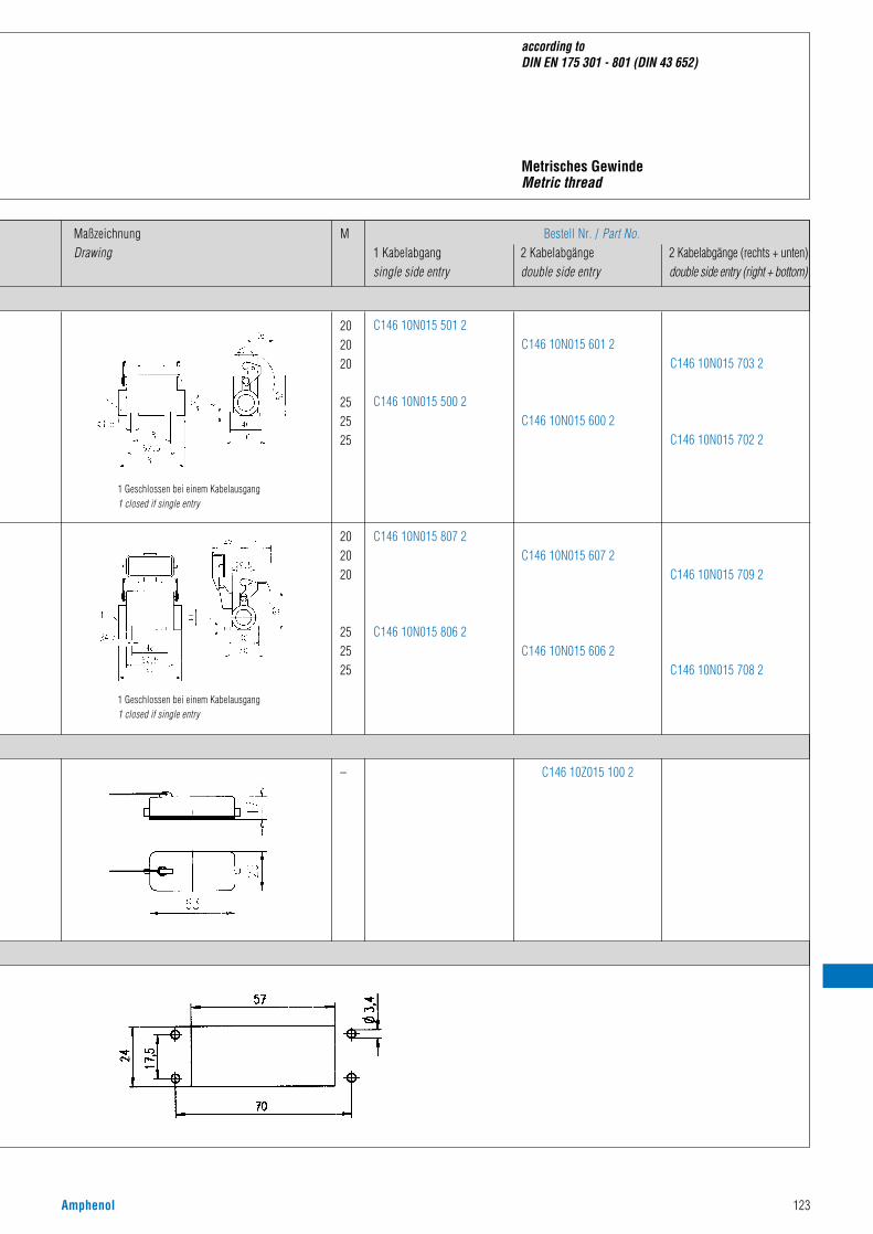
Amphenol 123
according to DIN EN 175 301 - 801 (DIN 43 652)
MaßzeichnungDrawing
M Bestell Nr. / Part No.1 Kabelabgang 2 Kabelabgänge 2 Kabelabgänge (rechts + unten)single side entry double side entry double side entry (right + bottom)
202020
252525
202020
252525
– C146 10Z015 100 2
1 Geschlossen bei einem Kabelausgang1 closed if single entry
1 Geschlossen bei einem Kabelausgang1 closed if single entry
C146 10N015 501 2
C146 10N015 500 2
C146 10N015 601 2
C146 10N015 600 2
C146 10N015 703 2
C146 10N015 702 2
C146 10N015 709 2
C146 10N015 708 2
C146 10N015 607 2
C146 10N015 606 2
C146 10N015 807 2
C146 10N015 806 2
Metrisches GewindeMetric thread

124 Amphenol
Gehäuseoberteile / Hoods
Bezeichnung - AbbildungDescription - Figure
MaßzeichnungDrawing
PG
16
16
21
C146 10G016 600 4
C146 10G025 601 2
C146 10G025 600 2
Gehäuse Housings
C 146 D 25 pol.C 146 A 16 pol.
Gehäuseunterteile / Housings
Tüllengehäuse, Abgang obenHood, top entry
13,5
16
16
21
C146 10G016 501 4
C146 10G016 500 4
C146 10G025 501 2
C146 10G025 500 2
Tüllengehäuse, Abgang SeiteHood, side entry
–
13,5
16
21
h
52,5
52,5
65
C146 10F025 000 2
C146 10G016 805 4
C146 10G016 804 4
C146 10G025 804 2
KupplungsgehäuseHood, coupling application
Anbaugehäuse 1)
Housing, bulkhead mounting
– C146 10F025 003 2Anbaugehäuse, mit Klappdeckel 1)
Housing, bulkhead mounting, with spring cover
1) incl. Flachdichtung / incl. gasket
nach DIN EN 175 301 - 801 (DIN 43 652)
Bestell Nr. / Part No.Niedrige Bauform/ Hohe Bauform/Low profile High profile
PG-GewindePG-thread

Amphenol 125
M
according to DIN EN 175 301 - 801 (DIN 43 652)
MaßzeichnungDrawing
20
25
20
25
C146 10R016 650 4
C146 10R016 600 4
C146 10R025 650 2
C146 10R025 600 2
C146 21R016 650 4
C146 21R016 600 4
C146 21R025 650 2
C146 21R025 600 2
20
25
20
25
C146 10R016 550 4
C146 10R016 500 4
C146 10R025 550 2
C146 10R025 500 2
C146 21R016 550 4
C146 21R016 500 4
C146 21R025 550 2
C146 21R025 500 2
–
20
25
20
25
h
52,5
65
52,5
65
C146 10F025 000 2
C146 10R016 854 4
C146 10R016 804 4
C146 10R025 854 2
C146 10R025 804 2
C146 21R016 854 4
C146 21R016 804 4
C146 21R025 854 2
C146 21R025 804 2
– C146 10F025 003 2
Bestell Nr. / Part No.Niedrige Bauform/ Hohe Bauform/Low profile High profile
Bestell Nr. / Part No.Niedrige Bauform/ Hohe Bauform/Low profile High profile
mit Stutzen /with stud ohne Stutzen /without stud
Metrisches GewindeMetric thread

126 Amphenol
Gehäuseunterteil / Housings
Bezeichnung - AbbildungDescription - Figure
MaßzeichnungDrawing
PG Bestell Nr. / Part No.1 Kabelabgang 2 Kabelabgängesingle side entry double side entry
SockelgehäuseHousing
16
21
C146 10F025 601 2
C146 10F025 600 2
C146 10F025 501 2
C146 10F025 500 2
Sockelgehäuse mit KlappdeckelHousing with spring cover
16
21
C146 10F025 607 2
C146 10F025 606 2
C146 10F025 807 2
C146 10F025 806 2
– C146 10Z025 100 2Schutzkappe für GehäuseunterteileCover for housings
Gehäuse Housings
C 146 D 25 pol.C 146 A 16 pol.
PG Verschraubung für Tüllen- und Sockelgehäuse siehe Seite 180-183 / PG gland bushings for hoods and housing see page 180-183Zubehör siehe Seite 184-186 / accessories see page 184-186 Bei Sockelgehäusen Abgang rechts dargestellt / housings are shown with right outlet
nach DIN 43 652 (CECC 75 301 - 801; EN 175 301 - 801)
1 Geschlossen bei einem Kabelausgang1 closed if single entry
1 Geschlossen bei einem Kabelausgang1 closed if single entry
85
Montageausschnitt / Panel cut out
Schutzkappen / Protective cover
PG-GewindePG-thread
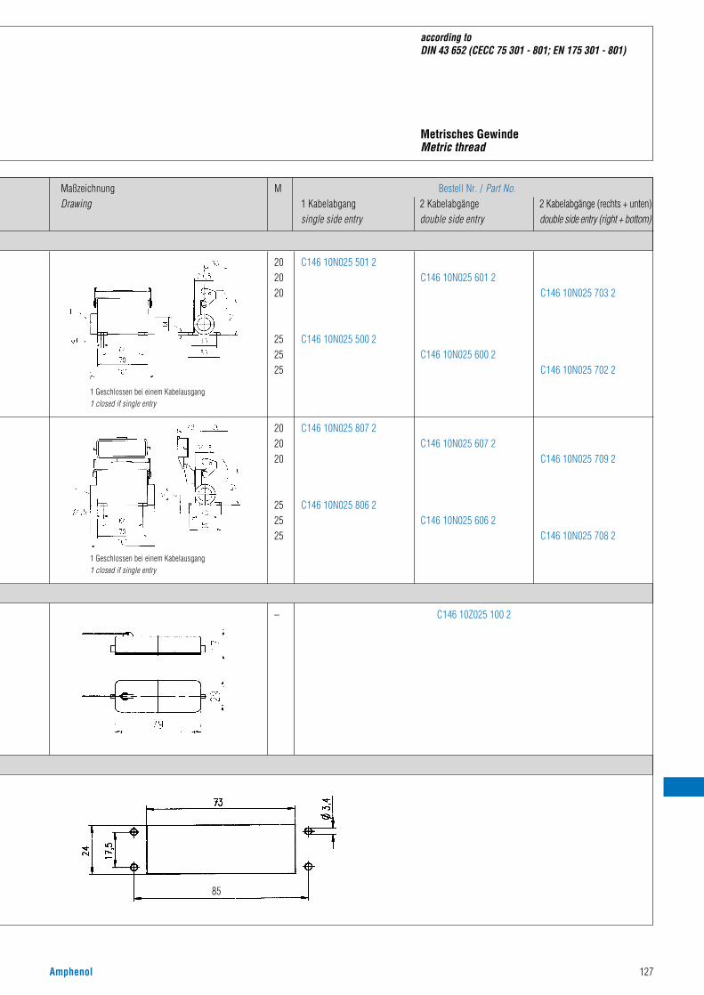
Amphenol 127
according to DIN 43 652 (CECC 75 301 - 801; EN 175 301 - 801)
MaßzeichnungDrawing
M
202020
252525
C146 10N025 601 2
C146 10N025 600 2
C146 10N025 501 2
C146 10N025 500 2
202020
252525
C146 10N025 607 2
C146 10N025 606 2
C146 10N025 807 2
C146 10N025 806 2
C146 10N025 703 2
C146 10N025 702 2
C146 10N025 709 2
C146 10N025 708 2
– C146 10Z025 100 2
1 Geschlossen bei einem Kabelausgang1 closed if single entry
1 Geschlossen bei einem Kabelausgang1 closed if single entry
85
Bestell Nr. / Part No.1 Kabelabgang 2 Kabelabgänge 2 Kabelabgänge (rechts + unten)single side entry double side entry double side entry (right + bottom)
Metrisches GewindeMetric thread

128 Amphenol
Tüllengehäuse, Abgang obenHood, top entry
21
29
C146 10G032 600 4
C146 10G032 601 4
Tüllengehäuse, Abgang SeiteHood, side entry
21
29
C146 10G032 500 4
C146 10G032 501 4
C 146 D 50 pol.C 146 A 32 pol.
Gehäuseoberteile / Hoods
Bezeichnung - AbbildungDescription - Figure
PGMaßzeichnungDrawing
Bestell Nr.Part No.
Gehäuse Housings
Verschraubung für Tüllen- und Sockelgehäuse siehe Seite 180-183 / gland bushings for hoods and housing see page 180-183Zubehör siehe Seite 184-186 / accessories see page 184-186
KupplungsgehäuseHood, coupling application
Tüllengehäuse, Abgang obenHood, top entry
Tüllengehäuse, Abgang SeiteHood, side entry
PG-GewindePG-thread
H
56
66
70,8
3º
Tg/Pg Tg/M
Ts/Pg
Ts/M
S
82
49,6
H
56
66
70,8
3º
Tg/Pg Tg/M
Ts/Pg
Ts/M
S
82
49,6
3º
Tg/Pg Tg/M
S
82
49,6
H
70,8
66
56
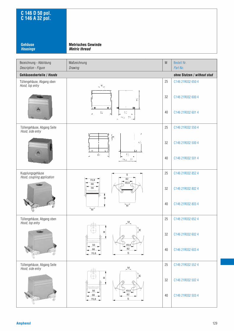
Amphenol 129
C 146 D 50 pol.C 146 A 32 pol.
Gehäuse Housings
Tüllengehäuse, Abgang obenHood, top entry
25
32
40
C146 21R032 650 4
C146 21R032 600 4
C146 21R032 601 4
Tüllengehäuse, Abgang SeiteHood, side entry
25
32
40
C146 21R032 550 4
C146 21R032 500 4
C146 21R032 501 4
25
32
40
C146 21R032 852 4
C146 21R032 802 4
C146 21R032 803 4
25
32
40
C146 21R032 652 4
C146 21R032 602 4
C146 21R032 603 4
25
32
40
C146 21R032 552 4
C146 21R032 502 4
C146 21R032 503 4
Gehäuseoberteile / Hoods ohne Stutzen / without stud
Bezeichnung - AbbildungDescription - Figure
MMaßzeichnungDrawing
Bestell Nr.Part No.
KupplungsgehäuseHood, coupling application
Tüllengehäuse, Abgang obenHood, top entry
Tüllengehäuse, Abgang SeiteHood, side entry
Metrisches GewindeMetric thread
S
82
49,6
H
70,8
66
56
M
M
H
56
66
70,8 S
82
49,6
M
M
H
56
66
70,8 S
82
49,6
M
M

130 Amphenol
Anbaugehäuse 1)
Housing, bulkhead mounting–
–
C146 10F032 000 4
C146 10F032 002 4
Sockelgehäuse, 1 KabelabgangHousing, single side entry
21
29
C146 10F032 500 4
C146 10F032 501 4
Sockelgehäuse, 2 KabelabgängeHousing, double side entry
1) incl. Flachdichtung / incl. gasketBei Sockelgehäusen Abgang rechts dargestellt / housings are shown with right outlet
21
29
C146 10F032 600 4
C146 10F032 601 4
C 146 D 50 pol.C 146 A 32 pol.
Gehäuseunterteile / Housings
Bezeichnung - AbbildungDescription - Figure
PGMaßzeichnungDrawing
Bestell Nr.Part No.
Montageausschnitt / Panel cut out
Gehäuse Housings
PG-GewindePG-thread
Anbaugehäuse 1) mit Bolzen undKlappdeckelHousing 1), bulkhead mounting andwith spring cover

Amphenol 131
– C146 10F032 002 4
C 146 D 50 pol.C 146 A 32 pol.
Gehäuse Housings
– C146 10F032 000 4
Sockelgehäuse, 1 KabelabgangHousing, single side entry
25
32
40
C146 10N032 550 4
C146 10N032 500 4
C146 10N032 501 4
Sockelgehäuse, 2 KabelabgängeHousing, double side entry
25
32
40
C146 10N032 650 4
C146 10N032 600 4
C146 10N032 601 4
Gehäuseunterteile / Housings mit Stutzen / with stud
Bezeichnung - AbbildungDescription - Figure
MMaßzeichnungDrawing
Bestell Nr.Part No.
Montageausschnitt / Panel cut out
Metrisches GewindeMetric thread
Anbaugehäuse 1)
Housing, bulkhead mounting
Anbaugehäuse 1) mit Bolzen undKlappdeckelHousing 1), bulkhead mounting andwith spring cover
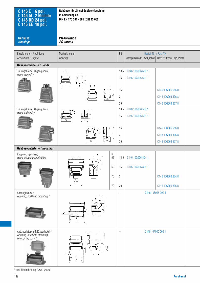
132 Amphenol
Gehäuseoberteile / Hoods
Bezeichnung - AbbildungDescription - Figure
Gehäuse für Längsbügelverriegelung in Anlehnung anDIN EN 175 301 - 801 (DIN 43 652)
MaßzeichnungDrawing
PG Bestell Nr. / Part No.Niedrige Bauform / Low profile Hohe Bauform / High profile
13,5
16
16
21
29
13,5
16
16
21
29
C146 10G006 600 1
C146 10G006 601 1
C146 10G006 500 1
C146 10G006 501 1
C146 10G006 656 8
C146 10G006 606 8
C146 10G006 607 8
C146 10G006 556 8
C146 10G006 506 8
C146 10G006 507 8
C 146 E 6 pol.C 146 M 2 ModuleC 146 DD 24 pol.C 146 EE 10 pol.
Gehäuseunterteile / Housings
Tüllengehäuse, Abgang obenHood, top entry
13,5
16
21
29
h52
52
70
70
C146 10G006 804 1
C146 10G006 805 1
C146 10G006 804 8
C146 10G006 805 8
Kupplungsgehäuse, Hood, coupling application
–
–
C146 10F006 003 1
C146 10F006 000 1Anbaugehäuse 1)
Housing, bulkhead mounting 1)
1) incl. Flachdichtung / incl. gasket
Tüllengehäuse, Abgang SeiteHood, side entry
Anbaugehäuse mit Klappdeckel 1)
Housing, bulkhead mountingwith spring cover 1)
Gehäuse Housings
PG-GewindePG-thread

Amphenol 133
housings for 1 locking-lever-system in accordance withDIN EN 175 301 - 801 (DIN 43 652)
MaßzeichnungDrawing
M
16
20
25
25
32
20
25
25
32
C146 10R006 656 1
C146 10R006 606 1
C146 10R006 607 1
C146 10R006 506 1
C146 10R006 507 1
C146 10R006 556 8
C146 10R006 506 8
C146 21R006 506 1
C146 21R006 507 1
C146 21R006 556 8
C146 21R006 506 8
C146 10R006 656 8
C146 10R006 606 8
C146 21R006 656 1
C146 21R006 606 1
C146 21R006 607 1
C146 21R006 656 8
C146 21R006 606 8
20
25
25
32
h52
52
70
70
C146 10R006 804 1
C146 10R006 805 1
C146 10R006 854 8
C146 10R006 804 8
C146 21R006 804 1
C146 21R006 805 1
C146 21R006 854 8
C146 21R006 804 8
–
–
C146 10F006 003 1
C146 10F006 000 1
Bestell Nr. / Part No.Niedrige Bauform/ Hohe Bauform/Low profile High profile
Bestell Nr. / Part No.Niedrige Bauform/ Hohe Bauform/Low profile High profile
mit Stutzen /with stud ohne Stutzen /without stud
Metrisches GewindeMetric thread

134 Amphenol
Gehäuseunterteil / Housings 1 Kabelabgang / Single side entry
Bezeichnung - AbbildungDescription - Figure
MaßzeichnungDrawing
PG
SockelgehäuseHousing
1616/21212929
162129
C146 10F006 803 2C146 10F006 503 2 (*l
C146 10F006 802 2C146 10F006 502 2 (*l
C146 10F006 603 2C146 10F006 602 2
C146 10F006 500 1C146 10F006 502 1 (*l
C146 10F006 600 1
Sockelgehäuse mit KlappdeckelHousing with spring cover
1616/21212929
C146 10F006 807 2C146 10F006 507 2 (*l
C146 10F006 806 2C146 10F006 506 2 (*l
C146 10F006 806 1C146 10F006 506 1 (*l
–
–
16
21
C146 10Z006 100 1
C146 10Z006 200 1
C146 21G006 501 1
C146 21G006 506 8
Schutzkappe für GehäuseunterteileCover for housings
C 146 E 6 pol.C 146 M 2 ModuleC 146 DD 24 pol.C 146 EE 10 pol.
Gehäuse für Längsbügelverriegelung in Anlehnung anDIN EN 175 301 - 801 (DIN 43 652)
Verschraubung für Tüllen- und Sockelgehäuse siehe Seite 180-183 / gland bushings for hoods and housing see page 180-183Zubehör siehe Seite 184-186 / accessories see page 184-186 Bei Sockelgehäusen Abgang rechts dargestellt / housings are shown with right outlet
Tüllengehäuse ohne StutzenHood, without stud
1 Geschlossen bei einem Kabelausgang1 closed if single entry
1 Geschlossen bei einem Kabelausgang1 closed if single entry
Gehäuse Housings
Schutzkappe für GehäuseoberteileCover for housings
Bestell Nr. / Part No.Niedrige Bauform/ Hohe Bauform/Low profile High profile
h
2 Kabelabgänge / Double side entry
1 Kabelabgang / Single side entry
162129
5454/74747474
547474
C146 10F006 607 2C146 10F006 606 2
C146 10F006 606 1
2 Kabelabgänge / Double side entry
Schutzkappen / Protective cover
Montageausschnitt / Panel cut out
PG-GewindePG-thread
5454/74747474
547474
Sondergehäuse / Special housings

Amphenol 135
housings for 1 locking-lever-system in accordance withDIN EN 175 301 - 801 (DIN 43 652)
(*r+u rechts und unten / right and buttom(*l links / left
MaßzeichnungDrawing
M
20
20
25
25
32
32
C146 10N006 803 2
C146 10N006 503 2(*l
C146 10N006 802 2
C146 10N006 502 2(*l
C146 10N006 803 1
C146 10N006 503 1(*l
C146 10N006 802 1
C146 10N006 502 1(*l
202025253232
545454/7454/747474
C146 10N006 807 2C146 10N006 507 2(*l
C146 10N006 806 2C146 10N006 506 2(*l
C146 10N006 807 1C146 10N006 507 1(*l
C146 10N006 806 1C146 10N006 506 1(*l
C146 10N006 603 2
C146 10N006 602 2
C146 10N006 603 1
C146 10N006 703 1(*r+u
C146 10N006 602 1
C146 10N006 702 1(*r+u
C146 10N006 607 2
C146 10N006 606 2
C146 10N006 607 1
C146 10N006 709 1(*r+u
C146 10N006 606 1
C146 10N006 708 1(*r+u
–
–
C146 10Z006 100 1
C146 10Z006 200 1
1 Geschlossen bei einem Kabelausgang1 closed if single entry
1 Geschlossen bei einem Kabelausgang1 closed if single entry
h54
54
54/74
54/74
74
74
Bestell Nr. / Part No.Niedrige Bauform/ Hohe Bauform/Low profile High profile
Bestell Nr. / Part No.Niedrige Bauform/ Hohe Bauform/Low profile High profile
1 Kabelabgang 2 Kabelabgänge
Metrisches GewindeMetric thread
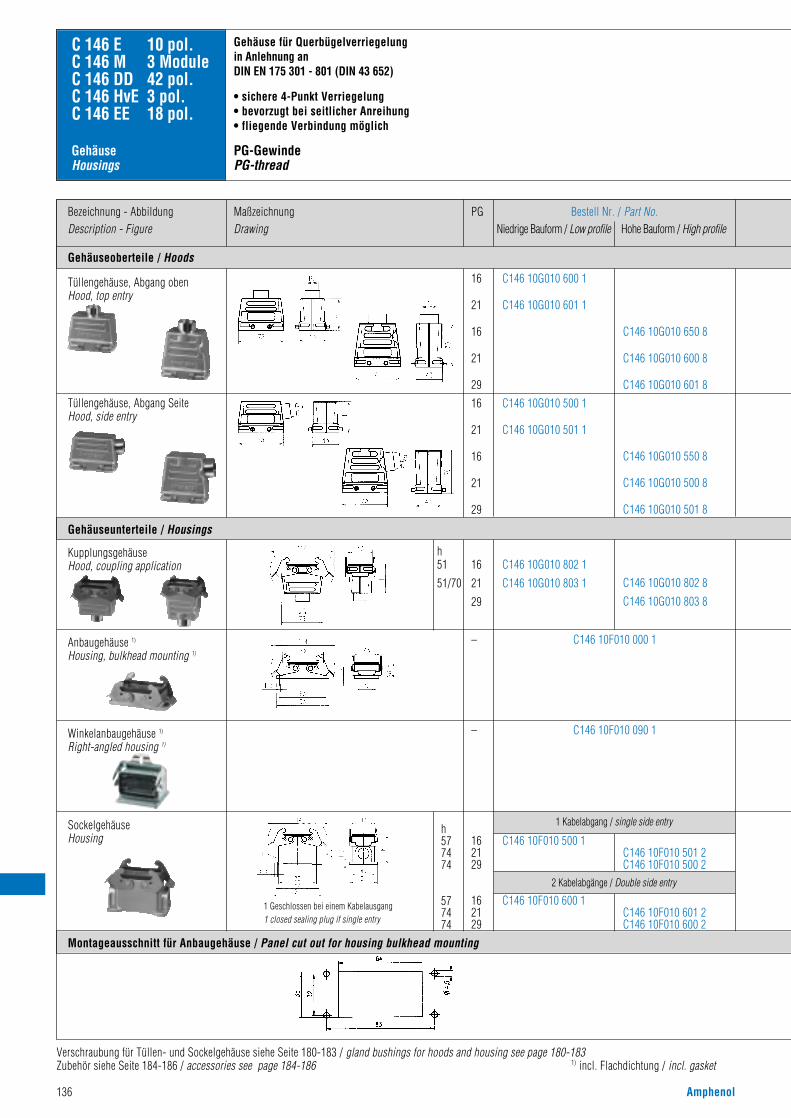
136 Amphenol
Gehäuseoberteile / Hoods
Bezeichnung - AbbildungDescription - Figure
MaßzeichnungDrawing
PG Bestell Nr. / Part No.Niedrige Bauform / Low profile Hohe Bauform / High profile
16
21
16
21
2916
21
16
21
29
C146 10G010 600 1
C146 10G010 601 1
C146 10G010 500 1
C146 10G010 501 1
C146 10G010 650 8
C146 10G010 600 8
C146 10G010 601 8
C146 10G010 550 8
C146 10G010 500 8
C146 10G010 501 8
C 146 E 10 pol.C 146 M 3 ModuleC 146 DD 42 pol.C 146 HvE 3 pol.C 146 EE 18 pol.
16
21
29
h51
51/70
h577474
577474
–
–
C146 10G010 802 1
C146 10G010 803 1 C146 10G010 802 8
C146 10G010 803 8
Tüllengehäuse, Abgang SeiteHood, side entry
C146 10F010 000 1
C146 10F010 090 1
162129
C146 10F010 500 1C146 10F010 501 2C146 10F010 500 2
2 Kabelabgänge / Double side entry
SockelgehäuseHousing
Gehäuse für Querbügelverriegelung in Anlehnung an DIN EN 175 301 - 801 (DIN 43 652)
• sichere 4-Punkt Verriegelung• bevorzugt bei seitlicher Anreihung• fliegende Verbindung möglich
PG-GewindePG-thread
Gehäuse Housings
Verschraubung für Tüllen- und Sockelgehäuse siehe Seite 180-183 / gland bushings for hoods and housing see page 180-183Zubehör siehe Seite 184-186 / accessories see page 184-186 1) incl. Flachdichtung / incl. gasket
Tüllengehäuse, Abgang obenHood, top entry
1 Geschlossen bei einem Kabelausgang1 closed sealing plug if single entry
Montageausschnitt für Anbaugehäuse / Panel cut out for housing bulkhead mounting
Gehäuseunterteile / Housings
162129
C146 10F010 600 1C146 10F010 601 2C146 10F010 600 2
1 Kabelabgang / single side entry
KupplungsgehäuseHood, coupling application
Winkelanbaugehäuse 1)
Right-angled housing 1)
Anbaugehäuse 1)
Housing, bulkhead mounting 1)

Amphenol 137
C146 10R010 550 1
C146 10R010 500 1
C146 10R010 550 8
C146 10R010 500 8
C146 21R010 550 1
C146 21R010 500 1
C146 21R010 550 8
C146 21R010 500 8
C146 10R010 852 1C146 10R010 802 1C146 10R010 803 1
C146 10R010 852 8C146 10R010 802 8C146 10R010 803 8
C146 21R010 852 1C146 21R010 802 1C146 21R010 803 1
C146 21R010 852 8C146 21R010 802 8C146 21R010 803 8
C146 10F010 000 1
housings for 2 locking-lever-systemaccording to DIN EN 175 301 - 801 (DIN 43 652)
• secured 4 point locking• prefered for side by side mounting• cable to cable possible
Metrisches GewindeMetric thread
(*r+u rechts und unten / right and buttom
1.) Verschlussschraube bei einem Kabelausgang1.) Screwed sealing plug if single entry
MaßzeichnungDrawing
M
20
25
25
32
4020
25
25
32
20253240
h5151/7051/7070
20
20
25
25
32
C146 10N010 501 1
C146 10N010 500 1
1 Kabelabgang / single side entry
C146 10N010 501 2
C146 10N010 500 2
C146 10N010 601 1
C146 10N010 701 1(*r+u
C146 10N010 600 1
C146 10N010 700 1(*r+u
C146 10N010 601 2
C146 10N010 600 2
2 Kabelabgänge / Double side entry
C146 10R010 650 1
C146 10R010 600 1
C146 10R010 650 8
C146 10R010 600 8
C146 10R010 601 8
C146 21R010 650 1
C146 21R010 600 1
C146 21R010 650 8
C146 21R010 600 8
C146 21R010 601 8
Bestell Nr. / Part No.Niedrige Bauform/ Hohe Bauform/Low profile High profile
Bestell Nr. / Part No.Niedrige Bauform/ Hohe Bauform/Low profile High profile
mit Stutzen /with stud ohne Stutzen /without stud
–
C146 10F010 090 1–
h
57
57
57/74
57
74
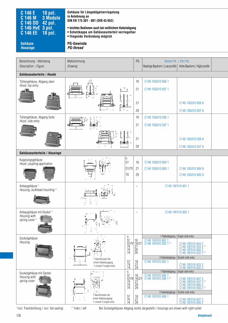
138 Amphenol
Gehäuseoberteile / Hoods
Bezeichnung - AbbildungDescription - Figure
MaßzeichnungDrawing
PG Bestell Nr. / Part No.Niedrige Bauform / Low profile Hohe Bauform / High profile
16
21
21
29
16
21
21
29
C146 10G010 606 1
C146 10G010 607 1
C146 10G010 506 1
C146 10G010 507 1
C146 10G010 606 8
C146 10G010 607 8
C146 10G010 506 8
C146 10G010 507 8
C 146 E 10 pol.C 146 M 3 ModuleC 146 DD 42 pol.C 146 HvE 3 pol.C 146 EE 18 pol.
Gehäuseunterteile / Housings
Tüllengehäuse, Abgang obenHood, top entry
16
21
29
h51
51/70
70
h5757/74747474
h5757/74747474
577474
–
–
C146 10G010 804 1
C146 10G010 805 1 C146 10G010 804 8
C146 10G010 805 8
Tüllengehäuse, Abgang SeiteHood, side entry
C146 10F010 001 1
C146 10F010 003 1
Anbaugehäuse 1)
Housing, bulkhead mounting 1)
1616/21212929
162129
577474
C146 10F010 802 1C146 10F010 502 1 (*l
C146 10F010 602 1C146 10F010 603 2C146 10F010 602 2
C146 10F010 803 2 C146 10F010 503 2 (*l
C146 10F010 802 2 C146 10F010 502 2 (*l
SockelgehäuseHousing
1) incl. Flachdichtung / incl. flat sealing (*l links / left Bei Sockelgehäusen Abgang rechts dargestellt / housings are shown with right outlet
Gehäuse für Längsbügelverriegelung in Anlehnung anDIN EN 175 301 - 801 (DIN 43 652)
• leichtes Bedienen auch bei seitlichem Kabelabgang• Schutzkappe am Gehäuseunterteil verriegelbar• fliegende Verbindung möglich
PG-GewindePG-thread
1 Kabelabgang / Single side entry
2 Kabelabgänge / Double side entry
1616/21212929
162129
C146 10F010 806 1C146 10F010 506 1 (*l
C146 10F010 606 1C146 10F010 607 2C146 10F010 606 2
C146 10F010 807 2 C146 10F010 507 2 (*l
C146 10F010 806 2 C146 10F010 506 2 (*l
1 Kabelabgang / Single side entry
2 Kabelabgänge / Double side entry
Sockelgehäuse mit DeckelHousing with spring cover
Anbaugehäuse mit Deckel 1)
Housing with spring cover 1)
1 Geschlossen bei einem Kabelausgang1 closed if single entry
1 Geschlossen bei einem Kabelausgang1 closed if single entry
KupplungsgehäuseHood, coupling application
Gehäuse Housings

Amphenol 139
(*l links / left (*r+u rechts und unten / right and buttom
housings for 1 locking-lever-system in accordance withDIN EN 175 301 - 801 (DIN 43 652)
• also easy to use for side entry • cover for housings lockable• cable to cable possible
Metrisches GewindeMetric thread
h57
57
57/74
57/74
74
74h57
57
57/74
57/74
74
74
1 Geschlossen bei einem Kabelausgang1 closed if single entry
1 Geschlossen bei einem Kabelausgang1 closed if single entry
MaßzeichnungDrawing
M
20
25
32
25
32
40
20
25
25
32
C146 10R010 656 1
C146 10R010 606 1
C146 10R010 607 1
C146 21R010 656 1
C146 21R010 606 1
C146 21R010 607 1
C146 10R010 656 8
C146 10R010 606 8
C146 10R010 607 8
C146 10R010 556 1
C146 10R010 506 1
C146 10R010 556 8
C146 10R010 506 8
C146 21R010 556 1
C146 21R010 506 1
C146 21R010 656 8
C146 21R010 606 8
C146 21R010 607 8
C146 21R010 556 8
C146 21R010 506 8
20253240
h5151/7051/7070
–
–
C146 10R010 854 8C146 10R010 804 8C146 10R010 805 8
C146 10R010 854 1C146 10R010 804 1C146 10R010 805 1
C146 21R010 854 1C146 21R010 804 1C146 21R010 805 1
C146 21R010 854 8C146 21R010 804 8C146 21R010 805 8
C146 10F010 001 1
C146 10F010 003 1
20
20
25
25
32
32
C146 10N010 803 1
C146 10N010 503 1 (*l
C146 10N010 802 1
C146 10N010 502 1 (*l
C146 10N010 603 1
C146 10N010 703 1 (r+u
C146 10N010 602 1
C146 10N010 702 1 (r+u
C146 10N010 803 2
C146 10N010 503 2 (*l
C146 10N010 802 2
C146 10N010 502 2 (*l
C146 10N010 603 2
C146 10N010 602 2
1 Kabelabgang / Single side entry 2 Kabelabgänge / Double side entry
20
20
25
25
32
32
C146 10N010 807 1
C146 10N010 507 1 (*l
C146 10N010 806 1
C146 10N010 506 1 (*l
C146 10N010 807 2
C146 10N010 507 2 (*l
C146 10N010 806 2
C146 10N010 506 2 (*l
C146 10N010 607 1
C146 10N010 708 1 (r+u
C146 10N010 606 1
C146 10N010 709 1 (r+u
C146 10N010 607 2
C146 10N010 606 2
1 Kabelabgang / Single side entry 2 Kabelabgänge / Double side entry
Bestell Nr. / Part No.Niedrige Bauform/ Hohe Bauform/Low profile High profile
Bestell Nr. / Part No.Niedrige Bauform/ Hohe Bauform/Low profile High profile
mit Stutzen /with stud ohne Stutzen /without stud

140 Amphenol
Gehäuseoberteile / Hoods
Bezeichnung - AbbildungDescription - Figure
MaßzeichnungDrawing
PG Bestell Nr. / Part No.Niedrige Bauform / Low profile Hohe Bauform / High profile
16
21
21
29
16
21
21
29
C146 10G010 602 1
C146 10G010 603 1
C146 10G010 502 1
C146 10G010 503 1
C146 10G010 602 8
C146 10G010 603 8
C146 10G010 502 8
C146 10G010 503 8
C146 10F010 002 1
C 146 E 10 pol.C 146 M 3 ModuleC 146 DD 42 pol.C 146 HvE 3 pol.C 146 EE 18 pol.
Tüllengehäuse, Abgang obenHood, top entry
–
Tüllengehäuse, Abgang SeiteHood, side entry
Anbaugehäuse mit Deckel 1)
Housing, with spring cover 1)
Sockelgehäuse, mit DeckelHousing, with spring cover
1) incl. Flachdichtung / incl. gasket Bei Sockelgehäusen Abgang rechts dargestellt / housings are shown with right outlet
Tüllengehäuse mit Querbügelin Anlehnung anDIN EN 175 301 - 801 (DIN 43 653)
• sichere 4-Punkt Verriegelung• Gehäuseunterteil mit Schutzdeckel• keine Bügel am Gehäuseunterteil
PG-GewindePG-thread
SockelgehäuseHousing
Gehäuse Housings
1616/21212929
16
21
29
57
74
74
C146 10F010 804 1C146 10F010 504 1 (*l
C146 10F010 604 1
C146 10F010 605 2
C146 10F010 604 2
C146 10F010 805 2 C146 10F010 505 2 (*l
C146 10F010 804 2 C146 10F010 504 2 (*l
1 Kabelabgang / Single side entry
2 Kabelabgänge / Double side entry
h5757/74747474
21
29
21
29
74
74
C146 10F010 509 2
C146 10F010 508 2
C146 10F010 609 2
C146 10F010 608 2
1 Kabelabgang / Single side entry
2 Kabelabgänge / Double side entry
h74
74
Gehäuseunterteile / Housings
1 Geschlossen bei einem Kabelausgang1 closed if single entry
1 Geschlossen bei einem Kabelausgang1 closed if single entry

Amphenol 141
(*l links / left (*r+u rechts und unten / right and buttom
hoods with 2 locking-levers in accordance withDIN EN 175 301 - 801 (DIN 43 653)
• secured 4 point locking• housing with cover• no locking levers at the housings
Metrisches GewindeMetric thread
MaßzeichnungDrawing
M
20
25
25
32
40
20
25
25
32
C146 10R010 652 1
C146 10R010 602 1
C146 10R010 652 8
C146 10R010 602 8
C146 10R010 603 8
C146 21R010 652 1
C146 21R010 602 1
C146 21R010 652 8
C146 21R010 602 8
C146 21R010 603 8
C146 10R010 552 1
C146 10R010 502 1
C146 10R010 552 8
C146 10R010 502 8
C146 21R010 552 1
C146 21R010 502 1
C146 21R010 552 8
C146 21R010 502 8
C146 10F010 002 1–
20
20
25
25
32
32
C146 10N010 805 1
C146 10N010 505 1 (*l
C146 10N010 804 1
C146 10N010 504 1 (*l
C146 10N010 805 2
C146 10N010 505 2 (*l
C146 10N010 804 2
C146 10N010 504 2 (*l
C146 10N010 605 1
C146 10N010 809 1(*r+u
C146 10N010 604 1
C146 10N010 808 1(*r+u
C146 10N010 605 2
C146 10N010 604 2
1 Kabelabgang / Single side entry 2 Kabelabgänge / Double side entryh57
57
57/74
57/74
74
74
20
25
32
C146 10N010 509 1
C146 10N010 508 1
C146 10N010 609 1
C146 10N010 608 1 C146 10N010 609 2
C146 10N010 608 2
C146 10N010 509 2
C146 10N010 508 2
1 Kabelabgang / Single side entry 2 Kabelabgänge / Double side entryh57
57/74
74
Bestell Nr. / Part No.Niedrige Bauform/ Hohe Bauform/Low profile High profile
Bestell Nr. / Part No.Niedrige Bauform/ Hohe Bauform/Low profile High profile
mit Stutzen /with stud ohne Stutzen /without stud
1 Geschlossen bei einem Kabelausgang1 closed if single entry
1 Geschlossen bei einem Kabelausgang1 closed if single entry
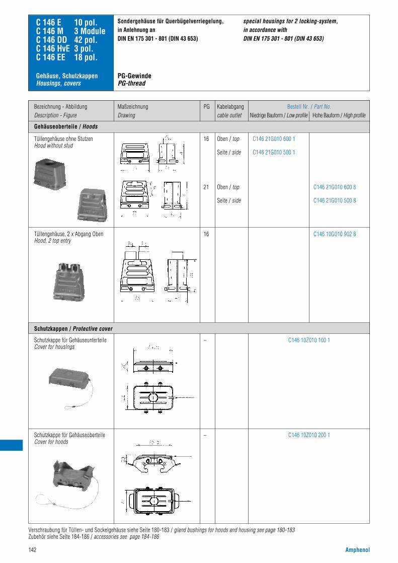
142 Amphenol
Gehäuseoberteile / Hoods
Bezeichnung - AbbildungDescription - Figure
MaßzeichnungDrawing
PG Kabelabgangcable outlet
Bestell Nr. / Part No.Niedrige Bauform / Low profile Hohe Bauform / High profile
C146 21G010 600 1
C146 21G010 500 1
C146 10Z010 100 1
C146 10Z010 200 1
C146 21G010 600 8
C146 21G010 500 8
C146 10G010 902 8
C 146 E 10 pol.C 146 M 3 ModuleC 146 DD 42 pol.C 146 HvE 3 pol.C 146 EE 18 pol.
Tüllengehäuse ohne StutzenHood without stud
Tüllengehäuse, 2 x Abgang ObenHood, 2 top entry
Schutzkappe für GehäuseunterteileCover for housings
Schutzkappe für GehäuseoberteileCover for hoods
Sondergehäuse für Querbügelverriegelung, in Anlehnung anDIN EN 175 301 - 801 (DIN 43 653)
Verschraubung für Tüllen- und Sockelgehäuse siehe Seite 180-183 / gland bushings for hoods and housing see page 180-183Zubehör siehe Seite 184-186 / accessories see page 184-186
Schutzkappen / Protective cover
special housings for 2 locking-system, in accordance withDIN EN 175 301 - 801 (DIN 43 653)
16
21
Oben / top
Seite / side
Oben / top
Seite / side
16
–
–
Gehäuse, SchutzkappenHousings, covers
PG-GewindePG-thread
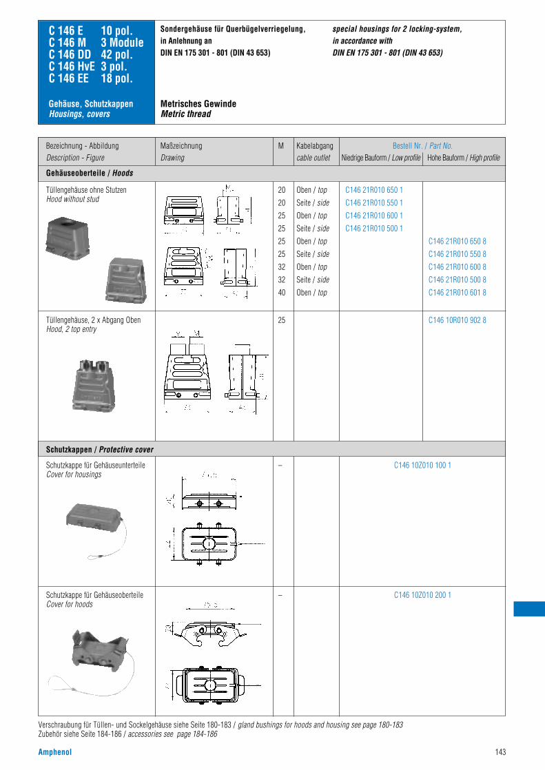
Amphenol 143
Gehäuseoberteile / Hoods
Bezeichnung - AbbildungDescription - Figure
MaßzeichnungDrawing
M Kabelabgangcable outlet
Bestell Nr. / Part No.Niedrige Bauform / Low profile Hohe Bauform / High profile
C146 21R010 650 1
C146 21R010 550 1
C146 21R010 600 1
C146 21R010 500 1
C146 10Z010 100 1
C146 10Z010 200 1
C146 21R010 650 8
C146 21R010 550 8
C146 21R010 600 8
C146 21R010 500 8
C146 21R010 601 8
C146 10R010 902 8
C 146 E 10 pol.C 146 M 3 ModuleC 146 DD 42 pol.C 146 HvE 3 pol.C 146 EE 18 pol.
Tüllengehäuse ohne StutzenHood without stud
Tüllengehäuse, 2 x Abgang ObenHood, 2 top entry
Schutzkappe für GehäuseunterteileCover for housings
Schutzkappe für GehäuseoberteileCover for hoods
Sondergehäuse für Querbügelverriegelung, in Anlehnung anDIN EN 175 301 - 801 (DIN 43 653)
Verschraubung für Tüllen- und Sockelgehäuse siehe Seite 180-183 / gland bushings for hoods and housing see page 180-183Zubehör siehe Seite 184-186 / accessories see page 184-186
Schutzkappen / Protective cover
special housings for 2 locking-system, in accordance withDIN EN 175 301 - 801 (DIN 43 653)
20
20
25
25
25
25
32
32
40
Oben / topSeite / sideOben / topSeite / sideOben / topSeite / sideOben / topSeite / sideOben / top
25
–
–
Gehäuse, SchutzkappenHousings, covers
Metrisches GewindeMetric thread

144 Amphenol
Gehäuseoberteile / Hoods
Bezeichnung - AbbildungDescription - Figure
MaßzeichnungDrawing
PG Bestell Nr. / Part No.Niedrige Bauform / Low profile Hohe Bauform / High profile
21
29
21
29
21
29
21
29
C146 10G016 600 1
C146 10G016 601 1
C146 10G016 500 1
C146 10G016 501 1
C146 10G016 600 8
C146 10G016 601 8
C146 10G016 500 8
C146 10G016 501 8
C 146 E 16 pol.C 146 M 5 ModuleC 146 D 40 pol.C 146 DD 72 pol.C 146 HSE 6 pol.C 146 HvE 6 pol.C 146 EE 32 pol.
Montageausschnitt für Anbaugehäuse / Panel cut out for housing bulkhead mounting
Tüllengehäuse, Abgang obenHood, top entry
21
29
21
29
h62
62
76
76
–
C146 10G016 802 1
C146 10G016 803 1
C146 10G016 802 8
C146 10G016 803 8
Tüllengehäuse, Abgang SeiteHood, side entry
C146 10F016 000 1
KupplungsgehäuseHood, coupling application
Anbaugehäuse 1)
Housing, bulkhead mounting 1)
21
29
h64/77
77
64/77
77
21
29
C146 10F016 500 1
C146 10F016 600 1
C146 10F040 501 2
C146 10F040 500 2
C146 10F040 601 2
C146 10F040 600 2
2 Kabelabgänge / Double side entry
SockelgehäuseHousing
Gehäuse für Querbügelverriegelung nach DIN EN 175 301 - 801 (DIN 43 652)
• sichere 4-Punkt Verriegelung• bevorzugt bei seitlicher Anreihung• fliegende Verbindung möglich
PG-GewindePG-thread
(*l links / left
1 Geschlossen bei einem Kabelausgang1 closed if single entry
Gehäuse / Housings
Gehäuseunterteile / Housings
1 Kabelabgang / Single side entry
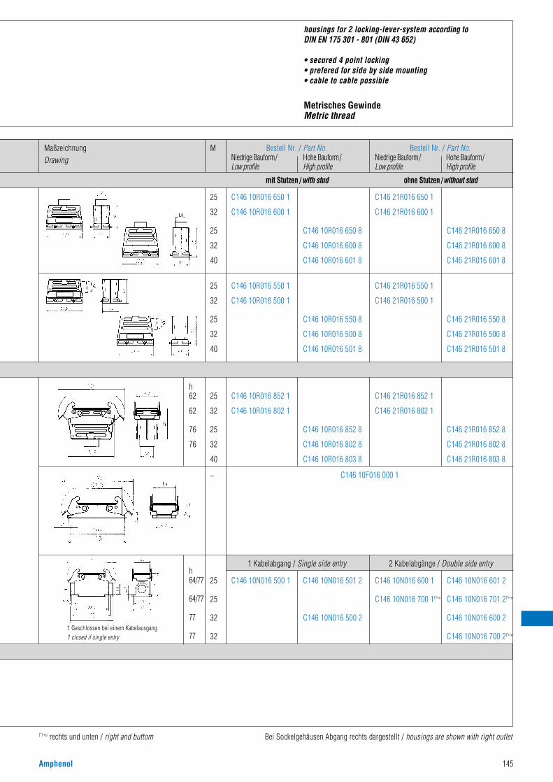
Amphenol 145
(*r+u rechts und unten / right and buttom Bei Sockelgehäusen Abgang rechts dargestellt / housings are shown with right outlet
housings for 2 locking-lever-system according toDIN EN 175 301 - 801 (DIN 43 652)
• secured 4 point locking• prefered for side by side mounting• cable to cable possible
Metrisches GewindeMetric thread
MaßzeichnungDrawing
M
25
32
25
32
40
25
32
25
32
40
C146 10R016 650 1
C146 10R016 600 1
C146 21R016 650 1
C146 21R016 600 1
C146 10R016 650 8
C146 10R016 600 8
C146 10R016 601 8
C146 21R016 650 8
C146 21R016 600 8
C146 21R016 601 8
C146 10R016 550 1
C146 10R016 500 1
C146 21R016 550 1
C146 21R016 500 1
C146 10R016 550 8
C146 10R016 500 8
C146 10R016 501 8
C146 21R016 550 8
C146 21R016 500 8
C146 21R016 501 8
C146 10R016 852 1
C146 10R016 802 1
C146 21R016 852 1
C146 21R016 802 1
C146 10R016 852 8
C146 10R016 802 8
C146 10R016 803 8
C146 21R016 852 8
C146 21R016 802 8
C146 21R016 803 8
25
32
25
32
40
h62
62
76
76
– C146 10F016 000 1
25
25
32
32
h64/77
64/77
77
77
C146 10N016 500 1 C146 10N016 501 2
C146 10N016 500 2
1 Kabelabgang / Single side entry
C146 10N016 600 1
C146 10N016 700 1(*r+u
C146 10N016 601 2
C146 10N016 701 2(*r+u
C146 10N016 600 2
C146 10N016 700 2(*r+u
2 Kabelabgänge / Double side entry
1 Geschlossen bei einem Kabelausgang1 closed if single entry
Bestell Nr. / Part No.Niedrige Bauform/ Hohe Bauform/Low profile High profile
Bestell Nr. / Part No.Niedrige Bauform/ Hohe Bauform/Low profile High profile
mit Stutzen /with stud ohne Stutzen /without stud

146 Amphenol
Gehäuseoberteile / Hoods
Bezeichnung - AbbildungDescription - Figure
MaßzeichnungDrawing
PG Bestell Nr. / Part No.Niedrige Bauform / Low profile Hohe Bauform / High profile
21
29
21
29
21
29
21
29
C146 10G016 606 1
C146 10G016 607 1
C146 10G016 506 1
C146 10G016 507 1
C146 10G016 606 8
C146 10G016 607 8
C146 10G016 506 8
C146 10G016 507 8
C 146 E 16 pol.C 146 M 5 ModuleC 146 D 40 pol.C 146 DD 72 pol.C 146 HSE 6 pol.C 146 HvE 6 pol.C 146 EE 32 pol.
Gehäuseunterteile / Housings
Tüllengehäuse, Abgang obenHood, top entry
21
29
21
29
h62
62
76
76
–
–
C146 10G016 804 1
C146 10G016 805 1
C146 10G016 804 8
C146 10G016 805 8
Tüllengehäuse, Abgang SeiteHood, side entry
KupplungsgehäuseHood, coupling application
C146 10F016 001 1
C146 10F016 003 1
Anbaugehäuse 1)
Housing, bulkhead mounting 1)
21212929
h64/7764/777777
6477
h64/7764/777777
64/7777
1 Kabelabgang / Single side entry
2 Kabelabgänge / Double side entry
C146 10F040 803 2C146 10F040 503 2 (*l
C146 10F040 802 2C146 10F040 502 2 (*l
C146 10F016 802 1C146 10F016 502 1 (*l
2129
C146 10F040 603 2C146 10F040 602 2
C146 10F016 602 1
21212929
C146 10F040 807 2C146 10F040 507 2 (*l
C146 10F040 806 2C146 10F040 506 2 (*l
C146 10F016 806 1C146 10F016 506 1 (*l
2129
C146 10F040 607 2C146 10F040 606 2
C146 10F016 606 1
SockelgehäuseHousing
Sockelgehäuse mit DeckelHousing with spring cover
1) incl. Flachdichtung / incl. gasket (*l links / left
Gehäuse für Längsbügelverriegelung nach DIN EN 175 301 - 801 (DIN 43 652)
• leichtes Bedienen auch bei seitlichem Kabelabgang• Schutzkappe am Gehäuseunterteil verriegelbar• fliegende Verbindung möglich
PG-GewindePG-thread
1 Geschlossen bei einem Kabelausgang1 closed if single entry
1 Geschlossen bei einem Kabelausgang1 closed if single entry
Gehäuse / Housings
Anbaugehäuse mit Deckel 1)
Housing with spring cover 1)
1 Kabelabgang / Single side entry
2 Kabelabgänge / Double side entry

Amphenol 147
(*l links / left (*r+u rechts und unten / right and buttom Bei Sockelgehäusen Abgang rechts dargestellt / housings are shown with right outlet
housings for 1 locking-lever-system according toDIN EN 175 301 - 801 (DIN 43 652)
• also easy to use for side entry • cover for housings lockable• cable to cable possible
Metrisches GewindeMetric thread
MaßzeichnungDrawing
M
25
32
25
32
40
25
32
25
32
40
C146 10R016 656 1
C146 10R016 606 1
C146 10R016 656 8
C146 10R016 606 8
C146 10R016 607 8
C146 21R016 656 1
C146 21R016 606 1
C146 21R016 656 8
C146 21R016 606 8
C146 21R016 607 8
C146 10R016 556 1
C146 10R016 506 1
C146 10R016 556 8
C146 10R016 506 8
C146 10R016 507 8
C146 21R016 556 1
C146 21R016 506 1
C146 21R016 556 8
C146 21R016 506 8
C146 21R016 507 8
C146 10R016 854 1
C146 10R016 804 1
C146 10R016 854 8
C146 10R016 804 8
C146 10R016 805 8
C146 21R016 854 1
C146 21R016 804 1
C146 21R016 854 8
C146 21R016 804 8
C146 21R016 805 8
25
32
25
32
40
h62
62
76
76
76
–
–
C146 10F016 001 1
C146 10F016 003 1
25
25
32
32
h64/77
64/77
77
77
h64/77
64/77
77
77
1 Kabelabgang / Single side entry 2 Kabelabgänge / Double side entry
1 Kabelabgang / Single side entry 2 Kabelabgänge / Double side entry
C146 10N016 802 1
C146 10N016 502 1 (*l
C146 10N016 803 2
C146 10N016 503 2 (*l
C146 10N016 802 2
C146 10N016 502 2 (*l
C146 10N016 602 1
C146 10N016 702 1(*r+u
C146 10N016 603 2
C146 10N016 703 2(*r+u
C146 10N016 602 2
C146 10N016 702 2(*r+u
C146 10N016 806 1
C146 10N016 506 1 (*l
C146 10N016 807 2
C146 10N016 507 2 (*l
C146 10N016 806 2
C146 10N016 506 2 (*l
C146 10N016 606 1
C146 10N016 708 1(*r+u
C146 10N016 607 2
C146 10N016 709 2(*r+u
C146 10N016 606 2
C146 10N016 708 2(*r+u
25
25
32
32
1 Geschlossen bei einem Kabelausgang1 closed if single entry
1 Geschlossen bei einem Kabelausgang1 closed if single entry
Bestell Nr. / Part No.Niedrige Bauform/ Hohe Bauform/Low profile High profile
Bestell Nr. / Part No.Niedrige Bauform/ Hohe Bauform/Low profile High profile
mit Stutzen /with stud ohne Stutzen /without stud
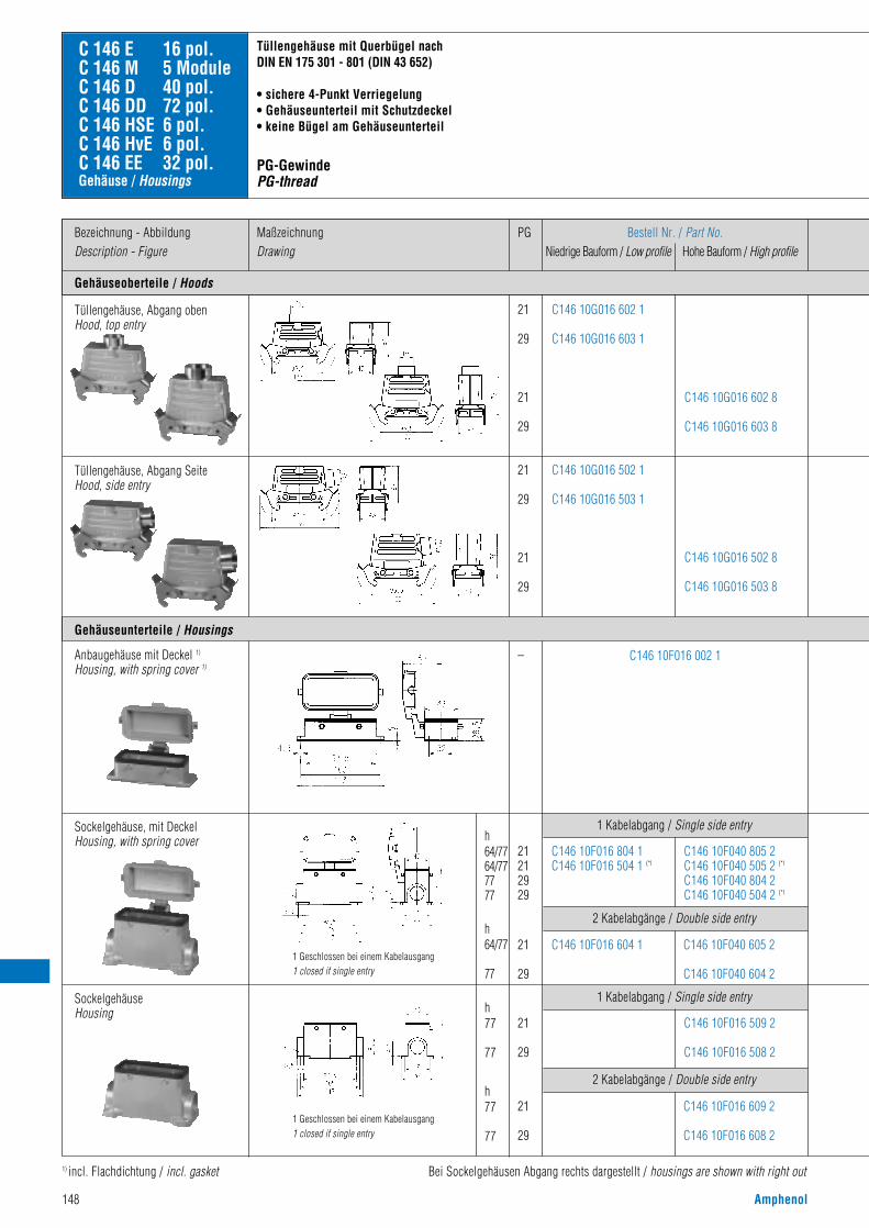
148 Amphenol
Gehäuseoberteile / Hoods
Bezeichnung - AbbildungDescription - Figure
MaßzeichnungDrawing
PG Bestell Nr. / Part No.Niedrige Bauform / Low profile Hohe Bauform / High profile
21
29
21
29
21
29
21
29
C146 10G016 602 1
C146 10G016 603 1
C146 10G016 502 1
C146 10G016 503 1
C146 10G016 602 8
C146 10G016 603 8
C146 10G016 502 8
C146 10G016 503 8
C146 10F016 002 1
C 146 E 16 pol.C 146 M 5 ModuleC 146 D 40 pol.C 146 DD 72 pol.C 146 HSE 6 pol.C 146 HvE 6 pol.C 146 EE 32 pol.
Gehäuseunterteile / Housings
–
Tüllengehäuse, Abgang SeiteHood, side entry
Anbaugehäuse mit Deckel 1)
Housing, with spring cover 1)
Sockelgehäuse, mit DeckelHousing, with spring cover
1) incl. Flachdichtung / incl. gasket Bei Sockelgehäusen Abgang rechts dargestellt / housings are shown with right out
Tüllengehäuse mit Querbügel nach DIN EN 175 301 - 801 (DIN 43 652)
• sichere 4-Punkt Verriegelung• Gehäuseunterteil mit Schutzdeckel• keine Bügel am Gehäuseunterteil
PG-GewindePG-thread
21212929
h64/7764/777777
h64/77
77
C146 10F040 805 2C146 10F040 505 2 (*l
C146 10F040 804 2C146 10F040 504 2 (*l
C146 10F016 804 1C146 10F016 504 1 (*l
21
29
C146 10F040 605 2
C146 10F040 604 2
C146 10F016 604 1
2 Kabelabgänge / Double side entry
1 Kabelabgang / Single side entry
SockelgehäuseHousing
21
29
h77
77
h77
77
C146 10F016 509 2
C146 10F016 508 2
21
29
C146 10F016 609 2
C146 10F016 608 2
2 Kabelabgänge / Double side entry
1 Kabelabgang / Single side entry
Gehäuse / Housings
Tüllengehäuse, Abgang obenHood, top entry
1 Geschlossen bei einem Kabelausgang1 closed if single entry
1 Geschlossen bei einem Kabelausgang1 closed if single entry

Amphenol 149
(*l links / left (*r+u rechts und unten / right and buttom
hoods with 2 locking-levers according to DIN EN 175 301 - 801 (DIN 43 652)
• secured 4 point locking• housing with cover• no locking levers at the housings
Metrisches GewindeMetric thread
2 Kabelabgänge / Double side entry1 Kabelabgang / Single side entry
25
32
h64/77
77
MaßzeichnungDrawing
M
25
32
25
32
40
25
32
25
32
40
C146 10R016 652 1
C146 10R016 602 1
C146 10R016 652 8
C146 10R016 602 8
C146 10R016 603 8
C146 21R016 652 1
C146 21R016 602 1
C146 21R016 652 8
C146 21R016 602 8
C146 21R016 603 8
C146 10R016 552 1
C146 10R016 502 1
C146 10R016 552 8
C146 10R016 502 8
C146 10R016 503 8
C146 21R016 552 1
C146 21R016 502 1
C146 21R016 552 8
C146 21R016 502 8
C146 21R016 503 8
C146 10F016 002 1–
25
25
32
32
h64/77
64/77
77
77
C146 10N016 804 1
C146 10N016 504 1 (*l
C146 10N016 805 2
C146 10N016 505 2 (*l
C146 10N016 804 2
C146 10N016 504 2 (*l
C146 10N016 604 1
C146 10N016 808 1(*r+u
C146 10N016 605 2
C146 10N016 809 2(*r+u
C146 10N016 604 2
C146 10N016 808 2(*r+u
Bestell Nr. / Part No.Niedrige Bauform/ Hohe Bauform/Low profile High profile
Bestell Nr. / Part No.Niedrige Bauform/ Hohe Bauform/Low profile High profile
mit Stutzen /with stud ohne Stutzen /without stud
2 Kabelabgänge / Double side entry1 Kabelabgang / Single side entry
C146 10N016 508 1 C146 10N016 509 2
C146 10N016 508 2
C146 10N016 608 1 C146 10N016 609 2
C146 10N016 608 2
1 Geschlossen bei einem Kabelausgang1 closed if single entry
1 Geschlossen bei einem Kabelausgang1 closed if single entry
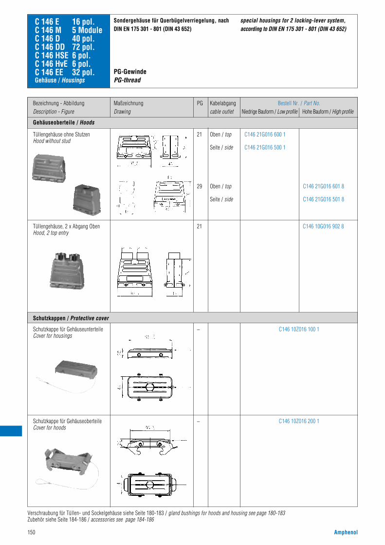
150 Amphenol
Gehäuseoberteile / Hoods
Bezeichnung - AbbildungDescription - Figure
MaßzeichnungDrawing
Bestell Nr. / Part No.Niedrige Bauform / Low profile Hohe Bauform / High profile
C146 21G016 600 1
C146 21G016 500 1
C146 10Z016 100 1
C146 10Z016 200 1
C146 21G016 601 8
C146 21G016 501 8
C146 10G016 902 8
C 146 E 16 pol.C 146 M 5 ModuleC 146 D 40 pol.C 146 DD 72 pol.C 146 HSE 6 pol.C 146 HvE 6 pol.C 146 EE 32 pol.
Tüllengehäuse ohne StutzenHood without stud
Tüllengehäuse, 2 x Abgang ObenHood, 2 top entry
Schutzkappe für GehäuseunterteileCover for housings
Schutzkappe für GehäuseoberteileCover for hoods
Sondergehäuse für Querbügelverriegelung, nach DIN EN 175 301 - 801 (DIN 43 652)
Schutzkappen / Protective cover
special housings for 2 locking-lever system,according to DIN EN 175 301 - 801 (DIN 43 652)
21
29
21
–
–
Verschraubung für Tüllen- und Sockelgehäuse siehe Seite 180-183 / gland bushings for hoods and housing see page 180-183Zubehör siehe Seite 184-186 / accessories see page 184-186
Gehäuse / Housings
PG Kabelabgangcable outlet
Oben / top
Seite / side
Oben / top
Seite / side
PG-GewindePG-thread

Amphenol 151
Verschraubung für Tüllen- und Sockelgehäuse siehe Seite 180-183 / gland bushings for hoods and housing see page 180-183Zubehör siehe Seite 184-186 / accessories see page 184-186
Gehäuseoberteile / Hoods
Bezeichnung - AbbildungDescription - Figure
MaßzeichnungDrawing
Bestell Nr. / Part No.Niedrige Bauform / Low profile Hohe Bauform / High profile
C146 21R016 650 1
C146 21R016 550 1
C146 21R016 600 1
C146 21R016 500 1
C146 10Z016 100 1
C146 10Z016 200 1
C146 21R016 650 8
C146 21R016 550 8
C146 21R016 600 8
C146 21R016 500 8
C146 21R016 601 8
C146 21R016 501 8
C146 10R016 910 8
C146 10R016 902 8
C 146 E 16 pol.C 146 M 5 ModuleC 146 D 40 pol.C 146 DD 72 pol.C 146 HSE 6 pol.C 146 HvE 6 pol.C 146 EE 32 pol.
Tüllengehäuse ohne StutzenHood without stud
Tüllengehäuse, 2 x Abgang ObenHood, 2 top entry
Schutzkappe für GehäuseunterteileCover for housings
Schutzkappe für GehäuseoberteileCover for hoods
Sondergehäuse für Querbügelverriegelung, nach DIN EN 175 301 - 801 (DIN 43 652)
Schutzkappen / Protective cover
special housings for 2 locking-lever system,according to DIN EN 175 301 - 801 (DIN 43 652)
25
32
40
25
32
–
–
Gehäuse / Housings
M Kabelabgangcable outlet
Oben / top
Seite / side
Oben / top
Seite / side
Oben / top
Seite / side
Metrisches GewindeMetric thread

152 Amphenol
Gehäuseoberteile / Hoods
Bezeichnung - AbbildungDescription - Figure
MaßzeichnungDrawing
PG Bestell Nr. / Part No.Niedrige Bauform / Low profile Hohe Bauform / High profile
21
29
21
29
21
29
21
29
C146 10G024 600 1
C146 10G024 601 1
C146 10G024 500 1
C146 10G024 501 1
C146 10G024 600 8
C146 10G024 601 8
C146 10G024 500 8
C146 10G024 501 8
C 146 E 24 pol.C 146 M 7 ModuleC 146 D 64 pol.C 146 DD 108 pol.C 146 HvE 10 pol.C 146 EE 46 pol.
Gehäuseunterteile / Housings
Montageausschnitt für Anbaugehäuse / Panel cut out for housing bulkhead mounting
Tüllengehäuse, Abgang obenHood, top entry
21
29
21
29
h62
62
76
76
–
C146 10G024 802 1
C146 10G024 803 1
C146 10G024 802 8
C146 10G024 803 8
Tüllengehäuse, Abgang SeiteHood, side entry
C146 10F024 000 1
KupplungsgehäuseHood, coupling application
Anbaugehäuse 1)
Housing, bulkhead mounting 1)
21
29
h64/80
80
h64/80
80
21
29
C146 10F024 500 1
C146 10F024 600 1
1 Kabelabgang / Single side entry
C146 10F064 501 2
C146 10F064 500 2
C146 10F064 601 2
C146 10F064 600 2
2 Kabelabgänge / Double side entry
SockelgehäuseHousing
Gehäuse für Querbügelverriegelung nach DIN EN 175 301 - 801 (DIN 43 652)
• sichere 4-Punkt Verriegelung• bevorzugt bei seitlicher Anreihung• fliegende Verbindung möglich
PG-GewindePG-thread
1) incl. Flachdichtung / incl. gasket Zubehör siehe Seite 184-186 / accessories see page 184-186Verschraubung für Tüllen- und Sockelgehäuse siehe Seite 180-183 / gland bushings for hoods and housing see page 180-183
1 Geschlossen bei einem Kabelausgang1 closed if single entry
Gehäuse / Housings
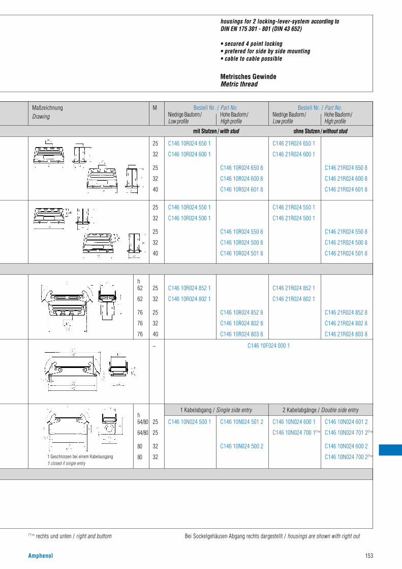
Amphenol 153
(*r+u rechts und unten / right and buttom Bei Sockelgehäusen Abgang rechts dargestellt / housings are shown with right out
housings for 2 locking-lever-system according toDIN EN 175 301 - 801 (DIN 43 652)
• secured 4 point locking• prefered for side by side mounting• cable to cable possible
Metrisches GewindeMetric thread
MaßzeichnungDrawing
M
25
32
25
32
40
25
32
25
32
40
C146 10R024 650 1
C146 10R024 600 1
C146 10R024 650 8
C146 10R024 600 8
C146 10R024 601 8
C146 21R024 650 1
C146 21R024 600 1
C146 21R024 650 8
C146 21R024 600 8
C146 21R024 601 8
C146 10R024 550 1
C146 10R024 500 1
C146 10R024 550 8
C146 10R024 500 8
C146 10R024 501 8
C146 21R024 550 1
C146 21R024 500 1
C146 21R024 550 8
C146 21R024 500 8
C146 21R024 501 8
C146 10R024 852 1
C146 10R024 802 1
C146 10R024 852 8
C146 10R024 802 8
C146 10R024 803 8
C146 21R024 852 1
C146 21R024 802 1
C146 21R024 852 8
C146 21R024 802 8
C146 21R024 803 8
25
32
25
32
40
h62
62
76
76
76
– C146 10F024 000 1
25
25
32
32
h64/80
64/80
80
80
C146 10N024 500 1 C146 10N024 501 2
C146 10N024 500 2
C146 10N024 600 1
C146 10N024 700 1(*r+u
C146 10N024 601 2
C146 10N024 701 2(*r+u
C146 10N024 600 2
C146 10N024 700 2(*r+u
1 Kabelabgang / Single side entry 2 Kabelabgänge / Double side entry
1 Geschlossen bei einem Kabelausgang1 closed if single entry
Bestell Nr. / Part No.Niedrige Bauform/ Hohe Bauform/Low profile High profile
Bestell Nr. / Part No.Niedrige Bauform/ Hohe Bauform/Low profile High profile
mit Stutzen /with stud ohne Stutzen /without stud
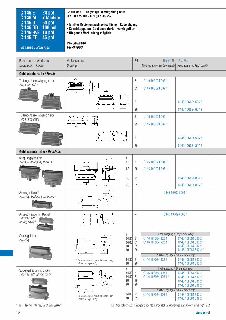
154 Amphenol
Gehäuseoberteile / Hoods
Bezeichnung - AbbildungDescription - Figure
MaßzeichnungDrawing
PG Bestell Nr. / Part No.Niedrige Bauform / Low profile Hohe Bauform / High profile
21
29
21
29
21
29
21
29
C146 10G024 606 1
C146 10G024 607 1
C146 10G024 506 1
C146 10G024 507 1
C146 10G024 606 8
C146 10G024 607 8
C146 10G024 506 8
C146 10G024 507 8
C 146 E 24 pol.C 146 M 7 ModuleC 146 D 64 pol.C 146 DD 108 pol.C 146 HvE 10 pol.C 146 EE 46 pol.
Gehäuseunterteile / Housings
Tüllengehäuse, Abgang obenHood, top entry
21
29
21
29
h62
62
76
76
–
–
C146 10G024 804 1
C146 10G024 805 1
C146 10G024 804 8
C146 10G024 805 8
Tüllengehäuse, Abgang SeiteHood, side entry
KupplungsgehäuseHood, coupling application
C146 10F024 001 1
C146 10F024 003 1
Anbaugehäuse 1)
Housing, bulkhead mounting 1)
21212929
h64/8064/808080
64/8080
h64/8064/808080
64/8080
1 Kabelabgang / Single side entry
1 Kabelabgang / Single side entry
2 Kabelabgänge / Double side entry
2 Kabelabgänge / Double side entry
C146 10F064 803 2C146 10F064 503 2 (*l
C146 10F064 802 2C146 10F064 502 2 (*l
C146 10F024 802 1C146 10F024 502 1 (*l
2129
C146 10F064 603 2C146 10F064 602 2
C146 10F024 602 1
21212929
C146 10F064 807 2C146 10F064 507 2 (*l
C146 10F064 806 2C146 10F064 506 2 (*l
C146 10F024 806 1C146 10F024 506 1 (*l
2129
C146 10F064 607 2C146 10F064 606 2
C146 10F024 606 1
SockelgehäuseHousing
Sockelgehäuse mit DeckelHousing with spring cover
1) incl. Flachdichtung / incl. flat gasket Bei Sockelgehäusen Abgang rechts dargestellt / housings are shown with right out
Gehäuse für Längsbügelverriegelung nach DIN EN 175 301 - 801 (DIN 43 652)
• leichtes Bedienen auch bei seitlichem Kabelabgang• Schutzkappe am Gehäuseunterteil verriegelbar• fliegende Verbindung möglich
PG-GewindePG-thread
Anbaugehäuse mit Deckel 1)
Housing with spring cover 1)
Gehäuse / Housings
1 Geschlossen bei einem Kabelausgang1 closed if single entry
1 Geschlossen bei einem Kabelausgang1 closed if single entry
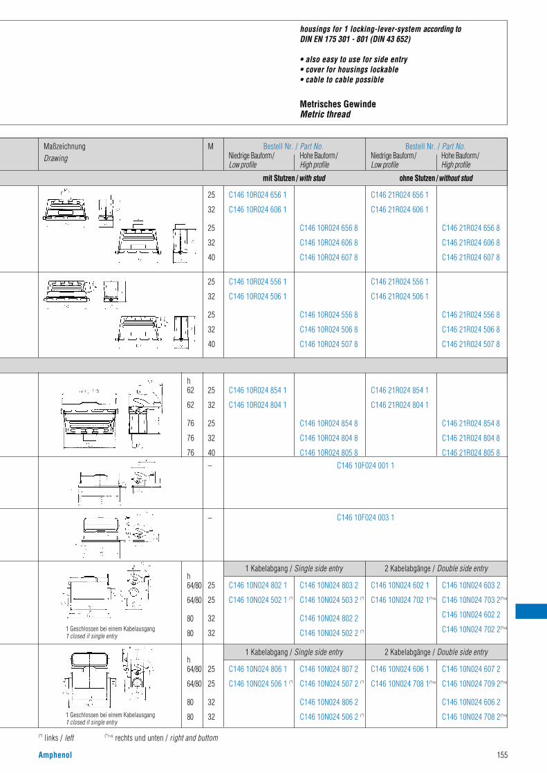
Amphenol 155
(*l links / left (*r+u rechts und unten / right and buttom
housings for 1 locking-lever-system according toDIN EN 175 301 - 801 (DIN 43 652)
• also easy to use for side entry• cover for housings lockable• cable to cable possible
Metrisches GewindeMetric thread
MaßzeichnungDrawing
M
25
32
25
32
40–
–
C146 10F024 001 1
C146 10F024 003 1
25
25
32
32
25
25
32
32
h64/80
64/80
80
80
h64/80
64/80
80
80
1 Kabelabgang / Single side entry 2 Kabelabgänge / Double side entry
1 Kabelabgang / Single side entry 2 Kabelabgänge / Double side entry
C146 10N024 802 1
C146 10N024 502 1 (*l
C146 10N024 803 2
C146 10N024 503 2 (*l
C146 10N024 802 2
C146 10N024 502 2 (*l
C146 10N024 602 1
C146 10N024 702 1(*r+u
C146 10N024 603 2
C146 10N024 703 2(*r+u
C146 10N024 602 2
C146 10N024 702 2(*r+u
C146 10N024 806 1
C146 10N024 506 1 (*l
C146 10N024 807 2
C146 10N024 507 2 (*l
C146 10N024 806 2
C146 10N024 506 2 (*l
C146 10N024 606 1
C146 10N024 708 1(*r+u
C146 10N024 607 2
C146 10N024 709 2(*r+u
C146 10N024 606 2
C146 10N024 708 2(*r+u
25
32
25
32
40
25
32
25
32
40
C146 10R024 656 1
C146 10R024 606 1
C146 10R024 656 8
C146 10R024 606 8
C146 10R024 607 8
C146 21R024 656 1
C146 21R024 606 1
C146 21R024 656 8
C146 21R024 606 8
C146 21R024 607 8
C146 10R024 556 1
C146 10R024 506 1
C146 10R024 556 8
C146 10R024 506 8
C146 10R024 507 8
C146 21R024 556 1
C146 21R024 506 1
C146 21R024 556 8
C146 21R024 506 8
C146 21R024 507 8
C146 10R024 854 1
C146 10R024 804 1
C146 10R024 854 8
C146 10R024 804 8
C146 10R024 805 8
C146 21R024 854 1
C146 21R024 804 1
C146 21R024 854 8
C146 21R024 804 8
C146 21R024 805 8
Bestell Nr. / Part No.Niedrige Bauform/ Hohe Bauform/Low profile High profile
Bestell Nr. / Part No.Niedrige Bauform/ Hohe Bauform/Low profile High profile
mit Stutzen /with stud ohne Stutzen /without stud
h62
62
76
76
76
1 Geschlossen bei einem Kabelausgang1 closed if single entry
1 Geschlossen bei einem Kabelausgang1 closed if single entry

156 Amphenol
Gehäuseoberteile / Hoods
Bezeichnung - AbbildungDescription - Figure
MaßzeichnungDrawing
PG Bestell Nr. / Part No.Niedrige Bauform / Low profile Hohe Bauform / High profile
21
29
21
29
21
29
21
29
C146 10G024 602 1
C146 10G024 603 1
C146 10G024 502 1
C146 10G024 503 1
C146 10G024 602 8
C146 10G024 603 8
C146 10G024 502 8
C146 10G024 503 8
C146 10F024 002 1
C 146 E 24 pol.C 146 M 7 ModuleC 146 D 64 pol.C 146 DD 108 pol.C 146 HvE 10 pol.C 146 EE 46 pol.
Tüllengehäuse, Abgang obenHood, top entry
–
Tüllengehäuse, Abgang SeiteHood, side entry
Anbaugehäuse mit Deckel 1)
Housing, with spring cover 1)
Sockelgehäuse, mit DeckelHousing, with spring cover
1) incl. Flachdichtung / incl. gasket Bei Sockelgehäusen Abgang rechts dargestellt / housings are shown with right out
Tüllengehäuse mit Querbügel nachDIN EN 175 301 - 801 (DIN 43 652 )
• sichere 4-Punkt Verriegelung• Gehäuseunterteil mit Schutzdeckel• keine Bügel am Gehäuseunterteil
PG-GewindePG-thread
21212929
h64/8064/808080
64/8080
C146 10F064 805 2C146 10F064 505 2 (*l
C146 10F064 804 2C146 10F064 504 2 (*l
C146 10F024 804 1C146 10F024 504 1 (*l
2129
C146 10F064 605 2C146 10F064 604 2
C146 10F024 604 1
2 Kabelabgänge / Double side entry
1 Kabelabgang / Single side entry
21
29
h80
80
80
80
C146 10F024 509 2
C146 10F024 508 2
21
29
C146 10F024 609 2
C146 10F024 608 2
2 Kabelabgänge / Double side entry
Gehäuse / Housings
1 Kabelabgang / Single side entry
Gehäuseunterteile / Housings
1 Geschlossen bei einem Kabelausgang1 closed if single entry
1 Geschlossen bei einem Kabelausgang1 closed if single entry
SockelgehäuseHousing

Amphenol 157
(*l links / left (*r+u rechts und unten / right and buttom
hoods with 2 locking-levers according to DIN EN 175 301 - 801 (DIN 43 652 )
• secured 4 point locking• housing with cover• no locking levers at the housings
Metrisches GewindeMetric thread
MaßzeichnungDrawing
M
25
32
25
32
40
25
32
25
32
40
C146 10F024 002 1–
25
25
32
32
h64/80
64/80
80
80
C146 10N024 804 1
C146 10N024 504 1 (*l
C146 10N024 805 2
C146 10N024 505 2 (*l
C146 10N024 804 2
C146 10N024 504 2 (*l
C146 10N024 604 1
C146 10N024 808 1(*r+u
C146 10N024 605 2
C146 10N024 809 2(*r+u
C146 10N024 604 2
C146 10N024 808 2(*r+u
C146 10N024 508 1 C146 10N024 509 2
C146 10N024 508 2
C146 10N024 608 1 C146 10N024 609 2
C146 10N024 608 2
2 Kabelabgänge / Double side entry1 Kabelabgang / Single side entry
2 Kabelabgänge / Double side entry1 Kabelabgang / Single side entry
25
32
h64/80
80
C146 10R024 652 1
C146 10R024 602 1
C146 10R024 652 8
C146 10R024 602 8
C146 10R024 603 8
C146 21R024 652 1
C146 21R024 602 1
C146 21R024 652 8
C146 21R024 602 8
C146 21R024 603 8
C146 10R024 552 1
C146 10R024 502 1
C146 10R024 552 8
C146 10R024 502 8
C146 10R024 503 8
C146 21R024 552 1
C146 21R024 502 1
C146 21R024 552 8
C146 21R024 502 8
C146 21R024 503 8
Bestell Nr. / Part No.Niedrige Bauform/ Hohe Bauform/Low profile High profile
Bestell Nr. / Part No.Niedrige Bauform/ Hohe Bauform/Low profile High profile
mit Stutzen /with stud ohne Stutzen /without stud
1 Geschlossen bei einem Kabelausgang1 closed if single entry
1 Geschlossen bei einem Kabelausgang1 closed if single entry

158 Amphenol
Gehäuseoberteile / Hoods
Bezeichnung - AbbildungDescription - Figure
MaßzeichnungDrawing
Bestell Nr. / Part No.Niedrige Bauform / Low profile Hohe Bauform / High profile
C146 21G024 600 1
C146 21G024 500 1
C146 10G024 903 8
C146 10G024 908 8
C146 10Z024 100 1
C146 10Z024 200 1
C146 21G024 601 8
C146 21G024 501 8
C 146 E 24 pol.C 146 M 7 ModuleC 146 D 64 pol.C 146 DD 108 pol.C 146 HvE 10 pol.C 146 EE 46 pol.
Tüllengehäuse ohne StutzenHood without stud
Schutzkappe für GehäuseunterteileCover for housings
Schutzkappe für GehäuseoberteileCover for hoods
Sondergehäuse für Querbügelverriegelung, nachDIN EN 175 301 - 801 (DIN 43 652)
Verschraubung für Tüllen- und Sockelgehäuse siehe Seite 180-183 / gland bushings for hoods and housing see page 180-183Zubehör siehe Seite 184-186 / accessories see page 184-186
Schutzkappen / covers
special housings for 2 locking-lever systems, according to DIN EN 175 301 - 801 (DIN 43 652)
21
29
21
29
–
–
Tüllengehäuse, 2 x Abgang ObenHood, 2 top entry
Gehäuse, SchutzkappenHousings, covers
PG Kabelabgangcable outlet
Oben / top
Seite / side
Oben / top
Seite / side
PG-GewindePG-thread

Amphenol 159
Gehäuseoberteile / Hoods
Bezeichnung - AbbildungDescription - Figure
MaßzeichnungDrawing
Bestell Nr. / Part No.Niedrige Bauform / Low profile Hohe Bauform / High profile
C146 21R024 650 1
C146 21R024 550 1
C146 21R024 600 1
C146 21R024 500 1
C146 10R024 909 8
C146 10R024 903 8
C146 10R024 908 8
C146 10Z024 100 1
C146 10Z024 200 1
C146 21R024 650 8
C146 21R024 550 8
C146 21R024 600 8
C146 21R024 500 8
C146 21R024 601 8
C146 21R024 501 8
C 146 E 24 pol.C 146 M 7 ModuleC 146 D 64 pol.C 146 DD 108 pol.C 146 HvE 10 pol.C 146 EE 46 pol.
Tüllengehäuse ohne StutzenHood without stud
Schutzkappe für GehäuseunterteileCover for housings
Schutzkappe für GehäuseoberteileCover for hoods
Sondergehäuse für Querbügelverriegelung, nachDIN EN 175 301 - 801 (DIN 43 652)
Verschraubung für Tüllen- und Sockelgehäuse siehe Seite 180-183 / gland bushings for hoods and housing see page 180-183Zubehör siehe Seite 184-186 / accessories see page 184-186
Schutzkappen / covers
special housings for 2 locking-lever systems, according to DIN EN 175 301 - 801 (DIN 43 652)
25
32
40
32/40
32
40
–
–
Tüllengehäuse, 2 x Abgang ObenHood, 2 top entry
Gehäuse, SchutzkappenHousings, covers
M Kabelabgangcable outlet
Oben / top
Seite / side
Oben / top
Seite / side
Oben / top
Seite / side
Metrisches GewindeMetric thread

160 Amphenol
Tüllengehäuse, Abgang oben
Hood, top entry
29
36
42
C146 10G048 606 1
C146 10G048 607 1
C146 10G048 608 1
Tüllengehäuse, Abgang Seite
Hood, side entry
29
36
42
C146 10G048 506 1
C146 10G048 507 1
C146 10G048 508 1
C 146 E 48 pol.C 146 M 14 ModuleC 146 D 128 pol.C 146 DD 216 pol.C 146 HVE 32 pol.
Gehäuseoberteile / Hoods
Bezeichnung - AbbildungDescription - Figure
PGMaßzeichnungDrawing
Bestell Nr.Part No.
Verschraubung für Tüllen- und Sockelgehäuse siehe Seite 180-183 / gland bushings for hoods and housing see page 180-183Zubehör siehe Seite 184-186 / accessories see page 184-186
Gehäuse für Längsbügelverriegelung housings for 1 locking-lever-systems
Gehäuse Housings
PG-GewindePG-thread
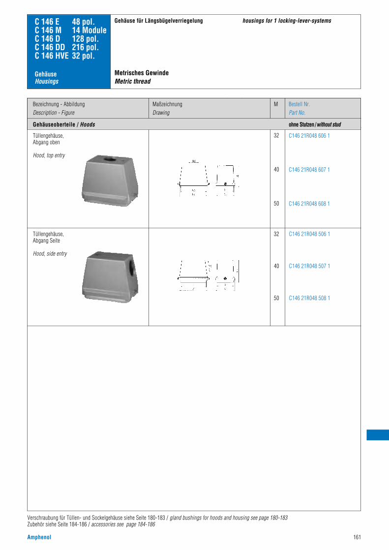
Amphenol 161
Tüllengehäuse, Abgang oben
Hood, top entry
32
40
50
C146 21R048 606 1
C146 21R048 607 1
C146 21R048 608 1
Tüllengehäuse, Abgang Seite
Hood, side entry
32
40
50
C146 21R048 506 1
C146 21R048 507 1
C146 21R048 508 1
C 146 E 48 pol.C 146 M 14 ModuleC 146 D 128 pol.C 146 DD 216 pol.C 146 HVE 32 pol.
Gehäuseoberteile / Hoods
Bezeichnung - AbbildungDescription - Figure
MMaßzeichnungDrawing
Bestell Nr.Part No.
Verschraubung für Tüllen- und Sockelgehäuse siehe Seite 180-183 / gland bushings for hoods and housing see page 180-183Zubehör siehe Seite 184-186 / accessories see page 184-186
Gehäuse für Längsbügelverriegelung housings for 1 locking-lever-systems
Gehäuse Housings
ohne Stutzen /without stud
Metrisches GewindeMetric thread
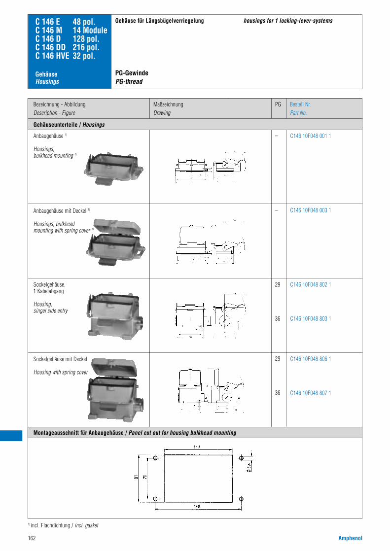
162 Amphenol
Anbaugehäuse 1)
Housings,bulkhead mounting 1)
Sockelgehäuse,1 Kabelabgang
Housing,singel side entry
–
–
29
36
29
36
C146 10F048 001 1
C146 10F048 003 1
C146 10F048 802 1
C146 10F048 803 1
C146 10F048 806 1
C146 10F048 807 1
C 146 E 48 pol.C 146 M 14 ModuleC 146 D 128 pol.C 146 DD 216 pol.C 146 HVE 32 pol.
Gehäuseunterteile / Housings
Bezeichnung - AbbildungDescription - Figure
PGMaßzeichnungDrawing
Bestell Nr.Part No.
1) incl. Flachdichtung / incl. gasket
Gehäuse für Längsbügelverriegelung housings for 1 locking-lever-systems
Montageausschnitt für Anbaugehäuse / Panel cut out for housing bulkhead mounting
Gehäuse Housings
PG-GewindePG-thread
Sockelgehäuse mit Deckel
Housing with spring cover
Anbaugehäuse mit Deckel 1)
Housings, bulkhead mounting with spring cover 1)

Amphenol 163
Anbaugehäuse 1)
Housings,bulkhead mounting 1)
Sockelgehäuse,1 Kabelabgang
Housing,singel side entry
–
–
32
40
32
40
C146 10F048 001 1
C146 10F048 003 1
C146 10N048 802 1
C146 10N048 803 1
C146 10N048 806 1
C146 10N048 807 1
C 146 E 48 pol.C 146 M 14 ModuleC 146 D 128 pol.C 146 DD 216 pol.C 146 HVE 32 pol.
Gehäuseunterteile / Housings
Bezeichnung - AbbildungDescription - Figure
MMaßzeichnungDrawing
Bestell Nr.Part No.
1) incl. Flachdichtung / incl. gasket
Gehäuse für Längsbügelverriegelung housings for 1 locking-lever-systems
Gehäuse Housings
mit Stutzen /with stud
Metrisches GewindeMetric thread
Anbaugehäuse mit Deckel 1)
Housings, bulkhead mounting with spring cover 1)
Sockelgehäuse mit Deckel
Housing with spring cover

164 Amphenol
Gehäuseoberteile / Hoods
Bezeichnung - AbbildungDescription - Figure
MaßzeichnungDrawing
PG Bestell Nr. / Part No.Niedrige Bauform / Low profile
21
21
C146 10G024 600 3
C146 10G024 500 3
C 146 HvE 16 pol.
Gehäuseunterteile / Housings
Montageausschnitt für Anbaugehäuse / Panel cut out for housing bulkhead mounting
Tüllengehäuse, Abgang obenHood, top entry
21
–
C146 10G024 802 3
Tüllengehäuse, Abgang SeiteHood, side entry
C146 10F024 000 3
KupplungsgehäuseHood, coupling application
Anbaugehäuse 1)
Housing, bulkhead mounting 1)
21 C146 10F024 500 3
1 Kabelabgang / Single side entry
C146 10F024 600 3
2 Kabelabgänge / 2 side entrySockelgehäuseHousing
Gehäuse für Querbügelverriegelung nach DIN EN 175 301 - 801 (DIN 43 652)
• mit Isolationsauskleidung• ohne Kodiersteg
housings for 2 locking-lever-system according toDIN EN 175 301 - 801 (DIN 43 652)
• with insulation inside• with removed coding element
Gehäuse Housings
1) incl. Flachdichtung / incl. gasket Zubehör siehe Seite 184-186 / accessories see page 184-186Verschraubung für Tüllen- und Sockelgehäuse siehe Seite 180-183 / gland bushings for hoods and housing see page 180-183
1 Geschlossen bei einem Kabelausgang1 closed if single entry
PG-GewindePG-thread

Amphenol 165
Gehäuseoberteile / Hoods
Bezeichnung - AbbildungDescription - Figure
MaßzeichnungDrawing
M Bestell Nr. / Part No.Niedrige Bauform / Low profile
25
32
25
32
C146 10R024 650 3
C146 10R024 600 3
C146 10R024 550 3
C146 10R024 500 3
C 146 HvE 16 pol.
Gehäuseunterteile / Housings
Tüllengehäuse, Abgang obenHood, top entry
25
32
–
C146 10R024 852 3
C146 10R024 802 3
Tüllengehäuse, Abgang SeiteHood, side entry
C146 10F024 000 3
KupplungsgehäuseHood, coupling application
Anbaugehäuse 1)
Housing, bulkhead mounting 1)
25 C146 10N024 500 3
1 Kabelabgang / Single side entry
C146 10N024 600 3
2 Kabelabgänge / 2 side entrySockelgehäuseHousing
Gehäuse für Querbügelverriegelung nach DIN EN 175 301 - 801 (DIN 43 652)
• mit Isolationsauskleidung• ohne Kodiersteg
housings for 2 locking-lever-system according toDIN EN 175 301 - 801 (DIN 43 652)
• with insulation inside• with removed coding element
Gehäuse Housings
1) incl. Flachdichtung / incl. gasket Zubehör siehe Seite 184-186 / accessories see page 184-186Verschraubung für Tüllen- und Sockelgehäuse siehe Seite 180-183 / gland bushings for hoods and housing see page 180-183
1 Geschlossen bei einem Kabelausgang1 closed if single entry
Metrisches GewindeMetric thread

166 Amphenol
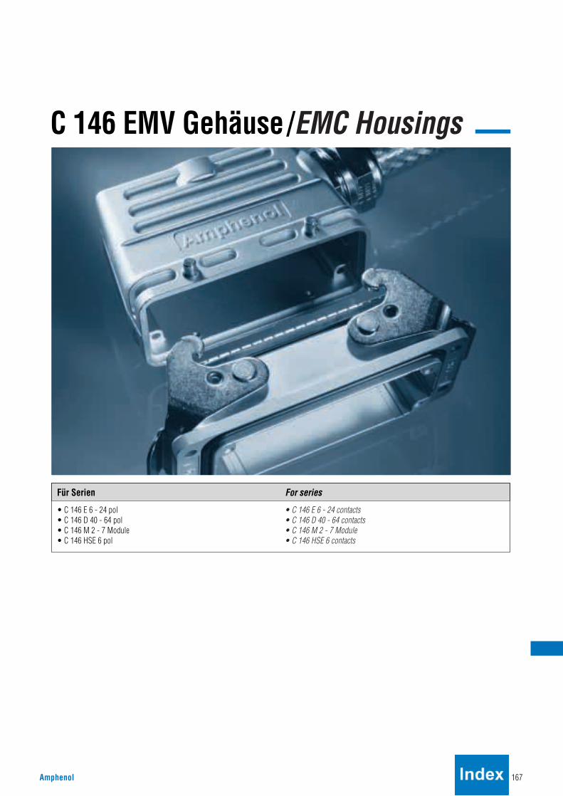
C 146 EMV Gehäuse/EMC Housings
Amphenol 167
• C 146 E 6 - 24 pol• C 146 D 40 - 64 pol• C 146 M 2 - 7 Module• C 146 HSE 6 pol
• C 146 E 6 - 24 contacts• C 146 D 40 - 64 contacts• C 146 M 2 - 7 Module• C 146 HSE 6 contacts
Für Serien For series

168 Amphenol
Das überlegene KonzeptThe advantage concept
C 146
• leitfähige Oberfläche• Standard Verriegelungssystem• gleiche Gehäuseabmessungen wie Standard Gehäuse• zwei Bauhöhen• mit und ohne Massestreifen• hohe Dämpfungseigenschaften• Schutzart IP 65• Steckzyklen > 500
MassestreifenGround strap
ZentrierflanschCentering flange
• conductive surface• standard locking levers• same housing dimensions like standard housings• two housing sizes• with or without ground strap• high attenuation• protection class IP 65• mating cycles > 500
Standard Gehäuse C 146Standard housing C 146
EMV-GehäuseEMC housings
Version A Standardflansch, ohne MassestreifenVersion A Standard flange, without ground strap
Version B Standardflansch, mit MassestreifenVersion B Standard flange, with ground strap
Version C Zentrierflansch, mit MassestreifenVersion C Centering flange, with ground strap

Amphenol 169

170 Amphenol
EMV-GehäuseEMC housings
Bezeichnung - AbbildungDescription - Figure
Gehäuseoberteile / Hoods
MaßzeichnungDrawing
PG KabelabgangCable outlet
C146 11G006 606 8C146 11G006 506 8C146 11G006 607 8C146 11G006 507 8
C146 11G006 556 1C146 11G006 606 1C146 11G006 506 1C146 11G006 607 1C146 11G006 507 1
Tüllengehäuse / Hood
Bestell Nr. / Part No.Niedrige Bauform Hohe BauformLow profile High profile
Seite / sideOben / topSeite / sideOben / topSeite / side
Oben / topSeite / sideOben / topSeite / side
1113,513,51616
21212929
Version
C146 11F006 901 8
C146 11F006 902 8
C146 11F006 001 8
A
B
C
AnbaugehäuseHousing, bulkhead mounting
Version C
Montageausschnitt / Panel cutout
Version A + B
Ø 4,5 od. M4
48
70
32,0
35,0
Version C
32,0
39,0-
0,20
0
R5,0-0+0,2
56
70
Ø 4,5 od. M4
Version A + B
C 146 E 6 pol.C 146 M 2 ModuleC 146 DD 24 pol.C 146 EE 10 pol.
Gehäuse für LängsbügelverriegelungHousings for 1 locking-lever-system
EMV Verschraubung für Tüllengehäuse siehe Seite 183 / EMC gland bushings for hoods see page 183
Gehäuseunterteile / Housings
PG-GewindePG-thread

Amphenol 171
EMV-GehäuseEMC housings
Bezeichnung - AbbildungDescription - Figure
Gehäuseoberteile / Hoods
MaßzeichnungDrawing
M KabelabgangCable outlet
C146 11R006 656 8C146 11R006 556 8C146 11R006 606 8C146 11R006 506 8
C146 11R006 556 1C146 11R006 606 1C146 11R006 506 1C146 11R006 607 1C146 11R006 507 1
Bestell Nr. / Part No.Niedrige Bauform Hohe BauformLow profile High profile
Seite / sideOben / topSeite / sideOben / topSeite / side
Oben / topSeite / sideOben / topSeite / side
1620202525
25253232
Version
C146 11F006 901 8
C146 11F006 902 8
C146 11F006 001 8
A
B
C
AnbaugehäuseHousing, bulkhead mounting
Version C
Version A + B
C 146 E 6 pol.C 146 M 2 ModuleC 146 DD 24 pol.C 146 EE 10 pol.
Gehäuse für LängsbügelverriegelungHousings for 1 locking-lever-system
EMV Verschraubung für Tüllengehäuse siehe Seite 183 / EMC gland bushings for hoods see page 183
Gehäuseunterteile / Housings
ohne Stutzen / without stud
Metrisches GewindeMetric thread
5170

172 Amphenol
EMV-GehäuseEMC housings
Bezeichnung - AbbildungDescription - Figure
Gehäuseoberteile / Hoods
MaßzeichnungDrawing
PG KabelabgangCable outlet
C146 11G010 600 8C146 11G010 500 8C146 11G010 601 8C146 11G010 501 8
C146 11G010 600 1C146 11G010 500 1C146 11G010 601 1C146 11G010 501 1
Tüllengehäuse / Hood
Bestell Nr. / Part No.Niedrige Bauform Hohe BauformLow profile High profile
Oben / topSeite / sideOben / topSeite / side
Oben / topSeite / sideOben / topSeite / side
16 162121
21 212929
Version
C146 11F010 901 8
C146 11F010 902 8
C146 11F010 000 8
A
B
C
AnbaugehäuseHousing, bulkhead mounting
Version C
Montageausschnitt / Panel cutout
Version A + B
C 146 E 10 pol.C 146 M 3 ModuleC 146 DD 42 pol.C 146 EE 18 pol.
Gehäuse für QuerbügelverriegelungHousings for 2 locking-lever-system
EMV Verschraubung für Tüllengehäuse siehe Seite 183 / EMC gland bushings for hoods see page 183
Version A + B Version C
Ø 4,5 od. M4
60
83
32,0
35,0
32,0
39,0-
0,20
0
R5,0-0+0,2
69
83
Ø 4,5 od. M4
Gehäuseunterteile / Housings
PG-GewindePG-thread

Amphenol 173
EMV-GehäuseEMC housings
Bezeichnung - AbbildungDescription - Figure
Gehäuseoberteile / Hoods
MaßzeichnungDrawing
M KabelabgangCable outlet
C146 11R010 650 8C146 11R010 550 8C146 11R010 600 8C146 11R010 500 8C146 11R010 601 8
C146 11R010 650 1C146 11R010 550 1C146 11R010 600 1C146 11R010 500 1C146 11R010 601 1
Tüllengehäuse / Hood
Bestell Nr. / Part No.Niedrige Bauform Hohe BauformLow profile High profile
Oben / topSeite / sideOben / topSeite / sideOben / top
Oben / topSeite / sideOben / topSeite / sideOben / top
20 20252532
25 25323240
Version
C146 11F010 901 8
C146 11F010 902 8
C146 11F010 000 8
A
B
C
AnbaugehäuseHousing, bulkhead mounting
Version C
Version A + B
C 146 E 10 pol.C 146 M 3 ModuleC 146 DD 42 pol.C 146 EE 18 pol.
Gehäuse für QuerbügelverriegelungHousings for 2 locking-lever-system
EMV Verschraubung für Tüllengehäuse siehe Seite 183 / EMC gland bushings for hoods see page 183
Gehäuseunterteile / Housings
ohne Stutzen / without stud
Metrisches GewindeMetric thread
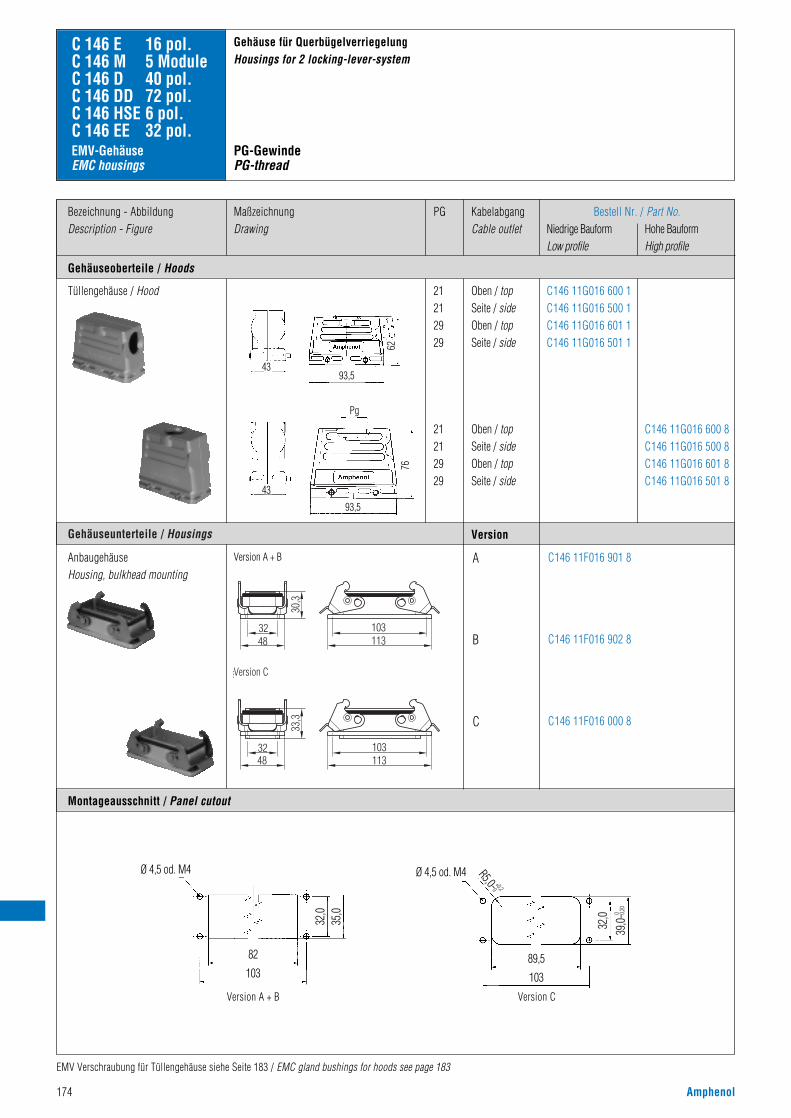
174 Amphenol
EMV-GehäuseEMC housings
Bezeichnung - AbbildungDescription - Figure
Gehäuseoberteile / Hoods
MaßzeichnungDrawing
PG KabelabgangCable outlet
C146 11G016 600 8C146 11G016 500 8C146 11G016 601 8C146 11G016 501 8
C146 11G016 600 1C146 11G016 500 1C146 11G016 601 1C146 11G016 501 1
Tüllengehäuse / Hood
Bestell Nr. / Part No.Niedrige Bauform Hohe BauformLow profile High profile
Oben / topSeite / sideOben / topSeite / side
Oben / topSeite / sideOben / topSeite / side
21 21 2929
21 21 2929
Version
C146 11F016 901 8
C146 11F016 902 8
C146 11F016 000 8
A
B
C
AnbaugehäuseHousing, bulkhead mounting
Montageausschnitt / Panel cutout
Version A + B
C 146 E 16 pol.C 146 M 5 ModuleC 146 D 40 pol.C 146 DD 72 pol.C 146 HSE 6 pol.C 146 EE 32 pol.
Gehäuse für QuerbügelverriegelungHousings for 2 locking-lever-system
EMV Verschraubung für Tüllengehäuse siehe Seite 183 / EMC gland bushings for hoods see page 183
Version A + B Version C
Ø 4,5 od. M4
82
103
32,0
35,0
32,0
39,0-
0,20
0
R5,0-0+0,2
89,5
103
Ø 4,5 od. M4
30,3
4832 103
113
33,3
4832 103
113
ersion C
Gehäuseunterteile / Housings
Version C
43
76
93,5
Pg
PG-GewindePG-thread
4393,5
62

4393,5
62
Amphenol 175
EMV-GehäuseEMC housings
Bezeichnung - AbbildungDescription - Figure
Gehäuseoberteile / Hoods
MaßzeichnungDrawing
M KabelabgangCable outlet
C146 11R016 650 8C146 11R016 550 8C146 11R016 600 8C146 11R016 500 8C146 11R016 601 8C146 11R016 501 8
C146 11R016 650 1C146 11R016 550 1C146 11R016 600 1C146 11R016 500 1
Tüllengehäuse / Hood
Bestell Nr. / Part No.Niedrige Bauform Hohe BauformLow profile High profile
Oben / topSeite / sideOben / topSeite / side
Oben / topSeite / sideOben / topSeite / sideOben / topSeite / side
25 25 3232
25 25 32324040
Version
C146 11F016 901 8
C146 11F016 902 8
C146 11F016 000 8
A
B
C
AnbaugehäuseHousing, bulkhead mounting
Montageausschnitt / Panel cutout
Version A + B
C 146 E 16 pol.C 146 M 5 ModuleC 146 D 40 pol.C 146 DD 72 pol.C 146 HSE 6 pol.C 146 EE 32 pol.
Gehäuse für QuerbügelverriegelungHousings for 2 locking-lever-system
EMV Verschraubung für Tüllengehäuse siehe Seite 183 / EMC gland bushings for hoods see page 183
Version A + B Version C
Ø 4,5 od. M4
82
103
32,0
35,0
32,0
39,0-
0,20
0
R5,0-0+0,2
89,5
103
Ø 4,5 od. M4
30,3
4832 103
113
33,3
4832 103
113
ersion C
Gehäuseunterteile / Housings
Version C
43
76
93,5
Metrisches GewindeMetric thread

176 Amphenol
EMV-GehäuseEMC housings
Bezeichnung - AbbildungDescription - Figure
Gehäuseoberteile / Hoods
MaßzeichnungDrawing
PG KabelabgangCable outlet
C146 11G024 600 8C146 11G024 500 8C146 11G024 601 8C146 11G024 501 8
C146 11G024 600 1C146 11G024 500 1C146 11G024 601 1C146 11G024 501 1
Tüllengehäuse / Hood
Bestell Nr. / Part No.Niedrige Bauform Hohe BauformLow profile High profile
Oben / topSeite / sideOben / topSeite / side
Oben / topSeite / sideOben / topSeite / side
21212929
21212929
Version
C146 11F024 901 8
C146 11F024 902 8
C146 11F024 000 8
A
B
C
AnbaugehäuseHousing, bulkhead mounting
Version C
Montageausschnitt / Panel cutout
Version A + B
C 146 E 24 pol.C 146 M 7 ModuleC 146 D 64 pol.C 146 DD 108 pol.C 146 EE 46 pol.
Gehäuse für QuerbügelverriegelungHousings for 2 locking-lever systems
EMV Verschraubung für Tüllengehäuse siehe Seite 183 / EMC gland bushings for hoods see page 183
Version A + B
Ø 4,5 od. M4
108
130
32,0
35,0
Version C
32,0
39,0-
0,20
0
R5,0-0+0,2
116
130
Ø 4,5 od. M4
Gehäuseunterteile / Housings
PG-GewindePG-thread

Amphenol 177
EMV-GehäuseEMC housings
Bezeichnung - AbbildungDescription - Figure
Gehäuseoberteile / Hoods
MaßzeichnungDrawing
M KabelabgangCable outlet
C146 11R024 650 8C146 11R024 550 8C146 11R024 600 8C146 11R024 500 8C146 11R024 601 8C146 11R024 501 8
C146 11R024 650 1C146 11R024 550 1C146 11R024 600 1C146 11R024 500 1
Tüllengehäuse / Hood
Bestell Nr. / Part No.Niedrige Bauform Hohe BauformLow profile High profile
Oben / topSeite / sideOben / topSeite / side
Oben / topSeite / sideOben / topSeite / sideOben / topSeite / side
25253232
252532324040
Version
C146 11F024 901 8
C146 11F024 902 8
C146 11F024 000 8
A
B
C
AnbaugehäuseHousing, bulkhead mounting
Version C
Version A + B
C 146 E 24 pol.C 146 M 7 ModuleC 146 D 64 pol.C 146 DD 108 pol.C 146 EE 46 pol.
Gehäuse für QuerbügelverriegelungHousings for 2 locking-lever systems
EMV Verschraubung für Tüllengehäuse siehe Seite 183 / EMC gland bushings for hoods see page 183
Gehäuseunterteile / Housings
Metrisches GewindeMetric thread

178 Amphenol

Amphenol 179
C 146 Zubehör / Accessories
• Verschraubungen• EMV Verschraubungen• Verschraubungen mit Zugentlastung• Codierbolzen• Führungsstifte / Buchsen• D-Sub Adapterplatten• Moosgummidichtungen• Klebeschild nach CSA-Vorschrift
• gland bushings• EMC gland bushings• Cable seals with cable clamp• Key pin• Guide pin / bush• D-Sub adaptors• Foam rubber sealing• Label for CSA regulation
Übersicht Overview

180 Amphenol
Bezeichnung - AbbildungDescription - Figure
ZeichnungDrawing
PGPG
StückzahlPieces
MM
Bestell Nr.Part No.
C 146
ZubehörAccessories
Metall, mit ausschneidbaren Dichtungen (Zwiebelringen) Metal, with variable innerdiameter
Metall, mit Standard Dichtung Metal, with standard diameter
Verschraubung IP 65 1)
Gland bushings IP 65 1)
VN16 110 0014 X(Thermoplast)
VN16 200 0114 X(Thermoplast)
11
–
–
–
–
–
–
–
20
–
–
–
–
–
–
–
–
–
–
–
–
–
10
10
VN16 135 0014 X13,5 10
VN16 160 0014 X
VN16 200 0114 X
16
20
10
10
VN16 210 0014 X
VN16 250 0114 X
21
25
10
10
VN16 290 0014 X
VN16 320 0114 X
29
32
10
10
VN16 360 0014 X
VN16 400 0114 X
36
40
10
10
VN16 420 0014 X
VN16 500 0114 X
42
50
10
10
VN16 110 0013 X(Thermoplast)
11 10
VN16 135 0013 X13,5 10
VN16 160 0013 X16 10
VN16 210 0013 X21 10
VN16 290 0013 X29 10
VN16 360 0013 X36 10
VN16 420 0013 X42 10
1) Achtung: nicht für Gehäuse ohne Stutzen geeignet / Attention: not usable for hoods without stud

Amphenol 181
Bezeichnung - AbbildungDescription - Figure
ZeichnungDrawing
PGPG
MM
StückzahlPieces
Bestell Nr.Part No.
C 146
ZubehörAccessories
Kabelverschraubung ohne DichtungCable clamp without gasket
Kabelverschraubung ohne DichtungCable clamp without gasket
Dichtung, DruckscheibeSealing, pressure disk
Ausschneidbare Dichtung,DruckscheibeSealing with variable inner diameter,and pressure rings
ZwischenstutzenStud
Verschraubung IP 65 1)
Gland bushings IP 65 1)
VN16 110 0004 V(Thermoplast)
11 5
VN16 135 0002 VVN16 160 0102 V
13,5–
–
–
–
–
–
–
16
–
–
–
–
–
–
–
–
–
–
–
–
–
–
–
–
–
–
–
–
–
–
–
–
55
VN16 160 0002 VVN16 200 0102 V
1620
55
VN16 210 0002 VVN16 250 0102 V
2125
55
VN16 290 0002 VVN16 320 0102 V
2932
55
VN16 135 0003 V13,5 5
VN16 160 0003 V
VN16 200 0103 V
16
20
5
5
VN16 210 0003 V
VN16 250 0103 V
21
25
5
5
VN16 290 0003 V
VN16 320 0103 V
29
32
5
5
VN16 110 0028 X11 10
VN16 135 0028 X13,5 10
VN16 160 0028 X16 10
VN16 210 0028 X21 10
VN16 290 0028 X29 10
VN16 110 0029 X11 10
VN16 135 0029 X13,5 10
VN16 160 0029 X16 10
VN16 210 0029 X21 10
VN16 290 0029 X29 10
N16 011 001011 1
N16 013 001013,5 1
N16 016 001016 1
N16 021 001021 1
N16 029 001029 1
1) Achtung: nicht für Gehäuse ohne Stutzen geeignet / Attention: not usable for hoods without stud

182 Amphenol
Bezeichnung - AbbildungDescription - Figure
Klemmbereich ØClamping range Ø
PGPG
StückzahlPieces
Amm
Bestell Nr. / Part No.
C 146
ZubehörAccessories
Kabelverschraubung mitVibrationsschutzGland bushing withvibration protection
4 - 10 mm
Verschraubung IP 67 (Material PA / - 20 °C + 80 °C)Gland bushings IP 67 (Material PA / - 20 °C + 80 °C)
VN16 110 0027 X11 1024,4
4 - 10 mm VN16 160 0127 X– 1020
5 - 12 mm VN16 135 0027 X13,5 1026,5
6 - 12 mm VN16 200 0127 X– 1024
9 - 14 mm VN16 160 0027 X16 1029,5
9 - 16 mm VN16 250 0127 X– 1028
13 - 18 mm VN16 210 0027 X21 1036,2
10 - 21 mm VN16 320 0127 X– 1036
14 - 25 mm VN16 290 0027 X29 1043,6
16 - 28 mm VN16 400 0127 X– 10
MM
–
16
–
20
–
25
–
32
–
4046
Blindstopfen aus Messingvernickelt mit Einstich und O-RingPlugs brass nickel-plated withrecess and o-ring
VN16 020 0113 (1) X10
VN16 025 0113 (1) X10
VN16 032 0113 (1) X10
VN16 040 0113 (1) X10
M 20
M 25
M 32
M 40

Amphenol 183
Bezeichnung - AbbildungDescription - Figure
Klemmbereich FClamping range F
PGPG
StückzahlPieces
Bestell Nr.Part No.
C 146
ZubehörAccessories
Kabelverschraubung EMVGland bushing EMC
4 - 10 mm
EMV Verschraubung IP 68 (Material CuZn / PA / - 20 °C + 80 °C)EMC gland bushings IP 68 (Material CuZn / PA / - 20 °C + 80 °C)
VN16 110 0026 X11 10
5,5 - 10 mm VN16 160 0126 X– 10
5 - 12 mm VN16 135 0026 X13,5 10
8 - 13 mm VN16 200 0126 X– 10
8 - 14 mm VN16 160 0026 X16 10
11 - 18 mm VN16 250 0126 X– 10
11 - 17,5 mm VN16 210 0026 X21 10
15 - 21 mm VN16 320 0126 X– 10
16 - 25 mm VN16 290 0026 X29 10
19 - 27 mm VN16 400 0126 X–
MM
–
16
–
20
–
25
–
32
–
40 10
1 = Zwischenstutzen2 = Hutmutter3 = Dichtung4 = 0-Ringe5 = Einsatz6 = Erdungsfinger
1 = Screwed gland2 = Cap nut3 = Sealing4 = 0 ring5 = Insert6 = Grounding finger
• Außenmantel und Schirm absetzen• Außenmantel nach ca. 15 mm mit Rundschnitt
versehen, jedoch nicht abziehen• Leitung durch die Verschraubung führen• Außenmantel abziehen• Leitung zurückziehen bis die Verbindung zwischen
Leitungsschirm und Kontaktfeder hergestellt ist
• Der Außenmantel des Kabels wird entfernt bis Unterseite Lamellen-Klemmkäfig, das Drahtgeflecht wird erst ein Stück weiter unten abgeschnitten und dann als ringförmiger Wulst ausgebildet. Der innere Schutzmantel kann am Kabel dranbleiben, sofern er durch die untere Öffnung der Verschraubung passt.
• Bei der Montage, beim Zusammenschrauben der Kabelverschraubung wird der ringförmige Wulst durch die Lamellentülle auf den Boden des Unterteils verpresst und findet in einer Auskofferung Platz. Dadurch wird die EMV-Sicherheit hergestellt.
• Cut and remove cable jacket and braid• Cut cable jacket appr. 15 mm further but
don’t remove it yet• Insert cable through backshell• Remove now the cut jacket part• Pull back cable until connection is made
between grounding fingers and braid
• The cable jacket should be removed as far as the underside of the cable clamping; the wire netting is then to be cut down a little further and subsequently must be formed into a circular rim. The protective jacket can remain attached to the cable provided that it passes through the lower opening of the clamp.
• On assembly, while screwing the cable clamp, the circular rim has to be pushed through and pressed on the fins commutator on the base of the underside and settle into a depression. By doing this the EMC security will remain.
• Außenmantel absetzen• Schirmgeflecht ca. 15 - 20 mm über den Außen-
mantel zurückschlagen• Leitungen in Verschraubung einführen, bis
Verbindung zwischen Leitungsschirm und Kontakt-feder hergestellt ist
• Cut and remove cable jacket• Fold braid appr. 15 to 20 mm back over jacket• Insert cable into backshell until grounding
fingers connect with braid
• Schirmgeflecht ca. 10 mm freilegen• Leitung durch die Verschraubung führen bis
Verbindung zwischen Leitungsschirm und Kontakt-feder hergestellt ist
• Expose braid appr. 10 mm• Insert cable through backshell until grounding
fingers rest on braid
Montagehinweise für PG-Verschraubung / Assembly instructions for PG-Clamp
Montagehinweise für metrische Verschraubung / Assembly instructions for metric clamp

184 Amphenol
C 146
ZubehörAccessories
Bezeichnung - AbbildungDescription - Figure
ZeichnungDrawing
StückzahlPieces
Bestell Nr.Part No.
Kodierbolzen mit SicherungsscheibeKey pin with lock washer
VN17 050 0004 (1)
VN17 050 0004 (101)
10
100
FührungsstiftGuide pin
VN13 040 0009 (1) X10
FührungsbuchseGuide socket
VN13 040 0008 (1) X10
Verrieglungsschraube fürKontakteinsätzeLocking screw for contact inserts
C146 D 15, 25C146 A 10, 16
VN03 030 002120
Verriegelungsschraube fürKontakteinsätzeLocking screw for contact inserts
C146 E; M; D 40, 64; H
VN03 030 002020
L23
20
VerriegelungssetLocking set
C146 E; M; D 40, 64; H
VN03 030 3000 X10
M 3

Amphenol 185
C 146
ZubehörAccessories
BezeichnungDescription
Kodierschema mit Kodierbolzen
Polarization system with key pin
Für Gehäuse mit einem KontakteinsatzFor housings with one contact insert
Für Gehäuse mit zwei KontakteinsätzenFor housings with two contact inserts
KodierbolzenBefestigungsschrauben
M - StifteinsatzF - Buchseneinsatz
Key pinLocking screw
M - Male insertF - Female insert
Kodierschema mit Führungsstiftund Führungsbuchse
Polarization system with guide pinand guide socket
KodierschemaPolarization system
Für Gehäuse mit einem KontakteinsatzFor housings with one contact insert
Für Gehäuse mit zwei KontakteinsätzenFor housings with two contact inserts
Führungsstift Führungsbuchse
+ BefestigungsschraubenM - StifteinsatzF - Buchseneinsatz
Guide pinGuide socket
+ Locking screwM - Male insertF - Female insert

186 Amphenol
Bezeichnung - AbbildungDescription - Figure
ZeichnungDrawing
GrößeSize
Bestell Nr.Part No.
C 146
ZubehörAccessories
Moosgummidichtung 2 mmFoam rubber sealing 2 mm
Adapterplatte D-Sub Set MetallAdaptor for D-Sub Set metal
Adapterplatte D-Sub Set einreihigAdaptor for D-Sub set single-row
Adapterplatte D-Sub Set zweireihigAdaptor for D-Sub set double-row
Hinweisschild für CSA-AnwendungLabel for CSA application
N06 080 0003 16
N06 080 0003 210
N06 080 0003 316
N06 080 0003 424
C146 N32 015 G215D-Sub15
C146 N32 025 G22525
C146 N32 009 G16
C146 N32 015 G16
C146 N32 025 G110
C146 N32 037 G116
C146 N32 050 G11650
C146 N33 009 G16
C146 N33 015 G16
C146 N33 025 G110
C146 N33 037 G116
C146 N33 050 G116
D-Sub915
25
37
D-Sub915
25
37
50
N07 045 0001 L50StückPieces
b70
83
103
130
a80
93
113
140
b49,5
49,5
a57
57
2 x Platte / adaptor4 x M3 x 6,58 x M3 x 14
2 x Platte / adaptor4 x M3 x 6,58 x M3 x 14
b4444
57
77,5
77,5
a51,551,5
64,5
85
85
2 x Platte / adaptor4 x M3 x 6,58 x M3 x 14
b4444
57
77,5
77,5
a51,551,5
64,5
85
85
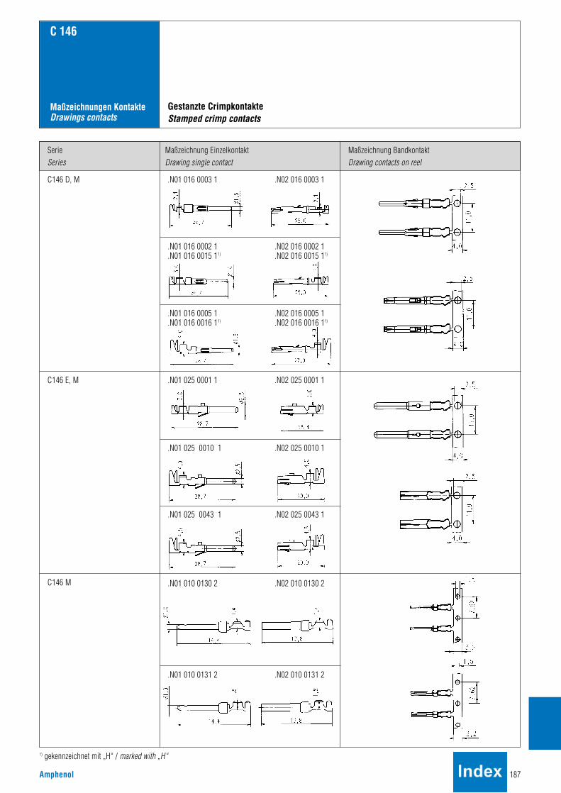
Amphenol 187
SerieSeries
Maßzeichnung EinzelkontaktDrawing single contact
Maßzeichnung BandkontaktDrawing contacts on reel
C 146
Maßzeichnungen KontakteDrawings contacts
C146 D, M .N01 016 0003 1 .N02 016 0003 1
.N01 016 0002 1 .N02 016 0002 1
.N01 016 0015 11) .N02 016 0015 11)
.N01 016 0005 1 .N02 016 0005 1
.N01 016 0016 11) .N02 016 0016 11)
.N01 025 0001 1 .N02 025 0001 1
.N01 025 0010 1 .N02 025 0010 1
.N01 010 0130 2 .N02 010 0130 2
.N01 010 0131 2 .N02 010 0131 2
C146 E, M
C146 M
Gestanzte CrimpkontakteStamped crimp contacts
.N01 025 0043 1 .N02 025 0043 1
1) gekennzeichnet mit „H“ / marked with „H“

188 Amphenol
SerieSeries
MaßzeichnungDrawing
QuerschnittWire gauge
A B StückzahlPieces
Bestell Nr.Part No.
C 146
Maßzeichnungen KontakteDrawings contacts
C146 D, DD, M .N01 016 002X
.N02 016 002X
.N01 025 003X
.N02 025 003X
.N01 025 00XX
.N02 025 00XX
.N01 036 000X
.N02 036 000X
C146 E, EE
C146 M
VN01 016 0024 (1)C
VN01 016 0025 (1)C
VN01 016 0026 (1)C
VN01 016 0027 (1)C
VN01 016 0028 (1)C
VN02 016 0024 (1)C
VN02 016 0025 (1)C
VN02 016 0026 (1)C
VN02 016 0027 (1)C
VN02 016 0028 (1)C
VN01 025 0035 (1)C
VN01 025 0036 (1)C
VN01 025 0037 (1)C
VN01 025 0038 (1)C
VN01 025 0039 (1)C
VN02 025 0035 (1)C
VN02 025 0036 (1)C
VN02 025 0037 (1)C
VN02 025 0038 (1)C
VN02 025 0039 (1)C
VN01 025 0029 (1)C
VN01 025 0030 (1)C
VN01 025 0031 (1)C
VN01 025 0032 (1)C
VN01 025 0033 (1)C
VN02 025 0029 (1)C
VN02 025 0030 (1)C
VN02 025 0031 (1)C
VN02 025 0032 (1)C
VN02 025 0033 (1)C
VN01 036 0004 (1)C
VN01 036 0005 (1)C
VN01 036 0001 (1)C
VN01 036 0002 (1)C
VN01 036 0003 (1)C
VN02 036 0004 (1)C
VN02 036 0005 (1)C
VN02 036 0001 (1)C
VN02 036 0002 (1)C
VN02 036 0003 (1)C
100
100
100
100
100
100
100
100
100
100
100
100
100
100
100
100
100
100
100
100
100
100
100
100
100
100
100
100
100
100
100
100
100
100
100
100
100
100
100
100
2,6
2,6
2,6
3,0
3,2
2,6
2,6
2,6
3,0
3,2
2,6
2,6
3,0
3,2
4,0
2,6
2,6
3,0
3,2
4,0
2,6
2,6
3,0
3,45
3,9
2,6
2,6
3,0
3,45
3,9
3,0
3,45
3,9
4,9
5,9
3,0
3,45
3,9
4,9
5,9
0,9
1,1
1,45
1,75
2,25
0,9
1,1
1,45
1,75
2,25
1,1
1,45
1,75
2,3
2,9
1,1
1,45
1,75
2,3
2,9
1,1
1,45
1,75
2,25
2,85
1,1
1,45
1,75
2,25
2,85
1,75
2,25
2,85
3,55
4,4
1,75
2,25
2,85
3,55
4,4
0,14 - 0,37
0,5
0,75 - 1,0
1,5
2,5
0,14 - 0,37
0,5
0,75 - 1,0
1,5
2,5
0,5
0,75 - 1,0
1,5
2,5
4,0
0,5
0,75 - 1,0
1,5
2,5
4,0
0,5
0,75 - 1,0
1,5
2,5
4,0
0,5
0,75 - 1,0
1,5
2,5
4,0
1,5
2,5
4,0
6,0
10,0
1,5
2,5
4,0
6,0
10,0
Gedrehte CrimpkontakteTurned crimp contacts

Amphenol 189
SerieSeries
Maßzeichnung EinzelkontaktDrawing single contact
Bestell Nr.Part No.
C 146
Maßzeichnungen KontakteDrawings contacts
C146 M LWL
C146 M FO
C146 M Koax
C146 M Coax
N01 016 0040 8
N02 016 0040 8
17 DM 537 421
17 DM 537 401
17 DM 537 425
17 DM 537 405
LWL Kontakte, Koax KontakteFO contacts, coax contacts

190 Amphenol
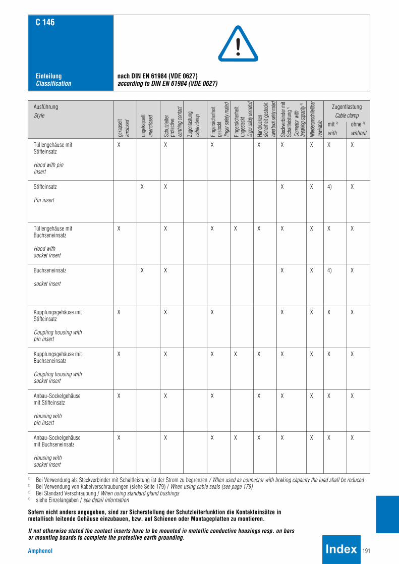
Amphenol 191
AusführungStyle
geka
pselt
enclo
sed
unge
kaps
eltun
enclo
sed
Zuge
ntas
tung
cable
clam
p
Fing
ersic
herh
eitge
steck
tfin
ger s
afety
mated
Fing
ersic
herh
eitun
geste
ckt
finge
r safe
ty un
mated
Hand
rück
en-
siche
rheit
ges
teckt
hand
back
safety
mate
d
Stec
kver
bind
er m
itSc
haltl
eistu
ng 1)
Conn
etor w
ith
brea
king c
apac
ity 1)
Wied
erans
chlie
ßbar
rewira
ble
Schu
tzleit
erpr
otec
tive
earth
ing co
ntact Zugentlastung
Cable clampmit 2) ohne 3)
with without
C 146
EinteilungClassification
nach DIN EN 61984 (VDE 0627)according to DIN EN 61984 (VDE 0627)
Tüllengehäuse mitStifteinsatz
Hood with pininsert
Stifteinsatz
Pin insert
X XX
X
X
X
X
X X X
X X X 4) X
X X X X X X
X
X
X
X
X
X X X X
X
X
X
X X X X X
X X
X
X
X
X
X X X X
X X X X X X X
Tüllengehäuse mitBuchseneinsatz
Hood withsocket insert
X
X
X X X 4) XBuchseneinsatz
socket insert
Kupplungsgehäuse mitStifteinsatz
Coupling housing withpin insert
Kupplungsgehäuse mitBuchseneinsatz
Coupling housing withsocket insert
Anbau-Sockelgehäuse mit Stifteinsatz
Housing withpin insert
Anbau-Sockelgehäuse mit Buchseneinsatz
Housing withsocket insert
1) Bei Verwendung als Steckverbinder mit Schaltleistung ist der Strom zu begrenzen / When used as connector with braking capacity the load shall be reduced2) Bei Verwendung von Kabelverschraubungen (siehe Seite 179) / When using cable seals (see page 179)3) Bei Standard Verschraubung / When using standard gland bushings4) siehe Einzelangaben / see detail information
Sofern nicht anders angegeben, sind zur Sicherstellung der Schutzleiterfunktion die Kontakteinsätze in metallisch leitende Gehäuse einzubauen, bzw. auf Schienen oder Montageplatten zu montieren.
If not otherwise stated the contact inserts have to be mounted in metallic conductive housings resp. on barsor mounting boards to complete the protective earth grounding.
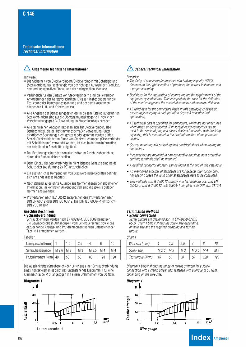
192 Amphenol
C 146
Technische InformationenTechnical information
Allgemeine technische Informationen
Hinweise:• Die Sicherheit von Steckverbindern/Steckverbinder mit Schaltleistung
(Steckvorrichtung) ist abhängig von der richtigen Auswahl der Produkte,dem ordungsgemäßen Einbau und der sachgemäßen Montage.
• Verbindlich für den Einsatz von Steckverbindern sind die jeweiligenAnforderungen der Gerätevorschriften. Dies gilt insbesondere für dieFestlegung der Bemessungsspannung und der damit zusammen-hängenden Luft- und Kriechstrecken.
• Alle Angaben der Bemessungsdaten der in diesem Katalog aufgeführtenSteckverbindern sind auf die Überspannungskategorie III sowie denVerschmutzungsgrad 3 (Anwendung im Maschinenbau) bezogen.
• Alle technischen Angaben beziehen sich auf Steckverbinder, alsoBetriebsmittel, die bei bestimmungsgemäßer Verwendung (unterelektrischer Spannung) nicht gesteckt oder getrennt werden dürfen.Soweit Steckverbinder im Sinne von Steckvorrichtungen (Steckverbindermit Schaltleistung) verwendet werden, ist dies in der Kurzinformationder betreffenden Abschnitte aufgeführt.
• Der Berührungsschutz der Kontakteinsätze im Anschlussbereich istdurch den Einbau sicherzustellen.
• Beim Einbau der Steckverbinder in nicht leitende Gehäuse sind beideSchutzleiter (Ausführung 2x PE) anzuschließen.
• Ein ausführliches Kompendium von Steckverbinder-Begriffen befindetsich am Ende dieses Kapitels.
• Nachstehend aufgeführte Auszüge aus Normen dienen der allgemeinenInformation. Im konkreten Anwendungsfall sind die jeweils gültigenNormen anzuwenden.
• Prüfverfahren nach IEC 60512 entsprechen den Prüfverfahren nach DIN EN 60512 oder DIN IEC 60512. Die DIN IEC 60664-1 entsprichtDIN VDE 0110-1
Anschlusstechniken• Schraubverbindung
Schraubklemmen werden nach EN 60999-1/VDE 0609 bemessen. Die Gewindegröße in Abhängigkeit vom Leiterquerschnitt sowie dasdazugehörige Anzugs- und Prüfdrehmoment können untenstehenderTabelle 1 entnommen werden.
Tabelle 1
Die Ausziehkräfte (Streubereich) der Leiter aus einer Schraubverbindungeines Kontaktelementes zeigt das untenstehende Diagramm 1 für eineKlemmschraube M 3, angezogen mit einem Drehmoment von 50 Ncm.
Diagramm 1
General technical information
Remarks:• The Safty of connectors/connectors with braking capacity (CBC)
depends on the right selection of products, the correct installation anda proper assembly.
• Decisions for the application of connectors are the requirements of theequipment specifications. This is especially the case for the definitionof the rated voltage and the related clearances and creepage distances.
• All rated data for the connectors listed in this catalogue is based onovervoltage category III and pollution degree 3 (machine toolapplication).
• All technical data is specified for connectors, which are not under loadwhen mated or disconnected. If in special cases connectors can beused in the sense of plug and socket devices (connector with breakingcapacity), this is mentioned in the brief information of the particularsection.
• Correct mounting will protect against electrical shock when mating theconnectors.
• It connectors are mounted in non conductive housings both protectiveearthing terminals shall be mounted.
• A detailed connector glossary can be found at the end of this catalogue.
• All mentioned excerpts of standards are for general information only.For specific cases the valid original standards have to be consulted.
• Test methods acc. IEC 60512 camply with test methods acc. DIN EN60512 or DIN IEC 60512. IEC 60664-1 complies with DIN VDE 0110-1
Termination methods• Screw connection
Screw clamps are designed acc. to EN 60999-1/VDE0609. Chart 1 below shows the screw size dependingon wire size and the required clamping and testingtorque.
Chart 1
Diagram 1 below shows the range of tensile strength for a screwconnection with a clamp screw M3, fastened with a torque of 50 Ncm,depending on the wire size.
Diagram 1
Wire size (mm2) 1 1,5 2,5 4 6 10
Screw size M 2,6 M 3 M 3 M 3,5 M 4 M 4
Test torque (Ncm) 40 50 50 80 120 120
Leiterquerschnitt (mm2) 1 1,5 2,5 4 6 10
Schraubengewinde M 2,6 M 3 M 3 M 3,5 M 4 M 4
Prüfdrehmoment (Ncm) 40 50 50 80 120 120
Tens
ile s
treng
th
Wire gauge
Ausz
iehk
raft
Leiterquerschnitt

Amphenol 193
C 146
Technische InformationenTechnical information
• CrimpverbindungEine Crimpverbindung ist eine nicht lösbare elektrische Verbindungzwischen einem Leiter und einem Crimpkontakt mit Hilfe derCrimptechnik. Durch genau auf Crimphülse und Leiterquerschnittabgestimmte Crimpprofile werden durch Druck und gezielte Verformungzuverlässige elektrische Verbindungen hergestellt. Es gibt offeneCrimphülsen (gestanzte Kontakte) und geschlossene Crimphülsen(gedrehte Kontakte).
Die wesentlichen Vorteile von Crimpverbindungen sind:• Rationelle Verarbeitung der Kontakte• Konstante elektrische und mechanische Werte durch gleichbleibende
Crimpqualität. (Eine ausführliche Beschreibung der Crimptechnologie findenSie in unserem Katalog „Werkzeuge“.)
Die Anforderungen an Crimpverbindungen sind in der DIN EN 60352-2,festgelegt.
Ein wesentliches Merkmal für die Qualität einer Crimpverbindung ist dieerreichte Zugfestigkeit des Anschlusses. Sie kann mit einfachen Mittelnzur Überwachung der Qualität herangezogen werden. Aus untenstehenderTabelle 2 kann die Mindest-Zugfestigkeit entnommen werden.
Tabelle 2
Zugfestigkeit von Crimpverbindungen
• Crimp connectionA crimp connection is a non-detachable electrical connection between awire and a crimp contact produced with the crimp technology. Precisecrimping dies are matched to the crimp barrel and the wire size and adefined deformation results in a reliable electrical connection. There areopen barrels (stamped contacts) and closed crimp barrels (turnedcontacts).
The main advantages of crimp connections are:• Efficient termination of contacts.• Reproduceable electrical and mechanical figures by a constant crimp
quality.
(A detailed description of the crimp technology can be found inour catalogue „tools“).
The requirements for crimp connections are defined in DIN EN 60352-2.
An important point for the quality of a crimp connection is the achievedtensile strength of the termination. Measuring the tensile strength is apractible means for quality control purposes. Chart 2 below shows therequired minimum tensile strength for open and closed barrels accordingto the wire size.
Chart 2
Tensile strength for crimp connetions
Leiterquerschnitt Zugfestigkeit
mm2 AWG1) N
0,05 30 6
0,08 28 11
0,12 26 15
0,14 18
0,22 24 28
0,25 32
0,32 22 40
0,5 20 60
0,75 85
0,82 18 90
1,0 108
1,3 16 135
1,5 150
2,1 14 200
2,5 230
3,3 12 275
4,0 310
5,3 10 355
6,0 360
8,4 8 370
10,0 380
Wire size Tensile strenghtmm2 AWG1) N0,05 30 6
0,08 28 11
0,12 26 15
0,14 18
0,22 24 28
0,25 32
0,32 22 40
0,5 20 60
0,75 85
0,82 18 90
1,0 108
1,3 16 135
1,5 150
2,1 14 200
2,5 230
3,3 12 275
4,0 310
5,3 10 355
6,0 360
8,4 8 370
10,0 3801) Nur zur Information 1) only for information
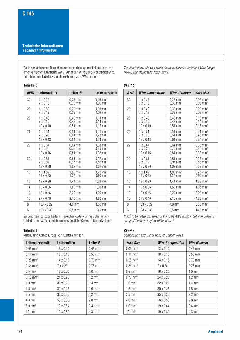
194 Amphenol
AWG Wire composition
C 146
Technische InformationenTechnical information
Da in verschiedenen Bereichen der Industrie auch mit Leitern nach deramerikanischen Drahtlehre AWG (American Wire Gauge) gearbeitet wird,folgt hiernach Tabelle 3 zur Umrechnung von AWG in mm2.
Tabelle 3
Zu beachten ist, dass Leiter mit gleicher AWG-Nummer, aber unter-schiedlichem Aufbau, leicht unterschiedliche Querschnitte aufweisen!
The chart below allows a cross reference between American Wire Gauge(AWG) and metric wire sizes (mm2).
Chart 3
It has to be noted that wires of the same AWG number but with differentcomposition have slightly different mm2.
AWG Leiteraufbau Leiter-Ø Leiterquerschnitt
30 1 x 0,25 0,25 mm 0,05 mm2
7 x 0,10 0,36 mm 0,06 mm2
28 1 x 0,32 0,32 mm 0,08 mm2
7 x 0,13 0,38 mm 0,09 mm2
26 1 x 0,40 0,40 mm 0,13 mm2
7 x 0,16 0,48 mm 0,14 mm2
19 x 0,10 0,51 mm 0,15 mm2
24 1 x 0,51 0,51 mm 0,21 mm2
7 x 0,20 0,61 mm 0,23 mm2
19 x 0,13 0,64 mm 0,24 mm2
22 1 x 0,64 0,64 mm 0,33 mm2
7 x 0,25 0,76 mm 0,36 mm2
19 x 0,16 0,81 mm 0,38 mm2
20 1 x 0,81 0,81 mm 0,52 mm2
7 x 0,32 0,97 mm 0,56 mm2
19 x 0,20 1,02 mm 0,62 mm2
18 1 x 1,02 1,02 mm 0,79 mm2
19 x 0,25 1,27 mm 0,96 mm2
16 19 x 0,29 1,44 mm 1,23 mm2
14 19 x 0,36 1,80 mm 1,95 mm2
12 19 x 0,46 2,29 mm 3,09 mm2
10 37 x 0,40 3,10 mm 4,60 mm2
8 133 x 0,29 4,0 mm 8,80 mm2
6 133 x 0,36 5,5 mm 13,5 mm2
Tabelle 4Aufbau und Abmessungen von Kupferleitungen
Chart 4Composition and Dimensions of Copper Wires
Leiterquerschnitt Leiteraufbau Leiter-Ø
0,09 mm2 12 x 0,10 0,48 mm
0,14 mm2 18 x 0,10 0,50 mm
0,25 mm2 14 x 0,15 0,70 mm
0,34 mm2 7 x 0,25 0,78 mm
0,5 mm2 16 x 0,20 1,0 mm
0,75 mm2 24 x 0,20 1,2 mm
1,0 mm2 32 x 0,20 1,4 mm
1,5 mm2 30 x 0,25 1,6 mm
2,5 mm2 35 x 0,30 2,2 mm
4,0 mm2 56 x 0,30 2,8 mm
6,0 mm2 19 x 0,64 3,4 mm
10 mm2 19 x 0,80 4,3 mm
Wire diameter Wire size
Wire Size Wire Composition Wire diameter0,09 mm2 12 x 0,10 0,48 mm
0,14 mm2 18 x 0,10 0,50 mm
0,25 mm2 14 x 0,15 0,70 mm
0,34 mm2 7 x 0,25 0,78 mm
0,5 mm2 16 x 0,20 1,0 mm
0,75 mm2 24 x 0,20 1,2 mm
1,0 mm2 32 x 0,20 1,4 mm
1,5 mm2 30 x 0,25 1,6 mm
2,5 mm2 35 x 0,30 2,2 mm
4,0 mm2 56 x 0,30 2,8 mm
6,0 mm2 19 x 0,64 3,4 mm
10 mm2 19 x 0,80 4,3 mm

Amphenol 195
C 146
Technische InformationenTechnical information
Strombelastbarkeit
Die Strombelastbarkeit eines Steckverbinders wird mit einer Derating-Kurve dargestellt. Aus ihr kann abgelesen werden, welche Ströme dauerndund gleichzeitig über alle Kontakte fließen dürfen. Die Kurve wird durchPrüfung ermittelt. Als Basis dient dazu die Norm DIN EN 60512. Die obereGrenztemperatur wird durch die verwendeten Kontakt- und Isolier-werkstoffe bestimmt. Die Summe aus der Umgebungstemperatur und derdurch die Strombelastung hervorgerufenen Übertemperatur darf die obereGrenztemperatur des Steckverbinders nicht übersteigen. Somit ist dieStrombelastbarkeit kein konstanter Wert, sondern sinkt mit steigenderUmgebungstemperatur. Als allgemeines Beispiel sei gesagt, dass beieinem vorgegebenen Steckverbinder, der bei einer Umgebungstemperaturvon 40°C mit einem Dauerstrom von 16A auf allen Kontakten belastetwerden darf, dieser Wert bei einer Umgebungstemperatur von 80°C aufz.B. 12A sinken kann. Auf der anderen Seite ist es in der Praxis sehr oftder Fall, dass nicht alle Anschlüsse gleichzeitig mit dem maximalzulässigen Strom belastet werden, so dass dann einzelne Kontakte miteinem höheren Strom als nach der Derating-Kurve zulässig, beaufschlagtwerden können. Diese Grenzwerte sind durch Prüfung zu ermitteln.
Diagramm 3
Current carrying capacity
The current carrying capacity of a connector is shown by a derating curve.The curve shows the currents that the connector can carry continuouslyand simultaneously through all its contacts. The curve is determined bytesting following the standard DIN EN 60512. The upper temperature islimited by the contact and insulation material used . The sum of theambient temperature and the temperature created by the current flow maynot exceed the upper temperature. This means that the current carryingcapacity has no fixed value but decreases with increasing ambienttemperatures. As a general example it can be said that a given connector which cancarry 16A through all its contacts at 40°C ambient temperature can carryless, e.g. 12A, at an ambient temperature of 80°C.On the other hand it is often the case that not all contacts carry the wholerated current, which means that some single contacts may carry a highercurrent than that according to the derating curve. These currents have tobe defined by testing.
Diagram 3
Tabelle 5
Strombelastbarkeit von Kupferleitern in (A)
Chart 5
Current carrying capacity of copper wires in (A)
- - - 7,6 10,4 13,5 18,3 25 32 44
- - - - 9,6 12 16,5 23 29 40
4,0 5,0 7,1 9,1 11,7 15,2 21 28 36 50
4,0 5,0 7,1 9,1 11,5 16,1 22 30 37 52
B1 Leiter in Schutzrohren und InstallationskanälenWires in conduits and installation channels
Installationsart Querschnitt (mm2) 0,25 0,34 0,5 0,75 1 1,5 2,5 4 6 10Installation type Wire size (mm2)
Stro
mbe
last
bark
eit
UmgebungstemperaturTypische Derating-Kurve
Durch die Werkstoffe gegebeneobere Grenztemperatur
Curre
nt c
arry
ing
capa
city
Ambient temperature (°C)Typical derating curve
Upper temperature limited by the connector materials
Darstellung in Anlehnung an DIN EN 60204 für PVC-isolierte Kupferleiter ineiner Umgebungstemperatur von +40°C unter Dauerbetriebsbedingungen. Für abweichende Bedingungen wie andere Temperaturen, Installationen,Isoliermaterialien oder Leitern sind entsprechende Korrekturfaktoren zuverwenden (siehe nächste Seite).
Description according to DIN EN 60204 for PVC insulated copper wires with a working temperature of +40C. For other requirements, such as for othertemperatures, mountings, or wires corresponding correction factors are used (see next page).
B2 Kabel und Leitungen in Schutzrohren oder InstallationskanälenCables and conductors in conduits or installation channels
C Kabel und Leitungen an WändenCables and conductors along walls
E Kabel und Leitungen auf KabelpritschenCables and conductors on plank

196 Amphenol
Ambient temperature (°C) Correction value
30 1,15
35 1,03
40 1,00
45 0,91
50 0,82
55 0,71
60 0,58
C 146
Technische InformationenTechnical information
Reduktionsfaktoren
Die Werte in der Tabelle 5 beziehen sich auf eine Umgebungstemperaturvon 40°C. Für andere Umgebungstemperaturen muss der Wert mit denFaktoren aus der folgenden Tabelle 6 korrigiert werden.
Tabelle 6
Reduction values
The values in chart 5 are based on an ambient temperature of 40 °C. For other ambient temperatures the values have to be adjusted using thecorrection values of chart 6 below.
Chart 6
Umgebungstemperatur (°C) Korrekturfaktor
30 1,15
35 1,03
40 1,00
45 0,91
50 0,82
55 0,71
60 0,58
Für Installationen mit vielen belasteten Kabeln und Leitungen/Paarenverringern sich die Werte der Strombelastbarkeit entsprechend dennachfolgenden Tabellen 7 und 8.
Tabelle 7
Reduktionsfaktoren für Leitungsanhäufung
Tabelle 8
Reduktionsfaktoren für Mehraderkabel (-leitungen) bis zu 10 mm2
Leiter von Steuerkreisen benötigen normalerweise keine Herabsetzung.
For installations with many cables and conductors under load the currentcarrying capacity is reduced according to the two following charts 7 and8.
Chart 7
Reduction values for accumulated conductors
Chart 8
Reduction values for multicore cable and conductors up to 10mm2
Conductors of control circuits generally do not need a reduction.
Art der Installation Anzahl der belasteten Kabel und Leitungen / PaareInstallation type Number of cables and conductors / pairs under load
2 4 6 9
Drehstromkabel und -leitungThreephase cable and conductor
B1 und/and B2CE-einlagig / one rowE-mehrlagig / multi row
Gleichstromleitung (Paar), unabhängig von der InstallationsartDC conductor (pair), independent of installation type
0,80 0,85 0,87 0,860,65 0,75 0,78 0,760,57 0,72 0,75 0,720,50 0,70 0,73 0,88
1,0 0,76 0,64 0,43
Anzahl der belasteten Leitungen (Paare) Wechselstrom (Leiter >1 mm2) Gleichstrom (Paare 0,2 bis 0,75 mm2)Number of conductors (pairs) under load AC (conductor > 1 mm2) DC (Pairs 0,2 to 0,75 mm2)
5 0,75 0,52
7 0,65 0,45
10 0,55 0,39
24 0,40 0,27
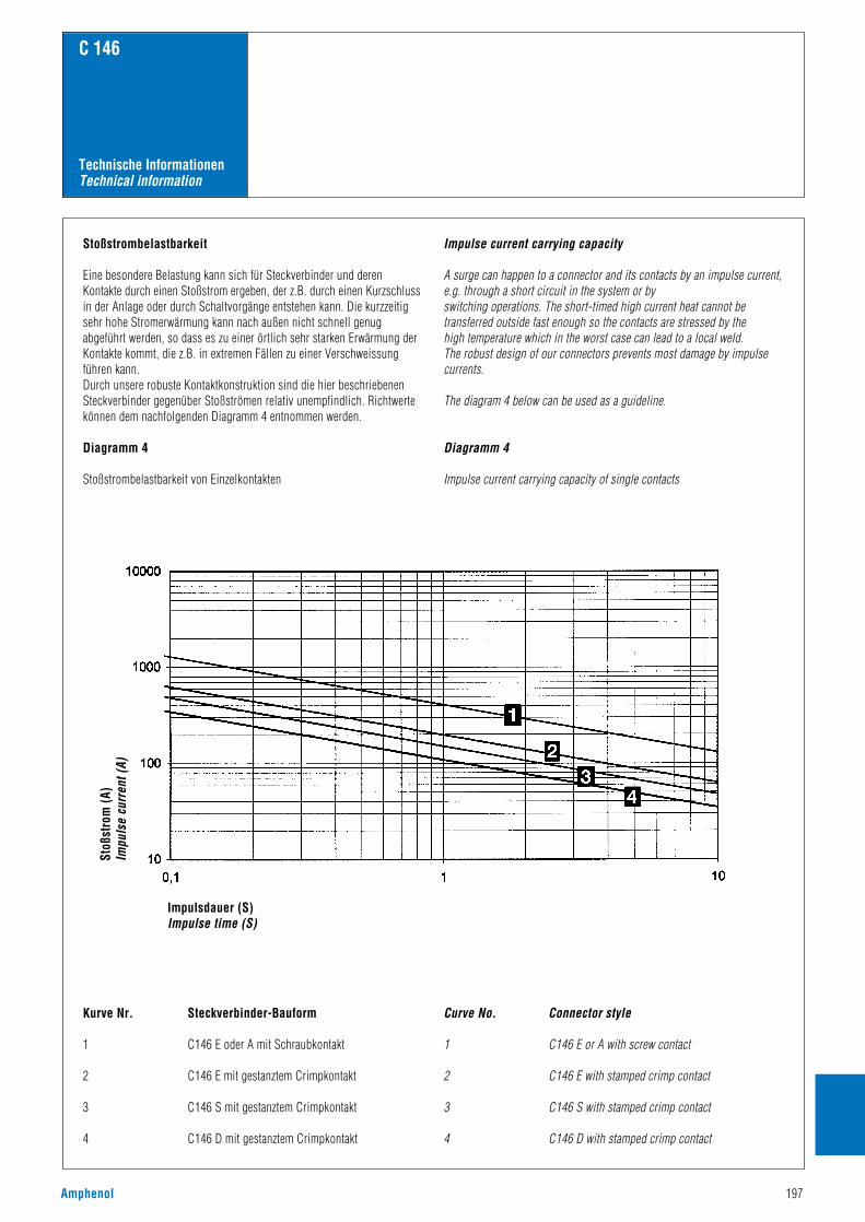
Amphenol 197
C 146
Technische InformationenTechnical information
Stoßstrombelastbarkeit
Eine besondere Belastung kann sich für Steckverbinder und derenKontakte durch einen Stoßstrom ergeben, der z.B. durch einen Kurzschlussin der Anlage oder durch Schaltvorgänge entstehen kann. Die kurzzeitigsehr hohe Stromerwärmung kann nach außen nicht schnell genugabgeführt werden, so dass es zu einer örtlich sehr starken Erwärmung derKontakte kommt, die z.B. in extremen Fällen zu einer Verschweissungführen kann.Durch unsere robuste Kontaktkonstruktion sind die hier beschriebenenSteckverbinder gegenüber Stoßströmen relativ unempfindlich. Richtwertekönnen dem nachfolgenden Diagramm 4 entnommen werden.
Diagramm 4
Stoßstrombelastbarkeit von Einzelkontakten
Kurve Nr. Steckverbinder-Bauform
1 C146 E oder A mit Schraubkontakt
2 C146 E mit gestanztem Crimpkontakt
3 C146 S mit gestanztem Crimpkontakt
4 C146 D mit gestanztem Crimpkontakt
Impulse current carrying capacity
A surge can happen to a connector and its contacts by an impulse current,e.g. through a short circuit in the system or by switching operations. The short-timed high current heat cannot betransferred outside fast enough so the contacts are stressed by thehigh temperature which in the worst case can lead to a local weld.The robust design of our connectors prevents most damage by impulsecurrents.
The diagram 4 below can be used as a guideline.
Diagramm 4
Impulse current carrying capacity of single contacts
Curve No. Connector style
1 C146 E or A with screw contact
2 C146 E with stamped crimp contact
3 C146 S with stamped crimp contact
4 C146 D with stamped crimp contact
Stoß
stro
m (A
)Im
puls
e cu
rren
t (A)
Impulsdauer (S)Impulse time (S)

198 Amphenol
C 146
Technische InformationenTechnical information
Spannungseinstufung der Steckverbinder
Allgemeines
Zur Spannungseinstufung von Steckverbindern werden die Luft- undKriechstrecken herangezogen. Die Beurteilung und Bemessung der Luft-und Kriechstrecken hat sich durch die Einführung derIsolationskoordination geändert.
Es gelten dafür die folgenden Normen:
IEC 60664-1/10.92Insulation coordination for equipment within low-voltage systems
DIN VDE 0110-1/4.97Isolationskoordination für elektrische Betriebsmittel in Niederspannungsanlagen
Isolationskoordination umfasst die Auswahl der elektrischen Isolations-eigenschaften eines Betriebsmittels hinsichtlich dessen Anwendung undin Bezug auf seine Umgebung.
LuftstreckenDie Luftstrecke ist die kürzeste Entfernung in Luft zwischen zwei leitendenTeilen. Ein wichtiger Punkt bei der Bemessung von Luftstrecken ist zu-nächst die Festlegung der Überspannungskategorie. Die Norm hat diemöglichen Überspannungen in die nachstehenden vier Kategorien ein-geteilt:
Überspannungskategorie IBetriebsmittel, die zur Anwendung in Geräten oder Teilen von Anlagenbestimmt sind, in denen keine Überspannungen auftreten können. Hier-unter fallen Geräte, die vorwiegend mit Kleinspannungen betriebenwerden.
Überspannungskategorie IIBetriebsmittel, die zur Anwendung in Anlagen oder Teilen von diesenbestimmt sind, in denen Blitzüberspannungen nicht berücksichtigt werdenmüssen, aber wohl Überspannungen durch Schaltvorgänge.Hierunter fallen z.B. elektrische Haushaltsgeräte.
Überspannungskategorie IIIBetriebsmittel, die zur Anwendung in Anlagen oder Teilen von diesenbestimmt sind, bei denen Blitzüberspannungen nicht berücksichtigtwerden müssen, wohl aber Überspannungen durch Schaltvorgänge und andie im Hinblick auf die Sicherheit und Verfügbarkeit des Betriebsmittelsoder von davon abhängigen Netzen besondere Anforderungen gestelltwerden.Hierunter fallen Betriebsmittel für feste Installationen, z.B.Schutzeinrichtungen, Schütze, Schalter und Steckdosen.
Überspannungskategorie IVBetriebsmittel, die zur Anwendung in Anlagen oder Teilen von diesenbestimmt sind, bei denen Blitzüberspannungen zu berücksichtigen sind.Hierunter fallen Betriebsmittel zum Anschluss an Freileitungen, z.B.Rundsteuerempfänger, Zähler.
Voltage grading of connectors
General
Clearances and creepage distances are the base for voltage grading ofconnectors. Valuation and dimensioning of clearances and creepagedistances have changed since the introduction of insulation coordination.
The following standards apply for this:
IEC 60664-1/10.92Insulation coordination for equipment withinlow-voltage systems
DIN VDE 0110-1/4.97Isolationskoordination für elektrische Betriebsmittel in Niederspannungsanlagen
Insulation coordination comprises the selection of the electrical insulationperformances of the equipment, taking into account the expected use andits environment.
ClearancesThe clearance is the shortest distance in air between two conductive parts.An important point for the dimensioning of clearances is thedetermination of the overvoltage category. The above standard specifiesthe possible overvoltages into the four following categories:
Overvoltage category IEquipment intended for the use in appliances or parts of installations inwhich no overvoltage can occur.Examples are low-voltage equipments.
Overvoltage category IIEquipment intended for the use in installations or parts of it in whichlightning overvoltages do not need to be considered, but switchingovervoltages generated by the equipment do need to be considered.Examples are household appliances.
Overvoltage category IIIEquipment intended for the use in installtions or parts of it in whichlightning overvoltages do not need to be considered, however switchingovervoltages generated by the euipment, and for cases where thereliability and the availability of the equipment or its dependent circuitsare subject to special requirements.Examples are protecting means, switches and sockets.
Overvoltage category IVEquipment intended for the use in installations or parts of it in whichlightning overvoltage has to be considered. Examples are electricity meters, overcurrent protection switches.

Amphenol 199
C 146
Technische InformationenTechnical information
Liegt die Überspannungskategorie fest, dann kann je nach Nenn-spannungsbereich des Stromversorgungs-Systems und der Über-spannungskategorie die Bemessungs-Stoßspannung für das Betriebs-mittel ermittelt werden. Es gilt dabei die folgende Tabelle 9:
Tabelle 9
Ist die Bemessungs-Stoßspannung ermittelt, so muss jetzt derVerschmutzungsgrad entsprechend der zu erwartenden Verschmutzung derunmittelbaren Umgebung des Betriebsmittels festgelegt werden. Hierzudienen die folgenden vier festgelegten Grade:
Verschmutzungsgrad 1Es tritt keine oder nur trockene, nicht leitfähige Verschmutzung auf. DieVerschmutzung hat keinen Einfluss.
Verschmutzungsgrad 2Es tritt nur nicht leitfähige Verschmutzung auf. Gelegentlich muss jedochmit vorübergehender Leitfähigkeit durch Betauung gerechnet werden.
Verschmutzungsgrad 3Es tritt leitfähige Verschmutzung auf oder trockene, nicht leitfähigeVerschmutzung, die leitfähig wird, da Betauung zu erwarten ist.
Verschmutzungsgrad 4Die Verunreinigung führt zu einer beständigen Leitfähigkeit, hervorgerufendurch leitfähigen Staub, Regen oder Schnee.
Zu beachten ist, dass Teile von Steckverbindern und Steckvor-richtungen mit ausreichender Kapselung (min. IP 54) auchnach einem niedrigeren Verschmutzungsgrad bemessen werdenkönnen. Dies gilt auch für Steckverbinder im Trennbereich, bei denen die Kapselung im gesteckten Zustand durch dasSteckverbindergehäuse erreicht wird und die nur für Prüf- und Wartungszwecke getrennt werden.
Aus der Bemessungs-Stoßspannung und dem Verschmutzungsgradkönnen jetzt aus Tabelle 10 die Mindest-Luftstrecken ermittelt werden.
Once the overvoltage category has been defined the rated impulsewithstand voltage can be selected for the equipment based on the nominalvoltage of the supply system and the overvoltage category using chart 9below:
Chart 9
After the rated impulse withstand voltage has been selected the pollutiondegree must be defined taking the expected pollution around theequipment into account.The following four degrees of pollution are established:
Pollution degree 1No pollution or only dry, non-conductive pollution occurs. The pollutionhas no influence.
Pollution degree 2Only non-conductive pollution occurs except occasionally a temporaryconductivity caused by condensation is to be expected.
Pollution degree 3Conductive pollution occurs or dry non-conductive pollution occurswhich becomes conductive due to condensation which is to be expected.
Pollution degree 4The pollution generates persistent conductivity caused by conductive dustor by rain or snow.
It has to be noted that for a connector or plug and socketdevise with a degree of protection of min. IP 54 the partsinside the enclosure may be dimensioned for a lower pollutiondegree. This also applies to mated connectors which enclosureis ensured through the connector housing and which may onlybe disengaged for test and maintenance purposes.
When impulse withstand voltage and the pollution degree are defined theminimum clearances can be selected from chart 10.
Nennspannung des Stromversorgungs-Systems in V (nach IEC 60038)Nominal voltage of the supply system in V(based on IEC 60038)
Bemessungs-Stoßspannung in kV für ÜberspannungskategorieRated impulse voltage in kV for overvoltage category
Drei-phasige Systeme / Three phase systems IV III II I
230/400 277/480 6 4 2,5 1,5
400/690 8 6 4 2,5
1000 12 8 6 4

200 Amphenol
C 146
Technische InformationenTechnical information
Tabelle 10
Bemessungs-Stoßspannungin kVImpulse withstand voltage in kV
0,330,400,500,600,801,01,21,52,02,53,04,05,06,08,010121520253040506080100
0,010,020,040,060,100,150,250,51,01,52345,58111418253340607590130170
0,2
0,250,51,01,52345,58111418253340607590130170
0,8
1,01,52345,58111418253340607590130170
1,6
2345,58111418253340607590130170
0,010,020,040,060,10,150,20,30,450,60,81,21,5233,54,55,581012,51722273545
0,2
0,30,450,60,81,21,5233,54,55,581012,51722273545
0,8
1,21,5233,54,55,581012,51722273545
1,6
233,54,55,581012,51722273545
Mindestluftstrecken in mm bis zu 2000 m über NNMinimum clearances in air in mm up to 2000 m above sea level
Fall A (inhomogenes Feld)Case A (non homogeneous field)
VerschmutzungsgradPollution degree
1 2 3 4 1 2 3 4
Fall B (homogenes Feld)Case B (homogeneous field)
VerschmutzungsgradPollution degree
Chart 10
Creepage distancesThe creepage distance is the shortest distance along the surface of theinsulating material between two conductive parts.For the dimensioning of the creepage distance the following factors aretaken into account: the rated voltage, the pollution degree and the trackingformation of the insulating material. The materials are separated into fourgroups according to their CTI values (Comparative Tracking Index):
Material group I 600 ≤ CTIMaterial group II 400 ≤ CTI < 600Material group IIIa 175 ≤ CTI < 400Material group IIIb 100 ≤ CTI < 175
KriechstreckenDie Kriechstrecke ist die kürzeste Entfernung entlang der Oberfläche einesIsolierstoffes zwischen zwei leitenden Teilen.Zur Bemessung der Kriechstrecke wird die aus der entsprechenden Netzartabgeleitete Bemessungsspannung und die bereits bei der Luftstreckegewählte Zuordung des Verschmutzungsgrades herangezogen. Außerdemwird die Kriechwegbildung des vom Hersteller verwendeten Isolierstoffesberücksichtigt. Die Isolierstoffe werden entsprechend ihremKriechwegbildungsfaktor CTI (Comparative Tracking Index) in vierGruppen eingeteilt:Isolierstoffgruppe I 600 ≤ CTIIsolierstoffgruppe II 400 ≤ CTI <600Isolierstoffgruppe IIIa 175 ≤ CTI <400Isolierstoffgruppe IIIb 100 ≤ CTI <175
Bei der Festlegung der Mindestluftstrecken von Steckverbindern sind inder Regel die Werte des inhomogenen Falls anzuwenden bzw. ist dieentsprechende Luftstrecke durch eine Spannungsprüfung zu überprüfen.
When defining the minimum clearances for connectors generally thevalues of the inhomogeneous field can be chosen or the requiredclearance has to be defined by a voltage test.
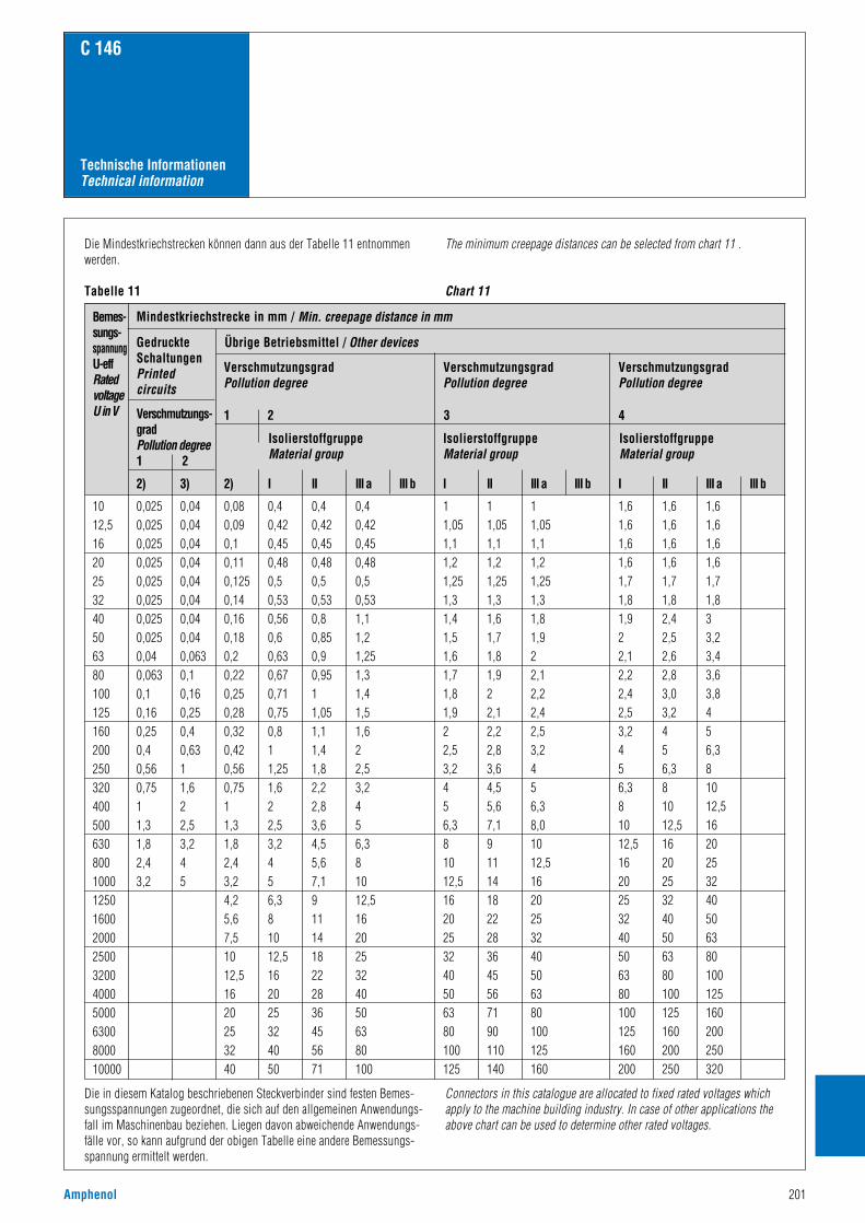
Amphenol 201
C 146
Technische InformationenTechnical information
Bemes-sungs-spannungU-effRated voltage U in V
1012,51620253240506380100125160200250320400500630800100012501600200025003200400050006300800010000
0,0250,0250,0250,0250,0250,0250,0250,0250,040,0630,10,160,250,40,560,7511,31,82,43,2
0,040,040,040,040,040,040,040,040,0630,10,160,250,40,6311,622,53,245
0,080,090,10,110,1250,140,160,180,20,220,250,280,320,420,560,7511,31,82,43,24,25,67,51012,51620253240
0,40,420,450,480,50,530,560,60,630,670,710,750,811,251,622,53,2456,381012,5162025324050
0,40,420,450,480,50,530,80,850,90,9511,051,11,41,82,22,83,64,55,67,19111418222836455671
0,40,420,450,480,50,531,11,21,251,31,41,51,622,53,2456,381012,51620253240506380100
11,051,11,21,251,31,41,51,61,71,81,922,53,2456,381012,51620253240506380100125
11,051,11,21,251,31,61,71,81,922,12,22,83,64,55,67,1911141822283645567190110140
11,051,11,21,251,31,81,922,12,22,42,53,2456,38,01012,51620253240506380100125160
1,61,61,61,61,71,81,922,12,22,42,53,2456,381012,51620253240506380100125160200
1,61,61,61,61,71,82,42,52,62,83,03,2456,381012,51620253240506380100125160200250
1,61,61,61,61,71,833,23,43,63,8456,381012,51620253240506380100125160200250320
Mindestkriechstrecke in mm / Min. creepage distance in mm
GedruckteSchaltungenPrintedcircuits
Verschmutzungs-gradPollution degree1 2
2) 3) 2) I II III a III b I II III a III b I II III a III b
Übrige Betriebsmittel / Other devices
VerschmutzungsgradPollution degree
IsolierstoffgruppeMaterial group
IsolierstoffgruppeMaterial group
IsolierstoffgruppeMaterial group
1 2 3 4
VerschmutzungsgradPollution degree
VerschmutzungsgradPollution degree
Die Mindestkriechstrecken können dann aus der Tabelle 11 entnommenwerden.
Tabelle 11
The minimum creepage distances can be selected from chart 11 .
Chart 11
Die in diesem Katalog beschriebenen Steckverbinder sind festen Bemes-sungsspannungen zugeordnet, die sich auf den allgemeinen Anwendungs-fall im Maschinenbau beziehen. Liegen davon abweichende Anwendungs-fälle vor, so kann aufgrund der obigen Tabelle eine andere Bemessungs-spannung ermittelt werden.
Connectors in this catalogue are allocated to fixed rated voltages whichapply to the machine building industry. In case of other applications theabove chart can be used to determine other rated voltages.

202 Amphenol
C 146
Technische InformationenTechnical information
Schutzarten
Elektrische Betriebsmittel, zu denen Steckverbinder zählen, müssen ausSicherheitsgründen gegen Einflüsse von außen, wie z.B. Staub, Fremd-körper, Berührung, Feuchtigkeit und Wasser geschützt werden. DiesenSchutz übernehmen bei Industrie-Steckverbindern die Gehäuse mit ihrerVerriegelung und dem abgedichteten Kabeleinlass.Den Grad der Schutzart kann man dem Einsatz entsprechend wählen. Inder Norm IEC 60529 bzw. DIN EN 60529 sind die Schutzgrade festgelegtund in verschiedene Klassen eingeteilt.Die Bezeichnung erfolgt in nachstehender Weise:
IP65Kennzeichen (Internat. Protection)1. Kennziffer (Schutzgrad gegen den Zugang zu gefährlichen Teilen und gegen feste Fremdkörper)2. Kennziffer (Schutzgrad gegen Wasser)Die nachfolgenden Tabellen 12 und 13 zeigen alle Schutzarten in einerÜbersicht.
Tabelle 12
Degree of protection
Electrical connector devices have to be protected for safety reasons fromoutside influences like dust, foreign objects, direct contact, moisture andwater. This protection is provided on industrial connectors by the housinglatching devices and sealed cable entries. The degree of protectiondepends on the type of intended use. The standard IEC 60529 and/or DINEN 60529 has specified the degree of protection and divided them intoseveral classes.
The degree of protection is indicated in the following way:IP 65
Code letters(Internat. Protection)1st charact. numeral (degree of protection against access to hazardous parts and against solid foreign objects)2nd charact. numeral (degree of protection against ingress of water)The following charts 12 an13 give an overview about all protectiondegrees.
Chart 12
1. Kenn- Kurzbeschreibung Definitionziffer
01
2
3
4
5
6
Nicht geschütztGeschützt gegen den Zugangzu gefährlichen Teilen mit dem Handrücken. Geschützt gegen feste Fremdkörper Ø ≥ 50 mm.Geschützt gegen den Zugangzu gefährlichen Teilen mit einem Finger. Geschützt gegen feste Fremdkörper Ø ≥ 12,5 mm.
Geschützt gegen den Zugang zu gefährlichen Teilen mit einem Werkzeug. Geschützt gegen feste Fremdkörper Ø ≥ 2,5 mm.Geschützt gegen den Zugang zu gefährlichen Teilen mit einem Draht. Geschützt gegen feste Fremdkörper Ø ≥ 1 mm.Geschützt gegen den Zugang zu gefährlichen Teilen mit einem Draht. Staubgeschützt.
Geschützt gegen den Zugang zu gefährlichen Teilen mit einem Draht. Staubdicht.
1st charact. Brief description Definitionnumeral
01
2
3
4
5
6
Non-protectedProtected against access tohazardous parts with theback of a hand. Protectedagainst solid foreignobjects of ≥50mm Ø.Protected against access tohazardous parts with afinger.Protected against solidforeign objects of≥12,5mm Ø. Protected against access to hazardous parts with atool. Protected againstsolid foreign objects of≥2,5mm Ø.Protected against access tohazardous parts with a wire.Protected against solidforeign objects of ≥1mm Ø.Protected against access tohazardous parts with a wire.Dust-protected.
Protected against access tohazardous parts with a wireDust-tight.
–Die Sonde, Kugel Ø 50 mm, darf nicht voll eindringen und muss ausreichenden Abstand zu gefährlichen Teilen haben.Der gegliederte Prüffinger, Ø 12 mm, 80 mm Länge, muss ausreichenden Abstandzu gefährlichen Teilen haben. Die Sonde, Ø 12,5 mm,darf nicht voll eindringen.Die Sonde, Ø 2,5 mm, darf überhaupt nicht eindringen.
Die Sonde, Ø1 mm, darf überhaupt nicht eindringen.
Die Sonde, Ø 1 mm, darf nichteindringen. Eindringen von Staub ist nicht vollständig verhindert, aber der Staub darf nicht in einer solchen Mengeeindringen, dass das zufrieden-stellende Arbeiten des Gerätes oder die Sicherheit beein-trächtigt wird.Die Sonde, Ø 1mm, darf nichteindringen. Kein Eindringen von Staub.
–The probe, sphere of 50mmØ, shall not fully penetrateand shall have adequateclearance from hazardousparts.The jointed test finger of12mm Ø, 80mm length, shall have adequate clearancefrom hazardous parts. Theprobe, sphere of 12,5mm Ø,shall not fully penetrate.The probe of 2,5mm Ø shallnot penetrate at all.
The probe of 1mm Ø shall not penetrate at all.
The probe of 1mm Ø shall not penetrate.Intrusion of dust is not totally prevented, but dustshall not penetrate in aquantity to interfere withsatisfactory operation of the device or to impair safety.The probe of 1mm Ø shall not penetrate.No intrusion of dust.
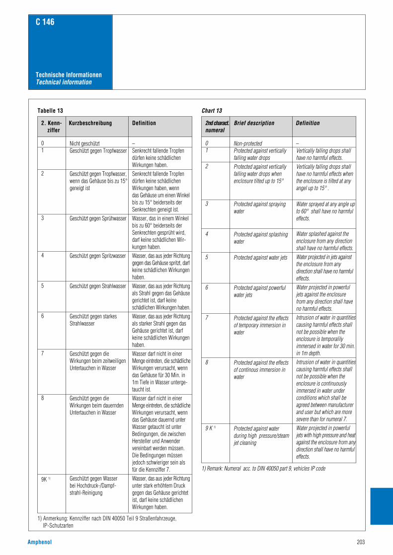
Amphenol 203
C 146
Technische InformationenTechnical information
Tabelle 13
1) Anmerkung: Kennziffer nach DIN 40050 Teil 9 Straßenfahrzeuge, IP-Schutzarten
Chart 13
1) Remark: Numeral acc. to DIN 40050 part 9, vehicles IP code
2. Kenn- Kurzbeschreibung Definitionziffer
01
2
3
4
5
6
7
8
9K 1)
Nicht geschütztGeschützt gegen Tropfwasser
Geschützt gegen Tropfwasser,wenn das Gehäuse bis zu 15°geneigt ist
Geschützt gegen Sprühwasser
Geschützt gegen Spritzwasser
Geschützt gegen Strahlwasser
Geschützt gegen starkesStrahlwasser
Geschützt gegen dieWirkungen beim zeitweiligenUntertauchen in Wasser
Geschützt gegen dieWirkungen beim dauerndenUntertauchen in Wasser
Geschützt gegen Wasser bei Hochdruck-/Dampf-strahl-Reinigung
2nd charact. Brief description Definitionnumeral
01
2
3
4
5
6
7
8
9 K 1)
Non-protectedProtected against verticallyfalling water dropsProtected against verticallyfalling water drops whenenclosure tilted up to 15°
Protected against sprayingwater
Protected against splashingwater
Protected against water jets
Protected against powerfulwater jets
Protected against the effectsof temporary immersion inwater
Protected against the effectsof continous immersion inwater
Protected against waterduring high pressure/steamjet cleaning
–Senkrecht fallende Tropfendürfen keine schädlichenWirkungen haben.Senkrecht fallende Tropfendürfen keine schädlichenWirkungen haben, wenn das Gehäuse um einen Winkelbis zu 15° beiderseits derSenkrechten geneigt ist.Wasser, das in einem Winkelbis zu 60° beiderseits derSenkrechten gesprüht wird, darf keine schädlichen Wir-kungen haben.Wasser, das aus jeder Richtunggegen das Gehäuse spritzt, darfkeine schädlichen Wirkungenhaben.Wasser, das aus jeder Richtungals Strahl gegen das Gehäusegerichtet ist, darf keineschädlichen Wirkungen haben.Wasser, das aus jeder Richtungals starker Strahl gegen dasGehäuse gerichtet ist, darfkeine schädlichen Wirkungenhaben.Wasser darf nicht in einerMenge eintreten, die schädlicheWirkungen verursacht, wenndas Gehäuse für 30 Min. in 1m Tiefe in Wasser unterge-taucht ist.Wasser darf nicht in einerMenge eintreten, die schädlicheWirkungen verursacht, wenndas Gehäuse dauernd unterWasser getaucht ist unterBedingungen, die zwischenHersteller und Anwendervereinbart werden müssen. Die Bedingungen müssenjedoch schwieriger sein alsfür die Kennziffer 7.Wasser, das aus jeder Richtungunter stark erhöhtem Druckgegen das Gehäuse gerichtetist, darf keine schädlichenWirkungen haben.
–Vertically falling drops shallhave no harmful effects.Vertically falling drops shallhave no harmful effects whenthe enclosure is tilted at anyangel up to 15° .
Water sprayed at any angle upto 60° shall have no harmfuleffects.
Water splashed against theenclosure from any directionshall have no harmful effects.Water projected in jets against the enclosure from any direction shall have no harmfuleffects.Water projected in powerful jets against the enclosure from any direction shall haveno harmful effects.Intrusion of water in quantitiescausing harmful effects shallnot be possible when theenclosure is temporalilyimmersed in water for 30 min.in 1m depth.Intrusion of water in quantitiescausing harmful effects shallnot be possible when theenclosure is continuouslyimmersed in water underconditions which shall beagreed between manufacturerand user but which are moresevere than for numeral 7.Water projected in powerful jets with high pressure and heatagainst the enclosure from anydirection shall have no harmfuleffects.

204 Amphenol
C 146
Technische InformationenTechnical information
KabelZum Anschluss an alle Amphenol-Industrie-Steckverbinder wird dieVerwendung von handelsüblichen hochflexiblen Kunststoff-Steuerleitungen nach VDE-Vorschriften empfohlen. Auf diese Leitungensind unsere Steckverbinder in Bezug auf Kontaktanzahl undKabeleinführung ausgelegt. Bei der Leitungsauswahl ist darauf zu achten, dass die Leitungen denSteckverbinder nicht angreifen (Lösungsmittel) oder eine möglicheFeuerbeständigkeit aufheben.
AbdichtungDie Abdichtung der Kabeleinführungen aller Amphenol-Industrie-Steckverbinder erfolgt mittels Verschraubungen. Wir verwendengrundsätzlich Dichtringe aus Neoprene, die eine gute Beständigkeit gegenFette, Öle und Benzin besitzen.
Auswahl der VerschraubungenNeben Dichtringen mit konstantem Innendurchmesser, dessen Maß derBezeichnung der Verschraubung entspricht, gibt es auch ausschneidbareDichtringe (Zwiebelringe), bei denen der Innendurchmesser durchAusschneiden von Ringen in einem gewissen Maße variiert werden kann.Die Auswahl der Verschraubung für verschiedene Kabeldurchmesser(Kabelaufbau) kann von nachfolgendem Diagramm 5 abgeleitet werden(siehe auch Seite 194).
Diagramm 5
CableFor the termination of all Amphenol-industrial connectors we recommendthe use of commercially available high flexible cable acc. to VDE or otherlocal specifications. Our connectors are designed to fit these cablesespecially as far as number of conductors and cable diameters areconcerned.When selecting cables care must be taken that the cables do not affect(solvent) the connector or preserve an existing fire resistance.
Sealing The sealing of the cable entries of all Amphenol-industrial connectors iswith gland bushings. All sealings are made from Neoprene which has agood resistance against grease, oil and gasoline.
Selection of gland bushingsBeside glands with a fixed inside diameter which equals the number, thereare also glands with variable inside diameters available (so-called onionglands). The inside diameter of these glands can be adjusted to theoutside cable diameter by cutting out the smaller rings.The selection of the appropiate gland bushing depends on the cablediameter (cable composition) can be made using the following diagram 5(see page 194).
Diagram 5
Ader
zahl
/ Nu
mbe
r of c
ondu
ctor
s
Kabel-Ø / Cable dia.
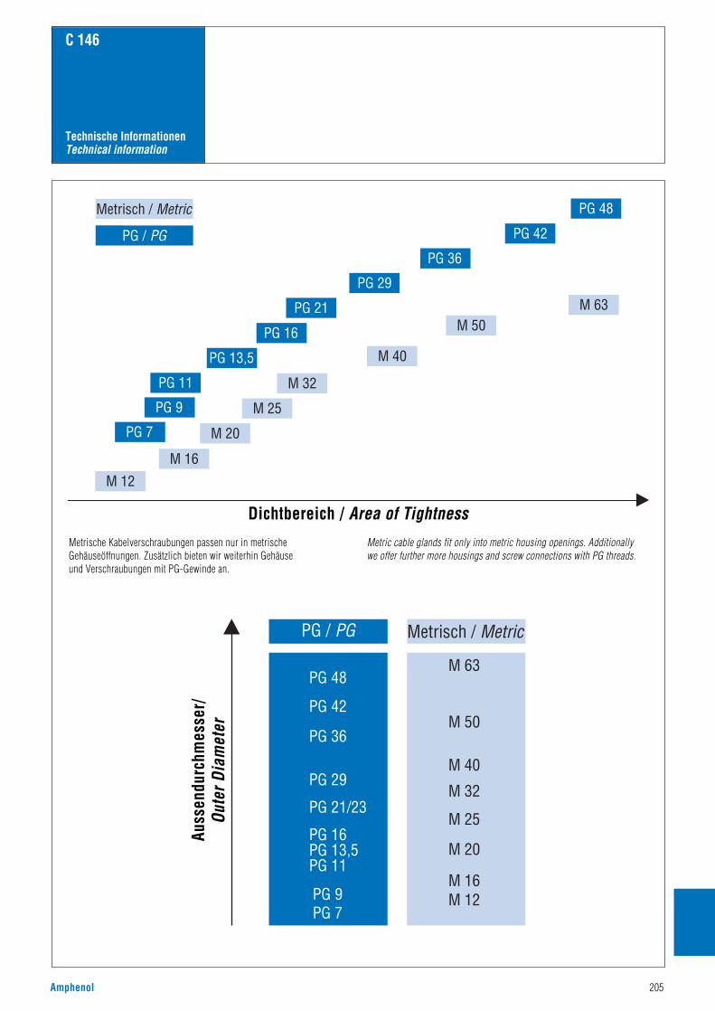
Amphenol 205
PG 48
PG 42
PG 36
PG 29
PG 21
PG 16
PG 13,5
PG 11
PG 9
PG 7
M 16
M 20
M 25
M 32
M 40
M 50M 63
M 12
PG / PG
Metrisch / Metric
PG 48
PG 42
PG 36
PG 29
PG 21/23
PG 16PG 13,5PG 11
PG 9
PG 48
M 63
M 50
M 40
M 32
M 25
M 20
M 16M 12
PG 7
PG / PG Metrisch / Metric
C 146
Technische InformationenTechnical information
Dichtbereich / Area of Tightness
Auss
endu
rchm
esse
r/Ou
ter D
iam
eter
Metrische Kabelverschraubungen passen nur in metrischeGehäuseöffnungen. Zusätzlich bieten wir weiterhin Gehäuse und Verschraubungen mit PG-Gewinde an.
Metric cable glands fit only into metric housing openings. Additionally we offer further more housings and screw connections with PG threads.

206 Amphenol
C 146
AbschirmungAbschirmung innerer oder äußerer elektrischer Felder durch Bildung einer Äquipotentialfläche inForm von Metallklappen oder Metallisierungen auf der Innen- und Außenseite von Kappen ausKunststoff. Die Abschirmung wird in der Regel mit dem Schirmgeflecht des angeschlossenen Kabelsund mit dem Gerätegehäuse verbunden.
Bemessungsgrößen, elektrische– Bemessungsspannung ist die Spannung, für die der Steckverbinder oder die Steckvorrichtungbemessen ist und auf die bestimmte Betriebseigenschaften bezogen werden. – Bemessungsstrom ist der Strom, den ein Steckverbinder oder eine Steckvorrichtung gleichzeitigdurch alle Kontakte dauernd (nicht intermittierend) führen kann, ohne dass dabei die obereGrenztemperatur überschritten wird. – Schaltleistung einer Steckvorrichtung ist die Leistung, welche die Steckvorrichtung unterfestgelegten Bedingungen schalten kann. –Prüfspannung ist die Spannung, der ein Steckverbinder oder eine Steckvorrichtung beivorgegebenen Bedingungen ohne Durch- oder Überschlag widersteht.
Bügelverriegelung Verriegelung von zwei Hälften eines Steckverbinderpaares durch ein formschlüssiges Element, dasdurch einen als Bügel ausgestalteten Hebel betätigt wird. Erst wenn die beiden Hälften vollständigzusammengesteckt sind, kommt der Bügel in seine Endlage.
CrimpbackenDerjenige Teil eines Crimpwerkzeugs, der den Crimpbereich verformt. Er besteht üblicherweise ausdem Crimpamboss, dem Crimpstempel und dem Positionierstück.
CrimpbereichDer Bereich der Crimphülse, in dem die Crimpverbindung durch Druckverformung oder Druckum-formung der Hülse um den Leiter herum ausgeführt ist.
CrimphülseEine Anschlusshülse, die einen oder mehrere Leiter aufnehmen kann und durch Anwendung einesCrimpwerkzeugs gecrimpt werden kann.
CrimpverbindungDurch systematisches Verformen einer Crimphülse um abisolierte Leiter herum hergestellte,dauerhafte elektrische und mechanische Verbindung; Crimpverbindung siehe IEC 60352-2, 2a; 2b;2c, DIN EN 60 352-2 (siehe auch Katalog „Werkzeuge“)
DurchgangswiderstandDer elektrische Widerstand in einem gesteckten bzw. geschalteten Kontaktpaar, gemessen zwischenden Anschlusspunkten unter vorgeschriebenen Messbedingungen. Prüfungen nach ICE 60512-2, DIN EN 60 512-2
Elektromagnetische EinflüsseBei Steckverbindern werden unerwünschte elektromagnetische Einflüsse auf die zu verbindendenLeitungen bzw. auf die Umgebung durch Abschirmung verhindert.
GehäuseTeil eines Steckverbinders, in dem Kontaktträger und Kontakte montiert sind. Es kann zurVerriegelung dienen.
GrenztemperaturenUntere und obere Temperaturen, die nicht zu einer Schädigung der Werkstoffe führen; dazwischenliegt der Betriebstemperaturbereich.– Untere Grenztemperatur: Die tiefste zulässige Temperatur, bei der ein Steckverbinder oder eineSteckvorrichtung noch betrieben werden darf.– Obere Grenztemperatur: Die höchste zulässige Temperatur, bei der ein Steckverbinder oder eineSteckvorrichtung noch betrieben werden darf. Sie ist die Summe aus Eigenerwärmung (ein-schließlich Kontakterwärmung) und Umgebungstemperatur.
IsolationswiderstandWiderstand der Isolierung zwischen zwei leitfähigen Teilen. Isoliervermögen eines Werkstoffes, derzwei benachbarte Kontakte oder einen Kontakt gegen Masse möglichst hochohmig trennt. Mess- undPrüfverfahren nach IEC 60512-2, 3a, DIN EN 60 512-2
IsolierstoffgruppeEinteilung von Isolierstoffen entsprechend ihren CTI-Werten (CTI = Comperative Tracking Index /Vergleichszahl der Kriechwegbildung).
Kompatible SteckverbinderZwei Steckverbinder sind kompatibel, wenn sie mechanisch austauschbar und zusammensteckbarsind und den gleichen technischen Anforderungen entsprechen.
KontaktgrößeKennzeichnung zur Differenzierung der Kontakte nach folgendem Systemena) Kennzeichnungssystem: Kennzeichnung des Kontaktes nach der maximal anschließbarenLeitergröße (AWG American Wire Gauge);
b) Strombelastbarkeitssystem: Kennzeichnung des Kontaktes nach seiner maximalenStrombelastbarkeit.c) Querschnittsystem: Kennzeichnung des Kontaktes nach dem maximal anschließbarenLeiterquerschnitt. Leiterwiderstand.
KontaktmaterialDie Wahl des Kontaktmaterials – meist Kupfer oder Kupferlegierungen – hängt von den gewünschtenEigenschaften des Steckverbinders ab. Hierbei spielen Durchgangswiderstand; Steck- und Ziehkräfteeine maßgebliche Rolle. Neben Steckhäufigkeit und Umwelteinflüssen bestimmen diese auch die Artder Oberflächenüberzüge Nickel, Zinn, Gold, Silber, Palladium. Sie werden galvanisch oderwalztechnisch aufgebracht.
KriechstreckenKürzeste Entfernung zwischen spannungsführenden Teilen auf der Oberfläche von Isolierkörpern,sofern festgelegte Mindestmaße vorliegen (Kriechstreckenverlängerung). Die Abstände dienen derSicherheit gegen Überschläge. Sie werden in Abhängigkeit von der Reihenspannung, denAnwendungsbedingungen und den Eigenschaften des Isolierwerkstoffes festgelegt. Dieunterschiedliche Kriechstromfestigkeit der Isolierstoffe ist bei der Festlegung der Kriechstrecken zubeachten (DIN VDE 0110-1.)
LebensdauerAnzahl der Steckzyklen, die noch nicht zum Durchrieb der leitenden Kontaktflächen führt und denKontaktwiderstand nicht unzulässig erhöht. Mess- und Prüfverfahren nach IEC 60512-5,DIN EN 60512-5
LuftstreckenKürzeste, als Fadenmaß gemessene Entfernung zwischen zwei spannungsführenden Metallteilen inder Luft, nach DIN VDE 0110-1.
Rechteck-VerbinderSteckverbinder mit vorwiegend rechteckiger Form des Steckgesichtes.
SchaltleistungDie Schaltleistung einer Steckvorrichtung ist die Leistung, die die Steckvorrichtung unterfestgelegten Bedingungen schalten kann.
SpannungsfestigkeitSpannung, der ein Steckverbinder oder eine Steckvorrichtung bei vorgegebenen Bedingungen ohneDurchschlag oder Überschlag widersteht. Die Spannungsfestigkeit liegt über der Nennspannung, siedient zum Nachweis des Isoliervermögens des Steckverbinders.
SteckverbinderEin Bauelement, das es gestattet elektrische Leiter anzuschließen, und dazu bestimmt ist, mit einempassenden Gegenstück Verbindungen herzustellen und zu trennen. Steckverbinder sind Betriebs-mittel, die bei bestimmungsgemäßer Verwendung (unter elektrischer Spannung) nicht gesteckt odergetrennt werden dürfen (im Gegensatz Steckverbinder mit Schaltleistung). Nach der Befestigungwerden freie und feste Steckverbinder unterschieden. Der Steckverbinder besteht aus dem Steckver-bindergehäuse und den Kontaktelementen. Das Steckverbindergehäuse enthält den Kontakteinsatz.
SteckverbindungEine elektrische Steckverbindung besteht aus zwei Steckverbindern, d. h. aus mindestens zweiKontaktelementen. Alle weiteren Komponenten wie Gehäuse, Kontaktträger, Kontakthalterung usw.,erfüllen sekundäre Funktionen.
Steckverbinder mit SchaltleistungEin Bauelement, das bei bestimmungsgemäßer Verwendung unter elektrischer Spannung oder Lastgesteckt oder getrennt wird. Der Schutzleiterkontakt muss während des Steckens vor- und währenddes Trennens nacheilen (voreilender Kontakt).
SteckzyklenMechanisches Betätigen von Steckverbindern und Steckvorrichtungen durch Stecken und Ziehen. EinSteckzyklus besteht aus je einem Steck- und Ziehvorgang.
ÜberspannungskategorieEin Zahlenwert, der eine Stehstoßspannung festlegt. Er werden die Überspannungskategorien I, II, IIIund IV verwendet.
VerschmutzungsgradZahlenwert, der die zu erwartende Verschmutzung der Mikro-Umgebung angibt. Er werden dieVerschmutzungsgrade 1, 2, 3 und 4 verwendet.
Voreilender KontaktErfordert der Schaltungsaufbau, dass aus Schutzgründen, z. B. für Schutzleiter, ein oder mehrereKontakte eines Steckverbinders beim Stecken zuerst Kontakt herstellen oder beim Ziehen als letztegetrennt werden, sind Steckverbinder mit voreilenden Kontakten (Stift bzw. Messer, Buchse oderFeder) zu verwenden.
Steckverbinderbegriffe
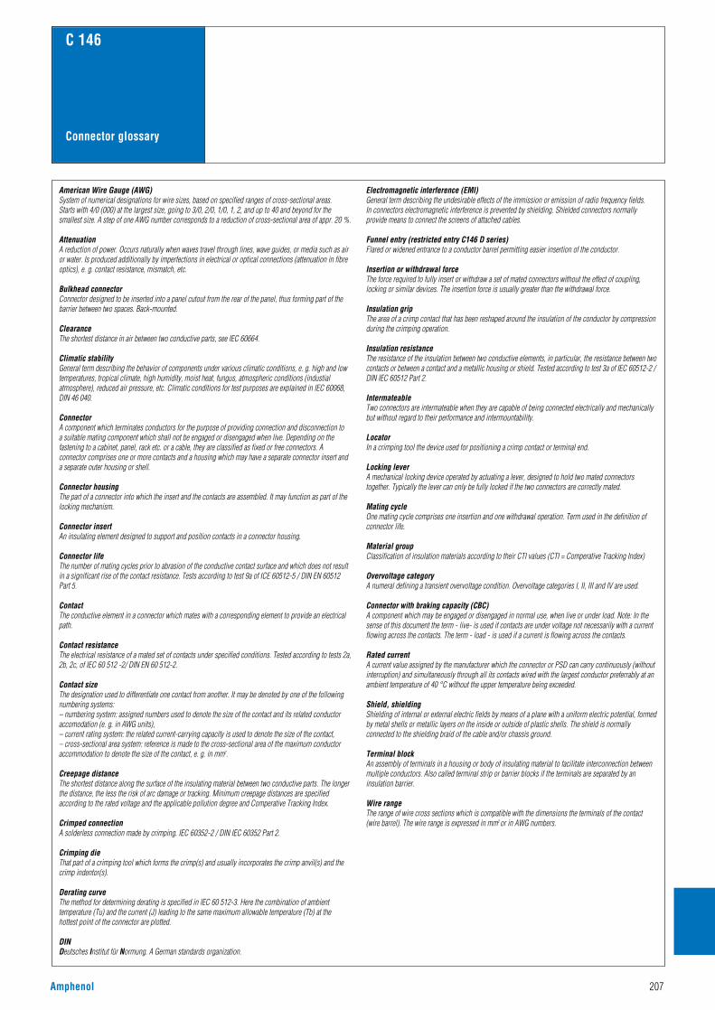
Amphenol 207
C 146
American Wire Gauge (AWG)System of numerical designations for wire sizes, based on specified ranges of cross-sectional areas. Starts with 4/0 (000) at the largest size, going to 3/0, 2/0, 1/0, 1, 2, and up to 40 and beyond for thesmallest size. A step of one AWG number corresponds to a reduction of cross-sectional area of appr. 20 %.
AttenuationA reduction of power. Occurs naturally when waves travel through lines, wave guides, or media such as airor water. Is produced additionally by imperfections in electrical or optical connections (attenuation in fibreoptics), e. g. contact resistance, mismatch, etc.
Bulkhead connectorConnector designed to be inserted into a panel cutout from the rear of the panel, thus forming part of thebarrier between two spaces. Back-mounted.
ClearanceThe shortest distance in air between two conductive parts, see IEC 60664.
Climatic stabilityGeneral term describing the behavior of components under various climatic conditions, e. g. high and lowtemperatures, tropical climate, high humidity, moist heat, fungus, atmospheric conditions (industialatmosphere), reduced air pressure, etc. Climatic conditions for test purposes are explained in IEC 60068,DIN 46 040.
ConnectorA component which terminates conductors for the purpose of providing connection and disconnection to a suitable mating component which shall not be engaged or disengaged when live. Depending on thefastening to a cabinet, panel, rack etc. or a cable, they are classified as fixed or free connectors. Aconnector comprises one or more contacts and a housing which may have a separate connector insert anda separate outer housing or shell.
Connector housingThe part of a connector into which the insert and the contacts are assembled. It may function as part of thelocking mechanism.
Connector insertAn insulating element designed to support and position contacts in a connector housing.
Connector lifeThe number of mating cycles prior to abrasion of the conductive contact surface and which does not resultin a significant rise of the contact resistance. Tests according to test 9a of ICE 60512-5 / DIN EN 60512Part 5.
ContactThe conductive element in a connector which mates with a corresponding element to provide an electricalpath.
Contact resistanceThe electrical resistance of a mated set of contacts under specified conditions. Tested according to tests 2a,2b, 2c, of IEC 60 512 -2/ DIN EN 60 512-2.
Contact sizeThe designation used to differentiate one contact from another. It may be denoted by one of the followingnumbering systems:– numbering system: assigned numbers used to denote the size of the contact and its related conductoraccomodation (e. g. in AWG units), – current rating system: the related current-carrying capacity is used to denote the size of the contact, – cross-sectional area system: reference is made to the cross-sectional area of the maximum conductoraccommodation to denote the size of the contact, e. g. in mm2.
Creepage distanceThe shortest distance along the surface of the insulating material between two conductive parts. The longerthe distance, the less the risk of arc damage or tracking. Minimum creepage distances are specifiedaccording to the rated voltage and the applicable pollution degree and Comperative Tracking Index.
Crimped connectionA solderless connection made by crimping. IEC 60352-2 / DIN IEC 60352 Part 2.
Crimping dieThat part of a crimping tool which forms the crimp(s) and usually incorporates the crimp anvil(s) and thecrimp indentor(s).
Derating curveThe method for determining derating is specified in IEC 60 512-3. Here the combination of ambienttemperature (Tu) and the current (J) leading to the same maximum allowable temperature (Tb) at thehottest point of the connector are plotted.
DINDeutsches Institut für Normung. A German standards organization.
Electromagnetic interference (EMI)General term describing the undesirable effects of the immission or emission of radio frequency fields. In connectors electromagnetic interference is prevented by shielding. Shielded connectors normallyprovide means to connect the screens of attached cables.
Funnel entry (restricted entry C146 D series)Flared or widened entrance to a conductor barrel permitting easier insertion of the conductor.
Insertion or withdrawal forceThe force required to fully insert or withdraw a set of mated connectors without the effect of coupling,locking or similar devices. The insertion force is usually greater than the withdrawal force.
Insulation gripThe area of a crimp contact that has been reshaped around the insulation of the conductor by compressionduring the crimping operation.
Insulation resistanceThe resistance of the insulation between two conductive elements, in particular, the resistance between twocontacts or between a contact and a metallic housing or shield. Tested according to test 3a of IEC 60512-2 /DIN IEC 60512 Part 2.
IntermateableTwo connectors are intermateable when they are capable of being connected electrically and mechanicallybut without regard to their performance and intermountability.
LocatorIn a crimping tool the device used for positioning a crimp contact or terminal end.
Locking leverA mechanical locking device operated by actuating a lever, designed to hold two mated connectorstogether. Typically the lever can only be fully locked if the two connectors are correctly mated.
Mating cycleOne mating cycle comprises one insertion and one withdrawal operation. Term used in the definition ofconnector life.
Material groupClassification of insulation materials according to their CTI values (CTI = Comperative Tracking Index)
Overvoltage categoryA numeral defining a transient overvoltage condition. Overvoltage categories I, II, III and IV are used.
Connector with braking capacity (CBC)A component which may be engaged or disengaged in normal use, when live or under load. Note: In thesense of this document the term - live- is used if contacts are under voltage not necessarily with a currentflowing across the contacts. The term - load - is used if a current is flowing across the contacts.
Rated currentA current value assigned by the manufacturer which the connector or PSD can carry continuously (withoutinterruption) and simultaneously through all its contacts wired with the largest conductor preferrably at anambient temperature of 40 °C without the upper temperature being exceeded.
Shield, shieldingShielding of internal or external electric fields by means of a plane with a uniform electric potential, formedby metal shells or metallic layers on the inside or outside of plastic shells. The shield is normallyconnected to the shielding braid of the cable and/or chassis ground.
Terminal blockAn assembly of terminals in a housing or body of insulating material to facilitate interconnection betweenmultiple conductors. Also called terminal strip or barrier blocks if the terminals are separated by aninsulation barrier.
Wire rangeThe range of wire cross sections which is compatible with the dimensions the terminals of the contact (wire barrel). The wire range is expressed in mm2 or in AWG numbers.
Connector glossary

208 Amphenol
C 146
AbisolierlängenStripping length
Anschlussquerschnitt [mm2]Termination crimp [mm2]
1,6(Kontakt ohne Clip)
(Contact without clip)
Anschlussquer-schnitt [mm2]Terminationcrimp [mm2]
0,14 - 0,37 8 + 1 N01 016 0024N02 016 0024
C146D/DD/M
0,5 8 + 1 N01 016 0025N02 016 0025
C146D/DD/M
7 + 1 N01 025 0029N02 025 0029
C146M
7 + 1 N01 025 0035N02 025 0035
C146E/EE
0,75 - 1,0 8 + 1 N01 016 0026N02 016 0026
C146D/DD/M
7 + 1 N01 025 0030N02 025 0030
C146M
7 + 1 N01 025 0036N02 025 0036
C146E/EE
1,5 8 + 1 N01 016 0027N02 016 0027
C146D/DD/M
7 + 1 N01 025 0031N02 025 0031
C146M
7 + 1 N01 025 0037N02 025 0037
C146E/EE
10 + 1 N01 036 0004N02 036 0004
C146M
2,5 6 + 1 N01 016 0028N02 016 0028
C146D/DD/M
7 + 1 N01 025 0032N02 025 0032
C146M
7 + 1 N01 025 0038N02 025 0038
C146E/EE
10 + 1 N01 036 0005N02 036 0005
C146M
4,0 7 + 1 N01 025 0033N02 025 0033
C146M
7 + 1 N01 025 0039N02 025 0039
C146E/EE
10 + 1 N01 036 0001N02 036 0001
C146M
6,0 10 + 1 N01 036 0002N02 036 0002
C146M
10,0 10 + 1 N01 036 0003N02 036 0003
C146M
Mind.abisolier-länge+Toleranz [mm]Min. strippinglength+tolerance[mm]
Kontakt ArtNr.
Contact partNo.
in Serie
Series
2,5(Kontakt mit Clip)
(Contact with clip )
Mind.abisolier-länge+Toleranz [mm]Min. strippinglength+tolerance[mm]
Kontakt ArtNr.
Contact partNo.
in Serie
Series
2,5(Kontakt ohne Clip)
(Contact without clip)
Mind.abisolier-länge+Toleranz [mm]Min. strippinglength+tolerance[mm]
Kontakt ArtNr.
Contact partNo.
in Serie
Series
3,6(Kontakt mit Clip)(Contact with clip)
Mind.abisolier-länge+Toleranz [mm]Min. strippinglength+tolerance[mm]
Kontakt ArtNr.
Contact partNo.
in Serie
Series
Gestanzte Crimphülsen Serie C146 Abisolierlängen füranzuschließenden Leiter
Stamped crimp contacts series C146, stripping length
Gedrehte Crimpkontakte Serie C146 Abisolierlängen füranzuschließenden Leiter
Turned crimp contacts series C146, stripping length
0,09 - 0,25
0,14 - 0,5 0,140,250,5
2624-2220
1,0 - 2,0 3,0 + 0,5N01 016 0003 N02 016 0003
C146D/MC146D/M
0,09 - 0,25 28 - 24 0,7 - 1,6 2,3 + 0,4 N01 010 0130 (2)N02 010 0130 (2)
C146MC146M
0,25 - 0,5 0,250,5
24-2220
1,6 - 2,0 2,3 + 0,4 N01 010 0131 (2)N02 010 0131 (2)
C146MC146M
0,5 - 1,5 0,50,751,01,5
2020 - 1818 - 1616 - 15
1,8 - 2,8 3,5 + 1,0
N01 016 0002N02 016 0002N01 016 0015N02 016 0015N01 025 0001N02 025 0001N01 025 0007
C146D/MC146D/MC146DC146DC146E/MC146E/M/SC146S
1,5 - 2,5 1,52,5
16 - 1514
2,5 - 3,5 3,5 + 1,0
N01 016 0005N02 016 0005N01 016 0016N02 016 0016N01 025 0010N02 025 0010N01 025 0008
C146D/MC146D/MC146DC146DC146E/MC146E/M/SC146S
2,5 - 4,0 2,54,0
1412
3,3 - 4,2 3,5 + 1,0N01 025 0043N02 025 0043
C146MC146M
LeiterquerschnittWire gauge
mm2 AWG
Isolierungsdurchmesserder Leitung [mm]Insulation diameter of the wire [mm]
Mindestabisolierlängemit Toleranz [mm]Min. stripping length[mm]
KontaktArt.-Nr.Contactpart No.
in Serie
Series
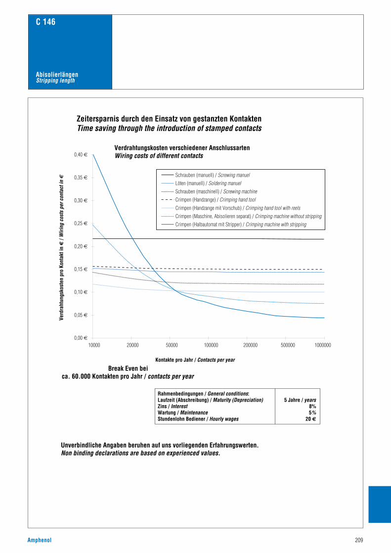
Amphenol 209
C 146
AbisolierlängenStripping length
0,00 €
0,05 €
0,10 €
0,15 €
0,20 €
0,25 €
0,30 €
0,35 €
0,40 €
10000 20000 50000 100000 200000 500000 1000000
Schrauben (manuell) / Screwing manuelLöten (manuell) / Soldering manuelSchrauben (maschinell) / Screwing machineCrimpen (Handzange) / Crimping hand toolCrimpen (Handzange mit Vorschub) / Crimping hand tool with reelsCrimpen (Maschine, Abisolieren separat) / Crimping machine without strippingCrimpen (Halbautomat mit Stripper) / Crimping machine with stripping
Zeitersparnis durch den Einsatz von gestanzten KontaktenTime saving through the introduction of stamped contacts
Kontakte pro Jahr / Contacts per year
Break Even beica. 60.000 Kontakten pro Jahr / contacts per year
Rahmenbedingungen / General conditions:Laufzeit (Abschreibung) / Maturity (Depreciation) 5 Jahre / yearsZins / Interest 8%Wartung / Maintenance 5%Stundenlohn Bediener / Hourly wages 20 €
Unverbindliche Angaben beruhen auf uns vorliegenden Erfahrungswerten.Non binding declarations are based on experienced values.
Verdrahtungskosten verschiedener AnschlussartenWiring costs of different contacts
Verd
raht
ungs
kost
en p
ro K
onta
kt in
€ /
Wiri
ng c
osts
per
con
tact
in €

210 Amphenol
C 146
MusterkofferSample Box
Steckverbinder Serie C 146 E 16 pol
Steckverbinder Serie C 146 A 10 pol
EMV Gehäuse
Standard Gehäuse hohe Bauform ohne Stutzen
Steckverbinder Serie C 146 A 3 pol
EMV Tüllengehäuse
Gedrehte Crimpkontakte
Gestanzte Crimpkontakte
Lösewerkzeug für 1,6 mm Kontakte
Kontakteinsätze Serie C 146 HvE 16 pol
Rahmen und Module Serie C 146 M
Kontakteinsätze Serie C 146 D 15 pol (für gedrehte Kontakte)
Kontakteinsätze Serie C 146 D 40 pol (für gestanzte Kontakte)
Kontakteinsätze Serie C 146 E 6 pol
Kontakteinsätze Serie C 146 A 16 pol
Kontakteinsätze Serie C 146 D 7 pol
Connector series C 146 E 16 contactsConnector series C 146 A 10 contactsEMC housingStandard housing high profile without studConnector series C 146 A 3 contactsEMC hoodTurned crimp contactsStamped crimp contactsRemoval tool for 1,6 mm contactsContact insert series C 146 HvE 16 contactsFrames and modules series C 146 MContact inserts series C 146 D 15 contacts (for turned contacts)Contact inserts series C 146 D 40 contacts (for stamped contacts)Contact inserts series C 146 E 6 contactsContact inserts series C 146 A 16 contactsContact inserts series C 146 D 7 contacts
16
1
1
2
3
4
5
6
7
8
9
10
11
12
13
14
15
16
1
2
3
4
5
6
7
8
9
10
11
12
13
14
15
16
2
3
4
5
67
89
10
11
12
13
14
15
Bestellnummer / Part NumberFM 0300 146

Amphenol 211
C 146
WerkzeugkofferTool box
Bezeichnung Katalog „Werkzeuge“ / Catalogue „Tools“
Bestell-Nr./ Part No. Seite / Page
Description
1 4 - Kerb Crimpzange2 Service Hand Crimpwerkzeug3 Lösewerkzeug4 Lösewerkzeug5 Zubehör6 Lösewerkzeug7 Zubehör8 Kontaktbehältnis9 Kontaktaufnahme
10 Crimpbacken11 Kontaktaufnahme
12 Crimpbacken13 Kontaktaufnahme
14 Crimpbacken15 Kontaktaufnahme
16 Crimpbacken17 Handcrimpwerkzeug
1 4 - Indent hand crimping tool2 Service hand crimping tool3 Removal tool4 Removal tool5 Accessories6 Removal tool7 Accessories8 Contact container9 Contact locator
10 Crimping dies11 Contact locator
12 Crimping dies13 Contact locator
14 Crimping dies15 Contact locator
16 Crimping dies17 Hand crimping tool
TB 0200 146TA 0200 146FG 0300 146 1FG 0300 146 3TB 0200 14617D 438 SPTA 0000
TA 0001 1460001TA 0000 202TA 0007 1460003TA 0000 141TA 0002 1460001TA 0000 163TA 0010 1460004TA 0000124TA 0000
9121717
917
5
7
77
77
77
75
1
17
18
19
20
21
22
23
24
25
26
27
23
45
6
Bestellnummer / Part NumberFM 0500 146FM 0501 146 (ohne / without TB0200 146)

Bestell Nr. / Part No. Seite / Page Bestell Nr. / Part No. Seite / Page Bestell Nr. / Part No. Seite / Page Bestell Nr. / Part No. Seite / Page
212 Amphenol
C 146
17 DM 537 401 77, 18917 DM 537 405 77, 18917 DM 537 421 77, 18917 DM 537 425 77, 18917D 438 SP 65, 84C146 10A003 002 4 88C146 10A003 102 3 100C146 10A004 002 4 88C146 10A004 102 6 108C146 10A006 000 1 34C146 10A006 002 1 34C146 10A006 102 1 34C146 10A006 102 3 101C146 10A006 102 5 95C146 10A006 500 1 34C146 10A006 810 1 56C146 10A007 000 2 10C146 10A007 500 2 10C146 10A008 000 2 10C146 10A008 500 2 10C146 10A010 000 1 36C146 10A010 002 1 36C146 10A010 002 4 89C146 10A010 102 1 36C146 10A010 102 3 102, 104C146 10A010 102 3 102, 104C146 10A010 102 4 89C146 10A010 104 3 104C146 10A010 500 1 36C146 10A010 500 10 46C146 10A010 810 1 56C146 10A015 000 2 12C146 10A015 009 2 12C146 10A015 060 2 12C146 10A015 500 2 12C146 10A016 000 1 38C146 10A016 002 1 38C146 10A016 002 3 103C146 10A016 002 4 90-91C146 10A016 004 4 91C146 10A016 102 1 38C146 10A016 102 3 103-104C146 10A016 102 4 90-91C146 10A016 104 3 104C146 10A016 104 4 91C146 10A016 500 1 38C146 10A016 810 1 56C146 10A018 500 10 46C146 10A024 000 1 40, 42C146 10A024 000 9 26C146 10A024 002 1 40, 42C146 10A024 004 1 42C146 10A024 005 1 42C146 10A024 102 1 40, 42C146 10A024 104 1 42C146 10A024 500 1 40, 42C146 10A024 505 1 42
C146 10A024 810 1 56C146 10A025 000 2 14, 18C146 10A025 005 2 18C146 10A025 009 2 14C146 10A025 060 2 14C146 10A025 500 2 14, 18C146 10A025 505 2 18C146 10A032 500 10 46C146 10A040 000 2 16C146 10A040 009 2 16C146 10A040 060 2 16C146 10A040 500 2 16C146 10A042 000 9 26C146 10A046 500 10 46C146 10A057 000 6 110C146 10A057 801 6 110C146 10A064 000 2 20, 22C146 10A064 005 2 22C146 10A064 009 2 20C146 10A064 060 2 20C146 10A064 500 2 20, 22C146 10A064 505 2 22C146 10A072 000 9 26C146 10A108 000 9 26-27C146 10A108 005 9 27C146 10B003 002 4 88C146 10B003 102 3 100C146 10B004 002 4 88C146 10B004 102 6 108C146 10B006 000 1 34C146 10B006 002 1 34C146 10B006 102 1 34C146 10B006 102 3 101C146 10B006 102 5 95C146 10B006 500 1 34C146 10B006 810 1 56C146 10B007 000 2 10C146 10B007 500 2 10C146 10B008 000 2 10C146 10B008 500 2 10C146 10B010 000 1 36C146 10B010 002 1 36C146 10B010 002 4 89C146 10B010 102 1 36C146 10B010 102 3 102, 104C146 10B010 102 4 89C146 10B010 104 3 104C146 10B010 500 1 36C146 10B010 500 10 46C146 10B010 810 1 56C146 10B015 000 2 12C146 10B015 009 2 12C146 10B015 060 2 12C146 10B015 500 2 12C146 10B016 000 1 38C146 10B016 002 1 38C146 10B016 002 3 103
C146 10B016 002 4 90-91C146 10B016 004 4 91C146 10B016 102 1 38C146 10B016 102 3 103-104C146 10B016 102 4 90-91C146 10B016 104 3 104C146 10B016 104 4 91C146 10B016 500 1 38C146 10B016 810 1 56C146 10B018 500 10 46C146 10B024 000 1 40, 42C146 10B024 000 9 26C146 10B024 002 1 40, 42C146 10B024 004 1 42C146 10B024 005 1 42C146 10B024 102 1 40, 42C146 10B024 104 1 42C146 10B024 500 1 40, 42C146 10B024 505 1 42C146 10B024 810 1 56C146 10B025 000 2 14, 18C146 10B025 005 2 18C146 10B025 009 2 14C146 10B025 060 2 14C146 10B025 500 2 14, 18C146 10B025 505 2 18C146 10B032 500 10 46C146 10B040 000 2 16C146 10B040 009 2 16C146 10B040 060 2 16C146 10B040 500 2 16C146 10B042 000 9 26C146 10B046 500 10 46C146 10B057 000 6 110C146 10B057 801 6 110C146 10B064 000 2 20, 22C146 10B064 005 2 22C146 10B064 009 2 20C146 10B064 060 2 20C146 10B064 500 2 20, 22C146 10B064 505 2 22C146 10B072 000 9 26C146 10B108 000 9 26-27C146 10B108 005 9 27C146 10F003 000 4 116-117C146 10F003 004 4 116-117C146 10F003 500 4 116C146 10F006 000 1 132-133C146 10F006 003 1 132-133C146 10F006 500 1 134C146 10F006 502 1 134C146 10F006 502 2 134C146 10F006 503 2 134C146 10F006 506 1 134C146 10F006 506 2 134C146 10F006 507 2 134C146 10F006 600 1 134
C146 10F006 602 2 134C146 10F006 603 2 134C146 10F006 606 1 134C146 10F006 606 2 134C146 10F006 607 2 134C146 10F006 802 2 134C146 10F006 803 2 134C146 10F006 806 1 134C146 10F006 806 2 134C146 10F006 807 2 134C146 10F010 000 1 136-137C146 10F010 001 1 138-139C146 10F010 002 1 140-141C146 10F010 003 1 138-139C146 10F010 090 1 136-137C146 10F010 500 1 136C146 10F010 500 2 136C146 10F010 501 2 136C146 10F010 502 1 138C146 10F010 502 2 138C146 10F010 503 2 138C146 10F010 504 1 140C146 10F010 504 2 140C146 10F010 505 2 140C146 10F010 506 1 138C146 10F010 506 2 138C146 10F010 507 2 138C146 10F010 508 2 140C146 10F010 509 2 140C146 10F010 600 1 136C146 10F010 600 2 136C146 10F010 601 2 136C146 10F010 602 1 138C146 10F010 602 2 138C146 10F010 603 2 138C146 10F010 604 1 140C146 10F010 604 2 140C146 10F010 605 2 140C146 10F010 606 1 138C146 10F010 606 2 138C146 10F010 607 2 138C146 10F010 608 2 140C146 10F010 609 2 140C146 10F010 802 1 138C146 10F010 802 2 138C146 10F010 803 2 138C146 10F010 804 1 140C146 10F010 804 2 140C146 10F010 805 2 140C146 10F010 806 1 138C146 10F010 806 2 138C146 10F010 807 2 138C146 10F015 000 2 120-121C146 10F015 003 2 120-121C146 10F015 500 2 122C146 10F015 501 2 122C146 10F015 600 2 122
BestellnummernverzeichnisSummary of Part Numbers

Bestell Nr. / Part No. Seite / Page Bestell Nr. / Part No. Seite / Page Bestell Nr. / Part No. Seite / Page Bestell Nr. / Part No. Seite / Page
Amphenol 213
C 146
BestellnummernverzeichnisSummary of Part Numbers
C146 10F015 601 2 122C146 10F015 606 2 122C146 10F015 607 2 122C146 10F015 806 2 122C146 10F015 807 2 122C146 10F016 000 1 144-145C146 10F016 001 1 146-147C146 10F016 002 1 148-149C146 10F016 003 1 146-147C146 10F016 500 1 144C146 10F016 502 1 146C146 10F016 504 1 148C146 10F016 506 1 146C146 10F016 508 2 148C146 10F016 509 2 148C146 10F016 600 1 144C146 10F016 602 1 146C146 10F016 604 1 148C146 10F016 606 1 146C146 10F016 608 2 148C146 10F016 609 2 148C146 10F016 802 1 146C146 10F016 804 1 148C146 10F016 806 1 146C146 10F024 000 1 152-153C146 10F024 000 3 164-165C146 10F024 001 1 154-155C146 10F024 002 1 156-157C146 10F024 003 1 154-155C146 10F024 500 1 152C146 10F024 500 3 164C146 10F024 502 1 154C146 10F024 504 1 156C146 10F024 506 1 154C146 10F024 508 2 156C146 10F024 509 2 156C146 10F024 600 1 152C146 10F024 600 3 164C146 10F024 602 1 154C146 10F024 604 1 156C146 10F024 606 1 154C146 10F024 608 2 156C146 10F024 609 2 156C146 10F024 802 1 154C146 10F024 804 1 156C146 10F024 806 1 154C146 10F025 000 2 124-125C146 10F025 003 2 124-125C146 10F025 500 2 126C146 10F025 501 2 126C146 10F025 600 2 126C146 10F025 601 2 126C146 10F025 606 2 126C146 10F025 607 2 126C146 10F025 806 2 126C146 10F025 807 2 126C146 10F032 000 4 130-131
C146 10F032 002 4 130-131C146 10F032 500 4 130C146 10F032 501 4 130C146 10F032 600 4 130C146 10F032 601 4 130C146 10F040 500 2 144C146 10F040 501 2 144C146 10F040 502 2 146C146 10F040 503 2 146C146 10F040 504 2 148C146 10F040 505 2 148C146 10F040 506 2 146C146 10F040 507 2 146C146 10F040 600 2 144C146 10F040 601 2 144C146 10F040 602 2 146C146 10F040 603 2 146C146 10F040 604 2 148C146 10F040 605 2 148C146 10F040 606 2 146C146 10F040 607 2 146C146 10F040 802 2 146C146 10F040 803 2 146C146 10F040 804 2 148C146 10F040 805 2 148C146 10F040 806 2 146C146 10F040 807 2 146C146 10F048 001 1 162-163C146 10F048 003 1 162-163C146 10F048 802 1 162C146 10F048 803 1 162C146 10F048 806 1 162C146 10F048 807 1 162C146 10F064 500 2 152C146 10F064 501 2 152C146 10F064 502 2 154C146 10F064 503 2 154C146 10F064 504 2 156C146 10F064 505 2 156C146 10F064 506 2 154C146 10F064 507 2 154C146 10F064 600 2 152C146 10F064 601 2 152C146 10F064 602 2 154C146 10F064 603 2 154C146 10F064 604 2 156C146 10F064 605 2 156C146 10F064 606 2 154C146 10F064 607 2 154C146 10F064 802 2 154C146 10F064 803 2 154C146 10F064 804 2 156C146 10F064 805 2 156C146 10F064 806 2 154C146 10F064 807 2 154C146 10G003 500 4 116C146 10G003 600 4 116
C146 10G003 804 4 116C146 10G006 500 1 132C146 10G006 501 1 132C146 10G006 506 8 132C146 10G006 507 8 132C146 10G006 556 8 132C146 10G006 600 1 132C146 10G006 601 1 132C146 10G006 606 8 132C146 10G006 607 8 132C146 10G006 656 8 132C146 10G006 804 1 132C146 10G006 804 8 132C146 10G006 805 1 132C146 10G006 805 8 132C146 10G010 500 1 136C146 10G010 500 4 120C146 10G010 500 8 136C146 10G010 501 1 136C146 10G010 501 4 120C146 10G010 501 8 136C146 10G010 502 1 140C146 10G010 502 8 140C146 10G010 503 1 140C146 10G010 503 8 140C146 10G010 506 1 138C146 10G010 506 8 138C146 10G010 507 1 138C146 10G010 507 8 138C146 10G010 550 8 136C146 10G010 600 1 136C146 10G010 600 4 120C146 10G010 600 8 136C146 10G010 601 1 136C146 10G010 601 4 120C146 10G010 601 8 136C146 10G010 602 1 140C146 10G010 602 8 140C146 10G010 603 1 140C146 10G010 603 8 140C146 10G010 606 1 138C146 10G010 606 8 138C146 10G010 607 1 138C146 10G010 607 8 138C146 10G010 650 8 136C146 10G010 802 1 136C146 10G010 802 8 136C146 10G010 803 1 136C146 10G010 803 8 136C146 10G010 804 1 138C146 10G010 804 4 120C146 10G010 804 8 138C146 10G010 805 1 138C146 10G010 805 4 120C146 10G010 805 8 138C146 10G010 902 8 142C146 10G015 500 2 120
C146 10G015 501 2 120C146 10G015 600 2 120C146 10G015 601 2 120C146 10G015 804 2 120C146 10G016 500 1 144C146 10G016 500 4 124C146 10G016 500 8 144C146 10G016 501 1 144C146 10G016 501 4 124C146 10G016 501 8 144C146 10G016 502 1 148C146 10G016 502 8 148C146 10G016 503 1 148C146 10G016 503 8 148C146 10G016 506 1 146C146 10G016 506 8 146C146 10G016 507 1 146C146 10G016 507 8 146C146 10G016 600 1 144C146 10G016 600 4 124C146 10G016 600 8 144C146 10G016 601 1 144C146 10G016 601 8 144C146 10G016 602 1 148C146 10G016 602 8 148C146 10G016 603 1 148C146 10G016 603 8 148C146 10G016 606 1 146C146 10G016 606 8 146C146 10G016 607 1 146C146 10G016 607 8 146C146 10G016 802 1 144C146 10G016 802 8 144C146 10G016 803 1 144C146 10G016 803 8 144C146 10G016 804 1 146C146 10G016 804 4 124C146 10G016 804 8 146C146 10G016 805 1 146C146 10G016 805 4 124C146 10G016 805 8 146C146 10G016 902 8 150C146 10G024 500 1 152C146 10G024 500 3 164C146 10G024 500 8 152C146 10G024 501 1 152C146 10G024 501 8 152C146 10G024 502 1 156C146 10G024 502 8 156C146 10G024 503 1 156C146 10G024 503 8 156C146 10G024 506 1 154C146 10G024 506 8 154C146 10G024 507 1 154C146 10G024 507 8 154C146 10G024 600 1 152C146 10G024 600 3 164
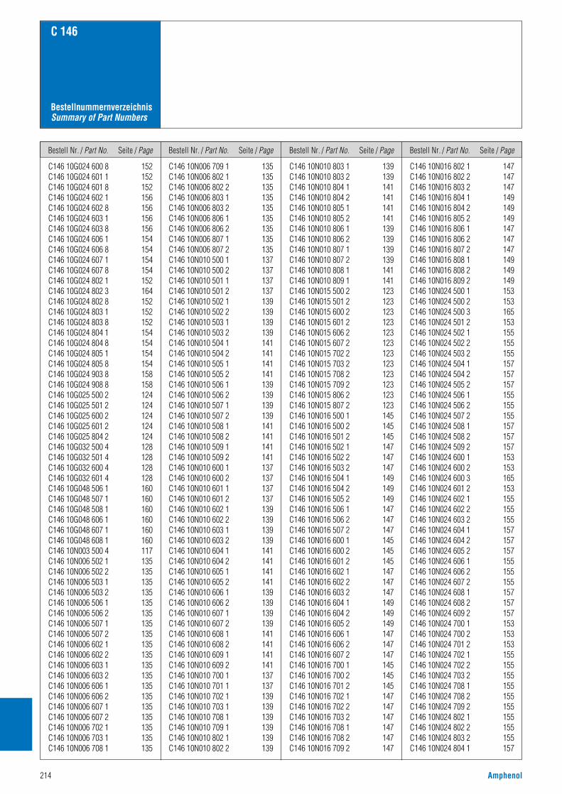
Bestell Nr. / Part No. Seite / Page Bestell Nr. / Part No. Seite / Page Bestell Nr. / Part No. Seite / Page Bestell Nr. / Part No. Seite / Page
214 Amphenol
C 146
BestellnummernverzeichnisSummary of Part Numbers
C146 10G024 600 8 152C146 10G024 601 1 152C146 10G024 601 8 152C146 10G024 602 1 156C146 10G024 602 8 156C146 10G024 603 1 156C146 10G024 603 8 156C146 10G024 606 1 154C146 10G024 606 8 154C146 10G024 607 1 154C146 10G024 607 8 154C146 10G024 802 1 152C146 10G024 802 3 164C146 10G024 802 8 152C146 10G024 803 1 152C146 10G024 803 8 152C146 10G024 804 1 154C146 10G024 804 8 154C146 10G024 805 1 154C146 10G024 805 8 154C146 10G024 903 8 158C146 10G024 908 8 158C146 10G025 500 2 124C146 10G025 501 2 124C146 10G025 600 2 124C146 10G025 601 2 124C146 10G025 804 2 124C146 10G032 500 4 128C146 10G032 501 4 128C146 10G032 600 4 128C146 10G032 601 4 128C146 10G048 506 1 160C146 10G048 507 1 160C146 10G048 508 1 160C146 10G048 606 1 160C146 10G048 607 1 160C146 10G048 608 1 160C146 10N003 500 4 117C146 10N006 502 1 135C146 10N006 502 2 135C146 10N006 503 1 135C146 10N006 503 2 135C146 10N006 506 1 135C146 10N006 506 2 135C146 10N006 507 1 135C146 10N006 507 2 135C146 10N006 602 1 135C146 10N006 602 2 135C146 10N006 603 1 135C146 10N006 603 2 135C146 10N006 606 1 135C146 10N006 606 2 135C146 10N006 607 1 135C146 10N006 607 2 135C146 10N006 702 1 135C146 10N006 703 1 135C146 10N006 708 1 135
C146 10N006 709 1 135C146 10N006 802 1 135C146 10N006 802 2 135C146 10N006 803 1 135C146 10N006 803 2 135C146 10N006 806 1 135C146 10N006 806 2 135C146 10N006 807 1 135C146 10N006 807 2 135C146 10N010 500 1 137C146 10N010 500 2 137C146 10N010 501 1 137C146 10N010 501 2 137C146 10N010 502 1 139C146 10N010 502 2 139C146 10N010 503 1 139C146 10N010 503 2 139C146 10N010 504 1 141C146 10N010 504 2 141C146 10N010 505 1 141C146 10N010 505 2 141C146 10N010 506 1 139C146 10N010 506 2 139C146 10N010 507 1 139C146 10N010 507 2 139C146 10N010 508 1 141C146 10N010 508 2 141C146 10N010 509 1 141C146 10N010 509 2 141C146 10N010 600 1 137C146 10N010 600 2 137C146 10N010 601 1 137C146 10N010 601 2 137C146 10N010 602 1 139C146 10N010 602 2 139C146 10N010 603 1 139C146 10N010 603 2 139C146 10N010 604 1 141C146 10N010 604 2 141C146 10N010 605 1 141C146 10N010 605 2 141C146 10N010 606 1 139C146 10N010 606 2 139C146 10N010 607 1 139C146 10N010 607 2 139C146 10N010 608 1 141C146 10N010 608 2 141C146 10N010 609 1 141C146 10N010 609 2 141C146 10N010 700 1 137C146 10N010 701 1 137C146 10N010 702 1 139C146 10N010 703 1 139C146 10N010 708 1 139C146 10N010 709 1 139C146 10N010 802 1 139C146 10N010 802 2 139
C146 10N010 803 1 139C146 10N010 803 2 139C146 10N010 804 1 141C146 10N010 804 2 141C146 10N010 805 1 141C146 10N010 805 2 141C146 10N010 806 1 139C146 10N010 806 2 139C146 10N010 807 1 139C146 10N010 807 2 139C146 10N010 808 1 141C146 10N010 809 1 141C146 10N015 500 2 123C146 10N015 501 2 123C146 10N015 600 2 123C146 10N015 601 2 123C146 10N015 606 2 123C146 10N015 607 2 123C146 10N015 702 2 123C146 10N015 703 2 123C146 10N015 708 2 123C146 10N015 709 2 123C146 10N015 806 2 123C146 10N015 807 2 123C146 10N016 500 1 145C146 10N016 500 2 145C146 10N016 501 2 145C146 10N016 502 1 147C146 10N016 502 2 147C146 10N016 503 2 147C146 10N016 504 1 149C146 10N016 504 2 149C146 10N016 505 2 149C146 10N016 506 1 147C146 10N016 506 2 147C146 10N016 507 2 147C146 10N016 600 1 145C146 10N016 600 2 145C146 10N016 601 2 145C146 10N016 602 1 147C146 10N016 602 2 147C146 10N016 603 2 147C146 10N016 604 1 149C146 10N016 604 2 149C146 10N016 605 2 149C146 10N016 606 1 147C146 10N016 606 2 147C146 10N016 607 2 147C146 10N016 700 1 145C146 10N016 700 2 145C146 10N016 701 2 145C146 10N016 702 1 147C146 10N016 702 2 147C146 10N016 703 2 147C146 10N016 708 1 147C146 10N016 708 2 147C146 10N016 709 2 147
C146 10N016 802 1 147C146 10N016 802 2 147C146 10N016 803 2 147C146 10N016 804 1 149C146 10N016 804 2 149C146 10N016 805 2 149C146 10N016 806 1 147C146 10N016 806 2 147C146 10N016 807 2 147C146 10N016 808 1 149C146 10N016 808 2 149C146 10N016 809 2 149C146 10N024 500 1 153C146 10N024 500 2 153C146 10N024 500 3 165C146 10N024 501 2 153C146 10N024 502 1 155C146 10N024 502 2 155C146 10N024 503 2 155C146 10N024 504 1 157C146 10N024 504 2 157C146 10N024 505 2 157C146 10N024 506 1 155C146 10N024 506 2 155C146 10N024 507 2 155C146 10N024 508 1 157C146 10N024 508 2 157C146 10N024 509 2 157C146 10N024 600 1 153C146 10N024 600 2 153C146 10N024 600 3 165C146 10N024 601 2 153C146 10N024 602 1 155C146 10N024 602 2 155C146 10N024 603 2 155C146 10N024 604 1 157C146 10N024 604 2 157C146 10N024 605 2 157C146 10N024 606 1 155C146 10N024 606 2 155C146 10N024 607 2 155C146 10N024 608 1 157C146 10N024 608 2 157C146 10N024 609 2 157C146 10N024 700 1 153C146 10N024 700 2 153C146 10N024 701 2 153C146 10N024 702 1 155C146 10N024 702 2 155C146 10N024 703 2 155C146 10N024 708 1 155C146 10N024 708 2 155C146 10N024 709 2 155C146 10N024 802 1 155C146 10N024 802 2 155C146 10N024 803 2 155C146 10N024 804 1 157
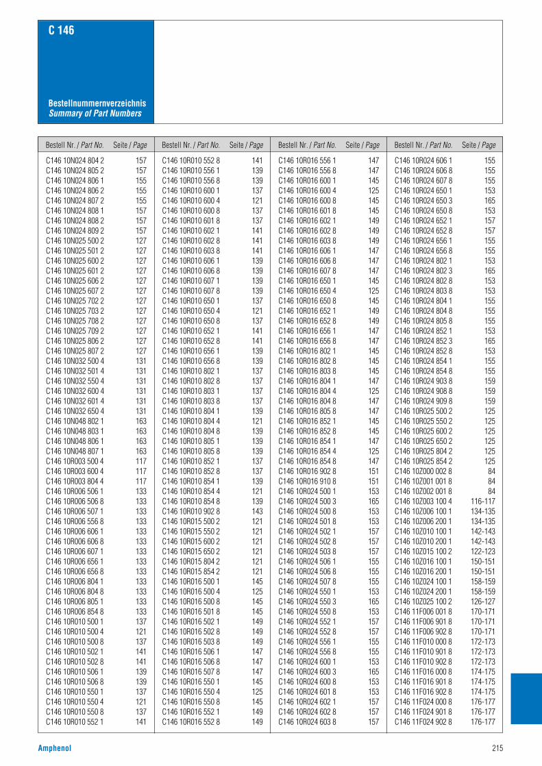
Bestell Nr. / Part No. Seite / Page Bestell Nr. / Part No. Seite / Page Bestell Nr. / Part No. Seite / Page Bestell Nr. / Part No. Seite / Page
Amphenol 215
C 146
BestellnummernverzeichnisSummary of Part Numbers
C146 10N024 804 2 157C146 10N024 805 2 157C146 10N024 806 1 155C146 10N024 806 2 155C146 10N024 807 2 155C146 10N024 808 1 157C146 10N024 808 2 157C146 10N024 809 2 157C146 10N025 500 2 127C146 10N025 501 2 127C146 10N025 600 2 127C146 10N025 601 2 127C146 10N025 606 2 127C146 10N025 607 2 127C146 10N025 702 2 127C146 10N025 703 2 127C146 10N025 708 2 127C146 10N025 709 2 127C146 10N025 806 2 127C146 10N025 807 2 127C146 10N032 500 4 131C146 10N032 501 4 131C146 10N032 550 4 131C146 10N032 600 4 131C146 10N032 601 4 131C146 10N032 650 4 131C146 10N048 802 1 163C146 10N048 803 1 163C146 10N048 806 1 163C146 10N048 807 1 163C146 10R003 500 4 117C146 10R003 600 4 117C146 10R003 804 4 117C146 10R006 506 1 133C146 10R006 506 8 133C146 10R006 507 1 133C146 10R006 556 8 133C146 10R006 606 1 133C146 10R006 606 8 133C146 10R006 607 1 133C146 10R006 656 1 133C146 10R006 656 8 133C146 10R006 804 1 133C146 10R006 804 8 133C146 10R006 805 1 133C146 10R006 854 8 133C146 10R010 500 1 137C146 10R010 500 4 121C146 10R010 500 8 137C146 10R010 502 1 141C146 10R010 502 8 141C146 10R010 506 1 139C146 10R010 506 8 139C146 10R010 550 1 137C146 10R010 550 4 121C146 10R010 550 8 137C146 10R010 552 1 141
C146 10R010 552 8 141C146 10R010 556 1 139C146 10R010 556 8 139C146 10R010 600 1 137C146 10R010 600 4 121C146 10R010 600 8 137C146 10R010 601 8 137C146 10R010 602 1 141C146 10R010 602 8 141C146 10R010 603 8 141C146 10R010 606 1 139C146 10R010 606 8 139C146 10R010 607 1 139C146 10R010 607 8 139C146 10R010 650 1 137C146 10R010 650 4 121C146 10R010 650 8 137C146 10R010 652 1 141C146 10R010 652 8 141C146 10R010 656 1 139C146 10R010 656 8 139C146 10R010 802 1 137C146 10R010 802 8 137C146 10R010 803 1 137C146 10R010 803 8 137C146 10R010 804 1 139C146 10R010 804 4 121C146 10R010 804 8 139C146 10R010 805 1 139C146 10R010 805 8 139C146 10R010 852 1 137C146 10R010 852 8 137C146 10R010 854 1 139C146 10R010 854 4 121C146 10R010 854 8 139C146 10R010 902 8 143C146 10R015 500 2 121C146 10R015 550 2 121C146 10R015 600 2 121C146 10R015 650 2 121C146 10R015 804 2 121C146 10R015 854 2 121C146 10R016 500 1 145C146 10R016 500 4 125C146 10R016 500 8 145C146 10R016 501 8 145C146 10R016 502 1 149C146 10R016 502 8 149C146 10R016 503 8 149C146 10R016 506 1 147C146 10R016 506 8 147C146 10R016 507 8 147C146 10R016 550 1 145C146 10R016 550 4 125C146 10R016 550 8 145C146 10R016 552 1 149C146 10R016 552 8 149
C146 10R016 556 1 147C146 10R016 556 8 147C146 10R016 600 1 145C146 10R016 600 4 125C146 10R016 600 8 145C146 10R016 601 8 145C146 10R016 602 1 149C146 10R016 602 8 149C146 10R016 603 8 149C146 10R016 606 1 147C146 10R016 606 8 147C146 10R016 607 8 147C146 10R016 650 1 145C146 10R016 650 4 125C146 10R016 650 8 145C146 10R016 652 1 149C146 10R016 652 8 149C146 10R016 656 1 147C146 10R016 656 8 147C146 10R016 802 1 145C146 10R016 802 8 145C146 10R016 803 8 145C146 10R016 804 1 147C146 10R016 804 4 125C146 10R016 804 8 147C146 10R016 805 8 147C146 10R016 852 1 145C146 10R016 852 8 145C146 10R016 854 1 147C146 10R016 854 4 125C146 10R016 854 8 147C146 10R016 902 8 151C146 10R016 910 8 151C146 10R024 500 1 153C146 10R024 500 3 165C146 10R024 500 8 153C146 10R024 501 8 153C146 10R024 502 1 157C146 10R024 502 8 157C146 10R024 503 8 157C146 10R024 506 1 155C146 10R024 506 8 155C146 10R024 507 8 155C146 10R024 550 1 153C146 10R024 550 3 165C146 10R024 550 8 153C146 10R024 552 1 157C146 10R024 552 8 157C146 10R024 556 1 155C146 10R024 556 8 155C146 10R024 600 1 153C146 10R024 600 3 165C146 10R024 600 8 153C146 10R024 601 8 153C146 10R024 602 1 157C146 10R024 602 8 157C146 10R024 603 8 157
C146 10R024 606 1 155C146 10R024 606 8 155C146 10R024 607 8 155C146 10R024 650 1 153C146 10R024 650 3 165C146 10R024 650 8 153C146 10R024 652 1 157C146 10R024 652 8 157C146 10R024 656 1 155C146 10R024 656 8 155C146 10R024 802 1 153C146 10R024 802 3 165C146 10R024 802 8 153C146 10R024 803 8 153C146 10R024 804 1 155C146 10R024 804 8 155C146 10R024 805 8 155C146 10R024 852 1 153C146 10R024 852 3 165C146 10R024 852 8 153C146 10R024 854 1 155C146 10R024 854 8 155C146 10R024 903 8 159C146 10R024 908 8 159C146 10R024 909 8 159C146 10R025 500 2 125C146 10R025 550 2 125C146 10R025 600 2 125C146 10R025 650 2 125C146 10R025 804 2 125C146 10R025 854 2 125C146 10Z000 002 8 84C146 10Z001 001 8 84C146 10Z002 001 8 84C146 10Z003 100 4 116-117C146 10Z006 100 1 134-135C146 10Z006 200 1 134-135C146 10Z010 100 1 142-143C146 10Z010 200 1 142-143C146 10Z015 100 2 122-123C146 10Z016 100 1 150-151C146 10Z016 200 1 150-151C146 10Z024 100 1 158-159C146 10Z024 200 1 158-159C146 10Z025 100 2 126-127C146 11F006 001 8 170-171C146 11F006 901 8 170-171C146 11F006 902 8 170-171C146 11F010 000 8 172-173C146 11F010 901 8 172-173C146 11F010 902 8 172-173C146 11F016 000 8 174-175C146 11F016 901 8 174-175C146 11F016 902 8 174-175C146 11F024 000 8 176-177C146 11F024 901 8 176-177C146 11F024 902 8 176-177
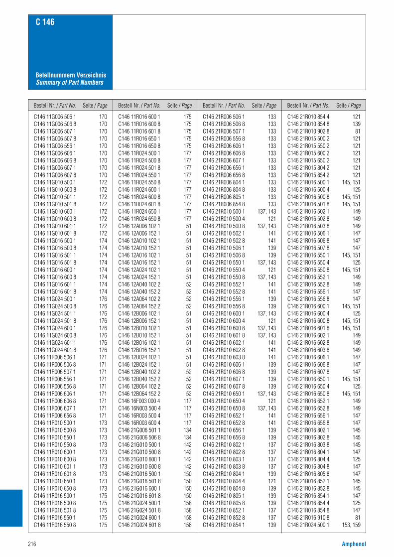
Bestell Nr. / Part No. Seite / Page Bestell Nr. / Part No. Seite / Page Bestell Nr. / Part No. Seite / Page Bestell Nr. / Part No. Seite / Page
216 Amphenol
C 146
Betellnummern VerzeichnisSummary of Part Numbers
C146 11G006 506 1 170C146 11G006 506 8 170C146 11G006 507 1 170C146 11G006 507 8 170C146 11G006 556 1 170C146 11G006 606 1 170C146 11G006 606 8 170C146 11G006 607 1 170C146 11G006 607 8 170C146 11G010 500 1 172C146 11G010 500 8 172C146 11G010 501 1 172C146 11G010 501 8 172C146 11G010 600 1 172C146 11G010 600 8 172C146 11G010 601 1 172C146 11G010 601 8 172C146 11G016 500 1 174C146 11G016 500 8 174C146 11G016 501 1 174C146 11G016 501 8 174C146 11G016 600 1 174C146 11G016 600 8 174C146 11G016 601 1 174C146 11G016 601 8 174C146 11G024 500 1 176C146 11G024 500 8 176C146 11G024 501 1 176C146 11G024 501 8 176C146 11G024 600 1 176C146 11G024 600 8 176C146 11G024 601 1 176C146 11G024 601 8 176C146 11R006 506 1 171C146 11R006 506 8 171C146 11R006 507 1 171C146 11R006 556 1 171C146 11R006 556 8 171C146 11R006 606 1 171C146 11R006 606 8 171C146 11R006 607 1 171C146 11R006 656 8 171C146 11R010 500 1 173C146 11R010 500 8 173C146 11R010 550 1 173C146 11R010 550 8 173C146 11R010 600 1 173C146 11R010 600 8 173C146 11R010 601 1 173C146 11R010 601 8 173C146 11R010 650 1 173C146 11R010 650 8 173C146 11R016 500 1 175C146 11R016 500 8 175C146 11R016 501 8 175C146 11R016 550 1 175C146 11R016 550 8 175
C146 11R016 600 1 175C146 11R016 600 8 175C146 11R016 601 8 175C146 11R016 650 1 175C146 11R016 650 8 175C146 11R024 500 1 177C146 11R024 500 8 177C146 11R024 501 8 177C146 11R024 550 1 177C146 11R024 550 8 177C146 11R024 600 1 177C146 11R024 600 8 177C146 11R024 601 8 177C146 11R024 650 1 177C146 11R024 650 8 177C146 12A006 102 1 51C146 12A006 152 1 51C146 12A010 102 1 51C146 12A010 152 1 51C146 12A016 102 1 51C146 12A016 152 1 51C146 12A024 102 1 51C146 12A024 152 1 51C146 12A040 102 2 52C146 12A040 152 2 52C146 12A064 102 2 52C146 12A064 152 2 52C146 12B006 102 1 51C146 12B006 152 1 51C146 12B010 102 1 51C146 12B010 152 1 51C146 12B016 102 1 51C146 12B016 152 1 51C146 12B024 102 1 51C146 12B024 152 1 51C146 12B040 102 2 52C146 12B040 152 2 52C146 12B064 102 2 52C146 12B064 152 2 52C146 16F003 000 4 117C146 16N003 500 4 117C146 16R003 500 4 117C146 16R003 600 4 117C146 21G006 501 1 134C146 21G006 506 8 134C146 21G010 500 1 142C146 21G010 500 8 142C146 21G010 600 1 142C146 21G010 600 8 142C146 21G016 500 1 150C146 21G016 501 8 150C146 21G016 600 1 150C146 21G016 601 8 150C146 21G024 500 1 158C146 21G024 501 8 158C146 21G024 600 1 158C146 21G024 601 8 158
C146 21R006 506 1 133C146 21R006 506 8 133C146 21R006 507 1 133C146 21R006 556 8 133C146 21R006 606 1 133C146 21R006 606 8 133C146 21R006 607 1 133C146 21R006 656 1 133C146 21R006 656 8 133C146 21R006 804 1 133C146 21R006 804 8 133C146 21R006 805 1 133C146 21R006 854 8 133C146 21R010 500 1 137, 143C146 21R010 500 4 121C146 21R010 500 8 137, 143C146 21R010 502 1 141C146 21R010 502 8 141C146 21R010 506 1 139C146 21R010 506 8 139C146 21R010 550 1 137, 143C146 21R010 550 4 121C146 21R010 550 8 137, 143C146 21R010 552 1 141C146 21R010 552 8 141C146 21R010 556 1 139C146 21R010 556 8 139C146 21R010 600 1 137, 143C146 21R010 600 4 121C146 21R010 600 8 137, 143C146 21R010 601 8 137, 143C146 21R010 602 1 141C146 21R010 602 8 141C146 21R010 603 8 141C146 21R010 606 1 139C146 21R010 606 8 139C146 21R010 607 1 139C146 21R010 607 8 139C146 21R010 650 1 137, 143C146 21R010 650 4 121C146 21R010 650 8 137, 143C146 21R010 652 1 141C146 21R010 652 8 141C146 21R010 656 1 139C146 21R010 656 8 139C146 21R010 802 1 137C146 21R010 802 8 137C146 21R010 803 1 137C146 21R010 803 8 137C146 21R010 804 1 139C146 21R010 804 4 121C146 21R010 804 8 139C146 21R010 805 1 139C146 21R010 805 8 139C146 21R010 852 1 137C146 21R010 852 8 137C146 21R010 854 1 139
C146 21R010 854 4 121C146 21R010 854 8 139C146 21R010 902 8 81C146 21R015 500 2 121C146 21R015 550 2 121C146 21R015 600 2 121C146 21R015 650 2 121C146 21R015 804 2 121C146 21R015 854 2 121C146 21R016 500 1 145, 151C146 21R016 500 4 125C146 21R016 500 8 145, 151C146 21R016 501 8 145, 151C146 21R016 502 1 149C146 21R016 502 8 149C146 21R016 503 8 149C146 21R016 506 1 147C146 21R016 506 8 147C146 21R016 507 8 147C146 21R016 550 1 145, 151C146 21R016 550 4 125C146 21R016 550 8 145, 151C146 21R016 552 1 149C146 21R016 552 8 149C146 21R016 556 1 147C146 21R016 556 8 147C146 21R016 600 1 145, 151C146 21R016 600 4 125C146 21R016 600 8 145, 151C146 21R016 601 8 145, 151C146 21R016 602 1 149C146 21R016 602 8 149C146 21R016 603 8 149C146 21R016 606 1 147C146 21R016 606 8 147C146 21R016 607 8 147C146 21R016 650 1 145, 151C146 21R016 650 4 125C146 21R016 650 8 145, 151C146 21R016 652 1 149C146 21R016 652 8 149C146 21R016 656 1 147C146 21R016 656 8 147C146 21R016 802 1 145C146 21R016 802 8 145C146 21R016 803 8 145C146 21R016 804 1 147C146 21R016 804 4 125C146 21R016 804 8 147C146 21R016 805 8 147C146 21R016 852 1 145C146 21R016 852 8 145C146 21R016 854 1 147C146 21R016 854 4 125C146 21R016 854 8 147C146 21R016 910 8 81C146 21R024 500 1 153, 159

Bestell Nr. / Part No. Seite / Page Bestell Nr. / Part No. Seite / Page Bestell Nr. / Part No. Seite / Page Bestell Nr. / Part No. Seite / Page
Amphenol 217
C 146
Betellnummern VerzeichnisSummary of Part Numbers
C146 21R024 500 8 153, 159C146 21R024 501 8 153, 159C146 21R024 502 1 157C146 21R024 502 8 157C146 21R024 503 8 157C146 21R024 506 1 155C146 21R024 506 8 155C146 21R024 507 8 155C146 21R024 550 1 153, 159C146 21R024 550 8 153, 159C146 21R024 552 1 157C146 21R024 552 8 157C146 21R024 556 1 155C146 21R024 556 8 155C146 21R024 600 1 153, 159C146 21R024 600 8 153, 159C146 21R024 601 8 153, 159C146 21R024 602 1 157C146 21R024 602 8 157C146 21R024 603 8 157C146 21R024 606 1 155C146 21R024 606 8 155C146 21R024 607 8 155C146 21R024 650 1 153, 159C146 21R024 650 8 153, 159C146 21R024 652 1 157C146 21R024 652 8 157C146 21R024 656 1 155C146 21R024 656 8 155C146 21R024 802 1 153C146 21R024 802 8 153C146 21R024 803 8 153C146 21R024 804 1 155C146 21R024 804 8 155C146 21R024 805 8 155C146 21R024 852 1 153C146 21R024 852 8 153C146 21R024 854 1 155C146 21R024 854 8 155C146 21R024 913 8 81C146 21R025 500 2 125C146 21R025 550 2 125C146 21R025 600 2 125C146 21R025 650 2 125C146 21R025 804 2 125C146 21R025 854 2 125C146 21R032 500 4 129C146 21R032 501 4 129C146 21R032 502 4 129C146 21R032 503 4 129C146 21R032 550 4 129C146 21R032 552 4 129C146 21R032 600 4 129C146 21R032 601 4 129C146 21R032 602 4 129C146 21R032 603 4 129C146 21R032 650 4 129
C146 21R032 652 4 129C146 21R032 802 4 129C146 21R032 803 4 129C146 21R032 852 4 129C146 21R048 506 1 161C146 21R048 507 1 161C146 21R048 508 1 161C146 21R048 606 1 161C146 21R048 607 1 161C146 21R048 608 1 161C146 30F003 000 4 118-119C146 30F003 004 4 118-119C146 30F003 500 4 118C146 30G003 500 4 118C146 30G003 600 4 118C146 30G003 804 4 118C146 30N003 500 4 119C146 30R003 500 4 119C146 30R003 600 4 119C146 30R003 804 4 119C146 30Z003 100 4 118-119C146 31N003 500 4 119C146 A00 001 E8 84C146 A03 001 E8 62, 73C146 A03 001 E8 62, 73C146 A03 501 E8 62, 77C146 A03 801 E8 62, 79C146 A05 001 E8 62, 71C146 A10 001 E8 62, 69C146 A20 001 G8 62, 65C146 B00 001 E8 84C146 B03 001 E8 62, 73C146 B03 501 E8 62, 77C146 B03 801 E8 62, 79C146 B05 001 E8 62, 71C146 B10 001 E8 62, 69C146 B20 001 G8 62, 65C146 C04 001 E8 62, 75C146 C05 001 E8 62, 75C146 C05 801 E8 62, 75C146 C10 001 G8 62, 67C146 D04 001 E8 62, 75C146 D05 001 E8 62, 75C146 D05 801 E8 62, 75C146 D10 001 E8 62, 67C146 E12 001 E8 63, 81C146 F12 001 G8 63, 81C146 G01 014 G8 63, 83C146 G01 024 G8 63, 83C146 G02 014 G8 63, 83C146 G02 024 G8 63, 83C146 H01 034 G8 63, 83C146 H01 044 G8 63, 83C146 H02 034 G8 63, 83C146 H02 044 G8 63, 83C146 N21 040 E1 X 51-52C146 N32 009 G1 186
C146 N32 015 G1 186C146 N32 015 G2 186C146 N32 025 G1 186C146 N32 025 G2 186C146 N32 037 G1 186C146 N32 050 G1 186C146 N33 009 G1 186C146 N33 015 G1 186C146 N33 025 G1 186C146 N33 037 G1 186C146 N33 050 G1 186C146 P06 001 G8 63C146 P06 002 G8 63C146 P10 001 G8 63C146 P10 002 G8 63C146 P16 001 G8 63C146 P16 002 G8 63C146 P24 001 G8 63C146 P24 002 G8 63C146 P24 101 G8 63C146 P24 102 G8 63C146 S06 001 G8 63C146 S06 002 G8 63C146 S10 001 G8 63C146 S10 002 G8 63C146 S16 001 G8 63C146 S16 002 G8 63C146 S24 001 G8 63C146 S24 002 G8 63C146 S24 101 G8 63C146 S24 102 G8 63FG 0200 146 1 44, 75, 84FG 0300 146 1 24, 67, 69, 84FG 0300 146 3 73, 77, 79, 84FG 0300 146 4 71, 84FG 1000 146 65, 67, 69, 71, 73,
75, 77, 79, 84FN01 010 0130 (2) 65FN01 010 0131 (2) 65FN02 010 0130 (2) 65FN02 010 0131 (2) 65HN01 016 0002 (1) 11, 13, 15, 17,
19, 21, 23, 67HN01 016 0002 (2) 11, 13, 15, 17,
19, 21, 23, 67HN01 016 0003 (1) 11, 13, 15, 17,
19, 21, 23, 67HN01 016 0003 (2) 11, 13, 15, 17,
19, 21, 23, 67HN01 016 0005 (1) 11, 13, 15, 17,
19, 21, 23, 67HN01 016 0005 (2) 11, 13, 15, 17,
19, 21, 23, 67HN01 016 0015 (1) 11, 13, 15, 17,
19, 21, 23, 67HN01 016 0016 (1) 11, 13, 15, 17,
19, 21, 23, 67
HN01 025 0001 (1) 35, 37, 39, 41,43, 75
HN01 025 0007 (1) 111HN01 025 0008 (1) 111HN01 025 0010 (1) 35, 37, 39, 41,
43, 75HN02 016 0002 (1) 11, 13, 15, 17,
19, 21, 23, 67HN02 016 0002 (2) 11, 13, 15, 17,
19, 21, 23, 67HN02 016 0003 (1) 11, 13, 15, 17,
19, 21, 23, 67HN02 016 0003 (2) 11, 13, 15, 17,
19, 21, 23, 67HN02 016 0005 (1) 11, 13, 15, 17,
19, 21, 23, 67HN02 016 0005 (2) 11, 13, 15, 17,
19, 21, 23, 67HN02 016 0015 (1) 11, 13, 15, 17,
19, 21, 23, 67HN02 016 0016 (1) 11, 13, 15, 17,
19, 21, 23, 67HN02 025 0001 (1) 35, 37, 39, 41,
43, 75, 111HN02 025 0010 (1) 35, 37, 39, 41,
43, 75, 111N01 016 0040 8 189 N02 016 0040 8 189T 1860 000 112T 1860 010 112T 1860 021 112T 1860 022 112T 1861 002 112T 1861 012 112T 1862 001 112TA 0000 24, 44, 67, 69, 71,
73, 75, 77, 79TA 0000 121 75TA 0000 124 71, 73, 79TA 0000 141 24, 44, 67, 75TA 0000 144 71, 73, 79TA 0000 163 24, 44, 67, 75TA 0000 180 73, 79TA 0000 184 69TA 0000 202 24, 67TA 0000 401 77TA 0000 402 77TA 0001 146 000 1 24, 67TA 0002 146 000 1 24, 67TA 0003 146 000 1 75TA 0004 146 000 1 44, 75TA 0005 146 000 3 44, 75TA 0007 146 000 3 24, 67TA 0010 146 000 1 69TA 0010 146 000 2 71, 79TA 0010 146 000 3 71TA 0010 146 000 4 73, 79

Bestell Nr. / Part No. Seite / Page Bestell Nr. / Part No. Seite / Page Bestell Nr. / Part No. Seite / Page Bestell Nr. / Part No. Seite / Page
218 Amphenol
C 146
Betellnummern VerzeichnisSummary of Part Numbers
TA 0010 146 000 5 73TA 0100 146 24, 67TA 0200 146 65TA 0500 24TB 0200 146 73, 79TB 0500 146 69TB 0600 146 44TN01 010 0130 (2) 65TN01 010 0131 (2) 65TN01 016 0002 (1) 11, 13, 15, 17,
19, 21, 23, 67TN01 016 0002 (2) 11, 13, 15, 17,
19, 21, 23, 67TN01 016 0003 (1) 11, 13, 15, 17,
19, 21, 23, 67TN01 016 0003 (2) 11, 13, 15, 17,
19, 21, 23, 67TN01 016 0005 (1) 11, 13, 15, 17,
19, 21, 23, 67TN01 016 0005 (2) 11, 13, 15, 17,
19, 21, 23, 67TN01 016 0015 (1) 11, 13, 15, 17,
19, 21, 23, 67TN01 016 0016 (1) 11, 13, 15, 17,
19, 21, 23, 67TN01 025 0001 (1) 35, 37, 39, 41,
43, 75TN01 025 0007 (1) 111TN01 025 0008 (1) 111TN01 025 0010 (1) 35, 37, 39, 41,
43, 75TN01 025 0043 (1) 75TN02 010 0130 (2) 65TN02 010 0131 (2) 65TN02 016 0002 (1) 11, 13, 15, 17,
19, 21, 23, 67TN02 016 0002 (2) 11, 13, 15, 17,
19, 21, 23, 67TN02 016 0003 (1) 11, 13, 15, 17,
19, 21, 23, 67TN02 016 0003 (2) 11, 13, 15, 17,
19, 21, 23, 67TN02 016 0005 (1) 11, 13, 15, 17,
19, 21, 23, 67TN02 016 0005 (2) 11, 13, 15, 17,
19, 21, 23, 67TN02 016 0015 (1) 11, 13, 15, 17,
19, 21, 23, 67TN02 016 0016 (1) 11, 13, 15, 17,
19, 21, 23, 67TN02 025 0001 (1) 35, 37, 39, 41,
43, 75, 111TN02 025 0010 (1) 35, 37, 39, 41,
43, 75, 111TN02 025 0043 (1) 75VN01 010 0130 (2) 65VN01 010 0131 (2) 65
VN01 016 0002 (1) 11, 13, 15, 17,19, 21, 23, 67
VN01 016 0002 (2) 11, 13, 15, 17,19, 21, 23, 67
VN01 016 0003 (1) 11, 13, 15, 17,19, 21, 23, 67
VN01 016 0003 (2) 11, 13, 15, 17,19, 21, 23, 67
VN01 016 0005 (1) 11, 13, 15, 17,19, 21, 23, 67
VN01 016 0005 (2) 11, 13, 15, 17,19, 21, 23, 67
VN01 016 0015 (1) 11, 13, 15, 17,19, 21, 23, 67
VN01 016 0016 (1) 11, 13, 15, 17,19, 21, 23, 67
VN01 016 0024 (1)C 11, 13, 15,17, 19, 21, 23, 27, 69, 188
VN01 016 0024 (2)C 11, 13, 15,17, 19, 21, 23, 27, 69
VN01 016 0025 (1)C 11, 13, 15,17, 19, 21, 23, 27, 69, 188
VN01 016 0025 (2)C 11, 13, 15,17, 19, 21, 23, 27, 69
VN01 016 0026 (1)C 11, 13, 15,17, 19, 21, 23, 27, 69, 188
VN01 016 0026 (2)C 11, 13, 15,17, 19, 21, 23, 27, 69
VN01 016 0027 (1)C 11, 13, 15,17, 19, 21, 23, 27, 69, 188
VN01 016 0027 (2)C 11, 13, 15,17, 19, 21, 23, 27, 69
VN01 016 0028 (1)C 11, 13, 15,17, 19, 21, 23, 27, 69, 188
VN01 016 0028 (2)C 11, 13, 15,17, 19, 21, 23, 27, 69
VN01 016 0040 (8) X 69VN01 025 0001 (101) 35, 37, 39,
41, 43, 75VN01 025 0001 (102) 35, 37, 39,
41, 43, 75VN01 025 0007 (101) 111VN01 025 0008 (101) 111VN01 025 0010 (101) 35, 37, 39,
41, 43, 75VN01 025 0010 (102) 35, 37, 39,
41, 43, 75VN01 025 0029 (1)C 71, 188VN01 025 0029 (2)C 71VN01 025 0030 (1)C 71, 188VN01 025 0030 (2)C 71VN01 025 0031 (1)C 71, 188VN01 025 0031 (2)C 71VN01 025 0032 (1)C 71, 188VN01 025 0032 (2)C 71VN01 025 0033 (1)C 71, 188VN01 025 0033 (2)C 71
VN01 025 0035 (1)C 35, 37, 39,41, 43, 47, 188
VN01 025 0035 (2)C 35, 37, 39,41, 43, 47
VN01 025 0036 (1)C 35, 37, 39,41, 43, 47, 188
VN01 025 0036 (2)C 35, 37, 39,41, 43, 47
VN01 025 0037 (1)C 35, 37, 39,41, 43, 47, 188
VN01 025 0037 (2)C 35, 37, 39,41, 43, 47
VN01 025 0038 (1)C 35, 37, 39,41, 43, 47, 188
VN01 025 0038 (2)C 35, 37, 39,41, 43, 47
VN01 025 0039 (1)C 35, 37, 39,41, 43, 47, 188
VN01 025 0039 (2)C 35, 37, 39,41, 43, 47
VN01 025 0043 (1) 75VN01 036 0001 (1)C 73, 79, 188VN01 036 0002 (1)C 73, 79, 188VN01 036 0003 (1)C 73, 79, 188VN01 036 0004 (1)C 73, 79, 188VN01 036 0005 (1)C 73, 79, 188VN02 010 0130 (2) 65VN02 010 0131 (2) 65VN02 016 0002 (1) 11, 13, 15, 17,
19, 21, 23, 67VN02 016 0002 (2) 11, 13, 15, 17,
19, 21, 23, 67VN02 016 0003 (1) 11, 13, 15, 17,
19, 21, 23, 67VN02 016 0003 (2) 11, 13, 15, 17,
19, 21, 23, 67VN02 016 0005 (1) 11, 13, 15, 17,
19, 21, 23, 67VN02 016 0005 (2) 11, 13, 15, 17,
19, 21, 23, 67VN02 016 0015 (1) 11, 13, 15, 17,
19, 21, 23, 67VN02 016 0016 (1) 11, 13, 15, 17,
19, 21, 23, 67VN02 016 0024 (1)C 11, 13, 15,
17, 19, 21, 23, 27, 69, 188VN02 016 0024 (2)C 11, 13, 15,
17, 19, 21, 23, 27, 69VN02 016 0025 (1)C 11, 13, 15,
17, 19, 21, 23, 27, 69, 188VN02 016 0025 (2)C 11, 13, 15,
17, 19, 21, 23, 27, 69VN02 016 0026 (1)C 11, 13, 15,
17, 19, 21, 23, 27, 69, 188VN02 016 0026 (2)C 11, 13, 15,
17, 19, 21, 23, 27, 69VN02 016 0027 (1)C 11, 13, 15,
17, 19, 21, 23, 27, 69, 188VN02 016 0027 (2)C 11, 13, 15,
17, 19, 21, 23, 27, 69VN02 016 0028 (1)C 11, 13, 15,
17, 19, 21, 23, 27, 69, 188VN02 016 0028 (2)C 11, 13, 15,
17, 19, 21, 23, 27, 69VN02 016 0040 (8) X 69VN02 025 0001 (101) 35, 37, 39,
41, 43, 75, 111VN02 025 0001 (102) 35, 37, 39,
41, 43, 75VN02 025 0010 (101) 35, 37, 39,
41, 43, 75, 111VN02 025 0010 (102) 35, 37, 39,
41, 43, 75VN02 025 0029 (1)C 71, 188VN02 025 0029 (2)C 71VN02 025 0030 (1)C 71, 188VN02 025 0030 (2)C 71VN02 025 0031 (1)C 71, 188VN02 025 0031 (2)C 71VN02 025 0032 (1)C 71, 188VN02 025 0032 (2)C 71VN02 025 0033 (1)C 71, 188VN02 025 0033 (2)C 71VN02 025 0035 (1)C 35, 37, 39,
41, 43, 47, 188VN02 025 0035 (2)C 35, 37, 39,
41, 43, 47VN02 025 0036 (1)C 35, 37, 39,
41, 43, 47, 188VN02 025 0036 (2)C 35, 37, 39,
41, 43, 47VN02 025 0037 (1)C 35, 37, 39,
41, 43, 47, 188VN02 025 0037 (2)C 35, 37, 39,
41, 43, 47VN02 025 0038 (1)C 35, 37, 39,
41, 43, 47, 188VN02 025 0038 (2)C 35, 37, 39,
41, 43, 47VN02 025 0039 (1)C 35, 37, 39,
41, 43, 47, 188VN02 025 0039 (2)C 35, 37, 39,
41, 43, 47VN02 025 0043 (1) 75VN02 036 0001 (1)C 73, 79, 188VN02 036 0002 (1)C 73, 79, 188VN02 036 0003 (1)C 73, 79, 188VN02 036 0004 (1)C 73, 79, 188VN02 036 0005 (1)C 73, 79, 188VN03 030 0020 184VN03 030 0021 184VN03 030 3000 X 184VN13 040 0008 (1) X 184VN13 040 0009 (1) X 184

Bestell Nr. / Part No. Seite / Page Bestell Nr. / Part No. Seite / Page Bestell Nr. / Part No. Seite / Page Bestell Nr. / Part No. Seite / Page
Amphenol 219
C 146
Betellnummern VerzeichnisSummary of Part Numbers
VN16 020 0113 (1) X 182VN16 025 0113 (1) X 182VN16 032 0113 (1) X 182VN16 040 0113 (1) X 182VN16 110 0004 V 181VN16 110 0013 X 180VN16 110 0014 X 180VN16 110 0026 X 183VN16 110 0027 X 182VN16 110 0028 X 181VN16 110 0029 X 181VN16 135 0002 V 181VN16 135 0003 V 181VN16 135 0013 X 180VN16 135 0014 X 180VN16 135 0026 X 183VN16 135 0027 X 182VN16 135 0028 X 181VN16 135 0029 X 181VN16 160 0002 V 181VN16 160 0003 V 181VN16 160 0013 X 180VN16 160 0014 X 180VN16 160 0026 X 183VN16 160 0027 X 182VN16 160 0028 X 181VN16 160 0029 X 181VN16 160 0102 V 181VN16 160 0126 X 183VN16 160 0127 X 182VN16 200 0102 V 181VN16 200 0103 V 181VN16 200 0114 X 180VN16 200 0114 X 180VN16 200 0126 X 183VN16 200 0127 X 182VN16 210 0002 V 181VN16 210 0003 V 181VN16 210 0013 X 180VN16 210 0014 X 180VN16 210 0026 X 183VN16 210 0027 X 182VN16 210 0028 X 181VN16 210 0029 X 181VN16 250 0102 V 181VN16 250 0103 V 181VN16 250 0114 X 180VN16 250 0126 X 183VN16 250 0127 X 182VN16 250 0131 V 81VN16 290 0002 V 181VN16 290 0003 V 181VN16 290 0013 X 180VN16 290 0014 X 180VN16 290 0026 X 183VN16 290 0027 X 182VN16 290 0028 X 181
VN16 290 0029 X 181VN16 320 0102 V 181VN16 320 0103 V 181VN16 320 0114 X 180VN16 320 0126 X 183VN16 320 0127 X 182VN16 360 0013 X 180VN16 360 0014 X 180VN16 400 0114 X 180VN16 400 0126 X 183VN16 400 0127 X 182VN16 420 0013 X 180VN16 420 0014 X 180VN16 500 0114 X 180VN17 050 0004 (1) 184VN17 050 0004 (101) 184ZN01 010 0130 (2) 65ZN01 010 0131 (2) 65ZN01 016 0002 (1) 11, 13, 15, 17,
19, 21, 23, 67ZN01 016 0002 (2) 11, 13, 15, 17,
19, 21, 23, 67ZN01 016 0003 (1) 11, 13, 15, 17,
19, 21, 23, 67ZN01 016 0003 (2) 11, 13, 15, 17,
19, 21, 23, 67ZN01 016 0005 (1) 11, 13, 15, 17,
19, 21, 23, 67ZN01 016 0005 (2) 11, 13, 15, 17,
19, 21, 23, 67ZN01 016 0015 (1) 11, 13, 15, 17,
19, 21, 23, 67ZN01 016 0016 (1) 11, 13, 15, 17,
19, 21, 23, 67ZN01 025 0001 (1) 35, 37, 39, 41,
43, 75ZN01 025 0001 (2) 35, 37, 39, 41,
43, 75ZN01 025 0007 (1) 111ZN01 025 0008 (1) 111ZN01 025 0010 (1) 35, 37, 39, 41,
43, 75ZN01 025 0010 (2) 35, 37, 39, 41,
43, 75ZN02 010 0130 (2) 65ZN02 010 0131 (2) 65ZN02 016 0002 (1) 11, 13, 15, 17,
19, 21, 23, 67ZN02 016 0002 (2) 11, 13, 15, 17,
19, 21, 23, 67ZN02 016 0003 (1) 11, 13, 15, 17,
19, 21, 23, 67ZN02 016 0003 (2) 11, 13, 15, 17,
19, 21, 23, 67ZN02 016 0005 (1) 11, 13, 15, 17,
19, 21, 23, 67ZN02 016 0005 (2) 11, 13, 15, 17,
19, 21, 23, 67ZN02 016 0015 (1) 11, 13, 15, 17,
19, 21, 23, 67ZN02 016 0016 (1) 11, 13, 15, 17,
19, 21, 23, 67ZN02 025 0001 (1) 35, 37, 39,
41, 43, 75, 111ZN02 025 0001 (2) 35, 37, 39,
41, 43, 75ZN02 025 0010 (1) 35, 37, 39,
41, 43, 75, 111ZN02 025 0010 (2) 35, 37, 39,
41, 43, 75

ATE
2040
D 1
205
10.0
00
Ged
ruck
t auf
chl
orfre
i geb
leic
htem
Pap
ier,
Änd
erun
gen
vorb
ehal
ten.
Prin
ted
on c
hlor
in-f
ree
blea
ched
pap
er. S
peci
ficat
ions
may
be
chan
ged
with
out n
otic
e.C
opyr
ight
12/
05 b
y A
mph
enol
-Tuc
hel E
lect
roni
cs G
mbH
, Ger
man
y
Ihr zuständiger Vertriebs- Ingenieur:Your engineering sales representative:
AmphenolAmphenol-Tuchel Electronics GmbH
August-Haeusser- Str. 10 . D-74080 Heilbronn . Germany . Phone +49 (0) 7131/9 29-0 . Fax +49 (0) 7131/9 29-486 · www.amphenol.info
International
ArgentinaAmphenol ArgentinaAv. Callao 9302nd Floor Office B “Plaza“C1023 AAP Buenos AiresPhone +54 / 11 / 4815 68 86Fax +54 / 11 / 4814 57 79
AustraliaAmphenol Australia Ltd.2 Fiveways BlvdKeysboroughVictoria 31 73Phone +61 / 3 / 8796 / 8888Fax +61 / 3 / 8796 / 8801
AustriaAmphenol-Tuchel AustriaLannerweg 14A-4614 MarchtrenkPhone +43 / 7243 / 52555Fax +43 / 7243 / 53535
BelgiumAmphenol-Tuchel BelgiumBrusselbaan 524bB 1600 Sint-Pieters-LeeuwPhone +32 / 2377 / 2549Fax +32 / 2377 / 5303
BrasiliaAmphenol do Brasil Ltda.Rua Diogo Moreira 132, 20th FloorCEP 05423-010 Sao Paulo SPPhone +55 / 11 / 3815.1003Fax +55 / 11 / 3815.1629
ChinaAmphenol-Tuchel Electronics GmbHChina Branch210-1 Taishan RoadChangzhou 213 022Phone +86 / 05 19 / 5 11 03 01Fax +86 / 05 19 / 5 11 02 99
FranceAmphenol-Tuchel FranceBât. Le Newton C7 Mail B. Thimonnier77185 LognesPhone +33 / 164627676Fax +33 / 164627677
GermanyAmphenol-Tuchel Electronics GmbHAugust-Haeusser- Str. 10 74080 Heilbronn Phone +49 / 7131 / 9 29-0 Fax +49 / 7131 / 9 29-486
Great BritainAmphenol-Tuchel Great Britain14 Plover CloseKempshott, BasingstokeHants, RG22 5PQPhone +44 / 1256 / 330749Fax +44 / 1256 / 330749
Hong KongAmphenol East Asia LimitedUnits 2201-02, Railway Plaza39 Chatham Road SouthTsimshatsui, KowloonPhone +8 52 / 26 99 / 26 63Fax +8 52 / 26 88 / 09 74
IndiaAmphetronix LimitedPlot No. 105 Bhosari Industrial AreaPune - 411 026Phone +91 / 20 / 27121418Fax +91 / 20 / 27120581
ItalyAmphenol-Tuchel ItalyVia Barbaiana n. 5l-20020 Lainate (MI)Phone. +39 / 2 / 932 541Fax +39 / 2 / 932 54444
JapanAmphenol Japan, K.K.2-3-27, Kudan MinamiChiyoda-KuTokyo 102Phone +81 / 3 / 32 63 / 56 11Fax +81 / 3 / 52 76 / 70 59
KoreaAmphenol DaeShin Limited#802 Joong-Dong 1131-5Wonmi-KuBucheon-CityKyunggi-DoKorea 420-020Phone +82 / 2 / 785 / 1588Fax +82 / 2 / 589 / 1514
MexicoAmphenol MexicoProlongacion Reforma 61 - 6 B2Col. Paseo de las LomasC.P. 01330 Mexico D.F.Phone +52 / 55 / 5258.9984Fax +52 / 55 / 5081.6890
SingaporeAmphenol East Asia LimitedAsia Pacific Sales OperationSingapore Branch300 Beach Road#25-07 The ConcourseSingapore 199555Phone +27 /11 / 305-95 74Fax +27 /11 / 305-95 76
South AfricaAmphenol International LtdChislehurston30 Impala RoadChislehurstonSandton, 2146Phone +27 / 11 / 7 83 95 17Fax +27 / 11 / 7 83 95 19
SpainAmphenol-Tuchel SpainCtra Sabadell a Mollet, km 4.5 Nave 508130 Santa Perpetua de Mogoda (Barcelona)Phone +34/93/574.41.34Fax +34/93/574.10.09
SwedenAmphenol-Tuchel ScandinaviaP.O. Box 20SE 195 42 MärstaPhone +46 / 8 591 / 175 76Fax +46 / 8 591 / 175 76
TaiwanAmphenol East Asia Ltd.Taiwan Branch (H.K.)116 Zhong Shan RoadLane 956 Taoyuan CityTaiwan R.O.C. 330Phone +886 / 3 / 370 / 7855Fax +886 / 3 / 360 7259
TurkeyAmphenol TurkiyeAyazaga Mah. Meydan Sk. No. 28Beybi Giz Plaza, Kat. 2634396 Maslak/ IstanbulPhone +90 / 0212 / 335 25 01Fax +90 / 0212 / 335 25 00
USAAmphenol-Tuchel Electronics6900 Haggerty RoadSuite 200Canton, Michigan 48187Phone +1 / 800 / 380 805 Phone +1 / 734 / 451 6400Fax +1 / 734 / 451 7197
Amphenol CorporationCorporate Headquarters358 Hall AvenueWallingford, CT 06492Phone +1 / 2 03 / 2 65 / 89 00Fax +1 / 2 03 / 2 65 / 86 28