SESIH)na - hvg-verwertung.de · SESIH)na..) ((Inhaltsverzeichnis 1. Technische Daten ~..1;.':; 2....
44
J 'J 3V'::I '009 vV' '866 ~ 0 ~ 'Ov896 l_' uo!snl 6p lU!Od lU!Od 6Um611\J l>\undzl6WlPS SESIH)na .. )
Transcript of SESIH)na - hvg-verwertung.de · SESIH)na..) ((Inhaltsverzeichnis 1. Technische Daten ~..1;.':; 2....

J
'J
3V'::I'009vV''866~0~'Ov896
l_'uo!snl6plU!OdlU!Od6Um611\J
l>\undzl6WlPS
SESIH)na..
)

(
(

Inhaltsverzeichnis
1. TechnischeDaten ~. ':;..1;2. Lieferumfang für Schmelz- und Siedepunkt-
bestimmung
3.3.1
BedienungselementeErklärungen zu den Bedienungselementen
4.4.14.24.34.44.5
Installation des B-535Hinweise und WarnvermerkeAufstellen des GerätesWechseln der HintergrundblendeEinfüllen des SilikonölsElektrischer Anschluss
5.5.1
Einsetzen des ProbenröhrchensEinsetzen des Probenhalters
6.6.1
Durchführung einer SchmelzpunktbestimmungBestimmung einer Probe mit unbekanntemSchmelzpunktBestimmung einer Probe mit bekanntemSchmelzpunktBestimmung eines Mischschmelzpunktes
e6.2
6.3
7. Durchführung einer Siedepunktsbestimmung
8. DurchführungeinerTropfpunktbestimmung
9.9.19.29.3
Unterhalt und ReinigungAllgemeinesWechseln des Öls
Reinigung der Lupe
10. Schematas10.1 Verdrahtungs-Schema10.2 Lageplander Sicherungen
11. Auswechselnvon Bauteilen11.1 AllgemeineVorbereitungen11.2 Wechselndes Heizmoduls11.3 Wechselnder Lupe11.4 Wechselndes Ventilators11.5 Wechselndes Heizwendels11.6 Wechselnder Beleuchtungslampen11.7 Wechselndes Digitalanzeigeprints
0
(;
2
12. Behebenvon Störungen
13. Zubehörund Ersatzteile
14. Notizen

Table of contents Sommaire
10. Diagrams10.1 Wiring diagram10.2 Locationof the fuses
--11. Replacingparts11.1 General precautions11.2 Changingthe heatingmodule11.3 Replacingthe magnifyinglens11.4 Replacingthe fan11.5 Replacingthe heatingcoil11.6 Replacingthe illuminationlamps11.7 Replacingthe digitaldisplay PCBGS3
8
1. Caracteristique techniques
2. Etendue de la livraison. Determination des pointsde fusion et d'ebullition
3.3.1
Elements de commande
Explications .concernant les elements decommande
4.4.14.24.34.44.5
Installations du B-535Information et avertissement
Montage de I'appareilRemplacement de I'ecran de fondRemplissage d'huile de siliconeBranchement electrique
5.5.1
Mise en place des tubes d'echantillonsMise en place du support d'echantillons
6.6.1
Determination d'un point de fusionDetermination du point de fusion d'un echantillondont le point de fusion est inconnuDetermination du point de fusion d'un echantillondont le point de fusion est connuDetermination du point de fusion d'un melange
6.2
6.3
7. Determination d'un point d'ebullition
8. Determination d'un point de goutte
9.9.19.29.3
Entretien et nettoyageGeneralites
Remplacement de I'huileNettoyage de la loupe
10. Schemas10.1 Schemade cäblage10.2 Pland'equipement- fusibles
11. Remplacementd'elementsde I'appareil11.1 Preparatifsengeneral11.2 Remplacementdu modulede chauffage11.3 Remplacementde la loupe11.4 Remplacementdu ventilateurde refroidissement11.5 . Remplacement du filament chauffant11.6 Remplacementdes ampoulesd'eclairage11.7 Remplacementde lacarted'affichagenumerique
3
GI)1. Technicaldata
;,;.2. Standardoutfit (versionfor meltingand boiling
pointdetermination)
3. Controls3.1 Descriptionof the controls
4. Installationof the B-5354.1 Instructionsandspecial precautions4.2 Setting up the apparatus4.3 Changingthe backgroundscreen4.4 Fillingthe apparatuswith siliconeoil4.5 Mainsconnection
5. Insertingthe specimentube5.1 Insertingthe specimenholder
6. Performinga meltingpointdetermination6.1 Determinationofa substancewith an unknown
-- meltingpoint6.2 Determinationof a substancewith a known melting
point6.3 Determiningthe meltingpointof a mixture
7. Performinga boilingpointdetermination
8. Performinga droppingpointdetermination
9. Maintenanceand cleaning9.1 General9.2 Changingthe oil9.3 Cleaningthe magnifyinglens
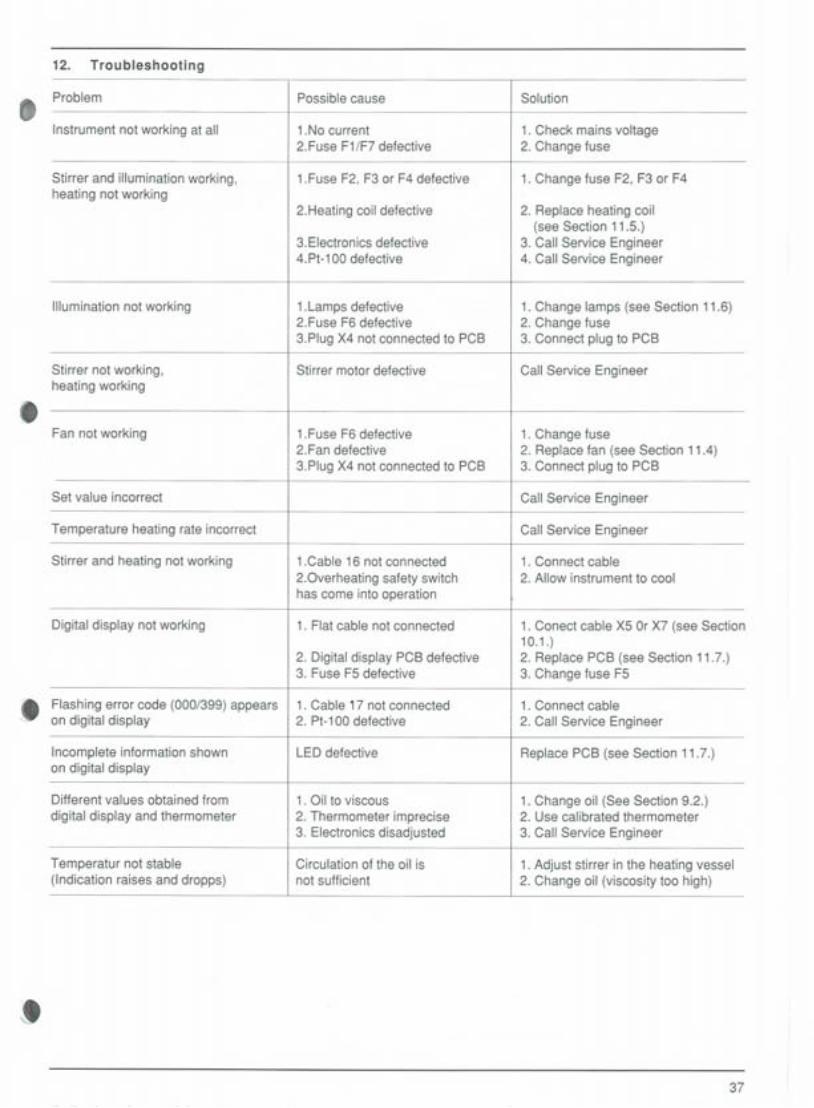
12. Troubleshooting
13. Accessoriesand spare parts
14. Notes
12. Eliminationdespannes
13. Accessoireset piecesde rechange
14. Notes

1. Technische Daten
t
G
8
8
4
Anschluss-Spannung: 117,220,240 V;50/60 Hz
Leistungsaufnahme: 200 Watt
Zulässige Spannungs-schwankung: +/- 10 %
Spannung Heizung: Netzspannung
Spannung Beleuchtung: 12 VoltWechselspannung
Ventilator: 12 Volt Gleichspannung
Rührmotor: Netzspannung
Ölvolumen Schmelz- undSiedepunktbestimmung:. ca. 110 ml
Ölvolumen Tropfpunkt-bestimmung: ca. 100 ml
Temperaturfühler: Pt-100
Temperaturbereich: Raumtemp. bis 280° C
Temperaturprogramm: Anstieg von 0.5/ 1/2oder 3° C pro Minute;30° C - 40° C über denvorgewählten Sollwert
Einstellgenauigkeit desSollwertpotentiometers: 0...200° C : +/- 5° C
200...280° C : +/- 7.5° C
Genauigkeit der Rampe: +/- 10 %
ÜbereinstimmungThermo- 0...200° C: +/- 0.7° Cmeter - Digitalanzeige 200...280° C: +/- 1.0° C
Abkühlung von 250 auf 60° C ca. 13 Minuten
Aufheizen von 60 auf 250° C ca. 7 Minuten'
Zulässige Umgebungs-temperatur 0...40° C
Dimensionen(Breite x Höhe x Tiefe) 220 x 285 x 260 mm
Gewicht: 4,8 kg

~-~
1. Technical data 1. Caracteristiques techniques
c
:8
8
"
5
Mains voltage 110,220,240V; 50/60 HzPower input 200 WattPermissable voltage tluctuation +/- 10%Voltage tor heating mains voltageVoltage tor illumination 12 Volts a.c.Fan 12 Volts d.c.Stirrer motor mains voltage
Oil volume tor melting andboiling pointdetermination approx. 110 ml
Oil volume tor dropping pointdetermination approx. 100 ml
Temperature sensor Pt-100
Temperature range Room temperature up to280° C
Temperature program Rise of 0.5, 1, 2 or 3° Cper minute;30 to 40° C above thepreset value
Regulating precision of set 0 ... 200° C: +/- 5° Cpoint potentiometer 200 ...280° C: +/- 7.5° C
Ramp precision +/- 10%
Concordancethermometer- 0...200° C: +/- 0.7° Cdigital display 200...280° C: +/- 1° C
Cooling from 250° C to 60° C approx. 13 minutes
Heating from 60° C to 250° C approx. '7minutes
Permissible ambienttemperature 0 ... 40° C
Dimensions(width x height x depth) 220 x 285 x 260 mm
Weight 4.8 kg
Tension du secteur 110,220,240 V;50/60HLConsommation 200 wattsFluctuations de la tensionadmissibles +/- 10%
Tension du chauffage tension du secteurTension d'eclairage 12 V. alternatifVentilateur 12 V. continuMoteur de I'agitateur tension du secteur
Volume d'huile pourdetermination de pointsde fusion et d'ebullition env.110ml
Volume d'huile pourdetermination depoint de goutte env.100ml
Sonde de temperature Pt 100
Plage de temperature depuis la temperatureambiante jusqu'a 280° C
Programme de temperature Montee de 0,5/1/2 ou3° C par minute - 30-40°au-dessus du point deconsigne preselectionne
Precision de reglage de 0...200° C: +/- 5° Cpotentiometre de consigne 200... 280° C: +/- 7.5° C
Precision de la rampe +/- 10%
Concordance entre thermo- 0...200° C: +/- 0.7° Cmetre et affichage numerique 200...280° C: +/- 1° C
Refroidissementde 250° C a 20° C env. 13 minutes
Chauffage de 60° C a 250° C env. 7 minutes
Temperature ambianteadmissible 0...40° C
Dimensions(Larg.lLong.lHaut.) 220 x 285 x 260 mm
Poids 4,8 kg

=======
(
=======
CJBÜCHI535 """"oe,,,", ~.
°0 Ö6ö6~6 60 w~::.co
1687
~-------
~NL~
01757
22899
22814
J~!III ~
19698, c:::::::1
@19697-L19698
!
~1)Jj
Geräteversionen
Büchi535ZurSchmelz-undSiedepunktbestimmung e220 V240 V117 V
50/60 Hz50/60 Hz50/60 Hz
2247022 47122 469
Dieses Gerät kann jederzeit mit dem Heizmodul zurTropfpunktbestimmung versehen werden (sieheZubehör).
8,
6
"2. Lieferumfang, für Schmelz- u[ld
Siedepunktbestimmung
1 Büchi 535, komplett aufgebaut1 Schutzhülle 251061 Netzkabel CH 10021
oder USA 10023oder Schuko 10029oder GB 17833oder AUS 17834
1 Betriebsanleitung, 3-sprachig 953401 Halter für Schmelz- und Siedepunkt-
röhrchen 20871100 Schmelzpunktröhrchen 1780810 Siedepunktröhrchen 1969710 Siedekapillaren 19698250 ml Silikonöl 01757
82 Ersatzsicherungen für Netzspannung220V/240V,117 V: 01687
1 Blendschutz 228141 Trichter 228991
"
Hintergrundblende hell 22796
Instrument versions
~ BÜCH535"" For melting and boiling point determination
220 V240 V117 V
50/60 Hz50/60 Hz50/60 Hz
2247022 47122469
This instrument can be adapted at any time with theheating module for dropping point determination (seeAccessories) .
8
Vers ions des appareils
Büchi 535Pour la determination des points de fusion etd'ebullition
220 V240 V117 V
50/60 Hz50/60 Hz50/60 Hz
224702247122469
Cet appareil peut etre complE~teen tout par le module dechauffage pour la determination du point de goutte (Voiraccessoires)
25106100211002310029178331783495340
20871
17808
196971969801757
01687228142289922796
2. Etendue de la livraison pour determinationdes points de fusion et d'ebullition
BÜCHI 535, complet et monteEnveloppe protectriceCäble de secteur CH
ou USAou Schukoou GBou AUS
Mode d'emploi, en 3 languesSupport pour tubes despoints de fusion et d'ebullition
100 Tubes d'echantillons pourpoint de fusionTubes d'echantillons pourpoint d'ebullition
10 Capillaires d'ebullition250 ml Huile de silicone2 Fusibles de rechange pour secteur
220/240 V; 11OVEcran antieblouissantEntonnoirEcran de fond clair
10
111
7
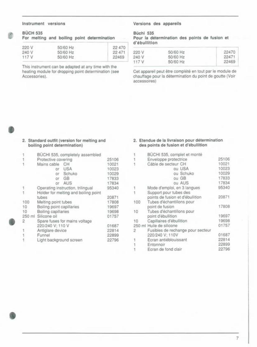
82. Standard outfit (version for melting and
boiling point determination)
BÜCHI535, completely assembledProtective covering 25106Mains cable CH 10021
or USA 10023or Schuko 10029or GB 17833or AUS 17834
1 Operatinginstruction,trilingual 953401 Holderfor meltiQgandboilingpoint
tubes 20871100 Meltingpointtubes 1780810 Boilingpointcapillaries 1969710 Boilingcapillaries 19698250 ml Siliconeoil 01757" 2 Spare fuses for mains voltage
220/240 V; 110 V 01687Antiglare device 22814Funnel 22899Light background screen 22796

10021Typ 12 (CH)10023USA10029Schuko17833GB17834 Australia
8
8
3. Bedienungselemente
\1 Hauptschalter mit eingebauter Positionsanzeige t==== 2 Schalterfür Kühlventilator==
3 Taste zum Ausschalten des Temperatur-11h I programmes
111 I 4 Wahltasten für Temperaturprogrammme
11 I I 5 Taste zum Abspeichern von Messwerten
6 Taste zum Abrufen der gespeicherten Messwerte
7 Sollwertpotentiometer
8 Funktionsanzeigelampe Heizung
9 Lupe zur Beobachtung der Proben
10 Digitalanzeige der Ölbadtemperatur respektive 8;der gespeicherten Messwerte
11 Probenhalter für Schmelzpunkt--und Siedepunkt-röhrchen
12 Expansionsgefäss
13 Apparateschild
= = \ I 14 Gerätestecker= == == == =
\ I
15 Hauptsicherungen= == =
16 Verbindungskabelfür MotorundHeizung
17 Verbindungskabelfür Temperaturfühler
18 Klammerfür Schmelzpunktröhrchen 819 Apparatekabel

1002110023100291783317834
Type 12 (CH)USASchukoGBAustralia
1002110023100291783317834
Type 12 (CH)USASchukoGBAustralia
,
9
3. Controls 3. Elements de commande
8 1 Mainswitch with built-inon/off lamp 1 Interrupteurprincipalavec indicateurde position
2 Coolingfan switch 2 Interrupteurpourventilateurde refroidissement
3 Resetbuttonfor temperatureprogram 3 Touchepoursupprimerle programmedetemperature
4 push buttonsfor selectingtemperatureheatingrates 4 Selecteurpour les programmesde temperature
5 push buttonfor storingmeasuredvalues 5 Touchede memorisationdesvaleursmesurees
6 Heating indicator lamp 6 Touchede rappeldesvaleurs mesurees
7 Set-pointpotentiometer 7 Potentiometredevaleur de consigne
8 Heating indicatorlamp 8 Lampe-temoinde fonctionnementdu chauffage
9 Magnifying lensfor observingspecimens 9 Loupepour observerlesechantillons
8 10 Digital display indicating the oil bath temperature 10 Affichage de la temperature du bain d'huile, resp.and the stored measured values des valeurs mesurees
11 Specimen holder for melting point and boiling 11 Support d'echantillon pour point de fusion etpoint tubes d'ebullition
12 Expansion vessel, rotable 12 Vase d'expansion orientable
13 Instrument identificationplate 13 Plaquetted'appareil
14 Power supplyconnector 14 Prisedesecteur
15 Main fuses 15 Fusiblesprincipaux
16 Connectioncable for motorand heatingmodule 16 Cablespour moteuretchauffage
17 Connectioncablefor temperaturesensor 17 Cablede lasonde de temperature
8 18 Holder for meltingpoint tubes 18 Supportpour tubes d'echantillonsde pointdefusion
19 Power supplycable19 Cablede secteur

3.1. Erklärungen zu den Bedienungselementen
t~", .. -I L. -' 10
lOa ,~
,C
~°c
8'
10 Digitalanzeige: Die digitale Temperaturanzeige istmöglich bis 325° C. (280°C + Rampe von ca. 30° C).Oberhalb dieser Temperatur beginntdie Anzeige zu blinken.Löschen der gespeicherten Werte:a) Nach Benützung der Heizrampen (4): durch Drük-ken der Taste 0 und anschliessend STO werdendie Werte im Speicher 2 und 3 gelöscht. Der Spei-cher 1 wird dabei mit dem momentanen Wertüberschrieben.b) Ohne vorherige Benützung der Heizrampen (4):Taste einer Rampe (4) drücken, anschliessend0 und zuletzt STO drücken.
10a Anzeige der Speichernummer 1-3
8
BÜCHI 535 Mefting Point
e
On/Off $/G
'C/min
0 ~1 2~
Hauptschalter: Das Gerät wird auf den mitDrehknopf (7) eingestellten Sollwert aufgeheizt,sofern der Ventilator (2) ausgeschaltet ist.
2 Kühlventilator: Der Ventilator wird eingeschaltet,wobei die Heizung gleichzeitig unterbrochen wird.
3 Reset: Die Heizrampen (4) werden ausgeschaltetund die Temperatur sinkt auf den vorgewähltenSollwert (7). Die mit STO (5) gespeicherten Wertebleiben erhalten.
4 Temperatur-Programm: Temperaturanstieg von0.5/1/2/3° C pro Minutebis ca.30 - 40° C über denvorgewählten Sollwert.
5 STO: mit dieser Taste können maximal dreiTemperaturwerte gespeichert werden.
6 RCL: mit Recall können die mit STO (5) gespeicher-ten Werte einzeln in die Digitalanzeige zurückgeholtwerden.
7 Sollwertpotentiometer: schnelles Aufheizen aufvorgewählten Sollwert.
8 Anzeigelampe, Heizung:Regelmässig blinkende Anzeige: Sollwert erreichtDauerlicht: Heizung in Betrieb, Sollwert noch nichterreichtKein Licht: Heizung ausgeschaltet
10

3.1. Description of the controls 3.1. Explications concernant les elements decommande
e
10 Digital display: temperatures up to 325° C (280° Cplus ramp of about 30° C) can be digitally displayed.If this temperature is exceeded, the display starts toflash.
10a Indication of store - No 1-3
Erasing the stored values:a) After using the heating ramps (4): by pressing theO-button and then the STO button, the values stored inthe memories 2 and 3 are erased. The value stored inthe memory 1 is retained and overwritten with theinstantaneous value., b) Without using the heating rampsbeforehand: Pressone of the heating ramp buttons (4), then the 0- buttonand finally the STO button.
10 Affichage numerique: L'affichage numeriquemonte jusqu'a 325° C (280° C + rampe d'environ30° C). L'affichage clignote en dehors de cetteplage.
10a Affichage position de la memoire 1-3
Effacement des valeurs memorisees:a) Apres emploi des rampes (4): Les valeurs memoriseesdans les memoires 2 et 3 sont effacees lorsqu'on pressesuccessivement les touches 0 et STO. La valeur dans lamemoire 1 reste memorisee. Recouverte par les valeursinstanees.b) Sansemploi prealable des rampes de chauffage: Pres-ser la touche (4) d'une rampe, ensuite 0 et enfin STO.
11
Main ON/OFF switch: The instrument is heated to 1 Interrupteur principal Encl./Decl.: I'appareil estthe value preset by means of the dial (7), providing chauffe jusqu'a la temperature de consignethat the fan (2) is switched off. reglee sur le bouton 5 , pour autant que le
ventilateur (2) soit declenche.2 When the fan is switched on the heater is
simultaneously switched off. 2 Le ventilateur est dechlenche, simultanement lechauffage est dechlenche.
8 3 Reset: The heating ramps (4) are switched offand the temperature drops to the preset value (7) 3 Reset: Les lampes de chauffag (4) sont dechlen-The temperatures stored by means of the STO (5) chees et la temperature tombe a la valeur debutton are retained consigne fixee (7).
4 Temperature program: This permits a temperature 4 Programme de temperature: montee en tem-rise of 0.5, 1, 2 or 3° C per minute, up to 30-40° C perature de 0,5/1/2/3° C par minute avecabove the preset value. possibilite de monter jusqu'a 30-40° C au-dessus
de la valeur de consigne.5 A maximum of three temperatures can be stored
using this button. 5 STO: Cette touche permet de memoriser 3temperatures au maximum.
6 RCL: By pressing the RECALL button, the tempera-tures stored using the STO button can be individual- 6 RCL: "Recall" permet de rappeier individuelle-Iy called up on the digital display. ment sur I'affichage numerique les trois tempera-
tures memorisees par STO.7 Set-point potentiometer: Rapid heating to apreset
value. 7 Potentiometre de consigne: chauffage rapide
8jusqu'a la valeur de consigne fixee.
8 Heating indicator lamp:Lamp flashing = set value reached 8 Lampe-temoin du chauffage: clignotement:Lampcontinouslylit = heatingswitchedon, setvalue valeur de consigne atteinte, permanente:not yet reached chauffage enclenche, valeur de consigne pasLampnot lit = heatingswitchedoff encore ateinte. Eteinte: chauffage dechlenche,
valeur de consigne pas encore atteinte.

4. Installation des Gerätes
4.1. Hinweiseund Warnvermerke
Dieses Gerät ist gemäss DIN 57411 Teil1NDE 0411 Teil1, Schutzmassnahmenfür elektronische Messgeräte,gebaut und hat das Werk in sicherheitstechnischeinwandfreiem Zustand verlassen. Um diesen Zustand zuerhalten und einen gefahrlosen Betrieb sicherzustellen,muss der Anwender die Hinweise und Warnvermerkebeachten, die in dieser Gebrauchsanweisung enthaltensind.Vor dem Einschalten ist sicherzustellen, dass die aufdem Apparateschil angegebene Betriebsspannung unddie Netzspannung übereinstimmen.Der Netzstecker darf nur in eine Steckdose mit Schutz-kontakt eingeführt werden. Die Schutzwirkung darf nichtdurch eine Verlängerungsleitung ohne Schutzleiteraufgehoben werden.
WarnungJegliche Unterbrechung des Schutzleiters innerhalboder ausserhalb des Gerätes oder Lösen des Schutzlei-teranschlusses kann dazu führen, dass das Gerät gefahr-bringend wird. Absichtliche Unterbrechung ist nichtzulässig.Beim Öffnen von Abdeckungen oder Entfernen vonTeilen, ausser wenn dies von Hand möglich ist, könnenspannungsführende Teile freigelegt werden. Auch kön-nen Anschluss-Stellen spannungsführend sein.Vor einem Abgleich, einer Wartung, einer Instandsetzungoder einem Austausch von Teilen muss das Gerät vonallen Spannungsquellen getrennt sein, wenn ein Öffnendes Gerätes erforderlich ist.Wenn danach ein Abgleich, eine Wartung oder eineReparatur am geöffneten Gerät unter Spannungunvermeidlich ist, so darf das nur durch eine Fachkraftgeschehen, die m'itden verbundenen Gefahren vertrautist.
Es ist sicherzustellen, dass nur Sicherungen vom ange-gebenen Typ und der angegebenen Nennstromstärke alsErsatz verwendetwerden. Die Verwendung geflickterSicherungen oder Kurzschliessen des Sicherungshaltersist unzulässig.Wenn anzunehmen ist, dass ein gefahrloser Betrieb nichtmehr möglich ist, so ist das Gerät ausser Betrieb zusetzen und gegen unabsichtlichen Betrieb zu sichern.
Es ist anzunehmen,<!lassein gefahrloser Betrieb nichtmehr möglich ist,- wenn das Gerät sichtbare Beschädigungen aufweist,- wenn das Gerät nicht mehr arbeitet,- nach längerer Lagerung unter ungünstigenVerhältnissen
- nach schwerenTransportbeanspruchungen.
Das Gerät mit Temperaturen über 2000 C nur kurzzeitigbetreiben, eine optimale Ölqualität kann somit gewährlei-stet werden.Bei längerer Betriebsdauer über 2000 C kann es vorkom-men, dass der Temperaturschutzschalter die Heizungund den Motor abstellt.Vorsicht beim Probenwechseln, Teile mit höheren Tem-peraturen können berührt werden.
12
c
,
8
8
---'-~--~"-' .-. ~~---=-'>-~~-"=~~~
4. Installation of the 8-530 4. Installationde I'appareil
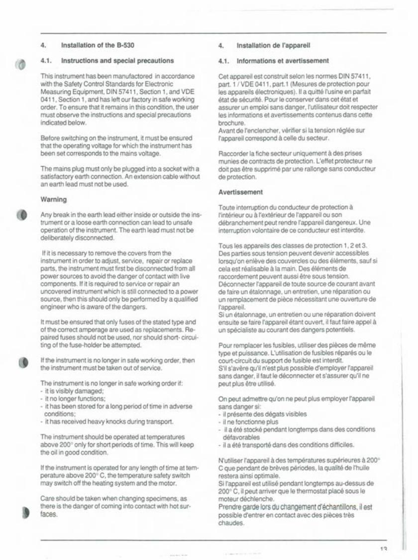
e 4.1. Instructions and special precautions
This instrument has been manufactored in accordance
with the Safety Contra IStandards for ElectronicMeasuring Equipment, DIN 57411 , Section 1, and VDE0411 , Section 1, and has leftour factory in safe workingorder. To ensure that it remains in this condition, the usermust observe the instructions and special precautionsindicated below.
Before switching on the instrument, it must be ensuredthat the operating voltage for which the instrument hasbeen set corresponds to the mains voltage.
The mains plug must only be plugged into a socket with asatisfactory earth connection. An extension cable withoutan earth lead must not be used.
Warning
8 Any break in the earth lead either inside or outside the ins-trument or a loose earth connection can lead to unsafe
operation of the instrument. The earth lead must not bedeliberately disconnected.
If it is necessary to remove the covers fram theinstrument in order to adjust, service, repair or replaceparts, the instrument must first be disconnected fram allpower sources to avoid the danger of contact with livecomponents. If it is required to service or repair anuncovered instrument which is still connected to apowersource, then this should only be performed by a qualifiedengineer who is aware of the dangers.
It must be ensured that only fuses of the stated type andof the correct amperage are used as replacements. Re-paired fuses should not be used, nor should short- circui-ting of the fuse-holder be attempted.
8 If the instrument is no longer in safe working order, thenthe instrument must be taken out of service.
The instrument is no longer in safe working order if:- it is visibly damaged;- it no longer functions;- it has been stored for a long period of time in adverse
conditions;- it has received heavy knocks during transport.
The instrument should be operated at temperaturesabove 2000 only for short periods of time. This will keepthe oil in good condition.
If the instrument is operated for any length of time at tem-perature above 2000 C, the temperature safety switchmay switch off the heating system and the motor.
tCare should be taken when changing specimens, asthere is the danger of coming into contact with hot sur-taces.
4.1. Informations et avertissement
Cet appareil est construit selon les normes DIN 57411,part. 1 / VDE 0411 , part. 1 (Mesures de protection pourles appareils electroniques). 11a quiMl'usine en parfaitetat de securite.Pour le conserver dans cet etat etassurer un empldi sans danger, I'utilisateur doit respecterles informations et avertissements contenus dans cettebrochure.Avant de I'enclencher, verifier si la tension reglee surI'appareil correspond a celle du secteur.
Raccorder la fiche secteur uniquement ades prisesmunies de contracts de protection. L'effet protecteur nedoit pas EHresupprime par une rallonge sans conducteurde protection.
Avertissement
Toute interruption du conducteurde protection aI'interieur ou a I'exterieur de I'appareil ou sondebranchement peut rendre I'appareil dangereux. Uneinterruption volontaire de ce conducteur est interdite.
Tous les appareils des classes de protection 1,2 et 3.Des parties sous tension peuvent devenir accessibleslorsqu'on enleve des couvercles ou des elements, sauf sicela est realisable a la main. Des elements deraccordement peuvent aussi EHresous tension.Deconnecter I'appareil de toute source de courant avantde faire un etalonnage, un entretien, une reparation ouun remplacement de piece necessitant une ouverture deI'appareil.Si un etalonnage, un entretien ou une reparation doiventensuite se faire I'appareil etant ouvert, il faut faire appel aun specialiste au courant des dangers potentieis.
Pour remplacer les fusibles, utiliser des pieces de memetype et puissance. L'utilisation de fusibles repares ou lecourt-circuit du support de fusible est interdit.S'il s'avere qu'il n'est plus possible d'employer I'appareilsans danger, iI faut le deconnecter et s'assurer qu'il nepeut plus etre utilise.
On peut admettre qu'on ne peut plus employer I'appareilsans danger si:- il presente des degats visibles- il ne fonctionne plus- il a ete stocke pendant longtemps dans des conditions
defavorables
- il a ete transporte dans des conditions difficiles.
N'utiliser I'appareil ades temperatures superieures a 2000C que pendant de breves periodes, la qualite de I'huilerestera ainsi optimale.Si I'appareil est utilise pendant longtemps au-dessus de2000 C, il peut arriver que le thermostat place sous lemoteurdechlenche. .
Prendre garde larsduchangementd'echantillons,ilestpossibled'entreren contactavecdes piecestreschaudes.
1~
~I,i,
','1,
,
'
I
"i',I!ij
Ii
-
====
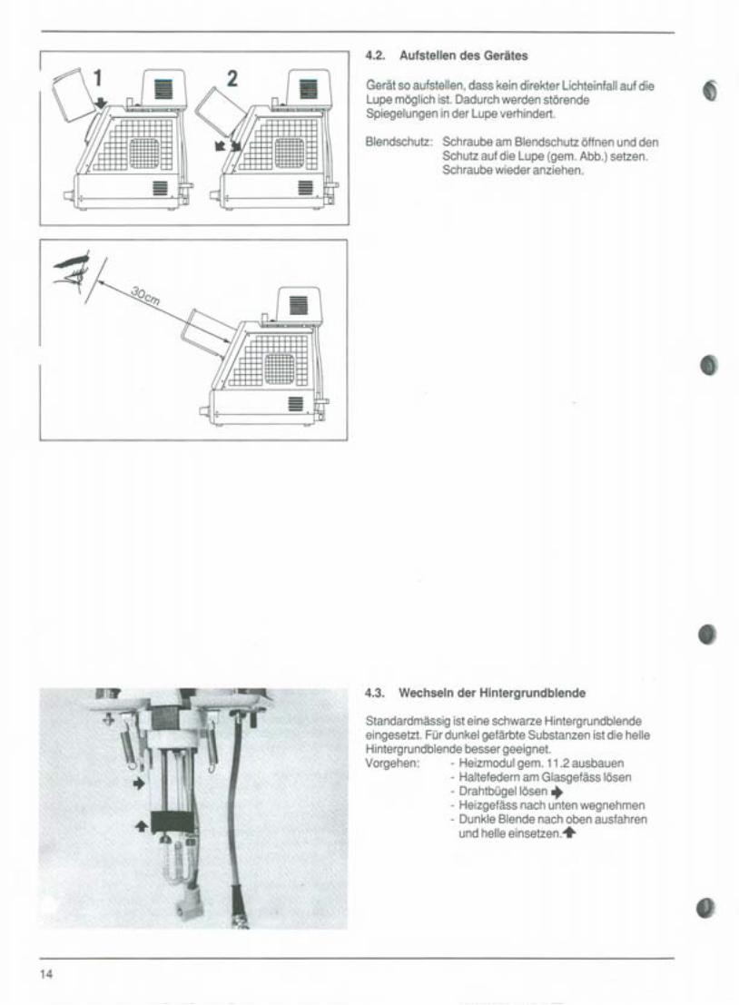
4.2. Aufstellen des Gerätes
Gerätso aufstellen,dass kein direkter Lichteinfallauf dieLupemöglich ist. Dadurchwerden störendeSpiegelungeninder Lupeverhindert.
t'
Blendschutz: Schraubeam Blendschutzöffnen und denSchutzauf die Lupe (gem.Abb.) setzen.Schraubewieder anziehen.
8
8
4.3. Wechseln der Hintergrundblende
Standardmässigist eine schwarze Hintergrundblendeeingesetzt.Fürdunkelgefärbte Substanzenist die helleHintergrundblendebesser geeignet.Vorgehen: - Heizmodulgem. 11.2ausbauen
- Haltefedernam Glasgefäss lösen- Drahtbügellösen +- Heizgefässnachuntenwegnehmen- DunkleBlende nachoben ausfahren
und helleeinsetzen.+
8)
14

0
t
t
8
4.2. Setting up the apparatus 4.2. Installation de I'appareil
Set up the apparatus in such a way that no light is able tofall directly onto the magnifying glass . This will ensurethat there is no troublesome reflection trom the magni-fying glass.
Antiglare device: Loosen the screw on the antiglare de-vice and place the screen over themagnifying glass (as shown in Figure).Tighten the screw again.
4.3. Changing the background screen
A black background screen is fitted as a standard feature.The white background screen is more suitable tor darksubstances.
Procedure: - Remove the heating module as describedin Section 11.2
- Release the spring grips from the glassvessel
- Release the wire arm +- Pull out the heating vessel trom
underneath
- Pull out the dark screen from the top andinsert the light screen +
Placer I'appareil de taGon a eviter qu'une lumiere directeatteignela loupe.On eviteraainsides reflexions -
genantes.
Ecran antieblouissant: devisser la vis de I'ecran et placerce dernier sur la loupe (seion fig.)Reserrer la vis. '
4.3. Remplacement de I'ecran de fond
-L'appareil est livre d'usine avec un ecran de fondantieblouissant noir. L'ecran blanc convient mieux pourdes substances de couleur sombre.
Marche a suivre:- Remplacer le module de chauffageselon 11.2.
Degager les ressorts de maintien durecipient en verre
- Degager I'etrier en fil +- Sortir le vase par le bas- Enlever I'ecran noir vers le haut et le
remplacer par leblanc. +
'l
i!"
!!;!1i!!i:,I:
il!:IiuiI;'I:
'li
,I:.:.,:1i:!i
:il"I!i
,!IIi
, I
!:~IIrl".1
:1:'1~TI
15 II,~I
11~
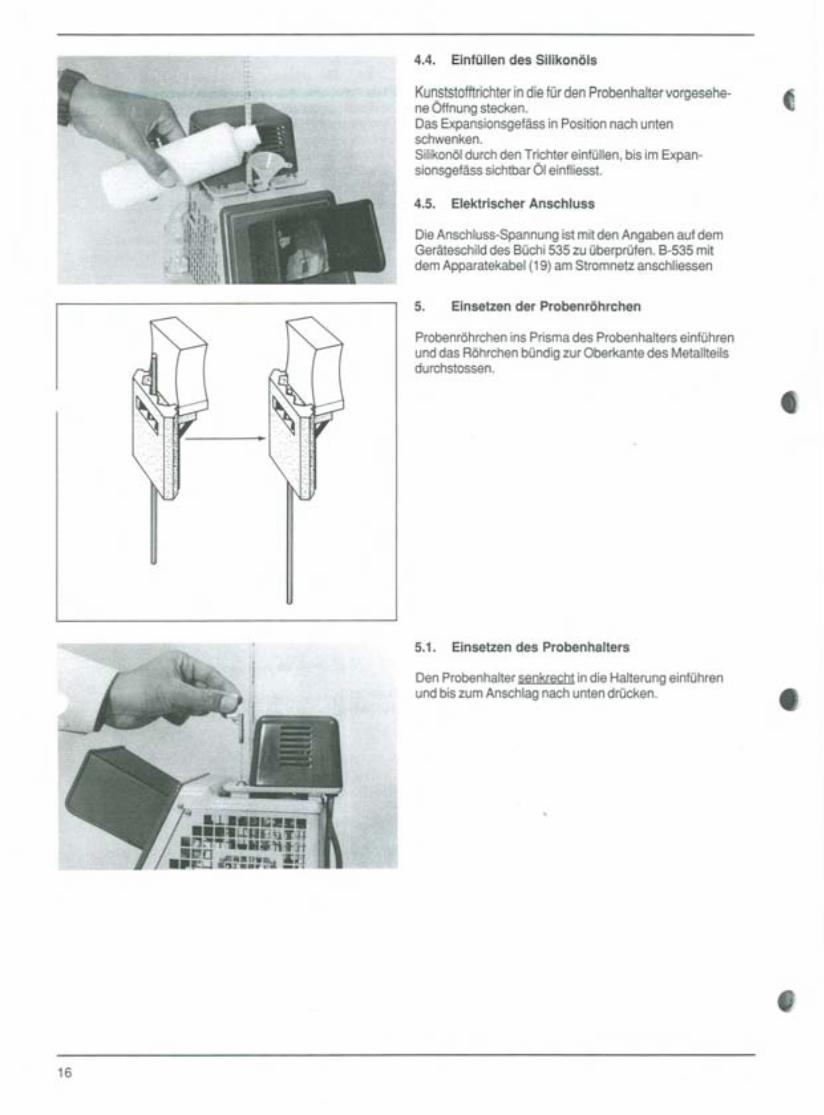
4.4. Einfüllendes Silikonöls
KunststofftrichterindietürdenProbenhaltervorgesehe-neÖffnungstecken. .
Das Expansionsgefäss in Position nach untenschwenken.
Silikonöl durch den Trichter einfüllen, bis im Expan-sionsgefäss sichtbar Öl einfliesst.
t
4.5. Elektrischer Anschluss
Die Anschluss-Spannung ist mit den Angaben auf demGeräteschild des Büchi 535 zu überprüfen. B-535 mitdem Apparatekabel (19) am Stromnetz anschliessen
5. Einsetzender Probenröhrchen
Probenröhrchen ins Prisma des Probenhalters einführen
und das Röhrchen bündig zur Oberkante des Metallteilsdurchstossen.
e
5.1. Einsetzendes Probenhalters
Den Probenhalter senkrecht in die Halterung einführenund bis zum Anschlag nach unten drücken.
8
>.
e
16

(0
"
- -~~~--~ ~~ ~--=~C~--- "'~~~=-'." "'---~
4.4. 4.4. Remplissage d'huile de siliconeFilling the apparatus with silicone oil
Insert the plastic funnel into the opening provided for thespecimen holder.Twistthe expansion vessel downwards into position.Pour silicone oil into the funnel untiloilcan be seenflowing into the expansion vessel.
4.5. Mains connection
Check that the mains voltage is the same as that indica-ted on the identification plate of the BÜCHI535. Connectthe B-535 to the means of the power supply cabel (19)
5. Inserting the specimen tubes
Insert the specimen tube inside the prism-shapedspecimen holder so that it lies flush with the top edge ofthe metal part.
5.1. Inserting the specimen holder
IInsert the specimen holder vertically into the bracket andpress it down fully into position.
-
Placer I'entonnoir sur I'ouverture pn3vue pour le supportd'echantillons.Mettre le vase d'expansion en position basse.Verser de I'huile de silicone dans I'entonnoir jusqu'a cequ'on la voie couler dans le vase d'expansion.
4.5. Branchement electrique
17
Verifier les indications da la plaquette d'appareil duBÜCHI535. Raccorder I'appareil B 535 au secteur aumoyen du cäble (19)
5. Mise en place des tubes d'echantillons
Placer le tube d'echantillon dans le prisme du support etpousser le tube jusqu'a ce qu'il vienne a fleur de I'aretesuperieure da la partie metallique.
5.1. Mise en place du support d'echantillons
Introduire le support verticalement dans la fixation et lepresser vers le bas jusqu'a la butee.

~======
c::::::::::I==c:::::=c:::::===
0I@I
BÜCHI 535 ""'''' 1'0'"
0.100 '*' 0 ~;".'"2~ 'STO RCL '"
0000 00 .
6. Durchführung einer Schmelzpunkt-Bestimmung
6.1. Bestimmung einer Probe mit unbekann-tem Schmelzpunkt
cProbenvorbereitung: Grobkristalline und nicht homo-gene Proben im Mörser zerkleinern und ca. 2mm hoch indas Schmelzpunktröhrchen einfüllen
Probenröhrchen im Probenhalter gemäss Abschnitt 5einsetzen
Expansionsgefäss (12) durch kurzes Drehen nach obenvollständig entleeren
~'. oeHauptschalter (1) einschalten und durch Drücken der0- Taste (3) Temperaturprogramm ausschalten.
Sollwert Temperatur (7) schrittweise um 50° CerhöhenSobald die Probe schmilzt, die ungefähre Temperatur inder Anzeige (10) ablesen. 8Sollwertpotentiometer (7) ca. 10° C unter den abgelese-nen Wert einstellen und den Ventilator {2) einschalten.Sobald die Öltemperatur den gleichen Wert erreicht wieam Potentiometer (7) vorgewählt wurde, Ventilator aus-schalten und ein neues Probenröhrchen einsetzen.
Je nach Methode die Taste mit dem gewünschtenTemperaturanstieg drücken und die Probe beobachten.
Beginn und Ende des Schmelzens der Probe beobach-ten und durch Drücken der STO Taste die entsprechen-den Temperaturwerte abspeichern. Anschliessend dieMesswerte durch Drücken der RCL Taste abrufen undnotieren.
8
.-18

6.6. Performing a melting point determination Determination d'un point de fusion
r6.1. Determination of a substance with an
unknown meltingpoint
Preparing the specimen: Grind specimens which havelarge crystals and are non-homogeneous, in a mortar, andfill the melting point tube to a height of approx. 2 mm.
Insert the specimen tube into the specimen holder, asdescribed in Section 5.
Completely empty the expansion vessel (12) by twisting itbriefly upwards.
Set the main switch (1) to the ON position and reset thetemperature program by pressing the 0- button (3).
Gradually increase the nominal temperature (7) by 50° Cuntil the specimen melts. Read off the approximatetemperature from the display (10).
tSet the set-point potentiometer (7) to a value about 10° Cbelow the temperature read off and switch on the coolingfan 2.
As soon as the oil temperature reaches the same valueas that preselected on the potentiometer (7), switch offthe cooling fan and insert a new specimen tube.
Depending on the method used, press the button for therequired temperature rise and observe the specimen.
Observe melting of the specimen and store the tempera-tures immediately at the beginning and end of the meltingprocess by pressing STO button.
t
~
6.1. Determination du point de fusion d'unechantillon dont le point de fusionestinconnu
Pn3parationde I'echantillon: Broyer au mortier les echan-tiIIons presentant de gros cristaux ou non homogenes etles verser dans le tube d'echantillons jusqu'a une hauteurd'environ 2 mm.
Placer le tube dans le support d'echantillons selon para-graphe 5.
Vider completement le vase d'expansion (12) en le tour-nant un moment vers le haut.
Enclencher I'interrupteurprincipal (1) et supprimer le pro-gramme de temperature en pressant la touche 0 (3).
Augmenter la temperature de consigne (7) par pas de50° C.
Des que I'echantillon fond, lire la temperature approxi-mative sur l'affichage(10).
Regler le potentiometre de consigne (7) environ 10° C endessous de la temperature lue sur I'affichage, enclen-eher le ventilateur de refroidissement (2) et placer unnouveau tube d'echantillons.
Selon la methode choisie, appuyer sur la touche corres-pondant a la vitesse d'elevation de la temperature desireeet observer I'echantillon.
Observer le debut et la fin de la fusion de I'echantillon etmemoriser immediatement les valeurs correspondantesde la temperature en pressant la touche STO.
Ensuite rappeier et noter les valeurs mesurees enpressant la touche RCL.
19

6.2. Bestimmung einer Probe mit bekanntemSchmelzpunktSchmelzpunkt 132,5° ...133°C
melting point 132.5° ...133°CPoint de fusion, 132,5° a 133°C
..)120°C
Grobkristalline und nicht homogene Proben imMörser zerkleinern und ca. 2 mm hoch in einProbenröhrchen einfüllen.
Probenröhrchen in Probenhalter einsetzen.
Expansionsgefäss durch kurzes Drehen nach obenvollständig entleeren.
132,5°CSollwertpotentiometer (7) ca. 10° C unter den erwar-teten Schmelzpunkt einstellen und Hauptschaltereinschalten.
Durch Drücken der O-Taste (3) Temperaturprogrammausschalten.
133°C
Sobald die Öltemperatur den am Sollwertpotentio-meter eingestellten Wert erreicht, die Taste mit demgewünschten Temperaturanstieg drücken und Probebeobachten; durch Drücken der Reset-Taste kannder Temperaturanstieg innerhalb des Temperatur-programmes abgebrochen werden;,die Temperatursinkt dann wieder auf den eingestellten Sollwert ab.
8
Beginn und Ende des Schmelzens der Probebeobachten und durch Drücken der STO-Taste (5)die entsprechenden Temperaturwerte speichern.
Nachher die Messwerte durch Drücken der RCL-Taste (6) abrufen und notieren.
Hinweis:Mit dem Temperaturprogramm kann ein Temperaturan-stieg von ca. 30° C-40° C erreicht werden. Das Einschal-ten des Kühlventilators schaltet die Heizung automatischaus.
8
e
20

6.2. 6.2. Determination avec un echantillon dont lepoint de fusion est connu
Determination of a substance with aknown melting point
t - Grind specimens which have large crystals andare non-homogeneous, in a mortar, and fill a specimentube to a height of about 2 mm.
- Insert the specimen tube in the specimen holder.
- Completely empty the expansion vessel by brieflytwisting it upwards.
- Set the set-point potentiometer (7) to a value about10° C below the expected melting point and set themain switch to the ON position.
- Reset the temperature program by pressing the0- button (3).
."- As soon as the oil temperature reaches the value
selected on the set-point potentiometer, press thebutton for the required temperature rise; by pressingthe RESET- button, it is possible to halt the temperaturerise within a given temperature program; thetemperature then drops back to the set value.
- Observemeltingof thespecimenandstorethetemperatures immediately at the beginning and end ofthe melting process by pressing the STO button (5).
- Then call up the measured temperatures by pressingthe RCL button (6) and make a note of them.
NB:
Using the temperature program, it is possible to achievea temperaturerise of about 30° C. Switching on thecooling fan automatically switches off the heater.
t
~
Dans le cas d'echantillons se presentant sous formede cristaux grossiers ou d'echantillons non homo-genes, broyer le produit dans un mortier puis le verserdans un tube d'echantillons jusqu'Eiune hauteurd'environ 2 mm.
- Placer le tube dans le support d'echantillons.
- Vider completement le vase d'expansion en le tour-nant un moment vers le haut.
- Regler le potentiometre de valeur de consigne (7)environ 10° C en dessus du point de fusion prevuet enclencher I'interrupteurprincipal.
- Supprimer le programme de temperature en pressantla touche 0 (3).
Des que la temperature d'huile a atteint la valeur reg-lee sur le potentiometre, presser la touche correspon-dant EiI'augmentation de temperature desiree et ob-server I'echantillon. En pressant la touche RESET, onpeut interrompre la montee de temperature au sein duprogramme de temperature; la temperature revientalors Eila valeur de consigne reglee.
- Observer le debut et la fin de la fusion de I'echantillonet memoriser immediatement les temperaturescorrespondantes en pressant la touche STO.
- Ensuite, rappeier et noter les valeurs mesurees enpressant la touche RCL (6).
Attention:Le programme de temperature permet une montee detemperature d'environ 30° -40° C En enchlenchant leventilateur de refroidissement, on coupe automatique-ment le chauffage.
21
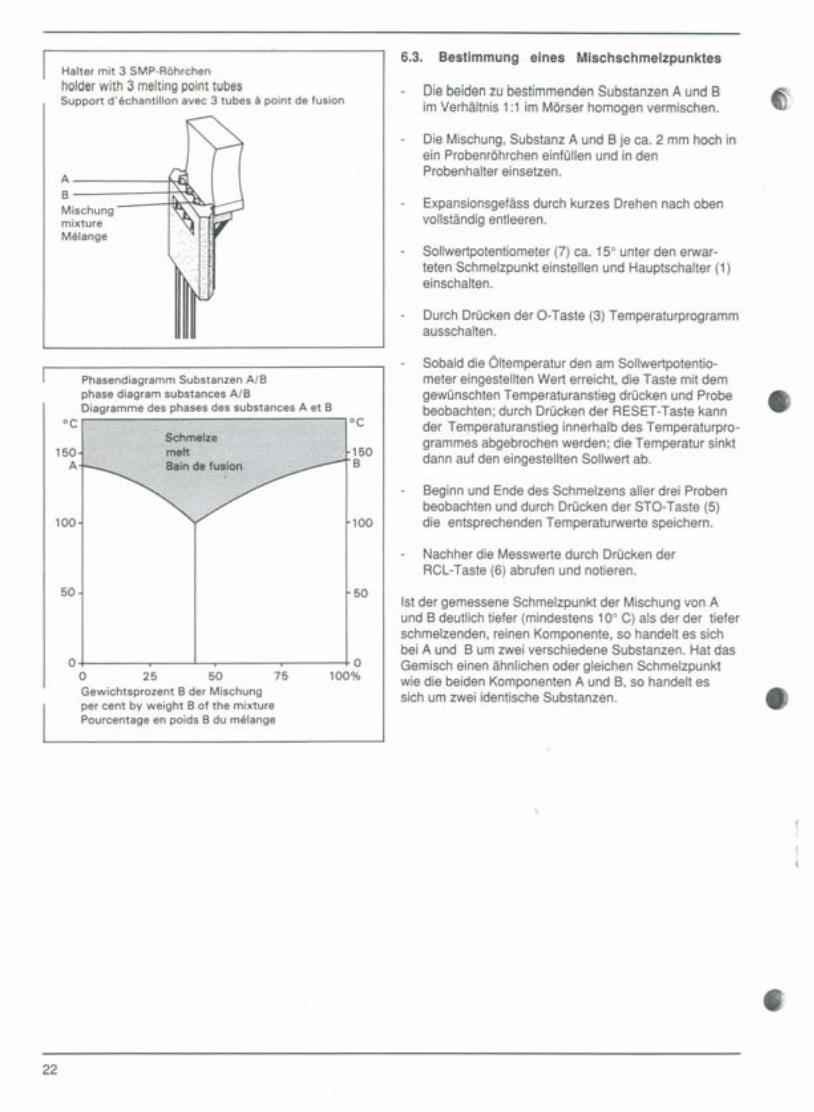
Halter mit 3 SMP-Röhrchen
holderwith 3 meltingpointtubesSupport d'echantillon avec 3 tubes a point de fusion
AB
MischungmixtureMelange
Phasendiagramm Substanzen AlBphase diagram substances AlBDiagramme des phases des substances A et B
oe
150A
100
oe
r1508
100
50 50
00 25 50
Gewichtsprozent 8 der Mischungper cent by weight 8 of the mixturePourcentage en poids 8 du melange
0100%75
6.3. Bestimmung eines Mischschmelzpunktes
Diebeidenzu bestimmendenSubstanzenA und BimVerhältnis1:1imMörserhomogenvermischen.
a..
.;>..'
Die Mischung, Substanz A und 8 je ca. 2 mm hoch inein Probenröhrcheneinfüllen und in denProbenhalter einsetzen.
Expansionsgefäss durch kurzes Drehen nach obenvollständig entleeren.
Sollwertpotentiometer (7) ca. 15° unter den erwar-teten Schmelzpunkt einstellen und Hauptschalter (1)einschalten.
Durch Drücken der O-Taste (3) Temperaturprogrammausschalten.
Sobald die Öltemperatur den am Sollwertpotentio-meter eingestellten Wert erreicht, die Taste mit demgewünschten Temperaturanstieg drücken und Probebeobachten; durch Drücken der RESET-Taste kannder Temperaturanstieg innerhalb des Temperaturpro-grammes abgebrochen werden; diecTemperatur sinktdann auf den eingestellten Sollwert ab.
8
Beginn und Ende des Schmelzens aller drei Probenbeobachten und durch Drücken der STO-Taste (5)die entsprechenden Temperaturwerte speichern.
Nachher die Messwerte durch Drücken derRCL-Taste (6) abrufen und notieren.
Ist der gemessene Schmelzpunkt der Mischung von Aund B deutlich tiefer (mindestens 10° C) als der der tieferschmelzenden, reinen Komponente, so handelt es sichbei A und B um zwei verschiedene Substanzen. Hat dasGemisch einen ähnlichen oder gleichen Schmelzpunktwie die beiden Komponenten A und 8, so handelt essich um zwei identische Substanzen. 8
8
22
r
.
.
6.3. 6.3. Determination du point de fusion d'unmelange
Determining the melting point of amixture
- Homogeneously mixin the mortar equal amounts ofthe two substances Aand Bwhose meltingpoint is tobe determined.
- FiIIthree specimen tubes, each to a height of 2 mm,withthe mixture,substance A and substance B. Insertthe tubes into the specimen holder.
- Completely empty the expansion vessel by brieflytwisting it upwards.
- Set the set-point potentiometer (7) to a value about15° C below the expected meltingpoint and set themain switch (1) to the ON position.
- Reset the temperature program by pressing the0- button (3).
- As soonas the oiltemperature reaches the valueselected on the set-point potentiometer, press thebutton for the required temperature rise and observethe specimen; by pressing the RESET- button, it ispossibleto haltthe temperaturerisewithina giventemperatureprogram;the temperaturethendropstothe setvalue.
- Observe melting of all three specimens andstore thetemperatures immediately at the beginning and end ofthe melting process by pressing the STO button (5).
- Then call up the measured temperatures by pressingthe RCL button (6) and make a note of them.
If the measured melting point of the mixture of A and B issignificantly lower (at least 10° C lower) than the meltingpoint of the lower melting, pure component, then A and Bare two different substances. If the mixture has a meltingpoint which is similar to or the same as that of the twocomponents A and B, then the two substances areidentical.
t
- Melanger intimement dans un mortier les deuxsubstances A ,etB determiner dans un rapport 1:1.
- Verser ensuite respectivement la substance A, lasubstance B et le melange chacun dans un tubejusqu'a une hauteur d'environ 2 mm et placer les troistubes dans le support d'echantillons.
- Vider completement le vase d'expansion en letournant un moment vers le haut.
- Reglerle potentiometre de valeur de consigne (7)environde 15°C endessousdu pointde fusionprevu et enclencher I'interrupteur principal (1) .
- Supprimer le programme de temperature en pressantla touche 0 (3).
- Des que la temperature d'huile atteint la valeur regleeau potentiometre, presser la touche correspondant ala vitesse d'elevation de temperature desiree etobserver I'echantillon.On peut interrompre I'elevationde temperature au sein d'un programme en pressantla touche RESET. La temperature revient alors a lavaleur de consigne reglee.
- Observer le debut et la fin de la fusion des trois echan-tiIIons et memoriser immediatement les temperaturecorrespondantes en pressant la touche 8TO.
- Rappeier ensuite et noter les valeurs mesurees enpressant la touche RCL (6).
Si le point de fusion du melange A et Best nettement in-ferieur (au moins 10° C) a celui de la substance pure dontle point de fusion est le plus bas, il s'agit pour A et B dedeux substances differentes. Si le melange a un point defusion analogue ou identique a celui des deux compo-sants A et B, il s'agit de deux substances identiques.
23 ,liIII

7. Durchführung einer Siedepunktbestimmungnach Siwoloboff
=======
=======Probeflüssigkeit 5...10 mm hoch in das Proben-röhrchen mit Ci}3.2 mm einfüllen.
6)
Siedekapillare mit dem dicken Ende voran in dieProbe eintauchen.
0 Probenröhrchen in Probenhalter einsetzen.
Expansionsgefäss durch kurzes Drehen nach obenvollständig entleeren.
Hauptschalter (1) einschalten und durch Drücken derO-Taste (3) Temperaturprogramm ausschalten.
Öltemperatur am Sollwertpotentiometer (7) auf eineTemperatur von ca. 10° C unter dem erwartetenSiedepunkt einstellen. Ist der ungefähre Siedepunktnicht bekannt, so wird analog der Schmelzpunktbe-stimmung, Abschnitt 6.1. eine schnelle Orientierungs-bestimmung durchgeführt. 8
Siedepunkt 100°Cboiling point 100°CPoint d'ebullition 100°C
Nach Erreichen des eingestellten Sollwertes diedem gewünschten Temperaturanstieg entsprechen-de Programmtaste (4) drücken und Probebeobachten.
200eDer Siedepunkt ist dann erreicht, wenn sich ameingetauchten Kapillarende ein rascher, kontinuier-licher Blasenstrom bildet (wie eine Perlenkette).
Durch Drücken der STO-Taste (5) den entsprechen-den Temperaturwert speichern.
95°e
Nachher den Messwert durch Drücken derRCL-Taste (6) abrufen und notieren.
Hinweis:Mit dem Temperaturprogramm kann ein Temperaturan-stieg von ca. 30° C - 40° C erreicht werden. Das Einschal-ten des Kühlventilators schaltet die Heizung automatischaus.
8
1000e
8
24
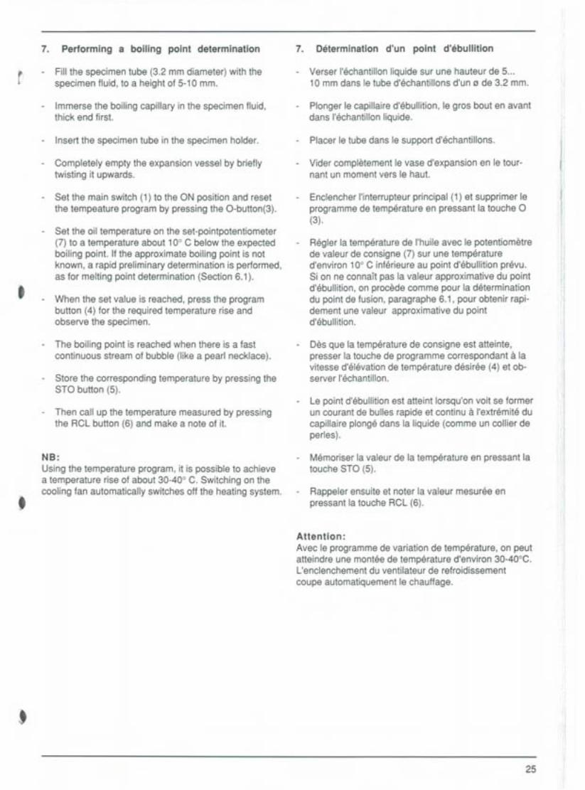
7. Performing a boiling point determination 7. Determination d'un point d'ebullition
t - Fill the specimen tube (3.2 mm diameter) with thespecimen fluid, to a height of 5-10 mm.
- Immerse the boiling capillary in the specimen fluid,thick end first.
- Insert the specimen tube in the specimen holder.
- Completely empty the expansion vessel by brieflytwisting it upwards.
- Set the main switch (1) to the ON position and resetthe tempeature program by pressing the 0-button(3).
- Set the oil temperature on the set-pointpotentiometer(7) to a temperature about 10° C below the expectedboiling point. If the approximate boiling point is notknown, a rapid preliminary determination is performed,as for melting point determination (Section 6.1).
t - When the set value is reached, press the prograrilbutton (4) for the required temperature rise andobserve the specimen.
- The boiling point is reached when there is a fastcontinuous stream of bubble (Iike a pearl necklace).
- Store the corresponding temperature by pressing theSTO button (5).
- Then call up the temperature measured by pressingthe RCL button (6) and make a note of it.
t
NB:Using the temperature program, it is possible to achievea temperature rise of about 30-40° C. Switching on thecooling fan automatically switches off the heating system.
t
- Verser I'echantillon liquide sur une hauteur de 5...10 mm dans le tube d'echantillons d'un 13de 3.2 mm.
- PIonger le capillaire d'ebullition, le gros bout en avantdans I'echantillonliquide.
- Placer le tube dans le support d'echantillons.
- Vider completement le vase d'expansion en le tour-nant un momentvers le haut.
- EnclencherI'interrupteurprincipal(1)et supprimerleprogramme de temperature en pressant la touche 0(3).
- Regler la temperature de I'huile avec le potentiometrede valeur de consigne (7) sur une temperatured'environ 10° C inferieure au point d'ebullition prevu.Si on ne conna!t pas la valeur approximative du pointd'ebullition, on procede comme pour la determinationdu point de fusion, paragraphe 6.1, pour obtenir rapi-dement une valeur approximative du pointd'ebullition.
- Des que la temperature de consigne est atteinte,presser la touche de programme correspondant a lavitesse d'elevation de temperature desiree (4) et ob-server I'echantillon.
- Le point d'ebullition est atteint lorsqu'on voit se formerun courant de bulles rapide et continu a I'extremite ducapillaire plonge dans la liquide (comme un collier deperles).
- Memoriser la valeur de la temperature en pressant latouche STO (5).
- Rappeier ensuite et noter la valeur mesuree enpressant la touche RCL (6).
Attention:Avec le programme de variation de temperature, on peutatteindre une montee de temperature d'environ 30-40°C.L'enclenchement du ventilateur de refroidissementcoupe automatiquement le chauffage.
i'I
25

i8. Durchführung einer Tropfpunktbestimmung
(nach Ubbelohde, DIN51801, Teil 2) 0)Heizmodul zur Tropfpunktbestimmung gemäss Beschrei-bung Kap. 11.2 einsetzen
"Hinweis: Mit dem Heizmodul für die Tropfpunktbestim-mung wird die Digitalanzeige ausser Funktion gesetzt.
Probenvorbereitung
Der Nippel wird auf eine glatte Oberfläche aus Glas oderMetall gestellt und mit der bis zum flüssigen Zustanderwärmten Probe gefüllt.
UJ[ ]
Hinweis: Bei klebrigen Proben wird die Platte vorgängigmit einem Formtrennmittel (z.B. Glycerin:Dextrin 1:1)bestrichen.
Den gefüllten Nippel abkühlen lassen und ca. 30 Minutenim Kühlschrank oder in Eiswasser lagern. 81
BÜCHI 535 Melring Poin'_l~". oe
". 0
Die überstehende Probe wird mit einem angewärmtenMesser so abgeschnitten, dass die Prol:>enoberflächeglatt ist.
0 r;;-;«- 2--;> STO RCL
Der Nippel wird bei einer Temperatur, die ein Aufschie-ben noch ermöglicht, auf die Halterung am Thermometergesteckt.
Tropfpunkt 340 Cdropping point 340 CPoint de goutte 340 C
Das komplette Thermometer ins Glasgefäss einführen,Hauptschalter (1) einschalten und durch Drücken derO-Taste (3) das Temperaturprogramm ausschalten.
Sollwertpotentiometer (7) ca. 10° C unter den erwartetenTropfpunkt einstellen.
i
.1!
I~~~~~tlit20°C
Sobald die Sollwerttemperatur erreicht ist, die Tempera-turprogrammtaste 1° C / Min. drücken.
Der Tropfpunkt ist diejenige Temperatur, die das Thermo-meter anzeigt, wenn der erste Tropfen sich von der Aus-trittsöffnung des Nippels ablöst.
33°C
34°C
~.
26
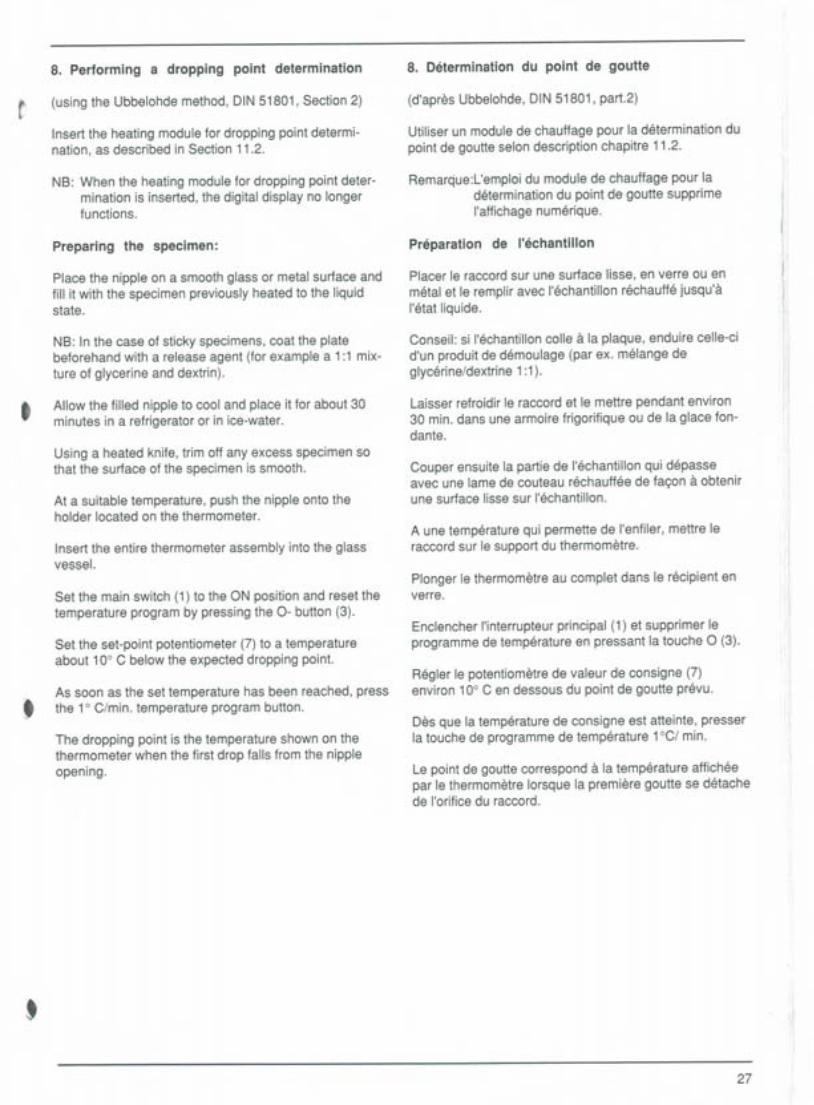
8. Performing a dropping point determination 8. Determination du point de goutte
t (using the Ubbelohde method, DIN 51801, Section 2)
Insert the heating module for dropping point determi-nation, as described in Section 11.2.
NB: When the heating module for dropping point deter-mination is inserted, the digital display no longerfunctions.
Preparing the specimen:
Place the nipple on a smooth glass or metal surface andfill it with the specimen previously heated to the liquidstate.
NB: In the case of sticky specimens, coat the platebeforehand with a release agent (for example a 1:1 mix-ture of glycerine and dextrin).
- Allow the filled nipple to cool and place it for about 30minutes in a refrigerator or in ice-water.
Using a heated knife, trim off any excess specimen sothat the surface of the specimen is smooth.
At a suitable temperature, push the nipple onto theholder located on the thermometer.
Insert the entire thermometer assembly into the glassvessel.
Set the main switch (1) to the ON position and reset thetemperature program by pressing the 0- button (3).
Set the set-point potentiometer (7) to a temperatureabout 10° C below the expected dropping point.
tAs soon as the set temperature has been reached, pressthe 1° C/min. temperature program button.
The dropping point is the temperature shown on thethermometer when the first drop falls from the nippleopening.
t
(d'apres Ubbelohde, DIN 51801, part.2)
Utiliser un modulede chauffage pour la determination dupoint de goutte selon description chapitre 11.2.
Remarcjue:L'emploidu module de chauffage pour ladeterminption du point de goutte supprimeI'affichagenumerique.
Preparation da I'echantillon
Placer le raccord sur une surface lisse, en verre ou enmetal et le remplir avec I'echantillon rechauffe jusqu'aI'etat liquide.
Conseil: si I'echantilloncolle a la plaque, enduire celle-cid'un produit de demoulage (par ex. melange deglycerine/dextrine 1:1).
Laisser refroidir le raccord et le mettre pendant environ30 min. dans une armoire frigorifique ou de la glace fon-dante.
Couper ensuite la partie de I'echantillon qui depasseavec une lame de couteau rechauffee de fagon a obtenirune surface lisse sur I'echantillon.
A une temperature qui permette de I'enfiler, mettre leraccord sur le support du thermometre.
PIonger le thermometre au complet dans le recipient enverre.
Enclencher I'interrupteurprincipal (1) et supprimer leprogramme de temperature en pressant la touche 0 (3).
Regler le potentiometre de valeur de consigne (7)environ 10° C en dessous du point de goutte prevu.
Des que la temperature de consigne est atteinte, presserla touche de programme de temperature 1°C/ min.
Le point de goutte correspond a la temperature afficheepar le thermometre lorsque la premiere goutte se detachede I'orificedu raccord.
27

9. Unterhalt und Reinigung
9.1. Allgemeines
Das Gehäuse des Schmelzpunktbestimmungsgerätes8-535 ist farbbeschichtet.Reinigung: Nur mit trockenem oder alkoholfeuchtemLappen.
9.2. Wechseln des Öls
Silikonöl kann mit der Zeit polymerisieren, vor allem wennbei hohen Temperaturen gearbeitet wird. Dadurch wirddie Viskosität des Öls erhöht. Von Zeit zu Zeit muss des-halb das Öl gewechselt werden.
Vorgehen:- Netzstecker ausziehen- Heizmodul gemäss Abschnitt 11.2 ausbauen.- Expansionsgefäss durch Lösen der Schliffklammer
entfernen.- Öl durch die Überlauföffnung ausleeren.- Diedrei Haltefedern am Glasgefäss und den Drahtbügel
lösen. Glasteil festhalten, Heizmodul nach obenausfahren und in ein passendes Becherglas stellen.
Reinigung des Glasgefässes:Heizgefäss mit einem Gemisch aus Petroleumbenzin undMethylenchlorid ausspülen.
9.3. Reinigung der Lupe
Die Lupe besteht aus Acrylglas und ist deshalb nichtlösungsmittelbeständig.
Zum Reinigen nur Ethanol verwenden.Kein Aceton, chlorierte Lösungsmittel oderÄhnlichesl
28
0
8iII
8
8:
9. Maintenance and cleaning 9. Entretien et nettoyage
~9.1. General
The housing of the 8üchi 535 used for determiningmelting points has a painted finish.Cleaning: Use only a dry cloth or alcohol.
9.2. Changing the oil
Silicone oil can withtime polymerise, especially iftheinstrument is operated at high temperatures. This in-creases the viscosity of the oil and hence the oilmust beperiodicallychanged.
t
Procedure:- Pulloutthe mainsplug.- Remove the heating module as described in Section
11.2.- Remove the expansion vessel by releasing the clips
from the ground-glass joint.- Remove the oil via the overflow opening.- Release the three spring grips on the glass vessel and
swing back the wire arm.- Hold the glass vessel and now pull out the motor from
the top and place it in a suitable beaker.
Cleaning of the glass vessel:Rinse out the heating vessel using a mixture of petroleumether and methylene chloride.
9.3. Cleaning the magnifying glass
The magnifying glass of an acrylic lens and is not resistantto solvents.
Use only ethanol for cleaning.Do not use acetone, chlorinated solvents orsimilar agents.
t
)
9.1. Generalites
Le boHierde I'appareil de determination du point defusion 8-535 est vernis.Nettoyage: uniquement avec un chiffon sec ou d'alcool.
9.2. Remplacem~nt de I'huile
L'huile de silicone se polymerise Eila longue, surtoutquand on travaille Eides temperatures elevees. 11enresulte une augmentation de la viscosite. C'est pourquoiil faut remplacer I'huile de temps en temps.
Marche a suivre:- Retirer la prise du secteur.- Demonter le module du chauffage selon
paragraphe 11.2.- Enleverlevased'expansionen demontant
le raccord rode.- Vider I'huile par la conduite de trop-plein.- Demonter les trois ressorts de maintien du recipient en
verre et I'etrier. Tenir la partie en verre, sortir le moteurvers le haut et le deposer dans un recipient en verre adhoc.
Nettoyage du recipient en verre:Rincer le recipient de chauffage avec un melange debenzine et de chlorure de methylene.
9.3. Nettoyage de la loupe
La loupe est en verre acrylique et ne resiste pas auxsolvants.
Utiliser uniquement de I'ethanol pour le nettoyage.N'employer jamais de I'acetone, des solvantschlores ou des produits similaires.
29
10. Verdrahtungs - Schema 10.Schema de cäblage10. Wiring Diagram
117V
" ~""1""1
( Geh. ) GEHÄUSE-\ober~t IRÜC!l2ttellf:;:tJOBERTEIL
X38 X44 X39
""09"'1'
"'139"90
"'"90gn
-=
E1
"'10~ '"
0
HEIZMODUL
535-G5 -3
ANZEIGEPRINT 8,XS!
LI/li16pol
"'11
~~ i!) )' r lilflf' r~-'I 9'gn S~ ~ br I : I I ~~t f ll~rslI .,;,. 1 1 3 n.IO.9 .8.4 .7 .5 n '1 3 . 5 6 IL J I J 1 '
3
~ X1 XI. X3'0 \ , ,
, t 535-G5-1HEIZREGELUNG .@13
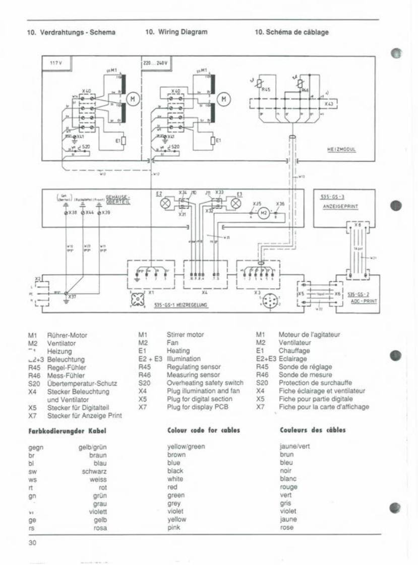
M1M2E1E2 + E3R45R46S20X4X5Xl
Stirrer motorFanHeatingIlluminationRegulating sensorMeasuring sensorOverheating safety switchPlug illumination and fanPlug for digital sectionPlug for display PCB
Colour code for cables
yellow/greenbrownblueblackwhiteredgreengreyvioletyellowpink
1 ~"'~lr EI'" r.J.-, I J
I I . I
IX5 -r'6Pot-L X61 535-65- 2I 41' I I ILJ -I J L '.J ADC-PRINT
"'11 -
M1 Moteurde I'agitateurM2 VentilateurE1 ChauffageE2+E3 EclairageR45 Sonde de reglageR46 Sonde de mesureS20 Protection de surchauffeX4 Fiche eclairage et ventilateurX5 Fiche pour partie digitaleXl Fiche pour la carte d'affichage
8.
M1 Rührer-MotorM2 Ventilator-1 Heizung,-.2+3 BeleuchtungR45 Regel-FühlerR46 Mess-FühlerS20 Übertemperatur-SchutzX4 Stecker Beleuchtung
und VentilatorX5 Stecker für DigitalteilXl Stecker für Anzeige Print
"
Couleurs des cables
jaune/vertbrunbleunoirblancrougevertgrisvioletjaunerose
8;
JkI .,).
RI.5 , An.' .)
rT11 +L=1f'"L 9' - rs gr- br n s .:.:.J
Farbkodierungder Kabel
gegn gelb/grünbr braunbl blausw schwarzws weissrt rot
gn grüngrau
'" violettge gelbrs rosa
30
--.-.-....-

10.2. Lageplan der Sicherungen 10.2. Location of the fuses
$10.2. Plan d'equipement - Fusibles
D
0OJ]
ic::J 10~ OJO
(0 äW f~~~]~ OJ ~
I
tX7
t 0
-CJc::J 0 0
bdbd
00 0000 ~O
~ ~ ~ UO:~~
~
DF2
n::nc:::J-
0
'!
0
0
10 pieces225602257022555
22558
X4
......-CJ -c=:J .
F1
F7
0
F1/F7 Fusible principalF2 ChauffageF3/F4 Partie analogiqueF5 PartiedigitaleF6 Ventilateur +
Eclairage
117/220/240V2.5 AT2.5 AFF0.1 AT0.5 AT0.5 AT
31
117/220/240 V 1O-erSetF1/F7 Hauptsicherung 2.5AT 22560F2 Heizung 2.5 AFF 22570F3/F4 Analog-Teil 0.1 AT 22555F5 Digital-Teil 0.5 ATF6 Ventilator+
Beleuchtung 0.5 AT 22558
117/220/240 V Set of tenF1/F7 Main fuse 2.5 AT 22560F2 Heater 2.5 AFF 22570
J F3/F4 Analog Section0.1 AT 22555
F5 Digital Section 0.5 ATF6 Fan and
illumination 0.5 AT 22558
8 8
8111111 8

11. Auswechseln von Bauteilen
11.1. Allgemeine Vorbereitungen 8'Bevor Teile am Gerät ausgewechselt werden, immerzuerst
- Hauptschalter ausschalten- Netzstecker ausziehen
11.2. Wechseln des Heizmoduls
- Temperaturfühlerstecker (17) herausziehen.- Schraube am Motor- und Heizungskabel (16) mittels
Schraubenzieher lösen und Stecker herausziehen.
- Schnellverschlüsse(0)durch leichten.Druckmit gleich-zeitiger halber Schraubenzieher-Drehung lösenHeizmodul nach oben herausfahren
8
11.3. Wechseln der Lupe
- Schrauben der Frontplatte beidseitig lösen- Rahmen mit Lupe und Digitalanzeige nach vorne
ausklappen- Schrauben der Lupenhalterung lösen- Lupe mit Fassung herausnehmen- Lupe auswechseln
811.4. Wechseln des Kühlventilators
- HeizmoduldurchÖffnender Schnell-Verschlüsseentfernen.
- Flachsteckhülsenam Ventilatorherausziehen- Schrauben(0) lösen"- neuenVentilatormontieren
Achtung: Bei falscher Montage der Flachstecker kannder Print beschädigt werden.Rosa Kabel: ObenGraues Kabel: Unten
8
32

11. Replacing parts
f) 11.1. General precautions
Before replacing any parts on the instrument, always:- Set the mains switch to the OFF position- Pullout the mainsplug
11.2. Changing the heating module
Pull out the temperature sensor plug (17). Using a screw-driver, loosen the screw on the cable (16) for the motorand heater and pull out the plug. Release the quickfasteners (0) by applying light pressure and at the sametime performing a half screwdriver turn. Pull out theheating module from the top.
t11.3. Replacingthe magnifyinglens
- Loosen the screws on the front plate on both sides.- Swing out the frame with the magnifying lens and the
digital display.- Loosen the screws on the magnifying glass mounting.- Remove the magnifying glass with its holder.- Change the magnifying glass.
t11.4. Replacing the cooling fan
- Removethe heatingmoduleby releasingtheCamlockfasteners.
- Pullouttheflatpush-onsleevesonthefan.- Loosenthe screws (0).
Mountthe newfan.
Note: If the flat plug is not mounted properly, the circuitboard may be damaged.Pink cable: topGrey cable: bottom
t
11. Remplacement de pieces
11.1. Preparatifsen general
Avant de remplacer des pieces de I'appareil, il faut tou-jours:- Declencher I'interrupteur principal- Retirer la fiche du secteur
11.2. Remplacement du module de chauffage
Enlever la prise de la sonde de temperature (17).A I'aide d'un tournvis, devisser la vis (16) du cäble du mo-teur et du chauffage.Enlever la prise.Degager le raccord rapide (0) en pressant legerement eten tournant avec un tournevis.Sortir le module chauffage vers le haut.
11.3. Remplacement de la loupe
- Devisserresvisdu panneaufrontal des deuxcötes.- Basculer vers I'av/mt le cadre avec la loupe et
I'affichage numerique;- Devisser les vis de fixation de la roupe.- Retirer la loupe et sa douille- Remplacerla loupe.
11.4. Remplacement du ventilateur derefroidissement
- Enleverle moduledechauffageen ouvrant leraccordCamlock.
- Enleverlesconnexionsplatesdu ventilateur.- Devisserlesvis(0).- Monterun nouveauventilateur.
Attention: La carte de circuit peut etre endommagee siles connexions plates sont montees incorrectement.Cäble rose: en haut
Cäble gris: en bas.
33

11.5. Wechseln des Heizwendels
- Heizmodulgemäss Kap. 11.2 herausnehemen- Haltefedern und Drahtbügel am Heizgefäss entfernen- Glasgefäss nach unten wegnehmen- Heizwendel mit Hilfe eines kleinen Schraubenziehers
aus der Halterung drücken.- Neue Heizung vorsichtig in die Halterung hinein-
drücken (bis sie einschnappt)
8
11.6. Wechseln der Beleuchtungslampen
- Heizmodulgern. Kap. 11.2herausnehmen.Lampeinkl. Reflektorsind nurgesteckt
- Lampe mit Reflektorherausziehenund auswechseln.(EinAuswechseln ist ebenfallsdurch Öffnendes Frontrahmens(gem.Kap. 11.3) möglich)
8
11.7. Wechseln des Digitalanzeigeprints GS 3
- Schrauben der Frontplatte mit Lupe und Digitalanzeigelösen
- Frontplatte nach vorne ausklappen- Schrauben am Gehäuse (0) beidseitig lösen und
Gehäuseoberteil abheben
- Digitalanzeigeprint losschrauben (0)- Steckverbindung am Grundprint lösen: dazu beide
Halter nach aussen drücken
- Metallplatte wegschrauben (0)- Stecker durch Öffnung ausführen und Print wechseln 8
8
34

11.5. Replacing the heating coil
e Remove the heating module as described in Section11.2.
Remove the spring grips and the wire arm from theheating vessel.Pull out the glass vessel from underneath.Press out the heating coil from the mounting with thehelp of a small screwdriver.Press new heating carefully into holder.
11.6. Replacing the illumination lamps
t Remove the heating module, as described in Section11.2.
The lamp and reflector are of the push-in type. Pull thelamp with reflector out and put a new one in its place.It is also possible to change the lamp by opening thefront frame (see Section 11.3).
11.7. Replacing the Digital display PCB GS 3
(I.\1!!!
- Loosen the screws on the front plate with themagnifying glass and digital display
- Swing out the front plate- Loosen the screwson both sidesof the housing (0)
and lift off the top section of the housing- Unscrewthe digital pes (0)- Disconnect the connector from the main pes; to do
this, press both retainers outwards- Unscrew and remove the metal plate (0)- Pullout the connectorthroughthe openingand
replace pes
,
11.5. Remplacement du filament chauffantSortir le moduledechauffageselon paragraphe 1.2.Enlever les ressortsde maintienet I'etrierdu recipientenverre.Retirer le recipientenverrevers lebas.A I'aided'un petittournevis,pousserle filamentdechauffagehorsde sonsupport.Montagede situmentdechauffageavec precautions.
11.6. Remplacement des lampes d'eclairage
Sortir le module de chauffage selon paragraphe 11.2.Les lampes et les reflecteurs ne sont qu'enfiches.Sortir la lampe avec les reflecteurs et la changer.On peut aussi changer les lampes en ouvrant le cadrefrontal (seldn paragraphe 11.3)
11.7. Remplacement de la carte d'affichagenumerique
- Devisser les vis du panneau frontal avec la loupe etI'affichage numerique
- Sasculer le panneau frontal vers I'avant- Devisser les vis des deux cates du boitier (0) et
soulever la partie superieure du boltier- Devisser la carte d'affichage numerique (0)- Enlever la fiche sur la carte de base en pressant les
deux supports vers I'exterieur- Devisser la plaque metallique (0)- Sortir la prise par I'ouverture et remplacer la carte
35

I
12. Beheben von Störungen
36
I'
8
8
8
<"törung Mögliche Ursache Behebung
Gerät funktioniert überhaupt nicht 1. Kein Strom 1. Netzspannung kontrollieren2. Apparate Sicherung F1/F7 defekt 2. Sicherung wechseln
Rührer und Beleuchtung funktio- 1. Sicherung defekt 1. Sicherung'F2, F3 od. F4 wechselnnieren, Heizung funktioniert nicht 2. Heizwendel defekt 2. Heizwendel gem. 11.5 ersetzen
3.Pt - 100 defekt 3. Service anrufen4. Elektronik defekt 4. Service anrufen
Beleuchtung funktioniert nicht 1. Lampen defekt 1. Lampen gem.11.6. wechseln2. Sicherung F6 defekt 2. Sicherung wechseln3. Stecker X4 nicht eingesteckt 3. Stecker mit Print verbinden
Rührer funktioniert nicht, Rührmotor defekt Service anrufen
Heizung funktioniert
I .Llhrerund Heizung 1. Kabel 16 nicht eingesteckt 1. Kabel einsteckenfunktionieren nicht. 2. Übertemperatur-Schutz hat 2. Gerät abkühlen lassen
angesprochen
Ventilator funktioniert nicht 1.Sicherung F6 defekt 1. Sicherung wechseln2.Ventilator defekt 2. Ventilator gem. 11.4 auswechseln3.Stecker X4 auf Print nichteingesteckt 3. Stecker mit Print verbinden
Sollwert stimmt nicht Service anrufen
Temperaturaufheizrate stimmt nicht Service anrufen
Digitalanzeige funktioniert nicht 1. Flachbandkabel nicht eingesteckt 1. Kabel X5 od. X7 einstecken(siehe 10.1.)
2. Digitalanzeigeprint defekt 2. Print gem. 11.7. wechseln3. Sicherung F5 defekt 3. Sicherung F5 wechseln
Digitalanzeige zeigt Fehlermeldung 1. Kabel (17) nicht eingesteckt 1. Kabel einstecken"'''0/399 blinkend 2. Pt-100 defekt 2. Service anrufen
Digitalanzeige unvollständig LED defekt Print GS3 (Gem. 11.7.) wechseln
Übereinstimmung Digitalanzeige- 1. Öl zu viskos 1. Öl (gem. 9.2. wechseln)Thermometer stimmt nicht 2. Thermometer ungenau 2. Geeichtes Thermometer
verwenden3. Elektronik dejustiert 3. $ervice anrufen
Temperatur nicht stabil Ölumwälzung ungenügend 1. Rührer im Heizgefäss zentrieren(Anzeige steigt und fällt) 2. Öl wechseln (Viskosität zu hoch)
12. Troubleshooting
-
t
I
8
37
Problem Possible cause Solution
Instrument not working at all 1.No current 1. Check mains voltage2.Fuse F1/F7 defective 2. Change fuse
Stirrer and illumination working, 1.Fuse F2, F3 or F4 defective 1. Change fuse F2, F3 or F4heating not working
2.Heating coil defective 2. Replace heating coil(see Section 11.5.)
3.Electronics defective 3. Call Service Engineer4.Pt-100 defective 4. Call Service Engineer
Illumination not working 1.Lamps defective 1. Change lamps (see Section 11.6)2.Fuse F6 defective 2. Change fuse3.Plug X4 not connected to PCS 3. Connect plug to PCS
Stirrer not working, Stirrer motor defective Call Service Engineerheating working
Fan not working 1.Fuse F6 defective 1. Change fuse2.Fan defective 2. Replace fan (see Section 11.4)3.Plug X4 not connected to PCS 3. Connect plug to PCS
Set value incorrect Call Service Engineer
Temperature heating rate incorrect Call Service Engineer
Stirrer and heating not working 1.Cable 16 not connected 1. Connect cable2.0verheating safety switch 2. Allow instrument to coolhas come into operation
Digital display not working 1. Flat cable not connected 1. Conect cable X5 OrX7 (see Section10.1.)
2. Digital display PCS defective 2. Replace PCS (see Section 11.7.)3. Fuse F5 defective 3. Change fuse F5
Flashing error code (000/399) appears 1. Cable 17 not connected 1. Connect cableon digital display 2. Pt-1QOdefective 2. Call Service Engineer
Incomplete information shown LED defective Replace PCS (see Section 11.7.)on digital display
Different values obtained from 1. Oil to viscous 1. Change oil (See Section 9.2.)digital display and thermometer 2. Thermometer imprecise 2. Use calibrated thermometer
3. Electronics disadjusted 3. Call Service Engineer
Temperatur not stable Circulation of the oil is 1. Adjust stirrer in the heating vessel(Indication raises and dropps) not sufficient 2. Change oil (viscosity too high)
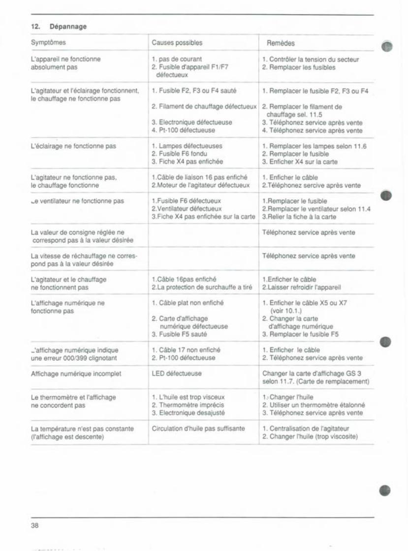
12. pepannage
38
8
8
8
"
Symptömes Causes possibles Remedes
L'appareil ne fonctionne 1. pas de courant 1. Contröler la tension du secteurabsolument pas 2. Fusible d'appareil F1/F7 2. Remplacer les fusibles
defectueux
L'agitateur et I'eclairage fonctionnent, 1. Fusible F2, F3 ou F4 saute 1. Remplacer le fusible F2, F3 ou F4le chauffage ne fonctionne pas
2. Filament de chauffage defectueux 2. Remplacer le filament dechauffage seI. 11.5
3. Electroniquedefectueuse 3. Telephonez service apres vente4. Pt-100 defectueuse 4. Telephonez service apres vente
L'eclairage ne fonctionne pas 1. Lampesdefectueuses 1. Remplacer les lampes selon 11.62. Fusible F6 fondu 2. Remplacer le fusible3. Fiche X4 pas enfichee 3. Enficher X4 sur la carte
L'agitateur ne fonctionne pas, 1.Cable de liaison 16 pas enfiche 1. Enficher le cablele chauffage fonctionne 2.Moteur de I'agitateur defectueux 2.Telephonez sercive apres vente
...eventilateur ne fonctionne pas 1.Fusible F6 defectueux 1.Remplacer le fusible2.Ventilateur defectueux 2.Remplacer le ventilateur selon 11.43.Fiche X4 pas enfichee sur la carte 3.Relier la fiche äla carte
La valeur de consigne reglee ne Telephonez service apres ventecorrespond pas a la valeur desiree
La vitesse de rechauffage ne corres- Telephonez service apres ventepond pas a la valeur desiree
L'agitateur et le chauffage 1.Cable 16pas enfichS 1.Enficher le cablene fonctionnent pas 2.La protection de surchauffe a tire 2.Laisser refroidir I'appareil
L'affichage numerique ne 1. Cable plat non enfiche 1. Enficher le cable X5 ou X7fonctionne pas (voir 10.1.)
2. Carte d'affichage 2. Changer la cartenumerique defectueuse d'affichage numerique
3. Fusible F5 saute 3. Remplacer le fusible F5
_'affichage numerique indique 1. Cable 17 non enfichS 1. Enficher le cableune erreur 000/399 clignotant 2. Pt-100 defectueuse 2. Telephonez service apres vente
Affichage numerique incomplet LED defectueuse Changer la carte d'affichage GS 3selon11.7. (Carte de remplacement)
Le thermometre et I'affichage 1. L'huile est trop visceux 1...ChangerI'huilene concordent pas 2. Thermometre imprecis 2. Utiliser un thermometre etalonne
3. Electronique desajuste 3. Telephonez service apres vente
La temperature n'est pas constante Circulation d'huile pas suffisante 1. Centralisation de I'agitateur(I'affichage est descente) 2. Changer I'huile (trop viscosite)
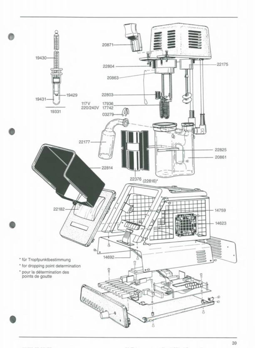
22804
I ..".
--.
,""" "'c,.,-,~,.', '
:,~~ "".':'.':11
~...,,' ~ ,:i
~ ~. . :,\~' ' : -" ",
- =,..-,-'''' ' . 't ,; ,'i'
8~ 20871
~. ',:\1,~,j
~1
19430
22175
* tür Troptpunktbestimmung* tor dropping point determination
* pour la determination despoints de goutte
20863
19429 22803
117V 17936
220/240V 17742' at\03279-4 UJJ
iII
19431
19331
822177
22825
20861
14759
8 14623
14692
8
39
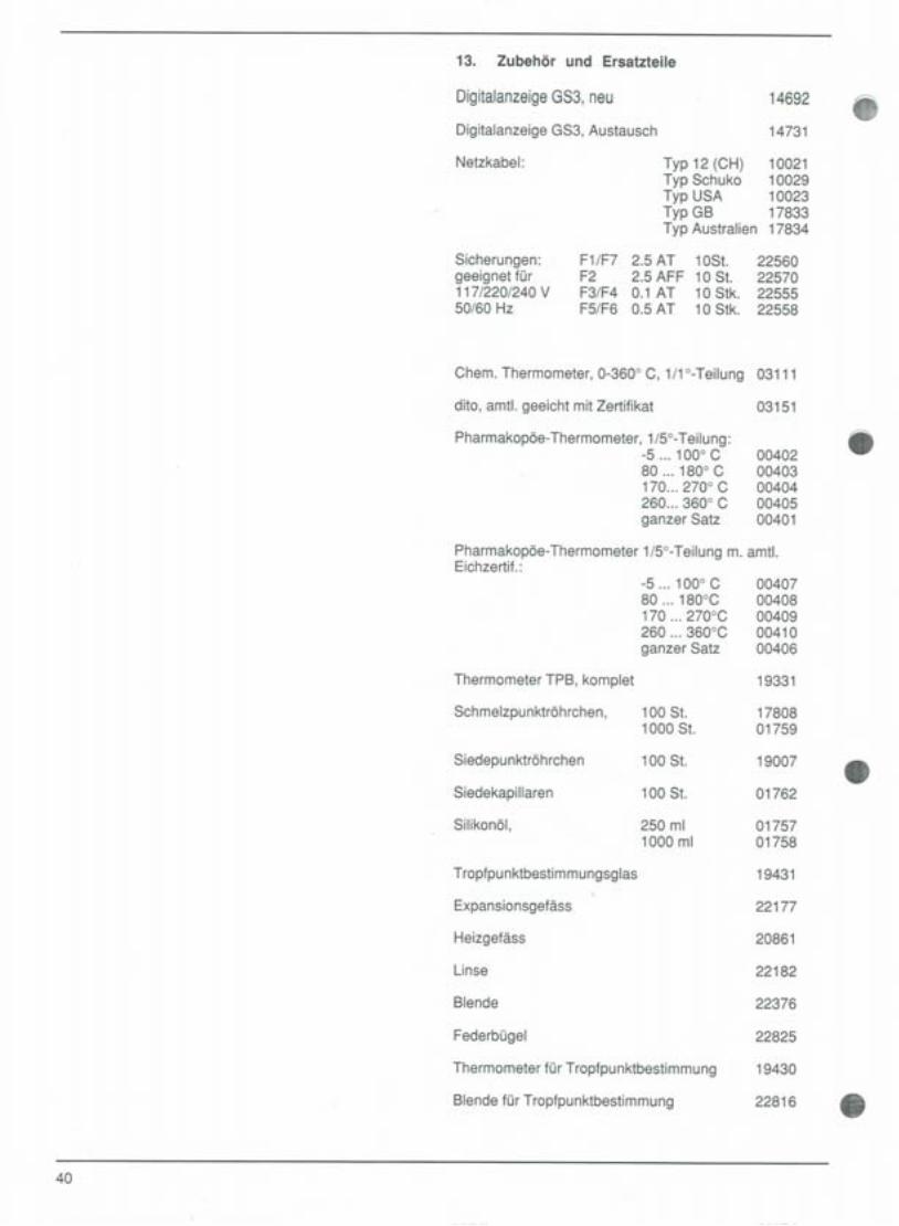
13. Zubehör und Ersatzteile
DigitalanzeigeGS3,neu 14692 8Digitalanzeige GS3, Austausch 14731
Netzkabel: Typ 12 (CH)Typ SchukoTyp USATyp GBTyp Australien
1002110029100231783317834
Sicherungen:geeignet für117/220/240 V50/60 Hz
F1/F7 2.5 AT 1OSt. 22560F2 2.5 AFF 10 St. 22570F3/F4 0.1 AT 10 Stk. 22555F5/F6 0.5 AT 10 Stk. 22558
40
Chem.Thermometer,0-3600C, 1/1°-Teilung 03111
dito,amt!.geeichtmitZertifikat 03151
Pharmakopöe-Thermometer,1/5°-Teilung: 8-5 ... 1000 C 0040280... 1800C 00403170... 2700C 00404260... 3600C 00405ganzer Satz 00401
Pharmakopöe-Thermometer 1/5°-Teilung m. amt!.Eichzertif.:
-5 ... 1000C 0040780 .,. 180°C 00408170 ... 270°C 00409260... 360°C 00410ganzer Satz 00406
Thermometer TPB, komplet 19331
Schmelzpunktröhrchen, 100 St. 178081000 St. 01759
Siedepunktröhrchen 100 St. 19007 8Siedekapillaren 100 St. 01762
Silikonöl, 250 ml 017571000 ml 01758
Tropfpunktbestimmungsglas 19431
Expansionsgefäss 22177
Heizgefäss 20861
Linse 22182
Blende 22376
Federbügel 22825
Thermometer für Tropfpunktbestimmung 19430
Blende für Tropfpunktbestimmung 22816 '"
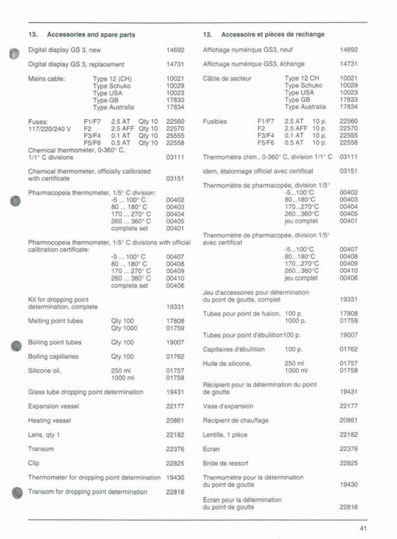
13. Accessories and spare parts
Digital display GS 3, new
Digital display GS 3, replacement
Mains cable: Type 12 (CH)Type SchukoType USAType GBType Australia
F1/F7 2.5 ATF2 2.5 AFFF3/F4 0.1 ATF5/F6 0.5 AT
Chemical thermometer, 0-360° C,1/1° C divisions
Oty 10Oty 10Oty 10Oty 10
Fuses:117/220/240 V
Chemical thermometer, officially calibratedwith certificate
8Pharmacopeia thermometer, 1/5° C division:
-5 ... 100° C80...180° C170...270° C260...360° Ccomplete set
14692
14731
1002110029100231783317834
22560225702555522558
03111
03151
0040200403004040040500401
Pharmocopeia thermometer, 1/5° C divisions with officialcalibration certificate:
-5 ... 100° C80... 180° C170...270° C260...360° Ccomplete set
Kit for dropping pointdetermination, complete
Melting point tubes Oty 100Oty 1000
Oty 100Boiling point tubes
Boiling capillaries Oty 100
Silicone oil, 250 ml1000 ml
Glass tube dropping point determination
Expansion vessel
Heating vessel
Lens, qty 1
Transom
Clip
0040700408004090041000406
19331
1780801759
19007
01762
0175701758
19431
22177
20861
22182
22376
22825
Thermometer for dropping point determination 19430
22816Transom for dropping point determination
13. Accessoire et pieces de rechange
14692
14731
1002110029100231783317834
22560225702255522558
idem, etalon nage officiel avec certificat
Thermometre chim., 0-360° C, division 1/1° C 03111
03151
0040200403004040040500401
Affichage numerique GS3, neuf
Affichage numerique GS3, echange
Cäble de secteur Type 12 CHType SchukoType USAType GBType Australia
Fusibles F1/F7F2F3/F4F5/F6
2.5 AT 10 p.2.5 AFF 10 p.0.1 AT 10 p.0.5 AT 10 p.
Thermometre de pharmacopee, division 1/5°-5...100°C80...180°C170...270°C260...360°Cjeu complet
Thermometre de pharmacopee, division 1/5°avec certificat
-5...100°C80...180°C170...270°C260...360°Cjeu complet
Jeu d'accessoires pour determinationdu point de goutte, complet
Tubes pour point de fusion, 100 p.1000 p.
Tubes pour point d'ebullition1 00 p.
Capillaires d'ebullition 100 p.
Huile de silicone, 250 ml1000 ml
Recipient pour la determination du pointde goutte
Vase d'expansion
Recipient de chauffage
Lentille, 1 piece
Ecran
Bride de ressort
Thermometre pour la determinationdu point de goutte
Ecran pour la determinationdu point de goutte
0040700408004090041000406
19331
1780801759
19007
01762
0175701758
19431
22177
20861
22182
22376
22825
19430
22816
41
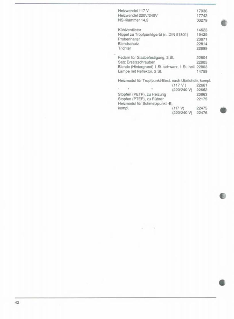
Heizwendel 117 VHeizwendel 220V/240VNS-Klammer 14,5
Kühlventilator
Nippel zu Tropfpunktgerät (n. DIN 51801)ProbenhalterBlendschutzTrichter
179361774203279
1462319429208712281422899
Federn für Glasbefestigung, 3 St. 22804Satz Ersatzschrauben 22805Blende (Hintergrund) 1 St. schwarz, 1 St. hell 22803Lampe mit Reflektor, 2 St. 14759
Heizmodul für Tropfpunkt-Best. nach Ubelohde, komp!.(117V) 22661(220/240 V) 22662
2086322175
Stopfen (PETP), zu HeizungStopfen (PTEP), zu RührerHeizmodul für Schmelzpunkt -B.komp!. (117 V)
(220/240 V)2247522476
8
8
8
8
42

Heating coil, 117 VHeating coil, 220 V 1240 VSGJ clamp, 14.5
Cooling fanNipple for dropping point instrument(according to DIN 51801)Specimen holderAntiglare deviceFunnel
Spring grips for glass vessel, qty 3Set of spare screwsScreen (background), 1x black, 1x whiteLamp with reflector, qty 2
Heating module for Ubbelohde dropping pointdetermination, complete
(117 V)(220/240 V)
Stopper (PETP), for heating deviceStopper (PETP), for stirrerHeating module for melting p. det.complete (117V)
(220/240 V)
0
22661226622086322175
Module de chauffage pour la determinatione point degoutte selon Ubbelohde,complet
(117 V)" " (220/240 V)
Bouchon(PETP),pourchauffageBouchon (PETP), pour agitateurModule de chauffage pour point de fusion,comp!. (117 V)
(220/240 V)
22661226622086322175
2247522476
2247522476
43
17936 Filament de chauffage, 117V 1793617742 Filament de chauffage 220V1240V 1774203279 Pince a rodage normalise 14,5 03279
14623 Ventilateur de refroidissement 14623
Raccord pour appareil de point de goutte19429 (seion DIN 51801) 1942920871 Support d'echantillons 2087122814 Ecran antieblouissant 22814
Entonnoir
22804 Ressorts pour fixer les verres, 3 pieces 2280422805 Jeu de vis de rechange 2280522803 Ecran (arriere-fond), 1 p. noire, 1 p. claire 2280314759 Lampe avec reflecteur, 2 p. 14759