SIMATIC NET to PROFIBUS on Industrial PC 6 C79000-G8976-C068 Contents 1 The Product Spectrum Around...
36
SIMATIC NET Introduction to PROFIBUS on Industrial PC Volume 1 of 1 1 The Product Spectrum Around the CP 5412 (A2) 2 How to Use the Manuals 3 Description of the Architecture 4 Addresses for Help and Training 5 Further Reading Glossary C79000-G8976-C068 Release 05 SIMATIC NET is a trademark of Siemens Siemens Aktiengesellschaft
Transcript of SIMATIC NET to PROFIBUS on Industrial PC 6 C79000-G8976-C068 Contents 1 The Product Spectrum Around...
SIMATIC NETIntroduction to PROFIBUS on Industrial PC
Volume 1 of 1
1 The Product Spectrum Around the CP 5412 (A2)
2 How to Use the Manuals
3 Description of the Architecture
4 Addresses for Help and Training
5 Further Reading
Glossary
C79000-G8976-C068 Release 05
SIMATIC NET is a trademark of SiemensSiemens Aktiengesellschaft
Wir haben den Inhalt der Druckschrift aufÜbereinstimmung mit der beschriebenen Hard- undSoftware geprüft. Dennoch können Abweichungennicht ausgeschlossen werden, so daß wir für dievollständige Übereinstimmung keine Gewährübernehmen. Die Angaben in der Druckschrift werdenjedoch regelmäßig überprüft. Notwendige Korrekturensind in den nachfolgenden Auflagen enthalten. FürVerbesserungsvorschläge sind wir dankbar.
Technische Änderungen vorbehalten.Weitergabe sowie Vervielfältigung dieser Unterlage,Verwertung und Mitteilung ihres Inhalts nicht gestattet,soweit nicht ausdrücklich zugestanden.Zuwiderhandlungen verpflichten zu Schadenersatz.Alle Rechte vorbehalten, insbesondere für den Fallder Patenterteilung oder GM-Eintragung.
C79000-G8976-C068Copyright © Siemens AG 1996All Rights Reserved
We have checked the contents of this manual foragreement with the hardware described. Sincedeviations cannot be precluded entirely, we cannotguarantee full agreement. However, the data in thismanual are reviewed regularly and any necessarycorrections included in subsequent editions.Suggestions for improvement are welcome.
Technical data subject to change.
The reproduction, transmission or use of thisdocument or its contents is not permitted withoutexpress written authority. Offenders will be liable fordamages. All rights, including rights created by patentgrant or registration of a utility or design, are reserved.
C79000-G8976-C068Copyright © Siemens AG 1996All Rights Reserved
Nous avons vérifié la conformité du contenu duprésent manuel avec le matériel et le logiciel qui ysont décrits. Or, des divergences n'étant pas exclues,nous ne pouvons pas nous porter garants pour laconformité intégrale. Si l'usage du manuel devaitrévéler des erreurs, nous en tiendrons compte etapporterons les corrections nécessaires dès laprochaine édition. Veuillez nous faire part de vossuggestions.Nous nous réservons le droit de modifier lescaractéristiques techniques.
Toute communication ou reproduction de ce supportd'informations, toute exploitation ou communication deson contenu sont interdites, sauf autorisationexpresse. Tout manquement à cette règle est illicite etexpose son auteur au versement de dommages etintérêts. Tous nos droits sont réservés, notammentpour le cas de la délivrance d'un brevet ou celui del'enregistrement d'un modèle d'utilité.
C79000-G8976-C068Copyright © Siemens AG 1996All Rights Reserved
Siemens Aktiengesellschaft Elektronikwerk KarlsruhePrinted in the Federal Republic of Germany
SIMATIC NETIntroduction to PROFIBUS on Industrial PC
Description C79000-B8976-C068/05
Note
We would point out that the contents of this product documentation shall not become a part of or modify any prior or existingagreement, commitment or legal relationship. The Purchase Agreement contains the complete and exclusive obligations ofSiemens. Any statements contained in this documentation do not create new warranties or restrict the existing warranty.
We would further point out that, for reasons of clarity, these operating instructions cannot deal with every possible problemarising from the use of this device. Should you require further information or if any special problems arise which are notsufficiently dealt with in the operating instructions, please contact your local Siemens representative.
GeneralThis device is electrically operated. In operation, certain parts of this device carry a dangerously highvoltage.
WARNING !Failure to heed warnings may result in serious physical injury and/or material damage.
Only appropriately qualified personnel may operate this equipment or work in its vicinity. Personnel must bethoroughly familiar with all warnings and maintenance measures in accordance with these operatinginstructions.
Correct and safe operation of this equipment requires proper transport, storage and assembly as well ascareful operator control and maintenance.
Personnel qualification requirements
Qualified personnel as referred to in the operating instructions or in the warning notes are defined as persons who are familiarwith the installation, assembly, startup and operation of this product and who posses the relevant qualifications for their work,e.g.:
− Training in or authorization for connecting up, grounding or labelling circuits and devices or systems in accordance withcurrent standards in safety technology;
− Training in or authorization for the maintenance and use of suitable safety equipment in accordance with current standards insafety technology;
− First Aid qualification.
!
Introduction to PROFIBUS on Industrial PCC79000-G8976-C068 5
Manuals for PROFIBUS on Industrial PC
Introduction to PROFIBUS on Industrial PC .............................................. C79000-G8976-C068
ET 200 Distributed I/O System.........................................................................6ES5 998-3ES22
Configuring the S7 Mode with COML S7 ................................................... C79000-G8976-C074
DP Programming Interface........................................................................ C79000-G8976-C071
FDL Programming Interface...................................................................... C79000-G8976-C072
FMS Programming Interface ..................................................................... C79000-G8976-C073
S7 Programming Interface ........................................................................ C79000-G8976-C077
Introduction to PROFIBUS on Industrial PC6 C79000-G8976-C068
Contents
1 The Product Spectrum Around the PROFIBUS on Industrial PC .....................................7
2 How to Use the Manuals .................................................................................................9
3 Description of the Architecture ......................................................................................113.1 The ISO/OSI Reference Model .....................................................................................123.2 SIMATIC NET Communications Networks ....................................................................133.3 PROFIBUS...................................................................................................................143.4 Network Architecture.....................................................................................................153.5 Overview of the Protocols.............................................................................................163.5.1 The PG Protocol ...........................................................................................................163.5.2 FMS Programming Interface.........................................................................................173.5.3 The DP Protocol ...........................................................................................................183.5.4 S7 Programming Interface............................................................................................203.5.5 The FDL Protocol .........................................................................................................213.6 The Multiprotocol Mode ................................................................................................223.7 Software and Hardware Components............................................................................233.8 Communications Options..............................................................................................25
4 Where to Obtain Help ...................................................................................................274.1 Help with Technical Questions ......................................................................................274.2 Contacts for SIMATIC NET Training .............................................................................28
5 Further Reading............................................................................................................29
Glossary..................................................................................................................................31
The Product Spectrum Around the PROFIBUS on Industrial PC
Introduction to PROFIBUS on Industrial PCC79000-G8976-C068 7
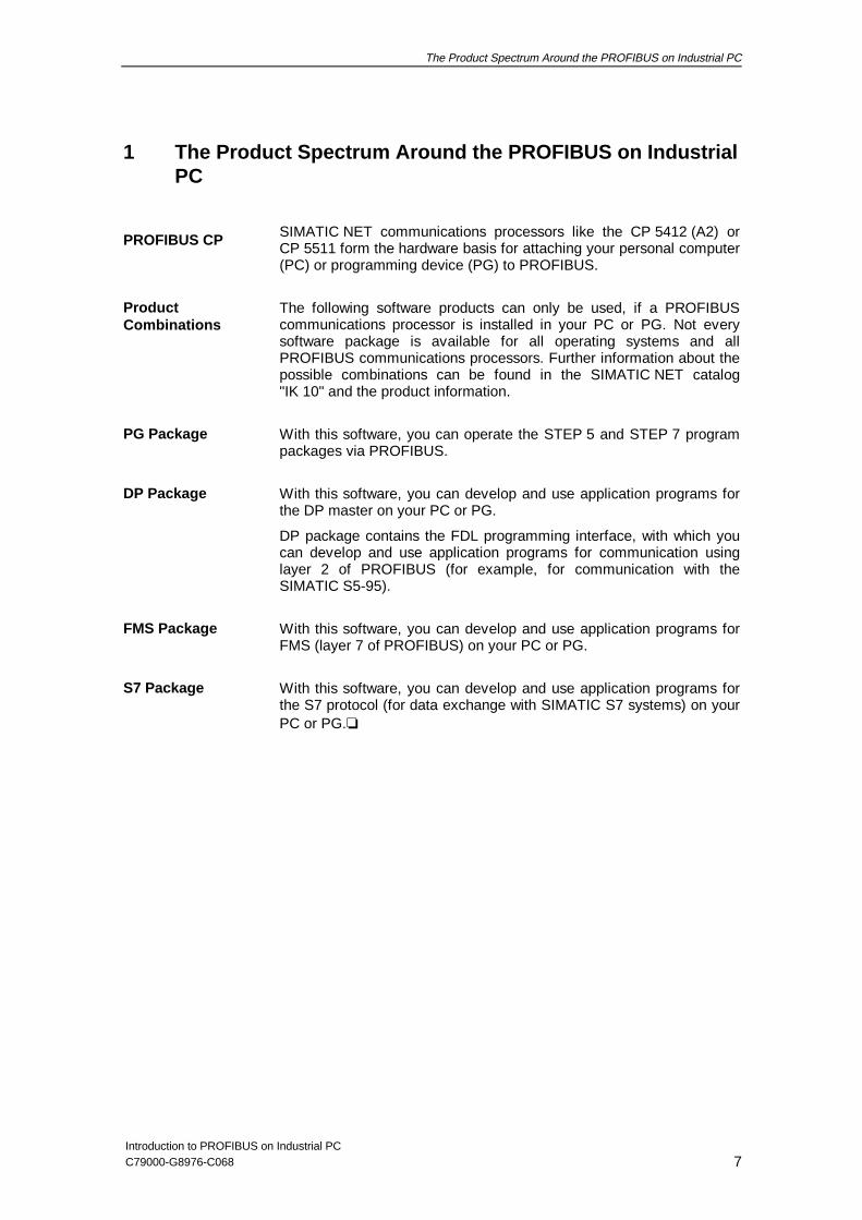
1 The Product Spectrum Around the PROFIBUS on IndustrialPC
SIMATIC NET communications processors like the CP 5412 (A2) orCP 5511 form the hardware basis for attaching your personal computer(PC) or programming device (PG) to PROFIBUS.
The following software products can only be used, if a PROFIBUScommunications processor is installed in your PC or PG. Not everysoftware package is available for all operating systems and allPROFIBUS communications processors. Further information about thepossible combinations can be found in the SIMATIC NET catalog"IK 10" and the product information.
With this software, you can operate the STEP 5 and STEP 7 programpackages via PROFIBUS.
With this software, you can develop and use application programs forthe DP master on your PC or PG.
DP package contains the FDL programming interface, with which youcan develop and use application programs for communication usinglayer 2 of PROFIBUS (for example, for communication with theSIMATIC S5-95).
With this software, you can develop and use application programs forFMS (layer 7 of PROFIBUS) on your PC or PG.
With this software, you can develop and use application programs forthe S7 protocol (for data exchange with SIMATIC S7 systems) on yourPC or PG.❏
PROFIBUS CP
ProductCombinations
PG Package
DP Package
FMS Package
S7 Package

The Product Spectrum Around the PROFIBUS on Industrial PC
Introduction to PROFIBUS on Industrial PC8 C79000-G8976-C068
NOTES
Description of the Architecture
Introduction to PROFIBUS on Industrial PCC79000-G8976-C068 9
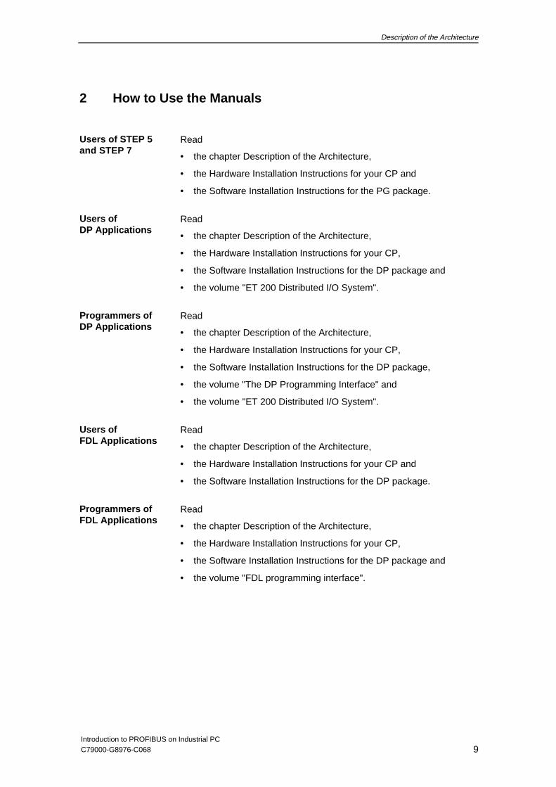
2 How to Use the Manuals
Read
• the chapter Description of the Architecture,
• the Hardware Installation Instructions for your CP and
• the Software Installation Instructions for the PG package.
Read
• the chapter Description of the Architecture,
• the Hardware Installation Instructions for your CP,
• the Software Installation Instructions for the DP package and
• the volume "ET 200 Distributed I/O System".
Read
• the chapter Description of the Architecture,
• the Hardware Installation Instructions for your CP,
• the Software Installation Instructions for the DP package,
• the volume "The DP Programming Interface" and
• the volume "ET 200 Distributed I/O System".
Read
• the chapter Description of the Architecture,
• the Hardware Installation Instructions for your CP and
• the Software Installation Instructions for the DP package.
Read
• the chapter Description of the Architecture,
• the Hardware Installation Instructions for your CP,
• the Software Installation Instructions for the DP package and
• the volume "FDL programming interface".
Users of STEP 5and STEP 7
Users ofDP Applications
Programmers ofDP Applications
Users ofFDL Applications
Programmers ofFDL Applications
Description of the Architecture
Introduction to PROFIBUS on Industrial PC10 C79000-G8976-C068
Read
• the chapter Description of the Architecture,
• the Hardware Installation Instructions for your CP,
• the Software Installation Instructions for the FMS package and
• the configuration instructions in the volume "ET 200 Distributed I/OSystem".
Read
• the chapter Description of the Architecture,
• the Hardware Installation Instructions for your CP,
• the Software Installation Instructions for the FMS package,
• the configuration instructions the volume "ET 200 Distributed I/OSystem" and
• the volume "FMS Programming interface“.
Read
• the chapter Description of the Architecture,
• the Hardware Installation Instructions for your CP,
• the Software Installation Instructions for the S7 package and
• the configuration instructions in the volume "Configuring the S7Mode with COML S7".
Read
• the chapter Description of the Architecture,
• the Hardware Installation Instructions for your CP,
• the Software Installation Instructions for the S7 package and
• the configuration instructions in "Configuring the S7 Mode withCOML S7" and
• the volume "S7 Programming Interface". ❏
Users ofFMS Applications
Programmers ofFMS Applications
Users ofS7 Applications
Programmers ofS7 Applications
Description of the Architecture
Introduction to PROFIBUS on Industrial PCC79000-G8976-C068 11
3 Description of the Architecture
This chapter provides you with an overview of the following:
• The conditions for trouble-free operation of a communications system.
• General information about the communications systems available from Siemens.
• Detailed information about the PROFIBUS communications network.
At the end of the chapter
• You will have the basic information you require about the reference model forcommunication, the ISO/OSI model.
• You will have an overview of the various communications networks available fromSiemens for different applications and requirements.
• You will know the PROFIBUS architecture.
Above all, you will recognize the advantages of using PROFIBUS, such as:
• Communication between all devices.
• Independence from specific vendors in a heterogeneous network.
• Applications based on standards allowing long-term planning and use of equipmentand systems.
Description of the Architecture
Introduction to PROFIBUS on Industrial PC12 C79000-G8976-C068
3.1 The ISO/OSI Reference Model
As the user of powerful automation components such as hostcomputers, programmable logic controllers, printers, data servers etc.,you expect trouble-free interaction between these devices and controlsystems and features such as:
• Use of communication systems without time-consumingconfiguration and programming.
• Independence from any one particular vendor.
• Flexible modification of plant structures without affectingcommunication.
• The highest possible reliability in data transmission.
• Long-term planning and use of equipment (today’s devices shouldbe able to communicate with those of tomorrow).
The answer to such requirements is a heterogeneous network ofautomation components , in which devices from a variety of vendorscan communicate (open communication ). In contrast, in ahomogeneous network, only devices of one vendor can communicatewith each other.
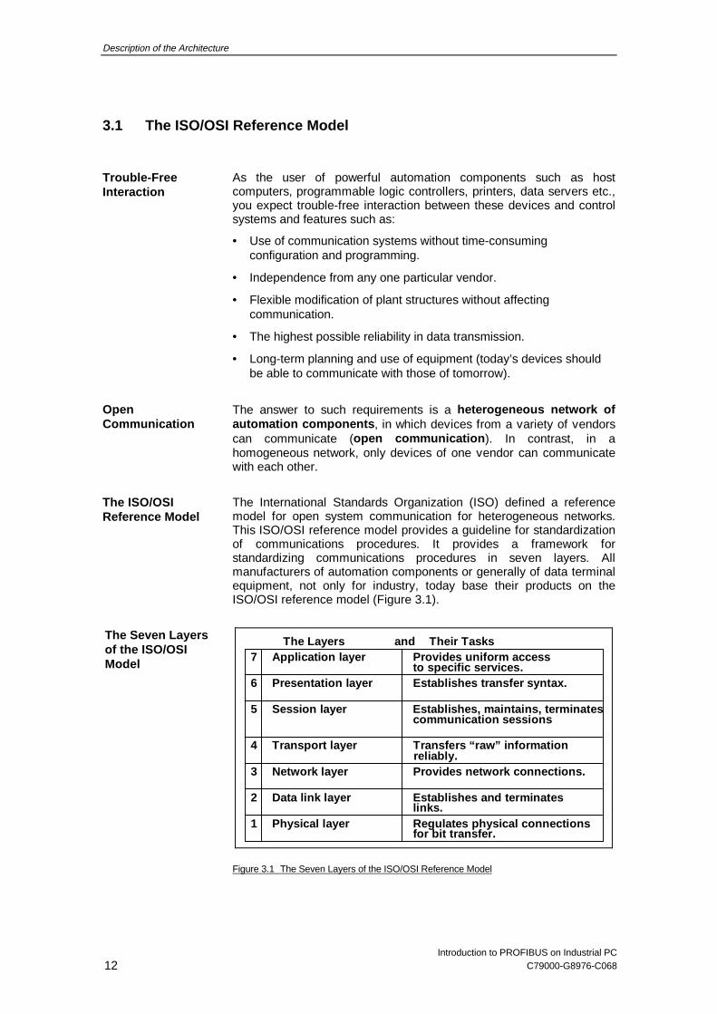
The International Standards Organization (ISO) defined a referencemodel for open system communication for heterogeneous networks.This ISO/OSI reference model provides a guideline for standardizationof communications procedures. It provides a framework forstandardizing communications procedures in seven layers. Allmanufacturers of automation components or generally of data terminalequipment, not only for industry, today base their products on theISO/OSI reference model (Figure 3.1).
The Layers and Their Tasks7 Application layer Provides uniform access
to specific services.6 Presentation layer Establishes transfer syntax.
5 Session layer Establishes, maintains, terminates
4 Transport layer Transfers “raw” information
3 Network layer Provides network connections.
2 Data link layer Establishes and terminates
1 Physical layer Regulates physical c onnections
communication sessions
links.
for bit transfer.
reliably.
Figure 3.1 The Seven Layers of the ISO/OSI Reference Model
Trouble-FreeInteraction
OpenCommunication
The ISO/OSIReference Model
The Seven Layersof the ISO/OSIModel
Description of the Architecture
Introduction to PROFIBUS on Industrial PCC79000-G8976-C068 13
3.2 SIMATIC NET Communications Networks
SIMATIC NET is an open, heterogeneous communications system witha variety of local area networks (LANs) providing various ranges ofperformance for manufacturing and process automation in industry. Itis based on national and international standards according to theISO/OSI reference model.
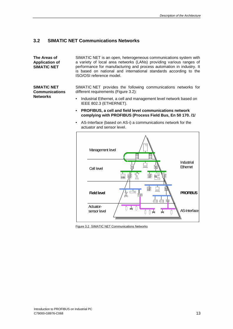
SIMATIC NET provides the following communications networks fordifferent requirements (Figure 3.2):
• Industrial Ethernet, a cell and management level network based onIEEE 802.3 (ETHERNET).
• PROFIBUS, a cell and field level communications networkcomplying with PROFIBUS (Process Field Bus, En 50 170. /1/
• AS-Interface (based on AS-i) a communications network for theactuator and sensor level.
Management level
Cell level
Field level
IndustrialEthernet
PROFIBUS
AS-InterfaceActuator-sensor level
Figure 3.2 SIMATIC NET Communications Networks
The Areas ofApplication ofSIMATIC NET
SIMATIC NETCommunicationsNetworks
Description of the Architecture
Introduction to PROFIBUS on Industrial PC14 C79000-G8976-C068
3.3 PROFIBUS
PROFIBUS is
• the network for the cell and field area of the medium performancerange within the open, heterogeneous SIMATIC NETcommunications system intended primarily for an industrialenvironment.
• a powerful communications system for low-cost applications. Itprovides all the known advantages of a bus system and meets allthe requirements for flexible, cost-effective networking ofprogrammable logic controllers and computers in an industrialenvironment.
Known under the name PROFIBUS, PROFIBUS is based on thestandard specified in EN 50 170 and is based on the ISO/OSIreference model. By meeting the requirements of EN 50 170,PROFIBUS provides the “openness” required for attaching componentsfrom other vendors that comply with the standard.
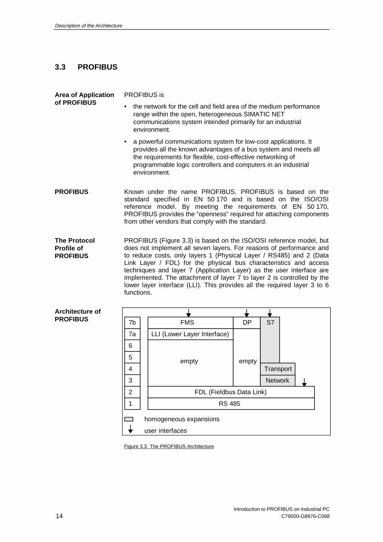
PROFIBUS (Figure 3.3) is based on the ISO/OSI reference model, butdoes not implement all seven layers. For reasons of performance andto reduce costs, only layers 1 (Physical Layer / RS485) and 2 (DataLink Layer / FDL) for the physical bus characteristics and accesstechniques and layer 7 (Application Layer) as the user interface areimplemented. The attachment of layer 7 to layer 2 is controlled by thelower layer interface (LLI). This provides all the required layer 3 to 6functions.
7b
7a
6
5
4
3
2
1
empty
FDL (Fieldbus Data Link)
RS 485
LLI (Lower Layer Interface)
FMS
empty
DP
Transport
S7
homogeneous expansions
Network
user interfaces
Figure 3.3 The PROFIBUS Architecture
Area of Applicationof PROFIBUS
PROFIBUS
The ProtocolProfile ofPROFIBUS
Architecture ofPROFIBUS
Description of the Architecture
Introduction to PROFIBUS on Industrial PCC79000-G8976-C068 15
3.4 Network Architecture
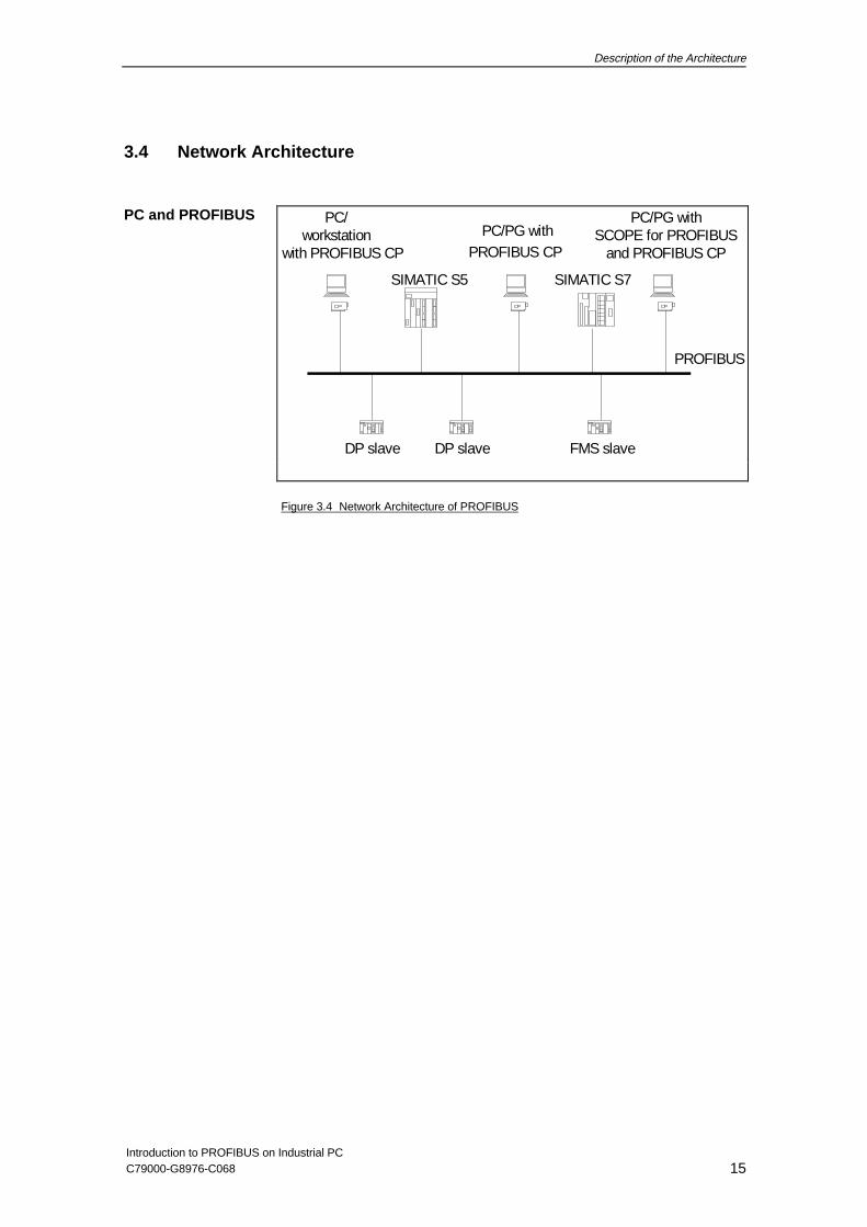
PC/workstation PC/PG with
SIMATIC S5 SIMATIC S7
SCOPE for PROFIBUSPC/PG with
DP slave DP slave FMS slave
with PROFIBUS CP PROFIBUS CP and PROFIBUS CP
PROFIBUS
Figure 3.4 Network Architecture of PROFIBUS
PC and PROFIBUS
Description of the Architecture
Introduction to PROFIBUS on Industrial PC16 C79000-G8976-C068
3.5 Overview of the Protocols
3.5.1 The PG Protocol
The PG protocol is used to operate the STEP 5 or STEP 7 SIMATICsoftware packages with SIMATIC NET communications processor.
This protocol allows access by STEP 5 or STEP 7 programs toSIMATIC programmable logic controllers via PROFIBUS.
The PG protocol is not yet available for the UNIX operating system.
Area of Applicationof the PG Protocol
Description of the Architecture
Introduction to PROFIBUS on Industrial PCC79000-G8976-C068 17
3.5.2 FMS Programming Interface
The Siemens implementation of the FMS programming interface isknown as SAPI-FMS.
The acronym SAPI-FMS stands for:
• SAPI - Simple Application Programmers Interface
• FMS - Fieldbus Message Specification - the layer 7 communicationsprotocol of PROFIBUS.
SAPI-FMS
• represents a simple C programming interface,
• provides access to the FMS services on PCs and PGs and
• is available as a C library and is operated with SIMATIC NET driversand SIMATIC NET communications processors.
The SAPI-FMS programming interface has the following advantages:
• SAPI-FMS is a simple but flexible and powerful interface.
• The SAPI-FMS programming interface uses asynchronousprocedures.
• SAPI-FMS handles sequential services such as the transfer of acommunication relationship list automatically.
• SAPI-FMS converts variable data automatically into the format ofthe local CPU.
• SAPI-FMS supports troubleshooting with an integrated tracefunction.
• The SAPI-FMS programming interface is compatible with otherSAPI programming interfaces.
• The SAPI-FMS programming interface can also be used by otherprograms, for example BASIC or Pascal programs.
SAPI-FMS
What Does SAPI-FMS Mean?
What Is SAPI-FMS?
Advantages of theSAPI-FMSProgrammingInterface
Description of the Architecture
Introduction to PROFIBUS on Industrial PC18 C79000-G8976-C068
3.5.3 The DP Protocol
The distributed peripheral I/Os (abbreviated to DP) allow you to use alarge number of distributed analog and digital input/output modules inthe immediate vicinity of the process.
Networking DP components using PROFIBUS means a considerablereduction in cabling compared with previous direct wiring of thecomponents.
Large distances between the individual I/O devices can be bridged byPROFIBUS (PROFIBUS). Distributed I/O stations collect the inputsignals locally and these are then fetched by the central controller inthe computer. The central controller also sends output data to thedistributed I/O stations cyclically.
The DP protocol is intended for time-critical applications. An optimizedand simplified transmission protocol means high transmission ratesand the use of a master-slave structure results in short cycle times.
The DP protocol is based on the communications standard for the fieldarea (PROFIBUS EN 50 170) EN 50 170. The concept of DPcommunication was worked out in a common project undertaken byleading manufacturers of automation equipment. It describes aheterogeneous transmission protocol tailor-made for the requirementsof the field area.
The main characteristics of the distributed peripheral I/O system are asfollows:
• Central control by one master.
• High data throughput thanks to a simple transmission protocol.
• Cyclic transmission of the process image in the input and outputdirection.
• Simple, cost-effective network attachment.
• Data transmission with the option of twisted-pair (RS 485) or fiber-optic cables.
• Detection of errors with on-line diagnostics.
• Based on EN 50 170, allowing parallel operation with FMS devices(masters and slaves) on one bus.
Distributed I/Os
MainCharacteristics
Description of the Architecture
Introduction to PROFIBUS on Industrial PCC79000-G8976-C068 19
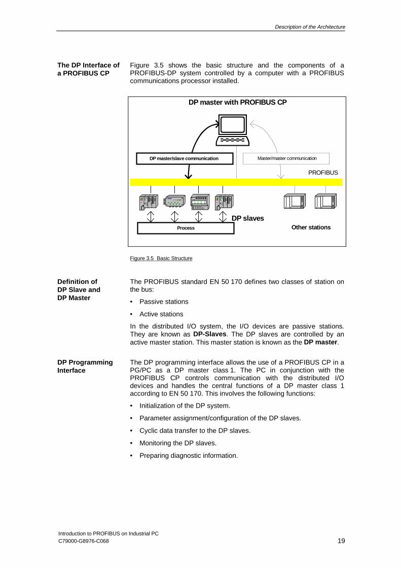
Figure 3.5 shows the basic structure and the components of aPROFIBUS-DP system controlled by a computer with a PROFIBUScommunications processor installed.
�
DP slavesOther stations
DP master with PROFIBUS CP
PROFIBUS
DP master/slave communication Master/master communication
Process
Figure 3.5 Basic Structure
The PROFIBUS standard EN 50 170 defines two classes of station onthe bus:
• Passive stations
• Active stations
In the distributed I/O system, the I/O devices are passive stations.They are known as DP-Slaves . The DP slaves are controlled by anactive master station. This master station is known as the DP master .
The DP programming interface allows the use of a PROFIBUS CP in aPG/PC as a DP master class 1. The PC in conjunction with thePROFIBUS CP controls communication with the distributed I/Odevices and handles the central functions of a DP master class 1according to EN 50 170. This involves the following functions:
• Initialization of the DP system.
• Parameter assignment/configuration of the DP slaves.
• Cyclic data transfer to the DP slaves.
• Monitoring the DP slaves.
• Preparing diagnostic information.
The DP Interface ofa PROFIBUS CP
Definition ofDP Slave andDP Master
DP ProgrammingInterface
Description of the Architecture
Introduction to PROFIBUS on Industrial PC20 C79000-G8976-C068
3.5.4 S7 Programming Interface
SAPI-S7 is the C programming interface for access to the S7communications protocol on PGs/PCs.
The acronym SAPI-FMS stands for:
• SAPI - Simple Application Programmers Interface
• S7 layer 7 communications protocol for SIMATIC S7 systems.
SAPI-S7
• Represents a simple C programming interface,
• Provides access to the S7 services on PCs and PGs and
• Is available as a C library and is operated with SIMATIC NETdrivers and SIMATIC NET communications processors.
The SAPI-S7 programming interface has the following advantages:
• SAPI-S7 is a simple but flexible and powerful interface.
• The SAPI-S7 programming interface uses asynchronousprocedures.
• SAPI-S7 handles sequential services such as the active andpassive establishment of an S7 connection.
• SAPI-S7 supports troubleshooting with an integrated trace function.
• The SAPI-S7 programming interface is compatible with other SAPIprogramming interfaces.
• The SAPI-S7 programming interface can also be used by otherprograms, for example BASIC or Pascal programs.
SAPI-S7
What Does SAPI-S7Mean?
What Is SAPI-S7?
Advantages of theSAPI-S7ProgrammingInterface
Description of the Architecture
Introduction to PROFIBUS on Industrial PCC79000-G8976-C068 21
3.5.5 The FDL Protocol
The FDL protocol is used for communication with PROFIBUScomponents complying with PROFIBUS EN 50 170. The CP can beoperated as a master.
A distinction is made between management services and productiveservices. With the management services you can make the localsettings required by the productive services. The productive servicesallow data transfer between the various PROFIBUS stations. A list ofthe services available can be found in the volume “FDL ProgrammingInterface”.
An application is created in the C/C++ programming language. TheFDL application can be written for MS DOS, for MS Windows 3.x, forMS Windows 95, for MS Windows NT or for UNIX.
Area of Applicationof theFDL Protocol
Services of theFDL Protocol
Creating anApplication
Description of the Architecture
Introduction to PROFIBUS on Industrial PC22 C79000-G8976-C068
3.6 The Multiprotocol Mode
With multiprotocol mode you can process more than one protocol atthe same time (for example DP and FMS). This applies both to the useof more than one protocol within an application as well as the paralleloperation of more than one application with different protocols.
Support of multiprotocol mode may be restricted when using specialcommunications processors and operating systems. You find furtherinformation in the product information.
What doesMultiprotocol ModeMean?
Support ofMultiprotocol Mode
Description of the Architecture
Introduction to PROFIBUS on Industrial PCC79000-G8976-C068 23
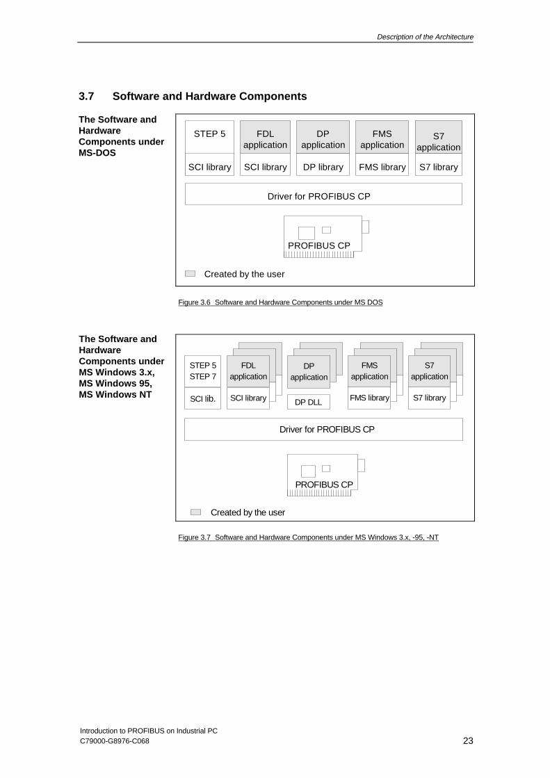
3.7 Software and Hardware Components
Driver for PROFIBUS CP
FMSapplication
FMS library
PROFIBUS CP
STEP 5
SCI library SCI library
FDLapplication
DPapplication
DP library
Created by the user
S7application
S7 library
Figure 3.6 Software and Hardware Components under MS DOS
Driver for PROFIBUS CP
PROFIBUS CP
DP DLL
DPapplication
SCI library
FDLapplication
SCI lib.
STEP 5STEP 7
Created by the user
S7 library
S7application
FMS library
FMSapplication
Figure 3.7 Software and Hardware Components under MS Windows 3.x, -95, -NT
The Software andHardwareComponents underMS-DOS
The Software andHardwareComponents underMS Windows 3.x,MS Windows 95,MS Windows NT
Description of the Architecture
Introduction to PROFIBUS on Industrial PC24 C79000-G8976-C068
Driver for PROFIBUS CP
PROFIBUS CP
FDL library
FDLapplication
Created by the user
S7 library
S7application
FMS library
FMSapplication
DP library
DPapplication
SCP library
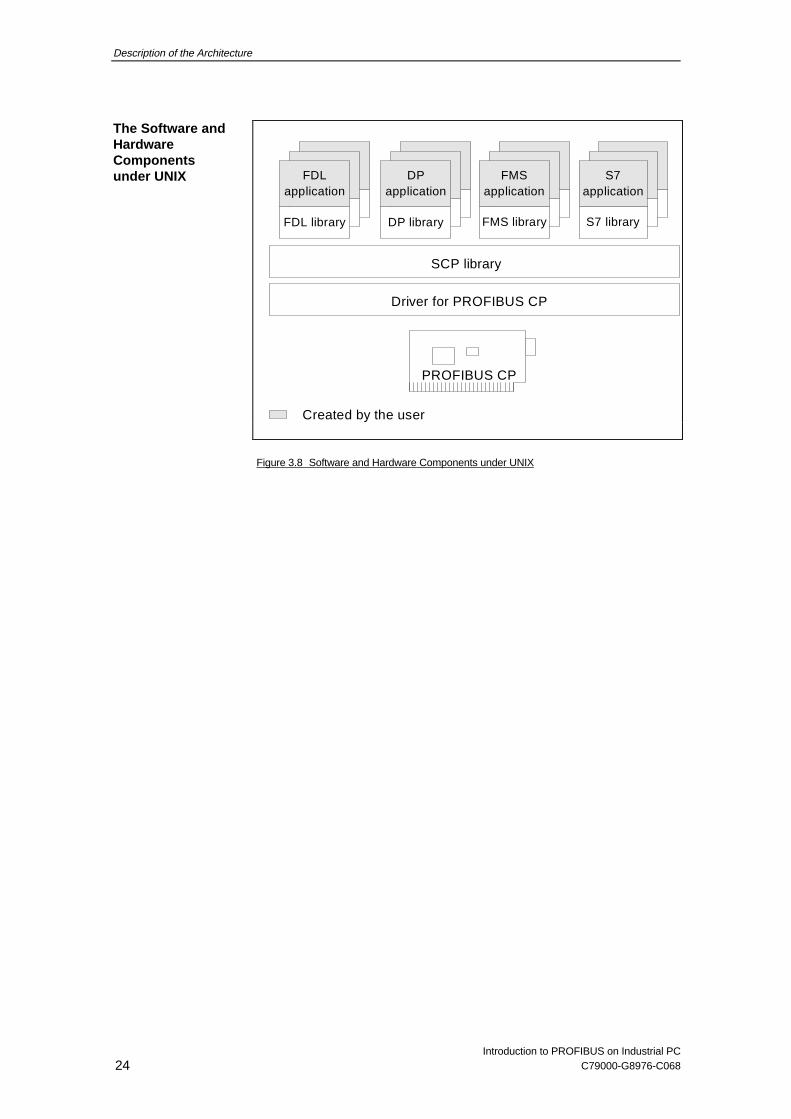
Figure 3.8 Software and Hardware Components under UNIX
The Software andHardwareComponentsunder UNIX
Description of the Architecture
Introduction to PROFIBUS on Industrial PCC79000-G8976-C068 25
3.8 Communications Options
communication is possible using the following:
• the STEP 5 package
• FMS applications
• FDL applications
• DP applications
communication is possible using the following:
• STEP 7 package
• FMS applications
• S7 applications
• FDL applications
• DP applications
communication is possible using the following:
• FMS applications
• FDL applications
communication is possible using the following:
• FMS applications
• FDL applications
• DP applications
communication is possible using the following:
• DP applications
The SCOPE for PROFIBUS records all the frames and can be used todebug and troubleshoot when programming and installing systems. ❏
with SIMATIC S5
with SIMATIC S7
with otherPGs/PCs orworkstations
with otherprogrammablelogic controllers
with DP slaves
SCOPE forPROFIBUSDiagnostic Tool

Description of the Architecture
Introduction to PROFIBUS on Industrial PC26 C79000-G8976-C068
NOTES
Where to Obtain Help
Introduction to PROFIBUS on Industrial PCC79000-G8976-C068 27
4 Where to Obtain Help
4.1 Help with Technical Questions
Documentation You will find information about topics related to using this software inthe following sources:
• In the relevant printed documentation
• In the help system integrated in the software (F1 key)
• In text files on the SIMATIC NET CD
Who to Contact If you have technical questions about using the software and yourproblem is not dealt with in the documentation or in the integrated helpsystem, please contact your Siemens representative or dealer.
The addresses are listed in the following:
• in our Catalog IK 10
• on the Internet (http://www.ad.siemens.de/net)
CommonQuestions
Our customer support on the Internet provides useful information andanswers to common questions. Under FAQ (Frequently AskedQuestions), you will find a variety of information about our entire rangeof products.
The address of the SIMATIC NET homepage in the worldwide web ofInternet is:
• http://www.ad.siemens.de/net
Hotline If you have problems, you can also contact our hotline:
• Telephone: 0911 - 895 - 7000(from abroad +49 - 911 - 895 - 7000)
• Telefax: 0911 - 895 - 7002 (from abroad +49 - 911 - 895 - 7002)
• E-Mail: [email protected]
• Mailbox (BBS, analog/ISDN, 8N1):0911 - 895 - 7100(vom Ausland +49 - 911 - 895 - 7100)
Where to Obtain Help
Introduction to PROFIBUS on Industrial PC28 C79000-G8976-C068
4.2 Contacts for SIMATIC NET Training
Course Enrollment
Siemens AGTrainings-Center für AutomatisierungstechnikA&D PT41 Kursbüro
Östliche Rheinbrückenstraße 5076181 Karlsruhe
• Telephone 0721 - 595 - 2917from abroad +49 - 721 - 595 - 2917
• Fax 0721 - 595 - 6987from abroad +49 - 721 - 595 - 6987
❑

Further Reading
Introduction to PROFIBUS on Industrial PCC79000-G8976-C068 29
5 Further Reading
/1/ EN 50170, Volume 2Deutsche elektrotechnische Komission im DIN und VDE (DKE), Frankfurt
❏

Further Reading
Introduction to PROFIBUS on Industrial PC30 C79000-G8976-C068
NOTES
Glossary
Introduction to PROFIBUS on Industrial PCC79000-G8976-C068 31
Glossary
Logical address of a module in S7 systems.
Bus parameters control the data transmission on the bus. Each ->station on the -> PROFIBUS network must use bus parameters thatmatch those of other stations.
Part of a -> subnet. Subnets can consist of bus segments andconnectivity devices such as repeaters and bridges. Segments aretransparent for addressing.
Communication Function Block: A communication technique forprogram-controlled transmission of data from or to a CPU in an S7-300/400 using special function blocks. These function blocks weredefined based on the IEC 1131-5 draft. The communication partnerscan be other modules with communication capabilities in anS7-300/400, operator stations, PCs or other controllers and computers.
Communications Processor. Module for communication tasks.
Device master data (GSD) contain DP slave descriptions complyingwith EN 50 170, Volume 2. Using device master data makesconfiguration of the -> DP master and -> DP slaves easier.
Input and output modules used at a distance (distributed) from the CPU(central processing unit of the controller). The connection between theprogrammable controller and the distributed I/Os is established on ->PROFIBUS. The programmable logic controllers do not recognize anydifference between these I/Os and local process inputs and outputs.
DP slaves have a modular design. A -> DP slave has at least one DPI/O module.
The DP I/O type identifies a -> DP I/O module. The following typesexist:
Input moduleOutput moduleInput/output module
A -> station with master functions in -> PROFIBUS DP. The DP mastercontrols the exchange of user data with the -> DP slaves assigned to it.
The DP module list contains the modules belonging to a -> DP slave.You make entries in the DP module list when configuring a -> DPmaster with -> COM PROFIBUS.
Name of a -> DP I/O module entered in the ->DP module list.
Base address
Bus parameters
Bus segment
CFB
CP
Device masterdata
Distributed I/Os
DP I/O module
DP I/O type
DP master
DP module list
DP modulename
Glossary
Introduction to PROFIBUS on Industrial PC32 C79000-G8976-C068
Type identifier of a -> DP I/O module in the -> device master data of a-> DP slave complying with EN 50 170, Volume 2.
A -> station with slave functions in -> PROFIBUS DP.
The DP slave catalog contains the device descriptions of -> DP slavesrequired for configuring -> DP masters according to the -> DPstandard. The DP slave catalog is available when configuring with ->COM PROFIBUS.
A DP slave name is entered in the DP slave list to identify a -> DPslave in the DP configuration.
PROFIBUS subnet in which only -> distributed I/Os are operated.
A -> DP master and all -> DP slaves with which this DP masterexchanges data.
Software required for the data transfer between applications and the ->CP.
Enhanced mode under 3.x for personal computers with an Intel 386 orcompatible processor.
Fieldbus Data Link. Layer 2 in -> PROFIBUS.
A message from one PROFIBUS station to another.
A frame header consists of an identifier for the -> frame and the sourceand destination address.
A frame trailer consists of a checksum and the end identifier of the ->frame.
The FREEZE mode is a DP mode in which process data are acquiredat the same time and fetched from all (or a group of) DP slaves. Thetime at which the data are acquired is indicated in the FREEZEcommand (a synchronization control frame).
A free address area (gap) between two active -> stations is checkedcyclically by the station with the lower -> PROFIBUS address to findout whether or not another station is requesting to enter the logical ring.The cycle time for this check is as follows:
gap update factor x target rotation time
Intelligent connectivity device that connects different types of localarea -> networks at OSI layer 7.
DP module type
DP slave
DP slavecatalog
DP slave name
DP subnet
DP subsystem
Driver
Enhanced mode
FDL
Frame
Frame header
Frame trailer
FREEZE mode
Gap updatefactor
Gateway
Glossary
Introduction to PROFIBUS on Industrial PCC79000-G8976-C068 33
Collection of data that may be distributed within the programmablelogic controller (for example flags/memory bits or data blocks) to betransferred using the -> global data technique.
A GD group is a group of -> stations that exchange global data witheach other. A -> GD packet is sent to the stations belonging to the GDgroup.
Global data (GD) is the name of a communication technique for thecyclic exchange of limited amounts of data from STEP 7 data areasbetween CPUs of the S7-300/400. Transmitted data can be receivedby several CPUs at the same time.
Part of the I/O area of SIMATIC S5 PLCs can be used for global dataexchange between SIMATIC S5 PLCs on -> PROFIBUS. The maincharacteristic of this technique is the cyclic transmission of data thathave changed since the last cycle.
DP slaves can be assigned to one or more groups using a groupidentifier. The -> control frames can be addressed to specific groups ofDP slaves using the group identifier.
A -> bus parameter for -> PROFIBUS. This specifies the highest ->PROFIBUS address (HSA) of an active -> station on the PROFIBUSbus. PROFIBUS addresses higher than the highest station address arepossible for passive stations (possible values: HSA 1 to 126).
An active station in -> PROFIBUS that can send -> frames on its owninitiative when it is in possession of the token.
A -> bus parameter for -> PROFIBUS. The maximum station delay(max. TSDR) specifies the longest interval required by a -> station inthe -> subnet between receiving the last bit of an unacknowledged ->frame and sending the first bit of the next frame. After sending anunacknowledged frame, a sender must wait for the max. TSDR toelapse before sending a further frame.
A -> bus parameter for -> PROFIBUS. The minimum station delay(min. TSDR) specifies the minimum time that the receiver of a ->frame must wait before sending the acknowledgment or sending a newframe. The min. TSDR takes into account the longest interval requiredby a station in the subnet for receiving an acknowledgment aftersending a frame.
A network consists of one or more interconnected -> subnets with anynumber of -> stations. Several networks can exist side by side. Thereis a common -> node table for every -> subnet.
GD packet
GD group
Global data
Global I/Os
Group identifier
HighestPROFIBUSaddress
Master
Maximumstation delay
Minimumstation delay
Network
Glossary
Introduction to PROFIBUS on Industrial PC34 C79000-G8976-C068
The node table applies to all -> networks within a -> system. Eachentry in the node table describes the interface between aprogrammable logic controller (or any other station) and a -> subnet.The entries in the subnet are used by the system to locate andestablish connections between stations.
The length of the reserved area at the beginning of a data buffer of theFDL programming interface.
The process image is a special memory area in the programmablelogic controller. At the start of the cyclic program, the signal states ofthe input modules are transferred to the process image of the inputs. Atthe end of the cyclic program, the process image of the outputs istransferred to the output modules.
SIMATIC NET bus system for industrial applications based onPROFIBUS.
A fieldbus complying with EN 50 170.
The PROFIBUS address is a unique identifier for a -> stationconnected to -> PROFIBUS (PROFIBUS). The PROFIBUS address istransferred in the -> frame to address a -> station.
PROFIBUS distributed I/Os. Transmission services complying withPROFIBUS EN 50 170.
A -> station with master functions in -> PROFIBUS DP.
PROFIBUS Fieldbus Message Specification. Upper sublayer of layer 7of the ISO/OSI reference model for PROFIBUS.
PROFIBUS PA is a recommendation of the PROFIBUS users'organization extending PROFIBUS EN 50 170 to include aspects ofintrinsic safety.
A set of rules governing data transmission. Using these rules, both theformats of the messages and the data flow during transmission can bespecified.
All the -> masters on -> PROFIBUS form a logical token ring. Withinthis token ring, the token is passed on from station to station. If thetransmission of the token is incorrect or if a master is removed fromthe ring, this leads to an error when the token is passed on (the token isnot accepted by this station) and the station is excluded from the ring.
Node table
Offset
Process image
PROFIBUS
PROFIBUSaddress
PROFIBUS DP
PROFIBUS DPmaster
PROFIBUS FMS
PROFIBUS PA
Protocol
Reorganizationtoken ring
Glossary
Introduction to PROFIBUS on Industrial PCC79000-G8976-C068 35
Diagnostic software for -> PROFIBUS with which the traffic on the ->network can be recorded and analyzed.
Synonym for -> bus segment.
Services provided by a communication protocol.
A -> bus parameter for -> PROFIBUS. The setup time specifies theminimum interval on the sender between receiving an acknowledgmentand sending a new call frame.
Siemens Network and Communication. Product name for -> Siemensnetworks and network components.
A bus parameter for -> PROFIBUS. The slot time (TSL) is the timeduring which the sender of a -> frame waits for the acknowledgmentfrom the receiver before detecting a timeout.
A station is identified by an -> PROFIBUS address in the ->PROFIBUS network.
A subnet is part of a -> network whose -> bus parameters (for example-> PROFIBUS addresses) must be matched. It includes the buscomponents and all attached stations. Subnets can, for example, beconnected together by -> gateways to form a network.
A -> system consists of several subnets with unique -> subnetnumbers. A subnet consists of several ->stations with unique ->PROFIBUS addresses.
A -> system consists of several -> subnets with unique subnetnumbers.
The SYNC mode is a DP mode in which several or all -> DP slavestransfer data to their process outputs at a certain time. The time atwhich the data is transferred is indicated in the SYNC command (acontrol command for synchronization).
All the electrical equipment within a system. A system includes, amongother things, programmable logic controllers, devices for operation andmonitoring, bus systems, field devices, actuators, supply lines.
A -> bus parameter for -> PROFIBUS. The token represents the rightto transmit for a -> station on PROFIBUS. A station compares theactual token rotation time it has measured with the target rotation timeand depending on the result can then send high or low priority frames.
SCOPE forPROFIBUS
Segment
Services
Setup time
SIMATIC NET
Slot time
Station
Subnet
Subnet number
SYNC mode
System
Target rotationtime

Glossary
Introduction to PROFIBUS on Industrial PC36 C79000-G8976-C068
Transmission rate on the bus (unit in bits per second). A -> busparameter for -> PROFIBUS. The set or selected transmission ratedepends on various conditions, for example distance across thenetwork.
A monitoring time that can be set for a -> DP slave so that it detectsthe failure of the -> DP master to which it is assigned.
❑
Transmissionrate
Watchdog (time)


![,QKDOWVYHU]HLFKQLVftp.beckhoff.com/.../Document/ipc/industrial-pc/c2012de.pdfJeder Industrie-PC C2012 verfügt über ein 1,44 MB, 3½ Zoll Diskettenlauf werk, das als Laufwerk A eingetragen](https://static.fdokument.com/doc/165x107/6129efbc74990009be5689ee/qkdowvyhu-jeder-industrie-pc-c2012-verfgt-ber-ein-144-mb-3-zoll-diskettenlauf.jpg)