
TECHNICAL CATALOG TECHNISCHER KATALOG Pages... · 2020. 12. 10. · • Rauheitsmessung •...
65
TECHNICAL CATALOG TECHNISCHER KATALOG
Transcript of TECHNICAL CATALOG TECHNISCHER KATALOG Pages... · 2020. 12. 10. · • Rauheitsmessung •...

TECHNICAL CATALOGTECHNISCHER KATALOG
Specifications and Dimensions for Tubes, Fittings, Connections, Clamps and Gaskets.
Spezifikationen und Abmessungen für Rohre, Formteile, Verbindungen, Klammern und Dichtungen.
www.dockweiler.com 03/2020 03/2020
2
www.dockweiler.com
3
PAGESEITE
DESCRIPTIONBESCHREIBUNG
5 Specifications Spezifikationen
21 TubesRohre
27 ElbowsBögen
35 T-PiecesT-Stücke
47 ReducersReduzierungen
57 EndcapsEndkappen
59 Dockweiler CapDockweiler Cap
61 Clamp connections for tubes according to DIN 32676 and ASME BPEKlemmverbindungen für Rohre gemäß DIN 32676 und ASME BPE
CONTENTINHALT
PAGESEITE
DESCRIPTIONBESCHREIBUNG
66 GasketsDichtungen
68 ClampsKlammern
69 Steril connections for tubes according to DIN 11864Sterilverbindungen für Rohre gemäß DIN 11864
83 O-Rings O-Ringe
85 ZeroConZeroCon
89
l3
l4l1
l2
d1s1d2 s2
d3s3
d4s4
COAX COAX
99 Technical HosesTechnische Schläuche
103
125
General Information | Allgemeine Informationen
Dockweiler Companies worldwide and international Sales PartnerDockweiler weltweit und internationale Vertriebspartner
www.dockweiler.com 03/2020 03/2020
4
www.dockweiler.com
5
SPECIFICATIONSSPEZIFIKATIONEN
www.dockweiler.com 03/2020 03/2020
6
www.dockweiler.com
7
SPECIFICATION SPEZIFIKATION
APPLICATIONS
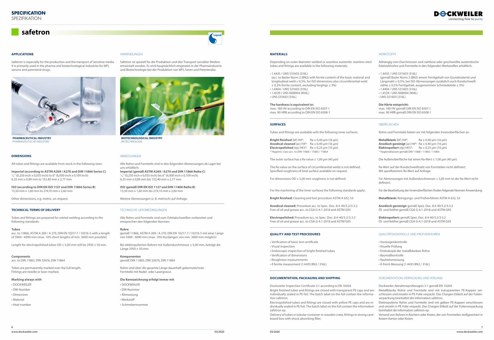
Safetron is especially for the production and the transport of sensitive media. It is primarily used in the pharma and biotechnological industries for WFI, serums and parenteral drugs.
SURFACES
Tubes and fittings are available with the following inner surfaces:
Bright finished (bf) H4*: Ra ≤ 0,40 µm (16 µin)Anodical cleaned (ac) H4*: Ra ≤ 0,40 µm (16 µin)Electropolished (ep) HE5*: Ra ≤ 0,25 µm (10 µin)* Hygienic class acc. to DIN 11866 / 11865 / 11864
The outer surface has a Ra value ≤ 1,00 µm (40 µin)
The Ra value on the surface of circumferential welds is not defined. Specified roughness of total surface available on request.
For dimensions OD ≤ 5,00 mm roughness is not defined.
For the machining of the inner surfaces the following standards apply:
Bright finished: Cleaning and test procedure ASTM A 632, S3
Anodical cleaned: Procedure acc. to Spec. Doc. 8.4-40/3.2/3.3.2Free of oil and grease acc. to CGA G-4.1-2018 and ASTM G93
Electropolished: Procedure acc. to Spec. Doc. 8.4-40/3.2/3.3.2Free of oil and grease acc. to CGA G-4.1-2018 and ASTM G93
OBERFLÄCHEN
Rohre und Formteile bieten wir mit folgenden Innenoberflächen an:
Metallblank (bf ) H4*: Ra ≤ 0,40 µm (16 µin)Anodisch gereinigt (ac) H4*: Ra ≤ 0,40 µm (16 µin)Elektropoliert (ep) HE5*: Ra ≤ 0,25 µm (10 µin)* Hygieneklassen gemäß DIN 11866 / 11865 / 11864
Die Außenoberfläche hat einen Ra-Wert ≤ 1,00 µm (40 µin)
Ra-Wert auf der Rundschweißnaht von Formteilen nicht definiert. Mit spezifiziertem Ra-Wert auf Anfrage.
Für Abmessungen mit Außendurchmesser ≤ 5,00 mm ist der Ra-Wert nicht definiert.
Für die Bearbeitung der Innenoberflächen finden folgende Normen Anwendung:
Metallblank: Reinigungs- und Prüfverfahren ASTM A 632, S3
Anodisch gereinigt: gemäß Spez. Doc. 8.4-40/3.2/3.3.2Öl- und fettfrei gemäß CGA G-4.1-2018 und ASTM G93
Elektropoliert: gemäß Spez. Doc. 8.4-40/3.2/3.3.2Öl- und fettfrei gemäß CGA G-4.1-2018 und ASTM G93
QUALITY AND TEST PROCEDURES
• Verification of basic test certificate • Visual inspection• Endoscopic inspection of bright finished tubes• Verification of dimensions• Roughness measurements• δ ferrite measurment (1.4435 BN2 / 316L)
QUALITÄTSKONTROLLE UND PRÜFVERFAHREN
• Vorzeugniskontrolle • Visuelle Prüfung• Endoskopie der metallblanken Rohre• Baumaßkontrolle• Rauheitsmessung• δ-Ferrit-Messung (1.4435 BN2 / 316L)
DOCUMENTATION, PACKAGING AND SHIPPING
Dockweiler Inspection Certificate 3.1 according to EN 10204. Bright finished tubes and fittings are closed with transparent PE caps and are individually sealed in PE foil. The batch label on the foil contain the informa-tion safetron.Electropolished tubes and fittings are closed with yellow PE caps and are in-dividually sealed in PE foil. The batch label on the foil contain the information safetron ep.Delivery of tubes in tubular container or wooden crate, fittings in strong card-board box with shock absorbing filler.
DOKUMENTATION, VERPACKUNG UND VERSAND
Dockweiler Abnahmeprüfzeugnis 3.1 gemäß EN 10204. Metallblanke Rohre und Formteile sind mit transparenten PE-Kappen ver-schlossen und einzeln in PE-Folie verpackt. Das Chargen-Etikett auf der Folien-verpackung beinhaltet die Information safetron.Elektropolierte Rohre und Formteile sind mit gelben PE-Kappen verschlossen und einzeln in PE-Folie verpackt. Das Chargen-Etikett auf der Folienverpackung beinhaltet die Information safetron ep.Versand von Rohren in Köchern oder Kisten, der von Formteilen stoßgesichert in festem Karton oder Kisten.
MATERIALS
Depending on outer diameter welded or seamless austenitic stainless steel tubes and fittings are available in the following materials:
• 1.4435 / UNS S31603 (316L) (acc. to Basler Norm 2 (BN2) with ferrite content of the basic material and longitudinal weld ≤ 0,5%, for ISO dimensions also circumferential weld ≤ 0,5% ferrite content, excluding forgings ≤ 3%)
• 1.4404 / UNS S31603 (316L) • 1.4539 / UNS N08904 (904L)• UNS S31603 (316L)
The hardness is equivalent to:max. 180 HV according to DIN EN ISO 6507-1max. 90 HRB according to DIN EN ISO 6508-1
WERKSTOFFE
Abhängig vom Durchmesser sind nahtlose oder geschweißte austenitische Edelstahlrohre und Formteile in den folgenden Werkstoffen erhältlich:
• 1.4435 / UNS S31603 (316L) (gemäß Basler Norm 2 (BN2) einem Ferritgehalt von Grundmaterial und Längsnaht ≤ 0,5%, bei ISO-Abmessungen zusätzlich auch Rundschweiß- nähte ≤ 0,5% Ferritgehalt, ausgenommen Schmiedeteile ≤ 3%)
• 1.4404 / UNS S31603 (316L) • 1.4539 / UNS N08904 (904L)• UNS S31603 (316L)
Die Härte entspricht:max. 180 HV gemäß DIN EN ISO 6507-1max. 90 HRB gemäß DIN EN ISO 6508-1
ANWENDUNGEN
Safetron ist speziell für die Produktion und den Transport sensibler Medien entwickelt worden. Es wird hauptsächlich eingesetzt in der Pharmaindustrie und Biotechnologie bei der Produktion von WFI, Seren und Parenteralia.
TECHNICAL TERMS OF DELIVERY
Tubes and fittings are prepared for orbital welding according to the following standards:
Tubes acc. to 11866, ASTM A 269 / A 270, DIN EN 10217-7 / 10216-5 with a length of 5900 - 6090 mm (max. 10% short lengths of min. 3000 mm possible)
Length for electropolished tubes OD ≤ 5,00 mm will be 2950 ± 50 mm.
Components acc. to DIN 11865, DIN 32676, DIN 11864
Tubes are permanently marked over the full length. Fittings are needle or laser marked.
Marking always with
• DOCKWEILER
• DW-Number
• Dimension
• Material
• Heat number
DIMENSIONS
All tubes and fittings are available from stock in the following sizes:
Imperial (according to ASTM A269 / A270 and DIN 11866 Series C)1/4" (0,250 inch x 0,035 inch) to 6" (6,000 inch x 0,109 inch) 6,35 mm x 0,89 mm to 152,40 mm x 2,77 mm
ISO (according to DIN EN ISO 1127 and DIN 11866 Series B)13,50 mm x 1,60 mm to 219,10 mm x 2,60 mm
Other dimensions, e.g. metric, on request.
ABMESSUNGEN
Alle Rohre und Formteile sind in den folgenden Abmessungen ab Lager bei uns erhältlich:Imperial (gemäß ASTM A269 / A270 und DIN 11866 Reihe C)1/4" (0,250 inch x 0,035 inch) bis 6" (6,000 inch x 0,109 inch) 6,35 mm x 0,89 mm bis 152,40 mm x 2,77 mm
ISO (gemäß DIN EN ISO 1127 und DIN 11866 Reihe B)13,50 mm x 1,60 mm bis 219,10 mm x 2,60 mm
Weitere Abmessungen (z. B. metrisch) auf Anfrage.
TECHNISCHE LIEFERBEDINGUNGEN
Alle Rohre und Formteile sind zum Orbitalschweißen vorbereitet und entsprechen den folgenden Normen:
Rohre gemäß 11866, ASTM A 269 / A 270, DIN EN 10217-7 / 10216-5 mit einer Länge von 5900 - 6090 mm (max. 10% Kurzlängen von min. 3000 mm möglich)
Bei elektropolierten Rohren mit Außendurchmesser ≤ 5,00 mm, beträgt die Länge 2950 ± 50 mm.
Komponenten gemäß DIN 11865, DIN 32676, DIN 11864
Rohre sind über die gesamte Länge dauerhaft gekennzeichnet. Formteile mit Nadel- oder Lasergravur.
Die Kennzeichnung erfolgt immer mit
• DOCKWEILER
• DW-Nummer
• Abmessung
• Werkstoff
• Schmelzennummer
safetron
PHARMACEUTICAL INDUSTRY PHARMAZEUTISCHE INDUSTRIE
BIOTECHNOLOGICAL INDUSTRYBIOTECHNOLOGIE
Liquid
www.dockweiler.com 03/2020 03/2020
8
www.dockweiler.com
9
SPECIFICATION SPEZIFIKATION
APPLICATIONS
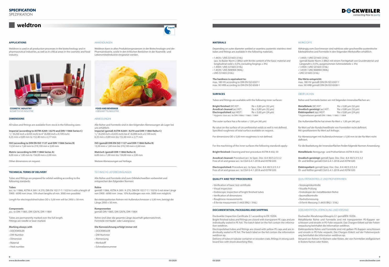
Weldtron is used in all production processes in the biotechnology and in pharmaceutical industries, as well as in critical areas in the cosmetic and food industry.
SURFACES
Tubes and fittings are available with the following inner surfaces:
Bright finished (bf) H3*: Ra ≤ 0,80 µm (32 µin)Anodical cleaned (ac) H3*: Ra ≤ 0,80 µm (32 µin)Electropolished (ep) HE3*: Ra ≤ 0,60 µm (24 µin)* Hygienic class acc. to DIN 11866 / 11865 / 11864
The outer surface has a Ra value ≤ 1,00 µm (40 µin)
Ra value on the surface of circumferential welds as well is not defined. Specified roughness of total surface available on request.
For dimensions OD ≤ 5,00 mm roughness is not defined.
For the machining of the inner surfaces the following standards apply:
Bright finished: Cleaning and test procedure ASTM A 632, S3
Anodical cleaned: Procedure acc. to Spec. Doc. 8.4-40/3.2/3.3.2Free of oil and grease acc. to CGA G-4.1-2018 and ASTM G93
Electropolished: Procedure acc. to Spec. Doc. 8.4-40/3.2/3.3.2Free of oil and grease acc. to CGA G-4.1-2018 and ASTM G93
OBERFLÄCHEN
Rohre und Formteile bieten wir mit folgenden Innenoberflächen an:
Metallblank (bf ) H3*: Ra ≤ 0,80 µm (32 µin)Anodisch gereinigt (ac) H3*: Ra ≤ 0,80 µm (32 µin)Elektropoliert (ep) HE3*: Ra ≤ 0,60 µm (24 µin)* Hygieneklassen gemäß DIN 11866 / 11865 / 11864
Die Außenoberfläche hat einen Ra-Wert ≤ 1,00 µm (40 µin)
Ra-Wert auf der Rundschweißnaht von Formteilen nicht definiert. Mit spezifiziertem Ra-Wert auf Anfrage.
Für Abmessungen mit Außendurchmesser ≤ 5,00 mm ist der Ra-Wert nicht definiert.
Für die Bearbeitung der Innenoberflächen finden folgende Normen Anwendung:
Metallblank: Reinigungs- und Prüfverfahren ASTM A 632, S3
Anodisch gereinigt: gemäß Spez. Doc. Doc. 8.4-40/3.2/3.3.2Öl- und fettfrei gemäß CGA G-4.1-2018 und ASTM G93
Elektropoliert: gemäß Spez. Doc. Doc. 8.4-40/3.2/3.3.2Öl- und fettfrei gemäß CGA G-4.1-2018 und ASTM G93
QUALITY AND TEST PROCEDURES
• Verification of basic test certificate • Visual inspection• Endoscopic inspection of bright finished tubes• Verification of dimensions• Roughness measurements• δ ferrite measurment (1.4435 BN2 / 316L)
QUALITÄTSKONTROLLE UND PRÜFVERFAHREN
• Vorzeugniskontrolle • Visuelle Prüfung• Endoskopie der metallblanken Rohre• Baumaßkontrolle• Rauheitsmessung• δ-Ferrit-Messung (1.4435 BN2 / 316L)
DOCUMENTATION, PACKAGING AND SHIPPING
Dockweiler Inspection Certificate 3.1 according to EN 10204. Bright finished tubes and fittings are closed with transparent PE caps and are individually sealed in PE foil. The batch label on the foil contain the informa-tion weldtron.Electropolished tubes and fittings are closed with yellow PE caps and are in-dividually sealed in PE foil. The batch label on the foil contain the information weldtron ep. Delivery of tubes in tubular container or wooden crate, fittings in strong card-board box with shock absorbing filler.
DOKUMENTATION, VERPACKUNG UND VERSAND
Dockweiler Abnahmeprüfzeugnis 3.1 gemäßEN 10204. Metallblanke Rohre und Formteile sind mit transparenten PE-Kappen ver-schlossen und einzeln in PE-Folie verpackt. Das Chargen-Etikett auf der Folien-verpackung beinhaltet die Information weldtron.Elektropolierte Rohre und Formteile sind mit gelben PE-Kappen verschlossen und einzeln in PE-Folie verpackt. Das Chargen-Etikett auf der Folienverpack-ung beinhaltet die Information weldtron ep.Versand von Rohren in Köchern oder Kisten, der von Formteilen stoßgesichert in festem Karton oder Kisten.
MATERIALS
Depending on outer diameter welded or seamless austenitic stainless steel tubes and fittings are available in the following materials:
• 1.4435 / UNS S31603 (316L) (acc. to Basler Norm 2 (BN2) with ferrite content of the basic material and longitudinal weld ≤ 0,5%, excluding forgings ≤ 3%)
• 1.4404 / UNS S31603 (316L) • 1.4539 / UNS N08904 (904L) • UNS S31603 (316L)
The hardness is equivalent to:max. 180 HV according to DIN EN ISO 6507-1max. 90 HRB according to DIN EN ISO 6508-1
WERKSTOFFE
Abhängig vom Durchmesser sind nahtlose oder geschweißte austenitische Edelstahlrohre und Formteile in den folgenden Werkstoffen erhältlich:
• 1.4435 / UNS S31603 (316L) (gemäß Basler Norm 2 (BN2) mit einem Ferritgehalt von Grundmaterial und Längsnaht ≤ 0,5%, ausgenommen Schmiedeteile ≤ 3%)
• 1.4404 / UNS S31603 (316L) • 1.4539 / UNS N08904 (904L)• UNS S31603 (316L)
Die Härte entspricht:max. 180 HV gemäß DIN EN ISO 6507-1max. 90 HRB gemäß DIN EN ISO 6508-1
ANWENDUNGEN
Weldtron kann in allen Produktionsprozessen in der Biotechnologie und der Pharmaindustrie, sowie in den kritischen Bereichen in der Kosmetik- und Lebensmittelindustrie eingesetzt werden.
TECHNICAL TERMS OF DELIVERY
Tubes and fittings are prepared for orbital welding according to the following standards:
Tubes acc. to 11866, ASTM A 269 / A 270, DIN EN 10217-7 / 10216-5 with a length of 5900 - 6090 mm (max. 10% short lengths of min. 3000 mm possible)
Length for electropolished tubes OD ≤ 5,00 mm will be 2950 ± 50 mm.
Components acc. to DIN 11865, DIN 32676, DIN 11864
Tubes are permanently marked over the full length. Fittings are needle or laser marked.
Marking always with
• DOCKWEILER
• DW-Number
• Dimension
• Material
• Heat number
TECHNISCHE LIEFERBEDINGUNGEN
Alle Rohre und Formteile sind zum Orbitalschweißen vorbereitet und entsprechen den folgenden Normen:
Rohre gemäß 11866, ASTM A 269 / A 270, DIN EN 10217-7 / 10216-5 mit einer Länge von 5900 - 6090 mm (max. 10% Kurzlängen von min. 3000 mm möglich)
Bei elektropolierten Rohren mit Außendurchmesser ≤ 5,00 mm, beträgt die Länge 2950 ± 50 mm.
Komponenten gemäß DIN 11865, DIN 32676, DIN 11864
Rohre sind über die gesamte Länge dauerhaft gekennzeichnet. Formteile mit Nadel- oder Lasergravur.
Die Kennzeichnung erfolgt immer mit
• DOCKWEILER
• DW-Nummer
• Abmessung
• Werkstoff
• Schmelzennummer
DIMENSIONS
All tubes and fittings are available from stock in the following sizes:
Imperial (according to ASTM A269 / A270 and DIN 11866 Series C)1/4" (0,250 inch x 0,035 inch) to 6" (6,000 inch x 0,109 inch) 6,35 mm x 0,89 mm to 152,40 mm x 2,77 mm
ISO (according to DIN EN ISO 1127 and DIN 11866 Series B)13,50 mm x 1,60 mm to 219,100 mm x 2,60 mm
Metric (according to DIN 11866 Series A)6,00 mm x 1,00 mm to 154,00 mm x 2,00 mm
Other dimensions on request.
ABMESSUNGEN
Alle Rohre und Formteile sind in den folgenden Abmessungen ab Lager bei uns erhältlich:Imperial (gemäß ASTM A269 / A270 und DIN 11866 Reihe C)1/4" (0,250 inch x 0,035 inch) bis 6" (6,000 inch x 0,109 inch)6,35 mm x 0,89 mm bis 152,40 mm x 2,77 mm
ISO (gemäß DIN EN ISO 1127 und DIN 11866 Reihe B)13,50 mm x 1,60 mm bis 219,100 mm x 2,60 mm
Metrisch (gemäß DIN 11866 Reihe A)6,00 mm x 1,00 mm bis 154,00 mm x 2,00 mm
Weitere Abmessungen auf Anfrage.
weldtron
COSMETIC INDUSTRY KOSMETISCHE INDUSTRIE
FOOD AND BEVERAGE LEBENSMITTELINDUSTRIE
Liquid
www.dockweiler.com 03/2020 03/2020
10
www.dockweiler.com
11
SPECIFICATION SPEZIFIKATION
bpe-direct Liquid
APPLICATIONS
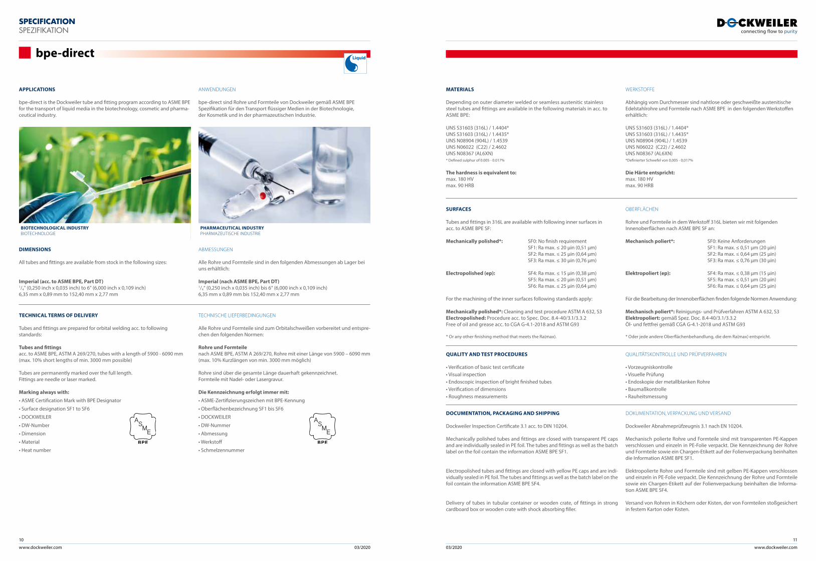
bpe-direct is the Dockweiler tube and fitting program according to ASME BPE for the transport of liquid media in the biotechnology, cosmetic and pharma-ceutical industry.
ANWENDUNGEN
bpe-direct sind Rohre und Formteile von Dockweiler gemäß ASME BPE Spezifikation für den Transport flüssiger Medien in der Biotechnologie, der Kosmetik und in der pharmazeutischen Industrie.
PHARMACEUTICAL INDUSTRY PHARMAZEUTISCHE INDUSTRIE
BIOTECHNOLOGICAL INDUSTRYBIOTECHNOLOGIE
DIMENSIONS
All tubes and fittings are available from stock in the following sizes:
Imperial (acc. to ASME BPE, Part DT)1/4" (0,250 inch x 0,035 inch) to 6" (6,000 inch x 0,109 inch) 6,35 mm x 0,89 mm to 152,40 mm x 2,77 mm
ABMESSUNGEN
Alle Rohre und Formteile sind in den folgenden Abmessungen ab Lager bei uns erhältlich:
Imperial (nach ASME BPE, Part DT)1/4“ (0,250 inch x 0,035 inch) bis 6“ (6,000 inch x 0,109 inch) 6,35 mm x 0,89 mm bis 152,40 mm x 2,77 mm
TECHNICAL TERMS OF DELIVERY
Tubes and fittings are prepared for orbital welding acc. to following standards:
Tubes and fittings acc. to ASME BPE, ASTM A 269/270, tubes with a length of 5900 - 6090 mm (max. 10% short lengths of min. 3000 mm possible)
Tubes are permanently marked over the full length. Fittings are needle or laser marked.
Marking always with:
• ASME Certification Mark with BPE Designator
• Surface designation SF1 to SF6
• DOCKWEILER
• DW-Number
• Dimension
• Material
• Heat number
TECHNISCHE LIEFERBEDINGUNGEN
Alle Rohre und Formteile sind zum Orbitalschweißen vorbereitet und entspre-chen den folgenden Normen:
Rohre und Formteile nach ASME BPE, ASTM A 269/270, Rohre mit einer Länge von 5900 – 6090 mm (max. 10% Kurzlängen von min. 3000 mm möglich)
Rohre sind über die gesamte Länge dauerhaft gekennzeichnet. Formteile mit Nadel- oder Lasergravur.
Die Kennzeichnung erfolgt immer mit:
• ASME-Zertifizierungszeichen mit BPE-Kennung
• Oberflächenbezeichnung SF1 bis SF6
• DOCKWEILER
• DW-Nummer
• Abmessung
• Werkstoff
• Schmelzennummer
SURFACES
Tubes and fittings in 316L are available with following inner surfaces in acc. to ASME BPE SF:
Mechanically polished*: SF0: No finish requirement SF1: Ra max. ≤ 20 μin (0,51 μm) SF2: Ra max. ≤ 25 μin (0,64 μm) SF3: Ra max. ≤ 30 μin (0,76 μm)
Electropolished (ep): SF4: Ra max. ≤ 15 μin (0,38 μm) SF5: Ra max. ≤ 20 μin (0,51 μm) SF6: Ra max. ≤ 25 μin (0,64 μm)
For the machining of the inner surfaces following standards apply:
Mechanically polished*: Cleaning and test procedure ASTM A 632, S3Electropolished: Procedure acc. to Spec. Doc. 8.4-40/3.1/3.3.2Free of oil and grease acc. to CGA G-4.1-2018 and ASTM G93
* Or any other finishing method that meets the Ra(max).
OBERFLÄCHEN
Rohre und Formteile in dem Werkstoff 316L bieten wir mit folgenden Innenoberflächen nach ASME BPE SF an:
Mechanisch poliert*: SF0: Keine Anforderungen SF1: Ra max. ≤ 0,51 μm (20 μin) SF2: Ra max. ≤ 0,64 μm (25 μin) SF3: Ra max. ≤ 0,76 μm (30 μin)
Elektropoliert (ep): SF4: Ra max. ≤ 0,38 μm (15 μin) SF5: Ra max. ≤ 0,51 μm (20 μin) SF6: Ra max. ≤ 0,64 μm (25 μin)
Für die Bearbeitung der Innenoberflächen finden folgende Normen Anwendung:
Mechanisch poliert*: Reinigungs- und Prüfverfahren ASTM A 632, S3Elektropoliert: gemäß Spez. Doc. 8.4-40/3.1/3.3.2Öl- und fettfrei gemäß CGA G-4.1-2018 und ASTM G93
* Oder jede andere Oberflächenbehandlung, die dem Ra(max) entspricht.
QUALITY AND TEST PROCEDURES
• Verification of basic test certificate • Visual inspection• Endoscopic inspection of bright finished tubes• Verification of dimensions• Roughness measurements
QUALITÄTSKONTROLLE UND PRÜFVERFAHREN
• Vorzeugniskontrolle • Visuelle Prüfung• Endoskopie der metallblanken Rohre• Baumaßkontrolle• Rauheitsmessung
DOCUMENTATION, PACKAGING AND SHIPPING
Dockweiler Inspection Certificate 3.1 acc. to DIN 10204.
Mechanically polished tubes and fittings are closed with transparent PE caps and are individually sealed in PE foil. The tubes and fittings as well as the batch label on the foil contain the information ASME BPE SF1.
Electropolished tubes and fittings are closed with yellow PE caps and are indi-vidually sealed in PE foil. The tubes and fittings as well as the batch label on the foil contain the information ASME BPE SF4.
Delivery of tubes in tubular container or wooden crate, of fittings in strong cardboard box or wooden crate with shock absorbing filler.
DOKUMENTATION, VERPACKUNG UND VERSAND
Dockweiler Abnahmeprüfzeugnis 3.1 nach EN 10204.
Mechanisch polierte Rohre und Formteile sind mit transparenten PE-Kappen verschlossen und einzeln in PE-Folie verpackt. Die Kennzeichnung der Rohre und Formteile sowie ein Chargen-Etikett auf der Folienverpackung beinhalten die Information ASME BPE SF1.
Elektropolierte Rohre und Formteile sind mit gelben PE-Kappen verschlossen und einzeln in PE-Folie verpackt. Die Kennzeichnung der Rohre und Formteile sowie ein Chargen-Etikett auf der Folienverpackung beinhalten die Informa- tion ASME BPE SF4.
Versand von Rohren in Köchern oder Kisten, der von Formteilen stoßgesichert in festem Karton oder Kisten.
MATERIALS
Depending on outer diameter welded or seamless austenitic stainless steel tubes and fittings are available in the following materials in acc. to ASME BPE:
UNS S31603 (316L) / 1.4404*UNS S31603 (316L) / 1.4435*UNS N08904 (904L) / 1.4539UNS N06022 (C22) / 2.4602UNS N08367 (AL6XN)* Defined sulphur of 0.005 - 0.017%
The hardness is equivalent to:max. 180 HVmax. 90 HRB
WERKSTOFFE
Abhängig vom Durchmesser sind nahtlose oder geschweißte austenitische Edelstahlrohre und Formteile nach ASME BPE in den folgenden Werkstoffen erhältlich:
UNS S31603 (316L) / 1.4404*UNS S31603 (316L) / 1.4435*UNS N08904 (904L) / 1.4539UNS N06022 (C22) / 2.4602UNS N08367 (AL6XN)*Definierter Schwefel von 0,005 - 0,017%
Die Härte entspricht:max. 180 HVmax. 90 HRB
www.dockweiler.com 03/2020 03/2020
12
www.dockweiler.com
13
SPECIFICATION SPEZIFIKATION
APPLICATIONS
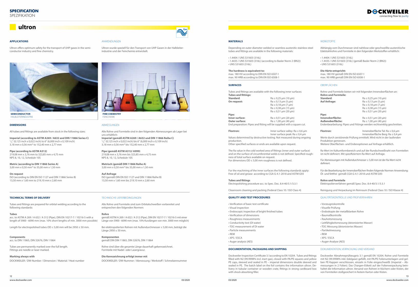
Ultron offers optimum safety for the transport of UHP gases in the semi-conductor industry and fine chemistry.
MATERIALS
Depending on outer diameter welded or seamless austenitic stainless steel tubes and fittings are available in the following materials:
• 1.4404 / UNS S31603 (316L)• 1.4435 / UNS S31603 (316L) (according to Basler Norm 2 (BN2))• UNS S31603 (316L)
The hardness is equivalent to:max. 180 HV according to DIN EN ISO 6507-1max. 90 HRB according to DIN EN ISO 6508-1
QUALITY AND TEST PROCEDURES
• Verification of basic test certificate • Visual inspection• Endoscopic inspection of bright finished tubes• Verification of dimensions• Roughness measurements• Conductivity test (DI water)• TOC-measurement of DI water• Particle measurements• REM• XPS / ESCA• Auger analysis (AES)
QUALITÄTSKONTROLLE UND PRÜFVERFAHREN
• Vorzeugniskontrolle• Visuelle Prüfung• Endoskopie der metallblanken Rohre• Baumaßkontrolle• Rauheitsmessung• Leitfähigkeitsmessung (deionisiertes Wasser)• TOC-Messung (deionisiertes Wasser)• Partikelmessung• REM• XPS / ESCA• Auger-Analyse (AES)
DOCUMENTATION, PACKAGING AND SHIPPING
Dockweiler Inspection Certificate 3.1according to EN 10204. Tubes and fittings filled with N2 (99.9998% incl. inert gas), closed with PA/PE squares and yellow PE caps, sleeved and sealed in PE – imperial dimensions double sleeved and sealed in PE. The batch label on the foil contains the information ultron. De-livery in tubular container or wooden crate, fittings in strong cardboard box with shock absorbing filler.
DOKUMENTATION, VERPACKUNG UND VERSAND
Dockweiler Abnahmeprüfzeugnis 3.1 gemäß EN 10204. Rohre und Formteile mit N2 (99.9998% inkl. Edelgase) gefüllt, mit PA/PE Folienunterlagen und gel-ben PE-Kappen verschlossen, einzeln in Folie eingeschweißt (Imperial – Ab-messungen in 2 Folien). Das Chargen-Etikett auf der Folienverpackung bein-haltet die Information ultron. Versand von Rohren in Köchern oder Kisten, der von Formteilen stoßgesichert in festem Karton oder Kisten.
WERKSTOFFE
Abhängig vom Durchmesser sind nahtlose oder geschweißte austenitische Edelstahlrohre und Formteile in den folgenden Werkstoffen erhältlich:
• 1.4404 / UNS S31603 (316L)• 1.4435 / UNS S31603 (316L) (gemäß Basler Norm 2 (BN2))• UNS S31603 (316L)
Die Härte entspricht:max. 180 HV gemäß DIN EN ISO 6507-1max. 90 HRB gemäß DIN EN ISO 6508-1
ANWENDUNGEN
Ultron wurde speziell für den Transport von UHP Gasen in der Halbleiter-industrie und der Feinchemie entwickelt.
ultron
TECHNICAL TERMS OF DELIVERY
Tubes and fittings are prepared for orbital welding according to the following standards:
Tubesacc. to ASTM A 269 / A 632 / A 312 (Pipe), DIN EN 10217-7 / 10216-5 with a length of 5900 - 6090 mm (max. 10% short lengths of min. 3000 mm possible)
Length for electropolished tubes OD ≤ 5,00 mm will be 2950 ± 50 mm.
Componentsacc. to DIN 11865, DIN 32676, DIN 11864
Tubes are permanently marked over the full length. Fittings are needle or laser marked.
Marking always with
DOCKWEILER / DW-Number / Dimension / Material / Heat number
TECHNISCHE LIEFERBEDINGUNGEN
Alle Rohre und Formteile sind zum Orbitalschweißen vorbereitet und entsprechen den folgenden Normen:
Rohre gemäß ASTM A 269 / A 632 / A 312 (Pipe), DIN EN 10217-7 / 10216-5 mit einer Länge von 5900 - 6090 mm (max. 10% Kurzlängen von min. 3000 mm möglich)
Bei elektropolierten Rohren mit Außendurchmesser ≤ 5,00 mm, beträgt die Länge 2950 ± 50 mm.
Komponentengemäß DIN DIN 11865, DIN 32676, DIN 11864
Rohre sind über die gesamte Länge dauerhaft gekennzeichnet. Formteile mit Nadel- oder Lasergravur.
Die Kennzeichnung erfolgt immer mit
DOCKWEILER / DW-Nummer / Abmessung / Werkstoff / Schmelzennummer
DIMENSIONS
All tubes and fittings are available from stock in the following sizes:
Imperial (according to ASTM A269 / A632 and DIN 11866 Series C)1/8" (0,125 inch x 0,022 inch) to 6" (6,000 inch x 0,109 inch) 3,18 mm x 0,56 mm* to 152,40 mm x 2,77 mm
Pipe (according to ASTM A312)219,08 mm x 3,76 mm to 323,85 mm x 4,75 mmNPS 8, 10, 12, Schedule 10S
Metric (according to DIN 11866 Series A)3,00 mm x 0,50 mm* to 35,00 mm x 1,50 mm
On requestISO (according to DIN EN ISO 1127 and DIN 11866 Series B)13,50 mm x 1,60 mm to 219,10 mm x 2,60 mm
ABMESSUNGEN
Alle Rohre und Formteile sind in den folgenden Abmessungen ab Lager bei uns erhältlich:Imperial (gemäß ASTM A269 / A632 und DIN 11866 Reihe C)1/8" (0,125 inch x 0,022 inch) bis 6" (6,000 inch x 0,109 inch) 3,18 mm x 0,56 mm* bis 152,40 mm x 2,77 mm
Pipe (gemäß ASTM A312/ A999)219,08 mm x 3,76 mm bis 323,85 mm x 4,75 mmNPS 8, 10, 12, Schedule 10S
Metrisch (gemäß DIN 11866 Reihe A)3,00 mm x 0,50 mm* bis 35,00 mm x 1,50 mm
Auf AnfrageISO (gemäß DIN EN ISO 1127 und DIN 11866 Reihe B)13,50 mm x 1,60 mm bis 219,10 mm x 2,60 mm
FINE CHEMISTRY FEINCHEMIE
SEMICONDUCTORHALBLEITERINDUSTRIE
Gas
SURFACES
Tubes and fittings are available with the following inner surfaces:Tubes and fittings:Standard: Ra ≤ 0,25 µm (10 µin)On request: Ra ≤ 0,13 µm (5 µin) Ra ≤ 0,18 µm (7 µin) Ra ≤ 0,38 µm (15 µin) Ra ≤ 0,51 µm (20 µin)Pipe: Inner surface: Ra ≤ 0,51 µm (20 µin)Outer surface: Ra ≤ 1,00 µm (40 µin)End preparation: Pipes and fitting will be supplied with a square cut.
Flextron: Inner surface valley: Ra ≤ 0,6 µm Inner surface peak: Ra ≤ 0,4 µmValues determined by destructive testing. Not measured during ongoing production. Other specified surfaces or ends are available upon request.
The Ra value in the cold worked area of fittings (inner and outer surface) and on the surface of circumferential welds is not defined. Specified rough-ness of total surface available on request. For dimensions OD ≤ 5,00 mm roughness is not defined.
For the machining of the inner surfaces the following standards apply: Free of oil and grease according to CGA G-4.1-2018 and ASTM G93
Tubes and fittingsElectropolishing procedure acc. to Spec. Doc. 8.4-40/3.1/3.3.1
Cleanroom cleaning and packing (Federal Class 10 / ISO Class 4)
OBERFLÄCHEN
Rohre und Formteile bieten wir mit folgenden Innenoberflächen an:Rohre und Formteile:Standard: Ra ≤ 0,25 µm (10 µin)Auf Anfrage: Ra ≤ 0,13 µm (5 µin) Ra ≤ 0,18 µm (7 µin) Ra ≤ 0,38 µm (15 µin) Ra ≤ 0,51 µm (20 µin)Pipe: Innenoberfläche: Ra ≤ 0,51 µm (20 µin)Außenoberfläche: Ra ≤ 1,00 µm (40 µin)Endenbearbeitung: Pipes und Fittinge werden rechtwinklig geschnitten.
Flextron: Innenoberfläche Tal: Ra ≤ 0,6 µm Innenoberfläche Berg: Ra ≤ 0,4 µmWerte durch zerstörende Prüfung ermittelt. Wird nicht in der laufenden Produktion gemessen.Weitere Oberflächen- und Endenoptionen auf Anfrage erhältlich.
Ra-Wert im Kaltumformbereich und auf der Rundschweißnaht von Formteilen ist nicht definiert. Mit spezifiziertem Ra-Wert auf Anfrage.
Für Abmessungen mit Außendurchmesser ≤ 5,00 mm ist der Ra-Wert nicht definiert.
Für die Bearbeitung der Innenoberflächen finden folgende Normen Anwendung:Öl- und fettfrei gemäß CGA G-4.1-2018 und ASTM G93
Rohre und FormteileElektropolierverfahren gemäß Spez. Doc. 8.4-40/3.1/3.3.1
Reinigung und Verpackung im Reinraum (Federal Class 10 / ISO Klasse 4)
www.dockweiler.com 03/2020 03/2020
14
www.dockweiler.com
15
SPECIFICATION SPEZIFIKATION
APPLICATIONS
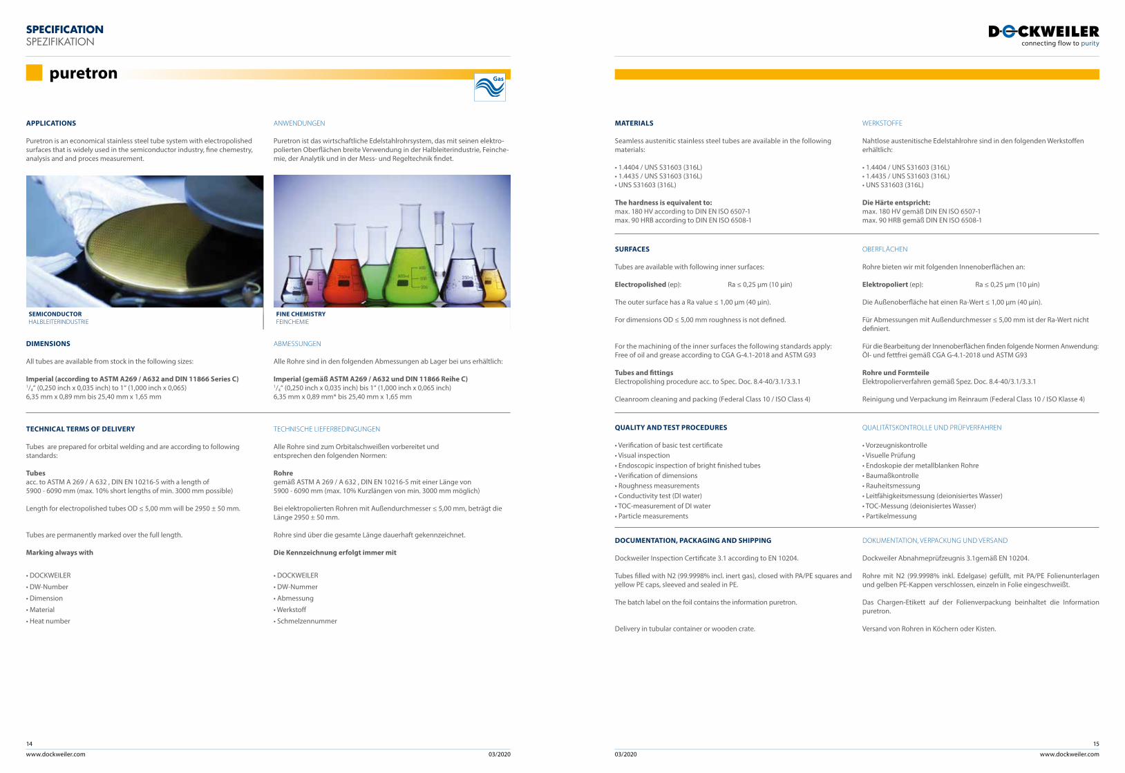
Puretron is an economical stainless steel tube system with electropolished surfaces that is widely used in the semiconductor industry, fine chemestry, analysis and and proces measurement.
ANWENDUNGEN
Puretron ist das wirtschaftliche Edelstahlrohrsystem, das mit seinen elektro-polierten Oberflächen breite Verwendung in der Halbleiterindustrie, Feinche-mie, der Analytik und in der Mess- und Regeltechnik findet.
TECHNICAL TERMS OF DELIVERY
Tubes are prepared for orbital welding and are according to following standards:
Tubesacc. to ASTM A 269 / A 632 , DIN EN 10216-5 with a length of 5900 - 6090 mm (max. 10% short lengths of min. 3000 mm possible)
Length for electropolished tubes OD ≤ 5,00 mm will be 2950 ± 50 mm.
Tubes are permanently marked over the full length.
Marking always with
• DOCKWEILER
• DW-Number
• Dimension
• Material
• Heat number
TECHNISCHE LIEFERBEDINGUNGEN
Alle Rohre sind zum Orbitalschweißen vorbereitet und entsprechen den folgenden Normen:
Rohre gemäß ASTM A 269 / A 632 , DIN EN 10216-5 mit einer Länge von 5900 - 6090 mm (max. 10% Kurzlängen von min. 3000 mm möglich)
Bei elektropolierten Rohren mit Außendurchmesser ≤ 5,00 mm, beträgt die Länge 2950 ± 50 mm.
Rohre sind über die gesamte Länge dauerhaft gekennzeichnet.
Die Kennzeichnung erfolgt immer mit
• DOCKWEILER
• DW-Nummer
• Abmessung
• Werkstoff
• Schmelzennummer
DIMENSIONS
All tubes are available from stock in the following sizes:
Imperial (according to ASTM A269 / A632 and DIN 11866 Series C)1/4“ (0,250 inch x 0,035 inch) to 1“ (1,000 inch x 0,065) 6,35 mm x 0,89 mm bis 25,40 mm x 1,65 mm
ABMESSUNGEN
Alle Rohre sind in den folgenden Abmessungen ab Lager bei uns erhältlich:
Imperial (gemäß ASTM A269 / A632 und DIN 11866 Reihe C)1/4“ (0,250 inch x 0,035 inch) bis 1“ (1,000 inch x 0,065 inch) 6,35 mm x 0,89 mm* bis 25,40 mm x 1,65 mm
SURFACES
Tubes are available with following inner surfaces:
Electropolished (ep): Ra ≤ 0,25 µm (10 µin)
The outer surface has a Ra value ≤ 1,00 µm (40 µin).
For dimensions OD ≤ 5,00 mm roughness is not defined.
For the machining of the inner surfaces the following standards apply: Free of oil and grease according to CGA G-4.1-2018 and ASTM G93
Tubes and fittingsElectropolishing procedure acc. to Spec. Doc. 8.4-40/3.1/3.3.1
Cleanroom cleaning and packing (Federal Class 10 / ISO Class 4)
OBERFLÄCHEN
Rohre bieten wir mit folgenden Innenoberflächen an:
Elektropoliert (ep): Ra ≤ 0,25 µm (10 µin)
Die Außenoberfläche hat einen Ra-Wert ≤ 1,00 µm (40 µin).
Für Abmessungen mit Außendurchmesser ≤ 5,00 mm ist der Ra-Wert nicht definiert.
Für die Bearbeitung der Innenoberflächen finden folgende Normen Anwendung:Öl- und fettfrei gemäß CGA G-4.1-2018 und ASTM G93
Rohre und FormteileElektropolierverfahren gemäß Spez. Doc. 8.4-40/3.1/3.3.1
Reinigung und Verpackung im Reinraum (Federal Class 10 / ISO Klasse 4)
QUALITY AND TEST PROCEDURES
• Verification of basic test certificate • Visual inspection• Endoscopic inspection of bright finished tubes• Verification of dimensions• Roughness measurements• Conductivity test (DI water)• TOC-measurement of DI water• Particle measurements
QUALITÄTSKONTROLLE UND PRÜFVERFAHREN
• Vorzeugniskontrolle• Visuelle Prüfung• Endoskopie der metallblanken Rohre• Baumaßkontrolle• Rauheitsmessung• Leitfähigkeitsmessung (deionisiertes Wasser)• TOC-Messung (deionisiertes Wasser)• Partikelmessung
DOCUMENTATION, PACKAGING AND SHIPPING
Dockweiler Inspection Certificate 3.1 according to EN 10204.
Tubes filled with N2 (99.9998% incl. inert gas), closed with PA/PE squares and yellow PE caps, sleeved and sealed in PE.
The batch label on the foil contains the information puretron.
Delivery in tubular container or wooden crate.
DOKUMENTATION, VERPACKUNG UND VERSAND
Dockweiler Abnahmeprüfzeugnis 3.1gemäß EN 10204.
Rohre mit N2 (99.9998% inkl. Edelgase) gefüllt, mit PA/PE Folienunterlagen und gelben PE-Kappen verschlossen, einzeln in Folie eingeschweißt.
Das Chargen-Etikett auf der Folienverpackung beinhaltet die Information puretron.
Versand von Rohren in Köchern oder Kisten.
MATERIALS
Seamless austenitic stainless steel tubes are available in the following materials:
• 1.4404 / UNS S31603 (316L)• 1.4435 / UNS S31603 (316L)• UNS S31603 (316L)
The hardness is equivalent to:max. 180 HV according to DIN EN ISO 6507-1max. 90 HRB according to DIN EN ISO 6508-1
WERKSTOFFE
Nahtlose austenitische Edelstahlrohre sind in den folgenden Werkstoffen erhältlich:
• 1.4404 / UNS S31603 (316L)• 1.4435 / UNS S31603 (316L)• UNS S31603 (316L)
Die Härte entspricht:max. 180 HV gemäß DIN EN ISO 6507-1max. 90 HRB gemäß DIN EN ISO 6508-1
puretron Gas
FINE CHEMISTRY FEINCHEMIE
SEMICONDUCTORHALBLEITERINDUSTRIE
www.dockweiler.com 03/2020 03/2020
16
www.dockweiler.com
17
SPECIFICATION SPEZIFIKATION
APPLICATIONS
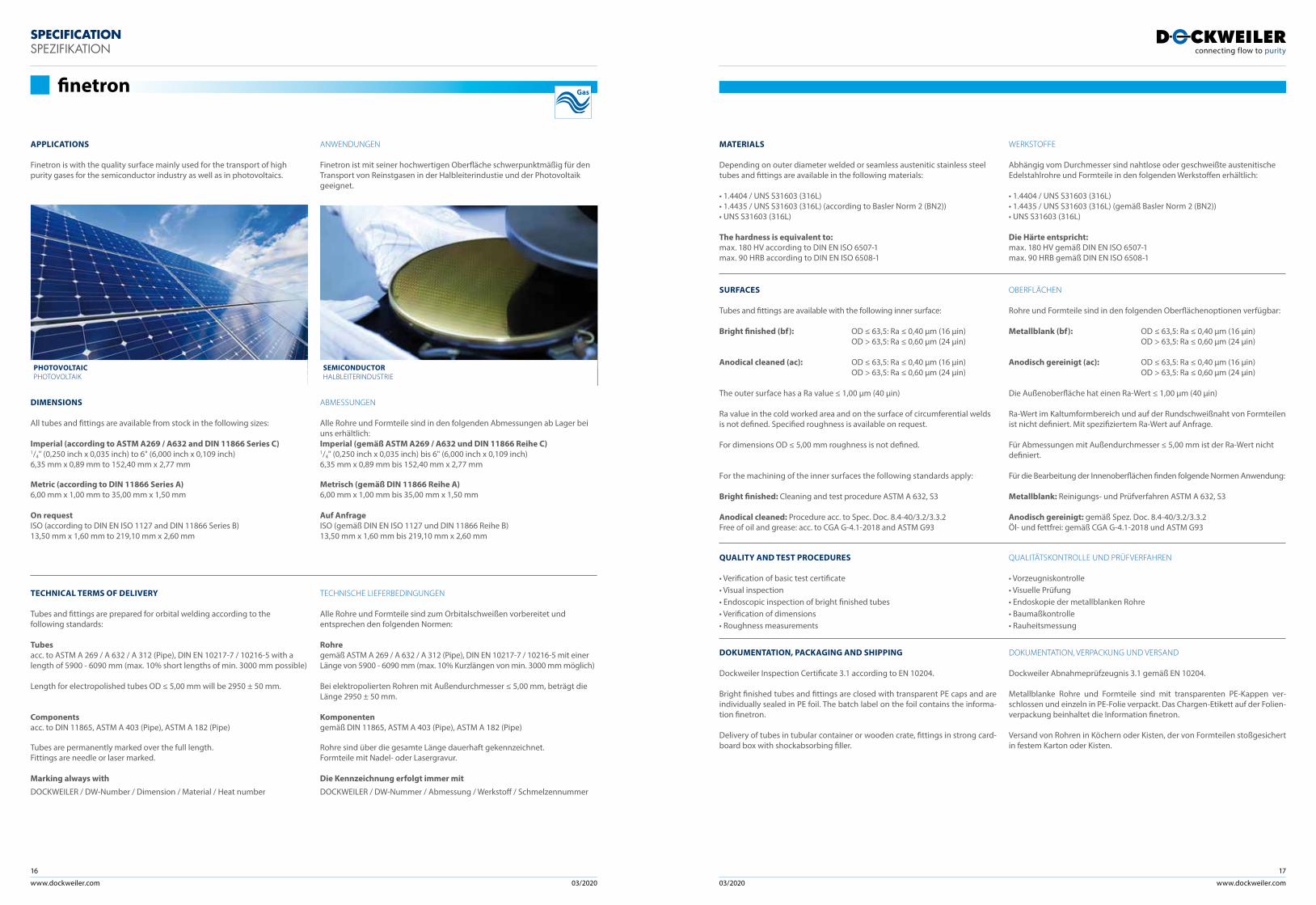
Finetron is with the quality surface mainly used for the transport of high purity gases for the semiconductor industry as well as in photovoltaics.
MATERIALS
Depending on outer diameter welded or seamless austenitic stainless steel tubes and fittings are available in the following materials:
• 1.4404 / UNS S31603 (316L)• 1.4435 / UNS S31603 (316L) (according to Basler Norm 2 (BN2))• UNS S31603 (316L)
The hardness is equivalent to:max. 180 HV according to DIN EN ISO 6507-1max. 90 HRB according to DIN EN ISO 6508-1
SURFACES
Tubes and fittings are available with the following inner surface:
Bright finished (bf): OD ≤ 63,5: Ra ≤ 0,40 µm (16 µin) OD > 63,5: Ra ≤ 0,60 µm (24 µin)
Anodical cleaned (ac): OD ≤ 63,5: Ra ≤ 0,40 µm (16 µin) OD > 63,5: Ra ≤ 0,60 µm (24 µin)
The outer surface has a Ra value ≤ 1,00 µm (40 µin)
Ra value in the cold worked area and on the surface of circumferential welds is not defined. Specified roughness is available on request.
For dimensions OD ≤ 5,00 mm roughness is not defined.
For the machining of the inner surfaces the following standards apply:
Bright finished: Cleaning and test procedure ASTM A 632, S3
Anodical cleaned: Procedure acc. to Spec. Doc. 8.4-40/3.2/3.3.2Free of oil and grease: acc. to CGA G-4.1-2018 and ASTM G93
OBERFLÄCHEN
Rohre und Formteile sind in den folgenden Oberflächenoptionen verfügbar:
Metallblank (bf): OD ≤ 63,5: Ra ≤ 0,40 µm (16 µin) OD > 63,5: Ra ≤ 0,60 µm (24 µin)
Anodisch gereinigt (ac): OD ≤ 63,5: Ra ≤ 0,40 µm (16 µin) OD > 63,5: Ra ≤ 0,60 µm (24 µin)
Die Außenoberfläche hat einen Ra-Wert ≤ 1,00 µm (40 µin)
Ra-Wert im Kaltumformbereich und auf der Rundschweißnaht von Formteilen ist nicht definiert. Mit spezifiziertem Ra-Wert auf Anfrage.
Für Abmessungen mit Außendurchmesser ≤ 5,00 mm ist der Ra-Wert nicht definiert.
Für die Bearbeitung der Innenoberflächen finden folgende Normen Anwendung:
Metallblank: Reinigungs- und Prüfverfahren ASTM A 632, S3
Anodisch gereinigt: gemäß Spez. Doc. 8.4-40/3.2/3.3.2Öl- und fettfrei: gemäß CGA G-4.1-2018 und ASTM G93
QUALITY AND TEST PROCEDURES
• Verification of basic test certificate • Visual inspection• Endoscopic inspection of bright finished tubes• Verification of dimensions• Roughness measurements
QUALITÄTSKONTROLLE UND PRÜFVERFAHREN
• Vorzeugniskontrolle• Visuelle Prüfung• Endoskopie der metallblanken Rohre• Baumaßkontrolle• Rauheitsmessung
DOKUMENTATION, PACKAGING AND SHIPPING
Dockweiler Inspection Certificate 3.1 according to EN 10204.
Bright finished tubes and fittings are closed with transparent PE caps and are individually sealed in PE foil. The batch label on the foil contains the informa-tion finetron.
Delivery of tubes in tubular container or wooden crate, fittings in strong card-board box with shockabsorbing filler.
DOKUMENTATION, VERPACKUNG UND VERSAND
Dockweiler Abnahmeprüfzeugnis 3.1 gemäß EN 10204.
Metallblanke Rohre und Formteile sind mit transparenten PE-Kappen ver-schlossen und einzeln in PE-Folie verpackt. Das Chargen-Etikett auf der Folien-verpackung beinhaltet die Information finetron.
Versand von Rohren in Köchern oder Kisten, der von Formteilen stoßgesichert in festem Karton oder Kisten.
WERKSTOFFE
Abhängig vom Durchmesser sind nahtlose oder geschweißte austenitische Edelstahlrohre und Formteile in den folgenden Werkstoffen erhältlich:
• 1.4404 / UNS S31603 (316L)• 1.4435 / UNS S31603 (316L) (gemäß Basler Norm 2 (BN2))• UNS S31603 (316L)
Die Härte entspricht:max. 180 HV gemäß DIN EN ISO 6507-1max. 90 HRB gemäß DIN EN ISO 6508-1
ANWENDUNGEN
Finetron ist mit seiner hochwertigen Oberfläche schwerpunktmäßig für den Transport von Reinstgasen in der Halbleiterindustie und der Photovoltaik geeignet.
TECHNICAL TERMS OF DELIVERY
Tubes and fittings are prepared for orbital welding according to the following standards:
Tubesacc. to ASTM A 269 / A 632 / A 312 (Pipe), DIN EN 10217-7 / 10216-5 with a length of 5900 - 6090 mm (max. 10% short lengths of min. 3000 mm possible)
Length for electropolished tubes OD ≤ 5,00 mm will be 2950 ± 50 mm.
Componentsacc. to DIN 11865, ASTM A 403 (Pipe), ASTM A 182 (Pipe)
Tubes are permanently marked over the full length. Fittings are needle or laser marked.
Marking always with
DOCKWEILER / DW-Number / Dimension / Material / Heat number
TECHNISCHE LIEFERBEDINGUNGEN
Alle Rohre und Formteile sind zum Orbitalschweißen vorbereitet und entsprechen den folgenden Normen:
Rohre gemäß ASTM A 269 / A 632 / A 312 (Pipe), DIN EN 10217-7 / 10216-5 mit einer Länge von 5900 - 6090 mm (max. 10% Kurzlängen von min. 3000 mm möglich)
Bei elektropolierten Rohren mit Außendurchmesser ≤ 5,00 mm, beträgt die Länge 2950 ± 50 mm.
Komponentengemäß DIN 11865, ASTM A 403 (Pipe), ASTM A 182 (Pipe)
Rohre sind über die gesamte Länge dauerhaft gekennzeichnet. Formteile mit Nadel- oder Lasergravur.
Die Kennzeichnung erfolgt immer mit
DOCKWEILER / DW-Nummer / Abmessung / Werkstoff / Schmelzennummer
DIMENSIONS
All tubes and fittings are available from stock in the following sizes:
Imperial (according to ASTM A269 / A632 and DIN 11866 Series C)1/4" (0,250 inch x 0,035 inch) to 6" (6,000 inch x 0,109 inch)6,35 mm x 0,89 mm to 152,40 mm x 2,77 mm
Metric (according to DIN 11866 Series A)6,00 mm x 1,00 mm to 35,00 mm x 1,50 mm
On requestISO (according to DIN EN ISO 1127 and DIN 11866 Series B)13,50 mm x 1,60 mm to 219,10 mm x 2,60 mm
ABMESSUNGEN
Alle Rohre und Formteile sind in den folgenden Abmessungen ab Lager bei uns erhältlich:Imperial (gemäß ASTM A269 / A632 und DIN 11866 Reihe C)1/4" (0,250 inch x 0,035 inch) bis 6" (6,000 inch x 0,109 inch)6,35 mm x 0,89 mm bis 152,40 mm x 2,77 mm
Metrisch (gemäß DIN 11866 Reihe A)6,00 mm x 1,00 mm bis 35,00 mm x 1,50 mm
Auf AnfrageISO (gemäß DIN EN ISO 1127 und DIN 11866 Reihe B)13,50 mm x 1,60 mm bis 219,10 mm x 2,60 mm
finetron
SEMICONDUCTORHALBLEITERINDUSTRIE
PHOTOVOLTAICPHOTOVOLTAIK
Gas
www.dockweiler.com 03/2020 03/2020
18
www.dockweiler.com
19
SPECIFICATION SPEZIFIKATION
APPLICATIONS
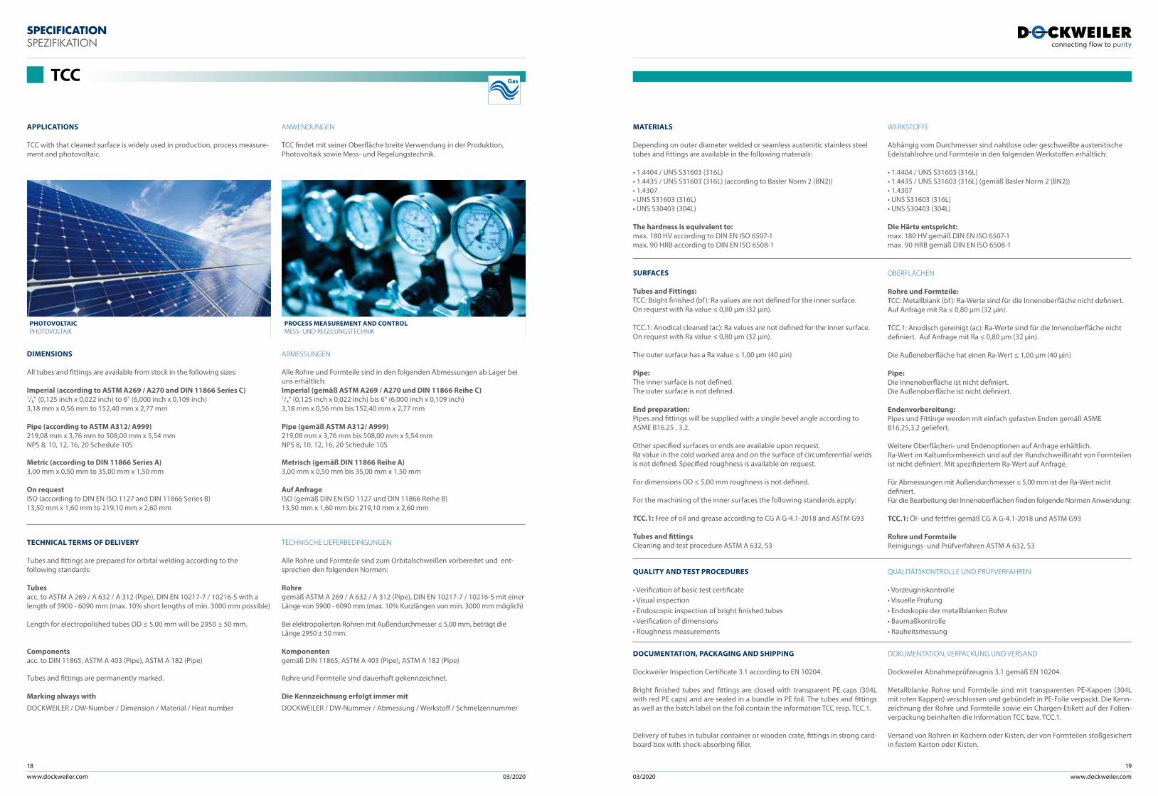
TCC with that cleaned surface is widely used in production, process measure-ment and photovoltaic.
SURFACES
Tubes and Fittings:TCC: Bright finished (bf ): Ra values are not defined for the inner surface. On request with Ra value ≤ 0,80 µm (32 µin).
TCC.1: Anodical cleaned (ac): Ra values are not defined for the inner surface. On request with Ra value ≤ 0,80 µm (32 µin).
The outer surface has a Ra value ≤ 1,00 µm (40 µin)
Pipe:The inner surface is not defined.The outer surface is not defined. End preparation:Pipes and fittings will be supplied with a single bevel angle according to ASME B16.25 , 3.2. Other specified surfaces or ends are available upon request.Ra value in the cold worked area and on the surface of circumferential welds is not defined. Specified roughness is available on request.
For dimensions OD ≤ 5,00 mm roughness is not defined.
For the machining of the inner surfaces the following standards apply:
TCC.1: Free of oil and grease according to CG A G-4.1-2018 and ASTM G93
Tubes and fittingsCleaning and test procedure ASTM A 632, S3
OBERFLÄCHEN
Rohre und Formteile:TCC: Metallblank (bf ): Ra-Werte sind für die Innenoberfläche nicht definiert. Auf Anfrage mit Ra ≤ 0,80 µm (32 µin).
TCC.1: Anodisch gereinigt (ac): Ra-Werte sind für die Innenoberfläche nicht definiert. Auf Anfrage mit Ra ≤ 0,80 µm (32 µin).
Die Außenoberfläche hat einen Ra-Wert ≤ 1,00 µm (40 µin)
Pipe:Die Innenoberfläche ist nicht definiert.Die Außenoberfläche ist nicht definiert.
Endenvorbereitung:Pipes und Fittinge werden mit einfach gefasten Enden gemäß ASME B16.25,3.2 geliefert.
Weitere Oberflächen- und Endenoptionen auf Anfrage erhältlich.Ra-Wert im Kaltumformbereich und auf der Rundschweißnaht von Formteilen ist nicht definiert. Mit spezifiziertem Ra-Wert auf Anfrage.
Für Abmessungen mit Außendurchmesser ≤ 5,00 mm ist der Ra-Wert nichtdefiniert.Für die Bearbeitung der Innenoberflächen finden folgende Normen Anwendung:
TCC.1: Öl- und fettfrei gemäß CG A G-4.1-2018 und ASTM G93
Rohre und FormteileReinigungs- und Prüfverfahren ASTM A 632, S3
QUALITY AND TEST PROCEDURES
• Verification of basic test certificate • Visual inspection• Endoscopic inspection of bright finished tubes• Verification of dimensions• Roughness measurements
QUALITÄTSKONTROLLE UND PRÜFVERFAHREN
• Vorzeugniskontrolle • Visuelle Prüfung• Endoskopie der metallblanken Rohre• Baumaßkontrolle• Rauheitsmessung
DOCUMENTATION, PACKAGING AND SHIPPING
Dockweiler Inspection Certificate 3.1 according to EN 10204.
Bright finished tubes and fittings are closed with transparent PE caps (304L with red PE caps) and are sealed in a bundle in PE foil. The tubes and fittings as well as the batch label on the foil contain the information TCC resp. TCC.1.
Delivery of tubes in tubular container or wooden crate, fittings in strong card-board box with shock-absorbing filler.
DOKUMENTATION, VERPACKUNG UND VERSAND
Dockweiler Abnahmeprüfzeugnis 3.1 gemäß EN 10204.
Metallblanke Rohre und Formteile sind mit transparenten PE-Kappen (304L mit roten Kappen) verschlossen und gebündelt in PE-Folie verpackt. Die Kenn-zeichnung der Rohre und Formteile sowie ein Chargen-Etikett auf der Folien-verpackung beinhalten die Information TCC bzw. TCC.1.
Versand von Rohren in Köchern oder Kisten, der von Formteilen stoßgesichert in festem Karton oder Kisten.
MATERIALS
Depending on outer diameter welded or seamless austenitic stainless steel tubes and fittings are available in the following materials:
• 1.4404 / UNS S31603 (316L)• 1.4435 / UNS S31603 (316L) (according to Basler Norm 2 (BN2))• 1.4307 • UNS S31603 (316L)• UNS S30403 (304L)
The hardness is equivalent to:max. 180 HV according to DIN EN ISO 6507-1max. 90 HRB according to DIN EN ISO 6508-1
WERKSTOFFE
Abhängig vom Durchmesser sind nahtlose oder geschweißte austenitische Edelstahlrohre und Formteile in den folgenden Werkstoffen erhältlich:
• 1.4404 / UNS S31603 (316L)• 1.4435 / UNS S31603 (316L) (gemäß Basler Norm 2 (BN2))• 1.4307 • UNS S31603 (316L)• UNS S30403 (304L)
Die Härte entspricht:max. 180 HV gemäß DIN EN ISO 6507-1max. 90 HRB gemäß DIN EN ISO 6508-1
ANWENDUNGEN
TCC findet mit seiner Oberfläche breite Verwendung in der Produktion, Photovoltaik sowie Mess- und Regelungstechnik.
TECHNICAL TERMS OF DELIVERY
Tubes and fittings are prepared for orbital welding according to the following standards:
Tubes acc. to ASTM A 269 / A 632 / A 312 (Pipe), DIN EN 10217-7 / 10216-5 with a length of 5900 - 6090 mm (max. 10% short lengths of min. 3000 mm possible)
Length for electropolished tubes OD ≤ 5,00 mm will be 2950 ± 50 mm.
Componentsacc. to DIN 11865, ASTM A 403 (Pipe), ASTM A 182 (Pipe)
Tubes and fittings are permanently marked.
Marking always with
DOCKWEILER / DW-Number / Dimension / Material / Heat number
TECHNISCHE LIEFERBEDINGUNGEN
Alle Rohre und Formteile sind zum Orbitalschweißen vorbereitet und ent-sprechen den folgenden Normen:
Rohregemäß ASTM A 269 / A 632 / A 312 (Pipe), DIN EN 10217-7 / 10216-5 mit einer Länge von 5900 - 6090 mm (max. 10% Kurzlängen von min. 3000 mm möglich)
Bei elektropolierten Rohren mit Außendurchmesser ≤ 5,00 mm, beträgt die Länge 2950 ± 50 mm.
Komponentengemäß DIN 11865, ASTM A 403 (Pipe), ASTM A 182 (Pipe)
Rohre und Formteile sind dauerhaft gekennzeichnet.
Die Kennzeichnung erfolgt immer mit
DOCKWEILER / DW-Nummer / Abmessung / Werkstoff / Schmelzennummer
DIMENSIONS
All tubes and fittings are available from stock in the following sizes:
Imperial (according to ASTM A269 / A270 and DIN 11866 Series C)1/8" (0,125 inch x 0,022 inch) to 6" (6,000 inch x 0,109 inch)3,18 mm x 0,56 mm to 152,40 mm x 2,77 mm
Pipe (according to ASTM A312/ A999)219,08 mm x 3,76 mm to 508,00 mm x 5,54 mmNPS 8, 10, 12, 16, 20 Schedule 10S
Metric (according to DIN 11866 Series A)3,00 mm x 0,50 mm to 35,00 mm x 1,50 mm
On requestISO (according to DIN EN ISO 1127 and DIN 11866 Series B)13,50 mm x 1,60 mm to 219,10 mm x 2,60 mm
ABMESSUNGEN
Alle Rohre und Formteile sind in den folgenden Abmessungen ab Lager bei uns erhältlich:Imperial (gemäß ASTM A269 / A270 und DIN 11866 Reihe C)1/8" (0,125 inch x 0,022 inch) bis 6" (6,000 inch x 0,109 inch)3,18 mm x 0,56 mm bis 152,40 mm x 2,77 mm
Pipe (gemäß ASTM A312/ A999)219,08 mm x 3,76 mm bis 508,00 mm x 5,54 mmNPS 8, 10, 12, 16, 20 Schedule 10S
Metrisch (gemäß DIN 11866 Reihe A)3,00 mm x 0,50 mm bis 35,00 mm x 1,50 mm
Auf AnfrageISO (gemäß DIN EN ISO 1127 und DIN 11866 Reihe B)13,50 mm x 1,60 mm bis 219,10 mm x 2,60 mm
TCC
PROCESS MEASUREMENT AND CONTROLMESS- UND REGELUNGSTECHNIK
PHOTOVOLTAICPHOTOVOLTAIK
Gas
www.dockweiler.com 03/2020 03/2020
20
www.dockweiler.com
21
APPLICATIONS
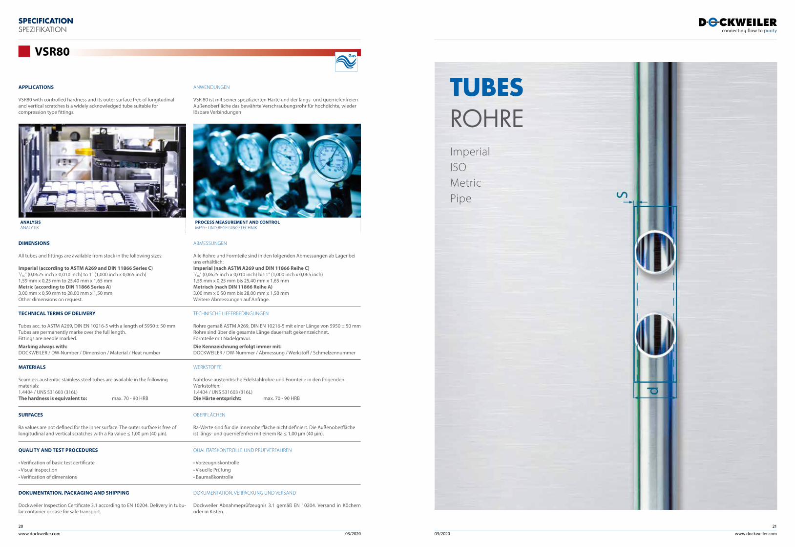
VSR80 with controlled hardness and its outer surface free of longitudinal and vertical scratches is a widely acknowledged tube suitable for compression type fittings.
ANWENDUNGEN
VSR 80 ist mit seiner spezifizierten Härte und der längs- und querriefenfreien Außenoberfläche das bewährte Verschraubungsrohr für hochdichte, wieder lösbare Verbindungen
TECHNICAL TERMS OF DELIVERY
Tubes acc. to ASTM A269, DIN EN 10216-5 with a length of 5950 ± 50 mmTubes are permanently marke over the full length. Fittings are needle marked.
Marking always with:DOCKWEILER / DW-Number / Dimension / Material / Heat number
TECHNISCHE LIEFERBEDINGUNGEN
Rohre gemäß ASTM A269, DIN EN 10216-5 mit einer Länge von 5950 ± 50 mmRohre sind über die gesamte Länge dauerhaft gekennzeichnet. Formteile mit Nadelgravur.
Die Kennzeichnung erfolgt immer mit:DOCKWEILER / DW-Nummer / Abmessung / Werkstoff / Schmelzennummer
MATERIALS
Seamless austenitic stainless steel tubes are available in the following materials: 1.4404 / UNS S31603 (316L)The hardness is equivalent to: max. 70 - 90 HRB
SURFACES
Ra values are not defined for the inner surface. The outer surface is free of longitudinal and vertical scratches with a Ra value ≤ 1,00 µm (40 µin).
OBERFLÄCHEN
Ra-Werte sind für die Innenoberfläche nicht definiert. Die Außenoberfläche ist längs- und querriefenfrei mit einem Ra ≤ 1,00 µm (40 µin).
QUALITY AND TEST PROCEDURES
• Verification of basic test certificate • Visual inspection• Verification of dimensions
QUALITÄTSKONTROLLE UND PRÜFVERFAHREN
• Vorzeugniskontrolle • Visuelle Prüfung• Baumaßkontrolle
DOKUMENTATION, PACKAGING AND SHIPPING
Dockweiler Inspection Certificate 3.1 according to EN 10204. Delivery in tubu-lar container or case for safe transport.
DOKUMENTATION, VERPACKUNG UND VERSAND
Dockweiler Abnahmeprüfzeugnis 3.1 gemäß EN 10204. Versand in Köchern oder in Kisten.
WERKSTOFFE
Nahtlose austenitische Edelstahlrohre und Formteile in den folgenden Werkstoffen:1.4404 / UNS S31603 (316L) Die Härte entspricht: max. 70 - 90 HRB
DIMENSIONS
All tubes and fittings are available from stock in the following sizes:
Imperial (according to ASTM A269 and DIN 11866 Series C)1/16" (0,0625 inch x 0,010 inch) to 1" (1,000 inch x 0,065 inch) 1,59 mm x 0,25 mm to 25,40 mm x 1,65 mmMetric (according to DIN 11866 Series A)3,00 mm x 0,50 mm to 28,00 mm x 1,50 mmOther dimensions on request.
ABMESSUNGEN
Alle Rohre und Formteile sind in den folgenden Abmessungen ab Lager bei uns erhältlich:Imperial (nach ASTM A269 und DIN 11866 Reihe C)1/16" (0,0625 inch x 0,010 inch) bis 1" (1,000 inch x 0,065 inch) 1,59 mm x 0,25 mm bis 25,40 mm x 1,65 mmMetrisch (nach DIN 11866 Reihe A)3,00 mm x 0,50 mm bis 28,00 mm x 1,50 mmWeitere Abmessungen auf Anfrage.
SPECIFICATION SPEZIFIKATION
VSR80
ANALYSISANALYTIK
PROCESS MEASUREMENT AND CONTROLMESS- UND REGELUNGSTECHNIK
TUBESROHREImperialISOMetricPipe
Gas
www.dockweiler.com 03/2020 03/2020
22
www.dockweiler.com
23
ds
l
ult
ron
pur
etro
n
fine
tron
TCC
VSR
80
saf
etro
n
wel
dtro
n
bpe
-dir
ect
x x x
x
x x x x
x x x x
x x x x x x
x x x x x x
x x x x x x
x x x x x x
x x x x x x
x x x x x x
ult
ron
pur
etro
n
fine
tron
TCC
VSR
80
saf
etro
n
wel
dtro
n
bpe
-dir
ect
x x x
x x x
x x x
x x x
x
x
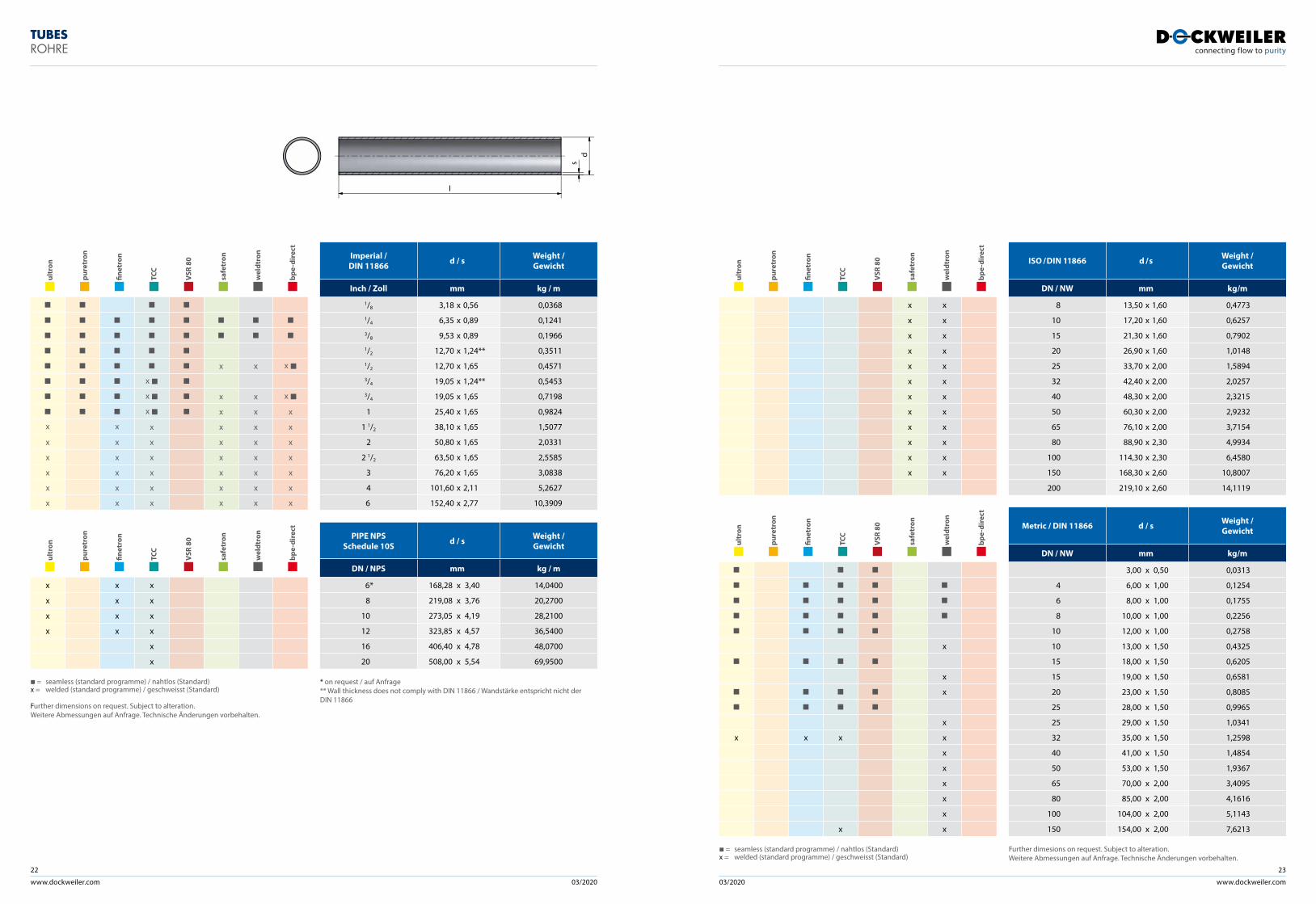
= seamless (standard programme) / nahtlos (Standard)x = welded (standard programme) / geschweisst (Standard)
Further dimensions on request. Subject to alteration. Weitere Abmessungen auf Anfrage. Technische Änderungen vorbehalten.
Imperial / DIN 11866 d / s Weight /
Gewicht
Inch / Zoll mm kg / m
1/8 3,18 x 0,56 0,03681/4 6,35 x 0,89 0,12413/8 9,53 x 0,89 0,19661/2 12,70 x 1,24** 0,35111/2 12,70 x 1,65 0,45713/4 19,05 x 1,24** 0,54533/4 19,05 x 1,65 0,7198
1 25,40 x 1,65 0,9824
1 1/2 38,10 x 1,65 1,5077
2 50,80 x 1,65 2,0331
2 1/2 63,50 x 1,65 2,5585
3 76,20 x 1,65 3,0838
4 101,60 x 2,11 5,2627
6 152,40 x 2,77 10,3909
PIPE NPS Schedule 10S d / s Weight /
Gewicht
DN / NPS mm kg / m
6* 168,28 x 3,40 14,0400
8 219,08 x 3,76 20,2700
10 273,05 x 4,19 28,2100
12 323,85 x 4,57 36,5400
16 406,40 x 4,78 48,0700
20 508,00 x 5,54 69,9500
* on request / auf Anfrage ** Wall thickness does not comply with DIN 11866 / Wandstärke entspricht nicht der DIN 11866
TUBES ROHRE
ult
ron
pur
etro
n
fine
tron
TCC
VSR
80
saf
etro
n
wel
dtro
n
bpe
-dir
ect
x x
x x
x x
x x
x x
x x
x x
x x
x x
x x
x x
x x
ult
ron
pur
etro
n
fine
tron
TCC
VSR
80
saf
etro
n
wel
dtro
n
bpe
-dir
ect
x
x
x
x
x x x x
x
x
x
x
x
x x
= seamless (standard programme) / nahtlos (Standard)x = welded (standard programme) / geschweisst (Standard)
ISO / DIN 11866 d / s Weight / Gewicht
DN / NW mm kg/m
8 13,50 x 1,60 0,4773
10 17,20 x 1,60 0,6257
15 21,30 x 1,60 0,7902
20 26,90 x 1,60 1,0148
25 33,70 x 2,00 1,5894
32 42,40 x 2,00 2,0257
40 48,30 x 2,00 2,3215
50 60,30 x 2,00 2,9232
65 76,10 x 2,00 3,7154
80 88,90 x 2,30 4,9934
100 114,30 x 2,30 6,4580
150 168,30 x 2,60 10,8007
200 219,10 x 2,60 14,1119
Metric / DIN 11866 d / s Weight / Gewicht
DN / NW mm kg/m
3,00 x 0,50 0,0313
4 6,00 x 1,00 0,1254
6 8,00 x 1,00 0,1755
8 10,00 x 1,00 0,2256
10 12,00 x 1,00 0,2758
10 13,00 x 1,50 0,4325
15 18,00 x 1,50 0,6205
15 19,00 x 1,50 0,6581
20 23,00 x 1,50 0,8085
25 28,00 x 1,50 0,9965
25 29,00 x 1,50 1,0341
32 35,00 x 1,50 1,2598
40 41,00 x 1,50 1,4854
50 53,00 x 1,50 1,9367
65 70,00 x 2,00 3,4095
80 85,00 x 2,00 4,1616
100 104,00 x 2,00 5,1143
150 154,00 x 2,00 7,6213
Further dimesions on request. Subject to alteration. Weitere Abmessungen auf Anfrage. Technische Änderungen vorbehalten.
www.dockweiler.com 03/2020 03/2020
24
www.dockweiler.com
25
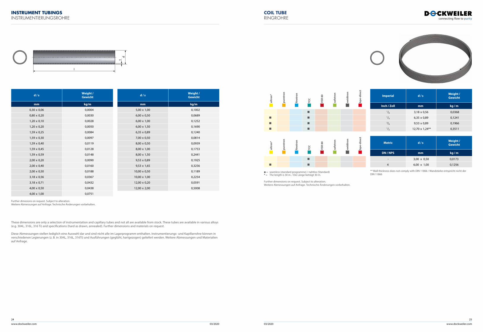
These dimensions are only a selection of instrumentation and capillary tubes and not all are available from stock. These tubes are available in various alloys (e.g. 304L, 316L, 316 Ti) and specifications (hard as drawn, annealed). Further dimensions and materials on request.
Diese Abmessungen stellen lediglich eine Auswahl dar und sind nicht alle im Lagerprogramm enthalten. Instrumentierungs- und Kapillarrohre können in verschiedenen Legierungen (z. B. in 304L, 316L, 316Ti) und Ausführungen (geglüht, hartgezogen) geliefert werden. Weitere Abmessungen und Materialien auf Anfrage.
d / s Weight / Gewicht
mm kg/m
0,30 x 0,06 0,0004
0,80 x 0,20 0,0030
1,20 x 0,10 0,0028
1,20 x 0,20 0,0050
1,59 x 0,25 0,0084
1,59 x 0,30 0,0097
1,59 x 0,40 0,0119
1,59 x 0,45 0,0128
1,59 x 0,59 0,0148
2,00 x 0,20 0,0090
2,00 x 0,40 0,0160
2,00 x 0,50 0,0188
3,18 x 0,56 0,0367
3,18 x 0,71 0,0432
4,00 x 0,50 0,0438
4,00 x 1,00 0,0751
Further dimesions on request. Subject to alteration. Weitere Abmessungen auf Anfrage. Technische Änderungen vorbehalten.
d / s Weight / Gewicht
mm kg/m
5,00 x 1,00 0,1002
6,00 x 0,50 0,0689
6,00 x 1,00 0,1252
6,00 x 1,50 0,1690
6,35 x 0,89 0,1240
7,00 x 0,50 0,0814
8,00 x 0,50 0,0939
8,00 x 1,00 0,1753
8,00 x 1,50 0,2441
9,53 x 0,89 0,1925
9,53 x 1,65 0,3256
10,00 x 0,50 0,1189
10,00 x 1,00 0,2254
12,00 x 0,20 0,0591
12,00 x 2,00 0,5008
INSTRUMENT TUBINGS INSTRUMENTIERUNGSROHRE
ds
l
COIL TUBERINGROHRE
ult
ron*
pur
etro
n
fine
tron
TCC
VSR
80
saf
etro
n
wel
dtro
n
bpe
-dir
ect
ult
ron*
pur
etro
n
fine
tron
TCC
VSR
80
saf
etro
n
wel
dtro
n
bpe
-dir
ect
= seamless (standard programme) / nahtlos (Standard)* = The length is 30 m. / Die Länge beträgt 30 m.
Further dimensions on request. Subject to alteration. Weitere Abmessungen auf Anfrage. Technische Änderungen vorbehalten.
Imperial d / s Weight / Gewicht
Inch / Zoll mm kg / m
1/8 3,18 x 0,56 0,03681/4 6,35 x 0,89 0,12413/8 9,53 x 0,89 0,19661/2 12,70 x 1,24** 0,3511
Metric d / s Weight / Gewicht
DN / NPS mm kg / m
- 3,00 x 0,50 0,0173
4 6,00 x 1,00 0,1256
** Wall thickness does not comply with DIN 11866 / Wandstärke entspricht nicht der DIN 11866
ds
l
ds
l
www.dockweiler.com 03/2020 03/2020
26
www.dockweiler.com
27
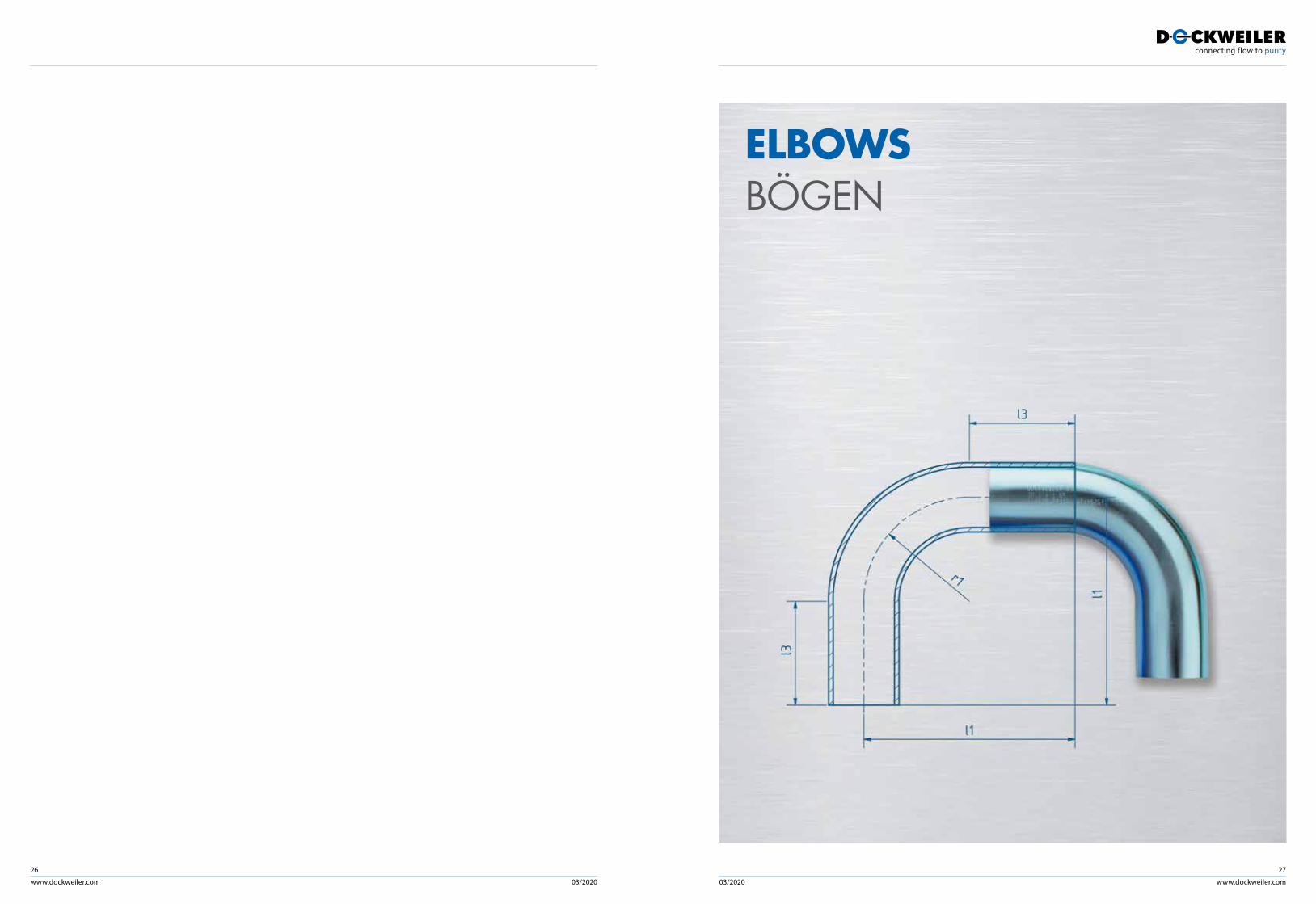
ELBOWSBÖGEN

www.dockweiler.com 03/2020 03/2020
28
www.dockweiler.com
29
ult
ron
fine
tron
TCC
saf
etro
n
wel
dtro
n
bpe
-dir
ect
• • • • • •• • • • • •• • •• • • • • •• • •• • • • • •• • • • • •• • • • • •• • • • • •• • • • • •• • • • • •• • • • • •
• • •• • • • • •
ult
ron
fine
tron
TCC
saf
etro
n
wel
dtro
n
bpe
-dir
ect
• •• •• •• •• •• •• •• •• •• •• •• •• •
Further dimesions on request. Subject to alteration. Weitere Abmessungen auf Anfrage. Technische Änderungen vorbehalten.
Imperial / DIN 11865 d1 s1 l2 r1
Inch / Zoll mm
1/4 6,35 0,89 50,80 14,303/8 9,53 0,89 50,80 28,601/2 12,70 1,24** 57,20 27,001/2 12,70 1,65 57,20 28,603/4 19,05 1,24** 57,20 26,003/4 19,05 1,65 57,20 28,60
1 25,40 1,65 57,20 38,10
1 1/2 38,10 1,65 63,50 57,20
2 50,80 1,65 76,20 76,20
2 1/2 63,50 1,65 85,70 95,30
3 76,20 1,65 92,10 114,30
4 101,60 2,11 114,30 152,40
6 152,40 2,77 158,80 228,60
6* 152,40 2,77 222,25 228,60
ISO / DIN 11865 d1 s1 l2 r1
DN / NW mm
8 13,50 1,60 33,30 20,00
10 17,20 1,60 36,60 28,00
15 21,30 1,60 37,40 30,00
20 26,90 1,60 51,80 28,50
25 33,70 2,00 55,70 38,00
32 42,40 2,00 59,70 47,50
40 48,30 2,00 63,60 57,00
50 60,30 2,00 71,50 76,00
65 76,10 2,00 94,40 95,00
80 88,90 2,30 102,40 114,50
100 114,30 2,30 118,20 152,50
150* 168,30* 2,60 94,70 228,50
150* 168,30* 2,60 149,70 228,50
* on request / auf Anfrage** Wall thickness does not comply with DIN 11865 / Wandstärke entspricht nicht der DIN 11865
l2
l2
d1s1
r1
ELBOWS 45° BÖGEN 45°
Metric / DIN 11865 d1 s1 l2 r1
DN / NW mm
4 6,00 1,00 32,10 16,00
6 8,00 1,00 32,10 13,50
6 8,00 1,00 32,10 24,00
8 10,00 1,00 33,30 20,00
8 10,00 1,00 33,30 24,00
10 12,00 1,00 35,80 26,00
10 13,00 1,50 35,80 26,00
15 18,00 1,50 35,80 26,00
15 19,00 1,50 39,50 35,00
20 23,00 1,50 41,60 40,00
25 28,00 1,50 60,70 50,00
25 29,00 1,50 60,70 50,00
32 35,00 1,50 62,80 55,00
40 41,00 1,50 64,90 60,00
50 53,00 1,50 69,00 70,00
65 70,00 2,00 73,10 80,00
80 85,00 2,00 92,30 90,00
100 104,00 2,00 96,40 100,00
150 154,00 2,00 193,20 225,00
ult
ron
fine
tron
TCC
saf
etro
n
wel
dtro
n
bpe
-dir
ect
• • • •• • • •• • •• • •• • • •• • •
•• • •
•• • • •• • •
•• • • •
•••••
• • • •Further dimesions on request. Subject to alteration. Weitere Abmessungen auf Anfrage. Technische Änderungen vorbehalten.
www.dockweiler.com 03/2020 03/2020
30
www.dockweiler.com
31
ult
ron
fine
tron
TCC
saf
etro
n
wel
dtro
n
bpe
-dir
ect
• • • • • •• • • • • •• • •• • • • • •• • •• • • • • •• • • • • •• • • • • •• • • • • •• • • • • •• • • • • •• • • • • •
• • •• • • • • •
ult
ron
fine
tron
TCC
saf
etro
n
wel
dtro
n
bpe
-dir
ect
• •• •• •• •• •• •• •• •• •• •• •
Further dimesions on request. Subject to alteration. Weitere Abmessungen auf Anfrage. Technische Änderungen vorbehalten.
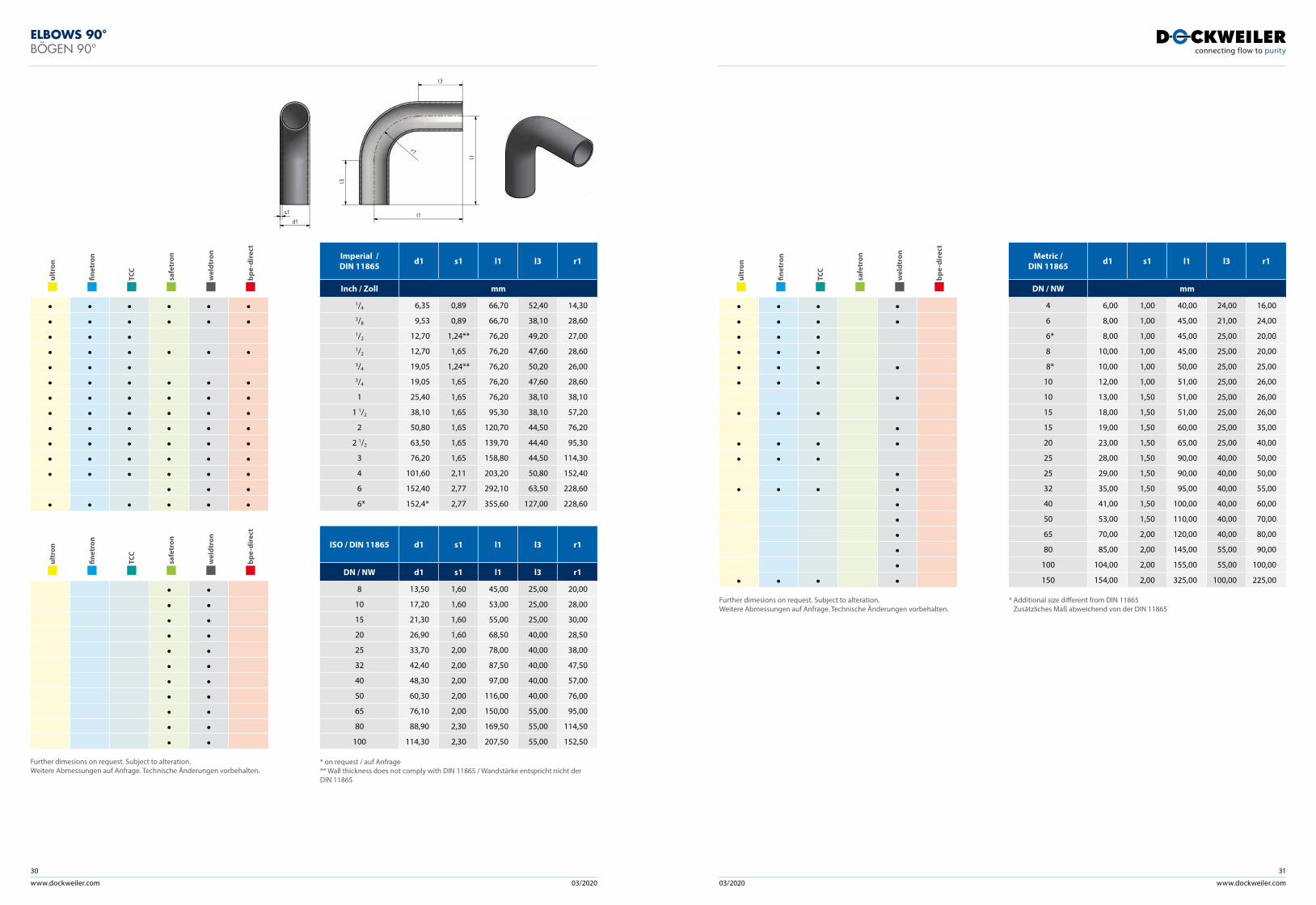
Imperial / DIN 11865 d1 s1 l1 l3 r1
Inch / Zoll mm
1/4 6,35 0,89 66,70 52,40 14,303/8 9,53 0,89 66,70 38,10 28,601/2 12,70 1,24** 76,20 49,20 27,001/2 12,70 1,65 76,20 47,60 28,603/4 19,05 1,24** 76,20 50,20 26,003/4 19,05 1,65 76,20 47,60 28,60
1 25,40 1,65 76,20 38,10 38,10
1 1/2 38,10 1,65 95,30 38,10 57,20
2 50,80 1,65 120,70 44,50 76,20
2 1/2 63,50 1,65 139,70 44,40 95,30
3 76,20 1,65 158,80 44,50 114,30
4 101,60 2,11 203,20 50,80 152,40
6 152,40 2,77 292,10 63,50 228,60
6* 152,4* 2,77 355,60 127,00 228,60
ISO / DIN 11865 d1 s1 l1 l3 r1
DN / NW d1 s1 l1 l3 r1
8 13,50 1,60 45,00 25,00 20,00
10 17,20 1,60 53,00 25,00 28,00
15 21,30 1,60 55,00 25,00 30,00
20 26,90 1,60 68,50 40,00 28,50
25 33,70 2,00 78,00 40,00 38,00
32 42,40 2,00 87,50 40,00 47,50
40 48,30 2,00 97,00 40,00 57,00
50 60,30 2,00 116,00 40,00 76,00
65 76,10 2,00 150,00 55,00 95,00
80 88,90 2,30 169,50 55,00 114,50
100 114,30 2,30 207,50 55,00 152,50
* on request / auf Anfrage** Wall thickness does not comply with DIN 11865 / Wandstärke entspricht nicht der DIN 11865
ELBOWS 90° BÖGEN 90°
s1d1
l3
l1
r1
l1
l3
ult
ron
fine
tron
TCC
saf
etro
n
wel
dtro
n
bpe
-dir
ect
• • • •• • • •• • •• • •• • • •• • •
•• • •
•• • • •• • •
•• • • •
•••••
• • • •Further dimesions on request. Subject to alteration. Weitere Abmessungen auf Anfrage. Technische Änderungen vorbehalten.
Metric / DIN 11865 d1 s1 l1 l3 r1
DN / NW mm
4 6,00 1,00 40,00 24,00 16,00
6 8,00 1,00 45,00 21,00 24,00
6* 8,00 1,00 45,00 25,00 20,00
8 10,00 1,00 45,00 25,00 20,00
8* 10,00 1,00 50,00 25,00 25,00
10 12,00 1,00 51,00 25,00 26,00
10 13,00 1,50 51,00 25,00 26,00
15 18,00 1,50 51,00 25,00 26,00
15 19,00 1,50 60,00 25,00 35,00
20 23,00 1,50 65,00 25,00 40,00
25 28,00 1,50 90,00 40,00 50,00
25 29,00 1,50 90,00 40,00 50,00
32 35,00 1,50 95,00 40,00 55,00
40 41,00 1,50 100,00 40,00 60,00
50 53,00 1,50 110,00 40,00 70,00
65 70,00 2,00 120,00 40,00 80,00
80 85,00 2,00 145,00 55,00 90,00
100 104,00 2,00 155,00 55,00 100,00
150 154,00 2,00 325,00 100,00 225,00
* Additional size different from DIN 11865 Zusätzliches Maß abweichend von der DIN 11865
www.dockweiler.com 03/2020 03/2020
32
www.dockweiler.com
33
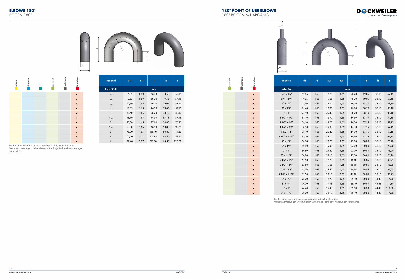
ELBOWS 180° BÖGEN 180°
ult
ron
fine
tron
TCC
saf
etro
n
wel
dtro
n
bpe
-dir
ect
•••••••••••
Further dimensions and qualitites on request. Subject to alteration.Weitere Abmessungen und Qualitäten auf Anfrage. Technische Änderungen vorbehalten.
Imperial d1 s1 l1 l2 r1
Inch / Zoll mm
1/4 6,35 0,89 66,70 9,55 57,153/8 9,53 0,89 66,70 9,55 57,151/2 12,70 1,65 76,20 19,05 57,153/4 19,05 1,65 76,20 19,05 57,15
1 25,40 1,65 76,20 38,10 38,10
1 1/2 38,10 1,65 114,30 57,15 57,15
2 50,80 1,65 127,00 50,80 76,20
2 1/2 63,50 1,65 146,10 50,85 95,25
3 76,20 1,65 165,10 50,80 114,30
4 101,60 2,11 215,90 63,50 152,40
6 152,40 2,77 292,10 63,50 228,60
l1
r1
d1
s1
l2
saf
etro
n
wel
dtro
n
bpe
-dir
ect
••••••••••••••••••••••
Imperial d1 s1 d2 s2 l1 l2 l3 r1
Inch / Zoll mm
3/4" x 1/2" 19,05 1,65 12,70 1,65 76,20 19,05 38,10 57,15
3/4" x 3/4" 19,05 1,65 19,05 1,65 76,20 19,05 38,10 57,15
1" x 1/2" 25,40 1,65 12,70 1,65 76,20 38,10 38,10 38,10
1" x 3/4" 25,40 1,65 19,05 1,65 76,20 38,10 38,10 38,10
1" x 1" 25,40 1,65 25,40 1,65 76,20 38,10 38,10 38,10
1 1/2" x 1/2" 38,10 1,65 12,70 1,65 114,30 57,15 38,10 57,15
1 1/2" x 1/2" 38,10 1,65 12,70 1,65 114,30 57,15 38,10 57,15
1 1/2" x 3/4" 38,10 1,65 19,05 1,65 114,30 57,15 38,10 57,15
1 1/2" x 1" 38,10 1,65 25,40 1,65 114,30 57,15 38,10 57,15
1 1/2" x 1 1/2" 38,10 1,65 38,10 1,65 114,30 57,15 38,10 57,15
2" x 1/2" 50,80 1,65 12,70 1,65 127,00 50,80 38,10 76,20
2" x 3/4" 50,80 1,65 19,05 1,65 127,00 50,80 38,10 76,20
2" x 1" 50,80 1,65 25,40 1,65 127,00 50,80 38,10 76,20
2" x 1 1/2" 50,80 1,65 38,10 1,65 127,00 50,80 38,10 76,20
2 1/2" x 1/2" 63,50 1,65 12,70 1,65 146,10 50,85 38,10 95,25
2 1/2" x 3/4" 63,50 1,65 19,05 1,65 146,10 50,85 38,10 95,25
2 1/2" x 1" 63,50 1,65 25,40 1,65 146,10 50,85 38,10 95,25
2 1/2" x 1 1/2" 63,50 1,65 38,10 1,65 146,10 50,85 38,10 95,25
3" x 1/2" 76,20 1,65 12,70 1,65 165,10 50,80 44,45 114,30
3" x 3/4" 76,20 1,65 19,05 1,65 165,10 50,80 44,45 114,30
3" x 1" 76,20 1,65 25,40 1,65 165,10 50,80 44,45 114,30
3" x 1 1/2" 76,20 1,65 38,10 1,65 165,10 50,80 44,45 114,30
Further dimensions and qualities on request. Subject to alteration. Weitere Abmessungen und Qualitäten auf Anfrage. Technische Änderungen vorbehalten.
180° POINT OF USE ELBOWS 180° BÖGEN MIT ABGANG
www.dockweiler.com 03/2020 03/2020
34
www.dockweiler.com
35
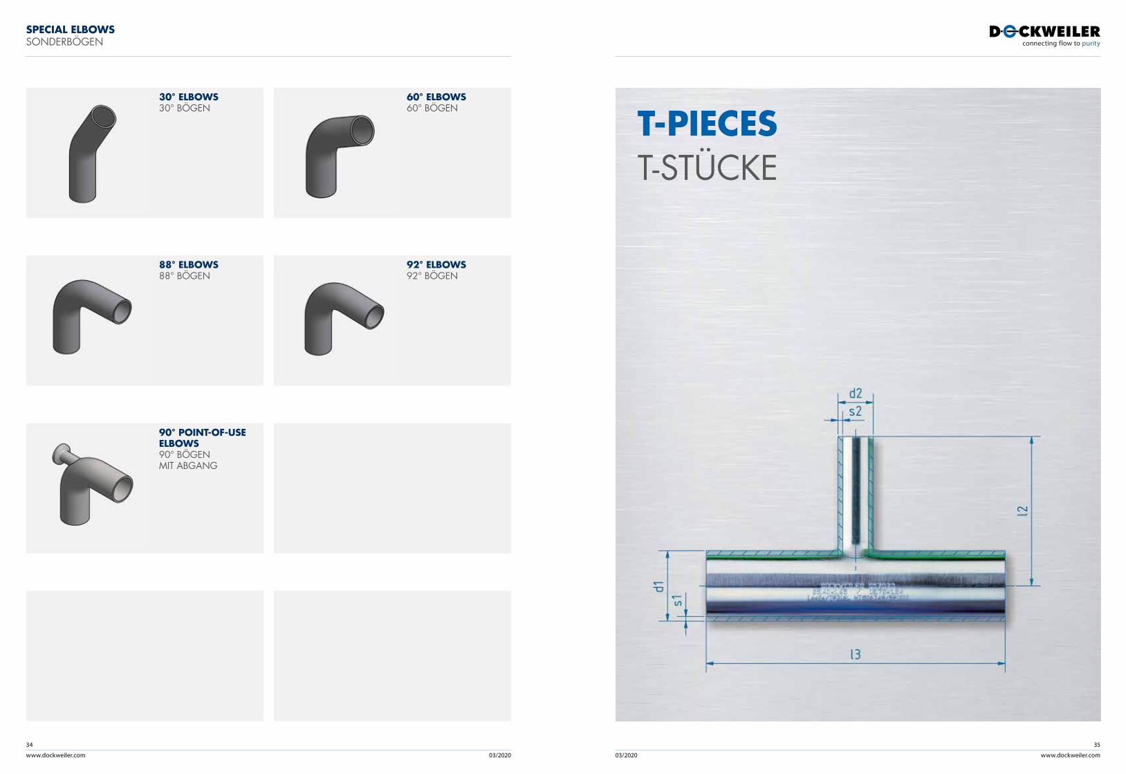
SPECIAL ELBOWS SONDERBÖGEN
88° ELBOWS88° BÖGEN
92° ELBOWS 92° BÖGEN
90° POINT-OF-USE ELBOWS 90° BÖGEN MIT ABGANG
30° ELBOWS30° BÖGEN
60° ELBOWS 60° BÖGEN
T-PIECEST-STÜCKE
www.dockweiler.com 03/2020 03/2020
36
www.dockweiler.com
37
ult
ron
fine
tron
TCC
saf
etro
n
wel
dtro
n
bpe
-dir
ect
• •• •• •• •• •• •• •• •• •• •• •• •• •• •• •• •• •• •• •• •• •• •• •• •• •
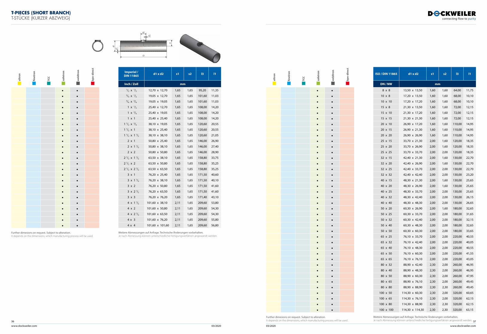
Further dimesions on request. Subject to alteration. It depends on the dimensions, which manufacturing process will be used.
Imperial / DIN 11865 d1 x d2 s1 s2 l3 l1
Inch / Zoll mm
1/2 x 1/2 12,70 x 12,70 1,65 1,65 95,20 11,353/4 x 1/2 19,05 x 12,70 1,65 1,65 101,60 11,033/4 x 3/4 19,05 x 19,05 1,65 1,65 101,60 11,03
1 x 1/2 25,40 x 12,70 1,65 1,65 108,00 14,20
1 x 3/4 25,40 x 19,05 1,65 1,65 108,00 14,20
1 x 1 25,40 x 25,40 1,65 1,65 108,00 14,20
1 1/2 x 3/4 38,10 x 19,05 1,65 1,65 120,60 20,55
1 1/2 x 1 38,10 x 25,40 1,65 1,65 120,60 20,55
1 1/2 x 1 1/2 38,10 x 38,10 1,65 1,65 120,60 21,05
2 x 1 50,80 x 25,40 1,65 1,65 146,00 26,90
2 x 1 1/2 50,80 x 38,10 1,65 1,65 146,00 27,40
2 x 2 50,80 x 50,80 1,65 1,65 146,00 28,90
2 1/2 x 1 1/2 63,50 x 38,10 1,65 1,65 158,80 33,75
2 1/2 x 2 63,50 x 50,80 1,65 1,65 158,80 35,25
2 1/2 x 2 1/2 63,50 x 63,50 1,65 1,65 158,80 35,25
3 x 1 76,20 x 25,40 1,65 1,65 171,50 40,60
3 x 1 1/2 76,20 x 38,10 1,65 1,65 171,50 40,10
3 x 2 76,20 x 50,80 1,65 1,65 171,50 41,60
3 x 2 1/2 76,20 x 63,50 1,65 1,65 171,50 41,60
3 x 3 76,20 x 76,20 1,65 1,65 171,40 43,10
4 x 1 1/2 101,60 x 38,10 2,11 1,65 209,60 53,80
4 x 2 101,60 x 50,80 2,11 1,65 209,60 54,30
4 x 2 1/2 101,60 x 63,50 2,11 1,65 209,60 54,30
4 x 3 101,60 x 76,20 2,11 1,65 209,60 55,80
4 x 4 101,60 x 101,60 2,11 1,65 209,60 56,80
Weitere Abmessungen auf Anfrage. Technische Änderungen vorbehalten.Je nach Abmessung können unterschiedliche Fertigungsverfahren angewandt werden.
l3
l1
d2
d1s1
s2
T-PIECES (SHORT BRANCH)T-STÜCKE (KURZER ABZWEIG)
ult
ron
fine
tron
TCC
saf
etro
n
wel
dtro
n
bpe
-dir
ect
• •• •• •• •• •• •• •• •• •• •• •• •• •• •• •• •• •• •• •• •• •• •• •• •• •• •• •• •• •• •• •• •• •• •• •• •• •• •• •• •
Further dimesions on request. Subject to alteration. It depends on the dimensions, which manufacturing process will be used.
ISO / DIN 11865 d1 x d2 s1 s2 l3 l1
DN / NW mm
8 x 8 13,50 x 13,50 1,60 1,60 64,00 11,75
10 x 8 17,20 x 13,50 1,60 1,60 68,00 10,10
10 x 10 17,20 x 17,20 1,60 1,60 68,00 10,10
15 x 8 21,30 x 13,50 1,60 1,60 72,00 12,15
15 x 10 21,30 x 17,20 1,60 1,60 72,00 12,15
15 x 15 21,30 x 21,30 1,60 1,60 72,00 12,15
20 x 10 26,90 x 17,20 1,60 1,60 110,00 14,95
20 x 15 26,90 x 21,30 1,60 1,60 110,00 14,95
20 x 20 26,90 x 26,90 1,60 1,60 110,00 14,95
25 x 15 33,70 x 21,30 2,00 1,60 120,00 18,35
25 x 20 33,70 x 26,90 2,00 1,60 120,00 18,35
25 x 25 33,70 x 33,70 2,00 2,00 120,00 18,35
32 x 15 42,40 x 21,30 2,00 1,60 130,00 22,70
32 x 20 42,40 x 26,90 2,00 1,60 130,00 22,70
32 x 25 42,40 x 33,70 2,00 2,00 130,00 22,70
32 x 32 42,40 x 42,40 2,00 2,00 130,00 23,20
40 x 15 48,30 x 21,30 2,00 1,60 130,00 25,65
40 x 20 48,30 x 26,90 2,00 1,60 130,00 25,65
40 x 25 48,30 x 33,70 2,00 2,00 130,00 25,65
40 x 32 48,30 x 42,40 2,00 2,00 130,00 26,15
40 x 40 48,30 x 48,30 2,00 2,00 130,00 26,65
50 x 20 60,30 x 26,90 2,00 1,60 180,00 32,65
50 x 25 60,30 x 33,70 2,00 2,00 180,00 31,65
50 x 32 60,30 x 42,40 2,00 2,00 180,00 32,15
50 x 40 60,30 x 48,30 2,00 2,00 180,00 32,65
50 x 50 60,30 x 60,30 2,00 2,00 180,00 33,65
65 x 25 76,10 x 33,70 2,00 2,00 220,00 40,55
65 x 32 76,10 x 42,40 2,00 2,00 220,00 40,05
65 x 40 76,10 x 48,30 2,00 2,00 220,00 40,55
65 x 50 76,10 x 60,30 2,00 2,00 220,00 41,55
65 x 65 76,10 x 76,10 2,00 2,00 220,00 43,05
80 x 32 88,90 x 42,40 2,30 2,00 260,00 46,95
80 x 40 88,90 x 48,30 2,30 2,00 260,00 46,95
80 x 50 88,90 x 60,30 2,30 2,00 260,00 47,95
80 x 65 88,90 x 76,10 2,30 2,00 260,00 49,45
80 x 80 88,90 x 88,90 2,30 2,30 260,00 49,45
100 x 50 114,30 x 60,30 2,30 2,00 320,00 60,65
100 x 65 114,30 x 76,10 2,30 2,00 320,00 62,15
100 x 80 114,30 x 88,90 2,30 2,30 320,00 62,15
100 x 100 114,30 x 114,30 2,30 2,30 320,00 63,15
Weitere Abmessungen auf Anfrage. Technische Änderungen vorbehalten.Je nach Abmessung können unterschiedliche Fertigungsverfahren angewandt werden.
www.dockweiler.com 03/2020 03/2020
38
www.dockweiler.com
39
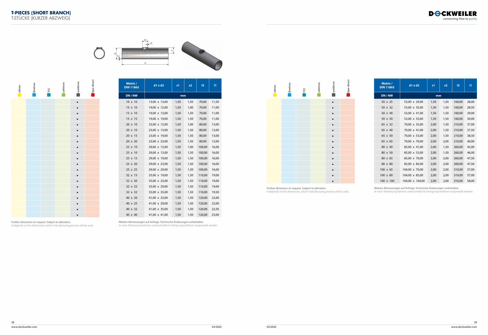
T-PIECES (SHORT BRANCH)T-STÜCKE (KURZER ABZWEIG)
ult
ron
fine
tron
TCC
saf
etro
n
wel
dtro
n
bpe
-dir
ect
•••••••••••••••••••••
Further dimesions on request. Subject to alteration. It depends on the dimensions, which manufacturing process will be used.
Metric / DIN 11865 d1 x d2 s1 s2 l3 l1
DN / NW mm
10 x 10 13,00 x 13,00 1,50 1,50 70,00 11,50
15 x 10 19,00 x 12,00 1,50 1,00 70,00 11,00
15 x 10 19,00 x 13,00 1,50 1,50 70,00 11,00
15 x 15 19,00 x 19,00 1,50 1,50 70,00 11,00
20 x 10 23,00 x 12,00 1,50 1,00 80,00 13,00
20 x 10 23,00 x 13,00 1,50 1,50 80,00 13,00
20 x 15 23,00 x 19,00 1,50 1,50 80,00 13,00
20 x 20 23,00 x 23,00 1,50 1,50 80,00 13,00
25 x 10 29,00 x 12,00 1,50 1,00 100,00 16,00
25 x 10 29,00 x 13,00 1,50 1,50 100,00 16,00
25 x 15 29,00 x 19,00 1,50 1,50 100,00 16,00
25 x 20 29,00 x 23,00 1,50 1,50 100,00 16,00
25 x 25 29,00 x 29,00 1,50 1,50 100,00 16,00
32 x 15 35,00 x 19,00 1,50 1,50 110,00 19,00
32 x 20 35,00 x 23,00 1,50 1,50 110,00 19,00
32 x 25 35,00 x 29,00 1,50 1,50 110,00 19,00
32 x 32 35,00 x 35,00 1,50 1,50 110,00 19,50
40 x 20 41,00 x 23,00 1,50 1,50 120,00 22,00
40 x 25 41,00 x 29,00 1,50 1,50 120,00 22,00
40 x 32 41,00 x 35,00 1,50 1,50 120,00 22,50
40 x 40 41,00 x 41,00 1,50 1,50 120,00 23,00
Weitere Abmessungen auf Anfrage. Technische Änderungen vorbehalten.Je nach Abmessung können unterschiedliche Fertigungsverfahren angewandt werden.
ult
ron
fine
tron
TCC
saf
etro
n
wel
dtro
n
bpe
-dir
ect
•••••••••••••••
Further dimesions on request. Subject to alteration. It depends on the dimensions, which manufacturing process will be used.
Metric / DIN 11865 d1 x d2 s1 s2 l3 l1
DN / NW mm
50 x 25 53,00 x 29,00 1,50 1,50 160,00 28,00
50 x 32 53,00 x 35,00 1,50 1,50 160,00 28,50
50 x 40 53,00 x 41,00 1,50 1,50 160,00 29,00
50 x 50 53,00 x 53,00 1,50 1,50 160,00 30,00
65 x 32 70,00 x 35,00 2,00 1,50 210,00 37,00
65 x 40 70,00 x 41,00 2,00 1,50 210,00 37,50
65 x 50 70,00 x 53,00 2,00 1,50 210,00 38,50
65 x 65 70,00 x 70,00 2,00 2,00 210,00 40,00
80 x 40 85,00 x 41,00 2,00 1,50 260,00 45,00
80 x 50 85,00 x 53,00 2,00 1,50 260,00 46,00
80 x 65 85,00 x 70,00 2,00 2,00 260,00 47,50
80 x 80 85,00 x 85,00 2,00 2,00 260,00 47,50
100 x 65 104,00 x 70,00 2,00 2,00 310,00 57,00
100 x 80 104,00 x 85,00 2,00 2,00 310,00 57,00
100 x 100 104,00 x 104,00 2,00 2,00 310,00 58,00
Weitere Abmessungen auf Anfrage. Technische Änderungen vorbehalten.Je nach Abmessung können unterschiedliche Fertigungsverfahren angewandt werden.
l3
l1
d2
d1s1
s2
www.dockweiler.com 03/2020 03/2020
40
www.dockweiler.com
41
ult
ron
fine
tron
TCC
saf
etro
n
wel
dtro
n
bpe
-dir
ect
• • • • • •• • • • • •• • • • • •• • •• • •• • •• • • • • •• • • • • •• • • • • •• • •• • •• • •• • •• • • •• • • • • •• • • • • •• • • • • •• • • • • •• • • • • •• • •• • • • • •• • •• • • • • •• • • • • •• • •• • • • • •• • •• • • • • •• • • • • •• • • • • •• • •• • • • • •• • •• • • • • •• • • • • •• • • • • •• • • • • •
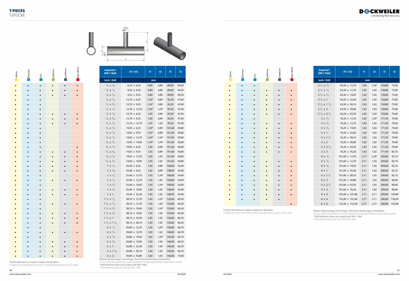
Further dimesions on request. Subject to alteration. It depends on the dimensions, which manufacturing process will be used.
Imperial /DIN 11865 d1 x d2 s1 s2 l3 l2
Inch / Zoll mm
1/4 x 1/4 6,35 x 6,35 0,89 0,89 89,00 44,503/8 x 1/4 9,53 x 6,35 0,89 0,89 89,00 44,503/8 x 3/8 9,53 x 9,53 0,89 0,89 89,00 44,501/2 x 1/4 12,70 x 6,35 1,24* 0,89 95,20 47,601/2 x 3/8 12,70 x 9,53 1,24* 0,89 95,20 47,601/2 x 1/2 12,70 x 12,70 1,24* 1,24* 95,20 47,601/2 x 1/4 12,70 x 6,35 1,65 0,89 95,20 47,601/2 x 3/8 12,70 x 9,53 1,65 0,89 95,20 47,601/2 x 1/2 12,70 x 12,70 1,65 1,65 95,20 47,603/4 x 1/4 19,05 x 6,35 1,24* 0,89 101,60 50,803/4 x 3/8 19,05 x 9,53 1,24* 0,89 101,60 50,803/4 x 1/2 19,05 x 12,70 1,24* 1,24* 101,60 50,803/4 x 3/4 19,05 x 19,05 1,24* 1,24* 101,60 50,803/4 x 1/4 19,05 x 6,35 1,65 0,89 101,60 50,803/4 x 3/8 19,05 x 9,53 1,65 0,89 101,60 50,803/4 x 1/2 19,05 x 12,70 1,65 1,65 101,60 50,803/4 x 3/4 19,05 x 19,05 1,65 1,65 101,60 50,80
1 x 1/4 25,40 x 6,35 1,65 0,89 108,00 54,00
1 x 3/8 25,40 x 9,53 1,65 0,89 108,00 54,00
1 x 1/2 25,40 x 12,70 1,65 1,24* 108,00 54,00
1 x 1/2 25,40 x 12,70 1,65 1,65 108,00 54,00
1 x 3/4 25,40 x 19,05 1,65 1,24* 108,00 54,00
1 x 3/4 25,40 x 19,05 1,65 1,65 108,00 54,00
1 x 1 25,40 x 25,40 1,65 1,65 108,00 54,00
1 1/2 x 1/2 38,10 x 12,70 1,65 1,24* 120,60 60,30
1 1/2 x 1/2 38,10 x 12,70 1,65 1,65 120,60 60,30
1 1/2 x 3/4 38,10 x 19,05 1,65 1,24* 120,60 60,30
1 1/2 x 3/4 38,10 x 19,05 1,65 1,65 120,60 60,30
1 1/2 x 1 38,10 x 25,40 1,65 1,65 120,60 60,30
1 1/2 x 1 1/2 38,10 x 38,10 1,65 1,65 120,60 60,30
2 x 1/2 50,80 x 12,70 1,65 1,24* 146,00 66,70
2 x 1/2 50,80 x 12,70 1,65 1,65 146,00 66,70
2 x 3/4 50,80 x 19,05 1,65 1,24* 146,00 66,70
2 x 3/4 50,80 x 19,05 1,65 1,65 146,00 66,70
2 x 1 50,80 x 25,40 1,65 1,65 146,00 66,70
2 x 1 1/2 50,80 x 38,10 1,65 1,65 146,00 66,70
2 x 2 50,80 x 50,80 1,65 1,65 146,00 73,00Weitere Abmessungen auf Anfrage. Technische Änderungen vorbehalten.Je nach Abmessung können unterschiedliche Fertigungsverfahren angewandt werden.* Wall thickness does not comply with DIN 11865 * Wandstärke entspricht nicht der DIN 11865
T-PIECEST-STÜCKE
ult
ron
fine
tron
TCC
saf
etro
n
wel
dtro
n
bpe
-dir
ect
• • •• • • • • •• • • • • •• • • • • •• • • • • •• • • • • •• • • • • •• • •• • • • • •• • • • • •• • • • • •• • • • • •• • • • • •• • • • • •• • • • • •• • •• • • • • •• • • • • •• • • • • •• • • • • •• • • • • •• • • • • •• • • • • •• • • • • •• • • • •
•Further dimesions on request. Subject to alteration. It depends on the dimensions, which manufacturing process will be used.
Imperial /DIN 11865 d1 x d2 s1 s2 l3 l2
Inch / Zoll mm
2 1/2 x 1/2 63,50 x 12,70 1,65 1,24* 158,80 73,00
2 1/2 x 1/2 63,50 x 12,70 1,65 1,65 158,80 73,00
2 1/2 x 3/4 63,50 x 19,05 1,65 1,65 158,80 73,00
2 1/2 x 1 63,50 x 25,40 1,65 1,65 158,80 73,00
2 1/2 x 1 1/2 63,50 x 38,10 1,65 1,65 158,80 73,00
2 1/2 x 2 63,50 x 50,80 1,65 1,65 158,80 73,00
2 1/2 x 2 1/2 63,50 x 63,50 1,65 1,65 158,80 79,40
3 x 1/2 76,20 x 12,70 1,65 1,24* 171,50 79,40
3 x 1/2 76,20 x 12,70 1,65 1,65 171,50 79,40
3 x 3/4 76,20 x 19,05 1,65 1,65 171,50 79,40
3 x 1 76,20 x 25,40 1,65 1,65 171,50 79,40
3 x 1 1/2 76,20 x 38,10 1,65 1,65 171,50 79,40
3 x 2 76,20 x 50,80 1,65 1,65 171,50 79,40
3 x 2 1/2 76,20 x 63,50 1,65 1,65 171,50 79,40
3 x 3 76,20 x 76,20 1,65 1,65 171,40 85,70
4 x 1/2 101,60 x 12,70 2,11 1,24* 209,60 92,10
4 x 1/2 101,60 x 12,70 2,11 1,65 209,60 92,10
4 x 3/4 101,60 x 19,05 2,11 1,65 209,60 92,10
4 x 1 101,60 x 25,40 2,11 1,65 209,60 92,10
4 x 1 1/2 101,60 x 38,10 2,11 1,65 209,60 92,10
4 x 2 101,60 x 50,80 2,11 1,65 209,60 98,40
4 x 2 1/2 101,60 x 63,50 2,11 1,65 209,60 98,40
4 x 3 101,60 x 76,20 2,11 1,65 209,60 98,40
4 x 4 101,60 x 101,60 2,11 2,11 209,60 104,80
6 x 4 152,40 x 101,60 2,77 2,11 285,80 130,20
6 x 6 152,40 x 152,40 2,77 2,77 285,80 142,90
Weitere Abmessungen auf Anfrage. Technische Änderungen vorbehalten.Je nach Abmessung können unterschiedliche Fertigungsverfahren angewandt werden. * Wall thickness does not comply with DIN 11865 * Wandstärke entspricht nicht der DIN 11865
d1s1
d2s2
l2
l3
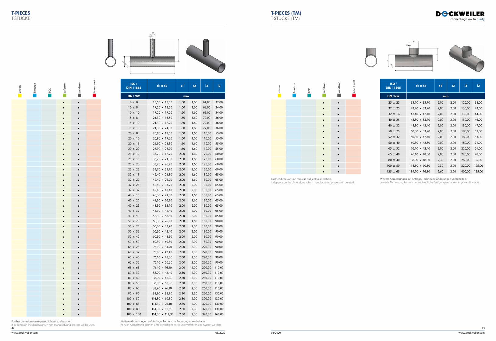
www.dockweiler.com 03/2020 03/2020
42
www.dockweiler.com
43
ult
ron
fine
tron
TCC
saf
etro
n
wel
dtro
n
bpe
-dir
ect
• •• •• •• •• •• •• •• •• •• •• •• •• •• •• •• •• •• •• •• •• •• •• •• •• •• •• •• •• •• •• •• •• •• •• •• •• •• •• •• •• •• •
Further dimesions on request. Subject to alteration. It depends on the dimensions, which manufacturing process will be used.
ISO / DIN 11865 d1 x d2 s1 s2 l3 l2
DN / NW mm
8 x 8 13,50 x 13,50 1,60 1,60 64,00 32,00
10 x 8 17,20 x 13,50 1,60 1,60 68,00 34,00
10 x 10 17,20 x 17,20 1,60 1,60 68,00 34,00
15 x 8 21,30 x 13,50 1,60 1,60 72,00 36,00
15 x 10 21,30 x 17,20 1,60 1,60 72,00 36,00
15 x 15 21,30 x 21,30 1,60 1,60 72,00 36,00
20 x 8 26,90 x 13,50 1,60 1,60 110,00 55,00
20 x 10 26,90 x 17,20 1,60 1,60 110,00 55,00
20 x 15 26,90 x 21,30 1,60 1,60 110,00 55,00
20 x 20 26,90 x 26,90 1,60 1,60 110,00 55,00
25 x 10 33,70 x 17,20 2,00 1,60 120,00 60,00
25 x 15 33,70 x 21,30 2,00 1,60 120,00 60,00
25 x 20 33,70 x 26,90 2,00 1,60 120,00 60,00
25 x 25 33,70 x 33,70 2,00 2,00 120,00 60,00
32 x 15 42,40 x 21,30 2,00 1,60 130,00 65,00
32 x 20 42,40 x 26,90 2,00 1,60 130,00 65,00
32 x 25 42,40 x 33,70 2,00 2,00 130,00 65,00
32 x 32 42,40 x 42,40 2,00 2,00 130,00 65,00
40 x 15 48,30 x 21,30 2,00 1,60 130,00 65,00
40 x 20 48,30 x 26,90 2,00 1,60 130,00 65,00
40 x 25 48,30 x 33,70 2,00 2,00 130,00 65,00
40 x 32 48,30 x 42,40 2,00 2,00 130,00 65,00
40 x 40 48,30 x 48,30 2,00 2,00 130,00 65,00
50 x 20 60,30 x 26,90 2,00 1,60 180,00 90,00
50 x 25 60,30 x 33,70 2,00 2,00 180,00 90,00
50 x 32 60,30 x 42,40 2,00 2,00 180,00 90,00
50 x 40 60,30 x 48,30 2,00 2,00 180,00 90,00
50 x 50 60,30 x 60,30 2,00 2,00 180,00 90,00
65 x 25 76,10 x 33,70 2,00 2,00 220,00 90,00
65 x 32 76,10 x 42,40 2,00 2,00 220,00 90,00
65 x 40 76,10 x 48,30 2,00 2,00 220,00 90,00
65 x 50 76,10 x 60,30 2,00 2,00 220,00 90,00
65 x 65 76,10 x 76,10 2,00 2,00 220,00 110,00
80 x 32 88,90 x 42,40 2,30 2,00 260,00 110,00
80 x 40 88,90 x 48,30 2,30 2,00 260,00 110,00
80 x 50 88,90 x 60,30 2,30 2,00 260,00 110,00
80 x 65 88,90 x 76,10 2,30 2,00 260,00 110,00
80 x 80 88,90 x 88,90 2,30 2,30 260,00 130,00
100 x 50 114,30 x 60,30 2,30 2,00 320,00 130,00
100 x 65 114,30 x 76,10 2,30 2,00 320,00 130,00
100 x 80 114,30 x 88,90 2,30 2,30 320,00 130,00
100 x 100 114,30 x 114,30 2,30 2,30 320,00 160,00
Weitere Abmessungen auf Anfrage. Technische Änderungen vorbehalten.Je nach Abmessung können unterschiedliche Fertigungsverfahren angewandt werden.
T-PIECEST-STÜCKE
ult
ron
fine
tron
TCC
saf
etro
n
wel
dtro
n
bpe
-dir
ect
• •• •• •• •• •• •• •• •• •• •• •• •• •
Further dimesions on request. Subject to alteration. It depends on the dimensions, which manufacturing process will be used.
ISO / DIN 11865 d1 x d2 s1 s2 l3 l2
DN / NW mm
25 x 25 33,70 x 33,70 2,00 2,00 120,00 38,00
32 x 25 42,40 x 33,70 2,00 2,00 130,00 43,00
32 x 32 42,40 x 42,40 2,00 2,00 130,00 44,00
40 x 25 48,30 x 33,70 2,00 2,00 130,00 46,00
40 x 32 48,30 x 42,40 2,00 2,00 130,00 47,00
50 x 25 60,30 x 33,70 2,00 2,00 180,00 52,00
52 x 32 60,30 x 42,40 2,00 2,00 180,00 53,00
50 x 40 60,30 x 48,30 2,00 2,00 180,00 71,00
65 x 32 76,10 x 42,40 2,00 2,00 220,00 61,00
65 x 40 76,10 x 48,30 2,00 2,00 220,00 78,00
80 x 40 88,90 x 48,30 2,30 2,00 260,00 85,00
100 x 50 114,30 x 60,30 2,30 2,00 320,00 125,00
125 x 65 139,70 x 76,10 2,60 2,00 400,00 155,00
Weitere Abmessungen auf Anfrage. Technische Änderungen vorbehalten.Je nach Abmessung können unterschiedliche Fertigungsverfahren angewandt werden.
d1s1
d2s2
l2
l3
T-PIECES (TM)T-STÜCKE (TM)
d1
s1
d2
s2
l2
l3
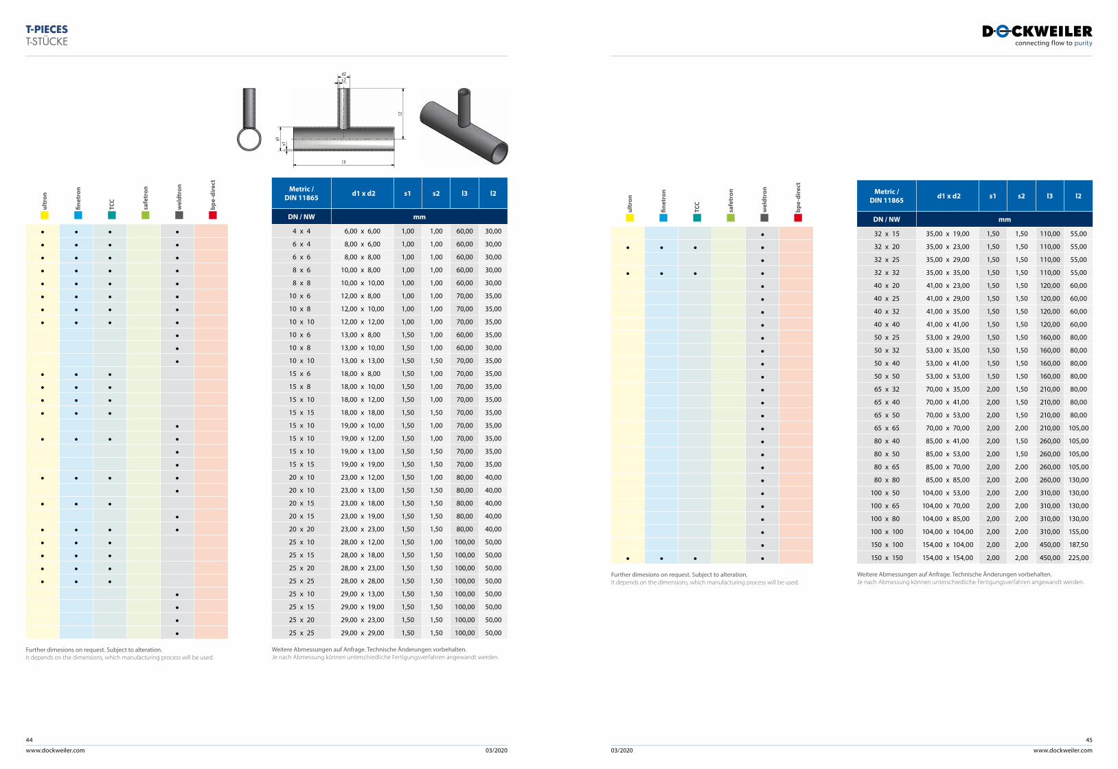
www.dockweiler.com 03/2020 03/2020
44
www.dockweiler.com
45
ult
ron
fine
tron
TCC
saf
etro
n
wel
dtro
n
bpe
-dir
ect
•• • • •
•• • • •
•••••••••••••••••••••
• • • •Further dimesions on request. Subject to alteration. It depends on the dimensions, which manufacturing process will be used.
Metric / DIN 11865 d1 x d2 s1 s2 l3 l2
DN / NW mm
32 x 15 35,00 x 19,00 1,50 1,50 110,00 55,00
32 x 20 35,00 x 23,00 1,50 1,50 110,00 55,00
32 x 25 35,00 x 29,00 1,50 1,50 110,00 55,00
32 x 32 35,00 x 35,00 1,50 1,50 110,00 55,00
40 x 20 41,00 x 23,00 1,50 1,50 120,00 60,00
40 x 25 41,00 x 29,00 1,50 1,50 120,00 60,00
40 x 32 41,00 x 35,00 1,50 1,50 120,00 60,00
40 x 40 41,00 x 41,00 1,50 1,50 120,00 60,00
50 x 25 53,00 x 29,00 1,50 1,50 160,00 80,00
50 x 32 53,00 x 35,00 1,50 1,50 160,00 80,00
50 x 40 53,00 x 41,00 1,50 1,50 160,00 80,00
50 x 50 53,00 x 53,00 1,50 1,50 160,00 80,00
65 x 32 70,00 x 35,00 2,00 1,50 210,00 80,00
65 x 40 70,00 x 41,00 2,00 1,50 210,00 80,00
65 x 50 70,00 x 53,00 2,00 1,50 210,00 80,00
65 x 65 70,00 x 70,00 2,00 2,00 210,00 105,00
80 x 40 85,00 x 41,00 2,00 1,50 260,00 105,00
80 x 50 85,00 x 53,00 2,00 1,50 260,00 105,00
80 x 65 85,00 x 70,00 2,00 2,00 260,00 105,00
80 x 80 85,00 x 85,00 2,00 2,00 260,00 130,00
100 x 50 104,00 x 53,00 2,00 2,00 310,00 130,00
100 x 65 104,00 x 70,00 2,00 2,00 310,00 130,00
100 x 80 104,00 x 85,00 2,00 2,00 310,00 130,00
100 x 100 104,00 x 104,00 2,00 2,00 310,00 155,00
150 x 100 154,00 x 104,00 2,00 2,00 450,00 187,50
150 x 150 154,00 x 154,00 2,00 2,00 450,00 225,00
Weitere Abmessungen auf Anfrage. Technische Änderungen vorbehalten.Je nach Abmessung können unterschiedliche Fertigungsverfahren angewandt werden.
ult
ron
fine
tron
TCC
saf
etro
n
wel
dtro
n
bpe
-dir
ect
• • • •• • • •• • • •• • • •• • • •• • • •• • • •• • • •
•••
• • •• • •• • •• • •
•• • • •
••
• • • ••
• • ••
• • • •• • •• • •• • •• • •
••••
Further dimesions on request. Subject to alteration. It depends on the dimensions, which manufacturing process will be used.
Metric / DIN 11865 d1 x d2 s1 s2 l3 l2
DN / NW mm
4 x 4 6,00 x 6,00 1,00 1,00 60,00 30,00
6 x 4 8,00 x 6,00 1,00 1,00 60,00 30,00
6 x 6 8,00 x 8,00 1,00 1,00 60,00 30,00
8 x 6 10,00 x 8,00 1,00 1,00 60,00 30,00
8 x 8 10,00 x 10,00 1,00 1,00 60,00 30,00
10 x 6 12,00 x 8,00 1,00 1,00 70,00 35,00
10 x 8 12,00 x 10,00 1,00 1,00 70,00 35,00
10 x 10 12,00 x 12,00 1,00 1,00 70,00 35,00
10 x 6 13,00 x 8,00 1,50 1,00 60,00 35,00
10 x 8 13,00 x 10,00 1,50 1,00 60,00 30,00
10 x 10 13,00 x 13,00 1,50 1,50 70,00 35,00
15 x 6 18,00 x 8,00 1,50 1,00 70,00 35,00
15 x 8 18,00 x 10,00 1,50 1,00 70,00 35,00
15 x 10 18,00 x 12,00 1,50 1,00 70,00 35,00
15 x 15 18,00 x 18,00 1,50 1,50 70,00 35,00
15 x 10 19,00 x 10,00 1,50 1,00 70,00 35,00
15 x 10 19,00 x 12,00 1,50 1,00 70,00 35,00
15 x 10 19,00 x 13,00 1,50 1,50 70,00 35,00
15 x 15 19,00 x 19,00 1,50 1,50 70,00 35,00
20 x 10 23,00 x 12,00 1,50 1,00 80,00 40,00
20 x 10 23,00 x 13,00 1,50 1,50 80,00 40,00
20 x 15 23,00 x 18,00 1,50 1,50 80,00 40,00
20 x 15 23,00 x 19,00 1,50 1,50 80,00 40,00
20 x 20 23,00 x 23,00 1,50 1,50 80,00 40,00
25 x 10 28,00 x 12,00 1,50 1,00 100,00 50,00
25 x 15 28,00 x 18,00 1,50 1,50 100,00 50,00
25 x 20 28,00 x 23,00 1,50 1,50 100,00 50,00
25 x 25 28,00 x 28,00 1,50 1,50 100,00 50,00
25 x 10 29,00 x 13,00 1,50 1,50 100,00 50,00
25 x 15 29,00 x 19,00 1,50 1,50 100,00 50,00
25 x 20 29,00 x 23,00 1,50 1,50 100,00 50,00
25 x 25 29,00 x 29,00 1,50 1,50 100,00 50,00
Weitere Abmessungen auf Anfrage. Technische Änderungen vorbehalten.Je nach Abmessung können unterschiedliche Fertigungsverfahren angewandt werden.
T-PIECEST-STÜCKE
d1s1
d2s2
l2
l3
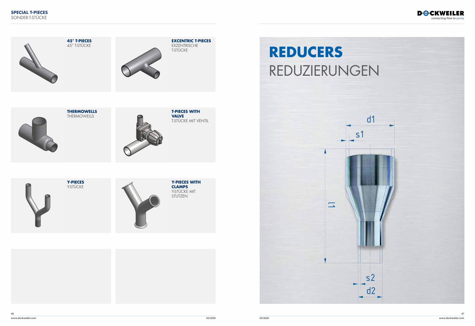
www.dockweiler.com 03/2020 03/2020
46
www.dockweiler.com
47
REDUCERSREDUZIERUNGEN
SPECIAL T-PIECESSONDER-T-STÜCKE
THERMOWELLS THERMOWELLS
T-PIECES WITH VALVE T-STÜCKE MIT VENTIL
Y-PIECES Y-STÜCKE
Y-PIECES WITH CLAMPSY-STÜCKE MIT STUTZEN
45° T-PIECES 45° T-STÜCKE
EXCENTRIC T-PIECES EXZENTRISCHE T-STÜCKE
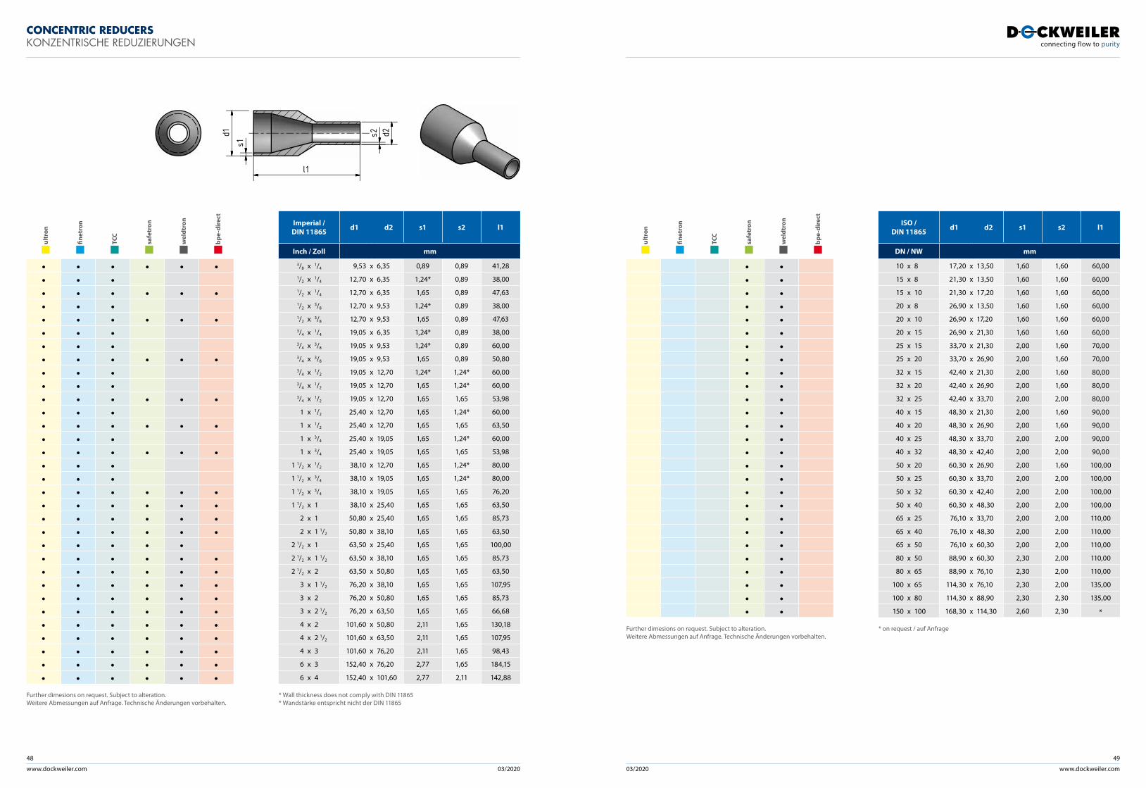
www.dockweiler.com 03/2020 03/2020
48
www.dockweiler.com
49
ult
ron
fine
tron
TCC
saf
etro
n
wel
dtro
n
bpe
-dir
ect
• • • • • •• • •• • • • • •• • •• • • • • •• • •• • •• • • • • •• • •• • •• • • • • •• • •• • • • • •• • •• • • • • •• • •• • •• • • • • •• • • • • •• • • • • •• • • • • •• • • • •• • • • • •• • • • • •• • • • • •• • • • • •• • • • • •• • • • • •• • • • • •• • • • • •• • • • • •• • • • • •
Further dimesions on request. Subject to alteration. Weitere Abmessungen auf Anfrage. Technische Änderungen vorbehalten.
Imperial /DIN 11865 d1 d2 s1 s2 l1
Inch / Zoll mm
3/8 x 1/4 9,53 x 6,35 0,89 0,89 41,281/2 x 1/4 12,70 x 6,35 1,24* 0,89 38,001/2 x 1/4 12,70 x 6,35 1,65 0,89 47,631/2 x 3/8 12,70 x 9,53 1,24* 0,89 38,001/2 x 3/8 12,70 x 9,53 1,65 0,89 47,633/4 x 1/4 19,05 x 6,35 1,24* 0,89 38,003/4 x 3/8 19,05 x 9,53 1,24* 0,89 60,003/4 x 3/8 19,05 x 9,53 1,65 0,89 50,803/4 x 1/2 19,05 x 12,70 1,24* 1,24* 60,003/4 x 1/2 19,05 x 12,70 1,65 1,24* 60,003/4 x 1/2 19,05 x 12,70 1,65 1,65 53,98
1 x 1/2 25,40 x 12,70 1,65 1,24* 60,00
1 x 1/2 25,40 x 12,70 1,65 1,65 63,50
1 x 3/4 25,40 x 19,05 1,65 1,24* 60,00
1 x 3/4 25,40 x 19,05 1,65 1,65 53,98
1 1/2 x 1/2 38,10 x 12,70 1,65 1,24* 80,00
1 1/2 x 3/4 38,10 x 19,05 1,65 1,24* 80,00
1 1/2 x 3/4 38,10 x 19,05 1,65 1,65 76,20
1 1/2 x 1 38,10 x 25,40 1,65 1,65 63,50
2 x 1 50,80 x 25,40 1,65 1,65 85,73
2 x 1 1/2 50,80 x 38,10 1,65 1,65 63,50
2 1/2 x 1 63,50 x 25,40 1,65 1,65 100,00
2 1/2 x 1 1/2 63,50 x 38,10 1,65 1,65 85,73
2 1/2 x 2 63,50 x 50,80 1,65 1,65 63,50
3 x 1 1/2 76,20 x 38,10 1,65 1,65 107,95
3 x 2 76,20 x 50,80 1,65 1,65 85,73
3 x 2 1/2 76,20 x 63,50 1,65 1,65 66,68
4 x 2 101,60 x 50,80 2,11 1,65 130,18
4 x 2 1/2 101,60 x 63,50 2,11 1,65 107,95
4 x 3 101,60 x 76,20 2,11 1,65 98,43
6 x 3 152,40 x 76,20 2,77 1,65 184,15
6 x 4 152,40 x 101,60 2,77 2,11 142,88
* Wall thickness does not comply with DIN 11865 * Wandstärke entspricht nicht der DIN 11865
CONCENTRIC REDUCERSKONZENTRISCHE REDUZIERUNGEN
d1s1
d2s2
l1
ult
ron
fine
tron
TCC
saf
etro
n
wel
dtro
n
bpe
-dir
ect
• •• •• •• •• •• •• •• •• •• •• •• •• •• •• •• •• •• •• •• •• •• •• •• •• •• •• •
Further dimesions on request. Subject to alteration. Weitere Abmessungen auf Anfrage. Technische Änderungen vorbehalten.
ISO / DIN 11865 d1 d2 s1 s2 l1
DN / NW mm
10 x 8 17,20 x 13,50 1,60 1,60 60,00
15 x 8 21,30 x 13,50 1,60 1,60 60,00
15 x 10 21,30 x 17,20 1,60 1,60 60,00
20 x 8 26,90 x 13,50 1,60 1,60 60,00
20 x 10 26,90 x 17,20 1,60 1,60 60,00
20 x 15 26,90 x 21,30 1,60 1,60 60,00
25 x 15 33,70 x 21,30 2,00 1,60 70,00
25 x 20 33,70 x 26,90 2,00 1,60 70,00
32 x 15 42,40 x 21,30 2,00 1,60 80,00
32 x 20 42,40 x 26,90 2,00 1,60 80,00
32 x 25 42,40 x 33,70 2,00 2,00 80,00
40 x 15 48,30 x 21,30 2,00 1,60 90,00
40 x 20 48,30 x 26,90 2,00 1,60 90,00
40 x 25 48,30 x 33,70 2,00 2,00 90,00
40 x 32 48,30 x 42,40 2,00 2,00 90,00
50 x 20 60,30 x 26,90 2,00 1,60 100,00
50 x 25 60,30 x 33,70 2,00 2,00 100,00
50 x 32 60,30 x 42,40 2,00 2,00 100,00
50 x 40 60,30 x 48,30 2,00 2,00 100,00
65 x 25 76,10 x 33,70 2,00 2,00 110,00
65 x 40 76,10 x 48,30 2,00 2,00 110,00
65 x 50 76,10 x 60,30 2,00 2,00 110,00
80 x 50 88,90 x 60,30 2,30 2,00 110,00
80 x 65 88,90 x 76,10 2,30 2,00 110,00
100 x 65 114,30 x 76,10 2,30 2,00 135,00
100 x 80 114,30 x 88,90 2,30 2,30 135,00
150 x 100 168,30 x 114,30 2,60 2,30 *
* on request / auf Anfrage
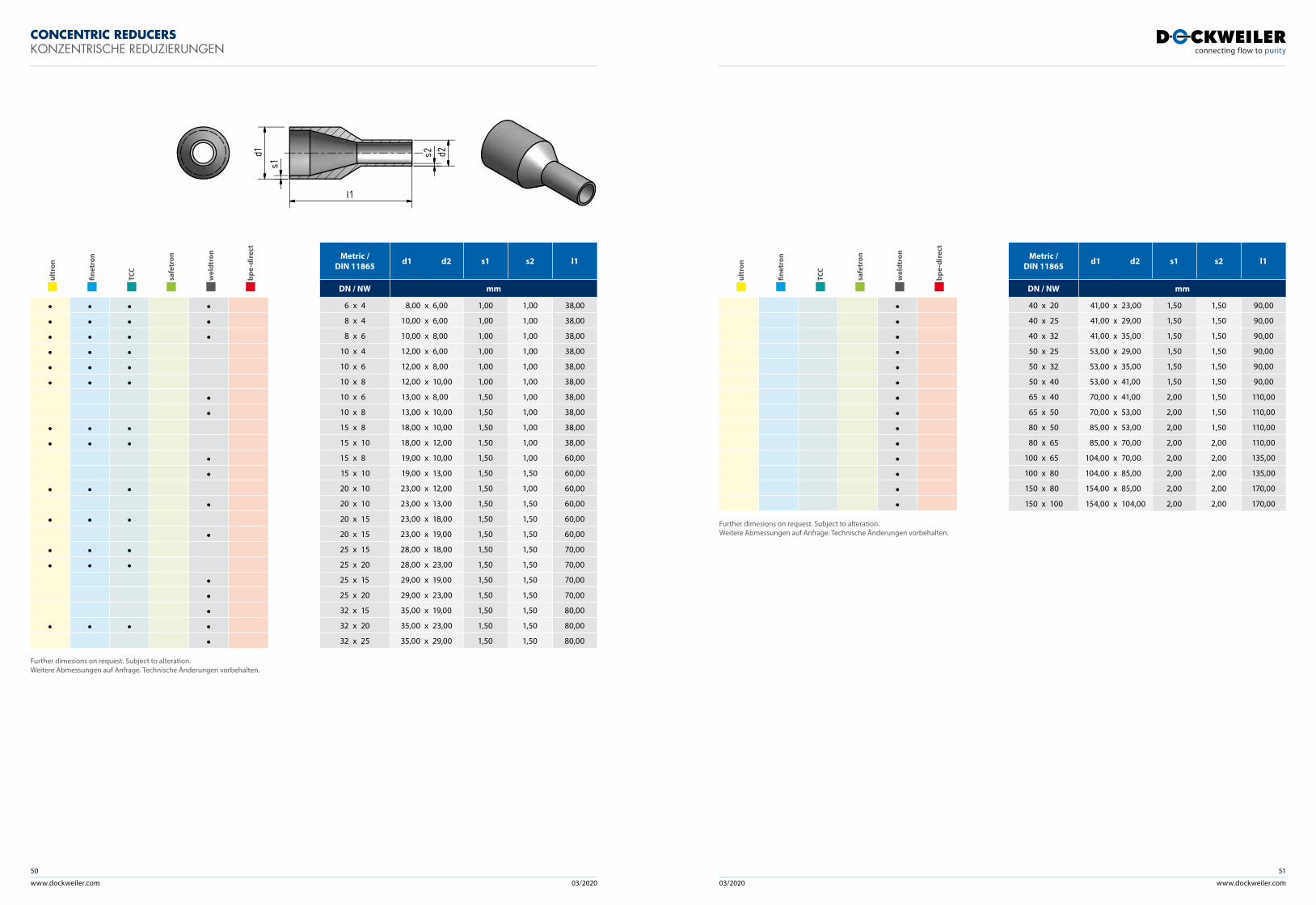
www.dockweiler.com 03/2020 03/2020
50
www.dockweiler.com
51
ult
ron
fine
tron
TCC
saf
etro
n
wel
dtro
n
bpe
-dir
ect
• • • •• • • •• • • •• • •• • •• • •
••
• • •• • •
••
• • ••
• • ••
• • •• • •
•••
• • • ••
Further dimesions on request. Subject to alteration. Weitere Abmessungen auf Anfrage. Technische Änderungen vorbehalten.
Metric / DIN 11865 d1 d2 s1 s2 l1
DN / NW mm
6 x 4 8,00 x 6,00 1,00 1,00 38,00
8 x 4 10,00 x 6,00 1,00 1,00 38,00
8 x 6 10,00 x 8,00 1,00 1,00 38,00
10 x 4 12,00 x 6,00 1,00 1,00 38,00
10 x 6 12,00 x 8,00 1,00 1,00 38,00
10 x 8 12,00 x 10,00 1,00 1,00 38,00
10 x 6 13,00 x 8,00 1,50 1,00 38,00
10 x 8 13,00 x 10,00 1,50 1,00 38,00
15 x 8 18,00 x 10,00 1,50 1,00 38,00
15 x 10 18,00 x 12,00 1,50 1,00 38,00
15 x 8 19,00 x 10,00 1,50 1,00 60,00
15 x 10 19,00 x 13,00 1,50 1,50 60,00
20 x 10 23,00 x 12,00 1,50 1,00 60,00
20 x 10 23,00 x 13,00 1,50 1,50 60,00
20 x 15 23,00 x 18,00 1,50 1,50 60,00
20 x 15 23,00 x 19,00 1,50 1,50 60,00
25 x 15 28,00 x 18,00 1,50 1,50 70,00
25 x 20 28,00 x 23,00 1,50 1,50 70,00
25 x 15 29,00 x 19,00 1,50 1,50 70,00
25 x 20 29,00 x 23,00 1,50 1,50 70,00
32 x 15 35,00 x 19,00 1,50 1,50 80,00
32 x 20 35,00 x 23,00 1,50 1,50 80,00
32 x 25 35,00 x 29,00 1,50 1,50 80,00
CONCENTRIC REDUCERSKONZENTRISCHE REDUZIERUNGEN
ult
ron
fine
tron
TCC
saf
etro
n
wel
dtro
n
bpe
-dir
ect
••••••••••••••
Further dimesions on request. Subject to alteration. Weitere Abmessungen auf Anfrage. Technische Änderungen vorbehalten.
Metric / DIN 11865 d1 d2 s1 s2 l1
DN / NW mm
40 x 20 41,00 x 23,00 1,50 1,50 90,00
40 x 25 41,00 x 29,00 1,50 1,50 90,00
40 x 32 41,00 x 35,00 1,50 1,50 90,00
50 x 25 53,00 x 29,00 1,50 1,50 90,00
50 x 32 53,00 x 35,00 1,50 1,50 90,00
50 x 40 53,00 x 41,00 1,50 1,50 90,00
65 x 40 70,00 x 41,00 2,00 1,50 110,00
65 x 50 70,00 x 53,00 2,00 1,50 110,00
80 x 50 85,00 x 53,00 2,00 1,50 110,00
80 x 65 85,00 x 70,00 2,00 2,00 110,00
100 x 65 104,00 x 70,00 2,00 2,00 135,00
100 x 80 104,00 x 85,00 2,00 2,00 135,00
150 x 80 154,00 x 85,00 2,00 2,00 170,00
150 x 100 154,00 x 104,00 2,00 2,00 170,00
d1s1
d2s2
l1
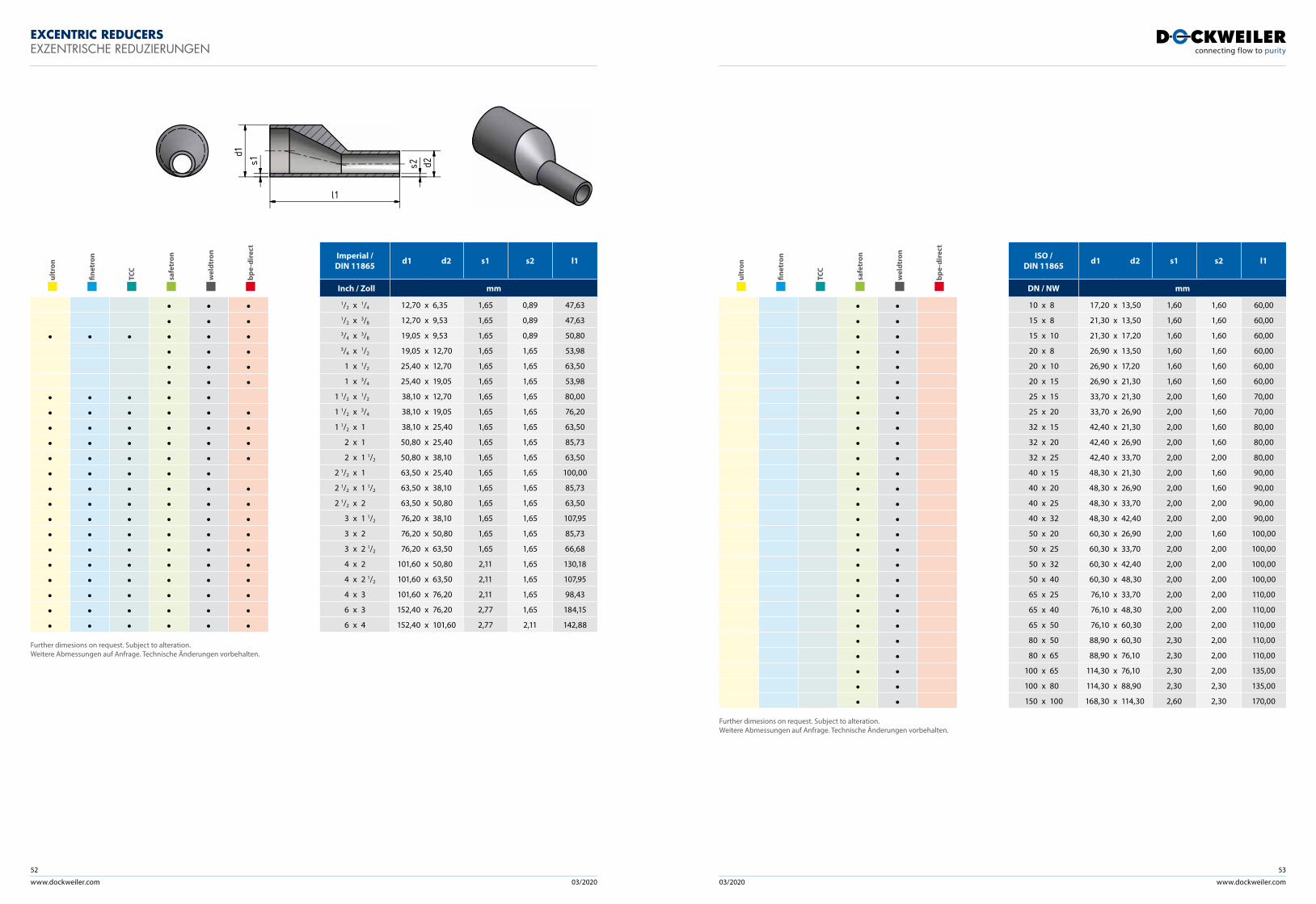
www.dockweiler.com 03/2020 03/2020
52
www.dockweiler.com
53
EXCENTRIC REDUCERSEXZENTRISCHE REDUZIERUNGEN
d1s1 d2s2
l1
Imperial /DIN 11865 d1 d2 s1 s2 l1
Inch / Zoll mm
1/2 x 1/4 12,70 x 6,35 1,65 0,89 47,631/2 x 3/8 12,70 x 9,53 1,65 0,89 47,633/4 x 3/8 19,05 x 9,53 1,65 0,89 50,803/4 x 1/2 19,05 x 12,70 1,65 1,65 53,98
1 x 1/2 25,40 x 12,70 1,65 1,65 63,50
1 x 3/4 25,40 x 19,05 1,65 1,65 53,98
1 1/2 x 1/2 38,10 x 12,70 1,65 1,65 80,00
1 1/2 x 3/4 38,10 x 19,05 1,65 1,65 76,20
1 1/2 x 1 38,10 x 25,40 1,65 1,65 63,50
2 x 1 50,80 x 25,40 1,65 1,65 85,73
2 x 1 1/2 50,80 x 38,10 1,65 1,65 63,50
2 1/2 x 1 63,50 x 25,40 1,65 1,65 100,00
2 1/2 x 1 1/2 63,50 x 38,10 1,65 1,65 85,73
2 1/2 x 2 63,50 x 50,80 1,65 1,65 63,50
3 x 1 1/2 76,20 x 38,10 1,65 1,65 107,95
3 x 2 76,20 x 50,80 1,65 1,65 85,73
3 x 2 1/2 76,20 x 63,50 1,65 1,65 66,68
4 x 2 101,60 x 50,80 2,11 1,65 130,18
4 x 2 1/2 101,60 x 63,50 2,11 1,65 107,95
4 x 3 101,60 x 76,20 2,11 1,65 98,43
6 x 3 152,40 x 76,20 2,77 1,65 184,15
6 x 4 152,40 x 101,60 2,77 2,11 142,88
ult
ron
fine
tron
TCC
saf
etro
n
wel
dtro
n
bpe
-dir
ect
• • •• • •
• • • • • •• • •• • •• • •
• • • • •• • • • • •• • • • • •• • • • • •• • • • • •• • • • •• • • • • •• • • • • •• • • • • •• • • • • •• • • • • •• • • • • • • • • • • •• • • • • •• • • • • •• • • • • •
Further dimesions on request. Subject to alteration. Weitere Abmessungen auf Anfrage. Technische Änderungen vorbehalten.
ISO / DIN 11865 d1 d2 s1 s2 l1
DN / NW mm
10 x 8 17,20 x 13,50 1,60 1,60 60,00
15 x 8 21,30 x 13,50 1,60 1,60 60,00
15 x 10 21,30 x 17,20 1,60 1,60 60,00
20 x 8 26,90 x 13,50 1,60 1,60 60,00
20 x 10 26,90 x 17,20 1,60 1,60 60,00
20 x 15 26,90 x 21,30 1,60 1,60 60,00
25 x 15 33,70 x 21,30 2,00 1,60 70,00
25 x 20 33,70 x 26,90 2,00 1,60 70,00
32 x 15 42,40 x 21,30 2,00 1,60 80,00
32 x 20 42,40 x 26,90 2,00 1,60 80,00
32 x 25 42,40 x 33,70 2,00 2,00 80,00
40 x 15 48,30 x 21,30 2,00 1,60 90,00
40 x 20 48,30 x 26,90 2,00 1,60 90,00
40 x 25 48,30 x 33,70 2,00 2,00 90,00
40 x 32 48,30 x 42,40 2,00 2,00 90,00
50 x 20 60,30 x 26,90 2,00 1,60 100,00
50 x 25 60,30 x 33,70 2,00 2,00 100,00
50 x 32 60,30 x 42,40 2,00 2,00 100,00
50 x 40 60,30 x 48,30 2,00 2,00 100,00
65 x 25 76,10 x 33,70 2,00 2,00 110,00
65 x 40 76,10 x 48,30 2,00 2,00 110,00
65 x 50 76,10 x 60,30 2,00 2,00 110,00
80 x 50 88,90 x 60,30 2,30 2,00 110,00
80 x 65 88,90 x 76,10 2,30 2,00 110,00
100 x 65 114,30 x 76,10 2,30 2,00 135,00
100 x 80 114,30 x 88,90 2,30 2,30 135,00
150 x 100 168,30 x 114,30 2,60 2,30 170,00
ult
ron
fine
tron
TCC
saf
etro
n
wel
dtro
n
bpe
-dir
ect
• •• •• •• •• •• •• •• •• •• •• •• •• •• •• •• •• •• •• •• •• •• •• •• •• •• •• •
Further dimesions on request. Subject to alteration. Weitere Abmessungen auf Anfrage. Technische Änderungen vorbehalten.
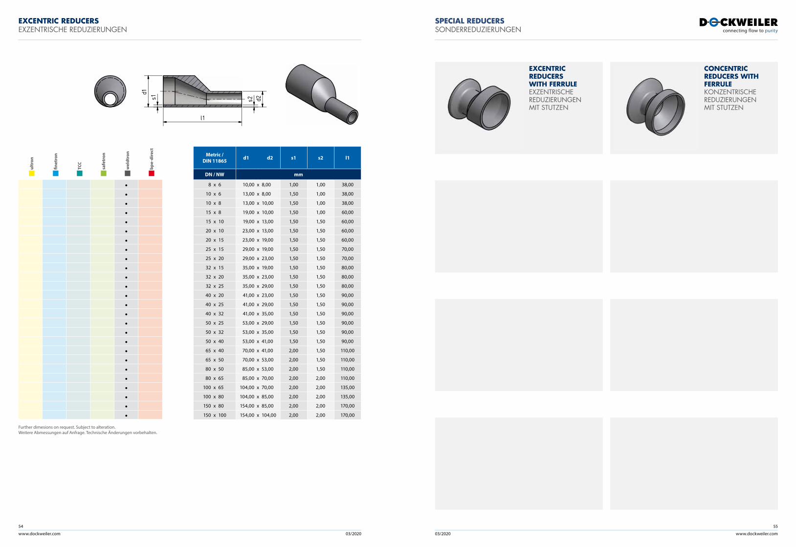
www.dockweiler.com 03/2020 03/2020
54
www.dockweiler.com
55
EXCENTRIC REDUCERSEXZENTRISCHE REDUZIERUNGEN
Metric / DIN 11865 d1 d2 s1 s2 l1
DN / NW mm
8 x 6 10,00 x 8,00 1,00 1,00 38,00
10 x 6 13,00 x 8,00 1,50 1,00 38,00
10 x 8 13,00 x 10,00 1,50 1,00 38,00
15 x 8 19,00 x 10,00 1,50 1,00 60,00
15 x 10 19,00 x 13,00 1,50 1,50 60,00
20 x 10 23,00 x 13,00 1,50 1,50 60,00
20 x 15 23,00 x 19,00 1,50 1,50 60,00
25 x 15 29,00 x 19,00 1,50 1,50 70,00
25 x 20 29,00 x 23,00 1,50 1,50 70,00
32 x 15 35,00 x 19,00 1,50 1,50 80,00
32 x 20 35,00 x 23,00 1,50 1,50 80,00
32 x 25 35,00 x 29,00 1,50 1,50 80,00
40 x 20 41,00 x 23,00 1,50 1,50 90,00
40 x 25 41,00 x 29,00 1,50 1,50 90,00
40 x 32 41,00 x 35,00 1,50 1,50 90,00
50 x 25 53,00 x 29,00 1,50 1,50 90,00
50 x 32 53,00 x 35,00 1,50 1,50 90,00
50 x 40 53,00 x 41,00 1,50 1,50 90,00
65 x 40 70,00 x 41,00 2,00 1,50 110,00
65 x 50 70,00 x 53,00 2,00 1,50 110,00
80 x 50 85,00 x 53,00 2,00 1,50 110,00
80 x 65 85,00 x 70,00 2,00 2,00 110,00
100 x 65 104,00 x 70,00 2,00 2,00 135,00
100 x 80 104,00 x 85,00 2,00 2,00 135,00
150 x 80 154,00 x 85,00 2,00 2,00 170,00
150 x 100 154,00 x 104,00 2,00 2,00 170,00
ult
ron
fine
tron
TCC
saf
etro
n
wel
dtro
n
bpe
-dir
ect
••••••••••••••••••••••••••
Further dimesions on request. Subject to alteration. Weitere Abmessungen auf Anfrage. Technische Änderungen vorbehalten.
SPECIAL REDUCERSSONDERREDUZIERUNGEN
EXCENTRIC REDUCERS WITH FERRULEEXZENTRISCHE REDUZIERUNGEN MIT STUTZEN
CONCENTRIC REDUCERS WITH FERRULEKONZENTRISCHE REDUZIERUNGEN MIT STUTZEN
d1s1 d2s2
l1
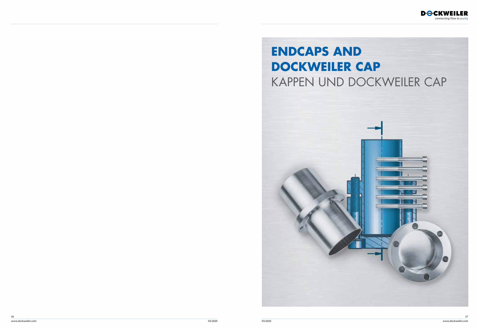
www.dockweiler.com 03/2020 03/2020
56
www.dockweiler.com
57
ENDCAPS AND DOCKWEILER CAPKAPPEN UND DOCKWEILER CAP
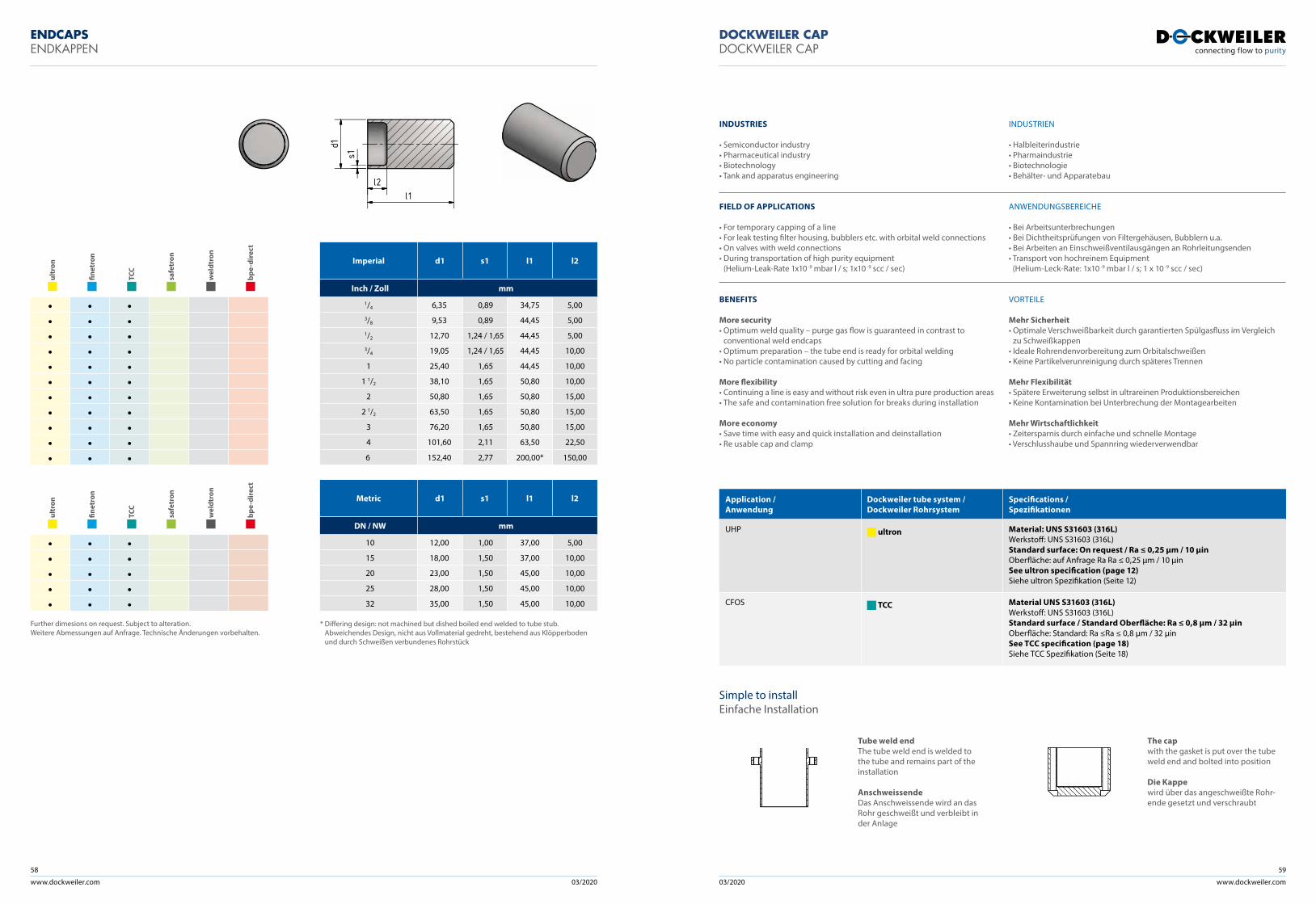
www.dockweiler.com 03/2020 03/2020
58
www.dockweiler.com
59
ENDCAPSENDKAPPEN
DOCKWEILER CAPDOCKWEILER CAP
d1
s1
l1l2
Imperial d1 s1 l1 l2
Inch / Zoll mm
1/4 6,35 0,89 34,75 5,003/8 9,53 0,89 44,45 5,001/2 12,70 1,24 / 1,65 44,45 5,003/4 19,05 1,24 / 1,65 44,45 10,00
1 25,40 1,65 44,45 10,00
1 1/2 38,10 1,65 50,80 10,00
2 50,80 1,65 50,80 15,00
2 1/2 63,50 1,65 50,80 15,00
3 76,20 1,65 50,80 15,00
4 101,60 2,11 63,50 22,50
6 152,40 2,77 200,00* 150,00
Metric d1 s1 l1 l2
DN / NW mm
10 12,00 1,00 37,00 5,00
15 18,00 1,50 37,00 10,00
20 23,00 1,50 45,00 10,00
25 28,00 1,50 45,00 10,00
32 35,00 1,50 45,00 10,00
* Differing design: not machined but dished boiled end welded to tube stub. Abweichendes Design, nicht aus Vollmaterial gedreht, bestehend aus Klöpperboden und durch Schweißen verbundenes Rohrstück
ult
ron
fine
tron
TCC
saf
etro
n
wel
dtro
n
bpe
-dir
ect
• • •• • •• • •• • •• • •• • •• • •• • •• • •• • •• • •
ult
ron
fine
tron
TCC
saf
etro
n
wel
dtro
n
bpe
-dir
ect
• • •• • •• • •• • •• • •
Further dimesions on request. Subject to alteration. Weitere Abmessungen auf Anfrage. Technische Änderungen vorbehalten.
Simple to installEinfache Installation
Tube weld endThe tube weld end is welded to the tube and remains part of the installation
AnschweissendeDas Anschweissende wird an das Rohr geschweißt und verbleibt in der Anlage
The capwith the gasket is put over the tube weld end and bolted into position
Die Kappewird über das angeschweißte Rohr- ende gesetzt und verschraubt
Application / Anwendung
Dockweiler tube system /Dockweiler Rohrsystem
Specifications /Spezifikationen
UHP ultron Material: UNS S31603 (316L) Werkstoff: UNS S31603 (316L)Standard surface: On request / Ra ≤ 0,25 µm / 10 µinOberfläche: auf Anfrage Ra Ra ≤ 0,25 µm / 10 µinSee ultron specification (page 12)Siehe ultron Spezifikation (Seite 12)
CFOS TCC Material UNS S31603 (316L)Werkstoff: UNS S31603 (316L)Standard surface / Standard Oberfläche: Ra ≤ 0,8 µm / 32 µinOberfläche: Standard: Ra ≤Ra ≤ 0,8 µm / 32 µinSee TCC specification (page 18) Siehe TCC Spezifikation (Seite 18)
INDUSTRIES
• Semiconductor industry• Pharmaceutical industry• Biotechnology• Tank and apparatus engineering
FIELD OF APPLICATIONS
• For temporary capping of a line• For leak testing filter housing, bubblers etc. with orbital weld connections• On valves with weld connections• During transportation of high purity equipment
(Helium-Leak-Rate 1x10 -9 mbar l / s; 1x10 -9 scc / sec)
BENEFITS
More security• Optimum weld quality – purge gas flow is guaranteed in contrast to
conventional weld endcaps• Optimum preparation – the tube end is ready for orbital welding• No particle contamination caused by cutting and facing
More flexibility• Continuing a line is easy and without risk even in ultra pure production areas• The safe and contamination free solution for breaks during installation
More economy• Save time with easy and quick installation and deinstallation• Re usable cap and clamp
INDUSTRIEN
• Halbleiterindustrie• Pharmaindustrie• Biotechnologie• Behälter- und Apparatebau
ANWENDUNGSBEREICHE
• Bei Arbeitsunterbrechungen• Bei Dichtheitsprüfungen von Filtergehäusen, Bubblern u.a. • Bei Arbeiten an Einschweißventil ausgängen an Rohrleitungsenden• Transport von hochreinem Equipment
(Helium-Leck-Rate: 1x10 -9 mbar l / s; 1 x 10 -9 scc / sec)
VORTEILE
Mehr Sicherheit• Optimale Verschweißbarkeit durch garantierten Spülgasfluss im Vergleich
zu Schweißkappen• Ideale Rohrendenvorbereitung zum Orbitalschweißen• Keine Partikelverunreinigung durch späteres Trennen
Mehr Flexibilität• Spätere Erweiterung selbst in ultrareinen Produktionsbereichen• Keine Kontamination bei Unter brechung der Montagearbeiten
Mehr Wirtschaftlichkeit• Zeitersparnis durch einfache und schnelle Montage• Verschlusshaube und Spannring wiederverwendbar
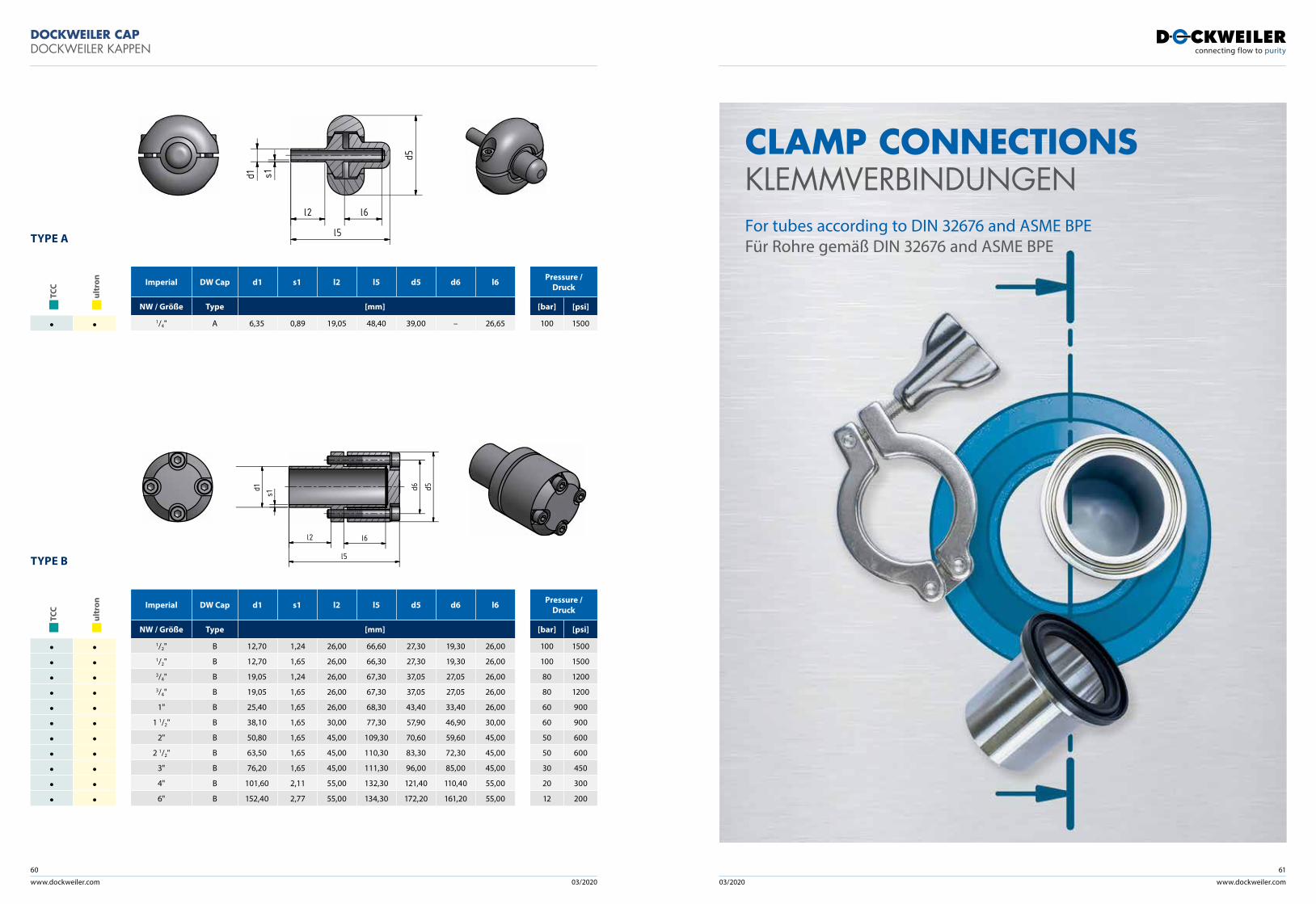
www.dockweiler.com 03/2020 03/2020
60
www.dockweiler.com
61
TYPE A
TYPE B
l2 l6
l5
d5
d1 s1d1
s1
l5
l6l2
d5d6
Pressure /Druck
[bar] [psi]
100 1500
TCC
ult
ron
• •
Imperial DW Cap d1 s1 l2 l5 d5 d6 l6
NW / Größe Type [mm]
1/4" A 6,35 0,89 19,05 48,40 39,00 – 26,65
Pressure /Druck
[bar] [psi]
100 1500
100 1500
80 1200
80 1200
60 900
60 900
50 600
50 600
30 450
20 300
12 200
TCC
ult
ron
• •• •• •• •• •• •• •• •• •• •• •
Imperial DW Cap d1 s1 l2 l5 d5 d6 l6
NW / Größe Type [mm]
1/2" B 12,70 1,24 26,00 66,60 27,30 19,30 26,001/2" B 12,70 1,65 26,00 66,30 27,30 19,30 26,003/4" B 19,05 1,24 26,00 67,30 37,05 27,05 26,003/4" B 19,05 1,65 26,00 67,30 37,05 27,05 26,00
1" B 25,40 1,65 26,00 68,30 43,40 33,40 26,00
1 1/2" B 38,10 1,65 30,00 77,30 57,90 46,90 30,00
2" B 50,80 1,65 45,00 109,30 70,60 59,60 45,00
2 1/2" B 63,50 1,65 45,00 110,30 83,30 72,30 45,00
3" B 76,20 1,65 45,00 111,30 96,00 85,00 45,00
4" B 101,60 2,11 55,00 132,30 121,40 110,40 55,00
6" B 152,40 2,77 55,00 134,30 172,20 161,20 55,00
CLAMP CONNECTIONS KLEMMVERBINDUNGEN For tubes according to DIN 32676 and ASME BPE Für Rohre gemäß DIN 32676 and ASME BPE
DOCKWEILER CAPDOCKWEILER KAPPEN
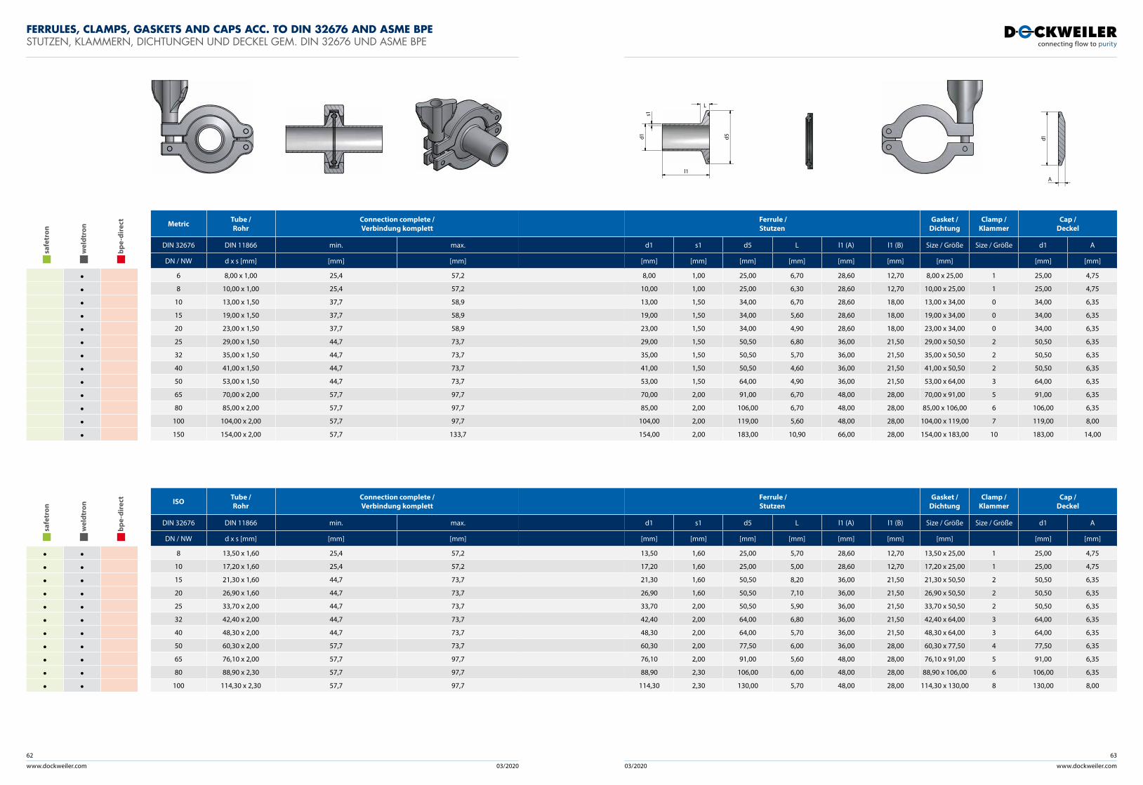
www.dockweiler.com 03/2020 03/2020
62
www.dockweiler.com
63
FERRULES, CLAMPS, GASKETS AND CAPS ACC. TO DIN 32676 AND ASME BPE STUTZEN, KLAMMERN, DICHTUNGEN UND DECKEL GEM. DIN 32676 UND ASME BPE
Ferrule / Stutzen
Gasket / Dichtung
Clamp / Klammer
Cap / Deckel
d1 s1 d5 L l1 (A) l1 (B) Size / Größe Size / Größe d1 A
[mm] [mm] [mm] [mm] [mm] [mm] [mm] [mm] [mm]
8,00 1,00 25,00 6,70 28,60 12,70 8,00 x 25,00 1 25,00 4,75
10,00 1,00 25,00 6,30 28,60 12,70 10,00 x 25,00 1 25,00 4,75
13,00 1,50 34,00 6,70 28,60 18,00 13,00 x 34,00 0 34,00 6,35
19,00 1,50 34,00 5,60 28,60 18,00 19,00 x 34,00 0 34,00 6,35
23,00 1,50 34,00 4,90 28,60 18,00 23,00 x 34,00 0 34,00 6,35
29,00 1,50 50,50 6,80 36,00 21,50 29,00 x 50,50 2 50,50 6,35
35,00 1,50 50,50 5,70 36,00 21,50 35,00 x 50,50 2 50,50 6,35
41,00 1,50 50,50 4,60 36,00 21,50 41,00 x 50,50 2 50,50 6,35
53,00 1,50 64,00 4,90 36,00 21,50 53,00 x 64,00 3 64,00 6,35
70,00 2,00 91,00 6,70 48,00 28,00 70,00 x 91,00 5 91,00 6,35
85,00 2,00 106,00 6,70 48,00 28,00 85,00 x 106,00 6 106,00 6,35
104,00 2,00 119,00 5,60 48,00 28,00 104,00 x 119,00 7 119,00 8,00
154,00 2,00 183,00 10,90 66,00 28,00 154,00 x 183,00 10 183,00 14,00
Ferrule / Stutzen
Gasket / Dichtung
Clamp / Klammer
Cap / Deckel
d1 s1 d5 L l1 (A) l1 (B) Size / Größe Size / Größe d1 A
[mm] [mm] [mm] [mm] [mm] [mm] [mm] [mm] [mm]
13,50 1,60 25,00 5,70 28,60 12,70 13,50 x 25,00 1 25,00 4,75
17,20 1,60 25,00 5,00 28,60 12,70 17,20 x 25,00 1 25,00 4,75
21,30 1,60 50,50 8,20 36,00 21,50 21,30 x 50,50 2 50,50 6,35
26,90 1,60 50,50 7,10 36,00 21,50 26,90 x 50,50 2 50,50 6,35
33,70 2,00 50,50 5,90 36,00 21,50 33,70 x 50,50 2 50,50 6,35
42,40 2,00 64,00 6,80 36,00 21,50 42,40 x 64,00 3 64,00 6,35
48,30 2,00 64,00 5,70 36,00 21,50 48,30 x 64,00 3 64,00 6,35
60,30 2,00 77,50 6,00 36,00 28,00 60,30 x 77,50 4 77,50 6,35
76,10 2,00 91,00 5,60 48,00 28,00 76,10 x 91,00 5 91,00 6,35
88,90 2,30 106,00 6,00 48,00 28,00 88,90 x 106,00 6 106,00 6,35
114,30 2,30 130,00 5,70 48,00 28,00 114,30 x 130,00 8 130,00 8,00
Metric Tube / Rohr
Connection complete / Verbindung komplett
DIN 32676 DIN 11866 min. max.
DN / NW d x s [mm] [mm] [mm]
6 8,00 x 1,00 25,4 57,2
8 10,00 x 1,00 25,4 57,2
10 13,00 x 1,50 37,7 58,9
15 19,00 x 1,50 37,7 58,9
20 23,00 x 1,50 37,7 58,9
25 29,00 x 1,50 44,7 73,7
32 35,00 x 1,50 44,7 73,7
40 41,00 x 1,50 44,7 73,7
50 53,00 x 1,50 44,7 73,7
65 70,00 x 2,00 57,7 97,7
80 85,00 x 2,00 57,7 97,7
100 104,00 x 2,00 57,7 97,7
150 154,00 x 2,00 57,7 133,7
ISO Tube / Rohr
Connection complete / Verbindung komplett
DIN 32676 DIN 11866 min. max.
DN / NW d x s [mm] [mm] [mm]
8 13,50 x 1,60 25,4 57,2
10 17,20 x 1,60 25,4 57,2
15 21,30 x 1,60 44,7 73,7
20 26,90 x 1,60 44,7 73,7
25 33,70 x 2,00 44,7 73,7
32 42,40 x 2,00 44,7 73,7
40 48,30 x 2,00 44,7 73,7
50 60,30 x 2,00 57,7 73,7
65 76,10 x 2,00 57,7 97,7
80 88,90 x 2,30 57,7 97,7
100 114,30 x 2,30 57,7 97,7
saf
etro
n
wel
dtro
n
bpe
-dir
ect
•••••••••••••
saf
etro
n
wel
dtro
n
bpe
-dir
ect
• •• •• •• •• •• •• •• •• •• •• •
s1d1
l1
d5
L
A
d1
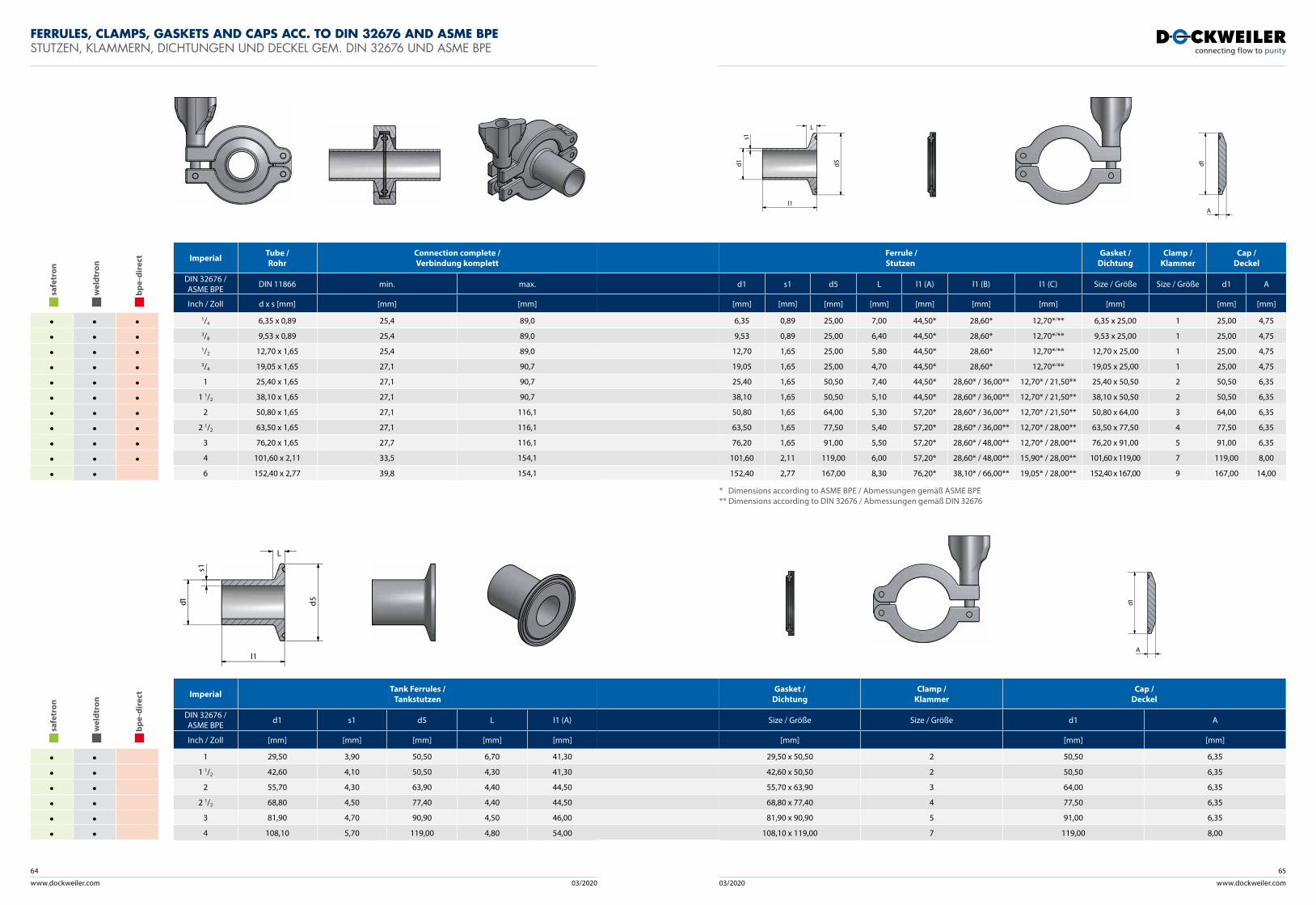
www.dockweiler.com 03/2020 03/2020
64
www.dockweiler.com
65
Ferrule / Stutzen
Gasket / Dichtung
Clamp / Klammer
Cap / Deckel
d1 s1 d5 L l1 (A) l1 (B) l1 (C) Size / Größe Size / Größe d1 A
[mm] [mm] [mm] [mm] [mm] [mm] [mm] [mm] [mm] [mm]
6,35 0,89 25,00 7,00 44,50* 28,60* 12,70*/** 6,35 x 25,00 1 25,00 4,75
9,53 0,89 25,00 6,40 44,50* 28,60* 12,70*/** 9,53 x 25,00 1 25,00 4,75
12,70 1,65 25,00 5,80 44,50* 28,60* 12,70*/** 12,70 x 25,00 1 25,00 4,75
19,05 1,65 25,00 4,70 44,50* 28,60* 12,70*/** 19,05 x 25,00 1 25,00 4,75
25,40 1,65 50,50 7,40 44,50* 28,60* / 36,00** 12,70* / 21,50** 25,40 x 50,50 2 50,50 6,35
38,10 1,65 50,50 5,10 44,50* 28,60* / 36,00** 12,70* / 21,50** 38,10 x 50,50 2 50,50 6,35
50,80 1,65 64,00 5,30 57,20* 28,60* / 36,00** 12,70* / 21,50** 50,80 x 64,00 3 64,00 6,35
63,50 1,65 77,50 5,40 57,20* 28,60* / 36,00** 12,70* / 28,00** 63,50 x 77,50 4 77,50 6,35
76,20 1,65 91,00 5,50 57,20* 28,60* / 48,00** 12,70* / 28,00** 76,20 x 91,00 5 91,00 6,35
101,60 2,11 119,00 6,00 57,20* 28,60* / 48,00** 15,90* / 28,00** 101,60 x 119,00 7 119,00 8,00
152,40 2,77 167,00 8,30 76,20* 38,10* / 66,00** 19,05* / 28,00** 152,40 x 167,00 9 167,00 14,00
Imperial Tube / Rohr
Connection complete / Verbindung komplett
DIN 32676 / ASME BPE DIN 11866 min. max.
Inch / Zoll d x s [mm] [mm] [mm]
1/4 6,35 x 0,89 25,4 89,03/8 9,53 x 0,89 25,4 89,01/2 12,70 x 1,65 25,4 89,03/4 19,05 x 1,65 27,1 90,7
1 25,40 x 1,65 27,1 90,7
1 1/2 38,10 x 1,65 27,1 90,7
2 50,80 x 1,65 27,1 116,1
2 1/2 63,50 x 1,65 27,1 116,1
3 76,20 x 1,65 27,7 116,1
4 101,60 x 2,11 33,5 154,1
6 152,40 x 2,77 39,8 154,1
saf
etro
n
wel
dtro
n
bpe
-dir
ect
• • •• • •• • •• • •• • •• • •• • •• • •• • •• • •• •
Gasket / Dichtung
Clamp / Klammer
Cap / Deckel
Size / Größe Size / Größe d1 A
[mm] [mm] [mm]
29,50 x 50,50 2 50,50 6,35
42,60 x 50,50 2 50,50 6,35
55,70 x 63,90 3 64,00 6,35
68,80 x 77,40 4 77,50 6,35
81,90 x 90,90 5 91,00 6,35
108,10 x 119,00 7 119,00 8,00
Imperial Tank Ferrules / Tankstutzen
DIN 32676 / ASME BPE d1 s1 d5 L l1 (A)
Inch / Zoll [mm] [mm] [mm] [mm] [mm]
1 29,50 3,90 50,50 6,70 41,30
1 1/2 42,60 4,10 50,50 4,30 41,30
2 55,70 4,30 63,90 4,40 44,50
2 1/2 68,80 4,50 77,40 4,40 44,50
3 81,90 4,70 90,90 4,50 46,00
4 108,10 5,70 119,00 4,80 54,00
saf
etro
n
wel
dtro
n
bpe
-dir
ect
• •• •• •• •• •• •
* Dimensions according to ASME BPE / Abmessungen gemäß ASME BPE** Dimensions according to DIN 32676 / Abmessungen gemäß DIN 32676
d5
l1
s1
d1
L
A
d1
s1d1
l1
d5
L
A
d1
FERRULES, CLAMPS, GASKETS AND CAPS ACC. TO DIN 32676 AND ASME BPE STUTZEN, KLAMMERN, DICHTUNGEN UND DECKEL GEM. DIN 32676 UND ASME BPE
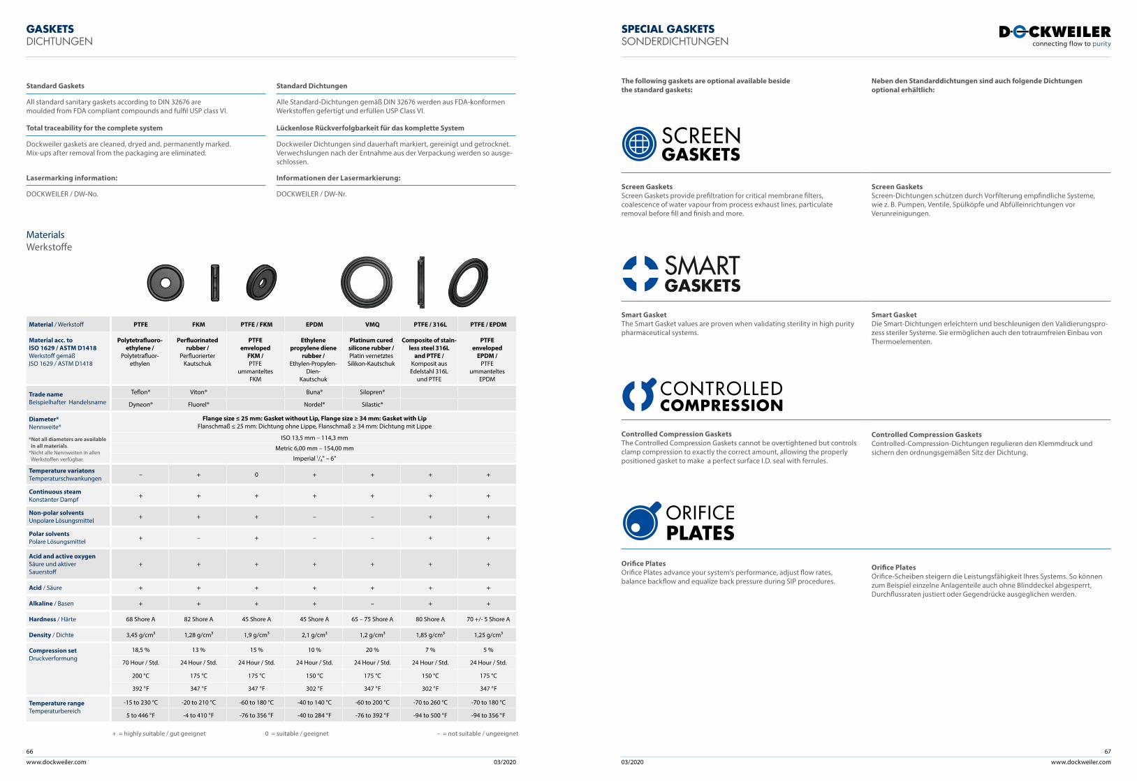
www.dockweiler.com 03/2020 03/2020
66
www.dockweiler.com
67
SPECIAL GASKETSSONDERDICHTUNGEN
The following gaskets are optional available beside the standard gaskets:
Neben den Standarddichtungen sind auch folgende Dichtungen optional erhältlich:
Screen GasketsScreen Gaskets provide prefiltration for critical membrane filters, coalescence of water vapour from process exhaust lines, particulate removal before fill and finish and more.
Screen GasketsScreen-Dichtungen schützen durch Vorfilterung empfindliche Systeme, wie z. B. Pumpen, Ventile, Spülköpfe und Abfülleinrichtungen vor Verunreinigungen.
Smart GasketThe Smart Gasket values are proven when validating sterility in high purity pharmaceutical systems.
Smart GasketDie Smart-Dichtungen erleichtern und beschleunigen den Validierungspro-zess steriler Systeme. Sie ermöglichen auch den totraumfreien Einbau von Thermoelementen.
Controlled Compression GasketsThe Controlled Compression Gaskets cannot be overtightened but controls clamp compression to exactly the correct amount, allowing the properly positioned gasket to make a perfect surface I.D. seal with ferrules.
Controlled Compression GasketsControlled-Compression-Dichtungen regulieren den Klemmdruck und sichern den ordnungsgemäßen Sitz der Dichtung.
Orifice Plates Orifice Plates advance your system‘s performance, adjust flow rates, balance backflow and equalize back pressure during SIP procedures.
Orifice Plates Orifice-Scheiben steigern die Leistungsfähigkeit Ihres Systems. So können zum Beispiel einzelne Anlagenteile auch ohne Blinddeckel abgesperrt, Durchflussraten justiert oder Gegendrücke ausgeglichen werden.
GASKETS DICHTUNGEN
Materials Werkstoffe
Standard Gaskets Standard Dichtungen
All standard sanitary gaskets according to DIN 32676 are moulded from FDA compliant compounds and fulfil USP class VI.
Alle Standard-Dichtungen gemäß DIN 32676 werden aus FDA-konformen Werkstoffen gefertigt und erfüllen USP Class VI.
Total traceability for the complete system Lückenlose Rückverfolgbarkeit für das komplette System
Dockweiler gaskets are cleaned, dryed and. permanently marked. Mix-ups after removal from the packaging are eliminated.
Dockweiler Dichtungen sind dauerhaft markiert, gereinigt und getrocknet.Verwechslungen nach der Entnahme aus der Verpackung werden so ausge-schlossen.
Lasermarking information: Informationen der Lasermarkierung:
DOCKWEILER / DW-No. DOCKWEILER / DW-Nr.
Material / Werkstoff PTFE FKM PTFE / FKM EPDM VMQ PTFE / 316L PTFE / EPDM
Material acc. toISO 1629 / ASTM D1418Werkstoff gemäßISO 1629 / ASTM D1418
Polytetrafluoro -ethylene /
Polytetrafluor- ethylen
Perfluorinated rubber /
Perfluorierter Kautschuk
PTFE enveloped
FKM /PTFE
ummanteltes FKM
Ethylene propylene diene
rubber /Ethylen- Propylen-
Dien-Kautschuk
Platinum cured silicone rubber /Platin vernetztes
Silikon-Kautschuk
Composite of stain-less steel 316L
and PTFE /Komposit aus Edelstahl 316L
und PTFE
PTFE enveloped
EPDM /PTFE
ummanteltes EPDM
Trade nameBeispielhafter Handelsname
Teflon® Viton® Buna® Silopren®
Dyneon® Fluorel® Nordel® Silastic®
Diameter*Nennweite*
Flange size ≤ 25 mm: Gasket without Lip, Flange size ≥ 34 mm: Gasket with LipFlanschmaß ≤ 25 mm: Dichtung ohne Lippe, Flanschmaß ≥ 34 mm: Dichtung mit Lippe
ISO 13,5 mm – 114,3 mm
Metric 6,00 mm – 154,00 mm
Imperial 1/4" – 6"
Temperature variatonsTemperatur schwankungen – + 0 + + + +
Continuous steamKonstanter Dampf + + + + + + +
Non-polar solventsUnpolare Lösungsmittel + + + – – + +
Polar solventsPolare Lösungsmittel + – + – – + +
Acid and active oxygenSäure und aktiver Sauerstoff
+ + + + + + +
Acid / Säure + + + + + + +
Alkaline / Basen + + + + – + +
Hardness / Härte 68 Shore A 82 Shore A 45 Shore A 45 Shore A 65 – 75 Shore A 80 Shore A 70 +/- 5 Shore A
Density / Dichte 3,45 g/cm³ 1,28 g/cm³ 1,9 g/cm³ 2,1 g/cm³ 1,2 g/cm³ 1,85 g/cm³ 1,25 g/cm³
Compression setDruckverformung
18,5 % 13 % 15 % 10 % 20 % 7 % 5 %
70 Hour / Std. 24 Hour / Std. 24 Hour / Std. 24 Hour / Std. 24 Hour / Std. 24 Hour / Std. 24 Hour / Std.
200 °C 175 °C 175 °C 150 °C 175 °C 150 °C 175 °C
392 °F 347 °F 347 °F 302 °F 347 °F 302 °F 347 °F
Temperature rangeTemperaturbereich
-15 to 230 °C -20 to 210 °C -60 to 180 °C -40 to 140 °C -60 to 200 °C -70 to 260 °C -70 to 180 °C
5 to 446 °F -4 to 410 °F -76 to 356 °F -40 to 284 °F -76 to 392 °F -94 to 500 °F -94 to 356 °F
+ = highly suitable / gut geeignet 0 = suitable / geeignet – = not suitable / ungeeignet
*Not all diameters are available in all materials. *Nicht alle Nennweiten in allen Werkstoffen verfügbar.
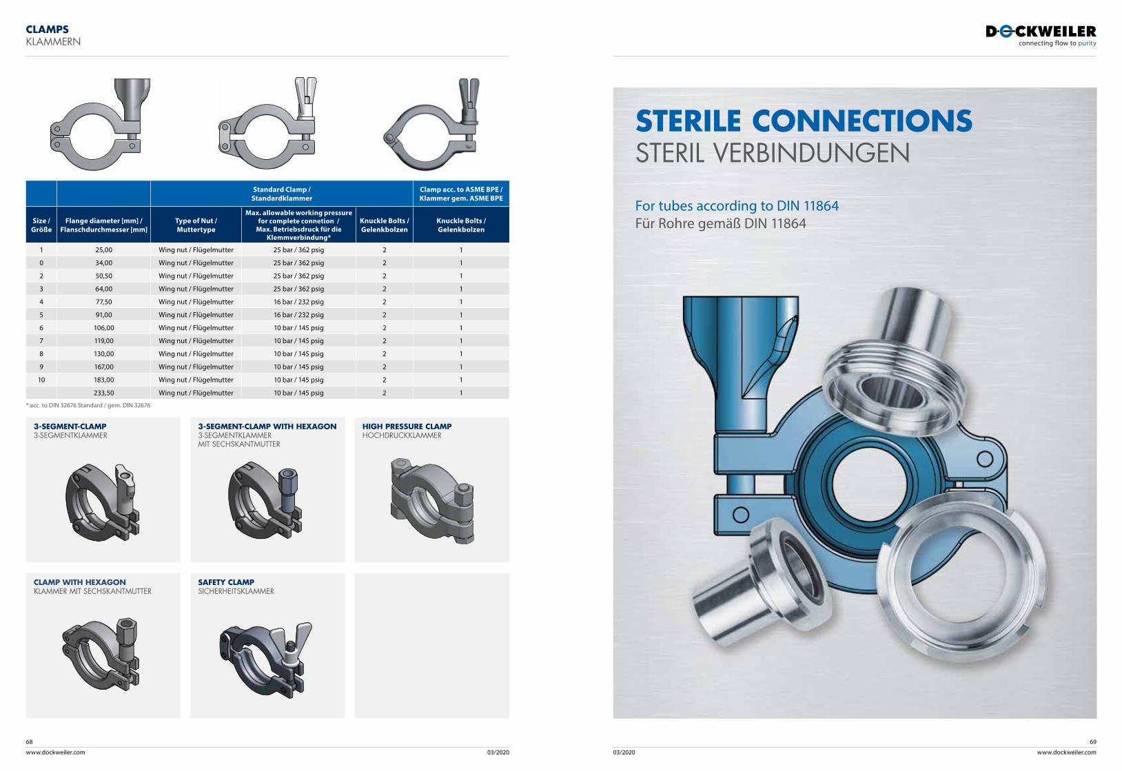
www.dockweiler.com 03/2020 03/2020
68
www.dockweiler.com
69
CLAMPSKLAMMERN
STERILE CONNECTIONS STERIL VERBINDUNGEN For tubes according to DIN 11864 Für Rohre gemäß DIN 11864
3-SEGMENT-CLAMP3-SEGMENTKLAMMER
CLAMP WITH HEXAGONKLAMMER MIT SECHSKANTMUTTER
3-SEGMENT-CLAMP WITH HEXAGON3-SEGMENTKLAMMER MIT SECHSKANTMUTTER
SAFETY CLAMPSICHERHEITSKLAMMER
HIGH PRESSURE CLAMPHOCHDRUCK KLAMMER
Standard Clamp / Standardklammer
Clamp acc. to ASME BPE / Klammer gem. ASME BPE
Size /Größe
Flange diameter [mm] / Flanschdurchmesser [mm]
Type of Nut / Muttertype
Max. allowable working pressure for complete connetion /
Max. Betriebsdruck für die Klemmverbindung*
Knuckle Bolts / Gelenkbolzen
Knuckle Bolts / Gelenkbolzen
1 25,00 Wing nut / Flügelmutter 25 bar / 362 psig 2 1
0 34,00 Wing nut / Flügelmutter 25 bar / 362 psig 2 1
2 50,50 Wing nut / Flügelmutter 25 bar / 362 psig 2 1
3 64,00 Wing nut / Flügelmutter 25 bar / 362 psig 2 1
4 77,50 Wing nut / Flügelmutter 16 bar / 232 psig 2 1
5 91,00 Wing nut / Flügelmutter 16 bar / 232 psig 2 1
6 106,00 Wing nut / Flügelmutter 10 bar / 145 psig 2 1
7 119,00 Wing nut / Flügelmutter 10 bar / 145 psig 2 1
8 130,00 Wing nut / Flügelmutter 10 bar / 145 psig 2 1
9 167,00 Wing nut / Flügelmutter 10 bar / 145 psig 2 1
10 183,00 Wing nut / Flügelmutter 10 bar / 145 psig 2 1
233,50 Wing nut / Flügelmutter 10 bar / 145 psig 2 1
* acc. to DIN 32676 Standard / gem. DIN 32676
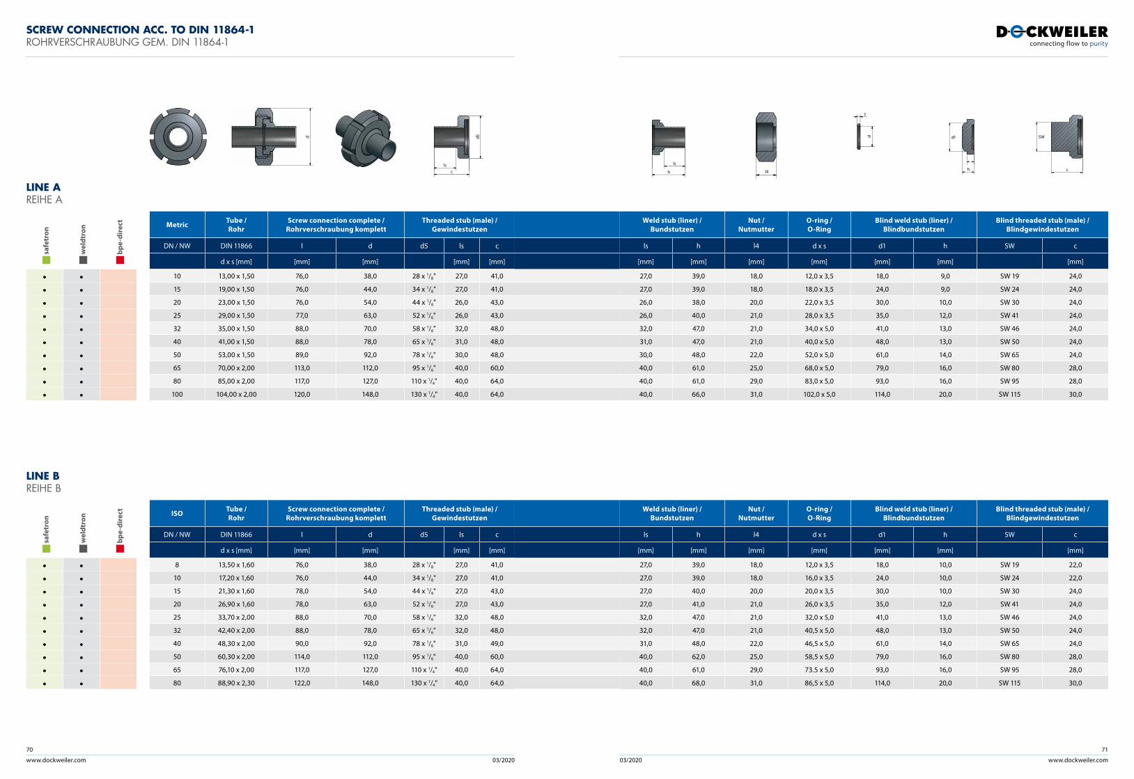
www.dockweiler.com 03/2020 03/2020
70
www.dockweiler.com
71
SCREW CONNECTION ACC. TO DIN 11864-1 ROHRVERSCHRAUBUNG GEM. DIN 11864-1
saf
etro
n
wel
dtro
n
bpe
-dir
ect
• •• •• •• •• •• •• •• •• •• •
Metric Tube / Rohr
Screw connection complete / Rohrverschraubung komplett
Threaded stub (male) / Gewindestutzen
DN / NW DIN 11866 l d d5 ls c
d x s [mm] [mm] [mm] [mm] [mm]
10 13,00 x 1,50 76,0 38,0 28 x 1/8" 27,0 41,0
15 19,00 x 1,50 76,0 44,0 34 x 1/8" 27,0 41,0
20 23,00 x 1,50 76,0 54,0 44 x 1/6" 26,0 43,0
25 29,00 x 1,50 77,0 63,0 52 x 1/6" 26,0 43,0
32 35,00 x 1,50 88,0 70,0 58 x 1/6" 32,0 48,0
40 41,00 x 1,50 88,0 78,0 65 x 1/6" 31,0 48,0
50 53,00 x 1,50 89,0 92,0 78 x 1/6" 30,0 48,0
65 70,00 x 2,00 113,0 112,0 95 x 1/6" 40,0 60,0
80 85,00 x 2,00 117,0 127,0 110 x 1/4" 40,0 64,0
100 104,00 x 2,00 120,0 148,0 130 x 1/4" 40,0 64,0
Weld stub (liner) / Bundstutzen
Nut / Nutmutter
O-ring / O-Ring
Blind weld stub (liner) / Blindbundstutzen
Blind threaded stub (male) / Blindgewindestutzen
ls h l4 d x s d1 h SW c
[mm] [mm] [mm] [mm] [mm] [mm] [mm]
27,0 39,0 18,0 12,0 x 3,5 18,0 9,0 SW 19 24,0
27,0 39,0 18,0 18,0 x 3,5 24,0 9,0 SW 24 24,0
26,0 38,0 20,0 22,0 x 3,5 30,0 10,0 SW 30 24,0
26,0 40,0 21,0 28,0 x 3,5 35,0 12,0 SW 41 24,0
32,0 47,0 21,0 34,0 x 5,0 41,0 13,0 SW 46 24,0
31,0 47,0 21,0 40,0 x 5,0 48,0 13,0 SW 50 24,0
30,0 48,0 22,0 52,0 x 5,0 61,0 14,0 SW 65 24,0
40,0 61,0 25,0 68,0 x 5,0 79,0 16,0 SW 80 28,0
40,0 61,0 29,0 83,0 x 5,0 93,0 16,0 SW 95 28,0
40,0 66,0 31,0 102,0 x 5,0 114,0 20,0 SW 115 30,0
d1
h c
SWd d5
cls
h
ls
l4
d
s
LINE A REIHE A
LINE B REIHE B
saf
etro
n
wel
dtro
n
bpe
-dir
ect
• •• •• •• •• •• •• •• •• •• •
ISO Tube / Rohr
Screw connection complete / Rohrverschraubung komplett
Threaded stub (male) / Gewindestutzen
DN / NW DIN 11866 l d d5 ls c
d x s [mm] [mm] [mm] [mm] [mm]
8 13,50 x 1,60 76,0 38,0 28 x 1/8" 27,0 41,0
10 17,20 x 1,60 76,0 44,0 34 x 1/8" 27,0 41,0
15 21,30 x 1,60 78,0 54,0 44 x 1/6" 27,0 43,0
20 26,90 x 1,60 78,0 63,0 52 x 1/6" 27,0 43,0
25 33,70 x 2,00 88,0 70,0 58 x 1/6" 32,0 48,0
32 42,40 x 2,00 88,0 78,0 65 x 1/6" 32,0 48,0
40 48,30 x 2,00 90,0 92,0 78 x 1/6" 31,0 49,0
50 60,30 x 2,00 114,0 112,0 95 x 1/6" 40,0 60,0
65 76,10 x 2,00 117,0 127,0 110 x 1/4" 40,0 64,0
80 88,90 x 2,30 122,0 148,0 130 x 1/4" 40,0 64,0
Weld stub (liner) / Bundstutzen
Nut / Nutmutter
O-ring / O-Ring
Blind weld stub (liner) / Blindbundstutzen
Blind threaded stub (male) / Blindgewindestutzen
ls h l4 d x s d1 h SW c
[mm] [mm] [mm] [mm] [mm] [mm] [mm]
27,0 39,0 18,0 12,0 x 3,5 18,0 10,0 SW 19 22,0
27,0 39,0 18,0 16,0 x 3,5 24,0 10,0 SW 24 22,0
27,0 40,0 20,0 20,0 x 3,5 30,0 10,0 SW 30 24,0
27,0 41,0 21,0 26,0 x 3,5 35,0 12,0 SW 41 24,0
32,0 47,0 21,0 32,0 x 5,0 41,0 13,0 SW 46 24,0
32,0 47,0 21,0 40,5 x 5,0 48,0 13,0 SW 50 24,0
31,0 48,0 22,0 46,5 x 5,0 61,0 14,0 SW 65 24,0
40,0 62,0 25,0 58,5 x 5,0 79,0 16,0 SW 80 28,0
40,0 61,0 29,0 73.5 x 5,0 93,0 16,0 SW 95 28,0
40,0 68,0 31,0 86,5 x 5,0 114,0 20,0 SW 115 30,0
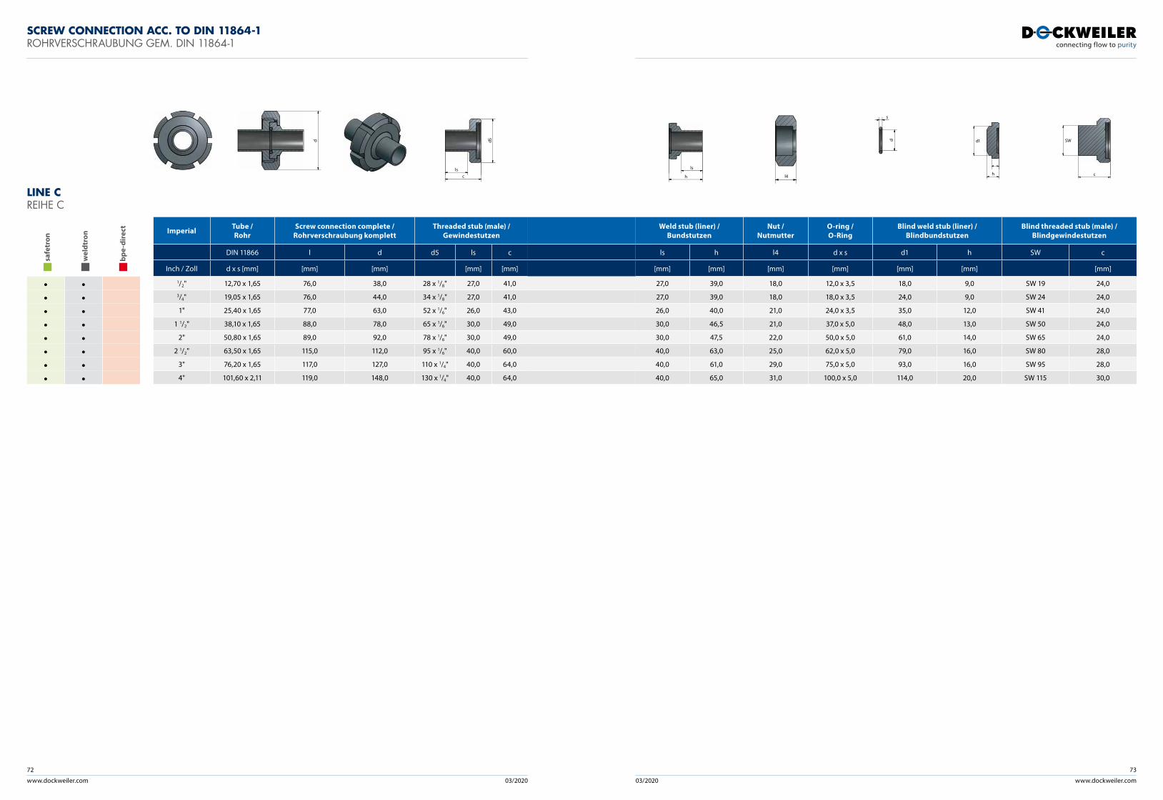
www.dockweiler.com 03/2020 03/2020
72
www.dockweiler.com
73
LINE C REIHE C
saf
etro
n
wel
dtro
n
bpe
-dir
ect
• •• •• •• •• •• •• •• •
Imperial Tube / Rohr
Screw connection complete / Rohrverschraubung komplett
Threaded stub (male) / Gewindestutzen
DIN 11866 l d d5 ls c
Inch / Zoll d x s [mm] [mm] [mm] [mm] [mm]
1/2" 12,70 x 1,65 76,0 38,0 28 x 1/8" 27,0 41,03/4" 19,05 x 1,65 76,0 44,0 34 x 1/8" 27,0 41,0
1" 25,40 x 1,65 77,0 63,0 52 x 1/6" 26,0 43,0
1 1/2" 38,10 x 1,65 88,0 78,0 65 x 1/6" 30,0 49,0
2" 50,80 x 1,65 89,0 92,0 78 x 1/6" 30,0 49,0
2 1/2" 63,50 x 1,65 115,0 112,0 95 x 1/6" 40,0 60,0
3" 76,20 x 1,65 117,0 127,0 110 x 1/4" 40,0 64,0
4" 101,60 x 2,11 119,0 148,0 130 x 1/4" 40,0 64,0
Weld stub (liner) / Bundstutzen
Nut / Nutmutter
O-ring / O-Ring
Blind weld stub (liner) / Blindbundstutzen
Blind threaded stub (male) / Blindgewindestutzen
ls h l4 d x s d1 h SW c
[mm] [mm] [mm] [mm] [mm] [mm] [mm]
27,0 39,0 18,0 12,0 x 3,5 18,0 9,0 SW 19 24,0
27,0 39,0 18,0 18,0 x 3,5 24,0 9,0 SW 24 24,0
26,0 40,0 21,0 24,0 x 3,5 35,0 12,0 SW 41 24,0
30,0 46,5 21,0 37,0 x 5,0 48,0 13,0 SW 50 24,0
30,0 47,5 22,0 50,0 x 5,0 61,0 14,0 SW 65 24,0
40,0 63,0 25,0 62,0 x 5,0 79,0 16,0 SW 80 28,0
40,0 61,0 29,0 75,0 x 5,0 93,0 16,0 SW 95 28,0
40,0 65,0 31,0 100,0 x 5,0 114,0 20,0 SW 115 30,0
SCREW CONNECTION ACC. TO DIN 11864-1 ROHRVERSCHRAUBUNG GEM. DIN 11864-1
d1
h c
SWd d5
cls
h
ls
l4
d
s
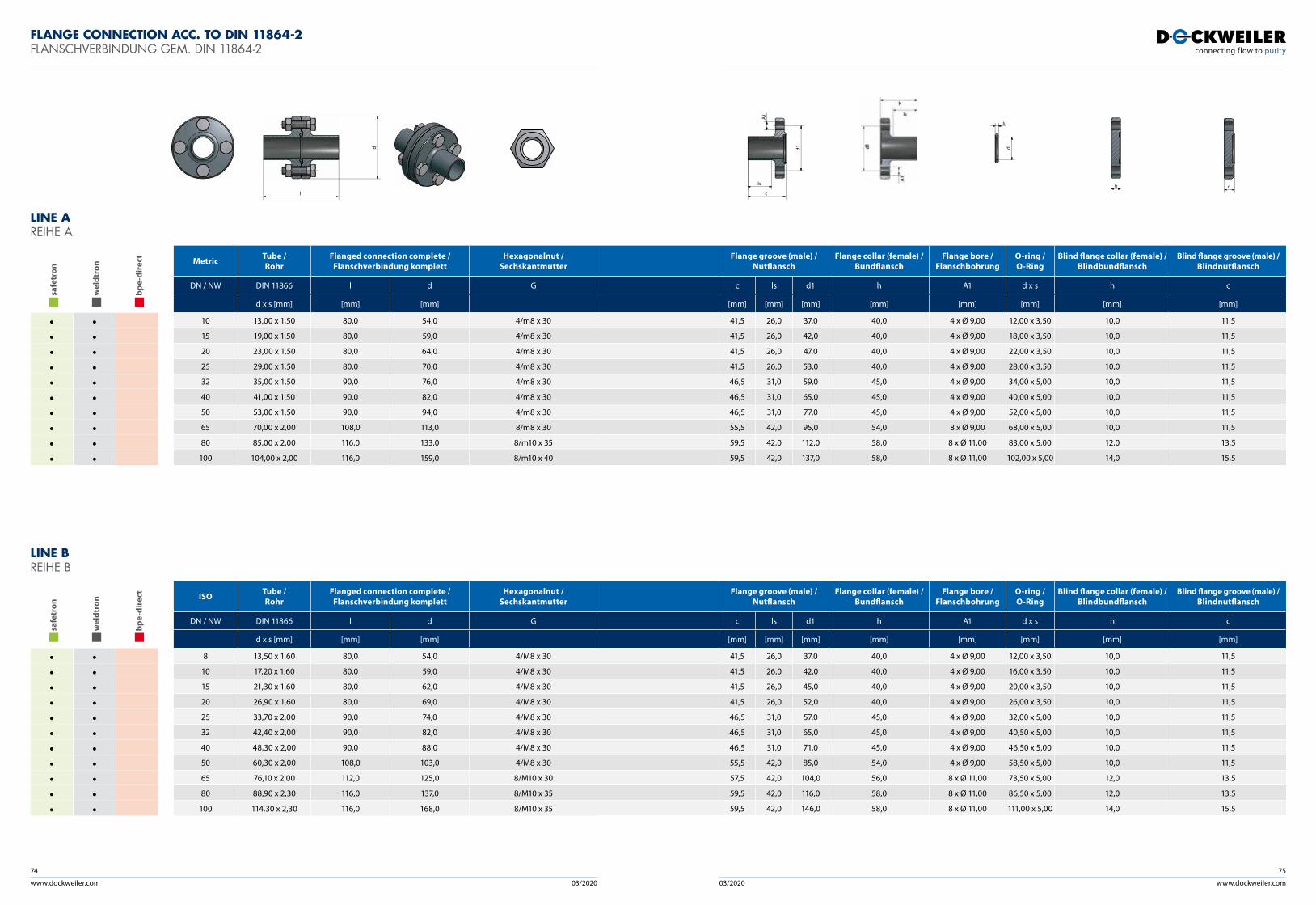
www.dockweiler.com 03/2020 03/2020
74
www.dockweiler.com
75
FLANGE CONNECTION ACC. TO DIN 11864-2 FLANSCHVERBINDUNG GEM. DIN 11864-2
LINE A REIHE A
saf
etro
n
wel
dtro
n
bpe
-dir
ect
• •• •• •• •• •• •• •• •• •• •
Metric Tube / Rohr
Flanged connection complete / Flanschverbindung komplett
Hexagonalnut / Sechskantmutter
DN / NW DIN 11866 l d G
d x s [mm] [mm] [mm]
10 13,00 x 1,50 80,0 54,0 4/m8 x 30
15 19,00 x 1,50 80,0 59,0 4/m8 x 30
20 23,00 x 1,50 80,0 64,0 4/m8 x 30
25 29,00 x 1,50 80,0 70,0 4/m8 x 30
32 35,00 x 1,50 90,0 76,0 4/m8 x 30
40 41,00 x 1,50 90,0 82,0 4/m8 x 30
50 53,00 x 1,50 90,0 94,0 4/m8 x 30
65 70,00 x 2,00 108,0 113,0 8/m8 x 30
80 85,00 x 2,00 116,0 133,0 8/m10 x 35
100 104,00 x 2,00 116,0 159,0 8/m10 x 40
Flange groove (male) /Nutflansch
Flange collar (female) /Bundflansch
Flange bore / Flanschbohrung
O-ring / O-Ring
Blind flange collar (female) /Blindbundflansch
Blind flange groove (male) /Blindnutflansch
c ls d1 h A1 d x s h c
[mm] [mm] [mm] [mm] [mm] [mm] [mm] [mm]
41,5 26,0 37,0 40,0 4 x Ø 9,00 12,00 x 3,50 10,0 11,5
41,5 26,0 42,0 40,0 4 x Ø 9,00 18,00 x 3,50 10,0 11,5
41,5 26,0 47,0 40,0 4 x Ø 9,00 22,00 x 3,50 10,0 11,5
41,5 26,0 53,0 40,0 4 x Ø 9,00 28,00 x 3,50 10,0 11,5
46,5 31,0 59,0 45,0 4 x Ø 9,00 34,00 x 5,00 10,0 11,5
46,5 31,0 65,0 45,0 4 x Ø 9,00 40,00 x 5,00 10,0 11,5
46,5 31,0 77,0 45,0 4 x Ø 9,00 52,00 x 5,00 10,0 11,5
55,5 42,0 95,0 54,0 8 x Ø 9,00 68,00 x 5,00 10,0 11,5
59,5 42,0 112,0 58,0 8 x Ø 11,00 83,00 x 5,00 12,0 13,5
59,5 42,0 137,0 58,0 8 x Ø 11,00 102,00 x 5,00 14,0 15,5
l
d
c
ls
d1
A1
d
s
h c
LINE B REIHE B
saf
etro
n
wel
dtro
n
bpe
-dir
ect
• •• •• •• •• •• •• •• •• •• •• •
ISO Tube / Rohr
Flanged connection complete /Flanschverbindung komplett
Hexagonalnut / Sechskantmutter
DN / NW DIN 11866 l d G
d x s [mm] [mm] [mm]
8 13,50 x 1,60 80,0 54,0 4/M8 x 30
10 17,20 x 1,60 80,0 59,0 4/M8 x 30
15 21,30 x 1,60 80,0 62,0 4/M8 x 30
20 26,90 x 1,60 80,0 69,0 4/M8 x 30
25 33,70 x 2,00 90,0 74,0 4/M8 x 30
32 42,40 x 2,00 90,0 82,0 4/M8 x 30
40 48,30 x 2,00 90,0 88,0 4/M8 x 30
50 60,30 x 2,00 108,0 103,0 4/M8 x 30
65 76,10 x 2,00 112,0 125,0 8/M10 x 30
80 88,90 x 2,30 116,0 137,0 8/M10 x 35
100 114,30 x 2,30 116,0 168,0 8/M10 x 35
Flange groove (male) /Nutflansch
Flange collar (female) /Bundflansch
Flange bore / Flanschbohrung
O-ring / O-Ring
Blind flange collar (female) /Blindbundflansch
Blind flange groove (male) /Blindnutflansch
c ls d1 h A1 d x s h c
[mm] [mm] [mm] [mm] [mm] [mm] [mm] [mm]
41,5 26,0 37,0 40,0 4 x Ø 9,00 12,00 x 3,50 10,0 11,5
41,5 26,0 42,0 40,0 4 x Ø 9,00 16,00 x 3,50 10,0 11,5
41,5 26,0 45,0 40,0 4 x Ø 9,00 20,00 x 3,50 10,0 11,5
41,5 26,0 52,0 40,0 4 x Ø 9,00 26,00 x 3,50 10,0 11,5
46,5 31,0 57,0 45,0 4 x Ø 9,00 32,00 x 5,00 10,0 11,5
46,5 31,0 65,0 45,0 4 x Ø 9,00 40,50 x 5,00 10,0 11,5
46,5 31,0 71,0 45,0 4 x Ø 9,00 46,50 x 5,00 10,0 11,5
55,5 42,0 85,0 54,0 4 x Ø 9,00 58,50 x 5,00 10,0 11,5
57,5 42,0 104,0 56,0 8 x Ø 11,00 73,50 x 5,00 12,0 13,5
59,5 42,0 116,0 58,0 8 x Ø 11,00 86,50 x 5,00 12,0 13,5
59,5 42,0 146,0 58,0 8 x Ø 11,00 111,00 x 5,00 14,0 15,5
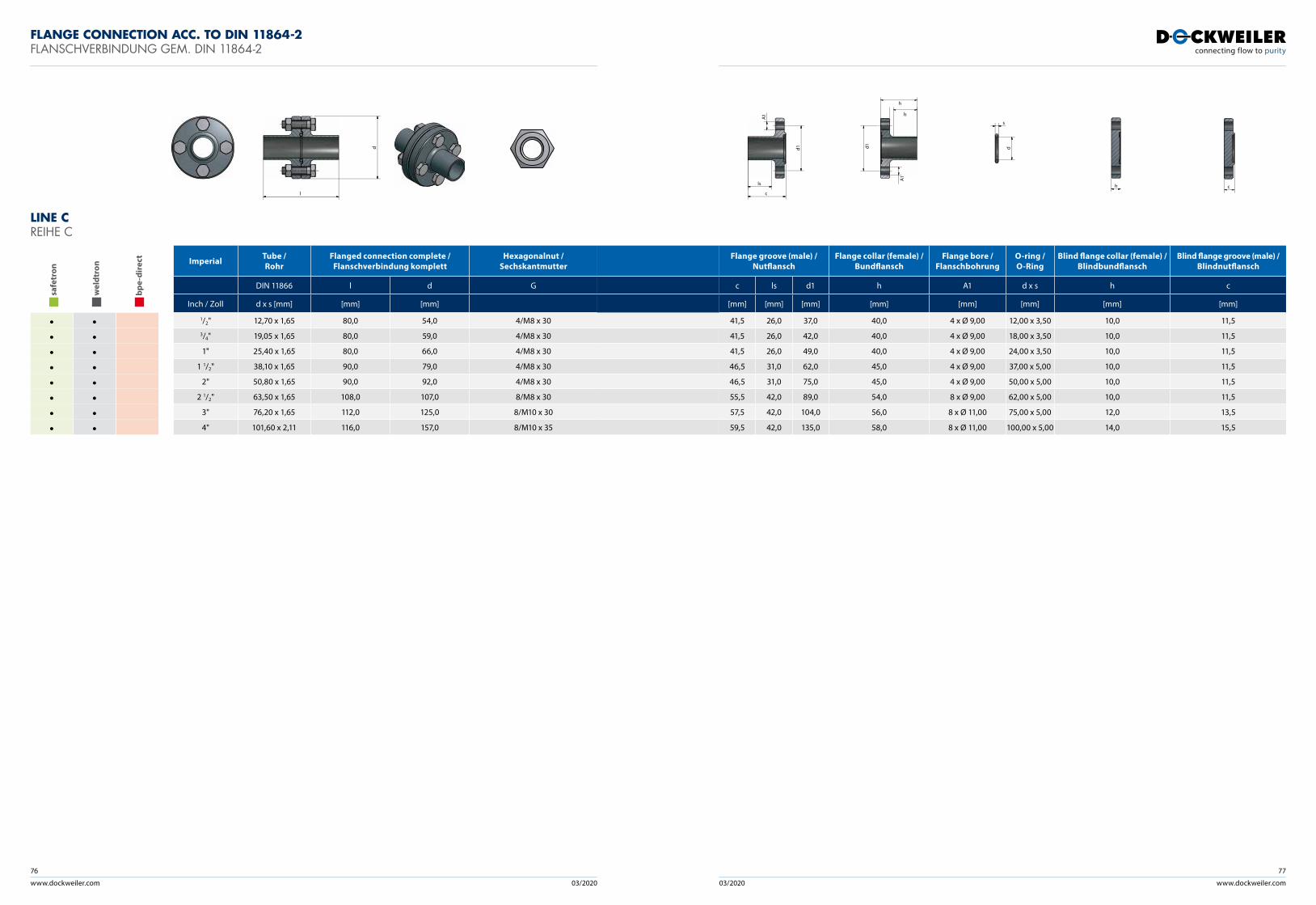
www.dockweiler.com 03/2020 03/2020
76
www.dockweiler.com
77
LINE C REIHE C
saf
etro
n
wel
dtro
n
bpe
-dir
ect
• •• •• •• •• •• •• •• •
Imperial Tube / Rohr
Flanged connection complete /Flanschverbindung komplett
Hexagonalnut / Sechskantmutter
DIN 11866 l d G
Inch / Zoll d x s [mm] [mm] [mm]
1/2" 12,70 x 1,65 80,0 54,0 4/M8 x 303/4" 19,05 x 1,65 80,0 59,0 4/M8 x 30
1" 25,40 x 1,65 80,0 66,0 4/M8 x 30
1 1/2" 38,10 x 1,65 90,0 79,0 4/M8 x 30
2" 50,80 x 1,65 90,0 92,0 4/M8 x 30
2 1/2" 63,50 x 1,65 108,0 107,0 8/M8 x 30
3" 76,20 x 1,65 112,0 125,0 8/M10 x 30
4" 101,60 x 2,11 116,0 157,0 8/M10 x 35
Flange groove (male) /Nutflansch
Flange collar (female) /Bundflansch
Flange bore / Flanschbohrung
O-ring / O-Ring
Blind flange collar (female) /Blindbundflansch
Blind flange groove (male) /Blindnutflansch
c ls d1 h A1 d x s h c
[mm] [mm] [mm] [mm] [mm] [mm] [mm] [mm]
41,5 26,0 37,0 40,0 4 x Ø 9,00 12,00 x 3,50 10,0 11,5
41,5 26,0 42,0 40,0 4 x Ø 9,00 18,00 x 3,50 10,0 11,5
41,5 26,0 49,0 40,0 4 x Ø 9,00 24,00 x 3,50 10,0 11,5
46,5 31,0 62,0 45,0 4 x Ø 9,00 37,00 x 5,00 10,0 11,5
46,5 31,0 75,0 45,0 4 x Ø 9,00 50,00 x 5,00 10,0 11,5
55,5 42,0 89,0 54,0 8 x Ø 9,00 62,00 x 5,00 10,0 11,5
57,5 42,0 104,0 56,0 8 x Ø 11,00 75,00 x 5,00 12,0 13,5
59,5 42,0 135,0 58,0 8 x Ø 11,00 100,00 x 5,00 14,0 15,5
FLANGE CONNECTION ACC. TO DIN 11864-2 FLANSCHVERBINDUNG GEM. DIN 11864-2
l
d
c
ls
d1
A1
h
ls
d
A1
1
d
s
h c
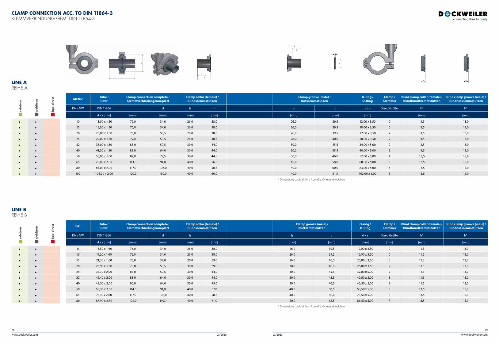
www.dockweiler.com 03/2020 03/2020
78
www.dockweiler.com
79
CLAMP CONNECTION ACC. TO DIN 11864-3 KLEMMVERBINDUNG GEM. DIN 11864-3
LINE A REIHE A
saf
etro
n
wel
dtro
n
bpe
-dir
ect
• •• •• •• •• •• •• •• •• •• •
Metric Tube / Rohr
Clamp connection complete / Klemmverbindung komplett
Clamp collar (female) /Bundklemmstutzen
DN / NW DIN 11866 l d ls h
d x s [mm] [mm] [mm] [mm] [mm]
10 13,00 x 1,50 76,0 34,0 26,0 38,0
15 19,00 x 1,50 76,0 34,0 26,0 38,0
20 23,00 x 1,50 76,0 50,5 26,0 38,0
25 29,00 x 1,50 77,0 50,5 28,0 38,5
32 35,00 x 1,50 88,0 50,5 30,0 44,0
40 41,00 x 1,50 88,0 64,0 30,0 44,0
50 53,00 x 1,50 89,0 77,5 30,0 44,5
65 70,00 x 2,00 113,0 91,0 40,0 56,5
80 85,00 x 2,00 117,0 106,0 40,0 58,5
100 104,00 x 2,00 120,0 130,0 40,0 60,0
Clamp groove (male) /Nutklemmstutzen
O-ring / O-Ring
Clamp / Klammer
Blind clamp collar (female) /Blindbundklemmstutzen
Blind clamp groove (male) /Blindnutklemmstutzen
ls c d x s Size / Größe h* h*
[mm] [mm] [mm] [mm] [mm]
26,0 39,5 12,00 x 3,50 0 11,5 13,0
26,0 39,5 18,00 x 3,50 0 11,5 13,0
26,0 39,5 22,00 x 3,50 2 11,5 13,0
28,0 40,0 28,00 x 3,50 2 11,5 13,0
30,0 45,5 34,00 x 5,00 2 11,5 13,0
30,0 45,5 40,00 x 5,00 3 11,5 13,0
30,0 46,0 52,00 x 5,00 4 13,5 15,0
40,0 58,0 68,00 x 5,00 5 13,5 15,0
40,0 60,0 83,00 x 5,00 6 13,5 15,0
40,0 61,5 102,00 x 5,00 8 13,5 15,0
c
ls
d
s
h hh
ls
LINE B REIHE B
saf
etro
n
wel
dtro
n
bpe
-dir
ect
• •• •• •• •• •• •• •• •• •• •
ISO Tube / Rohr
Clamp connection complete / Klemmverbindung komplett
Clamp collar (female) /Bundklemmstutzen
DN / NW DIN 11866 l d ls h
d x s [mm] [mm] [mm] [mm] [mm]
8 13,50 x 1,60 76,0 34,0 26,0 38,0
10 17,20 x 1,60 76,0 34,0 26,0 38,0
15 21,30 x 1,60 78,0 34,0 26,0 39,0
20 26,90 x 1,60 78,0 50,5 30,0 39,0
25 33,70 x 2,00 88,0 50,5 30,0 44,0
32 42,40 x 2,00 88,0 64,0 30,0 44,0
40 48,30 x 2,00 90,0 64,0 30,0 45,0
50 60,30 x 2,00 114,0 91,0 40,0 57,0
65 76,10 x 2,00 117,0 106,0 40,0 58,5
80 88,90 x 2,30 122,0 119,0 40,0 61,0
Clamp groove (male) /Nutklemmstutzen
O-ring / O-Ring
Clamp / Klammer
Blind clamp collar (female) /Blindbundklemmstutzen
Blind clamp groove (male) /Blindnutklemmstutzen
ls c d x s Size / Größe h* h*
[mm] [mm] [mm] [mm] [mm] [mm]
26,0 39,5 12,00 x 3,50 0 11,5 13,0
26,0 39,5 16,00 x 3,50 0 11,5 13,0
26,0 40,5 20,00 x 3,50 0 11,5 13,0
30,0 40,5 26,00 x 3,50 2 11,5 13,0
30,0 45,5 32,00 x 5,00 2 11,5 13,0
30,0 45,5 40,50 x 5,00 3 11,5 13,0
30,0 46,5 46,50 x 5,00 3 11,5 13,0
40,0 58,5 58,50 x 5,00 5 13,5 15,0
40,0 60,0 73,50 x 5,00 6 13,5 15,0
40,0 62,5 86,50 x 5,00 7 13,5 15,0
* Dimensions could differ / Abmaße können abweichen
* Dimensions could differ / Abmaße können abweichen
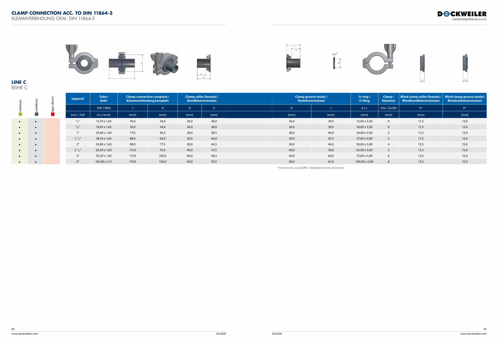
www.dockweiler.com 03/2020 03/2020
80
www.dockweiler.com
81
LINE C REIHE C
saf
etro
n
wel
dtro
n
bpe
-dir
ect
• •• •• •• •• •• •• •• •
Imperial Tube / Rohr
Clamp connection complete / Klemmverbindung komplett
Clamp collar (female) /Bundklemmstutzen
DIN 11866 l d ls h
Inch / Zoll d x s [mm] [mm] [mm] [mm] [mm]
1/2" 12,70 x 1,65 76,0 34,0 26,0 38,03/4" 19,05 x 1,65 76,0 34,0 26,0 38,0
1" 25,40 x 1,65 77,0 50,5 28,0 38,5
1 1/2" 38,10 x 1,65 88,0 64,0 30,0 44,0
2" 50,80 x 1,65 89,0 77,5 30,0 44,5
2 1/2" 63,50 x 1,65 115,0 91,0 40,0 57,5
3" 76,20 x 1,65 117,0 106,0 40,0 58,5
4" 101,60 x 2,11 119,0 130,0 40,0 59,5
Clamp groove (male) /Nutklemmstutzen
O-ring / O-Ring
Clamp / Klammer
Blind clamp collar (female) /Blindbundklemmstutzen
Blind clamp groove (male)/Blindnutklemmstutzen
ls c d x s Size / Größe h* h*
[mm] [mm] [mm] [mm] [mm] [mm]
26,0 39,5 12,00 x 3,50 0 11,5 13,0
26,0 39,5 18,00 x 3,50 0 11,5 13,0
28,0 40,0 24,00 x 3,50 2 11,5 13,0
30,0 45,5 37,00 x 5,00 3 11,5 13,0
30,0 46,0 50,00 x 5,00 4 13,5 15,0
40,0 59,0 62,00 x 5,00 5 13,5 15,0
40,0 60,0 75,00 x 5,00 6 13,5 15,0
40,0 61,0 100,00 x 5,00 8 13,5 15,0
CLAMP CONNECTION ACC. TO DIN 11864-3 KLEMMVERBINDUNG GEM. DIN 11864-3
c
ls
d
s
h hh
ls
* Dimensions could differ / Abmaße können abweichen
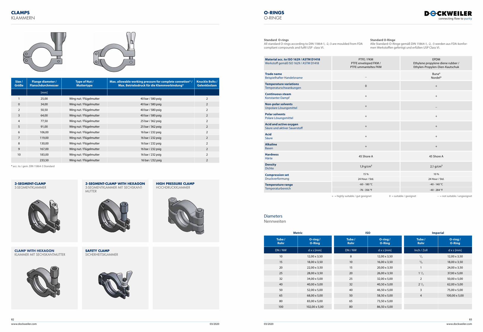
www.dockweiler.com 03/2020 03/2020
82
www.dockweiler.com
83
Material acc. to ISO 1629 / ASTM D1418Werkstoff gemäß ISO 1629 / ASTM D1418
PTFE / FKMPTFE enveloped FKM /
PTFE ummanteltes FKM
EPDM Ethylene propylene diene rubber /Ethylen-Propylen-Dien- Kautschuk
Trade nameBeispielhafter Handelsname _ Buna®
Nordel®
Temperature variationsTemperaturschwankungen 0 +
Continuous steamKonstanter Dampf + +
Non-polar solventsUnpolare Lösungsmittel + _
Polar solventsPolare Lösungsmittel + +
Acid and active oxygenSäure und aktiver Sauerstoff + +
AcidSäure + +
AlkalineBasen + +
HardnessHärte 45 Shore A 45 Shore A
DensityDichte 1,9 g/cm³ 2,1 g/cm³
Compression setDruckverformung
15 % 10 %
24 Hour / Std. 24 Hour / Std.
Temperature rangeTemperaturbereich
-60 - 180 °C -40 - 140 °C
-76 - 356 °F -40 - 284 °F
CLAMPS KLAMMERN
O-RINGS O-RINGE
Standard O-ringsAll standard O-rings according to DIN 11864-1, -2,-3 are moulded from FDA compliant compounds and fulfil USP class VI.
+ = highly suitable / gut geeignet 0 = suitable / geeignet – = not suitable / ungeeignet
DiametersNennweiten
Metric ISO Imperial
Tube / Rohr
O-ring / O-Ring
Tube / Rohr
O-ring / O-Ring
Tube / Rohr
O-ring / O-Ring
DN / NW d x s [mm] DN / NW d x s [mm] Inch / Zoll d x s [mm]
10 12,00 x 3,50 8 12,00 x 3,50 1/2 12,00 x 3,50
15 18,00 x 3,50 10 16,00 x 3,50 3/4 18,00 x 3,50
20 22,00 x 3,50 15 20,00 x 3,50 1 24,00 x 3,50
25 28,00 x 3,50 20 26,00 x 3,50 1 1/2 37,00 x 5,00
32 34,00 x 5,00 25 32,00 x 5,00 2 50,00 x 5,00
40 40,00 x 5,00 32 40,50 x 5,00 2 1/2 62,00 x 5,00
50 52,00 x 5,00 40 46,50 x 5,00 3 75,00 x 5,00
65 68,00 x 5,00 50 58,50 x 5,00 4 100,00 x 5,00
80 83,00 x 5,00 65 73,50 x 5,00
100 102,00 x 5,00 80 86,50 x 5,00
Standard O-RingeAlle Standard-O-Ringe gemäß DIN 11864-1, -2, -3 werden aus FDA-konfor-men Werkstoffen gefertigt und erfüllen USP Class VI.
Size / Größe
Flange diameter / Flanschdurchmesser
Type of Nut / Muttertype
Max. allowable working pressure for complete connetion* / Max. Betriebsdruck für die Klemmverbindung*
Knuckle Bolts / Gelenkbolzen
[mm]
1 25,00 Wing nut / Flügelmutter 40 bar / 580 psig 2
0 34,00 Wing nut / Flügelmutter 40 bar / 580 psig 2
2 50,50 Wing nut / Flügelmutter 40 bar / 580 psig 2
3 64,00 Wing nut / Flügelmutter 40 bar / 580 psig 2
4 77,50 Wing nut / Flügelmutter 25 bar / 362 psig 2
5 91,00 Wing nut / Flügelmutter 25 bar / 362 psig 2
6 106,00 Wing nut / Flügelmutter 16 bar / 232 psig 2
7 119,00 Wing nut / Flügelmutter 16 bar / 232 psig 2
8 130,00 Wing nut / Flügelmutter 16 bar / 232 psig 2
9 167,00 Wing nut / Flügelmutter 16 bar / 232 psig 2
10 183,00 Wing nut / Flügelmutter 16 bar / 232 psig 2
233,50 Wing nut / Flügelmutter 16 bar / 232 psig 2
3-SEGMENT-CLAMP3-SEGMENTKLAMMER
CLAMP WITH HEXAGONKLAMMER MIT SECHSKANTMUTTER
3-SEGMENT-CLAMP WITH HEXAGON3-SEGMENTKLAMMER MIT SECHSKANT-MUTTER
SAFETY CLAMPSICHERHEITSKLAMMER
HIGH PRESSURE CLAMPHOCHDRUCK KLAMMER
* acc. to / gem. DIN 11864-3 Standard
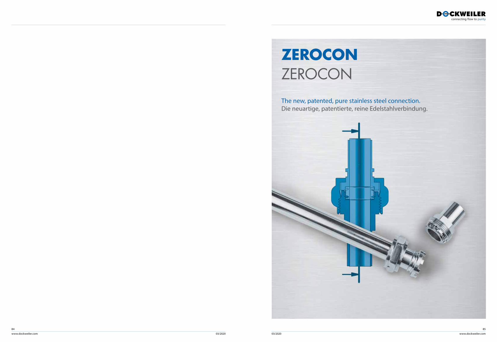
www.dockweiler.com 03/2020 03/2020
84
www.dockweiler.com
85
ZEROCONZEROCONThe new, patented, pure stainless steel connection. Die neuartige, patentierte, reine Edelstahlverbindung.
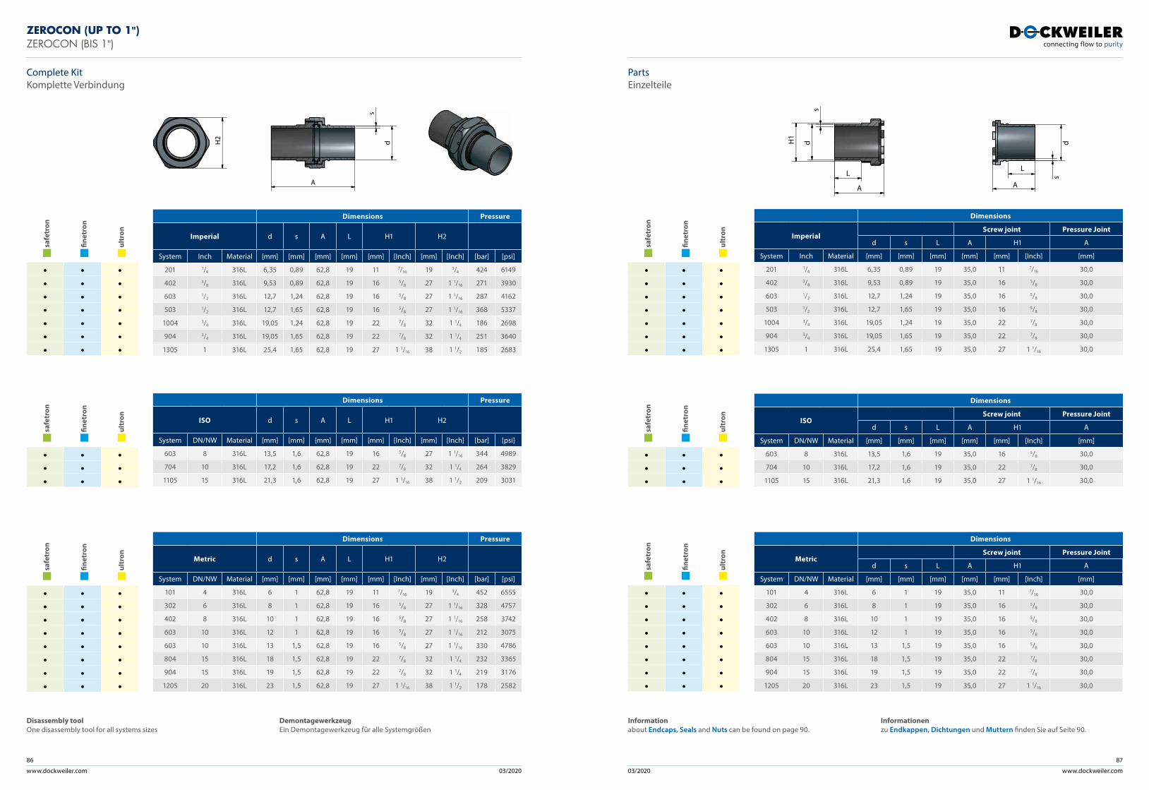
www.dockweiler.com 03/2020 03/2020
86
www.dockweiler.com
87
ZEROCON (UP TO 1")ZEROCON (BIS 1")
saf
etro
n
fine
tron
ult
ron
• • •• • •• • •• • •• • •• • •• • •
Dimensions Pressure
Imperial d s A L H1 H2
System Inch Material [mm] [mm] [mm] [mm] [mm] [Inch] [mm] [Inch] [bar] [psi]
201 1/4 316L 6,35 0,89 62,8 19 11 7/16 19 3/4 424 6149
402 3/8 316L 9,53 0,89 62,8 19 16 5/8 27 1 1/16 271 3930
603 1/2 316L 12,7 1,24 62,8 19 16 5/8 27 1 1/16 287 4162
503 1/2 316L 12,7 1,65 62,8 19 16 5/8 27 1 1/16 368 5337
1004 3/4 316L 19,05 1,24 62,8 19 22 7/8 32 1 1/4 186 2698
904 3/4 316L 19,05 1,65 62,8 19 22 7/8 32 1 1/4 251 3640
1305 1 316L 25,4 1,65 62,8 19 27 1 1/16 38 1 1/2 185 2683
saf
etro
n
fine
tron
ult
ron
• • •• • •• • •• • •• • •• • •• • •
Dimensions
ImperialScrew joint Pressure Joint
d s L A H1 A
System Inch Material [mm] [mm] [mm] [mm] [mm] [Inch] [mm]
201 1/4 316L 6,35 0,89 19 35,0 11 7/16 30,0
402 3/8 316L 9,53 0,89 19 35,0 16 5/8 30,0
603 1/2 316L 12,7 1,24 19 35,0 16 5/8 30,0
503 1/2 316L 12,7 1,65 19 35,0 16 5/8 30,0
1004 3/4 316L 19,05 1,24 19 35,0 22 7/8 30,0
904 3/4 316L 19,05 1,65 19 35,0 22 7/8 30,0
1305 1 316L 25,4 1,65 19 35,0 27 1 1/16 30,0
saf
etro
n
fine
tron
ult
ron
• • •• • •• • •• • •• • •• • •• • •• • •
Dimensions Pressure
Metric d s A L H1 H2
System DN/NW Material [mm] [mm] [mm] [mm] [mm] [Inch] [mm] [Inch] [bar] [psi]
101 4 316L 6 1 62,8 19 11 7/16 19 3/4 452 6555
302 6 316L 8 1 62,8 19 16 5/8 27 1 1/16 328 4757
402 8 316L 10 1 62,8 19 16 5/8 27 1 1/16 258 3742
603 10 316L 12 1 62,8 19 16 5/8 27 1 1/16 212 3075
603 10 316L 13 1,5 62,8 19 16 5/8 27 1 1/16 330 4786
804 15 316L 18 1,5 62,8 19 22 7/8 32 1 1/4 232 3365
904 15 316L 19 1,5 62,8 19 22 7/8 32 1 1/4 219 3176
1205 20 316L 23 1,5 62,8 19 27 1 1/16 38 1 1/2 178 2582
saf
etro
n
fine
tron
ult
ron
• • •• • •• • •• • •• • •• • •• • •• • •
Dimensions
MetricScrew joint Pressure Joint
d s L A H1 A
System DN/NW Material [mm] [mm] [mm] [mm] [mm] [Inch] [mm]
101 4 316L 6 1 19 35,0 11 7/16 30,0
302 6 316L 8 1 19 35,0 16 5/8 30,0
402 8 316L 10 1 19 35,0 16 5/8 30,0
603 10 316L 12 1 19 35,0 16 5/8 30,0
603 10 316L 13 1,5 19 35,0 16 5/8 30,0
804 15 316L 18 1,5 19 35,0 22 7/8 30,0
904 15 316L 19 1,5 19 35,0 22 7/8 30,0
1205 20 316L 23 1,5 19 35,0 27 1 1/16 30,0
saf
etro
n
fine
tron
ult
ron
• • •• • •• • •
Dimensions Pressure
ISO d s A L H1 H2
System DN/NW Material [mm] [mm] [mm] [mm] [mm] [Inch] [mm] [Inch] [bar] [psi]
603 8 316L 13,5 1,6 62,8 19 16 5/8 27 1 1/16 344 4989
704 10 316L 17,2 1,6 62,8 19 22 7/8 32 1 1/4 264 3829
1105 15 316L 21,3 1,6 62,8 19 27 1 1/16 38 1 1/2 209 3031
saf
etro
n
fine
tron
ult
ron
• • •• • •• • •
Dimensions
ISOScrew joint Pressure Joint
d s L A H1 A
System DN/NW Material [mm] [mm] [mm] [mm] [mm] [Inch] [mm]
603 8 316L 13,5 1,6 19 35,0 16 5/8 30,0
704 10 316L 17,2 1,6 19 35,0 22 7/8 30,0
1105 15 316L 21,3 1,6 19 35,0 27 1 1/16 30,0
A
s
dH2
sd
1
L
A
H
sd
L
A
Complete KitKomplette Verbindung
PartsEinzelteile
Informationabout Endcaps, Seals and Nuts can be found on page 90.
Informationenzu Endkappen, Dichtungen und Muttern finden Sie auf Seite 90.
Disassembly toolOne disassembly tool for all systems sizes
DemontagewerkzeugEin Demontagewerkzeug für alle Systemgrößen
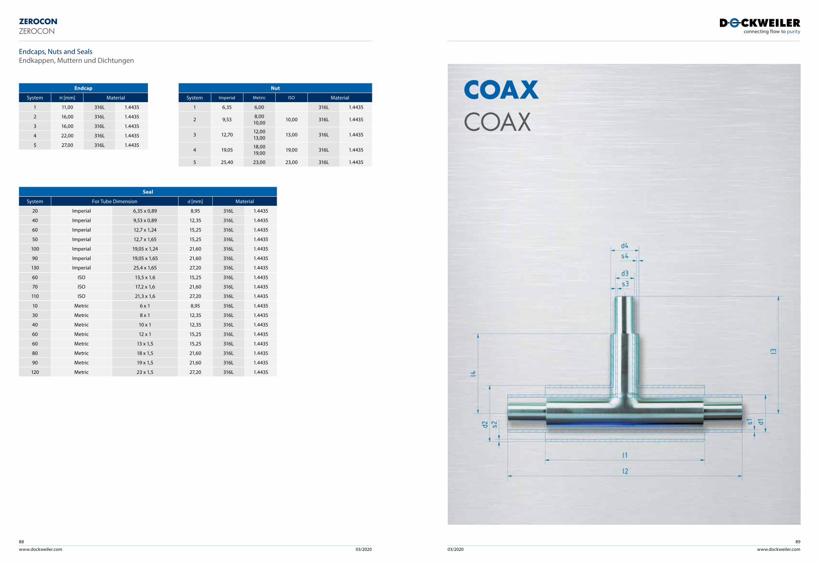
www.dockweiler.com 03/2020 03/2020 www.dockweiler.com
89
COAXCOAX
88
ZEROCONZEROCON
Endcaps, Nuts and SealsEndkappen, Muttern und Dichtungen
Seal
System For Tube Dimension d [mm] Material
20 Imperial 6,35 x 0,89 8,95 316L 1.4435
40 Imperial 9,53 x 0,89 12,35 316L 1.4435
60 Imperial 12,7 x 1,24 15,25 316L 1.4435
50 Imperial 12,7 x 1,65 15,25 316L 1.4435
100 Imperial 19,05 x 1,24 21,60 316L 1.4435
90 Imperial 19,05 x 1,65 21,60 316L 1.4435
130 Imperial 25,4 x 1,65 27,20 316L 1.4435
60 ISO 13,5 x 1,6 15,25 316L 1.4435
70 ISO 17,2 x 1,6 21,60 316L 1.4435
110 ISO 21,3 x 1,6 27,20 316L 1.4435
10 Metric 6 x 1 8,95 316L 1.4435
30 Metric 8 x 1 12,35 316L 1.4435
40 Metric 10 x 1 12,35 316L 1.4435
60 Metric 12 x 1 15,25 316L 1.4435
60 Metric 13 x 1,5 15,25 316L 1.4435
80 Metric 18 x 1,5 21,60 316L 1.4435
90 Metric 19 x 1,5 21,60 316L 1.4435
120 Metric 23 x 1,5 27,20 316L 1.4435
Endcap
System H [mm] Material
1 11,00 316L 1.4435
2 16,00 316L 1.4435
3 16,00 316L 1.4435
4 22,00 316L 1.4435
5 27,00 316L 1.4435
Nut
System Imperial Metric ISO Material
1 6,35 6,00 316L 1.4435
2 9,53 8,0010,00 10,00 316L 1.4435
3 12,70 12,0013,00 13,00 316L 1.4435
4 19,05 18,0019,00 19,00 316L 1.4435
5 25,40 23,00 23,00 316L 1.4435
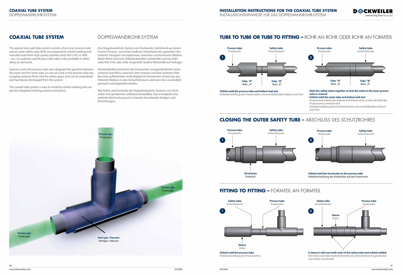
www.dockweiler.com 03/2020 03/2020
90
www.dockweiler.com
91
COAXIAL TUBE SYSTEM DOPPELWANDROHR-SYSTEM TUBE TO TUBE OR TUBE TO FITTING – ROHR AN ROHR ODER ROHR AN FORMTEIL
CLOSING THE OUTER SAFETY TUBE – ABSCHLUSS DES SCHUTZROHRES
FITTING TO FITTING – FORMTEIL AN FORMTEIL
The special twin wall tube system consists of an inner process tube and an outer safety tube. Both are prepared for orbital welding and manufactured from high quality stainless steel AISI 316L or 304L – acc. to customer specification (the tube is also available in other alloys on demand).
Spacers centre the process tube and safeguard the gas flow between the outer and the inner tube. In case of a leak in the process tube the escaping medium flows into the safety space and can be neutralised and harmlessly discharged from the system.
The coaxial tube system is easy to install by orbital welding and can also be integrated existing systems and plants.
Das Doppelwandrohr-System von Dockweiler, bestehend aus einem inneren Prozess- und einem äußeren Sicherheitsrohr, garantiert den sicheren Transport von explosiven, toxischen und korrosiven Medien. Beide Rohre sind zum Orbitalschweißen vorbereitet und aus Edel-stahl AISI 316L oder 304L hergestellt (andere Werkstoffe auf Anfrage).
Abstandshalter zentrieren das Prozessrohr und gewährleisten einen sicheren Durchfluss zwischen dem inneren und dem äußeren Rohr. Bei einer auftretenden Undichtigkeit im Prozessrohr strömt das aus-tretende Medium in den Sicherheitsraum und kann hier unschädlich gemacht und abgeleitet werden.
Alle Rohre und Formteile des Doppelwandrohr-Systems von Dock-weiler sind problemlos orbitalverschweißbar. Das ermöglicht eine einfache Nachrüstung auch in bereits bestehende Anlagen und Einrichtungen.
COAXIAL TUBE SYSTEMDOPPELWANDROHR-SYSTEM
INSTALLATION INSTRUCTIONS FOR THE COAXIAL TUBE SYSTEMINSTALLATIONSHINWEISE FÜR DAS DOPPELWANDROHR-SYSTEM
Orbital weld the process tube and helium leak testOrbitalschweißung des Prozessrohres, mit anschließendem Helium-Leck-Test
1
1
1
Tube “A”Rohr „A”
Tube “B”Rohr „B”
TerminatorEndstück
SleeveHülse
SleeveHülse
Safety tubeSicherheitsrohr
Safety tubeSicherheitsrohr
Process tubeProzessrohr
Process tubeProzessrohr
Process tubeProzessrohr
Process tubeProzessrohrProcess gas
Prozessgas
Inert gas / Vacuum Inertgas / Vakuum
Process gas Prozessgas
Process gas Prozessgas
Safety tubeSicherheitsrohr
Safety tubeSicherheitsrohr
- Slide the safety tubes together so that the weld on the inner process tube is covered
- Orbital weld the outer tube and helium leak test- Zusammenschieben der äußeren Sicherheitsrohre, so dass die Naht des
Prozessrohres verdeckt wird- Orbitalschweißung des Sicherheitsrohres mit anschließendem Helium-
Leck-Test
Orbital weld the terminator to the process tubeOrbitalschweißung des Endstückes auf das Prozessrohr
Orbital weld the process tubeOrbitalschweißung des Prozessrohres
A sleeve is slid over both ends of the safety tube and orbital weldedEine Hülse wird über beide Rohrenden des Sicherheitsrohres geschoben und orbital verschweißt
2
2
2
Tube “A”Rohr „A”
Tube “B”Rohr „B”
Safety tubeSicherheitsrohr
Safety tubeSicherheitsrohr
Process tubeProzessrohr
Process tubeProzessrohr
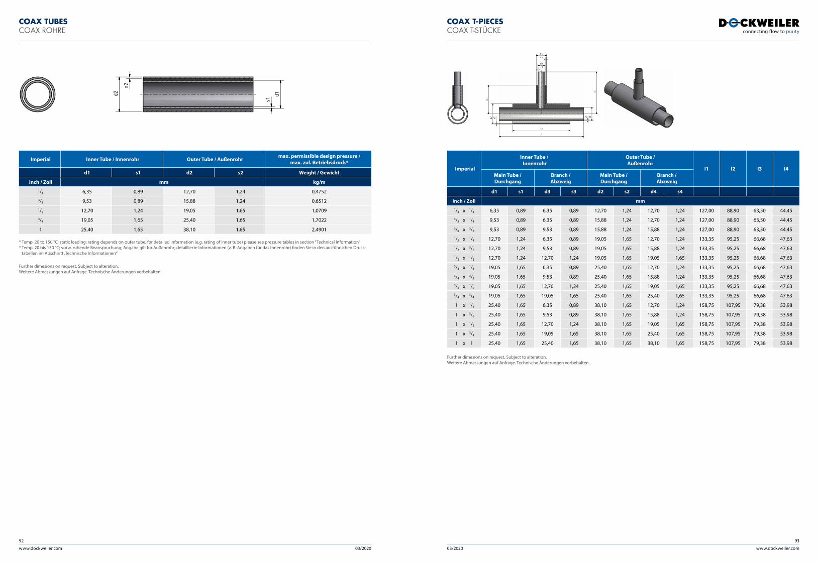
www.dockweiler.com 03/2020 03/2020
92
www.dockweiler.com
93
Imperial Inner Tube / Innenrohr Outer Tube / Außenrohr max. permissible design pressure / max. zul. Betriebsdruck*
d1 s1 d2 s2 Weight / Gewicht
Inch / Zoll mm kg/m1/4 6,35 0,89 12,70 1,24 0,47523/8 9,53 0,89 15,88 1,24 0,65121/2 12,70 1,24 19,05 1,65 1,07093/4 19,05 1,65 25,40 1,65 1,7022
1 25,40 1,65 38,10 1,65 2,4901
* Temp. 20 to 150 °C; static loading; rating depends on outer tube; for detailed information (e.g. rating of inner tube) please see pressure tables in section “Technical Information”* Temp. 20 bis 150 °C; vorw. ruhende Beanspruchung; Angabe gilt für Außenrohr; detaillierte Informationen (z. B. Angaben für das Innenrohr) finden Sie in den ausführlichen Druck-
tabellen im Abschnitt „Technische Informationen“
COAX TUBESCOAX ROHRE
COAX T-PIECESCOAX T-STÜCKE
Imperial
Inner Tube / Innenrohr
Outer Tube / Außenrohr
l1 l2 l3 l4Main Tube / Durchgang
Branch / Abzweig
Main Tube / Durchgang
Branch / Abzweig
d1 s1 d3 s3 d2 s2 d4 s4
Inch / Zoll mm1/4 x 1/4 6,35 0,89 6,35 0,89 12,70 1,24 12,70 1,24 127,00 88,90 63,50 44,453/8 x 1/4 9,53 0,89 6,35 0,89 15,88 1,24 12,70 1,24 127,00 88,90 63,50 44,453/8 x 3/8 9,53 0,89 9,53 0,89 15,88 1,24 15,88 1,24 127,00 88,90 63,50 44,451/2 x 1/4 12,70 1,24 6,35 0,89 19,05 1,65 12,70 1,24 133,35 95,25 66,68 47,631/2 x 3/8 12,70 1,24 9,53 0,89 19,05 1,65 15,88 1,24 133,35 95,25 66,68 47,631/2 x 1/2 12,70 1,24 12,70 1,24 19,05 1,65 19,05 1,65 133,35 95,25 66,68 47,633/4 x 1/4 19,05 1,65 6,35 0,89 25,40 1,65 12,70 1,24 133,35 95,25 66,68 47,633/4 x 3/8 19,05 1,65 9,53 0,89 25,40 1,65 15,88 1,24 133,35 95,25 66,68 47,633/4 x 1/2 19,05 1,65 12,70 1,24 25,40 1,65 19,05 1,65 133,35 95,25 66,68 47,633/4 x 3/4 19,05 1,65 19,05 1,65 25,40 1,65 25,40 1,65 133,35 95,25 66,68 47,63
1 x 1/4 25,40 1,65 6,35 0,89 38,10 1,65 12,70 1,24 158,75 107,95 79,38 53,98
1 x 3/8 25,40 1,65 9,53 0,89 38,10 1,65 15,88 1,24 158,75 107,95 79,38 53,98
1 x 1/2 25,40 1,65 12,70 1,24 38,10 1,65 19,05 1,65 158,75 107,95 79,38 53,98
1 x 3/4 25,40 1,65 19,05 1,65 38,10 1,65 25,40 1,65 158,75 107,95 79,38 53,98
1 x 1 25,40 1,65 25,40 1,65 38,10 1,65 38,10 1,65 158,75 107,95 79,38 53,98
d2
s2
d1s1
l3
l4
l1
l2
d1s1d2 s2
d3s3
d4s4
Further dimesions on request. Subject to alteration. Weitere Abmessungen auf Anfrage. Technische Änderungen vorbehalten.
Further dimesions on request. Subject to alteration. Weitere Abmessungen auf Anfrage. Technische Änderungen vorbehalten.
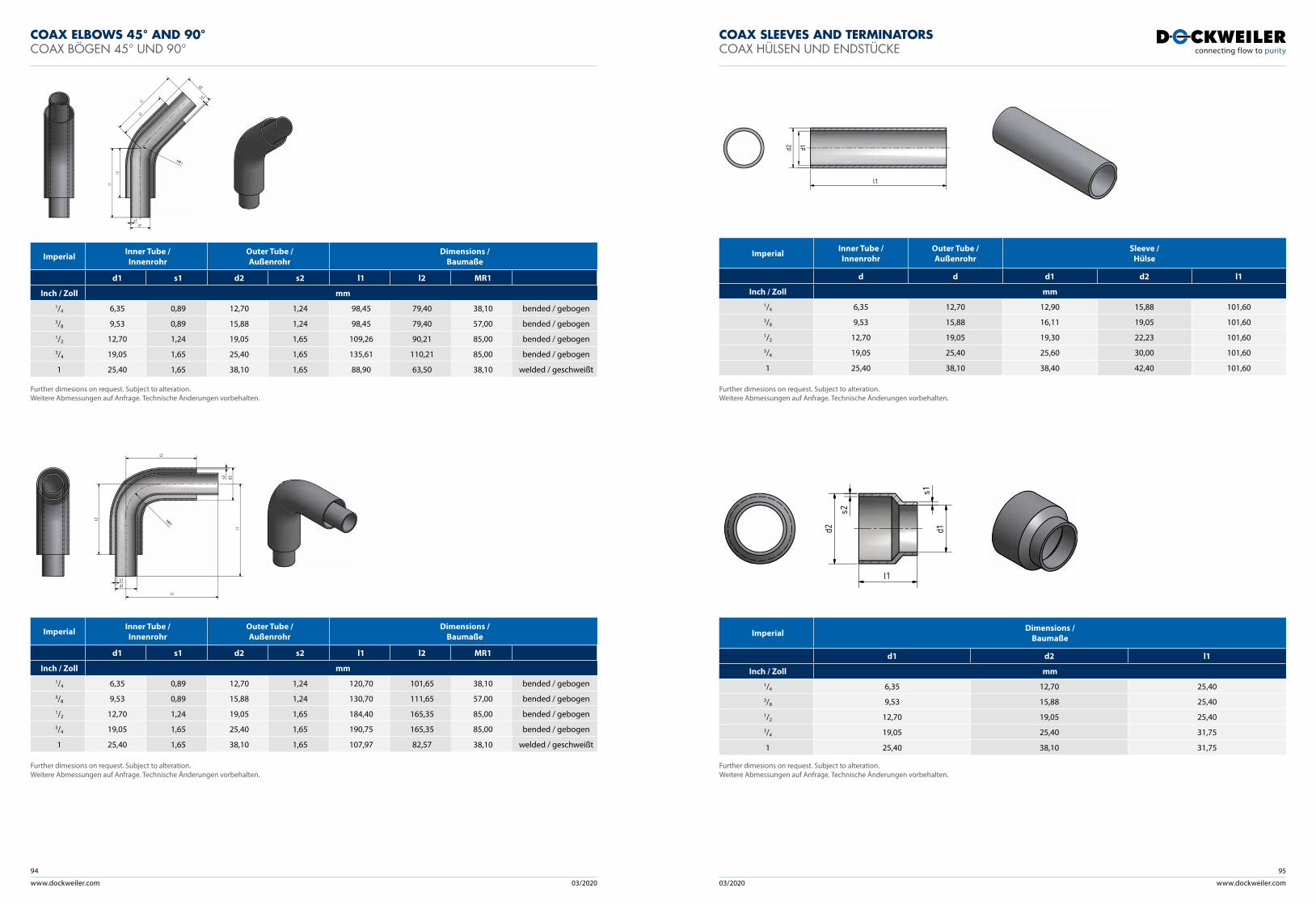
www.dockweiler.com 03/2020 03/2020
94
www.dockweiler.com
95
COAX ELBOWS 45° AND 90°COAX BÖGEN 45° UND 90°
COAX SLEEVES AND TERMINATORSCOAX HÜLSEN UND ENDSTÜCKE
Imperial Inner Tube / Innenrohr
Outer Tube / Außenrohr
Dimensions / Baumaße
d1 s1 d2 s2 l1 l2 MR1
Inch / Zoll mm1/4 6,35 0,89 12,70 1,24 98,45 79,40 38,10 bended / gebogen3/8 9,53 0,89 15,88 1,24 98,45 79,40 57,00 bended / gebogen1/2 12,70 1,24 19,05 1,65 109,26 90,21 85,00 bended / gebogen3/4 19,05 1,65 25,40 1,65 135,61 110,21 85,00 bended / gebogen
1 25,40 1,65 38,10 1,65 88,90 63,50 38,10 welded / geschweißt
Imperial Inner Tube / Innenrohr
Outer Tube / Außenrohr
Dimensions / Baumaße
d1 s1 d2 s2 l1 l2 MR1
Inch / Zoll mm1/4 6,35 0,89 12,70 1,24 120,70 101,65 38,10 bended / gebogen3/8 9,53 0,89 15,88 1,24 130,70 111,65 57,00 bended / gebogen1/2 12,70 1,24 19,05 1,65 184,40 165,35 85,00 bended / gebogen3/4 19,05 1,65 25,40 1,65 190,75 165,35 85,00 bended / gebogen
1 25,40 1,65 38,10 1,65 107,97 82,57 38,10 welded / geschweißt
Imperial Inner Tube / Innenrohr
Outer Tube / Außenrohr
Sleeve / Hülse
d d d1 d2 l1
Inch / Zoll mm1/4 6,35 12,70 12,90 15,88 101,603/8 9,53 15,88 16,11 19,05 101,601/2 12,70 19,05 19,30 22,23 101,603/4 19,05 25,40 25,60 30,00 101,60
1 25,40 38,10 38,40 42,40 101,60
Imperial Dimensions / Baumaße
d1 d2 l1
Inch / Zoll mm1/4 6,35 12,70 25,403/8 9,53 15,88 25,401/2 12,70 19,05 25,403/4 19,05 25,40 31,75
1 25,40 38,10 31,75
l1
l2
l1
l2
d1s1
d2
s2
MR1
l1
l1
l2
l2
d1s1
d2s2
MR1
l1
d2 1d
d1d2
s1
s2
l1
Further dimesions on request. Subject to alteration. Weitere Abmessungen auf Anfrage. Technische Änderungen vorbehalten.
Further dimesions on request. Subject to alteration. Weitere Abmessungen auf Anfrage. Technische Änderungen vorbehalten.
Further dimesions on request. Subject to alteration. Weitere Abmessungen auf Anfrage. Technische Änderungen vorbehalten.
Further dimesions on request. Subject to alteration. Weitere Abmessungen auf Anfrage. Technische Änderungen vorbehalten.
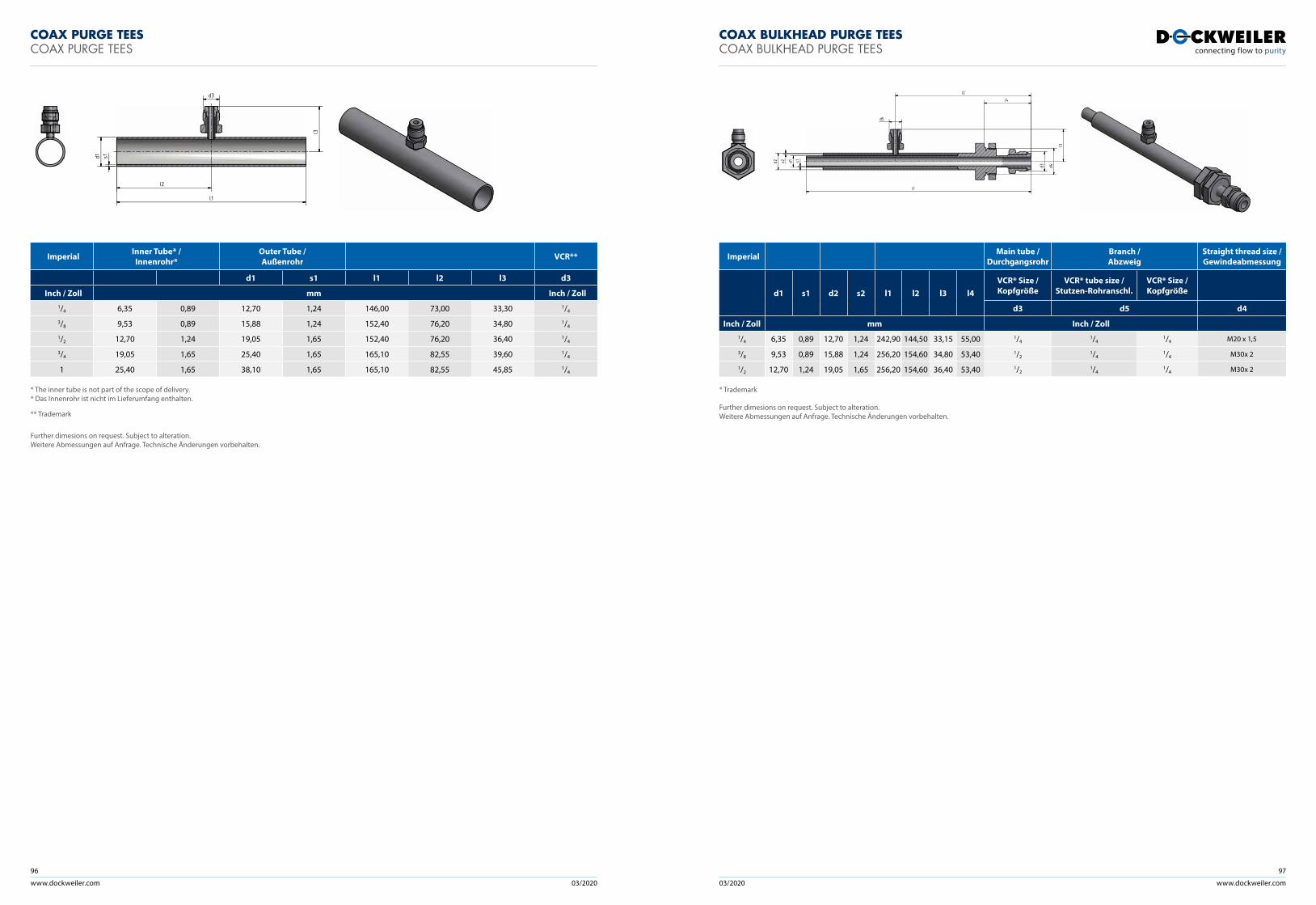
www.dockweiler.com 03/2020 03/2020
96
www.dockweiler.com
97
COAX PURGE TEESCOAX PURGE TEES
COAX BULKHEAD PURGE TEESCOAX BULKHEAD PURGE TEES
Imperial Inner Tube* / Innenrohr*
Outer Tube / Außenrohr VCR**
d1 s1 l1 l2 l3 d3
Inch / Zoll mm Inch / Zoll1/4 6,35 0,89 12,70 1,24 146,00 73,00 33,30 1/4
3/8 9,53 0,89 15,88 1,24 152,40 76,20 34,80 1/4
1/2 12,70 1,24 19,05 1,65 152,40 76,20 36,40 1/4
3/4 19,05 1,65 25,40 1,65 165,10 82,55 39,60 1/4
1 25,40 1,65 38,10 1,65 165,10 82,55 45,85 1/4
* The inner tube is not part of the scope of delivery.* Das Innenrohr ist nicht im Lieferumfang enthalten.
** Trademark
Imperial Main tube / Durchgangsrohr
Branch /Abzweig
Straight thread size /Gewindeabmessung
d1 s1 d2 s2 l1 l2 l3 l4VCR* Size / Kopfgröße
VCR* tube size /Stutzen-Rohranschl.
VCR* Size /Kopfgröße
d3 d5 d4
Inch / Zoll mm Inch / Zoll1/4 6,35 0,89 12,70 1,24 242,90 144,50 33,15 55,00 1/4
1/41/4 M20 x 1,5
3/8 9,53 0,89 15,88 1,24 256,20 154,60 34,80 53,40 1/21/4
1/4 M30x 2
1/2 12,70 1,24 19,05 1,65 256,20 154,60 36,40 53,40 1/21/4
1/4 M30x 2
* Trademark
d1 s1d3
l3
l1
l2
d1 s1d2 s2
l2
l4
d5
l1
l3
d3 d4
Further dimesions on request. Subject to alteration. Weitere Abmessungen auf Anfrage. Technische Änderungen vorbehalten.
Further dimesions on request. Subject to alteration. Weitere Abmessungen auf Anfrage. Technische Änderungen vorbehalten.
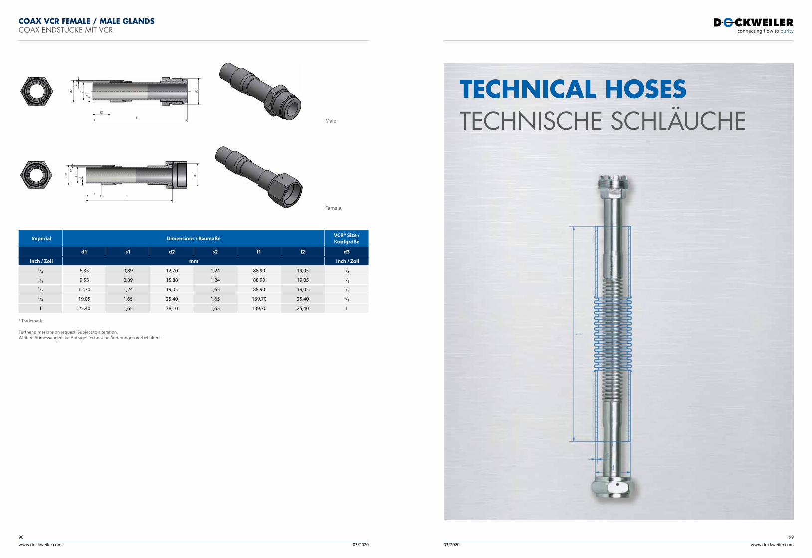
www.dockweiler.com 03/2020 03/2020
98
www.dockweiler.com
99
COAX VCR FEMALE / MALE GLANDSCOAX ENDSTÜCKE MIT VCR
Imperial Dimensions / Baumaße VCR* Size / Kopfgröße
d1 s1 d2 s2 l1 l2 d3
Inch / Zoll mm Inch / Zoll1/4 6,35 0,89 12,70 1,24 88,90 19,05 1/4
3/8 9,53 0,89 15,88 1,24 88,90 19,05 1/2
1/2 12,70 1,24 19,05 1,65 88,90 19,05 1/2
3/4 19,05 1,65 25,40 1,65 139,70 25,40 3/4
1 25,40 1,65 38,10 1,65 139,70 25,40 1
* Trademark
l2l1
d1s1
d2s2
d3l2
l1
d1s1
d2s2
d3
Male
Female
Further dimesions on request. Subject to alteration. Weitere Abmessungen auf Anfrage. Technische Änderungen vorbehalten.
TECHNICAL HOSESTECHNISCHE SCHLÄUCHE
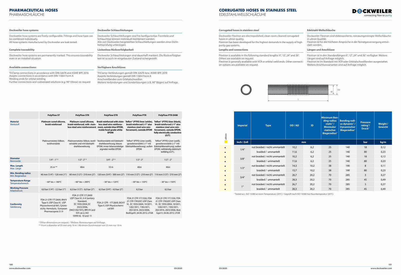
www.dockweiler.com 03/2020 03/2020
100
www.dockweiler.com
101
PHARMACEUTICAL HOSES PHARMASCHLÄUCHE
PolyFlow ST PolyFlow STR PolyFlow ETR PolyFlow PTR PolyFlow PTR OHM
Material Werkstoff
Platinum-cured silicone, braid-reinforced
Platinvernetztes Silikon, textilverstärkt
Platinum-cured silicone, braid-reinforced, with stain-less steel wire reinforcement
Platinvernetztes Silikon, textil-verstärkt und mit Edelstahl-
drahtbewehrung
Braid-reinforced with stain-less steel wire reinforce-
ment, outside blue EPDM, inside food-grade white
EPDM
Textilverstärkt mit Edelstahl-drahtbewehrung, blaues
EPDM, innen lebensmittelge-eignetes weißes EPDM
Teflon® (PTFE) liner (white), braid-reinforced (>1“ also
stainless steel wire rein-forcement), outside EPDM
Teflon® (PTFE)-Liner (weiß), gewebeverstärkt (>1“ mit
Edelstahlbewehrung), außen EPDM
Teflon® (PTFE) liner (black), braid-reinforced (>1“ also
stainless steel wire rein-forcement), outside EPDM, fully electrically conductive
(Ω/T)
Teflon® (PTFE)-Liner (weiß), gewebeverstärkt (>1“ mit
Edelstahlbewehrung), außen EPDM, vollständig elektrisch
leitfähig (Ω/T).
DiameterNennweite 1/4“ - 1“ * 1/2“- 2“ * 3/4“ - 2“ * 1/2“- 2“ 1/2“ - 2“
Max. Length Max. Länge 25 m ** 40m 10 m 40m 40m
Min. Bending radiusMin. Biegeradius 40 mm (1/4“) - 120 mm (1“) 60 mm (1/2“) - 210 mm (2“) 120 mm (3/4“) - 300 mm (2“) 110 mm (1/2“) - 210 mm (2“) 110 mm (1/2“) - 210 mm (2“)
Temperature RangeTemperaturbereich - 60° bis + 180°C - 60° bis + 200°C - 30° bis + 120°C - 30° bis + 150°C - 30° bis + 150°C
Working PressureArbeitsdruck 6,0 bar (1/4“) - 2,5 bar (1“) 6,5 bar (1/2“) - 6,0 bar (2“) 6,5 bar (3/4“) - 4,0 bar (2“) 6,5 bar 6,5 bar
ConformityValidierung
FDA 21 CFR 177.2600, BhVV Type II, USP Class VI, USP
Physiochemical 661, Cytoto-xicity, Hemolysis, European
Pharmacopeia 3.1.9
FDA 21 CFR 177.2600USP Class VI, 3-A Sanitary
Standard,EC 1935/2004, EC
2023/2006,DM21/03/1973, BfR XV and
XXI cat.2, ISO10993-8, -10 and -11
FDA 21 CFR - 177.2600, BGVV Type II, USP Physicochemi-
cal 661
FDA 21 CFR 177.1550, FDA 21 CFR 1783297, USP Class VI, EC 1935/2004, 10/2011,
1282/2011, 1183/2011, 202/2014, 2023/2006,
BedGgstV, 24.06.2013, LFGB
FDA 21 CFR 177.1550, FDA 21 CFR 1783297, USP Class VI, EC 1935/2004, 10/2011,
1282/2011, 1183/2011, 202/2014, 2023/2006, Bed.
Ggst V, 24.06.2013, LFGB
* Other dimensions on request. / Weitere Abmessungen auf Anfrage. ** From a diameter of 25 mm only 10 m / Ab einem Durchmesser von 25 mm nur 10 m
Dockweiler hose systems Dockweiler Schlauchleitungen
Dockweiler hose systems are freely configurable. Fittings and hose type can be combined individually.All hose systems manufactured by Dockweiler are leak tested.
Dockweiler Schlauchleitungen sind frei konfigurierbar. Formteile und Schlauchtyp können individuell kombiniert werden.Alle von Dockweiler hergestellten Schlauchleitungen werden einer Dicht-heitsprüfung unterzogen.
Complete traceability Lückenlose Rückverfolgbarkeit
Dockweiler hose systems are permanently marked. This ensures traceability even in an installed situation.
Dockweiler Schlauchleitungen sind dauerhaft markiert. Die Rückverfolgbar-keit ist so auch im eingebauten Zustand sichergestellt.
Available connections: Verfügbare Anschlüsse:
TriClamp connections in accordance with DIN 32676 and ASME BPE 2016Aseptic connections in accordance with DIN 11864 Form AWelding ends for orbital weldingFurther connections and customized solutions (e.g. 90° Elbow) on request
TriClamp-Verbindungen gemäß DIN 32676 bzw. ASME BPE 2019 Aseptik-Verbindungen gemäß DIN 11864 Form A Anschweißenden zum Orbitalschweißen Weitere Verbindungen und Sonderlösungen (z.B. 90° Bögen) auf Anfrage.
ult
ron
••••••••••
Imperial Type OD / AD ID
Minimum Ben-ding radius
static1 / Minimaler statischer
Biegeradius1
Bending radi-us dynamic1 / Dynamischer Biegeradius1
Pressure rating1/ Druck1
Weight / Gewicht
Inch / Zoll mm bar kg/m
1/4“not braided / nicht ummantelt 10,2 6,2 25 140 18 0,12
braided / ummantelt 11,6 6,2 25 140 80 0,23
3/8“not braided / nicht ummantelt 10,2 6,2 25 140 18 0,12
braided / ummantelt 11,6 6,2 25 140 80 0,23
1/2“not braided / nicht ummantelt 14,3 10,2 38 190 8 0,11
braided / ummantelt 15,7 10,2 38 190 80 0,23
3/4“not braided / nicht ummantelt 26,7 20,2 70 285 3 0,27
braided / ummantelt 28,3 20,2 70 285 45 0,49
1“not braided / nicht ummantelt 26,7 20,2 70 285 3 0,27
braided / ummantelt 28,3 20,2 70 285 45 0,49
1 Tested acc. ISO 10380 at room Temperature (20°C) / Geprüft nach ISO 10380 bei Raumtemperatur (20°C)
Corrugated hoses in stainless steel Edelstahl-Wellschläuche
Dockweiler Flextron are electropolished, clean room cleaned corrugated hoses in ultron quality.Flextron has been developed for the highest demands in the supply of high purity gas systems.
Dockweiler Flextron sind elektropolierte, reinraumgereinigte Wellschläuche in ultron Qualität.Flextron ist für die höchsten Ansprüche in der Reinstgasversorgung entwi-ckelt worden.
Lengths and connections Längen und Anschlüsse
Flextron is available in the following standard lengths: 6”, 12”, 24” and 36”. Others are available on request.Flextron is generally available with VCR or orbital weld ends. Other connecti-on options are available on request.
Flextron ist in den Standardlängen 6“, 12“, 24“ und 36“ verfügbar. Weitere Längen sind auf Anfrage möglich.Flextron ist im Standard mit VCR oder Orbitalschweißenden ausgestattet. Weitere Anschlussvarianten sind auf Anfrage möglich.
CORRUGATED HOSES IN STAINLESS STEELEDELSTAHL-WELLSCHLÄCUHE
www.dockweiler.com 03/2020 03/2020
102
www.dockweiler.com
103
GENERAL INFORMATIONALLGEMEINE INFORMATIONEN
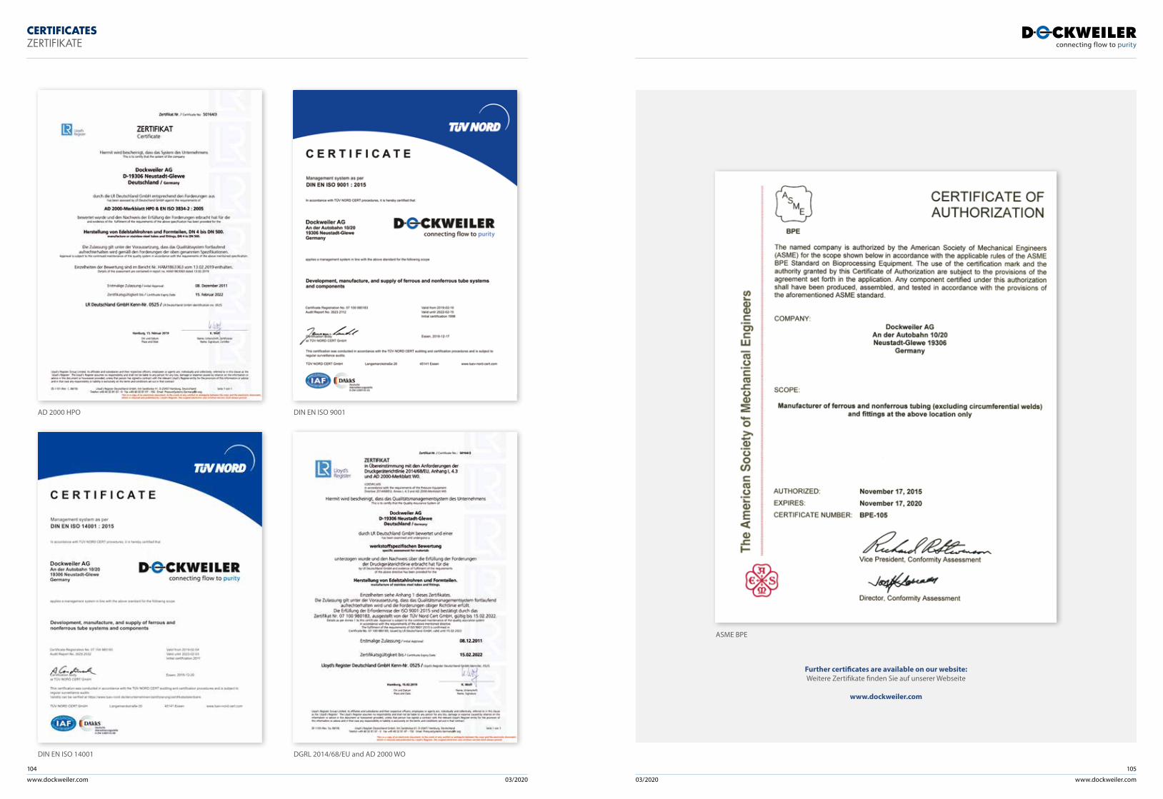
www.dockweiler.com 03/2020 03/2020
104
www.dockweiler.com
105
CERTIFICATESZERTIFIKATE
AD 2000 HPO DIN EN ISO 9001
Further certificates are available on our website:Weitere Zertifikate finden Sie auf unserer Webseite
www.dockweiler.com
DIN EN ISO 14001 DGRL 2014/68/EU and AD 2000 WO
ASME BPE
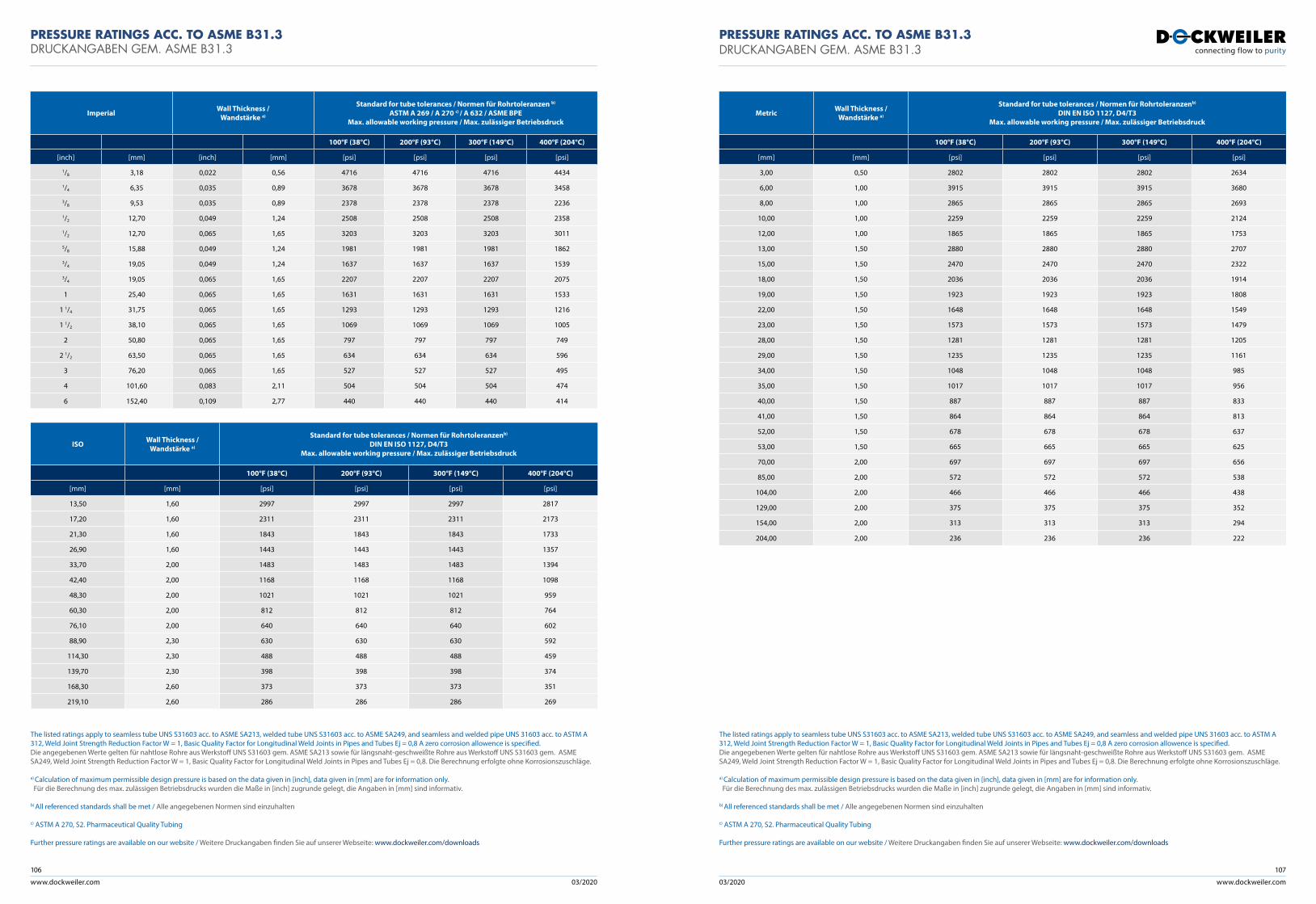
www.dockweiler.com 03/2020 03/2020
106
www.dockweiler.com
107
The listed ratings apply to seamless tube UNS S31603 acc. to ASME SA213, welded tube UNS S31603 acc. to ASME SA249, and seamless and welded pipe UNS 31603 acc. to ASTM A 312, Weld Joint Strength Reduction Factor W = 1, Basic Quality Factor for Longitudinal Weld Joints in Pipes and Tubes Ej = 0,8 A zero corrosion allowence is specified.Die angegebenen Werte gelten für nahtlose Rohre aus Werkstoff UNS S31603 gem. ASME SA213 sowie für längsnaht-geschweißte Rohre aus Werkstoff UNS S31603 gem. ASME SA249, Weld Joint Strength Reduction Factor W = 1, Basic Quality Factor for Longitudinal Weld Joints in Pipes and Tubes Ej = 0,8. Die Berechnung erfolgte ohne Korrosionszuschläge.
a) Calculation of maximum permissible design pressure is based on the data given in [inch], data given in [mm] are for information only. Für die Berechnung des max. zulässigen Betriebsdrucks wurden die Maße in [inch] zugrunde gelegt, die Angaben in [mm] sind informativ.
b) All referenced standards shall be met / Alle angegebenen Normen sind einzuhalten
c) ASTM A 270, S2. Pharmaceutical Quality Tubing
Further pressure ratings are available on our website / Weitere Druckangaben finden Sie auf unserer Webseite: www.dockweiler.com/downloads
Imperial Wall Thickness / Wandstärke a)
Standard for tube tolerances / Normen für Rohrtoleranzen b)
ASTM A 269 / A 270 c) / A 632 / ASME BPE Max. allowable working pressure / Max. zulässiger Betriebsdruck
100°F (38°C) 200°F (93°C) 300°F (149°C) 400°F (204°C)
[inch] [mm] [inch] [mm] [psi] [psi] [psi] [psi]
1/8 3,18 0,022 0,56 4716 4716 4716 4434
1/4 6,35 0,035 0,89 3678 3678 3678 3458
3/8 9,53 0,035 0,89 2378 2378 2378 2236
1/2 12,70 0,049 1,24 2508 2508 2508 2358
1/2 12,70 0,065 1,65 3203 3203 3203 3011
5/8 15,88 0,049 1,24 1981 1981 1981 1862
3/4 19,05 0,049 1,24 1637 1637 1637 1539
3/4 19,05 0,065 1,65 2207 2207 2207 2075
1 25,40 0,065 1,65 1631 1631 1631 1533
1 1/4 31,75 0,065 1,65 1293 1293 1293 1216
1 1/2 38,10 0,065 1,65 1069 1069 1069 1005
2 50,80 0,065 1,65 797 797 797 749
2 1/2 63,50 0,065 1,65 634 634 634 596
3 76,20 0,065 1,65 527 527 527 495
4 101,60 0,083 2,11 504 504 504 474
6 152,40 0,109 2,77 440 440 440 414
Metric Wall Thickness / Wandstärke a)
Standard for tube tolerances / Normen für Rohrtoleranzenb)
DIN EN ISO 1127, D4/T3Max. allowable working pressure / Max. zulässiger Betriebsdruck
100°F (38°C) 200°F (93°C) 300°F (149°C) 400°F (204°C)
[mm] [mm] [psi] [psi] [psi] [psi]
3,00 0,50 2802 2802 2802 2634
6,00 1,00 3915 3915 3915 3680
8,00 1,00 2865 2865 2865 2693
10,00 1,00 2259 2259 2259 2124
12,00 1,00 1865 1865 1865 1753
13,00 1,50 2880 2880 2880 2707
15,00 1,50 2470 2470 2470 2322
18,00 1,50 2036 2036 2036 1914
19,00 1,50 1923 1923 1923 1808
22,00 1,50 1648 1648 1648 1549
23,00 1,50 1573 1573 1573 1479
28,00 1,50 1281 1281 1281 1205
29,00 1,50 1235 1235 1235 1161
34,00 1,50 1048 1048 1048 985
35,00 1,50 1017 1017 1017 956
40,00 1,50 887 887 887 833
41,00 1,50 864 864 864 813
52,00 1,50 678 678 678 637
53,00 1,50 665 665 665 625
70,00 2,00 697 697 697 656
85,00 2,00 572 572 572 538
104,00 2,00 466 466 466 438
129,00 2,00 375 375 375 352
154,00 2,00 313 313 313 294
204,00 2,00 236 236 236 222
PRESSURE RATINGS ACC. TO ASME B31.3DRUCKANGABEN GEM. ASME B31.3
PRESSURE RATINGS ACC. TO ASME B31.3DRUCKANGABEN GEM. ASME B31.3
The listed ratings apply to seamless tube UNS S31603 acc. to ASME SA213, welded tube UNS S31603 acc. to ASME SA249, and seamless and welded pipe UNS 31603 acc. to ASTM A 312, Weld Joint Strength Reduction Factor W = 1, Basic Quality Factor for Longitudinal Weld Joints in Pipes and Tubes Ej = 0,8 A zero corrosion allowence is specified.Die angegebenen Werte gelten für nahtlose Rohre aus Werkstoff UNS S31603 gem. ASME SA213 sowie für längsnaht-geschweißte Rohre aus Werkstoff UNS S31603 gem. ASME SA249, Weld Joint Strength Reduction Factor W = 1, Basic Quality Factor for Longitudinal Weld Joints in Pipes and Tubes Ej = 0,8. Die Berechnung erfolgte ohne Korrosionszuschläge.
a) Calculation of maximum permissible design pressure is based on the data given in [inch], data given in [mm] are for information only. Für die Berechnung des max. zulässigen Betriebsdrucks wurden die Maße in [inch] zugrunde gelegt, die Angaben in [mm] sind informativ.
b) All referenced standards shall be met / Alle angegebenen Normen sind einzuhalten
c) ASTM A 270, S2. Pharmaceutical Quality Tubing
Further pressure ratings are available on our website / Weitere Druckangaben finden Sie auf unserer Webseite: www.dockweiler.com/downloads
ISO Wall Thickness / Wandstärke a)
Standard for tube tolerances / Normen für Rohrtoleranzenb)
DIN EN ISO 1127, D4/T3Max. allowable working pressure / Max. zulässiger Betriebsdruck
100°F (38°C) 200°F (93°C) 300°F (149°C) 400°F (204°C)
[mm] [mm] [psi] [psi] [psi] [psi]
13,50 1,60 2997 2997 2997 2817
17,20 1,60 2311 2311 2311 2173
21,30 1,60 1843 1843 1843 1733
26,90 1,60 1443 1443 1443 1357
33,70 2,00 1483 1483 1483 1394
42,40 2,00 1168 1168 1168 1098
48,30 2,00 1021 1021 1021 959
60,30 2,00 812 812 812 764
76,10 2,00 640 640 640 602
88,90 2,30 630 630 630 592
114,30 2,30 488 488 488 459
139,70 2,30 398 398 398 374
168,30 2,60 373 373 373 351
219,10 2,60 286 286 286 269

www.dockweiler.com 03/2020 03/2020
108
www.dockweiler.com
109
Imperial Wall Thickness / Wandstärke a)
Standard for tube tolerances / Normen für Rohrtoleranzen b)
ASTM A 269 / A 270 c) / A 632 / ASME BPE Max. allowable working pressure / Max. zulässiger Betriebsdruck
20°C 50°C 100°C 150°C
[inch] [mm] [mm] [inch] [bar] [bar] [bar] [bar]
1/8 3,18 0,56 0,022 548 529 485 439
1/4 6,35 0,89 0,035 424 409 375 339
3/8 9,53 0,89 0,035 271 262 240 217
1/2 12,70 1,24 0,049 287 276 253 229
1/2 12,70 1,65 0,065 368 355 325 294
5/8 15,88 1,24 0,049 225 217 199 180
3/4 19,05 1,24 0,049 186 179 164 148
3/4 19,05 1,65 0,065 251 243 222 201
1 25,40 1,65 0,065 185 178 163 148
1 1/4 31,75 1,65 0,065 146 141 129 117
1 1/2 38,10 1,65 0,065 121 116 107 96
2 50,80 1,65 0,065 90 86 79 72
2 1/2 63,50 1,65 0,065 71 69 63 57
3 76,20 1,65 0,065 59 57 52 47
4 101,60 2,11 0,083 56 54 50 45
6 152,40 2,77 0,109 49 47 43 39
Metric Wall Thickness / Wandstärke a)
Standard for tube tolerances / Normen für Rohrtoleranzenb)
DIN EN ISO 1127, D4/T3Max. allowable working pressure / Max. zulässiger Betriebsdruck
20°C 50°C 100°C 150°C
[mm] [mm] [bar] [bar] [bar] [bar]
3,00 0,50 321 310 284 257
6,00 1,00 452 436 400 362
8,00 1,00 328 317 290 263
10,00 1,00 258 248 228 206
12,00 1,00 212 204 187 169
13,00 1,50 330 318 292 264
15,00 1,50 282 272 249 226
18,00 1,50 232 223 205 185
19,00 1,50 219 211 193 175
22,00 1,50 187 180 165 149
23,00 1,50 178 172 158 143
28,00 1,50 145 140 128 116
29,00 1,50 140 135 123 112
34,00 1,50 118 114 104 94
35,00 1,50 115 111 101 92
40,00 1,50 100 96 88 80
41,00 1,50 97 94 86 78
52,00 1,50 76 73 67 61
53,00 1,50 75 72 66 60
70,00 2,00 78 75 69 63
85,00 2,00 64 62 57 51
104,00 2,00 52 50 46 42
129,00 2,00 42 40 37 33
154,00 2,00 35 34 31 28
204,00 2,00 26 25 23 21
PRESSURE RATINGS ACC. TO EN 13480-3DRUCKANGABEN GEM. EN 13480-3
PRESSURE RATINGS ACC. TO EN 13480-3DRUCKANGABEN GEM. EN 13480-3
The listed ratings apply to seamless tube UNS S31603 acc. to ASME SA213, welded tube UNS S31603 acc. to ASME SA249, and seamless and welded pipe UNS 31603 acc. to ASTM A 312, Weld Joint Strength Reduction Factor W = 1, Basic Quality Factor for Longitudinal Weld Joints in Pipes and Tubes Ej = 0,8 A zero corrosion allowence is specified.Die angegebenen Werte gelten für nahtlose Rohre aus Werkstoff UNS S31603 gem. ASME SA213 sowie für längsnaht-geschweißte Rohre aus Werkstoff UNS S31603 gem. ASME SA249, Weld Joint Strength Reduction Factor W = 1, Basic Quality Factor for Longitudinal Weld Joints in Pipes and Tubes Ej = 0,8. Die Berechnung erfolgte ohne Korrosionszuschläge.
a) Calculation of maximum permissible design pressure is based on the data given in [inch], data given in [mm] are for information only. Für die Berechnung des max. zulässigen Betriebsdrucks wurden die Maße in [inch] zugrunde gelegt, die Angaben in [mm] sind informativ.
b) All referenced standards shall be met / Alle angegebenen Normen sind einzuhalten
c) ASTM A 270, S2. Pharmaceutical Quality Tubing
Further pressure ratings are available on our website / Weitere Druckangaben finden Sie auf unserer Webseite: www.dockweiler.com/downloads
ISO Wall Thickness / Wandstärke a)
Standard for tube tolerances / Normen für Rohrtoleranzenb)
DIN EN ISO 1127, D4/T3Max. allowable working pressure / Max. zulässiger Betriebsdruck
20°C 50°C 100°C 150°C
[mm] [mm] [bar] [bar] [bar] [bar]
13,50 1,60 344 332 304 275
17,20 1,60 264 254 233 211
21,30 1,60 209 202 185 167
26,90 1,60 163 158 144 131
33,70 2,00 168 162 148 134
42,40 2,00 132 127 117 105
48,30 2,00 115 111 102 92
60,30 2,00 91 88 81 73
76,10 2,00 72 69 63 57
88,90 2,30 71 68 62 56
114,30 2,30 55 53 48 44
139,70 2,30 44 43 39 35
168,30 2,60 42 40 37 33
219,10 2,60 32 31 28 25
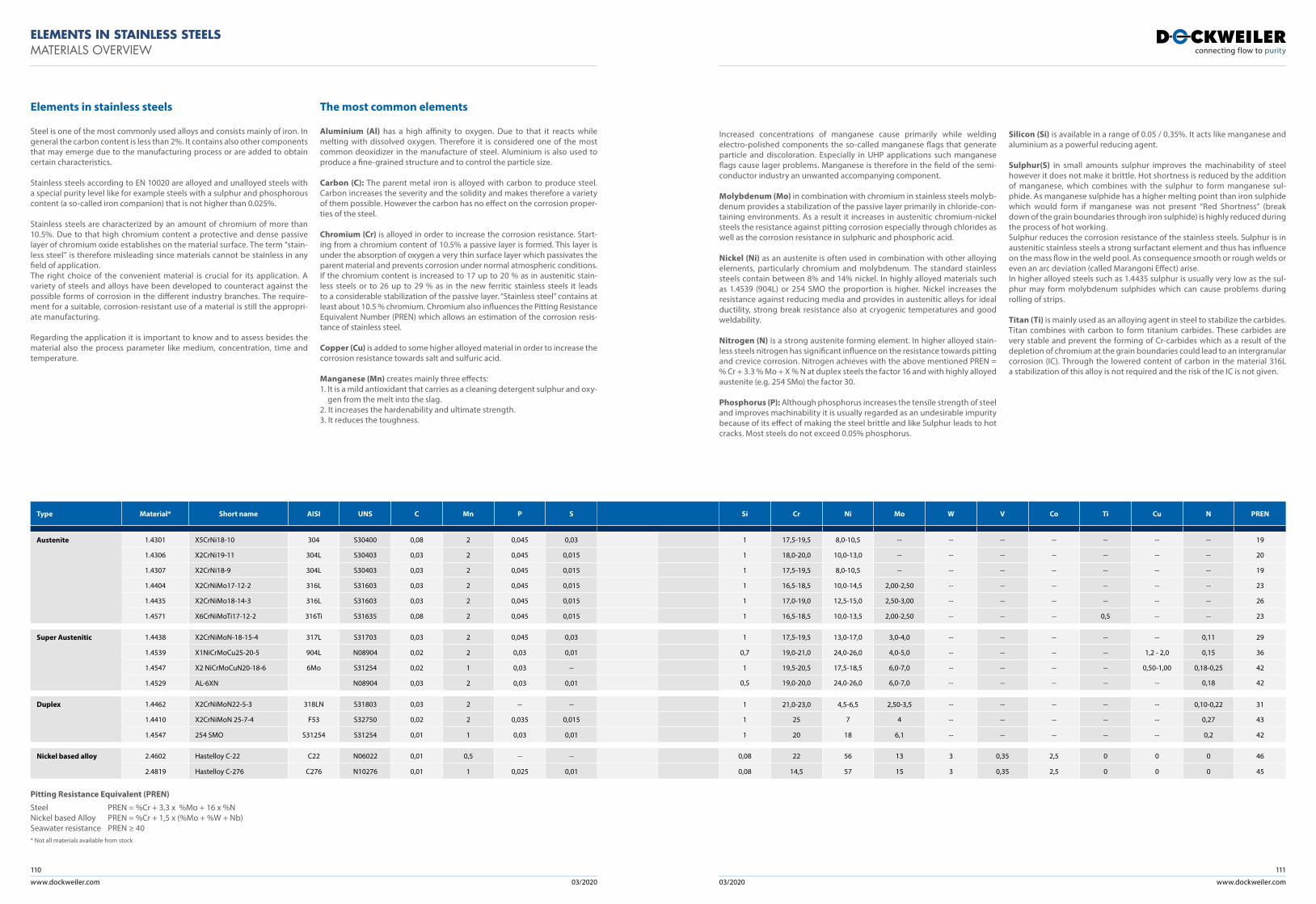
www.dockweiler.com 03/2020 03/2020
110
www.dockweiler.com
111
ELEMENTS IN STAINLESS STEELSMATERIALS OVERVIEW
Elements in stainless steels The most common elements
Steel is one of the most commonly used alloys and consists mainly of iron. In general the carbon content is less than 2%. It contains also other components that may emerge due to the manufacturing process or are added to obtain certain characteristics.
Stainless steels according to EN 10020 are alloyed and unalloyed steels with a special purity level like for example steels with a sulphur and phosphorous content (a so-called iron companion) that is not higher than 0.025%.
Stainless steels are characterized by an amount of chromium of more than 10.5%. Due to that high chromium content a protective and dense passive layer of chromium oxide establishes on the material surface. The term “stain-less steel” is therefore misleading since materials cannot be stainless in any field of application.The right choice of the convenient material is crucial for its application. A variety of steels and alloys have been developed to counteract against the possible forms of corrosion in the different industry branches. The require-ment for a suitable, corrosion-resistant use of a material is still the appropri-ate manufacturing.
Regarding the application it is important to know and to assess besides the material also the process parameter like medium, concentration, time and temperature.
Increased concentrations of manganese cause primarily while welding electro-polished components the so-called manganese flags that generate particle and discoloration. Especially in UHP applications such manganese flags cause lager problems. Manganese is therefore in the field of the semi-conductor industry an unwanted accompanying component.
Molybdenum (Mo) in combination with chromium in stainless steels molyb-denum provides a stabilization of the passive layer primarily in chloride-con-taining environments. As a result it increases in austenitic chromium-nickel steels the resistance against pitting corrosion especially through chlorides as well as the corrosion resistance in sulphuric and phosphoric acid.
Nickel (Ni) as an austenite is often used in combination with other alloying elements, particularly chromium and molybdenum. The standard stainless steels contain between 8% and 14% nickel. In highly alloyed materials such as 1.4539 (904L) or 254 SMO the proportion is higher. Nickel increases the resistance against reducing media and provides in austenitic alleys for ideal ductility, strong break resistance also at cryogenic temperatures and good weldability.
Nitrogen (N) is a strong austenite forming element. In higher alloyed stain-less steels nitrogen has significant influence on the resistance towards pitting and crevice corrosion. Nitrogen achieves with the above mentioned PREN = % Cr + 3.3 % Mo + X % N at duplex steels the factor 16 and with highly alloyed austenite (e.g. 254 SMo) the factor 30.
Phosphorus (P): Although phosphorus increases the tensile strength of steel and improves machinability it is usually regarded as an undesirable impurity because of its effect of making the steel brittle and like Sulphur leads to hot cracks. Most steels do not exceed 0.05% phosphorus.
Silicon (Si) is available in a range of 0.05 / 0.35%. It acts like manganese and aluminium as a powerful reducing agent.
Sulphur(S) in small amounts sulphur improves the machinability of steel however it does not make it brittle. Hot shortness is reduced by the addition of manganese, which combines with the sulphur to form manganese sul-phide. As manganese sulphide has a higher melting point than iron sulphide which would form if manganese was not present “Red Shortness” (break down of the grain boundaries through iron sulphide) is highly reduced during the process of hot working. Sulphur reduces the corrosion resistance of the stainless steels. Sulphur is in austenitic stainless steels a strong surfactant element and thus has influence on the mass flow in the weld pool. As consequence smooth or rough welds or even an arc deviation (called Marangoni Effect) arise. In higher alloyed steels such as 1.4435 sulphur is usually very low as the sul-phur may form molybdenum sulphides which can cause problems during rolling of strips.
Titan (Ti) is mainly used as an alloying agent in steel to stabilize the carbides.Titan combines with carbon to form titanium carbides. These carbides are very stable and prevent the forming of Cr-carbides which as a result of the depletion of chromium at the grain boundaries could lead to an intergranular corrosion (IC). Through the lowered content of carbon in the material 316L a stabilization of this alloy is not required and the risk of the IC is not given.
Aluminium (Al) has a high affinity to oxygen. Due to that it reacts while melting with dissolved oxygen. Therefore it is considered one of the most common deoxidizer in the manufacture of steel. Aluminium is also used to produce a fine-grained structure and to control the particle size.
Carbon (C): The parent metal iron is alloyed with carbon to produce steel. Carbon increases the severity and the solidity and makes therefore a variety of them possible. However the carbon has no effect on the corrosion proper-ties of the steel.
Chromium (Cr) is alloyed in order to increase the corrosion resistance. Start-ing from a chromium content of 10.5% a passive layer is formed. This layer is under the absorption of oxygen a very thin surface layer which passivates the parent material and prevents corrosion under normal atmospheric conditions. If the chromium content is increased to 17 up to 20 % as in austenitic stain-less steels or to 26 up to 29 % as in the new ferritic stainless steels it leads to a considerable stabilization of the passive layer. “Stainless steel” contains at least about 10.5 % chromium. Chromium also influences the Pitting Resistance Equivalent Number (PREN) which allows an estimation of the corrosion resis-tance of stainless steel.
Copper (Cu) is added to some higher alloyed material in order to increase the corrosion resistance towards salt and sulfuric acid.
Manganese (Mn) creates mainly three effects:1. It is a mild antioxidant that carries as a cleaning detergent sulphur and oxy-
gen from the melt into the slag. 2. It increases the hardenability and ultimate strength.3. It reduces the toughness.
Type Material* Short name AISI UNS C Mn P S
Austenite 1.4301 X5CrNi18-10 304 S30400 0,08 2 0,045 0,03
1.4306 X2CrNi19-11 304L S30403 0,03 2 0,045 0,015
1.4307 X2CrNi18-9 304L S30403 0,03 2 0,045 0,015
1.4404 X2CrNiMo17-12-2 316L S31603 0,03 2 0,045 0,015
1.4435 X2CrNiMo18-14-3 316L S31603 0,03 2 0,045 0,015
1.4571 X6CrNiMoTi17-12-2 316Ti S31635 0,08 2 0,045 0,015
Super Austenitic 1.4438 X2CrNiMoN-18-15-4 317L S31703 0,03 2 0,045 0,03
1.4539 X1NiCrMoCu25-20-5 904L N08904 0,02 2 0,03 0,01
1.4547 X2 NiCrMoCuN20-18-6 6Mo S31254 0,02 1 0,03 --
1.4529 AL-6XN N08904 0,03 2 0,03 0,01
Duplex 1.4462 X2CrNiMoN22-5-3 318LN S31803 0,03 2 -- --
1.4410 X2CrNiMoN 25-7-4 F53 S32750 0,02 2 0,035 0,015
1.4547 254 SMO S31254 S31254 0,01 1 0,03 0,01
Nickel based alloy 2.4602 Hastelloy C-22 C22 N06022 0,01 0,5 -- --
2.4819 Hastelloy C-276 C276 N10276 0,01 1 0,025 0,01
Si Cr Ni Mo W V Co Ti Cu N PREN
1 17,5-19,5 8,0-10,5 -- -- -- -- -- -- -- 19
1 18,0-20,0 10,0-13,0 -- -- -- -- -- -- -- 20
1 17,5-19,5 8,0-10,5 -- -- -- -- -- -- -- 19
1 16,5-18,5 10,0-14,5 2,00-2,50 -- -- -- -- -- -- 23
1 17,0-19,0 12,5-15,0 2,50-3,00 -- -- -- -- -- -- 26
1 16,5-18,5 10,0-13,5 2,00-2,50 -- -- -- 0,5 -- -- 23
1 17,5-19,5 13,0-17,0 3,0-4,0 -- -- -- -- -- 0,11 29
0,7 19,0-21,0 24,0-26,0 4,0-5,0 -- -- -- -- 1,2 - 2,0 0,15 36
1 19,5-20,5 17,5-18,5 6,0-7,0 -- -- -- -- 0,50-1,00 0,18-0,25 42
0,5 19,0-20,0 24,0-26,0 6,0-7,0 -- -- -- -- -- 0,18 42
1 21,0-23,0 4,5-6,5 2,50-3,5 -- -- -- -- -- 0,10-0,22 31
1 25 7 4 -- -- -- -- -- 0,27 43
1 20 18 6,1 -- -- -- -- -- 0,2 42
0,08 22 56 13 3 0,35 2,5 0 0 0 46
0,08 14,5 57 15 3 0,35 2,5 0 0 0 45
Pitting Resistance Equivalent (PREN)
Steel PREN = %Cr + 3,3 x %Mo + 16 x %NNickel based Alloy PREN = %Cr + 1,5 x (%Mo + %W + Nb)Seawater resistance PREN ≥ 40
* Not all materials available from stock
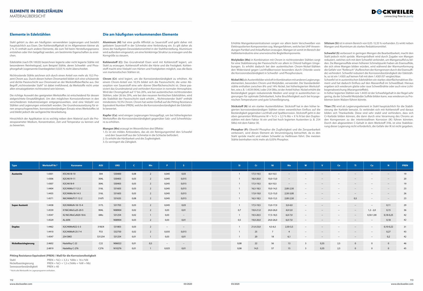
www.dockweiler.com 03/2020 03/2020
112
www.dockweiler.com
113
ELEMENTE IN EDELSTÄHLENMATERIALÜBERSICHT
Elemente in Edelstählen Die am häufigsten vorkommenden Elemente
Stahl gehört zu den am häufigsten verwendeten Legierungen und besteht hauptsächlich aus Eisen. Der Kohlenstoffgehalt ist im Allgemeinen kleiner als 2 %. Er enthält auch andere Elemente, die zum Teil beim Herstellungsprozess entstehen oder ihm beigefügt werden, um bestimmte Eigenschaften zu errei-chen.
Edelstähle (nach EN 10020) bezeichnen legierte oder nicht legierte Stähle mit besonderem Reinheitsgrad, zum Beispiel Stähle, deren Schwefel- und Phos-phorgehalt (sogenannte Eisenbegleiter) 0,025 % nicht überschreitet.
Nichtrostende Stähle zeichnen sich durch einen Anteil von mehr als 10,5 Pro-zent Chrom aus. Durch diesen hohen Chromanteil bildet sich eine schützende und dichte Passivschicht aus Chromoxid an der Werkstoffoberfläche aus. Der Begriff „nichtrostender Stahl“ ist dabei irreführend, da Werkstoffe nicht unter allen einsatzgebieten nichtrostend sein können.
Die richtige Auswahl des geeigneten Werkstoffes ist entscheidend für dessen zielgerichtete Einsatzfähigkeit. Um den möglichen Korrosionsformen in den verschiedenen Industriezweigen entgegenzuwirken, sind eine Vielzahl von Stählen und Legierungen entwickelt worden. Die Grundvoraussetzung für ei-nen anspruchsgerechten, korrosionsbeständigen Einsatz eines Werkstoffes ist und bleibt jedoch die sachgerechte Verarbeitung.
Hinsichtlich der Applikation ist es wichtig neben dem Material auch die Pro-zessparameter Medium, Konzentration, Zeit und Temperatur zu kennen und zu bewerten.
Erhöhte Mangankonzentrationen sorgen vor allem beim Verschweißen von Elektropolierten Komponenten sog. Manganfahnen, welche bei UHP Anwen-dungen Partikel und Anlauffarben erzeugen. Mangan ist somit im Bereich der Halbleiterindustrie eine unerwünschte Begleitkomponente.
Molybdän (Mo) in Kombination mit Chrom in nichtrostenden Stählen sorgt für eine Stabilisierung der Passivschicht vor allem in Chlorid haltigen Umge-bungen. Es erhöht dadurch bei den austenitischen Chrom-Nickel-Stählen den Widerstand gegen Lochfraßkorrosion besonders durch Chloride sowie die Korrosionsbeständigkeit in Schwefel- und Phosphorsäure.
Nickel (Ni) als Austenitbilder wird oft in Kombination mit anderen Legierungs-elementen, besonders Chrom und Molybdän, verwendet. Die Standardedel-stähle enthalten zwischen 8% und 14% Nickel, bei höherlegierten Werkstof-fen, wie z. B. 1.4539 (904L) oder 254 SMo, ist der Anteil höher. Nickel erhöht die Beständigkeit gegen reduzierende Medien und sorgt in austenitischen Le-gierungen für optimale Dehnbarkeit, hohe Bruchfestigkeit auch bei kryoge-nischen Temperaturen und gute Schweißeignung.
Stickstoff (N) ist ein starker Austenitbildner. Stickstoff hat in den höher le-gierten korrosionsbeständigen Stählen einen wesentlichen Einfluss auf die Beständigkeit gegenüber Lochfraß und Spaltkorrosion. Stickstoff geht in der oben genannten Wirksumme W = % Cr + 3,3 % Mo + X % N bei den Duplex-stählen mit dem Faktor 16 ein und bei hoch legierten Austeniten (z. B. 254 SMo) mit dem Faktor 30.
Phosphor (P): Obwohl Phosphor die Zugfestigkeit und die Zerspanbarkeit verbessert, wird dieses Element als Verunreinigung betrachtet, da es den Stahl spröde macht und neben Schwefel zu Heißrissen führt. Die meisten Stähle beinhalten nicht mehr als 0,05% Phosphor.
Silizium (Si) ist in einem Bereich von 0,05 / 0,35 % vorhanden. Es wirkt neben Mangan und Aluminium als starkes Reduktionsmittel.
Schwefel (S) verbessert in geringen Mengen die Bearbeitbarkeit, macht den Stahl jedoch nicht spröde. Warmsprödheit wird durch Zugabe von Mangan reduziert, welches sich mit dem Schwefel verbindet, um Mangansulfid zu bil-den. Da Mangansulfide einen höheren Schmelzpunkt haben als Eisensulfide, die sich ohne Mangan bilden würden, wird während der Warmumformung die Gefahr von “Rotbruch“ (Aufbrechen der Korngrenzen durch die Eisensulfi-de) verhindert. Schwefel reduziert die Korrosionsbeständigkeit der Edelstäh-le, so ist ein 1.4305 auf keinen Fall mit dem 1.4301/07 vergleichbar.Schwefel ist in austenitischen Edelstählen ein starkes oberflächenaktives Ele-ment und hat dadurch Einfluss auf den Massenfluß im Schweißbad. Hieraus ergeben sich wiederum glatte oder raue Schweißnähte oder auch eine Licht-bogenabweichung (Marangonieffekt).In höher legierten Stählen wie 1.4435 ist der Schwefelgehalt in der Regel sehr gering, da der Schwefel Molybdän Sulfide bilden kann, was wiederum zu Pro-blemen beim Walzen führen könnte.
Titan (Ti) wird als Legierungselement in Stahl hauptsächlich für die Stabili-sierung der Karbide benutzt. Es verbindet sich mit Kohlenstoff und daraus bilden sich Titankarbide. Diese sind sehr stabil und verhindern, dass sich Cr-Karbide bilden können, die dann durch eine Verarmung des Chroms an den Korngrenzen zu der interkristallinen Korrosion (IK) führen könnten. Durch den abgesenkten C-Gehalt in dem Werkstoff 316L ist eine Stabilisie-rung dieser Legierung nicht erforderlich, die Gefahr der IK ist nicht gegeben.
Aluminum (Al) hat eine große Affinität zu Sauerstoff und geht daher mit gelöstem Sauerstoff in der Schmelze eine Verbindung ein. Es gilt daher als eines der häufigsten Desoxidationsmittel in der Stahlherstellung. Aluminium wird außerdem eingesetzt, um eine feinkörnige Struktur zu erzeugen und die Korngröße zu steuern.
Kohlenstoff (C): Das Grundmetall Eisen wird mit Kohlenstoff legiert, um Stahl zu erzeugen. Kohlenstoff erhöht die Härte und die Festigkeit. Kohlen-stoff macht eine Vielzahl von Härten und Festigkeiten möglich, was die Basis von martensitischen Stählen ist.
Chrom (Cr): wird legiert, um die Korrosionsbeständigkeit zu erhöhen. Ab einem Chrom-Anteil von 10,5% bildet sich die Passivschicht, die unter Ab-sorption von Sauerstoff eine sehr dünne Oberflächenschicht ist. Diese pas-siviert das Grundmaterial und verhindert Korrosion in normaler Atmosphäre. Wird der Chromgehalt auf 17 bis 20%, wie bei austenitischen nichtrostenden Stählen, oder 26 bis 29%, wie bei den neueren ferritischen Edelstählen, wird die Stabilität der Passivschicht stark erhöht. „ Nichtrostender Stahl“ enthält mindestens 10,5% Chrom. Chrom hat weiter Einfluß auf die Pitting Resistance Equivalent Number (PREN), welche die Korrosionsbeständigkeit der Edelstäh-le bewertet.
Kupfer (Cu): wird einigen Legierungen hinzugefügt, um bei höherlegierten Werkstoffen die Korrosionsbeständigkeit gegenüber Salz- und Schwefelsäu-re zu erhöhen.
Mangan (Mn) erzeugt im Wesentlichen drei Effekte:1. Es ist ein mildes Antioxidans, das als ein Reinigungsmittel den Schwefel
und den Sauerstoff aus der Schmelze in die Schlacke befördert. 2. Es erhöht die Härtbarkeit und die Zugfestigkeit.3. Es verringert die Zähigkeit.
Type Werkstoff Nr.* Kurzname AISI UNS C Mn P S
Austenite 1.4301 X5CrNi18-10 304 S30400 0,08 2 0,045 0,03
1.4306 X2CrNi19-11 304L S30403 0,03 2 0,045 0,015
1.4307 X2CrNi18-9 304L S30403 0,03 2 0,045 0,015
1.4404 X2CrNiMo17-12-2 316L S31603 0,03 2 0,045 0,015
1.4435 X2CrNiMo18-14-3 316L S31603 0,03 2 0,045 0,015
1.4571 X6CrNiMoTi17-12-2 316Ti S31635 0,08 2 0,045 0,015
Super Austenit 1.4438 X2CrNiMoN-18-15-4 317L S31703 0,03 2 0,045 0,03
1.4539 X1NiCrMoCu25-20-5 904L N08904 0,02 2 0,03 0,01
1.4547 X2 NiCrMoCuN20-18-6 6Mo S31254 0,02 1 0,03 --
1.4529 AL-6XN N08904 0,03 2 0,03 0,01
Duplex 1.4462 X2CrNiMoN22-5-3 318LN S31803 0,03 2 -- --
1.4410 X2CrNiMoN 25-7-4 F53 S32750 0,02 2 0,035 0,015
1.4547 254 SMO S31254 S31254 0,01 1 0,03 0,01
Nickelbasislegierung 2.4602 Hastelloy C-22 C22 N06022 0,01 0,5 -- --
2.4819 Hastelloy C-276 C276 N10276 0,01 1 0,025 0,01
Si Cr Ni Mo W V Co Ti Cu N PREN
1 17,5-19,5 8,0-10,5 -- -- -- -- -- -- -- 19
1 18,0-20,0 10,0-13,0 -- -- -- -- -- -- -- 20
1 17,5-19,5 8,0-10,5 -- -- -- -- -- -- -- 19
1 16,5-18,5 10,0-14,5 2,00-2,50 -- -- -- -- -- -- 23
1 17,0-19,0 12,5-15,0 2,50-3,00 -- -- -- -- -- -- 26
1 16,5-18,5 10,0-13,5 2,00-2,50 -- -- -- 0,5 -- -- 23
1 17,5-19,5 13,0-17,0 3,0-4,0 -- -- -- -- -- 0,11 29
0,7 19,0-21,0 24,0-26,0 4,0-5,0 -- -- -- -- 1,2 - 2,0 0,15 36
1 19,5-20,5 17,5-18,5 6,0-7,0 -- -- -- -- 0,50-1,00 0,18-0,25 42
0,5 19,0-20,0 24,0-26,0 6,0-7,0 -- -- -- -- -- 0,18 42
1 21,0-23,0 4,5-6,5 2,50-3,5 -- -- -- -- -- 0,10-0,22 31
1 25 7 4 -- -- -- -- -- 0,27 43
1 20 18 6,1 -- -- -- -- -- 0,2 42
0,08 22 56 13 3 0,35 2,5 0 0 0 46
0,08 14,5 57 15 3 0,35 2,5 0 0 0 45
Pitting Resistance Equivalent (PREN) / Maß für die Korrosionsfestigkeit
Stahl PREN = %Cr + 3,3 x %Mo + 16 x %NNickelbasislegierung PREN = %Cr + 1,5 x (%Mo + %W + Nb)Seewasserbeständigkeit PREN ≥ 40
* Nicht alle Werkstoffe im Lagerprogramm enthalten.
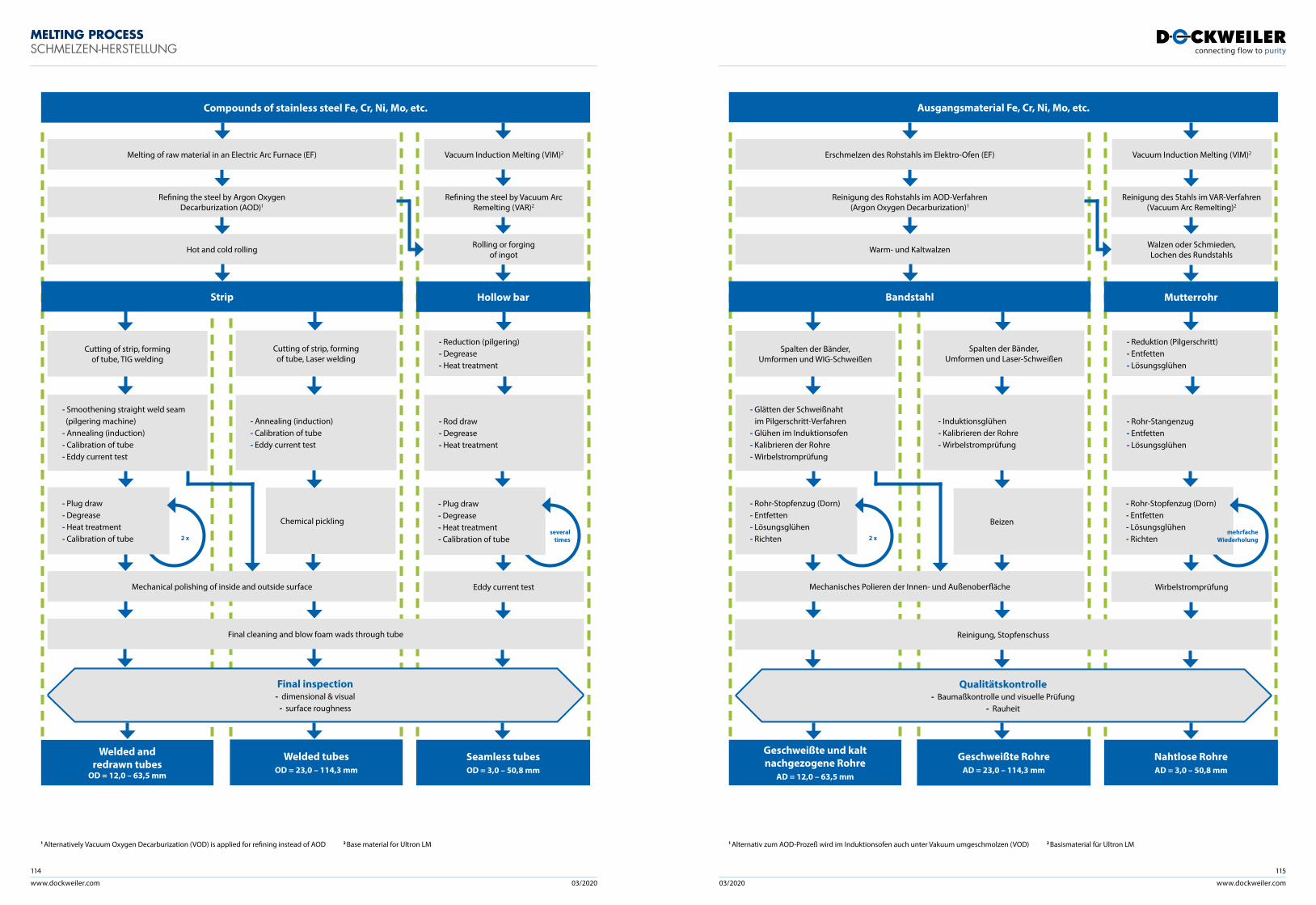
www.dockweiler.com 03/2020 03/2020
114
www.dockweiler.com
115
MELTING PROCESSSCHMELZEN-HERSTELLUNG
1 Alternativ zum AOD-Prozeß wird im Induktionsofen auch unter Vakuum umgeschmolzen (VOD) 2 Basismaterial für Ultron LM1 Alternatively Vacuum Oxygen Decarburization (VOD) is applied for refining instead of AOD 2 Base material for Ultron LM
- Rohr-Stopfenzug (Dorn) - Entfetten - Lösungsglühen - Richten
Reinigung des Stahls im VAR-Verfahren(Vacuum Arc Remelting)2
Vacuum Induction Melting (VIM)2
- Induktionsglühen - Kalibrieren der Rohre - Wirbelstromprüfung
- Rohr-Stangenzug - Entfetten - Lösungsglühen
Qualitätskontrolle- Baumaßkontrolle und visuelle Prüfung
- Rauheit
Wirbelstromprüfung
Spalten der Bänder,Umformen und Laser-Schweißen
- Reduktion (Pilgerschritt) - Entfetten - Lösungsglühen
Reinigung, Stopfenschuss
Reinigung des Rohstahls im AOD-Verfahren(Argon Oxygen Decarburization)1
Erschmelzen des Rohstahls im Elektro-Ofen (EF)
Warm- und Kaltwalzen
Spalten der Bänder,Umformen und WIG-Schweißen
- Glätten der Schweißnaht im Pilgerschritt-Verfahren - Glühen im Induktionsofen - Kalibrieren der Rohre - Wirbelstromprüfung
Mechanisches Polieren der Innen- und Außenoberfläche
Walzen oder Schmieden,Lochen des Rundstahls
2 x
Beizen
Ausgangsmaterial Fe, Cr, Ni, Mo, etc.
Bandstahl Mutterrohr
Geschweißte und kaltnachgezogene Rohre
AD = 12,0 – 63,5 mm
Geschweißte RohreAD = 23,0 – 114,3 mm
Nahtlose RohreAD = 3,0 – 50,8 mm
- Rohr-Stopfenzug (Dorn) - Entfetten - Lösungsglühen - Richten
mehrfacheWiederholung
- Plug draw - Degrease - Heat treatment - Calibration of tube
Refining the steel by Vacuum Arc Remelting (VAR)2
Vacuum Induction Melting (VIM)2
- Annealing (induction) - Calibration of tube - Eddy current test
- Rod draw - Degrease - Heat treatment
Final inspection- dimensional & visual
- surface roughness
Eddy current test
Cutting of strip, formingof tube, Laser welding
- Reduction (pilgering) - Degrease - Heat treatment
Final cleaning and blow foam wads through tube
Refining the steel by Argon Oxygen Decarburization (AOD)1
Melting of raw material in an Electric Arc Furnace (EF)
Hot and cold rolling
Cutting of strip, formingof tube, TIG welding
- Smoothening straight weld seam (pilgering machine) - Annealing (induction) - Calibration of tube - Eddy current test
Mechanical polishing of inside and outside surface
Rolling or forgingof ingot
2 x
Chemical pickling
Compounds of stainless steel Fe, Cr, Ni, Mo, etc.
Strip
Welded andredrawn tubes
OD = 12,0 – 63,5 mm
Welded tubesOD = 23,0 – 114,3 mm
Seamless tubesOD = 3,0 – 50,8 mm
- Plug draw - Degrease - Heat treatment - Calibration of tube
several times
Hollow bar
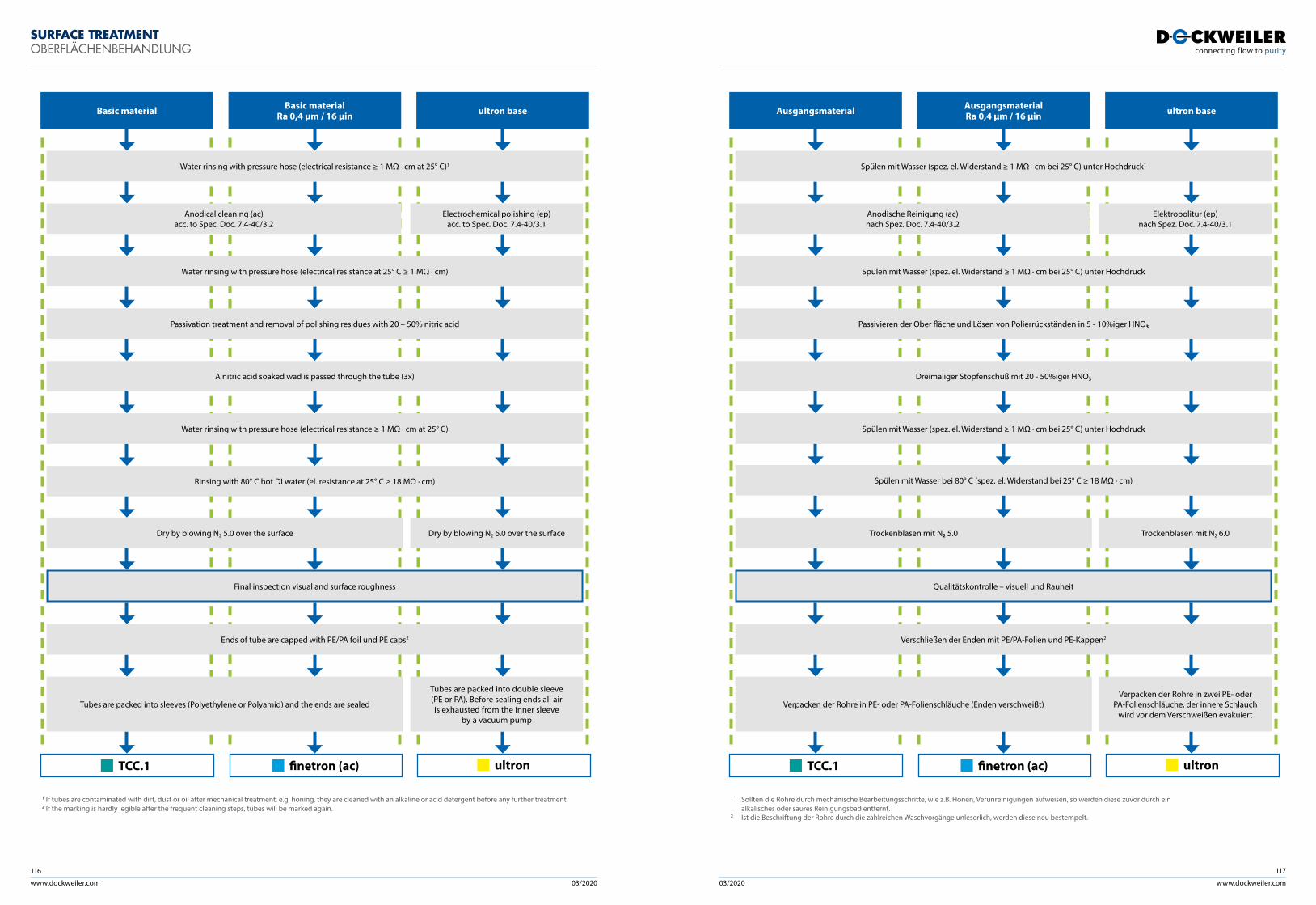
www.dockweiler.com 03/2020 03/2020
116
www.dockweiler.com
117
SURFACE TREATMENTOBERFLÄCHENBEHANDLUNG
Spülen mit Wasser bei 80° C (spez. el. Widerstand bei 25° C ≥ 18 MΩ · cm)
Ausgangsmaterial AusgangsmaterialRa 0,4 μm / 16 µin ultron base
Spülen mit Wasser (spez. el. Widerstand ≥ 1 MΩ · cm bei 25° C) unter Hochdruck
Passivieren der Ober fläche und Lösen von Polierrückständen in 5 - 10%iger HNO3
Dreimaliger Stopfenschuß mit 20 - 50%iger HNO3
Spülen mit Wasser (spez. el. Widerstand ≥ 1 MΩ · cm bei 25° C) unter Hochdruck
Verschließen der Enden mit PE/PA-Folien und PE-Kappen2
Qualitätskontrolle – visuell und Rauheit
Verpacken der Rohre in zwei PE- oder PA-Folienschläuche, der innere Schlauch
wird vor dem Verschweißen evakuiertVerpacken der Rohre in PE- oder PA-Folienschläuche (Enden verschweißt)
1 Sollten die Rohre durch mechanische Bearbeitungsschritte, wie z.B. Honen, Verunreinigungen aufweisen, so werden diese zuvor durch ein alkalisches oder saures Reinigungsbad entfernt.2 Ist die Beschriftung der Rohre durch die zahlreichen Waschvorgänge unleserlich, werden diese neu bestempelt.
TCC.1 finetron (ac) ULTRON® ultron
Spülen mit Wasser (spez. el. Widerstand ≥ 1 MΩ · cm bei 25° C) unter Hochdruck1
Trockenblasen mit N2 5.0 Trockenblasen mit N2 6.0
Basic material Basic materialRa 0,4 μm / 16 µin ultron base
Water rinsing with pressure hose (electrical resistance at 25° C ≥ 1 MΩ · cm)
Passivation treatment and removal of polishing residues with 20 – 50% nitric acid
A nitric acid soaked wad is passed through the tube (3x)
Water rinsing with pressure hose (electrical resistance ≥ 1 MΩ · cm at 25° C)
Rinsing with 80° C hot DI water (el. resistance at 25° C ≥ 18 MΩ · cm)
Ends of tube are capped with PE/PA foil und PE caps2
Final inspection visual and surface roughness
Tubes are packed into double sleeve (PE or PA). Before sealing ends all air is exhausted from the inner sleeve
by a vacuum pump
Tubes are packed into sleeves (Polyethylene or Polyamid) and the ends are sealed
1 If tubes are contaminated with dirt, dust or oil after mechanical treatment, e.g. honing, they are cleaned with an alkaline or acid detergent before any further treatment.2 If the marking is hardly legible after the frequent cleaning steps, tubes will be marked again.
TCC.1 finetron (ac) ULTRON® ultron
Water rinsing with pressure hose (electrical resistance ≥ 1 MΩ · cm at 25° C)1
Dry by blowing N2 5.0 over the surface Dry by blowing N2 6.0 over the surface
Anodical cleaning (ac)acc. to Spec. Doc. 7.4-40/3.2
Electrochemical polishing (ep)acc. to Spec. Doc. 7.4-40/3.1
Anodische Reinigung (ac) nach Spez. Doc. 7.4-40/3.2
Elektropolitur (ep) nach Spez. Doc. 7.4-40/3.1
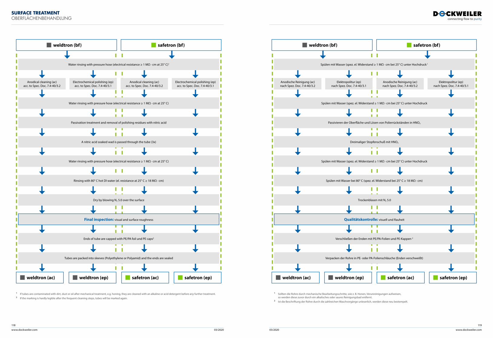
www.dockweiler.com 03/2020 03/2020
118
www.dockweiler.com
119
SURFACE TREATMENTOBERFLÄCHENBEHANDLUNG
weldtron (bf) safetron (bf)
Water rinsing with pressure hose (electrical resistance ≥ 1 MΩ · cm at 25° C)1
Water rinsing with pressure hose (electrical resistance ≥ 1 MΩ · cm at 25° C)
Passivation treatment and removal of polishing residues with nitric acid
A nitric acid soaked wad is passed through the tube (3x)
Water rinsing with pressure hose (electrical resistance ≥ 1 MΩ · cm at 25° C)
Rinsing with 80° C hot DI water (el. resistance at 25° C ≥ 18 MΩ · cm)
Dry by blowing N2 5.0 over the surface
Ends of tube are capped with PE/PA foil und PE caps2
Tubes are packed into sleeves (Polyethylene or Polyamid) and the ends are sealed
Final inspection: visual and surface roughness
Anodical cleaning (ac)acc. to Spec. Doc. 7.4-40/3.2
weldtron (ac)
Electrochemical polishing (ep)acc. to Spec. Doc. 7.4-40/3.1
weldtron (ep)
Anodical cleaning (ac)acc. to Spec. Doc. 7.4-40/3.2
safetron (ac)
Electrochemical polishing (ep)acc. to Spec. Doc. 7.4-40/3.1
safetron (ep)
1 If tubes are contaminated with dirt, dust or oil after mechanical treatment, e.g. honing, they are cleaned with an alkaline or acid detergent before any further treatment.2 If the marking is hardly legible after the frequent cleaning steps, tubes will be marked again.
weldtron (bf) safetron (bf)
Spülen mit Wasser (spez. el. Widerstand ≥ 1 MΩ · cm bei 25° C) unter Hochdruck 1
Spülen mit Wasser (spez. el. Widerstand ≥ 1 MΩ · cm bei 25° C) unter Hochdruck
Passivieren der Oberfläche und Lösen von Polierrückständen in HNO3
Dreimaliger Stopfenschuß mit HNO3
Spülen mit Wasser (spez. el. Widerstand ≥ 1 MΩ · cm bei 25° C) unter Hochdruck
Spülen mit Wasser bei 80° C (spez. el. Widerstand bei 25° C ≥ 18 MΩ · cm)
Trockenblasen mit N2 5.0
Verschließen der Enden mit PE/PA-Folien und PE-Kappen 2
Verpacken der Rohre in PE- oder PA-Folienschläuche (Enden verschweißt)
Qualitätskontrolle: visuell und Rauheit
Anodische Reinigung (ac)nach Spez. Doc. 7.4-40/3.2
weldtron (ac)
Elektropolitur (ep)nach Spez. Doc. 7.4-40/3.1
weldtron (ep)
Anodische Reinigung (ac)nach Spez. Doc. 7.4-40/3.2
safetron (ac)
Elektropolitur (ep)nach Spez. Doc. 7.4-40/3.1
safetron (ep)
1 Sollten die Rohre durch mechanische Bearbeitungsschritte, wie z. B. Honen, Verunreinigungen aufweisen, so werden diese zuvor durch ein alkalisches oder saures Reinigungsbad entfernt.
2 Ist die Beschriftung der Rohre durch die zahlreichen Waschvorgänge unleserlich, werden diese neu bestempelt.
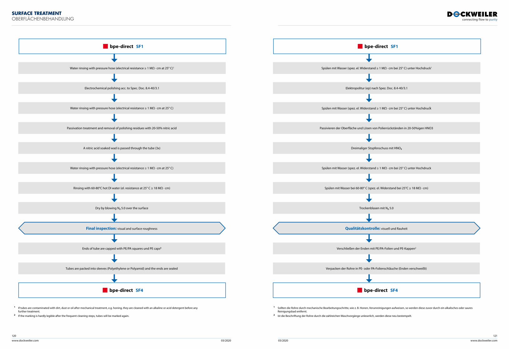
www.dockweiler.com 03/2020 03/2020
120
www.dockweiler.com
121
SURFACE TREATMENTOBERFLÄCHENBEHANDLUNG
1 If tubes are contaminated with dirt, dust or oil after mechanical treatment, e.g. honing, they are cleaned with an alkaline or acid detergent before any further treatment.2 If the marking is hardly legible after the frequent cleaning steps, tubes will be marked again.
Spülen mit Wasser (spez. el. Widerstand ≥ 1 MΩ · cm bei 25° C) unter Hochdruck1
Spülen mit Wasser (spez. el. Widerstand ≥ 1 MΩ · cm bei 25° C) unter Hochdruck
Spülen mit Wasser (spez. el. Widerstand ≥ 1 MΩ · cm bei 25° C) unter Hochdruck
Trockenblasen mit N2 5.0
Spülen mit Wasser bei 60-80° C (spez. el. Widerstand bei 25°C ≥ 18 MΩ · cm)
Elektropolitur (ep) nach Spez. Doc. 8.4-40/3.1
Dreimaliger Stopfenschuss mit HNO3
Passivieren der Oberfläche und Lösen von Polierrückständen in 20-50%igen HNO3
bpe-direct SF1
Qualitätskontrolle: visuell und Rauheit
Verschließen der Enden mit PE/PA-Folien und PE-Kappen2
Verpacken der Rohre in PE- oder PA-Folienschläuche (Enden verschweißt)
bpe-direct SF4
Water rinsing with pressure hose (electrical resistance ≥ 1 MΩ · cm at 25° C)1
Water rinsing with pressure hose (electrical resistance ≥ 1 MΩ · cm at 25° C)
Water rinsing with pressure hose (electrical resistance ≥ 1 MΩ · cm at 25° C)
Dry by blowing N2 5.0 over the surface
Rinsing with 60-80°C hot DI water (el. resistance at 25° C ≥ 18 MΩ · cm)
Electrochemical polishing acc. to Spec. Doc. 8.4-40/3.1
A nitric acid soaked wad is passed through the tube (3x)
Passivation treatment and removal of polishing residues with 20-50% nitric acid
bpe-direct SF1
Final inspection: visual and surface roughness
Ends of tube are capped with PE/PA squares und PE caps2
Tubes are packed into sleeves (Polyethylene or Polyamid) and the ends are sealed
bpe-direct SF4
1 Sollten die Rohre durch mechanische Bearbeitungsschritte, wie z. B. Honen, Verunreinigungen aufweisen, so werden diese zuvor durch ein alkalisches oder saures Reinigungsbad entfernt.2 Ist die Beschriftung der Rohre durch die zahlreichen Waschvorgänge unleserlich, werden diese neu bestempelt.
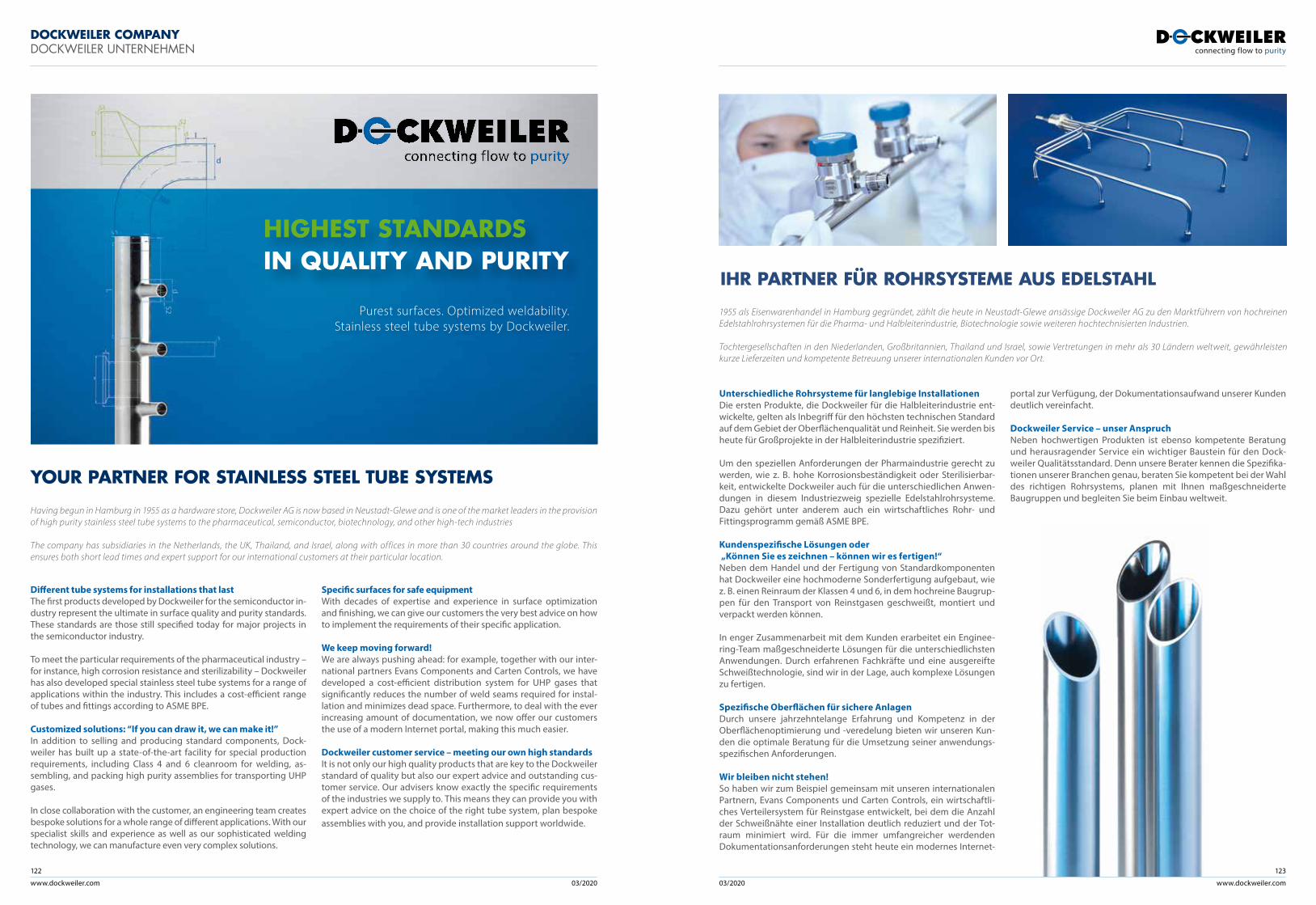
www.dockweiler.com 03/2020 03/2020
122
www.dockweiler.com
123
Different tube systems for installations that last The first products developed by Dockweiler for the semiconductor in-dustry represent the ultimate in surface quality and purity standards. These standards are those still specified today for major projects in the semiconductor industry.
To meet the particular requirements of the pharmaceutical industry – for instance, high corrosion resistance and sterilizability – Dockweiler has also developed special stainless steel tube systems for a range of applications within the industry. This includes a cost-efficient range of tubes and fittings according to ASME BPE.
Customized solutions: “If you can draw it, we can make it!”In addition to selling and producing standard components, Dock-weiler has built up a state-of-the-art facility for special production requirements, including Class 4 and 6 cleanroom for welding, as-sembling, and packing high purity assemblies for transporting UHP gases.
In close collaboration with the customer, an engineering team creates bespoke solutions for a whole range of different applications. With our specialist skills and experience as well as our sophisticated welding technology, we can manufacture even very complex solutions.
Specific surfaces for safe equipmentWith decades of expertise and experience in surface optimization and finishing, we can give our customers the very best advice on how to implement the requirements of their specific application.
We keep moving forward!We are always pushing ahead: for example, together with our inter-national partners Evans Components and Carten Controls, we have developed a cost-efficient distribution system for UHP gases that significantly reduces the number of weld seams required for instal-lation and minimizes dead space. Furthermore, to deal with the ever increasing amount of documentation, we now offer our customers the use of a modern Internet portal, making this much easier.
Dockweiler customer service – meeting our own high standards It is not only our high quality products that are key to the Dockweiler standard of quality but also our expert advice and outstanding cus-tomer service. Our advisers know exactly the specific requirements of the industries we supply to. This means they can provide you with expert advice on the choice of the right tube system, plan bespoke assemblies with you, and provide installation support worldwide.
DOCKWEILER COMPANYDOCKWEILER UNTERNEHMEN
IHR PARTNER FÜR ROHRSYSTEME AUS EDELSTAHL
Unterschiedliche Rohrsysteme für langlebige InstallationenDie ersten Produkte, die Dockweiler für die Halbleiterindustrie ent-wickelte, gelten als Inbegriff für den höchsten technischen Standard auf dem Gebiet der Oberflächenqualität und Reinheit. Sie werden bis heute für Großprojekte in der Halbleiterindustrie spezifiziert.
Um den speziellen Anforderungen der Pharmaindustrie gerecht zu werden, wie z. B. hohe Korrosionsbeständigkeit oder Sterilisierbar-keit, entwickelte Dockweiler auch für die unterschiedlichen Anwen-dungen in diesem Industriezweig spezielle Edelstahlrohrsysteme. Dazu gehört unter anderem auch ein wirtschaftliches Rohr- und Fittingsprogramm gemäß ASME BPE.
Kundenspezifische Lösungen oder „Können Sie es zeichnen – können wir es fertigen!“Neben dem Handel und der Fertigung von Standardkomponenten hat Dockweiler eine hochmoderne Sonderfertigung aufgebaut, wie z. B. einen Reinraum der Klassen 4 und 6, in dem hochreine Baugrup-pen für den Transport von Reinstgasen geschweißt, montiert und verpackt werden können.
In enger Zusammenarbeit mit dem Kunden erarbeitet ein Enginee-ring-Team maßgeschneiderte Lösungen für die unterschiedlichsten Anwendungen. Durch erfahrenen Fachkräfte und eine ausgereifte Schweißtechnologie, sind wir in der Lage, auch komplexe Lösungen zu fertigen.
Spezifische Oberflächen für sichere AnlagenDurch unsere jahrzehntelange Erfahrung und Kompetenz in der Oberflächenoptimierung und -veredelung bieten wir unseren Kun-den die optimale Beratung für die Umsetzung seiner anwendungs-spezifischen Anforderungen.
Wir bleiben nicht stehen!So haben wir zum Beispiel gemeinsam mit unseren internationalen Partnern, Evans Components und Carten Controls, ein wirtschaftli-ches Verteilersystem für Reinstgase entwickelt, bei dem die Anzahl der Schweißnähte einer Installation deutlich reduziert und der Tot-raum minimiert wird. Für die immer umfangreicher werdenden Dokumentationsanforderungen steht heute ein modernes Internet-
portal zur Verfügung, der Dokumentationsaufwand unserer Kunden deutlich vereinfacht.
Dockweiler Service – unser AnspruchNeben hochwertigen Produkten ist ebenso kompetente Beratung und herausragender Service ein wichtiger Baustein für den Dock-weiler Qualitätsstandard. Denn unsere Berater kennen die Spezifika-tionen unserer Branchen genau, beraten Sie kompetent bei der Wahl des richtigen Rohrsystems, planen mit Ihnen maßgeschneiderte Baugruppen und begleiten Sie beim Einbau weltweit.
1955 als Eisenwarenhandel in Hamburg gegründet, zählt die heute in Neustadt-Glewe ansässige Dockweiler AG zu den Marktführern von hochreinen Edelstahlrohrsystemen für die Pharma- und Halbleiterindustrie, Biotechnologie sowie weiteren hochtechnisierten Industrien.
Tochtergesellschaften in den Niederlanden, Großbritannien, Thailand und Israel, sowie Vertretungen in mehr als 30 Ländern weltweit, gewährleisten kurze Lieferzeiten und kompetente Betreuung unserer internationalen Kunden vor Ort.
Having begun in Hamburg in 1955 as a hardware store, Dockweiler AG is now based in Neustadt-Glewe and is one of the market leaders in the provision of high purity stainless steel tube systems to the pharmaceutical, semiconductor, biotechnology, and other high-tech industries
The company has subsidiaries in the Netherlands, the UK, Thailand, and Israel, along with offices in more than 30 countries around the globe. This ensures both short lead times and expert support for our international customers at their particular location.
YOUR PARTNER FOR STAINLESS STEEL TUBE SYSTEMS
HIGHEST STANDARDSIN QUALITY AND PURITY
Purest surfaces. Optimized weldability.Stainless steel tube systems by Dockweiler.
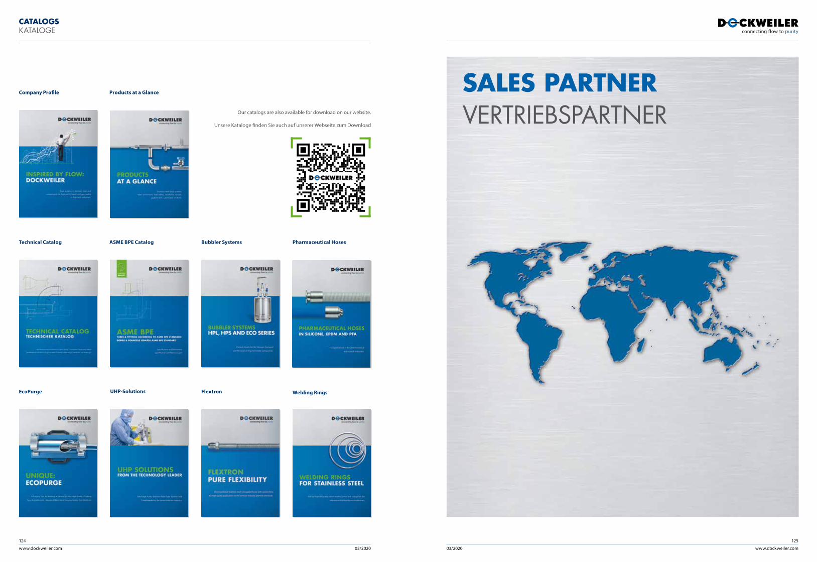
www.dockweiler.com 03/2020 03/2020
124
www.dockweiler.com
125
CATALOGSKATALOGE
Technical Catalog ASME BPE Catalog
UHP-Solutions
Company Profile Products at a Glance
EcoPurge Flextron
Bubbler Systems
Welding Rings
Pharmaceutical Hoses
Our catalogs are also available for download on our website.
Unsere Kataloge finden Sie auch auf unserer Webseite zum Download
SALES PARTNERVERTRIEBSPARTNER
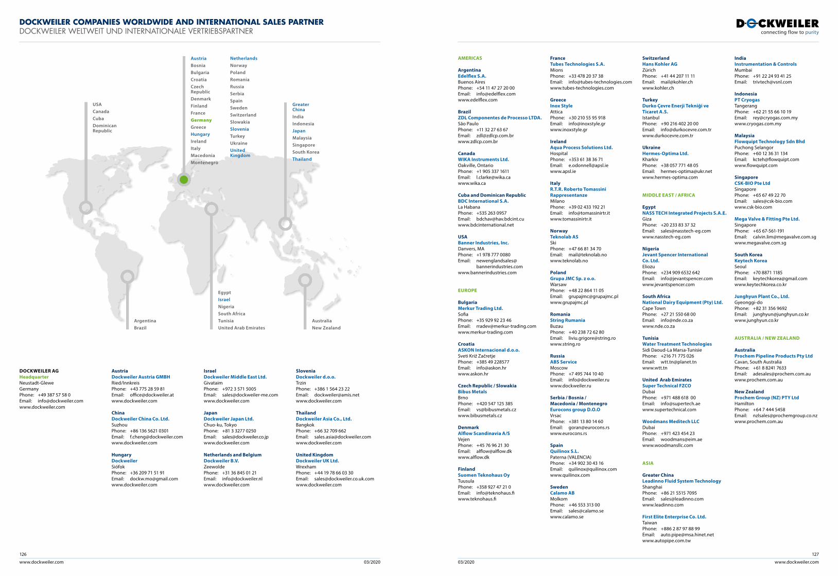
www.dockweiler.com 03/2020 03/2020
126
www.dockweiler.com
127
DOCKWEILER AG HeadquarterNeustadt-GleweGermanyPhone: +49 387 57 58 0 Email: [email protected] www.dockweiler.com
AustriaDockweiler Austria GMBHRied/InnkreisPhone: +43 775 28 59 81 Email: [email protected] www.dockweiler.com
ChinaDockweiler China Co. Ltd.SuzhouPhone: +86 136 5621 0301 Email: [email protected] www.dockweiler.com
HungaryDockweilerSiófokPhone: +36 209 71 51 91 Email: [email protected] www.dockweiler.com
IsraelDockweiler Middle East Ltd.GivataimPhone: +972 3 571 5005Email: [email protected]
JapanDockweiler Japan Ltd.Chuo-ku, TokyoPhone: +81 3 3277 0250 Email: [email protected] www.dockweiler.com
Netherlands and BelgiumDockweiler B.V.Zeewolde Phone: +31 36 845 01 21 Email: [email protected] www.dockweiler.com
SloveniaDockweiler d.o.o.TrzinPhone: +386 1 564 23 22 Email: [email protected] www.dockweiler.com
ThailandDockweiler Asia Co., Ltd.Bangkok Phone: +66 32 709 662 Email: [email protected] www.dockweiler.com
United KingdomDockweiler UK Ltd.WrexhamPhone: +44 19 78 66 03 30 Email: [email protected]
Greater ChinaIndiaIndonesiaJapanMalaysiaSingaporeSouth KoreaThailand
Austria BosniaBulgariaCroatia Czech Republic DenmarkFinlandFranceGermanyGreeceHungary IrelandItalyMacedoniaMontenegro
NetherlandsNorwayPolandRomaniaRussiaSerbiaSpainSwedenSwitzerlandSlowakiaSloveniaTurkeyUkraineUnited Kingdom
USACanadaCubaDominican Republic
ArgentinaBrazil
AustraliaNew Zealand
EgyptIsraelNigeriaSouth AfricaTunisiaUnited Arab Emirates
DOCKWEILER COMPANIES WORLDWIDE AND INTERNATIONAL SALES PARTNERDOCKWEILER WELTWEIT UND INTERNATIONALE VERTRIEBSPARTNER
AMERICAS
ArgentinaEdelflex S.A. Buenos Aires Phone: +54 11 47 27 20 00 Email: [email protected]
BrazilZDL Componentes de Processo LTDA.São Paulo Phone: +11 32 27 63 67Email: [email protected]
CanadaWIKA Instruments Ltd.Oakville, OntarioPhone: +1 905 337 1611Email: [email protected]
Cuba and Dominican RepublicBDC International S.A.La HabanaPhone: +535 263 0957Email: [email protected]
USABanner Industries, Inc.Danvers, MA Phone: +1 978 777 0080Email: newenglandsales@
bannerindustries.comwww.bannerindustries.com
EUROPE
BulgariaMerkur Trading Ltd. SofiaPhone: +35 929 92 23 46 Email: [email protected]
CroatiaASKON Internacional d.o.o.Sveti Križ ZačretjePhone: +385 49 228577Email: [email protected] www.askon.hr
Czech Republic / SlowakiaBibus Metals BrnoPhone: +420 547 125 385Email: [email protected] www.bibusmetals.cz
DenmarkAlflow Scandinavia A/S VejenPhone: +45 76 96 21 30 Email: [email protected] www.alflow.dk
FinlandSuomen Teknohaus Oy TuusulaPhone: +358 927 47 21 0 Email: [email protected] www.teknohaus.fi
FranceTubes Technologies S.A. MionsPhone: +33 478 20 37 38 Email: [email protected] www.tubes-technologies.com
GreeceInox Style AtticaPhone: +30 210 55 95 918 Email: [email protected] www.inoxstyle.gr
IrelandAqua Process Solutions Ltd. Hospital Phone: +353 61 38 36 71 Email: [email protected]
ItalyR.T.R. Roberto Tomassini Rappresentanze MilanoPhone: +39 02 433 192 21 Email: [email protected]
NorwayTeknolab AS SkiPhone: +47 66 81 34 70Email: [email protected] www.teknolab.no
PolandGrupa JMC Sp. z o.o. WarsawPhone: +48 22 864 11 05 Email: [email protected] www.grupajmc.pl
RomaniaString Rumania BuzauPhone: +40 238 72 62 80 Email: [email protected]
RussiaABS Service MoscowPhone: +7 495 744 10 40 Email: [email protected] www.dockweiler.ru Serbia / Bosnia / Macedonia / MontenegroEurocons group D.O.O VrsacPhone: +381 13 80 14 60Email: [email protected] www.eurocons.rs
SpainQuilinox S.L.Paterna (VALENCIA)Phone: +34 902 30 43 16 Email: [email protected] www.quilinox.com
SwedenCalamo AB MolkomPhone: +46 553 313 00 Email: [email protected]
SwitzerlandHans Kohler AG ZürichPhone: +41 44 207 11 11 Email: [email protected] www.kohler.ch
TurkeyDurko Çevre Enerji Tekniği ve Ticaret A.S.IstanbulPhone: +90 216 402 20 00Email: [email protected]
UkraineHermes-Optima Ltd.KharkivPhone: +38 057 771 48 05Email: [email protected]
MIDDLE EAST / AFRICA
EgyptNASS TECH Integrated Projects S.A.E. GizaPhone: +20 233 83 37 32 Email: [email protected] www.nasstech-eg.com
NigeriaJevant Spencer International Co. Ltd. EliozuPhone: +234 909 6532 642Email: [email protected] www.jevantspencer.com
South AfricaNational Dairy Equipment (Pty) Ltd. Cape TownPhone: +27 21 550 68 00Email: [email protected] www.nde.co.za
TunisiaWater Treatment Technologies Sidi Daoud-La Marsa-TunisiePhone: +216 71 775 026Email: [email protected]
United Arab EmiratesSuper Technical FZCODubaiPhone: +971 488 618 00Email: [email protected]
Woodmans Meditech LLCDubaiPhone: +971 423 454 23Email: [email protected] www.woodmansllc.com
ASIA
Greater ChinaLeadinno Fluid System Technology ShanghaiPhone: +86 21 5515 7095 Email: [email protected] www.leadinno.com
First Elite Enterprise Co. Ltd. TaiwanPhone: +886 2 87 97 88 99 Email: [email protected] www.autopipe.com.tw
IndiaInstrumentation & Controls MumbaiPhone: +91 22 24 93 41 25 Email: [email protected]
IndonesiaPT CryogasTangerangPhone: +62 21 55 66 10 19Email: [email protected]
MalaysiaFlowquipt Technology Sdn Bhd Puchong SelangorPhone: +60 12 36 31 134Email: [email protected] www.flowquipt.com
SingaporeCSK-BIO Pte Ltd SingaporePhone: +65 67 49 22 70Email: [email protected] www.csk-bio.com
Mega Valve & Fitting Pte Ltd. SingaporePhone: +65 67-561-191Email: [email protected] www.megavalve.com.sg
South KoreaKeytech Korea Seoul Phone: +70 8871 1185 Email: [email protected]
Junghyun Plant Co., Ltd.Gyeonggi-doPhone: +82 31 356 9692Email: [email protected]
AUSTRALIA / NEW ZEALAND
AustraliaProchem Pipeline Products Pty LtdCavan, South AustraliaPhone: +61 8 8241 7633Email: [email protected]
New ZealandProchem Group (NZ) PTY LtdHamiltonPhone: +64 7 444 5458 Email: [email protected]
Your local office
Dockweiler AGAn der Autobahn 10/2019306 Neustadt-GleweGermany
Phone: + 49 38757 58-0Fax: + 49 38757 58-222E-mail: [email protected]: www.dockweiler.com
01/2020