Fluid-structure interaction of composite propeller blades ...

KfK 4111August 1986
Theoryof Mode Interaction
in the Gyrotron
G. s. NusinovichInstitut für Kernphysik·
Kernforschungszentrum Karlsruhe

KERNFORSCHUNGS ZENTRUM KARLSRUHE
Institut für Kernphysik
KfK 4111
THEORY OF MODE INTERACTION IN THE GYROTRON
G.S. Nusinovich *
Lectures presented during a visit to the Institut für Kernphysik 11,
Kernforschungszentrum Karlsruhe, October, 1984
Kernforschungszentrum Karlsruhe GmbH, Karlsruhe
* Institute of Applied Physics, Acaderny of Sciences of the USSR, Gorky, USSR

Als Manuskript vervielfältigtFür diesen Bericht behalten wir uns alle Rechte vor
Kernforschungszentrum Karlsruhe GmbHPostfach 3640, 7500 Karlsruhe 1
ISSN 0303-4003

ABSTRACT
A nonlinear theory of multimode gyrotrons is developed, which
describes such effects as mode competition (ie suppression of
unexcited modes by the operating one), nonlinear excitation of
passive modes by the active one, and mode locking. Mode com
petition is the dominant effect for modes with close frequencies
(relative to the cyclotron resonance band). In such a system
only single mode oscillations are stable. Nonlinear excitation
of passive modes whose frequency is greater than the frequency
of the operating mode is possible due to electrons under the
action of the operating mode group in the decelerative phase
with respect to the passive modes. For three or more modes with
an equidistant spectrum of frequencies, mode locking takes
place when the beam current substantially exceeds the threshold
conditions, even though one mode finds itself in the nonlinear
excitation band. The results obtained permit one to estimate
the conditions for stable single mode oscillation in ~ultimode
gyrotrons.

THEORIE DER MODE-KONKURRENZ IM GYROTRON
ZUSAMMENFASSUNG
Eine nichtlineare Theorie eines mehrmodigen Gyrotrons wird
vorgestellt, die solche Effekte wie Mode-Konkurrenz (die
Unterdrückung einer nicht angeregten Mode durch die Betriebs
mode), die nichtlineare Anregung einer passiven Mode durch
die schon angeschwungene und Mode-Locking beschreibt. Der
wichtigste Effekt für Moden mit eng benachbarten Frequenzen
nah an der Zyklotronresonanz ist die Mode-Konkurrenz. Nur
einzelne Moden können stabil in ein solches System schwingen.
Die nichtlineare Anregung einer passiven Mode mit einer höheren
Frequenz als die der Betriebsmode wird ermöglicht, wenn die
Elektronen genug von der Betriebsmode entschleunigt werden.
Im Falle drei oder mehr Moden kann Mode Locking stattfinden,
wenn der Strom sehr viel höher als der Startstrom ist, auch
wenn eine Mode sich im Bereich der nichtlinearen Selbstanregung
befindet. Auf Grund der vorgestellten Ergebnisse kann man die
Bedingungen für stabile, ein-Mode Schwingung in mehrmodigen
Gyrotronen abschätzen.
PREFACE
From the earliest stages of gyrotron development, the Institute of Applied
Physics at Gorky/USSR played a leading role. When KfK started development ac
tivities on advanced gyrotrons in 1983, the basic theory was weil established
and a considerable body of experimental results was available.
To accelerate our entry into this new field of research, it was obviously
desirable to establish an exchange with the Institute at Gorky and to partici
pate in the knowledge and experience collected there over more than 15 years.
As a first step we were pleased to have had Prof. G.S. Nusinovich as a guest
for two weeks at the Institut für Kernphysik 11, Kernforschungszentrum Karls
ruhe. During this stay, G.S. Nusinovich presented aseries of lectures and
kindly made available to us the manuscripts, which are comprised in this
booklet.
These lectures provide a far more systematic and comprehensive treatment of
mode competition and start up phenomena than is otherwise published in the
literature. Thus they provide us with very useful guidelines for the develop
ment of a program package to calculate gyrotron phenomena for the KfK gyrotron
experiment. During the time since they were given, we have used them as a
basis for our own treatment of the problem, adapted to the parameters of our
experiment.
With the agreement of the author and of the Academy of Sciences of the USSR,
we are pleased to make these lectures available to the gyrotron community.
We are grateful to the Institute of Applied Physics, Academy of Sciences of
the USSR for making possible the visit of Prof. Nusinovich, and we hope that
this was just the beginning of a fruitful cooperation.
Minor modifications, such as the correction of obvious misprints,
as weil as the insertion of figure captions (to comply with guidelines for KfK
publications) have been made without further correspondence with the author.
E. Sorie
G. Hochschild

INDEX
page
Lecture 1 1
Introduction 1
Enhancement of the generated power 1
Increase in the operating frequency 2
Extension of the microwave pulse duration 2
Mode Selection 4
Radial mode selection 4
Azimuthal mode selection 5
Equations of a Multimode Gyrotron 7
Lecture 2 14
Stability of Single-Mode Oscillations for PurelyAmplitude and Phase-Amplitude Interaction ofGyrotron Modes 14
The stability of single-mode oscillations forpurely amplitude mode interaction 16
Automodulation instability 21
Lecture 3 27
Start-Up Scenario 27
Basic Effects of Mode Interaction 33
Purely amplitude mode interaction 34
Lecture 4 41
Phase-amplitude mode interaction 41
Space-Time Analysis of Nonstationary Processes inMultimode Gyrotrons 47
A gyrotron with a whispering gallery wave 47
A quas10ptical gyrotron 48
A gyrotron with a nonfixed axial structure ofthe RF field 51
Conclusion 53
REFERENCES 54
FIGURE CAPTIONS 57
FIGURES 60

-1-
THEORY OF MODE INTERACTION IN THE GYROTRON
G.S. Nusinovich
Institute of Applied Physics, Academy of
Sciences of the USSR, Gorky, USSR
LECTURE I
Introduction
The development of a powerful microwave electron oscillator
usually takes place in three main directions:
- enhancement of the generated power,
- increase in the operating frequency,
- extension of the microwave pulse duration and/or transition
to CW operation.
What is the move in each direction connected with?
(1)
can, obviously, take place owing to an increase in the operat
ing ~oltage \J and the beam current I (the potentialities
of increasing the electron efficiency ~ for highly effec
tive microwave oscillators cannot lead to significant increase
in the generated power). As the operating voltage and the beam
current grow, the amplitude of stationary microwave oscilla
tions A increases in accordance with the ba.lance equation
(2)
- 2 -
The left-hand part of (2) is the microwave power transferred
from the electron beam to the RF field of the resonator, the
right-hand part is the power of microwave losses in the reso
nator (V is the resonator volume, W is the operating fre
quency, Q is the Q-factor of the resonator). Since quite de
finite values of the oscillation amplitude)\ and the length
of the interaction space l- usually correspond to high-effi-
ciency operation, in order to maintain a constant efficiency
with an increase in the power of the electron beam and micro
wave oscillations, it is necessary to enlarge the cross-section
of the interaction space SJ.. (V==&l.L; *.
l.n.2.r~a.§.e ....ia !h~ .2p~r!!tln~ !r~Cßleac,;y for a constant level of
microwave power is also needed for enlarging the resonator
cross-section, because when the gyrotron operates at a fixed
mode of the resonator, all sizes of the resonator diminish pro
portional~y to the wav~length A and the microwav~ power drops
according to the balance equation (2). So, to keep the level of
the microwave power constant, it is necessary to enlarge the
resonator cross-section in the wavelength scale. ieee to ope
rate at higher modes of the resonator.
!X!eas!oa .2f....t,he....mic,!:o,!a.Y,eJ>.1!l.§.e....d.J::!I'!!ti,oa and CW operation can
make the resonator heating that is caused by ohmic losses of
microwave power essential. The power density of the ohmic los-
* We do not discuss here the possibilities of diminishing theQ-factor, because for powerful gyrotrons ~he diffraction Q is
Q mln 2.usually close to the minimum value ~QcUJ. ~grr(L/A) • Somecomments on gyrotrons with low-Q cavities will be given belowin Lecture 4.

- 3 -
ses is determined by the expression
(3)
proportional to
\2
S.L
where the ohmic Q is proportional to the ratio of the rasonator~12.
radius R to the skin layer depth <11" A. : Qoltm.'""'" R/d., and the
lateral surface of the cylindrical cavity (open in the axial di
rection) is equal to S~ == 211 RL. Therefore if the power density
of ohmic losses is too large for the mentioned gyrotron opera
tion (for CW operation the upper limit is of order 1 kW/cm2),
in order to avoid the resonator overheating one should enlarge
the resonator cross-section.
So, all the named directions of powerful gyrotron development
are concerned with the tendency to space-extended systems.
It was mentioned above that the increase of the resonator
cross-section leads to operation at high modes with a dense spec
trum of eigenfrequencies. The distance between the frequencies
of neighbouring modes is
(this formula takes into account the fact that effective axial
mode selection can be provided in cylindrical open resonators [1]
of gyrotrons). At the same time, the gyrotron active medium that
is an ensemble of electrons with the time of transition through
the resonator T = L lVII ( Ull
is the electron axial velocity),
has a typical band of amplification
Hence, when the distance between the neighbouring mode eigenfre
quencies given by (4) is smaller than the active medium band (5),
several modes of the gyrotron can be excited simultaneously. Un-

- 4 -
der such conditions the problem of providing stable single-mode
oscillations with high efficiency becomes important.
Mode Selection
Before the discussion of the problem on simultaneous excita
tion of several modest it should be mentioned that relation (4)
is valid unless we do not use different methods of transverse
mode selection..
Radial mode selection can be provided with a coaxial inner cylin-...... _---_ ........ --der in the resonator [2J. Such a cylinder tapered to the collec-
tor pushes the rays of modea w1th a large radial index p out
of the resonator. i.e. diminishes their diffraction Q. On the
contrary. when the radius of the inner cylinder increases to the
collector, the Q-factor of these modes becomes larger than the
Q-factors of the whispering gallery modes with a large azimuthaI
index m (m'>'>? ). This can take place when the inner cylinder
with the radius r- does not significantly disturb the field of
the whisperring gallery modes localized near the resonator wall,
i. e. when the caustic radius of these modes Re = r:;- R is
greater than r (here R is the radius of the resonator wall,
'Y;:' 2"~ is determined by the boundary condition '"J~ (~J ::::.0for the TE-modes).
The other method of radial mode selection can be called
electron selection (in contrast to the previous one, that is
electrodynamic selection). This method consists in the appro
priate choice of the radius of the electron guiding center Ro ..
Indeed, in gyrotrons the electron beam has a small spread in
Ro (A Ra« \) , which permits one to diminish the drop in
electron efficiency caused by the difference in the impedance
of coupling between different electrons and the resonator field.

- 5 -
For conventional gyrotrons with a cylindrical resonator and
axially symmetrie electron beam, the coupling impedance is pro
portional to
Here KJ. is the transverse wavenumber that is close to 2.~ be
cause gyrotrons usually operate near cutoff, n is the number
of the resonant cyclotron harmonie (W ~ n..u-\. ), the sum 'm+n!
in the Bessel function index corresponds to the case where elect
rons in the external magnetic field and the electromagnetic wave
in the resonator rotate in opposite azimuthaI directions, ,~-~)
corresponds to rotation in the same direction. It is known that
the function K (Ro) is maximum for Ro close to the caustic
radius Re . In such a case modes with neighbouring frequencies
and larger azimuthaI indices (smaller radial indices) have
Re '> R0 ,so the coefficient K is small .and the electrons
interact with these fields weakly. For modes with larger radial
indices, this radius of the electron guiding center Ra corres
ponds to subsequent peaks of the Bessel function whose maxima
are smaller that the inner one. Note, by the way, that modes
with larger radial indices occuPY a larger part of the resona
tor volume (in the expression for}( this fact corresponds to
a large value of v2-nf for the given 'V ), hence, the starting
currents of these modes grow with an increase in? .
Azimuthal mode selection. For azimuthal mode selection it is--------~----necessary to disturb the azimuthal symmetry of the interaction
space of conventional gyrotrons. The simplest way to do this is
to make axial slots in the resonator [J~4J. When the distance
between the two halves of such a cavity grows, this resonator

- 6 -
transforms to an open quasioptical two-mirror resonator [5](GY
rotrons with such quasioptical resonators have been actively
investigated in recent years, see, for example, [6,7J). It is
obvious that in two-mirror resonators the ~odes with one azi-
muthal variation at the mirror surface have highest diffraction
Q.
*Thus, the use of any method mentioned above sets a condi-
tion for the density of competing modes that is far less rigid
than (4):
ALt) A"-.J -
C.U L..L·In (6) a typical transverse size l-~
(6)
for modes differing in ra-
dial indices p is::the resonator diameter (the difference be
tween the eigenvalues -V for such neighbouring modes with
); for the whisper~ng gallery modes..........
mÄ-==21T Rc , L.l..-211Rc ; for the
is close to 1\f '>'> 1that satisfy the condition
modes of the quasioptical resonator that satisfy the condition
r~ :::: 2e( ~ '» ~ , 2~ is the distance between the mirrors),
L.L::::;4t ..Nevertheless, as the transverse sizes of the interaction
space grow, even a relatively large distance between the mode
eigenfrequencies (6) can become smaller than the amplification
band (5) .. In such a case, the self-excitation conditions can be
fulfilled for several modes simultaneously. The amplitudes of
these modes grow independently until they become so large that the
non-linear properties of the electron beam provoke mode inter-
action.
* Besides the mentioned methods of mode selection, there existother methods tllat consi:s.t,~,j':or example, in step -profiling of
the resonator [8,9] ..

related to the fre-
describes the change in the
- 7 -
Eguations of a Multimode Gyrotron•
Every resonant microwave electron oscillator can be described
by a self-con&istent set of equations which consists of the equa
tion of electron motion in the RF field and the equation of the
resonator field excitation by the electron beam. It is weIl
known (see, for example, \]O,11J) that the equation of electron
motion has just the same form for the gyrotron as for a no~li
near oscillator under the action of the external alternating
force whose frequency is close to one of the harmonics of the
oscillator eigenfrequency. vYhen the RF field acting on elect
rons is a SUffi of several modes of the resonator, the external
force is a superposition of all these modes and, corresponding
ly, the averaged equation of electron motion has the form [12,1 il
with the boundary condition Cl,(O) = 1 . In (7) the complex va-
lue O. == Pol '~r t- L(~-~o) ~Plc
energy of electron oscillations ( 'P~o is the initial value of
the orbital momentum, r~d= ~o is the initial orbital velocity
normalized to the light velocity) and the phase of the cyclot-
( i9) n ~ tron rotation ~y.+try=r.Le ;;:;;:=:.o'-L0Q.,'
quency uU~ close to the initial cyclotron frequency of elect-
rons uuHo (U0~ is the basic frequency for the averaging of
eq.(7)1 ~o is the electron phase at the input cross-section
of the resonator. The normalized axial coordinate c is pro-2.. ::-'
< _ t;.lo Wo.. Zportional to the axial coordinate -z . c: ~ ,:.- · .-:-:=-• 2. ~uo c
A== ~ (1- ~~O) . The sum of the RF forces of all modes thatq;J.o a..
cau resonate with electrons at different cyclotron harmonics
(e.u~~ rlSLUHo) is giyen in the right-hand part of (7). The func-

- 8 -
tions g~(~) describe the axial structure of the resonator
mO.des t Fs and ~s are the normalized amplitude and phase of
the s-th mode, respectively, taking its transverse structure
into account ,, A \.o(s /. nslo/S I ~ e rts-"1 (ns \
rse =~ Ho ~.LC in$.-n.s\) L hs • (8)
Here the amplitude of the s ...th mode As is normalized to the
value of the external magnetic field ~o ,the function
L =[..f- (.l- +L::L)~ 11~ t;1 (':I. Y) describes ~o, 111 the trans-h.s wa... 0)( 'OY '1 r~ ) 'J
verse structure of the ß~mode Lorentz force acting on the elect-
ronwith the coordinates X)Y of the guiding center, the mem
brane function 'ttl()l,y) is the solution of the Helmholtz equa
tion !:l.lii~ +k2.'(ll =0 with the boundary condition 'O~s:=:O't'~ .I. 't"So v n..
for the TE-modes at the resonator wall.
Equations of several mode excitation have been known for such
a long time that it is difficult to establish their author now .•
For radio oscillators, Van-der-Pol seems to be the first to
obtain these equations [14J (later they were analys,ed in de
tail for the case of two modes in papers [15, 16J and elsewhere) ..
Similar equations for optical masers were obtained by W. Lamb
07J. Finally, for microwave electron oscillators they were de-
rived by L. A. Vainstein, 08, 19J. The method of their derivation
is rather simple. The RF field of the resonator is presented
as a SUfi of high-Q modes with a fixed space structure and am
plitudes Aslt) that can slowly vary in time. The substitution
of the HF field in such a form into the Maxwell equations with
the condition l ~~ t <<.. W A taken into ac count , permits one
to reduce the wave equation to the equations of excitation that
are ordinary differential equations of the first order. These
equations for different types of oscillators differ only in the

- 9 -
form of the term responsible for a concrete active medium. For
gyrotrons, in particular, these equations have the form D2, 13]
Here the amplitude F~
(8), the dimensionless
less eigenfrequency of\ ,tts Q 11=LUs + L. tLQ '~~'>'I
~
value ~s called below
and the phase Ifs are determined by
time t equals t ~ wcvt , the dimension-, t.0c UJ~+ L(w~/2Qs)
the s-th mode equals W(' = "....... ::: (.) ,=, ~ Lva..- <..: 0...
is the Q-factor of the s-th mode, the
the factor of excitation equals
( 12)
o~ ~s
I 2" C , 11 ':Q \ ~ :.I..I ( r r s .. ~ ~ f( r&n. * -IALI's-ns O)\J \1/
~s;::;-l- J L .)'r-W(R.LOJ(0o)d.~o9".1...\ JJct) SJ~(~)e d~~~~11)S rs r OLiI 0 ~lA"I
1 ~ ~The dimensionless function ~(~.LOI~O) normalized to unity de-
scribes the electron distribution in the electron initial velo.~
cities and coordinates of the guiding centers R..I.o= (X) Y) =-(Ro}~)'
the parameter I s is proportional to the beam current I- ~,\1s+I\ )2-_ e 1 . tts. As. ns 2(ns-~) 2-
ISo- InC'" . j;rr'" Ns
C.n•• h.s! ~J.o \ Ln.! ,
~G in (12) is the norm of the s-th mode oscillations. For a
hollow annular electron beam, where the spread in electron velo
cities and radial coordinates of the guiding centers can be neg-
lected, VI (Rl01 ~()) ==21 R 8(R.L- R.1.o} S( (?,j.-r?>..I.o)· 8( (311 .... ~\lC) and,",r 11 0 r r .thus, e:p~= lsCP'5 ' where olit
2Ir Zrr ~s • c' ~)q,s= - ~ · -#; )lid[ ~ a: Qs J;(6 ) E;' 'Yen. •JtJ cl~.~cl ~.( 11 a)
S 0 0 ~~ ·Comparing equations (9) with the knO\Yn equations of excitation
(see, for example, [10,7]), where the active medium is described

- 10 -
by the polarization t?;:; '\. 'E (t is the dielectric sus-
ceptibility), one can easily relate ep and X, ~ CJ? = ~ ';( ..
)
In view of the assersion that eqs.(9) and (10) are ordinary
differential equations of the first order, it is necessary to
note that, in principle, the factor of excitation crs (11) is
determined as the integral over the resonator volume at a given
moment of time t .. At this moment the electrons which int.eract
ed with the RF field at a time t - -/:' ,where O~ t\ ~T= L ,u(\
are present in the resonator volume. Hence, the gyrotron active
medium, similar to active media of other microwave electron de
vices, possesses space-time dispersion and eqs.(9) and (10) are
integro-differential equations vrith a delay argument ..
The processes in the multimode gyrotron described by eqs.(7),
(9) and (10) can be characterized by some typical times .. For
electrons, this is the transit time lG ~ during which an elect-\I
rön passes through the resonator.. This time determines the ty-
pical width of the Lorentz force spectrum and, correspondingly,
the band of amplification (5). The typical time for mode ampli-
tudes in a "cold" resonator is the time of the oscillation de
cay 'Cet rvQs./W'b.. For a resonator filled by electrons, the ty
pical time for nonstationary processes ia the time of the am
plitude growth which, as follows from eq.. (9), is proportional
to "0 ro./ 1.1 s;~ ~ Qs. .. Since under usual conditions the beam- st u)~
current I exceeds the starting value Ist only by several
times, one can consider 't to be of the order of "tel • The
beating effects play an important role for phase relations be-
tween the modes.. These effects depend on the distance between. -1
the mode frequencies: for tWQ modes, rc'b "-J \ LJ,,\ - L02. \ ; for
three modes, besides L:b"-J\WL-lJ~\~1 (L,~=-1I2./~,) L-=f:.i ), such
I C) -~ • • ,times as '"Gb"J \ WL + u)j ~~('~JK \ ( L.) J)~()ZI?:» ·v:/=: ~ '=1= K

- 11 -
can be essential and so on. Note, that for gyrotrons with the
axial symmetry of the interaction space V s = ""JAht,l Ks R) el,ms~and, as follows from (8), Lh -= ::t.... + 1"\ (\< R ) e",(ms±n&)~ , the
s II~S_IL~ So C
phase ~s. is a sum of the term 0<.,$ depending on time and the
term (1Yts.+nsJ ~ depending on the azimuthaI coordinate ~ :
~~- o(.~ ~ (ms.±. ab) ':)' • Therefore, the beating harmonics in
eqs. (9) and (10) have the form (LÖz- lU'1Jt -(lTt2.-1l1.1) lq) (Z.ü·)z- LV1-l.(\!>)+-.-
- (2.m2.-tn.,\-m~J~ and so on.
Taking into account the expression for diffraction Q~n 2 .
QeUt ~ ßir (L/>..) given above, one can determine the ratio of
both times -C IT ~ [I~/(I- I st')J ,4~\t (L IA) • Since under
typical conditions in1·gyrotrons 4~\\"Ts:t/('1-1d)A,I~ and L>'>A ,the time of the mode amplitude growth is much greater than the
electron transit time 1r . This fact permits one to integrate
the equation of electron motion (7) assuming the mode amplitudes
to be constant and, then to analyse "slow" evolution of the mode
amplitudes, i.e. eqs.(9).
The typical times of phase beatings, inthe general case,
can be comparable with the electron transit time 1r because
the distance between the mode eigenfrequencies can be of the
order of the amplification band. Correspondingly, the equation
of electron motion (7) should be integrated for different values
of phase differences qJ2.-'-V4)j,~i-\.{!,\-~~andso on, which in
creases the time of computer analysis significantly. At the
same time, in many cases the equations for mode amplitudes (9)
do not depend on the phase differences A~ • These cases are:
a) Fast beating in time. This ease corresponds to a large dis
tance between the mode eigenfrequencies l tA) 2.- Lu" \ ,~2Wz..-W,,\'-l-U3,\
and so on, as compared with the width of the mode resonant
curve w~ / Qs. ..b) AzimuthaI orthogonality of modes with different azimuthal

- 12 -
and so on.
In the first case, one can average eq.(9) over the time
scale ~Q~/0Us and thus exclude all fast oscillations of dif
ferent phases. In the second case, the phase differences vary
with the azimuthal coordinate ~ and, hence, the integration
over ~ in the expression for the factor of excitation (11)
will lead to the averaging over the phase beating in eqs.(9)
and (10). Since in such cases eq.(9) for mode amplitudes does
not depend on mode phases, purely amplitude interaction takes
place between the modes, i.e. one mode amplitude evolution is
affected only by the amplitudes of~he~ modes, not by their
phases.
On the contrary, when several modes with a quasiequidistant
spectrum are in the cyclotron band and :. ' -" relations such as
QJYl2 = ml\+ rn~ can be valid for the azimuthal indices of
these modes, the ~plitude evolution of these modes depends not
only on the mode amplitudes, but on their different phases as
welle Whisperring gallery modes in a resonator with a large ra
dius can be an example of such a case. The condition 2m :=m +m2 't .3
is valid for azimuthal indices of these modes that differ only
by a unity. The spectrum of these modes is close to an equidis-
taut one: representing the eigenyalues \) for large h1.- inmli
the form [5]VI'n>f . m-tr ( ~Y/.?l ( -Cf is the p-th root of the
equation U' C:t) =0 ,U is the Airy function), one can obtain, r. ~ lw,,+w~-2.~) l Z. (h1..)1 /"t, 1
the estimation L20 j lüz
2. ~ 9 lir) '2 • m~ • J!'or
m~\O and f~ 6 ( tt ll \ =1.02, 11:2.1 =3 .. 25, snd \t~\ =4.82),
this frequency difference is not greater than the width of the
resonance curve for modes with ~~103. So, in this case beat
ing with the .phase difference 2. ~~ - ~-1 - \.V~ will be presented
in eq.(9) for the mode amplitudes and, hence, it will be ne-

- 13 -
cessary to analyse these equations together with the correspon
ding equation for phase 2.~J2-~,\·-If~.

- 14 -
LECTURE 2
Stability of Single-Mode Oscillations for Purely Amplitude
and Phase-Amplitude Interaction of Gyrotron Modes
In this lecture we shall restrict our consideration to the
investigation of the simplest and, perhaps, most important prob
lem in a large number of problems concerning mode interaction,
namely, the stability of single-mode stationary oscillations.
The simplicity of this problem is explained by the fact that on
ly the vicinity of the equilibrium state on the F-axis will be
investigated in the (2N-1)-coordinate space that corresponds to
the enhancement of the N-modes (with N amplitudes and N-1 phase
differences).
This investigation can be readily divided into two stages,
the first of which is the analysis of stationary single-mode os
cillations of the operating mode and the second one is the stu
dy of the stability of these oscillations with respect to the
parasitic mode oscillations whose amplitudes are assumed to be
small as compared to the amplitude of the operating mode.
A self-consistent set of equations for stationary single-mode
oscillations in the gyrotron follows from eqs.(7), (9) and (11a):
The
(13)
( 14)
(15)

- 15 -
(1 co):: 1 .. The index n 0 .. here corresponds to the operating mode(0] •
and i ts action on the electrons, the frequency W,:t. in this lec-
ture is equal to Wo .. Equation (15) corresponds to the ba
lance equation (2) given below in the dimensional variables.
The set of equations (13)-(15) was analysed in many papers
ooncerned with the theory of single-mode oscillations in the gy
rotron (see, for example, (1(~1). These equations' permit one to
determine the amplitude of the operating mode Po, for the gi
ven values of the beam current parameter Tc. Qc , the cyclotron
resonanoe mismatch ß and the axial structure of the resonator
. HF field 10 (e,) .. The results of numerous investigations of these
equations are summarized elsewhere (see, for example, [ja, 21]
and [22J ).
In the study of the stability of these oscillations we shall
distinguish two possible cases that were discussed in the first
lecture: the case of purely amplitude interaction and the case
of phase-amplitude mode interaction.. In the first case, it suf
fices to analyse the stability of the operating mode oscilla
tions with respect to one, arbitrary, parasitic mode, since pa
rasitic modes do not affect one another in this case and the
oondition of their self-excitation depends only on the intensi
ty of the operating mode .. On the contrary, in the oase of phase
amplitude mode interaction, where the oondit ions of time
( l2Wc-0J'-1'~ 1..0.t1 \ ~ .~ ) and spaoe ( 2. i11.o ::: rn-i + m+1 ) synchro-
nisms are satisfied, the parasitic modes are coupled. Here,
when the single-mode oscillations of the operating mode become
unstable , the oscillations of both satellites appear simulta
neously. This fact can be interpreted as automodulation of the
operating mode oscillations and, hence, this instability can be
oalled automodulation instability.
- 16 -
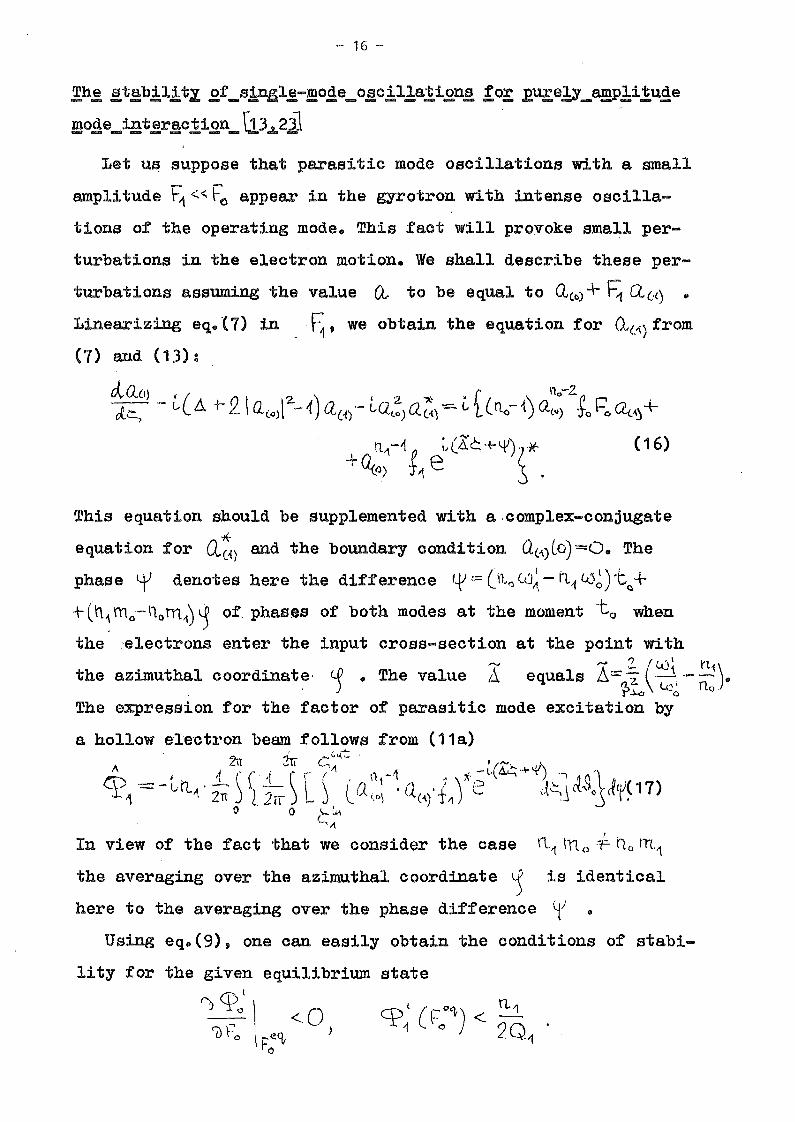
,!h,2 !!,t!!b,!l,!tz .2.f_s!D:ßl,2-!!!o~e_0l!c!lla.:~.i.2.n!!,!o!: .E.U!:e1Y_amP!i!u~e
mo~e_iat,2r!!c!i.2.n_\l3..a..2ilLet u~ suppose that parasitic mode oscillations with a small
amplitude r'1 <<. f: appear in the gyrotron with intense oscilla.
tions of the opera.ting mode. This fact will provoke small per
turbations in the electron motion. We shall describe these per
turbations assuming the value (1 to be equal to aCe) + ~ aLl) ..
Linearizing eq.. {7) in ~,we obtain the equation for Ct(:\) from
(7) and (13):
OvQ.Ü) _ i ( . 2.' 2.) '2. i(- ~ • [ \ 11 0-2. ~ r .J..~) L-.1. + \0.(0)[ --{ 0,(1)'- L-Q(.o) Q(-t) - L 1 (no- {) Q'Q) "Jo t-c, a<.~+
n,,-Ij p ;, (Kc. +YJ) ri't (16)
+~c}) t'l e .s
the given equilibrium state
f)<f.)l\-l-I <07l ~·o : ~o )
\F "o
This equation should be supplemented with a.complex-conjugate
'*equation for Q(~) and the bounda.ry condition Q('\)Lo)=O. The
phase tf denotes here the difference lf = (n,<:; <'0~ - h.-f tU~)-cQ+
+(n~mo-noh11)~ of. phasßs of both modes at the moment -to when
the 'electrons enter the input cross-section at the point with-., ,-J> 2. (1..0 \ 11.1 )the azimuthal coordinate, . c..P .. The value /1 equals f::. =: 2. ._1. - ~ ..
) rp..kJ lc~ rlo
The expression for the factor of parasitic mode excitation by
a hollow e'le'ctron beam follows from (11a.). ~ " (.t.(~ .
A zn 2tl C, , ("".... oJl\, A' \' I .._.t\ (\-1 ;t-\" .i<::;+,,)...... .,~cp '= - L(LA, . 2-!-., t .:_ l '\ \ C'a1,,1. • Cl,' t! \' e a~, \l~$() ,~(U( 17)
" TI) 2/\) ..... J . \ ("'j" ) .J \ •o 0 "-~
c."In view of the fact that we consider the case tl'i tn o 4=- llo rn,1
the averaging over the azimuthal coordinate ~ is identical
here to the averaging over the phase difference ~) ..
Using eq.(9), one can easily obtain the conditions of stabi
lity for
- 17 -
The first of these conditions defines the stability of oscil
lations of the operating mode with a stationary amplitude
with respect to its own perturbations. This condition is not
fulfilled for the unstable branch of the oscillator with herd
self-excitation, it is valid in the below consideration.
If the second condition is violated, the parasitic mode has
a positive increment and, hence, its oscillations will grow.
Taking the balance equation (15) into account, this condition
can be written in the form
(18)
(18a)
or, for the gyrotron in which the spread in electron velocities
and radii of guiding centers can be neglected, in the form
A I / :" I A = 110. ~{ 0."CPo qJ'\ '> 0 t1 - Q .
\I ~ 10 0
• On the other
pole interaction of electrons with the HF field
[~ . /. 2n", / 2.n."
harmonics 11J (see (12) ): I~ IeJ 'V ~J..o rJ..o
Two facts should be emphasized. First, both factors, qpoand ~1 ,depend on the amplitude of the operating mode (for
a parasitic mode, it follows from eq.(16) that determines the
value Q(-{) and, correspondingly, the factor CJ?'1 ' and includes
the value Q.{o) depending on Po ). Second, the given set of
equations can be applied to the analysis of the competition of
modes resonant with different cyclotron harmonics. A mode reso
nant with the lower harmonie or a mode resonant with the higher
one can have some advantages in this competition depending on
the beam voltage and the pitch-factor of electrons ~J.!~\\ .Rere we mean the ratio TI\. Q-1 /1
00
0• On the one hand, the ratio
of the effective impedances of coupling is proportional to the
electron orbital velocity to the power that corresponds to multi
at different

- 18 -
band, the diffraction Q of the resonator with a fixed length
is larger for the modes resonant with higher harmonics because
the wavelength is smaller, i. e .. QII./Q ~ (L/'AA.J'2.. ::: n.~ and,o (L/A<.tY· n; '2.
thus, the ratio I'1 Q A. /IoQo is proportional to (Q1~~/no~:~) ..The integration of eq.. (16) and the computation of the factor
of excitation (17) can be simplified by introducing the integ
ral variables that are independent of the phase difference 0/ ..Introducing the matrix
YA. I
ct(1) I~"-}.
'(2- 2rr l\
y= - .L~a(,\) ,~~
~})y~ 21T \
0 Q('\)' ~}
y~ Q~~)' ~n,}
'" . /l \ I 11where \:= L\); + <f, Q(1)'= '.(.,(1) - l, Q(-{) ,orie can transform. eq.. (16)
to the equation that does not include the phase ~ and has
a matrix form
~ =CY-Hclc.,
with the boundary condition yeo) =0 .. The matrix C.equal to
(16a)
is
2.><.,y 0 K A+x2.+ sy2.-1
o -2x'y -CD.+?:JX~'12~{) -'K.~ a: D. 4-)(2.+6['.-1 2.x'y 0
r>I
-(Ä+ öxz-+y'Z:--1) A 0 -Zx''j)
where ~o)= x- ~.'I ' and the matrix H for the modes resonant
with the fundamental cyclotron harmonics is

- 19 -
H=
(17a)
Henee, the faetor 1? ean be deter.mined by the expression that
follows from (17): . 0"'*:.2rr c: '\
41=-Lin-) [~. (Y" -Yz) ~:(~)J~J ~~~o c:.~
for the ease of higher eyelotron resonanees are given
• The expressions for Hnot inelude the phase <t'and does1\
and CI2,in [23].
Thus we have redueed our study to the following proeedure.
In the first stage, we integrate the equation of eleetron mo
tion in the field of the operating mode (13) and determine Q(O)(c,).
Then, we calculate the faetor G?o (14) and find from the ba-'
lanee equation. (15) the value of the beam current parameter
ToQo that corresponds to the given amplitude of the operating
mode F: • In the second stage, we determine the perturbation
in the electron motion a0)(~) that is caused by the field of
the parasitic mode using eq.(16a) and caleulate the factor ~1
(17a). After all these calculations we can determine the high
est value of ~ for which the condition of operating mode
stability (18a) is valid.
The results of the calculations were given in [23,13J .. As
an example, the dependence of the real part of the factor of
parasitie mode e:x:eitation CP-1 on the frequency mismatch A1=
is given in Fig.1 [13J
- 20 -
"..... 2.. ((),,-tUHo ( A):- Ao+A = -2: • tU n..o}-t = "
\?:>.i.o cifor the gyrotron in the absence of the operating mode oscilla-
A I
tions (<1'I\)L) and in the presence of these oscillations with
I the amplitudes ro =0 .. 04 and different values of mismatch2. <..U -lUHo " I
A -- • <:) - (the corresponding values of <:Po are shown~o- ~2. CD
in Fi~.1 by ~orizontal dashed lines, .t/1l~)=~f~-(~cd:._1)2~,~a~=17). It follows from Fig.1 that the main effect of the
operating mode 1s the suppression of the parasit1c mode, i.e."I
the factor ~~ in the presence of the operating mode is, as a
whole, much lower than for the unexcited gyrotron. The origin
o~ the latter effect will be analysed in the next lecture.
A most typical situation for gyrotrons 1s the case when the
beam currentis fixed and the external magnetic field is tuned
for the maximum of effic1ency. The corresponding dependence of
the operating mode amplitude on the mismatch ~o for the va-l\. 4 3
lue of the beam current parameter 1 =I -Q .)... =10 is given ino 0 0 '"'o~,
Fig.2. Using such dependences for the determination of f70 as" .
a function of 110
at a given value of 1 0 , oue can find the
zone of parasitic mode self-excitation in the plane of mismat-...... A
ches ~O) A .. This zone is shown in Fig.3 for the values 9; =1,A. 310 =10 , and ~0lct.=17 .. It follows from Fig.3 that self-exci-
tation of the parasitic mode can take place in the left-hand
side of the zone of the operating mode oscillations where the
amplitude of the operating mode is small (see Fig.. 2) and the
parasitic mode can be enhanced with a larger amplitude if its
frequency is closer to the center of the zone of self-excita-
( "" \tion ß '> 0) •
It should be noted that for the optimum parameters of theA.
electron efficiency of the operating mode ( Tc =103, t:o.ct:=17,
and Ao =0.4), the parasitic mode can be excited only when its
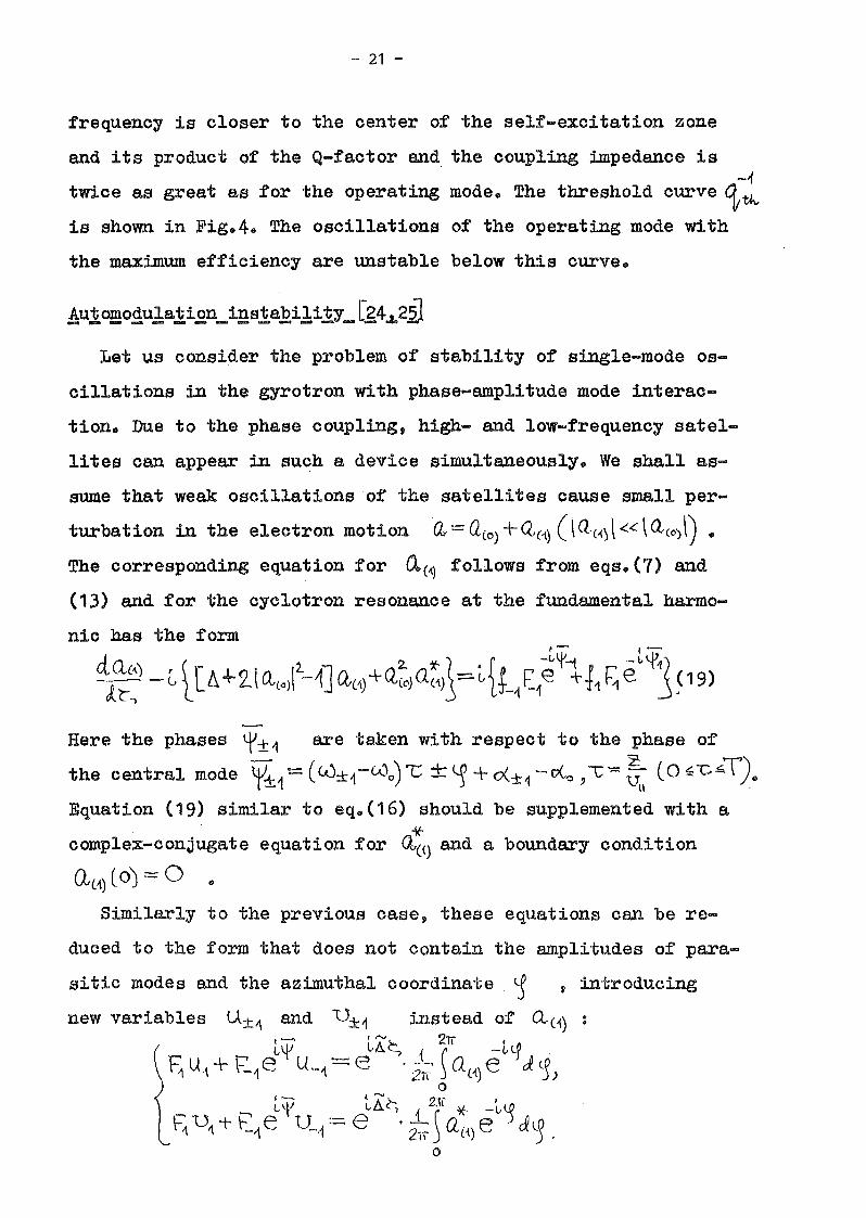
- 21 -
frequenoy is oloser to the oenter of the self-exoitation zone
end its produot of the Q-faotor and the coupling impedanoe i8-1
twioe as great as for the operating mode. The threshold ourve ~th,
is shown in Fig.4. The osoillations of the operating mode with
the maximum effioienoy are unstable below this ourve.
Let us oonsider the problem of stability of single-mode os
oillations in the gyrotron with phase-amplitude mode interao
tion. Due to the phase coupling, high- end low-frequenoy satel
lites oan appear in suoh a devioe simultaneously. We shall as
sume that weak osoillationsof the satellites oause small per-
turbation in the eleotron motion O:t:=: Q(O) + Q'(1) (\ Q(~J«\QCO) \) •
The oorresponding equation for ~(~ follows from eqs.(7) end
(13) and for the oyclotron resonanoe at the fundamental harmo
nio has the form
QQc-\) ~[ \2. iJ . 2. t- ( • f P -~t-1 P~- L~1/J.r-~ -L l L\+2.(Q(O) -~JQ,(1)+Q(O)a('\)j=!JTt_1E1e +t11 e J~19)
Rere the phases ~±1 are taken with respeot to the phase of- 2 ~)the oentral mode o/±1=(Lc)±1-W.,)""C +<-)'+o(±1-c{o,\;=uu (O~"'C~ ,.
Equation (19) similar to eq.(16) should be supplemented with a
'*oomplex-oonjugate equation for <l(i) and a boundary condition
Similarly to the previous ease, these equations can be re
duced to the form that does not eontain the amplitudes of para
sitic modes end the azimuthal coordinate ~ ,introducing
new variables U±i\ end U±1 instead of Qc'\)
.Lf _ LA{;{ 211 -~Y' .E, U1 + t.1e U._,\ - e .2IT ~ Q({) e eR.~)
o
""' ~ ~o/ ._, tA~ 1 2," * -L~\=1 U,\T \--1 e U--1 ~ e .2rr ~ Q({) e d~.
o

- 22 -
'" l LU'1 - <'-vo - ~ ~Rere ~..= f.>~ . «.)0 ,the phase r= le"i+\,p+1=(<.(:·tt+u...t1-2.cOo)""G+G<1-hX_r2o<<:
, 0
corresponds to four-photon decay of two quanta of the operating
mode to the quanta of both satellites. Equations for
follow from eq.(19) and its complex-conjugate one:
(20)
(21 )
The corresponding boundary conditions are U±'1 (c)=q, "lJ±'1(0) =0 •
Equations (20) and (21) do not include the satellite ~plitudes,
the azimuthal coordinate ~ ,and the phase difference lfI •A.
The expression for the factor of excitation <±?±-1 ('t1) can be
transformed in a similar manner
where
The equati.on for the phase difference '-Y follows trom eqs. (10)
cl~ W'" +tU~-i-2(.Jo . 1 ffi l( _ 1\ \\ A If
d..:t ::= C0 . + -J\ ~-1 + l/I\ -2.10 Cl?o. (24)o
If the beam current parameters tor all modes and their axial
structures are the same, I±.-t = To ) +±... (~,) :== 40U",,) , and
both the satellites have equal Q-tactors Q-If=QIf ,using
eq.(24) and expressions (22) and (23) one can determine the sta-
tionary value of the phase ALt' (for ~'1 4 0 ) that is stable

- 23 -
with respeet to the phase variations
(25)
of the mode eig~nfrequeney speetrum (see Leeture 1) with the
eleetron detuning of normal frequeneies taken into aeeount.
The equations for the satellite amplitudes whieh fo1low from
eqs.(9) and expressions (22) for the ease of phase-amplitude
mode interaetion are eoupled:
d. F, ,..., ( { J( \ ( (l'\ , - Cl? 11 ~ - '\
etl,: =. r-t CP"/1 - '2-I::,Q--1 ) + E.'t 'j;~J-'1·c.o.~f~~ 1J-"i C+!<;it./y.
clF-1 I ~ ( cp I ~ 11 ,,-:--)c:;lL; ~ ~ E-f (er_1/--f - 2.ToQJ + ~ -1/1f(:~Lf~+ep-tj"1' ~\l'f~~, )
here -c. ~ I o wot . Two eonditions of the operating mode stabili
ty with respeet to the satel1ites fol1ow from these equations
(26)
j i 2. -..,...... fT) l( cp iI • 2- .
6'" ' 0'-'t - <PA _,,' <1'-1 -1 '~ ~<;(t+ ':t'~ -1' -1 "l' ~Q.. epSfC +"li "\) I)
t -:-- ~ (tI\ll cpl ffil fT\1I ) 0 (27)+ ~tl.-l\!~' ~ l('~ \... '-1:'" -1' -11- ':t'1-1' 'r-1 1 '> ')'1, ) I I
where S'~= <P~J1 - 2.~ Q' ) S-1"" ep~ -1 - :z~ CL, are the inerements. ~ ~ ). 0
of the satellites.
Thus in eomparison with the ease of pure1y amplitude mode
interaetion analysed above t these equations eontain only one
additional parameter, namely, the mismateh 8 that eharae-
terizes weak nonequidistanee of the mod~ eigenfrequeney speet
rum.Similar1y to the previous ease , only the situation where
the Q-factors of all modes are equal should be analysed numeri
ea1ly and the ease Q±4-:F Q 0 ean be analysed analytiea1ly be...

amp1ification zone, the region of automodulation..-...;.
diminishes ( !l =0.5). The analyses of the cases
- 24 -
cause conditions (26) and (27) can be rewritten in the form0) A
3-t -= 1',\ + 2(~-\) cp~ < 0,
iFz~ :r~\) -\- ({-'J 4~ [~({) + ({ -r) eP~1'>0,
where the functions ':f'I}2. denote the expressions in the left
hand parts of conditions (26) end (27), respectively, the index
( 1) symbolizes the case ,==. Q0 la ==- 1 •. (~ ±~
The results of numerical investigations are given in Fig.5.
The axial structure of all modes was taken in the form 4C~) =
=~ l-( ~~..:t-1)z.L~od= {o. The solid 1me shows the zone of
the operating mode self-excitation. The dashed 1ine shows the
beam current parameter I~- 2..1 0 00
optimum for the electron ef
ficiency of the operating mode (the circle in this line corres
ponds to the maximum of the' electron orbital efficiency). The
dot-dash 1ine corresponds to the break in the operating mode os
cil1ations at the edge of the zone of hard self-excitation. For
different values of the distance between the mode frequencies
K ,the boundaries of the zone of the operating mode osci1
lation stability are given in Fig.5 for ~ =0, ~ =1. The dash
ed lines correspond to condition (26) and the solid lines, to
condition (27). These lines are shaded as viewed from the auto
modulation instability. As the distance between the mode fre
quencies grows, the zones of automodulation first expand (cf.A.r
the curves for Ä =0, 0.1 and 0.3). This fact can be explained
by the growing influence of' the dispersion in the gyrotron non
1inearity. Then, as the satellite frequencies move out of the
instabilityC-0{ + (~L1 -2l,-\- =
Iowo=0.02 end 0.05 show that weak nonequidistance of the mode eigen-
frequency spectrum does not, practically, affect the boundary

- 25 -
of the zone of autamodulation instability.
If the frequency mismatch of the cyclotron resonance for the
operating mode is optimum for efficiency ( ~o =0.6), the depen
dence of the critical beam current that corresponds to the ap
pearance of automodulation on the distance between the mode
frequencies ~ has the form shown in Fig.6. The dashed non-
shaded lines correspond to the case when the Q-factor of the
operating mode .is two times smaller than that of the satellites1\( q, =2). Even in this case, the central mode oscillatj.ons are
stable for an arbitrary distance between the mode frequencies
up to the beam currents exceeding the optimum one by two times
and greater. The minimum value of the critical beam current pa-,....,
rameter corresponds to the mode frequency mismatch 6.('''{' ~ 0.3
(see Fig.6). AB the resonator radius grows and the mode frequ
ency spectrum becomes more dense, the most "dangerous" satel
lites are, obviously, the ones with the frequency mismatch close,-.J
to ~ tt rather than the neighbouring satellites. It is natu-
ral to suppose that the automodulation instability is inherent
in the decay processes, i.e. with an increase in the beam cur
rent after the appearance of the first pair of satellites sub...
sequent pares of satellites will be excited.
Thus, the results obtained demonstrate the possibility to
provide stable single-mode oscillations with a high electron
efficiency in gyrotrons with an arbitrary dense spectrum of the
competing modes differing in their transverse structure. The
types of instability analysed here can. play an important role
in the cases when the beam current is increased over its value
optimum for efficiency in an effort to enhance the microwave
power.
This conclusion permits one to establish the fact that for

- 26 -
gyrotrons with the beam current that does not exceed the opti
mum value, the most important problem is the appropriate choice,
of the start-up scenario that can provide for the operating
mode to be first self-excited and then to operate with high
electron efficiency. We shall analyse this problem in the next
lecture.

- 27 -
LECTURE 3
Start-Up Scenario
Taking the results obtained in the previous lecture into
account, we shall assume that for the excitation of the ope
rating mode the gyrotron should be switched on so that the self
excitation conditions are fulfilled for the operating mode prior
to the others. This method of providing the operating mode os
cillations was proposed in [26J and then supplemented with the
analysis of a number of examples in [27].
In view of the fact that we consider a system of orthogonal
modes that are not coupled in the unexcited oscillator, the
condition of self-excitation can be studied for a.ny mode neg
lecting the presence of all the others in the spectrum of eigen-
*frequencies'. The corresponding condition follows from (9)
(28)
" I
Here the value ~s in the framework of a small-signal theory
does not depend on the oscillation amplitude and is only the2 Ws. - nSG·..lHo
function of the cyclotron resonance mismatch 6.s= (2.,'1... ' r,'\
rJ..o UJl{o
and the axial structure of the s-th mode fs(Ä) '[10,28,29]<:;0111;
" \ 0 t S LA ~ 2.crs ::::-llh.s+~) ~ ts(~Je s :i~\ . (29)
T~ P\~ C, 2. s ~~The value \ J ~ßle.-~e s dl~,\ in (29) characterizes the intensity
c:ks.
* Double degenerac.y is, in principle, characteristic of any
non-symmetric mode, since modes with different directions ofazimuthaI rotation .'Ve'lCp lLL (~t + mlS)~ ha.ve equal frequenciesin the "cold" system.. Tllis degenerac.y is, however, disturbedin the presence of electrons and the modes differ in the start-
ing currents and os'cillation frequencies due to the gyrot.....:ropy'--"of the electron beam.

- 28 -
of the spectrum of the HF Lorentz force acting on the electrons.
The first term in the right-hand part of (29) corresponds to
the "M"-type bunching of electrons that leads to cyclotron ab-AI
sorption (crs M. <:: 0 ). The second one, which iso proportional. I
to the derivative of the spectrum intensity, corresponds to
the "On-type inertial bunching of electrons. It follows from
(29) that the "Olt-type inertial bunching is dominant for c.ou:J:?> \'t
( the transit angle 8&:.:=. As~:ut;iS usually of order 2'}r ) and,A
hence, the real part of qpß can be positive and the gyrotron1\(
can be self-excited. The dependence of gps on the frequency
mismatch ~s for various axial structures of the HF field was
analysed elsewhere (see, for example, [29J).
The value of the starting current can be determined using
equation (28) and expression (29). Under usual experimental con
ditions, when the electron-optical and electrodynamic systems
are given, the starting current depends on the parameters that
can be varied, namely, the external magnetic field and the
anode Ua... and the resonator Ur- voltages. One should disting
uish here two types of operating regimes, pulsed and CW opera
tion. At CW operation, one can vary all the named parameters.
The tuning usually reduces to a procedure when optimum voltages
are chosen for the electron-optical system and then the magne
tic field is tuned first for the best self-excitation of the
operating mode end after this for the operation with the maxi
mum efficiency. Correspondingly, the zones of self-excitation
and oscillations are usually shown in the plane of parameters
"beam current versus magnetic field". An example of such
zones is given in Fig.7 taken from. [;30]. Here you can see the
self-excitation zones of various modes in the gyrotron that is
designed for operation at the TE15,1,1-mode at a frequency of
- 29 -
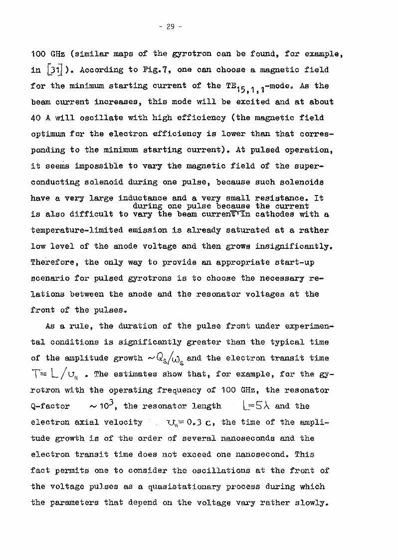
100 GHz (similar msps of the gyrotron can be found, for example,
in [Jfl). According to Fig. 7, one can choose a magnetic field
for the minimum starting current of the TE15,1,1-mode. AB the
beam current increases, this mode will be excited and at about
40 A will oscillate with high efficiency (the magnetic field
optimum for the electron efficiency is lower than that corres
ponding to the minimum starting current). At pulsed operation,
it seems impossible to vary the magnetic field of the super
conducting solenoid during one pulse, because such solenoids
have a very large inductance sud a very small resistance. Itduring one pulse because the current
is also difficult to vary the beam curren~n cathodes with a
temperature-limited emission is already saturated at a rather
low level of the anode voltage and then grows insignificantly.
Therefore, the only way to provide an appropriate start-up
scenario for pulsed gyrotrons is to choose the necessary re
lations between the anode and the resonator voltages at the
front of the pulses.
As a rule, the duration of the pulse front under experimen
tal conditions is significantly greater than the typical time
of the amplitude growth ~Qs/<.Js and the electron transit time
T':-' L/ vII .. The estimates show that, for example, for the gy
rotron with the operating frequency of 100 GHz, the resonator
Q-factor -- 103, the resonator length l 5,\ and the
electron axial velocity I:.J.\= 0.3 c, the time of the ampli-
tude growth is of the order of several nanoseconds sud the
electron transit time does not exceed one nanosecond. This
fact permits one to consider the oscillations at the front of
the voltage pulses as a quasistationary process during which
the parameters that depend on the voltage vary rather slowly.

- 30 -
In order to determine the zones of self-excitation of va
rious modes in the plane "anode voltage ·Ua.., versus resonator
voltage VI"" ", one should express the parameters ~s. and C;~At
in expression (29) for G?s in terms of Ua. and Ur
<-us~ \1S c.0Ho ~~ ~t. tVl-to L~, <"""s • (30)
CU Ho . 2. ~II 0 c.
The orbital velocity of electrons in the gyrotron adiaba-
tic electron gun at a small space charge density can be deter
mined by the expression ~2J2.
2. = 0(.&. U~ (31)~J.o cf-. H~ ,
where 0(= l-io /HC!, is the transmagnetic factor, i.e. the ratio
of the external magnetic field in the resonator region, t10 ,
to the magnetic field near the cathode, }{c • Introducing a
Uc..rcritical anode voltage ~ that corresponds to the appearance
of the anode current, when the height of the first cycle of the
electron trajectory equals the distance J between the ca
thode and the anode, one can express the ratio cL'L· H:! 0(2. in
(31) in terms of U~-r [331
cl2.. H~ =: clZ.. 1/2.=. 0 ~cz..V(:-r (32)d..,2.. N<:, L. e 0....
Substituting this expression into (31), we obtain
2-2.. oG e U(\~ (31a)
~.Lo::::: '2. .-~. ·U C~ •
Ov
The total electron velocity can be determined by the resonator
voltage
2.. =. 1_(0 1+ e Ur )-2~o meZ. f1
(33)

- 31 -
Using expressions (29)-(33) and the balance equation (28)>>
we ean determine the self-exeitation zones o~ different modes
in the plane" ·Uo.., versus Ur- tt for a gyrotron with an arbit
rary axial strueture of modes resonant with an arbitrary ey
elotron harmonie.
For a gyrotron whose axial strueture of modes ean be de
seribed by a gaussian funetion g(~) =~f l.-(2·~ - 1)'Z-} » theAI" ~
exeitation faetor <Ps. is [)4]
4:(=-E.CC~)2.(h. +:L\ r_CAs.~Qt)21 (34)'i:. g""' S So ro ti~) ~f L ~ ~ .
As ~ example, the self-exeitation zones of the modes resonant
with the fundamental eyelotron harmonie are shown in Fig.8
(see [35]) for a gyrotron with the gaussian axial strueture
of the HF field. The gYrotron parameters 1 0 ,~ou:t and 6 0p
eorrespond here to the maximum of the eleetron efficiency
(the voltage reaches the pulse top). The self-excitation
zones are given in the plane of parameters X = 'f~ /1- ,Y== 'P~ 1'2. · The zone of the operating mode self-excitation
is shaded. The point of the maximum efficiency,as seen from
Fig.8,lies in the field of hard self-exeitation (the bounda
ry of this field, where the oscillations break» is plot ted
by the dot-dash line) and can be attained only if the trajec
tory corresponding to the electron velocity components at the
pulse fronts passes aeross the shaded zone of"the soft self
exeitation. of the operating mode. Figure 8a shows an example
of a gyrotron with a rather large distanee between the fre-A of'"C __
quencies of eompeting modes (for the operating mode, D or0.4, for a high-frequency parasitic mode, b.h.~ =0.6» for a
low-frequency one, 6.t~ =0.2; the modes with equal minimum

- 32 -
starting currents are oonsidered). The trajectory I shows
electron velocity components for equal voltage pulses at the
anode and the resonator of the tube. The trajeetory 11 cor
responds to the ease where the difference between the resona
tor voltage and the anode voltage is constant through the
pulse. It is seen from Fig.8a that the first type of voltage
feeding results in initial excitation of a higher-frequeney
parasitic mode at the pulse front. Then, its oscillations
break and the operating mode appears and oseillates with high
efficiency at the pulse top. The second type of voltage feed
ing leads to the excitation only of the operating mode in the
pulsed gyrotron.
If the frequency speetrum of the eompeting modes is more
dense (Fig.8b), the first type voltage teeding provides initial
self-excitation of a high-frequency parasitic mode whose osoi1
lations are stable while the gyrotron 1s erossing the shaded
zone of the operating mode self-excitation and break on1y in
the zone of the low-frequency parasitic mode self-excitation.
Thus, in such a ease the low-frequency parasitic m~de oscil
lates with low effioiency at the pulse top and the oscil1a
tions are accompanied by the high-frequency parasitie mode
oscillations at the pulse fronts. The second type high-voltage
feeding results in near1y simu1taneous excitation of both
operating and low-frequency parasitic modes in this case. In
order to determine the oscil1ations that are established in
such a gyrotron it is necessary to investigate mode interac
tion, which is done below.
Thus, in the latter.case we have come close to the limit
of this kind of mode selection. Note that for a typical value

- 33 -
'2..of the squa.red orbital velocity ~l.;- 0.2, the case under study
corresponds to the relative distance between the competing
mode eigenfrequencies equal to 1%. If the frequency spectrum
is more rare, the proposed method of choosing the start-up
scenario of the gyrotron seems to be rather effective for mode
selection. For example, even the first type high-voltage feed
ing in the above-mentioned gyrotron with the TE15 ,1,1 operat
ing mode (Fig.7) can provide, es seen from Fig. 9 , stable os
cillations of the operating mode with high efficiency.
Basic Effects of Mode Interaction
It was elucidated above that it is very difficult to pro
vide the excitation only of one, operating, mode in a gyrot
ron with a very dense spectrum of the competing mode frequen
cies. When such a gyrotron is switched on several modes can
be excited simultaneously. Let us consider the oscillations
that can be established in such a device.
In order to give a clear picture for the origin of the
nonlinear effects of mode interaction, we shall resort to a
polynomial approximation of the dependence of the mode exci
tation factor ~s on the intensity of the HF field, that is
we shall take into account only the first nonlinear terms,
which permits us to describe the saturation effects in the
oscillator with soft self-excitation. The corresponding ex-"-
pression for q:>~ can be obtained as a result of the integra-
tion of the equation of electron motion (7) by successive ite
rations in t=L-. ~I ~ '.f.~;Cc.) e~l.\1s , substitution of the itera
tion terms obtained, Qk rv (V~)K , into the expression for
~ (11a) and calculation of Cf:<-' • The equations for the$ ,~.

- 34 -
(35)
the boundary conditions are QI(' (0) =0 for K ~ 1.. Rere, as com
pared to eq. (7), the fundamental frequency UJo.- is taken to
be equal to the initial cyclotron frequency of electrons in
the input cross-section, uJHo; the functions ~s in the
right-hand part of (35) for K ~ 1 contain the solutions of
the lower-order (in ('F'::i:JI< ) equations: 'f"t=~; ,"\=a~+2..lQ-1lZ.,
f3=.2.(Q1a2.+a~Q2.+a1a1)+Q,-1lQ.1l2.andso on. The' solution of
equation (35) has the formC; C; t:-,I
Q,k = L) 'fK J.~I +~[j (-:r;_~)Jc,I~ JÄt. (36)o 0 0
Below, the cases of purely amplitude end phase-amplitude mode
interaction will be considered separately ..
In conformity with the discussion given in Lecture 1 we
shall consider here the interaction of two modes.. The substi
tution of the solutions of eqs .. (36) into the expression forA
C1?$ (11a) permits us to obtain the following expression
(37)
,the coefficient o(~ describes the
"linear" properties of the s-th mode, the coefficient ~s
is responsible for the effect of saturation by the self-field
of the s-th mode, the coefficient ~S~ describes the effects
of the cross-interaction of modes. All these coefficients
depend on the cyclotron resonance mismatch 6.s and the
axial structure of the s-th mode; the coefficient Q&&I also
depends on the distance between the mode frequencies end on
- 35 -
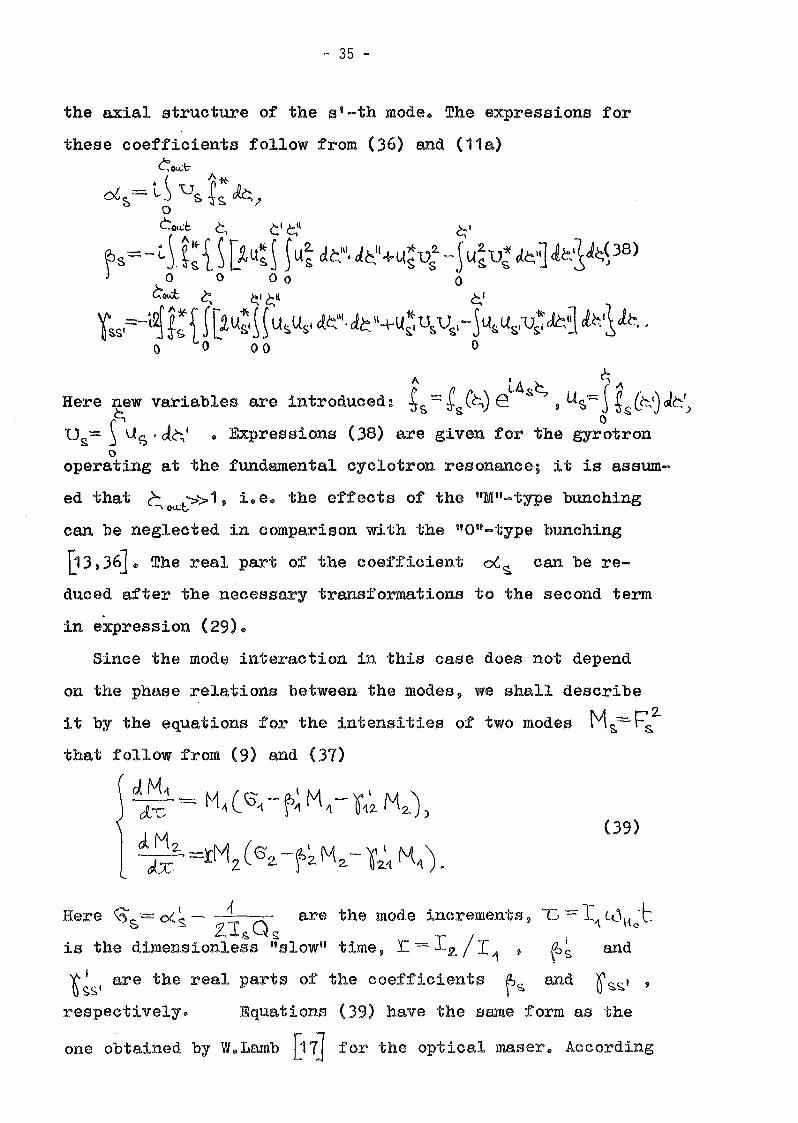
the axial structure of the sv-th mode. The expressions for
these coefficients follow from (36) and (11a)CC<N"b-
• ( A*oG e = L.) 'Os ~s. k.J
•.> 0
Cou.:c C, c' ~I ~'
ts= - cjt{ ~ ~u1 ~ ~ U~ dt,"'. J~'+LI~u:-}LI~U; Jc.'~ ~~ib;P8)o 0 00 0
Coo:t ~ ~I ~" ~'
'f\;SI=:-~ ~:1r~u;i~u~USI c{C:II
•d~ \\+u~ U~'USI-jUsu&;u~Jc1 cl~fl le, ,() () 00 0
A ;A ~ ~ARere new variables are introduced: ~s -=: gCt-.,) eL
s ,u~=j t/~I)k')~ s 0
Ds= SUs . Je;l • Expressions (38) are given for the gyrotrono
operating at the fundamental cyclotron resonance; it is assum-
ed that ~ Ol.l:l::>'> 1, i. e .. the effects of the "M"-type bunching
can be neglected in comparison with the "O"-type bunching
D3,36]. The real part of the coefficient <:Xs. can be re...
duced after the necessary transformations to the second term
in eXpression (29) ..
Since the mode interaction in this ease does not depend
on the phase relations between the modes, we ahall describe
i t by the equations for the intensities of two modes M~·-~:
that follow fram (9) sud (37)
~~' = M, (G",-t~ M'-01~ M,,),
J-d~2" ,-,,!M2 (62.-~~ M"- Q~1 M1').
Rere \3' = cX ~ - i . are the mode increments» -c -= Ti cU\tJ:s- ZIs Qs: /
is the dimensionless "slow" time» :r. -= I,2. 11
, ~~ and
~ ~Sl are the real parts of the coefficients ~s. and Qs.s.' ,
respectively~ Equations (39) have the same form as the
one obtained by W"Lamb [17] for the optical maser" According

-.36 -
to [17J, if the condition of "strong" coupling between the
modes
(40)
is fUlfilled, the phase portrait of the oscillator in the
plane ~1)~2 has the form shown in Fig.10a, i.e. mode com
petition takes place and the oscillations of one mode will
be established, depending on the initial conditions. If con
dition (40) is not valid, weak coupling between the modes takes
place and such modes coexist. The phase portrait of such a gy
rotron is shown in Fig.10b. It follows directly from expres
sions (38) that, if the modes have identical axial structures
(+'\C~)=;2(~)) and the distance between their frequencies
is small as compared to the cyclotron resonance band (i.e.
tiA ~.6.2., ), then the coefficients ~ß and 'fSS\ are related
as \(I =.21f, and, hence, the condition of "strong" coupling~ s.s,' rs.
(40) is valid. Equations (39) have, in this case, the same
form as for a conventional radio oscillator that was analysed
in D4-16J. The dependence of the coefficients 0<, ~ and ~~
on the transi t angle Qs.= 6.s·~~ is shown in Fig. 11 a for
a gyrotron with a constant amplitude of the HF field along
(. ~ O~~~c-t
the resonator axis . ~(c;):::.;:- )~milar dependence ofL,o..t.
'('~Sl on Eis. is given in Fig.11b for different values of the
ratio \< = ( C0~, - <..0 Ho) I (lUs- Lu 1-10) that characterizes the
distance between the frequencies of competing modes B3].In accordance with the data given in Fig.11, the lines for
equal values of the ratio -qr~ O~~· Oz~ /~~ ~ ~~ that defines the
degree of mode coupling, are plotted in Fig.12 in the plane
of transit angles of both modes 8s. and GS.I :=:: 6S\' t~ [J6}.
One can see from Fig.12 that as the distance between the fre-

- 37 -
quencies of competing modes in the zone of soft self-excita
tion (~~ '> 0) grows, the degree of mode coupling '-!! increas
es. This effect can be explained by the fact that we consider
a gyrotron with a negligibly small spread in the electron ve
locities and the radii of the guiding centers (these factors
weaken the mode coupling [37J). In addition, the electrons
differing in the azimuthaI coordinate of the guiding centers
interact with the rotating or symmetrie modes of the cylind
rical resonator with equal efficacy. That is why the space
extended electron beam rolled by the rotating modes of the
gyrotron becomes equivalent to the elementary beam of elect
rons with a common guiding center and, hence, two modes exci
ted due to the interaction with the same electrons behave si-
milarly to two kinds of beasts feeding on the same prey, one
of them suppressing the population of the other ~81. Under
such conditions, the transit effects that stipulate the dis
persion of the gyrotron nonlinearity play the dominant role.
In particular, when one mode frequency tends to the boundary
of the soft self-excitation zone and ~~~ 0, the coeffici
ent l"ssl' as seen from Fig.11b, can be rather large owing
to the cross-interaction of modes. As a result, the degree
of mode coupling grows when ~~ ~ 0 (see Fig.12)"
Besides the mode competition analysed above, which is the
basic effect of puraly amplitude mode interaction, the oppo
site effect can take place, namely, nonlinear mode excita
tion ~3J. The possibility of such an effect i8 self-evident
in Fig.11b which shows that the coefficient r~~i is negative
for a rather large value of the transit angle Gß • In this
situation, the growth of the intensity of the s'-th mode, aa
follows from (39), enhances the increment of the s-th mode,
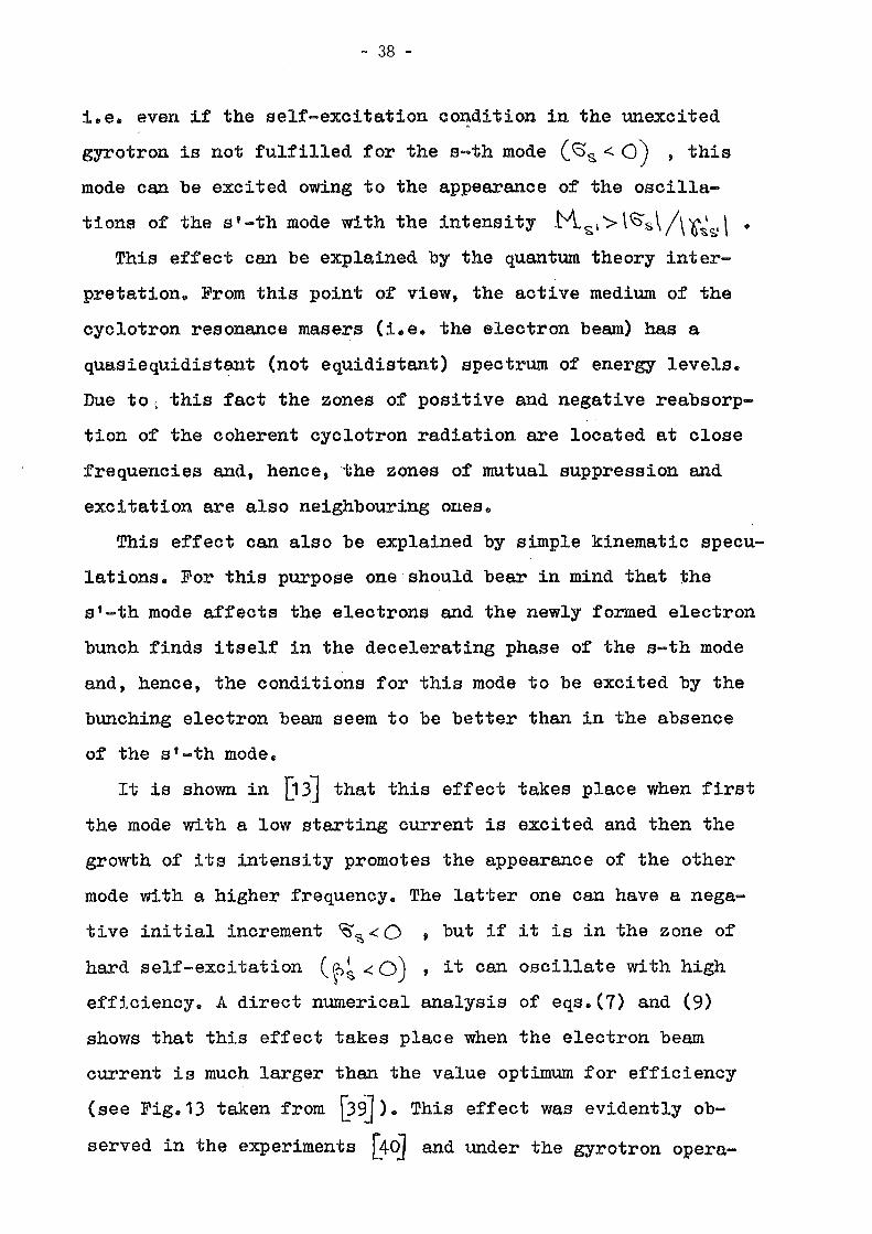
- 38 -
i.e. even if the self-excitation co~dition in the unexcited
gyrotron is not fulfilled for the s ...th mode (6'2, < 0) , this
mode can be excited owing to the appearance of the oscilla
tions of the st-th mode with the intensity .M.si'>\~S\/\6~s.'\ •This effect can be explained by the quantum theory inter
pretation. From this point of view, the active medium of the
cyclotron resonance masers (i.e. the electron beam) has a
quasiequidistant (not equidistant) spectrum of energy levels.
Due to~ this fact the zones of positive and negative reabsorp'"
tion of the coherent cyclotron radiation are located at close
frequencies and, hence, ,the zones of mutual suppression and
excitation are also neighbouring ones.
This effect can also be explained by simple kinematic specu
lations. For this purpose oneshould bear in mind that the
st-th mode affects the electrons and the newly formed electron
bunch finds itself in the decelerating phase of the s-th mode
and, hence, the conditions for this mode to be excited by the
bunching electron beam seem to be better than in the absence
of the sl-th mode.
lt is shown in [13J that this effect takes place when first
the mode with a low starting current is excited and then the
growth of its intensity promotes the appearance of the other
mode with a higher frequency. The latter one can have a nega
tive initial increment ~~<0 , but if it is in the zone of
herd self-·excitat ion (\i>~ < 0) , i t can oscillate with high
efficiency. A direct numerical analysis of eqs.(7) and (9)
shows that this effect takes place when the electron beam
current is much larger than the value optimum for efficiency
(see Fig.13 taken from [39J). This effect was evidently ob
served in the experiments [40J and under the gyrotron opera-

- 39 -
tion at the seeond harmonie, of the eyelotron frequeney' [31] ,
where as shown in [13], the oseillations at the seeond harmonie
provoke the exeitation of parasitie modes at the fundamental
eyclotron resonance. Here, the reason for the nonlinear exci
tation of parasitic modes at the fundamental resonanee lies
in the fact that the modes resonant with the seeond harmonie
have larger rates of saturation, whieh leads to the distur-
banee of the eondition of their stability (see (18) in Leetu-
re 2) as the amplitude of this mode grows ~3,4~ •
The results obtained permit us to demonstrate an example
of the evolution of the zones of self-excitation of two modes2. (.0 't - L0 H <> "" 2. t() - <-<"')-1
in the plane of mismatches /j.~=~ · ') , t1.::::: rz..2.. 2-f->.Lo L<-: H<) \-.1.0 C0Ho
(Fig.14) [13J. Let us assume that the electron beam eurrent
was increased rapidly at a certain initial moment of time,
thus providing the possibility for the gyrotron self-excita
tion. So long as the mode intensities in such a gyrotron are
rather small, the self-exeitation zones of both modes have a
symmetrie form (they are shown in Fig.14, where the inerement
of the second mode in the shaded zone is larger than that of
the first mode, the axial strueture of the resonator field
is t(c,J=~~t~L2;~-1J'2-) '~o~=17, the beam eurrent
parameter is 10
::::: I s Qs t;~u..t =103). If the eyclotron resonance
mismatch of the first mode 6. 1 corresponds to the minimum of
the starting current and the mismateh l is nonzero, the
first mode has a larger'inerement end its oseillations grow
faster. As the first mode intensity grows, the self-exeita-,
tion zone of the seeond mode changes as shown in Fig.14 (the
curve marked \7'1*0 ): the first mode suppresses the oseilla
tions of the seeond one at the right edge of the oscillation

- 40 -
zone (where the amplitude of the first mode is large) and in
the region of small mismatches between the mode frequenciesA~ (where the effects of mode competition are dominant).
At the same time, at the left edge of the oscillation zone,
where the conditions for the first mode are far from optimum
and its amplitude is rather small, the second mode with a higher
frequency that can oscillate with a larger amplitude can be
self-excited and, owing to the effect of nonlinear excitation,
its self-excitation zone spreads in the direction of large mis~
r,../
matches 6. •
Thus, we can now answer the question that arose when we
analysed the start-up scenario. When the self-exeitation con
ditions tor two modes with elose eigenfrequeneies are tul
filled nearly simultaneously(the separatrix with the ttsaddle"
state of equilibrium in Fig.10a is elose to the bisectrix of
the quadrant M-1)M2), the oscillations of one of the eompeting
modes will be established with almost equal probability depen
ding on the initial fluctuations of the radiation in the os
cillator. Note, that in such a ease eaeh of the two·modes will
oseillate with praetically equal efficieney because these modes
have equal Q-factors, eoupling impedanees and elose frequeneies.

- 41
LECTURE 4
In order to desGribe the phase-amplitude mode interaction ,
we should take into account three or more modes for which the
conditions of time \QC02.-c-<J1-CL\\ ~ ~ and space (azimu.thal)
2m ::::: ml\+ lil2
synchronism are fulfilled. Using the method of~ ~ I
successive iterations in F'z.·=~I=;·t&(6.,)e(,.~s for the in-
tegration of the equation of eleotron motion and the computa-
(41)
8=5 •
c;s =2.
s=1
tion of the factors of excitation, one can obtain the expres-
"sions for epg ~3J similar to (37)
is the phase difference that corresponds
to the synchronous harmonie of the alternating current. The
expressions for the coefficients ~s that describe the phase
coupling of modes, have the form [13JCo-d- ~ ~'~11 c. 1 .
~,,='~L ~ 47{ ~ [2.lA~) \ lAi J.C~". dc," +U~ui - ~'L(~D~ J~IJ Jc,'~ J~~)o 0 00 0
~ou:C c1
c,' t:," ~, (42)
~2 ~2L~ ~;i~ [2u~~ ~ \A~Ub JC~\I.&C.II+u~u"U~-~lA"UbqJ~jJ~~Je, .o 0 00 0
The expression for ~ 6 follows from the expression for ~ '{ ,
provided that we change the indices 1 ~ 3. All variables in
(42) are just the same as in formula (38). One can easily
find that for close mode frequencies (As~ ti) and their iden-
tical axial structures (~s(~,y=:~(~,)), ~-=. 2..~ := 2..~ (cf.2.. <-'tl~ r
(38) and (42) ).

- 42 -
The coefficients ~ ~ ,as well as the coefficients ~s
and Oss' (38), can be rather simply calculated analytically
for a gyrotron with a constant amplitude of the RF field along
the resonator axis t/~) "=~ (O<<';~~). The corresponding depen-"'od:.
dences of the coefficients ~ s and O~... \ on the transit angle
are shown in Figs.15 and 16. The transit angle of the central
mode 82= b.2.tovJ:. is given in Fig.15a-c along the horizontal
axis; the mismatch g is proportional to the distance between• ) t\ W2-(0~the mode frequencies: for the first mode (FJ.g.15a ,0. = 1 '
(1 c.v - <..02. (' (~ LI... z-<.{.'\{ofor the third mode, 0 = 6 W ~ 0(,\) • The designations in
<..02. - Wo
Fig.16 correspond to the ones accepted in Fig.11b.
I~ a simple case of three mode interaction, the phase-ampli
tude interaction of these modes can be described by the equa
tions for the mode amplitudes and the phase difference ~)
that follow from (9), (10) and (41) [13J ~
~ F4 _ ~ CE) \ r2.. \ 2.. I 2) 2. -~,t'Jv - -{ 0'1- ~'1 1. - ()121='2 - ~16 \='6 - ~~' F2 ' Rtl(~1e ))
We assumed here that the coupling impedances of all modes1\' ...... <.-0,,-+t.0~~-2 vJ2. '\ 1\ 1\
are equal, Q'- .,.. ,\ +0<." +0<.'6 -2..01.. 20 •..\..,2. 1.Vz.
For a gyrotron with close frequencies of the interacting
modes and identical axial structures of their fields (when

- 43 -
O~r;l = ~2..-= 2 $~I~= 2,~ ), the set of equations (43) defines
the equilibrium states of the oseillator, whieh for equal Q
faetors of all modes end a negligibly small nonequidistenee~ 5rom .
of their frequeney speetrum (f) ·~o) are as fOllows'l[13J
- single-mode oseillations with the intensity r~- ~ ;- oseillations of both lateral satellites in the absence of
r2. r2. G"the eentral mode 11 =. '6= 6~ , F2 =0;
- symmetrie synphase three-mode oseillations f =0 , FzZ,= .~ ,'f2.= ~2.~ 2. G"" f
'\ 6 1S~
... asymmetrie antisynphase three-mode oseillations ttJ =1\
e:-2 _ ~ F2.-~ ('2 +. (;:::::151\ ,,2. - ~ (2.'- "5') •
\2 - S~I '1 -10~ ~-\Jb) ,rö - ~O~I ,~+,,~
The analysis of the stability of these equilibrium states
shows that all multimode oscillations are unstable end the
eharaeteristie equation of the fourth order for the stability
of single-mode oseillations implied by (43) has three roots
with a negative real part and one root with a zero real part.
The latter is indicative of the fact that the oseillator with
single-mode oseillations of the central mode does not react
on the appearance of lateral satellites with small amplitudes
F" = \='3 end the phase difference \V =11 , i. e. on the auto
modulation with a frequency ....., \ W2 l -t...\l of the central mode
oscillations. Therefore, the single-mode oseillations of the
central mode can be considered here to be relatively stable
(this conclusion is also supported by the results of numeri-
cal computations of eqs.(43) ). However, we believe that
such astability ean be changed as a result of weak varia-
tion in the gyrotron parameters.
The difference in the mode Q-factors can, no doubt, affect
this stability. Let us suppose that the diffraetion Q of the
lateral satellites is smaller than that of the central mode
,

- 44 -
owing to electrodynamic selection and the beam current exceeds
the starting value only for the central mode (i. e'. 6'2, '>0
6'\ =: G~ < 0 ). The satellite intensities in such an oscilla
tor become equal as the time grows end the set of equations
(43) with the given above relations for the coefficients ~. ~s
y. I (6 and F1=F::I taken into account, reduces to the formOs.s. ) )ß .;:>
i~ = X[~ - ~ (X2-+ 6'12-+ 12 ~J] +Y(~-1 +)\2)
*~YL6-~(-)(Z-+y'Z-+4ili\ -+ Xlt>L+1-X-z» (44)
'6 ')(2+ '12-~=~[-'-V-X'Y-\(~Z+ ~ 2. jJ
, ~ \I I ~ S2.Rere X=V2Y2./\'Sl CA6 ~) y=y2r:2/tsl ~I\,T)Z =\;'\' ~=l8l Iowot)
0= ~t ,v = \ ~I~t) t =~\ I ~I\ • The first two equations in set (44)
define the stationary amplitude of the central mode (when
L-O )d:c -
v2.+\.J2.=~ X~·= 1 [1+Gf'+·rz~+~r)2.-1-'fz.IJ,.. I I") - 1+f" Vl' .
The analysis of stability of these equilibrium states shows
that only the equilibrium state with X_ is stable with res-
pect to the variations in ~rv """(or y.. and '1 ). It follows
from the last equation in set (44) that this equilibrium state
is unstable with respect to the appearance of satellites when
the condition
v< ; J2~\+~2.,2_\~ -2'(;
is fulfilled. This condition of automodulation instability
shows that as the Q-factor of the satellites decreases (the
parameter ~ increases), the stability of the single oscilla
tions of the central mode becomes better. This condition can

- 45 -
be also written in the form
t:'< 2..1f1+\l2.+Lf\)Q +2>'02
which gives a better illustration of the difference between
the example under study and the model analysed in [42J, where
the system with r =0 was considered. It was shown in [42J
that automodulation oscillations, in which the growth of the
central mode is stabilized by its decay into two passive sa
tellites, can be stable besides the single oscillations of-tht?- t.n.c.'C'emeyd: o· the ce.l\tra.e moc{e 6'2. a.tlc;{
the central mode,depending on the relations be ween the decre-
ments of the satellites ~"'?> .. Moreover, i t was shown that not
only stable automodulation but also automodulation with a pe
riodic change in the automodulation amplitude and stochastic
oscillations can take place in such an oscillator. The active
nonlinearity that is taken into account in eqs.(44) by the
coefficient ~~ ,as follows from the given condition of sta
bility, makes the oscillator dynamics more regular because it
becomes possible to stabilize the growth of the central mode
by its own saturation.
Another factor that can influence the gyrotron dynamics
is the difference in the mode frequencies, which causes the
dispersion of the gyrotron nonlinear properties .. Let ue con
eider the interaction of three modes with equal Q-factors andf"\ f\ 1 Lithe transit angles equal to C)'" ==lT) °t..72="6i1) 9~= ~ir .. In
such an, oscillator, as follows from Figs.11 and 12, the com~
petition of two first modes takes place (~~2.. ~~1 ':> ~~. (b~) ; at
the same time, the first mode that has the largest increment
can maintain the third one that is iX1 the hard self-excita-
tion zone.
The results of the integration of ·the set of equations (43)

- 46 -
are presented in Fig.17 [1 j]. The values of the coefficients
ot~ , ~s. ' ~ s.~i and ~ s are taken from Figs. 11 ,15 and 16 for
the given transit angles of the modes. As the beam current
grows, the oscillator dynamies becomes more complicated (cf.
Fig.17). When the beam current slightly exceeds the threshold
value Fig.17a, 11 I ~n. =1 .1 ; '§ =0), stable oscillations of the
first mode that has the loweßt starting current are established.
For a larger beam current ( Y! I.~ =1.2, Fig.17b), the ampli
tude of the first mode becomes greater and, correspondingly,
amplitude pulsations appear in the oscillations of the third,
damping, mode (at the same time, the first mode suppresses the
second one owing to the mode competition effect). Then, for
! ~n..I l~ =1.25 (Fig.17c), the first mode provokes nonlinear exci-
tation of the third mode and these two modes provoke pulsations
of the second mode due to the phase coupling. At last, for
I./I~~ =1.3 (Fig.17d) and larger currents ( I!I~n.~ =3,
Fig.17e), intense intermode beatings are established by the
three-mode oscillations with constant amplitudes and phase ~ ,
i.e. mode locking takes place. A gyrotron with a slightly non
equidistant spectrum of eigenfrequencies behaves in a similar"-0
manner (see Fig.17f,g where /} ~ 0).
Thus, due to the third mode whose role is here analogous
to the role of a saturable absorber used for mode locking in
lasers, the competition of two first (active) modes ceases to
be dominant in the nonlinear interaction of modes.
Note, however, that in our study the mode locking remained
stable even if the beam current exceeded the minimum threshold
value by 5-10 times. These results disagree with the data by
other authors [43,44J who carried out a space-time analysis of
other microwave oscillators and showed that, when the beam

- 47 -
current is much larger than the minimum threshold value, mode
locking 1s changed by stochast1c oscillations. It is shown be
low that this disagreement can be expla1ned by the fact that
until recently we have not taken into account the change in the
mode amplitude at times comparable with the transit time of
electrons T= l(un • Such changes can be significant for
large beam currents UIlder the conditions of electron rebunch
ing in a too strong HF field of the resonator and, hence, the
delay effects that usually complicate the microwave oscillator
dynamics [43,44] may become essential.
Space-Time Analysis of Nonstationary Processes in Multimode
Gyrotrons
We have considered nonlinear effects in multimode gyrotrons
using the mode representation of the resonator RF field. It is
obvious, however, that this method is too complicated for the
description of the processes in overmoded resonators with a
large number of interacting modes. In such cases it seems
reasonable to use space-time consideration of the resonator
RF field describing this field as waves with slowly varying
envelopes (without its representation as a sum of the resona
tor eigenmodes). A complex space-time structure of such an en
velope seems to correspond to the excitation of a large number
of eigenmodes.
Below, we shall describe brieflyaseries of problems which
can be investigated using this space-time consideration.
If the resonator radius is so large that the distance bet
ween the mode frequencies determined by relation (6) (see Lec-
ture 1) is much smaller.than the cyclotron amplification band (5),
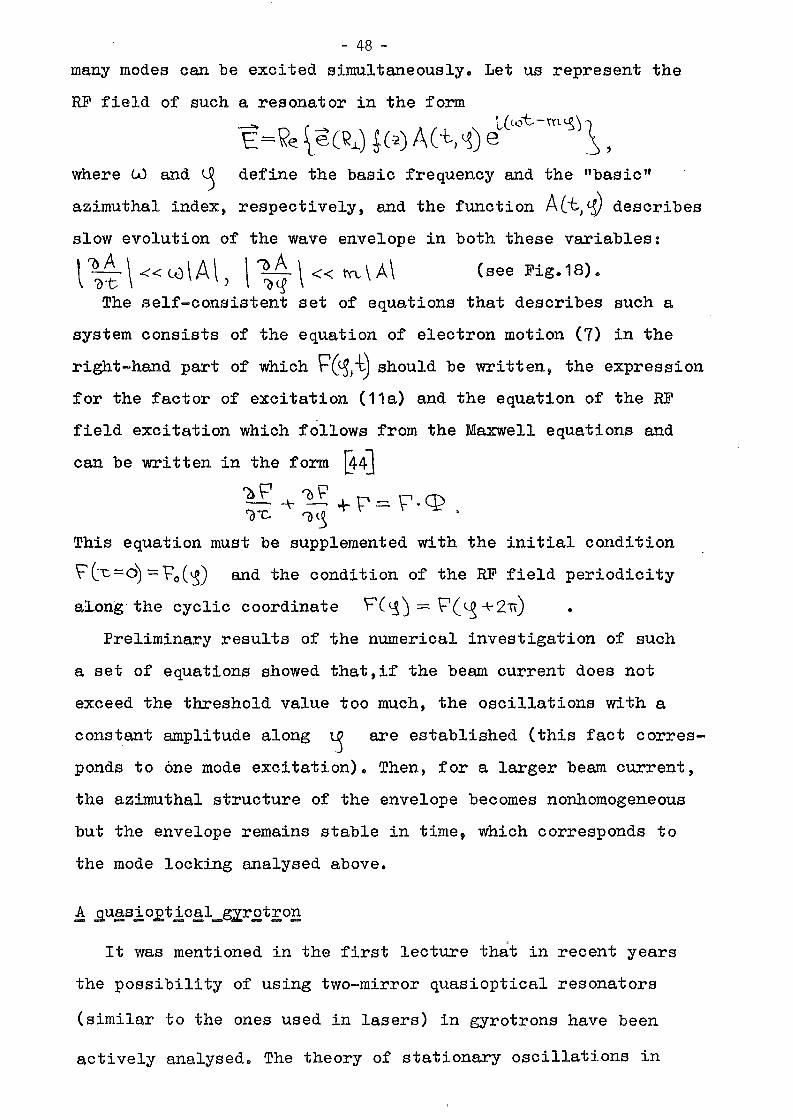
- 48 -
many modes can be excited simultaneously. Let us represent the
HF field of such a resonator in the form- L(("j't-\'n~) 1.E:= \(e l,e(\<.l) *(:~) A(-t,~) e _~ ,
where tU and ~ define the basic frequency and the "basic"
azimuthal indexJ respectivelYJ and the function A(~)~) describes
slow evolution of the wave envelope in both these variables:
,'OA \« lo\A\ \ '(jA '\« tn..\A\ (see Fig.18).\ ~·t ) ~c.g
The self-consistent set of equations that describes such a
system consists of the equation of electron motion (7) in the
right-hand part of which ~(~Ji) should be written t the expression
for the factor of excitation (11a) and the equation of the HF
field excitation which follows from the Maxwell equations and
can be wri tten in the form 8-4J~+~+r=.F.Cl?C(}'"C '0 ~ •
This equation must be supplemented with the initial condition
\='l1:=O) ~ro(~) and the condition of the HF field periodicity
al.ong' the cyclic coordinate F(~J = 'P(~ +211) •
Preliminary results of the numerical investigation of such
a set of equations showed thatJif the beam current does not
exceed the threshold value too much J the oscillations with a
constant amplitude along ~ are established (this fact corres
ponds to one mode excitation). Then J for a larger beam current J
the azimuthal structure of the envelope becomes nonhomogeneous
but the envelope remains stable in time, which corresponds to
the mode locking analysed above.
It was mentioned in the first lecture that in recent years
the possibility of using two-mirror quasioptical resonators
(similar to the ones used in lasers) in gyrotrons have been
actively analysed. The theory of stationary oscillations in

- 49 -
such quasioptical gyrotrons was developed in [6,46]. The nume
rical study of nonstationary processes in such systems with a
large number of excited modes was provided in [7J. We shall
consider here the results of investigations of similar proces
ses that were obtained using the space-time approach [47J.Let us represent the RF field of the resonator shown in
Fig.19 as a sum of two waves moving between the mirrors in the
opposite directions
We assume that alllosses of the microwave power in the resona
tor are caused by the fact that the coefficient of reflection
of the direct wave at the output mirror is different from uni
ty (R<1 ). Taking into account the above-mentioned condi
tions of the slow change of the wave envelopes in t and
along y , one cen easily reduce the Maxwell equations to the
equations of excitation of the opposite waves
?> F+ '0 Ft- A \ ~ \='- '() p- q:, \~ + 0 y~ = CI?+, ~-c - '()y =- .- .
These equations should be supplemented with the boundary
conditions \='+(Y=OJ = r-'_CY·=O), t_(Y=l'j=-R'\='+(Y=L') end the ini-, (0)
tial conditions F+- l"'t:.=O) = F± (Y) • Now we put the sum of these
two waves P+el~++ F_ et~- into the right-hand part of the
equation of electron motion (7) and replace the integration
over the resonator cross-section in the expression for the fac-1\
tor of excitation q:~ (11a) by the averaging over the diffe-
rence between the phases of the two opposite waves which varies
by 211 at the wavelength in the 'I -direction [47]. Thus
the equations obtained will be the equations averaged over a
small scale of the order of the wavelength in the y -direc
tion. Nevertheless, using these equations one can analyse the
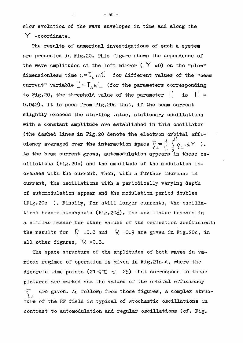
- 50 -
slow evolution of the wave envelopes in time and along the
Y -coordinate.
The results of numerical investigations of such a system
are presented in Fig.20. This figure shows the dependence of
the wave amplitudes at the left mirror ( Y =0) on the ttslowtt
dimensionless time l.-= I~ wt for different values of the "beam
current" variable L=Is KL (for the parameters corresponding
I ' \ 'to Fig.20, the threshold value of the parameter L is L =
0.042). It is seen from Fig.20a that, if the beam current
slightly exceeds the starting value, stationary oscillations
with a constant amplitude are establishedin this oscillator
(the dashed lines in Fig.20 denote the electron orbital effi-C
ciency averaged over the interaction space ~ ~ ~ tz..L ~ cA Y ).o
As the beam current grows, automodulation appears in these os-
cillations (Fig.20b) and the amplitude of the modulation in-
creases with the current. Then, with a further increase in
current, the oscillations with a periodically varying depth
of automodulation appear and the modulation period doubles
(Fig.20c ). Finally, for still larger currents, the oscilla
tions become stochastic (Fig.20d). The oscillator behaves in
a similar manner for other values of the reflection coefficient:
the results for R =0.8 and R =0.9 are giyen in Fig. 20c, in
all other figures, R =0.8.
The space structure of the amplitudes of both waves in va
rious regimes of operation is given in Fig.21a-d, where the
discrete time points (21 $; G'::;;;: 25) that correspond to these
pictures are marked and the values of the orbital efficiency
n are given. As follows from these figures, a complex strucCl..
ture of the RF field is typical of stochastic oscillations in
contrast to automodulation and regular oscillations (cf. Fig.
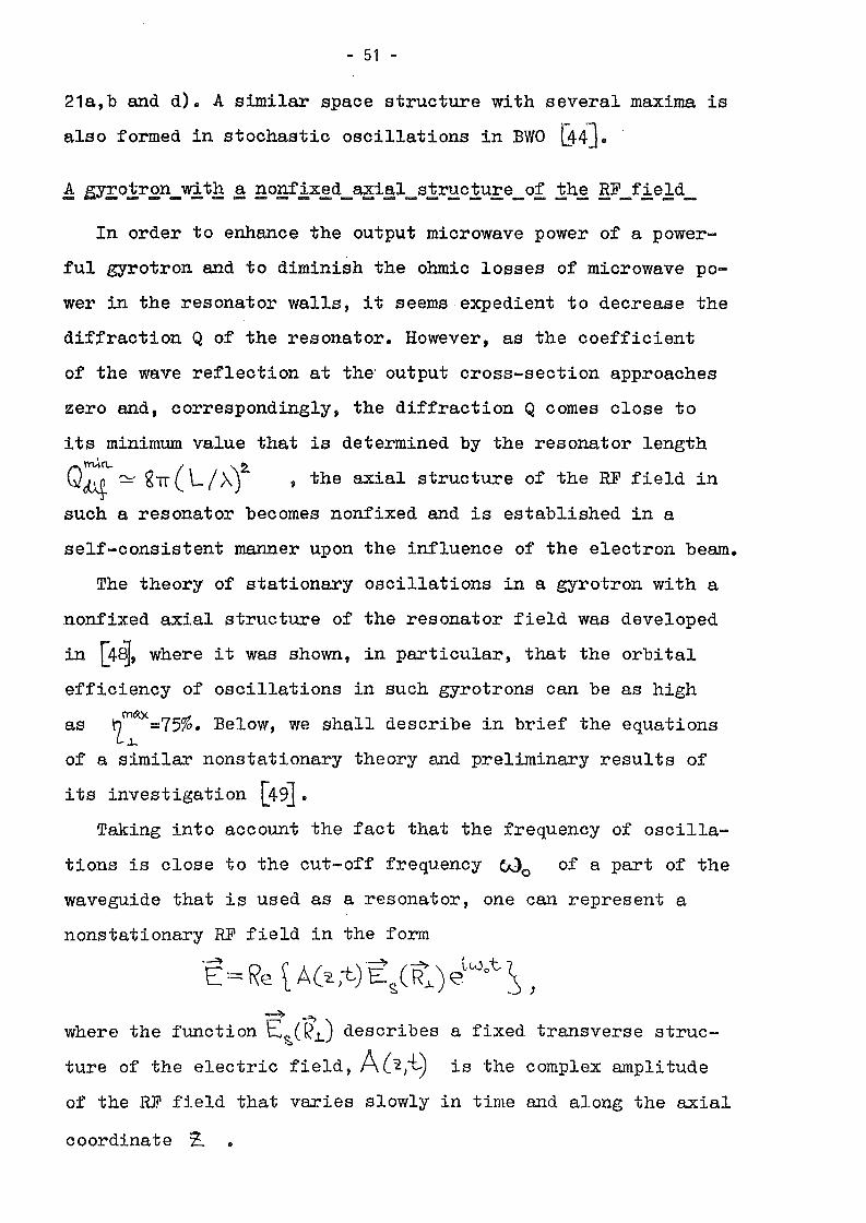
- 51 -
21a,b and d). A similar space structure with several maxima is
also formed in stochastic oscillations in BWO [44J.
In order to enhance the output microwave power of a power
ful gyrotron and to diminish the ohmic losses of microwave po
wer in the resonator walls, it seemsexpedient to decrease the
diffraction Q of the resonator. However, as the coefficient
of the wave reflection at the' output cross-section approaches
zero and, correspondingly, the diffraction Q comes close to
its minimum value that is determined by the resonator length
Q~~ glT ( LIA')2. ,the axial structure of the RF field in
such a resonator becomes nonfixed and is established in a
self-consistent manner upon the influence of the electron beam.
The theory of stationary oscillations in a gyrotron with a
nonfixed axial structure of the resonator field was developed
in [4~, where it was shown, in particular, that the orbital
efficiency of oscillations in such gyrotrons can be as highrn~}<
as ~~ =75%. Below, we shall describe in brief the equations
of a similar nonstationary theory and preliminary results of
i ts investigation [49].Taking into account the fact that the frequency of oscilla
tions is close to the cut-off frequency Wo of apart of the
waveguide that is used as a resonator, one can represent a
nonstationary RF field in the form
"E:= Re tA(~)-t}E~(R:) eLwot,~ ,
-...4 ~
where the function E~(RL) describes a fixed transverse struc-
ture of the electric field, A('l,+"') is the complex amplitude
of the RF field that varies slowly in time and along the axial
coordinate Z. •

- 52 -
by a
is a "slow" time, the beam current parame-
equation has the form
~2. ( (l I Zlf-.!. - L~ = ~ ( ~&~'Ot:,'2. ~"C 2lT ~a 0 •
to the expression given in [47J ~
, trI ~II -1I o-1b~ ,~ 12. (KR \ [(-y2._ hil.) :12.("')1tn c~ (1..6 1n..±1'l.- 0) In.
<> ,~J..
boundary conditions for the resonator that is for.medThe
-4Here L. =:~ LU tg '2. 0
I S'i\Oter 0 corresponds
Substituting this representation into the Maxwell equations
sud taking the condition of slow variation of the amplitude in
time l~~ \«co\A\ into account, one can easily obtain a pa
rabolic equation that descibes the excitation of the RF field
by the electron beam. In terms of variables of the gyrotron
theory this
of the
the form
'O~w \ =-ck r~i: ~ \\i'w •
C, -~()~is the condition of radiation
t l =0,\~=ö
Here the second condition
part of a regular waveguide with a cut-off narrowing in the in
put cross-section and whose output cross-section is deter.mined
by the ceasing of the interaction between the electrons and
the RF field due to a sharp change in the external magnetic
field, can be given in
Fourier components &~ of the resonator nonstationary field
~= r~~ e'l<.rt. ~.[(u.'-Wo)t-k,\Z.J~ ~W ,\<\,~ 2- /V::?'-l{'};' is the axi~lo
wavenumber.
Preliminary results on the study of the self-consistent
set of equations (7) and (45) are presented in Fig.22. The
calculations were carried out for C;o~=10, the negative fre
quency mismatch ß =-0.6 corresponds to the synchronism
between the electrons and the components of the RF field that
propagate in the direction opposite to the direction of the
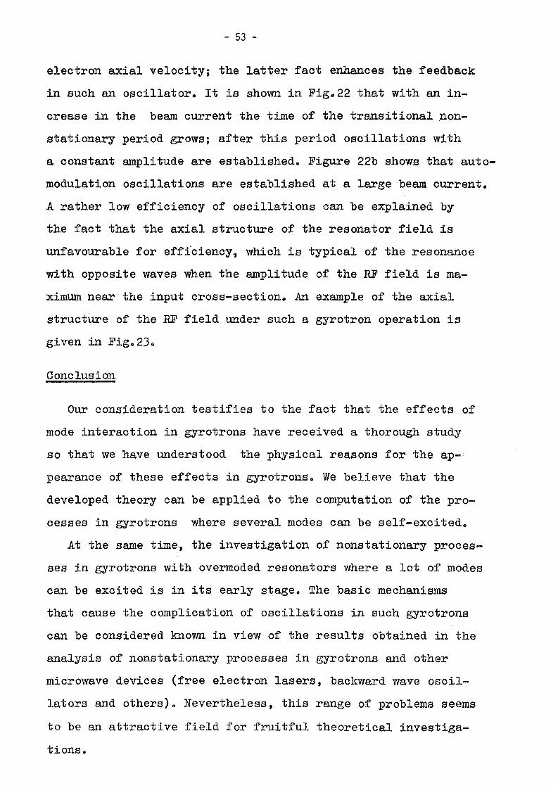
- 53 -
electron axial velocity; the latter fact enhances the feedback
in such an oscillator. It is shown in Fig.22 that with an in
crease in the beam current the time of the transitional ~on
stationary period grows; after this period oscillations with
a constant amplitude are established. Figure 22b shows that auto
modulation oscillations are established at a large beam current.
A rather low efficiency of oscillations can be explained by
the fact that the axial structure of the resonator field is
unfavourable for efficiency., which is typical of the resonance
with opposite waves when the amplitude of the RF field is ma
ximum near the input cross-section. An example of the axial
structure of the HF field under such a gyrotron operation is
given in Fig.23.
Conclusion
Our consideration testifies to the fact that the effects of
mode interaction in gyrotrons have received a thorough study
so that we have understood the physical reasons for the ap
pearance of these effects in gyrotrons. We believe that the
developed theory can be applied to the computation of the pro
cesses in gyrotrons where several modes can be self-excited.
At the same time, the investigation of nonstationary proces
ses in gyrotrons with overmoded resonators where a lot of modes
can be excited is in its early stage. The basic mechanisms
that cause the complication of oscillations in such gyrotrons
can be considered known in view of the results obtained in the
analysis of nonstationary processes in gyrotrons and other
microwave devices (free electron lasers, backward wave oscil
lators and others). Nevertheless, this range of problems seems
to be an attractive field for fruitful theoretical investiga
tions.

- 54 -
REFERENCES
1. Vlasov, S.N. et ale Radiophysies end Quantum Eleetronics,
1969, ~, 8, 972.
2. Vlasov, S.N., Zagryadskaya, L.N., and Orlova, I.M. Radiotekh
nika i Elektronika, 1976, ~, 7, 1485.
3. Antakov, 1.1. et ale Elektronnaya Tekhnika, Ser.1, Elektronika
SVCh, 1975, N8,20.
4. Luehinin, A.G. end Nusinovieh, G.S. Elektronnaya Tekhnika,
Ser.1, Elektronika SVCh, 1975, N11, 26.
5. Vainstein, L.A. Open Resonators and Open Waveguides, translated
by P.Beekmann, Boulder: Golem Press, 1969.
6. Sprangle, P., Vomvoridis, J.L., end Manheimer, W.M. Phys. Rev. A,
1981, ,g]" 3127.
7. Bondeson, A. et ale Int. J. Eleetronies, 1982, 53, 6, 547.
8. Carmel, Y et al. Phys. Rev. Lett. , 1983, .2.2, 2, 112.
9. Zapevalov, V.E. et ale X All-Union Conf. on Mierowave Eleetro-
nies, Conf. Digest, Minsk, USSR, 1983, p.12.
10. Gaponov, A.V., Petelin, M.I., and Yulpatov, V.K. Radiophysies
and Quantum Eleetronies, 1967, jQ, 9-10, 794.
11. Flyagin, V.A. et ale IEEE-MTT, 1977, MTT-25, 6, 514.
12. Moiseev, M.A. end Nusinovieh, G.S. Radiophysies and Quantum
Eleetronies, 1974, 17, 11, 1305.
13. Nus inovich, G.S. Int. J. Eleetronics, 1981, 21, 4, 457.
14. Van-der-Pol, B. Phyle Mag., 1922, il, 700.
15. Andronov, A.A. and Vitt, A.A. ZhTP, 1934, i, 1, 122.
16. Skibarko, A.P. and Strelkov, S.P. 1934, i, 1, 158.
17. Lamb, W.E. Phys. Rev. A, 1964, lli, 6a, 1429.
18. Vainstein, L.A. In: High Power Eleetronics, ed. by Nauka,
Moscow, 1969, v.6, 84.

- 55 -
19. Vainstein, L.A. and Solntsev, B.A. Leetures on Mierowave
Eleetronies, ed. by Soviet Radio, Moseow, 1972.
20. Nusinovieh, G.S. In: Gyrotron, ed. by the Institute of Appl.
Phys. Aead. Sei. of the USSR, Gorky, 1981, 146.
21. Kurayev, A.A. Mierowave Deviees with Periodieal Eleetron
Beams, Minsk, USSR, 1971.
22. Moiseev, M.A. and Nusinovieh, G.S. In: Gyrotron, ed. by the
Institute of Appl. Phys. Aead. Sei. of the USSR, Gorky, 1981, 41.
23. Zarnitsyna, I.G. and Nusinovieh, G.S. Radiophysies and Quantum
Eleetronies, 1974, 17, 12, 1418.
24. Nusinovieh, G.S. and Zapevalov, V.E. Radiotekhnika i Elektronika,
1984, ~, 11.
25. Flyagin, V.A. and Nusinovieh, G.S. Report at the 8th Int. Conf.
on Infrared and Millimeter Waves, Miami Beaeh, Florida, USA,
Dee. 1983, Infrared and Millimeter Waves, ed. by,Aeademie Press,
v.13, 1985.
26. Nusinovieh, G.S. Elektronnaya Tekhnika, Ser.1, Elektronika SVCh,
1974, 3, 44.
27. Kreiseher, K.E. and Temkin, R.J. Int. J. Infrared and Milli
meter Waves, 1981, ~, 2, 175.
28. Petelin, M.I. and Yulpatov, V.K. Radiophysies and Quantum
Electronies, 1975, 18, 2, 212.
29. Petelin, M.I. In: Gyrotron, ed. by the Institute of Appl. Phys.
Acad. Sei. of the USSR, Gorky, 1981, 5.
30. Jory, H.R. Report at the 4th Int. Symp. on Heating in Toroidal
Plasmas, Rome, Italy, Mareh 1984.
31. Zapevalov, V.E., Korablev, G.S., and Tsimring, Sh.E. Radio
tekhnika i Elektronika, 1977, ~, 8, 1661.
32. Gol'denberg, A.L. and Petelin, M.I. Radiophysics and Quantum
Eleetronics, 1973, 12, 1, 106.
33. Tsimring, Sh.E. Radiophysies and Quantum Eleetronies, 1972, 15,
8, 952.

- 56 -
34. Nusinovich t G.S. and Erm t R.E. Elektronnaya Tekhnika, Ser.1,
Elektronika SVCh, 1972, 8, 55.
35. Flyagin, V.A., Gol'denberg, A.L., and Nusinovich, G.S. Infrared
and Millimeter Waves, ed. by Academic Press, v.11, 1984.
36. Zarnitsyna, I.G. and Nusinovich, G.S. Radiophysics and Quantum
Electronics, 1975 t .1§t 2t· 223.
37. Nusinovich t G.S. Radiophysics and Quantum Electronics, 1976 t
.12t 12, 1301.
38. Smith, J.M. Models in Ecology, Cambridge University Press, 1974.
39. Zapevalov t V.E. and Nusinovich, G.S. Izv. VUZov, Radiofizika,
1984, 27, 1, 117;-Nusinovich, G.S. In: Infrared and Millimeter Waves, ed. by
Academic Press, 1984 t v.11.
40. Kreischer, K.E. et ale Plasma Fusion Center, MIT, USA, PFC/JA
-82-34, Dec. 1982.
41. Zarnitsyna, I.G. and Nusinovich, G.S. Radiophysics and Quantum
Electronics, 1977, 20, 3, 313.-42. Rabinovich, M.I. and Fabrikant t A.L. ZhETP, 1979, 77, 2, 617.
43. Bogomolov, Ya.L. et ale Optics Commun., 1979, 32, 3 t 209.-44. Ginzburg, N.S., Kuznetsov, S.P., and Fedoseeva, T.N. Izv. VUZov,
Radiofizika, 1978, 21, 7 t 1037.
45. Petelin, M.I. In: Gyrotron, ed. by the Institute of Appl. Phys.
Acad. Sci. of the USSR, Gorky, 1981, 77.
46. Zarnitsyna, I.G. and Nusinovich, G.S. Radiotekhnika i Elektro
nika, 1978, 23, 6, 1212.-47. Nusinovich t G.S. and Sher, E.M. Int. J. Elec'bronics, 1984, 56,
3, 275.
48. Bratman t V.L., Moiseev, M.A., Petelin, M.I., and Erm, R.E.
Radiophysics end Quantum Electronics, 1973, 16, 4, 474.
49. Ginzburg, N.S., ZavolskYt N.A., Nusinovich, G.S., and Sergeev,A.A.
Radiophysics end Quantum Electronics (to be published in 1985,28).
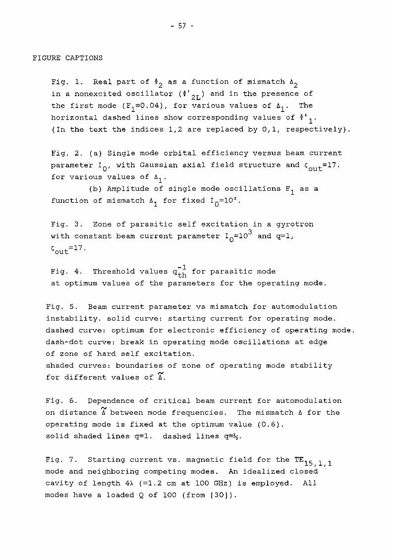
- 57 -
FIGURE CAPTIONS
Fig. 1. Real part of ~2 as a function of mismatch ~2
in a nonexcited oscillator (~'2L) and in the presence of
the first mode (F1=0.04), for various values of ~1' The
horizontal dashed lines show corresponding values of ~'1'
(In the text the indices 1,2 are replaced by 0,1, respectively).
Fig. 2. (a) Single mode orbital efficiency versus beam current
parameter I O' with Gaussian axial field structure and ~out=17.
for various values of ~1'
(b) Amplitude of single mode oscillations F1 as a
function of mismatch ~1 for fixed I O=10 3•
Fig. 3. Zone of parasitic self excitation in a gyrotron
with constant beam current parameter I O=103 and q=l,
~out=17.
Fig. 4. Threshold values q~~ for parasitic mode
at optimum values of the parameters for the operating mode.
Fig. 5. Beam current parameter vs mismatch for automodulation
instabi1ity. solid curve: starting current for operating mode.
dashed curve: optimum for electronic efficiency of operating mode.
dash-dot curve: break in operating mode oscillations at edge
of zone of hard self excitation.
shaded curves: boundaries of zone of operating mode stability. ,..,
for dlfferent values of ~.
Fig. 6. Dependence of critical beam current for automodulation
'"on distance ~ between mode frequencies. The mismatch ~ for the
operating mode is fixed at the optimum value (0.6).
solid shaded lines q=l. dashed lines q=~.
Fig. 7. Starting current vs. magnetic field for the TE 15 ,l,l
mode and neighboring competing modes. An idealized closed
cavity of length 4A (=1.2 cm at 100 GHz) is employed. All
modes have a loaded Q of 100 (from [30]).

- 58 -
Fig. 8. self exeitation zones (solid eurve) and voltage
trajeetories (dashed eurves) of modes resonant with the
fundamental eyelotron harmonie for parameters I O' ~out'
6 =0.4 eorresponding to the maximum eleetronie effieieneyopin the plane x=~ßl ,y=~ß2 . The shaded region eorresponds to
self exeitation of the operating mode. Trajeetory I: equal
voltages at anode and resonator. Trajeetory II: eonstant voltage
differenee between anode and resonator. (a): eompeting modes
weIl separated from operating mode; (b) denser frequeney
speetrum of eompeting modes.
Fig. 9. Starting eurrent vs resonator voltage with equal voltage
pulses at anode and resonator for the TE 15 ,1,1 mode.
Fig. 10~ Phase portrait of oseillator. (a) strong eoupling
between modes. (b) weak eoupling between modes.
Fig. 11. (a) Real parts of the eoeffieients
angle 0=6~ t for a uniform field profile.ou(b) Real parts of the eoeffieients
for different values of the ratio K=0 ,/0 .s s
tt, ß versus transit
o ,versus 0ss s
Fig. 12. Lines of eonstant values of ~=o~20~1/ß~ß~ in
the plane of transit angles 0 =6 ~ t' s=1,2.s s ou
Fig. 13. Nonstationary proeesses in a gyrotron for three
different values of the beam eurrent, showing support of
parasitie mode at very large eurrents.
Fig. 14. Field of parasitie self exeitation in the plane of~
mismatches 61 , 6 in a nonexeited oseillator (dashed lines)
and in a gyrotron with oseillation amplitude F1 +0 (shaded)
b) I/Imin =1.2, 6=0;st
d) I/Imin =1.3, 6=Ojst
f) I/Imin =3.0, 6=1;st
- 59 -
Fig. 15. Real (solid) and imaginary (dashed) parts of the
coefficients ~s for a three ~ode gyrotron as a function of
transit angle 82 for three values of 6=(w2 -w1 )/(w2 -wH )o
(mode 2 is the central mode) and constant field profile.
(a) s=l j (b) s=2; (c) s=3
Fig. 16. Dependence of the coefficients 0 ,and ß onss stransit angle 82 for different values of the ratio K=8 s ,/8 s '
Fig. 17. Amplitude and phase time evolution in a three modemingyrotron with relation between modes. a) I/Ist =1.1, 6=Oj
c) I/Imin =1.25, 6=0;st
e) I/Imin =3.0, 6=Ojst
g) I/Imin =3.0, 6=2.st
Fig. 18. Cross section of a CRM showing rotating wave envelope
A defined in lecture 4.
Fig. 19. Cross section of a CRM with counter-rotating waves in
plane geometry.
Fig. 20. Time dependence of the wave amplitude at the left
mirror for various values of the beam current variable.
Fig. 21. Spatial structure of both opposite waves at fixed
moments in time t=Iwt for various values of the beam current
variable.
rig. 22. Time dependence of efficiency for various values of
beam current parameter with =-0.6 and ~ t=10.ou(a) 1=0.01, 0.02 and 0.04, showing the increase in duration
of the nonstationary phase with increasing beam current.
(b) 1=0.1, showing the onset of automodulation oscillations.
Fig. 23. Axial structure of resonator field at large values of
the beam current parameter.
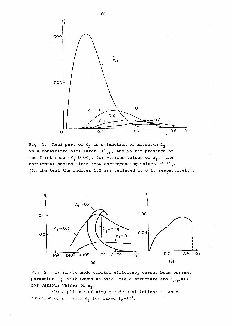
- 60 -I
lf>2
0.1
1\,
lf>2L
1000
500
o 0.2 0.4
-- 0.2
0.6
Fig. 1. Real part of ~2 as a function of mismatch A2in a nonexcited osci~lator (i'2L) and in the presence of
the first mode (F1=O,04), for various values of Al. The
horizontal d~shed lines show corresponding values of ~'1.
(In the text the indices 1,2 are replaced by 0,1, respectively).
0.4
0.2
(0)
0.08
0.04
0.2
(b)
0.4 61
Fig. 2. (a) Single mode orbital efficiency versus beam current
parameter 10, with Gaussian axial field structure and ~out=17.
for various values of Al'(b) Amplitude of single mode oscillations F1 as a
function of mismatch Al for fixed 10=10 3,

- 61 -
zone of oscil1ations I~--------ot the operating mode~
. Aort
Fig. 3. Zone of parasitic self excitation in a gyrotron
with constant beam current parameter I O=103 and q=1,
'out=17.
-02I
DA
0,2
o f1
Fig. 4. Threshold values q~~ for parasitic mode
at optimum values of the parameters for the operating mode.

- 62 -
02I
01I
o0,2 O~
I 0,6
Fig. 5. Beam current parameter vs mismatch for automodulation
instability. solid curve: starting current for operating mode.
dashed curve: optimum for electronic efficiency of operating mode.
dash-dot curve: break in operating mode oscillations at edge
of zone of hard self excitation.
shaded curves: boundaries of zone of operating mode stability. ,...,
for dlfferent values of 6.

- 63 -
11.1opi
6
2
o 04l
Fig. 6. Dependence of critical beam current for automodulation
on distance Tbetween mode frequencies. The mismatch Ä for the
operating mode is fixea at the optimum value (0.6).
solid shaded lines q=l. dashed lines q=~.
100 r-r--.,.---r--r;;:----,:-----.,.----.-----,
90
80
~ 70
...~ Wa:~ 50uClzi=a::<t;
v • 50 kV
Q • 2.0
L • 4>', SIN CAVITY
0L· 100
10
4.143.7 3.8 3.9
MAGNETIC FIELD (TESLA)
3.6
O'--__-L..__---L. '--__-'-__--'-__--'
3.5
Fig. 7. Starting current vs. magnetic field for the TE1S ,1,1
mode and neighboring competing modes. An idealized closed
cavity of length 4A (=1.2 cm at 100 GHz) is employed. All
modes have a loaded Q of 100 (from [30]).
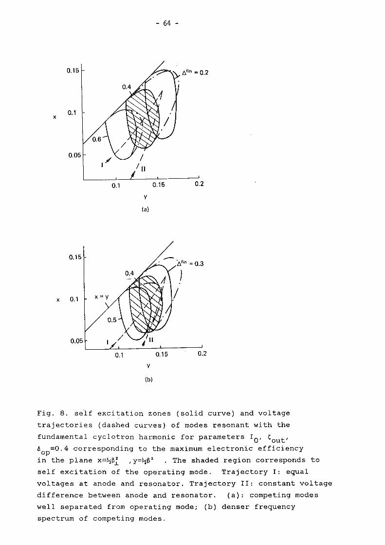
- 64 -
0.15
0.1x
0.05
0.15
x 0.1
0.05
0.1
0.1
y
(a)
y
(b)
0.15 0.2
t}in = 0.3
0.2
Fig. 8. setf exeitation zones (solid eurve) and voltage
trajeetories (dashed eurves) of modes re sonant with the
fundamental eyelotron harmonie for parameters I O' 'out'
6 =0.4 eorresponding to the maximum eleetronie effieieneyopin the plane x=~ßl ,y=~ß2 . The shaded region eorresponds to
self exeitation of the operating mode. Trajeetory I: equal
voltages at anode and resonator. Trajeetory II: eonstant voltage
differenee between anode and resonator. (a): eompeting modes
weil separated from operating mode; (b) denser frequeney
speetrum of eompeting modes.
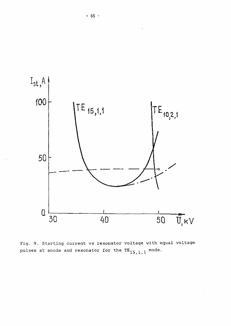
- 65 -
iOOTE 15 11
) )
50-- /'
U)KV50~o
Q~---_.....L.- ---L- ____
30
Fig. 9. Starting current vs resonator voltage with equal voltage
pulses at anode and resonator for the TE 15 / 1 / 1 mode.

- 66 -
a
Fig. 10. Phase portrait of oscillator. (a) strong coupling
between modes. (b) weak coupling between modes.

- 67 -
(0)
0.5
(b)
8
Fig. 11. (a) Real parts of the coefficients
angle 0=ßC t for a uniform field profile.ou(b) Real parts of the coefficients
for different values of the ratio K=0 ./0 .s s
a, ß versus transit
o , versus 0ss s
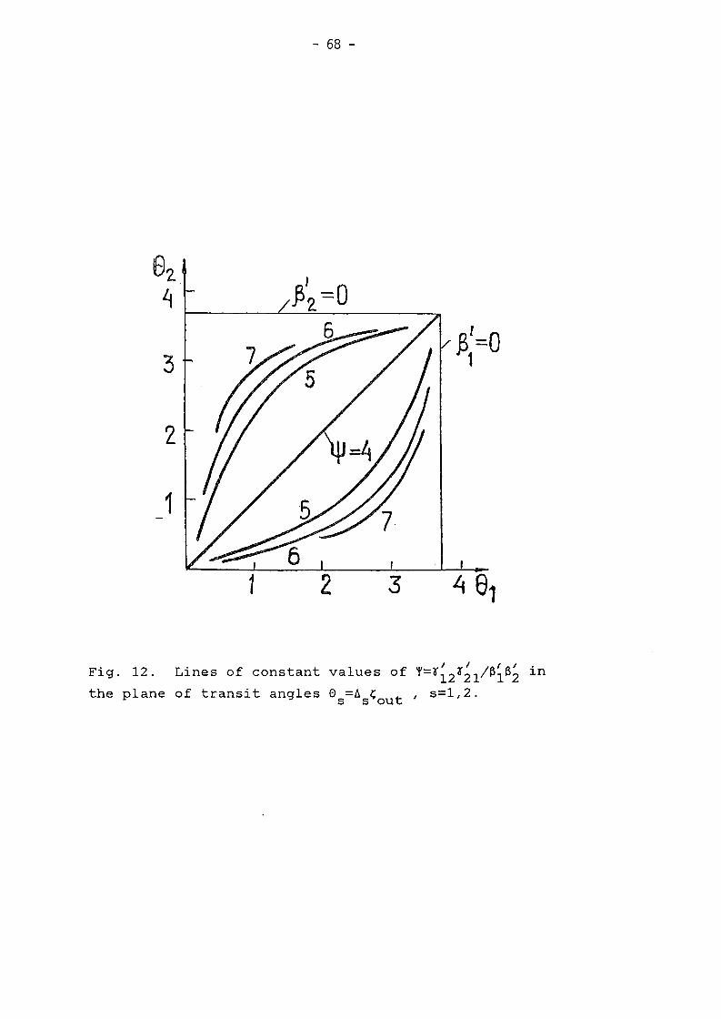
- 68 -
3
2
1
3
I I I IFig. 12. Lines of constant values of f=r12r21/ß1ßZ in
the plane of transit angles 0 =ß ~ t' s=1,2.s s ou
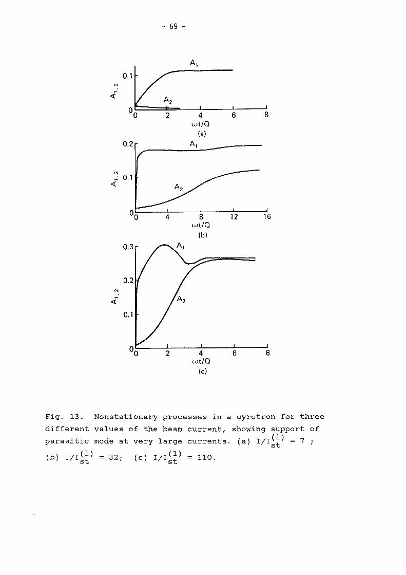
- 69 -
Al
0.1N
-<t:
2 4 6 8wt/O
(al0.2 Al
N_ 0.1<t:
4 8wt/O
(bI
0.3
0.2
0.1
2 4wt/O
(cl
6
Fig. 13. Nonstationary processes in a gyrotron for three
different values of the beam current, showing support of
parasitic mode at very large currents. (a) I/I~~) = 7 ;
(b) I/I~~) = 32; (c) 1/1(1) = 110.st

- 70 -
0,2
o
- 0,2
Fig. 14. Field of parasitic self excitation in the plane ofrJ
mismatches 61 , 6 in a nonexcited oscillator (dashed lines)
and in a gyrotron with oscillation amplitude F1 +0 (shaded)

SI,I! -3'iQ'l.
ö~O,75
- 3 l.o.rt: I
. 'l.~I,~I -'. in
0,0
2. 1.c..t. I
0,6 t X' O,~'\- 5t
O,L
0/1\\
~u.~
4 8
\
/ /3/
0,2 r / \
0 1 .'11 '2.1\
\
\ I .\ I I
\~ eI' I
\2 3
- O.?
0i \
-\ 0'=0751/ ,
S2. ~ / 0,5
/// I
- 0,1 r
- 0~
~ /f 015
- 0:6 1 I '-J
~ /,/ ,~....._~"--,-
e0,75--
..--"/' ...... 0 2.5
/ '/ ,..,-- 0,5
/ .// /
o~O,25
0.1
o
- 0,5
-M
- 0,'2.
-e1,1I -j 'l-Si· \'out~O
a b c
Fig. 15. Real (solid) and imaginary (dashed) parts of the
coefficients ~s for a three mode gyrotron as a function of
transit angle 02 for three values of ö=(w2 -w1 )/(w2 -wH )o
(mode 2 is the central mode) and constant field prof1le.
(a) s=l; (b) s=2; (c) s=3

- 72 -
0,5
o
-05)
Fig. 16. Dependence of the coefficients r ,and ß onss stransit angle O
2for different values of the ratio K=0 ,/0 .s s
e

- 73 -
'V, F. (d)
Fa (0)8=0
0.3 F,'0
0.2 -10
0.1 -20
-30100 200 300 r
~, F,,2 (b)
~, F, (e)0 " F,
-100.3-..........
0F3...........
...........-20 0.2 .......... ~ F,
0.1 -10 10-1
0 100 200 300
~, F. (c)
100 200 300 rF,
0 'V, F. (fl
10-1 F3 F2-'V_.-F340
30F,
-80 mln
10-3 20 10-1 111., = 3, 8 = 1
-120............
10...........
10-4...........
200 400 600 800 1000 1200 r 20 40 60 T
~, F. (g)F2
._._'V80
F,~O
40 10-1
208=2
20 40 60 r
b) I/Imin =1.2, 0=0;st
d) I/Imin =1.3, 0=0;st
f) I/Imin =3.0, 0=1;st
Fig. 17. Amplitude and phase time evolution in a three modemin
gyrotron with relation between modes. a) I/Ist =1.1, 0=0;
c) I/Imin =1.25, 0=0;st
e) I/I:~n =3.0, 0=0;
g) I/Imin =3.0, 0=2.st

- 74 -
-----: '~" "'-
'"\\I
//
~
Fig. 18. Cross section of a CRM showing rotating wave envelope
A defined in lecture 4.
R=1
Wave envelopes
------ ""~~
X
h\
ElectronsZ y
Outputradiation/--.........
R< 1
Fig. 19. Cross section of a CRM with counter-rotating waves in
plane geometry.
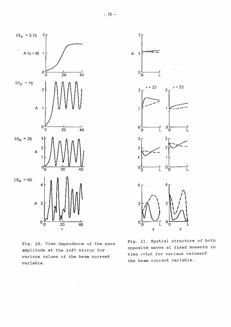
- 75 -
Ill st '" 3.75 2 2
A (y = 0) 1
20 40
A
L
A2
40
A
IIl st ::>: 15
fll st ::>: 25 3
fll st = 604
T
4
2
y
4
r,\ "\2 , I ,\ I ,\.1 ,
\
Fig. 20. Time dependence of the wave
amplitude at the left mirror for
various values of the beam current
variable.
Fig. 21. Spatial structure of both
opposite waves at fixed moments in
time t=Iwt for various valuesof
the beam current variable.
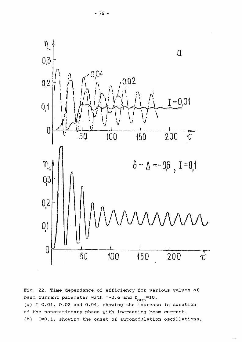
- 76 -
.,{. .\
0,2 i I ~\iJl
0,1 i ~ \.1,
o ~!150
r~,
•\
a
1=0,01
028
01I
o,.,.----.1.-_--1.-__---1-_---:.-1.- ,
50 100 150 200 17
Fig. 22. Time dependence of efficiency for various values of
beam current parameter with =-0.6 and ~ t=10.ou(a) I=O.Ol, 0.02 and 0.04, showing the increase in duration
of the nonstationary phase with increasing beam current.
(b) 1=0.1, showing the onset of automodulation oscillations.

- 77 -
\f \
0,05
I =01 1:'=200o I'
I =0.01, 'C=100
Fig. 23. Axial structure of resonator field at large values of
the beam current parameter.