Nanogenomics and Nanoproteomics Enabling Personalized, Predictive and Preventive Medicine

TinyWifi: Enabling Linux
Platform Support in TinyOS
Bachelor Thesis
Bernhard Kirchen
RWTH Aachen University, Germany
Chair for Communication and Distributed Systems
Advisors:
Muhammad Hamad Alizai M.Sc.Prof. Dr.-Ing. Klaus Wehrle
Prof. Dr.-Ing. Stefan Kowalewski
Registration date: 2010-05-21Submission date: 2010-10-08

I hereby affirm that I composed this work independently and used no other than thespecified sources and tools and that I marked all quotes as such.
Ich erklare hiermit, dass ich die vorliegende Arbeit selbstandig verfasst und keineanderen als die angegebenen Quellen und Hilfsmittel verwendet habe.
Aachen, 20th Sep. 2010
(Bernhard Kirchen)

Abstract
We present TinyWifi, a new platform for TinyOS – the de facto standard operatingsystem for sensornets. Although TinyOS is originally designed for use in wirelessembedded sensor nodes, TinyWifi allows for compiling TinyOS applications for Linuxdriven devices like PCs and handhelds. Our TinyWifi (pseudo-)platform integratesseamlessly into the existing TinyOS code base and enables TinyOS users to run theirapplications directly on Linux without the need to alter the original software.
The primary objective of TinyWifi is to be able to use communication protocols inIEEE 802.11 wireless mesh networks originally developed for inherently similar sen-sornets. By featuring direct execution of unaltered TinyOS applications, especiallyfor the purpose of evaluation, TinyWifi saves any re-implementation effort of thedeveloper. Particularly, we will use TinyWifi to compare protocols developed forsensornets with standard protocols used with wireless Linux driven devices.
Kurzfassung
Wir stellen TinyWifi vor, eine neue Platform fur TinyOS, dem Standard Betrieb-ssystem fur Sensornetze. Obwohl TinyOS fur den Einsatz in eingebetteten Syste-men entwickelt wurde, erlaubt es TinyWifi, existierende TinyOS Software fur Linuxbasierte Gerate wie PCs oder Handhelds zu kompilieren. Unsere TinyWifi (Pseudo-)Plattform passt sich nahtlos in das existierende TinyOS Codegerust ein und erlaubtes TinyOS-Benutzern, Programme unmittelbar auf Linux auszufuhren, ohne Veran-derungen an der ursprunglichen Software vornehmen zu mussen.
Der primare Verwendungszweck von TinyWifi lautet, die Benutzung von Sensornetz-Kommunikationsprotokollen in drahtlosen vermaschten Netzwerken (wireless meshnetworks) nach IEEE 802.11 Standard zu ermoglichen. Dies ist generell praktikabel,da sich Sensornetze und Wi-Fi-Netzwerke grundsatzlich ahneln. Der Aufwand zurNeuimplementierung insbesondere zwecks Evaluierung in Wi-Fi-Netzwerken wirddurch die Moglichkeit, bestehende TinyOS-Anwendungen ohne Veranderungen un-mittelbar unter Linux auszufuhren, eliminiert. Insbesondere werden wir TinyWifidazu nutzen, um Protokolle aus dem Bereich der Sensornetze mit in Wi-Fi-Netzeneingesetzten Standardprotokollen zu vergleichen.

Acknowledgements
Thanks to my primary supervisor Muhammad Hamad Alizai M.Sc., I had the chanceto choose a really interesting thesis to work on with enthusiasm and commitment.The support he gave me was essential to find the right starting points, conquer alldifficulties and to push through to the completion of this thesis. It is mainly becauseof him that I will be part of a reputable conference on sensor networks, which suffusesme with pride. I appreciate his open-door mentality and general kindness very muchand I am looking forward to work with him beyond this thesis.
It is due to Prof. Dr.-Ing. Klaus Wehrle, our respected professor, that there is sucha great research group at the RWTH University Aachen. Exciting research fields, asupportive and kind team, open-mindedness and a superb working atmosphere makethe ComSys group stand out. I am thankful he supports this thesis and gave me theopportunity to write it at ComSys. It is also very much appreciated that he enablesme to stick to the ComSys group as a HiWi to futher promote TinyWifi.
Beyond said people I would like to express my thanks to my second examiner, Prof.Dr.-Ing. Stefan Kowalewski, respected professor of the embedded systems group atthe RWTH University Aachen, for taking the time to grade my thesis.
Because writing always requires a lot of effort and one likely fails to do it good inthe first place, I am very glad for any feedback I received from friends of mine.
Finally, thank you, dear reader, for being interested and reading my thesis!


Contents
1 Introduction 1
2 Background and Related Work 3
2.1 Wireless Sensor Network Devices . . . . . . . . . . . . . . . . . . . . 3
2.1.1 Use Cases . . . . . . . . . . . . . . . . . . . . . . . . . . . . . 3
2.1.2 Basic Mote Hardware . . . . . . . . . . . . . . . . . . . . . . . 4
2.1.3 Mote Communication . . . . . . . . . . . . . . . . . . . . . . . 6
2.2 Sensornets versus Wireless Mesh Networks . . . . . . . . . . . . . . . 7
2.3 The TinyOS Open-Source Operating System . . . . . . . . . . . . . . 7
2.3.1 Driving Features of TinyOS . . . . . . . . . . . . . . . . . . . 8
2.3.2 Components and Interfaces . . . . . . . . . . . . . . . . . . . 8
2.3.3 TinyOS Hardware Abstraction Architecture . . . . . . . . . . 9
2.4 Network Communication and Timing in Linux . . . . . . . . . . . . . 10
2.4.1 Sockets in Linux . . . . . . . . . . . . . . . . . . . . . . . . . 11
2.4.2 Timing for Linux Processes . . . . . . . . . . . . . . . . . . . 11
3 Design 13
3.1 Hard and Soft Requirements . . . . . . . . . . . . . . . . . . . . . . . 13
3.2 TinyWifi Architecture . . . . . . . . . . . . . . . . . . . . . . . . . . 14
3.3 Counters, Alarms and Timers . . . . . . . . . . . . . . . . . . . . . . 16
3.4 Split-Phase Operations . . . . . . . . . . . . . . . . . . . . . . . . . . 17
3.5 Radio Communication . . . . . . . . . . . . . . . . . . . . . . . . . . 18
3.6 Serial Communication . . . . . . . . . . . . . . . . . . . . . . . . . . 19
3.7 Sensors . . . . . . . . . . . . . . . . . . . . . . . . . . . . . . . . . . . 20
4 Implementation 21
4.1 Build System . . . . . . . . . . . . . . . . . . . . . . . . . . . . . . . 21
4.2 TinyOS Outputs and Local Messages . . . . . . . . . . . . . . . . . . 22
4.2.1 Virtual LEDs . . . . . . . . . . . . . . . . . . . . . . . . . . . 23
4.2.2 Error Handling . . . . . . . . . . . . . . . . . . . . . . . . . . 23
4.3 Counters, Alarms and Timers . . . . . . . . . . . . . . . . . . . . . . 24
4.4 Split-Phase Operations . . . . . . . . . . . . . . . . . . . . . . . . . . 26
4.4.1 Split-Phase Operations Using Threads . . . . . . . . . . . . . 26
4.4.2 Impact of Threads on TinyOS Scheduler . . . . . . . . . . . . 27
4.5 Radio Communication . . . . . . . . . . . . . . . . . . . . . . . . . . 28
4.5.1 Communication Setup . . . . . . . . . . . . . . . . . . . . . . 29
4.5.2 Receiving Radio Messages . . . . . . . . . . . . . . . . . . . . 30
4.5.3 Sending Radio Messages . . . . . . . . . . . . . . . . . . . . . 30
4.6 Serial Communication . . . . . . . . . . . . . . . . . . . . . . . . . . 31
4.7 Sensors . . . . . . . . . . . . . . . . . . . . . . . . . . . . . . . . . . . 32
5 Evaluation 33
5.1 Proof of Concept and Portability . . . . . . . . . . . . . . . . . . . . 33
5.2 Timing and Sensing . . . . . . . . . . . . . . . . . . . . . . . . . . . . 34
5.3 Serial Communication . . . . . . . . . . . . . . . . . . . . . . . . . . 35
5.4 Wireless Communication . . . . . . . . . . . . . . . . . . . . . . . . . 36
5.5 Multihop Communication . . . . . . . . . . . . . . . . . . . . . . . . 36
6 Conclusion 39
6.1 Future Work . . . . . . . . . . . . . . . . . . . . . . . . . . . . . . . . 39
Bibliography 41
List of Figures 43
A TinyWifi Source Code Compact Disc 45

1Introduction
In this thesis we introduce TinyWifi, a new platform for the popular open-source op-erating system TinyOS [7], allowing to run TinyOS applications on Linux driven hostdevices. TinyOS is designed for use with wireless embedded nodes. A large commu-nity uses TinyOS to develop and evaluate applications and protocols in sensornets.It features a component-based architecture to provide a highly flexible frameworkwhile minimizing code size to support severely resource constrained devices. Whileproviding any important functionality like communication protocols, schedulers andpower management, TinyOS already supports more than a dozen different hardwareplatforms and numerous sensor boards [12].
We developed TinyWifi to be a new software based platform, which integrates seam-lessly into the unmodified TinyOS programming environment. Existing TinyOS codeand functionality is preserved and reused to a reasonable extend. By compiling forthe new TinyWifi platform, developers are enabled to use their software on currentLinux driven devices like PCs, routers, handhelds and mobile phones. TinyWifi codeaims to be portable among different Linux derivatives in order to allow for a widerange of usable target devices.
While Wi-Fi networks and sensornets distinguish from one another in their appli-cations and in the kind of participating devices, they share a significant amount ofsimilarity. Wireless communication within the 2.4 GHz frequency band is used inboth domains. Due to physical influences and radio wave interferences, routing pathsin both kind of networks are highly dynamic and links between nodes are bursty. Inboth domains, the logical topology is a mesh network in which each and every nodecan only communicate data to nodes in its radio range. Hence most algorithms andprotocols used in the sensornet domain are equally applicable in Wi-Fi networks andvice versa.
Nevertheless, building and evaluating new software for a second network domainrequires a disproportionate amount of additonal implementation effort. On this ac-count, evaluation and utilization of state-of-the-art sensornet mechanisms in the akin

2 1. Introduction
Wi-Fi domain is omitted in most cases. However, researchers implicitly expect theirresults to be applicable in the other domain as well [3, 8, 13]. That is why the majorconcept of TinyWifi is twofold: We want to (1) provide a powerful platform thatallows for compiling TinyOS applications for Linux driven host devices while (2)eliminating the need to alter or re-implement any of the exisiting TinyOS applica-tions. This way we extend the applicability of sensornet protocols to the inherentlysimilar Wi-Fi domain.
Resource rich devices like PCs or routers can handle much more information at atime than deeply embedded microcontroller powered systems. We exploit the su-perior processing capabilities of TinyWifi host devices to advance TinyOS softwarewherever sensible. Certainly, we designed TinyWifi to be accurate and behave equiv-alent to other TinyOS platforms at the same time.
The TinyWifi code base extends the TinyOS source files tree to allow for integratingTinyWifi easily into an existing local working copy of TinyOS. Applications forLinux are compiled by issuing“make tinywifi”, similar to“make <platform>”withother platforms. The nesC intermediate compiler produces a C source code filethat is compiled to an executable binary by the locally installed GNU C compiler.TinyWifi features setting a node ID via an additional command line parameterwhen compiling. Cross-compiling TinyWifi binaries for Linux driven devices with adifferent architecture than the compiling host computer is basically possible.
In line with the primary purpose of TinyWifi, the most important components arewireless networking for communication (radio ActiveMessaging) and timing capabil-ities. Having these two components available, simple but meaningful applicationscan be developed. TinyWifi uses Linux sockets and pthreads to communicate data inthe TinyOS split-phase fashion, while all timing capabilities of TinyOS are derivedfrom a single realtime Linux timer.
Nevertheless, TinyWifi supports all important hardware independent TinyOS func-tionality as well. Among those are LEDs, serial ActiveMessaging and sensing. Weprovide displaying the node’s virtual LEDs via console output. This is importantsince the LEDs are the obvious way to indicate any status of the node. Serial Ac-tiveMessaging is primarily used by a base station application to communicate datafrom and to a TinyWifi application. Finally, sensing data provides a way to generatesome information that is communicated among the nodes.
In the remainder of this thesis we will provide important background informationin chapter 2. While chapter 3 describes the design decisions in detail, we discussthe TinyWifi implementation in chapter 4. Our evaluation results on TinyWifi arepresented in chapter 5 and the thesis is concluded with chapter 6.

2Background and Related Work
This chapter presents some useful background information on relevant subjects. Itprovides knowledge that probably results in a better understanding of the main partof this thesis. Sensornet devices are presented in section 2.1, including use casesand hardware design, while basic information on sensornets and Wi-Fi networks isgiven in section 2.2. Afterwards we discuss important insights of TinyOS to sup-port comprehension of TinyWifi design decisions and implementation in section 2.3.Concluding this chapter is section 2.4, covering two important Linux related topics,namely sockets and realtime timers.
2.1 Wireless Sensor Network Devices
The most important difference between modern wired computer networks like eth-ernet or wireless networks like Wi-Fi and a sensornet is the kind of devices thatparticipate in the network. While computers and modern mobile phones are com-peratively resource rich devices, the nodes in a sensornet, also called motes, are smalldevices and provide very limited resources. That is why motes are special purposedevices that are developed for use in a specific deployment, whereas computers, mo-bile phones, and routers are multi-purpose devices, which are capable of handlingseveral tasks simultaneously.
2.1.1 Use Cases
The primary field of a mote is to observe one or more physical parameters liketemperature, humidity, acceleration, pressure or brightness. In more sophisticatedscenarios, video or audio data can also be gathered to a limited extend. In orderto make use of the raw data a mote collects, it is processed locally on the mote’s
4 2. Background and Related Work
hardware and communicated towards a base station. The data is then further re-fined by a resource rich computer and interpreted by the users afterwards. Typicalapplication scenarios for a sensornet include:
• Animal Habitat Observation [18]Motes can be mounted on animals in order to record data within the naturalenvironment of the animals. Tracking and sound analysis are popular usecases for biologists to learn about the subject. With the use of sophisticatedcommunication protocols,1 data reaches the base station even if the animals ofinterest live souterrain or cover a spacious habitat.
• Precision Agriculture [6]For the purpose of increasing crop yields, motes can be utilized to monitorgrowth and health of plants. This enables farmers to react quickly to un-intended developments, thus preventing financial losses. Additionally, moni-toring growth and status enables to plan harvests in greater advance and toincrease the range of products.
• Traffic Monitoring and Control [2]Traffic flow and density monitoring helps preventing traffic congestions andminimizing traffic light induced delays. Intelligent sensornets can be developedto autonomously redirect traffic and fine tune traffic lights to make the trafficflow smoothly.
• Intelligent Buildings [17]The amount and location of people in a building, outdoor temperature andhumidity, time of the day or properties of certain rooms are parameters forcontrolling air flow and temperature, humidity or lights. Sensing and actingsensornet motes enable a building’s infrastructure to take care of importantparameters without the need of supervising per hand.
• Vulcano Monitoring [19]Because eruptions of a vulcano are hard to predict, vulcanos are interestingresearch objects for geologists. Sensornets are used to monitor seismic activitywithout the need to provide additional infrastructure like electricity or wirednetwork.
2.1.2 Basic Mote Hardware
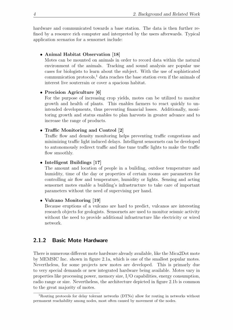
There is numerous different mote hardware already available, like the Mica2Dot moteby MEMSIC Inc. shown in figure 2.1a, which is one of the smallest popular motes.Nevertheless, for some projects new motes are developed. This is primarly dueto very special demands or new integrated hardware being available. Motes vary inproperties like processing power, memory size, I/O capabilities, energy consumption,radio range or size. Nevertheless, the architecture depicted in figure 2.1b is commonto the great majority of motes.
1Routing protocols for delay tolerant networks (DTNs) allow for routing in networks withoutpermanent reachability among nodes, most often caused by movement of the nodes.

2.1. Wireless Sensor Network Devices 5
(a) Mica2Dot Mote by MEMSIC [10]
Note that this mote is as small as a QuarterDollar coin (25 mm in diameter). It features128K byte of flash memory, 512K byte externalmemory, an integrated radio and weighs 3 g ex-cluding batteries.
MCUUART Timers
Digital I/OFlash Memory
ExternalMemory Radio Sensors
(limited) Energy Source
(b) Mote Architecture
The MCU (microcontroller unit), powered byan electric energy source, provides integratedfeatures like timers and UARTs. Externalmemory, the radio and sensors are additionalintegrated hardware connected to the MCU.
Figure 2.1 Sensor Node Hardware
The main component of many embedded system and especially of any mote is themicrocontroller. It is a tiny integrated piece of hardware whose internal architec-ture resembles the architecture of a computer. However, on the account of size andenergy consumption, particularly the processing power and memory size are notcomparable to any computer in use today. Besides the main memory, the micro-controller provides non-volatile flash memory that holds space for the software themote executes. Although the software is programmed prior to deployment and re-sides on the mote, sophisticated mechanisms like dynamic operating systems makereconfiguration possible.
The microcontroller is driven by a system clock an internal or external clock sourceprovides. In order to derive timing capabilities, the system clock is used to supplycounters of different widths at configurable speeds. Knowing the frequency of acounter, a fixed amount of increments (counter ticks) represents a fixed amount oftime. Therefore one or more compare values are configured to create a signal “timerexpired”: If the counter value equals the compare value, an interrupt is generated andthe microcontroller executes a special part of the software to service this event. Notethat a microcontroller provides several counters with at least one compare registereach and that counters run independently from the program execution, because extrahardware implements them.
Sensors are either attached to the mote on a modular basis or they are provided di-rectly on the mote’s circuitry board. In most cases, sensors are integrated electronicdevices as well. Connected to the microcontroller through a bus, sensors provideinformation on relevant properties of the environment. Typically, sensor data is col-lected with a certain frequency either indicated by a signal from the sensor meaningdata is available (interrupt) or by polling when a preconfigured timer expires.
Although there are ways to produce electrical energy on site, ranging from solarpanels to energy harvesting of movements or the bloodstream, motes are basically

6 2. Background and Related Work
B SF
APP
host computer
APP
client 1
APP
client 3
SF
client 2
IP BasedNetwork
C
CC
Serial Forwarder in Sensornets
Client motes C can communicate with one another using the radio (dotted arrows). A basestation mote B serves as gateway between the wireless domain and a host computer, usinga serial connection (dashed arrow). The serial forwarder connects to the appropriate serialport and provides messages through the unified serial forwarder packet source, which severalapplications can connect to at once. Interacting with the mote is possible even remotely, e.g.via the internet.
Figure 2.2 Functioning of the Serial Forwarder in Sensornets
powered by batteries to make them independent from any infrastructure. Certainly,this circumstance results in new challenges: Energy becomes a sparse resource aswell and the lifetime of a mote consequently becomes finite.
2.1.3 Mote Communication
The radio is utilized to communicate data wirelessly to another mote in range. Datathat has been successfully preprocessed by the microcontroller is transferred to the(in most cases separated) radio chip. The program is executed independently fromthe radio chip, and the completion of a transfer is eventually signaled by the radiochip. Because the destination mote is often not in radio range of the sender, a routingmechanism is used in the sensornet, so messages reach their destination in a hop-by-hop fashion. Since sending radio messages is one of the most energy consumingoperations, wireless communication is used wisely.
Serial communication is utilized to enable interaction between host computers andmotes. In conjunction with an RS232 serial converter or an USB serial converter, theUART (Universal Asynchronous Receiver Transmitter) of the microcontroller allowsfor a serial connection between mote and host computer. The serial line is usedfor programming the mote and exchanging data with the mote. Interaction withthe sensornet becomes possible for a computer when using a base station: Motesrunning the BaseStation application convert wirelessly received data, send it to thehost computer via the serial connection and vice versa.
Because a mote is connected with a single host computer at the same time, TinyOSprovides a serial forwarder. It allows for multiple users to interact with a connectedmote simultaneously, as shown in figure 2.2, and is available in three different pro-gramming languages to provide portability. Once executed and set up with theappropriate serial port, the data is converted properly and the message payloadfrom the mote is sent to applications registered with the serial forwarder and viceversa.

2.2. Sensornets versus Wireless Mesh Networks 7
2.2 Sensornets versus Wireless Mesh Networks
Many motes, like the Telos [16] and Mica Series by MEMSIC [9], use ZigBee com-pliant radio modules. These modules rely on the IEEE 802.15.4 standardizationfor wireless personal area networks (WPAN), whereas ZigBee provides higher levelcommunication protocols based on the IEEE 802.15.4 specifications. The IEEE stan-dard is intended to be used by low-speed, low-cost devices comsuming less power,so IEEE 802.15.4 suits most sensornet applications.
The standard is specified to be used within the 868 MHz frequency band (Europe),902-928 MHz frequency range (North America) or the very popular 2.4 GHz fre-quency band (worldwide). The latter is also occupied by the popular standardsof the IEEE 802.11 family, which is the underlying specification for wireless localarea networks (WLAN). Although lower frequencies provide a higher range due tophysical implications, the 2.4 GHz band is also popular for the use with motes, soWLAN capable devices and sensornets possibly operate in the same frequency band.Note that the very popular term “Wi-Fi” is a trademark of the Wi-Fi Alliance thatcertifies devices using WLAN and IEEE 802.11, but we use Wi-Fi as a synonym forthe IEEE 802.11 standard.
Wireless communication is unreliable, because radio waves (eletromagnetic waves)are influenced by nearly any obstacle in the propagation direction. Electromagneticwaves can scatter on objects, are reflected by them and get absorbed by matter.Especially moving objects and moving radio sources/receivers are problematic, be-cause movement causes highly dynamic link quality. Weather also has a significantinfluence on reachability among nodes and interference among radio waves can ren-der information opaque. The discussed influences on wireless communication are thesame for sensornets and WLANs, of course. Using the same frequency band empha-sizes this similarity. Summing up, links between both motes and WLAN devices aredynamic and bursty, resulting in unreliable routing paths within the network.
Messages travelling through the network are forwarded greedily and each mote actsas an individual router that has to decide where to forward a message to (if notdestined to the mote itself). Wirelessly networked devices are deployed with over-lapping radio ranges, so that each device has a link to more than one other deviceand varying link qualities. This way communication between motes can still be per-formed although some motes are temporarily not available or fail. Because the linksbetween nodes resemble a mesh in a graphic representation of this kind of networks,they are called meshnet.
2.3 The TinyOS Open-Source Operating System
The open-source TinyOS operating system is a programming environment and codeframework that offers easy to use libraries enabling developers to rapidly implementand build applications for a variety of motes. It is designed for embedded sensornodes, meeting requirements like small binary code size and advanced power man-agement. Its event-driven execution model features quick responses to events andsimultaneously allows for fine-grained power management.

8 2. Background and Related Work
Software is written in a stylized C language, called nesC [5], which is able to sup-port the component-based and event-driven nature of TinyOS. A sophisticatedmake system is delivered with TinyOS, enabling compiling, building and program-ming software with a single command: “make telosb install,123” compiles thesoftware in the current directory for a TelosB mote, patches ID 123 and programs itto the mote attached to the PC.
2.3.1 Driving Features of TinyOS
TinyOS is an event-driven operating system, meaning that the software solely reactsto events instead of running forever and processing something meaningful from timeto time. When no event is being processed and no task is scheduled, TinyOS puts theunderlying microcontroller hardware to a specific sleep mode in order to save as muchenergy as possible but being able to react to important (external) events. TinyOScomponents implement service routines for events like Boot.booted() or Timer.fired()and might signal another component’s event.
To account for the concurrency multiple processing hardware introduces, operationson sensors, the radio or integrated functionality like the UART are executed ina split-phase fashion. Numerous TinyOS library calls (e.g. AMSend.send()) trig-ger a complex operation but return immediately afert. Instead of polling for thecompletion of the task, TinyOS configures the hardware to indicate such an event.Meanwhile, TinyOS services another request. Upon completion of a task, TinyOSsignals the event to the application (e.g. AMSend.sendDone()).
2.3.2 Components and Interfaces
In TinyOS, components always provide a set of particular commands and react topredefined events. Interfaces determine which functionality is available in a com-ponent by describing commands and events components implementing the interfaceare required to provide. The basic concept behind TinyOS components is provid-ing or using at least one interface. In order to make use of functionality providedby an interface, a developer associates his application to a component implement-ing the interface of interest. Command and events belonging to a certain interfaceare noted using a dot notation: SplitControl.start() is command start() of interfaceSplitControl.
For the purpose of minimizing the size of the final binary, functionality is onlycompiled in if neccessary. TinyOS applications declare components they require,whereas all but only functionality neccessary to satisfy the application’s needs iscompiled in automatically. Each component is either a configuration or a module.While configurations redirect interfaces they provide to other components, modulesactually provide the interface by implementing the commands and events.
Configurations as well as modules consist of two parts: an implementation and adeclaration. The latter defines which interfaces are used and which are provided.For configurations, the implementation part tells what other components implement

2.3. The TinyOS Open-Source Operating System 9
1 configuration ActiveMessageC {provides interface AMSend ;
3 provides interface Packet ;}
5 implementation {components LinuxActiveMessageC , LinuxPacketC , MessageHelpersC ;
7 AMSend = LinuxActiveMessageC ;Packet = LinuxPacketC ;
9 LinuxPacketC . Helpers −> MessageHelpersC ;}
Listing 2.1: The configuration in this example provides interfaces AMSend andPacket. In line 6, three components are made available for use in the actualwiring. The nesC compiler is told in line 7 that interface AMSend is providedby component LinuxActiveMessageC. Interface MessageHelpers is used by compo-nent LinuxPacketC, and line 9 describes where to find the implementation for thisinterface, namely in component MessageHelpersC.
the interfaces provided. Besides wiring interfaces in their own declarations, con-figurations may wire foreign components as well. See listing 2.1 for a descriptiveexample of how components are wired together. Certainly, the implementation partin modules provides the actual software.
For the purpose of distinguishing components by their name, TinyOS specifies nam-ing conventions for TinyOS components: Components and interfaces differ in theirlast letter of the file name. Interfaces carry a simple name, preferably a verb ornoun, whereas names for components are terminated by a capital letter “C” or “P”.While component names ending with “C” identify a configuration and thus may beused to wire an aplication with, components with “P” tag a private module thatimplements an interfaces provided by another configuration.
2.3.3 TinyOS Hardware Abstraction Architecture
TinyOS uses a hardware abstraction architecture to support a variety of hardwareplatforms for the same application while maximizing code reuseability and perfor-mance, as described in TEP 2 [11]. Although abstraction typically conflicts withenergy and code efficiency, it is neccessary to hide hardware subtleties and allowfor portability. The TinyOS abstraction architecture, depicted in figure 2.3, consistsof three layers, specifically the HPL (hardware presentation layer), the HAL (hard-ware adaptation layer) and the HIL (hardware interface layer). Each layer fulfills aspecific purpose, which is explained in the following:
1. Hardware Interface Layer (HIL)Components belonging to this layer provide hardware independent TinyOSfunctions and events, such as timers. Applications use only components be-longing to the HIL in order to be portable among different mote hardware.However, no mechanism is installed to check whether applications violate thisrule.

10 2. Background and Related Work
HPLMicaZ
HPLTelosB
MicaZ TelosB
HALMicaZ
HALTelosB
HILMicaZ
platform indepen-dent application
HPLCC2420
HPLCC2420
HILCommon
HILCommon
HILTelosB
(a) Platform Independent Applications
HIL components may have a platform specificimplementation. Nevertheless, they provideplatform independent functionality. Althoughvery hardware specific, HPL components maybe shared by different platforms if the respec-tive motes share hardware as well (like theCC2420 radio chip).
HPLIRIS
IRIS
HALIRIS
platform depen-dent application
HILIRIS
(b) Platform Dependent Applications
When making use of functionality other thanthose provided by the HIL, applications becomeplatform specific and are thus not portable ingeneral. TinyOS does not employ a mecha-nism to prevent using non-HIL components, sohardware specific components may be wired tothe application as well.
Figure 2.3 TinyOS Hardware Abstraction Architecture
2. Hardware Presentation Layer (HPL)Being the layer closest to the hardware, components in the HPL offer the hard-ware’s capabilities as functions of reasonable fine-grained functional blocks.Nevertheless, HPL components are part of platform specific implementationsand not intended to be used by the application.
3. Hardware Adaptation Layer (HAL)Advancing the HPL, this layer further progresses the hardware functionalityto hardware independency. In contrast to the HPL, the HAL holds states andfunctionality that requires multiple hardware operations.
Due to the component-based nature of TinyOS, code reuse is simple when portingTinyOS to a new hardware platform. However, developing support for a new plat-form demands a lot of re-implementation in the HAL and especially in the HPLwhen using hardware not akin to already supported hardware. In order to develop afully functional platform, the developer concentrates on the HIL functionality. Ac-tiveMessaging (serial and wireless), timing, digital I/O (e.g. to drive LEDs) andsensor support are the most important parts of the HIL.
2.4 Network Communication and Timing in Linux
The ability to communicate data over a network of connected devices as well as tim-ing capabilities are important functionalities to drive a TinyOS running node. Bothof the following sections will support the reader in understanding the functioning ofTinyOS on top of the Linux operating system regarding these subjects.

2.4. Network Communication and Timing in Linux 11
2.4.1 Sockets in Linux
To enable inter-machine communication within a network like the internet, a com-pany’s intranet or private computer networks, the internet protocol (IP) is widelyaccepted and in use. Because of several demands, the internet protocol version 4is slowly replaced by version 6. That is e.g. to satisfy the need for new internetaddresses in order to supply every participating node with an unique identifier (IPaddress). Due to the fact that the number of internet ready devices rapidly growsbeyond the amount of addresses provided by the IP version 4 address space, unallo-cated identifiers are scarce.
Modern operating systems offer a simple way to make use of internet protocol basedcommunication, although the real user space implementation to actually use IPbased communication might be complex. Using sockets, programs can communicatedata to remote or local applications, while the operating system handles most ofthe work. This includes managing protocols running on top and underneath the IPlayer within the internet protocol communication stack. Data is sent to a socketand delivered eventually to the receiver while incoming data addressed to a specificsocket is transparently made available to the application using it. For network nodeshaving more than one network interface installed, data delivered through a socketis not bound to a particular interface but is sent on those interfaces providing aconnection to the destined host.
There are three basic types of IP sockets in Linux: Transmission Control Proto-col (TCP) sockets, User Datagram Protocol (UDP) sockets and raw sockets. TCPand UDP sockets cover the complete internet communication stack (not consideringthe application itself) and only deliver the actual payload of a message. Raw sock-ets however leave most control to the application, especially requiring it to carryTCP/UDP and IP headers around the message. TCP and UDP separate from eachother by one particular feature: TCP sockets provide connection oriented serviceswhile UDP is not using a connection but only delivering a packet independent of anyother message. Note that sockets not only allow for a convinient way to exchangedata between two applications on different hosts but also on the same host.
Sockets are the endpoints of inter-application communication and are unambiguouslyidentified by the IP address and the port number. While the IP address identifiesthe host computer, the port number is associated with exactly one process at thatparticular host computer. In Linux, sockets are special files that are referenced byan integer number. Numerous system calls allow for allocating a socket, configuringand using it.
2.4.2 Timing for Linux Processes
The Linux operating system provides three different (interval) timers per process,only one of which provides realtime timing and is therefore suiteable for TinyWifi.The itimer is designed as both an interval timer and single shot timer. To provideboth functionality even mixed up together, an itimer is configured with an intervalvalue and a timer value. The latter is constantly decremented according to theprocess’ activity and when it hits zero, a signal is generated.
12 2. Background and Related Work
Linux delivers this expiration signal of the itimer to the process belonging to therespective itimer and said process is then responsible of servicing the event. If –in the moment of expiration – the interval value is non-zero, the timer is reset tothat interval value. Linux features both setting up and starting an itimer as wellas reading the remaining value on an itimer, which is important to derive TinyOStiming capabilities.
To ease handling of itimers, two important programming structs are used, namelyitimerval and timeval. While a timeval struct consists of two integer numbers rep-resenting seconds and microseconds, an itimerval is made up of two timeval structsbeing the timer value and interval value. Summing up, the realtime itimer providesa sufficient resolution (microseconds) as well as satisfying accuracy on modern Linuxdriven systems to source TinyOS timing capabilities.

3Design
In this particular chapter, the outline of TinyWifi is discussed. Initially, we list ourdesign goals in section 3.1, before covering the TinyWifi architecture in section 3.2.Going deeper into the details of TinyWifi, timing capabilities are presented in sec-tion 3.3 and intricacies of TinyOS’s split-phase operations are explained afterwardsin section 3.4. Subsequently, principles of TinyWifi’s wireless and serial communi-cation facilities are addressed in section 3.5 and section 3.6, respectively. Finally insection 3.7, the use of sensor data in TinyWifi is explained.
3.1 Hard and Soft Requirements
The main goal of TinyWifi is enabling execution of applications written for TinyOSon Linux driven networked devices like PCs, mobile phones or routers. We wantto extend the TinyOS framework to generate executables for the Linux operatingsystem by compiling for the new TinyWifi platform. This procedure should be equiv-alent to compiling for any mote platform. By rewriting all important componentsto make them usable on Linux, developers should be able to compile applicationsissuing a single command “make linux”. In order to achieve this, the make systemalready delivered with TinyOS is extended to support this operation. The result isan executable binary, which, once executed, shows equivalent behavior as the sameTinyOS application running on motes.
Since our long term objective is to evaluate protocols used in the sensornet do-main in inherently similar Wi-Fi networks, TinyWifi must behave similarly to otherplatforms. Certainly, this includes inheriting the component based nature and split-phase operation feature of TinyOS. On that account, all hardware independent func-tionality popular motes like the Telos provide, should be available with TinyWifi,ensuring that TinyOS applications are executable on Linux without modifications.Nevertheless, at the same time we exploit the availability of resources not offered by

14 3. Design
motes but by resource rich devices like PCs when useful. Especially for the purposeof buffering incoming and outgoing packets, this approach is sensible.
For the purpose of enabling TinyWifi to become widely accepted eventually, thefollowing rather indirect features influence the design in general:
1. Preserving Exisiting StructuresThe TinyOS source tree will be utilized non-invasively, leaving it compatibleto all current platforms. The TinyWifi specific code integrates seamlesslyinto the existing TinyOS source tree. This way, users need only one TinyOSenvironment to develop code for both common motes and TinyWifi.
2. Portability Among Different Linux VersionsBy using portable C program code, we facilitate TinyWifi to be used withdifferent versions of Linux without the need to modify components. Sincewe use very common Linux system calls and mechanisms only, we envisionTinyWifi to be easily portable to different Linux derivatives for routers andforeign architectures.
3. Maximize Code ReuseTinyOS already supplies a lot of code and functionality. We designed TinyWifiin a way that we can make use of existing code and do not re-implementfunctionality which is already available.
4. Robust Software ImplementationTinyWifi code features robustness in unexpected situations by programmingdefensively and using error checking whenever sensible. Additionally, expres-sive error and warning messages help TinyWifi users to quickly identify codesnippets causing unintended behavior.
3.2 TinyWifi Architecture
As depicted in figure 3.1a, Hardware presentation layer (HPL) components interactdirectly with the real hardware. Components in the hardware adaptation layer(HAL) serve as a link between HPL and hardware interface layer (HIL), by simplywiring components or – more likely – by adding advanced mechanisms to the rathersimple HPL functionality. Certainly, HIL functionality is the same for every moteplatform, so the right choice to make a cut is the HAL, where HIL and HPL areconnected to one another.
On a common mote, hardware features are presented as software functionality bythe TinyOS abstraction architecture. In the case of TinyWifi, this is already doneby Linux. Instead of building on top of the hardware, we use Linux to derive theTinyOS related functionality and make it available to the application.
Prior to developing, we decided what hardware technology to replace with whichLinux facility. Figure 3.1b illustrates the replacement module for the bottom partof TinyOS’s hardware abstraction architecture. HPL/HAL elements outlined infigure 3.1 are the most important ones and we discuss the parallelism between eachcorrosponding element in the following:

3.2. TinyWifi Architecture 15
H I L
HAL
HPL
nesC Application
TinyOS
Mote Hardware
Radio Sensing LEDs Timing Serial
RadioWrapper
SensorWrapper
CounterInterrupts
IntegratedUART
I/OController
(a) Layered TinyOS Architecture on Motes
TinyOS features hardware independent (HIL) capa-bilities to use the hardware, e.g. the radio and sen-sors, while components within the hardware adap-tation layer (HAL) provide access to the very ba-sic implementation of hardware functionality in thehardware presentation layer (HPL).
Linux Operating System
SocketAPI
DummySensors
PseudoTerminal
ItimerAPI
ConsoleOutput
(b) Replacement HPL/HAL
Re-implementations of HPL and HALcomponents built on top of Linux replacethe respective components for use withmote hardware. Some HIL componentsmay be replaced as well but still are fullycompatible to other HIL components.
Figure 3.1 Layered TinyOS and TinyWifi Architecture
• Wireless CommunicationInstead of transmitting a data packet to be communicated to a radio chip,which then takes over control of the packet, we use Linux sockets for com-munication. These provide easy access to the network but require properconfiguration of the networked node.
• Sensing Physical ParametersTinyWifi target devices are multi purpose devices and are not specifically de-signed for measuring data. But most Linux capable devices feature at leastone real hardware sensor, e.g. to measure the processor temperature, whichcould be used to generate data.
• Binary Status IndicationMost motes provide LEDs for status indication, driven by digital I/O pins ofthe microcontroller. Instead of using real LEDs on Linux driven devices – if atall available –, we generate messages to standard output to indicate the statusof three virtual LEDs.
• Counters and TimersLike every digital processing machine, TinyWifi target devices provide countersand timers just like mote microcontrollers. However, these are occupied by theoperating system, forcing us to use timing capabilities offered by Linux. In thecase of TinyWifi, we make use of the Linux realtime itimer.
• Serial CommunicationMotes are connected to a host computer in order to be programmed or toforward data from the sensornet to a host computer and vice versa (basestation). For TinyOS applications using TinyWifi, we use the Linux built-

16 3. Design
Application
Counter Timer Alarm 1 Alarm 2 Alarm 3
HardwareCounter 1
Mote Hardware
HardwareCounter 2
CCR A CCR ACCR B CCR B
(a) Hardware Counters
Multiple counter compare registers (CCR) areavailable on a mote, utilized to derive timingcapability. Note that timers rely on an alarmrather than using the hardware.
Application
Counter Timer Alarm 1 Alarm 2 Alarm 3
Single Linux itimer
VirtualizeLinuxTimer
. . .. . .
(b) Linux itimer
In order to provide multiple timing sources, theLinux realtime itimer is first virtualized. Suchtimer is also sourcing the counters available inTinyWifi.
Figure 3.2 Timing Sources for Motes and TinyWifi
in pseudo terminal feature to send and receive data to and from a runningserial forwarder.
3.3 Counters, Alarms and Timers
A mote’s processing facility is the microcontroller featuring counters that incrementor decrement at a certain frequency (clock) in parallel to program execution. Coun-ters are the essential method to keep track of the real time. Read accessing thecounters is possible for TinyOS applications through respective components, allow-ing for quick and easy accessible high precision timing (for short time periods).
As shown in figure 3.2a, several compare registers for each counter allow for severalsimple timers to be set up. When the counter value matches one of the counter com-pare values, an event is triggered. TinyOS uses this simple mechanism to schedulemultiple coexisting alarms, which basically are timers with a very low abstractionlevel. Besides signaling the expiration event, alarms can be scheduled, stopped andchecked for their status.
In order to provide higher level timers as described in TEP 102 [11], e.g. supportingintervals, TinyOS provides components using simple alarms to derive the numberof sophisticated timers needed by the application. Unfortunately, in contrast toa microcontoller offering multiple adjustable timing events, Linux provides only asingle realtime itimer per process. This circumstance forces us to first virtualize theitimer functionality before being able to provide as many timers as needed by thesoftware in the upper hardware abstraction layers.
We decided to introduce a new interface LinuxTimer, recreating Linux itimer func-tionality, which is used by higher level components to fulfill their orderly purpose.By virtualizing timers of type LinuxTimer, illustrated in figure 3.2b, we provide anabundant amount of timing sources for all timer related components. Certainly, thesource to virtualize these timers is the itimer provided by Linux.

3.4. Split-Phase Operations 17
TinyOSrequestaccepted
sendpacket
send packet
processing packetpaused ... ... paused ...
packet sent
task 1 task 1 task 2 task 1:sendDone
processing packet ... listening ...... listening ...
incoming packet
packet arrivedm
ain
thre
ad
sen
der
thre
ad
rece
iver
thre
ad
task 1:packetarrived
Exemplary Split-Phase Operation
Threads executed in parallel to the main TinyOS process allow for mimickinghardware processing in parallel. When issuing a send command, the sendingthread takes over control of the message. As soon as the request has been accepted,TinyOS returns control to the application, which continues processing in parallelto the sending thread. Eventually, the thread signales the completion of sendingthe message to TinyOS and the respective application component. Additionally,by using a receiving thread, the main process is released from polling new incomingmessages as well.
Figure 3.3 Split-Phase Operations when using TinyWifi
Since counters are no more than the representation of the time past since the counterlast reached zero, TinyOS counters are simple to provide on Linux. We check thecurrent time against the startup time of TinyOS, revealing the value of a respectivehardware counter.
3.4 Split-Phase Operations
In section 2.3.1 we already introduced split-phase operations in TinyOS. To makesaid operations possible, multiple processing hardware working in parallel is required.Because we operate on top of Linux instead of controlling available hardware forourselfs, we are unable to provide the exact same kind of split-phase operations.
The processing time for TinyOS on Linux driven nodes is comperatively short, es-pecially on host computers with rich resources. On that account we could abandonsplit-phase operations and use imperative blocking instructions instead.
However, we want to provide split-phase like function calls for two reasons: Onthe one hand, we would also break with the requirement to behave as similar toother mote platforms as possible and on the other hand, the split-phase operationsprogramming paradigm dictates us to return control to the caller before signalingan event indicating the completion of the respective operation.
Our primary solution to this problem is utilizing threads to imitate the parallelismof multiple processing hardware. This is reasonable since program threads are exe-cuted concurrently due to scheduling of the operating system and can be executed

18 3. Design
S
R1
R2
R3
R4
(a) Intended Message Propagation
A sending node S transmits one message,which propagates omnidiretional, indicatedby arrows. Nodes Ri in radio range, indi-cated by the dotted circle, can hear the mes-sage and process it. Note that the messagemight be addressed for only one of the nodes.Nevertheless, all nodes in radio range arecapable of overhearing the message.
S
R1
R2
R3
F
A3
A2
A1
(b) Flooding in IP Networks
Assuming broadcast messages sent by S areforwarded by a receiving node F with ra-dio range indiated by the long dashed circle.The original message by S reaches nodesAi, indicated by dashed arrows. Since nodesAi are not in radio range of original senderS, we need to suppress forwarding broadcastmessages to achieve the sensornet behavior.
Figure 3.4 Message Propagation in Sensornets
on different processors, which provides the concurrency needed to mimic parallelprocessing. Instead of setting up a radio chip, we create threads, handling incomingand outgoing packets. Sending a message using the appropriate interface is dele-gated to the respective thread while the main TinyOS process continues working.As illustrated in figure 3.3, threads are well suited to mimic multiple processingfacilities, especially on computers with multiple processors.
3.5 Radio Communication
Exchanging data is the most important task for TinyWifi, since we want to explorethe applicability of sensornet communication protocols in the Wi-Fi domain. Pro-viding this functionality becomes possible having split-phase operations and timingavailable. TinyOS includes ActiveMessageC, which is a HIL component providinghigh level usage of the radio. Its purpose covers enabling and disabling the radiointerface, sending and receiving as well as packet manipulation ranging from times-tamps and acknowledgements to attaching the payload. As any other platform,TinyWifi provides its own version of said component and wires the functionality itprovides to underlying components.
When the radio is enabled by the application using the appropriate interface Split-Control, TinyOS is prepared to send and receive packets having created the appro-priate threads. In order to send and receive data via the networked interface(s), we

3.6. Serial Communication 19
use Linux UDP sockets. Because we want to make the TinyWifi host device behavesimilar to an integrated radio on a mote, depicted in figure 3.4a, two importantadjustments have to be done:
1. Broadcasting of UDP MessagesRadio messages in sensornets are received by any mote in radio range of thesender and are then analysed by TinyOS. Depending on the message beingdestined for a particular mote, the message is passed to listening components.Nevertheless, it is also possible to sniff packets, meaning receiving messagesnot addressed for the particular mote.Usually, UDP packets are used for unicast communication. Messages not ad-dressed for the receiving node are discarded in the lower levels of the IP stackby the operating system, hence do not reach the application. By broadcast-ing the UDP packets containing TinyOS messages, we ensure that packets arepassed through to the application and not discarded on a lower level of the IPcommunication stack, since broadcast messages are addressed to all nodes bydefiniton. When a message arrives, it is analysed by the receiving thread andthe appropriate event is triggered.
2. Suppress Message ForwardingSince we use an already fully functional communication protocol to carry mes-sages, namely IP, we have to take care that TinyOS packets are not forwardedby receiving nodes. This is important to prevent the network of being flooded,which would result in every participating node in the network to receive themessage, as illustrated in figure 3.4b.Instead only those nodes in range of the radio should receive the message.Although forwarding of packets destined to the broadcast address is decidedby the (individual) routing layer implementation used, we ensure the correctbehavior by setting the time to live (TTL) header value of the packet to zero.
As arranged by TinyOS (TEP 111 [11]), we specify the contents of the standardTinyWifi message separately for each header, footer and metadata. We have no usefor data in the footer but provide information on the message in the header and usethe matadata field to store timestamps and acknowledgements. The payload regionis filled by the application with content of interest, using our packet manipulationmechanisms to ensure that the message is not corrupted by the application.
3.6 Serial Communication
In most scenarios, a base station mote is utilized to forward messages from withinthe sensornet to resource rich computers for further processing and analysing. Acommon TinyOS application named BaseStation is used to forward incoming mes-sages through the serial port of the mote to another device. The host computerconnected to a base station executes an instance of the serial forwarder, redirectingincoming mote serial messages to all applications registered with the serial forwarderusing IP based communication.
20 3. Design
In contrast to sensornets, resource rich Linux driven devices can easily connect di-rectly to the network. Using a Linux capable networked node running BaseStationand an additional computer attached via a serial connection is inconvenient. In-stead, we make it possible for one single node to be both base station and serialforwarder. This is reasonable since Linux capable devices within a meshnet of-fer sufficient resources to power a serial forwarder besides other applications. Toachieve this feature, presented in detail in TEP 113 [11], we discuss two approaches:
1. Serial Forwarder Packet SourceSerial forwarders can be daisy chained by connecting to one another throughserial forwarder packet sources. By re-implementing the serial communicationstack of TinyOS, we could transform the data and provide it to a serial for-warder packet source. The serial fowarder will then be connected to the sourceprovided by the TinyOS process.
2. Software Implemented Serial PortA serial port the serial forwarder can connect to could be implemented insoftware. For that approach to success, the virtial port has to be available as aLinux device and behave exactly like a serial I/O port. Of course, this deviceshould be accessible through standard Linux device drivers.
Both approaches require a lot of code and for the virtual serial port, advancedmechanisms will probably be neccessary. However, Linux provides a feature thatalready offers the functionality needed to substantiate the second approach. Linuxpseudo terminals have been part of Linux for a long time and provide two pairedserial pseudo devices (ports). Using simple system calls, data written in one of thepaired devices appears as readable on the other device and vice versa.
When the serial communication stack is enabled by the TinyOS application, thepseudo terminal is set up and TinyOS hooks itself into one of the paired ports. Thename of the opposite device is disclosed to the user and the serial forwarder canbe connected to that particular port. Note that the Java based serial forwarder isnot capable of using the TinyWifi pseudo terminal serial port, whereas both the Cand C++ implementations can indeed connect to it. We assume that the Java basedserial forwarder cannot handle the pseudo terminal port because of Java limitations.
3.7 Sensors
We developed TinyWifi to enable researchers to evaluate sensornet protocols in theinherently similar Wi-Fi wireless domain. On that account, support for sensingdata is a secondary issue. Nevertheless, some data should be available to drivedata exchange within the network, since protocol evaluation is not possible withoutcommunication. By providing dummy data sources implementing interfaces usedwith real sensors, we allow for creating data to be sent through the network.
Most devices discussed to run TinyWifi utilize sensors, e.g. to monitor processortemperature. In some cases, these are avilable through Linux. Nevertheless, readingvalues from such sensors is highly platform specific and thus using real sensors toprovide data on some device types is a long term aim. Instead, we use a pseudo datasource like a sine generator to acquire data.

4Implementation
Having discussed the design of TinyWifi, we now present interesting implementationrelated details. First, the integration into the TinyOS source tree is presented insection 4.1. A look at the interaction with standard console output is given in sec-tion 4.2. In section 4.3, the implementation of TinyOS counters and timers using theLinux itimer is described. Afterwards, details of our approach to provide split-phaseoperations are explained in section 4.4. Subtleties of TinyOS communication capa-bilities when using TinyWifi are covered in section 4.5 for wireless data exchange andsection 4.6 for serial communication. Section 4.7 concludes this chapter, addressingthe simple dummy sensor data acquisition implementation in TinyWifi.
4.1 Build System
The TinyOS source tree is reasonably well organized. The root directory holds threeimportant folders: apps, support and tos. While mote applications for using andtesting TinyOS can be found within apps, folder support holds tools like the serialforwarder and files for use with the popular Linux build tool make to build TinyOSapplications. The last important folder within the TinyOS root directory is tos,which is – among others – home of TinyOS wide interfaces in subfolder interfaces,chip specific components in subfolder chips and all platform specific files in subfolderplatforms.
Usually, new platforms are derived from the Null platform, which is a dummy plat-form implementing the crucial components as stubs to make TinyOS compile ap-plications for it. Certainly, these applications will not work before implementingfunctioning components. We also started with the Null platform and incrementallyadded new functionality. The correctness of any component was tested extensivelyduring the development to ensure the functioning prior to progressing to anothercomponent.

22 4. Implementation
We hooked TinyWifi into the TinyOS build system the same way any other platformis integrated. For the purpose of preparing a new platform for the already providedmake environment, two files are of major importance: To make TinyOS recognizethe new platform, a target file must be available in folder support/make.2 The filecontains simple commands to declare the platform’s name, adds some compiler flagsand finally includes rules from a platform specific subfolder to build an applicationfor the target. Also part of the build process is .platform in the platform root di-rectory3. It defines additonal compiler options and folders included in the compiler’ssearch domain for nesC source files. For TinyWifi, some additional compiler optionsare neccessary, e.g. option “-lpthread” is given to enable thread support.
The command line to compile an application for TinyWifi is similar to compilingfor other platforms. By issuing “make tinywifi”, the application is compiled andan executable binary file containing the program is produced. Since other platformsuse “make <platform> install,<nodeid>” to patch the node’s ActiveMessage ad-dress and transfer the binary to the mote, we also feature that syntax to define anon-default ActiveMessaging address. The node’s ID given on the command line isused to declare a global constant via the “-D” option of the compiler. Our TinyWificode then uses this global constant’s value as the ActiveMessaging address. Ad-ditionally we offer compiling and executing with a single command line by typing“make tinywifi install,<nodeid> run”.
4.2 TinyOS Outputs and Local Messages
For several reasons like debugging, we want to use standard output to the consoleto print messages on the screen. In TinyOS, there already is a printf() facility withlimited platform support, redirecting messages to the serial port. On an attachedhost computer, the messages can then be read and displayed by a simple viewerapplication, also part of the TinyOS environment. Instead of redirecting messagesto the serial line, we want to print messages to standard output of the consolewithout detours by using the Linux built-in printf() command. We can achieve thisby including the appropriate Linux header file, which provides printf() using standardoutput. Nevertheless, additonal changes to the application are required to achievethe intended behavior.
Applications using the printf() function declare the path of the printf() library intheir Makefile in order to enable printf(). Since we want to integrate TinyWifiinto TinyOS without changes to the original source code, we have to build aroundthe exisiting printf() library. Indeed, applications using printf() can be compiled forTinyWifi, but support is limited until TinyOS is enabled to use the Linux printf()implementation. For this purpose, the path to the TinyOS printf() library must notbe provided in the application’s Makefile.
2Folder and file locations are given relative to the TinyOS source root, if not stated otherwise.3The term “platform root directory” refers to folder tos/platforms/tinywifi, holding the
platform specific files for TinyWifi.

4.2. TinyOS Outputs and Local Messages 23
LinuxActiveMessageC.nc: In function ’LinuxActiveMessageC$receiverThread’:2 LinuxActiveMessageC.nc:319: ERROR: setsockopt(...) failed!
LinuxActiveMessageC.nc:319: Linux says it was (errno): Socket operation on non−socket4 LinuxActiveMessageC.nc:319: gai strerror says it was: Bad value for ai flags
LinuxActiveMessageC.nc:319: program exits with status −4.
Listing 4.1: TinyWifi features information rich and descriptive error and warningmessages. Note that line 4 is special for networking related errors and warnings.
4.2.1 Virtual LEDs
Although Linux offers a much simpler way to provide messages to the user via printf(),LEDs are substantial for TinyWifi to support applications out of the box, since LEDsare often used on real motes. Subfolder leds in the platform root directory holds twofiles responsible for providing virtual LEDs: Configuration PlatformLedsC providesthree interfaces GeneralIO as Led0 through Led2 and uses interface Init. Whileinterface Init is passed through to component PlatformC and is used at boot time,the GeneralIO interfaces are wired to module PlatformLedsP implementing theLED functionality.
Features of LEDs defined by interface Leds are turning on and off as well as toggelingsingle LEDs. Additionally, reading and setting the LED configuration as a bitmaskis possible. As on any other platform, applications wire to the HIL component LedsCfor the purpose of accessing the LEDs. The high level features in interface Leds aremapped to the low level functions provided with interface GeneralIO.
In PlatformLedsP, we use general helper functions to control the pseudo LED states,which are stored in a simple global array. This way duplicate code is avoided andincreasing the amount of LEDs becomes simple. Moreover, the output can be con-figured to be either one message per LED access or one line revealing the LED’sstates, which is updated for every change. By defining LEDS SHUT UP,4 theoutput to the console can be completely suppressed.
4.2.2 Error Handling
TinyWifi code is developed to be resilient for the purpose of functioning correctly inexceptional situations. The most significant part in achieving robustness is thorougherror checking. Linux system calls are checked against success or failure and theappropriate error or warning message is displayed in the console.
In order to unify error messages and to offer a centrally adaptable and informationrich output, see listing 4.1, TinyWifi provides TinyWifiError.h implementing twocustomized error functions. Function tinyWifiNetError() is used to output error mes-sages when using Linux sockets, providing even more information than tinyWifiEr-ror(). The latter is a special case of tinyWifiNetError() and thus uses tinyWifiNetEr-ror() to print its messages, setting an error code of SUCCESS for the network relatederror code parameter.
4Constants influencing TinyOS applications compiled for TinyWifi can be found in header filehardware.h located in the platform root directory.
24 4. Implementation
Counter
LinuxCounterP(CounterFrom)
Counter<TMilli, uint32_t>
TimeConversionsC
TimeConversions
LinuxTimerC(TimerFrom)
LinuxTimer
MainC
Init
(a) CounterMilli32C
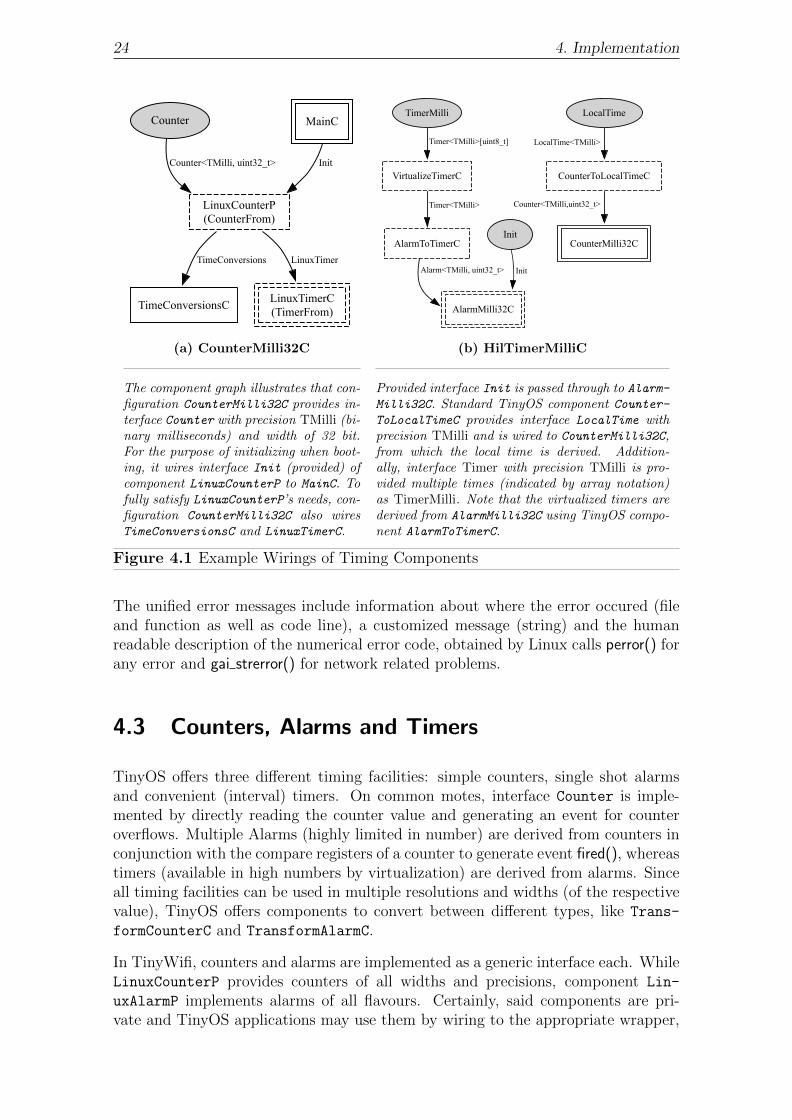
The component graph illustrates that con-figuration CounterMilli32C provides in-terface Counter with precision TMilli (bi-nary milliseconds) and width of 32 bit.For the purpose of initializing when boot-ing, it wires interface Init (provided) ofcomponent LinuxCounterP to MainC. Tofully satisfy LinuxCounterP’s needs, con-figuration CounterMilli32C also wiresTimeConversionsC and LinuxTimerC.
Timer<TMilli>[uint8_t]
AlarmToTimerC
Timer<TMilli>
LocalTime<TMilli>
CounterMilli32C
Counter<TMilli,uint32_t>
AlarmMilli32C
InitAlarm<TMilli, uint32_t>
TimerMilli LocalTime
Init
CounterToLocalTimeCVirtualizeTimerC
(b) HilTimerMilliC
Provided interface Init is passed through to Alarm-
Milli32C. Standard TinyOS component Counter-
ToLocalTimeC provides interface LocalTime withprecision TMilli and is wired to CounterMilli32C,from which the local time is derived. Addition-ally, interface Timer with precision TMilli is pro-vided multiple times (indicated by array notation)as TimerMilli. Note that the virtualized timers arederived from AlarmMilli32C using TinyOS compo-nent AlarmToTimerC.
Figure 4.1 Example Wirings of Timing Components
The unified error messages include information about where the error occured (fileand function as well as code line), a customized message (string) and the humanreadable description of the numerical error code, obtained by Linux calls perror() forany error and gai strerror() for network related problems.
4.3 Counters, Alarms and Timers
TinyOS offers three different timing facilities: simple counters, single shot alarmsand convenient (interval) timers. On common motes, interface Counter is imple-mented by directly reading the counter value and generating an event for counteroverflows. Multiple Alarms (highly limited in number) are derived from counters inconjunction with the compare registers of a counter to generate event fired(), whereastimers (available in high numbers by virtualization) are derived from alarms. Sinceall timing facilities can be used in multiple resolutions and widths (of the respectivevalue), TinyOS offers components to convert between different types, like Trans-
formCounterC and TransformAlarmC.
In TinyWifi, counters and alarms are implemented as a generic interface each. WhileLinuxCounterP provides counters of all widths and precisions, component Lin-
uxAlarmP implements alarms of all flavours. Certainly, said components are pri-vate and TinyOS applications may use them by wiring to the appropriate wrapper,

4.3. Counters, Alarms and Timers 25
like CounterMilli32C, CounterMilli16C . . . Alarm32khz32C and Alarm32khz16C.Component Counter<precision><width>C instantiates a new LinuxTimerC and anew LinuxCounterP with the appropritate precision and width, as illustrated in fig-ure 4.1a for a tangible example. For each component Alarm<precision><width>C,another LinuxTimerC is required, as well as a new LinuxAlarmP with the appropri-ate parameters. Every component providing an alarm or counter is given a namefollowing the naming conventions in TinyOS to provide compatibility with existingapplications.
Since the itimer functionality is used by several components, we take two steps inorder to supply multiple components with a separate timer:
1. Define New Timer InterfaceFor the purpose of successfully providing functionality similar to an itimerto several components, we introduce a TinyOS interface named LinuxTimer,describing the functionality needed to derive all TinyOS timing capabilities.Actually, this new interface is fairly similar to the high level interface Timer ofTinyOS. Nevertheless, the data types change from simple integers to structsof type timeval, and some additonal commands are required, e.g. getStartup-Time(), which returns the Linux time when the TinyOS application booted(important for counters).
2. Virtualize Linux TimerSimilar to the original TinyOS component VirtualizeTimerC, we provide 256instances of interface LinuxTimer by virtualization. The source timer for virtu-alization is component NativeLinuxTimerC, which implements said interfaceusing the unique Linux realtime itimer. All other instances of componentsusing interface LinuxTimer are set to wire themselves to LinuxTimerC, whichallocates a new timer of type LinuxTimer through virtualization componentVirtualizeLinuxTimerC.
Counter values are represented as simple unsigned integers and interpreted as ticks ofthe respective clock source. Since Linux uses seconds and microseconds to representtime, we need to convert from ticks to struct timeval and vice versa in many scenariosto provide the correct representation of time. We introduce interface TimeConver-
sions, implemented by component TimeConversionsC, which provides conversionfrom one representation into another for any precision.
For embedded systems, the ability to wait for a specific amount of time is veryimportant. Many external controllers are triggered by sophisticated protocols andrequire crucial timing. On that account, TinyOS provides interface BusyWait, whichallows for waiting a certain small amount of time with high precision due to theblocking nature of BusyWait. We use Linux system function usleep(), which blocksthe calling process for an amount of microseconds. The given value for commandBusyWait.wait() is converted to microseconds and results in the argument for usleep().
Additionally, any platform is required to provide its version of component HilTimer-MilliC, which is used by the frequently used HIL component TimerMilliC. See fig-ure 4.1b for the wiring graph of component HilTimerMilliC. Interface LocalTime

26 4. Implementation
offers reading the amount of time passed since startup of the mote in a 32 bit integer,sufficient to represent approximately 8 years of runtime in milliseconds. In contrastto other platforms, TinyWifi also provides component HilTimer32khzC, which pro-vides timers with 32 kHz precision as well as the respective interface LocalTime with32 kHz precision.
4.4 Split-Phase Operations
Despite commands to send out messages, there are more split-phase operations inTinyOS, e.g. ReadNow.read() in component DemoSensorP, which is our dummysensor implementation. Since sensing is a subsidiary feature, we do not use threadsto provide dummy sensor data, saving sophisticated programming code. Instead, atimer is set up to fire in the near future by command ReadNow.read(). The respectiveReadNow.readDone() event is signaled on timer expiration.
Another method to emulate split-phase operations is utilized in component Sine-
SensorP, being a part of the originial TinyOS source code. A task is posted to thescheduler and executed eventually, calculating some data and presenting it alongwith the ReadNow.readDone() event. For both the timer-based approach and thetask-based approach, control is immediately returned to the calling function andthe respective “done” event is signaled eventually, which conforms to the desiredbehavior of split-phase operations.
4.4.1 Split-Phase Operations Using Threads
For the purpose of providing well-engineered split-phase operations on top of Linux,we utilize program threads. In the current version of TinyWifi, we encounter twomajor split-phase operations that are handled by threads: AMSend.send() and Uart-Stream.send(), which are commands to send data via the radio and via the serialconnection, respectively. Since radio chips as well as the internal UART have to beset up correctly prior to utilization, interfaces SplitControl and StdControl areused to enable and disable the radio and UART.
Although very similar in functionality, these interfaces distinguish from one anotherin their behavior: While SplitControl controls a hardware component and signalsthe respective “done” event in the future, the commands in StdControl are blockingfunctions and only return after an attempt to change the hardware state has been ac-complished. We integrated the task-based approach discussed with SineSensorP tosupport split-phase operation behavior with interface SplitControl for componentLinuxActiveMessageC.
In the following, we exemplarily discuss the split-phase operations in LinuxAc-
tiveMessageC. On call of SplitControl.start(), we create thread receiverThread, whichfirst sets up the outgoing sockets and then creates another new thread, namelysenderThread. Afterwards, the incoming socket is configured properly using Linuxsystem calls and on success, the task reponsible for signaling SplitControl.startDone()is posted to the scheduler. At this stage, there are the main TinyOS process, a thread

4.4. Split-Phase Operations 27
handling incoming packets and another thread handling outgoing packets. Since allconcurrent threads alternate in execution, receiving and sending packets as well asprocessing the main application is done simultaneously.5
Until reception of a message, receiverThread remains in system call recvfrom(), notconsuming CPU time since recvfrom() is blocking. The message is handled by thethread in order to displace all processing intense procedures out of the TinyOSthread. Afterwards, the reception of a message has to be signaled to the applicationcomponent using the radio. Calling the appropriate event from within the threadwould result in the thread being blocked until the application is done processing theevent. On that account, we post a special task packetReceivedTask() to the mainprocess. During further processing of incoming packets, said task is scheduled forexecution and signals the arrival of the packet to the application eventually.
Thread senderThread is responsible for transmitting messages to other nodes in thenetwork. Like receiverThread, it is kept alive by an infinite loop in which the threadtests for packets to be sent out. Since infinite polling for events consumes processorpower, we developed the thread to pause after each transmission and wait for anotherpacket to be transmitted. Again, the completion of sending a message is signaled bya task, which is enqueued by the thread and executed eventually in the near future.
4.4.2 Impact of Threads on TinyOS Scheduler
Since enqueuing tasks to signal events is used by multiple concurrently executedthreads, we need to make sure that posting a task does not lead to corruption of thetask queue. For that purpose, we use a mutex6 to ensure exlusive use of functionpushTask() in component SchedulerBasicP.
Because TinyOS is a very energy efficient operating system, the scheduler puts themicrocontroller of a mote to sleep when no tasks are being scheduled for execution.Interface McuSleep defines commands to put the processor to sleep or update thepower state. The particular component implementing this interface allows for set-ting the correct sleep mode per platform, depending on the sleep modes supported.Important for continued functioning is reacting to events like timer expiration orcompletion of a measurement. Until such an event is triggered, the MCU can powerdown in order to save energy.
For TinyWifi, we issue Linux system call pause(), which halts the calling processuntil a signal is received. This approach makes TinyOS applications running withTinyWifi on Linux driven devices behave as expected – until threads are considered:The main process yielding the processor and waiting for a signal results in notrecognizing posting of a task when done by another thread. This is due to thethread being able to successfully post the task while the main process including thescheduler is halted. Hence, the newly posted task is not executed when enqueuedbut when the next signal is handled. To prevent this frequently occuring problem,
5Note that real concurrency is only achieved on systems with multiple processors, but schedulingon a single processor already allows for comparable concurrency.
6Mutexes allow for developing program code sections that can only be executed by one concur-rent process at a time.

28 4. Implementation
the function posting a task is altered to send a signal to the main process afterenqueuing the task. Certainly, the signal makes TinyOS return from pause() andenables TinyOS to recognize the newly enqueued task immediately.
4.5 Radio Communication
For the purpose of supporting radio communication, we basically have to provide im-plementation for component ActiveMessageC, as specified by TEP 116[11]. As withmost other platforms, a seperate version of this component is needed for TinyWifi.ActiveMessageC provides several interfaces for use with radio messaging, of whichmost are passed through to LinuxActiveMessageC:
• Initialization Prior to EnablingInterface Init is provided to execute code when booting. Component Plat-
formP calls command Init.init(), implemented in LinuxActiveMessageC, whichsets up mutexes for the use with threads.
• Controlling the RadioAs discussed in section 4.4.1, interface SplitControl is used to control theradio state, i.e. to enable or disable it. We use this interface to set up themessage handling threads (enabling radio) or to destroy them (disabling ra-dio). Since the threads are part of the core messaging functionality, moduleLinuxActiveMessageC provides said interface.
• Sending MessagesThe main command for sending messages is included in interface AMSend, whichalso features accessing the actual payload and the maximum payload length of amessage. Event AMSend.sendDone() indicates the completion of a previous callto AMSend.send() in a split-phase fashion. Certainly, LinuxActiveMessageCis the right module to implement interface AMSend.
• Receiving MessagesUsing ActiveMessageC allows for two ways of receiving messages: It is possiblefor an application to (1) sniff all overheard packets or (2) receive only messagesaddressed to the node, which is the usual behavior. An application wires itselfto either ActiveMessageC.Snoop or ActiveMessageC.Receive, respectively.ActiveMessageC provides both interfaces through LinuxActiveMessageC.
• Packet ManipulationTo allow for portability and protecting the internal message structures aroundthe payload, TinyOS requires applications to manipulate packets using prede-fined interfaces like AMPacket. Properties like source address, source group,and message type can be accessed via AMPacket, although this is also doneby the ActiveMessaging communication stack automatically. Module Linux-
Packet provides both interfaces Packet and AMPacket.
• Packet AcknowledgementsIt is possible to request an acknowledgement when sending packets, by using

4.5. Radio Communication 29
interface PacketAcknowledgements. It allows for setting and resetting the re-quest flag as well as checking whether the message was acknowledged by therecipient. We implemented some of this functionality in LinuxPacketAcksC,whereas LinuxActiveMessageC is responsible for recognizing and sending theactual acknowledgements. TinyOS specifies that the sendDone() event for out-going messages requiring acknowledgement is only signaled when the status ofthe particular message is fixed. This rule implies that it has to be possible tocheck sent messages for their acknowledgement status in the sendDone() eventhandler. For that reason, a timout timer is started when sending messageswith the acknowledgement flag set. On timeout expiration, the message isconsequently considered not acknowledged.
4.5.1 Communication Setup
Prior to using the radio messaging facility, threads, sockets, buffers, and variableshave to be set up correctly. In SplitControl.start(), appropriate action is triggereddepending on the current status. If the messaging facility is actually not ready forsending, we create thread receiverThread. As required by a split-phase operation,the function call returns immediately after thread creation. The actual setup is donein parallel by said thread.
Two outgoing sockets are inquired by receiverThread : One of these is prepared forsenderThread, the other will be used by receiverThread to send acknowledgements.After issuing socket() twice to get two new socket file descriptors, the sockets areconfigured to broadcast messages, i.e. to use both the internet protocol and MACbroadcast address. Additionally, the time-to-live header field is manipulated to beTINYWIFI TTL (value 0 by default) for any outgoing message by setting theappropriate socket property. In the next step, senderThread is created, which isnow enabled to start sending packets.
A third socket file descriptor is created in a similar way as the outgoing sockets. Thereceiving thread calls bind() in order to gain exclusive access on the specific communi-cation end point. Prior to entering the infinite loop and starting to receive messages,we catch the internet protocol addresses of the host machine and save them into alocal data structure to sort out looped back packets later. Finally, startDoneTask() isposted to the scheduler, eventually signaling the SplitControl.startDone() event whilereceiverThread enters an infinite loop and waits for incoming packets.
Since we do not want the sending thread to poll for new outgoing packets, we utilizepause(), but also need a signal to wake it up from pause(). Invocation of a signal han-dler is neccessary, as pause() will not return on reception of unhandled signals. Onthat account, senderThread registers signal handler sendPacket() first. Afterwards,senderThread enters an infinite loop and halts until the wake up signal is received.
Certainly, disabling the ActiveMessage communication stack is also possible. Func-tion SplitControl.stop() is intended to cancel all ongoing operations and free resources.In TinyWifi, we set a cancellation point for each thread, close the sockets and freesome memory. Again, a task is posted to complete the second phase of the split-phaseoperation, namely signaling SplitControl.stopDone() to the application.
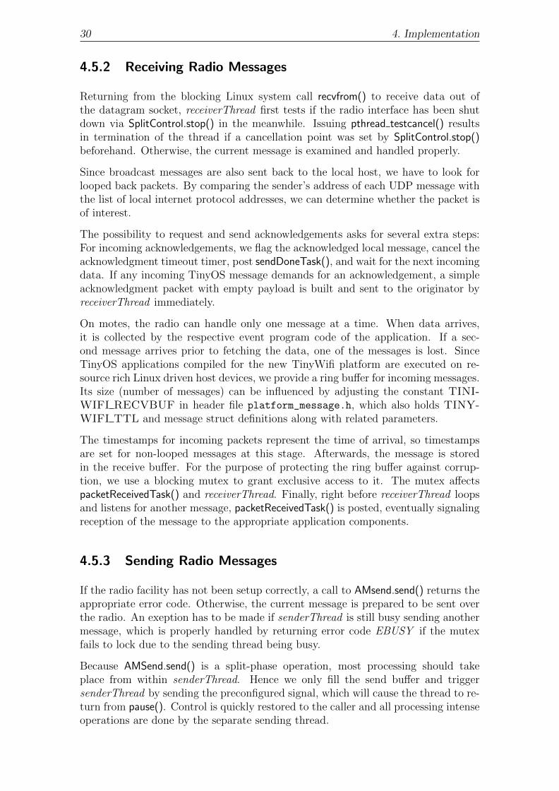
30 4. Implementation
4.5.2 Receiving Radio Messages
Returning from the blocking Linux system call recvfrom() to receive data out ofthe datagram socket, receiverThread first tests if the radio interface has been shutdown via SplitControl.stop() in the meanwhile. Issuing pthread testcancel() resultsin termination of the thread if a cancellation point was set by SplitControl.stop()beforehand. Otherwise, the current message is examined and handled properly.
Since broadcast messages are also sent back to the local host, we have to look forlooped back packets. By comparing the sender’s address of each UDP message withthe list of local internet protocol addresses, we can determine whether the packet isof interest.
The possibility to request and send acknowledgements asks for several extra steps:For incoming acknowledgements, we flag the acknowledged local message, cancel theacknowledgment timeout timer, post sendDoneTask(), and wait for the next incomingdata. If any incoming TinyOS message demands for an acknowledgement, a simpleacknowledgment packet with empty payload is built and sent to the originator byreceiverThread immediately.
On motes, the radio can handle only one message at a time. When data arrives,it is collected by the respective event program code of the application. If a sec-ond message arrives prior to fetching the data, one of the messages is lost. SinceTinyOS applications compiled for the new TinyWifi platform are executed on re-source rich Linux driven host devices, we provide a ring buffer for incoming messages.Its size (number of messages) can be influenced by adjusting the constant TINI-WIFI RECVBUF in header file platform_message.h, which also holds TINY-WIFI TTL and message struct definitions along with related parameters.
The timestamps for incoming packets represent the time of arrival, so timestampsare set for non-looped messages at this stage. Afterwards, the message is storedin the receive buffer. For the purpose of protecting the ring buffer against corrup-tion, we use a blocking mutex to grant exclusive access to it. The mutex affectspacketReceivedTask() and receiverThread. Finally, right before receiverThread loopsand listens for another message, packetReceivedTask() is posted, eventually signalingreception of the message to the appropriate application components.
4.5.3 Sending Radio Messages
If the radio facility has not been setup correctly, a call to AMsend.send() returns theappropriate error code. Otherwise, the current message is prepared to be sent overthe radio. An exeption has to be made if senderThread is still busy sending anothermessage, which is properly handled by returning error code EBUSY if the mutexfails to lock due to the sending thread being busy.
Because AMSend.send() is a split-phase operation, most processing should takeplace from within senderThread. Hence we only fill the send buffer and triggersenderThread by sending the preconfigured signal, which will cause the thread to re-turn from pause(). Control is quickly restored to the caller and all processing intenseoperations are done by the separate sending thread.

4.6. Serial Communication 31
The message is prepared to be sent via the socket in senderThread. Operations in-clude resetting the acknowledgement flag, setting the source and destination address,as well as setting other important header fields using the Packet and AMPacket in-terfaces. The timestamps are set directly after the message has been sent to achieveaccuracy. A notice is put out to the console if the Linux command sendto() failed forsome reason. The error code passed to AMSend.sendDone() later is adjusted properlyafter completion of the operation.
Subsequently, either sendDoneTask() is posted or the acknowledgement timeout timeris started. In the latter case, AMSend.sendDone() is either posted on expiration of thetimer or on reception of the appropriate acknowledgement message. For evaluationand performance purposes, the acknowledgement timeout can be easily adjusted inheader file platform_message.h with constant TINIWIFI ACK TIMEOUT.
4.6 Serial Communication
Component PlatformSerialC in the platform root directory suffices in order toimplement the serial messaging facility. That is because we can cut very low in thehardware abstraction architecture, due to the fact that the serial communication isbyte oriented, hence there is few difference in using an UART on a microcontollerand writing/reading to/from a Linux file descriptor. The sophisticated techniquesused to provide serial messaging are very similar to those in LinuxActiveMessageC,since both feature split-phase sending and receiving data operations.
Interfaces provided by PlatformSerialC are less in number than in component Lin-uxActiveMessageC: Interface StdControl, which is the non-split-phase alternativeof SplitControl, is used to enable and disable the serial communication facility.Mutexes are also required and therefor initialized by command init() of interfaceInit. The actual serial messaging functionality is defined by interfaces UartStreamand UartByte.
In contrast to LinuxActiveMessageC, the setup is done completely in StdCon-trol.start(), since this function is blocking and reports the success or failure of start-ing the communication stack on return. Neccessary operations include opening thepseudo terminal, saving the file descriptors of both serial ports provided by openpty(),granting access to them and creating one sending and one receiving thread. Finally,the device name of the software serial port and its speed are printed out on theconsole to ease indentification of said port. The respective stop command closes allfile descriptors and cancels both senderThread and receiverThread.
Thread receiverThread reads data available byte-by-byte and processes them indi-vidually. If the interrupt for incoming bytes is enabled, each byte is signaled toUartStream.receivedByte() by a separate task. A ring buffer is used to deposit in-coming bytes and to make them available to the signaling task. Additionally, thecurrent byte is written to another receive buffer provided by the application, if appli-cable. Function UartStream.receive() provides this buffer and configures an amountof bytes to be received (counter). For each byte written to the buffer, receiverThreaddecrements the counter. When the buffer is finally full, receiveDoneTask() is posted,signaling UartStream.receiveDone() in the near future.

32 4. Implementation
Command receive() of interface UartByte requires special treatment. It featuresa blocking read of a single byte from the serial input with a timeout of severalcharacters. Either one byte is available and its value is given to the caller or thefailure of the command is indicated on timeout expiration. In order to provide thisfunctionality along with the receiving thread, we decided for another use of pause().Function UartByte.receive() registers a signal handler, sets the timeout timer andthen calls pause(). On reception of a byte, receiverThread makes the newly receivedbyte accessible and wakes up UartByte.receive(), which then delivers the single bytewith status SUCCESS. Otherwise, the timeout timer expires, the event handler flagsthe operation as failed, and wakes up UartByte.receive() returning status FAIL to thecaller.
4.7 Sensors
We provide component DemoSensorC, implementing both interfaces Read and Read-
Now through DemoSensorP. Since sensors are always queried via said interfaces, exist-ing applications using sensors can be compiled for TinyWifi requiring only marginalmodifications: By re-wiring to DemoSensorC, all applications’ needs for sensors canbe satisfied when using TinyWifi. In contrast to Read, interface ReadNow uses com-mands and events preceded with keyword async, which tags functions save to executewithin interrupt handlers.
We provide different data sources for the two interfaces. For Read, we use TinyOScomponent SineSensorC as the sensor source. Since SineSensorC already featuresthe split-phase operation Read.read(), we simply exploit SineSensorC to provide theRead interface. Applications using interface ReadNow in TinyWifi’s DemoSensorC willsense a triangular signal, derived from the linearly rising local time. To substantiatethe split-phase operation ReadNow.read(), we use another timer that fires in the nearfuture. On expiration of that particular timer, ReadNow.readDone() is signaled alongwith the pseudo-sensor value.
5Evaluation
For the purpose of evaluating the functionality of our solution, we extensively testedthe features of TinyWifi. First, in section 5.1, we discuss that building TinyOSapplications for Linux is possible when using TinyWifi. Subsequently, we presentdifferent test applications examining the timing functionality in section 5.2, before wehave a look on the serial communication in section 5.3. Finally, we briefly discuss thewireless communication functionality for both simple neighborhood communicationand multihop communication in section 5.4 and section 5.5, respectively.
We primarily tested TinyWifi on our development notebook, which is a 2.0 GHz dualcore machine with 3 GByte memory running Ubuntu 10.04. Test applications byTinyOS as well as newly developed simple and advanced tests were used to examinethe functioning our implementation. If not stated otherwise, we used a virtualmachine, also running Ubuntu 10.04, to provide another node for communicationwhen neccessary.
5.1 Proof of Concept and Portability
Before testing our TinyWifi platform in detail, we try to build simple TinyOS ap-plications with TinyWifi to run on Linux and see if the result is useful.
Besides the Null platform, there is also a Null application, which uses interface Boot
and implements event Boot.booted(). Since the only event it implements is designedto do nothing, its only purpose is to show if compiling for our new platform works.In the case of TinyWifi, the result of entering command “make linux” is a C sourcefile build/linux/app.c, generated by the nesC compiler and a binary executable,subsequently produced by the locally installed gcc using the build/linux/app.c
source file.
Compiling the Null application – besides many other applications – is successful.The make process generates an executable build/tinywifi/main.exe out of the

34 5. Evaluation
build/linux/app.c source file derived by the nesC compiler. The executable binarycan be directly executed on Linux driven devices.
A similarly simple application is the TinyOS PowerUp application, which enablesthe first LED after booting. On execution of PowerUp after successful compiling, weindeed notice that the LED status line appears and LED0 is turned on as expected.It shows that or solution to provide LED support works. Applications Blink andOscilloscope, which also use LEDs, emphasize the correctness.
While our primary Linux derivative on which we developed and tested TinyWifi isUbuntu 10.04, we also successfully repeated the build process on Fedora Core 13 andopenSuse 11.3, representing the three major branches Debian, Slackware Linux andRedHat, respectively. Being able to run applications on different Linux versions, weshow that our TinyWifi code is portable to a variety of Linux derivatives. In anycase, we found at least application Blink and Oscilloscope working correctly.
5.2 Timing and Sensing
In order to test the timing functionalities developed for TinyWifi, we wrote severalapplications by ourselfs to check for the correct behavior of alarms, counters andtimers:
• LinuxTimerTest and VirtualizeLinuxTimerTestIn order to evaluate the functioning of the LinuxTimer interface implemen-tation using the Linux itimer, namely in component NativeLinuxTimerC, wedeveloped application LinuxTimerTest. Upon completion of the boot proce-dure, we check whether the startup time is set correctly. We configure thetimer to fire once in 1 s relative to 250 ms in the past, which is by design pos-sible and tested successfully at this stage. On timer expiration, getLeftover()and stop() are evaluated for correct functioning, prior to setting up the timeras an interval timer. We await timer expiration 5 times and check whether theresult is accurate. Additionally, VirtualizeLinuxTimerTest allows for testing thecorrectness and accuracy of multiple LinuxTimer instances provided by ourvirtualization facility. We find the results to be fully satisfiying in regard toaccuracy and funtionality.
• LinuxAlarmTestTinyWifi alarms already rely on the working underlying Linux itimer virtual-ization. In this test case, we use 4 alarms of different widths and precisions.The alarms are each set up to fire at different times in the future. The pri-mary objective of this test is to evaluae the accuracy of alarms. Additionally,we test command isRunning() and stop() on one of the alarms, which is rep-resentative for all other, since they rely on the same generic implementation(LinuxAlarmP). Again, the result is fully satisfying regarding accuracy andfuntionality. Note that this test also shows that the LinuxTimer interfacevirtualization works as expected.

5.3. Serial Communication 35
• LinuxCounterTestThis particular test application is designed to print the difference between theexpected counter values and the counter values retrieved through the respectiveinterface. We use all 4 available counter flavours and continuously comparethe expected and retrieved values with each other. We observe the overflowsignaling for correctness as well. During development, this test revealed a lot oferrors in the first implementation of counters but now shows that the countersare usable as expected and provide high accuracy.
• BlinkAdvancedThis application uses all flavors of interface BusyWait and calls wait() on allof them with different values. Prior to calling BusyWait.wait(), we save thecurrent uptime and check the uptime after the return of BusyWait.wait() forplausibility. Subsequently, we check the high level timing capability of TinyOSby allocating two timers of precision TMilli and one of precision T32kHz.On each timer expiration, the uptime in the respective precision is printedout. The tests show the correct functioning of interface BusyWait and provethat multiple high level timers can be used at the same time, while providingsatisfying accuracy.
TinyOS offers a simple test application Sense, which reads the DemoSensorC sensormodule and displays the bottom three bits of the reading with help of the node’sLEDs. By compiling and running Sense, we show that our dummy sensor imple-mentation as well as the LED output work properly. Note that application Multiho-pOscilloscope, presented in section 5.5, that the data from the sensor is reasonable.
5.3 Serial Communication
While evaluating the serial communication stack implementation of TinyWifi, weencountered difficulties. Executing the same binary on different machines resultedin different bahavior: In contrast to the development system, the serial line workedonly infrequently on the testbed nodes (outgoing direction). We were unable toidentify the cause of this behavior in the first place, but due to the indeterministicoccurence of this failure, we suspected a timing and concurrency issue.
Indeed, we had to ensure that the sending thread is instantly ready to transmitdata when signaling StdControl.start(). Additionally, we had to move the processingof the outgoing data from the thread function to the signal handler that was firstintended to only wake up the thread function from pause().
TinyOS provides a test application for the serial port named TestSerial. It consistsof a TinyOS application and a Java based host counterpart, which both send incre-menting counter values to each other. The host application prints the counter valueon the screen, while the node displays the three least significant bits on its LEDs.This test application works exactly as expected. Additionally, in use by the TinyOSBaseStation application and MultihopOscilloscope, the virtual serial connection is alsofound to work correctly in either direction.
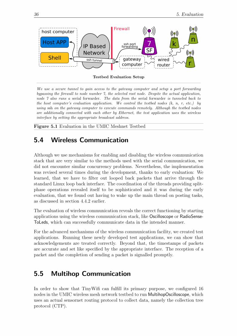
36 5. Evaluation
SF
host computer
gatewaycomputer
wiredrouter
IP BasedNetwork
r
nkHost APP
Shell
Firewall
7ssh portforwarding
ssh tunnel
Testbed Evaluation Setup
We use a secure tunnel to gain access to the gateway computer and setup a port forwardingbypassing the firewall to node number 7, the selected root node. Despite the actual application,node 7 also runs a serial forwarder. The data from the serial forwarder is tunneled back tothe host computer’s evaluation application. We control the testbed nodes (k, n, r, etc.) byusing ssh on the gateway computer to execute commands remotely. Although the testbed nodesare additionally connected with each other by Ethernet, the test application uses the wirelessinterface by setting the appropriate broadcast address.
Figure 5.1 Evaluation in the UMIC Meshnet Testbed
5.4 Wireless Communication
Although we use mechanisms for enabling and disabling the wireless communicationstack that are very similar to the methods used with the serial communication, wedid not encounter similar concurrency problems. Nevertheless, the implementationwas revised several times during the development, thanks to early evaluation: Welearned, that we have to filter out looped back packets that arrive through thestandard Linux loop back interface. The coordination of the threads providing split-phase operations revealed itself to be sophisticated and it was during the earlyevaluation, that we found out having to wake up the main thread on posting tasks,as discussed in section 4.4.2 earlier.
The evaluation of wireless communication reveals the correct functioning by startingapplications using the wireless communication stack, like Oscilloscope or RadioSense-ToLeds, which can successfully communicate data in the intended manner.
For the advanced mechanisms of the wireless communication facility, we created testapplications. Running these newly developed test applications, we can show thatacknowledgements are treated correctly. Beyond that, the timestamps of packetsare accurate and set like specified by the appropriate interface. The reception of apacket and the completion of sending a packet is signalled promptly.
5.5 Multihop Communication
In order to show that TinyWifi can fulfill its primary purpose, we configured 16nodes in the UMIC wireless mesh network testbed to run MultihopOscilloscope, whichuses an actual sensornet routing protocol to collect data, namely the collection treeprotocol (CTP).

5.5. Multihop Communication 37
MultihopOscilloscope Visualization
The screenshot of the MultihopOscilloscope Java based host application shows the data fromthe dummy sensors of 16 different nodes in the UMIC wireless mesh network testbed. Onlyfew nodes are in radio range of the collecting node (logical address 0), which indicates that thecollection tree protocol (CTP) of TinyOS works properly with TinyWifi on Linux driven wirelessnetworked nodes.Due to packet losses, curves can be discontinuous. The nodes are synchronized properly, sothat the curves do not overlap. We slightly changed the implementation of the Java based hostapplication: We (1) altered the background color of the plot area to be white and (2) set thestroke width to a higher value. With these modifications, the readability of the output is increasedtremendously, especially for the printed version.
Figure 5.2 TinyOS’s MultihopOscilloscope Host Application Output
The collection tree protocol is part of TinyOS and provides a best-effort anycastconnectionless communication service. It features forwarding messages to preselectedroot node(s). CTP uses trees to determine the next hop forwarding a messagegreedily towards the root node(s). The protocol is explained in much more detail byTEP 123 [11].
We configured node 7 (physical numbering) to run the MultihopOscilloscope withwireless address 0 (logical numbering). This makes node 7 the root node collectingall the data and forwarding it over the virtual serial line.
On the very same node, we ran a serial forwarder that connects to the virtualserial port of the root node and advertises the messages to a specific TCP port.We established an IP tunnel for that specific port from our host computer to nodenumber 7 over ssh in order to receive the data from the serial forwarder. We can thenvisualize the data that arrived at the CTP root node. The setup used is illustratedin figure 5.1 and also shows the configuration we will use when evaluating othersensornet protocols in the UMIC meshnet testbed.
We successfully received data from the sine sensor of all 16 of the configured nodes,as shown in figure 5.2. Hence, we finally reliably showed that we can use TinyWifito evaluate sensornet protocols designed for use with TinyOS in meshnets.

38 5. Evaluation

6Conclusion
In this thesis we presented TinyWifi, a new TinyOS platform enabling convenient androbust platform support for Linux driven host devices. Due to the inherent similarityof sensornets and meshnets, communication protocols for TinyOS can now easily beevaluated in Wi-Fi networks using TinyWifi. Because TinyWifi integrates smoothlyinto the current TinyOS source and supports all important hardware independentfunctionality, existing TinyOS applications can be compiled for Linux driven deviceswithout modifications. This approach saves a lot of re-implementation and allowsresearchers to evaluate their sensornet protocols in the Wi-Fi domain, instead of just(implicitly) claiming the applicability.
During the development of TinyWifi, we faced architecture and design related prob-lems of TinyOS, like split-phase operations, that demanded sophisticated solutionsin order to provide similar paradigms on top of Linux. We found a way to derive pow-erful timing functionalities from only a single Linux realtime timer and constructeda fully functional radio messaging facility working equally well in comparison withmotes. We also found a good way to provide a serial port running the TinyOSapplication by using Linux pseudo terminals.
Finally, we showed that TinyWifi is functioning as expected in a variety of differentsituations. We found that our approach is suitable to evaluate sensornet protocolsin meshnets with less time effort.
6.1 Future Work
Although TinyWifi already supports a range of different applications and is func-tioning correctly, some tasks are left to be dealt with in the future to further refineTinyWifi code and finally use it for research.

40 6. Conclusion
Linux Raw Sockets
Currently, we use UDP/IP packets to transmit TinyOS messages to other nodes. Atthe same time, we prune the main purpose of the internet protocol layer, namelyrouting, by setting the “time to live” header field to a value forcing the receivingnode to not route the packet to foreign nodes.
Nevertheless, this approach works well and saves a lot of sophisticated code. Addi-tionally, this method could be implemented and tested rather quickly, as required forthis thesis. But by sending messages through the internet protocol communicationstack of Linux without using its features, we cause latency as well as processing anddata overhead. Although this overhead is comparably negligible on resource richLinux driven devices, we want to use Linux raw sockets to get even closer to thebehavior of motes and cut back the overhead. Additionally, we do not rely on aproperly configured routing table, since data using raw sockets is sent out on theinterface regardless of the nerwork configuration. The effort to replace the sockettype so is expected to be limited to a single component and requires testing themessaging interface again.
Wireless Extensions
In some sensornet applications (e.g. link estimators), additional parameters likethe received signal strength indicator (RSSI) are of interest. Currently, we do notprovide support for such information, since obtaining them is hardware specific andlimits portability. Nevertheless, we will implement such functionality for use in ourmeshnet testbed and get even closer to the subtle features of motes.
Sencosrnet Protocol Evaluation
This thesis aimed at providing the basic infrastructure to allow for using existingTinyOS applications on Linux driven devices without the need to make great changesor even re-implement them each individually. The next step after progressing to rawsockets and using wireless extensions is starting to evaluate sensornet protocols inthe Wi-Fi domain.
In the near future, we intend to compare sensornet protocols to existing protocolscurrently used with Wi-Fi networks in a scientific way and to present our findingsto the research community.
Contribute TinyWifi to TinyOS Repository
TinyWifi is primarily targeted to extend applicability of state-of-the-art sensornetcommunication protocols to Wi-Fi networks. Hence, the TinyWifi platform supportshould be available to researchers for allowing evaluation of sensornet protocols inmeshnets in the future. TinyWifi integrates seamlessly into the existing TinyOSsource code, allowing to compile applications for motes as usual while having Linuxplatform support at the same time.
On that account, we intend to contribute TinyWifi to the official TinyOS repositoryas soon as TinyWifi proved itself to be reliable in use for our own evaluations.

Bibliography
[1] Alizai, M. H., Landsiedel, O., Bitsch Link, J. A., Goetz, S., andWehrle, K. Bursty Traffic over Bursty Links. In SenSys’09 (November 2009).
[2] Chen, L., Chen, Z., and Tu, S. A Realtime Dynamic Traffic ControlSystem Based on Wireless Sensor Network. In ICPPW’05: Proceedings of the2005 International Conference on Parallel Processing Workshops (Washington,DC, USA, 2005), IEEE Computer Society, pp. 258–264.
[3] Fonseca, R., Gnawali, O., Jamieson, K., and Levis, P. Four-Bit Wire-less Link Estimation. In HotNets (November 2007).
[4] Fonseca, R., Ratnasamy, S., Zhao, J., Ee, C. T., Culler, D.,Shenker, S., and Stoica, I. Beacon Vector Routing: Scalable Point-to-Point Routing in Wireless Sensornets. In NSDI (April 2005).
[5] Gay, D., Levis, P., von Behren, R., Welsh, M., Brewer, E., andCuller, D. The nesC language: A holistic approach to networked embeddedsystems. In ACM SIGPLAN PLDI (June 2003).
[6] Langendoen, K., Baggio, A., and Visser, O. Murphy Loves Potatoes:Experiences from a Pilot Sensor Network Deployment in Precision Agriculture.In Parallel and Distributed Processing Symposium, 2006. IPDPS 2006. 20thInternational (April 2006), p. 8 pp.
[7] Levis, P., Madden, S., Gay, D., Polastre, J., Szewczyk, R., Woo,A., Brewer, E., and Culler, D. The emergence of networking abstractionsand techniques in TinyOS. In NSDI’04: Proceedings of the 1st conference onSymposium on Networked Systems Design and Implementation (March 2004).
[8] Mao, Y., Wang, F., Qiu, L., Lam, S. S., and Smith, J. M. S4: SmallState and Small Stretch Routing Protocol for Large Wireless Sensor Networks.In NSDI (April 2007).
[9] MEMSIC Inc. Mica2, Mica2Dot, MicaZ, Telos, IRIS, Imote2 and CricketMote Datasheets available online in pdf format. http://www.memsic.com/
products/wireless-sensor-networks/wireless-modules.html.
[10] MEMSIC Inc. Mica2Dot Datasheet, Document Part Number: 6020-0043-06 Rev A. http://www.memsic.com/products/wireless-sensor-networks/wireless-modules.html.

42 Bibliography
[11] TinyOS Online Documentation. TinyOS Extension Proposals (TEPs).http://www.tinyos.net/tinyos-2.x/doc/.
[12] TinyOS Online Homepage. Mission Statement. http://www.tinyos.net/special/mission.
[13] Newsome, J., and Song, D. GEM: Graph EMbedding for routing and data-centric storage in sensor networks without geographic information. In SenSys’03(November 2003).
[14] Perkins, C. E., Royer, E. M., and Das, S. R. Ad hoc On-Demand Dis-tance Vector (AODV) Routing. In 2nd IEEE Workshop on Mobile ComputingSystems and Applications (February 1999).
[15] Polastre, J., Hill, J., and Culler, D. Versatile low power media accessfor wireless sensor networks. In SenSys’04 (November 2004).
[16] Polastre, J., Szewczyk, R., and Culler, D. Telos: Enabling Ultra-LowPower Wireless Research. In IPSN (April 2005).
[17] Singhvi, V., Krause, A., Guestrin, C., Garrett, Jr., J. H., andMatthews, H. S. Intelligent light control using sensor networks. In SenSys’05: Proceedings of the 3rd international conference on Embedded networkedsensor systems (New York, NY, USA, 2005), ACM, pp. 218–229.
[18] Szewczyk, R., Polastre, J., Mainwaring, A. M., and Culler, D. E.Lessons from a Sensor Network Expedition. In EWSN (2004), pp. 307–322.
[19] Werner-Allen, G., Lorincz, K., Welsh, M., Marcillo, O., Johnson,J., Ruiz, M., and Lees, J. Deploying a Wireless Sensor Network on an ActiveVolcano. IEEE Internet Computing 10 (2006), 18–25.

List of Figures
2.1 Sensor Node Hardware . . . . . . . . . . . . . . . . . . . . . . . . . . 5
2.2 Functioning of the Serial Forwarder in Sensornets . . . . . . . . . . . 6
2.3 TinyOS Hardware Abstraction Architecture . . . . . . . . . . . . . . 10
3.1 Layered TinyOS and TinyWifi Architecture . . . . . . . . . . . . . . 15
3.2 Timing Sources for Motes and TinyWifi . . . . . . . . . . . . . . . . 16
3.3 Split-Phase Operations when using TinyWifi . . . . . . . . . . . . . . 17
3.4 Message Propagation in Sensornets . . . . . . . . . . . . . . . . . . . 18
4.1 Example Wirings of Timing Components . . . . . . . . . . . . . . . . 24
5.1 Evaluation in the UMIC Meshnet Testbed . . . . . . . . . . . . . . . 36
5.2 TinyOS’s MultihopOscilloscope Host Application Output . . . . . . . . 37

44 List of Figures

ATinyWifi Source Code Compact Disc
Author:Bernhard Kirchen
Advisors:Hamad Alizai M.Sc.Prof. Klaus Wehrle
TinyWifiLinux Platform Support
for TinyOS
October 2010