Ultrasound-Based Guidance and Therapy
56
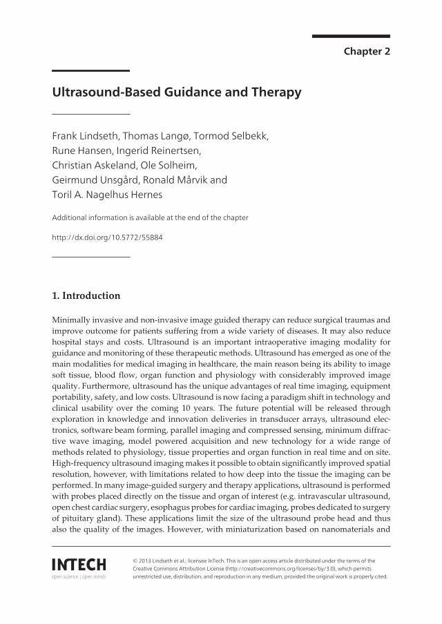
Chapter 2 Ultrasound-Based Guidance and Therapy Frank Lindseth, Thomas Langø, Tormod Selbekk, Rune Hansen, Ingerid Reinertsen, Christian Askeland, Ole Solheim, Geirmund Unsgård, Ronald Mårvik and Toril A. Nagelhus Hernes Additional information is available at the end of the chapter http://dx.doi.org/10.5772/55884 1. Introduction Minimally invasive and non-invasive image guided therapy can reduce surgical traumas and improve outcome for patients suffering from a wide variety of diseases. It may also reduce hospital stays and costs. Ultrasound is an important intraoperative imaging modality for guidance and monitoring of these therapeutic methods. Ultrasound has emerged as one of the main modalities for medical imaging in healthcare, the main reason being its ability to image soft tissue, blood flow, organ function and physiology with considerably improved image quality. Furthermore, ultrasound has the unique advantages of real time imaging, equipment portability, safety, and low costs. Ultrasound is now facing a paradigm shift in technology and clinical usability over the coming 10 years. The future potential will be released through exploration in knowledge and innovation deliveries in transducer arrays, ultrasound elec‐ tronics, software beam forming, parallel imaging and compressed sensing, minimum diffrac‐ tive wave imaging, model powered acquisition and new technology for a wide range of methods related to physiology, tissue properties and organ function in real time and on site. High-frequency ultrasound imaging makes it possible to obtain significantly improved spatial resolution, however, with limitations related to how deep into the tissue the imaging can be performed. In many image-guided surgery and therapy applications, ultrasound is performed with probes placed directly on the tissue and organ of interest (e.g. intravascular ultrasound, open chest cardiac surgery, esophagus probes for cardiac imaging, probes dedicated to surgery of pituitary gland). These applications limit the size of the ultrasound probe head and thus also the quality of the images. However, with miniaturization based on nanomaterials and © 2013 Lindseth et al.; licensee InTech. This is an open access article distributed under the terms of the Creative Commons Attribution License (http://creativecommons.org/licenses/by/3.0), which permits unrestricted use, distribution, and reproduction in any medium, provided the original work is properly cited.
Transcript of Ultrasound-Based Guidance and Therapy
Chapter 2
Ultrasound-Based Guidance and Therapy
Frank Lindseth, Thomas Langø, Tormod Selbekk,Rune Hansen, Ingerid Reinertsen,Christian Askeland, Ole Solheim,Geirmund Unsgård, Ronald Mårvik andToril A. Nagelhus Hernes
Additional information is available at the end of the chapter
http://dx.doi.org/10.5772/55884
1. Introduction
Minimally invasive and non-invasive image guided therapy can reduce surgical traumas andimprove outcome for patients suffering from a wide variety of diseases. It may also reducehospital stays and costs. Ultrasound is an important intraoperative imaging modality forguidance and monitoring of these therapeutic methods. Ultrasound has emerged as one of themain modalities for medical imaging in healthcare, the main reason being its ability to imagesoft tissue, blood flow, organ function and physiology with considerably improved imagequality. Furthermore, ultrasound has the unique advantages of real time imaging, equipmentportability, safety, and low costs. Ultrasound is now facing a paradigm shift in technology andclinical usability over the coming 10 years. The future potential will be released throughexploration in knowledge and innovation deliveries in transducer arrays, ultrasound elec‐tronics, software beam forming, parallel imaging and compressed sensing, minimum diffrac‐tive wave imaging, model powered acquisition and new technology for a wide range ofmethods related to physiology, tissue properties and organ function in real time and on site.High-frequency ultrasound imaging makes it possible to obtain significantly improved spatialresolution, however, with limitations related to how deep into the tissue the imaging can beperformed. In many image-guided surgery and therapy applications, ultrasound is performedwith probes placed directly on the tissue and organ of interest (e.g. intravascular ultrasound,open chest cardiac surgery, esophagus probes for cardiac imaging, probes dedicated to surgeryof pituitary gland). These applications limit the size of the ultrasound probe head and thusalso the quality of the images. However, with miniaturization based on nanomaterials and
© 2013 Lindseth et al.; licensee InTech. This is an open access article distributed under the terms of theCreative Commons Attribution License (http://creativecommons.org/licenses/by/3.0), which permitsunrestricted use, distribution, and reproduction in any medium, provided the original work is properly cited.
nanoelectronics technology, significant improvements in image quality may be obtained.Furthermore, new ultrasound technology can greatly enhance the detection of contrast agentsand drug carriers in the tissue. Integration of imaging with navigation technologies will easeimage interpretation and further improve precision and accuracy of the therapeutic procedure.Ultrasound technology may also be used for therapeutic purposes. High intensity focusedultrasound (HIFU) for ablation of tumor tissue is already a commercial product. It has alsobeen shown that ultrasound may improve the delivery and distribution of nanoparticles andlocal drug delivery by enhancing the local release, improving the penetration across thecapillary wall and through the extracellular matrix as well as enhance the cellular uptake. Theunderlying mechanisms are cavitation, radiation force and heating. The ultrasound inducedtransient increase in porosity and permeability of cell membranes can potentially enhance druguptake through tissue barriers (also the blood-brain barrier) and improve local drug delivery.
Therapeutic use of ultrasound will be addressed at the end of this chapter, which is mainlyabout guiding instruments into the body in a safe way using ultrasound, as well as thetechnological solutions involved to augment ultrasound in combination with other modalitiesand techniques. Ultrasound has been used to guide interventional instruments into the bodyfor a long time. Different approaches have been used. From freehand 2D guidance, via “needle”guides mounted on conventional ultrasound probes to ultrasound-based navigation usingtracking technology and 3D ultrasound (see figure 1). Surgical navigation will be the focus ofthis chapter and the analogy to GPS-navigation in a car is clear; instead of plotting the positionof the car onto electronic maps of the terrain using satellites and GPS-receivers the position ofimportant surgical instruments are shown on medical images of the patient using highlyaccurate tracking systems. Systems for image-guided surgery are now well established withinmany clinical disciplines. Surgical tools may be tracked by positioning systems and the surgeonmay accurately navigate the tools into the patient with high precision based on image infor‐mation only. Intraoperative imaging has shown to be important for obtaining improved tumorresection and increased survival for cancer patients undergoing surgery. Integration ofintraoperative imaging with navigation technology, providing the surgeon with updated imageinformation, is important to deal with tissue shifts and deformations that occur during surgery.MR, CT and ultrasound have been presented as alternative intraoperative imaging modalitiesshowing complementary information and having different benefits and drawbacks. Theseintraoperative imaging modalities are reported to be useful for accurate navigation of surgicalinstruments, monitoring the progression of surgery and solving the shift problem. Intraoper‐ative imaging has been used for updating preoperative images, which may be important foraccurate guidance. In recent years ultrasound has gained increased attention as a usefulintraoperative imaging modality (see figure 2), due to improved image quality and relativelylow price. In addition, more integrated solutions, that makes the technology user friendly andflexible has been presented. In the evolution of the next generation of ultrasound-basedmultimodal navigation systems, advances in ultrasound imaging, registration algorithms,visualization and display techniques and navigation accuracy are important ingredients. Wewill therefore start by looking into the technology that is needed in order to make ultrasound-based navigation a reality and then show key applications of the navigation technology. Recentadvances in ultrasound imaging will be useful also for intraoperative imaging. Furthermore,
Advancements and Breakthroughs in Ultrasound Imaging28

ultrasound needs to be integrated with tracking technology in order to make a navigationsystem with intraoperative imaging capabilities. In addition, such a system might be able touse preoperative CT/MR data, update these data to match the current patient anatomy usingintraoperative ultrasound, extract important structures from the different datasets, present theavailable multimodal information to the surgeon in an optimal way and be able to track all thesurgical tools. Last but not least we need to make sure that the navigation system is highlyaccurate so that we know that the navigation scene presented to the surgeon on the computerscreen is a realistic representation of what’s really going on inside the patient.
Figure 1. Ultrasound-based guidance: A) Freehand guidance: challenge to have the long axis of the instrument in the2D ultrasound plane. B) Needle guides: an adapter mounted on the probe makes sure that the instrument is withinthe 2D ultrasound plane. C) Navigation: tracking technology and 3D data from modalities like CT, MR and ultrasoundis used to guide relevant surgical instruments in place. Here an ultrasound probe is guided by MR during a freehand3D ultrasound aquistion
Figure 2. A) Workflow: Important steps in image-guided surgery. B) Ultrasound-based navigation example from neu‐rosurgery: Plan using preoperative MR. Acquire intraoperative 3D ultrasound. Navigation and resection control basedon updated ultrasound images. Acquire additional ultrasound data when needed.
Ultrasound-Based Guidance and Therapyhttp://dx.doi.org/10.5772/55884
29

2. Recent advances in ultrasound imaging
Sound in the human audible range have frequencies between 20 and 20 000 Hz. Ultrasound isdefined as sound with frequencies above 20 kHz. In medical imaging, the ultrasound frequen‐cies are usually between 2 and 40 MHz, with the highest frequencies currently used inintravascular ultrasound (IVUS).
The generation of an ultrasound image is based on transmission of sound pulses and receivingthe echoes that have been reflected from tissue boundaries or scattered from smaller objects.In most conventional scanners today, a narrow ultrasound beam is transmitted from theultrasound transducer. When the transmitted pressure pulse meets a hinder in form of aboundary between different soft tissues, or scatter points within the tissue with differentacoustic properties, some of the energy of the transmitted sound pulse is echoed back to thetransducer. This pulse-echo principle forms the basis of all ultrasound-imaging techniques,such as conventional brightness mode (B-mode) imaging of organs, imaging of blood flowusing Doppler techniques and exploration of mechanical tissue properties using ultrasoundelastography techniques.
2.1. Advances in ultrasound hardware and transducer technology
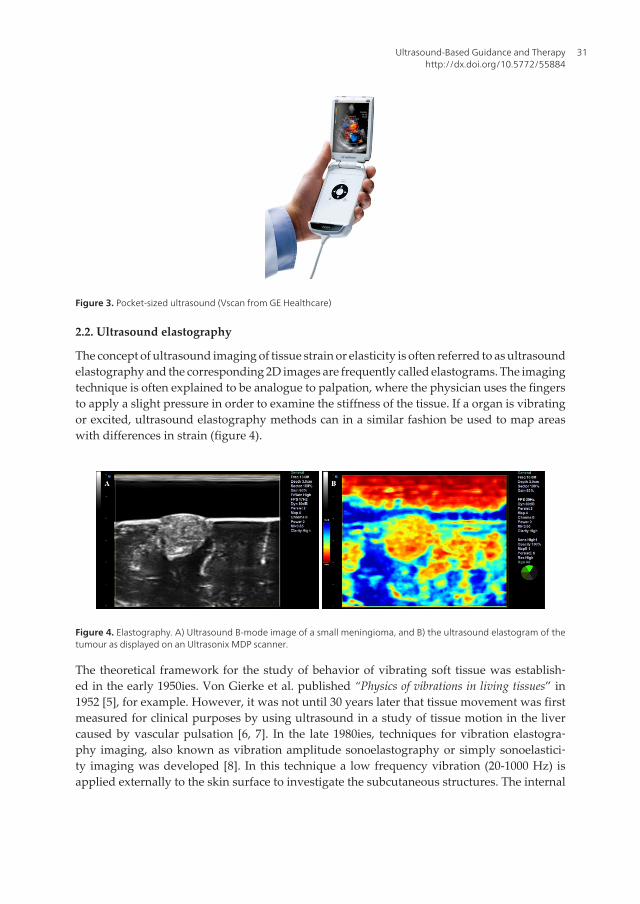
The ultrasound machines and ultrasound probes have gone through massive improvementsin the last decade. The general increase in computer power is opening new possibilities forimplementing sophisticated methods for beam forming. This may lead to higher resolutionand better image quality than for existing solutions [1]. The general trend with miniaturizationof components has also strongly influenced the size of the ultrasound imaging systems. Smallhandheld ultrasound devices have been developed, which makes ultrasound an extremelyportable imaging technology. One example of such a pocket sized ultrasound device is theVscan from GE Healthcare (figure 3), which has been explored for use in echocardiography [2].The ultrasound transducer technology has made tremendous progress the last decade. Thenumber of elements used by a transducer is increasing and the trend is to go from a single rowof elements (1D) to multi-row arrays (1.25D / 1.5D) and 2D matrix arrays. The latter providesthe possibility to perform 4D ultrasound imaging, in which a 3D ultrasound volume is acquiredand displayed in real time. 4D ultrasound imaging may also be used for monitoring oftreatment, e.g. radiofrequency ablation [3].
Ultrasound arrays today are mostly based on piezoelectric materials. The research activitiesin MUT (Micromachined Ultrasound Transducer) technology, and perhaps especially CMUT(capacitive MUT) transducers, pave the way for silicon-based arrays [4]. This may introduceprobes that are cheaper, more customizable and have higher frequencies and bandwidthcompared to piezoelectric transducers. In combination with the everlasting trend of miniatur‐ization, the CMUTs may in a long-term perspective allow complete ultrasound systems to beseamlessly integrated with surgical tools. It may very well be that the future surgical instru‐ment has an ultrasound transducer integrated on the tip, and a display unit integrated in thehandle.
Advancements and Breakthroughs in Ultrasound Imaging30
2.2. Ultrasound elastography
The concept of ultrasound imaging of tissue strain or elasticity is often referred to as ultrasoundelastography and the corresponding 2D images are frequently called elastograms. The imagingtechnique is often explained to be analogue to palpation, where the physician uses the fingersto apply a slight pressure in order to examine the stiffness of the tissue. If a organ is vibratingor excited, ultrasound elastography methods can in a similar fashion be used to map areaswith differences in strain (figure 4).
Figure 4. Elastography. A) Ultrasound B-mode image of a small meningioma, and B) the ultrasound elastogram of thetumour as displayed on an Ultrasonix MDP scanner.
The theoretical framework for the study of behavior of vibrating soft tissue was establish‐ed in the early 1950ies. Von Gierke et al. published “Physics of vibrations in living tissues” in1952 [5], for example. However, it was not until 30 years later that tissue movement was firstmeasured for clinical purposes by using ultrasound in a study of tissue motion in the livercaused by vascular pulsation [6, 7]. In the late 1980ies, techniques for vibration elastogra‐phy imaging, also known as vibration amplitude sonoelastography or simply sonoelastici‐ty imaging was developed [8]. In this technique a low frequency vibration (20-1000 Hz) isapplied externally to the skin surface to investigate the subcutaneous structures. The internal
Figure 3. Pocket-sized ultrasound (Vscan from GE Healthcare)
Ultrasound-Based Guidance and Therapyhttp://dx.doi.org/10.5772/55884
31

motion of the tissue is investigated with a pulsed Doppler technique. Stiff tissue respondsdifferently to the vibrations than softer tissue, and can therefore be distinguished in the real-time images.
In the early 1990ies, the development of compression elastography, also referred to as quasi-static elasticity imaging, begun. Ophir published a paper in 1991 where ultrasound radiofrequency (RF) data before and after applying compression were compared and processedusing cross-correlation to obtain the time-shifts of the echoes. This allowed the subsequentcalculation of elastograms [9]. The quasi-static elasticity imply that the force is applied for asufficiently long time for the tissue strain to stabilize, and the resulting difference in echo traveltime between ultrasound data acquired before and after compression can be calculated. Thetissue may also be excited by applying forces at the surface (manually or by electromechanicaldevices) or by physiological processes within the organ, as for example the pulsation of thearteries. The generated elastograms are usually displayed as a color-coded overlay on theconventional ultrasound brightness mode image. The color mapping may cover a range ofunit-less strain values as percentages from minimum (negative) strain to maximum (positive)strain. Alternatively, it may also be mapped from "soft" to "hard" tissue, thereby not quanti‐fying the strain range displayed. Quasi-static elasticity imaging has been evaluated in a broadrange of clinical applications. It has been reported used in diagnostics of tumors in for examplebreast, prostate, liver, the thyroid gland and in the brain (figure 4) [10-15]. Quasi-static elasticityimaging is an emerging ultrasound imaging modality, now becoming more and more availableas an option on commercial ultrasound systems.
As previously explained, the elastography methods require that the tissue is excited. The tissuemovement can be caused by physiological processes internally in the organ such as thepulsation of the arteries. The tissue can also be externally excited by manually pushing thetissue or by using an electromechanical vibrating device. An alternative approach is to use theacoustic radiation force of an ultrasonic focused beam to generate displacements in the tissuewith subsequent detection of the mechanical properties. One example of such an approach isthe Acoustic Radiation Force Impulse (ARFI) method developed at Duke University [16]. Inthis technique, short duration acoustic pulses (push pulses) are used to generate small localizeddisplacements deep in the tissue. These displacements are tracked by ultrasonic cross corre‐lation, in a similar fashion as for the quasi-static elasticity imaging. The method has beeninvestigated for imaging of focal liver lesions, prostate and breast [17-19].
Another example is the innovative Supersonic Shear Imaging (SSI) method developed by theresearch group at the Laboratoire Ondes et Acoustique [20]. In SSI the acoustic radiation forceis used to generate low-frequency shear waves (50-500 Hz) remotely in the tissue. The shearmodulus of the tissue can be quantified by imaging the share wave propagation in the tissueby using ultrasound frame rates of several kHz. The method has been explored for diagnosisof liver fibrosis, breast lesions and cornea [21-23].
For a more detailed overview about methods for ultrasound elasticity imaging and its clinicaluse we recommend to read the review papers by Wells and Liang [24] and Parker, Doyley andRubens [25].
Advancements and Breakthroughs in Ultrasound Imaging32

2.3. Nonlinear acoustics and contrast agents
In 1980, Carstensen and Muir published two papers describing the importance of nonlinearacoustics within the field of medical ultrasound imaging [26, 27]. These papers predicted anddemonstrated nonlinear acoustical effects relevant for intensities and frequencies common inbiomedical imaging. There has been an increasing interest with respect to nonlinear biomedicalacoustics during the last 30 years. This interest was further escalated by the introduction ofultrasound contrast agents in the form of microbubbles and the study of these microbubbleswas the main impetus for the introduction of the tissue harmonic imaging technique.
Nonlinear effects can be important in the forward wave propagation. The back-scatteredpressure levels of the echoes are typically too low to induce any significant nonlinear effects.One source of nonlinear terms is produced by the deformation of tissue volume elementsduring compression and expansion with strongly curved phase fronts. It is, however, commonto use transmit beams with relatively smooth phase fronts. Consequently, this nonlinear sourceis usually not the most dominant. The other important nonlinear source is nonlinear terms inthe tissue elasticity and hence in the relation between acoustic pressure and tissue compres‐sion/expansion. Nonlinear terms in the tissue elasticity are responsible for the fact that thetissue becomes stiffer during compression and softer during expansion. The compression alsoincreases the mass density of the tissue, but this effect is inferior to the increased stiffness andthe propagation velocity and will therefore be pressure dependent and will increase withincreasing compressions and thus with increasing pressure. The resulting distortion of thetransmit pressure field produces harmonic components which today are utilized in tissueharmonic imaging, especially in transcutaneous cardiac and abdominal imaging to suppressmultiple scattering [28-31].
Ultrasound imaging is based on several assumptions, and one important assumption is thatmultiple scattering is neglected. For many organs, this approximation is valid. However, forthe body wall, where larger variations in material parameters often are found, this assumptioncan be inadequate. Interfaces between soft tissue components with significant differences inmaterial parameters give so strong echoes from the transmitted acoustic pulses that multiplescattering can get significant amplitudes. Such multiple scatterings are usually termed pulsereverberations [32, 33]. These reverberations reduce the ratio of the strongest to the weakestscatterer that can be detected in the neighborhood of each other, defined as the contrastresolution in the image. Reduced contrast resolution is in particular a problem when imaginghypo-echoic structures such as the heart chambers, the lumen of large blood vessels, someatherosclerotic lesions, cysts, some tumors, the gallbladder as well as in fetal imaging. Thecontact interface between the ultrasound transducer itself and the soft tissue is also a strongreflector enhancing the problem with multiple scattering.
Ultrasound contrast agents are made as a suspension of gas microbubbles encapsulated in thinstabilizing shells made from lipid or albumin. Typical bubble size is in the 1-5 μm range andthe contrast bubbles are intravenously injected to increase the scattering from blood, which isweak compared to the scattering from soft tissues. Commercially available contrast bubblesare stable and small enough to enable transpulmonary passage and the blood half-life istypically in the range of 1-10 minutes. Scattering from microbubbles occurring within a liquid
Ultrasound-Based Guidance and Therapyhttp://dx.doi.org/10.5772/55884
33
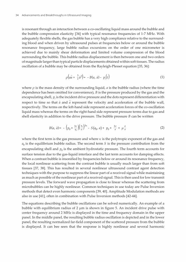
is resonant through an interaction between a co-oscillating liquid mass around the bubble andthe bubble compression elasticity [34] with typical resonance frequencies of 1-7 MHz. Withadequately flexible shells, the gas bubble has a very high compliance relative to the surround‐ing blood and when driven by ultrasound pulses at frequencies below or around the bubbleresonance frequency, large bubble radius excursions on the order of one micrometer isachieved due to mainly shear deformation and limited volume compression of the bloodsurrounding the bubble. This bubble radius displacement is then between one and two ordersof magnitude larger than typical particle displacements obtained within soft tissues. The radiusoscillation of a bubble may be obtained from the Rayleigh-Plesset equation [35, 36]:
ρ(aa + 32 a2)= - B(a, a) - pi(t) (1)
where ρ is the mass density of the surrounding liquid, a is the bubble radius (where the timedependence has been omitted for convenience), B is the pressure produced by the gas and theencapsulating shell, pi is the incident drive pressure and the dots represent differentiation withrespect to time so that a and a represent the velocity and acceleration of the bubble wall,respectively. The terms on the left-hand side represent acceleration forces of the co-oscillationliquid mass whereas the terms on the right-hand side represent pressure terms due to gas andshell elasticity in addition to the drive pressure. The bubble pressure B can be written
B(a, a)= - (p0 + 2σa0
)( a0
a )3κ- S (a0, a) + p0 + 2σ
a + μ aa (2)
where the first term is the gas pressure and where κ is the polytropic exponent of the gas anda0 is the equilibrium bubble radius. The second term S is the pressure contribution from theencapsulating shell and p0 is the ambient hydrostatic pressure. The fourth term accounts forsurface tension due to the gas-liquid interface and the last term accounts for damping effects.When a contrast bubble is insonified by frequencies below or around its resonance frequency,the local nonlinear scattering from the contrast bubble is usually much larger than from softtissues [37, 38]. This has resulted in several nonlinear ultrasound contrast agent detectiontechniques with the purpose to suppress the linear part of a received signal while maintainingas much as possible of the nonlinear part of a received signal. This is then used for low transmitpressure levels. The forward wave propagation is close to linear whereas the scattering frommicrobubbles can be highly nonlinear. Common techniques in use today are Pulse Inversionmethods that detect even harmonic components [39, 40]. Amplitude Modulation methods arealso in use [41], often in combination with Pulse Inversion methods [42-44].
The equations describing the bubble oscillations can be solved numerically. An example of abubble with equilibrium radius of 2 μm is shown in figure 5. An incident drive pulse withcenter frequency around 2 MHz is displayed in the time and frequency domain in the upperpanel. In the middle panel, the resulting bubble radius oscillation is depicted and in the lowerpanel, the resulting normalized far-field component of the scattered pressure from the bubbleis displayed. It can bee seen that the response is highly nonlinear and several harmonic
Advancements and Breakthroughs in Ultrasound Imaging34

components are present in the scattered pressure from the bubble. This response is obtainedwith an incident drive pulse having a mechanical index equal to 0.07, which is very lowcompared to what is used for regular tissue imaging. At such low transmit pressure levels, theforward wave propagation will be close to linear and distortion of the transmit field due tononlinear tissue elasticity will thus be very low. The harmonic components can then be usedto differentiate bubble echoes from tissue echoes through Pulse Inversion and AmplitudeModulation pulsing schemes. In most clinical applications of ultrasound contrast agents, it isdesirable to assess the micro-circulation or the tissue perfusion which cannot be done withoutthe use of contrast agents and which often is related to various diseases. It is then necessary toobtain a strong suppression of the tissue signal for detection of the contrast bubble signal.
An example of the use of ultrasound contrast agents in relation to minimally invasive inter‐ventions is radiofrequency ablation of liver tumors where contrast-enhanced ultrasound isused for improved detection and imaging of the lesions, for planning and guidance of multipleneedle electrodes and finally for immediate evaluation of the treatment [45].
SURF (Second order UltRasound Field) imaging is a nonlinear ultrasound imaging techniquebeing developed in Trondheim [46-50]. It is based on transmission of dual frequency bandpulse complexes consisting of a low frequency manipulation pulse and a high frequencyimaging pulse that are co-propagating. Two transmit pulse complexes that may be used withthe SURF technique are displayed in figure 6. With the use of conventional single frequencyband transmit pulses, nonlinear effects are mainly restricted to the generation of harmoniccomponents of the imaging pulse. With dual frequency band transmit pulses, other nonlineareffects also come into play. SURF imaging aims at further utilizing nonlinear acoustics forimproved imaging of various tissues and ultrasound contrast agents.
For imaging of ultrasound microbubbles, conventional techniques relies on driving the bubbleinto strong nonlinear oscillations with the imaging pulse at relatively low mechanical indexes.This is typically feasible when the imaging frequency is below or around the bubble resonancefrequency (as in the example of figure 5) and conventional contrast agents typically haveresonance frequencies below 7 MHz. However, when the imaging frequency is above thebubble resonance frequency a much higher mechanical index is required to obtain significant
between the ultrasound transducer itself and the soft tissue is also a strong reflector enhancing the problem with multiple
scattering.
Ultrasound contrast agents are made as a suspension of gas microbubbles encapsulated in thin stabilizing shells made from lipid or
albumin. Typical bubble size is in the 1-5 μm range and the contrast bubbles are intravenously injected to increase the scattering
from blood, which is weak compared to the scattering from soft tissues. Commercially available contrast bubbles are stable and
small enough to enable transpulmonary passage and the blood half-life is typically in the range of 1-10 minutes. Scattering from
microbubbles occurring within a liquid is resonant through an interaction between a co-oscillating liquid mass around the bubble
and the bubble compression elasticity [34] with typical resonance frequencies of 1-7 MHz. With adequately flexible shells, the gas
bubble has a very high compliance relative to the surrounding blood and when driven by ultrasound pulses at frequencies below
or around the bubble resonance frequency, large bubble radius excursions on the order of one micrometer is achieved due to
mainly shear deformation and limited volume compression of the blood surrounding the bubble. This bubble radius displacement
is then between one and two orders of magnitude larger than typical particle displacements obtained within soft tissues. The
radius oscillation of a bubble may be obtained from the Rayleigh-Plesset equation [35, 36]:
, (1)
where is the mass density of the surrounding liquid, is the bubble radius (where the time dependence has been omitted for
convenience), is the pressure produced by the gas and the encapsulating shell, is the incident drive pressure and the dots
represent differentiation with respect to time so that and represent the velocity and acceleration of the bubble wall,
respectively. The terms on the left-hand side represent acceleration forces of the co-oscillation liquid mass whereas the terms on the
right-hand side represent pressure terms due to gas and shell elasticity in addition to the drive pressure. The bubble pressure can
be written
, , (2)
where the first term is the gas pressure and where is the polytropic exponent of the gas and is the equilibrium bubble radius.
The second term is the pressure contribution from the encapsulating shell and is the ambient hydrostatic pressure. The fourth
term accounts for surface tension due to the gas-liquid interface and the last term accounts for damping effects. When a contrast
bubble is insonified by frequencies below or around its resonance frequency, the local nonlinear scattering from the contrast bubble
is usually much larger than from soft tissues [37, 38]. This has resulted in several nonlinear ultrasound contrast agent detection
techniques with the purpose to suppress the linear part of a received signal while maintaining as much as possible of the nonlinear
part of a received signal. This is then used for low transmit pressure levels. The forward wave propagation is close to linear
whereas the scattering from microbubbles can be highly nonlinear. Common techniques in use today are Pulse Inversion methods
that detect even harmonic components [39, 40]. Amplitude Modulation methods are also in use [41], often in combination with
Pulse Inversion methods [42-44].
Figure 5. Numerical simulation of oscillation for a bubble with equilibrium radius of 2 m and resonance frequency of 2.5 MHz. Upper panel
shows the drive pulse, middle panel shows the resulting bubble radius oscillation and lower panel shows the far-field component of the scattered
pressure from the bubble. Left panel displays the pulses in the time domain whereas the modulus of the Fourier Transform is displayed in the right
panel.
The equations describing the bubble oscillations can be solved numerically. An example of a bubble with equilibrium radius of 2
m is shown in figure 5. An incident drive pulse with center frequency around 2 MHz is displayed in the time and frequency
domain in the upper panel. In the middle panel, the resulting bubble radius oscillation is depicted and in the lower panel, the
resulting normalized far-field component of the scattered pressure from the bubble is displayed. It can bee seen that the response is
highly nonlinear and several harmonic components are present in the scattered pressure from the bubble. This response is obtained
with an incident drive pulse having a mechanical index equal to 0.07, which is very low compared to what is used for regular tissue
imaging. At such low transmit pressure levels, the forward wave propagation will be close to linear and distortion of the transmit
field due to nonlinear tissue elasticity will thus be very low. The harmonic components can then be used to differentiate bubble
2 3 4 5 60.1
0
0.1
(MPa
)
0 2 4 6 8 1040
20
0
(dB
)
2 3 4 5 61.61.8
22.22.4
(m
)
0 2 4 6 8 1040
20
0
(dB
)
2 3 4 5 60.5
0
0.5
1
Time (s)0 2 4 6 8 10
40
20
0
Frequency (MHz)
(dB
)
Figure 5. Numerical simulation of oscillation for a bubble with equilibrium radius of 2 μm and resonance frequency of2.5 MHz. The upper panels show the drive pulse, the middle panels show the resulting bubble radius oscillation andthe lower panels show the far-field component of the scattered pressure from the bubble. The left panels display thepulses in the time domain whereas the modulus of the Fourier Transform is displayed in the right panels.
Ultrasound-Based Guidance and Therapyhttp://dx.doi.org/10.5772/55884
35
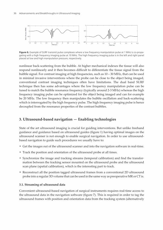
nonlinear back-scattering from the bubble. At higher mechanical indexes the tissue will alsorespond nonlinearly and it then becomes difficult to differentiate the tissue signal from thebubble signal. For contrast imaging at high frequencies, such as 10 – 30 MHz, that can be usedin minimal invasive interventions where the probe can be close to the object being imaged,conventional contrast imaging techniques often have limitations. The dual band SURFtechnique then has some advantages where the low frequency manipulation pulse can betuned to match the bubble resonance frequency (typically around 2-3 MHz) whereas the highfrequency imaging pulse can be optimized for the object being imaged and can for examplebe 20 MHz. The low frequency then manipulates the bubble oscillation and back-scatteringwhich is interrogated by the high frequency pulse. The high frequency imaging pulse is hencedecoupled from the resonance properties of the contrast bubbles.
3. Ultrasound-based navigation — Enabling technologies
State of the art ultrasound imaging is crucial for guiding interventions. But unlike freehandguidance and guidance based on ultrasound guides (figure 1) having optimal images on theultrasound scanner is not enough to enable surgical navigation. In order to use ultrasound-based navigation to guide such procedures we usually have to:
• Get the images out of the ultrasound scanner and into the navigation software in real-time.
• Track the position and orientation of the ultrasound probe at all times.
• Synchronize the image and tracking streams (temporal calibration) and find the transfor‐mation between the tracking sensor mounted on the ultrasound probe and the ultrasoundscan plane (spatial calibration), which is the interesting part to track.
• Reconstruct all the position tagged ultrasound frames from a conventional 2D ultrasoundprobe into a regular 3D volume that can be used in the same way as preoperative MR or CT is.
3.1. Streaming of ultrasound data
Convenient ultrasound-based navigation of surgical instruments requires real-time access tothe ultrasound data in the navigation software (figure 7). This is required in order to tag theultrasound frames with position and orientation data from the tracking system (alternatively
Figure 6. Example of SURF transmit pulse complexes where a low frequency manipulation pulse at 1 MHz is co-propa‐gating with a high frequency imaging pulse at 10 MHz. The high frequency imaging pulse is in the left and right panelplaced at low and high manipulation pressure, respectively.
Advancements and Breakthroughs in Ultrasound Imaging36

the tracking data could be directed directly into the scanner and the ultrasound frames couldbe used off-line, e.g. to generate a 3D volume from the tagged 2D frames). The traditional wayof getting real-time access to ultrasound frames is to connect the analog output (e.g., compositevideo, S-video) of the ultrasound scanner to a frame-grabbing card on the navigation computer.Using the analog output might affect the image quality due to the double digital-to-analog-to-digital conversion and no metadata (e.g. depth) follow the ultrasound images. Alternativelydigital data can be streamed directly from the ultrasound scanner and into the navigationcomputer. Traditionally this has required some kind of research collaboration between theultrasound manufacturer and the user but open ultrasound scanners are becoming available(e.g. the Ultrasonix scanner). These systems usually provide just a one-way streaming interfacebut two-way communication protocols where the scanner can be controlled (e.g. depth) by thenavigation system exists making more integrated solutions possible (figure 7). Either way, theprotocol (or interface / API) used is typically proprietary, although proposals for real-timestandards are starting to emerge (e.g. OpenIGTLink, DICOM in surgery (WG24)). When thelink between the ultrasound scanner and navigation system is digital, ultrasound data atdifferent stages in the processing chain on the scanner can be transferred (e.g. scan-converted,scan-line and RF-data). Furthermore, a digital streaming interface will be required in order touse the real-time 3D scanners that are now becoming available also for navigation. It’s difficultto capture the 3D content in the scanner display using a frame grabber so the data needs to betransferred in real-time or tagged with a tracking reference on the ultrasound scanner.
Figure 7. Streaming ultrasound data into the navigation system. The interface can either be analog using a framegrabber or digital using a direct link and a proprietary protocol. A digital interface can either be one-way (i.e. stream‐ing) or two-way (i.e. optionally control the scanner from the navigation system as well). In any case the image streammust be tagged with tracking data and in order to do that the two streams need to be synchronized.
3.2. Tracking of ultrasound probes
In order to use ultrasound to guide surgical procedures the ultrasound probe must be tracked.Several tracking technologies have been proposed over the years (mechanical, acoustical,
Ultrasound-Based Guidance and Therapyhttp://dx.doi.org/10.5772/55884
37

optical and electromagnetic), but currently the most widely used solutions are optical orelectromagnetic systems (see figure 8). Choosing the best tracking technology depends onthe application at hand and the ultrasound probes used. If possible optical tracking sys‐tems should be preferred as magnetic tracking in the operating room can be challenging dueto disturbances from metallic objects and the accuracy is close but not as good as opticalsystems under favorable conditions. For flexible us-probes or probes that are inserted intothe body magnetic tracking is required as the transformation between the sensor and thescan plane must be rigid and optical tracking demands clear line of sight to the cameras. Inaddition the magnetic sensors are very small, crucial in order to be embedded in instru‐ments and put into the body. When the ultrasound probe is tracked it becomes one of severaltools and the streamed ultrasound data can either be shown in real time at the right spot inthe patient or made into a 3D volume and shown together with other images to the surgeon.A brief description of the two main tracking technologies can be found below [51, 52]:
• Optical tracking systems: The basic idea is to use one or more cameras with markers distrib‐uted on a rigid structure where the geometry is specified beforehand (figure 8A). At leastthree markers are necessary to determine the position and orientation of the rigid body inspace. Additional markers allow a better camera visibility of the tracked object and improvethe measurement accuracy. The markers can be infrared light-emitting diodes (activemarkers), infrared light reflectors (passive markers) or some kind of pattern (usually achecker board) that can be identified using visual light and image analysis.
• Electromagnetic tracking systems: A receiver (sensor) is placed on the ultrasound probe andthe system measures the induced electrical currents when the sensor is moved within amagnetic field generated by either an alternating current (AC) or direct current (DC)transmitter / generator (figure 8B). The AC and DC devices are both sensitive to some typesof metallic objects placed too close to the transmitter or receiver, and to magnetic fieldsgenerated by power sources and devices such as cathode-ray tube monitors. Therefore, bothtypes of electromagnetic systems are challenging to use in an environment such as anoperating room, where various metallic objects are moved around in the field [53]. The twometal related phenomena that influence the performance of electromagnetic trackingsystems are ferromagnetism and eddy currents [54]. Ferromagnetic materials (e.g., iron,steel) affect both AC and DC systems, because they change the homogeneity of the tracker-generated magnetic field, although the DC systems may be more sensitive to these effects.In contrast, the AC technology is more affected by the presence of conductors such as copperand aluminum because of distortions caused by eddy currents [53, 55]. DC systemsminimize the eddy-current related distortions by sampling the field after eddy currents havedecayed.
• Comparisons between optical and magnetic tracking systems - pros and cons: The main advantageswith optical tracking systems are their robustness and high accuracy and the challenges areline of sight problems and the relatively big sensor frames. For electromagnetic trackingsystem it’s basically the other way around.
Advancements and Breakthroughs in Ultrasound Imaging38

Figure 8. Optical (A) and electromagnetic (B) tracking of ultrasound probes.
3.3. Ultrasound probe calibration
After streaming ultrasound data into the navigation software and tracking the ultrasoundprobe, calibration is needed in order to integrate the image stream with the tracking stream.Ultrasound probe calibration is an important topic as this is the main error source for ultra‐sound-based navigation (see section on accuracy). Two types of calibration are necessary;temporal calibration to find the lag between the image and tracking streams and spatialcalibration [56, 57] to find the transformation between the ultrasound scan plane and thetracking sensor mounted on the ultrasound-probe (see figure 9):
• Temporal calibration (find the time lag between the image stream and the tracking stream, see figure9A): The most common way to do this is to move the ultrasound probe up and down in awater bath and extract some feature in the generated us-images (or correlate the images andmeasure the displacement). This gives us two sinus-like curves, one for the vertical positionof the extracted feature in the images and one for the vertical component in the trackingdata. The two curves are compared and one of them is fitted to the other to find the time lagbetween the two streams.
• Spatial calibration (find the transformation between the image and the sensor, see figure 9B):Considerable effort has been spent on probe calibration over the last decade, and it stillseems to be a hot research topic. Maybe because it is a challenging task to make it accurate,especially if the same method / phantom is to be used for substantially different probes. Itis not possible to measure this transform with a ruler because the orientation of the scanplane relative to the sensor frame is unknown, we do not know the origin of the us-planeinside the probe housing and magnetic sensors do not have a known origin. A commonlyused approach for probe calibration is to acquire 2-D images of a phantom with knowngeometry and to identify distinct features in the images. Because the location of the same
Ultrasound-Based Guidance and Therapyhttp://dx.doi.org/10.5772/55884
39

features are known in the global coordinate system, the probe calibration matrix can befound from a relatively simple matrix equation. The probe calibration methods reported inthe literature mainly differ with respect to the phantom geometry, whereas the processingof the acquired data is more or less common for all methods. The majority of probe calibra‐tion methods can be categorized into one of three different classes: single- point or line; 2-D alignment; and freehand methods. The calibration matrix can be calculated as follows.Acquire the necessary amount of calibration images and find the coordinates of all thecalibration points in each image. Next, we transform the corresponding physical points fromglobal reference coordinates into sensor frame coordinates by using the inverse of thetracking matrix. The rigid body transformation that minimizes the mean Euclidian distancebetween the two homologous point sets will be the probe calibration matrix. The matrix canbe calculated using a direct least squares error minimization technique [58].
Figure 9. Temporal (A) and spatial (B) calibration of the ultrasound probe.
3.4. 3D Ultrasound
It is difficult to guide an instrument into place using conventional 2D ultrasound only(freehand guidance): in order to know where the instrument is we need to see it in theultrasound image and to reach the target we have to know where to go from there, a chal‐lenging hand-eye coordination task. It’s much more convenient to acquire a 3D ultrasoundvolume first and let the tracked instrument extract slices from the volume that can be annotatedwith the position and / or orientation of the instrument (see section on visualization).
3D ultrasound data can be acquired in different ways [59]. A conventional 1D array probe (2D+t) can be moved over the area of interest, either by freehand motion or by a motor. If freehandmovement is used all the ultrasound frames can be put together into a volume using trackingdata (figure 10) or correlation. A motor inside the probe hosing or external to it can also beused to cover the ROI by tilt, translation or rotation of the 1D array (figure 11). Furthermore,with a 2D matrix probe the ultrasound beam can be steered in the elevation direction in
Advancements and Breakthroughs in Ultrasound Imaging40
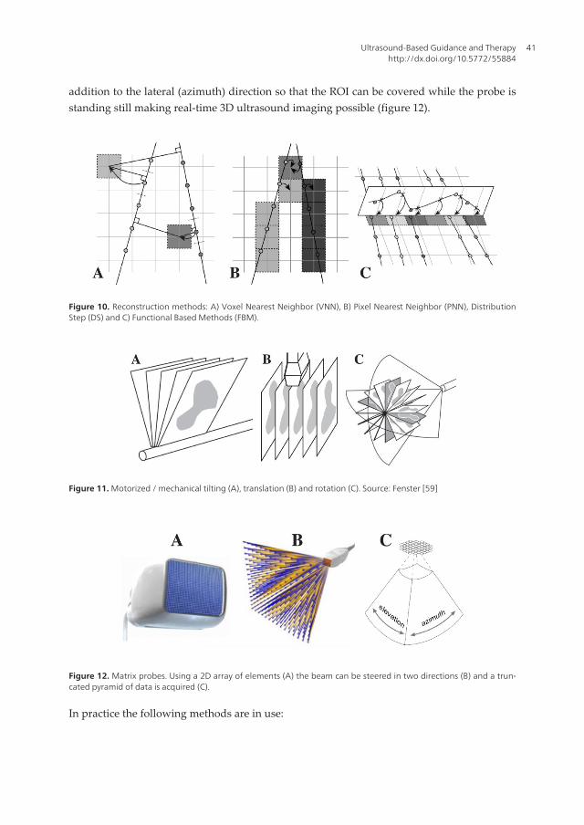
addition to the lateral (azimuth) direction so that the ROI can be covered while the probe isstanding still making real-time 3D ultrasound imaging possible (figure 12).
Figure 10. Reconstruction methods: A) Voxel Nearest Neighbor (VNN), B) Pixel Nearest Neighbor (PNN), DistributionStep (DS) and C) Functional Based Methods (FBM).
Figure 11. Motorized / mechanical tilting (A), translation (B) and rotation (C). Source: Fenster [59]
Figure 12. Matrix probes. Using a 2D array of elements (A) the beam can be steered in two directions (B) and a trun‐cated pyramid of data is acquired (C).
In practice the following methods are in use:
Ultrasound-Based Guidance and Therapyhttp://dx.doi.org/10.5772/55884
41

• Freehand 3D ultrasound: This is still the most wildly used method (mainly because of itsflexibility) and usually the method works in the following manner: Scan the area of interestusing a conventional 2D probe that is tracked and reconstruct the position tagged ultrasoundframes into a regular 3D volume that can be used in the same way as preoperative MR orCT. The ultrasound probe is usually tracked by optical or electromagnetic sensors, but othermethods have been proposed. Furthermore, different methods exist to reconstruct all the2D frames into a regular 3D volume. The methods can be categorized into tree main groups[60]:
◦ Voxel-based methods (VBM): VBM traverse each voxel in the target voxel grid and gatherinformation from the input 2D images to be placed in the voxel. One or several pixelsmay contribute to the value of each voxel. The simplest method in this category is VoxelNearest Neighbor (VNN), which traverses each voxel in the target volume and assignsthe value of the nearest image pixel (see figure 10A).
◦ Pixel-based methods (PBM): PBM usually consists of two steps: a Distribution Step (DS)where the input pixels are traversed and applied to one or several voxels and a Hole-Filling Step (HFS) where the voxels are traversed and empty voxels are being filled. Thesimplest method in this category is Pixel Nearest Neighbor (PNN) that runs through eachpixel in all the 2D input images and assigns the pixel value to the nearest voxel in thetarget volume (see figure 10B).
◦ Function based methods (FBM): FBM choose a particular function (like a polynomial) anddetermine the coefficients to make the functions pass through the input pixels. After‐wards, the function can be used to create a regular voxel array by evaluating the functionat regular intervals (see figure 10C). These methods produce reconstructed volumes withthe highest quality but are very computational intensive and are in limited use today.
• Motorized (or mechanical) 3D ultrasound: Instead of using freehand movement of the ultra‐sound probe over the area of interest a motor can cover the same region by tilting (figure11A), translating (figure 11B) or rotating (figure 11C) a conventional 1D ultrasound array.Motorized probes have existed for a long time and the motor can either be mounted insidethe probe housing (easy to use but requires a specially build ultrasound probe) or be appliedexternally (more flexible as conventional probes can be used). Many of the benefits withfreehand scanning also apply to motorized scanning, e.g. the possibility to use highfrequency probes with higher spatial resolution, also in the elevation direction (1.25D/1.5Dprobes). Motorized scanning can use the same kind of reconstruction methods as freehandscanning but usually more optimized methods are used as the movement is known and theprobe do not need to be tracked during the acquisition. Compared to freehand ultrasoundthe motorized probes are easier to use in an intraoperative setting, but on the other hand,they are not as flexible in general.
• Real-time 3D ultrasound using 2D matrix probes [61-65]: Instead of using a conventional 1Darray transducer that is moved by freehand or by a motor to sweep out the anatomy ofinterest, transducers with 2D phased arrays (figure 12A) that can generate 3D images in realtime have been developed. Electronics is used to control and steer the ultrasound beam
Advancements and Breakthroughs in Ultrasound Imaging42

(figure 12B) and sweep out a volume shaped like a truncated pyramid (figure 12C). Themain challenge with this technology is the large and heavy cable that would be required toconnect all the elements in the array to a wire. Fortunately technological achievements interms of multiplexing, sparse arrays and parallel processing over the last decade have madethese systems commercially available. They are used extensively in echocardiology, whichrequires dynamic three-dimensional imaging of the heart and its valves.
3.5. Integrated ultrasound-based navigation solutions
Ultrasound and navigation can be integrated in different ways as we have seen. Completesystems can usually be categorized as follows:
• Two-rack systems: Where the navigation computer with tracking system etc. and the ultra‐sound scanner are two separate systems. This is most common, especially in a researchenvironment. The main reason for this is flexibility, in principle any ultrasound scanner withan analog output can be used together with a navigation system that is equipped withultrasound-based navigation software. An example of such a configuration is our in houseresearch system for us-based navigation called CustusX (figure 13A). The system is used fordifferent clinical applications (e.g. neurosurgery and laparoscopy), each navigation rack isequipped with both optical and magnetic tracking and can be connected to a variety ofultrasound scannersusing analog and digital interfaces.
• One-rack systems: Here the ultrasound scanner and the navigation computer have beenintegrated in the same system. These systems are more convenient to use in the operatingroom but are less flexible. Most commercial solutions belong to this category. Two variationsexists:
◦ An ultrasound scanner with navigation software integrated. The PercuNav system fromPhilips, an integrated solution for navigation and intraoperative imaging, is an exampleof this (figure 13B).
◦ A navigation system with an ultrasound scanner integrated: The SonoWand system (Trond‐heim, Norway), where an ultrasound scanner has been embedded in the navigation rack,is an example of this (figure 13C). The system can be used in three distinct ways: 1) as anavigation system based on preoperative MR/CT data, 2) as a standalone ultrasoundscanner and 3) as an ultrasound-based navigation system with intraoperative imagingcapabilities, its main use.
4. Registration and segmentation in ultrasound-based navigation
Registration is the process of transforming an image into the coordinate system of a patient,or another image. After registration, the same anatomical features have the same coordinatesin both the image and the patient, or in both images. Image-to-patient registration is one of thecornerstones of any navigation system, and is necessary for navigation using pre-operative
Ultrasound-Based Guidance and Therapyhttp://dx.doi.org/10.5772/55884
43

images such as MR and/or CT. Image-to-image registration is useful to align pre-operativeimages before registration to the patient, and also to update the pre-operative images duringsurgery using for example intra-operative US. Only the latter involves US and will be the focusin this section, but image-to-patient registration is important for proper initialization of theMR/CT-to-US registration. The main motivation behind image-to-image registration is thatdifferent images contain different and complimentary information about the patient at a givenpoint in time. When we bring the images into the same coordinate system and into thecoordinate system of the patient, we can take advantage of more of the useful information inthe different images. Such information can be the size and location of the surgical target,important blood vessels, critical structures that should be avoided etc. The registration methodused in each case depends heavily on the type of images we want to register. The type of spatialtransformation, how we measure the similarity between the images and how this measure isoptimized are key components of any registration procedure.
4.1. Registration of preoperative images to the patient
Image-to-patient registration is a necessary and crucial step in order to use pre-operativeimages for guidance. Intraoperative ultrasound only shows a limited portion of the surgicalfield and might require some experience to appreciate. Preoperative data can therefore be usedfor overview and interpretation. In neurosurgery, for example, it is not possible to acquireultrasound images before opening of the dura. Pre-operative images are therefore necessaryfor planning the craniotomy.
One of the most frequently used registration methods consists in using self-adhesive markers,also called fiducials. The fiducials are glued to the patient's skin before MR or CT imaging. Themarkers can be identified in the images and the corresponding markers can be identified onthe patient using a tracked pointer once the patient is immobilized on the operating table(figure 14). A spatial transformation can then be computed transforming the image into thecoordinate system of the patient. The surgeon can then point on the patient using a tracked
Figure 13. Different approaches to integrating (3D) ultrasound and navigation. A) A two-rack solution and examplesof one-rack solutions (B and C).
Advancements and Breakthroughs in Ultrasound Imaging44
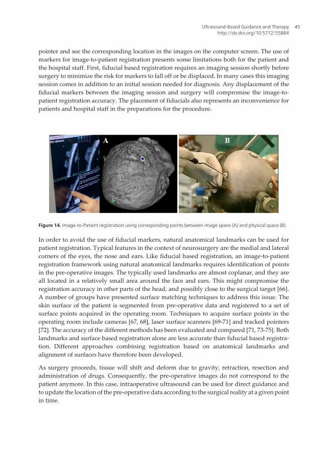
pointer and see the corresponding location in the images on the computer screen. The use ofmarkers for image-to-patient registration presents some limitations both for the patient andthe hospital staff. First, fiducial based registration requires an imaging session shortly beforesurgery to minimize the risk for markers to fall off or be displaced. In many cases this imagingsession comes in addition to an initial session needed for diagnosis. Any displacement of thefiducial markers between the imaging session and surgery will compromise the image-to-patient registration accuracy. The placement of fiducials also represents an inconvenience forpatients and hospital staff in the preparations for the procedure.
Figure 14. Image-to-Patient registration using corresponding points between image space (A) and physical space (B).
In order to avoid the use of fiducial markers, natural anatomical landmarks can be used forpatient registration. Typical features in the context of neurosurgery are the medial and lateralcorners of the eyes, the nose and ears. Like fiducial based registration, an image-to-patientregistration framework using natural anatomical landmarks requires identification of pointsin the pre-operative images. The typically used landmarks are almost coplanar, and they areall located in a relatively small area around the face and ears. This might compromise theregistration accuracy in other parts of the head, and possibly close to the surgical target [66].A number of groups have presented surface matching techniques to address this issue. Theskin surface of the patient is segmented from pre-operative data and registered to a set ofsurface points acquired in the operating room. Techniques to acquire surface points in theoperating room include cameras [67, 68], laser surface scanners [69-71] and tracked pointers[72]. The accuracy of the different methods has been evaluated and compared [71, 73-75]. Bothlandmarks and surface based registration alone are less accurate than fiducial based registra‐tion. Different approaches combining registration based on anatomical landmarks andalignment of surfaces have therefore been developed.
As surgery proceeds, tissue will shift and deform due to gravity, retraction, resection andadministration of drugs. Consequently, the pre-operative images do not correspond to thepatient anymore. In this case, intraoperative ultrasound can be used for direct guidance andto update the location of the pre-operative data according to the surgical reality at a given pointin time.
Ultrasound-Based Guidance and Therapyhttp://dx.doi.org/10.5772/55884
45

4.2. Ultrasound-based update of preoperative data
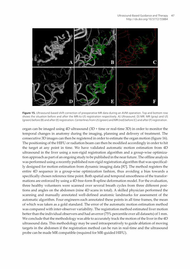
As surgery proceeds the pre-operative images no longer reflect the reality and updatedinformation is necessary for accurate navigation. Intra-operative ultrasound can be ac‐quired when needed during the procedure and be used for direct guidance and resectioncontrol, but also as a registration target for pre-operative images in order to update theirposition. This is particularly important for images such as functional MRI (fMRI) and diffusiontensor imaging (DTI) in neurosurgery because the information contained in these imagescannot be easy re-acquired during the procedure. By performing MR/CT-to-US registra‐tion, the information contained in the pre-operative images can be shifted to the correctposition at any given point in time (figure 15). Registration of MR/CT to US is a challeng‐ing task due to differences in image appearance and noise characteristics. The existingmethods can be divided into two main categories:
• Intensity-based methods: These methods take the original images (MR/CT and B-mode US) asinput, and the optimization of the registration parameters is computed from the imageintensities, either directly or indirectly (blurring, gradients etc.). Some of the existingmethods use well-known similarity measures such as mutual information and cross-correlation, while others have developed similarity measures particularly adapted to theregistration of MR/CT and ultrasound [76-82].
• Feature-based methods: These methods require segmentation or “enhancement” of particularfeatures in the images to be registered. The registration algorithm will then align thecorresponding features in each image. In MR/CT-to-US registration such feature might bethe vascular tree [83-85]. Blood vessels are relatively easy to identify and segment in bothMR angiography and Doppler ultrasound images, and are present in nearly any region ofinterest. A centerline or skeleton can be computed from the segmented vessels and be usedfor registration. The most commonly used method for feature-based registration is theiterative closest point algorithm (ICP) [86]. In the case of vessel registration, all the pointsin the moving dataset are paired with the closest point in the fixed dataset. Based on thesepoint correspondences, the registration parameters can be computed using the least squaresmethod. The resulting transformation is then applied to the moving dataset and new pointcorrespondences can be computed. The process is then iterated until convergence.
Several methods within the two main categories have been validated using retrospectiveclinical data [12, 14, 15]. So far no automatic method has been thoroughly validated intrao‐peratively (figure 15). The use of automatic registration methods in the operating roomrequires high quality data and straightforward, accurate, robust and fast image processing.With all this in place, image registration using intraoperative ultrasound will be able to correctthe position of pre-operative data and thereby provide updated and reliable information aboutanatomy, pathology and function during surgery.
4.3. Motion correction using 4D ultrasound
Intensity based registration of ultrasound images can also be used to track the motion of an organof interest. In the case of high-intensity focused ultrasound (HIFU or FUS) or radiotherapy, the
Advancements and Breakthroughs in Ultrasound Imaging46
organ can be imaged using 4D ultrasound (3D + time or real-time 3D) in order to monitor thetemporal changes in anatomy during the imaging, planning and delivery of treatment. Theconsecutive 3D images can then be registered in order to estimate the organ motion (figure 16).The positioning of the HIFU or radiation beam can then be modified accordingly in order to hitthe target at any point in time. We have validated automatic motion estimation from 4Dultrasound in the liver using a non-rigid registration algorithm and a group-wise optimiza‐tion approach as part of an ongoing study to be published in the near future. The offline analysiswas performed using a recently published non-rigid registration algorithm that was specifical‐ly designed for motion estimation from dynamic imaging data [87]. The method registers theentire 4D sequence in a group-wise optimization fashion, thus avoiding a bias towards aspecifically chosen reference time point. Both spatial and temporal smoothness of the transfor‐mations are enforced by using a 4D free-form B-spline deformation model. For the evaluation,three healthy volunteers were scanned over several breath cycles from three different posi‐tions and angles on the abdomen (nine 4D scans in total). A skilled physician performed thescanning and manually annotated well-defined anatomic landmarks for assessment of theautomatic algorithm. Four engineers each annotated these points in all time frames, the meanof which was taken as a gold standard. The error of the automatic motion estimation methodwas compared with inter-observer variability. The registration method estimated liver motionbetter than the individual observers and had an error (75% percentile over all datasets) of 1 mm.We conclude that the methodology was able to accurately track the motion of the liver in the 4Dultrasound data. This methodology may be used intraoperatively to guide ablation of movingtargets in the abdomen if the registration method can be run in real-time and the ultrasoundprobe can be made MR compatible (required for MR-guided HIFU).
Figure 15. Ultrasound-based shift correction of preoperative MR data during an AVM operation. Top and bottom rowshows the situation before and after the MR-to-US registration respectively. A) Ultrasound. D) MR. MR (gray) and US(green) before (B) and after (E) registration. Centerlines from US (green) and MR (red) before (C) and after (F) registration.
Ultrasound-Based Guidance and Therapyhttp://dx.doi.org/10.5772/55884
47
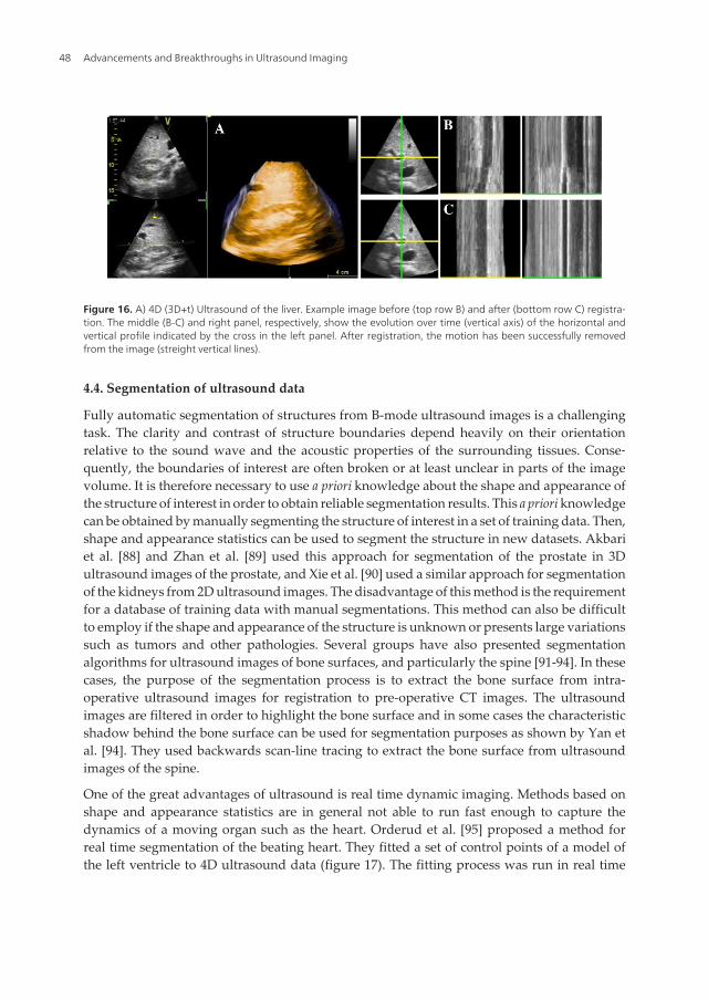
Figure 16. A) 4D (3D+t) Ultrasound of the liver. Example image before (top row B) and after (bottom row C) registra‐tion. The middle (B-C) and right panel, respectively, show the evolution over time (vertical axis) of the horizontal andvertical profile indicated by the cross in the left panel. After registration, the motion has been successfully removedfrom the image (streight vertical lines).
4.4. Segmentation of ultrasound data
Fully automatic segmentation of structures from B-mode ultrasound images is a challengingtask. The clarity and contrast of structure boundaries depend heavily on their orientationrelative to the sound wave and the acoustic properties of the surrounding tissues. Conse‐quently, the boundaries of interest are often broken or at least unclear in parts of the imagevolume. It is therefore necessary to use a priori knowledge about the shape and appearance ofthe structure of interest in order to obtain reliable segmentation results. This a priori knowledgecan be obtained by manually segmenting the structure of interest in a set of training data. Then,shape and appearance statistics can be used to segment the structure in new datasets. Akbariet al. [88] and Zhan et al. [89] used this approach for segmentation of the prostate in 3Dultrasound images of the prostate, and Xie et al. [90] used a similar approach for segmentationof the kidneys from 2D ultrasound images. The disadvantage of this method is the requirementfor a database of training data with manual segmentations. This method can also be difficultto employ if the shape and appearance of the structure is unknown or presents large variationssuch as tumors and other pathologies. Several groups have also presented segmentationalgorithms for ultrasound images of bone surfaces, and particularly the spine [91-94]. In thesecases, the purpose of the segmentation process is to extract the bone surface from intra-operative ultrasound images for registration to pre-operative CT images. The ultrasoundimages are filtered in order to highlight the bone surface and in some cases the characteristicshadow behind the bone surface can be used for segmentation purposes as shown by Yan etal. [94]. They used backwards scan-line tracing to extract the bone surface from ultrasoundimages of the spine.
One of the great advantages of ultrasound is real time dynamic imaging. Methods based onshape and appearance statistics are in general not able to run fast enough to capture thedynamics of a moving organ such as the heart. Orderud et al. [95] proposed a method forreal time segmentation of the beating heart. They fitted a set of control points of a model ofthe left ventricle to 4D ultrasound data (figure 17). The fitting process was run in real time
Advancements and Breakthroughs in Ultrasound Imaging48
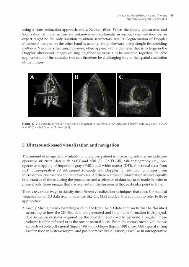
using a state estimation approach and a Kalman filter. When the shape, appearance andlocalization of the structure are unknown semi-automatic or manual segmentation by anexpert might be the only solution to obtain satisfactory results. Segmentation of Dopplerultrasound images, on the other hand is usually straightforward using simple thresholdingmethods. Vascular structures, however, often appear with a diameter that is to large in theDoppler ultrasound images causing neighboring vessels to be smeared together. Reliablesegmentation of the vascular tree can therefore be challenging due to the spatial resolutionof the images.
Figure 17. A 3D model of the left ventricle (A) matched in real-time to 4D Ultrasound shown here as slices in 3D (A)and 2D (B and C). Source: Orderud [95].
5. Ultrasound-based visualization and navigation
The amount of image data available for any given patient is increasing and may include pre-operative structural data such as CT and MRI (T1, T2, FLAIR, MR angiography etc.), pre-operative mapping of important gray (fMRI) and white matter (DTI), functional data fromPET, intra-operative 3D ultrasound (B-mode and Doppler) in addition to images frommicroscopes, endoscopes and laparoscopes. All these sources of information are not equallyimportant at all times during the procedure, and a selection of data has to be made in order topresent only those images that are relevant for the surgeon at that particular point in time.
There are various ways to classify the different visualization techniques that exist. For medicalvisualization of 3D data from modalities like CT, MRI and US, it is common to refer to threeapproaches:
• Slicing: Slicing means extracting a 2D plane from the 3D data and can further be classifiedaccording to how the 2D slice data are generated and how this information is displayed.The sequence of slices acquired by the modality and used to generate a regular imagevolume is often referred to as the raw or natural slices. From the reconstructed volume wecan extract both orthogonal (figure 18A) and oblique (figure 18B) slices. Orthogonal slicingis often used in systems for pre- and postoperative visualization, as well as in intraoperative
Ultrasound-Based Guidance and Therapyhttp://dx.doi.org/10.5772/55884
49
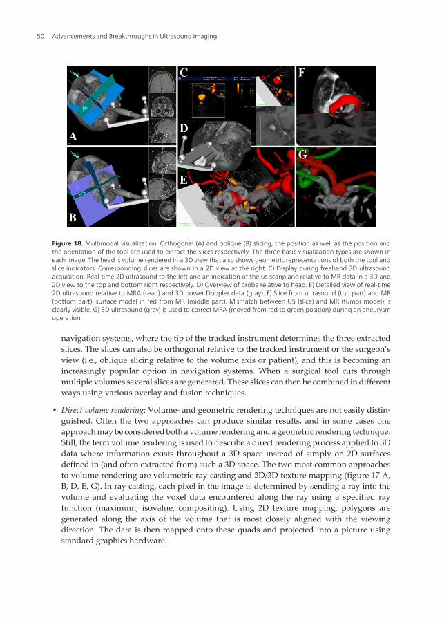
navigation systems, where the tip of the tracked instrument determines the three extractedslices. The slices can also be orthogonal relative to the tracked instrument or the surgeon’sview (i.e., oblique slicing relative to the volume axis or patient), and this is becoming anincreasingly popular option in navigation systems. When a surgical tool cuts throughmultiple volumes several slices are generated. These slices can then be combined in differentways using various overlay and fusion techniques.
• Direct volume rendering: Volume- and geometric rendering techniques are not easily distin‐guished. Often the two approaches can produce similar results, and in some cases oneapproach may be considered both a volume rendering and a geometric rendering technique.Still, the term volume rendering is used to describe a direct rendering process applied to 3Ddata where information exists throughout a 3D space instead of simply on 2D surfacesdefined in (and often extracted from) such a 3D space. The two most common approachesto volume rendering are volumetric ray casting and 2D/3D texture mapping (figure 17 A,B, D, E, G). In ray casting, each pixel in the image is determined by sending a ray into thevolume and evaluating the voxel data encountered along the ray using a specified rayfunction (maximum, isovalue, compositing). Using 2D texture mapping, polygons aregenerated along the axis of the volume that is most closely aligned with the viewingdirection. The data is then mapped onto these quads and projected into a picture usingstandard graphics hardware.
Figure 18. Multimodal visualization. Orthogonal (A) and oblique (B) slicing, the position as well as the position andthe orientation of the tool are used to extract the slices respectively. The three basic visualization types are shown ineach image. The head is volume rendered in a 3D view that also shows geometric representations of both the tool andslice indicators. Corresponding slices are shown in a 2D view at the right. C) Display during freehand 3D ultrasoundacquisition: Real-time 2D ultrasound to the left and an indication of the us-scanplane relative to MR data in a 3D and2D view to the top and bottom right respectively. D) Overview of probe relative to head. E) Detailed view of real-time2D ultrasound relative to MRA (read) and 3D power Doppler data (gray). F) Slice from ultrasound (top part) and MR(bottom part), surface model in red from MR (middle part). Mismatch between US (slice) and MR (tumor model) isclearly visible. G) 3D ultrasound (gray) is used to correct MRA (moved from red to green position) during an aneurysmoperation.
Advancements and Breakthroughs in Ultrasound Imaging50

• Geometric surface rendering: The technique used to render the texture-mapped quads isessentially the same technique that is used to render geometric surface representations ofrelevant structures (figure 17 A-F). However, the geometric representations must first beextracted from the image information. While it is possible in some cases to extract a structureand generate a 3D model of it by directly using an isosurface extraction algorithm [96], thegeneration of an accurate geometric model from medical data often requires a segmentationstep first. The most common surface representation is to use a lot of simple geometricprimitives (e.g., triangles), though other possibilities exist. Furthermore, the surfaces can bemade transparent so that it’s possible to see what’s beneath the structure.
The challenge is to combine the available data and visualization methods to present an optimalintegrated multimodal scene that shows only the relevant information at any given time to thesurgeon. Multimodal visualization and various image fusion techniques can be very beneficialwhen trying to take advantage of the best features in each modality. It is easier to perceive anintegration of two or more volumes in the same scene than to mentally fuse the same volumeswhen presented in separate display windows. This also offers an opportunity to pick relevantand necessary information from the most appropriate of the available datasets. Ideally,relevant information should include not only anatomical structures for reference and patho‐logical structures to be targeted, but also important structures to be avoided. Finally, aug‐mented reality techniques can be used to mix the virtual representation of the patient providedby 3D medical data and models extracted from these and the real representation provided bya microscope or a laparoscope for example, giving an even more realistic picture of thetreatment delivered through small incisions in minimally invasive procedures.
6. Ultrasound-based navigation accuracy
The delicacy, precision and extent of the work the surgeon can perform based on imageinformation rely on his/her confidence in the overall clinical accuracy and the anatomical orpathological representation. The overall clinical accuracy in image-guided surgery is thedifference between the location of a surgical tool relative to some structure as indicated in theimage information, and the location relative to the same structure in the patient. This accuracyis difficult to assess in a clinical setting due to the lack of fixed and well-defined landmarksinside the patient that can be accurately reached with a pointer. Common practice is thereforeto estimate the system’s overall accuracy in a controlled laboratory setting using precisely builtphantoms. In order to conclude on the potential clinical accuracy, the differences between theclinical and the laboratory settings must be carefully examined.
6.1. Error sources and key points
A comprehensive analysis of the error sources involved in neuronavigation based on intrao‐perative ultrasound as well as preoperative MRI can be found in Lindseth et al. [97]. The overallaccuracy is often referred to as the Navigation System Accuracy (NSA) and the essential pointsto remember can be summarized like this:
Ultrasound-Based Guidance and Therapyhttp://dx.doi.org/10.5772/55884
51

• The accuracy associated with navigation based on pre.op. MR/CT is independent of theaccuracy associated with navigation based on intraoperative ultrasound, and vice versa.
• The main error sources associated with preoperative MR/CT-based navigation are relatedto the patient registration process in a clinical setting, and the fact that the image maps arenot updated to reflect the changing patient terrain as surgery proceeds.
• In contrast, intraoperative ultrasound volumes are acquired in the same coordinate systemas navigation is performed. Patient registration is therefore not necessary, and a newultrasound volume can be acquired to reflect the current patient anatomy whenever needed.However, navigation based on ultrasound is associated with its own error chain. The mainerror source in this chain is the ultrasound probe calibration process. In addition, smallvariations in the speed of sound in different tissue types are a potential problem [97].
These points have major implications for the rational behind testing a navigation system inthe lab using a phantom, and make a statement about the interesting parameter to the surgeon:the overall clinical navigation system accuracy. A lab test of a system based on preoperativeMR/CT using a rigid phantom will give a very good navigation system accuracy (NSA<0.5mm,se figure 19, red line). Such a test will have limited validity in the general clinical situation, butis important to make sure that the system works as expected. The next phase in the evaluationof such a system would be to conduct a clinical study to investigate the system’s ability to dealwith a variety of different patient registration problems. Documenting that the systemperforms well in the rigid case and can deal in a satisfactory way with difficult patientregistration cases is the best a system vendor can do. This does not give any information aboutthe NSA experienced during a clinical case though. The surgeon must verify that the accuracyis acceptable after he has performed the patient registration procedure and anatomicallandmarks inside the patient must be used to gain an impression about the amount of tissueshift and deformation. This shift and deformation makes systems based on preoperative MR/CT of limited use during the procedure.
Figure 19. Navigation System Accuracy (NSA) based on preoperative (p) MR (red line) and intraoperative (i) US (greenline). iUS can be used to correct pMR using various image-to-image registration techniques (blue line).
Advancements and Breakthroughs in Ultrasound Imaging52
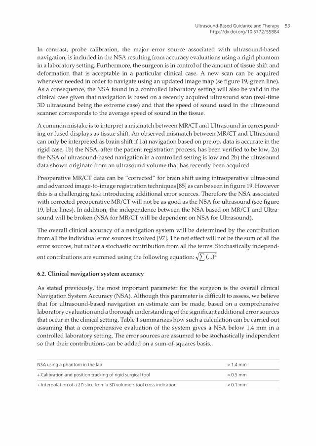
In contrast, probe calibration, the major error source associated with ultrasound-basednavigation, is included in the NSA resulting from accuracy evaluations using a rigid phantomin a laboratory setting. Furthermore, the surgeon is in control of the amount of tissue shift anddeformation that is acceptable in a particular clinical case. A new scan can be acquiredwhenever needed in order to navigate using an updated image map (se figure 19, green line).As a consequence, the NSA found in a controlled laboratory setting will also be valid in theclinical case given that navigation is based on a recently acquired ultrasound scan (real-time3D ultrasound being the extreme case) and that the speed of sound used in the ultrasoundscanner corresponds to the average speed of sound in the tissue.
A common mistake is to interpret a mismatch between MR/CT and Ultrasound in correspond‐ing or fused displays as tissue shift. An observed mismatch between MR/CT and Ultrasoundcan only be interpreted as brain shift if 1a) navigation based on pre.op. data is accurate in therigid case, 1b) the NSA, after the patient registration process, has been verified to be low, 2a)the NSA of ultrasound-based navigation in a controlled setting is low and 2b) the ultrasounddata shown originate from an ultrasound volume that has recently been acquired.
Preoperative MR/CT data can be “corrected” for brain shift using intraoperative ultrasoundand advanced image-to-image registration techniques [85] as can be seen in figure 19. Howeverthis is a challenging task introducing additional error sources. Therefore the NSA associatedwith corrected preoperative MR/CT will not be as good as the NSA for ultrasound (see figure19, blue lines). In addition, the independence between the NSA based on MR/CT and Ultra‐sound will be broken (NSA for MR/CT will be dependent on NSA for Ultrasound).
The overall clinical accuracy of a navigation system will be determined by the contributionfrom all the individual error sources involved [97]. The net effect will not be the sum of all theerror sources, but rather a stochastic contribution from all the terms. Stochastically independ‐
ent contributions are summed using the following equation: ∑ (...)2
6.2. Clinical navigation system accuracy
As stated previously, the most important parameter for the surgeon is the overall clinicalNavigation System Accuracy (NSA). Although this parameter is difficult to assess, we believethat for ultrasound-based navigation an estimate can be made, based on a comprehensivelaboratory evaluation and a thorough understanding of the significant additional error sourcesthat occur in the clinical setting. Table 1 summarizes how such a calculation can be carried outassuming that a comprehensive evaluation of the system gives a NSA below 1.4 mm in acontrolled laboratory setting. The error sources are assumed to be stochastically independentso that their contributions can be added on a sum-of-squares basis.
NSA using a phantom in the lab < 1.4 mm
+ Calibration and position tracking of rigid surgical tool < 0.5 mm
+ Interpolation of a 2D slice from a 3D volume / tool cross indication < 0.1 mm
Ultrasound-Based Guidance and Therapyhttp://dx.doi.org/10.5772/55884
53
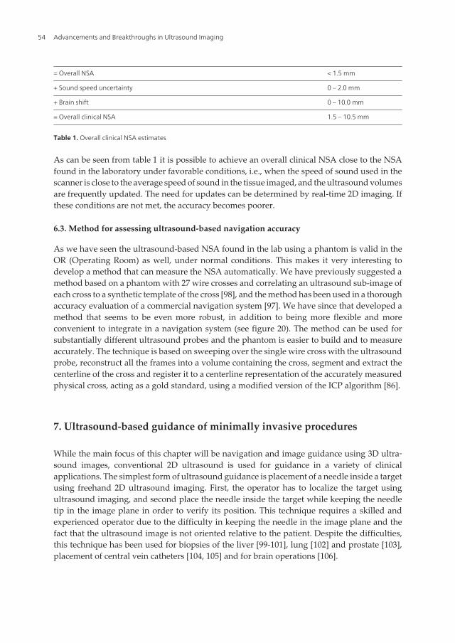
= Overall NSA < 1.5 mm
+ Sound speed uncertainty 0 – 2.0 mm
+ Brain shift 0 – 10.0 mm
= Overall clinical NSA 1.5 – 10.5 mm
Table 1. Overall clinical NSA estimates
As can be seen from table 1 it is possible to achieve an overall clinical NSA close to the NSAfound in the laboratory under favorable conditions, i.e., when the speed of sound used in thescanner is close to the average speed of sound in the tissue imaged, and the ultrasound volumesare frequently updated. The need for updates can be determined by real-time 2D imaging. Ifthese conditions are not met, the accuracy becomes poorer.
6.3. Method for assessing ultrasound-based navigation accuracy
As we have seen the ultrasound-based NSA found in the lab using a phantom is valid in theOR (Operating Room) as well, under normal conditions. This makes it very interesting todevelop a method that can measure the NSA automatically. We have previously suggested amethod based on a phantom with 27 wire crosses and correlating an ultrasound sub-image ofeach cross to a synthetic template of the cross [98], and the method has been used in a thoroughaccuracy evaluation of a commercial navigation system [97]. We have since that developed amethod that seems to be even more robust, in addition to being more flexible and moreconvenient to integrate in a navigation system (see figure 20). The method can be used forsubstantially different ultrasound probes and the phantom is easier to build and to measureaccurately. The technique is based on sweeping over the single wire cross with the ultrasoundprobe, reconstruct all the frames into a volume containing the cross, segment and extract thecenterline of the cross and register it to a centerline representation of the accurately measuredphysical cross, acting as a gold standard, using a modified version of the ICP algorithm [86].
7. Ultrasound-based guidance of minimally invasive procedures
While the main focus of this chapter will be navigation and image guidance using 3D ultra‐sound images, conventional 2D ultrasound is used for guidance in a variety of clinicalapplications. The simplest form of ultrasound guidance is placement of a needle inside a targetusing freehand 2D ultrasound imaging. First, the operator has to localize the target usingultrasound imaging, and second place the needle inside the target while keeping the needletip in the image plane in order to verify its position. This technique requires a skilled andexperienced operator due to the difficulty in keeping the needle in the image plane and thefact that the ultrasound image is not oriented relative to the patient. Despite the difficulties,this technique has been used for biopsies of the liver [99-101], lung [102] and prostate [103],placement of central vein catheters [104, 105] and for brain operations [106].
Advancements and Breakthroughs in Ultrasound Imaging54

A slightly more advanced technique for 2D ultrasound guidance includes a needle guidemounted on the ultrasound probe. The guide will ensure that the needle tip is in the imageplane at a given depth depending of the ultrasound image sector and the angle of the needleguide. The angle of the needle guide has to be adapted to the depth of the target. Even thoughthis system provides assistance in keeping the needle in the image plane, the operator has todo imaging and puncturing at the same time. In addition, the orientation issues concerningthe ultrasound image relative to the patient is not solved and the anatomical overview isrestricted to the current real time 2D image. However, the method is fast, does not requirespecialized equipment or complicated logistics, and provides sufficient guidance for a numberof applications such as biopsy of thyroid nodules [107], placement of ventricular catheters inthe brain [108, 109] and amniocentesis [110].
7.1. Ultrasound-based navigation in neurosurgery
Neuronavigation is the term used to describe the use of computer-assisted methods to guideor navigate instruments within the confinements of the scull (or spinal column) during surgery.A neuronavigation system should ideally provide high navigation accuracy throughout thesurgical procedure. However, the anatomy of the brain is known to shift position after openingof the skull and dura due to drainage of cerebrospinal fluid (CSF), gravity effects and/orremoval of tumor masses or hematomas. This shift in the position of the anatomy is oftenreferred to as brain shift and has been shown to occur in the early stage of the surgery withdisplacement values ranging up to several centimeters [111-113]. The brain shift may thereforesignificantly impair the accuracy of navigation based on preoperative images as the surgeryproceeds. Intraoperative ultrasound imaging provides a solution to the brain shift problem.
Figure 20. Automatic method for evaluating the accuracy in ultrasound-based navigation. A) The phantom with a sin‐gle wire cross in the middle of the water tank and a reference frame in the front. B) Physical wire cross in green and anultrasound volume of the wire cross in gray. C) The ultrasound data is segmented (red) and a small mismatch to thegold standard in green can be observed, i.e. small inaccuracies exist. D) Centerlines of the green and red wire crosses.E) Iterative closest point (ICP) registration between the two centerlines, initial correspondence shown. F) After someiterations. Final results showing the centerlines (G) and the wire crosses (H). The displacement is equal to the NSA.
Ultrasound-Based Guidance and Therapyhttp://dx.doi.org/10.5772/55884
55
Compared to using only preoperative images for guidance, the navigation of instrumentsbased on recently acquired intraoperative images can be performed with higher accuracy andprecision [97].
The combined use of ultrasound imaging and navigation technology has been explored sincethe early 1990ies. The University of Oulu was one of the pioneers and demonstrated the clinicaluse of a passive mechanical arm-based navigation system, which could display reconstructionsof preoperative images (CT/MR) and corresponding real-time intraoperative ultrasoundimages [114].
By attaching position sensors (also referred to as 3D localizers) on the ultrasound probe it ispossible to establish the relative spatial position of the image pixels, and it is possible toreconstruct 2D images into an image volume, hence the term 3D ultrasound. The localizerattached to the probe is usually ultrasonic, electromagnetic or optic, and the two latter options(optic, electromagnetic) are currently the most established in commercial systems. Hata et aldescribed in a paper from 1997 the initial clinical experience with a frame- and armlessnavigation system incorporating an ultrasound scanner and an ultrasound probe equippedwith an ultrasonic positioning sensor [115]. In 1998 Jödicke et al presented a system fordetection of brain shift, by comparing preoperative MR images and intraoperative 3D ultra‐sound [116]. The integration of ultrasound and navigation technology was also explored inTrondheim, Norway, and a system with the feasibility of 3D ultrasound and navigationguidance was developed. Using this system Unsgaard et al. performed the first brain tumouroperation with 3D ultrasound guidance in 1996, and the system development and clinicalexperience was described in several papers [117-119]. The technology was further developedand commercialized by the company Sonowand AS (Trondheim, Norway), which is a spin-off company from the research activities of the National Centre for 3D Ultrasound in Neuro‐surgery (1995-present (2013)) at St. Olavs University Hospital. The technology has beenexplored for use in several neurosurgical procedures, but its predominant use is withinresection of brain tumours [120]. The Sonowand system allows navigation of pre-calibratedtools equipped with an optic localizer, and it allows tools like biopsy forceps to be calibratedto the navigation system in situ in the operating room (figure 21) and used for image guidedbiopsies. The system facilitates simultaneous displays of reformatted image slices of intrao‐perative ultrasound and any preoperative MR series like T1, T2, FLAIR, etc. that has beenregistered to the patient. The position of navigated instruments is indicated in the displayedimage slices.
7.1.1. 3D Ultrasound in intracranial tumour surgery
Intracranial tumours include primary and secondary tumours in the brain, pituitary gland,and meninges. Primary tumours are neoplasms originating from supportive tissue in the brain,from meninges, or from pituitary tissue. Secondary brain tumours are metastases of malignantcells that originate from a primary tumour situated in another organ of the body that spreadswith the blood flow to the brain. Surgery is the primary treatment for most intracranialtumours. The patient's prognosis is in most cases related to the degree of resection of tumour.The surgical goal is usually to perform a total extirpation of the tumour, but without damaging
Advancements and Breakthroughs in Ultrasound Imaging56

adjacent normal brain tissue. If the tumour is located in so-called eloquent regions, harboringimportant functional tissue for movement, speech or vision, less extensive resections is oftenthe result. Brain tumour surgery can therefore be a delicate balance between obtainingextensive resections and avoiding functional deficits and loss of quality of life due to thesurgical trauma.
3D ultrasound is an established technique for intraoperative imaging in surgery of braintumours, and is used for localization of the tumour and for resection control. The firstacquisition of 3D ultrasound images is usually performed after opening the bone (craniotomy),but before opening the dura. Several ultrasound volumes (typically 3 to 6) are acquired duringthe operation to compensate for brain shift and to monitor the progress of tumour removal(figure 22).
Preoperative MR data can be displayed along with one or several ultrasound image volumesacquired at different stages of surgery. It may also be possible to import functional MR imagesto the navigation system. One way of doing this is to import anatomical MR images (e.g.T1/T2/FLAIR) with bold fMRI enhancements and DTI tractography overlaid as contours onthe anatomical images [121-123], as shown in figure 23. The navigation system may thereforeprovide multimodal visualization of medical images, incorporating functional and anatomicalinformation.
Figure 21. The Sonowand Invite® system for intraoperative ultrasound imaging and navigation (A), various tools ofthe navigation system equipped with optical localizer units showing one phased array ultrasound probe (B), a naviga‐tion pointer (C), a biopsy forceps (D), and a screen dump of the navigation display showing reformatted MR images intop row, and corresponding reformatted ultrasound images in bottom row (E). The tip of the navigated instrument isindicated with a bright spot in the reformatted image slices
Ultrasound-Based Guidance and Therapyhttp://dx.doi.org/10.5772/55884
57

Clinically, modern image technology has enabled more targeted surgical approaches, ascompared to standardized explorative brain dissections that were more common two decadesago. This reduces the surgical trauma, eases anatomical orientation within the surgical field, andmakes it possible for less experienced surgeons to obtain the same results as their more experi‐enced peers. Today, even in eloquent regions where surgery is associated with increased risk,good clinical results can be obtained [121]. We have also observed that survival increased afterthe introduction of 3D ultrasound imaging in malignant primary brain tumour surgery [124].Intraoperative imaging with ultrasound has also enabled more aggressive treatment strat‐egies in tumours that microscopically resemble the brain tissue and therefore are difficult toremove with sufficient accuracy. This has improved survival without compromising risks [125].Tailored probes designed for special surgical procedures such as the transphenoidal approach[126] through the nose can guide operations in narrow approaches with limited abilities for directvisualization. With further developments in ultrasound technology, clinical results can continue
Figure 22. Navigation display showing two perpendicular reformatted image slices from each image volume. Preoper‐ative MR slices in top row followed by slices from 3 different ultrasound volumes acquired at different stages in theoperation. The ultrasound volumes in row 2, 3, and 4 were acquired prior to the resection, during the resection withsome tumor tissue remaining, and after the end of the resection, respectively
Advancements and Breakthroughs in Ultrasound Imaging58
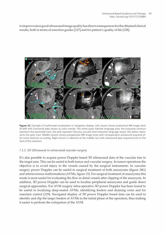
to improve since good ultrasound image quality has direct consequences for the obtained clinicalresults, both in terms of resection grades [127] and for patient’s quality of life [128].
Figure 23. Example of multimodal visualization in navigation display. Left column shows anatomical MR image slices(FLAIR) with functional data shown as color overlay. The white spots indicate language area, the turquoise contoursrepresent the pyramidal tract, the pink represent fasiculus arcuate (tract between language areas), the yellow repre‐sents the optic tract. Middle column shows preoperative MR image slices with intraoperative ultrasound acquired af‐ter some resection as overlay. Right column is identical as the middle, but with ultrasound data acquired prior to thestart of the resection.
7.1.2. 3D Ultrasound in intracranial vascular surgery
It’s also possible to acquire power Doppler based 3D ultrasound data of the vascular tree inthe target area. This can be useful in both tumor and vascular surgery. In tumor operations theobjective is to avoid injury to the vessels caused by the surgical instruments. In vascularsurgery power Doppler can be useful in surgical treatment of both aneurysms (figure 18G)and arteriovenous malformations (AVMs, figure 15). For surgical treatment of aneurysms thismode is most useful for evaluating the flow in distal vessels after clipping of the aneurysm. Inaddition, 3D power Doppler can be used to localize peripheral aneurysms and guide directsurgical approaches. For AVM surgery intra-operative 3D power Doppler has been found tobe useful in localizing deep-seated AVMs, identifying feeders and draining veins and forresection control [129]. Navigated display of 3D power Doppler based data can be used toidentify and clip the larger feeders of AVMs in the initial phase of the operation, thus makingit easier to perform the extirpation of the AVM.
Ultrasound-Based Guidance and Therapyhttp://dx.doi.org/10.5772/55884
59

Power Doppler based 3D ultrasound data are usually displayed in reddish color superimposedon the B-mode ultrasound slices, but the vessels are usually shown in a more optimal wayusing 3D rendering techniques. The power Doppler signal is often too intense and smearedout to give a sharp delineation of the small vessels. Robust acquisition of power Doppler based3D ultrasound data of sufficient quality is essential for vessel-based shift correction and it’simportant to increase the spatial resolution of such data in the coming years.
7.2. Ultrasound-based navigation in laparoscopic surgery
Open surgery is the gold standard for abdominal surgeries. But over the last few decades, therehas been an increasing demand to shift from open surgery to a minimally invasive approachto make the intervention and the post-operative phase less traumatizing for the patient.Advantages of laparoscopic surgery include decreased morbidity, reduced costs for society(less hospital time and quicker recovery), and also improved long-term outcomes whencompared to open surgery. During laparoscopy, the surgeons make use of a video camera forinstrument guidance. However, the video laparoscope can only provide two-dimensional (2D)surface visualization of the abdominal cavity. Laparoscopic ultrasound (LUS) providesinformation beyond the surface of the organs, and was therefore introduced by Yamakawaand coworkers in 1958 [130]. In 1991, Jakimowicz and Reuers introduced LUS scanning forexamination of the biliary tree during laparoscopic cholecystectomy [131]. It seemed that LUSgave valuable information and has since expanded in use with the increase in laparoscopicprocedures. LUS is today applied in laparoscopy in numerous ways for screening, diagnosticsand therapeutic purposes [132, 133]. Some examples of use are screening, like stone detectionor identification of lymph nodes, diagnostics, like staging of disease or assessment of opera‐bility and resection range, and therapeutic, like resection guidance or guidance of radiofrequency and cryoablation. Harms and coworkers were the first to integrate an electromag‐netic (EM) tracking sensor into the tip of a conventional laparoscopic ultrasound probe [134]and this made it possible to combine LUS with navigation technology, solving some of theorientation problems experienced when using laparoscopic ultrasound. The combination ofnavigation technology and LUS is becoming an active field of research to further improve thesafety, accuracy, and outcome of laparoscopic surgery.
Navigation, as explained earlier, is the combined use of tracking and imaging technology toprovide a visualization of the position of the tip of a surgical instrument relative to a targetand surrounding anatomy. Various display and visualizations methods of both instrumentsand the medical images can be used in laparoscopic surgery. Preoperative images are usefulfor planning as well as for guidance during the initial phase of the procedure as long as thetarget area is in the retroperitoneum [135]. When preoperative images are registered to thepatient, the surgeon is able to use navigation to plan the surgical pathway from the tip of theinstrument to the target site inside the patient. Thus, navigation provides the intuitivecorrespondence between the patient (physical space), the images (image space that representthe patient) and the tracked surgical instruments. However, when the surgical procedurestarts, tissue will shift and deform and preoperative data will no longer represent the truepatient anatomy. LUS then makes it possible to update the map for guidance and acquire image
Advancements and Breakthroughs in Ultrasound Imaging60
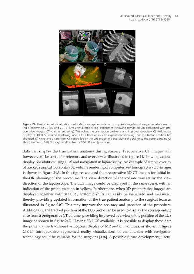
data that display the true patient anatomy during surgery. Preoperative CT images will,however, still be useful for reference and overview as illustrated in figure 24, showing variousdisplay possibilities using LUS and navigation in laparoscopy. An example of simple overlayof tracked surgical tools onto a 3D volume rendering of computerized tomography (CT) imagesis shown in figure 24A. In this figure, we used the preoperative 3D CT images for initial in-the-OR planning of the procedure. The view direction of the volume was set by the viewdirection of the laparoscope. The LUS image could be displayed in the same scene, with anindication of the probe position in yellow. Furthermore, when 3D preoperative images aredisplayed together with 3D LUS, anatomic shifts can easily be visualized and measured,thereby providing updated information of the true patient anatomy to the surgical team asillustrated in figure 24C. This may improve the accuracy and precision of the procedure.Additionally, the tracked position of the LUS probe can be used to display the correspondingslice from a preoperative CT volume, providing improved overview of the position of the LUSimage as shown in figure 24D. Having 3D LUS available, it is possible to display these datathe same way as traditional orthogonal display of MR and CT volumes, as shown in figure24E-G. Intraoperative augmented reality visualizations in combination with navigationtechnology could be valuable for the surgeons [136]. A possible future development, useful
Figure 24. Illustration of visualization methods for navigation in laparoscopy. A) Navigation during adrenalectomy us‐ing preoperative CT (3D and 2D). B) Live animal model (pig) experiment showing navigated LUS combined with pre‐operative images (CT volume rendering). This solves the orientation problems and improves overview. C) Multimodaldisplay of 3D LUS (volume rendering) and 3D CT from an ex vivo experiment showing that the tumor position haschanged. D) Anyplane slicing from CT controlled by the LUS probe and overlaying the LUS onto the corresponding CTslice (phantom). E-G) Orthogonal slices from a 3D LUS scan (phantom).
Ultrasound-Based Guidance and Therapyhttp://dx.doi.org/10.5772/55884
61

for spotting the true position of lesions and vessels and hence detect anatomic shifts quickly,would be to introduce LUS data into such a multimodal display.
Intraoperative ultrasound systems are inexpensive, compact, mobile, and have no require‐ments for special facilities in the operating room (OR) compared to MRI or CT. Ultrasoundimage quality is continuously improving and for certain cases (e.g. liver) LUS could obtainimage quality comparable to what is achieved in neurosurgery, as the probe is placed directlyon the surface of the organ. In neurosurgery, the image quality of ultrasound has beendemonstrated above. The most common LUS probe is a flexible 2- or 4-way array, linear orcurved, with a frequency range of 5-10 MHz. Typical imaging depths are in the range 0-10 cm,but with 5MHz deeper imaging can be performed. The LUS transducers usually have afootprint of less than 10 mm wide to fit through trocars and 20-50 mm long. They can bemanipulated at the shaft allowing real time images at user-controlled orientations andpositions, depending only on the specific probe configuration. Figure 25 shows variousconfigurations of LUS probes, while Table 2 provides an overview of currently availableprobes. Most LUS probes [137] can be sterilized [138].
Vendor Probe Frequency Type of probe
(see Fig. 2)
Transducer length, scan angle, other
Aloka UST-52109 3-7.5 MHz A 10 mm, 90°
UST-5524-LAP 4-10 MHz E 38 mm
UST-5526L-7.5 5-10 MHz D 33 mm
UST-5536-7.5 5-10 MHz E 38 mm
BK Medical 8666-RF 5-10 MHz E 30 mm, Puncture and biopsy guide
Hitachi EUP OL531 5-10 MHz C 120°, Biopsy and therapy
Toshiba PEF 704LA 5, 7.5, 10 MHz E 34 mm
PVM 787LA 5, 7.5, 10 MHz B 85°
Figure 25. Different LUS probes.
Advancements and Breakthroughs in Ultrasound Imaging62

Vendor Probe Frequency Type of probe
(see Fig. 2)
Transducer length, scan angle, other
Gore Tetrad VersaPlane 7.5 MHz (center
frequency)
E 56 mm
Philips / ATL LAP L9-5 5-9 MHz E NA
Esaote LP323 4-13 MHz E NA
Table 2. LUS probe from various manufacturers. Relevant specifications are also given.
Being a relatively new area of research, it is interesting to note that the number of activeresearch groups in the field of navigated laparoscopic ultrasound is approximately ten. Basedon literature and almost two decades working with surgeons on developments for advancedlaparoscopic surgery, a complete system designed for navigated LUS could be used accordingto the following clinical scenario:
• The preoperative data are imported and reconstructed into 3D volumes; several structuresand organs are segmented automatically (e.g. vessels from contrast CT scan) or semi-automatically (e.g. seed point set inside the tumor).
• A quick plan is made from the visualization in the navigation system just prior to surgery,perhaps in the OR during other preparations.
• Registration is performed without fiducials using a pointer (orientation of patient) and twolandmarks for a rough first approximation.
• Before mobilizing the target organ (e.g. the liver) a 3D LUS scan of major vessels near oraround the tumor is performed.
• The LUS images are reconstructed in 3D and an automatic vessel based registration (CT-to-ultrasound) is performed to fine tune the patient registration.
• Augmented reality visualization, e.g. on/off overlay of preoperative data and LUS on thevideo laparoscope view is preformed as needed by the surgeons during the procedure
• 3D LUS scans are updated a few times during the procedure, while the real time 2D LUSimage is available as either:
◦ A full size image with a corresponding indication in a 3D CT rendering of its orientationand position, or
◦ An overlay on the video laparoscope view with or without elements from the CT data(segmented structures for instance).
For rigid organ navigation, a single preoperative scan, highly accurate tracking (optical), andrigid surgical tools are sufficient to guide the procedure. However, for soft tissue navigation,additional tools are needed due to deformation and mobile organs in the abdominal cavity,resulting in more complex systems and additional devices in the OR. LUS can provide realtime behind-the-surface information (tissue, blood flow, elasticity). When combined with
Ultrasound-Based Guidance and Therapyhttp://dx.doi.org/10.5772/55884
63

advanced visualization techniques and preoperative images, LUS can enhance an augmentedreality scene to include updated images of details, important for high precision surgery thusenhancing the perception for surgeons during minimal access therapy. LUS integrated withminiaturized tracking technology is likely to play an important role in guiding future laparo‐scopic surgery.
7.3. Other applications
One of the first, and still one of the most important applications of ultrasound imaging is indiagnostics of various heart conditions. The dynamic real-time imaging makes ultrasound themodality of choice for characterization of a moving organ such as the heart. Some examplesof the use of echocardiography are evaluation of cardiovascular anomalies in fetuses andnewborns [139], assessment of aortic stenosis [140], evaluation of the function of the valvesand examination of the flow and function after heart attacks. These examples are purelydiagnostic applications without any kind of intervention associated, but ultrasound has alsobeen used for guidance in cardiac surgery. One example was presented by Wang et al. [141].They evaluated 129 patients who underwent robotic cardiac surgery. Transesophagealechocardiography was used for guidance of the cannula for peripheral cardiopulmonarybypass. Ultrasound imaging can potentially also be used for guidance in minimally invasivemitral valve repair on the beating heart [123].
Intra-operative guidance during endovascular procedures is usually performed with x-rayfluoroscopy. However, some investigators have reported the use of transabdominal ultra‐sound for guidance. Lie et al. [142] studied the use of 2D transabdominal ultrasound duringendovascular procedures. They found that ultrasound could be useful for guiding the insertionof guidewires, and control the wire position before connecting the second graft limb to themain limb of bifurcated grafts. Kaspersen et al. [143] reported a feasibility study registeringultrasound to pre-operatve CT data. This may be useful for updating the CT data used fornavigation and correct for breathing motion and deformation of the blood vessels during theprocedure. With recent advances in ultrasound technology, we believe that real-time 3Dultrasound have potential for further advancing the accuracy in the insertion of stentgrafts,and in particular the placement of fenestrated stentgrafts. Specifically, it is easier to track thetip of guidewires in three dimensions, while simultaneously visualizing a focused area of the3D anatomy in real-time. A systematic review by Malkawi et al [144] concluded that percuta‐neous endovascular repair was associated with fewer access related complications andreduced operative time. In a study by Arthurs et al [145], it was shown that use of ultrasoundguided access significantly reduced access-related complications compared to percutanousaccess without ultrasound guidance. Successful ultrasound guidance in secondary interven‐tions, for sealing endoleak after endovascular repair, has also been reported. Boks et al. [146]described transabdominal embolization using duplex ultrasound guidance, and Kasthuri etal. [147] used ultrasound for guiding percutaneous thrombin injection. Navigation of sten‐tgrafts during endovascular procedures has also been demonstrated in patients using CTimaging [148]. However, 3D or 4D ultrasound integrated with navigation technology forguidance of endovascular procedures has not yet been demonstrated in patients.
Advancements and Breakthroughs in Ultrasound Imaging64
3D ultrasound has also been used to guide surgery of the spine. Kolstad et al [149] reported in
2006 a study, where spinal cord tumors were visualized using ultrasound imaging, and 3D
ultrasound-guided tumor resection were performed using navigation technology. The
technical application of integrating ultrasound and navigation seems feasible since it solves
the orientation problem with conventional 2D ultrasound and may have the potential of
improving functional outcome of spinal cord tumor surgery.
8. Ultrasound and non-invasive therapy
8.1. High Intensity Focused Ultrasound (HIFU)
High-intensity focused ultrasound (HIFU or FUS) has been known and developed for decades
and can be applied to produce sharply delineated lesions in biological tissue (figure 26)
[150-153]. The development of magnetic resonance (MR) thermometry enabled the thermal
ablation progress to be monitored during sonication [154]. MR-guided HIFU (MRgFUS) has
been approved by the FDA for the symptomatic treatment of uterine fibroids since 2004 [155];
clinical trials have been reported for breast [156, 157] and brain [158, 159] therapy, as well as
pain palliation in bone [160, 161]. The MRgFUS treatment of abdominal organs, such as the
kidney, pancreas or liver, poses additional technological and clinical challenges. First, for most
therapeutic applications within the human body, tissue displacement caused by respiration
and/or the cardiac cycle must be considered, and can be assumed to be periodic in anaesthe‐
tized patients. However, this may not be the case for free-breathing patients. This movement
in addition to drift due to gravity and the intestine and bowel movement is important to
account for during sonication in order to achieve accurately located FUS with respect to the
target (e.g. tumour in the liver). Secondly, the presence of the rib cage affects the HIFU
treatment planning and set-up. The rib cage acts as an aberrator that might affect the focusing
[162, 163] and on the other hand, due to the high value of the absorption coefficient of the bone
[164], the overheating on the ribs can be quite significant. These two aspects are currently the
main challenges in order to achieve MRgFUS in moving abdominal organs.
Ultrasound-Based Guidance and Therapyhttp://dx.doi.org/10.5772/55884
65
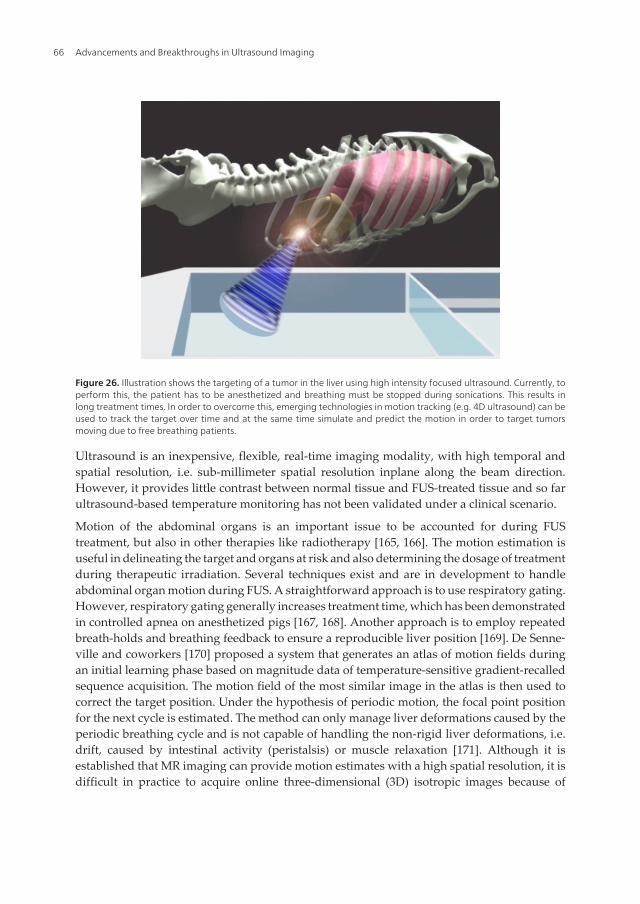
Figure 26. Illustration shows the targeting of a tumor in the liver using high intensity focused ultrasound. Currently, toperform this, the patient has to be anesthetized and breathing must be stopped during sonications. This results inlong treatment times. In order to overcome this, emerging technologies in motion tracking (e.g. 4D ultrasound) can beused to track the target over time and at the same time simulate and predict the motion in order to target tumorsmoving due to free breathing patients.
Ultrasound is an inexpensive, flexible, real-time imaging modality, with high temporal andspatial resolution, i.e. sub-millimeter spatial resolution inplane along the beam direction.However, it provides little contrast between normal tissue and FUS-treated tissue and so farultrasound-based temperature monitoring has not been validated under a clinical scenario.
Motion of the abdominal organs is an important issue to be accounted for during FUStreatment, but also in other therapies like radiotherapy [165, 166]. The motion estimation isuseful in delineating the target and organs at risk and also determining the dosage of treatmentduring therapeutic irradiation. Several techniques exist and are in development to handleabdominal organ motion during FUS. A straightforward approach is to use respiratory gating.However, respiratory gating generally increases treatment time, which has been demonstratedin controlled apnea on anesthetized pigs [167, 168]. Another approach is to employ repeatedbreath-holds and breathing feedback to ensure a reproducible liver position [169]. De Senne‐ville and coworkers [170] proposed a system that generates an atlas of motion fields duringan initial learning phase based on magnitude data of temperature-sensitive gradient-recalledsequence acquisition. The motion field of the most similar image in the atlas is then used tocorrect the target position. Under the hypothesis of periodic motion, the focal point positionfor the next cycle is estimated. The method can only manage liver deformations caused by theperiodic breathing cycle and is not capable of handling the non-rigid liver deformations, i.e.drift, caused by intestinal activity (peristalsis) or muscle relaxation [171]. Although it isestablished that MR imaging can provide motion estimates with a high spatial resolution, it isdifficult in practice to acquire online three-dimensional (3D) isotropic images because of
Advancements and Breakthroughs in Ultrasound Imaging66

technical limitations, spatial and temporal resolution trade-offs, and low signal-to-noise ratioassociated with fast 3D acquisition sequences [172]. In addition, the time duration between theactual target displacement and the availability of the motion information from MR data is notnegligible [173]. Hence, MR information-based real-time motion compensation generallycompromises spatial resolution, geometric distortion and the precision of the MR thermometry[174], of which the latter is of crucial importance during MRgFUS.
A first attempt at ultrasound-based motion tracking during MRgFUS was reported in phan‐toms undergoing periodic and rigid motion of small amplitude [173]. Continuous 1D ultra‐sound echo detection, along a direction parallel to the main axis of motion was used. This setupis not suitable for clinical applications as the external ultrasound imaging probe cannot sendbeams parallel to the axis of respiratory motion. Moreover, the local motion in the liver isspatially dependent and a 1D projection would not be sufficient. Truly simultaneous ultra‐sound and MR imaging has only been reported in literature recently [175-178]. Only one ofthese studies was targeted towards MRgFUS and moving abdominal organs sonication [175].They demonstrated in moving phantoms the feasibility of ultrasound-based 2D motion-compensated sonications integrated with reference free MR temperature monitoring, using aclinical ultrasound probe and a phased-array HIFU transducer [175]. An overview of our ownefforts for motion correction using 4D ultrasound can be found in section 4.3.
8.2. Ultrasound-induced drug delivery
Although diagnostic ultrasound is considered safe with no adverse effects, ultrasound canwith high acoustic outputs induce significant bioeffects (e.g. HIFU) and these bioeffects aredivided into thermal and mechanical effects. The thermal effect is related to energy absorptionin the tissue where part of the mechanical wave energy is converted to thermal energy andhence results in an increase in tissue temperature. The mechanical effects are related tocavitation and to radiation forces. Radiation forces arise when part of the forward propagatingwave is back-scattered or absorbed and result in a pushing force on the tissue along thedirection of the forward propagating wave. Within fluids, such radiation forces can give riseto acoustic streaming. Cavitation is related to the oscillation and possible collapse of gas nucleioccurring naturally within the body or artificially introduced as contrast agent in the form ofmicrobubbles. Oscillating gas bubbles will generate streaming currents in surrounding liquidsand hence shear forces on nearby cells that potentially result in bioeffects. Collapsing gasbubbles can result in high local temperatures, release of free radicals, emitted shock waves andhigh velocity micro jets piercing into nearby cell membranes.
Ultrasound-Based Guidance and Therapyhttp://dx.doi.org/10.5772/55884
67
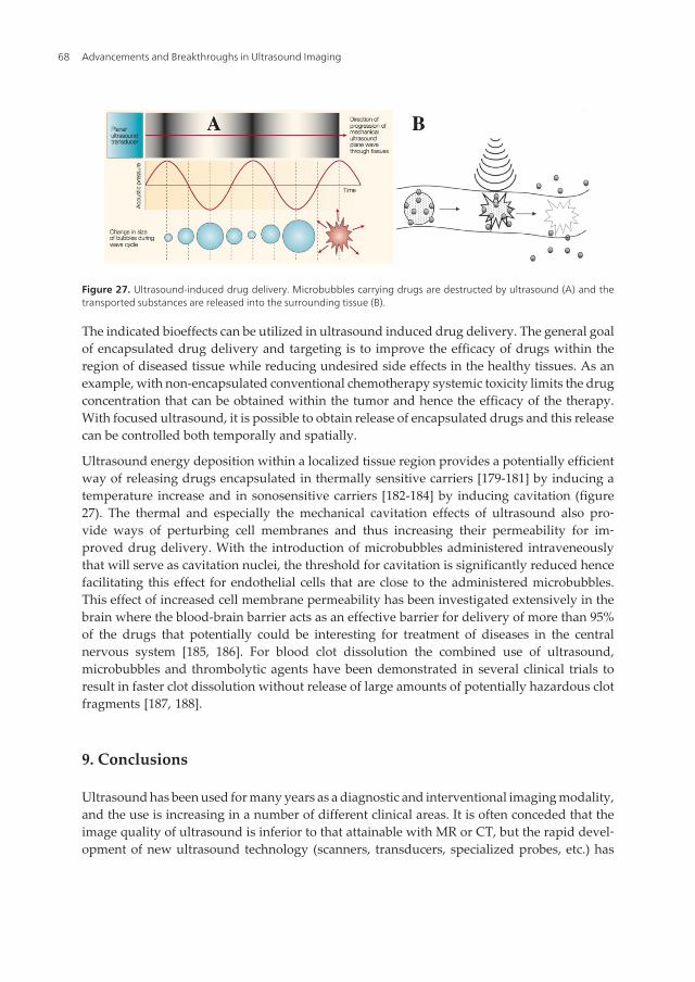
Figure 27. Ultrasound-induced drug delivery. Microbubbles carrying drugs are destructed by ultrasound (A) and thetransported substances are released into the surrounding tissue (B).
The indicated bioeffects can be utilized in ultrasound induced drug delivery. The general goalof encapsulated drug delivery and targeting is to improve the efficacy of drugs within theregion of diseased tissue while reducing undesired side effects in the healthy tissues. As anexample, with non-encapsulated conventional chemotherapy systemic toxicity limits the drugconcentration that can be obtained within the tumor and hence the efficacy of the therapy.With focused ultrasound, it is possible to obtain release of encapsulated drugs and this releasecan be controlled both temporally and spatially.
Ultrasound energy deposition within a localized tissue region provides a potentially efficientway of releasing drugs encapsulated in thermally sensitive carriers [179-181] by inducing atemperature increase and in sonosensitive carriers [182-184] by inducing cavitation (figure27). The thermal and especially the mechanical cavitation effects of ultrasound also pro‐vide ways of perturbing cell membranes and thus increasing their permeability for im‐proved drug delivery. With the introduction of microbubbles administered intraveneouslythat will serve as cavitation nuclei, the threshold for cavitation is significantly reduced hencefacilitating this effect for endothelial cells that are close to the administered microbubbles.This effect of increased cell membrane permeability has been investigated extensively in thebrain where the blood-brain barrier acts as an effective barrier for delivery of more than 95%of the drugs that potentially could be interesting for treatment of diseases in the centralnervous system [185, 186]. For blood clot dissolution the combined use of ultrasound,microbubbles and thrombolytic agents have been demonstrated in several clinical trials toresult in faster clot dissolution without release of large amounts of potentially hazardous clotfragments [187, 188].
9. Conclusions
Ultrasound has been used for many years as a diagnostic and interventional imaging modality,and the use is increasing in a number of different clinical areas. It is often conceded that theimage quality of ultrasound is inferior to that attainable with MR or CT, but the rapid devel‐opment of new ultrasound technology (scanners, transducers, specialized probes, etc.) has
Advancements and Breakthroughs in Ultrasound Imaging68
resulted in significantly improved image quality and make ultrasound the modality of choicefor several applications. Some of the obvious advantages being real-time imaging even forblood flow, portability, flexibility, safety and low cost. In addition, ultrasound images can beacquired in the coordinate system of a patient when combined with a tracking system withoutany need for registration. This makes surgical guidance based on intra-operative ultrasoundhighly accurate. The combination of several image modalities such as MR, CT and ultrasoundregistered to each other and to the patient make the interpretation of the individual imageseasier and enables the surgeon to take advantage of the complimentary information containedin each image. In this context, the ultrasound images provide real-time information in theregion of interest, while MR and CT provide anatomical overview facilitating the interpretationof the ultrasound data. The use of contrast agents enhance the visualization of vessels andincrease the number and types of lesions that can be detected using ultrasound. New technol‐ogies such as high-intensity focused ultrasound and the use of microbubbles for targeted drugdelivery are examples of non-invasive therapeutic applications where ultrasound will play anincreasingly important role in the future.
Author details
Frank Lindseth1,2,4, Thomas Langø1,4, Tormod Selbekk1,2,4, Rune Hansen1,2,4,Ingerid Reinertsen1,4, Christian Askeland1,4, Ole Solheim2,3,4, Geirmund Unsgård2,3,4,Ronald Mårvik2,3,4 and Toril A. Nagelhus Hernes1,2,4
*Address all correspondence to: [email protected]
1 SINTEF Medical Technology, Norway
2 The Norwegian University of Science and Technology (NTNU), Norway
3 St. Olavs University Hospital, Norway
4 National Centre for Ultrasound and Image Guided Therapy, Norway
References
[1] Mehdizadeh, S., et al., Eigenspace based minimum variance beamforming applied toultrasound imaging of acoustically hard tissues. IEEE Trans Med Imaging, 2012.31(10): p. 1912-21.
[2] Mjolstad, O.C., et al., Assessment of left ventricular function by GPs using pocket-sized ultrasound. Fam Pract, 2012. 29(5): p. 534-40.
Ultrasound-Based Guidance and Therapyhttp://dx.doi.org/10.5772/55884
69
[3] Hotta, N., et al., Usefulness of Real-Time 4D Ultrasonography during Radiofrequen‐cy Ablation in a Case of Hepatocellular Carcinoma. Case Rep Gastroenterol, 2011.5(1): p. 82-7.
[4] Rønnekleiv, A. Design Modeling of CMUT’s for Medical Imaging. in IEEE Interna‐tional Ultrasonics Symposium (IUS). 2009, p. 442-450.
[5] Gierke, H.E., et al., Physics of vibrations in living tissues. J Appl Physiol, 1952. 4(12):p. 886-900.
[6] Dickinson, R.J. and C.R. Hill, Measurement of soft tissue motion using correlation be‐tween A-scans. Ultrasound in Medicine and Biology, 1982. 8(3): p. 263-71.
[7] Wilson, L.S. and D.E. Robinson, Ultrasonic measurement of small displacements anddeformations of tissue. Ultrason Imaging, 1982. 4(1): p. 71-82.
[8] Lerner, R.M., S.R. Huang, and K.J. Parker, "Sonoelasticity" images derived from ul‐trasound signals in mechanically vibrated tissues. Ultrasound in Medicine and Biolo‐gy, 1990. 16(3): p. 231-9.
[9] Ophir, J., et al., Elastography: a quantitative method for imaging the elasticity of bio‐logical tissues. Ultrason Imaging, 1991. 13(2): p. 111-34.
[10] Bae, U., et al., Ultrasound thyroid elastography using carotid artery pulsation: pre‐liminary study. J Ultrasound Med, 2007. 26(6): p. 797-805.
[11] Emelianov, S.Y., et al., Elasticity Imaging of the Liver: Is a Hemangioma Hard orSoft? Proceedings of the 1998 IEEE Ultrasonics Symposium, 1998. 7: p. 1749-1752.
[12] Hiltawsky, K.M., et al., Freehand ultrasound elastography of breast lesions: clinicalresults. Ultrasound in Medicine and Biology, 2001. 27(11): p. 1461-9.
[13] Salomon, G., et al., Evaluation of prostate cancer detection with ultrasound real-timeelastography: a comparison with step section pathological analysis after radical pros‐tatectomy. Eur Urol, 2008. 54(6): p. 1354-62.
[14] Selbekk, T., J. Bang, and G. Unsgaard, Strain processing of intraoperative ultrasoundimages of brain tumours: initial results. Ultrasound in Medicine and Biology, 2005.31(1): p. 45-51.
[15] Souchon, R., et al., Visualisation of HIFU lesions using elastography of the humanprostate in vivo: preliminary results. Ultrasound in Medicine and Biology, 2003.29(7): p. 1007-15.
[16] Nightingale, K., et al., Acoustic radiation force impulse imaging: in vivo demonstra‐tion of clinical feasibility. Ultrasound in Medicine and Biology, 2002. 28(2): p. 227-35.
[17] Gallotti, A., et al., Acoustic Radiation Force Impulse (ARFI) ultrasound imaging ofsolid focal liver lesions. Eur J Radiol, 2012. 81(3): p. 451-5.
Advancements and Breakthroughs in Ultrasound Imaging70

[18] Tozaki, M., S. Isobe, and E. Fukuma, Preliminary study of ultrasonographic tissuequantification of the breast using the acoustic radiation force impulse (ARFI) technol‐ogy. Eur J Radiol, 2011. 80(2): p. e182-7.
[19] Zhai, L., et al., Acoustic radiation force impulse imaging of human prostates: initialin vivo demonstration. Ultrasound in Medicine and Biology, 2012. 38(1): p. 50-61.
[20] Bercoff, J., M. Tanter, and M. Fink, Supersonic shear imaging: a new technique forsoft tissue elasticity mapping. IEEE Trans Ultrason Ferroelectr Freq Control, 2004.51(4): p. 396-409.
[21] Athanasiou, A., et al., Breast lesions: quantitative elastography with supersonic shearimaging--preliminary results. Radiology, 2010. 256(1): p. 297-303.
[22] Bavu, E., et al., Noninvasive in vivo liver fibrosis evaluation using supersonic shearimaging: a clinical study on 113 hepatitis C virus patients. Ultrasound in Medicineand Biology, 2011. 37(9): p. 1361-73.
[23] Tanter, M., et al., High-resolution quantitative imaging of cornea elasticity using su‐personic shear imaging. IEEE Trans Med Imaging, 2009. 28(12): p. 1881-93.
[24] Wells, P.N. and H.D. Liang, Medical ultrasound: imaging of soft tissue strain andelasticity. J R Soc Interface, 2011. 8(64): p. 1521-49.
[25] Parker, K.J., M.M. Doyley, and D.J. Rubens, Imaging the elastic properties of tissue:the 20 year perspective. Phys Med Biol, 2011. 56(1): p. R1-R29.
[26] Carstensen, E.L., et al., Demonstration of nonlinear acoustical effects at biomedicalfrequencies and intensities. Ultrasound in Medicine and Biology, 1980. 6(4): p.359-68.
[27] Muir, T.G. and E.L. Carstensen, Prediction of nonlinear acoustic effects at biomedicalfrequencies and intensities. Ultrasound in Medicine and Biology, 1980. 6(4): p.345-57.
[28] Caidahl, K., et al., New concept in echocardiography: harmonic imaging of tissuewithout use of contrast agent. Lancet, 1998. 352(9136): p. 1264-70.
[29] Choudhry, S., et al., Comparison of tissue harmonic imaging with conventional US inabdominal disease. Radiographics, 2000. 20(4): p. 1127-35.
[30] Duck, F.A., Nonlinear acoustics in diagnostic ultrasound. Ultrasound in Medicineand Biology, 2002. 28(1): p. 1-18.
[31] Spencer, K.T., et al., Use of harmonic imaging without echocardiographic contrast toimprove two-dimensional image quality. American Journal of Cardiology, 1998.82(6): p. 794-799.
[32] Feldman, M.K., S. Katyal, and M.S. Blackwood, US artifacts. Radiographics, 2009.29(4): p. 1179-89.
Ultrasound-Based Guidance and Therapyhttp://dx.doi.org/10.5772/55884
71

[33] Kossoff, G., Basic physics and imaging characteristics of ultrasound. World J Surg,2000. 24(2): p. 134-42.
[34] Leighton, T.G., The Acoustic Bubble 1994, San Diego: Book from Academic Press.
[35] Plesset, M., The dynamics of cavitation bubbles. J Appl Mech, 1949. 16: p. 277–282.
[36] Rayleigh, L., On the pressure developed in a liquid during collapse of a sphericalcavity. Phil Mag, 1917. 34: p. 94–98.
[37] de Jong, N. and R. Cornet, Higher harmonics of vibrating gas-filled microspheres.Part one: Simulations. Ultrasonics, 1994. 32: p. 447–453.
[38] de Jong, N. and R. Cornet, Higher harmonics of vibrating gas-filled microspheres.Part two: Measurements. Ultrasonics, 1994. 32: p. 455–459.
[39] Burns, P.N., S.R. Wilson, and D.H. Simpson, Pulse inversion imaging of liver bloodflow: improved method for characterizing focal masses with microbubble contrast.Invest Radiol, 2000. 35(1): p. 58-71.
[40] Simpson, D.H., C.T. Chin, and P.N. Burns, Pulse inversion Doppler: a new methodfor detecting nonlinear echoes from microbubble contrast agents. IEEE Trans Ultra‐son Ferroelectr Freq Control, 1999. 46(2): p. 372-82.
[41] Mor-Avi, V., et al., Combined assessment of myocardial perfusion and regional leftventricular function by analysis of contrast-enhanced power modulation images. Cir‐culation, 2001. 104(3): p. 352-7.
[42] Eckersley, R.J., C.T. Chin, and P.N. Burns, Optimising phase and amplitude modula‐tion schemes for imaging microbubble contrast agents at low acoustic power. Ultra‐sound in Medicine and Biology, 2005. 31(2): p. 213-9.
[43] Haider, B. and R.Y. Chiao, Higher order nonlinear ultrasonic imaging. 1999 IEEE Ul‐trasonics Symposium Proceedings, Vols 1 and 2, 1999: p. 1527-1531.
[44] Phillips, P.J., Contrast Pulse Sequences (CPS): Imaging nonlinear microbubbles. 2001IEEE Ultrasonics Symposium Proceedings, Vols 1 and 2, 2001: p. 1739-1745.
[45] Leen, E., et al., Contrast-enhanced 3D ultrasound in the radiofrequency ablation ofliver tumors. World J Gastroenterol, 2009. 15(3): p. 289-99.
[46] Hansen, R. and B.A. Angelsen, SURF imaging for contrast agent detection. IEEETrans Ultrason Ferroelectr Freq Control, 2009. 56(2): p. 280-90.
[47] Hansen, R. and B.A. Angelsen, Contrast imaging by non-overlapping dual frequencyband transmit pulse complexes. IEEE Trans Ultrason Ferroelectr Freq Control, 2011.58(2): p. 290-7.
[48] Hansen, R., et al., Utilizing dual frequency band transmit pulse complexes in medicalultrasound imaging. J Acoust Soc Am, 2010. 127(1): p. 579-87.
Advancements and Breakthroughs in Ultrasound Imaging72

[49] Hansen, R., et al., Nonlinear propagation delay and pulse distortion resulting fromdual frequency band transmit pulse complexes. J Acoust Soc Am, 2011. 129(2): p.1117-27.
[50] Masoy, S.E., et al., SURF imaging: in vivo demonstration of an ultrasound contrastagent detection technique. IEEE Trans Ultrason Ferroelectr Freq Control, 2008. 55(5):p. 1112-21.
[51] Cinquin, P., et al., Computer assisted Medical Interventions. IEEE Engineering inmedicine and biology, 1995. May/June: p. 254-263.
[52] Meyer, K., H.L. Applewhite, and F.A. Biocca, A survey of position trackers. Presence:Teleoperators and Virtual Environments, 1992. 1(2): p. 173-200.
[53] Birkfellner, W., et al., Systematic distortions in magnetic position digitizers. MedPhys, 1998. 25(11): p. 2242-8.
[54] Kindratenko, V., A survey of electromagnetic position tracker calibration techniques.Virtual Reality, 2000(5): p. 169-182.
[55] Birkfellner, W., et al., Calibration of tracking systems in a surgical environment. IEEETrans Med Imaging, 1998. 17(5): p. 737-42.
[56] Lindseth, F., et al., Probe calibration for freehand 3-D ultrasound. Ultrasound MedBiol, 2003. 29(11): p. 1607-23.
[57] Mercier, L., et al., A review of calibration techniques for freehand 3-D ultrasoundsystems. Ultrasound Med Biol, 2005. 31(4): p. 449-71.
[58] Arun, K.S., T.S. Huang, and S.D. Blostein, Least-Squares Fitting of Two 3-D PointSets.
[59] Fenster, A., G. Parraga, and J. Bax, Three-dimensional ultrasound scanning. InterfaceFocus, 2011. 1(4): p. 503-19.
[60] Solberg, O.V., et al., Freehand 3D ultrasound reconstruction algorithms--a review.Ultrasound Med Biol, 2007. 33(7): p. 991-1009.
[61] Smith, S.W., G.E. Trahey, and O.T. von Ramm, Two-dimensional arrays for medicalultrasound. Ultrason Imaging, 1992. 14(3): p. 213-33.
[62] Turnbull, D.H. and F.S. Foster, Beam steering with pulsed two-dimensional trans‐ducer arrays. IEEE Trans Ultrason Ferroelectr Freq Control, 1991. 38(4): p. 320-33.
[63] Choe, J.W., et al., Volumetric real-time imaging using a CMUT ring array. IEEE TransUltrason Ferroelectr Freq Control, 2012. 59(6): p. 1201-11.
[64] Wygant, I.O., et al., Integration of 2D CMUT arrays with front-end electronics forvolumetric ultrasound imaging. IEEE Trans Ultrason Ferroelectr Freq Control, 2008.55(2): p. 327-42.
Ultrasound-Based Guidance and Therapyhttp://dx.doi.org/10.5772/55884
73
[65] Oralkan, O., et al., Volumetric ultrasound imaging using 2-D CMUT arrays. IEEETrans Ultrason Ferroelectr Freq Control, 2003. 50(11): p. 1581-94.
[66] West, J.B., et al., Fiducial point placement and the accuracy of point-based, rigidbody registration. Neurosurgery, 2001. 48(4): p. 810-6; discussion 816-7.
[67] Marmulla, R., et al., New Augmented Reality Concepts for Craniofacial Surgical Pro‐cedures. Plastic and Reconstructive Surgery, 2005. 115(3): p. 1124-1128.
[68] Shamir, R.R., et al., Surface-based facial scan registration in neuronavigation proce‐dures: a clinical study. J Neurosurg, 2009.
[69] Marmulla, R., G. Eggers, and J. Muhling, Laser surface registration for lateral skullbase surgery. Minim Invasive Neurosurg, 2005. 48(3): p. 181-5.
[70] Raabe, A., et al., Laser surface scanning for patient registration in intracranial image-guided surgery. Neurosurgery, 2002. 50(4): p. 797-801; discussion 802-3.
[71] Schlaier, J., J. Warnat, and A. Brawanski, Registration accuracy and practicability oflaser-directed surface matching. Comput Aided Surg, 2002. 7(5): p. 284-90.
[72] Maurer, C.R., Jr., R.J. Maciunas, and J.M. Fitzpatrick, Registration of head CT imagesto physical space using a weighted combination of points and surfaces. IEEE TransMed Imaging, 1998. 17(5): p. 753-61.
[73] Hoffmann, J., et al., Validation of 3D-laser surface registration for image-guided cra‐nio-maxillofacial surgery. J Craniomaxillofac Surg, 2005. 33(1): p. 13-8.
[74] Knott, P.D., et al., Contour and Paired-Point Registration in a Model for Image-Guid‐ed Surgery. The Laryngoscope, 2006. 116: p. 1877-1881.
[75] Schicho, K., et al., Comparison of laser surface scanning and fiducial marker-basedregistration in frameless stereotaxy. Journal of Neurosurgery, 2007. 106: p. 704-709.
[76] Arbel, T., et al., Automatic Non-linear MRI-Ultrasound Registration for the Correc‐tion of Intra-operative Brain deformations, in In Proc. MICCAI 20012001. p. 913-922.
[77] Arbel, T., et al., Automatic non-linear MRI-ultrasound registration for the correctionof intra-operative brain deformations. Comput Aided Surg, 2004. 9(4): p. 123-36.
[78] Coupe, P., et al., 3D Rigid Registration of Intraoperative Ultrasound and Preopera‐tive MR Brain Images Based on Hyperechogenic Structures. Int J Biomed Imaging,2012. 2012: p. 531319.
[79] De Nigris, D., D. Collins, and T. Arbel, Multi-Modal Image Registration based onGradient Orientations of Minimal Uncertainty. IEEE Trans Med Imaging, 2012.
[80] Ji, S., et al., Mutual-information-based image to patient re-registration using intrao‐perative ultrasound in image-guided neurosurgery. Med Phys, 2008. 35(10): p.4612-24.
Advancements and Breakthroughs in Ultrasound Imaging74
[81] Penney, G.P., et al., Deforming a Preoperative Volume to Represent the Intraopera‐tive Scene, in Computer Aided Surgery2002. p. 63-73.
[82] Roche, A., et al., Rigid Registration of 3D Ultrasound with MR Images: A New Ap‐proach Combining intensity and Gradient Information, in IEEE Transactions onMedical Imaging2001. p. 1038-1049.
[83] Reinertsen, I., et al., Vessel Driven Correction of Brain Shift, in In Proc. MICCAI20042004. p. 208-216.
[84] Reinertsen, I., et al., Validation of Vessel-based Registration for Correction of Brain-shift. Medical Image Analysis, 2007. 11(4): p. 374-88.
[85] Reinertsen, I., et al., Clinical validation of vessel-based registration for correction ofbrain-shift. Med Image Anal, 2007. 11(6): p. 673-84.
[86] Besl, P.J. and N.D. McKay, A Method for Registration of 3D Shapes. IEEE Transac‐tions on Pattern Analysis and Machine Intelligence, 1992. 14(2): p. 239-256.
[87] Metz, C.T., et al., Nonrigid registration of dynamic medical imaging data using nD +t B-splines and a groupwise optimization approach. Medical image analysis, 2011.15(2): p. 238-49.
[88] Akbari, H. and B. Fei, 3D ultrasound image segmentation using wavelet support vec‐tor machines. Med Phys, 2012. 39(6): p. 2972-84.
[89] Zhan, Y. and D. Shen, Deformable segmentation of 3-D ultrasound prostate imagesusing statistical texture matching method. IEEE Trans Med Imaging, 2006. 25(3): p.256-72.
[90] Xie, J., Y. Jiang, and H.T. Tsui, Segmentation of kidney from ultrasound imagesbased on texture and shape priors. IEEE Trans Med Imaging, 2005. 24(1): p. 45-57.
[91] Foroughi, P., et al., Ultrasound Bone Segmentation Using Dynamic Programming, inIEEE Ultrasonics Symposium2007. p. 2523-2526.
[92] Hacihaliloglu, I., et al., Non-iterative partial view 3D ultrasound to CT registration inultrasound-guided computer-assisted orthopedic surgery. Int J Comput Assist Radi‐ol Surg, 2012.
[93] Rasoulian, A., P. Abolmaesumi, and P. Mousavi, Feature-based multibody rigid reg‐istration of CT and ultrasound images of lumbar spine. Med Phys, 2012. 39(6): p.3154-66.
[94] Yan, C.X., et al., Validation of automated ultrasound-CT registration of vertebrae. IntJ Comput Assist Radiol Surg, 2012. 7(4): p. 601-10.
[95] Orderud, F., J. Hansgard, and S.I. Rabben, Real-time tracking of the left ventricle in3D echocardiography using a state estimation approach. Med Image Comput Com‐put Assist Interv, 2007. 10(Pt 1): p. 858-65.
Ultrasound-Based Guidance and Therapyhttp://dx.doi.org/10.5772/55884
75
[96] Lorensen, W.E. and H.E. Cline, Marching Cubes: A high resolution 3D surface con‐struction algorithm. Computer Graphics, 1987. 21(4): p. 163-169.
[97] Lindseth, F., et al., Accuracy evaluation of a 3D ultrasound-based neuronavigationsystem. Comput Aided Surg, 2002. 7(4): p. 197-222.
[98] Lindseth, F., J. Bang, and T. Lango, A robust and automatic method for evaluatingaccuracy in 3-D ultrasound-based navigation. Ultrasound Med Biol, 2003. 29(10): p.1439-52.
[99] Matos, H., et al., Effectiveness and safety of ultrasound-guided percutaneous liver bi‐opsy in children. Pediatr Radiol, 2012. 42(11): p. 1322-5.
[100] Copel, L., et al., Ultrasound-guided percutaneous liver biopsy: indications, risks, andtechnique. Surg Technol Int, 2003. 11: p. 154-60.
[101] Tzortzis, D., et al., Percutaneous US-guided liver biopsy in focal lesions using a semi‐automatic device allowing to perform multiple biopsies in a single-pass. MinervaGastroenterol Dietol, 2012. 58(1): p. 1-8.
[102] Fontalvo, L.F., et al., Percutaneous US-guided biopsies of peripheral pulmonary le‐sions in children. Pediatr Radiol, 2006. 36(6): p. 491-7.
[103] Pinto, F., et al., Imaging in prostate cancer diagnosis: present role and future perspec‐tives. Urol Int, 2011. 86(4): p. 373-82.
[104] Froehlich, C.D., et al., Ultrasound-guided central venous catheter placement decreas‐es complications and decreases placement attempts compared with the landmarktechnique in patients in a pediatric intensive care unit. Crit Care Med, 2009. 37(3): p.1090-6.
[105] Palepu, G.B., et al., Impact of ultrasonography on central venous catheter insertion inintensive care. Indian J Radiol Imaging, 2009. 19(3): p. 191-8.
[106] Unsgaard, G., et al., Brain operations guided by real-time two-dimensional ultra‐sound: new possibilities as a result of improved image quality. Neurosurgery, 2002.51(2): p. 402-11; discussion 411-2.
[107] Tublin, M.E., et al., Ultrasound-guided fine-needle aspiration versus fine-needle ca‐pillary sampling biopsy of thyroid nodules: does technique matter? J UltrasoundMed, 2007. 26(12): p. 1697-701.
[108] Strowitzki, M., et al., Accuracy of ultrasound-guided puncture of the ventricular sys‐tem. Childs Nerv Syst, 2008. 24(1): p. 65-9.
[109] Whitehead, W.E., et al., Accurate placement of cerebrospinal fluid shunt ventricularcatheters with real-time ultrasound guidance in older children without patent fonta‐nelles. J Neurosurg, 2007. 107(5 Suppl): p. 406-10.
Advancements and Breakthroughs in Ultrasound Imaging76
[110] Tonni, G., et al., 4D vs 2D ultrasound-guided amniocentesis. J Clin Ultrasound, 2009.37(8): p. 431-5.
[111] Letteboer, M.M.J., et al., Brain shift estimation in image-guided neurosurgery using3-D ultrasound. Ieee Transactions on Biomedical Engineering, 2005. 52(2): p. 268-276.
[112] Reinges, M.H.T., et al., Course of brain shift during microsurgical resection of supra‐tentorial cerebral lesions: limits of conventional neuronavigation. Acta Neurochir‐urgica, 2004. 146(4): p. 369-377.
[113] Roberts, D.W., et al., Intraoperative brain shift and deformation: A quantitative anal‐ysis of cortical displacement in 28 cases. Neurosurgery, 1998. 43(4): p. 749-758.
[114] Koivukangas, J., et al., Ultrasound-controlled neuronavigator-guided brain surgery. JNeurosurg, 1993. 79(1): p. 36-42.
[115] Hata, N., et al., Development of a frameless and armless stereotactic neuronavigationsystem with ultrasonographic registration. Neurosurgery, 1997. 41(3): p. 608-613.
[116] Jodicke, A., et al., Intraoperative three-dimensional ultrasonography: An approach toregister brain shift using multidimensional image processing. Minimally InvasiveNeurosurgery, 1998. 41(1): p. 13-19.
[117] Grønningsæter, Å., et al., SonoWand, an Ultrasound-based Neuronavigation System.Neurosurgery, 2000. 47(6): p. 1373-1380.
[118] Hirschberg, H. and G. Unsgaard, Incorporation of ultrasonic imaging in an opticallycoupled frameless stereotactic system. Acta Neurochir Suppl. (Wien), 1997. 68: p.75-80.
[119] Unsgaard, G., et al., Neuronavigation by intraoperative three-dimensional ultra‐sound: initial experience during brain tumor resection. Neurosurgery, 2002. 50(4): p.804-12; discussion 812.
[120] Unsgaard, G., et al., Intra-operative 3D ultrasound in neurosurgery. Acta Neurochir(Wien), 2006. 148(3): p. 235-53; discussion 253.
[121] Berntsen, E.M., et al., Functional magnetic resonance imaging and diffusion tensortractography incorporated into an intraoperative 3-dimensional ultrasound-basedneuronavigation system: impact on therapeutic strategies, extent of resection, andclinical outcome. Neurosurgery, 2010. 67(2): p. 251-64.
[122] Gulati, S., et al., Surgical resection of high-grade gliomas in eloquent regions guidedby blood oxygenation level dependent functional magnetic resonance imaging, diffu‐sion tensor tractography, and intraoperative navigated 3D ultrasound. Minim Inva‐sive Neurosurg, 2009. 52(1): p. 17-24.
[123] Rasmussen, I.A., Jr., et al., Functional neuronavigation combined with intra-opera‐tive 3D ultrasound: initial experiences during surgical resections close to eloquent
Ultrasound-Based Guidance and Therapyhttp://dx.doi.org/10.5772/55884
77
brain areas and future directions in automatic brain shift compensation of preopera‐tive data. Acta Neurochir (Wien), 2007. 149(4): p. 365-78.
[124] Saether, C.A., et al., Did survival improve after the implementation of intraoperativeneuronavigation and 3D ultrasound in glioblastoma surgery? A retrospective analy‐sis of 192 primary operations. J Neurol Surg A Cent Eur Neurosurg, 2012. 73(2): p.73-8.
[125] Jakola, A.S., et al., Comparison of a strategy favoring early surgical resection vs astrategy favoring watchful waiting in low-grade gliomas. JAMA, 2012. 308(18): p.1881-8.
[126] Solheim, O., et al., Intrasellar ultrasound in transsphenoidal surgery: a novel techni‐que. Neurosurgery, 2010. 66(1): p. 173-85; discussion 185-6.
[127] Solheim, O., et al., Ultrasound-guided operations in unselected high-grade gliomas--overall results, impact of image quality and patient selection. Acta Neurochir (Wien),2010. 152(11): p. 1873-86.
[128] Jakola, A.S., G. Unsgard, and O. Solheim, Quality of life in patients with intracranialgliomas: the impact of modern image-guided surgery. J Neurosurg, 2011. 114(6): p.1622-30.
[129] Unsgaard, G., et al., Operation of arteriovenous malformations assisted by stereo‐scopic navigation-controlled display of preoperative magnetic resonance angiogra‐phy and intraoperative ultrasound angiography. Neurosurgery, 2005. 56(2 Suppl): p.281-90; discussion 281-90.
[130] Yamakawa, K., S. Naito, and K. Azuma, Laparoscopic diagnosis of the intraabdomi‐nal organs. Jpn J Gastroenterol, 1958. 55: p. 741–7.
[131] Jakimowicz, J.J. and T.J.M. Ruers, Ultrasound-Assisted Laparoscopic Cholecystecto‐my: Preliminary Experience. Dig Surg, 1991. 8: p. 114-117.
[132] Jakimowicz, J.J., Intraoperative ultrasonography in open and laparoscopic abdominalsurgery: an overview. Surg Endosc, 2006. 20 Suppl 2: p. S425-35.
[133] Richardson, W., et al., SAGES guidelines for the use of laparoscopic ultrasound. SurgEndosc, 2010. 24: p. 745–756.
[134] Harms, J., et al., Three-dimensional navigated laparoscopic ultrasonography. SurgEndosc, 2001. 15(12): p. 1459–62.
[135] Mårvik, R., et al., Laparoscopic navigation pointer for 3-D image guided surgery.Surg Endosc, 2004. 18(8): p. 1242-8.
[136] Langø, T., et al., Navigation in laparoscopy – prototype research platform for im‐proved image-guided surgery. Minimally Invasive Therapy and Allied Technologies,2008. 17(1): p. 17-33.
Advancements and Breakthroughs in Ultrasound Imaging78
[137] Solberg, O.V., et al., Navigated ultrasound in laparoscopic surgery. Minim InvasiveTher Allied Technol (MITAT), 2009. 18(1): p. 36-53.
[138] Rutala, W.A., APIC guideline for selection and use of disinfectants. 1994, 1995, and1996 APIC Guidelines Committee. Am J Infect Control, 1996. 24(4): p. 313-42.
[139] El Guindi, W., et al., 3D ultrasound and Doppler angiography for evaluation of fetalcardiovascular anomalies. Int J Gynaecol Obstet, 2012, http://dx.doi.org/10.1016/j.ijgo.2012.08.015
[140] Rajani, R., J. Hancock, and J.B. Chambers, The art of assessing aortic stenosis. Heart,2012. 98 Suppl 4: p. iv14-iv22.
[141] Wang, Y., et al., Transesophageal echocardiography guided cannulation for peripher‐al cardiopulmonary bypass during robotic cardiac surgery. Chin Med J (Engl), 2012.125(18): p. 3236-9.
[142] Lie, T., et al., Ultrasound imaging during endovascular abdominal aortic aneurysmrepair using the Stentor bifurcated endograft. J Endovasc Surg, 1997. 4(3): p. 272-8.
[143] Kaspersen, J.H., et al., Three-dimensional ultrasound-based navigation combinedwith preoperative CT during abdominal interventions: a feasibility study. Cardio‐vasc Intervent Radiol, 2003. 26(4): p. 347-56.
[144] Malkawi, A.H., et al., Percutaneous access for endovascular aneurysm repair: a sys‐tematic review. Eur J Vasc Endovasc Surg, 2010. 39(6): p. 676-82.
[145] Arthurs, Z.M., et al., Ultrasound-guided access improves rate of access-related com‐plications for totally percutaneous aortic aneurysm repair. Ann Vasc Surg, 2008.22(6): p. 736-41.
[146] Boks, S.S., et al., Ultrasound-guided percutaneous transabdominal treatment of atype 2 endoleak. Cardiovasc Intervent Radiol, 2005. 28(4): p. 526-9.
[147] Kasthuri, R.S., S.M. Stivaros, and D. Gavan, Percutaneous ultrasound-guided throm‐bin injection for endoleaks: an alternative. Cardiovasc Intervent Radiol, 2005. 28(1): p.110-2.
[148] Manstad-Hulaas, F., et al., Three-dimensional electromagnetic navigation vs. fluoro‐scopy for endovascular aneurysm repair: a prospective feasibility study in patients. JEndovasc Ther, 2012. 19(1): p. 70-8.
[149] Kolstad, F., et al., Three-dimensional ultrasonography navigation in spinal cord tu‐mor surgery. Technical note. J Neurosurg Spine, 2006. 5(3): p. 264-70.
[150] Fry, W.J., Intense ultrasound; a new tool for neurological research. The Journal ofmental science, 1954. 100(418): p. 85-96.
[151] Fry, W.J., et al., Production of focal destructive lesions in the central nervous systemwith ultrasound. Journal of neurosurgery, 1954. 11(5): p. 471-8.
Ultrasound-Based Guidance and Therapyhttp://dx.doi.org/10.5772/55884
79
[152] Lele, P.P., A simple method for production of trackless focal lesions with focused ul‐trasound: physical factors. The Journal of physiology, 1962. 160: p. 494-512.
[153] Lynn, J.G., et al., A New Method for the Generation and Use of Focused Ultrasoundin Experimental Biology. The Journal of general physiology, 1942. 26(2): p. 179-93.
[154] Cline, H.E., et al., MR-guided focused ultrasound surgery. Journal of computer as‐sisted tomography, 1992. 16(6): p. 956-65.
[155] Chapman, A. and G. ter Haar, Thermal ablation of uterine fibroids using MR-guidedfocused ultrasound-a truly non-invasive treatment modality. European radiology,2007. 17(10): p. 2505-11.
[156] Furusawa, H., et al., The evolving non-surgical ablation of breast cancer: MR guidedfocused ultrasound (MRgFUS). Breast cancer, 2007. 14(1): p. 55-8.
[157] Huber, P.E., et al., A new noninvasive approach in breast cancer therapy using mag‐netic resonance imaging-guided focused ultrasound surgery. Cancer research, 2001.61(23): p. 8441-7.
[158] Martin, E., et al., High-intensity focused ultrasound for noninvasive functional neu‐rosurgery. Annals of neurology, 2009. 66(6): p. 858-61.
[159] McDannold, N., et al., Transcranial magnetic resonance imaging- guided focused ul‐trasound surgery of brain tumors: initial findings in 3 patients. Neurosurgery, 2010.66(2): p. 323-32; discussion 332.
[160] Catane, R., et al., MR-guided focused ultrasound surgery (MRgFUS) for the pallia‐tion of pain in patients with bone metastases--preliminary clinical experience. Annalsof oncology : official journal of the European Society for Medical Oncology / ESMO,2007. 18(1): p. 163-7.
[161] Liberman, B., et al., Pain palliation in patients with bone metastases using MR-guid‐ed focused ultrasound surgery: a multicenter study. Annals of surgical oncology,2009. 16(1): p. 140-6.
[162] Aubry, A. and A. Derode, Multiple scattering of ultrasound in weakly inhomogene‐ous media: application to human soft tissues. The Journal of the Acoustical Society ofAmerica, 2011. 129(1): p. 225-33.
[163] Kennedy, J.E., R.L. Clarke, and G.R. ter Haar. The effects of absorbers such as ribs inthe HIFU Beam-path on the focal profile. in 2nd Intl. Symp. on Therapeutic Ultra‐sound. 2002.
[164] Goss, S.A., L.A. Frizzell, and F. Dunn, Ultrasonic absorption and attenuation inmammalian tissues. Ultrasound in medicine & biology, 1979. 5(2): p. 181-6.
[165] Al-Bataineh, O., J. Jenne, and P. Huber, Clinical and future applications of high inten‐sity focused ultrasound in cancer. Cancer treatment reviews, 2012. 38(5): p. 346-53.
Advancements and Breakthroughs in Ultrasound Imaging80

[166] Jenne, J.W., T. Preusser, and M. Gunther, High-Intensity Focused Ultrasound: Princi‐ples, Therapy Guidance, Simulations and Applications. Zeitschrift fur medizinischePhysik, 2012. Online 9 August 2012.
[167] Kopelman, D., et al., Magnetic resonance-guided focused ultrasound surgery(MRgFUS). Four ablation treatments of a single canine hepatocellular adenoma.HPB : the official journal of the International Hepato Pancreato Biliary Association,2006. 8(4): p. 292-8.
[168] Kopelman, D., et al., Magnetic resonance-guided focused ultrasound surgery(MRgFUS): ablation of liver tissue in a porcine model. European journal of radiology,2006. 59(2): p. 157-62.
[169] Okada, A., et al., A case of hepatocellular carcinoma treated by MR-guided focusedultrasound ablation with respiratory gating. Magnetic resonance in medical sciences :MRMS : an official journal of Japan Society of Magnetic Resonance in Medicine, 2006.5(3): p. 167-71.
[170] de Senneville, B.D., C. Mougenot, and C.T. Moonen, Real-time adaptive methods fortreatment of mobile organs by MRI-controlled high-intensity focused ultrasound.Magnetic resonance in medicine : official journal of the Society of Magnetic Reso‐nance in Medicine / Society of Magnetic Resonance in Medicine, 2007. 57(2): p.319-30.
[171] von Siebenthal, M., et al., 4D MR imaging of respiratory organ motion and its varia‐bility. Physics in medicine and biology, 2007. 52(6): p. 1547-64.
[172] Ries, M., et al., Real-time 3D target tracking in MRI guided focused ultrasound abla‐tions in moving tissues. Magnetic resonance in medicine : official journal of the Soci‐ety of Magnetic Resonance in Medicine / Society of Magnetic Resonance in Medicine,2010. 64(6): p. 1704-12.
[173] de Oliveira, P.L., et al., Rapid motion correction in MR-guided high-intensity focusedultrasound heating using real-time ultrasound echo information. NMR in biomedi‐cine, 2010. 23(9): p. 1103-8.
[174] de Senneville, B.D., et al., Motion correction in MR thermometry of abdominal or‐gans: a comparison of the referenceless vs. the multibaseline approach. Magnetic res‐onance in medicine : official journal of the Society of Magnetic Resonance inMedicine / Society of Magnetic Resonance in Medicine, 2010. 64(5): p. 1373-81.
[175] Auboiroux, V., et al., Ultrasonography-based 2D motion-compensated HIFU sonica‐tion integrated with reference-free MR temperature monitoring: a feasibility study exvivo. Physics in medicine and biology, 2012. 57(10): p. N159-71.
[176] Feinberg, D.A., et al., Hybrid ultrasound MRI for improved cardiac imaging and re‐al-time respiration control. Magnetic resonance in medicine : official journal of the
Ultrasound-Based Guidance and Therapyhttp://dx.doi.org/10.5772/55884
81
Society of Magnetic Resonance in Medicine / Society of Magnetic Resonance in Medi‐cine, 2010. 63(2): p. 290-6.
[177] Tang, A.M., et al., Simultaneous ultrasound and MRI system for breast biopsy: com‐patibility assessment and demonstration in a dual modality phantom. IEEE transac‐tions on medical imaging, 2008. 27(2): p. 247-54.
[178] Viallon, M., et al., Observation and correction of transient cavitation-induced PRFSthermometry artifacts during radiofrequency ablation, using simultaneous ultra‐sound/MR imaging. Medical physics, 2010. 37(4): p. 1491-506.
[179] Yatvin, M.B., et al., Design of liposomes for enhanced local release of drugs by hyper‐thermia. Science, 1978. 202(4374): p. 1290-3.
[180] Lindner, L.H., et al., Novel temperature-sensitive liposomes with prolonged circula‐tion time. Clin Cancer Res, 2004. 10(6): p. 2168-78.
[181] de Smet, M., et al., Magnetic resonance imaging of high intensity focused ultrasoundmediated drug delivery from temperature-sensitive liposomes: an in vivo proof-of-concept study. J Control Release, 2011. 150(1): p. 102-10.
[182] Evjen, T.J., et al., Sonosensitive dioleoylphosphatidylethanolamine-containing lipo‐somes with prolonged blood circulation time of doxorubicin. Eur J Pharm Sci, 2011.43(4): p. 318-24.
[183] Hernot, S. and A.L. Klibanov, Microbubbles in ultrasound-triggered drug and genedelivery. Adv Drug Deliv Rev, 2008. 60(10): p. 1153-66.
[184] Tinkov, S., et al., Microbubbles as ultrasound triggered drug carriers. J Pharm Sci,2009. 98(6): p. 1935-61.
[185] Ting, C.Y., et al., Concurrent blood-brain barrier opening and local drug delivery us‐ing drug-carrying microbubbles and focused ultrasound for brain glioma treatment.Biomaterials, 2012. 33(2): p. 704-12.
[186] Hynynen, K., Ultrasound for drug and gene delivery to the brain. Adv Drug DelivRev, 2008. 60(10): p. 1209-17.
[187] Porter, T.R., et al., Thrombolytic enhancement with perfluorocarbon-exposed sonicat‐ed dextrose albumin microbubbles. Am Heart J, 1996. 132(5): p. 964-8.
[188] Molina, C.A., et al., Microbubble administration accelerates clot lysis during continu‐ous 2-MHz ultrasound monitoring in stroke patients treated with intravenous tissueplasminogen activator. Stroke, 2006. 37(2): p. 425-9.
Advancements and Breakthroughs in Ultrasound Imaging82