WMS 450 f.r Druck korr - American Musical Supply · D D. vi AKG WMS 450 V 1.10 Fig. 13 Fig. 16...
24
WMS 450 wireless microphone system BEDIENUNGSANLEITUNG (V 1.10) S. 2 Bitte vor Inbetriebnahme des Gerätes lesen! USER MANUAL (V 1.10) p. 18 Please read the manual before using the equipment! MODE D’EMPLOI (V 1.10) p. 34 Veuillez lire cette notice avant d’utiliser le système! INSTRUZIONI PER L’USO (V 1.10) p. 50 Prima di utilizzare l’apparecchio, leggere il manuale! MODO DE EMPLEO (V 1.10) p. 66 ¡Sirvase leer el manual antes de utilizar el equipo! INSTRUÇÕES DE USO (V 1.10) p. 82 Favor leia este manual antes de usar o equipamento!
-
Upload
hoangquynh -
Category
Documents
-
view
213 -
download
0
Transcript of WMS 450 f.r Druck korr - American Musical Supply · D D. vi AKG WMS 450 V 1.10 Fig. 13 Fig. 16...

WMS450 wireless microphone system
BEDIENUNGSANLEITUNG (V 1.10) S. 2 Bitte vor Inbetriebnahme des Gerätes lesen!
USER MANUAL (V 1.10) p. 18 Please read the manual before using the equipment!
MODE D’EMPLOI (V 1.10) p. 34 Veuillez lire cette notice avant d’utiliser le système!
INSTRUZIONI PER L’USO (V 1.10) p. 50 Prima di utilizzare l’apparecchio, leggere il manuale!
MODO DE EMPLEO (V 1.10) p. 66 ¡Sirvase leer el manual antes de utilizar el equipo!
INSTRUÇÕES DE USO (V 1.10) p. 82 Favor leia este manual antes de usar o equipamento!

ii AKG WMS 450 V 1.10
WMS 450 SR 450
�
��
�� �
��
11a
Fig. 1
Fig. 2
1311 11
10
1412
15
Fig. 8
Fig. 9
�
�
�
�
�
�
�
�
iiiAKG WMS 450 V 1.10
2 3
WMS 450 PT 450Fig. 4 Fig. 12
Fig. 5 / PT 450
30
29
29
25
27
2220
31
261917
18
1a 1b 1c
�
� �
�
�
�
�
�
�
1a
43
2
56
7
1b
28
�
�
�
iv AKG WMS 450 V 1.10
WMS 450 HT 450Fig. 3
Fig. 5 / HT 4501
2
3
4
5
6
1a
1b
1c
2
3
16
17
18
20
24
19
23
22
�
�
�
�
�
�
21
vAKG WMS 450 V 1.10
A
Fig. 7
�
��
�
�
B C�
�
�
��
�
�
Fig. 6
�
�
�
�
�
�
A C
B
� D
�
�
�
�
�
�
�
D

vi AKG WMS 450 V 1.10
Fig. 13
Fig. 16
Fig. 15Fig.14
Fig. 10 Fig. 11
�
�
1a 1b
Fig. 17
�
�
1a 1b
ĉ10cmĉ10cm
18
Important Note!AKG continually improves theinternal firmware of the WMS 450system in order to meet changingcustomer needs in the best possi-ble way.Should your system use a higherfirmware version than the onedescribed in this User Manual,some functions may differ fromthe related instructions. Tocheck the firmware version imple-mented in your receiver select theINFO screen (refer to section4.1.3). The firmware versiondescribed in this User Manual isstated on the cover and on thebottom of each page, next to theproduct name.Before you read on, we recom-mend comparing the receiver firm-ware version against the versionstated in the Manual. If the twoversions are not identical, pleasevisit www.akg.com to find outabout the latest changes.
Figs. 1 - 17. . . . . . . . . . . . . . . . . . . . . . . . . . . . . . . . . . . . . . . . . . . . . . . . . . . . . . . . . . . . . . . ii - vi
1 Safety and Environment . . . . . . . . . . . . . . . . . . . . . . . . . . . . . . . . . . . . . . . . . . . . . . . . . . . 191.1 Safety .. . . . . . . . . . . . . . . . . . . . . . . . . . . . . . . . . . . . . . . . . . . . . . . . . . . . . . . . . . . . . . 191.2 Environment. . . . . . . . . . . . . . . . . . . . . . . . . . . . . . . . . . . . . . . . . . . . . . . . . . . . . . . . . . 19
2 Description. . . . . . . . . . . . . . . . . . . . . . . . . . . . . . . . . . . . . . . . . . . . . . . . . . . . . . . . . . . . . . 192.1 Introduction . . . . . . . . . . . . . . . . . . . . . . . . . . . . . . . . . . . . . . . . . . . . . . . . . . . . . . . . . . 192.2 Unpacking . . . . . . . . . . . . . . . . . . . . . . . . . . . . . . . . . . . . . . . . . . . . . . . . . . . . . . . . . . . 192.3 Optional Accessories. . . . . . . . . . . . . . . . . . . . . . . . . . . . . . . . . . . . . . . . . . . . . . . . . . . 202.4 WMS 450. . . . . . . . . . . . . . . . . . . . . . . . . . . . . . . . . . . . . . . . . . . . . . . . . . . . . . . . . . . . 202.5 SR 450 Receiver . . . . . . . . . . . . . . . . . . . . . . . . . . . . . . . . . . . . . . . . . . . . . . . . . . . . . . 202.6 HT 450 Handheld Transmitter . . . . . . . . . . . . . . . . . . . . . . . . . . . . . . . . . . . . . . . . . . . . 212.7 PT 450 Bodypack Transmitter. . . . . . . . . . . . . . . . . . . . . . . . . . . . . . . . . . . . . . . . . . . . 21
3 Setting Up.. . . . . . . . . . . . . . . . . . . . . . . . . . . . . . . . . . . . . . . . . . . . . . . . . . . . . . . . . . . . . . 223.1 Inserting the Transmitter Battery . . . . . . . . . . . . . . . . . . . . . . . . . . . . . . . . . . . . . . . . . . 223.2 Positioning the Receiver . . . . . . . . . . . . . . . . . . . . . . . . . . . . . . . . . . . . . . . . . . . . . . . . 223.3 Rack Mounting . . . . . . . . . . . . . . . . . . . . . . . . . . . . . . . . . . . . . . . . . . . . . . . . . . . . . . . 22
3.3.1 Single Receiver. . . . . . . . . . . . . . . . . . . . . . . . . . . . . . . . . . . . . . . . . . . . . . . . . . . 223.3.2 Two Receivers Side by Side. . . . . . . . . . . . . . . . . . . . . . . . . . . . . . . . . . . . . . . . . 22
3.4 Connecting the Receiver to a Mixer . . . . . . . . . . . . . . . . . . . . . . . . . . . . . . . . . . . . . . . 223.5 Connecting the Receiver to Power . . . . . . . . . . . . . . . . . . . . . . . . . . . . . . . . . . . . . . . . 223.6 Powering Up the Receiver. . . . . . . . . . . . . . . . . . . . . . . . . . . . . . . . . . . . . . . . . . . . . . . 223.7 LOCK Mode. . . . . . . . . . . . . . . . . . . . . . . . . . . . . . . . . . . . . . . . . . . . . . . . . . . . . . . . . . 233.8 Setting Up the Receiver (SETUP Mode) . . . . . . . . . . . . . . . . . . . . . . . . . . . . . . . . . . . . 23
3.8.1 Setting the Frequency Group (Auto Group Setup). . . . . . . . . . . . . . . . . . . . . . . . 243.8.2 Selecting Frequencies from the Preset Screen . . . . . . . . . . . . . . . . . . . . . . . . . . 243.8.3 Setting Frequencies from the MHz Screen . . . . . . . . . . . . . . . . . . . . . . . . . . . . . 243.8.4 Editing the Receiver Name. . . . . . . . . . . . . . . . . . . . . . . . . . . . . . . . . . . . . . . . . . 25
3.9 Setting Up the Transmitter . . . . . . . . . . . . . . . . . . . . . . . . . . . . . . . . . . . . . . . . . . . . . . 253.9.1 Frequency. . . . . . . . . . . . . . . . . . . . . . . . . . . . . . . . . . . . . . . . . . . . . . . . . . . . . . . 253.9.2 Handheld Transmitter Input Gain . . . . . . . . . . . . . . . . . . . . . . . . . . . . . . . . . . . . . 253.9.3 Bodypack Transmitter: Connecting a Microphone/Instrument and Setting Input Gain. . . 26
3.10 Before the Soundcheck. . . . . . . . . . . . . . . . . . . . . . . . . . . . . . . . . . . . . . . . . . . . . . . . . 263.10.1 Finding Dead Spots . . . . . . . . . . . . . . . . . . . . . . . . . . . . . . . . . . . . . . . . . . . . . . 263.10.2 Setting the Squelch Threshold. . . . . . . . . . . . . . . . . . . . . . . . . . . . . . . . . . . . . . 27
3.11 Multichannel Systems . . . . . . . . . . . . . . . . . . . . . . . . . . . . . . . . . . . . . . . . . . . . . . . . . . 273.11.1 Setting Frequencies for Multichannel Systems (Auto Channel Setup) . . . . . . . 27
4 Operating Notes . . . . . . . . . . . . . . . . . . . . . . . . . . . . . . . . . . . . . . . . . . . . . . . . . . . . . . . . . 284.1 SR 450 Receiver . . . . . . . . . . . . . . . . . . . . . . . . . . . . . . . . . . . . . . . . . . . . . . . . . . . . . . 28
4.1.1 Selecting Modes. . . . . . . . . . . . . . . . . . . . . . . . . . . . . . . . . . . . . . . . . . . . . . . . . . 284.1.2 Selecting Screens. . . . . . . . . . . . . . . . . . . . . . . . . . . . . . . . . . . . . . . . . . . . . . . . . 284.1.3 Extra Functions . . . . . . . . . . . . . . . . . . . . . . . . . . . . . . . . . . . . . . . . . . . . . . . . . . 29
4.2 HT 450 Handheld Transmitter . . . . . . . . . . . . . . . . . . . . . . . . . . . . . . . . . . . . . . . . . . . . 304.2.1 Muting the Microphone . . . . . . . . . . . . . . . . . . . . . . . . . . . . . . . . . . . . . . . . . . . . 304.2.2 Microphone Technique . . . . . . . . . . . . . . . . . . . . . . . . . . . . . . . . . . . . . . . . . . . . . 304.2.3 PB 1000 and PPC 1000 (HT 450/C). . . . . . . . . . . . . . . . . . . . . . . . . . . . . . . . . . . 30
4.3 PT 450 Bodypack Transmitter. . . . . . . . . . . . . . . . . . . . . . . . . . . . . . . . . . . . . . . . . . . . 314.3.1 Muting the Microphone . . . . . . . . . . . . . . . . . . . . . . . . . . . . . . . . . . . . . . . . . . . . 314.3.2 Locking the ON-MUTE/PRG-OFF Switch . . . . . . . . . . . . . . . . . . . . . . . . . . . . . . 314.3.3 Microphone Technique . . . . . . . . . . . . . . . . . . . . . . . . . . . . . . . . . . . . . . . . . . . . . 31
5 Cleaning . . . . . . . . . . . . . . . . . . . . . . . . . . . . . . . . . . . . . . . . . . . . . . . . . . . . . . . . . . . . . . . . 316 Troubleshooting. . . . . . . . . . . . . . . . . . . . . . . . . . . . . . . . . . . . . . . . . . . . . . . . . . . . . . . . . . 327 Specifications . . . . . . . . . . . . . . . . . . . . . . . . . . . . . . . . . . . . . . . . . . . . . . . . . . . . . . . . . . . 33
FCC StatementThis equipment has been tested and found to comply with the limits for a Class B digital device, pursuant to Parts 74and 15 of the FCC Rules. These limits are designed to provide reasonable protection against harmful interference in aresidential installation. This equipment generates, uses, and can radiate radio frequency energy and, if not installed andused in accordance with the instructions, may cause harmful interference to radio communications. However, there is noguarantee that interference will not occur in a particular installation. If this equipment does cause harmful interference toradio or television reception, which can be determined by turning the equipment off and on, the user is encouraged totry to correct the interference by one or more of the following measures:• Reorient or relocate the receiving antenna.• Increase the separation between the equipment and the receiver.• Connect the equipment into an outlet on a circuit different from that to which the receiver is connected.• Consult the dealer or an experienced radio/TV technician for help.
Shielded cables and I/O cords must be used for this equipment to comply with the relevant FCC regulations.Changes or modifications not expressly approved in writing by AKG Acoustics may void the user’s authority to oper-ate this equipment.
This device complies with Part 15 of the FCC Rules. Operation is subject to the following two conditions: (1) thisdevice may not cause harmful interference, and (2) this device must accept any interference received, including inter-ference that may cause undesired operation.
AKG WMS 450 V 1.10
Table of Contents

19
1.1 Safety
1.2 Environment
2.1 Introduction
2.2 UnpackingCheck that the packaging containsall of the components listedabove. Should anything be miss-ing, please contact your AKGdealer.
1. Do not spill any liquids on the equipment and do not drop any objects through the ventilation slots inthe equipment.
2. The equipment may be used in dry rooms only.3. The equipment may be opened, serviced, and repaired by authorized personnel only. The equipment
contains no user-serviceable parts.4. Before connecting the equipment to power, check that the AC mains voltage stated on the supplied
power supply is identical to the AC mains voltage available where you will use the equipment. 5. Operate the equipment with the included power supply with an output voltage of 12 VDC only. Using
adapters with an AC output and/or a different output voltage may cause serious damage to the unit.6. If any solid object or liquid penetrates into the equipment, shut down the sound system immediately.
Disconnect the power supply from the power outlet immediately and have the equipment checked byAKG service personnel.
7. If you will not use the equipment for a long period of time, disconnect the power supply from thepower outlet. Please note that the equipment will not be fully isolated from power when you set thepower switch to OFF.
8. Do not place the equipment near heat sources such as radiators, heating ducts, or amplifiers, etc. anddo not expose it to direct sunlight, excessive dust, moisture, rain, mechanical vibrations, or shock.
9. To avoid hum or interference, route all audio lines, particularly those connected to the microphoneinputs, away from power lines of any type. If you use cable ducts, be sure to use separate ducts forthe audio lines.
10.Clean the equipment with a moistened (not wet) cloth only. Be sure to disconnect the power supplyfrom the power outlet before cleaning the equipment! Never use caustic or scouring cleaners or clean-ing agents containing alcohol or solvents since these may damage the enamel and plastic parts.
11.Use the equipment for the applications described in this manual only. AKG cannot accept any liabili-ty for damages resulting from improper handling or misuse.
1. The power supply will draw a small amount of current even when the equipment is switched off. Tosave energy, disconnect the power supply from the power outlet if you will leave the equipmentunused for a long period of time.
2. When scrapping the equipment, separate the case, circuit boards, and cables, and dispose of all com-ponents in accordance with local waste disposal rules.
3. The packaging of the equipment is recyclabe. To dispose of the packaging, make sure to use a col-lection/recycling system provided for that purpose and observe local legislation relating to waste dis-posal and recycling.
Thank you for purchasing an AKG product. This Manual contains important instructions for setting up andoperating your equipment. Please take a few minutes to read the instructions below carefully beforeoperating the equipment. Please keep the Manual for future reference. Have fun and impress your audi-ence!
• 1 HT 450 hand-held transmitter(see sticker onpackaging)
• 1 SA 64 standadapter
• 1 PB 1000Presence Boost Adapter(HT 450/C only; installed in microphone)
OR
• 1 SR 450receiver
• 2 UHF antennas
• 1 powersupply for thereceiver (seesticker onpackaging)
• 1 19"Rack MountKit
• ID Set
• 1 AA size battery forthe transmitter
• CH 400 carry-ing case
• “ManualSupplement“
• 1 PT 450 body-pack trans-mitter
• 1 MKG Linstrumentcable
• 1 terminalconnector
AKG WMS 450 V 1.10
1 Safety and environment
2 Description

20
2.3 Optional Accessories
2.4 WMS 450
2.5 SR 450 Receiver
• ControlsFront Panel
Refer to fig. 1 on page ii.
The WMS 450 wireless microphone system comprises the SR 450 stationary diversity receiver, handheld transmitters HT 450/C with C 5 microphone element and HT 450/D with D 5 microphone ele-ment, and the PT 450 bodypack transmitter. The receiver and transmitters operate in a 30 MHz subbandof each frequency set within the 650 MHz to 865 MHz UHF band. You can select the receiving frequen-cy from the preprogrammed frequency groups and subchannels of your receiver or set it directly in 25MHz-increments. Both the handheld and the bodypack transmitter are set to the parameters selected onthe receiver via infrared transmission.
The receiver provides two operating modes:In LOCK mode, all setup functions are electronically locked to prevent parameters from being readjust-ed unintentionally during a performance or lecture. The "LOCK" label on the display indicates the receiv-er is in LOCK mode.SETUP mode allows you to adjust and save all receiver parameters. In SETUP mode, the "LOCK" labeldisappears. An infrared transmission link tunes the handheld or bodypack transmitter to the same fre-quency as the one you selected on the receiver. You can also set the handheld transmitter audio inputgain on the receiver and transmit the setting to the transmitter via infrared.You can use the receiver as a standalone unit or install it in a 19" rack using the supplied Rack Mount Kit.
The display is protected from scratching by a transparent foil. You can peel the foil off at any time.
1 POWER: Switches power to the unit on or off.2 LCD display: The receiver provides a backlit LCD display.
The display indicates all receiver parameters:a RF bargraph indicating the field strength of the received signalb Alphanumeric display of the current settingc Preset/Receiver Name, Frequency Group, Subchannel (shown in Preset and NAME screens only)d Audio bargraph indicating the received audio levele Parameter to be adjusted, modeIf one or more warning functions are activated (see section 4.1.3), the display will be backlit in redwhen a critical condition occurs. As long as all parameters are within their normal ranges, the displayis backlit in green.
3 t å u: These three keys set the various parameters of the receiver. • In LOCK mode:
Short push on t or u: scrolls through the Frequency, Preset, and receiver Name screens.Long push on å: toggles between LOCK and SETUP modes.
• In SETUP mode only:Short push on å: Calls up a parameter for adjustment or confirms a selected value.Short push on u: selects a menu item or increases a parameter value.Short push on t: selects a menu item or decreases a parameter value.
4 ID: If you use the receiver within a multichannel system, you can color-code each channel. Removethe transparent ID cap, replace the black plastic tab with a different-color tab from the optional ColorCoding Kit, and replace the transparent cap.
a c d
e
b
• CU 400charger
• SRA 1 (shown),SRA 2 B, RA 4000 Bremoteantennas
• PS 4000antenna splitter
• AB 4000antennabooster
• HPA 4000headphoneamplifier
• PSU 4000 central powersupply
• MK PS anten-na cable
• Color CodingKit
• Front panelmounting kitfor suppliedantennas
• PPC 1000Polar Patternconverter forHT 450/C
• W 880 wind-screen for HT 450
• Remote MUTEswitchfor PT 450 (notshown)
AKG WMS 450 V 1.10
2 Description
21
Rear PanelRefer to fig. 2 on page ii.
Audio OutputsRefer to fig. 2 on page ii.
Bottom Panel
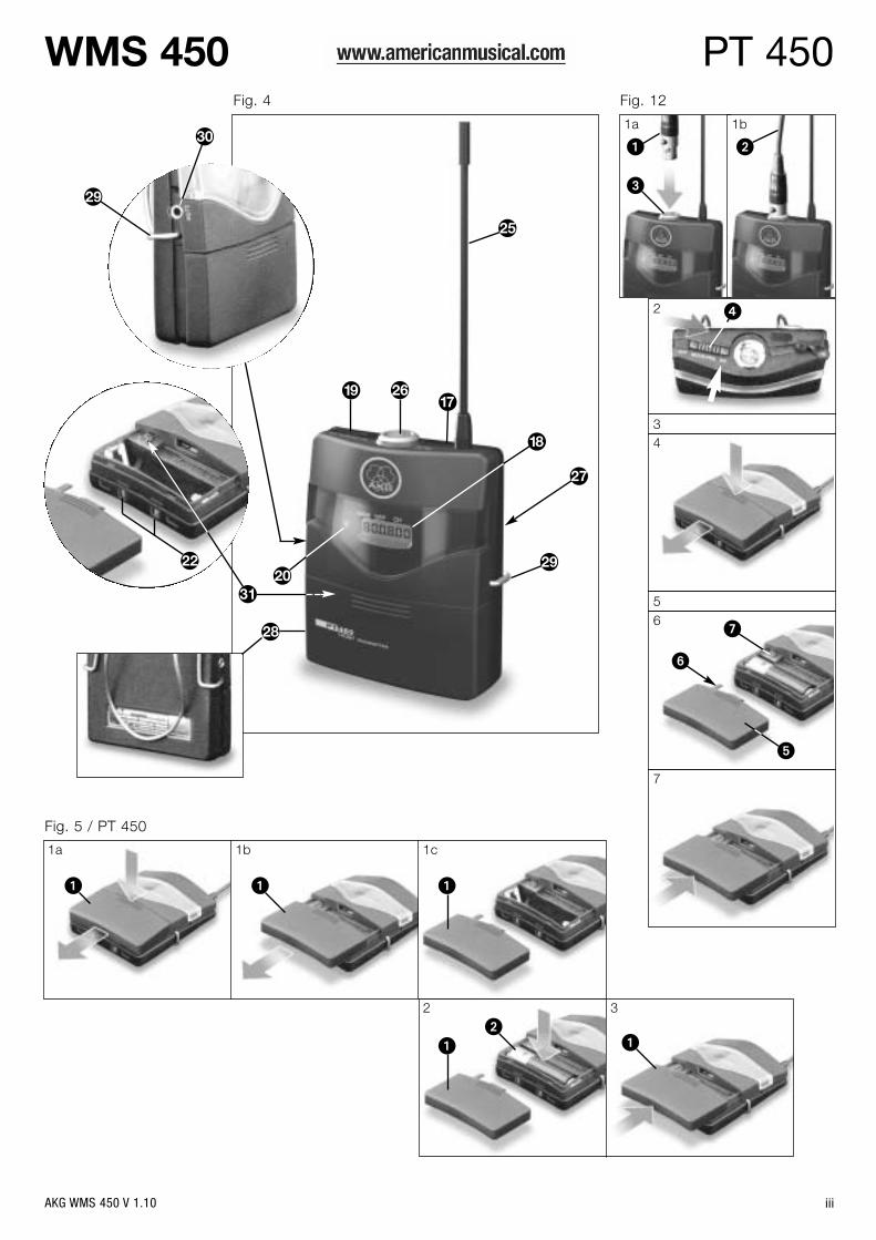
2.6 HT 450 HandheldTransmitterRefer to fig. 3 on page iv.
2.7 PT 450 BodypackTransmitterRefer to fig. 4 on page iii.
5 RF LEDs: The green OK LED is lit to indicate the receiver is receiving RF signal, the red MUTE LEDindicates that no signal is being received.
6 A and B diversity LEDs: These two LEDs are lit to indicate which of the two antennas is currentlyactive.
7 AF LEDs: Indicate the received audio level:OK (green): -40 dB to +3 dBCLIP (red): >3 dB (overload)
8 Infrared emitter: Transmits frequency data from the receiver to the handheld or bodypack transmit-ter. It also transmits the audio gain setting selected on the receiver to the handheld transmitter.The infrared emitter has a very narrow radiation angle (approx. 10°) and a maximum range of 8 inch-es (20 cm) to make sure only one transmitter will be tuned to the same frequency.
9 Output level control: This retractable rotary control attenuates the level of the balanced audio outputcontinuously by 0 to 30 dB.
10 DC IN: Locking DC input for connecting the included power supply.11 ANTENNA A/B: BNC sockets for connecting the two supplied UHF antennas (11a) or optional remote
antennas.12 BALANCED: Balanced 3-pin XLR audio output for connecting to, e.g., a microphone input on a mix-
ing console.13 UNBALANCED: Unbalanced 1/4" TS audio output jack for connecting to, e.g., a guitar amplifier.14 Output level switch: Slide switch for matching the BALANCED output level to the input gain of the
equipment connected to the receiver. The switch has two positions, 0 and -30 dB. The UNBALANCEDoutput level is not adjustable.
15 Receiver type plate indicating available carrier frequency ranges and approval information.
16 Microphone element: The handheld transmitter uses a permanently attached D 5 or C 5 microphoneelement (see packaging).
17 Infrared sensor: Receives the infrared signal emitted by the SR 450 receiver for automatically settingthe transmitter's carrier frequency and audio input gain.
18 LCD display: Indicates the selected frequency in MHz or as a Preset subchannel, current mode,transmitter audio gain setting, error messages, as well as the available battery capacity in 1-hourincrements for dry and 2-hour increments for rechargeable batteries counting down from "7 h".
19 ON-MUTE/PRG-OFF: This slide switch provides three positions:ON: The microphone output signal is fed to the transmitter for transmission to the receiver (normal
mode). The status LED (20) is lit green.MUTE/PRG: The audio signal is muted. The status LED (20) is lit red. Since power and the RF sec-
tion remain ON, no unwanted noise will become audible from the sound system when you mutethe audio signal.Sliding the switch from "OFF" to "MUTE/PRG" places the transmitter in programming mode. Thestatus LED (20) will extinguish.To switch the audio signal back on, slide the switch to "ON". The status LED (20) will change togreen.
OFF: Power to the transmitter is off. The status LED (20) is dark.20 Status LED: This bicolor LED indicates the following conditions:
Green: The battery will last for more than one hour, the transmitter is in normal mode.Red: The battery will be dead in less than one hour and/or the the audio signal is muted.Flashing red: Error message in the display.OFF: Power to the transmitter is off or the transmitter is in programming mode.
21 Battery compartment for the supplied AA size 1.5 V dry battery or a commercial 1.2 V, z2100 mAhNiMH AA size rechargeable battery.
22 Charging contacts: The recessed charging contacts allow you to charge a rechargeable battery onthe optional CU 400 charger without having to remove the battery from the transmitter.
23 Frequency sticker: Sticker attached to the transmitter shaft, indicating the available carrier frequen-cy range and approval data.
24 Color code for channel identification: If you use the transmitter within a multichannel system, youcan remove the black cover, letter and insert one of the supplied paper strips, and replace the coverwith the supplied clear-plastic cover.
17 - 20, 22, 24: Refer to section 2.5 Handheld Transmitter25 Antenna: Permanently connected, flexible antenna.26 Audio input: 3-pin mini XLR connector with both mic and line level pins that automatically match the con-
nector pinout of the recommended AKG microphones (optional) or supplied MKG L instrument cable.You can connect AKG microphones with a mini LXLR connector to the audio input of the PT 450:The MKG L instrument cable lets you connect an electric guitar, electric bass, or remote keyboard tothe bodypack transmitter.For further details, refer to the respective AKG brochures.
27 Frequency sticker: Sticker attached to the transmitter shaft, indicating the available carrier frequen-cy range and approval data.
28 Battery compartment for the supplied AA size 1.5 V dry battery or a commercial 1.2 V, z2100 mAhNiMH AA size rechargeable battery. The viewing window lets you check if there is a dry or recharge-able battery inside the battery compartment. You can also insert a white lettering strip (supplied) or acolor code strip (optional) into the viewing window.
29 Belt clip for fixing the transmitter to your belt.30 MUTE jack: This jack allows you to connect either the optional Remote Mute switch or the supplied
terminal connector for locking the ON-MUTE/PRG-OFF switch to prevent operating errors.31 Gain control: This rotary control inside the battery compartment allows you to match the bodypack
transmitter input gain to the microphone or instrument you connected to the transmitter.
AKG WMS 450 V 1.10
2 Description
22
Important!
3.1 Inserting the Transmitter Battery
Refer to fig. 5 on pages iii and iv.
Note:
3.2 Positioning the Receiver
Note:
3.3 Rack Mounting
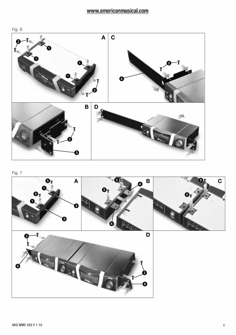
3.3.1 Single ReceiverRefer to fig. 6 on page v.
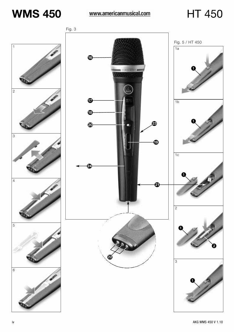
3.3.2 Two Receivers Side by Side
Refer to fig. 7 on page v.
Note:
3.4 Connecting the Receiverto a Mixer
Refer to fig. 8 on page ii.
3.5 Connecting the Receiverto Power
Refer to fig. 9 on page ii.
3.6 Powering Up the ReceiverNote:
Refer to fig. 1 on page ii.
Prior to setting up your WMS 450, check that the transmitter and receiver are tuned to the samefrequency, referring to sections 3.8 and 3.9.
1. Open the battery compartment cover (1).2. Insert the supplied battery (2) into the battery compartment, aligning the battery with the polarity sym-
bols.If you insert the battery the wrong way, the transmitter will not be powered.
3. Close the battery compartment cover (1).
Alternatively to the supplied dry battery, you may use a commercial 1.2 V AA size, z2100 mAhrechargeable battery.
Reflections off metal parts, walls, ceilings, etc. or the shadow effects of musicians and other people mayweaken or cancel the direct transmitter signal.For best results, place the receiver or remote antennas as follows:
1. Place the receiver/antennas near the performance area (stage). Make sure, though, that the transmit-ter will never get any closer to the receiver than 10 ft (3 m). Optimum separation is 16 ft. (5 m).
2. Check that you can see the receiver from where you will be using the transmitter.3. Place the receiver at least 5 ft. (1.5 m) away from any big metal objects, walls, scaffolding, ceilings,
etc.
You can either use the receiver freestanding or mount it in a 19" rack using the supplied Rack MountKit.
If you install one or ore receivers into a 19" rack, either mount the supplied antennas on the receiver frontpanel(s) or use remote antennas. This is the only way to ensure optimum reception quality.
1. Unscrew the four rubber feet (1) from the receiver bottom panel.2. Unscrew the two fixing screws (2) from each side panel.3. Use the fixing screws (2) to screw the short bracket 3 to one side panel and the long bracket (4) to the
other side panel. The brackets are contained in the supplied rack mounting kit.4. Install the receiver in your rack.
1. Unscrew the four rubber feet (1) from each receiver's bottom panel and remove the screws (5) fromthe rubber feet (1).
2. Unscrew the two fixing screws (2) from the right-hand side panel of one receiver and from the left-hand side panel of the other receiver.
3. Remove the plastic covers 3 from the side panels with the fixing screws (2) still on.4. Insert one connecting strip (4) into each free slot in the side panel of the first receiver, making sure to
align the hole in each connecting strip 4 with the appropriate threaded hole in the receiver bottompanel.
5. Fix the connecting strips (4) on the first receiver using the screws (5) you removed from the rubberfeet.
6. To join the two receivers, slide the connecting strips (4) on the first receiver through the free slots inthe side panel of the second receiver. Make sure to align the hole in each connecting strip (4) with theappropriate threaded hole in the bottom panel of the second receiver.
7. Fix the connecting strips (4) on the second receiver using the screws (5) you removed from the rub-ber feet (1).
8. Screw a short bracket (6) to the outer side panel of each receiver using for each bracket two of thescrews (2) you removed from the receiver side panels.
9. Install the receivers in your rack.
Be sure to keep the remaining screws (5) for later use.
Connect the audio output to the desired input:- BALANCED socket (1) - XLR cable - microphone input: set output level switch (2) to "-30 dB".- BALANCED socket (1) - XLR cable - line input: set output level switch (2) to "0 dB".- UNBALANCED jack (3) - 1/4" jack cable - unbalanced 1/4" microphone or line input jack.
1. Check that the AC mains voltage stated on the included power supply is identical to the ACmains voltage available where you will use your system. Using the power supply with a differ-ent AC voltage may cause damage to the unit.
2. Plug the feeder cable (1) on the included power supply into the DC IN socket (2) on the receiver rearpanel and screw down the DC connector (3).
3. Plug the power cable on the power supply into a convenient power outlet.
In the display illustrations in the following sections, flashing characters are identified by angle symbols">" and "<". Characters between quotation marks are examples of possible settings.The following symbols are used in Diagrams 1-14:
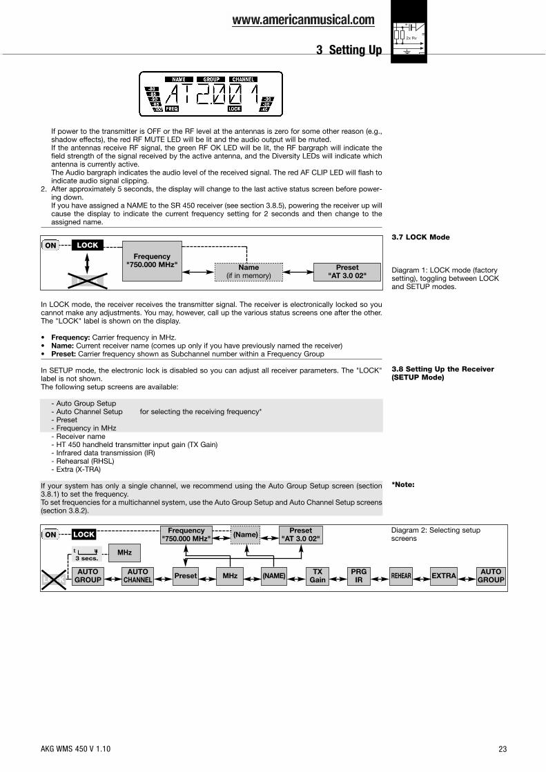
1. Press the front panel POWER switch to switch power to the receiver ON.Pressing POWER automatically places the receiver in Lock mode, and the display will indicate the cur-rently active frequency and the "LOCK" label as shown in the screenshot on the next page.
press and hold å press å briefly press t or u briefly
AKG WMS 450 V 1.10
3 Setting Up
23
3.7 LOCK Mode
Diagram 1: LOCK mode (factorysetting), toggling between LOCKand SETUP modes.
3.8 Setting Up the Receiver(SETUP Mode)
*Note:
If power to the transmitter is OFF or the RF level at the antennas is zero for some other reason (e.g.,shadow effects), the red RF MUTE LED will be lit and the audio output will be muted.If the antennas receive RF signal, the green RF OK LED will be lit, the RF bargraph will indicate thefield strength of the signal received by the active antenna, and the Diversity LEDs will indicate whichantenna is currently active.The Audio bargraph indicates the audio level of the received signal. The red AF CLIP LED will flash toindicate audio signal clipping.
2. After approximately 5 seconds, the display will change to the last active status screen before power-ing down.If you have assigned a NAME to the SR 450 receiver (see section 3.8.5), powering the receiver up willcause the display to indicate the current frequency setting for 2 seconds and then change to theassigned name.
In LOCK mode, the receiver receives the transmitter signal. The receiver is electronically locked so youcannot make any adjustments. You may, however, call up the various status screens one after the other.The "LOCK" label is shown on the display.
• Frequency: Carrier frequency in MHz.• Name: Current receiver name (comes up only if you have previously named the receiver)• Preset: Carrier frequency shown as Subchannel number within a Frequency Group
In SETUP mode, the electronic lock is disabled so you can adjust all receiver parameters. The "LOCK"label is not shown.The following setup screens are available:
- Auto Group Setup- Auto Channel Setup for selecting the receiving frequency*- Preset- Frequency in MHz- Receiver name- HT 450 handheld transmitter input gain (TX Gain)- Infrared data transmission (IR)- Rehearsal (RHSL)- Extra (X-TRA)
If your system has only a single channel, we recommend using the Auto Group Setup screen (section3.8.1) to set the frequency.To set frequencies for a multichannel system, use the Auto Group Setup and Auto Channel Setup screens(section 3.8.2).
ON
Frequency"750.000 MHz"
LOCK
LOCK
Preset"AT 3.0 02"
Name(if in memory)
ONPreset
"AT 3.0 02"Frequency
"750.000 MHz" (Name)
TXGainMHz EXTRAPRG
IRAUTO
GROUPAUTO
GROUPAUTO
CHANNEL REHEAR
LOCK
LOCK (NAME)Preset
MHzt u3 secs.
Diagram 2: Selecting setupscreens
AKG WMS 450 V 1.10
3 Setting Up

24
3.8.1 Selecting FrequencyGroups (Auto Group Setup)
Diagram 3: Automatic search for aclean (interference-free) Frequency
Group.
3.8.2 Selecting Frequenciesfrom the Preset Screen
Diagram 4: Selecting frequenciesmanually.
3.8.3 Setting Frequencies fromthe MHz Screen
Diagram 4a: Setting frequenciesdirectly.
Use t and u to select the number ofrequired channels between "1" (mini-mum) for a single-channel system and"12" (maximum) for a 12-channel system.Use t and u to select the desiredPreset. The Preset name is identical toits country ID code. Selectable Presetsinclude only those supporting theselected number of channels.The receiver will automatically find aGroup with the selected number ofclean frequencies within the selectedPreset and tune to the first clean fre-quency.If the receiver finds no clean frequency,the display will revert to the previousPreset name.
>RETRY<: start a new search.SAVE >Y<: save your setting.SAVE >N<: reject your setting.
Clean frequencies are frequencieswhere the receiver finds no RF signal oran RF signal whose level is lower thanthe current threshold setting.
Use t and u to select the desiredPreset.
Use t and u to select the desiredFrequency Group.
Use t and u to select the desired fre-quency as a Subchannel of the selectedFrequency Group.
SAVE >Y<: save your setting.SAVE >N<: reject your setting.
The MHz screen allows you to set the frequency directly in 25 kHz increments.
To call up the MHz screen, press andhold the two arrow keys simultaneouslyfor three seconds.
Press u to increase the frequency by 25 kHz or t to decrease the frequencyby 25 kHz.
SAVE >Y<: save your setting.SAVE >N<: reject your setting.
"AT 3.0 02"FREQ
"750.000"FREQ MHz
Preset
>PRG IR<IR
>GROUP<">3.0<"
>CHANNEL<">01<"
SAVE >N<>FREQ<
SAVE >Y<>FREQ<
>NAME<">AT<"
3.9.1
AUTO GROUP
3.9.1
>NAME<">AT<"
>RETRY<
>PRG IR<IR
SAVE >N<>FREQ<
SAVE >Y<>FREQ< >EXIT<
AUTOGROUP
No CH>1<
">AT3.001<"FREQ
>NAME<">AT<"
>NAME<>SCAN<
"750.000"FREQ MHz
"750.000"FREQ MHz
">750.025<"MHz
SAVE >N<>FREQ<
SAVE >Y<>FREQ<
">750.000<"MHz
3.9.1
t u3 sec.
>PRG IR<IR
AKG WMS 450 V 1.10
3 Setting Up
25
3.8.4 Editing the ReceiverNameNote:
Diagram 5: Editing the receivername.
3.9 Setting Up the TransmitterNote:
3.9.1 FrequencyRefer to figs. 3 (page iv) and 4(page iii).
Refer to figs. 10 (handheld trans-mitter) and 11 (bodypack transmit-ter) on page vi.
Diagram 6: Setting the transmittercarrier frequency.
3.9.2 Handheld TransmitterInput Gain
Refer to fig. 10 on page vi.
Diagram 7: Setting the audio inputgain on the handheld transmitter.
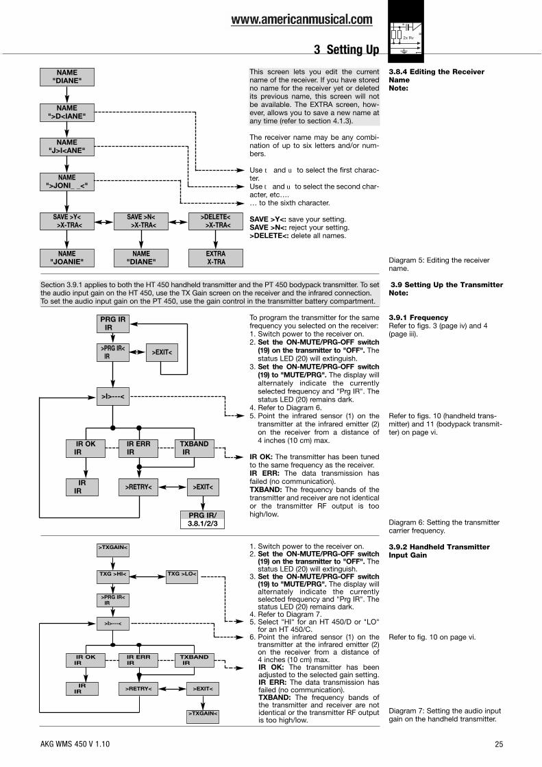
This screen lets you edit the currentname of the receiver. If you have storedno name for the receiver yet or deletedits previous name, this screen will notbe available. The EXTRA screen, how-ever, allows you to save a new name atany time (refer to section 4.1.3).
The receiver name may be any combi-nation of up to six letters and/or num-bers.
Use t and u to select the first charac-ter.Uset andu to select the second char-acter, etc….… to the sixth character.
SAVE >Y<: save your setting.SAVE >N<: reject your setting.>DELETE<: delete all names.
Section 3.9.1 applies to both the HT 450 handheld transmitter and the PT 450 bodypack transmitter. To setthe audio input gain on the HT 450, use the TX Gain screen on the receiver and the infrared connection.To set the audio input gain on the PT 450, use the gain control in the transmitter battery compartment.
To program the transmitter for the samefrequency you selected on the receiver:1. Switch power to the receiver on.2. Set the ON-MUTE/PRG-OFF switch
(19) on the transmitter to "OFF". Thestatus LED (20) will extinguish.
3. Set the ON-MUTE/PRG-OFF switch(19) to "MUTE/PRG". The display willalternately indicate the currentlyselected frequency and "Prg IR". Thestatus LED (20) remains dark.
4. Refer to Diagram 6.5. Point the infrared sensor (1) on the
transmitter at the infrared emitter (2)on the receiver from a distance of 4 inches (10 cm) max.
IR OK: The transmitter has been tunedto the same frequency as the receiver.IR ERR: The data transmission hasfailed (no communication).TXBAND: The frequency bands of thetransmitter and receiver are not identicalor the transmitter RF output is toohigh/low.
1. Switch power to the receiver on.2. Set the ON-MUTE/PRG-OFF switch
(19) on the transmitter to "OFF". Thestatus LED (20) will extinguish.
3. Set the ON-MUTE/PRG-OFF switch(19) to "MUTE/PRG". The display willalternately indicate the currentlyselected frequency and "Prg IR". Thestatus LED (20) remains dark.
4. Refer to Diagram 7.5. Select "HI" for an HT 450/D or "LO"
for an HT 450/C.6. Point the infrared sensor (1) on the
transmitter at the infrared emitter (2)on the receiver from a distance of 4 inches (10 cm) max.IR OK: The transmitter has beenadjusted to the selected gain setting.IR ERR: The data transmission hasfailed (no communication).TXBAND: The frequency bands ofthe transmitter and receiver are notidentical or the transmitter RF outputis too high/low.
NAME"DIANE"
NAME"DIANE"
NAME"J>I<ANE"
NAME">JONI_ _<"
SAVE >N<>X-TRA<
EXTRAX-TRA
>DELETE<>X-TRA<
SAVE >Y<>X-TRA<
NAME">D<IANE"
NAME"JOANIE"
PRG IRIR
PRG IR/3.8.1/2/3
IRIR >EXIT<>RETRY<
TXBANDIR
IR ERRIR
>I>---<
>PRG IR<IR
IR OKIR
>EXIT<
>TXGAIN<
>TXGAIN<
IRIR
TXG >LO<
>EXIT<>RETRY<
TXBANDIR
IR ERRIR
>I>---<
TXG >HI<
>PRG IR<IR
IR OKIR
AKG WMS 450 V 1.10
3 Setting Up
26
3.9.3 Bodypack Transmitter:Connecting a
Microphone/Instrument andSetting Input Gain
Important!
Refer to fig. 12 on page iii.
3.10 Before the Soundcheck
Important!
Refer to fig. 1 on page ii.
3.10.1 Finding Dead Spots
Diagram 8: Using the Rehearsalfunction to find dead spots
(dropouts).
The PT 450 bodypack transmitter has been designed primarily for use with "L" type MicroMic Seriesmicrophones from AKG (see section 2.7). If you wish to connect other microphones from AKG or othermanufacturers to the PT 450, please note that you may have to rewire the existing connector of yourmicrophone or replace it with a 3-pin mini XLR connector.
Audio input pinout:Pin 1: shieldPin 2: audio (inphase)Pin 3: audio
A positive supply voltage of 6 volts for condenser microphones is available on pin 3.
Please note that AKG cannot guarantee that the PT 450 bodypack transmitter will work perfectlywith products from other manufacturers and any damage that may result from such use is not cov-ered by the AKG warranty scheme.
1. Plug the mini XLR connector (1) on the cable of your microphone or on the MKG L instrument cable(2) into the audio input connector (3) on the bodypack transmitter.
2. Set the ON-MUTE/PRG-OFF switch (4) to "ON".3. Switch power to the receiver on.4. Open the battery compartment on the bodypack transmitter.5. Speak or sing into the microphone or play a few bars on your instrument (the louder the better).6. Use the integrated screwdriver (6) on the battery compartment cover (5) to set the gain control (7) to
the point where the signal will optimally drive the receiver's audio section (green AF OK LED lit, Audiobargraph indicating 0 dB on peaks).
7. Close the battery compartment.
1. Activate the Rehearsal function on the receiver referring to section 3.10.1 below.2. Move the transmitter around the area where you will use the system to check the area for "dead
spots", i.e., places where the field strength seems to drop and reception deteriorates.If you find any dead spots, try to eliminate them by repositioning the receiver or the antennas. If thisdoes not help, avoid the dead spots.
3. If the received signal is noisy, set the squelch threshold to a level where the noise will stop. (Refer tosection 3.10.2.)
Never set the squelch threshold any higher than absolutely necessary. The higher the squelchthreshold (-80 dB = max., -100 dB = min.), the lower the sensitivity of the receiver and thus theusable range between transmitter and receiver.
4. The RF bargraph on the receiver extinguishing and the red RF MUTE LED (5) coming on mean that nosignal is being received or the squelch is active.Switch the transmitter ON, move closer to the receiver, or set the squelch threshold to the point thatthe green RF OK LED (5) will illuminate and the RF bargraph reappear.
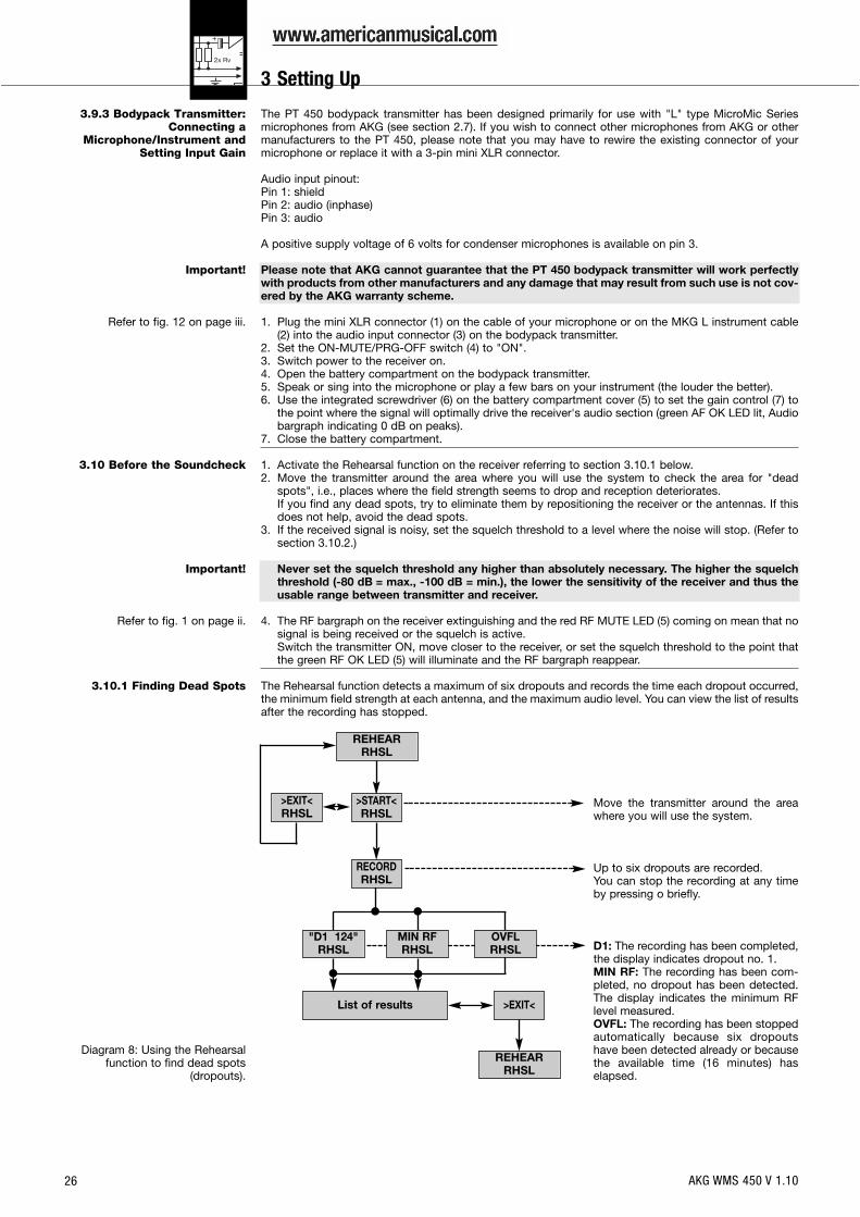
The Rehearsal function detects a maximum of six dropouts and records the time each dropout occurred,the minimum field strength at each antenna, and the maximum audio level. You can view the list of resultsafter the recording has stopped.
Move the transmitter around the areawhere you will use the system.
Up to six dropouts are recorded.You can stop the recording at any timeby pressing o briefly.
D1: The recording has been completed,the display indicates dropout no. 1.MIN RF: The recording has been com-pleted, no dropout has been detected.The display indicates the minimum RFlevel measured.OVFL: The recording has been stoppedautomatically because six dropoutshave been detected already or becausethe available time (16 minutes) haselapsed.
REHEARRHSL
REHEARRHSL
List of results
>EXIT<RHSL
>EXIT<
"D1 124"RHSL
OVFLRHSL
MIN RFRHSL
>START<RHSL
RECORDRHSL
AKG WMS 450 V 1.10
3 Setting Up
27
3.10.2 Setting the Squelch Threshold
Diagram 9: Setting the squelch threshold.
3.11 Multichannel Systems
Note:
3.11.1 Selecting Frequenciesfor Multichannel Systems(Auto Channel Setup)
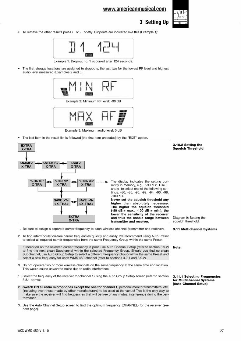
• To retrieve the other results press t or u briefly. Dropouts are indicated like this (Example 1):
Example 1: Dropout no. 1 occurred after 124 seconds.
• The first storage locations are assigned to dropouts, the last two for the lowest RF level and highestaudio level measured (Examples 2 and 3).
Example 2: Minimum RF level: -90 dB
Example 3: Maximum audio level: 0 dB
• The last item in the result list is followed (the first item preceded) by the "EXIT" option.
The display indicates the setting cur-rently in memory, e.g., "-90 dB". Use tandu to select one of the following set-tings: -80, -85, -90, -92, -94, -96, -98, -100 dB.Never set the squelch threshold anyhigher than absolutely necessary.The higher the squelch threshold (-80 dB = max., -100 dB = min.), thelower the sensitivity of the receiverand thus the usable range betweentransmitter and receiver.
1. Be sure to assign a separate carrier frequency to each wireless channel (transmitter and receiver).
2. To find intermodulation-free carrier frequencies quickly and easily, we recommend using Auto Presetto select all required carrier frequencies from the same Frequency Group within the same Preset.
If reception on the selected carrier frequency is poor, use Auto Channel Setup (refer to section 3.9.2)to find the next clean Subchannel within the selected Frequency Group. Should you find no cleanSubchannel, use Auto Group Setup to select a different Frequency Group within the same Preset andselect a new frequency for each WMS 450 channel (refer to sections 3.9.1 and 3.9.2).
3. Do not operate two or more wireless channels on the same frequency at the same time and location.This would cause unwanted noise due to radio interference.
1. Select the frequency of the receiver for channel 1 using the Auto Group Setup screen (refer to section3.8.1 above).
2. Switch ON all radio microphones except the one for channel 1, personal monitor transmitters, etc.(including even those made by other manufacturers) to be used at the venue! This is the only way tomake sure the receiver will find frequencies that will be free of any mutual interference during the per-formance.
3. Use the Auto Channel Setup screen to find the optimum frequency (CHANNEL) for the receiver (seenext page).
EXTRAX-TRA
EXTRAX-TRA
">-80< dB"X-TRA
">-100< dB"X-TRA
">-90< dB"X-TRA
SAVE >Y<>X-TRA<
SAVE >N<>X-TRA<
>NAME<X-TRA
>SQL<X-TRA
>STATUS<X-TRA
AKG WMS 450 V 1.10
3 Setting Up

28
>RETRY<: start a new search.
SAVE: >Y< save your setting.SAVE >N< reject your setting.
Diagram 10: Automatic search forclean frequencies for a
multichannel system.
4.1 SR 450 Receiver4.1.1 Selecting Modes
4.1.2 Selecting Screens
4. Use t and u to select the name ofthe desired Preset.
5. Use t and u to select the desiredFrequency Group.
6. The receiver will automatically findthe next clean frequency.As soon as the receiver has found aclean frequency, the Subchannelnumber assigned to this frequencywill be displayed.Clean frequencies are frequencieswhere the receiver finds no RF signalor an RF signal whose level is lowerthan the current threshold setting.
7. Refer to section 3.9.1: Program thetransmitter you assigned to channel 1and leave power to the transmitterON.
8. Repeat steps 1 through 7 above forall other channels of your system. Besure to set each channel to thesame preset (country) as channel 1!
To toggle between LOCK and SETUP modes, press and hold the å key for about 1.5 seconds.When the receiver is in LOCK mode, the "LOCK" label is shown on the display. In SETUP mode, the"LOCK" label is not shown.
Use t and u to select the desired status or setup screens. To call up the MHz screen, press and holdt and u simultaneously for three seconds.
Diagramm 11: Selecting screens.
AUTOCHANNEL
>EXIT<>INFO<>SQL<>STATUS<>NAME<
MHzt u3 sec.
TXGain EXTRAPRG
IR REHEAR
LOCK Mode:
SETUP Mode:
Preset"AT 3.0 02"
Frequency"750.000 MHz" (Name)
(NAME) PresetMHz
LOCK
LOCKAUTO
GROUP
AUTOCHANNEL
AUTO CHANNEL
SAVE >N<>FREQ<
SAVE >Y<>FREQ<
>PRG IR<IR
3.9.1
>EXIT<
>EXIT<
>RETRY<">AT3.001<"FREQ
>GROUP<">3.0<"
>CHANNEL<>SCAN<
>NAME<">AT<"
AKG WMS 450 V 1.10
3 Setting Up
4 Operating Notes
29
4.1.3 Extra Functions• NAME
Diagram 12: Entering a newreceiver name.
• STATUS
Diagram 13: Warning messages.
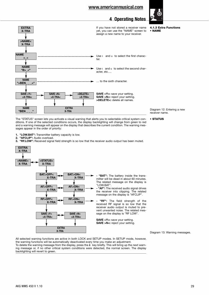
If you have not stored a receiver nameyet, you can use the "NAME" screen toassign a new name to your receiver.
Use t and u to select the first charac-ter.
Uset andu to select the second char-acter, etc….
… to the sixth character.
SAVE >Y<: save your setting.SAVE >N<: reject your setting.>DELETE<: delete all names.
The "STATUS" screen lets you activate a visual warning that alerts you to selectable critical system con-ditions. If one of the selected conditions occurs, the display backlighting will change from green to redand a warning message will appear on the display that describes the current condition. The warning mes-sages appear in the order of priority:
1. "LOW.BAT": Transmitter battery capacity is low.2. "AFCLIP": Audio overload.3. "RF.LOW": Received signal field strength is so low that the receiver audio output has been muted.
- "BAT": The battery inside the trans-mitter will be dead in about 60 minutes.The related message on the display is"LOW.BAT".- "AF": The received audio signal drivesthe receiver into clipping. The relatedmessage on the display is "AFCLIP".
- "RF": The field strength of thereceived RF signal is so low that thereceiver audio output is muted to pre-vent unwanted noise. The related mes-sage on the display is "RF LOW".
SAVE >Y<: save your setting.SAVE >N<: reject your setting.
All selected warning functions are active in both LOCK and SETUP modes. In SETUP mode, however,the warning functions will be automatically deactivated every time you make an adjustment.To delete the warning message from the display, press the å key briefly. This will bring up the next warn-ing message or, if no other critical system conditions were detected, the normal screen. The displaybacklighting will revert to green.
EXTRAX-TRA
>NAME<X-TRA
NAME"B>_<"
NAME">BEN_ _ _<"
SAVE >N<>X-TRA<
EXTRAX-TRA
>DELETE<>X-TRA<
SAVE >Y<>X-TRA<
NAME>_<
NAME"BEN _ _ _"
EXTRAX-TRA
>NAME<X-TRA
>STATUS<X-TRA
EXTRAX-TRA
SAVE >N<>X-TRA<
SAVE >Y<>X-TRA<
BAT.>OFF<X-TRA
AF.>OFF<X-TRA
AF.>ON<X-TRA
RF>OFF<X-TRA
RF.>ON<X-TRA
BAT.>ON<X-TRA
AKG WMS 450 V 1.10
4 Operating Notes

30
• INFO
Diagram 14: Calling up informationabout the receiver.
4.2 HT 450 HandheldTransmitter
4.2.1 Muting the MicrophoneRefer to fig. 3 on page iv.
4.2.2 Microphone Technique
• Working Distance andProximity Effect
Refer to fig. 13 on page vi.
• Angle of IncidenceRefer to fig. 13 on page vi.
• FeedbackRefer to fig. 14 on page vi.
• Backing ChoirRefer to fig. 15 on page vi.
4.2.3 PB 1000 and PPC 1000(HT 450/C only)
The INFO screen lets you call up information about your receiver.
"V1.1": firmware version"B 4--.50": frequency band"PV 1.0": Preset version
1. Set the ON-MUTE/PRG-OFF switch (19) to "MUTE/PRG" (center position).• If you switched from "OFF" to "MUTE/PRG":
The transmitter audio and RF sections are OFF and the status LED (20) is dark. The infrared receiv-er section is ON. The transmitter is in setup mode and you can program the carrier frequency andinput gain.The display indicates the frequency in MHz - frequency in Preset form - "Prg IR" and changes toalternating between the currently selected Preset and "Prg IR".
• If you switched from "ON" to "MUTE/PRG":The microphone is muted and the status LED (20) will change from green to red. The infraredreceiver section is OFF. Since the RF section continues transmitting the carrier frequency, nounwanted noises will become audible form the sound system.The display alternates between the currently selected Preset and the remaining battery capacity inhours.
2. To switch the microphone back on, set the ON-MUTE/PRG-OFF switch (19) to "ON".The status LED (20) will change to green. The display will indicate the remaining battery capacity inhours.
A handheld vocal microphone provides many ways of shaping the sound of your voice as it is heard overthe sound system.The following sections contain useful hints on how to use your HT 450 handheld transmitter for bestresults.
Basically, your voice will sound the bigger and mellower, the closer you hold the microphone to your lips.Moving away from the microphone will produce a more reverberant, more distant sound, as the micro-phone will pick more of the room’s reverberation.You can use this effect to make your voice sound aggressive, neutral, insinuating, etc. simply by chang-ing your working distance.Proximity effect is a more or less dramatic boost of low frequencies that occurs when you sing into themicrophone from less than 2 inches. It gives more "body" to your voice and an intimate, bass-heavysound.
Sing to one side of the microphone or above and across the microphone’s top. This provides a well-bal-anced, natural sound.If you sing directly into the microphone, it will not only pick up excessive breath noise but also overem-phasize "sss", "sh", "tch", "p", and "t" sounds.
Feedback is the result of part of the sound projected by a speaker being picked up by a microphone, fedto the amplifier, and projected again by the speaker. Above a specific volume or "system gain" settingcalled the feedback threshold, the signal starts being regenerated indefinitely, making the sound systemhowl and the sound engineer desperately dive for the master fader to reduce the volume and stop thehowling.To increase usable gain before feedback, place the main ("FOH") speakers in front of the microphones(along the front edge of the stage).If you use monitor speakers, be sure never to point any microphone directly at the monitors.Feedback may also be triggered by resonances depending on the acoustics of the room or hall. With res-onances at low frequencies, proximity effect may cause feedback. In this case, it is often enough to moveaway from the microphone a little to stop the feedback.
1. Never let more than two persons share a microphone.2. Ask your backing vocalists never to sing more than 35 degrees off the microphone axis.
The microphone is very insensitive to off-axis sounds. If the two vocalists were to sing into the micro-phone from a wider angle than 35 degrees, you may end up bringing up the fader of the microphonechannel far enough to create a feedback problem.
The PB 1000 Presence Boost Adapter (installed in the HT 450/C handheld transmitter) boosts the sen-sitivity of the microphone element by approx. 5 dB between 5 kHz and 9 kHz for optimum intelligibility ofspeech.
EXTRAX-TRA
EXTRAX-TRA
"V 1.1"X-TRA
"PV 1.0"X-TRA
EXITX-TRA
>EXIT<X-TRA
"B 4--.50"X-TRA
>NAME<X-TRA
>INFO<X-TRA
>STATUS<X-TRA
>SQL<X-TRA
AKG WMS 450 V 1.10
4 Operating Notes
31
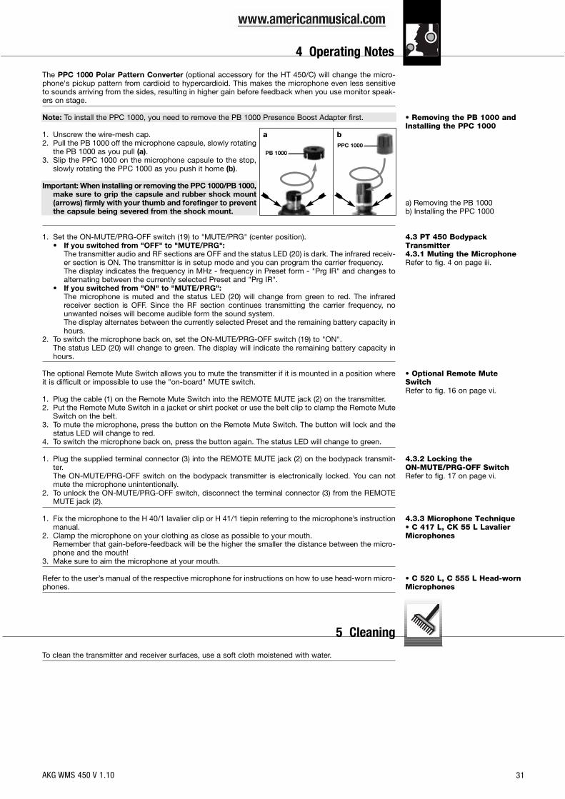
• Removing the PB 1000 andInstalling the PPC 1000
a) Removing the PB 1000b) Installing the PPC 1000
4.3 PT 450 BodypackTransmitter4.3.1 Muting the MicrophoneRefer to fig. 4 on page iii.
• Optional Remote MuteSwitchRefer to fig. 16 on page vi.
4.3.2 Locking the ON-MUTE/PRG-OFF SwitchRefer to fig. 17 on page vi.
4.3.3 Microphone Technique• C 417 L, CK 55 L LavalierMicrophones
• C 520 L, C 555 L Head-wornMicrophones
The PPC 1000 Polar Pattern Converter (optional accessory for the HT 450/C) will change the micro-phone's pickup pattern from cardioid to hypercardioid. This makes the microphone even less sensitiveto sounds arriving from the sides, resulting in higher gain before feedback when you use monitor speak-ers on stage.
Note: To install the PPC 1000, you need to remove the PB 1000 Presence Boost Adapter first.
1. Unscrew the wire-mesh cap.2. Pull the PB 1000 off the microphone capsule, slowly rotating
the PB 1000 as you pull (a).3. Slip the PPC 1000 on the microphone capsule to the stop,
slowly rotating the PPC 1000 as you push it home (b).
Important: When installing or removing the PPC 1000/PB 1000,make sure to grip the capsule and rubber shock mount(arrows) firmly with your thumb and forefinger to preventthe capsule being severed from the shock mount.
1. Set the ON-MUTE/PRG-OFF switch (19) to "MUTE/PRG" (center position).• If you switched from "OFF" to "MUTE/PRG":
The transmitter audio and RF sections are OFF and the status LED (20) is dark. The infrared receiv-er section is ON. The transmitter is in setup mode and you can program the carrier frequency.The display indicates the frequency in MHz - frequency in Preset form - "Prg IR" and changes toalternating between the currently selected Preset and "Prg IR".
• If you switched from "ON" to "MUTE/PRG":The microphone is muted and the status LED (20) will change from green to red. The infraredreceiver section is OFF. Since the RF section continues transmitting the carrier frequency, nounwanted noises will become audible form the sound system.The display alternates between the currently selected Preset and the remaining battery capacity inhours.
2. To switch the microphone back on, set the ON-MUTE/PRG-OFF switch (19) to "ON".The status LED (20) will change to green. The display will indicate the remaining battery capacity inhours.
The optional Remote Mute Switch allows you to mute the transmitter if it is mounted in a position whereit is difficult or impossible to use the "on-board" MUTE switch.
1. Plug the cable (1) on the Remote Mute Switch into the REMOTE MUTE jack (2) on the transmitter.2. Put the Remote Mute Switch in a jacket or shirt pocket or use the belt clip to clamp the Remote Mute
Switch on the belt.3. To mute the microphone, press the button on the Remote Mute Switch. The button will lock and the
status LED will change to red.4. To switch the microphone back on, press the button again. The status LED will change to green.
1. Plug the supplied terminal connector (3) into the REMOTE MUTE jack (2) on the bodypack transmit-ter.The ON-MUTE/PRG-OFF switch on the bodypack transmitter is electronically locked. You can notmute the microphone unintentionally.
2. To unlock the ON-MUTE/PRG-OFF switch, disconnect the terminal connector (3) from the REMOTEMUTE jack (2).
1. Fix the microphone to the H 40/1 lavalier clip or H 41/1 tiepin referring to the microphone’s instructionmanual.
2. Clamp the microphone on your clothing as close as possible to your mouth.Remember that gain-before-feedback will be the higher the smaller the distance between the micro-phone and the mouth!
3. Make sure to aim the microphone at your mouth.
Refer to the user’s manual of the respective microphone for instructions on how to use head-worn micro-phones.
To clean the transmitter and receiver surfaces, use a soft cloth moistened with water.
a bPPC 1000
PB 1000
AKG WMS 450 V 1.10
4 Operating Notes
5 Cleaning
32
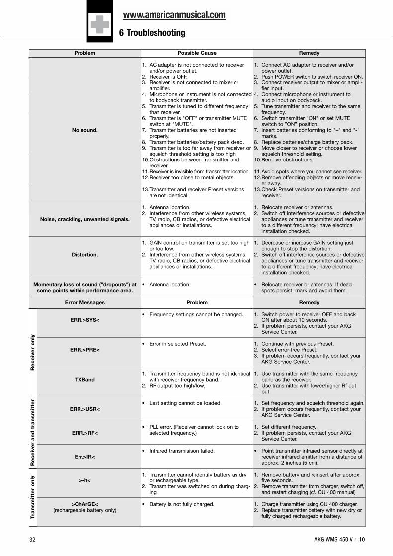
Problem
No sound.
Noise, crackling, unwanted signals.
Distortion.
Momentary loss of sound ("dropouts") atsome points within performance area.
Error Messages
ERR.>SYS<
ERR.>PRE<
TXBand
ERR.>USR<
ERR.>RF<
Err.>IR<
>-h<
>ChArGE<(rechargeable battery only)
Possible Cause
1. AC adapter is not connected to receiverand/or power outlet.
2. Receiver is OFF.3. Receiver is not connected to mixer or
amplifier.4. Microphone or instrument is not connected
to bodypack transmitter.5. Transmitter is tuned to different frequency
than receiver.6. Transmitter is "OFF" or transmitter MUTE
switch at "MUTE".7. Transmitter batteries are not inserted
properly.8. Transmitter batteries/battery pack dead.9. Transmitter is too far away from receiver or
squelch threshold setting is too high.10.Obstructions between transmitter and
receiver.11.Receiver is invisible from transmitter location.12.Receiver too close to metal objects.
13.Transmitter and receiver Preset versionsare not identical.
1. Antenna location.2. Interference from other wireless systems,
TV, radio, CB radios, or defective electricalappliances or installations.
1. GAIN control on transmitter is set too highor too low.
2. Interference from other wireless systems,TV, radio, CB radios, or defective electricalappliances or installations.
• Antenna location.
Problem
• Frequency settings cannot be changed.
• Error in selected Preset.
1. Transmitter frequency band is not identicalwith receiver frequency band.
2. RF output too high/low.
• Last setting cannot be loaded.
• PLL error. (Receiver cannot lock on toselected frequency.)
• Infrared transmisison failed.
1. Transmitter cannot identify battery as dryor rechargeable type.
2. Transmitter was switched on during charg-ing.
• Battery is not fully charged.
Remedy
1. Connect AC adapter to receiver and/orpower outlet.
2. Push POWER switch to switch receiver ON.3. Connect receiver output to mixer or ampli-
fier input.4. Connect microphone or instrument to
audio input on bodypack.5. Tune transmitter and receiver to the same
frequency.6. Switch transmitter "ON" or set MUTE
switch to ”ON” position.7. Insert batteries conforming to "+" and "-"
marks.8. Replace batteries/charge battery pack.9. Move closer to receiver or choose lower
squelch threshold setting.10.Remove obstructions.
11.Avoid spots where you cannot see receiver.12.Remove offending objects or move receiv-
er away.13.Check Preset versions on transmitter and
receiver.
1. Relocate receiver or antennas.2. Switch off interference sources or defective
appliances or tune transmitter and receiverto a different frequency; have electricalinstallation checked.
1. Decrease or increase GAIN setting justenough to stop the distortion.
2. Switch off interference sources or defectiveappliances or tune transmitter and receiverto a different frequency; have electricalinstallation checked.
• Relocate receiver or antennas. If deadspots persist, mark and avoid them.
Remedy
1. Switch power to receiver OFF and backON after about 10 seconds.
2. If problem persists, contact your AKGService Center.
1. Continue with previous Preset.2. Select error-free Preset.3. If problem occurs frequently, contact your
AKG Service Center.
1. Use transmitter with the same frequencyband as the receiver.
2. Use transmitter with lower/higher Rf out-put.
1. Set frequency and squelch threshold again.2. If problem occurs frequently, contact your
AKG Service Center.
1. Set different frequency.2. If problem persists, contact your AKG
Service Center.
• Point transmitter infrared sensor directly atreceiver infrared emitter from a distance ofapprox. 2 inches (5 cm).
1. Remove battery and reinsert after approx.five seconds.
2. Remove transmitter from charger, switch off,and restart charging (cf. CU 400 manual)
1. Charge transmitter using CU 400 charger.2. Replace transmitter battery with new dry or
fully charged rechargeable battery.
Receiv
er
only
Receiv
er
and t
ransm
itte
rT
ransm
itte
r only
AKG WMS 450 V 1.10
6 Troubleshooting

33
SR 450RF carrier frequency ranges: 650 to 680, 680 to 710, 720 to 750, 760 to 790, 790 to 820, 835 to 862 and 863 to 865 MHzModulation: FMAudio bandwidth: 35 to 20,000 HzTHD at 1 kHz: <0.3%Signal-to-noise: 120 dB(A)Audio outputs: balanced XLR and unbalanced TS 1/4" jack, balanced level switchable to -30 or 0 dBmDimensions: 200 x 44 x 190 mm (7.8 x 1.7 x 7.4 in.)Weight: 972 g (2.2 lbs.)
HT 450Carrier frequency ranges: 650 – 680, 680 – 710, 720 – 750, 760 – 790, 790 – 820, 835 to 862 and 863 to 865 MHzModulation: FMAudio bandwidth: 35 to 20,000 HzTHD: <0.7% typical at rated deviation/1 kHzS/N Ratio (A-weighted) 120 dB(A)RF output: 50 mW max. (ERP)Battery life: 1.5 V AA size dry battery: 6 hours; 1.2 V NiMH, 2100 mAh AA size rechargeable battery: 8 hrs.Size: 229 x 52.5 mm max. dia. (9 x 2 in.)Net Weight: 220 g (7.8 oz.)
PT 450Carrier frequency ranges: 650 – 680, 680 – 710, 720 – 750, 760 – 790, 790 – 820, 835 to 862 and 863 to 865 MHzModulation: FMAudio bandwidth: 35 to 20,000 HzTHD: <0.7% typical at rated deviation/1 kHzS/N ratio (A-weighted) 120 dB(A) typicalRF output: 50 mW max. (ERP)Battery life: 1.5 V AA size dry battery: 6 hours; 1.2 V NiMH, 2100 mAh AA size rechargeable battery: 8 hrs.Size: 60 x 73,5 x 30 mm (2.4 x 2.9 x 1.2 in.)Net weight: 90 g (3.2 oz.)
This equipment conforms to the standards listed in the Declaration of Conformity. To order a free copy of the Declaration of Conformity, visithttp://www.akg.com or contact [email protected].
AKG WMS 450 V 1.10
7 Specifications

Mikrofone · Kopfhörer · Drahtlosmikrofone · Drahtloskopfhörer · Kopfsprechgarnituren · Akustische KomponentenMicrophones · Headphones · Wireless Microphones · Wireless Headphones · Headsets · Electroacoustical ComponentsMicrophones · Casques HiFi · Microphones sans fil · Casques sans fil · Micros-casques · Composants acoustiquesMicrofoni · Cuffie HiFi · Microfoni senza filo · Cuffie senza filo · Cuffie-microfono · Componenti acusticiMicrófonos · Auriculares · Micrófonos inalámbricos · Auriculares inalámbricos · Auriculares con micrófono · Componentes acústicosMicrofones · Fones de ouvido · Microfones s/fios · Fones de ouvido s/fios · Microfones de cabeça · Componentes acústicos
AKG Acoustics GmbHLemböckgasse 21–25, A-1230 Vienna/AUSTRIA, phone: (+43-1) 86654-0*e-mail: [email protected]
AKG Acoustics, U.S.8500 Balboa Boulevard, Northridge, CA 91329, U.S.A, phone: (+1 818) 920-3212e-mail: [email protected]
For other products and distributors worldwide visit www.akg.com
Technische Änderungen vorbehalten. Specifications subject to change without notice. Ces caractéristiques sont susceptibles de modifi-cations. Ci riserviamo il diritto di effettuare modifiche tecniche. Nos reservamos el derecho de introducir modificaciones técnicas.Especificações sujeitas a mudanças sem aviso prévio.
Printed in China. 01/07/9100 U 1216