Zusatzkühlung Additional cool ing Refroidissement additionnel...ple men tary cool ing for the com...
12
KT-140-7 Zusatzkühlung Inhalt Seite 1 Sicherheit 1 2 Zusatzventilatoren 3 3 Wassergekühlte Zylinderköpfe 10 1 Sicherheit Im Bereich hoher thermischer Belas- tung kann eine zusätzliche Kühlung des Verdichters erforderlich werden (siehe Einsatzgrenzen in Prospekten und BITZER Software). In der vorlie- genden Technischen Information wer- den die Anwendungs- und Montage- hinweise für die wichtigsten Kühlungs- arten behandelt (Zusatzventilatoren, wassergekühlte Zylinderköpfe). Diese Technische Information wäh- rend der gesamten Verdichter- Lebensdauer aufbewahren. Folgende technische Dokumente ebenfalls beachten KB-104 (Betriebsanleitung) KB-110 (Betriebsanleitung) KW-100 (Wartungsanleitung) Autorisiertes Fachpersonal Sämtliche Arbeiten an Verdichtern und Kälteanlagen dürfen nur von Fachpersonal ausgeführt werden, das in allen Arbeiten ausgebildet und un- terwiesen wurde. Für die Qualifikation und Sachkunde des Fachpersonals gelten die jeweils landesüblichen Vorschriften und Richtlinien. Additional cooling Content Page 1 Safety 1 2 Additional fans 3 3 Water cooled cylinder heads 10 1 Safety It may be necessary to provide sup- plementary cooling for the compres- sor when subjected to high thermal load (refer to application limits in bro- chures and BITZER Software). This Technical Information deals with instructions for the use and assembly of the main cooling methods (addition- al fan, water-cooled cylinder heads). Retain this Technical Information dur- ing the entire lifetime of the compres- sor. Also observe the following techni- cal documents KB-104 (Operating Instructions) KB-110 (Operating Instructions) KW-100 (Maintenance Instructions) Authorized staff All work on compressor and refrigera- tion systems shall be carried out only by refrigeration personnel which has been trained and instructed in all work. The qualification and expert knowledge of the refrigeration person- nel is subject to the respective nation- al regulations and guidelines. Refroidissement additionnel Sommaire Page 1 Sécurité 1 2 Ventilateurs additionnels 3 3 Culasses à l'eau 10 1 Sécurité En cas de fortes contraintes thermi- ques, un refroidissement complémentai- re du compresseur peut s'avérer néces- saire (voir limites d'application dans prospectus et BITZER Software). Vous trouverez dans cette information tech- nique les instructions d'utilisation et de montage des principales méthodes de refroidissement (ventilateur additionnel, culasses à l'eau). Garder cette instruction de service pen- dant toute la durée de service du com- presseur. Respectez également les documents techniques suivants KB-104 (Instruction de service) KB-110 (Instruction de service) KW-100 (Instruction de maintenance) Personnel spécialisé autorisé Seul un personnel spécialisé ayant été formé et initié est autorisé à réaliser l'ensemble des travaux sur les com- presseurs et installations frigorifiques. Les niveaux de qualification et d’exper- tise technique du personnel sont sujets aux prescriptions et directives nationaux en vigueur.
Transcript of Zusatzkühlung Additional cool ing Refroidissement additionnel...ple men tary cool ing for the com...
KT-140-7
Zusatzkühlung
Inhalt Seite
1 Sicherheit 12 Zusatzventilatoren 33 Wassergekühlte
Zylinderköpfe 10
1 Sicherheit
Im Bereich hoher thermischer Belas -tung kann eine zusätzliche Kühlungdes Verdichters erforderlich werden(siehe Einsatzgrenzen in Prospektenund BITZER Software). In der vorlie-genden Technischen Information wer-den die Anwendungs- und Montage -hinweise für die wichtigsten Kühlungs -arten behandelt (Zusatzventilatoren,wassergekühlte Zylinderköpfe).
Diese Technische Information wäh -rend der gesamten Verdichter-Lebensdauer aufbewahren.
Folgende technische Dokumenteebenfalls beachten
KB-104 (Betriebsanleitung)KB-110 (Betriebsanleitung)KW-100 (Wartungsanleitung)
Autorisiertes Fachpersonal
Sämtliche Arbeiten an Ver dich ternund Kälte anlagen dürfen nur vonFach personal ausgeführt werden, dasin allen Arbeiten ausgebildet und un -ter wiesen wurde. Für die Qualifikationund Sachkunde des Fachpersonalsgelten die jeweils landesüblichenVorschriften und Richtlinien.
Additional cool ing
Content Page
1 Safety 12 Additional fans 33 Water cooled cyl in der
heads 10
1 Safety
It may be nec es sary to pro vide sup -ple men tary cool ing for the com pres -sor when sub ject ed to high ther malload (refer to application limits in bro -chures and BITZER Software). ThisTechnical Infor ma tion deals withinstruc tions for the use and assem blyof the main cool ing meth ods (addition-al fan, water- cooled cyl in der heads).
Retain this Technical Information dur-ing the entire lifetime of the compres-sor.
Also observe the following techni-cal documents
KB-104 (Operating Instructions)KB-110 (Operating Instructions)KW-100 (Maintenance Instructions)
Authorized staff
All work on compressor and refrigera-tion systems shall be carried out onlyby refrigeration personnel which hasbeen trained and instructed in allwork. The qualification and expertknowledge of the refrigeration person-nel is subject to the respective nation-al regulations and guidelines.
Refroidissement additionnel
Sommaire Page
1 Sécurité 12 Ventilateurs additionnels 33 Culasses à l'eau 10
1 Sécurité
En cas de for tes contrain tes ther mi -ques, un refroi dis se ment com plé men tai -re du com pres seur peut s'avérer néces -sai re (voir limites d'application danspro spec tus et BITZER Software). Voustrou ve rez dans cette information tech-nique les instruc tions d'utilisation et demon tage des prin ci pa les métho des derefroi dis se ment (ven ti la teur addi tion nel,culas ses à l'eau).
Garder cette instruction de service pen-dant toute la durée de service du com-presseur.
Respectez également les documentstechniques suivants
KB-104 (Instruction de service)KB-110 (Instruction de service)KW-100 (Instruction de maintenance)
Personnel spécialisé autorisé
Seul un personnel spécialisé ayant étéformé et initié est autorisé à réaliser l'ensemble des travaux sur les com-presseurs et installations frigorifiques.Les niveaux de qualification et d’exper-tise technique du personnel sont sujetsaux prescriptions et directives nationauxen vigueur.

2 KT-140-7
Residual hazards
Certain residual hazards from thecompressors are unavoidable.
All persons working on these unitsmust therefore read these TechnicalInformation carefully!
All of the following have validity:• specific safety regulations and
standards (e.g. EN 378, EN 60204and EN 60335),
• generally acknowledged safetystandards,
• EU directives,• national regulations.
Safety references
are instructions intended to preventhazards.
Safety references must be stringentlyobserved!
Attention!Instructions on preventing possi-ble damage to equipment.
Caution!Instructions on preventing a pos-sible minor hazard to persons.
Warning!Instructions on preventing a pos-sible severe hazard to persons.
Danger!Instructions on preventing aimmediate risk of severe hazardto persons.
General safety references
Warning!The compressor is under pres-sure with a holding charge to apressure of 0.2 to 0.5 bar aboveatmospheric pressure.Incorrect handling may causeinjury to skin and eyes.Wear safety goggles while work-ing on compressor.Do not open connections beforedown.
!!
!
!
Dangers résiduels
Le compresseur peut être la source dedangers résiduels inévitables.
Par conséquent, chaque personne quitravaille sur cet appareil doit lire attentive-ment cette Information Technique!
A prendre en considération• les prescriptions et normes de sécurité
relatives (par ex. EN 378, EN 60204 etEN 60335),
• les règles de sécurité généralementreconnues,
• les directives de l'UE,• prescriptions nationales.
Les indications de sécurité
sont des instructions pour éviter lesmises en danger.
Respecter scrupuleusement les indica-tions de sécurité!
Attention !Instruction pour éviter une possiblemise en danger d'appareils.
Prudence !Instruction pour éviter une possiblemise en danger bénigne de per-sonnes.
Avertissement !Instruction pour éviter une possiblemise en danger grave de per-sonnes.
Danger !Instruction pour une imminente miseen danger grave de personnes.
Indications de sécurité générales
Avertissement !A la livrai son, le com pres seur estrem pli d’un gaz de pro tec tion etsont en sur pres sion (envi ron0,2 .. 0,5 bar).Des blessures à la peau et aux yeuxsont possibles en cas de manie-ment inapproprié.Lors de travaux sur le compresseur,porter des lunettes de protection !Ne pas ouvrir les raccords avantd'avoir évacué la surpression.
!!
!
!
Restgefahren
Vom Verdichter können unvermeidba-re Restgefahren ausgehen.
Jede Person, die an diesem Gerätarbeitet, muss deshalb dieseTechnische Information sorgfältiglesen!
Es gelten zwingend• die einschlägigen Sicherheits-Vor -
schrif ten und Normen (z.B. EN 378,EN 60204 und EN 60335),
• die allgemein anerkanntenSicherheitsregeln,
• die EU-Richtlinien,• nationale Vorschriften.
Sicherheitshinweise
sind Anweisungen um Gefährdungenzu vermeiden.
Sicherheitshinweise genauestens ein-halten!
Achtung!Anweisung um eine möglicheGefähr dung von Geräten zu ver-meiden.
Vorsicht!Anweisung um eine möglicheminderschwere Gefähr dung vonPerso nen zu vermeiden.
Warnung!Anweisung um eine möglicheschwere Gefährdung vonPersonen zu vermeiden.
Gefahr!Anweisung um eine unmittelbareschwere Gefährdung vonPersonen zu vermeiden.
Allgemeine Sicherheitshinweise
Warnung!Der Verdichter ist im Auslie fe -rungs zustand mit Schutzgas ge -füllt (Überdruck ca. 0,2 .. 0,5 bar).Bei unsachgemäßer Handha -bung sind Verletzungen vonHaut und Augen möglich.Bei Arbeiten am VerdichterSchutz brille tragen!Anschlüsse nicht öffnen, bevorÜberdruck abgelassen ist.
!!
!
!
3KT-140-7
For any work on the compressor aftersystem has been commissioned:
Warning!Compressor is under pressure!In case of improper handlingsevere injuries are possible.Release pressure fromcompressor!Wear safety goggles!
After mounting of the additional fan:
Attention!After incorrect mounting refriger-ant or oil may escape.Before commissioning checkcompressor!
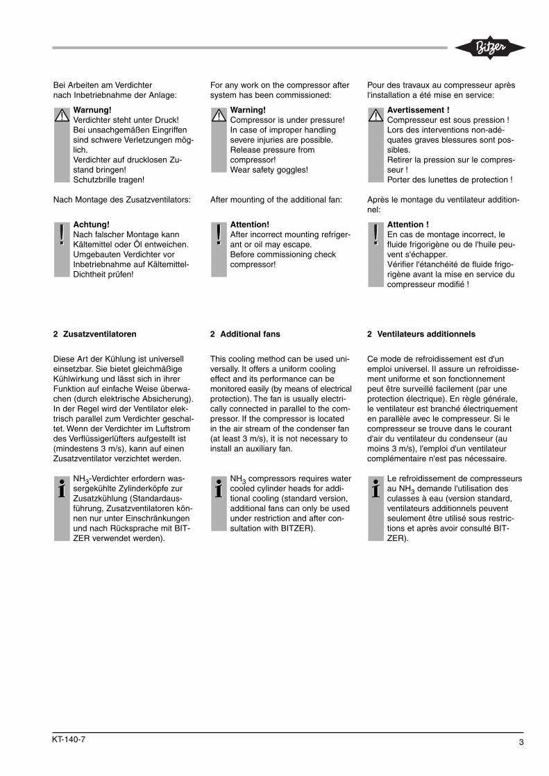
2 Additional fans
This cool ing meth od can be used uni -ver sal ly. It offers a uni form cool ing effect and its per for mance can bemon i tored eas i ly (by means of electri calpro tec tion). The fan is usu al ly electri -cal ly con nect ed in par allel to the com -pres sor. If the com pres sor is locat edin the air stream of the con dens er fan(at least 3 m/s), it is not nec es sary to install an aux il iary fan.
NH3 compressors requires watercooled cylinder heads for addi-tional cooling (standard version,additional fans can only be usedunder restriction and after con-sultation with BITZER).
!
!!
Pour des travaux au compresseur aprèsl'installation a été mise en service:
Avertissement !Compresseur est sous pression !Lors des interventions non-adé-quates graves blessures sont pos-sibles.Retirer la pression sur le compres-seur !Porter des lunettes de protection !
Après le montage du ventilateur addition-nel:
Attention !En cas de montage incorrect, le fluide frigorigène ou de l'huile peu-vent s'échapper.Vérifier l'étanchéité de fluide frigo-rigène avant la mise en service ducompresseur modifié !
2 Ventilateurs additionnels
Ce mode de refroi dis se ment est d'un emploi uni ver sel. II assu re un refroi dis se -ment uni for me et son fonc tion ne mentpeut être sur veillé faci le ment (par unepro tec tion élec tri que). En règle géné ra le,le ven ti la teur est bran ché élec tri que menten paral lè le avec le com pres seur. Si lecom pres seur se trou ve dans le courantd'air du ven ti la teur du conden seur (aumoins 3 m/s), l'emploi d'un ven ti la teurcom plé men tai re n'est pas néces sai re.
Le refroi dis se ment de com pres seursau NH3 deman de l'utilisation desculas ses à eau (ver sion stan dard,ven ti la teurs addi tion nels peuventseulement être uti li sé sous restric-tions et après avoir consulté BIT-ZER).
!
!!
Bei Arbeiten am Verdichternach Inbetriebnahme der Anlage:
Warnung!Verdichter steht unter Druck!Bei unsachgemäßen Eingriffensind schwere Verletzungen mög-lich.Verdichter auf drucklosen Zu -stand bringen!Schutzbrille tragen!
Nach Montage des Zusatzventilators:
Achtung!Nach falscher Montage kannKältemittel oder Öl entweichen.Umgebauten Verdichter vorInbetriebnahme auf Kältemittel-Dichtheit prüfen!
2 Zusatzventilatoren
Diese Art der Kühlung ist universelleinsetzbar. Sie bietet gleichmäßigeKühlwirkung und lässt sich in ihrerFunktion auf einfache Weise überwa-chen (durch elektrische Ab sicherung).In der Regel wird der Ventilator elek-trisch parallel zum Verdichter geschal-tet. Wenn der Ver dich ter im Luftstromdes Verflüssiger lüfters aufgestellt ist(mindestens 3 m/s), kann auf einenZusatz ventilator verzichtet werden.
NH3-Verdichter erfordern was-sergekühlte Zylinder köpfe zurZusatzkühlung (Standardaus -führung, Zusatz ventilatoren kön-nen nur unter Einschränkungenund nach Rück spra che mit BIT-ZER verwendet werden).
!
!!
4 KT-140-7
400
303
(331
*)
128
315 315
210
103
103
210
31010
4
215
315
210
103
400
303
(331
*)
128
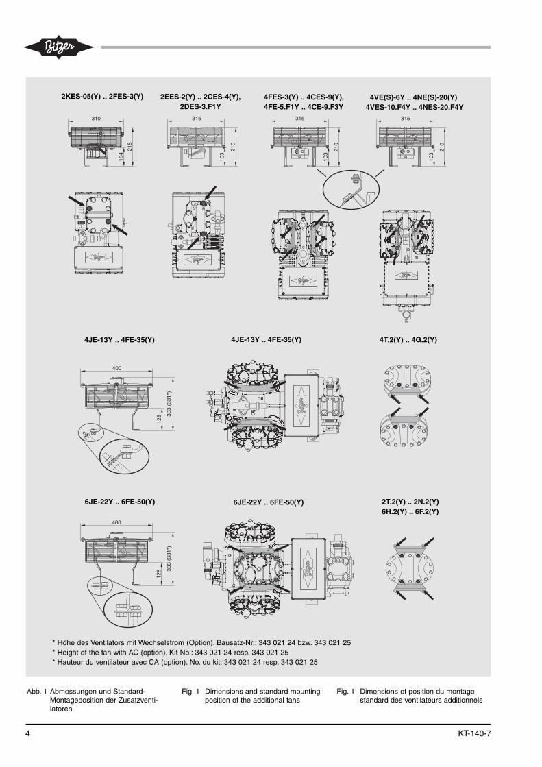
Abb. 1 Abmessungen und Standard-Montageposition der Zusatzventi-latoren
Fig. 1 Dimensions and standard mountingposition of the additional fans
Fig. 1 Dimensions et position du montagestandard des ventilateurs additionnels
* Höhe des Ventilators mit Wechselstrom (Option). Bausatz-Nr.: 343 021 24 bzw. 343 021 25* Height of the fan with AC (option). Kit No.: 343 021 24 resp. 343 021 25* Hauteur du ventilateur avec CA (option). No. du kit: 343 021 24 resp. 343 021 25
2KES-05(Y) .. 2FES-3(Y) 2EES-2(Y) .. 2CES-4(Y), 2DES-3.F1Y
4FES-3(Y) .. 4CES-9(Y),4FE-5.F1Y .. 4CE-9.F3Y
4VE(S)-6Y .. 4NE(S)-20(Y)4VES-10.F4Y .. 4NES-20.F4Y
4JE-13Y .. 4FE-35(Y)
6JE-22Y .. 6FE-50(Y) 6JE-22Y .. 6FE-50(Y)
4T.2(Y) .. 4G.2(Y)
2T.2(Y) .. 2N.2(Y)6H.2(Y) .. 6F.2(Y)
4JE-13Y .. 4FE-35(Y)
5KT-140-7
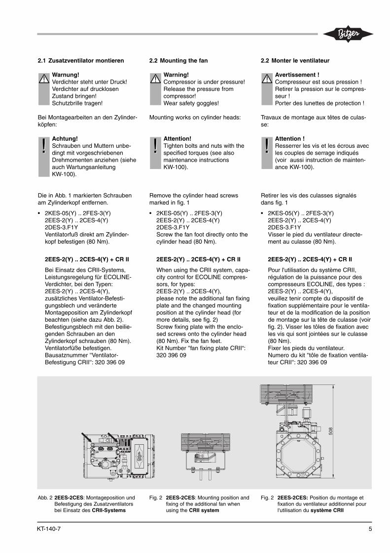
2.1 Zusatzventilator montieren
Warnung!Verdichter steht unter Druck!Verdichter auf drucklosenZustand bringen!Schutzbrille tragen!
Bei Montagearbeiten an den Zylinder -köpfen:
Achtung!Schrauben und Muttern unbe-dingt mit vorgeschriebenenDrehmomenten anziehen (sieheauch Wartungsanleitung KW-100).
Die in Abb. 1 markierten Schraubenam Zylinderkopf entfernen.
• 2KES-05(Y) .. 2FES-3(Y)2EES-2(Y) .. 2CES-4(Y) 2DES-3.F1YVentilatorfuß direkt am Zylinder-kopf befestigen (80 Nm).
2EES-2(Y) .. 2CES-4(Y) + CR II
Bei Einsatz des CRII-Systems,Leistungsregelung für ECOLINE-Verdichter, bei den Typen: 2EES-2(Y) .. 2CES-4(Y),zusätzliches Ventilator-Befesti-gungsblech und veränderteMontageposition am Zylinderkopfbeachten (siehe dazu Abb. 2) .Befestigungsblech mit den beilie-genden Schrau ben an denZylinderkopf schrauben (80 Nm).Ventilatorfüße befestigen.Bausatznummer ''Ventilator-Befestigung CRII'': 320 396 09
!
!!
2.2 Mounting the fan
Warning!Compressor is under pressure!Release the pressure from compressor!Wear safety goggles!
Mounting works on cylinder heads:
Attention!Tighten bolts and nuts with thespecified torques (see alsomaintenance instructions KW-100).
Remove the cylinder head screwsmarked in fig. 1
• 2KES-05(Y) .. 2FES-3(Y)2EES-2(Y) .. 2CES-4(Y) 2DES-3.F1YScrew the fan foot directly onto thecylinder head (80 Nm).
2EES-2(Y) .. 2CES-4(Y) + CR II
When using the CRII system, capa-city control for ECOLINE compres-sors, for types: 2EES-2(Y) .. 2CES-4(Y),please note the additional fan fixingplate and the changed mountingposition at the cylinder head (formore details, see fig. 2)Screw fixing plate with the enclo-sed screws onto the cylinder head (80 Nm). Fix the fan feet.Kit Number ''fan fixing plate CRII“:320 396 09
!
!!
2.2 Monter le ventilateur
Avertissement !Compresseur est sous pression !Retirer la pression sur le compres-seur !Porter des lunettes de protection !
Travaux de montage aux têtes de culas-se:
Attention !Resserrer les vis et les écrous avecles couples de serrage indiqués(voir aussi instruction de mainten-ance KW-100).
Retirer les vis des culasses signalés dans fig. 1
• 2KES-05(Y) .. 2FES-3(Y)2EES-2(Y) .. 2CES-4(Y) 2DES-3.F1YVisser le pied du ventilateur directe-ment au culasse (80 Nm).
2EES-2(Y) .. 2CES-4(Y) + CR II
Pour l'utilisation du système CRII,régulation de la puissance pour descompresseurs ECOLINE, des types : 2EES-2(Y) .. 2CES-4(Y),veuillez tenir compte du dispositif defixation supplémentaire pour le ventila-teur et de la modification de la positionde montage sur la tête de culasse (voirfig. 2). Visser les tôles de fixation avecles vis qui sont jointées sur le culasse(80 Nm). Fixer les pieds du ventilateur.Numero du kit ''tôle de fixation ventila-teur CRII'': 320 396 09
!
!!
Abb. 2 2EES-2CES: Montageposition undBefestigung des Zusatzventilatorsbei Einsatz des CRII-Systems
Fig. 2 2EES-2CES: Mounting position andfixing of the additional fan whenusing the CRII system
Fig. 2 2EES-2CES: Position du montage etfixation du ventilateur additionnel pourl'utilisation du système CRII
508

6 KT-140-7
• 4FES-3(Y) .. 4CES-9(Y), 4VE(S)-6Y .. 4NE(S)-20(Y)4FE-5.F1Y .. 4CE-9.F3Y4VE-10.F4Y .. 4NE-20.F4YScrew the fixing plates with theenclosed screws onto the cylinderheads (80 Nm). Fix the fan feet (see fig. 1).
• 4JE-13Y .. 6FE-50(Y)2T.2(Y) .. 6F.2(Y)Replace the cylinder head screwsby threaded bolts (80 Nm). Fit thefixing plates in the threaded boltsaccording to (fig. 1). Fasten with spring washers andnuts. Screw the fan feet.
All fixing plates for the cylinder headsof the ECOLINE series (types 4FES .. 6FE) are backward compa-tible.
Attention!After incorrect mounting refriger-ant or oil may escape.Before commissioning checkcompressor for refrigerant tight-ness!
!!
• 4FES-3(Y) .. 4CES-9(Y), 4VE(S)-6Y .. 4NE(S)-20(Y)4FE-5.F1Y .. 4CE-9.F3Y4VE-10.F4Y .. 4NE-20.F4YVisser les tôles de fixation avec les vis qui sont jointées sur les culasses(80 Nm). Fixer les pieds du ventilateur (voirfig. 1).
• 4JE-13Y .. 6FE-50(Y)2T.2(Y) .. 6F.2(Y)Remplacer les vis de la tête de culas-separ des goupilles filetés et y ser reravec 80 Nm. Enforcer les tôles de fixa-tion sur des goupilles filetés (fig. 1). Fixer avec rondelles élastiques etécrous. Visser les pieds du ventilateur.
Tous les tôles de fixation pour les culasses de la série ECOLINE (types 4FES .. 6FE) sont inverse compatible.
Attention !En cas de montage incorrect, le flui-de frigorigène ou de l'huile peuvents'échapper.Vérifier l'étanchéité de fluide frigo-rigène avant la mise en service ducompresseur modifié !
!!
• 4FES-3(Y) .. 4CES-9(Y), 4VE(S)-6Y .. 4NE(S)-20(Y)4FE-5.F1Y .. 4CE-9.F3Y4VE-10.F4Y .. 4NE-20.F4YBefestigungsbleche mit den beilie-genden Schrau ben an dieZylinderköpfe schrauben (80 Nm).Ventilatorfüße befestigen (sieheAbb. 1).
• 4JE-13Y .. 6FE-50(Y)2T.2(Y) .. 6F.2(Y)Zylinderkopfschrauben durchGewindebolzen ersetzen (80 Nm).Darauf Befesti gungs bleche auf -steck en (Abb. 1). Mit Feder schei ben und Muttern be festigen. Ventilatorfüße anschrauben.
Alle Befestigungsbleche für die Zylinderköpfe der ECOLINE-Baureihe(Typen 4FES .. 6FE) sind rückwärts-kompatibel.
Achtung!Nach falscher Montage kannKältemittel oder Öl entweichen.Umgebauten Verdichter vorInbetriebnahme auf Kältemittel-Dichtheit prüfen!
!!

7KT-140-7
Ø285417
504
259398
307
303
Ø28538
5
575
439
502
696
(726
*)
Ø344
4FES-3(Y) .. 4CES-9(Y)4FE-5.F1Y .. 4CE-9.F3Y
2KES-05(Y) .. 2FES-3(Y) 2EES-2(Y) .. 2CES-4(Y), 2DES-3.F1Y
4VE(S)-6Y .. 4NE(S)-20(Y)4VE-10.F4Y .. 4NE-20.F4Y
4JE-13Y .. 4FE-35(Y) 6JE-22Y .. 6FE-50(Y)
ECOLINE-Verdichter ECOLINE compressors Compresseurs ECOLINE
309
554
349
Ø285
453
680
(708
*)
445
Ø344
387 Ø280
476
224343
273
* Höhe des Verdichters + Ventilator mit Wechselstrom (Option). Bausatz-Nr.: 343 021 24 bzw. 343 021 25
* Height of the compressor + fan with AC (option). Kit No.: 343 021 24 resp. 343 021 25* Hauteur du compresseur + ventilateur avec CA (option). No. du kit: 343 021 24 resp. 343 021 25
2.2 Abmessungen 2.2 Dimensions 2.2 Dimensions

8 KT-140-7
Offene Verdichter Open drive compressors Compresseurs ouverts
� � �� � �
� � �
���
� � �
��
���
� � �
�
� � �
� � �
���
��
� �
� � �
� � �
��
��
4H.2(Y) .. 4G.2(Y) 6H.2(Y) .. 6F.2(Y)
2T.2(Y) .. 2N.2(Y) 4T.2(Y) .. 4N.2(Y)
2.3 In Betrieb nehmen
Spannungs- und Frequenzan gabenauf dem Typenschild des Ventilator-Motors mit den Daten des Strom -netzes vergleichen. Motor nur beiÜbereinstimmung anschließen. Dreh-richtung so wählen, dass der Zusatz-ventilator von oben auf den Verdichterbläst.
2.3 Commissioning
Compare the volt age and fre quen cyon the motor name plate with the volt-age sup ply data. Only con nect themotor if this data agree. Select therotation direction so that the air flowsdirectly onto the compressor.
2.3 Mise en service
Comparer les don nées de ten sion et defré quen ce sur la pla que du moteur duven ti la teur avec les don nées du sec teur.Rac cor der le moteur seulement s'il y aconcor dan ce. Choisir le sens de rota tionde sorte que le ven ti la teur souf fle de parle haut sur le com pres seur.

9KT-140-7
2KES-05(Y) .. 2FES-3(Y)
2EES-2(Y) .. 2CES-4(Y) �2DES-3.F1Y
4FES-3(Y) .. 4CES-9(Y)4FE-5.F1Y .. 4CE-6.F1Y4DE-7.F3Y, 4CE-9.F3Y
4VES-6Y .. 4NES-20(Y)4VE-6Y .. 4NE-20(Y)4VE-10.F4Y .. 4NE-20.F4Y
2T.2(Y) .. 2N.2(Y)
4T.2(Y) .. 4N.2(Y)
4JE-13Y .. 4FE-35(Y)
4H.2(Y) .. 4G.2(Y)
6JE-22Y .. 6FE-50(Y)
6H.2(Y) .. 6F.2(Y)
343 021 01
343 021 26
343 021 29
343 021 27
343 021 02
343 021 03
343 021 22
343 021 24 �
343 021 04
343 021 23
343 021 25 �
343 021 05
230V-1-50 Hz230V-1-60 Hz
230V-1-50 Hz230V-1-60 Hz
230V-1-50 Hz230V-1-60 Hz
230V-1-50 Hz230V-1-60 Hz
230 / 400V-3-50 Hz Δ / Y230 / 400V-3-60 Hz Δ / Y265 / 460V-3-60 Hz Δ / Y
230 / 400V-3-50 Hz Δ / Y230 / 400V-3-60 Hz Δ / Y265 / 460V-3-60 Hz Δ / Y
230 / 400V-3-50 Hz Δ / Y230 / 400V-3-60 Hz Δ / Y265 / 460V-3-60 Hz Δ / Y
230-1-50 Hz230-1-60 Hz
230 / 400V-3-50 Hz Δ / Y230 / 400V-3-60 Hz Δ / Y265 / 460V-3-60 Hz Δ / Y
230 / 400V-3-50 Hz Δ / Y230 / 400V-3-60 Hz Δ / Y265 / 460V-3-60 Hz Δ / Y
230-1-50 Hz230-1-60 Hz
230 / 400V-3-50 Hz Δ / Y230 / 400V-3-60 Hz Δ / Y265 / 460V-3-60 Hz Δ / Y
IP54
IP44
Typ
Type
Type
Bausatznummer
Kit Number
Numéro du kit
Spannung
Voltage
Tension
±10%
Strom-aufnahme
Currentconsumpt.
Intensité ducourant
A
Leistungs-aufnahme
Power consumption
Puissanceabsorbée
W
Luftmenge
Air volume
Volume d’air
m³/h
Schutzart
Enclosureclass
Classe de protection
0,460,54
0,530,55
0,530,55
0,530,55
0,50 / 0,290,55 / 0,320,57 / 0,33
0,50 / 0,290,55 / 0,320,57 / 0,33
0,50 / 0,290,55 / 0,320,57 / 0,33
0,590,82
0,50 / 0,290,55 / 0,320,57 / 0,33
0,50 / 0,290,55 / 0,320,57 / 0,33
0,590,82
0,50 / 0,290,55 / 0,320,57 / 0,33
6072
100120
100120
100120
120180190
120180190
120180190
120170
120180190
120180190
120170
120180190
9701100
27003100
27003100
27003100
220026503050
220026503050
220026503050
22002650
220026503050
220026503050
22002650
220026503050
2.4 Übersicht Ventilatoren inkl.Bausatznummern
2.4 Overview of fans incl. kit numbers
2.4 Résumé des ventilateurs incl.numéro du kit
All fans with winding protection.
Other voltages upon request.
Tous les ventilateurs avec protection d'enroul-
ment. Autres tensions sur demande.
Alle Ventilatoren mit Wicklungsschutz.
Andere Spannungen auf Anfrage.
� Wechselstromausführung (Option)
� Bei Einsatz des CRII-Systems,
Leistungsregelung für ECOLINE-
Verdichter, muss bei den Typen
2EES-2(Y) .. 2CES-4(Y) eine zu-
sätzliches Befestigungsblech für den
Ventilator bestellt und montiert werden
(Bausatznummer ''Ventilator-
Befestigung CRII'': 320 396 09).
� AC version (option)
� When using the CRII system, capacity
control for ECOLINE compressors,
with the compressors types
2EES-2(Y) .. 2CES-4(Y), an additional
fixing plate for the fan must be ordered
and mounted (kit number ''fan fixing
plate CRII'': 320 396 09).
� Version CA (option)
� L'utilisation du système CRII, régulation
de puissance pour des compresseurs
ECOLINE, il est necessaire de monter et
commander pour les types
2EES-2(Y) .. 2CES-4(Y) une tôles de
fixation du ventilateur additionnelle (nume-
ro du kit ''tôle de fixation ventilateur CRII'':
320 396 09).

3 Wassergekühlte Zylinderköpfe
• Option bei- 4J-13.2(Y) .. 6F-50.2(Y)- 2T.2(Y) .. 6F.2(Y)- III(Y) .. V(Y)
• Standard bei- VI W(Y), VII W(Y)- NH3-Aus führung der offenen
Verdichter: W2TA .. W6FA
Für korrosives Kühlwasser (z. B. See -wasser) ist eine Kunststoff beschich-tete Ausführung erhältlich.
3.1 Montage
Kühlwasser entsprechend Abbildung2 anschließen.
Bei 4- und 6-Zylinder-Ver dichtern istsowohl Reihen- als auch Parallel -schaltung möglich. Bei Parallel schal -tung darf die Min dest -Wasser mengevon 150 I/h für jeden Zylinderkopfnicht unterschritten werden.
Kühlwasser-Temperatur
• Eintritt:Das Kühlwasser für die Zylinder -köpfe sollte aus dem bereits er -wärm ten Kühlwasser des Verflüs -sigers abgezweigt werden.
• Austritt:Die Kühlwasser-Temperatur sollte50°C nicht übersteigen. In derRegel ist die Wärme abfuhr ausrei-chend, wenn die Tem peraturdiffe -renz zwischen Kühl wasser-Eintrittund -Austritt 5 .. 10 K oder derWasser-Durchsatz ca. 150 I/hbeträgt.
Stillstand des Verdichters
Beim Abschalten des Verdichtersmuss der Kühl wasser-Zufluss zumZylin der kopf unterbrochen werden(z. B. Wasserregler, Magnet ventil), umeine Rück konden sation von Kälte mittelin den Zylinder kopf zu vermeiden.
Flexible Leitungselemente
Bei elastischer Aufstellung des Ver -dich ters sollten flexible Leitungsele -men te eingebaut werden (Abb. 4).
3 Water cooled cyl in der heads
• Option for- 4J-13.2(Y) .. 6F-50.2(Y)- 2T.2(Y) .. 6F.2(Y)- III(Y) .. V(Y)
• Standard for- VI W(Y), VII W(Y)- NH3 design of the open drive
compressors: W2TA .. W6FA
For cor ro sive cool ing water (e. g. seawater) a plas tic-coat ed ver sion isavail able.
3.1 Assembly
Con nec t the cooling water accordingto figure 2.
Four and six cyl in der compressorsmay be con nect ed in series or in par -allel. For parallel connection a min i -mum water flow rate of 150 I/h ateach cylinder head must be ensured.
Cooling water temperature
• Inlet:The cooling water for the cylinderheads should preferably be sup-plied from the already warmedcooling water of the condenser.
• Outlet:The cool ing water tem per a turemust not exceed 50°C. Adequateheat trans fer is nor mal ly achievedwhen the inlet / out let water tem -per a ture dif fer ence is between 5and 10 K or with a water volumefIow of approx. 150 l/h.
Compressor standstill
When the compressor is off, the cool-ing water supply to the cylinder headsmust be interrupted (e. g. water regu-lator, solenoid valve) to avoid conden-sation of refrigerant back into thecylinder head.
Flexible pipe elements
If the com pres sor is flex ibly mount ed,the use of flexible pipe elements arerec om mend ed (figure 4).
3 Culasses à eau
• Option pour- 4J-13.2(Y) .. 6F-50.2(Y)- 2T.2(Y) .. 6F.2(Y)- III(Y) .. V(Y)
• Standard pour- VI W(Y), VII W(Y)- version NH3 des compresseurs
ouverts: W2TA .. W6FA
Une ver sion avec pro tec tion par rési nessyn thé ti ques est néces sai re en cas d'eaude refroidissement cor ro si ve (par ex. eaude mer).
3.1 Montage
Rac cor der l'eau de refroi dis se mentconformément au figure 2.
Pour les com pres seurs 4 ou 6 cylin dres,le mon tage en série ainsi que le mon tageen paral lè le sont pos si bles. En cas demon tage en paral lè le, s'assurer un débitd'eau mini mum de 150 l/h pour cha queculas se.
Tem pé ra ture d'eau de refroidissement
• Entrée:L'eau de refroidissement pour lesculas ses pro vient de pré fé ren ce del'eau pré cé de ment chauf fée duconden seur. En cas d'arrêt du com -pres seur.
• Sortie:La tem pé ra ture d'eau de refroidisse-ment ne devrait pas excé der 50°C. Enrègle géné ra le, l'évacu a tion calo ri fi queest suf fi san te si la dif fé ren ce de tem -pé ra ture entre entrée et sor tie se situeentre 5 et 10 K, ou si le débit d'eau sesitue aux envi rons de 150 l/h.
Arrêt du compresseur
L'arrivée d'eau de refroidissement à laculas se doit être cou pée (par ex. régula-teur d'eau, van ne magnétique), afin d'éviter une conden sa tion du flui de frigori -gène dans la culas se.
Eléments de conduite flexibles
En cas de mon tage "élas ti que" du com -pres seur, l'insertion des éléments deconduite flexibles est pré co ni sée (fig. 4).
10 KT-140-7

11KT-140-7
� � � � � � � � �
� � �
� � � � � � � � � � � � � � �
� � � �
� � �
� � � � � � �
� � � � � � � � � � �
� � � �
� � �
� � � � � � � � � � � � � � � � � � �
� � �
� � � �
� � �
� � � � � � � � � �
� � � � � � � � � � � � � �
� � �
� � �
� � �
� � � � � � � � � � � � � � � � � � � � � �
� � � � � � � � � � �
� � � � � � � � � � � � � � �
� � � � � �
� � �
� � �
� � � � � � � � � � � � � � � � � � � �
� � � � � � � � � � � �
� � � � � � � � � � � � � � � �
1
3
2
PC
Abb. 4 Wassergekühlte Zylinderköpfeanschließen
Fig. 4 Connecting the water cooled cylin-der heads
Fig. 4 Raccorder la culasse à eau
1 DrosselFlow restrictorRégulateur du débit
2 flexible LeitungselementeFlexible pipe elementsEléments de conduite flexibles
3 Wasserregler / MagnetventilWater regulator / solenoid valveRégulateur d'eau / vanne magnétique
Abmessungen
Die Verdichter-Abmessungen ändernsich nicht durch das Umrüsten aufwassergekühlte Zylinderköpfe. EinzigeAusnahme sind die Verdichter III(Y),IV(Y) und V(Y). Hier nimmt die Höheum maximal 1 cm zu.
Dimensions
The compressor dimensions do notchange by conversion to water cooledcylinder heads. Only exception are thecompressors III(Y), IV(Y) and V(Y).Here the height increases by 1 cm atmaximum.
Dimensions
Les dimensions des compresseurs nechangent pas par le rajustement enculasses à eau. Les seules exceptionssont les compresseurs III(Y), IV(Y) etV(Y). En ce cas le hauter augmente enmaximum par 1 cm.

BITZER Kühlmaschinenbau GmbHEschenbrünnlestraße 15 // 71065 Sindelfingen // Germany
Tel +49 (0)70 31 932-0 // Fax +49 (0)70 31 [email protected] // www.bitzer.de
Subject to change // Änderungen vorbehalten // Toutes modifications réservées // 80303603 // 11.2014