


Sprachen
Seiten
Rechtliche

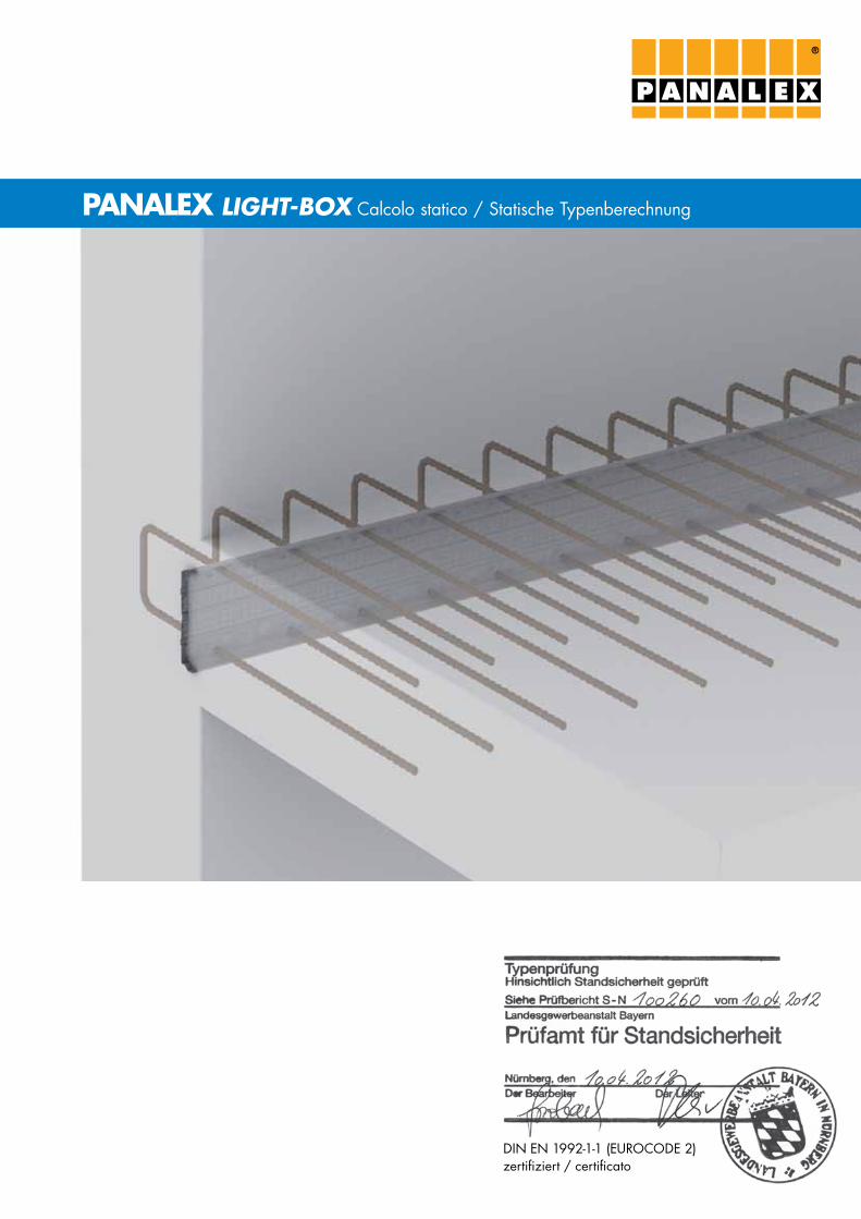
PANALEX LIGHT-BOX Calcolo statico / Statische Typenberechnung
®
DIN EN 1992-1-1 (EuroCoDE 2) zertifiziert / certificato
®
3
DIN EN 1992-1-1 (EurocoDE 2) zertifiziert / certificato
2
DIN EN 1992-1-1 (EurocoDE 2) zertifiziert / certificato
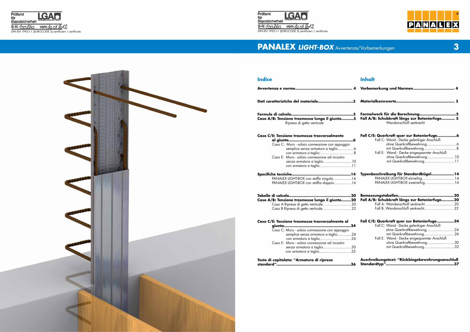
PANALEX LIGHT-BOX Avvertenze/Vorbemerkungen
®
Inhalt
Vorbemerkung und Normen.................................. 4
Materialkennwerte................................................ 5
Formelwerk für die Berechnung………………….………5Fall A/B: Schubkraft längs zur Betonierfuge........... 5
Wandanschluß senkrecht
Fall C/E: Querkraft quer zur Betonierfuge................6Fall C: Wand - Decke gelenkiger Anschluß ohne Querkraftbewehrung...............................6 mit Querkraftbewehrung...............................….8 Fall E: Wand - Decke eingespannter Anschluß ohne Querkraftbewehrung….......................10 mit Querkraftbewehrung................…….….11
Typenbeschreibung für Standardbügel...................14
PANALEX LIGHT-BoX einreihig………....................14 PANALEX LIGHT-BoX zweireihig…........................16
Bemessungstabellen..............................................20Fall A/B: Schubkraft längs zur Betonierfuge…....…20
Fall A: Wandanschluß senkrecht……..…….......…..20 Fall B: Wandanschluß senkrecht………..…......……22
Fall C/E: Querkraft quer zur Betonierfuge..............24Fall C: Wand - Decke gelenkiger Anschluß ohne Querkraftbewehrung.....................…..24 mit Querkraftbewehrung.............................26Fall E: Wand - Decke eingespannter Anschluß ohne Querkraftbewehrung….................……..30 mit Querkraftbewehrung............................32
Auschreibungstext: “Rückbiegebewehrungsanschluß Standardtyp”........................................................37
Indice
Avvertenza e norme............................................... 4
Dati caratteristiche del materiale.......................……5
Formule di calcolo……………………................…………5Caso A/B: Tensione trasmessa lungo il giunto..........5
ripresa di getto verticale
Caso C/E: Tensione trasmessa trasversalmente al giunto.....................................................6Caso C: Muro - solaio connessione con appoggio semplice senza armatura a taglio…............6
con armatura a taglio.....................…....…8Caso E: Muro - solaio connessione ad incastro senza armatura a taglio............................10
con armatura a taglio.........................….11 Specifiche tecniche………………...............................14
PANALEX LIGHT-BoX con staffa singola…..............14PANALEX LIGHT-BoX con staffia doppia….............16
Tabelle di calcolo…................................................20Caso A/B: Tensione trasmessa lungo il giunto........20
Caso A ripresa di getto verticale…………….....…..20Caso B ripresa di getto verticale…………………....22
Caso C/E: Tensione trasmessa trasversalmente algiunto.......................................................24Caso C: Muro - solaio connessione con appoggio semplice senza armatura a taglio...............24 con armatura a taglio..............................26 Caso E: Muro - solaio connessione ad incastro
senza armatura a taglio..........................30 con armatura a taglio..........................….32
Testo di capitolato: “Armatura di ripresa standard”.............................................................36

5
DIN EN 1992-1-1 (EurocoDE 2) zertifiziert / certificato
4
DIN EN 1992-1-1 (EurocoDE 2) zertifiziert / certificato
®
PANALEX LIGHT-BOX Avvertenze/Vorbemerkungen
Vorbemerkungen
ProjektStatische Typenberechnung Bewehrungsanschluss PANALEX LIGHT-BoX nach DIN EN 1992-1-1 (EuroCoDE 2) "und DBV-Merkblatt rückbiegen von Betonstahl und Anforderungen an Verwahrkästen, Fassung Januar 2011".
BerechnungsgrundlagenDIN EN 1992-1-1: Eurocode 2: Bemessung und Konstruktion von Stahlbeton- und Spannbetontragwerken - Teil 1-1: Allgemeine Bemessungsregeln und regeln für den Hochbau; Deutsche Fassung EN 1992-1-1:2004 + AC:2010 Ausgabe 2011-01
DIN EN 1992-1-1/NA: Nationaler Anhang - National festge- legte Parameter - Eurocode 2: Bemessung und Konstruktion von Stahlbeton- und Spann- betontragwerken - Teil 1-1: Allgemeine Bemessungsregeln und regeln für den Hochbau, Ausgabe Januar 2011
DBV Merkblatt rückbiegen von Betonstahl und Anforderungen an Verwahrkästen nach Eurocode 2, Fassung Januar 2011
BaustoffeBeton Betonfestigkeitsklasse C20/25 bis C30/37 nach DIN EN 1992-1-1
Betonstahl BSt 500 Wr laut DIN 488
Avvertenza
ProgettoCalcolo statico per armature di ripresa PANALEX LIGHT-BoX secondo DIN EN 1992-1-1 (EuroCoDICE 2) „e foglio informa-tivo DBV piegature dei ferri di armatura e richieste alla cassetta metallica, edizione gennaio 2011".
Base di calcoloDIN EN 1992-1-1: Eurocodice 2: Progettazione delle strutture di calcestruzzo - Parte 1-1: regole generali e regole per gli edifici; Testo tedesco EN 1992-1-1:2004 + AC:2010 edizione 2011-01
DIN EN 1992-1-1/NA: Appendice nazionale - parametri nazioniali - Eurocodice 2: Progettazione delle strutture di calcestruzzo - Parte 1-1: regole generali e regole per gli edifici; edizione gennaio 2011
Foglio informativo DBV: piegature dei ferri di armatura e richieste alla cassetta metallica secondo Eurocodice 2, edizione gennaio 2011
Materiali di costruzioneCalcestruzzo classe di resistenza del calcestruzzo C20/25 fino a C30/37 secondo DIN EN 1992-1-1
Acciaio d'armatura BSt 500 Wr secondo DIN 488
Materialkennwerte
Beton fck, cube fck fcd fctk;0,05 fbd
[N/mm²]
C20/25 25,00 20,00 11,33 1,50 2,30
C25/30 30,00 25,00 14,17 1,80 2,70
C30/37 37,00 30,00 17,00 2,00 3,00
Stahl fyk fyd, red.
[N/mm²]
BSt 500 WR 500,00 347,83
Fall A/B: Schubkraft längs zur Betonierfuge
Dati caratteristici del materiale
calcestruzzo fck, cube fck fcd fctk;0,05 fbd
[N/mm²]
C20/25 25,00 20,00 11,33 1,50 2,30
C25/30 30,00 25,00 14,17 1,80 2,70
C30/37 37,00 30,00 17,00 2,00 3,00
Acciaio fyk fyd, red.
[N/mm²]
BSt 500 WR 500,00 347,83
Caso A/B: tensione trasmessa lungo il giunto
vRdi = c * fctd + μ * σn + vRdi,s ≤ vRdi,max
fctd = αct * fctk;0,05
; αct = 0,85 e γc = 1,50; σn = 0
γc
liscio: c = 0,2 ; μ = 0,6 ; ν = 0,2
vRdi,s = ϱ * fyd,red * (1,2 * μ * sinα + cosα) ; α = 90°
0,80 * fyk =
0,8 * 500 =
400 N γs 1,15 1,15 mm²fyd,red = min 4 * lb,eq * fbd ; da lb,eq = α1 *
∅ *
fyd,red 0,7 * ∅ 4 fbd
As; ϱ=
Ai
vRdi = c * fctd + μ * σn + vRdi,s ≤ vRdi,max
fctd = αct * fctk;0,05
; αct = 0,85 und γc = 1,50; σn = 0
γc
glatt: c = 0,2 ; μ = 0,6 ; ν = 0,2
vRdi,s = ϱ * fyd,red * (1,2 * μ * sinα + cosα) ; α = 90°
0,80 * fyk =
0,8 * 500 =
400 N γs 1,15 1,15 mm²fyd,red = min 4 * lb,eq * fbd ; aus lb,eq = α1 *
∅ *
fyd,red 0,7 * ∅ 4 fbd
As; ϱ=
Ai
α * fck 0,85 * fckfcd = =
γc 1,5
0,80 * fyk 0,8 * 500 400 Nfyd,red = = = γs 1,15 1,15 mm²
fyk 500 Nfyd = =
γs 1,15 mm²
α * fck 0,85 * fckfcd = =
γc 1,5
0,80 * fyk 0,8 * 500 400 Nfyd,red = = = γs 1,15 1,15 mm²
fyk 500 Nfyd = =
γs 1,15 mm²
7
DIN EN 1992-1-1 (EurocoDE 2) zertifiziert / certificato
6
DIN EN 1992-1-1 (EurocoDE 2) zertifiziert / certificato
®
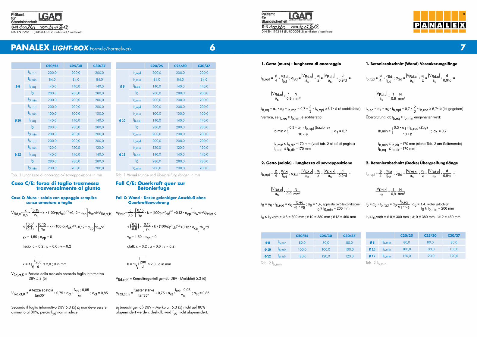
Fall C/E: Querkraft quer zur Betonierfuge
Fall C: Wand - Decke gelenkiger Anschluß ohne Querkraftbewehrung
PANALEX LIGHT-BOX Formule/Formelwerk
1. Betonierabschnitt (Wand) Verankerungslänge1. Getto (muro) - lunghezza di ancoraggio
2. Betonierabschnitt (Decke) Übergreifungslänge2. Getto (solaio) - lunghezza di sovrapposizione
c 0,15
VRd,c= *3 * k * (100*ρl*fck)1/3 +0,12 * σcp4*bw*d+VRd,ct,K
0,5 γc
0,5 0,15≤ _ + * 3 * k * (100*ρl*fck)1/3+0,12 * σcp4*bw*d
0,5 γc
γc = 1,50 ; σcp = 0
glatt: c = 0,2 ; μ = 0,6 ; ν = 0,2
Caso C/E: forza di taglio trasmessa trasversalmente al giunto
Caso C: Muro - solaio con appoggio semplice senza armatura a taglio
c 0,15VRd,c= *3 * k * (100*ρl*fck)1/3 +0,12 * σcp4*bw*d+VRd,ct,K
0,5 γc
0,5 0,15≤ _ + * 3 * k * (100*ρl*fck)1/3+0,12 * σcp4*bw*d
0,5 γc
γc = 1,50 ; σcp = 0
liscio: c = 0,2 ; μ = 0,6 ; ν = 0,2
C20/25 C25/30 C30/37
∅ 8
lb,rqd 200,0 200,0 200,0
lb,min 84,0 84,0 84,0
lb,eq 140,0 140,0 140,0
l0 280,0 280,0 280,0
l0,min 200,0 200,0 200,0
∅ 10
lb,rqd 200,0 200,0 200,0
lb,min 100,0 100,0 100,0
lb,eq 140,0 140,0 140,0
l0 280,0 280,0 280,0
l0,min 200,0 200,0 200,0
∅ 12
lb,rqd 200,0 200,0 200,0
lb,min 120,0 120,0 120,0
lb,eq 140,0 140,0 140,0
l0 280,0 280,0 280,0
l0,min 200,0 200,0 200,0
∅ σSd |VRd,c| al |VRd,c| dlb,rqd = * ; σSd = * = * = 4 fbd as z as 0,9*d
|VRd,c| 1 N *
as 0,9 mm²
2lb,eq = α1 * α5 * lb,rqd = 0,7 * * lb,rqd ≥ 6,7* ∅ (ist gegeben)
3Überprüfung, ob lb,eq ≥ lb,min eingehalten wird:
0,3 * α1 * lb,rqd (Zug)lb,min ≥ ; α1 = 0,7 10 * ∅
lb,min ≤ lb,dir =170 mm (siehe Tab. 2 am Seitenende)lb,eq ≤ lb,dir =170 mm
∅ σSd |VRd,c| al |VRd,c| dlb,rqd = * ; σSd = * = * = 4 fbd as z as 0,9*d
|VRd,c| 1 N *
as 0,9 mm²
2lb,eq = α1 * α5 * lb,rqd = 0,7 * * lb,rqd ≥ 6,7* ∅ (è soddisfatta)
3Verifica, se lb,eq ≥ lb,min è soddisfatto:
0,3 * α1 * lb,rqd (trazione)lb,min ≥ ; α1 = 0,7 10 * ∅
lb,min ≤ lb,dir =170 mm (vedi tab. 2 al piè di pagina)lb,eq ≤ lb,dir =170 mm
∅ σSd |VRd,c| al |VRd,c| dlb,rqd = * ; σSd = * = * = 4 fbd as z as 0,9*d
|VRd,c| 1 N *
as 0,9 mm²
lb,eql0 = α6 * lb,rqd = α6 ; α6 = 1,4, wobei jedoch gilt α1 * α5 l0 ≥ l0,min = 200 mm
l0 ≤ l0,vorh = ∅ 8 = 300 mm ; ∅10 = 380 mm ; ∅12 = 460 mm
∅ σSd |VRd,c| al |VRd,c| dlb,rqd = * ; σSd = * = * = 4 fbd as z as 0,9*d
|VRd,c| 1 N *
as 0,9 mm²
lb,eql0 = α6 * lb,rqd = α6 ; α6 = 1,4, applicata però la condizione α1 * α5 l0 ≥ l0,min = 200 mm
l0 ≤ l0,vorh = ∅ 8 = 300 mm ; ∅10 = 380 mm ; ∅12 = 460 mm
C20/25 C25/30 C30/37
∅ 8 lb,min 80,0 80,0 80,0
∅ 10 lb,min 100,0 100,0 100,0
∅ 12 lb,min 120,0 120,0 120,0
C20/25 C25/30 C30/37
∅ 8 lb,min 80,0 80,0 80,0
∅ 10 lb,min 100,0 100,0 100,0
∅ 12 lb,min 120,0 120,0 120,0
Tab. 1 Lunghezza di ancoraggio/ sovrapposizione in mm Tab. 1 Verankerungs- und Übergreifungslängen in mm
Tab. 2 lb,min Tab. 2 lb,min
200
k = 1+ ≤ 2,0 ; d in mm
d
Vrd,ct,K = Konsoltraganteil gemäß DBV - Merkblatt 5.3 (6)
Kastenstärke fctk ; 0,05 VRd,ct,K = * 0,75 * αct * ; αct = 0,85
tan35° γc
ρl braucht gemäß DBV – Merkblatt 5.3 (5) nicht auf 80% abgemindert werden, deshalb wird fyd nicht abgemindert.
200
k = 1+ ≤ 2,0 ; d in mm
d
Vrd,ct,K = Portata della mensola secondo foglio informativo DBV 5.3 (6)
Altezza scatola fctk ; 0,05 VRd,ct,K = * 0,75 * αct * ; αct = 0,85
tan35° γc
Secondo il foglio informativo DBV 5.3 (5) ρl non deve essere diminuito al 80%, perció fyd non si riduce.
9
DIN EN 1992-1-1 (EurocoDE 2) zertifiziert / certificato
8
DIN EN 1992-1-1 (EurocoDE 2) zertifiziert / certificato
®
Fall C: Wand - Decke gelenkiger Anschluß mit Querkraftbewehrung
bei der Berechnung darf nach DIN EN 1992-1-1 eine Druck-strebenneigung von cot θ = 1,2 berücksichtigt werden, dies ist bei den statischen Nachweisen der angrenzenden Bereiche gemäß DIN EN 1992-1-1 Kapitel 6.2.3 zu berücksichtigen.
Aufnehmbare Querkraft mit Querkraftbewehrung:
Caso C: Muro - solaio con appoggio semplice con armatura a taglio
nel calcolo secondo la DIN EN 1992-1-1 per l´incilinazione del montante può essere preso in considerazione cot θ = 1,2. Ciò è da rispettare nella verifica statica dell area adiacente secondo DIN EN 1992-1-1, capitolo 6.2.3
Forza di taglio ammissibile con armatura a taglio:
PANALEX LIGHT-BOX Formule/Formelwerk
AswVRd,s = * fywd * z * cot θ s
fyk 500 Nfywd = =
γs 1,15 mm²
z = 0,9 * d bzw. z ≤ d - cv,l - 30
0,9 * dAnsatz z = min d - cv,l - 30 = d - 25 - 30 = d - 55
Berechnung der erforderlichen Querkraftbewehrung: maxVEderf asw = fywd * z * 1,2
Die maximal aufnehmbare Querkraft mit Querkraftbewehrung im Bereich der rückbiegestelle wird wie folgt begrenzt:
fcd
fck
VEd ≤ 0,30 * z * υ1 * * bw; υ1 = 0,75 * (1,1- )
cot θ+tan θ 500 ≤ 0,75 ; cot θ = 1,2
Der rückbiegeanschluss muss die horizontalen Zugkräfte des Fachwerkes übertragen können. Deshalb gilt es zu überprüfen, ob die im sich ausbildenden Fachwerk auftretenden Horizontalkräfte vom Anschluss übertragen werden können (durch die vorhandenen Verankerungslängen bzw. Übergreifungslängen). Aus den gegebenen Verankerungs- und Übergreifungslängen lassen sich die übertragbaren Zugspannungen, welche durch fyd,red begrenzt werden, wie folgt ermitteln:
AswVRd,s = * fywd * z * cot θ s
fyk 500 Nfywd = =
γs 1,15 mm²
z = 0,9 * d cioè z ≤ d - cv,l - 30
0,9 * dApproccio z = min d - cv,l - 30 = d - 25 - 30 = d - 55
Calcolo dell armatura a taglio richiesta: maxVEderf asw = fywd * z * 1,2
La forza di taglio massima ammissibile nella zona di piega del tondino è calcolata con la seguente formula:
fcd
fck
VEd ≤ 0,30 * z * υ1 * * bw; υ1 = 0,75 * (1,1- )
cot θ+tan θ 500 ≤ 0,75 ; cot θ = 1,2
La cassetta di ripresa assemblata con il tondino (Light-Box) deve essere in grado di trasmettere le forze di trazione orizzontali. Perciò è da controllare se le forze verificatesi nel sistema complessivo vengono trasmesse dal giunto (composto dalla lunghezza d ancorraggio e lunghezza di sovrapposizione del tondino). Dalle lunghezze di ancoraggio e di sovrapposizione del tondino sono calcolabili le tensioni di trazione che possono essere trasmesse, limitate però da fyd,red:
0,3 * α1 * lb,rqd (Zug)lb,min ≥ ; α1 = 0,7 10 * ∅
lb,min ≤ lb,dir = 170 mm (siehe Tabelle 2 auf Seite 7)lb,eq ≤ lb,dir = 170 mm
lb,dir 1 4 170 3 4σSd = * * * fbd = * * * fbd α1 α5 ∅ 0,7 2 ∅
N ≤ fyd,red = 348
mm²
2. Betonierabschnitt (Decke) - Übergreifungslänge:
∅ σSd |VEd| al |VEd| 1 zlb,rqd = * ; σSd = * = * * * cot θ = 4 fbd as z as z 2
|VEd| N = 0,5 * * cot θ
as mm²
lb,eql0 = α6 * lb,rqd = α6 ; α6 = 1,4 gemäß NA DIN EN 1992- α1 * α5
1-1, Tab. 8.3 DE
α6 = 1,0 gemäß NA DIN EN 1992-1-1, Tab. 8.3 DE randabstand c1= 75 mm > 4 * ∅ (max. 4 * 12 = 48 mm) und lichter Stababstand a ≥ 8 * ∅, gegeben für ∅ 8 und ∅ 10 bei minimalem Stababstand von 100 mm (Minimum für ∅10 bei 90 mm > 8 * 10 mm = 80 mm), gegeben für ∅12 bis Stababstand von 150 mm (Minimum für ∅12 138 mm > 8 * 12 mm = 96 mm) wobei jedoch gilt l0 ≥ l0,min = 200 mm l0 ≤ l0,vorh = ∅8= 300 mm ; ∅10 = 380 mm ; ∅12 = 460 mm
0,3 * α1 * lb,rqd (Zug)lb,min ≥ ; α1 = 0,7 10 * ∅
lb,min ≤ lb,dir = 170 mm (vedi tabella 2 su pagina 7)lb,eq ≤ lb,dir = 170 mm
lb,dir 1 4 170 3 4σSd = * * * fbd = * * * fbd α1 α5 ∅ 0,7 2 ∅
N ≤ fyd,red = 348
mm²
2. Getto (solaio) - lunghezza di sovrapposizione:
∅ σSd |VEd| al |VEd| 1 zlb,rqd = * ; σSd = * = * * * cot θ 4 fbd as z as z 2
|VEd| N = 0,5 * * cot θ
as mm²
lb,eql0 = α6 * lb,rqd = α6 ; α6 = 1,4 secondo NA DIN EN 1992- α1 * α5
1-1, Tab. 8.3 DE
α6 = 1,0 secondo NA DIN EN 1992-1-1, Tab. 8.3 DE distanza dal bordo c1= 75 mm > 4 * ∅ (max. 4 * 12 = 48 mm) distanza netta della barra a ≥ 8 *∅, soddisfatto per ∅ 8 e ∅ 10 a distanza minima asta di 100 mm (minimo per ∅10 a 90 mm > 8 * 10 mm = 80 mm). Soddisfatto anche per ∅12 fino distanza asta di 150 mm (minimo per ∅12 a 138 mm > 8 * 12 mm = 96 mm), rispettando l0 > = l0,min = 200 mm.l0 ≤ l0,vorh = ∅8= 300 mm ; ∅10 = 380 mm ; ∅12 = 460 mm
1. Betonierabschnitt (Wand) - Verankerungslänge: ∅ σSd |VEd| al |VEd| 1 zlb,rqd = * ; σSd = * = * * *cot θ 4 fbd as z as z 2
|VEd| N = 0,5 * * cot θ
as mm² 2 lb,eq = α1*α5*lb,rqd = 0,7 * *lb,rqd ≥ 6,7 * ∅ (ist gegeben) 3Überprüfung, ob lb,eq ≥ lb,min eingehalten wird:
1. Getto (muro) - lunghezza di ancoraggio: ∅ σSd |VEd| al |VEd| 1 zlb,rqd = * ; σSd = * = * * *cot θ 4 fbd as z as z 2
|VEd| N = 0,5 * * cot θ
as mm² 2 lb,eq = α1*α5*lb,rqd = 0,7 * *lb,rqd ≥ 6,7 * ∅ (è soddisfatta) 3Verifica, se lb,eq ≥ lb,min è conforme:
Daraus folgt: l0,vorh 4 l0,vorh 4σSd = * * fbd = * * fbd ≤ fyd,red
α6 ∅ 1,4 (bzw. 1,0) ∅
N= 348
mm²
Nachweisführung:Ermittlung von VEd aus fcd fckVEd ≤ 0,30 * z * υ1 * * bw ; υ1 = 0,75 * 11,1- 2
cotθ + tanθ 500
≤ 0,75 ; cot θ = 1,2
Quindi segue: l0,vorh 4 l0,vorh 4σSd = * * fbd = * * fbd ≤ fyd,red
α6 ∅ 1,4 (cioè. 1,0) ∅
N= 348
mm²
Verifica:Calcolo di VEd fcd fckVEd ≤ 0,30 * z * υ1 * * bw ; υ1 = 0,75 * 11,1- 2
cotθ + tanθ 500
≤ 0,75 ; cot θ = 1,2

11
DIN EN 1992-1-1 (EurocoDE 2) zertifiziert / certificato
10
DIN EN 1992-1-1 (EurocoDE 2) zertifiziert / certificato
®
Überprüfung der Begrenzung der Druckstrebenneigung für θ = 40°: σcdVRd,cc = 0,48 * c * fck
1/3 * 11 - 1,2 * 2 * bw * z
fcd
= 0,48 * 0,2 * fck1/3 * bw * z
fcdVEd = 0,30 * z * υ1 * * bw = 0,30 * z * υ1 *
cotθ + tanθ
fcd * bw ; 1,2 +
1
1,2
υ1 = 0,75 * (1,1 - fck/500) ≤ 0,75
1,21 ≤ cot θ = 1,2 ≤ ≤ 3 1 -
VRd,cc
VEd
Verifica dell´inclinazione del montante per θ = 40°: σcdVRd,cc = 0,48 * c * fck
1/3 * 11 - 1,2 * 2 * bw * z
fcd
= 0,48 * 0,2 * fck1/3 * bw * z
fcdVEd = 0,30 * z * υ1 * * bw = 0,30 * z * υ1 *
cotθ + tanθ
fcd * bw ; 1,2 +
1
1,2
υ1 = 0,75 * (1,1 - fck/500) ≤ 0,75
1,21 ≤ cot θ = 1,2 ≤ ≤ 3 1 -
VRd,cc
VEd
PANALEX LIGHT-BOX Formule/Formelwerk
C20/25 C25/30 C30/37
Vrd,cc /VEd 0,2078 0,1791 0,1586
1,5147 1,4617 1,4261 ≥ cotθ = 1,2
C20/25 C25/30 C30/37
Vrd,cc /VEd 0,2078 0,1791 0,1586
1,5147 1,4617 1,4261 ≥ cotθ = 1,2 1,21 - Vrd,cc VEd
1,21 - Vrd,cc VEd
lb,eq = α1 * α5 * lb,rqd = 0,7 * 2 * lb,rqd
3
Überprüfung, ob lb,eq ≥ lb,min eingehalten wird:
lb,min ≥ 0,3 * α1 * lb,rqd (Zug) ; 10 * ∅ ; α1 = 0,7lb,min ≤ lb,dir = 170 mm (siehe Tabelle 3)lb,eq ≤ lb,dir = 170 mm
C20/25 C25/30 C30/37
∅ 8 lb,min 80,0 80,0 80,0
∅ 10 lb,min 100,0 100,0 100,0
∅ 12 lb,min 120,0 120,0 120,0
lb,eq = α1 * α5 * lb,rqd = 0,7 * 2 * lb,rqd
3
Verifica, se lb,eq ≥ lb,min è soddisfatto:
lb,min ≥ 0,3 * α1 * lb,rqd (trazione) ; 10 * ∅ ; α1 = 0,7lb,min ≤ lb,dir = 170 mm (vedi tabella 3)lb,eq ≤ lb,dir = 170 mm
C20/25 C25/30 C30/37
∅ 8 lb,min 80,0 80,0 80,0
∅ 10 lb,min 100,0 100,0 100,0
∅ 12 lb,min 120,0 120,0 120,0
Tab. 3: lb,min Tab. 3: lb,min
Fall E: Wand - Decke eingespannter Anschluß ohne Querkraftbewehrung
c 0,15VRd,c= * * k * 100 * ρl * fck + 0,12 * σcp * bw * d 0,5 γc
γc = 1,50 ; σcp = 0
glatt: c = 0,2 ; μ = 0,6 ; ν = 0,2
k = 1+ 200 ≤ 2,0 ; d in mm d
ρl braucht gemäß DBV-Merkblatt 5.3 (5) nicht auf 80% abgemindert werden, deshalb wird fyd nicht abgemindert
1. Betonierabschnitt (Wand) - Verankerungslänge:
∅ σSd |VRd,c| al |VRd,c| dlb,rqd = * ; σSd = * = * 4 fbd as z as 0,9 * d
|VRd,c| 1 N = *
as 0,9 mm²
Caso E: Muro - solaio connessione ad incastro senza armatura a taglio
c 0,15VRd,c= * * k * 100 * ρl * fck + 0,12 * σcp * bw * d 0,5 γc
γc = 1,50 ; σcp = 0
liscio: c = 0,2 ; μ = 0,6 ; ν = 0,2
k = 1+ 200
≤ 2,0 ; d in mm d
secondo foglio informativo DBV 5.3 (5) ρl non deve essere ridotto dell´80%, perciò fyd non è stato ridotto.
1. Getto (muro) - lunghezza di ancoraggio:
∅ σSd |VRd,c| al |VRd,c| dlb,rqd = * ; σSd = * = * 4 fbd as z as 0,9 * d
|VRd,c| 1 N = *
as 0,9 mm²
13
13
2. Betonierabschnitt (Decke) - Übergreifungslänge: ∅ σSd |VRd,c| al |VRd,c| dlb,rqd = * ; σSd = * = * = 4 fbd as z as 0,9 * d
|VRd,c| 1 N = * as 0,9 mm²
lb,eql0 = α6 * lb,rqd = α6 ; α6 = 1,4, wobei jedoch gilt α1 * α5
l0 ≥ l0,min = 200 mm
max (l0 ; l0,min) ≤ l0,vorh = ∅8 = 300 mm ; ∅10 = 380 mm ; ∅12 = 460 mm
Fall E: Wand - Decke eingespannter Anschluß mit Querkraftbewehrung
bei der Berechnung darf nach DIN EN 1992-1-1 eine Druckstre-benneigung von cot θ =1,2 berücksichtigt werden, dies ist bei den statischen Nachweisen der angrenzenden Bereiche gemäß DIN EN 1992-1-1 Kapitel 6.2.3 zu berücksichtigen.
Aufnehmbare Querkraft mit Querkraftbewehrung:
AswVRd,s = * fywd * z * cotθ s fyk 500
N
fywd = = γs 1,15 mm²
z = 0,9 * d bzw. z ≤ d - cv,l - 30
0,9 * dAnsatz z = min d - cv,l - 30 = d - 25 - 30 = d - 55
d = b1 - 10 mm - 0,5 * ø Stab (für LB12 mit ø8 :120 - 10 - 0,5 * 8 = 106 mm)
2. Getto (solaio) - lunghezza di sovrapposizione: ∅ σSd |VRd,c| al |VRd,c| dlb,rqd = * ; σSd = * = * 4 fbd as z as 0,9 * d
|VRd,c| 1 N = * as 0,9 mm²
lb,eql0 = α6 * lb,rqd = α6 ; α6 = 1,4, applicata però la condizione α1 * α5
l0 ≥ l0,min = 200 mm
max (l0 ; l0,min) ≤ l0,vorh = ∅8 = 300 mm ; ∅10 = 380 mm ; ∅12 = 460 mm
Caso E: Murso - solaio connessione ad incastro con armatura a taglio
nel calcolo secondo DIN EN 1992-1-1 del montante può essere preso in considerazione cot θ = 1,2. Ciò è da rispettare nella verifica statica dell´area adiacente secondo DIN EN 1992-1-1, capitolo 6.2.3
Forza di taglio ammissibile con armatura a taglio:
AswVRd,s = * fywd * z * cotθ s fyk 500
N
fywd = = γs 1,15 mm²
z = 0,9 * d cioè z ≤ d - cv,l - 30
0,9 * dApproccio z = min d - cv,l - 30 = d - 25 - 30 = d - 55
d = b1 - 10 mm - 0,5 * ø montante (per LB12 con ø8 :120 - 10 - 0,5 * 8 = 106 mm)
13
DIN EN 1992-1-1 (EurocoDE 2) zertifiziert / certificato
12
DIN EN 1992-1-1 (EurocoDE 2) zertifiziert / certificato
Die Berechnung der erforderlichen Querkraftbewehrung wird wie folgt berechnet:
maxVEderf asw = fywd * z * 1,2
Die maximal aufnehmbare Querkraft mit Querkraftbewehrung im Bereich der rückbiegestelle wird wie folgt begrenzt:
fcd fckVEd ≤ 0,30 * z * υ1 * * bw ; υ1= 0,75 * 1,1- cotθ+tanθ 500 ≤ 0,75 ; cotθ = 1,2
Calcolo dell´armatura a taglio richiesta:
maxVEderf asw = fywd * z * 1,2
La forza di taglio massima ammissibile nella zona di piega del tondino è calcolata con la seguente formula:
fcd fckVEd ≤ 0,30 * z * υ1 * * bw ; υ1= 0,75 * 1,1- cotθ+tanθ 500 ≤ 0,75 ; cotθ = 1,2
®
PANALEX LIGHT-BOX Formule/Formelwerk
Der rückbiegeanschluss muss die horizontalen Zugkräfte des Fachwerkes übertragen können. Deshalb gilt es zu überprüfen, ob die im sich ausbildenden Fachwerk auftretenden Horizon-talkräfte vom Anschluss übertragen werden können (durch die vorhandenen Verankerungslängen bzw. Übergreifungslängen).Aus den gegebenen Verankerungs- und Übergreifungslängen lassen sich die übertragbaren Zugspannungen, welche durch fyd,red begrenzt werden, wie folgt ermitteln:
1. Betonierabschnitt (Wand) - Verankerungslänge:
∅ σSd |VEd| al |VEd| 1 zlb,rqd = * ; σSd = * = * * * cotθ 4 fbd as z as z 2
|VEd| N = 0,5 * * cotθ as mm²
lb,eq = α1 * α5 * lb,rqd = 0,7 * 1,0 * lb,rqd ≥ 6,7 * ∅ (ist gegeben)
Überprüfung, ob lb,eq ≥ lb,min eingehalten wird:
lb,min ≥ 0,3 * α1 * lb,rqd (Zug) ; 10 * ∅ ; α1 = 0,7 lb,min ≤ lb,dir = 170 mm lb,eq ≤ lb,dir = 170 mm
lb,dir 1 4 170 1 4 NσSd = * * * fbd = * * * fbd ≤ fyd,red= 348 α1 α5 ∅ 0,7 1 ∅ mm²
2. Betonierabschnitt (Decke) - Übergreifungslänge:
∅ σSd |VEd| al |VEd| 1 zlb,rqd = * ; σSd = * = * * * cotθ 4 fbd as z as z 2
|VEd| N = 0,5 * * cotθ
as mm²
l0 = α6 * lb,rqd = α6
lb,eq ; α6 = 1,4 gemäß NA DIN EN
α1* α5 1992-1-1, Tab. 8.3 DE
La cassetta di ripresa assemblata con il tondino (Light-Box) deve essere in grado di trasmettere le forze di trazione orizzontali. Perciò è da controllare se le forze verificatesi nel sistema comp-lessivo vengono trasmesse dal giunto (composto dalla lunghezza d´ancoraggio e lunghezza di sovrapposizione del tondino). Dalle lunghezze d´ancoraggio e di sovrapposizione del tondino possono essere calcolate le tensioni di trazione tasferite, che sono limitate da fyd,red:
1. Getto (solaio) - lunghezza di sovrapposizione:
∅ σSd |VEd| al |VEd| 1 zlb,rqd = * ; σSd = * = * * * cotθ 4 fbd as z as z 2
|VEd| N = 0,5 * * cotθ as mm²
lb,eq = α1 * α5 * lb,rqd = 0,7 * 1,0 * lb,rqd ≥ 6,7 * ∅ (è soddisfatto)
Verifica, se lb,eq ≥ lb,min è conforme:
lb,min ≥ 0,3 * α1 * lb,rqd (trazione) ; 10 * ∅ ; α1 = 0,7 lb,min ≤ lb,dir = 170 mm lb,eq ≤ lb,dir = 170 mm
lb,dir 1 4 170 1 4 NσSd = * * * fbd = * * * fbd ≤ fyd,red= 348 α1 α5 ∅ 0,7 1 ∅ mm²
2. Getto (solaio) - lunghezza di sovrapposizione:
∅ σSd |VEd| al |VEd| 1 zlb,rqd = * ; σSd = * = * * * cotθ 4 fbd as z as z 2
|VEd| N = 0,5 * * cotθ
as mm²
l0 = α6 * lb,rqd = α6
lb,eq ; α6 = 1,4 secondo NA DIN EN
α1* α5 1992-1-1, Tab. 8.3 DE
α6 = 1,0 gemäß NA DIN EN 1992-1-1, Tab. 8.3 DE randab-stand c1 = 75 mm > 4 * ∅(max. 4 * 12 = 48 mm) und lichter Stababstand a ≥ 8 * ∅, gegeben für ø8 und ø10 bei minimalem Stababstand von 100 mm (Minimum für ø10 bei 90 mm > 8 * 10 mm = 80 mm), gegeben für ø12 bis Stababstand von 150 mm (Minimum für ∅12 138 mm > 8 * 12 mm = 96 mm) wobei jedoch gilt l0 ≥ l0,min = 200 mm (siehe Tab. 1 auf Seite 6) l0 ≤ l0,vorh = ∅8 = 300 mm ; ∅ 10 = 380 mm ; ∅12 = 460 mm
Daraus folgt:
σSd = l0,vorh
*4
* fbd = l0,vorh
* 4
* fbd ≤ fyd,red = 348 N
α6 ∅ 1,4 (bzw. 1,0) ∅ mm²
Nachweisführung: Ermittlung von VEd aus
VEd ≤ 0,30 * z * υ1 * fcd
* bw ; υ1 = 0,75 * 1,1- fck
cotθ + tanθ 500 ≤ 0,75 ; cotθ = 1,2
Überprüfung der Begrenzung der Druckstrebenneigung fürθ = 40°:
VRd,cc = 0,48 * c * fck1/3
* 1 - 1,2 *σcd
* bw * z fcd
= 0,48 * 0,2 * fck1/3
* bw * z
VEd = 0,30 * z * υ1 * fcd
* bw = 0,30 * z * υ1* fcd
* bw ; cotθ+tanθ 1,2 + 1
1,2
υ1 = 0,75 * (1,1 - fck / 500) ≤ 0,75
α6 = 1,0 secondo NA DIN 1992-1-1, tab. 8.3 DE distanza bordo c1 = 75 mm > 4 * ∅(max. 4 * 12 = 48 mm) e distanza netta della barra a ≥ 8 *∅, soddisfatto per ∅ 8 e ∅ 10 a distanza minima asta di 100 mm (minimo per ø 10 a 90 mm > 8 * 10 mm = 80 mm). Soddisfatto anche per ∅ 12 fino distanza asta di 150 mm (minimo per ∅ 12 a 138 mm > 8 * 12 mm = 96 mm), l0 ≥ l0,min = 200 mm (vedi tab. 1 su pagina 6) l0 ≤ l0,vorh = ∅8 = 300 mm ; ∅ 10 = 380 mm ; ∅ 12 = 460 mm
Quindi segue:
σSd = l0,vorh
*4
* fbd = l0,vorh
* 4
* fbd ≤ fyd,red = 348 N
α6 ∅ 1,4 (o 1,0) ∅ mm²
Verifica: Calcolo di VEd
VEd ≤ 0,30 * z * υ1 * fcd
* bw ; υ1 = 0,75 * 1,1- fck
cotθ + tanθ 500 ≤ 0,75 ; cotθ = 1,2
Verifica dell´inclinazione del montante θ = 40°:
VRd,cc = 0,48 * c * fck1/3
* 1 - 1,2 *σcd
* bw * z fcd = 0,48 * 0,2 * fck
1/3 * bw * z
VEd = 0,30 * z * υ1 * fcd
* bw = 0,30 * z * υ1* fcd
* bw ; cotθ+tanθ 1,2 + 1
1,2
υ1 = 0,75 * (1,1 - fck / 500) ≤ 0,75
1 ≤ cotθ = 1,2 ≤
1,2 ≤ 3
VRd,cc 1- VEd
1 ≤ cotθ = 1,2 ≤ 1,2
≤ 3 VRd,cc 1- VEd
C20/25 C25/30 C30/37
Vrd,cc /VEd 0,2078 0,1791 0,1586
1,5147 1,4617 1,4261 ≥ cotθ = 1,2
C20/25 C25/30 C30/37
Vrd,cc /VEd 0,2078 0,1791 0,1586
1,5147 1,4617 1,4261 ≥ cotθ = 1,2 1,21 - Vrd,cc VEd
1,21 - Vrd,cc VEd

15
DIN EN 1992-1-1 (EurocoDE 2) zertifiziert / certificato
14
DIN EN 1992-1-1 (EurocoDE 2) zertifiziert / certificato
®
PANALEX LIGHT-BOX Articoli Standard/Standardtypen
PANALEX LIGHT-BOX con staffa singola PANALEX LIGHT-BOX einreihig
Staffa singola: Qualità acciaio BSt 500 Wr secondo DIN 488.
Einfacher Bügel aus Stahl BSt 500 Wr laut DIN 488.
Cod. Art. LB5
Art. – Nr. L h1 b1 a s b h l0 st øLBA050810
1250 30 50
75 100 48
170
300 12 8LBA050815 100 150 48 300 8 8LBA050820 100 200 48 300 6 8LBA051015 100 150 60 380 8 10LBA051020 100 200 60 380 6 10
Cod. Art. LB7
Art. – Nr. L h1 b1 a s b h l0 st øLBA070810
1250 30 70
75 100 48
170
300 12 8LBA070815 100 150 48 300 8 8LBA070820 100 200 48 300 6 8LBA071010 75 100 60 380 12 10LBA071015 100 150 60 380 8 10LBA071020 100 200 60 380 6 10LBA071215 100 150 72 460 8 12LBA071220 100 200 72 460 6 12
Cod. Art. LB10
Art. – Nr. L h1 b1 a s b h l0 st øLBA100810
1250 30 100
75 100 48
170
300 12 8LBA100815 100 150 48 300 8 8LBA100820 100 200 48 300 6 8LBA101010 75 100 60 380 12 10LBA101015 100 150 60 380 8 10LBA101020 100 200 60 380 6 10LBA101210 75 100 72 460 12 12LBA101215 100 150 72 460 8 12LBA101220 100 200 72 460 6 12
a
b1
b
L
s
h1
L: Lunghezza/Gesamtlängeh1: Altezza scatola/ Kastenhöheb1: Larghezza scatola/ Kastenbreitea: Distanza inizio-fine/ Endabstands: Interasse/Bügelabstandh: Altezza staffa/Bügelhöheb: Larghezza staffa/ Bügelbreitel0: Lunghezza ancoraggio/ Verankerungslängest: Quantità staffe/ Bügelanzahlø: Diametro acciaio d armatura/ Durchmesser Bewehrungsstahl
h
lsl0

17
DIN EN 1992-1-1 (EurocoDE 2) zertifiziert / certificato
16
DIN EN 1992-1-1 (EurocoDE 2) zertifiziert / certificato
®
PANALEX LIGHT-BOX Articoli Standard/Standardtypen
PANALEX LIGHT-BOX con staffa doppia PANALEX LIGHT-BOX zweireihig
Staffa doppia: Qualità acciaio BSt 500 Wr secondo DIN 488.
Bügel aus Stahl BSt 500 Wr laut DIN 488.
Cod. Art. LB12
Art. – Nr. L h1 b1 a s b h l0 st øLBM120810
1250
30
120
75 100
100 170
300 12 8
LBM120815 100 150 300 8 8
LBM120820 100 200 300 6 8
LBM121010 60 75 100 380 12 10
LBM12101530
100 150 380 8 10
LBM121020 100 200 380 6 10
LBM121210 60 75 100 460 12 12
LBM12121530
100 150 460 8 12
LBM121220 100 200 460 6 12
Cod. Art. LB19
Art. – Nr. L h1 b1 a s b h l0 st øLBM190810
1250
30
190
75 100
170 170
300 12 8
LBM190815 100 150 300 8 8
LBM190820 100 200 300 6 8
LBM191010 75 100 380 12 10
LBM191015 100 150 380 8 10
LBM191020 100 200 380 6 10
LBM191210 60 75 100 460 12 12
LBM19121530
100 150 460 8 12
LBM191220 100 200 460 6 12
Cod. Art.Art. – Nr.
LB14
L h1 b1 a s b h l0 st øLBM140810
1250
30
140
75 100
120 170
300 12 8
LBM140815 100 150 300 8 8
LBM140820 100 200 300 6 8
LBM141010 75 100 380 12 10
LBM141015 100 150 380 8 10
LBM141020 100 200 380 6 10
LBM141210 60 75 100 460 12 12
LBM14121530
100 150 460 8 12
LBM141220 100 200 460 6 12
Cod. Art. LB16
Art. – Nr. L h1 b1 a s b h l0 st øLBM160810
1250
30
160
75 100
140 170
300 12 8
LBM160815 100 150 300 8 8
LBM160820 100 200 300 6 8
LBM161010 75 100 380 12 10
LBM161015 100 150 380 8 10
LBM161020 100 200 380 6 10
LBM161210 60 75 100 460 12 12
LBM16121530
100 150 460 8 12
LBM161220 100 200 460 6 12
Cod. Art. LB10
Art. – Nr. L h1 b1 a s b h l0 st øLBM100810
1250
30
100
75 100
80 170
300 12 8
LBM100815 100 150 300 8 8
LBM100820 100 200 300 6 8
LBM101010* 60 75 100 380 12 10
LBM101015*30
100 150 380 8 10
LBM101020* 100 200 380 6 10
LBM101210* 60 75 100 460 12 12
LBM101215*30
100 150 460 8 12
LBM101220* 100 200 460 6 12* Articolo in fase di progettazione / Bewehrungsanschluß in Projektierungsphase.

19
DIN EN 1992-1-1 (EurocoDE 2) zertifiziert / certificato
18
DIN EN 1992-1-1 (EurocoDE 2) zertifiziert / certificato
®
PANALEX LIGHT-BOX Articoli Standard/Standardtypen
a
b1
ba
L
h1
L
L: Lunghezza/Gesamtlängeh1: Altezza scatola/ Kastenhöheb1: Larghezza scatola/ Kastenbreitea: Distanza inizio-fine/ Endabstands: Interasse/Bügelabstandh: Altezza staffa/Bügelhöheb: Larghezza staffa/ Bügelbreitel0: Lunghezza ancoraggio/ Verankerungslängest: Quantità staffe/ Bügelanzahlø: Diametro acciaio d armatura/ Durchmesser Bewehrungsstahl
h
lslslo
Cod. Art. LB22
Art. – Nr. L h1 b1 a s b h l0 st øLBM220810
1250
30
220
75 100
200 170
300 12 8
LBM220815 100 150 300 8 8
LBM220820 100 200 300 6 8
LBM221010 75 100 380 12 10
LBM221015 100 150 380 8 10
LBM221020 100 200 380 6 10
LBM221210 60 75 100 460 12 12
LBM22121530
100 150 460 8 12
LBM221220 100 200 460 6 12
21
DIN EN 1992-1-1 (EurocoDE 2) zertifiziert / certificato
20
DIN EN 1992-1-1 (EurocoDE 2) zertifiziert / certificato
®
Tensione tangenziale lungo il giunto – Caso A
Schubkraft längs zur Betonierfuge – Fall A
Ipotesi: Carico ultimo del giunto secondo figura 8, caso A, DBV "ripiegabilità di acciaio d'armatura Eurocodice 2".
a1 < 5 cmσn = 0
Annahmen: Tragfähigkeit der Fuge nach Bild 8, Fall A, DBV-Merkblatt "rückbiegen EC 2".
a1 < 5 cmσn = 0
C20/25 VRdi + VRdi,sy ≤ VRdi,max [kN/m]
Armatura/ Bewehrung LB10 LB12 LB14 LB16 LB19 LB22
ø8/20 100,3 103,7 107,1 110,5 115,6 120,7
ø8/15 113,3 131,4 134,8 138,2 143,3 148,4
ø8/10 113,3 136,0 158,7 181,3 198,7 203,8
ø10/20 113,3 124,4 127,8 131,2 136,3 141,4
ø10/15 113,3 136,0 158,7 165,9 171,0 176,1
ø10/10 113,3 136,0 158,7 181,3 215,3 245,5
ø12/20 113,3 136,0 148,7 152,1 157,2 162,3
ø12/15 113,3 136,0 158,7 181,3 198,8 203,9
ø12/10 113,3 136,0 158,7 181,3 215,3 233,6
unione di elementi con tensione tangenziale lungo il giunto. Schema costruttivo secondo caso A, foglio informativo DBV Eurocodice 2.
Base di calcolo: superficie del giunto liscia
Lunghezza di sovrapposizione l0: ø 8 mm = 30 cm, ø 10 mm = 38 cm, ø 12 mm = 46 cm
Verbindung von Elementen mit einer Schubkraftübertragung längs zur Betonierfuge.Konstruktive Durchbildung gemäß Fall A, DBV-Merkblatt rückbiegen nach EC 2.
Berechnungsgrundlage: Fugenoberfläche glatt
Standardübergreifungs- längen l0: ø 8 mm = 30 cm, ø 10 mm = 38 cm, ø 12 mm = 46 cm
C25/30 VRdi + VRdi,sy ≤ VRdi,max [kN/m]
Armatura/ Bewehrung LB10 LB12 LB14 LB16 LB19 LB22
ø8/20 118,2 122,3 126,3 130,4 136,5 142,7
ø8/15 141,7 154,7 158,8 162,9 169,0 175,1
ø8/10 141,7 170,0 198,3 226,7 234,1 240,3
ø10/20 141,7 146,6 150,6 154,7 160,8 167,0
ø10/15 141,7 170,0 191,4 195,5 201,6 207,7
ø10/10 141,7 170,0 198,3 226,7 269,2 289,2
ø12/20 141,7 170,0 175,1 179,2 185,3 191,5
ø12/15 141,7 170,0 198,3 226,7 234,2 240,3
ø12/10 141,7 170,0 198,3 226,7 269,1 275,2
C30/37 VRdi + VRdi,sy ≤ VRdi,max [kN/m]
Armatura/ Bewehrung LB10 LB12 LB14 LB16 LB19 LB22
ø8/20 131,3 135,8 140,4 144,9 151,7 158,5
ø8/15 167,4 171,9 176,5 181,0 187,8 194,6
ø8/10 170,0 204,0 238,0 253,3 260,1 266,9
ø10/20 158,3 162,8 167,4 171,9 178,7 185,5
ø10/15 170,0 204,0 212,7 217,2 224,0 230,8
ø10/10 170,0 204,0 238,0 272,0 314,5 321,3
ø12/20 170,0 190,1 194,6 199,1 205,9 212,7
ø12/15 170,0 204,0 238,0 253,4 260,2 267,0
ø12/10 170,0 204,0 238,0 272,0 299,0 305,8
PANALEX LIGHT-BOX Caso A/Fall A
23
DIN EN 1992-1-1 (EurocoDE 2) zertifiziert / certificato
22
DIN EN 1992-1-1 (EurocoDE 2) zertifiziert / certificato
®
Tensione tangenziale lungo il giunto – Caso B
Schubkraft längs zur Betonierfuge – Fall B
Ipotesi: Carico ultimo del giunto secondo figura 8, caso B, DBV "ripiegabilità di acciaio d'armatura Eurocodice 2".
a1 < 5 cma2: Superficie liscia (DIN EN 1992-1-1:2004 + AC:2010, 6.2.5(2))σn = 0b = spessore di dimensionamento = spessore del muro - 2 * a1
Annahmen: Tragfähigkeit der Fuge nach Bild 8, Fall B, DBV-Merkblatt "rückbiegen EC 2".
a1 < 5 cma2: oberflächenbeschaffenheit glatt (DIN EN 1992-1-1:2004 + AC:2010, 6.2.5(2))σn = 0b = Bemessungsbreite der Wand = Wandstärke - 2 * a1
unione di elementi con tensione tangenziale lungo il giunto. Schema costruttivo secondo caso B, foglio informativo DBV Eurocodice 2.
Base di calcolo: superficie del giunto liscia
lunghezza di sovrapposizione l0: ø 8 mm = 30 cm, ø 10 mm = 38 cm, ø 12 mm = 46 cm
Verbindung von Elementen mit einer Schubkraftübertragung längs zur Betonierfuge.Konstruktive Durchbildung gemäß Fall B, DBV-Merkblatt rückbiegen nach EC 2.
Berechnungsgrundlage: Fugenoberfläche glatt
Standardübergreifungs- längen l0: ø 8 mm = 30 cm, ø 10 mm = 38 cm, ø 12 mm = 46 cm
PANALEX LIGHT-BOX Caso B/Fall B
C20/25 LB5, LB7, LB10 VRdi,c + VRdi,sy ≤ VRdi,maxArmatura/ Bewehrung b = 270 b= 290 b = 320 b = 330 b = 350 b = 370 b = 400
ø8/20 129,2 132,6 137,7 139,4 142,8 146,2 151,3
ø8/15 156,9 160,3 165,4 167,1 170,5 173,9 179,0
ø8/10 212,3 215,7 220,8 222,5 225,9 229,3 234,4
ø10/20 149,9 153,3 158,4 160,1 163,5 166,9 172,0
ø10/15 184,6 188,0 193,1 194,8 198,2 201,6 206,7
ø10/10 254,0 257,4 262,5 264,2 267,6 271,0 276,1
ø12/20 170,8 174,2 179,3 181,0 184,4 187,8 192,9
ø12/15 212,4 215,8 220,9 222,6 226,0 229,4 234,5
ø12/10 295,6 299,0 304,1 305,8 309,2 312,6 317,7
C25/30 LB5, LB7, LB10 VRdi,c + VRdi,sy ≤ VRdi,maxArmatura/ Bewehrung b = 270 b= 290 b = 320 b = 330 b = 350 b = 370 b = 400
ø8/20 152,9 156,9 163,1 165,1 169,2 173,3 179,4
ø8/15 185,3 189,4 195,5 197,6 201,6 205,7 211,8
ø8/10 250,5 254,5 260,7 262,7 266,8 270,9 277,0
ø10/20 177,2 181,2 187,4 189,4 193,5 197,6 203,7
ø10/15 217,9 222,0 228,1 230,1 234,2 238,3 244,4
ø10/10 299,4 303,5 309,6 311,6 315,7 319,8 325,9
ø12/20 201,7 205,7 211,9 213,9 218,0 222,1 228,2
ø12/15 250,5 254,6 260,7 262,8 266,8 270,9 277,0
ø12/10 348,2 352,3 358,4 360,5 364,6 368,6 374,8
C30/37 LB5, LB7, LB10 VRdi,c + VRdi,sy ≤ VRdi,maxArmatura/ Bewehrung b = 270 b= 290 b = 320 b = 330 b = 350 b = 370 b = 400
ø8/20 169,8 174,4 181,2 183,4 188,0 192,5 199,3
ø8/15 205,9 210,5 217,3 219,5 224,1 228,6 235,4
ø8/10 278,3 282,8 289,6 291,9 296,4 300,9 307,7
ø10/20 196,8 201,4 208,2 210,4 215,0 219,5 226,3
ø10/15 242,1 246,7 253,5 255,7 260,3 264,8 271,6
ø10/10 332,7 337,2 344,0 346,3 350,8 355,3 362,1
ø12/20 224,1 228,6 235,4 237,7 242,2 246,7 253,5
ø12/15 278,4 282,9 289,7 292,0 296,5 301,0 307,8
ø12/10 386,9 391,5 398,3 400,5 405,1 409,6 416,4
25
DIN EN 1992-1-1 (EurocoDE 2) zertifiziert / certificato
24
DIN EN 1992-1-1 (EurocoDE 2) zertifiziert / certificato
®
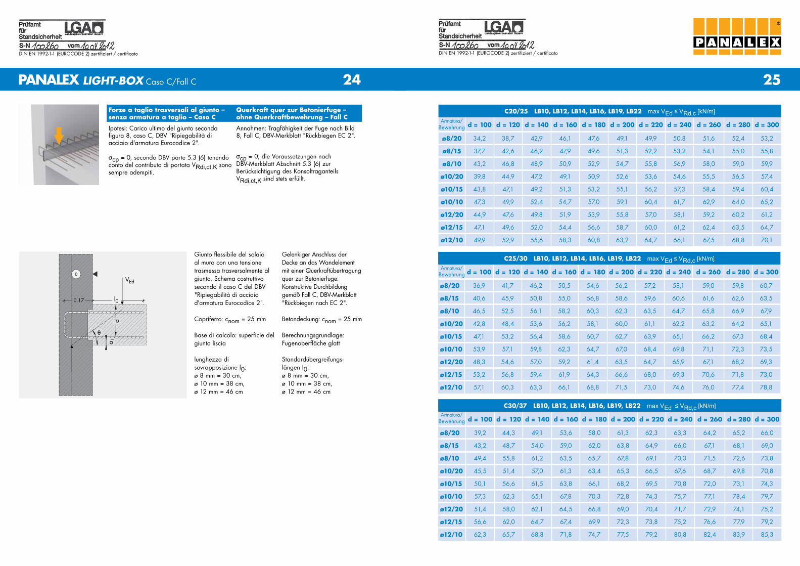
Giunto flessibile del solaio al muro con una tensione trasmessa trasversalmente al giunto. Schema costruttivo secondo il caso C del DBV "ripiegabilità di acciaio d'armatura Eurocodice 2".
Copriferro: cnom = 25 mm
Base di calcolo: superficie del giunto liscia
lunghezza di sovrapposizione l0: ø 8 mm = 30 cm, ø 10 mm = 38 cm, ø 12 mm = 46 cm
Gelenkiger Anschluss der Decke an das Wandelement mit einer Querkraftübertragung quer zur Betonierfuge. Konstruktive Durchbildung gemäß Fall C, DBV-Merkblatt "rückbiegen nach EC 2".
Betondeckung: cnom = 25 mm
Berechnungsgrundlage: Fugenoberfläche glatt
Standardübergreifungs- längen l0: ø 8 mm = 30 cm, ø 10 mm = 38 cm, ø 12 mm = 46 cm
Forze a taglio trasversali al giunto – senza armatura a taglio – Caso C
Querkraft quer zur Betonierfuge – ohne Querkraftbewehrung – Fall C
Ipotesi: Carico ultimo del giunto secondo figura 8, caso C, DBV "ripiegabilità di acciaio d'armatura Eurocodice 2".
σcp = 0, secondo DBV parte 5.3 (6) tenendo conto del contributo di portata VRdi,ct,K sono sempre adempiti.
Annahmen: Tragfähigkeit der Fuge nach Bild 8, Fall C, DBV-Merkblatt "rückbiegen EC 2".
σcp = 0, die Voraussetzungen nach DBV-Merkblatt Abschnitt 5.3 (6) zur Berücksichtigung des Konsoltraganteils VRdi,ct,K sind stets erfüllt.
PANALEX LIGHT-BOX Caso C/Fall C
C20/25 LB10, LB12, LB14, LB16, LB19, LB22 max VEd ≤ VRd,c [kN/m]
d = 100 d = 120 d = 140 d = 160 d = 180 d = 200 d = 220 d = 240 d = 260 d = 280 d = 300
ø8/20 34,2 38,7 42,9 46,1 47,6 49,1 49,9 50,8 51,6 52,4 53,2
ø8/15 37,7 42,6 46,2 47,9 49,6 51,3 52,2 53,2 54,1 55,0 55,8
ø8/10 43,2 46,8 48,9 50,9 52,9 54,7 55,8 56,9 58,0 59,0 59,9
ø10/20 39,8 44,9 47,2 49,1 50,9 52,6 53,6 54,6 55,5 56,5 57,4
ø10/15 43,8 47,1 49,2 51,3 53,2 55,1 56,2 57,3 58,4 59,4 60,4
ø10/10 47,3 49,9 52,4 54,7 57,0 59,1 60,4 61,7 62,9 64,0 65,2
ø12/20 44,9 47,6 49,8 51,9 53,9 55,8 57,0 58,1 59,2 60,2 61,2
ø12/15 47,1 49,6 52,0 54,4 56,6 58,7 60,0 61,2 62,4 63,5 64,7
ø12/10 49,9 52,9 55,6 58,3 60,8 63,2 64,7 66,1 67,5 68,8 70,1
Armatura/ Bewehrung
C25/30 LB10, LB12, LB14, LB16, LB19, LB22 max VEd ≤ VRd,c [kN/m]
d = 100 d = 120 d = 140 d = 160 d = 180 d = 200 d = 220 d = 240 d = 260 d = 280 d = 300
ø8/20 36,9 41,7 46,2 50,5 54,6 56,2 57,2 58,1 59,0 59,8 60,7
ø8/15 40,6 45,9 50,8 55,0 56,8 58,6 59,6 60,6 61,6 62,6 63,5
ø8/10 46,5 52,5 56,1 58,2 60,3 62,3 63,5 64,7 65,8 66,9 67,9
ø10/20 42,8 48,4 53,6 56,2 58,1 60,0 61,1 62,2 63,2 64,2 65,1
ø10/15 47,1 53,2 56,4 58,6 60,7 62,7 63,9 65,1 66,2 67,3 68,4
ø10/10 53,9 57,1 59,8 62,3 64,7 67,0 68,4 69,8 71,1 72,3 73,5
ø12/20 48,3 54,6 57,0 59,2 61,4 63,5 64,7 65,9 67,1 68,2 69,3
ø12/15 53,2 56,8 59,4 61,9 64,3 66,6 68,0 69,3 70,6 71,8 73,0
ø12/10 57,1 60,3 63,3 66,1 68,8 71,5 73,0 74,6 76,0 77,4 78,8
Armatura/ Bewehrung
C30/37 LB10, LB12, LB14, LB16, LB19, LB22 max VEd ≤ VRd,c [kN/m]
d = 100 d = 120 d = 140 d = 160 d = 180 d = 200 d = 220 d = 240 d = 260 d = 280 d = 300
ø8/20 39,2 44,3 49,1 53,6 58,0 61,3 62,3 63,3 64,2 65,2 66,0
ø8/15 43,2 48,7 54,0 59,0 62,0 63,8 64,9 66,0 67,1 68,1 69,0
ø8/10 49,4 55,8 61,2 63,5 65,7 67,8 69,1 70,3 71,5 72,6 73,8
ø10/20 45,5 51,4 57,0 61,3 63,4 65,3 66,5 67,6 68,7 69,8 70,8
ø10/15 50,1 56,6 61,5 63,8 66,1 68,2 69,5 70,8 72,0 73,1 74,3
ø10/10 57,3 62,3 65,1 67,8 70,3 72,8 74,3 75,7 77,1 78,4 79,7
ø12/20 51,4 58,0 62,1 64,5 66,8 69,0 70,4 71,7 72,9 74,1 75,2
ø12/15 56,6 62,0 64,7 67,4 69,9 72,3 73,8 75,2 76,6 77,9 79,2
ø12/10 62,3 65,7 68,8 71,8 74,7 77,5 79,2 80,8 82,4 83,9 85,3
Armatura/ Bewehrung
VEd
l00.17
da 1
θ

27
DIN EN 1992-1-1 (EurocoDE 2) zertifiziert / certificato
26
DIN EN 1992-1-1 (EurocoDE 2) zertifiziert / certificato
®
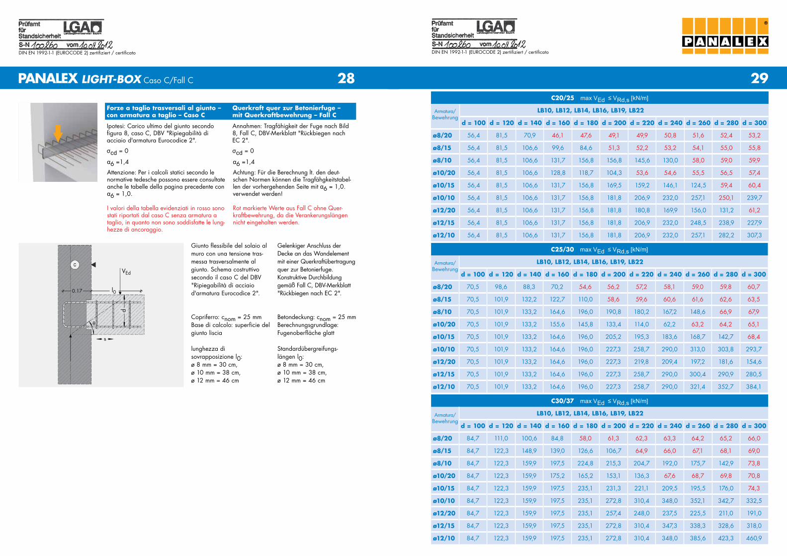
Giunto flessibile del solaio al muro con una tensione trasmessa trasversalmente al giunto. Schema costruttivo secondo il caso C del DBV "ripiegabilità di acciaio d'armatura Eurocodice 2".
Copriferro: cnom = 25 mm
Base di calcolo: superficie del giunto liscia
lunghezza di sovrapposizione l0: ø 8 mm = 30 cm, ø 10 mm = 38 cm, ø 12 mm = 46 cm
Gelenkiger Anschluss der Decke an das Wandelement mit einer Querkraftübertragung quer zur Betonierfuge. Konstruktive Durchbildung gemäß Fall C, DBV-Merkblatt "rückbiegen nach EC 2".
Betondeckung: cnom = 25 mm
Berechnungsgrundlage: Fugenoberfläche glatt
Standardübergreifungs- längen l0: ø 8 mm = 30 cm, ø 10 mm = 38 cm, ø 12 mm = 46 cm
Forze a taglio trasversali al giunto – con armatura a taglio – Caso C
Querkraft quer zur Betonierfuge – mit Querkraftbewehrung – Fall C
Ipotesi: Carico ultimo del giunto secondo figura 8, caso C, DBV "ripiegabilità di acciaio d'armatura Eurocodice 2".
σcd = 0
Annahmen: Tragfähigkeit der Fuge nach Bild 8, Fall C, DBV-Merkblatt "rückbiegen nach EC 2".
σcd = 0
PANALEX LIGHT-BOX Caso C/Fall C
α6 = 1,0
Attenzione: Per i calcoli statici secondo le normative italiane devono essere consultate le tabelle della pagina successiva con α6 = 1,4.
I valori della tabella evidenziati in rosso sono stati riportati dal caso C senza armatura a taglio, in quanto non sono soddisfatte le lung-hezze di ancoraggio.
α6 = 1,0
Achtung: Für die Berechnung lt. den italie-nischen Normen müssen die Tragfähigkeitsta-bellen der nachfolgenden Seite mit α6 = 1,4 verwendet werden.
rot markierte Werte aus Fall C ohne Quer-kraftbewehrung, da die Verankerungslängen nicht eingehalten werden.
C20/25 max VEd ≤ VRd,s [kN/m]
LB10, LB12, LB14, LB16, LB19, LB22
d = 100 d = 120 d = 140 d = 160 d = 180 d = 200 d = 220 d = 240 d = 260 d = 280 d = 300
ø8/20 56,4 81,5 106,6 107,6 94,7 49,1 49,9 50,8 51,6 52,4 53,2
ø8/15 56,4 81,5 106,6 131,7 151,1 141,0 127,8 53,2 54,1 55,0 55,8
ø8/10 56,4 81,5 106,6 131,7 156,8 181,8 206,9 228,1 218,5 207,5 194,1
ø10/20 56,4 81,5 106,6 131,7 156,8 171,0 160,8 148,0 127,7 56,5 57,4
ø10/15 56,4 81,5 106,6 131,7 156,8 181,8 206,9 231,8 222,4 211,6 198,6
ø10/10 56,4 81,5 106,6 131,7 156,8 181,8 206,9 232,0 257,1 282,2 307,3
ø12/20 56,4 81,5 106,6 131,7 156,8 181,8 206,9 199,4 188,4 174,8 153,9
ø12/15 56,4 81,5 106,6 131,7 156,8 181,8 206,9 232,0 257,1 276,6 267,1
Armatura/ Bewehrung
C25/30 max VEd ≤ VRd,s [kN/m]
LB10, LB12, LB14, LB16, LB19, LB22
d = 100 d = 120 d = 140 d = 160 d = 180 d = 200 d = 220 d = 240 d = 260 d = 280 d = 300
ø8/20 70,5 101,9 115,5 104,5 86,6 56,2 57,2 58,1 59,0 59,8 60,7
ø8/15 70,5 101,9 133,2 158,1 148,3 136,3 118,1 60,6 61,6 62,6 63,5
ø8/10 70,5 101,9 133,2 164,6 196,0 227,3 234,0 224,2 212,9 199,3 180,7
ø10/20 70,5 101,9 133,2 164,6 184,6 174,9 163,3 147,9 63,2 64,2 65,1
ø10/15 70,5 101,9 133,2 164,6 196,0 227,3 246,9 237,5 226,8 214,4 198,8
ø10/10 70,5 101,9 133,2 164,6 196,0 227,3 258,7 290,0 321,4 352,7 370,9
ø12/20 70,5 101,9 133,2 164,6 196,0 227,3 252,0 242,7 232,2 220,2 205,3
ø12/15 70,5 101,9 133,2 164,6 196,0 227,3 258,7 290,0 321,4 334,1 324,8
Armatura/ Bewehrung
C30/37 max VEd ≤ VRd,s [kN/m]
LB10, LB12, LB14, LB16, LB19, LB22
d = 100 d = 120 d = 140 d = 160 d = 180 d = 200 d = 220 d = 240 d = 260 d = 280 d = 300
ø8/20 84,7 122,3 112,9 100,0 58,0 61,3 62,3 63,3 64,2 65,2 66,0
ø8/15 84,7 122,3 159,9 155,1 144,0 129,3 64,9 66,0 67,1 68,1 69,0
ø8/10 84,7 122,3 159,9 197,5 235,1 238,9 229,1 217,8 204,5 187,1 73,8
ø10/20 84,7 122,3 159,9 199,5 181,0 169,9 156,0 134,2 68,7 69,8 70,8
ø10/15 84,7 122,3 159,9 197,5 235,1 251,7 242,1 231,5 219,1 203,9 181,6
ø10/10 84,7 122,3 159,9 197,5 235,1 272,8 310,4 348,0 382,5 373,5 363,8
ø12/20 84,7 122,3 159,9 197,5 235,1 272,8 267,4 257,5 246,4 233,5 217,7
ø12/15 84,7 122,3 159,9 197,5 235,1 272,8 310,4 348,0 363,8 354,5 344,6
Armatura/ Bewehrung
VEd
l00.17
d
θ
29
DIN EN 1992-1-1 (EurocoDE 2) zertifiziert / certificato
28
DIN EN 1992-1-1 (EurocoDE 2) zertifiziert / certificato
®
Forze a taglio trasversali al giunto – con armatura a taglio – Caso C
Querkraft quer zur Betonierfuge – mit Querkraftbewehrung – Fall C
Ipotesi: Carico ultimo del giunto secondo figura 8, caso C, DBV "ripiegabilità di acciaio d'armatura Eurocodice 2".
σcd = 0
Annahmen: Tragfähigkeit der Fuge nach Bild 8, Fall C, DBV-Merkblatt "rückbiegen nach EC 2".
σcd = 0
PANALEX LIGHT-BOX Caso C/Fall C
α6 =1,4
Attenzione: Per i calcoli statici secondo le normative tedesche possono essere consultate anche le tabelle della pagina precedente con α6 = 1,0.
I valori della tabella evidenziati in rosso sono stati riportati dal caso C senza armatura a taglio, in quanto non sono soddisfatte le lung-hezze di ancoraggio.
α6 =1,4
Achtung: Für die Berechnung lt. den deut-schen Normen können die Tragfähgkeitstabel-len der vorhergehenden Seite mit α6 = 1,0. verwendet werden!
rot markierte Werte aus Fall C ohne Quer-kraftbewehrung, da die Verankerungslängen nicht eingehalten werden.
Giunto flessibile del solaio al muro con una tensione tras-messa trasversalmente al giunto. Schema costruttivo secondo il caso C del DBV "ripiegabilità di acciaio d'armatura Eurocodice 2".
Copriferro: cnom = 25 mmBase di calcolo: superficie del giunto liscia
lunghezza di sovrapposizione l0: ø 8 mm = 30 cm, ø 10 mm = 38 cm, ø 12 mm = 46 cm
Gelenkiger Anschluss der Decke an das Wandelement mit einer Querkraftübertragung quer zur Betonierfuge. Konstruktive Durchbildung gemäß Fall C, DBV-Merkblatt "rückbiegen nach EC 2".
Betondeckung: cnom = 25 mmBerechnungsgrundlage: Fugenoberfläche glatt
Standardübergreifungs- längen l0: ø 8 mm = 30 cm, ø 10 mm = 38 cm, ø 12 mm = 46 cm
C20/25 max VEd ≤ VRd,s [kN/m]
LB10, LB12, LB14, LB16, LB19, LB22
d = 100 d = 120 d = 140 d = 160 d = 180 d = 200 d = 220 d = 240 d = 260 d = 280 d = 300
ø8/20 56,4 81,5 70,9 46,1 47,6 49,1 49,9 50,8 51,6 52,4 53,2
ø8/15 56,4 81,5 106,6 99,6 84,6 51,3 52,2 53,2 54,1 55,0 55,8
ø8/10 56,4 81,5 106,6 131,7 156,8 156,8 145,6 130,0 58,0 59,0 59,9
ø10/20 56,4 81,5 106,6 128,8 118,7 104,3 53,6 54,6 55,5 56,5 57,4
ø10/15 56,4 81,5 106,6 131,7 156,8 169,5 159,2 146,1 124,5 59,4 60,4
ø10/10 56,4 81,5 106,6 131,7 156,8 181,8 206,9 232,0 257,1 250,1 239,7
ø12/20 56,4 81,5 106,6 131,7 156,8 181,8 180,8 169,9 156,0 131,2 61,2
ø12/15 56,4 81,5 106,6 131,7 156,8 181,8 206,9 232,0 248,5 238,9 227,9
ø12/10 56,4 81,5 106,6 131,7 156,8 181,8 206,9 232,0 257,1 282,2 307,3
C30/37 max VEd ≤ VRd,s [kN/m]
LB10, LB12, LB14, LB16, LB19, LB22
d = 100 d = 120 d = 140 d = 160 d = 180 d = 200 d = 220 d = 240 d = 260 d = 280 d = 300
ø8/20 84,7 111,0 100,6 84,8 58,0 61,3 62,3 63,3 64,2 65,2 66,0
ø8/15 84,7 122,3 148,9 139,0 126,6 106,7 64,9 66,0 67,1 68,1 69,0
ø8/10 84,7 122,3 159,9 197,5 224,8 215,3 204,7 192,0 175,7 142,9 73,8
ø10/20 84,7 122,3 159,9 175,2 165,2 153,1 136,3 67,6 68,7 69,8 70,8
ø10/15 84,7 122,3 159,9 197,5 235,1 231,3 221,1 209,5 195,5 176,0 74,3
ø10/10 84,7 122,3 159,9 197,5 235,1 272,8 310,4 348,0 352,1 342,7 332,5
ø12/20 84,7 122,3 159,9 197,5 235,1 257,4 248,0 237,5 225,5 211,0 191,0
ø12/15 84,7 122,3 159,9 197,5 235,1 272,8 310,4 347,3 338,3 328,6 318,0
ø12/10 84,7 122,3 159,9 197,5 235,1 272,8 310,4 348,0 385,6 423,3 460,9
Armatura/ Bewehrung
C25/30 max VEd ≤ VRd,s [kN/m]
LB10, LB12, LB14, LB16, LB19, LB22
d = 100 d = 120 d = 140 d = 160 d = 180 d = 200 d = 220 d = 240 d = 260 d = 280 d = 300
ø8/20 70,5 98,6 88,3 70,2 54,6 56,2 57,2 58,1 59,0 59,8 60,7
ø8/15 70,5 101,9 132,2 122,7 110,0 58,6 59,6 60,6 61,6 62,6 63,5
ø8/10 70,5 101,9 133,2 164,6 196,0 190,8 180,2 167,2 148,6 66,9 67,9
ø10/20 70,5 101,9 133,2 155,6 145,8 133,4 114,0 62,2 63,2 64,2 65,1
ø10/15 70,5 101,9 133,2 164,6 196,0 205,2 195,3 183,6 168,7 142,7 68,4
ø10/10 70,5 101,9 133,2 164,6 196,0 227,3 258,7 290,0 313,0 303,8 293,7
ø12/20 70,5 101,9 133,2 164,6 196,0 227,3 219,8 209,4 197,2 181,6 154,6
ø12/15 70,5 101,9 133,2 164,6 196,0 227,3 258,7 290,0 300,4 290,9 280,5
ø12/10 70,5 101,9 133,2 164,6 196,0 227,3 258,7 290,0 321,4 352,7 384,1
Armatura/ Bewehrung
Armatura/ Bewehrung
VEd
l00.17
d
θ
31
DIN EN 1992-1-1 (EurocoDE 2) zertifiziert / certificato
30
DIN EN 1992-1-1 (EurocoDE 2) zertifiziert / certificato
®
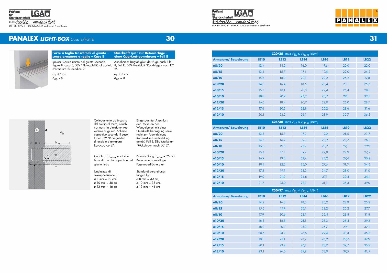
Forze a taglio trasversali al giunto – senza armatura a taglio – Caso E
Querkraft quer zur Betonierfuge – ohne Querkraftbewehrung – Fall E
Ipotesi: Carico ultimo del giunto secondo figura 8, caso E, DBV "ripiegabilità di acciaio d'armatura Eurocodice 2".
a1 < 5 cmσcp = 0
Annahmen: Tragfähigkeit der Fuge nach Bild 8, Fall E, DBV-Merkblatt "rückbiegen nach EC 2".
a1 < 5 cmσcp = 0
Collegamento ad incastro del solaio al muro, carichi trasmessi in direzione tras-versale al giunto. Schema costruttivo secondo il caso E del DBV "ripiegabilità di acciaio d'armatura Eurocodice 2".
Copriferro: cnom = 25 mmBase di calcolo: superficie del giunto liscia
lunghezza di sovrapposizione l0: ø 8 mm = 30 cm, ø 10 mm = 38 cm, ø 12 mm = 46 cm
Eingespannter Anschluss der Decke an das Wandelement mit einer Querkraftübertragung senk-recht zur Fugenrichtung. Konstruktive Durchbildung gemäß Fall E, DBV-Merkblatt "rückbiegen nach EC 2".
Betondeckung: cnom = 25 mmBerechnungsgrundlage: Fugenoberfläche glatt
Standardübergreifungs- längen l0: ø 8 mm = 30 cm, ø 10 mm = 38 cm, ø 12 mm = 46 cm
C25/30 max VEd ≤ VRd,c [kN/m]
Armatura/ Bewehrung LB10 LB12 LB14 LB16 LB19 LB22
ø8/20 13,3 15,3 17,2 19,0 21,5 23,7
ø8/15 14,7 16,9 19,0 20,9 23,7 26,1
ø8/10 16,8 19,3 21,7 23,9 27,1 29,9
ø10/20 15,4 17,7 19,9 22,0 24,9 27,5
ø10/15 16,9 19,5 21,9 24,2 27,4 30,2
ø10/10 19,4 22,3 25,0 27,6 31,3 34,6
ø12/20 17,2 19,9 22,3 24,7 28,0 31,0
ø12/15 19,0 21,9 24,6 27,1 30,8 34,1
ø12/10 21,7 25,0 28,1 31,1 35,3 39,0
C30/37 max VEd ≤ VRd,c [kN/m]
Armatura/ Bewehrung LB10 LB12 LB14 LB16 LB19 LB22
ø8/20 14,2 16,3 18,3 20,2 22,9 25,2
ø8/15 15,6 17,9 20,1 22,2 25,2 27,7
ø8/10 17,9 20,6 23,1 25,4 28,8 31,8
ø10/20 16,3 18,8 21,1 23,3 26,4 29,2
ø10/15 18,0 20,7 23,3 25,7 29,1 32,1
ø10/10 20,6 23,7 26,6 29,4 33,3 36,8
ø12/20 18,3 21,1 23,7 26,2 29,7 32,9
ø12/15 20,1 23,2 26,1 28,9 32,7 36,2
ø12/10 23,1 26,6 29,9 33,0 37,5 41,5
PANALEX LIGHT-BOX Caso E/Fall E
C20/25 max VEd ≤ VRd,c [kN/m]
Armatura/ Bewehrung LB10 LB12 LB14 LB16 LB19 LB22
ø8/20 12,4 14,2 16,0 17,6 20,0 22,0
ø8/15 13,6 15,7 17,6 19,4 22,0 24,2
ø8/10 15,6 18,0 20,1 22,2 25,2 27,8
ø10/20 14,3 16,4 18,5 20,4 23,1 25,5
ø10/15 15,7 18,1 20,3 22,4 25,4 28,1
ø10/10 18,0 20,7 23,2 25,7 29,1 32,1
ø12/20 16,0 18,4 20,7 22,9 26,0 28,7
ø12/15 17,6 20,3 22,8 25,2 28,6 31,6
ø12/10 20,1 23,2 26,1 28,9 32,7 36,2
VEd
l00.17
d
θ
a 1

33
DIN EN 1992-1-1 (EurocoDE 2) zertifiziert / certificato
32
DIN EN 1992-1-1 (EurocoDE 2) zertifiziert / certificato
®
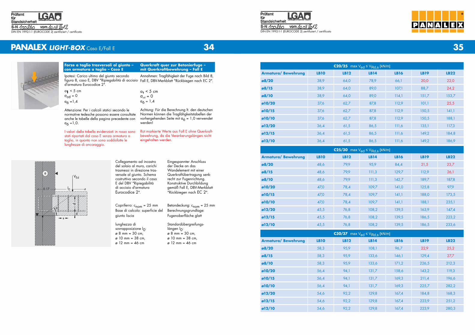
Forze a taglio trasversali al giunto – con armatura a taglio – Caso E
Querkraft quer zur Betonierfuge – mit Querkraftbewehrung – Fall E
Ipotesi: Carico ultimo del giunto secondo figura 8, caso E, DBV "ripiegabilità di acciaio d'armatura Eurocodice 2".
a1 < 5 cmσcd = 0
Annahmen: Tragfähigkeit der Fuge nach Bild 8, Fall E, DBV-Merkblatt "rückbiegen nach EC 2".
a1 < 5 cmσcd = 0
Collegamento ad incastro del solaio al muro, carichi trasmessi in direzione tras-versale al giunto. Schema costruttivo secondo il caso E del DBV "ripiegabilità di acciaio d'armatura Eurocodice 2".
Copriferro: cnom = 25 mmBase di calcolo: superficie del giunto liscia
lunghezza di sovrapposizione l0: ø 8 mm = 30 cm, ø 10 mm = 38 cm, ø 12 mm = 46 cm
Eingespannter Anschluss der Decke an das Wandelement mit einer Querkraftübertragung senk-recht zur Fugenrichtung. Konstruktive Durchbildung gemäß Fall E, DBV-Merkblatt "rückbiegen nach EC 2".
Betondeckung: cnom = 25 mmBerechnungsgrundlage: Fugenoberfläche glatt
Standardübergreifungs- längen l0: ø 8 mm = 30 cm, ø 10 mm = 38 cm, ø 12 mm = 46 cm
C25/30 max Ved ≤ VRd,s [kN/m]
Armatura/ Bewehrung LB10 LB12 LB14 LB16 LB19 LB22
ø8/20 48,6 79,9 111,3 103,2 75,5 23,7
ø8/15 48,6 79,9 111,3 142,7 138,0 116,4
ø8/10 48,6 79,9 111,3 142,7 189,7 222,5
ø10/20 47,0 78,4 109,7 141,0 125,8 97,9
ø10/15 47,0 78,4 109,7 141,1 188,0 173,5
ø10/10 47,0 78,4 109,7 141,1 188,1 235,1
ø12/20 45,5 76,8 108,2 139,5 163,9 147,4
ø12/15 45,5 76,8 108,2 139,5 186,5 223,2
ø12/10
C30/37 max Ved ≤ VRd,s [kN/m]
Armatura/ Bewehrung LB10 LB12 LB14 LB16 LB19 LB22
ø8/20 58,3 95,9 119,9 109,5 79,4 25,2
ø8/15 58,3 95,9 133,6 161,7 146,4 123,3
ø8/10 58,3 95,9 133,6 171,2 227,6 236,1
ø10/20 56,4 94,1 131,7 158,6 143,2 119,3
ø10/15 56,4 94,1 131,7 169,3 211,4 196,6
ø10/10 56,4 94,1 131,7 169,3 225,7 282,2
ø12/20 54,6 92,2 129,8 167,4 184,8 168,3
ø12/15 54,6 92,2 129,8 167,4 223,9 251,2
ø12/10
α6 = 1,0
Attenzione: Per i calcoli statici secondo le normative italiane devono essere consultate le tabelle della pagina successiva con α6 =1,4.
I valori della tabella evidenziati in rosso sono stati riportati dal caso E senza armatura a taglio, in quanto non sono soddisfatte le lung-hezze di ancoraggio.
α6 =1,0
Achtung: Für die Berechnung lt. den italie-nischen Normen müssen die Tragfähigkeitsta-bellen der nachfolgenden Seite mit α6 =1,4 verwendet werden!
rot markierte Werte aus Fall E ohne Quer-kraftbewehrung, da die Verankerungslängen nicht eingehalten werden.
PANALEX LIGHT-BOX Caso E/Fall E
C20/25 max Ved ≤ VRd,s [kN/m]
Armatura/ Bewehrung LB10 LB12 LB14 LB16 LB19 LB22
ø8/20 38,9 64,0 89,0 83,8 20,0 22,0
ø8/15 38,9 64,0 89,0 114,1 112,1 24,2
ø8/10 38,9 64,0 89,0 114,1 151,7 184,1
ø10/20 37,6 62,7 87,8 112,9 101,1 25,5
ø10/15 37,6 62,7 87,8 112,9 150,5 141,1
ø10/10 37,6 62,7 87,8 112,9 150,5 188,1
ø12/20 36,4 61,5 86,5 111,6 135,1 117,3
ø12/15 36,4 61,5 86,5 111,6 149,2 184,8
ø12/10
VEd
l00.17
d
θ
a 1
35
DIN EN 1992-1-1 (EurocoDE 2) zertifiziert / certificato
34
DIN EN 1992-1-1 (EurocoDE 2) zertifiziert / certificato
®
Forze a taglio trasversali al giunto – con armatura a taglio – Caso E
Querkraft quer zur Betonierfuge – mit Querkraftbewehrung – Fall E
Ipotesi: Carico ultimo del giunto secondo figura 8, caso E, DBV "ripiegabilità di acciaio d'armatura Eurocodice 2".
a1 < 5 cmσcd = 0
Annahmen: Tragfähigkeit der Fuge nach Bild 8, Fall E, DBV-Merkblatt "rückbiegen nach EC 2".
a1 < 5 cmσcd = 0
Collegamento ad incastro del solaio al muro, carichi trasmessi in direzione tras-versale al giunto. Schema costruttivo secondo il caso E del DBV "ripiegabilità di acciaio d'armatura Eurocodice 2".
Copriferro: cnom = 25 mmBase di calcolo: superficie del giunto liscia
lunghezza di sovrapposizione l0: ø 8 mm = 30 cm, ø 10 mm = 38 cm, ø 12 mm = 46 cm
Eingespannter Anschluss der Decke an das Wandelement mit einer Querkraftübertragung senk-recht zur Fugenrichtung. Konstruktive Durchbildung gemäß Fall E, DBV-Merkblatt "rückbiegen nach EC 2".
Betondeckung: cnom = 25 mmBerechnungsgrundlage: Fugenoberfläche glatt
Standardübergreifungs- längen l0: ø 8 mm = 30 cm, ø 10 mm = 38 cm, ø 12 mm = 46 cm
C25/30 max Ved ≤ VRd,s [kN/m]
Armatura/ Bewehrung LB10 LB12 LB14 LB16 LB19 LB22
ø8/20 48,6 79,9 95,9 84,4 21,5 23,7
ø8/15 48,6 79,9 111,3 129,7 112,9 26,1
ø8/10 48,6 79,9 111,3 142,7 189,7 187,8
ø10/20 47,0 78,4 109,7 141,0 125,8 97,9
ø10/15 47,0 78,4 109,7 141,1 188,0 173,5
ø10/10 47,0 78,4 109,7 141,1 188,1 235,1
ø12/20 45,5 76,8 108,2 139,5 163,9 147,4
ø12/15 45,5 76,8 108,2 139,5 186,5 223,2
ø12/10 45,5 76,8 108,2 139,5 186,5 233,6
C30/37 max Ved ≤ VRd,s [kN/m]
Armatura/ Bewehrung LB10 LB12 LB14 LB16 LB19 LB22
ø8/20 58,3 95,9 108,1 96,7 22,9 25,2
ø8/15 58,3 95,9 133,6 146,1 129,4 27,7
ø8/10 58,3 95,9 133,6 171,2 226,5 212,3
ø10/20 56,4 94,1 131,7 158,6 143,2 119,3
ø10/15 56,4 94,1 131,7 169,3 211,4 196,6
ø10/10 56,4 94,1 131,7 169,3 225,7 282,2
ø12/20 54,6 92,2 129,8 167,4 184,8 168,3
ø12/15 54,6 92,2 129,8 167,4 223,9 251,2
ø12/10 54,6 92,2 129,8 167,4 223,9 280,3
PANALEX LIGHT-BOX Caso E/Fall E
C20/25 max Ved ≤ VRd,s [kN/m]
Armatura/ Bewehrung LB10 LB12 LB14 LB16 LB19 LB22
ø8/20 38,9 64,0 78,9 66,1 20,0 22,0
ø8/15 38,9 64,0 89,0 107,1 88,7 24,2
ø8/10 38,9 64,0 89,0 114,1 151,7 153,7
ø10/20 37,6 62,7 87,8 112,9 101,1 25,5
ø10/15 37,6 62,7 87,8 112,9 150,5 141,1
ø10/10 37,6 62,7 87,8 112,9 150,5 188,1
ø12/20 36,4 61,5 86,5 111,6 135,1 117,3
ø12/15 36,4 61,5 86,5 111,6 149,2 184,8
ø12/10 36,4 61,5 86,5 111,6 149,2 186,9
α6 =1,4
Attenzione: Per i calcoli statici secondo le normative tedesche possono essere consultate anche le tabelle della pagina precedente con α6 =1,0.
I valori della tabella evidenziati in rosso sono stati riportati dal caso E senza armatura a taglio, in quanto non sono soddisfatte le lunghezze di ancoraggio.
α6 = 1,4
Achtung: Für die Berechnung lt. den deutschen Normen können die Tragfähgkeitstabellen der vorhergehenden Seite mit α6 = 1,0 verwendet werden!
rot markierte Werte aus Fall E ohne Querkraft-bewehrung, da die Verankerungslängen nicht eingehalten werden.
VEd
l00.17
d
θ
a 1
37
DIN EN 1992-1-1 (EurocoDE 2) zertifiziert / certificato
36
DIN EN 1992-1-1 (EurocoDE 2) zertifiziert / certificato
®
PANALEX LIGHT-BOX Calcolo statico / Statische Typenberechnung
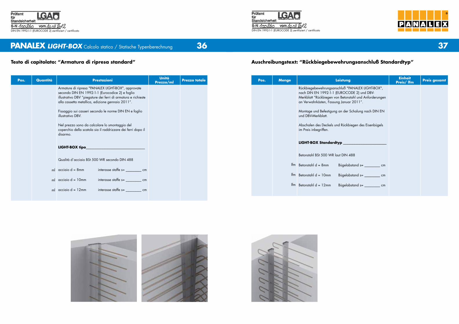
Testo di capitolato: “Armatura di ripresa standard”
Pos. Quantitá Prestazioni UnitáPrezzo/ml Prezzo totale
ml
ml
ml
Armature di ripresa "PANALEX LIGHT-BoX", approvate secondo DIN EN 1992-1-1 (Eurocodice 2) e foglio illustrativo DBV “piegature dei ferri di armatura e richieste alla cassetta metallica, edizione gennaio 2011”.
Fissaggio sui casseri secondo le norme DIN EN e foglio illustrativo DBV.
Nel prezzo sono da calcolare lo smontaggio del coperchio della scatola sia il raddrizzare dei ferri dopo il disarmo.
LIGHT-BOX tipo__________________________________
Qualitá d´acciaio BSt 500 Wr secondo DIN 488
acciaio d = 8mm interasse staffe s= _________ cm
acciaio d = 10mm interasse staffe s= _________ cm
acciaio d = 12mm interasse staffe s= _________ cm
Auschreibungstext: “Rückbiegebewehrungsanschluß Standardtyp”
Pos. Menge Leistung EinheitPreis/ lfm Preis gesamt
lfm
lfm
lfm
rückbiegebewehrungsanschluß "PANALEX LIGHT-BoX", nach DIN EN 1992-1-1 (EuroCoDE 2) und DBV-Merkblatt “rückbiegen von Betonstahl und Anforderungen an Verwahrkästen, Fassung Januar 2011”.
Montage und Befestigung an der Schalung nach DIN EN und DBV-Merkblatt.
Abschalen des Deckels und rückbiegen des Eisenbügels im Preis inbegriffen.
LIGHT-BOX Standardtyp _________________________
Betonstahl BSt 500 Wr laut DIN 488
Betonstahl d = 8mm Bügelabstand s= _________ cm
Betonstahl d = 10mm Bügelabstand s= _________ cm
Betonstahl d = 12mm Bügelabstand s= _________ cm
39
DIN EN 1992-1-1 (EurocoDE 2) zertifiziert / certificato
38
DIN EN 1992-1-1 (EurocoDE 2) zertifiziert / certificato
LIGHT-BOX A (Standard)
h
l0
®
PANALEX LIGHT-BOX PANALEX LIGHT-BOX
PANALEX LIGHT-BOX con staffa singola / einreihig PANALEX LIGHT-BOX con staffa doppia / zweireihig
LIGHT-BOX N
l0
LIGHT-BOX EE
l0
LIGHT-BOX DE
l0
LIGHT-BOX BD
l0
LIGHT-BOX BB
l0
LIGHT-BOX E
l0
LIGHT-BOX M2
l0
LIGHT-BOX M (Standard)
l0
LIGHT-BOX B
l0
LIGHT-BOX D
l0
LIGHT-BOX C
l0
LIGHT-BOX P
l0
LIGHT-BOX Q
l0l0
LIGHT-BOX O
®
PANALEX LIGHT-BOX Calcolo statico / Statische Typenberechnung
Das ProjektStatische Typenberechnung Bewehrungsanschluss PANALEX LIGHT-BoX nach DIN EN 1992-1-1 (EuroCoDE 2) und DBV-Merkblatt "rückbiegen von Betonstahl und Anforderungen an Verwahrkästen, Fassung Januar 2011".
AuftraggeberPANALEX S.r.o.Milady Horákové 272427201 KladnoTschechien
Datum13.02.2012
Il progettoCalcolo statico per armaturedi ripresa PANALEX LIGHT-BoX secondoDIN EN 1992-1-1 (EuroCoDICE 2) e foglio informativo DBV „piegature dei ferri di armatura e richieste alla cassetta metallica, edizione gennaio 2011".
CommittentePANALEX S.r.o.Milady Horákové 272427201 Kladnorepubblica Ceca
Data13.02.2012
PANALEX S.R.O.Milady Horákové 2724CZ-27201 KladnoT 00420 312 663 577F 00420 312 663 [email protected]
Top Related