
10 - Home - Jakob Fischer GmbH · 2014-11-28 · ón de aparatos e instalaciones químicas y petro-...
116
10 Rohr- verschraubung Tube fitting Racor de conexión
Transcript of 10 - Home - Jakob Fischer GmbH · 2014-11-28 · ón de aparatos e instalaciones químicas y petro-...
10
Rohr-verschraubung
Tube fitting Racor de conexión
RohrverschraubungTube fittingRacor de conexión
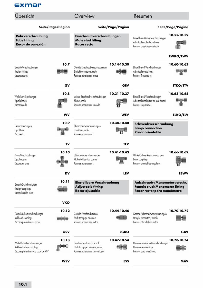
10.7Gerade VerschraubungenStraight fittingsRacores rectos
GV
10.8WinkelverschraubungenEqual elbowsRacores codo
WV
10.9T-VerschraubungenEqual teesRacores T
TV
10.10Kreuz-VerschraubungenEqual crossesRacores en cruz
KV
10.11Gerade ZwischenstutzenStraight couplingsRacor de unión recto
VKO
10.12Gerade SchottverschraubungenBulkhead couplingsRacores pasatabiques rectos
GSV
10.13Winkel-SchottverschraubungenBulkhead elbow couplingsRacores pasatabiques a codo de 90°
WSV
EinschraubverschraubungenMale stud fittingRacor recto
10.14-10.30Gerade EinschraubverschraubungenStraight connectors, maleRacores para roscar rectos
GEV
10.31-10.37Winkel-EinschraubverschraubungenElbows, maleRacores para roscar en codo
WEV
10.38-10.40T-EinschraubverschraubungenEqual tees, maleRacores para roscar T
TEV
10.41-10.43L-EinschraubverschraubungenMale stud tee-stud barrelsRacores para roscar L
LEV
Einstellbare VerschraubungAdjustable fittingRacor ajustable
10.44-10.46Gerade EinschraubstutzenStud standpipe adaptorsRacores para roscar rectos
EGKO
10.47-10.54Einschraubstutzen mit SchaftStud standpipe adaptors, maleRacores para roscar con vástago
ESS
10.55-10.59Einstellbare WinkelverschraubungenAdjustable male stud elbowsRacores angulares ajustables
EWKO/EWV
10.60-10.62Einstellbare T-VerschraubungenAdjustable equal teesRacores T ajustables
ETKO/ETV
10.63-10.65Einstellbare L-VerschraubungenAdjustable male stud tee-stud barrelsRacores L ajustables
ELKO/ELV
SchwenkverschraubungBanjo connectionRacor orientable
10.66-10.69Winkel-SchwenkverschraubungenBanjo couplingsRacores orientables angulares
ESWV
Aufschraub-/Manometerverschr.Female stud/Manometer fittingRacor recto/para manómetro
10.70-10.72Gerade AufschraubverschraubungenStraight connectors, femaleRacores atornillables rectos
GAV
10.73-10.74Manometer-AnschlußverschraubungenManometer couplingsRacores para manómetro
MAV
Seite/Page/Página Seite/Page/Página Seite/Page/Página
Übersicht Overview Resumen
10.1
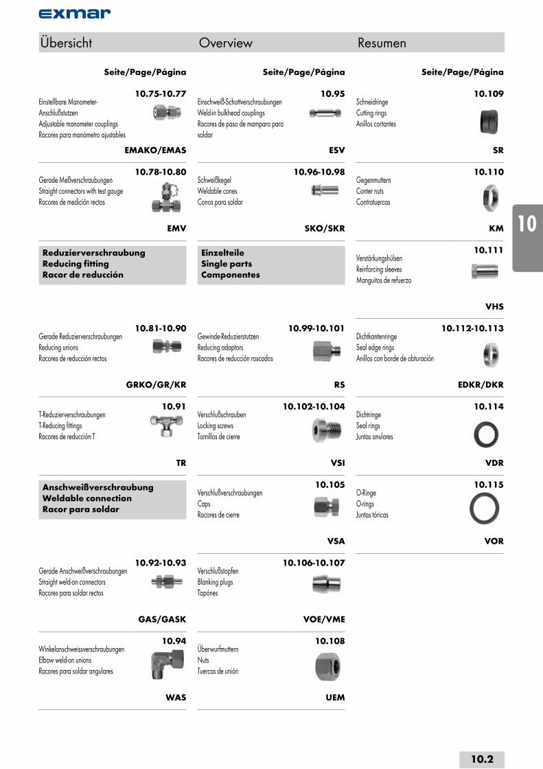
10.75-10.77Einstellbare Manometer-AnschlußstutzenAdjustable manometer couplingsRacores para manómetro ajustables
EMAKO/EMAS
10.78-10.80Gerade MeßverschraubungenStraight connectors with test gaugeRacores de medición rectos
EMV
ReduzierverschraubungReducing fittingRacor de reducción
10.81-10.90Gerade ReduzierverschraubungenReducing unionsRacores de reducción rectos
GRKO/GR/KR
10.91T-ReduzierverschraubungenT-Reducing fittingsRacores de reducción T
TR
AnschweißverschraubungWeldable connectionRacor para soldar
10.92-10.93Gerade AnschweißverschraubungenStraight weld-on connectorsRacores para soldar rectos
GAS/GASK
10.94WinkelanschweissverschraubungenElbow weld-on unionsRacores para soldar angulares
WAS
10.95Einschweiß-SchottverschraubungenWeld-in bulkhead couplingsRacores de paso de mamparo para soldar
ESV
10.96-10.98SchweißkegelWeldable conesConos para soldar
SKO/SKR
EinzelteileSingle partsComponentes
10.102-10.104VerschlußschraubenLocking screwsTornillos de cierre
VSI
10.105VerschlußverschraubungenCapsRacores de cierre
VSA
10.106-10.107VerschlußstopfenBlanking plugsTapónes
VOE/VME
10.108ÜberwurfmutternNutsTuercas de unión
UEM
10.109SchneidringeCutting ringsAnillos cortantes
SR
10.110GegenmutternConter nutsContratuercas
KM
10.111VerstärkungshülsenReinforcing sleevesManguitos de refuerzo
VHS
10.112-10.113DichtkantenringeSeal edge ringsAnillos con borde de obturación
EDKR/DKR
10.114DichtringeSeal ringsJuntas anulares
VDR
10.115O-RingeO-ringsJuntas tóricas
VOR
Seite/Page/Página Seite/Page/Página Seite/Page/Página
Übersicht Overview Resumen
10.99-10.101Gewinde-ReduzierstutzenReducing adaptorsRacores de reducción roscados
RS
10.2
i
s
10
20
30
40
50
60
70
a

AnwendungsbereicheEXMAR Schneidring- und Dichtkegelverschrau-bungen nach DIN EN ISO 8434-1 / DIN 2353 dienen zur Verbindung von Rohren mit glatten Enden.
Eine nach DIN genormte Abstufung in 3 Baurei-hen (LL, L und S) umfasst einen Nenndruckbe-reich bis 800 bar gem. DNV.
Die Einsatzgebiete der Edelstahlschneidringver-schraubungen umfassen den chemischen und petrochemischen Apparate- und Anlagenbau, die pharmazeutische Industrie, die Papier- und Kunststoffindustrie, Hafen- und Schleusenanla-gen, den Schiffsbau und die Luftfahrt, den Off-shore-Anlagenbau, die Mess- und Regeltechnik, sowie hydraulische Anlagen erhöhter korrosiver Beanspruchung.
Rohrverschraubung Tube fitting Racor
Areas of applicationEXMAR cutting ring fittings and tapered seal connections in accordance with DIN EN ISO 8434-1 / DIN 2353 serve to connect even ended tubes.
Three ranges of fittings (LL, L and S), in accor-dance with the DIN norm, cover a pressure range up to 800 bar according DNV.
The areas of application for stainless steel cutting ring fittings extend from chemical and petrochemical plant and equipment, through pharmaceutical, paper, plastic, shipbuilding and aircraft industries, sluice applications, off-shore, measurement and control, as well as highly corrosive hydraulic systems and installations.
Ámbitos de aplicaciónLos racores con anillo cortante y racores cónicos con junta tórica EXMAR según DIN EN ISO 8434-1/DIN 2353 se utilizan para la conexión de tubos con extremos lisos.
Una graduación normalizada según DIN en tres series (LL, L y S) cubre un rango de presión nominal de hasta 800 bar según DNV.
Los ámbitos de uso de los racores con anillo cor-tante de acero inoxidable abarcan la construcci-ón de aparatos e instalaciones químicas y petro-químicas, la industria farmacéutica, la industria del papel y plástico, instalaciones portuarias y de esclusas, la construcción naval y aeronáutica, la construcción Off-shore, la técnica de medida y de regulación y las instalaciones hidráulicas sujetas a cargas de corrosión altas.
Technische Informationen
Technical Information
Información Técnica
Funktion
Die Überwurfmutter (1) presst den keilförmig vor-geformten Schneidring (2) beim Anziehen in den Innenkegel (3) des Verschraubungsstutzens (4).
Der Schneidring wird dadurch ringförmig auf das Rohr (5) gepresst, so dass die gehärtete Schneidkante (6) des Schneidringes gleichför-mig in das Rohr einschneidet, wodurch sich ein ringförmiger Wulst des Rohrmaterials vor der Schneidkante aufwirft.
Die konstruktive Formgebung des Schneid-ringes begrenzt die Eindringtiefe. Gleichzeitig verkeilt sich der Schneidring mutternseitig auf dem Rohr (7) und bietet so zusätzlichen Halt und Entlastung der Schneidzone bei dynamischer Beanspruchung. Formschluss und Kraftschluss des Schneidringsystems gewähren einen sicheren Halt der Rohrverbindungen.
Principle
On tightening the nut (1) the cutting ring (2) is pressed into the inner taper (3) of the coupling stud (4) and into the tube (5).
The hardened cutting edge (6) cuts into the tube (5) and forms a circumferential bead in front of the cutting edge.
The design form of the cutting ring determines the cut-in depth. A tapered nut/cutting ring in-terface results in the cutting ring being pressed into the tube (7), thereby providing additional support and relief to the cut-in zone under dynamic load conditions. The mechanical and frictional principle of the cutting ring system guarantees a secure tube connection.
Función
Al apretar, la tuerca de unión (1) empuja el anillo de corte con forma de cuña (2) dentro del cono interior (3) del racor (4).
En esta operación, el anillo cortante ataca el tubo (5) en toda la circunferencia de forma que el filo templado (6) del anillo realiza un corte homogéneo en el mismo y levanta un reborde anular de material delante del filo.
El diseño constructivo del anillo de corte limita la profundidad de penetración. Al mismo tiempo, el anillo de corte se enclava en el tubo en el lado de la tuerca (7) y brinda fijación y descarga adicional en la zona de corte para esfuerzos dinámicos. La unión positiva y no po-sitiva del sistema de anillo de corte garantiza la fijación segura de las uniones de tubos.
Vor der FertigmontageBefore assemblyAntes del montaje final
Nach der FertigmontageAfter assemblyDespués del montaje final
10.3

Rohrverschraubung Tube fitting Racor
NormungEXMAR Rohrverschraubungen werden nach den entsprechenden DIN-Normen gefertigt.
Bauarten, die über die Norm hinausgehen, werden mit Rohranschlusskegel nach DIN 3861 gefertigt. Alle weiteren Maße sind den entsprechenden Normen angeglichen. Einschraubverschraubungen der einzelnen Ver-schraubungskörper werden standardmäßig mit Einschraubzapfen nach DIN 3852 Teil 1 und Teil 2 gefertigt. Abweichend von den DIN-Nor-men werden Einschraubzapfen mit NPT-Gewin-de nach ANSI B1.20.1-1983 hergestellt.
Druckbereiche SchneidringBaureihe Rohr NenndruckLL: sehr leicht 4 - 12 mm PN 100 (bar)L: leicht 6 - 10 mm PN 500 (bar)
12 - 18 mm PN 400 (bar)22 - 42 mm PN 250 (bar)
S: schwer 6 - 10 mm PN 800 (bar)12 - 16 mm PN 630 (bar)20 - 38 mm PN 420 (bar)
Die Festigkeit der Verschraubungen ist so ausgelegt, dass sie bei den aufgeführten Nenn-drücken eine 4-fache Sicherheit gewährt. Bei vorwiegend ruhender Belastung und Tempe-raturen bis 120°C können die Betriebsdrücke gleich den Nenndrücken gewählt werden. Bei höheren mechanischen Beanspruchungen (Schwingungen, Druckstößen usw.) empfehlen wir die Anwendung der Baureihe "S". Eine spannungsfrei gelagerte, solide Ausführung und entsprechend starke Halterung des Rohrsy-stems werden vorausgesetzt.
Druckbereiche DichtkegelBaureihe Rohr NenndruckL: leicht 6 - 18 mm PN 315 (bar)
22 - 42 mm PN 160 (bar)S: schwer 6 - 14 mm PN 630 (bar)
16 - 30 mm PN 400 (bar)38 mm PN 315 (bar)
WerkstoffeEXMAR Rohrverschraubungen werden serien-mäßig aus Werkstoff 1.4571 hergestellt. Die Verschraubungen können jedoch auch aus Hastelloy®, Titan und anderen hochlegierten Werkstoffqualitäten geliefert werden.
WerkzeugnisseWerden Bescheinigungen über Materialprü-fungen nach DIN EN 10 204 gewünscht, so ist dies bei Bestellung anzugeben (ab Abnahme-prüfzeugnis 3.1 gegen Berechnung).
NormativaLos racores EXMAR se fabrican de acuerdo con las normas pertinentes de la organización DIN.
Los tipos no contemplados en la norma se fa-brican con conos de conexión de tubos según DIN 3861. Las restantes dimensiones se han adaptado a las normas correspondientes. Los racores para roscar de los diferentes cuerpos atornillables se fabrican de forma estándar con vástagos roscados según DIN 3852 parte 1 y parte 2. Fuera del ámbito de la normativa DIN, se fabrican vástagos roscados con rosca NPT según ANSI B1.20.1-1983.
Rangos de presión Anillo cortanteSerie Tubo Presión nom.LL: muy ligera 4 - 12 mm PN 100 (bar)L: ligera 6 - 10 mm PN 500 (bar)
12 - 18 mm PN 400 (bar)22 - 42 mm PN 250 (bar)
S: pesada 6 - 10 mm PN 800 (bar)12 - 16 mm PN 630 (bar)20 - 38 mm PN 420 (bar)
La resistencia de los racores está dimensionada para garantizar cuatro veces la seguridad ne-cesaria con las presiones nominales señaladas. Si predominan cargas estáticas y temperaturas hasta 120ºC, pueden seleccionarse presiones de trabajo iguales a las presiones normales. Par cargas mecánicas superiores (vibraciones, golpes de ariete, etc.) recomendamos utilizar la serie "S". El requisito es una ejecución sólida, un apoyo libre de tensiones y un soporte de resistencia adecuado al sistema de tuberías.
Rangos de presión CónicosSerie Tubo Presión nom.L: ligera 6 - 18 mm PN 315 (bar)
22 - 42 mm PN 160 (bar)S: pesada 6 - 14 mm PN 630 (bar)
16 - 30 mm PN 400 (bar)38 mm PN 315 (bar)
MaterialesLos racores EXMAR se fabrican de serie con el material 1.4571/AISI 316 ti. Sin embargo, pue-den suministrarse también en Hastelloy®, titanio y otros materiales aleados de alta calidad.
Certificados de materialSi se necesitan certificados de ensayos de material según DIN EN 10 204, deberá espe-cificarse al realizar el pedido (se facturará a partir del certificado de recepción 3.1).
NormEXMAR tube fittings are manufactured to respective DIN standards.
Fittings outside standard norms are produced with tube connections according to DIN 3861. All further dimensions conform to the respective standards. Individual coupling studs are produ-ced in accordance with DIN 3852 Part 1 and 2 as standard. Studs with NPT threads deviate from the DIN standard, and are manufactured to ANSI B1.20.1-1983.
Pressure ranges Cutting ringSerie Tube Pressure nom.LL: extra light 4 - 12 mm PN 100 (bar)L: light 6 - 10 mm PN 500 (bar)
12 - 18 mm PN 400 (bar)22 - 42 mm PN 250 (bar)
S: heavy 6 - 10 mm PN 800 (bar)12 - 16 mm PN 630 (bar)20 - 38 mm PN 420 (bar)
The fittings are designed to guarantee a safety factor of 4 on the stated nominal pressure. By normal and undynamic loading and tempera-tures up to +120°C the operating pressure can be regarded as the nominal pressure. By ab-normal and highly dynamic conditions (vibrati-on, pulsing, etc.) the use of "S" range fittings is recommended. A strong, solid, stress free, and secure mounting system is pre-requisite.
Pressure ranges Tapered sealSerie Tube Pressure nom.L: light 6 - 18 mm PN 315 (bar)
22 - 42 mm PN 160 (bar)S: heavy 6 - 14 mm PN 630 (bar)
16 - 30 mm PN 400 (bar)38 mm PN 315 (bar)
MaterialEXMAR tube fittings are manufactured from AISI 316 ti material. Fittings can also be supplied in Hastelloy®, titanium and other high quality alloys.
Material certificatesAny request for documents on material tests according to DIN EN 10 204 should be made when placing the order ( from inspection certifi-cate 3.1 costs will be charged).
10.4
i
s
10
20
30
40
50
60
70
a
Rohrverschraubung Tube fitting Racor
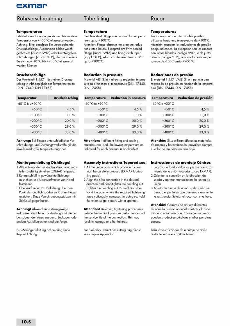
TemperaturenEdelstahlverschraubungen können bis zu einer Temperatur von +400°C eingesetzt werden. Achtung: Bitte beachten Sie unten stehende Druckabschläge. Ausnahmen bilden weich-gedichtete (Zusatz "WD") oder Dichtkegelver-schraubungen (Zusatz "KO"), die nur in einem Bereich von -10°C bis +200°C eingesetzt werden können.
DruckabschlägeDer Werkstoff 1.4571 lässt einen Druckab-schlag in Abhängigkeit der Temperaturen zu (DIN 17440, DIN 17458).
Temperatur Druckabschlag
-60°C bis +20°C -- -
+50°C 4,5 %
+100°C 11,0 %
+200°C 20,0 %
+300°C 29,0 %
+400°C 33,0 %
Achtung: Bei Einsatz unterschiedlicher Ver-schraubungs- und Dichtungswerkstoffe gilt die jeweils niedrigste Temperaturangabe!
Montageanleitung Dichtkegel1. Alle miteinander reibenden Verschraubungs-
teile sorgfältig einfetten (EXMAR Fettpaste).2. Rohranschluß in gewünschte Richtung
ausrichten und Überwurfmutter von Hand festziehen.
3. Überwurfmutter ⅓ Umdrehung über den Punkt des deutlich spürbaren Kraftanstieges anziehen. Dazu Verschraubungsstutzen mit Schlüssel gegenhalten.
Achtung! Abweichende Anzugswege reduzieren die Nenndruckleistung und die Le-bensdauer der Verschraubung. Leckagen oder andere Ausfallursachen sind die Folge.
Für Montageanleitung Schneidring siehe Kapitel Anhang.
TemperatureStainless steel fittings can be used for tempera-tures up to +400°C. Attention: Please observe the pressure reduc-tions listed below. Excepted are FKM-sealed fittings (suppl. "WD") and fittings with taper (suppl. "KO"), which can be used from -10°C up to +200°C.
Reduction in pressureMaterial AISI 316 ti allows a reduction in pres-sure as a function of temperature (DIN 17440, DIN 17458).
Temperature Reduction in pressure
-60°C to +20°C -- -
+50°C 4,5 %
+100°C 11,0 %
+200°C 20,0 %
+300°C 29,0 %
+400°C 33,0 %
Attention: If different fitting and sealing materials are used, the lowest temperature as indicated for each material is applicable!
Assembly instructions Tapered seal1. All the union parts which produce friction
must be carefully greased (EXMAR lubrica-ting paste).
2. Align the tube connection in the desired direction and hand-tighten the coupling nut.
3. Tighten the coupling nut ⅓ revolutions be-yond the point where the required tightening force noticeably increases. In doing so, hold the union spigot steady with a spanner.
Attention! Deviating tightening procedures reduce the nominal pressure performance and the service life of the connection. This may result in leakage or other failures.
For assembly instructions cutting ring please see chapter Appendix.
TemperaturasLos racores de acero inoxidable pueden utilizarse hasta una temperatura de +400ºC. Atención: respetar las reducciones de presión abajo indicadas. La excepción son los racores con juntas blandas (código "WD") o de junta cónica (código "KO"), aptos solo para tempe-raturas de -10°C hasta +200°C.
Reducciones de presiónEl material 1.4571/AISI 316 ti permite una reducción de presión en función de la tempera-tura (DIN 17440, DIN 17458)
Temperatura Reduccion de presión
-60°C a +20°C -- -
+50°C 4,5 %
+100°C 11,0 %
+200°C 20,0 %
+300°C 29,0 %
+400°C 33,0 %
Atención: Si se utilizan diferentes materiales de racores y hermetización, prevalece siempre el valor de temperatura más bajo.
Instrucciones de montaje Cónicos1. Engrasar a fondo todas las piezas con roza-
miento de la unión roscada (grasa EXMAR).2. Orientar la conexión en la dirección de-
seada y apretar manualmente la tuerca de unión.
3. Apretar la tuerca de unión ⅓ de vuelta su-perado el punto en que aumenta claramente la resistencia. Sujetar el racor con una llave.
Atención! Carreras de apriete diferentes reducen la presión nominal estática y la vida útil de la unión roscada. Como consecuencia pueden producirse pérdidas y fallos por otras causas.
Para las instrucciones de montaje de anillo cortante véase el capítulo Anexo.
10.5
Rohrverschraubung Tube fitting Racor
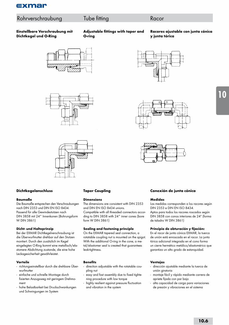
Dichtkegelanschluss
BaumaßeDie Baumaße entsprechen den Verschraubungen nach DIN 2353 und DIN EN ISO 8434.Passend für alle Gewindestutzen nach DIN 3858 mit 24° Innenkonen (Bohrungsform W DIN 3861)
Dicht- und HalteprinzipBei der EXMAR Dichtkegelverschraubung ist die Überwurfmutter drehbar auf den Stutzen montiert. Durch den zusätzlich im Kegel eingelegten O-Ring kommt eine metallisch/ela-stomere Abdichtung zustande, die eine hohe Leckagesicherheit gewährleistet.
Vorteile- richtungseinstellbar durch die drehbare Über-
wurfmutter- einfache und schnelle Montage durch
fixierten Anzugsweg mit geringem Drehmo-ment
- hohe Belastbarkeit bei Druckschwankungen und Schwingungen im System
Taper Coupling
DimensionsThe dimensions are consistent with DIN 2353 and DIN EN ISO 8434 unions.Compatible with all threaded connectors accor-ding to DIN 3858 with 24° inner cones (bore form W DIN 3861)
Sealing and fastening principleOn the EXMAR tapered seal connection, a rotatable coupling nut is mounted on the spigot. With the additional O-ring in the cone, a me-tal/elastomer seal is created that guarantees leak-tightness.
Benefits- direction adjustable with the rotatable cou-
pling nut- easy and fast assembly due to fixed tighte-
ning procedure with low torque- highly resilient against pressure fluctuation
and vibration in the system
Conexión de junta cónica
MedidasLas medidas corresponden a los racores según DIN 2353 e DIN EN ISO 8434.Aptos para todos los racores roscados según DIN 3858 con conos interiores de 24º (forma de taladro W DIN 3861)
Principio de obturación y fijación:En el racor de junta cónica EXMAR, la tuerca de unión está enroscada en el racor. La junta tórica adicional integrada en el cono forma un cierre hermético metálico/elastomérico que garantiza un alto grado de estanquidad.
Ventajas- dirección ajustable mediante la tuerca de
unión giratoria- montaje fácil y rápido mediante carrera de
apriete fijada con par bajo- alta capacidad de carga para variaciones
de presión y vibraciones en el sistema
Einstellbare Verschraubung mit Dichtkegel und O-Ring
Adjustable fittings with taper and O-ring
Racores ajustable con junta cónica y junta tórica
10.6
i
s
10
20
30
40
50
60
70
a

Gerade VerschraubungenStraight fittingsRacores rectos
GV-..L/SType -D1 Mat.-Nr. PN L1 L2 SW1 SW2 g/Stk GV-04LL 708.1020.040.10 100 29.5 12.0 10 9 16GV-06LL 708.1020.060.10 100 30.0 9.0 12 11 22GV-08LL 708.1020.080.10 100 33.5 10.0 14 12 30 GV-06L 708.1020.060.20 500 40.0 10.0 14 12 41GV-08L 708.1020.080.20 500 41.0 11.0 17 14 56GV-10L 708.1020.100.20 500 44.0 13.0 19 17 74GV-12L 708.1020.120.20 400 44.0 14.0 22 19 95GV-15L 708.1020.150.20 400 47.0 16.0 27 24 154GV-18L 708.1020.180.20 400 49.0 16.0 32 27 223GV-22L 708.1020.220.20 250 54.0 20.0 36 32 293GV-28L 708.1020.280.20 250 56.5 21.0 41 41 380GV-35L 708.1020.350.20 250 65.5 20.0 50 46 578GV-42L 708.1020.420.20 250 68.0 21.0 60 55 853 GV-06S 708.1020.060.30 800 46.5 16.0 17 14 72GV-08S 708.1020.080.30 800 49.0 18.0 19 17 92GV-10S 708.1020.100.30 800 51.5 17.0 22 19 122GV-12S 708.1020.120.30 630 52.5 19.0 24 22 148GV-14S 708.1020.140.30 630 59.5 22.0 27 24 207GV-16S 708.1020.160.30 630 58.5 21.0 30 27 250GV-20S 708.1020.200.30 420 69.5 23.0 36 32 403GV-25S 708.1020.250.30 420 78.0 26.0 46 41 749GV-30S 708.1020.300.30 420 84.5 27.0 50 46 890GV-38S 708.1020.380.30 420 95.0 29.0 60 55 1355
Baumaße sind Ungefährmaße bei angezogener Überwurfmutter.
Sizes are approximate dimensions at tightened nut.
Las medidas son aproximadas con la tuerca de unión apretada.
DIN EN ISO 8434-1-SC
Rohrverschraubung Tube fitting Racor de conexión
D1=Rohraussen-Ø D1=tube outside diameter D1=Ø exterior del tubo
10.7
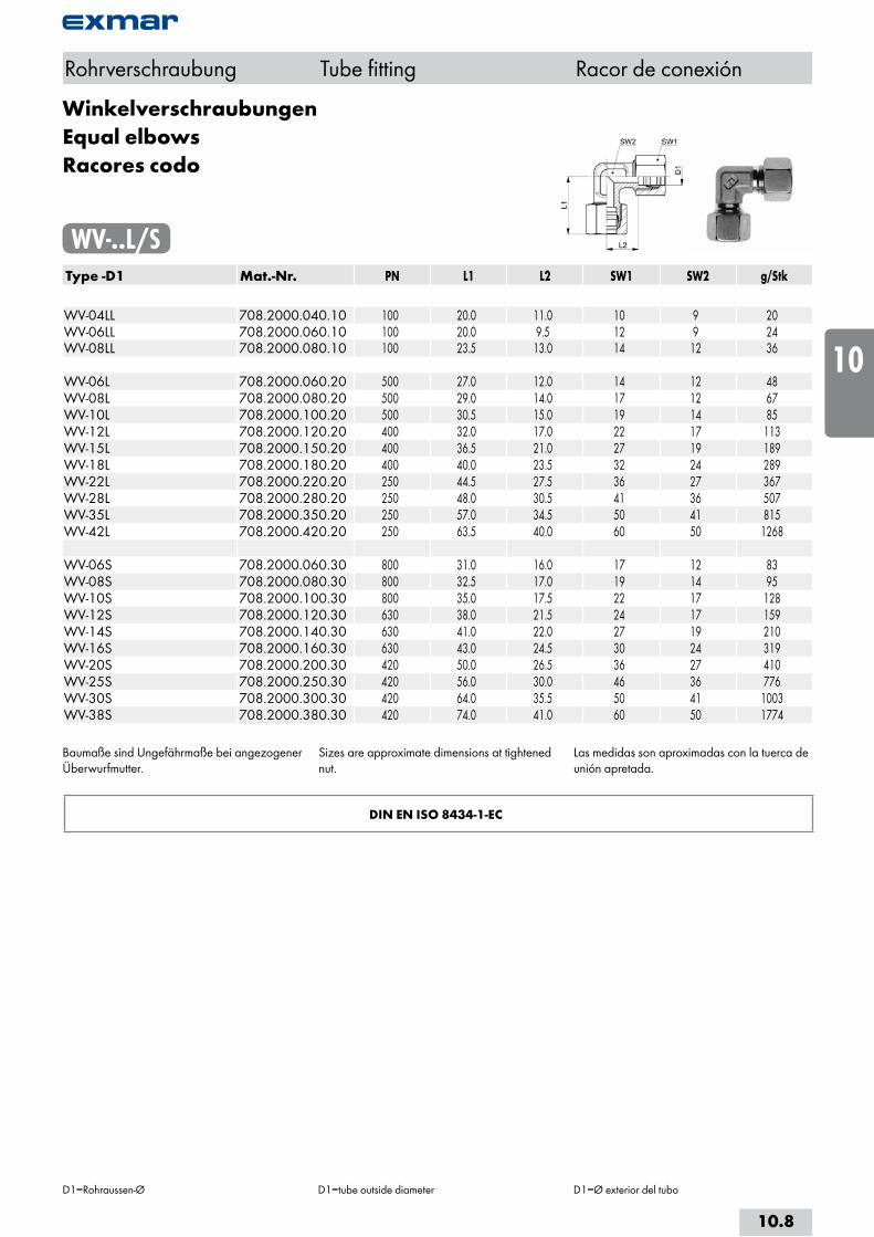
WinkelverschraubungenEqual elbowsRacores codo
WV-..L/SType -D1 Mat.-Nr. PN L1 L2 SW1 SW2 g/Stk WV-04LL 708.2000.040.10 100 20.0 11.0 10 9 20WV-06LL 708.2000.060.10 100 20.0 9.5 12 9 24WV-08LL 708.2000.080.10 100 23.5 13.0 14 12 36 WV-06L 708.2000.060.20 500 27.0 12.0 14 12 48WV-08L 708.2000.080.20 500 29.0 14.0 17 12 67WV-10L 708.2000.100.20 500 30.5 15.0 19 14 85WV-12L 708.2000.120.20 400 32.0 17.0 22 17 113WV-15L 708.2000.150.20 400 36.5 21.0 27 19 189WV-18L 708.2000.180.20 400 40.0 23.5 32 24 289WV-22L 708.2000.220.20 250 44.5 27.5 36 27 367WV-28L 708.2000.280.20 250 48.0 30.5 41 36 507WV-35L 708.2000.350.20 250 57.0 34.5 50 41 815WV-42L 708.2000.420.20 250 63.5 40.0 60 50 1268 WV-06S 708.2000.060.30 800 31.0 16.0 17 12 83WV-08S 708.2000.080.30 800 32.5 17.0 19 14 95WV-10S 708.2000.100.30 800 35.0 17.5 22 17 128WV-12S 708.2000.120.30 630 38.0 21.5 24 17 159WV-14S 708.2000.140.30 630 41.0 22.0 27 19 210WV-16S 708.2000.160.30 630 43.0 24.5 30 24 319WV-20S 708.2000.200.30 420 50.0 26.5 36 27 410WV-25S 708.2000.250.30 420 56.0 30.0 46 36 776WV-30S 708.2000.300.30 420 64.0 35.5 50 41 1003WV-38S 708.2000.380.30 420 74.0 41.0 60 50 1774
Baumaße sind Ungefährmaße bei angezogener Überwurfmutter.
Sizes are approximate dimensions at tightened nut.
Las medidas son aproximadas con la tuerca de unión apretada.
DIN EN ISO 8434-1-EC
Rohrverschraubung Tube fitting Racor de conexión
D1=Rohraussen-Ø D1=tube outside diameter D1=Ø exterior del tubo
10.8
i
s
10
20
30
40
50
60
70
a

T-VerschraubungenEqual teesRacores T
TV-..L/SType -D1 Mat.-Nr. PN L1 L2 SW1 SW2 g/Stk TV-04LL 708.3000.040.10 100 20.0 11.0 10 12 33TV-06LL 708.3000.060.10 100 20.0 9.5 12 12 40TV-08LL 708.3000.080.10 100 22.0 11.5 14 12 49 TV-06L 708.3000.060.20 500 27.0 12.0 14 12 71TV-08L 708.3000.080.20 500 29.0 14.0 17 12 85TV-10L 708.3000.100.20 500 30.5 15.0 19 14 118TV-12L 708.3000.120.20 400 32.0 17.0 22 17 157TV-15L 708.3000.150.20 400 36.5 21.0 27 19 240TV-18L 708.3000.180.20 400 40.0 23.5 32 24 381TV-22L 708.3000.220.20 250 44.5 27.5 36 27 468TV-28L 708.3000.280.20 250 48.0 30.5 41 36 665TV-35L 708.3000.350.20 250 57.0 34.5 50 41 1025TV-42L 708.3000.420.20 250 63.5 40.0 60 50 1614 TV-06S 708.3000.060.30 800 31.0 16.0 17 12 116TV-08S 708.3000.080.30 800 32.5 17.0 19 14 134TV-10S 708.3000.100.30 800 35.0 17.5 22 17 190TV-12S 708.3000.120.30 630 38.0 21.5 24 17 227TV-14S 708.3000.140.30 630 41.0 22.0 27 19 300TV-16S 708.3000.160.30 630 43.0 24.5 30 24 426TV-20S 708.3000.200.30 420 50.0 26.5 36 27 590TV-25S 708.3000.250.30 420 56.0 30.0 46 36 1180TV-30S 708.3000.300.30 420 64.0 35.5 50 41 1430TV-38S 708.3000.380.30 420 74.0 41.0 60 50 2337
Baumaße sind Ungefährmaße bei angezogener Überwurfmutter.
Sizes are approximate dimensions at tightened nut.
Las medidas son aproximadas con la tuerca de unión apretada.
DIN EN ISO 8434-1-TC
Rohrverschraubung Tube fitting Racor de conexión
D1=Rohraussen-Ø D1=tube outside diameter D1=Ø exterior del tubo
10.9

Kreuz-VerschraubungenEqual crossesRacores en cruz
KV-..L/SType -D1 Mat.-Nr. PN L1 L2 SW1 SW2 g/Stk KV-04LL 708.4000.040.10 100 21.0 11.0 10 9 32KV-06LL 708.4000.060.10 100 21.0 9.5 12 9 40KV-08LL 708.4000.080.10 100 23.0 11.5 14 12 61 KV-06L 708.4000.060.20 500 27.0 12.0 14 12 80KV-08L 708.4000.080.20 500 29.0 14.0 17 12 109KV-10L 708.4000.100.20 500 30.5 15.0 19 14 158KV-12L 708.4000.120.20 400 32.0 17.0 22 17 185KV-15L 708.4000.150.20 400 36.5 21.0 27 19 338KV-18L 708.4000.180.20 400 40.0 23.5 32 24 445KV-22L 708.4000.220.20 250 44.5 27.5 36 27 600KV-28L 708.4000.280.20 250 48.0 30.5 41 36 810KV-35L 708.4000.350.20 250 57.0 34.5 50 41 1250KV-42L 708.4000.420.20 250 63.5 40.0 60 50 1880 KV-06S 708.4000.060.30 800 31.0 16.0 17 12 140KV-08S 708.4000.080.30 800 32.5 17.0 19 14 175KV-10S 708.4000.100.30 800 35.0 17.5 22 17 235KV-12S 708.4000.120.30 630 37.0 21.5 24 17 315KV-14S 708.4000.140.30 630 41.0 22.0 27 19 385KV-16S 708.4000.160.30 630 43.0 24.5 30 24 500KV-20S 708.4000.200.30 420 50.0 26.5 36 27 857KV-25S 708.4000.250.30 420 56.0 30.0 46 36 1250KV-30S 708.4000.300.30 420 64.0 35.5 50 41 1540KV-38S 708.4000.380.30 420 74.0 41.0 60 50 3076
Baumaße sind Ungefährmaße bei angezogener Überwurfmutter.
Sizes are approximate dimensions at tightened nut.
Las medidas son aproximadas con la tuerca de unión apretada.
DIN EN ISO 8434-1-KC
Rohrverschraubung Tube fitting Racor de conexión
D1=Rohraussen-Ø D1=tube outside diameter D1=Ø exterior del tubo
10.10
i
s
10
20
30
40
50
60
70
a

Gerade Zwischenstutzenmit Dichtkegel und O-Ring
Straight couplingswith taper and O-ring
Racor de unión recto con junta cónica y junta tórica
VKO-..L/SType -D1 Mat.-Nr. PN L1 L2 SW1 g/Stk VKO-06L 708.1070.060.20 315 35.0 32.0 17 48VKO-08L 708.1070.080.20 315 36.0 32.0 17 42VKO-10L 708.1070.100.20 315 37.0 33.0 19 56VKO-12L 708.1070.120.20 315 37.5 33.0 22 78VKO-15L 708.1070.150.20 315 44.5 38.0 27 128VKO-18L 708.1070.180.20 315 39.0 36.0 32 182VKO-22L 708.1070.220.20 160 48.5 42.0 36 254VKO-28L 708.1070.280.20 160 54.5 46.0 46 440VKO-35L 708.1070.350.20 160 55.5 48.0 50 486VKO-42L 708.1070.420.20 160 60.5 52.0 60 712 VKO-06S 708.1070.060.30 630 36.0 32.0 17 44VKO-08S 708.1070.080.30 630 37.0 33.0 19 60VKO-10S 708.1070.100.30 630 37.5 33.0 22 84VKO-12S 708.1070.120.30 630 42.5 36.0 24 110VKO-14S 708.1070.140.30 630 45.5 39.0 27 142VKO-16S 708.1070.160.30 400 45.5 39.0 30 182VKO-20S 708.1070.200.30 400 50.5 44.0 36 300VKO-25S 708.1070.250.30 400 54.5 46.0 46 481VKO-30S 708.1070.300.30 400 58.5 52.0 50 646VKO-38S 708.1070.380.30 315 60.5 52.0 60 936
Rohrverschraubung Tube fitting Racor de conexión
D1=Rohraussen-Ø D1=tube outside diameter D1=Ø exterior del tubo
10.11

Gerade SchottverschraubungenBulkhead couplingsRacores pasatabiques rectos
GSV-..L/SType -D1 Mat.-Nr. PN M L1 L2 L3 SW1 SW2 SW3 g/StkM=metrisches Gewinde (zylindrisch) M=metric thread (straight) M=rosca métrica (cilindrica) GSV-06L 708.1500.060.20 500 12x1.5 64.0 7.0 27.0 14 17 17 72GSV-08L 708.1500.080.20 500 14x1.5 65.0 8.0 27.0 17 19 19 83GSV-10L 708.1500.100.20 500 16x1.5 68.0 10.0 28.0 19 22 22 125GSV-12L 708.1500.120.20 400 18x1.5 69.0 10.0 29.0 22 24 24 135GSV-15L 708.1500.150.20 400 22x1.5 73.0 12.0 31.0 27 27 30 230GSV-18L 708.1500.180.20 400 26x1.5 79.0 13.5 32.5 32 32 36 345GSV-22L 708.1500.220.20 250 30x2.0 84.0 16.5 34.5 36 36 41 435GSV-28L 708.1500.280.20 250 36x2.0 87.0 18.5 35.5 41 41 46 545GSV-35L 708.1500.350.20 250 45x2.0 98.0 18.5 36.5 50 50 55 874GSV-42L 708.1500.420.20 250 52x2.0 101.0 19.0 36.0 60 60 65 1365 GSV-06S 708.1500.060.30 800 14x1.5 71.0 12.0 29.0 17 19 19 112GSV-08S 708.1500.080.30 800 16x1.5 72.0 13.0 29.0 19 22 22 132GSV-10S 708.1500.100.30 800 18x1.5 75.0 14.5 29.5 22 24 24 170GSV-12S 708.1500.120.30 630 20x1.5 78.0 14.5 30.5 24 24 27 215GSV-14S 708.1500.140.30 630 22x1.5 81.0 17.0 32.0 27 27 30 322GSV-16S 708.1500.160.30 630 24x1.5 85.0 16.5 31.5 30 32 32 345GSV-20S 708.1500.200.30 420 30x2.0 90.0 17.5 33.5 36 41 41 575GSV-25S 708.1500.250.30 420 36x2.0 97.0 20.0 35.0 46 46 46 949GSV-30S 708.1500.300.30 420 42x2.0 112.0 21.5 37.5 50 50 50 1120GSV-38S 708.1500.380.30 420 52x2.0 121.0 22.0 37.0 60 65 65 1934
Baumaße sind Ungefährmaße bei angezogener Überwurfmutter.
für D1 ≤ 18 mm L6 = 3 mm für D1 > 18 mm L6 = 4 mm
Sizes are approximate dimensions at tightened nut.
for D1 ≤ 18 mm L6 = 3 mm for D1 > 18 mm L6 = 4 mm
Las medidas son aproximadas con la tuerca de unión apretada.
para D1 ≤ 18 mm L6 = 3 mmpara D1 > 18 mm L6 = 4 mm
DIN EN ISO 8434-1-BHC
Rohrverschraubung Tube fitting Racor de conexión
D1=Rohraussen-Ø D1=tube outside diameter D1=Ø exterior del tubo
10.12
i
s
10
20
30
40
50
60
70
a
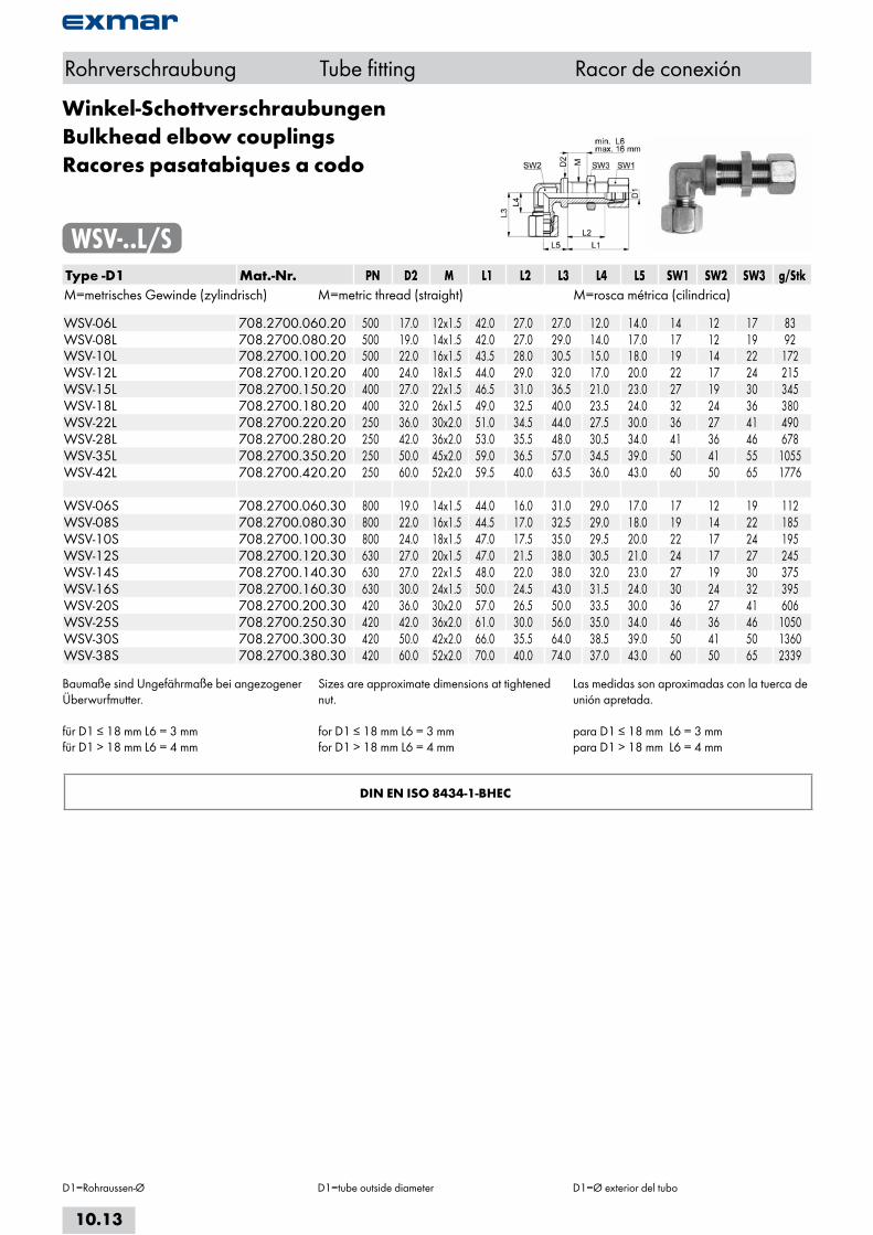
Winkel-SchottverschraubungenBulkhead elbow couplingsRacores pasatabiques a codo
WSV-..L/SType -D1 Mat.-Nr. PN D2 M L1 L2 L3 L4 L5 SW1 SW2 SW3 g/StkM=metrisches Gewinde (zylindrisch) M=metric thread (straight) M=rosca métrica (cilindrica) WSV-06L 708.2700.060.20 500 17.0 12x1.5 42.0 27.0 27.0 12.0 14.0 14 12 17 83WSV-08L 708.2700.080.20 500 19.0 14x1.5 42.0 27.0 29.0 14.0 17.0 17 12 19 92WSV-10L 708.2700.100.20 500 22.0 16x1.5 43.5 28.0 30.5 15.0 18.0 19 14 22 172WSV-12L 708.2700.120.20 400 24.0 18x1.5 44.0 29.0 32.0 17.0 20.0 22 17 24 215WSV-15L 708.2700.150.20 400 27.0 22x1.5 46.5 31.0 36.5 21.0 23.0 27 19 30 345WSV-18L 708.2700.180.20 400 32.0 26x1.5 49.0 32.5 40.0 23.5 24.0 32 24 36 380WSV-22L 708.2700.220.20 250 36.0 30x2.0 51.0 34.5 44.0 27.5 30.0 36 27 41 490WSV-28L 708.2700.280.20 250 42.0 36x2.0 53.0 35.5 48.0 30.5 34.0 41 36 46 678WSV-35L 708.2700.350.20 250 50.0 45x2.0 59.0 36.5 57.0 34.5 39.0 50 41 55 1055WSV-42L 708.2700.420.20 250 60.0 52x2.0 59.5 40.0 63.5 36.0 43.0 60 50 65 1776 WSV-06S 708.2700.060.30 800 19.0 14x1.5 44.0 16.0 31.0 29.0 17.0 17 12 19 112WSV-08S 708.2700.080.30 800 22.0 16x1.5 44.5 17.0 32.5 29.0 18.0 19 14 22 185WSV-10S 708.2700.100.30 800 24.0 18x1.5 47.0 17.5 35.0 29.5 20.0 22 17 24 195WSV-12S 708.2700.120.30 630 27.0 20x1.5 47.0 21.5 38.0 30.5 21.0 24 17 27 245WSV-14S 708.2700.140.30 630 27.0 22x1.5 48.0 22.0 38.0 32.0 23.0 27 19 30 375WSV-16S 708.2700.160.30 630 30.0 24x1.5 50.0 24.5 43.0 31.5 24.0 30 24 32 395WSV-20S 708.2700.200.30 420 36.0 30x2.0 57.0 26.5 50.0 33.5 30.0 36 27 41 606WSV-25S 708.2700.250.30 420 42.0 36x2.0 61.0 30.0 56.0 35.0 34.0 46 36 46 1050WSV-30S 708.2700.300.30 420 50.0 42x2.0 66.0 35.5 64.0 38.5 39.0 50 41 50 1360WSV-38S 708.2700.380.30 420 60.0 52x2.0 70.0 40.0 74.0 37.0 43.0 60 50 65 2339
Baumaße sind Ungefährmaße bei angezogener Überwurfmutter.
für D1 ≤ 18 mm L6 = 3 mm für D1 > 18 mm L6 = 4 mm
Sizes are approximate dimensions at tightened nut.
for D1 ≤ 18 mm L6 = 3 mm for D1 > 18 mm L6 = 4 mm
Las medidas son aproximadas con la tuerca de unión apretada.
para D1 ≤ 18 mm L6 = 3 mmpara D1 > 18 mm L6 = 4 mm
DIN EN ISO 8434-1-BHEC
Rohrverschraubung Tube fitting Racor de conexión
D1=Rohraussen-Ø D1=tube outside diameter D1=Ø exterior del tubo
10.13

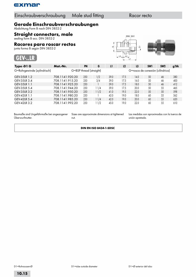
Gerade EinschraubverschraubungenAbdichtung Form B nach DIN 3852-2
Straight connectors, malesealing form B acc. DIN 3852-2
Racores para roscar rectosjunta forma B según DIN 3852-2
GEV-..LRType -D1 G Mat.-Nr. PN G L1 L2 L3 SW1 SW2 g/StkG=Rohrgewinde (zylindrisch) G=BSP thread (straight) G=rosca de conexión (cilíndrica) GEV-04LLR 1.8 708.1141.060.10 100 1/8 19.5 9.5 8.0 10 14 15GEV-06LLR 1.8 708.1141.100.10 100 1/8 19.5 8.0 8.0 12 14 19GEV-08LLR 1.8 708.1141.160.10 100 1/8 22.5 9.0 8.0 14 14 20 GEV-06LR 1.8 708.1141.100.20 500 1/8 23.5 8.5 8.0 14 14 25GEV-06LR 1.4 708.1141.110.20 500 1/4 25.0 10.0 12.0 14 19 40GEV-06LR 3.8 708.1141.120.20 500 3/8 26.5 11.5 12.0 14 22 58GEV-06LR 1.2 708.1141.125.20 500 1/2 28.0 13.0 14.0 14 27 100GEV-08LR 1.8 708.1141.160.20 500 1/8 23.5 8.5 8.0 17 14 32GEV-08LR 1.4 708.1141.170.20 500 1/4 25.0 10.0 12.0 17 19 43GEV-08LR 3.8 708.1141.180.20 500 3/8 27.5 12.5 12.0 17 22 59GEV-08LR 1.2 708.1141.185.20 500 1/2 28.0 13.0 14.0 17 27 99GEV-10LR 1.8 708.1141.265.20 500 1/8 25.5 10.5 8.0 19 17 43GEV-10LR 1.4 708.1141.270.20 500 1/4 26.0 11.0 12.0 19 19 50GEV-10LR 3.8 708.1141.280.20 500 3/8 27.5 12.5 12.0 19 22 64GEV-10LR 1.2 708.1141.285.20 500 1/2 28.0 14.0 14.0 19 27 102GEV-12LR 1.8 708.1141.375.20 400 1/8 25.0 11.5 8.0 22 19 58GEV-12LR 1.4 708.1141.380.20 400 1/4 27.0 12.0 12.0 22 19 62GEV-12LR 3.8 708.1141.390.20 400 3/8 27.5 12.5 12.0 22 22 70GEV-12LR 1.2 708.1141.400.20 400 1/2 28.0 13.0 14.0 22 27 101GEV-12LR 3.4 708.1141.405.20 400 3/4 29.0 14.0 16.0 22 32 104GEV-15LR 1.4 708.1141.528.20 400 1/4 28.0 13.0 12.0 27 24 98GEV-15LR 3.8 708.1141.532.20 400 3/8 28.5 13.5 12.0 27 24 102GEV-15LR 1.2 708.1141.534.20 400 1/2 29.0 14.0 14.0 27 27 114GEV-15LR 3.4 708.1141.536.20 400 3/4 30.0 15.0 16.0 27 32 172GEV-18LR 3.8 708.1141.644.20 400 3/8 31.0 14.5 12.0 32 27 136GEV-18LR 1.2 708.1141.646.20 400 1/2 31.0 14.5 14.0 32 27 142GEV-18LR 3.4 708.1141.648.20 400 3/4 31.0 14.5 16.0 32 32 185GEV-22LR 3.8 708.1141.763.20 250 3/8 30.0 16.0 12.0 36 32 180GEV-22LR 1.2 708.1141.764.20 250 1/2 33.0 16.5 14.0 36 32 200GEV-22LR 3.4 708.1141.768.20 250 3/4 33.0 16.5 16.0 36 32 196GEV-22LR 1.1 708.1141.770.20 250 1 34.0 17.5 18.0 36 41 289GEV-22LR 5.4 708.1141.771.20 250 1 1/4 35.0 18.5 20.0 36 50 368GEV-28LR 1.2 708.1141.840.20 250 1/2 34.0 17.5 14.0 41 41 210GEV-28LR 3.4 708.1141.845.20 250 3/4 34.0 17.5 16.0 41 41 230GEV-28LR 1.1 708.1141.850.20 250 1 34.0 17.5 18.0 41 41 270GEV-28LR 5.4 708.1141.860.20 250 1 1/4 35.0 18.5 20.0 41 50 247
Fortsetzung nächste Seite Continued on next page Continuación página próxima
Einschraubverschraubung Male stud fitting Racor recto
D1=Rohraussen-Ø D1=tube outside diameter D1=Ø exterior del tubo
10.14
i
s
10
20
30
40
50
60
70
a
Gerade EinschraubverschraubungenAbdichtung Form B nach DIN 3852-2
Straight connectors, malesealing form B acc. DIN 3852-2
Racores para roscar rectosjunta forma B según DIN 3852-2
GEV-..LRType -D1 G Mat.-Nr. PN G L1 L2 L3 SW1 SW2 g/StkG=Rohrgewinde (zylindrisch) G=BSP thread (straight) G=rosca de conexión (cilíndrica) GEV-35LR 1.2 708.1141.920.20 250 1/2 39.0 17.5 14.0 50 46 380GEV-35LR 3.4 708.1141.915.20 250 3/4 39.0 17.5 16.0 50 46 400GEV-35LR 1.1 708.1141.925.20 250 1 39.0 17.5 18.0 50 46 412GEV-35LR 5.4 708.1141.944.20 250 1 1/4 39.0 17.5 20.0 50 55 465GEV-35LR 3.2 708.1141.950.20 250 1 1/2 41.0 19.5 22.0 50 50 598GEV-42LR 1.1 708.1141.980.20 250 1 42.0 19.0 18.0 60 55 562GEV-42LR 5.4 708.1141.985.20 250 1 1/4 42.0 19.0 20.0 60 55 620GEV-42LR 3.2 708.1141.992.20 250 1 1/2 45.0 19.0 22.0 60 55 610
Baumaße sind Ungefährmaße bei angezogener Überwurfmutter.
Sizes are approximate dimensions at tightened nut.
Las medidas son aproximadas con la tuerca de unión apretada.
DIN EN ISO 8434-1-SDSC
Einschraubverschraubung Male stud fitting Racor recto
D1=Rohraussen-Ø D1=tube outside diameter D1=Ø exterior del tubo
10.15
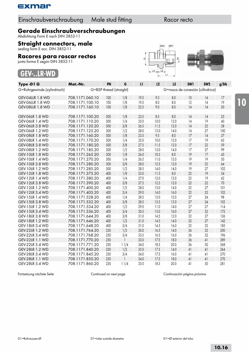
Gerade EinschraubverschraubungenAbdichtung Form E nach DIN 3852-11
Straight connectors, malesealing form E acc. DIN 3852-11
Racores para roscar rectosjunta forma E según DIN 3852-11
GEV-..LR-WDType -D1 G Mat.-Nr. PN G L1 L2 L3 SW1 SW2 g/StkG=Rohrgewinde (zylindrisch) G=BSP thread (straight) G=rosca de conexión (cilíndrica) GEV-04LLR 1.8 WD 708.1171.060.10 100 1/8 19.5 9.5 8.0 10 14 17GEV-06LLR 1.8 WD 708.1171.100.10 100 1/8 19.5 8.0 8.0 12 14 19GEV-08LLR 1.8 WD 708.1171.160.10 100 1/8 22.5 9.0 8.0 14 14 20 GEV-06LR 1.8 WD 708.1171.100.20 500 1/8 23.5 8.5 8.0 14 14 25GEV-06LR 1.4 WD 708.1171.110.20 500 1/4 25.0 10.0 12.0 14 19 40GEV-06LR 3.8 WD 708.1171.120.20 500 3/8 26.5 11.5 12.0 14 22 58GEV-06LR 1.2 WD 708.1171.125.20 500 1/2 28.0 13.0 14.0 14 27 100GEV-08LR 1.8 WD 708.1171.160.20 500 1/8 23.5 9.5 8.0 17 14 37GEV-08LR 1.4 WD 708.1171.170.20 500 1/4 25.0 10.0 12.0 17 19 63GEV-08LR 3.8 WD 708.1171.180.20 500 3/8 27.5 11.5 12.0 17 22 59GEV-08LR 1.2 WD 708.1171.185.20 500 1/2 28.0 13.0 14.0 17 27 99GEV-10LR 1.8 WD 708.1171.265.20 500 1/8 26.0 10.5 8.0 19 17 43GEV-10LR 1.4 WD 708.1171.270.20 500 1/4 26.5 11.0 12.0 19 19 50GEV-10LR 3.8 WD 708.1171.280.20 500 3/8 28.0 12.5 12.0 19 22 64GEV-10LR 1.2 WD 708.1171.285.20 500 1/2 28.5 14.0 14.0 19 27 102GEV-12LR 1.8 WD 708.1171.375.20 400 1/8 25.0 11.5 8.0 22 19 54GEV-12LR 1.4 WD 708.1171.380.20 400 1/4 27.0 12.0 12.0 22 19 62GEV-12LR 3.8 WD 708.1171.390.20 400 3/8 27.5 12.5 12.0 22 22 70GEV-12LR 1.2 WD 708.1171.400.20 400 1/2 28.0 13.0 14.0 22 27 101GEV-12LR 3.4 WD 708.1171.405.20 400 3/4 29.0 14.0 16.0 22 32 102GEV-15LR 1.4 WD 708.1171.528.20 400 1/4 28.5 13.0 12.0 27 24 98GEV-15LR 3.8 WD 708.1171.532.20 400 3/8 28.5 13.5 12.0 27 24 102GEV-15LR 1.2 WD 708.1171.534.20 400 1/2 29.0 11.0 14.0 27 27 114GEV-15LR 3.4 WD 708.1171.536.20 400 3/4 30.5 15.0 16.0 27 32 172GEV-18LR 3.8 WD 708.1171.644.20 400 3/8 31.0 14.5 12.0 32 27 136GEV-18LR 1.2 WD 708.1171.646.20 400 1/2 31.0 14.5 14.0 32 27 142GEV-18LR 3.4 WD 708.1171.648.20 400 3/4 31.0 14.5 16.0 32 32 185GEV-22LR 1.2 WD 708.1171.764.20 250 1/2 30.0 16.5 14.0 36 32 200GEV-22LR 3.4 WD 708.1171.768.20 250 3/4 33.5 16.5 16.0 36 32 196GEV-22LR 1.1 WD 708.1171.770.20 250 1 33.0 17.5 18.0 36 41 289GEV-22LR 5.4 WD 708.1171.771.20 250 1 1/4 34.0 18.5 20.0 36 50 368GEV-28LR 1.2 WD 708.1171.840.20 250 1/2 35.0 17.5 14.0 41 41 264GEV-28LR 3.4 WD 708.1171.845.20 250 3/4 34.0 17.5 16.0 41 41 270GEV-28LR 1.1 WD 708.1171.850.20 250 1 34.0 17.5 18.0 41 41 270GEV-28LR 5.4 WD 708.1171.860.20 250 1 1/4 35.0 18.5 20.0 41 50 281
Fortsetzung nächste Seite Continued on next page Continuación página próxima
Einschraubverschraubung Male stud fitting Racor recto
D1=Rohraussen-Ø D1=tube outside diametre D1=Ø exterior del tubo
10.16
i
s
10
20
30
40
50
60
70
a
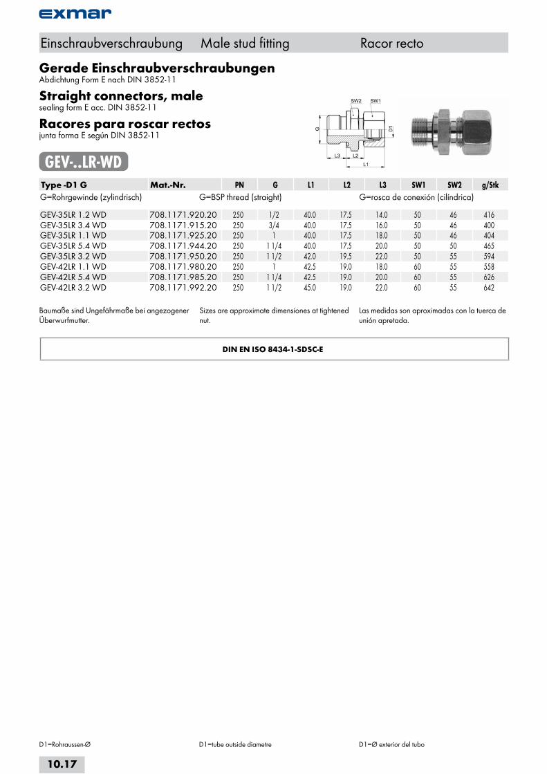
Gerade EinschraubverschraubungenAbdichtung Form E nach DIN 3852-11
Straight connectors, malesealing form E acc. DIN 3852-11
Racores para roscar rectosjunta forma E según DIN 3852-11
GEV-..LR-WDType -D1 G Mat.-Nr. PN G L1 L2 L3 SW1 SW2 g/StkG=Rohrgewinde (zylindrisch) G=BSP thread (straight) G=rosca de conexión (cilíndrica) GEV-35LR 1.2 WD 708.1171.920.20 250 1/2 40.0 17.5 14.0 50 46 416GEV-35LR 3.4 WD 708.1171.915.20 250 3/4 40.0 17.5 16.0 50 46 400GEV-35LR 1.1 WD 708.1171.925.20 250 1 40.0 17.5 18.0 50 46 404GEV-35LR 5.4 WD 708.1171.944.20 250 1 1/4 40.0 17.5 20.0 50 50 465GEV-35LR 3.2 WD 708.1171.950.20 250 1 1/2 42.0 19.5 22.0 50 55 594GEV-42LR 1.1 WD 708.1171.980.20 250 1 42.5 19.0 18.0 60 55 558GEV-42LR 5.4 WD 708.1171.985.20 250 1 1/4 42.5 19.0 20.0 60 55 626GEV-42LR 3.2 WD 708.1171.992.20 250 1 1/2 45.0 19.0 22.0 60 55 642
Baumaße sind Ungefährmaße bei angezogener Überwurfmutter.
Sizes are approximate dimensiones at tightened nut.
Las medidas son aproximadas con la tuerca de unión apretada.
DIN EN ISO 8434-1-SDSC-E
Einschraubverschraubung Male stud fitting Racor recto
D1=Rohraussen-Ø D1=tube outside diametre D1=Ø exterior del tubo
10.17

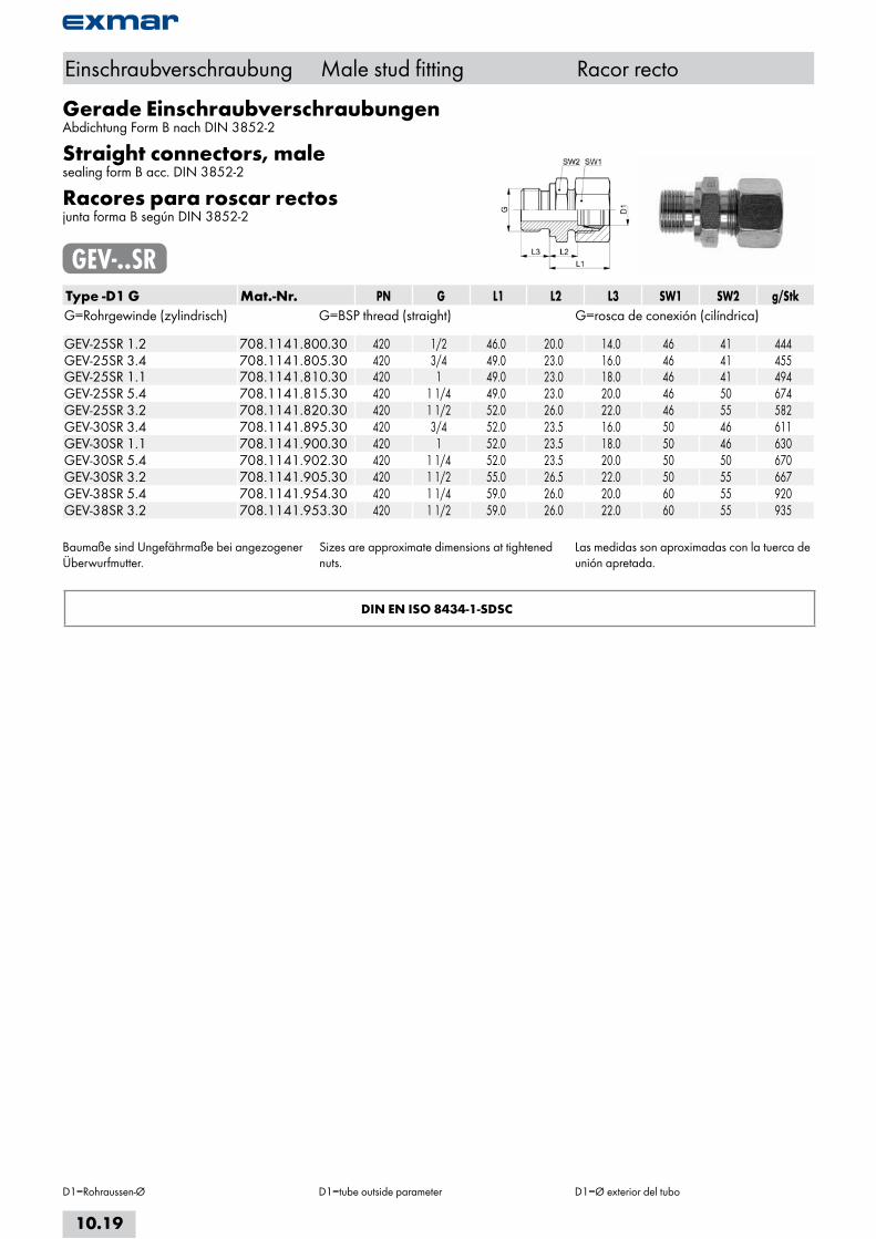
Gerade EinschraubverschraubungenAbdichtung Form B nach DIN 3852-2
Straight connectors, malesealing form B acc. DIN 3852-2
Racores para roscar rectosjunta forma B según DIN 3852-2
GEV-..SRType -D1 G Mat.-Nr. PN G L1 L2 L3 SW1 SW2 g/StkG=Rohrgewinde (zylindrisch) G=BSP thread (straight) G=rosca de conexión (cilíndrica) GEV-06SR 1.8 708.1141.100.30 800 1/8 27.5 12.5 8.0 17 14 40GEV-06SR 1.4 708.1141.110.30 800 1/4 28.0 13.0 12.0 17 19 54GEV-06SR 3.8 708.1141.120.30 800 3/8 30.5 15.5 12.0 17 22 63GEV-06SR 1.2 708.1141.125.30 800 1/2 33.0 18.0 12.0 17 27 107GEV-06SR 3.4 708.1141.126.30 800 3/4 35.0 20.0 12.0 17 32 152GEV-08SR 1.8 708.1141.160.30 800 1/8 30.0 14.5 12.0 19 17 58GEV-08SR 1.4 708.1141.170.30 800 1/4 30.5 15.0 12.0 19 19 63GEV-08SR 3.8 708.1141.180.30 800 3/8 31.0 15.5 12.0 19 22 82GEV-08SR 1.2 708.1141.185.30 800 1/2 33.5 18.0 14.0 19 27 108GEV-10SR 1.8 708.1141.265.30 800 1/8 31.5 14.0 8.0 22 19 77GEV-10SR 1.4 708.1141.270.30 800 1/4 32.0 14.5 12.0 22 19 73GEV-10SR 3.8 708.1141.280.30 800 3/8 32.5 15.0 12.0 22 22 89GEV-10SR 1.2 708.1141.285.30 800 1/2 35.0 17.5 14.0 22 27 125GEV-10SR 3.4 708.1141.290.30 800 3/4 37.0 19.5 16.0 22 32 208GEV-12SR 1.4 708.1141.380.30 630 1/4 33.0 16.5 12.0 24 22 91GEV-12SR 3.8 708.1141.390.30 630 3/8 33.5 17.0 12.0 24 22 100GEV-12SR 1.2 708.1141.400.30 630 1/2 34.0 17.5 14.0 24 27 135GEV-12SR 3.4 708.1141.405.30 630 3/4 34.0 17.5 16.0 24 32 192GEV-14SR 1.4 708.1141.500.30 630 1/4 35.0 16.0 12.0 27 24 118GEV-14SR 3.8 708.1141.502.30 630 3/8 37.5 18.5 12.0 27 24 130GEV-14SR 1.2 708.1141.504.30 630 1/2 38.0 19.0 14.0 27 27 154GEV-14SR 3.4 708.1141.506.30 630 3/4 40.0 21.0 16.0 27 32 195GEV-14SR 1.1 708.1141.510.30 630 1 42.0 23.0 18.0 27 41 350GEV-16SR 3.8 708.1141.564.30 630 3/8 36.5 18.0 12.0 30 27 156GEV-16SR 1.2 708.1141.566.30 630 1/2 37.0 18.5 14.0 30 27 161GEV-16SR 3.4 708.1141.568.30 630 3/4 39.0 20.5 16.0 30 32 240GEV-16SR 1.1 708.1141.570.30 630 1 41.0 22.5 18.0 30 41 348GEV-20SR 1.2 708.1141.706.30 420 1/2 44.0 20.5 14.0 36 32 245GEV-20SR 3.4 708.1141.708.30 420 3/4 44.0 20.5 16.0 36 32 277GEV-20SR 1.1 708.1141.712.30 420 1 46.0 22.5 18.0 36 41 387GEV-20SR 5.4 708.1141.715.30 420 1 1/4 46.0 22.5 20.0 36 50 574GEV-20SR 3.2 708.1141.717.30 420 1 1/2 49.0 25.5 22.0 36 55 778
Fortsetzung nächste Seite Continued on next page Continuación página próxima
Einschraubverschraubung Male stud fitting Racor recto
D1=Rohraussen-Ø D1=tube outside parameter D1=Ø exterior del tubo
10.18
i
s
10
20
30
40
50
60
70
a
Gerade EinschraubverschraubungenAbdichtung Form B nach DIN 3852-2
Straight connectors, malesealing form B acc. DIN 3852-2
Racores para roscar rectosjunta forma B según DIN 3852-2
GEV-..SRType -D1 G Mat.-Nr. PN G L1 L2 L3 SW1 SW2 g/StkG=Rohrgewinde (zylindrisch) G=BSP thread (straight) G=rosca de conexión (cilíndrica) GEV-25SR 1.2 708.1141.800.30 420 1/2 46.0 20.0 14.0 46 41 444GEV-25SR 3.4 708.1141.805.30 420 3/4 49.0 23.0 16.0 46 41 455GEV-25SR 1.1 708.1141.810.30 420 1 49.0 23.0 18.0 46 41 494GEV-25SR 5.4 708.1141.815.30 420 1 1/4 49.0 23.0 20.0 46 50 674GEV-25SR 3.2 708.1141.820.30 420 1 1/2 52.0 26.0 22.0 46 55 582GEV-30SR 3.4 708.1141.895.30 420 3/4 52.0 23.5 16.0 50 46 611GEV-30SR 1.1 708.1141.900.30 420 1 52.0 23.5 18.0 50 46 630GEV-30SR 5.4 708.1141.902.30 420 1 1/4 52.0 23.5 20.0 50 50 670GEV-30SR 3.2 708.1141.905.30 420 1 1/2 55.0 26.5 22.0 50 55 667GEV-38SR 5.4 708.1141.954.30 420 1 1/4 59.0 26.0 20.0 60 55 920GEV-38SR 3.2 708.1141.953.30 420 1 1/2 59.0 26.0 22.0 60 55 935
Baumaße sind Ungefährmaße bei angezogener Überwurfmutter.
Sizes are approximate dimensions at tightened nuts.
Las medidas son aproximadas con la tuerca de unión apretada.
DIN EN ISO 8434-1-SDSC
Einschraubverschraubung Male stud fitting Racor recto
D1=Rohraussen-Ø D1=tube outside parameter D1=Ø exterior del tubo
10.19

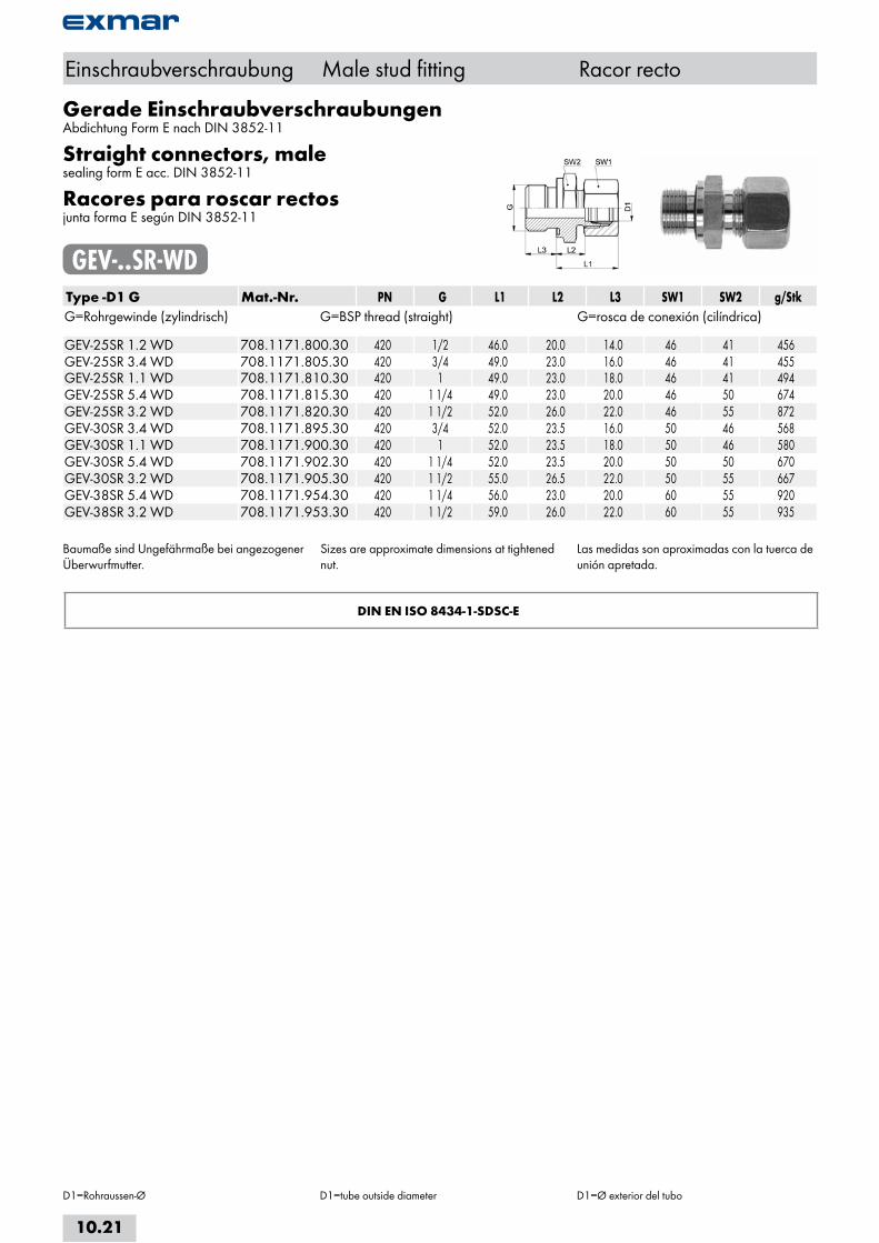
Gerade EinschraubverschraubungenAbdichtung Form E nach DIN 3852-11
Straight connectors, malesealing form E acc. DIN 3852-11
Racores para roscar rectosjunta forma E según DIN 3852-11
GEV-..SR-WDType -D1 G Mat.-Nr. PN G L1 L2 L3 SW1 SW2 g/StkG=Rohrgewinde (zylindrisch) G=BSP thread (straight) G=rosca de conexión (cilíndrica) GEV-06SR 1.8 WD 708.1171.100.30 800 1/8 27.5 12.5 8.0 17 14 40GEV-06SR 1.4 WD 708.1171.110.30 800 1/4 28.0 13.0 12.0 17 19 54GEV-06SR 3.8 WD 708.1171.120.30 800 3/8 30.5 15.5 12.0 17 22 63GEV-06SR 1.2 WD 708.1171.125.30 800 1/2 33.0 18.0 14.0 17 27 107GEV-08SR 1.8 WD 708.1171.160.30 800 1/8 29.5 14.5 8.0 19 17 42GEV-08SR 1.4 WD 708.1171.170.30 800 1/4 30.0 14.5 12.0 19 19 63GEV-08SR 3.8 WD 708.1171.180.30 800 3/8 31.0 15.5 12.0 19 22 82GEV-08SR 1.2 WD 708.1171.185.30 800 1/2 33.5 18.0 14.0 19 27 108GEV-10SR 1.8 WD 708.1171.265.30 800 1/8 31.5 14.0 8.0 22 19 48GEV-10SR 1.4 WD 708.1171.270.30 800 1/4 32.0 14.5 12.0 22 19 73GEV-10SR 3.8 WD 708.1171.280.30 800 3/8 32.5 15.0 12.0 22 22 89GEV-10SR 1.2 WD 708.1171.285.30 800 1/2 35.0 17.5 14.0 22 27 125GEV-10SR 3.4 WD 708.1171.290.30 800 3/4 37.0 19.5 16.0 22 32 166GEV-12SR 1.4 WD 708.1171.380.30 630 1/4 33.0 16.5 12.0 24 22 91GEV-12SR 3.8 WD 708.1171.390.30 630 3/8 33.5 17.0 12.0 24 22 100GEV-12SR 1.2 WD 708.1171.400.30 630 1/2 34.0 17.5 14.0 24 27 135GEV-12SR 3.4 WD 708.1171.405.30 630 3/4 34.0 17.5 16.0 24 32 192GEV-14SR 1.4 WD 708.1171.500.30 630 1/4 35.0 16.0 12.0 27 24 120GEV-14SR 3.8 WD 708.1171.502.30 630 3/8 37.5 18.5 12.0 27 24 130GEV-14SR 1.2 WD 708.1171.504.30 630 1/2 38.0 19.0 14.0 27 27 154GEV-14SR 3.4 WD 708.1171.506.30 630 3/4 40.0 21.0 16.0 27 32 195GEV-14SR 1.1 WD 708.1171.510.30 630 1 42.0 23.0 16.0 27 41 350GEV-16SR 3.8 WD 708.1171.564.30 630 3/8 36.5 18.0 12.0 30 27 156GEV-16SR 1.2 WD 708.1171.566.30 630 1/2 37.0 18.5 14.0 30 27 161GEV-16SR 3.4 WD 708.1171.568.30 630 3/4 39.0 20.5 16.0 30 32 226GEV-16SR 1.1 WD 708.1171.570.30 630 1 41.0 22.5 18.0 30 41 348GEV-20SR 1.2 WD 708.1171.706.30 420 1/2 44.0 20.5 14.0 36 32 245GEV-20SR 3.4 WD 708.1171.708.30 420 3/4 44.0 20.5 16.0 36 32 277GEV-20SR 1.1 WD 708.1171.712.30 420 1 46.0 22.5 18.0 36 41 387GEV-20SR 3.2 WD 708.1171.717.30 420 1 1/2 49.0 25.5 22.0 36 55 782GEV-20SR 5.4 WD 708.1171.715.30 420 1 1/4 46.0 22.5 20.0 36 50 574
Fortsetzung nächste Seite Continued on next page Continuación página próxima
Einschraubverschraubung Male stud fitting Racor recto
D1=Rohraussen-Ø D1=tube outside diameter D1=Ø exterior del tubo
10.20
i
s
10
20
30
40
50
60
70
a
Gerade EinschraubverschraubungenAbdichtung Form E nach DIN 3852-11
Straight connectors, malesealing form E acc. DIN 3852-11
Racores para roscar rectosjunta forma E según DIN 3852-11
GEV-..SR-WDType -D1 G Mat.-Nr. PN G L1 L2 L3 SW1 SW2 g/StkG=Rohrgewinde (zylindrisch) G=BSP thread (straight) G=rosca de conexión (cilíndrica) GEV-25SR 1.2 WD 708.1171.800.30 420 1/2 46.0 20.0 14.0 46 41 456GEV-25SR 3.4 WD 708.1171.805.30 420 3/4 49.0 23.0 16.0 46 41 455GEV-25SR 1.1 WD 708.1171.810.30 420 1 49.0 23.0 18.0 46 41 494GEV-25SR 5.4 WD 708.1171.815.30 420 1 1/4 49.0 23.0 20.0 46 50 674GEV-25SR 3.2 WD 708.1171.820.30 420 1 1/2 52.0 26.0 22.0 46 55 872GEV-30SR 3.4 WD 708.1171.895.30 420 3/4 52.0 23.5 16.0 50 46 568GEV-30SR 1.1 WD 708.1171.900.30 420 1 52.0 23.5 18.0 50 46 580GEV-30SR 5.4 WD 708.1171.902.30 420 1 1/4 52.0 23.5 20.0 50 50 670GEV-30SR 3.2 WD 708.1171.905.30 420 1 1/2 55.0 26.5 22.0 50 55 667GEV-38SR 5.4 WD 708.1171.954.30 420 1 1/4 56.0 23.0 20.0 60 55 920GEV-38SR 3.2 WD 708.1171.953.30 420 1 1/2 59.0 26.0 22.0 60 55 935
Baumaße sind Ungefährmaße bei angezogener Überwurfmutter.
Sizes are approximate dimensions at tightened nut.
Las medidas son aproximadas con la tuerca de unión apretada.
DIN EN ISO 8434-1-SDSC-E
Einschraubverschraubung Male stud fitting Racor recto
D1=Rohraussen-Ø D1=tube outside diameter D1=Ø exterior del tubo
10.21
Gerade EinschraubverschraubungenAbdichtung Form B nach DIN 3852-2
Straight connectors, malesealing form B acc. DIN 3852-2
Racores para roscar rectosjunta forma B según DIN 3852-2
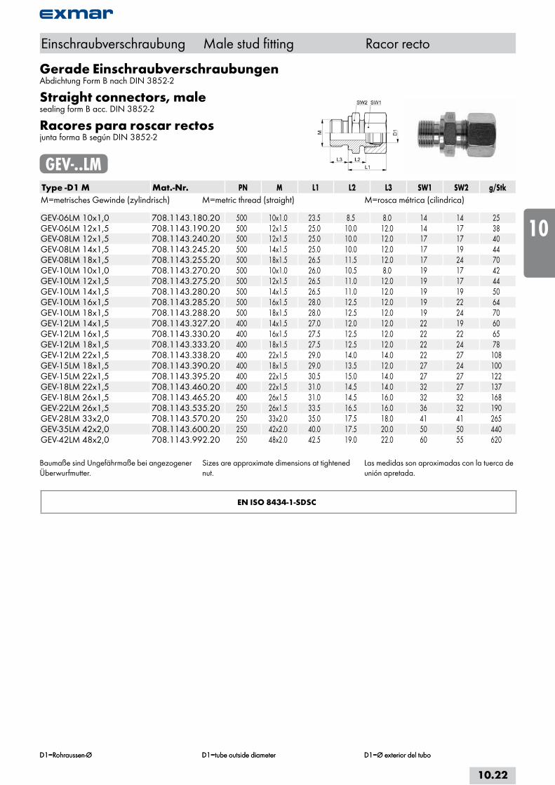
GEV-..LMType -D1 M Mat.-Nr. PN M L1 L2 L3 SW1 SW2 g/StkM=metrisches Gewinde (zylindrisch) M=metric thread (straight) M=rosca métrica (cilindrica) GEV-06LM 10x1,0 708.1143.180.20 500 10x1.0 23.5 8.5 8.0 14 14 25GEV-06LM 12x1,5 708.1143.190.20 500 12x1.5 25.0 10.0 12.0 14 17 38GEV-08LM 12x1,5 708.1143.240.20 500 12x1.5 25.0 10.0 12.0 17 17 40GEV-08LM 14x1,5 708.1143.245.20 500 14x1.5 25.0 10.0 12.0 17 19 44GEV-08LM 18x1,5 708.1143.255.20 500 18x1.5 26.5 11.5 12.0 17 24 70GEV-10LM 10x1,0 708.1143.270.20 500 10x1.0 26.0 10.5 8.0 19 17 42GEV-10LM 12x1,5 708.1143.275.20 500 12x1.5 26.5 11.0 12.0 19 17 44GEV-10LM 14x1,5 708.1143.280.20 500 14x1.5 26.5 11.0 12.0 19 19 50GEV-10LM 16x1,5 708.1143.285.20 500 16x1.5 28.0 12.5 12.0 19 22 64GEV-10LM 18x1,5 708.1143.288.20 500 18x1.5 28.0 12.5 12.0 19 24 70GEV-12LM 14x1,5 708.1143.327.20 400 14x1.5 27.0 12.0 12.0 22 19 60GEV-12LM 16x1,5 708.1143.330.20 400 16x1.5 27.5 12.5 12.0 22 22 65GEV-12LM 18x1,5 708.1143.333.20 400 18x1.5 27.5 12.5 12.0 22 24 78GEV-12LM 22x1,5 708.1143.338.20 400 22x1.5 29.0 14.0 14.0 22 27 108GEV-15LM 18x1,5 708.1143.390.20 400 18x1.5 29.0 13.5 12.0 27 24 100GEV-15LM 22x1,5 708.1143.395.20 400 22x1.5 30.5 15.0 14.0 27 27 122GEV-18LM 22x1,5 708.1143.460.20 400 22x1.5 31.0 14.5 14.0 32 27 137GEV-18LM 26x1,5 708.1143.465.20 400 26x1.5 31.0 14.5 16.0 32 32 168GEV-22LM 26x1,5 708.1143.535.20 250 26x1.5 33.5 16.5 16.0 36 32 190GEV-28LM 33x2,0 708.1143.570.20 250 33x2.0 35.0 17.5 18.0 41 41 265GEV-35LM 42x2,0 708.1143.600.20 250 42x2.0 40.0 17.5 20.0 50 50 440GEV-42LM 48x2,0 708.1143.992.20 250 48x2.0 42.5 19.0 22.0 60 55 620
Baumaße sind Ungefährmaße bei angezogener Überwurfmutter.
Sizes are approximate dimensions at tightened nut.
Las medidas son aproximadas con la tuerca de unión apretada.
EN ISO 8434-1-SDSC
Einschraubverschraubung Male stud fitting Racor recto
D1=Rohraussen-Ø D1=tube outside diameter D1=Ø exterior del tuboD1=Rohraussen-Ø D1=tube outside diameter D1=Ø exterior del tubo
10.22
i
s
10
20
30
40
50
60
70
a
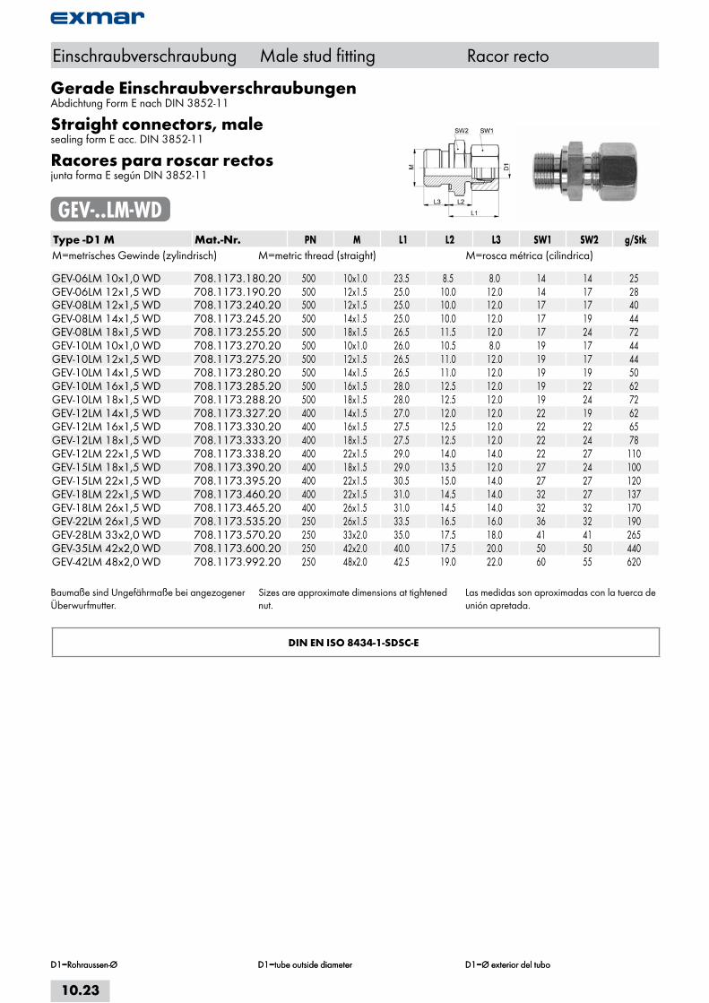
Gerade EinschraubverschraubungenAbdichtung Form E nach DIN 3852-11
Straight connectors, malesealing form E acc. DIN 3852-11
Racores para roscar rectosjunta forma E según DIN 3852-11
GEV-..LM-WDType -D1 M Mat.-Nr. PN M L1 L2 L3 SW1 SW2 g/StkM=metrisches Gewinde (zylindrisch) M=metric thread (straight) M=rosca métrica (cilindrica) GEV-06LM 10x1,0 WD 708.1173.180.20 500 10x1.0 23.5 8.5 8.0 14 14 25GEV-06LM 12x1,5 WD 708.1173.190.20 500 12x1.5 25.0 10.0 12.0 14 17 28GEV-08LM 12x1,5 WD 708.1173.240.20 500 12x1.5 25.0 10.0 12.0 17 17 40GEV-08LM 14x1,5 WD 708.1173.245.20 500 14x1.5 25.0 10.0 12.0 17 19 44GEV-08LM 18x1,5 WD 708.1173.255.20 500 18x1.5 26.5 11.5 12.0 17 24 72GEV-10LM 10x1,0 WD 708.1173.270.20 500 10x1.0 26.0 10.5 8.0 19 17 44GEV-10LM 12x1,5 WD 708.1173.275.20 500 12x1.5 26.5 11.0 12.0 19 17 44GEV-10LM 14x1,5 WD 708.1173.280.20 500 14x1.5 26.5 11.0 12.0 19 19 50GEV-10LM 16x1,5 WD 708.1173.285.20 500 16x1.5 28.0 12.5 12.0 19 22 62GEV-10LM 18x1,5 WD 708.1173.288.20 500 18x1.5 28.0 12.5 12.0 19 24 72GEV-12LM 14x1,5 WD 708.1173.327.20 400 14x1.5 27.0 12.0 12.0 22 19 62GEV-12LM 16x1,5 WD 708.1173.330.20 400 16x1.5 27.5 12.5 12.0 22 22 65GEV-12LM 18x1,5 WD 708.1173.333.20 400 18x1.5 27.5 12.5 12.0 22 24 78GEV-12LM 22x1,5 WD 708.1173.338.20 400 22x1.5 29.0 14.0 14.0 22 27 110GEV-15LM 18x1,5 WD 708.1173.390.20 400 18x1.5 29.0 13.5 12.0 27 24 100GEV-15LM 22x1,5 WD 708.1173.395.20 400 22x1.5 30.5 15.0 14.0 27 27 120GEV-18LM 22x1,5 WD 708.1173.460.20 400 22x1.5 31.0 14.5 14.0 32 27 137GEV-18LM 26x1,5 WD 708.1173.465.20 400 26x1.5 31.0 14.5 14.0 32 32 170GEV-22LM 26x1,5 WD 708.1173.535.20 250 26x1.5 33.5 16.5 16.0 36 32 190GEV-28LM 33x2,0 WD 708.1173.570.20 250 33x2.0 35.0 17.5 18.0 41 41 265GEV-35LM 42x2,0 WD 708.1173.600.20 250 42x2.0 40.0 17.5 20.0 50 50 440GEV-42LM 48x2,0 WD 708.1173.992.20 250 48x2.0 42.5 19.0 22.0 60 55 620
Baumaße sind Ungefährmaße bei angezogener Überwurfmutter.
Sizes are approximate dimensions at tightened nut.
Las medidas son aproximadas con la tuerca de unión apretada.
DIN EN ISO 8434-1-SDSC-E
Einschraubverschraubung Male stud fitting Racor recto
D1=Rohraussen-Ø D1=tube outside diameter D1=Ø exterior del tuboD1=Rohraussen-Ø D1=tube outside diameter D1=Ø exterior del tubo
10.23
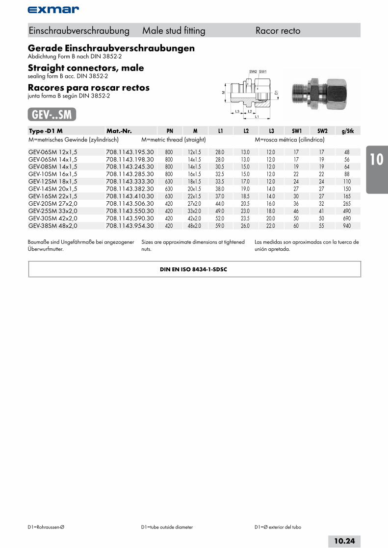
Gerade EinschraubverschraubungenAbdichtung Form B nach DIN 3852-2
Straight connectors, malesealing form B acc. DIN 3852-2
Racores para roscar rectosjunta forma B según DIN 3852-2
GEV-..SMType -D1 M Mat.-Nr. PN M L1 L2 L3 SW1 SW2 g/StkM=metrisches Gewinde (zylindrisch) M=metric thread (straight) M=rosca métrica (cilindrica) GEV-06SM 12x1,5 708.1143.195.30 800 12x1.5 28.0 13.0 12.0 17 17 48GEV-06SM 14x1,5 708.1143.198.30 800 14x1.5 28.0 13.0 12.0 17 19 56GEV-08SM 14x1,5 708.1143.245.30 800 14x1.5 30.5 15.0 12.0 19 19 64GEV-10SM 16x1,5 708.1143.285.30 800 16x1.5 32.5 15.0 12.0 22 22 88GEV-12SM 18x1,5 708.1143.333.30 630 18x1.5 33.5 17.0 12.0 24 24 110GEV-14SM 20x1,5 708.1143.382.30 630 20x1.5 38.0 19.0 14.0 27 27 150GEV-16SM 22x1,5 708.1143.410.30 630 22x1.5 37.0 18.5 14.0 30 27 165GEV-20SM 27x2,0 708.1143.506.30 420 27x2.0 44.0 20.5 16.0 36 32 265GEV-25SM 33x2,0 708.1143.550.30 420 33x2.0 49.0 23.0 18.0 46 41 490GEV-30SM 42x2,0 708.1143.590.30 420 42x2.0 52.0 23.5 20.0 50 50 690GEV-38SM 48x2,0 708.1143.954.30 420 48x2.0 59.0 26.0 22.0 60 55 940
Baumaße sind Ungefährmaße bei angezogener Überwurfmutter.
Sizes are approximate dimensions at tightened nuts.
Las medidas son aproximadas con la tuerca de unión apretada.
DIN EN ISO 8434-1-SDSC
Einschraubverschraubung Male stud fitting Racor recto
D1=Rohraussen-Ø D1=tube outside diameter D1=Ø exterior del tubo
10.24
i
s
10
20
30
40
50
60
70
a

Gerade EinschraubverschraubungenAbdichtung Form E nach DIN 3852-11
Straight connectors, malesealing form E acc. DIN 3852-11
Racores para roscar rectosjunta forma E según DIN 3852-11
GEV-..SM-WDType -D1 M Mat.-Nr. PN M L1 L2 L3 SW1 SW2 g/StkM=metrisches Gewinde (zylindrisch) M=metric thread (straight) M=rosca métrica (cilindrica) GEV-06SM 12x1,5 WD 708.1173.195.30 800 12x1.5 28.0 13.0 12.0 17 17 48GEV-06SM 14x1,5 WD 708.1173.198.30 800 14x1.5 28.0 13.0 12.0 17 19 58GEV-08SM 14x1,5 WD 708.1173.245.30 800 14x1.5 30.5 15.0 12.0 19 19 62GEV-10SM 16x1,5 WD 708.1173.285.30 800 16x1.5 32.5 15.0 12.0 22 22 88GEV-12SM 14x1,5 WD 708.1173.327.30 630 14x1.5 33.0 16.5 12.0 24 22 90GEV-12SM 18x1,5 WD 708.1173.333.30 630 18x1.5 33.5 17.0 12.0 24 24 110GEV-14SM 20x1,5 WD 708.1173.382.30 630 20x1.5 38.0 19.0 14.0 27 27 150GEV-16SM 22x1,5 WD 708.1173.410.30 630 22x1.5 37.0 18.5 14.0 30 27 165GEV-20SM 27x2,0 WD 708.1173.506.30 420 27x2.0 44.0 20.5 16.0 36 32 265GEV-25SM 33x2,0 WD 708.1173.550.30 420 33x2.0 49.0 23.0 16.0 46 41 490GEV-30SM 42x2,0 WD 708.1173.590.30 420 42x2.0 52.0 23.5 20.0 50 50 690GEV-38SM 48x2,0 WD 708.1173.954.30 420 48x2.0 59.0 26.0 22.0 60 55 940
Baumaße sind Ungefährmaße bei angezogener Überwurfmutter.
Sizes are approximate dimensions at tightened nut.
Las medidas son aproximadas con la tuerca de unión apretada.
DIN EN ISO 8434-1-SDSC-E
Einschraubverschraubung Male stud fitting Racor recto
D1=Rohraussen-Ø D1=tube outside diameter D1=Ø exterior del tubo
10.25
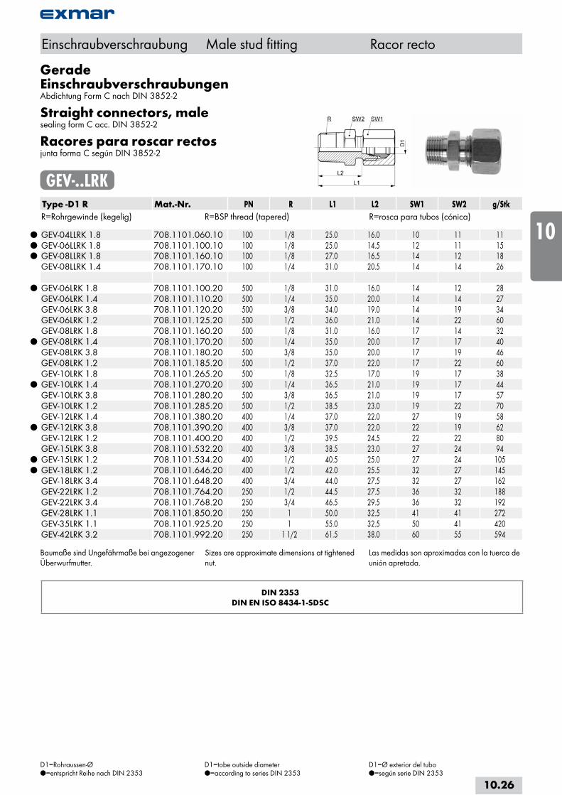
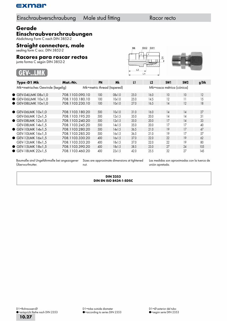
Gerade EinschraubverschraubungenAbdichtung Form C nach DIN 3852-2
Straight connectors, malesealing form C acc. DIN 3852-2
Racores para roscar rectosjunta forma C según DIN 3852-2
GEV-..LRKType -D1 R Mat.-Nr. PN R L1 L2 SW1 SW2 g/StkR=Rohrgewinde (kegelig) R=BSP thread (tapered) R=rosca para tubos (cónica)
GEV-04LLRK 1.8 708.1101.060.10 100 1/8 25.0 16.0 10 11 11 GEV-06LLRK 1.8 708.1101.100.10 100 1/8 25.0 14.5 12 11 15 GEV-08LLRK 1.8 708.1101.160.10 100 1/8 27.0 16.5 14 12 18 GEV-08LLRK 1.4 708.1101.170.10 100 1/4 31.0 20.5 14 14 26
GEV-06LRK 1.8 708.1101.100.20 500 1/8 31.0 16.0 14 12 28 GEV-06LRK 1.4 708.1101.110.20 500 1/4 35.0 20.0 14 14 27 GEV-06LRK 3.8 708.1101.120.20 500 3/8 34.0 19.0 14 19 34 GEV-06LRK 1.2 708.1101.125.20 500 1/2 36.0 21.0 14 22 60 GEV-08LRK 1.8 708.1101.160.20 500 1/8 31.0 16.0 17 14 32
GEV-08LRK 1.4 708.1101.170.20 500 1/4 35.0 20.0 17 17 40 GEV-08LRK 3.8 708.1101.180.20 500 3/8 35.0 20.0 17 19 46 GEV-08LRK 1.2 708.1101.185.20 500 1/2 37.0 22.0 17 22 60 GEV-10LRK 1.8 708.1101.265.20 500 1/8 32.5 17.0 19 17 38
GEV-10LRK 1.4 708.1101.270.20 500 1/4 36.5 21.0 19 17 44 GEV-10LRK 3.8 708.1101.280.20 500 3/8 36.5 21.0 19 17 57 GEV-10LRK 1.2 708.1101.285.20 500 1/2 38.5 23.0 19 22 70 GEV-12LRK 1.4 708.1101.380.20 400 1/4 37.0 22.0 27 19 58
GEV-12LRK 3.8 708.1101.390.20 400 3/8 37.0 22.0 22 19 62 GEV-12LRK 1.2 708.1101.400.20 400 1/2 39.5 24.5 22 22 80 GEV-15LRK 3.8 708.1101.532.20 400 3/8 38.5 23.0 27 24 94
GEV-15LRK 1.2 708.1101.534.20 400 1/2 40.5 25.0 27 24 105 GEV-18LRK 1.2 708.1101.646.20 400 1/2 42.0 25.5 32 27 145 GEV-18LRK 3.4 708.1101.648.20 400 3/4 44.0 27.5 32 27 162 GEV-22LRK 1.2 708.1101.764.20 250 1/2 44.5 27.5 36 32 188 GEV-22LRK 3.4 708.1101.768.20 250 3/4 46.5 29.5 36 32 192 GEV-28LRK 1.1 708.1101.850.20 250 1 50.0 32.5 41 41 272 GEV-35LRK 1.1 708.1101.925.20 250 1 55.0 32.5 50 41 420 GEV-42LRK 3.2 708.1101.992.20 250 1 1/2 61.5 38.0 60 55 594
Baumaße sind Ungefährmaße bei angezogener Überwurfmutter.
Sizes are approximate dimensions at tightened nut.
Las medidas son aproximadas con la tuerca de unión apretada.
DIN 2353DIN EN ISO 8434-1-SDSC
Einschraubverschraubung Male stud fitting Racor recto
D1=Rohraussen-Ø=entspricht Reihe nach DIN 2353
D1=tobe outside diameter=according to series DIN 2353
D1=Ø exterior del tubo=según serie DIN 2353
10.26
i
s
10
20
30
40
50
60
70
a
Gerade EinschraubverschraubungenAbdichtung Form C nach DIN 3852-2
Straight connectors, malesealing form C acc. DIN 3852-2
Racores para roscar rectosjunta forma C según DIN 3852-2
GEV-..LMKType -D1 Mk Mat.-Nr. PN Mk L1 L2 SW1 SW2 g/StkMk=metrisches Gewinde (kegelig) Mk=metric thread (tapered) Mk=rosca métrica (cónica)
GEV-04LLMK 08x1,0 708.1103.090.10 100 08x1.0 25.0 16.0 10 10 12 GEV-06LLMK 10x1,0 708.1103.180.10 100 10x1.0 25.0 14.5 12 11 15 GEV-08LLMK 10x1,0 708.1103.230.10 100 10x1.0 27.0 16.5 14 12 18
GEV-06LMK 10x1,0 708.1103.180.20 500 10x1.0 31.0 16.0 14 14 27 GEV-06LMK 12x1,5 708.1103.195.20 500 12x1.5 35.0 20.0 14 14 31
GEV-08LMK 12x1,5 708.1103.240.20 500 12x1.5 35.0 20.0 17 14 33 GEV-08LMK 14x1,5 708.1103.245.20 500 14x1.5 35.0 20.0 17 17 40
GEV-10LMK 14x1,5 708.1103.280.20 500 14x1.5 36.5 21.0 19 17 47 GEV-10LMK 16x1,5 708.1103.285.20 500 16x1.5 36.5 21.0 19 17 57
GEV-12LMK 16x1,5 708.1103.330.20 400 16x1.5 37.0 22.0 22 19 62 GEV-12LMK 18x1,5 708.1103.333.20 400 18x1.5 37.0 22.0 22 19 80
GEV-15LMK 18x1,5 708.1103.390.20 400 18x1.5 38.5 23.0 27 24 105 GEV-18LMK 22x1,5 708.1103.460.20 400 22x1.5 42.0 25.5 32 27 145
Baumaße sind Ungefährmaße bei angezogener Überwurfmutter.
Sizes are approximate dimensions at tightened nut.
Las medidas son aproximadas con la tuerca de unión apretada.
DIN 2353DIN EN ISO 8434-1-SDSC
Einschraubverschraubung Male stud fitting Racor recto
D1=Rohraussen-Ø=entspricht Reihe nach DIN 2353
D1=tobe outside diameter=according to series DIN 2353
D1=Ø exterior del tubo=según serie DIN 2353
10.27
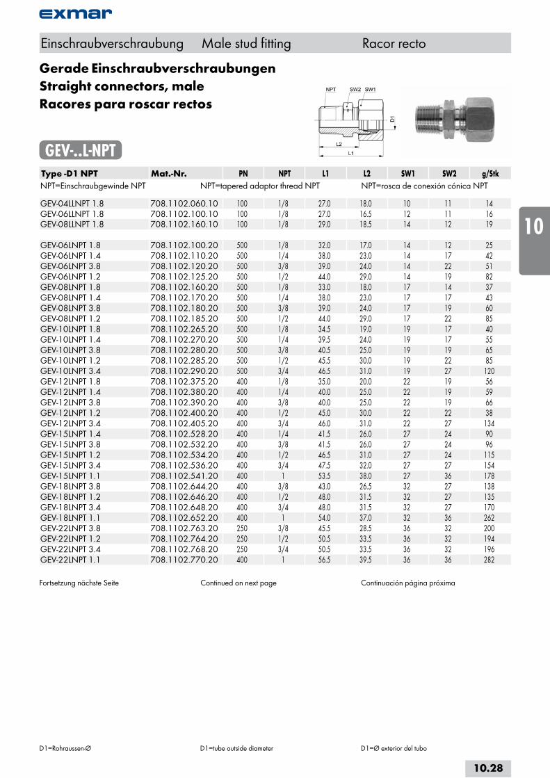
Gerade EinschraubverschraubungenStraight connectors, maleRacores para roscar rectos
GEV-..L-NPTType -D1 NPT Mat.-Nr. PN NPT L1 L2 SW1 SW2 g/StkNPT=Einschraubgewinde NPT NPT=tapered adaptor thread NPT NPT=rosca de conexión cónica NPT GEV-04LLNPT 1.8 708.1102.060.10 100 1/8 27.0 18.0 10 11 14GEV-06LLNPT 1.8 708.1102.100.10 100 1/8 27.0 16.5 12 11 16GEV-08LLNPT 1.8 708.1102.160.10 100 1/8 29.0 18.5 14 12 19 GEV-06LNPT 1.8 708.1102.100.20 500 1/8 32.0 17.0 14 12 25GEV-06LNPT 1.4 708.1102.110.20 500 1/4 38.0 23.0 14 17 42GEV-06LNPT 3.8 708.1102.120.20 500 3/8 39.0 24.0 14 22 51GEV-06LNPT 1.2 708.1102.125.20 500 1/2 44.0 29.0 14 19 82GEV-08LNPT 1.8 708.1102.160.20 500 1/8 33.0 18.0 17 14 37GEV-08LNPT 1.4 708.1102.170.20 500 1/4 38.0 23.0 17 17 43GEV-08LNPT 3.8 708.1102.180.20 500 3/8 39.0 24.0 17 19 60GEV-08LNPT 1.2 708.1102.185.20 500 1/2 44.0 29.0 17 22 85GEV-10LNPT 1.8 708.1102.265.20 500 1/8 34.5 19.0 19 17 40GEV-10LNPT 1.4 708.1102.270.20 500 1/4 39.5 24.0 19 17 55GEV-10LNPT 3.8 708.1102.280.20 500 3/8 40.5 25.0 19 19 65GEV-10LNPT 1.2 708.1102.285.20 500 1/2 45.5 30.0 19 22 85GEV-10LNPT 3.4 708.1102.290.20 500 3/4 46.5 31.0 19 27 120GEV-12LNPT 1.8 708.1102.375.20 400 1/8 35.0 20.0 22 19 56GEV-12LNPT 1.4 708.1102.380.20 400 1/4 40.0 25.0 22 19 59GEV-12LNPT 3.8 708.1102.390.20 400 3/8 40.0 25.0 22 19 66GEV-12LNPT 1.2 708.1102.400.20 400 1/2 45.0 30.0 22 22 38GEV-12LNPT 3.4 708.1102.405.20 400 3/4 46.0 31.0 22 27 134GEV-15LNPT 1.4 708.1102.528.20 400 1/4 41.5 26.0 27 24 90GEV-15LNPT 3.8 708.1102.532.20 400 3/8 41.5 26.0 27 24 96GEV-15LNPT 1.2 708.1102.534.20 400 1/2 46.5 31.0 27 24 115GEV-15LNPT 3.4 708.1102.536.20 400 3/4 47.5 32.0 27 27 154GEV-15LNPT 1.1 708.1102.541.20 400 1 53.5 38.0 27 36 178GEV-18LNPT 3.8 708.1102.644.20 400 3/8 43.0 26.5 32 27 138GEV-18LNPT 1.2 708.1102.646.20 400 1/2 48.0 31.5 32 27 135GEV-18LNPT 3.4 708.1102.648.20 400 3/4 48.0 31.5 32 27 170GEV-18LNPT 1.1 708.1102.652.20 400 1 54.0 37.0 32 36 262GEV-22LNPT 3.8 708.1102.763.20 250 3/8 45.5 28.5 36 32 200GEV-22LNPT 1.2 708.1102.764.20 250 1/2 50.5 33.5 36 32 194GEV-22LNPT 3.4 708.1102.768.20 250 3/4 50.5 33.5 36 32 196GEV-22LNPT 1.1 708.1102.770.20 400 1 56.5 39.5 36 36 282
Fortsetzung nächste Seite Continued on next page Continuación página próxima
Einschraubverschraubung Male stud fitting Racor recto
D1=Rohraussen-Ø D1=tube outside diameter D1=Ø exterior del tubo
10.28
i
s
10
20
30
40
50
60
70
a

Gerade EinschraubverschraubungenStraight connectors, maleRacores para roscar rectos
GEV-..L-NPTType -D1 NPT Mat.-Nr. PN NPT L1 L2 SW1 SW2 g/StkNPT=Einschraubgewinde NPT NPT=tapered adaptor thread NPT NPT=rosca de conexión cónica NPT GEV-28LNPT 3.4 708.1102.845.20 250 3/4 52.0 34.5 41 41 270GEV-28LNPT 1.1 708.1102.850.20 250 1 57.0 39.5 41 41 285GEV-28LNPT 5.4 708.1102.860.20 250 1 1/4 59.0 41.5 41 46 416GEV-35LNPT 1.1 708.1102.925.20 250 1 62.0 39.5 50 46 410GEV-35LNPT 5.4 708.1102.944.20 250 1 1/4 63.0 40.5 50 46 430GEV-42LNPT 5.4 708.1102.985.20 250 1 1/4 65.5 42.0 60 55 640GEV-42LNPT 3.2 708.1102.992.20 250 1 1/2 65.5 42.0 60 55 615
Baumaße sind Ungefährmaße bei angezogener Überwurfmutter.
Sizes are approximate dimensions at tightned nut. Las medidas son aproximadas con la tuerca de unión apretada.
DIN EN ISO 8434-1-SDSC
Einschraubverschraubung Male stud fitting Racor recto
D1=Rohraussen-Ø D1=tube outside diameter D1=Ø exterior del tubo
10.29

Gerade EinschraubverschraubungenStraight connectors, maleRacores para roscar rectos
GEV-..S-NPTType -D1 NPT Mat.-Nr. PN NPT L1 L2 SW1 SW2 g/StkNPT=Einschraubgewinde NPT NPT=tapered adaptor thread NPT NPT=rosca de conexión cónica NPT GEV-06SNPT 1.8 708.1102.100.30 800 1/8 36.0 21.0 17 14 45GEV-06SNPT 1.4 708.1102.110.30 800 1/4 43.0 28.0 17 17 55GEV-06SNPT 3.8 708.1102.120.30 800 3/8 43.0 28.0 17 19 70GEV-06SNPT 1.2 708.1102.125.30 800 1/2 50.0 35.0 17 22 93GEV-08SNPT 1.8 708.1102.160.30 800 1/8 38.5 23.0 17 17 48GEV-08SNPT 1.4 708.1102.170.30 800 1/4 43.5 28.0 19 17 60GEV-08SNPT 3.8 708.1102.180.30 800 3/8 43.5 28.0 19 19 74GEV-08SNPT 1.2 708.1102.185.30 800 1/2 50.5 35.0 19 22 108GEV-10SNPT 1.4 708.1102.270.30 800 1/4 45.0 27.5 22 19 71GEV-10SNPT 3.8 708.1102.280.30 800 3/8 45.0 27.5 22 19 86GEV-10SNPT 1.2 708.1102.285.30 800 1/2 52.0 34.5 22 22 104GEV-10SNPT 3.4 708.1102.290.30 800 3/4 52.0 34.5 22 27 154GEV-12SNPT 1.4 708.1102.380.30 630 1/4 46.0 29.5 24 22 96GEV-12SNPT 3.8 708.1102.390.30 630 3/8 46.0 29.5 24 22 100GEV-12SNPT 1.2 708.1102.400.30 630 1/2 51.0 34.5 24 22 121GEV-12SNPT 3.4 708.1102.405.30 630 3/4 51.0 34.5 24 27 170GEV-14SNPT 3.8 708.1102.502.30 630 3/8 50.0 31.0 27 24 125GEV-14SNPT 1.2 708.1102.504.30 630 1/2 55.0 36.0 27 24 160GEV-14SNPT 3.4 708.1102.506.30 630 3/4 55.0 36.0 27 27 180GEV-14SNPT 1.1 708.1102.510.30 630 1 62.0 43.0 27 36 230GEV-16SNPT 3.8 708.1102.564.30 630 3/8 49.0 30.5 30 27 152GEV-16SNPT 1.2 708.1102.566.30 630 1/2 54.0 35.5 30 27 170GEV-16SNPT 3.4 708.1102.568.30 630 3/4 54.0 35.5 30 27 196GEV-16SNPT 1.1 708.1102.570.30 630 1 61.0 42.5 30 36 324GEV-20SNPT 1.2 708.1102.706.30 420 1/2 61.0 37.5 36 32 246GEV-20SNPT 3.4 708.1102.708.30 420 3/4 61.0 37.5 36 32 268GEV-20SNPT 1.1 708.1102.712.30 420 1 66.0 42.5 36 36 360GEV-25SNPT 1.2 708.1102.800.30 420 1/2 66.0 40.0 46 41 421GEV-25SNPT 3.4 708.1102.805.30 420 3/4 66.0 40.0 46 41 474GEV-25SNPT 1.1 708.1102.810.30 420 1 71.0 45.0 46 41 503GEV-25SNPT 5.4 708.1102.815.30 420 1 1/4 72.0 46.0 46 46 654GEV-25SNPT 3.2 708.1102.820.30 420 1 1/2 72.0 46.0 46 50 GEV-30SNPT 3.4 708.1102.895.30 420 3/4 69.0 40.5 50 46 536GEV-30SNPT 1.1 708.1102.900.30 420 1 74.0 45.5 50 46 590GEV-30SNPT 5.4 708.1102.902.30 420 1 1/4 75.0 46.5 50 46 650GEV-30SNPT 3.2 708.1102.905.30 420 1 1/2 75.0 46.5 50 50 786GEV-38SNPT 1.1 708.1102.960.30 420 1 81.0 48.0 60 55 955GEV-38SNPT 5.4 708.1102.954.30 420 1 1/4 82.0 49.0 60 55 955GEV-38SNPT 3.2 708.1102.953.30 420 1 1/2 82.0 49.0 60 55 935
Baumaße sind Ungefährmaße bei angezogener Überwurfmutter.
Sizes are approximate dimensions at tightened nut.
Las medidas son aproximadas con la tuerca de unión apretada.
DIN EN ISO 8434-1-SDSC
Einschraubverschraubung Male stud fitting Racor recto
D1=Rohraussen-Ø D1=tube outside diameter D1=Ø exterior del tubo
10.30
i
s
10
20
30
40
50
60
70
a
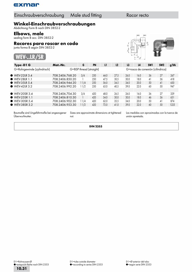
Winkel-EinschraubverschraubungenAbdichtung Form B nach DIN 3852-2
Elbows, malesealing form B acc. DIN 3852-2
Racores para roscar en codojunta forma B según DIN 3852-2
WEV-..LR/SRType -D1 G Mat.-Nr. G PN L1 L2 L3 L4 SW1 SW2 g/StkG=Rohrgewinde (zylindrisch) G=BSP thread (straight) G=rosca de conexión (cilíndrica)
WEV-22LR 3.4 708.2406.768.20 3/4 250 44.0 27.5 26.0 16.0 36 27 267 WEV-28LR 1.1 708.2406.850.20 1 250 47.5 30.5 30.0 18.0 41 36 418 WEV-35LR 5.4 708.2406.944.20 1 1/4 250 56.0 34.5 34.0 20.0 50 41 630 WEV-42LR 3.2 708.2406.992.20 1 1/2 250 63.0 40.5 39.0 22.0 60 50 947
WEV-20SR 3.4 708.2406.704.30 3/4 420 48.0 26.5 26.0 16.0 36 27 329 WEV-25SR 1.1 708.2406.810.30 1 420 54.0 30.0 30.0 18.0 46 36 631 WEV-30SR 5.4 708.2406.902.30 1 1/4 420 62.0 35.5 34.0 20.0 50 41 874 WEV-38SR 3.2 708.2406.953.30 1 1/2 420 72.0 41.0 39.0 22.0 60 50 1225
Baumaße sind Ungefährmaße bei angezogener Überwurfmutter.
Sizes are approximate dimensions at tightened nut.
Las medidas son aproximadas con la tuerca de unión apretada.
DIN 2353
Einschraubverschraubung Male stud fitting Racor recto
D1=Rohraussen-Ø=entspricht Reihe nach DIN 2353
D1=tube outside diameter=according to series DIN 2353
D1=Ø exterior del tubo=según serie DIN 2353
10.31

Einschraubverschraubung Male stud fitting Racor recto
Winkel-EinschraubverschraubungenAbdichtung Form B nach DIN 3852-2
Elbows, malesealing form B acc. DIN 3852-2
Racores para roscar en codojunta forma B según DIN 3852-2
WEV-..LM/SMType -D1 M Mat.-Nr. PN M L1 L2 L3 L4 SW1 SW2 g/StkM=metrisches Gewinde (zylindrisch) M=metric thread (straight) M=rosca métrica (cilindrica)
WEV-22LM 26x1,5 708.2443.535.20 250 26x1.5 44.0 27.5 26.0 16.0 36 27 267 WEV-28LM 33x2,0 708.2443.570.20 250 33x2.0 47.0 30.5 30.0 18.0 41 36 418 WEV-35LM 42x2,0 708.2443.600.20 250 42x2.0 56.0 34.5 34.0 20.0 50 41 630 WEV-42LM 48x2,0 708.2443.992.20 250 48x2.0 63.0 40.0 39.0 22.0 60 50 947
WEV-20SM 27x2,0 708.2443.506.30 420 27x2.0 48.0 26.5 26.0 16.0 36 27 329 WEV-25SM 33x2,0 708.2443.550.30 420 33x2.0 54.0 30.0 30.0 18.0 46 36 631 WEV-30SM 42x2,0 708.2443.590.30 420 42x2.0 62.0 35.5 34.0 20.0 50 41 874 WEV-38SM 48x2,0 708.2443.954.30 420 48x2.0 72.0 41.0 39.0 22.0 60 50 1225
Baumaße sind Ungefährmaße bei angezogener Überwurfmutter.
Sizes are approximate dimensions at tightened nut.
Las medidas son aproximadas con la tuerca de unión apretada.
DIN 2353
D1=Rohraussen-Ø=entspricht Reihe nach DIN 2353
D1=tube outside diameter=according to series DIN 2353
D1=Ø exterior del tubo=según serie DIN 2353
10.32
i
s
10
20
30
40
50
60
70
a
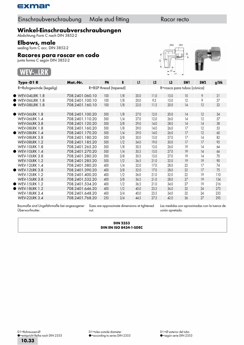
Winkel-EinschraubverschraubungenAbdichtung Form C nach DIN 3852-2
Elbows, malesealing form C acc. DIN 3852-2
Racores para roscar en codojunta forma C según DIN 3852-2
WEV-..LRKType -D1 R Mat.-Nr. PN R L1 L2 L3 SW1 SW2 g/StkR=Rohrgewinde (kegelig) R=BSP thread (tapered) R=rosca para tubos (cónica)
WEV-04LLRK 1.8 708.2401.060.10 100 1/8 20.0 11.0 15.0 10 9 21 WEV-06LLRK 1.8 708.2401.100.10 100 1/8 20.0 9.5 15.0 12 9 27 WEV-08LLRK 1.8 708.2401.160.10 100 1/8 22.0 11.5 20.0 14 12 32
WEV-06LRK 1.8 708.2401.100.20 500 1/8 27.0 12.0 20.0 14 12 34 WEV-06LRK 1.4 708.2401.110.20 500 1/4 27.0 12.0 26.0 14 12 57 WEV-06LRK 3.8 708.2401.120.20 500 3/8 29.0 14.0 28.0 14 14 58 WEV-08LRK 1.8 708.2401.160.20 500 1/8 29.0 14.0 26.0 17 12 53
WEV-08LRK 1.4 708.2401.170.20 500 1/4 29.0 14.0 26.0 17 12 60 WEV-08LRK 3.8 708.2401.180.20 500 3/8 30.0 15.0 27.0 17 14 82 WEV-08LRK 1.2 708.2401.185.20 500 1/2 34.0 19.0 30.0 17 17 95 WEV-10LRK 1.8 708.2401.265.20 500 1/8 30.5 15.0 26.0 19 14 64
WEV-10LRK 1.4 708.2401.270.20 500 1/4 30.5 15.0 27.0 19 14 66 WEV-10LRK 3.8 708.2401.280.20 500 3/8 30.5 15.0 27.0 19 14 70 WEV-10LRK 1.2 708.2401.285.20 500 1/2 36.5 21.0 32.0 19 19 90 WEV-12LRK 1.4 708.2401.380.20 400 1/4 32.0 17.0 28.0 22 17 74
WEV-12LRK 3.8 708.2401.390.20 400 3/8 32.0 17.0 28.0 22 17 75 WEV-12LRK 1.2 708.2401.400.20 400 1/2 36.0 21.0 32.0 22 19 110 WEV-15LRK 3.8 708.2401.532.20 400 3/8 36.5 21.0 28.0 27 19 134
WEV-15LRK 1.2 708.2401.534.20 400 1/2 36.5 21.0 34.0 27 19 216 WEV-18LRK 1.2 708.2401.646.20 400 1/2 40.0 23.5 36.0 32 24 273 WEV-18LRK 3.4 708.2401.648.20 400 3/4 40.0 23.5 34.0 32 24 233 WEV-22LRK 3.4 708.2401.768.20 250 3/4 44.5 27.5 42.0 36 27 295
Baumaße sind Ungefährmaße bei angezogener Überwurfmutter.
Sizes are approximate dimensions at tightened nut.
Las medidas son aproximadas con la tuerca de unión apretada.
DIN 2353DIN EN ISO 8434-1-SDEC
Einschraubverschraubung Male stud fitting Racor recto
D1=Rohraussen-Ø=entspricht Reihe nach DIN 2353
D1=tube outside diameter=according to series DIN 2353
D1=Ø exterior del tubo=según serie DIN 2353
10.33

Winkel-EinschraubverschraubungenAbdichtung Form C nach DIN 3852-2
Elbows, malesealing form C acc. DIN 3852-2
Racores para roscar en codojunta forma C según DIN 3852-2
WEV-..SRKType -D1 R Mat.-Nr. PN R L1 L2 L3 SW1 SW2 g/StkR=Rohrgewinde (kegelig) R=BSP thread (tapered) R=rosca para tubos (cónica)
WEV-06SRK 1.8 708.2401.100.30 800 1/8 31.0 16.0 26.0 17 12 59 WEV-06SRK 1.4 708.2401.110.30 800 1/4 31.0 16.0 26.0 17 12 61 WEV-06SRK 3.8 708.2401.120.30 800 3/8 31.0 16.0 28.0 17 14 80 WEV-06SRK 1.2 708.2401.125.30 800 1/2 31.0 16.0 30.0 17 17 101
WEV-08SRK 1.4 708.2401.170.30 800 1/4 32.5 17.0 27.0 19 14 79 WEV-08SRK 3.8 708.2401.180.30 800 3/8 32.5 17.0 27.0 19 14 85 WEV-08SRK 1.2 708.2401.185.30 800 1/2 34.5 19.0 30.0 19 17 102 WEV-10SRK 1.4 708.2401.270.30 800 1/4 35.0 17.5 27.0 22 17 92
WEV-10SRK 3.8 708.2401.280.30 800 3/8 35.0 17.5 28.0 22 17 95 WEV-10SRK 1.2 708.2401.285.30 800 1/2 35.0 17.5 32.0 22 17 131
WEV-12SRK 3.8 708.2401.390.30 630 3/8 38.0 21.5 28.0 24 17 115 WEV-12SRK 1.2 708.2401.400.30 630 1/2 38.0 21.5 32.0 24 17 130 WEV-14SRK 3.8 708.2401.502.30 630 3/8 41.0 22.0 32.0 27 19 147
WEV-14SRK 1.2 708.2401.504.30 630 1/2 41.0 22.0 32.0 27 19 158 WEV-16SRK 1.2 708.2401.566.30 630 1/2 43.0 24.5 32.0 30 24 200
Baumaße sind Ungefährmaße bei angezogener Überwurfmutter.
Sizes are approximate dimensions at tightened nut.
Las medidas son aproximadas con la tuerca de unión apretada.
DIN 2353DIN EN ISO 8434-1-SDEC
Einschraubverschraubung Male stud fitting Racor recto
D1=Rohraussen-Ø=entspricht Reihe nach DIN 2353
D1=tube outside diameter=according to series DIN 2353
D1=Ø exterior del tubo=según serie DIN 2353
10.34
i
s
10
20
30
40
50
60
70
a
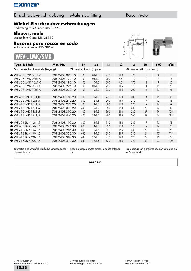
Winkel-EinschraubverschraubungenAbdichtung Form C nach DIN 3852-2
Elbows, malesealing form C acc. DIN 3852-2
Racores para roscar en codojunta forma C según DIN 3852-2
WEV-..LMK/SMKType -D1 Mk Mat.-Nr. PN Mk L1 L2 L3 SW1 SW2 g/StkMk=metrisches Gewinde (kegelig) Mk=metric thread (tapered) Mk=rosca métrica (cónica)
WEV-04LLMK 08x1,0 708.2403.090.10 100 08x1.0 21.0 11.0 17.0 10 9 17 WEV-06LLMK 08x1,0 708.2403.170.10 100 08x1.0 20.0 9.5 17.0 12 9 18
WEV-06LLMK 10x1,0 708.2403.180.10 100 10x1.0 20.0 9.5 17.0 12 9 20 WEV-08LLMK 08x1,0 708.2403.225.10 100 08x1.0 22.0 11.5 17.0 14 12 22
WEV-08LLMK 10x1,0 708.2403.230.10 100 10x1.0 22.0 11.5 20.0 14 12 24
WEV-06LMK 10x1,0 708.2403.180.20 500 10x1.0 27.0 12.0 20.0 14 12 32 WEV-08LMK 12x1,5 708.2403.240.20 500 12x1.5 29.0 14.0 26.0 17 12 43 WEV-10LMK 14x1,5 708.2403.278.20 500 14x1.5 30.5 15.0 27.0 19 14 59 WEV-12LMK 16x1,5 708.2403.330.20 400 16x1.5 32.0 17.0 28.0 22 17 80 WEV-15LMK 18x1,5 708.2403.390.20 400 18x1.5 36.5 21.0 32.0 27 19 136 WEV-18LMK 22x1,5 708.2403.460.20 400 22x1.5 40.0 23.5 36.0 32 24 188
WEV-06SMK 12x1,5 708.2403.190.30 800 12x1.5 31.0 16.0 26.0 17 12 55 WEV-08SMK 14x1,5 708.2403.245.30 800 14x1.5 32.5 17.0 27.0 19 14 70 WEV-10SMK 16x1,5 708.2403.285.30 800 16x1.5 35.0 17.5 28.0 22 17 98 WEV-12SMK 18x1,5 708.2403.333.30 630 18x1.5 38.0 21.5 28.0 24 17 118 WEV-14SMK 20x1,5 708.2403.382.30 630 20x1.5 41.0 22.0 32.0 27 19 154 WEV-16SMK 22x1,5 708.2403.410.30 630 22x1.5 43.0 24.5 32.0 30 24 190
Baumaße sind Ungefährmaße bei angezogener Überwurfmutter.
Sizes are approximate dimensions at tightened nut.
Las medidas son aproximadas con la tuerca de unión apretada.
DIN 2353
Einschraubverschraubung Male stud fitting Racor recto
D1=Rohraussen-Ø=entspricht Reihe nach DIN 2353
D1=tube outside diameter=according to series DIN 2353
D1=Ø exterior del tubo=según serie DIN 2353
10.35
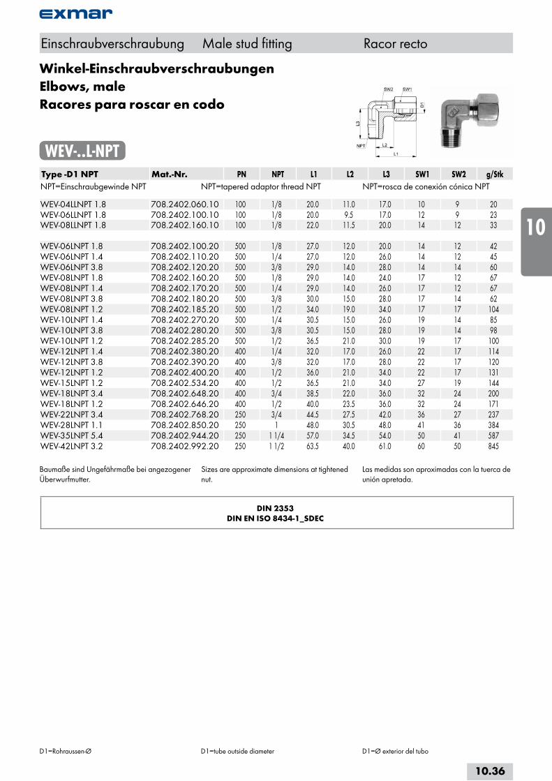
Winkel-EinschraubverschraubungenElbows, maleRacores para roscar en codo
WEV-..L-NPTType -D1 NPT Mat.-Nr. PN NPT L1 L2 L3 SW1 SW2 g/StkNPT=Einschraubgewinde NPT NPT=tapered adaptor thread NPT NPT=rosca de conexión cónica NPT WEV-04LLNPT 1.8 708.2402.060.10 100 1/8 20.0 11.0 17.0 10 9 20WEV-06LLNPT 1.8 708.2402.100.10 100 1/8 20.0 9.5 17.0 12 9 23WEV-08LLNPT 1.8 708.2402.160.10 100 1/8 22.0 11.5 20.0 14 12 33 WEV-06LNPT 1.8 708.2402.100.20 500 1/8 27.0 12.0 20.0 14 12 42WEV-06LNPT 1.4 708.2402.110.20 500 1/4 27.0 12.0 26.0 14 12 45WEV-06LNPT 3.8 708.2402.120.20 500 3/8 29.0 14.0 28.0 14 14 60WEV-08LNPT 1.8 708.2402.160.20 500 1/8 29.0 14.0 24.0 17 12 67WEV-08LNPT 1.4 708.2402.170.20 500 1/4 29.0 14.0 26.0 17 12 67WEV-08LNPT 3.8 708.2402.180.20 500 3/8 30.0 15.0 28.0 17 14 62WEV-08LNPT 1.2 708.2402.185.20 500 1/2 34.0 19.0 34.0 17 17 104WEV-10LNPT 1.4 708.2402.270.20 500 1/4 30.5 15.0 26.0 19 14 85WEV-10LNPT 3.8 708.2402.280.20 500 3/8 30.5 15.0 28.0 19 14 98WEV-10LNPT 1.2 708.2402.285.20 500 1/2 36.5 21.0 30.0 19 17 100WEV-12LNPT 1.4 708.2402.380.20 400 1/4 32.0 17.0 26.0 22 17 114WEV-12LNPT 3.8 708.2402.390.20 400 3/8 32.0 17.0 28.0 22 17 120WEV-12LNPT 1.2 708.2402.400.20 400 1/2 36.0 21.0 34.0 22 17 131WEV-15LNPT 1.2 708.2402.534.20 400 1/2 36.5 21.0 34.0 27 19 144WEV-18LNPT 3.4 708.2402.648.20 400 3/4 38.5 22.0 36.0 32 24 200WEV-18LNPT 1.2 708.2402.646.20 400 1/2 40.0 23.5 36.0 32 24 171WEV-22LNPT 3.4 708.2402.768.20 250 3/4 44.5 27.5 42.0 36 27 237WEV-28LNPT 1.1 708.2402.850.20 250 1 48.0 30.5 48.0 41 36 384WEV-35LNPT 5.4 708.2402.944.20 250 1 1/4 57.0 34.5 54.0 50 41 587WEV-42LNPT 3.2 708.2402.992.20 250 1 1/2 63.5 40.0 61.0 60 50 845
Baumaße sind Ungefährmaße bei angezogener Überwurfmutter.
Sizes are approximate dimensions at tightened nut.
Las medidas son aproximadas con la tuerca de unión apretada.
DIN 2353DIN EN ISO 8434-1_SDEC
Einschraubverschraubung Male stud fitting Racor recto
D1=Rohraussen-Ø D1=tube outside diameter D1=Ø exterior del tubo
10.36
i
s
10
20
30
40
50
60
70
a

Winkel-EinschraubverschraubungenElbows, maleRacores para roscar en codo
WEV-..S-NPTType -D1 NPT Mat.-Nr. PN NPT L1 L2 L3 SW1 SW2 g/StkNPT=Einschraubgewinde NPT NPT=tapered adaptor thread NPT NPT=rosca de conexión cónica NPT WEV-06SNPT 1.4 708.2402.110.30 800 1/4 31.0 16.0 26.0 17 12 71WEV-06SNPT 3.8 708.2402.120.30 800 3/8 31.0 16.0 28.0 17 14 82WEV-06SNPT 1.2 708.2402.125.30 800 1/2 31.0 16.0 32.5 17 17 99WEV-08SNPT 1.4 708.2402.170.30 800 1/4 32.5 17.0 26.0 19 14 99WEV-08SNPT 3.8 708.2402.180.30 800 3/8 33.5 18.0 28.0 19 14 107WEV-08SNPT 1.2 708.2402.185.30 800 1/2 34.5 19.0 34.0 19 17 133WEV-10SNPT 1.4 708.2402.270.30 800 1/4 35.0 17.5 26.0 22 17 137WEV-10SNPT 3.8 708.2402.280.30 800 3/8 35.0 17.5 28.0 22 17 149WEV-12SNPT 1.4 708.2402.380.30 630 1/4 38.0 21.5 27.0 24 17 166WEV-12SNPT 3.8 708.2402.390.30 630 3/8 38.0 21.5 28.0 24 17 173WEV-12SNPT 1.2 708.2402.400.30 630 1/2 38.0 21.5 33.0 24 17 197WEV-14SNPT 3.8 708.2402.502.30 630 3/8 41.0 22.0 28.0 27 19 169WEV-14SNPT 1.2 708.2402.504.30 630 1/2 41.0 22.0 34.0 27 19 175WEV-16SNPT 1.2 708.2402.655.30 630 1/2 43.0 24.5 36.0 30 24 198WEV-20SNPT 3.4 708.2402.708.30 420 3/4 50.0 26.5 42.0 36 27 311WEV-25SNPT 1.1 708.2402.810.30 420 1 56.0 30.0 48.0 46 36 570WEV-30SNPT 5.4 708.2402.902.30 420 1 1/4 64.0 35.5 54.0 50 41 829WEV-38SNPT 3.2 708.2402.953.30 420 1 1/2 74.0 41.0 61.0 60 50 1175
Baumaße sind Ungefährmaße bei angezogener Überwurfmutter.
Sizes are approximate dimensions at tightened nut.
Las medidas son aproximadas con la tuerca de unión apretada.
DIN 2353DIN EN ISO 8434-1-SDEC
Einschraubverschraubung Male stud fitting Racor recto
D1=Rohraussen-Ø D1=tube outside diameter D1=Ø exterior del tubo
10.37

T-EinschraubverschraubungenAbdichtung Form B nach DIN 3852-2
Equal tees, malesealing form B acc. DIN 3852-2
Racores para roscar Tjunta forma B según DIN 3852-2
TEV-..LR/SRType -D1 G Mat.-Nr. PN G L1 L2 L3 L4 SW1 SW2 g/StkG=Rohrgewinde (zylindrisch) G=BSP thread (straight) G=rosca de conexión (cilíndrica)
TEV-22LR 3.4 708.3702.768.20 250 3/4 44.0 27.5 26.0 16.0 36 27 381 TEV-28LR 1.1 708.3702.850.20 250 1 47.0 30.5 30.0 18.0 41 36 544 TEV-35LR 5.4 708.3702.944.20 250 1 1/4 56.0 34.5 34.0 20.0 50 41 931 TEV-42LR 3.2 708.3702.992.20 250 1 1/2 63.0 40.0 39.0 22.0 60 50 1408
TEV-20SR 3.4 708.3702.704.30 420 3/4 48.0 26.5 26.0 16.0 36 27 499 TEV-25SR 1.1 708.3702.810.30 420 1 54.0 30.0 30.0 18.0 46 36 921 TEV-30SR 5.4 708.3702.902.30 420 1 1/4 62.0 35.5 34.0 20.0 50 41 1217 TEV-38SR 3.2 708.3702.953.30 420 1 1/2 72.0 43.5 39.0 22.0 60 50 1722
Baumaße sind Ungefährmaße bei angezogener Überwurfmutter.
Sizes are approximate dimensions at tightened nut.
Las medidas son aproximadas con la tuerca de unión apretada.
DIN 2353
Einschraubverschraubung Male stud fitting Racor recto
D1=Rohraussen-Ø=entspricht Reihe nach DIN 2353
D1=tube outside diameter=according to series DIN 2353
D1=Ø exterior del tubo=según serie DIN 2353
10.38
i
s
10
20
30
40
50
60
70
a
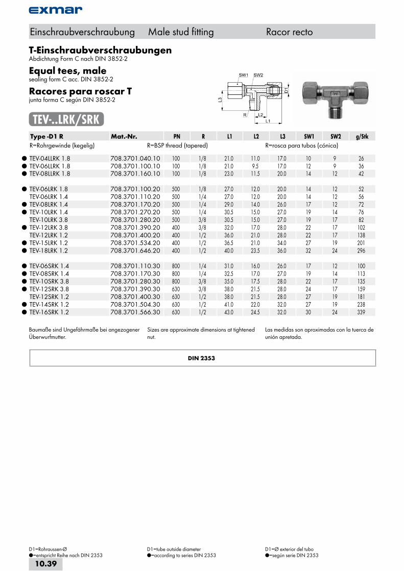
T-EinschraubverschraubungenAbdichtung Form C nach DIN 3852-2
Equal tees, malesealing form C acc. DIN 3852-2
Racores para roscar Tjunta forma C según DIN 3852-2
TEV-..LRK/SRKType -D1 R Mat.-Nr. PN R L1 L2 L3 SW1 SW2 g/StkR=Rohrgewinde (kegelig) R=BSP thread (tapered) R=rosca para tubos (cónica)
TEV-04LLRK 1.8 708.3701.040.10 100 1/8 21.0 11.0 17.0 10 9 26 TEV-06LLRK 1.8 708.3701.100.10 100 1/8 21.0 9.5 17.0 12 9 36 TEV-08LLRK 1.8 708.3701.160.10 100 1/8 23.0 11.5 20.0 14 12 42
TEV-06LRK 1.8 708.3701.100.20 500 1/8 27.0 12.0 20.0 14 12 52 TEV-06LRK 1.4 708.3701.110.20 500 1/4 27.0 12.0 20.0 14 12 56
TEV-08LRK 1.4 708.3701.170.20 500 1/4 29.0 14.0 26.0 17 12 72 TEV-10LRK 1.4 708.3701.270.20 500 1/4 30.5 15.0 27.0 19 14 76 TEV-10LRK 3.8 708.3701.280.20 500 3/8 30.5 15.0 27.0 19 17 82
TEV-12LRK 3.8 708.3701.390.20 400 3/8 32.0 17.0 28.0 22 17 102 TEV-12LRK 1.2 708.3701.400.20 400 1/2 36.0 21.0 28.0 22 17 138
TEV-15LRK 1.2 708.3701.534.20 400 1/2 36.5 21.0 34.0 27 19 201 TEV-18LRK 1.2 708.3701.646.20 400 1/2 40.0 23.5 36.0 32 24 296
TEV-06SRK 1.4 708.3701.110.30 800 1/4 31.0 16.0 26.0 17 12 100 TEV-08SRK 1.4 708.3701.170.30 800 1/4 32.5 17.0 27.0 19 14 113 TEV-10SRK 3.8 708.3701.280.30 800 3/8 35.0 17.5 28.0 22 17 135 TEV-12SRK 3.8 708.3701.390.30 630 3/8 38.0 21.5 28.0 24 17 159 TEV-12SRK 1.2 708.3701.400.30 630 1/2 38.0 21.5 28.0 27 19 181
TEV-14SRK 1.2 708.3701.504.30 630 1/2 41.0 22.0 32.0 27 19 238 TEV-16SRK 1.2 708.3701.566.30 630 1/2 43.0 24.5 32.0 30 24 339
Baumaße sind Ungefährmaße bei angezogener Überwurfmutter.
Sizes are approximate dimensions at tightened nut.
Las medidas son aproximadas con la tuerca de unión apretada.
DIN 2353
Einschraubverschraubung Male stud fitting Racor recto
D1=Rohraussen-Ø=entspricht Reihe nach DIN 2353
D1=tube outside diameter=according to series DIN 2353
D1=Ø exterior del tubo=según serie DIN 2353
10.39

T-EinschraubverschraubungenEqual tees, maleRacores para roscar T
TEV-..L-NPT/S-NPTType -D1 NPT Mat.-Nr. PN NPT L1 L2 L3 SW1 SW2 g/StkNPT=Einschraubgewinde NPT NPT=tapered adaptor thread NPT NPT=rosca de conexión cónica NPT TEV-04LLNPT 1.8 708.3704.040.10 100 1/8 21.0 11.0 17.0 10 9 26TEV-04LLNPT 1.4 708.3704.045.10 100 1/4 22.0 11.0 21.0 10 12 26TEV-06LLNPT 1.8 708.3704.100.10 100 1/8 21.0 9.5 17.0 12 9 43TEV-08LLNPT 1.8 708.3704.160.10 100 1/8 23.0 11.5 20.0 14 12 47 TEV-06LNPT 1.8 708.3704.100.20 500 1/8 27.0 12.0 20.0 14 12 50TEV-08LNPT 1.4 708.3704.170.20 500 1/4 29.0 14.0 26.0 17 12 73TEV-10LNPT 1.4 708.3704.270.20 500 1/4 30.5 15.0 27.0 19 14 90TEV-12LNPT 3.8 708.3704.390.20 400 3/8 32.0 17.0 28.0 22 17 129TEV-15LNPT 1.2 708.3704.534.20 400 1/2 36.5 21.0 34.0 27 19 215TEV-18LNPT 1.2 708.3704.646.20 400 1/2 40.0 23.5 36.0 32 24 295TEV-22LNPT 3.4 708.3704.768.20 250 3/4 44.5 27.5 42.0 36 27 433TEV-28LNPT 1.1 708.3704.850.20 250 1 48.0 30.5 48.0 41 36 619TEV-35LNPT 5.4 708.3704.944.20 250 1 1/4 57.0 34.5 54.0 50 41 910TEV-42LNPT 3.2 708.3704.992.20 250 1 1/2 63.5 40.0 61.0 60 50 1380 TEV-06SNPT 1.4 708.3704.110.30 800 1/4 31.0 16.0 26.0 17 12 94TEV-08SNPT 1.4 708.3704.170.30 800 1/4 32.5 17.0 27.0 19 14 114TEV-10SNPT 3.8 708.3704.280.30 800 3/8 35.0 17.5 28.0 22 17 157TEV-12SNPT 3.8 708.3704.390.30 630 3/8 38.0 21.5 28.0 24 17 184TEV-14SNPT 1.2 708.3704.504.30 630 1/2 41.0 22.0 32.0 27 19 242TEV-16SNPT 1.2 708.3704.566.30 630 1/2 43.0 24.5 36.0 30 24 327TEV-20SNPT 3.4 708.3704.704.30 420 3/4 50.0 26.5 42.0 36 27 520TEV-25SNPT 1.1 708.3704.810.30 420 1 56.0 30.0 48.0 46 36 983TEV-30SNPT 5.4 708.3704.902.30 420 1 1/4 64.0 35.5 54.0 50 41 1315TEV-38SNPT 3.2 708.3704.953.30 420 1 1/2 74.0 41.0 61.0 60 50 1946
Baumaße sind Ungefährmaße bei angezogener Überwurfmutter.
Sizes are approximate dimensions at tightened nut.
Las medidas son aproximadas con la tuerca de unión apretada.
DIN EN ISO 8434-1-SDTC
Einschraubverschraubung Male stud fitting Racor recto
D1=Rohraussen-Ø D1=tube outside diameter D1=Ø exterior del tubo
10.40
i
s
10
20
30
40
50
60
70
a

L-EinschraubverschraubungenAbdichtung Form B nach DIN 3852-2
Male stud tee-stud barrelssealing form B acc. DIN 3852-2
Racores para roscar Ljunta forma B según DIN 3852-2
LEV-..LR/SRType -D1 G Mat.-Nr. PN G L1 L2 L3 L4 SW1 SW2 g/StkG=Rohrgewinde (zylindrisch) G=BSP thread (straight) G=rosca de conexión (cilíndrica)
LEV-22LR 3.4 708.3712.708.20 250 3/4 44.0 35.0 26.0 16.0 36 27 371 LEV-28LR 1.1 708.3712.850.20 250 1 47.0 38.0 30.0 18.0 41 36 544 LEV-35LR 5.4 708.3712.944.20 250 1 1/4 56.0 45.0 34.0 20.0 50 41 844 LEV-42LR 3.2 708.3712.992.20 250 1 1/2 63.0 51.0 39.0 22.0 60 50 1240
LEV-20SR 3.4 708.3712.704.30 420 3/4 48.0 37.0 26.0 16.0 36 27 479 LEV-25SR 1.1 708.3712.810.30 420 1 54.0 42.0 30.0 18.0 46 36 891 LEV-30SR 5.4 708.3712.902.30 420 1 1/4 62.0 49.0 34.0 20.0 50 41 1227 LEV-38SR 3.2 708.3712.953.30 420 1 1/2 72.0 57.0 39.0 22.0 60 50 1712
Baumaße sind Ungefährmaße bei angezogener Überwurfmutter.
Abdichtung durch Dichtkante Form B nach DIN 3852-2.
Sizes are approximate dimensions at tightened nut.
Sealing by stud face form B acc. DIN 3852-2.
Las medidas son aproximadas con la tuerca de unión apretada.
Cierre hermético con junta de obturación forma B según DIN 3852-2.
DIN 2353
Einschraubverschraubung Male stud fitting Racor recto
D1=Rohraussen-Ø=entspricht Reihe nach DIN 2353
D1=tube outside diameter=according to series DIN 2353
D1=Ø exterior del tubo=según serie DIN 2353
10.41

L-EinschraubverschraubungenAbdichtung Form C nach DIN 3852-2
Male stud tee-stud barrelssealing form C acc. DIN 3852-2
Racores para roscar Ljunta forma C según DIN 3852-2
LEV-..LRK/SRKType -D1 R Mat.-Nr. PN R L1 L2 L3 SW1 SW2 g/StkR=Rohrgewinde (kegelig) R=BSP thread (tapered) R=rosca para tubos (cónica)
LEV-04LLRK 1.8 708.3711.040.10 100 1/8 21.0 11.0 16.0 10 9 26 LEV-06LLRK 1.8 708.3711.100.10 100 1/8 21.0 9.5 16.0 12 9 36 LEV-08LLRK 1.8 708.3711.161.10 100 1/8 23.0 11.5 20.0 14 12 42
LEV-06LRK 1.8 708.3711.100.20 500 1/8 27.0 12.0 20.0 14 12 53 LEV-06LRK 1.4 708.3711.111.20 500 1/4 27.0 12.0 20.0 14 12
LEV-08LRK 1.4 708.3711.170.20 500 1/4 29.0 14.0 26.0 17 12 75 LEV-10LRK 1.4 708.3711.270.20 500 1/4 30.0 15.0 27.0 19 14 100 LEV-12LRK 3.8 708.3711.390.20 400 3/8 32.0 17.0 28.0 22 17 120 LEV-15LRK 1.2 708.3711.534.20 400 1/2 36.0 21.0 34.0 27 19 167 LEV-18LRK 1.2 708.3711.646.20 400 1/2 40.0 23.5 36.0 32 24 296
LEV-06SRK 1.4 708.3711.111.30 800 1/4 31.0 16.0 26.0 17 12 97 LEV-08SRK 1.4 708.3711.170.30 800 1/4 32.0 17.0 27.0 19 14 128 LEV-10SRK 3.8 708.3711.280.30 800 3/8 34.0 17.5 28.0 22 17 172 LEV-12SRK 3.8 708.3711.390.30 630 3/8 38.0 21.5 28.0 24 17 244 LEV-14SRK 1.2 708.3711.504.30 630 1/2 41.0 22.0 32.0 27 19 240
LEV-16SRK 1.2 708.3711.566.30 630 1/2 43.0 24.5 32.0 30 24 320
Baumaße sind Ungefährmaße bei angezogener Überwurfmutter.
Sizes are approximate dimensions at tightened nut.
Las medidas son aproximadas con la tuerca de unión apretada.
DIN 2353
Einschraubverschraubung Male stud fitting Racor recto
D1=Rohraussen-Ø=entspricht Reihe nach DIN 2353
D1=tube outside diameter=according to series DIN 2353
D1=Ø exterior del tubo=según serie DIN 2353
10.42
i
s
10
20
30
40
50
60
70
a
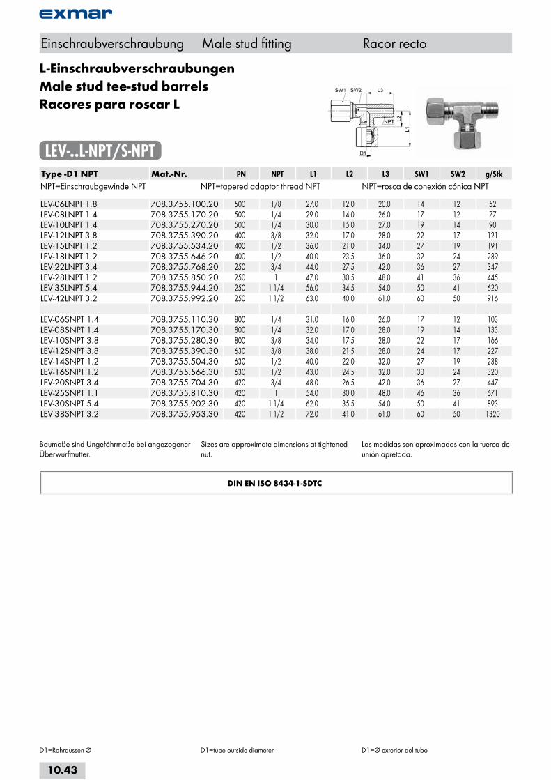
L-EinschraubverschraubungenMale stud tee-stud barrelsRacores para roscar L
LEV-..L-NPT/S-NPTType -D1 NPT Mat.-Nr. PN NPT L1 L2 L3 SW1 SW2 g/StkNPT=Einschraubgewinde NPT NPT=tapered adaptor thread NPT NPT=rosca de conexión cónica NPT LEV-06LNPT 1.8 708.3755.100.20 500 1/8 27.0 12.0 20.0 14 12 52LEV-08LNPT 1.4 708.3755.170.20 500 1/4 29.0 14.0 26.0 17 12 77LEV-10LNPT 1.4 708.3755.270.20 500 1/4 30.0 15.0 27.0 19 14 90LEV-12LNPT 3.8 708.3755.390.20 400 3/8 32.0 17.0 28.0 22 17 121LEV-15LNPT 1.2 708.3755.534.20 400 1/2 36.0 21.0 34.0 27 19 191LEV-18LNPT 1.2 708.3755.646.20 400 1/2 40.0 23.5 36.0 32 24 289LEV-22LNPT 3.4 708.3755.768.20 250 3/4 44.0 27.5 42.0 36 27 347LEV-28LNPT 1.2 708.3755.850.20 250 1 47.0 30.5 48.0 41 36 445LEV-35LNPT 5.4 708.3755.944.20 250 1 1/4 56.0 34.5 54.0 50 41 620LEV-42LNPT 3.2 708.3755.992.20 250 1 1/2 63.0 40.0 61.0 60 50 916 LEV-06SNPT 1.4 708.3755.110.30 800 1/4 31.0 16.0 26.0 17 12 103LEV-08SNPT 1.4 708.3755.170.30 800 1/4 32.0 17.0 28.0 19 14 133LEV-10SNPT 3.8 708.3755.280.30 800 3/8 34.0 17.5 28.0 22 17 166LEV-12SNPT 3.8 708.3755.390.30 630 3/8 38.0 21.5 28.0 24 17 227LEV-14SNPT 1.2 708.3755.504.30 630 1/2 40.0 22.0 32.0 27 19 238LEV-16SNPT 1.2 708.3755.566.30 630 1/2 43.0 24.5 32.0 30 24 320LEV-20SNPT 3.4 708.3755.704.30 420 3/4 48.0 26.5 42.0 36 27 447LEV-25SNPT 1.1 708.3755.810.30 420 1 54.0 30.0 48.0 46 36 671LEV-30SNPT 5.4 708.3755.902.30 420 1 1/4 62.0 35.5 54.0 50 41 893LEV-38SNPT 3.2 708.3755.953.30 420 1 1/2 72.0 41.0 61.0 60 50 1320
Baumaße sind Ungefährmaße bei angezogener Überwurfmutter.
Sizes are approximate dimensions at tightened nut.
Las medidas son aproximadas con la tuerca de unión apretada.
DIN EN ISO 8434-1-SDTC
Einschraubverschraubung Male stud fitting Racor recto
D1=Rohraussen-Ø D1=tube outside diameter D1=Ø exterior del tubo
10.43
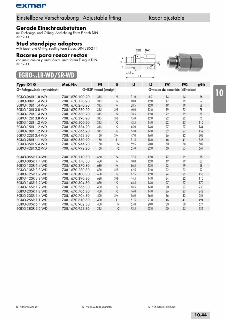
Gerade Einschraubstutzenmit Dichtkegel und O-Ring, Abdichtung Form E nach DIN 3852-11
Stud standpipe adaptorswith taper and O-ring, sealing form E acc. DIN 3852-11
Racores para roscar rectoscon junta cónica y junta tórica, junta forma E según DIN 3852-11
EGKO-..LR-WD/SR-WDType -D1 G Mat.-Nr. PN G L1 L2 SW1 SW2 g/StkG=Rohrgewinde (zylindrisch) G=BSP thread (straight) G=rosca de conexión (cilíndrica) EGKO-06LR 1.8 WD 708.1670.100.20 315 1/8 31.0 8.0 14 14 36EGKO-08LR 1.4 WD 708.1670.170.20 315 1/4 40.0 12.0 17 19 57EGKO-10LR 1.4 WD 708.1670.270.20 315 1/4 38.5 12.0 19 19 58EGKO-10LR 3.8 WD 708.1670.280.20 315 3/8 40.0 12.0 19 22 78EGKO-12LR 1.4 WD 708.1670.380.20 315 1/4 38.5 12.0 22 19 68EGKO-12LR 3.8 WD 708.1670.390.20 315 3/8 45.0 12.0 22 22 75EGKO-12LR 1.2 WD 708.1670.400.20 315 1/2 42.5 14.0 22 27 110EGKO-15LR 1.2 WD 708.1670.534.20 315 1/2 45.0 14.0 27 27 144EGKO-18LR 1.2 WD 708.1670.646.20 315 1/2 44.0 14.0 32 27 152EGKO-22LR 3.4 WD 708.1670.768.20 160 3/4 47.0 16.0 36 32 202EGKO-28LR 1.1 WD 708.1670.850.20 160 1 51.5 18.0 46 41 356EGKO-35LR 5.4 WD 708.1670.944.20 160 1 1/4 59.5 20.0 50 50 507EGKO-42LR 3.2 WD 708.1670.992.20 160 1 1/2 65.0 22.0 60 55 664 EGKO-06SR 1.4 WD 708.1670.110.30 630 1/4 37.5 12.0 17 19 56EGKO-08SR 1.4 WD 708.1670.170.30 630 1/4 40.0 12.0 19 19 62EGKO-10SR 1.4 WD 708.1670.270.30 630 1/4 36.5 12.0 22 19 68EGKO-10SR 3.8 WD 708.1670.280.30 630 3/8 42.5 12.0 22 22 92EGKO-12SR 1.2 WD 708.1670.400.30 630 1/2 47.5 12.0 24 22 153EGKO-12SR 3.8 WD 708.1670.390.30 630 3/8 44.5 14.0 24 22 110EGKO-14SR 1.2 WD 708.1670.504.30 630 1/2 48.5 14.0 27 27 170EGKO-16SR 1.2 WD 708.1670.566.30 400 1/2 48.5 14.0 30 27 230EGKO-20SR 1.2 WD 708.1670.706.30 400 1/2 46.0 14.0 36 27 242EGKO-20SR 3.4 WD 708.1670.704.30 400 3/4 56.0 16.0 36 32 286EGKO-25SR 1.1 WD 708.1670.810.30 400 1 61.5 21.0 46 41 494EGKO-30SR 5.4 WD 708.1670.902.30 400 1 1/4 65.0 20.0 50 50 674EGKO-38SR 3.2 WD 708.1670.953.30 315 1 1/2 73.5 22.0 60 55 931
Einstellbare Verschraubung Adjustable fitting Racor ajustable
D1=Rohraussen-Ø D1=tube outside diameter D1=Ø exterior del tubo
10.44
i
s
10
20
30
40
50
60
70
a
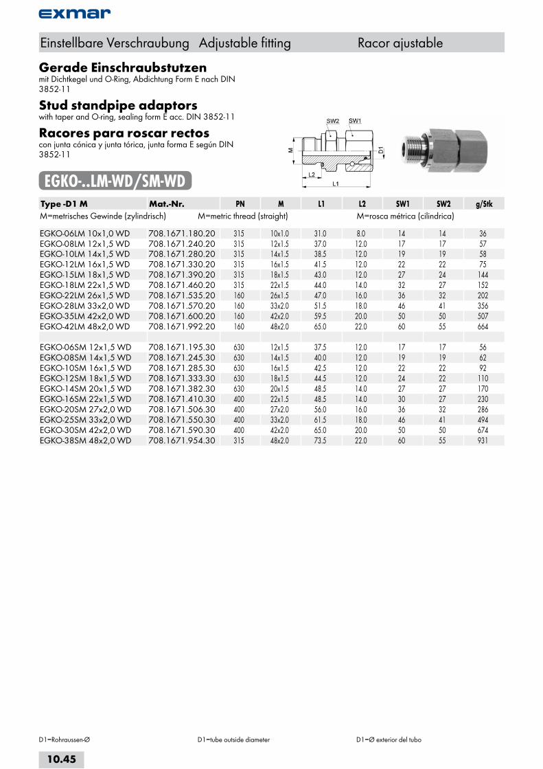
Gerade Einschraubstutzenmit Dichtkegel und O-Ring, Abdichtung Form E nach DIN 3852-11
Stud standpipe adaptorswith taper and O-ring, sealing form E acc. DIN 3852-11
Racores para roscar rectoscon junta cónica y junta tórica, junta forma E según DIN 3852-11
EGKO-..LM-WD/SM-WDType -D1 M Mat.-Nr. PN M L1 L2 SW1 SW2 g/StkM=metrisches Gewinde (zylindrisch) M=metric thread (straight) M=rosca métrica (cilindrica) EGKO-06LM 10x1,0 WD 708.1671.180.20 315 10x1.0 31.0 8.0 14 14 36EGKO-08LM 12x1,5 WD 708.1671.240.20 315 12x1.5 37.0 12.0 17 17 57EGKO-10LM 14x1,5 WD 708.1671.280.20 315 14x1.5 38.5 12.0 19 19 58EGKO-12LM 16x1,5 WD 708.1671.330.20 315 16x1.5 41.5 12.0 22 22 75EGKO-15LM 18x1,5 WD 708.1671.390.20 315 18x1.5 43.0 12.0 27 24 144EGKO-18LM 22x1,5 WD 708.1671.460.20 315 22x1.5 44.0 14.0 32 27 152EGKO-22LM 26x1,5 WD 708.1671.535.20 160 26x1.5 47.0 16.0 36 32 202EGKO-28LM 33x2,0 WD 708.1671.570.20 160 33x2.0 51.5 18.0 46 41 356EGKO-35LM 42x2,0 WD 708.1671.600.20 160 42x2.0 59.5 20.0 50 50 507EGKO-42LM 48x2,0 WD 708.1671.992.20 160 48x2.0 65.0 22.0 60 55 664 EGKO-06SM 12x1,5 WD 708.1671.195.30 630 12x1.5 37.5 12.0 17 17 56EGKO-08SM 14x1,5 WD 708.1671.245.30 630 14x1.5 40.0 12.0 19 19 62EGKO-10SM 16x1,5 WD 708.1671.285.30 630 16x1.5 42.5 12.0 22 22 92EGKO-12SM 18x1,5 WD 708.1671.333.30 630 18x1.5 44.5 12.0 24 22 110EGKO-14SM 20x1,5 WD 708.1671.382.30 630 20x1.5 48.5 14.0 27 27 170EGKO-16SM 22x1,5 WD 708.1671.410.30 400 22x1.5 48.5 14.0 30 27 230EGKO-20SM 27x2,0 WD 708.1671.506.30 400 27x2.0 56.0 16.0 36 32 286EGKO-25SM 33x2,0 WD 708.1671.550.30 400 33x2.0 61.5 18.0 46 41 494EGKO-30SM 42x2,0 WD 708.1671.590.30 400 42x2.0 65.0 20.0 50 50 674EGKO-38SM 48x2,0 WD 708.1671.954.30 315 48x2.0 73.5 22.0 60 55 931
Einstellbare Verschraubung Adjustable fitting Racor ajustable
D1=Rohraussen-Ø D1=tube outside diameter D1=Ø exterior del tubo
10.45
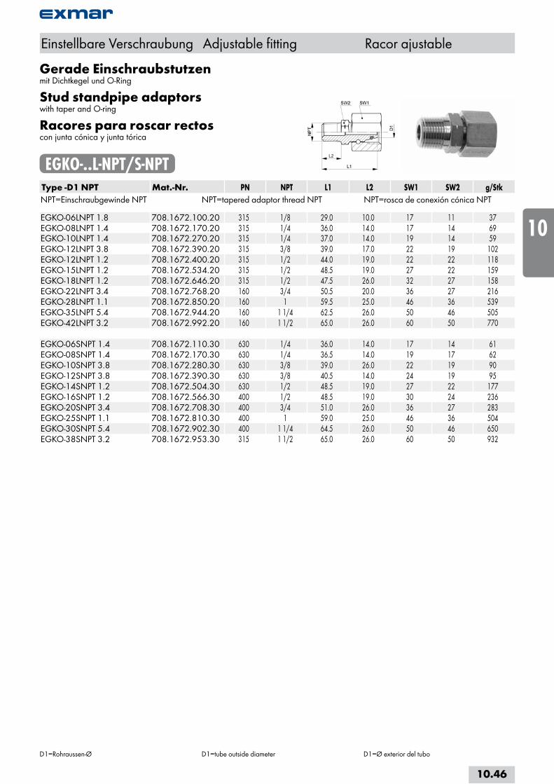
Gerade Einschraubstutzenmit Dichtkegel und O-Ring
Stud standpipe adaptorswith taper and O-ring
Racores para roscar rectoscon junta cónica y junta tórica
EGKO-..L-NPT/S-NPTType -D1 NPT Mat.-Nr. PN NPT L1 L2 SW1 SW2 g/StkNPT=Einschraubgewinde NPT NPT=tapered adaptor thread NPT NPT=rosca de conexión cónica NPT EGKO-06LNPT 1.8 708.1672.100.20 315 1/8 29.0 10.0 17 11 37EGKO-08LNPT 1.4 708.1672.170.20 315 1/4 36.0 14.0 17 14 69EGKO-10LNPT 1.4 708.1672.270.20 315 1/4 37.0 14.0 19 14 59EGKO-12LNPT 3.8 708.1672.390.20 315 3/8 39.0 17.0 22 19 102EGKO-12LNPT 1.2 708.1672.400.20 315 1/2 44.0 19.0 22 22 118EGKO-15LNPT 1.2 708.1672.534.20 315 1/2 48.5 19.0 27 22 159EGKO-18LNPT 1.2 708.1672.646.20 315 1/2 47.5 26.0 32 27 158EGKO-22LNPT 3.4 708.1672.768.20 160 3/4 50.5 20.0 36 27 216EGKO-28LNPT 1.1 708.1672.850.20 160 1 59.5 25.0 46 36 539EGKO-35LNPT 5.4 708.1672.944.20 160 1 1/4 62.5 26.0 50 46 505EGKO-42LNPT 3.2 708.1672.992.20 160 1 1/2 65.0 26.0 60 50 770 EGKO-06SNPT 1.4 708.1672.110.30 630 1/4 36.0 14.0 17 14 61EGKO-08SNPT 1.4 708.1672.170.30 630 1/4 36.5 14.0 19 17 62EGKO-10SNPT 3.8 708.1672.280.30 630 3/8 39.0 26.0 22 19 90EGKO-12SNPT 3.8 708.1672.390.30 630 3/8 40.5 14.0 24 19 95EGKO-14SNPT 1.2 708.1672.504.30 630 1/2 48.5 19.0 27 22 177EGKO-16SNPT 1.2 708.1672.566.30 400 1/2 48.5 19.0 30 24 236EGKO-20SNPT 3.4 708.1672.708.30 400 3/4 51.0 26.0 36 27 283EGKO-25SNPT 1.1 708.1672.810.30 400 1 59.0 25.0 46 36 504EGKO-30SNPT 5.4 708.1672.902.30 400 1 1/4 64.5 26.0 50 46 650EGKO-38SNPT 3.2 708.1672.953.30 315 1 1/2 65.0 26.0 60 50 932
Einstellbare Verschraubung Adjustable fitting Racor ajustable
D1=Rohraussen-Ø D1=tube outside diameter D1=Ø exterior del tubo
10.46
i
s
10
20
30
40
50
60
70
a
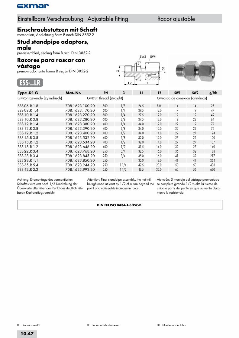
Einschraubstutzen mit Schaftvormontiert, Abdichtung Form B nach DIN 3852-2
Stud standpipe adaptors, malepre-assembled, sealing form B acc. DIN 3852-2
Racores para roscar con vástagopremontado, junta forma B según DIN 3852-2
ESS-..LRType -D1 G Mat.-Nr. PN G L1 L2 SW1 SW2 g/StkG=Rohrgewinde (zylindrisch) G=BSP thread (straight) G=rosca de conexión (cilíndrica) ESS-06LR 1.8 708.1623.100.20 500 1/8 24.5 8.0 14 14 25ESS-08LR 1.4 708.1623.170.20 500 1/4 29.5 12.0 17 19 47ESS-10LR 1.4 708.1623.270.20 500 1/4 27.5 12.0 19 19 49ESS-10LR 3.8 708.1623.280.20 500 3/8 27.5 12.0 19 22 64ESS-12LR 1.4 708.1623.380.20 400 1/4 34.0 12.0 22 19 72ESS-12LR 3.8 708.1623.390.20 400 3/8 34.0 12.0 22 22 74ESS-12LR 1.2 708.1623.400.20 400 1/2 34.0 14.0 22 27 124ESS-15LR 3.8 708.1623.532.20 400 3/8 32.0 12.0 27 22 100ESS-15LR 1.2 708.1623.534.20 400 1/2 32.0 14.0 27 27 107ESS-18LR 1.2 708.1623.646.20 400 1/2 31.5 14.0 32 27 140ESS-22LR 3.4 708.1623.768.20 250 3/4 32.5 16.0 36 32 188ESS-28LR 3.4 708.1623.845.20 250 3/4 35.0 16.0 41 32 217ESS-28LR 1.1 708.1623.850.20 250 1 35.0 18.0 41 41 264ESS-35LR 5.4 708.1623.944.20 250 1 1/4 42.5 20.0 50 50 438ESS-42LR 3.2 708.1623.992.20 250 1 1/2 46.5 22.0 60 55 630
Achtung: Endmontage des vormontierten Schaftes wird erst nach 1/2 Umdrehung der Überwurfmutter über den Punkt des deutlich fühl-baren Kraftanstiegs erreicht.
Attention: Final standpipe assembly, the nut will be tightened at least by 1/2 of a turn beyond the point of a noticeable increase in force.
Atención: El montaje del vástago premontado se completa girando 1/2 vuelta la tuerca de unión a partir del punto en que aumenta clara-mente la resistencia.
DIN EN ISO 8434-1-SDSC-B
Einstellbare Verschraubung Adjustable fitting Racor ajustable
D1=Rohraussen-Ø D1=tube outside diameter D1=Ø exterior del tubo
10.47
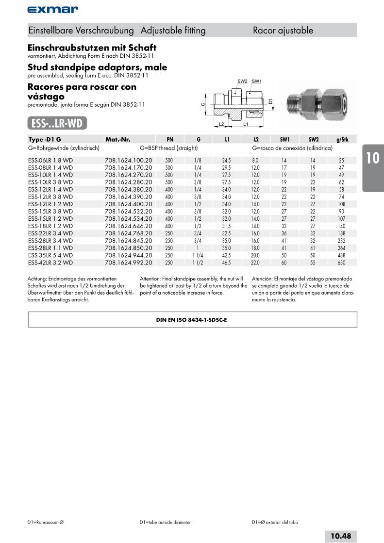
Einschraubstutzen mit Schaftvormontiert, Abdichtung Form E nach DIN 3852-11
Stud standpipe adaptors, malepre-assembled, sealing form E acc. DIN 3852-11
Racores para roscar con vástagopremontado, junta forma E según DIN 3852-11
ESS-..LR-WDType -D1 G Mat.-Nr. PN G L1 L2 SW1 SW2 g/StkG=Rohrgewinde (zylindrisch) G=BSP thread (straight) G=rosca de conexión (cilíndrica) ESS-06LR 1.8 WD 708.1624.100.20 500 1/8 24.5 8.0 14 14 25ESS-08LR 1.4 WD 708.1624.170.20 500 1/4 29.5 12.0 17 19 47ESS-10LR 1.4 WD 708.1624.270.20 500 1/4 27.5 12.0 19 19 49ESS-10LR 3.8 WD 708.1624.280.20 500 3/8 27.5 12.0 19 22 62ESS-12LR 1.4 WD 708.1624.380.20 400 1/4 34.0 12.0 22 19 58ESS-12LR 3.8 WD 708.1624.390.20 400 3/8 34.0 12.0 22 22 74ESS-12LR 1.2 WD 708.1624.400.20 400 1/2 34.0 14.0 22 27 108ESS-15LR 3.8 WD 708.1624.532.20 400 3/8 32.0 12.0 27 22 90ESS-15LR 1.2 WD 708.1624.534.20 400 1/2 32.0 14.0 27 27 107ESS-18LR 1.2 WD 708.1624.646.20 400 1/2 31.5 14.0 32 27 140ESS-22LR 3.4 WD 708.1624.768.20 250 3/4 32.5 16.0 36 32 188ESS-28LR 3.4 WD 708.1624.845.20 250 3/4 35.0 16.0 41 32 232ESS-28LR 1.1 WD 708.1624.850.20 250 1 35.0 18.0 41 41 264ESS-35LR 5.4 WD 708.1624.944.20 250 1 1/4 42.5 20.0 50 50 438ESS-42LR 3.2 WD 708.1624.992.20 250 1 1/2 46.5 22.0 60 55 630
Achtung: Endmontage des vormontierten Schaftes wird erst nach 1/2 Umdrehung der Überwurfmutter über den Punkt des deutlich fühl-baren Kraftanstiegs erreicht.
Attention: Final standpipe assembly, the nut will be tightened at least by 1/2 of a turn beyond the point of a noticeable increase in force.
Atención: El montaje del vástago premontado se completa girando 1/2 vuelta la tuerca de unión a partir del punto en que aumenta clara-mente la resistencia.
DIN EN ISO 8434-1-SDSC-E
Einstellbare Verschraubung Adjustable fitting Racor ajustable
D1=Rohraussen-Ø D1=tube outside diameter D1=Ø exterior del tubo
10.48
i
s
10
20
30
40
50
60
70
a

Einschraubstutzen mit Schaftvormontiert, Abdichtung Form B nach DIN 3852-2
Stud standpipe adaptors, malepre-assembled, sealing form B acc. DIN 3852-2
Racores para roscar con vástagopremontado, junta forma B según DIN 3852-2
ESS-..SRType -D1 G Mat.-Nr. PN G L1 L2 SW1 SW2 g/StkG=Rohrgewinde (zylindrisch) G=BSP thread (straight) G=rosca de conexión (cilíndrica) ESS-06SR 1.4 708.1623.110.30 800 1/4 27.0 12.0 17 19 42ESS-08SR 1.4 708.1623.170.30 800 1/4 29.5 12.0 19 19 58ESS-10SR 1.4 708.1623.270.30 800 1/4 29.5 12.0 22 19 66ESS-10SR 3.8 708.1623.280.30 800 3/8 32.0 12.0 22 22 81ESS-12SR 1.4 708.1623.380.30 630 1/4 34.0 12.0 24 19 72ESS-12SR 3.8 708.1623.390.30 630 3/8 34.0 12.0 24 22 110ESS-12SR 1.2 708.1623.400.30 630 1/2 32.0 14.0 24 27 127ESS-14SR 1.2 708.1623.504.30 630 1/2 37.0 14.0 27 27 142ESS-16SR 1.2 708.1623.566.30 630 1/2 37.0 14.0 30 32 160ESS-16SR 3.4 708.1623.568.30 630 3/4 45.0 16.0 30 27 211ESS-20SR 3.4 708.1623.704.30 420 3/4 43.0 16.0 36 32 261ESS-25SR 1.1 708.1623.810.30 420 1 48.0 18.0 46 41 480ESS-30SR 5.4 708.1623.902.30 420 1 1/4 51.0 20.0 50 50 675ESS-38SR 3.2 708.1623.953.30 420 1 1/2 60.0 22.0 60 55 899
Achtung: Endmontage des vormontierten Schaftes wird erst nach 1/2 Umdrehung der Überwurfmutter über den Punkt des deutlich fühl-baren Kraftanstiegs erreicht.
Attention: Final standpipe assembly, the nut will be tightened at least by 1/2 of a turn beyond the point of a noticeable increase in force.
Atención: El montaje del vástago premontado se completa girando 1/2 vuelta la tuerca de unión a partir del punto en que aumenta clara-mente la resistencia.
DIN EN ISO 8434-1-SDSC-B
Einstellbare Verschraubung Adjustable fitting Racor ajustable
D1=Rohraussen-Ø D1=tube outside diameter D1=Ø exterior del tubo
10.49

Einschraubstutzen mit Schaftvormontiert, Abdichtung Form E nach DIN 3852-11
Stud standpipe adaptors, malepre-assembled, sealing form E acc. DIN 3852-11
Racores para roscar con vástagopremontado, junta forma E según DIN 3852-11
ESS-..SR-WDType -D1 G Mat.-Nr. PN G L1 L2 SW1 SW2 g/StkG=Rohrgewinde (zylindrisch) G=BSP thread (straight) G=rosca de conexión (cilíndrica) ESS-06SR 1.4 WD 708.1624.110.30 800 1/4 27.0 12.0 17 19 42ESS-08SR 1.4 WD 708.1624.170.30 800 1/4 29.5 12.0 19 19 58ESS-10SR 1.4 WD 708.1624.270.30 800 1/4 32.0 12.0 22 19 50ESS-10SR 3.8 WD 708.1624.280.30 800 3/8 32.0 12.0 22 22 81ESS-12SR 1.4 WD 708.1624.380.30 630 1/4 34.0 12.0 24 19 78ESS-12SR 3.8 WD 708.1624.390.30 630 3/8 34.0 12.0 24 22 110ESS-12SR 1.2 WD 708.1624.400.30 630 1/2 32.0 14.0 24 27 127ESS-14SR 1.2 WD 708.1624.504.30 630 1/2 37.0 14.0 27 27 142ESS-16SR 1.2 WD 708.1624.566.30 630 1/2 37.0 14.0 30 27 160ESS-16SR 3.4 WD 708.1624.568.30 630 3/4 35.0 16.0 30 32 211ESS-20SR 3.4 WD 708.1624.704.30 420 3/4 43.0 16.0 36 32 261ESS-25SR 1.1 WD 708.1624.810.30 420 1 48.0 18.0 46 41 480ESS-30SR 5.4 WD 708.1624.902.30 420 1 1/4 51.0 20.0 50 50 675ESS-38SR 3.2 WD 708.1624.953.30 420 1 1/2 58.0 22.0 60 55 899
Achtung: Endmontage des vormontierten Schaftes wird erst nach 1/2 Umdrehung der Überwurfmutter über den Punkt des deutlich fühl-baren Kraftanstiegs erreicht.
Attention: Final standpipe assembly, the nut will be tightened at least by 1/2 of a turn beyond the point of a noticeable increase in force.
Atención: El montaje del vástago premontado se completa girando 1/2 vuelta la tuerca de unión a partir del punto en que aumenta clara-mente la resistencia.
DIN EN ISO 8434-1-SDSC-E
Einstellbare Verschraubung Adjustable fitting Racor ajustable
D1=Rohraussen-Ø D1=tube outside diameter D1=Ø exterior del tubo
10.50
i
s
10
20
30
40
50
60
70
a
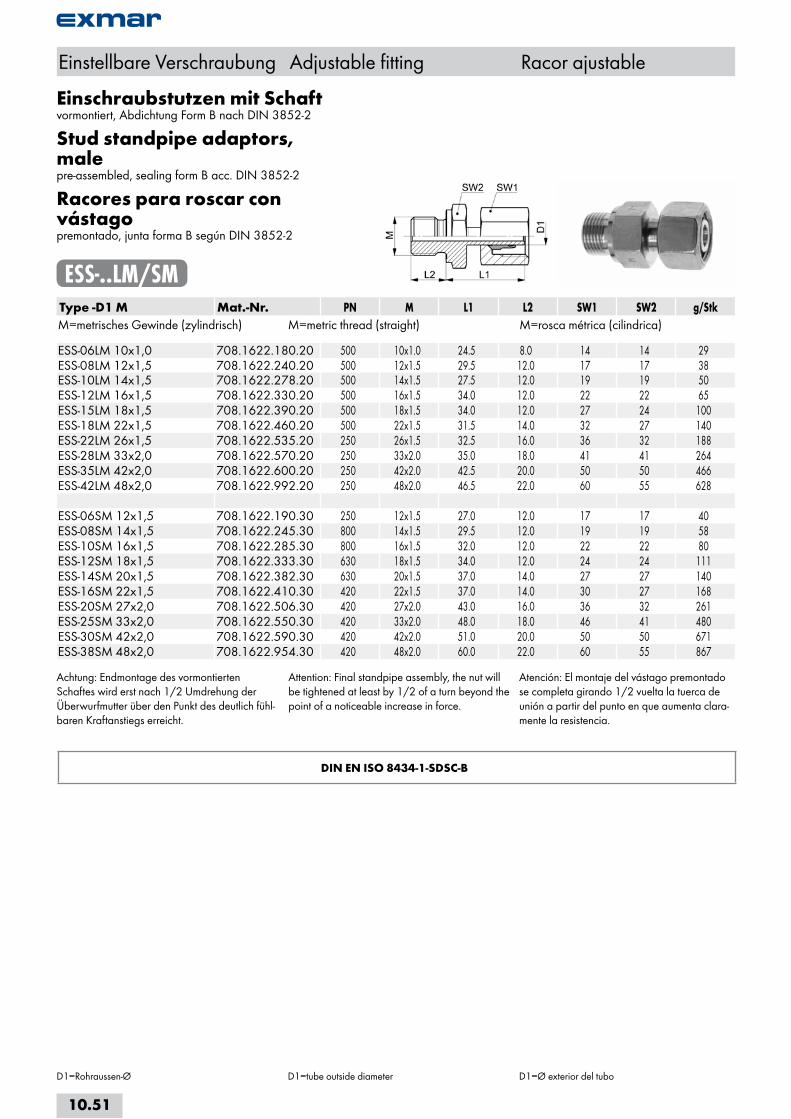
Einschraubstutzen mit Schaftvormontiert, Abdichtung Form B nach DIN 3852-2
Stud standpipe adaptors, malepre-assembled, sealing form B acc. DIN 3852-2
Racores para roscar con vástagopremontado, junta forma B según DIN 3852-2
ESS-..LM/SMType -D1 M Mat.-Nr. PN M L1 L2 SW1 SW2 g/StkM=metrisches Gewinde (zylindrisch) M=metric thread (straight) M=rosca métrica (cilindrica) ESS-06LM 10x1,0 708.1622.180.20 500 10x1.0 24.5 8.0 14 14 29ESS-08LM 12x1,5 708.1622.240.20 500 12x1.5 29.5 12.0 17 17 38ESS-10LM 14x1,5 708.1622.278.20 500 14x1.5 27.5 12.0 19 19 50ESS-12LM 16x1,5 708.1622.330.20 500 16x1.5 34.0 12.0 22 22 65ESS-15LM 18x1,5 708.1622.390.20 500 18x1.5 34.0 12.0 27 24 100ESS-18LM 22x1,5 708.1622.460.20 500 22x1.5 31.5 14.0 32 27 140ESS-22LM 26x1,5 708.1622.535.20 250 26x1.5 32.5 16.0 36 32 188ESS-28LM 33x2,0 708.1622.570.20 250 33x2.0 35.0 18.0 41 41 264ESS-35LM 42x2,0 708.1622.600.20 250 42x2.0 42.5 20.0 50 50 466ESS-42LM 48x2,0 708.1622.992.20 250 48x2.0 46.5 22.0 60 55 628 ESS-06SM 12x1,5 708.1622.190.30 250 12x1.5 27.0 12.0 17 17 40ESS-08SM 14x1,5 708.1622.245.30 800 14x1.5 29.5 12.0 19 19 58ESS-10SM 16x1,5 708.1622.285.30 800 16x1.5 32.0 12.0 22 22 80ESS-12SM 18x1,5 708.1622.333.30 630 18x1.5 34.0 12.0 24 24 111ESS-14SM 20x1,5 708.1622.382.30 630 20x1.5 37.0 14.0 27 27 140ESS-16SM 22x1,5 708.1622.410.30 420 22x1.5 37.0 14.0 30 27 168ESS-20SM 27x2,0 708.1622.506.30 420 27x2.0 43.0 16.0 36 32 261ESS-25SM 33x2,0 708.1622.550.30 420 33x2.0 48.0 18.0 46 41 480ESS-30SM 42x2,0 708.1622.590.30 420 42x2.0 51.0 20.0 50 50 671ESS-38SM 48x2,0 708.1622.954.30 420 48x2.0 60.0 22.0 60 55 867
Achtung: Endmontage des vormontierten Schaftes wird erst nach 1/2 Umdrehung der Überwurfmutter über den Punkt des deutlich fühl-baren Kraftanstiegs erreicht.
Attention: Final standpipe assembly, the nut will be tightened at least by 1/2 of a turn beyond the point of a noticeable increase in force.
Atención: El montaje del vástago premontado se completa girando 1/2 vuelta la tuerca de unión a partir del punto en que aumenta clara-mente la resistencia.
DIN EN ISO 8434-1-SDSC-B
Einstellbare Verschraubung Adjustable fitting Racor ajustable
D1=Rohraussen-Ø D1=tube outside diameter D1=Ø exterior del tubo
10.51
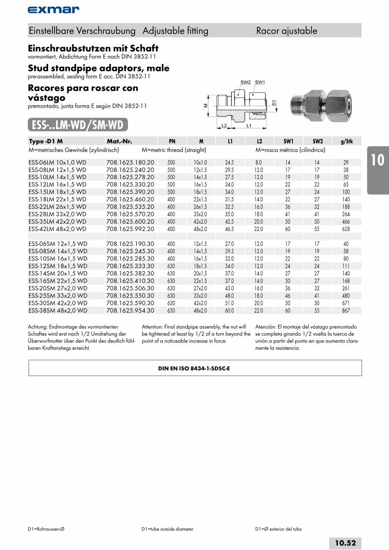
Einschraubstutzen mit Schaftvormontiert, Abdichtung Form E nach DIN 3852-11
Stud standpipe adaptors, malepre-assembled, sealing form E acc. DIN 3852-11
Racores para roscar con vástagopremontado, junta forma E según DIN 3852-11
ESS-..LM-WD/SM-WDType -D1 M Mat.-Nr. PN M L1 L2 SW1 SW2 g/StkM=metrisches Gewinde (zylindrisch) M=metric thread (straight) M=rosca métrica (cilindrica) ESS-06LM 10x1,0 WD 708.1625.180.20 500 10x1.0 24.5 8.0 14 14 29ESS-08LM 12x1,5 WD 708.1625.240.20 500 12x1.5 29.5 12.0 17 17 38ESS-10LM 14x1,5 WD 708.1625.278.20 500 14x1.5 27.5 12.0 19 19 50ESS-12LM 16x1,5 WD 708.1625.330.20 500 16x1.5 34.0 12.0 22 22 65ESS-15LM 18x1,5 WD 708.1625.390.20 500 18x1.5 34.0 12.0 27 24 100ESS-18LM 22x1,5 WD 708.1625.460.20 400 22x1.5 31.5 14.0 32 27 140ESS-22LM 26x1,5 WD 708.1625.535.20 400 26x1.5 32.5 16.0 36 32 188ESS-28LM 33x2,0 WD 708.1625.570.20 400 33x2.0 35.0 18.0 41 41 264ESS-35LM 42x2,0 WD 708.1625.600.20 400 42x2.0 42.5 20.0 50 50 466ESS-42LM 48x2,0 WD 708.1625.992.20 400 48x2.0 46.5 22.0 60 55 628 ESS-06SM 12x1,5 WD 708.1625.190.30 400 12x1.5 27.0 12.0 17 17 40ESS-08SM 14x1,5 WD 708.1625.245.30 400 14x1.5 29.5 12.0 19 19 58ESS-10SM 16x1,5 WD 708.1625.285.30 400 16x1.5 32.0 12.0 22 22 80ESS-12SM 18x1,5 WD 708.1625.333.30 630 18x1.5 34.0 12.0 24 24 111ESS-14SM 20x1,5 WD 708.1625.382.30 630 20x1.5 37.0 14.0 27 27 140ESS-16SM 22x1,5 WD 708.1625.410.30 630 22x1.5 37.0 14.0 30 27 168ESS-20SM 27x2,0 WD 708.1625.506.30 630 27x2.0 43.0 16.0 36 32 261ESS-25SM 33x2,0 WD 708.1625.550.30 630 33x2.0 48.0 18.0 46 41 480ESS-30SM 42x2,0 WD 708.1625.590.30 630 42x2.0 51.0 20.0 50 50 671ESS-38SM 48x2,0 WD 708.1625.954.30 630 48x2.0 60.0 22.0 60 55 867
Achtung: Endmontage des vormontierten Schaftes wird erst nach 1/2 Umdrehung der Überwurfmutter über den Punkt des deutlich fühl-baren Kraftanstiegs erreicht.
Attention: Final standpipe assembly, the nut will be tightened at least by 1/2 of a turn beyond the point of a noticeable increase in force.
Atención: El montaje del vástago premontado se completa girando 1/2 vuelta la tuerca de unión a partir del punto en que aumenta clara-mente la resistencia.
DIN EN ISO 8434-1-SDSC-E
Einstellbare Verschraubung Adjustable fitting Racor ajustable
D1=Rohraussen-Ø D1=tube outside diameter D1=Ø exterior del tubo
10.52
i
s
10
20
30
40
50
60
70
a
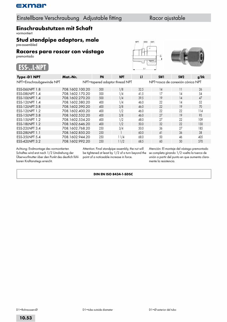
Einschraubstutzen mit Schaftvormontiert
Stud standpipe adaptors, malepre-assembled
Racores para roscar con vástagopremontado
ESS-..L-NPTType -D1 NPT Mat.-Nr. PN NPT L1 SW1 SW2 g/StkNPT=Einschraubgewinde NPT NPT=tapered adaptor thread NPT NPT=rosca de conexión cónica NPT ESS-06LNPT 1.8 708.1602.100.20 500 1/8 32.5 14 11 26ESS-08LNPT 1.4 708.1602.170.20 500 1/4 41.5 17 14 54ESS-10LNPT 1.4 708.1602.270.20 500 1/4 39.5 19 14 47ESS-12LNPT 1.4 708.1602.380.20 400 1/4 46.0 22 14 52ESS-12LNPT 3.8 708.1602.390.20 400 3/8 46.0 22 19 70ESS-12LNPT 1.2 708.1602.400.20 400 1/2 46.0 22 22 114ESS-15LNPT 3.8 708.1602.532.20 400 3/8 46.0 27 19 95ESS-15LNPT 1.2 708.1602.534.20 400 1/2 48.0 27 22 109ESS-18LNPT 1.2 708.1602.646.20 400 1/2 50.0 32 22 130ESS-22LNPT 3.4 708.1602.768.20 250 3/4 50.0 36 27 185ESS-28LNPT 1.1 708.1602.850.20 250 1 60.0 41 36 38ESS-35LNPT 5.4 708.1602.944.20 250 1 1/4 68.0 50 46 405ESS-42LNPT 3.2 708.1602.992.20 250 1 1/2 68.5 60 50 570
Achtung: Endmontage des vormontierten Schaftes wird erst nach 1/2 Umdrehung der Überwurfmutter über den Punkt des deutlich fühl-baren Kraftanstiegs erreicht.
Attention: Final standpipe assembly, the nut will be tightened at least by 1/2 of a turn beyond the point of a noticeable increase in force.
Atención: El montaje del vástago premontado se completa girando 1/2 vuelta la tuerca de unión a partir del punto en que aumenta clara-mente la resistencia.
DIN EN ISO 8434-1-SDSC
Einstellbare Verschraubung Adjustable fitting Racor ajustable
D1=Rohraussen-Ø D1=tube outside diameter D1=Ø exterior del tubo
10.53
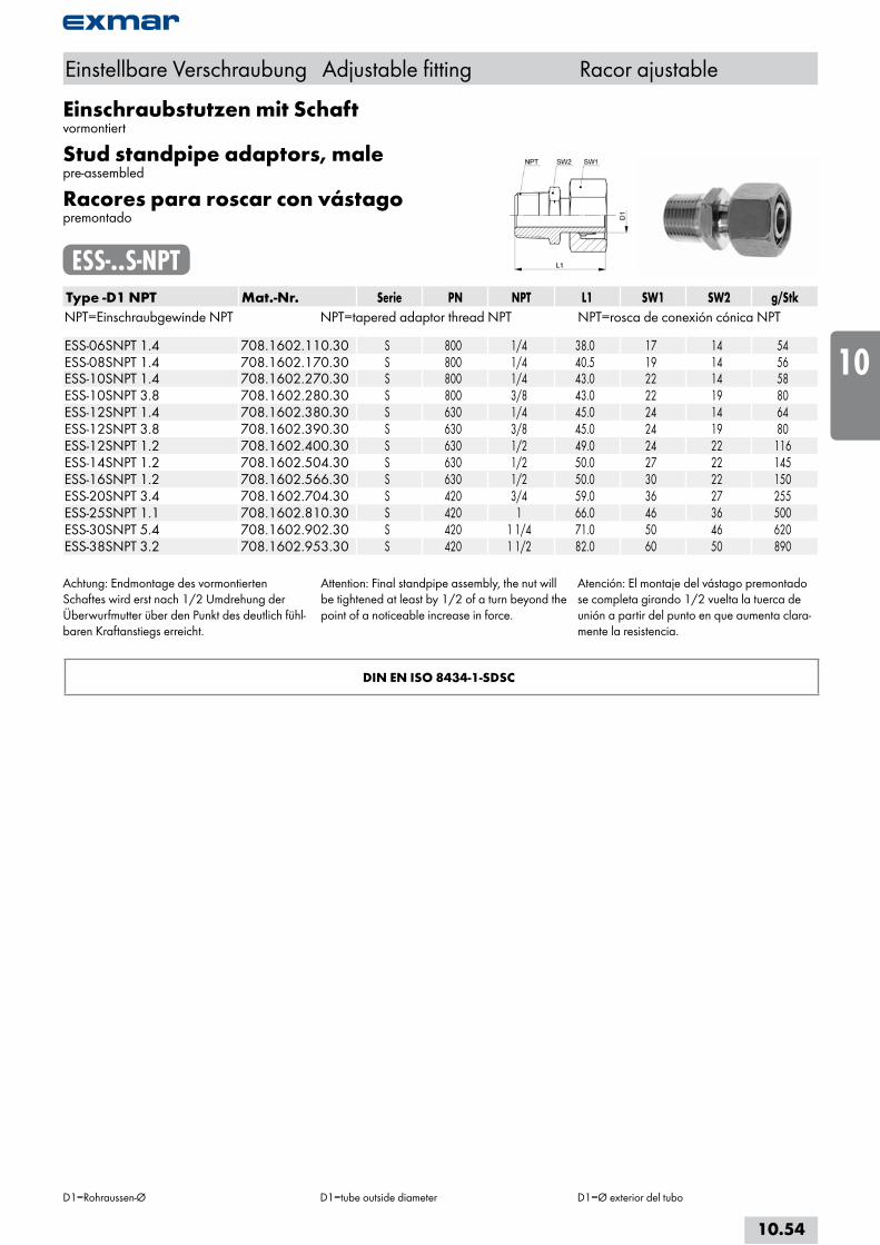
Einschraubstutzen mit Schaftvormontiert
Stud standpipe adaptors, malepre-assembled
Racores para roscar con vástagopremontado
ESS-..S-NPTType -D1 NPT Mat.-Nr. Serie PN NPT L1 SW1 SW2 g/StkNPT=Einschraubgewinde NPT NPT=tapered adaptor thread NPT NPT=rosca de conexión cónica NPT ESS-06SNPT 1.4 708.1602.110.30 S 800 1/4 38.0 17 14 54ESS-08SNPT 1.4 708.1602.170.30 S 800 1/4 40.5 19 14 56ESS-10SNPT 1.4 708.1602.270.30 S 800 1/4 43.0 22 14 58ESS-10SNPT 3.8 708.1602.280.30 S 800 3/8 43.0 22 19 80ESS-12SNPT 1.4 708.1602.380.30 S 630 1/4 45.0 24 14 64ESS-12SNPT 3.8 708.1602.390.30 S 630 3/8 45.0 24 19 80ESS-12SNPT 1.2 708.1602.400.30 S 630 1/2 49.0 24 22 116ESS-14SNPT 1.2 708.1602.504.30 S 630 1/2 50.0 27 22 145ESS-16SNPT 1.2 708.1602.566.30 S 630 1/2 50.0 30 22 150ESS-20SNPT 3.4 708.1602.704.30 S 420 3/4 59.0 36 27 255ESS-25SNPT 1.1 708.1602.810.30 S 420 1 66.0 46 36 500ESS-30SNPT 5.4 708.1602.902.30 S 420 1 1/4 71.0 50 46 620ESS-38SNPT 3.2 708.1602.953.30 S 420 1 1/2 82.0 60 50 890
Achtung: Endmontage des vormontierten Schaftes wird erst nach 1/2 Umdrehung der Überwurfmutter über den Punkt des deutlich fühl-baren Kraftanstiegs erreicht.
Attention: Final standpipe assembly, the nut will be tightened at least by 1/2 of a turn beyond the point of a noticeable increase in force.
Atención: El montaje del vástago premontado se completa girando 1/2 vuelta la tuerca de unión a partir del punto en que aumenta clara-mente la resistencia.
DIN EN ISO 8434-1-SDSC
Einstellbare Verschraubung Adjustable fitting Racor ajustable
D1=Rohraussen-Ø D1=tube outside diameter D1=Ø exterior del tubo
10.54
i
s
10
20
30
40
50
60
70
a

Einstellbare Winkelverschraubungenmit Dichtkegel und O-Ring
Adjustable equal elbowswith taper and O-ring
Racores angulares ajustablescon junta cónica y junta tórica
EWKO-..L/SType -D1 Mat.-Nr. PN L1 L2 L3 SW1 SW2 g/Stk EWKO-06L 708.2670.060.20 315 20.0 12.0 24.5 14 12 37EWKO-08L 708.2670.080.20 315 22.0 14.0 26.0 17 12 51EWKO-10L 708.2670.100.20 315 23.0 15.0 28.0 19 14 71EWKO-12L 708.2670.120.20 315 25.0 17.0 28.5 22 17 94EWKO-15L 708.2670.150.20 315 29.0 21.0 31.5 27 19 156EWKO-18L 708.2670.180.20 315 32.5 23.5 34.0 32 24 229EWKO-22L 708.2670.220.20 160 36.5 27.5 37.0 36 27 307EWKO-28L 708.2670.280.20 160 39.5 30.5 37.0 46 36 431EWKO-35L 708.2670.350.20 160 45.5 34.5 48.0 50 41 654EWKO-42L 708.2670.420.20 160 52.0 40.0 52.5 60 50 1005 EWKO-06S 708.2670.060.30 630 24.0 16.0 25.5 17 12 59EWKO-08S 708.2670.080.30 630 25.0 17.0 26.0 19 14 71EWKO-10S 708.2670.100.30 630 26.5 17.5 28.5 22 17 114EWKO-12S 708.2670.120.30 630 30.5 21.5 29.5 24 17 140EWKO-14S 708.2670.140.30 630 30.0 22.0 33.0 27 19 193EWKO-16S 708.2670.160.30 400 34.5 24.5 34.0 30 24 242EWKO-20S 708.2670.200.30 400 37.5 26.5 41.5 36 27 366EWKO-25S 708.2670.250.30 400 42.0 30.0 45.5 46 36 727EWKO-30S 708.2670.350.30 400 48.5 35.5 49.5 50 41 973EWKO-38S 708.2670.380.30 315 55.5 40.5 55.0 60 50 1391
Baumaße sind Ungefährmaße bei angezogener Überwurfmutter.
Sizes are approximate dimensions at tightened nut.
Las medidas son aproximadas con la tuerca de unión apretada.
Einstellbare Verschraubung Adjustable fitting Racor ajustable
D1=Rohraussen-Ø D1=tube outside diameter D1=Ø exterior del tubo
10.55
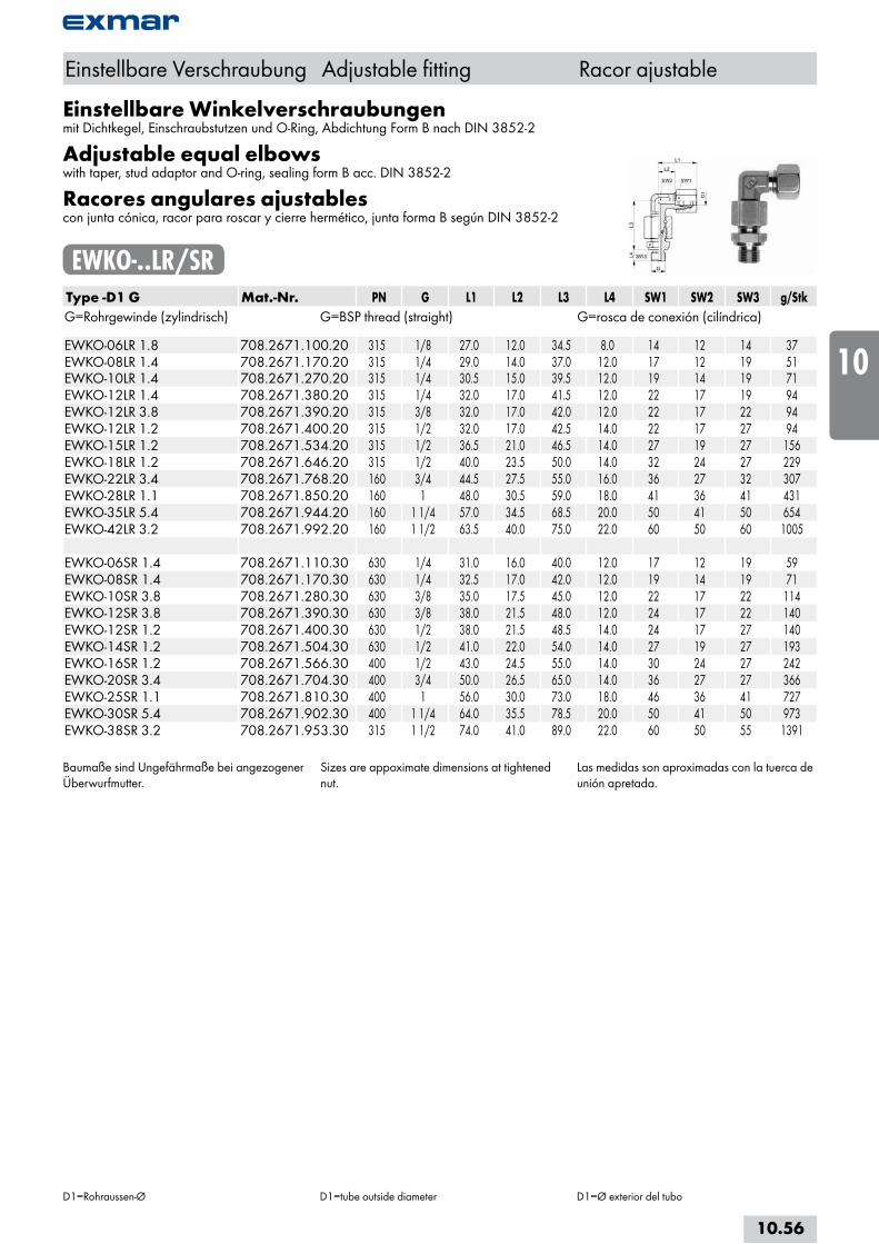
Einstellbare Winkelverschraubungenmit Dichtkegel, Einschraubstutzen und O-Ring, Abdichtung Form B nach DIN 3852-2
Adjustable equal elbowswith taper, stud adaptor and O-ring, sealing form B acc. DIN 3852-2
Racores angulares ajustablescon junta cónica, racor para roscar y cierre hermético, junta forma B según DIN 3852-2
EWKO-..LR/SRType -D1 G Mat.-Nr. PN G L1 L2 L3 L4 SW1 SW2 SW3 g/StkG=Rohrgewinde (zylindrisch) G=BSP thread (straight) G=rosca de conexión (cilíndrica) EWKO-06LR 1.8 708.2671.100.20 315 1/8 27.0 12.0 34.5 8.0 14 12 14 37EWKO-08LR 1.4 708.2671.170.20 315 1/4 29.0 14.0 37.0 12.0 17 12 19 51EWKO-10LR 1.4 708.2671.270.20 315 1/4 30.5 15.0 39.5 12.0 19 14 19 71EWKO-12LR 1.4 708.2671.380.20 315 1/4 32.0 17.0 41.5 12.0 22 17 19 94EWKO-12LR 3.8 708.2671.390.20 315 3/8 32.0 17.0 42.0 12.0 22 17 22 94EWKO-12LR 1.2 708.2671.400.20 315 1/2 32.0 17.0 42.5 14.0 22 17 27 94EWKO-15LR 1.2 708.2671.534.20 315 1/2 36.5 21.0 46.5 14.0 27 19 27 156EWKO-18LR 1.2 708.2671.646.20 315 1/2 40.0 23.5 50.0 14.0 32 24 27 229EWKO-22LR 3.4 708.2671.768.20 160 3/4 44.5 27.5 55.0 16.0 36 27 32 307EWKO-28LR 1.1 708.2671.850.20 160 1 48.0 30.5 59.0 18.0 41 36 41 431EWKO-35LR 5.4 708.2671.944.20 160 1 1/4 57.0 34.5 68.5 20.0 50 41 50 654EWKO-42LR 3.2 708.2671.992.20 160 1 1/2 63.5 40.0 75.0 22.0 60 50 60 1005 EWKO-06SR 1.4 708.2671.110.30 630 1/4 31.0 16.0 40.0 12.0 17 12 19 59EWKO-08SR 1.4 708.2671.170.30 630 1/4 32.5 17.0 42.0 12.0 19 14 19 71EWKO-10SR 3.8 708.2671.280.30 630 3/8 35.0 17.5 45.0 12.0 22 17 22 114EWKO-12SR 3.8 708.2671.390.30 630 3/8 38.0 21.5 48.0 12.0 24 17 22 140EWKO-12SR 1.2 708.2671.400.30 630 1/2 38.0 21.5 48.5 14.0 24 17 27 140EWKO-14SR 1.2 708.2671.504.30 630 1/2 41.0 22.0 54.0 14.0 27 19 27 193EWKO-16SR 1.2 708.2671.566.30 400 1/2 43.0 24.5 55.0 14.0 30 24 27 242EWKO-20SR 3.4 708.2671.704.30 400 3/4 50.0 26.5 65.0 14.0 36 27 27 366EWKO-25SR 1.1 708.2671.810.30 400 1 56.0 30.0 73.0 18.0 46 36 41 727EWKO-30SR 5.4 708.2671.902.30 400 1 1/4 64.0 35.5 78.5 20.0 50 41 50 973EWKO-38SR 3.2 708.2671.953.30 315 1 1/2 74.0 41.0 89.0 22.0 60 50 55 1391
Baumaße sind Ungefährmaße bei angezogener Überwurfmutter.
Sizes are appoximate dimensions at tightened nut.
Las medidas son aproximadas con la tuerca de unión apretada.
Einstellbare Verschraubung Adjustable fitting Racor ajustable
D1=Rohraussen-Ø D1=tube outside diameter D1=Ø exterior del tubo
10.56
i
s
10
20
30
40
50
60
70
a
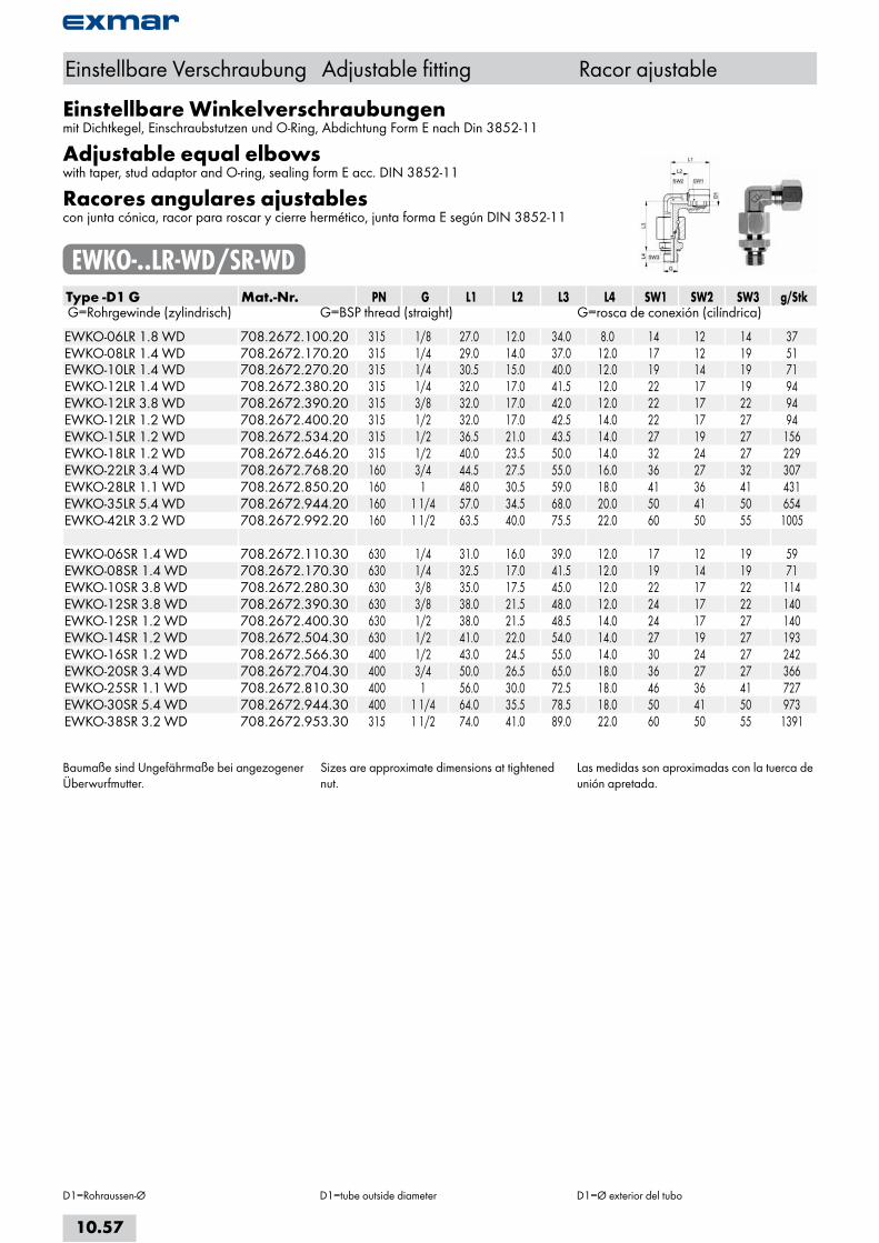
Einstellbare Winkelverschraubungenmit Dichtkegel, Einschraubstutzen und O-Ring, Abdichtung Form E nach Din 3852-11
Adjustable equal elbowswith taper, stud adaptor and O-ring, sealing form E acc. DIN 3852-11
Racores angulares ajustablescon junta cónica, racor para roscar y cierre hermético, junta forma E según DIN 3852-11
EWKO-..LR-WD/SR-WDType -D1 G Mat.-Nr. PN G L1 L2 L3 L4 SW1 SW2 SW3 g/Stk G=Rohrgewinde (zylindrisch) G=BSP thread (straight) G=rosca de conexión (cilíndrica) EWKO-06LR 1.8 WD 708.2672.100.20 315 1/8 27.0 12.0 34.0 8.0 14 12 14 37EWKO-08LR 1.4 WD 708.2672.170.20 315 1/4 29.0 14.0 37.0 12.0 17 12 19 51EWKO-10LR 1.4 WD 708.2672.270.20 315 1/4 30.5 15.0 40.0 12.0 19 14 19 71EWKO-12LR 1.4 WD 708.2672.380.20 315 1/4 32.0 17.0 41.5 12.0 22 17 19 94EWKO-12LR 3.8 WD 708.2672.390.20 315 3/8 32.0 17.0 42.0 12.0 22 17 22 94EWKO-12LR 1.2 WD 708.2672.400.20 315 1/2 32.0 17.0 42.5 14.0 22 17 27 94EWKO-15LR 1.2 WD 708.2672.534.20 315 1/2 36.5 21.0 43.5 14.0 27 19 27 156EWKO-18LR 1.2 WD 708.2672.646.20 315 1/2 40.0 23.5 50.0 14.0 32 24 27 229EWKO-22LR 3.4 WD 708.2672.768.20 160 3/4 44.5 27.5 55.0 16.0 36 27 32 307EWKO-28LR 1.1 WD 708.2672.850.20 160 1 48.0 30.5 59.0 18.0 41 36 41 431EWKO-35LR 5.4 WD 708.2672.944.20 160 1 1/4 57.0 34.5 68.0 20.0 50 41 50 654EWKO-42LR 3.2 WD 708.2672.992.20 160 1 1/2 63.5 40.0 75.5 22.0 60 50 55 1005 EWKO-06SR 1.4 WD 708.2672.110.30 630 1/4 31.0 16.0 39.0 12.0 17 12 19 59EWKO-08SR 1.4 WD 708.2672.170.30 630 1/4 32.5 17.0 41.5 12.0 19 14 19 71EWKO-10SR 3.8 WD 708.2672.280.30 630 3/8 35.0 17.5 45.0 12.0 22 17 22 114EWKO-12SR 3.8 WD 708.2672.390.30 630 3/8 38.0 21.5 48.0 12.0 24 17 22 140EWKO-12SR 1.2 WD 708.2672.400.30 630 1/2 38.0 21.5 48.5 14.0 24 17 27 140EWKO-14SR 1.2 WD 708.2672.504.30 630 1/2 41.0 22.0 54.0 14.0 27 19 27 193EWKO-16SR 1.2 WD 708.2672.566.30 400 1/2 43.0 24.5 55.0 14.0 30 24 27 242EWKO-20SR 3.4 WD 708.2672.704.30 400 3/4 50.0 26.5 65.0 18.0 36 27 27 366EWKO-25SR 1.1 WD 708.2672.810.30 400 1 56.0 30.0 72.5 18.0 46 36 41 727EWKO-30SR 5.4 WD 708.2672.944.30 400 1 1/4 64.0 35.5 78.5 18.0 50 41 50 973EWKO-38SR 3.2 WD 708.2672.953.30 315 1 1/2 74.0 41.0 89.0 22.0 60 50 55 1391
Baumaße sind Ungefährmaße bei angezogener Überwurfmutter.
Sizes are approximate dimensions at tightened nut.
Las medidas son aproximadas con la tuerca de unión apretada.
Einstellbare Verschraubung Adjustable fitting Racor ajustable
D1=Rohraussen-Ø D1=tube outside diameter D1=Ø exterior del tubo
10.57
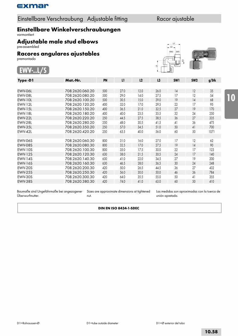
Einstellbare Winkelverschraubungenvormontiert
Adjustable male stud elbowspre-assembled
Racores angulares ajustablespremontado
EWV-..L/SType -D1 Mat.-Nr. PN L1 L2 L3 SW1 SW2 g/Stk EWV-06L 708.2620.060.20 500 27.0 12.0 26.0 14 12 35EWV-08L 708.2620.080.20 500 29.0 14.0 27.5 17 12 54EWV-10L 708.2620.100.20 500 30.5 15.0 29.0 19 14 68EWV-12L 708.2620.120.20 400 32.0 17.0 29.5 22 17 95EWV-15L 708.2620.150.20 400 36.5 21.0 32.5 27 19 170EWV-18L 708.2620.180.20 400 40.0 23.5 35.5 32 24 250EWV-22L 708.2620.220.20 250 44.5 27.5 38.5 36 27 335EWV-28L 708.2620.280.20 250 48.0 30.5 41.5 41 36 475EWV-35L 708.2620.350.20 250 57.0 34.5 51.0 50 41 700EWV-42L 708.2620.420.20 250 63.5 40.0 56.0 60 50 1071 EWV-06S 708.2620.060.30 800 31.0 16.0 27.0 17 12 62EWV-08S 708.2620.080.30 800 32.5 17.0 27.5 19 14 90EWV-10S 708.2620.100.30 800 35.0 17.5 30.0 22 17 123EWV-12S 708.2620.120.30 630 38.0 21.5 30.5 24 17 140EWV-14S 708.2620.140.30 630 41.0 22.0 34.5 27 19 200EWV-16S 708.2620.160.30 630 46.5 28.0 36.5 30 24 248EWV-20S 708.2620.200.30 420 50.0 26.5 44.5 36 27 432EWV-25S 708.2620.250.30 420 56.0 30.0 50.0 46 36 784EWV-30S 708.2620.300.30 420 64.0 35.5 55.0 50 41 355EWV-38S 708.2620.380.30 420 74.0 41.0 63.0 60 50 410
Baumaße sind Ungefährmaße bei angezogener Überwurfmutter.
Sizes are approximate dimensions at tightened nut.
Las medidas son aproximadas con la tuerca de unión apretada.
DIN EN ISO 8434-1-SDEC
Einstellbare Verschraubung Adjustable fitting Racor ajustable
D1=Rohraussen-Ø D1=tube outside diameter D1=Ø exterior del tubo
10.58
i
s
10
20
30
40
50
60
70
a
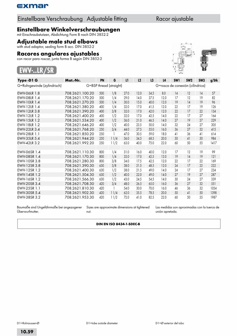
Einstellbare Winkelverschraubungenmit Einschraubstutzen, Abdichtung Form B nach DIN 3852-2
Adjustable male stud elbowswith stud adaptor, sealing form B acc. DIN 3852-2
Racores angulares ajustablescon racor para roscar, junta forma B según DIN 3852-2
EWV-..LR/SRType -D1 G Mat.-Nr. PN G L1 L2 L3 L4 SW1 SW2 SW3 g/StkG=Rohrgewinde (zylindrisch) G=BSP thread (straight) G=rosca de conexión (cilíndrica) EWV-06LR 1.8 708.2621.100.20 500 1/8 27.0 12.0 34.5 8.0 14 12 14 57EWV-08LR 1.4 708.2621.170.20 500 1/4 29.0 14.0 37.5 12.0 17 12 19 82EWV-10LR 1.4 708.2621.270.20 500 1/4 30.0 15.0 40.0 12.0 19 14 19 96EWV-12LR 1.4 708.2621.380.20 400 1/4 32.0 17.0 41.5 12.0 22 17 19 126EWV-12LR 3.8 708.2621.390.20 400 3/8 32.0 17.0 42.0 12.0 22 17 22 134EWV-12LR 1.2 708.2621.400.20 400 1/2 32.0 17.0 42.5 14.0 22 17 27 164EWV-15LR 1.2 708.2621.534.20 400 1/2 36.0 21.0 46.5 14.0 27 19 27 229EWV-18LR 1.2 708.2621.646.20 400 1/2 40.0 23.5 50.0 14.0 32 24 27 305EWV-22LR 3.4 708.2621.768.20 250 3/4 44.0 27.5 55.0 16.0 36 27 32 415EWV-28LR 1.1 708.2621.850.20 250 1 47.0 30.5 59.0 18.0 41 36 41 614EWV-35LR 5.4 708.2621.944.20 250 1 1/4 56.0 34.5 68.5 20.0 50 41 50 984EWV-42LR 3.2 708.2621.992.20 250 1 1/2 63.0 40.0 75.0 22.0 60 50 55 1417 EWV-06SR 1.4 708.2621.110.30 800 1/4 31.0 16.0 40.0 12.0 17 12 19 99EWV-08SR 1.4 708.2621.170.30 800 1/4 32.0 17.0 42.5 12.0 19 14 19 121EWV-10SR 3.8 708.2621.280.30 800 3/8 34.0 17.5 42.5 12.0 22 17 22 169EWV-12SR 3.8 708.2621.390.30 630 3/8 38.0 21.5 48.5 12.0 24 17 22 222EWV-12SR 1.2 708.2621.400.30 630 1/2 38.0 21.5 49.0 14.0 24 17 27 234EWV-14SR 1.2 708.2621.504.30 630 1/2 40.0 22.0 49.0 14.0 27 19 27 287EWV-16SR 1.2 708.2621.566.30 630 1/2 43.0 24.5 54.5 14.0 30 24 27 339EWV-20SR 3.4 708.2621.708.30 420 3/4 48.0 26.5 65.0 16.0 36 27 32 551EWV-25SR 1.1 708.2621.810.30 420 1 54.0 30.0 70.0 16.0 46 36 32 1054EWV-30SR 5.4 708.2621.902.30 420 1 1/4 62.0 35.5 78.5 20.0 50 41 50 1398EWV-38SR 3.2 708.2621.953.30 420 1 1/2 72.0 41.0 82.5 22.0 60 50 55 1987
Baumaße sind Ungefährmaße bei angezogener Überwurfmutter.
Sizes are approximate dimensions at tightened nut.
Las medidas son aproximadas con la tuerca de unión apretada.
DIN EN ISO 8434-1-SDEC-B
Einstellbare Verschraubung Adjustable fitting Racor ajustable
D1=Rohraussen-Ø D1=tube outside diameter D1=Ø exterior del tubo
10.59
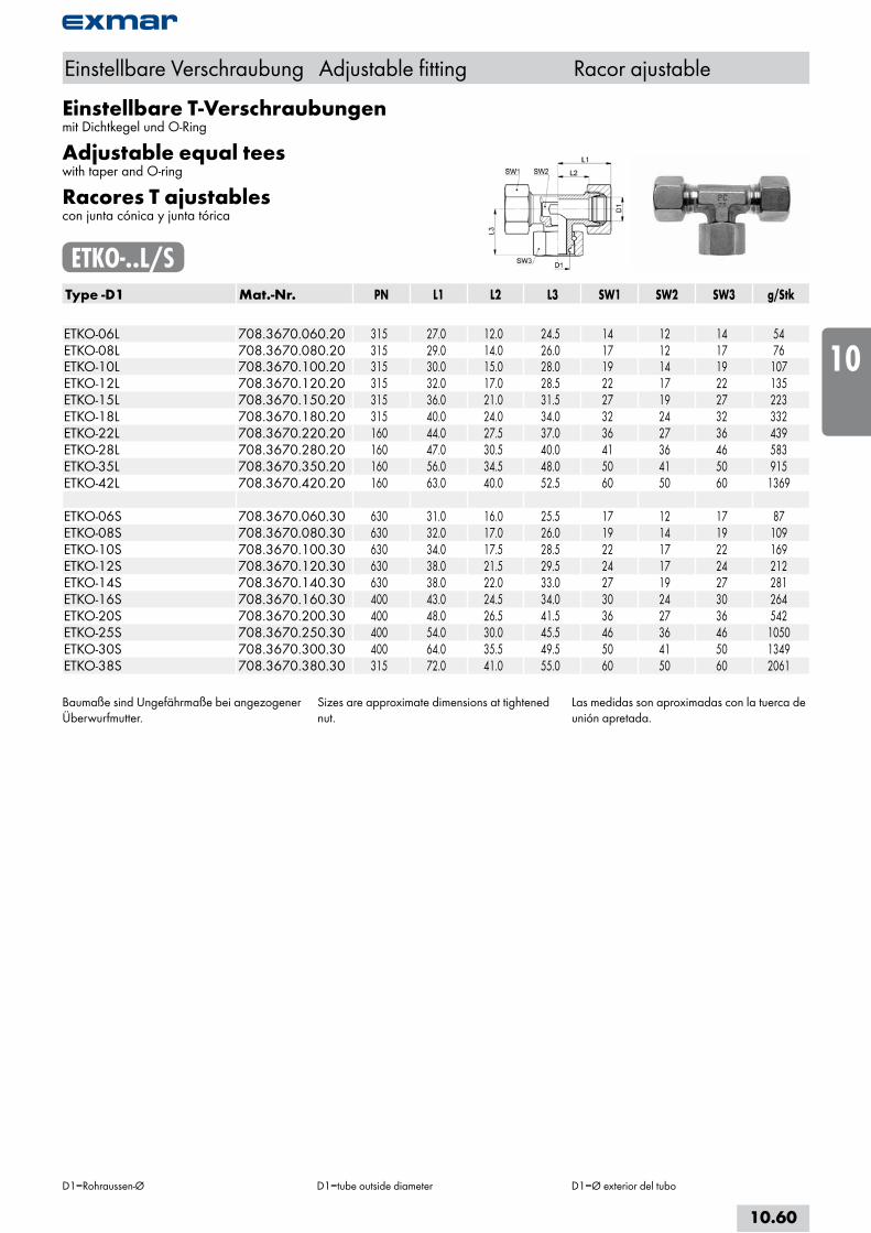
Einstellbare T-Verschraubungenmit Dichtkegel und O-Ring
Adjustable equal teeswith taper and O-ring
Racores T ajustablescon junta cónica y junta tórica
ETKO-..L/SType -D1 Mat.-Nr. PN L1 L2 L3 SW1 SW2 SW3 g/Stk ETKO-06L 708.3670.060.20 315 27.0 12.0 24.5 14 12 14 54ETKO-08L 708.3670.080.20 315 29.0 14.0 26.0 17 12 17 76ETKO-10L 708.3670.100.20 315 30.0 15.0 28.0 19 14 19 107ETKO-12L 708.3670.120.20 315 32.0 17.0 28.5 22 17 22 135ETKO-15L 708.3670.150.20 315 36.0 21.0 31.5 27 19 27 223ETKO-18L 708.3670.180.20 315 40.0 24.0 34.0 32 24 32 332ETKO-22L 708.3670.220.20 160 44.0 27.5 37.0 36 27 36 439ETKO-28L 708.3670.280.20 160 47.0 30.5 40.0 41 36 46 583ETKO-35L 708.3670.350.20 160 56.0 34.5 48.0 50 41 50 915ETKO-42L 708.3670.420.20 160 63.0 40.0 52.5 60 50 60 1369 ETKO-06S 708.3670.060.30 630 31.0 16.0 25.5 17 12 17 87ETKO-08S 708.3670.080.30 630 32.0 17.0 26.0 19 14 19 109ETKO-10S 708.3670.100.30 630 34.0 17.5 28.5 22 17 22 169ETKO-12S 708.3670.120.30 630 38.0 21.5 29.5 24 17 24 212ETKO-14S 708.3670.140.30 630 38.0 22.0 33.0 27 19 27 281ETKO-16S 708.3670.160.30 400 43.0 24.5 34.0 30 24 30 264ETKO-20S 708.3670.200.30 400 48.0 26.5 41.5 36 27 36 542ETKO-25S 708.3670.250.30 400 54.0 30.0 45.5 46 36 46 1050ETKO-30S 708.3670.300.30 400 64.0 35.5 49.5 50 41 50 1349ETKO-38S 708.3670.380.30 315 72.0 41.0 55.0 60 50 60 2061
Baumaße sind Ungefährmaße bei angezogener Überwurfmutter.
Sizes are approximate dimensions at tightened nut.
Las medidas son aproximadas con la tuerca de unión apretada.
Einstellbare Verschraubung Adjustable fitting Racor ajustable
D1=Rohraussen-Ø D1=tube outside diameter D1=Ø exterior del tubo
10.60
i
s
10
20
30
40
50
60
70
a

Einstellbare T-Verschraubungenvormontiert
Adjustable equal teespre-assembled
Racores T ajustablespremontado
ETV-..L/SType -D1 Mat.-Nr. PN L1 L2 L3 SW1 SW2 g/Stk ETV-06L 708.3620.060.20 500 27.0 12.0 26.0 14 12 60ETV-08L 708.3620.080.20 500 29.0 14.0 27.5 17 12 85ETV-10L 708.3620.100.20 500 30.5 15.0 29.0 19 14 105ETV-12L 708.3620.120.20 400 32.0 17.0 29.5 22 17 145ETV-15L 708.3620.150.20 400 36.5 21.0 32.5 27 19 235ETV-18L 708.3620.180.20 400 40.0 23.5 35.5 32 24 340ETV-22L 708.3620.220.20 250 44.5 27.5 38.5 36 27 464ETV-28L 708.3620.280.20 250 48.0 30.5 41.5 41 36 592ETV-35L 708.3620.350.20 250 57.0 34.5 51.0 50 41 977ETV-42L 708.3620.420.20 250 63.5 40.0 56.0 60 50 1414 ETV-06S 708.3620.060.30 800 31.0 16.0 27.0 17 12 99ETV-08S 708.3620.080.30 800 32.5 17.0 27.5 19 14 117ETV-10S 708.3620.100.30 800 35.0 17.5 30.0 22 17 175ETV-12S 708.3620.120.30 630 38.0 21.5 31.0 24 17 214ETV-14S 708.3620.140.30 630 41.0 22.0 35.0 27 19 265ETV-16S 708.3620.160.30 630 43.0 24.5 36.5 30 24 375ETV-20S 708.3620.200.30 420 50.0 26.5 44.5 36 27 590ETV-25S 708.3620.250.30 420 56.0 30.0 50.0 46 36 1125ETV-30S 708.3620.300.30 420 64.0 35.5 55.0 50 41 1366ETV-38S 708.3620.380.30 420 74.0 41.0 63.0 60 50 2084
Baumaße sind Ungefährmaße bei angezogener Überwurfmutter.
Sizes are approximate dimensions at tightened nut.
Las medidas son aproximadas con la tuerca de unión apretada.
DIN EN ISO 8434-1-SDTC
Einstellbare Verschraubung Adjustable fitting Racor ajustable
D1=Rohraussen-Ø D1=tube outside diameter D1=Ø exterior del tubo
10.61
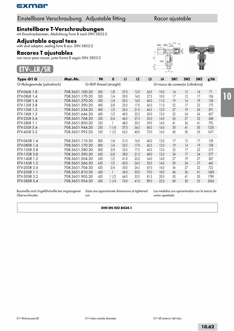
Einstellbare T-Verschraubungenmit Einschraubstutzen, Abdichtung Form B nach DIN 3852-2
Adjustable equal teeswith stud adaptor, sealing form B acc. DIN 3852-2
Racores T ajustablescon racor para roscar, junta forma B según DIN 3852-2
ETV-..LR/SRType -D1 G Mat.-Nr. PN G L1 L2 L3 L4 SW1 SW2 SW3 g/StkG=Rohrgewinde (zylindrisch) G=BSP thread (straight) G=rosca de conexión (cilíndrica) ETV-06LR 1.8 708.3651.100.20 500 1/8 27.0 12.0 34.5 10.0 14 12 14 71ETV-08LR 1.4 708.3651.170.20 500 1/4 29.0 14.0 37.5 10.0 17 12 17 106ETV-10LR 1.4 708.3651.270.20 500 1/4 30.5 14.0 40.0 11.0 19 14 19 128ETV-12LR 3.8 708.3651.390.20 400 3/8 32.0 17.0 42.0 11.0 22 17 22 175ETV-15LR 1.2 708.3651.534.20 400 1/2 36.5 21.0 46.5 12.0 27 19 24 291ETV-18LR 1.2 708.3651.646.20 400 1/2 40.0 23.5 50.0 12.0 32 24 24 427ETV-22LR 3.4 708.3651.768.20 250 3/4 44.5 27.5 55.0 14.0 36 27 32 568ETV-28LR 1.1 708.3651.850.20 250 1 48.0 30.5 59.0 14.0 41 36 41 792ETV-35LR 5.4 708.3651.944.20 250 1 1/4 57.0 34.5 68.5 16.0 50 41 50 1230ETV-42LR 3.2 708.3651.992.20 250 1 1/2 63.5 40.0 75.0 16.0 60 50 55 1671 ETV-06SR 1.4 708.3651.110.30 800 1/4 31.0 16.0 40.0 12.0 17 12 17 128ETV-08SR 1.4 708.3651.170.30 800 1/4 32.5 17.0 42.5 12.0 19 14 19 158ETV-10SR 3.8 708.3651.280.30 800 3/8 35.0 17.5 45.0 12.0 22 17 22 219ETV-12SR 3.8 708.3651.390.30 630 3/8 38.0 21.5 48.0 12.0 24 17 24 277ETV-14SR 1.2 708.3651.504.30 630 1/2 41.0 22.0 54.0 14.0 27 19 27 387ETV-16SR 1.2 708.3651.566.30 630 1/2 43.0 24.5 55.0 14.0 30 24 27 442ETV-20SR 3.4 708.3651.704.30 420 3/4 50.0 26.5 67.0 16.0 36 27 32 722ETV-25SR 1.1 708.3651.810.30 420 1 56.0 30.0 73.0 18.0 46 36 41 1428ETV-30SR 3.2 708.3651.905.30 420 1 1/2 64.0 35.5 81.5 20.0 50 41 50 1789ETV-38SR 5.4 708.3651.954.30 420 1 1/4 74.0 41.0 89.0 22.0 60 50 55 2624
Baumaße sind Ungefährmaße bei angezogener Überwurfmutter.
Sizes are approximate dimensions at tightened nut.
Las medidas son aproximadas con la tuerca de unión apretada.
DIN EN ISO 8434-1
Einstellbare Verschraubung Adjustable fitting Racor ajustable
D1=Rohraussen-Ø D1=tube outside diameter D1=Ø exterior del tubo
10.62
i
s
10
20
30
40
50
60
70
a

Einstellbare L-Verschraubungenmit Dichtkegel und O-Ring
Adjustable male stud tee-stud barrelwith taper and O-ring
Racores L ajustablescon junta cónica y junta tórica
ELKO-..L/SType -D1 Mat.-Nr. PN L1 L2 L3 SW1 SW2 SW3 g/Stk ELKO-06L 708.3671.060.20 315 27.0 12.0 24.5 14 12 14 53ELKO-08L 708.3671.080.20 315 29.0 14.0 26.0 17 12 17 80ELKO-10L 708.3671.100.20 315 30.0 15.0 28.0 19 14 19 109ELKO-12L 708.3671.120.20 315 32.0 17.0 28.0 22 17 22 132ELKO-15L 708.3671.150.20 315 36.0 21.0 31.5 27 19 27 223ELKO-18L 708.3671.180.20 315 40.0 23.5 34.0 32 24 32 337ELKO-22L 708.3671.220.20 160 44.0 27.5 37.0 36 27 36 439ELKO-28L 708.3671.280.20 160 47.0 30.5 40.0 41 36 46 568ELKO-35L 708.3671.350.20 160 56.0 34.5 48.0 50 41 50 905ELKO-42L 708.3671.420.20 160 63.0 40.0 52.5 60 50 60 1344 ELKO-06S 708.3671.060.30 630 31.0 15.0 25.5 17 12 17 89ELKO-08S 708.3671.080.30 630 32.0 17.0 25.5 19 14 19 109ELKO-10S 708.3671.100.30 630 34.0 17.5 28.0 19 17 22 170ELKO-12S 708.3671.120.30 630 38.0 21.5 29.5 24 17 24 212ELKO-14S 708.3671.140.30 630 38.0 22.0 33.0 27 19 27 277ELKO-16S 708.3671.160.30 400 43.0 24.5 33.0 30 24 30 345ELKO-20S 708.3671.200.30 400 48.0 26.5 41.5 36 27 36 548ELKO-25S 708.3671.250.30 400 54.0 30.0 45.5 46 36 46 1036ELKO-30S 708.3671.300.30 400 62.0 35.5 49.5 50 41 50 1341ELKO-38S 708.3671.380.30 315 72.0 41.0 55.0 60 50 60 1964
Baumaße sind Ungefährmaße bei angezogener Überwurfmutter.
Sizes are approximate dimensions at tightened nut.
Las medidas son aproximadas con la tuerca de unión apretada.
Einstellbare Verschraubung Adjustable fitting Racor ajustable
D1=Rohraussen-Ø D1=tube outside diameter D1=Ø exterior del tubo
10.63

Einstellbare L-Verschraubungenvormontiert
Adjustable male stud tee-stud barrelspre-assembled
Racores L ajustablespremontado
ELV-..L/SType -D1 Mat.-Nr. PN L1 L2 L3 L4 SW1 SW2 g/Stk ELV-06L 708.3630.060.20 500 27.0 12.0 26.0 27.0 14 12 60ELV-08L 708.3630.080.20 500 29.0 14.0 27.5 29.0 17 12 85ELV-10L 708.3630.100.20 500 30.0 15.0 29.0 30.5 19 14 115ELV-12L 708.3630.120.20 400 32.0 17.0 29.5 32.0 22 17 135ELV-15L 708.3630.150.20 400 36.0 21.0 32.5 36.5 27 19 240ELV-18L 708.3630.180.20 400 40.0 23.5 35.5 40.0 32 24 340ELV-22L 708.3630.220.20 250 44.0 27.5 38.5 44.5 36 27 464ELV-28L 708.3630.280.20 250 44.0 30.5 41.5 48.0 41 36 604ELV-35L 708.3630.350.20 250 56.0 34.5 51.0 57.0 50 41 941ELV-42L 708.3630.420.20 250 63.0 40.0 56.0 63.5 60 50 1433 ELV-06S 708.3630.060.30 800 31.0 16.0 27.0 31.0 17 12 100ELV-08S 708.3630.080.30 800 32.0 17.0 27.5 32.5 19 14 125ELV-10S 708.3630.100.30 800 33.0 17.5 30.0 35.0 22 17 175ELV-12S 708.3630.120.30 630 37.0 21.5 31.0 38.0 24 17 205ELV-14S 708.3630.140.30 630 38.0 22.0 35.0 41.0 27 19 285ELV-16S 708.3630.160.30 630 43.0 24.5 36.5 43.0 30 24 375ELV-20S 708.3630.200.30 420 46.0 26.5 44.5 50.0 36 27 590ELV-25S 708.3630.250.30 420 51.0 30.0 50.0 56.0 46 36 1130ELV-30S 708.3630.300.30 420 62.0 35.5 55.0 64.0 50 41 1373ELV-38S 708.3630.380.30 420 72.0 41.0 63.0 74.0 60 50 2070
Baumaße sind Ungefährmaße bei angezogener Überwurfmutter.
Sizes are approximate dimensions at tightened nut.
Las medidas son aproximadas con la tuerca de unión apretada.
DIN EN ISO 8434-1-SDTC
Einstellbare Verschraubung Adjustable fitting Racor ajustable
D1=Rohraussen-Ø D1=tube outside diameter D1=Ø exterior del tubo
10.64
i
s
10
20
30
40
50
60
70
a
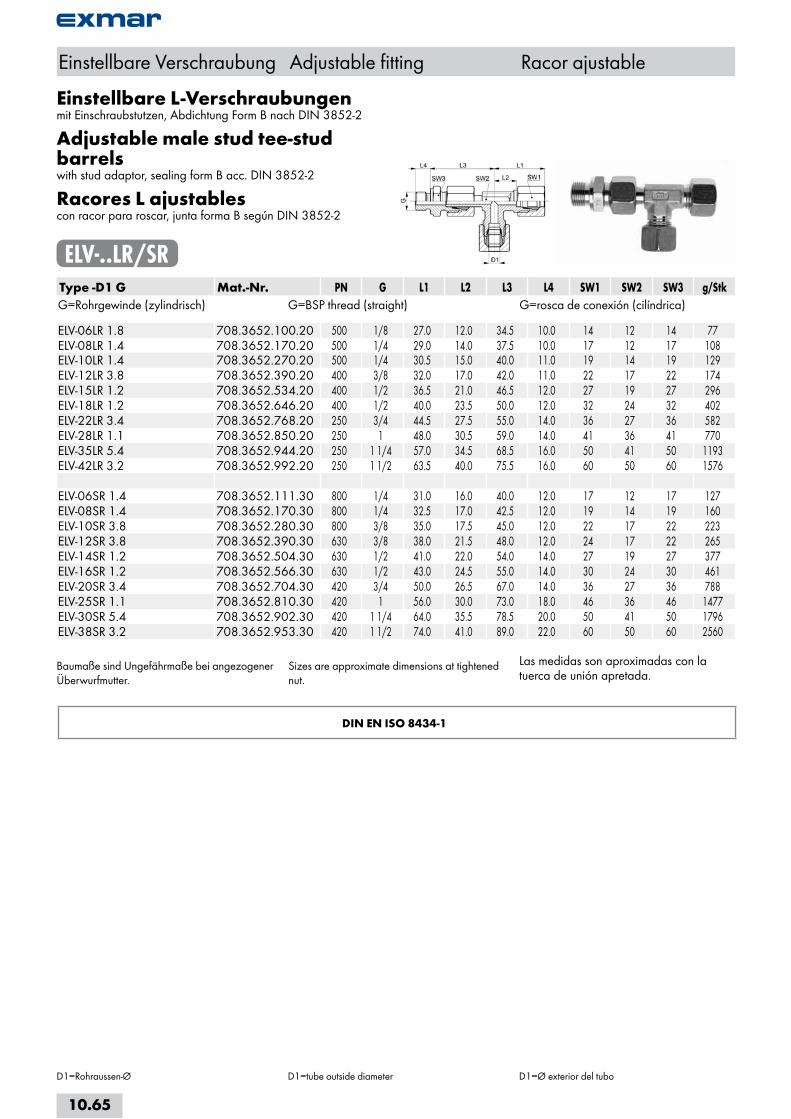
Einstellbare L-Verschraubungenmit Einschraubstutzen, Abdichtung Form B nach DIN 3852-2
Adjustable male stud tee-stud barrelswith stud adaptor, sealing form B acc. DIN 3852-2
Racores L ajustablescon racor para roscar, junta forma B según DIN 3852-2
ELV-..LR/SRType -D1 G Mat.-Nr. PN G L1 L2 L3 L4 SW1 SW2 SW3 g/StkG=Rohrgewinde (zylindrisch) G=BSP thread (straight) G=rosca de conexión (cilíndrica) ELV-06LR 1.8 708.3652.100.20 500 1/8 27.0 12.0 34.5 10.0 14 12 14 77ELV-08LR 1.4 708.3652.170.20 500 1/4 29.0 14.0 37.5 10.0 17 12 17 108ELV-10LR 1.4 708.3652.270.20 500 1/4 30.5 15.0 40.0 11.0 19 14 19 129ELV-12LR 3.8 708.3652.390.20 400 3/8 32.0 17.0 42.0 11.0 22 17 22 174ELV-15LR 1.2 708.3652.534.20 400 1/2 36.5 21.0 46.5 12.0 27 19 27 296ELV-18LR 1.2 708.3652.646.20 400 1/2 40.0 23.5 50.0 12.0 32 24 32 402ELV-22LR 3.4 708.3652.768.20 250 3/4 44.5 27.5 55.0 14.0 36 27 36 582ELV-28LR 1.1 708.3652.850.20 250 1 48.0 30.5 59.0 14.0 41 36 41 770ELV-35LR 5.4 708.3652.944.20 250 1 1/4 57.0 34.5 68.5 16.0 50 41 50 1193ELV-42LR 3.2 708.3652.992.20 250 1 1/2 63.5 40.0 75.5 16.0 60 50 60 1576 ELV-06SR 1.4 708.3652.111.30 800 1/4 31.0 16.0 40.0 12.0 17 12 17 127ELV-08SR 1.4 708.3652.170.30 800 1/4 32.5 17.0 42.5 12.0 19 14 19 160ELV-10SR 3.8 708.3652.280.30 800 3/8 35.0 17.5 45.0 12.0 22 17 22 223ELV-12SR 3.8 708.3652.390.30 630 3/8 38.0 21.5 48.0 12.0 24 17 22 265ELV-14SR 1.2 708.3652.504.30 630 1/2 41.0 22.0 54.0 14.0 27 19 27 377ELV-16SR 1.2 708.3652.566.30 630 1/2 43.0 24.5 55.0 14.0 30 24 30 461ELV-20SR 3.4 708.3652.704.30 420 3/4 50.0 26.5 67.0 14.0 36 27 36 788ELV-25SR 1.1 708.3652.810.30 420 1 56.0 30.0 73.0 18.0 46 36 46 1477ELV-30SR 5.4 708.3652.902.30 420 1 1/4 64.0 35.5 78.5 20.0 50 41 50 1796ELV-38SR 3.2 708.3652.953.30 420 1 1/2 74.0 41.0 89.0 22.0 60 50 60 2560
Baumaße sind Ungefährmaße bei angezogener Überwurfmutter.
Sizes are approximate dimensions at tightened nut.
Las medidas son aproximadas con la tuerca de unión apretada.
DIN EN ISO 8434-1
Einstellbare Verschraubung Adjustable fitting Racor ajustable
D1=Rohraussen-Ø D1=tube outside diameter D1=Ø exterior del tubo
10.65

Winkel-SchwenkverschraubungenAbdichtung mit metallischem Dichtkantenring
Banjo couplingssealing with metal seal-edge ring
Racores orientables angularesjunta con anillo con borde de obturación metálico
ESWV-..LR/SRType -D1 G Mat.-Nr. PN G L1 L2 L3 L4 L5 SW1 SW2 g/StkG=Rohrgewinde (zylindrisch) G=BSP thread (straight) G=rosca de conexión (cilíndrica) ESWV-04LLR 1.8 708.2840.060.10 100 1/8 25.5 16.0 21.0 10.0 8.0 10 14 40ESWV-06LLR 1.8 708.2840.100.10 100 1/8 26.0 14.5 21.0 10.0 8.0 12 14 42ESWV-08LLR 1.8 708.2840.160.10 100 1/8 26.0 14.5 21.0 10.0 8.0 14 14 52 ESWV-06LR 1.8 708.2840.100.20 500 1/8 27.5 13.0 21.0 10.0 8.0 14 14 59ESWV-06LR 1.4 708.2840.110.20 500 1/4 29.5 15.0 23.0 13.5 10.0 14 19 59ESWV-08LR 1.4 708.2840.170.20 500 1/4 28.5 14.0 27.0 13.5 10.0 17 19 93ESWV-10LR 1.4 708.2840.270.20 500 1/4 29.5 15.0 27.0 13.5 10.0 19 19 102ESWV-12LR 1.4 708.2840.380.20 500 1/4 29.5 15.0 30.0 15.5 10.0 22 19 158ESWV-12LR 3.8 708.2840.390.20 500 3/8 32.0 17.5 32.5 16.0 10.0 22 22 159ESWV-15LR 1.2 708.2840.534.20 500 1/2 36.0 21.0 43.0 19.5 12.0 27 27 284ESWV-18LR 1.2 708.2840.646.20 400 1/2 36.5 20.5 43.0 21.5 12.0 32 27 320ESWV-22LR 3.4 708.2840.768.20 250 3/4 43.0 27.0 48.0 24.0 16.0 36 32 485ESWV-28LR 1.1 708.2840.850.20 250 1 48.0 31.5 59.0 30.5 18.0 41 41 882ESWV-35LR 5.4 708.2840.944.20 250 1 1/4 57.0 35.5 70.0 35.5 20.0 50 50 1508ESWV-42LR 3.2 708.2840.992.20 250 1 1/2 62.5 40.0 80.0 40.5 22.0 60 60 2341 ESWV-06SR 1.4 708.2840.110.30 800 1/4 30.5 16.0 27.0 13.5 10.0 17 19 87ESWV-08SR 1.4 708.2840.170.30 800 1/4 30.5 16.0 27.0 13.5 10.0 19 19 103ESWV-10SR 3.8 708.2840.280.30 800 3/8 34.0 18.0 32.5 16.0 10.0 22 22 170ESWV-12SR 3.8 708.2840.390.30 630 3/8 34.0 18.0 32.5 16.0 10.0 24 22 179ESWV-14SR 1.2 708.2840.504.30 630 1/2 39.5 22.0 41.0 19.5 12.0 27 27 303ESWV-16SR 1.2 708.2840.566.30 630 1/2 39.5 21.5 43.0 21.5 12.0 30 27 316ESWV-20SR 3.4 708.2840.704.30 420 3/4 47.5 26.0 48.0 24.0 16.0 36 32 518ESWV-25SR 1.1 708.2840.810.30 420 1 55.0 31.0 59.0 30.5 18.0 46 41 1030ESWV-30SR 5.4 708.2840.902.30 420 1 1/4 63.0 36.5 70.0 35.5 20.0 50 50 1637ESWV-38SR 3.2 708.2840.953.30 420 1 1/2 71.5 41.0 80.0 40.5 22.0 60 55 2627
L4 ist ein Ungefährmaß bei angezogener Überwurfmutter.
L4 = approximate length with tightened nut. L4 es una medida aproximada con la tuerca de unión apretada.
DIN EN ISO 8434-1
Schwenkverschraubung Banjo connection Racor orientable
D1=Rohraussen-Ø D1=tube outside diameter D1=Ø exterior del tubo
10.66
i
s
10
20
30
40
50
60
70
a
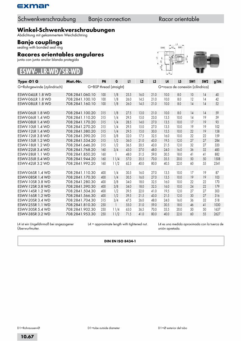
Winkel-SchwenkverschraubungenAbdichtung mit gekammertem Weichdichtring
Banjo couplingssealing with bonded seal ring
Racores orientables angularesjunta con junta anular blanda protegida
ESWV-..LR-WD/SR-WDType -D1 G Mat.-Nr. PN G L1 L2 L3 L4 L5 SW1 SW2 g/StkG=Rohrgewinde (zylindrisch) G=BSP thread (straight) G=rosca de conexión (cilíndrica) ESWV-04LLR 1.8 WD 708.2841.060.10 100 1/8 25.5 16.0 21.0 10.0 8.0 10 14 40ESWV-06LLR 1.8 WD 708.2841.100.10 100 1/8 26.0 14.5 21.0 10.0 8.0 12 14 42ESWV-08LLR 1.8 WD 708.2841.160.10 100 1/8 26.0 14.5 21.0 10.0 8.0 14 14 52 ESWV-06LR 1.8 WD 708.2841.100.20 315 1/8 27.5 13.0 21.0 10.0 8.0 14 14 59ESWV-06LR 1.4 WD 708.2841.110.20 315 1/4 29.5 15.0 23.0 13.5 10.0 14 19 59ESWV-08LR 1.4 WD 708.2841.170.20 315 1/4 28.5 14.0 27.0 13.5 10.0 17 19 93ESWV-10LR 1.4 WD 708.2841.270.20 315 1/4 29.5 15.0 27.0 13.5 10.0 19 19 102ESWV-12LR 1.4 WD 708.2841.380.20 315 1/4 29.5 15.0 30.0 15.5 10.0 22 19 158ESWV-12LR 3.8 WD 708.2841.390.20 315 3/8 32.0 17.5 32.5 16.0 10.0 22 22 159ESWV-15LR 1.2 WD 708.2841.534.20 315 1/2 36.0 21.0 43.0 19.5 12.0 27 27 284ESWV-18LR 1.2 WD 708.2841.646.20 315 1/2 36.5 20.5 43.0 21.5 12.0 32 27 320ESWV-22LR 3.4 WD 708.2841.768.20 160 3/4 43.0 27.0 48.0 24.0 16.0 36 32 485ESWV-28LR 1.1 WD 708.2841.850.20 160 1 48.0 31.5 59.0 30.5 18.0 41 41 882ESWV-35LR 5.4 WD 708.2841.944.20 160 1 1/4 57.0 35.5 70.0 35.5 20.0 50 50 1508ESWV-42LR 3.2 WD 708.2841.992.20 160 1 1/2 62.5 40.0 80.0 40.5 22.0 60 55 2341 ESWV-06SR 1.4 WD 708.2841.110.30 400 1/4 30.5 16.0 27.0 13.5 10.0 17 19 87ESWV-08SR 1.4 WD 708.2841.170.30 400 1/4 30.5 16.0 27.0 13.5 10.0 19 19 103ESWV-10SR 3.8 WD 708.2841.280.30 400 3/8 34.0 18.0 32.5 16.0 10.0 22 22 170ESWV-12SR 3.8 WD 708.2841.390.30 400 3/8 34.0 18.0 32.5 16.0 10.0 24 22 179ESWV-14SR 1.2 WD 708.2841.504.30 400 1/2 39.5 22.0 41.0 19.5 12.0 27 27 303ESWV-16SR 1.2 WD 708.2841.566.30 400 1/2 39.5 21.5 43.0 21.5 12.0 30 27 316ESWV-20SR 3.4 WD 708.2841.704.30 315 3/4 47.5 26.0 48.0 24.0 16.0 36 32 518ESWV-25SR 1.1 WD 708.2841.810.30 250 1 55.0 31.0 59.0 30.5 18.0 46 41 1030ESWV-30SR 5.4 WD 708.2841.902.30 250 1 1/4 63.0 36.5 70.0 35.5 20.0 50 50 1637ESWV-38SR 3.2 WD 708.2841.953.30 250 1 1/2 71.5 41.0 80.0 40.0 22.0 60 55 2627
L4 ist ein Ungefährmaß bei angezogener Überwurfmutter.
L4 = approximate length with tightened nut. L4 es una medida aproximada con la tuerca de unión apretada.
DIN EN ISO 8434-1
Schwenkverschraubung Banjo connection Racor orientable
D1=Rohraussen-Ø D1=tube outside diameter D1=Ø exterior del tubo
10.67
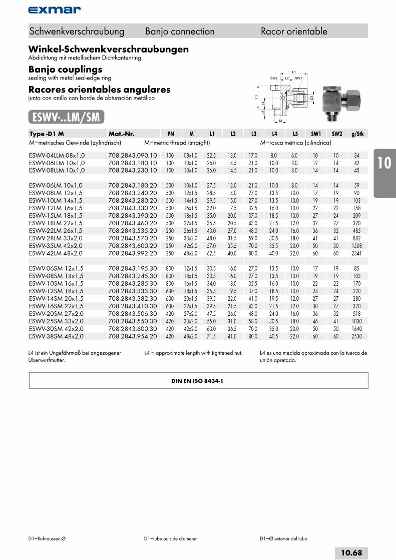
Winkel-SchwenkverschraubungenAbdichtung mit metallischem Dichtkantenring
Banjo couplingssealing with metal seal-edge ring
Racores orientables angularesjunta con anillo con borde de obturación metálico
ESWV-..LM/SMType -D1 M Mat.-Nr. PN M L1 L2 L3 L4 L5 SW1 SW2 g/StkM=metrisches Gewinde (zylindrisch) M=metric thread (straight) M=rosca métrica (cilindrica) ESWV-04LLM 08x1,0 708.2843.090.10 100 08x1.0 22.5 13.0 17.0 8.0 6.0 10 10 34ESWV-06LLM 10x1,0 708.2843.180.10 100 10x1.0 26.0 14.5 21.0 10.0 8.0 12 14 42ESWV-08LLM 10x1,0 708.2843.230.10 100 10x1.0 26.0 14.5 21.0 10.0 8.0 14 14 45 ESWV-06LM 10x1,0 708.2843.180.20 500 10x1.0 27.5 13.0 21.0 10.0 8.0 14 14 59ESWV-08LM 12x1,5 708.2843.240.20 500 12x1.5 28.5 14.0 27.0 13.5 10.0 17 19 90ESWV-10LM 14x1,5 708.2843.280.20 500 14x1.5 29.5 15.0 27.0 13.5 10.0 19 19 103ESWV-12LM 16x1,5 708.2843.330.20 500 16x1.5 32.0 17.5 32.5 16.0 10.0 22 22 158ESWV-15LM 18x1,5 708.2843.390.20 500 18x1.5 35.0 20.0 37.0 18.5 10.0 27 24 209ESWV-18LM 22x1,5 708.2843.460.20 500 22x1.5 36.5 20.5 43.0 21.5 12.0 32 27 320ESWV-22LM 26x1,5 708.2843.535.20 250 26x1.5 43.0 27.0 48.0 24.0 16.0 36 32 485ESWV-28LM 33x2,0 708.2843.570.20 250 33x2.0 48.0 31.5 59.0 30.5 18.0 41 41 882ESWV-35LM 42x2,0 708.2843.600.20 250 42x2.0 57.0 35.5 70.0 35.5 20.0 50 50 1508ESWV-42LM 48x2,0 708.2843.992.20 250 48x2.0 62.5 40.0 80.0 40.0 22.0 60 60 2341 ESWV-06SM 12x1,5 708.2843.195.30 800 12x1.5 30.5 16.0 27.0 13.5 10.0 17 19 85ESWV-08SM 14x1,5 708.2843.245.30 800 14x1.5 30.5 16.0 27.0 13.5 10.0 19 19 103ESWV-10SM 16x1,5 708.2843.285.30 800 16x1.5 34.0 18.0 32.5 16.0 10.0 22 22 170ESWV-12SM 18x1,5 708.2843.333.30 630 18x1.5 35.5 19.5 37.0 18.5 10.0 24 24 220ESWV-14SM 20x1,5 708.2843.382.30 630 20x1.5 39.5 22.0 41.0 19.5 12.0 27 27 280ESWV-16SM 22x1,5 708.2843.410.30 630 22x1.5 39.5 21.5 43.0 21.5 12.0 30 27 320ESWV-20SM 27x2,0 708.2843.506.30 420 27x2.0 47.5 26.0 48.0 24.0 16.0 36 32 518ESWV-25SM 33x2,0 708.2843.550.30 420 33x2.0 55.0 31.0 58.0 30.5 18.0 46 41 1030ESWV-30SM 42x2,0 708.2843.600.30 420 42x2.0 63.0 36.5 70.0 35.0 20.0 50 50 1640ESWV-38SM 48x2,0 708.2843.954.20 420 48x2.0 71.5 41.0 80.0 40.5 22.0 60 60 2530
L4 ist ein Ungefährmaß bei angezogener Überwurfmutter.
L4 = approximate length with tightened nut. L4 es una medida aproximada con la tuerca de unión apretada.
DIN EN ISO 8434-1
Schwenkverschraubung Banjo connection Racor orientable
D1=Rohraussen-Ø D1=tube outside diameter D1=Ø exterior del tubo
10.68
i
s
10
20
30
40
50
60
70
a
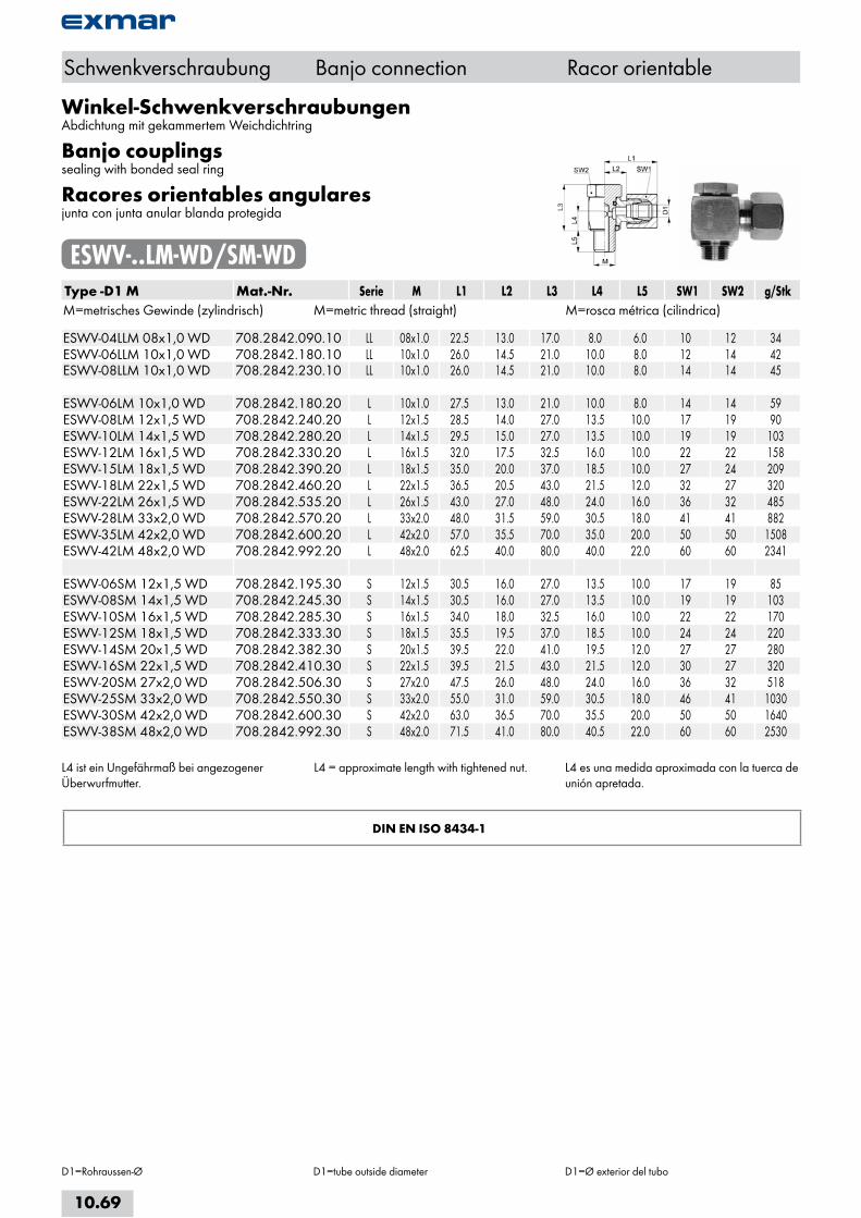
Winkel-SchwenkverschraubungenAbdichtung mit gekammertem Weichdichtring
Banjo couplingssealing with bonded seal ring
Racores orientables angularesjunta con junta anular blanda protegida
ESWV-..LM-WD/SM-WDType -D1 M Mat.-Nr. Serie M L1 L2 L3 L4 L5 SW1 SW2 g/StkM=metrisches Gewinde (zylindrisch) M=metric thread (straight) M=rosca métrica (cilindrica) ESWV-04LLM 08x1,0 WD 708.2842.090.10 LL 08x1.0 22.5 13.0 17.0 8.0 6.0 10 12 34ESWV-06LLM 10x1,0 WD 708.2842.180.10 LL 10x1.0 26.0 14.5 21.0 10.0 8.0 12 14 42ESWV-08LLM 10x1,0 WD 708.2842.230.10 LL 10x1.0 26.0 14.5 21.0 10.0 8.0 14 14 45 ESWV-06LM 10x1,0 WD 708.2842.180.20 L 10x1.0 27.5 13.0 21.0 10.0 8.0 14 14 59ESWV-08LM 12x1,5 WD 708.2842.240.20 L 12x1.5 28.5 14.0 27.0 13.5 10.0 17 19 90ESWV-10LM 14x1,5 WD 708.2842.280.20 L 14x1.5 29.5 15.0 27.0 13.5 10.0 19 19 103ESWV-12LM 16x1,5 WD 708.2842.330.20 L 16x1.5 32.0 17.5 32.5 16.0 10.0 22 22 158ESWV-15LM 18x1,5 WD 708.2842.390.20 L 18x1.5 35.0 20.0 37.0 18.5 10.0 27 24 209ESWV-18LM 22x1,5 WD 708.2842.460.20 L 22x1.5 36.5 20.5 43.0 21.5 12.0 32 27 320ESWV-22LM 26x1,5 WD 708.2842.535.20 L 26x1.5 43.0 27.0 48.0 24.0 16.0 36 32 485ESWV-28LM 33x2,0 WD 708.2842.570.20 L 33x2.0 48.0 31.5 59.0 30.5 18.0 41 41 882ESWV-35LM 42x2,0 WD 708.2842.600.20 L 42x2.0 57.0 35.5 70.0 35.0 20.0 50 50 1508ESWV-42LM 48x2,0 WD 708.2842.992.20 L 48x2.0 62.5 40.0 80.0 40.0 22.0 60 60 2341 ESWV-06SM 12x1,5 WD 708.2842.195.30 S 12x1.5 30.5 16.0 27.0 13.5 10.0 17 19 85ESWV-08SM 14x1,5 WD 708.2842.245.30 S 14x1.5 30.5 16.0 27.0 13.5 10.0 19 19 103ESWV-10SM 16x1,5 WD 708.2842.285.30 S 16x1.5 34.0 18.0 32.5 16.0 10.0 22 22 170ESWV-12SM 18x1,5 WD 708.2842.333.30 S 18x1.5 35.5 19.5 37.0 18.5 10.0 24 24 220ESWV-14SM 20x1,5 WD 708.2842.382.30 S 20x1.5 39.5 22.0 41.0 19.5 12.0 27 27 280ESWV-16SM 22x1,5 WD 708.2842.410.30 S 22x1.5 39.5 21.5 43.0 21.5 12.0 30 27 320ESWV-20SM 27x2,0 WD 708.2842.506.30 S 27x2.0 47.5 26.0 48.0 24.0 16.0 36 32 518ESWV-25SM 33x2,0 WD 708.2842.550.30 S 33x2.0 55.0 31.0 59.0 30.5 18.0 46 41 1030ESWV-30SM 42x2,0 WD 708.2842.600.30 S 42x2.0 63.0 36.5 70.0 35.5 20.0 50 50 1640ESWV-38SM 48x2,0 WD 708.2842.992.30 S 48x2.0 71.5 41.0 80.0 40.5 22.0 60 60 2530
L4 ist ein Ungefährmaß bei angezogener Überwurfmutter.
L4 = approximate length with tightened nut. L4 es una medida aproximada con la tuerca de unión apretada.
DIN EN ISO 8434-1
Schwenkverschraubung Banjo connection Racor orientable
D1=Rohraussen-Ø D1=tube outside diameter D1=Ø exterior del tubo
10.69
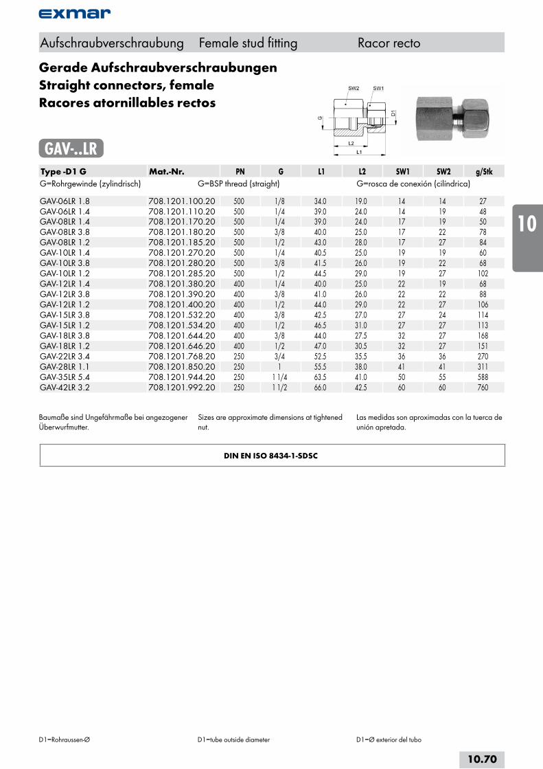
Baumaße sind Ungefährmaße bei angezogener Überwurfmutter.
Sizes are approximate dimensions at tightened nut.
Las medidas son aproximadas con la tuerca de unión apretada.
DIN EN ISO 8434-1-SDSC
Aufschraubverschraubung Female stud fitting Racor recto
D1=Rohraussen-Ø D1=tube outside diameter D1=Ø exterior del tubo
Gerade AufschraubverschraubungenStraight connectors, femaleRacores atornillables rectos
GAV-..LRType -D1 G Mat.-Nr. PN G L1 L2 SW1 SW2 g/StkG=Rohrgewinde (zylindrisch) G=BSP thread (straight) G=rosca de conexión (cilíndrica) GAV-06LR 1.8 708.1201.100.20 500 1/8 34.0 19.0 14 14 27GAV-06LR 1.4 708.1201.110.20 500 1/4 39.0 24.0 14 19 48GAV-08LR 1.4 708.1201.170.20 500 1/4 39.0 24.0 17 19 50GAV-08LR 3.8 708.1201.180.20 500 3/8 40.0 25.0 17 22 78GAV-08LR 1.2 708.1201.185.20 500 1/2 43.0 28.0 17 27 84GAV-10LR 1.4 708.1201.270.20 500 1/4 40.5 25.0 19 19 60GAV-10LR 3.8 708.1201.280.20 500 3/8 41.5 26.0 19 22 68GAV-10LR 1.2 708.1201.285.20 500 1/2 44.5 29.0 19 27 102GAV-12LR 1.4 708.1201.380.20 400 1/4 40.0 25.0 22 19 68GAV-12LR 3.8 708.1201.390.20 400 3/8 41.0 26.0 22 22 88GAV-12LR 1.2 708.1201.400.20 400 1/2 44.0 29.0 22 27 106GAV-15LR 3.8 708.1201.532.20 400 3/8 42.5 27.0 27 24 114GAV-15LR 1.2 708.1201.534.20 400 1/2 46.5 31.0 27 27 113GAV-18LR 3.8 708.1201.644.20 400 3/8 44.0 27.5 32 27 168GAV-18LR 1.2 708.1201.646.20 400 1/2 47.0 30.5 32 27 151GAV-22LR 3.4 708.1201.768.20 250 3/4 52.5 35.5 36 36 270GAV-28LR 1.1 708.1201.850.20 250 1 55.5 38.0 41 41 311GAV-35LR 5.4 708.1201.944.20 250 1 1/4 63.5 41.0 50 55 588GAV-42LR 3.2 708.1201.992.20 250 1 1/2 66.0 42.5 60 60 760
10.70
i
s
10
20
30
40
50
60
70
a

Baumaße sind Ungefährmaße bei angezogener Überwurfmutter.
Sizes are approximate dimensions at tightened nut.
Las medidas son aproximadas con la tuerca de unión apretada.
DIN EN ISO 8434-1-SDSC
Aufschraubverschraubung Female stud fitting Racor recto
D1=Rohraussen-Ø D1=tube outside diameter D1=Ø exterior del tubo
Gerade AufschraubverschraubungenStraight connectors, femaleRacores atornillables rectos
GAV-..SRType -D1 G Mat.-Nr. PN G L1 L2 SW1 SW2 g/StkG=Rohrgewinde (zylindrisch) G=BSP thread (straight) G=rosca de conexión (cilíndrica) GAV-06SR 1.8 708.1201.100.30 800 1/8 36.0 21.0 17 17 50GAV-06SR 1.4 708.1201.110.30 800 1/4 41.0 26.0 17 19 49GAV-08SR 1.4 708.1201.170.30 800 1/4 41.5 26.0 19 19 59GAV-10SR 1.4 708.1201.270.30 800 1/4 44.0 26.5 22 22 114GAV-10SR 3.8 708.1201.280.30 800 3/8 44.0 26.5 22 24 100GAV-12SR 1.4 708.1201.380.30 630 1/4 43.5 27.0 24 22 106GAV-12SR 3.8 708.1201.390.30 630 3/8 43.0 26.5 24 24 112GAV-12SR 1.2 708.1201.400.30 630 1/2 46.0 29.5 24 27 122GAV-14SR 1.2 708.1201.504.30 630 1/2 51.0 32.0 27 27 148GAV-16SR 1.2 708.1201.566.30 630 1/2 50.0 31.5 30 27 175GAV-20SR 3.8 708.1201.703.30 420 3/8 51.0 27.5 36 32 245GAV-20SR 1.2 708.1201.706.30 420 1/2 58.0 34.5 36 32 248GAV-20SR 3.4 708.1201.708.30 420 3/4 58.0 34.5 36 36 300GAV-25SR 1.1 708.1201.810.30 420 1 63.5 37.5 46 41 466GAV-30SR 5.4 708.1201.902.30 420 1 1/4 70.5 42.0 50 55 719GAV-38SR 3.2 708.1201.953.30 420 1 1/2 76.5 43.5 60 60 890
10.71
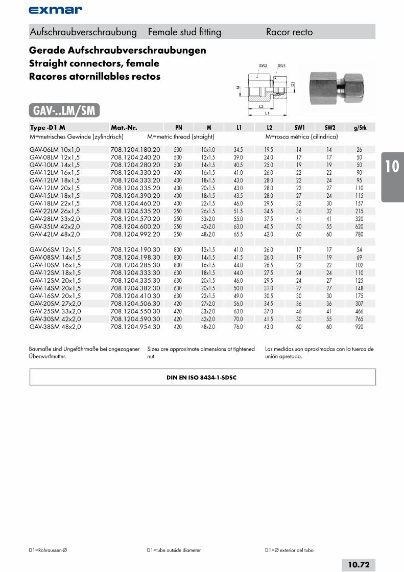
Baumaße sind Ungefährmaße bei angezogener Überwurfmutter.
Sizes are approximate dimensions at tightened nut.
Las medidas son aproximadas con la tuerca de unión apretada.
DIN EN ISO 8434-1-SDSC
Aufschraubverschraubung Female stud fitting Racor recto
D1=Rohraussen-Ø D1=tube outside diameter D1=Ø exterior del tubo
Gerade AufschraubverschraubungenStraight connectors, femaleRacores atornillables rectos
GAV-..LM/SMType -D1 M Mat.-Nr. PN M L1 L2 SW1 SW2 g/StkM=metrisches Gewinde (zylindrisch) M=metric thread (straight) M=rosca métrica (cilindrica) GAV-06LM 10x1,0 708.1204.180.20 500 10x1.0 34.5 19.5 14 14 26GAV-08LM 12x1,5 708.1204.240.20 500 12x1.5 39.0 24.0 17 17 50GAV-10LM 14x1,5 708.1204.280.20 500 14x1.5 40.5 25.0 19 19 50GAV-12LM 16x1,5 708.1204.330.20 400 16x1.5 41.0 26.0 22 22 90GAV-12LM 18x1,5 708.1204.333.20 400 18x1.5 43.0 28.0 22 24 95GAV-12LM 20x1,5 708.1204.335.20 400 20x1.5 43.0 28.0 22 27 110GAV-15LM 18x1,5 708.1204.390.20 400 18x1.5 43.5 28.0 27 24 115GAV-18LM 22x1,5 708.1204.460.20 400 22x1.5 46.0 29.5 32 30 157GAV-22LM 26x1,5 708.1204.535.20 250 26x1.5 51.5 34.5 36 32 215GAV-28LM 33x2,0 708.1204.570.20 250 33x2.0 55.0 37.5 41 41 320GAV-35LM 42x2,0 708.1204.600.20 250 42x2.0 63.0 40.5 50 55 620GAV-42LM 48x2,0 708.1204.992.20 250 48x2.0 65.5 42.0 60 60 780 GAV-06SM 12x1,5 708.1204.190.30 800 12x1.5 41.0 26.0 17 17 54GAV-08SM 14x1,5 708.1204.198.30 800 14x1.5 41.5 26.0 19 19 69GAV-10SM 16x1,5 708.1204.285.30 800 16x1.5 44.0 26.5 22 22 102GAV-12SM 18x1,5 708.1204.333.30 630 18x1.5 44.0 27.5 24 24 110GAV-12SM 20x1,5 708.1204.335.30 630 20x1.5 46.0 29.5 24 27 125GAV-14SM 20x1,5 708.1204.382.30 630 20x1.5 50.0 31.0 27 27 148GAV-16SM 20x1,5 708.1204.410.30 630 22x1.5 49.0 30.5 30 30 175GAV-20SM 27x2,0 708.1204.506.30 420 27x2.0 56.0 34.5 36 36 307GAV-25SM 33x2,0 708.1204.550.30 420 33x2.0 63.0 37.0 46 41 466GAV-30SM 42x2,0 708.1204.590.30 420 42x2.0 70.0 41.5 50 55 765GAV-38SM 48x2,0 708.1204.954.30 420 48x2.0 76.0 43.0 60 60 920
10.72
i
s
10
20
30
40
50
60
70
a
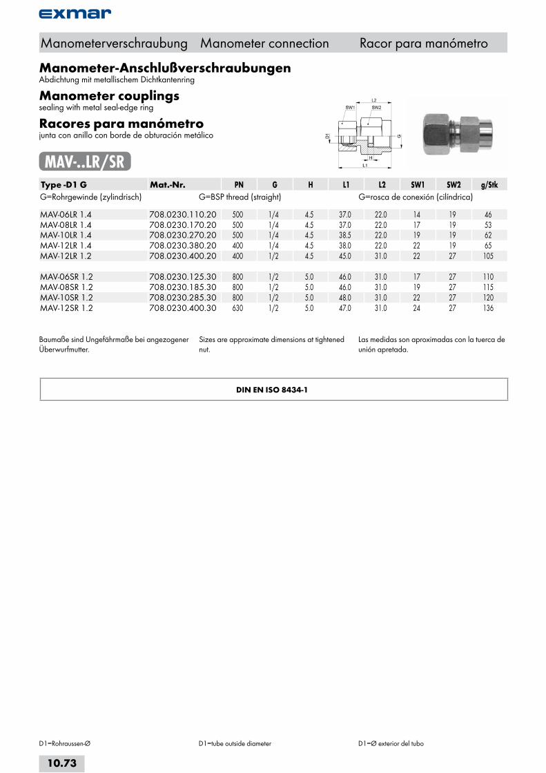
Manometer-AnschlußverschraubungenAbdichtung mit metallischem Dichtkantenring
Manometer couplingssealing with metal seal-edge ring
Racores para manómetrojunta con anillo con borde de obturación metálico
MAV-..LR/SRType -D1 G Mat.-Nr. PN G H L1 L2 SW1 SW2 g/StkG=Rohrgewinde (zylindrisch) G=BSP thread (straight) G=rosca de conexión (cilíndrica) MAV-06LR 1.4 708.0230.110.20 500 1/4 4.5 37.0 22.0 14 19 46MAV-08LR 1.4 708.0230.170.20 500 1/4 4.5 37.0 22.0 17 19 53MAV-10LR 1.4 708.0230.270.20 500 1/4 4.5 38.5 22.0 19 19 62MAV-12LR 1.4 708.0230.380.20 400 1/4 4.5 38.0 22.0 22 19 65MAV-12LR 1.2 708.0230.400.20 400 1/2 4.5 45.0 31.0 22 27 105 MAV-06SR 1.2 708.0230.125.30 800 1/2 5.0 46.0 31.0 17 27 110MAV-08SR 1.2 708.0230.185.30 800 1/2 5.0 46.0 31.0 19 27 115MAV-10SR 1.2 708.0230.285.30 800 1/2 5.0 48.0 31.0 22 27 120MAV-12SR 1.2 708.0230.400.30 630 1/2 5.0 47.0 31.0 24 27 136
Baumaße sind Ungefährmaße bei angezogener Überwurfmutter.
Sizes are approximate dimensions at tightened nut.
Las medidas son aproximadas con la tuerca de unión apretada.
DIN EN ISO 8434-1
Manometerverschraubung Manometer connection Racor para manómetro
D1=Rohraussen-Ø D1=tube outside diameter D1=Ø exterior del tubo
10.73
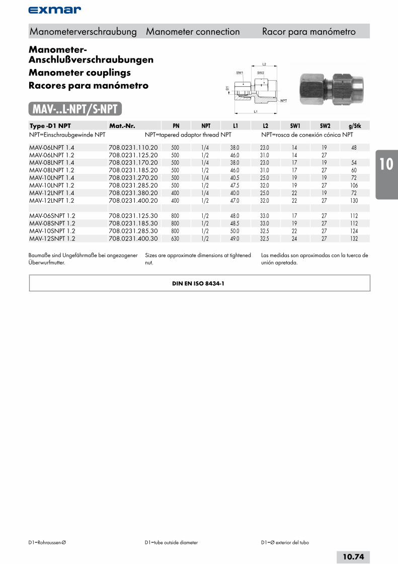
Manometer-AnschlußverschraubungenManometer couplingsRacores para manómetro
MAV-..L-NPT/S-NPTType -D1 NPT Mat.-Nr. PN NPT L1 L2 SW1 SW2 g/StkNPT=Einschraubgewinde NPT NPT=tapered adaptor thread NPT NPT=rosca de conexión cónica NPT MAV-06LNPT 1.4 708.0231.110.20 500 1/4 38.0 23.0 14 19 48MAV-06LNPT 1.2 708.0231.125.20 500 1/2 46.0 31.0 14 27 MAV-08LNPT 1.4 708.0231.170.20 500 1/4 38.0 23.0 17 19 54MAV-08LNPT 1.2 708.0231.185.20 500 1/2 46.0 31.0 17 27 60MAV-10LNPT 1.4 708.0231.270.20 500 1/4 40.5 25.0 19 19 72MAV-10LNPT 1.2 708.0231.285.20 500 1/2 47.5 32.0 19 27 106MAV-12LNPT 1.4 708.0231.380.20 400 1/4 40.0 25.0 22 19 72MAV-12LNPT 1.2 708.0231.400.20 400 1/2 47.0 32.0 22 27 130 MAV-06SNPT 1.2 708.0231.125.30 800 1/2 48.0 33.0 17 27 112MAV-08SNPT 1.2 708.0231.185.30 800 1/2 48.5 33.0 19 27 112MAV-10SNPT 1.2 708.0231.285.30 800 1/2 50.0 32.5 22 27 124MAV-12SNPT 1.2 708.0231.400.30 630 1/2 49.0 32.5 24 27 132
Baumaße sind Ungefährmaße bei angezogener Überwurfmutter.
Sizes are approximate dimensions at tightened nut.
Las medidas son aproximadas con la tuerca de unión apretada.
DIN EN ISO 8434-1
Manometerverschraubung Manometer connection Racor para manómetro
D1=Rohraussen-Ø D1=tube outside diameter D1=Ø exterior del tubo
10.74
i
s
10
20
30
40
50
60
70
a

Einstellbare Manometerverschraubungenmit Dichtkegel und O-Ring
Adjustable manometer couplingswith taper and O-ring
Racores para manómetro ajustab-lescon junta cónica y junta tórica
EMAKO-..LR/SRType -D1 G Mat.-Nr. PN G L1 L2 SW1 SW2 g/StkG=Rohrgewinde (zylindrisch) G=BSP thread (straight) G=rosca de conexión (cilíndrica) EMAKO-06LR 1.4 708.0245.110.20 315 1/4 34.5 24.5 14 19 45EMAKO-08LR 1.4 708.0245.170.20 315 1/4 34.5 25.0 17 19 57EMAKO-10LR 1.4 708.0245.270.20 315 1/4 35.0 26.5 19 19 63EMAKO-12LR 1.4 708.0245.380.20 315 1/4 35.0 27.5 22 19 75 EMAKO-06SR 1.2 708.0245.125.30 630 1/2 41.5 24.5 17 27 110EMAKO-08SR 1.2 708.0245.185.30 630 1/2 42.0 25.0 19 27 112EMAKO-10SR 1.2 708.0245.285.30 630 1/2 42.5 27.0 22 27 123EMAKO-12SR 1.2 708.0245.400.30 630 1/2 44.0 29.0 24 27 139
Baumaße sind Ungefährmaße bei angezogener Überwurfmutter.
Sizes are approximate dimensions at tightened nut.
Las medidas son aproximadas con la tuerca de unión apretada.
Manometerverschraubung Manometer connection Racor para manómetro
D1=Rohraussen-Ø D1=tube outside diameter D1=Ø exterior del tubo
10.75

Einstellbare Manometer-AnschlußstutzenAbdichtung mit metallischem Dichtkantenring
Adjustable manometer couplingssealing with metal seal-edge ring
Racores para manómetro ajustab-lesjunta con anillo con borde de obturación metálico
EMAS-..LR/SRType -D1 G Mat.-Nr. PN G H L1 SW1 SW2 g/StkG=Rohrgewinde (zylindrisch) G=BSP thread (straight) G=rosca de conexión (cilíndrica) EMAS-06LR 1.4 708.0235.110.20 500 1/4 4.5 38.0 14 19 46EMAS-08LR 1.4 708.0235.170.20 500 1/4 4.5 38.0 17 19 53EMAS-10LR 1.4 708.0235.270.20 500 1/4 4.5 40.0 19 19 62EMAS-12LR 1.4 708.0235.380.20 400 1/4 4.5 40.0 22 19 70 EMAS-06SR 1.2 708.0235.125.30 800 1/2 5.0 48.0 17 27 105EMAS-08SR 1.2 708.0235.185.30 800 1/2 5.0 50.0 19 27 107EMAS-10SR 1.2 708.0235.285.30 800 1/2 5.0 50.0 22 27 125EMAS-12SR 1.2 708.0235.400.30 630 1/2 5.0 47.5 24 27 134
Baumaße sind Ungefährmaße bei angezogener Überwurfmutter.
Sizes are approximate dimensions at tightened nut.
Las medidas son aproximadas con la tuerca de unión apretada.
DIN EN ISO 8434-1
Manometerverschraubung Manometer connection Racor para manómetro
D1=Rohraussen-Ø D1=tube outside diameter D1=Ø exterior del tubo
10.76
i
s
10
20
30
40
50
60
70
a

Einstellbare Manometer-AnschlußstutzenAdjustable manometer couplingsRacores para manómetro ajustab-les
EMAS-..L-NPT/S-NPTType -D1 NPT Mat.-Nr. PN NPT L1 SW1 SW2 g/StkNPT=Einschraubgewinde NPT NPT=tapered adaptor thread NPT NPT=rosca de conexión cónica NPT EMAS-06LNPT 1.4 708.0236.110.20 500 1/4 38.0 14 19 48EMAS-08LNPT 1.4 708.0236.170.20 500 1/4 38.0 17 19 54EMAS-10LNPT 1.4 708.0236.270.20 500 1/4 39.5 19 19 56EMAS-12LNPT 1.4 708.0236.380.20 400 1/4 40.5 22 19 72 EMAS-06SNPT 1.2 708.0236.125.30 800 1/2 45.0 17 27 116EMAS-08SNPT 1.2 708.0236.185.30 800 1/2 46.0 19 27 112EMAS-10SNPT 1.2 708.0236.285.30 800 1/2 47.0 22 27 126EMAS-12SNPT 1.2 708.0236.400.30 630 1/2 47.5 24 27 135
Baumaße sind Ungefährmaße bei angezogener Überwurfmutter.
Sizes are approximate dimensions at tightened nut.
Las medidas son aproximadas con la tuerca de unión apretada.
DIN EN ISO 8434-1
Manometerverschraubung Manometer connection Racor para manómetro
D1=Rohraussen-Ø D1=tube outside diameter D1=Ø exterior del tubo
10.77
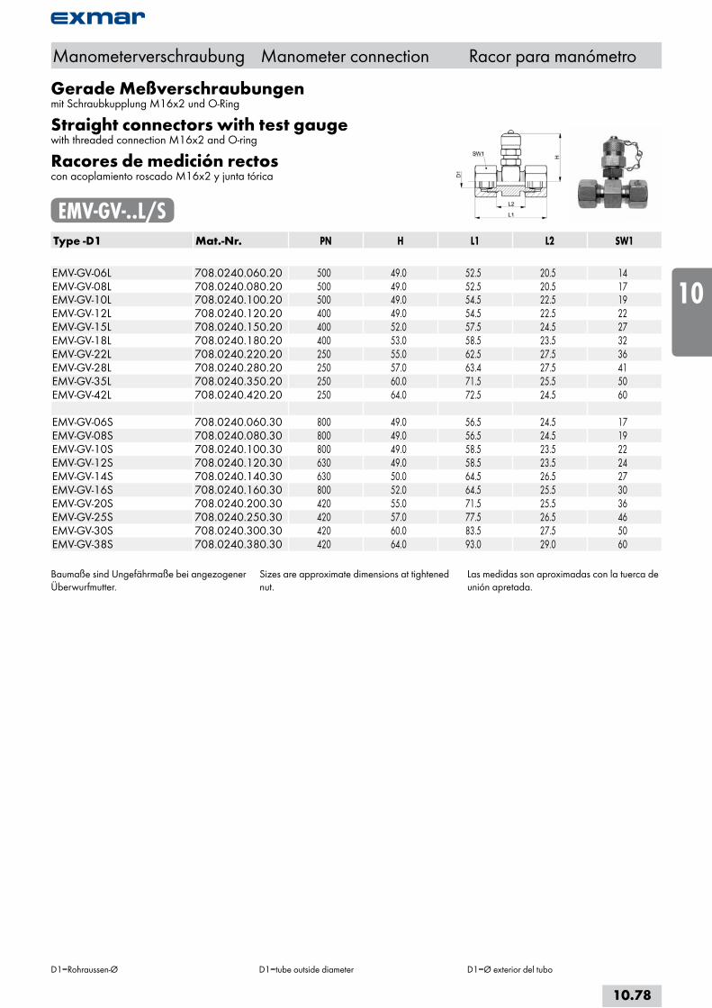
Gerade Meßverschraubungenmit Schraubkupplung M16x2 und O-Ring
Straight connectors with test gaugewith threaded connection M16x2 and O-ring
Racores de medición rectoscon acoplamiento roscado M16x2 y junta tórica
EMV-GV-..L/SType -D1 Mat.-Nr. PN H L1 L2 SW1 EMV-GV-06L 708.0240.060.20 500 49.0 52.5 20.5 14EMV-GV-08L 708.0240.080.20 500 49.0 52.5 20.5 17EMV-GV-10L 708.0240.100.20 500 49.0 54.5 22.5 19EMV-GV-12L 708.0240.120.20 400 49.0 54.5 22.5 22EMV-GV-15L 708.0240.150.20 400 52.0 57.5 24.5 27EMV-GV-18L 708.0240.180.20 400 53.0 58.5 23.5 32EMV-GV-22L 708.0240.220.20 250 55.0 62.5 27.5 36EMV-GV-28L 708.0240.280.20 250 57.0 63.4 27.5 41EMV-GV-35L 708.0240.350.20 250 60.0 71.5 25.5 50EMV-GV-42L 708.0240.420.20 250 64.0 72.5 24.5 60 EMV-GV-06S 708.0240.060.30 800 49.0 56.5 24.5 17EMV-GV-08S 708.0240.080.30 800 49.0 56.5 24.5 19EMV-GV-10S 708.0240.100.30 800 49.0 58.5 23.5 22EMV-GV-12S 708.0240.120.30 630 49.0 58.5 23.5 24EMV-GV-14S 708.0240.140.30 630 50.0 64.5 26.5 27EMV-GV-16S 708.0240.160.30 800 52.0 64.5 25.5 30EMV-GV-20S 708.0240.200.30 420 55.0 71.5 25.5 36EMV-GV-25S 708.0240.250.30 420 57.0 77.5 26.5 46EMV-GV-30S 708.0240.300.30 420 60.0 83.5 27.5 50EMV-GV-38S 708.0240.380.30 420 64.0 93.0 29.0 60
Baumaße sind Ungefährmaße bei angezogener Überwurfmutter.
Sizes are approximate dimensions at tightened nut.
Las medidas son aproximadas con la tuerca de unión apretada.
Manometerverschraubung Manometer connection Racor para manómetro
D1=Rohraussen-Ø D1=tube outside diameter D1=Ø exterior del tubo
10.78
i
s
10
20
30
40
50
60
70
a

Meßanschlüssemit Schraubkupplung M16x2, Kegelausführung
Test point gaugewith threaded connection M16x2, tapered version
Conexión de medicióncon acoplamiento roscado M16x2, versión cónico
EMV-..Type -M Mat.-Nr. PN M H L1 SW1M=metrisches Gewinde (zylindrisch) M=metric thread (straight) M=rosca métrica (cilindrica) EMV-M 10x1,0 706.0246.150.30 630 10x1.0 28.0 10.0 17
mit O-Ring-Dichtung am Einschraubgewinde; Dichtung: FKM
with O-ring-seal on stud in thread; seal: FKM con junta tórica en la rosca; junta: FKM
Type -NPT Mat.-Nr. PN NPT H L1 SW1NPT=Einschraubgewinde NPT NPT=tapered adaptor thread NPT NPT=rosca de conexión cónica NPT EMV-NPT1.8 706.0247.020.30 630 1/8 24.5 9.5 17EMV-NPT1.4 706.0247.040.30 630 1/4 20.0 14.0 17
Type -G Mat.-Nr. PN G H L1 SW1G=Rohrgewinde (zylindrisch) G=BSP thread (straight) G=rosca de conexión (cilíndrica) EMV-G1.4A-WD 706.0249.040.30 630 1/4 25.0 12.0 19
Abdichtung durch Profildichtung FKM FKM soft seal design FKM junta flexible
Manometerverschraubung Manometer connection Racor para manómetro
10.79

Meßanschlüsse für 24° KonenTest point gauge for 24° taperConexión de medición para conos de 24°
EMV-..L/SType -D1 Mat.-Nr. PN M H SW1M=metrisches Gewinde (zylindrisch) M=metric thread (straight) M=rosca métrica (cilindrica)
EMV-06L 708.0243.060.20 500 12x1.5 64.0 14 EMV-08L 708.0243.080.20 500 14x1.5 64.0 17 EMV-10L 708.0243.100.20 500 16x1.5 65.0 19 EMV-12L 708.0243.120.20 500 18x1.5 65.0 22 EMV-15L 708.0243.150.20 500 22x1.5 52.0 27 EMV-18L 708.0243.180.20 500 26x1.5 55.0 32 EMV-22L 708.0243.220.20 250 30x2.0 55.0 36 EMV-28L 708.0243.280.20 250 36x2.0 55.0 41 EMV-35L 708.0243.350.20 250 45x2.0 57.0 50 EMV-42L 708.0243.420.20 250 52x2.0 57.0 60
EMV-06S 708.0243.060.30 800 14x1.5 64.0 17 EMV-08S 708.0243.080.30 800 16x1.5 65.0 19 EMV-10S 708.0243.100.30 800 18x1.5 65.0 22 EMV-12S 708.0243.120.30 630 20x1.5 68.0 24 EMV-14S 708.0243.140.30 630 22x1.5 52.0 27 EMV-16S 708.0243.160.30 630 24x1.5 52.0 30 EMV-20S 708.0243.200.30 630 30x2.0 57.0 36 EMV-25S 708.0243.250.30 630 36x2.0 58.0 46 EMV-30S 708.0243.300.30 630 42x2.0 60.0 50 EMV-38S 708.0243.380.30 630 52x2.0 62.0 60
Manometerverschraubung Manometer connection Racor para manómetro
D1=Rohraussen-Ø=Ausführung mit Dichtkegel
D1=tube outside diameter=Version with taper
D1=Ø exterior del tubo=Versión con junta cónica
10.80
i
s
10
20
30
40
50
60
70
a

Reduzierverschraubungenmit Dichtkegel und O-Ring
Reducing fittingswith taper and O-ring
Racores de reduccióncon junta cónica y junta tórica
GRKO-..LType -D1 /D2 Mat.-Nr. PN L1 L2 SW1 SW2 SW3 g/Stk GRKO-08/06L 708.1870.140.20 315 38.0 22.0 14 12 17 42GRKO-10/06L 708.1870.175.20 315 40.0 24.0 14 14 19 54GRKO-10/08L 708.1870.190.20 315 40.0 24.0 17 14 19 56GRKO-12/06L 708.1870.215.20 315 40.0 24.0 14 17 22 68GRKO-12/08L 708.1870.225.20 315 40.0 24.0 17 17 22 72GRKO-12/10L 708.1870.240.20 315 41.5 25.0 19 17 22 74GRKO-15/06L 708.1870.391.20 315 43.5 27.5 14 22 27 100GRKO-15/08L 708.1870.400.20 315 43.5 27.5 17 22 27 118GRKO-15/10L 708.1870.410.20 315 44.5 28.0 19 22 27 118GRKO-15/12L 708.1870.420.20 315 44.0 28.0 22 22 27 122GRKO-18/06L 708.1870.563.20 315 43.0 26.5 14 24 32 122GRKO-18/08L 708.1870.570.20 315 43.0 26.5 17 24 32 132GRKO-18/10L 708.1870.575.20 315 44.5 27.5 19 24 32 150GRKO-18/12L 708.1870.580.20 315 44.0 27.5 22 24 32 152GRKO-18/15L 708.1870.610.20 315 45.5 28.5 27 24 32 170GRKO-22/06L 708.1870.723.20 160 47.0 30.5 14 27 36 178GRKO-22/08L 708.1870.724.20 160 47.0 30.5 17 27 36 180GRKO-22/10L 708.1870.725.20 160 48.5 31.5 19 27 36 186GRKO-22/12L 708.1870.730.20 160 48.0 31.5 22 27 36 194GRKO-22/15L 708.1870.745.20 160 49.5 31.5 27 27 36 236GRKO-22/18L 708.1870.755.20 160 50.0 31.0 32 27 36 250GRKO-28/06L 708.1870.828.20 160 49.0 31.5 14 36 46 322GRKO-28/08L 708.1870.829.20 160 49.0 31.5 17 36 46 315GRKO-28/10L 708.1870.830.20 160 50.5 33.5 19 36 46 320GRKO-28/12L 708.1870.835.20 160 50.0 33.5 22 36 46 328GRKO-28/15L 708.1870.865.20 160 51.5 34.5 27 36 46 350GRKO-28/18L 708.1870.870.20 160 52.0 34.0 32 36 46 376GRKO-28/22L 708.1870.900.20 160 54.5 36.0 36 36 46 420
Fortsetzung nächste Seite Continued on next page Continuación página próxima
Reduzierverschraubung Reducing fitting Racor de reducción
D1/D2=Rohraussen-Ø D1/D2=tube outside diameter D1/D2=Ø exterior del tubo
10.81
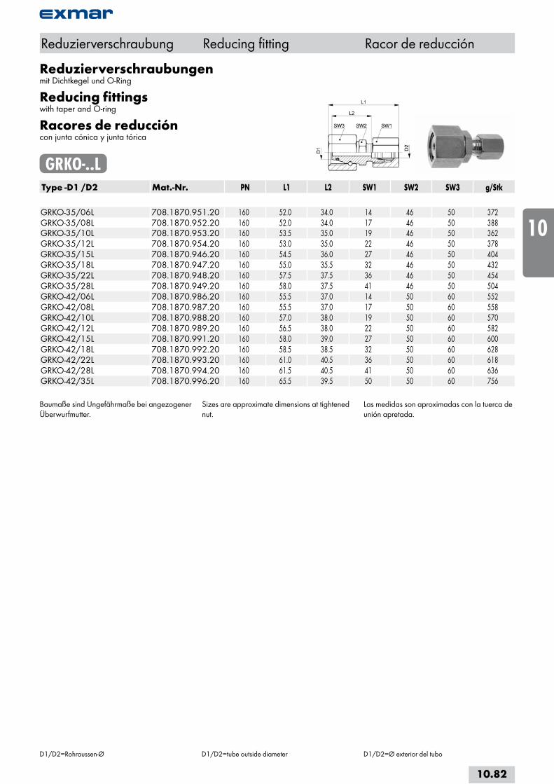
Reduzierverschraubungenmit Dichtkegel und O-Ring
Reducing fittingswith taper and O-ring
Racores de reduccióncon junta cónica y junta tórica
GRKO-..LType -D1 /D2 Mat.-Nr. PN L1 L2 SW1 SW2 SW3 g/Stk GRKO-35/06L 708.1870.951.20 160 52.0 34.0 14 46 50 372GRKO-35/08L 708.1870.952.20 160 52.0 34.0 17 46 50 388GRKO-35/10L 708.1870.953.20 160 53.5 35.0 19 46 50 362GRKO-35/12L 708.1870.954.20 160 53.0 35.0 22 46 50 378GRKO-35/15L 708.1870.946.20 160 54.5 36.0 27 46 50 404GRKO-35/18L 708.1870.947.20 160 55.0 35.5 32 46 50 432GRKO-35/22L 708.1870.948.20 160 57.5 37.5 36 46 50 454GRKO-35/28L 708.1870.949.20 160 58.0 37.5 41 46 50 504GRKO-42/06L 708.1870.986.20 160 55.5 37.0 14 50 60 552GRKO-42/08L 708.1870.987.20 160 55.5 37.0 17 50 60 558GRKO-42/10L 708.1870.988.20 160 57.0 38.0 19 50 60 570GRKO-42/12L 708.1870.989.20 160 56.5 38.0 22 50 60 582GRKO-42/15L 708.1870.991.20 160 58.0 39.0 27 50 60 600GRKO-42/18L 708.1870.992.20 160 58.5 38.5 32 50 60 628GRKO-42/22L 708.1870.993.20 160 61.0 40.5 36 50 60 618GRKO-42/28L 708.1870.994.20 160 61.5 40.5 41 50 60 636GRKO-42/35L 708.1870.996.20 160 65.5 39.5 50 50 60 756
Baumaße sind Ungefährmaße bei angezogener Überwurfmutter.
Sizes are approximate dimensions at tightened nut.
Las medidas son aproximadas con la tuerca de unión apretada.
Reduzierverschraubung Reducing fitting Racor de reducción
D1/D2=Rohraussen-Ø D1/D2=tube outside diameter D1/D2=Ø exterior del tubo
10.82
i
s
10
20
30
40
50
60
70
a
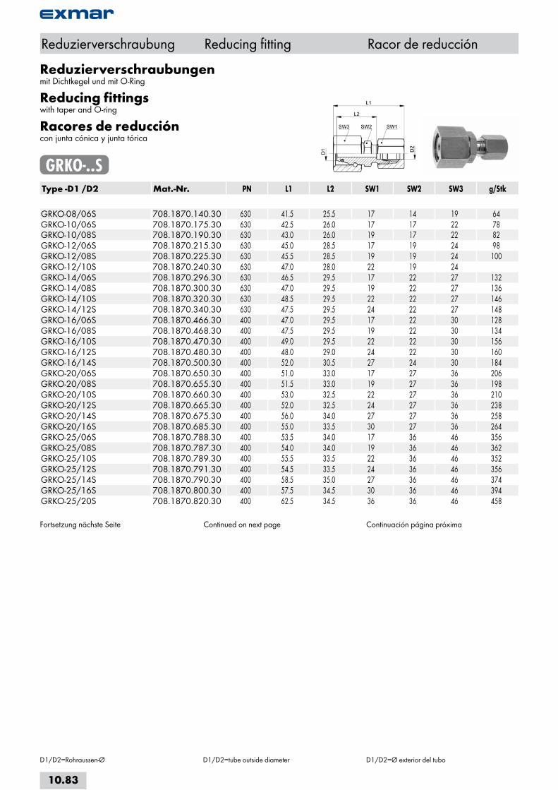
Reduzierverschraubungenmit Dichtkegel und mit O-Ring
Reducing fittingswith taper and O-ring
Racores de reduccióncon junta cónica y junta tórica
GRKO-..SType -D1 /D2 Mat.-Nr. PN L1 L2 SW1 SW2 SW3 g/Stk GRKO-08/06S 708.1870.140.30 630 41.5 25.5 17 14 19 64GRKO-10/06S 708.1870.175.30 630 42.5 26.0 17 17 22 78GRKO-10/08S 708.1870.190.30 630 43.0 26.0 19 17 22 82GRKO-12/06S 708.1870.215.30 630 45.0 28.5 17 19 24 98GRKO-12/08S 708.1870.225.30 630 45.5 28.5 19 19 24 100GRKO-12/10S 708.1870.240.30 630 47.0 28.0 22 19 24 GRKO-14/06S 708.1870.296.30 630 46.5 29.5 17 22 27 132GRKO-14/08S 708.1870.300.30 630 47.0 29.5 19 22 27 136GRKO-14/10S 708.1870.320.30 630 48.5 29.5 22 22 27 146GRKO-14/12S 708.1870.340.30 630 47.5 29.5 24 22 27 148GRKO-16/06S 708.1870.466.30 400 47.0 29.5 17 22 30 128GRKO-16/08S 708.1870.468.30 400 47.5 29.5 19 22 30 134GRKO-16/10S 708.1870.470.30 400 49.0 29.5 22 22 30 156GRKO-16/12S 708.1870.480.30 400 48.0 29.0 24 22 30 160GRKO-16/14S 708.1870.500.30 400 52.0 30.5 27 24 30 184GRKO-20/06S 708.1870.650.30 400 51.0 33.0 17 27 36 206GRKO-20/08S 708.1870.655.30 400 51.5 33.0 19 27 36 198GRKO-20/10S 708.1870.660.30 400 53.0 32.5 22 27 36 210GRKO-20/12S 708.1870.665.30 400 52.0 32.5 24 27 36 238GRKO-20/14S 708.1870.675.30 400 56.0 34.0 27 27 36 258GRKO-20/16S 708.1870.685.30 400 55.0 33.5 30 27 36 264GRKO-25/06S 708.1870.788.30 400 53.5 34.0 17 36 46 356GRKO-25/08S 708.1870.787.30 400 54.0 34.0 19 36 46 362GRKO-25/10S 708.1870.789.30 400 55.5 33.5 22 36 46 352GRKO-25/12S 708.1870.791.30 400 54.5 33.5 24 36 46 356GRKO-25/14S 708.1870.790.30 400 58.5 35.0 27 36 46 374GRKO-25/16S 708.1870.800.30 400 57.5 34.5 30 36 46 394GRKO-25/20S 708.1870.820.30 400 62.5 34.5 36 36 46 458
Fortsetzung nächste Seite Continued on next page Continuación página próxima
Reduzierverschraubung Reducing fitting Racor de reducción
D1/D2=Rohraussen-Ø D1/D2=tube outside diameter D1/D2=Ø exterior del tubo
10.83

Reduzierverschraubungenmit Dichtkegel und mit O-Ring
Reducing fittingswith taper and O-ring
Racores de reduccióncon junta cónica y junta tórica
GRKO-..SType -D1 /D2 Mat.-Nr. PN L1 L2 SW1 SW2 SW3 g/Stk GRKO-30/06S 708.1870.937.30 400 58.5 38.0 17 41 50 412GRKO-30/08S 708.1870.936.30 400 59.0 38.0 19 41 50 416GRKO-30/10S 708.1870.939.30 400 60.5 37.5 22 41 50 424GRKO-30/12S 708.1870.940.30 400 59.5 37.5 24 41 50 432GRKO-30/14S 708.1870.941.30 400 63.5 39.0 27 41 50 480GRKO-30/16S 708.1870.942.30 400 62.5 38.5 30 41 50 468GRKO-30/20S 708.1870.943.30 400 67.5 38.5 36 41 50 528GRKO-30/25S 708.1870.945.30 400 70.5 39.0 46 41 50 672GRKO-38/06S 708.1870.965.30 315 62.0 39.0 17 50 60 574GRKO-38/08S 708.1870.966.30 315 62.5 39.0 19 50 60 578GRKO-38/10S 708.1870.967.30 315 64.0 38.5 22 50 60 632GRKO-38/12S 708.1870.968.30 315 63.0 38.5 24 50 60 638GRKO-38/14S 708.1870.969.30 315 67.0 40.0 27 50 60 652GRKO-38/16S 708.1870.970.30 315 66.0 39.5 30 50 60 672GRKO-38/20S 708.1870.971.30 315 71.0 39.5 36 50 60 682GRKO-38/25S 708.1870.972.30 315 74.0 40.0 46 50 60 818GRKO-38/30S 708.1870.975.30 315 77.0 40.5 50 50 60 914
Baumaße sind Ungefährmaße bei angezogener Überwurfmutter.
Sizes are approximate dimensions at tightened nut.
Las medidas son aproximadas con la tuerca de unión apretada.
Reduzierverschraubung Reducing fitting Racor de reducción
D1/D2=Rohraussen-Ø D1/D2=tube outside diameter D1/D2=Ø exterior del tubo
10.84
i
s
10
20
30
40
50
60
70
a

Gerade ReduzierverschraubungenReducing unionsRacores de reducción rectos
GR-..LType -D1 /D2 Mat.-Nr. PN L1 L2 SW1 SW2 SW3 g/Stk GR-06/04LL 708.1024.110.10 100 30.0 10.5 12 11 10 20GR-08/06LL 708.1024.140.10 100 32.0 11.0 14 12 12 26 GR-08/06L 708.1024.140.20 500 41.0 11.0 17 14 14 51GR-10/06L 708.1024.175.20 500 42.5 12.0 19 17 14 58GR-10/08L 708.1024.190.20 500 42.5 12.0 19 17 17 58GR-12/06L 708.1024.215.20 400 43.0 13.0 22 19 14 63GR-12/08L 708.1024.225.20 400 43.0 13.0 22 19 17 70GR-12/10L 708.1024.240.20 400 44.5 14.0 22 19 19 80GR-15/06L 708.1024.391.20 400 44.5 14.0 27 24 14 100GR-15/08L 708.1024.400.20 400 44.5 14.0 27 24 17 105GR-15/10L 708.1024.410.20 400 46.0 15.0 27 24 19 110GR-15/12L 708.1024.420.20 400 45.5 15.0 27 24 22 132GR-18/08L 708.1024.570.20 400 46.0 14.5 32 27 17 115GR-18/10L 708.1024.575.20 400 47.5 15.5 32 27 19 145GR-18/12L 708.1024.580.20 400 47.0 15.5 32 27 22 175GR-18/15L 708.1024.610.20 400 48.5 16.5 32 27 27 175GR-22/10L 708.1024.725.20 250 50.0 17.5 36 32 19 198GR-22/12L 708.1024.730.20 250 49.5 17.5 36 32 22 200GR-22/15L 708.1024.745.20 250 51.0 18.5 36 32 27 220GR-22/18L 708.1024.755.20 250 51.5 18.0 36 32 32 274GR-28/10L 708.1024.830.20 250 51.5 18.5 41 41 19 250GR-28/12L 708.1024.835.20 250 51.0 18.5 41 41 22 270GR-28/15L 708.1024.865.20 250 52.5 19.5 41 41 27 296GR-28/18L 708.1024.870.20 250 53.0 19.0 41 41 32 307GR-28/22L 708.1024.900.20 250 55.5 21.0 41 41 36 309GR-35/15L 708.1024.946.20 250 57.5 19.0 50 46 27 390GR-35/18L 708.1024.947.20 250 58.0 19.0 50 46 32 410GR-35/22L 708.1024.948.20 250 60.5 21.0 50 46 36 434GR-35/28L 708.1024.949.20 250 61.0 21.0 50 46 41 455GR-42/15L 708.1024.991.20 250 60.0 21.0 60 55 27 550GR-42/18L 708.1024.992.20 250 60.5 20.5 60 55 32 590GR-42/22L 708.1024.993.20 250 63.0 22.5 60 55 36 610GR-42/28L 708.1024.994.20 250 63.5 22.5 60 55 41 650GR-42/35L 708.1024.996.20 250 68.0 21.5 60 55 50 786
Baumaße sind Ungefährmaße bei angezogener Überwurfmutter.
Sizes are approximate dimensions at tightened nut.
Las medidas son aproximadas con la tuerca de unión apretada.
Reduzierverschraubung Reducing fitting Racor de reducción
D1/D2=Rohraussen-Ø D1/D2=tube outside diameter D1/D2=Ø exterior del tubo
10.85
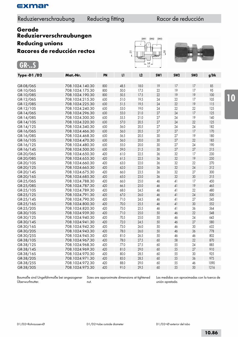
Gerade ReduzierverschraubungenReducing unionsRacores de reducción rectos
GR-..SType -D1 /D2 Mat.-Nr. PN L1 L2 SW1 SW2 SW3 g/Stk GR-08/06S 708.1024.140.30 800 48.5 18.0 19 17 17 85GR-10/06S 708.1024.175.30 800 50.0 17.5 22 19 17 95GR-10/08S 708.1024.190.30 800 50.5 17.5 22 19 19 100GR-12/06S 708.1024.215.30 630 51.0 19.5 24 22 17 105GR-12/08S 708.1024.225.30 630 51.5 19.5 24 22 19 115GR-12/10S 708.1024.240.30 630 53.0 19.0 24 22 22 125GR-14/06S 708.1024.296.30 630 55.0 21.0 27 24 17 125GR-14/08S 708.1024.300.30 630 55.5 21.0 27 24 19 140GR-14/10S 708.1024.320.30 630 57.0 20.5 27 24 22 125GR-14/12S 708.1024.340.30 630 56.0 20.5 27 24 24 182GR-16/06S 708.1024.466.30 630 56.0 20.5 27 27 17 170GR-16/08S 708.1024.468.30 630 56.5 20.5 30 27 19 180GR-16/10S 708.1024.470.30 630 56.0 20.0 30 27 22 185GR-16/12S 708.1024.480.30 630 55.0 20.0 30 27 24 190GR-16/14S 708.1024.500.30 630 59.0 21.5 30 27 27 215GR-20/06S 708.1024.650.30 420 61.0 22.5 36 32 17 230GR-20/08S 708.1024.655.30 420 61.5 22.5 36 32 19 250GR-20/10S 708.1024.660.30 420 63.0 22.0 36 32 22 270GR-20/12S 708.1024.665.30 420 62.0 22.0 36 32 24 312GR-20/14S 708.1024.675.30 420 66.0 23.5 36 32 27 300GR-20/16S 708.1024.685.30 420 65.0 23.0 36 32 30 315GR-25/06S 708.1024.788.30 420 66.0 25.0 46 41 17 450GR-25/08S 708.1024.787.30 420 66.5 25.0 46 41 19 465GR-25/10S 708.1024.789.30 420 68.0 24.5 46 41 22 480GR-25/12S 708.1024.791.30 420 67.0 26.0 46 41 24 500GR-25/14S 708.1024.790.30 420 71.0 24.5 46 41 27 545GR-25/16S 708.1024.800.30 420 70.0 25.5 46 41 30 552GR-25/20S 708.1024.820.30 420 75.0 25.5 46 41 36 564GR-30/10S 708.1024.939.30 420 71.0 25.0 50 46 22 548GR-30/12S 708.1024.940.30 420 70.5 25.0 50 46 24 643GR-30/14S 708.1024.941.30 420 72.0 24.5 50 46 27 580GR-30/16S 708.1024.942.30 420 73.0 26.0 50 46 30 632GR-30/20S 708.1024.943.30 420 78.0 26.0 50 46 36 778GR-30/25S 708.1024.945.30 420 81.0 26.5 50 46 46 802GR-38/10S 708.1024.967.30 420 78.0 27.5 60 58 22 870GR-38/12S 708.1024.968.30 420 77.0 27.5 60 55 24 885GR-38/14S 708.1024.969.30 420 81.0 29.0 60 55 27 910GR-38/16S 708.1024.970.30 420 80.0 28.5 60 55 30 925GR-38/20S 708.1024.971.30 420 85.0 28.5 60 55 36 975GR-38/25S 708.1024.972.30 420 88.0 29.0 60 55 46 1090GR-38/30S 708.1024.975.30 420 91.0 29.5 60 55 50 1216
Baumaße sind Ungefährmaße bei angezogener Überwurfmutter.
Sizes are approximate dimensions at tightened nut.
Las medidas son aproximadas con la tuerca de unión apretada.
Reduzierverschraubung Reducing fitting Racor de reducción
D1/D2=Rohraussen-Ø D1/D2=tube outside diameter D1/D2=Ø exterior del tubo
10.86
i
s
10
20
30
40
50
60
70
a

Konus-ReduzieranschlüsseTaper reducing fittingsConexiones de reducción cónicas
KR-..LType -D1 /D2 Mat.-Nr. PN L1 L2 SW1 SW2 SW3 g/Stk KR-08/06L 708.1820.140.20 500 43.0 28.0 17 12 14 42KR-10/06L 708.1820.175.20 500 42.5 27.0 19 12 14 55KR-10/08L 708.1820.190.20 500 43.5 28.0 19 14 17 58KR-12/06L 708.1820.215.20 400 44.5 29.0 22 14 14 63KR-12/08L 708.1820.225.20 400 44.5 29.0 22 14 17 70KR-12/10L 708.1820.240.20 400 46.0 30.0 22 17 19 72KR-15/06L 708.1820.391.20 400 45.0 31.0 27 17 14 95KR-15/08L 708.1820.400.20 400 45.0 31.0 27 17 17 98KR-15/10L 708.1820.410.20 400 46.5 32.0 27 17 19 100KR-15/12L 708.1820.420.20 400 47.0 32.0 27 19 22 104KR-18/06L 708.1820.563.20 400 46.5 31.5 32 19 14 133KR-18/08L 708.1820.570.20 400 46.5 31.5 32 19 17 135KR-18/10L 708.1820.575.20 400 47.0 31.5 32 19 19 140KR-18/12L 708.1820.580.20 400 46.5 31.5 32 19 22 145KR-18/15L 708.1820.610.20 400 48.0 32.5 32 24 27 165KR-22/06L 708.1820.723.20 250 46.5 31.5 36 24 14 152KR-22/08L 708.1820.724.20 250 46.5 31.5 36 24 17 157KR-22/10L 708.1820.725.20 250 48.0 32.5 36 24 19 170KR-22/12L 708.1820.730.20 250 47.5 32.5 36 24 22 186KR-22/15L 708.1820.745.20 250 49.0 33.5 36 24 27 214KR-22/18L 708.1820.755.20 250 50.5 34.0 36 27 32 245KR-28/06L 708.1820.828.20 250 49.0 34.0 41 30 14 185KR-28/08L 708.1820.829.20 250 49.0 34.0 41 30 17 190KR-28/10L 708.1820.830.20 250 50.5 35.0 41 30 19 215KR-28/12L 708.1820.835.20 250 50.0 35.0 41 30 22 214KR-28/15L 708.1820.865.20 250 51.5 36.0 41 30 27 245KR-28/18L 708.1820.870.20 250 52.0 35.5 41 30 32 257KR-28/22L 708.1820.900.20 250 54.5 37.5 41 32 36 310KR-35/06L 708.1820.951.20 250 56.0 41.5 50 36 14 314KR-35/08L 708.1820.952.20 250 56.0 41.5 50 36 17 318KR-35/10L 708.1820.953.20 250 58.0 42.5 50 36 19 325KR-35/12L 708.1820.954.20 250 57.0 42.5 50 36 22 345KR-35/15L 708.1820.946.20 250 58.5 43.5 50 36 27 368KR-35/18L 708.1820.947.20 250 59.0 43.0 50 36 32 392KR-35/22L 708.1820.948.20 250 62.5 45.0 50 36 36 480KR-35/28L 708.1820.949.20 250 63.0 45.0 50 41 41 426
Fortsetzung nächste Seite Continued on next page Continuación página próxima
Reduzierverschraubung Reducing fitting Racor de reducción
D1/D2=Rohraussen-Ø D1/D2=tube outside diameter D1/D2=Ø exterior del tubo
10.87
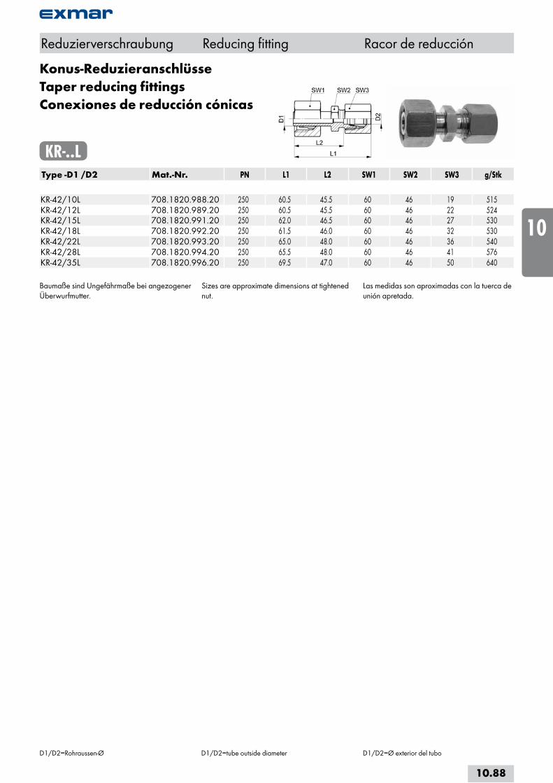
Konus-ReduzieranschlüsseTaper reducing fittingsConexiones de reducción cónicas
KR-..LType -D1 /D2 Mat.-Nr. PN L1 L2 SW1 SW2 SW3 g/Stk KR-42/10L 708.1820.988.20 250 60.5 45.5 60 46 19 515KR-42/12L 708.1820.989.20 250 60.5 45.5 60 46 22 524KR-42/15L 708.1820.991.20 250 62.0 46.5 60 46 27 530KR-42/18L 708.1820.992.20 250 61.5 46.0 60 46 32 530KR-42/22L 708.1820.993.20 250 65.0 48.0 60 46 36 540KR-42/28L 708.1820.994.20 250 65.5 48.0 60 46 41 576KR-42/35L 708.1820.996.20 250 69.5 47.0 60 46 50 640
Baumaße sind Ungefährmaße bei angezogener Überwurfmutter.
Sizes are approximate dimensions at tightened nut.
Las medidas son aproximadas con la tuerca de unión apretada.
Reduzierverschraubung Reducing fitting Racor de reducción
D1/D2=Rohraussen-Ø D1/D2=tube outside diameter D1/D2=Ø exterior del tubo
10.88
i
s
10
20
30
40
50
60
70
a
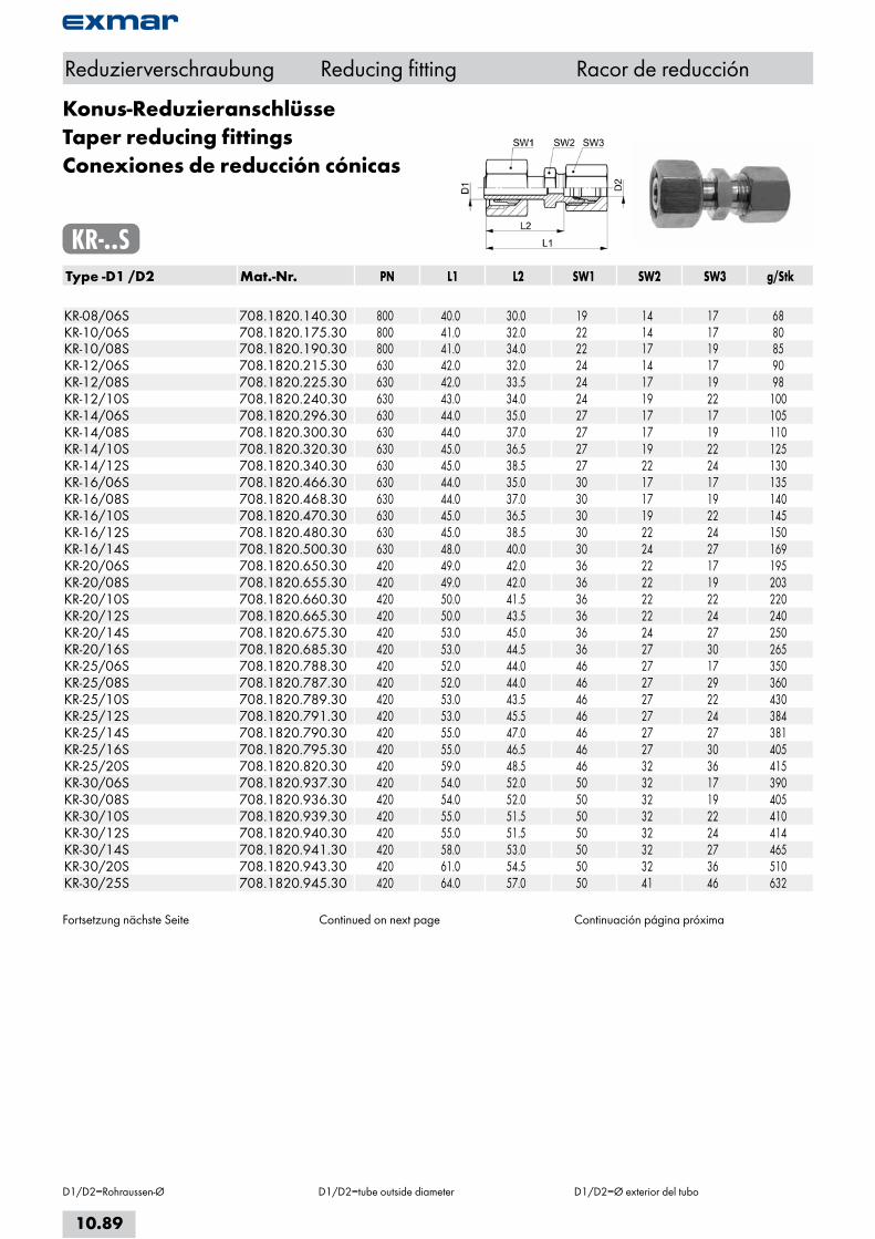
Konus-ReduzieranschlüsseTaper reducing fittingsConexiones de reducción cónicas
KR-..SType -D1 /D2 Mat.-Nr. PN L1 L2 SW1 SW2 SW3 g/Stk KR-08/06S 708.1820.140.30 800 40.0 30.0 19 14 17 68KR-10/06S 708.1820.175.30 800 41.0 32.0 22 14 17 80KR-10/08S 708.1820.190.30 800 41.0 34.0 22 17 19 85KR-12/06S 708.1820.215.30 630 42.0 32.0 24 14 17 90KR-12/08S 708.1820.225.30 630 42.0 33.5 24 17 19 98KR-12/10S 708.1820.240.30 630 43.0 34.0 24 19 22 100KR-14/06S 708.1820.296.30 630 44.0 35.0 27 17 17 105KR-14/08S 708.1820.300.30 630 44.0 37.0 27 17 19 110KR-14/10S 708.1820.320.30 630 45.0 36.5 27 19 22 125KR-14/12S 708.1820.340.30 630 45.0 38.5 27 22 24 130KR-16/06S 708.1820.466.30 630 44.0 35.0 30 17 17 135KR-16/08S 708.1820.468.30 630 44.0 37.0 30 17 19 140KR-16/10S 708.1820.470.30 630 45.0 36.5 30 19 22 145KR-16/12S 708.1820.480.30 630 45.0 38.5 30 22 24 150KR-16/14S 708.1820.500.30 630 48.0 40.0 30 24 27 169KR-20/06S 708.1820.650.30 420 49.0 42.0 36 22 17 195KR-20/08S 708.1820.655.30 420 49.0 42.0 36 22 19 203KR-20/10S 708.1820.660.30 420 50.0 41.5 36 22 22 220KR-20/12S 708.1820.665.30 420 50.0 43.5 36 22 24 240KR-20/14S 708.1820.675.30 420 53.0 45.0 36 24 27 250KR-20/16S 708.1820.685.30 420 53.0 44.5 36 27 30 265KR-25/06S 708.1820.788.30 420 52.0 44.0 46 27 17 350KR-25/08S 708.1820.787.30 420 52.0 44.0 46 27 29 360KR-25/10S 708.1820.789.30 420 53.0 43.5 46 27 22 430KR-25/12S 708.1820.791.30 420 53.0 45.5 46 27 24 384KR-25/14S 708.1820.790.30 420 55.0 47.0 46 27 27 381KR-25/16S 708.1820.795.30 420 55.0 46.5 46 27 30 405KR-25/20S 708.1820.820.30 420 59.0 48.5 46 32 36 415KR-30/06S 708.1820.937.30 420 54.0 52.0 50 32 17 390KR-30/08S 708.1820.936.30 420 54.0 52.0 50 32 19 405KR-30/10S 708.1820.939.30 420 55.0 51.5 50 32 22 410KR-30/12S 708.1820.940.30 420 55.0 51.5 50 32 24 414KR-30/14S 708.1820.941.30 420 58.0 53.0 50 32 27 465KR-30/20S 708.1820.943.30 420 61.0 54.5 50 32 36 510KR-30/25S 708.1820.945.30 420 64.0 57.0 50 41 46 632
Fortsetzung nächste Seite Continued on next page Continuación página próxima
Reduzierverschraubung Reducing fitting Racor de reducción
D1/D2=Rohraussen-Ø D1/D2=tube outside diameter D1/D2=Ø exterior del tubo
10.89

Konus-ReduzieranschlüsseTaper reducing fittingsConexiones de reducción cónicas
KR-..SType -D1 /D2 Mat.-Nr. PN L1 L2 SW1 SW2 SW3 g/Stk KR-38/06S 708.1820.965.30 420 58.0 55.0 60 41 17 545KR-38/08S 708.1820.966.30 420 58.0 55.0 60 41 19 555KR-38/10S 708.1820.967.30 420 59.0 54.5 60 41 22 575KR-38/12S 708.1820.968.30 420 59.0 54.5 60 41 24 580KR-38/14S 708.1820.969.30 420 62.0 56.0 60 41 27 617KR-38/16S 708.1820.970.30 420 62.0 55.5 60 41 30 620KR-38/20S 708.1820.971.30 420 65.0 57.5 60 41 36 820KR-38/25S 708.1820.972.30 420 68.0 60.0 60 41 46 880KR-38/30S 708.1820.975.30 420 71.0 60.5 60 41 50 910
Baumaße sind Ungefährmaße bei angezogener Überwurfmutter.
Sizes are approximate dimensions at tightened nut.
Las medidas son aproximadas con la tuerca de unión apretada.
Reduzierverschraubung Reducing fitting Racor de reducción
D1/D2=Rohraussen-Ø D1/D2=tube outside diameter D1/D2=Ø exterior del tubo
10.90
i
s
10
20
30
40
50
60
70
a

T-ReduzierverschraubungenT-Reducing fittingsRacores de reducción T
TR-..L/SType -D1 /D2 /D3 Mat.-Nr. PN L1 L2 L3 SW1 SW2 SW3 g/Stk TR-06/08/06L 708.3004.058.20 500 29.0 29.0 29.0 14 17 14 82TR-06/10/06L 708.3004.061.20 500 30.0 30.0 30.5 14 19 14 97TR-08/06/08L 708.3004.093.20 500 29.0 29.0 29.0 17 14 17 80TR-08/10/08L 708.3004.104.20 500 30.0 30.0 30.5 17 19 17 109TR-10/06/10L 708.3004.147.20 500 30.5 30.5 30.0 19 14 19 100TR-10/08/10L 708.3004.153.20 500 30.5 30.5 30.0 19 17 19 113TR-10/10/08L 708.3004.160.20 500 30.5 30.5 30.5 19 19 17 113TR-10/15/10L 708.3004.175.20 500 36.5 36.5 36.5 19 27 19 208TR-12/08/12L 708.3004.210.20 400 32.0 32.0 32.0 22 17 12 145TR-12/10/12L 708.3004.222.20 400 32.0 32.0 32.5 22 19 22 150TR-12/12/10L 708.3004.232.20 400 32.0 32.0 32.0 22 22 19 150TR-12/18/12L 708.3004.258.20 400 39.0 39.0 40.0 22 32 22 276TR-15/12/15L 708.3004.422.20 400 36.5 36.5 36.0 27 22 27 240TR-18/10/18L 708.3004.584.20 400 40.0 40.0 39.5 32 19 32 328TR-18/12/18L 708.3004.599.20 400 40.0 40.0 39.0 32 22 32 341TR-18/18/10L 708.3004.637.20 400 40.0 40.0 40.0 32 32 19 351TR-22/10/22L 708.3004.738.20 250 44.5 44.5 43.5 36 19 36 486TR-22/12/22L 708.3004.740.20 250 44.5 44.5 43.0 36 22 36 494TR-22/15/22L 708.3004.800.20 250 44.5 44.5 43.5 36 27 36 513TR-22/18/22L 708.3004.862.20 250 44.5 44.5 44.0 36 32 36 506TR-28/10/28L 708.3004.906.20 250 47.0 47.0 43.5 41 19 41 624TR-28/12/28L 708.3004.916.20 250 47.0 47.0 46.0 41 22 41 643TR-28/18/28L 708.3004.928.20 250 47.0 47.0 47.0 41 32 41 685TR-28/22/28L 708.3004.948.20 250 47.0 47.0 47.5 41 36 41 688TR-35/12/35L 708.3004.975.20 250 57.0 57.0 53.0 50 22 50 974TR-42/28/42L 708.3004.987.20 250 63.5 63.5 61.0 60 41 60 1526TR-42/35/42L 708.3004.988.20 250 63.5 63.5 63.0 60 50 60 1566 TR-06/12/06S 708.3004.065.30 800 37.0 37.0 38.0 17 24 17 193TR-12/16/12S 708.3004.256.30 630 42.0 42.0 43.0 24 30 24 329TR-16/10/16S 708.3004.454.30 630 43.0 43.0 43.0 30 22 30 419TR-16/12/16S 708.3004.455.30 630 43.0 43.0 42.0 30 24 30 314TR-20/08/20S 708.3004.668.30 420 50.0 50.0 45.5 36 19 36 551TR-20/14/20S 708.3004.692.30 420 50.0 50.0 48.0 36 27 36 590TR-25/06/25S 708.3004.898.30 420 56.0 56.0 50.0 46 17 46 1021TR-25/10/25S 708.3004.899.30 420 56.0 56.0 52.0 46 22 46 1023TR-25/16/25S 708.3004.900.30 420 56.0 56.0 52.0 46 30 46 1050TR-30/16/30S 708.3004.970.30 420 64.0 64.0 59.0 50 30 50 1362TR-30/06/30S 708.3004.969.30 420 64.0 64.0 57.0 50 17 50 1390TR-38/06/38S 708.3004.979.30 420 74.0 74.0 65.0 60 17 60 2151
Baumaße sind Ungefährmaße bei angezogener Überwurfmutter.
Sizes are approximate dimensions at tightened nut.
Las medidas son aproximadas con la tuerca de unión apretada.
Reduzierverschraubung Reducing fitting Racor de reducción
D1/D2/D3=Rohraussen-Ø D1/D2/D3=tube outside diameter D1/D2/D3=Ø exterior del tubo
10.91

Gerade AnschweißverschraubungenDIN 3909
Straight weld-on connectorsDIN 3909
Racores para soldar rectosDIN 3909
GAS-..L/SType -D1 Mat.-Nr. PN D2 L1 L2 L3 SW1 SW2 g/Stk GAS-06L 708.1400.060.20 500 10.0 29.0 14.0 7.0 14 12 25GAS-08L 708.1400.080.20 500 12.0 31.0 16.0 8.0 17 14 36GAS-10L 708.1400.100.20 500 14.0 33.5 18.0 8.0 19 17 47GAS-12L 708.1400.120.20 400 16.0 33.0 18.0 8.0 22 19 55GAS-15L 708.1400.150.20 400 19.0 37.5 22.0 10.0 27 22 90GAS-18L 708.1400.180.20 400 22.0 40.0 23.5 10.0 32 27 130GAS-22L 708.1400.220.20 250 27.0 45.5 28.5 12.0 36 32 190GAS-28L 708.1400.280.20 250 32.0 48.0 30.5 12.0 41 41 270GAS-35L 708.1400.350.20 250 40.0 55.0 32.5 14.0 50 46 395GAS-42L 708.1400.420.20 250 46.0 58.5 35.0 16.0 60 55 585 GAS-06S 708.1400.060.30 800 11.0 34.0 19.0 7.0 17 14 38GAS-08S 708.1400.080.30 800 13.0 36.5 21.0 8.0 19 17 54GAS-10S 708.1400.100.30 800 15.0 40.0 22.5 8.0 22 19 70GAS-12S 708.1400.120.30 630 17.0 41.0 24.5 10.0 24 22 125GAS-14S 708.1400.140.30 630 19.0 46.0 27.0 10.0 27 24 140GAS-16S 708.1400.160.30 630 21.0 45.0 26.5 10.0 30 27 156GAS-20S 708.1400.200.30 420 26.0 53.0 29.5 12.0 36 32 240GAS-25S 708.1400.250.30 420 31.0 58.0 32.0 12.0 46 41 460GAS-30S 708.1400.300.30 420 36.0 64.0 35.5 14.0 50 46 555GAS-38S 708.1400.380.30 420 44.0 71.0 38.0 16.0 60 55 786
Baumaße sind Ungefährmaße bei angezogener Überwurfmutter.
Sizes are approximate dimensions at tightened nut.
Las medidas son aproximadas con la tuerca de unión apretada.
DIN EN ISO 8434-1-WDSC
Anschweißverschraubung Weldable connection Racor para soldar
D1=Rohraussen-Ø D1=tube outside diameter D1=Ø exterior del tubo
10.92
i
s
10
20
30
40
50
60
70
a
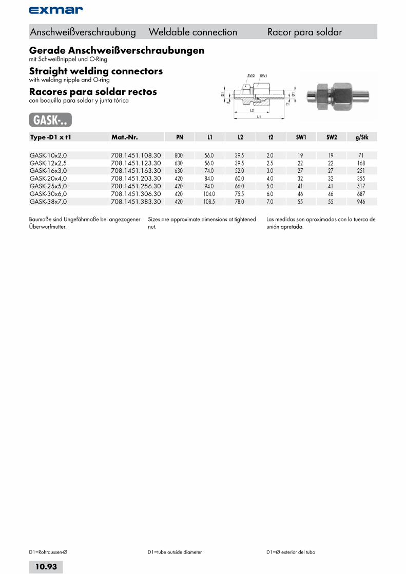
Gerade Anschweißverschraubungenmit Schweißnippel und O-Ring
Straight welding connectorswith welding nipple and O-ring
Racores para soldar rectoscon boquilla para soldar y junta tórica
GASK-..Type -D1 x t1 Mat.-Nr. PN L1 L2 t2 SW1 SW2 g/Stk GASK-10x2,0 708.1451.108.30 800 56.0 39.5 2.0 19 19 71GASK-12x2,5 708.1451.123.30 630 56.0 39.5 2.5 22 22 168GASK-16x3,0 708.1451.163.30 630 74.0 52.0 3.0 27 27 251GASK-20x4,0 708.1451.203.30 420 84.0 60.0 4.0 32 32 355GASK-25x5,0 708.1451.256.30 420 94.0 66.0 5.0 41 41 517GASK-30x6,0 708.1451.306.30 420 104.0 75.5 6.0 46 46 687GASK-38x7,0 708.1451.383.30 420 108.5 78.0 7.0 55 55 946
Baumaße sind Ungefährmaße bei angezogener Überwurfmutter.
Sizes are approximate dimensions at tightened nut.
Las medidas son aproximadas con la tuerca de unión apretada.
Anschweißverschraubung Weldable connection Racor para soldar
D1=Rohraussen-Ø D1=tube outside diameter D1=Ø exterior del tubo
10.93

WinkelanschweissverschraubungenElbow welding unionsRacores para soldar angulares
WAS-..L/SType -D1 Mat.-Nr. PN D2 L1 L2 L3 SW1 SW2 g/Stk WAS-06L 708.2400.060.20 500 10.0 27.0 15.0 19.0 14 12 34WAS-08L 708.2400.080.20 500 12.0 29.0 15.0 23.0 17 12 47WAS-10L 708.2400.100.20 500 14.0 30.0 15.0 24.0 19 14 61WAS-12L 708.2400.120.20 400 16.0 32.0 15.0 25.0 22 17 78WAS-15L 708.2400.150.20 400 19.0 36.0 15.0 30.0 27 19 127WAS-18L 708.2400.180.20 400 22.0 40.0 16.5 33.0 32 24 204WAS-22L 708.2400.220.20 250 27.0 44.0 16.5 37.0 36 27 261WAS-28L 708.2400.280.20 250 32.0 47.0 16.5 42.0 41 36 382WAS-35L 708.2400.350.20 250 40.0 56.0 21.5 49.0 50 41 638WAS-42L 708.2400.420.20 250 46.0 63.0 23.0 57.0 60 50 998 WAS-06S 708.2400.060.30 800 11.0 31.0 15.0 23.0 17 12 54WAS-08S 708.2400.080.30 800 13.0 32.0 16.0 24.0 19 14 71WAS-10S 708.2400.100.30 800 15.0 34.0 16.5 25.0 22 17 96WAS-12S 708.2400.120.30 630 17.0 38.0 16.5 29.0 24 17 123WAS-14S 708.2400.140.30 630 19.0 40.0 16.0 30.0 27 19 154WAS-16S 708.2400.160.30 630 21.0 43.0 18.5 33.0 30 24 230WAS-20S 708.2400.200.30 420 26.0 48.0 21.5 37.0 36 27 327WAS-25S 708.2400.250.30 420 31.0 54.0 24.0 42.0 46 36 589WAS-30S 708.2400.300.30 420 36.0 62.0 26.5 49.0 50 41 839WAS-38S 708.2400.380.30 420 44.0 72.0 31.0 57.0 60 50 1298
Anschweißverschraubung Weldable connection Racor para soldar
D1=Rohraussen-Ø D1=tube outside diameter D1=Ø exterior del tubo
10.94
i
s
10
20
30
40
50
60
70
a
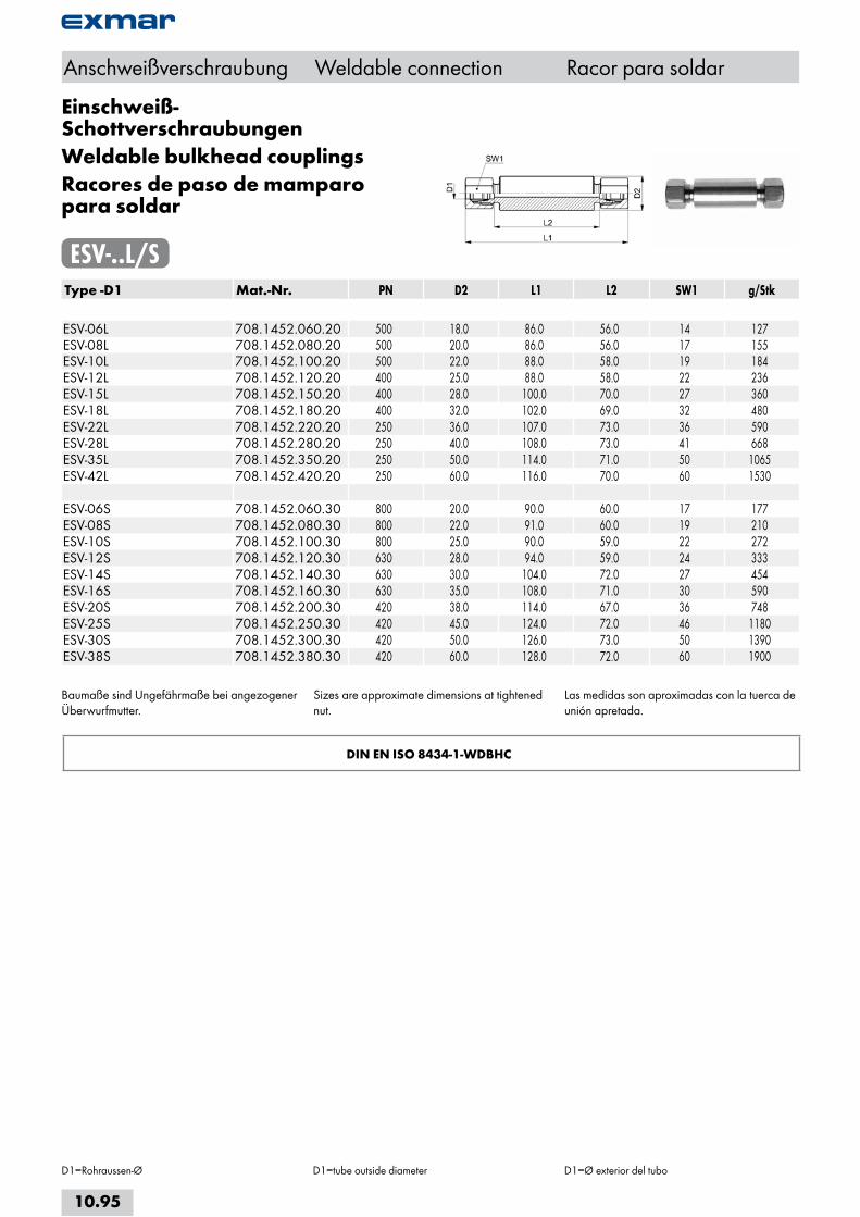
Einschweiß-SchottverschraubungenWeldable bulkhead couplingsRacores de paso de mamparo para soldar
ESV-..L/SType -D1 Mat.-Nr. PN D2 L1 L2 SW1 g/Stk ESV-06L 708.1452.060.20 500 18.0 86.0 56.0 14 127ESV-08L 708.1452.080.20 500 20.0 86.0 56.0 17 155ESV-10L 708.1452.100.20 500 22.0 88.0 58.0 19 184ESV-12L 708.1452.120.20 400 25.0 88.0 58.0 22 236ESV-15L 708.1452.150.20 400 28.0 100.0 70.0 27 360ESV-18L 708.1452.180.20 400 32.0 102.0 69.0 32 480ESV-22L 708.1452.220.20 250 36.0 107.0 73.0 36 590ESV-28L 708.1452.280.20 250 40.0 108.0 73.0 41 668ESV-35L 708.1452.350.20 250 50.0 114.0 71.0 50 1065ESV-42L 708.1452.420.20 250 60.0 116.0 70.0 60 1530 ESV-06S 708.1452.060.30 800 20.0 90.0 60.0 17 177ESV-08S 708.1452.080.30 800 22.0 91.0 60.0 19 210ESV-10S 708.1452.100.30 800 25.0 90.0 59.0 22 272ESV-12S 708.1452.120.30 630 28.0 94.0 59.0 24 333ESV-14S 708.1452.140.30 630 30.0 104.0 72.0 27 454ESV-16S 708.1452.160.30 630 35.0 108.0 71.0 30 590ESV-20S 708.1452.200.30 420 38.0 114.0 67.0 36 748ESV-25S 708.1452.250.30 420 45.0 124.0 72.0 46 1180ESV-30S 708.1452.300.30 420 50.0 126.0 73.0 50 1390ESV-38S 708.1452.380.30 420 60.0 128.0 72.0 60 1900
Baumaße sind Ungefährmaße bei angezogener Überwurfmutter.
Sizes are approximate dimensions at tightened nut.
Las medidas son aproximadas con la tuerca de unión apretada.
DIN EN ISO 8434-1-WDBHC
Anschweißverschraubung Weldable connection Racor para soldar
D1=Rohraussen-Ø D1=tube outside diameter D1=Ø exterior del tubo
10.95

Schweißkegelmit O-Ring
Weldable coneswith O-ring
Conos para soldarcon junta tórica
SKOType -D1 x t1 Mat.-Nr. D2 L1 O-ring g/Stk SKO-06x1,5 708.1453.061.30 3.0 31.0 4.0x1.5 4SKO-08x1,5 708.1453.081.30 5.0 31.0 6.0x1.5 6SKO-08x2,0 708.1453.082.30 4.0 31.0 6.0x1.5 10SKO-10x1,5 708.1453.105.30 7.0 32.5 7.5x1.5 12SKO-10x2,0 708.1453.108.30 6.0 32.5 7.5x1.5 14SKO-12x1,5 708.1453.122.30 9.0 32.5 9.0x1.5 16SKO-12x2,0 708.1453.125.30 8.0 32.5 9.0x1.5 18SKO-12x2,5 708.1453.123.30 7.0 32.5 9.0x1.5 22SKO-12x3,0 708.1453.124.30 6.0 32.5 9.0x1.5 SKO-14x2,0 708.1453.141.30 10.0 40.0 10.0x2.0 24SKO-14x2,5 708.1453.143.30 9.0 40.0 10.0x2.0 28SKO-14x3,0 708.1453.142.30 8.0 40.0 10.0x2.0 34SKO-15x2,0 708.1453.151.30 11.0 36.0 12.0x2.0 24SKO-15x2,5 708.1453.152.30 10.0 36.0 12.0x2.0 30SKO-16x2,0 708.1453.161.30 12.0 39.0 12.0x2.0 30SKO-16x2,5 708.1453.162.30 11.0 39.0 12.0x2.0 36SKO-16x3,0 708.1453.163.30 10.0 39.0 12.0x2.0 40SKO-18x1,5 708.1453.181.30 15.0 36.0 15.0x2.0 24SKO-18x2,0 708.1453.182.30 15.0 36.0 15.0x2.0 31SKO-18x2,5 708.1453.183.30 13.0 36.0 15.0x2.0 38SKO-20x2,0 708.1453.204.30 16.0 44.5 16.3x2.4 44SKO-20x2,5 708.1453.201.30 15.0 44.5 16.3x2.4 54SKO-20x3,0 708.1453.202.30 14.0 44.5 16.3x2.4 62SKO-20x3,5 708.1453.205.30 13.0 44.5 16.3x2.4 70SKO-20x4,0 708.1453.203.30 12.0 44.5 16.3x2.4 76SKO-22x2,0 708.1453.221.30 18.0 38.5 20.0x2.0 40SKO-22x2,5 708.1453.223.30 17.0 38.5 20.0x2.0 62SKO-25x3,0 708.1453.253.30 19.0 49.5 20.3x2.4 88SKO-25x3,5 708.1453.258.30 18.0 49.5 20.3x2.4 99SKO-25x4,0 708.1453.255.30 18.0 49.5 20.3x2.4 110SKO-25x5,0 708.1453.256.30 15.0 49.5 20.3x2.4 130SKO-28x2,5 708.1453.281.30 23.0 41.5 26.0x2.0 70SKO-28x3,0 708.1453.282.30 22.0 41.5 26.0x2.0 80SKO-30x3,0 708.1453.301.30 24.0 52.0 25.3x2.4 114SKO-30x4,0 708.1453.302.30 22.0 52.0 25.3x2.4 142SKO-30x5,0 708.1453.304.30 20.0 52.0 25.3x2.4 168SKO-30x6,0 708.1453.306.30 18.0 52.0 25.3x2.4 192
Fortsetzung nächste Seite Continued on next page Continuación página próxima
Anschweißverschraubung Weldable connection Racor para soldar
D1=Rohraussen-Ø D1=tube outside diameter D1=Ø exterior del tubo
10.96
i
s
10
20
30
40
50
60
70
a

Schweißnippelmit O-Ring
Welding nipplewith O-ring
Boquillas para soldarcon junta tórica
SKOType -D1 x t1 Mat.-Nr. D2 L1 O-ring g/Stk SKO-35x3,5 708.1453.352.30 28.0 47.0 32.0x2.5 138SKO-35x4,0 708.1453.353.30 27.0 47.0 32.0x2.5 152SKO-38x3,0 708.1453.384.30 32.0 56.5 33.3x2.4 160SKO-38x4,0 708.1453.381.30 30.0 56.5 33.3x2.4 200SKO-38x5,0 708.1453.385.30 28.0 56.5 33.3x2.4 242SKO-38x6,0 708.1453.382.30 26.0 56.5 33.3x2.4 276SKO-38x7,0 708.1453.383.30 24.0 56.5 33.3x2.4 316SKO-38x8,0 708.1453.386.30 22.0 56.5 33.3x2.4 376SKO-42x3,0 708.1453.993.30 36.0 47.0 38.0x2.5 150SKO-42x4,0 708.1453.994.30 34.0 47.0 38.0x2.5 188
O-Ringe aus FKM werden separat mitgeliefert, erst nach dem Schweißvorgang aufziehen.
passend in 24°-Innenkonus(Bohrungsform W DIN 3861)
FKM O-rings supplied seperately, to be fitted after welding.
fitting type 24° inside tapers(bore type W DIN 3861)
Las juntas tóricas de FKM se suministran por separado; montarlas después de soldar.
encaja en cono interior de 24º(forma de taladro W DIN 3861)
DIN EN ISO 8434-1-WDNP
Anschweißverschraubung Weldable connection Racor para soldar
D1=Rohraussen-Ø D1=tube outside diameter D1=Ø exterior del tubo
10.97
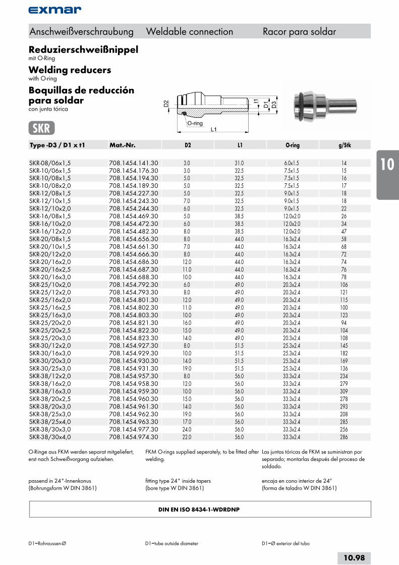
Reduzierschweißnippelmit O-Ring
Welding reducerswith O-ring
Boquillas de reducción para soldarcon junta tórica
SKRType -D3 / D1 x t1 Mat.-Nr. D2 L1 O-ring g/Stk SKR-08/06x1,5 708.1454.141.30 3.0 31.0 6.0x1.5 14SKR-10/06x1,5 708.1454.176.30 3.0 32.5 7.5x1.5 15SKR-10/08x1,5 708.1454.194.30 5.0 32.5 7.5x1.5 16SKR-10/08x2,0 708.1454.189.30 5.0 32.5 7.5x1.5 17SKR-12/08x1,5 708.1454.227.30 5.0 32.5 9.0x1.5 18SKR-12/10x1,5 708.1454.243.30 7.0 32.5 9.0x1.5 18SKR-12/10x2,0 708.1454.244.30 6.0 32.5 9.0x1.5 22SKR-16/08x1,5 708.1454.469.30 5.0 38.5 12.0x2.0 26SKR-16/10x2,0 708.1454.472.30 6.0 38.5 12.0x2.0 34SKR-16/12x2,0 708.1454.482.30 8.0 38.5 12.0x2.0 47SKR-20/08x1,5 708.1454.656.30 8.0 44.0 16.3x2.4 58SKR-20/10x1,5 708.1454.661.30 7.0 44.0 16.3x2.4 68SKR-20/12x2,0 708.1454.666.30 8.0 44.0 16.3x2.4 72SKR-20/16x2,0 708.1454.686.30 12.0 44.0 16.3x2.4 74SKR-20/16x2,5 708.1454.687.30 11.0 44.0 16.3x2.4 76SKR-20/16x3,0 708.1454.688.30 10.0 44.0 16.3x2.4 78SKR-25/10x2,0 708.1454.792.30 6.0 49.0 20.3x2.4 106SKR-25/12x2,0 708.1454.793.30 8.0 49.0 20.3x2.4 121SKR-25/16x2,0 708.1454.801.30 12.0 49.0 20.3x2.4 115SKR-25/16x2,5 708.1454.802.30 11.0 49.0 20.3x2.4 100SKR-25/16x3,0 708.1454.803.30 10.0 49.0 20.3x2.4 123SKR-25/20x2,0 708.1454.821.30 16.0 49.0 20.3x2.4 94SKR-25/20x2,5 708.1454.822.30 15.0 49.0 20.3x2.4 104SKR-25/20x3,0 708.1454.823.30 14.0 49.0 20.3x2.4 108SKR-30/12x2,0 708.1454.927.30 8.0 51.5 25.3x2.4 145SKR-30/16x3,0 708.1454.929.30 10.0 51.5 25.3x2.4 182SKR-30/20x3,0 708.1454.930.30 14.0 51.5 25.3x2.4 169SKR-30/25x3,0 708.1454.931.30 19.0 51.5 25.3x2.4 136SKR-38/12x2,0 708.1454.957.30 8.0 56.0 33.3x2.4 234SKR-38/16x2,0 708.1454.958.30 12.0 56.0 33.3x2.4 279SKR-38/16x3,0 708.1454.959.30 10.0 56.0 33.3x2.4 309SKR-38/20x2,5 708.1454.960.30 15.0 56.0 33.3x2.4 278SKR-38/20x3,0 708.1454.961.30 14.0 56.0 33.3x2.4 293SKR-38/25x3,0 708.1454.962.30 19.0 56.0 33.3x2.4 208SKR-38/25x4,0 708.1454.963.30 17.0 56.0 33.3x2.4 285SKR-38/30x3,0 708.1454.977.30 24.0 56.0 33.3x2.4 256SKR-38/30x4,0 708.1454.974.30 22.0 56.0 33.3x2.4 286
O-Ringe aus FKM werden separat mitgeliefert, erst nach Schweißvorgang aufziehen.
passend in 24°-Innenkonus(Bohrungsform W DIN 3861)
FKM O-rings supplied seperately, to be fitted after welding.
fitting type 24° inside tapers(bore type W DIN 3861)
Las juntas tóricas de FKM se suministran por separado; montarlas después del proceso de soldado.
encaja en cono interior de 24º(forma de taladro W DIN 3861)
Anschweißverschraubung Weldable connection Racor para soldar
D1=Rohraussen-Ø D1=tube outside diameter D1=Ø exterior del tubo
DIN EN ISO 8434-1-WDRDNP
10.98
i
s
10
20
30
40
50
60
70
a
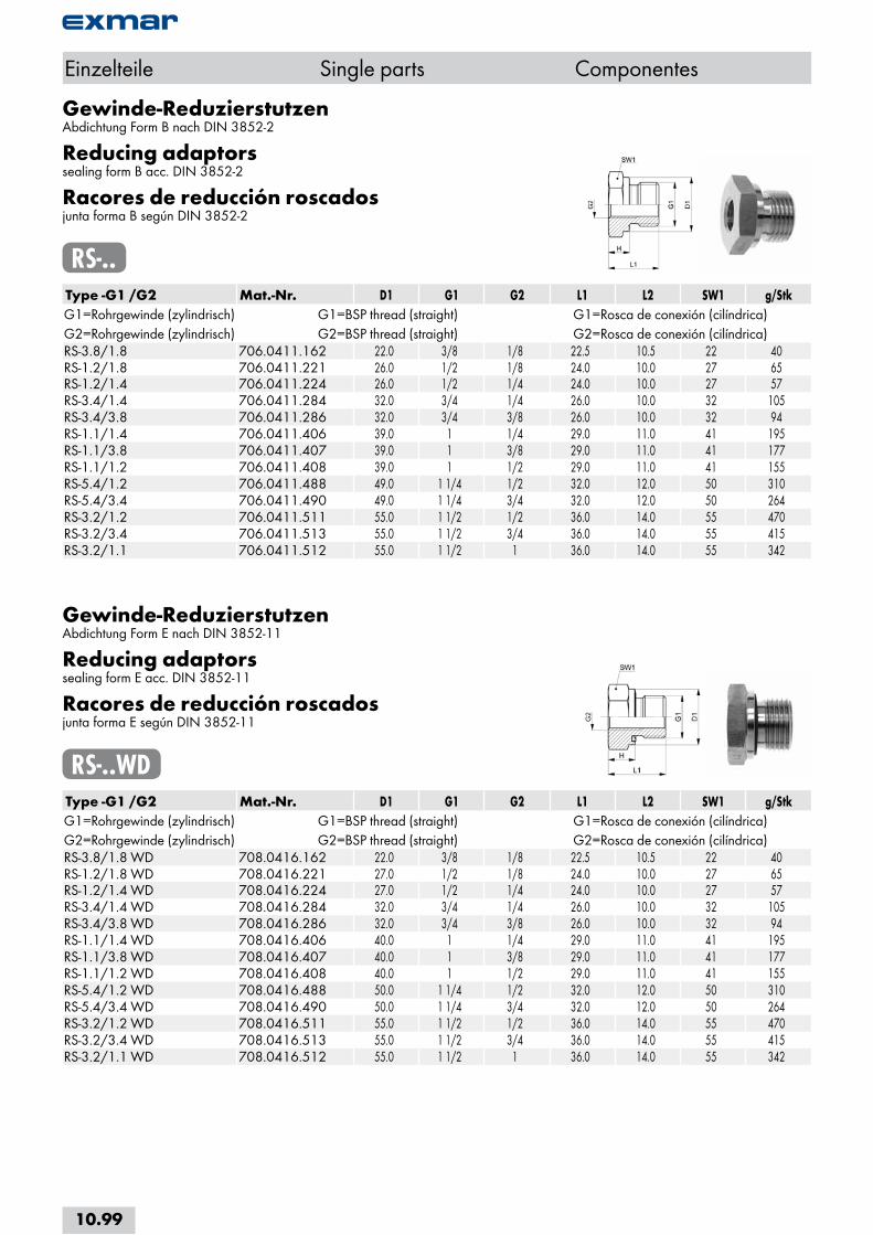
Gewinde-ReduzierstutzenAbdichtung Form B nach DIN 3852-2
Reducing adaptorssealing form B acc. DIN 3852-2
Racores de reducción roscadosjunta forma B según DIN 3852-2
RS-..Type -G1 /G2 Mat.-Nr. D1 G1 G2 L1 L2 SW1 g/StkG1=Rohrgewinde (zylindrisch) G1=BSP thread (straight) G1=Rosca de conexión (cilíndrica)G2=Rohrgewinde (zylindrisch) G2=BSP thread (straight) G2=Rosca de conexión (cilíndrica)RS-3.8/1.8 706.0411.162 22.0 3/8 1/8 22.5 10.5 22 40RS-1.2/1.8 706.0411.221 26.0 1/2 1/8 24.0 10.0 27 65RS-1.2/1.4 706.0411.224 26.0 1/2 1/4 24.0 10.0 27 57RS-3.4/1.4 706.0411.284 32.0 3/4 1/4 26.0 10.0 32 105RS-3.4/3.8 706.0411.286 32.0 3/4 3/8 26.0 10.0 32 94RS-1.1/1.4 706.0411.406 39.0 1 1/4 29.0 11.0 41 195RS-1.1/3.8 706.0411.407 39.0 1 3/8 29.0 11.0 41 177RS-1.1/1.2 706.0411.408 39.0 1 1/2 29.0 11.0 41 155RS-5.4/1.2 706.0411.488 49.0 1 1/4 1/2 32.0 12.0 50 310RS-5.4/3.4 706.0411.490 49.0 1 1/4 3/4 32.0 12.0 50 264RS-3.2/1.2 706.0411.511 55.0 1 1/2 1/2 36.0 14.0 55 470RS-3.2/3.4 706.0411.513 55.0 1 1/2 3/4 36.0 14.0 55 415RS-3.2/1.1 706.0411.512 55.0 1 1/2 1 36.0 14.0 55 342
Einzelteile Single parts Componentes
Gewinde-ReduzierstutzenAbdichtung Form E nach DIN 3852-11
Reducing adaptorssealing form E acc. DIN 3852-11
Racores de reducción roscadosjunta forma E según DIN 3852-11
RS-..WDType -G1 /G2 Mat.-Nr. D1 G1 G2 L1 L2 SW1 g/StkG1=Rohrgewinde (zylindrisch) G1=BSP thread (straight) G1=Rosca de conexión (cilíndrica)G2=Rohrgewinde (zylindrisch) G2=BSP thread (straight) G2=Rosca de conexión (cilíndrica)RS-3.8/1.8 WD 708.0416.162 22.0 3/8 1/8 22.5 10.5 22 40RS-1.2/1.8 WD 708.0416.221 27.0 1/2 1/8 24.0 10.0 27 65RS-1.2/1.4 WD 708.0416.224 27.0 1/2 1/4 24.0 10.0 27 57RS-3.4/1.4 WD 708.0416.284 32.0 3/4 1/4 26.0 10.0 32 105RS-3.4/3.8 WD 708.0416.286 32.0 3/4 3/8 26.0 10.0 32 94RS-1.1/1.4 WD 708.0416.406 40.0 1 1/4 29.0 11.0 41 195RS-1.1/3.8 WD 708.0416.407 40.0 1 3/8 29.0 11.0 41 177RS-1.1/1.2 WD 708.0416.408 40.0 1 1/2 29.0 11.0 41 155RS-5.4/1.2 WD 708.0416.488 50.0 1 1/4 1/2 32.0 12.0 50 310RS-5.4/3.4 WD 708.0416.490 50.0 1 1/4 3/4 32.0 12.0 50 264RS-3.2/1.2 WD 708.0416.511 55.0 1 1/2 1/2 36.0 14.0 55 470RS-3.2/3.4 WD 708.0416.513 55.0 1 1/2 3/4 36.0 14.0 55 415RS-3.2/1.1 WD 708.0416.512 55.0 1 1/2 1 36.0 14.0 55 342
10.99

Gewinde-ReduzierstutzenAbdichtung Form B nach DIN 3852-2
Reducing adaptorssealing form B acc. DIN 3852-2
Racores de reducción roscadosjunta forma B según DIN 3852-2
RS-...Type -G1 /G2 Mat.-Nr. D1 G1 G2 L1 L2 SW1 g/StkG1=Rohrgewinde (zylindrisch) G1=BSP thread (straight) G1=Rosca de conexión (cilíndrica)G2=Rohrgewinde (zylindrisch) G2=BSP thread (straight) G2=Rosca de conexión (cilíndrica)RS-1.8/1.4 706.0411.044 14.0 1/8 1/4 31.0 23.0 19 30RS-1.8/3.8 706.0411.046 14.0 1/8 3/8 32.0 24.0 24 65RS-1.4/1.8 706.0411.102 18.0 1/4 1/8 28.0 16.0 19 38RS-1.4/3.8 706.0411.106 18.0 1/4 3/8 36.0 24.0 24 68RS-1.4/1.2 706.0411.108 18.0 1/4 1/2 40.0 28.0 27 80RS-1.4/3.4 706.0411.110 18.0 1/4 3/4 43.0 31.0 36 175RS-3.8/1.4 706.0411.164 22.0 3/8 1/4 36.0 24.0 22 70RS-3.8/1.2 706.0411.168 22.0 3/8 1/2 41.0 29.0 27 95RS-3.8/3.4 706.0411.170 22.0 3/8 3/4 44.0 32.0 36 185RS-1.2/3.8 706.0411.226 26.0 1/2 3/8 36.0 22.0 27 100RS-1.2/3.4 706.0411.232 26.0 1/2 3/4 46.0 32.0 36 186RS-1.2/1.1 706.0411.236 26.0 1/2 1 49.0 35.0 41 220RS-1.2/5.4 706.0411.237 26.0 1/2 1 1/4 53.0 39.0 55 487RS-3.4/1.2 706.0411.288 32.0 3/4 1/2 41.0 25.0 32 145RS-3.4/1.1 706.0411.296 32.0 3/4 1 51.0 35.0 41 240RS-3.4/5.4 706.0411.297 32.0 3/4 1 1/4 55.0 39.0 55 525RS-3.4/3.2 706.0411.298 32.0 3/4 1 1/2 57.0 41.0 60 620RS-1.1/3.4 706.0411.412 39.0 1 3/4 47.0 29.0 41 275RS-1.1/5.4 706.0411.416 39.0 1 1 1/4 57.0 39.0 55 520RS-1.1/3.2 706.0411.417 39.0 1 1 1/2 59.0 41.0 60 600RS-5.4/1.1 706.0411.487 49.0 1 1/4 1 52.0 32.0 50 158RS-5.4/3.2 706.0411.489 49.0 1 1/4 1 1/2 60.0 40.0 60 640RS-3.2/5.4 706.0411.514 55.0 1 1/2 1 1/4 58.0 36.0 55 535
Einzelteile Single parts Componentes
10.100
i
s
10
20
30
40
50
60
70
a

Gewinde-ReduzierstutzenAbdichtung Form E nach DIN 3852-11
Reducing adaptorssealing form E acc. DIN 3852-11
Racores de reducción roscadosjunta forma E según DIN 3852-11
RS-...WDType -G1 /G2 Mat.-Nr. D1 G1 G2 L1 L2 SW1 g/StkG1=Rohrgewinde (zylindrisch) G1=BSP thread (straight) G1=Rosca de conexión (cilíndrica)G2=Rohrgewinde (zylindrisch) G2=BSP thread (straight) G2=Rosca de conexión (cilíndrica)RS-1.8/1.4 WD 708.0416.044 14.0 1/8 1/4 31.0 23.0 19 30RS-1.8/3.8 WD 708.0416.046 14.0 1/8 3/8 32.0 24.0 24 65RS-1.4/1.8 WD 708.0416.102 19.0 1/4 1/8 28.0 16.0 19 38RS-1.4/3.8 WD 708.0416.106 19.0 1/4 3/8 36.0 24.0 24 68RS-1.4/1.2 WD 708.0416.108 19.0 1/4 1/2 40.0 28.0 27 80RS-1.4/3.4 WD 708.0416.110 19.0 1/4 3/4 43.0 31.0 36 175RS-3.8/1.4 WD 708.0416.164 22.0 3/8 1/4 36.0 24.0 22 70RS-3.8/1.2 WD 708.0416.168 22.0 3/8 1/2 41.0 29.0 27 95RS-3.8/3.4 WD 708.0416.170 22.0 3/8 3/4 44.0 32.0 36 185RS-1.2/3.8 WD 708.0416.226 27.0 1/2 3/8 36.0 22.0 27 100RS-1.2/3.4 WD 708.0416.232 27.0 1/2 3/4 46.0 32.0 36 186RS-1.2/1.1 WD 708.0416.236 27.0 1/2 1 49.0 35.0 41 220RS-1.2/5.4 WD 708.0416.237 27.0 1/2 1 1/4 53.0 39.0 55 487RS-3.4/1.2 WD 708.0416.288 32.0 3/4 1/2 41.0 25.0 32 145RS-3.4/1.1 WD 708.0416.296 32.0 3/4 1 51.0 35.0 41 240RS-3.4/5.4 WD 708.0416.297 32.0 3/4 1 1/4 55.0 39.0 55 525RS-3.4/3.2 WD 708.0416.298 32.0 3/4 1 1/2 57.0 41.0 60 620RS-1.1/3.4 WD 708.0416.412 40.0 1 3/4 47.0 29.0 41 275RS-1.1/5.4 WD 708.0416.416 40.0 1 1 1/4 57.0 39.0 55 520RS-1.1/3.2 WD 708.0416.417 40.0 1 1 1/2 59.0 41.0 60 600RS-5.4/1.1 WD 708.0416.487 50.0 1 1/4 1 52.0 32.0 50 458RS-5.4/3.2 WD 708.0416.489 50.0 1 1/4 1 1/2 60.0 40.0 60 640RS-3.2/5.4 WD 708.0416.514 55.0 1 1/2 1 1/4 58.0 36.0 55 535
Einzelteile Single parts Componentes
10.101

Verschlußschraubenmit Innensechskant, DIN 908, Abdichtung Form B nach DIN 3852-2
Locking screwswith internal hexagon, DIN 908, sealing form B acc. DIN 3852-2
Tornillos de cierrecon hexágono interior, DIN 908, junta forma B según DIN 3852-2
VSI-..MType -M Mat.-Nr. PN D1 M H L1 SW1 g/StkM=metrisches Gewinde (zylindrisch) M=metric thread (straight) M=rosca métrica (cilindrica) VSI-M 10x1,0 706.0723.150 800 14.0 10x1.0 4.0 12.0 5 6VSI-M 12x1,5 706.0723.195 800 17.0 12x1.5 5.0 17.0 6 12VSI-M 14x1,5 706.0723.225 800 19.0 14x1.5 5.0 17.0 6 20VSI-M 16x1,5 706.0723.265 800 21.0 16x1.5 5.0 17.0 8 22VSI-M 18x1,5 706.0723.305 800 23.0 18x1.5 5.0 17.0 8 32VSI-M 20x1,5 706.0723.345 800 25.0 20x1.5 5.0 19.0 10 44VSI-M 22x1,5 706.0723.375 800 27.0 22x1.5 5.0 19.0 10 50VSI-M 26x1,5 706.0723.435 800 31.0 26x1.5 5.0 21.0 12 80VSI-M 27x2,0 706.0723.400 800 32.0 27x2.0 5.0 21.0 12 80VSI-M 33x2,0 706.0723.510 630 39.0 33x2.0 6.5 22.5 17 138VSI-M 42x2,0 706.0723.642 420 49.0 42x2.0 6.5 22.5 22 208VSI-M 48x2,0 706.0723.748 420 55.0 48x2.0 6.5 22.5 24 210
Verschlußschraubenmit Innensechskant, DIN 908, Abdichtung Form E nach DIN 3852-11
Locking screwswith internal hexagon, DIN 908, sealing form E acc. DIN 3852-11
Tornillos de cierrecon hexágono interior, DIN 908, junta forma E según DIN 3852-11
VSI-..MWDType -M Mat.-Nr. PN D1 M H L1 SW1 g/StkM=metrisches Gewinde (zylindrisch) M=metric thread (straight) M=rosca métrica (cilindrica) VSI-M 10x1,0 WD 708.0724.150 800 14.0 10x1.0 4.0 12.0 5 6VSI-M 12x1,5 WD 708.0724.195 800 17.0 12x1.5 5.0 17.0 6 12VSI-M 14x1,5 WD 708.0724.225 800 19.0 14x1.5 5.0 17.0 6 20VSI-M 16x1,5 WD 708.0724.265 800 22.0 16x1.5 5.0 17.0 8 22VSI-M 18x1,5 WD 708.0724.305 800 24.0 18x1.5 5.0 17.0 8 32VSI-M 20x1,5 WD 708.0724.345 800 26.0 20x1.5 5.0 19.0 10 44VSI-M 22x1,5 WD 708.0724.375 800 27.0 22x1.5 5.0 19.0 10 50VSI-M 26x1,5 WD 708.0724.435 800 32.0 26x1.5 5.0 21.0 12 80VSI-M 27x2,0 WD 708.0724.400 630 32.0 27x2.0 5.0 21.0 12 80VSI-M 33x2,0 WD 708.0724.510 630 40.0 33x2.0 6.5 22.5 17 138VSI-M 42x2,0 WD 708.0724.642 420 50.0 42x2.0 6.5 22.5 22 208VSI-M 48x2,0 WD 708.0724.748 420 55.0 48x2.0 6.5 22.5 24 210
Einzelteile Single parts Componentes
10.102
i
s
10
20
30
40
50
60
70
a

Verschlußschraubenmit Innensechskant, DIN 908, Abdichtung Form B nach DIN 3852-2
Locking screwswith internal hexagon, DIN 908, sealing form B acc. DIN 3852-2
Tornillos de cierrecon hexágono interior, DIN 908, junta forma B según DIN 3852-2
VSI-..RType -G Mat.-Nr. PN D1 G H L1 SW1 g/StkG=Rohrgewinde (zylindrisch) G=BSP thread (straight) G=rosca de conexión (cilíndrica) VSI-R1.8 706.0721.020 800 14.0 1/8 4.0 12.0 5 6VSI-R1.4 706.0721.040 800 18.0 1/4 5.0 17.0 6 18VSI-R3.8 706.0721.060 800 22.0 3/8 5.0 17.0 8 26VSI-R1.2 706.0721.080 800 26.0 1/2 5.0 19.0 10 44VSI-R3.4 706.0721.120 800 32.0 3/4 5.0 21.0 12 76VSI-R1.1 706.0721.160 630 39.0 1 6.5 22.5 17 126VSI-R5.4 706.0721.180 420 49.0 1 1/4 6.5 22.5 22 192VSI-R3.2 706.0721.200 420 55.0 1 1/2 6.5 22.5 24 268
Verschlußschraubenmit Innensechskant, DIN 908, Abdichtung Form E nach DIN 3852-11
Locking screwswith internal hexagon, DIN 908, sealing form E acc. DIN 3852-11
Tornillos de cierrecon hexágono interior, DIN 908, junta forma E según DIN 3852-11
VSI-..RWDType -G Mat.-Nr. PN D1 G H L1 SW1 g/StkG=Rohrgewinde (zylindrisch) G=BSP thread (straight) G=rosca de conexión (cilíndrica) VSI-R1.8 WD 708.0722.020 800 14.0 1/8 4.0 12.0 5 6VSI-R1.4 WD 708.0722.040 800 19.0 1/4 5.0 17.0 6 16VSI-R3.8 WD 708.0722.060 800 22.0 3/8 5.0 17.0 8 29VSI-R1.2 WD 708.0722.080 800 27.0 1/2 5.0 19.0 10 42VSI-R3.4 WD 708.0722.120 800 32.0 3/4 5.0 21.0 12 76VSI-R1.1 WD 708.0722.160 630 40.0 1 6.5 22.5 17 120VSI-R5.4 WD 708.0722.180 420 50.0 1 1/4 6.5 22.5 22 186VSI-R3.2 WD 708.0722.200 420 55.0 1 1/2 6.5 22.5 24 256
Einzelteile Single parts Componentes
10.103
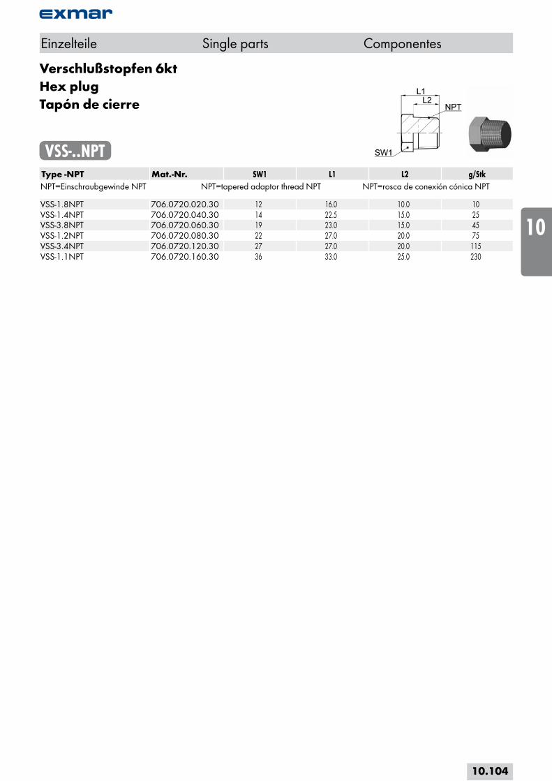
Verschlußstopfen 6ktHex plugTapón de cierre
VSS-..NPT Type -NPT Mat.-Nr. SW1 L1 L2 g/StkNPT=Einschraubgewinde NPT NPT=tapered adaptor thread NPT NPT=rosca de conexión cónica NPT VSS-1.8NPT 706.0720.020.30 12 16.0 10.0 10VSS-1.4NPT 706.0720.040.30 14 22.5 15.0 25VSS-3.8NPT 706.0720.060.30 19 23.0 15.0 45VSS-1.2NPT 706.0720.080.30 22 27.0 20.0 75VSS-3.4NPT 706.0720.120.30 27 27.0 20.0 115VSS-1.1NPT 706.0720.160.30 36 33.0 25.0 230
Einzelteile Single parts Componentes
10.104
i
s
10
20
30
40
50
60
70
a

VerschlußverschraubungenCapsRacores de cierre
VSA-..L/SType -D1 Mat.-Nr. PN L1 L2 L3 SW1 SW2 g/Stk VSA-06L 708.1205.060.20 500 24.0 15.0 16.0 14 12 22VSA-08L 708.1205.080.20 500 24.0 15.0 16.0 17 14 30VSA-10L 708.1205.100.20 500 27.0 15.0 19.0 19 17 38VSA-12L 708.1205.120.20 500 27.0 15.0 19.0 22 19 50VSA-15L 708.1205.150.20 500 30.0 15.0 22.0 27 24 84VSA-18L 708.1205.180.20 500 31.0 17.0 22.0 32 27 124VSA-22L 708.1205.220.20 250 35.0 17.0 26.0 36 32 166VSA-28L 708.1205.280.20 250 35.0 17.0 26.0 41 41 238VSA-35L 708.1205.350.20 250 41.0 22.0 30.0 50 46 356VSA-42L 708.1205.420.20 250 42.0 23.0 30.0 60 55 556 VSA-06S 708.1205.060.30 800 26.0 15.0 18.0 17 14 36VSA-08S 708.1205.080.30 800 28.0 15.0 20.0 19 17 42VSA-10S 708.1205.100.30 800 28.0 16.0 20.0 22 19 64VSA-12S 708.1205.120.30 630 29.0 17.0 20.0 24 22 78VSA-14S 708.1205.140.30 630 32.0 16.0 24.0 27 24 118VSA-16S 708.1205.160.30 630 34.0 19.0 24.0 30 27 142VSA-20S 708.1205.200.30 420 39.0 22.0 28.0 36 32 236VSA-25S 708.1205.250.30 420 42.0 24.0 30.0 46 41 448VSA-30S 708.1205.300.30 420 47.0 27.0 34.0 50 46 540VSA-38S 708.1205.380.30 420 51.0 31.0 36.0 60 55 870
Baumaße sind Ungefährmaße bei angezogener Überwurfmutter.
Sizes are approximate dimensions at tightened nut.
Las medidas son aproximadas con la tuerca de unión apretada.
DIN EN ISO 8434-1
Einzelteile Single parts Componentes
D1=Rohraussen-Ø D1=tube outside diameter D1=Ø exterior del tubo
10.105
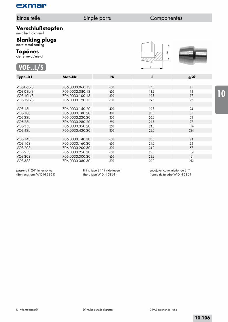
Verschlußstopfenmetallisch dichtend
Blanking plugsmetal-metal sealing
Tapónescierre metal/metal
VOE-..L/SType -D1 Mat.-Nr. PN L1 g/Stk VOE-06L/S 706.0033.060.13 630 17.5 11VOE-08L/S 706.0033.080.13 630 18.5 13VOE-10L/S 706.0033.100.13 630 19.5 17VOE-12L/S 706.0033.120.13 630 19.5 22 VOE-15L 706.0033.150.20 400 19.5 24VOE-18L 706.0033.180.20 400 20.0 31VOE-22L 706.0033.220.20 250 20.5 52VOE-28L 706.0033.280.20 250 21.5 97VOE-35L 706.0033.350.20 250 24.0 176VOE-42L 706.0033.420.20 250 25.0 234 VOE-14S 706.0033.140.30 630 20.0 24VOE-16S 706.0033.160.30 630 21.0 34VOE-20S 706.0033.200.30 630 24.0 57VOE-25S 706.0033.250.30 630 25.0 104VOE-30S 706.0033.300.30 630 26.5 151VOE-38S 706.0033.380.30 630 30.0 213
passend in 24°-Innenkonus(Bohrungsform W DIN 3861)
fitting type 24° inside tapers(bore type W DIN 3861)
encaja en cono interior de 24º(forma de taladro W DIN 3861)
Einzelteile Single parts Componentes
D1=Rohraussen-Ø D1=tube outside diameter D1=Ø exterior del tubo
10.106
i
s
10
20
30
40
50
60
70
a
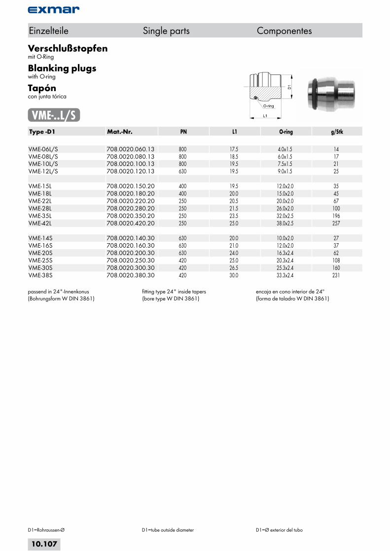
Verschlußstopfenmit O-Ring
Blanking plugswith O-ring
Tapóncon junta tórica
VME-..L/SType -D1 Mat.-Nr. PN L1 O-ring g/Stk VME-06L/S 708.0020.060.13 800 17.5 4.0x1.5 14VME-08L/S 708.0020.080.13 800 18.5 6.0x1.5 17VME-10L/S 708.0020.100.13 800 19.5 7.5x1.5 21VME-12L/S 708.0020.120.13 630 19.5 9.0x1.5 25 VME-15L 708.0020.150.20 400 19.5 12.0x2.0 35VME-18L 708.0020.180.20 400 20.0 15.0x2.0 45VME-22L 708.0020.220.20 250 20.5 20.0x2.0 67VME-28L 708.0020.280.20 250 21.5 26.0x2.0 100VME-35L 708.0020.350.20 250 23.5 32.0x2.5 196VME-42L 708.0020.420.20 250 25.0 38.0x2.5 257 VME-14S 708.0020.140.30 630 20.0 10.0x2.0 27VME-16S 708.0020.160.30 630 21.0 12.0x2.0 37VME-20S 708.0020.200.30 630 24.0 16.3x2.4 62VME-25S 708.0020.250.30 420 25.0 20.3x2.4 108VME-30S 708.0020.300.30 420 26.5 25.3x2.4 160VME-38S 708.0020.380.30 420 30.0 33.3x2.4 231
passend in 24°-Innenkonus(Bohrungsform W DIN 3861)
fitting type 24° inside tapers(bore type W DIN 3861)
encaja en cono interior de 24º(forma de taladro W DIN 3861)
Einzelteile Single parts Componentes
D1=Rohraussen-Ø D1=tube outside diameter D1=Ø exterior del tubo
10.107
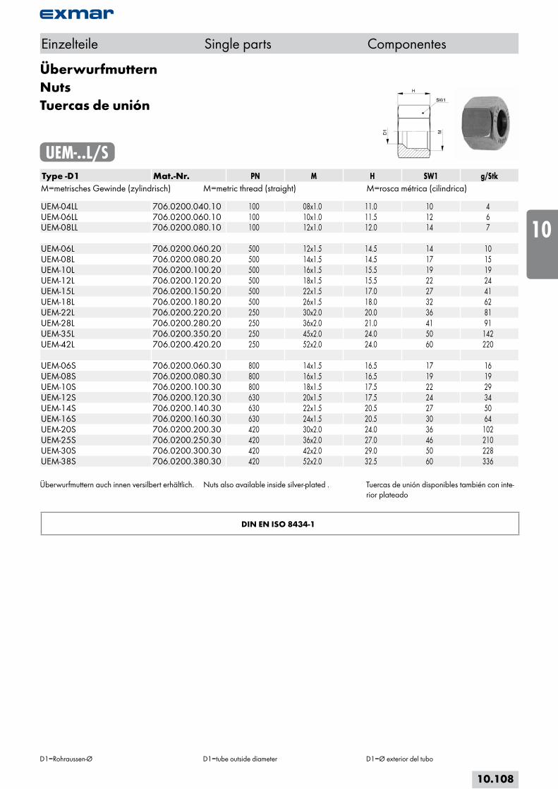
ÜberwurfmutternNutsTuercas de unión
UEM-..L/SType -D1 Mat.-Nr. PN M H SW1 g/StkM=metrisches Gewinde (zylindrisch) M=metric thread (straight) M=rosca métrica (cilindrica) UEM-04LL 706.0200.040.10 100 08x1.0 11.0 10 4UEM-06LL 706.0200.060.10 100 10x1.0 11.5 12 6UEM-08LL 706.0200.080.10 100 12x1.0 12.0 14 7 UEM-06L 706.0200.060.20 500 12x1.5 14.5 14 10UEM-08L 706.0200.080.20 500 14x1.5 14.5 17 15UEM-10L 706.0200.100.20 500 16x1.5 15.5 19 19UEM-12L 706.0200.120.20 500 18x1.5 15.5 22 24UEM-15L 706.0200.150.20 500 22x1.5 17.0 27 41UEM-18L 706.0200.180.20 500 26x1.5 18.0 32 62UEM-22L 706.0200.220.20 250 30x2.0 20.0 36 81UEM-28L 706.0200.280.20 250 36x2.0 21.0 41 91UEM-35L 706.0200.350.20 250 45x2.0 24.0 50 142UEM-42L 706.0200.420.20 250 52x2.0 24.0 60 220 UEM-06S 706.0200.060.30 800 14x1.5 16.5 17 16UEM-08S 706.0200.080.30 800 16x1.5 16.5 19 19UEM-10S 706.0200.100.30 800 18x1.5 17.5 22 29UEM-12S 706.0200.120.30 630 20x1.5 17.5 24 34UEM-14S 706.0200.140.30 630 22x1.5 20.5 27 50UEM-16S 706.0200.160.30 630 24x1.5 20.5 30 64UEM-20S 706.0200.200.30 420 30x2.0 24.0 36 102UEM-25S 706.0200.250.30 420 36x2.0 27.0 46 210UEM-30S 706.0200.300.30 420 42x2.0 29.0 50 228UEM-38S 706.0200.380.30 420 52x2.0 32.5 60 336
Überwurfmuttern auch innen versilbert erhältlich. Nuts also available inside silver-plated . Tuercas de unión disponibles también con inte-rior plateado
DIN EN ISO 8434-1
Einzelteile Single parts Componentes
D1=Rohraussen-Ø D1=tube outside diameter D1=Ø exterior del tubo
10.108
i
s
10
20
30
40
50
60
70
a

SchneidringeDIN 3861
Cutting ringsDIN 3861
Anillos cortantesDIN 3861
SR-..L/SType -D1 Mat.-Nr. PN L1 g/Stk SR-06L/S 706.0021.060.13 800 9.0 2SR-08L/S 706.0021.080.13 800 9.0 2SR-10L/S 706.0021.100.13 800 10.0 3SR-12L/S 706.0021.120.13 630 9.5 3 SR-04LL 706.0021.040.10 100 4.5 1SR-06LL 706.0021.060.10 100 5.5 1SR-08LL 706.0021.080.10 100 5.5 1 SR-15L 706.0021.150.20 400 9.5 4SR-18L 706.0021.180.20 400 9.5 5SR-22L 706.0021.220.20 250 10.5 6SR-28L 706.0021.280.20 250 11.0 8SR-35L 706.0021.350.20 250 13.0 17SR-42L 706.0021.420.20 250 13.5 21 SR-14S 706.0021.140.30 630 10.0 4SR-16S 706.0021.160.30 630 9.5 4SR-20S 706.0021.200.30 420 12.5 9SR-25S 706.0021.250.30 420 12.5 11SR-30S 706.0021.300.30 420 13.0 15SR-38S 706.0021.380.30 420 13.0 19
DIN EN ISO 8434-1
Einzelteile Single parts Componentes
D1=Rohraussen-Ø D1=tube outside diameter D1=Ø exterior del tubo
10.109
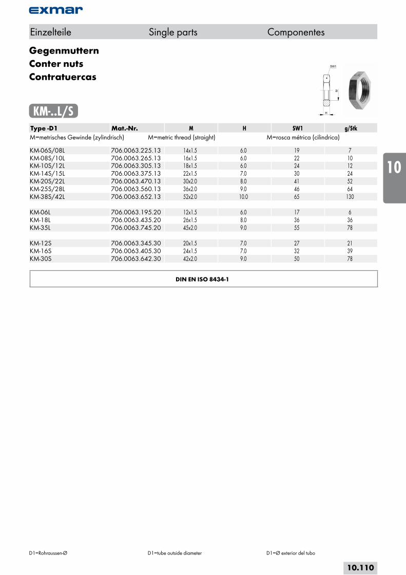
GegenmutternConter nutsContratuercas
KM-..L/SType -D1 Mat.-Nr. M H SW1 g/StkM=metrisches Gewinde (zylindrisch) M=metric thread (straight) M=rosca métrica (cilindrica) KM-06S/08L 706.0063.225.13 14x1.5 6.0 19 7KM-08S/10L 706.0063.265.13 16x1.5 6.0 22 10KM-10S/12L 706.0063.305.13 18x1.5 6.0 24 12KM-14S/15L 706.0063.375.13 22x1.5 7.0 30 24KM-20S/22L 706.0063.470.13 30x2.0 8.0 41 52KM-25S/28L 706.0063.560.13 36x2.0 9.0 46 64KM-38S/42L 706.0063.652.13 52x2.0 10.0 65 130 KM-06L 706.0063.195.20 12x1.5 6.0 17 6KM-18L 706.0063.435.20 26x1.5 8.0 36 36KM-35L 706.0063.745.20 45x2.0 9.0 55 78 KM-12S 706.0063.345.30 20x1.5 7.0 27 21KM-16S 706.0063.405.30 24x1.5 7.0 32 39KM-30S 706.0063.642.30 42x2.0 9.0 50 78
DIN EN ISO 8434-1
Einzelteile Single parts Componentes
D1=Rohraussen-Ø D1=tube outside diameter D1=Ø exterior del tubo
10.110
i
s
10
20
30
40
50
60
70
a
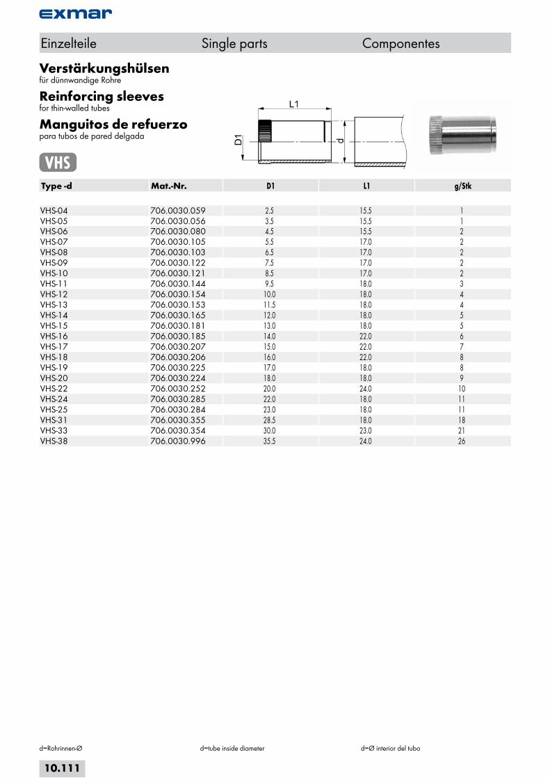
Verstärkungshülsenfür dünnwandige Rohre
Reinforcing sleevesfor thin-walled tubes
Manguitos de refuerzopara tubos de pared delgada
VHSType -d Mat.-Nr. D1 L1 g/Stk VHS-04 706.0030.059 2.5 15.5 1VHS-05 706.0030.056 3.5 15.5 1VHS-06 706.0030.080 4.5 15.5 2VHS-07 706.0030.105 5.5 17.0 2VHS-08 706.0030.103 6.5 17.0 2VHS-09 706.0030.122 7.5 17.0 2VHS-10 706.0030.121 8.5 17.0 2VHS-11 706.0030.144 9.5 18.0 3VHS-12 706.0030.154 10.0 18.0 4VHS-13 706.0030.153 11.5 18.0 4VHS-14 706.0030.165 12.0 18.0 5VHS-15 706.0030.181 13.0 18.0 5VHS-16 706.0030.185 14.0 22.0 6VHS-17 706.0030.207 15.0 22.0 7VHS-18 706.0030.206 16.0 22.0 8VHS-19 706.0030.225 17.0 18.0 8VHS-20 706.0030.224 18.0 18.0 9VHS-22 706.0030.252 20.0 24.0 10VHS-24 706.0030.285 22.0 18.0 11VHS-25 706.0030.284 23.0 18.0 11VHS-31 706.0030.355 28.5 18.0 18VHS-33 706.0030.354 30.0 23.0 21VHS-38 706.0030.996 35.5 24.0 26
Einzelteile Single parts Componentes
d=Rohrinnen-Ø d=tube inside diameter d=Ø interior del tubo
10.111

Dichtkantenringefür Außengewinde von Schwenkverschraubungen
Seal edge ringsfor external threads of Banjo couplings
Anillos con borde de obturaciónpara roscas exteriores de racores orientables
EDKR-..M/RType -M Mat.-Nr. D1 D2 M H g/StkM=metrisches Gewinde (zylindrisch) M=metric thread (straight) M=rosca métrica (cilindrica) EDKR-M 10/R1.8 706.0026.150 14.0 10.0 10x1.0 2.5 1EDKR-M 12x1,5 706.0026.195 17.0 12.0 12x1.5 2.5 1EDKR-M 14x1,5 706.0026.225 19.0 14.0 14x1.5 3.0 2EDKR-M 16x1,5 706.0026.265 21.0 16.0 16x1.5 3.0 2EDKR-M 18x1,5 706.0026.305 23.0 18.0 18x1.5 3.0 3EDKR-M 20x1,5 706.0026.345 25.0 20.0 20x1.5 3.0 3EDKR-M 22x1,5 706.0026.375 27.0 22.0 22x1.5 4.5 5EDKR-M 26x1,5 706.0026.435 31.0 26.0 26x1.5 3.5 4EDKR-M 27/R3.4 706.0026.440 32.0 27.0 27x2.0 3.5 5EDKR-M 33/R1.1 706.0026.510 39.0 33.5 33x2.0 3.5 6EDKR-M 42/R5.4 706.0026.642 49.0 42.0 42x2.0 3.5 9EDKR-M 48/R3.2 706.0026.748 55.0 48.0 48x2.0 7.5 11
Type -G Mat.-Nr. D1 D2 G H g/StkG=Rohrgewinde (zylindrisch) G=BSP thread (straight) G=rosca de conexión (cilíndrica) EDKR-M 10/R1.8 706.0026.150 14.0 10.0 1/8 2.5 1EDKR-R1.4 706.0025.040 18.0 18.0 1/4 3.0 2EDKR-R3.8 706.0025.060 22.0 22.0 3/8 3.0 3EDKR-R1.2 706.0025.080 26.0 21.0 1/2 5.5 5EDKR-M 27/R3.4 706.0026.440 32.0 27.0 3/4 3.5 5EDKR-M 33/R1.1 706.0026.510 39.0 33.5 1 3.5 6EDKR-M 42/R5.4 706.0026.642 49.0 42.0 1 1/4 3.5 9EDKR-M 48/R3.2 706.0026.748 55.0 48.0 1 1/2 7.5 11
M/G für Außengewinde ISO 228/ DIN 13
M/G for external threads ISO 228/DIN 13
M/G para roscas exteriores ISO 228/ DIN 13
Einzelteile Single parts Componentes
10.112
i
s
10
20
30
40
50
60
70
a

Dichtkantenringefür Innengewinde für Manometer-Verschraubungen
Seal edge ringsfor internal threads for manometer fittings
Anillos con borde de obturaciónpara roscas interiores de racores manométricos
DKR-..M/RType -M Mat.-Nr. D1 D2 M H g/StkM=metrisches Gewinde (zylindrisch) M=metric thread (straight) M=rosca métrica (cilindrica) DKR-M 20x1,5 706.0024.345 17.5 12.0 20x1.5 5.0 2
Type -G Mat.-Nr. D1 D2 G H g/StkG=Rohrgewinde (zylindrisch) G=BSP thread (straight) G=rosca de conexión (cilíndrica) DKR-R 1.4 706.0023.040 11.5 6.0 1/4 4.5 1DKR-R 1.2 706.0023.080 18.5 12.0 1/2 5.0 4
M/G für Innengewinde DIN-ISO 228/DIN 13
M/G for internal threads DIN-ISO 228/DIN 13
M/G para roscas interiores DIN-ISO 228/DIN 13
Einzelteile Single parts Componentes
10.113
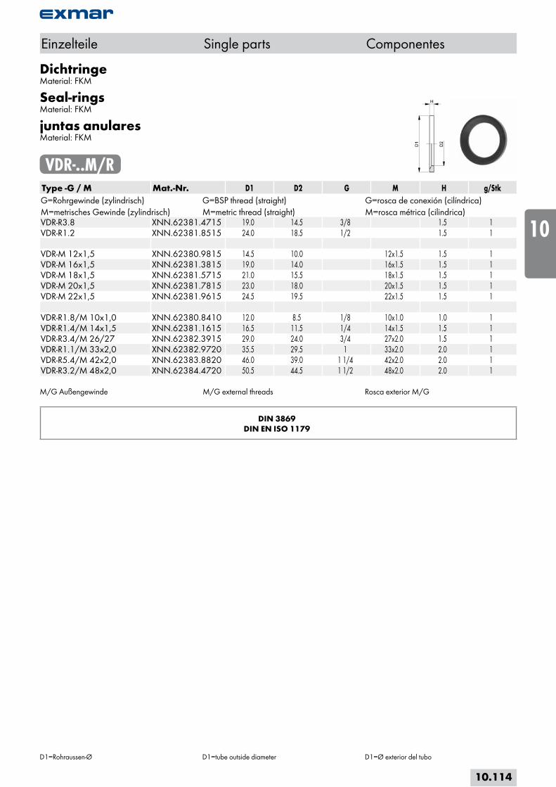
DichtringeMaterial: FKM
Seal-ringsMaterial: FKM
juntas anularesMaterial: FKM
VDR-..M/RType -G / M Mat.-Nr. D1 D2 G M H g/StkG=Rohrgewinde (zylindrisch) G=BSP thread (straight) G=rosca de conexión (cilíndrica)M=metrisches Gewinde (zylindrisch) M=metric thread (straight) M=rosca métrica (cilindrica)VDR-R3.8 XNN.62381.4715 19.0 14.5 3/8 1.5 1VDR-R1.2 XNN.62381.8515 24.0 18.5 1/2 1.5 1 VDR-M 12x1,5 XNN.62380.9815 14.5 10.0 12x1.5 1.5 1VDR-M 16x1,5 XNN.62381.3815 19.0 14.0 16x1.5 1.5 1VDR-M 18x1,5 XNN.62381.5715 21.0 15.5 18x1.5 1.5 1VDR-M 20x1,5 XNN.62381.7815 23.0 18.0 20x1.5 1.5 1VDR-M 22x1,5 XNN.62381.9615 24.5 19.5 22x1.5 1.5 1 VDR-R1.8/M 10x1,0 XNN.62380.8410 12.0 8.5 1/8 10x1.0 1.0 1VDR-R1.4/M 14x1,5 XNN.62381.1615 16.5 11.5 1/4 14x1.5 1.5 1VDR-R3.4/M 26/27 XNN.62382.3915 29.0 24.0 3/4 27x2.0 1.5 1VDR-R1.1/M 33x2,0 XNN.62382.9720 35.5 29.5 1 33x2.0 2.0 1VDR-R5.4/M 42x2,0 XNN.62383.8820 46.0 39.0 1 1/4 42x2.0 2.0 1VDR-R3.2/M 48x2,0 XNN.62384.4720 50.5 44.5 1 1/2 48x2.0 2.0 1
M/G Außengewinde M/G external threads Rosca exterior M/G
DIN 3869DIN EN ISO 1179
Einzelteile Single parts Componentes
D1=Rohraussen-Ø D1=tube outside diameter D1=Ø exterior del tubo
10.114
i
s
10
20
30
40
50
60
70
a
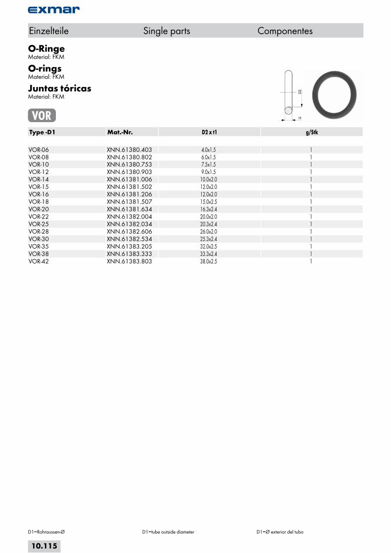
O-RingeMaterial: FKM
O-ringsMaterial: FKM
Juntas tóricasMaterial: FKM
VORType -D1 Mat.-Nr. D2 x t1 g/Stk VOR-06 XNN.61380.403 4.0x1.5 1VOR-08 XNN.61380.802 6.0x1.5 1VOR-10 XNN.61380.753 7.5x1.5 1VOR-12 XNN.61380.903 9.0x1.5 1VOR-14 XNN.61381.006 10.0x2.0 1VOR-15 XNN.61381.502 12.0x2.0 1VOR-16 XNN.61381.206 12.0x2.0 1VOR-18 XNN.61381.507 15.0x2.5 1VOR-20 XNN.61381.634 16.3x2.4 1VOR-22 XNN.61382.004 20.0x2.0 1VOR-25 XNN.61382.034 20.3x2.4 1VOR-28 XNN.61382.606 26.0x2.0 1VOR-30 XNN.61382.534 25.3x2.4 1VOR-35 XNN.61383.205 32.0x2.5 1VOR-38 XNN.61383.333 33.3x2.4 1VOR-42 XNN.61383.803 38.0x2.5 1
Einzelteile Single parts Componentes
D1=Rohraussen-Ø D1=tube outside diameter D1=Ø exterior del tubo
10.115