Assembled Fiber Optic Cables - Amazon Web Services
52
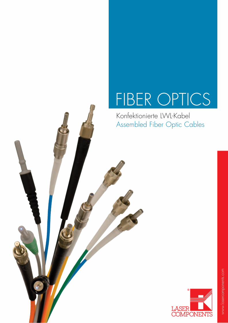
www.lasercomponents.com FIBER OPTICS Konfektionierte LWL-Kabel Assembled Fiber Optic Cables
Transcript of Assembled Fiber Optic Cables - Amazon Web Services
ww
w.la
serc
ompo
nent
s.co
m
FIBER OPTICSKonfektionierte LWL-KabelAssembled Fiber Optic Cables

„Complicated technology has to be paired with easy handling. Not the other way round.“Prof. Dr. Hermann Simon, *1947
Editorial
Liebe Leserinnen und Leser,Lichtwellenleiter gewinnen in der Datenübertragung, Sensorik und auch Medizin-technik immer mehr an Bedeutung. Größere Datenvolumen, höhere Datenraten und mehr Leistung müssen übertragen werden.
Aus der Vielzahl der Anwendungen ergibt sich eine große Typenvielfalt von opti-schen Kabeln mit unterschiedlichen Fasertypen und Steckverbindern.
Damit Sie diesen Markt rasch bedienen können, bietet Ihnen LASER COMPONENTS einen LWL-Konfektionierungs-Service an. Greifen Sie auf über 25 Jahre Erfahrung im Bereich Lichtwellenleiter-Konfektionierung zurück. Von uns erhalten Sie Lösungen, welche optimal auf Ihre Anwendungen und Anforderungen zugeschnitten sind. Sie profitieren direkt von der stetigen Prozessoptimierung. Auf Ihr Feedback wird direkt reagiert - damit auch Sie Ihre Kunden ausnahmslos zufrieden stellen können.
Unsere Produktingenieure stehen Ihnen für offene Fragen gern zur Verfügung. Vorab wünschen wir Ihnen viel Freude beim Blättern durch den vorliegenden Katalog.
Ihr
Patrick Paul Günther Paul Geschäftsführer Geschäftsführer/Gründer
Dear Reader,Optical fibers are gaining increasing importance in data transmission, sensor technology, and medical technology. Larger amounts of data, higher data rates, and more power have to be transmitted.
These versatile applications have resulted in the development of a large variety of optical cables, which are available with different types of fibers and connectors.
In order for you to serve this market quickly, LASER COMPONENTS offers its fiber assembly service: 25 years of experience in optical fiber assemblies on which you can rely. We have solutions that are optimally suited to your appli-cations and requirements. You profit from continuous process optimization. We re-spond directly to your feedback; in turn, you can address your customers’ needs.
Our product engineers are available at any time to field your questions. In the meantime, have fun perusing this catalog.
Yours
Patrick Paul Günther Paul CEO President/Founder
Patrick Paul (links), Günther Paul

www.lasercomponents.com | 33
INHALT
Fertigung in Deutschland ..........................5
Die Produktionsstätte ................................6
Optische Fasern ....................................10Graded Index Fibers ..............................14Step Index Fibers ..................................15Fasern für IR Strahlung .............................24Polymer Optische Fasern ........................27
Kabelaufbauten ....................................29
Steckertypen ........................................34
Optische Beschichtungen ........................37
Kabel & deren Anwendungen .................39Optische Leistungsübertragung .................40Optische Datenübertragung .....................42Medizintechnik ......................................43Beleuchtung & Sensorik mit POF ...............44
Weitere Kataloge .................................45
Unsere Webseite ..................................46
CONTENT
Produced in Germany ..............................5
Production Site ........................................7
Optical Fibers ......................................11Graded Index Fibers ...............................14Step Index Fibers ..................................15Fibers for IR Radiation .............................24Polymer Optical Fibers ...........................27
Cable Assemblies .................................29
Connector Types ...................................34
Optical Coatings ..................................37
Assembled Fibers & Their Applications ......39Optical Power Transmisseion ....................40Optical Data Transmission .......................42Medical Technoloy .................................43Illumination & Sensor Technology with POF .44
Further Catalogs ...................................45
Our Website ........................................46

www.lasercomponents.com | 5
Fertigung in Deutschland
Production in Germany
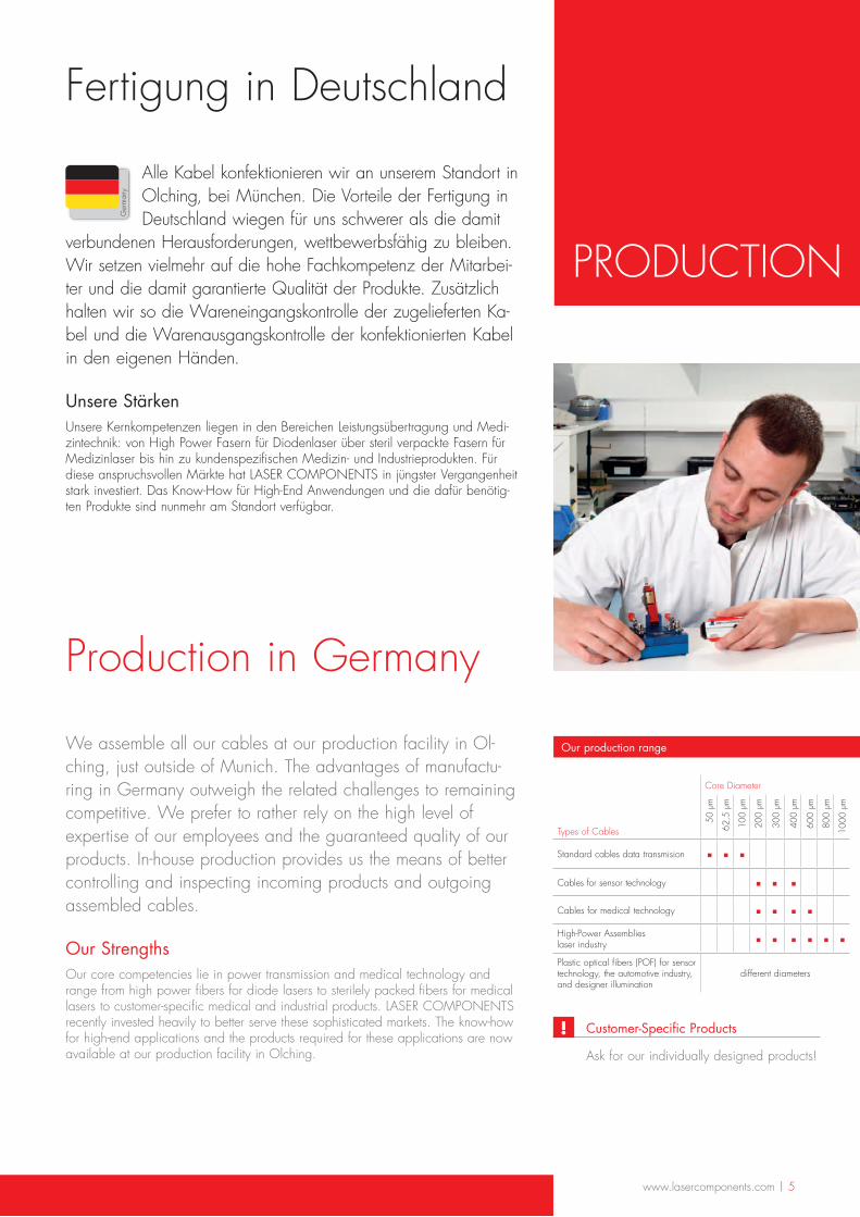
We assemble all our cables at our production facility in Ol-ching, just outside of Munich. The advantages of manufactu-ring in Germany outweigh the related challenges to remaining competitive. We prefer to rather rely on the high level of expertise of our employees and the guaranteed quality of our products. In-house production provides us the means of better controlling and inspecting incoming products and outgoing assembled cables.
Our StrengthsOur core competencies lie in power transmission and medical technology and range from high power fibers for diode lasers to sterilely packed fibers for medical lasers to customer-specific medical and industrial products. LASER COMPONENTS recently invested heavily to better serve these sophisticated markets. The know-how for high-end applications and the products required for these applications are now available at our production facility in Olching. Ask for our individually designed products!
Our production range
Core Diameter
Types of Cables
50 µ
m
62,5
µm
100
µm
200
µm
300
µm
400
µm
600
µm
800
µm
1000
µm
Standard cables data transmision ▪ ▪ ▪Cables for sensor technology ▪ ▪ ▪Cables for medical technology ▪ ▪ ▪ ▪High-Power Assemblies laser industry ▪ ▪ ▪ ▪ ▪ ▪Plastic optical fibers (POF) for sensor technology, the automotive industry, and designer illumination
different diameters
Alle Kabel konfektionieren wir an unserem Standort in Olching, bei München. Die Vorteile der Fertigung in Deutschland wiegen für uns schwerer als die damit
verbundenen Herausforderungen, wettbewerbsfähig zu bleiben. Wir setzen vielmehr auf die hohe Fachkompetenz der Mitarbei-ter und die damit garantierte Qualität der Produkte. Zusätzlich halten wir so die Wareneingangskontrolle der zugelieferten Ka-bel und die Warenausgangskontrolle der konfektionierten Kabel in den eigenen Händen.
Unsere StärkenUnsere Kernkompetenzen liegen in den Bereichen Leistungsübertragung und Medi-zintechnik: von High Power Fasern für Diodenlaser über steril verpackte Fasern für Medizinlaser bis hin zu kundenspezifischen Medizin- und Industrieprodukten. Für diese anspruchsvollen Märkte hat LASER COMPONENTS in jüngster Vergangenheit stark investiert. Das Know-How für High-End Anwendungen und die dafür benötig-ten Produkte sind nunmehr am Standort verfügbar.
made in Ger
man
y
PRODUCTION
Customer-Specific Products!
6 | www.lasercomponents.com
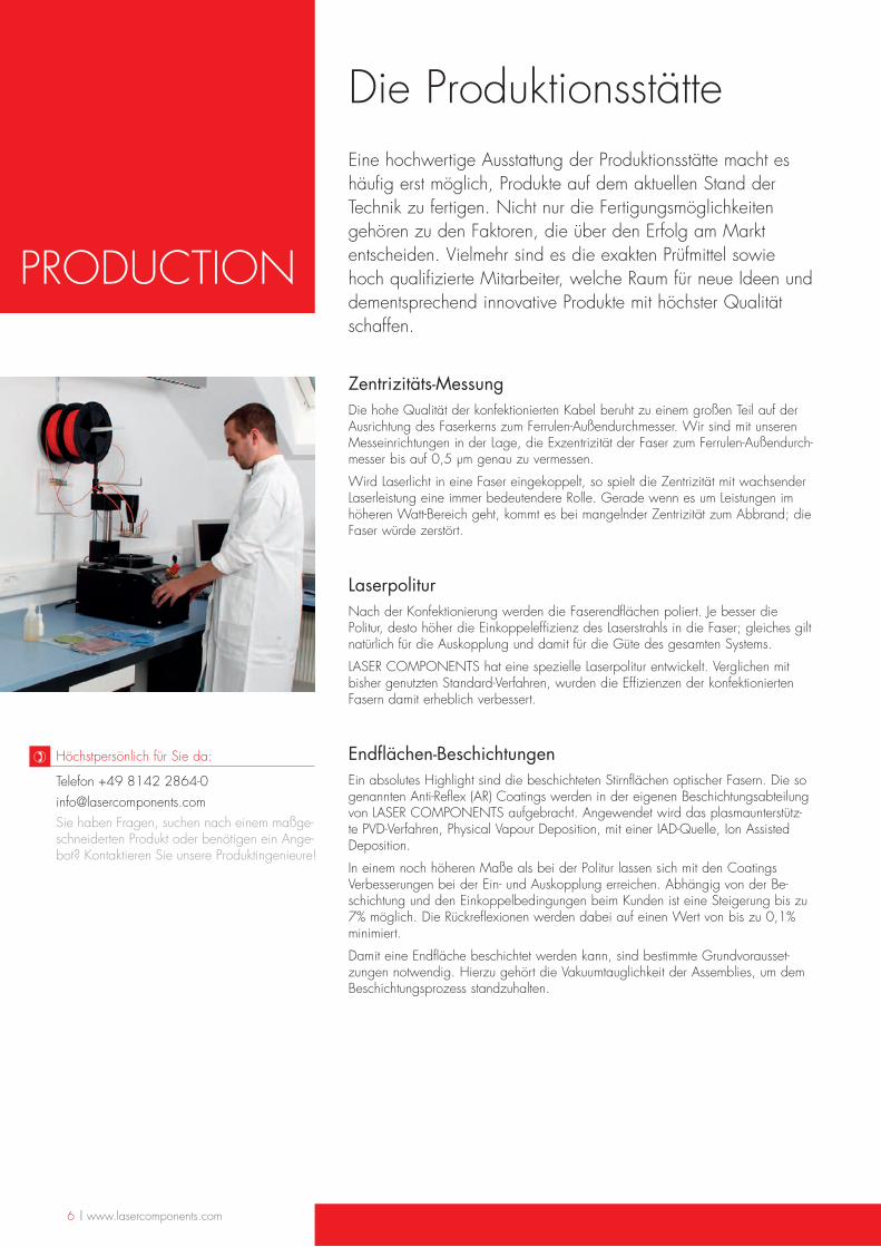
Die ProduktionsstätteEine hochwertige Ausstattung der Produktionsstätte macht es häufig erst möglich, Produkte auf dem aktuellen Stand der Technik zu fertigen. Nicht nur die Fertigungsmöglichkeiten gehören zu den Faktoren, die über den Erfolg am Markt entscheiden. Vielmehr sind es die exakten Prüfmittel sowie hoch qualifizierte Mitarbeiter, welche Raum für neue Ideen und dementsprechend innovative Produkte mit höchster Qualität schaffen.
Zentrizitäts-MessungDie hohe Qualität der konfektionierten Kabel beruht zu einem großen Teil auf der Ausrichtung des Faserkerns zum Ferrulen-Außendurchmesser. Wir sind mit unseren Messeinrichtungen in der Lage, die Exzentrizität der Faser zum Ferrulen-Außendurch-messer bis auf 0,5 µm genau zu vermessen.
Wird Laserlicht in eine Faser eingekoppelt, so spielt die Zentrizität mit wachsender Laserleistung eine immer bedeutendere Rolle. Gerade wenn es um Leistungen im höheren Watt-Bereich geht, kommt es bei mangelnder Zentrizität zum Abbrand; die Faser würde zerstört.
LaserpoliturNach der Konfektionierung werden die Faserendflächen poliert. Je besser die Politur, desto höher die Einkoppeleffizienz des Laserstrahls in die Faser; gleiches gilt natürlich für die Auskopplung und damit für die Güte des gesamten Systems.
LASER COMPONENTS hat eine spezielle Laserpolitur entwickelt. Verglichen mit bisher genutzten Standard-Verfahren, wurden die Effizienzen der konfektionierten Fasern damit erheblich verbessert.
Endflächen-BeschichtungenEin absolutes Highlight sind die beschichteten Stirnflächen optischer Fasern. Die so genannten Anti-Reflex (AR) Coatings werden in der eigenen Beschichtungsabteilung von LASER COMPONENTS aufgebracht. Angewendet wird das plasmaunterstütz-te PVD-Verfahren, Physical Vapour Deposition, mit einer IAD-Quelle, Ion Assisted Deposition.
In einem noch höheren Maße als bei der Politur lassen sich mit den Coatings Verbesserungen bei der Ein- und Auskopplung erreichen. Abhängig von der Be-schichtung und den Einkoppelbedingungen beim Kunden ist eine Steigerung bis zu 7% möglich. Die Rückreflexionen werden dabei auf einen Wert von bis zu 0,1% minimiert.
Damit eine Endfläche beschichtet werden kann, sind bestimmte Grundvorausset-zungen notwendig. Hierzu gehört die Vakuumtauglichkeit der Assemblies, um dem Beschichtungsprozess standzuhalten.
Telefon +49 8142 2864-0 [email protected] Sie haben Fragen, suchen nach einem maßge-schneiderten Produkt oder benötigen ein Ange-bot? Kontaktieren Sie unsere Produktingenieure!
Höchstpersönlich für Sie da:)
PRODUCTION
www.lasercomponents.com | 7
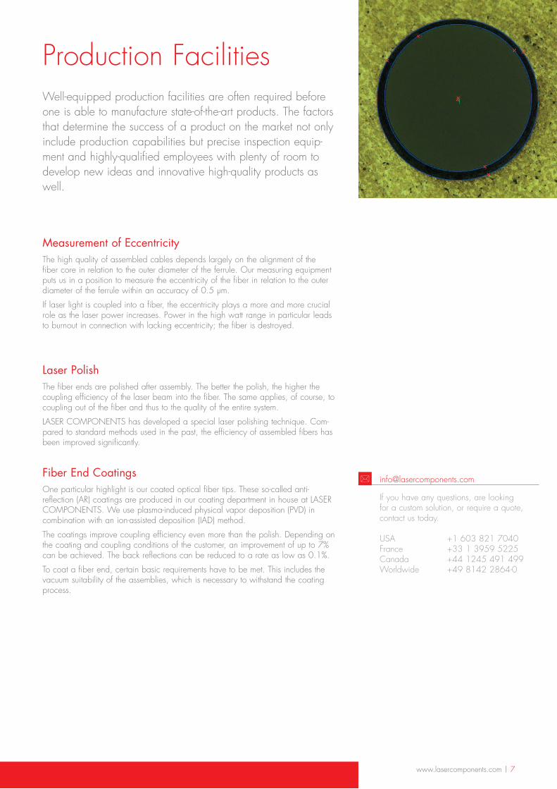
Production FacilitiesWell-equipped production facilities are often required before one is able to manufacture state-of-the-art products. The factors that determine the success of a product on the market not only include production capabilities but precise inspection equip-ment and highly-qualified employees with plenty of room to develop new ideas and innovative high-quality products as well.
Measurement of EccentricityThe high quality of assembled cables depends largely on the alignment of the fiber core in relation to the outer diameter of the ferrule. Our measuring equipment puts us in a position to measure the eccentricity of the fiber in relation to the outer diameter of the ferrule within an accuracy of 0.5 µm.
If laser light is coupled into a fiber, the eccentricity plays a more and more crucial role as the laser power increases. Power in the high watt range in particular leads to burnout in connection with lacking eccentricity; the fiber is destroyed.
Laser PolishThe fiber ends are polished after assembly. The better the polish, the higher the coupling efficiency of the laser beam into the fiber. The same applies, of course, to coupling out of the fiber and thus to the quality of the entire system.
LASER COMPONENTS has developed a special laser polishing technique. Com-pared to standard methods used in the past, the efficiency of assembled fibers has been improved significantly.
Fiber End CoatingsOne particular highlight is our coated optical fiber tips. These so-called anti-reflection (AR) coatings are produced in our coating department in house at LASER COMPONENTS. We use plasma-induced physical vapor deposition (PVD) in combination with an ion-assisted deposition (IAD) method.
The coatings improve coupling efficiency even more than the polish. Depending on the coating and coupling conditions of the customer, an improvement of up to 7% can be achieved. The back reflections can be reduced to a rate as low as 0.1%.
To coat a fiber end, certain basic requirements have to be met. This includes the vacuum suitability of the assemblies, which is necessary to withstand the coating process.
If you have any questions, are looking for a custom solution, or require a quote, contact us today. USA +1 603 821 7040 France +33 1 3959 5225 Canada +44 1245 491 499 Worldwide +49 8142 2864-0
*
www.lasercomponents.com/lc/optical-fibers/
www.lasercomponents.com/lc/optical-fibers/
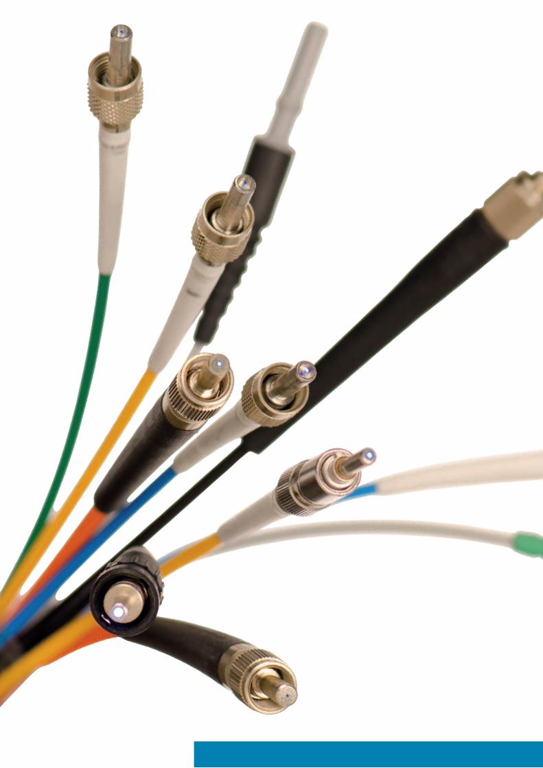
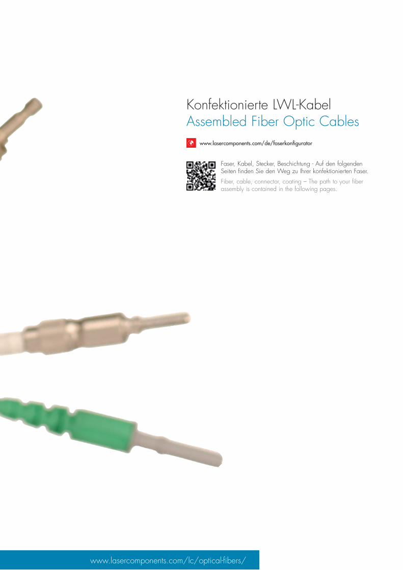
Konfektionierte LWL-KabelAssembled Fiber Optic Cables
Faser, Kabel, Stecker, Beschichtung - Auf den folgenden Seiten finden Sie den Weg zu Ihrer konfektionierten Faser.
Fiber, cable, connector, coating – The path to your fiber assembly is contained in the following pages.
www.lasercomponents.com/de/faserkonfigurator
10 | www.lasercomponents.com
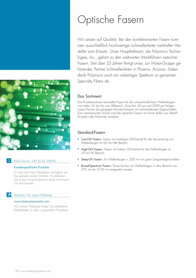
Optische Fasern
Wir setzen auf Qualität. Bei den konfektionierten Fasern kom-men ausschließlich hochwertige Lichtwellenleiter namhafter Her-steller zum Einsatz. Unser Hauptlieferant, die Polymicro Techno-logies, Inc., gehört zu den weltweiten Marktführern optischer Fasern. Seit über 25 Jahren fertigt unser, zur Molex-Gruppe ge-hörender, Partner Lichtwellenleiter in Phoenix, Arizona. Dabei deckt Polymicro auch ein vielseitiges Spektrum so genannter Specialty Fibers ab.
Das SortimentDas Produktsortiment beinhaltet Fasern für die unterschiedlichsten Wellenlängen; vom tiefen UV- bis hin zum IR-Bereich. Zwischen 50 µm und 2000 µm fertigen unsere Partner die gängigen Kerndurchmesser mit verschiedensten Eigenschaften. Zum mechanischen Schutz sind die optischen Fasern mit einem Buffer aus Tefzel®, Acrylate oder Polyimide versehen.
Standard-Fasern
▪ Low-OH Fasern. Fasern mit niedrigem OH-Gehalt für die Verwendung von Wellenlängen im VIS bis NIR Bereich
▪ High-OH Fasern. Fasern mit hohem OH-Gehalt für die Wellenlängen im UV bis VIS Bereich
▪ Deep-UV Fasern. Für Wellenlängen < 200 nm mit guten Langzeiteigenschaften
▪ Broad-Spectrum Fasern. Diese können mit Wellenlängen in dem Bereich von 275 nm bis 2100 nm eingesetzt werden.
Besuchen Sie unsere Webseite
www.lasercomponents.com
Auf unserer Webseite finden Sie detaillierte Datenblätter zu allen vorgestellten Produkten.
) Rufen Sie an: +49 8142 2864-0
Kundenspezfische Produkte
Es sind weit mehr Glasfasern verfügbar, als hier gelistet werden konnten. Kontaktieren Sie unsere Ansprechpartner direkt und lassen Sie sich beraten.
www.lasercomponents.com | 11
Optical Fibers
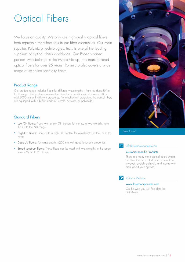
Draw Tower
We focus on quality. We only use high-quality optical fibers from reputable manufacturers in our fiber assemblies. Our main supplier, Polymicro Technologies, Inc., is one of the leading suppliers of optical fibers worldwide. Our Phoenix-based partner, who belongs to the Molex Group, has manufactured optical fibers for over 25 years. Polymicro also covers a wide range of so-called specialty fibers.
Product RangeOur product range includes fibers for different wavelengths – from the deep UV to the IR range. Our partners manufacture standard core diameters between 50 µm and 2000 µm with different properties. For mechanical protection, the optical fibers are equipped with a buffer made of Tefzel®, acrylate, or polyimide.
Standard Fibers
▪ Low-OH fibers: Fibers with a low OH content for the use of wavelengths from the Vis to the NIR range
▪ High-OH fibers: Fibers with a high OH content for wavelengths in the UV to Vis range
▪ Deep-UV fibers: For wavelengths <200 nm with good long-term properties
▪ Broad-spectrum fibers: These fibers can be used with wavelengths in the range from 275 nm to 2100 nm.
Visit our Website
www.lasercomponents.com
On the web you will find detailed datasheets.
Customer-specific Products
There are many more optical fibers availa-ble than the ones listed here. Contact our product specialists directly and inquire with them about your options.
12 | www.lasercomponents.com
Fasern nach AnwendungenGlasfasern bestehen aus einem Kern (Core), einem Mantel (Cladding) und einer Schutzhülle (Buffer). Abhängig von der Anwendung werden verschiedene Typen optischer Fasern eingesetzt. Insgesamt stellen wir Ihnen fünf Faser-Gruppen vor, die sich für die Datenübertragung, Medizintechnik, Leistungsübertragung, Sensorik, Spektroskopie und Beleuchtung eignen.
▪ Glasfasern mit Gradientenindex-Profil Kern-/Manteldurchmesser: 50/125 µm, 62,5/125 µm, 100/140 µm Verwendung: Datenübertragung Sensorik
▪ Großkern-Glasfasern mit Stufenindex-Profil Kerndurchmesser: 50 µm – 2000 µm Verwendung: Datenübertragung Leistungsübertragung Medizintechnik Sensorik
▪ Plastikfasern mit Stufenindex-Profil Kerndurchmesser: 250 µm – 3000 µm Verwendung: Beleuchtung Sensorik
▪ Hohlkernfasern mit Stufenindex-Profil Kerndurchmesser: 300 µm – 1000 µm Verwendung: Medizintechnik Leistungsübertragung der CO2 und Er:YAG Wellenlängen
▪ Saphirfasern mit Stufenindex-Profil Kerndurchmesser: 250 µm – 425 µm Verwendung: Spektroskopie Medizintechnik Sensorik
Kundenspezifische ProdukteWir konfektionieren alle der oben aufgeführten Fasern mit verschiedensten Steckver-bindern. Die Stecker stellen wir Ihnen auf Seite 34 vor.
www.lasercomponents.com | 13
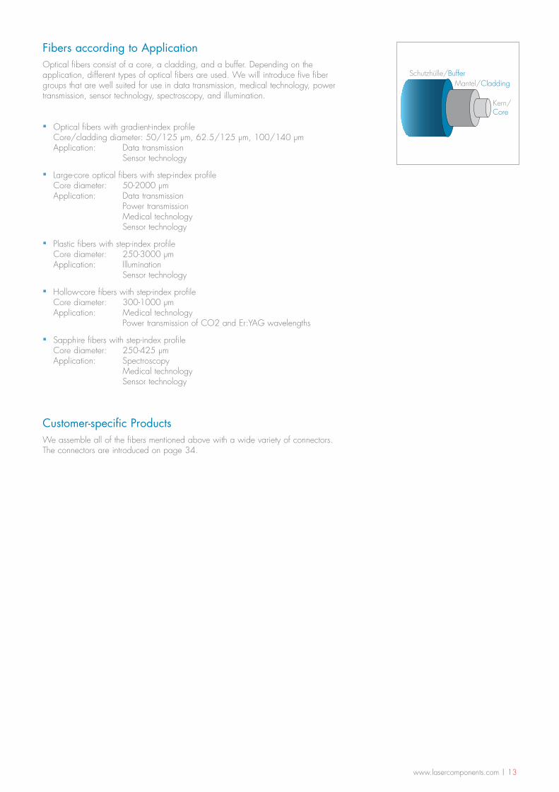
Schutzhülle/BufferMantel/Cladding
Kern/Core
Fibers according to ApplicationOptical fibers consist of a core, a cladding, and a buffer. Depending on the application, different types of optical fibers are used. We will introduce five fiber groups that are well suited for use in data transmission, medical technology, power transmission, sensor technology, spectroscopy, and illumination.
▪ Optical fibers with gradient-index profile Core/cladding diameter: 50/125 µm, 62.5/125 µm, 100/140 µm Application: Data transmission Sensor technology
▪ Large-core optical fibers with step-index profile Core diameter: 50-2000 µm Application: Data transmission Power transmission Medical technology Sensor technology
▪ Plastic fibers with step-index profile Core diameter: 250-3000 µm Application: Illumination Sensor technology
▪ Hollow-core fibers with step-index profile Core diameter: 300-1000 µm Application: Medical technology Power transmission of CO2 and Er:YAG wavelengths
▪ Sapphire fibers with step-index profile Core diameter: 250-425 µm Application: Spectroscopy Medical technology Sensor technology
Customer-specific ProductsWe assemble all of the fibers mentioned above with a wide variety of connectors. The connectors are introduced on page 34.
14 | www.lasercomponents.com
Gradientenindex- Fasern
Gradient-index Fibers
Bei den Gradientenindexfasern (GI) handelt es sich um die gän-gigsten Fasern, die hauptsächlich für die Datenübertragung verwen-det werden. Typische Einsatzge-biete sind lokale Netzwerke (Lo-cal Area Networks - LAN) sowie die industrielle Datenübertragung.
Gradient-index (GI) fibers are standard fibers that are primarily used in data transmission. Typical fields of application include local area networks (LAN) and industri-al data transmission.
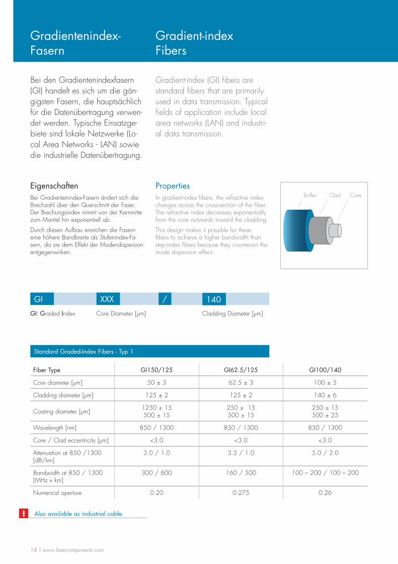
EigenschaftenBei Gradientenindex-Fasern ändert sich die Brechzahl über den Querschnitt der Faser. Der Brechungsindex nimmt von der Kernmitte zum Mantel hin exponentiell ab.
Durch diesen Aufbau erreichen die Fasern eine höhere Bandbreite als Stufenindex-Fa-sern, da sie dem Effekt der Modendispersion entgegenwirken.
PropertiesIn gradient-index fibers, the refractive index changes across the cross-section of the fiber. The refractive index decreases exponentially from the core outwards toward the cladding.
This design makes it possible for these fibers to achieve a higher bandwidth than step-index fibers because they counteract the mode dispersion effect.
Buffer Clad Core
GI: Graded Index Core Diameter [µm] Cladding Diameter [µm]
GI XXX / 140
Standard Graded-Index Fibers - Typ 1
Fiber Type GI150/125 GI62.5/125 GI100/140
Core diameter [µm] 50 ± 3 62.5 ± 3 100 ± 5
Cladding diameter [µm] 125 ± 2 125 ± 2 140 ± 6
Coating diameter [µm] 1250 ± 15 500 ± 15
250 ± 15 500 ± 15
250 ± 15 500 ± 25
Wavelength [nm] 850 / 1300 850 / 1300 850 / 1300
Core / Clad eccentricity [µm] <3.0 <3.0 <3.0
Attenuation at 850 /1300 [dB/km]
3.0 / 1.0 3.5 / 1.0 5.0 / 2.0
Bandwidth at 850 / 1300 [MHz x km]
300 / 600 160 / 500 100 – 200 / 100 – 200
Numerical aperture 0.20 0.275 0.26
Also available as industrial cable.!

www.lasercomponents.com | 15
Die Stufenindex-Fasern werden für die Übertragung von Laserlei-stung, in der Sensorik, für indus-trielle Anwendungen und in der Medizintechnik.
Step-index fibers are used in po-wer transmission, sensor techno-logy, industrial applications, and medical technology.
EigenschaftenStufenindexfasern (SI) haben ihren Namen vom stufenförmigen Brechzahlprofil zwischen Kernglas und Mantelglas. Im Kernglas ist der Brechungsindex konstant und höher als im Mantelglas.
Bei den Stufenindexfasern wird zwischen den Launch- und den Großkern-Fasern unter-schieden.
PropertiesStep-index (SI) fibers owe their name to the step-shaped refractive index profile between the core and cladding. In the core, the refractive index is constant and higher than in the cladding.
There are two types of step-index fibers: launch fibers and large-core fibers.
Launch-FasernDie so genannten Launch-Fasern haben eine kleine numerische Apertur (NA) und werden in Kerndurchmessern von 40 µm - 105 µm angeboten.
Großkern-FasernGroßkern-Fasern haben einen Kerndurchmes-ser von 200 µm - 2000 µm und meistens eine große numerische Apertur. Hierdurch ist eine einfache Einkopplung des Lichts in die Faser möglich. Sie können mit preiswerten Montagetechniken sowie kostengünstigen Dioden verwendet werden und eigenen sich vor allem für die Übertragung von hohen Leistungen.
Bei den Großkern-Fasern ist die Bandbreite eingeschränkt. Dieses ist jedoch nur relevant, wenn kohärente Signale über eine lange Strecke übertragen werden müssen.
Launch FibersSo-called launch fibers have a small numeri-cal aperture (NA) and are available in core diameters of 40 - 105 µm.
Large-core FibersLarge-core fibers have a core diameter of 200 - 2000 µm, and they usually have a lar-ge numerical aperture. This makes the simple coupling of light into the fiber possible. They can be used with inexpensive assembly tech-niques and diodes, and they are particularly suited for high power transmission.
The bandwidth in large-core fibers is limited; however, this is only relevant if coherent signals have to be transmitted across a long distance.
Stufenindex Fasern
Step-index Fibers
Buffer Clad Core
16 | www.lasercomponents.com
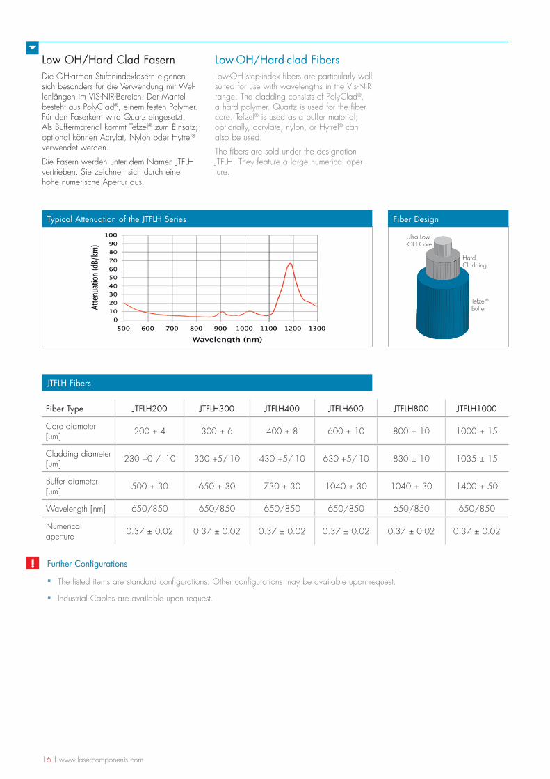
Low OH/Hard Clad FasernDie OH-armen Stufenindexfasern eigenen sich besonders für die Verwendung mit Wel-lenlängen im VIS-NIR-Bereich. Der Mantel besteht aus PolyClad®, einem festen Polymer. Für den Faserkern wird Quarz eingesetzt. Als Buffermaterial kommt Tefzel® zum Einsatz; optional können Acrylat, Nylon oder Hytrel®
verwendet werden.
Die Fasern werden unter dem Namen JTFLH vertrieben. Sie zeichnen sich durch eine hohe numerische Apertur aus.
Low-OH/Hard-clad FibersLow-OH step-index fibers are particularly well suited for use with wavelengths in the Vis-NIR range. The cladding consists of PolyClad®, a hard polymer. Quartz is used for the fiber core. Tefzel® is used as a buffer material; optionally, acrylate, nylon, or Hytrel® can also be used.
The fibers are sold under the designation JTFLH. They feature a large numerical aper-ture.
JTFLH Fibers
Fiber Type JTFLH200 JTFLH300 JTFLH400 JTFLH600 JTFLH800 JTFLH1000
Core diameter [µm] 200 ± 4 300 ± 6 400 ± 8 600 ± 10 800 ± 10 1000 ± 15
Cladding diameter [µm] 230 +0 / -10 330 +5/-10 430 +5/-10 630 +5/-10 830 ± 10 1035 ± 15
Buffer diameter [µm] 500 ± 30 650 ± 30 730 ± 30 1040 ± 30 1040 ± 30 1400 ± 50
Wavelength [nm] 650/850 650/850 650/850 650/850 650/850 650/850
Numerical aperture 0.37 ± 0.02 0.37 ± 0.02 0.37 ± 0.02 0.37 ± 0.02 0.37 ± 0.02 0.37 ± 0.02
Tefzel®Buffer
HardCladding
Ultra Low -OH Core
Fiber DesignTypical Attenuation of the JTFLH Series
Further Configurations
▪ The listed items are standard configurations. Other configurations may be available upon request.
▪ Industrial Cables are available upon request.
!
www.lasercomponents.com | 17
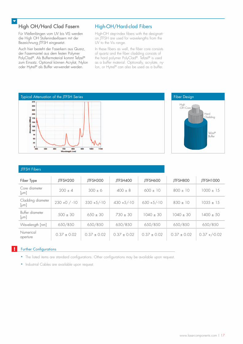
High OH/Hard Clad FasernFür Wellenlängen vom UV bis VIS werden die High OH Stufenindexfasern mit der Bezeichnung JTFSH eingesetzt.
Auch hier besteht der Faserkern aus Quarz, der Fasermantel aus dem festen Polymer PolyClad®. Als Buffermaterial kommt Tefzel® zum Einsatz. Optional können Acrylat, Nylon oder Hytrel® als Buffer verwendet werden.
High-OH/Hard-clad FibersHigh-OH step-index fibers with the designati-on JTFSH are used for wavelengths from the UV to the Vis range.
In these fibers as well, the fiber core consists of quartz and the fiber cladding consists of the hard polymer PolyClad®. Tefzel® is used as a buffer material. Optionally, acrylate, ny-lon, or Hytrel® can also be used as a buffer.
JTFSH Fibers
Fiber Type JTFSH200 JTFSH300 JTFSH400 JTFSH600 JTFSH800 JTFSH1000
Core diameter [µm] 200 ± 4 300 ± 6 400 ± 8 600 ± 10 800 ± 10 1000 ± 15
Cladding diameter [µm] 230 +0 / -10 330 +5/-10 430 +5/-10 630 +5/-10 830 ± 10 1035 ± 15
Buffer diameter [µm] 500 ± 30 650 ± 30 730 ± 30 1040 ± 30 1040 ± 30 1400 ± 50
Wavelength [nm] 650/850 650/850 650/850 650/850 650/850 650/850
Numerical aperture 0.37 ± 0.02 0.37 ± 0.02 0.37 ± 0.02 0.37 ± 0.02 0.37 ± 0.02 0.37 +/-0.02
Tefzel®Buffer
HardCladding
High -OH Core
Fiber DesignTypical Attenuation of the JTFSH Series
▪ The listed items are standard configurations. Other configurations may be available upon request.
▪ Industrial Cables are available upon request.
Further Configurations!
18 | www.lasercomponents.com
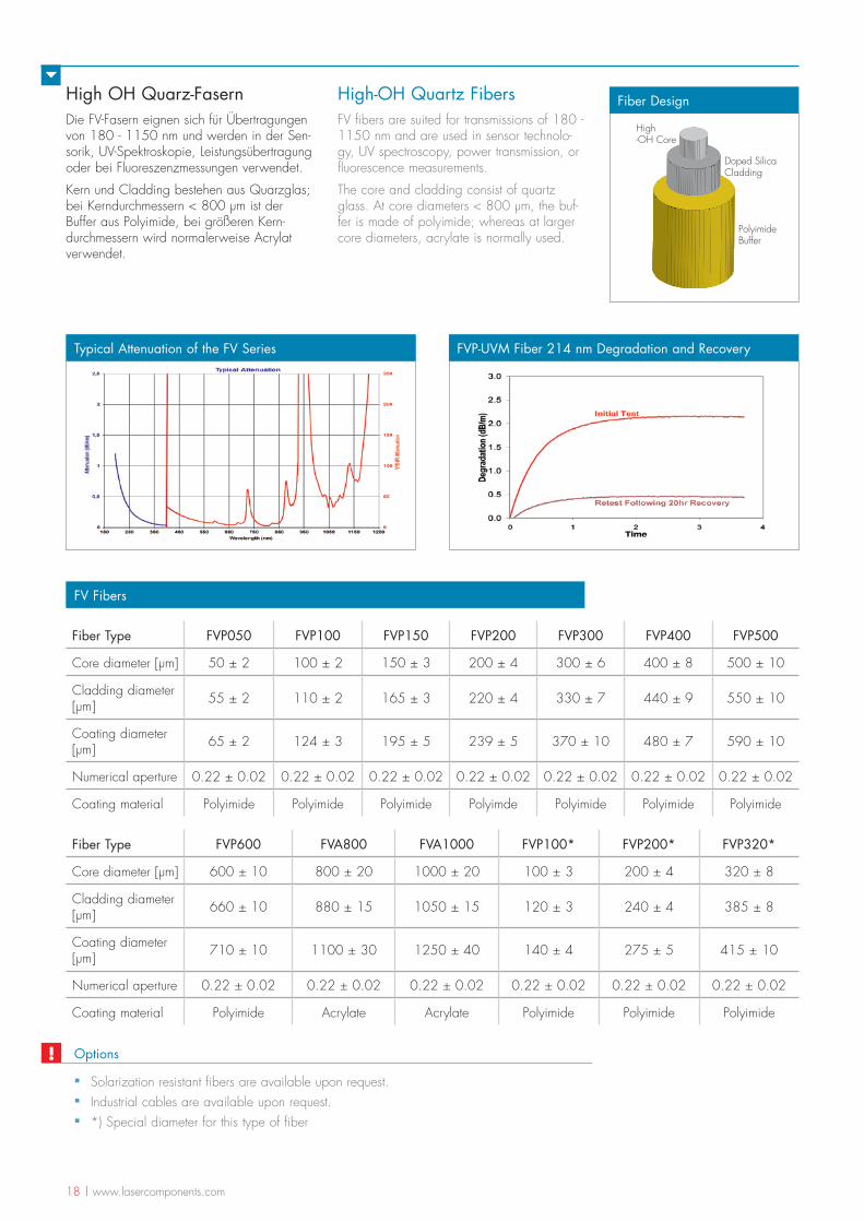
High OH Quarz-FasernDie FV-Fasern eignen sich für Übertragungen von 180 - 1150 nm und werden in der Sen-sorik, UV-Spektroskopie, Leistungsübertragung oder bei Fluoreszenzmessungen verwendet.
Kern und Cladding bestehen aus Quarzglas; bei Kerndurchmessern < 800 µm ist der Buffer aus Polyimide, bei größeren Kern-durchmessern wird normalerweise Acrylat verwendet.
High-OH Quartz FibersFV fibers are suited for transmissions of 180 - 1150 nm and are used in sensor technolo-gy, UV spectroscopy, power transmission, or fluorescence measurements.
The core and cladding consist of quartz glass. At core diameters < 800 µm, the buf-fer is made of polyimide; whereas at larger core diameters, acrylate is normally used.
FV Fibers
Fiber Type FVP050 FVP100 FVP150 FVP200 FVP300 FVP400 FVP500
Core diameter [µm] 50 ± 2 100 ± 2 150 ± 3 200 ± 4 300 ± 6 400 ± 8 500 ± 10
Cladding diameter [µm] 55 ± 2 110 ± 2 165 ± 3 220 ± 4 330 ± 7 440 ± 9 550 ± 10
Coating diameter [µm] 65 ± 2 124 ± 3 195 ± 5 239 ± 5 370 ± 10 480 ± 7 590 ± 10
Numerical aperture 0.22 ± 0.02 0.22 ± 0.02 0.22 ± 0.02 0.22 ± 0.02 0.22 ± 0.02 0.22 ± 0.02 0.22 ± 0.02
Coating material Polyimide Polyimide Polyimide Polyimde Polyimide Polyimide Polyimide
PolyimideBuffer
Doped Silica Cladding
High -OH Core
Fiber Design
Typical Attenuation of the FV Series
Fiber Type FVP600 FVA800 FVA1000 FVP100* FVP200* FVP320*
Core diameter [µm] 600 ± 10 800 ± 20 1000 ± 20 100 ± 3 200 ± 4 320 ± 8
Cladding diameter [µm] 660 ± 10 880 ± 15 1050 ± 15 120 ± 3 240 ± 4 385 ± 8
Coating diameter [µm] 710 ± 10 1100 ± 30 1250 ± 40 140 ± 4 275 ± 5 415 ± 10
Numerical aperture 0.22 ± 0.02 0.22 ± 0.02 0.22 ± 0.02 0.22 ± 0.02 0.22 ± 0.02 0.22 ± 0.02
Coating material Polyimide Acrylate Acrylate Polyimide Polyimide Polyimide
FVP-UVM Fiber 214 nm Degradation and Recovery
Options
▪ Solarization resistant fibers are available upon request. ▪ Industrial cables are available upon request. ▪ *) Special diameter for this type of fiber
!
www.lasercomponents.com | 19
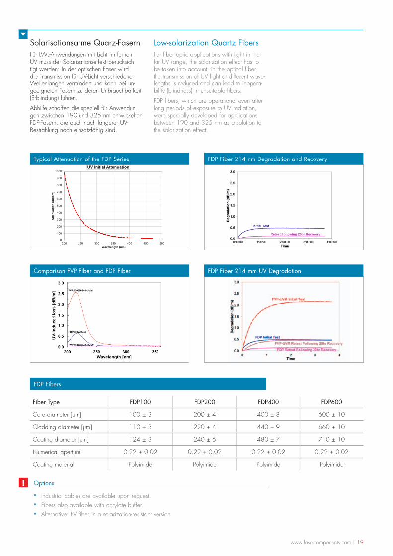
Solarisationsarme Quarz-FasernFür LWL-Anwendungen mit Licht im fernen UV muss der Solarisationseffekt berücksich-tigt werden: In der optischen Faser wird die Transmission für UV-Licht verschiedener Wellenlängen vermindert und kann bei un-geeigneten Fasern zu deren Unbrauchbarkeit (Erblindung) führen.
Abhilfe schaffen die speziell für Anwendun-gen zwischen 190 und 325 nm entwickelten FDP-Fasern, die auch nach längerer UV-Bestrahlung noch einsatzfähig sind.
Low-solarization Quartz FibersFor fiber optic applications with light in the far UV range, the solarization effect has to be taken into account: in the optical fiber, the transmission of UV light at different wave-lengths is reduced and can lead to inopera-bility (blindness) in unsuitable fibers.
FDP fibers, which are operational even after long periods of exposure to UV radiation, were specially developed for applications between 190 and 325 nm as a solution to the solarization effect.
FDP Fibers
Fiber Type FDP100 FDP200 FDP400 FDP600
Core diameter [µm] 100 ± 3 200 ± 4 400 ± 8 600 ± 10
Cladding diameter [µm] 110 ± 3 220 ± 4 440 ± 9 660 ± 10
Coating diameter [µm] 124 ± 3 240 ± 5 480 ± 7 710 ± 10
Numerical aperture 0.22 ± 0.02 0.22 ± 0.02 0.22 ± 0.02 0.22 ± 0.02
Coating material Polyimide Polyimide Polyimide Polyimide
0
100
200
300
400
500
600
700
800
900
1000
200 250 300 350 400 450 500
Atte
nuat
ion
(dB
/km
)
Wavelength (nm)
UV Initial Attenuation
Typical Attenuation of the FDP Series FDP Fiber 214 nm Degradation and Recovery
Comparison FVP Fiber and FDP Fiber FDP Fiber 214 mm UV Degradation
▪ Industrial cables are available upon request. ▪ Fibers also available with acrylate buffer. ▪ Alternative: FV fiber in a solarization-resistant version
Options!
20 | www.lasercomponents.com
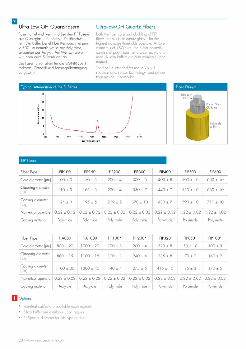
Ultra Low OH Quarz-FasernFasermantel und -kern sind bei den FIP-Fasern aus Quarzglas – für höchste Zerstörschwel-len. Der Buffer besteht bei Kerndurchmessern < 800 µm normalerweise aus Polyimide, ansonsten aus Acrylat. Auf Wunsch bieten wir Ihnen auch Silikonbuffer an.
Die Faser ist vor allem für die VIS-NIR-Spekt-roskopie, Sensorik und Leistungsübertragung vorgesehen.
Ultra-low-OH Quartz FibersBoth the fiber core and cladding of FIP fibers are made of quartz glass – for the highest damage thresholds possible. At core diameters of <800 µm, the buffer normally consists of polyimides; otherwise, acrylate is used. Silicon buffers are also available upon request.
The fiber is intended for use in Vis-NIR spectroscopy, sensor technology, and power transmission in particular.
FIP Fibers
Fiber Type FIP100 FIP150 FIP200 FIP300 FIP400 FIP500 FIP600
Core diameter [µm] 100 ± 3 150 ± 3 200 ± 4 300 ± 6 400 ± 8 500 ± 10 600 ± 10
Cladding diameter [µm] 110 ± 3 165 ± 3 220 ± 4 330 ± 7 440 ± 9 550 ± 10 660 ± 10
Coating diameter [µm] 124 ± 3 195 ± 5 239 ± 5 370 ± 10 480 ± 7 590 ± 10 710 ± 10
Numerical aperture 0.22 ± 0.02 0.22 ± 0.02 0.22 ± 0.02 0.22 ± 0.02 0.22 ± 0.02 0.22 ± 0.02 0.22 ± 0.02
Coating material Polyimide Polyimide Polyimide Polyimide Polyimide Polyimide Polyimide
PolyimideBuffer
Doped Silica Cladding
Ultra Low-OH Core
Fiber DesignTypical Attenuation of the FI Series
Fiber Type FIA800 FIA1000 FIP100* FIP200* FIP320 FIP050* FIP100*
Core diameter [µm] 800 ± 20 1000 ± 20 100 ± 3 200 ± 4 320 ± 8 50 ± 10 100 ± 3
Cladding diameter [µm] 880 ± 15 1100 ± 15 120 ± 3 240 ± 4 385 ± 8 70 ± 2 140 ± 2
Coating diameter [µm] 1100 ± 30 1300 ± 40 140 ± 4 275 ± 5 415 ± 10 85 ± 3 170 ± 5
Numerical aperture 0.22 ± 0.02 0.22 ± 0.02 0.22 ± 0.02 0.22 ± 0.02 0.22 ± 0.02 0.22 ± 0.02 0.22 ± 0.02
Coating material Acrylate Acrylate Polyimide Polyimide Polyimide Polyimide Polyimide
Options
▪ Industrial cables are available upon request. ▪ Silica buffer are available upon request. ▪ *) Special diameter for this type of fiber
!
www.lasercomponents.com | 21
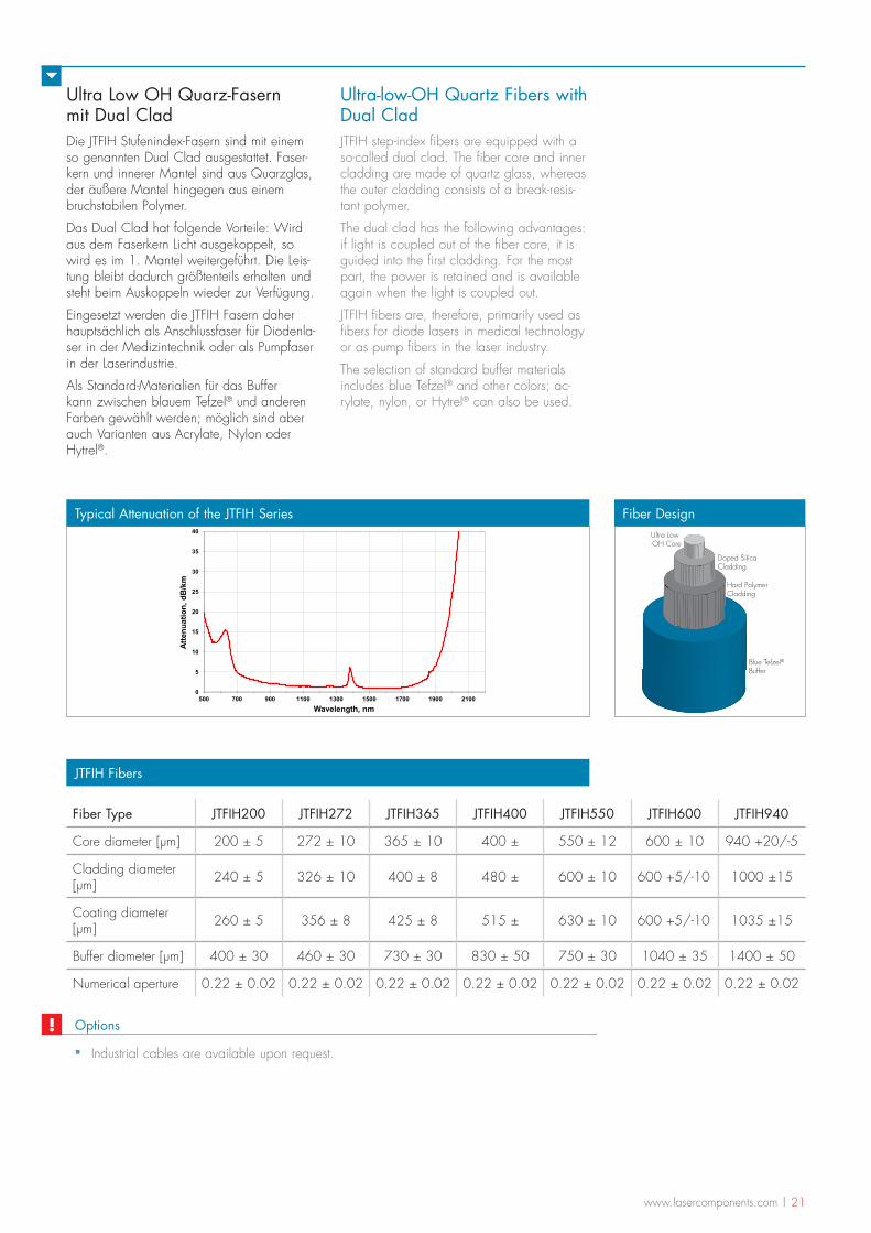
Ultra Low OH Quarz-Fasern mit Dual CladDie JTFIH Stufenindex-Fasern sind mit einem so genannten Dual Clad ausgestattet. Faser-kern und innerer Mantel sind aus Quarzglas, der äußere Mantel hingegen aus einem bruchstabilen Polymer.
Das Dual Clad hat folgende Vorteile: Wird aus dem Faserkern Licht ausgekoppelt, so wird es im 1. Mantel weitergeführt. Die Leis-tung bleibt dadurch größtenteils erhalten und steht beim Auskoppeln wieder zur Verfügung.
Eingesetzt werden die JTFIH Fasern daher hauptsächlich als Anschlussfaser für Diodenla-ser in der Medizintechnik oder als Pumpfaser in der Laserindustrie.
Als Standard-Materialien für das Buffer kann zwischen blauem Tefzel® und anderen Farben gewählt werden; möglich sind aber auch Varianten aus Acrylate, Nylon oder Hytrel®.
Ultra-low-OH Quartz Fibers with Dual CladJTFIH step-index fibers are equipped with a so-called dual clad. The fiber core and inner cladding are made of quartz glass, whereas the outer cladding consists of a break-resis-tant polymer.
The dual clad has the following advantages: if light is coupled out of the fiber core, it is guided into the first cladding. For the most part, the power is retained and is available again when the light is coupled out.
JTFIH fibers are, therefore, primarily used as fibers for diode lasers in medical technology or as pump fibers in the laser industry.
The selection of standard buffer materials includes blue Tefzel® and other colors; ac-rylate, nylon, or Hytrel® can also be used.
JTFIH Fibers
Fiber Type JTFIH200 JTFIH272 JTFIH365 JTFIH400 JTFIH550 JTFIH600 JTFIH940
Core diameter [µm] 200 ± 5 272 ± 10 365 ± 10 400 ± 550 ± 12 600 ± 10 940 +20/-5
Cladding diameter [µm] 240 ± 5 326 ± 10 400 ± 8 480 ± 600 ± 10 600 +5/-10 1000 ±15
Coating diameter [µm] 260 ± 5 356 ± 8 425 ± 8 515 ± 630 ± 10 600 +5/-10 1035 ±15
Buffer diameter [µm] 400 ± 30 460 ± 30 730 ± 30 830 ± 50 750 ± 30 1040 ± 35 1400 ± 50
Numerical aperture 0.22 ± 0.02 0.22 ± 0.02 0.22 ± 0.02 0.22 ± 0.02 0.22 ± 0.02 0.22 ± 0.02 0.22 ± 0.02
Blue Tefzel®Buffer
Doped Silica Cladding
Ultra Low-OH Core
Hard Polymer Cladding
Fiber Design
0
5
10
15
20
25
30
35
40
500 700 900 1100 1300 1500 1700 1900 2100
Atte
nuat
ion,
dB
/km
Wavelength, nm
Typical Attenuation of the JTFIH Series
Options
▪ Industrial cables are available upon request.
!
22 | www.lasercomponents.com
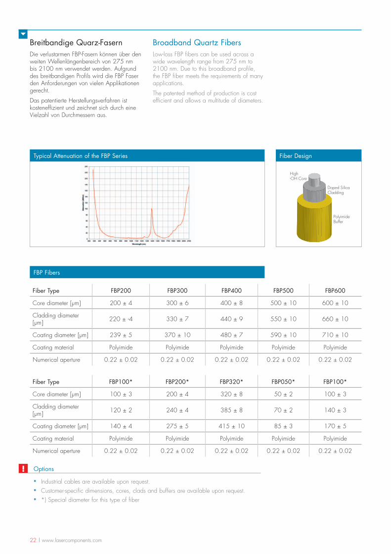
Breitbandige Quarz-FasernDie verlustarmen FBP-Fasern können über den weiten Wellenlängenbereich von 275 nm bis 2100 nm verwendet werden. Aufgrund des breitbandigen Profils wird die FBP Faser den Anforderungen von vielen Applikationen gerecht.
Das patentierte Herstellungsverfahren ist kosteneffizient und zeichnet sich durch eine Vielzahl von Durchmessern aus.
Broadband Quartz FibersLow-loss FBP fibers can be used across a wide wavelength range from 275 nm to 2100 nm. Due to this broadband profile, the FBP fiber meets the requirements of many applications.
The patented method of production is cost efficient and allows a multitude of diameters.
FBP Fibers
Fiber Type FBP200 FBP300 FBP400 FBP500 FBP600
Core diameter [µm] 200 ± 4 300 ± 6 400 ± 8 500 ± 10 600 ± 10
Cladding diameter [µm] 220 ± -4 330 ± 7 440 ± 9 550 ± 10 660 ± 10
Coating diameter [µm] 239 ± 5 370 ± 10 480 ± 7 590 ± 10 710 ± 10
Coating material Polyimide Polyimide Polyimide Polyimide Polyimide
Numerical aperture 0.22 ± 0.02 0.22 ± 0.02 0.22 ± 0.02 0.22 ± 0.02 0.22 ± 0.02
PolyimideBuffer
Doped Silica Cladding
High -OH Core
Fiber DesignTypical Attenuation of the FBP Series
Fiber Type FBP100* FBP200* FBP320* FBP050* FBP100*
Core diameter [µm] 100 ± 3 200 ± 4 320 ± 8 50 ± 2 100 ± 3
Cladding diameter [µm] 120 ± 2 240 ± 4 385 ± 8 70 ± 2 140 ± 3
Coating diameter [µm] 140 ± 4 275 ± 5 415 ± 10 85 ± 3 170 ± 5
Coating material Polyimide Polyimide Polyimide Polyimide Polyimide
Numerical aperture 0.22 ± 0.02 0.22 ± 0.02 0.22 ± 0.02 0.22 ± 0.02 0.22 ± 0.02
Options
▪ Industrial cables are available upon request. ▪ Customer-specific dimensions, cores, clads and buffers are available upon request. ▪ *) Special diameter for this type of fiber
!
www.lasercomponents.com | 23
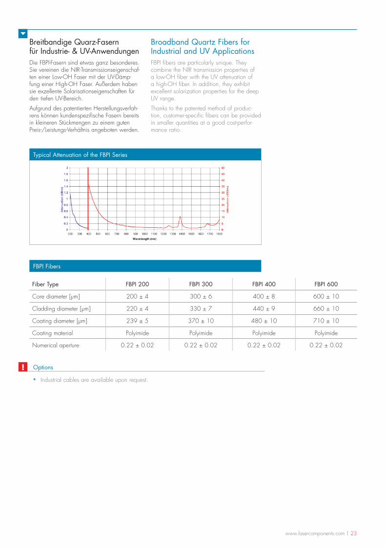
Breitbandige Quarz-Fasern für Industrie- & UV-AnwendungenDie FBPI-Fasern sind etwas ganz besonderes. Sie vereinen die NIR-Transmissionseigenschaf-ten einer Low-OH Faser mit der UV-Dämp-fung einer High-OH Faser. Außerdem haben sie exzellente Solarisationseigenschaften für den tiefen UV-Bereich.
Aufgrund des patentierten Herstellungsverfah-rens können kundenspezifische Fasern bereits in kleineren Stückmengen zu einem guten Preis-/Leistungs-Verhältnis angeboten werden.
Broadband Quartz Fibers for Industrial and UV ApplicationsFBPI fibers are particularly unique. They combine the NIR transmission properties of a low-OH fiber with the UV attenuation of a high-OH fiber. In addition, they exhibit excellent solarization properties for the deep UV range.
Thanks to the patented method of produc-tion, customer-specific fibers can be provided in smaller quantities at a good cost-perfor-mance ratio.
FBPI Fibers
Fiber Type FBPI 200 FBPI 300 FBPI 400 FBPI 600
Core diameter [µm] 200 ± 4 300 ± 6 400 ± 8 600 ± 10
Cladding diameter [µm] 220 ± 4 330 ± 7 440 ± 9 660 ± 10
Coating diameter [µm] 239 ± 5 370 ± 10 480 ± 10 710 ± 10
Coating material Polyimide Polyimide Polyimide Polyimide
Numerical aperture 0.22 ± 0.02 0.22 ± 0.02 0.22 ± 0.02 0.22 ± 0.02
Typical Attenuation of the FBPI Series
Options
▪ Industrial cables are available upon request.
!
24 | www.lasercomponents.com
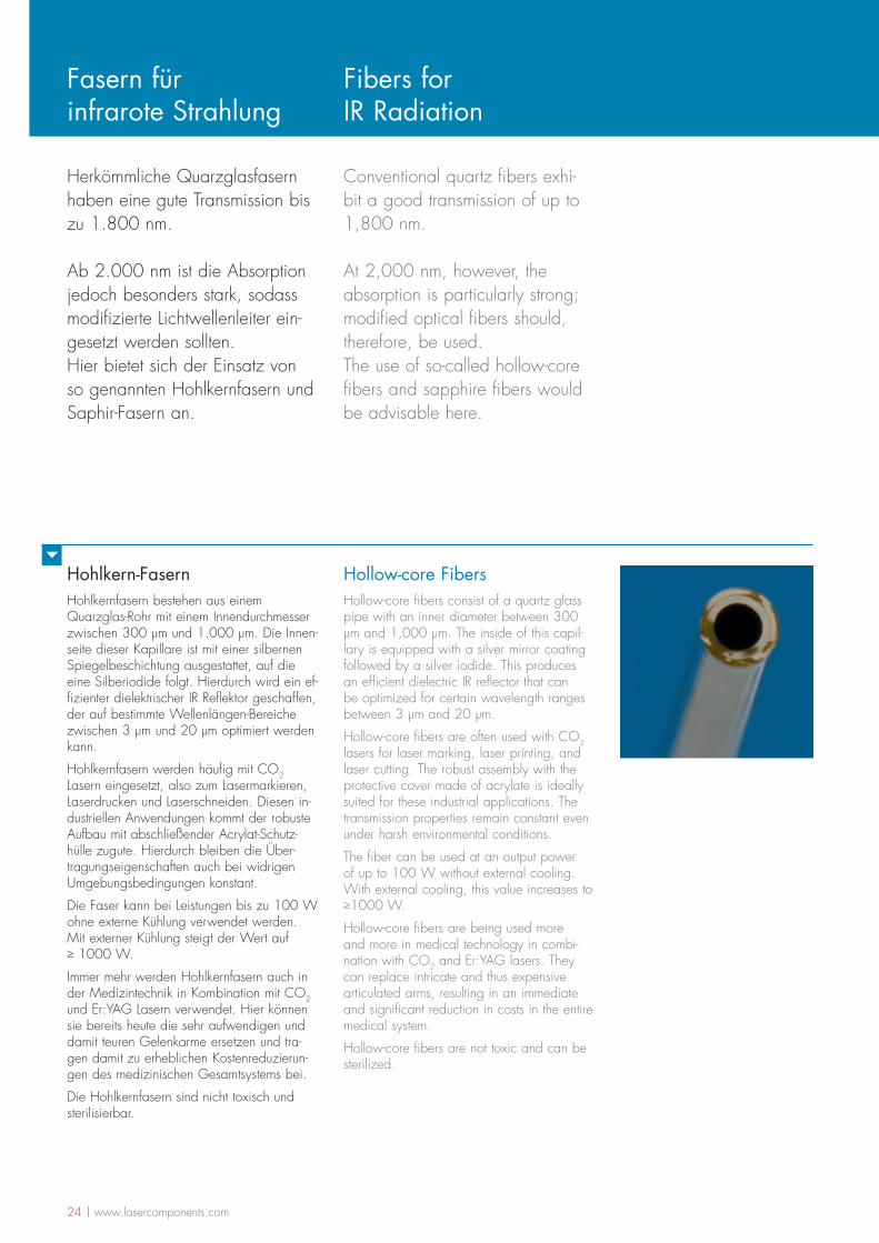
Hohlkern-FasernHohlkernfasern bestehen aus einem Quarzglas-Rohr mit einem Innendurchmesser zwischen 300 µm und 1.000 µm. Die Innen-seite dieser Kapillare ist mit einer silbernen Spiegelbeschichtung ausgestattet, auf die eine Silberiodide folgt. Hierdurch wird ein ef-fizienter dielektrischer IR Reflektor geschaffen, der auf bestimmte Wellenlängen-Bereiche zwischen 3 µm und 20 µm optimiert werden kann.
Hohlkernfasern werden häufig mit CO2 Lasern eingesetzt, also zum Lasermarkieren, Laserdrucken und Laserschneiden. Diesen in-dustriellen Anwendungen kommt der robuste Aufbau mit abschließender Acrylat-Schutz-hülle zugute. Hierdurch bleiben die Über-tragungseigenschaften auch bei widrigen Umgebungsbedingungen konstant.
Die Faser kann bei Leistungen bis zu 100 W ohne externe Kühlung verwendet werden. Mit externer Kühlung steigt der Wert auf > 1000 W.
Immer mehr werden Hohlkernfasern auch in der Medizintechnik in Kombination mit CO2 und Er:YAG Lasern verwendet. Hier können sie bereits heute die sehr aufwendigen und damit teuren Gelenkarme ersetzen und tra-gen damit zu erheblichen Kostenreduzierun-gen des medizinischen Gesamtsystems bei.
Die Hohlkernfasern sind nicht toxisch und sterilisierbar.
Hollow-core FibersHollow-core fibers consist of a quartz glass pipe with an inner diameter between 300 µm and 1,000 µm. The inside of this capil-lary is equipped with a silver mirror coating followed by a silver iodide. This produces an efficient dielectric IR reflector that can be optimized for certain wavelength ranges between 3 µm and 20 µm.
Hollow-core fibers are often used with CO2 lasers for laser marking, laser printing, and laser cutting. The robust assembly with the protective cover made of acrylate is ideally suited for these industrial applications. The transmission properties remain constant even under harsh environmental conditions.
The fiber can be used at an output power of up to 100 W without external cooling. With external cooling, this value increases to >1000 W.
Hollow-core fibers are being used more and more in medical technology in combi-nation with CO2 and Er:YAG lasers. They can replace intricate and thus expensive articulated arms, resulting in an immediate and significant reduction in costs in the entire medical system.
Hollow-core fibers are not toxic and can be sterilized.
Herkömmliche Quarzglasfasern haben eine gute Transmission bis zu 1.800 nm.
Ab 2.000 nm ist die Absorption jedoch besonders stark, sodass modifizierte Lichtwellenleiter ein-gesetzt werden sollten.Hier bietet sich der Einsatz von so genannten Hohlkernfasern und Saphir-Fasern an.
Conventional quartz fibers exhi-bit a good transmission of up to 1,800 nm.
At 2,000 nm, however, the absorption is particularly strong; modified optical fibers should, therefore, be used.The use of so-called hollow-core fibers and sapphire fibers would be advisable here.
Fasern für infrarote Strahlung
Fibers for IR Radiation
www.lasercomponents.com | 25
Acrylate Buffer
Ag Layer
AgI Layer
Silica Tube
Hollow ID
Fiber Design
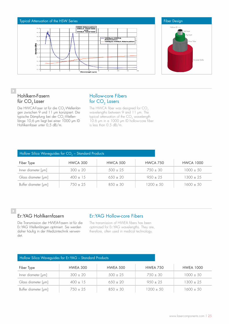
Hohlkern-Fasern für CO2 LaserDie HWCA-Faser ist für die CO2-Wellenlän-gen zwischen 9 und 11 µm konzipiert. Die typische Dämpfung bei der CO2-Wellen-länge 10,6 µm liegt bei einer 1000 µm ID Hohlkernfaser unter 0,5 dB/m.
Hollow-core Fibers for CO2 LasersThe HWCA fiber was designed for CO2 wavelengths between 9 and 11 µm. The typical attenuation of the CO2 wavelength 10.6 µm in a 1000 µm ID hollow-core fiber is less than 0.5 dB/m.
Fiber Type HWCA 300 HWCA 500 HWCA 750 HWCA 1000
Inner diameter [µm] 300 ± 20 500 ± 25 750 ± 30 1000 ± 50
Glass diameter [µm] 400 ± 15 650 ± 20 950 ± 25 1300 ± 25
Buffer diameter [µm] 750 ± 25 850 ± 30 1200 ± 50 1600 ± 50
Hollow Silica Waveguides for CO2 – Standard Products
Hollow Silica Waveguides for Er:YAG – Standard Products
Er:YAG HohlkernfasernDie Transmission der HWEA-Fasern ist für die Er:YAG Wellenlängen optimiert. Sie werden daher häufig in der Medizintechnik verwen-det.
Er:YAG Hollow-core FibersThe transmission of HWEA fibers has been optimized for Er:YAG wavelengths. They are, therefore, often used in medical technology.
Typical Attenuation of the HSW Series
Fiber Type HWEA 300 HWEA 500 HWEA 750 HWEA 1000
Inner diameter [µm] 300 ± 20 500 ± 25 750 ± 30 1000 ± 50
Glass diameter [µm] 400 ± 15 650 ± 20 950 ± 25 1300 ± 25
Buffer diameter [µm] 750 ± 25 850 ± 30 1200 ± 50 1600 ± 50
26 | www.lasercomponents.com
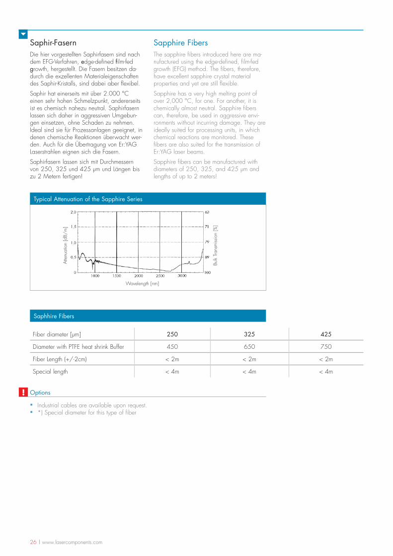
Saphir-FasernDie hier vorgestellten Saphirfasern sind nach dem EFG-Verfahren, edge-defined film-fed growth, hergestellt. Die Fasern besitzen da-durch die exzellenten Materialeigenschaften des Saphir-Kristalls, sind dabei aber flexibel.
Saphir hat einerseits mit über 2.000 °C einen sehr hohen Schmelzpunkt, andererseits ist es chemisch nahezu neutral. Saphirfasern lassen sich daher in aggressiven Umgebun-gen einsetzen, ohne Schaden zu nehmen. Ideal sind sie für Prozessanlagen geeignet, in denen chemische Reaktionen überwacht wer-den. Auch für die Übertragung von Er:YAG Laserstrahlen eignen sich die Fasern.
Saphirfasern lassen sich mit Durchmessern von 250, 325 und 425 µm und Längen bis zu 2 Metern fertigen!
Sapphire FibersThe sapphire fibers introduced here are ma-nufactured using the edge-defined, film-fed growth (EFG) method. The fibers, therefore, have excellent sapphire crystal material properties and yet are still flexible.
Sapphire has a very high melting point of over 2,000 °C, for one. For another, it is chemically almost neutral. Sapphire fibers can, therefore, be used in aggressive envi-ronments without incurring damage. They are ideally suited for processing units, in which chemical reactions are monitored. These fibers are also suited for the transmission of Er:YAG laser beams.
Sapphire fibers can be manufactured with diameters of 250, 325, and 425 µm and lengths of up to 2 meters!
Saphhire Fibers
Fiber diameter [µm] 250 325 425
Diameter with PTFE heat shrink Buffer 450 650 750
Fiber Length (+/-2cm) < 2m < 2m < 2m
Special length < 4m < 4m < 4m
Wavelength [nm]
Atte
nuat
ion
[dB/
m]
Bulk
Tran
smiss
ion
[%]
Typical Attenuation of the Sapphire Series
Options
▪ Industrial cables are available upon request. ▪ *) Special diameter for this type of fiber
!
www.lasercomponents.com | 27
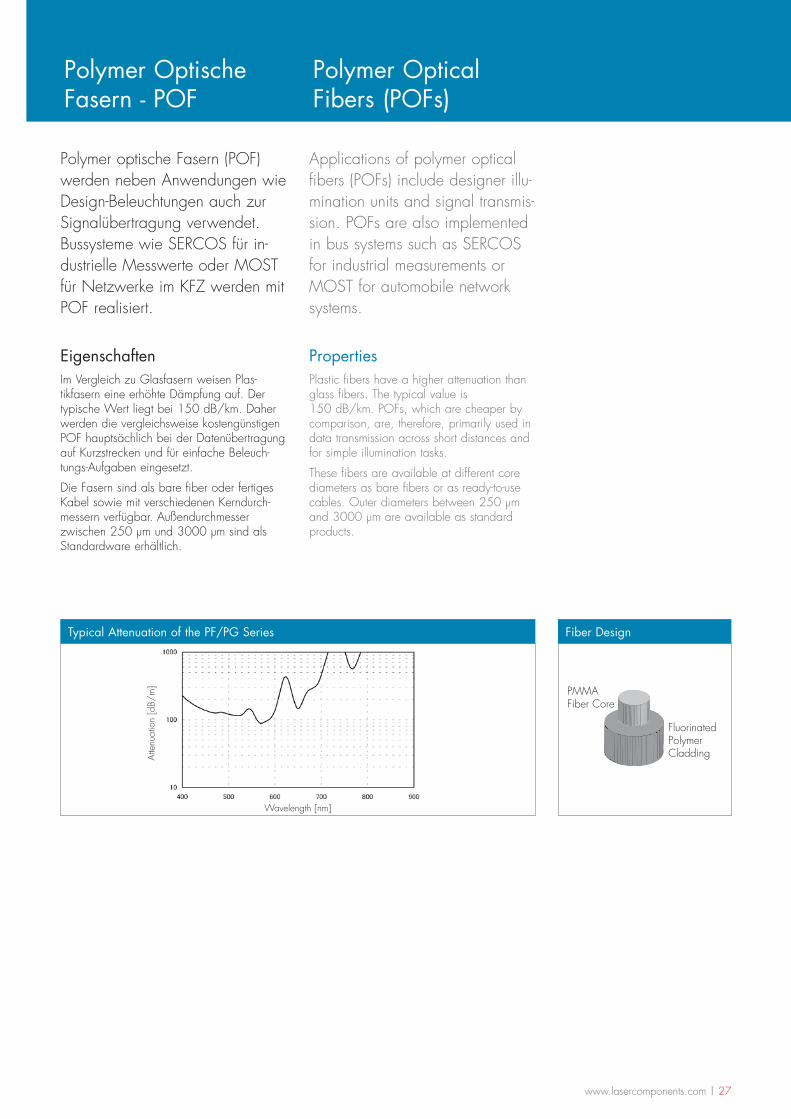
Polymer optische Fasern (POF) werden neben Anwendungen wie Design-Beleuchtungen auch zur Signalübertragung verwendet. Bussysteme wie SERCOS für in-dustrielle Messwerte oder MOST für Netzwerke im KFZ werden mit POF realisiert.
Applications of polymer optical fibers (POFs) include designer illu-mination units and signal transmis-sion. POFs are also implemented in bus systems such as SERCOS for industrial measurements or MOST for automobile network systems.
PropertiesPlastic fibers have a higher attenuation than glass fibers. The typical value is 150 dB/km. POFs, which are cheaper by comparison, are, therefore, primarily used in data transmission across short distances and for simple illumination tasks.
These fibers are available at different core diameters as bare fibers or as ready-to-use cables. Outer diameters between 250 µm and 3000 µm are available as standard products.
EigenschaftenIm Vergleich zu Glasfasern weisen Plas-tikfasern eine erhöhte Dämpfung auf. Der typische Wert liegt bei 150 dB/km. Daher werden die vergleichsweise kostengünstigen POF hauptsächlich bei der Datenübertragung auf Kurzstrecken und für einfache Beleuch-tungs-Aufgaben eingesetzt.
Die Fasern sind als bare fiber oder fertiges Kabel sowie mit verschiedenen Kerndurch-messern verfügbar. Außendurchmesser zwischen 250 µm und 3000 µm sind als Standardware erhältlich.
Polymer Optische Fasern - POF
Polymer Optical Fibers (POFs)
Fluorinated Polymer Cladding
PMMAFiber Core
Fiber Design
Wavelength [nm]
Atte
nuat
ion
[dB/
m]
Typical Attenuation of the PF/PG Series
28 | www.lasercomponents.com
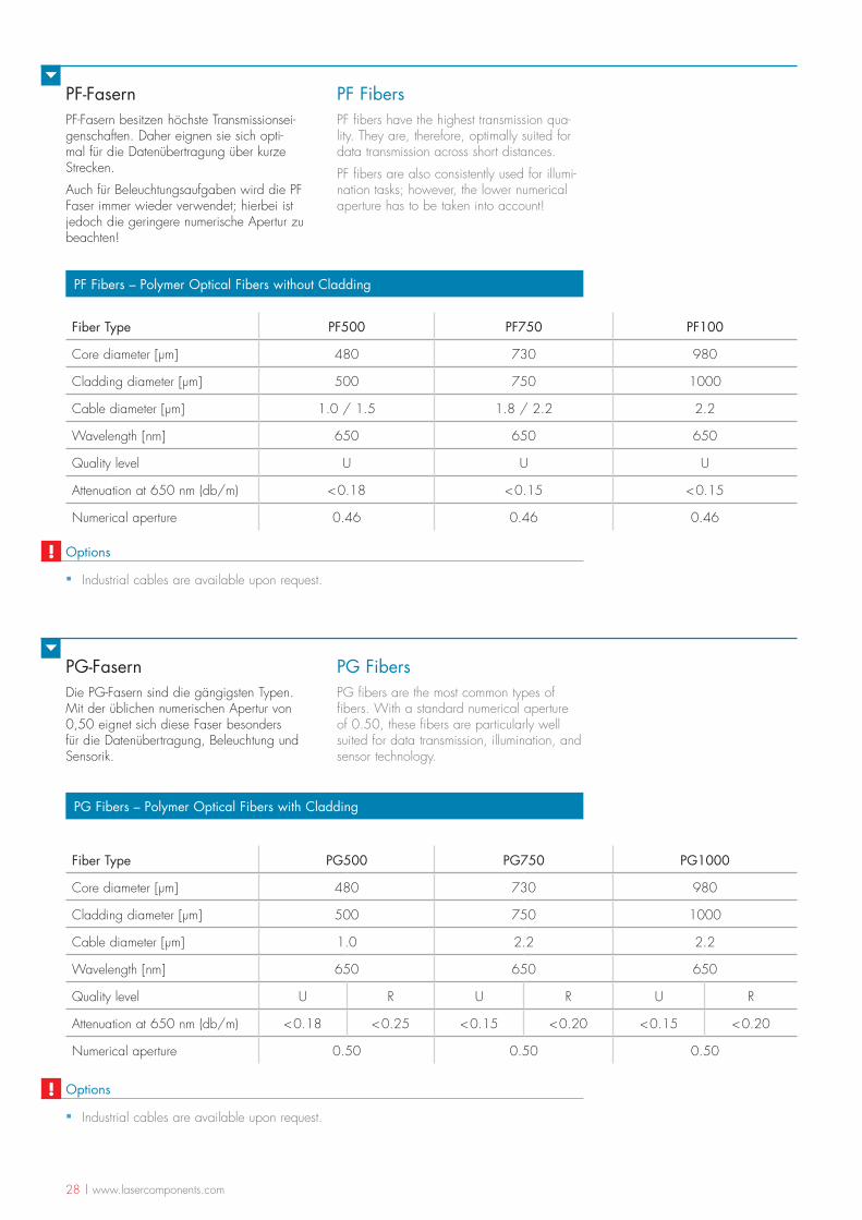
PF-FasernPF-Fasern besitzen höchste Transmissionsei-genschaften. Daher eignen sie sich opti-mal für die Datenübertragung über kurze Strecken.
Auch für Beleuchtungsaufgaben wird die PF Faser immer wieder verwendet; hierbei ist jedoch die geringere numerische Apertur zu beachten!
PF Fibers – Polymer Optical Fibers without Cladding
PG-FasernDie PG-Fasern sind die gängigsten Typen. Mit der üblichen numerischen Apertur von 0,50 eignet sich diese Faser besonders für die Datenübertragung, Beleuchtung und Sensorik.
PG Fibers – Polymer Optical Fibers with Cladding
PF FibersPF fibers have the highest transmission qua-lity. They are, therefore, optimally suited for data transmission across short distances.
PF fibers are also consistently used for illumi-nation tasks; however, the lower numerical aperture has to be taken into account!
PG FibersPG fibers are the most common types of fibers. With a standard numerical aperture of 0.50, these fibers are particularly well suited for data transmission, illumination, and sensor technology.
Fiber Type PF500 PF750 PF100
Core diameter [µm] 480 730 980
Cladding diameter [µm] 500 750 1000
Cable diameter [µm] 1.0 / 1.5 1.8 / 2.2 2.2
Wavelength [nm] 650 650 650
Quality level U U U
Attenuation at 650 nm (db/m) < 0.18 < 0.15 < 0.15
Numerical aperture 0.46 0.46 0.46
Fiber Type PG500 PG750 PG1000
Core diameter [µm] 480 730 980
Cladding diameter [µm] 500 750 1000
Cable diameter [µm] 1.0 2.2 2.2
Wavelength [nm] 650 650 650
Quality level U R U R U R
Attenuation at 650 nm (db/m) < 0.18 < 0.25 < 0.15 < 0.20 < 0.15 < 0.20
Numerical aperture 0.50 0.50 0.50
Options
▪ Industrial cables are available upon request.
!
Options
▪ Industrial cables are available upon request.
!
www.lasercomponents.com | 29
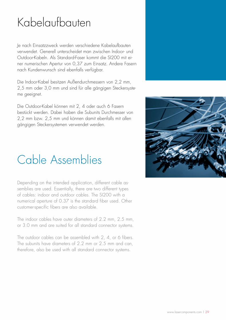
Kabelaufbauten
Cable Assemblies
Je nach Einsatzzweck werden verschiedene Kabelaufbauten verwendet. Generell unterscheidet man zwischen Indoor- und Outdoor-Kabeln. Als Standard-Faser kommt die SI200 mit ei-ner numerischen Apertur von 0,37 zum Einsatz. Andere Fasern nach Kundenwunsch sind ebenfalls verfügbar.
Die Indoor-Kabel besitzen Außendurchmessern von 2,2 mm, 2,5 mm oder 3,0 mm und sind für alle gängigen Steckersyste-me geeignet.
Die Outdoor-Kabel können mit 2, 4 oder auch 6 Fasern bestückt werden. Dabei haben die Subunits Durchmesser von 2,2 mm bzw. 2,5 mm und können damit ebenfalls mit allen gängigen Steckersystemen verwendet werden.
Depending on the intended application, different cable as-semblies are used. Essentially, there are two different types of cables: indoor and outdoor cables. The SI200 with a numerical aperture of 0.37 is the standard fiber used. Other customer-specific fibers are also available.
The indoor cables have outer diameters of 2.2 mm, 2.5 mm, or 3.0 mm and are suited for all standard connector systems.
The outdoor cables can be assembled with 2, 4, or 6 fibers. The subunits have diameters of 2.2 mm or 2.5 mm and can, therefore, also be used with all standard connector systems.
30 | www.lasercomponents.com
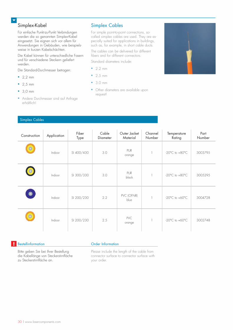
Simplex-KabelFür einfache Punkt-zu-Punkt Verbindungen werden die so genannten Simplex-Kabel eingesetzt. Sie eignen sich vor allem für Anwendungen in Gebäuden, wie beispiels-weise in kurzen Kabelschächten.
Die Kabel können für unterschiedliche Fasern und für verschiedene Steckern geliefert werden.
Die Standard-Durchmesser betragen:
▪ 2,2 mm
▪ 2,5 mm
▪ 3,0 mm
▪ Andere Durchmesser sind auf Anfrage erhältlich!
Simplex CablesFor simple point-to-point connections, so-called simplex cables are used. They are es-pecially suited for applications in buildings, such as, for example, in short cable ducts.
The cables can be delivered for different fibers and for different connectors.
Standard diameters include:
▪ 2.2 mm
▪ 2.5 mm
▪ 3.0 mm
▪ Other diameters are available upon request!
Bitte geben Sie bei Ihrer Bestellung die Kabellänge von Steckerstirnfläche zu Steckerstirnfläche an.
Bestellinformation Order Information!
Construction Application Fiber Type
Cable Diameter
Outer Jacket Material
Channel Number
Temperature Rating
Part Number
Indoor SI 400/430 3.0PUR
orange1 -20°C to +80°C 3003795
Indoor SI 300/330 3.0PUR black
1 -20°C to +80°C 3005295
Indoor SI 200/230 2.2PVC (OFNR)
blue1 -20°C to +60°C 3004728
Indoor SI 200/230 2.5PVC
orange1 -20°C to +60°C 3002748
Simplex Cables
Please include the length of the cable from connector surface to connector surface with your order.
www.lasercomponents.com | 31
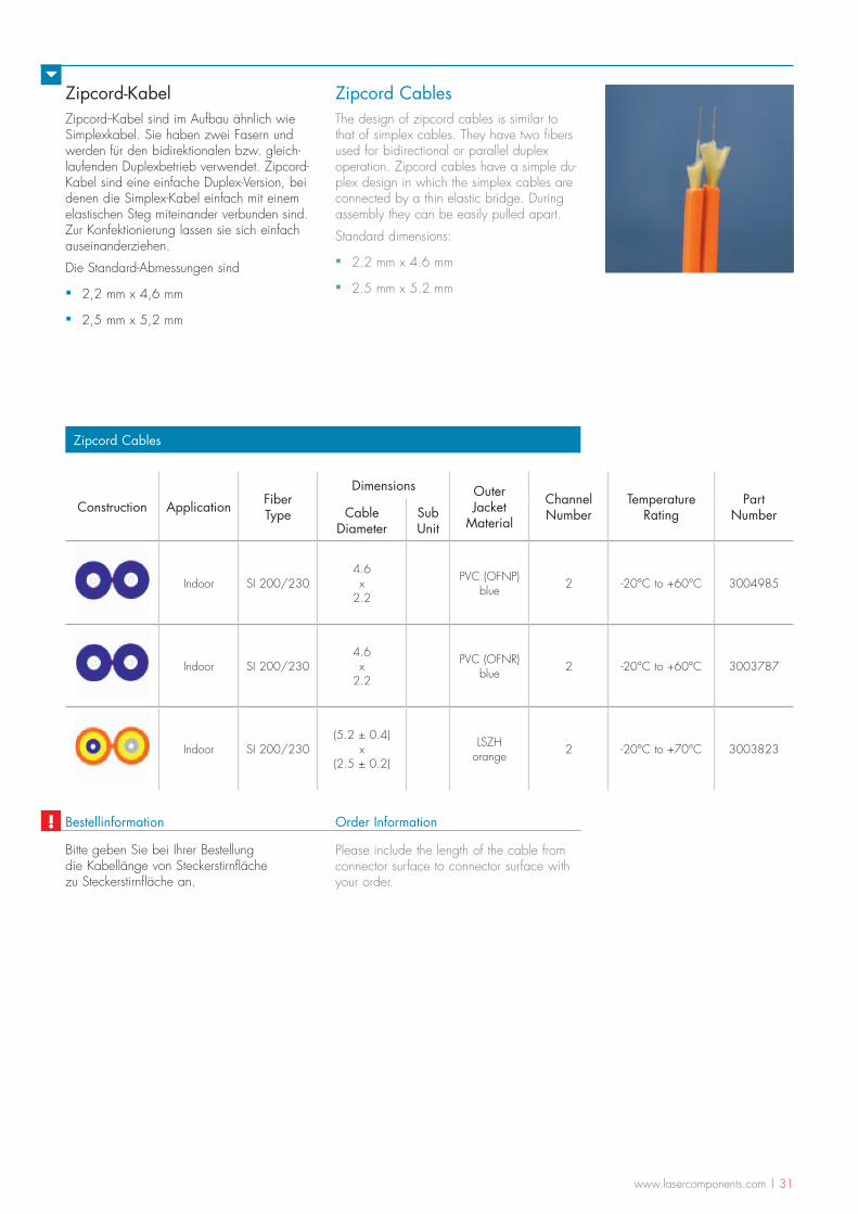
Zipcord-KabelZipcord--Kabel sind im Aufbau ähnlich wie Simplexkabel. Sie haben zwei Fasern und werden für den bidirektionalen bzw. gleich-laufenden Duplexbetrieb verwendet. Zipcord-Kabel sind eine einfache Duplex-Version, bei denen die Simplex-Kabel einfach mit einem elastischen Steg miteinander verbunden sind. Zur Konfektionierung lassen sie sich einfach auseinanderziehen.
Die Standard-Abmessungen sind
▪ 2,2 mm x 4,6 mm
▪ 2,5 mm x 5,2 mm
Zipcord CablesThe design of zipcord cables is similar to that of simplex cables. They have two fibers used for bidirectional or parallel duplex operation. Zipcord cables have a simple du-plex design in which the simplex cables are connected by a thin elastic bridge. During assembly they can be easily pulled apart.
Standard dimensions:
▪ 2.2 mm x 4.6 mm
▪ 2.5 mm x 5.2 mm
Bitte geben Sie bei Ihrer Bestellung die Kabellänge von Steckerstirnfläche zu Steckerstirnfläche an.
Bestellinformation Order Information!
Construction Application Fiber Type
Dimensions Outer Jacket
Material
Channel Number
Temperature Rating
Part NumberCable
DiameterSub Unit
Indoor SI 200/2304.6 x
2.2
PVC (OFNP) blue 2 -20°C to +60°C 3004985
Indoor SI 200/2304.6 x
2.2
PVC (OFNR) blue 2 -20°C to +60°C 3003787
Indoor SI 200/230(5.2 ± 0.4)
x (2.5 ± 0.2)
LSZH orange 2 -20°C to +70°C 3003823
Zipcord Cables
Please include the length of the cable from connector surface to connector surface with your order.
32 | www.lasercomponents.com
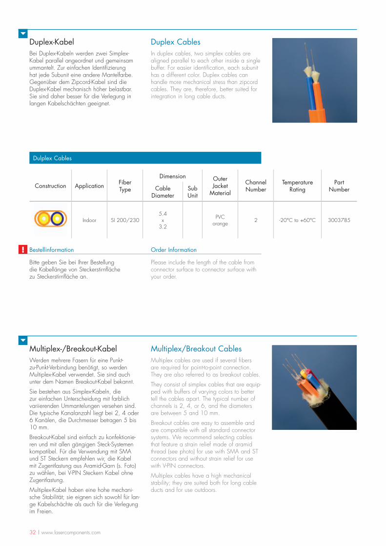
Multiplex-/Breakout-KabelWerden mehrere Fasern für eine Punkt-zu-Punkt-Verbindung benötigt, so werden Multiplex-Kabel verwendet. Sie sind auch unter dem Namen Breakout-Kabel bekannt.
Sie bestehen aus Simplex-Kabeln, die zur einfachen Unterscheidung mit farblich variierenden Ummantelungen versehen sind. Die typische Kanalanzahl liegt bei 2, 4 oder 6 Kanälen, die Durchmesser betragen 5 bis 10 mm.
Breakout-Kabel sind einfach zu konfektionie-ren und mit allen gängigen Steck-Systemen kompatibel. Für die Verwendung mit SMA und ST Steckern empfehlen wir, die Kabel mit Zugentlastung aus Aramid-Garn (s. Foto) zu wählen, bei V-PIN Steckern Kabel ohne Zugentlastung.
Multiplex-Kabel haben eine hohe mechani-sche Stabilität; sie eignen sich sowohl für lan-ge Kabelschächte als auch für die Verlegung im Freien.
Multiplex/Breakout CablesMultiplex cables are used if several fibers are required for point-to-point connection. They are also referred to as breakout cables.
They consist of simplex cables that are equip-ped with buffers of varying colors to better tell the cables apart. The typical number of channels is 2, 4, or 6, and the diameters are between 5 and 10 mm.
Breakout cables are easy to assemble and are compatible with all standard connector systems. We recommend selecting cables that feature a strain relief made of aramid thread (see photo) for use with SMA and ST connectors and without strain relief for use with V-PIN connectors.
Multiplex cables have a high mechanical stability; they are suited both for long cable ducts and for use outdoors.
Duplex-KabelBei Duplex-Kabeln werden zwei Simplex-Kabel parallel angeordnet und gemeinsam ummantelt. Zur einfachen Identifizierung hat jede Subunit eine andere Mantelfarbe. Gegenüber dem Zipcord-Kabel sind die Duplex-Kabel mechanisch höher belastbar. Sie sind daher besser für die Verlegung in langen Kabelschächten geeignet.
Duplex CablesIn duplex cables, two simplex cables are aligned parallel to each other inside a single buffer. For easier identification, each subunit has a different color. Duplex cables can handle more mechanical stress than zipcord cables. They are, therefore, better suited for integration in long cable ducts.
Construction Application Fiber Type
Dimension Outer Jacket
Material
Channel Number
Temperature Rating
Part NumberCable
DiameterSub Unit
Indoor SI 200/2305.4 x
3.2
PVC orange 2 -20°C to +60°C 3003785
Dulplex Cables
Bitte geben Sie bei Ihrer Bestellung die Kabellänge von Steckerstirnfläche zu Steckerstirnfläche an.
Bestellinformation Order Information!Please include the length of the cable from connector surface to connector surface with your order.
www.lasercomponents.com | 33
UmmantelungenDie meisten Fasertypen sind standardmä-ßig nicht als fertige Industriekabellösungen erhältlich sondern werden kundenspezifisch in unserem Haus angefertigt. Bis zu einer Kabellänge von 20 Metern lassen sich die Fasern in der Regel problemlos in entspre-chende Tubes einziehen.
Folgende Ummantelungen sind in verschiede-nen Durchmessern und Farben möglich:
▪ PVC Schutzschlauch
▪ PVC Hohlschlauch mit Kevlar
▪ PTFE-Schläuche
▪ Silikon-Schläuche
▪ Metallschläuche in unterschiedlichen Ausführungen
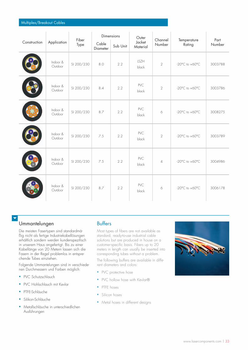
Multiplex/Breakout Cables
Construction Application Fiber Type
Dimensions Outer Jacket
Material
Channel Number
Temperature Rating
Part NumberCable
Diameter Sub Unit
Indoor & Outdoor SI 200/230 8.0 2.2
LSZH
black2 -20°C to +60°C 3003788
Indoor & Outdoor SI 200/230 8.4 2.2
PVC
black2 -20°C to +60°C 3003786
Indoor & Outdoor SI 200/230 8.7 2.2
PVC
black6 -20°C to +60°C 3008275
Indoor & Outdoor SI 200/230 7.5 2.2
PVC
black2 -20°C to +60°C 3003789
Indoor & Outdoor SI 200/230 7.5 2.2
PVC
black4 -20°C to +60°C 3004986
Indoor & Outdoor SI 200/230 8.7 2.2
PVC
black6 -20°C to +60°C 3006178
BuffersMost types of fibers are not available as standard, ready-to-use industrial cable solutions but are produced in house on a customer-specific basis. Fibers up to 20 meters in length can usually be inserted into corresponding tubes without a problem.
The following buffers are available in diffe-rent diameters and colors:
▪ PVC protective hose
▪ PVC hollow hose with Kevlar®
▪ PTFE hoses
▪ Silicon hoses
▪ Metal hoses in different designs
34 | www.lasercomponents.com
Steckertypen
Connector Types
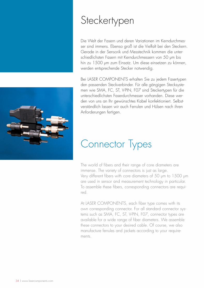
Die Welt der Fasern und deren Variationen im Kerndurchmes-ser sind immens. Ebenso groß ist die Vielfalt bei den Steckern. Gerade in der Sensorik und Messtechnik kommen die unter-schiedlichsten Fasern mit Kerndurchmessern von 50 µm bis hin zu 1500 µm zum Einsatz. Um diese einsetzen zu können, werden entsprechende Stecker notwendig.
Bei LASER COMPONENTS erhalten Sie zu jedem Fasertypen den passenden Steckverbinder. Für alle gängigen Stecksyste-men wie SMA, FC, ST, V-PIN, F07 sind Steckertypen für die unterschiedlichsten Faserdurchmesser vorhanden. Diese wer-den von uns an Ihr gewünschtes Kabel konfektioniert. Selbst-verständlich lassen wir auch Ferrulen und Hülsen nach ihren Anforderungen fertigen.
The world of fibers and their range of core diameters are immense. The variety of connectors is just as large.Very different fibers with core diameters of 50 µm to 1500 µm are used in sensor and measurement technology in particular. To assemble these fibers, corresponding connectors are requi-red.
At LASER COMPONENTS, each fiber type comes with its own corresponding connector. For all standard connector sys-tems such as SMA, FC, ST, V-PIN, F07, connector types are available for a wide range of fiber diameters. We assemble these connectors to your desired cable. Of course, we also manufacture ferrules and jackets according to your require-ments.
www.lasercomponents.com | 35
FC StecksystemEin häufig in den USA und im asiatischen Raum verwendetes Stecksystem ist der FC-Stecker.
Der FC-Stecker hat einen axial gefederten Stift, um die Anpresskraft der Stirnfläche zu begrenzen und einen physikalischen Kontakt zweier Stirnflächen zu ermöglichen. Der Ferrulendurchmesser beträgt 2,5 mm.
In der Regel wird der mit Verdreh-Schutz ausgestattete Stecker für Singlemode-Anwendungen eingesetzt; es sind aber auch Multimode-Versionen verfügbar. Arretiert wird der Stecker durch ein Gewinde.
ST StecksystemST-Stecksysteme werden häufig in der Telekommunikation eingesetzt. Die schnel-le Verriegelung der Stecker ist durch den Bajonett-Verschluss gewährleistet. Der Ferru-lenaußendurchmesser bei ST-Steckern beträgt 2,5 mm.
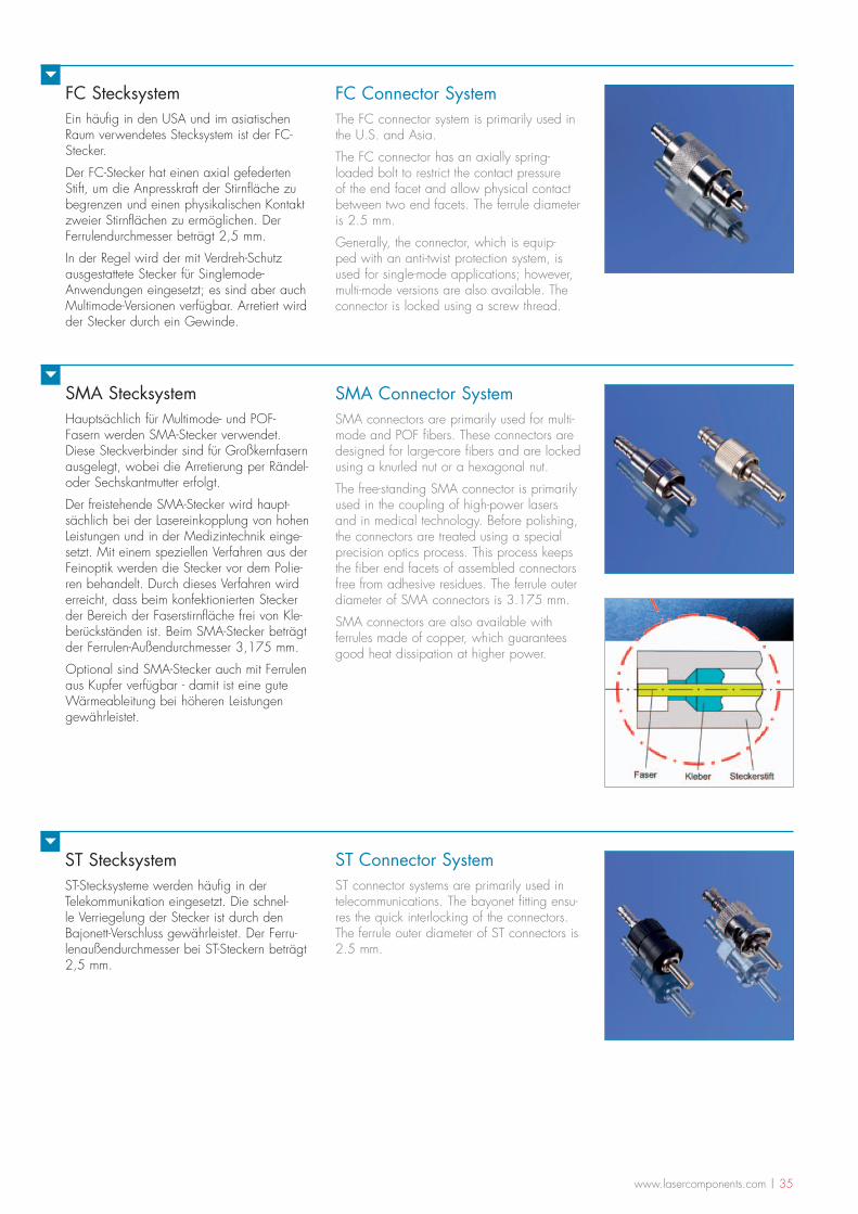
SMA StecksystemHauptsächlich für Multimode- und POF-Fasern werden SMA-Stecker verwendet. Diese Steckverbinder sind für Großkernfasern ausgelegt, wobei die Arretierung per Rändel- oder Sechskantmutter erfolgt.
Der freistehende SMA-Stecker wird haupt-sächlich bei der Lasereinkopplung von hohen Leistungen und in der Medizintechnik einge-setzt. Mit einem speziellen Verfahren aus der Feinoptik werden die Stecker vor dem Polie-ren behandelt. Durch dieses Verfahren wird erreicht, dass beim konfektionierten Stecker der Bereich der Faserstirnfläche frei von Kle-berückständen ist. Beim SMA-Stecker beträgt der Ferrulen-Außendurchmesser 3,175 mm.
Optional sind SMA-Stecker auch mit Ferrulen aus Kupfer verfügbar - damit ist eine gute Wärmeableitung bei höheren Leistungen gewährleistet.
FC Connector SystemThe FC connector system is primarily used in the U.S. and Asia.
The FC connector has an axially spring-loaded bolt to restrict the contact pressure of the end facet and allow physical contact between two end facets. The ferrule diameter is 2.5 mm.
Generally, the connector, which is equip-ped with an anti-twist protection system, is used for single-mode applications; however, multi-mode versions are also available. The connector is locked using a screw thread.
SMA Connector SystemSMA connectors are primarily used for multi-mode and POF fibers. These connectors are designed for large-core fibers and are locked using a knurled nut or a hexagonal nut.
The free-standing SMA connector is primarily used in the coupling of high-power lasers and in medical technology. Before polishing, the connectors are treated using a special precision optics process. This process keeps the fiber end facets of assembled connectors free from adhesive residues. The ferrule outer diameter of SMA connectors is 3.175 mm.
SMA connectors are also available with ferrules made of copper, which guarantees good heat dissipation at higher power.
ST Connector SystemST connector systems are primarily used in telecommunications. The bayonet fitting ensu-res the quick interlocking of the connectors. The ferrule outer diameter of ST connectors is 2.5 mm.
36 | www.lasercomponents.com
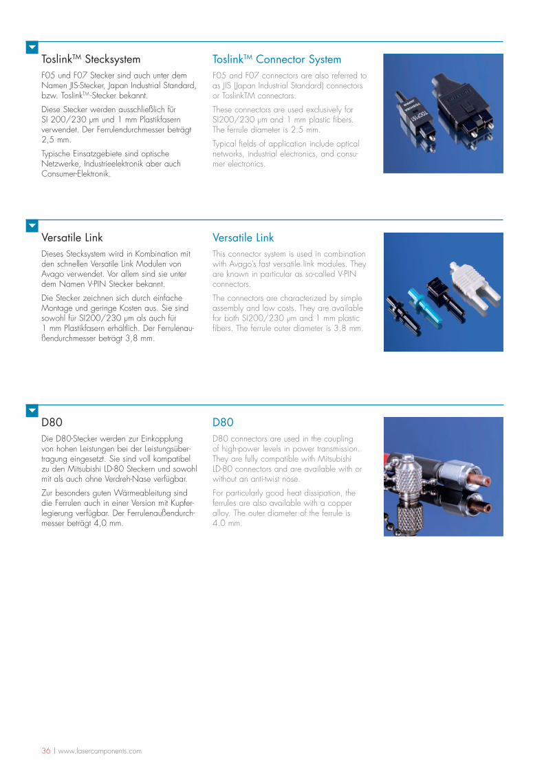
Versatile LinkDieses Stecksystem wird in Kombination mit den schnellen Versatile Link Modulen von Avago verwendet. Vor allem sind sie unter dem Namen V-PIN Stecker bekannt.
Die Stecker zeichnen sich durch einfache Montage und geringe Kosten aus. Sie sind sowohl für SI200/230 µm als auch für 1 mm Plastikfasern erhältlich. Der Ferrulenau-ßendurchmesser beträgt 3,8 mm.
D80Die D80-Stecker werden zur Einkopplung von hohen Leistungen bei der Leistungsüber-tragung eingesetzt. Sie sind voll kompatibel zu den Mitsubishi LD-80 Steckern und sowohl mit als auch ohne Verdreh-Nase verfügbar.
Zur besonders guten Wärmeableitung sind die Ferrulen auch in einer Version mit Kupfer-legierung verfügbar. Der Ferrulenaußendurch-messer beträgt 4,0 mm.
ToslinkTM StecksystemF05 und F07 Stecker sind auch unter dem Namen JIS-Stecker, Japan Industrial Standard, bzw. ToslinkTM -Stecker bekannt.
Diese Stecker werden ausschließlich für SI 200/230 µm und 1 mm Plastikfasern verwendet. Der Ferrulendurchmesser beträgt 2,5 mm.
Typische Einsatzgebiete sind optische Netzwerke, Industrieelektronik aber auch Consumer-Elektronik.
ToslinkTM Connector SystemF05 and F07 connectors are also referred to as JIS (Japan Industrial Standard) connectors or ToslinkTM connectors.
These connectors are used exclusively for SI200/230 µm and 1 mm plastic fibers. The ferrule diameter is 2.5 mm.
Typical fields of application include optical networks, industrial electronics, and consu-mer electronics.
Versatile LinkThis connector system is used in combination with Avago’s fast versatile link modules. They are known in particular as so-called V-PIN connectors.
The connectors are characterized by simple assembly and low costs. They are available for both SI200/230 µm and 1 mm plastic fibers. The ferrule outer diameter is 3.8 mm.
D80D80 connectors are used in the coupling of high-power levels in power transmission. They are fully compatible with Mitsubishi LD-80 connectors and are available with or without an anti-twist nose.
For particularly good heat dissipation, the ferrules are also available with a copper alloy. The outer diameter of the ferrule is 4.0 mm.
www.lasercomponents.com | 37
Optische Beschichtungen
Optical Coatings
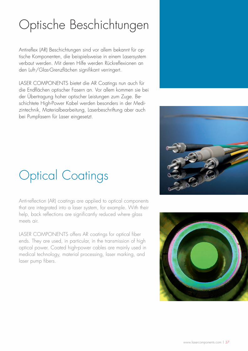
Antireflex (AR) Beschichtungen sind vor allem bekannt für op-tische Komponenten, die beispielsweise in einem Lasersystem verbaut werden. Mit deren Hilfe werden Rückreflexionen an den Luft-/Glas-Grenzflächen signifikant verringert.
LASER COMPONENTS bietet die AR Coatings nun auch für die Endflächen optischer Fasern an. Vor allem kommen sie bei der Übertragung hoher optischer Leistungen zum Zuge. Be-schichtete High-Power Kabel werden besonders in der Medi-zintechnik, Materialbearbeitung, Laserbeschriftung aber auch bei Pumpfasern für Laser eingesetzt.
Anti-reflection (AR) coatings are applied to optical components that are integrated into a laser system, for example. With their help, back reflections are significantly reduced where glass meets air.
LASER COMPONENTS offers AR coatings for optical fiber ends. They are used, in particular, in the transmission of high optical power. Coated high-power cables are mainly used in medical technology, material processing, laser marking, and laser pump fibers.
38 | www.lasercomponents.com
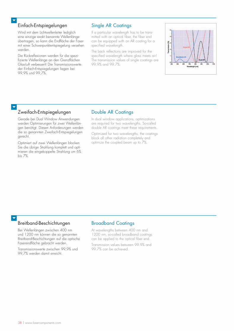
Einfach-EntspiegelungenWird mit dem Lichtwellenleiter lediglich eine einzige exakt benannte Wellenlänge übertragen, so kann die Endfläche der Faser mit einer Schwerpunktentspiegelung versehen werden.
Die Rückreflexionen werden für die spezi-fizierte Wellenlänge an den Grenzflächen Glas-Luft verbessert! Die Transmissionswerte der Einfach-Entspiegelungen liegen bei 99,9% und 99,7%.
Single AR CoatingsIf a particular wavelength has to be trans-mitted with an optical fiber, the fiber end can be equipped with an AR coating for a specified wavelength.
The back reflections are improved for the specified wavelength where glass meets air! The transmission values of single coatings are 99.9% and 99.7%.
Zweifach-Entspiegelungen Gerade bei Dual Window Anwendungen werden Optimierungen für zwei Wellenlän-gen benötigt. Diesen Anforderungen werden die so genannten Zweifach-Entspiegelungen gerecht.
Optimiert auf zwei Wellenlängen blocken Sie die übrige Strahlung komplett und opti-mieren die eingekoppelte Strahlung um 6% bis 7%.
Breitband-BeschichtungenBei Wellenlängen zwischen 400 nm und 1200 nm können die so genannten Breitband-Beschichtungen auf die optische Faserendfläche gebracht werden.
Transmissionswerte zwischen 99,9% und 99,7% werden damit erreicht.
Double AR Coatings In dual window applications, optimizations are required for two wavelengths. So-called double AR coatings meet these requirements.
Optimized for two wavelengths, the coatings block all other radiation completely and optimize the coupled beam up to 7%.
Broadband CoatingsAt wavelengths between 400 nm and 1200 nm, so-called broadband coatings can be applied to the optical fiber end.
Transmission values between 99.9% and 99.7% can be achieved.
www.lasercomponents.com | 39
Produkte & deren Anwendungen
Products and Their Applications
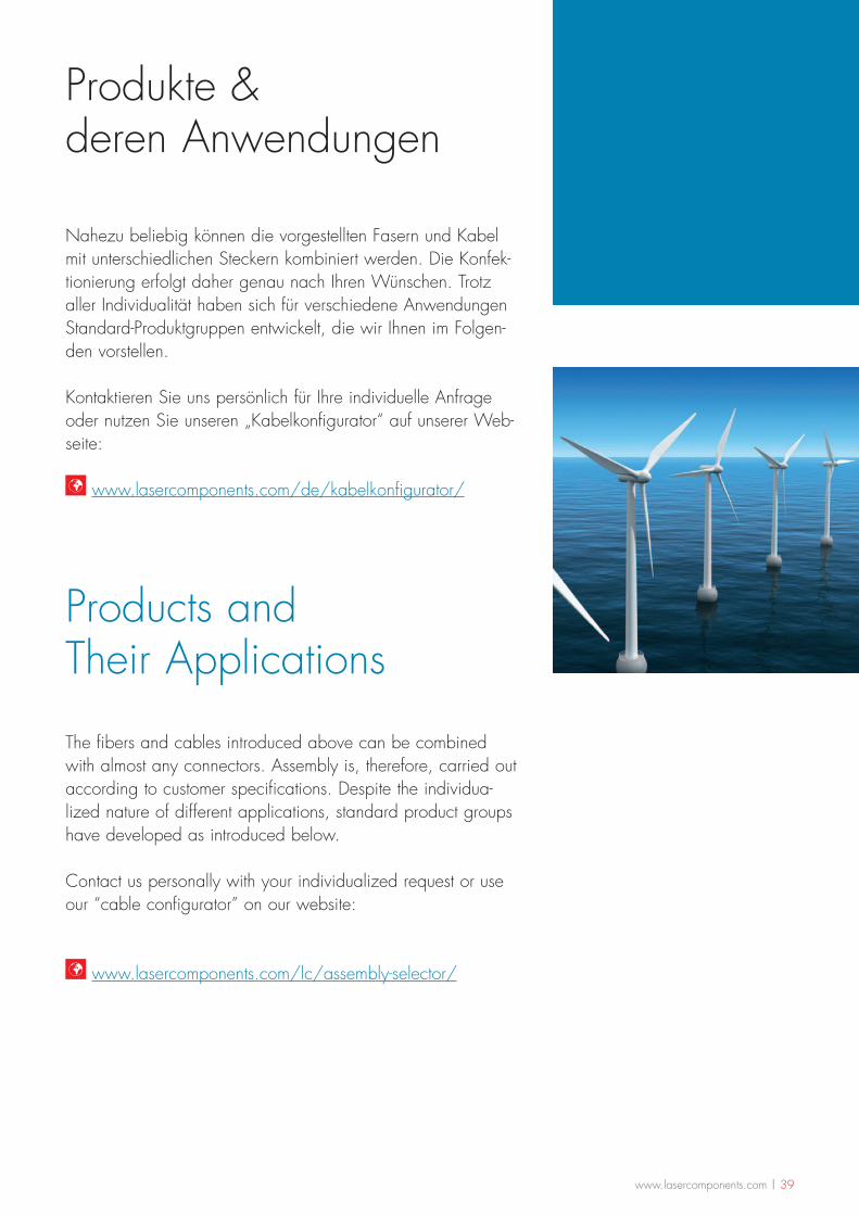
Nahezu beliebig können die vorgestellten Fasern und Kabel mit unterschiedlichen Steckern kombiniert werden. Die Konfek-tionierung erfolgt daher genau nach Ihren Wünschen. Trotz aller Individualität haben sich für verschiedene Anwendungen Standard-Produktgruppen entwickelt, die wir Ihnen im Folgen-den vorstellen.
Kontaktieren Sie uns persönlich für Ihre individuelle Anfrage oder nutzen Sie unseren „Kabelkonfigurator“ auf unserer Web-seite:
www.lasercomponents.com/de/kabelkonfigurator/
The fibers and cables introduced above can be combined with almost any connectors. Assembly is, therefore, carried out according to customer specifications. Despite the individua-lized nature of different applications, standard product groups have developed as introduced below.
Contact us personally with your individualized request or use our “cable configurator” on our website:
www.lasercomponents.com/lc/assembly-selector/
40 | www.lasercomponents.com
Optische Leistungsübertragung
Optical Power Transmission
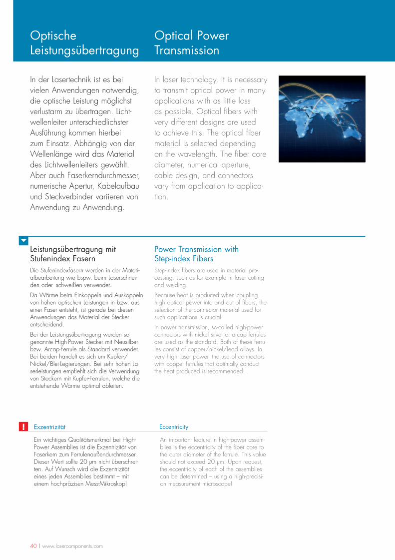
In der Lasertechnik ist es bei vielen Anwendungen notwendig, die optische Leistung möglichst verlustarm zu übertragen. Licht-wellenleiter unterschiedlichster Ausführung kommen hierbei zum Einsatz. Abhängig von der Wellenlänge wird das Material des Lichtwellenleiters gewählt. Aber auch Faserkerndurchmesser, numerische Apertur, Kabelaufbau und Steckverbinder variieren von Anwendung zu Anwendung.
In laser technology, it is necessary to transmit optical power in many applications with as little loss as possible. Optical fibers with very different designs are used to achieve this. The optical fiber material is selected depending on the wavelength. The fiber core diameter, numerical aperture, cable design, and connectors vary from application to applica-tion.
Leistungsübertragung mit Stufenindex FasernDie Stufenindexfasern werden in der Materi-albearbeitung wie bspw. beim Laserschnei-den oder -schweißen verwendet.
Da Wärme beim Einkoppeln und Auskoppeln von hohen optischen Leistungen in bzw. aus einer Faser entsteht, ist gerade bei diesen Anwendungen das Material der Stecker entscheidend.
Bei der Leistungsübertragung werden so genannte High-Power Stecker mit Neusilber- bzw. Arcap-Ferrule als Standard verwendet. Bei beiden handelt es sich um Kupfer-/Nickel/Blei-Legierungen. Bei sehr hohen La-serleistungen empfiehlt sich die Verwendung von Steckern mit Kupfer-Ferrulen, welche die entstehende Wärme optimal ableiten.
Ein wichtiges Qualitätsmerkmal bei High-Power Assemblies ist die Exzentrizität von Faserkern zum Ferrulenaußendurchmesser. Dieser Wert sollte 20 µm nicht überschrei-ten. Auf Wunsch wird die Exzentrizität eines jeden Assemblies bestimmt – mit einem hochpräzisen Mess-Mikroskop!
Exzentrizität
An important feature in high-power assem-blies is the eccentricity of the fiber core to the outer diameter of the ferrule. This value should not exceed 20 µm. Upon request, the eccentricity of each of the assemblies can be determined – using a high-precisi-on measurement microscope!
Eccentricity!
Power Transmission with Step-index FibersStep-index fibers are used in material pro-cessing, such as for example in laser cutting and welding.
Because heat is produced when coupling high optical power into and out of fibers, the selection of the connector material used for such applications is crucial.
In power transmission, so-called high-power connectors with nickel silver or arcap ferrules are used as the standard. Both of these ferru-les consist of copper/nickel/lead alloys. In very high laser power, the use of connectors with copper ferrules that optimally conduct the heat produced is recommended.
www.lasercomponents.com | 41
Leistungsübertragung mit HohlkernfasernHohlkernfasern werden zur Leistungsübertra-gung von CO2 und Er:YAG Lasern einge-setzt. Häufig werden sie aufgrund dieser Wellenlängen auch als IR-Fasern bezeichnet.
Die innen hohlen Fasern werden hauptsäch-lich mit den im Infokasten angegebenen Ste-ckern konfektioniert. Gerade in der Medizin-technik kommen Assemblies zum Einsatz, die nach jeder Anwendung vollständig sterilisiert werden müssen.
Fiber Step Index Fiber
Core Diameter 200 µm – 1500 µm
Connectors SMA, free-standing SMA with copper ferrule, D80 with copper ferrule
Standard lengths 1 m - 10 m Additional wavelengths upon request.
Buffer PVC tube, PTEE tube, metal tube, silicon tube
Eccentricity < 20 µm < 10 µm available upon request
Product Specifications
Fiber Hollow Silica Fiber
Core Diameter 300 µm – 1000 µm
Connectors SMA, ST, FC
Standard lengths 1 m - 6 m Other lengths available upon request
Buffer PVC tube , PTEE tube, metal tube, silicon tube
Product Specifications
▪ Beschichtung Single AR, Dual AR, Breitband AR
▪ Zentralwellenlänge 532 nm - 1550 nm Weitere Wellenlängen auf Anfrage.
▪ Reflexion R = 0,1..0,5 %
AR Beschichtung möglich
▪ Coating Single AR, dual AR, broadband AR
▪ CWL 532 nm - 1550 nm Additional wavelengths upon request.
▪ Reflection R = 0,1..0,5 %
AR Coatings Available!
Power Transmission with Hollow-core FibersHollow-core fibers are used in the power transmission of CO2 and Er:YAG lasers. Due to these wavelengths, they are also often referred to as IR fibers.
Hollow-core fibers are primarily assembled with the connectors listed in the information box. In medical technology in particular, as-semblies are used that have to be completely sterilized after each use.
42 | www.lasercomponents.com
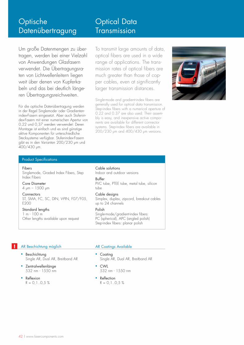
Um große Datenmengen zu über-tragen, werden bei einer Vielzahl von Anwendungen Glasfasern verwendet. Die Übertragungsra-ten von Lichtwellenleitern liegen weit über denen von Kupferka-beln und das bei deutlich länge-ren Übertragungsreichweiten.
Für die optische Datenübertragung werden in der Regel Singlemode- oder Gradienten-index-Fasern eingesetzt. Aber auch Stufenin-dex-Fasern mit einer numerischen Apertur von 0,22 und 0,37 werden verwendet: Deren Montage ist einfach und es sind günstige aktive Komponenten für unterschiedliche Stecksysteme verfügbar. Stufenindex-Fasern gibt es in den Varianten 200/230 µm und 400/430 µm.
Optische Datenübertragung
Optical Data Transmission
To transmit large amounts of data, optical fibers are used in a wide range of applications. The trans-mission rates of optical fibers are much greater than those of cop-per cables, even at significantly larger transmission distances.
Single-mode and gradient-index fibers are generally used for optical data transmission. Step-index fibers with a numerical aperture of 0.22 and 0.37 are also used: Their assem-bly is easy, and inexpensive active compo-nents are available for different connector systems. Step-index fibers are available in 200/230 µm and 400/430 µm versions.
Fibers Singlemode, Graded Index Fibers, Step Index Fibers
Core Diameter 4 µm – 1500 µm
Connectors ST, SMA, FC, SC, DIN, V-PIN, F07/F05, E200
Standard lengths 1 m - 100 m Other lengths available upon request
Cable solutions Indoor and outdoor versions
Buffer PVC tube, PTEE tube, metal tube, silicon tube
Cable designs Simplex, duplex, zipcord, breakout cables up to 24 channels
Polish Single-mode/gradient-index fibers: PC (spherical), APC (angled polish) Step-index fibers: planar polish
Product Specifications
▪ Beschichtung Single AR, Dual AR, Breitband AR
▪ Zentralwellenlänge 532 nm - 1550 nm
▪ Reflexion R = 0,1..0,5 %
AR Beschichtung möglich
▪ Coating Single AR, Dual AR, Breitband AR
▪ CWL 532 nm - 1550 nm
▪ Reflection R = 0,1..0,5 %
AR Coatings Available!
www.lasercomponents.com | 43
Medizintechnik Medical Technology
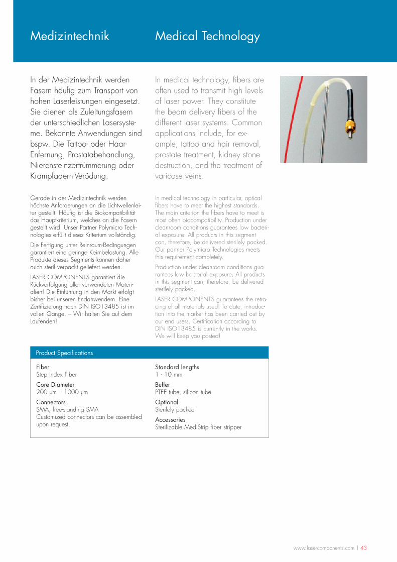
In der Medizintechnik werden Fasern häufig zum Transport von hohen Laserleistungen eingesetzt. Sie dienen als Zuleitungsfasern der unterschiedlichen Lasersyste-me. Bekannte Anwendungen sind bspw. Die Tattoo- oder Haar-Enfernung, Prostatabehandlung, Nierensteinzertrümmerung oder Krampfadern-Verödung.
Gerade in der Medizintechnik werden höchste Anforderungen an die Lichtwellenlei-ter gestellt. Häufig ist die Biokompatibilität das Hauptkriterium, welches an die Fasern gestellt wird. Unser Partner Polymicro Tech-nologies erfüllt dieses Kriterium vollständig.
Die Fertigung unter Reinraum-Bedingungen garantiert eine geringe Keimbelastung. Alle Produkte dieses Segments können daher auch steril verpackt geliefert werden.
LASER COMPONENTS garantiert die Rückverfolgung aller verwendeten Materi-alien! Die Einführung in den Markt erfolgt bisher bei unseren Endanwendern. Eine Zertifizierung nach DIN ISO13485 ist im vollen Gange. – Wir halten Sie auf dem Laufenden!
Fiber Step Index Fiber
Core Diameter 200 µm – 1000 µm
Connectors SMA, free-standing SMA Customized connectors can be assembled upon request.
Standard lengths 1 - 10 mm
Buffer PTEE tube, silicon tube
Optional Sterilely packed
Accessories Sterilizable MediStrip fiber stripper
Product Specifications
In medical technology in particular, optical fibers have to meet the highest standards. The main criterion the fibers have to meet is most often biocompatibility. Production under cleanroom conditions guarantees low bacteri-al exposure. All products in this segment can, therefore, be delivered sterilely packed.Our partner Polymicro Technologies meets this requirement completely.
Production under cleanroom conditions gua-rantees low bacterial exposure. All products in this segment can, therefore, be delivered sterilely packed.
LASER COMPONENTS guarantees the retra-cing of all materials used! To date, introduc-tion into the market has been carried out by our end users. Certification according to DIN ISO13485 is currently in the works. We will keep you posted!
In medical technology, fibers are often used to transmit high levels of laser power. They constitute the beam delivery fibers of the different laser systems. Common applications include, for ex-ample, tattoo and hair removal, prostate treatment, kidney stone destruction, and the treatment of varicose veins.
44 | www.lasercomponents.com
Beleuchtung & Sensorik mit POF
Illumination and Sensor Technology with POFs
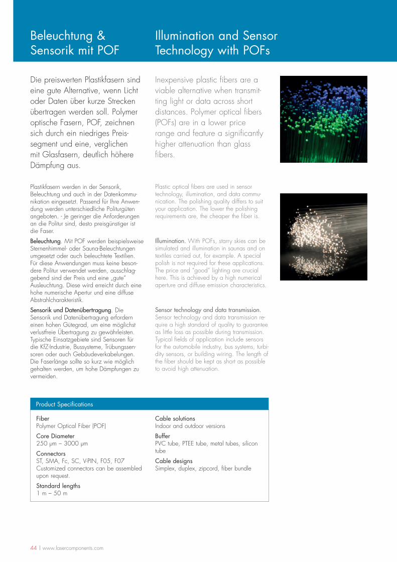
Die preiswerten Plastikfasern sind eine gute Alternative, wenn Licht oder Daten über kurze Strecken übertragen werden soll. Polymer optische Fasern, POF, zeichnen sich durch ein niedriges Preis-segment und eine, verglichen mit Glasfasern, deutlich höhere Dämpfung aus.
Fiber Polymer Optical Fiber (POF)
Core Diameter 250 µm – 3000 µm
Connectors ST, SMA, Fc, SC, V-PIN, F05, F07 Customized connectors can be assembled upon request.
Standard lengths 1 m – 50 m
Cable solutions Indoor and outdoor versions
Buffer PVC tube, PTEE tube, metal tubes, silicon tube
Cable designs Simplex, duplex, zipcord, fiber bundle
Product Specifications
Plastikfasern werden in der Sensorik, Beleuchtung und auch in der Datenkommu-nikation eingesetzt. Passend für Ihre Anwen-dung werden unterschiedliche Politurgüten angeboten. - Je geringer die Anforderungen an die Politur sind, desto preisgünstiger ist die Faser.
Beleuchtung. Mit POF werden beispielsweise Sternenhimmel- oder Sauna-Beleuchtungen umgesetzt oder auch beleuchtete Textilien. Für diese Anwendungen muss keine beson-dere Politur verwendet werden, ausschlag-gebend sind der Preis und eine „gute“ Ausleuchtung. Diese wird erreicht durch eine hohe numerische Apertur und eine diffuse Abstrahlcharakteristik.
Sensorik und Datenübertragung. Die Sensorik und Datenübertragung erfordern einen hohen Gütegrad, um eine möglichst verlustfreie Übertragung zu gewährleisten. Typische Einsatzgebiete sind Sensoren für die KfZ-Industrie, Bussysteme, Trübungssen-soren oder auch Gebäudeverkabelungen. Die Faserlänge sollte so kurz wie möglich gehalten werden, um hohe Dämpfungen zu vermeiden.
Plastic optical fibers are used in sensor technology, illumination, and data commu-nication. The polishing quality differs to suit your application. The lower the polishing requirements are, the cheaper the fiber is.
Illumination. With POFs, starry skies can be simulated and illumination in saunas and on textiles carried out, for example. A special polish is not required for these applications. The price and “good” lighting are crucial here. This is achieved by a high numerical aperture and diffuse emission characteristics.
Sensor technology and data transmission. Sensor technology and data transmission re-quire a high standard of quality to guarantee as little loss as possible during transmission. Typical fields of application include sensors for the automobile industry, bus systems, turbi-dity sensors, or building wiring. The length of the fiber should be kept as short as possible to avoid high attenuation.
Inexpensive plastic fibers are a viable alternative when transmit-ting light or data across short distances. Polymer optical fibers (POFs) are in a lower price range and feature a significantly higher attenuation than glass fibers.
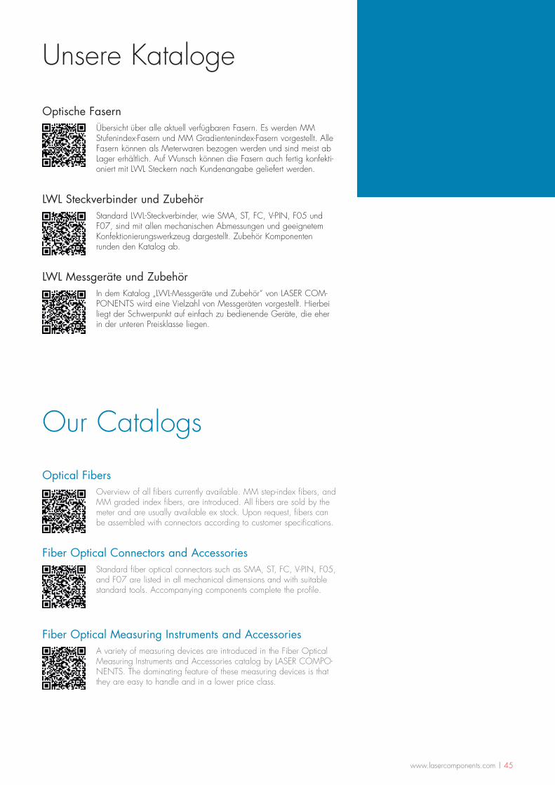
www.lasercomponents.com | 45
Unsere Kataloge
Our Catalogs
Optische FasernÜbersicht über alle aktuell verfügbaren Fasern. Es werden MM Stufenindex-Fasern und MM Gradientenindex-Fasern vorgestellt. Alle Fasern können als Meterwaren bezogen werden und sind meist ab Lager erhältlich. Auf Wunsch können die Fasern auch fertig konfekti-oniert mit LWL Steckern nach Kundenangabe geliefert werden.
LWL Steckverbinder und ZubehörStandard LWL-Steckverbinder, wie SMA, ST, FC, V-PIN, F05 und F07, sind mit allen mechanischen Abmessungen und geeignetem Konfektionierungswerkzeug dargestellt. Zubehör Komponenten runden den Katalog ab.
LWL Messgeräte und ZubehörIn dem Katalog „LWL-Messgeräte und Zubehör“ von LASER COM-PONENTS wird eine Vielzahl von Messgeräten vorgestellt. Hierbei liegt der Schwerpunkt auf einfach zu bedienende Geräte, die eher in der unteren Preisklasse liegen.
Optical FibersOverview of all fibers currently available. MM step-index fibers, and MM graded index fibers, are introduced. All fibers are sold by the meter and are usually available ex stock. Upon request, fibers can be assembled with connectors according to customer specifications.
Fiber Optical Connectors and AccessoriesStandard fiber optical connectors such as SMA, ST, FC, V-PIN, F05, and F07 are listed in all mechanical dimensions and with suitable standard tools. Accompanying components complete the profile.
Fiber Optical Measuring Instruments and AccessoriesA variety of measuring devices are introduced in the Fiber Optical Measuring Instruments and Accessories catalog by LASER COMPO-NENTS. The dominating feature of these measuring devices is that they are easy to handle and in a lower price class.
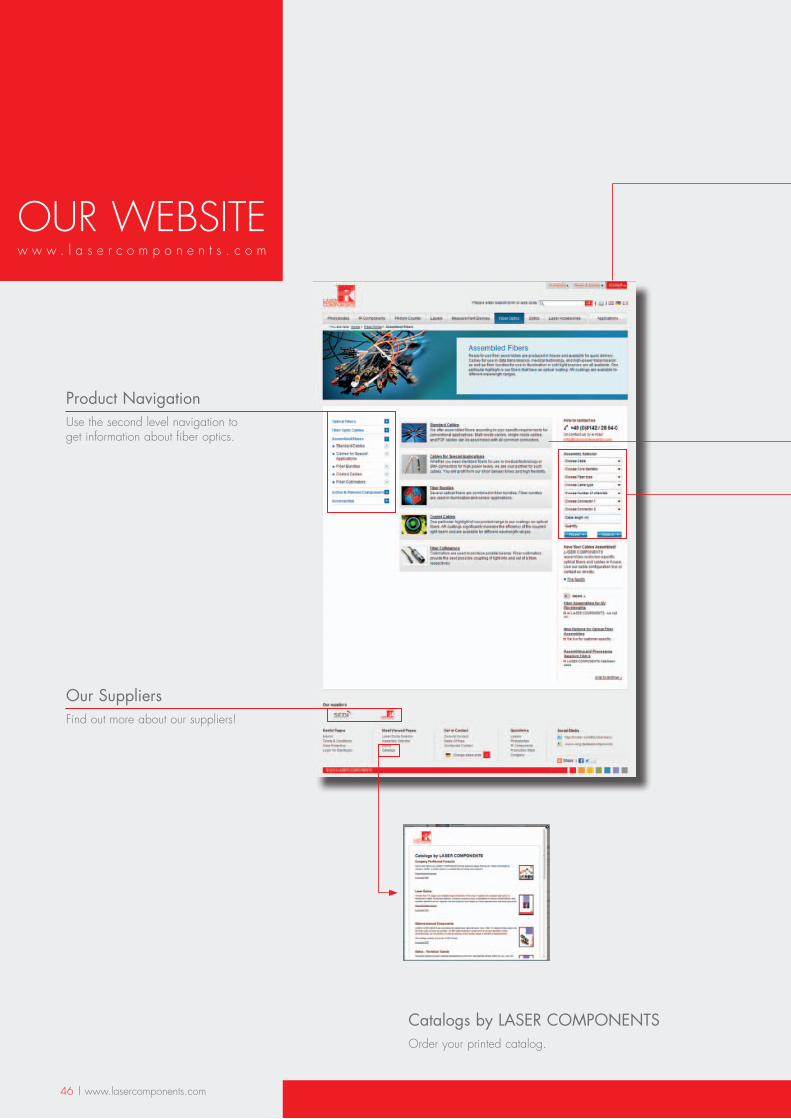
46 | www.lasercomponents.com
Product NavigationUse the second level navigation to get information about fiber optics.
Our SuppliersFind out more about our suppliers!
Catalogs by LASER COMPONENTSOrder your printed catalog.
OUR WEBSITEw w w . l a s e r c o m p o n e n t s . c o m
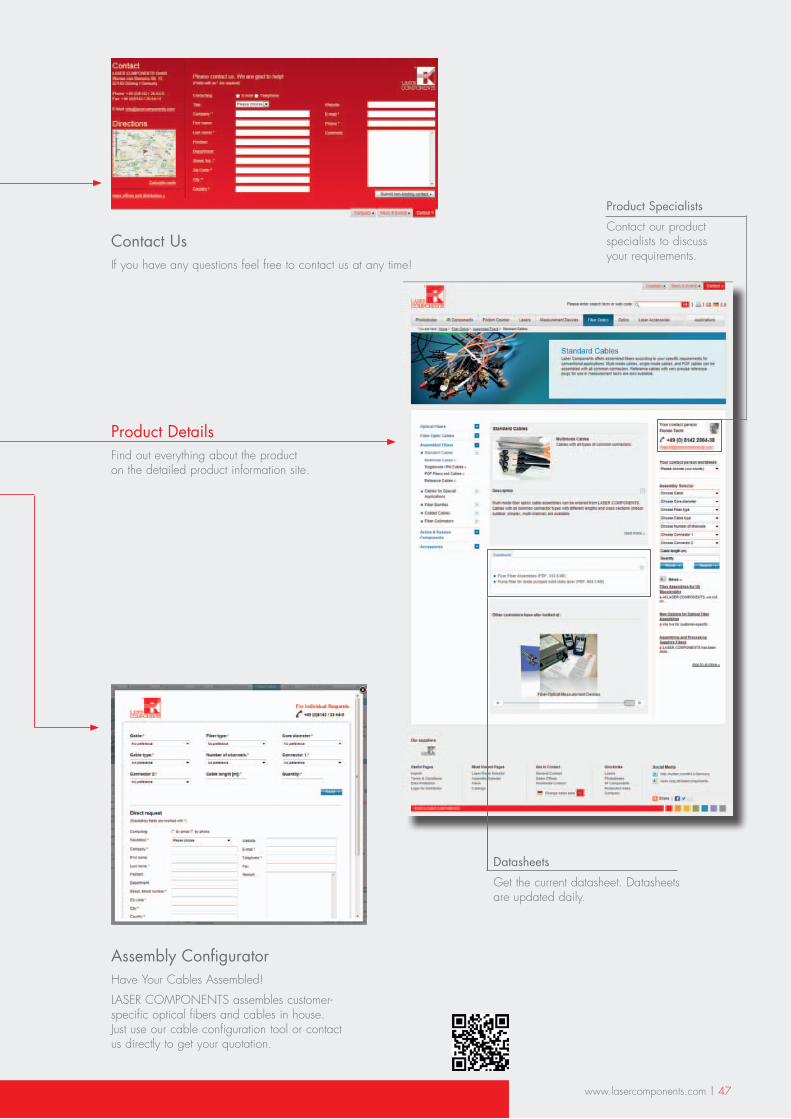
www.lasercomponents.com | 47
Assembly ConfiguratorHave Your Cables Assembled!
LASER COMPONENTS assembles customer-specific optical fibers and cables in house. Just use our cable configuration tool or contact us directly to get your quotation.
Contact UsIf you have any questions feel free to contact us at any time!
Product DetailsFind out everything about the product on the detailed product information site.
Datasheets
Get the current datasheet. Datasheets are updated daily.
Product Specialists
Contact our product specialists to discuss your requirements.
48
Impressum Imprint
- Herausgeber
LASER COMPONENTS GmbH Werner-von-Siemens-Str. 15 82140 Olching/Germany
Tel: +49 8142 2864-0 Fax: +49 8142 2864-11
www.lasercomponents.com [email protected]
Geschäftsführer: Patrick Paul, Günther Paul Handelsregister München HRB 77055
è Druck flyeralarm GmbH, Würzburg
i Copyright und Ausschluss
Diese Broschüre sowie alle enthaltenen Beiträge und Abbildungen sind urheberrechtlich geschützt. Mit Ausnahme der gesetzlich erlaubten Fälle ist für eine Verwertung die Einwilligung der Laser Components GmbH erforderlich.
Trotz gründlicher Recherche kann keine Verantwortung für die Richtigkeit der Inhalte übernommen werden. Technische Änderungen ohne Ankündigung vorbehalten.
© 2013. Alle Rechte vorbehalten.
Version: 04/13-V6
- Editor
LASER COMPONENTS GmbH Werner-von-Siemens-Str. 15 82140 Olching/Germany
Tel: +49 8142 2864-0 Fax: +49 8142 2864-11
www.lasercomponents.com [email protected]
General Managers: Patrick Paul, Günther Paul Commercial Register in Munich HRB 77055
è Printer flyeralarm GmbH, Würzburg
i Copyright
This catalog, including all written and visual entries, is protected by copyright. With the exception of specific cases permitted by law, use of this material without the consent of Laser Components GmbH is punishable by law.
Despite thorough research, Laser Components GmbH will not accept responsibility for any inaccuracy of content. Technical material is subject to change without notice.
© 2013. All rights reserved.
® Hinweise zur Marken-Inhaberschaft
Tefzel® und Hytrel® sind eingetragene Markenzeichen der DuPont Corporation.
® Notes on the trademark ownership
Tefzel® und Hytrel® are registered trademarks of DuPont Corporation.

ww
w.la
serc
ompo
nent
s.co
m
Germany & Worldwide Contact Laser Components GmbHWerner-von-Siemens-Str. 15 82140 Olching / Germany
Tel.: +49 8142 2864-0 Fax: +49 8142 2864-11 [email protected]
USA Laser Components USA, Inc.9 River Road Hudson NH 03051/ USA
Tel: +1 603 821 7040 Fax: +1 603 821 7041 [email protected]
France Laser Components S.A.S.45 bis Route des Gardes 92190 Meudon / France
Tel.: +33 1 39 5l9 52 25 Fax: +33 1 39 59 53 50 [email protected]
Great Britain Laser Components UK Ltd.Goldlay House 114 Parkway Chelmsford Essex CM2 7PR / UK
Tel.: +44 1245 491 499 Fax: +44 1245 491 801 [email protected]
Kontakt ▪ Contact