Austausch der Replacement of the Remplacement de la ... · SW-500-3 Austausch der Wellenabdichtung...
16
SW-500-3 Austausch der Wellenabdichtung Verdichtertypen • OS.53 • OS.70 • OS.74 • OS.85 Inhalt 1 Allgemeines 1 2 Wellenabdichtung prüfen 2 3 Ausbau 3 4 Einbau 7 5 Austausch 13 1 Allgemeines Wegen den spezifischen Anforderun- gen bei Alternativ-Kältemitteln sind die offenen Schraubenverdichter mit einer weiterentwickelten Wellenab- dichtung ausgestattet. Es handelt sich dabei um eine besonders hochwertige Konstruktion mit Metallfaltenbalg so- wie einem Gleitringpaar aus Silizium- carbid und Spezial-Kohle (siehe Ab- bildung 1). Diese Wartungsanleitung beschreibt den Ersatz früherer Wellenabdichtun- gen (ohne Faltenbalg) durch die neue Konstruktion sowie deren Austausch im Schadensfall. Autorisiertes Fachpersonal Sämtliche Arbeiten an Verdichtern und Kälteanlagen dürfen nur von Fachpersonal ausgeführt werden, das in allen Arbeiten ausgebildet und un- terwiesen wurde. Für die Qualifikation und Sachkunde des Fachpersonals gelten die jeweils gültigen Richtlinien. Replacement of the Shaft Seal Compressor types • OS.53 • OS.70 • OS.74 • OS.85 Content 1 General 1 2 Inspection of the shaft seal 2 3 Removal 3 4 Mounting 7 5 Replacement 13 1 General Due to the specific demands of the alternative refrigerants the open drive screw compressors are fitted with a shaft seal which is further developed. This is of an especially high quality construction with metal bellows and sliding ring pair of a silicon carbide and special carbon (see figure 1). This maintenance instruction de- scribes the replacement of previous shaft seals (without bellows) by the new construction and also its replace- ment in case of damage. Authorized staff All work on compressor and refrigera- tion systems shall be carried out only by refrigeration personnel which has been trained and instructed in all work. The qualification and expert knowledge of the refrigeration person- nel corresponds to the respectively valid guidelines. Remplacement de la garniture d'étanchéité Types de compresseurs • OS.53 • OS.70 • OS.74 • OS.85 Sommaire 1 Généralités 1 2 Contrôler la garnit. d'étanchéité 2 3 Démontage 3 4 Montage 7 5 Remplacement 13 1 Généralités En raison des exigences spécifiques liées aux fluides frigorigènes de substitution, les compresseurs à vis ouverts sont équi- pés d'une garniture d'étanchéité perfec- tionnée. Il s'agit d'une conception de très haute qualité avec soufflet métallique et un couple de bagues de glissement en carbure de silicium et carbone spécial (voir figure 1). Cette instruction de maintenance décrit le remplacement des garnitures d'étanché- ité employées précédemment (sans souf- flet) par le nouveau modèle, ainsi que le remplacement de celui-ci en cas de dété- rioration. Personnel spécialisé autorisé Seul un personnel spécialisé ayant été formé et initié est autorisé à réaliser l'ensemble des travaux sur les compres- seurs et installations frigorifiques. Les directives en vigueur à cet effet sont valables pour la qualification et la compé- tence du personnel spécialisé. * Sonderausführung für NH 3 * Special version for NH 3 * Version spéciale pour NH 3
Transcript of Austausch der Replacement of the Remplacement de la ... · SW-500-3 Austausch der Wellenabdichtung...

SW-500-3
Austausch derWellenabdichtung
Verdichtertypen
• OS.53• OS.70• OS.74• OS.85
Inhalt
1 Allgemeines 12 Wellenabdichtung prüfen 23 Ausbau 34 Einbau 75 Austausch 13
1 Allgemeines
Wegen den spezifischen Anforderun -gen bei Alternativ-Kältemitteln sinddie offenen Schraubenverdichter miteiner weiterentwickelten Wellenab -dich tung ausgestattet. Es handelt sichdabei um eine besonders hochwertigeKon struktion mit Metall falten balg so -wie einem Gleitring paar aus Silizium -carbid und Spezial-Kohle (siehe Ab -bildung 1).
Diese Wartungsanleitung beschreibtden Ersatz früherer Wellen abdich tun -gen (ohne Faltenbalg) durch die neueKonstruktion sowie deren Austauschim Schadensfall.
Autorisiertes Fachpersonal
Sämtliche Arbeiten an Ver dich ternund Kälte anlagen dürfen nur vonFach personal ausgeführt werden, dasin allen Arbeiten ausgebildet und un -ter wiesen wurde. Für die Qualifikationund Sachkunde des Fachpersonalsgelten die jeweils gültigen Richtlinien.
Replacement of theShaft Seal
Compressor types
• OS.53• OS.70• OS.74• OS.85
Content
1 General 12 Inspection of the shaft seal 23 Removal 34 Mounting 75 Replacement 13
1 General
Due to the spe cif ic demands of thealter na tive refrig er ants the open drivescrew compressors are fitted with ashaft seal which is fur ther de vel oped.This is of an espe cial ly high qual itycon struc tion with metal bel lows andsliding ring pair of a silicon carbideand special carbon (see figure 1).
This main te nance instruc tion de -scribes the replace ment of previousshaft seals (with out bel lows) by thenew con struc tion and also its replace-ment in case of dam age.
Authorized staff
All work on compressor and refrigera-tion systems shall be carried out onlyby refrigeration personnel which hasbeen trained and instructed in allwork. The qualification and expertknowledge of the refrigeration person-nel corresponds to the respectivelyvalid guidelines.
Remplacement de lagar ni ture d'étanchéité
Types de com pres seurs
• OS.53• OS.70• OS.74• OS.85
Sommaire
1 Généralités 12 Contrôler la garnit. d'étanchéité 23 Démontage 34 Montage 75 Remplacement 13
1 Généralités
En rai son des exi gen ces spé ci fi ques liéesaux flui des fri go ri gè nes de sub sti tu tion,les com pres seurs à vis ouverts sont équi -pés d'une gar ni ture d'étanchéité per fec -tion née. Il s'agit d'une concep tion de trèshaute qua li té avec souf flet métal li que etun cou ple de bagues de glis sement encarbure de silicium et car bo ne spécial(voir figure 1).
Cette instruc tion de main te nan ce décrit lerem pla ce ment des gar ni tures d'étan ché -ité employées pré cé dem ment (sans souf -flet) par le nou veau modè le, ainsi que lerem pla ce ment de celui-ci en cas de dété -rio ra tion.
Personnel spécialisé autorisé
Seul un personnel spécialisé ayant étéformé et initié est autorisé à réaliser l'ensemble des travaux sur les compres-seurs et installations frigorifiques. Lesdirectives en vigueur à cet effet sontvalables pour la qualification et la compé-tence du personnel spécialisé.
* Sonderausführung für NH3 * Special version for NH3 * Version spéciale pour NH3

2
2 Inspection of the shaft seal
A rou tine inspec tion of the shaft sealis not general ly nec es sary. With regard to increased oper a tion al reli -abil ity it is how ev er rec om mend ed tocheck in con nec tion with an oil change, faults in the oil sup ply andalso at reg u lar inter vals when oper at -ing with high dis charge gas tem per a -tures and oil tem per a tures. Pay spe-cial atten tion to cracks in the O-ring,as well as wear, scor ing and mate ri aldepos its, oil car bon and cop per plat -ing on the seal ing ring. An oil leakrate of 0.05 cm3/h is with in the tol er -ance. Any oil which does leak out canbe led away by means of the pipeconnection on the sealing cover of theshaft seal.
Possible fail ure caus es
• Causes for lack of lubri ca tionsymptoms: hard en ing and crack ingof O-rings, oil car bon, scoring onthe sliding face- filter of oil orifice blocked- time delay before oil solenoid
valve opens is too long (toleranceup to 2 s)
- operation with too small pressuredifference
- high refrigerant concentration inoil (oil temperature too low)
• Cause for overheatingsame symptoms as for lack of lubri-cation- oil injection temperature too high
• Cause for scores and wear on slid-ing rings- high pro por tion of dirt in oil
• Cause for copper plating- high oil acidity
• Causes for strong vibrations- irregular drive- weak unit base frame- coupling not sufficiently fixed- coupling displaced
2 Contrôler la garniture d'étanchéité
En règle géné ra le, un contrô le de rou ti nede la gar ni ture d'étanchéité n'est pasnéces sai re. En vue d'une sécu ri té defonc tion ne ment accrue, il est cepen dantrecom man dé de contrôler lors de la vida -ge d'huile ou en cas de pro blè mes surl'alimentation d'huile ainsi qu'à inter val lesrégu liers en cas de fonc tion ne ment avecdes tem pé ra tures de gas au refou le mentet d'huile éle vées. Por ter l'atten tion surles fis su res particulièrement dans lesjoints annulaires ainsi que sur l'usure, lapré sen ce de stries et de dépôts de matiè -re, de cala mi ne et de cuivre sur lesbagues de glis se ment. Une perte d'huilejusqu'à envi ron 0,05 cm3/h est admis si -ble. Cette huile peut être drainée à l'aided'un raccord de tuyau se situant au cou-vercle de fermeture de la garniture d'é-tanchéité.
Causes de défaillance possibles
• Causes du manque de lubri fi ca tion:dur cis se ment et fis su res dans lesjoints annulaires, cala mi ne, apparitionssur la surface de glissement- filtre bouché à l'orifice d'huile- temporisation trop longue à l'ouverture
de vanne magnétique d'huile (toléran-ce au maximum 2 s)
- fonctionnement à une pression diffé-rentielle trop faible
- quantité de fluide frigorigène dansl'huile trop importante (températured'huile trop basse)
• Cause de surchauffemêmes symptômes qu'un manque delubrification- température d'injection de l'huile trop
élevée
• Cause des striures et usure desbagues de glissement- impuretées en grande quantité dans
l'huile
• Cause de cuivrage- acidité de l'huile trop élevée
• Causes des fortes vibrations- entraînement irrégulier- socle du groupe peu stable- accouplement mal fixé- déport de l'accouplement
2 Wellenabdichtung überprüfen
Eine routinemäßige Überprüfung derWellenabdichtung ist in der Regelnicht erforderlich. Im Hinblick auf er -höhte Betriebssicherheit empfiehltsich jedoch eine Überprüfung im Zu -sam menhang mit Ölwechsel, Störun -gen in der Ölversorgung sowie – inre gel mäßigen Abständen – bei Be -trieb mit hohen Druckgas- und Öltem-peraturen. Dabei besonders auf Rissean den O-Ringen achten sowie anden Gleit ringen auf Ver schleiß, Rie -fen, Materi al-Ab lagerungen, Ölkohleund Kupfer plat tierung. Leckölmengenbis zu ca. 0,05 cm3/h liegen im Tole -ranz bereich. Dieses Öl kann übereinen Rohran schluss am Abschluss -deckel der Wellen abdich tung abge-führt werden.
Mögliche Schadensursachen
• Ursachen für SchmierungsmangelSymptome: Verhärtungen undRisse an O-Ringen, Ölkohle,Ausbrüche auf der Gleitfläche- verstopftes Sieb an der Öldüse- zu lange Verzögerungszeit bis
zum Öffnen des Ölmagnetventils(Toleranz bis max. 2 s)
- Betrieb bei zu geringer Druck -differenz
- hoher Kältemittel-Anteil im Öl(zu niedrige Öltemperatur)
• Ursache für Überhitzunggleiche Symptome wie bei Schmie -rungsmangel- zu hohe Öleinspritztemperatur
• Ursache für Riefen und Verschleißan Gleitringen- hoher Schmutzanteil im Öl
• Ursache für Cu-Plattierung- hoher Säuregrad im Öl
• Ursachen für starke Schwingungen- ungleichförmiger Antrieb- labiler Aggregat-Grundrahmen- ungenügende Befestigung der
Kupplung- Kupplungsversatz
SW-500-3

3
3 Ausbau
3.1 Vorbereitung
Die Wellenabdichtungen sind jenach Kältemittel und Öl unter-schiedlich aus geführt. Benötigte Wellenabdich tunganhand der Ersatzteillisten SE-100, SE-250 und SE-500auswählen.
Werkzeuge und Hilfsmittel
• Schraubenschlüssel- Sechskant- Innensechskant
• Plastikhammer
• Haken und Abzieh-Vorrichtungzum Abziehen der rotierendenEinheit
• Innensechskant-Schlüssel mit ge -kürztem Winkelstück (Beipack zurErsatz-Wellenabdichtung)
• Schaber und Schmirgelleinenzum Entfernen von Dichtungsres -ten
• Polierleinenzum Glätten der Wellen oberfläche
Demontage der Anbauteile
Warnung!Verdichter steht unter Druck!Schwere Verletzungen möglich.Verdichter auf drucklosen Zu -stand bringen!Schutzbrille tragen!
Anschlie ßend Motor, Kup plungs -gehäu se, Kupplung und Passfederdemontieren.
!
3 Removal
3.1 Preparation
The shaft seals are differentlydesigned according to refriger-ant and oil. Select the required shaft sealwith the spare part lists SE-100,SE-250 and SE-500.
Tools and other mate ri als
• Spanners- hexagon spanner- hexagon socket screw spanner
• Plastic ham mer
• Hooks and pull ing deviceto remove the rotat ing unit
• Hexagon socket screw spannerwith short ened leg (packed withreplace ment shaft seal)
• Scraper and smoothing clothto remove gasket remains
• Polishing clothto smooth the surface of the shaft
Dismantling of mounting parts
Warning!Compressor is under pressure!Serious injuries are possible.Release the pressure in thecompressor!Wear safety goggles!
Remove motor, coupling hous ing,coupling and key.
!
3 Démontage
3.1 Préparation
Les garnitures d'étanchéite sontréalisées selon l'huile et le fluide fri-gorigène. La garniture d'étanchéitenécessaire est à choisir à partir deslistes des pièces détachées SE-100,SE-250 et SE-500.
Outillage et équi pe ments auxi liai res
• Clés- clé à fourche- clé à six pans creux
• Maillet en plas ti que
• Crochets et arra che-pou liepour reti rer la par tie tour nan te
• Clé à six pans creux avec coude rac -cour ci (livrée avec la gar ni ture d'étan-chéité de remplacement)
• Racloir et toile émeripour éli mi ner des res tes de joint
• Toile à polirpour lis ser la sur fa ce de l'arbre
Démantage des pièces montées
Avertissement !Compresseur est sous pression !Des graves blessures sont possible.Retirer la pression sur le compres-seur!Porter des lunettes de protection !
Démon ter ensuite le moteur, la cage d'ac-couplement et la clavet te.
!
SW-500-3
SW-500-34
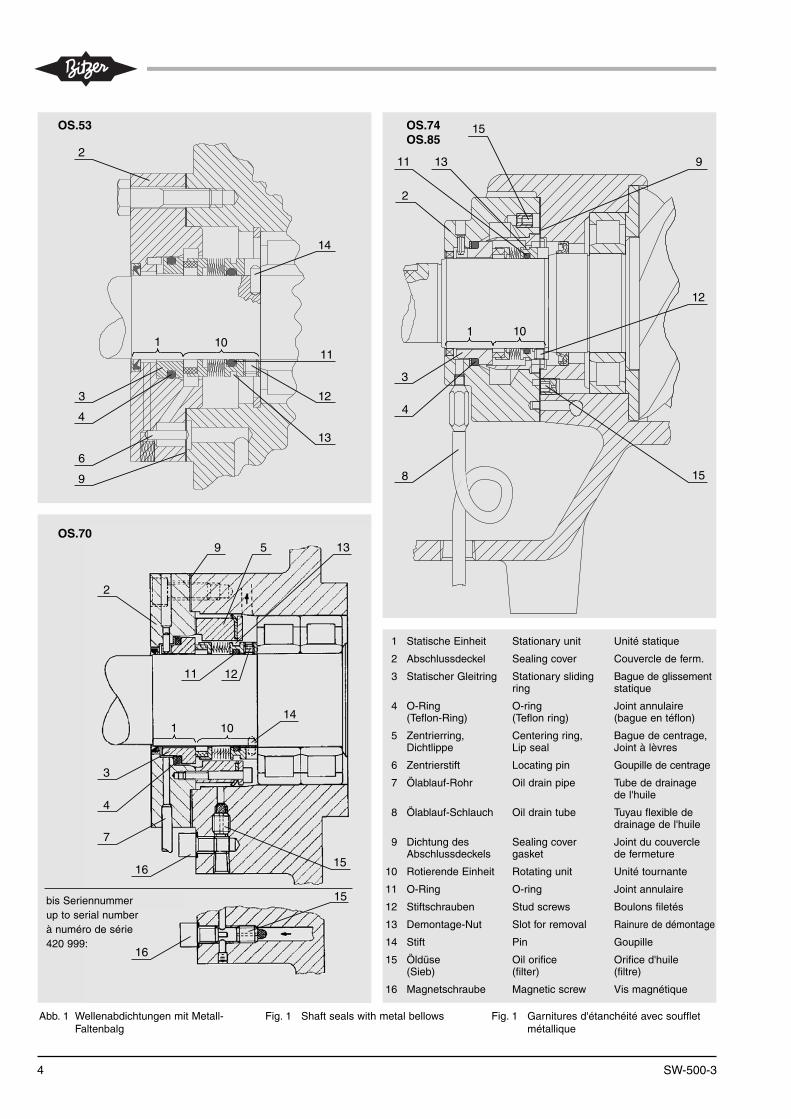
Abb. 1 Wellenabdichtungen mit Metall-Faltenbalg
Fig. 1 Shaft seals with metal bellows Fig. 1 Garnitures d'étanchéité avec souf fletmétal li que
2
3
1 10
4
6
12
11
13
14
9
1 10
2
8
12
1311
15
4
3
15
9
OS.53 OS.74OS.85
OS.70
1 10
3
2
5 13
11 12
14
4
7
16
15
15
bis / to / à No. 420 999:
16
9
1 Statische Einheit Stationary unit Unité statique
2 Abschlussdeckel Sealing cover Couvercle de ferm.
3 Statischer Gleitring Stationary sliding Bague de glissementring statique
4 O-Ring O-ring Joint annulaire(Teflon-Ring) (Teflon ring) (bague en téflon)
5 Zentrierring, Centering ring, Bague de centrage,Dichtlippe Lip seal Joint à lèvres
6 Zentrierstift Locating pin Goupille de centrage
7 Ölablauf-Rohr Oil drain pipe Tube de drainagede l'huile
8 Ölablauf-Schlauch Oil drain tube Tuyau flexible dedrainage de l'huile
9 Dichtung des Sealing cover Joint du couvercle Abschlussdeckels gasket de fermeture
10 Rotierende Einheit Rotating unit Unité tournante
11 O-Ring O-ring Joint annulaire
12 Stiftschrauben Stud screws Boulons filetés
13 Demontage-Nut Slot for removal Rainure de démontage
14 Stift Pin Goupille
15 Öldüse Oil orifice Orifice d'huile(Sieb) (filter) (filtre)
16 Magnetschraube Magnetic screw Vis magnétique
bis Seriennummerup to serial numberà numéro de série420 999:
5
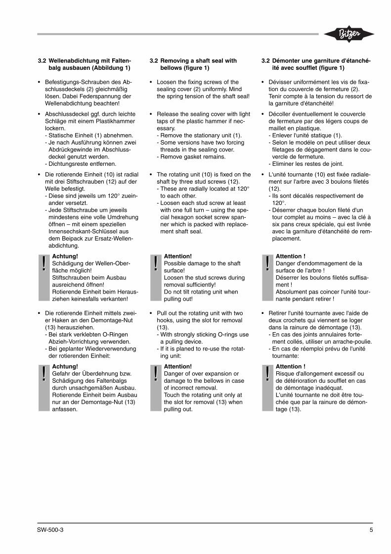
3.2 Wellenabdichtung mit Falten -balg ausbauen (Abbildung 1)
• Befestigungs-Schrauben des Ab -schluss deckels (2) gleich mäßiglösen. Dabei Federspannung derWellenabdichtung beachten!
• Ab schluss deckel ggf. durch leichteSchläge mit einem Plastik hammerlockern.- Statische Einheit (1) abnehmen.- Je nach Ausführung können zwei
Abdrückgewinde im Ab schluss -deckel genutzt werden.
- Dichtungsreste entfernen.
• Die rotierende Einheit (10) ist radialmit drei Stiftschrauben (12) auf derWelle befestigt.- Diese sind je weils um 120° zuein-
ander versetzt.- Jede Stiftschraube um jeweils
mindestens eine volle Um drehungöffnen – mit einem speziellenInnensechs kant-Schlüssel ausdem Bei pack zur Ersatz-Wel len -abdich tung.
Achtung!Schädigung der Wellen-Ober -fläche möglich!Stiftschrauben beim Ausbauausreichend öffnen!Rotierende Einheit beim Heraus -zie hen keinesfalls verkanten!
• Die rotierende Einheit mittels zwei-er Haken an den Demontage-Nu t(13) herausziehen.- Bei stark ver kleb ten O-Ringen
Abzieh-Vor rich tung verwenden.- Bei geplanter Wiederverwendung
der rotierenden Einheit:
Achtung!Gefahr der Über dehnung bzw.Schädigung des Falten balgsdurch unsachgemäßen Ausbau.Rotierende Einheit beim Aus baunur an der Demon tage-Nut (13)anfassen.
!!
!!
3.2 Removing a shaft seal withbellows (figure 1)
• Loosen the fix ing screws of thesealing cover (2) uniformly. Mindthe spring ten sion of the shaft seal!
• Release the sealing cover with lighttaps of the plastic hammer if nec-essary.- Remove the stationary unit (1).- Some versions have two forcing
threads in the sealing cover.- Remove gasket remains.
• The rotat ing unit (10) is fixed on theshaft by three stud screws (12).- These are radi al ly locat ed at 120°
to each other.- Loos en each stud screw at least
with one full turn – using the spe -cial hexagon socket screw span-ner which is packed with replace -ment shaft seal.
Attention!Possible dam age to the shaftsur face!Loosen the stud screws dur ingremov al sufficiently!Do not tilt rotating unit whenpulling out!
• Pull out the rotat ing unit with twohooks, using the slot for remov al(13).- With strong ly stick ing O-rings use
a pull ing device.- If it is planed to re-use the rotat -
ing unit:
Attention!Dan ger of over expan sion ordam age to the bel lows in caseof incor rect remov al.Touch the rotating unit only atthe slot for remov al (13) whenpulling out.
!!
!!
3.2 Démonter une gar ni ture d'étanché -ité avec souf flet (figure 1)
• Dévisser uni for mé ment les vis de fixa -tion du cou ver cle de fermeture (2).Tenir compte à la ten sion du res sort dela garniture d 'étanchéité!
• Décoller éven tuel le ment le cou ver clede fermeture par des légers coups demaillet en plastique.- Enlever l'unité sta ti que (1).- Selon le modéle on peut utiliser deux
filetages de dégagement dans le cou-vercle de fermeture.
- Eliminer les restes de joint.
• L'unité tour nan te (10) est fixée radia le -ment sur l'arbre avec 3 boulons filetés(12).- Ils sont déca lés res pec ti ve ment de
120°.- Déserrer chaque boulon fileté d'un
tour com plet au moins – avec la clé àsix pans creux spé cia le, qui est livréeavec la gar ni ture d'étanchéité de rem-placement.
Attention !Danger d'endommagement de la surface de l'arbre !Déserrer les boulons filetés suf fi sa -ment !Absolument pas coincer l'unité tour -nan te pendant retirer !
• Retirer l'unité tour nan te avec l'aide dedeux cro chets qui vien nent se logerdans la rai nu re de démon tage (13).- En cas des joints annulaires for te -
ment col lés, utiliser un arra che-pou lie.- En cas de réemploi prévu de l'unité
tour nan te:
Attention !Ris que d'allon ge ment exces sif oude dété rio ra tion du souf flet en casde démon tage inadé quat.L'unité tour nan te ne doit être tou-chée que par la rai nu re de démon -tage (13).
!!
!!
SW-500-3

6
3.3 Removing a shaft seal with outbel lows (figure 2)
The shaft seals of the first OS.53 andOS.70 are designed without bellows. Ifsuch a shaft seal is removed anyhow,it should be replaced by a bellowsseal.
• Loosen the fix ing screws of thesealing cover (2) uniformly. Mindthe spring ten sion of the shaft seal!
• Release the sealing cover with lighttaps of the plastic hammer if nec-essary.- Remove the stationary unit (1).- Remove gasket remains.
• Pull out the rotat ing unit with twohooks, using the slot for remov al(13).
Attention!Possible dam age to the shaftsur face!Do not tilt rotating unit whenpulling out!
!!
3.3 Démonter une gar ni ture d'étanché -ité sans souf flet (figure 2)
Les gar ni tures d'étanchéité des premiersOS.53 et OS.70 sont exécutés sans souf -flet. En cas de démontage de cette gar ni -ture d'étanchéité, elle doit être replacéepar une gar ni ture d'étanchéité avec souf-flet.
• Dévisser uni for mé ment les vis de fixa -tion du cou ver cle de fermeture (2).Tenir compte à la ten sion du res sort dela garniture d'étanchéité!
• Décoller éven tuel le ment le cou ver clede fermeture par des légers coups demaillet en plastique.- Enlever l 'unité sta ti que (1).- Eliminer les restes de joint.
• Retirer l'unité tour nan te avec l'aide dedeux cro chets qui vien nent se logerdans la rai nu re de démon tage (13).
Attention !Danger d'endommagement de la surface de l'arbre !Absolument pas coincer l'unité tour -nan te pendant retirer !
!!
3.3 Wellenabdichtung ohne Falten -balg ausbauen (Abbildung 2)
Die Wellen abdichtungen der erstenOS.53 und OS.70 sind ohne Falten -balg ausgeführt. Wenn eine solcheWellen abdich tung ohnehin ausgebautwird, sollte sie durch eine Falten balg-Abdich tung ersetzt werden.
• Befestigungs-Schrauben des Ab -schluss deckels (2) gleich mäßiglösen. Dabei Federspannung derWellenabdichtung beachten!
• Ab schluss deckel ggf. durch leichteSchläge mit einem Plastik hammerlockern.- Statische Einheit (1) abneh men.- Dichtungsreste entfernen.
• Rotierende Einheit vorsichtig vonder Welle abziehen. Dabei mit zweiHaken in die Demontage-Nut (13)greifen.
Achtung!Schädigung der Wellen-Ober -fläche möglich!Rotierende Einheit beim Heraus -zie hen keinesfalls verkanten!
!!
SW-500-3
Abb. 2 Wellenabdichtungen ohneFaltenbalg (frühere Ausführung)
Fig. 2 Shaft seals without bellows(previous construction)
Fig. 2 Garnitures d'étanchéité sans soufflet(construction précédente)
1 10
3
2
11 14 4
13
15
9
1 Statische Einheit Stationary unit Unité statique
2 Abschlussdeckel Sealing cover Couvercle de ferm.
3 Statischer Gleitring Stationary sliding Bague de glissementring statique
4 O-Ring O-ring Joint annulaire
9 Dichtung des Sealing cover Joint de couvercleAbschlussdeckels gasket de fermeture
10 Rotierende Einheit Rotating unit Unité tournante
11 O-Ring O-ring Joint annulaire
13 Demontage-Nut Slot for removal Rainure de démontage
14 Stift Pin Goupile
15 Öldüse, Sieb Oil orifice, filter Orifice d'huile, filtre

7
4 Wellenabdichtung mit Metall -falten balg einbauen (Abb. 1)
4.1 Vorbereitung
Werkzeuge und Hilfsmitteln bereitlegen wie in Kapitel 3.1 beschrie ben.
Welle, Flansch und Wellenabdich -tungs-Raum sehr gründ lich reinigen.Dabei Ablage run gen, insbesondereDichtungsreste auf der Welle vorsich-tig entfernen. Bei Bedarf sollte dieOber fläche mit einem ölgetränkten,feinen Polier leinen (kein Schmirgel -leinen) geglättet werden.
Bei Verdacht auf starken Trieb -werk sver schleiß (verunreinigtesÖl, starker Abrieb) sollte derVerdichter vorsorglich ge tauschtoder überholt werden.
Austauschteile bereit halten
• Die Ersatz-Wellenabdichtung solltebis unmittelbar vor dem Einbau inder Schutzfolie verpackt bleiben –zum Schutz der Gleitflächen.Auch bei der Montage ist sorgfältig-ste Handhabung erforderlich, damitdie Gleitringe nicht beschädigt wer-den können.
• Statische und rotierende Einheitgemeinsam tauschen (kompletteWellenab dich tung).
• Keinesfalls gebrauchte O-Ringewiederverwenden!
• Für den Betrieb mit Ammoniak(NH3):Spezielle Wellenabdichtung fürNH3 verwenden!
Wellenab dich tung komplett austau-schen bei
• Beschädigung der Gleit ringe
• starken Verschleiß-Spuren auf denGleitflächen
• Kupfer-Plattierung
• Ablagerungen von Ölkohle
Bei Wel lenabdichtung ohne Falten -balg
Neue Wel lenabdichtung mit Falten -balg einbauen. Ab schluss deckeleben falls austauschen. Die Tausch -barkeit ist gewährleistet.
4 Mounting the shaft seal withmetal bel lows (figure 1)
4.1 Preparation
Keep ready tools as described inchapter 3.1.
Clean very thorough ly shaft, flangeand shaft seal cham ber. Removecare ful ly any de pos its e. g. gas ket re -mains on the shaft. If nec es sarysmoothe the sur face with fine pol ish -ing cloth soaked in oil (not withsmooth ing cloth).
When strong wear to the driveparts is sus pect ed (con tam i nat -ed oil, strong depos its) a pre cau -tion ary com pres sor replace mentor over haul is urgent ly rec om -mend ed.
Keep ready replacement parts
• The replace ment shaft seal shouldremain in the pro tec tive pack inguntil imme di ate ly before mountingto avoid dam age to the slidingfaces.Careful han dling is also nec es sarydur ing fix ing to pre vent dam age tothe sliding rings.
• Replace stationary and rotating unittogether (complete shaft seal).
• Do not re-use old O-rings in anycase!
• For operation with ammonia (NH3):Use the special shaft seal for NH3!
Replacing shaft seal completely if
• damage of sliding rings
• strong wear tracks on sliding faces
• cop per plat ing
• depos its of oil car bon
For shaft seal without bellows
Mount new shaft seal with bellows.Replace also seal ing cover. Theexchan gea bil ity is guar an teed.
4 Monter la garniture d'étanchéitéavec soufflet métallique (figure 1)
4.1 Préparation et recom man da tions
Préparer l'outillage comme décrit danschapitre 3.1.
Net toyer soi gneu se ment l'arbre, le flas -que et le com par ti ment de la gar ni tured'étanchéité. Reti rer pru dem ment desdépôts sur l'arbre par ex. res tes du joint.Si néces sai re, lis ser la sur fa ce de l'arbreavec une fine toile à polir impré gnéed'huile (pas de toile émeri).
En cas de forte usure du méca nis -me d'entraînement (huile conta mi -née, abra sion impor tan te) un rem -pla ce ment pré ven tif du com pres seurou une révi sion sont for te mentrecom man dés.
Préparer les pièces de remplacement
• La gar ni ture d'étanchéité de remplace-ment devrait res ter dans son embal la -ge d'origine jusqu'à sa mise en placeimmi nen te, ceci afin de pro té ger lessur fa ces de glis se ment.De même, pour le mon tage, un manie -ment soi gné est néces sai re afin queles bagues de glissement ne soientpas endom ma gées.
• Remplacer les unités tournante et sta-tique en commun (gar ni ture d'étan-chéité com plète).
• Ne pas réuti li ser des joints annulairesusa gés en aucun cas!
• Pour fonctionnement avec ammo-niaque (NH3):Utiliser la garniture d'étanchéité spé-ciale pour NH3!
Remplacer la gar ni ture d'étanchéitécom plètement en cas de
• dégât sur des bagues de glissement
• tra ces d'usure très mar quées sur dessurfaces de glissement
• cuivrage
• dépôts de cala mi ne
En cas d'une gar ni ture d'étanchéitésans soufflet
Monter une nouvelle gar ni ture d'étanché -ité. Remplacer aussi le couvercle de fer-meture. L'interchangeabilité étant garan -tie.
SW-500-3

8
4.2 Clean ing and examining the oilchannel (figure 1)
OS.53
• Screw out the orifice (15) (hexagonsocket, size 4 mm).
• Check the orifice and the oil chan-nel for dirt and if necessary cleanby blowing through with nitrogen.
• Screw the orifice as far as possible.
OS.70
• Remove the magnetic screw (16)and – from serial no. 421 000 on –also the oil pipe.
• Screw out the orifice with filter (15)(hexagon socket, size 4 mm).
• Check the orifice and the oil chan-nel for dirt and if necessary cleanby blowing through with nitrogen.
• Screw in the orifice as far as possible.
OS.74 and OS.85
• Check the oil channel for dirt and ifnecessary clean by blowing throughwith nitrogen.
• Screw out both orifices (15) (hexa-gon socket, size 4 mm).
• Check the orifices and the oil chan-nel for dirt and if necessary cleanby blowing through with nitrogen.
• Screw in the orifices as far as pos-sible.
4.2 Net toyer et contrôler le canald'huile (figure 1)
OS.53
• Dévisser l'orifice (15) (six pans creux,clé 4).
• Contrôler soi gneu se ment l'orifice et lecanal d'huile au regard d'encras se mentou des dépôts et, si néces sai re, lesnet toyer par injec tion d'un jet d'azote.
• Revis ser l'orifice à fond.
OS.70
• Démonter la vis magné ti que (16) et, àpar tir du numé ro de série 421 000,aussi la condui te d'huile.
• Dévisser l'orifice avec le fil tre (15) (sixpans creux, clé 4).
• Contrôler soi gneu se ment l'orifice et lecanal d'huile au regard d'en cras se mentou des dépôts et, si néces sai re, lesnet toyer par injec tion d'un jet d'azote.
• Revisser l'orifice à fond.
OS.74 et OS.85
• Contrôler soi gneu se ment la pro pre tédu canal d'huile et, si néces sai re, net -toyer par in jec tion d'un jet d'azote.
• Dévisser les deux orifices (15) (sixpans creux, clé 4).
• Contrôler soi gneu se ment les orifices etle canal d'huile au regard d'encras se -ment ou des dépôts et, si néces sai re,les net toyer par injec tion d'un jet d'azote.
• Revis ser les orifices à fond.
4.2 Ölkanal reinigen und prüfen(Abbildung 1)
OS.53
• Düse (15) herausschrauben (Innen -sechskant SW 4).
• Düse und Ölkanal sorgfältig aufVer schmutz un gen prüfen und ggf.mit Stickstoff ausblasen.
• Düse wieder bis zum An schlag ein-schrauben.
OS.70
• Magnetschraube (16) und ab Seri -en nummer 421 000 auch Ölleitungentfernen.
• Düse mit Sieb (15) heraus schrau -ben (Innensechskant SW 4).
• Düse und Ölkanal sorgfältig auf Ver -schmutzungen prüfen und ggf. mitStickstoff ausblasen.
• Düse wieder bis auf An schlag ein-schrauben.
OS.74 und OS.85
• Ölkanal sorgfältig auf Ver schmutz -un gen prüfen mit Stickstoff ausbla-sen.
• Beide Düsen (15) herausschrauben(Innensechs kant SW 4).
• Düsen und Ölkanal sorgfältig aufVer schmutz un gen prüfen und ggf.mit Stickstoff ausblasen.
• Düsen wieder bis auf Anschlag ein-schrauben.
SW-500-3

9
Radialen Ölkanal verschließen –nur bei OS.53 undbei Ersatz einer Wellenabdichtungohne Faltenbalg
Das Schmieröl gelangt bei den beidenWel len abdichtungs-Versionen aufunterschiedlichen Wegen zu denLager flächen:
• in der neuen Fal ten balg-Aus -führung über einen Ringkanal inder statischen Einheit
• in der früheren Version ohneFalten balg über einen radialenÖIkanal im Lagerdeckel
Dieser Ölkanal muss beim Ersatz ver-schlossen werden. Dazu:
• Kerbstift (Ø4 x 10 mm) von derFlansch-Seite her in den Ölkanalim Lagerdeckel einstecken.
• Kerbstift mittels Hammer und Dornbündig oder leicht vertieft in denKanal eintreiben (siehe Abbil -dung 3).
• Ab schluss deckel eben falls austau-schen.
Closing the radi al oil channel –only with OS.53 andin case of replacing a shaft sealwithout bellows
The lubri cant reaches the bearing sur-faces differently for both shaft sealversions:
• in the new bellows design bymeans of a ring groove in the sta -tion ary unit
• in the previous version without bel-lows by a radial oil channel in thebearing cover
This oil channel must be closed incase of replacement. Therefore:
• Insert grooved pin (Ø4 x 10 mm)from the flange side into the oilchannel in the bearing cover.
• Drive in the grooved pin by meansof a ham mer and a punch until it islevel or a lit tle below the sur face(see figure 3).
• Replace also seal ing cover.
Obturer le canal d'huile radial –seu le ment pour OS.53 eten cas de remplacement d'unegarniture d'étanchéité sans soufflet
Chez les deux versions des gar ni turesd'étanchéité le lubri fiant arrive en trajetsdifférentes aux portées:
• dans la gar ni ture d'étanchéité nouvellepar un canal cir cu lai re dans l'unité sta-tique
• dans la gar ni ture d'étanchéité précé-dente sans souf flet par un canal d'huileradial dans le couvercle de palier
Ce canal d'huile doit être obtu rer en casde remplacement. Pour cela:
• Introduire la gou pille cannalée (Ø4 x10 mm) du côté de bride dans le canald'huile du couvercle de palier.
• Enforcer la gou pille cannalée par forceà l'aide d'un maillet et d'un chas se-gou pille, de maniè re à affleu rer ou àêtre légè re ment enfon cée (voir figu-re 3).
• Remplacer aussi le couvercle de fer-meture.
SW-500-3
Abb. 3 Kerbstift (Verschluss-Stift) fürradialen Ölkanal (OS.53)
Fig. 3 Grooved pin (sealing pin) for radi-al oil channel (OS.53)
Fig. 3 Goupille cannelée (d'obturation) pourle canal radial d'huile (OS.53)
KerbstiftGrooved pin ∅ 4 x 10 mmGoupille cannelée

10
4.3 Mounting (according to fig. 1)
• Oil the sliding ring, O-rings andshaft with clean refrigeration com-pressor oil. However, do not oil theflat gas ket or flange surface!
Rotating unit
• Slide the rotat ing unit (10) onto theshaft with a light turn ing motionuntil it sits against the shoul der onthe shaft or the internal ring of thebearing.- With OS.53 and OS.70:
A drive pin (14) is pressed intothe shaft shoul der. It must lockinto the slot in the seal end.
• Press the rotating unit against theshaft shoul der in order to avoidangu lar dis place ment.In doing so tighten the stud screws(12) uniformly – with the internalhexagon key packed with replace -ment shaft seal.
Attention!Destruction the shaft seal possi-ble!Avoid tilting of the sliding ringand mount it with utmost care!Tighten the stud screwssecurely.
Mounting the stationary unit(with sealing cover completely pre-assembled)
OS.53
• Slide the complete stationary unitover the shaft, whilst lightly turning,as far as it will go.
• Position the unit exactly so that thelocating pin (6) in the oil channel ofthe sealing cover fits into the oilchannel of the flange.
• Fix the sealing cover screwingsquarely. Tighten the screws uni-formly.Tightening torque 40 Nm
!!
4.3 Montage (suivant figure 1)
• Enduire la bague de glissement, lesjoints annulaires et l'arbre avec de l'huile pro pre pour machines frigori-fiques. Mais ne pas endui re d'huile lejoint plat et la surface de la bride.
Unité tour nan te
• Glisser l'unité tour nan te (10) sur l'arbredans un léger mou ve ment rota tif et lapous ser jusqu'à l'arrêt contre le colletde l'arbre ou encore la bague intérieu-re du palier à rouleaux.- Pour les modèles OS.53 et OS.70:
Une gou pille d'entraîne ment (14) estpres sée dans le col let du vile bre quin.Cette gou pille doit enclencher dansl'encoche en extré mi té.
• Pour évi ter un déca la ge angu lai re,pres ser l'unité tournante contre le col -let du vile bre quin.En même temps serrer uni for mé mentles boulons filetés (12) – avec la clésix pans creux livrée avec la gar ni tured'étanchéité de remplacement.
Attention !Des truc tion de la gar ni ture d'étan-chéité possible !Ne coince pas la bague de glisse-ment et monter-la avec pré cau tion !Serrer les boulons filetés bien.
Monter l'unité statique(avec couvercle de fermeture complè-tement prémontée)
OS.53
• Glisser l'unité statique entier sur l'arbredans un léger mou ve ment rota tif et lapous ser jusqu'à ce qu'elle arri ve enbutée.
• Posi tionner l'unité exactement demaniè re telle que la gou pille de cen tra -ge (6) dans le canal d'huile du cou ver -cle de fermeture avan ce dans le canald'huile de la flas que de corps.
• Visser le couvercle de fermeture.Serrer les vis uniformement en croix.Couple de serrage 40 Nm
!!
4.3 Einbau (entsprechend Abb. 1)
• Gleitring, O-Ringe und Welle mitsau berem Kälte ma schi nen-Öl ein -ölen. Flachdichtung und Flansch -fläche jedoch nicht einölen!
Rotierende Einheit
• Rotierende Einheit (10) unter leich -tem Drehen auf die Welle schiebenund bis auf An schlag gegen denWel len bund bzw. den Innenring desRollen lagers drü cken.- Bei OS.53 und OS.70:
Im Bund der Kurbel welle ist einMitnehmer stift (14) einge presst.Er muss in die Nut des Endstücksein ras ten.
• Rotierende Einheit gegen denBund der Kurbel welle drücken umeinen Winkelversatz zu vermeiden.Dabei Stiftschrauben (12) gleich-mäßig festziehen – mit dem Innen -sechs kant-Schlüssel aus dem Bei -pack zur Ersatz-Wellenabdichtung.
Achtung!Zerstörung der Wellenabdich -tung möglich!Gleitring nicht verkanten und mitgrößter Sorgfalt einbauen!Stiftschrauben gut festziehen.
Statische Einheit einbauen(mit Abschlussdeckel komplett vor-montiert)
OS.53
• Die gesamte statische Einheit unterleichtem Drehen über die Welle bisauf An schlag einschieben.
• Die Einheit exakt so posi tionieren,dass der Zentrierstift (6) im Öl kanaldes Abschlussdeckels in den Ölka-nal des Gehäuseflansches einragt.
• Abschlussdeckel festschrauben.Dabei Schrauben über Kreuzgleichmäßig anziehen.Anzugs moment 40 Nm
!!
SW-500-3
11
OS.70
• Mitgelieferte Ge win debolzen alsMontagehilfe in zwei gegenüberlie-gende Gewinde im Verdichter -flansch eindrehen.
• Die gesamte statische Einheit aufdie Welle schieben.- Dabei können zwei Deckel schrau -
ben zum Ein ziehen benutzt wer-den.
- Verkanten unbedingt vermeiden!Dazu die beiden Schrauben ge -gen überliegend anordnen undgleichmäßig anziehen.
• Statische Einheit exakt so posi tio -nieren, dass das Ölab lauf-Rohr (7)nach unten führt!
• Montagehilfen (Ge win debolzen)entfernen und Abschlussdeckelfestschrauben. Dabei Schraubenüber Kreuz gleichmäßig anziehen.Anzugs moment 80 Nm
OS.74 und OS.85
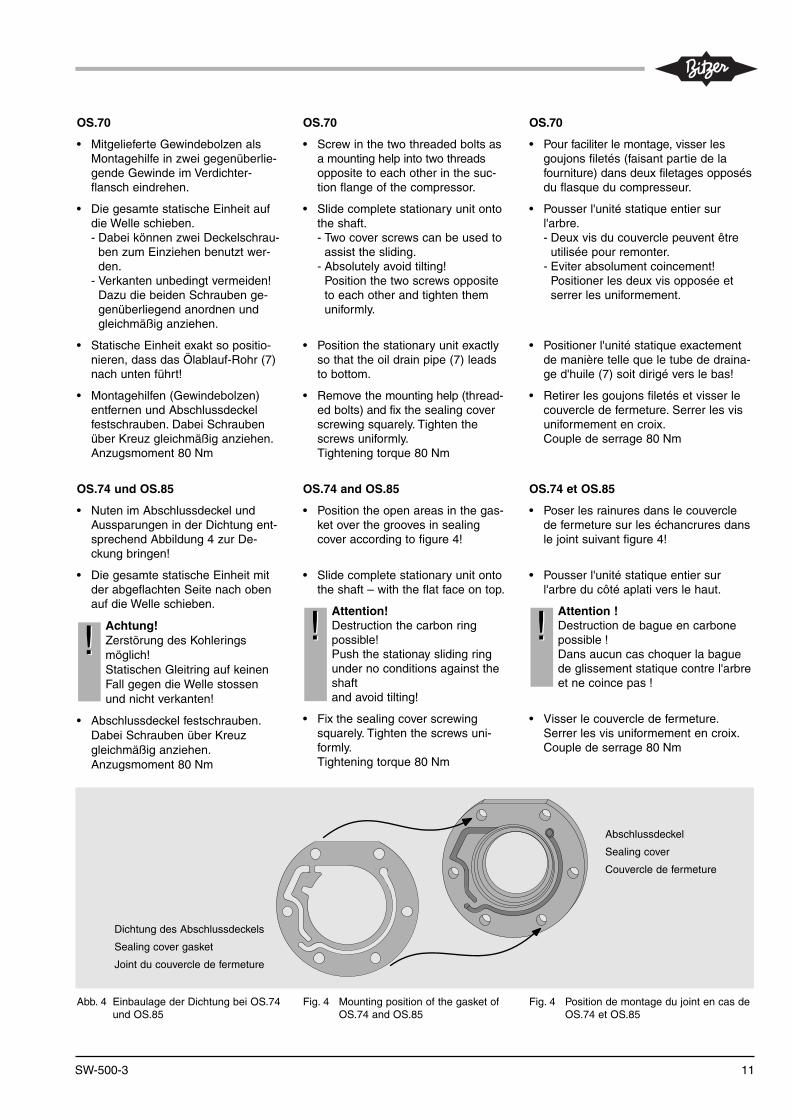
• Nuten im Abschlussdeckel undAus spa rungen in der Dichtung ent-sprechend Abbildung 4 zur De -ckung bringen!
• Die gesamte statische Einheit mitder abgeflachten Seite nach obenauf die Welle schieben.
Achtung!Zerstörung des Kohleringsmöglich!Statischen Gleitring auf keinenFall gegen die Welle stossenund nicht verkanten!
• Abschlussdeckel festschrauben.Dabei Schrauben über Kreuzgleichmäßig anziehen.Anzugs moment 80 Nm
!!
OS.70
• Screw in the two threaded bolts asa mounting help into two threadsopposite to each other in the suc-tion flange of the compressor.
• Slide complete stationary unit ontothe shaft.- Two cover screws can be used to
assist the sliding.- Absolutely avoid tilting!
Position the two screws oppositeto each other and tighten themuniformly.
• Position the stationary unit exactlyso that the oil drain pipe (7) leadsto bottom.
• Remove the mounting help (thread-ed bolts) and fix the sealing coverscrewing squarely. Tighten thescrews uniformly.Tightening torque 80 Nm
OS.74 and OS.85
• Position the open areas in the gas-ket over the grooves in sealingcover according to figure 4!
• Slide complete stationary unit ontothe shaft – with the flat face on top.
Attention!Destruction the carbon ringpossible!Push the stationay sliding ringunder no conditions against theshaftand avoid tilting!
• Fix the sealing cover screwingsquarely. Tighten the screws uni-formly.Tightening torque 80 Nm
!!
OS.70
• Pour faci li ter le mon tage, vis ser lesgoujons file tés (fai sant par tie de lafour ni ture) dans deux file tages oppo sésdu flas que du com pres seur.
• Pous ser l'unité statique entier surl'arbre.- Deux vis du cou ver cle peuvent être
utilisée pour remon ter.- Eviter absolument coincement!
Positioner les deux vis oppo sée etserrer les uniformement.
• Positioner l'unité statique exactementde maniè re telle que le tube de draina-ge d'huile (7) soit diri gé vers le bas!
• Retirer les goujons file tés et visser lecou ver cle de fermeture. Serrer les visuniformement en croix.Couple de serrage 80 Nm
OS.74 et OS.85
• Poser les rainures dans le couverclede fermeture sur les échancrures dansle joint suivant figure 4!
• Pous ser l'unité statique entier surl'arbre du côté apla ti vers le haut.
Attention !Des truc tion de bague en car bo nepossible !Dans aucun cas choquer la baguede glissement statique contre l'arbreet ne coince pas !
• Visser le cou ver cle de fermeture.Serrer les vis uniformement en croix.Couple de serrage 80 Nm
!!
SW-500-3
Dichtung des Abschlussdeckels
Sealing cover gasket
Joint du couvercle de fermeture
Abschlussdeckel
Sealing cover
Couvercle de fermeture
Abb. 4 Einbaulage der Dichtung bei OS.74und OS.85
Fig. 4 Mounting position of the gasket ofOS.74 and OS.85
Fig. 4 Position de montage du joint en cas deOS.74 et OS.85

12
• Screw the oil drain tube (8).
Attention!Sealing surface of the shaft sealmight become deformated.Tighten the nipple of the oil draintube only slightly.
• Form the tube to a siphon and fix it.Put it through the hole in the hous-ing. See figure 1.
5 OS.74:Replacement of a previous shaftseal through a new version
Dismounting the shaft seal(ac cor ding chapter 3.2)
• Remove sealing cover (2) with sta-tionary unit (1), rotating unit (10)and the O-rings (4) und (11) (seefigure 3).
• Remove the oil drain pipe (7) andthe shaft seal cover gasket (9).
Removing the oil pipe
• Remove the oil pipe (21) and anglepipe connection (23).
• Reseal the thread of the angle pipeconnection (23).- Screw it in with the open side
downwards.- Close the connection of the dis-
charge side with 1/8''-27 NPTFplug (22).
Mounting the new oil pipe
• Select oil pipe (24):- longer oil pipe for OS.7471- shorter oil pipe for OS.7461 and
OS.7451
• Remove plug (26) at the bottom ofthe compressor. Screw in thestraight pipe connection (27).
• Screw in the oil pipe here and atthe angle pipe connection (23).
• If there is no plug (26), remove theSchrader valve (25) at the bottomof the compressor.
!!
• Visser le tuyau flexible de drainage del'huile (8).
Attention !La surface d'étanchéité de la garni-ture peut être déformée.Serrer le raccord fileté du tuyau dedrainage d'huile délicatement.
• Former un siphon avec le tube et lefixer. L'introduire dans l'ouverture ducorps Voir figure 1.
5 OS.74:Remplacer une garniture d'étan-chéité précédente par la nouvelleversion
Démonter la garniture d'étanchéité(suivant chapitre 3.2)
• Enlever le couvercle de fermeture (2)avec l'unité statique (1), l'unité tour-nante (10), ainsi que les joints annu-laires (4) et (11) (figure 3).
• Démonter le tube de drainage d'huile(7) et le joint du couvercle de fermetu-re (9).
Démonter la conduite d'huile
• Démonter la conduite d'huile (21) ainsique le raccord angulaire (23).
• Rendre à nouveau étanche le filetagedu raccord angulaire (23).- Visser avec l'ouverture vers le bas.- Fermer la connexion coté refoule-
ment avec le 1/8''-27 NPTF bouchon(22).
Monter la nouvelle conduite d'huile
• Choisir la conduite d'huile (24):- conduite la plus longue pour OS.7471- conduite la plus courte pour
lOS.7461 et OS.7451
• Enlever le bouchon (26) en dessousdu compresseur. Visser le raccord detube (27).
• Visser la conduite d'huile à cet endroitet au raccord angulaire (23).
• S'il n'y a pas de bouchon (26), enleverle raccord schrader (25) en dessousdu compresseur.
!!
• Ölablauf-Schlauch (8) einschrau-ben.
Achtung!Dichtfläche der Wellen abdich -tung kann verformt werden.Nippel des Ölablauf-Schlauchsnur leicht an ziehen.
• Schlauch zu einem Siphon formenund fixieren. Durch die Öffnung imGehäuse führen. Siehe Abbil -dung 1.
5 OS.74:Frühere Wellenab dich tung durchdie neue Version tauschen
Wellenabdichtung ausbauen(analog Kapitel 3.2)
• Ab schluss deckel (2) mit statischerEinheit (1), rotierende Einheit (10)sowie O-Rin ge (4) und (11) entfer-nen (Abbildung 3).
• Ölablauf-Rohr (7) und Dich tung desAbschlussdeckels (9) entfernen.
Ölleitung ausbauen
• Ölleitung (21) und Winkel-Ver -schrau bung (23) entfernen.
• Gewinde der Winkel-Rohrver -schrau bung (23) neu abdichten.- Mit der Öffnung nach unten ein-
schrauben.- Druck seiti gen Anschluss mit
1/8''-27 NPTF-Stop fen (22) ver -schlie ßen.
Neue Ölleitung montieren
• Ölleitung (24) auswählen:- längere Ölleitung für OS.7471- kürzere Ölleitung für OS.7461 und
OS.7451
• Stopfen (26) an der Unterseite desVerdichters entfernen. und geradeRohrverschraubung (27) ein schrau -ben.
• Ölleitung hier und an der Winkel-Rohr verschrau bung (23) einschrau-ben.
• Wenn Stopfen (26) nicht vorhandenist, Schraderventil (25) an derUnterseite des Verdichters entfer-nen.
!!
SW-500-3

13
• Gerade Rohrver schrau bung (27)einschrauben.
• Hier und an der Winkel-Rohrver -schrau bung (23) Ölleitung ein-schrauben.
• Neue Wellen abdichtung mit neuerDichtung des Abschlussdeckels (9)einbauen – siehe Kapitel 4.3.
• Screw in straight pipe connection(27).
• Screw in the oil pipe here and atthe angle pipe connec tion (23).
• Mount the new sealing cover with anew gasket (9) – see chapter 4.3.
• Visser le raccord de tube (27).
• Visser la conduite d'huile à cet endroitet au raccord angulaire (23).
• Monter la nouvelle garniture d'étan ché -ité avec le nouveau joint du couverclede fermeture (9) – voir chapitre 4.3.
SW-500-3
21 22
23 24 25
1/8'' NPTF
1 10
2
7
12
1311
17
4
3
9
15
1 Statische Einheit Stationary unit Unité statique
2 Abschlussdeckel Sealing cover Couvercle de ferm.
3 Statischer Gleitring Stationary sealing Bague de glissementring statique
4 O-Ring O-ring Joint annulaire(Teflon-Ring) (teflon ring) (bague en téflon)
7 Ölablauf-Rohr Oil drain pipe Tube de drainaged'huile
9 Dichtung des Sealing cover Joint du couvercle Abschlussdeckels gasket de fermeture
10 Rotierende Einheit Rotating unit Unité tournante
11 O-Ring O-ring Joint annulaire
12 Stiftschrauben Stud screws Boulons filetés
13 Demontage-Nut Slot for removal Rainure de démont.
15 Öldüse Oil orifice Orifice d'huile
17 Öldurchfluss- Oil flow switch Contrôleur de Wächter débit d'huile
21 Ölleitung der frü- Oil pipe of the Conduite d'huile heren Version previous version précédente
22 neuer Stopfen New plug Bouchon nouveau
23 Winkel-Rohr- Angle pipe Raccord de tubeverschraubung connection angulaire
24 neue Ölleitung New oil pipe Conduite d'huilenouvelle
25 Schrader-Ventil Schrader valve Raccord Schrader
26 Stopfen Plug Bouchon
27 gerade Rohr- Straight pipe Raccord de tubeverschraubung connection en ligne droit
26
23
25
27
24
23
25
27
24
Abb. 4 Ansichten OS.74 und Wellen -abdichtung (frühere Ausführung)
Fig. 4 Views of OS.74 and shaft seal(previous construction)
Fig. 4 Vues du OS.74 et garnitured'étanchéité (construction précédente)
OS.74
frühereAusführung
previouscon struction
construction précédente
OS.74
OS.74Version 2
OS.74Version 1
SeitenansichtSide viewVue de côté
Ansicht von untenView from belowVue de dessous
Ansicht von untenView from belowVue de dessous

14
Notes
SW-500-3

15
Notes
SW-500-3

BITZER Kühlmaschinenbau GmbHEschenbrünnlestraße 15 // 71065 Sindelfingen // Germany
Tel +49 (0)70 31 932-0 // Fax +49 (0)70 31 [email protected] // www.bitzer.de
Subject to change // Änderungen vorbehalten // Toutes modifications réservées // 80530101 // 09.2011