Busbar mounting 160 A, Größe / Size 00 3- · PDF fileJung Polykontakt GmbH...
21
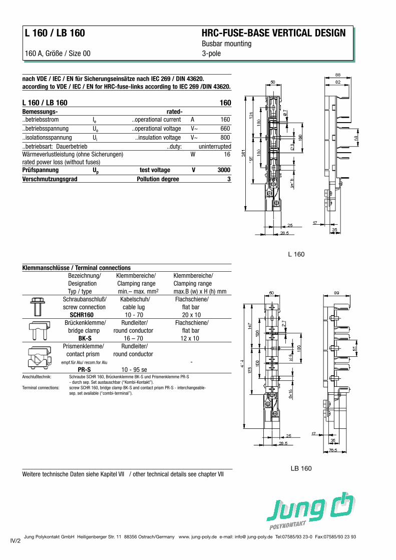
Jung Polykontakt GmbH Heiligenberger Str. 11 88356 Ostrach/Germany www. jung-poly.de e-mail: info@ jung-poly.de Tel:07585/93 23-0 Fax:07585/93 23 93 Klemmanschlüsse / Terminal connections Bezeichnung/ Klemmbereiche/ Klemmbereiche/ Designation Clamping range Clamping range Typ / type min.– max. mm 2 max.B (w) x H (h) mm Schraubanschluß/ Kabelschuh/ Flachschiene/ screw connection cable lug flat bar SCHR160 10 - 70 20 x 10 Brückenklemme/ Rundleiter/ Flachschiene/ bridge clamp round conductor flat bar BK-S 16 – 70 12 x 10 Prismenklemme/ Rundleiter/ contact prism round conductor empf.für Alu/ recom.for Alu - PR-S 10 - 95 se Anschlußtechnik: Schraube SCHR 160, Brückenklemme BK-S und Prismenklemme PR-S - durch sep. Set austauschbar (“Kombi-Kontakt”). Terminal connections: screw SCHR 160, bridge clamp BK-S and contact prism PR-S - interchangeable- sep. set available (“combi-terminal”). L 160 / LB 160 HRC-FUSE-BASE VERTICAL DESIGN Busbar mounting 160 A, Größe / Size 00 3-pole IV/2 Weitere technische Daten siehe Kapitel VII / other technical details see chapter VII nach VDE / IEC / EN für Sicherungseinsätze nach IEC 269 / DIN 43620. according to VDE / IEC / EN for HRC-fuse-links according to IEC 269 /DIN 43620. L 160 / LB 160 160 Bemessungs- rated- ..betriebsstrom I e ..operational current A 160 ..betriebsspannung U e ..operational voltage V~ 660 ..isolationsspannung U i ..insulation voltage V~ 800 ..betriebsart: Dauerbetrieb ..duty: uninterrupted Wärmeverlustleistung (ohne Sicherungen) W 16 rated power loss (without fuses) Prüfspannung U p test voltage V 3000 Verschmutzungsgrad Pollution degree 3 L 160 LB 160
Transcript of Busbar mounting 160 A, Größe / Size 00 3- · PDF fileJung Polykontakt GmbH...
Jung Polykontakt GmbH Heiligenberger Str. 11 88356 Ostrach/Germany www. jung-poly.de e-mail: info@ jung-poly.de Tel:07585/93 23-0 Fax:07585/93 23 93
Klemmanschlüsse / Terminal connections
Bezeichnung/ Klemmbereiche/ Klemmbereiche/
Designation Clamping range Clamping range
Typ / type min.– max. mm2 max.B (w) x H (h) mm
Schraubanschluß/ Kabelschuh/ Flachschiene/
screw connection cable lug flat bar
SCHR160 10 - 70 20 x 10
Brückenklemme/ Rundleiter/ Flachschiene/
bridge clamp round conductor flat bar
BK-S 16 – 70 12 x 10
Prismenklemme/ Rundleiter/
contact prism round conductor
empf.für Alu/ recom.for Alu -
PR-S 10 - 95 seAnschlußtechnik: Schraube SCHR 160, Brückenklemme BK-S und Prismenklemme PR-S
- durch sep. Set austauschbar (“Kombi-Kontakt”).
Terminal connections: screw SCHR 160, bridge clamp BK-S and contact prism PR-S - interchangeable-
sep. set available (“combi-terminal”).
L 160 / LB 160 HRC-FUSE-BASE VERTICAL DESIGNBusbar mounting
160 A, Größe / Size 00 3-pole
IV/2
Weitere technische Daten siehe Kapitel VII / other technical details see chapter VII
nach VDE / IEC / EN für Sicherungseinsätze nach IEC 269 / DIN 43620.
according to VDE / IEC / EN for HRC-fuse-links according to IEC 269 /DIN 43620.
L 160 / LB 160 160Bemessungs- rated-
..betriebsstrom Ie ..operational current A 160
..betriebsspannung Ue ..operational voltage V~ 660
..isolationsspannung Ui ..insulation voltage V~ 800
..betriebsart: Dauerbetrieb ..duty: uninterrupted
Wärmeverlustleistung (ohne Sicherungen) W 16
rated power loss (without fuses)
Prüfspannung Up test voltage V 3000
Verschmutzungsgrad Pollution degree 3
L 160
LB 160
Jung Polykontakt GmbH Heiligenberger Str. 11 88356 Ostrach/Germany www. jung-poly.de e-mail: info@ jung-poly.de Tel:07585/93 23-0 Fax:07585/93 23 93
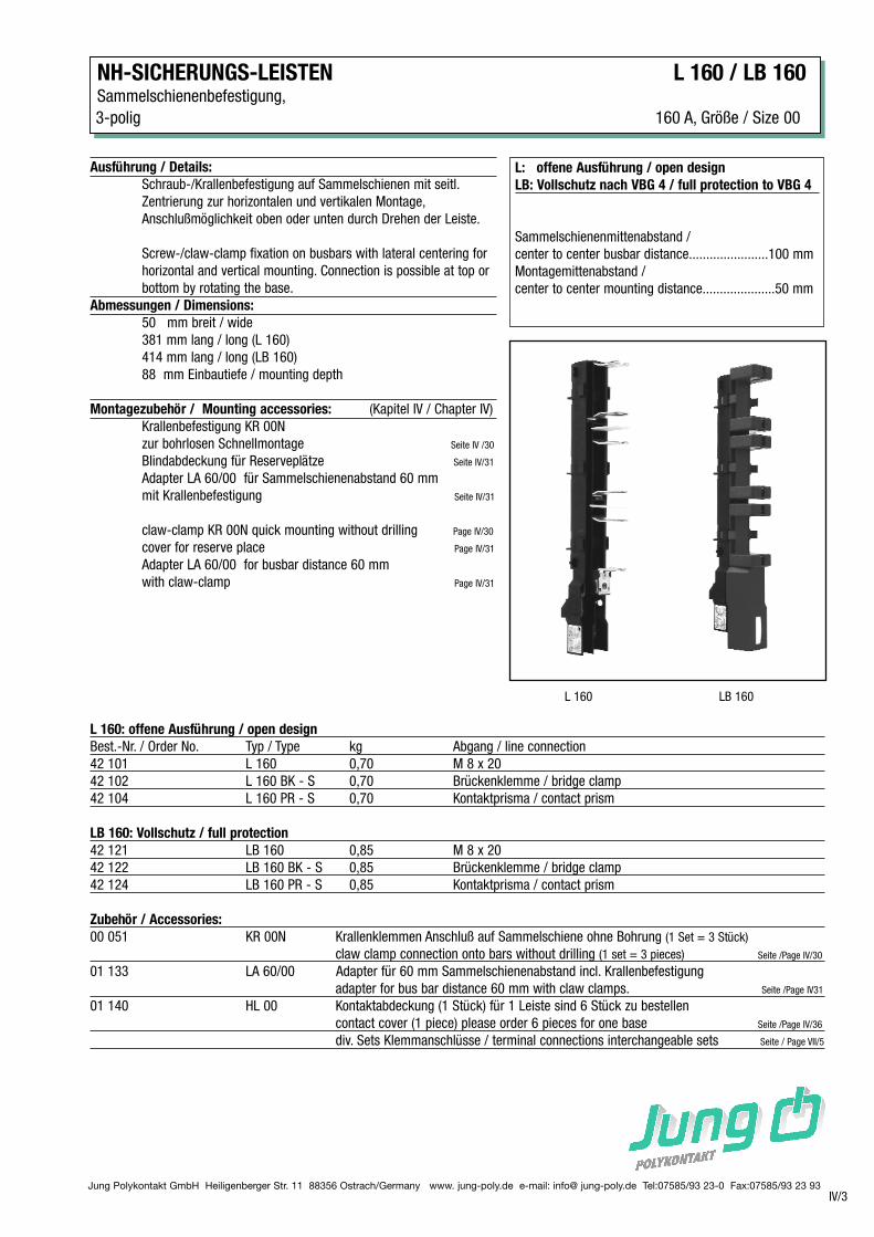
NH-SICHERUNGS-LEISTEN L 160 / LB 160Sammelschienenbefestigung,
3-polig 160 A, Größe / Size 00
IV/3
L: offene Ausführung / open design
LB: Vollschutz nach VBG 4 / full protection to VBG 4
Sammelschienenmittenabstand /
center to center busbar distance.......................100 mm
Montagemittenabstand /
center to center mounting distance.....................50 mm
Ausführung / Details:
Schraub-/Krallenbefestigung auf Sammelschienen mit seitl.
Zentrierung zur horizontalen und vertikalen Montage,
Anschlußmöglichkeit oben oder unten durch Drehen der Leiste.
Screw-/claw-clamp fixation on busbars with lateral centering for
horizontal and vertical mounting. Connection is possible at top or
bottom by rotating the base.
Abmessungen / Dimensions:
50 mm breit / wide
381 mm lang / long (L 160)
414 mm lang / long (LB 160)
88 mm Einbautiefe / mounting depth
Montagezubehör / Mounting accessories: (Kapitel IV / Chapter IV)
Krallenbefestigung KR 00N
zur bohrlosen Schnellmontage Seite IV /30
Blindabdeckung für Reserveplätze Seite IV/31
Adapter LA 60/00 für Sammelschienenabstand 60 mm
mit Krallenbefestigung Seite IV/31
claw-clamp KR 00N quick mounting without drilling Page IV/30
cover for reserve place Page IV/31
Adapter LA 60/00 for busbar distance 60 mm
with claw-clamp Page IV/31
L 160: offene Ausführung / open design
Best.-Nr. / Order No. Typ / Type kg Abgang / line connection
42 101 L 160 0,70 M 8 x 20
42 102 L 160 BK - S 0,70 Brückenklemme / bridge clamp
42 104 L 160 PR - S 0,70 Kontaktprisma / contact prism
LB 160: Vollschutz / full protection
42 121 LB 160 0,85 M 8 x 20
42 122 LB 160 BK - S 0,85 Brückenklemme / bridge clamp
42 124 LB 160 PR - S 0,85 Kontaktprisma / contact prism
Zubehör / Accessories:
00 051 KR 00N Krallenklemmen Anschluß auf Sammelschiene ohne Bohrung (1 Set = 3 Stück)
claw clamp connection onto bars without drilling (1 set = 3 pieces) Seite /Page IV/30
01 133 LA 60/00 Adapter für 60 mm Sammelschienenabstand incl. Krallenbefestigung
adapter for bus bar distance 60 mm with claw clamps. Seite /Page IV31
01 140 HL 00 Kontaktabdeckung (1 Stück) für 1 Leiste sind 6 Stück zu bestellen
contact cover (1 piece) please order 6 pieces for one base Seite /Page IV/36
div. Sets Klemmanschlüsse / terminal connections interchangeable sets Seite / Page VII/5
L 160 LB 160

Jung Polykontakt GmbH Heiligenberger Str. 11 88356 Ostrach/Germany www. jung-poly.de e-mail: info@ jung-poly.de Tel:07585/93 23-0 Fax:07585/93 23 93IV/4
L / LF / LB / LBF 00/185 HRC-FUSE-BASE VERTICAL DESIGNBusbar mounting,
160 A, Größe / Size 00 3-pole
nach VDE / IEC / EN für Sicherungseinsätze nach IEC 269 / DIN 43620.
according to VDE / IEC / EN for HRC-fuse-links according to IEC 269 /DIN 43620.
L / LF / LB / LBF 00/185 160Bemessungs- rated-
..betriebsstrom Ie ..operational current A 160
..betriebsspannung Ue ..operational voltage V~ 660
..isolationsspannung Ui ..insulation voltage V~ 800
..betriebsart: Dauerbetrieb ..duty: uninterrupted
Wärmeverlustleistung (ohne Sicherungen) W 19
rated power loss (without fuses)
Prüfspannung Up test voltage V 3000
Verschmutzungsgrad Pollution degree 3
Klemmanschlüsse / Terminal connections
Bezeichnung/ Klemmbereiche/ Klemmbereiche/
Designation Clamping range Clamping range
Typ / type min.– max. mm2 max.B (w) x H (h) mm
Schraubanschluß/ Kabelschuh/ Flachschiene/
screw connection cable lug flat bar
SCHR160 10 - 70 20 x 10
Brückenklemme/ Rundleiter/ Flachschiene/
bridge clamp round conductor flat bar
BK-S 16 – 70 12 x 10
Prismenklemme/ Rundleiter/
contact prism round conductor
empf.für Alu/ recom.for Alu -
PR-S 10 - 95 se
Anschlußtechnik: Schraube SCHR 160, Brückenklemme BK-S und Prismenklemme PR-S
- durch sep. Set austauschbar (“Kombi-Kontakt”).
Terminal connections: screw SCHR 160, bridge clamp BK-S and contact prism PR-S - interchangeable-
sep. set available (“combi-terminal”).
Weitere technische Daten siehe Kapitel VII / other technical details see chapter VII
Jung Polykontakt GmbH Heiligenberger Str. 11 88356 Ostrach/Germany www. jung-poly.de e-mail: info@ jung-poly.de Tel:07585/93 23-0 Fax:07585/93 23 93IV/5
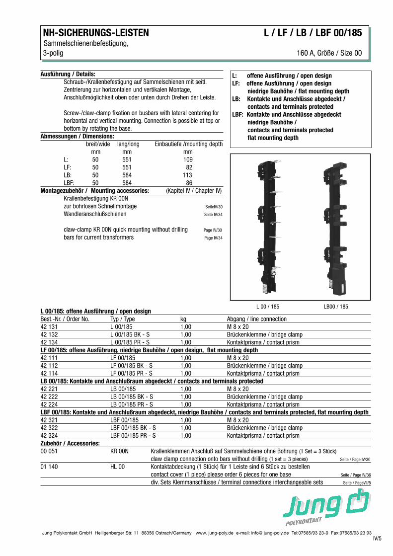
NH-SICHERUNGS-LEISTEN L / LF / LB / LBF 00/185Sammelschienenbefestigung,
3-polig 160 A, Größe / Size 00
L: offene Ausführung / open design
LF: offene Ausführung / open design
niedrige Bauhöhe / flat mounting depth
LB: Kontakte und Anschlüsse abgedeckt /
contacts and terminals protected
LBF: Kontakte und Anschlüsse abgedeckt
niedrige Bauhöhe /
contacts and terminals protected
flat mounting depth
Ausführung / Details:
Schraub-/Krallenbefestigung auf Sammelschienen mit seitl.
Zentrierung zur horizontalen und vertikalen Montage,
Anschlußmöglichkeit oben oder unten durch Drehen der Leiste.
Screw-/claw-clamp fixation on busbars with lateral centering for
horizontal and vertical mounting. Connection is possible at top or
bottom by rotating the base.
Abmessungen / Dimensions:
breit/wide lang/long Einbautiefe /mounting depth
mm mm mm
L: 50 551 109
LF: 50 551 82
LB: 50 584 113
LBF: 50 584 86
Montagezubehör / Mounting accessories: (Kapitel IV / Chapter IV)
Krallenbefestigung KR 00N
zur bohrlosen Schnellmontage SeiteIV/30
Wandleranschlußschienen Seite IV/34
claw-clamp KR 00N quick mounting without drilling Page IV/30
bars for current transformers Page IV/34
L 00/185: offene Ausführung / open design
Best.-Nr. / Order No. Typ / Type kg Abgang / line connection
42 131 L 00/185 1,00 M 8 x 20
42 132 L 00/185 BK - S 1,00 Brückenklemme / bridge clamp
42 134 L 00/185 PR - S 1,00 Kontaktprisma / contact prism
LF 00/185: offene Ausführung, niedrige Bauhöhe / open design, flat mounting depth
42 111 LF 00/185 1,00 M 8 x 20
42 112 LF 00/185 BK - S 1,00 Brückenklemme / bridge clamp
42 114 LF 00/185 PR - S 1,00 Kontaktprisma / contact prism
LB 00/185: Kontakte und Anschlußraum abgedeckt / contacts and terminals protected
42 221 LB 00/185 1,00 M 8 x 20
42 222 LB 00/185 BK - S 1,00 Brückenklemme / bridge clamp
42 224 LB 00/185 PR - S 1,00 Kontaktprisma / contact prism
LBF 00/185: Kontakte und Anschlußraum abgedeckt, niedrige Bauhöhe / contacts and terminals protected, flat mounting depth
42 321 LBF 00/185 1,00 M 8 x 20
42 322 LBF 00/185 BK - S 1,00 Brückenklemme / bridge clamp
42 324 LBF 00/185 PR - S 1,00 Kontaktprisma / contact prism
Zubehör / Accessories:
00 051 KR 00N Krallenklemmen Anschluß auf Sammelschiene ohne Bohrung (1 Set = 3 Stück)
claw clamp connection onto bars without drilling (1 set = 3 pieces) Seite / Page IV/30
01 140 HL 00 Kontaktabdeckung (1 Stück) für 1 Leiste sind 6 Stück zu bestellen
contact cover (1 piece) please order 6 pieces for one base Seite / Page IV/36
div. Sets Klemmanschlüsse / terminal connections interchangeable sets Seite / PageVII/5
L 00 / 185 LB00 / 185
Jung Polykontakt GmbH Heiligenberger Str. 11 88356 Ostrach/Germany www. jung-poly.de e-mail: info@ jung-poly.de Tel:07585/93 23-0 Fax:07585/93 23 93
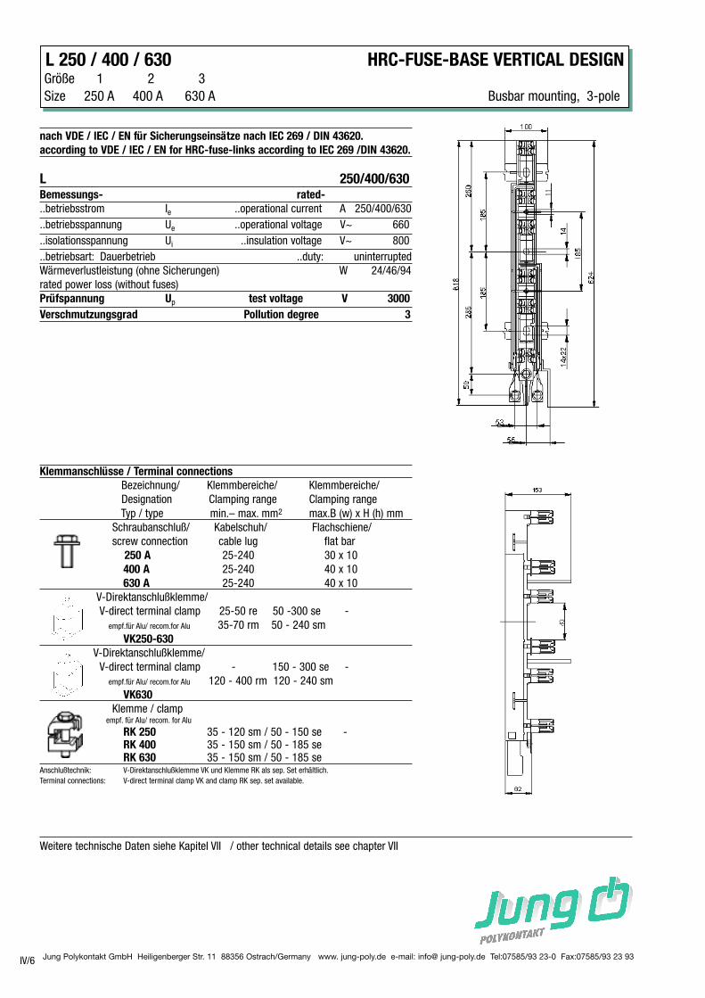
L 250 / 400 / 630 HRC-FUSE-BASE VERTICAL DESIGNGröße 1 2 3
Size 250 A 400 A 630 A Busbar mounting, 3-pole
IV/6
nach VDE / IEC / EN für Sicherungseinsätze nach IEC 269 / DIN 43620.
according to VDE / IEC / EN for HRC-fuse-links according to IEC 269 /DIN 43620.
L 250/400/630Bemessungs- rated-
..betriebsstrom Ie ..operational current A 250/400/630
..betriebsspannung Ue ..operational voltage V~ 660
..isolationsspannung Ui ..insulation voltage V~ 800
..betriebsart: Dauerbetrieb ..duty: uninterrupted
Wärmeverlustleistung (ohne Sicherungen) W 24/46/94
rated power loss (without fuses)
Prüfspannung Up test voltage V 3000
Verschmutzungsgrad Pollution degree 3
Klemmanschlüsse / Terminal connections
Bezeichnung/ Klemmbereiche/ Klemmbereiche/
Designation Clamping range Clamping range
Typ / type min.– max. mm2 max.B (w) x H (h) mm
Schraubanschluß/ Kabelschuh/ Flachschiene/
screw connection cable lug flat bar
250 A 25-240 30 x 10
400 A 25-240 40 x 10
630 A 25-240 40 x 10
V-Direktanschlußklemme/
V-direct terminal clamp 25-50 re 50 -300 se -
empf.für Alu/ recom.for Alu 35-70 rm 50 - 240 sm
VK250-630
V-Direktanschlußklemme/
V-direct terminal clamp - 150 - 300 se -
empf.für Alu/ recom.for Alu 120 - 400 rm 120 - 240 sm
VK630
Klemme / clampempf. für Alu/ recom. for Alu
RK 250 35 - 120 sm / 50 - 150 se -RK 400 35 - 150 sm / 50 - 185 seRK 630 35 - 150 sm / 50 - 185 se
Anschlußtechnik: V-Direktanschlußklemme VK und Klemme RK als sep. Set erhältlich.
Terminal connections: V-direct terminal clamp VK and clamp RK sep. set available.
Weitere technische Daten siehe Kapitel VII / other technical details see chapter VII
Jung Polykontakt GmbH Heiligenberger Str. 11 88356 Ostrach/Germany www. jung-poly.de e-mail: info@ jung-poly.de Tel:07585/93 23-0 Fax:07585/93 23 93
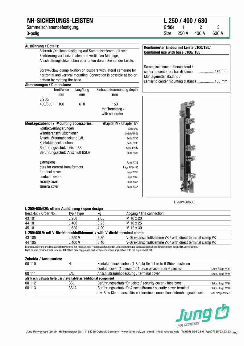
NH-SICHERUNGS-LEISTEN L 250 / 400 / 630Sammelschienenbefestigung, Größe 1 2 3
3-polig Size 250 A 400 A 630 A
IV/7
Kombinierter Einbau mit Leiste L100/185/
Combined use with base L100/ 185
Sammelschienenmittenabstand /
center to center busbar distance.......................185 mm
Montagemittenabstand /
center to center mounting distance...................100 mm
Ausführung / Details:
Schraub-/Krallenbefestigung auf Sammelschienen mit seitl.
Zentrierung zur horizontalen und vertikalen Montage,
Anschlußmöglichkeit oben oder unten durch Drehen der Leiste.
Screw-/claw-clamp fixation on busbars with lateral centering for
horizontal and vertical mounting. Connection is possible at top or
bottom by rotating the base.
Abmessungen / Dimensions:
breit/wide lang/long Einbautiefe/mounting depth
mm mm mm
L 250/
400/630 100 618 153
mit Trennsteg /
with separator
Montagezubehör / Mounting accessories: (Kapitel IV / Chapter IV)
Kontaktverlängerungen Seite IV/32
Wandleranschlußschienen Seite IV/34-35
Anschlußraumabdeckung LAL Seite IV/35
Kontaktabdeckhauben Seite IV/36
Berührungsschutz Leiste BSL Seite IIV/37
Berührungsschutz Anschluß BSLA Seite IV/37
extensions Page IV/32
bars for current transformers Page IV/34-35
terminal cover Page IV/35
contact covers Page IV/36
security cover Page IV/37
terminal cover Page IV/37
L 250/400/630: offene Ausführung / open design
Best.-Nr. / Order No. Typ / Type kg Abgang / line connection
43 101 L 250 2,65 M 10 x 20
44 101 L 400 3,25 M 10 x 25
45 101 L 630 4,20 M 12 x 30
L 250/400 V: mit V-Direktanschlußklemme / with V-direkt terminal clamp
43 105 L 250 V 2,80 V-Direktanschlußklemme VK / with direct terminal clamp VK
44 105 L 400 V 3,40 V-Direktanschlußklemme VK / with direct terminal clamp VKLeistenausführung mit Direktanschlußklemme RK möglich. Die Typenbezeichnung der Leistenausführung Schraubanschluß ist dann mit dem Zusatz RK zu versehen./
Base can be provided with terminal RK. When ordering please add screw connection application with the supplement RK.
Zubehör / Accessories:
00 110 HL Kontaktabdeckhauben (1 Stück) für 1 Leiste 6 Stück bestellen
contact cover (1 piece) for 1 base please order 6 pieces Seite /Page IV/36
00 111 LAL Anschlußraumabdeckung / terminal cover Seite / Page IV/35
als Nachrüstsatz lieferbar / available as additional equipment
00 112 BSL Berührungsschutz für Leiste / security cover - fuse base Seite / Page IV/37
00 113 BSLA Berührungsschutz für Anschlußraum / security cover terminal Seite / Page IV/37
div. Sets Klemmanschlüsse / terminal connections interchangeable sets Seite / Page VII/5-6
L 250/400/630
Jung Polykontakt GmbH Heiligenberger Str. 11 88356 Ostrach/Germany www. jung-poly.de e-mail: info@ jung-poly.de Tel:07585/93 23-0 Fax:07585/93 23 93
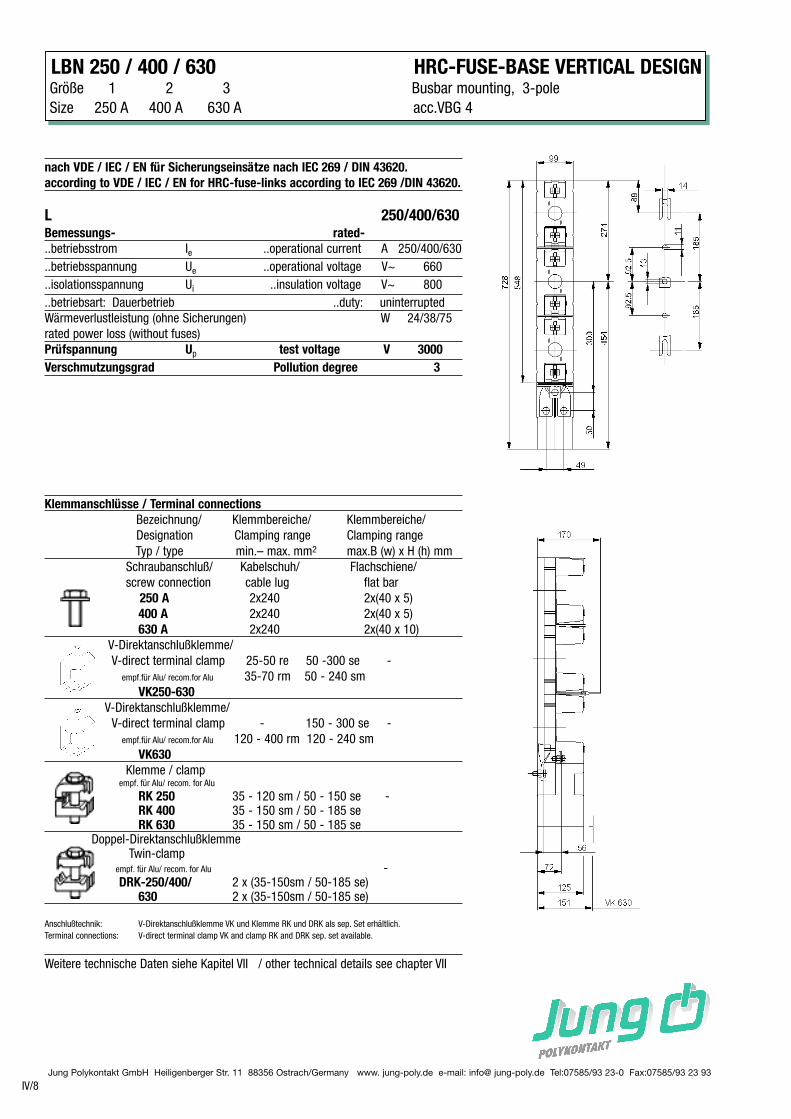
LBN 250 / 400 / 630 HRC-FUSE-BASE VERTICAL DESIGNGröße 1 2 3 Busbar mounting, 3-pole
Size 250 A 400 A 630 A acc.VBG 4
IV/8
Weitere technische Daten siehe Kapitel VII / other technical details see chapter VII
Klemmanschlüsse / Terminal connections
Bezeichnung/ Klemmbereiche/ Klemmbereiche/
Designation Clamping range Clamping range
Typ / type min.– max. mm2 max.B (w) x H (h) mm
Schraubanschluß/ Kabelschuh/ Flachschiene/
screw connection cable lug flat bar
250 A 2x240 2x(40 x 5)
400 A 2x240 2x(40 x 5)
630 A 2x240 2x(40 x 10)
V-Direktanschlußklemme/
V-direct terminal clamp 25-50 re 50 -300 se -
empf.für Alu/ recom.for Alu 35-70 rm 50 - 240 sm
VK250-630
V-Direktanschlußklemme/
V-direct terminal clamp - 150 - 300 se -
empf.für Alu/ recom.for Alu 120 - 400 rm 120 - 240 sm
VK630
Klemme / clampempf. für Alu/ recom. for Alu
RK 250 35 - 120 sm / 50 - 150 se -RK 400 35 - 150 sm / 50 - 185 seRK 630 35 - 150 sm / 50 - 185 se
Doppel-DirektanschlußklemmeTwin-clamp
empf. für Alu/ recom. for Alu -DRK-250/400/ 2 x (35-150sm / 50-185 se)
630 2 x (35-150sm / 50-185 se)
Anschlußtechnik: V-Direktanschlußklemme VK und Klemme RK und DRK als sep. Set erhältlich.
Terminal connections: V-direct terminal clamp VK and clamp RK and DRK sep. set available.
nach VDE / IEC / EN für Sicherungseinsätze nach IEC 269 / DIN 43620.
according to VDE / IEC / EN for HRC-fuse-links according to IEC 269 /DIN 43620.
L 250/400/630Bemessungs- rated-
..betriebsstrom Ie ..operational current A 250/400/630
..betriebsspannung Ue ..operational voltage V~ 660
..isolationsspannung Ui ..insulation voltage V~ 800
..betriebsart: Dauerbetrieb ..duty: uninterrupted
Wärmeverlustleistung (ohne Sicherungen) W 24/38/75
rated power loss (without fuses)
Prüfspannung Up test voltage V 3000
Verschmutzungsgrad Pollution degree 3
Jung Polykontakt GmbH Heiligenberger Str. 11 88356 Ostrach/Germany www. jung-poly.de e-mail: info@ jung-poly.de Tel:07585/93 23-0 Fax:07585/93 23 93
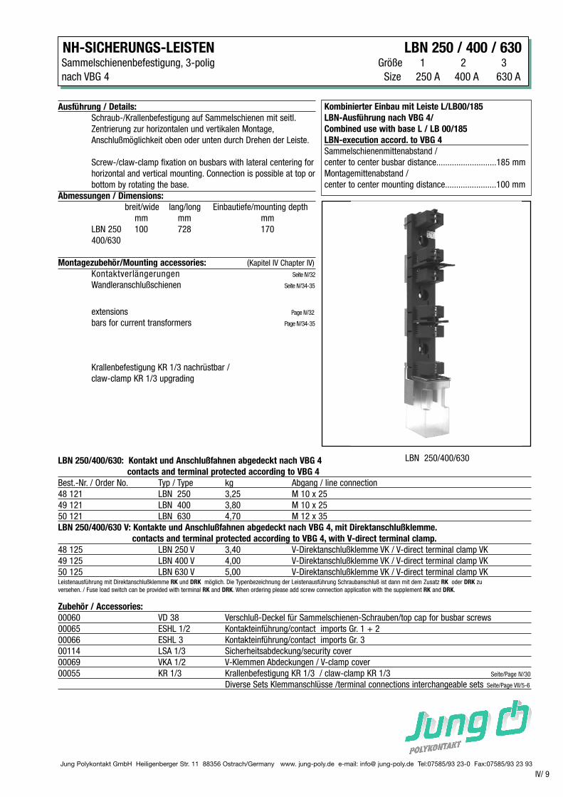
NH-SICHERUNGS-LEISTEN LBN 250 / 400 / 630Sammelschienenbefestigung, 3-polig Größe 1 2 3
nach VBG 4 Size 250 A 400 A 630 A
IV/ 9
Kombinierter Einbau mit Leiste L/LB00/185
LBN-Ausführung nach VBG 4/
Combined use with base L / LB 00/185
LBN-execution accord. to VBG 4
Sammelschienenmittenabstand /
center to center busbar distance...........................185 mm
Montagemittenabstand /
center to center mounting distance.......................100 mm
Ausführung / Details:
Schraub-/Krallenbefestigung auf Sammelschienen mit seitl.
Zentrierung zur horizontalen und vertikalen Montage,
Anschlußmöglichkeit oben oder unten durch Drehen der Leiste.
Screw-/claw-clamp fixation on busbars with lateral centering for
horizontal and vertical mounting. Connection is possible at top or
bottom by rotating the base.
Abmessungen / Dimensions:
breit/wide lang/long Einbautiefe/mounting depth
mm mm mm
LBN 250 100 728 170
400/630
Montagezubehör/Mounting accessories: (Kapitel IV Chapter IV)
Kontaktverlängerungen Seite IV/32
Wandleranschlußschienen Seite IV/34-35
extensions Page IV/32
bars for current transformers Page IV/34-35
Krallenbefestigung KR 1/3 nachrüstbar /
claw-clamp KR 1/3 upgrading
LBN 250/400/630: Kontakt und Anschlußfahnen abgedeckt nach VBG 4
contacts and terminal protected according to VBG 4
Best.-Nr. / Order No. Typ / Type kg Abgang / line connection
48 121 LBN 250 3,25 M 10 x 25
49 121 LBN 400 3,80 M 10 x 25
50 121 LBN 630 4,70 M 12 x 35
LBN 250/400/630 V: Kontakte und Anschlußfahnen abgedeckt nach VBG 4, mit Direktanschlußklemme.
contacts and terminal protected according to VBG 4, with V-direct terminal clamp.
48 125 LBN 250 V 3,40 V-Direktanschlußklemme VK / V-direct terminal clamp VK
49 125 LBN 400 V 4,00 V-Direktanschlußklemme VK / V-direct terminal clamp VK
50 125 LBN 630 V 5,00 V-Direktanschlußklemme VK / V-direct terminal clamp VKLeistenausführung mit Direktanschlußklemme RK und DRK möglich. Die Typenbezeichnung der Leistenausführung Schraubanschluß ist dann mit dem Zusatz RK oder DRK zu
versehen. / Fuse load switch can be provided with terminal RK and DRK. When ordering please add screw connection application with the supplement RK and DRK.
Zubehör / Accessories:
00060 VD 38 Verschluß-Deckel für Sammelschienen-Schrauben/top cap for busbar screws
00065 ESHL 1/2 Kontakteinführung/contact imports Gr. 1 + 2
00066 ESHL 3 Kontakteinführung/contact imports Gr. 3
00114 LSA 1/3 Sicherheitsabdeckung/security cover
00069 VKA 1/2 V-Klemmen Abdeckungen / V-clamp cover
00055 KR 1/3 Krallenbefestigung KR 1/3 / claw-clamp KR 1/3 Seite/Page IV/30
Diverse Sets Klemmanschlüsse /terminal connections interchangeable sets Seite/Page VII/5-6
LBN 250/400/630
Jung Polykontakt GmbH Heiligenberger Str. 11 88356 Ostrach/Germany www. jung-poly.de e-mail: info@ jung-poly.de Tel:07585/93 23-0 Fax:07585/93 23 93IV/10
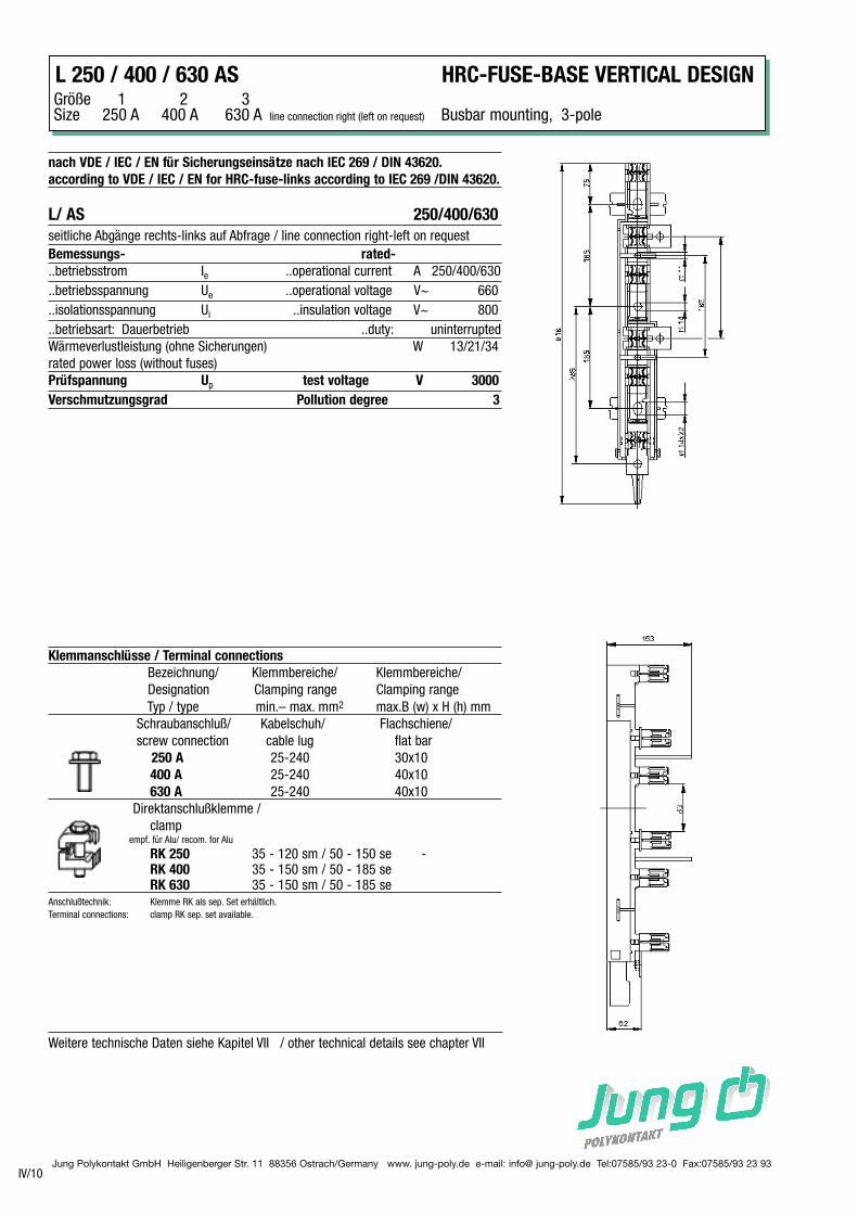
L 250 / 400 / 630 AS HRC-FUSE-BASE VERTICAL DESIGNGröße 1 2 3 Size 250 A 400 A 630 A line connection right (left on request) Busbar mounting, 3-pole
nach VDE / IEC / EN für Sicherungseinsätze nach IEC 269 / DIN 43620.
according to VDE / IEC / EN for HRC-fuse-links according to IEC 269 /DIN 43620.
L/ AS 250/400/630
seitliche Abgänge rechts-links auf Abfrage / line connection right-left on request
Bemessungs- rated-
..betriebsstrom Ie ..operational current A 250/400/630
..betriebsspannung Ue ..operational voltage V~ 660
..isolationsspannung Ui ..insulation voltage V~ 800
..betriebsart: Dauerbetrieb ..duty: uninterrupted
Wärmeverlustleistung (ohne Sicherungen) W 13/21/34
rated power loss (without fuses)
Prüfspannung Up test voltage V 3000
Verschmutzungsgrad Pollution degree 3
Weitere technische Daten siehe Kapitel VII / other technical details see chapter VII
Klemmanschlüsse / Terminal connections
Bezeichnung/ Klemmbereiche/ Klemmbereiche/
Designation Clamping range Clamping range
Typ / type min.– max. mm2 max.B (w) x H (h) mm
Schraubanschluß/ Kabelschuh/ Flachschiene/
screw connection cable lug flat bar
250 A 25-240 30x10
400 A 25-240 40x10
630 A 25-240 40x10
Direktanschlußklemme /
clampempf. für Alu/ recom. for Alu
RK 250 35 - 120 sm / 50 - 150 se -RK 400 35 - 150 sm / 50 - 185 seRK 630 35 - 150 sm / 50 - 185 se
Anschlußtechnik: Klemme RK als sep. Set erhältlich.
Terminal connections: clamp RK sep. set available.
Jung Polykontakt GmbH Heiligenberger Str. 11 88356 Ostrach/Germany www. jung-poly.de e-mail: info@ jung-poly.de Tel:07585/93 23-0 Fax:07585/93 23 93IV/11
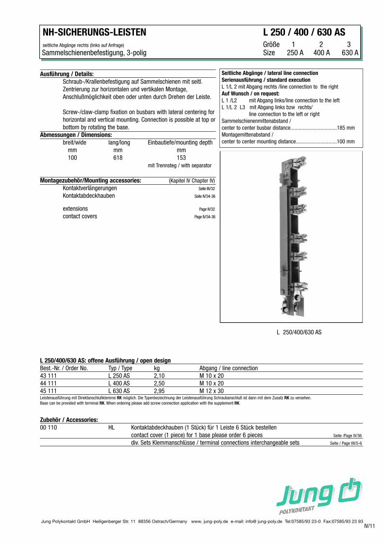
NH-SICHERUNGS-LEISTEN L 250 / 400 / 630 AS
seitliche Abgänge rechts (links auf Anfrage) Größe 1 2 3 Sammelschienenbefestigung, 3-polig Size 250 A 400 A 630 A
Seitliche Abgänge / lateral line connection
Serienausführung / standard execution
L 1/L 2 mit Abgang rechts /line connection to the right
Auf Wunsch / on request:
L 1 /L2 mit Abgang links/line connection to the left
L 1/L 2 L3 mit Abgang links bzw rechts/
line connection to the left or right
Sammelschienenmittenabstand /
center to center busbar distance..................................185 mm
Montagemittenabstand /
center to center mounting distance..............................100 mm
Ausführung / Details:
Schraub-/Krallenbefestigung auf Sammelschienen mit seitl.
Zentrierung zur horizontalen und vertikalen Montage,
Anschlußmöglichkeit oben oder unten durch Drehen der Leiste.
Screw-/claw-clamp fixation on busbars with lateral centering for
horizontal and vertical mounting. Connection is possible at top or
bottom by rotating the base.
Abmessungen / Dimensions:
breit/wide lang/long Einbautiefe/mounting depth
mm mm mm
100 618 153
mit Trennsteg / with separator
Montagezubehör/Mounting accessories: (Kapitel IV Chapter IV)
Kontaktverlängerungen Seite IIV/32
Kontaktabdeckhauben Seite IV/34-36
extensions Page IV/32
contact covers Page IV/34-36
L 250/400/630 AS: offene Ausführung / open design
Best.-Nr. / Order No. Typ / Type kg Abgang / line connection
43 111 L 250 AS 2,10 M 10 x 20
44 111 L 400 AS 2,50 M 10 x 20
45 111 L 630 AS 2,95 M 12 x 30Leistenausführung mit Direktanschlußklemme RK möglich. Die Typenbezeichnung der Leistenausführung Schraubanschluß ist dann mit dem Zusatz RK zu versehen.
Base can be provided with terminal RK. When ordering please add screw connection application with the supplement RK.
Zubehör / Accessories:
00 110 HL Kontaktabdeckhauben (1 Stück) für 1 Leiste 6 Stück bestellen
contact cover (1 piece) for 1 base please order 6 pieces Seite /Page IV/36
div. Sets Klemmanschlüsse / terminal connections interchangeable sets Seite / Page VII/5-6
L 250/400/630 AS
Jung Polykontakt GmbH Heiligenberger Str. 11 88356 Ostrach/Germany www. jung-poly.de e-mail: info@ jung-poly.de Tel:07585/93 23-0 Fax:07585/93 23 93
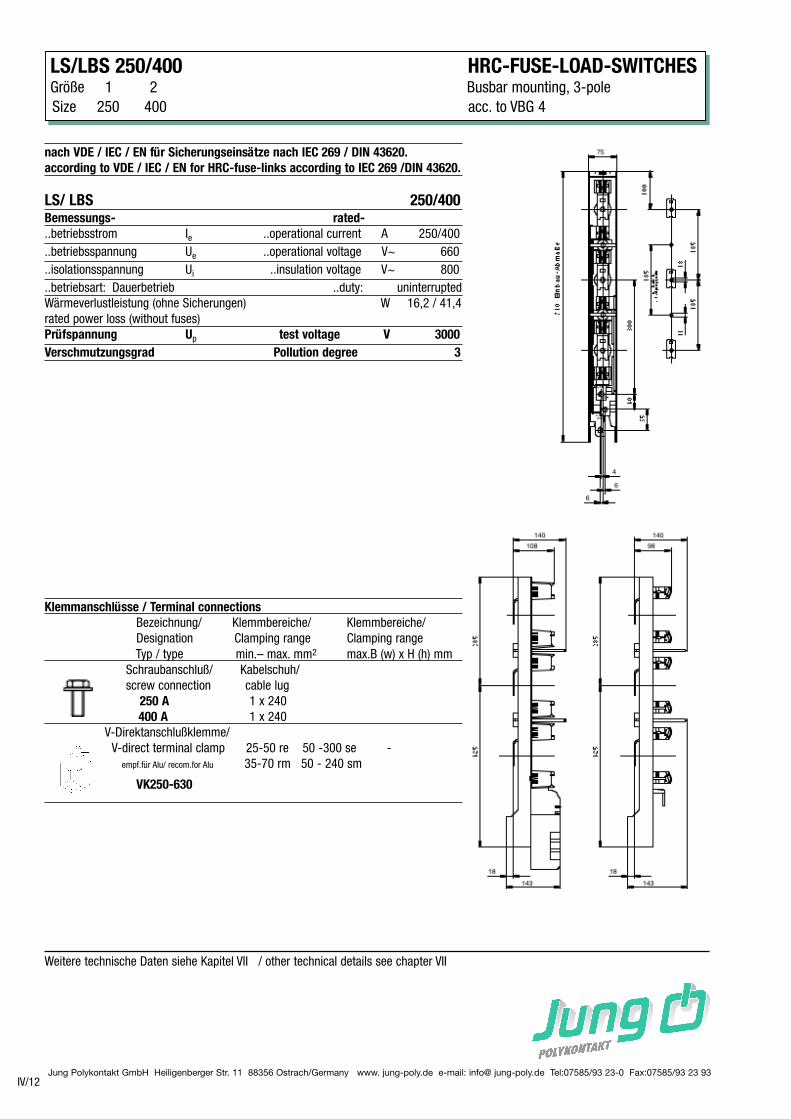
LS/LBS 250/400 HRC-FUSE-LOAD-SWITCHESGröße 1 2 Busbar mounting, 3-pole
Size 250 400 acc. to VBG 4
IV/12
Weitere technische Daten siehe Kapitel VII / other technical details see chapter VII
nach VDE / IEC / EN für Sicherungseinsätze nach IEC 269 / DIN 43620.
according to VDE / IEC / EN for HRC-fuse-links according to IEC 269 /DIN 43620.
LS/ LBS 250/400Bemessungs- rated-
..betriebsstrom Ie ..operational current A 250/400
..betriebsspannung Ue ..operational voltage V~ 660
..isolationsspannung Ui ..insulation voltage V~ 800
..betriebsart: Dauerbetrieb ..duty: uninterrupted
Wärmeverlustleistung (ohne Sicherungen) W 16,2 / 41,4
rated power loss (without fuses)
Prüfspannung Up test voltage V 3000
Verschmutzungsgrad Pollution degree 3
Klemmanschlüsse / Terminal connections
Bezeichnung/ Klemmbereiche/ Klemmbereiche/
Designation Clamping range Clamping range
Typ / type min.– max. mm2 max.B (w) x H (h) mm
Schraubanschluß/ Kabelschuh/
screw connection cable lug
250 A 1 x 240
400 A 1 x 240
V-Direktanschlußklemme/
V-direct terminal clamp 25-50 re 50 -300 se -
empf.für Alu/ recom.for Alu 35-70 rm 50 - 240 sm
VK250-630
Jung Polykontakt GmbH Heiligenberger Str. 11 88356 Ostrach/Germany www. jung-poly.de e-mail: info@ jung-poly.de Tel:07585/93 23-0 Fax:07585/93 23 93
NH-SICHERUNGS-LEISTEN LS/LBS 250/400
Sammelschienenbefestigung, 3-polig Größe / Size 1 2
nach VBG 4 250 400
IV/13
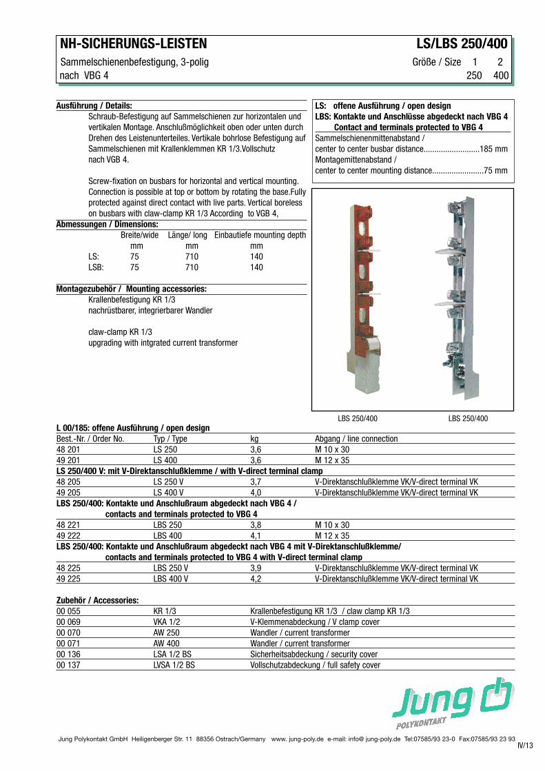
LS: offene Ausführung / open design
LBS: Kontakte und Anschlüsse abgedeckt nach VBG 4
Contact and terminals protected to VBG 4
Sammelschienenmittenabstand /
center to center busbar distance..........................185 mm
Montagemittenabstand /
center to center mounting distance........................75 mm
Ausführung / Details:
Schraub-Befestigung auf Sammelschienen zur horizontalen und
vertikalen Montage. Anschlußmöglichkeit oben oder unten durch
Drehen des Leistenunterteiles. Vertikale bohrlose Befestigung auf
Sammelschienen mit Krallenklemmen KR 1/3.Vollschutz
nach VGB 4.
Screw-fixation on busbars for horizontal and vertical mounting.
Connection is possible at top or bottom by rotating the base.Fully
protected against direct contact with live parts. Vertical boreless
on busbars with claw-clamp KR 1/3 According to VGB 4,
Abmessungen / Dimensions:
Breite/wide Länge/ long Einbautiefe mounting depth
mm mm mm
LS: 75 710 140
LSB: 75 710 140
Montagezubehör / Mounting accessories:
Krallenbefestigung KR 1/3
nachrüstbarer, integrierbarer Wandler
claw-clamp KR 1/3
upgrading with intgrated current transformer
LBS 250/400 LBS 250/400
L 00/185: offene Ausführung / open design
Best.-Nr. / Order No. Typ / Type kg Abgang / line connection
48 201 LS 250 3,6 M 10 x 30
49 201 LS 400 3,6 M 12 x 35
LS 250/400 V: mit V-Direktanschlußklemme / with V-direct terminal clamp
48 205 LS 250 V 3,7 V-Direktanschlußklemme VK/V-direct terminal VK
49 205 LS 400 V 4,0 V-Direktanschlußklemme VK/V-direct terminal VK
LBS 250/400: Kontakte und Anschlußraum abgedeckt nach VBG 4 /
contacts and terminals protected to VBG 4
48 221 LBS 250 3,8 M 10 x 30
49 222 LBS 400 4,1 M 12 x 35
LBS 250/400: Kontakte und Anschlußraum abgedeckt nach VBG 4 mit V-Direktanschlußklemme/
contacts and terminals protected to VBG 4 with V-direct terminal clamp
48 225 LBS 250 V 3,9 V-Direktanschlußklemme VK/V-direct terminal VK
49 225 LBS 400 V 4,2 V-Direktanschlußklemme VK/V-direct terminal VK
Zubehör / Accessories:
00 055 KR 1/3 Krallenbefestigung KR 1/3 / claw clamp KR 1/3
00 069 VKA 1/2 V-Klemmenabdeckung / V clamp cover
00 070 AW 250 Wandler / current transformer
00 071 AW 400 Wandler / current transformer
00 136 LSA 1/2 BS Sicherheitsabdeckung / security cover
00 137 LVSA 1/2 BS Vollschutzabdeckung / full safety cover
Jung Polykontakt GmbH Heiligenberger Str. 11 88356 Ostrach/Germany www. jung-poly.de e-mail: info@ jung-poly.de Tel:07585/93 23-0 Fax:07585/93 23 93
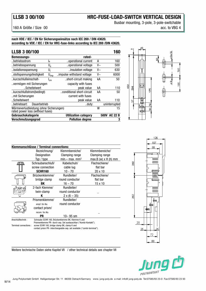
LLSB 3 00/100 HRC-FUSE-LOAD-SWITCH VERTICAL DESIGNBusbar mounting, 3-pole, 3-pole-switchable
160 A Größe / Size 00 acc. to VBG 4
IV/14
Weitere technische Daten siehe Kapitel VII / other technical details see chapter VII
nach VDE / IEC / EN für Sicherungseinsätze nach IEC 269 / DIN 43620.
according to VDE / IEC / EN for HRC-fuse-links according to IEC 269 /DIN 43620.
LLSB 3 00/100 160Bemessungs- rated-
..betriebsstrom Ie ..operational current A 160
..betriebsspannung Ue ..operational voltage V~ 500
..isolationsspannung Ui ..insulation voltage V~ 630
..stoßspannungsfestigkeit Uimp ..impulse withstand voltage V~ 6000
..kurzschlußeinschalt- Icm ..short-circuit making kA 50
..vermögen mit Sicherungen capacity with fuses
..Scheitelwert peak value kA 110
..kurzschlußstrom(bedingt) ..conditional short-circuit kA 50
..mit Sicherungen current with fuses
..Scheitelwert peak value kA 110
..betriebsart: Dauerbetrieb ..duty: uninterrupted
Wärmeverlustleistung (ohne Sicherungen) W 15rated power loss (without fuses)
Gebrauchskategorie Utilization category 500V AC 22 B
Verschmutzungsgrad Pollution degree 3
Klemmanschlüsse / Terminal connections:
Bezeichnung/ Klemmbereiche/ Klemmbereiche/
Designation Clamping range Clamping range
Typ / type min.– max. mm2 max.B (w) x H (h) mm
Schraubanschluß/ Kabelschuh/ Flachschiene/
screw connection cable lug flat bar
SCHR160 10 - 70 20 x 10
Brückenklemme/ Rundleiter/ Flachschiene/
bridge clamp round conductor flat bar
BK 16 – 70 15 x 10
2-fach Klemme/ Rundleiter/
twin-clamp round conductor _
K 2 x (6 – 35)
Prismenklemme/ Rundleiter/
empf. für Alu round conductor
contact prism/
recom. for Alu _
PR 10– 95 smAnschlußtechnik : Schraube SCHR 160, Brückenklemme BK, Klemme K und
Prismenklemme PR- durch sep. Set austauschbar (“Kombi-Kontakt”).
Terminal connections : screw SCHR 160, bridge clamp BK, clamp K and
contact prism PR- interchangeable-sep. set available (“combi-terminal”).
9
Jung Polykontakt GmbH Heiligenberger Str. 11 88356 Ostrach/Germany www. jung-poly.de e-mail: info@ jung-poly.de Tel:07585/93 23-0 Fax:07585/93 23 93
MONTAGEZUBEHÖR KRALLENKLEMMEN / CLAW-CLAMPMOUNTING ACCESSORIES
IV/30
Bitte beachten Sie auch Kapitel III/ 13-18 / Please look also at chapter III/ 13-18
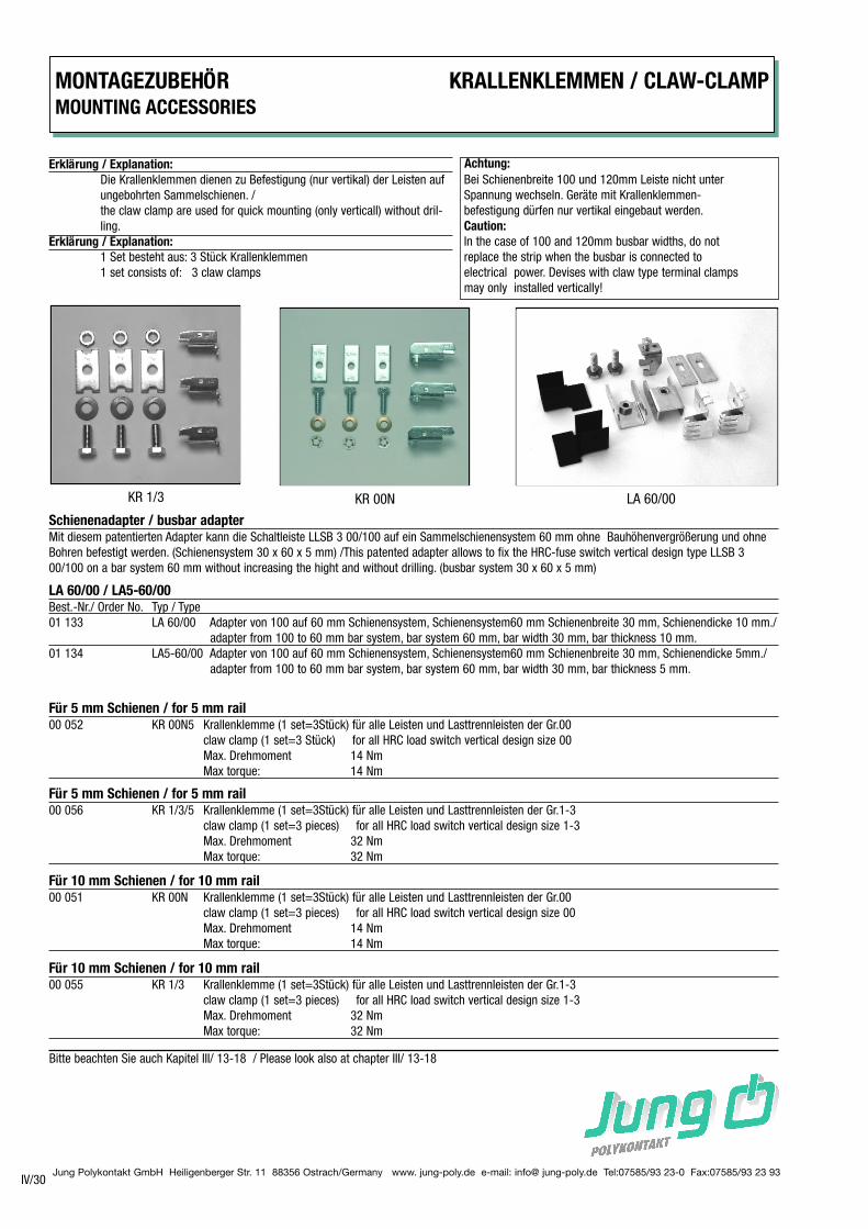
Erklärung / Explanation:
Die Krallenklemmen dienen zu Befestigung (nur vertikal) der Leisten auf
ungebohrten Sammelschienen. /
the claw clamp are used for quick mounting (only verticall) without dril-
ling.
Erklärung / Explanation:
1 Set besteht aus: 3 Stück Krallenklemmen
1 set consists of: 3 claw clamps
Achtung:
Bei Schienenbreite 100 und 120mm Leiste nicht unter
Spannung wechseln. Geräte mit Krallenklemmen-
befestigung dürfen nur vertikal eingebaut werden.
Caution:
In the case of 100 and 120mm busbar widths, do not
replace the strip when the busbar is connected to
electrical power. Devises with claw type terminal clamps
may only installed vertically!
Schienenadapter / busbar adapter
Mit diesem patentierten Adapter kann die Schaltleiste LLSB 3 00/100 auf ein Sammelschienensystem 60 mm ohne Bauhöhenvergrößerung und ohne
Bohren befestigt werden. (Schienensystem 30 x 60 x 5 mm) /This patented adapter allows to fix the HRC-fuse switch vertical design type LLSB 3
00/100 on a bar system 60 mm without increasing the hight and without drilling. (busbar system 30 x 60 x 5 mm)
Für 5 mm Schienen / for 5 mm rail
00 052 KR 00N5 Krallenklemme (1 set=3Stück) für alle Leisten und Lasttrennleisten der Gr.00
claw clamp (1 set=3 Stück) for all HRC load switch vertical design size 00
Max. Drehmoment 14 Nm
Max torque: 14 Nm
Für 5 mm Schienen / for 5 mm rail
00 056 KR 1/3/5 Krallenklemme (1 set=3Stück) für alle Leisten und Lasttrennleisten der Gr.1-3
claw clamp (1 set=3 pieces) for all HRC load switch vertical design size 1-3
Max. Drehmoment 32 Nm
Max torque: 32 Nm
Für 10 mm Schienen / for 10 mm rail
00 051 KR 00N Krallenklemme (1 set=3Stück) für alle Leisten und Lasttrennleisten der Gr.00
claw clamp (1 set=3 pieces) for all HRC load switch vertical design size 00
Max. Drehmoment 14 Nm
Max torque: 14 Nm
Für 10 mm Schienen / for 10 mm rail
00 055 KR 1/3 Krallenklemme (1 set=3Stück) für alle Leisten und Lasttrennleisten der Gr.1-3
claw clamp (1 set=3 pieces) for all HRC load switch vertical design size 1-3
Max. Drehmoment 32 Nm
Max torque: 32 Nm
KR 1/3 KR 00N LA 60/00
LA 60/00 / LA5-60/00
Best.-Nr./ Order No. Typ / Type
01 133 LA 60/00 Adapter von 100 auf 60 mm Schienensystem, Schienensystem60 mm Schienenbreite 30 mm, Schienendicke 10 mm./
adapter from 100 to 60 mm bar system, bar system 60 mm, bar width 30 mm, bar thickness 10 mm.
01 134 LA5-60/00 Adapter von 100 auf 60 mm Schienensystem, Schienensystem60 mm Schienenbreite 30 mm, Schienendicke 5mm./
adapter from 100 to 60 mm bar system, bar system 60 mm, bar width 30 mm, bar thickness 5 mm.
Jung Polykontakt GmbH Heiligenberger Str. 11 88356 Ostrach/Germany www. jung-poly.de e-mail: info@ jung-poly.de Tel:07585/93 23-0 Fax:07585/93 23 93
BLINDABDECKUNGEN / COVER MONTAGEZUBEHÖRFür Reserveplätze / for reserve place MOUNTING ACCESSORIES
IV/31
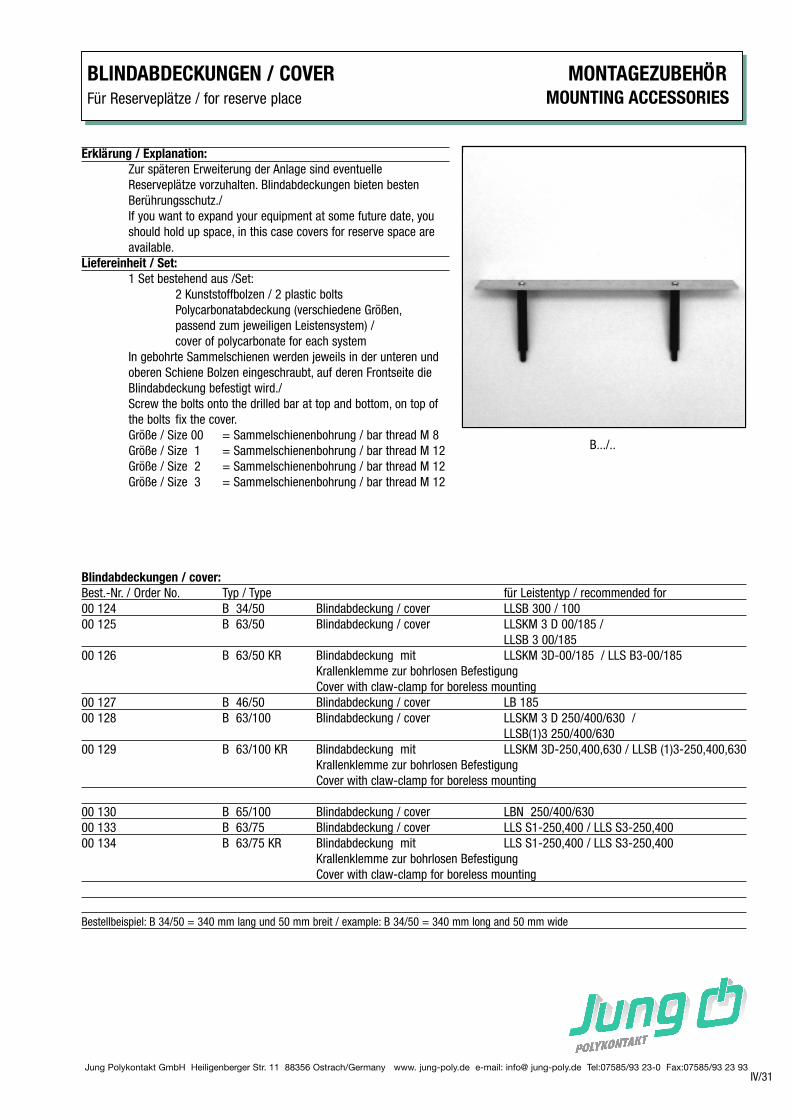
B.../..
Blindabdeckungen / cover:
Best.-Nr. / Order No. Typ / Type für Leistentyp / recommended for
00 124 B 34/50 Blindabdeckung / cover LLSB 300 / 100
00 125 B 63/50 Blindabdeckung / cover LLSKM 3 D 00/185 /
LLSB 3 00/185
00 126 B 63/50 KR Blindabdeckung mit LLSKM 3D-00/185 / LLS B3-00/185
Krallenklemme zur bohrlosen Befestigung
Cover with claw-clamp for boreless mounting
00 127 B 46/50 Blindabdeckung / cover LB 185
00 128 B 63/100 Blindabdeckung / cover LLSKM 3 D 250/400/630 /
LLSB(1)3 250/400/630
00 129 B 63/100 KR Blindabdeckung mit LLSKM 3D-250,400,630 / LLSB (1)3-250,400,630
Krallenklemme zur bohrlosen Befestigung
Cover with claw-clamp for boreless mounting
00 130 B 65/100 Blindabdeckung / cover LBN 250/400/630
00 133 B 63/75 Blindabdeckung / cover LLS S1-250,400 / LLS S3-250,400
00 134 B 63/75 KR Blindabdeckung mit LLS S1-250,400 / LLS S3-250,400
Krallenklemme zur bohrlosen Befestigung
Cover with claw-clamp for boreless mounting
Bestellbeispiel: B 34/50 = 340 mm lang und 50 mm breit / example: B 34/50 = 340 mm long and 50 mm wide
Erklärung / Explanation:
Zur späteren Erweiterung der Anlage sind eventuelle
Reserveplätze vorzuhalten. Blindabdeckungen bieten besten
Berührungsschutz./
If you want to expand your equipment at some future date, you
should hold up space, in this case covers for reserve space are
available.
Liefereinheit / Set:
1 Set bestehend aus /Set:
2 Kunststoffbolzen / 2 plastic bolts
Polycarbonatabdeckung (verschiedene Größen,
passend zum jeweiligen Leistensystem) /
cover of polycarbonate for each system
In gebohrte Sammelschienen werden jeweils in der unteren und
oberen Schiene Bolzen eingeschraubt, auf deren Frontseite die
Blindabdeckung befestigt wird./
Screw the bolts onto the drilled bar at top and bottom, on top of
the bolts fix the cover.
Größe / Size 00 = Sammelschienenbohrung / bar thread M 8
Größe / Size 1 = Sammelschienenbohrung / bar thread M 12
Größe / Size 2 = Sammelschienenbohrung / bar thread M 12
Größe / Size 3 = Sammelschienenbohrung / bar thread M 12
Jung Polykontakt GmbH Heiligenberger Str. 11 88356 Ostrach/Germany www. jung-poly.de e-mail: info@ jung-poly.de Tel:07585/93 23-0 Fax:07585/93 23 93
MONTAGEZUBEHÖR ADAPTER , KONTAKTVERLÄNGERUNGEN MOUNTING ACCESSORIES ADAPTER , EXTENSIONS
IV/32
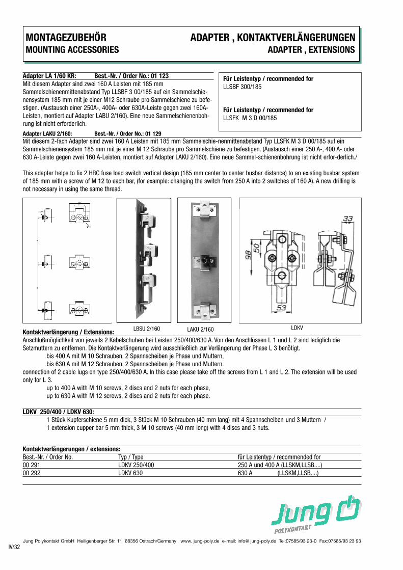
Adapter LA 1/60 KR: Best.-Nr. / Order No.: 01 123
Mit diesem Adapter sind zwei 160 A Leisten mit 185 mm
Sammelschienenmittenabstand Typ LLSBF 3 00/185 auf ein Sammelschie-
nensystem 185 mm mit je einer M12 Schraube pro Sammelschiene zu befe-
stigen. (Austausch einer 250A-, 400A- oder 630A-Leiste gegen zwei 160A-
Leisten, montiert auf Adapter LABU 2/160). Eine neue Sammelschienenboh-
rung ist nicht erforderlich.
Für Leistentyp / recommended for
LLSBF 300/185
Für Leistentyp / recommended for
LLSFK M 3 D 00/185
Adapter LAKU 2/160: Best.-Nr. / Order No.: 01 129
Mit diesem 2-fach Adapter sind zwei 160 A Leisten mit 185 mm Sammelschie-nenmittenabstand Typ LLSFK M 3 D 00/185 auf ein
Sammelschienensystem 185 mm mit je einer M 12 Schraube pro Sammelschiene zu befestigen. (Austausch einer 250 A-, 400 A- oder
630 A-Leiste gegen zwei 160 A-Leisten, montiert auf Adapter LAKU 2/160). Eine neue Sammel-schienenbohrung ist nicht erfor-derlich./
This adapter helps to fix 2 HRC fuse load switch vertical design (185 mm center to center busbar distance) to an existing busbar system
of 185 mm with a screw of M 12 to each bar, (for example: changing the switch from 250 A into 2 switches of 160 A). A new drilling is
not necessary in using the same thread.
Kontaktverlängerung / Extensions:
Anschlußmöglichkeit von jeweils 2 Kabelschuhen bei Leisten 250/400/630 A. Von den Anschlüssen L 1 und L 2 sind lediglich die
Setzmuttern zu entfernen. Die Kontaktverlängerung wird ausschließlich zur Verlängerung der Phase L 3 benötigt.
bis 400 A mit M 10 Schrauben, 2 Spannscheiben je Phase und Muttern,
bis 630 A mit M 12 Schrauben, 2 Spannscheiben je Phase und Muttern.
connection of 2 cable lugs on type 250/400/630 A. In this case please take off the screws from L 1 and L 2. The extension will be used
only for L 3.
up to 400 A with M 10 screws, 2 discs and 2 nuts for each phase,
up to 630 A with M 12 screws, 2 discs and 2 nuts for each phase.
LDKV 250/400 / LDKV 630:
1 Stück Kupferschiene 5 mm dick, 3 Stück M 10 Schrauben (40 mm lang) mit 4 Spannscheiben und 3 Muttern /
1 extension cupper bar 5 mm thick, 3 M 10 screws (40 mm long) with 4 discs and 3 nuts.
Kontaktverlängerungen / extensions:
Best.-Nr. / Order No. Typ / Type für Leistentyp / recommended for
00 291 LDKV 250/400 250 A und 400 A (LLSKM,LLSB....)
00 292 LDKV 630 630 A (LLSKM,LLSB....)
LBSU 2/160 LAKU 2/160 LDKV
BLINDLEISTEN / COVER STRIPS MONTAGEZUBEHÖR
MOUNTING ACCESSORIES
IV/33Jung Polykontakt GmbH Heiligenberger Str. 11 88356 Ostrach/Germany www. jung-poly.de e-mail: info@ jung-poly.de Tel:07585/93 23-0 Fax:07585/93 23 93
Blendleisten / 1 Set bestehend aus: Länge x Breite
cover strips: 1 Set consisting of: Length x Width
Best.-Nr. / Typ / Stück Montage für Leistentyp / mm
Order No. Type Pcs. Mounting Appropiate for Type
00 090 BLN 00 1 schraubbar links und rechts LLS B 3 00/100 310 x 25
pluggable left and right
00 092 BLN 185 1 schraubbar links oder rechts LLSB (F) 3 00/185 585 x 25
screwable left or right
00 093 BLN 32-185/3 1 schraubbar links oder rechts LLSB3 3 00/185 574 x 25
screwable left or right in Kombination mit/ in combination with LLSB3 250/400/630
00 095 BLN 1 schraubbar links oder rechts LLSB (S) 3 250/400/630 585 x 25
screwable left or right
00 105 BLK 0/185 1 schraubbar links oder rechts LLSK M 3 D 00/185 630 x 25
screwable left or right
00 104 BLK 1 schraubbar links oder rechts LLSK M 3 D 250/400/630 630 x 25
screwable left or right
00 107 BLKS 0/185 1 schraubbar links oder rechts LLSK M 3 D 00/185 580 x 25
screwable left or right in einem 600. Feld
00 106 BLKS 1 schraubbar links oder rechts LLSK M 3 D 250/400/630 580 x 25
screwable left or right in einem 600. Feld
00 096 BLS 1 schraubbar links oder rechts LLS S1-250/400 612,5 x 20
screwable left or right LLS S3-250/400
Erklärung / Explanation:
Blendleisten werden zur Abdeckung von seitlichen Zwischenräumen bis 25 mm Breite eingebaut, z.B. zwischen
Schrankrahmen und Leistenseite, etc..
Cover strips are used to cover lateral gaps of up to 25 mm, e. g. between cabinet frame and base side, etc..
Jung Polykontakt GmbH Heiligenberger Str. 11 88356 Ostrach/Germany www. jung-poly.de e-mail: info@ jung-poly.de Tel:07585/93 23-0 Fax:07585/93 23 93
MONTAGEZUBEHÖR WANDLERANSCHLUSS-SCHIENENMOUNTING ACCESSORIES BARS FOR CURRENT TRANSFORMERS
IV/34
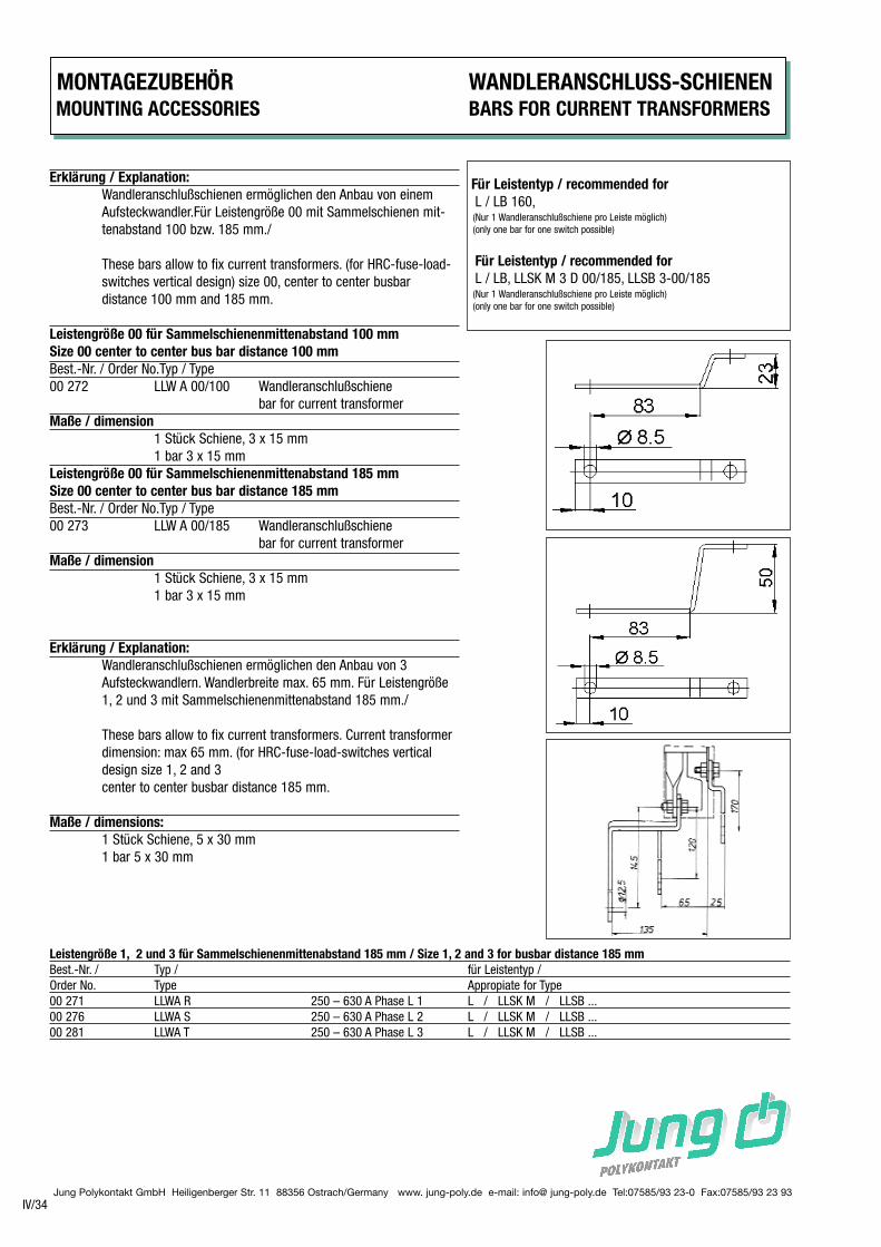
Erklärung / Explanation:
Wandleranschlußschienen ermöglichen den Anbau von einem
Aufsteckwandler.Für Leistengröße 00 mit Sammelschienen mit-
tenabstand 100 bzw. 185 mm./
These bars allow to fix current transformers. (for HRC-fuse-load-
switches vertical design) size 00, center to center busbar
distance 100 mm and 185 mm.
Leistengröße 00 für Sammelschienenmittenabstand 100 mm
Size 00 center to center bus bar distance 100 mm
Best.-Nr. / Order No.Typ / Type
00 272 LLW A 00/100 Wandleranschlußschiene
bar for current transformer
Maße / dimension
1 Stück Schiene, 3 x 15 mm
1 bar 3 x 15 mm
Leistengröße 00 für Sammelschienenmittenabstand 185 mm
Size 00 center to center bus bar distance 185 mm
Best.-Nr. / Order No.Typ / Type
00 273 LLW A 00/185 Wandleranschlußschiene
bar for current transformer
Maße / dimension
1 Stück Schiene, 3 x 15 mm
1 bar 3 x 15 mm
Erklärung / Explanation:
Wandleranschlußschienen ermöglichen den Anbau von 3
Aufsteckwandlern. Wandlerbreite max. 65 mm. Für Leistengröße
1, 2 und 3 mit Sammelschienenmittenabstand 185 mm./
These bars allow to fix current transformers. Current transformer
dimension: max 65 mm. (for HRC-fuse-load-switches vertical
design size 1, 2 and 3
center to center busbar distance 185 mm.
Maße / dimensions:
1 Stück Schiene, 5 x 30 mm
1 bar 5 x 30 mm
Für Leistentyp / recommended for
L / LB 160, (Nur 1 Wandleranschlußschiene pro Leiste möglich)
(only one bar for one switch possible)
Für Leistentyp / recommended for
L / LB, LLSK M 3 D 00/185, LLSB 3-00/185(Nur 1 Wandleranschlußschiene pro Leiste möglich)
(only one bar for one switch possible)
Leistengröße 1, 2 und 3 für Sammelschienenmittenabstand 185 mm / Size 1, 2 and 3 for busbar distance 185 mm
Best.-Nr. / Typ / für Leistentyp /
Order No. Type Appropiate for Type
00 271 LLWA R 250 – 630 A Phase L 1 L / LLSK M / LLSB ...
00 276 LLWA S 250 – 630 A Phase L 2 L / LLSK M / LLSB ...
00 281 LLWA T 250 – 630 A Phase L 3 L / LLSK M / LLSB ...
ANSCHLUSSRAUM-ABDECKUNG / TERMINAL COVER
WANDLERANSCHLUSS-SCHIENEN / BARS FOR CURRENT TRANSFORMERS
MONTAGEZUBEHÖR / MOUNTING ACCESSORIES
IV/35Jung Polykontakt GmbH Heiligenberger Str. 11 88356 Ostrach/Germany www. jung-poly.de e-mail: info@ jung-poly.de Tel:07585/93 23-0 Fax:07585/93 23 93
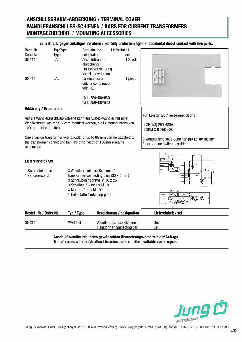
Zum Schutz gegen zufälliges Berühren / For fully protection against accidental direct contact with live parts.
Best.-Nr. Typ/Type Bezeichnung Liefereinheit
Order No. Type designation set
00 111 LAL Anschlußraum- 1 Stück
abdeckung
nur bei Verwendung
von HL anwendbar
00 111 LAL terminal cover 1 piece
only in combination
with HL
für L 250/400/630
for L 250/400/630
Erklärung / Explanation
Auf die Wandleranschluss-Schiene kann ein Austeckwandler mit einer
Wandlerbreite von max. 65mm montiert werden, die Leistenbaubreite von
100 mm bleibt erhalten.
One snap-on transformer with a width of up to 65 mm can be attached to
the transformer connecting bar. The strip width of 100mm remains
unchanged.
Für Leistentyp / recommended for
LLSB 1(3) 250-630A
LLSKM 3 D 250-630
3 Wandleranschluss-Schienen pro Leiste möglich
3 bar for one switch possible
Liefereinheit / Set
1 Set besteht aus: 3 Wandleranschluss-Schienen /
1 set consists of: transformer connecting bars (30 x 5 mm)
3 Schrauben / screws M 10 x 25
3 Scheiben / washers M 10
3 Muttern / nuts M 10
1 Halteplatte / retaining plate
Bestell. Nr / Order No. Typ / Type Bezeichnung / designation Liefereinheit / set
00 270 WAS 1-3 Wandleranschluss-Schienen Set
Transformer connecting bar set
Anschlußwandler mit Ihrem gewünschten Übersetzungsverhältnis auf Anfrage
Transformers with indiviualised transformaation ratios available upon request
Jung Polykontakt GmbH Heiligenberger Str. 11 88356 Ostrach/Germany www. jung-poly.de e-mail: info@ jung-poly.de Tel:07585/93 23-0 Fax:07585/93 23 93
MONTAGEZUBEHÖR Kontaktabdeckungen/-Hauben/ Leistensicherheitsabdeckung
MOUNTING ACCESSORIES Terminal cover/ Contact shroudes/ Security cover
IV/36
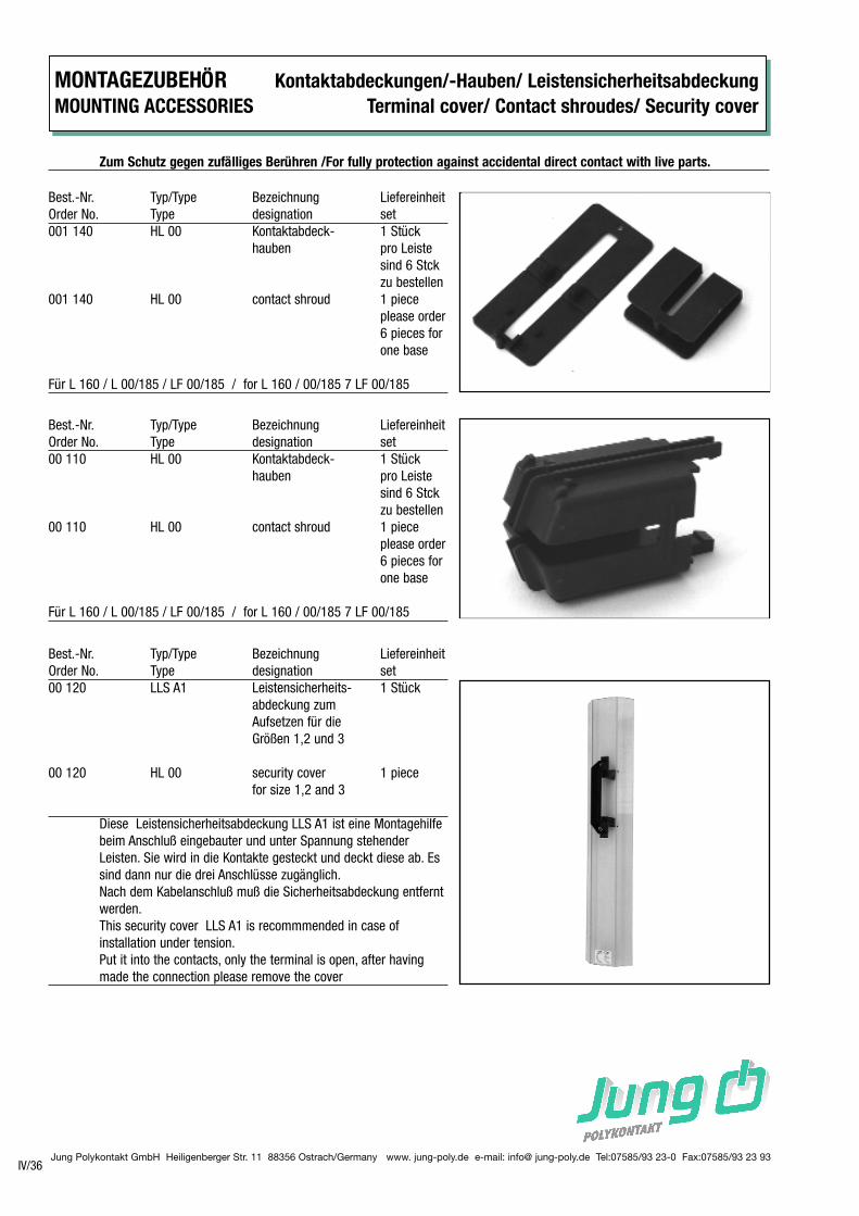
Zum Schutz gegen zufälliges Berühren /For fully protection against accidental direct contact with live parts.
Best.-Nr. Typ/Type Bezeichnung Liefereinheit
Order No. Type designation set
001 140 HL 00 Kontaktabdeck- 1 Stück
hauben pro Leiste
sind 6 Stck
zu bestellen
001 140 HL 00 contact shroud 1 piece
please order
6 pieces for
one base
Für L 160 / L 00/185 / LF 00/185 / for L 160 / 00/185 7 LF 00/185
Best.-Nr. Typ/Type Bezeichnung Liefereinheit
Order No. Type designation set
00 110 HL 00 Kontaktabdeck- 1 Stück
hauben pro Leiste
sind 6 Stck
zu bestellen
00 110 HL 00 contact shroud 1 piece
please order
6 pieces for
one base
Für L 160 / L 00/185 / LF 00/185 / for L 160 / 00/185 7 LF 00/185
Best.-Nr. Typ/Type Bezeichnung Liefereinheit
Order No. Type designation set
00 120 LLS A1 Leistensicherheits- 1 Stück
abdeckung zum
Aufsetzen für die
Größen 1,2 und 3
00 120 HL 00 security cover 1 piece
for size 1,2 and 3
Diese Leistensicherheitsabdeckung LLS A1 ist eine Montagehilfe
beim Anschluß eingebauter und unter Spannung stehender
Leisten. Sie wird in die Kontakte gesteckt und deckt diese ab. Es
sind dann nur die drei Anschlüsse zugänglich.
Nach dem Kabelanschluß muß die Sicherheitsabdeckung entfernt
werden.
This security cover LLS A1 is recommmended in case of
installation under tension.
Put it into the contacts, only the terminal is open, after having
made the connection please remove the cover
MONTAGEZUBEHÖR MOUNTING ACCESSORIES
IV/37Jung Polykontakt GmbH Heiligenberger Str. 11 88356 Ostrach/Germany www. jung-poly.de e-mail: info@ jung-poly.de Tel:07585/93 23-0 Fax:07585/93 23 93
Best.-Nr. Typ/Type Bezeichnung Liefereinheit
Order No. Type designation set
001 112 BSL Berührungsschutz 1 Stück
für die Leiste
security cover 1 piece
fuse-base
001 113 BSLA Berührungsschutz 1 Stück
für den
Anschlußraum
security cover 1 piece
terminal
Für L 160 / L 00/185 / LF 00/185 / for L 160 / 00/185 7 LF 00/185