CH1 CH2User Manual 隔离附件(ISFE)...
12
User Manual 隔离附件(ISFE) www.siglent.com 地址:深圳市宝安区68区留仙三路安通达工业园4栋三楼 服务热线:800-999-0807 R CH1 CH2 Islated Islated CH1 CH2 Isolated Front End Module Max. Input Voltages:Isolated CH1 and CH2 ±600Vpk Bandwidths:1MHz Max. Floating Voltage: From isolated channel to earth ground 1000Vrms Between two isolated channel 2000Vrms OPT01007110001 S/N: 版本号:V1.1
Transcript of CH1 CH2User Manual 隔离附件(ISFE)...

User Manual
隔离附件(ISFE)
www.siglent.com
地址:深圳市宝安区68区留仙三路安通达工业园4栋三楼
服务热线:800-999-0807
R
CH1 CH2
Islated Islated CH1 CH2
Isolated Front End ModuleMax. Input Voltages:Isolated CH1 and CH2 ±600Vpk
Bandwidths:1MHz
Max. Floating Voltage:
From isolated channel to earth ground 1000Vrms
Between two isolated channel 2000Vrms
OPT01007110001
S/N:
版本号:V1.1

鼎阳科技有限公司版权所有
未经本公司同意,不得以任何形式或手段复制、摘抄、翻译本手册的内容。
简介
2
应用环境:
即插即用,示波器选件。
USB5V供电,功耗小于1W,方便使用。
单通道隔离电压1000Vrms,通道间隔离电压2000Vrms。
可以用来测量不共地信号;家用220V交流信号;三相交流电
信号等。
使用本产品实现普通示波器通道间隔离,被测信号与大地的
隔离。
规格参数:
输入最大电压:±600Vpk
工作电压:5V±5%,USB供电
工作电流:约200mA
输出电压范围:-3Vpk~3Vpk
衰减比例:200:1
隔离通道到大地最大电压:1000Vrms
隔离通道间最大电压:2000Vrms
输入阻抗:9MΩ
带宽:1MHz
了解下列安全性预防措施,以避免人身伤害,并防止本产品
或与其相连接的任何其它产品受到损坏。为了避免可能发生的危
险,请务必按照规定使用本产品。
禁止将模块的输出端(金属BNC)与高压信号连接,否则会导致
示波器损坏或者使用者触电!
防止火灾或人身伤害
当探头或测试导线与电源线相连接时,请勿随意插拔。
将产品接地
使用前,检查探头,测试线,是否有机械性损伤,如果有请
更换。 请勿输入超过额定范围的电压
请勿开盖操作
如盖板或面板已卸下,请勿操作本产品。
使用适当的保险丝
只可使用符合本产品规定类型和额定值的保险丝。
怀疑产品出现故障时,请勿操作
如怀疑本产品有损坏,请让合格的维修人员进行检查。
避免电路外露
被测信号处于活跃状态时请勿接触外露的接头和元件。
安全说明
1

3 4
勿在潮湿环境下操作
保持产品表面清洁和干燥
请勿在易燃易爆环境中操作
安全术语和标记
本产品上使用的术语 本产品上会出现如下术语:
DANGER:表示标记附近有直接伤害危险存在。
WARNING:表示标记附近有潜在的伤害危险。
CAUTION:表示对本产品及其他财产有潜在的危险。
本系列产品上使用的标记
本产品上可能出现如下标记:
双层 绝缘
警告高压
保护性终端
小心 请参阅用户手册
应用说明
ISFE
示波器
GND
信号线缆
GND1
信号线缆
输出信号源
供电线路
浮地信号测量
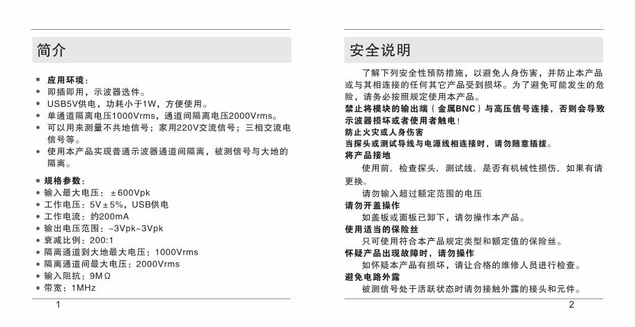
ISFE
示波器
GND
信号线缆
GND1
信号线缆
输出信号源
输出信号源
GND2
实现示波器通道隔离

5 6
接口说明
介绍隔离模块的所有外部接口及其功能,使用前请认真阅读,
避免使用不当造成触电:
◆ 隔离端外部接口BNC
隔离端接口共两个,采用黑色"塑胶材质"的BNC插头;标有
Isolated CH1, Isolated CH2字样;此接口通过电缆线或者探头
与被测量的高压信号连接。
◆ 共地端外部接口BNC
共地端外部接口共两个,为"金属材质"的BNC插头;标有
CH1,CH2字样;此接口可以通过转接头或者同轴电缆线与示波
器的通道连接,严禁将此接口与高压信号连接。
◆ USB接口
USB接口,与示波器USB接口连接,用于隔离附件供电。
接口示意图
◆ 调零接口
隔离附件面板背面可旋动调零旋钮。

7 8
操作规程
本产品主要用于高压信号测量,请使用者务必按照本操作规
程使用!
◆ 调零
首先将隔离附件与示波器的通道正确连接,将示波器的接地
端子接地;然后使用USB连接线将示波器USB口与隔离附件USB
口连接;
打开示波器并将交直流选取置于直流档位;
调节幅度旋钮置100mV档位,调节隔离附件背部的调零旋钮,
使零电平线居中;调节示波器幅度旋钮置20mV档位,微调;
◆ 测量
在被测源断电时,将测试探头或者线缆连接到隔离附件;各
个接口的连接方法请参照上述接口说明;确认所有连线均已连接
好之后,才可给被测设备上电;
注意在测量过程中请勿碰触隔离附件裸露在外面的金属,不
要在测量过程中断开或者连接连线。
◆ 断开连接
确认被测信号端(隔离模块的隔离输入端)没有电压电流之
后,方可断开连接。
服务与支持
◆ 保修概要
鼎阳科技有限公司保证生产和销售的产品,从授权经销商发
货之日起三年内(附件一年),不会出现材料和工艺缺陷。如产
品在保修期限内确有缺陷,鼎阳科技有限公司将根据保修单的详
细规定,提供修理或更换服务。
若需要服务或索取保修单的完整副本,请与最近的鼎阳科技
有限公司销售或服务办事处联系。
除此概要或适用的保修单中所提供的保修之外,鼎阳科技有
限公司不作其他任何明示或暗示的保修保证,包括但不限于对适
销性和特殊适用性的暗含保修。鼎阳科技有限公司对间接的、特
殊的或由此产生的损坏不承担任何责任。

9 1
◆ 联系我们
如您在使用本产品的过程中有任何问题或需求,可直接联系
鼎阳公司服务与支持团队,他们将为您解答产品的技术问题,同
时给您提供产品应用解决方案和产品培训服务。
深圳市鼎阳科技有限公司
服务热线:800-999-0807
地址:深圳市宝安区68区留仙三路安通达工业区4栋三楼
E-mail:[email protected]
获取最新产品和服务资讯请登录 http://www.siglent.com
STATEMENT
Copyright© by Siglent Technologies Co., Ltd. all rights
reserved. Siglent is a regisrered trademark of Siglent
Corporation.
Contents in this Manual are not allowed to copy, ectract and
translate before being allowed by Siglent.

2 3
INTRODUCTION
◆ Applications:
A accessory for oscilloscope, plug and play
Less than 1W power dissipation, USB power supply
1000Vrms form each channel to earth gound, 2000Vrms
between channels
Providing isolation from ground and isolation between
channels allowing you to take floating measurements
◆ Specifications:
MAX. Input Voltage: ±600Vpk
Voltage Rating: 5V±5%
Current Rating: 200mA
Output Voltage: -3Vpk~3Vpk
Attenuant Fator: 200:1
Max Voltage form Channl to Earth Gound: 1000Vrms
Max Voltage Between Channels: 2000Vrms
Input Impedance:9MΩ
Bandwidth:≤1MHz
Safety Information: Read First
Carefully read the following safety information before using
the device.
Do not connect the Output BNC to high voltage,
otherwise it will cause electric shock or oscilloscope
damage.
To avoid electrical shock or fire:
Do not hot plug the device.
Ground the device to earth ground
Before using, inspect voltage probes, test leads and
accessories for mechanical damage and replace if damaged.
Do not apply voltage that is outside of the rating range..
Do not operate the device with covers or panels removed.
Use proper fuse to protect the operator
Servicing described in this manual is to be done only by
qualified service personnel. To avoid electrical shock, do not
service the device unless you are qualified.
Do not touch the exposed metal when connecting with active
voltage source
4 5
Do not operate in damp conditions.
Keep the surface clean and dry.
Do not operate in an explosive atmosphere.
Safety Terms and Symbols
Terms in this Manual.
These terms may be appeared in this manual:
DANGER: indicates an injury hazard that may immediately
happen.
WARNING :indicates an injury hazard that may not
immediately happen.
CAUTION: indicates a poteential damage to the instrument or
other property might occur.
Symbols on the Product.
The following symbols may appear on the product:
Hazardous Protective Refer to the Double Voltage Earth Terminal instruction Insulated
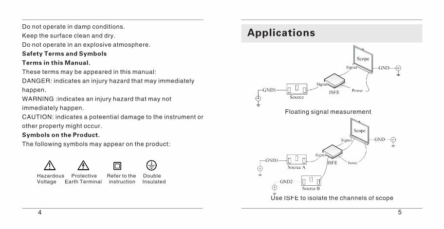
Applications
Floating signal measurement
Use ISFE to isolate the channels of scope

6 7
Interface
Read this part before you make any connection, to avoid
electrical shock:
◆ Input BNC
Two input BNC jacks (black) have no exposed metal and are
fully insulated to protect against electrical shock. This part can
be connected with source through proper probes or wires.
◆ Ooutput BNC
The output BNC jacks made of metal. While the device
powered on, do not contact them. These parts are supposed to
connect with scope.
◆ USB Host
Power supply interface. This interface is used to power the
device on.◆ Adjusting Knob
Adjust the knob at the back side of the device,make the level
to zero.
8 9
Operations
This device is used to test high voltage that may cause
electrical shock, please operate it follow the steps below.
◆ Adjust
Ground the device to earth ground.
Conect the device to scope and power on.
Set the scope to 100mv/div(DC Coupling). Adjust the konb at
the back side and make the level to zero.
◆ Measurment
Connect the device, scope and source before powering them
on.
Don't contact any exposed metal while the electrical loops
are active.
◆ Disconnect
Make sure that the source, device and scope are powered off
before disconnected.
Service and Support
Warranty
Siglent Technologies warrants each SIGLENT
manufactured and sold product against defects
in material and workmanshio under normal use
and service for a period of three years from
shipment(accessories one year). SIGLENT will
either repair or, at our option, replace any product returned to our authorized service
center within this period according to the
princioles in warranty card. If you need service or complete accessories of warranty card,
please contact the nearest SIGLENT office in
your region.
The warranty above replaces all other

10
Contact us
11
warranties, expressed or implied, including but
not limited to any inplied warranty or
merchantability, fitness, or adequacy for any
particular purpose or use. SIGLENT shall not be
liable for any special, incidental, or consequential damages, whether in contract or
otherwise. The customer is responsible for the transportation and insurance charges for the
return of products to theservice facility.
If you need any technical support or other help,
you can contact SIGLENT service department
directly.
Siglent Technologies Co., Ltd
Add: 3/F, Building 4, Antongda industry area,3rd
LiuXan Rd, Baona District, ShenZhen, China.
Tel: 800-999-0807
E-mail:[email protected]
To get latest product and service information
please log in http://www.siglent.com