
Compact 3D quantum memory - arxiv.org · Compact 3D quantum memory Edwar Xie,1,2,3, a) Frank...
5
Compact 3D quantum memory Edwar Xie, 1, 2, 3, a) Frank Deppe, 1, 2, 3 Michael Renger, 1, 2 Daniel Repp, 2 Peter Eder, 1, 2, 3 Michael Fischer, 1, 2, 3 Jan Goetz, 1, 2 Stefan Pogorzalek, 1, 2 Kirill G. Fedorov, 1, 2 Achim Marx, 1 and Rudolf Gross 1, 2, 3, b) 1) Walther-Meißner-Institut, Bayerische Akademie der Wissenschaften, 85748 Garching, Germany 2) Physik-Department, Technische Universit¨ at M¨ unchen, 85748 Garching, Germany 3) Nanosystems Initiative Munich (NIM), Schellingstraße 4, 80799 M¨ uunchen, Germany (Dated: 15 May 2018) Superconducting 3D microwave cavities offer state-of-the-art coherence times and a well controlled environ- ment for superconducting qubits. In order to realize at the same time fast readout and long-lived quantum information storage, one can couple the qubit both to a low-quality readout and a high-quality storage cavity. However, such systems are bulky compared to their less coherent 2D counterparts. A more compact and scalable approach is achieved by making use of the multimode structure of a 3D cavity. In our work, we investigate such a device where a transmon qubit is capacitively coupled to two modes of a single 3D cavity. The external coupling is engineered so that the memory mode has an about 100 times larger quality factor than the readout mode. Using an all-microwave second-order protocol, we realize a lifetime enhancement of the stored state over the qubit lifetime by a factor of 6 with a fidelity of approximately 80% determined via quantum process tomography. We also find that this enhancement is not limited by fundamental constraints. Engineered quantum systems are a versatile re- source for promising applications, such as quantum computing 1,2 , quantum communication 3,4 and quantum cryptography 5 . Commonly, quantum resources are fairly fragile and decay on a short timescale. Therefore, they have to be protected by placing them in a well- isolated enviroment 6 . In circuit quantum electrody- namics (QED), this is typically realized by coupling a superconducting qubit to a microwave resonator serv- ing both for qubit protection 7 and readout 8 . More- over, the resonator itself can be designed to decay much slower than the qubit 9 . Then, the lifetime of a quan- tum state can be enhanced by the intermediate storage of the qubit state in a long-lived resonator mode. In terms of coherence times, 3D microwave waveguide cav- ities yield the best results so far, reaching the millisec- ond regime 10,11 . Other quantum memories can be con- structed using microscopic defect states 12–14 or a nano- mechanical oscillator 15 . In circuit QED architectures, long storage times and fast readout are conflicting re- quirements, asking for slow and fast cavity decay, re- spectively. A possible solution is to physically separate the storage and the readout resonators 16–20 . However, regarding scalabitiy and reduction of footprint, this ap- proach is not optimal. By combining the high Q-factors of 3D cavities with the fast readout capabilities and com- pactness of 2D resonators, the system dimensions can be reduced 21 . Another promising approach is to use the multimode structure of 2D resonators 22 . In this case, the system turns out to be even more compact and scal- able, however, this is achieved at the expense of a rather low storage time. To combine the benefits from both ap- proaches, the multimode structure of a single 3D cavity a) Electronic mail: [email protected] b) Electronic mail: [email protected] can be employed 23,24 . On the one hand, we take advan- tage of high-Q 3D cavities and, on the other hand, we entirely get rid of a separate readout resonator without losing the fast readout capability. In this Letter, we introduce and analyze a compact quantum memory system based on a fixed-frequency transmon qubit 25 coupled to two distinct modes of a single 3D microwave cavity (cf. Fig. 1). The cavity is made of aluminum (Al 99.5 %) with two antennas for external coupling. It is mounted inside a dilution re- frigerator with approximately 30 mK base temperature. From a finite-element simulation 26 of the cavity trans- verse electric (TE) modes [cf. Fig. 1 (c)] we observe that the TE101 mode can be overcoupled while maintain- ing an undercoupled TE201 mode by properly placing the coupling antennas. In this way, the completely de- coupled, highly coherent TE201 mode can be used for information storage and the well-coupled TE101 mode for dispersive readout at a megahertz rate 8 . In our configuration, the fundamental TE101 readout mode ω RO /2π = 5.518 GHz is overcoupled and has a de- cay rate κ RO /2π = 4 MHz, whereas the first harmonic TE201 storage mode ω s /2π =8.707 546 GHz has a de- cay rate κ s /2π = 24.7 kHz [cf. Fig. 1 (d)]. From a bare cavity measurement, we estimate the internal Q-factors Q RO 0 ’ 1.9 × 10 6 and Q s 0 ’ 1 × 10 6 . For the TE201 mode to be symmetric with regard to the antennas, we insert two 3 mm × 10 mm large silicon chips centered near the electric field antinodes. One serves as a dummy and on the other we fabricate the single-junction trans- mon qubit using aluminum technology and double-angle shadow evaporation. Due to its off-center placement inside the cavity, it couples to both the TE101 and the TE201 mode simultaneously with an equal coupling strength g/2π ’ 53 MHz. In addition, there is a small residual coupling g 102 /2π ’ 8 MHz to the TE102 mode 27 . The qubit transition frequency ω q /2π =6.234 GHz is de- arXiv:1803.04711v2 [quant-ph] 14 May 2018
Transcript of Compact 3D quantum memory - arxiv.org · Compact 3D quantum memory Edwar Xie,1,2,3, a) Frank...
Compact 3D quantum memoryEdwar Xie,1, 2, 3, a) Frank Deppe,1, 2, 3 Michael Renger,1, 2 Daniel Repp,2 Peter Eder,1, 2, 3 Michael Fischer,1, 2, 3 JanGoetz,1, 2 Stefan Pogorzalek,1, 2 Kirill G. Fedorov,1, 2 Achim Marx,1 and Rudolf Gross1, 2, 3, b)1)Walther-Meißner-Institut, Bayerische Akademie der Wissenschaften, 85748 Garching,Germany2)Physik-Department, Technische Universitat Munchen, 85748 Garching, Germany3)Nanosystems Initiative Munich (NIM), Schellingstraße 4, 80799 Muunchen,Germany
(Dated: 15 May 2018)
Superconducting 3D microwave cavities offer state-of-the-art coherence times and a well controlled environ-ment for superconducting qubits. In order to realize at the same time fast readout and long-lived quantuminformation storage, one can couple the qubit both to a low-quality readout and a high-quality storage cavity.However, such systems are bulky compared to their less coherent 2D counterparts. A more compact andscalable approach is achieved by making use of the multimode structure of a 3D cavity. In our work, weinvestigate such a device where a transmon qubit is capacitively coupled to two modes of a single 3D cavity.The external coupling is engineered so that the memory mode has an about 100 times larger quality factorthan the readout mode. Using an all-microwave second-order protocol, we realize a lifetime enhancement ofthe stored state over the qubit lifetime by a factor of 6 with a fidelity of approximately 80 % determined viaquantum process tomography. We also find that this enhancement is not limited by fundamental constraints.
Engineered quantum systems are a versatile re-source for promising applications, such as quantumcomputing1,2, quantum communication3,4 and quantumcryptography5. Commonly, quantum resources are fairlyfragile and decay on a short timescale. Therefore,they have to be protected by placing them in a well-isolated enviroment6. In circuit quantum electrody-namics (QED), this is typically realized by coupling asuperconducting qubit to a microwave resonator serv-ing both for qubit protection7 and readout8. More-over, the resonator itself can be designed to decay muchslower than the qubit9. Then, the lifetime of a quan-tum state can be enhanced by the intermediate storageof the qubit state in a long-lived resonator mode. Interms of coherence times, 3D microwave waveguide cav-ities yield the best results so far, reaching the millisec-ond regime10,11. Other quantum memories can be con-structed using microscopic defect states12–14 or a nano-mechanical oscillator15. In circuit QED architectures,long storage times and fast readout are conflicting re-quirements, asking for slow and fast cavity decay, re-spectively. A possible solution is to physically separatethe storage and the readout resonators16–20. However,regarding scalabitiy and reduction of footprint, this ap-proach is not optimal. By combining the high Q-factorsof 3D cavities with the fast readout capabilities and com-pactness of 2D resonators, the system dimensions can bereduced21. Another promising approach is to use themultimode structure of 2D resonators22. In this case,the system turns out to be even more compact and scal-able, however, this is achieved at the expense of a ratherlow storage time. To combine the benefits from both ap-proaches, the multimode structure of a single 3D cavity
a)Electronic mail: [email protected])Electronic mail: [email protected]
can be employed23,24. On the one hand, we take advan-tage of high-Q 3D cavities and, on the other hand, weentirely get rid of a separate readout resonator withoutlosing the fast readout capability.
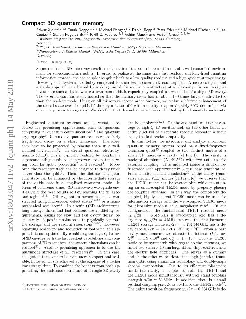
In this Letter, we introduce and analyze a compactquantum memory system based on a fixed-frequencytransmon qubit25 coupled to two distinct modes of asingle 3D microwave cavity (cf. Fig. 1). The cavity ismade of aluminum (Al 99.5 %) with two antennas forexternal coupling. It is mounted inside a dilution re-frigerator with approximately 30 mK base temperature.From a finite-element simulation26 of the cavity trans-verse electric (TE) modes [cf. Fig. 1 (c)] we observe thatthe TE101 mode can be overcoupled while maintain-ing an undercoupled TE201 mode by properly placingthe coupling antennas. In this way, the completely de-coupled, highly coherent TE201 mode can be used forinformation storage and the well-coupled TE101 modefor dispersive readout at a megahertz rate8. In ourconfiguration, the fundamental TE101 readout modeωRO/2π = 5.518 GHz is overcoupled and has a de-cay rate κRO/2π = 4 MHz, whereas the first harmonicTE201 storage mode ωs/2π = 8.707 546 GHz has a de-cay rate κs/2π = 24.7 kHz [cf. Fig. 1 (d)]. From a barecavity measurement, we estimate the internal Q-factorsQRO
0 ' 1.9× 10⁶ and Qs0 ' 1× 10⁶. For the TE201
mode to be symmetric with regard to the antennas, weinsert two 3 mm× 10 mm large silicon chips centered nearthe electric field antinodes. One serves as a dummyand on the other we fabricate the single-junction trans-mon qubit using aluminum technology and double-angleshadow evaporation. Due to its off-center placementinside the cavity, it couples to both the TE101 andthe TE201 mode simultaneously with an equal couplingstrength g/2π ' 53 MHz. In addition, there is a smallresidual coupling g102/2π ' 8 MHz to the TE102 mode27.The qubit transition frequency ωq/2π = 6.234 GHz is de-
arX
iv:1
803.
0471
1v2
[qu
ant-
ph]
14
May
201
8
2
(b)
355 µm
-2 -1 0 1 2102
104
106
108
1010
1012 Ø 1.6 mm antennaØ 0.1 mm antenna
simul
ated
Qs x
antenna's x-position (mm)
overcoupledregime
± 0.14 mm
Qs0 ≈ 1x10⁶
Qsx ≈ 3.7x10⁵
TE101 TE201 TE102 high
low
xz
xy
xz
(c)(a)
1 cm
(d) (e)
≃
≃
(kHz)
FIG. 1. (a) Photograph of the aluminum 3D cavity. The reddashed line indicates the equatorial plane of the cavity. (b)Optical micrograph of the superconducting transmon qubit.The two gridded metallic capacitors are connected via a sub-micron Josephson junction indicated by the red arrow. (c)Simulated y-component of the electrical field distribution inthe cavity equatorial plane for the lowest three modes. An-tenna pins are depicted as circles. The chip positions aremarked with black rectangles. Their center positions are dis-placed in x-direction from the cavity center by 6 mm. (d)Transmission power versus frequency of the storage mode(dots) with Lorentzian fit (line). (e) Simulated external Q-factor Qs
x of the storage mode for two different antenna diam-eters as a function of the antenna’s x-position [x = 0 denotesthe cavity center as shown in (c)]. The overcoupled regimeis marked with a grey box. The green arrow indicates Qs
x
for this experiment (antenna diameter of 0.1 mm). The blackarrows show the positioning window to reach Qs
x ≥ Qs0.
signed to fall in between ωs and ωRO resulting in disper-sive shifts of χRO = 3.6 MHz and χs = 1.1 MHz for thereadout and storage mode, respectively. We measure anaverage qubit energy decay time T q
1 = (1.32± 0.05) µsand a decoherence time T q
2 = 2.49 µs, which is obtainedvia a Ramsey-type experiment. The qubit has an anhar-monicity α = ωef−ωq ' −2π×185 MHz. Due to the largedetuning between qubit and readout mode, the qubit life-time is not Purcell limited, even though the readout modeis designed to have a fast decay. For our sample, the Pur-cell limit for the qubit lifetime is calculated to be 20 µs.
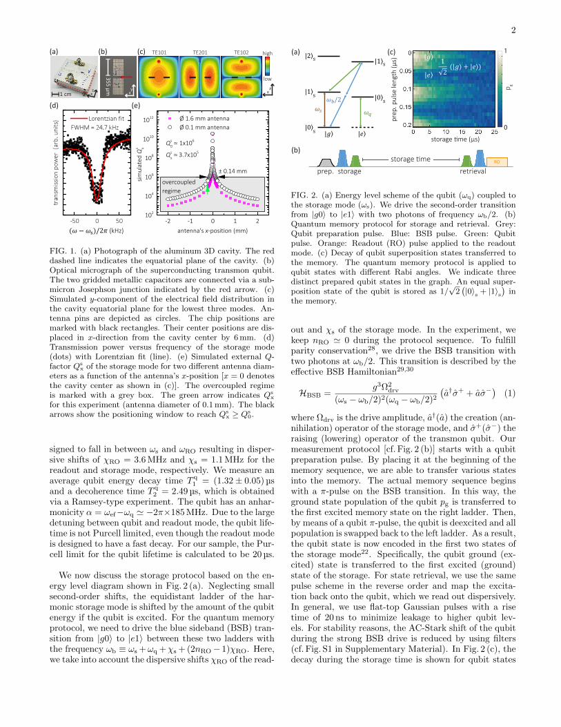
We now discuss the storage protocol based on the en-ergy level diagram shown in Fig. 2 (a). Neglecting smallsecond-order shifts, the equidistant ladder of the har-monic storage mode is shifted by the amount of the qubitenergy if the qubit is excited. For the quantum memoryprotocol, we need to drive the blue sideband (BSB) tran-sition from |g0〉 to |e1〉 between these two ladders withthe frequency ωb ≡ ωs +ωq +χs + (2nRO− 1)χRO. Here,we take into account the dispersive shifts χRO of the read-
(a)
/2
s
s
s
s
s
storage time (µs)
pre
p. p
ulse
leng
th (µ
s)
(c)
prep. storage retrievalROstorage time
(b)
0
1
p g
FIG. 2. (a) Energy level scheme of the qubit (ωq) coupled tothe storage mode (ωs). We drive the second-order transitionfrom |g0〉 to |e1〉 with two photons of frequency ωb/2. (b)Quantum memory protocol for storage and retrieval. Grey:Qubit preparation pulse. Blue: BSB pulse. Green: Qubitpulse. Orange: Readout (RO) pulse applied to the readoutmode. (c) Decay of qubit superposition states transferred tothe memory. The quantum memory protocol is applied toqubit states with different Rabi angles. We indicate threedistinct prepared qubit states in the graph. An equal super-position state of the qubit is stored as 1/
√2(|0〉s + |1〉s
)in
the memory.
out and χs of the storage mode. In the experiment, wekeep nRO ' 0 during the protocol sequence. To fulfillparity conservation28, we drive the BSB transition withtwo photons at ωb/2. This transition is described by theeffective BSB Hamiltonian29,30
HBSB =g3Ω2
drv
(ωs − ωb/2)2(ωq − ωb/2)2(a†σ+ + aσ−
)(1)
where Ωdrv is the drive amplitude, a†(a) the creation (an-nihilation) operator of the storage mode, and σ+(σ−) theraising (lowering) operator of the transmon qubit. Ourmeasurement protocol [cf. Fig. 2 (b)] starts with a qubitpreparation pulse. By placing it at the beginning of thememory sequence, we are able to transfer various statesinto the memory. The actual memory sequence beginswith a π-pulse on the BSB transition. In this way, theground state population of the qubit pg is transferred tothe first excited memory state on the right ladder. Then,by means of a qubit π-pulse, the qubit is deexcited and allpopulation is swapped back to the left ladder. As a result,the qubit state is now encoded in the first two states ofthe storage mode22. Specifically, the qubit ground (ex-cited) state is transferred to the first excited (ground)state of the storage. For state retrieval, we use the samepulse scheme in the reverse order and map the excita-tion back onto the qubit, which we read out dispersively.In general, we use flat-top Gaussian pulses with a risetime of 20 ns to minimize leakage to higher qubit lev-els. For stability reasons, the AC-Stark shift of the qubitduring the strong BSB drive is reduced by using filters(cf. Fig. S1 in Supplementary Material). In Fig. 2 (c), thedecay during the storage time is shown for qubit states

3
0 5 10 15 20 25 30 35
0.0
0.2
0.4
0.6
0.8
1.0no
rmal
ized
popu
latio
n
storage time (µs)
Storage mode T coh1 = 9.20 µs
Qubit T q1 = 1.32 µs
Readout mode T RO1 = 0.08 µs
Quantum memory dataQuantum memory fit T s
1 = 8.43 µs
4 6 8 10 120
10
20
T s1 (µs)
T s1 = 8.0 ± 1.8 µs
12 16 20 240
10
20
T s2 (µs)
T s2 = 15.5 ± 2.2 µs
coun
t(a)
(b) (c)
FIG. 3. (a) Comparison of decay rates of the quantum mem-ory system. An exemplary trace of a single quantum memorymeasurement is shown (black rectangles). The correspondingdecay time is obtained with an exponential fit. (b) and (c)Statistics of the T s
1 and T s2 of a Fock state |1〉s in the storage
mode.
prepared with different preparation pulse lengths. Thetypical Rabi oscillation pattern is visible, however, witha significantly smaller decay rate as compared to that ofthe bare qubit. Hence, we find that superposition statesof the qubit are stored as superpositions of Fock statesin the storage mode as expected.
In order to study the decay time of the memory, weuse a protocol preparing the qubit in the |g〉 state to ob-tain the Fock state |1〉s in the memory. The decay of thisstate is plotted versus the storage time in Fig. 3 (a). Wemeasure an average relaxation time T s
1 = (8.0± 1.8) µs.The data is in good agreement with an exponential decay.Small deviations from this behavior can be attributed tomeasurement artifacts. We can also perform a protocolpreparing the qubit in state 1/
√2 (|g〉+ |e〉) and rotat-
ing the qubit by π/2 at the end of the protocol. SuchRamsey-type measurement yields T s
2 = (15.5± 2.2) µs.Figure 3 (b) and (c) display histograms of the measuredmemory decay and decoherence times, respectively. Bothfollow a normal distribution. These fluctuations are fre-quently observed in literature and typically explained byensembles of microscopic two-level fluctuators31,32. Themeasured coherence time is slightly lower than expectedfrom the 2T1-bound. As a result, we extract a dephasingtime of T s
ϕ = (1/T s2 − 1/2T s
1)−1 = 0.5 ms for the storagemode. Originally, a bare harmonic oscillator exhibits nodephasing, however, in our case, we can explain this be-havior by considering a stochastic qubit jump rate11 be-tween |g〉 and |e〉. This results in frequency jumps of ωs
due to the dispersive interaction and, as a consequence,a loss of phase information. We consider this mecha-nism to be dominant in our experiment because, via the
relation10 Γϕ ' Peκq, with κq being the qubit decayrate and Γϕ the pure dephasing rate, we extract a qubitexcited state population in equilibrium Pe = 0.3 % inagreement with an estimate33 based on the temperatureof the cavity walls of 50 mK. Furthermore, both T s
1 andT s2 are by a factor of 6 longer than their bare-qubit coun-
terparts. This observation is another indication, thatthe storage mode partially inherits the dephasing prop-erties of the qubit. Finally, we compare the quantumstorage time with the decay time of a coherent state inthe storage mode. To this end, we excite the storagemode directly with a sufficiently long microwave pulse offrequency ωs and directly monitor the field leaking outof the resonator (cf. Fig. S2 in Supplementary Material).The resulting value T coh
1 = 9.2 µs agrees well with theFock-state storage time T s
1 within the expected statisti-cal variation. The next parameter of interest is the decaytime of the readout mode TRO
1 , which we determine toTRO1 = 80 ns in a similar way. This values shows that the
overcoupled antenna configuration allows us to read outthe qubit state on a time scale 100 times shorter than thestorage time. A similar 2D system22 with a single pla-nar on-chip resonator reaches only a factor of 37. Witha single 3D cavity23,24, ratios of 16.7 and 154 have beendemonstrated. Using a combination of two rectangularsuperconducting 3D cavities16–20, where one serves forreadout and the other one for storage, ratios of 15.8, 45.8,1500, 1818 and 2500 are obtained. By proper surfacetreatment of the cavity, we expect to be able to increaseQs
0 to approximately 5× 10⁷ as demonstrated in Ref. 34.Our simulations [cf. Fig. 1(e)] show that comparable val-ues can be obtained for Qs
x with a more accurate an-tenna positioning of ±0.016 mm. In this way, we predictthat the ratio between readout and storage time could beextended to 25 000, exceeding the highest currently re-ported value of 7300 for superconducting qubit-memoryarchitectures employing cylindrical 3D cavities35. Othermemory systems, such as spin-ensembles coupled to su-perconducting qubits, exhibit storage times comparableto rectangular superconducting 3D cavities13,36. How-ever, the spread in Rabi frequencies is a source for de-phasing and the low cooperativity leads to a low efficiencyin terms of the absorbed and re-emitted signal. Bothdrawbacks are not present in our type of system. Quan-tum memories based on nano-mechanical resonators alsohave similar storage times15, but currently suffer fromaccess times which are two orders of magnitude higherthan those presented in this work.
To complete the analysis of our quantum memory ex-periment, we characterize the fidelity of the protocol bymeans of the retrieved qubit population pg(tp) after theprotocol of duration tp. The Z fidelity FZ = pg(tp)/pg(0),which is the fidelity obtained from measurements alongthe quantization axis, is depicted in Fig. 4 (a) for sevendifferent working points of the quantum memory proto-col. At each working point, we perform several quantummemory measurements with calibrated π-pulses. Theworking points differ in the average protocol length tp.

4
0 50 100 150 200 250 300 350 400
0.0
0.2
0.4
0.6
0.8
1.0F Z
qubit decay limit decay + anharm. limit
averaged protocol length tp (ns)
1.2 1.3 1.4 1.50
50
100 T q1 = 1.32 ± 0.05 µs
coun
t
T q1 (µs)
(b)
(a)
prot. length
0 50 100 150 200 250 300 350 400
0.6
0.8
1.0
Fcorr
Z
averaged protocol length tp (ns)
anharmonicity limit
FIG. 4. (a) Z fidelity measurements of the quantum memoryprotocol versus protocol length. Green line: qubit decay limitwith T q
1 = (1.32± 0.05) µs. Light green area: Statistical vari-ations. Protocol lengths (inset) are set using different drivepowers. Triangles: Long protocol lengths are achieved using3π pulses for the qubit transition. Orange dashed line: prod-uct of the qubit decay limited fidelity and the anharmonicitylimited fidelity F corr
Z . Inset: Histogram of T q1 . (b) Z fidelity
corrected for the qubit decay in order to make different proto-col lengths comparable. Dotted line: fit. Red shaded region:fit uncertainty.
When using short pulses, which require a higher drivepower to accomplish a π-rotation, we achieve a maximumof FZ = (82± 7) %. Longer tp let the maximum fidelitydrop to (76± 3) % due to qubit decay during the pulsesequence. However, within the statistical error margins,FZ is constant over the range of protocol lengths. Asa cross-check, we perform quantum process tomographyof the memory protocol starting in the |g0〉 state. Wefind a process fidelity FQPT = 78 % (for technical de-tails cf. Supplementary Material). This value coincidesvery well with the outcomes of the Z fidelity measure-ments and proves that our experiment is not limited bydephasing. Hence, further analysis is performed usingFZ. To shed more light onto the origin of these observa-tions, we make FZ from protocols of various lengths com-parable by computationally eliminating the qubit decay.From this corrected Z fidelity F corr
Z = FZ/ exp(−t/T q1 ),
we determine a maximum value of F corrZ = (96± 4) % for
tp = 370 ns as shown in Fig. 4 (b). For shorter proco-tol lengths, we observe a lower F corr
Z . This result pointsto a typical source of error for transmon qubits, namelystate leakage caused by the low anharmonicity. To quan-tify the leakage37, we use a simplified picture and definethe leakage rate as ΓL = γ↑ + γ↓ + γsp, with the exci-tation rate γ↑, the stimulated emission rate γ↓ and thespontaneous emission rate γsp to and from higher states,
respectively. Then, we can write the steady state leak-age population PL = γ↑/ΓL [1− exp(−ΓLtp)] = a/(2a+γsptp) [1− exp(−2a− γsptp)], with a = γ↑tp = γ↓tp. Therates γ↑, γ↓ are directly proportional to the drive strengthΩdrv and indirectly proportional to tp, because the spec-tral width of our flat-top Gaussian shaped pulses witha fixed rise time is independent of the plateau length.We can identify a with the ability of the drive pulse tocreate a leakage population, which depends on the fixedpulse rise time and the anharmonicity of the qubit. Inthe end, the corrected Z fidelity is expected to behave asF corrZ = 1−PL(tp, a, γsp). We use this function with a andγsp as fit parameters to fit our data. Fitting the data weobtain the reasonable value γsp/2π = (13.8± 11.5) MHzfor the spontaneous emission rate. Therefore, when aim-ing for even shorter pulses, the fidelity will be limited toFZ ' 69 % due to the qubit anharmonicity. To furtherincrease the fidelity, optimal control pulses are necessaryto reduce state leakage for short pulses38. In addition, alonger qubit lifetime11 would allow for longer pulses and,in turn, for a higher fidelity at a given anharmonicity.
In conclusion, we have demonstrated a quantum mem-ory protocol for a fixed-frequency transmon qubit by har-nessing the multimode structure of a single 3D cavity. Inthis way, we have access to a long-lived storage modebut retain a fast readout capability. We are able to storequbit superposition states into the memory. The ratio be-tween the readout and the storage rate shows a significantimprovement compared to planar multimode resonatorsand is on a par with other measured values for single rect-angular 3D cavities24. Furthermore, our measurementsindicate that the dephasing of the memory is limited bythe coupling to the qubit. We find a maximum Z fidelityof FZ = (82± 7) % limited by qubit relaxation and an-harmonicity. This value matches well with the quantumprocess fidelity of FQPT = 78 %. With few straightfor-ward technical improvements, our compact platform canbe further improved to store cat states17 or GHZ states39
for continuous variable quantum computing. Regardingscalability, there are several attractive options. For ex-ample, more superconducting qubits using the storagemode as a bus can be inserted into the cavity for build-ing logical qubits40. Furthermore, coupling the qubitto higher cavity modes allows for a quantum memoryregister41,42. With respect to analog quantum simula-tion, the implementation of Bose-Hubbard chains43 withthe storage modes acting as bosons is facilitated by ourcompact architecture and less constraints on the amountof control lines. In particular, one can think of 2D latticegeometries for simulation of molecules44 or solid statesystems45.
SUPPLEMENTARY MATERIAL
See supplementary material for details on sample fab-rication, experimental techniques and quantum processtomography.

5
ACKNOWLEDGMENTS
We acknowledge financial support from the GermanResearch Foundation through FE 1564/1-1, the ex-cellence cluster Nanosystems Initiative Munich (NIM),the doctorate program ExQM of the Elite Network ofBavaria, and the International Max Planck ResearchSchool Quantum Science and Technology.
1C. H. Bennett and D. P. DiVincenzo, Nature 404, 247 (2000).2L. M. Vandersypen, M. Steffen, G. Breyta, C. S. Yannoni, M. H.Sherwood, and I. L. Chuang, Nature 414, 883 (2001).
3A. Furusawa, J. L. Sørensen, S. L. Braunstein, C. A. Fuchs, H. J.Kimble, and E. S. Polzik, Science 282, 706 (1998).
4R. Di Candia, K. Fedorov, L. Zhong, S. Felicetti, E. Menzel,M. Sanz, F. Deppe, A. Marx, R. Gross, and E. Solano, EPJQuantum Technology 2, 25 (2015).
5A. K. Ekert, Phys. Rev. Lett. 67, 661 (1991).6J. M. Raimond, M. Brune, and S. Haroche, Reviews of ModernPhysics 73, 565 (2001).
7H. Paik, D. I. Schuster, L. S. Bishop, G. Kirchmair, G. Catelani,A. P. Sears, B. R. Johnson, M. J. Reagor, L. Frunzio, L. I. Glaz-man, S. M. Girvin, M. H. Devoret, and R. J. Schoelkopf, Phys.Rev. Lett. 107, 240501 (2011).
8A. Blais, R.-S. Huang, A. Wallraff, S. M. Girvin, and R. J.Schoelkopf, Phys. Rev. A 69, 062320 (2004).
9A. Wallraff, D. I. Schuster, A. Blais, L. Frunzio, R.-S. Huang,J. Majer, S. Kumar, S. M. Girvin, and R. J. Schoelkopf, Nature431, 162 (2004).
10M. Reagor, W. Pfaff, C. Axline, R. W. Heeres, N. Ofek, K. Sliwa,E. Holland, C. Wang, J. Blumoff, K. Chou, M. J. Hatridge,L. Frunzio, M. H. Devoret, L. Jiang, and R. J. Schoelkopf, Phys.Rev. B 94, 014506 (2016).
11C. Rigetti, J. M. Gambetta, S. Poletto, B. L. T. Plourde, J. M.Chow, A. D. Corcoles, J. A. Smolin, S. T. Merkel, J. R. Rozen,G. A. Keefe, M. B. Rothwell, M. B. Ketchen, and M. Steffen,Phys. Rev. B 86, 100506 (2012).
12M. Neeley, M. Ansmann, R. C. Bialczak, M. Hofheinz, N. Katz,E. Lucero, A. O’Connell, H. Wang, A. N. Cleland, and J. M.Martinis, Nature Physics 4, 523 (2008).
13Y. Kubo, C. Grezes, A. Dewes, T. Umeda, J. Isoya, H. Sumiya,N. Morishita, H. Abe, S. Onoda, T. Ohshima, V. Jacques,A. Dreau, J.-F. Roch, I. Diniz, A. Auffeves, D. Vion, D. Esteve,and P. Bertet, Phys. Rev. Lett. 107, 220501 (2011).
14X. Zhu, S. Saito, A. Kemp, K. Kakuyanagi, S.-i. Karimoto,H. Nakano, W. J. Munro, Y. Tokura, M. S. Everitt, K. Nemoto,M. Kasu, N. Mizuochi, and K. Semba, Nature 478, 221 (2011).
15A. P. Reed, K. H. Mayer, J. D. Teufel, L. D. Burkhart, W. Pfaff,M. Reagor, L. Sletten, X. Ma, R. J. Schoelkopf, E. Knill, andK. W. Lehnert, Nature Physics 13, 1163 (2017).
16A. J. Sirois, M. A. Castellanos-Beltran, M. P. DeFeo, L. Ranzani,F. Lecocq, R. W. Simmonds, J. D. Teufel, and J. Aumentado,Appl. Phys. Lett. 106, 172603 (2015).
17B. Vlastakis, G. Kirchmair, Z. Leghtas, S. E. Nigg, L. Frunzio,S. M. Girvin, M. Mirrahimi, M. H. Devoret, and R. J. Schoelkopf,Science 342, 607 (2013).
18K. Liu, Y. Xu, W. Wang, S.-B. Zheng, T. Roy, S. Kundu,M. Chand, A. Ranadive, R. Vijay, Y. Song, L. Duan, and L. Sun,Science Advances 3 (2017), 10.1126/sciadv.1603159.
19W. Wang, L. Hu, Y. Xu, K. Liu, Y. Ma, S.-B. Zheng, R. Vijay,Y. P. Song, L.-M. Duan, and L. Sun, Phys. Rev. Lett. 118,223604 (2017).
20N. Ofek, A. Petrenko, R. Heeres, P. Reinhold, Z. Leghtas,B. Vlastakis, Y. Liu, L. Frunzio, S. M. Girvin, L. Jiang, M. Mir-rahimi, M. H. Devoret, and R. J. Schoelkopf, Nature 536, 441(2016).
21C. Axline, M. Reagor, R. Heeres, P. Reinhold, C. Wang, K. Shain,W. Pfaff, Y. Chu, L. Frunzio, and R. J. Schoelkopf, Appl. Phys.Lett. 109, 042601 (2016).
22P. J. Leek, M. Baur, J. M. Fink, R. Bianchetti, L. Steffen, S. Fil-ipp, and A. Wallraff, Phys. Rev. Lett. 104, 100504 (2010).
23S. Gasparinetti, S. Berger, A. A. Abdumalikov, M. Pechal, S. Fil-ipp, and A. J. Wallraff, Science Advances 2 (2016), 10.1126/sci-adv.1501732.
24E. Flurin, V. V. Ramasesh, S. Hacohen-Gourgy, L. S. Martin,N. Y. Yao, and I. Siddiqi, Phys. Rev. X 7, 031023 (2017).
25J. Koch, T. M. Yu, J. Gambetta, A. A. Houck, D. I. Schuster,J. Majer, A. Blais, M. H. Devoret, S. M. Girvin, and R. J.Schoelkopf, Phys. Rev. A 76, 042319 (2007).
26CST Studio Suite www.cst.com.27A. P. Sears, A. Petrenko, G. Catelani, L. Sun, H. Paik, G. Kirch-
mair, L. Frunzio, L. I. Glazman, S. M. Girvin, and R. J.Schoelkopf, Phys. Rev. B 86, 180504 (2012).
28J. Goetz, F. Deppe, K. G. Fedorov, P. Eder, M. Fischer,S. Pogorzalek, E. Xie, A. Marx, and R. Gross, ArXiv e-prints(2017), arXiv:1708.06405.
29A. Blais, J. Gambetta, A. Wallraff, D. I. Schuster, S. M. Girvin,M. H. Devoret, and R. J. Schoelkopf, Phys. Rev. A 75, 032329(2007).
30A. Wallraff, D. I. Schuster, A. Blais, J. M. Gambetta, J. Schreier,L. Frunzio, M. H. Devoret, S. M. Girvin, and R. J. Schoelkopf,Phys. Rev. Lett. 99, 050501 (2007).
31C. Muller, J. Lisenfeld, A. Shnirman, and S. Poletto, Phys. Rev.B 92, 035442 (2015).
32J. Goetz, F. Deppe, P. Eder, M. Fischer, M. Muting, J. P.Martnez, S. Pogorzalek, F. Wulschner, E. Xie, K. G. Fedorov,A. Marx, and R. Gross, Quantum Science and Technology 2,025002 (2017).
33X. Y. Jin, A. Kamal, A. P. Sears, T. Gudmundsen, D. Hover,J. Miloshi, R. Slattery, F. Yan, J. Yoder, T. P. Orlando, S. Gus-tavsson, and W. D. Oliver, Phys. Rev. Lett. 114, 240501 (2015).
34M. Reagor, H. Paik, G. Catelani, L. Sun, C. Axline, E. Holland,I. M. Pop, N. A. Masluk, T. Brecht, L. Frunzio, M. H. Devoret,L. Glazman, and R. J. Schoelkopf, Appl. Phys. Lett. 102, 192604(2013).
35S. Rosenblum, Y. Y. Gao, P. Reinhold, C. Wang, C. J. Axline,L. Frunzio, S. M. Girvin, L. Jiang, M. Mirrahimi, M. H. Devoret,and R. J. Schoelkopf, Nature Communications 9, 652 (2018).
36C. Grezes, B. Julsgaard, Y. Kubo, W. L. Ma, M. Stern, A. Bien-fait, K. Nakamura, J. Isoya, S. Onoda, T. Ohshima, V. Jacques,D. Vion, D. Esteve, R. B. Liu, K. Mølmer, and P. Bertet, Phys.Rev. A 92, 020301 (2015).
37Z. Chen, J. Kelly, C. Quintana, R. Barends, B. Campbell,Y. Chen, B. Chiaro, A. Dunsworth, A. G. Fowler, E. Lucero,E. Jeffrey, A. Megrant, J. Mutus, M. Neeley, C. Neill, P. J. J.O’Malley, P. Roushan, D. Sank, A. Vainsencher, J. Wenner, T. C.White, A. N. Korotkov, and J. M. Martinis, Phys. Rev. Lett.116, 020501 (2016).
38F. Motzoi, J. M. Gambetta, P. Rebentrost, and F. K. Wilhelm,Phys. Rev. Lett. 103, 110501 (2009).
39H. Paik, A. Mezzacapo, M. Sandberg, D. T. McClure, B. Abdo,A. D. Corcoles, O. Dial, D. F. Bogorin, B. L. T. Plourde, M. Stef-fen, A. W. Cross, J. M. Gambetta, and J. M. Chow, Phys. Rev.Lett. 117, 250502 (2016).
40J. M. Gambetta, J. M. Chow, and M. Steffen, npj QuantumInformation 3, 2 (2017).
41T. H. Kyaw, S. Felicetti, G. Romero, E. Solano, and L.-C. Kwek,Scientific Reports 5, 8621 (2015).
42R. K. Naik, N. Leung, S. Chakram, P. Groszkowski, Y. Lu,N. Earnest, D. C. McKay, J. Koch, and D. I. Schuster, NatureCommunications 8, 1904 (2017).
43M. Leib and M. J. Hartmann, New Journal of Physics 12, 093031(2010).
44A. Aspuru-Guzik, A. D. Dutoi, P. J. Love, and M. Head-Gordon,Science 309, 1704 (2005).
45I. Buluta and F. Nori, Science 326, 108 (2009).